implantological success via prosthetics: trias implant system · the trias ® implant system ......
TRANSCRIPT

Implant surgery –
Instructions
Implanto logical success v ia prosthet ics :
Tr ias ® Implant system
Contents
1. Introduction 4
2. Advanced Implantology Training Programme 7
3. Indication 8
4. Equipment 9
5. Example of Clinical Procedure 14
5.1. Preparation and Diagnostics 14
5.2. Planning and Selection of Implant 16
5.3. Ordering of Materials 19
5.4. Surgical Procedure 21
5.4.1. Definition of Implant Position 21
5.4.2. Incision 23
5.4.3. Preparation of Implant Bed 25
A) Marking with the round or cortical drill 25
B) Pilot drilling with the twist drill 25
C) Depth measurement 26
D) Extension with the 2-caliber drill 26
E) Final drilling, 3.3 mm dia. 27
F) Final drilling > 3.3 mm dia. 27
5.4.4. Insertion 28
5.4.5. Implant Seal and Suture 30
Tr ias ® Implant system2

6. Application of torque ratchet 31
7. Re-opening and Prosthetic Treatment 33
Overview of the possiblities of prosthetic treatment
with the Trias® Implant system
Trias ® Implant system 3

1. Introduction
Servo-Dental has from the very beginning held the view that high-quality implantology
is successful only with custom-made prosthetics tailored to the individual patient. The Trias®
line of products thus provides the fitting treatment for each individual case. The implementa-
tion of reliable modern technologies and designs in one implant and the ease of handling of
the Trias® implant system have been a matter of course but also a fundamental prerequisite.
In addition to various subjects on which science and industry are at present working, it
was especially the microgap between implant and abutment which was a challenge to the
development capacities. After the causes of the crestal bone loss had been investigated in
various scientific studies, it was imperative to account for the novel findings from the point of
view of technology and design.
The Trias® implant system with the patent-protected fine gold seal between implant
and abutment is the result of the work carried out by the V.I.P.-Prothetik network (procedure,
innovations and products for implant and endoprothetics) from Thuringia consisting of nine
innovative companies and four research centres from the field of medical technology.
Tr ias ® Implant system4

Tr ias ® Implant system 5
For the external design, the thread structure was further optimized. The extension
lamellae in the shoulder area ensure excellent primary stability through reduced heat genera-
tion during insertion. Due to the increase in surface, the circumferential grooves improve
osseointegration. Compression and tapping thread in the apical area merge with one another
harmoniously. The standardized internal design ensures exchangeability of the prosthetic posts
so that platform switching is possible, if desired.
> novel quick connection between implant and
abutment screw
> polished edge
> extension lamellae: improved primary stability, reduction
of heat generation during insertion
> circular grooves: optimized osseointegration
> floating transition between compression and tapping
thread
> apical rounding
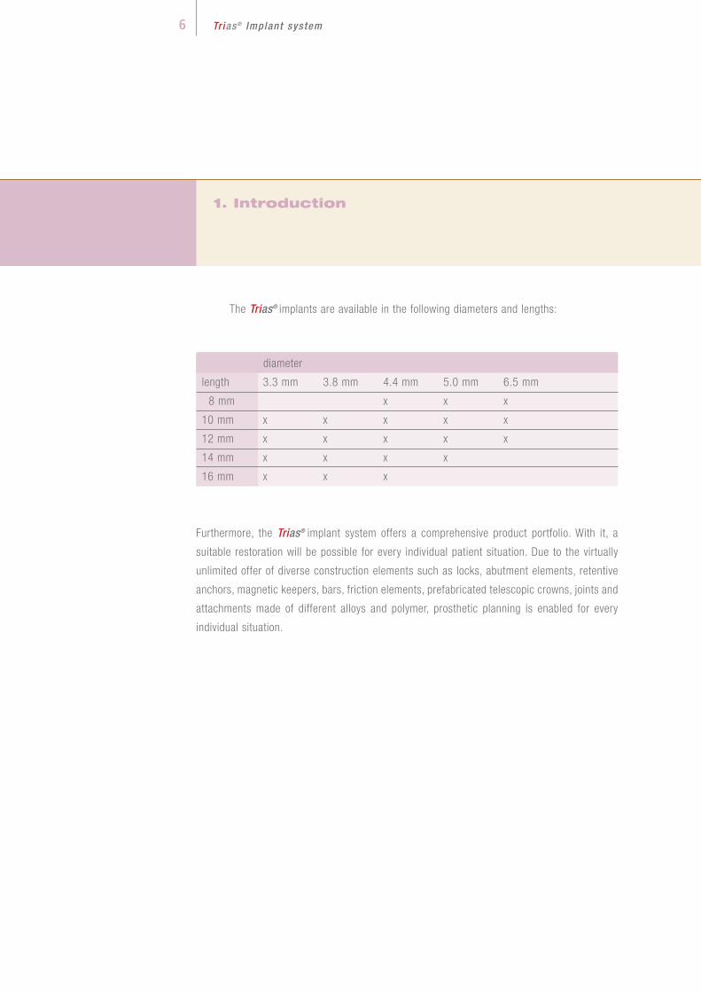
The Trias® implants are available in the following diameters and lengths:
diameter
length 3.3 mm 3.8 mm 4.4 mm 5.0 mm 6.5 mm
8 mm x x x
10 mm x x x x x
12 mm x x x x x
14 mm x x x x
16 mm x x x
Furthermore, the Trias® implant system offers a comprehensive product portfolio. With it, a
suitable restoration will be possible for every individual patient situation. Due to the virtually
unlimited offer of diverse construction elements such as locks, abutment elements, retentive
anchors, magnetic keepers, bars, friction elements, prefabricated telescopic crowns, joints and
attachments made of different alloys and polymer, prosthetic planning is enabled for every
individual situation.
1. Introduction
Tr ias ® Implant system6

Tr ias ® Implant system 7
2. Advanced Implantology Training Programme
It is the aim of Servo-Dental not only to offer high-class implant systems and a broad
range of solutions for prosthetic treatment for dentists having specialized in implantology but
also to provide possibilities of qualification and exchange of experience. For this purpose,
together with experienced practitioners, a comprehensive advanced training programme was
developed. The individual areas were exactly matched to the training requirements of dentists,
surgeons and assistants.
The course system is organized in levels. It acquaints beginners with the fundamentals
of implantology and accompanies them in becoming experts in implantology. Persons inter-
ested can decide themselves which course level they want to begin with and which level they
want to reach. For dentists who newly tackle this field, it is advisable to start with a free basic
course which gives an overview of the forty years of development and the state of the art of
implantology. The uppermost level, and thus the final point, of the course programme is the
first practical implantation which is supervised by an experienced surgeon. For surgeons, on
the basis of the theoretical fundamentals of the open or closed sine lift, step-by-step proce-
dures are demonstrated and practically applied within the scope of a surgery. Assistants learn
both the universal and the system-specific procedure for the preparation and carrying-out of
an implantation as well as the billing of implantological services. Individual habits and questi-
ons of practices are naturally taken into account in all courses.

3. Indication
Tr ias ® Implant system8
The Trias® implant can be used both for single-tooth and for multi-tooth replacement
in any position justified in terms of anatomy and prosthetics. Besides the two-phase healing
(subgingival), single-phase healing (transgingival) is possible using a gingiva former. Circular
bone material of at least 1 mm is recommended. When used for reimplantation, the alveolar
diameter should be completely filled out or expanded to achieve high primary stability.
Our products are certified in accordance with Annex II of Directive 93/42/EEC,
DIN EN ISO 13485:2003.
The application and safety information for the Trias® implant system in this brochure
and in the Instructions for Use is to be complied with. The application of the implant is reser-
ved to dentists having knowledge of the system which can be acquired in advanced training
events.
Servo-Dental reserves the right to modify its products to allow for innovative develop-
ments.

Tr ias ® Implant system 9
4. Equipment
The surgical tray is a standardized box whose instrument tray is specifically manufac-
tured for the Trias® implant system. Thanks to its outside dimensions, the standardized box can
be sterilized in commercial sterilizers. Furthermore, due to a special seal and the incorporated
filter system, it offers the advantage of sterile storage of the instruments without additional
sterilization jacket. The tray for the instruments whose dimensions are standardized also fits
into other surgical trays.
The instrument tray is made of high-grade stainless steel. The instruments are arran-
ged according to the operating procedure and follow the order marked by arrows. The contents
of the surgical tray can be adapted to the user’s wishes.
To spare the instruments
which are not used for the
scheduled surgery, it is
recommended to equip the
tray only with the instru-
ments needed. For this, an
additional small surgical
tray is available.
1. Surgical tray

4. Equipment
Tr ias ® Implant system1 0
2. round drilland/or cortical drill
3. twist drill2.0 mm dia.
4. depth gauge
5. 2-caliber drill3.0 mm dia.
6. parallelization tool
7. final drill – marked in green
3.3 mm dia.,
lengths: 10 mm, 12 mm, 14 mm, 16 mm
8. final drill – marked in yellow
3.8 mm dia.,
lengths: 10 mm, 12 mm, 14 mm, 16 mm
9. final drill – double marked in red
4.4 mm dia.,
lengths: 8 mm, 10 mm, 12 mm, 14 mm, 16 mm
10. final drill – marked in blue
5.0 mm dia.,
lengths: 8 mm, 10 mm, 12 mm, 14 mm

Tr ias ® Implant system 1 1
11. preparation drill for 6.5 mm dia. – marked in white
6.0 mm dia., lengths: 8 mm, 10 mm, 12 mm
(no standard item)
12. final drill – double marked in white
6.5 mm dia., lengths: 8 mm, 10 mm, 12 mm
(no standard item)
13. universal insertion tool, long
14. universal insertion tool, short
15. universal insertion tool, mechanical
16. drill extension
17. drill key, manual
18. torque ratchet
19. lab dish

4. Equipment
Tr ias ® Implant system1 2
Using a colour coding system all drills intended for one and the same diameter can be
identified both by the silicon holder and by a colour ring on the drill itself (Fig. 1). As a result,
confounding of the drills is largely precluded.
The slots marked with white silicon holders are reserved for the pre-drills and the final
drills for the implant diameter of 6.5 mm. As their use is restricted to a relatively limited indi-
cation, equipping of the instrument tray with these drills as a standard was dispensed with.
Subsequent integration is possible at any time.
The grey silicon holders are equipped with instruments which are used irrespective of
diameter and length of the implant to be inserted. The use of these surgical instruments is des-
cribed in chapter 5.4 (round drill, twist drill, depth gauge, 2-caliber drill and parallelization
tools).
Fig. 1

Tr ias ® Implant system 1 3
The universal insertion tools with short or long shaft and the mechanical insertion tool
can be used not only for implant insertion but also for other prosthetic work. This is possible
because the shaft is provided with an octagon for the implants and with a hexagon for the
prosthetic screw (Fig. 2).
To extend the drill, the standard variant (lean form, without trigger safety switch) or the
variant with trigger safety switch are optionally available.
In addition, the scope of supply comprises a torque ratchet whose use is described in
chapter 6.Fig. 2

5. Example of Clinical Procedure
Tr ias ® Implant system1 4
5.1. Preparation and Diagnostics
Implantation has developed into a standard dental therapy. A substantial part of the
success achieved is due to compliance with the indications and the pre-surgery preparation
which also covers the preparation of the patient.
Only an informed patient can actively help ensure the long-term success of the implant.
After provision and evaluation of all diagnostic documents, the course of the therapy can be
definitely fixed. The course of the therapy should be discussed with the patient in detail.
The instruction of the patient comprises in particular:
> explanation of the intervention, including discussion of general and patient-
specific risks
> presentation and consideration of alternative concepts
> information about costs as against the alternative treatment, after instruction
of the patient
> written consent to the surgery after instruction of the patient

Tr ias ® Implant system 1 5
The clinical examination serves to determine:
> the form and width of the alveolar process
> the width of the fixed gingiva
> the position of the neighbouring structures
Before the treatment is started, the patient has to thoroughly clean his teeth and to
rinse the mouth for about half a minute with a disinfecting solution. Then local anesthesia is
carried out (often peripheral infiltration anesthesia which is also sufficient for the mandibular
molar area).
The perioral area, including nose and chin, are to be disinfected. The facial area is
covered with a sterile slotted cloth and the chest area with a sterile chest cloth. The qualifica-
tion of the surgery personnel is as necessary as the preparation of the area of intervention to
protect them from cross infections and implants from contamination.
Besides the general and specific anamnesis, the diagnostics comprises the statement
of the clinical findings. Defects that need therapy are remedied before the implantation.

Tr ias ® Implant system1 6
5. Example of Clinical Procedure
The X-ray sphere in the template / thermo-formed splint shows not only the position
of the implant but also the gingival height to be expected (hint for calculation: scale of
radiograph = dia. of sphere / dia. of original sphere).
The measurement results from the radiograph (bone height = bone height on radio-
graph / scale of radiograph) and the results additionally obtained for the mucosal
thickness furnish an almost three-dimensional impression of the bone profile that can
be transferred to the model.
5.2. Planning and Selection of Implant
The implantation should always be carried out in the position which is most favourable
from the point of view of prosthetics taking account of the anatomic and bone-physiological
conditions. In the ideal case, a multilateral bone wall of at least 1.0 mm surrounds the implant
in an area in which the gingiva cannot be displaced.
There are various options for the selection of the implant, each of them being based on
X-ray diagnostics. This may be carried out by two- or three-dimensional CT or MRT methods.
For the esthetic and functional success of the implantation, the optimal positioning of
the implants should be identified in cooperation with the dental technician.

Tr ias ® Implant system 1 7
With the planning tool (Fig. 3, see also following page) it is now possible to select the
respective implant true to scale. Please note: Due to the design, there is a difference between
the possible insertion depth of the implant and the drilled cavity of 0.3 mm (Fig. 4).
In the case of well-founded indications, the advantages of three-dimensional diagno-
stics should always be set against the risks.
These risks are related to the exposure to radiation which at present is of the order of
approx. 2 to 4 mSv and thus approx. 100 to 1000 times that for a conventional radiograph.
The manufacture of the drilling templates is, however, based on the analysis of the
bone structures in which experience plays an important part. Analysis errors (position of the
mandibular nerve, bone boundaries, etc.) are transferred to the template to be fabricated.
The advantage of three-dimensional template navigation consists in the virtual pre-
liminary planning and the ascertainment of the bone situation, e.g. width of resi-
dual ridge, cavities and potential resorption zones. As it is possible to get the jaw
model, including the desired drilling templates, before the surgery, it is possible to
better plan the surgery and to fabricate temporary dentures beforehand.
Considering the investment involved and the higher costs for the patient (CT exami-
nation, drilling templates, fee for attending dentist), the “conventional” diagnostics
by OPG is an option.
Fig. 4
Fig. 3

5. Example of Clinical Procedure
Tr ias ® Implant system1 8
Planning safety can be ensured by
> fabricating a situation model with diagnostic wax-up to simulate the envisaged
implant treatment
> conceiving a planning tool to transfer the implant position and, if possible, for use
as a drilling tool. It serves, however, only as guidance. For precise measurements
tomograms or computer tomographies are to be made.
Tr ias ® Planning tool (no measuring instrument)
scale 1 : 1
scale 1 : 1.19
scale 1 : 1.26
Fig. 5

Tr ias ® Implant system 1 9
5.3. Ordering of Materials
To be on the safe side, it is advisable to order a greater/smaller diameter or a
greater/smaller length of an implant, as this offers the possibility of inserting an implant other
than the original one without delay. Each individual delivery of an implant comprises, besi-
des the implant itself, the healing screw to close the implant and a universal insertion
tool:
healing screw
colour ring for implant
diameter identification
implant carrier = universal
insertion tool (short)
implant
Fig. 6
Scope of supply for implant

Four your safety – the colour coding system
From the final drills to the implants to the abutments, all parts are assigned to a diame-
ter using a colour coding system:
green 3.3 mm dia.
yellow 3.8 mm dia.
red 4.4 mm dia.
blue 5.0 mm dia.
white 6.5 mm dia. (incl. preparation drill, 6.0 mm dia.)
The abutments can also be set on smaller or greater implant diameters (platform swit-
ching), as all implants are of the same internal design (cone, octa tube and thread).
The implant carrier is at the same time a universal insertion tool. This instrument
has both an octagon for implant insertion and a hexagon to fix all prosthetic abutments.
5. Example of Clinical Procedure
Tr ias ® Implant system2 0

Tr ias ® Implant system 2 1
Fig. 7
Lab fabricated drilling
template
Fig. 8
Representation of
pilot drill hole
using a drilling
template
Fig. 9
Drilling template
(SurgiGuide)
of the SimPlant® platform,
Materialise GmbH
5.4. Surgical procedure
5.4.1. Drilling template
A drilling template can be advantageous for the prosthetically favourable positioning of
the implants. The use of drilling templates fabricated on the basis of CT pictures has already
been described.

Fig. 10
Drilling template in situ
5. Example of Clinical Procedure
Tr ias ® Implant system2 2
The fabrication of the drilling template in the dental laboratory is carried out on the
basis of an impression and the pertaining radiographs. For the Trias® implant system the asso-
ciated sleeves are available which consist of a sleeve-in-sleeve system. When the template is
fabricated with a sleeve 2.0 mm in internal diameter, a fitting sleeve with an internal diameter
of 2.0 mm can be inserted:
One possibility of influencing the direction of insertion in a defined way when several
implants are inserted is the use of the parallel implant. The resulting prosthetic directi-
on of insertion may be limited for certain treatments (bridge or bar, conical or telesco-
pic crown).
Using the knurled head screw, the parallel implant is screwed into the implant inserted
first. The freely movable arm serves to make the next pilot drill hole. The mobility is limited by
the length of the arm and its axial rotation. With various arms an axial rotation from 0° to 6°
and up to 10° is possible.

Tr ias ® Implant system 2 3
5.4.2. Incision
In dependence on the number of implants and on anatomic and esthetic aspects, the
gingiva is opened using a scalpel or laser and the location for the implant is freed by folding
the soft tissue cover outwards (the implant should, if possible, be placed at the highest point
of the bone). Alternatively, opening can be carried out using a mucosa punch (optionally avai-
lable). For this procedure the exact bone dimensions must, however, be known.
Opening by means of a scalpel offers a good view of the place of implantation and the
incision can be expanded, if necessary. Some examples:
Mandible, without teeth – implants interforaminal
Fig. 11: Two implants mandible
Fig. 12: Four to six implants/vestibuloplasty
Fig. 13: Four to six implants, transgingival or immediate loading / cone
Fig. 11
Fig. 12
Fig. 13

Fig. 18
Fig. 17
Fig. 16
Fig. 15
Fig. 14
5. Example of Clinical Procedure
Tr ias ® Implant system2 4
The drills of the Trias® implant system need external cooling. It takes place automati-
cally via a separate supply on the surgery hand piece or is ensured by a surgery assistant. The
risk of overheating of the bone by clogging of the cooling hole as may occur when internally
cooled drills are used is thus avoided.
Maxilla
Fig. 14: Single-tooth implants
Fig. 15: Several implants
Fig. 16: Several implants / alternating incision for vestibuloplasty
Fig. 17: Free-end gap, palatally displaced incision
Fig. 18: Single-tooth implantation, parapapillar incision

Fig. 20
Fig. 19
Fig. 21
A. Marking with the round or cortical drill
at the prosthetically optimal point. If the ridge is tapered, the place of insertion which
at least is of the order of the implant diameter should be flattened beforehand using
the round drill.
Recommended speed: 1,400 rpm. (Figs. 19 and 20)
B. Pilot drilling with the twist drill
The twist drill has a diameter of 2.0 mm and is provided with depth marks correspon-
ding to the implant lengths: 8, 10, 12, 14, 16 mm. The depth of the pilot drill hole
depends on the anatomic situation and the implant length selected. For each implant
length, a depth stop is available which is slipped over the twist drill to define the dril-
ling depth.
Recommended speed: 800 rpm. (Figs. 21 and 22)
5.4.3. Preparation of Implant Bed
The descriptions of the following drilling steps give recommendations which need to be
adapted to the surgery conditions depending on the bone mineral density and the bone quality.
Tr ias ® Implant system 2 5
Fig. 22

Fig. 25
Fig. 23
5. Example of Clinical Procedure
Tr ias ® Implant system2 6
C. Depth measurement
The depth measurement can be carried out using the depth gauge or the parallelization
tools. Both instruments have a depth graduation beginning with 8 mm and extending
in 2 mm spacings up to 16 mm. If parallelization tools are inserted, the pilot drilling
can be checked against a radiograph and changes can be made, e.g. the pilot drill hole
can be deepened or a final drill shorter than originally provided can be used (Fig. 23).
When several implants are inserted, the parallelization tools can substantially support
the parallelism of the pilot drilling. To achieve this, a parallelization tool is positioned in
the completed pilot drill hole. Then the alignment of the next pilot drilling can be made
visually (Fig. 24).
D. Extension with the 2-caliber drill
The 2-caliber drill is a special cutter which follows the specified pilot drilling with its
round guiding nose (2.0 mm dia.) and increases the drilling diameter to 3.0 mm. The
depth specified for the pilot drilling is not changed.
Recommended speed: 800 rpm. (Figs. 25 and 26)
Fig. 24
Fig. 26

Fig. 27
Tr ias ® Implant system 2 7
E. Final drilling, 3.3 mm dia.
All final drills are provided with a depth stop. The
selection of the right length must be borne in mind.
For the 3.3 mm diameter, only one final drilling is
necessary.
Recommended speed: max. 600 rpm. (Fig. 27)
Attention:
Careful preparation of the implant bed with intensive but pressureless cooling is to be
ensured. This applies to the relatively large diameters of 5.00 mm and 6.00 / 6.5 mm
in particular.
The four- to six-edged final drills are very well suited to obtain autologous bone mate-
rial (Fig. 30). For purposes of augmentation, this material can be collected in the lab dish.
Fig. 29
F. Final drilling > 3.3 mm dia.
For a final diameter of, for example, 3.8 mm, first the final drill of 3.3 mm dia. (green
colour ring) and then the final drill of 3.8 mm dia. (yellow ring) are used.
Recommended speed: max. 500 rpm. (Figs. 27, 28 and 29)
For implant diameters greater than 3.8 mm, final drills 4.4 mm, 5.0 mm and 6.5 mm in
diameter are available. Here, as a principle, the drills with the smaller diameters are
used one after another in ascending order as pre-drills. For the implant 6.5 mm in dia-
meter, the separate 6.0 mm pre-drill is used as an intermediate step.
Recommended speed: max. 400 rpm.
Fig. 28
Fig. 30

5.4.4. Insertion
Before breaking the seal, the diameters (colour coding) and the length of the implant
must be checked. The Trias® implant is removed from the packaging and inserted into the
implant bed after having briefly been wetted with autologous blood. The Trias® implant is
arranged on an implant carrier (see page 19) which is identical with the universal insertion
tool.
By slowly inserting the implant (approx. 15 rpm, torque max. 60 Ncm), the self-tapping
capacity is ensured while the friction increases sensibly. After one or two revolutions the
plastic ring can be removed. Then the insertion can take place flush with the cortical bone
(Fig. 34). Make sure that no soft tissue particles get into the implant bed.
The implant needs not be transferred but can be set into the prepared implant bed and
then be gently inserted direct from the packaging (Fig. 33).
Fig. 34
5. Example of Clinical Procedure
Tr ias ® Implant system2 8
Fig. 33

Tr ias ® Implant system 2 9
> It is pointed out that immediate loading is not recommended for
a torque < 35 Ncm
> If 45 Ncm is exceeded, the protocol for dense bones is to be complied with.
> As an alternative to manual insertion, the Trias® implants can also
be inserted using the mechanical insertion tool, the recommended speed
being 20 rpm.
> The implant position can be checked using the implant post.
The final position of the implant should be reached by means of a torque ratchet (see
also chapter 6). At a recommended torque of 35 to 45 Ncm, this allows an estimate of
the actually reached torque to be made (Fig. 35).
Fig. 35

5.4.5. Implant Closure and Suture
Now the wound is closed with a head or mattress suture depending on the esthetical
(e.g. papilla form) or anatomic requirements (Fig. 37). Before closure, defects in the jaw or
extraction wounds can be augmented.
In case a temporary denture is necessary in the front teeth area, a temporary element
with different gingival heights is available. This element which is made of plastics can be pro-
vided with a temporary crown which is ground out of contact and has a purely esthetic functi-
on (Fig. 38). Further details are available from product sheets offered for the respective system
elements of Servo-Dental.
General information:
The patient must be instructed expressly and in detail about the necessary oral
hygienic measures and integrated into a continuous recall system.
5. Example of Clinical Procedure
Tr ias ® Implant system3 0
Fig. 37
Fig. 36
By means of the healing screw forming part of the implant carrier the implant is
closed. The torque ratchet is not used here (Fig. 36).
Fig. 38

Tr ias ® Implant system 3 1
6. Application of torque ratchet
The torque ratchet contained in the instrument tray which has been specifically fabri-
cated for the Trias® implant system can be used
> for manual implant bed preparation (using the manual drill key)
> to fix the implants in their final position
> to insert the abutments as well as the central screw and the bar screw.
The Instructions for Use accompanying each ratchet must be observed.
Important:
The torque ratchet is to be disassembled and cleaned prior to initial and after each
use.
Fig. 39
The torque ratchet (Fig. 39) consists of the ratchet head, the ratchet handle and the
setscrew at the end of the ratchet handle. By axially rotating the ratchet, “insertion”
(ON) or “removal” (OFF) can be selected.
As the ratchet wheel is exchangeable, the torque ratchet can also be used for tools of
other implant manufacturers.
ratchet wheel pin (to exchange ratchet wheel) torque adjustment

The torque range of the ratchet is 10 to 40 Ncm.
The torque is set by rotating the setscrew and thus displacing the marking
(Figs. 40/41). When doing so, the scale disappears into the ratchet handle on
whose edge it indicates the torque setting. When the set torque is reached,
the ratchet is angled in the articulation between handle and head (Fig. 41):
6. Application of torque ratchet
Tr ias ® Implant system3 2
Fig. 40
ratchet wheel ratchet head ratchet handle setscrew
Fig. 41

Tr ias ® Implant system 3 3
7. Re-opening and Prosthetic Treatment
After the implant has healed – preferably over three months for the mandible and six
months for the maxilla –, the final treatment can take place. In the case of early loading, the
implants are to be blocked by a bar connection until the final treatment is carried out. It is
absolutely necessary to comply with the protocol for early loading.
An overview of prosthetic abutments can be found in the annex to these Instructions
and of their application in product sheets offered for the respective system elements of Servo-
Dental.
After re-opening using a scalpel or mucosa punch, the healing screw of the implant is
removed. The use of lasers is possible if the titanium parts are covered beforehand, e.g. by
using the healing screw made of plastics.
Before impressions are taken, the gingiva is formed over ten to 14 days using gingiva
formers at different sulcus heights.
Impression posts are used to take the closed- or open-tray impression. While for the
closed-tray impression the central screw is used, which is suitable for all abutments, a speci-
al impression screw is available for the open-tray method.
Information:
For prosthetic treatment after a temporary treatment and for abutments which are
placed by the chair-side technique, it is not necessary to use sulcus formers
(Trias®ball, -magnetic, -cone, -tsa, -locator®).

7. Re-opening and Prosthetic Treatment
It is recommended to document the patient’s situation before and after the surgery by
radiographs.
For the final treatment, a great selection of abutments is available. An overview is given
at the back of these instructions.
For detailed information material for these and many other prosthetic components
(bolts, articulations, attachments etc.), please contact Servo-Dental.
Innovative products made in Germany ensure systemic solutions for the present and for
the future. The basis for this is the combination of more than 30 years of competence in the
fields of production, service and distribution:
Implantological success via prosthetics!
Tr ias ® Implant system3 4
Trias®solo: various individual posts for fixed or conditionally removable prostheses
Trias®ball: ball attachment system
Trias®magnetic: magnetic attachment system
Trias®bar: various components for bar solutions
Trias®cone: system for double-crown prostheses, also for diverging implants
Trias®tsa: titanium shock absorber: prosthetics with special abutments with
absorber element
Trias®locator®: cylindrical attachment with retention

Tr ias ® Implant system 3 5
Besides the Trias® series of products, we offer you a great number of other products
for prosthetics and implantology:
> NPM dental alloys
> magnetic systems
> attachments
> ball elements
> friction elements for telescope technology
> bolts
> articulations/joints
> anchoring systems
> cast systems
We are prepared to help you – from the planning to the design or in case of repairs –
to find the suitable solution for each individual patient and accompany you with competent
advice, rapid availability of services and products of highest quality.
> Acquaint yourself with our range of products, courses and exhibitions under
www.servo-dental.de.
> Contact our customer consultants by phone under
+49 (0) 23 31 - 95 91-0.

Tr ias ® Implant system
> Gingiva forming
> Moulding
> Model fabrication
> Trias®solo
> especially for bridge prosthetics
> Trias®cone
> Trias®ball
> Trias®bar
> Trias®magnetic 1)
> Trias®locator® 2)
> Trias®tsa 3)
Possibilities of Prosthetic TreatmentP
re
pa
ra
tio
nC
on
dit
ion
all
y r
em
ov
ab
le/
fix
ed
pro
sth
es
is
Re
mo
va
ble
pro
sth
es
is
gingiva former esthetic former
impression post + central screw impression post + impression screw
central screw handle for abutment model analog
central screw (identical for all Trias® abutments)
titanium post high-melting alloy post plastic sleeves (optional for high-melting alloy + titanium posts)
titanium abutment 0° standardprofiles
titanium abutment 0° emergenceprofiles
titanium abutment 15° emergenceprofiles
titanium abutment 25° emergence profiles
bar post (for diverging implants) conical post
cone post cone cap, retentive conical threaded sleeve
locator blue, 680 g
magnetic post magnet S3, 300 g strength magnet S5, 500 g strength
Trias®ball post, sphere 1.8 mm dia. Trias®ball matrix for sphere 1.8 mm dia.
Trias®ball housing for 1.8 mm matrix
round bar, titanium (l = 5 cm)
round bar, precious metal (l = 5 cm)
dolder bar, precious metal (drop shaped) (l = 5 cm)
bar post, plastics
Bar prosthetics, cast
bar post titanium / high-melting alloy
Bar prosthetics laser or tray technique
Universal rider,orange, resilient,
internal dia. 1.9 mm
Universal rider,yellow, rigid,
internal dia. 1.8 mm
Universal rider,black,internal dia. 1.6 mm
Universal rider,red,internal dia. 1.5 mm
Universal rider,white,internal dia. 1.4 mm
outer sleeve,stainless steel,for Universal rider
precious metal matrix (milled)
TeleClickretentionelements
Matrices for bar prosthetics
dolder bar, plastics (drop shaped) (l = 5 cm)
round bar, plastics (l = 5 cm)
parallel bar, plastics (l = 5 cm)
Trias®ball housing for 2.5 mm matrix
O-ring matrices or metal matrices available as alternatives
Trias®ball post, sphere 2.5 mm dia. Trias®ball matrix for sphere 2.5 mm dia.
standard post + impression cap + central screw
tsa® post (H1)
pink, 1361 g transparent, 2268 g red, 880 g green, 1361 g matrix housing, titanium, incl.construction female mold +spacer disc
tsa® post (H2-H4) tsa® matrix
standard post titanium conical abutment gold sealing ring with positioning pin(optional for all Trias®solo abutments)
Ti post for ZrO2 abutments +ZrO2 ball abutment
®titanium shock absorber
Alternative: flex spherical post 7°,ball 2.5 mm dia.
closed-tray impression open-tray impression
cone cap, frictive
females for 0°-10° to compensate divergences in retention levels females for 10°-20° to compensate divergences in retention levels

Possibilities of Prosthetic TreatmentTr ias ® Implant system
> Gingiva forming
> Moulding
> Model fabrication
> Trias®solo
> Trias®cone
> Trias®ball
> Trias®bar
> Trias®magnetic 1)
> Trias®locator® 2)
> Trias®tsa 3)
Pre
pa
ra
tio
nC
on
dit
ion
all
y r
em
ov
ab
le/
fix
ed
pro
sth
es
is
Re
mo
va
ble
pro
sth
es
is

Tr ias ® Implant system
Important information:
For all measures associated with the implantation the lege artis principle is valid.
Training, advice with respect to the application, and advanced training in the handling of Trias®
implants are organized by Servo-Dental. The fundamental prerequisite for the implantation of
Trias® implants is compliance with the rules on indication and contraindication. Mastering of
the surgery techniques, respect of the sterility conditions and the competence of the assistants
are to be ensured by the attending dentist. The X-ray template helps select the implants and
is not a measuring instrument. Due to the ongoing product development, the presentation of
the products may deviate.
Servo-Dental GmbH & Co. KG
Rohrstraße 30
D-58093 Hagen-Halden
Phone: +49 (0 ) 23 31 - 95 91-0
Fax: +49 (0 ) 23 31 - 95 91-25
www.servo-dental.de
1) Dyna Dental Engeneering B.V., the Netherlands, 4600 Bergen Op Zoom
2) Zest Anchors Inc., USA, 92029 CA Escondido
3) Bonecare GmbH, Germany, 86150 Augsburg