imperial - cmc construction services 42 stripping corner the stripping corner allows gangs for...
TRANSCRIPT

ImperialImperialImperialImperialImperial
40
scaffolding bracket
shoe plate
push-pull prop
Fig. 40.1: Guardrail system 1 (controlled access zone) Fig. 40.2: Guardrail system 2 (controlled access zone)
Detail: Shoe plate Detail: Scaffolding adapter
scaffolding adapter
shoe plateanchored to theground scaffolding adapter
WWWWWall braces / Wall braces / Wall braces / Wall braces / Wall braces / Working scaforking scaforking scaforking scaforking scaffoldsfoldsfoldsfoldsfolds
Wall braces areattached to the multi-function profiles byformwork-propconnectors and flangescrews.
brace frame 250brace frame 250brace frame 250brace frame 250brace frame 250consists of push-pull
prop R 250, brace SRL120 and double-jointedfoot plate.
AnchoringAnchoringAnchoringAnchoringAnchoringBefore anchoring
the formwork to theground, theproperties of theground and the ratingof the dowels or nailsmust be verifiedaccording to thefederal, state andlocal codes and regu-lations.
Working scaffoldsWorking scaffoldsWorking scaffoldsWorking scaffoldsWorking scaffoldsTo provide a safe
and roomy workingplatform you caneither use twoscaffolding brackets(Fig. 40.1) or acombination of ascaffolding bracketand the scaffoldingadapter (Fig. 40.2).
noitpircseD noitpircseD noitpircseD noitpircseD noitpircseD oN-.feR oN-.feR oN-.feR oN-.feR oN-.feR tnemtsujdA tnemtsujdA tnemtsujdA tnemtsujdA tnemtsujdA)tf(egnar )tf(egnar )tf(egnar )tf(egnar )tf(egnar
.mdA .mdA .mdA .mdA .mdAerusserp erusserp erusserp erusserp erusserp
)fbl( )fbl( )fbl( )fbl( )fbl(
elisnet.mdA elisnet.mdA elisnet.mdA elisnet.mdA elisnet.mdA)fbl(ecrof )fbl(ecrof )fbl(ecrof )fbl(ecrof )fbl(ecrof
thgieW thgieW thgieW thgieW thgieW)sbl( )sbl( )sbl( )sbl( )sbl(
foaeradednemmoceR foaeradednemmoceR foaeradednemmoceR foaeradednemmoceR foaeradednemmoceRnoitacilppa noitacilppa noitacilppa noitacilppa noitacilppa
sporpllup-hsuP sporpllup-hsuP sporpllup-hsuP sporpllup-hsuP sporpllup-hsuP
061Rporpllup-hsuP 04-901-92"8/15-'4
"4/36-'6ot026,5 026,5 3.42 —
052Rporpllup-hsuP 06-901-92"4/32-'6"6-'01ot
026,5 547,6 0.14ehtfoporpllup-hsuP
elbatius052emarfecarb'21otpusthgiehllawrof
064Rporpllup-hsuP 08-901-92"4/31-'11
"4/30-'71ot594,4 547,6 9.87
otpurofkrowmrofllaWsllawhgih'02
036Rporpllup-hsuP 58-901-92ot"4/38-'61
"4/17-"42001,2 001,2 0.051
otpurofkrowmrofllaWsllawhgih'03
guard-railing post
DescriptionDescriptionDescriptionDescriptionDescription Ref.-No.Ref.-No.Ref.-No.Ref.-No.Ref.-No.
Push-pull propPush-pull propPush-pull propPush-pull propPush-pull propR 630 ................... 29-109-8529-109-8529-109-8529-109-8529-109-85R 460 ................... 29-109-8029-109-8029-109-8029-109-8029-109-80R 250 ................... 29-109-6029-109-6029-109-6029-109-6029-109-60R 160 ................... 29-109-4029-109-4029-109-4029-109-4029-109-40
Articulatedfoot plate ............. 29-802-4829-802-4829-802-4829-802-4829-802-48Formwork-prop connector .... 29-804-8529-804-8529-804-8529-804-8529-804-85scaffoldingadapter ................ 23-311-1023-311-1023-311-1023-311-1023-311-10shoe plate ........... 23-311-9523-311-9523-311-9523-311-9523-311-95
41
WWWWWall braces / Wall braces / Wall braces / Wall braces / Wall braces / Working scaforking scaforking scaforking scaforking scaffoldsfoldsfoldsfoldsfolds
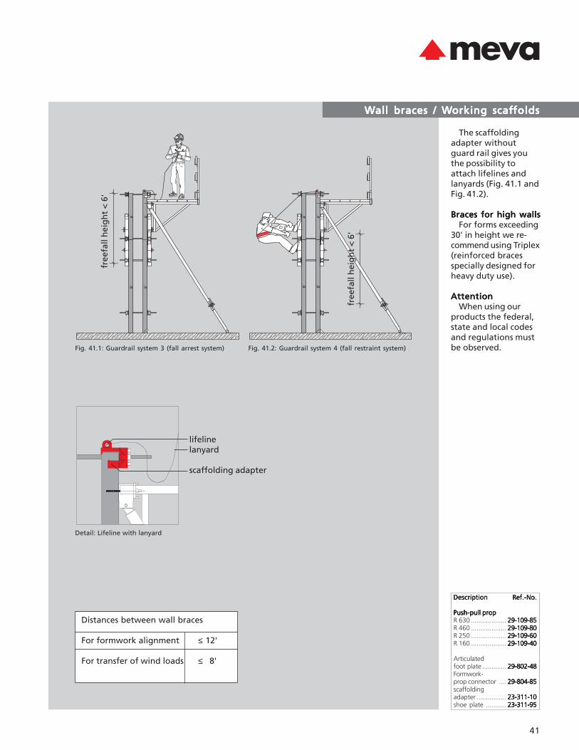
The scaffoldingadapter withoutguard rail gives youthe possibility toattach lifelines andlanyards (Fig. 41.1 andFig. 41.2).
Braces for high wallsBraces for high wallsBraces for high wallsBraces for high wallsBraces for high wallsFor forms exceeding
30' in height we re-commend using Triplex(reinforced bracesspecially designed forheavy duty use).
AttentionAttentionAttentionAttentionAttentionWhen using our
products the federal,state and local codesand regulations mustbe observed.
DescriptionDescriptionDescriptionDescriptionDescription Ref.-No.Ref.-No.Ref.-No.Ref.-No.Ref.-No.
Push-pull propPush-pull propPush-pull propPush-pull propPush-pull propR 630 ................... 29-109-8529-109-8529-109-8529-109-8529-109-85R 460 ................... 29-109-8029-109-8029-109-8029-109-8029-109-80R 250 ................... 29-109-6029-109-6029-109-6029-109-6029-109-60R 160 ................... 29-109-4029-109-4029-109-4029-109-4029-109-40
Articulatedfoot plate ............. 29-802-4829-802-4829-802-4829-802-4829-802-48Formwork-prop connector .... 29-804-8529-804-8529-804-8529-804-8529-804-85scaffoldingadapter ................ 23-311-1023-311-1023-311-1023-311-1023-311-10shoe plate ........... 23-311-9523-311-9523-311-9523-311-9523-311-95
Fig. 41.1: Guardrail system 3 (fall arrest system) Fig. 41.2: Guardrail system 4 (fall restraint system)
Detail: Lifeline with lanyard
lifelinelanyard
scaffolding adapter
free
fall
hei
gh
t <
6'
Distances between wall braces
For formwork alignment ≤ 12'
For transfer of wind loads ≤ 8'
free
fall
hei
gh
t <
6'

ImperialImperialImperialImperialImperial
42
Stripping cornerStripping cornerStripping cornerStripping cornerStripping corner
The stripping cornerallows gangs forelevator shafts andcore walls to be setand stripped withoutdisassembling thegangs (Fig. 42.1 and42.2).The stripping corner isdesigned with threepieces to permit inwardmovement when aturnbuckle connectionis retracted. Minimalcrane time is requiredbecause the strippingcorners turn all sides ofthe gang into onemoveable unit. Afterresetting the gang forthe next pour, theturnbuckles return thegang form to therectangular shape.
Stripping cornersallow easy stripping ofgangs adjacent tocorners or pilasters(Fig. 42.3).
Fig. 42.1
Fig. 42.2
Fig. 42.3
Detail (expanded)DescriptionDescriptionDescriptionDescriptionDescription Ref.-No.Ref.-No.Ref.-No.Ref.-No.Ref.-No.
stripping cornerstripping cornerstripping cornerstripping cornerstripping corner8’ x 1’ .................. 23-309-1023-309-1023-309-1023-309-1023-309-104’ x 1’ .................. 23-309-2023-309-2023-309-2023-309-2023-309-20
Detail (retracted)
43
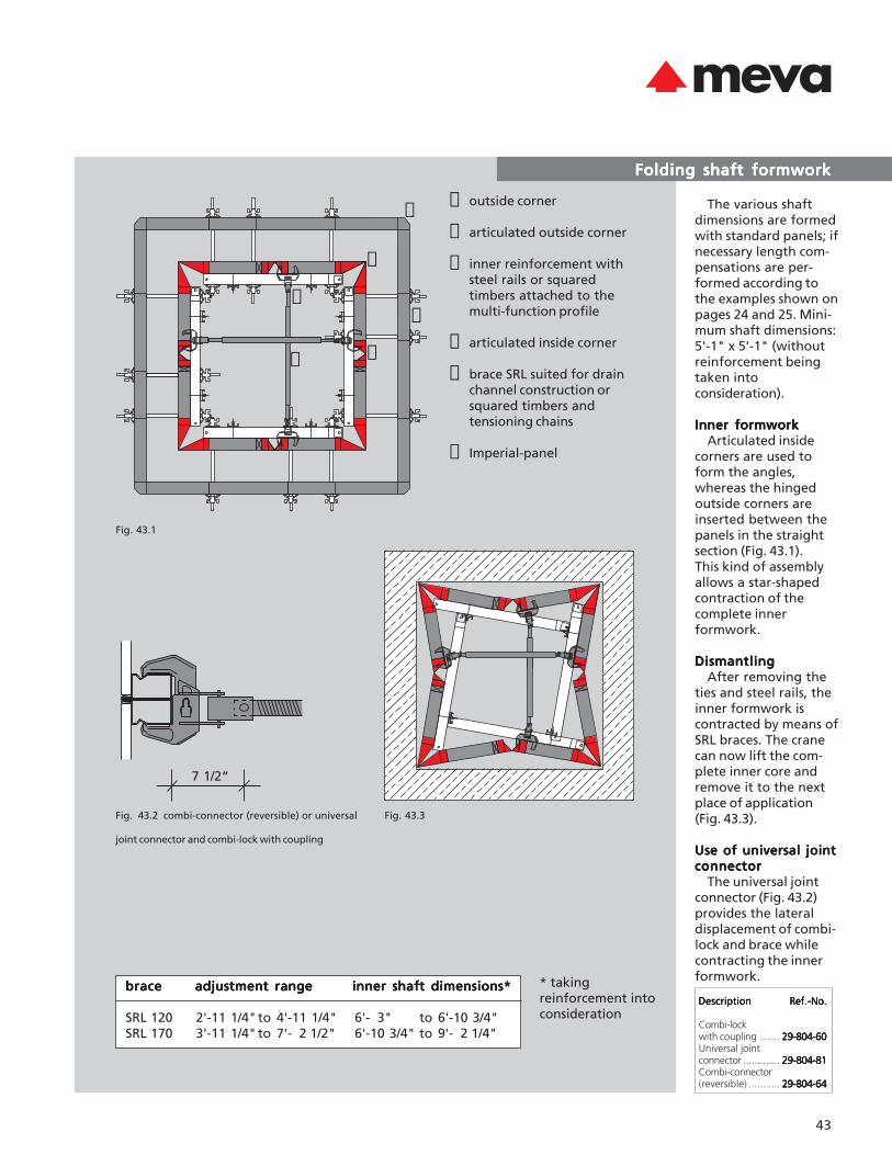
➀ outside corner
➁ articulated outside corner
➂ inner reinforcement withsteel rails or squaredtimbers attached to themulti-function profile
➃ articulated inside corner
➄ brace SRL suited for drainchannel construction orsquared timbers andtensioning chains
➅ Imperial-panel
Fig. 43.2 combi-connector (reversible) or universal
joint connector and combi-lock with coupling
7 1/2“
bracebracebracebracebrace adjustment rangeadjustment rangeadjustment rangeadjustment rangeadjustment range inner shaft dimensions*inner shaft dimensions*inner shaft dimensions*inner shaft dimensions*inner shaft dimensions*
SRL 120 2'-11 1/4"to 4'-11 1/4" 6'- 3" to 6'-10 3/4"SRL 170 3'-11 1/4"to 7'- 2 1/2" 6'-10 3/4" to 9'- 2 1/4"
➀
➁
➂
➃
➄
➅
Fig. 43.3
Folding shaft formworkFolding shaft formworkFolding shaft formworkFolding shaft formworkFolding shaft formwork
The various shaftdimensions are formedwith standard panels; ifnecessary length com-pensations are per-formed according tothe examples shown onpages 24 and 25. Mini-mum shaft dimensions:5'-1" x 5'-1" (withoutreinforcement beingtaken intoconsideration).
Inner formworkInner formworkInner formworkInner formworkInner formworkArticulated inside
corners are used toform the angles,whereas the hingedoutside corners areinserted between thepanels in the straightsection (Fig. 43.1).This kind of assemblyallows a star-shapedcontraction of thecomplete innerformwork.
DismantlingDismantlingDismantlingDismantlingDismantlingAfter removing the
ties and steel rails, theinner formwork iscontracted by means ofSRL braces. The cranecan now lift the com-plete inner core andremove it to the nextplace of application(Fig. 43.3).
Use of universal jointUse of universal jointUse of universal jointUse of universal jointUse of universal jointconnectorconnectorconnectorconnectorconnector
The universal jointconnector (Fig. 43.2)provides the lateraldisplacement of combi-lock and brace whilecontracting the innerformwork.
DescriptionDescriptionDescriptionDescriptionDescription Ref.-No.Ref.-No.Ref.-No.Ref.-No.Ref.-No.
Combi-lockwith coupling ....... 29-804-6029-804-6029-804-6029-804-6029-804-60Universal jointconnector ............. 29-804-8129-804-8129-804-8129-804-8129-804-81Combi-connector(reversible) ........... 29-804-6429-804-6429-804-6429-804-6429-804-64
Fig. 43.1
* takingreinforcement intoconsideration

ImperialImperialImperialImperialImperial
44
Assembly and stripping (general)Assembly and stripping (general)Assembly and stripping (general)Assembly and stripping (general)Assembly and stripping (general)
Fig. 44.1
Fig 44.2
filler for easy stripping
Planning stagePlanning stagePlanning stagePlanning stagePlanning stageReasonable planning
and preparation arethe keys to a successfulapplication of anymodern formworksystems.
First of all, determinethe amount offormwork materialthat will be needed. Inthis regard severalfactors of influenceshould be taken intoaccount:• weight of the form-work to be handled• time allowed forassembly anddismantling• transportation of theformwork from onepour to the next –either panel by panel,or in gangs (whichconsiderably reducesforming time)• capacity of the liftingequipment• size of pours (takinginto account thenumber of corners etc.)
Once all theseaspects have beenconsidered, the quan-tities of formworkitems can be specified.
Assembly AreaAssembly AreaAssembly AreaAssembly AreaAssembly AreaThe area where the
formwork is set shouldbe clean, even andcapable of taking theexpected load.
Formwork AssemblyFormwork AssemblyFormwork AssemblyFormwork AssemblyFormwork AssemblyIn most cases it is
recommended to setthe outside formworkfirst. Always start at aconvenient locationand immediatelyattach a brace to thepanels set in place. Ifyou choose to pre-assemble large-sizegangs on the ground,attach braces andworking scaffoldbefore lifting thewhole unit. You shouldhave a flat surface forthe pre-assembly.
Don’t forget to spraythe alkus face withrelease agent.
Panel connectionPanel connectionPanel connectionPanel connectionPanel connectionIn general the 4’ and
8’ high panels are con-nected at the verticaljoint using 2 assemblylocks, while 12’ highpanels are connectedwith 3 assembly locks.
Exception: outsidecorners are connectedto the adjacent panelsas follows:• outside corner 4’ high:2 assembly locks• outside corner 8’ high:3 assembly locks• outside corner 12‘ high:5 assembly locks
45
Assembly and stripping (general)Assembly and stripping (general)Assembly and stripping (general)Assembly and stripping (general)Assembly and stripping (general)
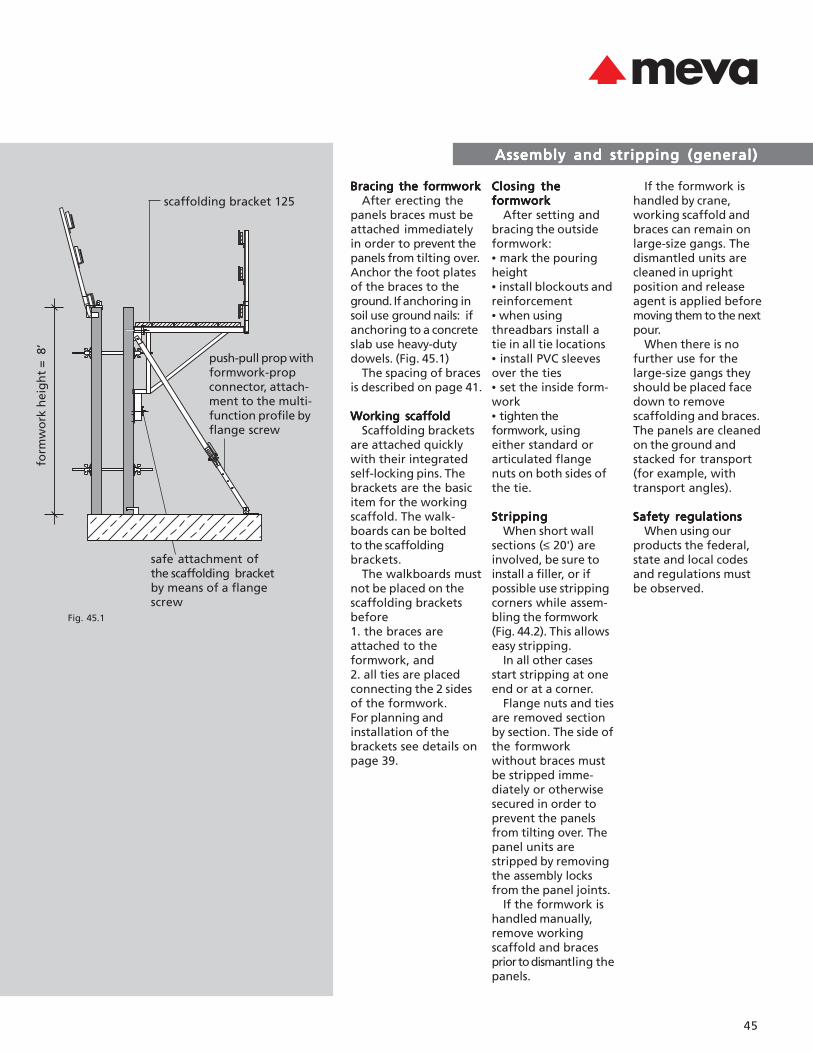
scaffolding bracket 125
push-pull prop withformwork-propconnector, attach-ment to the multi-function profile byflange screw
safe attachment ofthe scaffolding bracketby means of a flangescrew
form
wo
rk h
eig
ht
= 8
’
Fig. 45.1
Bracing the formBracing the formBracing the formBracing the formBracing the formworkworkworkworkworkAfter erecting the
panels braces must beattached immediatelyin order to prevent thepanels from tilting over.Anchor the foot platesof the braces to theground. If anchoring insoil use ground nails: ifanchoring to a concreteslab use heavy-dutydowels. (Fig. 45.1)
The spacing of bracesis described on page 41.
Working scaffoldWorking scaffoldWorking scaffoldWorking scaffoldWorking scaffoldScaffolding brackets
are attached quicklywith their integratedself-locking pins. Thebrackets are the basicitem for the workingscaffold. The walk-boards can be boltedto the scaffoldingbrackets.
The walkboards mustnot be placed on thescaffolding bracketsbefore1. the braces areattached to theformwork, and2. all ties are placedconnecting the 2 sidesof the formwork.For planning andinstallation of thebrackets see details onpage 39.
Closing theClosing theClosing theClosing theClosing theformworkformworkformworkformworkformwork
After setting andbracing the outsideformwork:• mark the pouringheight• install blockouts andreinforcement• when usingthreadbars install atie in all tie locations• install PVC sleevesover the ties• set the inside form-work• tighten theformwork, usingeither standard orarticulated flangenuts on both sides ofthe tie.
StrippingStrippingStrippingStrippingStrippingWhen short wall
sections (≤ 20') areinvolved, be sure toinstall a filler, or ifpossible use strippingcorners while assem-bling the formwork(Fig. 44.2). This allowseasy stripping.
In all other casesstart stripping at oneend or at a corner.
Flange nuts and tiesare removed sectionby section. The side ofthe formworkwithout braces mustbe stripped imme-diately or otherwisesecured in order toprevent the panelsfrom tilting over. Thepanel units arestripped by removingthe assembly locksfrom the panel joints.
If the formwork ishandled manually,remove workingscaffold and bracesprior to dismantling thepanels.
If the formwork ishandled by crane,working scaffold andbraces can remain onlarge-size gangs. Thedismantled units arecleaned in uprightposition and releaseagent is applied beforemoving them to the nextpour.
When there is nofurther use for thelarge-size gangs theyshould be placed facedown to removescaffolding and braces.The panels are cleanedon the ground andstacked for transport(for example, withtransport angles).
Safety regulationsSafety regulationsSafety regulationsSafety regulationsSafety regulationsWhen using our
products the federal,state and local codesand regulations mustbe observed.
ImperialImperialImperialImperialImperial
46
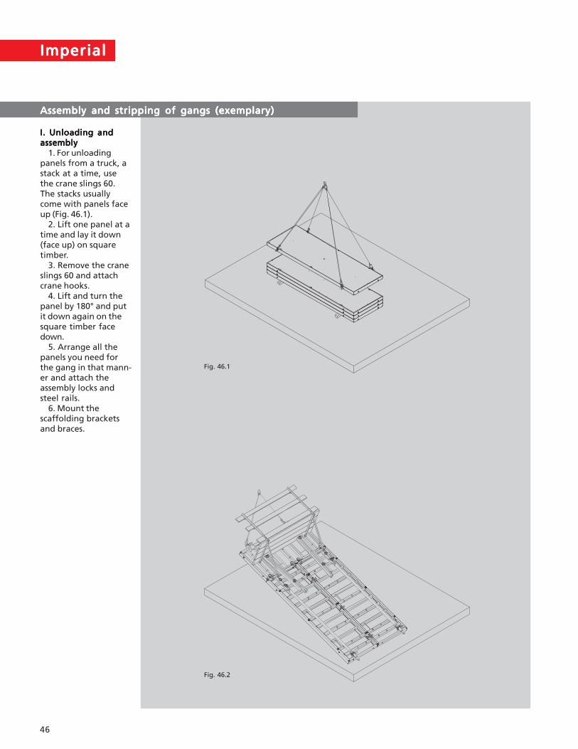
I. Unloading andI. Unloading andI. Unloading andI. Unloading andI. Unloading andassemblyassemblyassemblyassemblyassembly
1. For unloadingpanels from a truck, astack at a time, usethe crane slings 60.The stacks usuallycome with panels faceup (Fig. 46.1).
2. Lift one panel at atime and lay it down(face up) on squaretimber.
3. Remove the craneslings 60 and attachcrane hooks.
4. Lift and turn thepanel by 180° and putit down again on thesquare timber facedown.
5. Arrange all thepanels you need forthe gang in that mann-er and attach theassembly locks andsteel rails.
6. Mount thescaffolding bracketsand braces.
Assembly and stripping of gangs (exemplary)Assembly and stripping of gangs (exemplary)Assembly and stripping of gangs (exemplary)Assembly and stripping of gangs (exemplary)Assembly and stripping of gangs (exemplary)
Fig. 46.1
Fig. 46.2

47
II. Lifting andII. Lifting andII. Lifting andII. Lifting andII. Lifting andsettingsettingsettingsettingsetting
1. For lifting thegang use at least 2crane hooks plusstandard crane slings(supplied by contrac-tor (Fig. 46.2)).
2. Lift the gang toupright position andspray the alkus facewith release agent(Fig. 47.1).
3. Move the ganginto place andimmediately anchorthe braces to theground.
4. Remove thecrane hook.
5. Proceed with theother gangs in thesame way (Fig. 47.2).
Assembly and stripping of gangs (exemplary)Assembly and stripping of gangs (exemplary)Assembly and stripping of gangs (exemplary)Assembly and stripping of gangs (exemplary)Assembly and stripping of gangs (exemplary)
Fig. 47.1
Fig. 47.2

ImperialImperialImperialImperialImperial
48
III. Closing formworkIII. Closing formworkIII. Closing formworkIII. Closing formworkIII. Closing formworkThe opposite
formwork is assem-bled the same way asdescribed before. Forthis formwork, how-ever, you may notnecessarily needbraces.a) Closing with DW-a) Closing with DW-a) Closing with DW-a) Closing with DW-a) Closing with DW-threadbarsthreadbarsthreadbarsthreadbarsthreadbars
1. Insert the tiesthrough the first form-work equal to therequired wall thickness.
2. Install spacer conesand PVC sleeves overthe ties.
3. Lift and move thesecond formwork intoplace.
4. Push the tiesthrough the secondformwork and securethem on both sideswith flange nuts.
5. When using sys-tems without spacersapply Z-bars to ensureconstant wall thickness(Fig. 48.1, 48.2).b) Closing withb) Closing withb) Closing withb) Closing withb) Closing withtaper tiestaper tiestaper tiestaper tiestaper ties
1. Lift and movesecond formwork intoplace.
2. Insert the taperties and adjust them tothe required wallthickness. Secure theties on both sides withflange nuts.c) Closing withc) Closing withc) Closing withc) Closing withc) Closing withshebolts or steelshebolts or steelshebolts or steelshebolts or steelshebolts or steelconesconesconesconescones
Please consulttechnical departmentfor details.
Attention:Attention:Attention:Attention:Attention:Do not remove
crane hooks until bothsides of the formworkare sufficiently securedwith ties.
Assembly and stripping of gangs (exemplary)Assembly and stripping of gangs (exemplary)Assembly and stripping of gangs (exemplary)Assembly and stripping of gangs (exemplary)Assembly and stripping of gangs (exemplary)
Fig. 48.1
Fig. 48.2

49
IVIVIVIVIV. Pouring. Pouring. Pouring. Pouring. PouringSee pages 39 ff. for
safety advice forworkers on platforms(Fig. 49.1).
Observe all federal,state and local codesand regulations forpouring concrete.Attention:Attention:Attention:Attention:Attention:
The admissiblefresh concretepressure of 2,025 lbs/sq.ft. must not beexceeded.VVVVV. Stripping and. Stripping and. Stripping and. Stripping and. Stripping anddismantlingdismantlingdismantlingdismantlingdismantling
Do not startstripping until theconcrete has set tothe point where itcannot deformanymore.
Always start withthe second side of theformwork (the onewithout braces).
1. Mount the cranehooks to the gangs,attach the standardcrane slings and pullthem tight.
2. Remove the tiesand assembly locks.
3. Pull the gang upvertically (Fig. 49.2).
4. Move the gang tothe next pour or atemporary storage, ordismantle it (as re-quired).
5. If heavily soiledyou might need toclean the panels andspray them withrelease agent beforethe next use.
Attention:Attention:Attention:Attention:Attention:All personnel must
be OFF the formworkwhen moving gangsby crane. Make sureto remove all looseobjects (such asconcrete remnants,tools, etc.).
Assembly and stripping of gangs (exemplary)Assembly and stripping of gangs (exemplary)Assembly and stripping of gangs (exemplary)Assembly and stripping of gangs (exemplary)Assembly and stripping of gangs (exemplary)
Fig. 49.1
Fig. 49.2

ImperialImperialImperialImperialImperial
50
Crane slings Stapos 60Crane slings Stapos 60Crane slings Stapos 60Crane slings Stapos 60Crane slings Stapos 60
Fig. 50.1 Fig. 50.2
Fig. 50.3 Fig. 50.4
Fig. 50.5DescriptionDescriptionDescriptionDescriptionDescription Ref.-No.Ref.-No.Ref.-No.Ref.-No.Ref.-No.
Crane slingsStapos 60 ............ 29-403-2529-403-2529-403-2529-403-2529-403-25
Crane slings made ofpolyester tape withdouble-sided textilecoating. The load-bearing capacity isstamped on the coating.The sling is providedwith a galvanized self-locking fastening device.4 crane slings 60 areneeded to move andtransport panel stacks.They loop securely tothe four corners(Fig. 50.1).
HandlingHandlingHandlingHandlingHandlingPlace the panel stack
on square timbers (Fig.50.2). First push thesuspension deviceunder the stack withyour foot (Fig. 50.3).Then yank the sling up(Fig. 50.5). The elasticfastening pin willengage completely inthe profile groove andsecures the stackagainst accidentaluplift (Fig. 50.4).

51
Crane slings Stapos 60Crane slings Stapos 60Crane slings Stapos 60Crane slings Stapos 60Crane slings Stapos 60
TTTTTechnical dataechnical dataechnical dataechnical dataechnical data
Description Crane slings Stapos 60
Ref.-no. 29-403-25
Weight 9.9 lbs
Color green
Adm. load-bearing capacity per sling 2,200 lbs
Adm. stack weight 4,400 lbs
For frame profile width 2 3/8"
Max. stack height 10 panels
Max. stack height for Imperial 8'x8' = 5 panelslarge size panels Imperial 12'x8' = 3 panels
While transportingthe stack by crane theload-bearing capacityis uniformly distributedto all slings. Just oneperson is required forattachment and re-moval of the slings.
AttentionAttentionAttentionAttentionAttentionThe Stapos crane
slings may be used onlyin conjunction withdouble-rope cranedevices in compliancewith applicable safetyregulations. If panelwidth exceeding 6'-6"a four-rope cranedevice is imperative(Fig. 51.1).
Fig. 51.1

ImperialImperialImperialImperialImperial
52
Lifting hook 60 / Crane slings 60Lifting hook 60 / Crane slings 60Lifting hook 60 / Crane slings 60Lifting hook 60 / Crane slings 60Lifting hook 60 / Crane slings 60
Fig. 52.1
Fig. 52.3
TTTTTransport deviceransport deviceransport deviceransport deviceransport deviceThe transport device
(Fig. 52.1 and 52.3)helps in quickly loadingand unloading trucksand moving the stacksnear the ground. Thelifting hooks areinserted into thewelded sleeves of thebottom panel frame.
Lifting hookLifting hookLifting hookLifting hookLifting hookThe lifting hook can
be used with any four-rope crane device avail-able on the constructionsite to transport stacksof panels (alwaysuse 4 hooks at a time).
To calculate theadmissible load-bearingcapacity assume only 2hooks.
AttentionAttentionAttentionAttentionAttentionAfter tightening the
device check to makesure the hooks aresafely locked(Fig. 52.2).
Fig. 52.2
locked position
DescriptionDescriptionDescriptionDescriptionDescription Ref.-No.Ref.-No.Ref.-No.Ref.-No.Ref.-No.
Crane slings 60 .... 29-401-4529-401-4529-401-4529-401-4529-401-45Lifting hook 60 .... 29-401-4029-401-4029-401-4029-401-4029-401-40
53
Lifting hook 60 / Crane slings 60Lifting hook 60 / Crane slings 60Lifting hook 60 / Crane slings 60Lifting hook 60 / Crane slings 60Lifting hook 60 / Crane slings 60
Fig. 53.1
Fig. 53.2
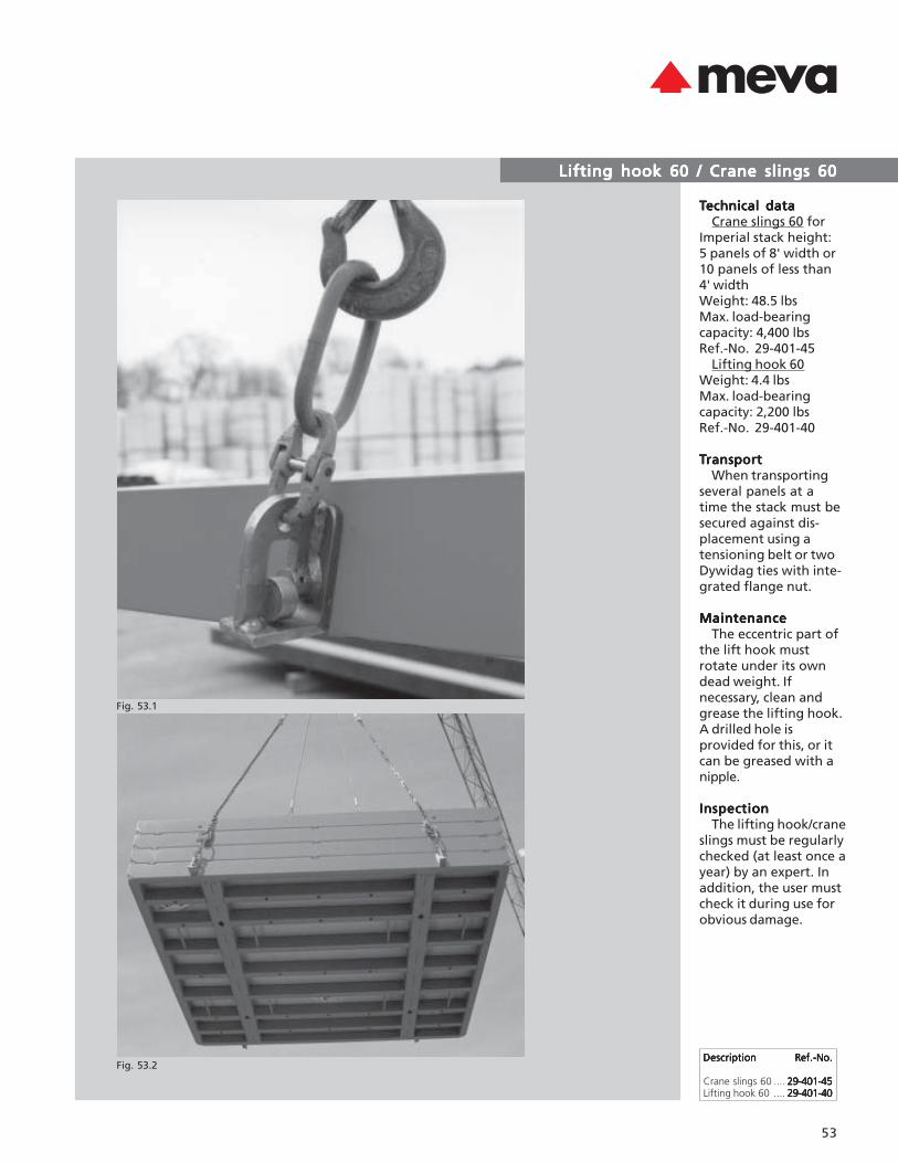
TTTTTechnical dataechnical dataechnical dataechnical dataechnical dataCrane slings 60 for
Imperial stack height:5 panels of 8' width or10 panels of less than4' widthWeight: 48.5 lbsMax. load-bearingcapacity: 4,400 lbsRef.-No. 29-401-45
Lifting hook 60Weight: 4.4 lbsMax. load-bearingcapacity: 2,200 lbsRef.-No. 29-401-40
TTTTTransportransportransportransportransportWhen transporting
several panels at atime the stack must besecured against dis-placement using atensioning belt or twoDywidag ties with inte-grated flange nut.
MaintenanceMaintenanceMaintenanceMaintenanceMaintenanceThe eccentric part of
the lift hook mustrotate under its owndead weight. Ifnecessary, clean andgrease the lifting hook.A drilled hole isprovided for this, or itcan be greased with anipple.
InspectionInspectionInspectionInspectionInspectionThe lifting hook/crane
slings must be regularlychecked (at least once ayear) by an expert. Inaddition, the user mustcheck it during use forobvious damage.
DescriptionDescriptionDescriptionDescriptionDescription Ref.-No.Ref.-No.Ref.-No.Ref.-No.Ref.-No.
Crane slings 60 .... 29-401-4529-401-4529-401-4529-401-4529-401-45Lifting hook 60 .... 29-401-4029-401-4029-401-4029-401-4029-401-40
ImperialImperialImperialImperialImperial
54
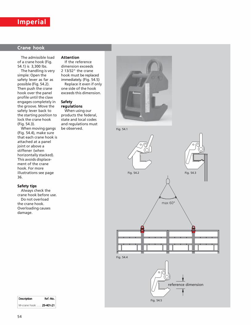
Crane hookCrane hookCrane hookCrane hookCrane hook
AttentionAttentionAttentionAttentionAttentionIf the reference
dimension exceeds2 13/32" the cranehook must be replacedimmediately. (Fig. 54.5)
Replace it even if onlyone side of the hookexceeds this dimension.
SafetySafetySafetySafetySafetyregulationsregulationsregulationsregulationsregulations
When using ourproducts the federal,state and local codesand regulations mustbe observed.
The admissible loadof a crane hook (Fig.54.1) is 3,300 lbs.
The handling is verysimple: Open thesafety lever as far aspossible (Fig. 54.2).Then push the cranehook over the panelprofile until the clawengages completely inthe groove. Move thesafety lever back tothe starting position tolock the crane hook(Fig. 54.3).
When moving gangs(Fig. 54.4), make surethat each crane hook isattached at a paneljoint or above astiffener (whenhorizontally stacked).This avoids displace-ment of the cranehook. For moreillustrations see page36.
Safety tipsSafety tipsSafety tipsSafety tipsSafety tipsAlways check the
crane hook before use.Do not overload
the crane hook.Overloading causesdamage.
DescriptionDescriptionDescriptionDescriptionDescription Ref.-No.Ref.-No.Ref.-No.Ref.-No.Ref.-No.
M-crane hook ...... 29-401-2129-401-2129-401-2129-401-2129-401-21
reference dimension
Fig. 54.1
Fig. 54.2 Fig. 54.3
Fig. 54.4
Fig. 54.5

55
Single-sided formworkSingle-sided formworkSingle-sided formworkSingle-sided formworkSingle-sided formwork
Support frame STBSupport frame STBSupport frame STBSupport frame STBSupport frame STBThe Imperial form-
work – together withsupport frames – canalso be applied whenconcrete has to bepoured against anexisting wall or thelike, i.e. when a sin-gle-sided formwork isrequired. Supportframes 300 are goodfor wall heights up to12'. Support frames450 with heightextensions allow forwall heights over 26'.
Technical datasheets are availableon request.
Climbing formworkClimbing formworkClimbing formworkClimbing formworkClimbing formwork
KLK 230KLK 230KLK 230KLK 230KLK 230When forming high
walls, facades, pillars,staircases or elevatorshafts, Imperialformwork is set andsecured on climbingscaffold KLK 230.
Technical datasheets are availableon request.
AttentionAttentionAttentionAttentionAttentionThe use of support
frame and climbingscaffold requires adetailed formworkplanning!
ImperialImperialImperialImperialImperial
56
ServiceServiceServiceServiceService
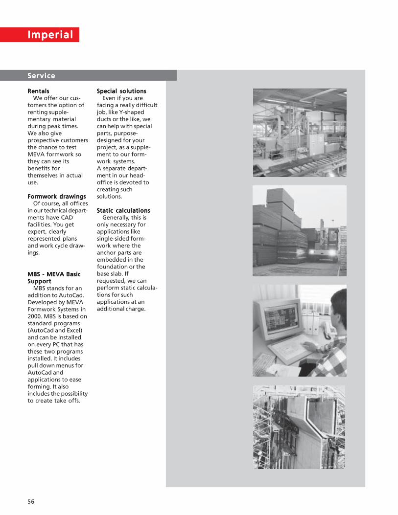
RentalsRentalsRentalsRentalsRentalsWe offer our cus-
tomers the option ofrenting supple-mentary materialduring peak times.We also giveprospective customersthe chance to testMEVA formwork sothey can see itsbenefits forthemselves in actualuse.
Formwork drawingsFormwork drawingsFormwork drawingsFormwork drawingsFormwork drawingsOf course, all offices
in our technical depart-ments have CADfacilities. You getexpert, clearlyrepresented plansand work cycle draw-ings.
Special solutionsSpecial solutionsSpecial solutionsSpecial solutionsSpecial solutionsEven if you are
facing a really difficultjob, like Y-shapedducts or the like, wecan help with specialparts, purpose-designed for yourproject, as a supple-ment to our form-work systems.A separate depart-ment in our head-office is devoted tocreating suchsolutions.
Static calculationsStatic calculationsStatic calculationsStatic calculationsStatic calculationsGenerally, this is
only necessary forapplications likesingle-sided form-work where theanchor parts areembedded in thefoundation or thebase slab. Ifrequested, we canperform static calcula-tions for suchapplications at anadditional charge.
MBS - MEVA BasicMBS - MEVA BasicMBS - MEVA BasicMBS - MEVA BasicMBS - MEVA BasicSupportSupportSupportSupportSupport
MBS stands for anaddition to AutoCad.Developed by MEVAFormwork Systems in2000. MBS is based onstandard programs(AutoCad and Excel)and can be installedon every PC that hasthese two programsinstalled. It includespull down menus forAutoCad andapplications to easeforming. It alsoincludes the possibilityto create take offs.

57
NotesNotesNotesNotesNotes

ImperialImperialImperialImperialImperial
58
NotesNotesNotesNotesNotes