impeller-induced rotqr-dynamic forces ...authors.library.caltech.edu/27/1/aco098.pdfof a dynamometer...
TRANSCRIPT

Proceedings of U.S.-Korea Fluids Eng. Seminar, Sep. 1989.
IMPELLER-INDUCED ROTQR-DYNAMIC FORCES
Allan J. Acosta, Christopher E. Brennen, Thomas K. Caughey California Institute of Technology
ABSTRACT
The flow through and around the rotor of a turbomachine exerts a force on the rotor and, hence, rotor shaft and bearing system. In some circumstances this force may lead to excitation of shaft whirl in the direction of impeller rotation. Recent international research of this phenomenon is briefiy reviewed; these find- ings suggest that turbomachines intended to operate well above the first critical speed should take the effect into account.
INTRODUCTION
It is well known to pump engineers that centrifugal pump impellers produce a ra- dial force, particularly at off-design. Indeed, estimates of this force for a small range of pump types and configurations are found in standard reference works (e.g., Lazarkiewicz and Troskolanski, 1965) and concern with this issue has led to a number of notable experiments, among which may be cited that by Hergt and Krieger (1969). Compressor engineers, perhaps because of typically higher rotative speeds, have had a long history of vibration problems This has led to the development early on of a concept of "cross-coupledn impeller force and dis- placement relations somewhat similar to that of a journal bearing. The result is a possible excitation of a shaft or impeller whirl which could be destructive. The possible existance of such a fluid-induced force (as well as damping and inertia) is of vital importance for dynamic analysis of turbomachinery mechanical systems and has received great attention in the compressor literature. These cross-coupled aerodynamic forces are now sometimes simply called "Alfordn forces. For refer- ence to Alford's original work and related areas, please refer to the recent sum- mary text on rotordynamics by Vance, 1988.
There appeared to be no parallel development in hydraulic turbomachinery until comparatively recently. However, as is inevitable with increasing power density of turbomachine applications in aerospace and even in commercial pumps for power plants, operational problems and failures from many sources began to appear in

the open literature. One of the most interesting of these (Childs, et. al., 1985) describes the vibrational characteristics of the liquid oxygen pump for the Space Shuttle turborocket and the various structural and Auid mechanical sources that may contribute to problems. Already, the utility industry in the United States had responded to this need to survey such problems (Makay and Szamody, 1978) eventually to lead to an extensive pump research and development program by the Electric Power Research Institute, EPRI, which were reviewed in part by Pace, et. al. in 1986.
Concern with these kinds of pump problems in the field as well as in aerospace had already led to independent experimental research efforts elsewhere on impeller-induced forces at Caltech, the Universities of Tokyo and Osaka, and the Sulzer Brothers Corporation, Winterthur, who were eventually to lead the EPRI sponsored pump research development program. In addition, significant devel- opments more directed at problems of seals and wear-rings had taken place at many universities and industrial research groups. These seal problems and the dynamic representation of them are emphasized in the book by Vance; less avail- able but the main center if not focus and repository of these fluid-induced exci- tations both from seals, bearings and the impeller flow itself, are to be found in the five NASA workshops on rotordynamic instability held at Texas A&M edited by Childs and Hendricks. Space does not premit but a mere passing reference to many of these important contributions; in what follows we focus upon rotordy- namic forces caused by whirling, centrifugal, radial-flow pump impellers. Mea- surement techniques are briefly described as are the leading results and the effect of cavitation. Some simplified flow models are briefly described that appear to simulate observed behavior.
IMPELLER FLOW-INDUCED FORCE SYSTEM
It has been found that, for a wide range of impeller-housing configurations, the force exerted upon the impeller can be expressed in the form
where F is the force on the impeller. The term x represents the displacement of the impeller centerline from the center of the housing; A is a 2 x 2 matrix called the impeller force matrix, and F, is the residual impeller force. The terms F,, A and x are, in reality, time-dependent because of inherent flow unsteadiness, blade passing forces and possible vibrations or whirling excursions of the impeller or shaft axis. For the design of bearings and shafting, it is usually sufficient to know the time-averaged value of F, and in the pump literature this force is then called simply the "volute forcen or just "radialn force. Data on the volute force is given in reference design monographs (e.g., Lazarkiewicz, et. al.) for a limited range of design parameters. This force varies strongly with flow coefficient for single volute pumps and, to prevent this, many commercial or boiler feed pumps are de- signed to have multiple volutes or diffusor collectors to avoid this flow asymmetry

for "off-design" flow rates. In a similar vein, it is useful to consider the effect of the displacement term Ax to be a time-averaged force in respect to impeller shaft rotation to supress blade-to-blade fluctuations. It was realized early on, particu- larly in the work originated by Dornrn and Hergt of the KSB organization (see, for example, Hergt and Krieger, 1969), that the total force given in Eq. (1) was a function of the position of the impeller centerline with respect to the housing axis of symmetry and that an impeller centerline position could be found even for off- design flows that would result in smaller even zero volute force. One may think of these positions as a "hydrodynamic center" and that the locus of such positions as a function of flow rate as an important design concept.
This point of view, however, does not fully describe the character of the coeffi- cient A. Figure 1 shows a schematic diagram of the forces that may act on the shaft of a rotating and whirling impeller. It is well known in the field and was documented by Hergt and Krieger that the centerlines of impelIers could undergo complicated orbits. The displacements of the impeller centerline are small with respect to impeller radius and are limited in practice by the wearing ring clear- ances. (In what follows we consider the force in Eq. (I) to be due to the impeller- housing interaction alone and not to the effects of the hydrodynamic forces aris- ing from wear rings or other sealing surfaces treated fully in the conferences or- ganized by Childs, et. al., e. g., 1989.) It is on that basis that the linear approx- imation of Eq. (1) is made. Chamieh, et. al. was, to our knowledge, the first to show that for slow, quasi-steady circular orbits of a conventional volute/impeller combination the coefficient A was a skew-symmetric matrix. In this work the components of A were averaged around one or more integral number of whirl or- bits to smooth out the effects of blade-to-blade variations as the impeller shaft rotated with respect to the cut water in Fig. 1. These results were most inter- esting, for they showed for the first time that the intrinsic flow-induced force, by being skew-symmetric, led to a force system that would tend to maintain a shaft whirling motion once started.
These measurements were made in a stationary, laboratory-fixed reference frame in which the shaft reactions were measured in respect to earth, much as done by Hergt and Krieger, but interpreted differently. It was to be expected, and indeed had already been found by Ohashi with a different kind of apparatus, that the elements of A are a strong function of frequency of whirl which may be expressed in dimensionless terms as the ratio n / w where w is the angular fre- quency of impeller shaft rotation and 0 is the whirl frequency. In the work of the Caltech group, as well as that of Prof. Ohashi at the University of Tokyo and later by Sulzer Brothers, the position of the impeller center, X, was made to un- dergo strictly controlled motions and then to measure directly the ensuing forces. Ckmieh first, and then Jery, et. al. (1984) at Caltech, elected to enforce a small circular whirl orbit upon the rotating impeller and to measure the subsequent re- actions.
The resulting fluid forces acting on the impeller were measured directly by means
of a dynamometer rotating and whirling with the impeller shaft. The schematic diagram in Fig. 2 shows the physical arrangement of the Caltech test apparatus. The key features here are the imposition of a small eccentric whirl amplitude E; in what follows all dimensions are normalized by the impeller radius r2, and forces by the discharge meridional area Az times the dynamic pressure based upon tip speed U2 (i.e., p ~ r z w ~ b ~ , p being density and b2 the impeller discharge breadth). Then Eq. (I) appears
x/r 2 F = ( F O x ) + [ A l ( F o ~ ~ / r z ) = ( F O x ) + [ A ( D l u ) l ( ~ c o s n t ) For, - sin i2t (2)
where the explicit dependence upon displacements x, y of the impeller centerline are shown and the coefficient matrix [A], is indicated to be a function of the whirl ratio D/w. Equation (2) has particularly convenient form for analysis of the fluid- mechanical origin of the rotordynamic force. It should be emphasized again that these forces are averaged over several whirl orbits (usually 256, Franz, 1989a) to minimize noise. Also shown in the force system of Fig. 1 acting on the impeller are the averaged radial or normal force FN and horizontal FT with respect to the whirl orbit. It may be readily shown that
This too is a most useful representation for if FT > 0, the force system is de- stabilizing, that is, the force tends to drive the shaft in a whirl orbit.
We should mention, however, that dynamicists represent the force system in a different way by identifying the components of force proportional to displacement (x, y), velocity (5,fi) and acceleration (2, j i ) to result in the expression
( ) = (") Fos, - I ( ) - I ( ) - [MI (i) . In this representation [K], [C], [MI are termed the stiffness, damping and mass matrices respectively. It is readily shown that (Jery, et. al., 1984)
Presumably if the fluid forces are well represented by the form of Eq. (4), the coefficients [K], [C], [MI would be reasonably independent of D/w; the present results often show this is not the case.
SOME RESULTS
We illustrate some features of the rotordynamic force matrix or a conventional process pump impeller mounted in a conventional spiral volute. The impeller

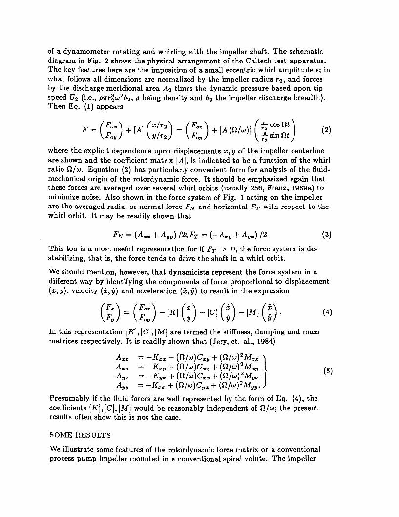
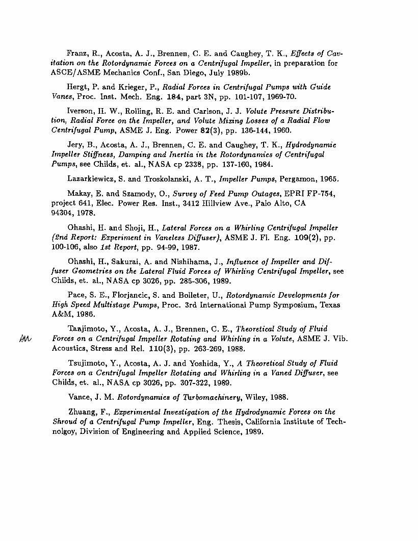
itself is 162 rnm diameter; it has five EIades with a 25' discharge blade angle and at the best efficiency point has a dimensionless specific speed of Ns = 0.59. (N8 = w \ / 8 / ( ~ h t ) f ) where Q is the volumetric flow rate, Aht is the isotropic enthalpy rise per unit mass and w is the angular shaft frequency all in consis- tent units.) The specific speed is typical of boiler feed pump stages and process pumps in a wide variety of situations. The impeller "eyen and suction shroud extends upstream about 2: impeller discharge breadths and the breadth here is 0.097 of the discharge diameter which is quite normal for this specific speed. The impeller is mounted in a single volute designed in accordance with the rules of Lazarkiewicz, et. al. The radial clearance between the impeller discharge and the centerline of the cutwater is 9 percent of the discharge diameter, rather larger than some boiler feed pumps. We report these details to emphasize the pump is "typical" of many applications; a standard non-cavitating performance diagram shown in Fig. 3 for the pump and the effects of cavitation on performance are shown in Fig. 4. It may be seen from these figures that the performance behavior is quite typical (efficiency was not measured).
The details of the instrumentation, data acquisition, calibration and data pro- cessing are extensively reported by Franz (1989a), Arndt (1988), Jery (1984) and earlier by Chamieh (1985). We present here the more recent results by Franz. Of major concern to us here is the force matrix coefficient [A]; the steady volute force F, was found to have a minimum near the design point for the volute and was otherwise similar in magnitude and trends to the data reported in the book by Lazarkiewicz and Troskolanski, for example.
The behavior of the components of [A] are shown in Fig. 5 for the normal oper- ating poing expressed as sums and differences of the terms A,,, Ayy, A,,, As,. It may be seen there that [A] is strongly skew symmetric with the diagonal terms nearly equal and the off-diagonal terms nearly equal and opposite. This property is seen to extend over a wide range of whirl ratio from reverse whirl to forward whirl. The order of magnitude of these terms A,,, A,,, etc, is about unity; the "skewnessn is exact to within about 10 percent of this and varies somewhat with flow coefficient (not shown).
This is an interesting and indeed even important experimental finding because it shows for this exceedingly commonly used type of centrifugal pump, that a desta- bilizing tangential force FT exists over a reasonably large range of whirl ratio, i.e., from 0 < f l / w < 0.5. The normal force FN when positive tends to deflect the impeller further outwards towards the housing, thereby weakening the stiffness of the shaft. Characteristically, for all of the impeller /volute combinations tested earlier by Jerry in the same apparatus, the tangential force decreased as the whirl ratio increased, thus giving rise to the damping ternt of Eq. (5). These experi- mental findings are also important for they support the experimental procedure first by Ohashi and Shoji (1987) and Bolleter, et. al. (l987), the Sulzer group, who measured impeller force interactions with linear excitation in only one di- rection rather than the circular orbits used by the Caltech group. An interesting

comparison of these different experimental techniques is made by Ohashi and stu- dents (Ohashi, et. al., 1989); in these works it was necessary to assume the skew- symmetry shown experimentally in Fig. 5.
THE EFFECTS OF CAVITA'I'ION
It is well known and shown in Fig. 4 that cavitation has a profound effect upon performance; indeed at cavitation "breakdown," the pump becomes choked and the pressure rise may fall to very low values. One might imagine that these effects of cavitation would greatly worsen the destabilizing effects shown in Fig. 5. To our surprise, this was found not to be the case, as is shown clearly in Fig. 6. We see there that operation at the normal level of 3 percent total head lass, if any- thing, reduces the destabilizing force FT. The average volute force F, appear6 to decrease as this total head or total pressure decreases and it is only near break- down that the tangential force rises sharply, this at a whirl ratio of 0.1. Thus, for the practical range of cavitation on the one centrifugal pump thoroughly tested, the effect of cavitation on the impeller force is not adverse. Similar findings have been reported by the Sulzer group (private communication, Dr. U. Rolleter).
MODELS FOR THE FLOW INTERACTION The skew-symmetry property of the force matrix is striking as well as important, and it is not surprising that a number of Row models have been proposed to ex- plain the effect. Possibly the oldest and simple& of these is the representation of the impelIer/voIute interaction by that of a point source-vortex representing the impeller interacting with a spiral lifting surface as the volute. This concept due to Domm and Hergt (aee Flow Research on Blading, Dzung (ed.), Elsevier, 1970) helps to explain the steady volute force F, and with elaboration becomes a full nan-steady two-dimensional lifting surface computation by Prof. Ohashi (see Childs and Hendricks, NASA cp 2133, p, 317). It has been remarked by many that these flow-induced forces are very similar in form to the force aris- ing in whirling seals, in particular the skew symmetry. Accordingly, one might then tend to seek a simpler explanation for the observed effects by simpler flow models. We wish here to mention two that do that; in both, the flow through the impeller is highly simplified to be that of an "actuator" disk with basically a one dimensional flow representation of the flow through the irnpleller permit- ting circumferential changes with radial effects being governed by local continuity. The differences are in the representation of the volute flow and volute interac- tion, Adkins and Brennen (1988), building on the work of Iverson, et. al., 1960, utilize a one-dimensional bulk flow, for the volute which couples the volute and impeller fiows with this inherent flow unsteadiness due to whirl incorporated in the impeller flow. Tsujimoto, et. al. (1988) consider the volute flow to be two- dimensional. Unlike earlier work of Chamieh (Caltech Ph.D. thesis, l983), this flow was allowed to be rotational, the vorticity arising naturally out of the cau- pling of the unsteady impeller and volute fiows and the flow around the volute is represented by a distribution of (unsteady) bound point vortices.

Both schemes were highly successful in reproducing the skew-symmetric property of the force matrix [ A ] , as well as steady force term F,. Adkins made, however, an important discovery, since confirmed by Bolleter at Sulzer, in detailed mea- surement of pressure distributions around impeller shrouds. Namely, that the measured force matrices for zero whirl (that is, just the stiffness component of [ A ] ) was due in major part to the external pressure distribution arising from im- peller eccentricity. Indeed, this effect on the measurements of the present Fig. 5 accounts for $ of the effect at zero whirl ratio. This from a different point of view justifies the attention given by Mackey and Szamody (1978 and in subsequent EPRI publications) to the importance of impeller radial and side clearances at the discharge of boiler feed pump impellers.
The Tsujimoto calculations, being two-dimensional, are somewhat more complex than a bulk flow model; the results of such two-dimensional computations agree most favorably with experiments made on strictly 2-D impellers over a range of whirl ratios from -1 to 1 (synchronous), Tsujimoto, et. al. (1988). In addi- tion, these actuator impeller flow models lend themselves to empirical inclusion of incidence-angle dependent viscous losses and to the handy representation of vaned diffusers as well as volutes (Tsujimoto, et. al., 1989). Indeed, Tsujimoto has shown subsequently (private communication) that rotating stalls can be pre- dicted and accounted for in impeller/vaned diffuser combinations. It wou!d be in- teresting as Franz (1989) suggests to include effects of cavitation with rotor whirl along these same lines, but this has, to our knowledge, not yet been attempted, even with a bulk flow model.
DISCUSSION
We have seen that even the simplest garden variety industrial centrifugal pump is subject to a destabilizing tangential force, tending to excite the impeller shaft in the direction of forward whirl. Whether or not whirl in an application does oc- cur will depend upon the damping in whirl (the slope of the FT vs ~ I / w curve), as well as the dynamical properties of the entire rotor-dynamic system as treated at length in Vance's monograph and the effects of the wear rings and seals discussed by Childs. If an excitation is to occur with impeller force systems similar to that reported here in Fig. 5, it will be certainly for rotordynamic systems operating well above the first or second critical flexural speed as then the lowest mode may then fall into the critical region where FT 2 0 in the range n / w 5 0.5 approx- imately. In that event, a sub-harmonic vibration, if any, would exist. There is some suggestion (Childs, 1985) that the Space Shuttle turbomachinery may have suffered from such an excitation.
We have mentio~ed before that the linear approximation of Eq. (I) should be plausible. In fact, Bolleter, et. al., as well as Ohashi, have shown experimentally that this assumption for this flow-induced impeller force is correct. 0 ther forces arising from wear-rings and interstage seals are known to be very non-linear in the eccentricity effect. A preliminary investigation of the external shroud forces

caused by eccentric operation of non-whirling impe!!er shrouds in stationary cas- ings just recently completed (Zhuang, 1989) has shown the force matrix to be skew-symmetric and to be quite non-linear in the eccentricity/clearance ratio, much as anticipated by Childs (1986) in his bulk flow analysis of this problem. This, as well as many interesting problems, remain to be tackled for axial and mixed flow machines, as well as for the compressibility effect not yet touched upon. It seems clear that with increased operating speeds and power density ex- pected of most turbomachine applications in the future, these flow-induced rotor forces will be with us for some time.
ACKNOWLEDGEMENTS
As with most university research, we depend upon our hard working students for inspired work. We would like to thank Dimitri Chamieh, Belgacem Jery, Ron Franz, Scott Miscovish, Michael Karyeaclis and Fei Zhuang for their untiring ef- forts. This work was supported by the National Aeronautics and Space Adminis- tration under contract NAS8-33108 with Dr. Henry Stinson as technical monitor. This support is gratefully acknowledged.
REFERENCES
Adkins, D. R. and Brennen, C. E., Analysis of Hydrodynamic Radial Forces on Centrifugal Pump Impellers, ASME J. F1. Eng. 110(1), pp. 20-28, 1988.
Arndt, N. Tbrbomachinery Rotor Forces, Report No. 249.9, California Insti- tute of Technology, Division of Engineering and Applied Science, 1988.
Bolleter, U., Wyss, A., Welte, I. and Stiirchler, R., Measurement of Hydrody- namic Interaction Matrices of Boiler Feed Pumps Impellers, ASME J . Vib. Acous- tics, Stress and Rel. 109(2), pp. 144-151, 1987.
Chamieh, D. S., Acosta, A. J., Brennen, C. E. and Caughey, T. K., Experi- mental Measurements of Hydrodynamic Radial Forces and Stiffness Matrices for a Centrifugal-Pump Impeller, ASME J . FI. Eng. 107(3), pp. 307-315, 1985.
Childs, D. W. and Moyer, D. S., Vibration Characteristics of the HPOTP (High Pressure Oxygen Wbopump) of the SSME (Space Shuttle Main Engine), ASME J . Eng. Gas. T. and Pwr. 107(1), pp. 152-159, 1985.
Childs, D. W. Force and Moment Rotordynamic Coeficients for Pump- Impeller Shroud Surfaces, NASA cp 2443, pp. 503-529, 1986.
Childs, D. W. and Hendricks, R. C. (eds.), Rotordynamic Instability Problems in High-Performance Turbomachinery 1988, NASA Conf. Pub. 3026, 1989. Also, NASA Conf. Pub. 2443, 1986; NASA Conf. Pub. 2338, 1984.
Franz, R. J. Experimental Investigation of the Effect of Cavitation on the Ro- tordynamic Forces on a Whirling Impeller, Report 249.8, California Institute of Technology, Division of Engineering and Applied Science, 1989a.
Franz, R., Acosta, A. J., Brennen, C , E. and Caughey, Ti K,, E ! - c t s ef Cav- itation on the Rotordynamic Forces on a Centrifugal Impeller, in preparation for ASCE/ASME Mechanics Conf., San Diego, July 1989b.
Hergt, P. and Krieger, P., Radial Forces in Centrifugal Pumps with Guide Vanes, Proc. Inst. Mech. Eng. 184, part 3N, pp. 101-107, 1969-70.
Iverson, H. W., Rolling, R. E. and Carlson, J. J. Volute Pressure Distribu- tion, Radial Force on the Impeller, and Volute Mixing Losses of a Radial Flow Centrifugal Pump, ASME 3. Eng. Power 82(3), pp. 136144, 1960.
Jery, B., Acosta, A. J., Brennen, C. E. and Caughey, T. K., Hydrodynamic Impeller Stiflness, Damping and Inertia in the Rotordynamics of Centrifugal Pumps, see Childs, et. al., NASA cp 2338, pp. 137-160, 1984.
Lazarkiewicz, S. and Troskolanski, A. T., Impeller Pumps, Pergamon, 1965.
Makay, E. and Szamody, O., Survey of Feed Pump Outages, EPRI FP-754, project 641, Elec. Power Res. Inst., 3412 Hillview Ave., Palo Alto, CA 94304, 1978.
Ohashi, H. and Shoji, H., Lateral Forces on a Whirling Centrifugal Impeller (2nd Report: Experiment in Vaneless Difluser), ASME J. F1. Eng. 109(2), pp. 100-106, also 1st Report, pp. 94-99, 1987.
Ohashi, H., Sakurai, A. and Nishihama, J., Influence of Impeller and Dif- fuser Geometries on the Lateral Fluid Forces of Whirling Centrifugal Impeller, see Childs, et. al., NASA cp 3026, pp. 285-306, 1989.
Pace, S. E., Florjancic, S. and Bolleter, U., Rotordynamic Developments for High Speed Multistage Pumps, Proc. 3rd International Pump Symposium, Texas A&M, 1986.
Tamjimoto, Y., Acosta, A. J., Brennen, C. E., Theoretical Study of Fluid Ain/ Forces on a Centrifugal Impeller Rotating and Whirling in a Volute, ASME 3. Vib.
Acoustics, Stress and Rel. 110(3), pp. 263-269, 1988.
Tsujimoto, Y., Acosta, A. J. and Yoshida, Y., A Theoretical Study of Fluid Forces on a Centrifugal Impeller Rotating and Whirling in a Vaned Diffuser, see Childs, et. al., NASA cp 3026, pp. 307-322, 1989.
Vance, J. M. Rotordynamics of Ilttrbornachinery, Wiley, 1988.
Zhuang, F., Experimental Investigation of the Hydrodynamic Forces on the Shroud of a Centrifugal Pump Impeller, Eng. Thesis, California Institute of Tech- nolgoy, Division of Engineering and Applied Science, 1989.

CIRCULAR WHIRL ORBIT
Fig. 1. Schematic diagram of the force system on a rotating whirling impeller showing the instantaneous force, displacement, and the whirl orbit averaged forces.
- a
PLAN VIEW
Fig. 2. Cross-section of the Caltech impeller force test facility. The eccentricity of the whirl orbit system (9,ll) was 1.2 mm for the present tests. The impeller shaft speed is adjustable from 0 to 3600 rpm; the whirl speed was adjustable to 1800 rpm in either direction. Strain gauge signals from the rotating dynamometer (6) were led through the shaft (10) to a slip ring assembly and thence to the data acquisition system (Franz, 1989a).
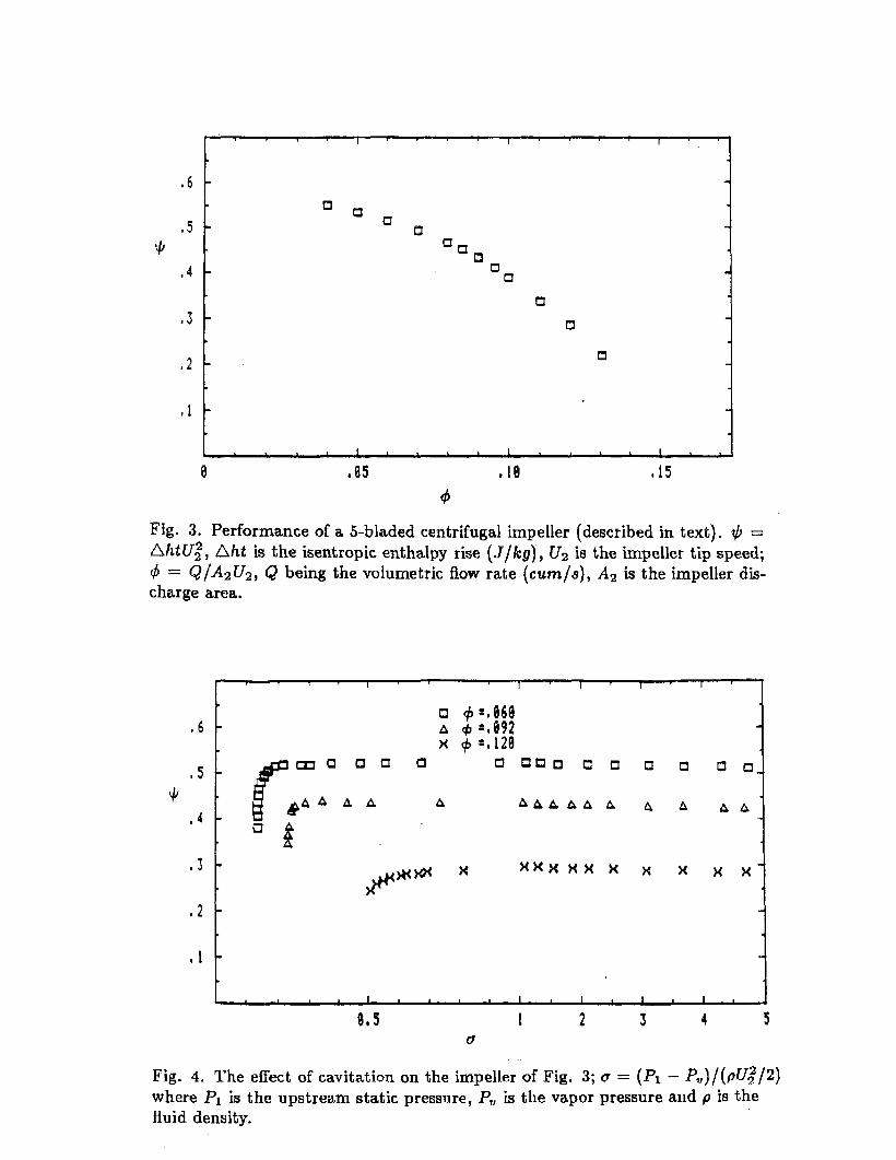
Fig. 3. Performance of a 5-bladed centrifugal impeller (described in text). + = Aht~; , Aht is the isentropic enthalpy rise (J/kg) , Uz is the impeller tip speed; 4 = Q/A2U2, Q being the volumetric flow rate (cumls), Az is the impeller dis- charge area.
Fig. 4. The effect of cavitation on the impeller of Fig. 3; a = (PI - PV)/(pUg/2) where PI i~ the upstream static pressure, P, is the vapor pressure and p is the fluid density.
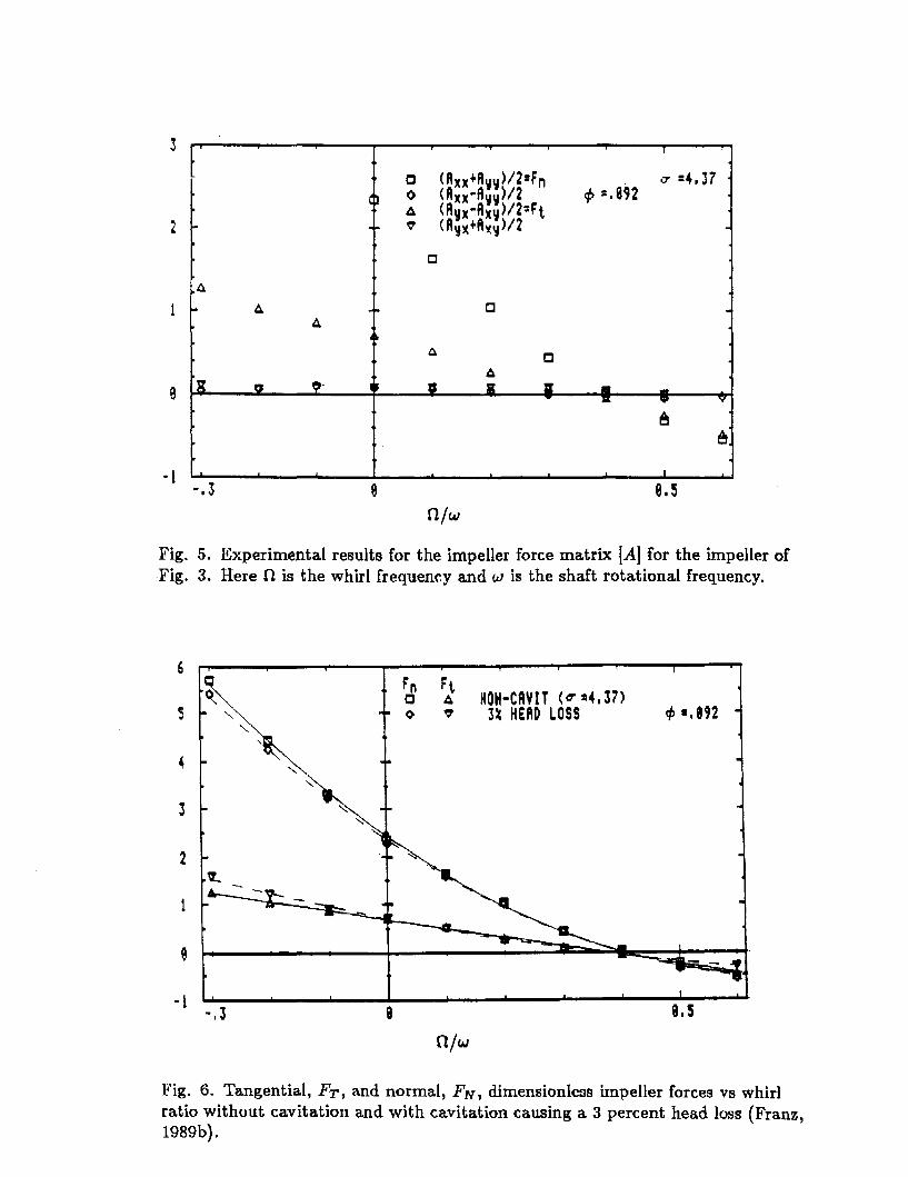
Fig. 5. Experimental reaults for the impeller force matrix IA] for the impeller of Fig. 3. Here It is the whirl frequency and w is the shaft rotational frequency.
Fig. 6. Tangential, FT, and normal, FN, dimensionless impeller forces vs whirl ratio without cavitation and with cavitation causing a 3 percent head loss (Franz, l989b).