impact of the non-linear character of the compressive stress–strain curves on thermal and...
TRANSCRIPT
A
Ccpdmom©
K
1
ctpr
R
i
R
(
0h
Available online at www.sciencedirect.com
Journal of the European Ceramic Society 33 (2013) 211–219
Impact of the non-linear character of the compressive stress–strain curves onthermal and mechanical properties of porous microcracked ceramics
Giovanni Bruno a,∗, Yassine Kilali b,d, Alexander M. Efremov c
a Corning Incorporated, S&T, CMP, SP-FR06, Corning, NY, 14831, USAb Corning SAS, CS&S, 7bis av. De Valvins, Avon, F-77210 France
c Corning OOO, 26 Liter A, Shatelena Str., 194021 St. Petersburg, Russia
Received 13 July 2012; received in revised form 5 September 2012; accepted 9 September 2012Available online 5 October 2012
bstract
omplementary to recent theoretical work, this paper describes implications of the non-linear stress–strain behavior observed in porous micro-racked ceramics. Practical aspects of this behavior under uniaxial compression are discussed. In particular, it is shown that the axial moduli oforous microcracked aluminum titanate and cordierite change upon application of a constant or ladder-like time protocol load. The extent of changeepends on material microstructural features, such as texture, porosity and microcrack density, as well as on the applied load. In fact, the underlyingechanism is microcrack closure (or even healing), which causes stiffening of the material; at the same time, a uniaxial compressive load can also
pen new microcracks, or propagate existing ones via microcrack sliding, thus softening the material. The change in the elastic response of theaterial is accompanied by changes in other properties, such as thermal expansion.
2012 Elsevier Ltd. All rights reserved.
eywords: Porous ceramics; Anelasticity; Microcracking; Uniaxial compression
i
Rt
α
mtr
dacc
. Introduction
One of the major attributes of porous cellular microcrackederamics is their thermal shock resistance, particularly in highemperature applications, such as catalytic substrates or dieselarticulate filters. According to1 there are several thermal shockesistance parameters:
= σf × (1 − ν)
α × E(1)
f crack initiation is the phenomenon to consider;
′′′ = E
σ2f × (1 − ν)
or R′′′′ = E × γ
σ2f × (1 − ν)
and
Rst =√
γ
α2 × E(2)
∗ Corresponding author. Tel.: +1 607 9741421; fax: +1 607 9742383.E-mail addresses: [email protected], [email protected]
G. Bruno), [email protected] (Y. Kilali).d Tel.: +33 164 697421; fax: +33 164 697454.
tlab(
ls
955-2219/$ – see front matter © 2012 Elsevier Ltd. All rights reserved.ttp://dx.doi.org/10.1016/j.jeurceramsoc.2012.09.004
f crack propagation is paramount.The maximization of R or Rst and the minimization of R′′′ or
′′′′ are the materials engineering and performance criteria forhose ceramics.
Since above we have defined γ the surface energy for fracture; the thermal expansion coefficient; E the Young’s or elasticodulus; σf the strength and ν the Poisson’s ratio, it is clear that
he mechanical properties of those ceramics play a fundamentalole in their performance.
Moreover, these materials have to compromise betweenemands for a low coefficient of thermal expansion (CTE)nd/or Young’s modulus, and for high strength. Since theseeramics have a strong anisotropy of the lattice CTE, micro-racking almost always occurs when cooling from the firingemperature.2–4 In spite of the fact that microcracking wouldimit the strength, it has the positive effect of decreasing CTEnd Young’s modulus, thus maximizing R and Rst. The materialsecome resilient to stress,1,5,6 and increase their strain tolerancei.e., the strain at rupture).
While ceramics are thought to be linear elastic (ateast under small loads), historically, porous rocks havehown anelastic behavior7,8 and even theoretical works

2 pean C
hmtrlms
miandpmimcsiccgatt
icocmaY
2
bwdao
bcpd(tt1
eso
oc
t
4sw
cfTot3((fsCrs(tentd
σ
wc
nss
oSZau
3
ihfii
12 G. Bruno et al. / Journal of the Euro
ave attempted rationalizing the anelasticity in terms oficromechanical principles9; similarly, more recently other sys-
ems, such as itacolumite,10 potassium phosphates/silicates,11
efractories,12 and aluminum titanate13–15 have displayed non-inear stress–strain curves. Although different from monolithic
aterials, composites16 and thermal barrier coatings17,18 alsohow well-known and documented non-linearity.
Recently, the non-linear stress–strain behavior of porousicrocracked monolithic ceramics has also been investigated
n the case of honeycomb porous ceramics19–21 for filtrationpplications, dealt with in the present work. In particular, Pozd-yakova et al.19 have found that different materials displayifferent dependences of the axial modulus on applied com-ressive stress E(σ). Furthermore, in Ref. 19 it was shown thaticrocrack closure and propagation follow different kinetics
n a uniaxial compression test. Bruno and Kachanov21 haveodeled the uniaxial compressive test on the same kind of
eramics in terms of microcrack densities of open and closedliding microcracks. The abovementioned effects (closure, slid-ng, propagation) have been shown not to be systematic for everyomposition and porosity value,20 but the most important out-ome of these studies is that the values of Young’s modulusenerated by RUS22 and sonic resonance23 are valid only at lowpplied loads. This statement has direct consequences if we thinkhat an increase of the Young’s modulus is commonly associatedo that of the strength.24–26
Therefore, in this work we focused our attention on themplications of the non-linear stress–strain behavior in porouseramics for filtration and membrane applications (in the formf extruded honeycombs), and the conditions under which ahange of the Young’s modulus occurs, exploring two classicaterials: aluminum titanate and cordierite. We concentrate on
xial properties (along the extrusion axis) and we refer to theoung’s modulus as the axial modulus or stiffness.
. Materials and methods
A cordierite composition produced at Corning Incorporatedy extruding and firing a mixture of talc, alumina, clay and silica,as used (for the composition and the firing see27,28). Neutroniffraction texture analysis, fully reported in Ref. 29, showed
low level of crystal texture (1.2× random), with the c-axisriented along the extrusion direction.
Aluminum titanate material was prepared by extruding aatch mixture of titania, alumina, silica, strontium and calciumarbonates.30 Honeycomb logs were dried and then fired at tem-eratures exceeding 1450 ◦C, with both heating and coolingone in ambient atmosphere with rates not exceeding 5 ◦C/minfor more details see31). Also in this case, crystallographic tex-ure data are available in the literature,32 and show a slightendency of c-axis grains to align to the extrusion axis (texture.3× random).
Two kinds of samples have been extracted from the samextruded log: for compression tests, bars of approximate dimen-ions 13 mm × 25 mm × 50 mm (containing an integer numberf cells); for dilation experiments, square prism specimens
sqcs
eramic Society 33 (2013) 211–219
f approximate dimensions 5 mm × 5 mm × 50 mm (3 × 3 cellsross section).
The nominal porosity was determined by mercury porosime-ry on an Autopore 9520 from Micromeritics.
Classic dilatometry was carried out using a Netzsch DL02 C single pushrod dilatometer, calibrated with a fused silicatandard. A ramp of 10 ◦C/min on both heating and coolingas used.An Instron test rig (model 5500R), equipped with a load
ell of 5 kN with two tailored aluminum platens, was usedor uniaxial compression tests (see sample mount in Fig. 1a).hick paper foils were interposed to reduce friction at the pointsf contact and to minimize barreling and micro-buckling dueo end-effects. Sample were strain gauged (reference 1-LY41-/350 from HBM, France) to track the sample macroscopic strainalong the axial, extrusion direction). An epoxy glue was usedZ70 from HBM), with an accelerator (BY10 from HBM) toacilitate adhesion and avoid penetration of the glue inside theample wall. The loading and unloading rates were 100 N/min.omplete cycles consisted in the following protocol: linear load
amp up to the maximum load (about 70% of the compressiontrength), constant load for about 6 h, unload ramp to zero loadsee inset of Fig. 1a). The stress was calculated by correctinghe applied load for the closed frontal area. Indeed, the hon-ycomb geometry (see inset in Fig. 1) has channels, which doot contribute to the solid cross-section. The formula we usedo calculate the stress from the applied load F and the sampleimensions reads33:
= F
A
[t(2L − t)
L2
]−1
(3)
hereby A is the macroscopic cross-section, L is the honeycombell length, and t is the wall thickness (Fig. 1b).
The variation of the sample dilation as a function of theumber of cycles was checked by comparing sister dilationpecimens in the untested conditions, and compression-testedpecimens, after one or two cycles.
The microstructure of the materials investigated wasbserved by scanning electron microscopy, using a LEO FEG-EM (field emission gun scanning electron microscope, Carleiss, Munich, Germany). Backscattered electron images werecquired on ceramographically polished samples, typicallysing 10 kV accelerating voltage.
. Results
The microstructure of the investigated materials is shownn Fig. 2. Aluminum titanate (AT), with 38% porosity, hasigh microcrack density and the presence of three phases (AT,eldspar and alumina 30,32), while cordierite (with 48% poros-ty) is nearly single phase, with presence of glass pockets (brightslands) and minor secondary phases (grey features), such as
pinel and sapphirine. Although the field of view does not allowuantitative estimation of the amount of microcracking, it islear that in the case of cordierite, the density of microcracks isubstantially lower.
G. Bruno et al. / Journal of the European Ceramic Society 33 (2013) 211–219 213
F rimen
fcsn
1cf
(
bsToircc
2ssuv
ltescpucws
2icptcResn
p
ig. 1. (a) Photo of the sample and gauge rosette mount, and sketch of the expe
The results of the compression tests are displayed in Fig. 3or the aluminum titanate (AT) composition, and in Fig. 4 forordierite. We used the convention representing compressivetress as positive, but strain as measured by the gauge (i.e.,egative if compressive).
In Figs. 3 and 4 cycles 1–3 refer to tests done with about week time lag from one another. This strategy was used to dis-ard any influence of possible microcrack kinetics,19 and allowor full stress relaxation (if any had to occur).
For aluminum titanate, we observe the following featuresFig. 3):
Cycle 1 shows stiffening during the first load ramp, followedy strain relaxation (in compression) upon holding at constanttress, and finally again a non-linear behavior upon unloading.his pattern has already been reported in Ref. 21, for the casef a ladder-like time protocol (repeated ramp-hold cycles atncreasing stress values). Analogous to21 we observe also: (a) aesidual compressive strain at the end of the load-hold-unloadycle; (b) a different axial modulus (slope of the stress–strainurve) between the top of the loading and unloading curves.
Cycles 2 and 3 are much more linear. In particular cycle is strongly influenced by the stiffening effect, and showsubstantially higher axial moduli than the initial ‘untreated’ample. Upon further cycling (load-hold-unload), the axial mod-
lus slightly decreases, still remaining higher than the baselinealues.The situation is more complicated for cordierite (Fig. 4):
m
s
t load protocol. (b) Sketch of the honeycomb sample shape and cross-section.
The initial cycle shows a slight amount of stiffening uponoading. However, upon stress hold we observe a relaxationowards tensile strains. Upon unloading, the behavior is lin-ar (closed microcracks do not slide back immediately, andtiffen the material [20,21]), but upon application of a secondycle, the axial modulus slightly decreases, indicating that someermanent damage has been introduced (please note that thenloading branch of cycle 2 could not be recorded). Furtherycling decreases the axial modulus, but it basically remainsithin a factor of 0.9 lower than the stiffness of the baseline
ample.This complex behavior has already been observed in Ref.
0, upon application of a ladder-like stress-time protocol (seenset of Fig. 5). Data from that work are reported in Fig. 5 forordierites with different porosities. We observe that for highorosities some stiffening occurs upon loading. Unfortunately,he unloading curve could not be recorded, and no conclusionould be drawn on the permanent nature of the deformation inef. 20. In the case of intermediate porosities (∼50%) largeffect do not seem to be present, indicating that microcrack clo-ure, sliding and propagation, they all compensate to a vanishinget effect.
Additional results were reported in Ref. 4, where a very highorosity cordierite was shown to permanently decrease its axial
odulus, due to excessive damage.It is interesting to observe that non-microcracked materials,uch as porous silicon carbide, do not show non-linearities (or

214 G. Bruno et al. / Journal of the European Ceramic Society 33 (2013) 211–219
Ft
vcTg
o
Fpiom
0
5
10
15
20
25
-0.2 -0.15 -0.1 -0.05 0
Ap
pli
ed
Co
mp
res
siv
e S
tre
ss
(M
Pa
)
Engineering Strain (%)
12
3
Fig. 4. Stress–strain curves for cordierite, subjected first to a load-hold-unloadcycle and after successive cycles.
Fop
s
ig. 2. SEM microstructure of the two investigated materials: (a) aluminumitanate, 38% porosity and (b) cordierite, 48% porosity.
ery limited amount thereof), and above all they do not show anyhange of the axial modulus upon further cycling (see Fig. 6).he first point is shown more extensively, and further data are
iven in Ref. 4.The change in axial modulus is accompanied by a change inther physical properties. Particularly relevant for the thermal
0
5
10
15
20
25
-0.2 -0.15 -0.1 -0.05 0
Ap
pli
ed
Co
mp
res
siv
e S
tre
ss
(M
Pa
)
Engineering Strain (%)
1 3 2
ig. 3. Stress–strain curves under applied compressive load, for the AT of 38%orosity. The slope increases after the first cycle (simple load-hold-unload), andt slightly decreases with successive load/unload cycles. With increasing numberf load/unload cycles the slope stabilizes at a greater value than the untreatedaterial. Successive runs have been done on the same sample.
eifidv
Fic
ig. 5. Ladder-like cycle for different cordierites. During the cycle, stiffeningccurs only at high porosities, while little effect is manifested at intermediateorosity values. The stress-time protocol is indicated in the inset.
hock resistance of these materials is the coefficient of thermalxpansion (CTE). Macroscopic dilation data for the 38% poros-ty AT and for the cordierite samples are shown in Fig. 7. We
rst notice the typical hysteresis upon heating–cooling cycles,ue to microcrack closure-reopening cycles.2,4,34 This is moreisible in AT because of the larger microcrack density. Uponig. 6. Stress–strain curves for SiC, subjected to a first ladder-like cycle (insetn Fig. 4) and measured after it (second cycle). No remarkable change of slopean be observed.

G. Bruno et al. / Journal of the European C
-600
-400
-200
0
200
400
600
800
1000
1200a
b
0 200 400 600 800 1000
dL
/Lo
(pp
m)
Temperature ( °C)
Before-Heating
Before- Cooling
After- Heating
After- Cooling
-400
-300
-200
-100
0
100
200
300
400
0 200 400 600 800 1000
delt
aL
/Lo
(pp
m)
Temperature ( °C)
Before- Heating
Before- Cooling
After- Heating
After- Cooling
Fig. 7. Variation of the thermal expansion after applied compressive load. (a)F(c
cb1tR
4
hcpassas
aiu
rcb
arsmtt
msapscbobacap
Tudi
fi(fiac
m(iteedt
(
s
ρ
or aluminum titanate (38% porosity) the total dilation increases after cycle 2.b) For cordierite (48% porosity), the dilation does not appreciably change afterycle 2.
ompression cycling, a variation of the total dilation is apprecia-le for AT, where the CTE between room temperature (RT) and000 ◦C changes from 0.45 × 10⁻⁶ ◦C−1 in the as-received stateo 1.1 × 10⁻⁶ ◦C−1 after cycle 2; for cordierite the CTE betweenT and 1000 ◦C remains of the order of 0.3 × 10⁻⁶ ◦C−1.
. Discussion
The explanation for the phenomena observed in Figs. 3 and 4as been given in Refs.19,21: microcracks close and slide underompression, causing stiffening, but can also propagate both atores cusps (pores could act as microcrack initiation sites) andt sliding crack tips, via a Poisson’s effect. This is schematicallyhown in Table 1 (the expected analogous behavior under ten-ion is also displayed). All the phenomena depicted in Table 1re anelastic, since they dissipate strain energy, and render thetress–strain curve non-linear.21
The difference between the axial moduli at the top of loadingnd upon initial unloading is due to the fact that microcracks slid-ng during loading do not immediately start to slide back uponnloading, but they need to overcome the friction resistance.
Another possible mechanism for deformation, and for theesidual compressive strain is the fact that some of the micro-racks, which may have healed, do not reopen. This can alsoe considered an anelastic phenomenon, since it is irreversible
wc
p
eramic Society 33 (2013) 211–219 215
nd the amount of energy necessary to close the crack is noteleased back upon unloading. In addition, the total slope of thetress–strain curve is affected by the fact that the pore structureay behave like a ‘sponge‘, i.e., in points where the solid skele-
on connectivity is small, the structure may deform like a hinge,hereby allowing pore re-shaping.
Indeed, for cordierite, propagating microcracks compensateicrocrack closure (note that these microcracks are sub-critical,
ince they are blunted at pores). This is visible in the strain relax-tion towards tension at constant applied load (microcracks areropagating), and in the fact that the axial modulus in succes-ive cycles decreases: the introduced damage dominates once theompressive load that closes microcracks is removed. The com-ination of the two phenomena mentioned above yields a smallr negligible net effect. In other words, for cordierite the com-ination of energy-dissipating phenomenona (crack bluntingnd microcrack sliding), and the stiffening effect of microcracklosure yields a quasi-linear stress–strain curve. As discussedbove, the pore structure ‘sponge’-like deformation may alsolay a role to determine the apparent stiffness of the sample.
A summary of the changes in axial modulus is given inable 2, where we referred values to the initial Young’s mod-lus. As mentioned before, after an initial increase for AT andecrease for cordierite, the level of change slightly diminishesn all materials.
As far as the CTE is concerned, the observed changes (Fig. 7)t well the scenario presented above: for aluminum titanate38% porosity), microcrack closure (and healing) not only stif-ens the material, but renders it more connected, and thereforenduces higher thermal dilation, while for cordierite the situ-tion is nearly unchanged because the newly formed and thelosed/healed microcracks compensate each other.
In ref.21 we modeled the stress–strain behavior by means of aicromechanical model. We have used the differential scheme
DS), first introduced by Vavakin and Salganik,35 to model thenfluence of microcracks on the strain, and a modified differen-ial scheme, introduced by Mc Laughlin,36 to account for theffect of porosity. We have therefore proposed the followingquations to quantify the influence of porosity p and microcrackensity ρ on the ratio between the measured axial modulus Eeffhat of the dense bulk material, E0:
E0
Eeff
)= (1 − p)−C1 × exp (C2ρ
open + C3ρsliding) (4)
The microcrack density parameter is defined (only for penny-haped cracks) as 37
= 1
V
∑i
a3i (5)
here V is the total volume under consideration, and ai are therack radii.
In Eq. (4) Ci, i = 1,3 are constants depending on materialsroperties (E0 and ν0, the dense material Young’s modulus and

216 G. Bruno et al. / Journal of the European Ceramic Society 33 (2013) 211–219
Table 1Summary of mechanisms of the influence of microcracks on stress–strain curves.
Mechanism Result Compression Tension
Crack initiation at pores Active in different ways, amplified in tension by a factor of 2.5
Propagation of existing cracks (by “wing” cracks) Amplified in tension could be stable in compression
Microcrack closure Not present in tension
Table 2Young’s modulus and CTE variation as a function of load/hold/unload cycles inAT and cordierite materials.
Property Cycle AT Cordierite
Young’s modulus1 1 12 1.25 0.983 1.19 0.90
C
Pb
W
s5 φ
5
(σ0
waesmT
wssmdtutmaWA
teum
21
TERT−1000 ◦C1 1 12 2.44 1.14
oisson’s ratio), and load conditions. In fact, C1 and C2 are giveny
C1 = 3(1 − ν0)(9 + 5ν0)
2(7 − 5ν0)
C2 = 16(1 − ν20)(10 − 3ν0)
45(2 − ν0)
(6)
hile C3 is different upon loading and unloading:
C3,loading = 32(1 − ν20)
3(2 − ν0)
{sin3 φ
3− sin5 φ
5+ μ
(cos3 φ
3− co
C3,unloading = 32(1 − ν20)
3(2 − ν0)E0
{(σ0 − σ)
(sin3 φ
3− sin5 φ
5
)+ μ
here μ is the microcrack surface friction coefficient, σ is thepplied stress, σ0 is the maximum applied stress during thexperiment, φ is the angle between the normal to the (penny-hape) microcrack surface and the load axis; φ* and φ** are theaximum values of φ upon loading and unloading, respectively.hey are given by:
∗∗ 1 2μ(σ20 − σ2)
φ =2
arcsin(σ0 − σ)2 + μ2(σ0 + σ)2
φ∗ = 1
2arctan μ−1
(8)t
)}φ=φ∗
φ=0
+ σ)
(cos3 φ
3− cos5 φ
5
)}φ=φ∗∗
φ=0
(7)
The modified DS for porosity (E0/Eeff)porosity = (1 − p)−C1
as proposed by McAdams38 on an empirical basis. Succes-ively, it was used by Gibson and Ashby in the case of cellulartructures,39 and by Bruno et al. in the case of porous (andicrocracked) ceramics.40 The most important modification we
id (which motivated the use of this scheme for porosity), washe use of C1 as extracted from tomography images, and notsing Eq. (6). This would allow interpreting this parameter,he pore shape factor, in a more realistic way, i.e., using a realicrostructure, instead of ideal pore shapes such as ellipsoids
nd spheres, used for the micromechanical model calculations.e therefore used C1 = 2.7 for cordierite,20 and C1 = 3.3 for
T.41
With these inputs at hand, we could calculate the values ofhe microcrack density parameters ρ at various stages of thexperiment, i.e., at the beginning and at the end of loading andnloading. We used the following values for the dense Young’sodulus of AT and cordierite:
E0, AT = 300 GPa and ν0, AT = 0.3 (from ),E0, Cord = 142 GPa and ν0, Cord = 0.31 (from the polycrys-
alline average quoted in Ref. 42).Following,21 the equations we used in each case are:
G. Bruno et al. / Journal of the European C
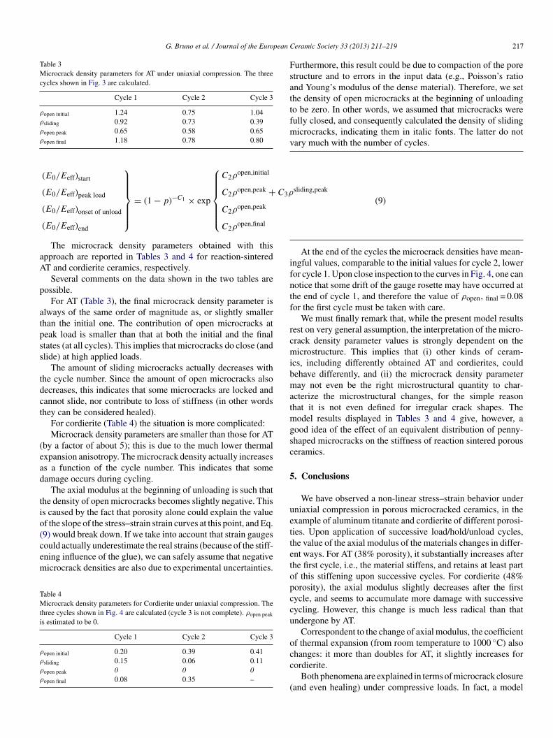
Table 3Microcrack density parameters for AT under uniaxial compression. The threecycles shown in Fig. 3 are calculated.
Cycle 1 Cycle 2 Cycle 3
ρopen initial 1.24 0.75 1.04ρsliding 0.92 0.73 0.39ρopen peak 0.65 0.58 0.65ρ
C3ρ
aA
p
atpss
tdct
(ead
tio(cem
TMti
ρ
ρ
ρ
ρ
Fsattfmv
ifntf
rcmibmatmgsc
5
uett
open final 1.18 0.78 0.80
(E0/Eeff)start
(E0/Eeff)peak load
(E0/Eeff)onset of unload
(E0/Eeff)end
⎫⎪⎪⎪⎪⎪⎬⎪⎪⎪⎪⎪⎭
= (1 − p)−C1 × exp
⎧⎪⎪⎪⎪⎪⎨⎪⎪⎪⎪⎪⎩
C2ρopen,initial
C2ρopen,peak +
C2ρopen,peak
C2ρopen,final
The microcrack density parameters obtained with thispproach are reported in Tables 3 and 4 for reaction-sinteredT and cordierite ceramics, respectively.
Several comments on the data shown in the two tables areossible.
For AT (Table 3), the final microcrack density parameter islways of the same order of magnitude as, or slightly smallerhan the initial one. The contribution of open microcracks ateak load is smaller than that at both the initial and the finaltates (at all cycles). This implies that microcracks do close (andlide) at high applied loads.
The amount of sliding microcracks actually decreases withhe cycle number. Since the amount of open microcracks alsoecreases, this indicates that some microcracks are locked andannot slide, nor contribute to loss of stiffness (in other wordshey can be considered healed).
For cordierite (Table 4) the situation is more complicated:Microcrack density parameters are smaller than those for AT
by a factor of about 5); this is due to the much lower thermalxpansion anisotropy. The microcrack density actually increasess a function of the cycle number. This indicates that someamage occurs during cycling.
The axial modulus at the beginning of unloading is such thathe density of open microcracks becomes slightly negative. Thiss caused by the fact that porosity alone could explain the valuef the slope of the stress–strain strain curves at this point, and Eq.9) would break down. If we take into account that strain gauges
ould actually underestimate the real strains (because of the stiff-ning influence of the glue), we can safely assume that negativeicrocrack densities are also due to experimental uncertainties.able 4icrocrack density parameters for Cordierite under uniaxial compression. The
hree cycles shown in Fig. 4 are calculated (cycle 3 is not complete). ρopen peak
s estimated to be 0.
Cycle 1 Cycle 2 Cycle 3
open initial 0.20 0.39 0.41
sliding 0.15 0.06 0.11
open peak 0 0 0
open final 0.08 0.35 –
etopccu
occ
(
eramic Society 33 (2013) 211–219 217
sliding,peak
(9)
urthermore, this result could be due to compaction of the poretructure and to errors in the input data (e.g., Poisson’s rationd Young’s modulus of the dense material). Therefore, we sethe density of open microcracks at the beginning of unloadingo be zero. In other words, we assumed that microcracks wereully closed, and consequently calculated the density of slidingicrocracks, indicating them in italic fonts. The latter do not
ary much with the number of cycles.
At the end of the cycles the microcrack densities have mean-ngful values, comparable to the initial values for cycle 2, loweror cycle 1. Upon close inspection to the curves in Fig. 4, one canotice that some drift of the gauge rosette may have occurred athe end of cycle 1, and therefore the value of ρopen, final = 0.08or the first cycle must be taken with care.
We must finally remark that, while the present model resultsest on very general assumption, the interpretation of the micro-rack density parameter values is strongly dependent on theicrostructure. This implies that (i) other kinds of ceram-
cs, including differently obtained AT and cordierites, couldehave differently, and (ii) the microcrack density parameteray not even be the right microstructural quantity to char-
cterize the microstructural changes, for the simple reasonhat it is not even defined for irregular crack shapes. The
odel results displayed in Tables 3 and 4 give, however, aood idea of the effect of an equivalent distribution of penny-haped microcracks on the stiffness of reaction sintered porouseramics.
. Conclusions
We have observed a non-linear stress–strain behavior underniaxial compression in porous microcracked ceramics, in thexample of aluminum titanate and cordierite of different porosi-ies. Upon application of successive load/hold/unload cycles,he value of the axial modulus of the materials changes in differ-nt ways. For AT (38% porosity), it substantially increases afterhe first cycle, i.e., the material stiffens, and retains at least partf this stiffening upon successive cycles. For cordierite (48%orosity), the axial modulus slightly decreases after the firstycle, and seems to accumulate more damage with successiveycling. However, this change is much less radical than thatndergone by AT.
Correspondent to the change of axial modulus, the coefficientf thermal expansion (from room temperature to 1000 ◦C) also
hanges: it more than doubles for AT, it slightly increases forordierite.Both phenomena are explained in terms of microcrack closureand even healing) under compressive loads. In fact, a model

2 pean C
(tmocimbsmfalm
A
C
R
1
1
1
1
1
1
1
1
1
1
2
2
2
2
2
2
2
2
2
2
3
3
3
3
3
3
3
18 G. Bruno et al. / Journal of the Euro
introduced in a separate work) has been deployed to calculatehe microcrack density parameters (for equivalent penny-shaped
icrocrack distributions). For AT we have found that the densityf open microcracks decreases with successive load/hold/unloadycling, but so does the density of sliding microcracks (and bynference, the density of closed microcracks). For cordierite, the
odel well calculates the density of open microcracks at theeginning and at the end of the cycles, as well as the density ofliding microcracks, but it breaks down at peak load for openicrocracks. The physical interpretation of this fact is that, aside
rom all experimental and model input errors, the load at whichll (or actually most) of the microcracks close (and slide or evenocks) is smaller than that we used in our experiments, and other
echanisms are acting beyond this point.
cknowledgement
Anne Crochet and Tony Montigny of Corning Incorporated,ETC, Avon, France.
eferences
1. Hasselman DPH. Thermal stress resistance parameters for brittle refractoryceramics: a compendium. Ceram Bull 1970;49:1033–7.
2. Thomas HAJ, Stevens R. Aluminium titanate—a literature review,part 1—microcracking phenomena. Br Ceram Trans J 1989;88:144–51.
3. Buessem WR, Thielke NR, Sarakauskas RV. Thermal expansion hysteresisof aluminum titanate. Ceram Age 1952;60:38–40.
4. Bruno G, Pozdnyakova I, Efremov AM, Levandovskyi AN, Clausen B,Hughes DJ. Thermal and mechanical response of industrial porous ceramics.Mater Sci Forum 2010;652:191–6.
5. Gulati ST, Widjaja S. New developments in diesel oxidation cat-alysts and diesel particulate filters. In: SAE paper 2003-26-0017.2003.
6. Melscoet-Chauvel IM, Remy C, Tao T. High porosity filter development forNOx/PM reductions. Ceram Eng Sci Proc 2005;26:11–9.
7. Heap MJ, Vinciguerra S, Meredith PG. The evolution of elastic moduli withincreasing crack damage during cyclic stressing of a basalt from Mt. Etnavolcano. Tectonophys 2009;471:153–60.
8. Frishbutter A, Neov D, Scheffzük C, Vrana M, Walther K. Lattice strain mea-surements on sandstones under loading using neutron diffraction. J StructGeol 2000;22:1587–600.
9. Kachanov M. Microcrack model of rock inelasticity, Parts I and II. MechMater 1982;19–27(1):28–41.
0. Doncieux A, Stagnol D, Huger M, Chotard T, Gault C, Ota T, et al.Thermo-elastic behavior of a natural quartzite: itacolumite. J Mater Sci2008;43:4167–74.
1. Sato I, Ichikawa Y, Sakanoue J, Mizutani M, Adachi N, Ota T.Flexible ceramics in the system KZr(PO4)3–KAlSi2O6 prepared by mim-icking the microstructure of Itacolumite. J Am Ceram Soc 2008;91:607–10.
2. Ghassemi-Kakroudi M, Huger M, Gault C, Chotard T. Damage evalu-ation of two alumina refractory castables. J Eur Ceram Soc 2009;29:2211–8.
3. Babelot C, Guignard A, Huger M, Gault C, Chotard T, Adachi N. Prepa-ration and thermomechanical characterization of aluminum titanate flexibleceramics. J Mater Sci 2011;46:1211–9.
4. Leplay P, Réthoré J, Meille S, Baietto M-C. Damage law identification of a
quasi-brittle ceramic from a bending test using digital image correlation. JEur Ceram Soc 2010;30:2715–25.5. Belrhiti Y, Gallet-Doncieux A, Germaneau A, Doumalin P, Dupre JC, Alz-ina A, et al. Application of optical methods to investigate the non-linear
3
eramic Society 33 (2013) 211–219
asymmetric behavior of ceramics exhibiting large strain to rupture by four-points bending test. J Eur Ceram Soc 2012;32:4073–81.
6. Prewo KM. Tension and flexural strength of silicon carbide fibre-reinforcedglass ceramics. J Mater Sci 1986;21:3590–600.
7. Dwivedi G, Nakamura T, Sampath S. Controlled introduction ofanelasticity in plasma-soprayed ceramics. J Am Ceram Soc 2011;94:S104–11.
8. Liu Y, Nakamura T, Srinivasan V, Vaidya A, Gouldstone A, SampathS. Non-linear elastic properties of plasma-sprayed zirconia coatings andassociated relationships with processing conditions. Acta Mater 2007;55:4667–78.
9. Pozdnyakova I, Bruno G, Efremov AM, Clausen B, Hughes DJ. Stress-dependent elastic properties of porous cellular ceramics. Adv Eng Mater2009;11:1023–9.
0. Bruno G, Efremov AM, An CP, Wheaton BR, Hughes DJ. Connect-ing the macro and microscopic strain response in porous ceramics PartII—microcracking. J Mater Sci 2012;47:3674–89.
1. Bruno G, Kachanov M. Porous microcracked ceramics under compression:micromechanical model of non-linear behavior. Acta Mater, submitted.
2. Shyam A, Muth J, Lara-Curzio E. Elastic properties of �-eucryptite in theglassy and microcracked crystalline states. Acta Mater 2012;60:5867–76.
3. ASTM Standard Test Method for Flexural Strength of Advanced Ceram-ics with Engineered Porosity (Honeycomb cellular Channels) at AmbientTemperatures- C1674-11; 2011.
4. Costa Oliveira FA, Delmas F, Araújo A, Fernandes JC, Dias D. Incorporationof aluminium residues in dense cordierite formulations. Mater Sci Forum2006;514–516:1722–5.
5. Nilsson RT, Ziebarth RP. Method for increasing the strength of porousceramic bodies and bodies made therefrom- US Patent US 7,381,681 B2(2008).
6. Leplay P, Réthoré J, Meille S, Baietto M-C. Identification of asymmetricconstitutive laws at high temperature based on digital image correlation. JEur Ceram Soc 2012;32:3949–58.
7. Murtagh MJ, Sherwood DL, Socha L. Development of a diesel particu-late filter composition and its effect on thermal durability and filtrationperformance- SAE Technical Paper 940235;1994.
8. Merkel GA, Murtagh MJ. Fabrication of low thermal expansion, high poros-ity cordierite body. Patent EP 0 545 008 A1 (1993).
9. Bruno G, Vogel S. Calculation of the average coefficient of thermalexpansion in oriented cordierite polycrystals. J Am Ceram Soc 2008;91:2646.
0. Backhaus-Ricoult M, Glose C, Tepesch P, Wheaton BR, Zimmermann J.Aluminum titanate composites for diesel particulate filter applications. In:Narayan R, Colombo P, editors. Advances in bioceramics and porous ceram-ics III- ceramic engineering and science proceedings 2010, 31. 2010. p.145–56.
1. Ogunwumi SB, Tepesch PD, Chapman T, Warren CW, Melscoet-ChauvelI, Tennent DL. Aluminum titanate composition for diesel particulate filters.SAE Paper 2005-01-0583; 2005.
2. Bruno G, Efremov AM, Wheaton BR, Webb JE. Microcrackorientation in porous aluminum titanate. Acta Mater 2010;58:6649–55.
3. Chen DKS. Mechanical behavior and strength of honeycomb ceramic cel-lular substrates- A microscopic view. In: ASME winter annual meeting.1990.
4. Bruno G, Efremov AM, An CP, Nickerson ST. Not all microcracks areborn equal: thermal vs. mechanical microcracking in porous ceramics.In: Widjaja S, Singh D, editors. Advances in bioceramics and porousceramics iv- ceramic engineering & science proceedings 2011, 32. 2011.p. 137–52.
5. Vavakin AS, Salganik RL. Effective characteristics of non-homogenousmedia with isolated nonhomogeneities. Mechanics of solids. Engl Transof Mekhanika Tverdogo Tela 1975;10:65–75.
6. McLaughlin R. A study of the differential scheme for composite materials.
Int J Eng Sci 1977;15:237–44.7. Kachanov M, Tsukrov I, Shafiro B. Effective moduli of solidswith cavities of various shapes. Appl Mech Rev 1994;47:S151–74.

pean C
3
3
4
4
G. Bruno et al. / Journal of the Euro
8. McAdam GD. Some relations of powder characteristics to the elasticmodulus and shrinkage of sintered ferrous compacts. J Iron Steel Inst1951;168:346–58.
9. Gibson LJ, Ashby MF. The mechanics of three-dimensional cellular mate-
rials. Proc Roy Soc London 1982;A382:43–59.0. Bruno G, Efremov AM, Levandovskyi AN, Clausen B. Connecting themacro and microscopic strain response in porous ceramics: modeling andexperimental validation. J Mater Sci 2011;46:161–73.
4
eramic Society 33 (2013) 211–219 219
1. Levandovskiy AN, Efremov AM, Schermerhorn A. Mechanical simula-tion of porous material structure represented by a uniform cubic mesh.In: Proceedings (CD) of the 3rd international conference on porous mediaand its applications in science and engineering ICPM3 June 20–25.
2010.2. Toohill K, Siegesmund S, Bass JD. Sound velocity and elasticity of cordieriteand implications for deep crustal seismic anisotropy. Phys Chem Miner1999;26:333–43.