impact of electromagnetic losses in closed two …
TRANSCRIPT

Progress In Electromagnetics Research, Vol. 135, 601–625, 2013
IMPACT OF ELECTROMAGNETIC LOSSES IN CLOSEDTWO-COMPONENT MAGNETIC SHIELDS ON THEAMPACITY OF UNDERGROUND POWER CABLES
Juan Carlos del Pino-Lopez1, *, Pedro Cruz-Romero1, andLuis Serrano-Iribarnegaray2
1Department of Electrical Engineering, University of Seville, Caminode los Descubrimientos s/n, Seville 41092, Spain2Department of Electrical Engineering, Polytechnic University ofValencia, Camino de Vera, s/n, Valencia 46022, Spain
Abstract—In this paper two typical arrangements of undergroundsingle-core high voltage three-phase power cables (flat and trefoilprotected by PVC pipes) inside a closed shield of three differentmaterials (low-carbon steel, non-oriented grain steel and aluminium)are analysed. The shield has two components: a U-shaped base anda flat plate (cover) located on top of the base. Whereas most ofprevious papers on this subject only dealt with the degree of mitigationobtained with each material, this paper, in addition to also addressingthis issue, mainly focusses on the effect that electromagnetic lossesinduced in the shield have on the ampacity of the cable and the costinvolved (material and losses). To obtain the numerical results, ahigh number of simulations by a well-known commercial finite elementmethod software (COMSOL Multiphysics) have been performed. Theresults obtained in the numerous cases analysed are widely commentedand the solutions that enable an important mitigation with no currentderating and at a comparatively low cost are highlighted.
1. INTRODUCTION
In the last decades several proposals have been published to mitigatethe magnetic field (MF) generated by underground cables, undesirablein certain circumstances (proximity of dwellings, disruptive effects insensitive equipment, etc.). In particular, one design that has raiseda certain interest in the scientific community is the shield composed
Received 23 November 2012, Accepted 26 December 2012, Scheduled 2 January 2013* Corresponding author: Juan Carlos del Pino-Lopez ([email protected]).

602 Pino-Lopez, Cruz-Romero, and Serrano-Iribarnegaray
by two parts: a U-shape base and a flat plate (cover) located on topof the base, obtaining a closed shield. This design, proposed in [1] forferromagnetic materials, has the advantage over previous closed shieldsof simplifying the laying procedure and the subsequent maintenanceoperations, keeping meanwhile the typical high MF mitigation of closedshields compared with open ones. Moreover, it does not require weldingbecause each of the longitudinal sections of the shield (of about 1m)has a conical shape so that it can be partially overlapped to the nextone.
This solution has been installed in several real lines in thelast years. In [2] three applications in Italy are described (trefoilconfiguration at 132 and 380 kV), obtaining a shielding effectivenessSE (ratio between the non-mitigated field and the mitigated one indB) greater than 25 dB. On the other hand, in [3] several experimentsof installation of a similar ferromagnetic shield in a 150 kV line inBelgium are described, comprising both trefoil and flat configurationsand different thicknesses. The SE obtained was around 26 dB. Inthis work the use of aluminium was also tested, obtaining a lowerSE = 18 dB.
Regarding the losses generated by this kind of shield, in [4] an in-depth analysis is performed, comparing the losses dissipated by threetypes of material: two ferromagnetic materials of different magneticpermeabilities and aluminium. The main conclusion is that if lossesmust be limited aluminium is the best choice, provided that its lowermitigation compared with high-permeability material is enough.
The importance of minimizing electromagnetic losses is associatedto two important issues that must be taken into account. On one side,these losses can cause an additional temperature rise in the conductors,leading to a current reduction of the line. On the other side, these lossesincrease the operational cost of the line over all the years of operation.Therefore it is crucial to know how to reduce the induced losses intothe screen in order to reduce both issues.
To this end, in this paper we go a step further by performing anin-depth parametric analysis by means of 2-D finite element method(FEM) models, developed to show the influence of the geometricalparameters of the shield not only on the MF mitigation achieved,but also on the electromagnetic losses induced in the shield and theirinfluence on the carrying capacity of the mitigated line. Furthermore,the economic cost of the shield is studied, taking into account boththe material cost and the losses cost over all the years of operation. Inthis sense, three types of material are considered: a low-carbon steel,a non-oriented grain steel and aluminium. In order to analyse theworst situation (from the thermal point of view), either a flat or trefoil

Progress In Electromagnetics Research, Vol. 135, 2013 603
configuration of the power cables will be considered installed into PVCpipes.
2. FEM MODEL
The problem to be solved is rather complex, since there are two physicsinvolved: an electromagnetic problem coupled to a thermal one. Inaddition, the complex geometrical shape of the screen requires the useof numerical techniques. In this situation the best choice is to use aFEM formulation for a suitable modelling of the system to be studiedin order to compute either the mitigated MF [5–7] or the temperatureof the power cables [7–9]. The mathematical models to be solved aredescribed in the following sections.
2.1. Electromagnetic Problem
The mitigated MF is computed by means of a FEM model based onthe following assumptions:
1) The cables are straight and infinitely long, thereby rendering theproblem 2-D.
2) All materials have constant electrical properties, with theexception of conductive materials (conductors and screen), whoseelectrical conductivity σ(θ) depends on temperature:
σ(θ) =σ0
1 + α(θ − 20)(1)
where θ is the unknown temperature and σ0 and α are theconductivity and the temperature coefficient of the material at20C, respectively.
3) The electrical conductivity of mother soil is ignored.4) The phase currents are sinusoidal and balanced.
In this situation, the equation to be solved can be described as
∇×(
1µ∇× ~A
)+ jωσ ~A = ~Je (2)
where ~A is the magnetic vector potential, ω the angular frequency,σ the conductivity, µ the permeability, and ~Je the external currentdensity. To take into account the nonlinear behaviour of ferromagneticmaterials, µ will be considered as a function of the flux density.

604 Pino-Lopez, Cruz-Romero, and Serrano-Iribarnegaray
For better understanding, the shielding effectiveness of the shieldis quantified in terms of the ratio between the resulting (root sumsquare) nonmitigated and mitigated MFs in dB:
SE(x, y) = 20 · log
∣∣∣ ~Bp(x, y)∣∣∣
∣∣∣ ~Bs(x, y)∣∣∣
(3)
where ~Bp is the MF generated by the power cables and ~Bs the mitigatedfield.
The power losses generated in the cables and in the shield will beused as the heat input for the thermal problem. In particular, eddycurrent losses (Pe) can be calculated from the total current density ~Jas follows:
Pe =∫ ~J · ~J∗
σdS (4)
On the other hand, the losses generated in nonlinear ferromagneticmaterials are also considered. These losses can be conceptuallyseparated into three loss components, known as the hysteresis Ph,classical eddy current Pe, and additional losses Pa [10]. ConsideringSteinmetz’s [11–13] and Bertotti’s [13, 14] equations, the total lossescan be described as
P = Ph + Pe + Pa = KhfaBbm + Pe + Kaf
1.5B1.5m (5)
where Pe can be computed by (4), Bm is the maximum flux density,Kh is the hysteresis loss coefficient, Ka is the additional loss coefficient,and a and b are constants. The latter coefficients are obtained frominformation provided by the manufacturer.
2.2. Thermal Problem
The starting assumptions for the thermal problem are as follows:1) Since power cables are straight and infinitely long, the heat
transfer problem can be formulated in 2D on the x-y plane.2) The temperature gradient in the soil at great distance (25 m) from
the cables is zero.3) Power cables are buried in homogeneous soil.4) All materials have constant thermal properties, including the
thermal resistivity of the soil, since no moisture migration isconsidered.
5) The effect of radiation at the ground surface is neglected.6) The soil temperature at a depth of 15 m is known (θs).

Progress In Electromagnetics Research, Vol. 135, 2013 605
7) The heat flux at soil surface is transferred by convection, withknown convection heat transfer coefficient (h) and temperature ofthe air (θa) [15].
8) Heat radiation is present between the outer cable surface andthe inner pipe surface, with known surface emissivity (ε) of thematerials [15].
9) The air region inside the plastic pipes is a closed system, soheat convection is present. The mass conservation, momentumconservation and energy conservation equations must be solved [8].
As a consequence, the associated steady-state heat conductionequation can be expressed [15] as
∂
∂x
(1ρ
∂θ
∂x
)+
∂
∂y
(1ρ
∂θ
∂y
)+ q = 0 (6)
where q is the heat source generated by the power cables and theshield (computed from the electromagnetic problem), θ is the unknowntemperature, and ρ is the thermal resistivity of each material.
The coupled electromagnetic-thermal problem is iteratively solvedas there are temperature-sensitive elements, such as the electricalconductivity of the conductors and the shield, which must becontinuously corrected for the newly calculated temperature.
Figure 1. Underground phase conductors, screen and trenchdimensions.

606 Pino-Lopez, Cruz-Romero, and Serrano-Iribarnegaray
Table 1. Parameters of the power cable (copper) and pipes.
Conductordiameter (mm)
30.2DC Resistanceof conductor
(20C) (Ω/km)0.0274
XLPE insulationthickness (mm)
18.25Insulation thermal
resistivity(K·m/W)
3.5
Copper sheaththickness (mm)
0.45Copper sheathSection (mm2)
95
PVC jacketthickness (mm)
3.2Jacket thermal
resistivity(K·m/W)
6
Cable externaldiameter (mm)
74Copper thermal
resistivity(K·m/W)
0.0025
Copper thermalcoefficient α (C−1)
0.00393
Pipe externaldiameter (mm)
160PVC thermal
resistivity(K·m/W)
6
Pipe internaldiameter (mm)
140 PVC emissivity 0.9
3. CASE STUDY 1: POWER CABLES IN FLATCONFIGURATION
Two situations are discussed in this research. The first one concernsabout a closed shield installed to mitigate the MF generated bya 132 kV underground three-phase power system placed in flatconfiguration, as shown in Fig. 1. Phase conductors are installed inPVC pipes having an external diameter of 160mm, with a separationof wp = 25 cm, buried at a depth of dp = 1.25m and have a cross-section of 630 mm2, with the electrical and thermal parameters shownin Table 1. Trench dimensions are wt = 1.1m and dt = 1.6m.
On the other hand, the values of the thermal resistivity of the soilis ρs = 1.25K·m/W, and the temperature of the soil at a depth of 15 mis θs = 10C. The convection heat transfer coefficient at soil surface

Progress In Electromagnetics Research, Vol. 135, 2013 607
Figure 2. Relative permeability of the employed steels.
is h = 25 W/m2·K and the air temperature θa = 25C. Finally, thesurface emissivity of the outer cable surface and the inner duct surface(both are PVC) is ε = 0.9. In this situation, the ampacity of the lineis about 809 A when there is no shield installed, in accordance withthe IEC 60287 standard, since the permissible operating temperatureis θm = 90C (cable insulation is XLPE). Therefore this value will beconsidered as the current flowing through the line in the parametricanalysis.
The shield is initially considered to have the following dimensionstaken as a reference: a 3 mm thickness, a base width of about 660mm,a height of 532 mm and the cover of 1040mm. Once the power cablesare installed into the shield, it is filled with cement mortar, which hasa thermal resistivity of ρc = 0.83 K·m/W.
Three materials are employed in the shield: aluminium (Al), alow-carbon steel (LCS) and a non-oriented grain steel (NOS). Theirelectrical and thermal parameters are shown in Table 2, which includesthe coefficients needed to compute the hysteresis and additional lossesby Equation (5) (data obtained from the manufacturer). Since bothsteels are nonlinear ferromagnetic materials, its relative permeabilityis a function of the flux density µr(B), as shown in Fig. 2.
These materials have been selected since they can provide SEvalues higher than 0 dB in any point of the external area out of theshield (hence the MF has been reduced), as shows Fig. 3, where itis represented the SE field provided by the shield with each material.Also, Fig. 3 shows a remarkable efficiency obtained with NOS shieldcompared to aluminium and LCS shields.
Regarding the relative position between the shield and the phaseconductors, in the parametric analysis it will be assume that the shieldis approximately centered with the power cables (the bottom of theshield is about 0.2 m away from the cables center), as shown in Fig. 1,although it is easier to lay them directly on the bottom of the shield.

608 Pino-Lopez, Cruz-Romero, and Serrano-Iribarnegaray
Table 2. Parameters for the various materials used in the shield(20C).
MaterialDensity
(kg/m3)σ (S/m) µr
ρ
(K·m/W)α (C−1)
Aluminium 2700 38·106 1 0.00625 0.004
Low carbon
steel7580 6.5·106 µr (B) 0.0125 0.005
Non-oriented
grain steel7700 2.3·106 µr (B) 0.03 0.005
Material Kh a b Ka
Aluminium − − − −Low carbon
steel0.045 1.15 1.35 0.0045
Non-oriented
grain steel0.0109 1.234 1.775 4.4·10−4
(a) (b) (c)
Figure 3. SE field and iso-lines for shields made of (a) aluminium,(b) low carbon steel and (c) non-oriented grain steel.
This is because in this situation the maximum temperature of thecables is the lowest possible without having a negative influence onthe SE achieved with the three materials used, as shown in Fig. 4,where it is represented the evolution of the SE achieved at the point ofinterest situated at 1m above ground surface (Fig. 1) and the maximumtemperature of the cables when the separation from the bottom of theshield is increased.

Progress In Electromagnetics Research, Vol. 135, 2013 609
Figure 4. Evolution of the SE (at 1 m above ground surface) and themaximum temperature of the cables with their separation from thebottom of the shield (3-mm thickness).
Table 3. Evolution of the electromagnetic losses induced in the shield(3-mm thickness) with the distance between cables and the bottom ofthe shield for the three materials used.
Aluminium Low carbon steel Non-oriented grain steel
Distance (m) Pe (W/m) Ph (W/m) Pa (W/m) Pe (W/m) Ph (W/m) Pa (W/m) Pe (W/m)
0 36.52 18.15 6.20 52.25 16.61 4.32 49.91
0.05 19.91 14.83 4.92 37.87 9.06 1.16 22.86
0.1 11.05 10.72 3.34 24.15 7.19 0.96 14.64
0.2 9.21 10.31 3.17 22.62 7.14 0.96 13.99
0.3 12.41 13.27 4.25 30.42 12.72 1.47 24.39
As can be seen, the SE remains constant, or even increases, whenpower cables are separated from the bottom of the shield, while theirtemperature decreases. In particular, when aluminium is used, thetemperature of the cables can even decrease below the maximumtemperature of 90C. This way the effect on the ampacity of the line isminimum. This is partially caused by the lower electromagnetic lossesthat are induced in the shield when the conductors are farther fromits bottom, as shown in Table 3, where each term of the induced lossesdecreases with higher distances and are minimum at about 0.2 m ofseparation. In this sense, it should be remarked that the induced losseson steel shields are more important than those on the aluminium shieldfor the same shield size, as will be seen again through the parametricanalysis. In addition, when the shield is centered with the line, the

610 Pino-Lopez, Cruz-Romero, and Serrano-Iribarnegaray
temperature also decreases because there is more amount of cementmortar surrounding the power cables, whose lower thermal resistivityhelps to better cool the power cables.
3.1. Parametric Analysis
The following parametric analysis involves both geometrical andeconomical parameters, focusing on those aspects which directlyinfluence the cable ampacity and the total cost associated with aparticular size of the shield. In this sense, only one dimension isrevised on each analysis, leaving the other dimensions at the referencevalues. When necessary, the shield size is modified by several scalingfactors applied either to the height or the width or to both dimensions(referenced as height scaling factor, width scaling factor and totalscaling factor, respectively). It must be noticed that is crucial toevaluate separately the effects of each of the geometrical parameters inorder to establish the dimensions of the shield which achieve the bestshielding effectiveness without limiting the ampacity of the line. Thisis described in the following sections for the example shown in Fig. 1.
3.1.1. Influence of Shield Thickness
For the shield dimensions mentioned earlier, Fig. 5 shows the evolutionof the SE in the point of interest (at 1m above ground surface and inthe vertical of the central conductor) and the maximum temperature ofthe cables with the thickness of the shield. As can be observed, bettermitigation results are obtained when using NOS shields, followed byaluminium and LCS, both of them providing similar mitigation levels
Figure 5. Evolution of the SE (at 1 m above ground surface) and themaximum temperature of the cables with the thickness of the shield.

Progress In Electromagnetics Research, Vol. 135, 2013 611
Table 4. Total power losses induced in the shield (W/m) for variousthicknesses.
Thickness(mm)
Al LCS NOS
2 14.39 34.69 21.363 10.56 35.33 21.414 8.33 35.66 21.496 5.92 36.12 21.688 4.69 36.48 21.87
depending on the shield thickness. However, in this particular caseonly the aluminium shield will not have a negative impact on theampacity of the line, since the maximum temperature of the cablesremains always below 90C when this material is used. Furthermore,this effect is more important when the thickness increases, which notonly improves the mitigacion level, but can also cool power cablesbelow its initial temperature when there is no shield installed (e.g., a4-mm aluminium shield leads to a temperature of the phase conductorsof 86C, lower than the initial value of 90C for a current of 809 A).This behavior is not only explained by the lower power losses inducedin the aluminium shield when increasing its thickness (Table 4), butalso because there is much more amount of good thermally conductormaterial (aluminium) that helps to evacuate the heat from the cables.So if necessary, using a suitable thickness on an aluminium shield wouldavoid overheating of the cables.
On the other side, although a greater thickness of the shieldalso leads to better SE values when using NOS or LCS, themaximum temperature on the conductors remains almost constantand higher than 90C in both materials. This is because the inducedelectromagnetic losses in both materials are quite higher than thoseof the aluminium shield, as shown in Table 4. However, despite thesehigher losses, the maximum temperature of the conductors slightlydecreases thanks to the thermal properties of both steels and cementmortar. So, the ampacity of the line should be reduced in order toavoid overheating of the cables, especially in the case of LCS as themaximum temperature should be decreased in about 8C.
Taking all this into account, it can be concluded that the onlyway to limit the impact on the cable’s ampacity when using NOS orLCS shields may be by modifying the size of the shield, since greaterthicknesses seem to have no significant effects. This is developed next.

612 Pino-Lopez, Cruz-Romero, and Serrano-Iribarnegaray
Figure 6. Evolution of the SE (at 1 m above ground surface) and themaximum temperature of the cables with the size (total scaling factor)of the shield.
3.1.2. Influence of Shield Size
The size of the shield can be modified by applying a scaling factorsimultaneously to both the height and the width of the shield, butwithout changing its thickness. Fig. 6 shows how the SE and themaximum temperature of the conductor vary when increasing theshield size (increasing the total scaling factor for a shield thicknessof 3mm). It is easily observed how in general NOS shields providea higher mitigation efficiency than aluminium and LCS due to itshigher relative permeability. But Fig. 6 also shows that bigger shieldsmade of any of the three materials leads to lower temperatures, andhence this helps us to limit the impact on the ampacity of the line.Again, this reduction on the temperature is caused by two effects: thelower induced losses in the shield and the presence of a higher amountof materials which have good thermal properties (shield and cementmortar).
However, the SE evolves in different ways on each material. So,while the SE remains almost constant in the case of LCS, in the caseof NOS shields it decreases strongly. On the contrary, the mitigationefficiency of aluminium shields are much better with higher thicknesses.
Nevertheless, it should be clarified that the size of the shield islimited by trench dimensions and, hence, this parameter cannot be setas freely as desired. So it may be of importance to study the influenceof the shape of the shield in order to adjust the shield into the limitsof the trench, for example by modifying separately the height or thewidth of the shield, as developed next.
Progress In Electromagnetics Research, Vol. 135, 2013 613
3.1.3. Influence of the Width and the Height of the Shield
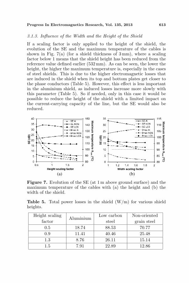
If a scaling factor is only applied to the height of the shield, theevolution of the SE and the maximum temperature of the cables isshown in Fig. 7(a) (for a shield thickness of 3 mm), where a scalingfactor below 1 means that the shield height has been reduced from thereference value defined earlier (532 mm). As can be seen, the lower theheight, the higher the maximum temperature is, especially in the casesof steel shields. This is due to the higher electromagnetic losses thatare induced in the shield when its top and bottom plates get closer tothe phase conductors (Table 5). However, this effect is less importantin the aluminium shield, as induced losses increase more slowly withthis parameter (Table 5). So if needed, only in this case it would bepossible to reduce the height of the shield with a limited impact onthe current-carrying capacity of the line, but the SE would also bereduced.
(a) (b)
Figure 7. Evolution of the SE (at 1 m above ground surface) and themaximum temperature of the cables with (a) the height and (b) thewidth of the shield.
Table 5. Total power losses in the shield (W/m) for various shieldheights.
Height scalingfactor
AluminiumLow carbon
steelNon-orientedgrain steel
0.5 18.74 88.53 70.770.9 11.41 40.46 25.481.3 8.76 26.11 15.141.5 7.91 22.89 12.86

614 Pino-Lopez, Cruz-Romero, and Serrano-Iribarnegaray
In any case, increasing the height of the shield tends to diminishthe influence of the shield losses on the ampacity of the mitigated linewhen using any of the three materials, while their mitigation levelsremain quite constant (case of NOS and LCS shields) or even increase(aluminium shield). However, as it has been observed along this study,LCS shields have always the lowest SE values and the higher impacton the temperature of the phase conductors.
In relation to the shield width (Fig. 7(b)), results are very similarto those of the previous section, where the maximum temperature canbe reduced if the shield width is incremented, mainly with the LCSand aluminium shields. However, this effect is less important in thecase of NOS shields, since the maximum temperature remains almostconstant when modifying this parameter.
Therefore, from this parametric analysis it can be concluded thata suitable shape and size of the shield can provide enough mitigationlevels with a minimum effect, or even no effect, on the current ratingof the power cables. An optimization study is required to take intoaccount all the geometrical parameters involved.
3.2. Shield Cost
When selecting the shield to be installed in a particular place, notonly the mitigation levels and the impact on the line ampacity mustbe taken into account, but also its cost, which includes the cost of thematerial and losses cost over the years of operation. The final goal isto find the aluminium or steel shield with the best balance betweenshielding effectiveness and cost.
So, from the parametric analysis developed previously, it can bederived that using a shield size of 1.3 times greater than the dimensionstaken as a reference it is possible to keep the ampacity of the line inthe initial 809 A, since phase conductors will have a temperature lowerthan 90C (Fig. 6). In this way, it is possible to compare the shield costfor each material without worrying about the line temperature. To dothat, it is considered a line length of 100 m to be shielded, obtaining thetotal cost of the shield (material and losses) over a period of 30 yearsas stated in the IEC 60287 for the cost of power cables [16]. Referencedata are: 2600 euro/t for aluminium; 600 euro/t for LCS; 900 euro/tfor NOS; energy price: 0.1 euro/ton; discount rate: 5%; energy costrate: 2%; and demand charge: 0.03 euro/W·year.
In this situation, Fig. 8(a) shows the evolution of the SE and thetotal cost of the shield for different thicknesses of each material. It iseasily observed that the total cost associated to the aluminium shield isthe cheapest choice, although aluminium is the most expensive materialfrom those considered. On the contrary, the cheapest materials (both

Progress In Electromagnetics Research, Vol. 135, 2013 615
(a) (b)
Figure 8. Evolution of the SE (at 1 m above ground surface) and thetotal cost of 100 m of shield (total scaling factor of 1.3) with (a) thethickness of the shield and (b) the current through the line.
Table 6. Total cost of different shields (euro) over 30 years as afunction of the minimum mitigation requirements.
SEmin (dB) Aluminium Low carbon steelNon-orientedgrain steel
26 15,356 46,456 32,75628 17,102 48,342 34,127
29.5 18,672 48,832 36,03231 19,705 49,462 36,851
steels) leads to a total cost about two times more expensive that thealuminium shield. This is due to the higher electromagnetic lossesinduced on the steel shields, which greatly increase the final cost.
Taking all this into account, if a minimum mitigation level of 26 dBis required in a particular place, different options can be deduced fromFig. 8(a), selecting the suitable thickness for each material to meet themitigation requirements. In this case, it would be needed a 3 mm thickaluminium shield, a 6 mm thick LCS shield and a 2.5 mm NOS shield.The cost associated to these shields are listed in Table 6, where it isalso shown the total cost of the shields when meeting higher mitigationrequirements.
This way, although NOS shield is the better choice in termsof shielding effectiveness, the aluminium shield seems to be theoptimum choice since it provides enough mitigation levels to complythe mitigation requirements with the lowest cost possible.

616 Pino-Lopez, Cruz-Romero, and Serrano-Iribarnegaray
Figure 8(a) is computed considering that the current flowingthrough the line is equal to its ampacity (809 A), which is the mostcritical situation. But this current may vary being usually lowerand hence modifying both the mitigation efficiency and the total costassociated with the shield. This is shown in Fig. 8(b) for the shieldsolutions that comply with a minimum SE of 26 dB (Table 6), where itis represented the evolution of SE and the total cost of the shield withthe line current. As can be seen, when the line current is lower than 809A the SE values of aluminium and LCS shields increase slightly, whileit is worsened in NOS shields. In any case, the mitigation levels remainhigh. In addition, the total cost for the three materials diminishes withthe current, since the induced electromagnetic losses do so.
3.3. Comparison with Open Shields
From the previous section it can be concluded that an aluminiumshield may be the best choice due to its balance between shieldingeffectiveness and cost. However, it may be of interest to compare thissolution with others that are usually employed in underground powercables in flat configuration. In particular, an aluminium open shieldin H-layout can provide important mitigation levels close to those ofthe closed shield [7]. This is shown in Fig. 9, where it is representedthe evolution of the SE and the total cost of both shields for a range ofthicknesses that have no effect on the ampacity of the line. It is easilyobserved that both solutions can provided similar results in terms of
Figure 9. Evolution of the SE (at 1 m above ground surface) and thetotal cost of 100 m of shield with the thickness of the plates used inan aluminium closed shield (total scaling factor of 1.3) and a H-layoutopen shield (vertical plates of 1-m lenght separated by 1 m; horizontalplate of 0.9m length and situated at 0.12 m above cables).

Progress In Electromagnetics Research, Vol. 135, 2013 617
Figure 10. Underground power cables in trefoil configuration insidethe shield.
mitigation levels, but the closed shield is still cheaper than the H-layout, although the difference is not as remarkable as that observedin Fig. 8(a) when using NOS or LCS closed shields. So, the H-layoutstill is a solution of interest to be taken into account, specially whentrench dimensions are restricted, since its width is only about 1m,lower than that of the closed shield that is about 1.35m.
4. CASE STUDY 2: POWER CABLES IN TREFOILCONFIGURATION
The second study included in this research is in relation with the sametype of shield applied to the same 132 kV power line, but in this casethe line is laid in trefoil configuration, as shown in Fig. 10.
Again, phase conductors are installed into 160mm PVC pipes,which are in contact. All the boundary conditions for theelectromagnetic and thermal problems are identical to those used inthe study case 1, but this leads to a new ampacity value for the linein trefoil configuration, which is about 765 A, value that is consideredto be flowing through the line in the parametric analysis. For therest, all dimensions and parameters of the system remain the same,except for the shield size taken as a reference, which in this case isinitially considered to have a 3mm thickness, a base width of 350 mm,a height of 340 mm and the cover is 560mm wide. This way, the shield

618 Pino-Lopez, Cruz-Romero, and Serrano-Iribarnegaray
(a) (b) (c)
Figure 11. SE field and iso-lines for shields made of (a) aluminium,(b) low carbon steel and (c) non-oriented grain steel.
is adjusted to the line size in order to simplify the laying process toensure the trefoil configuration, as described in [1, 2].
A new parametric analysis is developed next using also aluminium(Al), a low carbon steel (LCS) and a non-oriented grain steel (NOS),with the electrical and thermal parameters shown in Table 2 andFig. 2. Again, these materials have been selected since they can providerelevant mitigations levels (SE > 0 dB) nearby the point of interestsituated at 1 m above ground surface, especially in the case of NOSshield, as shown in Fig. 11.
Regarding the relative position between the shield and the powercables, contrary to that observed in the case study 1, there are nosignificant differences in the SE and the temperature of the cableswhether the shield is centered or not with them, since there are lowerlosses induced in the shield due to the compact configuration of the line(Fig. 10). So, in our analysis we will assume the conductors installedat the bottom of the shield due to the easiness to lay them.
4.1. Parametric Analysis
4.1.1. Influence of Shield Thickness and Size
If only the shield thickness is varied, the SE and the maximumtemperature on the phase conductors evolve as shown in Fig. 12(a). Inthis case, the worst mitigation results are presented for the aluminiumshield, which barely reaches mitigations levels of 21 dB when using athickness of 8 mm. In the same way, the LCS shield has poor mitigation

Progress In Electromagnetics Research, Vol. 135, 2013 619
(a) (b)
Figure 12. Evolution of the SE (at 1 m above ground surface) and themaximum temperature of the cables with (a) the thickness and (b) thesize of the shield.
levels if low thicknesses are used, but its SE improves when using valueshigher than 5mm. On the contrary, the NOS shield is always able toreach values of SE far above 26 dB. Nevertheless, only when usingaluminium it is possible not to overheat the power cables employing agreater thickness. So NOS shields, and particularly LCS shields, haveto be carefully considered as they may cause an important currentrating reduction of the power line.
Therefore, it may be of interest to visualize the effects on the SEand the maximum temperature when a bigger shield is installed. Thisis shown in Fig. 12(b), where the thickness of the shield is fixed to3mm. It is clear that only the aluminium shield improves its SE withthe shield size, while it worsens on both steels, especially on the NOSshield. Regarding the impact on the maximum temperature of thecables, it can be easily limited by slightly increasing the shield sizewhen using aluminium or NOS, although it is also possible in LCSshields employing a much bigger shield. This is caused by the higherelectromagnetic losses generated in the LCS shield, as shown in Table 7.
4.1.2. Influence of Shield Width and Height
The influence of both the shield height and width are shown inFigs. 13(a) and 13(b) respectively, for a thickness of 3 mm. It is easilyobserved that both dimensions have similar effects on the SE providedby each material, where only the mitigation efficiency of the aluminiumshield slightly improves while it remains constant for the LCS case andstrongly decreases for the NOS shield.

620 Pino-Lopez, Cruz-Romero, and Serrano-Iribarnegaray
Table 7. Total power losses induced in the shield (W/m) for variousshield sizes.
Total scalingfactor
AluminiumLow carbon
steelNon-orientedgrain steel
1 16.22 22.91 8.341.3 14.81 18.35 7.311.6 14.42 16.27 6.722 14.11 14.35 6.19
(a) (b)
Figure 13. Evolution of the SE (at 1 m above ground surface) and themaximum temperature of the cables with (a) the height and (b) thewidth of the shield.
So the only important advantage obtained from increasing one ofthese dimensions is that it helps us to limit the impact on the ampacityof the line, as can be seen in Figs. 13(a) and 13(b). However, eachmaterial has a different reaction to these actions. For example, itseems that aluminium shields reach lower temperatures faster whenincreasing the shield height instead of increasing its width. On thecontrary, the temperature seems to diminish faster when increasingthe width on LCS or NOS shields. This behaviour is related not onlywith the electromagnetic losses induced on each material (Table 8),but also with their thermal properties.
4.2. Shield Cost
The economic analysis developed for this case study has beenperformed with the same data listed in the corresponding section of the

Progress In Electromagnetics Research, Vol. 135, 2013 621
Table 8. Total power losses in the shield (W/m) for various shieldwidths.
Width scalingfactor
AluminiumLow carbon
steelNon-orientedgrain steel
1 16.22 22.91 8.341.3 16.35 19.83 7.861.6 16.60 18.17 7.792 16.72 16.78 7.61
(a) (b)
Figure 14. Evolution of the SE (at 1m above ground surface) andthe total cost of 100 m of shield (total scaling factor of 1.3) with (a) thethickness of the shield and (b) the current through the line.
case study 1 (material and energy cost). However it is again necessaryto select a particular size for the shield in order to avoid the currentderating of the power line. In this sense, a shield size of 1.3 timesthe size taken as a reference is selected. This shield is supposed to beinstalled along a line length of 100 m.
With these data, Fig. 14(a) shows the most important results whenthe shield thickness is increased. In particular the evolution of the SEand the total cost of the shield over 30 years of operation. It can beseen that the higher cost is obtained when using LCS to make theshield, which is about 1.6 times higher than the cost associated tothe cheapest option (aluminium). Moreover, the shielding efficiency ofboth materials are very similar, so it is clear that LCS shields wouldbe rejected. However, the cost of NOS shield is quite close to that ofaluminium shield, especially at lower thickness, and they provide muchhigher efficiency levels than the aluminium.

622 Pino-Lopez, Cruz-Romero, and Serrano-Iribarnegaray
Table 9. Total cost of different shields (euro) over 30 years as afunction of the minimum mitigation requirements.
SEmin (dB) AluminiumLow carbon
steelNon-orientedgrain steel
26 17,262 29,365 13,16428 21,125 29,867 13,465
29.5 23,864 30,035 13,83931 25,746 31,854 14,265
Considering all this, if a minimum SE of 26 dB is required, it wouldbe necessary to choose the suitable thickness for each material to meetthis constraint. In our case this leads to a NOS shield of 2.5 mm,a LCS shield of 7 mm and an aluminium shield of 9 mm. The totalcost associated to these configurations is listed in Table 9, which alsoincludes the total cost for other requirements of SE.
As can be concluded, for any SEmin the best choice in this case is touse a NOS shield, since it complies with the mitigation requirementswith the lowest cost possible. In any case, the total costs shown inFig. 14(a) have been computed for a current flowing through the cablesequal to its ampacity (765 A), which is the most critical situation. Infact, the current is usually lower. So this is considered in Fig. 14(b),where it is shown the influence of the current of the line in themitigation efficiency and the cost of the shield when a SEmin = 26dBis required. It is easily observed that, in general, the current throughthe cables has no important effects on both parameters, except for thecase of LCS shields, whose SE can be lower than 26 dB if the currentflowing through the line is about 700 A or less. But also, for thismaterial the total cost of the shield decreases faster than the cost ofthe other materials when the current is lower.
5. CONCLUSIONS
The shielding effectiveness of a closed two-component magnetic shieldand the impact of the induced electromagnetic losses on the totalshield cost and the ampacity of the power cables have been studiedfor two cases of an underground power line, installed in flat and trefoilconfiguration, both protected by PVC pipes. Three different materialsfor the shield have been considered in the study (aluminium, a lowcarbon steel and non oriented grain steel), which is performed by meansof a FEM electromagnetic-thermal coupled model.

Progress In Electromagnetics Research, Vol. 135, 2013 623
A parametric analysis has been developed for the selectedconfigurations of the line, concluding that the geometrical parametersof the shield have significant effects not only on the shieldingeffectiveness, but also on the ampacity of the shielded line and theshield cost (including material and losses cost over the years ofoperation). Tables and curves with comparative data presented in thispaper help to select the suitable dimensions of a shield to be placed ina particular situation, in order to obtain the best mitigation levels andthe lowest impact on the current rating of the mitigated line. In thissense, it has to be noticed that, in general, a greater size of the shieldleads to a lower impact on the current rating of the mitigated line, butthis also leads to a lower mitigation efficiency when using steel.
From all the materials considered to make the shield, this studyconcludes that aluminium provides significant mitigation levels withthe lowest cost possible when shielding a line in flat configuration.Its mitigation efficiency is even close to that observed in other highefficiency open shields frequently used in lines laid in flat configuration,like the H-layout, but with a lower cost. However, if higher values ofmitigation are needed, a non-oriented grain steel shield may be selectedto be installed next to the line, but in this case the total cost of theshield is about twice of the aluminium.
On the other hand, if the line is laid in trefoil formation, a shieldmade of non-oriented grain steel is the best choice, since it providesvery high mitigation levels with a reasonable cost, which is similarto the total cost of aluminium shields. However, in this situationaluminium shields cannot provide such high mitigation levels as thoseof the non-oriented grain steel.
Finally, in all the studied cases it is noticed that low carbon steelshields can provide significant mitigation levels when using a high valueof thickness, but its cost is quite high compared to those of the othermaterials considered, which makes this material not to be best choicein any of the studied configurations.
ACKNOWLEDGMENT
This work has been supported by the Spanish Ministry of Science& Innovation under grant ENE2010-18867 and by the regionalGovernment of Andalucıa under grant P09-TEP-5170.
REFERENCES
1. Maioli, P., E. Borghi, F. Donazzi, and S. Belli, “Methodfor shielding the magnetic field generated by an electrical

624 Pino-Lopez, Cruz-Romero, and Serrano-Iribarnegaray
power transmission line and electrical power transmission lineso shielded,” Patent, International Publication Number: WO2005/013450 A1, Feb. 2005.
2. Conti, R., F. Donazzi, P. Maioli, R. Rendina, and E. A. Sena,“Some Italian experiences in the utilization of HV undergroundcable systems to solve local problems due to magnetic field andother environmental issues,” Cigre Session, Paper C4-303, 2006.
3. De Wulf, M., P. Wouters, P. Sergeant, L. Dupre, E. Hoferlin,S. Jacobs, and P. Harlet, “Electromagnetic shielding of high-voltage cables,” J. Magn. Magn. Mater., Vol. 316, 908–911, 2007.
4. Sergeant, P. and S. Koroglu, “Electromagnetic losses inmagnetic shields for buried high voltage cables,” Progress InElectromagnetics Research, Vol. 115, 441–460, 2011.
5. Xu, X. and X. Yang, “A hybrid formulation based on uniformunimoment method or investigating the electromagnetic shieldingof sources within a steel pipe,” Progress In ElectromagneticsResearch, Vol. 12, 133–157, 1996.
6. Xu, X.-B. and G. Liu, “A two-step numerical solution of magneticfield produced by ELF sources within a steel pipe,” Progress InElectromagnetics Research, Vol. 28, 17–28, 2000.
7. Del Pino, J.-C. and P. Cruz, “Influence of different types ofmagnetic shields on the thermal behaviour and ampacity ofunderground power cables,” IEEE Trans. on Power Delivery,Vol. 26, No. 4, 2659–2667, 2011.
8. Liang, Y., “Steady-state thermal analysis of power cable systemsin ducts using streamline-upwind/Petrov-Galerkin finite elementmethod,” IEEE Trans. on Dielectrics and Electrical Insulation,Vol. 19, No. 1, 283–290, 2012.
9. Anders, G.-J., M. Chaaban, and N. Bedard, “New approachto ampacity evaluation of cables in ducts using finite elementtechnique,” IEEE Trans. on Power Delivery, Vol. 2, 969–975,1987.
10. Bertotti, G., Hysteresis in Magnetism, Academic Press, SanDiego, 1998.
11. Ionel, D.-M., M. Popescu, S. J. Dellinger, T. J. E. Miller,R. J. Heideman, and M. I. McGilp, “On the variation with fluxand frequency of the core loss coefficients in electrical machines,”IEEE Trans. on Industry Applications, Vol. 42, No. 3, 658–667,2006.
12. Lee, P.-K., K. C. Kuo, C. J. Wu, Z. T. Wong, and J. Y. Yen,“Prediction of iron losses using the modified Steinmetz equation

Progress In Electromagnetics Research, Vol. 135, 2013 625
under sinusoidal waveform,” Proceedings of 2011 8th AsianControl Conference (ASCC), 579–584, 2011.
13. Ozturk, N. and E. Celik, “Application of genetic algorithmsto core loss coefficient extraction,” Progress In ElectromagneticResearch M, Vol. 19, 133–146, 2011.
14. Bertotti, G., “General properties of power losses in softferromagnetic materials,” IEEE Trans. on Magnetics, Vol. 24,No. 1, 621–630, 1998.
15. Anders, G.-J., Rating of Electric Power Cables: AmpacityComputations for Transmission, Distribution and IndustrialApplications, New York, 1997.
16. IEC Standard 60287, Electric Cables — Calculation of theCurrent Rating — Part 3-2: Sections on Operating Conditions —Economic Optimization of Power Cable Size, 2nd edition, 2006.