impact of diatomaceous biofilms on the frictional drag of ... · impact of diatomaceous biofilms...
TRANSCRIPT
Impact of diatomaceous biofilms on the frictional drag of fouling-release coatings
M. P. Schultza*, J. M. Walkerb, C. N. Steppec and K. A. Flackd
aDepartment of Naval Architecture and Ocean Engineering, United States Naval Academy, Annapolis, USA; bNational Centre forMaritime Engineering and Hydrodynamics, Australian Maritime College, University of Tasmania, Launceston, Australia;cDepartment of Oceanography, United States Naval Academy, Annapolis, USA; dDepartment of Mechanical Engineering, UnitedStates Naval Academy, Annapolis, USA
(Received 17 July 2015; accepted 9 October 2015)
Skin-friction results are presented for fouling-release (FR) hull coatings in the unexposed, clean condition and afterdynamic exposure to diatomaceous biofilms for 3 and 6 months. The experiments were conducted in a fully developedturbulent channel flow facility spanning a wide Reynolds number range. The results show that the clean FR coatingstested were hydraulically smooth over much of the Reynolds number range. Biofilms, however, resulted in an increasein skin-friction of up to 70%. The roughness functions for the biofilm-covered surfaces did not display universal behav-ior, but instead varied with the percentage coverage by the biofilm. The effect of the biofilm was observed to scale withits mean thickness and the square root of the percentage coverage. A new effective roughness length scale (keff) for bio-films based on these parameters is proposed. Boundary layer similarity-law scaling is used to predict the impact of thesebiofilms on the required shaft power for a mid-sized naval surface combatant at cruising speed. The increase in power isestimated to be between 1.5% and 10.1% depending on the biofilm thickness and percentage coverage.
Keywords: drag; powering; biofilms; biofouling; roughness; fouling-release coatings
Introduction
The consequences of marine biofouling are significantand far-reaching. One such outcome is the increase inhull roughness on ships due to the settlement and growthof biofouling organisms. This increased roughness ele-vates frictional drag, which in turn increases fuel con-sumption and decreases vessel range and speed (egKempf 1937; Lewthwaite et al. 1985; Leer-Andersen &Larsson 2003; Townsin 2003; Schultz 2007). These out-comes also generate a significant economic impact. Forexample, an economic analysis of US Navy destroyersplaces the overall cost associated with hull fouling at ~$1 million per ship per year (Schultz et al. 2011).
A great deal of research has focussed on understand-ing the effects of biofouling on ship drag and powering.A review of this work is given by Townsin (2003), anda primary conclusion of this paper is that the impact ofcalcareous macrofouling (eg barnacles and oysters) ismuch better understood than for soft fouling (eg bacteria,micro- and macroalgae). There are several possible rea-sons for this. First, biofilms are complex assemblages ofdiverse organisms ranging from bacteria to diatoms andalgae. This makes them highly variable in density, heightand other parameters that affect their ‘effective’
roughness height in a hydrodynamic sense, and hencethis can generate significant variability in their impact onship performance. Second, the organisms comprising thebiofilm produce extracellular polymeric substances (EPS)that make it compliant. This compliancy can producerich interactions with the fluid flow over the biofilmmaking flow modeling and drag prediction for biofilm-covered surfaces difficult. Lastly, biofilms can be alteredand dislodged by the flow, which makes their drag char-acteristics time dependent even at a steady flow velocity.Perhaps because of these complexities, there is no gener-ally accepted method for quantifying the nature andimpact of a given biofilm, although in recent years moreresearch into biofilms developed on antifouling (AF)paints and FR coatings has been reported (eg Hunsuckeret al. 2014; Muthukrishnan et al. 2014; van Mooy et al.2014; Zargiel & Swain 2014). In spite of recent interest,better guidance is needed to develop a more consistentapproach in assessing biofilms. It should be noted thatthis is related to both identifying critical biofilm parame-ters and modeling their effects on hydrodynamics.
Despite the aforementioned challenges, a significantbody of research has been devoted to quantifying theeffect of biofilms on frictional drag. Discussion of the
*Corresponding author. Email: [email protected] work of M. P. Schultz, C. N. Steppe, and K. A. Flack was authored as part of their official duties as Employees of the UnitedStates Government and is therefore a work of the United States Government. In accordance with 17 USC. 105, no copyright protec-tion is available for such works under US Law. J. M. Walker hereby waives her right to assert copyright, but not her right to benamed as co-author in the article.
© 2015 Taylor & Francis
Biofouling, 2015Vol. 31, Nos. 9–10, 759–773, http://dx.doi.org/10.1080/08927014.2015.1108407
Dow
nloa
ded
by [
US
Nav
al A
cade
my]
at 0
5:19
14
Dec
embe
r 20
15
drag penalties of slime films on ships dates at least asfar back as McEntee (1915). In this work, the increase indrag as a result of slime is anecdotally asserted to be0.5% per day while a ship is at dock. Obviously, this isan oversimplification in that the drag increase can beexpected to be influenced by myriad factors. It does,nonetheless, point to the longstanding recognition thatbiofilms can significantly increase the drag of ships.Because of this, the topic has been investigated by anumber of researchers over the years (eg Benson et al.1938; Watanabe et al. 1969; Lewthwaite et al. 1985;Schultz & Swain 1999; Schultz 2004). All these studiesindicate that biofilms generate a significant increase infrictional drag. However, the increase is observed todepend strongly on the fouling type, morphology, biofilmthickness and coverage. Within this body of research, thestudy of Haslbeck and Bohlander (1992) is particularlynoteworthy in that it directly documents the effect of abiofilm on the powering requirements of a ship coatedwith an ablative AF paint. Through ship powering trialsconducted before and after hull cleaning, these authorsobserved that the biofilm increased the powering require-ments of the ship by up to 18% compared with the cleanhull condition.
Because of the deleterious impacts of biofouling, anumber of coating technologies are aimed at reducingthe accumulation of biofouling on ships (Finnie &Williams 2010). For the most part these coatings can begrouped into two categories: AF and FR coatings. AFcoatings function by using biocides to control biofouling.FR coatings, on the other hand, contain no biocides butact to reduce the adhesion of fouling on the surface suchthat hydrodynamic forces can dislodge settled organisms.It is of note that both AF and FR coatings are suscepti-ble to fouling by diatomaceous slimes. For example,
Schultz et al. (201l) point out that the typical, in-servicehull condition for US Navy destroyers coated with abla-tive copper AF paint systems is a heavy diatomaceousbiofilm. FR coatings, particularly silicone-basedhydrophobic coatings, foul readily with diatoms, andthese biofilms are particularly tenacious on FR surfaces(Holland et al. 2004; Zargiel & Swain 2014). However,the hydrodynamic impact of biofilms on these surfaces isnot well established.
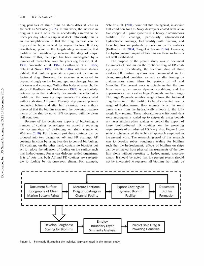
The purpose of the present study was to documentthe impact of biofilms on the frictional drag of FR coat-ing systems. Specifically, the frictional drag of threemodern FR coating systems was documented in theclean, as-applied condition as well as after fouling bydiatomaceous slime films for periods of ~3 and6 months. The present work is notable in that the bio-films were grown under dynamic conditions, and theexperiments cover a rather large Reynolds number range.The large Reynolds number range allows the frictionaldrag behavior of the biofilm to be documented over arange of hydrodynamic flow regimes, which in somecases spans from the hydraulically smooth to the fullyrough flow regime. These laboratory-scale frictional datawere subsequently scaled up to ship-scale using bound-ary layer similarity-law scaling to predict the impact ofthese biofilm-fouled FR coatings on the poweringrequirements of a mid-sized US Navy ship. Figure 1 pre-sents a schematic of the technical approach employed inthe present work. The overarching goal of this researchwas to develop robust roughness scaling for biofilmssuch that the hydrodynamic effects of biofilms on shipscan be estimated from physical measurements of the bio-film alone without resorting to hydrodynamic measure-ments. It should be noted that the present results shouldnot be interpreted to represent all biofilms that might be
Figure 1. Schematic illustrating the technical approach used in the present study.
760 M.P. Schultz et al.
Dow
nloa
ded
by [
US
Nav
al A
cade
my]
at 0
5:19
14
Dec
embe
r 20
15
found on in-service ships. Instead, they should be takento be representative examples for the particular biofilmculture reported on here. Further research is needed toexplore the effect of the aforementioned complexities ofbiofilms on the resulting impact on ship performance.
Materials and methods
In this section the experimental facilities and methodswill be discussed. First, the turbulent channel flow facil-ity and method used for the hydrodynamic measurementswill be presented. Next, the test surfaces used in the pre-sent investigation will be discussed. Then some detailsof the dynamic biofilm exposure facility and method willbe given. Finally, the uncertainties associated with theexperiments will be examined.
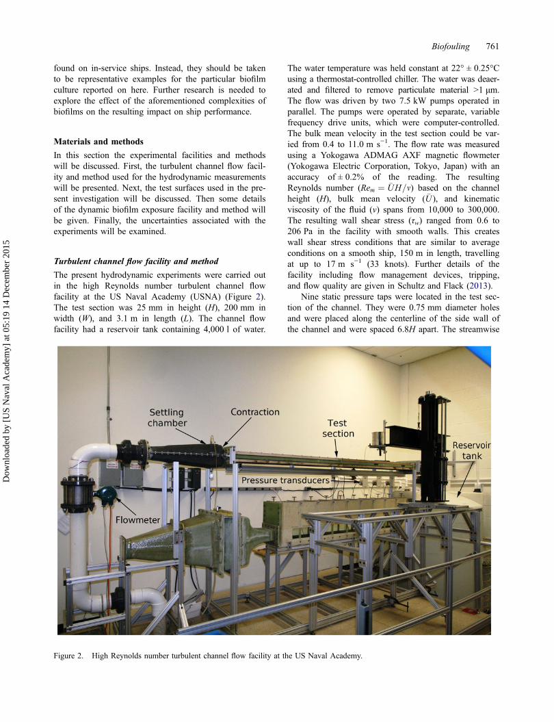
Turbulent channel flow facility and method
The present hydrodynamic experiments were carried outin the high Reynolds number turbulent channel flowfacility at the US Naval Academy (USNA) (Figure 2).The test section was 25 mm in height (H), 200 mm inwidth (W), and 3.1 m in length (L). The channel flowfacility had a reservoir tank containing 4,000 l of water.
The water temperature was held constant at 22° ± 0.25°Cusing a thermostat-controlled chiller. The water was deaer-ated and filtered to remove particulate material >1 μm.The flow was driven by two 7.5 kW pumps operated inparallel. The pumps were operated by separate, variablefrequency drive units, which were computer-controlled.The bulk mean velocity in the test section could be var-ied from 0.4 to 11.0 m s−1. The flow rate was measuredusing a Yokogawa ADMAG AXF magnetic flowmeter(Yokogawa Electric Corporation, Tokyo, Japan) with anaccuracy of ± 0.2% of the reading. The resultingReynolds number (Rem ¼ �UH=m) based on the channelheight (H), bulk mean velocity ( �U ), and kinematicviscosity of the fluid (ν) spans from 10,000 to 300,000.The resulting wall shear stress (τw) ranged from 0.6 to206 Pa in the facility with smooth walls. This createswall shear stress conditions that are similar to averageconditions on a smooth ship, 150 m in length, travellingat up to 17 m s−1 (33 knots). Further details of thefacility including flow management devices, tripping,and flow quality are given in Schultz and Flack (2013).
Nine static pressure taps were located in the test sec-tion of the channel. They were 0.75 mm diameter holesand were placed along the centerline of the side wall ofthe channel and were spaced 6.8H apart. The streamwise
Figure 2. High Reynolds number turbulent channel flow facility at the US Naval Academy.
Biofouling 761
Dow
nloa
ded
by [
US
Nav
al A
cade
my]
at 0
5:19
14
Dec
embe
r 20
15
pressure gradient (dp/dx) was determined with three GE-Druck LPM 9,000 series differential pressure transducers(GE Measurement & Control, Billerica, MA, USA). Thetransducers had ranges of 20, 50, and 100 mbar, respec-tively, and had an accuracy of ±0.1% of full scale. Theuse of multiple gauges provided both redundancy in thepressure gradient measurements over their commonranges and also allowed uncertainty to be minimized byusing more a sensitive gauge when the pressure gradientwas small. Pressure taps 5–8 were used to measure thestreamwise pressure gradient in the channel. These werelocated ~90H–110H downstream of the trip at the inletto the channel. The linearity in the measured pressuregradient using these four taps was good with a coeffi-cient of determination (R2) of the regression generally>0.995.
The wall shear stress, τw, was determined via mea-surement of the streamwise pressure gradient given asfollows:
sw ¼ �H
2
dp
dx(1)
or expressed as the skin-friction coefficient, Cf
Cf ¼ sw12 q �U
2¼ 2
Us
�U
� �2
(2)
where H = channel height, p = static pressure, x =streamwise distance, ρ = fluid density, �U= bulk meanvelocity, and Uτ = friction velocity=
ffiffiffiffiswq
q.
To obtain the roughness function, ΔU+, for the testsurfaces, the similarity-law procedure of Granville(1987) for fully developed internal flows was employed.Granville’s method states that the roughness function canbe obtained as follows:
DUþ ¼ �UþS � �Uþ
R ¼ffiffiffiffiffiffiffi2
CfS
s�
ffiffiffiffiffiffiffi2
CfR
s(3)
where the subscripts S and R denote smooth and roughsurfaces, respectively, evaluated at the same value of thefriction Reynolds number (Reτ) and
+ denotes inner nor-malization (ie by the friction velocity, Uτ, for velocitiesor by the viscous length scale, m=Us, for lengths). Thefriction Reynolds number is defined as:
Res ¼ Ush
m(4)
where h = channel half-height.In the present study, the flow developed over smooth
walls for a distance of 60H in the upstream portion of thechannel. The roughness-covered plates formed the top andbottom walls for the remainder of the test section. Guidedby the study of Antonia and Luxton (1971), Hong, et al.
(2011) found that a fetch of 17.5H downstream of a transi-tion from smooth- to rough-wall channel flow was suffi-cient to re-establish fully developed conditions in terms ofboth the mean flow and Reynolds stresses. In the presentinvestigation, there was a roughness fetch of 30H beforepressure tap 5, the first tap used in the determination ofdp/dx.
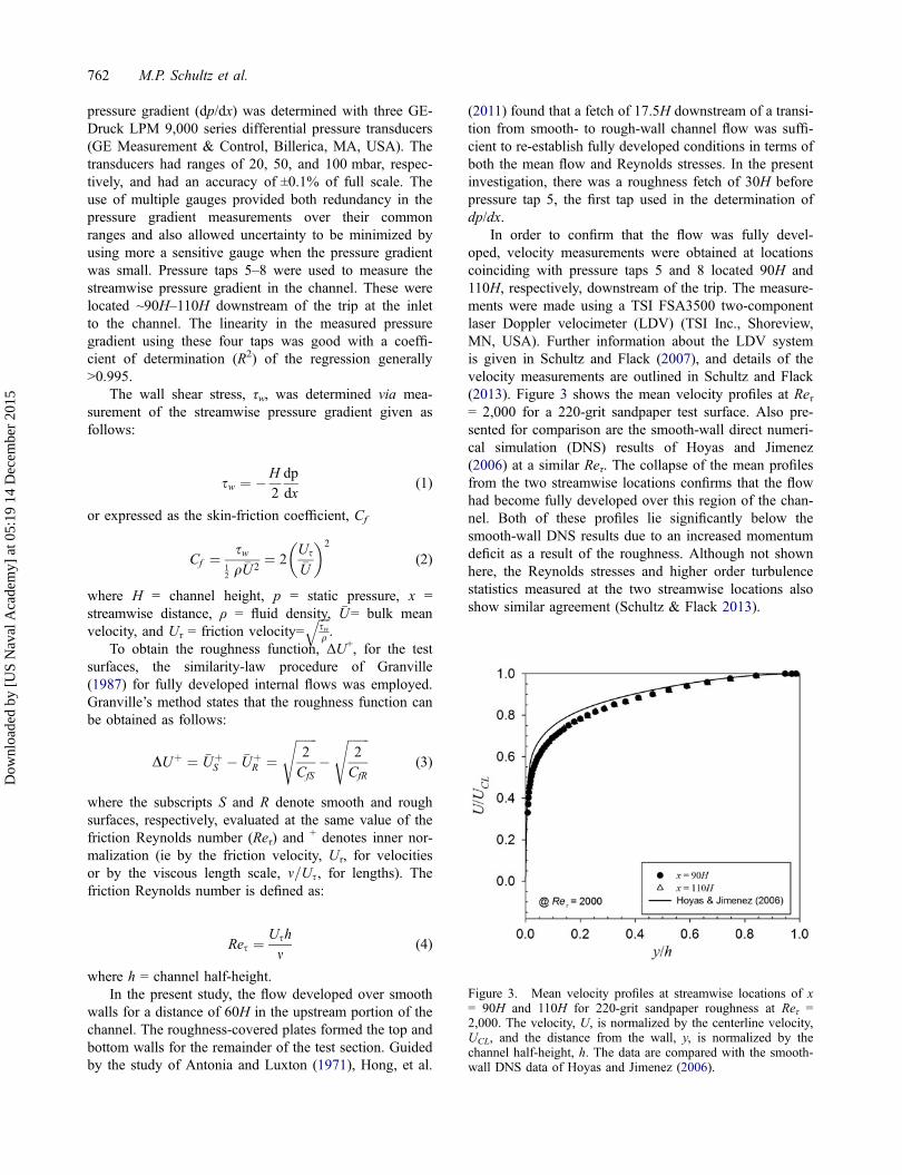
In order to confirm that the flow was fully devel-oped, velocity measurements were obtained at locationscoinciding with pressure taps 5 and 8 located 90H and110H, respectively, downstream of the trip. The measure-ments were made using a TSI FSA3500 two-componentlaser Doppler velocimeter (LDV) (TSI Inc., Shoreview,MN, USA). Further information about the LDV systemis given in Schultz and Flack (2007), and details of thevelocity measurements are outlined in Schultz and Flack(2013). Figure 3 shows the mean velocity profiles at Reτ= 2,000 for a 220-grit sandpaper test surface. Also pre-sented for comparison are the smooth-wall direct numeri-cal simulation (DNS) results of Hoyas and Jimenez(2006) at a similar Reτ. The collapse of the mean profilesfrom the two streamwise locations confirms that the flowhad become fully developed over this region of the chan-nel. Both of these profiles lie significantly below thesmooth-wall DNS results due to an increased momentumdeficit as a result of the roughness. Although not shownhere, the Reynolds stresses and higher order turbulencestatistics measured at the two streamwise locations alsoshow similar agreement (Schultz & Flack 2013).
Figure 3. Mean velocity profiles at streamwise locations of x= 90H and 110H for 220-grit sandpaper roughness at Reτ =2,000. The velocity, U, is normalized by the centerline velocity,UCL, and the distance from the wall, y, is normalized by thechannel half-height, h. The data are compared with the smooth-wall DNS data of Hoyas and Jimenez (2006).
762 M.P. Schultz et al.
Dow
nloa
ded
by [
US
Nav
al A
cade
my]
at 0
5:19
14
Dec
embe
r 20
15
Test surfaces
The test plates were fabricated from cast acrylic sheet.They were machined using a CNC Haas VF-11 three-axis,vertical milling machine controlled by Esprit CAD/CAMsoftware. The plates were secured to the milling machineby a custom vacuum table fixture. The test plate dimen-sions were 8.75 mm in thickness, 200 mm in width, and
1.52 m in length. Three commercial FR coating systemswere tested: a silicone FR paint system (InternationalIntersleek® 700; Specimen A), a fluoropolymer FR paintsystem (International Intersleek® 900; Specimen B), andfluoropolymer FR paint system formulated to resist slimefouling (International Intersleek® 1100SR; Specimen C)(International Paint Ltd, Gateshead, UK).
The coatings were applied onto clean and lightlyabraded acrylic panels by airless spray at AkzoNobel’sMarine Coatings business (International Paint Ltd). Allof the coating panels comprised the full coating schemerepresentative of those typically used on both commer-cial and military vessels. This included a primer, a tiecoat, and a fouling control coating. Following applicationof the full scheme, all the coated panels were dried forseveral days at ambient temperature prior to shipment toUSNA for testing. Each coating scheme was applied totwo replicate test panels. A set of uncoated acrylic con-trol surfaces was also tested.
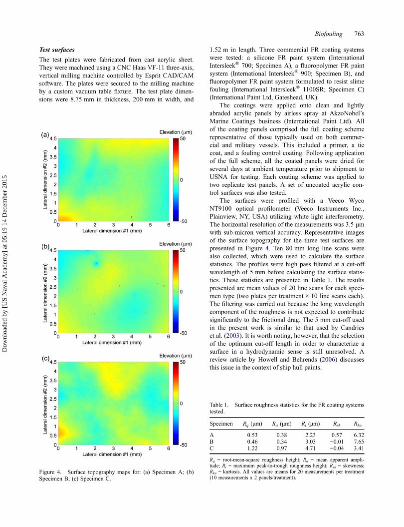
The surfaces were profiled with a Veeco WycoNT9100 optical profilometer (Veeco Instruments Inc.,Plainview, NY, USA) utilizing white light interferometry.The horizontal resolution of the measurements was 3.5 μmwith sub-micron vertical accuracy. Representative imagesof the surface topography for the three test surfaces arepresented in Figure 4. Ten 80 mm long line scans werealso collected, which were used to calculate the surfacestatistics. The profiles were high pass filtered at a cut-offwavelength of 5 mm before calculating the surface statis-tics. These statistics are presented in Table 1. The resultspresented are mean values of 20 line scans for each speci-men type (two plates per treatment × 10 line scans each).The filtering was carried out because the long wavelengthcomponent of the roughness is not expected to contributesignificantly to the frictional drag. The 5 mm cut-off usedin the present work is similar to that used by Candrieset al. (2003). It is worth noting, however, that the selectionof the optimum cut-off length in order to characterize asurface in a hydrodynamic sense is still unresolved. Areview article by Howell and Behrends (2006) discussesthis issue in the context of ship hull paints.
Figure 4. Surface topography maps for: (a) Specimen A; (b)Specimen B; (c) Specimen C.
Table 1. Surface roughness statistics for the FR coating systemstested.
Specimen Rq (μm) Ra (μm) Rt (μm) Rsk Rku
A 0.53 0.38 2.23 0.57 6.32B 0.46 0.34 3.03 −0.01 7.65C 1.22 0.97 4.71 −0.04 3.41
Rq = root-mean-square roughness height; Ra = mean apparent ampli-tude; Rt = maximum peak-to-trough roughness height; Rsk = skewness;Rku = kurtosis. All values are means for 20 measurements per treatment(10 measurements x 2 panels/treatment).
Biofouling 763
Dow
nloa
ded
by [
US
Nav
al A
cade
my]
at 0
5:19
14
Dec
embe
r 20
15
Dynamic biofilm exposure facility and method
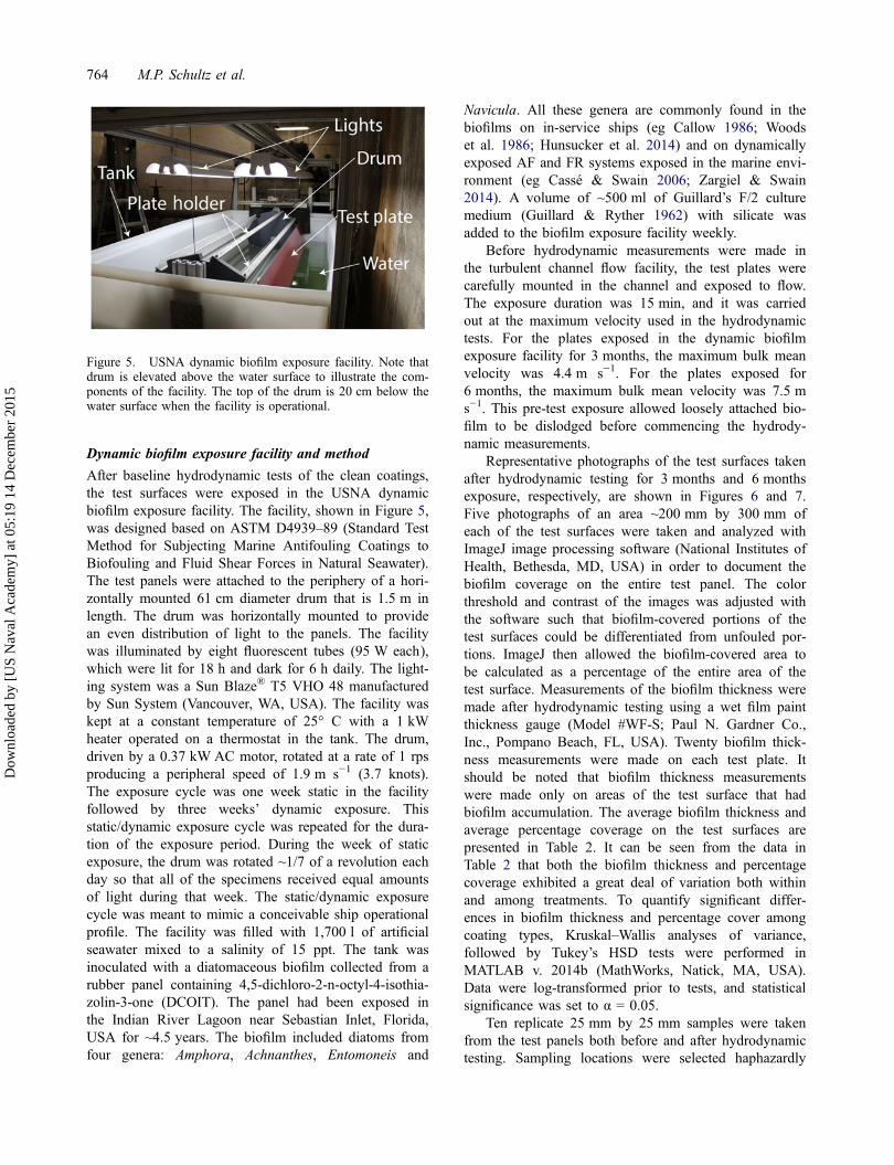
After baseline hydrodynamic tests of the clean coatings,the test surfaces were exposed in the USNA dynamicbiofilm exposure facility. The facility, shown in Figure 5,was designed based on ASTM D4939–89 (Standard TestMethod for Subjecting Marine Antifouling Coatings toBiofouling and Fluid Shear Forces in Natural Seawater).The test panels were attached to the periphery of a hori-zontally mounted 61 cm diameter drum that is 1.5 m inlength. The drum was horizontally mounted to providean even distribution of light to the panels. The facilitywas illuminated by eight fluorescent tubes (95 W each),which were lit for 18 h and dark for 6 h daily. The light-ing system was a Sun Blaze® T5 VHO 48 manufacturedby Sun System (Vancouver, WA, USA). The facility waskept at a constant temperature of 25° C with a 1 kWheater operated on a thermostat in the tank. The drum,driven by a 0.37 kW AC motor, rotated at a rate of 1 rpsproducing a peripheral speed of 1.9 m s−1 (3.7 knots).The exposure cycle was one week static in the facilityfollowed by three weeks’ dynamic exposure. Thisstatic/dynamic exposure cycle was repeated for the dura-tion of the exposure period. During the week of staticexposure, the drum was rotated ~1/7 of a revolution eachday so that all of the specimens received equal amountsof light during that week. The static/dynamic exposurecycle was meant to mimic a conceivable ship operationalprofile. The facility was filled with 1,700 l of artificialseawater mixed to a salinity of 15 ppt. The tank wasinoculated with a diatomaceous biofilm collected from arubber panel containing 4,5-dichloro-2-n-octyl-4-isothia-zolin-3-one (DCOIT). The panel had been exposed inthe Indian River Lagoon near Sebastian Inlet, Florida,USA for ~4.5 years. The biofilm included diatoms fromfour genera: Amphora, Achnanthes, Entomoneis and
Navicula. All these genera are commonly found in thebiofilms on in-service ships (eg Callow 1986; Woodset al. 1986; Hunsucker et al. 2014) and on dynamicallyexposed AF and FR systems exposed in the marine envi-ronment (eg Cassé & Swain 2006; Zargiel & Swain2014). A volume of ~500 ml of Guillard’s F/2 culturemedium (Guillard & Ryther 1962) with silicate wasadded to the biofilm exposure facility weekly.
Before hydrodynamic measurements were made inthe turbulent channel flow facility, the test plates werecarefully mounted in the channel and exposed to flow.The exposure duration was 15 min, and it was carriedout at the maximum velocity used in the hydrodynamictests. For the plates exposed in the dynamic biofilmexposure facility for 3 months, the maximum bulk meanvelocity was 4.4 m s−1. For the plates exposed for6 months, the maximum bulk mean velocity was 7.5 ms−1. This pre-test exposure allowed loosely attached bio-film to be dislodged before commencing the hydrody-namic measurements.
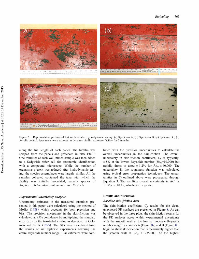
Representative photographs of the test surfaces takenafter hydrodynamic testing for 3 months and 6 monthsexposure, respectively, are shown in Figures 6 and 7.Five photographs of an area ~200 mm by 300 mm ofeach of the test surfaces were taken and analyzed withImageJ image processing software (National Institutes ofHealth, Bethesda, MD, USA) in order to document thebiofilm coverage on the entire test panel. The colorthreshold and contrast of the images was adjusted withthe software such that biofilm-covered portions of thetest surfaces could be differentiated from unfouled por-tions. ImageJ then allowed the biofilm-covered area tobe calculated as a percentage of the entire area of thetest surface. Measurements of the biofilm thickness weremade after hydrodynamic testing using a wet film paintthickness gauge (Model #WF-S; Paul N. Gardner Co.,Inc., Pompano Beach, FL, USA). Twenty biofilm thick-ness measurements were made on each test plate. Itshould be noted that biofilm thickness measurementswere made only on areas of the test surface that hadbiofilm accumulation. The average biofilm thickness andaverage percentage coverage on the test surfaces arepresented in Table 2. It can be seen from the data inTable 2 that both the biofilm thickness and percentagecoverage exhibited a great deal of variation both withinand among treatments. To quantify significant differ-ences in biofilm thickness and percentage cover amongcoating types, Kruskal–Wallis analyses of variance,followed by Tukey’s HSD tests were performed inMATLAB v. 2014b (MathWorks, Natick, MA, USA).Data were log-transformed prior to tests, and statisticalsignificance was set to α = 0.05.
Ten replicate 25 mm by 25 mm samples were takenfrom the test panels both before and after hydrodynamictesting. Sampling locations were selected haphazardly
Figure 5. USNA dynamic biofilm exposure facility. Note thatdrum is elevated above the water surface to illustrate the com-ponents of the facility. The top of the drum is 20 cm below thewater surface when the facility is operational.
764 M.P. Schultz et al.
Dow
nloa
ded
by [
US
Nav
al A
cade
my]
at 0
5:19
14
Dec
embe
r 20
15
along the full length of each panel. The biofilm wasscraped from the panels and preserved in 70% EtOH.One milliliter of each well-mixed sample was then addedto a Sedgwick rafter cell for taxonomic identificationwith a compound microscope. While the number oforganisms present was reduced after hydrodynamic test-ing, the species assemblages were largely similar. All thesamples collected contained the taxa with which thefacility was initially inoculated, namely species ofAmphora, Achnanthes, Entomoneis and Navicula.
Experimental uncertainty analysis
Uncertainty estimates in the measured quantities pre-sented in this paper were calculated using the method ofMoffat (1988), which accounts for both precision andbias. The precision uncertainty in the skin-friction wascalculated at 95% confidence by multiplying the standarderror (SE) by the two-tailed t value as described in Cole-man and Steele (1995). The SEs were calculated fromthe results of six replicate experiments covering theentire Reynolds number range. Bias estimates were com-
bined with the precision uncertainties to calculate theoverall uncertainties in the skin-friction. The overalluncertainty in skin-friction coefficient, Cf, is typically± 8% at the lowest Reynolds number (Rem=10,000) butrapidly drops to about ± 1.2% for Rem ≥ 40,000. Theuncertainty in the roughness function was calculatedusing typical error propagation techniques. The uncer-tainties in Cf outlined above were propagated throughEquation 3. The resulting overall uncertainty in ΔU+ is±3.8% or ±0.15, whichever is greater.
Results and discussion
Baseline skin-friction data
The skin-friction coefficient, Cf, results for the clean,unexposed FR surfaces are presented in Figure 8. As canbe observed in the three plots, the skin-friction results forthe FR surfaces agree within experimental uncertaintywith the smooth wall at the low to moderate Reynoldsnumber range. Specimens A (Figure 8a) and B (Figure 8b)begin to show skin-friction that is measurably higher thanthe smooth wall at Rem > 235,000. At the highest
Figure 6. Representative pictures of test surfaces after hydrodynamic testing: (a) Specimen A; (b) Specimen B; (c) Specimen C; (d)Acrylic control. Specimens were exposed in dynamic biofilm exposure facility for 3 months.
Biofouling 765
Dow
nloa
ded
by [
US
Nav
al A
cade
my]
at 0
5:19
14
Dec
embe
r 20
15
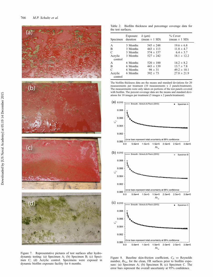
Figure 7. Representative pictures of test surfaces after hydro-dynamic testing: (a) Specimen A; (b) Specimen B; (c) Speci-men C; (d) Acrylic control. Specimens were exposed indynamic biofilm exposure facility for 6 months.
Table 2. Biofilm thickness and percentage coverage data forthe test surfaces.
SpecimenExposureduration
k (μm)(mean ± 1 SD)
% Cover(mean ± 1 SD)
A 3 Months 545 ± 248 19.6 ± 6.8B 3 Months 443 ± 113 11.8 ± 4.7C 3 Months 574 ± 157 6.4 ± 3.7Acrylic
control3 Months 527 ± 242 18.1 ± 12.2
A 6 Months 520 ± 100 14.2 ± 8.2B 6 Months 443 ± 139 13.7 ± 7.8C 6 Months 98 ± 31 49.2 ± 10.1Acrylic
control6 Months 392 ± 73 27.8 ± 21.9
The biofilm thickness data are the means and standard deviations for 20measurements per treatment (10 measurements x 2 panels/treatment).The measurements were only taken on portions of the test panels coveredwith biofilm. The percent coverage data are the means and standard devi-ations for 10 images per treatment (5 images x 2 panels/treatment).
Figure 8. Baseline skin-friction coefficient, Cf, vs Reynoldsnumber, Rem, for the clean, FR surfaces prior to biofilm expo-sure: (a) Specimen A; (b) Specimen B; (c) Specimen C. Theerror bars represent the overall uncertainty at 95% confidence.
766 M.P. Schultz et al.
Dow
nloa
ded
by [
US
Nav
al A
cade
my]
at 0
5:19
14
Dec
embe
r 20
15
Reynolds number tested (Rem ~ 300,000), the skin-fric-tion for Specimen A was 4.2% greater than the hydrauli-cally smooth condition, while it was 3.6% higher forSpecimen B. Specimen C (Figure 8c) started to show theeffects of roughness at a slightly lower Reynolds numberthan the other two coatings. For example, the skin-fric-tion for Specimen C became detectably higher than thesmooth wall at Rem > 210,000 and is 5.7% greater thanthe hydraulically smooth condition at the highest Rey-nolds number tested. Overall, the hydrodynamic perfor-mance of all the FR surfaces tested in the clean conditionis quite similar. The very subtle differences appear to berelated to small differences in surface roughness thatlikely arise from application rather than being inherent inany differences in the coatings themselves. As will bediscussed later, all these surfaces would be expected tooperate in the hydraulically smooth regime, or nearly so,at ship-scale. It is of note that the paint application usedhere, while being similar in equipment and technique tothat carried out in dry dock, was done in a laboratory set-ting. This allowed environmental factors to be much moreclosely controlled and resulted in a smoother paint appli-cation. The resulting paint roughness is, therefore, signifi-cantly smoother than typically achieved in dry dock(International Paint, personal communication withauthors, 3 July 2014). The surfaces presented hereshould, therefore, be taken as a substantially better finishthan can be expected with the given paint system in anactual hull application.
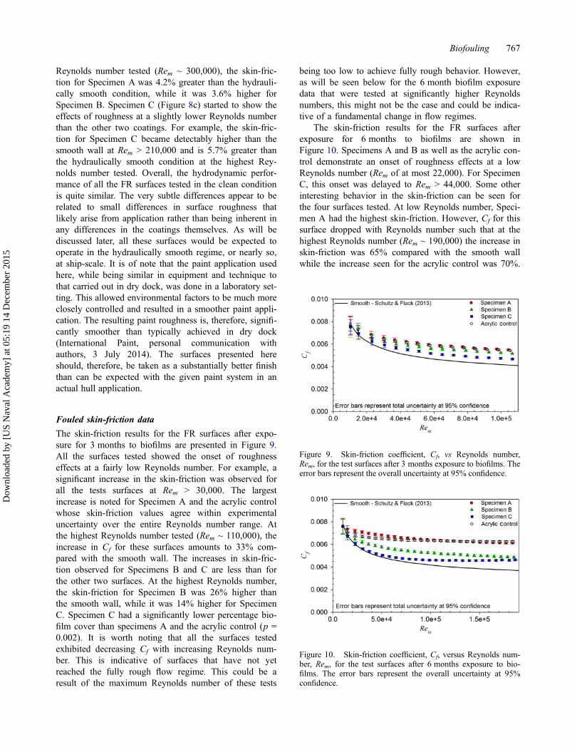
Fouled skin-friction data
The skin-friction results for the FR surfaces after expo-sure for 3 months to biofilms are presented in Figure 9.All the surfaces tested showed the onset of roughnesseffects at a fairly low Reynolds number. For example, asignificant increase in the skin-friction was observed forall the tests surfaces at Rem > 30,000. The largestincrease is noted for Specimen A and the acrylic controlwhose skin-friction values agree within experimentaluncertainty over the entire Reynolds number range. Atthe highest Reynolds number tested (Rem ~ 110,000), theincrease in Cf for these surfaces amounts to 33% com-pared with the smooth wall. The increases in skin-fric-tion observed for Specimens B and C are less than forthe other two surfaces. At the highest Reynolds number,the skin-friction for Specimen B was 26% higher thanthe smooth wall, while it was 14% higher for SpecimenC. Specimen C had a significantly lower percentage bio-film cover than specimens A and the acrylic control (p =0.002). It is worth noting that all the surfaces testedexhibited decreasing Cf with increasing Reynolds num-ber. This is indicative of surfaces that have not yetreached the fully rough flow regime. This could be aresult of the maximum Reynolds number of these tests
being too low to achieve fully rough behavior. However,as will be seen below for the 6 month biofilm exposuredata that were tested at significantly higher Reynoldsnumbers, this might not be the case and could be indica-tive of a fundamental change in flow regimes.
The skin-friction results for the FR surfaces afterexposure for 6 months to biofilms are shown inFigure 10. Specimens A and B as well as the acrylic con-trol demonstrate an onset of roughness effects at a lowReynolds number (Rem of at most 22,000). For SpecimenC, this onset was delayed to Rem > 44,000. Some otherinteresting behavior in the skin-friction can be seen forthe four surfaces tested. At low Reynolds number, Speci-men A had the highest skin-friction. However, Cf for thissurface dropped with Reynolds number such that at thehighest Reynolds number (Rem ~ 190,000) the increase inskin-friction was 65% compared with the smooth wallwhile the increase seen for the acrylic control was 70%.
Figure 10. Skin-friction coefficient, Cf, versus Reynolds num-ber, Rem, for the test surfaces after 6 months exposure to bio-films. The error bars represent the overall uncertainty at 95%confidence.
Figure 9. Skin-friction coefficient, Cf, vs Reynolds number,Rem, for the test surfaces after 3 months exposure to biofilms. Theerror bars represent the overall uncertainty at 95% confidence.
Biofouling 767
Dow
nloa
ded
by [
US
Nav
al A
cade
my]
at 0
5:19
14
Dec
embe
r 20
15
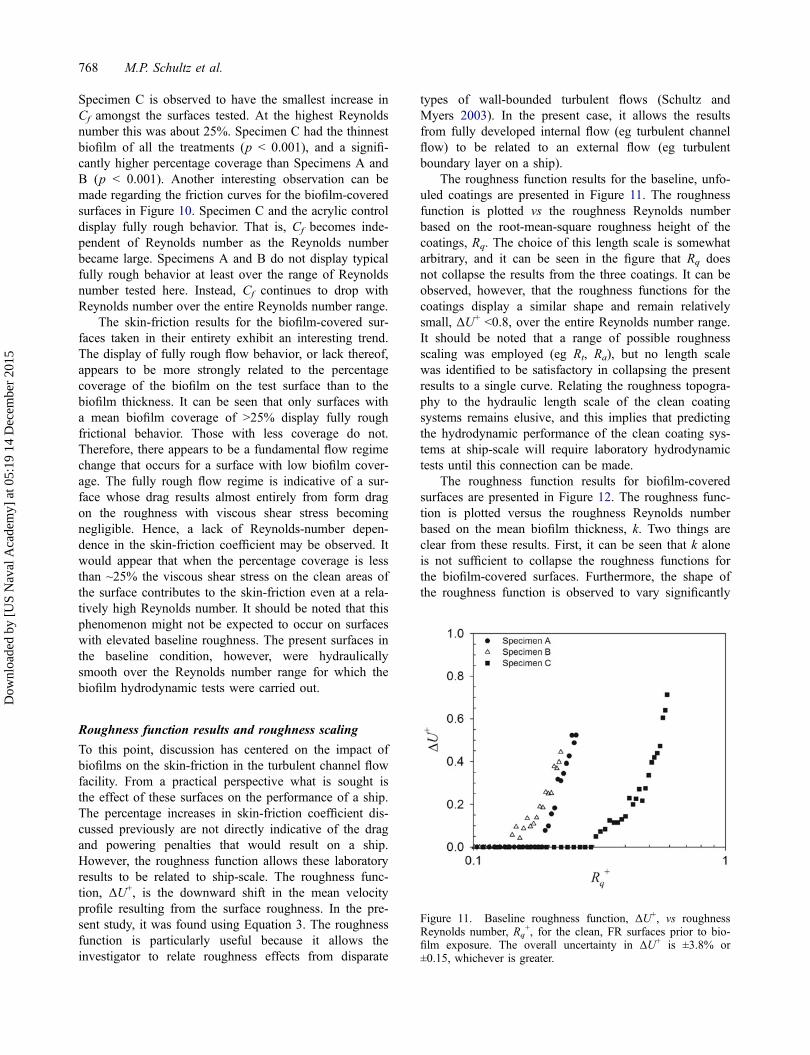
Specimen C is observed to have the smallest increase inCf amongst the surfaces tested. At the highest Reynoldsnumber this was about 25%. Specimen C had the thinnestbiofilm of all the treatments (p < 0.001), and a signifi-cantly higher percentage coverage than Specimens A andB (p < 0.001). Another interesting observation can bemade regarding the friction curves for the biofilm-coveredsurfaces in Figure 10. Specimen C and the acrylic controldisplay fully rough behavior. That is, Cf becomes inde-pendent of Reynolds number as the Reynolds numberbecame large. Specimens A and B do not display typicalfully rough behavior at least over the range of Reynoldsnumber tested here. Instead, Cf continues to drop withReynolds number over the entire Reynolds number range.
The skin-friction results for the biofilm-covered sur-faces taken in their entirety exhibit an interesting trend.The display of fully rough flow behavior, or lack thereof,appears to be more strongly related to the percentagecoverage of the biofilm on the test surface than to thebiofilm thickness. It can be seen that only surfaces witha mean biofilm coverage of >25% display fully roughfrictional behavior. Those with less coverage do not.Therefore, there appears to be a fundamental flow regimechange that occurs for a surface with low biofilm cover-age. The fully rough flow regime is indicative of a sur-face whose drag results almost entirely from form dragon the roughness with viscous shear stress becomingnegligible. Hence, a lack of Reynolds-number depen-dence in the skin-friction coefficient may be observed. Itwould appear that when the percentage coverage is lessthan ~25% the viscous shear stress on the clean areas ofthe surface contributes to the skin-friction even at a rela-tively high Reynolds number. It should be noted that thisphenomenon might not be expected to occur on surfaceswith elevated baseline roughness. The present surfaces inthe baseline condition, however, were hydraulicallysmooth over the Reynolds number range for which thebiofilm hydrodynamic tests were carried out.
Roughness function results and roughness scaling
To this point, discussion has centered on the impact ofbiofilms on the skin-friction in the turbulent channel flowfacility. From a practical perspective what is sought isthe effect of these surfaces on the performance of a ship.The percentage increases in skin-friction coefficient dis-cussed previously are not directly indicative of the dragand powering penalties that would result on a ship.However, the roughness function allows these laboratoryresults to be related to ship-scale. The roughness func-tion, ΔU+, is the downward shift in the mean velocityprofile resulting from the surface roughness. In the pre-sent study, it was found using Equation 3. The roughnessfunction is particularly useful because it allows theinvestigator to relate roughness effects from disparate
types of wall-bounded turbulent flows (Schultz andMyers 2003). In the present case, it allows the resultsfrom fully developed internal flow (eg turbulent channelflow) to be related to an external flow (eg turbulentboundary layer on a ship).
The roughness function results for the baseline, unfo-uled coatings are presented in Figure 11. The roughnessfunction is plotted vs the roughness Reynolds numberbased on the root-mean-square roughness height of thecoatings, Rq. The choice of this length scale is somewhatarbitrary, and it can be seen in the figure that Rq doesnot collapse the results from the three coatings. It can beobserved, however, that the roughness functions for thecoatings display a similar shape and remain relativelysmall, ΔU+ <0.8, over the entire Reynolds number range.It should be noted that a range of possible roughnessscaling was employed (eg Rt, Ra), but no length scalewas identified to be satisfactory in collapsing the presentresults to a single curve. Relating the roughness topogra-phy to the hydraulic length scale of the clean coatingsystems remains elusive, and this implies that predictingthe hydrodynamic performance of the clean coating sys-tems at ship-scale will require laboratory hydrodynamictests until this connection can be made.
The roughness function results for biofilm-coveredsurfaces are presented in Figure 12. The roughness func-tion is plotted versus the roughness Reynolds numberbased on the mean biofilm thickness, k. Two things areclear from these results. First, it can be seen that k aloneis not sufficient to collapse the roughness functions forthe biofilm-covered surfaces. Furthermore, the shape ofthe roughness function is observed to vary significantly
Figure 11. Baseline roughness function, ΔU+, vs roughnessReynolds number, Rq
+, for the clean, FR surfaces prior to bio-film exposure. The overall uncertainty in ΔU+ is ±3.8% or±0.15, whichever is greater.
768 M.P. Schultz et al.
Dow
nloa
ded
by [
US
Nav
al A
cade
my]
at 0
5:19
14
Dec
embe
r 20
15
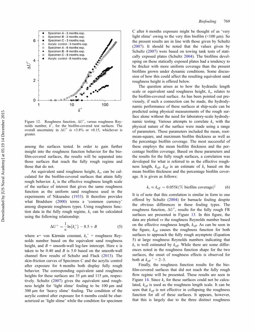
among the surfaces tested. In order to gain furtherinsight into the roughness function behavior for the bio-film-covered surfaces, the results will be separated intothose surfaces that reach the fully rough regime andthose that do not.
An equivalent sand roughness height, ks, can be cal-culated for the biofilm-covered surfaces that attain fullyrough behavior. ks is the effective roughness length scaleof the surface of interest that gives the same roughnessfunction as the uniform sand roughness used in theexperiments of Nikuradse (1933). It therefore provideswhat Bradshaw (2000) terms a ‘common currency’among disparate roughness types. Using roughness func-tion data in the fully rough regime, ks can be calculatedusing the following relationship:
DUþ ¼ 1
jln kþs� �� 8:5þ B (5)
where κ= von Kármán constant, ks+ = roughness Rey-
nolds number based on the equivalent sand roughnessheight, and B = smooth-wall log-law intercept. Here κ istaken to be 0.40 and B is 5.0 based on the smooth-wallchannel flow results of Schultz and Flack (2013). Theskin-friction curves of Specimen C and the acrylic controlafter exposure for 6 months both display fully roughbehavior. The corresponding equivalent sand roughnessheights for these surfaces are 35 μm and 115 μm, respec-tively. Schultz (2007) gives the equivalent sand rough-ness height for ‘light slime’ fouling to be 100 μm and300 μm for ‘heavy slime’ fouling. The condition of theacrylic control after exposure for 6 months could be char-acterized as ‘light slime’ while the condition for specimen
C after 6 months exposure might be thought of as ‘verylight slime’ owing to the very thin biofilm (<100 μm). Sothe present results are in line with those given by Schultz(2007). It should be noted that the values given bySchultz (2007) were based on towing tank tests of stati-cally exposed plates (Schultz 2004). The biofilms devel-oping on these statically exposed plates had a tendency tobe thicker with more uniform coverage than the presentbiofilms grown under dynamic conditions. Some discus-sion of how this could affect the resulting equivalent sandroughness height is offered below.
The question arises as to how the hydraulic lengthscale or equivalent sand roughness height, ks, relates tothe biofilm-covered surface. As has been pointed out pre-viously, if such a connection can be made, the hydrody-namic performance of these surfaces at ship-scale can bepredicted using physical measurements of the rough sur-face alone without the need for laboratory-scale hydrody-namic testing. Various attempts to correlate ks with thephysical nature of the surface were made using a rangeof parameters. These parameters included the mean, root-mean-square, and maximum biofilm thickness as well asthe percentage biofilm coverage. The most successful ofthese employs the mean biofilm thickness and the per-centage biofilm coverage. Based on these parameters andthe results for the fully rough surfaces, a correlation wasdeveloped for what is referred to as the effective rough-ness length, keff. keff is an estimate of ks based on themean biofilm thickness and the percentage biofilm cover-age. It is given as follows:
ks � keff ¼ 0:055k % biofilm coverageð Þ12 (6)
It is of note that this correlation is similar in form to oneoffered by Schultz (2004) for barnacle fouling despitethe obvious differences in these fouling types. Theroughness function, ΔU+, results for the fully rough FRsurfaces are presented in Figure 13. In this figure, thedata are plotted vs the roughness Reynolds number basedon the effective roughness length, keff. As can be seen inthe figure, keff causes the roughness function for bothsurfaces to approach the fully rough asymptote (Equation5) at large roughness Reynolds numbers indicating thatks is well estimated by keff. While there are some differ-ences noted in the roughness function shape for the twosurfaces, the onset of roughness effects is observed forboth at keff
+ = 2–3.Finally, the roughness function results for the bio-
film-covered surfaces that did not reach the fully roughflow regime will be presented. These results are seen inFigure 14. Since ks for these surfaces could not be calcu-lated, keff is used as the roughness length scale. It can beseen that keff is not effective in collapsing the roughnessfunction for all of these surfaces. It appears, however,that this is largely due to the three distinct roughness
Figure 12. Roughness function, ΔU+, versus roughness Rey-nolds number, k+, for the biofilm-covered test surfaces. Theoverall uncertainty in ΔU+ is ±3.8% or ±0.15, whichever isgreater.
Biofouling 769
Dow
nloa
ded
by [
US
Nav
al A
cade
my]
at 0
5:19
14
Dec
embe
r 20
15
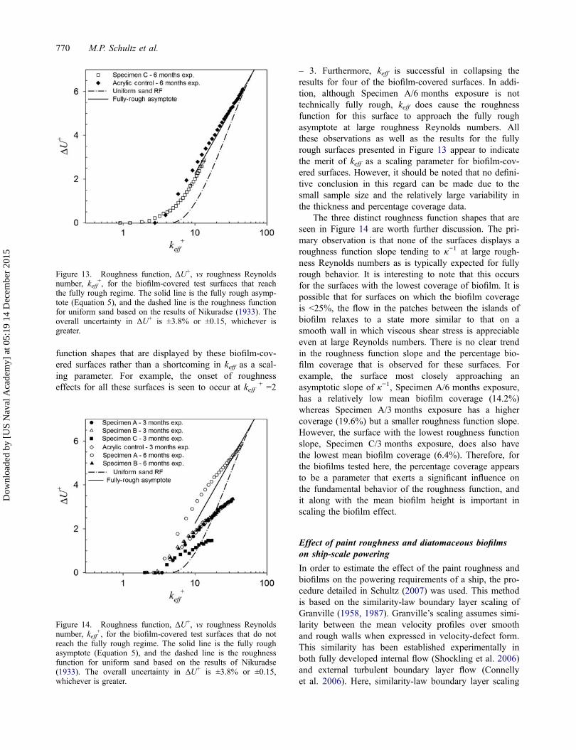
function shapes that are displayed by these biofilm-cov-ered surfaces rather than a shortcoming in keff as a scal-ing parameter. For example, the onset of roughnesseffects for all these surfaces is seen to occur at keff
+ =2
– 3. Furthermore, keff is successful in collapsing theresults for four of the biofilm-covered surfaces. In addi-tion, although Specimen A/6 months exposure is nottechnically fully rough, keff does cause the roughnessfunction for this surface to approach the fully roughasymptote at large roughness Reynolds numbers. Allthese observations as well as the results for the fullyrough surfaces presented in Figure 13 appear to indicatethe merit of keff as a scaling parameter for biofilm-cov-ered surfaces. However, it should be noted that no defini-tive conclusion in this regard can be made due to thesmall sample size and the relatively large variability inthe thickness and percentage coverage data.
The three distinct roughness function shapes that areseen in Figure 14 are worth further discussion. The pri-mary observation is that none of the surfaces displays aroughness function slope tending to κ−1 at large rough-ness Reynolds numbers as is typically expected for fullyrough behavior. It is interesting to note that this occursfor the surfaces with the lowest coverage of biofilm. It ispossible that for surfaces on which the biofilm coverageis <25%, the flow in the patches between the islands ofbiofilm relaxes to a state more similar to that on asmooth wall in which viscous shear stress is appreciableeven at large Reynolds numbers. There is no clear trendin the roughness function slope and the percentage bio-film coverage that is observed for these surfaces. Forexample, the surface most closely approaching anasymptotic slope of κ−1, Specimen A/6 months exposure,has a relatively low mean biofilm coverage (14.2%)whereas Specimen A/3 months exposure has a highercoverage (19.6%) but a smaller roughness function slope.However, the surface with the lowest roughness functionslope, Specimen C/3 months exposure, does also havethe lowest mean biofilm coverage (6.4%). Therefore, forthe biofilms tested here, the percentage coverage appearsto be a parameter that exerts a significant influence onthe fundamental behavior of the roughness function, andit along with the mean biofilm height is important inscaling the biofilm effect.
Effect of paint roughness and diatomaceous biofilmson ship-scale powering
In order to estimate the effect of the paint roughness andbiofilms on the powering requirements of a ship, the pro-cedure detailed in Schultz (2007) was used. This methodis based on the similarity-law boundary layer scaling ofGranville (1958, 1987). Granville’s scaling assumes simi-larity between the mean velocity profiles over smoothand rough walls when expressed in velocity-defect form.This similarity has been established experimentally inboth fully developed internal flow (Shockling et al. 2006)and external turbulent boundary layer flow (Connellyet al. 2006). Here, similarity-law boundary layer scaling
Figure 13. Roughness function, ΔU+, vs roughness Reynoldsnumber, keff
+, for the biofilm-covered test surfaces that reachthe fully rough regime. The solid line is the fully rough asymp-tote (Equation 5), and the dashed line is the roughness functionfor uniform sand based on the results of Nikuradse (1933). Theoverall uncertainty in ΔU+ is ±3.8% or ±0.15, whichever isgreater.
Figure 14. Roughness function, ΔU+, vs roughness Reynoldsnumber, keff
+, for the biofilm-covered test surfaces that do notreach the fully rough regime. The solid line is the fully roughasymptote (Equation 5), and the dashed line is the roughnessfunction for uniform sand based on the results of Nikuradse(1933). The overall uncertainty in ΔU+ is ±3.8% or ±0.15,whichever is greater.
770 M.P. Schultz et al.
Dow
nloa
ded
by [
US
Nav
al A
cade
my]
at 0
5:19
14
Dec
embe
r 20
15
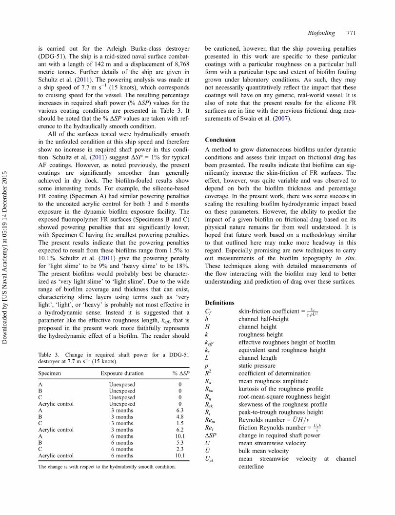
is carried out for the Arleigh Burke-class destroyer(DDG-51). The ship is a mid-sized naval surface combat-ant with a length of 142 m and a displacement of 8,768metric tonnes. Further details of the ship are given inSchultz et al. (2011). The powering analysis was made ata ship speed of 7.7 m s−1 (15 knots), which correspondsto cruising speed for the vessel. The resulting percentageincreases in required shaft power (% ΔSP) values for thevarious coating conditions are presented in Table 3. Itshould be noted that the % ΔSP values are taken with ref-erence to the hydraulically smooth condition.
All of the surfaces tested were hydraulically smoothin the unfouled condition at this ship speed and thereforeshow no increase in required shaft power in this condi-tion. Schultz et al. (2011) suggest ΔSP = 1% for typicalAF coatings. However, as noted previously, the presentcoatings are significantly smoother than generallyachieved in dry dock. The biofilm-fouled results showsome interesting trends. For example, the silicone-basedFR coating (Specimen A) had similar powering penaltiesto the uncoated acrylic control for both 3 and 6 monthsexposure in the dynamic biofilm exposure facility. Theexposed fluoropolymer FR surfaces (Specimens B and C)showed powering penalties that are significantly lower,with Specimen C having the smallest powering penalties.The present results indicate that the powering penaltiesexpected to result from these biofilms range from 1.5% to10.1%. Schultz et al. (2011) give the powering penaltyfor ‘light slime’ to be 9% and ‘heavy slime’ to be 18%.The present biofilms would probably best be character-ized as ‘very light slime’ to ‘light slime’. Due to the widerange of biofilm coverage and thickness that can exist,characterizing slime layers using terms such as ‘verylight’, ‘light’, or ‘heavy’ is probably not most effective ina hydrodynamic sense. Instead it is suggested that aparameter like the effective roughness length, keff, that isproposed in the present work more faithfully representsthe hydrodynamic effect of a biofilm. The reader should
be cautioned, however, that the ship powering penaltiespresented in this work are specific to these particularcoatings with a particular roughness on a particular hullform with a particular type and extent of biofilm foulinggrown under laboratory conditions. As such, they maynot necessarily quantitatively reflect the impact that thesecoatings will have on any generic, real-world vessel. It isalso of note that the present results for the silicone FRsurfaces are in line with the previous frictional drag mea-surements of Swain et al. (2007).
Conclusion
A method to grow diatomaceous biofilms under dynamicconditions and assess their impact on frictional drag hasbeen presented. The results indicate that biofilms can sig-nificantly increase the skin-friction of FR surfaces. Theeffect, however, was quite variable and was observed todepend on both the biofilm thickness and percentagecoverage. In the present work, there was some success inscaling the resulting biofilm hydrodynamic impact basedon these parameters. However, the ability to predict theimpact of a given biofilm on frictional drag based on itsphysical nature remains far from well understood. It ishoped that future work based on a methodology similarto that outlined here may make more headway in thisregard. Especially promising are new techniques to carryout measurements of the biofilm topography in situ.These techniques along with detailed measurements ofthe flow interacting with the biofilm may lead to betterunderstanding and prediction of drag over these surfaces.
DefinitionsCf skin-friction coefficient = sw
12 q �U
2
h channel half-heightH channel heightk roughness heightkeff effective roughness height of biofilmks equivalent sand roughness heightL channel lengthp static pressureR2 coefficient of determinationRa mean roughness amplitudeRku kurtosis of the roughness profileRq root-mean-square roughness heightRsk skewness of the roughness profileRt peak-to-trough roughness heightRem Reynolds number = �UH=mReτ friction Reynolds number = Ush
mΔSP change in required shaft powerU mean streamwise velocity�U bulk mean velocityUcl mean streamwise velocity at channel
centerline
Table 3. Change in required shaft power for a DDG-51destroyer at 7.7 m s−1 (15 knots).
Specimen Exposure duration % ΔSP
A Unexposed 0B Unexposed 0C Unexposed 0Acrylic control Unexposed 0A 3 months 6.3B 3 months 4.8C 3 months 1.5Acrylic control 3 months 6.2A 6 months 10.1B 6 months 5.3C 6 months 2.3Acrylic control 6 months 10.1
The change is with respect to the hydraulically smooth condition.
Biofouling 771
Dow
nloa
ded
by [
US
Nav
al A
cade
my]
at 0
5:19
14
Dec
embe
r 20
15
Uτ friction velocity =ffiffiffiffiswq
qΔU+ roughness function = �Uþ
S � �UþR ¼
ffiffiffiffiffi2CfS
q�ffiffiffiffiffi
2CfR
qW channel widthx streamwise directiony wall-normal directionα statistical significance levelκ von Karman constantν kinematic viscosityr fluid densityτw wall shear stressSuperscripts+ normalized by Uτ or V/Uτ
Subscriptsr rough walls smooth wall
AcknowledgementsThanks go to International Paint (IP) for applying the coatingstested in this study. The authors are especially indebted toBarry Kidd, Harry Joyce, Jennifer Longyear, and Phil Stensonfrom IP who provided significant technical assistance. Kelli andTravis Hunsucker from Geoff Swain’s research group at theFlorida Institute of Technology Center for Corrosion wereinstrumental in setting up the dynamic biofilm facility, and forthat the authors are extremely grateful. They would also like tothank Brandon Stanley and Joe Dillard at USNA for fabricatingthe test plates. Technical support for the tests was provided byDon Bunker, Dan Rhodes, and Bill Beaver of the USNAHydromechanics Laboratory.
Disclosure statementNo potential conflict of interest was reported by the authors.
FundingThe authors gratefully acknowledge the financial support of thisresearch by the Office of Naval Research [ONR Award #N00014-13-WX-2-0747]. The work was also supported by anAustralian Fulbright Scholarship for JMW.
ReferencesAntonia RA, Luxton RE. 1971. The response of a turbulent
boundary layer to a step change in surface roughness. Part1. Smooth to rough. J Fluid Mech. 48:721–761.
Benson JM, Ebert JW, Beery TD. 1938. Investigation in theNACA tank of the effect of immersion in salt water on theresistance of plates coated with different shipbottom paints.NACA Memorandum Report C&R C-S19-1(3).
Bradshaw P. 2000. A note on “critical roughness height” and“transitional roughness”. Phys Fluids. 12:1611–1614.
Callow ME. 1986. Fouling algae from ‘in-service’ ships. BotMar. 29:351–357.
Candries M, Atlar M, Mesbahi E, Pazouki K. 2003. The mea-surement of the drag characteristics of tin-free self-polishing
co-polymers and fouling release coatings using a rotor appa-ratus. Biofouling. 19:27–36.
Cassé F, Swain GW. 2006. The development of microfouling onfour commercial antifouling coatings under static anddynamic immersion. Int Biodeterior Biodegrad. 57:179–185.
Coleman HW, Steele WG. 1995. Engineering application ofexperimental uncertainty analysis. AIAA J. 33:1888–1896.
Connelly JS, Schultz MP, Flack KA. 2006. Velocity-defect scal-ing for turbulent boundary layers with a range of relativeroughness. Exp Fluids. 40:188–195.
Finnie AA, Williams DN. 2010. Paint and coatings technologyfor the control of marine fouling. In: Dürr S, Thomason JC,editors. Biofouling. Oxford: Wiley-Blackwell; p. 185–206.
Granville PS. 1958. The frictional resistance and turbulentboundary layer of rough surfaces. J Ship Res. 2:52–74.
Granville PS. 1987. Three indirect methods for the drag charac-terization of arbitrarily rough surface on flat plates. J ShipRes. 31:70–77.
Guillard RR, Ryther JH. 1962. Studies on marine planktonicdiatoms. 1. Cyclotella nana Hustedt and Detonula confer-vacea (Cleve). Can J Microbiol. 8:229–239.
Haslbeck EG, Bohlander G. 1992. Microbial biofilm effects ondrag - lab and field. In: Proceedings of the SNAME ShipProduction Symposium. Paper No. 3A-1. Jersey City, NJ:SNAME; 7p.
Holland R, Dugdale TM, Wetherbee R, Brennan AB, Finlay JA,Callow JA, Callow ME. 2004. Adhesion and motility of foul-ing diatoms on a silicone elastomer. Biofouling. 20:323–329.
Hong J, Katz J, Schultz MP. 2011. Near-wall turbulence statis-tics and flow structures over three-dimensional roughnessin a turbulent channel flow. J Fluid Mech. 667:1–37.
Howell D, Behrends B. 2006. A review of surface roughnessin antifouling coatings illustrating the importance of cutofflength. Biofouling. 22:401–410.
Hoyas S, Jimenez J. 2006. Scaling of the velocity fluctuationsin turbulent channels up to Ret = 2003. Phys Fluids 18:Article # 011702.
Hunsucker KZ, Koka A, Lund G, Swain GW. 2014. Diatomcommunity structure on in-service cruise ship hulls.Biofouling. 30:1133–1140.
Kempf G. 1937. On the effect of roughness on the resistanceof ships. Trans INA. 79:109–119.
Leer-Andersen M, Larsson L. 2003. An experimental/numericalapproach for evaluating skin friction on full-scale shipswith surface roughness. J Mar Sci Technol. 8:26–36.
Lewthwaite JC, Molland AF, Thomas KW. 1985. An investiga-tion into the variation of ship skin frictional resistance withfouling. Trans R Inst Naval Archit. 127:269–284.
McEntee W. 1915. Variation of frictional resistance of shipswith condition of wetted surface. Trans SNAME. 24:37–42.
Moffat RJ. 1988. Describing the uncertainties in experimentalresults. Exp Therm Fluid Sci. 1:3–17.
Muthukrishnan T, Abed RM, Dobretsov S, Kidd B, Finnie AA.2014. Long-term microfouling on commercial biocidal foul-ing control coatings. Biofouling. 30:1155–1164.
Nikuradse J. 1933. Laws of flow in rough pipes. NACA TechnMemorandum 1292.
Schultz MP. 2004. Frictional resistance of antifouling coatingsystems. ASME J Fluids Eng. 126:1039–1047.
Schultz MP. 2007. Effects of coating roughness and biofoulingon ship resistance and powering. Biofouling. 23:331–341.
Schultz MP, Flack KA. 2007. The rough-wall turbulent bound-ary layer from the hydraulically smooth to the fully roughregime. J Fluid Mech. 580:381–405.
772 M.P. Schultz et al.
Dow
nloa
ded
by [
US
Nav
al A
cade
my]
at 0
5:19
14
Dec
embe
r 20
15
Schultz MP, Flack KA. 2013. Reynolds-number scaling of tur-bulent channel flow. Phys Fluids 25:Article #025104.
Schultz MP, Myers A. 2003. Comparison of three roughnessfunction determination methods. Exp Fluids. 35:372–379.
Schultz MP, Swain GW. 1999. The effect of biofilms on turbu-lent boundary layers. ASME J Fluids Eng. 121:733–746.
Schultz MP, Bendick JA, Holm ER, Hertel WM. 2011. Economicimpact of biofouling on a naval surface ship. Biofouling.27:87–98.
Shockling MA, Allen JJ, Smits AJ. 2006. Roughness effects inturbulent pipe flow. J Fluid Mech. 564:267–285.
Swain G, Kovach B, Touzot A, Casse F, Kavanagh CJ. 2007.Measuring the performance of today’s antifouling coatings.J Ship Prod. 23:164–171.
Townsin RL. 2003. The ship hull fouling penalty. Biofouling.19:9–15.
Van Mooy BAS, Hmelo LR, Fredricks HF, Ossolinski JE, PedlerBE, Bogorff J, Smith PJS. 2014. Quantitative exploration ofthe contribution of settlement, growth, dispersal and grazingto the accumulation of natural marine biofilms on antifoulingand fouling-release coatings. Biofouling. 30:223–236.
Watanabe S, Nagamatsu N, Yokoo K, Kawakami Y. 1969. Theaugmentation in frictional resistance due to slime. J KansaiSoc Naval Archit. 131:45–53.
Woods DC, Fletcher RL, Jones EBG. 1986. Diatom fouling ofin-service shipping with particular reference to the influ-ence of hydrodynamic forces. In: Round FE, editor. Pro-ceedings of the ninth international diatom symposium.Bristol: Biopress; p. 49–59.
Zargiel KA, Swain GW. 2014. Static vs dynamic settlementand adhesion of diatoms to ship hull coatings. Biofouling.30:115–129.
Biofouling 773
Dow
nloa
ded
by [
US
Nav
al A
cade
my]
at 0
5:19
14
Dec
embe
r 20
15