impact damage detection in composite materials of ... · impact damage detection in composite...
TRANSCRIPT

1
IMPACT DAMAGE DETECTION IN COMPOSITE MATERIALS OF
AIRCRAFTS BY OPTICAL FIBRE SENSORS
Ioannis PITROPAKIS, Helge PFEIFFER and Martine WEVERS
Katholieke Universiteit Leuven
Material Performance and Non-destructive Testing
Department of Metallurgy and Materials Engineering (MTM)
Kasteelpark Arenberg 44
Bus 2450
3001 Leuven - BELGIUM
0032/16/32 12 34 (Tel)
0032/16/32 12 54 (Tel)
0032/16/32 19 90 (Fax)
1. INTRODUCTION
The safe use of aircrafts can only be guaranteed when appropriate damage assessment is available. The
last years, interest in structural health monitoring systems for composite materials of the aircrafts
based on optical fibre sensors is increasing. Structural health monitoring (SHM) is the automated
damage detection in engineering structures by sensor networks. Since the last two decades, the
literature on SHM is exponentially growing [1]. After basic and applied research, some applications
came to the market and nowadays, they are on the way to be a standard in engineering structures, such
as chemical plants, oil pipelines and bridges [2]. The applications of SHM in aircraft industry such as
in airplanes and in helicopters are however, still in an experimental phase. There are different reasons
for this:
• Lack of technical maturity
o Solutions proposed so far only solved isolated problems of an otherwise complex
system
o Difficulties to match all natural environmental conditions
o Measured data are difficult to interpret due to the complex nature of aircraft parts
• Lack of acceptance by end-users
o Complicated and long-term certification process expected
o Scepticism against new technologies
o Pessimistic expectations concerning the return-of-investment
The lack of acceptance by end-users can be overcome by convincing technical solutions that respond
to all the challenges inherent to aircraft operations. The major problem already mentioned in the list
above is the difficult interpretation of measured data obtained in complex aircraft components.

2
One possibility to detect “barely visible impact damage (BVID)” after impact in aircraft materials is
non-destructive testing (NDT) using ultrasound [3]. The ultrasonic waves are usually excited and
received by piezoceramic sensors. Modern SHM applications intend to use optical fibres as receiving
elements. There are in general many reasons why the application of optical methods for acoustic
sensing is more advantageous compared to the widespread use of traditional piezoceramics. Optical
fibres are relatively insensitive to electromagnetic interferences, they can work as line-integrating
sensors and they are very small. The most frequently applied optical fibre technology in SHM research
based on Fibre Bragg Gratings (FBG) for e.g. monitoring the strain in civil infrastructures [4]. For
many other technologies, such as the Fabry-Perot Interferometer, or micro-bend sensors, the single-
mode fibre in a polarimetric set-up is the most promising method. However, the studies performed so
far are relatively limited, and this is in contrast to the high potential that emerges from this technology.
Additional efforts have to be made so that the basics of this technology are fully explored (stable
baseline conditions, advanced data analysis, adaption for aircraft operations).
In order to find damage in aircrafts components, we need a physically-based interaction of appropriate
gauges with that respective component under investigation. In plate-like structures frequently present
in aircraft, ultrasonic Lamb waves are interesting candidates for such an interaction. Lamb waves are
essentially acoustic waves, but they differ from classic bulk waves in their propagation properties:
o Lamb waves propagate in plate-like structures
o Lamb waves can propagate over long ranges (up to tens or even hundreds of metres)
and they are therefore well-suited for global and long range inspections
Is has been shown in the past that optical fibre sensors can be used to detect acoustic emission [3, 4].
Furthermore, optical fibre sensors can monitor large areas without the need to cover the structure with
an enormous amount of sensors. Single mode (SM) fibres are also cheap, highly specialised expensive
equipment can be avoided and they are insensitive to electromagnetic interferences. In previous
studies, they have already been used successfully to monitor impact damage in helicopter tail-boom
using active ultrasonic excitation [4-6].
2 MATERIALS AND METHODS
In this study the in-situ detection of impact using the polarimetric approach is presented. The extent of
damage can approximately be derived from appropriate parameters of the acoustic signals. The
principle of detection can be described as follows. By means of a stabilised laser source (wavelength
1310 nm) polarised light (continuous-wave) is propagating through the core of the optical fibre. When
not subjected to external influences, the material is approximately isotropic and two linear orthogonal
modes propagate through the Single Mode (SM) fibre at the same velocity. However, when Lamb
waves arising from an impact interact with the fibre, the material becomes more anisotropic. The
periodic ultrasonic pressure on the fibre thus alternates the refractive indices, causing the two
polarization modes to travel at different velocities causing a resulting phase shift. When both modes
have passed a polarisation filter, the signal can be read out by a light diode.

3
Source OscAmpSensor
Figure 1 Simplified scheme for detection of impact in a polarimetric set-up
Figure 1 shows the principal set-up that is used for the detection of impact on flat lab-scale specimens.
Such as mentioned above, in contrast to the studies previously published, no active ultrasonic source
was applied but the impact was directly measured in-situ. This will have consequences for the sound
propagation to be expected because a broad acoustic frequency spectrum will be excited with
individual time-dependent behaviour. The polarisation was measured and controlled by an AGILENT
polarisation analyser/controller (N7788B-400). It has to be mentioned that for almost all impact tests,
the impact energy was non-destructive.
The laboratory-scale parts are made of carbon-fibre reinforced epoxy (CFRE) composites. On the
plate, two different optical fibres were attached by appropriate adhesives: a Single-Mode optical fibre
and a Single-Mode Polarization-Maintenance optical fibre, as well as piezoelectric patches that served
as a reference. Figure 2 shows the impact-testing set-up that is designed to introduce a non-destructive
low-velocity impact in the CFRE plates. An impactor with specified weight was allowed to fall from a
pre-determined height to strike the test specimen supported on a horizontal plate.

4
Figure 2 Impact testing set-up
For the feasibility test on a helicopter composite tail boom, a SMARTape® optical fibre sensor was
used to simplify the handling of the fragile and brittle optical fibres during the sample preparation. It is
manufactured by the company SMARTEC from Manno, Switzerland. It is a PPS/glass fibre composite
tape with an embedded optical fibre. This thermoplastic composite tape also protects the optical fibre
from external mechanical or chemical influences which could possibly damage the optical sensor in
service.
1. Single Mode Fibre
2. Polarization Maintenance
Fibre
3. Piezoelectric Patch
Tube: cm scale
Sphere: 18.9gr

5
3. RESULTS AND DISCUSSION
3.1. CARBON-FIBRE REINFORCED EPOXY (CFRE) PLATE
Due to the impact from the metallic sphere, impact-generated vibration signals were recorded. The
initial height of the impactor (metallic sphere) was 10 cm, and the signals received from each sensor
can be seen in Figure 3. There is a clear difference between the signals obtained by the two types of
optical fibres, the single-mode and the polarization-maintenance optical fibre, and the piezoelectric
patch.
Figure 3 Vibration signals from impact at 10 cm: From PZT (left), from SM fibre (centre), from PM fibre (right)
These tests show the extraordinary sensitivity of single-mode fibres in the polarimetric set-up which is
caused by the change of the polarisation state as a result of the external pressure waves. PM-SM fibres
can also be used to detect impact, but the signal-noise ratio is clearly better in the case of single-mode
fibres. The signal of the PM fibre is similar to the SM fibre when the SM fibre is used without a
polarisation filter. This shows that the signal at PM-SM fibres and of SM fibres without polarisation
filters just arises from intensity modulation due to effects like micro-bending.
Figure 4 below shows the impact-generated vibration signal detected by the single-mode optical fibre
by when the metallic sphere is dropped from a height of 6 and 10cm respectively. It is clear the more
intense the impact, the higher the amplitude of the optical signal.
Piezoelectric Sensor Single Mode Fibre Polarization Maintenance Fibre Single Mode Fibre Piezoelectric Sensor Single Mode Fibre Piezoelectric Sensor Single Mode Fibre Piezoelectric Sensor Single Mode Fibre Piezoelectric Sensor Single Mode Fibre

6
Figure 4 Impact test from distances 6 and 10 cm and signal received from the Single Mode Optical Fiber
3.2. EC-135 TAIL-BOOM
A demonstrator part from a Eurocopter’s EC 135 Tail-Boom is used for the comparison of the
detection capabilities between optical fibres and piezoceramic transducers [5, 6]. For the detection of
the generated acoustic waves by the SMARTape fibre is used which is glued on that respective part
(see Figure 5).
Figure 5 Part of EC-135 Tail-boom (left), Piezoelectric patch & SMARTape (right)
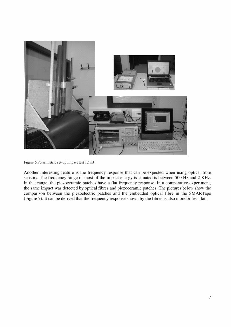
The next Figure 6 shows the set-up used for the experiments.
7
Figure 6 Polarimetric set-up Impact test 12 mJ
Another interesting feature is the frequency response that can be expected when using optical fibre
sensors. The frequency range of most of the impact energy is situated is between 500 Hz and 2 KHz.
In that range, the piezoceramic patches have a flat frequency response. In a comparative experiment,
the same impact was detected by optical fibres and piezoceramic patches. The pictures below show the
comparison between the piezoelectric patches and the embedded optical fibre in the SMARTape
(Figure 7). It can be derived that the frequency response shown by the fibres is also more or less flat.

8
Figure 7 Acoustic emission waveforms (2
nd burst is an echo) and frequency distribution recorded by piezoelectric crystals
(PZT) and by optical fibres, obtained from impact in monolithic carbon fibre reinforced epoxy plates
Finally, one can conclude that piezoceramic patches and optical fibre sensors show similar response to
impact in such model situations, this especially holds for the signal to noise ratio. However, there are
also some inherent differences that need attention if further waveform analysis is intended. Optical
fibre sensors of this type are line integrating sensors and piezoceramic patches are point sensors [7].
When the sensing area of the optical fibre is clearly larger than some wavelengths, the signal obtained
by fibre sensor shows differences with respect to a point sensor.
This phenomenon can be understood if one considers the optical fibre as a kind of acoustic
interferometer. Signals arriving from the acoustic source arrive at the fibre at different times (time-of-
flight), according to their increasing distance from the source. The detector itself measures all
incoming signals, thus adding-up all the incoming waves (see also [8]). Depending on the respective
amplitude and phase shift, a resulting waveform will be measured. Furthermore, the sensitivity for the
detection of the Lamb modes, S0 and A0 depends on the polarisation of the light propagating in the
sensing fibre [9]. Lamb mode selection could therefore be achieved by corresponding polarizer
settings.

9
3.3 POLARIZATION CONTROL OF OPTICAL FIBRES
In the literature it has already been recognised that the polarisation of the light modes in the single-
mode optical fibre has an influence on the sensitivity of the specific Lamb modes detected [9].
Therefore, a big series of impact tests was performed at different polarisations.
The results below show the waveforms and the corresponding RMS values for different polarisation
angles (Figure 8).
Figure 8 Screenshot of the polarisation controller
-50 0 50 100 150 200 250 300 350 400
50
100
150
200
250
300
RM
S (m
V)
Angle (°)
Figure 9 Detected RMS according to constant non-destructive impact
conditions as a function of the polarisation (12 mJ), the data were fitted by a
sinusoidal function.
These results also show that the polarisation should be controlled when the instrument is used for
damage detection. Otherwise, the amplitude could be underestimated with a factor of more than 3.

10
2.4 IMPACT ENERGY AND ACOUSTIC RESPONSE
The relationship between the impact energy and RMS values measured was determined for different
impact energies and set-ups. The RMS values show for all cases investigated a square-root behaviour
versus the initial impact energy (see Figure 10). At the moment, models on impact energies are
analysed to account for this behaviour. Interestingly, this behaviour only holds for non-destructive
impact. If the impact energies are higher, additional energy is consumed for the structural destruction
of the material resulting in an acoustic energy lower than expected according to the square-root law. A
deviation from this square root law thus directly shows when destructive processes occur.
0 5 10 15 20 25 30
0
100
200
300
400
500
Data
Fit
RM
S (
mV
)
Height (cm)
Figure 10 RMS value of acoustic waves versus non-destructive impact energy, the fit-
curve is modelled by a simple square-root law.
2.5 EXAMPLE OF FINAL IMPLEMENTATION SOFTWARE
The following picture shows a screenshot of a Labview illustrating an example for a possible steering
programme for an impact detection system that shows essential features of a final impact detection
system (Figure 11). Using a dedicated set-up, two different thresholds can be defined, such as the
height of the impact pulse and the energy content. If an impact of certain intensity occurs, a alarm
signal is given. Impacts from hazardous external parameters such as birds etc., that can hit an aircraft’s
critical part during flight, can be instantly be monitored by the optical sensors and give a direct signal
on the material condition.

11
Figure 11 Screenshot of a Labview-programme showing essential features of an impact detection
system, such as localisation and the range of impact energy
This limited study could show that optical fibres in the polarimetric set-up are appropriate sensors for
the in-situ monitoring of impact. When compared with the conventional piezoceramic patches, the
performance when regarding the signal-to-noise ratio is similar.
ACKNOWLEDGEMENTS
The research leading to these results has received funding from the European Community's Seventh
Framework Programme [FP7/2007-2013] under grant agreement n°212912 (Project: Aircraft
Integrated Structural Health Assessment II - AISHA II). A special thank to Johan Vanhulst (KU
Leuven) for the technical support.
3. REFERENCES
[1] H. Pfeiffer and M. Wevers. Aircraft Integrated Structural Health Assessment – Structural
Health Monitoring and its implementation within the European project AISHA in EU Project
Meeting on Aircraft Integrated Structural Health Assessment (AISHA), Vol. 13 (10),
www.ndt.net, Leuven, Belgium 2008.
[2] C. Boller, F.K. Chang and Y. Fujino, Encyclopedia of Structural Health Monitoring, Wiley
2009.

12
[3] M. Wevers, L. Rippert and S. Van Huffel, Optical fibres for in situ monitoring the damage
development in composites and the relation with acoustic emission measurements Journal of
Acoustic Emission 18 (2000) 41-50.
[4] S. Vandenplas, J.M. Papy, M. Wevers and S. Van Huffel, Acoustic emission monitoring using
a multimode optical fibre sensor Insight 46 (2004) 203-209.
[5] M. Ercsey-Ravasz, F. Fransens, H. Pfeiffer, G. Monavon, C. Korosec, W. Hillger, S. Van
Huffel and M. Wevers. Structural Health Monitoring of a helicopter tail boom using Lamb
waves – Advanced data analysis of results obtained with integrated optical fibre sensing
technology in EU Project Meeting on Aircraft Integrated Structural Health Assessment
(AISHA), Vol. 13 (10), www.ndt.net, Leuven, Belgium 2008.
[6] M. Wevers and F. Fransens. Ultrasonic Lamb wave inspection of aircraft components using
integrated optical fibre sensing technology Proc. of the in European Conference of non-
destructive testing, Berlin 2006.
[7] G. Thursby, B. Sorazu, D. Betz, W. Staszewski and B. Culshaw. Comparison of point and
integrated fiber optic sensing techniques for ultrasound detection and location of damage.
Smart Mater Struct. 13 (2004) Vol. 5384, 287-295.
[8] P. Burgholzer, C. Hofer, G. Paltauf, M. Haltmeier and O. Scherzer, Thermoacoustic
tomography with integrating area and line detectors IEEE Trans. Ultrason. Ferroelectr. Freq.
Control 52 (2005) 1577-1583.
[9] G. Thursby, B. Sorazu, F. Dong and B. Culshaw, Damage Detection in Structural Materials
using Polarimetric Fibre Optic Sensors Smart Structures and Materials, Proceedings of SPIE
5050 (2003) 61-70.