image restoration using multiresolution texture …wolberg/capstone/inpainting/...image restoration...
TRANSCRIPT

Image Restoration using Multiresolution Texture Synthesis and Image Inpainting
Hitoshi Yamauchi, J̈org Haber, and Hans-Peter Seidel
Max-Planck-Institut f̈ur Informatik, Saarbr̈ucken, GermanyE-mail: {hitoshi,haberj,hpseidel}@mpi-sb.mpg.de
Abstract
We present a new method for the restoration of digitizedphotographs. Restoration in this context refers to removalof image defects such as scratches and blotches as well asto removal of disturbing objects as, for instance, subtitles,logos, wires, and microphones.
Our method combines techniques from texture synthesisand image inpainting, bridging the gap between these twoapproaches that have recently attracted strong research in-terest. Combining image inpainting and texture synthesis ina multiresolution approach gives us the best of both worldsand enables us to overcome the limitations of each of thoseindividual approaches.
The restored images obtained with our method look plau-sible in general and surprisingly good in some cases. Thisis demonstrated for a variety of input images that exhibitdifferent kinds of defects.
Keywords: multiresolution texture synthesis, image in-painting, image restoration, frequency decomposition
1 Introduction and Related Work
Today, digital photo cameras have established them-selves on both consumer and professional markets. Apartfrom the immediate availability of photos for viewingand/or electronic transfer to an editorial office, digital cam-eras have the big advantage of producing electronic imagesthat can easily be stored and copied without loss of qualityfor the next decades to come. Although these advantagesmay sound great, one has to consider that the number ofanalog camera sales worldwide each year is still a multi-ple of the number of corresponding digital camera sales:the quality and resolution of analog images is still hard toachieve even for high-end (and high-price) digital cameras.
As a result, the amount of analog images that have to bedigitized in order to “live forever” is still growing. In addi-tion, many photographs from the pre-digital era still need tobe digitized to prevent them from decay. Unfortunately, thismaterial often exhibits defects such as scratches or blotches.
Equally disturbing artifacts are, for instance, subtitles, lo-gos, and physical objects such as wires and microphones,which should be removed from the image. Obviously, it isdesirable to remove defects or disturbing objects in a fullyautomatic way. Such automatism would include detectionof the image regions to be repaired as well. Although anautomatic detection should be possible for obvious defects,the detection of unwanted objects is a completely subjec-tive process that cannot be performed without user interac-tion. Due to this restriction, and to avoid going beyond thescope of this paper, we do not address automatic detectionhere. For the special case of image sequences, detection andrestoration of image defects has been addressed in [14].
In this paper we present a new method to automati-cally repair “damaged” areas of digitized photographs. Ourmethod performs a frequency decomposition of the inputimage to combine techniques and ideas from two differentareas of research:texture synthesisandimage inpainting.
Recently, texture synthesis [9, 19] has become an ac-tive area of research. The common idea of all texture syn-thesis approaches is to create a new texture from a (typ-ically small) initial seed texture such that the appearance(i.e. structure and color) of the synthesized texture resem-bles the sample texture. Early approaches employed imagepyramids and histogram matching to create two- or three-dimensional textures from a 2-D sample image [11], or syn-thesized textures by sampling successive spatial frequencybands from an input texture, which has been decomposedusing a Laplacian pyramid [7]. Texture synthesis based onstatistical measurements of the seed image and its waveletdecomposition has been proposed in [17]. The approachpresented in [10] is based on the original work in [9] andintroduces a scheme to select the order of pixels that aresynthesized. Recent publications focus on texture synthesison surfaces [20, 18, 21], texture synthesis for “natural tex-tures” [2], real-time texture synthesis [15, 22], or on texturetransfer [8, 12].
In principle, texture synthesis techniques could be em-ployed to repair digitized photographs, see also Figure 1.Especially if a damaged area needs to be filled with somepattern or structure, texture synthesis does a good job —

input image texture synthesis [19] image inpainting [16] our method
Figure 1. Comparison between texture synthesis, image inpainting, and our method for input imageswith texture (top row) and with texture and additional intensity gradient (bottom row). Each row leftto right: input image (damaged areas are masked out); resulting images from texture synthesis [19],from image inpainting [16], and from our new method.
given that the sample area in the same image is largeenough. However, texture synthesis usually fails, if the areato be reconstructed contains an additional color or intensitygradient as it is shown in Figure 1 (bottom row).
Image inpainting techniques are, in a way, complemen-tary to texture synthesis. Pioneered by Bertalmioet al. [3],approaches have been presented that propagate informa-tion from the surroundings of masked areas into their in-terior. Unlike texture synthesis, image inpainting handlescolor/intensity gradients correctly, but fails to reconstructareas that should contain textures with fine detail. Theapproach presented in [3] is based on PDEs. Informa-tion from the environment of masked areas is propagatedalong isophotes, which are computed to be perpendicularto the discretized gradient vector for each pixel along theinpainting contour. A 2-D Laplacian is used to estimatecolor/intensity variation and propagates this variation alongthe isophote direction. Anisotropic diffusion iterations arerun from time to time to smooth the inpainted region. Tospeed up the computation time of this approach, an isotropicdiffusion model with user-defined diffusion barriers hasbeen proposed in [16]. The mathematical background ofimage inpainting has been thoroughly investigated in [6, 5].
The only approach we are aware of that can handle bothtexture and intensity variation for image restoration hasbeen presented by Hirani and Totsuka [13]. Their algorithmis based on projections onto convex sets and employs a
Fourier transform together with a clipping procedure, whichare carried out alternatively for a user-defined number of it-erations. In addition to the damaged area, the user mustinteractively select a sample region, which is needed to re-pair the damaged area. The sample region is restricted tobe a translated version of the defective region w.r.t. its tex-ture. Different intensities of sample and defective region aretaken care of automatically.
2 Overview of our Method
As it is mentioned in the introduction, we do not addressautomatic detection of damaged image regions in this paperfor several reasons. Thus, we require the user to provide abinary maskM that identifies the image regions to be re-constructed. We assume this mask to be of equal size as theinput imageI, i.e. for each pixel inI we have a correspond-ing binary value inM . Yet, we do not require that the maskis given in pixel precision: damaged areas inI may be cov-ered generously inM . If, however, the masked area inM ismuch larger than the actual damaged area inI, unnecessarydegradation of the resulting image quality may occur.
Our algorithm proceeds as follows (cf. also Figure 2):
1. The input imageI is decomposed into a high-frequency partH and a low-frequency partL using adiscrete cosine transformation (DCT) (cf. Section 3.1).

2. The fast image inpainting algorithm proposed in [16]is applied to the interior of the masked areas of thelow-frequency imageL to obtain the inpainted imageL∗. During this step, information from the whole inputimage may be used by the image inpainting algorithm.However, only the pixels inside the masked areas willbe modified.
3. The high-frequency imageH is decomposed into aGaussian pyramid withn+1 levelsHi (i = 0, . . . , n).Section 3.2 provides some more details about this step.
4. Starting from the highest levelHn, we apply multires-olution texture synthesis [19] inside the masked areasin Hi (i = n, . . . , 0):
4.1. First, akD-tree for fast nearest neighbor look-up is built [1]. However, the search space fortexture synthesis in levelHi does not only con-tain the non-masked areas ofHi, but additionallyincludes the corresponding areas of the alreadysynthesized higher levelsH∗
k (k = i+1, . . . , n).To obtain the seed image for the highest levelHn,we simply apply the complementary maskMn toHn.
4.2. Texture synthesis is applied inside the maskedarea ofHi. Theneighborhood vector(cf. [19]),which is used to perform a look-up in thekD-tree, is composed of the pixel information fromthe texture synthesis kernel in levelHi and ofall corresponding kernels from the higher levelsH∗
k (k = i+1, . . . , n). This ensures high co-herency among all texture synthesis levels.
More details about this texture synthesis step are givenin Section 3.3.
5. The synthesized high-frequency imageH∗0 and the in-
painted low-frequency imageL∗ are summed up toyield I∗, which represents the restored version of theinput imageI.
Details of our implementation are given in the followingSection 3. Figure 3 shows some of the intermediate levelsof our algorithm for a sample input image.
3 Implementation Details
3.1 Frequency Decomposition
In the first step of our algorithm, the input imageI isdecomposed into a set of spectral sub-bands using a dis-crete cosine transform (DCT). Next, we select the firstκsub-bands and compute the inverse DCT of this subset. Theresulting image is used as the low-frequency imageLκ.
H 0
H*0 L *
I *
H*1
H 1
H*2
H 2
=I H L+
Figure 2. Overview of our method. Top to bot-tom: the input image I is decomposed into ahigh-frequency image H and a low-frequencyimage L using a DCT. Image inpainting is ap-plied to the low-frequency part L to obtain theinpainted image L∗. The high-frequency partH is decomposed into a Gaussian pyramid(shown up to level 2 in this example). Startingfrom the highest level ( H2), multiresolutiontexture synthesis is applied to the maskedareas of the levels Hi. For each level, theneighborhood vector for the texture synthe-sis (cf. [19]) is composed of the kernels of thatlevel and of all higher levels. In this way, co-herency is maintained throughout all texturesynthesis levels. Finally, the resulting high-frequency image H∗
0 and the low-frequencyimage L∗ are summed up to yield the restoredimage I∗.

I L∗ H0,H1 H∗0 ,H∗
1
Figure 3. Multiresolution texture synthesis. Left to right: input image I; inpainted low-frequencyimage L∗; two levels ( H0,H1) of the Gaussian decomposition of the high-frequency image H; thesame two levels after texture synthesis ( H∗
0 ,H∗1 ). The detail images Hi and H∗
i (i = 0, 1) are shownwith gamma correction to emphasize the high-frequency detail. The restored image I∗ is shown inFigure 1 bottom right.
The corresponding high-frequency imageHκ is obtainedby subtraction:Hκ := I − Lκ. Obviously, the parame-ter κ determines an upper bound for the (low) frequenciesthat are contained inLκ. Our goal is, to have as much de-tail (= high frequencies) as possible inHκ, while makingsure that low-frequency gradients are completely containedin Lκ. To this end, we compute the autocorrelation matrix1
Aκ of Hκ: Aκ := DCT−1(DCT(Hκ) · DCT(Hκ)). Fora non-square input imageI, we padHκ with zeros to ob-tain a square matrixH ′
κ and clip the zeroed border of theresultingA′
κ := H ′κ · H ′
κ. Next, we compute the standarddeviation of the autocorrelation matrixAκ. In Figure 4, theresulting standard deviations of the autocorrelation matricesof the input images shown in Figure 5 are plotted over therange ofκ = 1, . . . , 16. We found that choosing the lowestκ value that yields a standard deviation of less than 0.001gives good results in general.
3.2 Gaussian Decomposition
The decomposition of the high-frequency imageH intoa Gaussian pyramid is based on the approach proposed byBurt and Adelson [4]. In particular, we employ the 5x5Gaussian kernelω proposed in [4] with the recommendedparameter valuea = 0.4:
ω(u, v) = ω̂(u) ω̂(v)ω̂(0) = 0.4, ω̂(±1) = 0.25, ω̂(±2) = 0.05
The pyramid decomposition proposed in [4] requires thatthe input image has a resolution of(p 2N + 1)× (q 2N + 1)pixels (p, q,N ∈ N) to ensure that a Gaussian pyramid of
1Actually, the autocorrelation matrixA of a matrix H is defined asA := DCT−1(DCT(H) · DCT(H)), whereH denotes the conjugate ofH. In our case, the matricesHκ (and thus also DCT(Hκ)) contain realnumbers only.
0 5 10 15κ
0
0.005
0.01st
anda
rd d
evia
tion
painting posters
tables
wall
Figure 4. Standard deviations of the auto-correlation matrices Aκ of the input imagesshown in Figure 5 plotted over the range ofκ = 1, . . . , 16.
N+1 levels may be constructed. In our case, we may safelyterminate the pyramid decomposition at a leveln � N+1.This can be explained as follows: during the texture synthe-sis in leveli, we include the pixel information from the ker-nels of all higher levelsi+1, . . . , n into the nearest neighborsearch. To be successful, however, the search needs to haveenough candidates (contiguous groups of pixels). Thus, thesize of the smallestHn must not be too small. In practice,we obtained good results for pyramid decompositions up tolevel three. As a consequence, the resolution of the inputimageI is practically unrestricted for our method.
3.3 Texture Synthesis
For the texture synthesis (Step 4 in Section 2), we im-plemented and tested the approaches presented in [9], [19],

and [2]. Apart from the advantage of speed-up of the algo-rithm in [19], we found the results of all approaches to bepretty similar. We finally implemented the approach pro-posed in [12], which basically switches between the tex-ture synthesis algorithms from [19] and [2] from level tolevel, depending on a local distance criterion. During thetexture synthesis in levelHi, we typically used the 5x5causal kernel from [19] withinHi, a standard 3x3 ker-nel for levelHi+1, and a 1x1 kernel for the higher levelsHk (k = i+2, . . . , n).
Multiresolution texture synthesis is applied inside themasked areas of each levelHi (i = n, . . . , 0). The com-plementary part ofHi (i.e. the part ofHi which is outsidethe masked areas) is used as the seed image. Since theHi
differ in size from level to level, the mask has to be adapted.Let M0 := M denote the user-defined binary mask in thesize of the input image. We decompose this mask into aGaussian pyramid up to leveln using the same approachand kernel as for the image data (see Section 3.2). This op-eration is carried out in floating point arithmetic with 1.0and 0.0 representing true and false for the initial levelM0,respectively. Thus, the higher levelsMi (i = 1, . . . , n) con-tain blurry images of the initial maskM . Next, we quantizeevery Mi back into a binary mask such that 0.0 maps tofalse and any other value in]0, 1] is mapped to true. Giventhat the number of levels of the pyramid is typically three orfour in our application, the clear distinction between 0.0 andany value larger than zero is not an issue in single precisionfloating point.
4 Results
Our algorithm is controlled by two different parameters:the number of DCT sub-bands (κ), from which the low-frequency imageLκ is computed (cf. Section 3.1), and thenumber of levels (n + 1) in the Gaussian decompositionof the high-frequency image (cf. Section 2). In practice,we obtained very good results when choosing the lowestκ value that yields a standard deviation of less than 0.001as described in Section 3.1. Thus, the choice ofκ is fullyautomated in our approach. The optimal number of levelsin the Gaussian decomposition is somewhat hard to predict,though. In general, we obtained good results when usingthree or four levels, i.e. settingn = 2 or n = 3.
Figure 5 shows some results obtained with our method.Each input image is shown with its mask applied. For thepurpose of illustration, the color of each mask has beenchosen to differ significantly from the content of the inputimage. We found that the restored images look plausiblein general. In some cases we obtained results that lookedsurprisingly good. One example is thetable image (Fig-ure 5, right column), where the flare of the highlight thatis reflected from the marble floor is restored very well af-
ter the masked tables have been removed. We have notperformed numerical comparisons of the results of differ-ent image restoration techniques, though. We believe thata simple RMS comparison is useless in the context of im-age restoration, since it does not take into account relevantperception issues.
In our approach, we apply image inpainting to handleintensity gradients in the input images. During our simula-tions, we found that multiresolution texture synthesis alonecan solve the intensity variation problem to a certain ex-tent. However, the larger and the more irregularly shapedthe masked areas are, the more favorably it is to use imageinpainting in addition to multiresolution texture synthesis.
Currently, our implementation is rather experimental: nooptimizations have been performed, and the timings includegathering of quite a lot of statistical data. All timings werecollected on a 1.7 GHz Pentium4 PC and are given for aninput image size of 600×450 pixels. The time to restorean image depends heavily on the percentage of the maskedpixels. In our simulations, we typically used masks thatcovered 4–6 % of the input image. For these masks, ouralgorithm took about 5–10 min to complete (including I/O).The initial fast image inpainting took 4–20 sec, dependingon the convergence of the (iterative) inpainting algorithm.
5 Conclusion and Future Work
We have presented a new method that combines texturesynthesis and image inpainting in a multiresolution frame-work for the restoration of digitized photographs. The com-bination of these two powerful approaches enables us tosimultaneously recover texture and color/intensity gradientinformation. We have demonstrated the quality of the re-sults of our method for a variety of defective input images.
One of the ideas we’d like to put into practice is the ap-plicability of a “fuzzy mask”, i.e. a mask where each pixelhas a probability between 0.0 and 1.0 instead of a binarytrue/false. Such masks would be useful to create smoothtransitions between the content of the image that is kept andthe modified pixels.
In addition, we are planning to investigate a tight cou-pling of the initial image inpainting and the results from atexture synthesis step. Image inpainting propagates infor-mation from the environment of a masked area to the inte-rior. However, the structure inside the masked area is notknown. Texture synthesis does not know about the struc-ture either, but it can give some reasonable results if theunknown structure is assumed to be similar to what is stillvisible in other parts of the input image. Therefore it seemspromising to “guide” the initial image inpainting using theresult of a previous texture synthesis. In this way, diffu-sion could proceed along important feature lines, therebyimproving the quality of the inpainting step significantly.
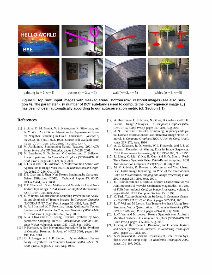
painting (n=2, κ=4) posters (n=2, κ=6) wall (n=2, κ=5) tables (n=3, κ=5)
Figure 5. Top row: input images with masked areas. Bottom row: restored images (see also Sec-tion 4). The parameter κ (= number of DCT sub-bands used to compute the low-frequency image Lκ)has been chosen automatically according to our autocorrelation metric (cf. Section 3.1).
References
[1] S. Arya, D. M. Mount, N. S. Netanyahu, R. Silverman, andA. Y. Wu. An Optimal Algorithm for Approximate Near-est Neighbor Searching in Fixed Dimensions.Journal ofthe ACM, 46(6):891–923, 1998. Source code available fromhttp://www.cs.umd.edu/˜mount/ANN/ .
[2] M. Ashikhmin. Synthesizing Natural Textures.2001 ACMSymp. Interactive 3D Graphics, pages 217–226, 2001.
[3] M. Bertalmio, S. Guillermo, V. Caselles, and C. Ballester.Image Inpainting. InComputer Graphics (SIGGRAPH ’00Conf. Proc.), pages 417–424, July 2000.
[4] P. J. Burt and E. H. Adelson. A Multiresolution Spline withApplication to Image Mosaics.ACM Transactions on Graph-ics, 2(4):217–236, Oct. 1983.
[5] T. F. Chan and J. Shen. Non-Texture Inpainting by Curvature-Driven Diffusions (CDD). Technical Report TR 00-35,UCLA CAM, Sept. 2000.
[6] T. F. Chan and J. Shen. Mathematical Models for Local Non-Texture Inpaintings.SIAM Journal on Applied Mathematics,62(3):1019–1043, June 2002.
[7] J. De Bonet. Multiresolution Sampling Procedure for Analy-sis and Synthesis of Texture Images. InComputer Graphics(SIGGRAPH ’97 Conf. Proc.), pages 361–368, Aug. 1997.
[8] A. A. Efros and W. T. Freeman. Image Quilting for TextureSynthesis and Transfer. InComputer Graphics (SIGGRAPH’01 Conf. Proc.), pages 341–346, Aug. 2001.
[9] A. A. Efros and T. K. Leung. Texture Synthesis by Non-parametric Sampling. InIEEE International Conf. on Com-puter Vision, volume 2, pages 1033–1038, Sept. 1999.
[10] P. Harrison. A Non-Hierarchical Procedure for Re-Synthesisof Complex Textures. InProc. of WSCG 2001, pages 190–197, Feb. 2001.
[11] D. J. Heeger and J. R. Bergen. Pyramid-Based TextureAnalysis/Synthesis. InComputer Graphics (SIGGRAPH ’95Conf. Proc.), pages 229–238, Aug. 1995.
[12] A. Hertzmann, C. E. Jacobs, N. Oliver, B. Curless, and D. H.Salesin. Image Analogies. InComputer Graphics (SIG-GRAPH ’01 Conf. Proc.), pages 327–340, Aug. 2001.
[13] A. N. Hirani and T. Totsuka. Combining Frequency and Spa-tial Domain Information for Fast Interactive Image Noise Re-moval. InComputer Graphics (SIGGRAPH ’96 Conf. Proc.),pages 269–276, Aug. 1996.
[14] A. C. Kokaram, R. D. Morris, W. J. Fitzgerald, and P. J. W.Rayner. Detection of Missing Data in Image Sequences.IEEE Trans. Image Processing, 4(11):1496–1508, Nov. 1995.
[15] L. Liang, C. Liu, Y. Xu, B. Guo, and H.-Y. Shum. Real-Time Texture Synthesis Using Patch-Based Sampling.ACMTransactions on Graphics, 20(3):127–150, July 2001.
[16] M. M. Oliveira, B. Bowen, R. McKenna, and Y.-S. Chang.Fast Digital Image Inpainting. InProc. of the InternationalConf. on Visualization, Imaging and Image Processing (VIIP2001), pages 261–266, Sept. 2001.
[17] E. P. Simoncelli and J. Portilla. Texture Characterization viaJoint Statistics of Wavelet Coefficient Magnitudes. InProc.of Fifth International Conf. on Image Processing, volume I,pages 62–66. IEEE Computer Society, Oct. 1998.
[18] G. Turk. Texture Synthesis on Surfaces. InComputer Graph-ics (SIGGRAPH ’01 Conf. Proc.), pages 347–354, 2001.
[19] L.-Y. Wei and M. Levoy. Fast Texture Synthesis Using Tree-Structured Vector Quantization. InComputer Graphics (SIG-GRAPH ’00 Conf. Proc.), pages 479–488, July 2000.
[20] L.-Y. Wei and M. Levoy. Texture Synthesis over ArbitraryManifold Surfaces. InComputer Graphics (SIGGRAPH ’01Conf. Proc.), pages 355–360, Aug. 2001.
[21] L. Ying, A. Hertzmann, H. Biermann, and D. Zorin. Textureand Shape Synthesis on Surfaces. InRendering Techniques2001, pages 301–312, 2001.
[22] S. Zelinka and M. Garland. Towards Real-Time Texture Syn-thesis with the Jump Map. InRendering Techniques 2002,pages 101–107, 2002.