im502 - lincoln electric
TRANSCRIPT

LN-742 & LN-742H Wire Feeders
OPERATOR’S MANUAL
IM502-AJune, 2000
Safety Depends on YouLincoln arc welding and cuttingequipment is designed and builtwith safety in mind. However, youroverall safety can be increased byproper installation ... and thought-ful operation on your part. DONOT INSTALL, OPERATE ORREPAIR THIS EQUIPMENTWITHOUT READING THISMANUAL AND THE SAFETYPRECAUTIONS CONTAINEDTHROUGHOUT. And, mostimportantly, think before you actand be careful.
For use with machines having Code Numbers: 1002910030102341023510236102371004610047
• Sales and Service through Subsidiaries and Distributors Worldwide •
Cleveland, Ohio 44117-1199 U.S.A. TEL: 216.481.8100 FAX: 216.486.1751 WEB SITE: www.lincolnelectric.com
• World's Leader in Welding and Cutting Products •
Date of Purchase:Serial Number:Code Number:Model:Where Purchased:
This manual covers equipment which is no longer in production by The Lincoln Electric Co. Speci�cations and availability of optional features may have changed.

FOR ENGINEpowered equipment.
1.a. Turn the engine off before troubleshooting and maintenancework unless the maintenance work requires it to be running.
____________________________________________________1.b.Operate engines in open, well-ventilated
areas or vent the engine exhaust fumes outdoors.
____________________________________________________1.c. Do not add the fuel near an open flame
welding arc or when the engine is running.Stop the engine and allow it to cool beforerefueling to prevent spilled fuel from vaporiz-ing on contact with hot engine parts andigniting. Do not spill fuel when filling tank. Iffuel is spilled, wipe it up and do not startengine until fumes have been eliminated.
____________________________________________________1.d. Keep all equipment safety guards, covers
and devices in posit ion and in goodrepair.Keep hands, hair, clothing and toolsaway from V-belts, gears, fans and all othermoving parts when starting, operating orrepairing equipment.
____________________________________________________
1.e. In some cases it may be necessary to remove safetyguards to perform required maintenance. Removeguards only when necessary and replace them when themaintenance requiring their removal is complete.Always use the greatest care when working near movingparts.
___________________________________________________1.f. Do not put your hands near the engine fan. Do not attempt
to override the governor or idler by pushing on the throttlecontrol rods while the engine is running.
___________________________________________________1.g. To prevent accidentally starting gasoline engines while
turning the engine or welding generator during maintenancework, disconnect the spark plug wires, distributor cap ormagneto wire as appropriate.
iSAFETYi
ARC WELDING CAN BE HAZARDOUS. PROTECT YOURSELF AND OTHERS FROM POSSIBLE SERIOUS INJURY OR DEATH.KEEP CHILDREN AWAY. PACEMAKER WEARERS SHOULD CONSULT WITH THEIR DOCTOR BEFORE OPERATING.
Read and understand the following safety highlights. For additional safety information, it is strongly recommended that youpurchase a copy of “Safety in Welding & Cutting - ANSI Standard Z49.1” from the American Welding Society, P.O. Box351040, Miami, Florida 33135 or CSA Standard W117.2-1974. A Free copy of “Arc Welding Safety” booklet E205 is availablefrom the Lincoln Electric Company, 22801 St. Clair Avenue, Cleveland, Ohio 44117-1199.
BE SURE THAT ALL INSTALLATION, OPERATION, MAINTENANCE AND REPAIR PROCEDURES AREPERFORMED ONLY BY QUALIFIED INDIVIDUALS.
WARNING
Mar ‘95
ELECTRIC AND MAGNETIC FIELDSmay be dangerous
2.a. Electric current flowing through any conductor causes localized Electric and Magnetic Fields (EMF). Welding current creates EMF fields around welding cables and welding machines
2.b. EMF fields may interfere with some pacemakers, andwelders having a pacemaker should consult their physicianbefore welding.
2.c. Exposure to EMF fields in welding may have other healtheffects which are now not known.
2.d. All welders should use the following procedures in order tominimize exposure to EMF fields from the welding circuit:
2.d.1. Route the electrode and work cables together - Securethem with tape when possible.
2.d.2. Never coil the electrode lead around your body.
2.d.3. Do not place your body between the electrode andwork cables. If the electrode cable is on your right side, the work cable should also be on your right side.
2.d.4. Connect the work cable to the workpiece as close aspossible to the area being welded.
2.d.5. Do not work next to welding power source.
1.h. To avoid scalding, do not remove theradiator pressure cap when the engine ishot.
CALIFORNIA PROPOSITION 65 WARNINGS
Diesel engine exhaust and some of its constituentsare known to the State of California to cause can-cer, birth defects, and other reproductive harm.
The engine exhaust from this product containschemicals known to the State of California to causecancer, birth defects, or other reproductive harm.
The Above For Diesel Engines The Above For Gasoline Engines

iiSAFETYii
ARC RAYS can burn.4.a. Use a shield with the proper filter and cover
plates to protect your eyes from sparks andthe rays of the arc when welding or observingopen arc welding. Headshield and filter lensshould conform to ANSI Z87. I standards.
4.b. Use suitable clothing made from durable flame-resistantmaterial to protect your skin and that of your helpers fromthe arc rays.
4.c. Protect other nearby personnel with suitable, non-flammablescreening and/or warn them not to watch the arc nor exposethemselves to the arc rays or to hot spatter or metal.
ELECTRIC SHOCK cankill.3.a. The electrode and work (or ground) circuits
are electrically “hot” when the welder is on.Do not touch these “hot” parts with your bareskin or wet clothing. Wear dry, hole-free
gloves to insulate hands.
3.b. Insulate yourself from work and ground using dry insulation.Make certain the insulation is large enough to cover your fullarea of physical contact with work and ground.
In addition to the normal safety precautions, if weldingmust be performed under electrically hazardousconditions (in damp locations or while wearing wetclothing; on metal structures such as floors, gratings orscaffolds; when in cramped positions such as sitting,kneeling or lying, if there is a high risk of unavoidable oraccidental contact with the workpiece or ground) usethe following equipment:
• Semiautomatic DC Constant Voltage (Wire) Welder.• DC Manual (Stick) Welder.• AC Welder with Reduced Voltage Control.
3.c. In semiautomatic or automatic wire welding, the electrode,electrode reel, welding head, nozzle or semiautomaticwelding gun are also electrically “hot”.
3.d. Always be sure the work cable makes a good electricalconnection with the metal being welded. The connectionshould be as close as possible to the area being welded.
3.e. Ground the work or metal to be welded to a good electrical(earth) ground.
3.f. Maintain the electrode holder, work clamp, welding cable andwelding machine in good, safe operating condition. Replacedamaged insulation.
3.g. Never dip the electrode in water for cooling.
3.h. Never simultaneously touch electrically “hot” parts ofelectrode holders connected to two welders because voltagebetween the two can be the total of the open circuit voltageof both welders.
3.i. When working above floor level, use a safety belt to protectyourself from a fall should you get a shock.
3.j. Also see Items 6.c. and 8.
FUMES AND GASEScan be dangerous.5.a. Welding may produce fumes and gases
hazardous to health. Avoid breathing thesefumes and gases.When welding, keepyour head out of the fume. Use enoughventilation and/or exhaust at the arc to keep
fumes and gases away from the breathing zone. Whenwelding with electrodes which require specialventilation such as stainless or hard facing (seeinstructions on container or MSDS) or on lead orcadmium plated steel and other metals or coatingswhich produce highly toxic fumes, keep exposure aslow as possible and below Threshold Limit Values (TLV)using local exhaust or mechanical ventilation. Inconfined spaces or in some circumstances, outdoors, arespirator may be required. Additional precautions arealso required when welding on galvanized steel.
5.b. Do not weld in locations near chlorinated hydrocarbon vaporscoming from degreasing, cleaning or spraying operations.
The heat and rays of the arc can react with solvent vapors toform phosgene, a highly toxic gas, and other irritating products.
5.c. Shielding gases used for arc welding can displace air andcause injury or death. Always use enough ventilation,especially in confined areas, to insure breathing air is safe.
5.d. Read and understand the manufacturer’s instructions for thisequipment and the consumables to be used, including thematerial safety data sheet (MSDS) and follow youremployer’s safety practices. MSDS forms are available fromyour welding distributor or from the manufacturer.
5.e. Also see item 1.b. Mar ‘95

FOR ELECTRICALLYpowered equipment.
8.a. Turn off input power using the disconnectswitch at the fuse box before working onthe equipment.
8.b. Install equipment in accordance with the U.S. NationalElectrical Code, all local codes and the manufacturer’srecommendations.
8.c. Ground the equipment in accordance with the U.S. NationalElectrical Code and the manufacturer’s recommendations.
CYLINDER may explodeif damaged.7.a. Use only compressed gas cylinders
containing the correct shielding gas for theprocess used and properly operatingregulators designed for the gas and
pressure used. All hoses, fittings, etc. should be suitable forthe application and maintained in good condition.
7.b. Always keep cylinders in an upright position securelychained to an undercarriage or fixed support.
7.c. Cylinders should be located:• Away from areas where they may be struck or subjected tophysical damage.
• A safe distance from arc welding or cutting operations andany other source of heat, sparks, or flame.
7.d. Never allow the electrode, electrode holder or any otherelectrically “hot” parts to touch a cylinder.
7.e. Keep your head and face away from the cylinder valve outletwhen opening the cylinder valve.
7.f. Valve protection caps should always be in place and handtight except when the cylinder is in use or connected foruse.
7.g. Read and follow the instructions on compressed gascylinders, associated equipment, and CGA publication P-l,“Precautions for Safe Handling of Compressed Gases inCylinders,” available from the Compressed Gas Association1235 Jefferson Davis Highway, Arlington, VA 22202.
iiiSAFETYiii
Mar ‘95
WELDING SPARKS cancause fire or explosion.6.a. Remove fire hazards from the welding area.
If this is not possible, cover them to preventthe welding sparks from starting a fire.Remember that welding sparks and hot
materials from welding can easily go through small cracksand openings to adjacent areas. Avoid welding nearhydraulic lines. Have a fire extinguisher readily available.
6.b. Where compressed gases are to be used at the job site,special precautions should be used to prevent hazardoussituations. Refer to “Safety in Welding and Cutting” (ANSIStandard Z49.1) and the operating information for theequipment being used.
6.c. When not welding, make certain no part of the electrodecircuit is touching the work or ground. Accidental contactcan cause overheating and create a fire hazard.
6.d. Do not heat, cut or weld tanks, drums or containers until theproper steps have been taken to insure that such procedureswill not cause flammable or toxic vapors from substancesinside. They can cause an explosion even though they havebeen “cleaned”. For information, purchase “RecommendedSafe Practices for the Preparation for Welding and Cutting ofContainers and Piping That Have Held HazardousSubstances”, AWS F4.1 from the American Welding Society(see address above).
6.e. Vent hollow castings or containers before heating, cutting orwelding. They may explode.
6.f. Sparks and spatter are thrown from the welding arc. Wear oilfree protective garments such as leather gloves, heavy shirt,cuffless trousers, high shoes and a cap over your hair. Wearear plugs when welding out of position or in confined places.Always wear safety glasses with side shields when in awelding area.
6.g. Connect the work cable to the work as close to the weldingarea as practical. Work cables connected to the buildingframework or other locations away from the welding areaincrease the possibility of the welding current passingthrough lifting chains, crane cables or other alternate cir-cuits. This can create fire hazards or overheat lifting chainsor cables until they fail.
6.h. Also see item 1.c.

ivSAFETYiv
PRÉCAUTIONS DE SÛRETÉPour votre propre protection lire et observer toutes les instructionset les précautions de sûreté specifiques qui parraissent dans cemanuel aussi bien que les précautions de sûreté générales suiv-antes:
Sûreté Pour Soudage A L’Arc1. Protegez-vous contre la secousse électrique:
a. Les circuits à l’électrode et à la piéce sont sous tensionquand la machine à souder est en marche. Eviter toujourstout contact entre les parties sous tension et la peau nueou les vétements mouillés. Porter des gants secs et sanstrous pour isoler les mains.
b. Faire trés attention de bien s’isoler de la masse quand onsoude dans des endroits humides, ou sur un planchermetallique ou des grilles metalliques, principalement dans les positions assis ou couché pour lesquelles une grandepartie du corps peut être en contact avec la masse.
c. Maintenir le porte-électrode, la pince de masse, le câblede soudage et la machine à souder en bon et sûr étatdefonctionnement.
d.Ne jamais plonger le porte-électrode dans l’eau pour lerefroidir.
e. Ne jamais toucher simultanément les parties sous tensiondes porte-électrodes connectés à deux machines à souderparce que la tension entre les deux pinces peut être letotal de la tension à vide des deux machines.
f. Si on utilise la machine à souder comme une source decourant pour soudage semi-automatique, ces precautionspour le porte-électrode s’applicuent aussi au pistolet desoudage.
2. Dans le cas de travail au dessus du niveau du sol, se protégercontre les chutes dans le cas ou on recoit un choc. Ne jamaisenrouler le câble-électrode autour de n’importe quelle partiedu corps.
3. Un coup d’arc peut être plus sévère qu’un coup de soliel,donc:
a. Utiliser un bon masque avec un verre filtrant appropriéainsi qu’un verre blanc afin de se protéger les yeux du ray-onnement de l’arc et des projections quand on soude ouquand on regarde l’arc.
b. Porter des vêtements convenables afin de protéger lapeau de soudeur et des aides contre le rayonnement del‘arc.
c. Protéger l’autre personnel travaillant à proximité ausoudage à l’aide d’écrans appropriés et non-inflammables.
4. Des gouttes de laitier en fusion sont émises de l’arc desoudage. Se protéger avec des vêtements de protection libresde l’huile, tels que les gants en cuir, chemise épaisse, pan-talons sans revers, et chaussures montantes.
5. Toujours porter des lunettes de sécurité dans la zone desoudage. Utiliser des lunettes avec écrans lateraux dans les
zones où l’on pique le laitier.
6. Eloigner les matériaux inflammables ou les recouvrir afin deprévenir tout risque d’incendie dû aux étincelles.
7. Quand on ne soude pas, poser la pince à une endroit isolé dela masse. Un court-circuit accidental peut provoquer unéchauffement et un risque d’incendie.
8. S’assurer que la masse est connectée le plus prés possiblede la zone de travail qu’il est pratique de le faire. Si on placela masse sur la charpente de la construction ou d’autresendroits éloignés de la zone de travail, on augmente le risquede voir passer le courant de soudage par les chaines de lev-age, câbles de grue, ou autres circuits. Cela peut provoquerdes risques d’incendie ou d’echauffement des chaines et descâbles jusqu’à ce qu’ils se rompent.
9. Assurer une ventilation suffisante dans la zone de soudage.Ceci est particuliérement important pour le soudage de tôlesgalvanisées plombées, ou cadmiées ou tout autre métal quiproduit des fumeés toxiques.
10. Ne pas souder en présence de vapeurs de chlore provenantd’opérations de dégraissage, nettoyage ou pistolage. Lachaleur ou les rayons de l’arc peuvent réagir avec les vapeursdu solvant pour produire du phosgéne (gas fortement toxique)ou autres produits irritants.
11. Pour obtenir de plus amples renseignements sur la sûreté,voir le code “Code for safety in welding and cutting” CSAStandard W 117.2-1974.
PRÉCAUTIONS DE SÛRETÉ POURLES MACHINES À SOUDER ÀTRANSFORMATEUR ET ÀREDRESSEUR
1. Relier à la terre le chassis du poste conformement au code del’électricité et aux recommendations du fabricant. Le dispositifde montage ou la piece à souder doit être branché à unebonne mise à la terre.
2. Autant que possible, I’installation et l’entretien du poste seronteffectués par un électricien qualifié.
3. Avant de faires des travaux à l’interieur de poste, la debranch-er à l’interrupteur à la boite de fusibles.
4. Garder tous les couvercles et dispositifs de sûreté à leurplace.
Mar. ‘93

Thank You for selecting a QUALITY product by Lincoln Electric. We want youto take pride in operating this Lincoln Electric Company product••• as much pride as we have in bringing this product to you!
Read this Operators Manual completely before attempting to use this equipment. Save this manual and keep ithandy for quick reference. Pay particular attention to the safety instructions we have provided for your protection.The level of seriousness to be applied to each is explained below:
WARNINGThis statement appears where the information must be followed exactly to avoid serious personal injury orloss of life.
This statement appears where the information must be followed to avoid minor personal injury or damage tothis equipment.
CAUTION
Please Examine Carton and Equipment For Damage ImmediatelyWhen this equipment is shipped, title passes to the purchaser upon receipt by the carrier. Consequently, Claimsfor material damaged in shipment must be made by the purchaser against the transportation company at thetime the shipment is received.
Please record your equipment identification information below for future reference. This information can befound on your machine nameplate.
Model Name & Number _____________________________________
Code & Serial Number _____________________________________
Date of Purchase _____________________________________
Whenever you request replacement parts for or information on this equipment always supply the informationyou have recorded above.
vv

viTABLE OF CONTENTS
LN-742 & LN-742H
Page
Safety . . . . . . . . . . . . . . . . . . . . . . . . . . . . . . . . . . . . . . . . . . . . . . . . . . . . . . . i-iv
Installation . . . . . . . . . . . . . . . . . . . . . . . . . . . . . . . . . . . . . . . . . . . . . . . . . . . Section ATechnical Specifications - LN-742 . . . . . . . . . . . . . . . . . . . . . . . . . . . . . . A-1Mounting Location . . . . . . . . . . . . . . . . . . . . . . . . . . . . . . . . . . . . . . . . . . A-2Input Cable Connections . . . . . . . . . . . . . . . . . . . . . . . . . . . . . . . . . . . . . A-2Work Cable . . . . . . . . . . . . . . . . . . . . . . . . . . . . . . . . . . . . . . . . . . . . . . . . A-5Gun and Cable Assemblies . . . . . . . . . . . . . . . . . . . . . . . . . . . . . . . . . . . A-5Gun Cable Connections . . . . . . . . . . . . . . . . . . . . . . . . . . . . . . . . . . . . . . A-5Water Connections (For Water Cooled Guns) . . . . . . . . . . . . . . . . . . . . . A-6GMAW Shielding Gas Hookup . . . . . . . . . . . . . . . . . . . . . . . . . . . . . . . . . A-7
Operation . . . . . . . . . . . . . . . . . . . . . . . . . . . . . . . . . . . . . . . . . . . . . . . . . . . . Section BOperating Instructions . . . . . . . . . . . . . . . . . . . . . . . . . . . . . . . . . . . . . . . B-1Safety Precautions . . . . . . . . . . . . . . . . . . . . . . . . . . . . . . . . . . . . . . . . . . B-1General Description . . . . . . . . . . . . . . . . . . . . . . . . . . . . . . . . . . . . . . . . . B-1Recommended Processes and Equipment . . . . . . . . . . . . . . . . . . . . . . . B-1Controls and Settings . . . . . . . . . . . . . . . . . . . . . . . . . . . . . . . . . . . . . . . . B-2Acceleration Setting . . . . . . . . . . . . . . . . . . . . . . . . . . . . . . . . . . . . . . . . . B-3English or Metric Speed Display Units . . . . . . . . . . . . . . . . . . . . . . . . . . . B-3Circuit Protection . . . . . . . . . . . . . . . . . . . . . . . . . . . . . . . . . . . . . . . . . . . B-3Drive Roll Installation . . . . . . . . . . . . . . . . . . . . . . . . . . . . . . . . . . . . . . . . B-3Idle Roll Pressure Setting . . . . . . . . . . . . . . . . . . . . . . . . . . . . . . . . . . . . . B-7Wire Loading . . . . . . . . . . . . . . . . . . . . . . . . . . . . . . . . . . . . . . . . . . . . . . B-8Making a Weld . . . . . . . . . . . . . . . . . . . . . . . . . . . . . . . . . . . . . . . . . . . . . B-12Wire Reel Changing . . . . . . . . . . . . . . . . . . . . . . . . . . . . . . . . . . . . . . . . . B-12
Accessories . . . . . . . . . . . . . . . . . . . . . . . . . . . . . . . . . . . . . . . . . . . . . . . . . . Section CGeneral . . . . . . . . . . . . . . . . . . . . . . . . . . . . . . . . . . . . . . . . . . . . . . . . . . . C-1Flux System Components . . . . . . . . . . . . . . . . . . . . . . . . . . . . . . . . . . . . C-2Power Input Cables . . . . . . . . . . . . . . . . . . . . . . . . . . . . . . . . . . . . . . . . . C-3Welding Guns . . . . . . . . . . . . . . . . . . . . . . . . . . . . . . . . . . . . . . . . . . . . . . C-3Spindles, Stands, and Adapters . . . . . . . . . . . . . . . . . . . . . . . . . . . . . . . . C-4Attaching the Wire Reel Stand . . . . . . . . . . . . . . . . . . . . . . . . . . . . . . . . . C-5Drive Roll Kits . . . . . . . . . . . . . . . . . . . . . . . . . . . . . . . . . . . . . . . . . . . . . . C-6
Maintenance . . . . . . . . . . . . . . . . . . . . . . . . . . . . . . . . . . . . . . . . . . . . . . . . . Section DRoutine Maintenance . . . . . . . . . . . . . . . . . . . . . . . . . . . . . . . . . . . . . . . . D-1Periodic Maintenance . . . . . . . . . . . . . . . . . . . . . . . . . . . . . . . . . . . . . . . . D-1
Troubleshooting and Repair . . . . . . . . . . . . . . . . . . . . . . . . . . . . . . . . . . . . Section EHow To Use Troubleshooting Guide . . . . . . . . . . . . . . . . . . . . . . . . . . . . E-1Troubleshooting Guide . . . . . . . . . . . . . . . . . . . . . . . . . . . . . . . . . . . . . . . E-2
Electrical Diagram . . . . . . . . . . . . . . . . . . . . . . . . . . . . . . . . . . . . . . . . . . . . . Section F
Parts Manual . . . . . . . . . . . . . . . . . . . . . . . . . . . . . . . . . . . . . . . . . . . . . . . . . Appendix

A-1INSTALLATION A-1
PHYSICAL DIMENSIONS
ENVIRONMENTAL RATING (ALL MODELS)
BOTH LN-742 AND LN-742H LENGTHTOTAL WEIGHT
LESS ELECTRODE
24.3 lbs(11.1 kg)
WIDTH HEIGHT
2 ROLL FEEDERWITH WIRE STAND (K377)
2 ROLL FEEDERWITHOUT WIRE STAND
4 ROLL FEEDERWITH WIRE STAND (K377)
4 ROLL FEEDERWITHOUT WIRE STAND
34.3 lbs(15.6 kg)
29.0 lbs(13.2 kg)
39.0 lbs(17.8 kg)
10.52 in.(267 mm)
21.58 in.(548 mm)
11.50 in.(292 mm)
22.56 in.(573 mm)
9.76 in.(247 mm)
9.76 in.(247 mm)
11.60 in.(295 mm)
11.60 in.(295 mm)
10.89 in.(277 mm)
17.00 in.(432 mm)
11.11 in.(282 mm)
17.00 in.(432 mm)
SYSTEM
LN-742
LN-742H
DIAMETER
0.025 in. through 1/16 in. (0.6 through 1.6 mm)
0.025 in. through 0.045 in. (0.6 through 1.2 mm)
0.045 in. through 3/32 in. (1.2 through 2.4 mm)
0.045 in. (1.2 mm)
TECHNICAL SPECIFICATIONS – LN-742
INPUT VOLTAGE
WIRE FEED SPEED
WIRE DIAMETERS
40 to 42V ±10%, 50/60 Hz, 4.0 Amps
WIRE SPEED RANGE
50 in. to 770 in. per minute (1.25 to 19.5 m/min)
80 in. to 1200 in. per minute (2.00 to 30.5 m/min)
SYSTEM
LN-742
LN-742H
LN-742
LN-742H
ELECTRODE
SOLID
SOLID
CORED
CORED
TEMPERATURE RATING (ALL MODELS)OPERATING
STORAGE
-4˚F to 104˚F (-20˚C to +40˚C)
-40˚F to 104˚F (-40˚C to +40˚C)
LN-742 & LN-742H
IP21 (IEC 974-5)

A-2INSTALLATION
LN-742 & LN-742H
A-2
MOUNTING LOCATION
The LN-742 wire feeders can be mounted directly ontop of the power source providing that it is secure andlevel. The LN-742 can also be mounted to anundercarriage when portability is required. The LN-742should be installed upright on a horizontal surface.
A K178-1 mounting platform is available for mountingthe LN-742 to the top of Idealarc power sources. Referto Section C, Accessories, for details.
INPUT CABLE CONNECTIONS
Refer to Section C, Accessories, for descriptions ofthe various input cable assemblies available for theLN-742 wire feeder.
Turn input power off before connecting the LN-742wire feeder.------------------------------------------------------------------------
For connecting an LN-742 to a specific Lincoln powersource, follow steps 1 through 5, and refer to theconnection diagram in Figure A.3. The welding cableused must be sized according to the current and theduty cycle of the application.
With input power disconnected at the source, installthe input cable per connection diagram A.3, andcomplete the following instructions:
1. Connect the end of the control cable with the 14-pin cable plug to the mating receptacle on thepower source.
2. Connect the electrode lead to the power sourceoutput terminal of the desired polarity.
3. Referring to Figure A.1, route the other end of theelectrode cable through the large oval hole in therear panel of the LN-742 case. Connect theelectrode to the copper strap on the side of thegearbox using the stud and nut provided.
FIGURE A.1 – INPUT CONTROL CABLE ANDELECTRODE CABLE CONNECTIONS.
WARNING
NUT
STUDELECTRODE
CONTROLCABLE
COPPERSTRAP

A-3INSTALLATION
LN-742 & LN-742H
A-3
4. Connect the remaining end of the control cablewith the eight-socket cable plug to the matingreceptacle on the LN-742.
5. Referring to Figure A.2, install the input cableunder the wire reel mounting stand strain reliefclamp. Remove the screws holding the clamp tothe base of wire reel mounting assembly. Put theinput cable under the clamp and reinstall thescrews.
The connection diagram, Figure A.3, shows theelectrode as positive. To change polarity, turn thepower source off. Reverse the electrode and workcables at the power source, and set the wire feedervoltmeter polarity switch on the power source to theproper polarity.
Pins not listed in the table in Figure A.3 are notconnected on the cable.
If using the K589-1 remote control kit, set the powersource control switch to the “Remote” position.
WIRE REELMOUNTINGASSEMBLY
CONTROLCABLE
ELECTRODECABLE
STRAINRELIEFCLAMP
FIGURE A.2 – STRAIN RELIEF CLAMP.

A-4INSTALLATION
LN-742 & LN-742H
A-4
ELECTRICSHOCK
CAN KILL
TURN INPUT POWER OFFBEFORE CONNECTING THELN-742 WIRE FEEDER.
WARNING
CLEVELAND, OHIO U.S.A
-+
LINCOLNPOWER SOURCE
LN-742WIRE FEEDER
LN-742INPUT CABLE
ASSEMBLY
TO WORK
ELECTRODE CABLE
14-SOCKET BOX RECEPTACLE, FRONT VIEWAND 14-PIN CABLE PLUG, REAR VIEW
FUNCTIONS ARE LISTED FOR REFERENCEONLY AND EACH MAY OR MAY NOT BEPRESENT IN YOUR EQUIPMENT.
14-SOCKET BOX RECEPTACLE, REAR VIEWAND 14-PIN CABLE PLUG, FRONT VIEW
14 PINAMPHENOL
K=42 K=42I=41 I=41
H=21 H=21C=2 C=2
G=75 G=75D=4 D=4
F=76
PIN
C 2 TRIGGER CIRCUIT
TRIGGER CIRCUIT
OUTPUT CONTROL
OUTPUT CONTROL
OUTPUT CONTROL
WORK
42V AC
42V AC
4
77
76
75
21
41
42
LEAD FUNCTION
F=76E=77 E=77
DE
F
G
H
I
K
FIGURE A.3 – LN-742 WIRE FEEDER TO LINCOLN POWER SOURCE – CONNECTION DIAGRAM.

A-5INSTALLATION
LN-742 & LN-742H
A-5
WORK CABLE
Connect a work lead of sufficient size and length(Table A.1) between the proper output stud on thepower source and the work. Be sure the connection tothe work makes tight metal-to-metal electrical contact.
TABLE A.1 – WORK LEAD SPECIFICATIONS
Copper Work Cable Size, AWG
Current 60% Up To 50 Ft 50 Ft-100 Ft Duty Cycle (15.2 m) (15.2-30.4 m)
300 Amps 0 (53 mm2) 00 (67 mm2)400 Amps 00 (67 mm2) 000 (85 mm2)500 Amps 00 (67 mm2) 000 (85 mm2)600 Amps 000 (85 mm2) 0000 (107 mm2)
GUN AND CABLE ASSEMBLIES
An expanding line of Magnum Fast-Mate gun andcable assemblies are available to allow welding withsolid and cored electrodes using the GMAW process.See the appropriate Magnum literature for descriptionsof the 200 to 400 ampere air cooled gun and cablesthat are available. Gun cable lengths range from 10 ft.(3.0m) to 25 ft. (7.6m) and feed electrode sizes .025”(0.6mm) to 5/64” (2.0mm).
An expanding line of Magnum X-Tractor gun and cableassemblies provides fume extraction capability forwelding with solid and cored electrodes using theGMAW process. See the appropriate Magnumliterature for descriptions of the 250 to 400 ampere aircooled gun and cables that are available. Gun cablelengths range from 10 ft. (3.0 m) to 15 ft. (4.5 m) andfeed electrode sizes .035” (0.9 mm) to 1/16” (1.6 mm).These guns require the use of either the K173-1 orK184* vacuum units.
* Requires S14927-8 connector hose and an S20591 hose adapter.

A-6INSTALLATION
LN-742 & LN-742H
A-6
WATER CONNECTIONS(FOR WATER COOLED GUNS)
The LN-7 GMA must have a K590-1 Water SolenoidKit installed (see Section C, Accessories). Refer toFigure A.4 and perform the following steps:
The maximum water pressure permitted for use withthe LN-742 is 55 psi (3.8 bar).
NOTE: If not using a Lincoln water cooler, and if yourwater cooling device is not designed for use with awaterline solenoid valve, you may remove the solenoidand screw the male fitting (after applying sealant)directly into the brass manifold block.
1. Using male 5/8-18 UNF left-hand thread fittings,connect appropriate water hoses to the coolantinlet and outlet on the back of the LN-742.Connect the other ends of these hoses to theappropriate ports on your water cooling units.
2. In the event the water line fittings on your watercooled gun are incompatible with the female quickconnects on the front of the LN-742, male quickconnects are provided for installation on 3/16 in.I.D. hose (customer to provide appropriateclamps). The feeder connectors self seal whendisconnected.
FIGURE A.4 – WATER CONNECTIONS.
t
t
FRONT
BACK

A-7INSTALLATION
LN-742 & LN-742H
A-7
GMAW SHIELDING GAS HOOKUP
Gas under pressure is explosive.Always keep gas cylinders in anupright position and chained to theundercarriage or a stationarysupport. See American NationalStandard Z-49.1, “Safety In WeldingAnd Cutting”, published by theAmerican Welding Society.
------------------------------------------------------------------------
Customer must provide a cylinder of shielding gas, apressure regulator, a flow control valve, and a hosefrom the flow valve to the gas inlet fitting of the LN-742.Install per Figure A.5 and the following:
1. Connect the supply hose from the gas cylinderflow valve outlet to the 5/8-18 female inert gasfitting on the back panel of the LN-742.
The LN-742 can be used with any shielding gasrecommended in the electrode’s product literature at amaximum pressure of 60 psi (4.1 bar). This mayinclude gasses such as Argon, Helium and Nitrogenand blended gases such as Ar-He, Ar-N2, Ar-O2, Ar-
CO2, CO2, AR-CO2,-O2.
WARNING
FIGURE A.5 – SHIELDING GAS HOOKUP.
t
GASSUPPLY
HOSE

B-1OPERATION
LN-742 & LN-742H
B-1
OPERATING INSTRUCTIONS
Read and understand the entire Operation Sectionprior to operating the machine.
SAFETY PRECAUTIONS
ELECTRIC SHOCKcan kill.
• Do not touch electrically live partsor electrode with skin or wetclothing.
• Insulate yourself from work orground.
• Always wear dry insulatinggloves.
FUMES AND GASEScan be dangerous.
• Keep your head out of fumes.
• Use ventilation or exhaust toremove fumes from breathingzone.
WELDING SPARKScan cause fire or explosion.
• Keep flammable material away.
• Do not weld on containers thathave held combustibles.
ARC RAYScan burn.
• Wear eye, ear, and bodyprotection.
Observe additional Safety Guidelines detailed inthe beginning of this manual.
GENERAL DESCRIPTION
The LN-742 semiautomatic constant speed wire feederis specifically equipped for gas metal arc welding usingflux-cored Outershield electrodes and solid wire. TheLN-742 is also suitable for self-shielded flux-coredInnershield electrodes, submerged arc welding (ifconstant voltage is satisfactory), and other open arcwelding. It has been factory assembled with thefollowing features:
• Wire feed control [50 to 770 in./min (1.25 to 19.5m/min) for the LN-742; 80 to 1200 in./min (2.00 to30.5 m/min) for the LN-742H].
• Factory installed gas solenoid valve and gasfittings.
• Wire drive uses a permanent magnet motor andincludes tool-less “quick-release” idle roll pressurearm, outgoing guide tube and gun cable fastening.
• Optional factory installed water solenoid and fittingsfor use with water cooled welding guns.
The LN-742 4-Roll is designed to provide the additionalfeeding force required when using gun cables over 15ft (4.6 m) long or when the wire is pulled long distances(such as when bulk packages are used). Because thefour-roll feeder has twice the contact surface, it canalso help when feeding softer wires by delivering thesame or more feeding force as the two-roll with lessoverall wire deformation.
RECOMMENDED PROCESSES ANDEQUIPMENT
The LN-742 is recommended for use in MIG andInnershield welding applications with constant voltagepower sources with 42 VAC auxiliary power and a 14-pin connector receptacle, such as the Invertec V300-PRO, DC-650-PRO, or Lincoln CV type powersources.
The LN-742 is capable of the following wire feedranges:
• 0.025 to 1/16 in. (0.6 to 1.6 mm) solid wire for gas-metal-arc or CV submerged arc processes.
• 0.045 to 3/32 in. (1.2 to 2.4 mm) cored wire forOutershield gas-metal-arc processes.
WARNING

B-2OPERATIONB-2
• 0.045 to 5/64 in. (1.2 to 2.0 mm) cored wire forInnershield processes.
The LN-742H is capable of the following wire feedranges:
• 0.025 to 0.045 in. (0.6 to 1.2 mm) solid wire for gas-metal-arc or CV submerged arc processes.
• 0.045 in. (1.2 mm) cored wire for Outershield gas-metal-arc or Innershield processes.
CONTROLS AND SETTINGS
The operator controls are located on the keypadshown in Figure B.1. The keypad consists of: 7membrane keys with tactile-feel embossed domes,that are generously spaced to provide easy selection,even while wearing welding gloves; a long-life, 3-1/2digit, 7 segment LED display with 0.56 in. (14.2 mm)character height, permitting easy viewing even fromlong gun cable distances; and high intensity, red, LEDindicator lights that allow for viewing at almost anyangle.
TRIGGER MODE CONTROLS. This control enablesthe operator to choose the mode of operation asshown by the indicator lights. Pressing the key causesthe mode lights to sequence (from top to bottom). Thetop light indicates standard (two-step) trigger mode. In
this mode the unit will only be active when the triggeris pressed. The middle light indicates lock (four-step)trigger mode. In this mode the solenoid is energizedwhen the trigger is pressed, the power source andwire feeder are energized after preflow time when thetrigger is released. Closing the trigger a second timeturns off the wire feeder and then the power sourceafter burnback time. Releasing the trigger a secondtime turns off the solenoid after Burnback time. Thebottom light indicates spot weld trigger mode. Closingthe trigger allows a single, timed, weld cycle. Theduration of the weld cycle is set with the time selectioncontrols. The spot on timer starts when weldingcurrent flows.
TIME SELECTION CONTROLS. This control enablesthe operator to choose which timer will be displayedas shown by the indicator lights. Pressing the keycauses the mode lights to sequence (from top tobottom). Any timers not available to the currentlyselected mode will be skipped. Times displayed in theLED display are adjusted using the setting adjustmentarrows to the left of the LED display. The top left lightindicates the preflow time is being displayed inseconds. The top right indicator light indicates thepostflow time is being displayed in seconds. Themiddle light indicates the burnback time is beingdisplayed in seconds. The bottom light indicates thespot weld time is being displayed in seconds.
LN-742 & LN-742H
COLD INCH
OLTMETER
INCH
WFS
PREFLOW POSTFLOW
BURNBACK
SPOT
STD
LOCK
SPOT
TIMETRIGGER MODE
t1 t2
GAS PURGE
t
t
t
GASPURGE
KEY
LEDDISPLAY
FUNCTIONSELECTIONCONTROLS
TIMERSELECTIONCONTROLS
SETTINGADJUSTMENTARROW KEYS
TRIGGERMODE
CONTROLS
COLDINCHKEY
FIGURE B.1 – WIRE FEEDER CONTROLS.

B-3OPERATIONB-3
FUNCTION SELECTION CONTROLS. This controlenables the operator to select the function that will bedisplayed as shown by the indicator lights. Pressingthe key causes the mode lights to sequence (from topto bottom). Settings displayed in the LED display areadjusted using the setting adjustment arrows to theleft of the LED display. The top light indicates the arcvoltage is being displayed in volts. The middle lightindicates the inch speed is being displayed. Thebottom light indicates the weld feed speed (WFS) isbeing displayed.
INCREASE ARROW. This key increases the settingof the parameter selected to be displayed, using the“Quick-Set” feature for fast and accurate setting.
DECREASE ARROW. This key decreases the settingof the parameter selected to be displayed, using the“Quick-Set” feature for fast and accurate setting.
QUICK-SET FEATURE. This feature permits thearrow keys to control each display digit one at a time.The display digits blink in sequence from left to right.Pressing an arrow key immediately after a digit blinksalters that digit. Releasing the arrow key causes theleft-to-right sequencing to resume.
COLD INCH KEY. This key energizes the wire feederto inch the wire forward, but does not energize thepower source or solenoid valve.
GAS PURGE KEY. This key energizes the solenoidvalve to purge any remaining gasses, but does notenergize the wire feeder or power source.
ACCELERATION SETTING
Pressing both the Gas Purge key and the FunctionSelection key at the same time, on the keypad shownin Figure B.1, enables the acceleration setting display.The LED display will indicate “A-X” with “X” being anumber from 1 (slowest) to 5 (fastest). This number isadjusted using the setting adjustment arrow keys. Toexit the acceleration setting function, press both keys asecond time, or press any other key except for thesetting adjustment arrow keys.
ENGLISH OR METRIC SPEEDDISPLAY UNITS
Pressing both the Gas Purge key and Timer Selectionkey causes the speed display units to toggle betweeninches per minute (no decimal point displayed) ormeters per minute (decimal point displayed). If the LEDdisplay is showing the voltmeter or one of the timersettings when these keys are pressed, the display willchange to the weld speed to indicate the selectedspeed display units. See Figure B.1 for key locations.
CIRCUIT PROTECTION
The LN-742 has solid-state overload protection of thewire drive motor. If the wire drive motor becomesoverloaded for an extended period of time, theprotection circuitry turns off the power source, wirefeeder, and solenoid, then displays the error code E30on the LED display. This indicates the wire drive motoris overloaded, with the number indicating the timeremaining in seconds before the unit will automaticallyreset. This number continues to decrement everysecond until it reaches zero. At that time the unitresets automatically and the previous display willreturn indicating that the unit is ready for operation.
Over loads can result from: improper tip size, liner,drive rolls, or guide tubes; obstructions or bends in thegun cable; feeding wire that is larger than the ratedcapacity of the feeder; or any other factors that wouldimpede normal wire feeding.
DRIVE ROLL INSTALLATION
CHANGING DRIVE ROLLS FOR TWO-ROLL WIRE FEEDERS:
To change drive rolls on a two-roll wire feeder, refer toFigure B.2 and perform the following steps:
1. Turn off the welding power source.
2. Rotate the latch knob on the quick release arm.
3. Remove the hex head screw and clamping collar.Remove the drive roll from the shaft.
4. The new roll to be installed is stamped for the sizewire to be fed. An “A” after the size indicatesaluminum wire. Remove the rolls from the kit andwipe them clean. Wipe the output shaft and locatingshoulder clean.
LN-742 & LN-742H

B-4OPERATIONB-4
LN-742 & LN-742H
GUIDE TUBE DETAIL
OUTGOINGGUIDE TUBE
INSERT
OUTGOINGGUIDETUBE
LARGERADIUS
DRIVEROLL
INCOMINGGUIDETUBESMALL
RADIUS
IDLEROLL
CLAMPINGCOLLAR
SPACER (IF REQUIRED)
OUTPUTSHAFT
DRIVEROLL
HALVES
FIGURE B.2 – INSTALLING DRIVE ROLLS ON A TWO-ROLL FEEDER.

B-5OPERATIONB-5
5. Use the clamping collar and hex head screw toinstall the roll on the output shaft. Certain size driverolls consist of two roll halves, and may contain aspacer. If the drive roll you are installing contains aspacer, the spacer fits between the two halves ofthe drive roll. Double grooved drive rolls are to beinstalled with side stenciled for correct wire sizefacing outward and with slotted spacer on top ofroll. Tighten the hex head screw.
6. Loosen the molded hand-screw on the front of thewire drive and pull the gun connector out of theconnector block. The guide tube provided in thegun connector is for .045” (1.2mm) or smaller wiresizes (marked with one ring). If larger wire sizesare used, remove and replace the guide tube withthe larger hole guide tube (marked with four rings)which is provided in the storage hole ofappropriate capacity wire drive faceplates (nearmotor). The guide tube is secured with a setscrew on the bottom of the brass hex so the guidetube is flush with the incoming end of the gunconnector.
7. Back out the guide tube clamping screws.Remove the old guide tubes, if installed.
8. Insert the longer guide tube into the rear hole andthe other guide tube through the front hole. Thefine wire chisel point end of the guide tube musthave the larger radius end next to the drive roll.See Figure B.2. Push the guide tube back as faras it will go and tighten the clamping screw. Insertthe incoming guide tube as far back as it will goand tighten the clamping screw. The clampingscrews are dog points. When the guide tubes areproperly installed these dog points will lock intothe annular grooves in each of the guide tubes.
9. Re-install the gun connector into the conductorblock and tighten the molded hand-screw.
10. Re-latch the idle roll pressure arm.
11. Set the idle roll pressure as detailed in the IdleRoll Pressure Setting procedure detailed later inthis section.
CHANGING DRIVE ROLLS FOR FOUR-ROLL WIRE FEEDERS:
To change drive rolls on a four-roll wire feeder, refer toFigure B.3 and perform the following steps:
1. Turn off welding power source.
2. Remove the gun and cable.
3. Open both quick release levers by moving thelevers outward and pulling them toward you.
4. Loosen the thumb screws holding the guide tubesin place. Remove the incoming guide tube, ifinstalled.
5. Remove the hex head screws and clampingcollars from the output shafts. Remove the driverolls and middle guide tube.
6. The new rolls to be installed are stenciled with thewire size that will be fed. An “A” after the numberindicates aluminum wire. Remove the rolls fromthe kit and wipe them clean. Wipe the outputshafts and locating shoulders clean.
7. Install one roll onto the output shaft closest to theincoming side of the feeder clamping collar andhex head screw. Certain size drive rolls consist oftwo roll halves, and may contain a spacer. If thedrive roll you are installing contains a spacer, thespacer fits between the two halves of the driveroll. Double grooved drive rolls are to be installedwith side stenciled for correct wire size facingoutward and with slotted spacer on top of roll.Tighten the hex head screw.
8. Install the middle guide tube, but do not tighten atthis time. When installing a 0.035” middle guidetube the larger radius should be aligned towardsthe drive roll. Slide the guide tube up against theinstalled drive roll.
9. Install the second drive roll on the remaining shaftthe same way as the first. Center the middle guidetube between the rolls and tighten thethumbscrews holding it in place.
10. Loosen the molded hand-screw on the front of thewire drive and pull the gun connector out of theconnector block. The guide tube provided in thegun connector is for .045” (1.2mm) or smaller wiresizes (marked with one ring). If larger wire sizesare used, remove and replace the guide tube withthe larger hole guide tube (marked with four rings)which is provided in the storage hole ofappropriate capacity wire drive faceplates (nearmotor). The guide tube is secured with a setscrew on the bottom of the brass hex so the guidetube is flush with the incoming end of the gunconnector.
11. With the gun connector removed, back out thescrews for the outgoing guide tube.
12. Install the outgoing guide tube in the front hole.Be certain that the proper plastic insert is used.For proper installation of the outgoing guide tubeinsert, refer to Figure B.3. The fine wire chiselpoint tube must have largest radius next to driveroll. Tighten in place.
13. Re-install the gun connector into the conductorblock and tighten the molded hand-screw.
LN-742 & LN-742H

B-6OPERATIONB-6
LN-742 & LN-742H
FIGURE B.3 – INSTALLING DRIVE ROLLS ON A FOUR-ROLL FEEDER.
GUIDE TUBE DETAIL
OUTGOINGGUIDE TUBE
INSERT
OUTGOINGGUIDETUBE
MIDDLEGUIDETUBESMALL
RADIUS
IDLEROLL
LARGERADIUS
CLAMPINGCOLLAR
OUTPUTSHAFT
SPACER(IF REQUIRED)
DRIVEROLL
HALVES

B-7OPERATIONB-7
14. Slide the longer incoming guide tube into the rearhole of the gearbox until it almost touches thedrive roll and guide tube. Tighten the thumbscrewto hold it in place.
15. Be certain that the guide tubes do not touch thedrive rolls or idle rolls. If they do touch, readjustthem and tighten in place.
16. Close and latch both quick release levers.
IDLE ROLL PRESSURE SETTING
The idle roll pressure is set at the factory. Two-rollfeeders are set with the pressure adjustment knobbacked out two turns from full pressure, and four-rollfeeders are set backed out three turns. This is anapproximate setting. For small wire sizes andaluminum wire the optimum idle roll pressure varieswith type of wire, surface condition, lubrication, andhardness. The optimum idle roll setting can bedetermined as follows:
Two-roll wire feeders:
1. Press the end of the gun against a solid objectthat is electrically isolated from the welder outputand press the trigger for several seconds.
2. If the wire “birdnests”, jams, or breaks at the driveroll, the idle roll pressure is set too high. Back thepressure adjustment knob, Figure B.4, out 1/2turn. Run new wire through the gun and repeatstep 1.
3. If the only result is drive roll slippage, loosen thegun cable clamping screw on the conductor blockand pull the gun cable forward about six inches.There should be a slight waviness in the exposedwire. If there is no waviness, the pressure is toolow. Increase the pressure setting 1/4 turn. Lockthe gun cable in place and repeat steps 1 and 2.
Four-roll wire feeders:
1. Release the incoming idle roll and perform thepressure setting procedure for two roll feeders toset outgoing idle roll pressure.
2. After outgoing pressure is set, determine howmany turns away from full pressure the setting is.
3. Set both idle roll tensions to this setting. Engageboth idle rolls before welding. For mostapplications, best wire feeding will occur whenboth idle roll pressures are set the same.
FIGURE B.4 – IDLE ROLL PRESSURE SETTING.
LN-742 & LN-742H
PRESSUREADJUSTMENT
KNOB

B-8OPERATIONB-8
WIRE LOADING
Loading a 22 to 30 Lb. (10 to 14 kg) Readi-ReelPackage Using the Molded Plastic K363-PReadi-Reel Adapter:
The Spindle should be located in the LOWER mounting holeof the K1524-1 Universal Stand if used.
1) Depress the Release Bar on the Retaining Collar andremove it from the spindle. NOTE: Earlier spindlesused a threaded collar. See Figure B.5a or B.5b.
2) Place the Adapter on the spindle.
3) Re-install the Retaining Collar. Make sure that theRelease Bar “pops up” and that the collar retainersfully engage the retaining groove on the spindle.
4) Rotate the spindle and adapter so the retainingspring is at the 12 o'clock position.
5) Position the Readi-Reel so that it will rotate in adirection when feeding so as to be de-reeled fromthe bottom of the coil.
6) Set one of the Readi-Reel inside cage wires on theslot in the retaining spring tab.
7) Lower the Readi-Reel to depress the retainingspring and align the other inside cage wires withthe grooves in the molded adapter.
8) Slide the cage all the way onto the adapter untilthe retaining spring "pops up" fully.
Check to be sure the Retaining Spring has fullyreturned to the locking position and has SECURELYlocked the Readi-Reel Cage in place. RetainingSpring must rest on the cage, not the welding elec-trode.___________________________________________
9) To remove Readi-Reel from Adapter, depressretaining spring tab with thumb while pulling theReadi-Reel cage from the molded adapter withboth hands. Do not remove adapter from spindle.
LN-742 & LN-742H
WARNING
2 IN. O.D. SPINDLE ADAPTER
RETAINING SPRING
BRAKEHOLDING
PIN
GROOVES
READI-REEL
INSIDE CAGE WIRES THREADEDLOCKINGCOLLAR
FIGURE B.5b (Retaining Collar)FIGURE B.5a (Threaded Locking Collar)

B-9OPERATIONB-9
TO MOUNT 10 TO 44 lb (4.5 to 20 kg) SPOOLS (12 in./300 mm DIAMETER) OR 13-14 lb (6 kg)INNERSHIELD COILS:
The spindle should be located in the lower mountinghole of the K1524-1 Universal Stand if used.
[For 8 in. (200 mm) spools, a K468 spindle adaptermust first be slipped onto the spindle.]
[For 13 to 14 lb (6 kg) Innershield coils, a K435 CoilAdapter must be used.]
1. Depress the Release Bar on the Retaining Collarand remove it from the spindle. NOTE: Earlierspindles used a threaded collar. See Figure B.5a orB.5b.
2. Place the spool on the spindle, making certainthe spindle brake pin enters one of the holes inthe backside of the spool. Be certain the wirecomes off the reel in a direction so as to de-reelfrom the bottom of the coil.
3. Re-install the Retaining Collar. Make sure thatthe Release Bar “pops up” and that the collarretainers fully engage the retaining groove on thespindle.
ELECTRODE FEEDING AND BRAKEADJUSTMENT
1. Turn the Readi-Reel or spool until the free end ofthe electrode is accessible.
2. While tightly holding the electrode, cut off the bentend and straighten the first six inches. Cut off thefirst inch. (If the electrode is not properlystraightened, it may not feed or may not go intothe outgoing guide tube, causing a “birdnest”.)
3. Insert the free end through the incoming guidetube.
4. Press the cold inch key or gun trigger and pushthe electrode into the drive roll.
ELECTRIC SHOCKcan kill.
• Do not touch electrically live partssuch as output terminals orinternal wiring.
• When inching with the guntrigger, electrode and drivemechanism are “hot” to work andground and could remain “hot” forseveral seconds after the guntrigger is released.
------------------------------------------------------------------------5. Inch the electrode through the gun.
6. Adjust the brake tension with the thumbscrew onthe spindle hub until the reel turns freely but withlittle or no overrun when wire feeding is stopped.Do not overtighten.
LN-742 & LN-742H
WARNING

B-10OPERATIONB-10
WIRE REEL LOADING – 50 AND 60 LBCOILS (K303 OR K376 WIRE REEL STAND)
ADJUSTABLE WIRE REEL BRAKE
The mount for standard 50 and 60 pound electrodecoils includes a two-position brake assembly.Generally the brake should be at the inner position(nearest to the wire reel shaft) for wire feed speedsbelow 400 in./min (10 m/min). It should be at the outerposition for the faster wire speeds often used whenfeeding smaller diameter electrode.
To adjust the brake position, remove the wire reel. Pullthe cotter pin that holds the brake shoe to the arm,move the shoe and replace the cotter pin. Do not bendthe cotter pin - it is held in place by a friction fit.
TO MOUNT A 50 OR 60 LB COIL:
1. To remove the wire reel from its shaft, grasp thespring loaded knob and pull out. This straightensthe knob so it seats into the shaft when released.Remove the reel.
2. Lay the reel flat on the floor. Loosen the spinnernut and remove the cover plate. See Figure B.6.
3. Place the coil of electrode on the reel so itunwinds as the reel rotates clockwise. DO NOTcut the tie wires at this time.
4. Be sure the coil is placed so the spring loadedarms will not interfere with the later removal of thecoil tie wires.
5. When loading 0.030 to 0.045” electrode, becertain the coil is placed on the reel so the springloaded arms are at the center of the slots in thecardboard coil liner. This provides the positivecompression of the coil sides needed for trouble-free wire feeding.
6. Put the cover plate on the reel so the four arms ofthe cover plate straddle and are in line with thespring loaded arms of the reel.
7. Tighten the cover as much as possible by hand.DO NOT hammer on the spinner nut arms.
Always be sure the free end of the coil is securely heldwhile the tie wires are being cut and until the wire isfeeding through the drive rolls. Failure to do this willresult in “back lashing” of the coil, which may tangle thewire. A tangled coil will not feed. It must be untangledor discarded.------------------------------------------------------------------------
8. Cut and remove only the tie wire holding the freeend of the coil. Insert the free end into one of theholes in the cover and secure it by bending itback. Cut and remove the remaining tie wires.
9. Replace the reel on the wire feeder. Grasp theshaft knob, pull it out and swing it across the reelhub, locking the reel in place.
FIGURE B.6 – LOADING A 50 OR 60 LB COIL.
LN-742 & LN-742H
SPINNERNUT
COVERPLATE
COIL
REEL
SLOTS
CARDBOARDCOILLINER
TIE WIRE
SPRINGLOADEDARM
CAUTION

B-11OPERATIONB-11
WIRE REEL LOADING – 50 AND 60 LBCOILS (K1524-1 UNIVERSAL WIRE REELSTAND)
TO MOUNT A 50 to 60 lb (22.7 to 27.2 kg) COIL:(USING K1504-1 COIL REEL) (FOR 50 to 60 lbREADI-REELS A K438 READI-REEL ADAPTERMUST BE USED.)
The spindle should be located in the UPPER mount-ing hole.
1. With the K-1504-1 Coil Reel mounted on the 2 in.(51 mm) spindle (or with reel laying flat on thefloor) loosen the spinner nut and remove the reelcover. See Figure B.7.
2. Before cutting the tie wires, place the coil of elec-trode on the reel so it unwinds from the bottomas the reel rotates.
3. Tighten the spinner nut against the reel cover asmuch as possible by hand, using the reel coverspokes for leverage. DO NOT hammer on thespinner nut arms.
4. Cut and remove only the tie wire holding the freeend of the coil. Hook the free end around the rimof the reel cover and wrap it around to secure.Cut and remove the retaining tie wires.
FIGURE B.7 – K1504-1 COIL REEL.
Always be sure the free end of the coil is securelyheld while the tie wires are being cut and until the wireis feeding through the drive rolls. Failure to do this willresult in “backlash” of the coil, which may tangle thewire. A tangled coil will not feed, so it must either beuntangled or discarded.____________________________________
5. Be sure the coil is engaged with the spindlebrake pin and the Release Bar and RetainingCollar “pops up” and that the collar retainers fullyengage the retaining groove on the spindle.
LN-742 & LN-742H
SPINNER NUT
COVERPLATE
SLOTS
CARDBOARDCOIL LINER
COIL
TIE WIRE
SPRINGLOADED ARM
REEL
CAUTION

B-12OPERATIONB-12
MAKING A WELD
1. Use only constant voltage power type sources. Ifusing a multiple process power source, be sure itis set for constant voltage output per instructionsin the manual for the power source.
2. Set the power source polarity switch or properlyconnect the electrodes and work leads for thecorrect electrode polarity.
3. Set the voltage using the control on the powersource or, if used, the optional K589-1 Remote Kitor K857 Remote Voltage Control. Set the opencircuit voltage to approximately 2 volts higherthan the desired procedure voltage. The finalsetting must be made according to the arc voltagewhile welding.
4. Use the Mode Selection key to set the desiredoperating mode.
5. Use the Function Selection key and SelectionSetting arrow keys to set the desired Inch andWeld Feed speeds.
6. Use the Time Selection key and Selection Settingarrow keys to set the desired timers.
7. Inch the electrode through the gun and cable. Forsolid wire, cut the electrode within approximately3/8 in. of the end of the contact tip. If using coredwire, cut the electrode within 3/4 in. of theextension guide.
8. Connect the work cable to the metal to be welded.The work cable must make good electricalcontact with the work. The work must also begrounded.
When using an open arc process, it is necessary touse correct eye, head, and body protection.------------------------------------------------------------------------
9. Position the electrode over the joint. The end ofthe electrode may be lightly touching the work.
10. Lower your welding helmet. Close the gun triggerand begin welding. Hold the gun so the contact tipto work distance gives the correct electricalstickout as required for the procedure being used.
11. To stop welding, release the gun trigger and thenpull the gun away from the work after the arc goesout.
WIRE REEL CHANGING
At the end of a coil, remove the last of the old electrodefrom the conductor cable. Either pull it out at thenozzle, or use the following procedure:
1. Cut off the end of the electrode at the gun end. Donot break it off by hand. Breaking by hand puts aslight bend in the wire, making it difficult to pull itback through the nozzle.
2. Uncouple the gun conductor cable from theconductor block on the wire feeder drive unit andlay the gun cable out straight.
3. Using pliers, grip the wire and pull it out of thecable from the connector end.
4. After the electrode has been removed, connectthe gun conductor back to the wire feeder.
5. Load a new reel of electrode per the instructionsfor the specific reel type given previously in thissection.
LN-742 & LN-742H
WARNING

C-1ACCESSORIESC-1
GENERALThe following is a list of the accessories that can beused with the LN-742 wire feeder.
A detailed description of each item is given later in thissection.
LN-742 & LN-742H
Product Number Name
K163 Undercarriage
K178-1 Mounting Platform
K589-1 Remote Control Kit
K590-1 Water Solenoid Kit
K590-2 Water Connection Kit
K857 Remote Voltage Control Kit
K58 Magnetic Separator
K310 Flux Screen
K320 Flux Tank
K591 Input Cable - 400 Amps
K592 Input Cable - 600 Amps
K593-10 Input Cable and Gas Hose - 400 Amps
K619 Input Cable - 350 Amps
K162H Spindle
K363P 22 to 30 lb Readi-Reel Adapter
K376 and 303 50 to 60 lb Wire Reel Mounting Stands
K1524-1 Universal Wire Reel Stand - 2” Spindle
K1504-1 60 lb Coil Adapter for K1524-1 Stand
K1551-1 Insulated Lift Bail for K1524-1 Stand
K1556-1 Caster Kit for K1524-1 Stand
K1557-1 Swivel Platform for K1524-1 Stand
K377 Small Mounting Stand for Readi-Reel Coils and 22 to 30 lb Spindle with 2 in. O.D.
K378 Small Mounting Stand for 13 to 14 lb Innershield Coils
K435 Spindle Adapter for 14 lb Coils
K438 50 to 60 lb Readi-Reel Adapter
K445 Mounting Stand for Readi-Reel Coils and 50 to 60 lb Spindle with 2 in. O.D.
K468 Spindle Adapter for 8 in. O.D. Spools
M11514 Wire Reel Dust Shield Door for K303 and K376
S14543 Wire Reel Dust Shield for K376 50 to 60 lb Wire Reel Mounting Stand
TABLE C.1 – LN-7 GMA ACCESSORIES.

C-2ACCESSORIESC-2
K163 UNDERCARRIAGE
The undercarriage includes casters, wheels, a handle,and related hardware. Casters are mounted at the frontand wheels at the rear of the platform. The handle isbolted to the front of the platform so the wire feedercan be tilted back and wheeled like a two-wheel truck.Installation sheet M13424 is provided with theundercarriage.
K178-1 MOUNTING PLATFORM
This is a turntable type platform for mounting the LN-742 to the top of Idealarc power sources. Bolt theplatform to the lift bail per the instructions (M16260)supplied with the platform.
K589-1 REMOTECONTROL KIT
Provides remote potentiometer control of weld speedand arc voltage up to 16.4 ft (5.0 m) from the wirefeeder. Power source must have remote controlcapability. (K856 Power Source Remote Kit requiredfor CV-300/400-I, and smaller CV- Model machinesbelow Code 9900.) Install K589-1 Kit per S20520installation instructions provided with the kit.
K590-1 WATER SOLENOID KIT
Includes a solenoid valve already attached to amounting bracket and supply connection manifoldassembly for easy installation on the upper rear panelof the LN-742 case. Also includes water-cooled guntube fittings and self-sealing outlet and inlet quick-connectors for mounting to the front of the LN-742case.
K590-2 WATER CONNECTION KIT
This kit is the same as the K590-1 except that it doesnot include the solenoid for water coolers requiringcontinuous flow.
K857 REMOTE VOLTAGECONTROL KIT
Installs on the side of the LN-742 control box cover andgives voltage control at the wire feeder.
K857 can be installed on the LN-742 when it is usedwith newer Lincoln power sources that are equippedwith a 6-socket ms-type receptacle or K864 14-pinconnector adaptor for connection of the plug on the 28ft (8.5 m) control cable of the K857. See theinstructions (S19103) included with the kit.
FLUX SYSTEM COMPONENTS
The flux system is available to permit the LN-742 to beused for submerged arc welding. It is comprised of thecomponents described below.
K58 MAGNETIC SEPARATOR
The K58 is a permanent magnet type separatordesigned to fit the top of the standard fill funnel of thecontinuous flux feeding system.
The purpose of the separator is to remove magneticmaterials such as mill scale and any other extraneousmagnetic materials which may have been recoveredalong with the flux to be processed.
It is important to remove these magnetic particles fromthe flux which is to be used in the continuous fluxfeeding systems. If the magnetic material is notremoved it will gather around the nozzle of the gun andimpede or shut off the flux flow when making relativelylong welds or welding continuously. The magneticparticles can also cause porosity in the weld.
K310 FLUX SCREEN
The unit was designed to fit the top of either thestandard fill funnel or a K58 magnetic separator. Theunit has a steel screen with 0.065 to 0.075 in. openingsand an air vibrator attached to the frame. The vibratorcan be used with air line pressures ranging from 20through 100 psi.
For ease of handling, the user should connect theincoming air line to the 1/8 in. pipe elbow with the aidof a quick disconnect type air coupling.
It is very important that reclaimed flux to be used in thecontinuous flux feeding system be passed through theK310 screen or its equivalent.
LN-742 & LN-742H

C-3ACCESSORIESC-3
K320 FLUX TANK
Either turn off the incoming air line or remove the quickdisconnect if one has been installed. Slightly loosenthe tank cap and let the air in the tank escape in theholes in the side of the cap. After pressure has beenreleased, remove the cap from the tank. Using thefunnel provided, put 100 pounds of flux in the tank. It isvery important that only new or properly reclaimed fluxbe put in the tank. Coarse particles and/or magneticparticles will stop the flux feeding process. New Lincolnflux is properly screened at the factory. All reclaimedflux must be separately screened through a vibratingscreen with 0.065 in. to 0.075 in. openings and be putthrough a magnetic separator. The K310 vibratedscreen and K58 magnetic separator are available forthis purpose. The screen in the funnel supplied with thetank has much larger openings and its only purpose isto keep paper and slag out of the tank.
There will always be a small amount of air and possibledrops of water coming out of the end of the tube coiledunder the tank. This is an automatic disposal system incase the plant air has water and dirt in it.
POWER INPUT CABLES
A variety of power input cable assemblies are avail-able for various current ratings and power source con-nection types. All provide a polarized control cableplug and a lugged electrode cable for connection tothe wire feeder.
K591 INPUT CABLE
Consists of an eight-conductor control cable with 14-pin control cable plug and a 2/0 (67 mm2) electrodecable with Twist-MateTM connector. It is rated at 400amps, 60% duty cycle, and is available in lengths of10, 25, and 50 feet (3.0, 7.6, and 15.2 m).
K592 INPUT CABLE
Consists of an eight-conductor control cable with 14-pin control cable plug and a 3/0 (85 mm2) electrodecable with stud terminals. It is rated at 600 amps, 60%duty cycle, and is available in lengths of 10, 25, and50 feet (3.0, 7.6, and 15.2 m).
K593-10 INPUT CABLE ANDGAS HOSE
Similar to the K591, but includes a gas hose with a5/8-18 male fitting for the LN-742 inlet, and waterhoses with 5/8-18 left-hand male fittings to connectbetween the water cooler and an LN-742 equippedwith the optional K590-1 water solenoid kit. It is ratedat 400 amps, 60% duty cycle, and is available in a 10ft (3.0 m) length.
K619 INPUT CABLE
Consists of an eight-conductor control cable with 14-pin control cable plug and a 1/0 (53 mm2) electrodecable with stud terminals. It is rated at 350 amps, 60%duty cycle, and is available in lengths of 10, 25, and50 feet (3.0, 7.6, and 15.2 m).
WELDING GUNS
GMAW GUNS
An expanding line of Magnum GMA gun and cableassemblies are available to allow welding with solidand cored electrodes using the GMAW process. Seethe appropriate Magnum literature for descriptions ofthe 200-400 ampere air cooled guns and cables thatare available. Gun cable lengths range from 10 to 25 ft.(3.0 to 7.5 m) and feed electrode sizes 0.025 in. to 5/64in. (0.6 to 2.0 mm).
LN-742 & LN-742H

C-4ACCESSORIESC-4
SPINDLES, STANDS, ANDADAPTERS
There are a variety of spindles and wire reel adaptersavailable for use with the LN-742. Select the desiredsetup according to your specific welding needs.
K162H SPINDLE
The K162H spindle is used for mounting Readi-Reelsand 2 in. I.D. spools with a 60 lb capacity on a K303 orK376 Wire Reel Stand. When used with Readi-Reels,a Readi-Reel Adapter is required. For 8 in. O.D.spools, a K468 Spindle Adapter is available.
K363P 22 TO 30 LB READI-REELADAPTER
Adapts Lincoln Readi-Reel coils of 22 and 33 lb (10and 14 kg) to a 2 in. (51 mm) spindle. Durable, moldedplastic, one piece construction. Designed for easyloading -- adapter remains on spindle for quickchangeover. (Included with K377.)
K376 AND K303 50 TO 60 LB WIRE REELMOUNTING STANDS
The K376 50 to 60 lb Wire Reel Mounting Stand andthe K303 Wire Reel Mounting Stand are the same withthe exception that the K303 stand includes a dustshield. The assembly includes a framework to which isattached the 50 to 60 lb wire reel, a mounting spindle,a lift bale, and a cable clamp for fastening the inputcable assembly. It is easily mounted to the basic wirefeed unit by following the Attaching the Wire ReelStand procedure at the end of this section.
UNIVERSAL WIRE REEL STAND (K1524-1)
Includes a 2" (51mm) O.D. Spindle with adjustablebrake and two locations for mounting the spindle toallow for the mounting of 50 - 60lb, 10 - 30 lb, 13 -14lb, and 8" O.D. coils with proper spindle adapters.(See OPERATION section) Capable of being mount-ed on the top of a suitable power source or surfacewithout the need for any other mounting kit. Optionalfeatures available for this stand include:
• K1555-1 insulated lift bale • K1556-1 caster kit• K1557-1 swivel platform.
60 LB. (27.2 KG) COIL ADAPTER (K1504-1)
Permits 50-60 lb. (22.7-27.2 Kg) coils to be mountedto a 2" (51mm) spindle.
K1551-1 INSULATED LIFT BALE: Provides abolt on lift bale with an electrically insulated lift hook.
K1556-1 CASTER KIT: Comes with 4 light duty2" O.D. casters which mount in place of the rubberfeet on the wire stand. Use in light duty applicationswhere portability is required. Can be used in combi-nation with the K1557-1 swivel platform.
K1557-1 SWIVEL PLATFORM: Allows for themounting of the wire feeder reel stand assembly ontop of a suitable power source if the need for the wirefeeder reel stand assembly to swivel is desired. Alsohas mounting holes in the base feet for mounting toany surface that it can be fastened to. Comes with arotating tool tray to hold gun tips, guide tubes, driverolls, etc. Will work in combination with the K1556-1caster kit.
LN-742 & LN-742H

C-5ACCESSORIESC-5
K377 SMALL MOUNTING STAND FORREADI-REEL COILS AND 22 TO 30 LBSPINDLE WITH 2 IN. I.D.
This assembly includes a wire reel spindle (similar tothe K162 spindle) attached to a small frame. The unitis supplied with the K363 Readi-Reel Adapter for usingthe Lincoln “Readi-Reel Electrode Coils”. Without theadapter the unit is capable of handling spools with a2 in. I.D., a 12 in. maximum O.D., and a 4 in. width. Forspools with an 8 in. O.D., a K468 spindle adapter isavailable. The spindle has an adjustable brakingsystem. See Attaching the Wire Reel Standprocedure at the end of this section for installationprocedures.
K378 SMALL MOUNTING STAND FOR13 TO 14 LB INNERSHIELD COILS
This assembly includes the same smaller frame asused in the K377 and the fully enclosed canistersystem for dereeling of the 14 lb coil. This system hasa fixed brake for the 14 lb coil. See Attaching the WireReel Stand Procedure at the end of this section forinstallation procedures.
K435 SPINDLE ADAPTER FOR 14 LB COILS
Permits 14 lb (6 kg) Innershield coils to be mounted on2 in. (51 mm) O.D. spindles. For K377 and K445, orK303 and K376 with optional K162H adapter.
K438 50 TO 60 LB READI-REEL ADAPTER
Adapts Lincoln Readi-Reel coils of 50 to 60 lb (22.7 to27.7 kg) to a 2 in. (51 mm) spindle. (Included withK445.)
K445 MOUNTING STAND FOR READI-REEL COILS AND 50 TO 60 LB SPINDLEWITH 2 IN. O.D.
50 to 60 lb (22.7 to 27.7 kg) Readi-Reel mountingstand. This assembly includes framework that a 2 in.(51 mm) O.D. spindle with adjustable brake and 50 to60 lb (22.7 to 27.7 kg) (K438) Readi-Reel adapter.Includes a lift bail and cable clamp for fastening theinput cable assembly. Does not include a dust shield.A dust shield that covers the wire reel and protects thewire from falling dirt and dust is available for this unit.Order part number S14543. This unit will accept theM11514 door kit (see K303) but only if alreadyequipped with optional dust shield (S14543).
K468 SPINDLE ADAPTER FOR8 IN. O.D. SPOOLS
Permits 8 in. (203 mm) O.D. spools to be mounted on2 in. (51 mm) O.D. spindles. For K377 and K445, orK303 and K376 with optional K162H adapter.
M11514 WIRE REEL DUST SHIELD DOORFOR K303 AND K376
In extremely dusty and dirty locations this door kit canbe added to those units having the dust shield kit(S14543). This door kit includes a hinged door andsliding bottom seal. When these parts are attached tothe reel support per the instructions included, the unitbecomes a completely enclosed housing. Order partno. M11514.
S14543 WIRE REEL DUST SHIELD FORK376 50 TO 60 LB WIRE REEL MOUNTINGSTAND
A shield is available to cover the wire and reel toprotect the wire from falling dirt and dust. Order partno. S14543. Instructions are provided with the kit.
ATTACHING THE WIREREEL STANDThe mounting hardware for mounting the stands isincluded with the LN-742. Screws and washers areinserted in their respective mounting holes. Toconnect:
1. Remove the three 3/8 in. hex head bolts from theback of the wire feed unit.
2. Place the wire reel mounting stand mountingbracket in position against the back of the wirefeed unit.
3. Replace and tighten the hex head bolts. The longscrew and plain washer go into the top hole.
LN-742 & LN-742H
C-6ACCESSORIESC-6
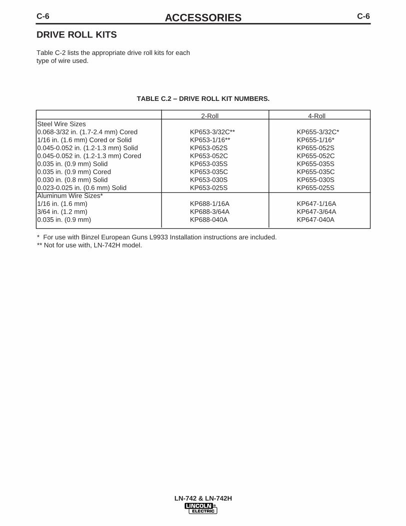
DRIVE ROLL KITS
Table C-2 lists the appropriate drive roll kits for eachtype of wire used.
LN-742 & LN-742H
2-Roll 4-RollSteel Wire Sizes0.068-3/32 in. (1.7-2.4 mm) Cored KP653-3/32C** KP655-3/32C*1/16 in. (1.6 mm) Cored or Solid KP653-1/16** KP655-1/16*0.045-0.052 in. (1.2-1.3 mm) Solid KP653-052S KP655-052S0.045-0.052 in. (1.2-1.3 mm) Cored KP653-052C KP655-052C0.035 in. (0.9 mm) Solid KP653-035S KP655-035S0.035 in. (0.9 mm) Cored KP653-035C KP655-035C0.030 in. (0.8 mm) Solid KP653-030S KP655-030S0.023-0.025 in. (0.6 mm) Solid KP653-025S KP655-025SAluminum Wire Sizes*1/16 in. (1.6 mm) KP688-1/16A KP647-1/16A3/64 in. (1.2 mm) KP688-3/64A KP647-3/64A0.035 in. (0.9 mm) KP688-040A KP647-040A
TABLE C.2 – DRIVE ROLL KIT NUMBERS.
* For use with Binzel European Guns L9933 Installation instructions are included.** Not for use with, LN-742H model.

D-1MAINTENANCED-1
LN-742 & LN-742H
ROUTINE MAINTENANCE
DRIVE ROLLS AND GUIDE TUBES
After feeding every coil of wire, inspect the drive rollsection. Clean the assembly as necessary. Do not usesolvent to clean the drive roll assembly as it may washthe lubricant out of the bearings. The drive rolls andguide tubes are stamped with the wire sizes they willfeed. If a wire size other than that stamped on the rollsis to be used, the rolls and guide tubes must bechanged.
The drive rolls for 0.045 and 0.052 cored electrodeand 1/16, 0.068, 5/64, 3/32, and 7/64 electrode havea double set of teeth so they can be reversed foradditional life. Drive rolls for 0.023 through 0.052 solidelectrodes have no teeth.
Refer to the instructions in Section B, Operation forinstallation of drive rolls.
WIRE REEL MOUNTING
To prolong the life of the reel shaft on the 50 to 60 lbcoils, periodically coat it with a thin layer of grease. Nomaintenance to the two position brake is required. Ifthe brake shoe wears through to metal, replace thebrake assembly.
No routine maintenance is required for Readi-Reelsand 10 to 30 lb spools. Do not lubricate the 2 in.spindles.
PERIODIC MAINTENANCE
WIRE DRIVE MOTOR AND GEARBOX
Every year inspect the gearbox and coat the gearteeth with a moly-disulfide filled grease. Do not usegraphite grease.
Every six months check the motor brushes. Replacethem if they are less than 1/4 in. long.
GUN AND CABLE MAINTENANCE
For instructions on periodic maintenance for thewelding gun and cables, refer to the instructionsincluded with your specific model of welding gun.

E-1TROUBLESHOOTINGE-1
LN-742 & LN-742H
If for any reason you do not understand the test procedures or are unable to perform the tests/repairs safely, contact yourLocal Lincoln Authorized Field Service Facility for technical troubleshooting assistance before you proceed.
CAUTION
This Troubleshooting Guide is provided tohelp you locate and repair possible machinemalfunctions. Simply follow the three-stepprocedure listed below.
Step 1. LOCATE PROBLEM (SYMPTOM).Look under the column labeled “PROBLEM(SYMPTOMS)”. This column describespossible symptoms that the machine mayexhibit. Find the listing that best describesthe symptom that the machine is exhibiting.
Step 2. POSSIBLE CAUSE.The second column labeled “POSSIBLECAUSE” lists the obvious external possibili-ties that may contribute to the machinesymptom.
Step 3. RECOMMENDED COURSE OFACTIONThis column provides a course of action forthe Possible Cause, generally it states tocontact you local Lincoln Authorized FieldService Facility.
If you do not understand or are unable toperform the Recommended Course ofAction safely, contact you local LincolnAuthorized Field Service Facility.
HOW TO USE TROUBLESHOOTING GUIDE
Service and Repair should only be performed by Lincoln Electric Factory Trained Personnel.Unauthorized repairs performed on this equipment may result in danger to the technician andmachine operator and will invalidate your factory warranty. For your safety and to avoidElectrical Shock, please observe all safety notes and precautions detailed throughout this manual.__________________________________________________________________________
WARNING
WARNINGELECTRIC SHOCK can kill.• Do not touch electrically live parts such as
internal wiring.
• Only qualified personnel should install, use or ser-vice this equipment.

E-2TROUBLESHOOTINGE-2
LN-742 & LN-742H
Observe all Safety Guidelines detailed throughout this manual
If for any reason you do not understand the test procedures or are unable to perform the tests/repairs safely, contact yourLocal Lincoln Authorized Field Service Facility for technical troubleshooting assistance before you proceed.
CAUTION
PROBLEMS(SYMPTOMS)
POSSIBLE AREAS OFMISADJUSTMENTS(S)
RECOMMENDEDCOURSE OF ACTION
The display is blank. No wire feedwhen the gun trigger is activated.
No wire feed when the gun triggeris activated. The solenoid does notfunction. No arc voltage present.The display board indicates theLN-742 has input power applied.
1. Make sure the control cable isconnected to the welding powersource correctly.
2. Make sure the welding powersource is turned on and func-tioning properly.
3. Check the 42 VAC fuse or cir-cuit breaker in the weldingpower source.
1. Check or replace the gun triggerswitch.
2. Check the gun trigger recepta-cle. Check for loose or faultyconnections.
If all recommended possible areas ofmisadjustment have been checkedand the problem persists, Contactyour local Lincoln AuthorizedField Service Facility.

E-3TROUBLESHOOTINGE-3
LN-742 & LN-742H
Observe all Safety Guidelines detailed throughout this manual
If for any reason you do not understand the test procedures or are unable to perform the tests/repairs safely, contact yourLocal Lincoln Authorized Field Service Facility for technical troubleshooting assistance before you proceed.
CAUTION
PROBLEMS(SYMPTOMS)
POSSIBLE AREAS OFMISADJUSTMENTS(S)
RECOMMENDEDCOURSE OF ACTION
When the gun trigger is activatedthe wire feed motor runs and thesolenoid functions but no arc volt-age is present.
The wire feeds when the gun trig-ger is activated but there is no con-trol of the wire feed speed.
The wire feed speed does notchange when welding currentbegins to flow.
1. Make sure the welding powersource is functioning properly.Disconnect the control cablefrom the Lincoln power source.Place a jumper across socketsC and D of the 14 pin amphenolplug at the power source. Opencircuit voltage should be pre-sent at the welder output termi-nals. If no voltage is present atthe output terminals the powersource is faulty.
2. The control cable may be faulty.Check leads #2 and #4 (pins Cand D) for continuity (zeroohms).
3. The welding cables may mefaulty. Check for loose or faultyconnections.
4. The gun may be faulty. Checkor replace.
1. Check for loose or faulty con-nections between the tach andthe control board plug J3.
1. The inch and weld speeds maybe set to the same value.
2. If the display shows the ----symbol the inch speed hasbeen disabled. To enable theinch speed press the increasearrow key.
3. Check plug J2 on the controlboard for loose or faulty con-nections.
If all recommended possible areas ofmisadjustment have been checkedand the problem persists, Contactyour local Lincoln AuthorizedField Service Facility.

E-4TROUBLESHOOTINGE-4
LN-742 & LN-742H
Observe all Safety Guidelines detailed throughout this manual
If for any reason you do not understand the test procedures or are unable to perform the tests/repairs safely, contact yourLocal Lincoln Authorized Field Service Facility for technical troubleshooting assistance before you proceed.
CAUTION
PROBLEMS(SYMPTOMS)
POSSIBLE AREAS OFMISADJUSTMENTS(S)
RECOMMENDEDCOURSE OF ACTION
The LN-742 voltmeter does notfunction or read correctly when theactual arc voltage is present. Thewire feeder is feeding wire correct-ly.
The LN-742 shuts down whilewelding and the HXX symbolappears on the display.
The display and/or indicator lightsdo not change when the arrow orselect keys are pressed.
The arrow keys do not change thewelding wire feed speed.
1. Make sure the polarity switch onthe Lincoln welding powersource is in the correct positionfor the welding process.
2. Check or replace the controlcable. Check the continuity(zero ohms) of leads #21 and#67.
1. Check for mechanical restric-tions in the wire feed path.
1. Make sure the control cable isconnected to the welding powersource correctly.
2. Check the 42 VAC fuse or cir-cuit breaker in the weldingpower source.
1. If a remote control unit is con-nected to the LN-742 the arrowkeys will not change weldingwire feed speed. Use the WFSpot on the remote control unit ordisconnect the remote controlunit and use the arrow keys.
If all recommended possible areas ofmisadjustment have been checkedand the problem persists, Contactyour local Lincoln AuthorizedField Service Facility.

E-5TROUBLESHOOTINGE-5
LN-742 & LN-742H
Observe all Safety Guidelines detailed throughout this manual
If for any reason you do not understand the test procedures or are unable to perform the tests/repairs safely, contact yourLocal Lincoln Authorized Field Service Facility for technical troubleshooting assistance before you proceed.
CAUTION
PROBLEMS(SYMPTOMS)
POSSIBLE AREAS OFMISADJUSTMENTS(S)
RECOMMENDEDCOURSE OF ACTION
The purge key does not activatethe gas solenoid. The solenoiddoes activate when the gun triggeris pulled.
The gas solenoid does not activateeither when the purge key ispressed or when the gun trigger ispulled.
The cold inch key does not activatethe wire feed motor. The wire feedmotor operates normally when thegun trigger is pulled.
The HI symbol appears on the dis-play when the voltmeter function isselected.
The Er symbol appears on the dis-play.
The EXX appears on the display.(XX is some number from 1 to 10.)
The EP symbol appears on thedisplay.
The uP symbol appears on the dis-play. (Microprocessor RAM error.)
1. Contact your local LincolnAuthorized Field ServiceFacility.
1. Check plug J6, located on thecontrol board for loose or faultyconnections.
1. Contact your local LincolnAuthorized Field ServiceFacility.
1. If the arc voltage is greater than44 VDC, this is a normal condi-tion. The voltmeter only reads0-44 VDC.
1. This is an EPROM error. Theparameter recalled at power-upis out of range. Press any keyto reset unit. Check all weldsettings before proceeding withweld.
1. Remove input power to thefeeder (42 VAC). Wait 5 sec-onds. The symbol should notreappear when power isreturned.
1. Remove input power to thefeeder (42 VAC). Wait 5 sec-onds. The symbol should notreappear when power isreturned.
1. Remove input power to thefeeder (42 VAC). Wait 5 sec-onds. The symbol should notreappear when power isreturned.
If all recommended possible areas ofmisadjustment have been checkedand the problem persists, Contactyour local Lincoln AuthorizedField Service Facility.

E-6TROUBLESHOOTINGE-6
LN-742 & LN-742H
Observe all Safety Guidelines detailed throughout this manual
If for any reason you do not understand the test procedures or are unable to perform the tests/repairs safely, contact yourLocal Lincoln Authorized Field Service Facility for technical troubleshooting assistance before you proceed.
CAUTION
PROBLEMS(SYMPTOMS)
POSSIBLE AREAS OFMISADJUSTMENTS(S)
RECOMMENDEDCOURSE OF ACTION
The wire is feeding rough or notfeeding. The drive rolls are turn-ing.
The drive rolls do not turn when thegun trigger is pressed. The gassolenoid activates and arc voltageis present.
1. Check for mechanical restric-tions in the wire feeding path.Check the gun and gun compo-nents.
2. Check the drive roll position andidle roll pressure.
3. The electrode may be dirty orrusty.
4. Check for the correct gun liner,tip, and guide tubes.
1. Check plug J5 on the controlboard for loose or faulty con-nections.
If all recommended possible areas ofmisadjustment have been checkedand the problem persists, Contactyour local Lincoln AuthorizedField Service Facility.

E-7TROUBLESHOOTINGE-7
LN-742 & LN-742H
Observe all Safety Guidelines detailed throughout this manual
If for any reason you do not understand the test procedures or are unable to perform the tests/repairs safely, contact yourLocal Lincoln Authorized Field Service Facility for technical troubleshooting assistance before you proceed.
CAUTION
PROBLEMS(SYMPTOMS)
POSSIBLE AREAS OFMISADJUSTMENTS(S)
RECOMMENDEDCOURSE OF ACTION
The welding arc is variable or“hunting”.
Poor arc striking with sticking or“blast-offs”. The weld bead may beropy and narrow.
1. Check the welding cables forloose or faulty connections.
2. Make sure the wire feed speed,voltage, polarity and shieldinggas are correct for the processbeing used.
3. Check for mechanical restric-tions in the wire feed path.
4. Make sure the welding powersource is functioning properly.
1. Make sure the wire feed speed,voltage, polarity and shieldinggas are correct for the processbeing used.
2. Make sure the welding powersource is functioning properly.
3. Make certain the gas solenoid isoperating properly and the gasflow rate is correct for the pro-cedure.
4. The welding gun may be faulty.Check for gas leaks or replacegun.
If all recommended possible areas ofmisadjustment have been checkedand the problem persists, Contactyour local Lincoln AuthorizedField Service Facility.

F-1DIAGRAMSF-1
LN-742 & LN-742H
CLE
VELA
ND
, OH
IO U
.S.A
.
3-2
9-96
H
L
9124
R
W
IRIN
G D
IAG
RA
M
LN
-74
2
J1
P.M
.
RU
B
+ -A
CA
C
542
500M
542
500M
2
J3J4
J5J6
J7
BR
IDG
E
INP
UT
CA
BLE
REC
EPTA
CLE
CO
NTR
OL
P.C
. B
OA
RD
2 4 21
A B C D E
*
*
**
*
*1
14
58
13
46
12
34
1 2
J3
J4
J2
J6
J1
J5J7
1 2
CA
VITY
NU
MB
ERIN
G S
EQU
ENC
E*
CO
NN
ECTO
R C
AVI
TYN
UM
BER
ING
SEQ
UEN
CE
LEA
D C
OLO
R C
OD
ING
B -
BLA
CK
R -
RED
W -
WH
ITE
U -
BLU
E
BW
INP
UT
ELEC
TRO
DE
CA
BLE
(NO
N L
EAD
SID
E O
F C
ON
NEC
TOR
)
J2
*
21
67
75 76 77
F G H
75 76 77
6
712
4
4
4
500
500 DIS
PLA
YP
.C.
BO
AR
D
12 A
B
C DE
FG
E50
0
KEY
PA
D
* *
J10
500 A B C D E F G
N.A
.
18
552
554
553
67
554551552553
(CO
MP
ON
ENT
SID
E O
F P
.C.
BO
AR
D)
J10
1 2 3 4 5 6
1 2** *
517
516
W W
CD
AB
GF
551
RU
B
W
W
13
46
***
516
GUNR W BC
W
CW
A B C D E F
517
75 76 77
GUN B W RG
- G
REE
NN
- B
RO
WN
10K
5K
518
516
L L L
P9
518
J11
P8
PIN
NU
MB
ERIN
G S
EQU
ENC
E
P9
PIN
1
J9J8
L R.F
. C
HO
KE
517518
BW
R.F
. TO
RO
ID A
SS
EMB
LY
J11
512A
W.F
.S.
VOLT
AG
E
512A
TAC
H BU
R
ELEC
TRIC
AL
SYM
BO
LS P
ER E
1537
.
N.A
. P
RES
ENT
ON
LY O
N T
HE
LN-7
42H
MO
DEL
S.
P8
R R
R.F
. TO
RO
ID A
SS
EMB
LY
R
R
41 42
A B C D E
GU
N
CO
NTR
OL
CA
BLE
W.F
.S.
PO
T. C
ON
NEC
TOR
AN
DVO
LTA
GE
PO
T. C
ON
NEC
TOR
OP
TIO
NA
L R
EMO
TEW
IRE
FEED
SP
EED
&VO
LTA
GE
PO
T. A
SS
EMB
LY
CU
RR
ENT
SEN
SIN
GR
EED
SW
ITC
H
GA
SS
OLE
NO
ID
OP
TIO
NA
LW
ATE
RS
OLE
NO
ID
P10
P11
34
56
78
12
34
56
78
12
34
56
78
910
1112
12
34
12
34
56
78
12
34
56
12
12
12
34
UU
(CO
MP
ON
ENT
SID
E O
F P
.C.
BO
AR
D)
** ***
J14 J1
3
J12
L L L
L L L
NO
TE
: T
his
dia
gra
m is
fo
r re
fere
nce
onl
y.
It m
ay n
ot
be
accu
rate
fo
r al
l mac
hine
s co
vere
d b
y th
is m
anua
l. T
he s
pec
ific
dia
gra
m f
or
a p
artic
ular
co
de
is p
aste
d in
sid
eth
e m
achi
ne o
n o
ne o
f th
e en
clo
sure
pan
els.
If
the
dia
gra
m is
ille
gib
le, w
rite
to
the
Ser
vice
Dep
artm
ent
for
a re
pla
cem
ent.
Giv
e th
e eq
uip
men
t co
de
num
ber
..

NOTES
LN-742 & LN-742H

Now Available...12th EditionThe Procedure Handbook of Arc Welding
With over 500,000 copies of previous editions publishedsince 1933, the Procedure Handbook is considered by many to be the “Bible” of the arc welding industry.
This printing wil l go fast so don ’t delay. Place your order now using the coupon below.
The hardbound book contains over 750 pages of weldinginformation, techniques and procedures. Much of this material has never been included in any other book.
A must for al l welders, supervisors, engineers anddesigners. Many welding instructors will want to use the bookas a reference for all students by taking advantage of the lowquantity discount prices which include shipping by4th class parcel post.
$15.00 postage paid U.S.A. Mainland
How To Read Shop Drawings
The book contains the latest information and applicationdata on the American Welding Society Standard WeldingSymbols. Detailed discussion tells how engineers anddraftsmen use the “short-cut” language of symbols to passon assembly and welding information to shop personnel.
Practical exercises and examples develop the reader’s abilityto visualize mechanically drawn objects as they will appearin their assembled form.
187 pages with more than 100 illustrations. Size 8-1/2” x 11”Durable, cloth-covered board binding.
$4.50 postage paid U.S.A. Mainland
New Lessons in Arc WeldingLessons, simply written, cover manipulatory techniques;
machine and electrode characteristics; related subjects,such as distortion; and supplemental information on arcwelding applications, speeds and costs. Practice materials,exercises, questions and answers are suggested for each lesson.
528 pages, well illustrated, 6” x 9” size, bound in simulated,gold embossed leather.
$5.00 postage paid U.S.A. Mainland
Need Welding Training?The Lincoln Electric Company operates the oldest and
most respected Arc Welding School in the United States at itscorporate headquarters in Cleveland, Ohio. Over 100,000 stu-dents have graduated. Tuit ion is low and the training is “hands on”
For details write: Lincoln Welding School22801 St. Clair Ave. Cleveland, Ohio 44117-1199.
and ask for bulletin ED-80 or call 216-383-2259 and ask for theWelding School Registrar.
Lincoln Welding SchoolBASIC COURSE $700.00
5 weeks of fundamentalsThere is a 10% discount on all orders of $50.00 or more for shipment at one time to one location.Orders of $50 or less before discount or orders outside of North America must be prepaid with charge, check or money order in U.S. Funds Only.Prices include shipment by 4 thClass Book Rate for U.S.A. Mainland Only. Please allow up to 4 weeks for delivery.UPS Shipping for North America Only. All prepaid orders that request UPS shipment please add:
$5.00 For order value up to $49.99$10.00 For order value between $50.00 & $99.99$15.00 For order value between $100.00 & $149.00
For North America invoiced orders over $50.00 & credit card orders, if UPS is requested, it will be invoiced or charged to you at cost.Outside U.S.A. Mainland order must be prepaid in U.S. Funds. Please add $2.00 per book for surface mail or $15.00 per book for air parcel post shipment.METHOD OF PAYMENT: (Sorry, No C.O.D. Orders)
CHECK ONE:Name: _______________________________________________
Please Invoice (only if order is over $50.00)Address: _______________________________________________
Check or Money Order Enclosed, U.S. Funds only _______________________________________________
Credit Card - Telephone: _______________________________________________
Signature as it appears on Charge Card:Account No. |_|_|_|_|_|_|_|_|_|_|_|_|_|_|_|_|_|_|_|_|_| Exp Date |_|_| |_|_| ______________________Month Year
USE THIS FORM TO ORDER: Order from: BOOK DIVISION, The Lincoln Electric Company, 22801 St. Clair Avenue, Cleveland, Ohio 44117-1199BOOKS OR FREE INFORMATIVE CATALOGS Telephone: 216-383-2211 or, for fastest service, FAX this completed form to: 216-361-5901.
Lincoln Welding School Titles: Price Code Quantity Cost(ED-80) New Lessons in Arc Welding $5.00 L
Seminar Information Procedure Handbook “Twelfth Edition” $15.00 PH(ED-45) How to Read Shop Drawings $4.50 H
Educational Video Information Incentive Management $5.00 IM(ED-93) A New Approach to Industrial Economics $5.00 NA
James F. Lincoln Arc Welding The American Century of John C. Lincoln $5.00 ACFoundation Book Information Welding Preheat Calculator $3.00 WC-8
(JFLF-515) Pipe Welding Charts $4.50 ED-89SUB TOTAL
Additional Shipping Costs if anyTOTAL COST
MasterCard
VISA ®
AMERICAN EXPRESS
MasterCardMasterCard®
AMERICAN EXPRESS

NOTES
LN-742 & LN-742H

NOTES
LN-742 & LN-742H

WARNING
AVISO DEPRECAUCION
ATTENTION
WARNUNG
ATENÇÃO
Spanish
French
German
Portuguese
Japanese
Chinese
Korean
Arabic
READ AND UNDERSTAND THE MANUFACTURER’S INSTRUCTION FOR THIS EQUIPMENT AND THE CONSUMABLES TO BEUSED AND FOLLOW YOUR EMPLOYER’S SAFETY PRACTICES.
SE RECOMIENDA LEER Y ENTENDER LAS INSTRUCCIONES DEL FABRICANTE PARA EL USO DE ESTE EQUIPO Y LOSCONSUMIBLES QUE VA A UTILIZAR, SIGA LAS MEDIDAS DE SEGURIDAD DE SU SUPERVISOR.
LISEZ ET COMPRENEZ LES INSTRUCTIONS DU FABRICANT EN CE QUI REGARDE CET EQUIPMENT ET LES PRODUITS AETRE EMPLOYES ET SUIVEZ LES PROCEDURES DE SECURITE DE VOTRE EMPLOYEUR.
LESEN SIE UND BEFOLGEN SIE DIE BETRIEBSANLEITUNG DER ANLAGE UND DEN ELEKTRODENEINSATZ DES HER-STELLERS. DIE UNFALLVERHÜTUNGSVORSCHRIFTEN DES ARBEITGEBERS SIND EBENFALLS ZU BEACHTEN.
● Do not touch electrically live parts orelectrode with skin or wet clothing.
● Insulate yourself from work andground.
● No toque las partes o los electrodosbajo carga con la piel o ropa moja-da.
● Aislese del trabajo y de la tierra.
● Ne laissez ni la peau ni des vête-ments mouillés entrer en contactavec des pièces sous tension.
● Isolez-vous du travail et de la terre.
● Berühren Sie keine stromführendenTeile oder Elektroden mit IhremKörper oder feuchter Kleidung!
● Isolieren Sie sich von denElektroden und dem Erdboden!
● Não toque partes elétricas e elec-trodos com a pele ou roupa molha-da.
● Isole-se da peça e terra.
● Keep flammable materials away.
● Mantenga el material combustiblefuera del área de trabajo.
● Gardez à l’écart de tout matérielinflammable.
● Entfernen Sie brennbarres Material!
● Mantenha inflamáveis bem guarda-dos.
● Wear eye, ear and body protection.
● Protéjase los ojos, los oídos y elcuerpo.
● Protégez vos yeux, vos oreilles etvotre corps.
● Tragen Sie Augen-, Ohren- und Kör-perschutz!
● Use proteção para a vista, ouvido ecorpo.

WARNING
AVISO DEPRECAUCION
ATTENTION
WARNUNG
ATENÇÃO
Spanish
French
German
Portuguese
Japanese
Chinese
Korean
Arabic
LEIA E COMPREENDA AS INSTRUÇÕES DO FABRICANTE PARA ESTE EQUIPAMENTO E AS PARTES DE USO, E SIGA ASPRÁTICAS DE SEGURANÇA DO EMPREGADOR.
● Keep your head out of fumes.● Use ventilation or exhaust to
remove fumes from breathing zone.
● Los humos fuera de la zona de res-piración.
● Mantenga la cabeza fuera de loshumos. Utilice ventilación oaspiración para gases.
● Gardez la tête à l’écart des fumées.● Utilisez un ventilateur ou un aspira-
teur pour ôter les fumées des zonesde travail.
● Vermeiden Sie das Einatmen vonSchweibrauch!
● Sorgen Sie für gute Be- undEntlüftung des Arbeitsplatzes!
● Mantenha seu rosto da fumaça.● Use ventilação e exhaustão para
remover fumo da zona respiratória.
● Turn power off before servicing.
● Desconectar el cable de ali-mentación de poder de la máquinaantes de iniciar cualquier servicio.
● Débranchez le courant avant l’entre-tien.
● Strom vor Wartungsarbeitenabschalten! (Netzstrom völlig öff-nen; Maschine anhalten!)
● Não opere com as tampas removidas.● Desligue a corrente antes de fazer
serviço.● Não toque as partes elétricas nuas.
● Do not operate with panel open orguards off.
● No operar con panel abierto oguardas quitadas.
● N’opérez pas avec les panneauxouverts ou avec les dispositifs deprotection enlevés.
● Anlage nie ohne Schutzgehäuseoder Innenschutzverkleidung inBetrieb setzen!
● Mantenha-se afastado das partesmoventes.
● Não opere com os paineis abertosou guardas removidas.

• Sales and Service through Subsidiaries and Distributors Worldwide •Cleveland, Ohio 44117-1199 U.S.A. TEL: 216.481.8100 FAX: 216.486.1751 WEB SITE: www.lincolnelectric.com
• World's Leader in Welding and Cutting Products •