im pb-g1: packaged water chiller, pb 20-30...
TRANSCRIPT

:A1
:TION

INSTALLATION
RECEIVING & HANDLING
The unit should be inspected immediately after receiptfor possible shipping damage. The type PB waterchillers are shipped F.O.B. factory, and all claims forhandling and shipping damage are the responsibility ofthe consignee.
The mounting legs plus the leg hardware are shipped in-side unit.
The unit can be lifted by means of slings under eachend. Since the weight is not equally distributed betweenboth ends, care should be exercised in the placement ofthe slings in order to obtain the proper balance.
The unit should be placed in its final position before at-taching the mounting legs to avoid damage duringhandling.
LOCATION & MOUNTING
The PB unit should be located so as to provide serviceclearances of 3 feet on all sides and the top plus 6 l/2feet on either end of the unit in the event it becomesnecessary to remove a chiller tube bundle. If space islimited, the complete chillers can be removed throughthe rear of the unit cabinet after removing the panelsand the bolted in vertical support to which the panelsare fastened. The tube bundle can then be removedfrom each chiller. In this case, 3 feet on each end is suf-ficient.
Make certain that the floor is adequate to support thefull operating weight of the complete unit. Operatingweights are given in Table I. The compressors arespring-mounted so that a minimum of compressorvibration is transmitted to the frame of the unit.
Attachment of Mounting Legs-The mounting legsshould be installed at the four corners of the unit usingthe hardware shipped with the legs. The bolts shouldpass through the legs and on through the frame of theunit. Fig. 1 shows two of the bolts in place.
Stacking of Units-Two units (maximum) may bestacked together so as to conserve space. When this isdone, it will be necessary to provide other means ofsupporting the two PB units since the legs supplied withthe equipment will not support two units. It is recom-mended that the locally fabricated base be high enoughto raise the units at least 1 foot above the floor to aid inservicing the equipment. Local codes should be check-ed to determine the minimum required distance.
When stacking two units, the bottom panel of the upperunit and the top panel of the lower unit should be
removed and discarded. This will provide greater accesswhen servicing the equipment.
Fig. 1 Unit with LH (Facing Gauge Panel) End Panel Removed
Under some extreme conditions of humidity, sweatingmay occur on the end bell of the compressors or thesuction lines in which case protection against mositurearound the electrical connections of the lower unit maybe required when stacking two units together.
Hanging Units-The PB unit may be hung from a ceilingor joist by one of the methods shown in Fig. 2.Sweating may occur as mentioned in the previousparagraph and to facilitate the removal of any collectedwater, the bottom panel is cross-broken toward thecenter where a 1/2 inch diameter hole is provided fordrainage.
PRESSURE TESTING (If Repair Necessary)
No pressure testing is necessary unless some damagewas incurred during the shipment of the unit, and it isnecessary to make repair to the refrigerant circuit. Inthis case the repairs should be made, the unit pressuretested at a pressure not to exceed 200 PSIG and

Fig. 2 Suggested Methods for Hanging Units
evacuated prior to charging. These latter two pro-cedures are described in paragraphs to follow.
LEAK TESTING (If Repair Necessary)
In the case of loss of the refrigerant charge, the unitshould be checked for leaks prior to charging the com-plete system. This can do done by charging onlyenough refrigerant into the system to build the pressureup to approximately 30 PSIG and adding sufficient dryNitrogen to bring the pressure up to a maximum of 200PSIG and then leak test with a Halide or electronic leakdetector. CAUTION: Do not use Oxygen to build uppressure as a serious explosion can result. A pressureregulating valve should always be used on the drum be-ing used to build up the system pressure. Also, do notexceed the test pressures given above. When the testpressure is reached, disconnect the gas cylinder.
If any leaks are found in welded or silver soldered jointsor if it is necessary to replace a gasket, relieve the testpressure in the system before proceeding. For copperjoints, Easy-Flo silver solder is recommended.
After making any necessary repair, the system shouldbe evacuated as described below.
EVACUATION (If Repair Necessary)
After it has been determined that there are norefrigerant leaks, the system should be evacuated usinga vacuum pump with a capacity of approximately 3 cu.ft./min. and that will reduce the vacuum to at least 1millimeter.
A Mercury manometer, electronic or other type ofmicron gauge should be connected at the farthest pointfrom the vacuum pump. For readings below 1millimeter, the electronic or other micron gauge shouldbe used.
The triple evacuation method is recommended and isparticularly helpful if the vacuum pump is unable to ob-tain the desired 1 millimeter of vacuum. The system isfirst evacuated to approximately 29 inches of vacuum.Enough refrigerant is then added to the system to bringthe pressure up to zero pounds. Then the system isonce again evacuated to approximately 29 inches ofvacuum. This is repeated 3 times. The first pull downwill remove about 90 per cent of the noncondensables,the second about 90 per cent of that remaining from thefirst pull down, and after the third, approximately 1/10of 1 per cent noncondensables will remain.
CHARGING THE SYSTEMS (If Repair Necessary)
All type PB water chillers are leak tested at the factoryand shipped with the correct charge of refrigerant-22 asindicated in Table I. In the event the refrigerant chargewas lost due to shipping damage, the system(s) shouldbe charged as follows after first repairing any leaks andevacuating the system(s):
1. Connect the refrigerant drum to the backseatinggauge port on the liquid shut-off valve and purgethe charging line between the refrigerant cylinderand the charging value. Then open the valve tothe mid-position.

2.
3.
4.
5.
6.
7.
8.
Turn on both the cooling tower water pump andchilled water pump and allow water to circulatethrough the condenser and the chiller.
If the system is under a vacuum, stand therefrigerant drum with the connection up andopen the drum and break the vacuum withrefrigerant gas.
With a system gas pressure higher than theequivalent of a freezing temperature, invert thecharging cylinder and elevate the drum abovethe condenser. With the drum in this position,valves open, water pumps operating, liquidrefrigerant will flow into the condenser. Approx-imately 75 per cent of the total requirementestimated for the unit should be charged in thismanner.
After 75 per cent of the required charge hasentered the condenser, reconnect the refrigerantdrum and charging line to the gauge port on thecompressor suction shutoff valve. Again, purgethe connecting line, stand the drum with theconnection up and place the suction shut-offvalve in the mid-poistion.
Make sure all refrigerant shut-off valves are openand that water is still circulating through thechiller and condenser. Start the compressor byfirst closing the disconnect switch and thenplace the control center selector switch in the“on” position, checking immediately that (a)compressor motor starting characteristics arenormal and (b) that suction pressure and leavingwater temperature are above the freezing zone.
Allow vapor refrigerant to enter the system untilthe liquid-line sight glass (es) indicates a full flowof refrigerant. The absence of any bubbles in thesight glass(es) indicates a normal charge but tobe accurate, this determination should be madewhen the system is operating under full load. Becareful not to overcharge; this may be checkedby the liquid-line temperature which should nothave more than 10 to 15 degrees of sub-coolingat the condenser outlet.
After approximately 1 hour’s operation, thecombination moisture indicator and sight glassshould show a clear stream of liquid refrigerantand a dry blue condition. Make sure to allow atleast 1 hour’s running time for the color tostabilize.
ELECTRICAL CONNECTIONS
Since the units are approved for group fusing, it is onlynecessary to bring the power line from one disconnect
switch to the terminal block located in the controlcenter section of the unit. In addition the cooling-towerpump (if used) and chilled-water pump interlock con-nection between terminals “F” and “G” must be com-pleted. Reference should be made to the wiring diagramin the Electrical Data Page 5 or to the wiring diagram onthe inside of the control center door. The field connec-tions are shown in the shaded area. Separate coolingtower and chiller water pump starters with appropriatecontrol devices must be provided by the installer.
Wire, disconnect and Fusetron sizes are shown in Elec-trical Data Table Ill. Fusetrons are recommended sincethey can be sized much closer to the actual motor runn-ing current than standard fuses. Even though sized veryclose to the running current, Fusetrons will not blow outduring the higher-inrush current at start due to a builtintime lag. This, therefore, gives much better motor pro-tection.
Knockouts are provided in the RH (when facing gaugepanel) end panel for bringing in the power as well aspump-interlock connections.
All units have a 220 volt control circuit. For highervoltage units (above 240 volt rating) a controltransformer is supplied, mounted and wired to providethe 220 volt control voltage. The transformer rating is 80volt-amperes (adjusted for operating ambienttemperature). The unit control-circuit rating is 48 volt-amperes.
With the arrangement shown on the wiring diagram,the chilled-water pump and cooling-tower pump (if us-ed) will be operating continuously once they are started.If it is desired to cycle the cooling-tower pump with thecompressor, this can be accomplished by electrically in-terlocking the control circuit for the cooling-towerpump starter through the auxiliary contacts of thecompressor-motor starters. It is recommended that theauxiliary contacts for both compressor-motor startersbe connected in parallel so that the cooling-tower pumpwill be energized whenever either compressor is started,
IMPORTANT: The voltage to these units should bewithin the limitation of plus or minus 10% (except on208/220 volt units where the voltage limitation is plus10% on 220 volts and minus 5% on 208 volts) and thevoltage unbalance between phases must not exceed3%. Since a 3 1/2% voltage unbalance will cause an ap-proximate 25% increase in motor temperature, it ismost important that unbalance between phases be at aminimum.
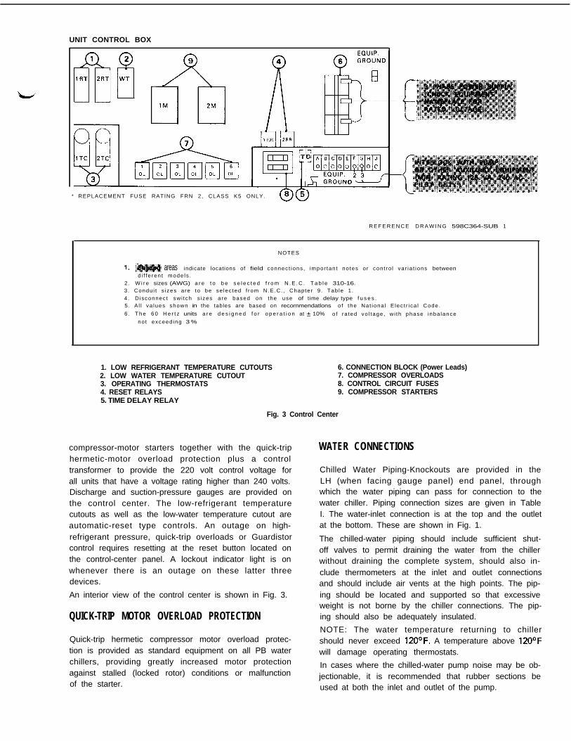
CONTROL CENTER
The control center contains all of the necessary protec-tive and operating controls. These include the twosingle-step operating thermostats, the Guardistor- pro-tective circuit controls, low-water temperature cutout,low-refrigerant temperature cutouts and high- pressurecutouts. In addition, the control center includes the
UNIT CONTROL BOX
* REPLACEMENT FUSE RATING FRN 2, CLASS K5 ONLY.ww
R E F E R E N C E D R A W I N G 598C364-SUB 1
NOTES
areas indicate locations of field connec t ions , impor tan t no tes o r con t ro l va r ia t ions betweend i f f e ren t mode ls .
2 . W i r e sizes (AWG) a r e t o b e s e l e c t e d f r o m N . E . C . T a b l e 310-16.3 . Condu i t s i zes a re to be se lec ted f rom N.E .C. , Chap te r 9 . Tab le 1 .4 . D isconnec t sw i t ch s i zes a re based on the use of time delay type f u s e s .5 . A l l va lues shown in the tables are based on recornmendatlons o f the Na t iona l E lec t r i ca l Code .
6 . T h e 6 0 H e r t z units a r e d e s i g n e d f o r o p e r a t i o n at 2 10% o f ra ted vo l tage , w i th phase inba lance
no t exceed ing 3 %
1. LOW REFRIGERANT TEMPERATURE CUTOUTS2. LOW WATER TEMPERATURE CUTOUT3. OPERATING THERMOSTATS4. RESET RELAYS5. TIME DELAY RELAY
6. CONNECTION BLOCK (Power Leads)7. COMPRESSOR OVERLOADS8. CONTROL CIRCUIT FUSES9. COMPRESSOR STARTERS
Fig. 3 Control Center
compressor-motor starters together with the quick-triphermetic-motor overload protection plus a controltransformer to provide the 220 volt control voltage forall units that have a voltage rating higher than 240 volts.Discharge and suction-pressure gauges are provided onthe control center. The low-refrigerant temperaturecutouts as well as the low-water temperature cutout areautomatic-reset type controls. An outage on high-refrigerant pressure, quick-trip overloads or Guardistorcontrol requires resetting at the reset button located onthe control-center panel. A lockout indicator light is onwhenever there is an outage on these latter threedevices.
An interior view of the control center is shown in Fig. 3.
QUICK-TRIP MOTOR OVERLOAD PROTECTION
Quick-trip hermetic compressor motor overload protec-tion is provided as standard equipment on all PB waterchillers, providing greatly increased motor protectionagainst stalled (locked rotor) conditions or malfunctionof the starter.
WATER CONNECTIONS
Chilled Water Piping-Knockouts are provided in theLH (when facing gauge panel) end panel, throughwhich the water piping can pass for connection to thewater chiller. Piping connection sizes are given in TableI. The water-inlet connection is at the top and the outletat the bottom. These are shown in Fig. 1.
The chilled-water piping should include sufficient shut-off valves to permit draining the water from the chillerwithout draining the complete system, should also in-clude thermometers at the inlet and outlet connectionsand should include air vents at the high points. The pip-ing should be located and supported so that excessiveweight is not borne by the chiller connections. The pip-ing should also be adequately insulated.
NOTE: The water temperature returning to chillershould never exceed 12OOF. A temperature above 120°Fwill damage operating thermostats.
In cases where the chilled-water pump noise may be ob-jectionable, it is recommended that rubber sections beused at both the inlet and outlet of the pump.
Small water-pressure test valves are provided at boththe inlet and outlet connections to the chiller. This per-mits checking of the water-pressure drop through thechiller. The pressure drop through the chillers is shownin Figure 6, Page 13.
A cleanable-type water strainer with a mesh of approx-imately 20 is recommended at the inlet to the chiller,particularly on installations where the chilled-water pip-ing is made up of steel pipe with welded joints or wherethe water or piping is subject to considerable foreignmatter.
Condenser Water Piping- Knockouts are also providedin the LH end panel for the condenser water piping. Aninlet and an outlet connection must be made to each ofthe two condensers and then connected together to acommon supply and return line. The inlet water shouldbe connected to the lower connection on each con-denser, and the outlet water should be connected to theupper connection on each condenser. The connectionlocations are shown in Fig. 1, and the connection sizesare given in Table I. Each condenser on the standardPB-020W and PB-025W is arranged for series flow(four-pass) while the standard PB-030W condensers arearranged for parallel flow (two-pass).
Water piping should comply with local codes andshould always include:
1.
2.
3.
4.
5.
6.
Gate valves to isolate the condenser
A cleanable-type strainer in the supply line,ahead of the water-regulating valve, if used.
Provision for drainina the condenser and piping.NOTE: The condenser is not self-draining andmust be blown out. Refer to the section in thismanual under Seasonal Servicing for additionalinformation on this.
Insulation on the supply line, depending onwater temperature and ambient dew pointtemperature.
A flow balancing valve on a cooling-towerinstallation.
Pipe hangers properly located so as to take theweight and strain off the piping accessories andfittings.
NOTE: In most cases, it will not be necessary to providevibration-eliminator sections in the condenser-inlet andoutlet-water lines, but where noise and vibration iscritical (an example would be where a pipe chase goesthrough walls adjoining living quarters in an apartmentbuilding), they should be used.
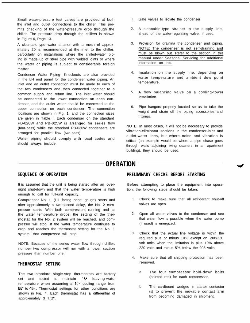
OPERATIONSEQUENCE OF OPERATION PRELIMINARY CHECKS BEFORE STARTING
It is assumed that the unit is being started after an over- Before attempting to place the equipment into opera-night shut-down and that the water temperature is high tion, the following steps should be taken:enough to call for full-unit capacity.
Compressor No. 1 (LH facing panel gauge) starts andafter approximately a two-second delay, the No. 2 com-pressor starts. With both compressors running and asthe water temperature drops, the setting of the ther-mostat for the No. 2 system will be reached, and com-pressor will stop. If the water temperature continues todrop and reaches the thermostat setting for the No. 1system, that compressor will stop.
1.
2.
3.
Check to make sure that all refrigerant shut-offvalves are open.
Open all water valves to the condenser and seethat water flow is possible when the water pump(if used) is energized.
NOTE: Because of the series water flow through chiller,number two compressor will run with a lower suctionpressure than number one.
Check that the actual line voltage is within therequired plus or minus 10% except on 208/220volt units when the limitation is plus 10% above220 volts and minus 5% below the 208 volts.
4. Make sure that all shipping protection has been
THERMOSTAT SETTING removed.
The two standard single-step thermostats are factoryset and tested to maintain 45’ leaving-watertemperature when assuming a IO0 cooling range from55’ to 45’. Thermostat settings for other conditions areshown in Fig. 4. Each thermostat has a differential ofapproximately 3 1/2
a. The four compressor hold-down bolts(painted red) for each compressor.
b. The cardboard wedges in starter contactor(s) to prevent the movable contact armfrom becoming damaged in shipment.

47 10 48 5347 12 48 l/2 54112
49 8 49 l/2 53 l/249 10 50 5549 12 50 l/2 56 II2
Fig. 4Thermostat Setting at Various Leaving-Water Temperatures and Cooling Ranges
5. With the main disconnect switch in the “off”position, make sure all line-starter contacts meetwith even pressure and that all moving partsmove freely. Check that the Fusetrons are in thecircuit, that the thermostats are set below thechilled water temperature and that the hand-off-auto switches are in the “off” position.
6. Check that the four gauge valves are open.NOTE: During normal operation, it is recom-mended that the gauge shut-off valves be kept ina closed position except when taking a reading inorder to prolong the life of the gauges.
7. See that the compressors have a proper supplyof oil. The oil should be visible in the lower por-tion of the sight glass.
8. Manual ly operate the condenser-waterregulating valve (used on city water installations)to clean the water lines of sediment that ac-cumulated during installation. This will preventthe sediment from damaging the seat of thewater-regulating valve when operating in anautomatic position. This can be done by liftingthe spring mechanism.
STARTING AND OPERATIONAL CHECKS
below should be performed:
1. Check the compressor(s) motor amperage tomake sure it is normal. The correct amperage isgiven on the compressor nameplate and is in-cluded also in the Electrical Data Page 11.
2. Check the operation of all the protective controlsto make certain that each interrupts the controlcircuit and stops the compressor. The correctsettings for the controls are given in Table II.Check the controls as follows:
a. High Pressure Cutouts-Throttle thecondenser-water supply slowly untilreaching the cutout point (270 PSIG). Stopthe compressor manually if the dischargepressure exceeds the correct cutout settingby 15 to 20 PSIG.
b. Low-Outlet Water Temperature FreezeControl-If there is a thermometer in theoutlet water of the chiller, the control canbe checked by slowly throttling the supplywater to the chiller. This will cause theoutlet-water temperature to drop. Thereduction in water flow must be done slow-ly enough for the thermometer to react tothe temperature change. If a thermometer
The chilled water flow through the chillers is connectedfor series flow, with the flow from number one tonumber two chiller. The colder water in number twochiller will cause number two compressor to run with alower suction pressure and lower line current thannumber one.
Immediately after starting the unit, the checks listed
is not available in the outlet water, the con-trol can be checked by placing the controlbulb in a container of water; and by slowlyadding ice to the water, the operation point(36’F.I of the control can be reached.
C. L o w - R e f r i g e r a n t T e m p e r a t u r eControls-The bulb for this control is

located in a well in the liquid-refrigerantside of the chiller. An electric-temperaturemeter, such as a Simpson Thermometer,should be used in checking this control.The cutout point can be checked by inser-ting a thermocouple, from the meter, in thewell in contact with the bulb. Therefrigerant temperature can then be reduc-ed by slowly throttling the liquid-refrigerantshut-off valve until the cutout point isreached. If the compressor does not stopby the time the temperature drops to27’F., manually stop the unit andrecalibrate the cutout.
C.
d.
e.
f.
g.
h.
3. One of the most frequent complaints during theearly history of a water-chilling system is that of
pressure drop through chiller and refer toTable 1 for flow).
Water pump not functioning properly.
Plugged water strainer.
Lack of head-pressure control.
Operation of lower than design-watertemperature.
Inadequate air over coils.
Lack of low-side load. Operating with onlya portion of air units installed.
low-suction pressure and the unit cutting out onthe low-refrigerant temperature control. Severalcauses for this condition are listed below:
a. Air in water circuit of water chiller.
b. Inadequate quantity of water (check
4. Record a complete set of operating data forfuture usage and preserve in your or thecustomer’s file. This data should include com-plete nameplate information on the PB unit.
5. Instruct the owner on proper operation and careof the system.
MAINTENANCELUBRICATION
After the system is once placed into operation, no addi-tional lubrication is required for the compressor unless alarge amount of oil is lost from the system due to a largerefrigerant leak.
discharge and suction shut-off valves and openthe compressor-disconnect switch.
4. After the suction pressure reaches 2 PSIG, thesystem can be opened.
PUMPING DOWNSEASONAL SERVICING
If it becomes necessary to pump the system down, ex-treme care should be used to avoid damage to the waterchiller due to freezing. Always make sure that full-waterflow is maintained through the chiller while pumpingdown. It is suggested that the pump-down be ac-complished in three steps as follows:
Prior to seasonal shut-down periods and before startingagain, the following service procedures should be com-pleted.
SHUT-DOWN
1. With the condenser liquid-outlet valve closedand with water flowing through the water chiller,start the compressor and allow it to operate untilthe suction pressure reaches 30 PSIG at whichtime the compressor should be stopped.
1.
2. After waiting approximately four minutes, againstart the compressor. Operate the compressoruntil the suction pressure reach approximately 5PSIG. Stop the compressor at this point.
3. After again waiting approximately four minutes,continue to operate the compressor until thesuction gauge reads approximately 5” of 2.vacuum, stop the compressor, close off the
Where f reez ing tempera tu res may beencountered, the condenser and chiller-waterpiping should be disconnected from the supplyand drained of all water. Dry air blown throughthe condenser will aid in forcing all water out(remove end heads). The condensers are notself-draining. Water permitted to remain in thepiping and condenser will rupture these parts ifsubjected to freezing temperatures. Forced cir-culation of antifreeze through the water circuitsis the only sure method of avoiding freezing trou-ble.
Take measures to prevent the shut-off valve inthe water-supply line from being accidentallyturned on.

3. If a cooling tower is used and if the water pump 5.will be exposed to freezing temperatures, be sureto remove the pump-drain plug and leave itremoved so that any water which may ac-cumulate will drain away.
4. Open compressor disconnect switch and removeFusetrons.
5. Check for corrosion and clean and paint rustedsurfaces.
START-UP6.
)
1. Check and tighten all electrical connections.
2. Replace the drain in cooling-tower pump if it wasremoved at shut-down time the previous season. 8.
3. Install Fusetrons in main disconnect switch.
Clean and flush water tower for all unitsoperating on a water tower. Make sure tower“blow-down” or bleed-off is operating. Set upand use good maintenance program to prevent“liming up” of both tower and condensers. Itshould be recognized that atmospheric air con-tains many contaminants which increase theneed for proper water treatment. (Arrange forlocal water analysis and treatment recommenda-tions. 1
Clean all surfaces and remove all litter.
Refer to the procedures of “Preliminary Checksbefore Starting” before energizing the com-pressor circuit.
Refer to procedures of “Starting and OperationalChecks” after starting the compressor.
4. Reconnect water lines and turn on supply water.Flush out condenser and check for leaks.

-AU MMEWSlOWS I INCHES
I REFERENCE DRAWING-599C37&SUB 2 TABLE I - DIMENSION TABLE IOPERATING CHARGE Condenser Condenser Chiller Approx. Weights
Unit Per Tota l Ref r ig . Pump Down W*ter Water Unit UnitModel circuit u n i t TVP~ Capacity Lbs. Volume Volume Net Operating A B C D E F G HNumber Lb8. Lb,. of Refrigerant Gallons Gallons Lbs. Lbs.
PB OZOW 11 2 2 R-22 2 6 1.7 11 1 .740 1.865 17-l/2 24-7/32 3 - 3 / a lo-19/32 16-l/4 4-15/16 l-1/4 2-l/2
PB 025W 14 28 R-22 3 4 2.1 11 1 .640 1.960 17-l/2 24.7/32 3.3/6 10.19/32 16-l/4 4.15/16 l-114 2-l/2
PB 03OW 16 32 R-22 4 0 2.6 12 2 .030 2 ,190 19.5/32 23.21/32 4-l/2 lo-19/32 19-l/4 7-15/l 6 l-1/2 3
Dimension Table Notes-A. Condenser pump down capacity is based on ARI rating recommendation (60% full-90 F)B. Chiller water capacity is total for two coolers.C. 78 IN. MINIMUM SPACE REQUIRED AT EITHER END OF UNIT TO REMOVE COOLER TUBE BUNDLE.
NOTES
1. The following items are not supplied as part ofPB chiller assembly.
A. WIRING, disconnects, fuses or circuit breakersbetween unit control center and power supply.(Power and control wiring between unit controlcenter and compressors is supplied.)
B. VENT PIPING for condenser relief valves.
C. Condenser or chiller water lines and fittings
other than covered by this drawing.
D. EXTERNAL VIBRATION ABSORBERS for unit
mounting or water lines.
2. SERVICE CLEARANCES-3 feet on all sides. Seeinstallation bulletin for additional details.
3. INTERNAL UNIT details not required for installa-tion or layout purposes are omitted from drawing.
4. Legs and mounting hardware are shipped packedinside unit for field mounting.
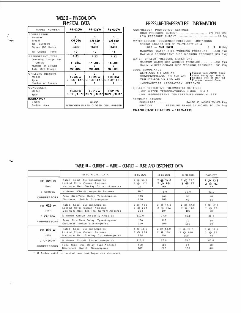
TABLE II - PHYSICAL DATAPHYSICAL DATA
M O D E L N U M B E R
COMPRESSORNumberModa lNo. Cylinders
S p e e d (60 Her tz )
Oil Charge - Pints
REFRIGERANT TYPEOperating Charge Per
C i rcu i tNumber of CircuitsTo ta l Un i t Charge
CHILLERS (Number )M o d e l
TypeNumber of Circuits
CONDENSERM o d e l
Type
NSULATIONChi l l e rSuction Lines
PB 020 w
Uses
2 CH090A
COMPRESSORS
PB 025 w
Uses
2 CH120A
COMPRESSORS
PB 030 w
Uses
2 CH150W
COMPRESSORS
L
GLASSNITROGEN FILLED CLOSED CELL RUBBER
PRESSURE-TEMPERATURE INFORMATIONCOMPRESSOR PROTECTIVE SETTINGS
HIGH PRESSURE CUTOUT .._...._......._................... 270 Psig Max.LOW PRESSURE CUTOUT .._..._....................,................... 20 Psig
WATER-COOLED CONDENSER-PRESSURE LIMITATIONSSPRING LOADED RELIEF VALVE-SETTING &
SIZE - 3/8 INCH .._............................. 3 0 0 Psig
M A X I M U M W A T E R S I D E W O R K I N G P R E S S U R E . ...150 Ps igMAXIMUM REFRIGERANT SIDE WORKING PRESSURE. .335 Ps ig
WATER CHILLER PRESSURE LIMITATIONSMAXIMUM WATER SIDE WORKING PRESSURE . . . . . ...150 PsigMAXIMUM REFRIGERANT SIDE WORKING PRESSURE ..300 Psig
C O D E C O M P L I A N C EUNIT-ASA B . 9 A N D A R I
1
Exempt from ASME CodeCONDENSER-ASA B.9 AND ARI unde r Pa rag raph U- ld .5 .
CHILLER-ASA B.9 A N D A R IS e c t i o n V I I I o f U n f i r e dPressure Vessel Code.
UNDERWRITERS LABORATORY APPROVED
C H I L L E R P R O T E C T I V E T H E R M O S T A T S E T T I N G SL O W W A T E R T E M P E R A T U R E - M I N I M U M 3 6 FL O W R E F R I G E R A N T T E M P E R A T U R E - M I N I M U M 2 8 F
PRESSURE GAUGESDISCHARGE . . . . . . ..PRESSURE RANGE 30 INCHES TO 600 PsigS U C T I O N PRESSURE RANGE 30 INCHES TO 200 Psig
CRANK CASE HEATERS - 110 WATTS
TABLE Ill - CURRENT - WIRE - CONDUIT - FUSE AND DISCONNECT DATA
ELECTRICAL DATA 3-60-200 3-60-230 3-60-460 3-60-575
R a t e d L o a d C u r r e n t - A m p e r e s 2 @ 3 9 . 8L o c k e d R o t o r C u r r e n t - A m p e r e s 2 @ 177M a x i m u m U n i t Startinq C u r r e n t - A m o e r e s 177
M i n i m u m C i r c u i t A m p a c i t v - A m p e r e s 9 0 . 0 7 8 . 0 3 9 . 0 3 2 . 0
F u s e S i z e - T i m e D e l a y T y p e - A m p e r e s 1 2 5 1 0 0 5 0 40Disconnec t Swi tch S ize-Amperes ‘ 1 0 0 1 0 0 6 0 6 0
R a t e d L o a d C u r r e n t - A m p e r e s 2 @ 4 8 5 2 @ 4 4 . 0 2 @ 2 2 . 0 2 @ 1 7 . 6L o c k e d R o t o r C u r r e n t - A m p e r e s 2 @ 2 2 4 2 @ 1 9 4 2 @ 1 0 0 2 @ 7 8M a x i m u m U n i t S t a r t i n a C u r r e n t - A m o e r e s 2 2 4 1 9 4 100 78
M i n i m u m C i r c u i t A m p a c i t y - A m p e r e s 110.0 9 7 . 0 5 5 . 0 4 0 . 0
F u s e S i z e - T i m e D e l a y T y p e - A m p e r e s 1 5 0 125 7 0 5 0D isconnec t Sw i tch S i z e - A m p e r e s 2 0 0 2 0 0 1 0 0 6 0
R a t e d L o a d C u r r e n t - A m p e r e s 2 @ 4 8 . 5 2 @ 4 4 . 0 2 @ 2 2 . 0 2 @ 1 7 . 6L o c k e d R o t o r C u r r e n t - A m p e r e s 2 @ 2 2 4 2 @ 1 9 4 2 @ 1 0 0 2 @ 7 8M a x i m u m U n i t S t a r t i n g C u r r e n t - A m p e r e s 2 2 4 1 9 4 100 7 8
M i n i m u m C i r c u i t A m p a c i t y - A m p e r e s 1 1 0 . 0 9 7 . 0 55.0 4 0 . 0
F u s e S i z e - T i m e D e l a y T y p e - A m p e r e s 1 5 0 1 2 5 7 0 5 0Disconnec t Swi tch S ize-Amperes 200 2 0 0 1 0 0 6 0
* If fusible switch is required, use next larger size disconnect

SCHEMATIC WIRING DIAGRAM
NOTES SYMBOLS LEGEND
1. INTERLOCK FROM PUMP OR OTHER A”X,L,ARY 0 C O I L C-HTR - CRANKCASE HEATER
EOUIPMENT TO SE LOCATED BETWEEN TERMI- CONTACTSCT - COMPRESSOR THERMOSTAT
-it- normally openHP - HIGH P R E S S U R E C U T O U T
NALS F AND G.
2 . C O N T R O L C I R C U I T V O L T A G E I S 2 3 0 V O L T S .
ON UNITS WITH NAMEPLATE GREATER OR LESS
T H A N 2 3 0 V O L T S , A T R A N S F O R M E R I S F U R -
NISHEO TO SUPPLY 230 VOLTS TO CONTROL
CIRCUIT.
3 . W H E N C O N T R O L T R A N S F O R M E R IS NOT RE-
OUIRED, LEADS NO. 24 (I 2 5 A R E O M I T T E D
AND LEADS NO. 22 & 2 3 C O N N E C T D I R E C T L Y
T O T E R M I N A L S 1 & 3.
4. ALL SO HERTZ UNITS ARE U.L. LISTED.
-u- normally closed
-lxrl- F U S E
6”b W I N D I N G
00M O M E N T A R Y P S
normally open04 TERMINAL ON STRIP
@ATERMINAL
C O M P O N E N T
+ S C H E M A T I C W I R EJ U N C T I O N
-++%+ CRANKCASE HEATER
- F A C T O R Y W I R I N G
IL - INDICATING LIGHTLP - LOW PRESSURE CUTOUTM - CONTACTORM A - A U X . C O N T A C T O N C O N T A C T O ROL - OVERLOAD RELAYRR - RESET RELAYRS - RESET SWITCHRT - REFRIG. THERMOSTATss - SYSTEM SWITCH (ON-OFF1TC - THERMOSTAT COOLINGT D - TIME DELAY RELAYW T - WATER THERMOSTAT
- METAL JUMPER BETWEEN TERMINALSIJI+ - AUTOMATIC RESET DEVICE
---_ WIRING BY O T H E R S
AUTOMATIC RESET CONNECTIONSDEVICE 0
l 1,DENTlFlEO TERMINALUNlDENTlFlED OR IMAGINARY TERMINAL
INDICATING LIGHT D - WIRE NUT
Figure 5

MODELSPBOPOW, 025W AND 03OW
I I -,..- i”;‘ ., ...x
50.0 ‘.
GALLONS PER MINUTE (US.1
Figure 6
WATER PRESSURE DROPS
FLOW CORRECT ION FACTOR
ETHYLENE GLYCOL
LEAVING PERCENTTEMPERATURE SOLUTION
F BY WEIGHT
15 3320 29
25 2530 2235 17
FREEZE FLOWPOINT CORRECTION
F FACTOR
0 25.95 25.4
10 24.615 24.520 2 3 . 6
The rate of flow of ethylene glycol solution in gallons perminute may be calculated using the following formulaond the flow factors from the flow correctlo,, factor table.
GPM =Tons of Refrigeration x Factor
TI - Tz
Where:
Factor - From Flow Correction Factor Table
TI - Entering Ethylene Glycol SolutionTemperature-F
T2 - Leaving Ethylene Glycol SolutionTemperature-F
CONDENSER WATER FLOW
a. The PB 02OW, 025W and 03OW hove two refrigerant circuits; one half 1%) of the condenser GPM shown is required in each circuit.
60
% GLYCOL BY WEIGHT
10 20 30 40 50
SOLUTION TEMPERATURE - F
Figure 7