illustrated guide to turf spraying
TRANSCRIPT
ILLUSTRATED GUIDE TO TURF SPRAYING

Table of Contents
Description Page Introduction 1
Safety Precautions 1
Application 2
Technical Information and Formulas 18
Spray Calibration 19
Boom Sprayer Calibration 23
Maximum Target Rates for Spray Hawk 31
Smithco Nozzle Performance Chart #1 32
Smithco Nozzle Performance Chart #2 33
Smithco Nozzle Performance Chart #3 34
Smithco Nozzle Performance Chart #4 35
Smithco Nozzle Performance Chart #5 36
Smithco Nozzle Performance Chart #6 37
Star Command Calibration Test 38

1
INTRODUCTION This guide is intended to offer practical guidelines for the distribution of liquid chemicals over an area of turfgrass such as golf courses, parkland, school grounds and lawns. It offers two procedures for Boom Sprayer Calibration. There are other proven procedures available. Smithco makes no representation as to the suitability of any procedure or product for any particular situation. This Guide is suitable for self-propelled Spray Vehicles, sprayers towed by vehicles and tractors or sprayers mounted onto vehicles. This guide is intended to be used in conjunction with:
1. The Sprayer Owners Manual 2. The Spray Boom Owners Manual 3. The Electronic Spray Control System Owners Manual (if the sprayer is so equipped) 4. It may also be useful to the user to refer to the catalogs produced by nozzle
manufacturers (Spraying Systems Co., TeeJet and others) SAFETY PRECAUTIONS Persons engaged in the handling, preparation or application of chemicals must follow accepted practices to insure the safety of themselves and others. • WEAR protective clothing including: gloves; hat; respirator, eye protection and skin
covering suitable for protection from chemicals being used. • BATHE thoroughly after any exposure to chemicals, giving particular attention to eyes,
nose, ear and mouth. • CLEAN equipment and materials in accordance with employer, municipal and state
regulations, using only approved areas and drains. • DISPOSE of chemicals and rinse solutions by approved and legal methods • PROVIDE methods and materials for operators to wash eyes and hands immediately
during the spraying process. • PROVIDE methods and materials for control, safe dilution & neutralization of chemical
spills during preparation, spraying, transporting and clean up.

2
APPLICATION
A. – PUMPS USED FOR SPRAYING TURF
he type of pump selected for the spraying is usually the determining factor in selecting pressure variables used in spraying tasks. Most dedicated spray vehicles (e.g., Smithco Spray Star 2000 & 3180, Toro Multipro 1100 & 5500) are fitted with Centrifugal pumps. These are known as high volume/low
pressure pumps. Typically 60-70 gallons of flow per minute at pressures up to 100 PSI.
Positives 1. They are relatively inexpensive. 2. Easy to replace and rebuild. 3. Can be pumped against a closed system, as they will bypass within
the volute. 4. Has a relatively small size to fit in many places. 5. Requires little horsepower to run. 6. Can use less expensive hydraulic agitation due to high flow
rates. 7. 316 Stainless Steel for no corrosion. 8. Pressure Switch port, when pump gets low pressure, buzzer
on dash will ring. 9. Air bleed port, to eliminate air lock. 10. Life Guard silicon carbide seals standard.
Negatives
1. All the material pumped passes through the heart and critical components, so wear can be a factor if a lot of abrasives (wetable powders) are used.
2. Considered a “throw-away” pump by a lot of end users. 3. Low Pressure means it cannot be used in some applications.
T

3
B. - HOSE AND HANDGUN SPRAYING
hand gun (or hand-nozzle or hand-lance) is used to control and direct the spray pattern to the ground, shrub or tree. They must be constructed of long lasting and non-corrosive materials such as brass, stainless and aluminum The hand gun fits to a hose of any length from the sprayer allowing operator mobility.
The hose should be as short as possible while still permitting operator mobility. Liquid loses pressure due to friction as it travels through the hose, from 1 to 3 PSI for each foot (30 cm) of hose length.
For most hand gun chemical spraying, 40 psi at the nozzle is typical. To properly select a pump that can deliver the right nozzle pressure, you must consider the normal pressure drop that occurs within the length of hose. The amount of pressure drop through the hose depends on the hose length, hose diameter and flow rate. For example, as the chart shows, 300' of 1/2" hose, spraying at 6 gpm, will have a pressure drop of approximately 120 psi. That means you need a pump delivering at least 160 psi in order to ensure 40 psi a the nozzle.
A

4
Note: When determining the total pump pressure requirement for high tree spraying, you must also consider the spray height/reach you need to attain. Generally, pumps of up to 700 psi are used for this purpose. (see chart below)
Calculating Pump Flow for Hand Gun Spraying For low-level spraying with a hand gun, such as for lawn and turf care, proffessional applicators typically "walk" the lawn at about 1000 sq. ft. per minute. That means the "gpm" rate of hte hand gun wil lgenerally be the same as the "gallons per 1000 sq. ft." To determine your total pump flow requirement:

5
C - BOOM SPRAYING
oom Spraying is the most effective, accurate and efficient method of applying chemicals to large turf areas. It may be done my means of: 1. A dedicated spray vehicle 2. A sprayer mounted upon a utility vehicle 3. A sprayer drawn behind a tractor or other
towing vehicle These sprayers are equipped with wide spray booms. Generally these booms are between 15 feet (4.5 m) and 20 feet (6 m) in width. They are divided into 3 sections with hinges, which permit the long outer sections to be moved out of the way if an obstacle such as a tree or fence is struck. There are essentially three types of booms in use today. The first is called a “wet boom” in that the material to be sprayed is carried to the individual nozzles through a structural element of the boom. Secondly is a “dry boom” (above) in which the structural elements are used to support sections of hose between nozzle body sections. Lastly, “boomless” nozzles are used to put out wider spray paths from a single (or cluster of specialized nozzles) nozzles from a single, center mounted location. The most typical boomless nozzles used are a “flood-jet” or “field-jet” type nozzle. Also available is a “Boom-Jet” (right) nozzle capable of delivering widths up to 70 feet. They all have positives and negatives, but there is no right or wrong boom type. Individual preference usually takes priority with the superintendent’s choice. Along the length of the boom are located some type of spray nozzles, usually spaced 10" (25 cm) or 20" (51 cm) apart. Smithco booms are factory set for 20" high with 110°nozzles at 20" spacing. There are a vast number of nozzle types, shapes and sizes available. They are made of many materials. Stainless steel, nylon and ceramic are best suited for turf spraying. Brass is not satisfactory due to shorter useful life. These nozzles are usually mounted on “nozzle bodies” of a specific type. Nozzle bodies accomplish the following tasks:
1. Provide clamp or mount to the boom structure. 2. Provide “Drip-less Diaphragm” with a spring and check valve to prevent material
leaking out when boom is shut off. 3. Provide “Quick-Cap” mount for spray tips so that tip alignment when cleaning and
replacing nozzles is easy, automatic and foolproof. 4. Nozzles are color-coded. Each size has its own color. An operator can see at a
glance if all nozzles are identical.
B

6
Nozzle bodies are now available with multiple tip capabilities. Each nozzle body can be mounted with three, four or five tip configurations. This allows the spray tech to change the nozzle tip quickly and simply to the right one for the particular job he’s performing. He also has extra tips always on board and can easily switch a broken or damaged one to complete a critical application without having to return to the maintenance area. The SPRAY BOOM NOZZLE has 3 functions:
1. To regulate the flow of liquid (the volume) 2. To form the liquid into droplets which will be sprayed over the turf. 3. To disperse a specific pattern in order to insure proper coverage on the turf.
The first function - to regulate the flow is done through the size of the orifice opening within the nozzle. All nozzles, regardless of type, have some point within them that regulates the flow of liquid. Obviously, the larger the opening the greater the rate of flow volume. Volume is expressed in Gallons Per Minute or Liters Per Minute. Tips are rated for flow and if a flat fan type tip, it’s operating angle. When discussing tips and flow rates, the industry standard is to assume that the operating pressure is forty-PSI. The first two, or three numbers (Tee-Jets are available in 65º, 80º &110º) express the angle the tip applies material. The last two numbers are the flow rate at forty PSI. Therefore, a flat fan tip rated as an 8008 has a spray angle of eighty degrees and a flow rate of eight-tenths of a gallon per minute. A Tee-Jet 11008 would have an angle of 110 degrees and the same flow rating. Complete nozzle charts are available at the end of this guide for some of the most popular tips used in the Turf industry. Do not confuse the term volume with application rate, which will be covered later. As pressure increases, the flow volume through a given nozzle also increases. For example, an average size nozzle which discharges .52 GPM (1.4 LPM) at 30 PSI (2 BAR), will discharge .73 GPM (2 LPM) at 60 PSI (4 BAR). In this example, an increase in pressure of 100% has caused an increase in discharge of 40% Some nozzles deliver a small volume (for example, 0.2 GPM [.75 LPM]). Some nozzles deliver a relative large volume (for example, 1.5 GPM [5.7 LPM]), or 7 1/2 times as much as the smaller nozzle in this example. We will discuss more on the types of nozzles as we address the nozzle's other functions. The amount of material (volume) to be applied is determined by the type of effect the chemical is to have on the turf.

7
Just some brief general comments on turf management chemicals. They are made for four general purposes: 1. Fungicides Prevent or cure fungus on turfgrass. They are made in 2 general types: a. Systemic Chemicals enter the plant system and protect or cure it of
fungus. b. Contact Kills fungus with which it comes into contact 2. Insecticides Eliminate damaging insects and worms (such as grubs, beetles, ants,
etc.) 3. Herbicides Control and eliminate undesirable weeds and grass from turf areas
and non-turf areas such as bunkers, trails, fences, etc. 4. Nutrients & Fertilizer Promote growth, beauty and color in turfgrass Some materials have to be applied so that they get into the soil below the plant leaves. (This is called "soil application") In order to do this; they are best applied with a large volume of water. They are often then watered in" using the irrigation system. This type of chemical material includes systemic chemicals and chemicals designed to destroy pests, which live in the thatch and the soil. Other materials must be applied to reach a problem that is present on the plant leaves. This is called Foliar Application and requires a lower volume of water. Instead of irrigation water, dry air and sunshine further activate these materials. They include contact fungicide and many herbicides. Above all, the user of sprayers and chemicals must follow the directions provided with the spray material. It is the only way to insure safe and effective results. It provides information on how much chemical and how much water is to be applied to the area to be sprayed. The second function of a nozzle on a sprayer is to form the liquid into droplets. The size of the droplet is determined by two factors:
1. The design of the nozzle 2. The system operating pressure (PSI / BAR)
Some applications are done best by big droplets such as systemic fungicides and insecticides and some herbicides in order to reduce drift. Other applications require small droplets like contact fungicides and some herbicides.

8
This, again, often is determined by whether the chemical is foliar applied or soil applied. Large droplets for soil applied material, small droplets, which more fully cover plant for foliar applied materials. Pressure also affects droplet size. More pressure at the same nozzle produces smaller droplets, more subject to drift. The general rule on pressure is to use the lowest pressure possible with just enough to form adequate spray nozzle patterns. Though there are many types and sizes of nozzles, two specific types have proven most successful in turfgrass management.. The first type is target directed. It sprays the material in a direct line downward to the target turf grass These are flat fan nozzles, commonly referred to as TeeJet nozzles. They are available in a wide variety of sizes for any required discharge volume rate. They are the best for many contact or foliar applied pesticides. They are spaced either 10" (25 cm) or 20" (51 cm) apart. They overlap one another by about 50%. A graph of the pattern formed by flat fan (TeeJet) nozzles would show most liquid concentrated at the center, then tapering off where it begins to overlap with the next nozzle approximately 30%. The second types useful in turf management are broadcast type nozzles. They are commonly referred to as raindrop or floodjet nozzles. They spray a hollow-cone shaped pattern of much larger droplets, which fall quickly to the turf under their own weight. They are best for systemic pesticides or any material requiring a large volume of water for soil application.
The larger droplets are not subject to drift from wind and are a safer, environmentally friendly choice in many situations. The nozzle's third function is to disperse the material at a specific pattern, which will insure an even distribution of chemical across the swath covered by the boom.
NOZZLE TILT - Research has proven that a tilt of about 45° for Flood nozzles will significantly improve the spray pattern uniformity. The nozzle tilt reduces the effect of boom height variation. By tilting the nozzle, the effect of boom height variations, which occur while traveling through the field, are dramatically reduced.
9
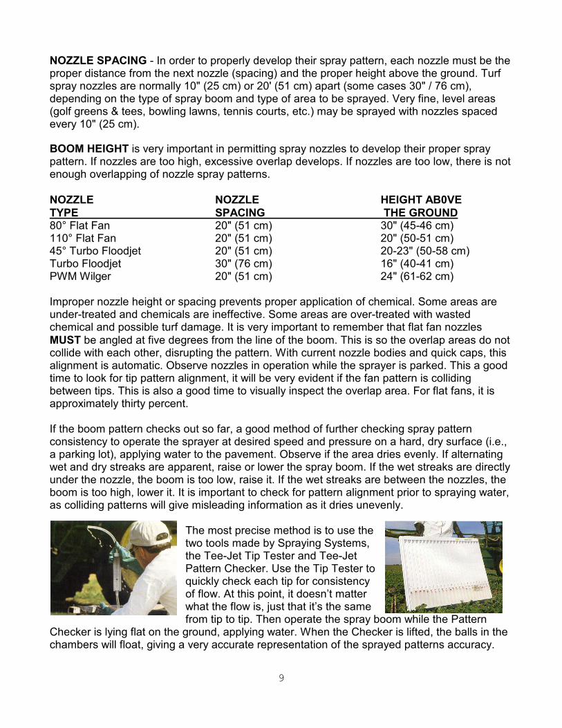
NOZZLE SPACING - In order to properly develop their spray pattern, each nozzle must be the proper distance from the next nozzle (spacing) and the proper height above the ground. Turf spray nozzles are normally 10" (25 cm) or 20' (51 cm) apart (some cases 30" / 76 cm), depending on the type of spray boom and type of area to be sprayed. Very fine, level areas (golf greens & tees, bowling lawns, tennis courts, etc.) may be sprayed with nozzles spaced every 10" (25 cm). BOOM HEIGHT is very important in permitting spray nozzles to develop their proper spray pattern. If nozzles are too high, excessive overlap develops. If nozzles are too low, there is not enough overlapping of nozzle spray patterns. NOZZLE NOZZLE HEIGHT AB0VE TYPE SPACING THE GROUND 80° Flat Fan 20" (51 cm) 30" (45-46 cm) 110° Flat Fan 20" (51 cm) 20" (50-51 cm) 45° Turbo Floodjet 20" (51 cm) 20-23" (50-58 cm) Turbo Floodjet 30" (76 cm) 16" (40-41 cm) PWM Wilger 20" (51 cm) 24" (61-62 cm) Improper nozzle height or spacing prevents proper application of chemical. Some areas are under-treated and chemicals are ineffective. Some areas are over-treated with wasted chemical and possible turf damage. It is very important to remember that flat fan nozzles MUST be angled at five degrees from the line of the boom. This is so the overlap areas do not collide with each other, disrupting the pattern. With current nozzle bodies and quick caps, this alignment is automatic. Observe nozzles in operation while the sprayer is parked. This a good time to look for tip pattern alignment, it will be very evident if the fan pattern is colliding between tips. This is also a good time to visually inspect the overlap area. For flat fans, it is approximately thirty percent. If the boom pattern checks out so far, a good method of further checking spray pattern consistency to operate the sprayer at desired speed and pressure on a hard, dry surface (i.e., a parking lot), applying water to the pavement. Observe if the area dries evenly. If alternating wet and dry streaks are apparent, raise or lower the spray boom. If the wet streaks are directly under the nozzle, the boom is too low, raise it. If the wet streaks are between the nozzles, the boom is too high, lower it. It is important to check for pattern alignment prior to spraying water, as colliding patterns will give misleading information as it dries unevenly.
The most precise method is to use the two tools made by Spraying Systems, the Tee-Jet Tip Tester and Tee-Jet Pattern Checker. Use the Tip Tester to quickly check each tip for consistency of flow. At this point, it doesn’t matter what the flow is, just that it’s the same from tip to tip. Then operate the spray boom while the Pattern
Checker is lying flat on the ground, applying water. When the Checker is lifted, the balls in the chambers will float, giving a very accurate representation of the sprayed patterns accuracy.

10
FURTHER NOZZLE INFORMATION • NOZZLE SCREENS (STRAINERS): Smaller nozzles require nozzle screens or strainers to prevent
clogging.
Teejet type nozzles from size 8001 and 80015 and RF Flat Spray Raindrop Nozzles require 100 mesh screens
Teejet type nozzles from size 8002 through 8008 and RF Flat Spray Raindrop Nozzles require 50 mesh screens
Raindrop Hollow Cone Nozzles Size RA-2 through RA-6 require 50 mesh screens
Raindrop Hollow Cone Nozzles Size RA-8 and larger does not require strainers.
Turbo Floodjet Nozzles TF-VS2 through TFVS-3 require 50 mesh screens. Turbo Floodjet Nozzles TF-VS4 and larger do not require screens.
• Always be alert to the possibility of a plugged or damaged nozzle. Serious misapplication may
result. • Check nozzles out-put periodically.
11
D – AGITATION
he question often comes up whether hydraulic or mechanical agitation is superior. There is really no correct answer. Both are very acceptable if they perform the required job and that is to keep the insoluble materials used, suspended in the carrier. The often misconstrued feeling that mechanical agitation is better stems from the fact that it became popular when fiberglass tanks
and small volume piston-diaphragm pumps became popular. Because the small volume output of the diaphragm pump precluded the use of hydraulic agitation, mechanical means had to be devised. These were considerably more expensive, due to the cost of the pump, as well as the costs associated with fiberglass tanks and stainless steel mechanical systems. Over time, the more expensive systems became misconstrued as superior Review the capacity of nozzles being used. Total capacity of all nozzles plus agitation system must
not exceed pumping system capabilities. FLUSH PUMP AFTER USE
Shut-Off 20GPM 40GPM 60GPM 80GPM 100GPM 120psi 100psi 80psi 60psi 30psi 10psi 100psi 95psi 76psi 52psi 26psi 5psi 80psi 75psi 62psi 45psi 21psi - 60psi 55psi 40psi 25psi 5psi - The point is, as long as there is enough volume to provide adequate turbulence to keep particulate matter suspended, there is no difference in quality of agitation. To further this end, devices such as “Venturi” tips or “Eductor” nozzles continue to reduce the differences in effectiveness. These nozzles literally double to triple the flow through them by “Venturi” action. The case could be made that mechanical agitation is considered inferior as the need to have rigid walls to mount shafts, packing glands to prevent leaks and extra horsepower to turn the shafts are required.
E – SPRAY CONTROLLERS
he spraying industry have grown considerable more sophisticated since the days of the “Ratchet Valve” was the standard to turn spray booms on and off. Today, computers are being used more and more to control the spraying event. They have become popular
because they increase efficiency and productivity, especially in large scale operations. The level and sophistication of these devices brief descriptions of the various controllers in use today. Remember that computers really only do two things: 1. Monitor and adjust flow to keep application rate constant as it senses changes in ground speed; and 2. Keep track of volume sprayed and acreage covered. Computers can be either “flow” based, “pressure” based or in one unique instance, both. Smithco is not a supporter of pressure based control systems due to the earlier explained loss of pressure due to friction through lines, fittings and solenoids. Pressure based systems would be accurate only if the pressure transducer was placed at the tip, and then only for that tip. Most systems mount the transducer up around the solenoids, so they are only relatively accurate. That is, they will accurately read and report pressure and pressure changes where the transducer is mounted, but that may have nothing to do with what is going on at the tip.
When do you have forty PSI at the tip on a boom mounted with 8008 nozzles? Only when that tip delivers eight tenths of a gallon in one minute!
T
T
12
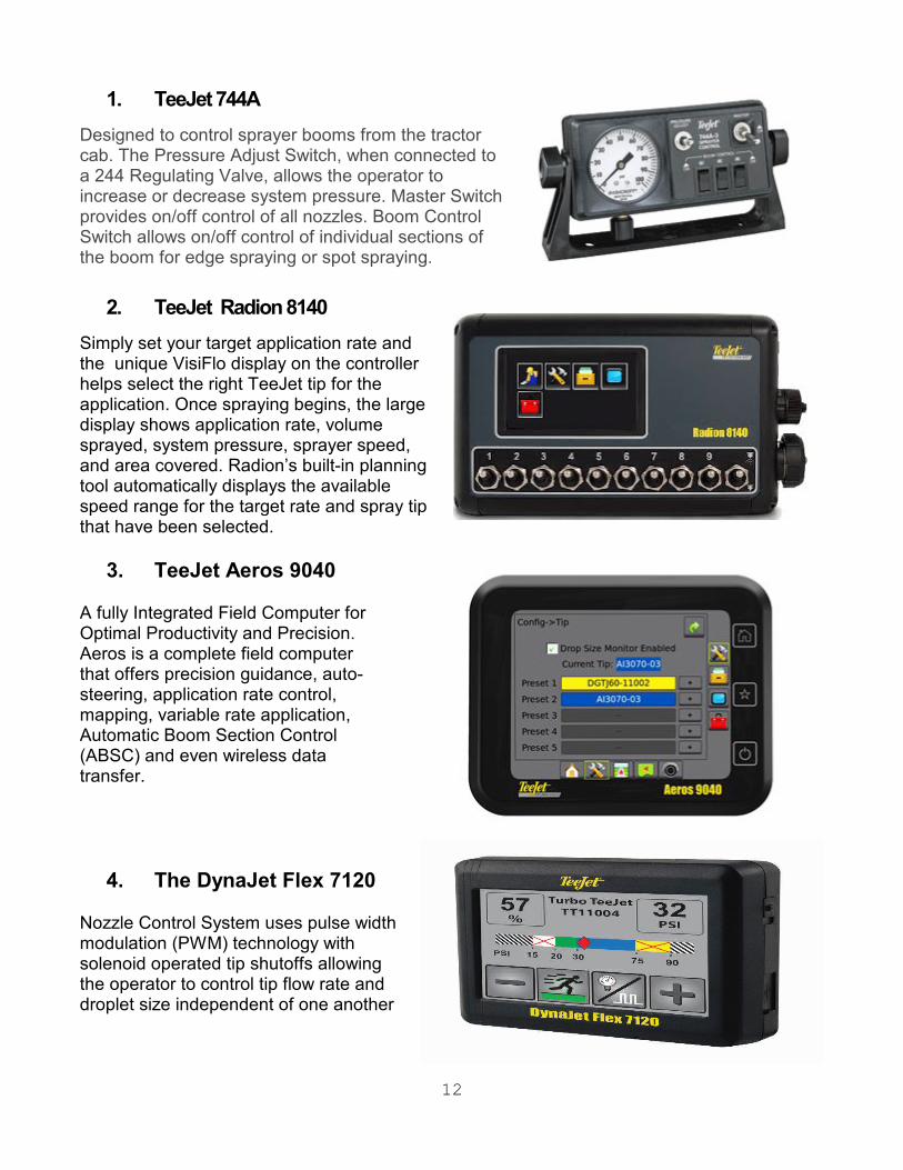
1. TeeJet 744A Designed to control sprayer booms from the tractor cab. The Pressure Adjust Switch, when connected to a 244 Regulating Valve, allows the operator to increase or decrease system pressure. Master Switch provides on/off control of all nozzles. Boom Control Switch allows on/off control of individual sections of the boom for edge spraying or spot spraying.
2. TeeJet Radion 8140 Simply set your target application rate and the unique VisiFlo display on the controller helps select the right TeeJet tip for the application. Once spraying begins, the large display shows application rate, volume sprayed, system pressure, sprayer speed, and area covered. Radion’s built-in planning tool automatically displays the available speed range for the target rate and spray tip that have been selected.
3. TeeJet Aeros 9040 A fully Integrated Field Computer for Optimal Productivity and Precision. Aeros is a complete field computer that offers precision guidance, auto-steering, application rate control, mapping, variable rate application, Automatic Boom Section Control (ABSC) and even wireless data transfer.
4. The DynaJet Flex 7120 Nozzle Control System uses pulse width modulation (PWM) technology with solenoid operated tip shutoffs allowing the operator to control tip flow rate and droplet size independent of one another
13
M
F – ACCESSORIES
any accessories are now available for sprayers in the turf industry. This will be by no means a complete list, but will address the most popular options selected by our end users. These options are listed randomly, in no particular order.
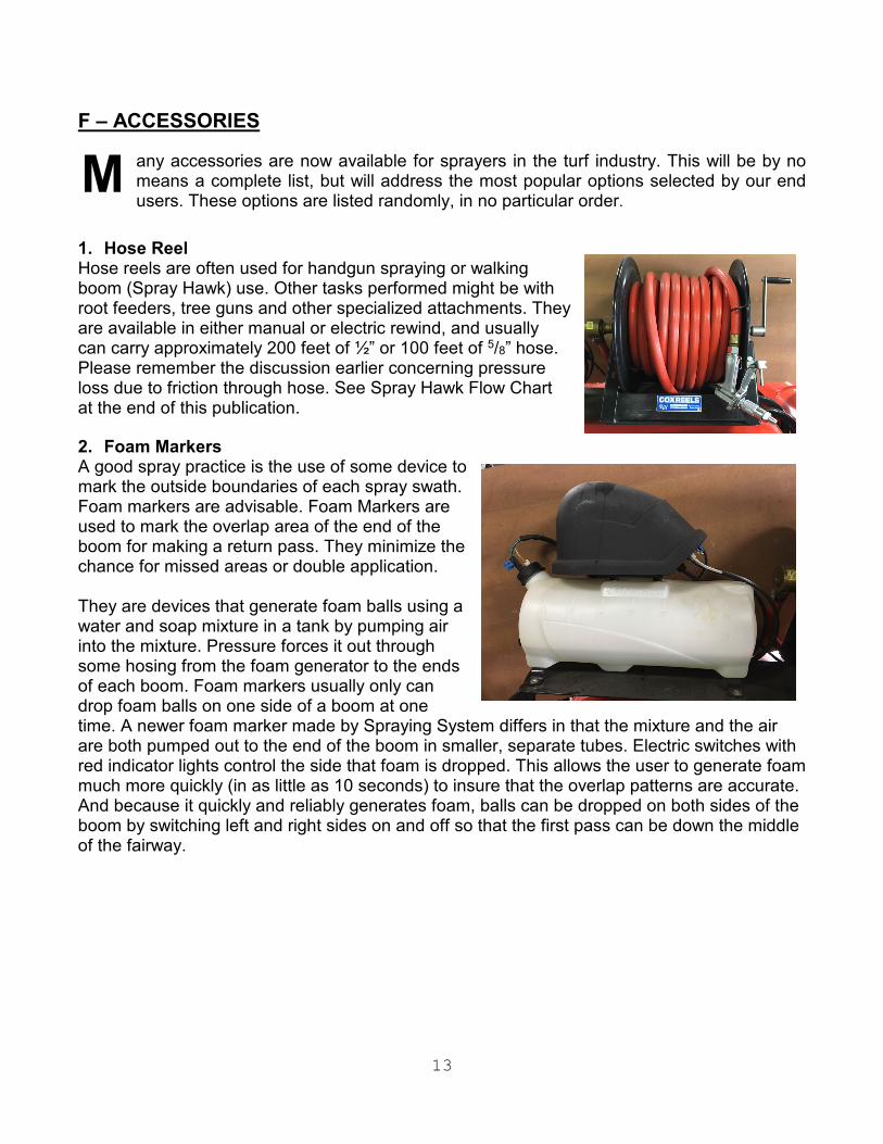
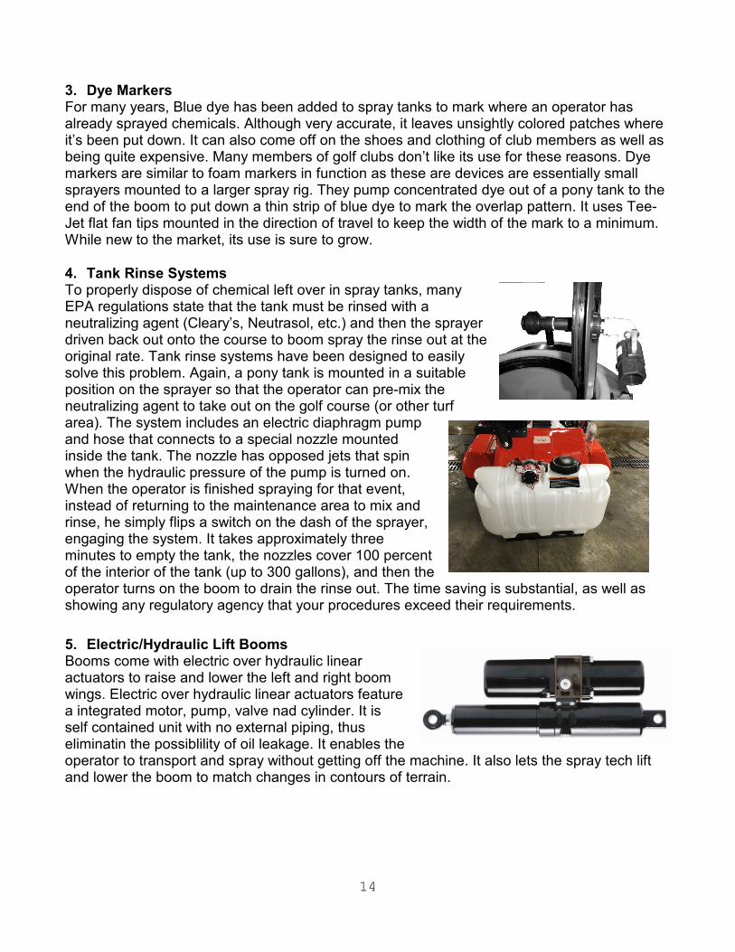
1. Hose Reel Hose reels are often used for handgun spraying or walking boom (Spray Hawk) use. Other tasks performed might be with root feeders, tree guns and other specialized attachments. They are available in either manual or electric rewind, and usually can carry approximately 200 feet of ½” or 100 feet of 5/8” hose. Please remember the discussion earlier concerning pressure loss due to friction through hose. See Spray Hawk Flow Chart at the end of this publication. 2. Foam Markers A good spray practice is the use of some device to mark the outside boundaries of each spray swath. Foam markers are advisable. Foam Markers are used to mark the overlap area of the end of the boom for making a return pass. They minimize the chance for missed areas or double application. They are devices that generate foam balls using a water and soap mixture in a tank by pumping air into the mixture. Pressure forces it out through some hosing from the foam generator to the ends of each boom. Foam markers usually only can drop foam balls on one side of a boom at one time. A newer foam marker made by Spraying System differs in that the mixture and the air are both pumped out to the end of the boom in smaller, separate tubes. Electric switches with red indicator lights control the side that foam is dropped. This allows the user to generate foam much more quickly (in as little as 10 seconds) to insure that the overlap patterns are accurate. And because it quickly and reliably generates foam, balls can be dropped on both sides of the boom by switching left and right sides on and off so that the first pass can be down the middle of the fairway.
14
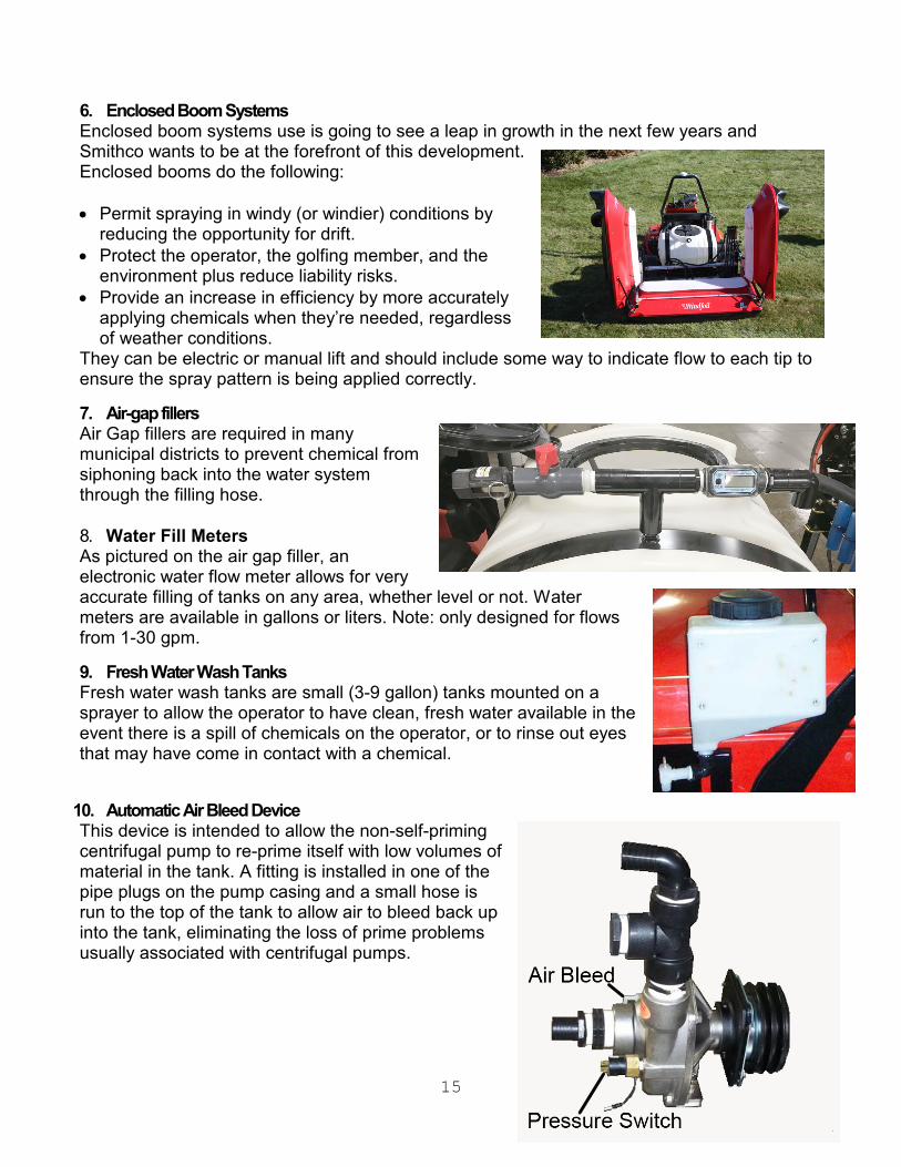
3. Dye Markers For many years, Blue dye has been added to spray tanks to mark where an operator has already sprayed chemicals. Although very accurate, it leaves unsightly colored patches where it’s been put down. It can also come off on the shoes and clothing of club members as well as being quite expensive. Many members of golf clubs don’t like its use for these reasons. Dye markers are similar to foam markers in function as these are devices are essentially small sprayers mounted to a larger spray rig. They pump concentrated dye out of a pony tank to the end of the boom to put down a thin strip of blue dye to mark the overlap pattern. It uses Tee-Jet flat fan tips mounted in the direction of travel to keep the width of the mark to a minimum. While new to the market, its use is sure to grow. 4. Tank Rinse Systems To properly dispose of chemical left over in spray tanks, many EPA regulations state that the tank must be rinsed with a neutralizing agent (Cleary’s, Neutrasol, etc.) and then the sprayer driven back out onto the course to boom spray the rinse out at the original rate. Tank rinse systems have been designed to easily solve this problem. Again, a pony tank is mounted in a suitable position on the sprayer so that the operator can pre-mix the neutralizing agent to take out on the golf course (or other turf area). The system includes an electric diaphragm pump and hose that connects to a special nozzle mounted inside the tank. The nozzle has opposed jets that spin when the hydraulic pressure of the pump is turned on. When the operator is finished spraying for that event, instead of returning to the maintenance area to mix and rinse, he simply flips a switch on the dash of the sprayer, engaging the system. It takes approximately three minutes to empty the tank, the nozzles cover 100 percent of the interior of the tank (up to 300 gallons), and then the operator turns on the boom to drain the rinse out. The time saving is substantial, as well as showing any regulatory agency that your procedures exceed their requirements. 5. Electric/Hydraulic Lift Booms Booms come with electric over hydraulic linear actuators to raise and lower the left and right boom wings. Electric over hydraulic linear actuators feature a integrated motor, pump, valve nad cylinder. It is self contained unit with no external piping, thus eliminatin the possiblility of oil leakage. It enables the operator to transport and spray without getting off the machine. It also lets the spray tech lift and lower the boom to match changes in contours of terrain.
15
6. Enclosed Boom Systems Enclosed boom systems use is going to see a leap in growth in the next few years and Smithco wants to be at the forefront of this development. Enclosed booms do the following: • Permit spraying in windy (or windier) conditions by
reducing the opportunity for drift. • Protect the operator, the golfing member, and the
environment plus reduce liability risks. • Provide an increase in efficiency by more accurately
applying chemicals when they’re needed, regardless of weather conditions.
They can be electric or manual lift and should include some way to indicate flow to each tip to ensure the spray pattern is being applied correctly. 7. Air-gap fillers Air Gap fillers are required in many municipal districts to prevent chemical from siphoning back into the water system through the filling hose. 8. Water Fill Meters As pictured on the air gap filler, an electronic water flow meter allows for very accurate filling of tanks on any area, whether level or not. Water meters are available in gallons or liters. Note: only designed for flows from 1-30 gpm. 9. Fresh Water Wash Tanks Fresh water wash tanks are small (3-9 gallon) tanks mounted on a sprayer to allow the operator to have clean, fresh water available in the event there is a spill of chemicals on the operator, or to rinse out eyes that may have come in contact with a chemical.
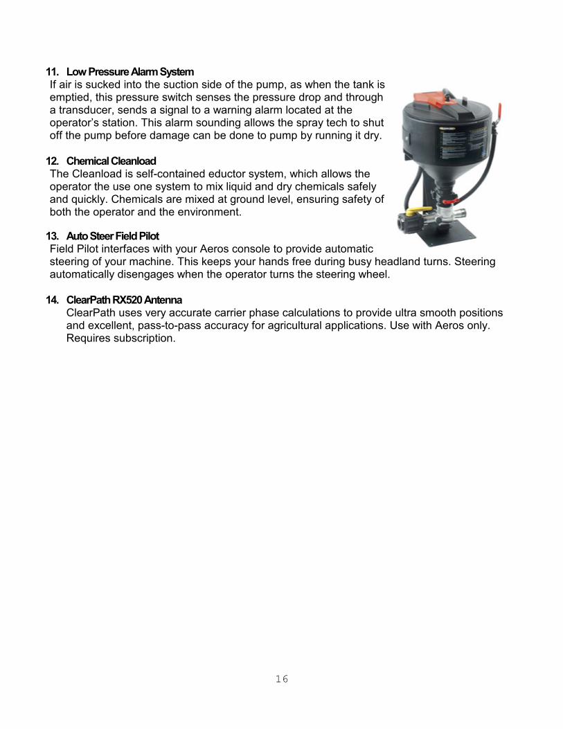
10. Automatic Air Bleed Device This device is intended to allow the non-self-priming centrifugal pump to re-prime itself with low volumes of material in the tank. A fitting is installed in one of the pipe plugs on the pump casing and a small hose is run to the top of the tank to allow air to bleed back up into the tank, eliminating the loss of prime problems usually associated with centrifugal pumps.
16
11. Low Pressure Alarm System If air is sucked into the suction side of the pump, as when the tank is emptied, this pressure switch senses the pressure drop and through a transducer, sends a signal to a warning alarm located at the operator’s station. This alarm sounding allows the spray tech to shut off the pump before damage can be done to pump by running it dry.
12. Chemical Cleanload The Cleanload is self-contained eductor system, which allows the operator the use one system to mix liquid and dry chemicals safely and quickly. Chemicals are mixed at ground level, ensuring safety of both the operator and the environment.
13. Auto Steer Field Pilot Field Pilot interfaces with your Aeros console to provide automatic steering of your machine. This keeps your hands free during busy headland turns. Steering automatically disengages when the operator turns the steering wheel.
14. ClearPath RX520 Antenna ClearPath uses very accurate carrier phase calculations to provide ultra smooth positions and excellent, pass-to-pass accuracy for agricultural applications. Use with Aeros only. Requires subscription.

17
TECHNICAL INFORMATION

18
SPRAYER CALIBRATION Broadcast Application Sprayer calibration (1) readies your sprayer for operation and (2) diagnoses tip wear. This will give you optimum performance of your tips. Equipment Needed:
• Calibration Container • Calculator • Cleaning Brush • One new spray tip matched to the nozzles on your sprayer • Stopwatch or wristwatch with second hand.
STEP NUMBER 1
Check Your Tractor/Sprayer Speed!
Knowing your real sprayer speed is an essential part of accurate spraying. Speedometer readings and some electronic measurement devices can be inaccurate because of wheel slippage. Check the time required to move over a 100- or 200-foot strip on your field. Fence posts can serve as permanent markers. The starting post should be far enough away to permit your tractor/sprayer to reach desired spraying speed. Hold that speed as you travel between the “start” and “end” markers. Most accurate measurement will be obtained with the spray tank half full. Refer to the table on page 140 to calculate your real speed. When the correct throttle and gear settings are identified, mark your tachometer or speedometer to help you control this vital part of accurate chemical application. STEP NUMBER 2
The Inputs
Before spraying, record the following: EXAMPLE Nozzle type on your sprayer .TT11004 Flat (All nozzles must be identical) Recommended application volume 20 GPA (From manufacturer’s label) Measured sprayer speed 6 MPH Nozzle spacing 20 Inches

19
STEP NUMBER 3 Calculating Required Nozzle Output
Determine GPM nozzle output from formula. FORMULA: GPM = GPAxMPHxW 5940(constant) EXAMPLE: GPM = 20x6x20 = 2400 5940 5940 ANSWER GPM = 0.404
STEP NUMBER 4
Setting the Correct Pressure
• Turn on your sprayer and check for leaks or blockage. Inspect and clean, if necessary, all tips and strainers with brush. Replace one tip and strainer with an identical new tip and strainer on sprayer boom.
• Check appropriate tip selection table and determine the pressure required to deliver the nozzle output calculated from the formula in Step 3 for your new tip. Since all of the tabulations are based on spraying water, conversion factors must be used when spraying solutions that are heavier or lighter than water.
• Turn on your sprayer and adjust pressure. Collect and measure the volume of the spray from the new tip for one minute in the collection jar. Fine tune the pressure until you collect .40 GPM.
• You have now adjusted your sprayer to the proper pressure. It will properly deliver the application rate specified by the chemical manufacturer at your measured sprayer speed.

20
STEP NUMBER 5
Checking Your System
Problem Diagnosis: Now, check the flow rate of a few tips on each boom section. If the flow rate of any tip is 10 percent greater or less than that of the newly installed spray tip, recheck the output of that tip. If only one tip is faulty, replace with new tip and strainer and your system is ready for spraying. However, if a second tip is defective, replace all tips on the entire boom. This may sound unrealistic, but two worn tips on a boom are ample indication of tip wear problems. Replacing only a couple of worn tips invites potentially serious application problems.
Banding and Directed Applications
The only difference between the above procedure and calibrating for banding or directed applications is the input value used for “W” in the formula in Step 3. For single nozzle banding or boomless applications:
W = Sprayed band width or wath width (in inches). For multiple nozzle directed applications:
W = Row spacing (in inches) divided by the number of nozzles per row.

22
INTRODUCTION TO CALIBRATION
number of acceptable methods for calibrating a turf sprayer are widely available. Two methods are described later in this guide. Calibrating simply means to adjust a set of variables on the sprayer in order to deliver the desire amount of chemical to a known area of turf.
The variables are:
• OPERATING PRESSURE • NOZZLE ORIFICE SIZE • TRAVEL SPEED • NOZZLE SPACING (Previously discussed in this guide)
The job of calibrating the sprayer consists of balancing these variables so that your sprayer delivers the desired application rate. That is, an amount of chemical on a given area. It is expressed as:
Gallons Per Acre (GPA) (1 US GPA = .83 UK GPA) or Gallons Per 1,000 Square Feet (GPT) or Liters Per Hectare (LPH) ( 1 US GPA = 9.3 5 LPH)
The calibration methods chosen must take these variables into account. They must include known ground speed (by measurement or from an accurate speedometer) and nozzle output (GPM or LPM) from a nozzle chart or from actual measurement. 1st VARIABLE- PRESSURE: Just as pressure increases the volume discharge rate, it also increases the application rate. Pressure must increase by 4 times in order to double the application rate. Small pressure changes of 10 PSI ( 1.4 BAR) or less do not greatly affect performance. Pressure is established and maintained by a pressure control valve or by a flow control valve located on the sprayer. 2nd VARIABLE - NOZZLE CAPACITY (Volume): We have covered the different types of spray patterns of various nozzles and made our selection of type accordingly. We now have to choose a size, which will provide the correct application rate. Sizes are available for all requirements. Consult the nozzle chart in this guide for your nozzle type in order to select the correct size. 3rd VARIABLE- TRAVEL SPEED: Increased travel speed decreases the application rate (GPA or GPT or LPH). Travel speed must be safe and appropriate for the area to be sprayed. Unlike pressure changes, which have only a minor effect on application rate, ground speed changes have a more major and direct effect. For example: A 50% increase in ground speed means a 100% decrease in application rate. If the vehicle does not have an accurate speedometer, correct speed must be determined by timing the sprayer travel over a measured distance. (Refer to the page in this guide titled, "Useful Formulas". To calibrate a sprayer, the user must:
A

23
1. Understand the variables
• Operating Pressure (PSI/BAR) • Nozzle Orifice Size (GPM/LPM) • Travel Speed (MPH/KPH)
2. Set those variables using one of the proven methods available. 3. Make a trial run and measure the output (use water, not chemical) 4. Determine the output. 5. Make adjustments to the 3 variables until the output is at the desired level. BOOM SPRAYER CALIBRATION
A. PREPARATION
1. Before adding any chemical, fill the sprayer tank with one-half of the desired amount of water. It is suggested (and required by law in some areas), that water only be added to a sprayer tank through an Anti-Siphon ("Air-Gap") Filler System to prevent contamination of the water supply. Operate the sprayer to be certain all valves, hoses, as well as the pump and engine (or PTO) are operating properly. Make certain that each nozzle is spraying a consistent pattern.
2. Set (or check) the Spray Boom so that the Nozzles are the correct height above the
ground for the type of nozzle and the nozzle spacing (distance between each nozzle) that is being used. NOZZLE NOZZLE HEIGHT AB0VE TYPE SPACING THE GROUND 80° Flat Fan 20" (51 cm) 30" (45-46 cm) 110° Flat Fan 20" (51 cm) 20" (50-51 cm) 45° Turbo Floodjet 20" (51 cm) 20-23" (50-58 cm) Turbo Floodjet 30" (76 cm) 16" (40-41 cm) PWM Wilger 20" (51 cm) 24" (61-62 cm)
3. Calibration of the sprayer is to be done with water, not chemicals. This insures safety to the operator or individual performing the calibration operation. Only after all calibration procedures are completed should chemicals be added to the sprayer.
4. Carefully measure the amounts of spray material to be added to the tank. Always read
the label instructions, then follow these instructions exactly.
5. If the chemical to be sprayed is a dry (powder) material, it is essential that it be thoroughly mixed with water in a small container such as a pail, to form a slurry before adding to the sprayer tank. Then, while the sprayer is running, add the mixture to the tank with the agitation system operating. Always add the material to the sprayer tank through a filter screen in the tank opening. Then, add the balance of the desired amount of water to the tank.
Liquid chemicals may be added directly from their storage container to the tank through a filter screen, with the agitation system in operation.

24
(NOTE: Instructions #4 & #5 do not apply if the sprayer is equipped with a Concentrate Injection System. If your sprayer is equipped with a Concentrate Injection System, refer to the operating instructions provided with that system.) B. CALIBRATION TECHNIQUES The 2 Calibration Techniques outlined here are:
I. The Nozzle Chart Method of Calibration II. The ~128" Method of Calibration
Each method may be useful in various circumstances and conditions. It is important to note that there are other acceptable and proven methods of calibrating a turf sprayer for application. Other techniques may be more suitable depending on operational needs and technical competence of the operator.

25
1. THE NOZZLE CHART METHOD OF CALIBRATION
a. Introduction
The Nozzle Chart Method (see sample below) is useful when the sprayer nozzles are new or nearly new. It is also the most useful method to employ when the sprayer is equipped with a Computer Based Spray Control System (CBSCS). The CBSCS does most of the calibration work; it is up to the operator to select the proper combination of nozzle size and ground speed, which will deliver the desire application rate. The nozzle chart method requires the use of the appropriate nozzle charts, which are found at the end of this guide. (Nozzle Charts 1 through 7). Nozzle charts are available for:
1. Three different types of nozzles: a. Spraying Systems Teejet Flat Fan b. Spraying Systems TurfJet
c. Spraying Systems Turbo TeeJet 2. Three different nozzle spacings:
a. 10 Inch (25 cm) b. 20 Inch (51 cm) c. 30 Inch (76 cm) (Turbo Floodjet)
3. Three different expressions of application rate:
a. US Gallons per acre (GPA) b. US Gallons per 1,000 sq. ft. (GPT) c. Liters per hectare (LPH)
NOTE: The information provided in the previous pages of this guide should help determine the proper type of nozzle for your needs. Nozzle charts for other nozzles are available from the manufacturer.
26
b. CALIBRATION STEPS USING THE NOZZLE CHART METHOD
Determine "HOW" your sprayer is to be calibrated from the list of variable factors available (below).
1. NOZZLE TYPE Teejet, Raindrop, Turbo Flood ? 2. SPACING 10" (25 cm) or 20 (51 cm) or 30" (76 cm). 3. EXPRESSION OF APPLICATION RATE G.P.A. or G.P.T. or L.P.H.
The answers to these three questions will direct you to the appropriate nozzle chart for your application among the charts on the pages in the back of this guide. The correct nozzle chart MUST be used.
c. DETERMINE THE DESIRED APPLICATION RATE.
This is determined from the information on chemical labels or other technical information available from a variety of sources.
d. DETERMINE AN ACCEPTABLE GROUND SPEED
Conditions over which the sprayer will operate generally dictate the appropriate ground speed. Within the limits of practicality and efficiency, spraying should generally be done at the lowest possible speed. This increases operator safety and contributes to more precise application of chemicals. For example, golf greens and tees and hill areas would generally be sprayed in the range of 2 1/2 to 3 1/2 Miles per hour (4-6 kph). Larger, open and more level areas such as golf fairways and open park or school grounds would be sprayed at 4 1/2 to 6 mph (7-10 kph). The best guideline is the fastest speed, which is “safe and comfortable for the piece of equipment.” Often, operators can withstand more punishment than the sprayer.
The vehicle which carries or tows the sprayer should be equipped with a precise low-speed speedometer. If it is not, exact ground speed at a given engine speed must be determined by timing the travel of the sprayer over a measured course.
e. DETERMINE NOZZLE SIZE
Now refer to the appropriate nozzle chart in this guide for your nozzle TYPE (the type of nozzle you have or the type you wish to use), nozzle SPACING and CALIBRATION TYPE (GPM, GPT or LPH).
You will note from the chart that application rates from any given nozzle decrease as the ground speed increases. In other words, the faster you drive, the less material you are applying. Application rates are shown in the columns to the right of the charts. Once the desired application rate is decided upon, it should be located, as nearly as possible in one of these columns on the appropriate chart for your operation. It could well be that the approximate rate desired would be obtained from the nozzles already installed in the boom. If this is not possible, then nozzles will need to be changed.

27
IMPORTANT NOTE: When selecting a new nozzle size refer to the Discharge Rate Column" on the nozzle charts. The Discharge Rate (GPM or LPM) multiplied by the number of nozzles should not exceed 75% of the actual discharge volume of the sprayer pump. (i.e., if you need to use nozzles which discharge 0.8 gallons per minute [3.0 Liters per minute], and the spray boom is equipped with 12 nozzles, the sprayer pump would have to produce an actual discharge volume of 13 GPM ~49 LPM] in order to properly supply these nozzles.) If the collective volume of the spray boom nozzles exceeds the actual discharge volume of the pump, inadequate pressure and poor nozzle distribution patterns may result.
Once nozzle type and size have been determined, those nozzles are installed in the sprayer boom. Nozzles could be expected to be replaced after 15-20 hours of actual sprayer operation if made of softer materials. After nozzles are installed, make trial application of water over a known area to check application rate.
f. FOR SPRAYERS WITH ELECTRONIC SPRAY CONTROL SYSTEMS
On sprayers equipped with Electronic Spray Control Systems ("Spray Computers") such as those manufactured by Spraying Systems (Tee-Jet) Raven Ind., Micro-Trak Co. & Dickey-John Co., it is still important to select the right type and size of nozzle for the required operation. Electronic Spray Control Systems cannot function properly if the nozzles are not capable of delivering the programmed (desired) application rate. Nozzles which are too large will not develop adequate pressure or satisfactory spray patterns. Nozzles which are too small will not allow the discharge of spray material at the programmed application rate.
Further, when calibrating sprayers which are equipped with Electronic Spray Control Systems, care must be taken to use the mode of operation on the Spray Control System (Gallons per Acre ["US" Mode]; Gallons per 1,000 sq. ft. ["Turf" Mode]; or Liters per Hectare [Std. International Mode], which corresponds with the nozzle calibration charts (GPA, GPT or LPH).
g. USING THE NOZZLE CHARTS
Select the correct chart based on your nozzle type, nozzle spacing and desired expression of application rate (GPA, GPT, LPH). If the desired operating speed is not found on the nozzle chart, it is simple to determine application rates at different speeds by extrapolating from the application rates at the given speed. For example: If the desired speed is 2 1/2 MPH (4 kph) on a sprayer using Raindrop nozzles (Chart 5). The average between the application rates for 2 MPH and 3 MPH may be assumed to be the application rate for 2 1/2 MPH. For example: RA-5 Nozzle, 50 PSI, the application rate for 2 MPH is 74 GPA and the application rate for 3 MPH is 50 GPA. Add 74 + 50 (124) then divide by 2 (62). Therefore, the application rate at 2 1/2 MPH is 62 GPA. Another example: The desired speed is 6 MPH. Use the application rate column for 3 MPH and divide by 2.
28
h. CONVERTING NOZZLE CHART METHOD TO BRITISH GALLONS
To convert any of the Gallon Per Acre rates to Imperial Gallons per acre, (ImpGPA) multiply by .83. To convert any of the liter Per Hectare rates to Imperial Gallons Per Hectare (ImpGPH), multiply by .22.
i. CHECKING THE ACTUAL APPLICATION RATE
After the combination of ground speed, nozzle size and operating pressure has been selected, the sprayer should be operated to determine if the target application rate is being achieved. The following "128" method is one way to validate the Nozzle Chart Method of calibration.
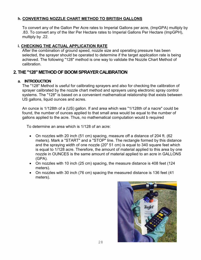
2. THE "128" METHOD OF BOOM SPRAYER CALIBRATION
a. INTRODUCTION The "128" Method is useful for calibrating sprayers and also for checking the calibration of sprayer calibrated by the nozzle chart method and sprayers using electronic spray control systems. The "128" is based on a convenient mathematical relationship that exists between US gallons, liquid ounces and acres. An ounce is 1/128th of a (US) gallon. If and area which was "1/128th of a nacre" could be found, the number of ounces applied to that small area would be equal to the number of gallons applied to the acre. Thus, no mathematical computation would b required
To determine an area which is 1/128 of an acre: • On nozzles with 20 inch (51 cm) spacing, measure off a distance of 204 ft. (62
meters). Mark a "START" and a "STOP" line. The rectangle formed by this distance and the spraying width of one nozzle (20" 51 cm) is equal to 340 square feet which is equal to 1/128 acre. Therefore, the amount of material applied to this area by one nozzle in OUNCES is the same amount of material applied to an acre in GALLONS (GPA).
• On nozzles with 10 inch (25 cm) spacing, the measure distance is 408 feet (124 meters).
• On nozzles with 30 inch (76 cm) spacing the measured distance is 136 feet (41 meters).

29
b. CALIBRATING FOR APPLICATION 1. Fill the sprayer tank with water. Run the sprayer, inspect it for leaks and make sure all
systems function properly.
2. Drive the sprayer through the measured distance discussed above at normal spraying speed, record the travel time required to cover the measured distance in seconds with a stopwatch. The carrying or towing vehicle is to be traveling at the desired speed when it crosses the start line of the measured course. Repeat this procedure and determine the average of the two times.
3. With the sprayer parked, run the sprayer at the required pressure level. Catch the
output of each nozzle in a container, which is marked or graduated in Ounces for the same period of time which it took the sprayer to cover the measured course in step #2.
4. NOTE: If a Dedicated Spray Vehicle or a sprayer which is powered by a vehicle's
PTO/Hydraulic system is used, it will be necessary to operate the vehicle engine at spraying speed using a hand throttle.
5. Observe the volume of water in the collection bottle. The number of OUNCES collected
in the time it takes to cover the marked course. Take the average nozzle output by adding the outputs of each nozzle and then dividing that sum by the number of nozzles.
6. The NUMBER OF OUNCES collected in the time required to cover the SMALL AREA is
equal to the NUMBER OF GALLONS applied per ACRE. For example: if an average of 40 ounces of water are collected in the time required to cover the 1/128 acre area, the application rate is 40 gallons per acre (GPA).
AVERAGE OUTPUT (OUNCES) = APPLICATION RATE (GPA)
7. NOTE: As a practical matter, if high application rates are desired (above 75 GPA), the measured course length should be reduced by half (i.e. 102-ft [31 m] for 20-inch (52 cm) spaced nozzles). The volume collected (above) is then doubled (multiplied by 2).
8. Observe individual nozzle output volumes. If an individual nozzle's is 10% above or
below the average output, check for blockages in the nozzle or in the nozzle strainer. If the nozzle is worn or damaged, replace it.
9. Compare this actual application rate with the recommended rate. If the actual rate is
more than 5% higher or lower than the intended rate, adjustments must be made.
10. Increasing or decreasing the spraying pressure may make minor adjustments in application rate. Lowering spraying pressure decreases application rate. Increasing spraying pressure increases application rate. This procedure normally does not apply to spray systems controlled by an electronic spray control system that governs flow rate.

30
11. Increasing or decreasing the travel speed of the sprayer if conditions permit may make adjustments in application rate. Slower speeds increase application rate. Faster speeds decrease application rate.
12. Nozzle sizes can be changed to provide the correct application rate. Refer to the nozzle
charts in this book for the desired nozzle type.
13. Re-calibrate the sprayer (steps 2-6) after any adjustments are made.
14. As previously discussed, there are other acceptable methods of Turf Sprayer Calibration. Chemical suppliers, Agricultural Extension Agents, Universities and consultants of various types offer helpful advice on this subject. Technical catalogues are available from nozzle manufacturers.
3. TRANSFERRING THE "128" METHOD OF CALIBRATION INTO METRIC (LITERS PER HECTARE) The same steps are used that are used when calibrating in gallons per acre. First a relationship between a measurable amount (milliliters) and the calibration amount (liter) is determined. That ratio is 1: 1,000. Now an area which is 1/1,000 th of a hectare must be measured. On spray booms with 51 cm (20 inch) spacing, mark off an area which is 20 meters (65.6 feet) long. The area formed by that length and the width of one spray nozzle (20 meters by .5 meters) is 10 square meters which is 1/1,000 of a hectare. Therefore, the amount of spray material applied to this small area in milliliters is equal to the amount applied to one hectare in liters. Then, follow the remaining steps 2-10, substituting milliliters for ounces, liters for gallons, square meters for square feet and hectares for acres.
AVERAGE OUTPUT (MILLILITERS) = APPLICATION RATE (LITERS/HA)

31
Maximum Target Rates for Spray Hawk with Smithco Spray Star Centrifugal Pump Systems
All Rates Calculated at 3 MPH
1/2 Inch Hose Max Pressure GPT GPA 04 Tips 100 Feet 55 PSI 1.05 GPT 46 GPA 200 Feet 52 PSI 1.005 GPT 44 GPA 08 Tips 100 Feet 40 PSI 1.8 GPT 78 GPA 200 Feet 30 PSI 1.6 GPT 70 GPA 15 Tips 100 Feet 35 PSI 3.15 GPT 137 GPA 200 Feet 23 PSI 2.5 GPT 109 GPA
5/8 Inch Hose 04 Tips 100 Feet 70 PSI 1.2 GPT 52 GPA 200 Feet 65 PSI 1.05 GPT 46 GPA 08 Tips 100 Feet 52 PSI 2.05 GPT 89 GPA 200 Feet 42 PSI 1.85 GPT 80 GPA 15 Tips 100 Feet 46 PSI 3.6 GPT 157 GPA 200 Feet 36 PSI 3.15 GPT 137 GPA

32

33