illuminating the past: artificial lighting in america
TRANSCRIPT
ILLUMINATING THE PAST: ARTIFICIAL LIGHTING IN AMERICA (1610-1930) AND A
GUIDE TO LIGHTING HISTORIC HOUSE MUSEUMS
by
DEEPANNITA GHOSH
(Under the Direction of MARK E. REINBERGER)
ABSTRACT
Today, with a wide array of resources available, we are able to manipulate artificial light
to suit our physical and psychological needs. This belies the lighting conditions of the past when
houses were lit only by a few candles or oil lamps. This thesis attempts to provide an
understanding of artificial lighting in domestic interiors in America from 1610-1930 in terms of
the fuels used, the evolving technologies and spatial relations between the users, fixtures and
architectural elements, and the various aesthetic movements that influenced the style of lighting.
It also discusses and analyzes the challenges of lighting historic house museums, where light has
to satisfy the conflicting criteria of aiding the viewing of the historic interiors and art objects,
minimizing photochemical damage and creating an authentic period setting. Based on these
issues, a set of guidelines has been provided as an aid to lighting historic house museums.
INDEX WORDS: History of Artificial Lighting, Period Light Fixtures, Lighting Styles,
Lighting Restoration, Lighting Historic House Museums, Colonial Lighting, Federal Light Fixtures, Gothic Light Fixtures, Victorian Light Fixtures, Greek Revival Light Fixtures, Early Modern Light Fixtures, Art Nouveau Light Fixtures, Candles, Candlesticks, Chandeliers, Girandoles,

Sconces, Hall Lamps, Lanterns, Rushlight, Crusie Lamps, Betty Lamps, Argand Lamps, Astral Lamps, Sinumbra Lamps, Student Lamps, Welbsach Lamps, Inverted Gas Mantles, Whale Oil Lamps, Kerosene Lamps, Burning Fluid Lamps, Camphene, Gaslight, Gas-electric Combination Fixtures, Early Electric Lamps, Early Bulbs, Tiffany Lamps, Dirk Van Erp, Thomas A. Edison, Joseph Swan, Reproduction Light Fixtures, Rewiring of Light Fixtures, Wiring of Historic Houses, Daylight Control, Solar Films, Ultraviolet Protection for Historic Interiors.
ILLUMINATING THE PAST: ARTIFICIAL LIGHTING IN AMERICA (1610-1930) AND A
GUIDE TO LIGHTING HISTORIC HOUSE MUSEUMS
by
DEEPANNITA GHOSH
B.Arch., Indian Institute of Technology, Kharagpur, India, 2001
A Thesis Submitted to the Graduate Faculty of The University of Georgia in Partial Fulfillment
of the Requirements for the Degree
MASTER OF HISTORIC PRESERVATION
ATHENS, GEORGIA
2004
© 2004
Deepannita Ghosh
All Rights Reserved
ILLUMINATING THE PAST: ARTIFICIAL LIGHTING IN AMERICA (1610-1930) AND A
GUIDE TO LIGHTING HISTORIC HOUSE MUSEUMS
by
DEEPANNITA GHOSH
Major Professor: Mark E. Reinberger
Committee: John C. Waters Thomas L. Houser Jeanne Strong
Electronic Version Approved: Maureen Grasso Dean of the Graduate School The University of Georgia May 2004
iv
ACKNOWLEDGEMENTS
I wish to extend my deep gratitude to my Major Professor, Dr. Mark E. Reinberger, for his
advice provided in all aspects of the thesis, from content development, presentation, to
proofreading. I am also grateful to my committee members - Prof. John C. Waters, Prof. Thomas
L. Houser and Ms. Jeanne Strong - for their valuable inputs, ideas and criticism that helped shape
the thesis.
I would also like to thank following friends: Nikhil Kaza for his encouragement and
support throughout the compilation of this work; Maria Chinwala for our walks and talks that
provided the pleasant breaks from thesis work; Jaya Halepete for the comfort of knowing there is
someone I can turn to at times of distress; Rajeev Prabhakar for his insightful comments on my
work, his guidance for my thesis presentation and for the love and assurance I needed to complete
this thesis. A special thanks to my sister for her love and faith in me.
Lastly, wholehearted thanks must go to my parents for their hard work and perseverance
that have helped me achieve my goals in life, and for always standing by me.
v
TABLE OF CONTENTS
Page
ACKNOWLEDGEMENTS ............................................................................................................iv
LIST OF FIGURES ........................................................................................................................vi
CHAPTER
I INTRODUCTION .........................................................................................................1
II A HISTORY OF LIGHTING FUELS AND LIGHTING TECHNOLOGIES..............8
III LIGHT FIXTURES IN THE HOME: 1610 to 1930 ...................................................42
IV LIGHTING OF HISTORIC HOUSE MUSEUMS....................................................159
V SUMMARY GUIDELINES FOR LIGHTING HISTORIC HOUSE MUSEUMS...223
BIBLIOGRPAHY........................................................................................................................232
APPENDICES
A TIMELINE OF LIGHTING IN DOMESTIC INTERIORS: 1610-1930 ..................237
B REQUIRED LIGHT LEVELS FOR INDOOR ACTIVITIES ..................................238
C RECOMMENDED ULTRAVIOLET AND VISIBLE LIGHT LEVELS FOR
HISTORIC INTERIORS.......................................................................................239

vi
LIST OF FIGURES
Page
Figure 1: Parts of an Argand Lamp................................................................................................15
Figure 2: Parts of an Astral Lamp ..................................................................................................17
Figure 3: Parts of a Kerosene Lamp...............................................................................................21
Figure 4: Replica of the First Incandescent Bulb Demonstrated by Thomas Edison in 1879 .......31
Figure 5: 1893 Incandescent Bulb with a Looped Squirted Cellulose Filament ...........................34
Figure 6: Edison GEM bulb in 1909 ..............................................................................................36
Figure 7: Edison Mazda Lamp of 1910 .........................................................................................39
Figure 8: Edison Mazda Lamp of 1911 with Continuously Drawn Filament ................................40
Figure 9: The Interiors of a Colonial House in Ipswich, Massachusetts, c.1650 ..........................43
Figure 10: Splint-holder.................................................................................................................45
Figure 11: Iron Rush Holder with Counterweight .........................................................................45
Figure 12: Iron Double Crusie or Phoebe Lamp............................................................................46
Figure 13: Iron Betty Lamps ..........................................................................................................46
Figure 14: Tin Betty on a Tin Stand ..............................................................................................49
Figure 15: A Seventeenth-century Trestle Table Used as a Candle Stand ....................................51
Figure 16: Pricket Candlestick on Four- legged Iron Stand ...........................................................53
Figure 17: Drip-pan Candleholder .................................................................................................53
Figure 18: Candleholder with a Slide Ejector ................................................................................55
Figure 19: Spiral-ejector Candleholder..........................................................................................55
vii
Figure 20: Typical Colonial Brass Candlestick .............................................................................56
Figure 21: Tin Candle Sconces with Reflective Backs..................................................................58
Figure 22: Eighteenth-century Chandelier with Wood Turned Center Shaft and Curved Sheet
Metal Arms ....................................................................................................................58
Figure 23: Chandelier with a Large Sheet Metal Ring ..................................................................59
Figure 24: Eighteenth-century Chandelier with a Double Cone Center, Curved Arms, Fluted Cups
and Fluted Canopy.........................................................................................................59
Figure 25: Twin Pendant Candleholder of Tinned Sheet Iron with Shade ....................................61
Figure 26: Pendant Candleholder...................................................................................................61
Figure 27: Early Candle Lanterns ..................................................................................................62
Figure 28: Hurricane Glass Shades ................................................................................................64
Figure 29: Two Wooden and One Iron Colonial Candle Stand .....................................................64
Figure 30: Typical Federal Period Parlor.......................................................................................65
Figure 31: Hog-scraper ..................................................................................................................68
Figure 32: Double Candle Student Lamp ......................................................................................70
Figure 33: Group of Dolphin Candlesticks ....................................................................................70
Figure 34: Bennington Earthenware Candlesticks.........................................................................72
Figure 35: Adam Style Glass Chandelier.......................................................................................72
Figure 36: Early Vertical-wick Metal Whale Oil Lamp with a Drip Pan......................................75
Figure 37: Tin Petticoat Lamp .......................................................................................................75
Figure 38: Three Glass Spark Lamps.............................................................................................75
Figure 39: Blown Glass Whale Oil Lamp with Pressed Base .......................................................77
Figure 40: Hall Lantern..................................................................................................................79
viii
Figure 41: Chandeliers with Multiple Argand Burners .................................................................79
Figure 42: Argand Mantle Lamp ...................................................................................................81
Figure 43: Argand Student Lamp ..................................................................................................81
Figure 44: Greek Revival Parlor ....................................................................................................84
Figure 45: Brass Candlestick with Beehive Casting......................................................................85
Figure 46: Brass Candlestick with Knops......................................................................................85
Figure 47: Brass Candlestick with Spool Turnings .......................................................................85
Figure 48: Pair of Lusters ..............................................................................................................86
Figure 49: Pair of Girandoles.........................................................................................................88
Figure 50: Whale Oil glass Lamp with a Double Wick Burner and the Bull’s Eye and Drape
Pattern............................................................................................................................88
Figure 51: Composite Style Whale Oil Lamp................................................................................90
Figure 52: Burning Fluid Lamp with Glass Font, Brass Stem and Milk Glass Pressed Base .......90
Figure 53: Brass Sinumbra Lamp ..................................................................................................92
Figure 54: Lard Solar Lamp...........................................................................................................94
Figure 55: Burners of Gas Fixtures................................................................................................97
Figure 56: Inverted ‘T’ Gas Fixture ...............................................................................................99
Figure 57: Mid-nineteenth Century Gasolier.................................................................................99
Figure 58: Rod-hung Gasolier .....................................................................................................101
Figure 59: Gas Table Lamp being Supplied Gas by a Flexible Hose from the Gasolier.............101
Figure 60: Gas Brackets, c.1850 ..................................................................................................102
Figure 61: Gas pendants, c.1850 ..................................................................................................102
ix
Figure 62: The Gothic Interiors of Lyndhurst, in Tarrytown, New York, built by Alexander
Jackson Davis in 1838.................................................................................................104
Figure 63: Gothic Gas Fixtures ....................................................................................................106
Figure 64: Gothic Hall Lantern....................................................................................................106
Figure 65: Typical Victorian Parlor.............................................................................................108
Figure 66: Colored Luster from the Victorian Period..................................................................108
Figure 67: Glass and Ormolu Chandelier with Vase in the Center..............................................110
Figure 68: Composite Kerosene Lamp with Pressed Glass Base and Lower Stem.....................110
Figure 69: Lomax Table Lamp with Rim to Catch the Drip ........................................................112
Figure 70: Bridal Lamp................................................................................................................112
Figure 71: Double Student Kerosene Lamp.................................................................................113
Figure 72: Kerosene Hall Lamp with Cranberry Glass Shade.....................................................115
Figure 73: Kerosene Lamp with Ives Shade ................................................................................117
Figure 74: Neo-Grec-style and Eastlake-style gasoliers..............................................................117
Figure 75: 1880s Gasolier showing the influence of the English Arts and Crafts Movement as well
as Anglo-Japanese Influences......................................................................................118
Figure 76: Center Slide Gasoliers ................................................................................................120
Figure 77: Gasolier Using Gas Candles .......................................................................................120
Figure 78: Neo-revivalist Parlor in the Modern Period ...............................................................122
Figure 79: Interiors of Greene and Greene’s Gamble House in Pasadena, California with a
Japanese- inspired Rectangular Light Fixture ..............................................................124
Figure 80: Dining room in Frank Lloyd Wright-designed F.C. Bogk House with Built- in Light
Fixtures on the Ceiling ................................................................................................126
x
Figure 81: Free-standing Floor Lighting Designed by Frank Lloyd Wright ...............................126
Figure 82: Rochester-type Kerosene Burner................................................................................128
Figure 83: All-glass Kerosene Table Lamp .................................................................................130
Figure 78: Composite Kerosene table Lamp from the Early 1890s with a Hand-painted Molded
Glass Stem...................................................................................................................130
Figure 79: All-metal Kerosene Banquet Lamp............................................................................131
Figure 86: Kerosene Vase Lamp Made of Molded and Painted Glass ........................................133
Figure 87: Aladdin Kerosene Student Lamp with Cased Glass Shade ........................................133
Figure 88: Kerosene Piano Lamp ................................................................................................135
Figure 89: Double Brass Hanging Angle Lamp with Pulleys for Raising and Lowering the Fixture
.....................................................................................................................................135
Figure 90: Kerosene Library Lamps ............................................................................................137
Figure 91: Light Fixture with Inverted Gas Mantles and Chain Switches ..................................137
Figure 92: Electrified Turn-of-the-century Gasolier....................................................................139
Figure 93: Electrified Gas ‘J’ Fixture ..........................................................................................139
Figure 94: Early Twentieth Century Gas-electric Combination Fixtures ....................................140
Figure 95: Combination Gas-electric Hall Light .........................................................................142
Figure 96: Early Electric Fixtures with Exposed Bulbs and Crimped Shades ............................142
Figure 97: Holophane Glass Shades with Ruffled Edges ............................................................143
Figure 98: Four Light Brass Pan Electric Fixture with Art Glass Shades ...................................146
Figure 99: Shower Electric Fixtures ............................................................................................146
Figure 100: Alabaster Bowl Electric Fixture ...............................................................................147
Figure 101: Mission-style Gas Fixture with Slag Glass Shades ..................................................147
xi
Figure 102: Dirk Van Erp Copper Table Lamp with Mica Shade ...............................................149
Figure 103: Tiffany Student lamp with a Green Striated Favrile Globe......................................152
Figure 104: Tiffany Lily Lamp ....................................................................................................152
Figure 105: Semi-geometric Tiffany Lamp with Leaded Glass Shade........................................153
Figure 106: Typical Art Nouveau Electric Table Lamp with Iridescent Quezel Shade ..............155
Figure 107: Leaded Glass Shades by the Handel Company ........................................................155
Figure 108: Reverse-painted Parrot Lampshade by the Handel Company..................................157
Figure 109: Puffed Boudoir Lamp with a Reverse-painted Rose Bouquet Shade by the Pairpoint
Company......................................................................................................................157
Figure 110: Breadloaf Table Lamp with a Green Cased Shade...................................................158
Figure 111: Newspaper Clipping of the Original Light Fixtures in the Legislative Chamber in
British Columbia’s Legislative Building.....................................................................164
Figure 112: Drawing of the Recreated Globe Fixtures and the Restored Lighting in British
Columbia’s Legislative Building.................................................................................164
Figure 113: Cliveden Historic House Museum with the Shutters on the Ground Level Closed and
the Blinds on the Upper Level Drawn for Conservation Purposes .............................172
Figure 114: Solar film Applied on a Window of the South Square Room in Monticello Producing
Waves and Reflections on the Window Surface .........................................................175
Figure 115: Durbar wing of the Osborne House with Light Fixtures and Interiors Designed in an
Indian-style. .................................................................................................................181
Figure 116: Restored and Electrified Chandelier in Colonial Williamsburg...............................185
Figure 117: Reproduction Light Fixtures in the University of Notre Dame’s Administrative
Building .......................................................................................................................188
xii
Figure 118: 1950s Lighting of Linsly-Chittenden Hall at Yale University.................................190
Figure 119: Reproduction Pendant Fixtures for the Linsly-Chittenden Hall...............................192
Figure 120: Linsly-Chittenden Hall Lit by Eight Reproduction Pendants ..................................192
Figure 121: Drawing of the Reproduction Fixtures used in Holmes Lounge ..............................193
Figure 122: Reproduction Chandeliers used in Holmes Lounge .................................................193
Figure 123: Fiber optics Used to Retrofit Period Gas Fixtures in the Georgia State Capitol......199
Figure 124: Track Lights Concealed in the Window Sill in Holmes Lounge .............................201
Figure 125: Track Lights Tucked Beneath the Masking Valance in Holmes Lounge .................203
Figure 126: Parlor at Monticello Lit Using Click Strips above the Pediment .............................204
Figure 127: Torchere Used at Monticello ....................................................................................204
Figure 128: Dining Room at the House of Seven Gable before the Lighting Retrofit ................205
Figure 129: Dining Room at the House of Seven Gable after the Lighting Retrofit ...................206
Figure 130: Track Lights in the Parlor of the House of the Seven Gables ..................................207
Figure 131: Attic Lighting in the House of the Seven Gables .....................................................207
Figure 132: Lighting of the Kitchen Cabinet at the House of the Seven Gables .........................209
Figure 133: Illuminated Fireplace in the Kitchen of the House of the Seven Gables .................210
Figure 134: Track Lights in the Fireplace of the Kitchen of the House of Seven Gables ...........210
Figure 135: Unlit Fireplace in the Parlor of the House of the Seven Gables...............................211
Figure 136: Illuminated Fireplace in the Parlor of the House of the Seven Gables ....................211
Figure 137: Display Cabinet in the Waddesdon Manor Lit with Tungsten Bulbs.......................218
Figure 138: Display Cabinet in the Waddesdon Manor Lit with Fiber Optics ............................218
Figure 139: Charles Darwin’s Study at the Down House ............................................................220
1
CHAPTER I
INTRODUCTION
Lighting is an essential component of interior design. Apart from providing a feeling of
safety and facilitating the performance of visual tasks, light in a domestic interior space aids in
the creation of an appropriate visual environment. Our perception of space is largely influenced
by our visual sense, which in turn is affected by the quantity and quality of light available.
Lighting levels and types influence our psychological behavior and rouse emotional responses.
Dark, poorly lit interiors give the impression of gloom as opposed to bright spaces which appear
more cheerful. Candlelight is used to express visual warmth, intimacy and vitality in an interior,
while bright fluorescent lights are used in more formal, impersonal settings like offices. The type
of lighting also has an effect on the rendition of color within an interior space. Incandescent
lights tend to enhance the red end of the color spectrum, while fluorescents usually enhance the
blue end. The contrasts of light and shadow help bring out shapes, dimensions, forms and
heighten textures. Directed beams of light are used to highlight objects of interest and provide a
sense of hierarchy within a room. Further, lighting also gives a perception of weight. Dark
interiors usually make objects appear heavier than they are. Hence, lighting today is considered
to be of critical importance not only for elementary domestic comfort but also to create the
desired visual impact. A good lighting scheme helps bring architectural interiors to life and is an
essential ingredient in defining the character of a space.1
While resources today provide us with the luxury of manipulating light to create desired
aesthetic effects, our ancestors had little choice in the matter of interior lighting. Up until the late 1 Roger W. Moss, Lighting For Historic Buildings: A Guide to Selecting Reproductions (Washington, D.C, 1988); Allen Tate and C. Ray Smith, Interior Design in the 20th Century (New York, NY, 1986).
2
nineteenth century, the open flame was the only source of artificial illumination. The abundant
light from the multitude of contraptions fitted in our houses today belies the days when
households had to make do with a few candles and were surrounded by shadows and darkness
after sundown. We turn on our light switches without a flicker of thought, completely oblivious
to the time when man’s activities were largely curtailed by the darkness of night. Lighting has
come a long way from being completely subservient to the vagaries of nature to a point where it
is able to extend the brilliance of day to the gloom of night. Being able to produce light when and
where we need it is one of the greatest achievements of civilized society. With the progress in
lighting technology, man has been able to extend his hours of activity beyond sundown.
Advances in lighting technology have broadened and changed the role of light in society from
being used for ceremonial and religious purposes, to being seen as a symbol of wealth and
luxury, and finally to being accepted as an integral element of all interior design. With
technological progress, the psychological perception and spatial relationship between light and
architecture also kept evolving with light sources growing more distant. Both candles and oil
lamps were intimate forms of lighting, kept close to the spaces to be illuminated. This changed
with the advent of gas lighting and electricity, as both gas and electric light sources could be
installed at considerable distances away from the observers due to their high intensity. They
could even be adjusted from a distance using switches. With time, shades for light fixtures
started getting thicker and darker further distancing the light source from the observer and
casting an amorphous light.2
2 Wolfgang Schivelbusch, Disenchanted Night: The Industrialization of Light in the Nineteenth Century (Berkeley, 1988). pp.44.

3
At a very early stage the decorative aspect of artificial lighting was discovered and
explored with a variety of designs for supports, bases, burners and fonts.3 These designs reflected
the available technologies, resources and materials, as well as the architectural styles and
aesthetic movements of historical periods. The degree of elaboration in the light fixtures and the
level of lighting in a house were indicative of the affluence of the inhabitants of the house. The
type of illumination also reflected the individual tastes of the owners and their daily habits.
People’s rituals and routines in the past were largely guided by the availability of light. This is
evident from a number of literary sources such as books, diaries and travel accounts. One
eighteenth-century writer wrote: ‘When evening came we used to set a candle on a candle stand
and pull the stand into the center of the room so that four people could sit around it and see to
work.’4 It was common for people to schedule evening engagements on full-moon nights. In Jane
Austen’s Sense and Sensibility, published in 1811, she writes that when the Dashwoods arrived
at rather short notice at Barton Park they were received by Sir John who ‘hoped they would
excuse the smallness of the party…He had been to several families that morning, in hopes of
procuring some addition to their number; but it was moonlight, and everybody was full of
engagements.’ Without a doubt it can be said that lighting, its presence or absence, its quality or
quantity, affected every home and the way people lived.5
We find today a great interest among the masses to experience life as it was lived in the
past. Old houses are being opened in large numbers to the public to be examined, appreciated,
and as agencies of instruction and inspiration. There is a growing demand to view these houses
in their historic conditions, as the original designers conceived them. Preservationists and
3 Fonts are integral parts of the oil lamp s that contain the fuel, support the burner and receive the lower part of the wicks. 4 Elisabeth Donaghy Garrett, "The American Home, Part I," The Magazine Antiques (January, 1983). 5 Betty Crowe Leviner, ""Luminous and Splendid": Lighting Colonial Virginia Interiors by Candlelight," APT Bulletin 31 (2000): pp.18.
4
architects are increasingly taking a more holistic view of preserving historic houses, restoring not
just the architectural features of the house but also the furnishings, the wall papers, the artifacts,
the service systems, the personal belongings of the occupants, as well as the non-tangible
elements such as the mood and the atmosphere within the house. Apart from their educational
value, houses appeal to the nostalgic emotions of people and, by creating an atmosphere based
on historic authenticity, can leave a lasting impression on the visitors’ minds. Visitors come to
view not just the grand architectural features and the exhibits but to learn about the way of life in
the past. The success of a house museum lies in being less of an institution and more of a home
where things are exhibited in their natural settings as they were in the past when the house was
occupied and lived in. Light and lighting play major roles in our understanding of history and
society, our appreciation of architecture and technological development, and so illumination
should be of utmost importance in the design and operation of historic house museums. A good
illumination plan can go a long way towards creating the appropriate period-setting, aiding the
interpretative process, enhancing the house’s unique aspects, saving energy, and facilitating the
viewing of artifacts. However, in many cases lighting is often the last item to be considered in
the planning of house museums and is the first to be jettisoned in the event of a budget crunch. In
many cases the lighting plan in house museums is loosely formed and curators are lax about the
lighting quality and quantity to be employed. This is a pity because proper illumination is
necessary for the full appreciation of the interior design and artifacts within the house. Moreover,
sentiments can be stirred by using lighting to depict the stories of the lives of the inhabitants.6
Lighting a historic house museum is a complex process requiring much thought because
the lighting scheme has to satisfy many conflicting needs. Being a historic site, the lighting
6 Laurence Vail Coleman, Historic House Museums (Washington, D.C., 1973). pp.35; Gersil Kay, "Historic Lighting- Saint or Sinner?," Journal of Architectural Conservation 8 (March, 2002): pp.42.
5
should be appropriate to the interpretive period of the museum, both in terms of the fixture type
and the level of light. The lighting should convey the original appearance of the house and
should not in any way detract from its historic character. While most houses in the past were
dimly- lit light with few light sources, house museums today need to be equipped with sufficient
light to aid visitors viewing the house’s many splendors. The purpose of the house museum will
be defeated if people are unable to satisfactorily view its collection and interiors. Further, light
also plays a part in the deterioration of sensitive artifacts and collections in house museums.
Adequate control methods have to be employed to ensure that the light does not damage the
cultural resources within the house. Adding new lighting into older houses which were never
wired for electricity can be a very complicated process and even in those that were, the
upgrading of wiring, maintenance, repair and new installations can lead to irreversible damage to
the historic fabric. Care must be taken that new lighting is added without disrupting or defacing
the historic interiors. A successful lighting plan for a house museum must carefully measure the
importance of these contrasting roles of light.
The purpose of this thesis is to provide a framework on which preservationists, curators,
and enthusiastic homeowners can base the lighting plan of a house museum. However, it must be
kept in mind that each house is different and has its own unique features and limitations.
Planners and designers must approach the lighting of each house museum differently and find
solutions that would be apt for the individual house in question. Before deciding on appropriate
lighting for a historic house museum one must have a sound understanding of the various
lighting technologies and styles that have developed and evolved over the years. The thesis, thus,
begins with an account of the various ways people produced light in the past, followed by an
examination of the relationship between architecture and light fixtures, and of how illuminants
6
evolved over the years in tandem with the developments in architectural styles. For the purpose
of the thesis, the period chosen for documenting the history of artificial lighting in America is
1610 to 1930, which in turn is further broken down into Colonial, Federal, Revivalist, Victorian
and Modern periods, based on the aesthetic and design principles of the various decades. Due to
constraints of time, I limited the lighting survey to a period before the introduction of fluorescent
lighting in the markets, and the advent of Art Deco and Streamline-style light fixtures, which
were born during the Great Depression. They ushered in an era of designs based on the principles
of speed, material efficiency and industrial production. Also, while documenting the
chronological history of lighting styles and fixtures in the thesis, I have primarily focused on the
latest developments in lighting in the various stylistic periods. However, it must be kept in mind
that not all regions within America progressed simultaneously, particularly before the
introduction of railroads. Hence, the choice of light fixtures in homes must largely depend on
geographical location - the availability of lighting fuels, the introduction of gas and electric lines
in the area - and cultural preferences. Following the documentation and survey of light fixtures in
America from the period 1610-1930, I have dealt with the various issues that arise when lighting
a historic house museum, including selection of appropriate light levels, selection of light
fixtures and reproduction light fixtures, wiring of the house, and the installation of the fixtures.
The final chapter puts down some broad guidelines that can be used when dealing with the
lighting of a historic house museum.
With the wide array of lighting technologies available to us today, it is difficult to
identify with the hardships of going through life with the aid of flickering candles or sooty oil
lamps. Neither is it possible for us to imagine going through the laborious process of candle

7
making, the constant need of snuffing7 or the difficulty of reading by a flame. It is by studying
our past and learning how our ancestors lived that we can appreciate our present and look
forward to the future. I hope that this thesis will help in a small way in shedding light on the
ways of lighting domestic interiors in the past and pave the way to more historically-sensitive
lighting in house museums in the future, as well as the incorporation of lighting in the overall
interpretive process.
7 Snuffing was the process of trimming the charred end of the candlewick.
8
CHAPTER II
A HISTORY OF LIGHTING FUELS AND LIGHTING TECHNOLOGIES
Natural light was the predominant illumination source for historic buildings constructed
before the mid-nineteenth century. Most people lived in virtual darkness after sundown and had
to keep track of the cycle of the moon for limited outdoor activities after nightfall. All artificial
lighting originated from fire. Families usually huddled around the fireplace that served the three
cultural services of bringing warmth, cooking food and providing a meager quantity of light. As
civilization progressed, the original unity of the services of the hearth dissolved and the functions
of fire were separated. The first function of fire to be separated out was lighting.8
Candlewood and Rushlight
The earliest means of artificial lighting was simply a sliver of wood, or what was
popularly known as splint, lit by a flame. The splint was usually about seven inches long and a
quarter of an inch thick and preferably of a resinous wood obtained from the coniferous trees.
They were most likely used as a supplement to the light provided by the hearth and a ready
source of portable light.9
The rushlight had to be prepared by a more elaborate process. According to Loris S.
Russell in A Heritage of Light (1968), the rushlight used the so-called soft rush (Juncus effusus),
which grows in wet areas, usually adjacent to the streams. The thicker stems were selected and
cut into convenient lengths, normally about eight to ten inches. The outer, fibrous layers of the
8 Schivelbusch, Disenchanted Night: The Industrialization of Light in the Nineteenth Century. pp.4. 9 Bill Poese, Lighting Through The Years: The Light in the Darkness (Des Moines, Iowa, 1976). pp.5; Loris S. Russell, A Heritage of Light: Lamps and Lighting in the Early Canadian Home (Toronto, 1968). pp.12.
9
stem were then peeled off manually and only the last strip was left intact in order to hold the
length of pith together. The sticks of pith were then placed in the sun to bleach and dry. After the
rush lengths were thoroughly dry, they were impregnated with fatty, flammable substances -
usually lard or tallow - that were saved from cooking operations or otherwise acquired solely for
the purpose. Impregnation was done with the help of a special iron boat-shaped ladle known as a
grisette.10
Candles
The invention of candles came about due to the need for a portable, small, compact light
source that would not require an auxiliary fuel, have a long burning life, give off little soot or
smoke and could be lighted easily. While the early history of candles is hazy, it is a known fact
that the candle evolved from the taper, a rope imbued with grease, beeswax, resin or bitumen,
which was used from ancient times. The greatest innovation in the development of the candle (as
well as the oil lamp), which distinguished it from the candlewoods and rushlights, was the wick.
With the introduction of the wick the site of combustion was clearly separated from the actual
fuel. The early candles were made by pouring the melted fuel over the wick or by repeated
dipping of the wick in the fuel.11
The earliest type of candles used were tallow candles. Tallow candles were made from
animal fat, usually that of sheep or cattle, and were a dark yellowish color. They had the
disadvantage of having a low melting point and tended to bend and melt easily in warm weather.
Further, because they were composed of animal fat, they were edible and attracted rodents. They
10 Helen Bringham Hebard, Early Lighting in New England 1620-1861 (Rutland, Vermont, 1964). pp.27-28; Russell, A Heritage of Light: Lamps and Lighting in the Early Canadian Home . pp.13; The Rushlight Club, Early Lighting: A Pictorial Guide (Boston, 1972). pp.9. 11 Schivelbusch, Disenchanted Night: The Industrialization of Light in the Nineteenth Century. pp.5-6.
10
burned rapidly giving off an unpleasant odor and tended to gutter with liquid tallow running off
in rivulets along the side before it could be burned. In addition, they required constant snuffing to
remove the charred end of the wick. While the best-quality tallow candles could go on burning
without snuffing for as long as twenty minutes, ordinary tallow candles needed to be snuffed
every few minutes so that they would provide a steady flame. All these factors made their use
very inconvenient. But, due to the ease of making them and their relative low price, tallow
candles were the most wide spread source of artificial light in colonial days. Various substances,
such as camphor, beeswax and alum, were added to make the tallow stiffer and improve the
quality of light.12
By the time of the first settlements in America, the candle - formed by surrounding a
fiber wick with a fuel of tallow or beeswax - had been in use for centuries. However, candles
were not used initially by the early settlers due to the lack of cattle to provide for the raw
material for making tallow candles. In Bradford’s ‘History of Plymouth Plantation’ it is recorded
that the first cattle to be brought into the New World were on the ship “Charity” in 1624.
However, it took many years for the cattle count to increase sufficiently for tallow to be
produced adequately.13
In addition to common tallow candles, beeswax and bayberry wax were also greatly
favored for making candles. Beeswax had the desirable quality of burning evenly and was easy
to handle. However, it was expensive and could be used only by wealthy households. Bayberry
wax was laboriously harvested from the berries of the wax myrtle (Myrica cerifera) shrub, which
grew in all the colonies, particularly around the coastal areas of New England, and provided a
12 Maureen Dillon, Artificial Sunshine: A Social History of Domestic Lighting (London, 2002). pp.45; Russell, A Heritage of Light: Lamps and Lighting in the Early Canadian Home . pp.16. 13 Helen Bringham Hebard, Early Lighting in New England 1620-1861 (Rutland, Vermont: Charles E. Tuttle Company, 1964), 31
11
suitable natural material to make candles. Bayberry candles were firm, produced a bright light,
and had an attractive gray-green color. Further, they gave off a pleasant aromatic smoke when
they were extinguished. However, the process of extracting wax from bayberry was very tedious
as it took about four to fifteen pounds of bayberries to make one candle.14
By the mid-eighteenth century, spermaceti, a waxy substance prepared from oil in the
head of the sperm whale, was being used to make the best-quality candles. These candles could
supposedly burn for double the duration of tallow candles of the same dimension and one
spermaceti candle produced as much light as three tallow candles. The spermaceti candle flame
was supposedly used as a standard light measure for photometry (the science of light
measurement) and they were slightly cheaper than beeswax candles. Due to heavy hunting there
was, however, a rapid decline of the sperm whale population by the early nineteenth century. 15
In 1823 the French chemist Michel Eugene Chevreul (1786-1889) made an important
discovery when he realized that tallow was not one substance but a solid mixture of stearic acid,
palmitic acid and oleic acid, combined with glycerin to form a neutral non-flammable material.
By removing the glycerin from the tallow mixture (a process called saponification), and then
treating the soap with sulphuric acid, Chevreul invented a new substance called stearine. Stearine
was harder than tallow, odorless and burned brighter and longer. It was also cheaper than
spermaceti or beeswax candles. This innovation was coupled with the discovery in 1820 by the
Frenchman Cambaceres that plaited wicks - as opposed to twisted ones - were less prone to
gutter. Plaited wicks put an end to the constant round of snuffing and trimming wicks once they
were lit. Instead of being made of twisted strands of cotton, wicks were now plaited tightly; the
burned portion curled over into the hotter outer part of the flame and was completely consumed,
14 Hebard, Early Lighting in New England 1620-1861. pp.32; Russell, A Heritage of Light: Lamps and Lighting in the Early Canadian Home . pp.23. 15 Moss, Lighting For Historic Buildings: A Guide to Selecting Reproductions. pp.34.
12
rather than falling messily into the melting wax. Chandlers made another important discovery -
that candles with more wicks than one gave out greater amount of light for the same weight due
to more efficient combustion. William Palmer from England patented the special candles known
as magnum candles in the 1830s which had as many as four wicks.16
Candles were first made by the laborious process of hand-dipping. Candle molding was
later introduced by the Frenchman Sieur de Brez of Paris in the fifteenth century. In 1801,
Thomas Binns devised a water-cooled mold which simplified the candle molding process. Mass
production of candles became possible in 1823, when inventor Joseph Morgan introduced a
machine which continuously produced molded candles using a cylinder featuring a movable
piston that ejected candles as they solidified. The candle-making machine was further improved
by Tuck & Palmer between 1842 and 1845. The Americans, Humistan and Stainforth, worked
further to incorporate improved and new features to the machine. The next major improvement
came in 1861 when Field devised a machine that could mould candles with conical ends which
could fit in sockets of all sizes. All these innovations in the process of candle manufacture helped
make candles more affordable, and helped them meet the competition of Argand lamps and other
oil lamps. 17
The final improvement made in the development of the candle and one that has lasted till
today was the use of paraffin wax, a mixture of solid hydrocarbons obtained from petroleum.
This was made possible by the availability of petroleum in commercial quantities by the 1860s.
Paraffin wax equaled beeswax and spermaceti candles for brightness and hardness and was
cheaper. Paraffin wax is still widely used today in commercial candle making.
16 "A Brief History of Candles" (Craftsland), available from http://www.craftsland.com/candle_history.html; Dillon, Artificial Sunshine: A Social History of Domestic Lighting. pp.47; Moss, Lighting For Historic Buildings: A Guide to Selecting Reproductions. pp.34; W.T. O'Dea, The Social History of Lighting (London, 1958). pp.54. 17 O'Dea, The Social History of Lighting. pp. 54-55.
13
Whale Oil
Tallow is one of the few natural fats that is solid enough at normal temperatures to
support itself and so provide the material for candles. There are several other animal and
vegetable fats, which are usually liquid or semi- liquid but when conducted through a wick will
burn to produce a luminous flame. The easiest way to use them for lighting was to place them in
a shallow container, and add some fiber as a wick. When fire was applied to the wick, gas was
produced, and the vapor stated burning to produce a flame. This gave rise to the primitive lamp.
Pan lamps, consisting of hollowed-out stone or clay, or a shell containing whatever oil was
available, were used since fire was discovered.18
The earliest oil lamps used in America were crusie and Betty lamps, which were simple
pan lamps. The great advantage of using these oil lamps was that they were not at all particular
about the fuel they used. Drippings from bacon, sausage, and roasted meats could be used as fuel
with these lamps. The most common fuel used with them was fish oil, obtained from the liver of
fish. Fish oil was used with little, if any, refining and gave out a disagreeable smell when used.
Soon fish oil was replaced by whale oil. Beginning about 1680 and continuing till about 1865
whale fishing carried out in small boats was an important industry in many small towns all along
the New England coast. Two types of oils obtained from whales that were used for lighting were:
whale oil, which was the oil made from the blubber of the Greenland Right Whale; and sperm
oil, which was from the cavity of the head of the Sperm Whale. Sperm oil was the superior of the
two, as it burned longer than whale oil. Sperm oil was, however, harder to obtain and hence was
more expensive. Its rarity and high cost restricted its use in primarily pub lic halls and naval
vessels. It was whale oil that was commonly used for illumination in residences. Whale oil was
18 Nadja Maril, American Lighting: 1840-1940 (Pennsylvania, 1989). pp.9; Russell, A Heritage of Light: Lamps and Lighting in the Early Canadian Home . pp.49.
14
well suited as a burning fluid because it provided excellent light and produced minimal smoke
and odor. Whale oil lamps were made of metal as well as glass and were widely produced for
homes in the late eighteenth century.
Light provided by these oil lamps was, however, minimal and it was not until the
discovery of the Argand lamp (FIGURE 1), which used the new theories of combustion
developed by Antoine Lavoisier in 1770, that there was a drastic improvement in the level of
light output of the oil lamp. Lavoisier’s theory showed that oxygen in the air combined with the
material being burnt during combustion and was as necessary as the fuel for satisfactory burning.
Ami Argand, the father of scientific lighting, was born in Geneva, Switzerland, in 1750. He
studied physics under de Sassure and chemistry under Lavoisier. In 1784 he devised a burner
having a tubular wick held between two concentric metal tubes. The inner tube was left open at
the bottom to permit air to come in contact with both the inner and outer surface of the wick. A
constant draft was thus maintained both on the inside as well as the outside of the flame.
Consequently, it burned at a higher temperature completely consuming the carbon particles left
unburned by the traditional wicks. The particles would previously go into the flame as soot
dimming the light produced. Combustion and efficiency were further increased by the addition of
a glass chimney in the form of a cylinder open at the bottom, which helped produce an upward
current to draw more air through the lamp. The chimney also protected the flame from drafts
which caused smoking. Another innovation he made to lamp design was a mechanism for
winding the wick up and down, thereby varying its length. This made it possible to regulate the
supply of oil and hence, the intensity of light. Argand lamps also employed the fountain feed
principle to supply the fuel, which was either whale or colza oil (an oil obtained from rape-seed),
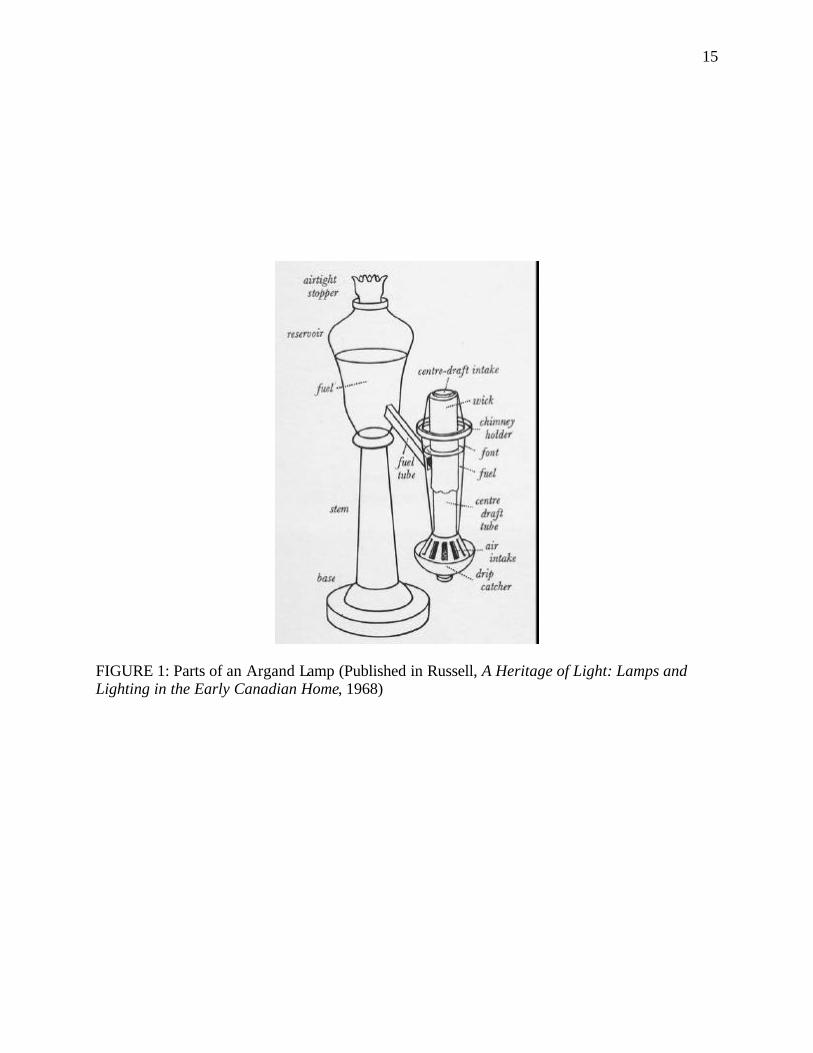
15
FIGURE 1: Parts of an Argand Lamp (Published in Russell, A Heritage of Light: Lamps and Lighting in the Early Canadian Home, 1968)
16
to the burner. The fountain feed system consisted of the oil reservoir that was located to the side
of the burner and connected by an arm, reducing spillage and providing fuel steadily for
extended operation. The Argand lamp, supposedly, produced light equal to that of six wax
candles. Thus, the use of the Argand lamp using the central-draft principle resulted in a great
increase in the amount of light, and the first truly scientific design in artificial illumination. 19
The basic Argand principle of a tubular wick with a center draft was adapted in at least
four slightly different forms during the nineteenth century. They deviated from the original
Argand mainly because of a rearrangement of parts. The disadvantage of Argand lamps was that
with the reservoir raised higher than the wick, the lamps tended to be top-heavy and the reservoir
cast a shadow, so the lamp could not give all-around illumination. Further, the deep form of the
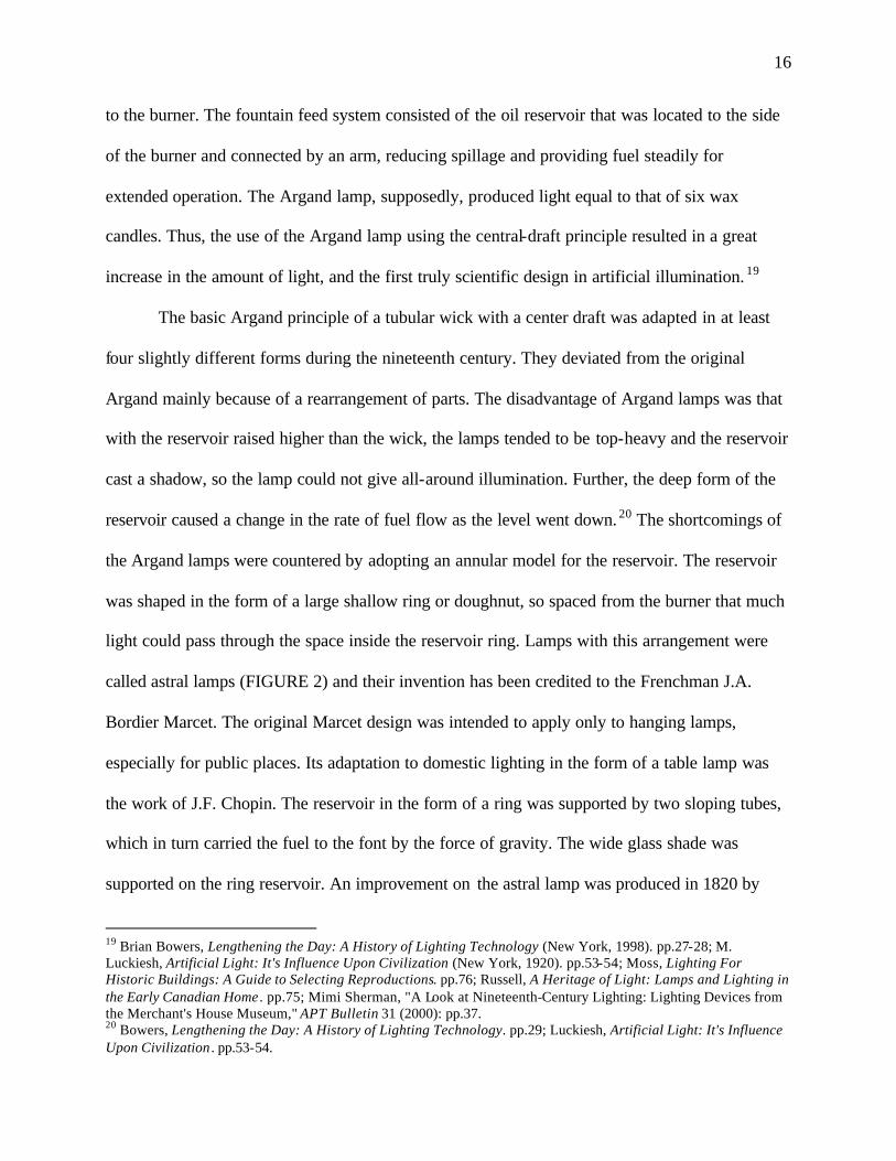
reservoir caused a change in the rate of fuel flow as the level went down. 20 The shortcomings of
the Argand lamps were countered by adopting an annular model for the reservoir. The reservoir
was shaped in the form of a large shallow ring or doughnut, so spaced from the burner that much
light could pass through the space inside the reservoir ring. Lamps with this arrangement were
called astral lamps (FIGURE 2) and their invention has been credited to the Frenchman J.A.
Bordier Marcet. The original Marcet design was intended to apply only to hanging lamps,
especially for public places. Its adaptation to domestic lighting in the form of a table lamp was
the work of J.F. Chopin. The reservoir in the form of a ring was supported by two sloping tubes,
which in turn carried the fuel to the font by the force of gravity. The wide glass shade was
supported on the ring reservoir. An improvement on the astral lamp was produced in 1820 by
19 Brian Bowers, Lengthening the Day: A History of Lighting Technology (New York, 1998). pp.27-28; M. Luckiesh, Artificial Light: It's Influence Upon Civilization (New York, 1920). pp.53-54; Moss, Lighting For Historic Buildings: A Guide to Selecting Reproductions. pp.76; Russell, A Heritage of Light: Lamps and Lighting in the Early Canadian Home . pp.75; Mimi Sherman, "A Look at Nineteenth-Century Lighting: Lighting Devices from the Merchant's House Museum," APT Bulletin 31 (2000): pp.37. 20 Bowers, Lengthening the Day: A History of Lighting Technology. pp.29; Luckiesh, Artificial Light: It's Influence Upon Civilization . pp.53-54.
17
FIGURE 2: Parts of an Astral Lamp (Published in Russell, A Heritage of Light: Lamps and Lighting in the Early Canadian Home, 1968)
18
Samuel Parker. In the improved design the cross-section of the reservoir was wedge-shaped, and
its orientation to the flame was such that at a short distance from the lamp shadow was
obliterated. This idea was further enhanced by George Phillips of London, who converted the
wedge shape to a flattened oval. This new shape for the reservoir showed even greater efficiency
in getting rid of shadows. Lamps produced by Phillips came to be known as sinumbra or
shadowless. These lamps, like Argand lamps, came with tall, straight glass chimneys. The
sinumbra lamp enjoyed its greatest popularity in the 1840s.21
Lard Oil
A problem with using the Argand burner was that it required the best grades of oil, which
became increasingly expensive as the whale population declined. While lard was cheap and
readily available, it was too viscous to flow easily through the complex Argand-burner
mechanism unless first heated and softened. Throughout the first decades of the nineteenth
century a number of lamps were patented that used the cheaper lard oil. They were, however,
only partially successful. These lamps either used flat wicks and pistons or canting devices to
force the fuel into the burner or wires to transmit the heat from the burner to the solid contents of
the reservoir.22
It was only in the early 1840s that a practical means was found to combine inexpensive
lard oil with the efficient combustion of the Argand burner. The resulting solar lamp made it
possible to use lard successfully as a burning fuel and even made it fashionable. The solar lamp
used the central-draft technology of the Argand lamp and consisted of a compact burner which
21 Maril, American Lighting: 1840-1940. pp.15; Russell, A Heritage of Light: Lamps and Lighting in the Early Canadian Home . pp.83-85; Sherman, "A Look at Nineteenth-Century Lighting: Lighting Devices from the Merchant's House Museum," pp.39. 22 Maril, American Lighting: 1840-1940. pp.15.
19
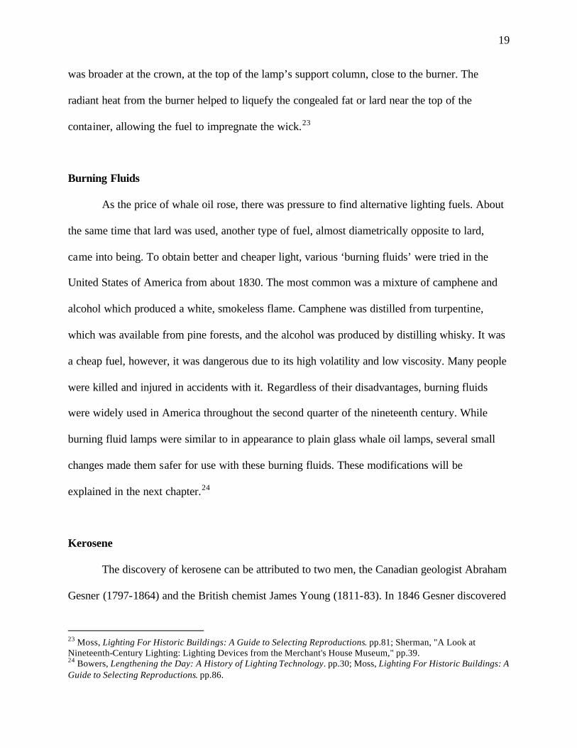
was broader at the crown, at the top of the lamp’s support column, close to the burner. The
radiant heat from the burner helped to liquefy the congealed fat or lard near the top of the
container, allowing the fuel to impregnate the wick.23
Burning Fluids
As the price of whale oil rose, there was pressure to find alternative lighting fuels. About
the same time that lard was used, another type of fuel, almost diametrically opposite to lard,
came into being. To obtain better and cheaper light, various ‘burning fluids’ were tried in the
United States of America from about 1830. The most common was a mixture of camphene and
alcohol which produced a white, smokeless flame. Camphene was distilled from turpentine,
which was available from pine forests, and the alcohol was produced by distilling whisky. It was
a cheap fuel, however, it was dangerous due to its high volatility and low viscosity. Many people
were killed and injured in accidents with it. Regardless of their disadvantages, burning fluids
were widely used in America throughout the second quarter of the nineteenth century. While
burning fluid lamps were similar to in appearance to plain glass whale oil lamps, several small
changes made them safer for use with these burning fluids. These modifications will be
explained in the next chapter.24
Kerosene
The discovery of kerosene can be attributed to two men, the Canadian geologist Abraham
Gesner (1797-1864) and the British chemist James Young (1811-83). In 1846 Gesner discovered
23 Moss, Lighting For Historic Buildings: A Guide to Selecting Reproductions. pp.81; Sherman, "A Look at Nineteenth-Century Lighting: Lighting Devices from the Merchant's House Museum," pp.39. 24 Bowers, Lengthening the Day: A History of Lighting Technology. pp.30; Moss, Lighting For Historic Buildings: A Guide to Selecting Reproductions. pp.86.
20
that one could extract kerosene, a fairly clean, thin fluid, by heating coal in a retort. Across the
Atlantic, meanwhile, Young began experimenting with the distillation of coal in Manchester,
England, when in 1848 he discovered a lighting fuel oozing out in a coal mine. He finally
obtained the fuel by dry distilling coal and like Gesner discovered kerosene. Although Young
patented his discovery earlier than Gesner, Gesner’s process of obtaining kerosene appears to
have been more efficient as it resulted in a cleaner fuel. The manufacture of kerosene from
bituminous coal and oil shale using Gesner’s process began in New York and Boston in the
1850s.25
The use of kerosene as a lamp fuel did not catch on very fast and grew slowly between
1854 and 1859. Kerosene was expensive then, as it had to be distilled from surface petroleum.
This changed rapidly after the success of Edwin L. Drake’s first oil well, which he drilled in
Titusville, Pennsylvania, in 1859, ushering in the age of kerosene.26
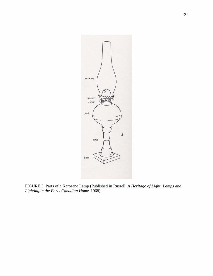
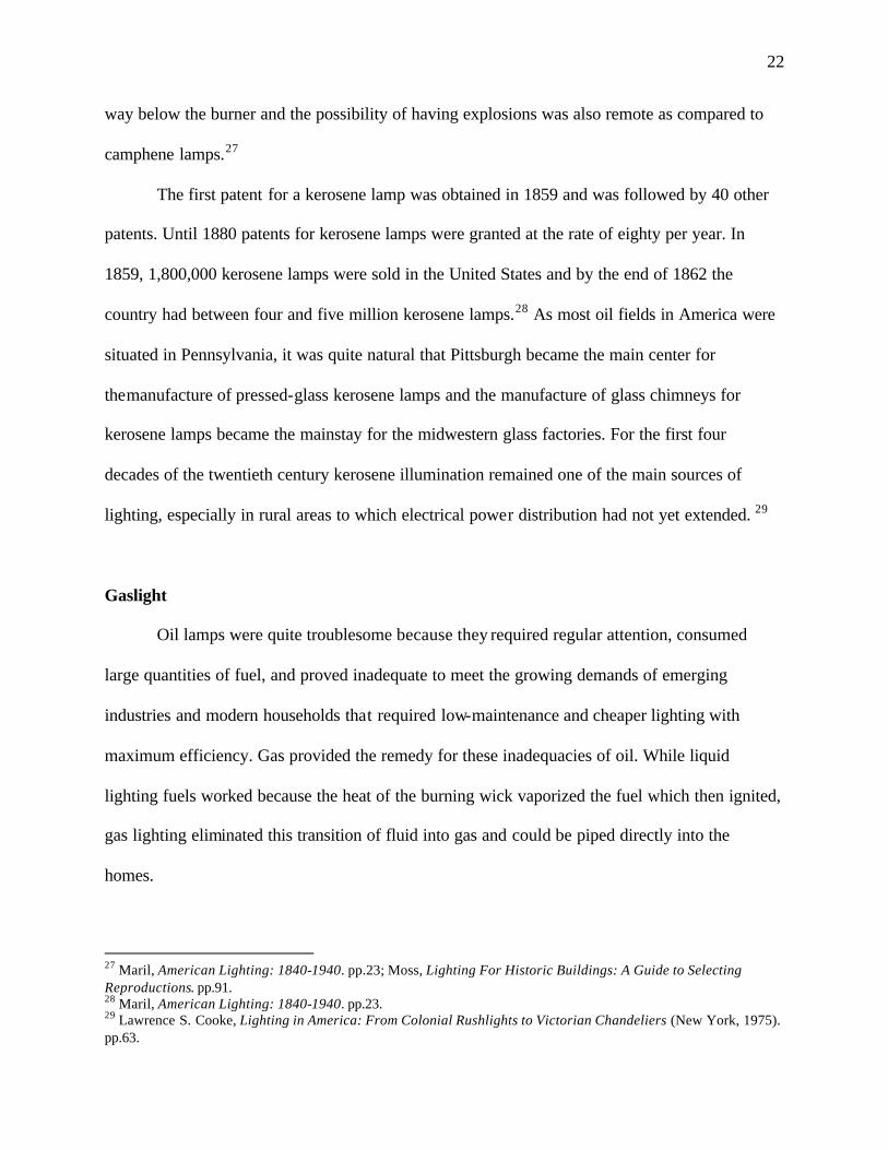
Thereafter, refineries were constructed in Pennsylvania at a rapid scale. This was
accompanied by a drastic expansion of America’s railroad network. Both these factors caused
kerosene to supplant whale oil, burning fluid and even lard oil as the preferred burning fuel by
the 1860s (FIGURE 3). Further, the dramatic increase in the cost of turpentine during the Civil
War brought about an abrupt end to the use of burning fluid and made kerosene even more
practical to use. Kerosene became a cheap fuel, proved to be very efficient, and was considerably
safe. It burnt with less smell and was light enough to flow through the wick readily without
needing any pumping action. This made it possible for oil fonts of the kerosene lamps to extend
25 Bowers, Lengthening the Day: A History of Lighting Technology. pp.33; Russell, A Heritage of Light: Lamps and Lighting in the Early Canadian Home . pp.132-134. 26 Russell, A Heritage of Light: Lamps and Lighting in the Early Canadian Home . pp.138-139.
21
FIGURE 3: Parts of a Kerosene Lamp (Published in Russell, A Heritage of Light: Lamps and Lighting in the Early Canadian Home, 1968)
22
way below the burner and the possibility of having explosions was also remote as compared to
camphene lamps.27
The first patent for a kerosene lamp was obtained in 1859 and was followed by 40 other
patents. Until 1880 patents for kerosene lamps were granted at the rate of eighty per year. In
1859, 1,800,000 kerosene lamps were sold in the United States and by the end of 1862 the
country had between four and five million kerosene lamps.28 As most oil fields in America were
situated in Pennsylvania, it was quite natural that Pittsburgh became the main center for
themanufacture of pressed-glass kerosene lamps and the manufacture of glass chimneys for
kerosene lamps became the mainstay for the midwestern glass factories. For the first four
decades of the twentieth century kerosene illumination remained one of the main sources of
lighting, especially in rural areas to which electrical power distribution had not yet extended. 29
Gaslight
Oil lamps were quite troublesome because they required regular attention, consumed
large quantities of fuel, and proved inadequate to meet the growing demands of emerging
industries and modern households that required low-maintenance and cheaper lighting with
maximum efficiency. Gas provided the remedy for these inadequacies of oil. While liquid
lighting fuels worked because the heat of the burning wick vaporized the fuel which then ignited,
gas lighting eliminated this transition of fluid into gas and could be piped directly into the
homes.
27 Maril, American Lighting: 1840-1940. pp.23; Moss, Lighting For Historic Buildings: A Guide to Selecting Reproductions. pp.91. 28 Maril, American Lighting: 1840-1940. pp.23. 29 Lawrence S. Cooke, Lighting in America: From Colonial Rushlights to Victorian Chandeliers (New York, 1975). pp.63.
23
The distinction for being the original inventor of gas lighting goes to the Frenchman
Philippe Lebon, a graduate of the Ecole des Ponts et Chaussees, who at the age of twenty four
started experimenting with burning wood in a closed furnace and collecting the gas given off in a
vessel over water. He obtained a patent for his discovery in 1799 which marks the beginning of
the era of gas lighting. While Lebon made a start, it was the Scottish engineer, William Murdoch
working for James Watt, the inventor of the steam engine, who made it possible to extract
illuminating gas from coal and distribute it from a central reservoir to a number of outlets. In
1792 Murdoch used the gas distilled from coal to light his home in England. In 1802 he used gas
lighting to light the exterior of Boulton and Watt’s Soho works in order to celebrate the Treaty of
Amiens and then he lighted the Phillips and Lee factory at Salford in 1805. The credit for
marketing and making gas lighting popular and common in homes goes to Frederic Albert
Winzer of Moravia, Germany who had moved to England and consequently changed his name to
Windsor. He took out a patent on the manufacture of gas, and in 1812 he organized a company in
London in order to produce and distribute gas for public use with the help of his chief engineer,
Samuel Clegg. 30
The popularity and success of gas lighting in London, in particular for street lighting, led
to its spread in other cities. Philadelphia was the first city in America to demonstrate gas lighting
when the Italian fireworks manufacturer, M. Ambroise and Company, exhibited lights arranged
in the form of figures, temples and Masonic devices in August 1796. David Melville of Rhode
Island first obtained a patent for the manufacture of gas lighting in America in 1810. In 1816, the
New Theater in Philadelphia was the first commercial building in the United States to have its
interior lit by gas. In 1816 Baltimore, Maryland established the first gas street lighting system in
30 Bowers, Lengthening the Day: A History of Lighting Technology. pp.42-44; Dillon, Artificial Sunshine: A Social History of Domestic Lighting. pp.127-128; Russell, A Heritage of Light: Lamps and Lighting in the Early Canadian Home. pp.288, 290.
24
America. Cities like Boston and New York followed suit in 1822 and 1827 respectively. In 1835,
Philadelphia established its gas plant along with a meter system which was installed to accurately
measure the amount of gas used by each costumer in order to accurately charge for gas
consumption. 31
The problem of introducing gas lighting in homes was that it was only profitable for gas
companies to operate in large cities where the concentration of the population was large enough
to make the construction of gas pipelines cost-effective. In 1830 the idea of involving investors
in the running of a public corporate company like a gas company was introduced and it became a
common practice by the 1840s. By 1860 gas lighting started entering any city or town with a
population big enough to invest in the necessary equipment and piping. Gaslight began the
industrialization of lighting.32
Although gaslight had its dangers of explosions and poisoning, it proved to be a brilliant
source of light, producing a dazzling white light distinctly brighter than all other light sources
used at that time. The reason for this was that the gas’s high temperature of combustion allowed
the carbon particles that make up the flame to burn white hot, while they only reached a reddish
orange glow in the flames of the oil lamps and candles. The larger size of the flame also caused it
to burn brighter. No longer was the size of the flame determined by the wick. This gave
flexibility to the gas flame allowing it to be molded into a variety of shapes. Another novelty of
the gas flame was its uniformity. With candles and oil lamps the flame varied depending on the
wick length or the wind direction, while gas flames provided a steady light requiring no tending.
The only variation in the gas flame was caused by changes in pressure of the gas being sent out
of the gas-works. Several methods were devised to keep gas flow uniform, and at optimum
31 Maril, American Lighting: 1840-1940. pp.38. 32 Ibid. pp.39.
25
pressure. One of these consisted of introducing a washer with a narrow opening in the burner,
through which the gas emerged into a much larger chamber above. Another method was to install
a filter of muslin through which the gas was made to pass to the main chamber of the burner. The
other significant feature of the gaslight was its ability to be regulated by simply turning the gas
keys that controlled the supply of gas to the burners. By varying the supply of the gas the size of
the flame could be regulated. Also, with gas lighting the individual lamps did not need to be
regulated individually. All the lamps connected to the gas mains could be altered at the same
time. So for the first time lamps could be regulated from a distance.33
Gas Mantle
Gaslight would have succumbed to competition and quickly be replaced by electricity if
it had continued to remain just a light from a gas flame. It managed to hold its own against
innovations in the development of electric lighting due to the advent of the gas mantle. The
inventor of the gas mantle was an Austrian called Karl Auer von Welbasch, who was a student of
R.W. von Bunsen at the University of Heidelberg. Bunsen was already known for the discovery
of a burner (named after him as the Bunsen burner) in 1855 in which the jet of gas is already
mixed with a controlled current of air befo re reaching the place where it is burned. The result is a
very hot, pale blue, sootless flame. Welsbach’s discovery of the luminous property of rare metal
oxides in 1872 was by accident. As he was boiling a solution of salts of rare metals in a beaker,
the solution happened to boil over and spill on to an asbestos mat. To his surprise he found that
as the salts dried on the asbestos fibers and became hot, they began to emit a luminous light.34
After experimenting further he found that he did not need the asbestos fibers. He used a fine
33 Russell, A Heritage of Light: Lamps and Lighting in the Early Canadian Home; Schivelbusch, Disenchanted Night: The Industrialization of Light in the Nineteenth Century. pp.40-44. 34 Bowers, Lengthening the Day: A History of Lighting Technology. pp.127.
26
cotton fabric, impregnated with a solution of the oxides of thorium and cerium. When it was
appropriately mounted over a Bunsen-type burner, and the fabric burnt away, it could be heated
by the gas flame to incandescence, producing an intense white light. He recommended that the
best possible proportions of the rare earth oxides were one part of ceria and ninety-nine parts of
thoria. The first factory to produce gas mantles was formed in 1887 and was called the
Incandescent Gas Light Company. The gas mantle produced much more light than traditional gas
lighting while using much less gas. While gas mantles made prior to 1889 gave out six to eight
candlepowers35 of light per cubic foot, those produced after 1889 provided up to twenty
candlepowers per cubic foot. This was far more than the early light bulbs which only radiated
sixteen candlepowers of light per cubic foot. Gas mantles also cost only one-fifth to one-sixth of
what it took to produce electric light.36
Mantles were made by knitting cotton or other fiber in the shape of cylinders and then
dousing them in a solution of nitrates of cerium and thorium. Asbestos thread was then used to
sew one end of the cylinder. The asbestos thread also served as the loop for holding the mantle
over the burner. Once the mantle was dry it was burned. By this process the organic matter
disappeared and the nitrates were converted into oxides. After burning off, all the residual black
matter was removed but the mantle was too delicate to be transported. In order to strengthen the
mantle it was dipped into collodion, which is a gluey solution of gun-cotton or cellulose nitrates
in alcohol and ether. When the mantle was first used the collodion burned off, leaving the mantle
which, though too fragile to be handled, could be used for a long time without needing to be
35 Until the early years of the twentieth century, the luminous intensity of gas burners and electric lamps was measured in candle power (c.p.). This was the equivalent to the light produced by one spermaceti candle weighing two ounces and burning 120 grains an hour. Approximately, 8 c.p. = 10 watts, 16 c.p. = 25 watts, 25 c.p. = 36 watts, 50 c.p. = 60 watts. 36 Luckiesh, Artificial Light: It's Influence Upon Civilization. pp.100; Maril, American Lighting: 1840-1940. pp.43; Russell, A Heritage of Light: Lamps and Lighting in the Early Canadian Home. pp.297; Schivelbusch, Disenchanted Night: The Industrialization of Light in the Nineteenth Century. pp.48.
27
replaced. The early gas mantles sat upright and were held on a support, which was usually a
piece of fireclay, above the flame. In order to compete with electrical lighting that faced their
bulbs downwards, inverted gas mantles were invented in 1897. These inverted mantles usually
used special boosting devices to fire the gas downwards.37
Incandescent Lighting
Experiments with incandescent lighting started as early as 1838 with several inventors
trying to produce lamps using carbon or platinum filaments as these materials had the ability to
withstand a great amount of heat. The only drawback with using platinum was that it was
expensive. However, the lead- in wires holding the conductor had to be platinum as it was the
only metal known then to have the same coefficient of expansion as glass and could thus be
sealed through the glass without cracking it. Although, both carbon and platinum had high
melting points they had a tendency of burning out due to oxidation. Hence, a foolproof method
of evacuating the air needed to be devised before one could come up with a successful
incandescent lamp. In 1865, Hermann Sprengel invented the mercury vacuum pump. However,
the vacuum pump was not efficient enough to produce a truly practical lamp. In 1875, an
apparatus which provided a sufficiently high vacuum was produced with Sir William Crooke’s
modification of Sprengel’s mercury vacuum pump. Once this was accomplished, it paved the
way for the invention of a viable incandescent lamp. There were four filament lamp inventors of
prime significance: Joseph Swan and St. George Lane Fox of Britain, Thomas Edison and Hiram
37 Bowers, Lengthening the Day: A History of Lighting Technology. pp.127-128; Luckiesh, Artificial Light: It's Influence Upon Civilization . pp.100-101; Maril, American Lighting: 1840-1940 . pp.43.
28
Maxim from the United States of America. Out of these Joseph Swan and Thomas Edison made
the greatest contributions.38
Joseph Swan
Although Thomas Edison is known as the inventor of the first successful incandescent
lamp, Joseph Swan made significant early contributions in the deve lopment of the carbon
filament. About 1850 Swan started experimented with carbon filaments. He produced the
filament by carbonizing thin strips of paper, that is, driving off the oxygen and hydrogen present
by heating them with charcoal in a crucible. This made the carbon strong and flexible. Before
carbonizing, the filament was bent into a horseshoe shape to prevent breakage due to thermal
expansion. In 1860 he placed the filament in a glass bulb and pumped out the air as best as he
could. Although the filament did heat up to incandescence, the inside of the bulb got quickly
blackened with particles of carbon evaporated from the filament. He came to realize that his
attempts to create a successful incandescent lamp would come to naught unless an efficient
vacuum pump was developed. The improvement in the vacuum pump in 1875 gave Swan the
impetus to resume his quest to create the perfect incandescent lamp.39
Swan soon began using carbonized parchmentized paper. Apart from being
carbonized, the paper was treated with sulphuric acid to give it a smooth, hard finish. But
he finally abandoned both carbonized and carbonized parchmentized paper and decided
instead to use parchmentized thread, that is, cotton thread treated in sulphuric acid to
make the cotton fibers stronger, compact and more uniform. Parchmentized thread
remained Swan’s favored filament material for many years. In October 1880 Swan gave
38 Bowers, Lengthening the Day: A History of Lighting Technology. pp.86; Dillon, Artificial Sunshine: A Social History of Domestic Lighting. pp.163. 39 Bowers, Lengthening the Day: A History of Lighting Technology. pp.87, 90-91.Ibid., 87, 90, 91
29
the first public demonstration of his lamp using the parchmentized thread filament.
However, Swan never filed for a patent for his incandescent lamp.40
In 1882 Thomas Edison set up the Edison Electric Light Company in London and
began legal proceedings against Swan for patent infringement, but a prolonged legal
battle was avoided when the two companies combined in 1883 into the Edison & Swan
United Company. 41
Thomas Edison
The American inventor, Thomas Alva Edison, had already been acclaimed as the inventor
of the stock ticker, the telephone transmitter, multiplex telegraphy, and the phonograph when he
turned his attention to electricity and lighting in 1877. The Edison Electric Light Company was
formed in 1878, having all the rights to Edison’s inventions in the area of electrical lighting. His
early experiments with incandescent lighting were complete failures and after many futile trials
at coming up with a suitable carbon filament, he declared in November 1878 that carbon was not
a suitable filament material. He then turned his attention to platinum. He used very fine platinum
wires which would offer high resistance owing to their smaller cross-section. Based on Ohm’s
law formulated in 1827, by offering higher resistance to the current passing through, the filament
or wire would incandescent at greatly reduced current levels. Due to the failure of all his
experiments with platinum and platinum’s high cost, Edison realized that the filament worked
best if composed solely of carbon and contained in a completely evacuated vessel.42
40 Ibid. pp.91-92, 102; Dillon, Artificial Sunshine: A Social History of Domestic Lighting . pp.164. 41 Dillon, Artificial Sunshine: A Social History of Domestic Lighting. pp.168. 42 Bowers, Lengthening the Day: A History of Lighting Technology. pp.95-96; James A. Cox, A Century of Light (1979). pp.26, 28, 33; Luckiesh, Artificial Light: It's Influence Upon Civilization. pp.129.
30
Between September and October 1879 a variety of forms of carbon were tried. Edison’s
first successful lamp was made on October 19th, 1879 and used a conductor of carbonized cotton
thread bent in the shape of a hairpin. The negative aspect of Edison’s carbonized thread was that
it was very fragile. So the carbonized thread was soon discarded and supplanted by Bristol board,
a kind of hard, smooth paper which was carbonized in a furnace to yield a hard, smooth filament.
It was this material that was used for the public demonstration of incandescent lamps at Edison’s
laboratory in Menlo Park, New Jersey on December 31st, 1879 (FIGURE 4). With the success of
the Bristol board filament, by midsummer 1880 Edison began commercial production of Bristol
Board lamps. He began considering ways of building a system of mass production to cut costs.
Soon a number of satellite companies were formed for particular tasks, such as the Edison Lamp
Company to produce lamps, the Edison Machine Works for dynamos, the Electric Tube
Company for such things as junction boxes, underground wiring and so on. In April 1882, the
high demand of lamps made it necessary to move operations from the Menlo Park factory to a
larger plant in Harrison, New Jersey where 150 employees produced twelve hundred lamps per
day. 43
Meanwhile, Edison was in search of a better filament material. He turned to the animal
and vegetation kingdom, trying out the entire range from bones, hoofs, and hides to onions,
macaroni, rope, plants, all types of wood and literally every conceivable organic matter. One day
his attention turned to an old fan lying around in the lab; He pulled out a strip of bamboo and ran
some tests using it. The results of the test were promising and Edison scoured the world looking
for the perfect bamboo fiber. A particular type of Japanese bamboo was found to be the most
suitable, and a farmer on the island of Kyushu was appointed to cultivate it. The bamboo
filament lamp remained Edison’s standard lamp from mid-1881 until 1894. The only 43 Bowers, Lengthening the Day: A History of Lighting Technology. pp.96; Cox, A Century of Light. pp.33, 54.
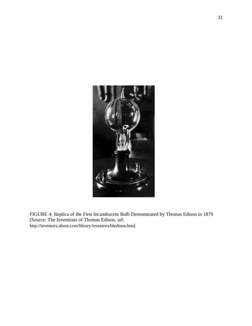
31
FIGURE 4: Replica of the First Incandescent Bulb Demonstrated by Thomas Edison in 1879 (Source: The Inventions of Thomas Edison, url: http://inventors.about.com/library/inventors/bledison.htm)
32
developments were that the platinum clamps attaching the filament to the platinum lead- in wires
were replaced by copper plating on the ends of the filament, which in turn were plated to the
lead-in wires.44
The decade 1880-90 was a great boom time for incandescent lighting. With mass
production, the production cost of a bulb was pared down from seventy cents in 1881 to fifty
cents in 1880 and as little as thirty-seven cents in 1883. The lowering of manufacturing costs of
incandescent bulbs caused a huge rise in consumption. To meet this demand, six companies
emerged as major competition to the Electric Company between 1880 and 1890, one of which
was the Thomson-Houston Electric Company. The rapid growth in the infant industry, along
with the passing of numerous patents and the formation of new companies, led to scores of legal
battles. In 1889, the scattered Edison manufacturing companies were organized under a single
company called the Edison General Electric Company. Also, several mergers led to the
emergence of three spearheads in the lighting industry - Edison General Electric Company,
Westinghouse and Thomas-Houston. On April 15, 1892, the Edison General Electric Company
and Thomas-Houston joined forces after the former decided to buy out the latter, which was
emerging as major competition. However, after evaluating the position of both companies, the
board members decided that it would be wiser to reverse the roles. Thomas-Houston was doing
better than the Edison General Electric Company with a better rate of return on its invested
capital and was into the preferred alternating current as opposed to the Edison General Electric
Company which still insisted on using direct current.45
Meanwhile, innovations and new tests were being carried out to come up with better
filaments, not just in the United States but also in England. There was one limitation of using
44 Bowers, Lengthening the Day: A History of Lighting Technology. pp.98; Cox, A Century of Light. pp.50, 52. 45 Cox, A Century of Light. pp.35-36, 54.
33
bamboo and that was the filament size could not exceed the distance between the joints of the
bamboo cane. Joseph Swan used his expertise in chemistry to come up with a superior filament
material: the ‘squirted’ filament. Cotton, which is primarily cellulose, reacts with nitric acid to
give nitrocellulose. Nitrocellulose in turn dissolves readily in acetic acid. Swan discovered that
by squirting the nitrocellulose solution with alcohol, the cellulose was reconstituted into an
extremely fine thread, longer and more uniform than the original cotton. Swan patented this
method in December 1883 (FIGURE 5). In 1888, following the success of Swan’s experiments,
Leigh S. Powell, another English scientist, found a practical replacement for bamboo fiber which
was adopted by most lamp manufacturers in the United States by 1894. Powell’s method
involved dissolving the cotton thread in hot zinc chloride and then squirting the mixture through
a die into alcohol, which acted as the hardening agent. The zinc chloride was then washed away
providing a strong, smooth, structureless filament, which could be cut into any desired length
before being carbonized.46
The ending of the Edison patent in 1894 forced the lighting industry to come up with
some innovations. It was known for a long time that the efficiency of a filament was subject to
the temperature it was able to achieve and increased with increase in temperature. So it was the
constant aim of scientists to reach higher filament temperatures. Of all the filaments that had
been tried, carbon had the highest melting point at 35500C. In spite of this fact, carbon was the
least efficient because the highest temperature it could be operated at was only about 16000C.
Another problem with the carbon filament was that when it became very hot the incandescent
carbon, in the evacuated bulb, tended to vaporize and deposit on the glass surface. This caused
blackening and brought down the efficiency of the lamp. As a consequence, “getters” were
46 Bowers, Lengthening the Day: A History of Lighting Technology. pp.107; Cox, A Century of Light. pp.55; Luckiesh, Artificial Light: It's Influence Upon Civilization. pp.130.
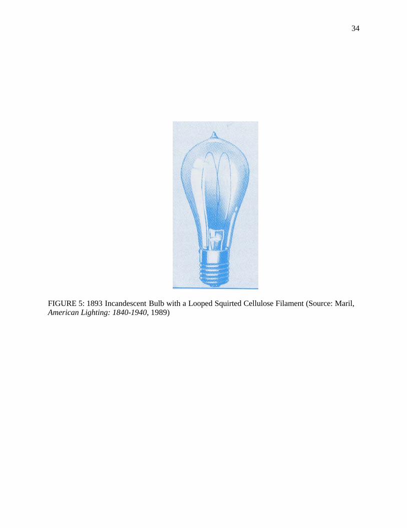
34
FIGURE 5: 1893 Incandescent Bulb with a Looped Squirted Cellulose Filament (Source: Maril, American Lighting: 1840-1940, 1989)
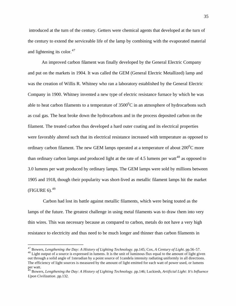
35
introduced at the turn of the century. Getters were chemical agents that developed at the turn of
the century to extend the serviceable life of the lamp by combining with the evaporated material
and lightening its color.47
An improved carbon filament was finally developed by the General Electric Company
and put on the markets in 1904. It was called the GEM (General Electric Metallized) lamp and
was the creation of Willis R. Whitney who ran a laboratory established by the General Electric
Company in 1900. Whitney invented a new type of electric resistance furnace by which he was
able to heat carbon filaments to a temperature of 35000C in an atmosphere of hydrocarbons such
as coal gas. The heat broke down the hydrocarbons and in the process deposited carbon on the
filament. The treated carbon thus developed a hard outer coating and its electrical properties
were favorably altered such that its electrical resistance increased with temperature as opposed to
ordinary carbon filament. The new GEM lamps operated at a temperature of about 2000C more
than ordinary carbon lamps and produced light at the rate of 4.5 lumens per watt48 as opposed to
3.0 lumens per watt produced by ordinary lamps. The GEM lamps were sold by millions between
1905 and 1918, though their popularity was short-lived as metallic filament lamps hit the market
(FIGURE 6).49
Carbon had lost its battle against metallic filaments, which were being touted as the
lamps of the future. The greatest challenge in using metal filaments was to draw them into very
thin wires. This was necessary because as compared to carbon, metals do not have a very high
resistance to electricity and thus need to be much longer and thinner than carbon filaments in
47 Bowers, Lengthening the Day: A History of Lighting Technology. pp.145; Cox, A Century of Light. pp.56-57. 48 Light output of a source is expressed in lumens. It is the unit of luminous flux equal to the amount of light given out through a solid angle of 1steradian by a point source of 1candela intensity radiating uniformly in all directions. The efficiency of light sources is measured by the amount of light emitted for each watt of power used, or lumens per watt. 49 Bowers, Lengthening the Day: A History of Lighting Technology. pp.146; Luckiesh, Artificial Light: It's Influence Upon Civilization . pp.132.
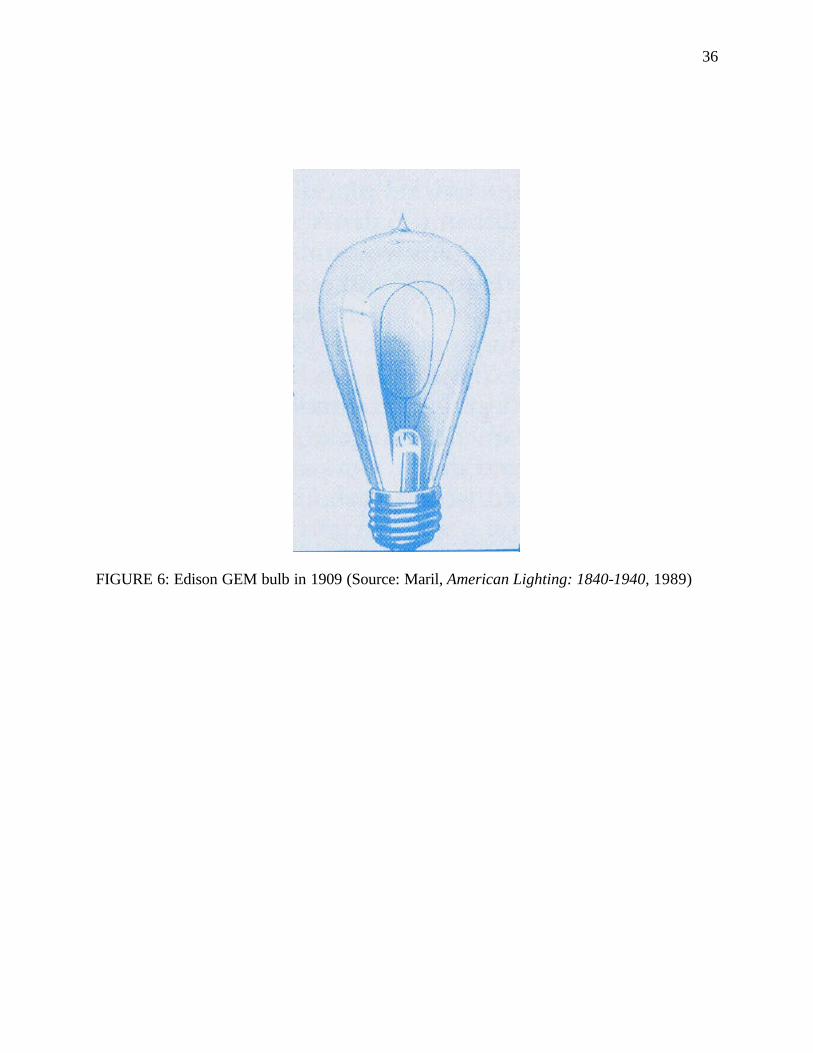
36
FIGURE 6: Edison GEM bulb in 1909 (Source: Maril, American Lighting: 1840-1940, 1989)
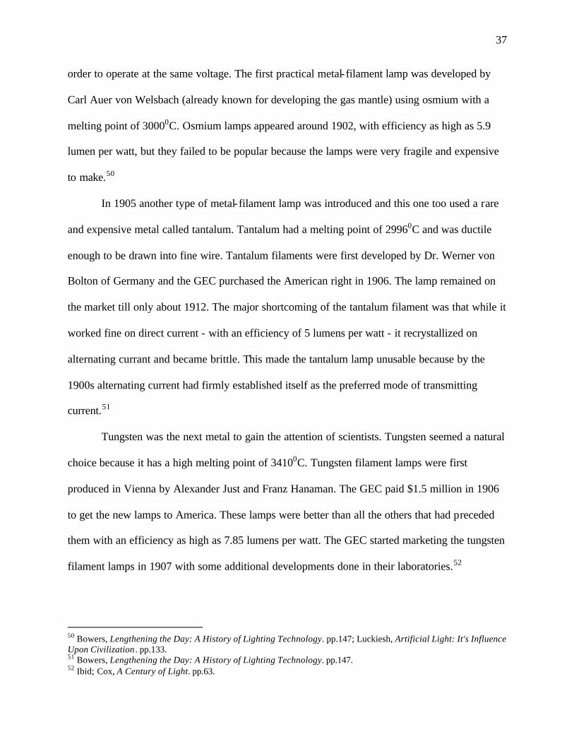
37
order to operate at the same voltage. The first practical metal- filament lamp was developed by
Carl Auer von Welsbach (already known for developing the gas mantle) using osmium with a
melting point of 30000C. Osmium lamps appeared around 1902, with efficiency as high as 5.9
lumen per watt, but they failed to be popular because the lamps were very fragile and expensive
to make.50
In 1905 another type of metal- filament lamp was introduced and this one too used a rare
and expensive metal called tantalum. Tantalum had a melting point of 29960C and was ductile
enough to be drawn into fine wire. Tantalum filaments were first developed by Dr. Werner von
Bolton of Germany and the GEC purchased the American right in 1906. The lamp remained on
the market till only about 1912. The major shortcoming of the tantalum filament was that while it
worked fine on direct current - with an efficiency of 5 lumens per watt - it recrystallized on
alternating currant and became brittle. This made the tantalum lamp unusable because by the
1900s alternating current had firmly established itself as the preferred mode of transmitting
current.51
Tungsten was the next metal to gain the attention of scientists. Tungsten seemed a natural
choice because it has a high melting point of 34100C. Tungsten filament lamps were first
produced in Vienna by Alexander Just and Franz Hanaman. The GEC paid $1.5 million in 1906
to get the new lamps to America. These lamps were better than all the others that had preceded
them with an efficiency as high as 7.85 lumens per watt. The GEC started marketing the tungsten
filament lamps in 1907 with some additional developments done in their laboratories.52
50 Bowers, Lengthening the Day: A History of Lighting Technology. pp.147; Luckiesh, Artificial Light: It's Influence Upon Civilization . pp.133. 51 Bowers, Lengthening the Day: A History of Lighting Technology. pp.147. 52 Ibid; Cox, A Century of Light. pp.63.
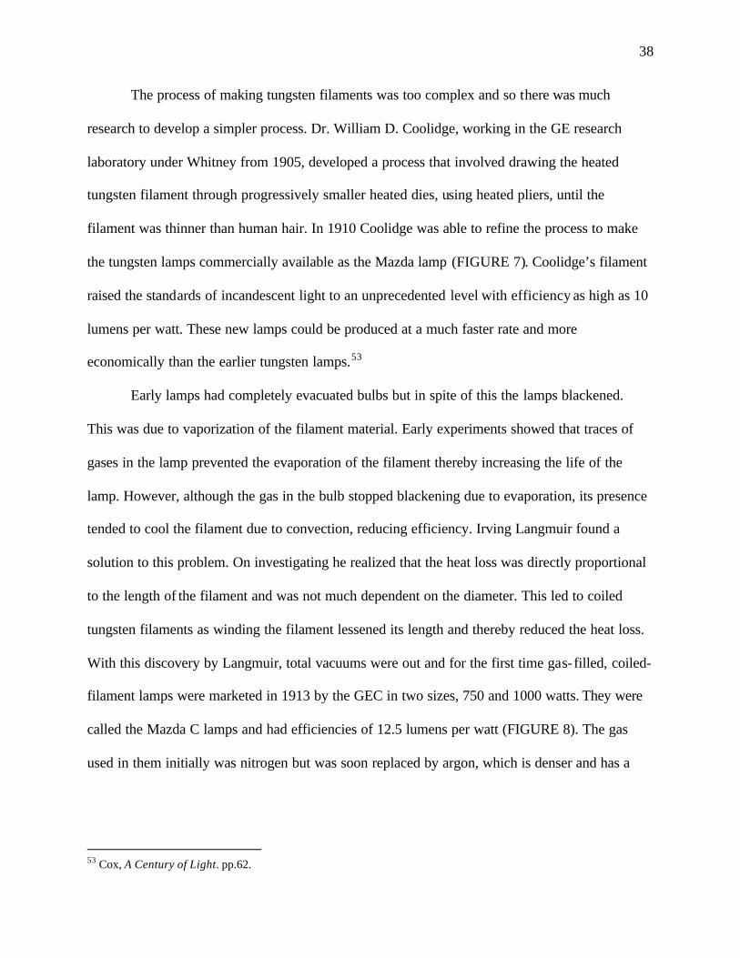
38
The process of making tungsten filaments was too complex and so there was much
research to develop a simpler process. Dr. William D. Coolidge, working in the GE research
laboratory under Whitney from 1905, developed a process that involved drawing the heated
tungsten filament through progressively smaller heated dies, using heated pliers, until the
filament was thinner than human hair. In 1910 Coolidge was able to refine the process to make
the tungsten lamps commercially available as the Mazda lamp (FIGURE 7). Coolidge’s filament
raised the standards of incandescent light to an unprecedented level with efficiency as high as 10
lumens per watt. These new lamps could be produced at a much faster rate and more
economically than the earlier tungsten lamps.53
Early lamps had completely evacuated bulbs but in spite of this the lamps blackened.
This was due to vaporization of the filament material. Early experiments showed that traces of
gases in the lamp prevented the evaporation of the filament thereby increasing the life of the
lamp. However, although the gas in the bulb stopped blackening due to evaporation, its presence
tended to cool the filament due to convection, reducing efficiency. Irving Langmuir found a
solution to this problem. On investigating he realized that the heat loss was directly proportional
to the length of the filament and was not much dependent on the diameter. This led to coiled
tungsten filaments as winding the filament lessened its length and thereby reduced the heat loss.
With this discovery by Langmuir, total vacuums were out and for the first time gas-filled, coiled-
filament lamps were marketed in 1913 by the GEC in two sizes, 750 and 1000 watts. They were
called the Mazda C lamps and had efficiencies of 12.5 lumens per watt (FIGURE 8). The gas
used in them initially was nitrogen but was soon replaced by argon, which is denser and has a
53 Cox, A Century of Light. pp.62.
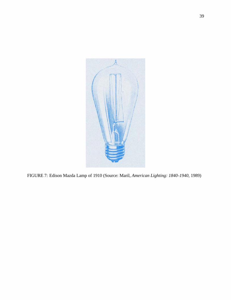
39
FIGURE 7: Edison Mazda Lamp of 1910 (Source: Maril, American Lighting: 1840-1940, 1989)
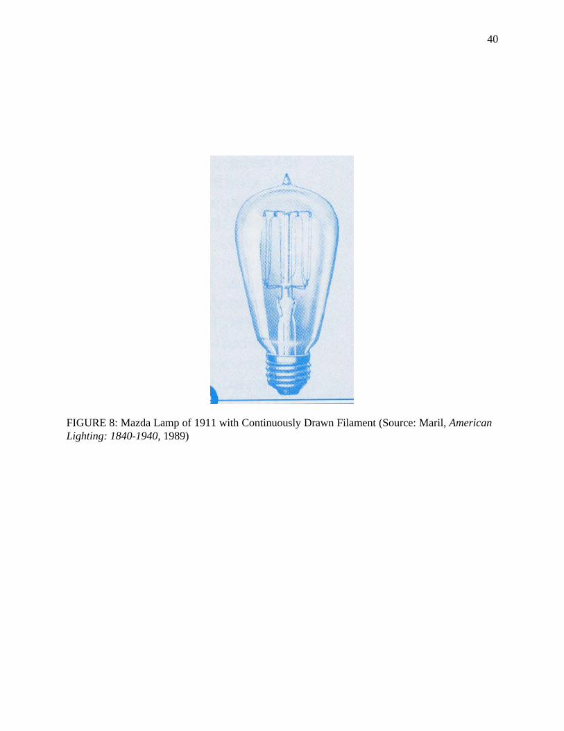
40
FIGURE 8: Mazda Lamp of 1911 with Continuously Drawn Filament (Source: Maril, American Lighting: 1840-1940, 1989)
41
lower thermal conductivity. These new tungsten lamps sounded the death knell for gas lighting
though gas continued in use for emergency purposes until 1920.54
Until 1920, the bulbs had characteristic ‘pips’ at their tips where the bulb was sealed as
the bulbs were evacuated from the end opposite the cap and the lead in wires. This changed when
in 1919 L.E. Mitchell and A.J. White removed the annoying sharp tip from the lamps by devising
a way to evacuate the bulb through the cap so that the point where the bulb was sealed could be
enclosed with the cap and protected. The early bulbs were made of clear glass and produced
intense glare. In 1925, Marvin Pipkin developed the process for frosting the inside of the bulb by
treating it with acid twice. The first bath created sharp, tiny crevices in the glass producing a
very brittle glass while the second bath smoothed the sharp edges, rounded the crevices leading
to an evenly frosted glass which has been used ever since.55
54 Bowers, Lengthening the Day: A History of Lighting Technology. pp.150; Cox, A Century of Light. pp.63-64. 55 Bowers, Lengthening the Day: A History of Lighting Technology. pp.153; Edward J. Covington, "Marvin Pipkin - A Biography" (February 21, 2004), available from http://home.frognet.net/~ejcov/pipkin.html; Edward J. Covington, "The White Mazda Lamps" (21 Februrary, 2004), available from http://home.frognet.net/~ejcov/whitem.html.
42
CHAPTER III
LIGHT FIXTURES IN THE HOME: 1610 to 1930 Colonial Period: (1610-1780)
The colonial period was marked by medieval simplicity which was reflected in the way
people lived. Architecture and the decorative arts in the seventeenth century were largely
governed by functionality rather than aesthetics. Also, household goods, furniture and decorative
objects were influenced by the styles prevalent in Europe, particularly England, from where the
early settlers of America had arrived. Lighting devices used in the house were no exception.
Natural light was the most common form of interior lighting in most houses in colonial
America. The living pattern, work routine, furniture arrangements, textiles, colors of interiors
and decoration schemes were all dictated by the daylight hours, while nights were almost spent
in darkness, save for the light of the fireplace, grease lamps, and candles. The usual day started at
dawn and ended soon after supper so the family spent as little time in darkness as possible.
Early colonial houses (FIGURE 9) usually had large brick fireplaces in the main room,
which were used as both kitchen and all-purpose living space, and it was the hearth that provided
the brightest light at night, and also served to prepare food and provide warmth. The family
would huddle together near the fireplace every evening after the day’s work was done. Some
woods in the fireplace, particularly faggots of pine or birch, burned with more luminosity than
the others. It was then simply a logical step to come up with the idea of singling out these woods
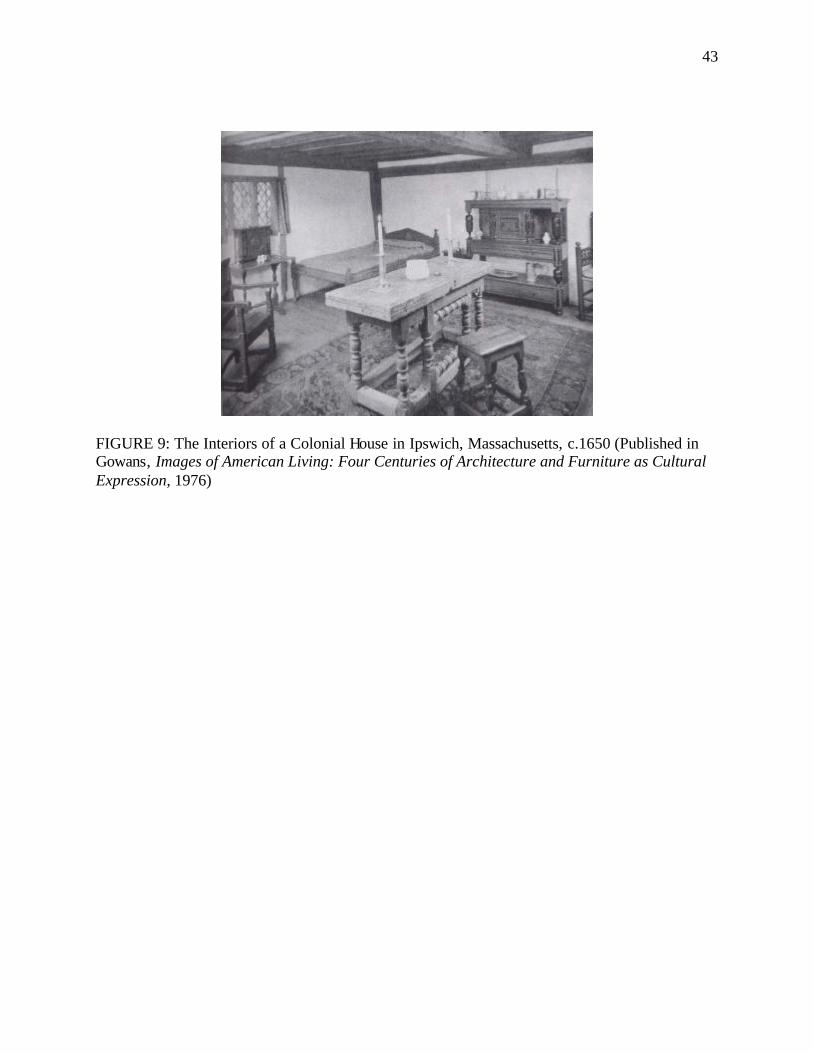
43
FIGURE 9: The Interiors of a Colonial House in Ipswich, Massachusetts, c.1650 (Published in Gowans, Images of American Living: Four Centuries of Architecture and Furniture as Cultural Expression, 1976)
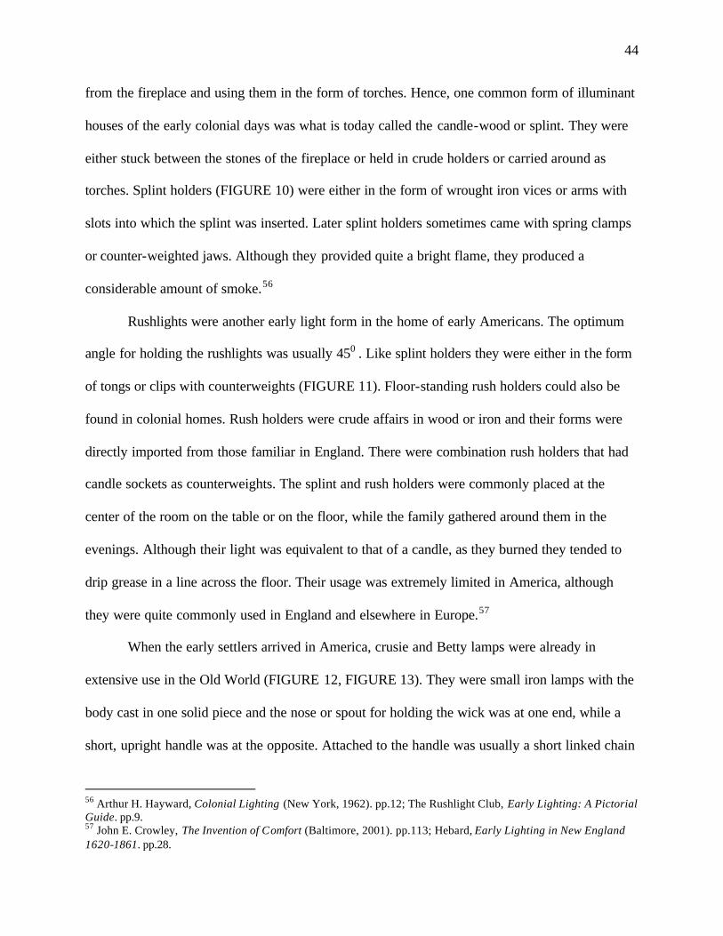
44
from the fireplace and using them in the form of torches. Hence, one common form of illuminant
houses of the early colonial days was what is today called the candle-wood or splint. They were
either stuck between the stones of the fireplace or held in crude holders or carried around as
torches. Splint holders (FIGURE 10) were either in the form of wrought iron vices or arms with
slots into which the splint was inserted. Later splint holders sometimes came with spring clamps
or counter-weighted jaws. Although they provided quite a bright flame, they produced a
considerable amount of smoke.56
Rushlights were another early light form in the home of early Americans. The optimum
angle for holding the rushlights was usually 450 . Like splint holders they were either in the form
of tongs or clips with counterweights (FIGURE 11). Floor-standing rush holders could also be
found in colonial homes. Rush holders were crude affairs in wood or iron and their forms were
directly imported from those familiar in England. There were combination rush holders that had
candle sockets as counterweights. The splint and rush holders were commonly placed at the
center of the room on the table or on the floor, while the family gathered around them in the
evenings. Although their light was equivalent to that of a candle, as they burned they tended to
drip grease in a line across the floor. Their usage was extremely limited in America, although
they were quite commonly used in England and elsewhere in Europe.57
When the early settlers arrived in America, crusie and Betty lamps were already in
extensive use in the Old World (FIGURE 12, FIGURE 13). They were small iron lamps with the
body cast in one solid piece and the nose or spout for holding the wick was at one end, while a
short, upright handle was at the opposite. Attached to the handle was usually a short linked chain
56 Arthur H. Hayward, Colonial Lighting (New York, 1962). pp.12; The Rushlight Club, Early Lighting: A Pictorial Guide. pp.9. 57 John E. Crowley, The Invention of Comfort (Baltimore, 2001). pp.113; Hebard, Early Lighting in New England 1620-1861. pp.28.
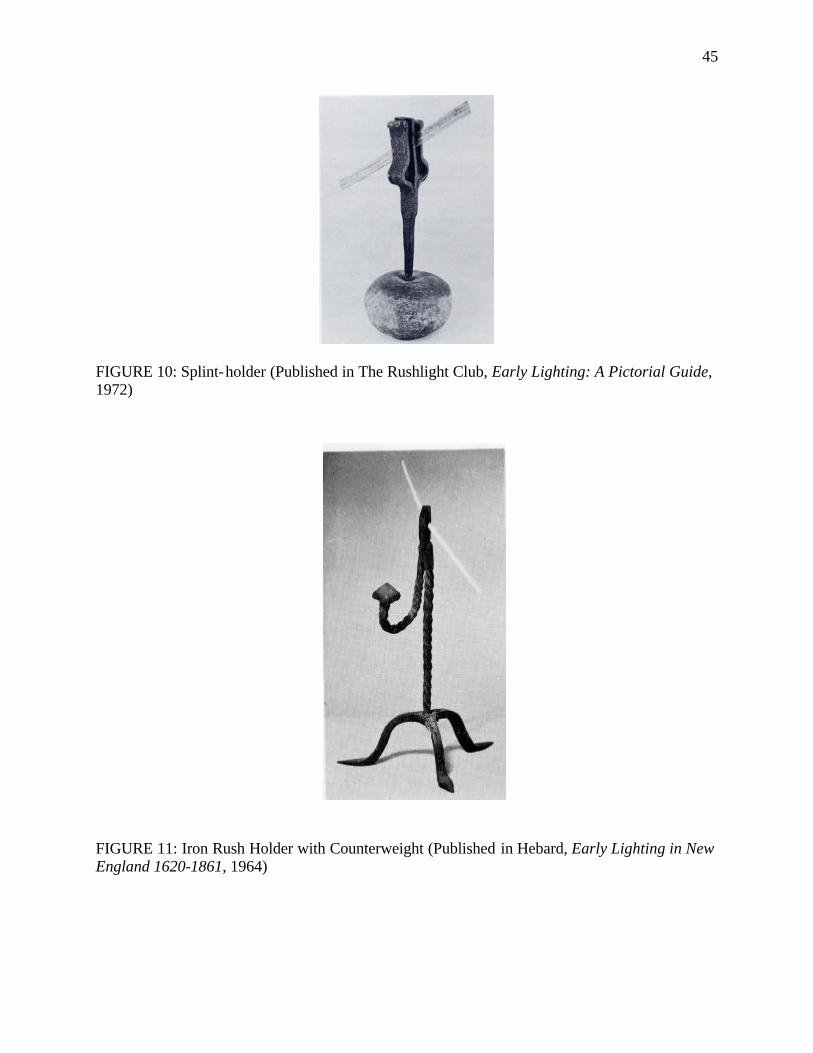
45
FIGURE 10: Splint-holder (Published in The Rushlight Club, Early Lighting: A Pictorial Guide, 1972)
FIGURE 11: Iron Rush Holder with Counterweight (Published in Hebard, Early Lighting in New England 1620-1861, 1964)
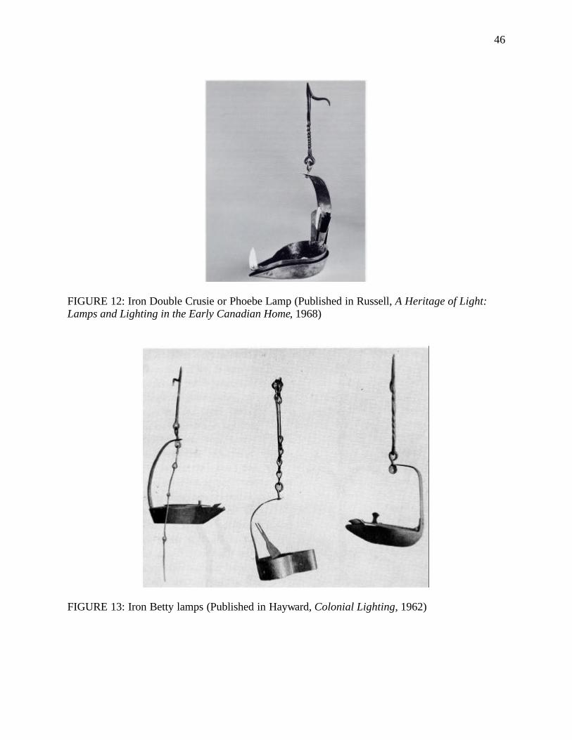
46
FIGURE 12: Iron Double Crusie or Phoebe Lamp (Published in Russell, A Heritage of Light: Lamps and Lighting in the Early Canadian Home, 1968)
FIGURE 13: Iron Betty lamps (Published in Hayward, Colonial Lighting, 1962)
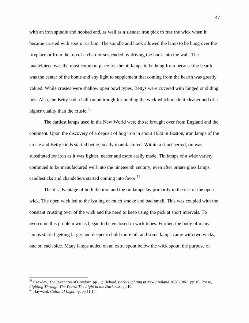
47
with an iron spindle and hooked end, as well as a slender iron pick to free the wick when it
became crusted with soot or carbon. The spindle and hook allowed the lamp to be hung over the
fireplace or from the top of a chair or suspended by driving the hook into the wall. The
mantelpiece was the most common place for the oil lamps to be hung from because the hearth
was the center of the home and any light to supplement that coming from the hearth was greatly
valued. While crusies were shallow open bowl types, Bettys were covered with hinged or sliding
lids. Also, the Betty had a half-round trough for holding the wick which made it cleaner and of a
higher quality than the crusie.58
The earliest lamps used in the New World were those brought over from England and the
continent. Upon the discovery of a deposit of bog iron in about 1630 in Boston, iron lamps of the
crusie and Betty kinds started being locally manufactured. Within a short period, tin was
substituted for iron as it was lighter, neater and more easily made. Tin lamps of a wide variety
continued to be manufactured well into the nineteenth century, even after ornate glass lamps,
candlesticks and chandeliers started coming into favor.59
The disadvantage of both the iron and the tin lamps lay primarily in the use of the open
wick. The open wick led to the issuing of much smoke and bad smell. This was coupled with the
constant crusting over of the wick and the need to keep using the pick at short intervals. To
overcome this problem wicks began to be enclosed in wick tubes. Further, the body of many
lamps started getting larger and deeper to hold more oil, and some lamps came with two wicks,
one on each side. Many lamps added on an extra spout below the wick spout, the purpose of
58 Crowley, The Invention of Comfort. pp.11; Hebard, Early Lighting in New England 1620-1861 . pp.16; Poese, Lighting Through The Years: The Light in the Darkness. pp.10. 59 Hayward, Colonial Lighting. pp.11,13.
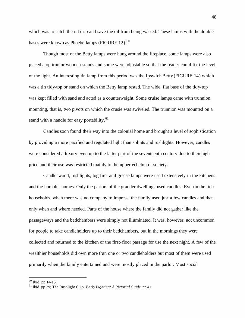
48
which was to catch the oil drip and save the oil from being wasted. These lamps with the double
bases were known as Phoebe lamps (FIGURE 12).60
Though most of the Betty lamps were hung around the fireplace, some lamps were also
placed atop iron or wooden stands and some were adjustable so that the reader could fix the level
of the light. An interesting tin lamp from this period was the Ipswich Betty (FIGURE 14) which
was a tin tidy-top or stand on which the Betty lamp rested. The wide, flat base of the tidy-top
was kept filled with sand and acted as a counterweight. Some cruise lamps came with trunnion
mounting, that is, two pivots on which the crusie was swiveled. The trunnion was mounted on a
stand with a handle for easy portability.61
Candles soon found their way into the colonial home and brought a level of sophistication
by providing a more pacified and regulated light than splints and rushlights. However, candles
were considered a luxury even up to the latter part of the seventeenth century due to their high
price and their use was restricted mainly to the upper echelon of society.
Candle-wood, rushlights, log fire, and grease lamps were used extensively in the kitchens
and the humbler homes. Only the parlors of the grander dwellings used candles. Even in the rich
households, when there was no company to impress, the family used just a few candles and that
only when and where needed. Parts of the house where the family did not gather like the
passageways and the bedchambers were simply not illuminated. It was, however, not uncommon
for people to take candleholders up to their bedchambers, but in the mornings they were
collected and returned to the kitchen or the first- floor passage for use the next night. A few of the
wealthier households did own more than one or two candleholders but most of them were used
primarily when the family entertained and were mostly placed in the parlor. Most social
60 Ibid. pp.14-15. 61 Ibid. pp.29; The Rushlight Club, Early Lighting: A Pictorial Guide. pp.41.

49
FIGURE 14: Tin Betty on a Tin Stand (Published in Hayward, Colonial Lighting, 1962)
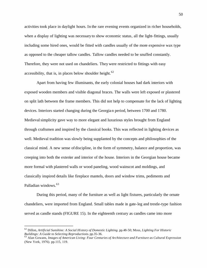
50
activities took place in daylight hours. In the rare evening events organized in richer households,
when a display of lighting was necessary to show economic status, all the light- fittings, usually
including some hired ones, would be fitted with candles usually of the more expensive wax type
as opposed to the cheaper tallow candles. Tallow candles needed to be snuffed constantly.
Therefore, they were not used on chandeliers. They were restricted to fittings with easy
accessibility, that is, in places below shoulder height.62
Apart from having few illuminants, the early colonial houses had dark interiors with
exposed wooden members and visible diagonal braces. The walls were left exposed or plastered
on split lath between the frame members. This did not help to compensate for the lack of lighting
devices. Interiors started changing during the Georgian period, between 1700 and 1780.
Medieval simplicity gave way to more elegant and luxurious styles brought from England
through craftsmen and inspired by the classical books. This was reflected in lighting devices as
well. Medieval tradition was slowly being supplanted by the concepts and philosophies of the
classical mind. A new sense of discipline, in the form of symmetry, balance and proportion, was
creeping into both the exterior and interior of the house. Interiors in the Georgian house became
more formal with plastered walls or wood paneling, wood wainscot and moldings, and
classically inspired details like fireplace mantels, doors and window trims, pediments and
Palladian windows.63
During this period, many of the furniture as well as light fixtures, particularly the ornate
chandeliers, were imported from England. Small tables made in gate- leg and trestle-type fashion
served as candle stands (FIGURE 15). In the eighteenth century as candles came into more
62 Dillon, Artificial Sunshine: A Social History of Domestic Lighting. pp.48-50; Moss, Lighting For Historic Buildings: A Guide to Selecting Reproductions. pp.35-36. 63 Alan Gowans, Images of American Living: Four Centuries of Architecture and Furniture as Cultural Expression (New York, 1976). pp.115, 119.
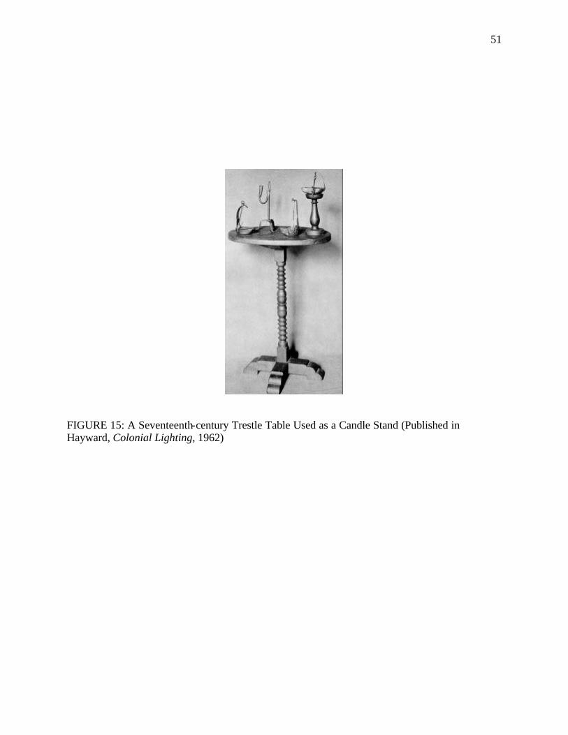
51
FIGURE 15: A Seventeenth-century Trestle Table Used as a Candle Stand (Published in Hayward, Colonial Lighting, 1962)
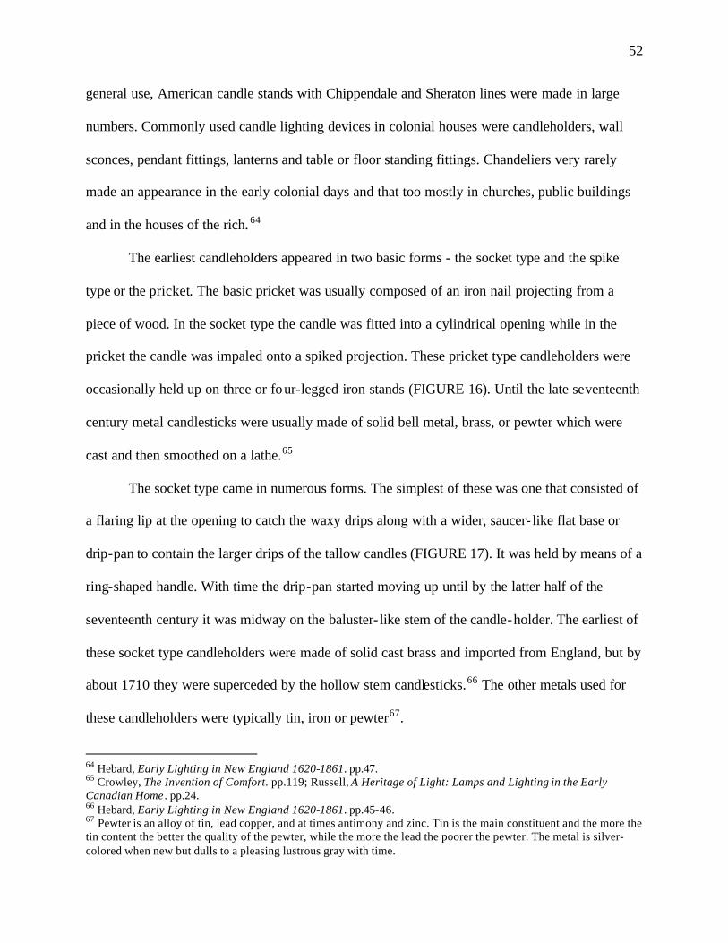
52
general use, American candle stands with Chippendale and Sheraton lines were made in large
numbers. Commonly used candle lighting devices in colonial houses were candleholders, wall
sconces, pendant fittings, lanterns and table or floor standing fittings. Chandeliers very rarely
made an appearance in the early colonial days and that too mostly in churches, public buildings
and in the houses of the rich. 64
The earliest candleholders appeared in two basic forms - the socket type and the spike
type or the pricket. The basic pricket was usually composed of an iron nail projecting from a
piece of wood. In the socket type the candle was fitted into a cylindrical opening while in the
pricket the candle was impaled onto a spiked projection. These pricket type candleholders were
occasionally held up on three or four-legged iron stands (FIGURE 16). Until the late seventeenth
century metal candlesticks were usually made of solid bell metal, brass, or pewter which were
cast and then smoothed on a lathe.65
The socket type came in numerous forms. The simplest of these was one that consisted of
a flaring lip at the opening to catch the waxy drips along with a wider, saucer- like flat base or
drip-pan to contain the larger drips of the tallow candles (FIGURE 17). It was held by means of a
ring-shaped handle. With time the drip-pan started moving up until by the latter half of the
seventeenth century it was midway on the baluster- like stem of the candle-holder. The earliest of
these socket type candleholders were made of solid cast brass and imported from England, but by
about 1710 they were superceded by the hollow stem candlesticks.66 The other metals used for
these candleholders were typically tin, iron or pewter67.
64 Hebard, Early Lighting in New England 1620-1861. pp.47. 65 Crowley, The Invention of Comfort. pp.119; Russell, A Heritage of Light: Lamps and Lighting in the Early Canadian Home . pp.24. 66 Hebard, Early Lighting in New England 1620-1861. pp.45-46. 67 Pewter is an alloy of tin, lead copper, and at times antimony and zinc. Tin is the main constituent and the more the tin content the better the quality of the pewter, while the more the lead the poorer the pewter. The metal is silver-colored when new but dulls to a pleasing lustrous gray with time.
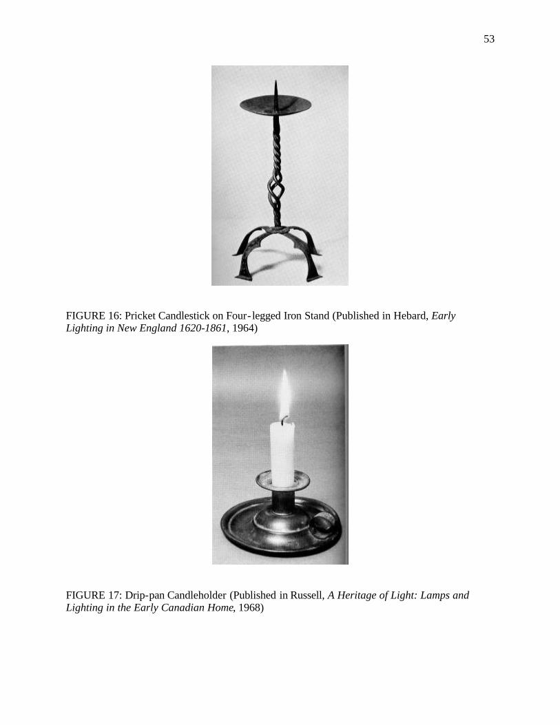
53
FIGURE 16: Pricket Candlestick on Four- legged Iron Stand (Published in Hebard, Early Lighting in New England 1620-1861, 1964)
FIGURE 17: Drip-pan Candleholder (Published in Russell, A Heritage of Light: Lamps and Lighting in the Early Canadian Home, 1968)
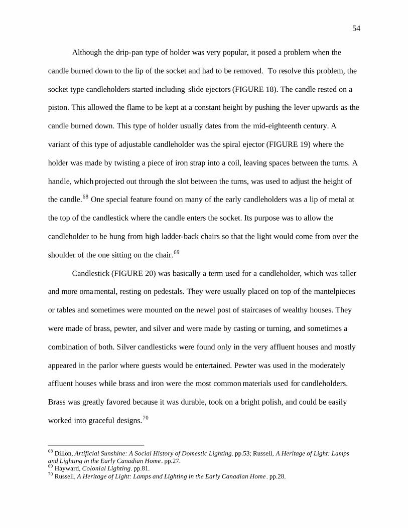
54
Although the drip-pan type of holder was very popular, it posed a problem when the
candle burned down to the lip of the socket and had to be removed. To resolve this problem, the
socket type candleholders started including slide ejectors (FIGURE 18). The candle rested on a
piston. This allowed the flame to be kept at a constant height by pushing the lever upwards as the
candle burned down. This type of holder usually dates from the mid-eighteenth century. A
variant of this type of adjustable candleholder was the spiral ejector (FIGURE 19) where the
holder was made by twisting a piece of iron strap into a coil, leaving spaces between the turns. A
handle, which projected out through the slot between the turns, was used to adjust the height of
the candle.68 One special feature found on many of the early candleholders was a lip of metal at
the top of the candlestick where the candle enters the socket. Its purpose was to allow the
candleholder to be hung from high ladder-back chairs so that the light would come from over the
shoulder of the one sitting on the chair.69
Candlestick (FIGURE 20) was basically a term used for a candleholder, which was taller
and more ornamental, resting on pedestals. They were usually placed on top of the mantelpieces
or tables and sometimes were mounted on the newel post of staircases of wealthy houses. They
were made of brass, pewter, and silver and were made by casting or turning, and sometimes a
combination of both. Silver candlesticks were found only in the very affluent houses and mostly
appeared in the parlor where guests would be entertained. Pewter was used in the moderately
affluent houses while brass and iron were the most common materials used for candleholders.
Brass was greatly favored because it was durable, took on a bright polish, and could be easily
worked into graceful designs.70
68 Dillon, Artificial Sunshine: A Social History of Domestic Lighting. pp.53; Russell, A Heritage of Light: Lamps and Lighting in the Early Canadian Home . pp.27. 69 Hayward, Colonial Lighting. pp.81. 70 Russell, A Heritage of Light: Lamps and Lighting in the Early Canadian Home . pp.28.
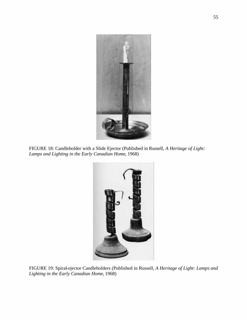
55
FIGURE 18: Candleholder with a Slide Ejector (Published in Russell, A Heritage of Light: Lamps and Lighting in the Early Canadian Home, 1968)
FIGURE 19: Spiral-ejector Candleholders (Published in Russell, A Heritage of Light: Lamps and Lighting in the Early Canadian Home, 1968)
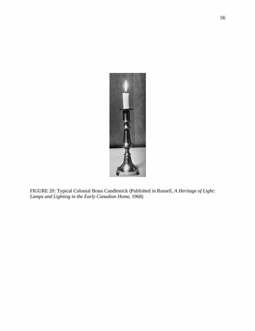
56
FIGURE 20: Typical Colonial Brass Candlestick (Published in Russell, A Heritage of Light: Lamps and Lighting in the Early Canadian Home, 1968)
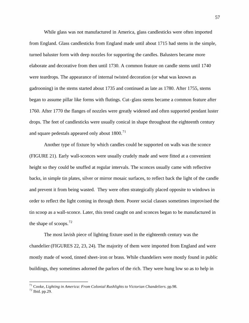
57
While glass was not manufactured in America, glass candlesticks were often imported
from England. Glass candlesticks from England made until about 1715 had stems in the simple,
turned baluster form with deep nozzles for supporting the candles. Balusters became more
elaborate and decorative from then until 1730. A common feature on candle stems until 1740
were teardrops. The appearance of internal twisted decoration (or what was known as
gadrooning) in the stems started about 1735 and continued as late as 1780. After 1755, stems
began to assume pillar like forms with flutings. Cut-glass stems became a common feature after
1760. After 1770 the flanges of nozzles were greatly widened and often supported pendant luster
drops. The feet of candlesticks were usually conical in shape throughout the eighteenth century
and square pedestals appeared only about 1800.71
Another type of fixture by which candles could be supported on walls was the sconce
(FIGURE 21). Early wall-sconces were usually crudely made and were fitted at a convenient
height so they could be snuffed at regular intervals. The sconces usually came with reflective
backs, in simple tin plates, silver or mirror mosaic surfaces, to reflect back the light of the candle
and prevent it from being wasted. They were often strategically placed opposite to windows in
order to reflect the light coming in through them. Poorer social classes sometimes improvised the
tin scoop as a wall-sconce. Later, this trend caught on and sconces began to be manufactured in
the shape of scoops.72
The most lavish piece of lighting fixture used in the eighteenth century was the
chandelier (FIGURES 22, 23, 24). The majority of them were imported from England and were
mostly made of wood, tinned sheet- iron or brass. While chandeliers were mostly found in public
buildings, they sometimes adorned the parlors of the rich. They were hung low so as to help in
71 Cooke, Lighting in America: From Colonial Rushlights to Victorian Chandeliers. pp.98. 72 Ibid. pp.29.

58
FIGURE 21: Tin Candle Sconces with Reflective Backs (Published in Hayward, Colonial Lighting, 1962)
FIGURE 22: Eighteenth-century Chandelier with Turned Wood Center Shaft and Curved Sheet Metal Arms. (Published in Hayward, Colonial Lighting, 1962)
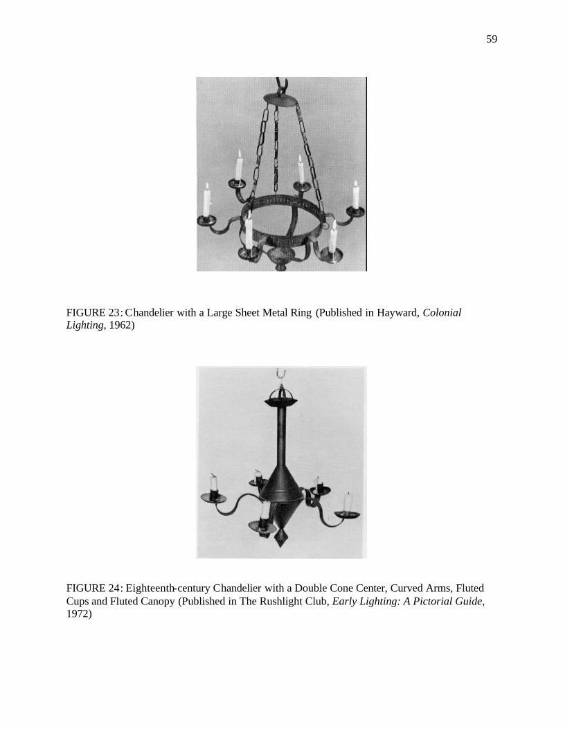
59
FIGURE 23: Chandelier with a Large Sheet Metal Ring (Published in Hayward, Colonial Lighting, 1962)
FIGURE 24: Eighteenth-century Chandelier with a Double Cone Center, Curved Arms, Fluted Cups and Fluted Canopy (Published in The Rushlight Club, Early Lighting: A Pictorial Guide, 1972)
60
their maintenance. In the eighteenth century, a few small brass foundries were developing brass
candlesticks but the large-scale American brass foundries, which were capable of producing
chandeliers, developed only in the nineteenth century. Many of the wood and tinned sheet-iron
chandeliers were manufactured natively. However, not many could afford chandeliers, so
pendant-fittings (FIGURES 25, 26) with one or two candle sockets were the poor man’s
chandelier. These pendant-fittings sometimes included glass- lined hoods for reflecting light from
the candles.73
Lighting staircases, passageways and foyers posed special challenges, as they were
draughty. Consequently, fittings in these areas had to be glazed to prevent the candle flame from
guttering and extinguishing. Thus, lanterns came to be used. Lanterns took a long time to find
favor in the colonies and the first lanterns used in America appeared in the first quarter of the
eighteenth century. Most of the early lanterns used candles, though some were designed for small
oil lamps. They were usually designed with glass windows. However, at times when glass was
not available windows were made of thinly scraped horn or mica. The common materials used
for lanterns were copper, tin, iron, brass and to some extent wood. The early lanterns sometimes
had reflective, metal backs. They usually had metal tops and bases, along with a ring on top for
hanging. There were ventilators in the top to allow the smoke and hot air to escape. The glass in
some of the early lanterns were protected by wire guards. Pierced lanterns (FIGURE 27) were
another popular type of early lantern. Their bodies were usually of tin pierced in intricate,
beautiful patterns. When these lanterns were illuminated by candles they produced charming
lace- like effects.74
73 Dillon, Artificial Sunshine: A Social History of Domestic Lighting. pp.53; Moss, Lighting For Historic Buildings: A Guide to Selecting Reproductions. pp.37. 74 Hayward, Colonial Lighting. pp.55-56, 62.
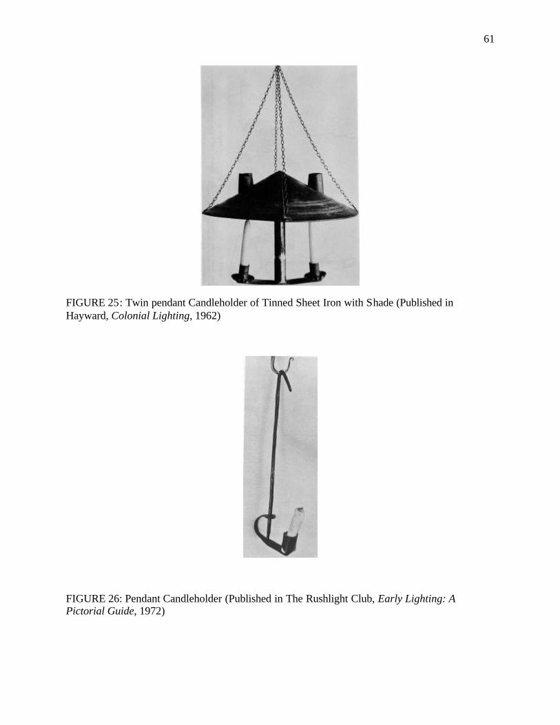
61
FIGURE 25: Twin pendant Candleholder of Tinned Sheet Iron with Shade (Published in Hayward, Colonial Lighting, 1962)
FIGURE 26: Pendant Candleholder (Published in The Rushlight Club, Early Lighting: A Pictorial Guide, 1972)
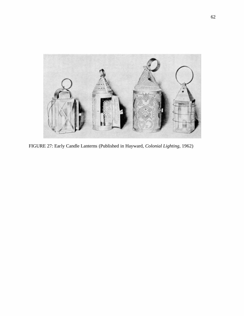
62
FIGURE 27: Early Candle Lanterns (Published in Hayward, Colonial Lighting, 1962)
63
The first lantern one usually came across was in the entranceway and for this reason these
lanterns were usually ornate and handsome. On the staircases, one occasionally came across flat-
backed, wall-mounted lanterns. Like an elegant form of lantern, the candle vase lamp, came into
use in the eighteenth century. It comprised of a candle placed in a socket at the base of a large
glass vase, which could then be suspended from chains, mounted on wall-brackets or placed on
tables and torcheres. In the South, where the weather conditions favored many open windows, a
particular form of lighting, called the hurricane glass (FIGURE 28), became popular. It consisted
of a tall glass cylinder, open at both ends and bulging in the middle which was placed over the
lighted candle to protect the flame against draughts and keep the light steady. 75
Floor-standing candle fittings or candle stands were common lighting devices in the
colonial home. They were either made of wood or iron and many had extendable arms which
could be adjusted as needed. They also often had snuffers and extinguishers attached (FIGURE
29).
Federal Period (1780-1840)
The Federal period marked a move to a more delicate version of classicism based on the
growing popularity of the publicized works of Robert Adam. Classical forms became the order
of the day and details like vases, lyres, acanthus leaves, and figures in classical costumes were
featured on decorative objects and architectural works. Buildings and furniture (FIGURE 30)
alluded to Roman or Renaissance prototypes. Lightness was the central characteristic of the
Federal spirit. Materials, colors and shapes all tended towards lightness. Woods of lighter
weight, texture and color found favor among cabinetmakers. Plaster in delicate details adorned
75 Dillon, Artificial Sunshine: A Social History of Domestic Lighting. pp.92; Hayward, Colonial Lighting . pp.103.
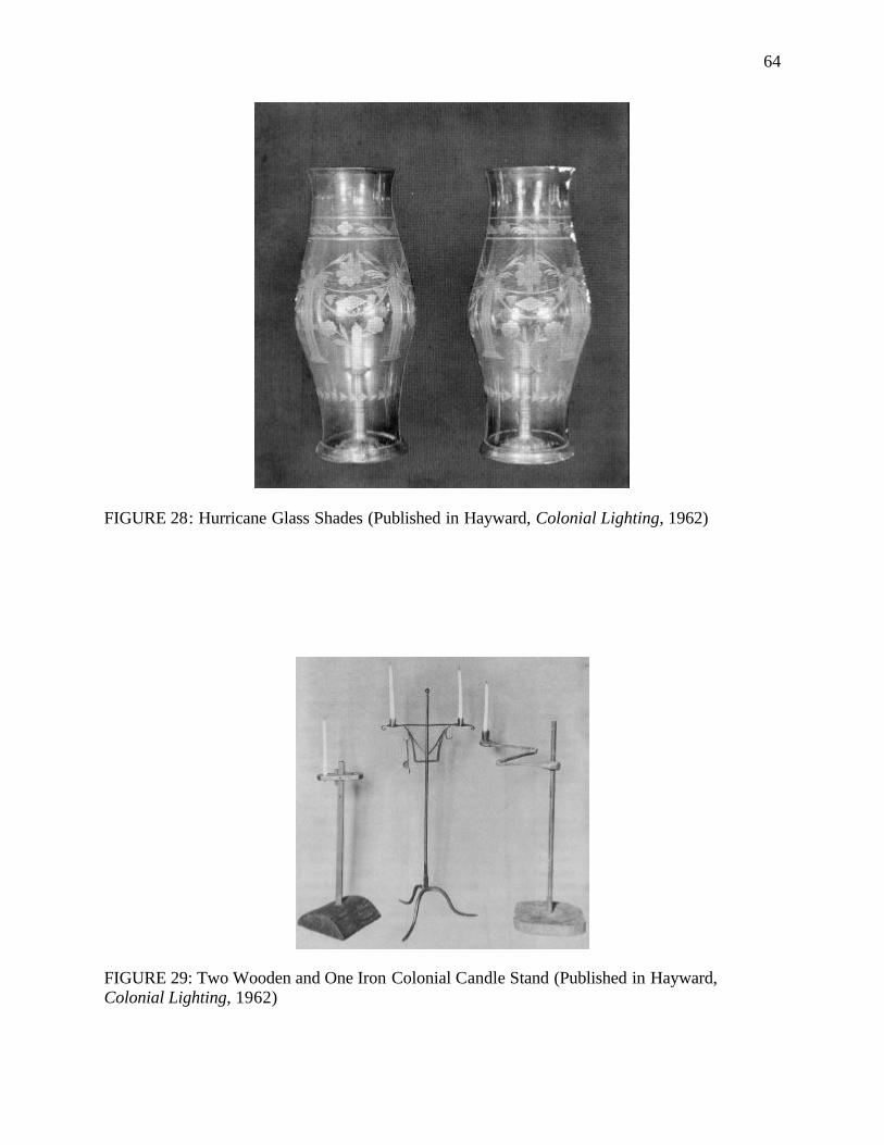
64
FIGURE 28: Hurricane Glass Shades (Published in Hayward, Colonial Lighting, 1962)
FIGURE 29: Two Wooden and One Iron Colonial Candle Stand (Published in Hayward, Colonial Lighting, 1962)
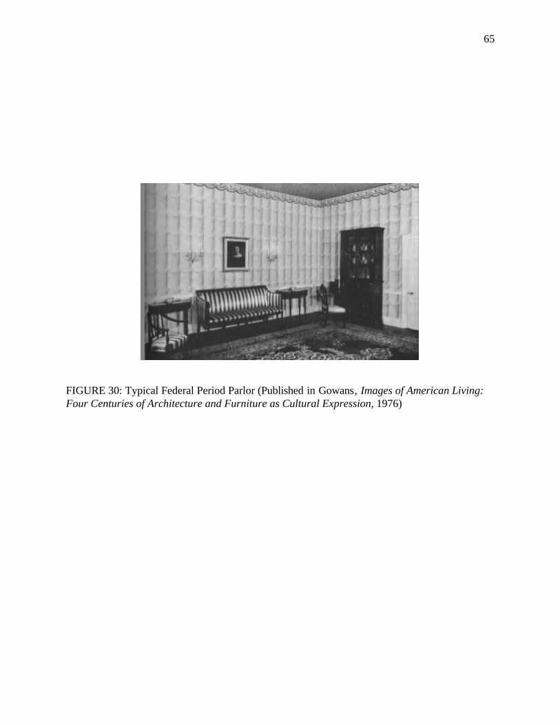
65
FIGURE 30: Typical Federal Period Parlor (Published in Gowans, Images of American Living: Four Centuries of Architecture and Furniture as Cultural Expression, 1976)
66
ceilings, fireplaces, cornices and case pieces. Wallpaper, designed in patterns of intricate
delicacy replaced paneling to the point where little more than the baseboard remained. White
became the predominant color for decorative details, which was characteristically set off against
pastel walls. This gave the rooms a light, airy look reducing the burden on artificial lighting to
some extent. While brass was still a common material for interior fittings, gilding became
popular, along with silver and glass giving the interiors a brighter look.76
The delicacy and the popularity of classical details of this period were also reflected in
the lighting devices used. Also significant in this period was the growth of indigenous industries
to produce sophisticated household goods that were previously imported from Europe. With
advances in technology, lighting fixtures started being locally produced. A number of glass
works were set up in America during this period. The first glass-blowing business was at Salem
in Massachusetts in 1639. The focus was on manufacturing glass bottles and tableware. In 1750 a
group of German workmen started glass works in Quincy, Massachusetts. They produced a great
deal of glassware as well as several styles of lamps. The glass was, however, of poor quality. In
1780, a glass works was established in the town of Temple, New Hampshire and it manufactured
glass lamps of artistic merit. In 1787 and in 1817, glass-manufacturing companies were
established in Boston and Cambridge, Massachusetts respectively. The Cambridge factory
remained in operation until late in the nineteenth century. Some of the workers from the Boston
and Cambridge factories collaborated and opened up a glasswork in the village of Sandwich in
1825. “Sandwich Glass” became one of the most popular types of glass for lamps and
76 Gowans, Images of American Living: Four Centuries of Architecture and Furniture as Cultural Expression. pp.166, 168.
67
candlesticks during this period. Sandwich glass was special because it was iridescent and
silvery.77
Early glass was produced using the blowpipe, a method that was arduous, unhealthy and
required a high degree of skill. In 1827, a workman at the Cambridge glass factory invented the
mold machine, which was immediately adopted by the Sandwich factory and perfected by them.
At first this device still required the use of a blowpipe as the glass was forced into the mold by
blowing it. Later, stamping machines came into use. Instead of blowpipes, iron ladles were used
to pour the molten glass. This gave rise to press-molded glass.78
Candles still reined supreme as the most popular mode of lighting in the Federal period,
although whale oil lamps with drop burners started appearing in America by the early nineteenth
century. The manual piston socket type candleholder was followed by the spring- loaded piston in
the beginning of the nineteenth century, which could raise the candle by itself and help keep it at
a constant level. Many brass candleholders of this variety found today trace their origins to the
Cornelius and Baker Company in Philadelphia that operated from 1853-1869. The spring- loaded
candleholders were very popular due to their high safety factor and many came with cowled
shades that helped to direct light downwards. They were particularly useful for writing, reading
and lace-making. Another type of candleholder to become popular in the first half of the
nineteenth century was known as the hog-scraper (FIGURE 31). It had a narrow convex base
instead of the saucer shaped concave tray and did not have a handle, instead often it came with a
hook along the nozzle to be hung over the back of a chair or the edge of a bookshelf.79
77 Hayward, Colonial Lighting. pp.105-106. 78 Ibid. pp.107. 79 Dillon, Artificial Sunshine: A Social History of Domestic Lighting. pp.90; Russell, A Heritage of Light: Lamps and Lighting in the Early Canadian Home . pp.27; The Rushlight Club, Early Lighting: A Pictorial Guide . pp.23.
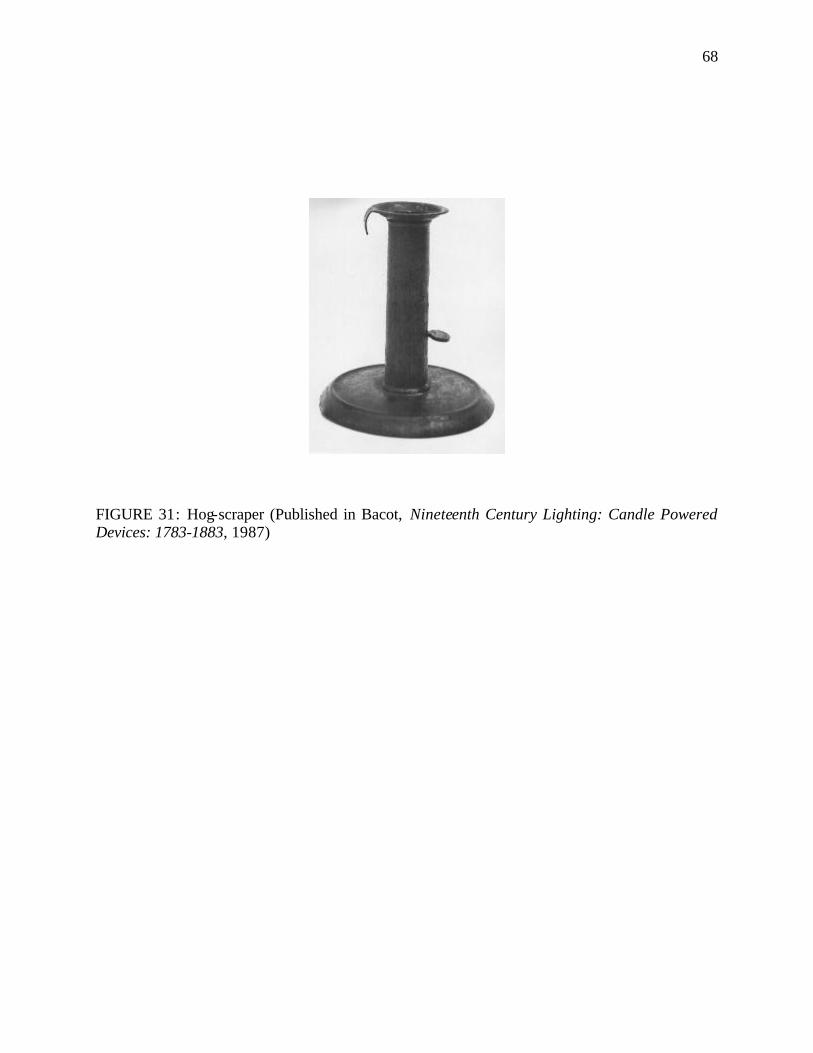
68
FIGURE 31: Hog-scraper (Published in Bacot, Nineteenth Century Lighting: Candle Powered Devices: 1783-1883, 1987)
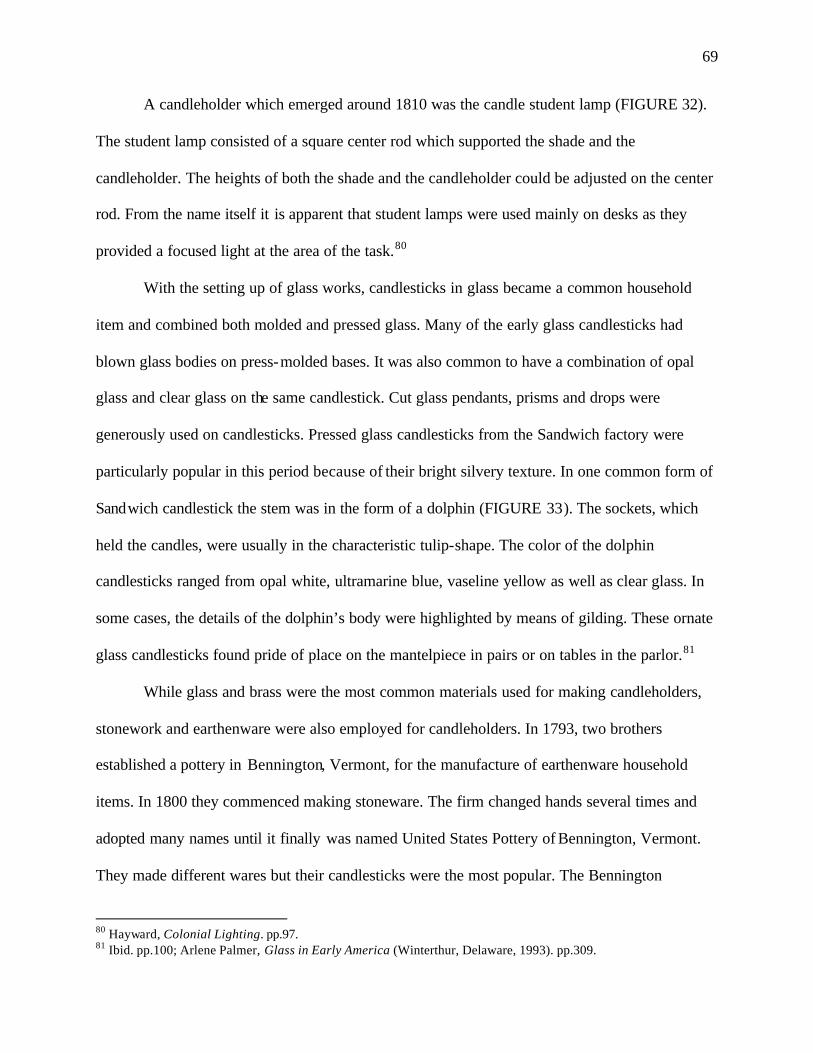
69
A candleholder which emerged around 1810 was the candle student lamp (FIGURE 32).
The student lamp consisted of a square center rod which supported the shade and the
candleholder. The heights of both the shade and the candleholder could be adjusted on the center
rod. From the name itself it is apparent that student lamps were used mainly on desks as they
provided a focused light at the area of the task.80
With the setting up of glass works, candlesticks in glass became a common household
item and combined both molded and pressed glass. Many of the early glass candlesticks had
blown glass bodies on press-molded bases. It was also common to have a combination of opal
glass and clear glass on the same candlestick. Cut glass pendants, prisms and drops were
generously used on candlesticks. Pressed glass candlesticks from the Sandwich factory were
particularly popular in this period because of their bright silvery texture. In one common form of
Sandwich candlestick the stem was in the form of a dolphin (FIGURE 33). The sockets, which
held the candles, were usually in the characteristic tulip-shape. The color of the dolphin
candlesticks ranged from opal white, ultramarine blue, vaseline yellow as well as clear glass. In
some cases, the details of the dolphin’s body were highlighted by means of gilding. These ornate
glass candlesticks found pride of place on the mantelpiece in pairs or on tables in the parlor.81
While glass and brass were the most common materials used for making candleholders,
stonework and earthenware were also employed for candleholders. In 1793, two brothers
established a pottery in Bennington, Vermont, for the manufacture of earthenware household
items. In 1800 they commenced making stoneware. The firm changed hands several times and
adopted many names until it finally was named United States Pottery of Bennington, Vermont.
They made different wares but their candlesticks were the most popular. The Bennington
80 Hayward, Colonial Lighting. pp.97. 81 Ibid. pp.100; Arlene Palmer, Glass in Early America (Winterthur, Delaware, 1993). pp.309.
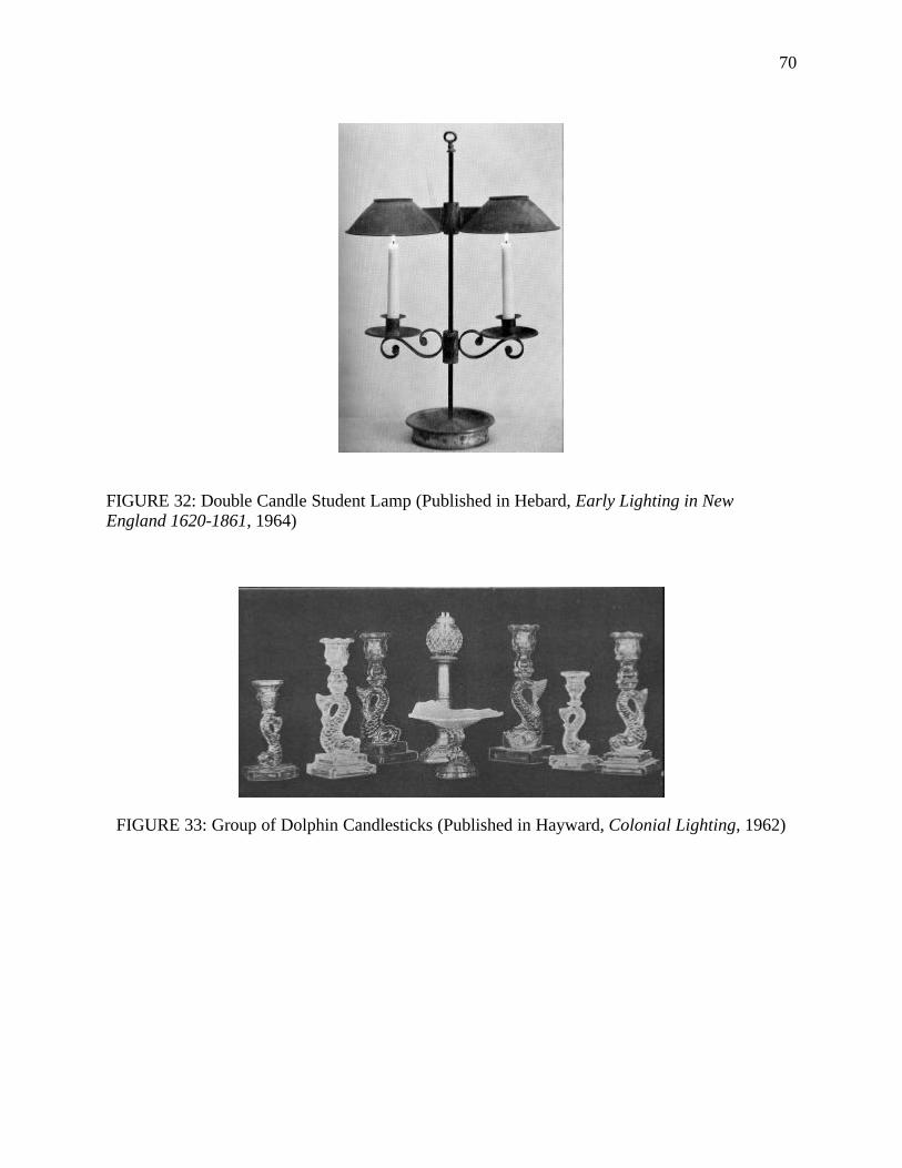
70
FIGURE 32: Double Candle Student Lamp (Published in Hebard, Early Lighting in New England 1620-1861, 1964)
FIGURE 33: Group of Dolphin Candlesticks (Published in Hayward, Colonial Lighting, 1962)
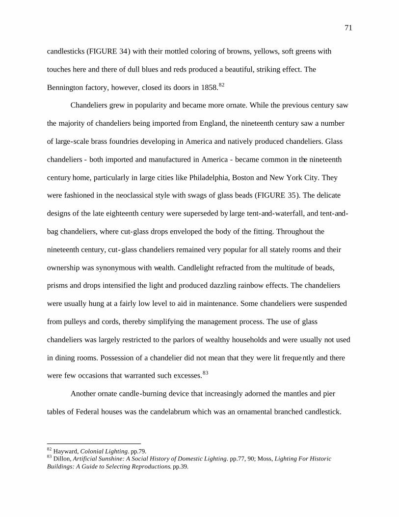
71
candlesticks (FIGURE 34) with their mottled coloring of browns, yellows, soft greens with
touches here and there of dull blues and reds produced a beautiful, striking effect. The
Bennington factory, however, closed its doors in 1858.82
Chandeliers grew in popularity and became more ornate. While the previous century saw
the majority of chandeliers being imported from England, the nineteenth century saw a number
of large-scale brass foundries developing in America and natively produced chandeliers. Glass
chandeliers - both imported and manufactured in America - became common in the nineteenth
century home, particularly in large cities like Philadelphia, Boston and New York City. They
were fashioned in the neoclassical style with swags of glass beads (FIGURE 35). The delicate
designs of the late eighteenth century were superseded by large tent-and-waterfall, and tent-and-
bag chandeliers, where cut-glass drops enveloped the body of the fitting. Throughout the
nineteenth century, cut-glass chandeliers remained very popular for all stately rooms and their
ownership was synonymous with wealth. Candlelight refracted from the multitude of beads,
prisms and drops intensified the light and produced dazzling rainbow effects. The chandeliers
were usually hung at a fairly low level to aid in maintenance. Some chandeliers were suspended
from pulleys and cords, thereby simplifying the management process. The use of glass
chandeliers was largely restricted to the parlors of wealthy households and were usually not used
in dining rooms. Possession of a chandelier did not mean that they were lit frequently and there
were few occasions that warranted such excesses.83
Another ornate candle-burning device that increasingly adorned the mantles and pier
tables of Federal houses was the candelabrum which was an ornamental branched candlestick.
82 Hayward, Colonial Lighting. pp.79. 83 Dillon, Artificial Sunshine: A Social History of Domestic Lighting. pp.77, 90; Moss, Lighting For Historic Buildings: A Guide to Selecting Reproductions. pp.39.
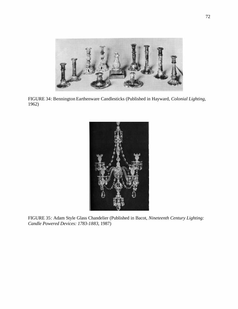
72
FIGURE 34: Bennington Earthenware Candlesticks (Published in Hayward, Colonial Lighting, 1962)
FIGURE 35: Adam Style Glass Chandelier (Published in Bacot, Nineteenth Century Lighting: Candle Powered Devices: 1783-1883, 1987)
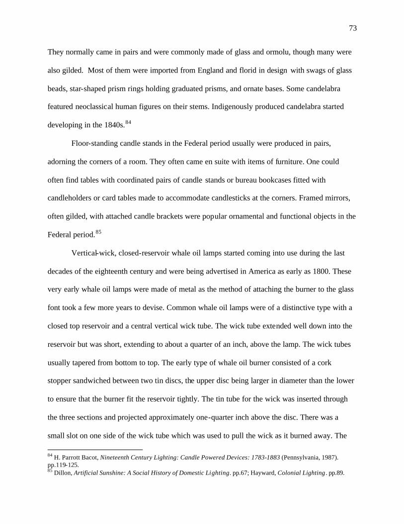
73
They normally came in pairs and were commonly made of glass and ormolu, though many were
also gilded. Most of them were imported from England and florid in design with swags of glass
beads, star-shaped prism rings holding graduated prisms, and ornate bases. Some candelabra
featured neoclassical human figures on their stems. Indigenously produced candelabra started
developing in the 1840s.84
Floor-standing candle stands in the Federal period usually were produced in pairs,
adorning the corners of a room. They often came en suite with items of furniture. One could
often find tables with coordinated pairs of candle stands or bureau bookcases fitted with
candleholders or card tables made to accommodate candlesticks at the corners. Framed mirrors,
often gilded, with attached candle brackets were popular ornamental and functional objects in the
Federal period.85
Vertical-wick, closed-reservoir whale oil lamps started coming into use during the last
decades of the eighteenth century and were being advertised in America as early as 1800. These
very early whale oil lamps were made of metal as the method of attaching the burner to the glass
font took a few more years to devise. Common whale oil lamps were of a distinctive type with a
closed top reservoir and a central vertical wick tube. The wick tube extended well down into the
reservoir but was short, extending to about a quarter of an inch, above the lamp. The wick tubes
usually tapered from bottom to top. The early type of whale oil burner consisted of a cork
stopper sandwiched between two tin discs, the upper disc being larger in diameter than the lower
to ensure that the burner fit the reservoir tightly. The tin tube for the wick was inserted through
the three sections and projected approximately one-quarter inch above the disc. There was a
small slot on one side of the wick tube which was used to pull the wick as it burned away. The
84 H. Parrott Bacot, Nineteenth Century Lighting: Candle Powered Devices: 1783-1883 (Pennsylvania, 1987). pp.119-125. 85 Dillon, Artificial Sunshine: A Social History of Domestic Lighting. pp.67; Hayward, Colonial Lighting . pp.89.
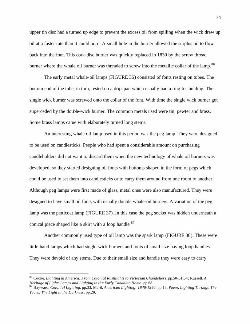
74
upper tin disc had a turned up edge to prevent the excess oil from spilling when the wick drew up
oil at a faster rate than it could burn. A small hole in the burner allowed the surplus oil to flow
back into the font. This cork-disc burner was quickly replaced in 1830 by the screw thread
burner where the whale oil burner was threaded to screw into the metallic collar of the lamp.86
The early metal whale-oil lamps (FIGURE 36) consisted of fonts resting on tubes. The
bottom end of the tube, in turn, rested on a drip-pan which usually had a ring for holding. The
single wick burner was screwed onto the collar of the font. With time the single wick burner got
superceded by the double-wick burner. The common metals used were tin, pewter and brass.
Some brass lamps came with elaborately turned long stems.
An interesting whale oil lamp used in this period was the peg lamp. They were designed
to be used on candlesticks. People who had spent a considerable amount on purchasing
candleholders did not want to discard them when the new technology of whale oil burners was
developed, so they started designing oil fonts with bottoms shaped in the form of pegs which
could be used to set them into candlesticks or to carry them around from one room to another.
Although peg lamps were first made of glass, metal ones were also manufactured. They were
designed to have small oil fonts with usually double whale-oil burners. A variation of the peg
lamp was the petticoat lamp (FIGURE 37). In this case the peg socket was hidden underneath a
conical piece shaped like a skirt with a loop handle.87
Another commonly used type of oil lamp was the spark lamp (FIGURE 38). These were
little hand lamps which had single-wick burners and fonts of small size having loop handles.
They were devoid of any stems. Due to their small size and handle they were easy to carry
86 Cooke, Lighting in America: From Colonial Rushlights to Victorian Chandeliers. pp.50-51,54; Russell, A Heritage of Light: Lamps and Lighting in the Early Canadian Home . pp.68. 87 Hayward, Colonial Lighting. pp.33; Maril, American Lighting: 1840-1940. pp.18; Poese, Lighting Through The Years: The Light in the Darkness. pp.29.
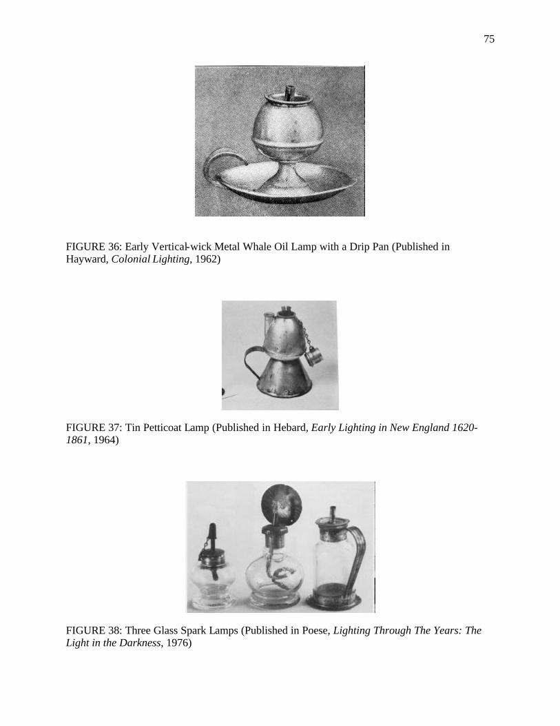
75
FIGURE 36: Early Vertical-wick Metal Whale Oil Lamp with a Drip Pan (Published in Hayward, Colonial Lighting, 1962)
FIGURE 37: Tin Petticoat Lamp (Published in Hebard, Early Lighting in New England 1620-1861, 1964)
FIGURE 38: Three Glass Spark Lamps (Published in Poese, Lighting Through The Years: The Light in the Darkness, 1976)
76
around. They provided only dim light for short time spans, like sparks (from where they got their
name), and so they were primarily used for finding one’s way to the bed after which they were
snuffed out.88
With the setting up of glass works in America, glass oil lamps were manufactured in
abundance. Most of the lamps came from the two New England glass plants in Sandwich and
Cambridge. The Sandwich glass was more popular owing to its peculiar silvery brilliance. It was
around 1816 that the first advertisements for glass lamps were put up by the Boston Glass
Manufactory. The peg lamp was the first type of lighting device to be made completely of glass.
With the launch of the glass peg lamp, it was only a step forward for the manufacture of glass
whale oil lamps with standards or shafts of either blown or pressed glass. The earliest of such
lamps were the blown button-stem lamps which had baluster stems, oval fonts which were
shaped to imitate wine glasses, and flat round bases. Small blown spark lamps with glass handles
were the other type of glass lamp manufactured in the early years. The tall glass whale oil lamps
with pressed bases (FIGURE 39) were first produced in the 1820s. The font and the stem were
blown separately and joined by means of a disc or wafer. The pressed base was also made
separately and joined to the upper part while it was still in a semi-molten state. Bases came in
various shapes - squares, squares with indented corners, circular, stepped, or hexagonal. Bases
were also often pressed with lacy designs like acanthus leaves. It was common for glass
companies to use the same bases for whale oil lamps that they had originally designed as bases
for bowls, glasses, sweet meat jars, castor bottles and candlesticks. Often lamps of a particular
design were produced in pairs to be used on either sides of the mantle or table.89
88 Hayward, Colonial Lighting. pp.45-46; Poese, Lighting Through The Years: The Light in the Darkness. pp.19. 89 Cooke, Lighting in America: From Colonial Rushlights to Victorian Chandeliers. pp.54-55; Maril, American Lighting: 1840-1940. pp.11.
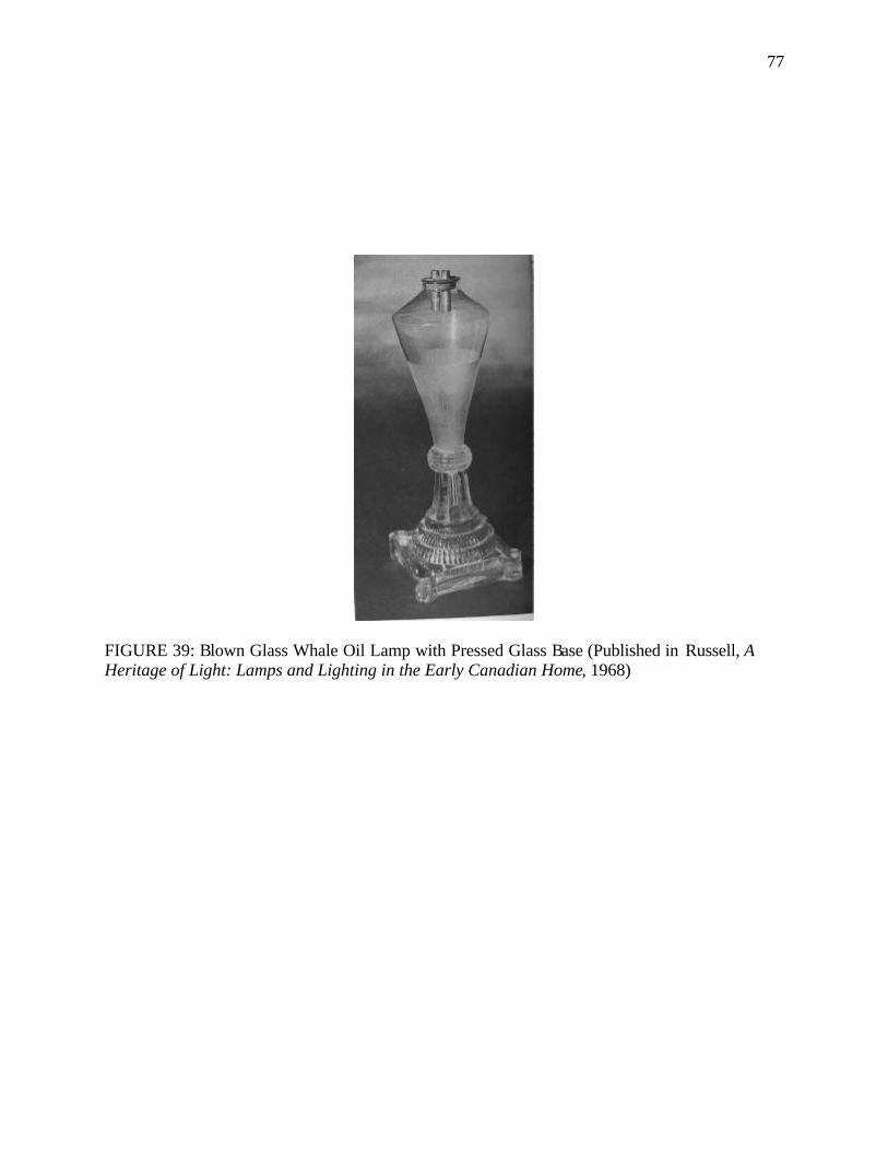
77
FIGURE 39: Blown Glass Whale Oil Lamp with Pressed Glass Base (Published in Russell, A Heritage of Light: Lamps and Lighting in the Early Canadian Home, 1968)
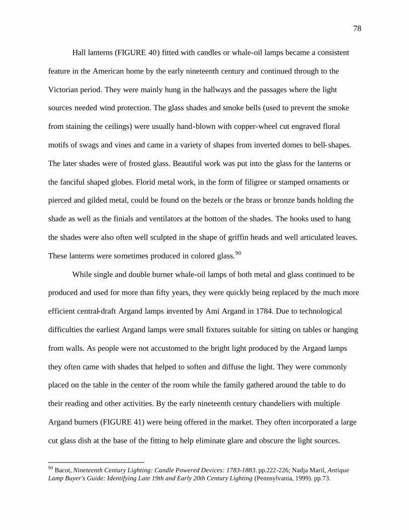
78
Hall lanterns (FIGURE 40) fitted with candles or whale-oil lamps became a consistent
feature in the American home by the early nineteenth century and continued through to the
Victorian period. They were mainly hung in the hallways and the passages where the light
sources needed wind protection. The glass shades and smoke bells (used to prevent the smoke
from staining the ceilings) were usually hand-blown with copper-wheel cut engraved floral
motifs of swags and vines and came in a variety of shapes from inverted domes to bell-shapes.
The later shades were of frosted glass. Beautiful work was put into the glass for the lanterns or
the fanciful shaped globes. Florid metal work, in the form of filigree or stamped ornaments or
pierced and gilded metal, could be found on the bezels or the brass or bronze bands holding the
shade as well as the finials and ventilators at the bottom of the shades. The hooks used to hang
the shades were also often well sculpted in the shape of griffin heads and well articulated leaves.
These lanterns were sometimes produced in colored glass.90
While single and double burner whale-oil lamps of both metal and glass continued to be
produced and used for more than fifty years, they were quickly being replaced by the much more
efficient central-draft Argand lamps invented by Ami Argand in 1784. Due to technological
difficulties the earliest Argand lamps were small fixtures suitable for sitting on tables or hanging
from walls. As people were not accustomed to the bright light produced by the Argand lamps
they often came with shades that helped to soften and diffuse the light. They were commonly
placed on the table in the center of the room while the family gathered around the table to do
their reading and other activities. By the early nineteenth century chandeliers with multiple
Argand burners (FIGURE 41) were being offered in the market. They often incorporated a large
cut glass dish at the base of the fitting to help eliminate glare and obscure the light sources.
90 Bacot, Nineteenth Century Lighting: Candle Powered Devices: 1783-1883. pp.222-226; Nadja Maril, Antique Lamp Buyer's Guide: Identifying Late 19th and Early 20th Century Lighting (Pennsylvania, 1999). pp.73.
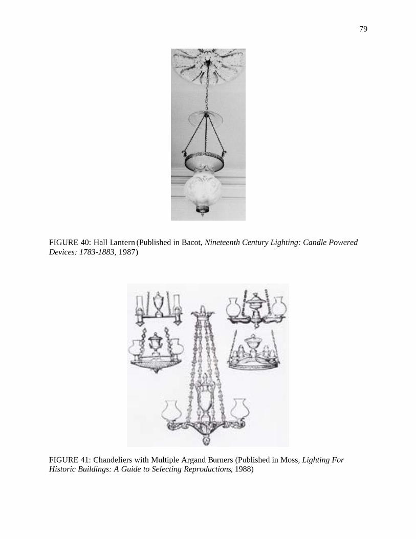
79
FIGURE 40: Hall Lantern (Published in Bacot, Nineteenth Century Lighting: Candle Powered Devices: 1783-1883, 1987)
FIGURE 41: Chandeliers with Multiple Argand Burners (Published in Moss, Lighting For Historic Buildings: A Guide to Selecting Reproductions, 1988)
80
Argand lamps and chandeliers with their glass shades and glass dishes broke historic precedents
and established the first prototype for semi- indirect lighting.91
Argand pedestal lamps (FIGURE 42) with double Argand burners were favored for
illuminating halls, wall areas in large rooms as well as mantles. They usually had bodies of brass
or gilded bronze and stood on marble plinths. The solidity of brass or bronze was usually offset
by the delicacy of the cut glass pendants, prisms or drops that hung down from the center
reservoir. The reservoir was often in the shape of an urn, a popular neoclassical form. Mantel
lamps were a more elaborate version of the Argand lamps with a slight rearrangement of the
parts. They usually came in sets of three - a central lamp with a symmetrical pair of burners and
two side lamps having single burners. As their name suggests they usually adorned the mantles.
Wall sconces using the Argand principle were also used in Federal homes. They usually
had reflective backs to multiply the light emitting from the lamp. Student lamps (FIGURE 43)
were very popular in this period, although they were top-heavy and there was the constant
chance of them toppling over. Their greatest advantage lay in the fact that their height was
adjustable and many came with two burners. They usually came with conical shades.
Revivalism (1820-1860)
This was a period that looked back at the styles of the past and drew heavily from Greco-
Roman precedents as well as the Gothic era. Elements from exotic oriental sources also found
their way into the American home with Egyptian, Chinese and Moorish sources leading
91 Dillon, Artificial Sunshine: A Social History of Domestic Lighting. pp.106; Maril, Antique Lamp Buyer's Guide: Identifying Late 19th and Early 20th Century Lighting. pp.124; Schivelbusch, Disenchanted Night: The Industrialization of Light in the Nineteenth Century. pp.166-168.
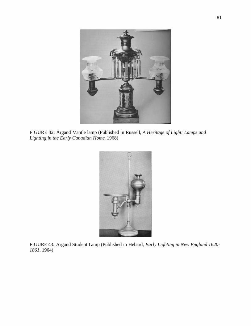
81
FIGURE 42: Argand Mantle lamp (Published in Russell, A Heritage of Light: Lamps and Lighting in the Early Canadian Home, 1968)
FIGURE 43: Argand Student Lamp (Published in Hebard, Early Lighting in New England 1620-1861, 1964)
82
the way. There was an increasing interest in recreating the glory of the past and a romantic desire
to experience life in the past. This period also saw the beginning of greater decorative detailing
and ornamentation on light fixtures with the industrial revolution of 1851. The Industrial
Revolution had a great impact on manufacturing, thereby, making it easier and cheaper to
produce ornamentation. The steam-powered scroll saw and other complex carving machines
replaced the pain-staking and slow process of hand carving to produce intricate details in wood.
Power looms were used to weave elaborately ornamented textiles. With the growth of industries,
a wealthy class of factory and mill owners was emerging. The industries and mills also supported
a whole new group of professionals who had the money to afford to buy the products of the
industry. There was a growing awareness of United States becoming a superior world power and
this led to a greater effort to emulate Europe in arts, manufacture, culture and commerce, which
was seen as the center of high culture. There was also an increased influx of European imports.92
Greek Revival (1820-1860):
With the turn of the nineteenth century a growing sense of national ident ity resulted in
the need to find a national style in art and architecture. Architecture and art were meant to be
viewed not merely as objects of beauty, but symbols of the American ideal and independence;
they had to be living proof of the classical convic tion that men could control their destinies and
mold worlds to their will. The Greek Revival style had already begun in Europe and it was
adopted by American designers who saw in ancient Greek democracy a parallel with America.
The Greek War of Independence, being fought at the beginning of the nineteenth century, stirred
up strong sentiments in Americans. They saw a clear parallel between the Greek fight for
independence from the Turks and their own fight for independence from the British. Moreover, 92 John Pile, A History of Interior Design (New York, 2000). pp.192-195.
83
Greek architecture was seen as “masculine”, a character that Americans wished to emulate.
Hence, it was only natural that the Greek style of architecture began to be seen as the most
appropriate style to represent the new independent America. So while the Federal style had
initiated an interest in the usage of ancient classical details, the Greek revival tried to create an
authentic impression of ancient Greece, both in the interior and exterior of the house (FIGURE
44). While the Federal period alluded to classical precedents, the Greek Revival sought exact
reproductions of classical monuments.
Rooms were made to look Greek with woodwork and plaster details: egg and dart and
key moldings, as well as pilasters and columns using one of the orders. A heavy dependence on
archaeology was sought, not only in the deliberate and pedantic transplantation of Greek and
Roman motifs and materials - columns, caryatids, lyres, scrolls, mahogany, gilt appliqués and
marble - but a direct reproduction of what were thought to be Greco-Roman types of doors
frames, chairs, tables, and light fittings.
Candles continued to be used in houses of this period even though whale oil lamps were
introduced. Candlesticks - of both metal and glass - took on more elaborate forms in this period.
Brass candlesticks (FIGURE 45, FIGURE 46, FIGURE 47) were adorned with elaborately cast
balusters featuring decorative motifs like the beehive, spool turnings and faceted knops on
octagonal, stepped bases. Lusters (FIGURE 48), and ornately designed gilded brass, bronze and
pot metal (zinc) candlesticks were usually found in pairs in the houses of this period.
One of the characteristic lighting devices used in the American home during this period
was the girandole. The term girandole was used in an American sense to refer to highly
ornamented candlesticks and candelabra made of metal and having crystal prisms. They were
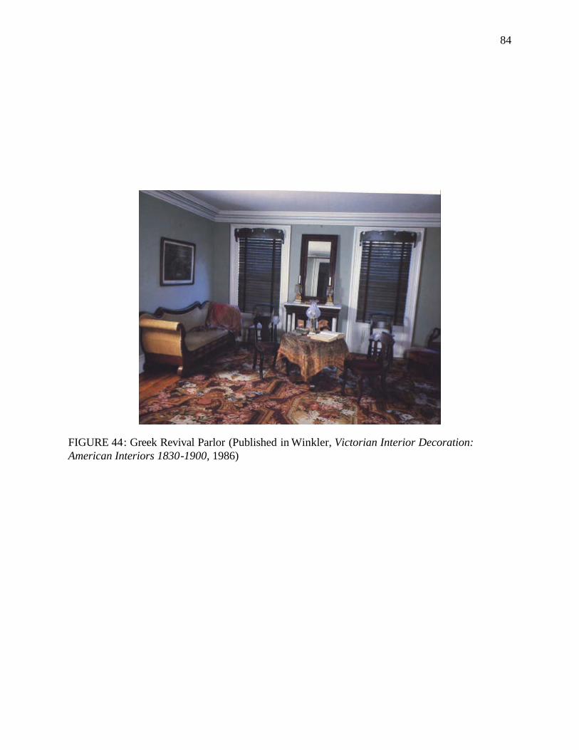
84
FIGURE 44: Greek Revival Parlor (Published in Winkler, Victorian Interior Decoration: American Interiors 1830-1900, 1986)
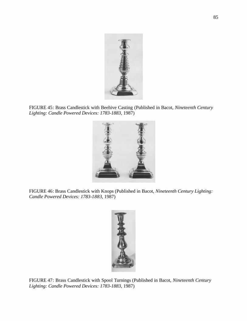
85
FIGURE 45: Brass Candlestick with Beehive Casting (Published in Bacot, Nineteenth Century Lighting: Candle Powered Devices: 1783-1883, 1987)
FIGURE 46: Brass Candlestick with Knops (Published in Bacot, Nineteenth Century Lighting: Candle Powered Devices: 1783-1883, 1987)
FIGURE 47: Brass Candlestick with Spool Turnings (Published in Bacot, Nineteenth Century Lighting: Candle Powered Devices: 1783-1883, 1987)
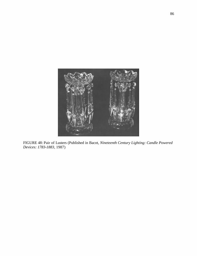
86
FIGURE 48: Pair of Lusters (Published in Bacot, Nineteenth Century Lighting: Candle Powered Devices: 1783-1883, 1987)
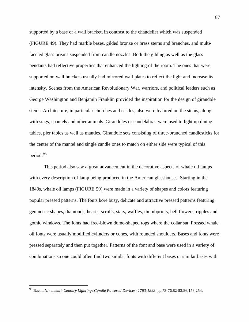
87
supported by a base or a wall bracket, in contrast to the chandelier which was suspended
(FIGURE 49). They had marble bases, gilded bronze or brass stems and branches, and multi-
faceted glass prisms suspended from candle nozzles. Both the gilding as well as the glass
pendants had reflective properties that enhanced the lighting of the room. The ones that were
supported on wall brackets usually had mirrored wall plates to reflect the light and increase its
intensity. Scenes from the American Revolutionary War, warriors, and political leaders such as
George Washington and Benjamin Franklin provided the inspiration for the design of girandole
stems. Architecture, in particular churches and castles, also were featured on the stems, along
with stags, spaniels and other animals. Girandoles or candelabras were used to light up dining
tables, pier tables as well as mantles. Girandole sets consisting of three-branched candlesticks for
the center of the mantel and single candle ones to match on either side were typical of this
period.93
This period also saw a great advancement in the decorative aspects of whale oil lamps
with every description of lamp being produced in the American glasshouses. Starting in the
1840s, whale oil lamps (FIGURE 50) were made in a variety of shapes and colors featuring
popular pressed patterns. The fonts bore busy, delicate and attractive pressed patterns featuring
geometric shapes, diamonds, hearts, scrolls, stars, waffles, thumbprints, bell flowers, ripples and
gothic windows. The fonts had free-blown dome-shaped tops where the collar sat. Pressed whale
oil fonts were usually modified cylinders or cones, with rounded shoulders. Bases and fonts were
pressed separately and then put together. Patterns of the font and base were used in a variety of
combinations so one could often find two similar fonts with different bases or similar bases with
93 Bacot, Nineteenth Century Lighting: Candle Powered Devices: 1783-1883. pp.73-76,82-83,86,153,254.
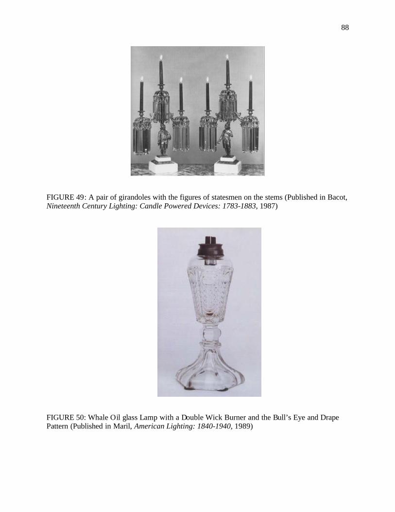
88
FIGURE 49: A pair of girandoles with the figures of statesmen on the stems (Published in Bacot, Nineteenth Century Lighting: Candle Powered Devices: 1783-1883, 1987)
FIGURE 50: Whale Oil glass Lamp with a Double Wick Burner and the Bull’s Eye and Drape Pattern (Published in Maril, American Lighting: 1840-1940, 1989)
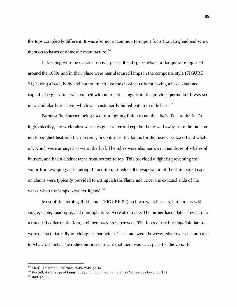
89
the tops completely different. It was also not uncommon to import fonts from England and screw
them on to bases of domestic manufacture.94
In keeping with the classical revival phase, the all-glass whale oil lamps were replaced
around the 1850s and in their place were manufactured lamps in the composite style (FIGURE
51) having a base, body and burner, much like the classical column having a base, shaft and
capital. The glass font was retained without much change from the previous period but it was set
onto a tubular brass stem, which was customarily bolted onto a marble base.95
Burning fluid started being used as a lighting fluid around the 1840s. Due to the fuel’s
high volatility, the wick tubes were designed taller to keep the flame well away from the fuel and
not to conduct heat into the reservoir, in contrast to the lamps for the heavier colza oil and whale
oil, which were arranged to warm the fuel. The tubes were also narrower than those of whale-oil
burners, and had a distinct taper from bottom to top. This provided a tight fit preventing the
vapor from escaping and igniting. In addition, to reduce the evaporation of the fluid, small caps
on chains were typically provided to extinguish the flame and cover the exposed ends of the
wicks when the lamps were not lighted.96
Most of the burning-fluid lamps (FIGURE 52) had two-wick burners, but burners with
single, triple, quadruple, and quintuple tubes were also made. The burner base plate screwed into
a threaded collar on the font, and there was no vapor vent. The fonts of the burning-fluid lamps
were characteristically much higher than wider. The fonts were, however, shallower as compared
to whale oil fonts. The reduction in size meant that there was less space for the vapor to
94 Maril, American Lighting: 1840-1940. pp.14. 95 Russell, A Heritage of Light: Lamps and Lighting in the Early Canadian Home . pp.102. 96 Ibid. pp.98.
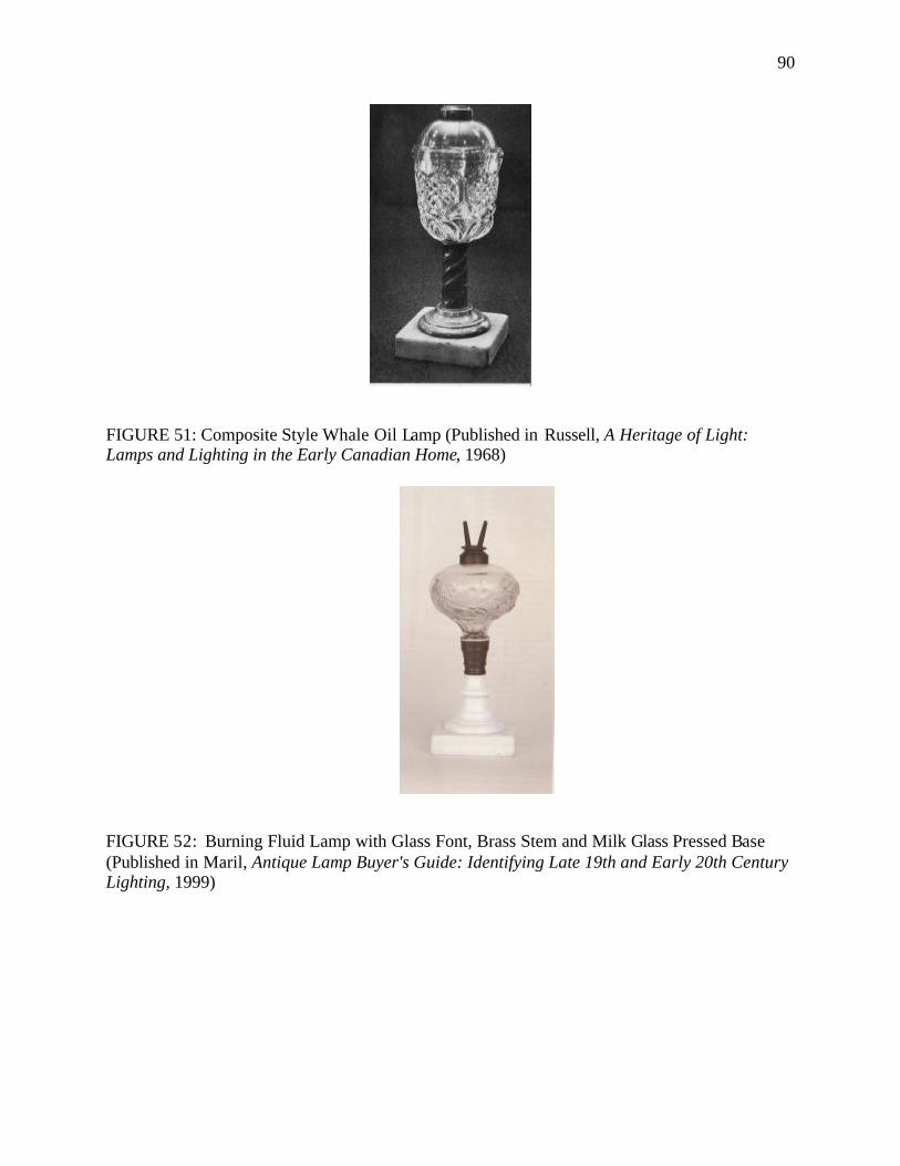
90
FIGURE 51: Composite Style Whale Oil Lamp (Published in Russell, A Heritage of Light: Lamps and Lighting in the Early Canadian Home, 1968)
FIGURE 52: Burning Fluid Lamp with Glass Font, Brass Stem and Milk Glass Pressed Base (Published in Maril, Antique Lamp Buyer's Guide: Identifying Late 19th and Early 20th Century Lighting, 1999)
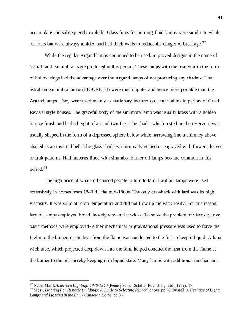
91
accumulate and subsequently explode. Glass fonts for burning-fluid lamps were similar to whale
oil fonts but were always molded and had thick walls to reduce the danger of breakage.97
While the regular Argand lamps continued to be used, improved designs in the name of
‘astral’ and ‘sinumbra’ were produced in this period. These lamps with the reservoir in the form
of hollow rings had the advantage over the Argand lamps of not producing any shadow. The
astral and sinumbra lamps (FIGURE 53) were much lighter and hence more portable than the
Argand lamps. They were used mainly as stationary features on center tables in parlors of Greek
Revival style houses. The graceful body of the sinumbra lamp was usually brass with a golden
bronze finish and had a height of around two feet. The shade, which rested on the reservoir, was
usually shaped in the form of a depressed sphere below while narrowing into a chimney above
shaped as an inverted bell. The glass shade was normally etched or engraved with flowers, leaves
or fruit patterns. Hall lanterns fitted with sinumbra burner oil lamps became common in this
period.98
The high price of whale oil caused people to turn to lard. Lard oil- lamps were used
extensively in homes from 1840 till the mid-1860s. The only drawback with lard was its high
viscosity. It was solid at room temperature and did not flow up the wick easily. For this reason,
lard oil lamps employed broad, loosely woven flat wicks. To solve the problem of viscosity, two
basic methods were employed- either mechanical or gravitational pressure was used to force the
fuel into the burner, or the heat from the flame was conducted to the fuel to keep it liquid. A long
wick tube, which projected deep down into the font, helped conduct the heat from the flame at
the burner to the oil, thereby keeping it in liquid state. Many lamps with additional mechanisms
97 Nadja Maril, American Lighting: 1840-1940 (Pennsylvania: Schiffer Publishing, Ltd., 1989), 17 98 Moss, Lighting For Historic Buildings: A Guide to Selecting Reproductions. pp.78; Russell, A Heritage of Light: Lamps and Lighting in the Early Canadian Home . pp.86.
92
FIGURE 53: Brass Sinumbra Lamp (Published in Poese, Lighting Through The Years: The Light in the Darkness, 1976)
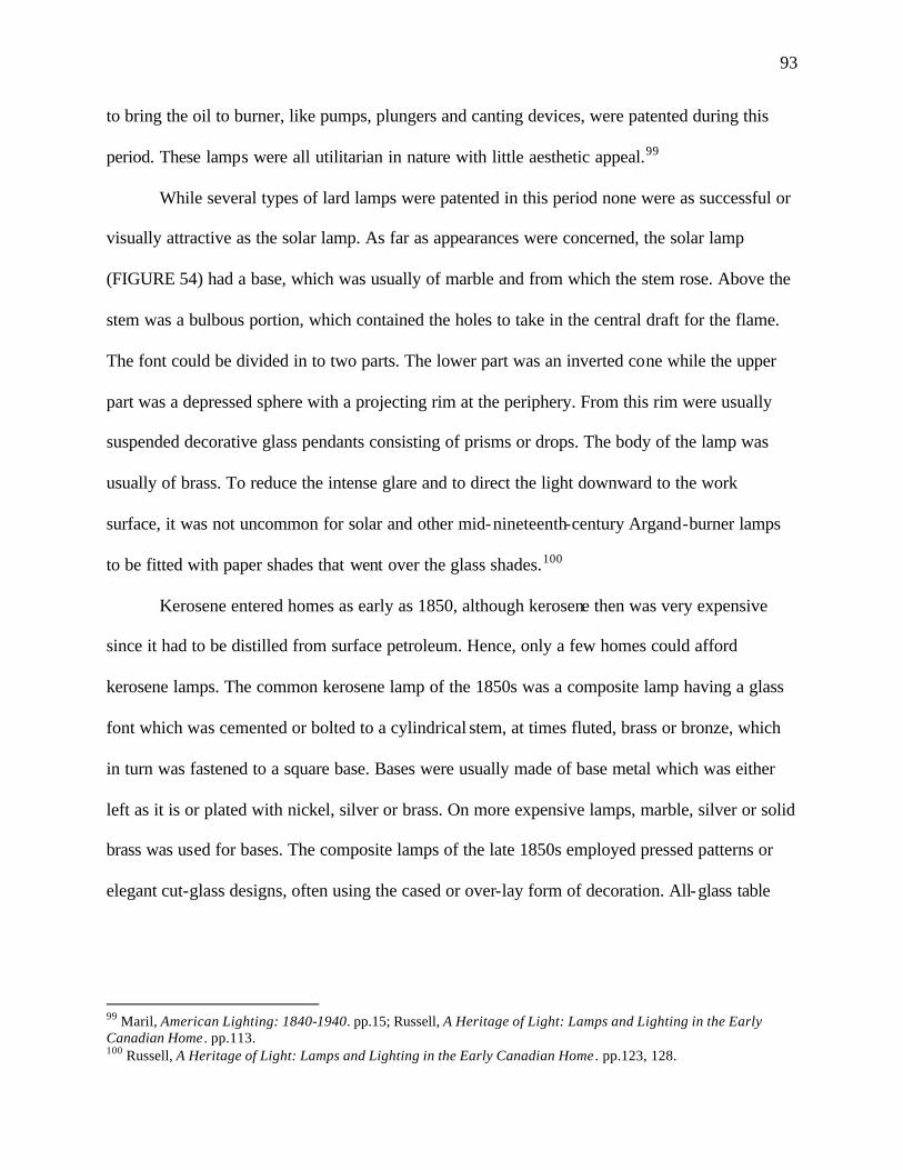
93
to bring the oil to burner, like pumps, plungers and canting devices, were patented during this
period. These lamps were all utilitarian in nature with little aesthetic appeal.99
While several types of lard lamps were patented in this period none were as successful or
visually attractive as the solar lamp. As far as appearances were concerned, the solar lamp
(FIGURE 54) had a base, which was usually of marble and from which the stem rose. Above the
stem was a bulbous portion, which contained the holes to take in the central draft for the flame.
The font could be divided in to two parts. The lower part was an inverted cone while the upper
part was a depressed sphere with a projecting rim at the periphery. From this rim were usually
suspended decorative glass pendants consisting of prisms or drops. The body of the lamp was
usually of brass. To reduce the intense glare and to direct the light downward to the work
surface, it was not uncommon for solar and other mid-nineteenth-century Argand-burner lamps
to be fitted with paper shades that went over the glass shades.100
Kerosene entered homes as early as 1850, although kerosene then was very expensive
since it had to be distilled from surface petroleum. Hence, only a few homes could afford
kerosene lamps. The common kerosene lamp of the 1850s was a composite lamp having a glass
font which was cemented or bolted to a cylindrical stem, at times fluted, brass or bronze, which
in turn was fastened to a square base. Bases were usually made of base metal which was either
left as it is or plated with nickel, silver or brass. On more expensive lamps, marble, silver or solid
brass was used for bases. The composite lamps of the late 1850s employed pressed patterns or
elegant cut-glass designs, often using the cased or over-lay form of decoration. All-glass table
99 Maril, American Lighting: 1840-1940. pp.15; Russell, A Heritage of Light: Lamps and Lighting in the Early Canadian Home . pp.113. 100 Russell, A Heritage of Light: Lamps and Lighting in the Early Canadian Home . pp.123, 128.
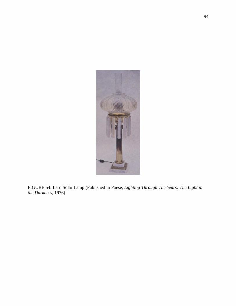
94
FIGURE 54: Lard Solar Lamp (Published in Poese, Lighting Through The Years: The Light in the Darkness, 1976)
95
lamps were the other popular category of early kerosene lamps, although the division of font,
stem and base was still preserved.101
Chimneys were a necessary feature of kerosene lamps. Many kerosene lamps also
employed shades to avoid glare. Shades on kerosene lamps used in this period were of blown
glass and displayed Greek motifs. They were of two basic kinds. The first was globe-shaped,
usually of etched glass with cut ornamentation. The second type was vase-shaped, with a flaring,
scalloped upper rim. The grape-leaf design and Greek-key design commonly featured on the
shades.102
Gas lighting was initially introduced for lighting streets, industries, commercial
establishments and public buildings, and did not find favor for residential use. The dazzling
white light it produced was in sharp contrast with the warm red glow of candles and oil lamps
that people were used to until then. Its smell and heat made it unpopular. There was also public
reaction against using gaslight in residences because of the associations it had with
industrialization and a centralized supply. People still held the notion that a good light was
supposed to be accompanied by good oil and a good wick. In spite of these shortcomings and
negative feelings, gas found its way into city houses in the 1840s and 1850s.103
Gas installations in the typical residence of this period included chandeliers, or gasoliers
as they were commonly called, hanging from the ceilings of the prominent rooms such as
parlors, halls and dining rooms. Gas wall brackets were a common feature in houses from 1850
to the 1890s. Table lamps required a long tube of India rubber or gum elastic covered with
101 Cooke, Lighting in America: From Colonial Rushlights to Victorian Chandeliers. pp.57-58; Russell, A Heritage of Light: Lamps and Lighting in the Early Canadian Home . pp.146-147. 102 Cooke, Lighting in America: From Colonial Rushlights to Victorian Chandeliers. pp.63,151. 103 Moss, Lighting For Historic Buildings: A Guide to Selecting Reproductions. pp.101; Schivelbusch, Disenchanted Night: The Industrialization of Light in the Nineteenth Century. 161-162.
96
horsehair in order to connect with the gas pipe in the wall or ceiling. Gas lanterns or pendants
lighted passageways, vestibules and stairwells.104
The form of gaslight fixtures was largely dictated by their function. The basic principle
was that a pipe delivered the gas to the burner which had an adjustable gas keys to regulate the
flow of the gas. The gasolier consisted of a set of nozzles with adjustable gas keys. The vertical
arm was attached to the ceiling while the horizontal arms terminated in jets. The gas keys were
usually located midway on the horizontal arms, though on certain fixtures like the crystal ones
they were placed right below the burner. On table lamps, the gas keys were located at the base of
the lamps where the flexible tubings joined the lamps.105
The initial gas burners were novelties and fittings came without shades. But this led to
complaints about the harshness of the naked flame and suggestions that the flame could be
injurious to eyesight. Further, currents of air cooled the flame and caused incomplete
combustion. So most gas fixtures had frosted, etched shades that helped give out a more
amorphous, diffused light. Shades used with flat- flame burners were generally globe-shaped,
also called ‘moons’ or bowl shaped half-hemispheres, also known as ‘half-moons’. These were,
however, not recommended for use with batswing burners as fluctuating gas pressure caused the
flame to broaden excessively at times and thereby, lead to the cracking of the glass shade.106
The burners of the gas fixtures (FIGURE 55), which were basically tubular devices with
openings at the top for the gas jet, were screwed onto the threaded end of the horizontal arm. The
first burners had simple round holes and were wasteful and inefficient, but by about 1816 the
‘batwing’ burner was introduced. It consisted of a domical top with a slit- like opening across it
104 Maril, American Lighting: 1840-1940. pp.48. 105 Moss, Lighting For Historic Buildings: A Guide to Selecting Reproductions. pp.102. 106 Dillon, Artificial Sunshine: A Social History of Domestic Lighting. pp.144; Maril, American Lighting: 1840-1940. pp.36; Moss, Lighting For Historic Buildings: A Guide to Selecting Reproductions. pp.102.
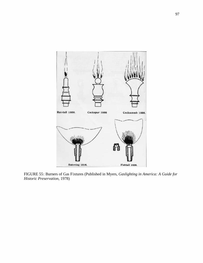
97
FIGURE 55: Burners of Gas Fixtures (Published in Myers, Gaslighting in America: A Guide for Historic Preservation, 1978)
98
and was primarily used for outdoor illumination. The slit- like opening resulted in a thin, wide,
fan-shaped flame. In 1820, another type of flat- flame burner was devised; this burner had a flat
or slightly concave top with two tube openings pointing obtusely towards each other. The flame
that resulted from the two gas jets was higher and narrower than the earlier ‘batwing’. This
burner was known as ‘fishtail’ or ‘union jet’. The fishtail burners were most commonly used in
homes, apart from the gas candles, until the discovery of the incandescent mantle. Later
developments in gas burners were just minor variations of the earlier burners with no significant
change. Gas burners using the Argand center-draft principle were used from time to time
although they were not very popular in the United States. They featured ornamental galleries to
support chimneys, multiple holes and hollow centers, and produced circular columns of flame.
They were not as luminous as the flat-flame burners and their chimneys were prone to breakage
and difficult to clean. 107
The early gasoliers were normally cast in brass. The simplest form of the gasolier was an
inverted letter “T” (FIGURE 56) and consisted of a simple double light with no shades or plain
opal shades. They were used in modest, unpretentious houses and in utilitarian spaces like
corridors and kitchens until the end of the gas era. In general, the mid-nineteenth century
gasoliers (FIGURE 57) were lavish affairs with curvaceous scrolled arms that were adorned with
delicate floral and foliate ornaments; elaborate center shafts carved with human figures, putti108,
allegorical bronze statuettes, animals, and foliage, as well as decorative canopies. Apart from the
central vertical arm and the horizontal branches having the burners, some early gasoliers also
included ornamental chains suspended from the central shaft to each of the branches. In some
107 Dillon, Artificial Sunshine: A Social History of Domestic Lighting. pp.136-137; Denys Peter Myers, Gaslighting in America: A Guide for Historic Preservation (Washington, D.C., 1978). pp.14-17; Russell, A Heritage of Light: Lamps and Lighting in the Early Canadian Home . pp.294-295. 108 Putti, plural for putto, are representations of chubby cupid like boys or children, usually nude, particularly in Rennaisance art.

99
FIGURE 56: Inverted ‘T’ Gas Fixture (Published in Myers, Gaslighting in America: A Guide for Historic Preservation, 1978)
FIGURE 57: Mid-nineteenth Century Gasolier (Published in Myers, Gaslighting in America: A Guide for Historic Preservation, 1978)
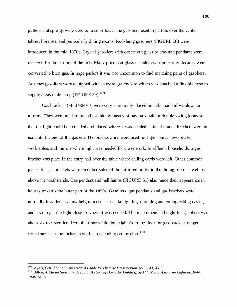
100
pulleys and springs were used to raise or lower the gasoliers used in parlors over the center
tables, libraries, and particularly dining rooms. Rod-hung gasoliers (FIGURE 58) were
introduced in the mid-1850s. Crystal gasoliers with ornate cut glass prisms and pendants were
reserved for the parlors of the rich. Many prism-cut glass chandeliers from earlier decades were
converted to burn gas. In large parlors it was not uncommon to find matching pairs of gasoliers.
At times gasoliers were equipped with an extra gas cock to which was attached a flexible hose to
supply a gas table lamp (FIGURE 59).109
Gas brackets (FIGURE 60) were very commonly placed on either side of windows or
mirrors. They were made more adjustable by means of having single or double swing joints so
that the light could be extended and placed where it was needed. Jointed branch brackets were in
use until the end of the gas era. The bracket arms were used for light sources over desks,
worktables, and mirrors where light was needed for close work. In affluent households, a gas
bracket was place in the entry hall over the table where calling cards were left. Other common
places for gas brackets were on either sides of the mirrored buffet in the dining room as well as
above the washstands. Gas pendant and hall lamps (FIGURE 61) also made their appearance in
houses towards the latter part of the 1850s. Gasoliers, gas pendants and gas brackets were
normally installed at a low height in order to make lighting, dimming and extinguishing easier,
and also to get the light close to where it was needed. The recommended height for gasoliers was
about six to seven feet from the floor while the height from the floor for gas brackets ranged
from four feet nine inches to six feet depending on location. 110
109 Myers, Gaslighting in America: A Guide for Historic Preservation. pp.35, 43, 45, 85. 110 Dillon, Artificial Sunshine: A Social History of Domestic Lighting. pp.144; Maril, American Lighting: 1840-1940. pp.50.
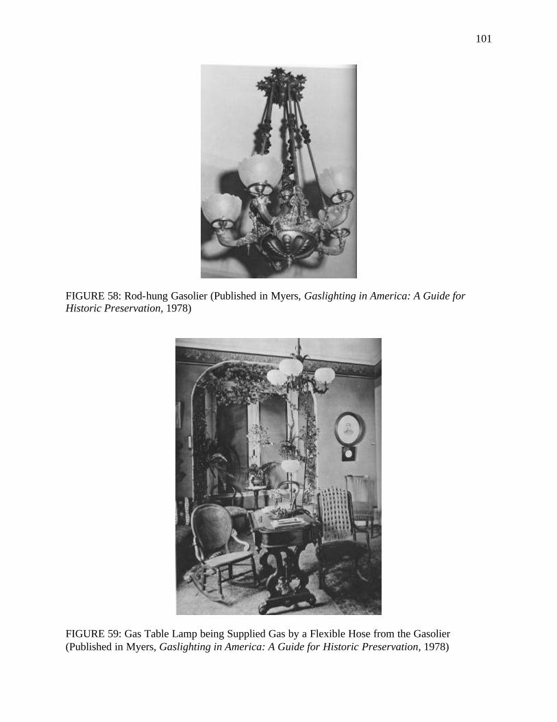
101
FIGURE 58: Rod-hung Gasolier (Published in Myers, Gaslighting in America: A Guide for Historic Preservation, 1978)
FIGURE 59: Gas Table Lamp being Supplied Gas by a Flexible Hose from the Gasolier (Published in Myers, Gaslighting in America: A Guide for Historic Preservation, 1978)
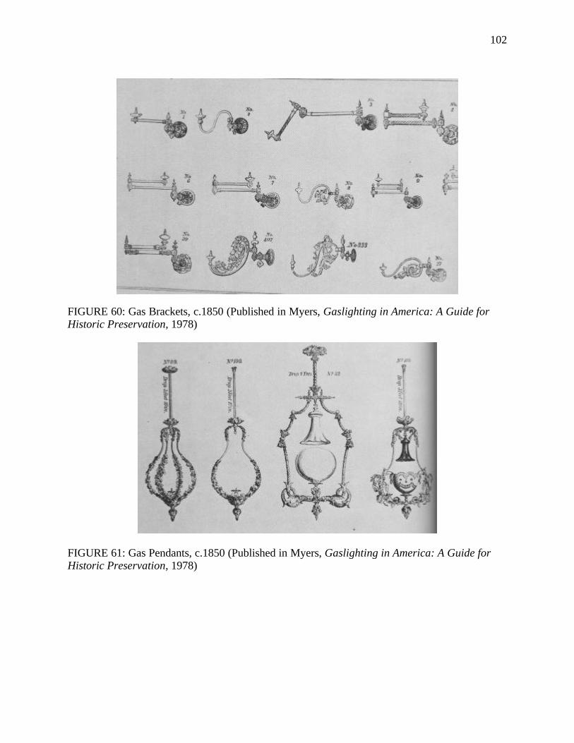
102
FIGURE 60: Gas Brackets, c.1850 (Published in Myers, Gaslighting in America: A Guide for Historic Preservation, 1978)
FIGURE 61: Gas Pendants, c.1850 (Published in Myers, Gaslighting in America: A Guide for Historic Preservation, 1978)
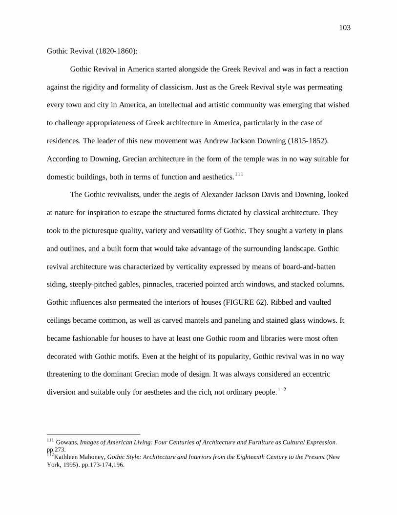
103
Gothic Revival (1820-1860):
Gothic Revival in America started alongside the Greek Revival and was in fact a reaction
against the rigidity and formality of classicism. Just as the Greek Revival style was permeating
every town and city in America, an intellectual and artistic community was emerging that wished
to challenge appropriateness of Greek architecture in America, particularly in the case of
residences. The leader of this new movement was Andrew Jackson Downing (1815-1852).
According to Downing, Grecian architecture in the form of the temple was in no way suitable for
domestic buildings, both in terms of function and aesthetics.111
The Gothic revivalists, under the aegis of Alexander Jackson Davis and Downing, looked
at nature for inspiration to escape the structured forms dictated by classical architecture. They
took to the picturesque quality, variety and versatility of Gothic. They sought a variety in plans
and outlines, and a built form that would take advantage of the surrounding landscape. Gothic
revival architecture was characterized by verticality expressed by means of board-and-batten
siding, steeply-pitched gables, pinnacles, traceried pointed arch windows, and stacked columns.
Gothic influences also permeated the interiors of houses (FIGURE 62). Ribbed and vaulted
ceilings became common, as well as carved mantels and paneling and stained glass windows. It
became fashionable for houses to have at least one Gothic room and libraries were most often
decorated with Gothic motifs. Even at the height of its popularity, Gothic revival was in no way
threatening to the dominant Grecian mode of design. It was always considered an eccentric
diversion and suitable only for aesthetes and the rich, not ordinary people.112
111 Gowans, Images of American Living: Four Centuries of Architecture and Furniture as Cultural Expression. pp.273. 112Kathleen Mahoney, Gothic Style: Architecture and Interiors from the Eighteenth Century to the Present (New York, 1995). pp.173-174,196.
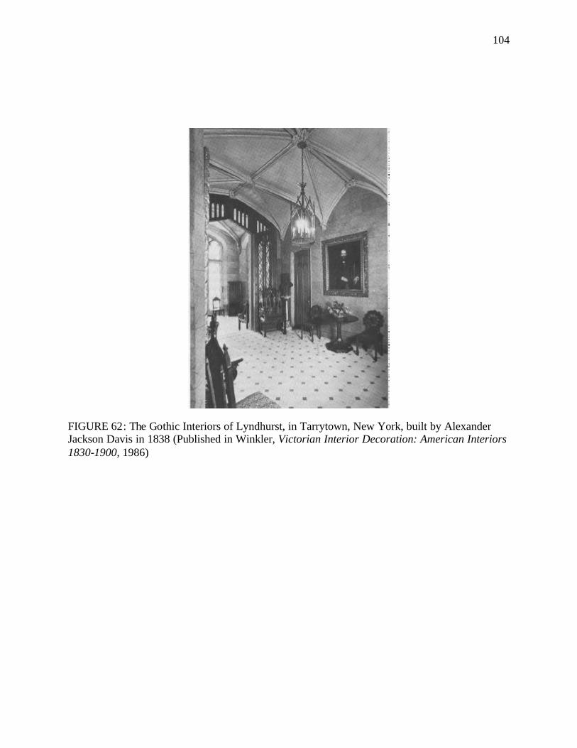
104
FIGURE 62: The Gothic Interiors of Lyndhurst, in Tarrytown, New York, built by Alexander Jackson Davis in 1838 (Published in Winkler, Victorian Interior Decoration: American Interiors 1830-1900, 1986)
105
Around this time gothic motifs started appearing in furniture and decorative accessories,
including lighting fixtures, in order to fit more appropriately in Gothic interiors. Gothic style was
ideal for intricate metalwork which was manifested on candlesticks, chandeliers, lanterns and
gasoliers. So lanterns with crenellations and arched glass panels became common. Arms of
gasoliers were adorned with carvings aping the design of Pugin. Coronets were applied on
burners, chandeliers and gasoliers. Fixtures (FIGURES 63, 64) with carvings of pinnacles,
trefoils and quatrefoils were found in interior decorations. Unfortunately, not many American
companies produced Gothic light fixtures so the majority of them were imported from Europe.
Victorian Period (1860-1890)
The Gothic style started transforming itself into a more elaborate style characterized by a
proliferation of decoration, additive ornament and eclectic borrowing from the past. While the
interest in motifs of the past was still very much there, styles from different historical periods
were no longer seen exclusively and there was an indiscriminate mixing up of details from
various historical styles on the same building in an effort to develop a new style. While the
Greek and Gothic revival periods had seen the beginning of an interest in elaborate
ornamentation in the interiors of houses, the Victorian period was a frenzy of decorative excess.
While the earlier period had sowed the seeds of picturesqueness with the birth of the Gothic
Revival, this period made picturesqeness the underlying theme of architecture and interior
design. The right word, however, to describe the design theme of this period would be –
“picturesque eclecticism”, with a free mixing of styles from various periods and the great variety
of styles that this period generated as well as supported. Jagged silhouettes, textural contrasts,
more vertical proportions, endless angles, projections and asymmetrical forms were applied in
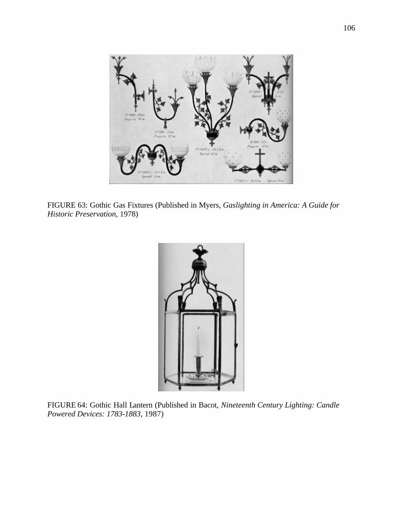
106
FIGURE 63: Gothic Gas Fixtures (Published in Myers, Gaslighting in America: A Guide for Historic Preservation, 1978)
FIGURE 64: Gothic Hall Lantern (Published in Bacot, Nineteenth Century Lighting: Candle Powered Devices: 1783-1883, 1987)
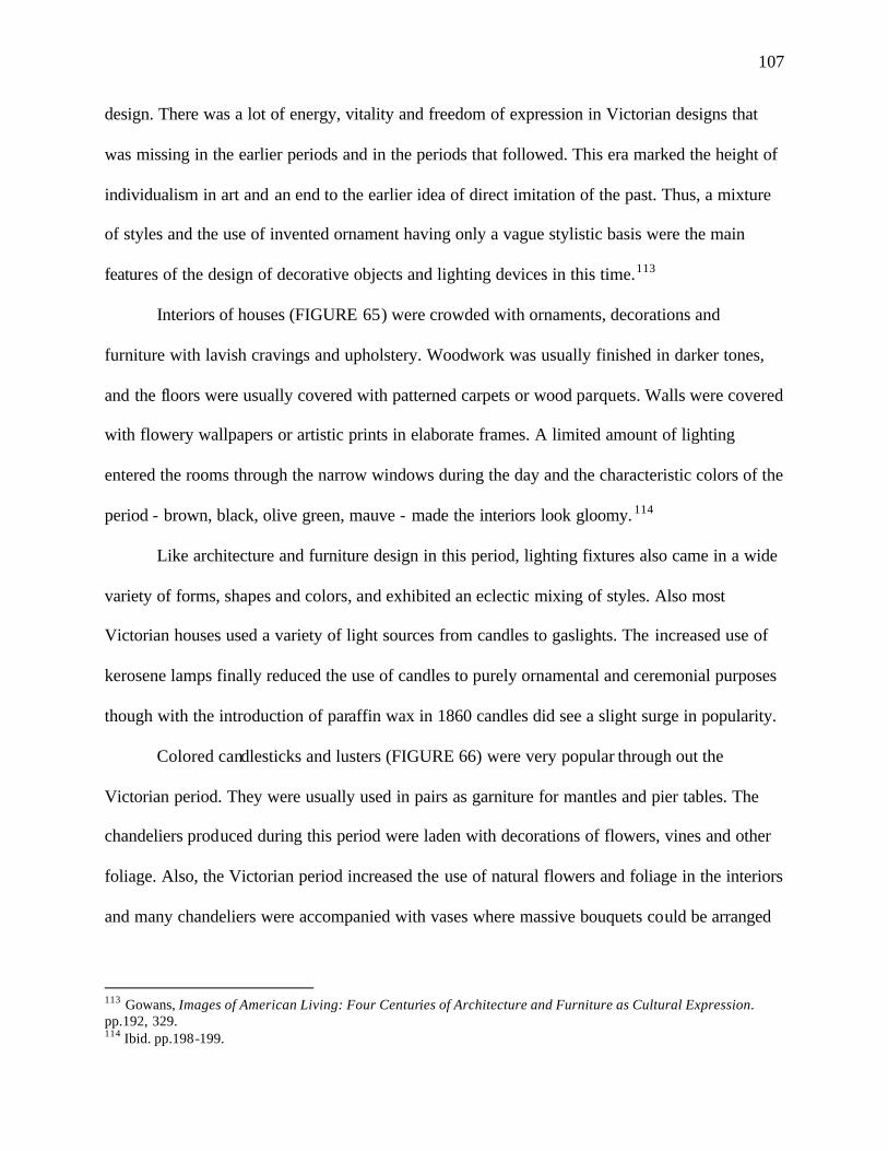
107
design. There was a lot of energy, vitality and freedom of expression in Victorian designs that
was missing in the earlier periods and in the periods that followed. This era marked the height of
individualism in art and an end to the earlier idea of direct imitation of the past. Thus, a mixture
of styles and the use of invented ornament having only a vague stylistic basis were the main
features of the design of decorative objects and lighting devices in this time.113
Interiors of houses (FIGURE 65) were crowded with ornaments, decorations and
furniture with lavish cravings and upholstery. Woodwork was usually finished in darker tones,
and the floors were usually covered with patterned carpets or wood parquets. Walls were covered
with flowery wallpapers or artistic prints in elaborate frames. A limited amount of lighting
entered the rooms through the narrow windows during the day and the characteristic colors of the
period - brown, black, olive green, mauve - made the interiors look gloomy. 114
Like architecture and furniture design in this period, lighting fixtures also came in a wide
variety of forms, shapes and colors, and exhibited an eclectic mixing of styles. Also most
Victorian houses used a variety of light sources from candles to gaslights. The increased use of
kerosene lamps finally reduced the use of candles to purely ornamental and ceremonial purposes
though with the introduction of paraffin wax in 1860 candles did see a slight surge in popularity.
Colored candlesticks and lusters (FIGURE 66) were very popular through out the
Victorian period. They were usually used in pairs as garniture for mantles and pier tables. The
chandeliers produced during this period were laden with decorations of flowers, vines and other
foliage. Also, the Victorian period increased the use of natural flowers and foliage in the interiors
and many chandeliers were accompanied with vases where massive bouquets could be arranged
113 Gowans, Images of American Living: Four Centuries of Architecture and Furniture as Cultural Expression. pp.192, 329. 114 Ibid. pp.198-199.
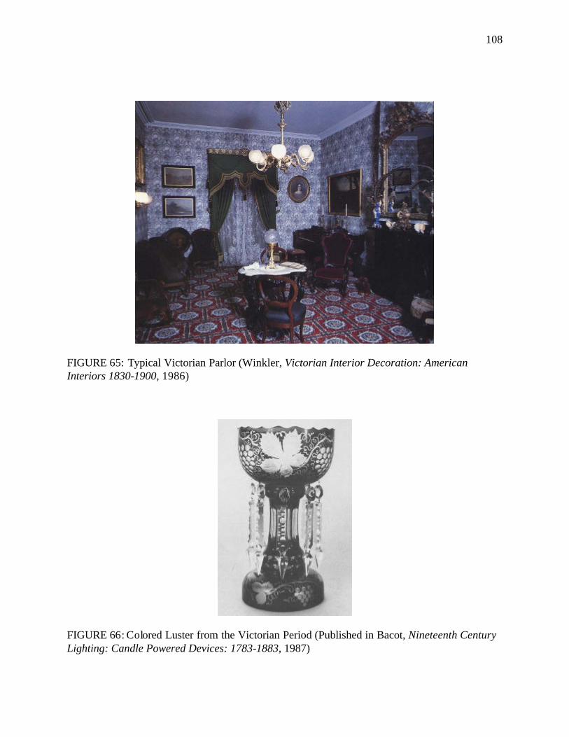
108
FIGURE 65: Typical Victorian Parlor (Winkler, Victorian Interior Decoration: American Interiors 1830-1900, 1986)
FIGURE 66: Colored Luster from the Victorian Period (Published in Bacot, Nineteenth Century Lighting: Candle Powered Devices: 1783-1883, 1987)
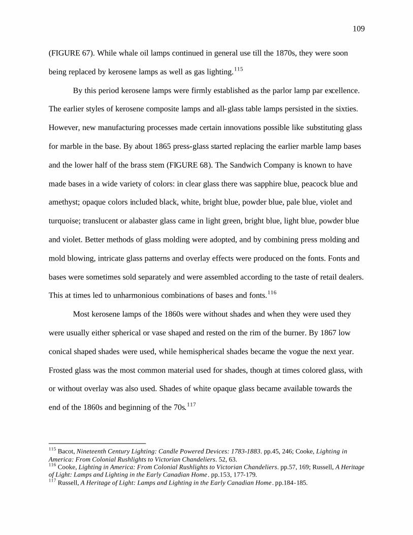
109
(FIGURE 67). While whale oil lamps continued in general use till the 1870s, they were soon
being replaced by kerosene lamps as well as gas lighting.115
By this period kerosene lamps were firmly established as the parlor lamp par excellence.
The earlier styles of kerosene composite lamps and all-glass table lamps persisted in the sixties.
However, new manufacturing processes made certain innovations possible like substituting glass
for marble in the base. By about 1865 press-glass started replacing the earlier marble lamp bases
and the lower half of the brass stem (FIGURE 68). The Sandwich Company is known to have
made bases in a wide variety of colors: in clear glass there was sapphire blue, peacock blue and
amethyst; opaque colors included black, white, bright blue, powder blue, pale blue, violet and
turquoise; translucent or alabaster glass came in light green, bright blue, light blue, powder blue
and violet. Better methods of glass molding were adopted, and by combining press molding and
mold blowing, intricate glass patterns and overlay effects were produced on the fonts. Fonts and
bases were sometimes sold separately and were assembled according to the taste of retail dealers.
This at times led to unharmonious combinations of bases and fonts.116
Most kerosene lamps of the 1860s were without shades and when they were used they
were usually either spherical or vase shaped and rested on the rim of the burner. By 1867 low
conical shaped shades were used, while hemispherical shades became the vogue the next year.
Frosted glass was the most common material used for shades, though at times colored glass, with
or without overlay was also used. Shades of white opaque glass became available towards the
end of the 1860s and beginning of the 70s.117
115 Bacot, Nineteenth Century Lighting: Candle Powered Devices: 1783-1883. pp.45, 246; Cooke, Lighting in America: From Colonial Rushlights to Victorian Chandeliers. 52, 63. 116 Cooke, Lighting in America: From Colonial Rushlights to Victorian Chandeliers. pp.57, 169; Russell, A Heritage of Light: Lamps and Lighting in the Early Canadian Home . pp.153, 177-179. 117 Russell, A Heritage of Light: Lamps and Lighting in the Early Canadian Home . pp.184-185.
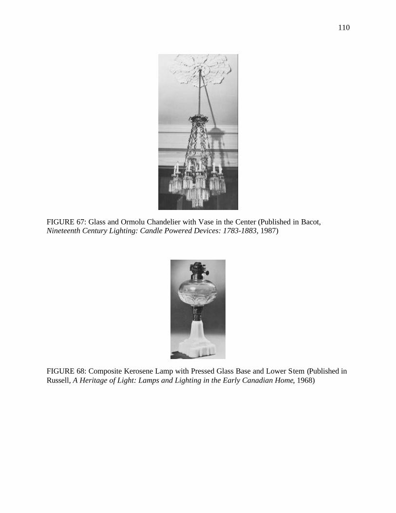
110
FIGURE 67: Glass and Ormolu Chandelier with Vase in the Center (Published in Bacot, Nineteenth Century Lighting: Candle Powered Devices: 1783-1883, 1987)
FIGURE 68: Composite Kerosene Lamp with Pressed Glass Base and Lower Stem (Published in Russell, A Heritage of Light: Lamps and Lighting in the Early Canadian Home, 1968)
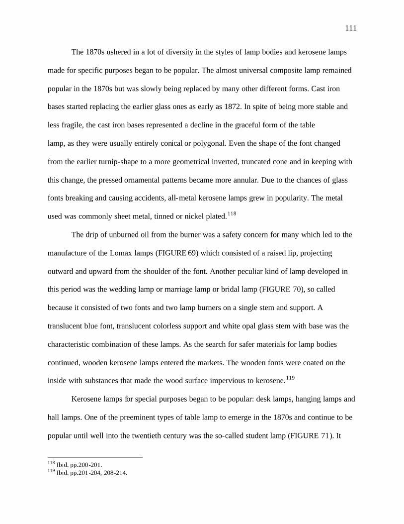
111
The 1870s ushered in a lot of diversity in the styles of lamp bodies and kerosene lamps
made for specific purposes began to be popular. The almost universal composite lamp remained
popular in the 1870s but was slowly being replaced by many other different forms. Cast iron
bases started replacing the earlier glass ones as early as 1872. In spite of being more stable and
less fragile, the cast iron bases represented a decline in the graceful form of the table
lamp, as they were usually entirely conical or polygonal. Even the shape of the font changed
from the earlier turnip-shape to a more geometrical inverted, truncated cone and in keeping with
this change, the pressed ornamental patterns became more annular. Due to the chances of glass
fonts breaking and causing accidents, all-metal kerosene lamps grew in popularity. The metal
used was commonly sheet metal, tinned or nickel plated.118
The drip of unburned oil from the burner was a safety concern for many which led to the
manufacture of the Lomax lamps (FIGURE 69) which consisted of a raised lip, projecting
outward and upward from the shoulder of the font. Another peculiar kind of lamp developed in
this period was the wedding lamp or marriage lamp or bridal lamp (FIGURE 70), so called
because it consisted of two fonts and two lamp burners on a single stem and support. A
translucent blue font, translucent colorless support and white opal glass stem with base was the
characteristic combination of these lamps. As the search for safer materials for lamp bodies
continued, wooden kerosene lamps entered the markets. The wooden fonts were coated on the
inside with substances that made the wood surface impervious to kerosene.119
Kerosene lamps for special purposes began to be popular: desk lamps, hanging lamps and
hall lamps. One of the preeminent types of table lamp to emerge in the 1870s and continue to be
popular until well into the twentieth century was the so-called student lamp (FIGURE 71). It
118 Ibid. pp.200-201. 119 Ibid. pp.201-204, 208-214.
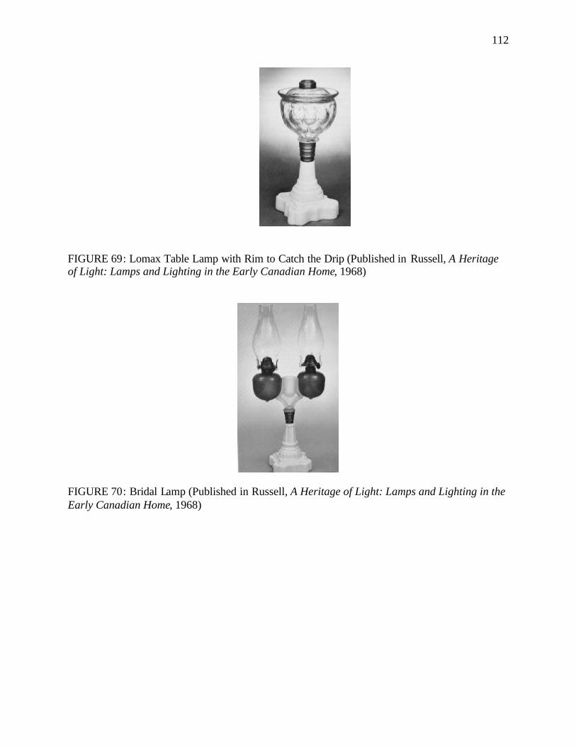
112
FIGURE 69: Lomax Table Lamp with Rim to Catch the Drip (Published in Russell, A Heritage of Light: Lamps and Lighting in the Early Canadian Home, 1968)
FIGURE 70: Bridal Lamp (Published in Russell, A Heritage of Light: Lamps and Lighting in the Early Canadian Home, 1968)
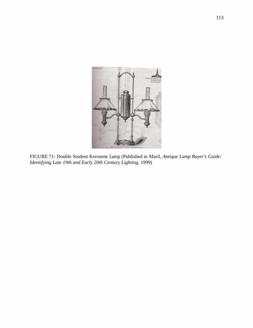
113
FIGURE 71: Double Student Kerosene Lamp (Published in Maril, Antique Lamp Buyer's Guide: Identifying Late 19th and Early 20th Century Lighting, 1999)
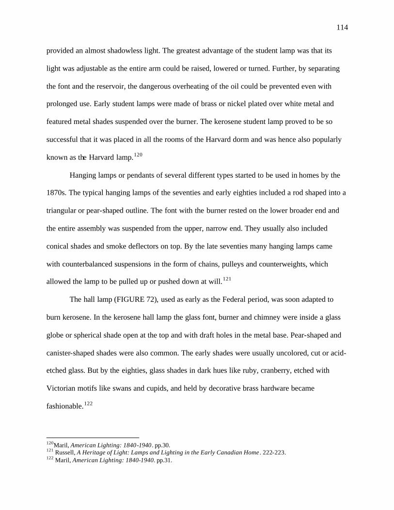
114
provided an almost shadowless light. The greatest advantage of the student lamp was that its
light was adjustable as the entire arm could be raised, lowered or turned. Further, by separating
the font and the reservoir, the dangerous overheating of the oil could be prevented even with
prolonged use. Early student lamps were made of brass or nickel plated over white metal and
featured metal shades suspended over the burner. The kerosene student lamp proved to be so
successful that it was placed in all the rooms of the Harvard dorm and was hence also popularly
known as the Harvard lamp.120
Hanging lamps or pendants of several different types started to be used in homes by the
1870s. The typical hanging lamps of the seventies and early eighties included a rod shaped into a
triangular or pear-shaped outline. The font with the burner rested on the lower broader end and
the entire assembly was suspended from the upper, narrow end. They usually also included
conical shades and smoke deflectors on top. By the late seventies many hanging lamps came
with counterbalanced suspensions in the form of chains, pulleys and counterweights, which
allowed the lamp to be pulled up or pushed down at will.121
The hall lamp (FIGURE 72), used as early as the Federal period, was soon adapted to
burn kerosene. In the kerosene hall lamp the glass font, burner and chimney were inside a glass
globe or spherical shade open at the top and with draft holes in the metal base. Pear-shaped and
canister-shaped shades were also common. The early shades were usually uncolored, cut or acid-
etched glass. But by the eighties, glass shades in dark hues like ruby, cranberry, etched with
Victorian motifs like swans and cupids, and held by decorative brass hardware became
fashionable.122
120Maril, American Lighting: 1840-1940 . pp.30. 121 Russell, A Heritage of Light: Lamps and Lighting in the Early Canadian Home . 222-223. 122 Maril, American Lighting: 1840-1940. pp.31.
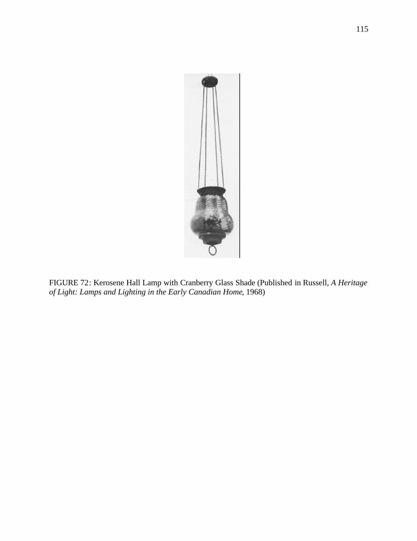
115
FIGURE 72: Kerosene Hall Lamp with Cranberry Glass Shade (Published in Russell, A Heritage of Light: Lamps and Lighting in the Early Canadian Home, 1968)
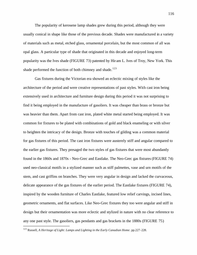
116
The popularity of kerosene lamp shades grew during this period, although they were
usually conical in shape like those of the previous decade. Shades were manufactured in a variety
of materials such as metal, etched glass, ornamental porcelain, but the most common of all was
opal glass. A particular type of shade that originated in this decade and enjoyed long-term
popularity was the Ives shade (FIGURE 73) patented by Hiram L. Ives of Troy, New York. This
shade performed the function of both chimney and shade.123
Gas fixtures during the Victorian era showed an eclectic mixing of styles like the
architecture of the period and were creative representations of past styles. With cast iron being
extensively used in architecture and furniture design during this period it was not surprising to
find it being employed in the manufacture of gasoliers. It was cheaper than brass or bronze but
was heavier than them. Apart from cast iron, plated white metal started being employed. It was
common for fixtures to be plated with combinations of gold and black enameling or with silver
to heighten the intricacy of the design. Bronze with touches of gilding was a common material
for gas fixtures of this period. The cast iron fixtures were austerely stiff and angular compared to
the earlier gas fixtures. They presaged the two styles of gas fixtures that were most abundantly
found in the 1860s and 1870s - Neo-Grec and Eastlake. The Neo-Grec gas fixtures (FIGURE 74)
used neo-classical motifs in a stylized manner such as stiff palmettes, vase and urn motifs of the
stem, and cast griffins on branches. They were very angular in design and lacked the curvaceous,
delicate appearance of the gas fixtures of the earlier period. The Eastlake fixtures (FIGURE 74),
inspired by the wooden furniture of Charles Eastlake, featured low relief carvings, incised lines,
geometric ornaments, and flat surfaces. Like Neo-Grec fixtures they too were angular and stiff in
design but their ornamentation was more eclectic and stylized in nature with no clear reference to
any one past style. The gasoliers, gas pendants and gas brackets in the 1880s (FIGURE 75) 123 Russell, A Heritage of Light: Lamps and Lighting in the Early Canadian Home . pp.227-228.
117
FIGURE 73: Kerosene Lamp with Ives Shade (Published in Russell, A Heritage of Light: Lamps and Lighting in the Early Canadian Home, 1968)
FIGURE 74: Neo-Grec-style (left) and Eastlake-style Gasoliers (Published in Myers, Gaslighting in America: A Guide for Historic Preservation, 1978)
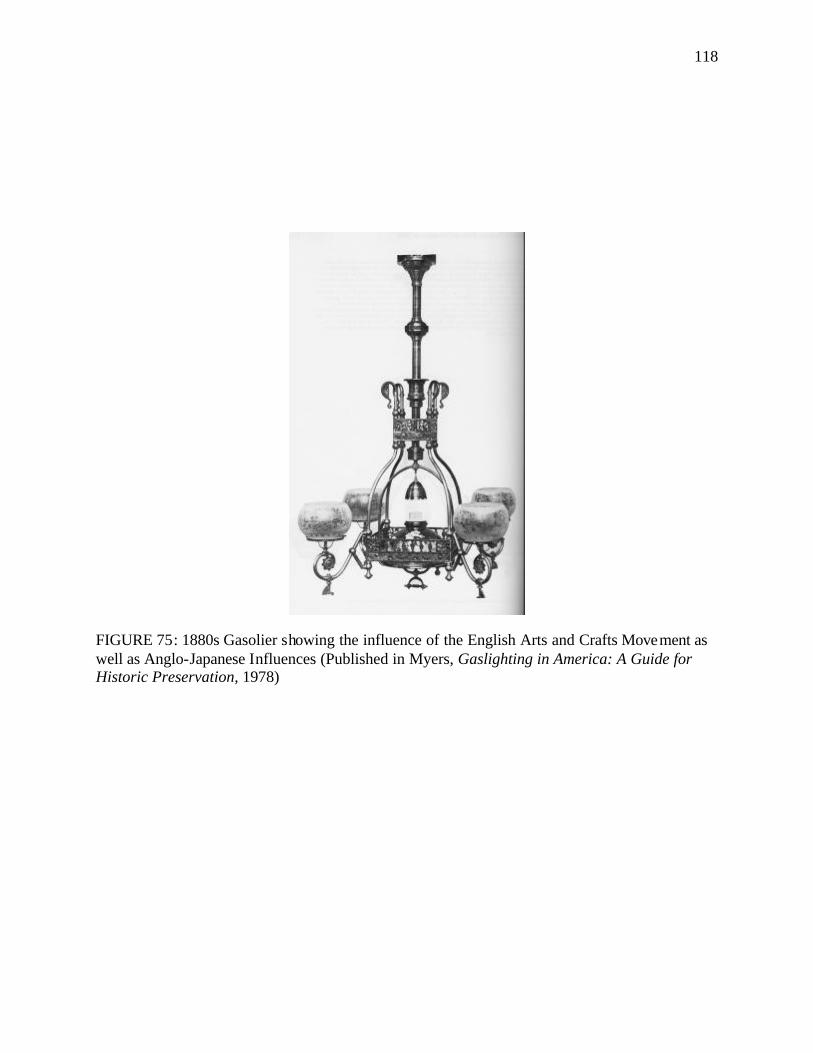
118
FIGURE 75: 1880s Gasolier showing the influence of the English Arts and Crafts Movement as well as Anglo-Japanese Influences (Published in Myers, Gaslighting in America: A Guide for Historic Preservation, 1978)
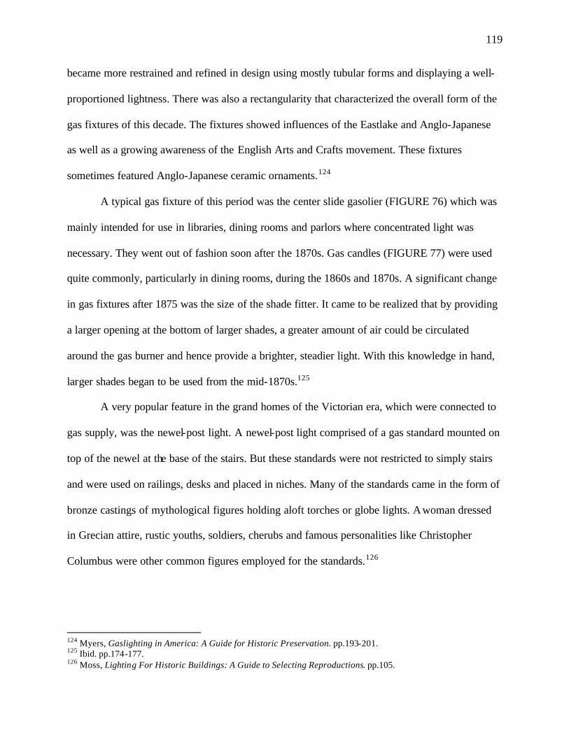
119
became more restrained and refined in design using mostly tubular forms and displaying a well-
proportioned lightness. There was also a rectangularity that characterized the overall form of the
gas fixtures of this decade. The fixtures showed influences of the Eastlake and Anglo-Japanese
as well as a growing awareness of the English Arts and Crafts movement. These fixtures
sometimes featured Anglo-Japanese ceramic ornaments.124
A typical gas fixture of this period was the center slide gasolier (FIGURE 76) which was
mainly intended for use in libraries, dining rooms and parlors where concentrated light was
necessary. They went out of fashion soon after the 1870s. Gas candles (FIGURE 77) were used
quite commonly, particularly in dining rooms, during the 1860s and 1870s. A significant change
in gas fixtures after 1875 was the size of the shade fitter. It came to be realized that by providing
a larger opening at the bottom of larger shades, a greater amount of air could be circulated
around the gas burner and hence provide a brighter, steadier light. With this knowledge in hand,
larger shades began to be used from the mid-1870s.125
A very popular feature in the grand homes of the Victorian era, which were connected to
gas supply, was the newel-post light. A newel-post light comprised of a gas standard mounted on
top of the newel at the base of the stairs. But these standards were not restricted to simply stairs
and were used on railings, desks and placed in niches. Many of the standards came in the form of
bronze castings of mythological figures holding aloft torches or globe lights. A woman dressed
in Grecian attire, rustic youths, soldiers, cherubs and famous personalities like Christopher
Columbus were other common figures employed for the standards.126
124 Myers, Gaslighting in America: A Guide for Historic Preservation. pp.193-201. 125 Ibid. pp.174-177. 126 Moss, Lighting For Historic Buildings: A Guide to Selecting Reproductions. pp.105.
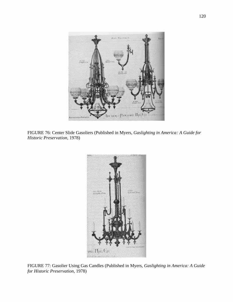
120
FIGURE 76: Center Slide Gasoliers (Published in Myers, Gaslighting in America: A Guide for Historic Preservation, 1978)
FIGURE 77: Gasolier Using Gas Candles (Published in Myers, Gaslighting in America: A Guide for Historic Preservation, 1978)
121
Modern Period (1890-1930)
The excesses of the Victorian period brought forth a reaction against the overuse of
ornamentation. People lamented the use of machine-made ornaments which, according to them,
dehumanized the relationship between artists and their art and thereby caused deterioration in the
quality of art. The stylistic mixture that had been advocated by the earlier Victorian period began
to be looked upon as chaotic and disorganized. A need was felt to incorporate order into the
architecture of the period.
The community of architects and designers started organizing themselves into two
distinct camps to establish a new order. There were the neo-revivalists who formed the larger of
the two groups. All the styles of the past - Roman, Italian Renaissance, Gothic - were brought
back and made the symbols of new America. The elaborate and accurate copying of past
European models became a manifestation of wealth for the American nouveau rich (FIGURE
78). With sea travel becoming faster and safer, many Americans traveled to Europe to study art
and architecture. They came back with an astute understanding of the architecture of the past and
were “not so much designers as arrangers of period-room displays.” The most famous architects
who belonged to this group include Richard Morris Hunt, McKim, Mead & White, Daniel H.
Burnham, and Bertram G. Goodhue.127
The other group that emerged in the early 1890s were the progressives and they were
only a handful of designers who dared to eschew tradition and think differently. They tried to
find the solution to the reformation in the opposite direction, that is, by rejecting the past and
forming novel ideas based on strong design principles. The group was further broken down into
several subgroups. All these coalesced under one common influencing factor- the Arts and Crafts
127 Gowans, Images of American Living: Four Centuries of Architecture and Furniture as Cultural Expression. pp.374.
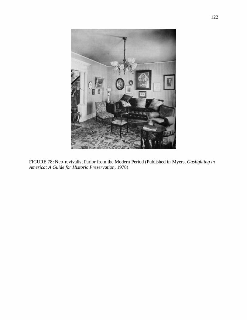
122
FIGURE 78: Neo-revivalist Parlor from the Modern Period (Published in Myers, Gaslighting in America: A Guide for Historic Preservation, 1978)
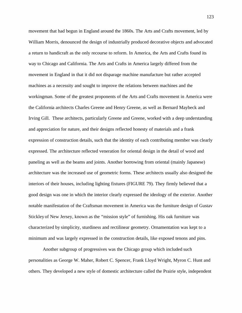
123
movement that had begun in England around the 1860s. The Arts and Crafts movement, led by
William Morris, denounced the design of industrially produced decorative objects and advocated
a return to handicraft as the only recourse to reform. In America, the Arts and Crafts found its
way to Chicago and California. The Arts and Crafts in America largely differed from the
movement in England in that it did not disparage machine manufacture but rather accepted
machines as a necessity and sought to improve the relations between machines and the
workingman. Some of the greatest proponents of the Arts and Crafts movement in America were
the California architects Charles Greene and Henry Greene, as well as Bernard Maybeck and
Irving Gill. These architects, particularly Greene and Greene, worked with a deep understanding
and appreciation for nature, and their designs reflected honesty of materials and a frank
expression of construction details, such that the identity of each contributing member was clearly
expressed. The architecture reflected veneration for oriental design in the detail of wood and
paneling as well as the beams and joints. Another borrowing from oriental (mainly Japanese)
architecture was the increased use of geometric forms. These architects usually also designed the
interiors of their houses, including lighting fixtures (FIGURE 79). They firmly believed that a
good design was one in which the interior clearly expressed the ideology of the exterior. Another
notable manifestation of the Craftsman movement in America was the furniture design of Gustav
Stickley of New Jersey, known as the “mission style” of furnishing. His oak furniture was
characterized by simplicity, sturdiness and rectilinear geometry. Ornamentation was kept to a
minimum and was largely expressed in the construction details, like exposed tenons and pins.
Another subgroup of progressives was the Chicago group which included such
personalities as George W. Maher, Robert C. Spencer, Frank Lloyd Wright, Myron C. Hunt and
others. They developed a new style of domestic architecture called the Prairie style, independent
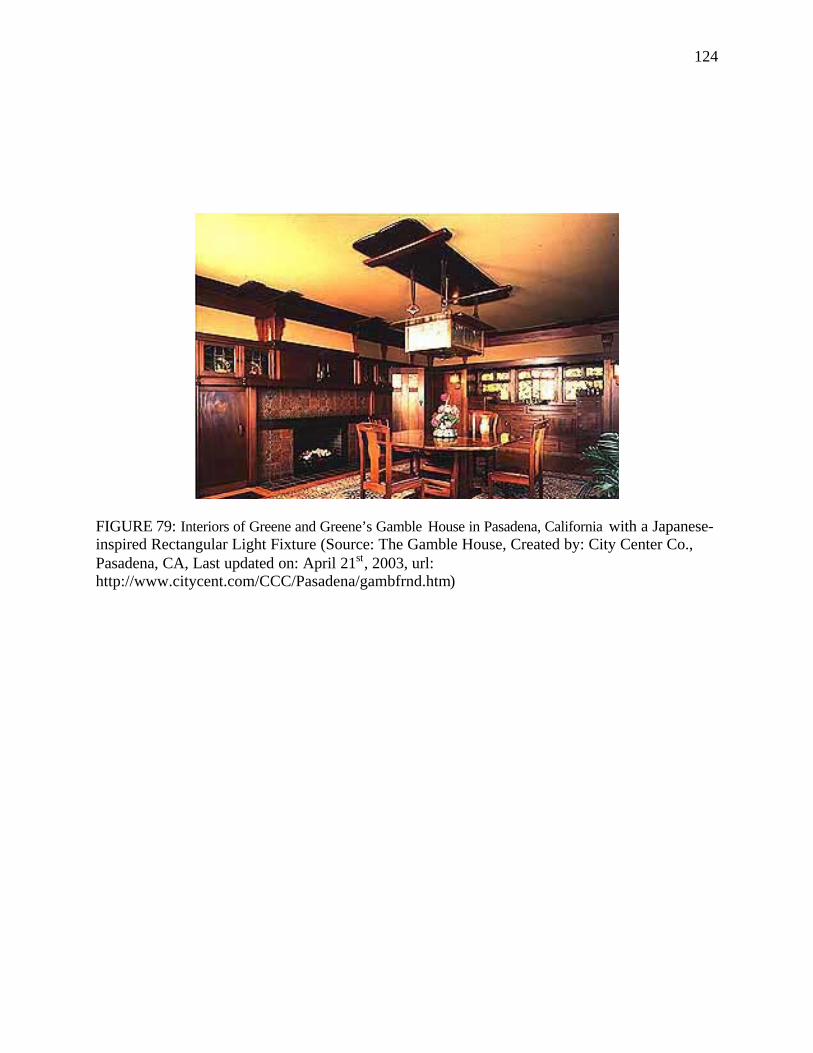
124
FIGURE 79: Interiors of Greene and Greene’s Gamble House in Pasadena, California with a Japanese-inspired Rectangular Light Fixture (Source: The Gamble House, Created by: City Center Co., Pasadena, CA, Last updated on: April 21st, 2003, url: http://www.citycent.com/CCC/Pasadena/gambfrnd.htm)
125
of any historicism. These houses were characterized by a broad and horizontal disposition of
lines. This imposed horizontality made sure that they were always kept to the human scale, never
becoming overwhelming, with forms that related well to human needs and comprehension. Every
aspect of the Prairie house reflected clarity, precision and angularity. Ornamentation was largely
dependent on the texture of different materials and the juxtaposition of various forms and shapes.
Plans were based on Louis Sullivan’s mantra of ‘form follows function,’ intended to enhance the
human experience and efficiency. Like the California architects, the Prairie School was also
greatly influenced by Japanese architecture in their usage of simple lines, geometrical forms and
their sensitivity to nature. The architects of the Chicago school, particularly Frank Lloyd Wright
designed the interiors to integrate them with the exteriors. Frank Lloyd Wright invoked the
concept of organic architecture during this period that called for an integration of plan, structure
and ornamentation. He designed his own light fixtures that were most commonly built- in or
attached to his buildings (FIGURE 80). However, he is also credited with the design of some
unique floor standing lamps that were inspired by Japanese arts (FIGURE 81).128
The other significant design force during this period came from a European style called
Art Nouveau. Art Nouveau was a reaction to the dull pretensions of revivalism that had been the
norm through out the 1800s. The style wanted to do away with the hodgepodge of Victorian
interiors and create totally integrated interiors where the all the elements were in harmony with
one another. Architects began to design more than just the outer shell of the house and started
creating objects beyond the realms of their profession: jewelry, hairpins and light fixtures. While
Art Nouveau was not imitative of any past historical styles, it was ornamental with largely
128 Thomas A. Heinz, Frank Lloyd Wright Furniture Portfolio (Layton, UT, 1993). pp.38; C. Ray Smith, Interior Design In 20th-Century America: A History (New York, 1987). pp.46.
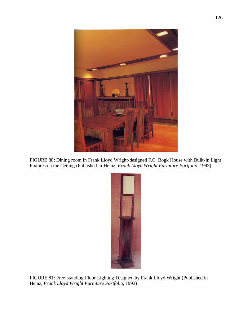
126
FIGURE 80: Dining room in Frank Lloyd Wright-designed F.C. Bogk House with Built- in Light Fixtures on the Ceiling (Published in Heinz, Frank Lloyd Wright Furniture Portfolio, 1993)
FIGURE 81: Free-standing Floor Lighting Designed by Frank Lloyd Wright (Published in Heinz, Frank Lloyd Wright Furniture Portfolio, 1993)
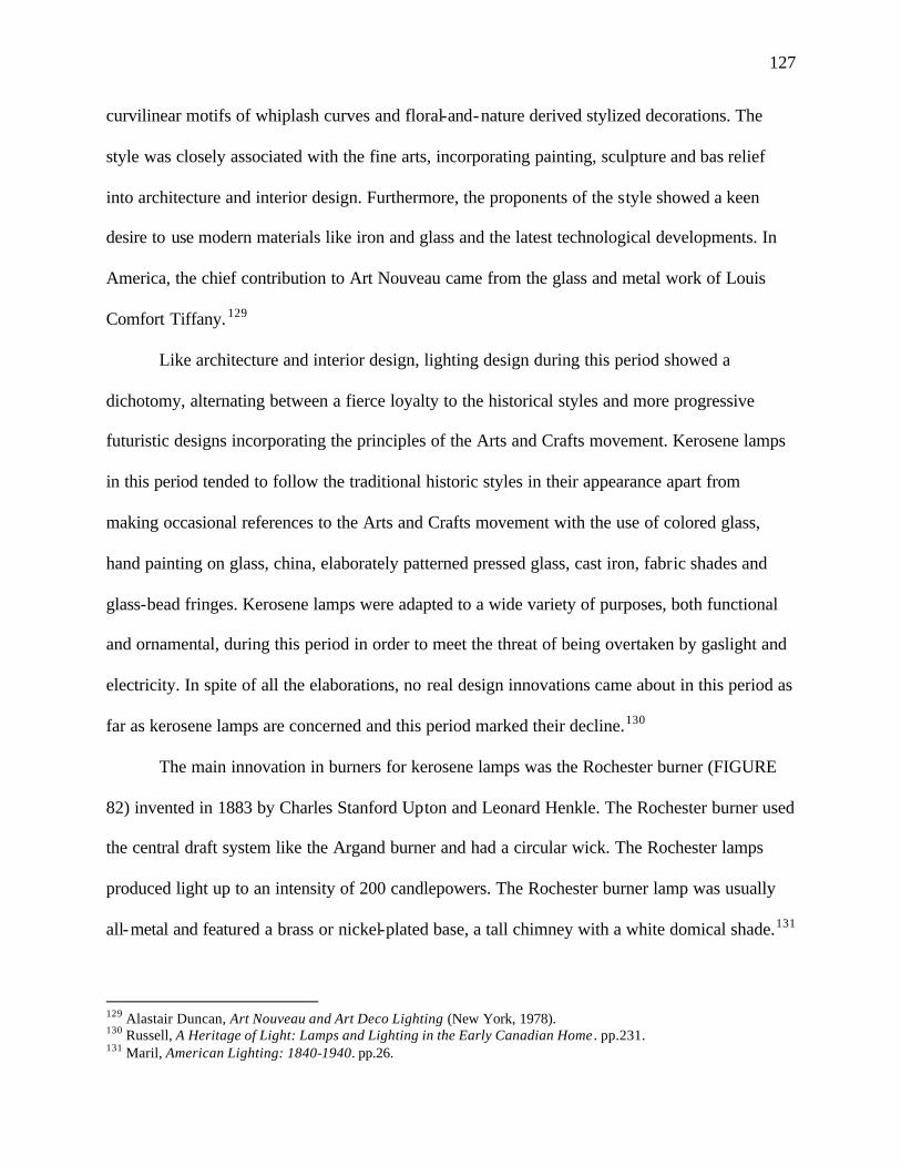
127
curvilinear motifs of whiplash curves and floral-and-nature derived stylized decorations. The
style was closely associated with the fine arts, incorporating painting, sculpture and bas relief
into architecture and interior design. Furthermore, the proponents of the style showed a keen
desire to use modern materials like iron and glass and the latest technological developments. In
America, the chief contribution to Art Nouveau came from the glass and metal work of Louis
Comfort Tiffany. 129
Like architecture and interior design, lighting design during this period showed a
dichotomy, alternating between a fierce loyalty to the historical styles and more progressive
futuristic designs incorporating the principles of the Arts and Crafts movement. Kerosene lamps
in this period tended to follow the traditional historic styles in their appearance apart from
making occasional references to the Arts and Crafts movement with the use of colored glass,
hand painting on glass, china, elaborately patterned pressed glass, cast iron, fabric shades and
glass-bead fringes. Kerosene lamps were adapted to a wide variety of purposes, both functional
and ornamental, during this period in order to meet the threat of being overtaken by gaslight and
electricity. In spite of all the elaborations, no real design innovations came about in this period as
far as kerosene lamps are concerned and this period marked their decline.130
The main innovation in burners for kerosene lamps was the Rochester burner (FIGURE
82) invented in 1883 by Charles Stanford Upton and Leonard Henkle. The Rochester burner used
the central draft system like the Argand burner and had a circular wick. The Rochester lamps
produced light up to an intensity of 200 candlepowers. The Rochester burner lamp was usually
all-metal and featured a brass or nickel-plated base, a tall chimney with a white domical shade.131
129 Alastair Duncan, Art Nouveau and Art Deco Lighting (New York, 1978). 130 Russell, A Heritage of Light: Lamps and Lighting in the Early Canadian Home . pp.231. 131 Maril, American Lighting: 1840-1940. pp.26.
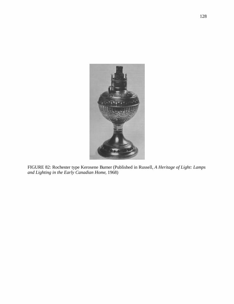
128
FIGURE 82: Rochester type Kerosene Burner (Published in Russell, A Heritage of Light: Lamps and Lighting in the Early Canadian Home, 1968)
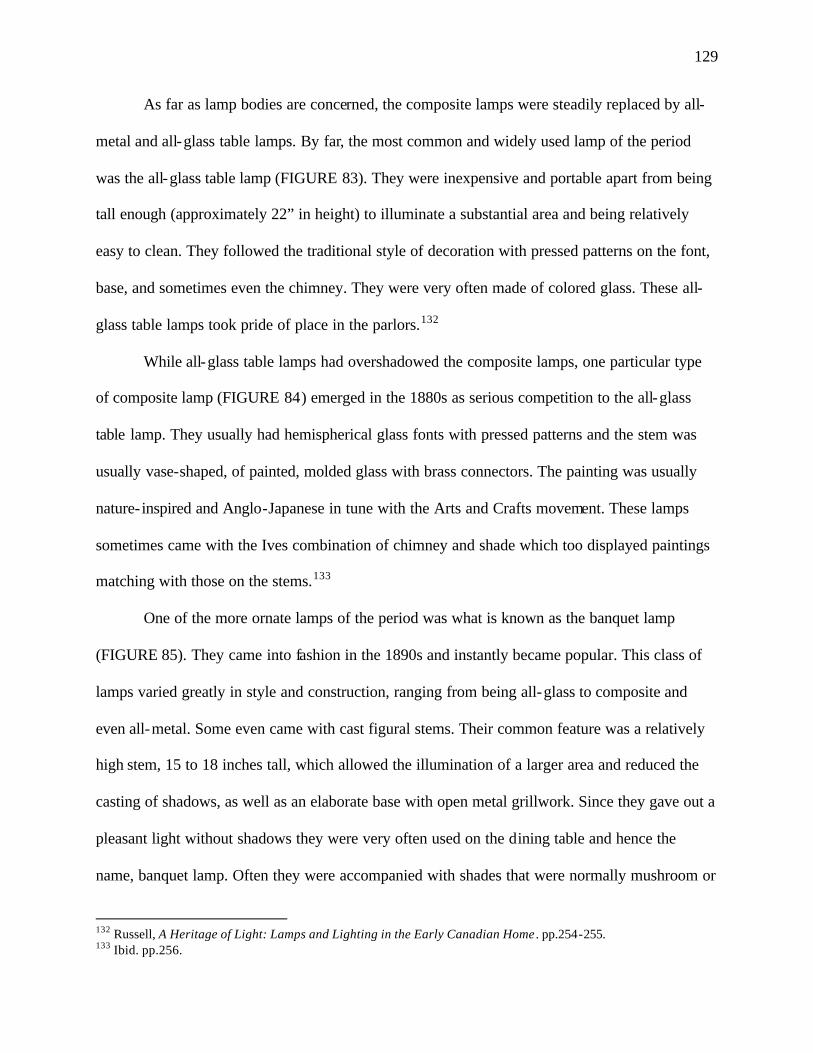
129
As far as lamp bodies are concerned, the composite lamps were steadily replaced by all-
metal and all-glass table lamps. By far, the most common and widely used lamp of the period
was the all-glass table lamp (FIGURE 83). They were inexpensive and portable apart from being
tall enough (approximately 22” in height) to illuminate a substantial area and being relatively
easy to clean. They followed the traditional style of decoration with pressed patterns on the font,
base, and sometimes even the chimney. They were very often made of colored glass. These all-
glass table lamps took pride of place in the parlors.132
While all-glass table lamps had overshadowed the composite lamps, one particular type
of composite lamp (FIGURE 84) emerged in the 1880s as serious competition to the all-glass
table lamp. They usually had hemispherical glass fonts with pressed patterns and the stem was
usually vase-shaped, of painted, molded glass with brass connectors. The painting was usually
nature- inspired and Anglo-Japanese in tune with the Arts and Crafts movement. These lamps
sometimes came with the Ives combination of chimney and shade which too displayed paintings
matching with those on the stems.133
One of the more ornate lamps of the period was what is known as the banquet lamp
(FIGURE 85). They came into fashion in the 1890s and instantly became popular. This class of
lamps varied greatly in style and construction, ranging from being all-glass to composite and
even all-metal. Some even came with cast figural stems. Their common feature was a relatively
high stem, 15 to 18 inches tall, which allowed the illumination of a larger area and reduced the
casting of shadows, as well as an elaborate base with open metal grillwork. Since they gave out a
pleasant light without shadows they were very often used on the dining table and hence the
name, banquet lamp. Often they were accompanied with shades that were normally mushroom or
132 Russell, A Heritage of Light: Lamps and Lighting in the Early Canadian Home . pp.254-255. 133 Ibid. pp.256.
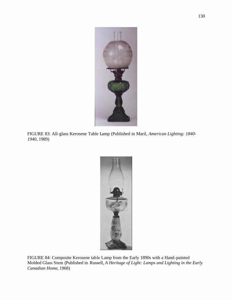
130
FIGURE 83: All-glass Kerosene Table Lamp (Published in Maril, American Lighting: 1840-1940, 1989)
FIGURE 84: Composite Kerosene table Lamp from the Early 1890s with a Hand-painted Molded Glass Stem (Published in Russell, A Heritage of Light: Lamps and Lighting in the Early Canadian Home, 1968)
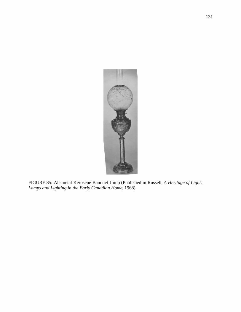
131
FIGURE 85: All-metal Kerosene Banquet Lamp (Published in Russell, A Heritage of Light: Lamps and Lighting in the Early Canadian Home, 1968)
132
ball-shaped of frosted glass or were of paneled slag glass. Shades of banquet lamps were usually
not painted because they were meant to provide light. Apart from banquet lamps, the other tall
and characteristic lamp of the period was the vase lamp (FIGURE 86). Their value was almost
completely aesthetic and they were regarded as status symbols. The vase lamps had elaborate
fonts, which were in reality not the actual fonts in most cases and were called vases. They were
either globular or egg-shaped and were usually made of opaque glass hand-painted with Art
Nouveau themes like flowers, birds and foliage, or scenic designs or of Bristolglass134 or china.
The vase was topped by a domical or hemispherical shade, surrounding the tall, narrow chimney.
The design on the shade usually matched that of the vase. The real font was usually a separate
receptacle called an oil pot and was usually held within the vase. This lamp is also popularly
known as the “Gone-with-the-wind lamp” because of its use in the movie.135
The kerosene student lamps of the earlier decade continued to be popular throughout this
period and on into the twentieth century. While the earlier student lamps had metal shades, the
student lamps of this period came with metal shade holders around seven to ten inches wide in
diameter that held glass shades of broad tulip shape, typical of the Art Nouveau style, in opal or
cased glass. By the 1890s student lamps started taking on ornate forms of cast brass lamps
designed in the style of the Aladdin lamp (FIGURE 87). Student lamps were also produced by
the Tiffany Studios. They had spherical Favrile or leaded glass shades (to be discussed later in
this chapter).136
134 The Bristol glass factory was set up in Bristol, UK in 1651 and by the end of the seventeenth century there were as many as nine glasshouses in Bristol. These glasshouses specialized in the making of mold blown vessels made of semi -opaque and opalescent glass. They were usually opaque white glass decorated in enamel colors or a dark blue glass or to a much less extent green glass. The Bristol glass makers also specialized in gilding and glass-cutting. For more information on Bristol glass refer to: E.M. Elville, The Collector's Dictionary of Glass (London, 1961). pp.28-31. 135 Maril, American Lighting: 1840-1940. pp.30; Russell, A Heritage of Light: Lamps and Lighting in the Early Canadian Home . pp.254-256. 136 Maril, American Lighting: 1840-1940. pp.30; Egon Neustadt, The Lamps of Tiffany (New York, 1970). pp.44.
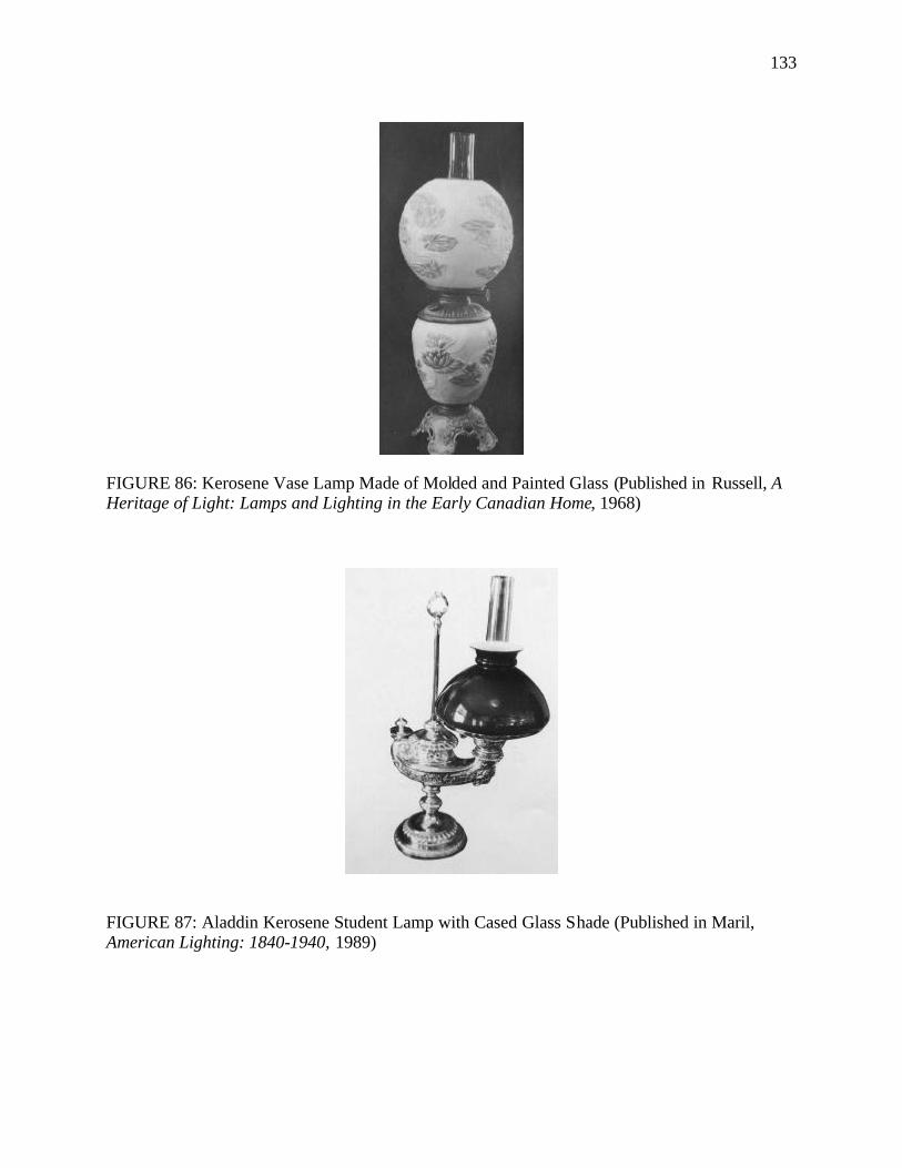
133
FIGURE 86: Kerosene Vase Lamp Made of Molded and Painted Glass (Published in Russell, A Heritage of Light: Lamps and Lighting in the Early Canadian Home, 1968)
FIGURE 87: Aladdin Kerosene Student Lamp with Cased Glass Shade (Published in Maril, American Lighting: 1840-1940, 1989)
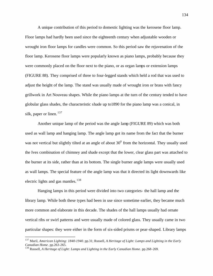
134
A unique contribution of this period to domestic lighting was the kerosene floor lamp.
Floor lamps had hardly been used since the eighteenth century when adjustable wooden or
wrought iron floor lamps for candles were common. So this period saw the rejuvenation of the
floor lamp. Kerosene floor lamps were popularly known as piano lamps, probably because they
were commonly placed on the floor next to the piano, or as organ lamps or extension lamps
(FIGURE 88). They comprised of three to four-legged stands which held a rod that was used to
adjust the height of the lamp. The stand was usually made of wrought iron or brass with fancy
grillwork in Art Nouveau shapes. While the piano lamps at the turn of the century tended to have
globular glass shades, the characteristic shade up to1890 for the piano lamp was a conical, in
silk, paper or linen. 137
Another unique lamp of the period was the angle lamp (FIGURE 89) which was both
used as wall lamp and hanging lamp. The angle lamp got its name from the fact that the burner
was not vertical but slightly tilted at an angle of about 300 from the horizontal. They usually used
the Ives combination of chimney and shade except that the lower, clear glass part was attached to
the burner at its side, rather than at its bottom. The single burner angle lamps were usually used
as wall lamps. The special feature of the angle lamp was that it directed its light downwards like
electric lights and gas mantles.138
Hanging lamps in this period were divided into two categories- the hall lamp and the
library lamp. While both these types had been in use since sometime earlier, they became much
more common and elaborate in this decade. The shades of the hall lamps usually had ornate
vertical ribs or swirl patterns and were usually made of colored glass. They usually came in two
particular shapes: they were either in the form of six-sided prisms or pear-shaped. Library lamps
137 Maril, American Lighting: 1840-1940. pp.31; Russell, A Heritage of Light: Lamps and Lighting in the Early Canadian Home . pp.263-265. 138 Russell, A Heritage of Light: Lamps and Lighting in the Early Canadian Home . pp.268-269.
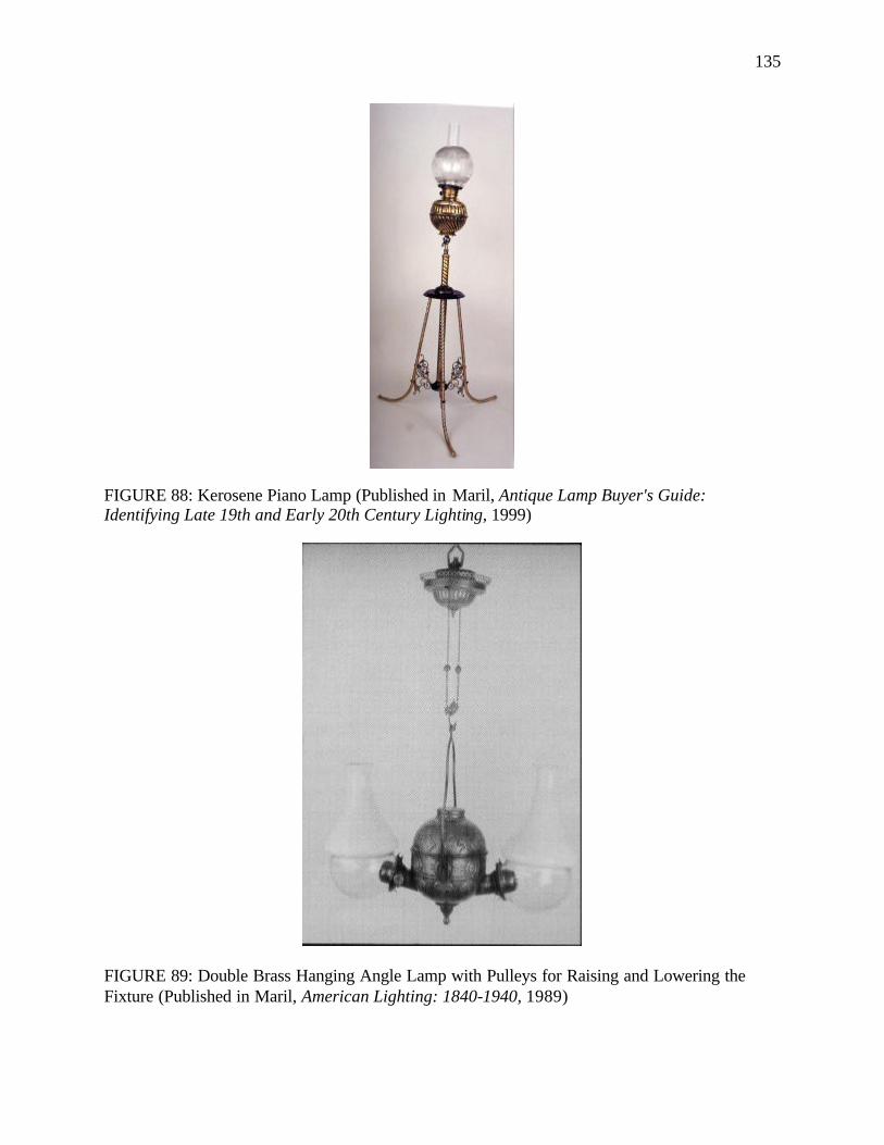
135
FIGURE 88: Kerosene Piano Lamp (Published in Maril, Antique Lamp Buyer's Guide: Identifying Late 19th and Early 20th Century Lighting, 1999)
FIGURE 89: Double Brass Hanging Angle Lamp with Pulleys for Raising and Lowering the Fixture (Published in Maril, American Lighting: 1840-1940, 1989)
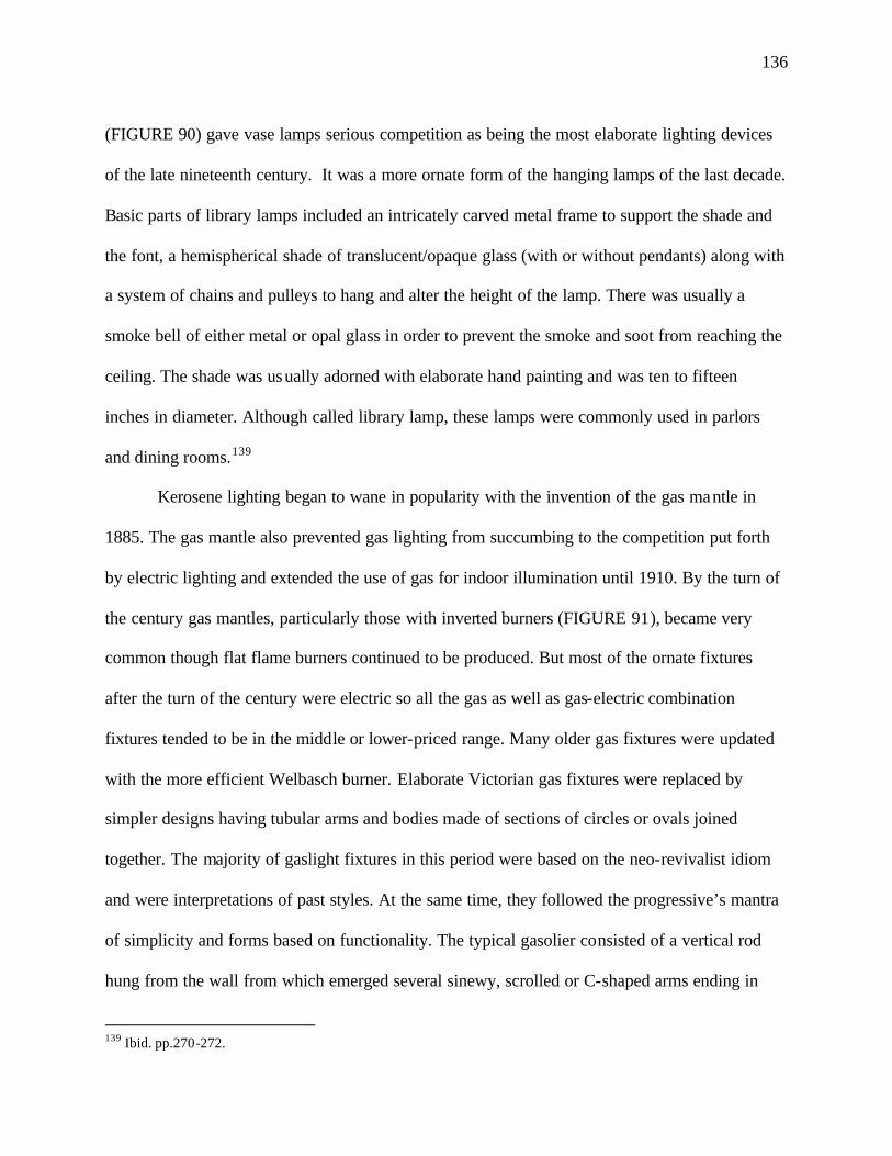
136
(FIGURE 90) gave vase lamps serious competition as being the most elaborate lighting devices
of the late nineteenth century. It was a more ornate form of the hanging lamps of the last decade.
Basic parts of library lamps included an intricately carved metal frame to support the shade and
the font, a hemispherical shade of translucent/opaque glass (with or without pendants) along with
a system of chains and pulleys to hang and alter the height of the lamp. There was usually a
smoke bell of either metal or opal glass in order to prevent the smoke and soot from reaching the
ceiling. The shade was usually adorned with elaborate hand painting and was ten to fifteen
inches in diameter. Although called library lamp, these lamps were commonly used in parlors
and dining rooms.139
Kerosene lighting began to wane in popularity with the invention of the gas mantle in
1885. The gas mantle also prevented gas lighting from succumbing to the competition put forth
by electric lighting and extended the use of gas for indoor illumination until 1910. By the turn of
the century gas mantles, particularly those with inverted burners (FIGURE 91), became very
common though flat flame burners continued to be produced. But most of the ornate fixtures
after the turn of the century were electric so all the gas as well as gas-electric combination
fixtures tended to be in the middle or lower-priced range. Many older gas fixtures were updated
with the more efficient Welbasch burner. Elaborate Victorian gas fixtures were replaced by
simpler designs having tubular arms and bodies made of sections of circles or ovals joined
together. The majority of gaslight fixtures in this period were based on the neo-revivalist idiom
and were interpretations of past styles. At the same time, they followed the progressive’s mantra
of simplicity and forms based on functionality. The typical gasolier consisted of a vertical rod
hung from the wall from which emerged several sinewy, scrolled or C-shaped arms ending in
139 Ibid. pp.270-272.
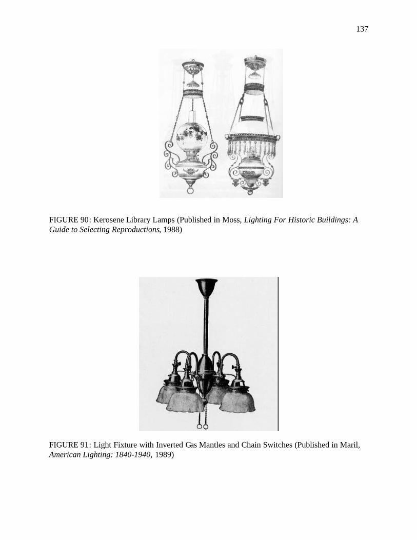
137
FIGURE 90: Kerosene Library Lamps (Published in Moss, Lighting For Historic Buildings: A Guide to Selecting Reproductions, 1988)
FIGURE 91: Light Fixture with Inverted Gas Mantles and Chain Switches (Published in Maril, American Lighting: 1840-1940, 1989)
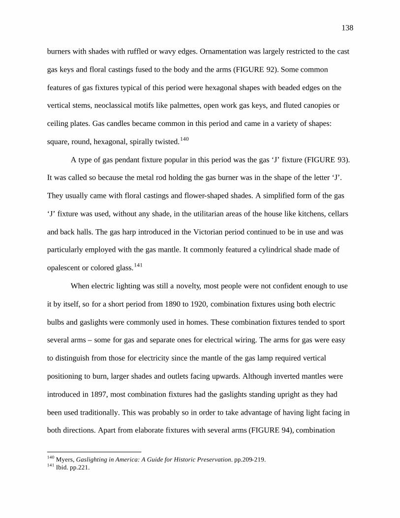
138
burners with shades with ruffled or wavy edges. Ornamentation was largely restricted to the cast
gas keys and floral castings fused to the body and the arms (FIGURE 92). Some common
features of gas fixtures typical of this period were hexagonal shapes with beaded edges on the
vertical stems, neoclassical motifs like palmettes, open work gas keys, and fluted canopies or
ceiling plates. Gas candles became common in this period and came in a variety of shapes:
square, round, hexagonal, spirally twisted.140
A type of gas pendant fixture popular in this period was the gas ‘J’ fixture (FIGURE 93).
It was called so because the metal rod holding the gas burner was in the shape of the letter ‘J’.
They usually came with floral castings and flower-shaped shades. A simplified form of the gas
‘J’ fixture was used, without any shade, in the utilitarian areas of the house like kitchens, cellars
and back halls. The gas harp introduced in the Victorian period continued to be in use and was
particularly employed with the gas mantle. It commonly featured a cylindrical shade made of
opalescent or colored glass.141
When electric lighting was still a novelty, most people were not confident enough to use
it by itself, so for a short period from 1890 to 1920, combination fixtures using both electric
bulbs and gaslights were commonly used in homes. These combination fixtures tended to sport
several arms – some for gas and separate ones for electrical wiring. The arms for gas were easy
to distinguish from those for electricity since the mantle of the gas lamp required vertical
positioning to burn, larger shades and outlets facing upwards. Although inverted mantles were
introduced in 1897, most combination fixtures had the gaslights standing upright as they had
been used traditionally. This was probably so in order to take advantage of having light facing in
both directions. Apart from elaborate fixtures with several arms (FIGURE 94), combination
140 Myers, Gaslighting in America: A Guide for Historic Preservation. pp.209-219. 141 Ibid. pp.221.
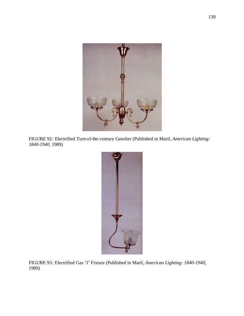
139
FIGURE 92: Electrified Turn-of-the-century Gasolier (Published in Maril, American Lighting: 1840-1940, 1989)
FIGURE 93: Electrified Gas ‘J’ Fixture (Published in Maril, American Lighting: 1840-1940, 1989)
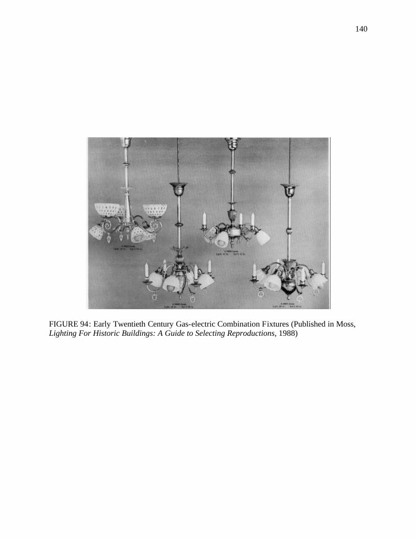
140
FIGURE 94: Early Twentieth Century Gas-electric Combination Fixtures (Published in Moss, Lighting For Historic Buildings: A Guide to Selecting Reproductions, 1988)
141
fixtures also came in the form of pendant fittings and gas-electric hall lights (FIGURE 95).
Several of the combination fixtures had gas jets shaped as candles rather than gas burners with
elaborate shades. In combination fixtures that used gas candles the gas was usually the secondary
source of light, used only for emergency purposes.142
As electric lighting was considered a great novelty in its early days, several of the early
fixtures came with no shades, exposing the bulb and celebrating the new technology. The few
that had shades were such that the bulbs were kept visible. The electric wiring was also
considered a novel concept in the early days and many designers felt that the bare bulb and
exposed wire should be enough for the proper aesthetic display of lighting. The wires were
weaved through chains as chain-hung light fixtures rose to preponderance around 1915 when the
cloth covered electric wire was perfected. The chains often supported single exposed light bulbs
which were sometimes accompanied with crimped opal glass shades very popular in this period
(FIGURE 96). Apart for aesthetic reasons, it was also practical to leave bulbs exposed as the
early carbon-filament bulbs offered light of low wattage (approximately nine watts), and hence it
was more efficient to use the bulbs without shades.143
Even when shades were used on early electric fixtures their purpose was to augment the
light of the bulb. One such popular shade common at the turn of the century was the Holophane
shade manufactured by the Holophane Lighting Corporation. These were crystal prismatic
shades designed to increase illumination (FIGURE 97). Their usage declined once higher
wattage tungsten filament lamps came into use in 1907. After 1907, the shades used became
increasingly opalescent to diffuse the harsh, shadow-producing light of the early unfrosted
142 Maril, American Lighting: 1840-1940. pp.51; Moss, Lighting For Historic Buildings: A Guide to Selecting Reproductions. pp.127. 143 Dillon, Artificial Sunshine: A Social History of Domestic Lighting. pp.191; Maril, American Lighting: 1840-1940. pp.89.
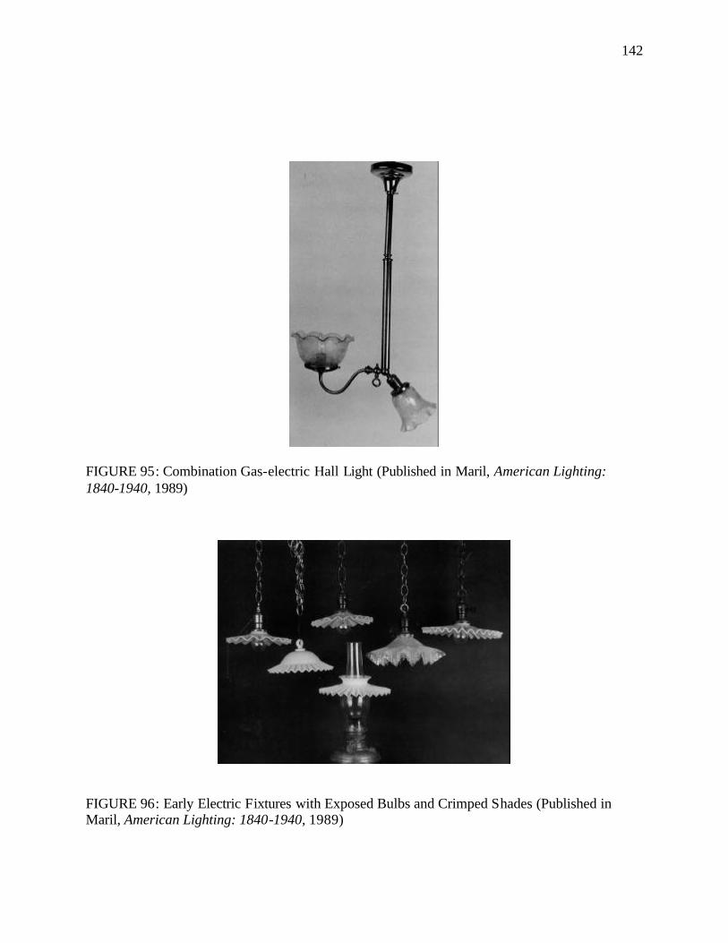
142
FIGURE 95: Combination Gas-electric Hall Light (Published in Maril, American Lighting: 1840-1940, 1989)
FIGURE 96: Early Electric Fixtures with Exposed Bulbs and Crimped Shades (Published in Maril, American Lighting: 1840-1940, 1989)
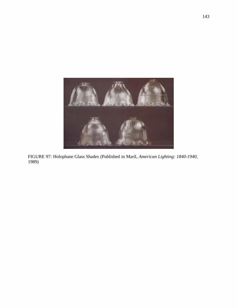
143
FIGURE 97: Holophane Glass Shades (Published in Maril, American Lighting: 1840-1940, 1989)
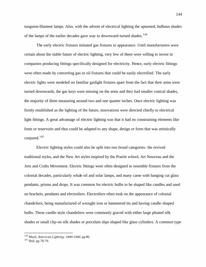
144
tungsten-filament lamps. Also, with the advent of electrical lighting the upturned, bulbous shades
of the lamps of the earlier decades gave way to downward-turned shades.144
The early electric fixtures imitated gas fixtures in appearance. Until manufacturers were
certain about the stable future of electric lighting, very few of them were willing to invest in
companies producing fittings specifically designed for electricity. Hence, early electric fittings
were often made by converting gas or oil fixtures that could be easily electrified. The early
electric lights were modeled on familiar gaslight fixtures apart from the fact that their arms were
turned downwards, the gas keys were missing on the arms and they had smaller conical shades,
the majority of them measuring around two and one quarter inches. Once electric lighting was
firmly established as the lighting of the future, innovations were directed chiefly to electrical
light fittings. A great advantage of electric lighting was that it had no constraining elements like
fonts or reservoirs and thus could be adapted to any shape, design or form that was artistically
conjured.145
Electric lighting styles could also be split into two broad categories- the revived
traditional styles, and the New Art styles inspired by the Prairie school, Art Nouveau and the
Arts and Crafts Movement. Electric fittings were often designed to resemble fixtures from the
colonial decades, particularly whale oil and solar lamps, and many came with hanging cut glass
pendants, prisms and drops. It was common for electric bulbs to be shaped like candles and used
on brackets, pendants and electroliers. Electroliers often took on the appearance of colonial
chandeliers, being manufactured of wrought iron or hammered tin and having candle-shaped
bulbs. These candle-style chandeliers were commonly graced with either large pleated silk
shades or small clip-on silk shades or porcelain slips shaped like glass cylinders. A common type
144 Maril, American Lighting: 1840-1940. pp.86. 145 Ibid. pp.78-79.
145
of early electric fixture in the spirit of the colonial revival was the pan fixture (FIGURE 98). Pan
electric fixtures were usually hung from chains and comprised of two brass plates facing each
other from which were attached the arms ending in shade bells with their conical or flower-
shaped shades. Similar to the pan fixture was the shower fixture (FIGURE 99) which was
comprised of a large brass canopy or pan mounted on the ceiling from which hung chains
supporting the shade bells and shades. The shades used with these fixtures were Holophane
shades, satin glass shades, frosted, acid-etched, raise-molded or hand painted. Many shades used
during this period had frilly, ruffled edges but the majority were simply conical. 146
Another type of electric light fixture common during this period was the electric lighting
bowl. These were hanging ceiling fixtures which comprised of inverted translucent white
opalescent glass or alabaster domes shaped like bowls. By using translucent bowls, these fixtures
projected light in two ways, casting some light down indirectly through the bowl and reflecting
the rest off the ceiling. The bowls were at times painted with natural scenes or had designs
stenciled on them for added effect. Also at times bowl fixtures were combined with shower
fixtures or more infrequently with candle lamps (FIGURE 100).
In keeping with the trend of the Arts and Crafts Movement, Mission style electric light
fixtures (FIGURE 101) were also produced. Inspired by the austerely straight lines forming
squares and rectangles of the Mission oak furniture, Mission style light fixtures often used square
metal tubing, and geometric shades. Rectilinear wooden posts and square oak bases holding
stained glass shades became a common sight. Boxy shades, in basic shapes, made of wood or
hammered metal and slag glass147 of various shades, were hung from heavy chains and tubes.
146 Ibid. pp.77-78, 142-143,; Moss, Lighting For Historic Buildings: A Guide to Selecting Reproductions. pp.127. 147 Slag glass is a collectors' name for opaque pressed glass with coloured streaks, usually white and/or cream streaks. Slag glass is commonly found in purple, less common in blue and brown and green.
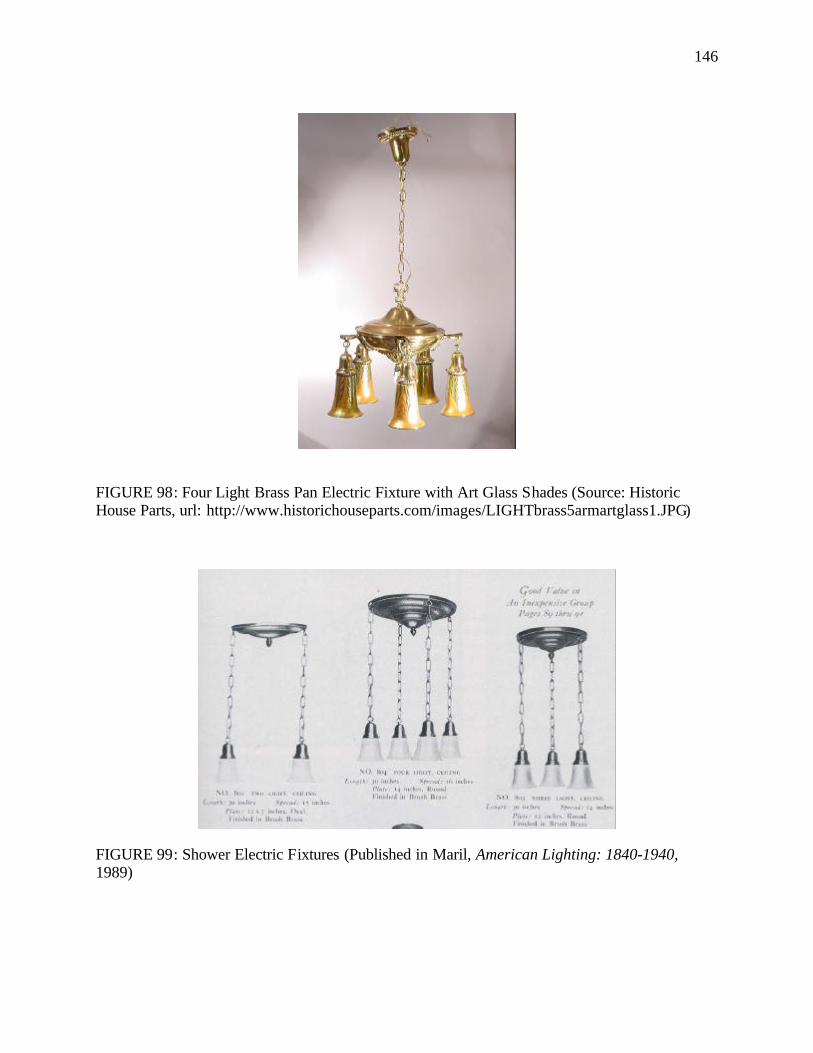
146
FIGURE 98: Four Light Brass Pan Electric Fixture with Art Glass Shades (Source: Historic House Parts, url: http://www.historichouseparts.com/images/LIGHTbrass5armartglass1.JPG)
FIGURE 99: Shower Electric Fixtures (Published in Maril, American Lighting: 1840-1940, 1989)
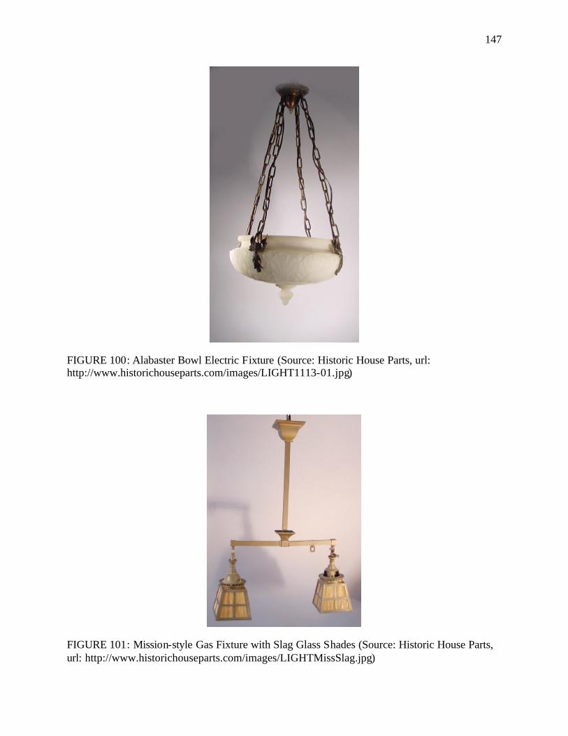
147
FIGURE 100: Alabaster Bowl Electric Fixture (Source: Historic House Parts, url: http://www.historichouseparts.com/images/LIGHT1113-01.jpg)
FIGURE 101: Mission-style Gas Fixture with Slag Glass Shades (Source: Historic House Parts, url: http://www.historichouseparts.com/images/LIGHTMissSlag.jpg)
148
The common metals used on these Mission-style fixtures were wrought iron or hammered copper
or brass. A well-known San Francisco-based, Mission- style lamp designer from 1910 to 1930
was Dirk Van Erp. Van Erp had emigrated from Holland and settled in San Francisco where he
started hammering vases from discarded brass military shell casings. By 1910, he had opened a
store where he sold exquisitely designed table lamps having mushroom-shaped hammered
copper bases and translucent shades produced from mica (FIGURE 102). At its peak, Van Erp's
shop was staffed only by his son and daughter, plus two metalsmiths, Harry Dixon and August
Tiesselinck, each of whom later established a shop of his own. Production at the Van Erp shop
was extremely low as Van Erp insisted on using only the highest quality materials and a few
simple hand tools. The other main manufacturer of Mission-style copper lamps was the Roycroft
Copper Shop in East Aurora, New York, founded in 1895 by Elbert Hubbard. Copper proved to
be a logical and popular choice of Mission-style light fixtures for three main reasons. Firstly, it
was highly malleable and was able to assume many shapes. Secondly, it was affordable, making
it available to a larger number of consumers. In addition, copper could be treated chemically to
produce an immediately pleasing patina ranging from reddish brown to nearly black. After each
copper lamp had been hammered into the desired shape, the craftsman would dip it into a
chemical solution. The dark patina produced imitated the look of metal wares from earlier
periods. This effect was in keeping with the Arts and Crafts philosophy of looking to the
craftsmen of the past for inspiration. 148
The Art Nouveau, which seized the American design industry from 1890 to 1920, also
left a profound impression on lighting styles. The discovery of the electric bulb gave the Art
148 Maril, American Lighting: 1840-1940. pp.51, 55.
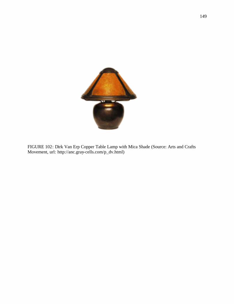
149
FIGURE 102: Dirk Van Erp Copper Table Lamp with Mica Shade (Source: Arts and Crafts Movement, url: http://anc.gray-cells.com/p_dv.html)
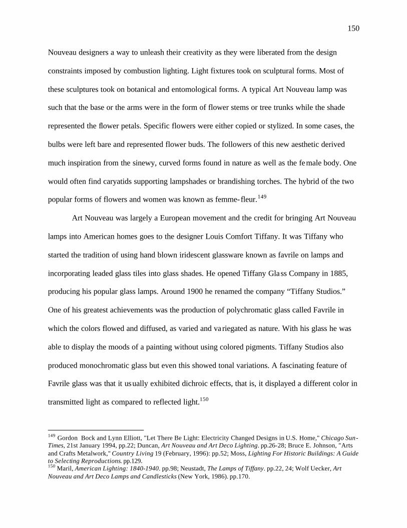
150
Nouveau designers a way to unleash their creativity as they were liberated from the design
constraints imposed by combustion lighting. Light fixtures took on sculptural forms. Most of
these sculptures took on botanical and entomological forms. A typical Art Nouveau lamp was
such that the base or the arms were in the form of flower stems or tree trunks while the shade
represented the flower petals. Specific flowers were either copied or stylized. In some cases, the
bulbs were left bare and represented flower buds. The followers of this new aesthetic derived
much inspiration from the sinewy, curved forms found in nature as well as the female body. One
would often find caryatids supporting lampshades or brandishing torches. The hybrid of the two
popular forms of flowers and women was known as femme-fleur.149
Art Nouveau was largely a European movement and the credit for bringing Art Nouveau
lamps into American homes goes to the designer Louis Comfort Tiffany. It was Tiffany who
started the tradition of using hand blown iridescent glassware known as favrile on lamps and
incorporating leaded glass tiles into glass shades. He opened Tiffany Glass Company in 1885,
producing his popular glass lamps. Around 1900 he renamed the company “Tiffany Studios.”
One of his greatest achievements was the production of polychromatic glass called Favrile in
which the colors flowed and diffused, as varied and va riegated as nature. With his glass he was
able to display the moods of a painting without using colored pigments. Tiffany Studios also
produced monochromatic glass but even this showed tonal variations. A fascinating feature of
Favrile glass was that it usually exhibited dichroic effects, that is, it displayed a different color in
transmitted light as compared to reflected light.150
149 Gordon Bock and Lynn Elliott, "Let There Be Light: Electricity Changed Designs in U.S. Home," Chicago Sun-Times, 21st January 1994, pp.22; Duncan, Art Nouveau and Art Deco Lighting. pp.26-28; Bruce E. Johnson, "Arts and Crafts Metalwork," Country Living 19 (February, 1996): pp.52; Moss, Lighting For Historic Buildings: A Guide to Selecting Reproductions. pp.129. 150 Maril, American Lighting: 1840-1940. pp.98; Neustadt, The Lamps of Tiffany. pp.22, 24; Wolf Uecker, Art Nouveau and Art Deco Lamps and Candlesticks (New York, 1986). pp.170.
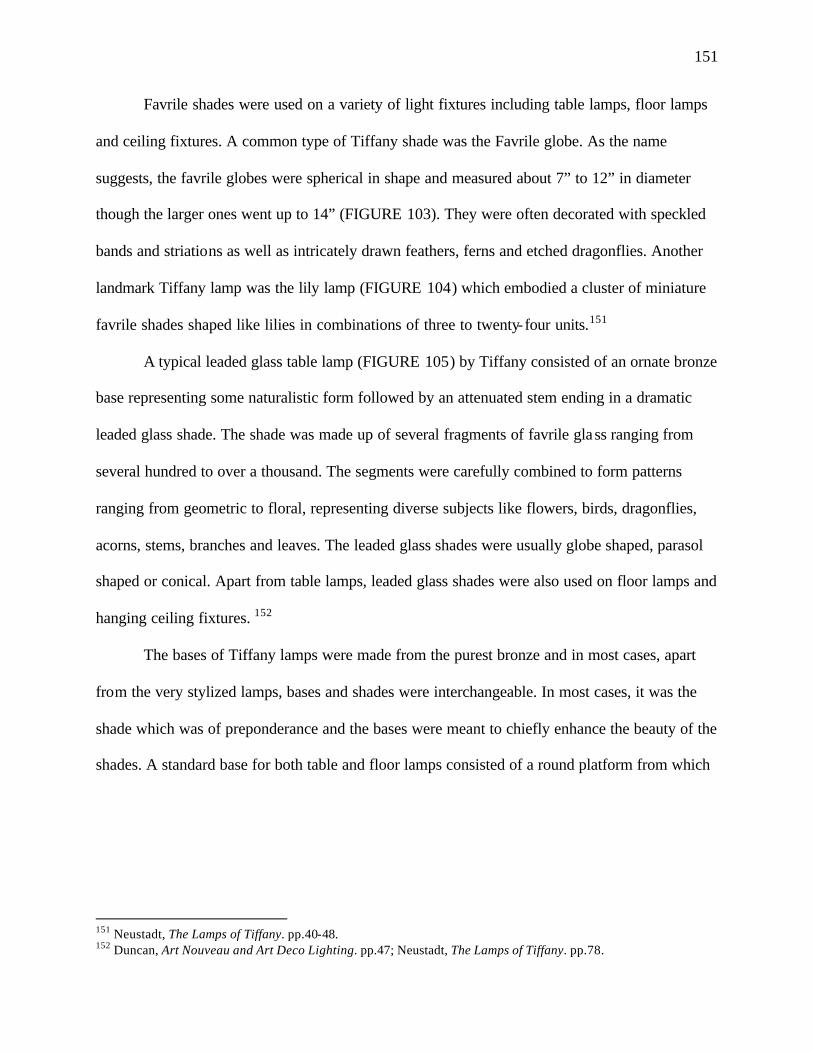
151
Favrile shades were used on a variety of light fixtures including table lamps, floor lamps
and ceiling fixtures. A common type of Tiffany shade was the Favrile globe. As the name
suggests, the favrile globes were spherical in shape and measured about 7” to 12” in diameter
though the larger ones went up to 14” (FIGURE 103). They were often decorated with speckled
bands and striations as well as intricately drawn feathers, ferns and etched dragonflies. Another
landmark Tiffany lamp was the lily lamp (FIGURE 104) which embodied a cluster of miniature
favrile shades shaped like lilies in combinations of three to twenty-four units.151
A typical leaded glass table lamp (FIGURE 105) by Tiffany consisted of an ornate bronze
base representing some naturalistic form followed by an attenuated stem ending in a dramatic
leaded glass shade. The shade was made up of several fragments of favrile glass ranging from
several hundred to over a thousand. The segments were carefully combined to form patterns
ranging from geometric to floral, representing diverse subjects like flowers, birds, dragonflies,
acorns, stems, branches and leaves. The leaded glass shades were usually globe shaped, parasol
shaped or conical. Apart from table lamps, leaded glass shades were also used on floor lamps and
hanging ceiling fixtures. 152
The bases of Tiffany lamps were made from the purest bronze and in most cases, apart
from the very stylized lamps, bases and shades were interchangeable. In most cases, it was the
shade which was of preponderance and the bases were meant to chiefly enhance the beauty of the
shades. A standard base for both table and floor lamps consisted of a round platform from which
151 Neustadt, The Lamps of Tiffany. pp.40-48. 152 Duncan, Art Nouveau and Art Deco Lighting. pp.47; Neustadt, The Lamps of Tiffany. pp.78.
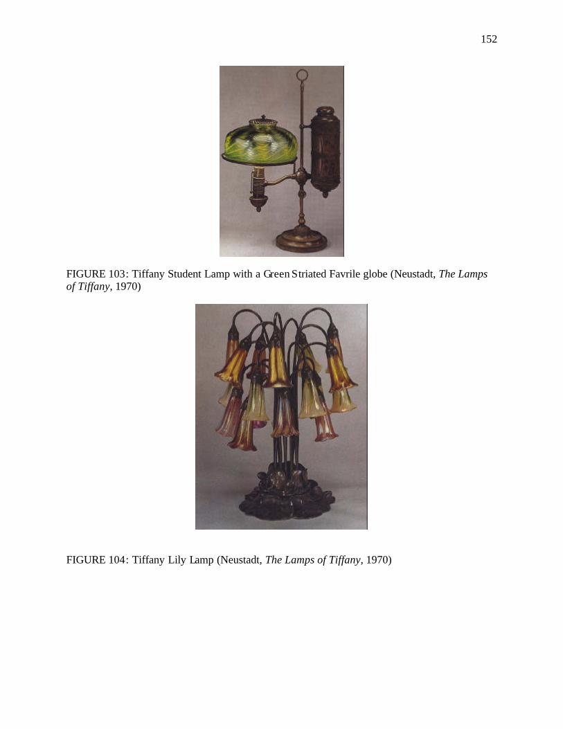
152
FIGURE 103: Tiffany Student Lamp with a Green Striated Favrile globe (Neustadt, The Lamps of Tiffany, 1970)
FIGURE 104: Tiffany Lily Lamp (Neustadt, The Lamps of Tiffany, 1970)
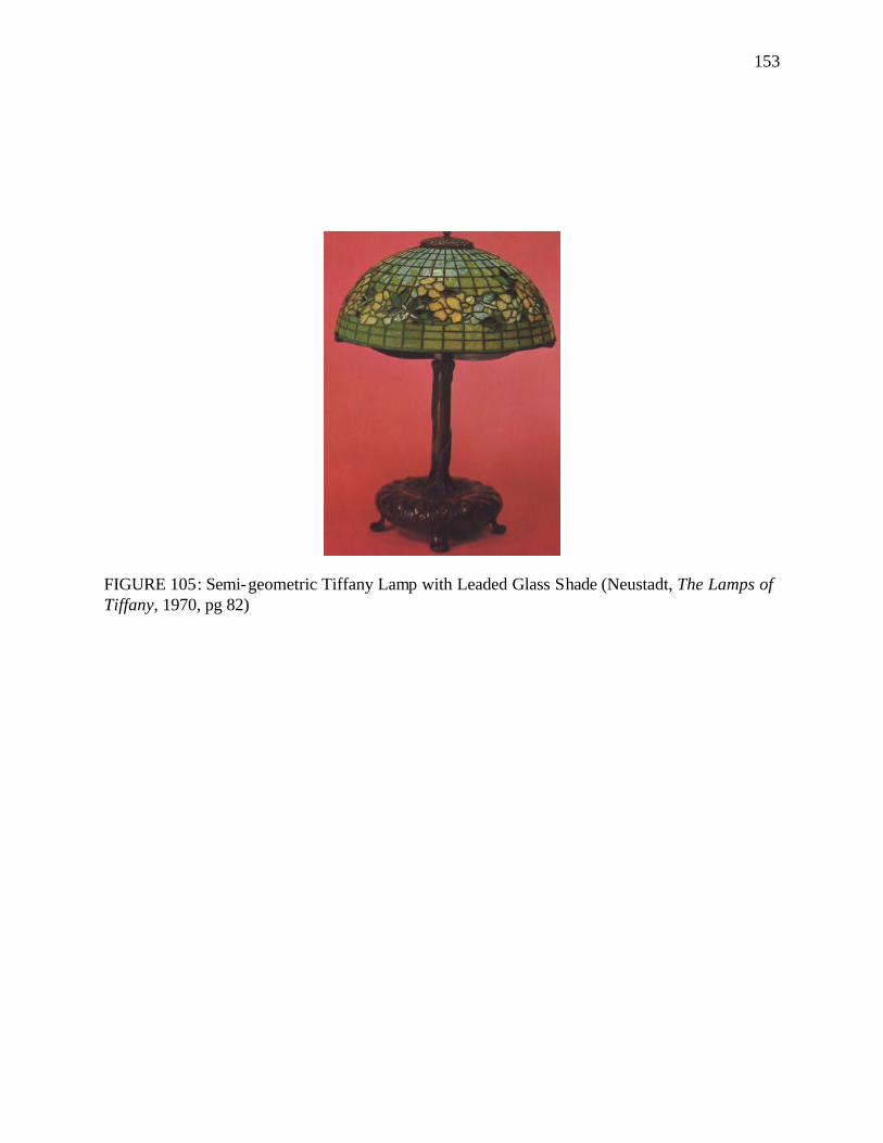
153
FIGURE 105: Semi-geometric Tiffany Lamp with Leaded Glass Shade (Neustadt, The Lamps of Tiffany, 1970, pg 82)
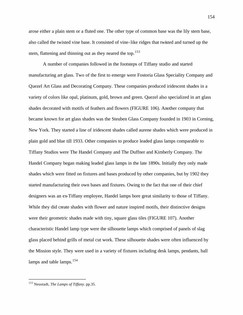
154
arose either a plain stem or a fluted one. The other type of common base was the lily stem base,
also called the twisted vine base. It consisted of vine- like ridges that twisted and turned up the
stem, flattening and thinning out as they neared the top.153
A number of companies followed in the footsteps of Tiffany studio and started
manufacturing art glass. Two of the first to emerge were Fostoria Glass Speciality Company and
Quezel Art Glass and Decorating Company. These companies produced iridescent shades in a
variety of colors like opal, platinum, gold, brown and green. Quezel also specialized in art glass
shades decorated with motifs of feathers and flowers (FIGURE 106). Another company that
became known for art glass shades was the Steuben Glass Company founded in 1903 in Corning,
New York. They started a line of iridescent shades called aurene shades which were produced in
plain gold and blue till 1933. Other companies to produce leaded glass lamps comparable to
Tiffany Studios were The Handel Company and The Duffner and Kimberly Company. The
Handel Company began making leaded glass lamps in the late 1890s. Initially they only made
shades which were fitted on fixtures and bases produced by other companies, but by 1902 they
started manufacturing their own bases and fixtures. Owing to the fact that one of their chief
designers was an ex-Tiffany employee, Handel lamps bore great similarity to those of Tiffany.
While they did create shades with flower and nature inspired motifs, their distinctive designs
were their geometric shades made with tiny, square glass tiles (FIGURE 107). Another
characteristic Handel lamp type were the silhouette lamps which comprised of panels of slag
glass placed behind grills of metal cut work. These silhouette shades were often influenced by
the Mission style. They were used in a variety of fixtures including desk lamps, pendants, hall
lamps and table lamps.154
153 Neustadt, The Lamps of Tiffany. pp.35.
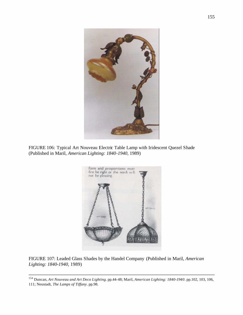
155
FIGURE 106: Typical Art Nouveau Electric Table Lamp with Iridescent Quezel Shade (Published in Maril, American Lighting: 1840-1940, 1989)
FIGURE 107: Leaded Glass Shades by the Handel Company (Published in Maril, American Lighting: 1840-1940, 1989)
154 Duncan, Art Nouveau and Art Deco Lighting. pp.44-48; Maril, American Lighting: 1840-1940. pp.102, 103, 106, 111; Neustadt, The Lamps of Tiffany. pp.98.
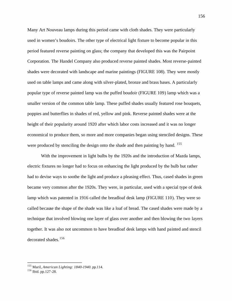
156
Many Art Nouveau lamps during this period came with cloth shades. They were particularly
used in women’s boudoirs. The other type of electrical light fixture to become popular in this
period featured reverse painting on glass; the company that developed this was the Pairpoint
Corporation. The Handel Company also produced reverse painted shades. Most reverse-painted
shades were decorated with landscape and marine paintings (FIGURE 108). They were mostly
used on table lamps and came along with silver-plated, bronze and brass bases. A particularly
popular type of reverse painted lamp was the puffed boudoir (FIGURE 109) lamp which was a
smaller version of the common table lamp. These puffed shades usually featured rose bouquets,
poppies and butterflies in shades of red, yellow and pink. Reverse painted shades were at the
height of their popularity around 1920 after which labor costs increased and it was no longer
economical to produce them, so more and more companies began using stenciled designs. These
were produced by stenciling the design onto the shade and then painting by hand. 155
With the improvement in light bulbs by the 1920s and the introduction of Mazda lamps,
electric fixtures no longer had to focus on enhancing the light produced by the bulb but rather
had to devise ways to soothe the light and produce a pleasing effect. Thus, cased shades in green
became very common after the 1920s. They were, in particular, used with a special type of desk
lamp which was patented in 1916 called the breadloaf desk lamp (FIGURE 110). They were so
called because the shape of the shade was like a loaf of bread. The cased shades were made by a
technique that involved blowing one layer of glass over another and then blowing the two layers
together. It was also not uncommon to have breadloaf desk lamps with hand painted and stencil
decorated shades.156
155 Maril, American Lighting: 1840-1940. pp.114. 156 Ibid. pp.127-28.
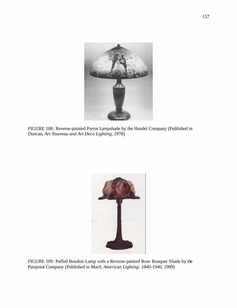
157
FIGURE 108: Reverse-painted Parrot Lampshade by the Handel Company (Published in Duncan, Art Nouveau and Art Deco Lighting, 1978)
FIGURE 109: Puffed Boudoir Lamp with a Reverse-painted Rose Bouquet Shade by the Pairpoint Company (Published in Maril, American Lighting: 1840-1940, 1989)
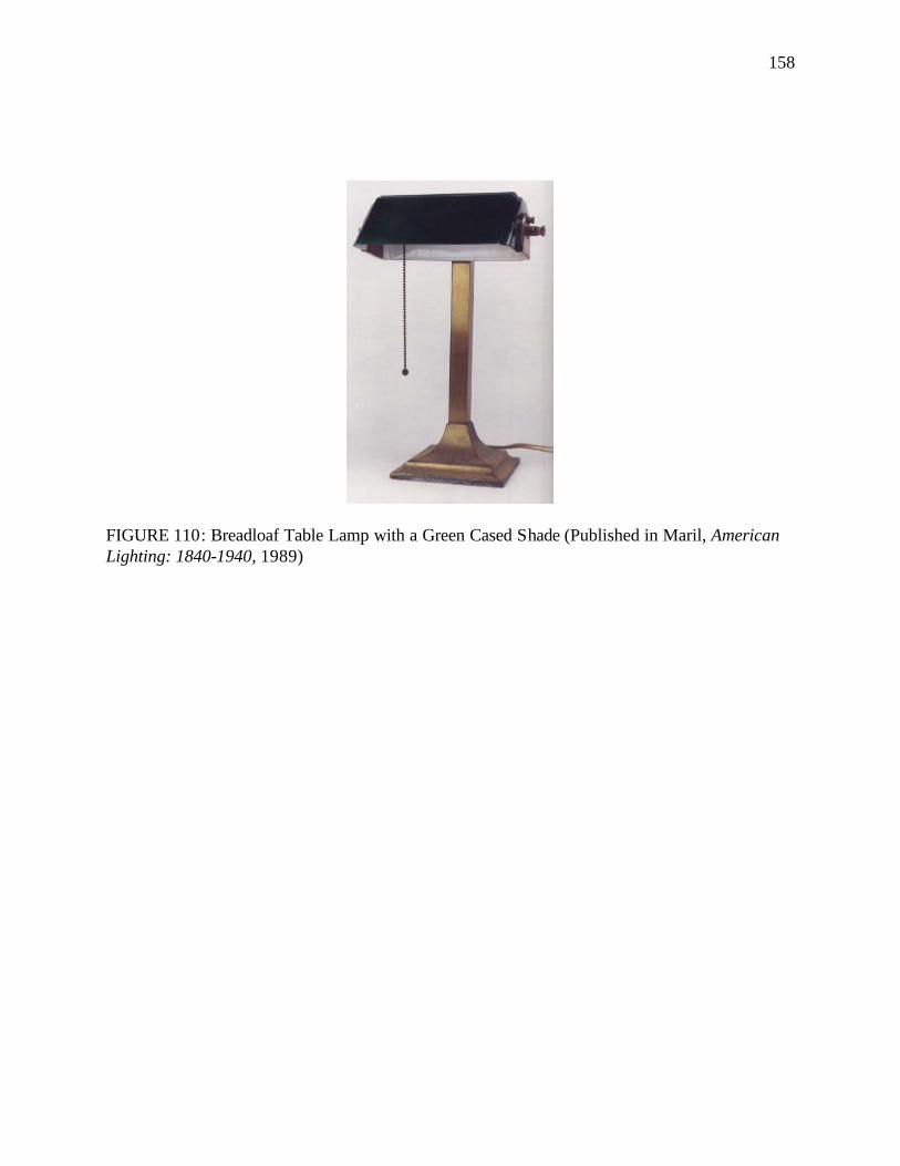
158
FIGURE 110: Breadloaf Table Lamp with a Green Cased Shade (Published in Maril, American Lighting: 1840-1940, 1989)
159
CHAPTER IV
LIGHTING OF HISTORIC HOUSE MUSEUMS
Arriving at an appropriate lighting plan for a historic house museum causes much tension
and pulls designers in opposite directions due to the unharmonious relationship that exists
between modern expectations for light in an exhibition space and the historic character and
ambience that a house should project. Unlike the control of other environmental factors like
temperature, air pollution, relative humidity, the issue of lighting a historic house museum is not
just technical but also conceptual. Light is expected to play multiple roles in a house museum
where it not only aids in the viewing of collections and interiors but is also an integral part of the
interpretive plan of the museum - giving the house its period appearance, conveying to viewers
the lighting conditions of the times, and the way the inhabitants lived. Apart from its purely
functional and interpretive roles, light in a museum is also an instrument of deterioration for
which the lighting designers must take corrective and preventive measures. To prepare an
effective lighting plan one must take into account light’s various conflicting roles and come up
with a delicate balancing act. Very broadly, the deliverables of a lighting plan should include: a
list of all the light fixtures within the museum along with a brief note on the justification for the
fixture’s inclusion; a description of their location along with a catalog description of each item in
a room; their relationship to the museum’s interpretation as well as an operational and
maintenance program. The plan must be supported by appropriate drawings which would include
a ceiling plan to show the lighting arrangement of the ceiling as well as longitudinal and
transverse sections drawn to scale. These architectural drawings should clearly indicate each
lighting fixture to be used along with projections showing the reach of the light produced and the
160
objects it illuminates. These drawing will help create an image of what the lighting will look like
and will greatly aid the electrician during the installation process. Each house must be treated on
an individual basis with its own set of issues as there is no one-size-fits-all solution to the
lighting problem. An important point to bear in mind is that prior to designing the lighting of a
house museum the site’s overall interpretive goal has to be clearly set and the furniture placed
according to the interpretation plan. The interpretive plan must be the framework around which
all other plans fit. The interpretive plan must indicate an interpretive period, a theme (or a couple
of themes) on which to base the interpretation, the objects of prime importance in the house’s
collection, and methods and techniques to be employed in order to aid in the interpretation
process. The lighting plan must be guided by the interpretive plan and the objective of the
lighting plan must be to support the interpretive plan. 157 This chapter will deal with some of the
major issues to be considered when planning the lighting of a historic house museum.
Participants
It must always be kept in mind that the lighting of a house is not a solitary element, but a
part of a much larger picture which is the house, the landscaping, the furnishing, the artifacts, the
people who have lived there, and the stories it has experienced. The lighting plan must bring out
and enhance the relationship between all these elements and help in the successful interpretation
of the house’s history. Hence, the decision-making process and the execution of a lighting
scheme in a house museum must have the sustained participation of a range of professionals
working as a team. At the core of the team would be the lighting designer, lighting engineer, art
157 Jessica Foy Donnelly, Interpreting Historic House Museums (Walnut Creek, CA, 2002). pp.133-134; Edwin P. Rambusch and Martin V. Rambusch, "Creating Effective Lighting Systems for Historic Houses of Worship", available from http://www.sacredplaces.org/PSP-InfoClearingHouse/articles/CREATING%20EFFECTIVE%20LIGHTING%20SYSTEMS%20FOR%20HISTORIC%20HOUSES%20OF%20WO.htm.
161
conservator, historian and historic preservationist. Historians would contribute their knowledge
of historical light fixtures and light levels as well as the results of historical research. They would
also share their knowledge of the individual objects of art on exhibit in the house, the important
architectural features and their importance in the interpretation. Conservators would play an
important role in the restoration process of existing light fixtures and would address the needs
and susceptibilities of the individual collection materials. Lighting designers would be aware of
the availability and use of various light fixtures, their characteristics and maintenance regime.
Lighting engineers would guide the rewiring process, design of the electrical delivery systems,
their setting up and the reviewing of safety issues. Preservationist mus t ensure that work is
carried out according to professional standards and pays due respect to the historic fabric of the
building. 158
These core members must consult with other groups of professions as well. Structural
engineers must be consulted before considering any structural alterations to accommodate
electrical wires and light fittings. Work must also be coordinated with the paint consultants to
ensure that the paint and the illumination enhance each other and same is the case with the
furniture planners. To assess the needs and interests of the visitors, interpreters as well as
representatives of the public must also be drawn into the lighting process. The managerial and
maintenance staff too must be involved in the planning to ensure the safety of the materials in the
house while work is being carried out. Moreover, since they will be responsible for the day-to-
day operation and maintenance of the lighting, their input is crucial in the planning stage.
158 Paul Himmelstein and Barbara Appelbaum, "An Overview of Light and Lighting in Historic Structures That House Collections," APT Bulletin 31 (2000): pp.15.
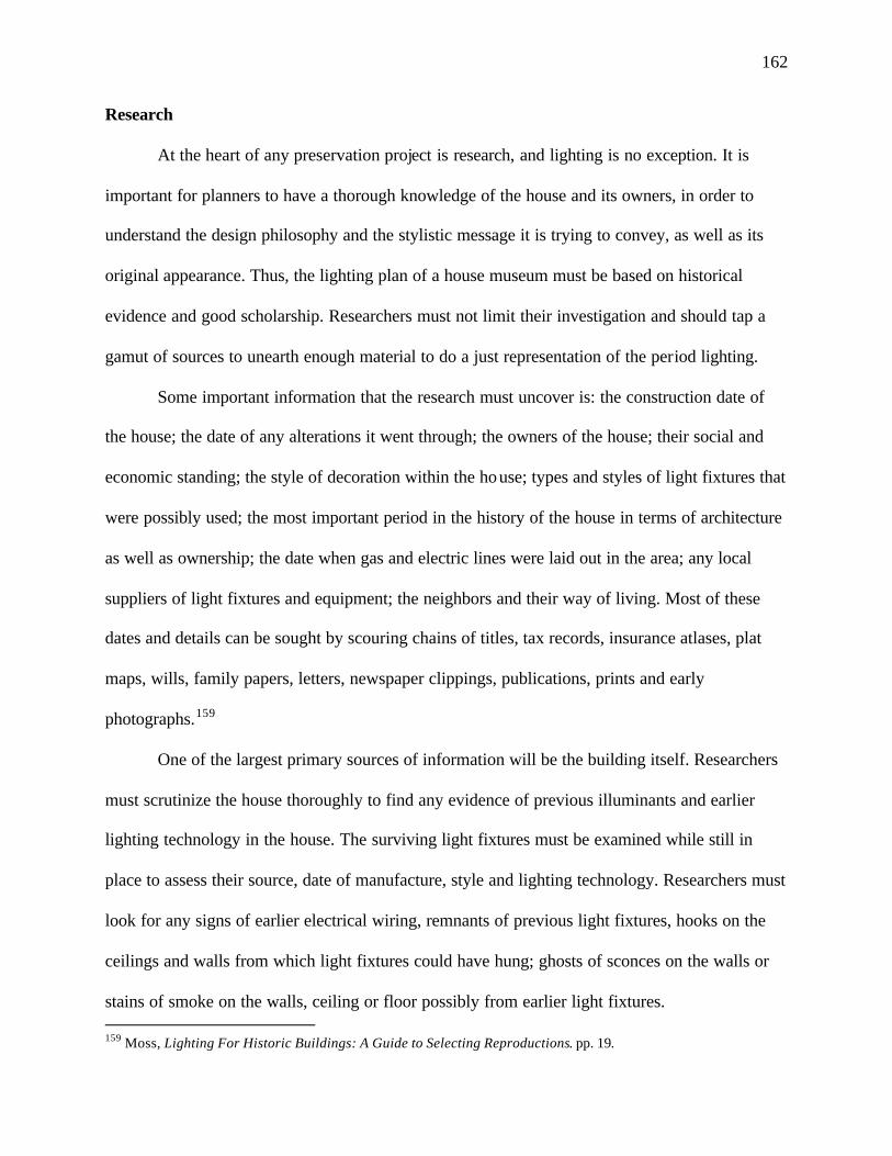
162
Research
At the heart of any preservation project is research, and lighting is no exception. It is
important for planners to have a thorough knowledge of the house and its owners, in order to
understand the design philosophy and the stylistic message it is trying to convey, as well as its
original appearance. Thus, the lighting plan of a house museum must be based on historical
evidence and good scholarship. Researchers must not limit their investigation and should tap a
gamut of sources to unearth enough material to do a just representation of the period lighting.
Some important information that the research must uncover is: the construction date of
the house; the date of any alterations it went through; the owners of the house; their social and
economic standing; the style of decoration within the house; types and styles of light fixtures that
were possibly used; the most important period in the history of the house in terms of architecture
as well as ownership; the date when gas and electric lines were laid out in the area; any local
suppliers of light fixtures and equipment; the neighbors and their way of living. Most of these
dates and details can be sought by scouring chains of titles, tax records, insurance atlases, plat
maps, wills, family papers, letters, newspaper clippings, publications, prints and early
photographs.159
One of the largest primary sources of information will be the building itself. Researchers
must scrutinize the house thoroughly to find any evidence of previous illuminants and earlier
lighting technology in the house. The surviving light fixtures must be examined while still in
place to assess their source, date of manufacture, style and lighting technology. Researchers must
look for any signs of earlier electrical wiring, remnants of previous light fixtures, hooks on the
ceilings and walls from which light fixtures could have hung; ghosts of sconces on the walls or
stains of smoke on the walls, ceiling or floor possibly from earlier light fixtures. 159 Moss, Lighting For Historic Buildings: A Guide to Selecting Reproductions. pp. 19.
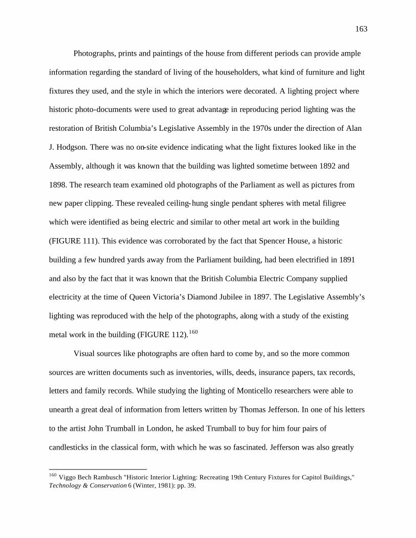
163
Photographs, prints and paintings of the house from different periods can provide ample
information regarding the standard of living of the householders, what kind of furniture and light
fixtures they used, and the style in which the interiors were decorated. A lighting project where
historic photo-documents were used to great advantage in reproducing period lighting was the
restoration of British Columbia’s Legislative Assembly in the 1970s under the direction of Alan
J. Hodgson. There was no on-site evidence indicating what the light fixtures looked like in the
Assembly, although it was known that the building was lighted sometime between 1892 and
1898. The research team examined old photographs of the Parliament as well as pictures from
new paper clipping. These revealed ceiling-hung single pendant spheres with metal filigree
which were identified as being electric and similar to other metal art work in the building
(FIGURE 111). This evidence was corroborated by the fact that Spencer House, a historic
building a few hundred yards away from the Parliament building, had been electrified in 1891
and also by the fact that it was known that the British Columbia Electric Company supplied
electricity at the time of Queen Victoria’s Diamond Jubilee in 1897. The Legislative Assembly’s
lighting was reproduced with the help of the photographs, along with a study of the existing
metal work in the building (FIGURE 112).160
Visual sources like photographs are often hard to come by, and so the more common
sources are written documents such as inventories, wills, deeds, insurance papers, tax records,
letters and family records. While studying the lighting of Monticello researchers were able to
unearth a great deal of information from letters written by Thomas Jefferson. In one of his letters
to the artist John Trumball in London, he asked Trumball to buy for him four pairs of
candlesticks in the classical form, with which he was so fascinated. Jefferson was also greatly
160 Viggo Bech Rambusch "Historic Interior Lighting: Recreating 19th Century Fixtures for Capitol Buildings," Technology & Conservation 6 (Winter, 1981): pp. 39.
164
FIGURE 111: Newspaper Clipping of the Original Light Fixtures in the Legislative Chamber in British Columbia’s Legislative Building (Published in Rambusch, “Historic Interior Lighting: Recreating 19th Century Fixtures for Capitol Buildings,” Technology & Conservation (Winter 1981)
FIGURE 112: Drawing of the Recreated Globe Fixtures and the Restored Lighting in British Columbia’s Legislative Building (Published in Rambusch, “Historic Interior Lighting: Recreating 19th Century Fixtures for Capitol Buildings,” Technology & Conservation (Winter 1981)
165
impressed with the technology of the Argand lamp and corresponded with James Madison,
Richard Henry Lee and Charles Thomson about its virtues. He was later known to have bought
three Argand oil lamps in London, two of which he presented to Thomson and Lee.161 Oral
history is sometimes one of the most valuable means of getting useful research information, and
wherever possible previous owners, their family members and friends, as well neighbors of the
household must be interviewed and consulted. Local historians, academicians, and antiquarians
of the area must also be cultivated as good information sources. It may be prudent to consult with
historians and staff at other sites of the same period as well as neighboring houses to garner
further pertinent information. Any published material as well new paper articles related to the
house must be referred to as research material.162
The uncovering of data must be followed by a careful organization and analysis of the
information collected, with the final product being a report which would synthesize all the
evidence gathered and its relevance to the final lighting plan. Any information obtained must not
be blindly accepted but must be checked in relation to similar information gained from other
sources. Different pieces of information should be tied together to form a credible story. Thus, no
data must be considered in isolation. An important point to keep in mind is that researching a
historic house in an ongoing process and is never complete, so the plan should be flexible
enough to accommodate any new discoveries or changes in information.
Light as a Destructive Force
The first thing to be considered in the lighting plan is the use of natural light because
daylight is the historic source of illumination and is considered the best form of illumination for
161 Susan R Stein and John B. Rudder, "Lighting Jefferson's Monticello: Considering the Past, Present, and Future," APT Bulletin 31 (2000): pp. 22-23. 162 Donnelly, Interpreting Historic House Museums. pp. 8.
166
historic houses. Most historic houses largely depended on natural lighting for their illumination,
and even when other sources were invented the sun continued to be the primary light-giver. Most
objects in earlier times were meant to be viewed in daylight, and daylight is considered to be the
appropriate historical color reference. So to see artifacts and tapestries in their historically correct
colors daylight is necessary. Apart from historic considerations, the presence of natural light in a
room is therapeutic to the human spirit and also practical from the energy efficiency point of
view. Needless to say, natural lighting during the day should be encouraged in house museums.
However, if left unchecked, daylight can cause a great deal of damage to collections and
architectural features, and so an important part of the lighting plan should be the protection of
artifacts, furniture and decorative fixtures in the house from the damaging effects of light.
In order to control damage due to light, it is important to have a basic knowledge of the
light spectrum. Daylight is made up of a broad spectrum of energy known as electromagnetic
radiation which is measured in nanometers (nm), a billionth of a meter. The significant parts of
the spectrum include the ultraviolet, visible, and infrared ranges. The visible part of the spectrum
ranges from blue-violet to red and from a wavelength of 400-760nm. Ultra violet (UV) radiation
has a shorter wavelength than visible light (<400nm) and infrared (IR) radiation has a longer
wavelength (>760nm). The lower the wavelength, the higher the energy level and thereby the
greater is the potential for causing photochemical damage. Fortunately, parts of the spectrum
having wavelengths below the UV rays either get absorbed by ozone in the earth's atmosphere or
do not pass through window glass. The most damaging part of light is, thereby, the ultraviolet
rays, followed by visible light. Infrared energy is not known to cause any molecular degradation
167
but does result in the heating up of collections. Hence, efforts must be made to eliminate as much
UV rays as possible, while visible light must be kept under control.163
The materials most affected by UV rays are: oil paints, varnishes, color pigments, dyes,
wood and textiles. These are all organic compounds formed of the long carbon-chain molecules
known as polymers. When exposed to the harmful radiations in daylight, the long molecular
chains become unstable and a variety of destabilizing reactions take place which can be
classified into the two groups: free radical chain reactions and auto-oxidation. Oil paints tend to
get bleached by light and also increase in transparency over time. Both natural and synthetic
varnishes undergo free radical chain reactions under excess light, which can cause solubility to
underlying paint layers during varnish removal. In addition, cracking, hazing, loss of gloss and
yellowing are other damaging effects of light on varnishes. Cellulose, the main component of
wood, gets bleached when exposed to sunlight over long periods. The absorption of UV rays by
cellulose results in the breaking up of the long molecular chains, which, in turn, lowers the
degree of polymerization, and weakens the material. An example of deterioration of wood due to
overexposure to light was found in Monticello where several mahogany tables were bleached,
severely distorting the original color of the table tops, before solar films were applied onto the
windows. Textiles made from natural fibers also contain a high proportion of cellulose and hence
deteriorate in the same manner as wood. In naturally-dyed textiles, tapestries, costumes, dyed
leather, paintings in distemper media, gouache watercolors, prints, drawings, and wallpapers
damage occurs on two fronts: loss of color and pattern, and embrittlement of the fabric.164
163 Meg Loew Craft and M. Nicole Miller, "Controlling Daylight in Historic Structures: A Focus on Interior Methods," APT Bulletin 31 (2000): pp. 54; Rebecca Ellison, "The Effects of Daylight" (The Building Conservation Directory, 2000), available from http://www.buildingconservation.com/articles/daylight/daylight.htm. 164 Ellison, "The Effects of Daylight"; Stein and Rudder, "Lighting Jefferson's Monticello: Considering the Past, Present, and Future," pp. 24.
168
Ultraviolet radiation is measured in microwatts of radiation per lumen (µW/lm). It is
recommended that the amount of ultraviolet radiation should not exceed the amount of
75µW/lm. Today’s technical advances make it possible to almost eliminate UV rays from natural
light entering the room and significantly reduce output from artificial light sources. Since visible
light causes only slightly less damage than UV rays, the lux levels in a room must also be
controlled. The general recommendations for visible light in a room are: a maximum of 50 lux165
or 5 foot candles166 for very sensitive items like paper, wallpaper, textiles, ivory, dyed leather,
watercolors and gouache, fur, feathers, manuscripts and old photographs; 150 to 200 lux or 15 to
20 foot candles for sensitive materials like oil and tempera paintings, leather, wood, furniture and
lacquer ware; for less sensitive materials like glass, metals, stone or ceramics levels may rise to a
maximum of 300 lux or 30 foot candles.167
Infrared radiation present in the light spectrum produces heat. It is recommended that an
object not be heated up rapidly more than 100F and not be more than warm to the touch.
Fluctuations of temperature levels lead to expansion and contraction during heating and cooling,
particularly in dark-colored objects that tend to absorb more heat. As certain objects, like cobalt
or manganese-colored glass, are unable to adjust to these expansions and contractions, they tend
to crack. Other damaging effects of thermal gains are: acceleration of chemical degradation and
fluctuations in relative humidity. It is critical to avoid direct sunlight as one hour of direct
exposure to the sun’s rays is capable of doing as much harm as one year at the recommended
light levels.168
165 A lux is a unit of illumination equal to 1umen per square meter. 1 lux = 0.0929 foot candle 166 When one lumen of light falls on a 1-square-foot surface, the resultant illumination level is one foot candle. 167 Craft and Miller, "Controlling Daylight in Historic Structures: A Focus on Interior Methods," pp. 54 168Craft and Miller, "Controlling Daylight in Historic Structures: A Focus on Interior Methods," pp. 54; Martin Drury, "Historic Buildings: The Conservation of Their Fixtures, Fittings, Decorations and Contents" (The National Trust Policy Papers, 1996), available from http://www.nationaltrust.org.uk/historicproperties/ downloads/3004A.PDF.])
169
According to the reciprocity law, the same amount of photochemical damage will be
produced by a strong light in a short time or a weak light in a long time. So apart from
controlling the intensity of light entering a room, the duration of light exposure should also be
minimized as far as possible for historic houses. It has been mentioned in the National Trust
Policy Papers titled ‘Historic Buildings: The Conservation of their Fixtures, Fittings,
Decorations and Contents’ that:
In order to limit cumulative damage to sensitive contents to levels not exceeding
those generally accepted for museums, rooms should not be exposed to more than
1000 hours of controlled daylight per year. This 1000 hours can be divided up
into 600 hours per annum for visitor access (4 hours per day, 5 days per week for
a 30-week season) and 400 hours per annum for maintenance and cleaning (which
only amounts to one hour per room per day)…Any further use of houses for
educational, entertainment or other purposes results in 10% annual increase in
cumulative light damage for every two hours of additional opening per week.169
When rooms are not in use lights should be turned off and shutters should be closed to
completely block the entry of light.
The first step in light control would be to analyze the light exposure, particularly of
visible and ultraviolet light, in a room and on specific objects. The sun-path in relation to the
house at different times of the day and different seasons, as well as the placement of windows
should be studied. Seasonal changes in sunlight exposure and environmental factors are
important to note because they can alter the amount of light entering the room. Landscape
features like deciduous trees that overhang a window can bring about significant shifts in the
daylight exposure of a room depending upon the time of the year. Other environmental 169 Drury, "Historic Buildings: The Conservation of Their Fixtures, Fittings, Decorations and Contents".
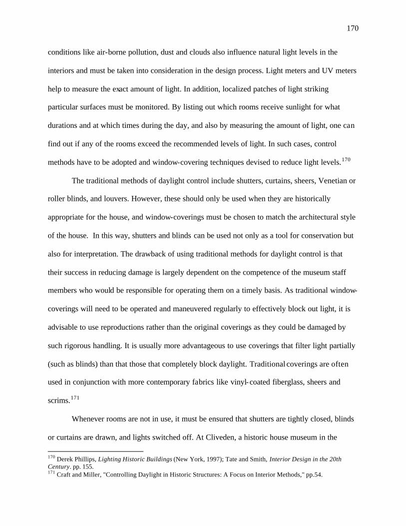
170
conditions like air-borne pollution, dust and clouds also influence natural light levels in the
interiors and must be taken into consideration in the design process. Light meters and UV meters
help to measure the exact amount of light. In addition, localized patches of light striking
particular surfaces must be monitored. By listing out which rooms receive sunlight for what
durations and at which times during the day, and also by measuring the amount of light, one can
find out if any of the rooms exceed the recommended levels of light. In such cases, control
methods have to be adopted and window-covering techniques devised to reduce light levels.170
The traditional methods of daylight control include shutters, curtains, sheers, Venetian or
roller blinds, and louvers. However, these should only be used when they are historically
appropriate for the house, and window-coverings must be chosen to match the architectural style
of the house. In this way, shutters and blinds can be used not only as a tool for conservation but
also for interpretation. The drawback of using traditional methods for daylight control is that
their success in reducing damage is largely dependent on the competence of the museum staff
members who would be responsible for operating them on a timely basis. As traditional window-
coverings will need to be operated and maneuvered regularly to effectively block out light, it is
advisable to use reproductions rather than the original coverings as they could be damaged by
such rigorous handling. It is usually more advantageous to use coverings that filter light partially
(such as blinds) than that those that completely block daylight. Traditional coverings are often
used in conjunction with more contemporary fabrics like vinyl-coated fiberglass, sheers and
scrims.171
Whenever rooms are not in use, it must be ensured that shutters are tightly closed, blinds
or curtains are drawn, and lights switched off. At Cliveden, a historic house museum in the
170 Derek Phillips, Lighting Historic Buildings (New York, 1997); Tate and Smith, Interior Design in the 20th Century. pp. 155. 171 Craft and Miller, "Controlling Daylight in Historic Structures: A Focus on Interior Methods," pp.54.
171
Germantown neighborhood of Philadelphia, the museum managers keep the ground- level
exterior shutters closed for light control and security purposes, along with the blinds on the upper
level when the site is closed to the public (FIGURE 113). This greatly reduces damage to
architectural features and collections within the historic structure. In places with cold winters,
museums may face the problem of condensation when using window coverings as they tend to
block the flow of warm air, leading to a higher rate of condensation on the window surface. To
avoid this, window coverings should be reopened after dark.172
Apart from the traditional methods of daylight-control, a number of products are now
available to filter out ultraviolet rays as well as to minimize visible radiation in a room. These
products should be evaluated based on the reversibility of their application, ease of installation,
maintenance and removal, physical appearance, longevity, effectiveness in eliminating UV rays,
reducing visible light levels and controlling glare and cost. They fall largely within the two
categories of soft controls and rigid controls. Soft controls come in the form of solar control
films. These are self-adhesive laminates of polyester or acetate, usually finished with special
scratch-free coatings. They are relatively inexpensive and normally easy to install. They can be
cut to size and applied either internally or externally on a window pane, although their durability
is greatly reduced when applied externally. The ultraviolet absorbers are either present in the
film base or are incorporated in the adhesive. Usually the films are more effective when the
absorbers are not in the adhesive. Films usually successfully filter out 95% to 99.9% of
ultraviolet radiations in the range of 200 to 380 nm. In order to control visible light, the films
have to be tinted with dyes or made reflective with metallic particles. This can distort the
appearance of the window from the exterior and also affect the way colors are perceived in the
interiors of the room. The lower the percentage of transmission, the more visually disturbing the 172 Ibid.: pp.55.
172
FIGURE 113: Cliveden Historic House Museum with the Shutters on the Ground Level Closed and the Blinds on the Upper Level Drawn for Conservation Purposes (Published in Craft, “Controlling Daylight in Historic Structures: A Focus on Interior Methods,” APT Bulletin (2000, vol: 31)
173
films appear. While solar films are available in many colors, historic houses museums usually
choose to use a neutral gray colored solar film. Many house museums restrict the use of colored
solar films because of the visual distortion they cause, both from the exterior and in the interior.
These museums usually add drapes, shades or blinds in light-sensitive areas along with clear
solar films. Today, however, solar films like the Vista window film, are available which are
virtually clear and have high glare control.173
Solar films should not be adhered onto the surface of old glass windows, including crown
glass, glasses with irregular surface finishes, stained or colored glass. Applying the film to
irregular glass prevents the continuous adhesion of the film. More importantly, complications
may arise in the removal of old film, leading to the scratching or breaking of historic glass.
While films usually last for as many as five to ten years, they should be checked periodically
every six months to see if they are working effectively and should be replaced as soon as they
show signs of age or wear, as old films may be difficult to remove. Moreover, the chemical
agents sometimes used in the removal of films can damage wood trim and historic paint on the
window frame. Care must also be taken during the application process, such that the surface is
clean and free from grit, so as to prevent premature failure. In most cases, manufacturers insist
that approved distributors carry out the installation process in order to guarantee the
effectiveness. This is advisable for historic houses where errors in installation can lead to
irreparable damages. Cleaning and maintenance instructions must be followed regularly to
ensure that the adhesion does not fail. Due to such complications of applying the film directly
onto the glass with adhesives, it may be more prudent to use roller blinds made from film, rather
than applying the film on the glass. However, the drawback of this method of application is that
173Ibid.: pp.54; Ellison, "The Effects of Daylight"; Virginia L. Kubler, "Interior Fashion Focus: Solar Control—The Intelligent Choice" (Draperies and Window Coverings Online, November 1999), available from http://www.dwcdesignet.com/DWC/Nov'99/solar.html.
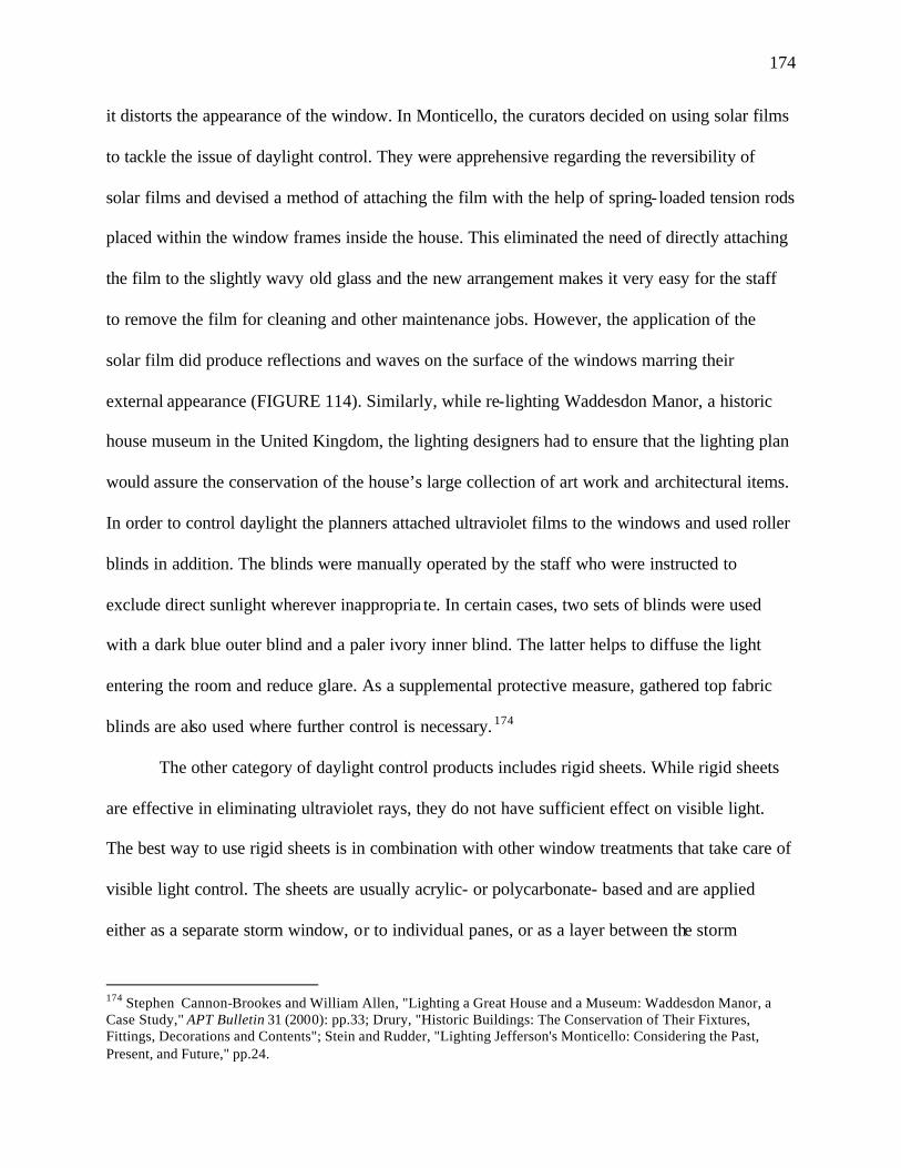
174
it distorts the appearance of the window. In Monticello, the curators decided on using solar films
to tackle the issue of daylight control. They were apprehensive regarding the reversibility of
solar films and devised a method of attaching the film with the help of spring- loaded tension rods
placed within the window frames inside the house. This eliminated the need of directly attaching
the film to the slightly wavy old glass and the new arrangement makes it very easy for the staff
to remove the film for cleaning and other maintenance jobs. However, the application of the
solar film did produce reflections and waves on the surface of the windows marring their
external appearance (FIGURE 114). Similarly, while re-lighting Waddesdon Manor, a historic
house museum in the United Kingdom, the lighting designers had to ensure that the lighting plan
would assure the conservation of the house’s large collection of art work and architectural items.
In order to control daylight the planners attached ultraviolet films to the windows and used roller
blinds in addition. The blinds were manually operated by the staff who were instructed to
exclude direct sunlight wherever inappropria te. In certain cases, two sets of blinds were used
with a dark blue outer blind and a paler ivory inner blind. The latter helps to diffuse the light
entering the room and reduce glare. As a supplemental protective measure, gathered top fabric
blinds are also used where further control is necessary. 174
The other category of daylight control products includes rigid sheets. While rigid sheets
are effective in eliminating ultraviolet rays, they do not have sufficient effect on visible light.
The best way to use rigid sheets is in combination with other window treatments that take care of
visible light control. The sheets are usually acrylic- or polycarbonate- based and are applied
either as a separate storm window, or to individual panes, or as a layer between the storm
174 Stephen Cannon-Brookes and William Allen, "Lighting a Great House and a Museum: Waddesdon Manor, a Case Study," APT Bulletin 31 (2000): pp.33; Drury, "Historic Buildings: The Conservation of Their Fixtures, Fittings, Decorations and Contents"; Stein and Rudder, "Lighting Jefferson's Monticello: Considering the Past, Present, and Future," pp.24.
175
FIGURE 114: Solar film Applied on a Window of the South Square Room in Monticello Producing Waves and Reflections on the Window Surface (Published in Stein, “Lighting Jefferson's Monticello: Considering the Past, Present, and Future,” APT Bulletin (2000, vol: 31)
176
window and the window glass. Using the rigid sheet as a storm window not only cuts down
ultraviolet radiation but also helps in insulation. When using storm windows, care should be
taken to reduce the condensation problem discussed earlier. Storm windows must be attached
without causing any damage to the historic fabric and must be easy to remove to facilitate
cleaning. Sheets are applied to individual panes by cutting them to the appropriate size and then
attaching them to the wood trim by means of flush clips, or standard swivel clips used on the
perimeter of panels, or using glazier points or cup hooks, or with the help of Velcro dots in the
case of metal casement windows. This is one of the most effective methods of applying rigid
sheets at it is easy to manage due to the size of the individual sheets, and is not in direct contact
with the old glass. The only disadvantage with this method of application is that it does not
provide any sort of insulation and like other rigid sheet applications visible light control must
still be tackled.175
Apart from restricting the glaze of the sun, it is important to use UV filters for light
fixtures as they too emit harmful UV rays and visible light, although the amount of UV radiation
emitted by them is much lower than that present in sunlight. However, if they are left on for long
periods during the day their effect over time could be harmful. Fluorescent lighting gives out a
significant proportion of UV rays and its use must be avoided in historic house museums if
possible. Apart from emitting harmful UV rays, fluorescent light is not aesthetically appropriate
for most historic interiors. In case they are used they should be covered using UV-absorbing soft,
thin plastic sheets or hard, plastic tube guards. The tube guards are of more permanent nature and
can be expected to last at least ten years. But like films, the plastic sleeves will have to be
175Craft and Miller, "Controlling Daylight in Historic Structures: A Focus on Interior Methods," pp.59.
177
checked periodically and replaced when necessary. Further, care should be taken that the sleeves
and tubes fit the lamps completely so that no UV radiation is allowed to escape.176
When incandescent lamps are used in historic houses, care should be taken to use low-
wattage lamps with low UV output that are now widely available in the markets. Museum staff
must be trained to turn off all light fixtures when the museum is not in use and in the case of
museums with docent-guided tours, lights may be turned on when rooms are being displayed. In
cases where the house requires lighting to display several fugitive organic materials, like
manuscripts, paintings, wooden furniture and textiles that are extremely susceptible to
photochemical damage, the use of fiber-optic lighting must be considered. The advantage of
fiber-optic lighting is that it does not emit any ultraviolet or infrared radiation, thereby
significantly delaying the eventual deterioration caused by light. Fiber-optic lighting is
particularly suitable for display or task lighting and is of use in confined locations, such as
display cases, where the heat built-up may be significant 177
Selecting Appropriate Fixtures Day lighting would make up most of the functional lighting in a historic house given that
most house museums operate during daylight hours. Wherever possible, it is advisable to avoid
the use of artificial lighting in rooms during daylight hours. Unfortunately, this is not always
possible as day lighting alone will not sometimes adequately light a room. The introduction of
daylight-control measures can greatly reduce the light levels of a room. With the progression of
time, historic houses may get surrounded by taller buildings blocking the sun’s light from
entering them. Further, many houses do not permit the entry of natural light due to the sensitivity
176Ellison, "The Effects of Daylight". 177Ibid; Kay, "Historic Lighting- Saint or Sinner?," pp.45.
178
of the collections. Provisions must also be made for night time use of the house as on special
occasions the museum may choose to remain open to the public in the evenings. In certain cases
house museums are venues for private parties and banquets in the evenings for which lighting
needs must be considered. These practical and circumstantial reasons make it necessary to
compliment natural light with artificial light to create the right effect in historic house museums.
But aside from their purely functional aspect, artificial lighting must also be incorporated within
the decorative scheme of a house museum to demonstrate the styles of light fixtures that were in
vogue during the time the house was in use as well as the tastes and habits of the people who
lived there. Lighting fixtures must be chosen so as to evoke nostalgic emotions among visitors,
and support the period appearance of the building. Planners must ensure that the type and
number of fixtures selected are appropriate to the interpretive period and that the fixtures are
located in their historically correct positions.
In order to light a house authentically, a sound knowledge and understanding of changing
lighting technologies must be acquired. Colonial houses were practically bereft of any artificial
lighting apart from a few candles set in candleholders and sconces, rushlights and crude oil
lamps. Oil lamps did not become practical until the discovery of the Argand lamp in 1780, and
kerosene lamps started growing in popularity only after the opening of the Pennsylvania oil
fields on the eve of the Civil War. Chandeliers were hardly used in the colonial period except in
the residences of the rich. While there is a general tendency to assume that colonial chandeliers
were manufactured of brass, many of them were in fact made of wood and tinned-sheet iron. The
popularity of chandeliers grew with the Federal period when crystal chandeliers starting making
their appearance in residences. These chandeliers were restricted to the main living parlors.
While gas lighting was introduced as early as the 1840s, it did not fully catch on until the 1870s,
179
when a regular supply of gas was piped into homes. Even when gas was introduced, many
houses used oil lamps along with gaslights. Houses that were located beyond the local gas mains
also continued using oil for lighting. Many of the colonial fixtures like candleholders continued
to be used well into the Victorian era, although their number in the household was reduced. The
average Victorian house contained an eclectic mix of different types of light fixtures using
different technologies. When electricity became available to the public in the early 1880s, many
houses adopted it immediately as it was considered to be the energy of the future. There were,
however, some houses that did not welcome the new technology considering it to be dangerous
and expensive. They retained the use of kerosene lamps and gaslights. The brief period of 1890-
1920 saw the rise of gas-electric combination fixtures. However, by the 1920s electricity won the
race and became the universal illuminant. Fixtures must be selected to best represent the time
period when the house was in use. A point to remember when selecting fixtures for a house
museum is that it is not inappropriate to include certain fixtures from earlier periods as many
light fixtures were passed down as heirlooms and houses at times favored a mix of lighting types,
using candles together with oil lamps and gaslights. Lighting fixtures also differed in the various
regions of America and depended of cultural preferences, particularly before the construction of
railways from the 1830s to the 1860s. Gas and electric lines took longer to reach the smaller
towns and cities, and so these places continued the use of oil lamps well into the 1900s. Further,
selection of fixtures must be governed by the status and wealth of the owners, irrespective of the
period being represented.178
Planners usually are faced with three options when selecting appropriate light fixtures for
a historic house: 1) making do with the existing, original light fixtures, either by restoring them
178 Maril, American Lighting: 1840-1940. pp.6-7; Mary Ellen Polson, "Lighting the Living Rooms," Old-House Journal (January-February, 1999).
180
or modifying them; 2) augmenting the original fixtures with suitable reproductions; and 3)
augmenting the original fixtures with supplemental modern lighting. While the first is, without a
doubt, the most authentic historically, it is not practical as many houses have lost most of their
period light fittings due to deterioration or theft. Also, historic houses usually had many fewer
light fixtures than we are used to today, particularly for the purpose of viewing exhibits. In
certain cases where the modifying procedure is deemed too intrusive to the historic fabric of the
fixture, it may be necessary to use the other available options to augment the period fixtures. An
example of this is the Osborne House, Isle of Wight, (FIGURE 115) where the re-electrification
project of the dining hall and the drawing room excluded all the period fittings from being
rewired due to the inevitable wear and tear that they would suffer by the rigorous handling and
by the frequent changing of bulbs by the staff. Instead modern light fixtures were sensitively
added while maintaining the historic fixtures in their original locations. In most cases, therefore,
it is a well-balanced combination of all three options that is employed.179
Restoring and Adapting Original Fixtures
When lighting a historic house museum, planners must first study the fixtures extant in
the house. They should prepare an inventory of the light fixtures in place, which should include:
the style of the fixtures; their location; the fuel they used; and a documentation of their condition
supported by photographs. Fixtures should be examined to see if they are appropriate to the
interpretive period being represented in the house museum and the decorative style of the house.
As long as the light fitting is not completely discordant with the decorative and interpretive
179Julius Bryant, "Chasing Shadows: Exploring the Meaning of Light in English heritage Houses," APT Bulletin 31 (2000): pp.30; Melissa L. Cook and Maximilian L. Ferro, "Electric Lighting and Wiring in Historic American Buildings: Guidelines for restoration and Rehabilitation Projects," Technology & Conservation 8 (Spring, 1983): pp.36.
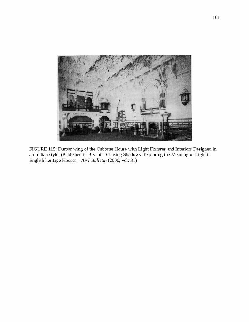
181
FIGURE 115: Durbar wing of the Osborne House with Light Fixtures and Interiors Designed in an Indian-style. (Published in Bryant, “Chasing Shadows: Exploring the Meaning of Light in English heritage Houses,” APT Bulletin (2000, vol: 31)
182
scheme of the house, efforts should be made to preserve and retain any historic light fittings
existing in the house. Account should be taken to see that they are correctly positioned in the
house. That is, their location should relate to the spaces they light, for example, a chandelier
would typically be hung from a ceiling medallion and sconces were commonly placed on either
sides of a chimney. Fixtures should be investigated to see if they can be used in their original
state or whether modifications have to be made in order to adapt them with modern technological
advancements. If so, enquiries should be made into whether such modifications can be carried
out without damaging the period fixture or without altering it irreversibly. Once these
preliminary observations and investigations are made, the fixtures may be taken down, cleaned
and sent to workshops in order to be restored or adapted.
Where the existing light fitting predates the electrical era, it will need to be altered so as
to be wired for electricity, unless supplemental lighting is to be considered. This is because flame
sources can no longer be used for safety reasons. As far as possible, the original period fixtures
should be electrified or rewired and put to use unless: a) the restoration or wiring causes damage
or leads to irreversible changes; or b) the light fixture is of a rare and unique kind and must be
preserved in its pristine, original form. Sometimes restoration or rewiring of the historic light
fixture may destroy burners that have survived in their original states. In such cases it may be
wiser to leave the fixture unchanged or to use a suitable reproduction or a similar antique that has
lost its burner. The process of rewiring a period light fixture must be non- intrusive, reversible,
aesthetically integrated with the appearance of the fixture and composed of inert materials that
would not adversely affect the body of the fixture. Since modern bulbs with tungsten filaments
and frosted interiors did not become available until the 1920s, reproduction carbon-filament
bulbs may be acquired for early electrical fixtures, particular those where the bulbs were left
183
exposed. Chemical and mechanical cleaning methods must be used with the utmost caution so as
to not cause any damage or deface the appearance of the fixtures. The restoration or rewiring
process should ensure that further modifications and regular maintenance operations are easy to
conduct. Further, preparing and testing with the help of mock-ups should be practiced before
carrying out any work on original fixtures. Any modifications made to the original fixture must
be clearly documented. When restoring, modernizing or rewiring period fixtures it is crucial that
the work be assigned to experienced professionals in the field, as haphazard work of restoration
or rewiring can cause irreparable damage to a period lamp.180
A project that demonstrates a successful lighting restoration and adaptation is the lighting
project of Colonial Williamsburg which was undertaken during the renovation of the Capitol
building. The project sought to electrify the traditional brass chandeliers meant to use wax
candles present in the Capitol building. The work was carried out by the Metals and Arms
Conservation Laboratory of Colonial Williamsburg along with a local company that was to carry
out the electrification of the chandeliers. To simulate the appearance of traditional candles, the
lighting designers chose a digital lighting system supplied by Ray St. Louis of R. F. St. Louis
Associates. The system consisted of an epoxy candle, cast from a silicone rubber mold of an
actual candle, with a digital control board embedded in its interior. A three-quarter watt
replaceable bulb is inserted into the output leads emerging from the candle top. The wires for the
candle are of copper, one green and the other red. The two are bonded together with polyvinyl
butyral. Extremely thin wiring was used so that it could be attached to the chandelier arms
externally. As the wires were red and green, they needed to be camouflaged so as to avoid being
visible to the visitors. After much testing, a gold-colored pilot pen was used to color the wires.
180 Kathy Z. Gillis and David Harvey, "Lighting the Way: A Conservator's Approach to Electrifying Brass Chandeliers," APT Bulletin 31 (2000): pp.50; Moss, Lighting For Historic Buildings: A Guide to Selecting Reproductions. pp.15.
184
The chemicals used in the ink of the Pilot pens were analyzed and it was concluded that as long
as the wires were colored on a separate support material and then allowed to dry before being
brought to contact with the brass chandelier, the ink would have no adverse affect on the brass or
the lacquer on the surface of the chandelier. The electrical wires were attached on the chandelier
arms with the help of transparent monofilament wires instead of an adhesive as the use of the
adhesive could lead to a harmful chemical bond. The monofilament nylon wire, on the other
hand, is chemically inert, completely reversible and allows great flexibility for maintenance
operations (FIGURE 116).181
Using Reproductions
With more and more historic houses being preserved today there is a growing demand for
period lighting fixtures. There is, however, a dearth of historic lamps and fixtures because as
light technologies changed it was often easier to simply discard old fixtures than to convert them.
Light fixtures were also seen as prime material to be used as metal-scrap during World War I and
World War II. It is even more difficult to find original glass shades and chimneys due to their
fragile nature. There is, thus, a burgeoning market of reproduction light fixtures today with
greater number of manufacturers trying to reproduce historic fixtures as closely as possible to the
original. The reproduction manufacturers normally base their designs on original documents or
models, but minor alterations in scale and finish to suit modern tastes and modern homes are
quite common. 182
Whenever a fixture is copied from a particular prototype it almost inevitably departs
somewhat from the original. Reproductions of oil, gas and gas-electric fixtures are hardly ever
181 Gillis and Harvey, "Lighting the Way: A Conservator's Approach to Electrifying Brass Chandeliers," pp.46-47. 182 Moss, Lighting For Historic Buildings: A Guide to Selecting Reproductions. pp.21.
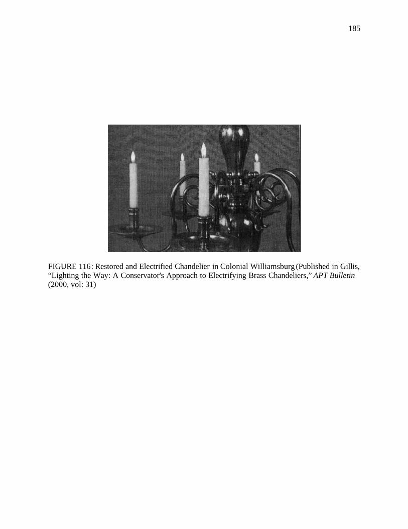
185
FIGURE 116: Restored and Electrified Chandelier in Colonial Williamsburg (Published in Gillis, “Lighting the Way: A Conservator's Approach to Electrifying Brass Chandeliers,” APT Bulletin (2000, vol: 31)
186
exact copies of their originals as they need to be adapted for modern electrification. In the case
of T-shaped gas fixtures, the modern couplings at the right-angle joints have to be slightly larger
than the originals to allow for the electrical wires to connect. For fixtures using burners and
candles the introduction of electric sockets leads to changes in the spatial relationship between
the arms, shade fitters and shades. Further, the back plates of candle and oil burning wall
brackets may have to be enlarged to cover the modern electrical boxes. Oftentimes,
manufacturers make blunders by skipping important components, like forgetting to add gas
cocks on reproduction gas fixtures, or a glass chimney on a custom-made Argand lamp, which
adversely affects the appearance of the reproduction and detracts from its authenticity. It is also
common to find manufacturers who use a variety of sources to craft their light fixtures,
borrowing an element from here and another from there, based largely on the availability of their
resources and their own tastes. This largely obscures the stylistic classifications of their fixtures
making them tend more towards modern adaptations of period fixtures rather than authentic
reproductions.183
Planners must have an extensive knowledge of the type of fixtures they are looking for
before attempting to purchase reproductions. It is also prudent to compare an original fixture
with the reproduction before making the purchase. Care should be taken when purchasing
colonial-era chandeliers for residences because most of the reproductions are based on examples
found in public places like churches and meeting houses and are much larger in scale than would
normally be found in a house. Chandeliers were rarely used in colonial times in residences and it
was far more common to find task lights in the form of wall sconces, table lamps and floor
183 Ibid. pp.27.
187
lamps. Every effort must be made to ensure that reproductions are not cheap imitations but are
the products of scholarly research, meticulous detailing and careful thought.184
On occasions when the budget is tight and cost-cutting methods have to be sought,
reproduction manufacturers should make sensible substitutions of materials and finishes or minor
changes in scale without compromising the over-all effect. Such substitutions can reduce costs
by 20-50% and still result in acceptable products. In the cases where reproduction fixtures are up
on the ceiling or high on the walls (from where it is difficult to discriminate the differences
between authentic and slightly modified details) certain latitudes in design to cut costs may be
considered. Since bronze today is not as readily available as it was in the past, manufacturers
have to often use substitute materials for the reproduction of bronze fixtures. Brass is the closest
substitute for bronze and can be finished to match the original bronze patinas. Other acceptable
substitutes for bronze and copper include the use of steel or aluminum plated to approximate the
original finish. Another way in which manufacturers cut down costs is by using bronze or brass
on the small elements and steel or aluminum substitutes in the larger spun elements. The
reproduction light fixtures in the University of Notre Dame’s Administrative Building (FIGURE
117) made use of bronze powder clear-coated with Incralac on steel housings instead of using
patinated solid-brass or bronze housings.185 Also, the reproduction manufacturers decided to use
cast-bronze applied ornaments instead of casting the entire ring of the fixtures. For the shades
they substituted the alabaster panels for marbled acrylic or faux alabaster. However, care should
be taken that the cost-saving options do not mar the period setting of the house or appear garish.
184 Ibid. pp. 21, 24-27. 185 Incralac is an acrylic based protective lacquer, designed especially for the protection of copper, brass and similar alloys. It is suitable for interior or exterior use. It was developed by INCRA (International Copper Research Association) for the protection and prevention from tarnishing of copper, brass and similar alloys. It usually comes with a UV inhibitor and can be either sprayed or applied with a brush
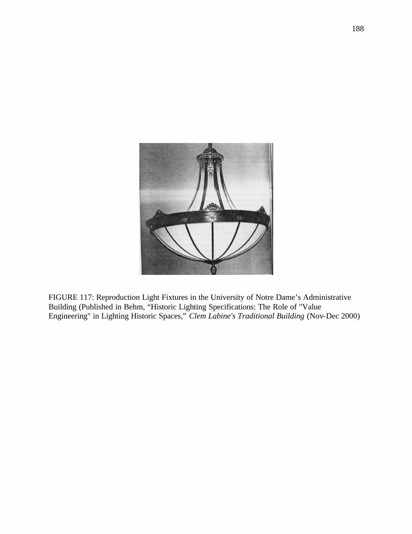
188
FIGURE 117: Reproduction Light Fixtures in the University of Notre Dame’s Administrative Building (Published in Behm, “Historic Lighting Specifications: The Role of "Value Engineering" in Lighting Historic Spaces,” Clem Labine's Traditional Building (Nov-Dec 2000)
189
When setting up the budget for reproductions the long-term values of products have to be
considered. At times the more-expensive product may be cheaper in the long run. 186
When selecting reproductions designers should make sure that they support the
interpretive plan of the house museum and are suited to the room they light in terms of style,
type, age, scale, finish and their relationship to other architectural and decorative elements in the
room. The design of the reproductions should tally with the results of the research conducted on
the light fixtures that were used in the house and the general decorative scheme of the house. If
photographs of the original light fixtures used in the house are available then the reproductions
can be custom-made for the house or similar reproductions can be sought. In the absence of any
physical or photographic evidence of original light fixtures used in the house, evidence may be
garnered from other metal ornaments and decorative themes present in the house, as well as from
houses of the same time period in similar locations.
When designing the lighting for the reinstated Linsly-Chittenden Hall at Yale University,
the lighting designer applied the theme of “going back to the future” and decided to have ceiling
fixtures custom-made based on old photographs and decorative motifs present on the campus in
the place of the 1950s-style linear fluorescents tha t were present in the lecture room (FIGURE
118). The hall with its dome-shaped ceiling did not originally have any ceiling fixtures and got
its ambient lighting solely from gas and electric table lamps. Since the designers did not have
any precedent in the room on which to base the design of the pendants they had to look
elsewhere on the campus. They found an octagonal pendant with a milk-glass shade in one of the
lobbies and decided to use that as the prototype. Photographs were taken of the original fixture
which served as the basis for the reproductions. The eight reproduction pendants were hung
186Gary H. Behm, "Historic Lighting Specifications: The Role of "Value Engineering" in Lighting Historic Spaces," Clem Labine's Traditional Building 13 (Nov.-Dec., 2000): pp.182, 184.
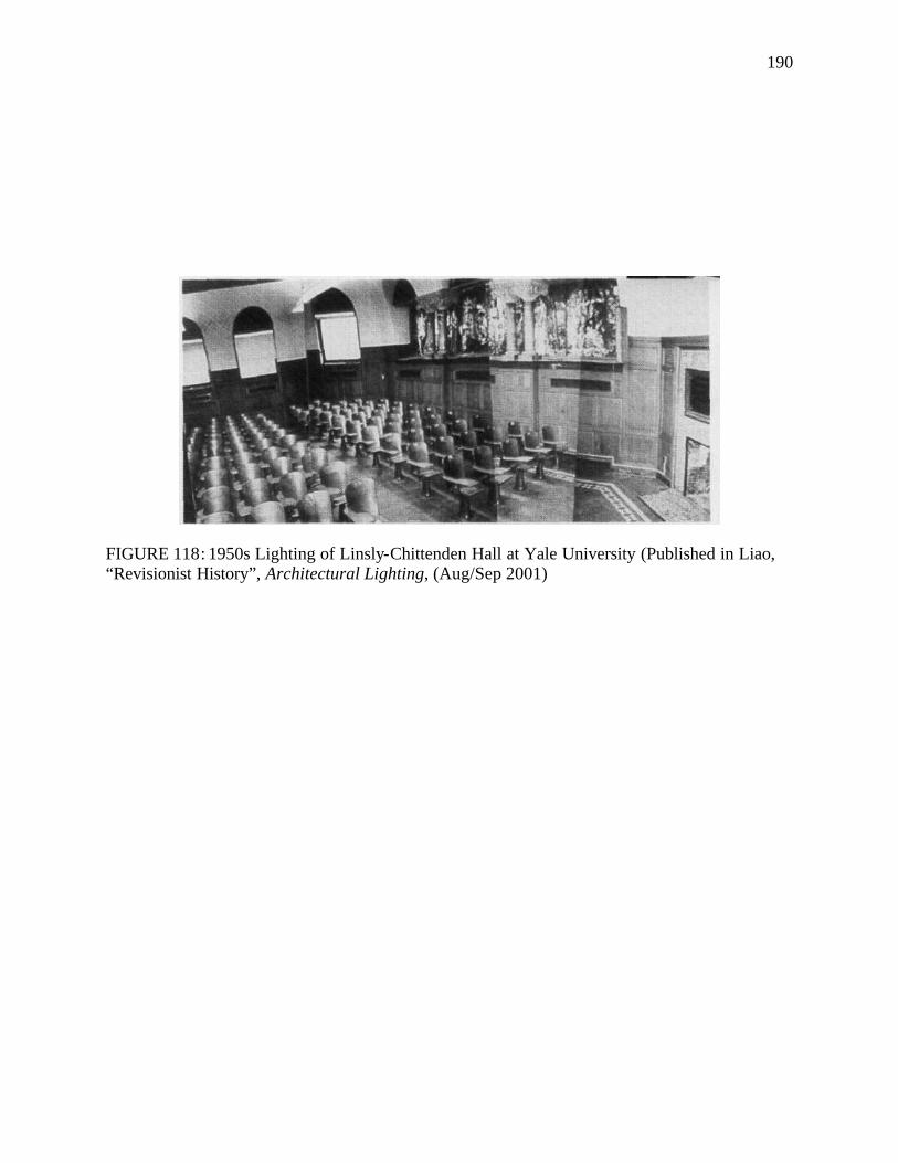
190
FIGURE 118: 1950s Lighting of Linsly-Chittenden Hall at Yale University (Published in Liao, “Revisionist History”, Architectural Lighting, (Aug/Sep 2001)
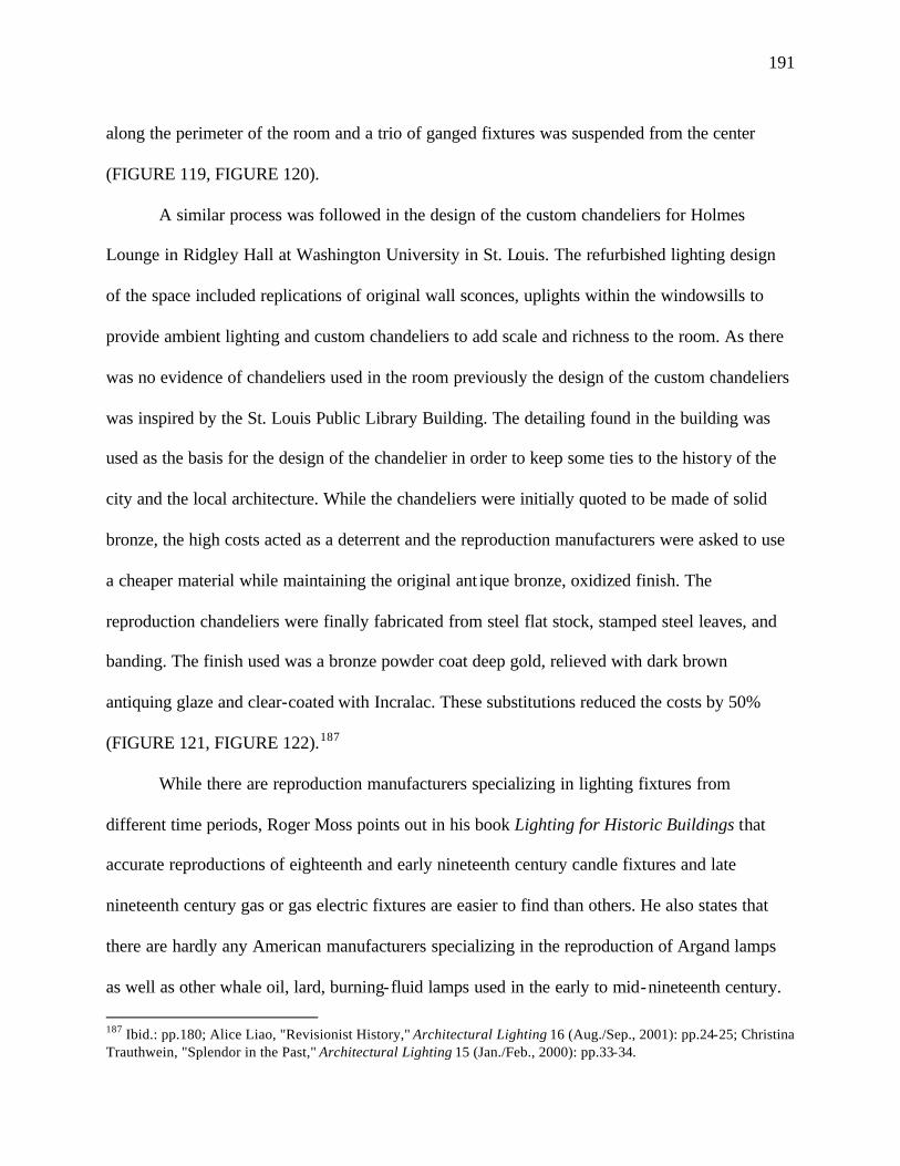
191
along the perimeter of the room and a trio of ganged fixtures was suspended from the center
(FIGURE 119, FIGURE 120).
A similar process was followed in the design of the custom chandeliers for Holmes
Lounge in Ridgley Hall at Washington University in St. Louis. The refurbished lighting design
of the space included replications of original wall sconces, uplights within the windowsills to
provide ambient lighting and custom chandeliers to add scale and richness to the room. As there
was no evidence of chandeliers used in the room previously the design of the custom chandeliers
was inspired by the St. Louis Public Library Building. The detailing found in the building was
used as the basis for the design of the chandelier in order to keep some ties to the history of the
city and the local architecture. While the chandeliers were initially quoted to be made of solid
bronze, the high costs acted as a deterrent and the reproduction manufacturers were asked to use
a cheaper material while maintaining the original ant ique bronze, oxidized finish. The
reproduction chandeliers were finally fabricated from steel flat stock, stamped steel leaves, and
banding. The finish used was a bronze powder coat deep gold, relieved with dark brown
antiquing glaze and clear-coated with Incralac. These substitutions reduced the costs by 50%
(FIGURE 121, FIGURE 122).187
While there are reproduction manufacturers specializing in lighting fixtures from
different time periods, Roger Moss points out in his book Lighting for Historic Buildings that
accurate reproductions of eighteenth and early nineteenth century candle fixtures and late
nineteenth century gas or gas electric fixtures are easier to find than others. He also states that
there are hardly any American manufacturers specializing in the reproduction of Argand lamps
as well as other whale oil, lard, burning-fluid lamps used in the early to mid-nineteenth century.
187 Ibid.: pp.180; Alice Liao, "Revisionist History," Architectural Lighting 16 (Aug./Sep., 2001): pp.24-25; Christina Trauthwein, "Splendor in the Past," Architectural Lighting 15 (Jan./Feb., 2000): pp.33-34.
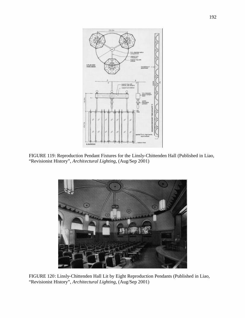
192
FIGURE 119: Reproduction Pendant Fixtures for the Linsly-Chittenden Hall (Published in Liao, “Revisionist History”, Architectural Lighting, (Aug/Sep 2001)
FIGURE 120: Linsly-Chittenden Hall Lit by Eight Reproduction Pendants (Published in Liao, “Revisionist History”, Architectural Lighting, (Aug/Sep 2001)
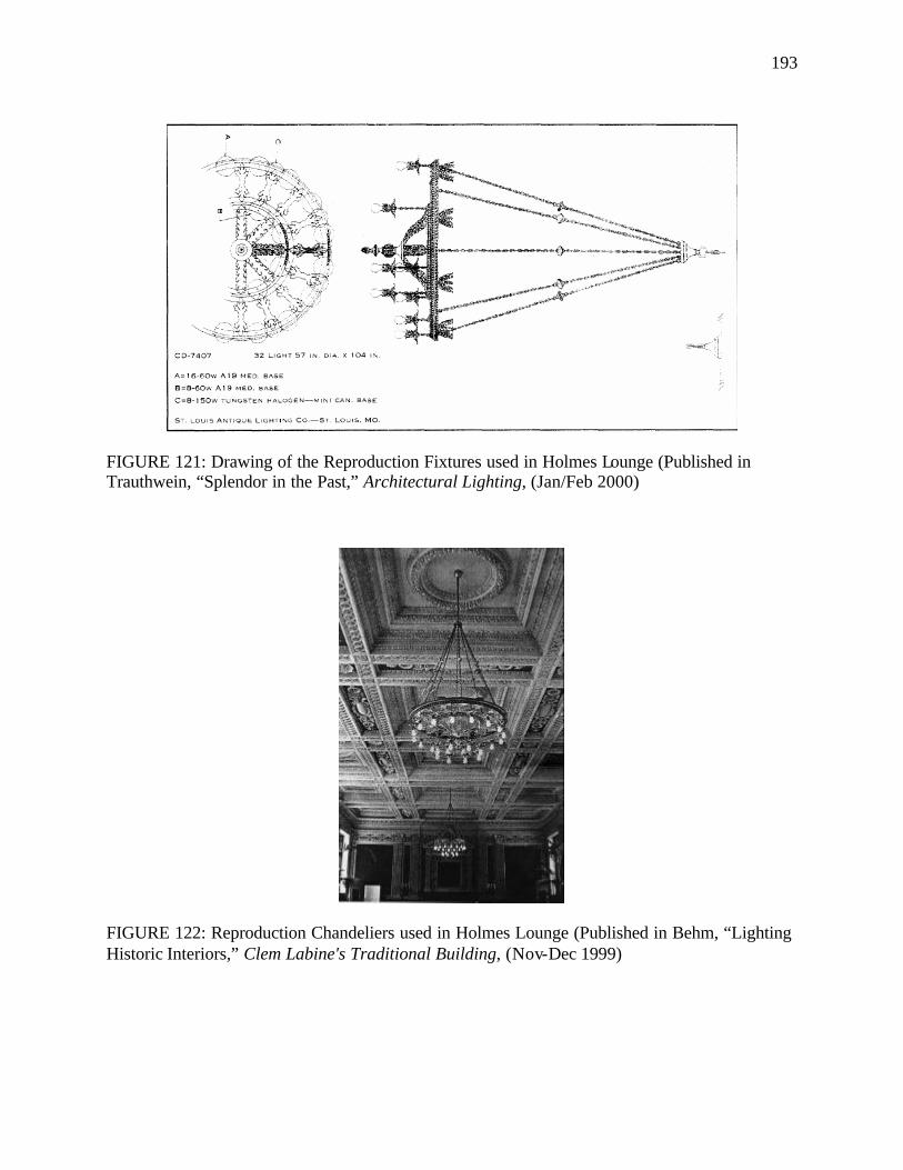
193
FIGURE 121: Drawing of the Reproduction Fixtures used in Holmes Lounge (Published in Trauthwein, “Splendor in the Past,” Architectural Lighting, (Jan/Feb 2000)
FIGURE 122: Reproduction Chandeliers used in Holmes Lounge (Published in Behm, “Lighting Historic Interiors,” Clem Labine's Traditional Building, (Nov-Dec 1999)
194
This is largely due to the fact that these oil lamps as well as early gas fixtures require cast and
turned elements which are expensive to reproduce, finish and assemble. These fixtures also
require glass shades and chimneys that demand cutting and etching techniques that are too
laborious to reproduce. However, it may be possible to obtain antique Argand, sinumbra and
solar lamps, though they are quite expensive. Also, it is extremely hard to find two and a half
inch fitter shades for mid-nineteenth century gas fixtures. Most manufacturers tend to produce
four-inch fitter shades that were used by later gas and electric fixtures.188
The reproduction light market today is flooded with turn-of-the-century and early
twentieth century electrical lighting fixtures as more and more houses from this period are being
deemed historic and worthy of preservation. There is a huge array of fixture types to choose from
including revivalist electroliers, pan lights, shower lights, pendants, table lamps, as well as art
glass fixtures. With a greater majority of homebuyers today gravitating towards the appeal of
Craftsman bungalows, Arts and Crafts reproduction fixtures are finding a large market of
purchasers eager to retain their house’s original flavor. These Arts and Crafts reproduction
manufacturers get their inspiration from the early twentieth century architects Greene and
Greene, the heritage of Mission, the Prairie school, Gustav Stickley’s furniture and English Arts
and Crafts style. There are firms that make reproductions of light fixtures by particular architects.
A Japanese firm called Yamagiva was awarded the patent to produce Frank Lloyd Wright-style
reproduction light fixtures. Apart from reproductions of early electric light fixtures, there are
manufacturers specializing in providing reproductions of early bulbs having low wattages and
188 Moss, Lighting For Historic Buildings: A Guide to Selecting Reproductions. pp. 24, 26-27.
195
authentic appearance suited for Victorian, Art Nouveau and Art Deco fixtures and particularly
for fixtures where the bulbs are left exposed.189
Care should be taken that the reproduction or adapted period fixtures are installed in a
manner that would be historically appropria te. Gaslights must not be hung from chains but from
pipes as they had been originally. Also, chandeliers and gaslights must not be hung too high from
the floor. This would not only cause a distortion in the relationship of the furnishings and the
fixture but would also produce a historically inaccurate high light level and make it difficult for
the visitors to appreciate the decorative elements of the fixture. Historic authenticity dictates that
ceiling-hung candle, oil and gas fixtures be installed at a he ight from where it would have been
easy to light, extinguish and clean them. Typically, chandeliers, gasoliers and hall lights should
be hung at a height of no more than 78 to 84 inches from the floor to the bottom of the fixture.190
Using Modern Lighting in Historic Houses
In most cases, historic house museums will require supplemental lighting to compliment
the historic light fixtures and reproductions present in the house. The availability of period
fixtures is limited and reproductions are not always feasible to use because of financial
constraints. Also, the introduction of additional period light fixtures can be misleading to the
visitors of historic houses and drift away from an authentic period setting. Thus, to have an
adequate level of ambient lighting necessary for proper viewing it may be essential to add
modern fixtures into the historic interiors. Moreover, a historic house museum often has a
sizeable collection of artifacts - paintings, china, and other decorative objects - that require
189 Molly Maloney Bowler, "Shedding Light on a Philosophy of Living: Reproduction Lighting and Modern Variations," American Bungalow 1 (1991): pp.32; Moss, Lighting For Historic Buildings: A Guide to Selecting Reproductions; "Wright Lighting," Interior Design 65 (1994). 190 Moss, Lighting For Historic Buildings: A Guide to Selecting Reproductions. pp.18.
196
specia l lighting for which there are no suitable historic precedents. In such cases modern light
fixtures will be required to highlight and display the house’s collections as well significant
architectural features. Also, modern lighting may be necessary to meet the level of light required
for safety and maintenance procedures.
Whatever supplemental modern lighting is used must be well concealed and if exposed
should not in any way detract from the historic and architectural integrity of the house. The
modern light fixtures must be as unobtrusive as possible and should not deface the architecture in
any way. Before adding supplemental lighting, planners must analyze what or if any alterations
have to be made in the historic fabric in order to accommodate the additional lighting and
whether such alterations would be reversible and devoid of any adverse affects. Recessed ceiling
fixtures must be avoided as they tend to attract attention and damage ceilings. Suitable
supplemental lighting may be in the form of portable spots at floor level or fixtures located above
and behind the viewer. Wherever possible they should be programmed so as to be turned on only
by the museum docent or to be self-activated by the visitor. Common ways to conceal
supplemental lighting are to place them behind structural features like beams, columns, window
sills or tuck them behind furniture and along the edge of moldings.
The technology of fiber optic lighting may be employed to display important objects as
they are easy to conceal, discreet and can be used in even the most inaccessible areas. Glass in
the fibers effectively filter out nearly all the harmful ultraviolet rays and significantly attenuate
infrared energy, thereby reducing heat output. This makes them ideal for lighting rooms with
sensitive artifacts and display cabinets where heat build-up must be eliminated. Further, the
fundamental idea of breaking down a single light source into many parts is also of use in the case
of a house museum where light levels in the range of 50 to 200 lux are required at extremely
197
short distances, sometimes less than 600mm. Fiber optic lighting is very useful for lighting up
display areas requiring varying degrees of light using a single light source. The fact that only a
single light source is used to deliver light to several different points makes maintenance easier,
eliminates the need to change several light bulbs and also the attendant need for ladders and
scaffolding to maintain several light fixtures. As considerably fewer lamps are required to
produce multiple points of functional light with fiber optic lighting, less light is wasted and less
electrical power consumed.191
Fiber optic lighting can also be used to retrofit existing period fixtures, chandeliers, wall
sconces, table and floor lamps. Proprietary methods are available which can produce realistic
flickering candle or gaslight effects using fiber optics. The other practical benefit of using fiber
optic lighting is that once the illumination is installed and focused the integrity of the lighting
design remains unaltered. In the case of conventional lights, when replacing bulbs and doing
other maintenance there is a possibility that the wrong beam or wattage or color or shape lamp
may be installed, thereby distorting the overall effect.192
The installation of fiber-optic lighting can be quite complicated, even more so in a
historic structure, so very competent lighting professionals have to be employed to deal with it.
A further disadvantage with using fiber optic lights is that in many cases setting up fiber optic
lighting in a historic building would require running the fiber quite a distance from the light
source and hence quite a bit of threading through interstitial spaces. The problem lies in the fact
191 Kay, "Historic Lighting- Saint or Sinner?," pp.41; Kevan Shaw, "Fibre Optic Lighting" (Kevan Shaw Lighting Design, 4-1-99 1999), available from http://www.kevan-shaw.com/articles/tech/fibre/fibre.html. 192 Kay, "Historic Lighting- Saint or Sinner?," pp.45,47.
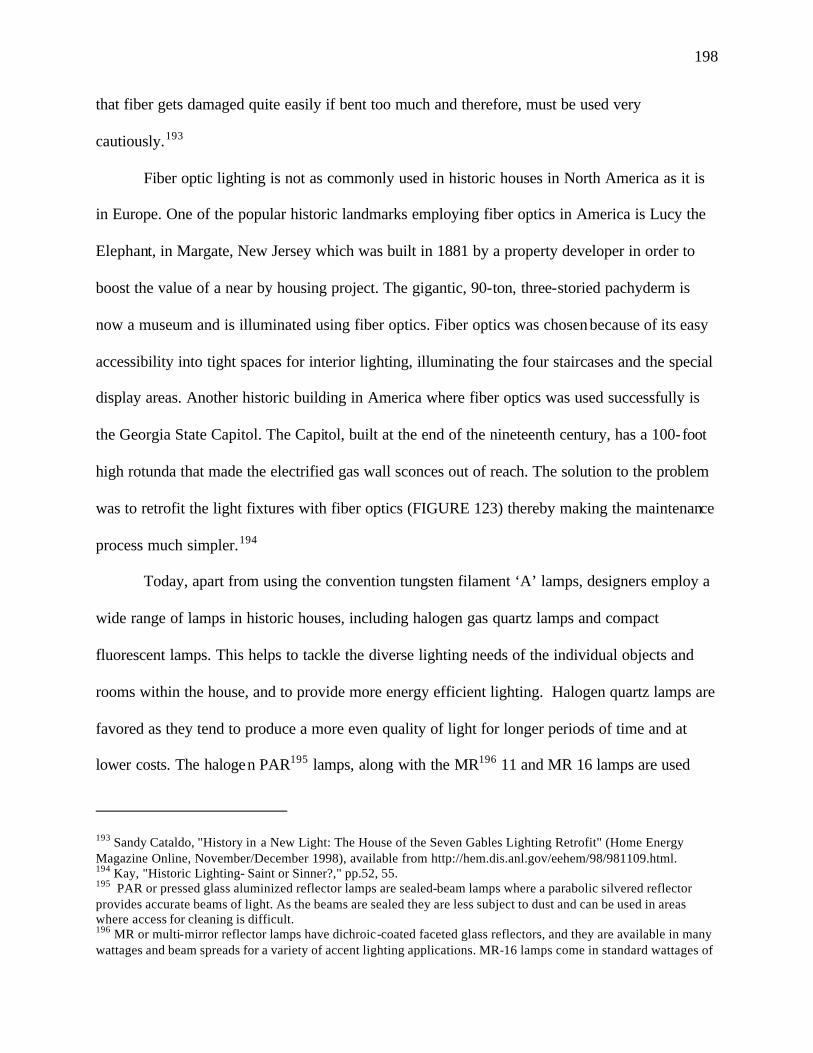
198
that fiber gets damaged quite easily if bent too much and therefore, must be used very
cautiously.193
Fiber optic lighting is not as commonly used in historic houses in North America as it is
in Europe. One of the popular historic landmarks employing fiber optics in America is Lucy the
Elephant, in Margate, New Jersey which was built in 1881 by a property developer in order to
boost the value of a near by housing project. The gigantic, 90-ton, three-storied pachyderm is
now a museum and is illuminated using fiber optics. Fiber optics was chosen because of its easy
accessibility into tight spaces for interior lighting, illuminating the four staircases and the special
display areas. Another historic building in America where fiber optics was used successfully is
the Georgia State Capitol. The Capitol, built at the end of the nineteenth century, has a 100-foot
high rotunda that made the electrified gas wall sconces out of reach. The solution to the problem
was to retrofit the light fixtures with fiber optics (FIGURE 123) thereby making the maintenance
process much simpler.194
Today, apart from using the convention tungsten filament ‘A’ lamps, designers employ a
wide range of lamps in historic houses, including halogen gas quartz lamps and compact
fluorescent lamps. This helps to tackle the diverse lighting needs of the individual objects and
rooms within the house, and to provide more energy efficient lighting. Halogen quartz lamps are
favored as they tend to produce a more even quality of light for longer periods of time and at
lower costs. The halogen PAR195 lamps, along with the MR196 11 and MR 16 lamps are used
193 Sandy Cataldo, "History in a New Light: The House of the Seven Gables Lighting Retrofit" (Home Energy Magazine Online, November/December 1998), available from http://hem.dis.anl.gov/eehem/98/981109.html. 194 Kay, "Historic Lighting- Saint or Sinner?," pp.52, 55. 195 PAR or pressed glass aluminized reflector lamps are sealed-beam lamps where a parabolic silvered reflector provides accurate beams of light. As the beams are sealed they are less subject to dust and can be used in areas where access for cleaning is difficult. 196 MR or multi-mirror reflector lamps have dichroic-coated faceted glass reflectors, and they are available in many wattages and beam spreads for a variety of accent lighting applications. MR-16 lamps come in standard wattages of
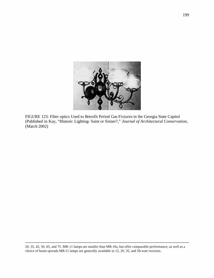
199
FIGURE 123: Fiber optics Used to Retrofit Period Gas Fixtures in the Georgia State Capitol (Published in Kay, “Historic Lighting- Saint or Sinner?,” Journal of Architectural Conservation, (March 2002)
20, 35, 42, 50, 65, and 75. MR-11 lamps are smaller than MR-16s, but offer comparable performance, as well as a choice of beam spreads.MR-11 lamps are generally available in 12, 20, 35, and 50-watt versions.
200
extensively by designers today as accent lighting. The MR lamps come with special dichroic
reflectors that allow two-thirds of the infrared radiation emitted by the filament to be directed
back towards the base of the lamp. Thus the forward beam of light contains up to 66% less heat.
This fact coupled with their small size makes them ideal for accent lighting as well as picture
lights where accurate color rendition is necessary. Halogen sources provide light that is closer in
color reproduction to daylight and can be used to simulate daylight conditions in historic
houses.197
During the revitalization of Holmes Lounge the lighting designers Randy Burkett and
Ron Kurtz decided to recreate the splendor of the past by using reproduction fixtures and to
introduce modern lighting in a manner that would be sensitive to the hall’s original design and
the fabric of the room. At the same time they had the task of making the space multifunctional
and wanted the new lighting system to bring out the space’s architectural details, subtle hues and
grandeur. To accomplish this, the designers needed accent lights for the art works and the
architecture apart from the ambient lighting. But they had to make sure that any modern fixture
they added was not visible to the viewer and only thematic and traditional fixtures would be left
visible to the public. The designers ruled out recessed downlights as they would damage the
historic ceiling. The window sills in the hall, having a depth of about fifteen inches, were chosen
as the location to conceal multi-circuit track lights (FIGURE 124). Wall-washers in the form of
two 500W halogen lamps were also mounted to the track on the ledge in front of the window.
This helped to uplight the decorative ceiling. In order to highlight the artwork and the
architectural ornaments on the end walls the track fixtures in the window wells at the ends of the
room included PAR 36 halogen accent lights. Lenses are fitted on the fixtures to diffuse the light
197 "General Electric Company", available from http://www.gelighting.com/na/home/home_halogen.html; Rambusch and Rambusch, "Creating Effective Lighting Systems for Historic Houses of Worship".
201
FIGURE 124: Track Lights Concealed in the Window Sill in Holmes Lounge (Published in Trauthwein, “Splendor in the Past,” Architectural Lighting, (Jan/Feb 2000)
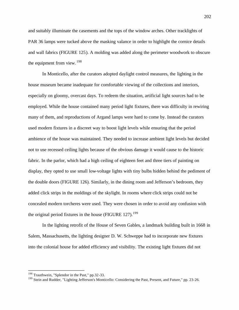
202
and suitably illuminate the casements and the tops of the window arches. Other tracklights of
PAR 36 lamps were tucked above the masking valance in order to highlight the cornice details
and wall fabrics (FIGURE 125). A molding was added along the perimeter woodwork to obscure
the equipment from view. 198
In Monticello, after the curators adopted daylight control measures, the lighting in the
house museum became inadequate for comfortable viewing of the collections and interiors,
especially on gloomy, overcast days. To redeem the situation, artificial light sources had to be
employed. While the house contained many period light fixtures, there was difficulty in rewiring
many of them, and reproductions of Argand lamps were hard to come by. Instead the curators
used modern fixtures in a discreet way to boost light levels while ensuring that the period
ambience of the house was maintained. They needed to increase ambient light levels but decided
not to use recessed ceiling lights because of the obvious damage it would cause to the historic
fabric. In the parlor, which had a high ceiling of eighteen feet and three tiers of painting on
display, they opted to use small low-voltage lights with tiny bulbs hidden behind the pediment of
the double doors (FIGURE 126). Similarly, in the dining room and Jefferson’s bedroom, they
added click strips in the moldings of the skylight. In rooms where click strips could not be
concealed modern torcheres were used. They were chosen in order to avoid any confusion with
the original period fixtures in the house (FIGURE 127).199
In the lighting retrofit of the House of Seven Gables, a landmark building built in 1668 in
Salem, Massachusetts, the lighting designer D. W. Schweppe had to incorporate new fixtures
into the colonial house for added efficiency and visibility. The existing light fixtures did not
198 Trauthwein, "Splendor in the Past," pp.32-33. 199 Stein and Rudder, "Lighting Jefferson's Monticello: Considering the Past, Present, and Future," pp. 23-26.
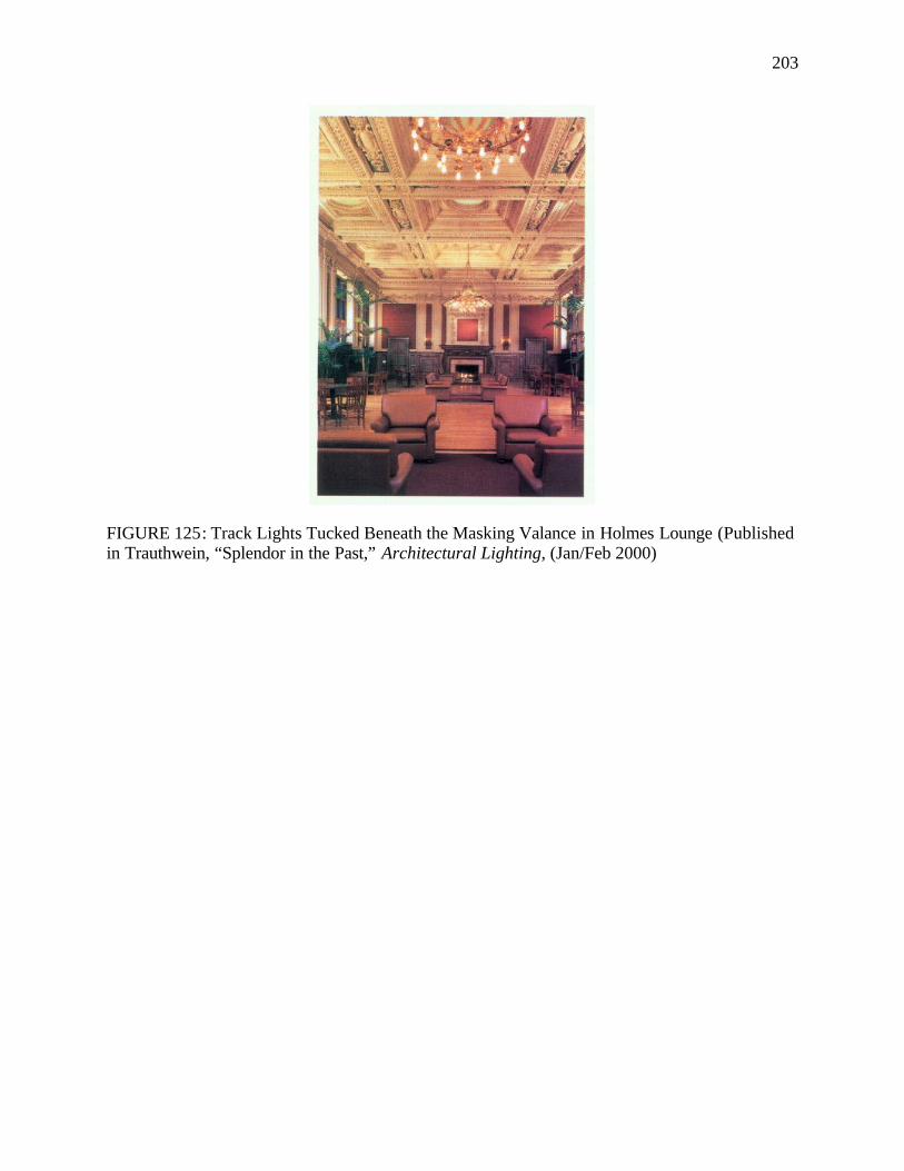
203
FIGURE 125: Track Lights Tucked Beneath the Masking Valance in Holmes Lounge (Published in Trauthwein, “Splendor in the Past,” Architectural Lighting, (Jan/Feb 2000)
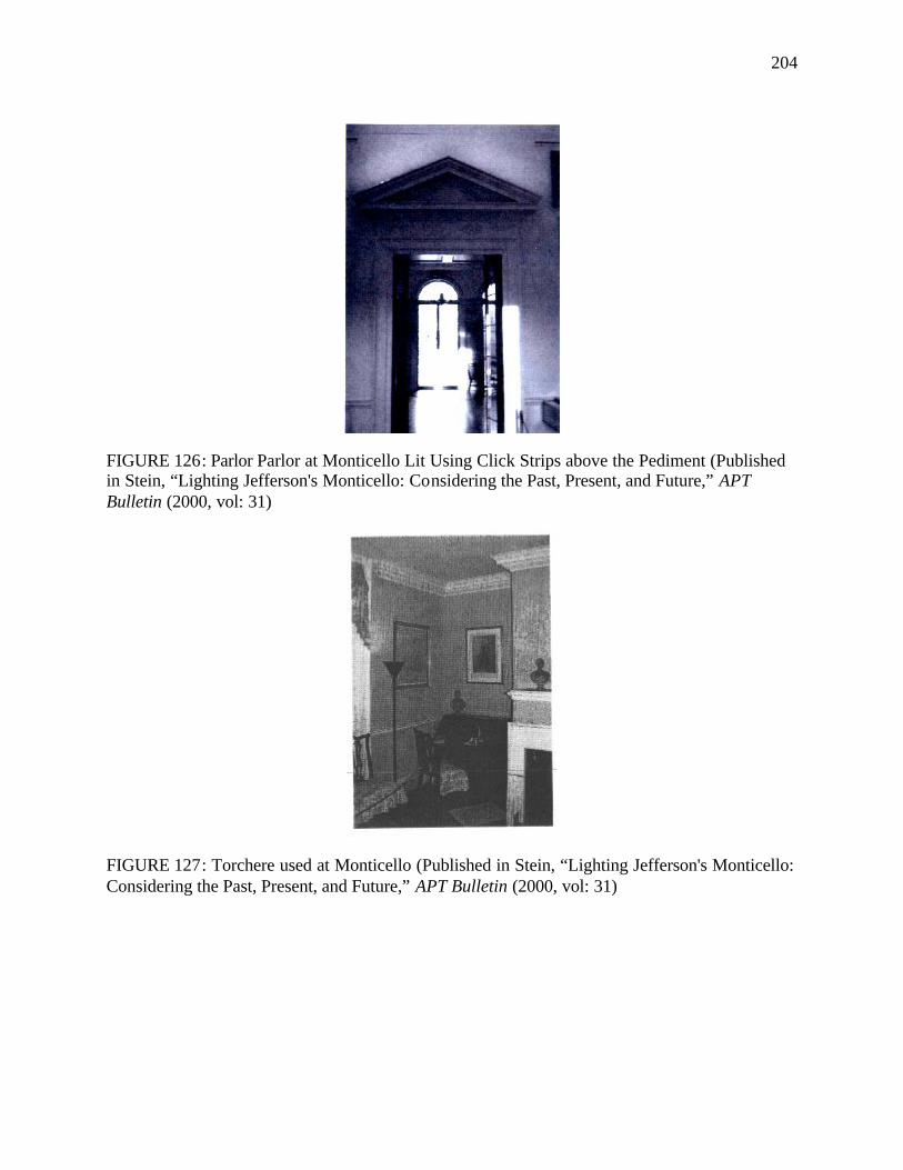
204
FIGURE 126: Parlor Parlor at Monticello Lit Using Click Strips above the Pediment (Published in Stein, “Lighting Jefferson's Monticello: Considering the Past, Present, and Future,” APT Bulletin (2000, vol: 31)
FIGURE 127: Torchere used at Monticello (Published in Stein, “Lighting Jefferson's Monticello: Considering the Past, Present, and Future,” APT Bulletin (2000, vol: 31)
205
provide sufficient light to do justice to the house’s colonial architectural features, collections of
pewter and porcelain, photographs, and artifacts of its maritime and social history. Instead of
recreating or adapting period light fixtures, the designers decided to replace the inefficient
modern fixtures within the house with smaller-sized modern fixtures. They were placed
unobtrusively in locations that had already been established for the previous lighting installation,
thereby eliminating the need to bore new holes and cause further damage. The ambient light
levels were kept the same as before (about five foot-candles in each room) but accent lights were
added and more directed light was provided. While this made it easier to view the artifacts and
interior details than earlier, it did compromise on the over-all historic authenticity and distorted
the period setting of the interiors.
The designers at the House of Seven Gables used low-voltage halogen lights for most of
the spotlighting needs, concentrating the light on important decorative objects in small areas. For
track lights to illuminate larger spaces, Schweppe replaced the previous 100 and 150 watts ‘A’
lamps with 50-75 watts PAR 20 and PAR 30 quartz halogen lamps (FIGURE 128, FIGURE
129). The new track lights made use of the holes and some of the hardware already in place on
the timber ceiling beams but used tracks that were significantly smaller in size (FIGURE 130).
All the decorative light fixtures in the house were re- lamped with lower-wattage incandescent
bulbs. In the attic, glaring R-40 lamps were used to view the post-and-beam construction. These
were replaced with PAR 30 spotlights. The lighting team installed new tracks in the attic by
concealing the wiring and hardware behind the beams and had the lights focused on the beams
rather than the visitors’ eyes (FIGURE 131). Since most of the display cabinets in the house
were open and posed no threat of heat build-up, Schweppe used five-watt quartz strip lighting to
illuminate the cabinets. For the enclosed parlor display cabinet, Schweppe considered the use of
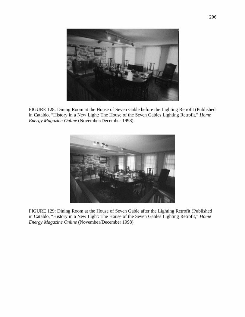
206
FIGURE 128: Dining Room at the House of Seven Gable before the Lighting Retrofit (Published in Cataldo, “History in a New Light: The House of the Seven Gables Lighting Retrofit,” Home Energy Magazine Online (November/December 1998)
FIGURE 129: Dining Room at the House of Seven Gable after the Lighting Retrofit (Published in Cataldo, “History in a New Light: The House of the Seven Gables Lighting Retrofit,” Home Energy Magazine Online (November/December 1998)
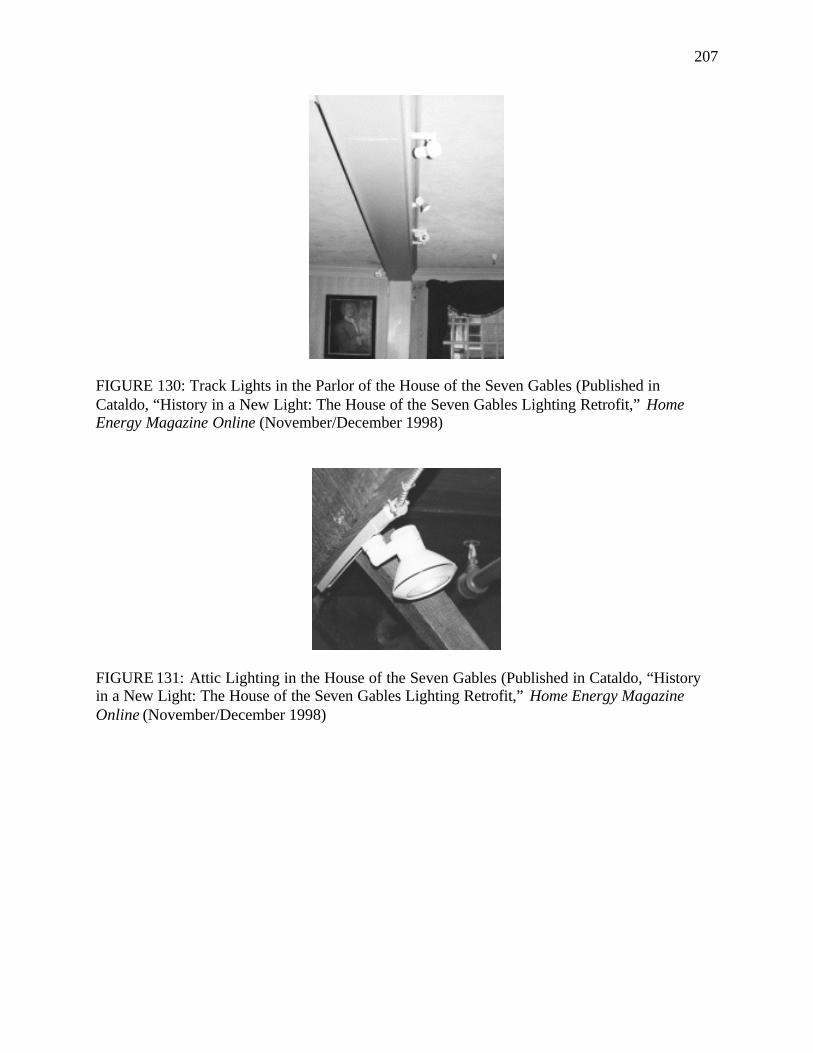
207
FIGURE 130: Track Lights in the Parlor of the House of the Seven Gables (Published in Cataldo, “History in a New Light: The House of the Seven Gables Lighting Retrofit,” Home Energy Magazine Online (November/December 1998)
FIGURE 131: Attic Lighting in the House of the Seven Gables (Published in Cataldo, “History in a New Light: The House of the Seven Gables Lighting Retrofit,” Home Energy Magazine Online (November/December 1998)
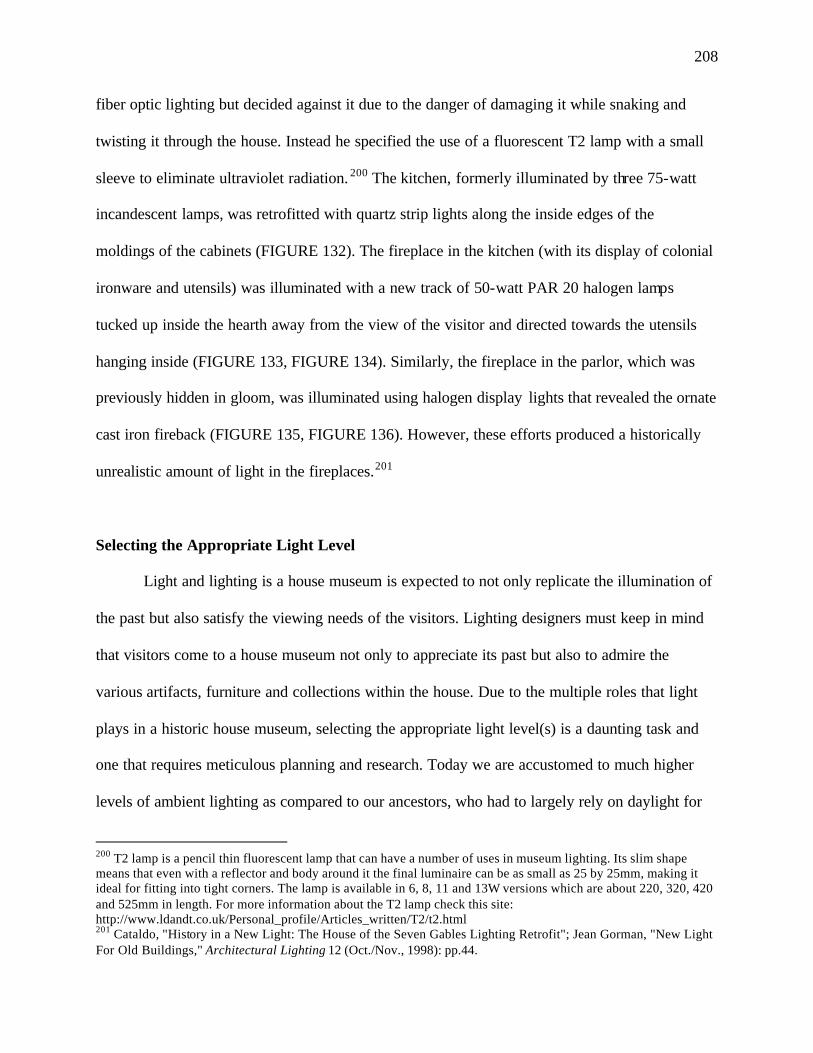
208
fiber optic lighting but decided against it due to the danger of damaging it while snaking and
twisting it through the house. Instead he specified the use of a fluorescent T2 lamp with a small
sleeve to eliminate ultraviolet radiation. 200 The kitchen, formerly illuminated by three 75-watt
incandescent lamps, was retrofitted with quartz strip lights along the inside edges of the
moldings of the cabinets (FIGURE 132). The fireplace in the kitchen (with its display of colonial
ironware and utensils) was illuminated with a new track of 50-watt PAR 20 halogen lamps
tucked up inside the hearth away from the view of the visitor and directed towards the utensils
hanging inside (FIGURE 133, FIGURE 134). Similarly, the fireplace in the parlor, which was
previously hidden in gloom, was illuminated using halogen display lights that revealed the ornate
cast iron fireback (FIGURE 135, FIGURE 136). However, these efforts produced a historically
unrealistic amount of light in the fireplaces.201
Selecting the Appropriate Light Level
Light and lighting is a house museum is expected to not only replicate the illumination of
the past but also satisfy the viewing needs of the visitors. Lighting designers must keep in mind
that visitors come to a house museum not only to appreciate its past but also to admire the
various artifacts, furniture and collections within the house. Due to the multiple roles that light
plays in a historic house museum, selecting the appropriate light level(s) is a daunting task and
one that requires meticulous planning and research. Today we are accustomed to much higher
levels of ambient lighting as compared to our ancestors, who had to largely rely on daylight for
200 T2 lamp is a pencil thin fluorescent lamp that can have a number of uses in museum lighting. Its slim shape means that even with a reflector and body around it the final luminaire can be as small as 25 by 25mm, making it ideal for fitting into tight corners. The lamp is available in 6, 8, 11 and 13W versions which are about 220, 320, 420 and 525mm in length. For more information about the T2 lamp check this site: http://www.ldandt.co.uk/Personal_profile/Articles_written/T2/t2.html 201 Cataldo, "History in a New Light: The House of the Seven Gables Lighting Retrofit"; Jean Gorman, "New Light For Old Buildings," Architectural Lighting 12 (Oct./Nov., 1998): pp.44.
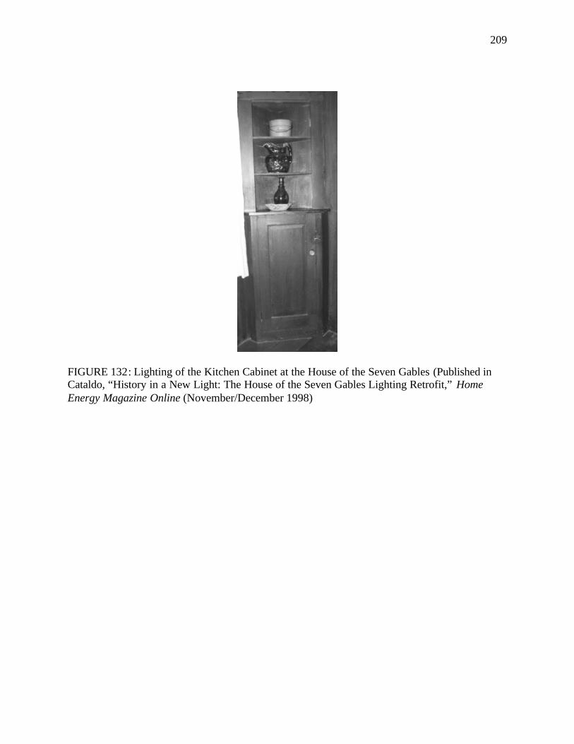
209
FIGURE 132: Lighting of the Kitchen Cabinet at the House of the Seven Gables (Published in Cataldo, “History in a New Light: The House of the Seven Gables Lighting Retrofit,” Home Energy Magazine Online (November/December 1998)
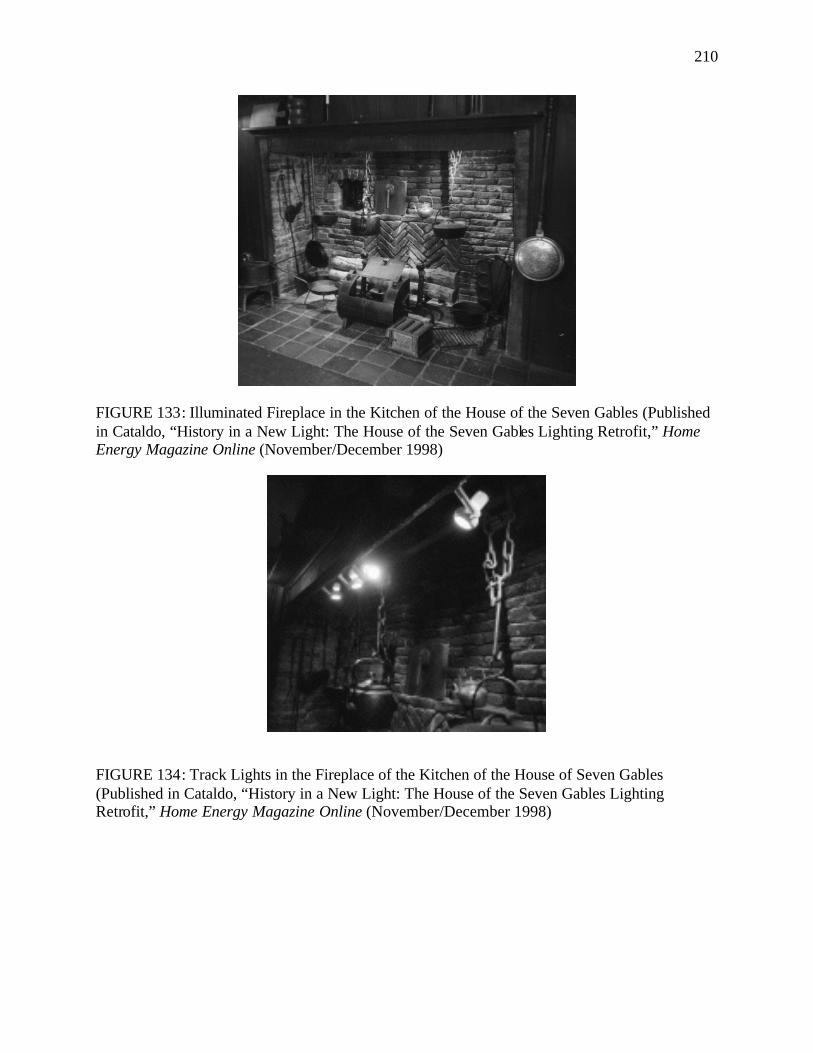
210
FIGURE 133: Illuminated Fireplace in the Kitchen of the House of the Seven Gables (Published in Cataldo, “History in a New Light: The House of the Seven Gables Lighting Retrofit,” Home Energy Magazine Online (November/December 1998)
FIGURE 134: Track Lights in the Fireplace of the Kitchen of the House of Seven Gables (Published in Cataldo, “History in a New Light: The House of the Seven Gables Lighting Retrofit,” Home Energy Magazine Online (November/December 1998)
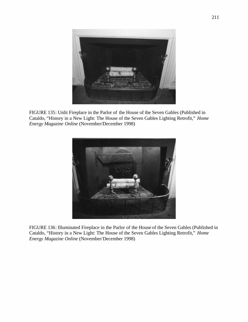
211
FIGURE 135: Unlit Fireplace in the Parlor of the House of the Seven Gables (Published in Cataldo, “History in a New Light: The House of the Seven Gables Lighting Retrofit,” Home Energy Magazine Online (November/December 1998)
FIGURE 136: Illuminated Fireplace in the Parlor of the House of the Seven Gables (Published in Cataldo, “History in a New Light: The House of the Seven Gables Lighting Retrofit,” Home Energy Magazine Online (November/December 1998)
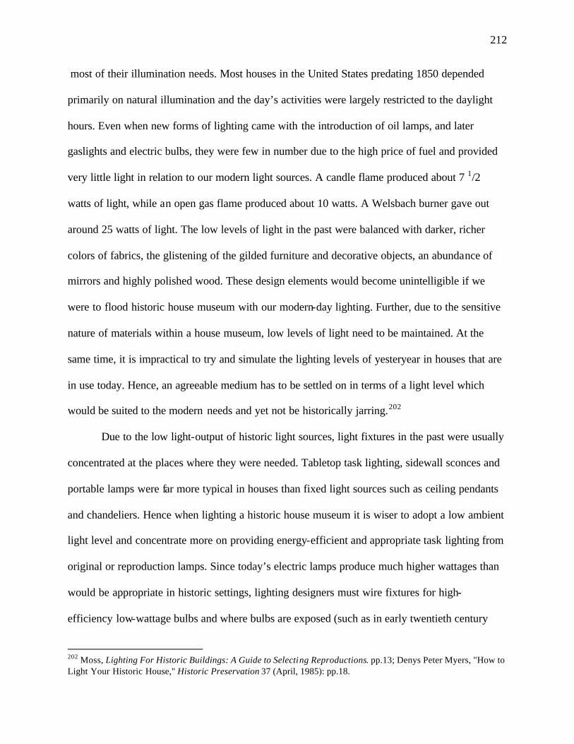
212
most of their illumination needs. Most houses in the United States predating 1850 depended
primarily on natural illumination and the day’s activities were largely restricted to the daylight
hours. Even when new forms of lighting came with the introduction of oil lamps, and later
gaslights and electric bulbs, they were few in number due to the high price of fuel and provided
very little light in relation to our modern light sources. A candle flame produced about 7 1/2
watts of light, while an open gas flame produced about 10 watts. A Welsbach burner gave out
around 25 watts of light. The low levels of light in the past were balanced with darker, richer
colors of fabrics, the glistening of the gilded furniture and decorative objects, an abundance of
mirrors and highly polished wood. These design elements would become unintelligible if we
were to flood historic house museum with our modern-day lighting. Further, due to the sensitive
nature of materials within a house museum, low levels of light need to be maintained. At the
same time, it is impractical to try and simulate the lighting levels of yesteryear in houses that are
in use today. Hence, an agreeable medium has to be settled on in terms of a light level which
would be suited to the modern needs and yet not be historically jarring.202
Due to the low light-output of historic light sources, light fixtures in the past were usually
concentrated at the places where they were needed. Tabletop task lighting, sidewall sconces and
portable lamps were far more typical in houses than fixed light sources such as ceiling pendants
and chandeliers. Hence when lighting a historic house museum it is wiser to adopt a low ambient
light level and concentrate more on providing energy-efficient and appropriate task lighting from
original or reproduction lamps. Since today’s electric lamps produce much higher wattages than
would be appropriate in historic settings, lighting designers must wire fixtures for high-
efficiency low-wattage bulbs and where bulbs are exposed (such as in early twentieth century
202 Moss, Lighting For Historic Buildings: A Guide to Selecting Reproductions. pp.13; Denys Peter Myers, "How to Light Your Historic House," Historic Preservation 37 (April, 1985): pp.18.
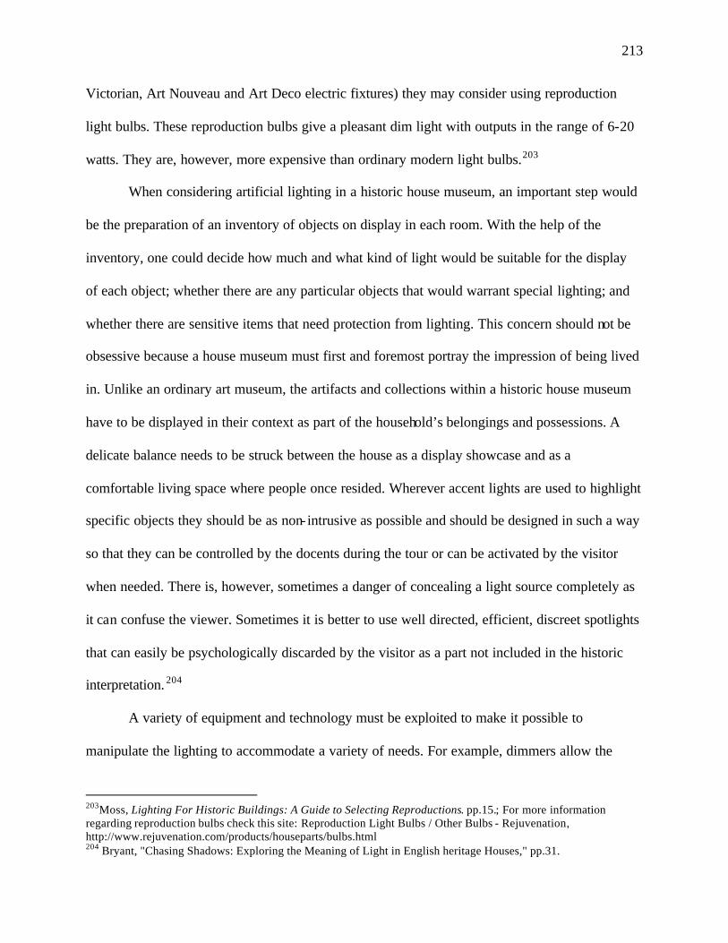
213
Victorian, Art Nouveau and Art Deco electric fixtures) they may consider using reproduction
light bulbs. These reproduction bulbs give a pleasant dim light with outputs in the range of 6-20
watts. They are, however, more expensive than ordinary modern light bulbs.203
When considering artificial lighting in a historic house museum, an important step would
be the preparation of an inventory of objects on display in each room. With the help of the
inventory, one could decide how much and what kind of light would be suitable for the display
of each object; whether there are any particular objects that would warrant special lighting; and
whether there are sensitive items that need protection from lighting. This concern should not be
obsessive because a house museum must first and foremost portray the impression of being lived
in. Unlike an ordinary art museum, the artifacts and collections within a historic house museum
have to be displayed in their context as part of the household’s belongings and possessions. A
delicate balance needs to be struck between the house as a display showcase and as a
comfortable living space where people once resided. Wherever accent lights are used to highlight
specific objects they should be as non- intrusive as possible and should be designed in such a way
so that they can be controlled by the docents during the tour or can be activated by the visitor
when needed. There is, however, sometimes a danger of concealing a light source completely as
it can confuse the viewer. Sometimes it is better to use well directed, efficient, discreet spotlights
that can easily be psychologically discarded by the visitor as a part not included in the historic
interpretation. 204
A variety of equipment and technology must be exploited to make it possible to
manipulate the lighting to accommodate a variety of needs. For example, dimmers allow the
203Moss, Lighting For Historic Buildings: A Guide to Selecting Reproductions. pp.15.; For more information regarding reproduction bulbs check this site: Reproduction Light Bulbs / Other Bulbs - Rejuvenation, http://www.rejuvenation.com/products/houseparts/bulbs.html 204 Bryant, "Chasing Shadows: Exploring the Meaning of Light in English heritage Houses," pp.31.
214
manipulating of the lighting level in the house to suit the time, season and activity taking place in
the room. With the help of dimmers rooms can be kept dimly lit during the tour hours to replicate
period illumination and then brightened up for cleaning and maintenance. Use of dimmers also
extends the life of lamps as dimmers gently move power to the filament in 10-60 seconds, rather
than instantly, causing less shock and damage to the filament.205 The lighting system in the house
may also be programmed to a couple of scene-sets eliminating the need for the museum staff to
use the dimmers to create particular effects. A particular scene-set may be used for historic tours
during the day; another may be used for evening functions; while yet another may be set for
cleaning and maintenance operations. This is particularly useful for historic house museums
expected to be used for multiple purposes.
Historic houses could also benefit from programmed photosensitive lighting systems that
would monitor the exterior light levels and accordingly control the interior lighting so as to
maintain a comfortable lighting level for viewing purposes and avoid a glaring difference
between the exterior light level and the interior lighting. Such a system would not only help
create a more pleasing lighting atmosphere but also save energy. While incandescent tungsten
filament lamps with their pleasing warm color are the conventional source of light in historic
houses, today lamp designers are experimenting with a variety of lamps, in order to enhance light
levels, have better color rendition, and improve energy efficiency.
Due regard must be paid to the psychology of visual perception when planning the
lighting of a historic house museum. Lighting designers should carefully plan out the route of the
tour to allow the eyes of the visitors to adapt to the low light- levels of the historic interiors. The
human eye accommodates the brightest light it perceives, automatically closing so that objects in
adjacent darker surroundings cannot be seen as well. Hence, the illumination en route to the 205Rambusch and Rambusch, "Creating Effective Lighting Systems for Historic Houses of Worship".
215
displays or rooms requiring conservation- level lighting must decrease progressively until the
exhibit is reached. This will give the visitors enough time to adjust to the low light levels and
will make the objects in dim surroundings more visible. Wide contrast in light levels should be
avoided and transition spaces should be planned to have light levels similar to the rooms they
connect. This is more easily done in larger houses than smaller one where tour-routes are easier
to adjust.206
While lighting Waddesdon Manor, a historic house museum in England, the designers
wanted to create a period lighting atmosphere while protecting the museum’s large collection of
artifacts and paintings, and also enabling visitors to clearly view the paintings and art objects.
Due to the sensitivity of the objects within the house, a 50-lux ceiling for ambient light levels
was set at the onset of the project. The work of the lighting designers was largely based on
determining how much light was needed for visual tasks and a sound understanding of the
adaptation of the human eye to changes in light levels. Hence, control of the visitor’s visual
adaptation became a critical issue for the lighting team. They found out that they could work
with much lower light levels and still hold on to visitor’s interest if they managed to control their
adaptation. In order to achieve this, they decided to restrict the entry to the house at timed
intervals. Visitors were invited into the entry hall for several minutes until their eyes were fully
adapted to the low ambient light levels in the house. Only when this adaptation process was
completed would the actual tour of the rooms begun. All transitional places were also kept at low
light levels to avoid any sudden changes in brightness.207
In order to control the harmful radiations from the sun, solar films were used along with
blinds. With daylight being controlled, artificial lighting needed to be used for proper
206Kay, "Historic Lighting- Saint or Sinner?," pp.42. 207Cannon-Brookes and Allen, "Lighting a Great House and a Museum: Waddesdon Manor, a Case Study," pp.33, 36.
216
illumination. The fixtures present in the house were all restored and suitably wired for electricity.
Chandeliers were electrified and made use of electric candles. The usual norm is to equip the
electric candles with dimmers so their brightness can be adjusted relative to the appearance of
the interiors. This helps to lower the brightness of the candles with reduced ambient light levels
so that the candles do not appear too bright. However, in Waddesdon Manor the designers
decided not to use dimmers since the ambient light levels would always be maintained at a
constant level. Instead they decided to use high-quality tungsten filament lamps with the lowest
wattage available in order to reduce glare and excessive brightness.208
Apart from the period fixtures present in the house, the lighting team had to give due
consideration to the special lighting needs of the paintings and artifacts on display in the house.
Special task lights had to be installed to enable visitors to satisfactorily view the objects while
making sure that conservation needs were met. The lighting team showed the greatest innovation
in the lighting for the paintings. Traditionally, paintings are lighted by either linear tungsten or
compact fluorescent lamps at fairly close proximity to the painting projected either from the back
of the wall or the frame. This arrangement causes most of the light to be focused on the top of
the painting, thereby, drawing away attention from the main subject in the center or lower half of
the painting and there is concern over the effects of the close lights to the paintings. Also, the
yellow hue of tungsten lamps greatly distorts the colors of paintings, particularly those in the
blue range, while fluorescent lamps give out ultraviolet radiation harmful for the paintings.
To correct these shortcomings, the Waddesdon lighting team came up with a completely
new design for the picture lights. They decided to use halogen sources for better color rendition
and reduction of heat. Small dichroic MR 11 lamps were used. In order for the light to reach the
center of the paintings the arms of the picture lights were lengthened. This also helped reduce the 208 Ibid.: pp.34.
217
intensity of light and thereby improve conservation of the paintings. For full- length portraits
some additional uplights were added at the bottoms of the frames. An antique gold color was
chosen for the picture lights. For smaller-size paintings the dichroic lamps were abandoned for
halogen sources without dichroic reflectors. This provided a more soothing beam of light and
reduced the intensity level. Thus, intensity of light over the canvases was controlled by the
choice of the wattage and the light source, the distance between the lamps, the arm length, the tilt
of the bulbs and the tilt of the cases of the picture lights.
The lighting team also faced the challenge of having to light glass display cabinets
containing a variety of art objects. The cabinets had earlier been lit by tungsten six-watt bulbs
causing undesirable heat gain within the gilded cases, and the yellow light of the tungsten lamps
greatly distorted the colors of the objects. To get rid of the heat build-up, the lighting team
decided to make use of fiber optic lighting where the source would be separated by a
considerable distance from the actual points of illumination. The sources were concealed under
furniture beneath the cases while the harness of tubes containing fiber-optic tails were weaved
through the glass sides of the cases. To make them as indiscreet as possible a gold-flock finish
was applied to harmonize the arms of the harness with the gilding of the cases. This arrangement
was successful in both eliminating the heat gain and providing good color rendering (FIGURE
137, FIGURE 138).209
In certain cases lighting in historic buildings is used to create a mood or evoke a
particular emotion in order to weave a story about the building’s past. This was the case in the
home of Charles Darwin at Down House in the United Kingdom. Here light was used more for
the creation of the right atmosphere than to function as illumination. Using the lighting scheme
209Ibid.: pp.34-36.
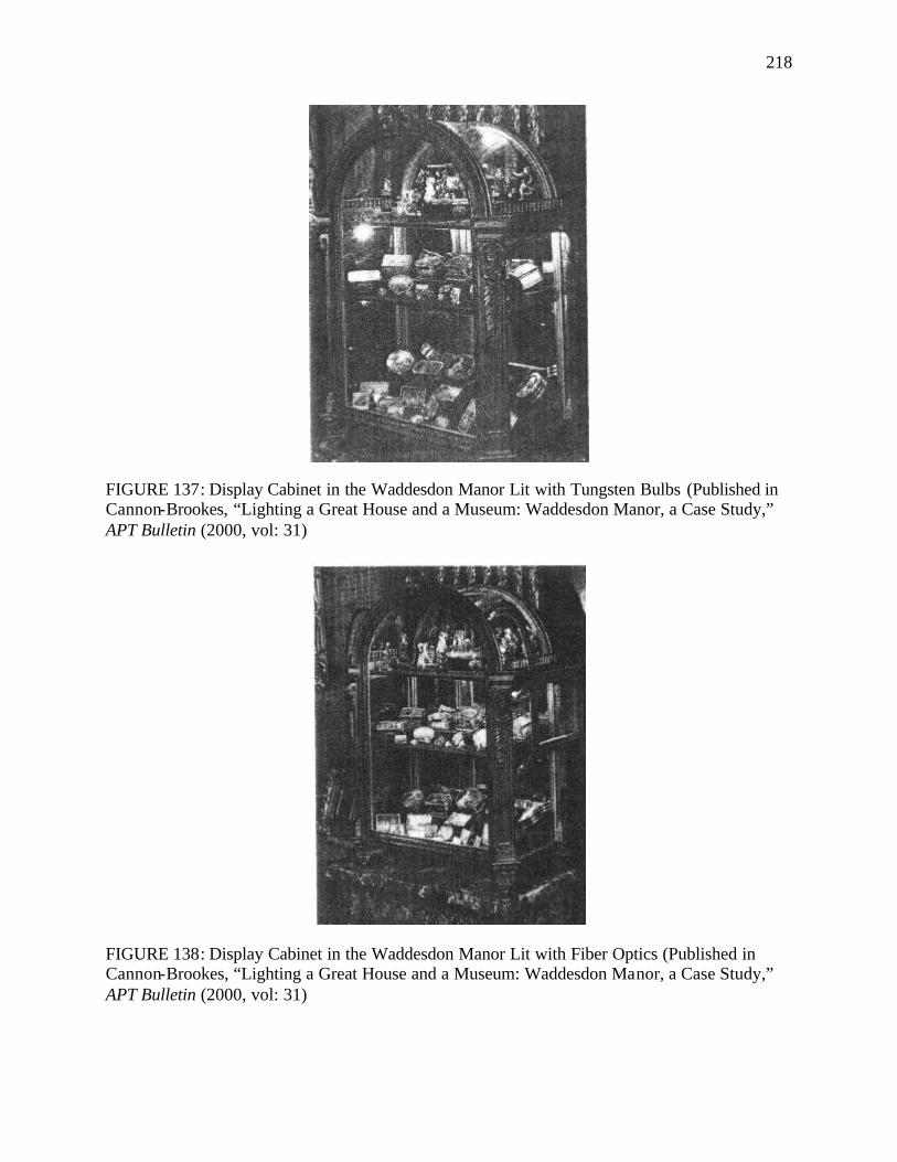
218
FIGURE 137: Display Cabinet in the Waddesdon Manor Lit with Tungsten Bulbs (Published in Cannon-Brookes, “Lighting a Great House and a Museum: Waddesdon Manor, a Case Study,” APT Bulletin (2000, vol: 31)
FIGURE 138: Display Cabinet in the Waddesdon Manor Lit with Fiber Optics (Published in Cannon-Brookes, “Lighting a Great House and a Museum: Waddesdon Manor, a Case Study,” APT Bulletin (2000, vol: 31)
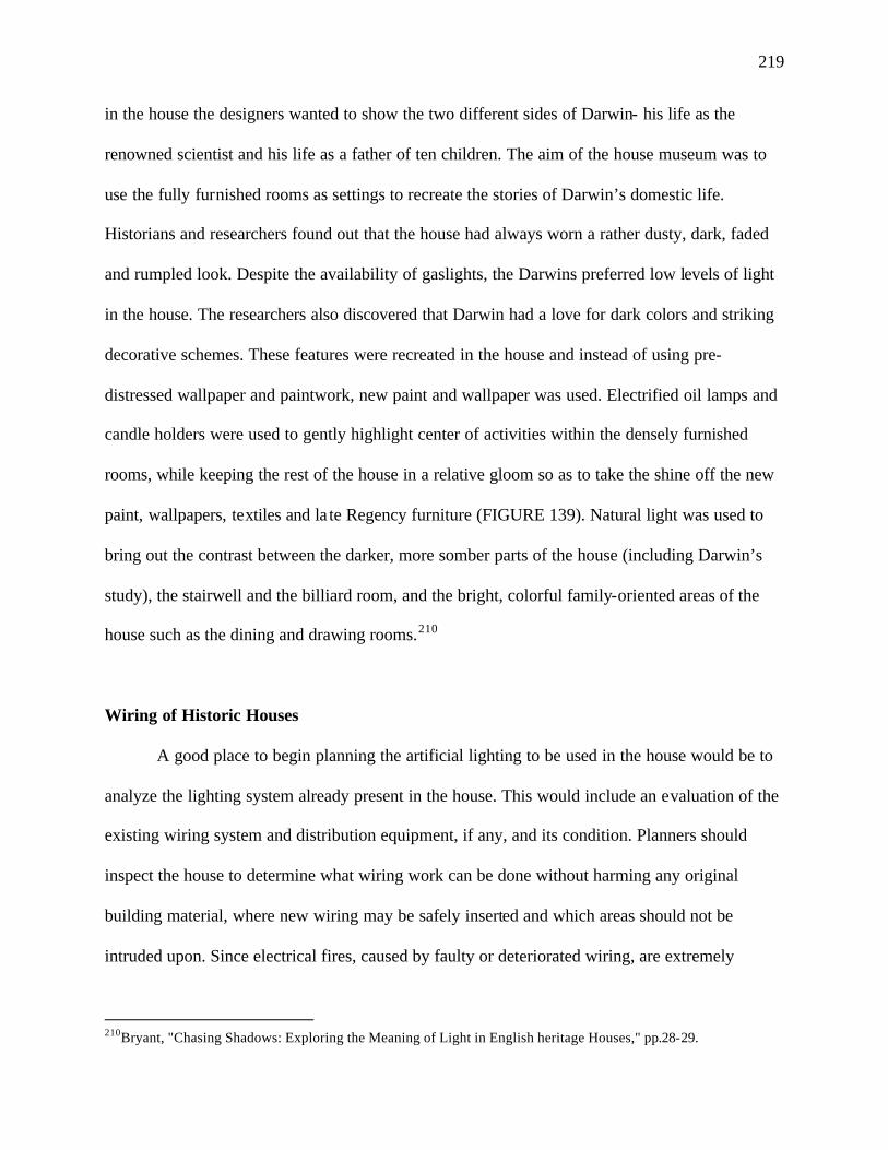
219
in the house the designers wanted to show the two different sides of Darwin- his life as the
renowned scientist and his life as a father of ten children. The aim of the house museum was to
use the fully furnished rooms as settings to recreate the stories of Darwin’s domestic life.
Historians and researchers found out that the house had always worn a rather dusty, dark, faded
and rumpled look. Despite the availability of gaslights, the Darwins preferred low levels of light
in the house. The researchers also discovered that Darwin had a love for dark colors and striking
decorative schemes. These features were recreated in the house and instead of using pre-
distressed wallpaper and paintwork, new paint and wallpaper was used. Electrified oil lamps and
candle holders were used to gently highlight center of activities within the densely furnished
rooms, while keeping the rest of the house in a relative gloom so as to take the shine off the new
paint, wallpapers, textiles and la te Regency furniture (FIGURE 139). Natural light was used to
bring out the contrast between the darker, more somber parts of the house (including Darwin’s
study), the stairwell and the billiard room, and the bright, colorful family-oriented areas of the
house such as the dining and drawing rooms.210
Wiring of Historic Houses
A good place to begin planning the artificial lighting to be used in the house would be to
analyze the lighting system already present in the house. This would include an evaluation of the
existing wiring system and distribution equipment, if any, and its condition. Planners should
inspect the house to determine what wiring work can be done without harming any original
building material, where new wiring may be safely inserted and which areas should not be
intruded upon. Since electrical fires, caused by faulty or deteriorated wiring, are extremely
210Bryant, "Chasing Shadows: Exploring the Meaning of Light in English heritage Houses," pp.28-29.
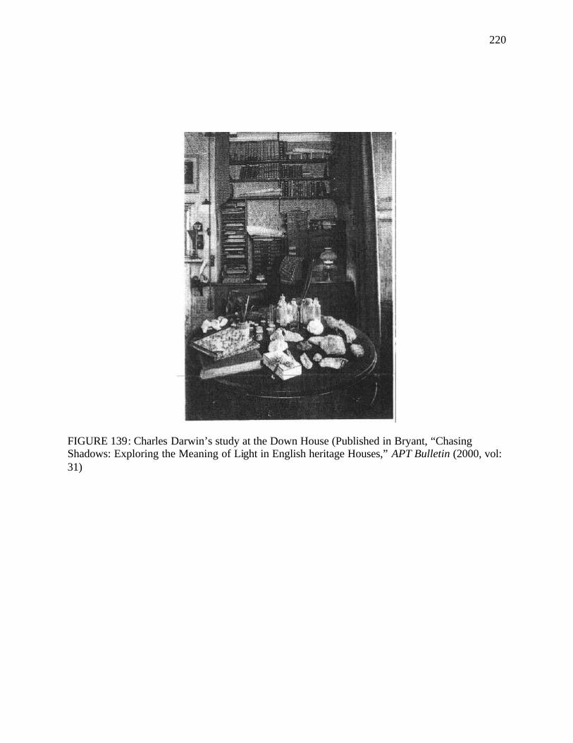
220
FIGURE 139: Charles Darwin’s study at the Down House (Published in Bryant, “Chasing Shadows: Exploring the Meaning of Light in English heritage Houses,” APT Bulletin (2000, vol: 31)
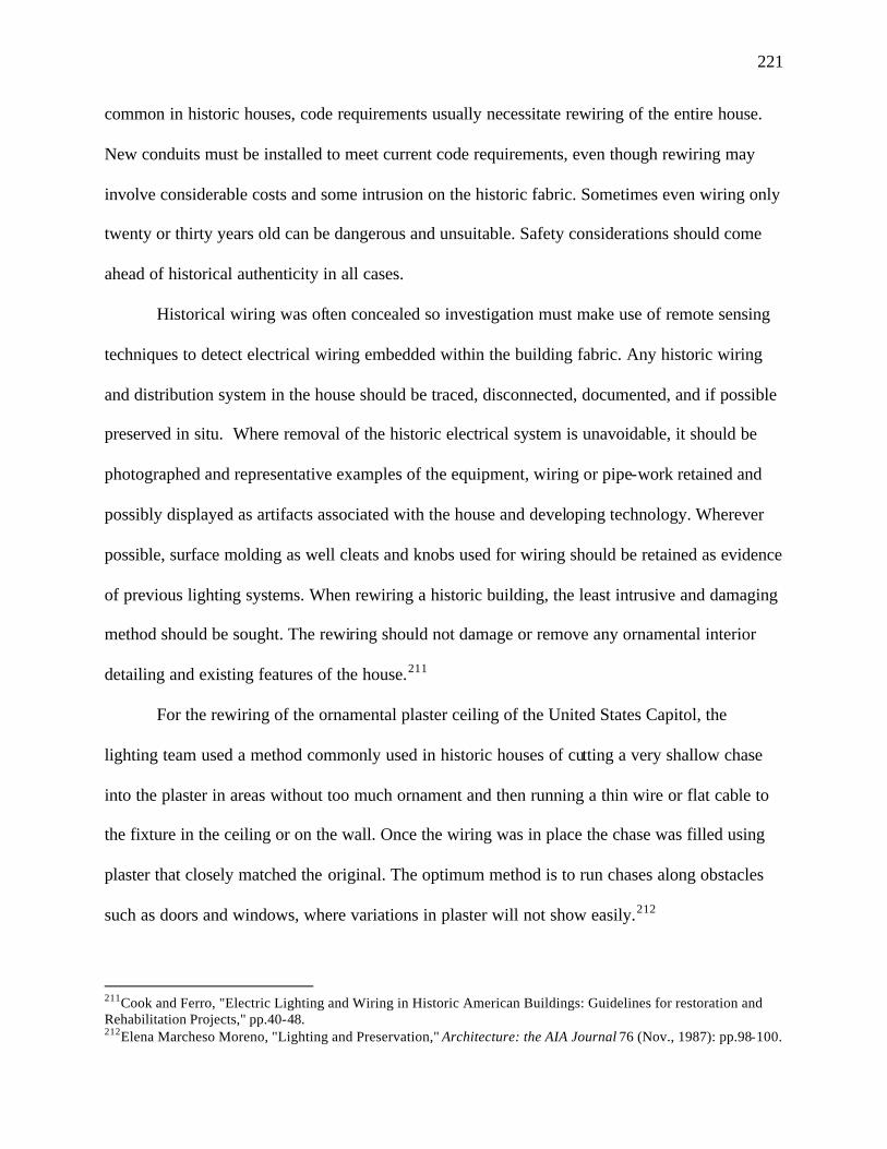
221
common in historic houses, code requirements usually necessitate rewiring of the entire house.
New conduits must be installed to meet current code requirements, even though rewiring may
involve considerable costs and some intrusion on the historic fabric. Sometimes even wiring only
twenty or thirty years old can be dangerous and unsuitable. Safety considerations should come
ahead of historical authenticity in all cases.
Historical wiring was often concealed so investigation must make use of remote sensing
techniques to detect electrical wiring embedded within the building fabric. Any historic wiring
and distribution system in the house should be traced, disconnected, documented, and if possible
preserved in situ. Where removal of the historic electrical system is unavoidable, it should be
photographed and representative examples of the equipment, wiring or pipe-work retained and
possibly displayed as artifacts associated with the house and developing technology. Wherever
possible, surface molding as well cleats and knobs used for wiring should be retained as evidence
of previous lighting systems. When rewiring a historic building, the least intrusive and damaging
method should be sought. The rewiring should not damage or remove any ornamental interior
detailing and existing features of the house.211
For the rewiring of the ornamental plaster ceiling of the United States Capitol, the
lighting team used a method commonly used in historic houses of cutting a very shallow chase
into the plaster in areas without too much ornament and then running a thin wire or flat cable to
the fixture in the ceiling or on the wall. Once the wiring was in place the chase was filled using
plaster that closely matched the original. The optimum method is to run chases along obstacles
such as doors and windows, where variations in plaster will not show easily.212
211Cook and Ferro, "Electric Lighting and Wiring in Historic American Buildings: Guidelines for restoration and Rehabilitation Projects," pp.40-48. 212Elena Marcheso Moreno, "Lighting and Preservation," Architecture: the AIA Journal 76 (Nov., 1987): pp.98-100.
222
For the lighting project of the House of Seven Gables in Salem, Massachusetts, the
lighting designer was faced with the challenge of retrofitting the house’s lighting without making
any holes in the walls, ceilings or floors. A preservation team had surveyed the house and
appraised the lighting designer of the places where new wiring could be inserted. The new
lighting scheme made use of the existing wiring in most places and used remote transformers to
step down the voltage when necessary. The transformers to step down the standard voltage to
low voltage were hidden in the basement of the house. In areas that had to be lit but had no
existing 120-volt wiring, smaller wires were concealed by running them on top of beams and
along baseboards. For the fireplaces in the kitchen, the wiring was hidden in the mortar joints
and cracks in the walls, and underneath the pine floorboards. In the attic, the wiring for the new
track lights was tucked up in the space above the beams. 213
213Cataldo, "History in a New Light: The House of the Seven Gables Lighting Retrofit".
223
CHAPTER V
SUMMARY GUIDELINES FOR LIGHTING HISTORIC HOUSE MUSEUMS
House museums, today, have a great deal of flexibility and several choices in terms of the
kind of lighting to be employed. The market is full of a diverse medley of lighting types and
fixtures, each appropriate for a particular function, location or occasion. With developments in
lighting technologies, the needs and expectations in terms of both the quality and quantity of
light have grown. Today people are accustomed to light levels that would be considered blinding
less than a century ago. Light is seen as a basic necessity of living and not just a source of
comfort or luxury. It is thus not a very feasible option for us to go back to the lighting conditions
of the past when lighting historic houses.
Apart from the consideration of lighting quantity and quality, safety is also ranked high in
the choice of light fixtures today. Safety considerations preclude the use of all open-flame light
sources today, which were once the only illuminants available. In spite of the restrictions on
duplicating historic lighting levels and types, there is a fascination for experiencing the living
conditions including the lighting conditions of our forefathers, giving rise to an ever-growing
number of historic house museums. This duality of the human nature of expecting the comfort
and safety of modern lighting while wishing to learn about the hardships and lack of resources in
the past raises several conflicting and complex issues that need to be addressed while lighting
historic house museums.
I have categorized these issues under the broad categories of: 1) Research; 2) Existing
Historic Light Fixtures; 3) Daylight Control; 4) Use of Reproduction Light Fixtures; 5) Use of
224
Modern Light Fixtures; 6) Selection of the Appropriate Light Levels; 7) Building Codes and
Wiring of Historic Houses; 8) Maintenance and Historic Interpretation of Lighting. Certain
guidelines for the lighting of historic house museums have been put forth with regard to each of
these eight issues, based on the discussions of the previous chapter. A successful lighting plan of
a historic house museum is one that pays regard to each of these issues and balances out the often
conflicting lighting needs. While going over the guidelines it must be remembered that there is
no standard solution to the planning of lighting in a historic house museum and each house must
be studied individually to find solutions that are ideal and unique to the house in question. Also,
since lighting is a part of the larger picture of historic interiors and architecture of the house, the
lighting team must include the participation of a wide range of professionals working together as
a cohesive unit.
1) Research
1.1 Sound and comprehensive research, concerning the history of the house and its inhabitants,
must form the backbone of the lighting plan. A number of sources must be referred to
including the chains of titles, tax records, insurance atlases, plat maps, wills, family papers,
newspaper clippings, publications, prints and early photographs. The building itself must
be thoroughly examined to uncover all evidences and information regarding its lighting
history. Also, oral history sources such as family members, local historians, academicians
and antiquarians must be tapped.214
1.2 The different pieces of information obtained must be considered in relation to one
another and a research report must be prepared where all the information obtained is
documented, analyzed and verified. 214 Moss, Lighting For Historic Buildings: A Guide to Selecting Reproductions. pp.19.
225
1.3 It must be remembered that research is never complete, so there should always be enough
flexibility in the plan to accommodate changes due to new information obtained.
2) Existing Historic Light Fixtures
2.1 All existing light fixtures in the house must be studied while still in place and an inventory
of the fixtures must be prepared to record: the style of the fixtures; the manufacturers, if
known; their locations; the lighting sources or the fuels used; if they are wired for
electricity; and their present condition, supported by photographs. The fixtures should be
checked to see that they are in their historically authentic locations.
2.2 Any modifications to historic fixtures in the house should be carried out only if the changes
made are reversible, non- intrusive, aesthetically compatible with the appearance of the
fixture, and composed of chemically inert materials.215
2.3 Tests should be run with mock-ups before attempting to carry out any work on original
fixtures.216
2.4 Trained and well-experienced professionals in the field must carry out all wiring and
restorations of historic fixtures.
3) Daylight Control
3.1 Daylight must be factored into the lighting plan as it will, in most cases, form a major
portion of the functional lighting in the museum.
3.2 Due to the damaging effects of sunlight careful study must be conducted to analyze the
sunlight exposure of the various rooms of the house at different times of the day and
215 Gillis and Harvey, "Lighting the Way: A Conservator's Approach to Electrifying Brass Chandeliers," pp.47. 216 Ibid.: pp.50.
226
different seasons. Light meters and UV meters must be used to measure exact amounts of
light and spot readings must be taken of light falling on the sensitive objects in the room.
3.3 Ultraviolet radiations in a room should not exceed 75µW/lm (microwatts of radiation per
lumen).217
3.4 For visible light, the recommended amounts are as follows: a maximum of 50 lux or 5 foot
candles for very sensitive items like paper, wallpaper, textiles, watercolors, manuscripts
and old photographs; 150 to 200 lux or 15 to 20 foot candles for sensitive materia ls like oil
paintings, wood, furniture and lacquer ware; levels may rise to a maximum of 300 lux or 30
foot candles for less sensitive materials like glass, metals, stone or ceramics.218
3.5 When the levels of harmful radiations are higher than the recommended levels sunlight
control methods must be adopted. Traditional methods of daylight control include shutters,
curtains, sheers, Venetian or roller blinds, and louvers. Non-traditional methods are
grouped into either of the two: soft controls such as solar films, and rigid controls such as
acrylic-based or polycarbonate-based rigid sheets.219
3.6 Care should be taken that daylight control methods do not damage the historic fabric or
adversely affect the quality of light in the room.
3.7 Apart from controlling the intensity, it is also important to minimize the duration of
daylight exposure. Whenever rooms are not in use all lights should be turned off, and
shutters should be closed.
217 Craft and Miller, "Controlling Daylight in Historic Structures: A Focus on Interior Methods," pp.54. 218 Ibid. 219 Ibid.: pp.55-56.
227
4) Use of Reproduction Light Fixtures
4.1 When the day lighting (particularly, after control methods are applied) and the original
light fixtures are not enough to meet the lighting needs suitable reproductions may be used.
4.2 Reproductions used must conform to the architectural style and the interiors of the house,
and the interpretive goal and period selected. Typically, houses of the colonial period
(1610-1780) should be equipped with only rush holders, candle fixtures and simple oil
lamps. Glass fixtures and glass chandeliers were introduced in the American homes in the
Federal period (1780-1840). Whale oil lamps, including Argand lamps, were commonly
featured in Federal houses, although candles were still extensively used. Glass lamps grew
more ornate in the Greek Revival period (1820-1860) with elaborate press-molded patterns.
The 1840s witnessed the short- lived popularity of two lighting fuels: burning fluids or
camphene, and lard. Solar lamps using lard oil were popular lighting devices in this period.
However, both camphene and lard could not stand up to the competition put forth by
kerosene that was introduced in American homes from the 1860s and continued to be an
important lighting fuel till well into the twentieth century. Gas also started being used as a
domestic lighting fuel in the 1840s and 1850s. In the Victorian period (1860-1890) houses
saw an eclectic mix of lighting types being used with kerosene lamps, gas fixtures, and
candleholders all jostling for attention. Ornamentation was at its height in this period. The
Modern period (1890-1930) saw gaslight soar to popularity with the discovery of the gas
mantle, which gave electric lighting serious competition. Aesthetically, light fixtures in the
modern period followed three varied philosophies: neo-revivalism, the Arts and Craft
movement and the Art Nouveau movement. The former looked back at the styles of the
previous decades, while the latter two wanted to break free from the mold of traditional
228
designs. From the 1920s electric lighting became the lighting source of choice in American
houses.
4.3 The reproductions must be the products of comprehensive research and meticulous
detailing, and must be as close in appearance to the historical prototypes as possible.
4.4 An extensive knowledge of the type of fixtures being sought is necessary before attempting
to purchase the reproductions. Original fixtures should be consulted and compared with the
reproductions before making the purchases.220
4.5 The reproductions must be installed or placed in their historically appropriate locations.
4.6 When installing reproductions, it is always advisable to use mock-ups on the site before
making the actual installation. 221
5) Use of Modern Light Fixtures
5.1 Modern light fixtures may be used in historic house museums to enhance overall lighting
levels and effects, and to highlight certain objects of interest or architectural features. Their
use must not detract from the historicity and architectural integrity of the house or damage
the historic fabric of the house or produce glare.
5.2 A report must be prepared to assess what alterations need to be made to accommodate the
additional modern light fittings; in which parts of the house such changes are acceptable,
feasible and safe; and which parts of house must not be altered.
5.3 As far as possible, modern light fixtures must be well concealed and installed out of the
line of sight of visitors. The common ways of concealing modern lighting in historic houses
220 Moss, Lighting For Historic Buildings: A Guide to Selecting Reproductions. pp.26. 221 Gillis and Harvey, "Lighting the Way: A Conservator's Approach to Electrifying Brass Chandeliers," pp.50.
229
are to place them behind structural features, behind furniture, on the floor level, and along
the edge of moldings.
5.4 Fiber optic lighting may be employed in house museums as it is easy to conceal, low-
maintenance, virtually free of harmful of ultraviolet radiations and infrared energy, and can
be used in even the most inaccessible areas. It is particularly useful for lighting rooms with
objects sensitive to photochemical degradation and display cabinets. Fiber optic technology
can also be used to retrofit period light fixtures.
5.5 As the installation of fiber optic lighting can be complicated, professional help must be
sought.
6) Selection of the Appropriate Light Levels
6.1 The level of lighting in the house must relate to the historic standards and illumination
conditions, while making sure that visitors are able to comfortably view and appreciate the
historic interiors.
6.2 Historic houses usually had low levels of ambient lighting since light sources were very
inefficient as compared to today. Lighting used was mostly task-specific. Hence, a greater
number of appropriate task- lighting sources must be used rather than a high level of
ambient light.222
6.3 It is always safer to specify less light rather than more in a historic house as most historic
houses had very low levels of illumination and were decorated with objects that tended to
reflect a great deal of light.223
222 Phillips, Lighting Historic Buildings. pp.52. 223 Ibid. pp.46.
230
6.4 As far as possible, the lamps fitted onto period and reproduction fixtures must give out the
same or similar wattage of light as was historically produced.
6.5 An inventory of objects to be displayed in each room should be prepared so that it may be
determined what quality and quantity of light would be suitable for their display; what light
fixtures need to be employed for the task and how they are to be positioned; and if any of
the objects are sensitive and need protection from the lighting.
6.6 Dimmers and programmed scene-sets should be used in order to vary the light levels
according the needs and the hours of the day.
6.7 Planners should lay the tour route such that visitors have enough time to adapt to the lower
illumination levels of the historic interiors. The route to the dimly- lit areas of the house
must get progressively darker until they are reached. Also, sharp contrasts of light levels
must be avoided.224
6.8 The degree of lighting and the type of light fixtures used must be commensurate with the
economic status of the owners of the house.
7) Building Codes and Wiring in Historic Houses
7.1 Building codes must be strictly adhered to when wiring a historic house museum. In most
cases, old electrical systems are hazardous and need replacement.
7.2 The lighting system present in the house must be thoroughly examined. Since many of the
historic wiring systems were concealed, remote sensing techniques should be employed to
detect them.
7.3 As far as possible, the old wiring should be traced, disconnected, documented and
preserved in situ. When removal is unavoidable, they should be photographed, along with 224 Cannon-Brookes and Allen, "Lighting a Great House and a Museum: Waddesdon Manor, a Case Study," pp.36.
231
the documentation, and samples of the historic wiring should be kept as artifacts associated
with the house’s history and its technological progress.225
7.4 When conducting the rewiring of a historic house, the least intrusive and most reversible
method should be sought.
7.5 As with all present day buildings, historic house museums must make adequate provisions
for emergency lighting.
8) Maintenance and Historic Interpretation of Lighting
8.1 Lighting and light fixtures should be included as a component of the historic site
interpretation along with the architecture, furniture, other decorative arts, and family
history. The museum custodians should be cognizant of not only what the historic light
fixtures look like but also how they worked, who looked after them and how they affected
the living patterns of the inhabitants.226
8.2 A detailed housekeeping and conservation manual must be drawn up to ensure the proper
daily care as well as conservation of the light fixtures by the house staff. 227
8.3 The entire lighting restoration and wiring process must be well documented so as help
researchers, and to make any future work and maintenance procedures easier to conduct.
225 Himmelstein and Appelbaum, "An Overview of Light and Lighting in Historic Structures That House Collections," pp.14. 226 Sherman, "A Look at Nineteenth-Century Lighting: Lighting Devices from the Merchant's House Museum." 227 Drury, "Historic Buildings: The Conservation of Their Fixtures, Fittings, Decorations and Contents".
232
BIBLIOGRAPHY
Bacot, H. Parrott. Nineteenth Century Lighting: Candle Powered Devices: 1783-1883. Pennsylvania: Schiffer Publishing Ltd., 1987. Behm, Gary H. "Historic Lighting Specifications: The Role of "Value Engineering" in Lighting Historic Spaces." Clem Labine's Traditional Building 13, no. 6 (2000): 180-202. ———. "Lighting Historic Interiors." Clem Labine's Traditional Building 12, no. 6 (1999): 194-214. Bock, Gordon , and Lynn Elliott. "Let There Be Light: Electricity Changed Designs in U.S. Home." Chicago Sun-Times, 21st January 1994, 22. Bowers, Brian. Lengthening the Day: A History of Lighting Technology. New York: Oxford University Press Inc., 1998. Bowler, Molly Maloney. "Shedding Light on a Philosophy of Living: Reproduction Lighting and Modern Variations." American Bungalow 1, no. 3 (1991): 30-35. A Brief History of Candles. Craftsland. Available from http://www.craftsland.com/candle_history.html Bryant, Julius. "Chasing Shadows: Exploring the Meaning of Light in English heritage Houses." APT Bulletin 31, no. 1 (2000): 27-31. Cannon-Brookes, Stephen , and William Allen. "Lighting a Great House and a Museum: Waddesdon Manor, a Case Study." APT Bulletin 31, no. 1 (2000): 32-36. Cataldo, Sandy. History in a New Light: The House of the Seven Gables Lighting Retrofit. Home Energy Magazine Online, November/December 1998. Ava ilable from http://hem.dis.anl.gov/eehem/98/981109.html Coleman, Laurence Vail. Historic House Museums. Washington, D.C.: Gale Research Company, 1973. Cook, Melissa L. , and Maximilian L. Ferro. "Electric Lighting and Wiring in Historic American Buildings: Guidelines for restoration and Rehabilitation Projects." Technology & Conservation 8, no. 41 (1983): 28-48. Cooke, Lawrence S. Lighting in America: From Colonial Rushlights to Victorian Chandeliers. New York: Main Street/Universe Books, 1975.
233
Covington, Edward J. Marvin Pipkin - A Biography. February 21, 2004. Available from http://home.frognet.net/~ejcov/pipkin.html ———. The White Mazda Lamps. 21 Februrary, 2004. Available from http://home.frognet.net/~ejcov/whitem.html Cox, James A. A Century of Light: Benjamin Co., 1979. Craft, Meg Loew, and M. Nicole Miller. "Controlling Daylight in Historic Structures: A Focus on Interior Methods." APT Bulletin 31, no. 1 (2000): 53-59. Crowley, John E. The Invention of Comfort . Baltimore: The Johns Hopkins University Press, 2001. Dillon, Maureen. Artificial Sunshine: A Social History of Domestic Lighting. London: The National Trust, 2002. Donnelly, Jessica Foy. Interpreting Historic House Museums. Walnut Creek, CA: Alta Mira Press, 2002. Drury, Martin. Historic Buildings: The Conservation of Their Fixtures, Fittings, Decorations and Contents. The National Trust Policy Papers, 1996. Available from http://www.nationaltrust.org.uk/historicproperties/ downloads/3004A.PDF. Duncan, Alastair. Art Nouveau and Art Deco Lighting. New York: Simon and Schuster, 1978. Ellison, Rebecca. The Effects of Daylight. The Building Conservation Directory, 2000. Available from http://www.buildingconservation.com/articles/daylight/daylight.htm Elville, E.M. The Collector's Dictionary of Glass. London: Country Life Ltd., 1961. Garrett, Elisabeth Donaghy. "The American Home, Part I." The Magazine Antiques (1983): 221. General Electric Company. Available from http://www.gelighting.com/na/home/home_halogen.html Gillis, Kathy Z. , and David Harvey. "Lighting the Way: A Conservator's Approach to Electrifying Brass Chandeliers." APT Bulletin 31, no. 1 (2000): 45-51. Gorman, Jean. "New Light For Old Buildings." Architectural Lighting 12, no. 5 (1998): 44-48. Gowans, Alan. Images of American Living: Four Centuries of Architecture and Furniture as Cultural Expression. New York: Harper and Row Publishers, 1976. Hayward, Arthur H. Colonial Lighting. New York: Dover Publications, Inc., 1962.
234
Hebard, Helen Bringham. Early Lighting in New England 1620-1861. Rutland, Vermont: Charles E. Tuttle Company, 1964. Heinz, Thomas A. Frank Lloyd Wright Furniture Portfolio. Layton, UT: Gibbs Smith, 1993. Himmelstein, Paul , and Barbara Appelbaum. "An Overview of Light and Lighting in Historic Structures That House Collections." APT Bulletin 31, no. 1 (2000): 13-15. Johnson, Bruce E. "Arts and Crafts Metalwork." Country Living 19, no. 2 (1996): 52. Kay, Gersil. "Historic Lighting- Saint or Sinner?" Journal of Architectural Conservation 8, no. 1 (2002): 38-56. Kubler, Virginia L. Interior Fashion Focus: Solar Control—The Intelligent Choice. Draperies and Window Coverings Online, November 1999. Available from http://www.dwcdesignet.com/DWC/Nov'99/solar.html. Leviner, Betty Crowe. ""Luminous and Splendid": Lighting Colonial Virginia Interiors by Candlelight." APT Bulletin 31, no. 1 (2000): 17-20. Liao, Alice. "Revisionist History." Architectural Lighting 16, no. 6 (2001): 24-26, 40. Luckiesh, M. Artificial Light: It's Influence Upon Civilization. New York: The Century Company, 1920. Mahoney, Kathleen. Gothic Style: Architecture and Interiors from the Eighteenth Century to the Present. New York: Harry N. Abrams, 1995. Maril, Nadja. American Lighting: 1840-1940. Pennsylvania: Schiffer Publishing, Ltd., 1989. ———. Antique Lamp Buyer's Guide: Identifying Late 19th and Early 20th Century Lighting. Pennsylvania: Schiffer Publishing, Ltd, 1999. Moreno, Elena Marcheso. "Lighting and Preservation." Architecture: the AIA Journal 76, no. 11 (1987): 98-100. Moss, Roger W. Lighting For Historic Buildings: A Guide to Selecting Reproductions. Washington, D.C: The Preservation Press, 1988. Myers, Denys Peter. Gaslighting in America: A Guide for Historic Preservation. Washington, D.C.: Heritage Conservation and Recreation Services, 1978. ———. "How to Light Your Historic House." Historic Preservation 37 (1985): 15-19. Neustadt, Egon. The Lamps of Tiffany. New York: The Fairfield Press, 1970. O'Dea, W.T. The Social History of Lighting. London: Routledge and Kegan Paul, 1958.
235
Palmer, Arlene. Glass in Early America. Winterthur, Delaware: Henry Francis Du Pont Winterthur Museum, Inc., 1993. Phillips, Derek. Lighting Historic Buildings. New York: McGraw Hill, 1997. Pile, John. A History of Interior Design. New York: John Wiley & Sons, Inc, 2000. Poese, Bill. Lighting Through The Years: The Light in the Darkness. Des Moines, Iowa: Wallace-Homestead Book Company, 1976. Polson, Mary Ellen. "Lighting the Living Rooms." Old-House Journal, no. 1 (1999): 49-55. Rambusch, Edwin P. , and Martin V. Rambusch. Creating Effective Lighting Systems for Historic Houses of Worship. Available from http://www.sacredplaces.org/PSP-InfoClearingHouse/articles/CREATING%20EFFECTIVE%20LIGHTING%20SYSTEMS%20FOR%20HISTORIC%20HOUSES%20OF%20WO.htm Rambusch , Viggo Bech. "Historic Interior Lighting: Recreating 19th Century Fixtures for Capitol Buildings." Technology & Conservation 6, no. 4 (1981): 36-41. Russell, Loris S. A Heritage of Light: Lamps and Lighting in the Early Canadian Home. Toronto: University of Toronto Press, 1968. Schivelbusch, Wolfgang. Disenchanted Night: The Industrialization of Light in the Nineteenth Century. Berkeley: The University of California Press, 1988. Shaw, Kevan. Fibre Optic Lighting. Kevan Shaw Lighting Design, 4-1-99 1999. Available from http://www.kevan-shaw.com/articles/tech/fibre/fibre.html. Sherman, Mimi. "A Look at Nineteenth-Century Lighting: Lighting Devices from the Merchant's House Museum." APT Bulletin 31, no. 1 (2000): 37-43. Smith, C. Ray. Interior Design In 20th-Century America: A History. New York: Harper & Row Publishers, 1987. Stein, Susan R, and John B. Rudder. "Lighting Jefferson's Monticello: Considering the Past, Present, and Future." APT Bulletin 31, no. 1 (2000): 21-26. Tate, Allen, and C. Ray Smith. Interior Design in the 20th Century. New York, NY: Harper & Row, Publishers, 1986. The Rushlight Club. Early Lighting: A Pictorial Guide. Boston: Author, 1972. Trauthwein, Christina. "Splendor in the Past." Architectural Lighting 15, no. 1 (2000): 32-34.

236
Uecker, Wolf. Art Nouveau and Art Deco Lamps and Candlesticks. New York: Abbeville Press and Publishers, 1986. Winkler, Gail Caskey, and Roger W. Moss. Victorian Interior Decoration: American Interiors 1830-1900. New York: Henry Holt And Company, 1986. "Wright Lighting." Interior Design 65, no. 4 (1994): 66-67.
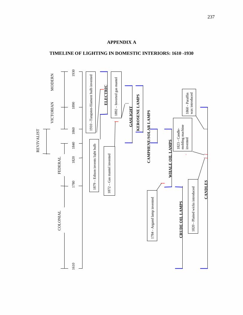
237
APPENDIX A
TIMELINE OF LIGHTING IN DOMESTIC INTERIORS: 1610 -1930
KE
RO
SEN
E L
AM
PS
1879
– E
diso
n in
vent
s lig
ht b
ulb
WH
AL
E O
IL L
AM
PS
CA
MP
HE
NE
/SO
LA
R L
AM
PS
1823
- C
andl
e-m
oldi
ng m
achi
ne
inve
nted
1784
- A
rgan
d la
mp
inve
nted
1872
– G
as m
ante
l inv
ente
d
FED
ER
AL
1780
RE
VIV
AL
IST
VIC
TO
RIA
N
1820
- Pl
aite
d w
icks
intro
duce
d
1890
18
60
1840
CA
ND
LE
S
GA
SLIG
HT
1820
1860
- Pa
raff
in
wax
intro
duce
d
EL
EC
TR
IC
CR
UD
E O
IL L
AM
PS
1610
CO
LO
NIA
L
MO
DE
RN 19
30
1892
– In
verte
d ga
s m
ante
l in
vent
ed
1910
–Tu
ngst
en-f
ilam
ent b
ulb
inve
nted
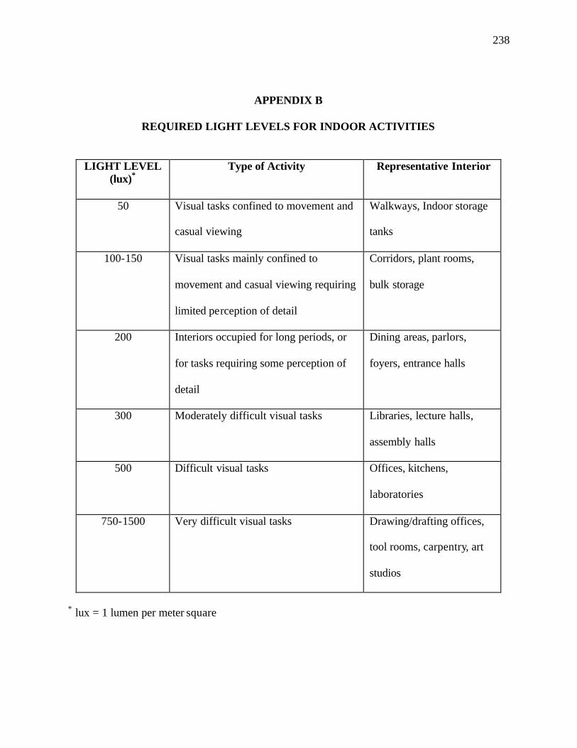
238
APPENDIX B
REQUIRED LIGHT LEVELS FOR INDOOR ACTIVITIES
LIGHT LEVEL (lux)*
Type of Activity Representative Interior
50 Visual tasks confined to movement and
casual viewing
Walkways, Indoor storage
tanks
100-150 Visual tasks mainly confined to
movement and casual viewing requiring
limited perception of detail
Corridors, plant rooms,
bulk storage
200 Interiors occupied for long periods, or
for tasks requiring some perception of
detail
Dining areas, parlors,
foyers, entrance halls
300 Moderately difficult visual tasks Libraries, lecture halls,
assembly halls
500 Difficult visual tasks Offices, kitchens,
laboratories
750-1500 Very difficult visual tasks Drawing/drafting offices,
tool rooms, carpentry, art
studios
* lux = 1 lumen per meter square
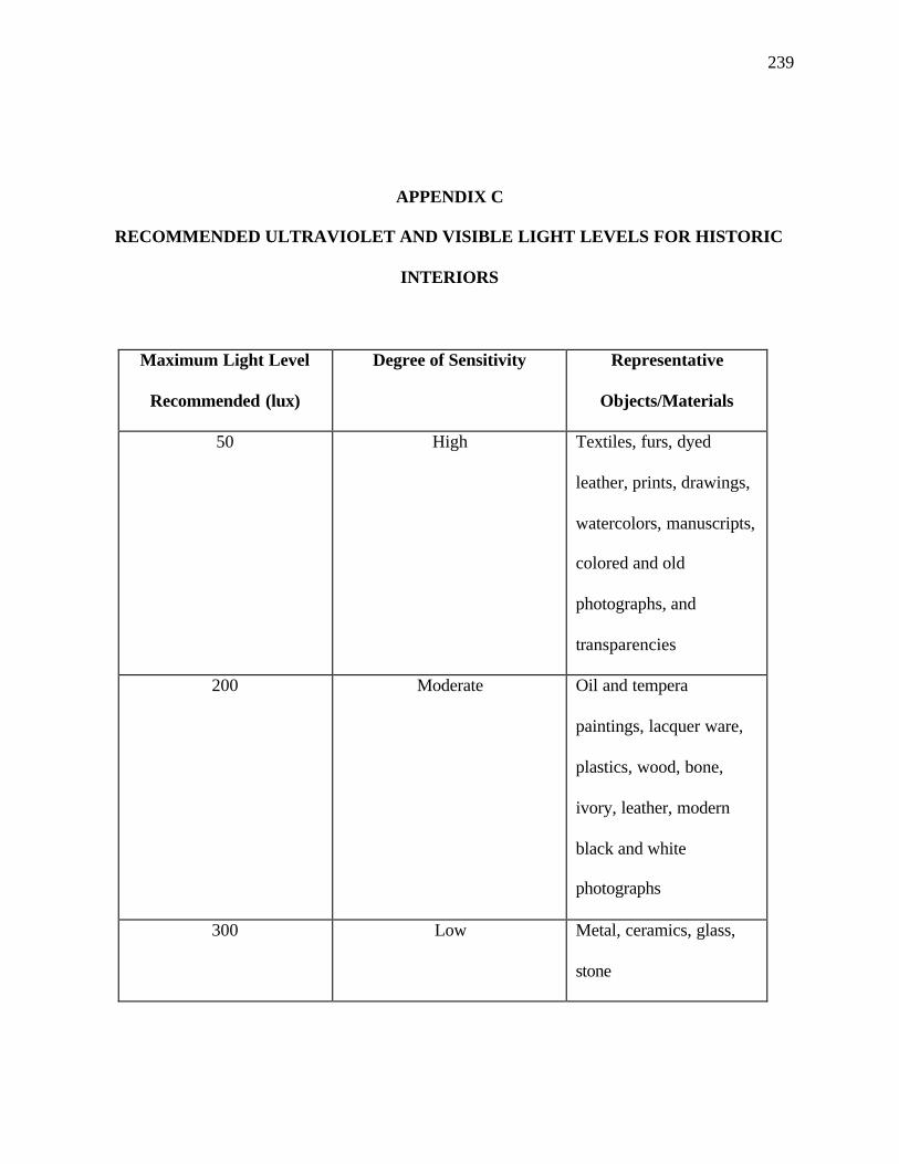
239
APPENDIX C
RECOMMENDED ULTRAVIOLET AND VISIBLE LIGHT LEVELS FOR HISTORIC
INTERIORS
Maximum Light Level
Recommended (lux)
Degree of Sensitivity Representative
Objects/Materials
50 High Textiles, furs, dyed
leather, prints, drawings,
watercolors, manuscripts,
colored and old
photographs, and
transparencies
200 Moderate Oil and tempera
paintings, lacquer ware,
plastics, wood, bone,
ivory, leather, modern
black and white
photographs
300 Low Metal, ceramics, glass,
stone
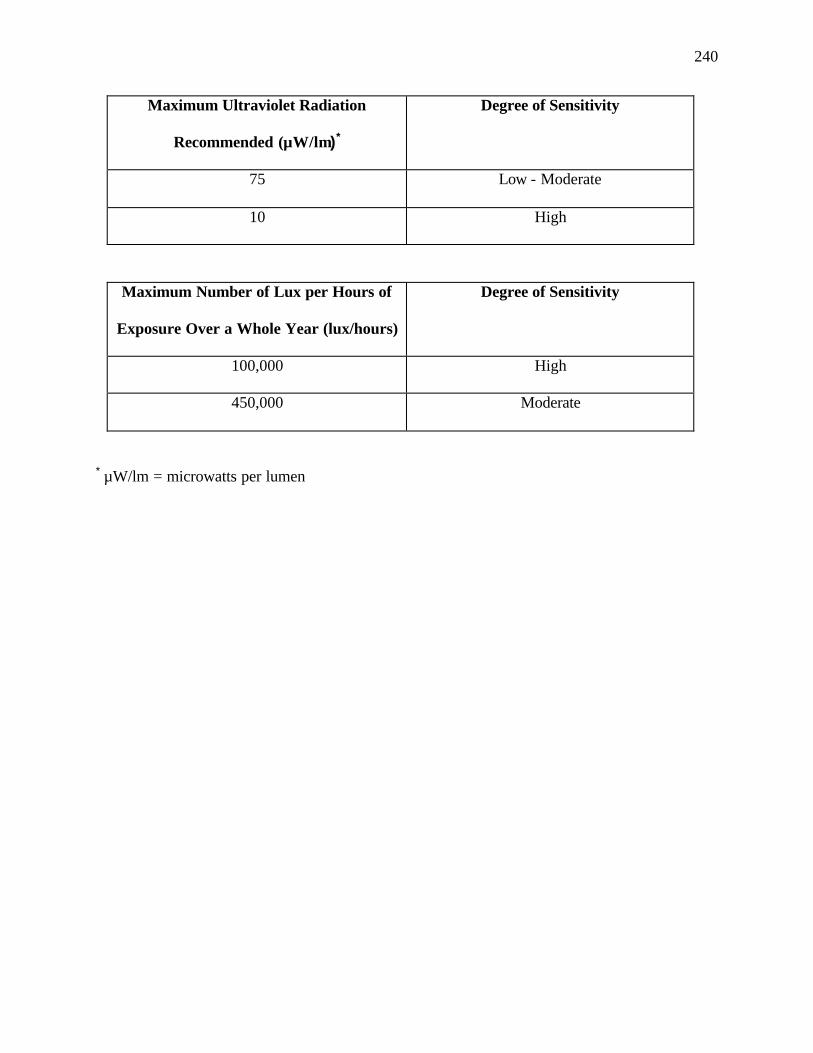
240
Maximum Ultraviolet Radiation
Recommended (µW/lm)*
Degree of Sensitivity
75 Low - Moderate
10 High
Maximum Number of Lux per Hours of
Exposure Over a Whole Year (lux/hours)
Degree of Sensitivity
100,000 High
450,000 Moderate
* µW/lm = microwatts per lumen