il - digital library/67531/metadc678961/m2/1/high... · multiphase reacting flow sii\/iiulatton*...
TRANSCRIPT

A COKE/SOOT FORMATION MODEL F'OR .
MULTIPHASE REACTING FLOW SII\/IIULATTON*
S.L. Chang, S.A. Lottes, C.Q. Zhou**, and M. Petrick
Argonne National Laboratory Argonne, IL 60439
a contractor of the U. S. Government undei contract No. W-31-109-ENG-38. Accordingly, the U. S. Government retains a nonexclusive. royalty-free license to publish or reproduce the publishcd form of this contribution, or allow others to do so. for U. S. Government D U ~ S ~ S .
March 1997
OlSfRlBUnON OF fwls DOCUMENT IS UNUMRED &R
*Work supported by U.S. Department of Energy, Assistant Secretary for Fossil Energy, under
**Purdue University Calumet, Hammond, IN 46323 Accepted for publication in the Proceedings of the Technical Meeting of Combustion Fundamentals and Applications, April 27-29, 1997, Point Clear, AL, sponsored by Central States Section of the Combustion Institute.
Contract W-3 1-109-ENG-38.

DISCLAIMER
This report was prepared as an account of work sponsored by an agency of the United States Government. Neither the United States Government nor any agency thereof, nor any of their employees, make any warranty, express or implied, or assumes any legal liabii- ty or mponsibnity for the accuracy, completeness, or usefulness of any information, appa- ratus, product, or process disclosed, or represents that its use would not infringe privately owned rights. Reference herein to any specific commercial product, process, or service by trade name, trademark, manufacturer, or otherwise does not neceSSarily constitute or Fmply its endorsement, recommendation, or favoring by the United States Government or any agency thereof. The views and opinions of authors expressed herein do not necessar- ily state or reflect those of the United States Government or any agency thereof.

Portions of this document m y be illegible in electronic image products. Smages are produced fnwr the best avaiiable original document.

A COKE/SOOT FORR/IATION MODEL FOR MULTIPHASE REACTING FLOW SIMULATION*
S.L. Chang, S.A. Lottes, C.Q. Zhou, and M. Petrick
ABSTRACT
In a high temperature and oxygen deficient environment, hydrocarbons are converted to lighter hydrocarbon components and a by-product of small carbon rich solid particles is formed. The solid is called coke for a petroleum cracking process and soot in flames. Both coke and soot are pollutants. A capability to predict the formation of coke or soot in a process is vital to the development of advanced technologies that reduce pollutant emission to the environments.
A multiphase reacting flow computer code, ICRKFLO, developed at Argonne National Laboratory (ANL) has been used to investigate the effects of operating conditions on the coke yield of a large-scale petroleum cracking reactor. ICRKFLO is a general computational fluid dynamic computer code that solves conservation equations of general flow properties of the gas, liquid, and solid phases. This code has been validated by comparisons with available experimental data and the code was used to evaluate the performance of several multiphase reacting flow systems. A unique feature of the ICRKFLO code is the coke formation and transport model. The model characterizes the formation of the coke on the particle surface during cracking reactions and the transport of coke with the particle flow. A methodology has been developed to extract empirical kinetic constants of the coke formation model from test data.
The coke formation and transport model has been used in a parametric study to evaluate the effects of reactor size and operating conditions on the coke yield. Based on the results of the parametric study, a strategy was developed to select operating conditions to control the coke yield of a large-scale reactor. The model can also be used for modeling soot formation in flames, e.g., diesel spray combustion and fire. The details of the coke/soot formation model and the methodology of extracting kinetic constants will be presented in the paper.
*Work supported by U.S. Department of Energy, Assistant Secretary for Fossil Energy, under Contract W-3 1 - 109-ENG-3 8.

A COKE/SOOT FORMATION MODEL FOR MULTIPHASE REACTING FLOW SIMULATION
S.L. Chang”, S.A. Lottes, C.Q. Zhoii*:$, and M. Petrick Argonne National Laboratory
9700 South Cass Avenue Argonne, Illinois 60439
**Purdue University Calumet Hammond, Indiana 46323
ABSTRACT Coke is a by-product in petroleum fluid catalytic
cracking (FCC) processes. The concentration of coke in an FCC riser reactor is an critical parameter used to evaluate the riser performance. A coke formation and transport model was developed. It was incorporated into a computational fluid dynamic (CFD) computer code, ICRKFLO, to simulate the coke formation processes in an FCC riser reactor. Based on a similar process, a soot formation model can be derived from the coke formation model and used for diesel combustion processes, where soot is emitted as one of the primary pollutants.
INTRODUCTION Computational fluid dynamics (CFD) has been used
to enhance the understanding of hydrodynamics, thermodynamics, and chemical kinetics of flow systems. For the past 20 years, many CFD codes have been developed and evolved greatly with the advancement in both numerical techniques and computer hardware. CFD applications were extended from simple laboratory-type to complex industrial-type flow systems. Computer simulation is regarded as an effective and cost-saving tool to further improve the performance of flow systems.
Several CFD codes have been developed at Argonne National Laboratory (AM,) to study flow characteristics of various engineering systems. Among them, ICRKFLO (Chang and Lottes, 1996) and ICOMFLO (Chang and Lottes, 19951) codes were developed for multi-phase reacting flows. The codes have been used to simulate multiphase reacting flows in fluid catalytic cracking (FCC) reactors (Chang et al., 1996a), coal-fired combustors (Chang and Lottes, 1993), internal combustion engines (Chang and Wang, 1987), and air- breathing jet engines (Zhou and Chiu, 1983). The codes are continually validated with experimental data from industry partners and published experimental data in the literature (Chang and Lottes, 1995b, Chang et al., 1995, Chang and Lottes. 1993, and Lottes and Chang, 1991).
The ICRKFLO code has several unique features. Among them is a coke formation model for petroleum
fluid catalytic cracking (FCC) processes. FCC processes are used by the refining industry to convert crude oil to more valuable lighter oil products, such as gasoline. Coke is a by-product during cracking processes. Coke concentration in a riser reactor is an critical parameter used to evaluate the riser performance. Coke can be formed from thermal cracking or catalytic reactions. Thermal cracking occurs primarily in gas phase and results in massive precipitation of thermal coke on particle surfaces (Ho, 1992). Catalytic reactions occur on the catalyst surface, and in this case coke is formed on the catalyst particle surface and adheres to it. In either case, coke is transported by particles. A model was developed to describe the formation and transport of the coke in a FCC riser flow. By incorporating the model into the ICRKFLO code, local coke concentration throughout an FCC riser can be calculated along with the total coke yield. Locations and conditions in the reactor where coke is formed most rapidly can be identified.
Soot is one of the primary pollutants emitted from diesel engines. The soot is produced from fuel-rich burning of a diesel spray. The soot formation process is similar to coke formation in the petroleum cracking process. A soot formation model derived from the coke model was developed for diesel combustion processes. The coke and soot formation models are presented in this paper.
COMPUTER MODELS
The ICRKFLO CFD Code The ICRKFLO code solves the governing equations
for flow system containing three phases: gaseous species, liquid droplets, and solid particles. The governing conservation equations for mass, momentum, enthalpy, and species are expressed as elliptic-type partial differential equations which contain source and sink terms derived from rate equations for reaction, evaporation, precipitation, and other processes which couple thz equations. The turbulence properties, interfacial mass. momentum and heat transfer, and chemical reactions are
* Corresponding Author Proceedings of the 1997 Technical Meeting of the Central States Section of the Combustion Institute
Jctincci i n phcnorncnological models for use to solve thc go vc rn i n g eq ua tio ns.
Governinq Eauations The gas-phase governing equations include
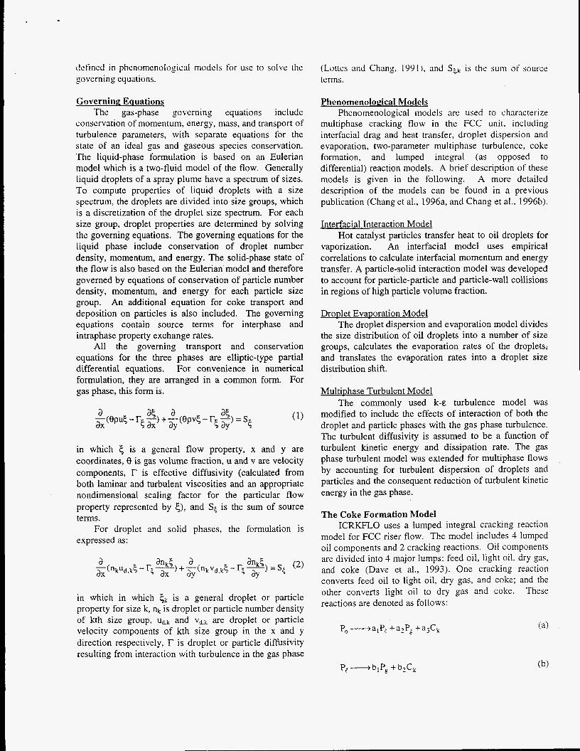
conscrvation of momentum, energy, mass, and transport of turbulence parameters, with separate equations for the state of an ideal gas and gaseous species conservation. The liquid-phase formulation is based on an Eulerian model which is a two-fluid model of the flow. Generally liquid droplets of a spray plume have a spectrum of sizes. To compute properties of liquid droplets with a size spectrum, the droplets are divided into size groups, which is a discretization of the droplet size spectrum. For each size group, droplet properties are determined by solving the governing equations. The governing equations for the liquid phase include conservation of droplet number density, momentum, and energy. The solid-phase state of the flow is also based on the Eulerian model and therefore governed by equations of conservation of particle number density, momentum, and energy for each particle size group. An additional equation for coke transport and deposition on particles is also included. The governing equations contain source terms for interphase and intraphase property exchange rates.
All the governing transport and conservation equations for the three phases are elliptic-type partial differential equations. For convenience in numerical formulation, they are arranged in a common form. For gas phase, this form is.
in which 5 is a general flow property, x and y are coordinates, 8 is gas volume fraction, u and v are velocity components, r is effective diffusivity (calculated from both laminar and turbulent viscosities and an appropriate nondimensional scaling factor for the particular flow property represented by s), and Sg is the sum of source terms.
For droplet and solid phases, the formulation is expressed as:
in which in which jk is a general droplet or particle property for size k, nk is droplet or particle number density of kth size group, Ud.k and vd.k are droplet or particle velocity components of kth size group in the x and y direction respectively, r is droplet or particle diffusivity resulting from interaction with turbulence in the gas phase
(Lottcs and Chang, 199L). and Sg.k is the sum of source terms.
Phenomenological Models Phenomenological models are used to characterize
multiphase cracking flow in the FCC unit. including interfacial drag and heat transfer, droplet dispersion and evaporation, two-parameter multiphase turbulence, coke formation, and lumped integral (as opposed to differential) reaction models. A brief description of these models is given in the following. A more detailed description of the models can be found in a previous publication (Chang et al., 1996a, and Chang et al., 1996b).
Interfacial Interaction Model Hot catalyst particles transfer heat to oil droplets for
vaporization. An interfacial model uses empirical correlations to calculate interfacial momentum and energy transfer. A particle-solid interaction model was developed to account for particle-particle and particle-wall collisions in regions of high particle volume fraction.
DroDlet EvaDoration Model The droplet dispersion and evaporation model divides
the size distribution of oil droplets into a number of size groups, calculates the evaporation rates of the droplets; and translates the evaporation rates into a droplet size distribution shift.
Multiuhase Turbulent Model The commonly used k-E turbulence model was
modified to include the effects of interaction of both the droplet and particle phases with the gas phase turbulence. The turbulent diffusivity is assumed to be a function of turbulent kinetic energy and dissipation rate. The gas phase turbulent model was extended for multiphase flows by accounting for turbulent dispersion of droplets and particles and the consequent reduction of turbulent kinetic energy in the gas phase.
The Coke Formation Model ICRKFLO uses a lumped integral cracking reaction
model for FCC riser flow. The model includes 4 lumped oil components and 2 cracking reactions. Oil components are divided into 4 major lumps: feed oil, light oil, dry gas, and coke (Dave et al., 1993). One cracking reaction converts feed oil to light oil, dry gas, and coke; and the other converts light oil to dry gas and coke. These reactions are denoted as follows:

whcre P,, PI, P,, Ck represent feed oil, light oil, dry gas, Afk Afk S& = p- = pu-
and coke, respectively, and stoichiometric coefficients, 31, Ats AX a?, a ~ , bl, and b?, are expressed in mass fractions. Reaction rates of these reactions are expressed in Arrhenius formula as,
in which At, is a soltd flow tin,e scale.
Code Validation _- d fo - -ko.a exp(-E, / RT)+ f,' (3)A A series of experimental tests were conducted to dt validate the ICRKFLO code and the coke formation
model for the simulation of an FCC riser reactor. Figure 1 compares calculated and measured species concentrations of feed oil, light oil, dry gas, and coke at the riser exit. The comparison shows excellent a, Oreement.
(4) - -ko,b eXp(-Eb / RT)$ df, -- dt
60 in which, k,, is the rate constant, E is activation energy, and Q is a catalyst decay function defined as,
u 40 Y Q = exp(-t,a, 1 (5 )
Coke formed in cracking reactions (a) and (b) precipitates on the surface of catalyst particles. Local coke concentration (dk) is governed by the following transport equation.
c3 - z - G 20
0 (6 ) a a aY 0 20 40 60
x(nkus,kd,) +-(nkvs.kdk) = sc ,k 1 ms
Measured Species Conc. in which ms is the mass of a particle, and the coke concentration dk is defined as the mass of coke per unit mass of particle.
The source term in the coke transport equation accounts for the formation rate of coke. The rate can be derived from the formation rates of feed oil and light oil as,
-- dfk - a3ko,a exp(-E, / RT)$ f z + dt
The coke concentration fk in Eq.(7) is defined based on a time scale from the gas flow rate while dk is defined based on a time scale from the solid flow rate. In order to get the interfacial mass exchange rates correct, the time scale difference needs to be taken into account. The functional relationship between the two definitions are shown in Eq.(8).
Thus, the source of the coke transport equation (6) can be written as,
The Soot Formation Model Soot is a primary pollutant emitted from diesel
combustion. Fuel properties and combustion processes have the most significant effect on the soot formation. Liquid fuel is injected at a pressure much higher than the cylinder pressure through a nozzle system into the engine cylinder. The pressure drop breaks up the injected liquid fuel stream to form a spray of droplets which can be characterized by the spray angle, penetration depth (or injection velocity), and droplet size distribution. With the initial injection velocity, fuel droplets penetrate into. the high temperature air. The fuel spray advances with time until droplets are vaporized by hot air or combustion gas.
In a spray plume, fuel droplets heated by the surrounding hot air or combustion gas begin rapid vaporization, controlled by the heat transfer rate, when droplet temperature reaches the boiling point. This rate of vaporization depends mainly on the droplet size. boiling point, latent heat of liquid fuel, and gas temperature.
The fuel vapor mixes with air in the spray plume. The mixture starts to burn when the gas temperature reaches the ignition point and fuelhir mixture ratio is within the flammability limits. The heat release by the combustion raises cylinder pressure to drive the piston and produce work. The combustion products include mainly C02 and H20 , and small amount of pollutants.

primarily NOx and soot. Soot is produced by fuel rich burning. Figure 2 shows a spray combustion structure and pollutant formation rates in the spray plume. The flame structure is characterized by the center line temperature and stoichiometric ratio (actual fuei/air ratio to stoichiometric fuelhir ratio). There is a flame zone in the spray where temperature is high and fuel is consumed rapidly. Soot is formed inside the spray plume where stoichiometric ratio is fuel rich.
center line
flame zone
temperature
stoichiometric ratio
rate of soot formation
Figure 2 Pollutant Formation in a Diesel Flame
Diesel fuel is one of the FCC cracking products. The light oil cracking reaction can be converted to a diesel fuel decomposition reaction (c) that produces soot.
The rate of soot formation can be derived as,
When soot is formed, nucleation first takes place, then soot particles agglomerate into larger size. Soot particles in a diesel flame have a spectrum of sizes. To compute particle properties in the flame, particles need to be divided into size groups and for each size group, particle properties are determined by solving the governing equations.
The particle number density distribution function is represented by a solid line in Figure 3. It is a typical bell- shaped normal distribution. The arrows pointing down indicate the nucleation process of soot formation and the horizontal arrows represent the size shifting due to the agglomeration process.
7 -
I .6
1.2 gsrmlno
0.8
0.4
0
n
0 0.5 I 1.5 2
dr, Figure 3 Soot Number Density Distribution
RESULTS AND DISCUSSION A typical computaticjnal flow field of the lower
portion of an FCC riser reactor is shown in Figure 4 including a vector plot of gas velocity, and contour plots of gas temperature, feed oil droplet number density, and feed oil vapor concentrations. The feed oil is injected from left side of the riser and hot particles are injected from the right side near the bottom of the riser. It clearly shows there is a mixing zone where feed oil droplets are mixed with hot carrier particles and vaporized. The heavy oil vapor is then converted to products including light oil, dry gas and coke. The gas accelerates from the entrance region up the riser due to the vaporization of feed oil and the cracking reactions that convert the heavier feed oil to lighter products.
The velocity vector field for the gas flow is shown in Figure 4a. The gas velocity field in this mixing zone of the riser is highly influenced by the addition of new mass in the gas phase from vaporizing feed oil droplets. The vaporizing droplets cause expansion of the gas and therefore an increase in gas velocity. This phenomenon is seen most clearly in the region just before and into the necking down of the tube.
Gas temperature is primarily influenced by the heat transported by the carrier particles and the heat required for vaporization of the heavy oil in the mixing zone. The results of these influences are shown in the temperature contours of Figure 4b. The numbers on the figure are temperatures normalized by the inlet particle temperature.
Figures 4c shows the velocity and number density field of feed oil droplets. Most droplets are vaporized quickly and turned into the downstream. Consequently, many small droplets are confined to the left half of the figure, which is the side of the tube containing the oil injection port. Some larger droplets hit the tube wall opposite to the injection side and are vaporized on it.

1 .o 0.5 0 1 0.5 0
YD Ym (a) gas velocity (b) gas temperature
Feed oil injection
0.1
'a
0
1 0.5 0 1 0.5 0
I
'a
vaporization takes pliice in t h a region. The figure docs show, however, that a significant portion of feed oil vapor does exist in the right side o f the riser. y/D < 0.5. The heating and vaporization time. especially for larger droplets, primarily account for this distribution in the main portion of the mixing zone. Further downstream, fluid dynamic mixing will progressiveiy lessen the skew in the feed oil concentration profile.
(c) droplet number dens. (d) feed oil conc. Figure 4 Computational Flow Properties in the mixing
zone of an FCC Riser
Contours of feed oil vapor concentration are plotted in Figure 4d. The feed oil concentration is the highest for the left side of the riser, y/D > 0.5, because most of the
Feed Oil 4 b
I -1 8 A \ - -
high
low
Catalyst Particles
Figure 5 Coke Concentration in an FCC Riser
Figure 5 shows a plot of coke concentration with a superimposed vector plot of particle velocity. The asymmetry in the mixing zone is cIearIy apparent and caused by feed oil and catalyst entering from different sides of the reactor, Areas of high coke concentration correspond to areas of high feed oil vapor concentration because that is where most of the cracking reactions will occur. The areas of high concentration of feed oil vapor correspond to regions of lower temperature due to heat transfer from gas to droplets for vaporization. Velocity vectors turn into the axial flow direction very rapidly after entering the main narrow portion of the riser, so cross

stream mixing beyond that point will be nearly entirely diffusive or turbulent in nature.
~ ~~~ ~ ~ ~
y/D=O.j 10.000 BPD
-y/D=0.3 10,000 BPD
y/D=0.5 1 BPD / ----
0 2 4 6 8 10
Riser height (m)
Figure 6 Change of Coke Concentration (gkg of particles) up the Riser
Figure 6 shows the evolution of coke production in both the small scale and large scale riser. As seen in the figure, the coke produced in the scaled up riser at corresponding heights is always larger over the cross section than in the small scale unit, and the longer length required to reach the same percent of cracking of the feed oil results in a significantly greater fraction of coke produced in grams of coke per kilogram of feed oil.
CONCLUSION A coke formation and transport model has been
developed for a CFD computer code ICRKFLO. The model characterizes the formation of coke from cracking processes and the transport of coke by catalyst particles in an FCC riser reactor. By using this model, local coke concentration throughout an FCC riser can be calculated along with the total coke yield. Locations and conditions in the reactor where coke is formed most rapidly can be identified for both small scale and large scale risers.
A similar soot formation model was developed for diesel flames. It can be used to predict soot formation in a diesel spray combustor.
ACKNOWLEDGMENTS This work was supported by U.S. Department of
Energy, Assistant Secretary for Fossil Energy, under Contract W-3 1- 109-ENG-38 and managed by Bartlesville Project Office. Ernest Zuech was the program manager.
REFERENCES Chang, S.L. and S.A. Lottes, ICRKFLO - Two-
Dimensional Multiple Phase Integral Pctrolcum Cracking Flow Computer Code. Computer SoI‘twarc Copyright. ANL-SF-95-138 (1996).
Chang, S.L., S.A. Lottes, C.Q. Zhou, and M. Petrick. Evaluation of blultiphase Heat Transfer and Droplet Evaporation in Petroleum Cracking Flows, HTD-Vol. 335, Proc. of the ASME Heat Transfer Division 4: 17-27, Int. Mech. Engr. Congress and Exposition, Atlanta, GA (November 17-22, 1996a).
Chang, S.L., C.Q. Zhou, S.A. Lottes, J.X. Bouillard, and M. Petrick, A Sectional Coupling Approach for the Simulation of Multiphase Reacting Flow in a Bent Reactor, HTD-Vol. 335, Proceedings of the ASME Heat Transfer Division 4:36 1-373, Int. Mech. Engr. Congress and Exposition, Atlanta, GA (November 17-22, 1996b).
Chang, S.L. and S.A. Lottes, ICOMFLO2 - Two- Dimensional Multiple Phase Integral Combustion Flow Computer Code, Computer Software Copyright, ANL-SF- 93-109 (September 11, 1995a).
Chang, S.L., and S.A. Lottes, “Characteristic of Multi- Phase Flow with Particle Evaporation in a Combustor with Counter-Flow Injection”, Energy Convers. Mgmt,
Chang, S.L., S.A. Lottes, and M. Petrick, “Development of a Three-phase Reacting Flow Computer Model for Analysis of Petroleum Cracking:’ Proceedings of 1995 Mid-America Chinese Professional Annual Convention, Itasca, IL, pp.281-288 (June 23-25, 1995).
Chang, S.L., and S.A. Lottes, “Integral Combustion Simulation of a Turbulent Reacting Flow in a Channel with Cross-Stream Injection,” Numerical Heat Transfer Part A, 24( 1 j:25-43 (1993).
Chang, S.L., and C.S. Wang, “Thermal Radiation and Spray Group Combustion in Diesel Engines,” ASME Winter Annual Meeting, Boston, Mass., HTD-8 1:25-34 (December 13-18, 1987).
Dave, N.C., G.J. D u e , and P. Udaja, “A Four-Lump Kinetic Model for the Cracking/Coking of Recycled Heavy Oil,” Fuel, 72(9):1331-1334, (1993).
Ho, T.C., “Study of Coke Formation in Resid Catalytic Cracking,” Ind. Eng. Chem. Res., (3 1):228 1-2256. 1992.
Lottes, S.A., and S.L. Chang, “Computer Simulation of Jet Penetration and Fluid Mixing in a Channel with Cross- Stream Jets,” Proceedings of the 7th International Conference on Advanced Science and Technology. ANL.
Zhou, X.Q., and H.H. Chiu, “Spray Group Combustion Processes in Air Breathing Propulsion Combustors,“ AIANSAEIASME 19th Joint Propulsion Conference, Seattle, Washington, AIAA-83- 1323, ( 1983).
36(11)1031-1045, (1995b).
IL, pp.188-19S, (1991).