iko thompson brazil service co.,ltd. (brazil) nippon...
TRANSCRIPT
REDRED
CAT-1566E
Linear Motion Rolling Guide Series General Catalog
Linear Motion Rolling Guide Series General Catalog R
ED
Printed in China © 2016.7 (AKA)
NIPPON THOMPSON CO., LTD. (JAPAN) Head Office : 19-13 Takanawa 2-chome Minato-ku Tokyo 108-8586, Japan Phone : +81 (0)3-3448-5850 Fax : +81 (0)3-3447-7637 E-mail : [email protected] URL : http://www.ikont.co.jp/eg Plant : Gifu, Kamakura
IKO THOMPSON ASIA CO., LTD. (THAILAND) 1-7 Zuellig House, 3rd Floor Silom Road, Silom, Bangrak Bangkok 10500, Thailand Phone : +66 (0)2-637-5115 FAX : +66 (0)2-637-5116 E-mail : [email protected]
NIPPON THOMPSON EUROPE B.V. (EUROPE)The Netherlands (Sales Head Office) Sheffieldstraat 35-39 3047 AN Rotterdam The Netherlands Phone : +31 (0)10-462 68 68 Fax : +31 (0)10-462 60 99 E-mail : [email protected] Branch Mündelheimer Weg 54 40472 Düsseldorf Germany Phone : +49 (0)211-41 40 61 Fax : +49 (0)211-42 76 93 E-mail : [email protected]
Regensburg Sales Office Im Gewerbepark D 30 93059 Regensburg Germany Phone : +49 (0)941-20 60 70 Fax : +49 (0)941-20 60 719 E-mail : [email protected]
Neunkirchen Sales Office Gruben Str. 95c 66540 Neunkirchen Germany Phone : +49 (0)6821-99 98 60 Fax : +49 (0)6821-99 98 626 E-mail : [email protected]. Branch 2 Vincent Avenue, Crownhill Milton Keynes, Bucks, MK8 0AB United Kingdom Phone : +44 (0)1908-566144 Fax : +44 (0)1908-565458 E-mail : [email protected] Branch Autovia Madrid-Barcelona, Km. 43,700 Polig. Ind. AIDA - Nove A-8, Ofic. 2-1a
19200 Azuqueca de Henares (Guadalajara) Spain Phone : +34 949-26 33 90 Fax : +34 949-26 31 13 E-mail : [email protected] Branch Roissypole Le Dôme 2 rue de La Haye BP 15950 Tremblay en France 95733 Roissy C. D. G. Cedex France Phone : +33 (0)1-48 16 57 39 Fax : +33 (0)1-48 16 57 46 E-mail : [email protected]
IKO INTERNATIONAL, INC. (U.S.A.)East Coast Operations (Sales Head Office) 91 Walsh Drive Parsippany, NJ 07054 U.S.A. Phone : +1 973-402-0254 Toll Free : 1-800-922-0337 Fax : +1 973-402-0441 E-mail : [email protected] Operations 101 Mark Street Suite-G, Wood Dale, IL 60191 U.S.A. Phone : +1 630-766-6464 Toll Free : 1-800-323-6694 Fax : +1 630-766-6869 E-mail : [email protected]
Minnesota Sales Office 1500 McAndrews Road West, Suite 210 Burnsville, MN 55337 U.S.A. Phone : +1 952-892-8415 Toll Free : 1-800-323-6694 Fax : +1 952-892-1722 E-mail : [email protected] Coast Operations 9830 Norwalk Boulevard, Suite 198 Santa Fe Springs, CA 90670 U.S.A. Phone : +1 562-941-1019 Toll Free : 1-800-252-3665 Fax : +1 562-941-4027 E-mail : [email protected]
Silicon Valley Sales Office 1500 Wyatt Drive, Suite 10 Santa Clara, CA 95054 U.S.A. Phone : +1 408-492-0240 Toll Free : 1-800-252-3665 Fax : +1 408-492-0245 E-mail : [email protected] Operations 2150 Boggs Road, Suite 100 Duluth, GA 30096 U.S.A. Phone : +1 770-418-1904 Toll Free : 1-800-874-6445 Fax : +1 770-418-9403 E-mail : [email protected] Operations 8105 N. Beltline Road, Suite 130 lrving, TX 75063 U.S.A. Phone : +1 972-929-1515 Toll Free : 1-800-295-7886 Fax : +1 972-915-0060 E-mail : [email protected]
IKO THOMPSON BRAZIL SERVICE CO.,LTD. (BRAZIL) Av.Paulista, 854 10th floor, Top Center, 01310-100, Sao Paulo, SP, Brazil Phone : +55 (0)11-2186-0221 Fax : +55 (0)11-2186-0299 E-mail : [email protected]
IKO THOMPSON KOREA CO.,LTD. (KOREA) 2F, 111, Yeouigongwon-ro, Yeongdeungpo-gu, Seoul, Korea Phone : +82 (0)2-6337-5851 Fax : +82 (0)2-6337-5852 E-mail : [email protected]
IKO THOMPSON BEARINGS CANADA, INC.(CANADA) 731-2425 Matheson Boulevard East 7th floor Mississauga, Ontario L4W 5K4, Canada Phone : +1 905-361-2872 Fax : +1 905-361-6401 E-mail : [email protected]
IKO-THOMPSON (SHANGHAI) LTD. (CHINA)Shanghai (Sales Head Office) 1608-10 MetroPlaza No.555 LouShanGuan Road ChangNing District Shanghai People's Republic of China 200051 Phone : +86 (0)21-3250-5525 Fax : +86 (0)21-3250-5526 E-mail : [email protected] Branch Room1506, Jingtai Tower, NO.24, Jianguomenwai Avenue, Chaoyang District, Beijing People's Republic of China 100022 Phone : +86 (0)10-6515-7681 Fax : +86 (0)10-6515-7681∗106 E-mail : [email protected] Branch Room 834, Garden Tower, Garden Hotel 368 Huanshi East Road, Yuexiu District, Guangzhou, Guangdong People's Republic of China 510064 Phone : +86 (0)20-8384-0797 Fax : +86 (0)20-8381-2863 E-mail : [email protected] Branch Room 2300, Truroll Plaza No.72 Wusheng Road, Qiao kou District, Wuhan, Hubei People's Republic of China 430033 Phone : +86 (0)27-8556-1610 Fax : +86 (0)27-8556-1630 E-mail : [email protected]
Shenzhen Office Room 420, Oriental Plaza, 1072 Jianshe Road, Luohu District, Shenzhen, Guangdong People's Republic of China 518001 Phone : +86 (0)755-2265-0553 Fax : +86 (0)755-2298-0665 E-mail : [email protected] Ningbo Office Room 3406, Zhongnongxin Building, No.181 Zhongshan East Road, Haishu Ward, Ningbo, Zhejiang People's Republic of China 315000 Phone : +86 (0)574-8718-9535 Fax : +86 (0)574-8718-9533 E-mail : [email protected] Qingdao Office 2107 Block A, World Trade Center Building, No.230 Changjiang Middle Road, Development Zone Qingdao People's Republic of China 266555 Phone : +86 (0)532-8670-2246 FAX : +86 (0)532-8670-2242 E-mail : [email protected] Shenyang Office 2-1203 Tower I.City Plaza Shenyang, No.206 Nanjing North Street Heping District, Shenyang People's Republic of China 110001 Phone : +86 (0)24-2334-2662 FAX : +86 (0)24-2334-2442 E-mail : [email protected]
Recognizing that conservation of the global environment is the top-priority challenge for the world’s population, Nippon Thompson will conduct its activities with consideration of the environment as a corporate social responsibility, reduce its negative impact on the environment, and help foster a rich global environment.
ISO 9001 & 14001 Quality system registration certificate
• The specifications and dimensions of products in this catalog are subject to change without prior notice.
• When these products are exported, the exporter should confirm a forwarding country and a use, and, in case of falling under the customer's requirements, take necessary procedures such as export permission application.
• Although all data in this catalog has been carefully compiled to make the information as complete as possible, NIPPON THOMPSON CO., LTD. shall not be liable for any damages whatsoever, direct or indirect, based upon any information in this catalog. NIPPON THOMPSON CO., LTD. makes no warranty, either express or impiled, including the impiled warranty of merchantability or fitness for a particular purpose.
• Reproduction and conversion without permission are prohibited.

Linear Motion Rolling Guides are used with satisfactory results for various applications requiring precision positioning such as semi-conductor manufacturing equipment, large sized machine tools, industrial robots, and precision equipment.In contrast to conventional rolling bearings used in rotating parts, Linear Motion Rolling Guides are the products applicable to plane sliding surfaces, and meet the increasing needs for linear motion and precision positioning in machines and equipment.Linear Way and Linear Roller Way of Rail Guide Type, Linear Ball Spline of Shaft Guide Type, and other products, recognized for their high quality and excellent features, are available.
Linear Motion Rolling Guides are manufactured through a control system that alleviates their impact on the global environment to meet the quality requirements of ISO 14001 in compliance with the quality requirements level of ISO 9001 for quality improvement.The standard products listed in this catalog comply with the specifications of the six hazardous materials mentioned cited in the European RoHS Directive.
•
•
Ⅰ-1 Ⅰ-2
Linear Ball Spline
Linear Bushing
Stroke Rotary Bushing
Linear Slide Unit
Crossed Roller Way
Roller Way & Flat Roller Cage
Shaf
t Gui
de T
ype
Flat G
uide T
ype
Linear Motion Rolling Guide Series Full LineupLinear Motion Rolling Guide Series Full LineupLin
ear M
otion
Roll
ing G
uide S
eries
Gen
eral
Cata
log B
LUE
Linea
r Mot
ion R
olling
Guid
e Ser
ies G
ener
al Ca
talog
BLU
E
BLUEBLUE
Printed in Korea © 2013.07 (AKA)
Linear Motion Rolling Guide Series General Catalog B
LUE
Linear Motion Rolling Guide Series General Catalog
Recognizing that conservation of the global environment is the top-priority challenge for the world’s population, Nippon Thompson will conduct its activities with consideration of the environment as a corporate social responsibility, reduce its negative impact on the environment, and help foster a rich global environment.
ISO 9001 & 14001 Quality system registration certificate
notice.
permission application.
possible, NIPPON THOMPSON CO., LTD. shall not be liable for any damages whatsoever, direct or indirect, based upon any information in this catalog. NIPPON THOMPSON CO., LTD. makes no
particular purpose.
NIPPON THOMPSON CO., LTD. (JAPAN)
Head office : 19-19 Takanawa 2-chome Minato-ku Tokyo 108-8586, Japan Phone : +81 (0)3-3448-5850
Plant : Gifu, Kamakura
IKO-THOMPSON (SHANGHAI) LTD. (CHINA)Shanghai Sales Head Office 1608-10 MetroPlaza No.555 LouShanGuan Road ChangNing District Shanghai People's Republic of China 200051 Phone : +86 (0)21-3250-5525
Beijing Branch Room 609 Scitech Tower
People's Republic of China 100004 Phone : +86 (0)10-6515-7681
106
Guangzhou Branch Room 834, Garden Tower, Garden Hotel People's Republic of China 510064 Phone : +86 (0)20-8384-0797
Wuhan Branch
People's Republic of China 430033 Phone : +86 (0)27-8556-1610
Xi'an Office Room 1613, Building B, Jinqiao International Plaza
People’s Republic of China 710075 Phone : +86 (0)29-8882-3225
Shenzhen Office Room 507, Oriental Plaza, 1072 Jianshe Road, Luohu District, Shenzhen, Guangdong People’s Republic of China 518001 Phone : +86 (0)20-8384-0797
Chengdu Office Room 01-A, 12F of Tower 1, Central Plaza
People’s Republic of China 610016 Phone : +86 (0)28-6250-5159
Ningbo Office
People’s Republic of China 315000 Phone : +86 (0)574-8718-9535
Qingdao Office
People's Republic of China 266555 Phone : +86 (0)532-8670-2246
Shenyang Office 2-1203 Tower I.City Plaza Shenyang, No.206
People's Republic of China 110001 Phone : +86 (0)24-2334-2662
NIPPON THOMPSON CO., LTD. (THAILAND) ASEAN REPRESENTATIVE OFFICE (BANGKOK) 1-7 Zuellig House, 5th Floor Silom Road, Silom, Bangrak Bangkok 10500, Thailand Phone : +66 (0)2-637-5115
IKO INTERNATIONAL, INC. (U.S.A.)
East Coast Operation (Sales Head Office)
Parsippany, NJ 07054 U.S.A. Phone : +1 973-402-0254 Toll Free : 1-800-922-0337
Midwest Operation 500 East Thorndale Avenue, Suite K
U.S.A. Phone : +1 630-766-6464 Toll Free : 1-800-323-6694
West Coast Operation 9830 Norwalk Boulevard, Suite 198 Santa Fe Springs, CA 90670 U.S.A. Phone : +1 310-609-3988 Toll Free : 1-800-252-3665
Silicon Valley Sales Office 3333 Bowers Avenue, Suite 155 Santa Clara, CA 95054 U.S.A. Phone : +1 408-492-0240 Toll Free : 1-800-252-3665
Southeast Operation 2150 Boggs Road, Suite 100 Duluth, GA 30096 U.S.A. Phone : +1 770-418-1904 Toll Free : 1-800-874-6445
Southwest Operation 8105 N. Beltline Road, Suite 130
U.S.A. Phone : +1 972-929-1515 Toll Free : 1-800-295-7886
NIPPON THOMPSON EUROPE B.V. (EUROPE)
The Netherlands Sales Head Office Sheffieldstraat 35-39 3047 AN Rotterdam The Netherlands Phone : +31 (0)10-462 68 68
Germany Branch
40472 Düsseldorf Germany Phone : +49 (0)211-41 40 61
Regensburg Sales Office Im Gewerbepark D 30 93059 Regensburg Germany Phone : +49 (0)941-20 60 70
E-mail : [email protected]
Neunkirchen Sales Office Gruben Str.95c 66540 Neunkirchen Germany Phone : +49 (0)6821-99 98 60
E-mail : [email protected]. Branch 2 Vincent Avenue, Crownhill Milton Keynes, Bucks, MK8 0AB United Kingdom Phone : +44 (0)1908-566144
E-mail : [email protected] Branch Autovia Madrid-Barcelona, Km. 43,700 Polig. Ind. AIDA - Nove A-8, Ofic. 2-1 19200 Azuqueca de Henares
Phone : +34 949-26 33 90
France Branch Roissypole Le Dôme 2 rue de La Haye BP 15950 Tremblay en France
France Phone : +33 (0)1-48 16 57 39
E-mail : [email protected]
IKO-BLUE_H1H4_13mm.indd 1
Linear WayLinear Roller Way
Recorded in CAT-1565E
REDRED
Linear Motion Rolling Guide Series General Catalog R
ED
Linear Motion Rolling Guide Series General Catalog
Printed in Korea © 2013.07 (AKA)
Recognizing that conservation of the global environment is the top-priority challenge for the world’s population, Nippon Thompson will conduct its activities with consideration of the environment as a corporate social responsibility, reduce its negative impact on the environment, and help foster a rich global environment.
ISO 9001 & 14001 Quality system registration certificate
• The specifications and dimensions of products in this catalog are subject to change without prior notice.
• When these products are exported, the exporter should confirm a forwarding country and a use, and, in case of falling under the customer's requirements, take necessary procedures such as export permission application.
• Although all data in this catalog has been carefully complied to make the information as complete as possible, NIPPON THOMPSON CO., LTD. shall not be liable for any damages whatsoever, direct or indirect, based upon any information in this catalog. NIPPON THOMPSON CO., LTD. makes no warranty, either express or impiled, including the impiled warranty of merchantability or fitness for a particular purpose.
• Reproduction and conversion without permission are prohibited.
NIPPON THOMPSON CO., LTD. (JAPAN)
Head office : 19-19 Takanawa 2-chome Minato-ku Tokyo 108-8586, Japan Phone : +81 (0)3-3448-5850 Fax : +81 (0)3-3447-7637 E-mail : [email protected] URL : http://www.ikont.co.jp/eg Plant : Gifu, Kamakura
IKO-THOMPSON (SHANGHAI) LTD. (CHINA)Shanghai Sales Head Office 1608-10 MetroPlaza No.555 LouShanGuan Road ChangNing District Shanghai People's Republic of China 200051 Phone : +86 (0)21-3250-5525 Fax : +86 (0)21-3250-5526 E-mail : [email protected] Branch Room 609 Scitech Tower No.22 Jianguomenwai Avenue, Chaoyang District, Beijing People's Republic of China 100004 Phone : +86 (0)10-6515-7681 Fax : +86 (0)10-6515-7689 E-mail : [email protected] Branch Room 834, Garden Tower, Garden Hotel 368 Huanshi East Road, Yuexiu District, Guangzhou, Guangdong People's Republic of China 510064 Phone : +86 (0)20-8384-0797 Fax : +86 (0)20-8381-2863 E-mail : [email protected] Branch Room 0233, Novotel Wuhan Xinhua 558 Jianshe Avenue, Jiang Han District, Wuhan, Hubei People's Republic of China 430022 Phone : +86 (0)27-8556-1610 Fax : +86 (0)27-8556-1630 E-mail : [email protected]
Xi'an Office Room 1613, Building B, Jinqiao International Plaza No.50 Keji Road, Gaoxin District, Xi'an, Shanxi People’s Republic of China 710075 Phone : +86 (0)29-8882-3225 Fax : +86 (0)29-8882-3215 E-mail : [email protected] Shenzhen Office Room 507, Oriental Plaza, 1072 Jianshe Road, Luohu District, Shenzhen, Guangdong People’s Republic of China 518001 Phone : +86 (0)20-8384-0797 Fax : +86 (0)20-8381-2863 E-mail : [email protected] Chengdu Office Room 01-A, 12F of Tower 1, Central Plaza 8 Shuncheng Avenue, Jinjiang District ,Chengdu, Sichuan People’s Republic of China 610016 Phone : +86 (0)28-6250-5159 Fax : +86 (0)28-6250-5259 E-mail : [email protected] Ningbo Office Room 3406, Zhongnongxin Building, No.181 Zhongshan East Road, Haishu Ward, Ningbo, Zhejiang People’s Republic of China 315000 Phone : +86 (0)574-8718-9535 Fax : +86 (0)574-8718-9533 E-mail : [email protected] Qingdao Office 2107 Block A,World Trade Center Building, No.230 Changjiang Middle Road, Development Zone Qingdao 266555, CHINA TEL : +86 (0)532-8670-2246 FAX : +86 (0)532-8670-2242 E-mail : [email protected] Shenyang Office 2-1203 Tower I.City Plaza Shenyang NO.206 Nanjing North Street Heping District, Shenyang 110001, P.R. CHINA TEL : +86 (0)24-2334-2662 FAX : +86 (0)24-2334-2442 E-mail : [email protected]
NIPPON THOMPSON CO., LTD. (THAILAND) ASEAN REPRESENTATIVE OFFICE (BANGKOK) 1-7 Zuellig House, 5th Floor Silom Road, Silom, Bangrak Bangkok 10500, Thailand Phone : +66 (0)2-637-5115 FAX : +66 (0)2-637-5116 E-mail : [email protected]
IKO INTERNATIONAL, INC. (U.S.A.)
East Coast Operation (Sales Head Office) 91 Walsh Drive Parsippany, NJ 07054 U.S.A. Phone : +1 973-402-0254 Toll Free : 1-800-922-0337 Fax : +1 973-402-0441 E-mail : [email protected] Operation 500 East Thorndale Avenue, Suite K Wood Dale, IL 60191 U.S.A. Phone : +1 630-766-6464 Toll Free : 1-800-323-6694 Fax : +1 630-766-6869 E-mail : [email protected] Coast Operation 9830 Norwalk Boulevard, Suite 198 Santa Fe Springs, CA 90670 U.S.A. Phone : +1 310-609-3988 Toll Free : 1-800-252-3665 Fax : +1 310-609-3916 E-mail : [email protected]
Silicon Valley Sales Office 3333 Bowers Avenue, Suite 155 Santa Clara, CA 95054 U.S.A. Phone : +1 408-492-0240 Toll Free : 1-800-252-3665 Fax : +1 408-492-0245 E-mail : [email protected] Operation 2150 Boggs Road, Suite 100 Duluth, GA 30096 U.S.A. Phone : +1 770-418-1904 Toll Free : 1-800-874-6445 Fax : +1 770-418-9403 E-mail : [email protected] Operation 8105 N. Beltline Road, Suite 130 lrving, TX 75063 U.S.A. Phone : +1 972-929-1515 Toll Free : 1-800-295-7886 Fax : +1 972-915-0060 E-mail : [email protected]
NIPPON THOMPSON EUROPE B.V. (EUROPE)
The Netherlands Sales Head Office Sheffieldstraat 35-39 3047 AN Rotterdam The Netherlands Phone : +31 (0)10-462 68 68 Fax : +31 (0)10-462 60 99 E-mail : [email protected] Branch Mündelheimer Weg 56 40472 Düsseldorf Germany Phone : +49 (0)211-41 40 61 Fax : +49 (0)211-42 76 93 E-mail : [email protected]
Regensburg Sales Office Im Gewerbepark D 30 93059 Regensburg Germany Phone : +49 (0)941-20 60 70 Fax : +49 (0)941-20 60 719 E-mail : [email protected]
Neunkirchen Sales Office Gruben Str.95c 66540 Neunkirchen Germany Phone : +49 (0)6821-99 98 60 Fax : +49 (0)6821-99 98 626 E-mail : [email protected]. Branch 2 Vincent Avenue, Crownhill Milton Keynes, Bucks, MK8 0AB United Kingdom Phone : +44 (0)1908-566144 Fax : +44 (0)1908-565458 E-mail : [email protected] Branch Autovia Madrid-Barcelona, Km. 43,700 Polig. Ind. AIDA - Nove A-8, Ofic. 2-1 19200 Azuqueca de Henares (Guadalajara) Spain Phone : +34 949-26 33 90 Fax : +34 949-26 31 13 E-mail : [email protected] Branch Roissypole Le Dôme 2 rue de La Haye BP 15950 Tremblay en France 95733 Roissy C. D. G. Cedex France Phone : +33 (0)1-48 16 57 39 Fax : +33 (0)1-48 16 57 46 E-mail : [email protected]
Recorded in CAT-1566E
Rai
l Gui
de
Typ
e
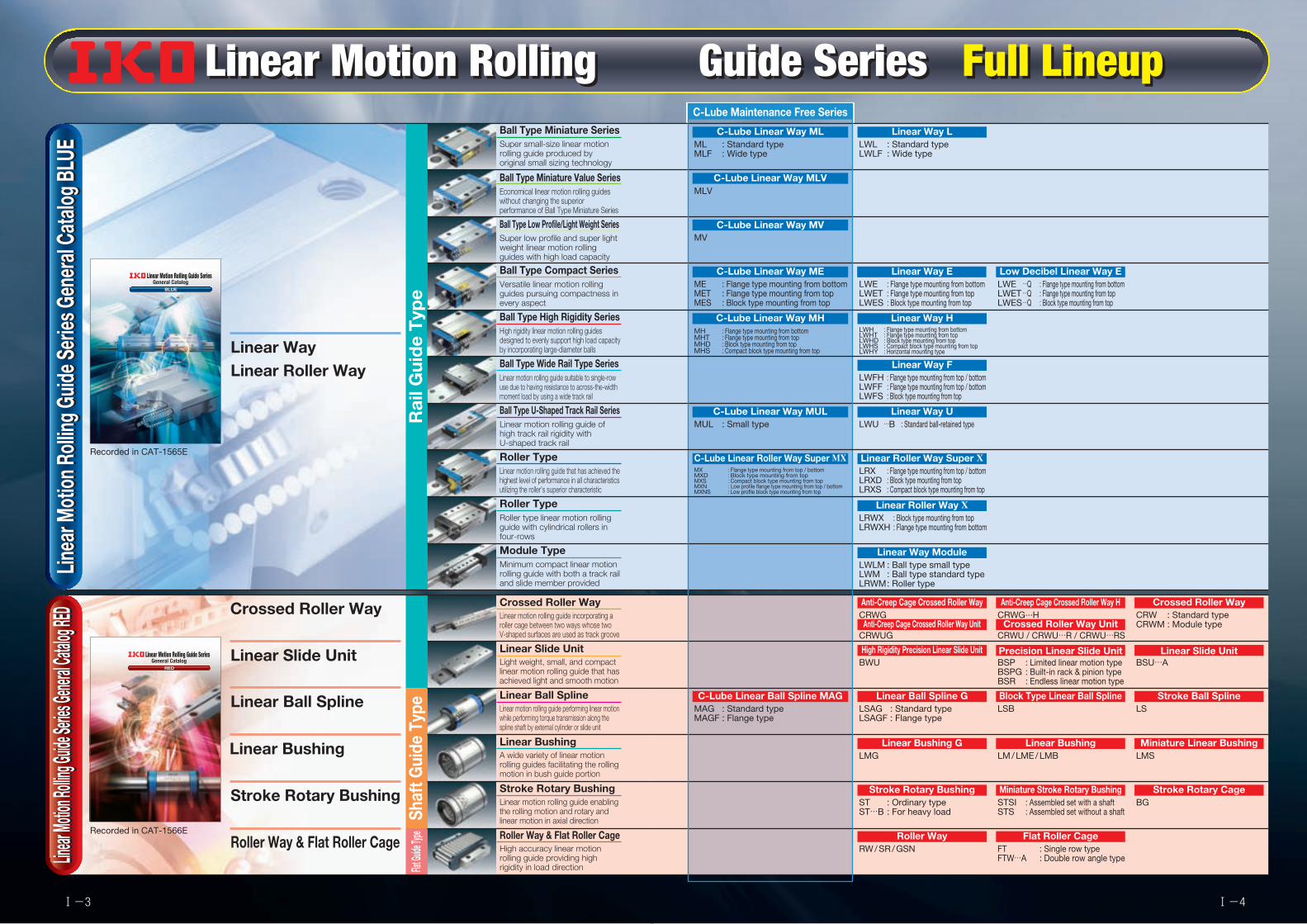
Ball Type Miniature SeriesML : Standard typeMLF : Wide type
C-Lube Linear Way ML
C-Lube Maintenance Free Series
LWL : Standard typeLWLF : Wide type
Linear Way LSuper small-size linear motion rolling guide produced by original small sizing technology
Ball Type Miniature Value SeriesEconomical linear motion rolling guides without changing the superior performance of Ball Type Miniature Series
Ball Type Low Profile/Light Weight SeriesSuper low profile and super light weight linear motion rolling guides with high load capacity
Ball Type Compact SeriesME : Flange type mounting from bottomMET : Flange type mounting from topMES : Block type mounting from top
C-Lube Linear Way MELWE : Flange type mounting from bottomLWET : Flange type mounting from topLWES : Block type mounting from top
Linear Way ELWE …Q : Flange type mounting from bottomLWET …Q : Flange type mounting from topLWES …Q : Block type mounting from top
Low Decibel Linear Way EVersatile linear motion rolling guides pursuing compactness in every aspect
Ball Type High Rigidity SeriesMH : Flange type mounting from bottomMHT : Flange type mounting from topMHD : Block type mounting from topMHS : Compact block type mounting from top
C-Lube Linear Way MHLWH : Flange type mounting from bottomLWHT : Flange type mounting from topLWHD : Block type mounting from topLWHS : Compact block type mounting from topLWHY : Horizontal mounting type
Linear Way HHigh rigidity linear motion rolling guides designed to evenly support high load capacity by incorporating large-diameter balls
Ball Type Wide Rail Type SeriesLWFH : Flange type mounting from top / bottomLWFF : Flange type mounting from top / bottomLWFS : Block type mounting from top
Linear Way FLinear motion rolling guide suitable to single-row use due to having resistance to across-the-width moment load by using a wide track rail
Ball Type U-Shaped Track Rail SeriesMUL : Small type
C-Lube Linear Way MULLWU …B : Standard ball-retained type
Linear Way ULinear motion rolling guide of high track rail rigidity with U-shaped track rail
Roller TypeMX : Flange type mounting from top / bottomMXD : Block type mounting from topMXS : Compact block type mounting from topMXN : Low profile flange type mounting from top / bottomMXNS : Low profile block type mounting from top
C-Lube Linear Roller Way Super MXLRX : Flange type mounting from top / bottomLRXD : Block type mounting from topLRXS : Compact block type mounting from top
Linear Roller Way Super XLinear motion rolling guide that has achieved the highest level of performance in all characteristics utilizing the roller's superior characteristic
Roller TypeLRWX : Block type mounting from topLRWXH : Flange type mounting from bottom
Linear Roller Way XRoller type linear motion rolling guide with cylindrical rollers in four-rows
Module TypeLWLM : Ball type small typeLWM : Ball type standard typeLRWM : Roller type
Linear Way ModuleMinimum compact linear motion rolling guide with both a track rail and slide member provided
Crossed Roller WayCRWGAnti-Creep Cage Crossed Roller Way
CRWUGAnti-Creep Cage Crossed Roller Way Unit
CRWG···HAnti-Creep Cage Crossed Roller Way H
CRW : Standard typeCRWM : Module type
Crossed Roller Way
CRWU / CRWU…R / CRWU…RSCrossed Roller Way Unit
Linear motion rolling guide incorporating a roller cage between two ways whose two V-shaped surfaces are used as track groove
Linear Slide UnitBWUHigh Rigidity Precision Linear Slide Unit
BSP : Limited linear motion typeBSPG : Built-in rack & pinion typeBSR : Endless linear motion type
Precision Linear Slide UnitBSU…A
Linear Slide UnitLight weight, small, and compact linear motion rolling guide that has achieved light and smooth motion
Linear Ball SplineMAG : Standard typeMAGF : Flange type
C-Lube Linear Ball Spline MAGLSAG : Standard typeLSAGF : Flange type
Linear Ball Spline GLSBBlock Type Linear Ball Spline
LSStroke Ball Spline
Linear motion rolling guide performing linear motion while performing torque transmission along the spline shaft by external cylinder or slide unit
Linear BushingLMG
Linear Bushing GLM / LME / LMB
Linear BushingLMSMiniature Linear Bushing
A wide variety of linear motion rolling guides facilitating the rolling motion in bush guide portion
Stroke Rotary BushingST : Ordinary typeST…B : For heavy load
Stroke Rotary BushingSTSI : Assembled set with a shaftSTS : Assembled set without a shaft
Miniature Stroke Rotary BushingBG
Stroke Rotary CageLinear motion rolling guide enabling the rolling motion and rotary and linear motion in axial direction
Roller Way & Flat Roller CageRW / SR / GSN
Roller WayFT : Single row typeFTW…A : Double row angle type
Flat Roller CageHigh accuracy linear motion rolling guide providing high rigidity in load direction
MLVC-Lube Linear Way MLV
MVC-Lube Linear Way MV
Linear M
otion R
olling G
uide S
eries G
eneral
Catalog
RED
Linear M
otion R
olling G
uide S
eries G
eneral
Catalog
RED
Linear Ball Spline
Linear Bushing
Stroke Rotary Bushing
Linear Slide Unit
Crossed Roller Way
Roller Way & Flat Roller Cage
Shaf
t Gui
de T
ype
Flat G
uide T
ype
Linear Motion Rolling Guide Series Full LineupLinear Motion Rolling Guide Series Full LineupLin
ear M
otion
Roll
ing G
uide S
eries
Gen
eral
Cata
log B
LUE
Linea
r Mot
ion R
olling
Guid
e Ser
ies G
ener
al Ca
talog
BLU
E
BLUEBLUE
Printed in Korea © 2013.07 (AKA)
Linear Motion Rolling Guide Series General Catalog B
LUE
Linear Motion Rolling Guide Series General Catalog
Recognizing that conservation of the global environment is the top-priority challenge for the world’s population, Nippon Thompson will conduct its activities with consideration of the environment as a corporate social responsibility, reduce its negative impact on the environment, and help foster a rich global environment.
ISO 9001 & 14001 Quality system registration certificate
notice.
permission application.
possible, NIPPON THOMPSON CO., LTD. shall not be liable for any damages whatsoever, direct or indirect, based upon any information in this catalog. NIPPON THOMPSON CO., LTD. makes no
particular purpose.
NIPPON THOMPSON CO., LTD. (JAPAN)
Head office : 19-19 Takanawa 2-chome Minato-ku Tokyo 108-8586, Japan Phone : +81 (0)3-3448-5850
Plant : Gifu, Kamakura
IKO-THOMPSON (SHANGHAI) LTD. (CHINA)Shanghai Sales Head Office 1608-10 MetroPlaza No.555 LouShanGuan Road ChangNing District Shanghai People's Republic of China 200051 Phone : +86 (0)21-3250-5525
Beijing Branch Room 609 Scitech Tower
People's Republic of China 100004 Phone : +86 (0)10-6515-7681
106
Guangzhou Branch Room 834, Garden Tower, Garden Hotel People's Republic of China 510064 Phone : +86 (0)20-8384-0797
Wuhan Branch
People's Republic of China 430033 Phone : +86 (0)27-8556-1610
Xi'an Office Room 1613, Building B, Jinqiao International Plaza
People’s Republic of China 710075 Phone : +86 (0)29-8882-3225
Shenzhen Office Room 507, Oriental Plaza, 1072 Jianshe Road, Luohu District, Shenzhen, Guangdong People’s Republic of China 518001 Phone : +86 (0)20-8384-0797
Chengdu Office Room 01-A, 12F of Tower 1, Central Plaza
People’s Republic of China 610016 Phone : +86 (0)28-6250-5159
Ningbo Office
People’s Republic of China 315000 Phone : +86 (0)574-8718-9535
Qingdao Office
People's Republic of China 266555 Phone : +86 (0)532-8670-2246
Shenyang Office 2-1203 Tower I.City Plaza Shenyang, No.206
People's Republic of China 110001 Phone : +86 (0)24-2334-2662
NIPPON THOMPSON CO., LTD. (THAILAND) ASEAN REPRESENTATIVE OFFICE (BANGKOK) 1-7 Zuellig House, 5th Floor Silom Road, Silom, Bangrak Bangkok 10500, Thailand Phone : +66 (0)2-637-5115
IKO INTERNATIONAL, INC. (U.S.A.)
East Coast Operation (Sales Head Office)
Parsippany, NJ 07054 U.S.A. Phone : +1 973-402-0254 Toll Free : 1-800-922-0337
Midwest Operation 500 East Thorndale Avenue, Suite K
U.S.A. Phone : +1 630-766-6464 Toll Free : 1-800-323-6694
West Coast Operation 9830 Norwalk Boulevard, Suite 198 Santa Fe Springs, CA 90670 U.S.A. Phone : +1 310-609-3988 Toll Free : 1-800-252-3665
Silicon Valley Sales Office 3333 Bowers Avenue, Suite 155 Santa Clara, CA 95054 U.S.A. Phone : +1 408-492-0240 Toll Free : 1-800-252-3665
Southeast Operation 2150 Boggs Road, Suite 100 Duluth, GA 30096 U.S.A. Phone : +1 770-418-1904 Toll Free : 1-800-874-6445
Southwest Operation 8105 N. Beltline Road, Suite 130
U.S.A. Phone : +1 972-929-1515 Toll Free : 1-800-295-7886
NIPPON THOMPSON EUROPE B.V. (EUROPE)
The Netherlands Sales Head Office Sheffieldstraat 35-39 3047 AN Rotterdam The Netherlands Phone : +31 (0)10-462 68 68
Germany Branch
40472 Düsseldorf Germany Phone : +49 (0)211-41 40 61
Regensburg Sales Office Im Gewerbepark D 30 93059 Regensburg Germany Phone : +49 (0)941-20 60 70
E-mail : [email protected]
Neunkirchen Sales Office Gruben Str.95c 66540 Neunkirchen Germany Phone : +49 (0)6821-99 98 60
E-mail : [email protected]. Branch 2 Vincent Avenue, Crownhill Milton Keynes, Bucks, MK8 0AB United Kingdom Phone : +44 (0)1908-566144
E-mail : [email protected] Branch Autovia Madrid-Barcelona, Km. 43,700 Polig. Ind. AIDA - Nove A-8, Ofic. 2-1 19200 Azuqueca de Henares
Phone : +34 949-26 33 90
France Branch Roissypole Le Dôme 2 rue de La Haye BP 15950 Tremblay en France
France Phone : +33 (0)1-48 16 57 39
E-mail : [email protected]
IKO-BLUE_H1H4_13mm.indd 1
Linear WayLinear Roller Way
Recorded in CAT-1565E
REDRED
Linear Motion Rolling Guide Series General Catalog R
ED
Linear Motion Rolling Guide Series General Catalog
Printed in Korea © 2013.07 (AKA)
Recognizing that conservation of the global environment is the top-priority challenge for the world’s population, Nippon Thompson will conduct its activities with consideration of the environment as a corporate social responsibility, reduce its negative impact on the environment, and help foster a rich global environment.
ISO 9001 & 14001 Quality system registration certificate
• The specifications and dimensions of products in this catalog are subject to change without prior notice.
• When these products are exported, the exporter should confirm a forwarding country and a use, and, in case of falling under the customer's requirements, take necessary procedures such as export permission application.
• Although all data in this catalog has been carefully complied to make the information as complete as possible, NIPPON THOMPSON CO., LTD. shall not be liable for any damages whatsoever, direct or indirect, based upon any information in this catalog. NIPPON THOMPSON CO., LTD. makes no warranty, either express or impiled, including the impiled warranty of merchantability or fitness for a particular purpose.
• Reproduction and conversion without permission are prohibited.
NIPPON THOMPSON CO., LTD. (JAPAN)
Head office : 19-19 Takanawa 2-chome Minato-ku Tokyo 108-8586, Japan Phone : +81 (0)3-3448-5850 Fax : +81 (0)3-3447-7637 E-mail : [email protected] URL : http://www.ikont.co.jp/eg Plant : Gifu, Kamakura
IKO-THOMPSON (SHANGHAI) LTD. (CHINA)Shanghai Sales Head Office 1608-10 MetroPlaza No.555 LouShanGuan Road ChangNing District Shanghai People's Republic of China 200051 Phone : +86 (0)21-3250-5525 Fax : +86 (0)21-3250-5526 E-mail : [email protected] Branch Room 609 Scitech Tower No.22 Jianguomenwai Avenue, Chaoyang District, Beijing People's Republic of China 100004 Phone : +86 (0)10-6515-7681 Fax : +86 (0)10-6515-7689 E-mail : [email protected] Branch Room 834, Garden Tower, Garden Hotel 368 Huanshi East Road, Yuexiu District, Guangzhou, Guangdong People's Republic of China 510064 Phone : +86 (0)20-8384-0797 Fax : +86 (0)20-8381-2863 E-mail : [email protected] Branch Room 0233, Novotel Wuhan Xinhua 558 Jianshe Avenue, Jiang Han District, Wuhan, Hubei People's Republic of China 430022 Phone : +86 (0)27-8556-1610 Fax : +86 (0)27-8556-1630 E-mail : [email protected]
Xi'an Office Room 1613, Building B, Jinqiao International Plaza No.50 Keji Road, Gaoxin District, Xi'an, Shanxi People’s Republic of China 710075 Phone : +86 (0)29-8882-3225 Fax : +86 (0)29-8882-3215 E-mail : [email protected] Shenzhen Office Room 507, Oriental Plaza, 1072 Jianshe Road, Luohu District, Shenzhen, Guangdong People’s Republic of China 518001 Phone : +86 (0)20-8384-0797 Fax : +86 (0)20-8381-2863 E-mail : [email protected] Chengdu Office Room 01-A, 12F of Tower 1, Central Plaza 8 Shuncheng Avenue, Jinjiang District ,Chengdu, Sichuan People’s Republic of China 610016 Phone : +86 (0)28-6250-5159 Fax : +86 (0)28-6250-5259 E-mail : [email protected] Ningbo Office Room 3406, Zhongnongxin Building, No.181 Zhongshan East Road, Haishu Ward, Ningbo, Zhejiang People’s Republic of China 315000 Phone : +86 (0)574-8718-9535 Fax : +86 (0)574-8718-9533 E-mail : [email protected] Qingdao Office 2107 Block A,World Trade Center Building, No.230 Changjiang Middle Road, Development Zone Qingdao 266555, CHINA TEL : +86 (0)532-8670-2246 FAX : +86 (0)532-8670-2242 E-mail : [email protected] Shenyang Office 2-1203 Tower I.City Plaza Shenyang NO.206 Nanjing North Street Heping District, Shenyang 110001, P.R. CHINA TEL : +86 (0)24-2334-2662 FAX : +86 (0)24-2334-2442 E-mail : [email protected]
NIPPON THOMPSON CO., LTD. (THAILAND) ASEAN REPRESENTATIVE OFFICE (BANGKOK) 1-7 Zuellig House, 5th Floor Silom Road, Silom, Bangrak Bangkok 10500, Thailand Phone : +66 (0)2-637-5115 FAX : +66 (0)2-637-5116 E-mail : [email protected]
IKO INTERNATIONAL, INC. (U.S.A.)
East Coast Operation (Sales Head Office) 91 Walsh Drive Parsippany, NJ 07054 U.S.A. Phone : +1 973-402-0254 Toll Free : 1-800-922-0337 Fax : +1 973-402-0441 E-mail : [email protected] Operation 500 East Thorndale Avenue, Suite K Wood Dale, IL 60191 U.S.A. Phone : +1 630-766-6464 Toll Free : 1-800-323-6694 Fax : +1 630-766-6869 E-mail : [email protected] Coast Operation 9830 Norwalk Boulevard, Suite 198 Santa Fe Springs, CA 90670 U.S.A. Phone : +1 310-609-3988 Toll Free : 1-800-252-3665 Fax : +1 310-609-3916 E-mail : [email protected]
Silicon Valley Sales Office 3333 Bowers Avenue, Suite 155 Santa Clara, CA 95054 U.S.A. Phone : +1 408-492-0240 Toll Free : 1-800-252-3665 Fax : +1 408-492-0245 E-mail : [email protected] Operation 2150 Boggs Road, Suite 100 Duluth, GA 30096 U.S.A. Phone : +1 770-418-1904 Toll Free : 1-800-874-6445 Fax : +1 770-418-9403 E-mail : [email protected] Operation 8105 N. Beltline Road, Suite 130 lrving, TX 75063 U.S.A. Phone : +1 972-929-1515 Toll Free : 1-800-295-7886 Fax : +1 972-915-0060 E-mail : [email protected]
NIPPON THOMPSON EUROPE B.V. (EUROPE)
The Netherlands Sales Head Office Sheffieldstraat 35-39 3047 AN Rotterdam The Netherlands Phone : +31 (0)10-462 68 68 Fax : +31 (0)10-462 60 99 E-mail : [email protected] Branch Mündelheimer Weg 56 40472 Düsseldorf Germany Phone : +49 (0)211-41 40 61 Fax : +49 (0)211-42 76 93 E-mail : [email protected]
Regensburg Sales Office Im Gewerbepark D 30 93059 Regensburg Germany Phone : +49 (0)941-20 60 70 Fax : +49 (0)941-20 60 719 E-mail : [email protected]
Neunkirchen Sales Office Gruben Str.95c 66540 Neunkirchen Germany Phone : +49 (0)6821-99 98 60 Fax : +49 (0)6821-99 98 626 E-mail : [email protected]. Branch 2 Vincent Avenue, Crownhill Milton Keynes, Bucks, MK8 0AB United Kingdom Phone : +44 (0)1908-566144 Fax : +44 (0)1908-565458 E-mail : [email protected] Branch Autovia Madrid-Barcelona, Km. 43,700 Polig. Ind. AIDA - Nove A-8, Ofic. 2-1 19200 Azuqueca de Henares (Guadalajara) Spain Phone : +34 949-26 33 90 Fax : +34 949-26 31 13 E-mail : [email protected] Branch Roissypole Le Dôme 2 rue de La Haye BP 15950 Tremblay en France 95733 Roissy C. D. G. Cedex France Phone : +33 (0)1-48 16 57 39 Fax : +33 (0)1-48 16 57 46 E-mail : [email protected]
Recorded in CAT-1566E
Rai
l Gui
de
Typ
e
Ball Type Miniature SeriesML : Standard typeMLF : Wide type
C-Lube Linear Way ML
C-Lube Maintenance Free Series
LWL : Standard typeLWLF : Wide type
Linear Way LSuper small-size linear motion rolling guide produced by original small sizing technology
Ball Type Miniature Value SeriesEconomical linear motion rolling guides without changing the superior performance of Ball Type Miniature Series
Ball Type Low Profile/Light Weight SeriesSuper low profile and super light weight linear motion rolling guides with high load capacity
Ball Type Compact SeriesME : Flange type mounting from bottomMET : Flange type mounting from topMES : Block type mounting from top
C-Lube Linear Way MELWE : Flange type mounting from bottomLWET : Flange type mounting from topLWES : Block type mounting from top
Linear Way ELWE …Q : Flange type mounting from bottomLWET …Q : Flange type mounting from topLWES …Q : Block type mounting from top
Low Decibel Linear Way EVersatile linear motion rolling guides pursuing compactness in every aspect
Ball Type High Rigidity SeriesMH : Flange type mounting from bottomMHT : Flange type mounting from topMHD : Block type mounting from topMHS : Compact block type mounting from top
C-Lube Linear Way MHLWH : Flange type mounting from bottomLWHT : Flange type mounting from topLWHD : Block type mounting from topLWHS : Compact block type mounting from topLWHY : Horizontal mounting type
Linear Way HHigh rigidity linear motion rolling guides designed to evenly support high load capacity by incorporating large-diameter balls
Ball Type Wide Rail Type SeriesLWFH : Flange type mounting from top / bottomLWFF : Flange type mounting from top / bottomLWFS : Block type mounting from top
Linear Way FLinear motion rolling guide suitable to single-row use due to having resistance to across-the-width moment load by using a wide track rail
Ball Type U-Shaped Track Rail SeriesMUL : Small type
C-Lube Linear Way MULLWU …B : Standard ball-retained type
Linear Way ULinear motion rolling guide of high track rail rigidity with U-shaped track rail
Roller TypeMX : Flange type mounting from top / bottomMXD : Block type mounting from topMXS : Compact block type mounting from topMXN : Low profile flange type mounting from top / bottomMXNS : Low profile block type mounting from top
C-Lube Linear Roller Way Super MXLRX : Flange type mounting from top / bottomLRXD : Block type mounting from topLRXS : Compact block type mounting from top
Linear Roller Way Super XLinear motion rolling guide that has achieved the highest level of performance in all characteristics utilizing the roller's superior characteristic
Roller TypeLRWX : Block type mounting from topLRWXH : Flange type mounting from bottom
Linear Roller Way XRoller type linear motion rolling guide with cylindrical rollers in four-rows
Module TypeLWLM : Ball type small typeLWM : Ball type standard typeLRWM : Roller type
Linear Way ModuleMinimum compact linear motion rolling guide with both a track rail and slide member provided
Crossed Roller WayCRWGAnti-Creep Cage Crossed Roller Way
CRWUGAnti-Creep Cage Crossed Roller Way Unit
CRWG···HAnti-Creep Cage Crossed Roller Way H
CRW : Standard typeCRWM : Module type
Crossed Roller Way
CRWU / CRWU…R / CRWU…RSCrossed Roller Way Unit
Linear motion rolling guide incorporating a roller cage between two ways whose two V-shaped surfaces are used as track groove
Linear Slide UnitBWUHigh Rigidity Precision Linear Slide Unit
BSP : Limited linear motion typeBSPG : Built-in rack & pinion typeBSR : Endless linear motion type
Precision Linear Slide UnitBSU…A
Linear Slide UnitLight weight, small, and compact linear motion rolling guide that has achieved light and smooth motion
Linear Ball SplineMAG : Standard typeMAGF : Flange type
C-Lube Linear Ball Spline MAGLSAG : Standard typeLSAGF : Flange type
Linear Ball Spline GLSBBlock Type Linear Ball Spline
LSStroke Ball Spline
Linear motion rolling guide performing linear motion while performing torque transmission along the spline shaft by external cylinder or slide unit
Linear BushingLMG
Linear Bushing GLM / LME / LMB
Linear BushingLMSMiniature Linear Bushing
A wide variety of linear motion rolling guides facilitating the rolling motion in bush guide portion
Stroke Rotary BushingST : Ordinary typeST…B : For heavy load
Stroke Rotary BushingSTSI : Assembled set with a shaftSTS : Assembled set without a shaft
Miniature Stroke Rotary BushingBG
Stroke Rotary CageLinear motion rolling guide enabling the rolling motion and rotary and linear motion in axial direction
Roller Way & Flat Roller CageRW / SR / GSN
Roller WayFT : Single row typeFTW…A : Double row angle type
Flat Roller CageHigh accuracy linear motion rolling guide providing high rigidity in load direction
MLVC-Lube Linear Way MLV
MVC-Lube Linear Way MV
Linear M
otion R
olling G
uide S
eries G
eneral
Catalog
RED
Linear M
otion R
olling G
uide S
eries G
eneral
Catalog
RED
Ⅰ-3 Ⅰ-4

Types of Linear Motion Rolling Guides Specifications of Linear Motion Rolling Guides
Rai
l Gui
de
Typ
eS
haft
Gui
de
Typ
eFl
at G
uide
Typ
e
Rai
l Gui
de
Typ
eS
haft
Gui
de
Typ
eFl
at G
uide
Typ
e
End
less
line
ar m
oti
on
End
less
line
ar m
oti
on
Lim
ited
line
ar m
oti
on
Flat Roller Cage
Roller Way
Stroke Rotary Bushing
Stroke Ball Spline
Linear Bushing
Linear Ball Spline
Linear Slide Unit
Crossed Roller Way
Linear Roller Way
Linear Way
Types and Specifications ofTypes and Specifications of Linear Motion Rolling Guide SeriesLinear Motion Rolling Guide Series
Ball
Ball
Ball
Ball
Ball
Ball
Roller
Roller
Roller
RollerTy
pe o
f rol
ling
elem
ent
Rig
idity
Fric
tiona
l ch
arac
teris
tic
Eas
e of
m
ount
ing
Item
-lis
ted
ca
talo
g
Gen
eral
ap
plic
atio
ns
Typ
e of
m
otio
n
Complex load, medium to heavy load
Load
d
irect
ion
and
lo
ad c
arry
ing
cap
acity
Complex load, heavy to extra-heavy load
Complex load, medium load
Complex load, light to medium load
Complex load, medium to heavy load
Radial load, light load
Complex load, medium to heavy load
Radial load, light load
Unidirectional load, extra-heavy load
Unidirectional load, extra-heavy load
BLUE
Code description Excellent Good Fair
The Rail Guide Type achieves linear motion along a rail. This product can receive a complex load and features high performance, excellent total balance and easy handling.
Linear Way
Endless linear motion
Linear Roller Way Linear Slide Unit
Limited linear motionCrossed Roller Way
Endless linear motion Limited linear motionThe Flat Guide Type achieves linear motion on a surface. This product can receive only a unidirectional load but feature high rigidity in the load direction.
Flat Roller Cage
The Shaft Guide Type achieves linear motion along a shaft. This product is easy to handle and suitable for relatively low load conditions. Some shaft guide products can achieve both rotation and reciprocating linear motion.
Linear Ball Spline
Endless linear motion
Linear Bushing
Limited linear motionStroke Ball Spline
Limited linear motion + rotationStroke Rotary Bushing
Roller Way
BLUE
RED
RED
RED
RED
RED
RED
RED
RED
Lim
ited
linea
r m
otio
n +
rot
atio
nLi
mite
d lin
ear m
otio
nEn
dles
s lin
ear m
otio
n
● NC machine tool● Precision working
machine● Robot● Transfer machine
● Heavy duty machine tool
● Large working machine
● High-rigidity robot
● Precision working machine
● Electronic parts assembling machine
● Precision measuring instrument
● Electronic parts assembling machine
● Robot● Testing and
inspection equipment
● Transfer machine
● Packaging machine
● Measuring instrument
● Medical instrument
● Robot● Testing and
inspection equipment
● Printing press● Press die set● Precision
measuring instrument
● NC machine tool
● Precision working machine
● Precision working machine
● Optical measuring instrument
Lim
ited
linea
r m
otio
n
Endless linear motion
Endless linear motion
Limited linear motion
Limited linear motion
Endless linear motion
Endless linear motion
Limited linear motion
Limited linear motion + rotation
Endless linear motion
Limited linear motion
Ⅰ-5 Ⅰ-6
Linear Motion Rolling Guide Series General Catalog RED INDEXLinear Motion Rolling Guide Series General Catalog RED INDEX
Anti-Creep Cage Crossed Roller Way
Anti-Creep Cage Crossed Roller Way H
Crossed Roller Way Anti-Creep Cage Crossed Roller Way Unit
Crossed Roller Way Unit
High Rigidity Precision Linear Slide Unit Precision Linear Slide Unit Linear Slide Unit
C-Lube Linear Ball Spline MAG Linear Ball Spline G Stroke Ball SplineBlock Type Linear Ball Spline
Linear Bushing G Linear Bushing Miniature Linear Bushing
Stroke Rotary Bushing Miniature Stroke Rotary Bushing Stroke Rotary Cage
Roller Way Flat Roller Cage
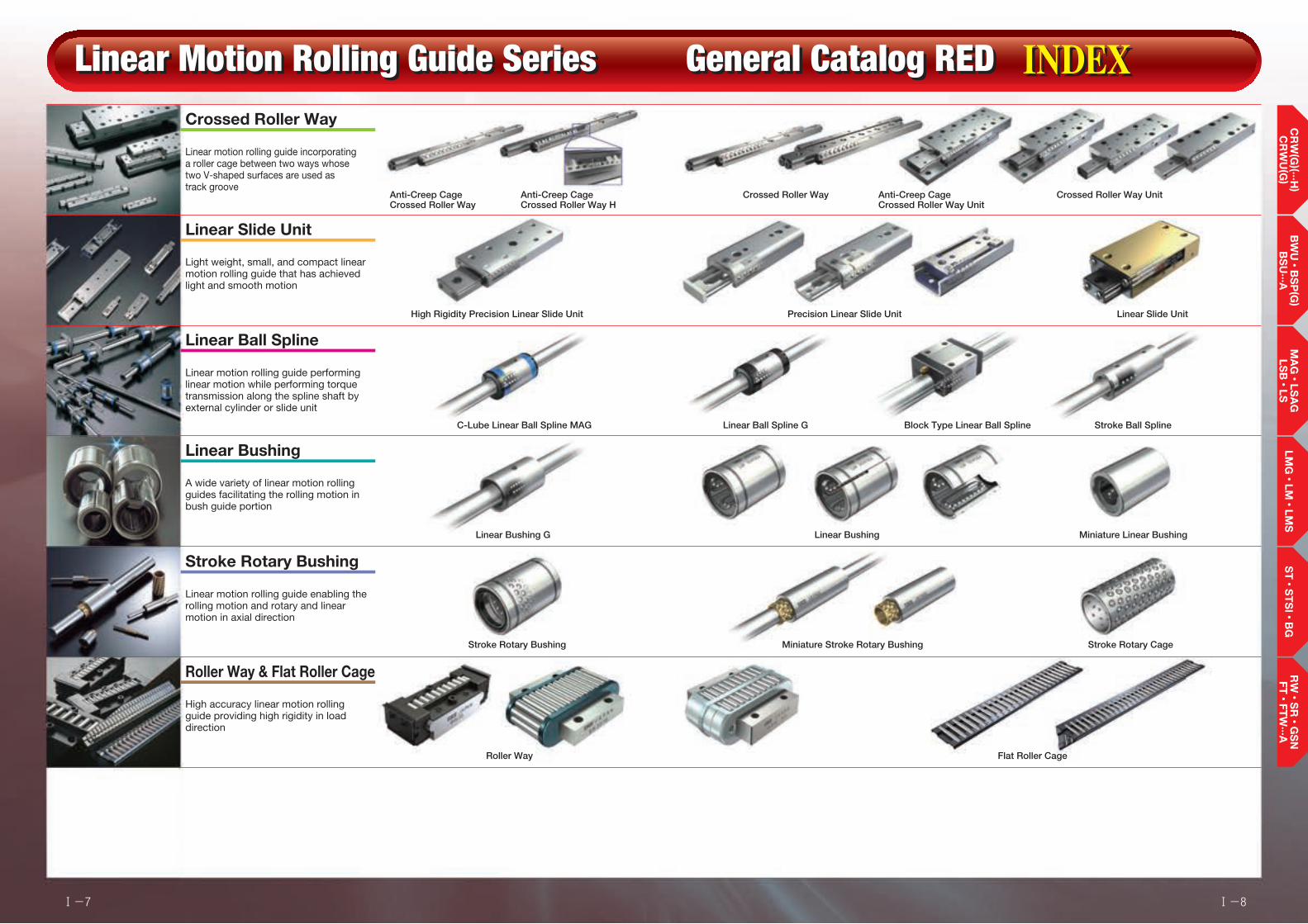
Linear Slide Unit
Light weight, small, and compact linear motion rolling guide that has achieved light and smooth motion
Crossed Roller Way
Linear motion rolling guide incorporating a roller cage between two ways whose two V-shaped surfaces are used as track groove
Linear Ball Spline
Linear motion rolling guide performing linear motion while performing torque transmission along the spline shaft by external cylinder or slide unit
Linear Bushing
A wide variety of linear motion rolling guides facilitating the rolling motion in bush guide portion
Stroke Rotary Bushing
Linear motion rolling guide enabling the rolling motion and rotary and linear motion in axial direction
Roller Way & Flat Roller Cage
High accuracy linear motion rolling guide providing high rigidity in load direction
LMG・
LM・
LMS
ST・
ST
SI ・
BG
CR
W(G
)(···H)
CR
WU
(G)
BW
U・
BS
P(G
) B
SU
···AM
AG・
LSA
G
LSB・
LSR
W・
SR・
GS
N
FT・
FTW
···A
Ⅰ-7 Ⅰ-8

● Anti-Creep CageCrossed Roller Way
Anti-Creep CageCrossed Roller Way H
Crossed Roller Way
Rail Guide Type
Crossed Roller Way
···Ⅱ-7Explanation ···Ⅱ-27Dimension Table
● Anti-Creep CageCrossed Roller Way Unit
Crossed Roller Way Unit
···Ⅱ-55Explanation ···Ⅱ-61Dimension Table
● High Rigidity Precision Linear Slide Unit
···Ⅱ-75Explanation ···Ⅱ-81Dimension Table
● Precision Linear Slide Unit
···Ⅱ-83Explanation ···Ⅱ-89Dimension Table
● Linear Slide Unit
···Ⅱ-95Explanation ···Ⅱ-99Dimension Table
Explanation and Dimension Table for Respective Product Series
General Explanation
● C-Lube Linear Ball Spline MAGLinear Ball Spline G
Shaft Guide Type
Linear Ball Spline
···Ⅱ-107Explanation ···Ⅱ-123Dimension Table
● Block Type Linear Ball Spline
···Ⅱ-131Explanation ···Ⅱ-141Dimension Table
● Stroke Ball Spline
···Ⅱ-143Explanation ···Ⅱ-149Dimension Table
Flat Guide Type
● Roller Way
···Ⅱ-215Explanation ···Ⅱ-221Dimension Table
● Flat Roller Cage
···Ⅱ-225Explanation ···Ⅱ-231Dimension Table
Linear Slide Unit
● Stroke Rotary Bushing
···Ⅱ-195Explanation ···Ⅱ-199Dimension Table
● Miniature Stroke Rotary Bushing
···Ⅱ-203Explanation ···Ⅱ-207Dimension Table
● Stroke Rotary Cage
···Ⅱ-209Explanation ···Ⅱ-212Dimension Table
Stroke Rotary Bushing
● Linear Bushing G
···Ⅱ-153Explanation ···Ⅱ-159Dimension Table
● Linear Bushing
···Ⅱ-161Explanation ···Ⅱ-167Dimension Table
● Miniature Linear Bushing
···Ⅱ-189Explanation ···Ⅱ-192Dimension Table
Linear Bushing
● General Explanation ···················································································Ⅲ-2
No. 8360644814207969717976736541
No. 734431070081075553946
No. 7637662
U.S. PATENTED
C-Lube Linear Ball Spline MAG
Linear Slide Unit No. 60994105893646
Linear Bushing
Crossed Roller WayNo. 6190046 5967667
6176617 54907296082899
Linear Ball Spline
Ⅱ-1 Ⅱ-2
Ⅱ-3 Ⅱ-4
Crossed Roller Way
Anti-Creep Cage Crossed Roller WayAnti-Creep Cage Crossed Roller Way HCrossed Roller WayAnti-Creep Cage Crossed Roller Way UnitCrossed Roller Way Unit
Features of Crossed Roller Way Series
A wide variety of series products including cage misalignment prevention mechanism are available! Features of Crossed Roller Way
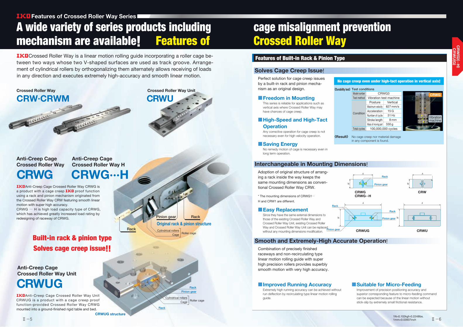
Crossed Roller Way is a linear motion rolling guide incorporating a roller cage be-tween two ways whose two V-shaped surfaces are used as track groove. Arrange-ment of cylindrical rollers by orthogonalizing them alternately allows receiving of loads in any direction and executes extremely high-accuracy and smooth linear motion.
Features of Built-in Rack & Pinion Type
CRWUG structure
Crossed Roller Way
CRW·CRWM
Anti-Creep CageCrossed Roller Way
CRWG
Anti-Creep CageCrossed Roller Way Unit
CRWUG
Anti-Creep CageCrossed Roller Way H
CRWG···H
Crossed Roller Way Unit
CRWU
Rack
Roller cageCageCylindrical rollers
Roller cageCageCylindrical rollers
RackPinion gear
Original rack & pinion structure
Pinion gear Rack
Rack
■ Freedom in MountingThis series is reliable for applications such as vertical axis where Crossed Roller Way may have chances of cage creep.
■ High-Speed and High-Tact OperationAny corrective operation for cage creep is not necessary even for high velocity operation.
■ Saving EnergyNo remedy motion of cage is necessary even in long term operation.
Solves Cage Creep Issue!
Model numberTest method
Condition
Total cycles
PostureMaximum velocityAccelerationNumber of cycleStroke lengthMass of moving part
CRWG3Vibration test machine
100,000,000 cycles
Vertical 827 mm/s 15 G 31 Hz 8 mm 330 g
《Result》
《Durability test》Test conditions
CRWGCRWG···H
CRW
Perfect solution for cage creep issues by a built-in rack and pinion mecha-nism as an original design.
■ Easy ReplacementSince they have the same external dimensions to those of the existing Crossed Roller Way and Crossed Roller Way Unit, existing Crossed Roller Way and Crossed Roller Way Unit can be replaced without any mounting dimensions modification.
Interchangeable in Mounting Dimensions!Adoption of original structure of arrang-ing a rack inside the way keeps the same mounting dimensions as conven-tional Crossed Roller Way CRW.
* The mounting dimensions of CRWG1…
H and CRW1 are different.
■ Improved Running AccuracyExtremely high running accuracy can be achieved without run deflection by recirculating type linear motion rolling guide.
■ Suitable for Micro-FeedingImprovement of precision positioning accuracy and superior corresponding feature to micro-feeding command can be expected because of the linear motion without stick-slip by extremely small frictional resistance.
Smooth and Extremely-High Accurate Operation!Combination of precisely finished raceways and non-recirculating type linear motion rolling guide with super high precision rollers provides superbly smooth motion with very high accuracy.
CRWG
CRWUG CRWU
A
H
No cage creep even under high-tact operation in vertical axis!
HH
AA
A
H
Rack
Pinion gear
Rack
Pinion gear
Rack
Pinion gear
Anti-Creep Cage Crossed Roller Way CRWG is a product with a cage creep proof function using a rack and pinion mechanism originated from the Crossed Roller Way CRW featuring smooth linear motion with super high accuracy.CRWG … H is high load capacity type of CRWG, which has achieved greatly increased load rating by redesigning of raceway of CRWG.
Anti-Creep Cage Crossed Roller Way Unit CRWUG is a product with a cage creep proof function-provided Crossed Roller Way CRWG mounted into a ground-finished rigid table and bed.
Built-in rack & pinion typeSolves cage creep issue!!
No cage creep nor material damage in any component is found.
Vibration machine
Ⅱ-5 Ⅱ-61N=0.102kgf=0.2248lbs.1mm=0.03937inch
1Points● Superior load balance
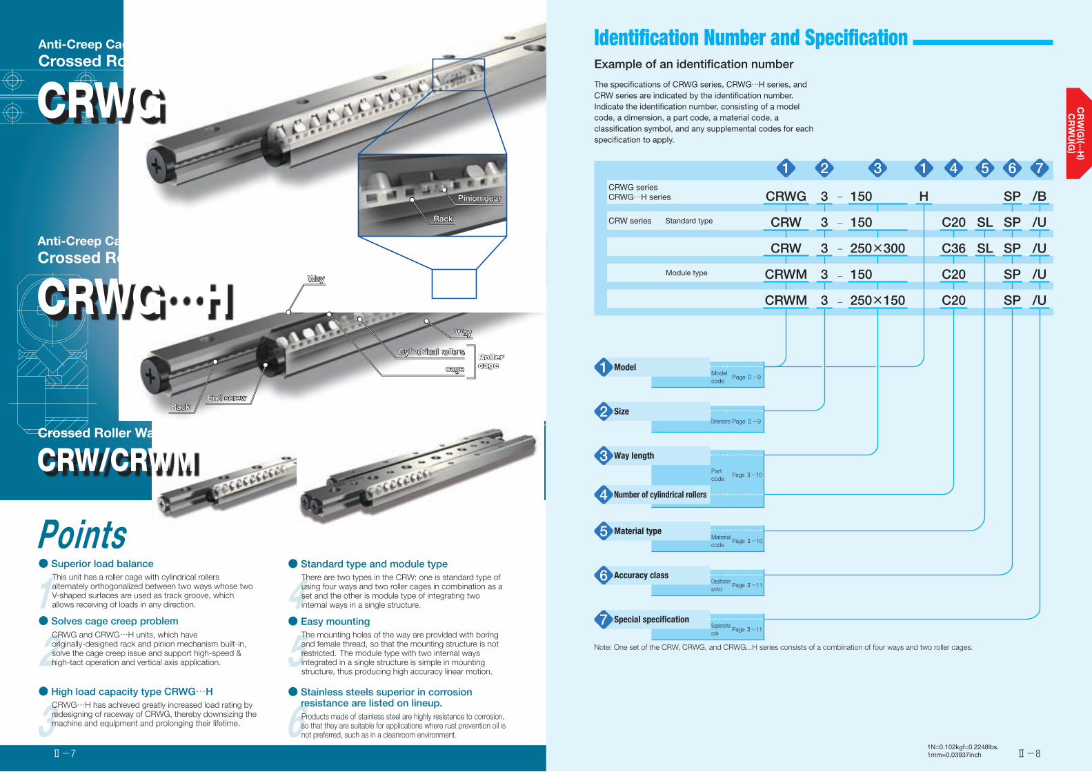
This unit has a roller cage with cylindrical rollers alternately orthogonalized between two ways whose two V-shaped surfaces are used as track groove, which allows receiving of loads in any direction.
2● Solves cage creep problem
CRWG and CRWG…H units, which have originally-designed rack and pinion mechanism built-in, solve the cage creep issue and support high-speed & high-tact operation and vertical axis application.
3● High load capacity type CRWG…H
CRWG…H has achieved greatly increased load rating by redesigning of raceway of CRWG, thereby downsizing the machine and equipment and prolonging their lifetime.
4● Standard type and module type
There are two types in the CRW: one is standard type of using four ways and two roller cages in combination as a set and the other is module type of integrating two internal ways in a single structure.
5● Easy mounting
The mounting holes of the way are provided with boring and female thread, so that the mounting structure is not restricted. The module type with two internal ways integrated in a single structure is simple in mounting structure, thus producing high accuracy linear motion.
6Products made of stainless steel are highly resistance to corrosion, so that they are suitable for applications where rust prevention oil is not preferred, such as in a cleanroom environment.
CRW/CRWMCrossed Roller Way
CRWGAnti-Creep CageCrossed Roller Way
CRWG…HAnti-Creep CageCrossed Roller Way H
● Stainless steels superior in corrosion resistance are listed on lineup.
RackRack
Pinion gearPinion gear
WayWay
Cylindrical rollersCylindrical rollers
End screwEnd screw
WayWay
cagecage
RackRack
Roller cageRoller cage
Ⅱ-8Ⅱ-7
Identification Number and Specification
1N=0.102kgf=0.2248lbs.1mm=0.03937inch
Example of an identification number
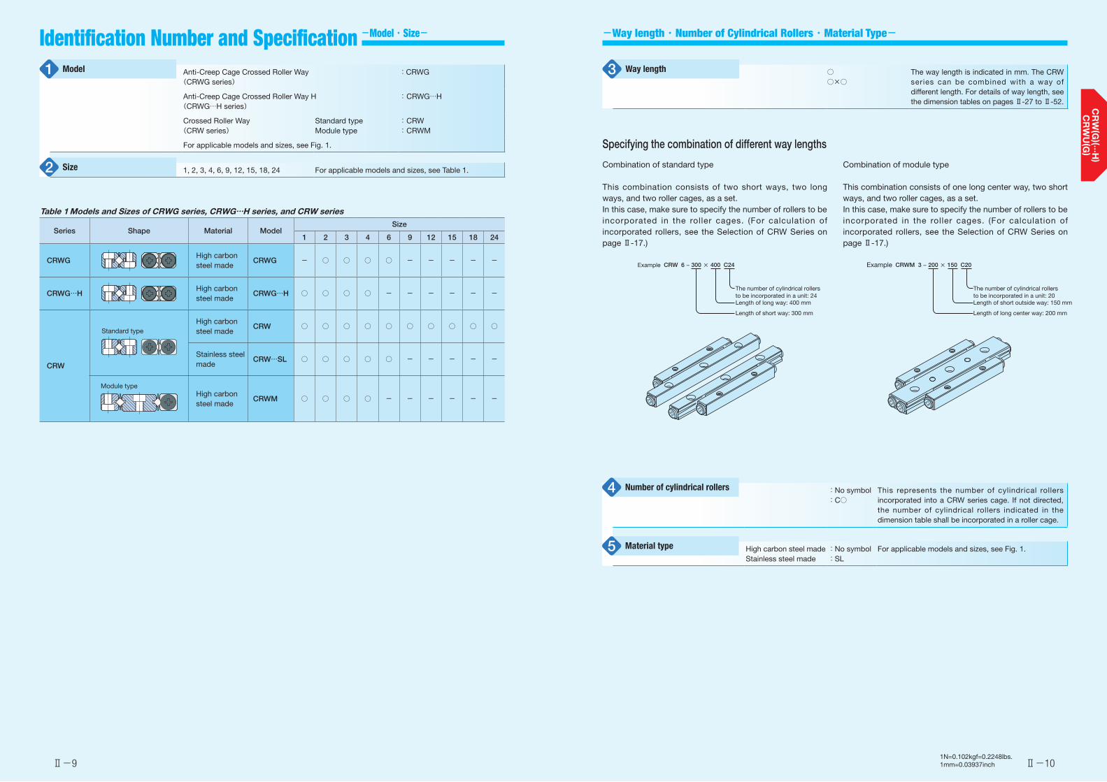
The specifications of CRWG series, CRWG…H series, and CRW series are indicated by the identification number. Indicate the identification number, consisting of a model code, a dimension, a part code, a material code, a classification symbol, and any supplemental codes for each specification to apply.
1 2 3 1 4 5 6 7CRWG seriesCRWG…H series CRWG 3 - 150 H SP /B
CRW series Standard type CRW 3 - 150 C20 SL SP /U
CRW 3 - 250×300 C36 SL SP /U
Module type CRWM 3 - 150 C20 SP /U
CRWM 3 - 250×150 C20 SP /U
Model1 Model code
Page Ⅱ-9
Size2Dimensions Page Ⅱ-9
Way length3Part code
Page Ⅱ-10
Number of cylindrical rollers4
Material type5 Material code
Page Ⅱ-10
Accuracy class6 Classification symbol
Page Ⅱ-11
Special specification7 Supplemental code
Page Ⅱ-11
Note: One set of the CRW, CRWG, and CRWG...H series consists of a combination of four ways and two roller cages.
Ⅱ-9 Ⅱ-10
-Way length ・ Number of Cylindrical Rollers ・ Material Type-Identification Number and Specification
-Model ・ Size-
1N=0.102kgf=0.2248lbs.1mm=0.03937inch
Specifying the combination of different way lengths
Combination of standard type
This combination consists of two short ways, two long ways, and two roller cages, as a set.In this case, make sure to specify the number of rollers to be incorporated in the roller cages. (For calculation of incorporated rollers, see the Selection of CRW Series on page Ⅱ-17.)
Combination of module type
This combination consists of one long center way, two short ways, and two roller cages, as a set. In this case, make sure to specify the number of rollers to be incorporated in the roller cages. (For calculation of incorporated rollers, see the Selection of CRW Series on page Ⅱ-17.)
Example CRW 6 − 300 × 400 C24
Length of long way: 400 mm
Length of short way: 300 mm
The number of cylindrical rollers to be incorporated in a unit: 24
Example CRWM 3 − 200 × 150 C20
Length of short outside way: 150 mm
Length of long center way: 200 mm
The number of cylindrical rollers to be incorporated in a unit: 20
Anti-Creep Cage Crossed Roller Way(CRWG series)
:CRWG
Anti-Creep Cage Crossed Roller Way H(CRWG…H series)
: CRWG…H
Crossed Roller Way(CRW series)
Standard typeModule type
: CRW: CRWM
For applicable models and sizes, see Fig. 1.
1, 2, 3, 4, 6, 9, 12, 15, 18, 24 For applicable models and sizes, see Table 1.
Model1
Size2
:No symbol:C○
This represents the number of cylindrical rollers incorporated into a CRW series cage. If not directed, the number of cylindrical rollers indicated in the dimension table shall be incorporated in a roller cage.
High carbon steel madeStainless steel made
:No symbol:SL
For applicable models and sizes, see Fig. 1.
Number of cylindrical rollers4
Material type5
○○×○
The way length is indicated in mm. The CRW series can be combined with a way of different length. For details of way length, see the dimension tables on pages Ⅱ-27 to Ⅱ-52.
Way length3
Table 1 Models and Sizes of CRWG series, CRWG…H series, and CRW series
Series Shape Material ModelSize
1 2 3 4 6 9 12 15 18 24
CRWGHigh carbon steel made
CRWG - ○ ○ ○ ○ - - - - -
CRWG…HHigh carbon steel made
CRWG…H ○ ○ ○ ○ - - - - - -
CRW
High carbon steel made
CRW ○ ○ ○ ○ ○ ○ ○ ○ ○ ○
Stainless steel made
CRW…SL ○ ○ ○ ○ ○ - - - - -
High carbon steel made
CRWM ○ ○ ○ ○ - - - - - -
Standard type
Module type

Ⅱ-11 Ⅱ-12
-Special Specification--Accuracy Class ・ Special Specification-
1N=0.102kgf=0.2248lbs.1mm=0.03937inch
CRWG, CRWG…H, CRW
A
A
B
A/LΔ
A/LΔ A/LΔ
/LΔ
B/LΔ
CRWM
SP
10
8
6
4
2
0 200 400 600 800 1000 1200
Way length L mm
Par
alle
lism
μ
mΔ
Fig. 1 Accuracy
Fig. 2 Mounting by special mounting screw
Table 2 Application of special specifications
Special specificationSupplemental
code
Size
1 2 3 4 6 9 12 15 18 24
Special mounting screw /B - - ○ ○ ○ ○ ○ ○ ○ ○High rigidity roller cage (1)(2) /M - - - - ○ ○ ○ ○ ○ ○End stopper SA (2) /SA - ○ ○ ○ ○ ○ ○ ○ ○ ○End stopper SB (2) /SB - ○ ○ ○ ○ ○ ○ ○ ○ ○Wiper seal (2) /U - ○ ○ ○ ○ ○ ○ ○ ○ ○
Notes(1) Not applicable to module type. (2) Not applicable to CRWG series and CRWG…H series.
B, M, SA, SB, U For applicable special specifications, see Table 2.For combination of multiple special specifications, see Table 3.For details of special specifications, see pages Ⅱ-11 to Ⅱ-14.
Special specification7
StandardSuper precision
:No symbol:SP
For parallelism of the raceway to reference mounting surface and the tolerance of the parallelism of two raceways of CRWM, see Fig. 1.
Accuracy class6
Table 3 Combination of special specificationsM ○SA ○ ○SB ○ ○ -U ○ ○ - -
B M SA SB
Remarks 1. The combination of "-" shown in the table is not available. 2. When using multiple types for combination, please indicate by arranging the symbols in alphabetical order.
Special mounting screw /B
Preload adjusting-side way can be moved by adjusting the preload. Allowance for movement is required between a way fixing screw and mounting hole, but special mounting screws are provided for the cases where enough allowance is not provided or a fixing screw should be mounted from the way side as shown in Fig. 2.This special mounting screw can also be used for the case where the mounting hole for mounting the fixed-side way and positioning accuracy of female thread are not enough. This special mounting screw is high carbon steel-made only.
High rigidity roller cage /M
The cage is changed into a high rigidity copper alloy-made cage designed to suit vertical axis application. This cage has a structure to prevent a roller from dropping off in one-side direction.For using a high rigidity roller cage for vertical axis application, it is recommended to use the cage in combination with end stopper SB.
Table 4 Dimensions of special mounting screw
unit: mm
Size Bolt size d D H L S
3 M 3 2.3 5 3 12 5 4 M 4 3.1 6 4 15 6 6 M 5 3.9 8 5 20 8 9 M 6 4.6 8.5 6 30 1212 M 8 6.2 11.5 8 40 1715 M10 7.9 14 10 45 1618 M12 9.6 16 12 50 1924 M14 11.2 19.5 14 70 26
Bolt size
L
d
D
S
H
Ⅱ-13 Ⅱ-14
-Special Specification--Special Specification-
1N=0.102kgf=0.2248lbs.1mm=0.03937inch
End stopper SA /SA
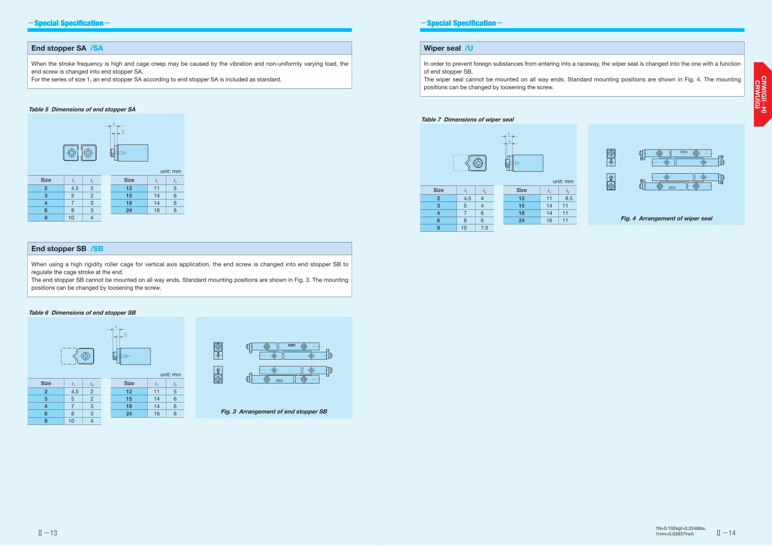
When the stroke frequency is high and cage creep may be caused by the vibration and non-uniformly varying load, the end screw is changed into end stopper SA.For the series of size 1, an end stopper SA according to end stopper SA is included as standard.
End stopper SB /SB
When using a high rigidity roller cage for vertical axis application, the end screw is changed into end stopper SB to regulate the cage stroke at the end.The end stopper SB cannot be mounted on all way ends. Standard mounting positions are shown in Fig. 3. The mounting positions can be changed by loosening the screw.
Wiper seal /U
In order to prevent foreign substances from entering into a raceway, the wiper seal is changed into the one with a function of end stopper SB.The wiper seal cannot be mounted on all way ends. Standard mounting positions are shown in Fig. 4. The mounting positions can be changed by loosening the screw.
Table 5 Dimensions of end stopper SA
unit: mm
Size t1 t2 Size t1 t2
2 4.5 2 12 11 53 5 2 15 14 64 7 3 18 14 66 8 3 24 16 69 10 4
t1
t2
Table 6 Dimensions of end stopper SB
unit: mm
Size t1 t2 Size t1 t2
2 4.5 2 12 11 53 5 2 15 14 64 7 3 18 14 66 8 3 24 16 69 10 4
t1
t2
Table 7 Dimensions of wiper seal
unit: mm
Size t1 t2 Size t1 t2
2 4.5 4 12 11 8.53 5 4 15 14 114 7 6 18 14 116 8 6 24 16 119 10 7.5
t1
t2
Fig. 3 Arrangement of end stopper SB
Fig. 4 Arrangement of wiper seal
Ⅱ-15 Ⅱ-16
Load Rating and Allowable Load
1N=0.102kgf=0.2248lbs.1mm=0.03937inch
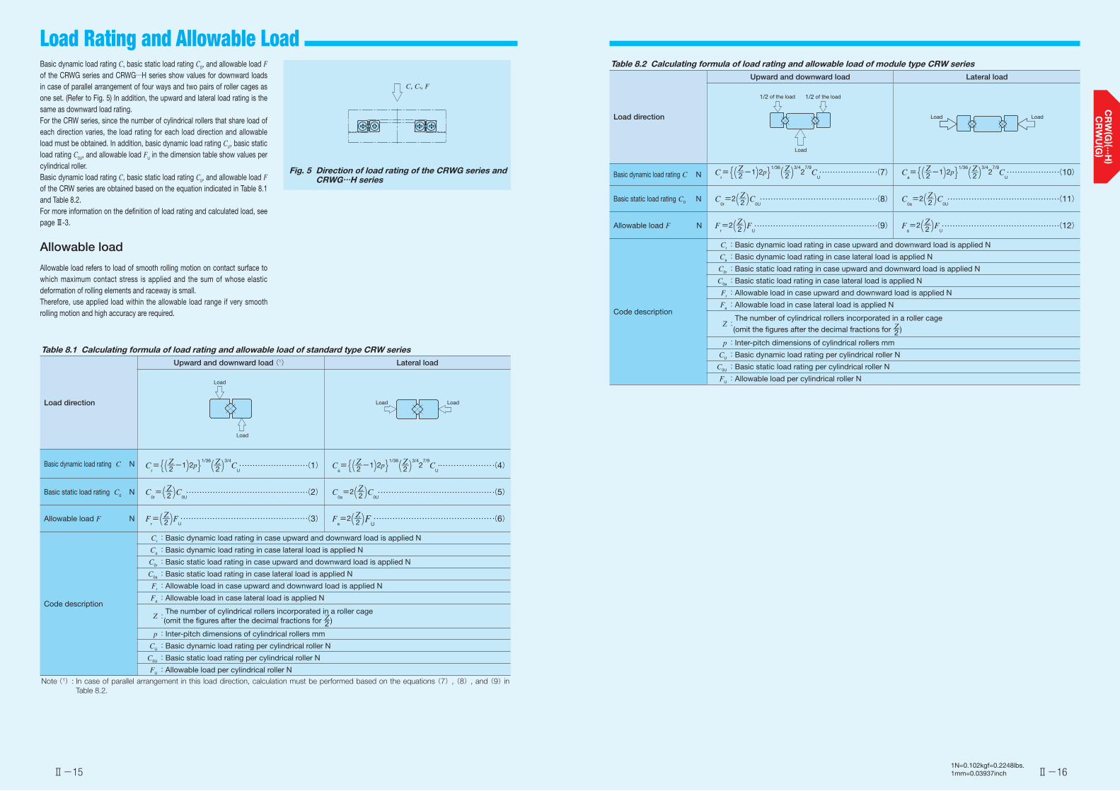
Basic dynamic load rating C, basic static load rating C0, and allowable load F of the CRWG series and CRWG…H series show values for downward loads in case of parallel arrangement of four ways and two pairs of roller cages as one set. (Refer to Fig. 5) In addition, the upward and lateral load rating is the same as downward load rating.For the CRW series, since the number of cylindrical rollers that share load of each direction varies, the load rating for each load direction and allowable load must be obtained. In addition, basic dynamic load rating CU, basic static load rating C0U, and allowable load FU in the dimension table show values per cylindrical roller.Basic dynamic load rating C, basic static load rating C0, and allowable load F of the CRW series are obtained based on the equation indicated in Table 8.1 and Table 8.2.For more information on the definition of load rating and calculated load, see page Ⅲ-3.
Allowable load
Allowable load refers to load of smooth rolling motion on contact surface to which maximum contact stress is applied and the sum of whose elastic deformation of rolling elements and raceway is small.Therefore, use applied load within the allowable load range if very smooth rolling motion and high accuracy are required.
Fig. 5 Direction of load rating of the CRWG series and CRWG…H series
C, C0, F
Table 8.1 Calculating formula of load rating and allowable load of standard type CRW series
Load direction
Upward and downward load (1) Lateral load
Basic dynamic load rating C N Cr={(Z―2-1)2p}1/36(Z―2 )
3/4C
U (1) C
a={(Z―2-1)2p}1/36(Z―2 )
3/42
7/9C
U (4)
Basic static load rating C0 N C
0r=(Z―2 )C0U
(2) C0a=2(Z―2 )C0U
(5)
Allowable load F N Fr=(Z―2 )FU
(3) Fa=2(Z―2 )FU
(6)
Code description
Cr:Basic dynamic load rating in case upward and downward load is applied N
Ca:Basic dynamic load rating in case lateral load is applied N
C0r:Basic static load rating in case upward and downward load is applied N
C0a:Basic static load rating in case lateral load is applied N
Fr:Allowable load in case upward and downward load is applied N
Fa:Allowable load in case lateral load is applied N
Z: The number of cylindrical rollers incorporated in a roller cage (omit the figures after the decimal fractions for Z―2 )
p:Inter-pitch dimensions of cylindrical rollers mm
CU:Basic dynamic load rating per cylindrical roller N
C0U:Basic static load rating per cylindrical roller N
FU:Allowable load per cylindrical roller N
Note (1): In case of parallel arrangement in this load direction, calculation must be performed based on the equations (7), (8), and (9) in Table 8.2.
Load
Load
Load Load
Table 8.2 Calculating formula of load rating and allowable load of module type CRW series
Load direction
Upward and downward load Lateral load
Basic dynamic load rating C N Cr={(Z―2-1)2p}1/36(Z―2 )
3/42
7/9C
U (7) C
a={(Z―2-1)2p}1/36(Z―2 )
3/42
7/9C
U (10)
Basic static load rating C0 N C
0r=2(Z―2 )C0U
(8) C0a=2(Z―2 )C0U
(11)
Allowable load F N Fr=2(Z―2 )FU
(9) Fa=2(Z―2 )FU
(12)
Code description
Cr:Basic dynamic load rating in case upward and downward load is applied N
Ca:Basic dynamic load rating in case lateral load is applied N
C0r:Basic static load rating in case upward and downward load is applied N
C0a:Basic static load rating in case lateral load is applied N
Fr:Allowable load in case upward and downward load is applied N
Fa:Allowable load in case lateral load is applied N
Z: The number of cylindrical rollers incorporated in a roller cage
(omit the figures after the decimal fractions for Z―2 )
p:Inter-pitch dimensions of cylindrical rollers mm
CU:Basic dynamic load rating per cylindrical roller N
C0U:Basic static load rating per cylindrical roller N
FU:Allowable load per cylindrical roller N
1/2 of the load 1/2 of the load
Load
Load Load

Ⅱ-17 Ⅱ-18
Selection of CRW Series
1N=0.102kgf=0.2248lbs.1mm=0.03937inch
For selection of CRW series specifications, stroke length and the number of cylindrical rollers, as well as accuracy, load rating and allowable load, must be determined.
Stroke length and the number of cylindrical rollers
Stroke length of the CRW series affects the way length and the number of cylindrical rollers.Therefore, select specifications by following the procedure below taking into account the stroke length used and applied load.
❶ Calculation of way lengthThe way length, which should be 1.5 times longer than the stroke length used, is obtained from the equation below.
L≧1.5S (13)
Where L: Way length mm S: Stroke length used mm
❷ Calculation of maximum stroke lengthIdeally the stroke length used should be less than 80% of the maximum stroke length, which is obtained from the equation below.
S1≧1
0.8 S (14)
Where S1: Maximum stroke length mmS : Stroke length used mm
S
L≧1.5S
❸ Calculation of cage length and the number of rollersWith the way length and maximum stroke length determined, the allowable length for cage can be calculated.Calculation method of the cage length varies depending on specifications of end screws and end stopper fitted to the way end.
(1) With standard end screws and end stopper SA (excluding Size 1 series)The dimensions between rollers at both ends is obtained from the following equation by using a value obtained by subtracting a half of the maximum stroke length from the way length.
LR=L- S1
2 (15)
Where LR : Allowable dimensions between rollers at both ends mm
L : Way length mmS1 : Maximum stroke length mm
The number of rollers to be incorporated in a roller cage is obtained by the following equation.
Z= LR-DW
p +1 (16)
Where Z : Number of cylindrical rollers (figures after the decimal fractions are omitted)
LR : Allowed dimensions between rollers at both ends mm
DW: Diameter of cylindrical rollers (refer to the dimension table) mm
p : Inter-pitch dimensions of cylindrical rollers (refer to the dimension table) mm
L
L
S1
LR
S1/2
S1/2
(2) For Size 1 seriesThe stroke length is regulated by cage and end stopper and the cage length is obtained by the following equation.
R=L- S1
2 (17)
Where R: Allowable cage length mmL: Way length mmS1: Maximum stroke length mm
The number of rollers to be incorporated in a roller cage is obtained by the following equation.
Z= R-2e +1p
(18)
Where Z : Number of cylindrical rollers (figures after the decimal fractions are omitted)
R: Allowable cage length mme : End dimension of cage (refer to the dimension
table) mmp : Inter-pitch dimensions of cylindrical rollers (refer
to the dimension table) mm
(3) For end stopper SB and wiper sealThe stroke length is regulated by cage and end stopper or wiper seal and the cage length is obtained by the following equation.
R=L-t2-S1 (19)
Where R : Allowable cage length mmL : Way length mmS1 : Maximum stroke length mmt2 : Thickness of end stopper SB or wiper seal mm
(See Table 6 in page Ⅱ-13, and Table 7 in page Ⅱ-14)
The number of rollers to be incorporated in a roller cage is obtained by the equation (18) as with the Size 1 series.
L
L
R
S1/2
S1/2
S1
R
L
S1t2
Calculation examples
Form of use ………………………………………… CRW 6Applied load ………………………………………… P = 7000 NStroke length ………………………………………… S = 195 mm
Select specifications for parallel use of Crossed Roller Way under the above conditions (refer to Fig. 26 in page Ⅱ-23).
❶ Calculation of way lengthThe way length L is calculated from the equation (13).
L≧1.5S=1.5×195=292.5
Therefore, select L = 300 mm based on the standard length in the dimension table.
❷ Calculation of maximum stroke lengthThe maximum stroke length S1 is calculated from the equation (14).
S1≧1
S= 10.8 0.8
×195≒244
Allowable dimensions between rollers at both ends LR is calculated from the equation (15).
LR= L- S1 =300- 2442 2
=178
❸ Calculation of the number of rollersThe number of cylindrical rollers Z is calculated from the equation (16). However, DW and p in this form are DW = 6 mm、p = 9 mm according to the dimension table.
Z= LR-DW +1=178-6p 9
+1≒20.1
Therefore, it should be Z = 20 by omitting figures after the decimal fractions.
❹ Calculation of allowable loadAllowable load in parallel arrangement F is calculated from equation (9) described in Table 8.2 in page Ⅱ-16. However, allowable load per cylindrical roller FU is FU = 769 N according to the dimension table.
F=2(Z―2 )FU=2(20―2 )×769=15380
Therefore, allowable load F is larger than applied load P = 7000 N. When allowable load becomes smaller than applied load, it is necessary to increase the number of cylindrical rollers by extending way length, or increase the cylindrical roller diameter.
❺ Determination of specificationsSpecifications obtained in accordance with the above is CRW6-300 and the number of cylindrical rollers is 20.
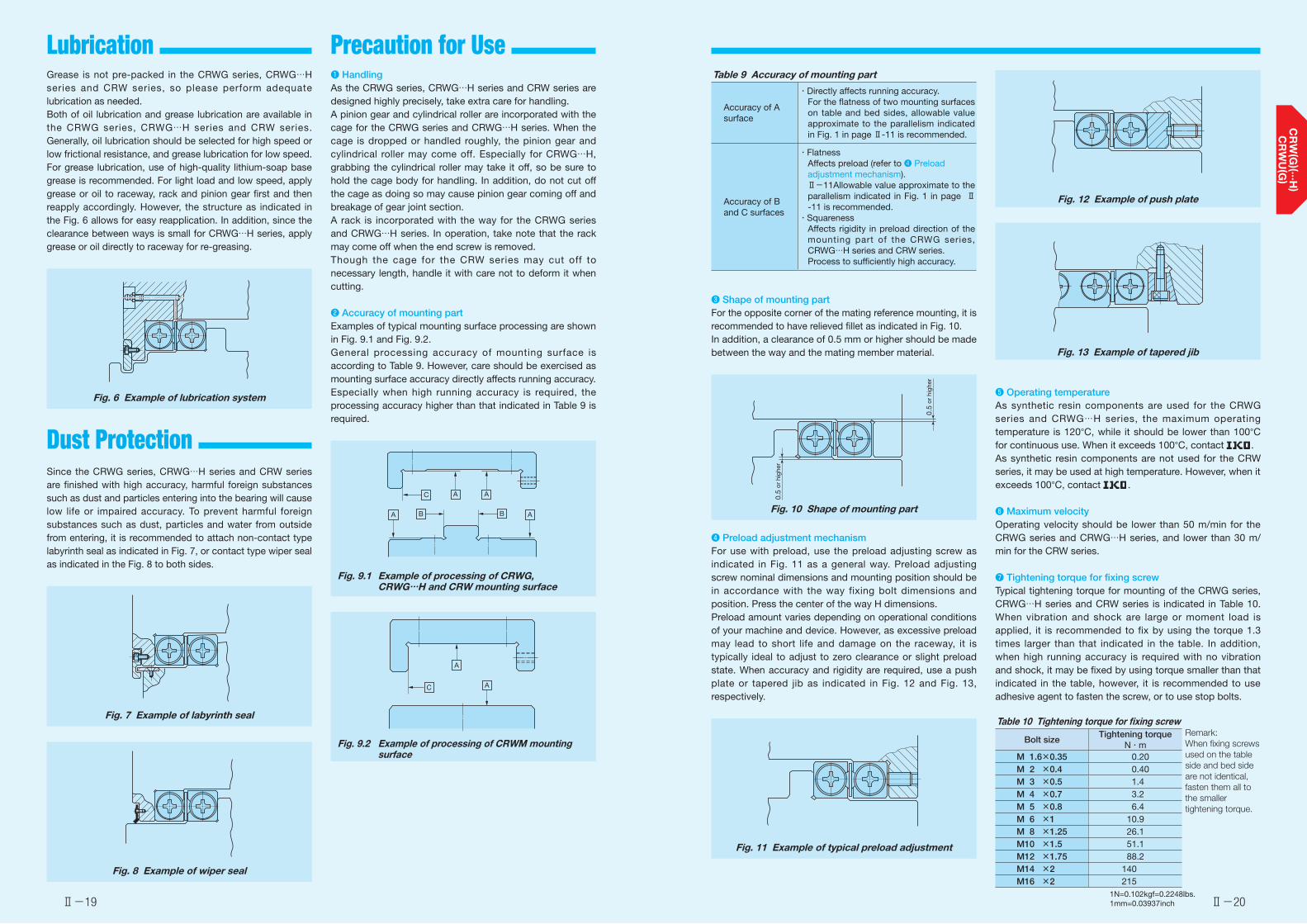
Ⅱ-19 Ⅱ-20
Lubrication Precaution for Use
1N=0.102kgf=0.2248lbs.1mm=0.03937inch
Grease is not pre-packed in the CRWG series, CRWG…H series and CRW series, so please perform adequate lubrication as needed.Both of oil lubrication and grease lubrication are available in the CRWG series, CRWG…H series and CRW series. Generally, oil lubrication should be selected for high speed or low frictional resistance, and grease lubrication for low speed. For grease lubrication, use of high-quality lithium-soap base grease is recommended. For light load and low speed, apply grease or oil to raceway, rack and pinion gear first and then reapply accordingly. However, the structure as indicated in the Fig. 6 allows for easy reapplication. In addition, since the clearance between ways is small for CRWG…H series, apply grease or oil directly to raceway for re-greasing.
Fig. 6 Example of lubrication system
Since the CRWG series, CRWG…H series and CRW series are finished with high accuracy, harmful foreign substances such as dust and particles entering into the bearing will cause low life or impaired accuracy. To prevent harmful foreign substances such as dust, particles and water from outside from entering, it is recommended to attach non-contact type labyrinth seal as indicated in Fig. 7, or contact type wiper seal as indicated in the Fig. 8 to both sides.
Fig. 7 Example of labyrinth seal
Fig. 8 Example of wiper seal
❶ HandlingAs the CRWG series, CRWG…H series and CRW series are designed highly precisely, take extra care for handling.A pinion gear and cylindrical roller are incorporated with the cage for the CRWG series and CRWG…H series. When the cage is dropped or handled roughly, the pinion gear and cylindrical roller may come off. Especially for CRWG…H, grabbing the cylindrical roller may take it off, so be sure to hold the cage body for handling. In addition, do not cut off the cage as doing so may cause pinion gear coming off and breakage of gear joint section.A rack is incorporated with the way for the CRWG series and CRWG…H series. In operation, take note that the rack may come off when the end screw is removed.Though the cage for the CRW series may cut off to necessary length, handle it with care not to deform it when cutting.
❷ Accuracy of mounting partExamples of typical mounting surface processing are shown in Fig. 9.1 and Fig. 9.2.General processing accuracy of mounting surface is according to Table 9. However, care should be exercised as mounting surface accuracy directly affects running accuracy. Especially when high running accuracy is required, the processing accuracy higher than that indicated in Table 9 is required.
Fig. 9.1 Example of processing of CRWG, CRWG…H and CRW mounting surface
Fig. 9.2 Example of processing of CRWM mounting surface
A
A
A
AB B
C
A
AC
Table 9 Accuracy of mounting part
Accuracy of A surface
・Directly affects running accuracy.For the flatness of two mounting surfaces on table and bed sides, allowable value approximate to the parallelism indicated in Fig. 1 in page Ⅱ-11 is recommended.
Accuracy of B and C surfaces
・FlatnessAffects preload (refer to ❹ Preload adjustment mechanism).Ⅱ-11Allowable value approximate to the parallelism indicated in Fig. 1 in page Ⅱ-11 is recommended.
・SquarenessAffects rigidity in preload direction of the mounting part of the CRWG series, CRWG…H series and CRW series.Process to sufficiently high accuracy.
❸ Shape of mounting partFor the opposite corner of the mating reference mounting, it is recommended to have relieved fillet as indicated in Fig. 10.In addition, a clearance of 0.5 mm or higher should be made between the way and the mating member material.
Fig. 10 Shape of mounting part
❹ Preload adjustment mechanismFor use with preload, use the preload adjusting screw as indicated in Fig. 11 as a general way. Preload adjusting screw nominal dimensions and mounting position should be in accordance with the way fixing bolt dimensions and position. Press the center of the way H dimensions.Preload amount varies depending on operational conditions of your machine and device. However, as excessive preload may lead to short life and damage on the raceway, it is typically ideal to adjust to zero clearance or slight preload state. When accuracy and rigidity are required, use a push plate or tapered jib as indicated in Fig. 12 and Fig. 13, respectively.
Fig. 11 Example of typical preload adjustment
0.5
or h
ighe
r
0.5
or h
ighe
r
Fig. 12 Example of push plate
Fig. 13 Example of tapered jib
❺ Operating temperatureAs synthetic resin components are used for the CRWG series and CRWG…H series, the maximum operating temperature is 120°C, while it should be lower than 100°C for continuous use. When it exceeds 100°C, contact .As synthetic resin components are not used for the CRW series, it may be used at high temperature. However, when it exceeds 100°C, contact .
❻ Maximum velocityOperating velocity should be lower than 50 m/min for the CRWG series and CRWG…H series, and lower than 30 m/min for the CRW series.
❼ Tightening torque for fixing screwTypical tightening torque for mounting of the CRWG series, CRWG…H series and CRW series is indicated in Table 10. When vibration and shock are large or moment load is applied, it is recommended to fix by using the torque 1.3 times larger than that indicated in the table. In addition, when high running accuracy is required with no vibration and shock, it may be fixed by using torque smaller than that indicated in the table, however, it is recommended to use adhesive agent to fasten the screw, or to use stop bolts.
Table 10 Tightening torque for fixing screw
Bolt sizeTightening torque
N・mRemark: When fixing screws used on the table side and bed side are not identical, fasten them all to the smaller tightening torque.
M 1.6×0.35 0.20M 2 ×0.4 0.40M 3 ×0.5 1.4M 4 ×0.7 3.2M 5 ×0.8 6.4M 6 ×1 10.9M 8 ×1.25 26.1M10 ×1.5 51.1M12 ×1.75 88.2M14 ×2 140M16 ×2 215
Dust Protection
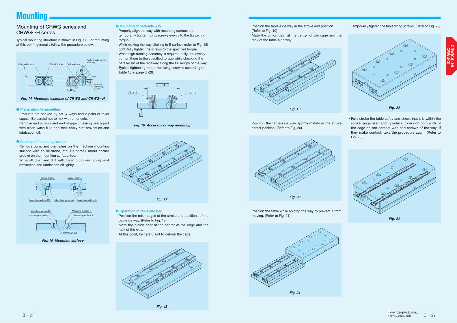
Ⅱ-21 Ⅱ-22
Mounting
1N=0.102kgf=0.2248lbs.1mm=0.03937inch
Mounting of CRWG series and CRWG…H seriesTypical mounting structure is shown in Fig. 14. For mounting at this point, generally follow the procedure below.
Fig. 14 Mounting example of CRWG and CRWG…H
❶ Preparation for mounting・Products are packed by set (4 ways and 2 pairs of roller
cages). Be careful not to mix with other sets. ・Remove end screws and end stopper, clean up each part
with clean wash fluid and then apply rust prevention and lubrication oil.
❷ Cleanup of mounting surface・Remove burrs and blemishes on the machine mounting
surface with an oil-stone, etc. Be careful about corner groove on the mounting surface, too.
・Wipe off dust and dirt with clean cloth and apply rust prevention and lubrication oil lightly.
Fig. 15 Mounting surface
Fixing-side way Bed-side way Bed-side way
Preload adjusting screw
Preload-adjustment-side way
Corner groove Corner groove
Mounting surface C Mounting surface A Mounting surface A
Mounting surface AMounting surface A
Mounting surface B Mounting surface B
Corner groove
❸ Mounting of bed-side way・Properly align the way with mounting surface and
temporarily tighten fixing screws evenly to the tightening torque.
・While making the way sticking to B surface (refer to Fig. 15) tight, fully tighten the screws to the specified torque.
・When high running accuracy is required, fully and evenly tighten them to the specified torque while checking the parallelism of the raceway along the full length of the way.
・Typical tightening torque for fixing screw is according to Table 10 in page Ⅱ-20.
Fig. 16 Accuracy of way mounting
Fig. 17
❹ Operation of table and bed・Position the roller cages at the stroke end positions of the
bed-side way. (Refer to Fig. 18)・Mate the pinion gear at the center of the cage and the
rack of the way.・At this point, be careful not to deform the cage.
Fig. 18
A A
A
Δ
Δ
Δ
・Position the table-side way in the stroke end position. (Refer to Fig. 19)・Mate the pinion gear at the center of the cage and the
rack of the table-side way.
Fig. 19
・Position the table-side way approximately in the stroke center position. (Refer to Fig. 20)
Fig. 20
・Position the table while holding the way to prevent it from moving. (Refer to Fig. 21)
Fig. 21
・Temporarily tighten the table fixing screws. (Refer to Fig. 22)
Fig. 22
・Fully stroke the table softly and check that it is within the stroke range used and cylindrical rollers on both ends of the cage do not contact with end screws of the way. If they make contact, take the procedure again. (Refer to Fig. 23)
Fig. 23

Ⅱ-23 Ⅱ-24
Mounting
1N=0.102kgf=0.2248lbs.1mm=0.03937inch
❺ Preload adjustment・Preload adjustment is performed with fixing screws of the
table-side way tightened temporarily.・Preload adjustment is started from the preload adjusting
screw at the center of way length and then both ends in turn.
・While measuring the clearance on the table sides, tighten the preload adjusting screws subsequently until deflection of the dial gauge stops. Measure the tightening torque for preload adjusting screws at this point.・When adjusting preload adjusting screw near either end,
stroke the table softly and check that the cylindrical roller is on the preload adjusting screw section.・After the above procedure, the clearance becomes zero or
in slight preload state, but preload is still not adjusted evenly. With the same procedure again, re-adjust all the preload adjusting screws evenly to the torque previously measured.
Fig. 24 Example of preload adjustment method
❻ Full tightening of preload-adjustment-side way・Fixing screws are lightly tightened to even torque. As with
preload adjusting screws, temporarily fix them to torque similar to the specified torque in turn from the way center to both ends.・When tightening fixing screws near either end, stroke the
table softly and check that the cylindrical roller is on fixing screw section.・Finally with the same procedure, fully tighten all the fixing
screws evenly to the specified torque.
❼ Check after assembly・Fully stroke the table softly and check that running is
smooth without abnormal noise.・Measure the table upper and side surfaces with dial gauge
or the like and check the running accuracy.
Fig. 25 Accuracy check after assembly
Mounting of standard type CRW series
Typical mounting structure is shown in Fig. 26. For mounting at this point, generally follow the procedure below.
Fig. 26 Mounting example of standard type CRW series
❶ Preparation for mounting・Products are packed by set (4 ways and 2 pairs of roller
cages). Be careful not to mix with other sets.・Remove end screws and end stopper, clean up each part
with clean wash fluid and then apply rust prevention and lubrication oil.
❷ Cleanup of mounting surface・Remove burrs and blemishes on the machine mounting
surface with an oil-stone, etc. Be careful about corner groove on the mounting surface, too.
・Wipe off dust and dirt with clean cloth and apply rust prevention and lubrication oil lightly.
Fig. 27 Mounting surface
Fixing-side way Bed-side way Bed-side way
Preload adjusting screw
Preload-adjustment-side way
Corner groove Corner groove
Mounting surface C Mounting surface A Mounting surface A
Mounting surface AMounting surface A
Mounting surface B Mounting surface B
Corner groove
❸ Mounting of bed-side way・Properly align the way with mounting surface and
temporarily tighten fixing screws evenly to the tightening torque.・While making the way sticking to B surface (refer to Fig.
27) tight, fully tighten the screws to the specified torque.・When high running accuracy is required, fully and evenly
tighten them to the specified torque while checking the parallelism of the raceway along the full length of the way.・Typical tightening torque for fixing screw is according to
Table 10 in page Ⅱ-20.
Fig. 28 Accuracy of way mounting
❹ Mounting of table-side way・Properly align the fixing-side way with mounting surface
and temporarily tighten fixing screws evenly to the tightening torque.・While making the fixing-side way sticking to C surface
tight, fully tighten the screws to the specified torque.・Set back the preload adjusting screws in advance, make
the preload-adjusting-side way sticking to the mounting surface, and then temporarily tighten fixing screws lightly to the even torque.
Fig. 29 Mounting of table-side way
A A
A
Δ
Δ
Δ
C surface
Fixing-side way
Preload-adjustment-side way
Preload adjusting screw
❺ Operation of table and bed・Make alignment of the position in height and cross
direction so that the roller cage can be inserted between the table-side way and bed-side way.
・Carefully insert the roller cage and assembly it at approximate center of the way length. At this point, be careful not to deform the cage. ・Mount end screws and end stopper of each way.・Push the entire table against the preload adjusting screws
and tighten the preload adjusting screws to make temporary adjustment until the clearance between ways becomes zero. ・Fully stroke the table softly and correct the roller cage
position to the center.
Fig. 30 Position alignment before operation
❻ Preload adjustment・Preload adjustment is performed with fixing screws of the
preload-adjusting-side way tightened temporarily.・Preload adjustment is started from the preload adjusting
screw at the center of way length and then both ends in turn.
・While measuring the clearance on the table sides, tighten the preload adjusting screws subsequently until deflection of the dial gauge stops. Measure the tightening torque for preload adjusting screws at this point.・When adjusting preload adjusting screw near either end,
stroke the table softly and check that the cylindrical roller is on the preload adjusting screw section.・After the above procedure, the clearance becomes zero or
in slight preload state, but preload is still not adjusted evenly. With the same procedure again, re-adjust all the preload adjusting screws evenly to the torque previously measured.
Fig. 31 Example of preload adjustment method
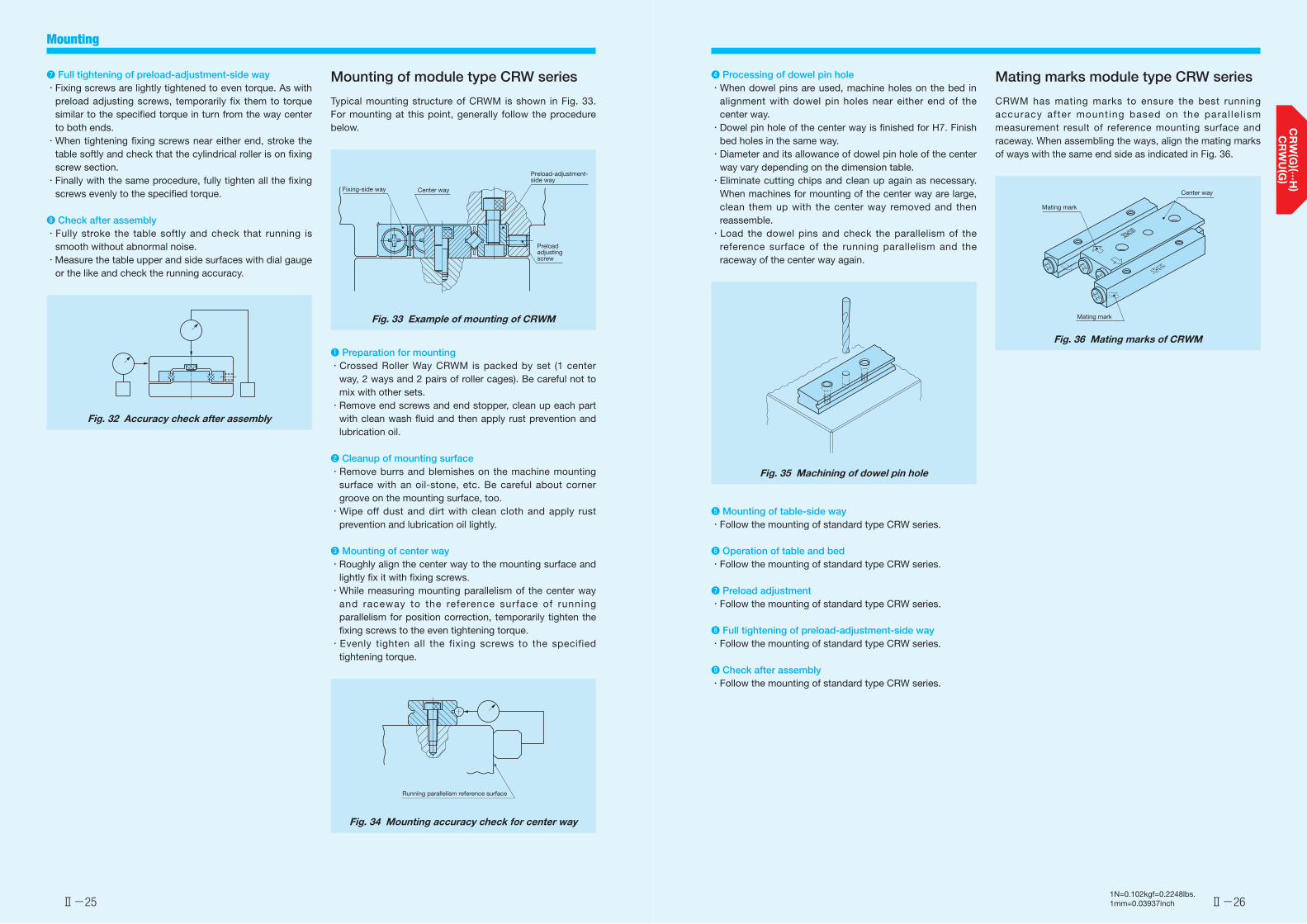
Ⅱ-25 Ⅱ-26
Mounting
1N=0.102kgf=0.2248lbs.1mm=0.03937inch
Mating marks module type CRW series
CRWM has mating marks to ensure the best running accuracy after mounting based on the paral le l ism measurement result of reference mounting surface and raceway. When assembling the ways, align the mating marks of ways with the same end side as indicated in Fig. 36.
Fig. 36 Mating marks of CRWM
Mating mark
Center way
Mating mark
❼ Full tightening of preload-adjustment-side way・Fixing screws are lightly tightened to even torque. As with
preload adjusting screws, temporarily fix them to torque similar to the specified torque in turn from the way center to both ends.・When tightening fixing screws near either end, stroke the
table softly and check that the cylindrical roller is on fixing screw section.・Finally with the same procedure, fully tighten all the fixing
screws evenly to the specified torque.
❽ Check after assembly・Fully stroke the table softly and check that running is
smooth without abnormal noise.・Measure the table upper and side surfaces with dial gauge
or the like and check the running accuracy.
Fig. 32 Accuracy check after assembly
Mounting of module type CRW series
Typical mounting structure of CRWM is shown in Fig. 33. For mounting at this point, generally follow the procedure below.
Fig. 33 Example of mounting of CRWM
❶ Preparation for mounting・Crossed Roller Way CRWM is packed by set (1 center
way, 2 ways and 2 pairs of roller cages). Be careful not to mix with other sets.
・Remove end screws and end stopper, clean up each part with clean wash fluid and then apply rust prevention and lubrication oil.
❷ Cleanup of mounting surface・Remove burrs and blemishes on the machine mounting
surface with an oil-stone, etc. Be careful about corner groove on the mounting surface, too.
・Wipe off dust and dirt with clean cloth and apply rust prevention and lubrication oil lightly.
❸ Mounting of center way・Roughly align the center way to the mounting surface and
lightly fix it with fixing screws.・While measuring mounting parallelism of the center way
and raceway to the reference surface of running parallelism for position correction, temporarily tighten the fixing screws to the even tightening torque.
・Evenly tighten all the fixing screws to the specified tightening torque.
Fig. 34 Mounting accuracy check for center way
Fixing-side way Center way
Preload-adjustment-side way
Preload adjusting screw
Running parallelism reference surface
❹ Processing of dowel pin hole・When dowel pins are used, machine holes on the bed in
alignment with dowel pin holes near either end of the center way.
・Dowel pin hole of the center way is finished for H7. Finish bed holes in the same way.・Diameter and its allowance of dowel pin hole of the center
way vary depending on the dimension table.・Eliminate cutting chips and clean up again as necessary.
When machines for mounting of the center way are large, clean them up with the center way removed and then reassemble.・Load the dowel pins and check the parallelism of the
reference surface of the running parallelism and the raceway of the center way again.
Fig. 35 Machining of dowel pin hole
❺ Mounting of table-side way・Follow the mounting of standard type CRW series.
❻ Operation of table and bed・Follow the mounting of standard type CRW series.
❼ Preload adjustment・Follow the mounting of standard type CRW series.
❽ Full tightening of preload-adjustment-side way・Follow the mounting of standard type CRW series.
❾ Check after assembly・Follow the mounting of standard type CRW series.

Anti-Creep Cage Crossed Roller Way
Ⅱ-28
Anti-Creep Cage Crossed Roller Way
Ⅱ-27
Identification number
Mass (Ref.) Nominal dimensions mm Maximum stroke length
Basic dynamic load rating
Basic static load rating
Allowable load
Way (1)
g
Roller cage (2)
g
Boundary dimensions Dimension of roller cage Mounting dimensions C(3)
N
C0(3)
N
F(3)
NA H L(n×F) E DW R Z p e W g M d1 d2 h t mm
CRWG 2- 30 6.53 0.38
12 6
30(1×15)
7.5 2
25.6 4
4 2.8 5.5 2.5 M3 2.55 4.4 2 1.5
9 913 1 180 392
CRWG 2- 45 9.53 0.72 45(2×15) 41.6 8 7 1 570 2 350 783
CRWG 2- 60 12.5 0.88 60(3×15) 49.6 10 21 1 860 2 940 979
CRWG 2- 75 15.5 1.22 75(4×15) 65.6 14 19 2 420 4 110 1 370
CRWG 2- 90 18.5 1.39 90(5×15) 73.6 16 33 2 680 4 700 1 570
CRWG 2-105 21.5 1.72 105(6×15) 89.6 20 31 3 190 5 880 1 960
CRWG 2-120 24.5 1.89 120(7×15) 97.6 22 45 3 440 6 460 2 150
CRWG 2-135 27.5 2.22 135(8×15) 113.6 26 43 3 910 7 640 2 550
CRWG 2-150 30.5 2.39 150(9×15) 121.6 28 57 4 150 8 230 2 740
CRWG 3- 50 22.8 1.69
18 8
50(1×25)
12.5 3
42 6
5 3.5 8.3 3.5 M4 3.3 6 3.1 2
13 2 740 3 660 1 220
CRWG 3- 75 33.3 2.71 75(2×25) 62 10 23 4 080 6 090 2 030
CRWG 3-100 43.8 3.72 100(3×25) 82 14 33 5 300 8 530 2 840
CRWG 3-125 54.4 4.74 125(4×25) 102 18 43 6 440 11 000 3 660
CRWG 3-150 64.9 5.75 150(5×25) 122 22 53 7 530 13 400 4 470
CRWG 3-175 75.4 6.77 175(6×25) 142 26 63 8 570 15 800 5 280
CRWG 3-200 85.9 7.78 200(7×25) 162 30 73 9 580 18 300 6 090
CRWG 3-225 96.4 8.80 225(8×25) 182 34 83 10 600 20 700 6 910
CRWG 3-250 107 9.81 250(9×25) 202 38 93 11 500 23 200 7 720
Notes (1) The value shows the mass of a piece of way. (2) The value shows the mass of a roller cage. (3) This is the value when a combination of four ways and two roller cages is used in parallel arrangement.
1N=0.102kgf=0.2248lbs.1mm=0.03937inch
42 63
CRWG
Shape
SizetEn×F
L
F
Et
h
H
d 2
d 1
WW
g
A
0-
0.3
M
Z (Number of rollers)
R
pe
DW
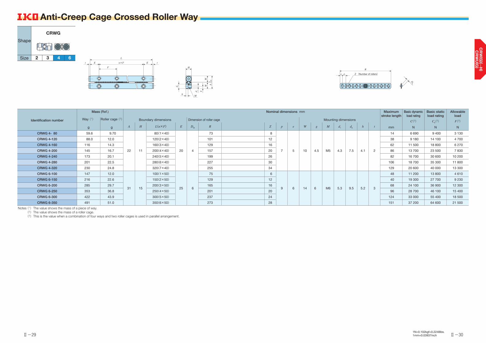
Ⅱ-29
Anti-Creep Cage Crossed Roller Way
Ⅱ-30
Anti-Creep Cage Crossed Roller Way
Identification number
Mass (Ref.) Nominal dimensions mm Maximum stroke length
Basic dynamic load rating
Basic static load rating
Allowable load
Way (1)
g
Roller cage (2)
g
Boundary dimensions Dimension of roller cage Mounting dimensions C(3)
N
C0(3)
N
F(3)
NA H L(n×F) E DW R Z p e W g M d1 d2 h t mm
CRWG 4- 80 59.6 9.70
22 11
80(1×40)
20 4
73 8
7 5 10 4.5 M5 4.3 7.5 4.1 2
14 6 690 9 400 3 130
CRWG 4-120 88.0 12.0 120(2×40) 101 12 38 9 180 14 100 4 700
CRWG 4-160 116 14.3 160(3×40) 129 16 62 11 500 18 800 6 270
CRWG 4-200 145 16.7 200(4×40) 157 20 86 13 700 23 500 7 830
CRWG 4-240 173 20.1 240(5×40) 199 26 82 16 700 30 600 10 200
CRWG 4-280 201 22.5 280(6×40) 227 30 106 18 700 35 300 11 800
CRWG 4-320 230 24.8 320(7×40) 255 34 129 20 600 40 000 13 300
CRWG 6-100 147 12.0
31 15
100(1×50)
25 6
75 6
9 6 14 6 M6 5.3 9.5 5.2 3
48 11 200 13 800 4 610
CRWG 6-150 216 22.6 150(2×50) 129 12 40 19 300 27 700 9 230
CRWG 6-200 285 29.7 200(3×50) 165 16 68 24 100 36 900 12 300
CRWG 6-250 353 36.8 250(4×50) 201 20 96 28 700 46 100 15 400
CRWG 6-300 422 43.9 300(5×50) 237 24 124 33 000 55 400 18 500
CRWG 6-350 491 51.0 350(6×50) 273 28 151 37 200 64 600 21 500
Notes (1) The value shows the mass of a piece of way. (2) The value shows the mass of a roller cage. (3) This is the value when a combination of four ways and two roller cages is used in parallel arrangement.
1N=0.102kgf=0.2248lbs.1mm=0.03937inch
42 63
CRWG
Shape
SizetEn×F
L
F
Et
h
H
d 2
d 1
WW
g
A
0-
0.3
M
Z (Number of rollers)
R
pe
DW
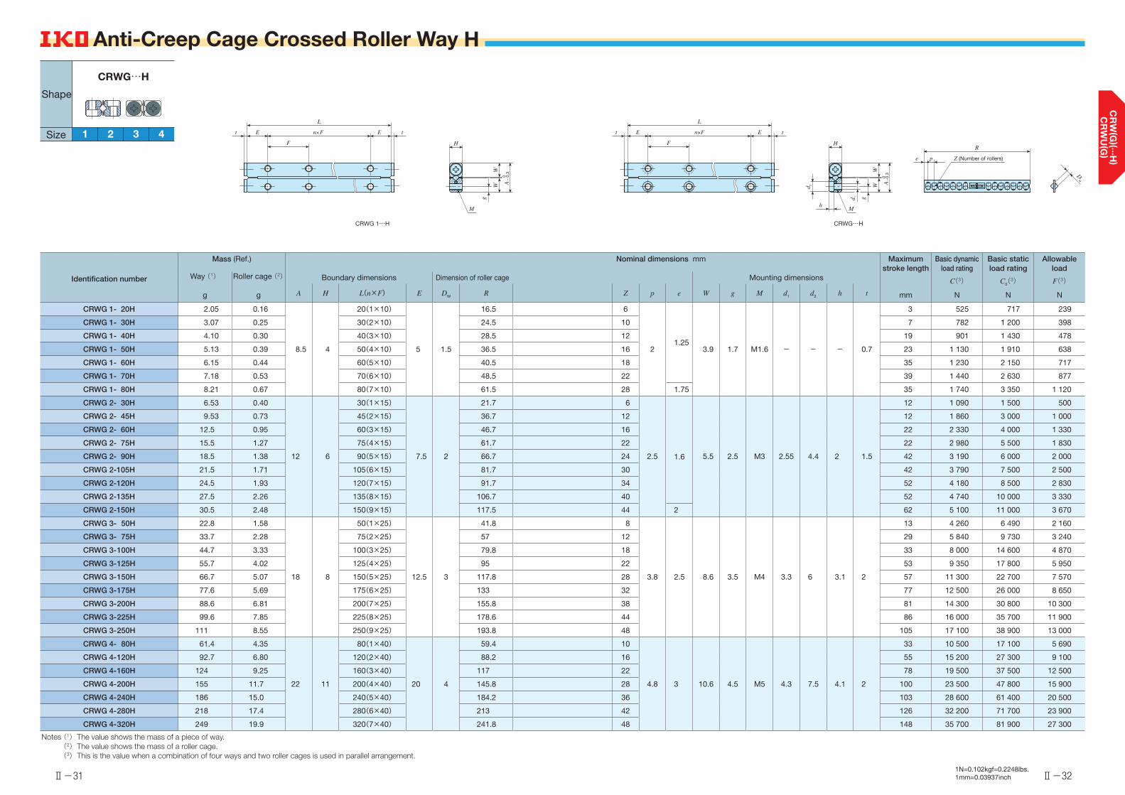
Ⅱ-31
Anti-Creep Cage Crossed Roller Way H
Ⅱ-32
Anti-Creep Cage Crossed Roller Way H
Identification number
Mass (Ref.) Nominal dimensions mm Maximum stroke length
Basic dynamic load rating
Basic static load rating
Allowable load
Way (1)
g
Roller cage (2)
g
Boundary dimensions Dimension of roller cage Mounting dimensions C(3)
N
C0(3)
N
F(3)
NA H L(n×F) E DW R Z p e W g M d1 d2 h t mm
CRWG 1- 20H 2.05 0.16
8.5 4
20(1×10)
5 1.5
16.5 6
21.25
3.9 1.7 M1.6 - - - 0.7
3 525 717 239
CRWG 1- 30H 3.07 0.25 30(2×10) 24.5 10 7 782 1 200 398
CRWG 1- 40H 4.10 0.30 40(3×10) 28.5 12 19 901 1 430 478
CRWG 1- 50H 5.13 0.39 50(4×10) 36.5 16 23 1 130 1 910 638
CRWG 1- 60H 6.15 0.44 60(5×10) 40.5 18 35 1 230 2 150 717
CRWG 1- 70H 7.18 0.53 70(6×10) 48.5 22 39 1 440 2 630 877
CRWG 1- 80H 8.21 0.67 80(7×10) 61.5 28 1.75 35 1 740 3 350 1 120
CRWG 2- 30H 6.53 0.40
12 6
30(1×15)
7.5 2
21.7 6
2.5 1.6 5.5 2.5 M3 2.55 4.4 2 1.5
12 1 090 1 500 500
CRWG 2- 45H 9.53 0.73 45(2×15) 36.7 12 12 1 860 3 000 1 000
CRWG 2- 60H 12.5 0.95 60(3×15) 46.7 16 22 2 330 4 000 1 330
CRWG 2- 75H 15.5 1.27 75(4×15) 61.7 22 22 2 980 5 500 1 830
CRWG 2- 90H 18.5 1.38 90(5×15) 66.7 24 42 3 190 6 000 2 000
CRWG 2-105H 21.5 1.71 105(6×15) 81.7 30 42 3 790 7 500 2 500
CRWG 2-120H 24.5 1.93 120(7×15) 91.7 34 52 4 180 8 500 2 830
CRWG 2-135H 27.5 2.26 135(8×15) 106.7 40 52 4 740 10 000 3 330
CRWG 2-150H 30.5 2.48 150(9×15) 117.5 44 2 62 5 100 11 000 3 670
CRWG 3- 50H 22.8 1.58
18 8
50(1×25)
12.5 3
41.8 8
3.8 2.5 8.6 3.5 M4 3.3 6 3.1 2
13 4 260 6 490 2 160
CRWG 3- 75H 33.7 2.28 75(2×25) 57 12 29 5 840 9 730 3 240
CRWG 3-100H 44.7 3.33 100(3×25) 79.8 18 33 8 000 14 600 4 870
CRWG 3-125H 55.7 4.02 125(4×25) 95 22 53 9 350 17 800 5 950
CRWG 3-150H 66.7 5.07 150(5×25) 117.8 28 57 11 300 22 700 7 570
CRWG 3-175H 77.6 5.69 175(6×25) 133 32 77 12 500 26 000 8 650
CRWG 3-200H 88.6 6.81 200(7×25) 155.8 38 81 14 300 30 800 10 300
CRWG 3-225H 99.6 7.85 225(8×25) 178.6 44 86 16 000 35 700 11 900
CRWG 3-250H 111 8.55 250(9×25) 193.8 48 105 17 100 38 900 13 000
CRWG 4- 80H 61.4 4.35
22 11
80(1×40)
20 4
59.4 10
4.8 3 10.6 4.5 M5 4.3 7.5 4.1 2
33 10 500 17 100 5 690
CRWG 4-120H 92.7 6.80 120(2×40) 88.2 16 55 15 200 27 300 9 100
CRWG 4-160H 124 9.25 160(3×40) 117 22 78 19 500 37 500 12 500
CRWG 4-200H 155 11.7 200(4×40) 145.8 28 100 23 500 47 800 15 900
CRWG 4-240H 186 15.0 240(5×40) 184.2 36 103 28 600 61 400 20 500
CRWG 4-280H 218 17.4 280(6×40) 213 42 126 32 200 71 700 23 900
CRWG 4-320H 249 19.9 320(7×40) 241.8 48 148 35 700 81 900 27 300
Notes (1) The value shows the mass of a piece of way. (2) The value shows the mass of a roller cage. (3) This is the value when a combination of four ways and two roller cages is used in parallel arrangement.
1N=0.102kgf=0.2248lbs.1mm=0.03937inch
3 41 2
CRWG…H
Shape
Size
h
H
d 2
d 1
WW
g
A
M
Z (Number of rollers)
R
pe
tEn×F
L
F
Et
0−
0.3
H
WW
g
A
M
tEn×F
L
F
Et
0−
0.3 D
W
CRWG 1…H CRWG…H

Ⅱ-33
Crossed Roller Way
Ⅱ-34
Crossed Roller Way
Identification number
Mass (Ref.) Nominal dimensions mm Basic dynamic load rating
Basic static load rating
Allowable loadBoundary dimensions Dimension of roller cage Mounting dimensions
Way (1)
kg/m
Roller cage (2)
gA H L(n×F) E DW R Z p e W g M d1 d2 h t
CU(3)
N
C0U(3)
N
FU(3)
N
CRW 1- 20
0.12 0.38 8.5 4
20(1×10)
5 1.5
16.5 5
3 2.25 3.9 1.8 M2 1.65 3 1.4 1.7 125 120 39.8
CRW 1- 20 SL
CRW 1- 3030(2×10) 25.5 8
CRW 1- 30 SL
CRW 1- 4040(3×10) 31.5 10
CRW 1- 40 SL
CRW 1- 5050(4×10) 37.5 12
CRW 1- 50 SL
CRW 1- 6060(5×10) 43.5 14
CRW 1- 60 SL
CRW 1- 7070(6×10) 52.5 17
CRW 1- 70 SL
CRW 1- 8080(7×10) 61.5 20
CRW 1- 80 SL
Notes (1) The value shows the mass per meter of a way.(2) The value shows the mass of a roller cage with ten cylindrical rollers.(3) The value shows the load of a cylindrical roller.
DW
R
pe Z (Number of rollers)
Mh d 1
W
g
A
0-
0.3
H
d 2
W
E tn×F
L
F
Et
1N=0.102kgf=0.2248lbs.1mm=0.03937inch
4
Standard type
1 2 63
CRWCRW…SL
189 12 2415
Shape
Size

Ⅱ-35
Crossed Roller Way
Ⅱ-36
Crossed Roller Way
Identification number
Mass (Ref.) Nominal dimensions mm Basic dynamic load rating
Basic static load rating
Allowable loadBoundary dimensions Dimension of roller cage Mounting dimensions
Way (1)
kg/m
Roller cage (2)
gA H L(n×F) E DW R Z p e W g M d1 d2 h t
CU(3)
N
C0U(3)
N
FU(3)
N
CRW 2- 30
0.24 0.98 12 6
30( 1×15)
7.5 2
29.6 7
4 2.8 5.5 2.5 M3 2.55 4.4 2 1.5 293 294 97.9
CRW 2- 30 SL
CRW 2- 45 45( 2×15) 41.6 10
CRW 2- 45 SL
CRW 2- 60 60( 3×15) 53.6 13
CRW 2- 60 SL
CRW 2- 75 75( 4×15) 65.6 16
CRW 2- 75 SL
CRW 2- 90 90( 5×15) 77.6 19
CRW 2- 90 SL
CRW 2-105105( 6×15) 89.6 22
CRW 2-105 SL
CRW 2-120120( 7×15) 101.6 25
CRW 2-120 SL
CRW 2-135135( 8×15) 113.6 28
CRW 2-135 SL
CRW 2-150150( 9×15) 125.6 31
CRW 2-150 SL
CRW 2-165165(10×15) 137.6 34
CRW 2-165 SL
CRW 2-180180(11×15) 149.6 37
CRW 2-180 SL
Notes (1) The value shows the mass per meter of a way. (2) The value shows the mass of a roller cage with ten cylindrical rollers. (3) The value shows the load of a cylindrical roller.
DW
R
pe Z (Number of rollers)
Mh
d 1
W
g
A
0-
0.3
H
d 2 W
E tn×F
L
F
Et
1N=0.102kgf=0.2248lbs.1mm=0.03937inch
4
Standard type
1 2 63189 12 2415
CRWCRW…SL
Shape
Size

Ⅱ-37
Crossed Roller Way
Ⅱ-38
Crossed Roller Way
Identification number
Mass (Ref.) Nominal dimensions mm Basic dynamic load rating
Basic static load rating
Allowable loadBoundary dimensions Dimension of roller cage Mounting dimensions
Way (1)
kg/m
Roller cage (2)
gA H L(n×F) E DW R Z p e W g M d1 d2 h t
CU(3)
N
C0U(3)
N
FU(3)
N
CRW 3- 50
0.50 2.96 18 8
50( 1×25)
12.5 3
42 8
5 3.5 8.3 3.5 M4 3.3 6 3.1 2 638 609 203
CRW 3- 50 SL
CRW 3- 75 75( 2×25) 62 12
CRW 3- 75 SL
CRW 3-100100( 3×25) 82 16
CRW 3-100 SL
CRW 3-125125( 4×25) 102 20
CRW 3-125 SL
CRW 3-150150( 5×25) 122 24
CRW 3-150 SL
CRW 3-175175( 6×25) 142 28
CRW 3-175 SL
CRW 3-200200( 7×25) 162 32
CRW 3-200 SL
CRW 3-225225( 8×25) 182 36
CRW 3-225 SL
CRW 3-250250( 9×25) 202 40
CRW 3-250 SL
CRW 3-275275(10×25) 222 44
CRW 3-275 SL
CRW 3-300300(11×25) 242 48
CRW 3-300 SL
Notes (1) The value shows the mass per meter of a way. (2) The value shows the mass of a roller cage with ten cylindrical rollers. (3) The value shows the load of a cylindrical roller.
DW
R
pe Z (Number of rollers)
Mh
d 1
W
g
A
0-
0.3
H
d 2
W
E tn×F
L
F
Et
1N=0.102kgf=0.2248lbs.1mm=0.03937inch
4
Standard type
1 2 63189 12 2415
CRWCRW…SL
Shape
Size
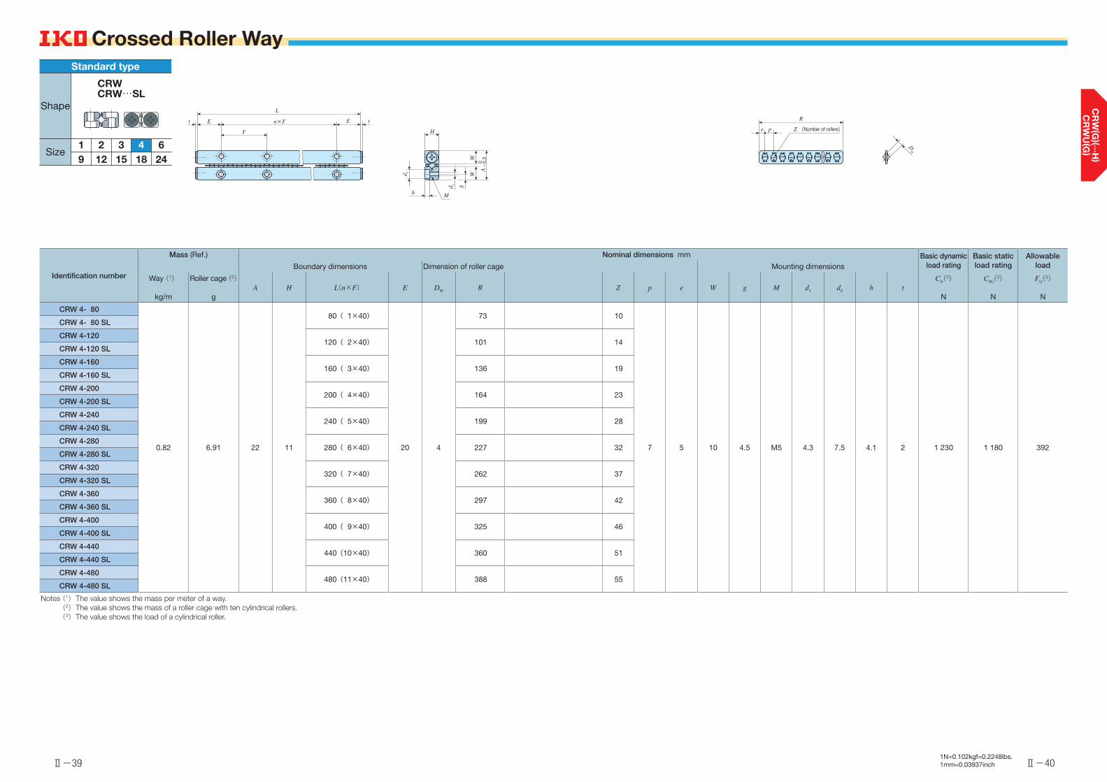
Ⅱ-39
Crossed Roller Way
Ⅱ-40
Crossed Roller Way
Identification number
Mass (Ref.) Nominal dimensions mm Basic dynamic load rating
Basic static load rating
Allowable loadBoundary dimensions Dimension of roller cage Mounting dimensions
Way (1)
kg/m
Roller cage (2)
gA H L(n×F) E DW R Z p e W g M d1 d2 h t
CU(3)
N
C0U(3)
N
FU(3)
N
CRW 4- 80
0.82 6.91 22 11
80( 1×40)
20 4
73 10
7 5 10 4.5 M5 4.3 7.5 4.1 2 1 230 1 180 392
CRW 4- 80 SL
CRW 4-120120( 2×40) 101 14
CRW 4-120 SL
CRW 4-160160( 3×40) 136 19
CRW 4-160 SL
CRW 4-200200( 4×40) 164 23
CRW 4-200 SL
CRW 4-240240( 5×40) 199 28
CRW 4-240 SL
CRW 4-280280( 6×40) 227 32
CRW 4-280 SL
CRW 4-320320( 7×40) 262 37
CRW 4-320 SL
CRW 4-360360( 8×40) 297 42
CRW 4-360 SL
CRW 4-400400( 9×40) 325 46
CRW 4-400 SL
CRW 4-440440(10×40) 360 51
CRW 4-440 SL
CRW 4-480480(11×40) 388 55
CRW 4-480 SL
Notes (1) The value shows the mass per meter of a way. (2) The value shows the mass of a roller cage with ten cylindrical rollers. (3) The value shows the load of a cylindrical roller.
DW
R
pe Z (Number of rollers)
Mh
d 1
W
g
A
0-
0.3
H
d 2
W
E tn×F
L
F
Et
1N=0.102kgf=0.2248lbs.1mm=0.03937inch
4
Standard type
1 2 63189 12 2415
CRWCRW…SL
Shape
Size

Ⅱ-41
Crossed Roller Way
Ⅱ-42
Crossed Roller Way
Identification number
Mass (Ref.) Nominal dimensions mm Basic dynamic load rating
Basic static load rating
Allowable loadBoundary dimensions Dimension of roller cage Mounting dimensions
Way (1)
kg/m
Roller cage (2)
gA H L(n×F) E DW R Z p e W g M d1 d2 h t
CU(3)
N
C0U(3)
N
FU(3)
N
CRW 6-100
1.57 20.3 31 15
100( 1×50)
25 6
84 9
9 6 14 6 M6 5.3 9.5 5.2 3 2 570 2 310 769
CRW 6-100 SL
CRW 6-150150( 2×50) 129 14
CRW 6-150 SL
CRW 6-200200( 3×50) 165 18
CRW 6-200 SL
CRW 6-250250( 4×50) 210 23
CRW 6-250 SL
CRW 6-300300( 5×50) 246 27
CRW 6-300 SL
CRW 6-350350( 6×50) 282 31
CRW 6-350 SL
CRW 6-400400( 7×50) 327 36
CRW 6-400 SL
CRW 6-450450( 8×50) 363 40
CRW 6-450 SL
CRW 6-500500( 9×50) 408 45
CRW 6-500 SL
CRW 6-550550(10×50) 444 49
CRW 6-550 SL
CRW 6-600600(11×50) 489 54
CRW 6-600 SL
Notes (1) The value shows the mass per meter of a way. (2) The value shows the mass of a roller cage with ten cylindrical rollers. (3) The value shows the load of a cylindrical roller.
DW
R
pe Z (Number of rollers)
Mh
d 1
W
g
A
0-
0.3
H
d 2 W
E tn×F
L
F
Et
1N=0.102kgf=0.2248lbs.1mm=0.03937inch
4
Standard type
1 2 63189 12 2415
CRWCRW…SL
Shape
Size
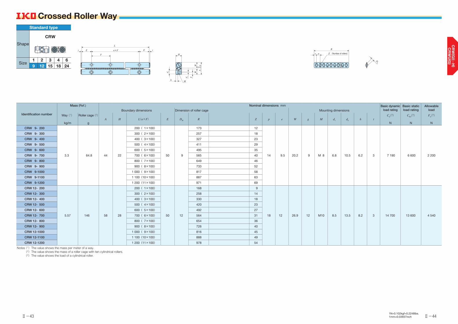
Ⅱ-43
Crossed Roller Way
Ⅱ-44
Crossed Roller Way
Identification number
Mass (Ref.) Nominal dimensions mm Basic dynamic load rating
Basic static load rating
Allowable loadBoundary dimensions Dimension of roller cage Mounting dimensions
Way (1)
kg/m
Roller cage (2)
gA H L(n×F) E DW R Z p e W g M d1 d2 h t
CU(3)
N
C0U(3)
N
FU(3)
N
CRW 9- 200
3.3 64.8 44 22
200( 1×100)
50 9
173 12
14 9.5 20.2 9 M 8 6.8 10.5 6.2 3 7 190 6 600 2 200
CRW 9- 300 300( 2×100) 257 18
CRW 9- 400 400( 3×100) 327 23
CRW 9- 500 500( 4×100) 411 29
CRW 9- 600 600( 5×100) 495 35
CRW 9- 700 700( 6×100) 565 40
CRW 9- 800 800( 7×100) 649 46
CRW 9- 900 900( 8×100) 733 52
CRW 9-1000 1 000( 9×100) 817 58
CRW 9-1100 1 100(10×100) 887 63
CRW 9-1200 1 200(11×100) 971 69
CRW 12- 200
5.57 146 58 28
200( 1×100)
50 12
168 9
18 12 26.9 12 M10 8.5 13.5 8.2 3 14 700 13 600 4 540
CRW 12- 300 300( 2×100) 258 14
CRW 12- 400 400( 3×100) 330 18
CRW 12- 500 500( 4×100) 420 23
CRW 12- 600 600( 5×100) 492 27
CRW 12- 700 700( 6×100) 564 31
CRW 12- 800 800( 7×100) 654 36
CRW 12- 900 900( 8×100) 726 40
CRW 12-1000 1 000( 9×100) 816 45
CRW 12-1100 1 100(10×100) 888 49
CRW 12-1200 1 200(11×100) 978 54
Notes (1) The value shows the mass per meter of a way. (2) The value shows the mass of a roller cage with ten cylindrical rollers. (3) The value shows the load of a cylindrical roller.
DW
R
pe Z (Number of rollers)
Mh
d 1
W
g
A
0-
0.3
H
d 2
W
E tn×F
L
F
Et
1N=0.102kgf=0.2248lbs.1mm=0.03937inch
4
Standard type
1 2 63189 12 2415
CRW
Shape
Size

Ⅱ-45
Crossed Roller Way
Ⅱ-46
Crossed Roller Way
Identification number
Mass (Ref.) Nominal dimensions mm Basic dynamic load rating
Basic static load rating
Allowable loadBoundary dimensions Dimension of roller cage Mounting dimensions
Way (1)
kg/m
Roller cage (2)
gA H L(n×F) E DW R Z p e W g M d1 d2 h t
CU(3)
N
C0U(3)
N
FU(3)
N
CRW 15- 300*
8.75 273 71 36
300( 2×100)
50 15
261 11
23 15.5 33 14 M12 10.5 16.5 10.2 5 23 800 21 900 7 300
CRW 15- 400* 400( 3×100) 330 14
CRW 15- 500* 500( 4×100) 422 18
CRW 15- 600* 600( 5×100) 491 21
CRW 15- 700* 700( 6×100) 583 25
CRW 15- 800* 800( 7×100) 652 28
CRW 15- 900* 900( 8×100) 744 32
CRW 15-1000* 1 000( 9×100) 813 35
CRW 15-1100* 1 100(10×100) 905 39
CRW 15-1200* 1 200(11×100) 974 42
CRW 18- 300*
11.3 447 83 40
300( 2×100)
50 18
262 9
28 19 38.5 18 M14 12.5 18.5 12.2 5 35 800 32 700 10 900
CRW 18- 400* 400( 3×100) 346 12
CRW 18- 500* 500( 4×100) 430 15
CRW 18- 600* 600( 5×100) 514 18
CRW 18- 700* 700( 6×100) 570 20
CRW 18- 800* 800( 7×100) 654 23
CRW 18- 900* 900( 8×100) 738 26
CRW 18-1000* 1 000( 9×100) 822 29
CRW 18-1100* 1 100(10×100) 906 32
CRW 18-1200* 1 200(11×100) 990 35
Notes (1) The value shows the mass per meter of a way. (2) The value shows the mass of a roller cage with ten cylindrical rollers. (3) The value shows the load of a cylindrical roller.
Remark: The identification numbers with * are our semi-standard items.
DW
R
pe Z (Number of rollers)
Mh
d 1
W
g
A
0-
0.3
H
d 2
W
E tn×F
L
F
Et
1N=0.102kgf=0.2248lbs.1mm=0.03937inch
4
Standard type
1 2 63189 12 2415
CRW
Shape
Size
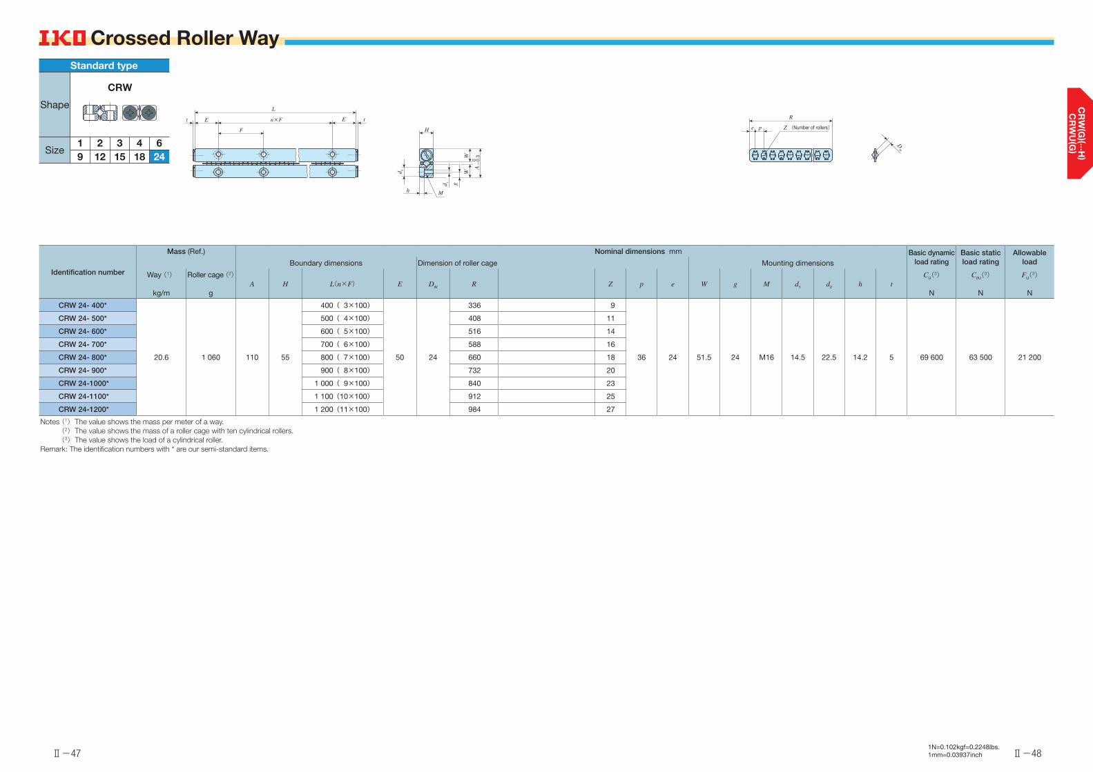
Ⅱ-47
Crossed Roller Way
Ⅱ-48
Crossed Roller Way
Identification number
Mass (Ref.) Nominal dimensions mm Basic dynamic load rating
Basic static load rating
Allowable loadBoundary dimensions Dimension of roller cage Mounting dimensions
Way (1)
kg/m
Roller cage (2)
gA H L(n×F) E DW R Z p e W g M d1 d2 h t
CU(3)
N
C0U(3)
N
FU(3)
N
CRW 24- 400*
20.6 1 060 110 55
400( 3×100)
50 24
336 9
36 24 51.5 24 M16 14.5 22.5 14.2 5 69 600 63 500 21 200
CRW 24- 500* 500( 4×100) 408 11
CRW 24- 600* 600( 5×100) 516 14
CRW 24- 700* 700( 6×100) 588 16
CRW 24- 800* 800( 7×100) 660 18
CRW 24- 900* 900( 8×100) 732 20
CRW 24-1000* 1 000( 9×100) 840 23
CRW 24-1100* 1 100(10×100) 912 25
CRW 24-1200* 1 200(11×100) 984 27
Notes (1) The value shows the mass per meter of a way. (2) The value shows the mass of a roller cage with ten cylindrical rollers. (3) The value shows the load of a cylindrical roller.
Remark: The identification numbers with * are our semi-standard items.
DW
R
pe Z (Number of rollers)
Mh
d 1
W
g
A
0-
0.3
H
d 2
W
E tn×F
L
F
Et
1N=0.102kgf=0.2248lbs.1mm=0.03937inch
4
Standard type
1 2 63
CRW
189 12 2415
Shape
Size

Ⅱ-49
Crossed Roller Way
Ⅱ-50
Crossed Roller Way
Identification number
Mass (Ref.) Nominal dimensions and tolerances mm Basic dynamic load rating
Basic static load rating
Allowable loadBoundary dimensions Dimension of roller cage Mounting dimensions
Way (1)
kg/m
Roller cage (2)
gA H L(n×F) i DW R Z p e W1 W2 E1 E2 M d1 d2 h Dim. D
tolerancet
CU(3)
N
C0U(3)
N
FU(3)
ND
CRWM 1- 20
0.49 0.38 17 4.5
20( 1×10)
0.5 1.5
16.5 5
3 2.25 13.4 7.8 5 10 M2 1.65 3 1.4 2+0.010 0
1.7 125 120 39.8
CRWM 1- 30 30( 2×10) 25.5 8
CRWM 1- 40 40( 3×10) 31.5 10
CRWM 1- 50 50( 4×10) 37.5 12
CRWM 1- 60 60( 5×10) 43.5 14
CRWM 1- 70 70( 6×10) 52.5 17
CRWM 1- 80 80( 7×10) 61.5 20
CRWM 2- 30
0.99 0.98 24 6.5
30( 1×15)
0.5 2
29.6 7
4 2.8 19 11 7.5 15 M3 2.55 4.4 2 3+0.010 0
1.5 293 294 97.9
CRWM 2- 45 45( 2×15) 41.6 10
CRWM 2- 60 60( 3×15) 53.6 13
CRWM 2- 75 75( 4×15) 65.6 16
CRWM 2- 90 90( 5×15) 77.6 19
CRWM 2-105 105( 6×15) 89.6 22
CRWM 2-120 120( 7×15) 101.6 25
CRWM 2-135 135( 8×15) 113.6 28
CRWM 2-150 150( 9×15) 125.6 31
CRWM 2-165 165(10×15) 137.6 34
CRWM 2-180 180(11×15) 149.6 37
Notes (1) The value shows the total mass per meter of a set of three ways. (2) The value shows the mass of a roller cage with ten cylindrical rollers. (3) The value shows the load of a cylindrical roller.
DW
R
pe Z (Number of rollers)
A
0-
0.4
F
W1
n×F E1E1t t
L
D
(Dowel pin hole)
E2E2 F
H
i
M
i
h
Mh
d 2
d 2 d 1
d 1W
2
1N=0.102kgf=0.2248lbs.1mm=0.03937inch
4
Module type
1 2 3
CRWM
Shape
Size
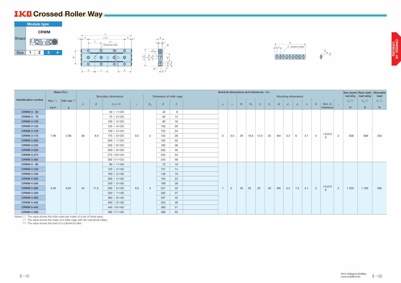
Ⅱ-51
Crossed Roller Way
Ⅱ-52
Crossed Roller Way
Identification number
Mass (Ref.) Nominal dimensions and tolerances mm Basic dynamic load rating
Basic static load rating
Allowable loadBoundary dimensions Dimension of roller cage Mounting dimensions
Way (1)
kg/m
Roller cage (2)
gA H L(n×F) i DW R Z p e W1 W2 E1 E2 M d1 d2 h Dim. D
tolerancet
CU(3)
N
C0U(3)
N
FU(3)
ND
CRWM 3- 50
1.99 2.96 36 8.5
50( 1×25)
0.5 3
42 8
5 3.5 29 16.6 12.5 25 M4 3.3 6 3.1 4+0.012 0
2 638 609 203
CRWM 3- 75 75( 2×25) 62 12
CRWM 3-100 100( 3×25) 82 16
CRWM 3-125 125( 4×25) 102 20
CRWM 3-150 150( 5×25) 122 24
CRWM 3-175 175( 6×25) 142 28
CRWM 3-200 200( 7×25) 162 32
CRWM 3-225 225( 8×25) 182 36
CRWM 3-250 250( 9×25) 202 40
CRWM 3-275 275(10×25) 222 44
CRWM 3-300 300(11×25) 242 48
CRWM 4- 80
3.28 6.91 44 11.5
80( 1×40)
0.5 4
73 10
7 5 35 20 20 40 M5 4.3 7.5 4.1 5+0.012 0
2 1 230 1 180 392
CRWM 4-120 120( 2×40) 101 14
CRWM 4-160 160( 3×40) 136 19
CRWM 4-200 200( 4×40) 164 23
CRWM 4-240 240( 5×40) 199 28
CRWM 4-280 280( 6×40) 227 32
CRWM 4-320 320( 7×40) 262 37
CRWM 4-360 360( 8×40) 297 42
CRWM 4-400 400( 9×40) 325 46
CRWM 4-440 440(10×40) 360 51
CRWM 4-480 480(11×40) 388 55
Notes (1) The value shows the total mass per meter of a set of three ways. (2) The value shows the mass of a roller cage with ten cylindrical rollers. (3) The value shows the load of a cylindrical roller.
DW
R
pe Z (Number of rollers)
A
0-
0.4
F
W1
n×F E1E1t t
L
D
(Dowel pin hole)
E2E2 F
H
i
M
i
h
Mh
d 2
d 2 d 1
d 1W
2
1N=0.102kgf=0.2248lbs.1mm=0.03937inch
4
Module type
1 2 3
CRWM
Shape
Size

Ⅱ-53 Ⅱ-54

2● Solves cage creep issue
As CRWG with cage creep proof function is incorporated with CRWUG, there is no risk of cage creep and it works reliable in high-speed and high-tact operation, or in vertical axis. 4
● Easy mountingMounting surface is precisely grounded. In addition, female screws and boring are used for table and bed, respectively to ensure appropriate preload state. Therefore, highly reliable linear motion can be achieved just by fitting them to the machine and device.
1Points● High rigidity and high accuracy
Since CRWG or CRW with excellent load balance is incorporated with grounded high rigidity table and bed, elastic deformation is small for load in every direction, leading to highly accurate and stable linear motion. 3
● Wide variationThree types of CRWU with different sectional shapes are available with many size variations. You can select an optimal product for the specifications of your machine and device.
CRWUCrossed Roller Way Unit
Anti-Creep CageCrossed Roller Way Unit
CRWUGStopper
Table
Pinion gear
Rack
Preload adjusting screw
Way for table
End screw
Bed
End stopper
Center way
Cylindrical rollersRoller cage
CageRack
Ⅱ-561N=0.102kgf=0.2248lbs.1mm=0.03937inchⅡ-55
Identification Number and Specification Example of an identification number
The specification of CRWUG and CRWU series is indicated by the identification number. Indicate the identification number, consisting of a model code, width, and length for each specification to apply.
1 2 3 1CRWUG series CRWUG 60 - 130
CRWU series CRWU 60 - 130 R
Model1 Model code
Page Ⅱ-57
Width2Dimensions Page Ⅱ-57
Length3
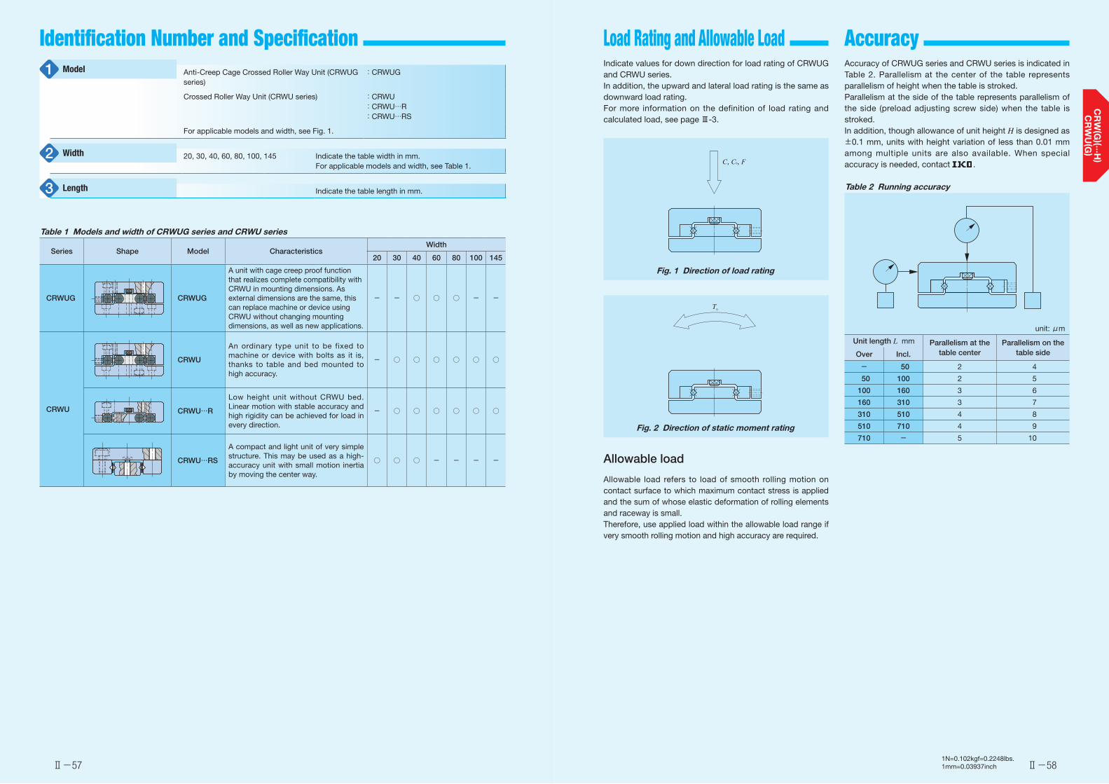
Ⅱ-57 Ⅱ-581N=0.102kgf=0.2248lbs.1mm=0.03937inch
Load Rating and Allowable Load Accuracy Identification Number and Specification Indicate values for down direction for load rating of CRWUG and CRWU series.In addition, the upward and lateral load rating is the same as downward load rating.For more information on the definition of load rating and calculated load, see page Ⅲ-3.
C, C0, F
Fig. 1 Direction of load rating
T0
Fig. 2 Direction of static moment rating
Accuracy of CRWUG series and CRWU series is indicated in Table 2. Parallelism at the center of the table represents parallelism of height when the table is stroked.Parallelism at the side of the table represents parallelism of the side (preload adjusting screw side) when the table is stroked.In addition, though allowance of unit height H is designed as ±0.1 mm, units with height variation of less than 0.01 mm among multiple units are also available. When special accuracy is needed, contact .
Table 2 Running accuracy
unit: μm
Unit length L mm Parallelism at the table center
Parallelism on the table sideOver Incl.
- 50 2 4
50 100 2 5
100 160 3 6
160 310 3 7
310 510 4 8
510 710 4 9
710 - 5 10
Allowable load
Allowable load refers to load of smooth rolling motion on contact surface to which maximum contact stress is applied and the sum of whose elastic deformation of rolling elements and raceway is small.Therefore, use applied load within the allowable load range if very smooth rolling motion and high accuracy are required.
Anti-Creep Cage Crossed Roller Way Unit (CRWUG series)
:CRWUG
Crossed Roller Way Unit (CRWU series) :CRWU:CRWU…R:CRWU…RS
For applicable models and width, see Fig. 1.
20, 30, 40, 60, 80, 100, 145 Indicate the table width in mm.For applicable models and width, see Table 1.
Indicate the table length in mm.
Model1
Width2
Length3
Table 1 Models and width of CRWUG series and CRWU series
Series Shape Model CharacteristicsWidth
20 30 40 60 80 100 145
CRWUG CRWUG
A unit with cage creep proof function that realizes complete compatibility with CRWU in mounting dimensions. As external dimensions are the same, this can replace machine or device using CRWU without changing mounting dimensions, as well as new applications.
- - ○ ○ ○ - -
CRWU
CRWU
An ordinary type unit to be fixed to machine or device with bolts as it is, thanks to table and bed mounted to high accuracy.
- ○ ○ ○ ○ ○ ○
CRWU…R
Low height unit without CRWU bed. Linear motion with stable accuracy and high rigidity can be achieved for load in every direction.
- ○ ○ ○ ○ ○ ○
CRWU…RS
A compact and light unit of very simple structure. This may be used as a high-accuracy unit with small motion inertia by moving the center way.
○ ○ ○ - - - -

Ⅱ-59 Ⅱ-601N=0.102kgf=0.2248lbs.1mm=0.03937inch
Precaution for Use Lubrication
Dust Protection
Grease is not pre-packed in the CRWUG series and CRWU series, so please perform adequate lubrication as needed.Both of oil lubrication and grease lubrication are available in the CRWUG series and CRWU series. Generally, oil lubrication should be selected for high speed or low frictional resistance, and grease lubrication for low speed. For grease lubrication, use of high-quality lithium-soap base grease is recommended.
Since the CRWUG series and CRWU series are finished with high accuracy, harmful foreign substances such as dust and particles entering into the bearing will cause low life or impaired accuracy. For applications in other than clean environment, cover the entire unit with a protective case, etc. to prevent harmful foreign substances such as dust, particles and water from outside from entering.
❶ HandlingAs the CRWUG series and CRWU series are designed highly precisely, take extra care for handling.Cage of the CRWUG series has a pinion gear incorporated. When the cage is dropped or handled roughly, the pinion gear may come off. In addition, do not cut off the cage as doing so may cause pinion gear coming off and breakage of gear joint section.Way of the CRWUG series has a rack incorporated. In operation, take note that the rack may come off when the end screw is removed.For the CRWU series, the cage may be deviated from the right position due to offset load or irregular and high-velocity motion, etc. Fully stroke it once in certain operating time or certain number of reciprocating motion to correct the cage position.
❷ Preload re-adjustmentPreload amount of the CRWUG series and CRWU series is adjusted to zero or slight preload state, so they may be used as they are.Preload amount of the CRWUG series, CRWU, and CRWU…R may be re-adjusted by following the procedure below.Preload adjustment is started from the preload adjusting screw at the center of way length and then both ends in turn, with fixing screws of the preload adjusting side way temporarily fixed.While measuring the clearance on the table sides, tighten the preload adjusting screws subsequently until deflection of the dial gauge stops. Measure the tightening torque for preload adjusting screws at this point.When adjusting preload adjusting screw near either end, stroke the table softly and check that the cylindrical roller is on the preload adjusting screw section.After the above procedure, the clearance becomes zero or in slight preload state, but preload is still not adjusted evenly. With the same procedure again, re-adjust all the preload adjusting screws evenly to the torque previously measured.
Fig. 3 Example of preload adjustment method
❸ Operating temperatureAs synthetic resin components are used for the CRWUG series, the maximum operating temperature is 120°C, while it should be lower than 100°C for continuous use. When it exceeds 100°C, contact .As synthetic resin components are not used for the CRWU series, it may be used at high temperature. However, when it exceeds 100°C, contact .
❹ Maximum velocityOperating velocity should not exceed 30 m/min during operation.
❺ Tightening torque for fixing screwTable 3 shows typical tightening torque for mounting CRWUG Series and CRWU Series. When vibration and shock are la rge or moment load is appl ied, i t is recommended to fix by using the torque 1.3 times larger than that indicated in the table. In addition, when high running accuracy is required with no vibration and shock, it may be fixed by using torque smaller than that indicated in the table, however, it is recommended to use adhesive agent to fasten the screw, or to use stop bolts.
Table 3 Tightening torque for �xing screw
Bolt sizeTightening torque
N・m
M 2 ×0.4 0.40
M 2.5×0.45 0.80
M 3 ×0.5 1.4
M 4 ×0.7 3.2
M 5 ×0.8 6.4
M 6 ×1 10.9
M 8 ×1.25 26.1
❻ Dowel pin hole of CRWU…RA dowel pin hole is machined on the center way of the CRWU…R. When a dowel pin is used, machine a hole on the mounting surface of the machine after mounting of the center way.Refer to the dimension table for diameter and its tolerances of dowel pin hole of the center way.
❼ Mounting part dimensions of CRWU…RNot to allow the table to interfere with the mounting surface, it is necessary to set mounting surface height referring to the dimensions H1 and H in the dimension table.Example bed mounting dimensions are indicated in Table 4.
Table 4 Example of mounting dimensions of CRWU…R bed
unit: μm
Identification number h (minimum) W3 W4
CRWU 30 …R 0.5 13 -
CRWU 40-35R0.5
1813
-CRWU 40 …R
CRWU 60 …R 0.5 26.5 -
CRWU 80 …R 0.5 38 16
CRWU100 …R 0.5 42 14
CRWU145 …R 1.0 68.5 28.5
h
W3
(W4)
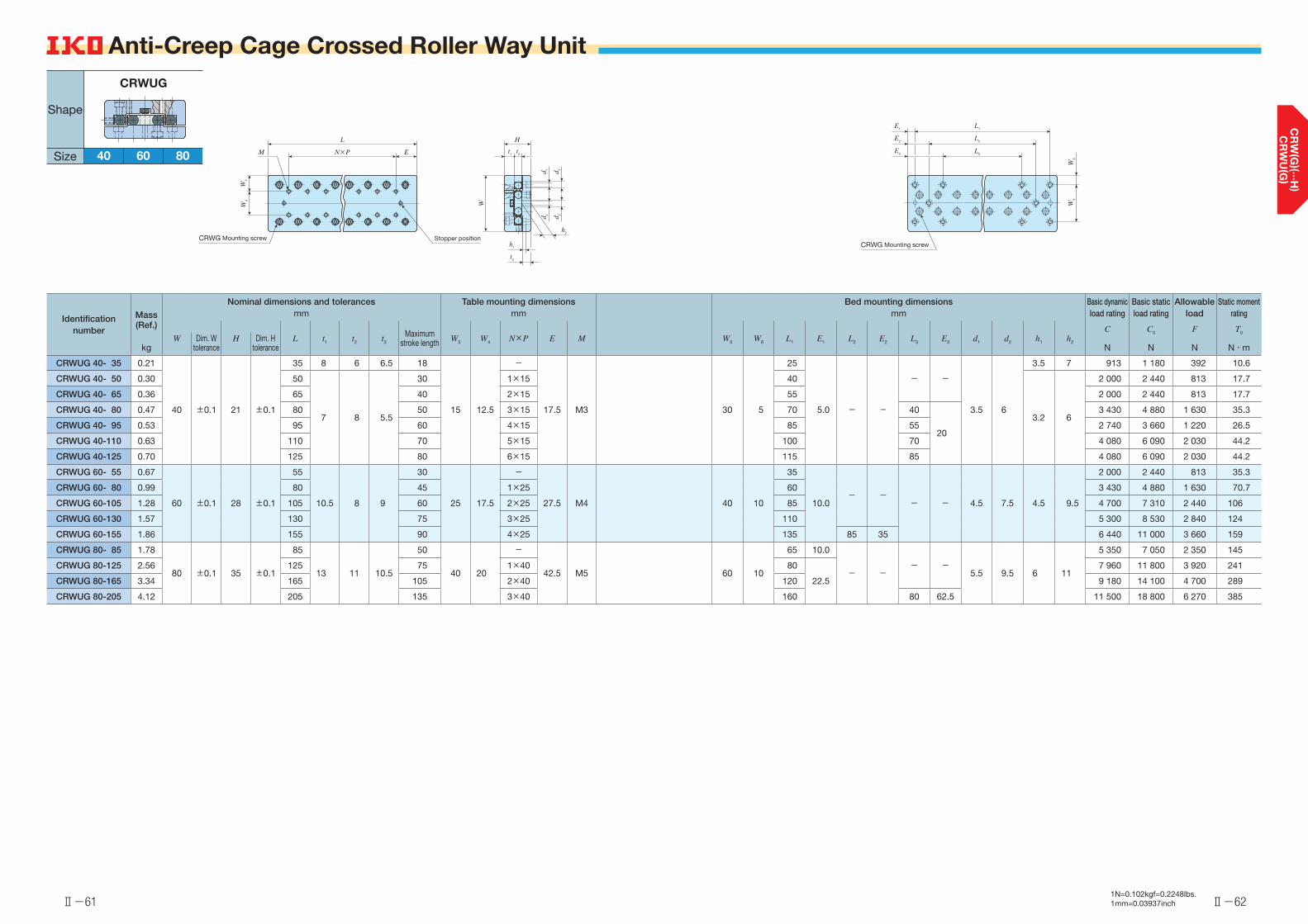
Ⅱ-62Ⅱ-611N=0.102kgf=0.2248lbs.1mm=0.03937inch
Identification number
Mass (Ref.)
kg
Nominal dimensions and tolerances Table mounting dimensions Bed mounting dimensions Basic dynamic load rating
Basic static load rating
Allowable load
Static moment ratingmm mm mm
L t1 t2 t3
Maximum stroke length W3 W4 N×P E M W5 W6 L1 E1 L2 E2 L3 E3 d1 d2 h1 h2
C
N
C0
N
F N
T0
N・mW Dim. W
toleranceH Dim. H
tolerance
CRWUG 40- 35 0.21
40 ±0.1 21 ±0.1
35 8 6 6.5 18
15 12.5
-
17.5 M3 30 5
25
5.0 - -
- -
3.5 6
3.5 7 913 1 180 392 10.6
CRWUG 40- 50 0.30 50
7 8 5.5
30 1×15 40
3.2 6
2 000 2 440 813 17.7
CRWUG 40- 65 0.36 65 40 2×15 55 2 000 2 440 813 17.7
CRWUG 40- 80 0.47 80 50 3×15 70 40
20
3 430 4 880 1 630 35.3
CRWUG 40- 95 0.53 95 60 4×15 85 55 2 740 3 660 1 220 26.5
CRWUG 40-110 0.63 110 70 5×15 100 70 4 080 6 090 2 030 44.2
CRWUG 40-125 0.70 125 80 6×15 115 85 4 080 6 090 2 030 44.2
CRWUG 60- 55 0.67
60 ±0.1 28 ±0.1
55
10.5 8 9
30
25 17.5
-
27.5 M4 40 10
35
10.0- -
- - 4.5 7.5 4.5 9.5
2 000 2 440 813 35.3
CRWUG 60- 80 0.99 80 45 1×25 60 3 430 4 880 1 630 70.7
CRWUG 60-105 1.28 105 60 2×25 85 4 700 7 310 2 440 106
CRWUG 60-130 1.57 130 75 3×25 110 5 300 8 530 2 840 124
CRWUG 60-155 1.86 155 90 4×25 135 85 35 6 440 11 000 3 660 159
CRWUG 80- 85 1.78
80 ±0.1 35 ±0.1
85
13 11 10.5
50
40 20
-
42.5 M5 60 10
65 10.0
- -- -
5.5 9.5 6 11
5 350 7 050 2 350 145
CRWUG 80-125 2.56 125 75 1×40 80
22.5
7 960 11 800 3 920 241
CRWUG 80-165 3.34 165 105 2×40 120 9 180 14 100 4 700 289
CRWUG 80-205 4.12 205 135 3×40 160 80 62.5 11 500 18 800 6 270 385
Anti-Creep Cage Crossed Roller Way Unit
L
N×P EM
W4
W3
Stopper positionCRWG Mounting screwh
2
W
H
t1
t2
d 1 d 2
d 1 d 2
h1
t3
L1
W5
W6
E1
L2
L3
CRWG Mounting screw
E2
E3
Shape
Size 40 60
CRWUG
80
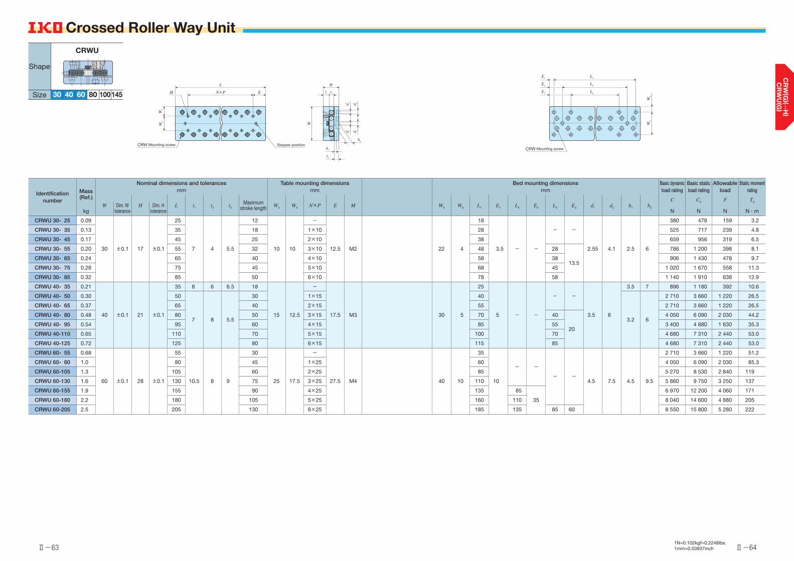
Ⅱ-63 Ⅱ-641N=0.102kgf=0.2248lbs.1mm=0.03937inch
Identification number
Mass (Ref.)
kg
Nominal dimensions and tolerances Table mounting dimensions Bed mounting dimensions Basic dynamic load rating
Basic static load rating
Allowable load
Static moment ratingmm mm mm
L t1 t2 t3
Maximum stroke length W3 W4 N×P E M W5 W6 L1 E1 L2 E2 L3 E3 d1 d2 h1 h2
C
N
C0
N
F N
T0
N・mW Dim. W
toleranceH Dim. H
tolerance
CRWU 30- 25 0.09
30 ±0.1 17 ±0.1
25
7 4 5.5
12
10 10
-
12.5 M2 22 4
18
3.5 - -
- -
2.55 4.1 2.5 6
380 478 159 3.2
CRWU 30- 35 0.13 35 18 1×10 28 525 717 239 4.8
CRWU 30- 45 0.17 45 25 2×10 38 659 956 319 6.5
CRWU 30- 55 0.20 55 32 3×10 48 28
13.5
786 1 200 398 8.1
CRWU 30- 65 0.24 65 40 4×10 58 38 906 1 430 478 9.7
CRWU 30- 75 0.28 75 45 5×10 68 45 1 020 1 670 558 11.3
CRWU 30- 85 0.32 85 50 6×10 78 58 1 140 1 910 638 12.9
CRWU 40- 35 0.21
40 ±0.1 21 ±0.1
35 8 6 6.5 18
15 12.5
-
17.5 M3 30 5
25
5 - -
- -
3.5 6
3.5 7 896 1 180 392 10.6
CRWU 40- 50 0.30 50
7 8 5.5
30 1×15 40
3.2 6
2 710 3 660 1 220 26.5
CRWU 40- 65 0.37 65 40 2×15 55 2 710 3 660 1 220 26.5
CRWU 40- 80 0.48 80 50 3×15 70 40
20
4 050 6 090 2 030 44.2
CRWU 40- 95 0.54 95 60 4×15 85 55 3 400 4 880 1 630 35.3
CRWU 40-110 0.65 110 70 5×15 100 70 4 680 7 310 2 440 53.0
CRWU 40-125 0.72 125 80 6×15 115 85 4 680 7 310 2 440 53.0
CRWU 60- 55 0.68
60 ±0.1 28 ±0.1
55
10.5 8 9
30
25 17.5
-
27.5 M4 40 10
35
10
- -
- -4.5 7.5 4.5 9.5
2 710 3 660 1 220 51.2
CRWU 60- 80 1.0 80 45 1×25 60 4 050 6 090 2 030 85.3
CRWU 60-105 1.3 105 60 2×25 85 5 270 8 530 2 840 119
CRWU 60-130 1.6 130 75 3×25 110 5 860 9 750 3 250 137
CRWU 60-155 1.9 155 90 4×25 135 85
35
6 970 12 200 4 060 171
CRWU 60-180 2.2 180 105 5×25 160 110 8 040 14 600 4 880 205
CRWU 60-205 2.5 205 130 6×25 185 135 85 60 8 550 15 800 5 280 222
Crossed Roller Way Unit Crossed Roller Way Unit
L
N×P EM
W4
W3
Stopper positionCRW Mounting screwh2
W
H
t1 t2
d 1 d 2
d 1 d 2
h1
t3
L1
W5
W6
E1
L2
L3
CRW Mounting screw
E2
E380
Shape
Size 30 40 10060
CRWU
145
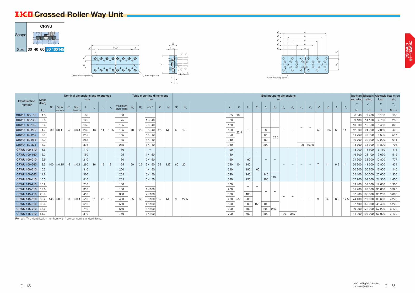
Ⅱ-65 Ⅱ-661N=0.102kgf=0.2248lbs.1mm=0.03937inch
Identification number
Mass (Ref.)
kg
Nominal dimensions and tolerances Table mounting dimensions Bed mounting dimensions Basic dynamic load rating
Basic static load rating
Allowable load
Static moment ratingmm mm mm
L t1 t2 t3
Maximum stroke length W3 W4 N×P E M W5 W6 L1 E1 L2 E2 L3 E3 L4 E4 L5 E5 d1 d2 h1 h2
C
N
C0
N
F N
T0
N・mW Dim. W
toleranceH Dim. H
tolerance
CRWU 80- 85 1.8
80 ±0.1 35 ±0.1
85
13 11 10.5
50
40 20
-
42.5 M5 60 10
65 10
- -
- -
- -- -
5.5 9.5 6 11
6 640 9 400 3 130 188
CRWU 80-125 2.6 125 75 1× 40 80
22.5
9 130 14 100 4 700 282
CRWU 80-165 3.4 165 105 2× 40 120 10 300 16 500 5 480 329
CRWU 80-205 4.2 205 135 3× 40 160 80
62.5
12 500 21 200 7 050 423
CRWU 80-245 5.1 245 155 4× 40 200 120 14 700 25 900 8 620 517
CRWU 80-285 5.9 285 185 5× 40 240 160 16 700 30 600 10 200 611
CRWU 80-325 6.7 325 215 6× 40 280 200 120 102.5 18 700 35 300 11 800 705
CRWU 100-110* 3.6
100 ±0.15 45 ±0.1
110
16 15 13
60
50 25
-
55 M6 60 20
90
10
- -
- -
- - - - 7 11 6.5 14
13 900 18 500 6 150 415
CRWU 100-160* 5.2 160 95 1× 50 140 16 600 23 100 7 690 519
CRWU 100-210* 6.9 210 130 2× 50 190 90
60
21 600 32 300 10 800 727
CRWU 100-260* 8.5 260 165 3× 50 240 140 26 300 41 500 13 800 934
CRWU 100-310* 10.2 310 200 4× 50 290 190 30 800 50 700 16 900 1 140
CRWU 100-360* 11.8 360 235 5× 50 340 240 140110
35 100 60 000 20 000 1 350
CRWU 100-410* 13.5 410 265 6× 50 390 290 190 37 200 64 600 21 500 1 450
CRWU 145-210* 13.2
145 ±0.2 60 ±0.1
210
21 22 16
130
85 30
-
105 M8 90 27.5
100
55
- -
- -
- -- - 9 14 8.5 17.5
39 400 52 800 17 600 1 900
CRWU 145-310* 19.6 310 180 1×100 200 61 200 92 300 30 800 3 320
CRWU 145-410* 25.9 410 350 2×100 300 100
155
67 900 106 000 35 200 3 800
CRWU 145-510* 32.2 510 450 3×100 400 200 74 400 119 000 39 600 4 270
CRWU 145-610* 38.6 610 550 4×100 500 300 100
255
87 100 145 000 48 400 5 220
CRWU 145-710* 45.0 710 650 5×100 600 400 200 99 200 172 000 57 200 6 170
CRWU 145-810* 51.3 810 750 6×100 700 500 300 100 355 111 000 198 000 66 000 7 120
Remark: The identification numbers with * are our semi-standard items.
Crossed Roller Way Unit Crossed Roller Way Unit
L1
W5
W6
L2
L3
L4
L5
CRW Mounting screw
E1
E2
E3
E4
E5
L
N×P EM
W4
W3
Stopper positionCRW Mounting screwh2
W
H
t1 t2
d 1 d 2
d 1 d 2
h1
t3
80
Shape
Size 30 40 10060
CRWU
145

Ⅱ-67 Ⅱ-681N=0.102kgf=0.2248lbs.1mm=0.03937inch
Identification number
Mass (Ref.)
kg
Nominal dimensions and tolerances Table mounting dimensions Center way mounting dimensions and tolerances Basic dynamic load rating
Basic static load rating
Allowable load
Static moment ratingmm mm mm
L Maximum stroke length W3 W4 N×P E M H1 t1 W5 W6 N1×P1 E1 M1 L6 E6 W1 W2 t2
C
N
C0
N
F N
T0
N・mW Dim. W
toleranceH Dim. H
toleranceD Dim. D
tolerance
CRWU 30- 25R 0.06
30 ±0.1 11 ±0.1
25 12
10 10
-
12.5 M2 11 7 - 15
1×10
7.5 M2
- - - -
12.8 8.6 4
380 478 159 3.2
CRWU 30- 35R 0.08 35 18 1×10 2×10 525 717 239 4.8
CRWU 30- 45R 0.11 45 25 2×10 3×10 659 956 319 6.5
CRWU 30- 55R 0.13 55 32 3×10 4×10
2+0.020
0
30
12.5
786 1 200 398 8.1
CRWU 30- 65R 0.16 65 40 4×10 5×10 40 906 1 430 478 9.7
CRWU 30- 75R 0.18 75 45 5×10 6×10 50 1 020 1 670 558 11.3
CRWU 30- 85R 0.21 85 50 6×10 7×10 60 1 140 1 910 638 12.9
CRWU 40- 35R 0.13
40 ±0.1
14
±0.1
35 18
15 12.5
-
17.5 M3
14 8
- 20
1×1510
M3
- - - -
17 11.5 6 896 1 180 392 10.6
CRWU 40- 50R 0.21
15
50 30 1×15
15 7
2×15
13.1 13.45 8
2 710 3 660 1 220 26.5
CRWU 40- 65R 0.26 65 40 2×15 2×15 17.5 2 710 3 660 1 220 26.5
CRWU 40- 80R 0.34 80 50 3×15 4×15 10
3+0.020
0
4517.5 4 050 6 090 2 030 44.2
CRWU 40- 95R 0.38 95 60 4×15 4×1517.5 25
3 400 4 880 1 630 35.3
CRWU 40-110R 0.46 110 70 5×15 5×1560
4 680 7 310 2 440 53.0
CRWU 40-125R 0.50 125 80 6×15 5×15 25 32.5 4 680 7 310 2 440 53.0
CRWU 60- 55R 0.44
60 ±0.1 18.5 ±0.1
55 30
25 17.5
-
27.5 M4 18.5 10.5 17 21.5
1×25
15 M4 4+0.020
0
35
10 26.6 16.7 8
2 710 3 660 1 220 51.2
CRWU 60- 80R 0.66 80 45 1×25 2×25 60 4 050 6 090 2 030 85.3
CRWU 60-105R 0.85 105 60 2×25 3×25 85 5 270 8 530 2 840 119
CRWU 60-130R 1.1 130 75 3×25 4×25 110 5 860 9 750 3 250 137
CRWU 60-155R 1.3 155 90 4×25 5×25 135 6 970 12 200 4 060 171
CRWU 60-180R 1.5 180 105 5×25 6×25 160 8 040 14 600 4 880 205
CRWU 60-205R 1.7 205 130 6×25 7×25 185 8 550 15 800 5 280 222
Crossed Roller Way Unit Crossed Roller Way Unit
E1
E6L6
N1×P1
M1
D
(Dowel pin hole)
W6
W5
H1
t1
W
t2
H
W2
W1
CRW Mounting screw
L
N×P EM
W4
W3
Stopper position
80
Shape
Size 30 40 10060
CRWU…R
145
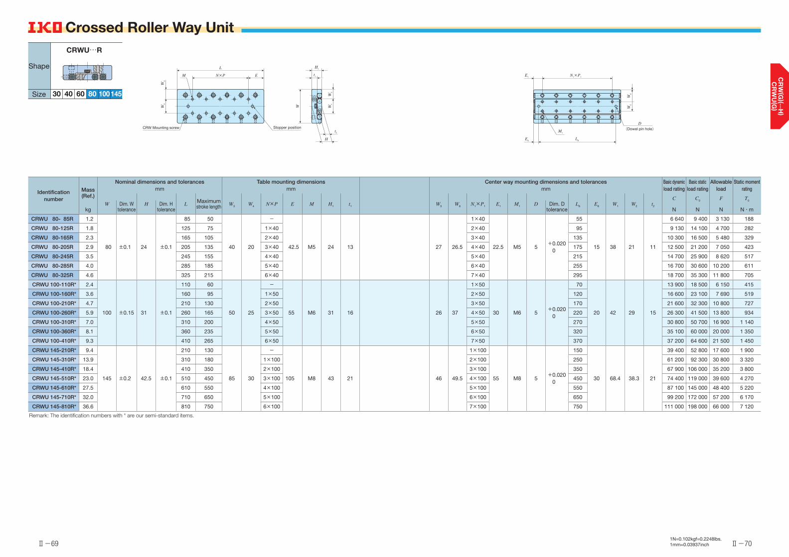
Ⅱ-69 Ⅱ-701N=0.102kgf=0.2248lbs.1mm=0.03937inch
Identification number
Mass (Ref.)
kg
Nominal dimensions and tolerances Table mounting dimensions Center way mounting dimensions and tolerances Basic dynamic load rating
Basic static load rating
Allowable load
Static moment ratingmm mm mm
L Maximum stroke length W3 W4 N×P E M H1 t1 W5 W6 N1×P1 E1 M1 L6 E6 W1 W2 t2
C
N
C0
N
F N
T0
N・mW Dim. W
toleranceH Dim. H
toleranceD Dim. D
tolerance
CRWU 80- 85R 1.2
80 ±0.1 24 ±0.1
85 50
40 20
-
42.5 M5 24 13 27 26.5
1×40
22.5 M5 5+0.020
0
55
15 38 21 11
6 640 9 400 3 130 188
CRWU 80-125R 1.8 125 75 1×40 2×40 95 9 130 14 100 4 700 282
CRWU 80-165R 2.3 165 105 2×40 3×40 135 10 300 16 500 5 480 329
CRWU 80-205R 2.9 205 135 3×40 4×40 175 12 500 21 200 7 050 423
CRWU 80-245R 3.5 245 155 4×40 5×40 215 14 700 25 900 8 620 517
CRWU 80-285R 4.0 285 185 5×40 6×40 255 16 700 30 600 10 200 611
CRWU 80-325R 4.6 325 215 6×40 7×40 295 18 700 35 300 11 800 705
CRWU 100-110R* 2.4
100 ±0.15 31 ±0.1
110 60
50 25
-
55 M6 31 16 26 37
1×50
30 M6 5+0.020
0
70
20 42 29 15
13 900 18 500 6 150 415
CRWU 100-160R* 3.6 160 95 1×50 2×50 120 16 600 23 100 7 690 519
CRWU 100-210R* 4.7 210 130 2×50 3×50 170 21 600 32 300 10 800 727
CRWU 100-260R* 5.9 260 165 3×50 4×50 220 26 300 41 500 13 800 934
CRWU 100-310R* 7.0 310 200 4×50 5×50 270 30 800 50 700 16 900 1 140
CRWU 100-360R* 8.1 360 235 5×50 6×50 320 35 100 60 000 20 000 1 350
CRWU 100-410R* 9.3 410 265 6×50 7×50 370 37 200 64 600 21 500 1 450
CRWU 145-210R* 9.4
145 ±0.2 42.5 ±0.1
210 130
85 30
-
105 M8 43 21 46 49.5
1×100
55 M8 5+0.020
0
150
30 68.4 38.3 21
39 400 52 800 17 600 1 900
CRWU 145-310R* 13.9 310 180 1×100 2×100 250 61 200 92 300 30 800 3 320
CRWU 145-410R* 18.4 410 350 2×100 3×100 350 67 900 106 000 35 200 3 800
CRWU 145-510R* 23.0 510 450 3×100 4×100 450 74 400 119 000 39 600 4 270
CRWU 145-610R* 27.5 610 550 4×100 5×100 550 87 100 145 000 48 400 5 220
CRWU 145-710R* 32.0 710 650 5×100 6×100 650 99 200 172 000 57 200 6 170
CRWU 145-810R* 36.6 810 750 6×100 7×100 750 111 000 198 000 66 000 7 120
Remark: The identification numbers with * are our semi-standard items.
Crossed Roller Way Unit Crossed Roller Way Unit
H1
t1
W
t2
H
W2
W1
CRW Mounting screw
L
N×P EM
W4
W3
Stopper position
E1
E6L6
N1×P1
M1
D(Dowel pin hole)
W6
W5
80
Shape
Size 30 40 10060
CRWU…R
145

Ⅱ-71 Ⅱ-721N=0.102kgf=0.2248lbs.1mm=0.03937inch
Identification numberMass (Ref.)
kg
Nominal dimensions and tolerances Table mounting dimensions Center way mounting dimensions Basic dynamic load rating
Basic static load rating
Allowable load
Static moment ratingmm mm mm
L Maximum stroke length W3 W4 N×P E M H1 t1 W1 W2 N1×P1 E1 M1 t2
C
N
C0
N
F N
T0
N・mW Dim. W
toleranceH Dim. H
tolerance
CRWU 20- 25RS 0.03
20 ±0.1 8 ±0.1
25 12
14 3
1×183.5
M2.5 7.5 3.5 7 6.5
2× 7.5 5
M2.5 4
380 478 159 1.8
CRWU 20- 35RS 0.05 35 18 1×28 2×10
7.5
525 717 239 2.8
CRWU 20- 45RS 0.06 45 25 1×2012.5
3×10 659 956 319 3.7
CRWU 20- 55RS 0.07 55 32 1×30 4×10 786 1 200 398 4.6
CRWU 30- 65RS 0.20
30 ±0.1 12 ±0.1
65 40
22 4
1×30
17.5 M3 11.5 5.5 12 9
3×15
10 M3 6
1 850 2 940 979 19.1
CRWU 30- 80RS 0.24 80 50 1×45 4×15 2 130 3 530 1 180 22.9
CRWU 30- 95RS 0.29 95 60 2×30 5×15 2 410 4 110 1 370 26.7
CRWU 40-105RS 0.58
40 ±0.1 16 ±0.1
105 60
30 5
1×50
27.5 M4 15.5 7.5 16 12
3×25
15 M4 8
4 680 7 310 2 440 63.6
CRWU 40-130RS 0.72 130 75 1×75 4×25 5 860 9 750 3 250 84.8
CRWU 40-155RS 0.85 155 90 2×50 5×25 6 970 12 200 4 060 106
Crossed Roller Way Unit Crossed Roller Way Unit
t2
W
t1
H1
H
W2
W1
M
CRW Mounting screw
W3
W4
N×P E
L
E1
M1
N1×P1
Stopper position
Shape
Size 20 30 40
CRWU…RS
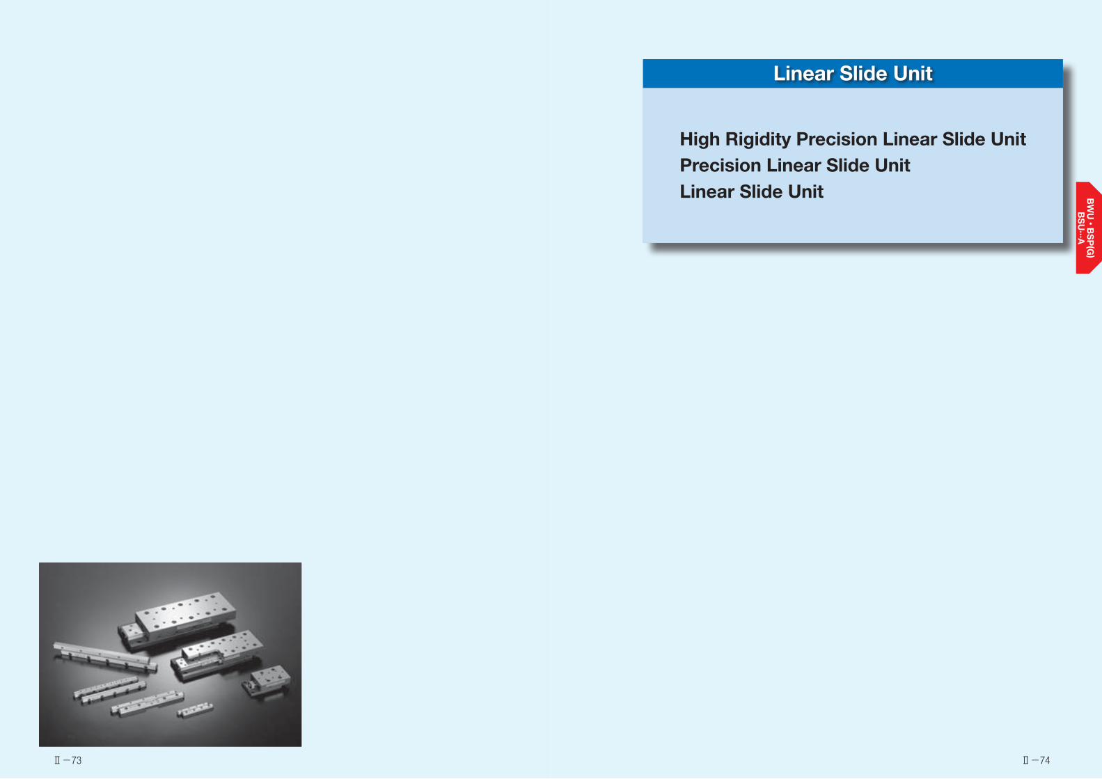
Linear Slide Unit
High Rigidity Precision Linear Slide UnitPrecision Linear Slide UnitLinear Slide Unit
Ⅱ-73 Ⅱ-74
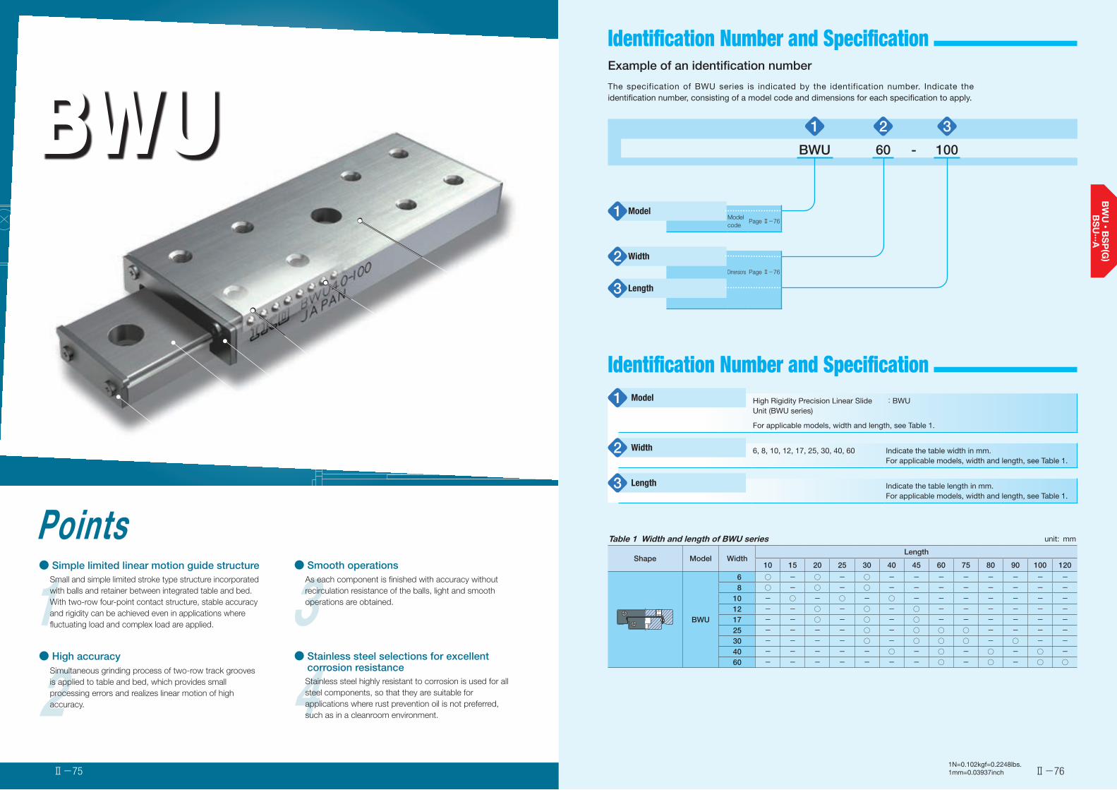
Identification Number and Specification
2● High accuracy
Simultaneous grinding process of two-row track grooves is applied to table and bed, which provides small processing errors and realizes linear motion of high accuracy. 4Stainless steel highly resistant to corrosion is used for all
steel components, so that they are suitable for applications where rust prevention oil is not preferred, such as in a cleanroom environment.
1Points● Simple limited linear motion guide structure
Small and simple limited stroke type structure incorporated with balls and retainer between integrated table and bed.With two-row four-point contact structure, stable accuracy and rigidity can be achieved even in applications where fluctuating load and complex load are applied. 3
● Smooth operationsAs each component is finished with accuracy without recirculation resistance of the balls, light and smooth operations are obtained.
BWUHigh Rigidity Precision Linear Slide Unit
● Stainless steel selections for excellent corrosion resistance
Table
Ball
Integrated retainer
End stopper
End stopper
Bed
Ⅱ-76Ⅱ-75
Example of an identification number
The specification of BWU series is indicated by the identification number. Indicate the identification number, consisting of a model code and dimensions for each specification to apply.
1N=0.102kgf=0.2248lbs.1mm=0.03937inch
1 2 3
BWU 60 - 100
Model1 Model code
Page Ⅱ-76
Width2Dimensions Page Ⅱ-76
Length3
High Rigidity Precision Linear Slide Unit (BWU series)
:BWU
For applicable models, width and length, see Table 1.
6, 8, 10, 12, 17, 25, 30, 40, 60 Indicate the table width in mm.For applicable models, width and length, see Table 1.
Indicate the table length in mm.For applicable models, width and length, see Table 1.
Model1
Width2
Length3
Identification Number and Specification
Table 1 Width and length of BWU series unit: mm
Shape Model WidthLength
10 15 20 25 30 40 45 60 75 80 90 100 120
BWU
6 ○ - ○ - ○ - - - - - - - - 8 ○ - ○ - ○ - - - - - - - -10 - ○ - ○ - ○ - - - - - - -12 - - ○ - ○ - ○ - - - - - -17 - - ○ - ○ - ○ - - - - - -25 - - - - ○ - ○ ○ ○ - - - -30 - - - - ○ - ○ ○ ○ - ○ - -40 - - - - - ○ - ○ - ○ - ○ -60 - - - - - - - ○ - ○ - ○ ○
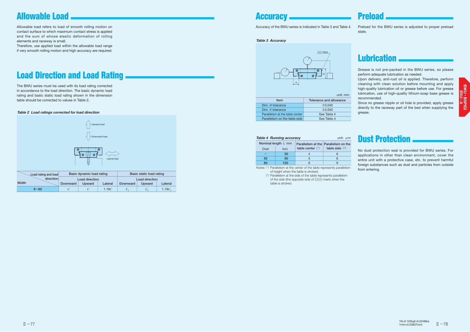
Allowable Load
Load Direction and Load Rating
Accuracy Preload
Ⅱ-77 Ⅱ-78
Allowable load refers to load of smooth rolling motion on contact surface to which maximum contact stress is applied and the sum of whose elastic deformation of rolling elements and raceway is small.Therefore, use applied load within the allowable load range if very smooth rolling motion and high accuracy are required.
The BWU series must be used with its load rating corrected in accordance to the load direction. The basic dynamic load rating and basic static load rating shown in the dimension table should be corrected to values in Table 2.
Table 2 Load ratings corrected for load direction
Load rating and load direction
Width
Basic dynamic load rating Basic static load rating
Load direction Load directionDownward Upward Lateral Downward Upward Lateral
6~60 C C 1.19C C0 C0 1.19C0
Upward load
Downward load
Lateral load
Accuracy of the BWU series is indicated in Table 3 and Table 4.
Table 3 Accuracy
unit: mm
Item Tolerance and allowance
Dim. H tolerance ±0.040Dim. N tolerance ±0.050Parallelism at the table center See Table 4Parallelism on the table side See Table 4
Table 4 Running accuracy unit: μm
Nominal length L mm Parallelism at the table center(1)
Parallelism on the table side(2)Over Incl.
- 50 4 650 80 5 880 120 6 9
Notes (1) Parallelism at the center of the table represents parallelism of height when the table is stroked.
(2) Parallelism at the side of the table represents parallelism of the side (the opposite side of mark) when the table is stroked.
Mark
N
H
Preload for the BWU series is adjusted to proper preload state.
Grease is not pre-packed in the BWU series, so please perform adequate lubrication as needed.Upon delivery, anti-rust oil is applied. Therefore, perform cleaning with clean solution before mounting and apply high-quality lubrication oil or grease before use. For grease lubrication, use of high-quality lithium-soap base grease is recommended.Since no grease nipple or oil hole is provided, apply grease directly to the raceway part of the bed when supplying the grease.
No dust protection seal is provided for BWU series. For applications in other than clean environment, cover the entire unit with a protective case, etc. to prevent harmful foreign substances such as dust and particles from outside from entering.
Lubrication
Dust Protection
1N=0.102kgf=0.2248lbs.1mm=0.03937inch
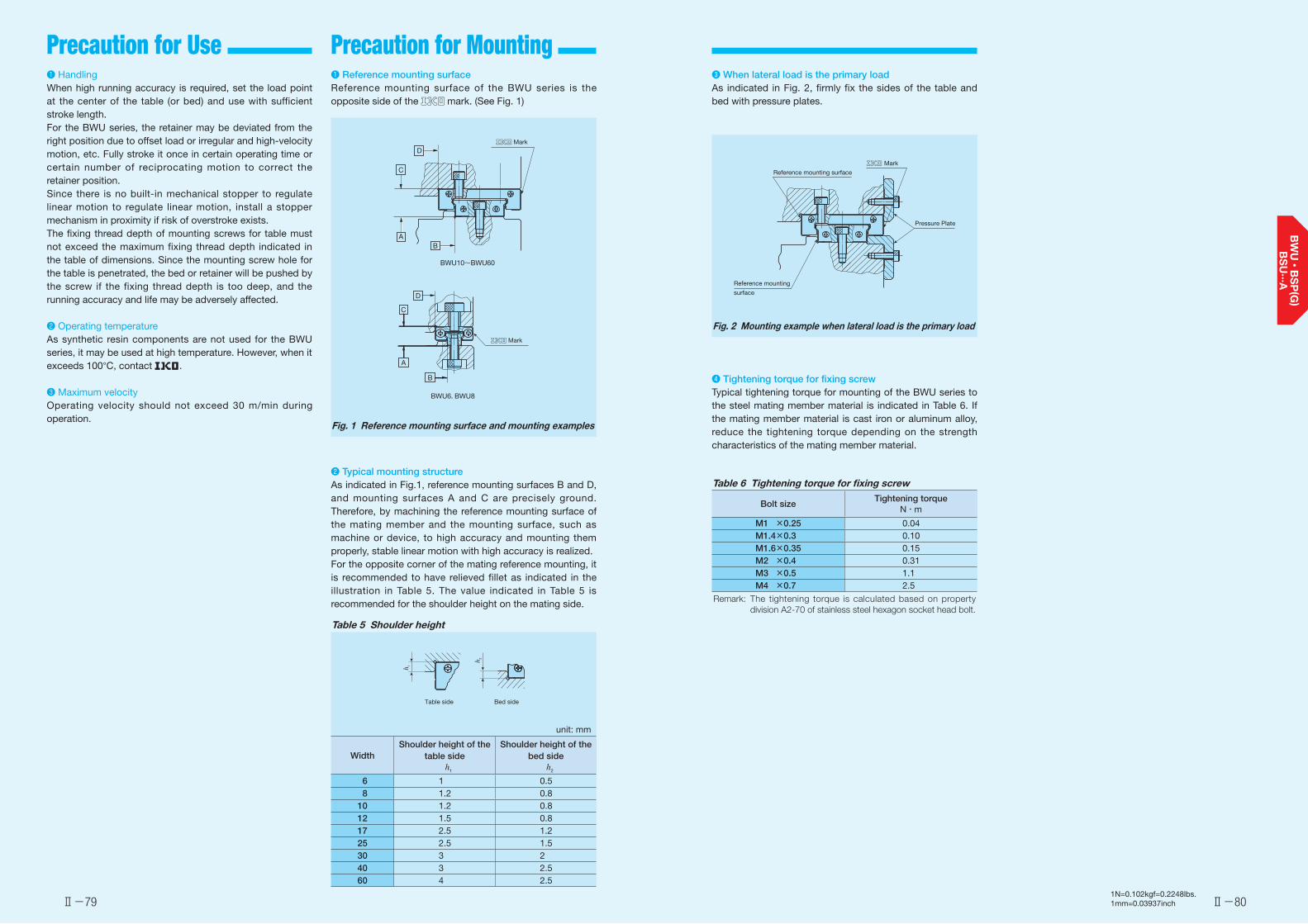
Precaution for Use Precaution for Mounting
Ⅱ-79 Ⅱ-80
❶ Reference mounting surfaceReference mounting surface of the BWU series is the opposite side of the mark. (See Fig. 1)
Fig. 1 Reference mounting surface and mounting examples
❷ Typical mounting structureAs indicated in Fig.1, reference mounting surfaces B and D, and mounting surfaces A and C are precisely ground. Therefore, by machining the reference mounting surface of the mating member and the mounting surface, such as machine or device, to high accuracy and mounting them properly, stable linear motion with high accuracy is realized.For the opposite corner of the mating reference mounting, it is recommended to have relieved fillet as indicated in the illustration in Table 5. The value indicated in Table 5 is recommended for the shoulder height on the mating side.
Table 5 Shoulder height
unit: mm
WidthShoulder height of the
table sideh1
Shoulder height of the bed side
h2
6 1 0.5 8 1.2 0.810 1.2 0.812 1.5 0.817 2.5 1.225 2.5 1.530 3 240 3 2.560 4 2.5
MarkD
C
AB
BWU10~BWU60
Mark
D
C
A
B
BWU6, BWU8
Table side Bed side
h 1
h 2
❸ When lateral load is the primary loadAs indicated in Fig. 2, firmly fix the sides of the table and bed with pressure plates.
Fig. 2 Mounting example when lateral load is the primary load
❹ Tightening torque for fixing screwTypical tightening torque for mounting of the BWU series to the steel mating member material is indicated in Table 6. If the mating member material is cast iron or aluminum alloy, reduce the tightening torque depending on the strength characteristics of the mating member material.
Table 6 Tightening torque for fixing screw
Bolt sizeTightening torque
N・m
M1 ×0.25 0.04M1.4×0.3 0.10M1.6×0.35 0.15M2 ×0.4 0.31M3 ×0.5 1.1M4 ×0.7 2.5
Remark: The tightening torque is calculated based on property division A2-70 of stainless steel hexagon socket head bolt.
Mark
Pressure Plate
Reference mounting surface
Reference mounting
surface
❶ HandlingWhen high running accuracy is required, set the load point at the center of the table (or bed) and use with sufficient stroke length.For the BWU series, the retainer may be deviated from the right position due to offset load or irregular and high-velocity motion, etc. Fully stroke it once in certain operating time or certain number of reciprocating motion to correct the retainer position.Since there is no built-in mechanical stopper to regulate linear motion to regulate linear motion, install a stopper mechanism in proximity if risk of overstroke exists.The fixing thread depth of mounting screws for table must not exceed the maximum fixing thread depth indicated in the table of dimensions. Since the mounting screw hole for the table is penetrated, the bed or retainer will be pushed by the screw if the fixing thread depth is too deep, and the running accuracy and life may be adversely affected.
❷ Operating temperatureAs synthetic resin components are not used for the BWU series, it may be used at high temperature. However, when it exceeds 100°C, contact .
❸ Maximum velocityOperating velocity should not exceed 30 m/min during operation.
1N=0.102kgf=0.2248lbs.1mm=0.03937inch
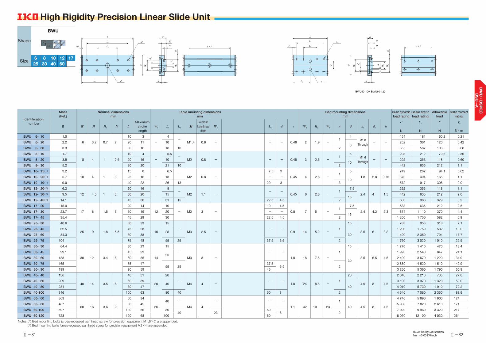
Ⅱ-81 Ⅱ-821N=0.102kgf=0.2248lbs.1mm=0.03937inch
High Rigidity Precision Linear Slide Unit
Identification number
Mass (Ref.)
Nominal dimensions mm
Table mounting dimensions mm
Bed mounting dimensions mm
Basic dynamic load rating
Basic static load rating
Allowable load
Static moment rating
W H H1 N LMaximum
stroke length
W1 L1 L2 MMaximum
fixing thread depth
W2 L3 d t W3 H2 W4 n P d1 d2 hC
N
C0
N
F N
T0
N・mg
BWU 6- 10 1.0
6 3.2 0.7 2
10 3
-
4-
M1.4 0.8 - - - 0.46 2 1.9 -1
4M1.0
Through- -
154 181 60.2 0.21
BWU 6- 20 2.2 20 11 108
252 361 120 0.42
BWU 6- 30 3.3 30 16 18 10 2 355 587 196 0.68
BWU 8- 10 1.7
8 4 1 2.5
10 4
-
5.5-
M2 0.8 - - - 0.45 3 2.6 -1
5M1.6
Through- -
203 212 70.6 0.36
BWU 8- 20 3.5 20 16 1010
292 353 118 0.60
BWU 8- 30 5.2 30 20 21 10 2 442 635 212 1.1
BWU 10- 15(1) 3.2
10 4 1 3
15 8
-
6.5-
M2 0.8 -
7.5 3
0.45 4 2.6 -1
5
1.8 2.8 0.75
249 282 94.1 0.62
BWU 10- 25(1) 5.7 25 16 13 - -10
370 494 165 1.1
BWU 10- 40(1) 9.0 40 22 26 13 20 3 3 572 917 306 2.0
BWU 12- 20(2) 6.2
12 4.5 1 3
20 16
-
8-
M2 1.1 -- -
0.45 6 2.8 -1
7.5
2.4 4 1.5
292 353 118 1.1
BWU 12- 30(2) 9.5 30 20 1515
442 635 212 2.0
BWU 12- 45(2) 14.1 45 30 31 15 22.5 4.5 2 603 988 329 3.2
BWU 17- 20 15.0
17 8 1.5 5
20 14
12
10
- M2 3 -
10 4.5
0.8 7 5 -1
7.5
2.4 4.2 2.3
588 635 212 2.5
BWU 17- 30 23.7 30 19 20 - -15
874 1 110 370 4.4
BWU 17- 45 35.4 45 29 30 22.5 4.5 2 1 200 1 750 582 6.9
BWU 25- 30 40.6
25 9 1.8 5.5
30 23
10
15
-M3 2.5 -
- -0.9 14 5.2 -
1
15
3.5 6 3.2
783 953 318 7.1
BWU 25- 45 62.5 45 2825
30
1 200 1 750 582 13.0
BWU 25- 60 84.3 60 38 1 490 2 380 794 17.7
BWU 25- 75 104 75 48 55 25 37.5 6.5 2 1 760 3 020 1 010 22.5
BWU 30- 30 64.4
30 12 3.4 6
30 23
14
15
-
M3 3 -
- -
1.0 18 7.5 -
1
15
3.5 6.5 4.5
1 270 1 410 470 13.4
BWU 30- 45 99.1 45 2925
30
1 920 2 540 847 24.1
BWU 30- 60 133 60 35 2 490 3 670 1 220 34.9
BWU 30- 75 165 75 4755 25
37.56.5 2
2 880 4 520 1 510 42.9
BWU 30- 90 199 90 59 45 3 250 5 360 1 790 50.9
BWU 40- 40 136
40 14 3.5 8
40 31
20
20
-M4 4 -
- -1.0 24 8.5 -
1
20
4.5 8 4.5
2 040 2 210 735 27.8
BWU 40- 60 209 60 3940
40
3 100 3 970 1 320 50.0
BWU 40- 80 281 80 47 4 010 5 730 1 910 72.2
BWU 40-100 346 100 63 80 40 50 8 2 4 640 7 060 2 350 88.9
BWU 60- 60 363
60 16 3.6 9
60 34
36
40 -
M4 4
- - -
1.1 42 10 23
1
40 4.5 8 4.5
4 740 5 690 1 900 124
BWU 60- 80 487 80 45 5 930 7 820 2 610 171
BWU 60-100 597 100 56 8040 23
508 2
7 020 9 960 3 320 217
BWU 60-120 723 120 68 100 60 8 050 12 100 4 030 264
Notes (1) Bed mounting bolts (cross-recessed pan head screw for precision equipment M1.6×5) are appended.(2) Bed mounting bolts (cross-recessed pan head screw for precision equipment M2×4) are appended.
BWU60-100, BWU60-120
L
L1 M
(t) L2
L3 d
W2
H
H2
H1
W3
W4
W1 d 2
d 1
N
W
n×P
H
h
H2
NW
3
W1
W
d 1
d 2
H1 n×P
L
L3 d
L1 M
L2(t)
h
Shape
Size
BWU
176 86030
104025
1260

1Points● Light weight and compact
Weight is saved by precise forming of stainless steel plate to U shape and integration of the way and mounting surface, and downsizing was realized by functional allocation of parts.
2● Stable performance
With simple two-row four-point contact structure, motion accuracy with stable load carrying capacity and high motion accuracy can be achieved for load in every direction.
3● Quiet and smooth operations
The excellent retaining and guiding mechanism of the ball and precisely-finished raceway realizes very quiet and smooth operations.High response characteristics and positioning accuracy are obtained for micro-feeding operation as well.
4● High safety
Since non-combustible or self-extinguishing materials are used for all synthetic resin components, they may be used for wide range of applications including household office automation equipment that requires incombustibility.
5Stainless steel highly resistant to corrosion is used for all steel components, so that they are suitable for applications where rust prevention oil is not preferred, such as in a cleanroom environment.
BSPLimited linear motion type
BSPGBuilt-in rack & pinion type
BSREndless linear motion type
Precision Linear Slide Unit
● Stainless steel selections for excellent corrosion resistance
Table
Balls and retainer
Rack
Rack
Pinion gear
Bed
End plate
Race
Circulator
Track rail
Ball
Stopper
Slide unit
Ⅱ-84Ⅱ-83
Identification Number and Specification
1N=0.102kgf=0.2248lbs.1mm=0.03937inch
Example of an identification number
The specifications of BSP, BSPG and BSR are indicated by the identification number. Indicate the identification number, consisting of a model code, dimensions, a material code, and a clearance code for each specification to apply.
1 2 3 4 5
BSP 15 50 SL T1
BSPG 12 35 SL T1
BSR 20 60 SL T1
Model1 Model code
Page Ⅱ-85
Width2Dimensions Page Ⅱ-85
Length3
Material type4 Material code
Page Ⅱ-85
Clearance amount5 Clearance code
Page Ⅱ-85

Ⅱ-85 Ⅱ-86
Accuracy Lubrication Identification Number and Specification
1N=0.102kgf=0.2248lbs.1mm=0.03937inch
Grease is not pre-packed in the BSP and BSR, so please perform adequate lubrication as needed.Upon delivery, anti-rust oil is applied. Therefore, perform cleaning with clean solution before mounting, apply high-quality lubrication oil or grease to the raceway, and conduct shakedown before use.The BSPG is packed with special grease applied to the raceway and rack and pinion. In general applications, keep cleanliness and mount it as it is.
Precision Linear Slide Unit Limited linear motion typeBuilt-in rack & pinion typeEndless linear motion type
:BSP:BSPG:BSR
For applicable models and width, see Table 1.
7, 10, 12, 15, 20, 25 Indicate the width in mm.For applicable models and width, see Table 1.
Model1
Width2
Indicate the length in mm.
Stainless steel made :SL Stainless steel (SL) can be specified only for the material type.
StandardT1Clearance
:No symbol:T1
For details of clearance amount, see Table 2.Typically, apply the standard clearance for use in small frictional resistance and the clearance adjusted to the clearance code T1 for applications requiring high linear motion accuracy.
Length3
Material type4
Clearance amount5
Table 1 Models and width
Shape Model CharacteristicsWidth
7 10 12 15 20 25
BSP
Retainer made of special synthetic resin is used to prevent interference noise from contact of balls. This type performs very smooth and light limited linear motion without stick-slip.
○ ○ - ○ ○ ○
BSPG
A pinion gear assembled in the retainer integrated with two-row ball raceway is engaged with the racks fixed to the table and bed to prevent creeping of retainer position. Like BSP, this type also performs smooth linear motion.
- - ○ ○ ○ ○
BSR
The ball circulation structure made of special synthetic resin realizes quiet and smooth endless linear motion according to the length of a track rail.
- - ○ ○ ○ ○
Limited linear motion type
Built-in rack & pinion type
Endless linear motion type
Table 3 Running accuracy for BSP and BSPG
unit: μm
Stroke lengthmm
Parallelism at the bed center against the table mounting surface
Δ 1
Parallelism at the bed center against the table reference mounting surface
Δ 2
Over Incl.
- 18 3 618 30 4 830 50 5 1050 80 6 12
1
2
Mark
Δ
Δ
Table 2 Clearance of raceways unit: μm
Type and code Clearance of raceways
Standard(no symbol) 0 ~ +4T1 -4 ~ 0
Table 4 Running accuracy for BSR
unit: μm
Stroke lengthmm
Parallelism at the slide unit center against the track rail mounting surface
Δ 1
Parallelism at the slide unit center against the track rail reference mounting surface
Δ 2
Over Incl.
- 18 3 618 30 4 830 50 5 1050 80 6 12
1
2
Mark
Δ
Δ
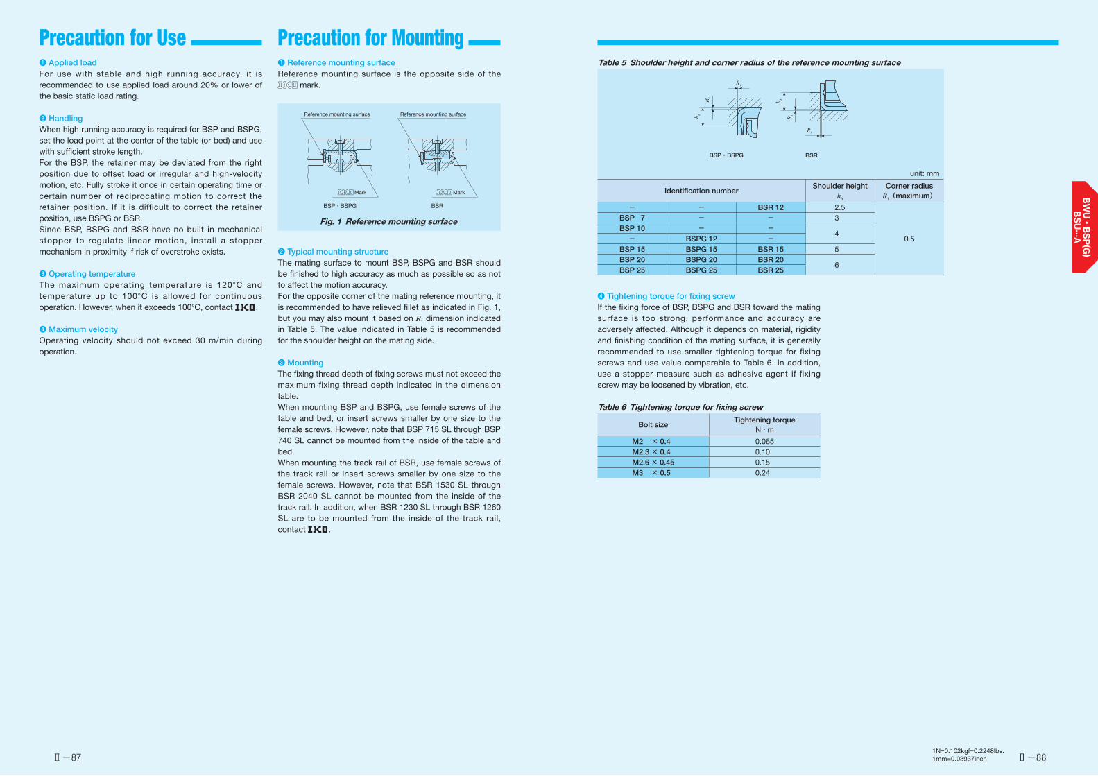
Ⅱ-87 Ⅱ-88
Precaution for Use Precaution for Mounting
1N=0.102kgf=0.2248lbs.1mm=0.03937inch
❶ Applied loadFor use with stable and high running accuracy, it is recommended to use applied load around 20% or lower of the basic static load rating.
❷ HandlingWhen high running accuracy is required for BSP and BSPG, set the load point at the center of the table (or bed) and use with sufficient stroke length.For the BSP, the retainer may be deviated from the right position due to offset load or irregular and high-velocity motion, etc. Fully stroke it once in certain operating time or certain number of reciprocating motion to correct the retainer position. If it is difficult to correct the retainer position, use BSPG or BSR.Since BSP, BSPG and BSR have no built-in mechanical stopper to regulate l inear motion, install a stopper mechanism in proximity if risk of overstroke exists.
❸ Operating temperatureThe maximum operating temperature is 120°C and temperature up to 100°C is allowed for continuous operation. However, when it exceeds 100°C, contact .
❹ Maximum velocityOperating velocity should not exceed 30 m/min during operation.
❶ Reference mounting surfaceReference mounting surface is the opposite side of the
mark.
Reference mounting surfaceReference mounting surface
BSP・BSPG BSR
Mark Mark
Fig. 1 Reference mounting surface
❷ Typical mounting structureThe mating surface to mount BSP, BSPG and BSR should be finished to high accuracy as much as possible so as not to affect the motion accuracy.For the opposite corner of the mating reference mounting, it is recommended to have relieved fillet as indicated in Fig. 1, but you may also mount it based on R1 dimension indicated in Table 5. The value indicated in Table 5 is recommended for the shoulder height on the mating side.
❸ MountingThe fixing thread depth of fixing screws must not exceed the maximum fixing thread depth indicated in the dimension table.When mounting BSP and BSPG, use female screws of the table and bed, or insert screws smaller by one size to the female screws. However, note that BSP 715 SL through BSP 740 SL cannot be mounted from the inside of the table and bed.When mounting the track rail of BSR, use female screws of the track rail or insert screws smaller by one size to the female screws. However, note that BSR 1530 SL through BSR 2040 SL cannot be mounted from the inside of the track rail. In addition, when BSR 1230 SL through BSR 1260 SL are to be mounted from the inside of the track rail, contact .
❹ Tightening torque for fixing screwIf the fixing force of BSP, BSPG and BSR toward the mating surface is too strong, performance and accuracy are adversely affected. Although it depends on material, rigidity and finishing condition of the mating surface, it is generally recommended to use smaller tightening torque for fixing screws and use value comparable to Table 6. In addition, use a stopper measure such as adhesive agent if fixing screw may be loosened by vibration, etc.
Table 6 Tightening torque for fixing screw
Bolt sizeTightening torque
N・m
M2 × 0.4 0.065M2.3 × 0.4 0.10M2.6 × 0.45 0.15M3 × 0.5 0.24
Table 5 Shoulder height and corner radius of the reference mounting surface
unit: mm
Identification numberShoulder height
h3
Corner radiusR1(maximum)
- - BSR 12 2.5
0.5
BSP 7 - - 3BSP 10 - -
4- BSPG 12 -
BSP 15 BSPG 15 BSR 15 5BSP 20 BSPG 20 BSR 20
6BSP 25 BSPG 25 BSR 25
BSP・BSPG BSR
R1
R1
h 3
R1
h 3
R1
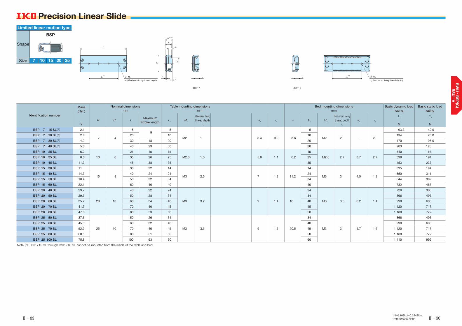
Ⅱ-89 Ⅱ-901N=0.102kgf=0.2248lbs.1mm=0.03937inch
Precision Linear Slide
Identification number
Mass (Ref.)
g
Nominal dimensionsmm
Table mounting dimensionsmm
Bed mounting dimensionsmm
Basic dynamic load rating
Basic static load rating
W H LMaximum
stroke lengthL1 M1
Maximum fixing thread depth
s1
h1 t1 w L2 M2
Maximum fixing thread depth
s2
h2 t2
C
N
C0
N
BSP 7 15 SL(1) 2.1
7 4
15 9
5
M2 1 3.4 0.9 3.6
5
M2 2 - 2
93.3 42.0
BSP 7 20 SL(1) 2.8 20 10 10 134 70.0
BSP 7 30 SL(1) 4.2 30 18 20 20 170 98.0
BSP 7 40 SL(1) 5.6 40 23 30 30 203 126
BSP 10 25 SL 6.2
10 6
25 15 15
M2.6 1.5 5.8 1.1 6.2
15
M2.6 2.7 3.7 2.7
340 156
BSP 10 35 SL 8.8 35 26 25 25 398 194
BSP 10 45 SL 11.3 45 38 35 35 453 233
BSP 15 30 SL 11
15 8
30 22 14
M3 2.5 7 1.2 11.2
14
M3 3 4.5 1.2
395 194
BSP 15 40 SL 14.7 40 24 24 24 550 311
BSP 15 50 SL 18.4 50 32 34 34 644 389
BSP 15 60 SL 22.1 60 40 40 40 732 467
BSP 20 40 SL 23.7
20 10
40 22 24
M3 3.2 9 1.4 16
24
M3 3.5 6.2 1.4
726 386
BSP 20 50 SL 29.7 50 28 34 34 866 496
BSP 20 60 SL 35.7 60 34 40 40 998 606
BSP 20 70 SL 41.7 70 40 45 45 1 120 717
BSP 20 80 SL 47.6 80 53 50 50 1 180 772
BSP 25 50 SL 37.6
25 10
50 26 34
M3 3.5 9 1.6 20.5
34
M3 3 5.7 1.6
866 496
BSP 25 60 SL 45.3 60 32 40 40 998 606
BSP 25 70 SL 52.9 70 40 45 45 1 120 717
BSP 25 80 SL 60.5 80 51 50 50 1 180 772
BSP 25 100 SL 75.8 100 63 60 60 1 410 992
Note (1) BSP 715 SL through BSP 740 SL cannot be mounted from the inside of the table and bed.
2−M2
s2 (Maximum fixing thread depth)
L2
±0.1t2
BSP 10BSP 7
t2
W (w)
t1 t2
h2
h1
H±0.040
2−M1
s1 (Maximum fixing thread depth)
L1
±0.1
L
20
Limited linear motion type
Shape
Size 7 10 2515
BSP
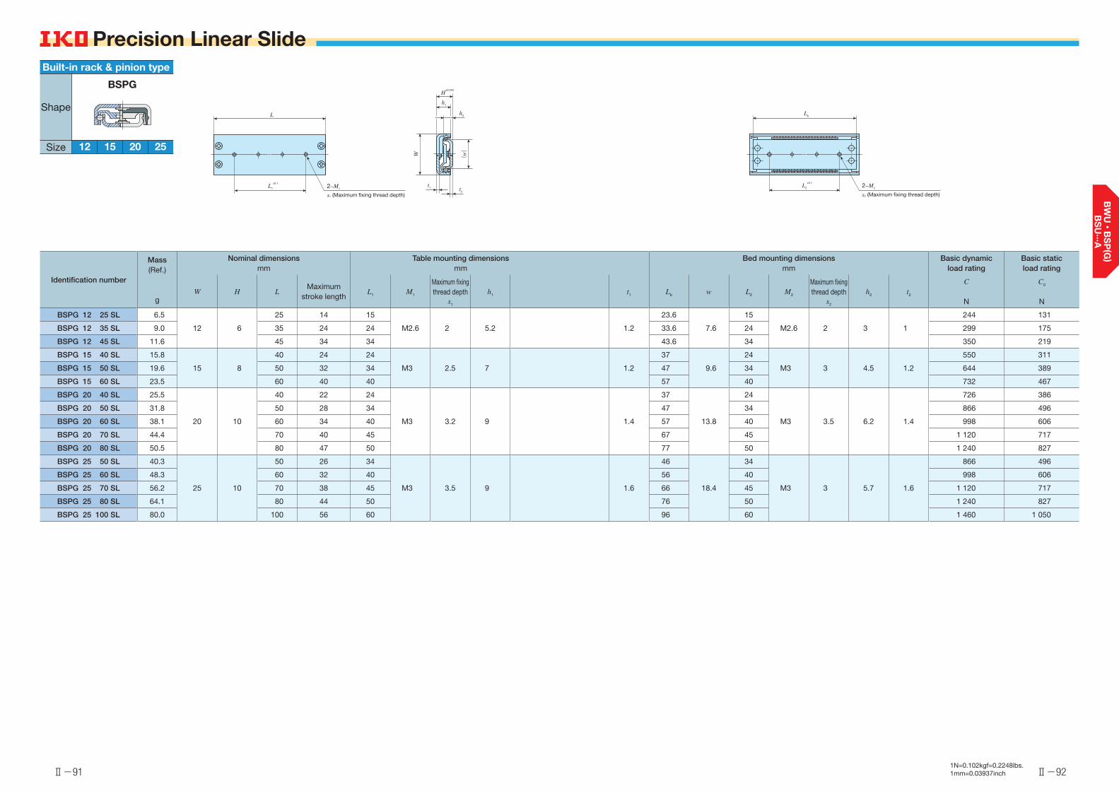
Ⅱ-91 Ⅱ-921N=0.102kgf=0.2248lbs.1mm=0.03937inch
Precision Linear Slide
Identification number
Mass (Ref.)
g
Nominal dimensionsmm
Table mounting dimensionsmm
Bed mounting dimensionsmm
Basic dynamic load rating
Basic static load rating
W H LMaximum
stroke lengthL1 M1
Maximum fixing thread depth
s1
h1 t1 Lb w L2 M2
Maximum fixing thread depth
s2
h2 t2
C
N
C0
N
BSPG 12 25 SL 6.5
12 6
25 14 15
M2.6 2 5.2 1.2
23.6
7.6
15
M2.6 2 3 1
244 131
BSPG 12 35 SL 9.0 35 24 24 33.6 24 299 175
BSPG 12 45 SL 11.6 45 34 34 43.6 34 350 219
BSPG 15 40 SL 15.8
15 8
40 24 24
M3 2.5 7 1.2
37
9.6
24
M3 3 4.5 1.2
550 311
BSPG 15 50 SL 19.6 50 32 34 47 34 644 389
BSPG 15 60 SL 23.5 60 40 40 57 40 732 467
BSPG 20 40 SL 25.5
20 10
40 22 24
M3 3.2 9 1.4
37
13.8
24
M3 3.5 6.2 1.4
726 386
BSPG 20 50 SL 31.8 50 28 34 47 34 866 496
BSPG 20 60 SL 38.1 60 34 40 57 40 998 606
BSPG 20 70 SL 44.4 70 40 45 67 45 1 120 717
BSPG 20 80 SL 50.5 80 47 50 77 50 1 240 827
BSPG 25 50 SL 40.3
25 10
50 26 34
M3 3.5 9 1.6
46
18.4
34
M3 3 5.7 1.6
866 496
BSPG 25 60 SL 48.3 60 32 40 56 40 998 606
BSPG 25 70 SL 56.2 70 38 45 66 45 1 120 717
BSPG 25 80 SL 64.1 80 44 50 76 50 1 240 827
BSPG 25 100 SL 80.0 100 56 60 96 60 1 460 1 050
2−M2
s2 (Maximum fixing thread depth)
L2
±0.1
Lb
W
(w)
t1 t2
h2
h1
H±0.040
2−M1
s1 (Maximum fixing thread depth)
L1
±0.1
L
Built-in rack & pinion type
Shape
Size 12 15 2520
BSPG
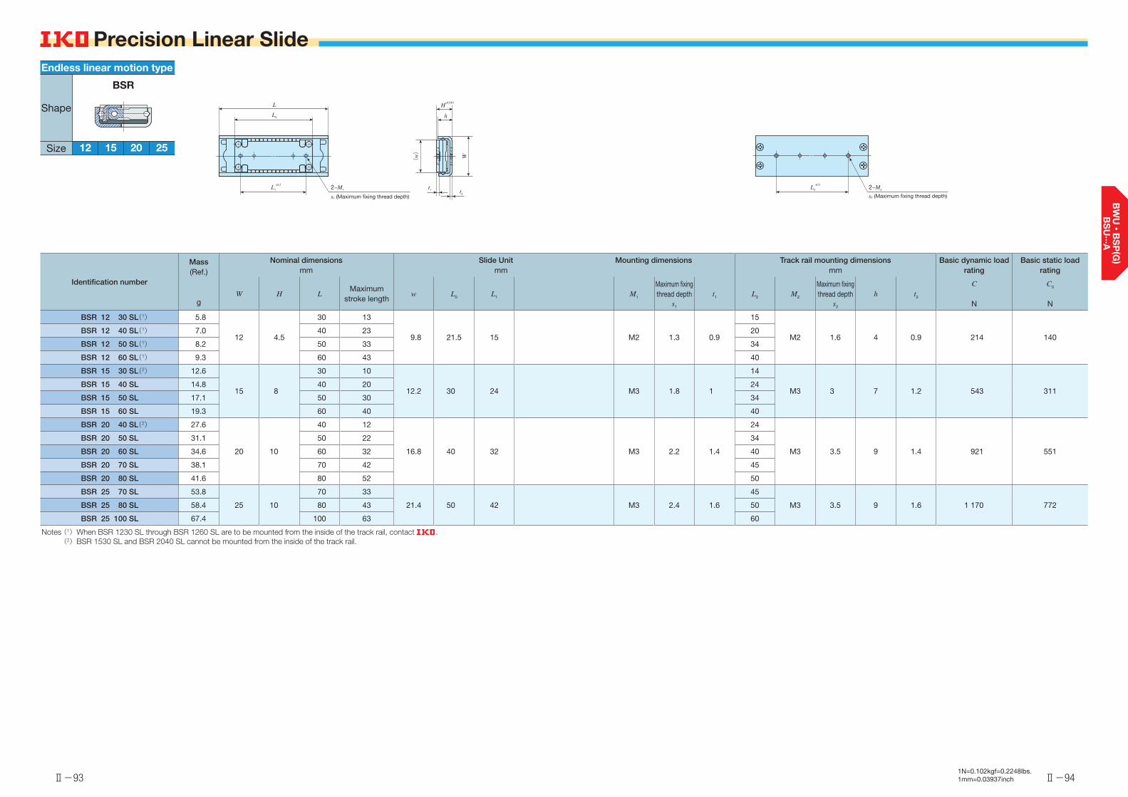
Ⅱ-93 Ⅱ-941N=0.102kgf=0.2248lbs.1mm=0.03937inch
Precision Linear Slide
Identification number
Mass (Ref.)
g
Nominal dimensionsmm
Slide Unitmm
Mounting dimensions Track rail mounting dimensionsmm
Basic dynamic load rating
Basic static load rating
W H LMaximum
stroke lengthw L0 L1 M1
Maximum fixing thread depth
s1
t1 L2 M2
Maximum fixing thread depth
s2
h t2
C
N
C0
N
BSR 12 30 SL(1) 5.8
12 4.5
30 13
9.8 21.5 15 M2 1.3 0.9
15
M2 1.6 4 0.9 214 140BSR 12 40 SL(1) 7.0 40 23 20
BSR 12 50 SL(1) 8.2 50 33 34
BSR 12 60 SL(1) 9.3 60 43 40
BSR 15 30 SL(2) 12.6
15 8
30 10
12.2 30 24 M3 1.8 1
14
M3 3 7 1.2 543 311BSR 15 40 SL 14.8 40 20 24
BSR 15 50 SL 17.1 50 30 34
BSR 15 60 SL 19.3 60 40 40
BSR 20 40 SL(2) 27.6
20 10
40 12
16.8 40 32 M3 2.2 1.4
24
M3 3.5 9 1.4 921 551
BSR 20 50 SL 31.1 50 22 34
BSR 20 60 SL 34.6 60 32 40
BSR 20 70 SL 38.1 70 42 45
BSR 20 80 SL 41.6 80 52 50
BSR 25 70 SL 53.8
25 10
70 33
21.4 50 42 M3 2.4 1.6
45
M3 3.5 9 1.6 1 170 772BSR 25 80 SL 58.4 80 43 50
BSR 25 100 SL 67.4 100 63 60
Notes (1) When BSR 1230 SL through BSR 1260 SL are to be mounted from the inside of the track rail, contact . (2) BSR 1530 SL and BSR 2040 SL cannot be mounted from the inside of the track rail.
(w)
W
t1 t2
h
H±0.040
2−M2
s2 (Maximum fixing thread depth)
L2
±0.1
L
L0
2−M1
s1 (Maximum fixing thread depth)
L1
±0.1
Endless linear motion type
Shape
Size 12 15 2520
BSR

Identification Number and Specification
2● Smooth operations
Since the ball is guided by the retainer made of synthetic resin and rotates on high accuracy round shank way, it can obtain a light and smooth motion. 4
● Excellent corrosion resistanceThe ball and way are mode of stainless steel and the surface of table and bed have anodic oxidization coating, allowing high corrosion resistance.
1Points● Light weight linear motion guide unit
Since the product uses aluminum alloy for table and bed, it is a light weight and compact limited linear motion guide unit. 3
● Easy mountingSince the product is properly preloaded, it can easily gain a stable linear motion only by fixing it against precisely grounded mounting surface with bolts.
BSU…ALinear Slide Unit
Ball
Table
Clearance adjustment screw
Retainer
Bed
Way
Ⅱ-96Ⅱ-951N=0.102kgf=0.2248lbs.1mm=0.03937inch
Example of an identification number
The specification of BSU…A series is indicated by the identification number. Indicate the identification number, consisting of a model code and dimensions for each specification to apply.
1 2 3 1
BSU 44 – 50 A
Model1 Modelcode
Page Ⅱ-96
Width2Dimensions Page Ⅱ-96
Length3
Linear Slide Unit :BSU…A
For applicable models, width and length, see Table 1.
44, 66 Indicate the table width in mm.For applicable models, width and length, see Table 1.
Indicate the length in mm.For applicable models, width and length, see Table 1.
Model1
Width2
Length3
Identification Number and Specification
Table 1 Width and length of BSU…A series unit: mm
Shape Model WidthLength
50 80 100 125 150
BSU…A44 ○ ○ ○ - -
66 - - ○ ○ ○
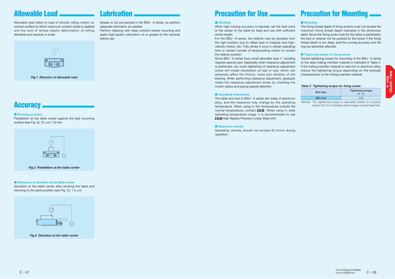
Load Rating and Life Precaution for Mounting Allowable Load Lubrication Precaution for Use
Ⅱ-97 Ⅱ-981N=0.102kgf=0.2248lbs.1mm=0.03937inch
Allowable load refers to load of smooth rolling motion on contact surface to which maximum contact stress is applied and the sum of whose elastic deformation of rolling elements and raceway is small.
Fig.1 Direction of allowable load
❶ Running accuracyParallelism at the table center against the bed mounting surface (see Fig. 2): 10 μm / 10 mm
Fig.2 Parallelism at the table center
❷ Allowance of deviation at the table centerDeviation at the table center after stroking the table and returning to the same position (see Fig. 3.): 1.5 μm
Fig.3 Deviation at the table center
F
Accuracy
❶ MountingThe fixing thread depth of fixing screws must not exceed the maximum fixing thread depth indicated in the dimension table. Since the fixing screw hole for the table is penetrated, the bed or retainer will be pushed by the screw if the fixing thread depth is too deep, and the running accuracy and life may be adversely affected.
❷ Tightening torque for fixing screwTypical tightening torque for mounting of the BSU…A series to the steel mating member material is indicated in Table 2. If the mating member material is cast iron or aluminum alloy, reduce the tightening torque depending on the strength characteristics of the mating member material.
Table 2 Tightening torque for fixing screw
Bolt sizeTightening torque
N・m
M5×0.8 5.0
Remark: The tightening torque is calculated based on property division A2-70 of stainless steel hexagon socket head bolt.
Grease is not pre-packed in the BSU…A series, so perform adequate lubrication as needed.Perform cleaning with clean solution before mounting and apply high-quality lubrication oil or grease to the raceway before use.
❶ HandlingWhen high running accuracy is required, set the load point at the center of the table (or bed) and use with sufficient stroke length.For the BSU…A series, the retainer may be deviated from the right position due to offset load or irregular and high-velocity motion, etc. Fully stroke it once in certain operating time or certain number of reciprocating motion to correct the retainer position.Since BSU…A series have small allowable load F, handling requires special care. Especially when clearance adjustment is performed, too much tightening of clearance adjustment screw will create impression on ball or way, which can adversely affect the friction, noise and vibration of the bearing. When performing clearance adjustment, gradually rotate the clearance adjustment screw by checking the motion status and paying special attention.
❷ Operating temperatureThe table and bed of BSU…A series are made of aluminum alloy, and the clearance may change by the operating temperature. When using in the temperature outside the normal temperature, contact . When using in wide operating temperature range, it is recommended to use
High Rigidity Precision Linear Slide Unit.
❸ Maximum velocityOperating velocity should not exceed 30 m/min during operation.
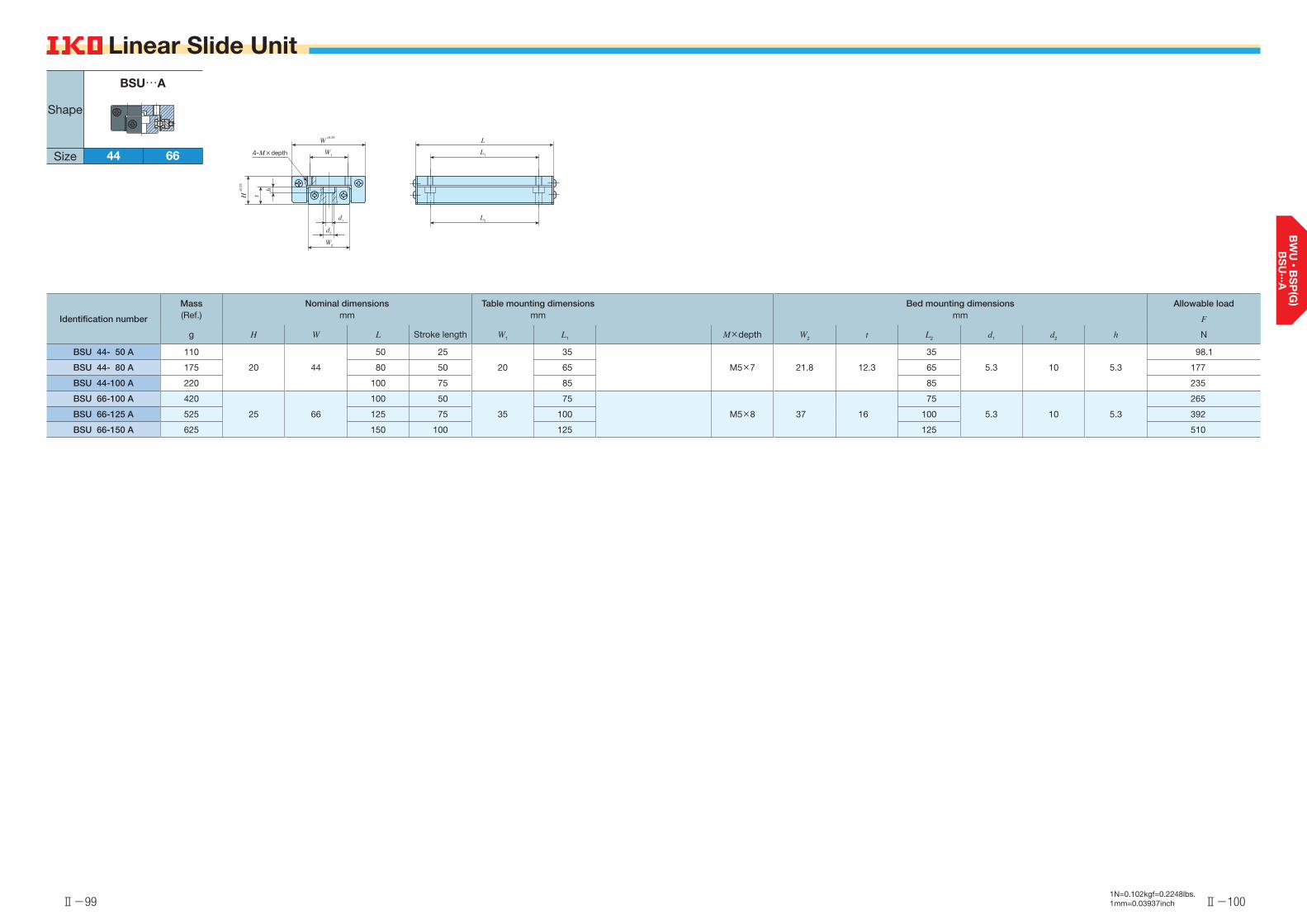
Ⅱ-99
Linear Slide Unit
Ⅱ-100
Linear Slide Unit
1N=0.102kgf=0.2248lbs.1mm=0.03937inch
Identification number
Mass (Ref.)
g
Nominal dimensionsmm
Table mounting dimensionsmm
Bed mounting dimensionsmm
Allowable load
F
NH W L Stroke length W1 L1 M×depth W2 t L2 d1 d2 h
BSU 44- 50 A 110
20 44
50 25
20
35
M5×7 21.8 12.3
35
5.3 10 5.3
98.1
BSU 44- 80 A 175 80 50 65 65 177
BSU 44-100 A 220 100 75 85 85 235
BSU 66-100 A 420
25 66
100 50
35
75
M5×8 37 16
75
5.3 10 5.3
265
BSU 66-125 A 525 125 75 100 100 392
BSU 66-150 A 625 150 100 125 125 510
±0.25
4-M×depth
W
±0.
25H
W1
d1
d2
W2
L
L1
L2
h
t
Shape
Size 44 66
BSU…A
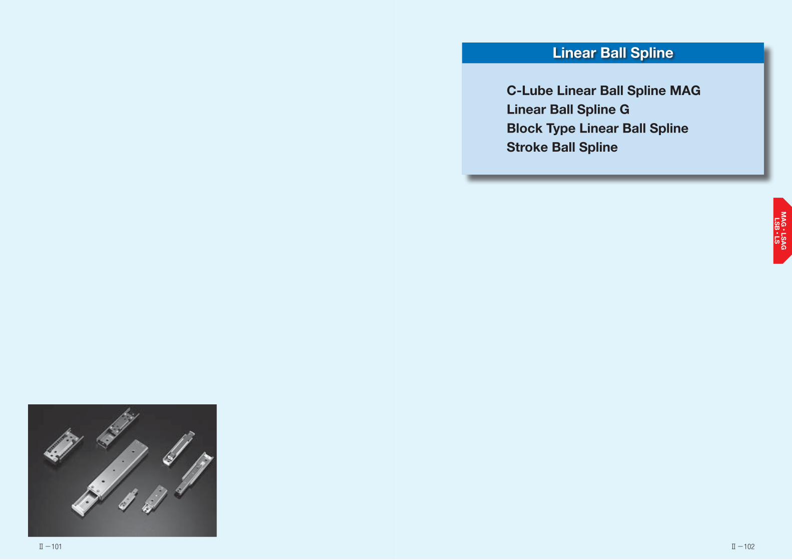
Ⅱ-101 Ⅱ-102
Linear Ball Spline
C-Lube Linear Ball Spline MAGLinear Ball Spline GBlock Type Linear Ball SplineStroke Ball Spline
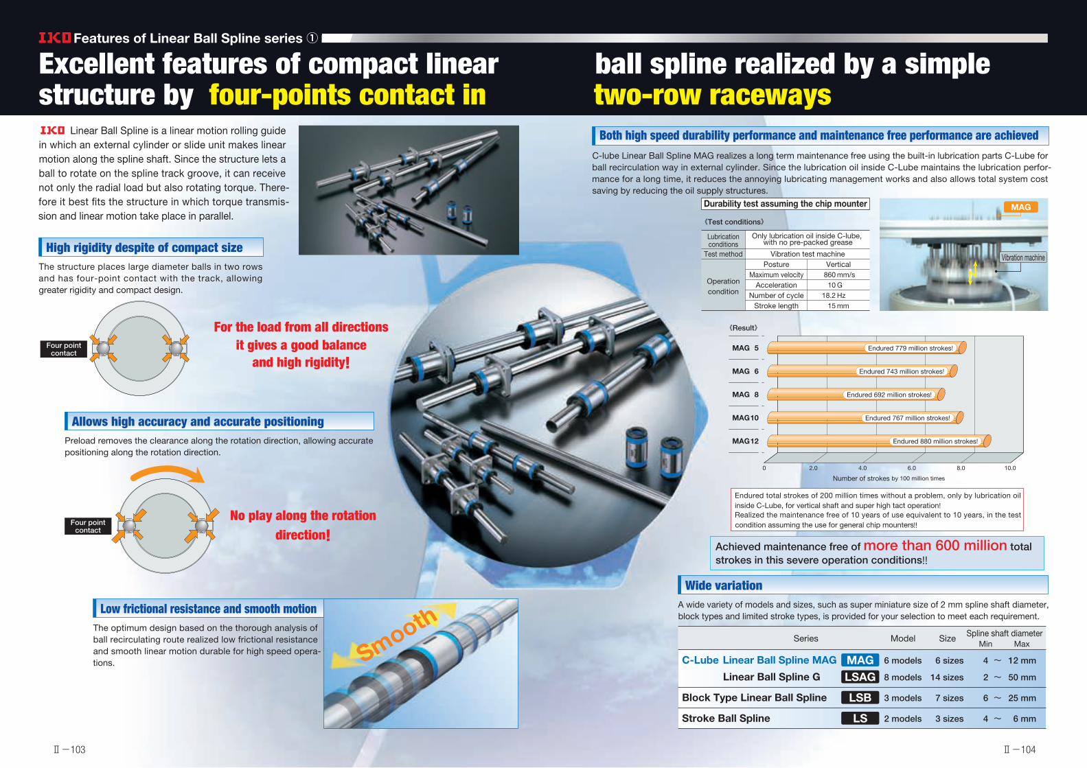
1N=0.102kgf=0.2248lbs.1mm=0.03937inch
Features of Linear Ball Spline series ①
Linear Ball Spline is a linear motion rolling guide in which an external cylinder or slide unit makes linear motion along the spline shaft. Since the structure lets a ball to rotate on the spline track groove, it can receive not only the radial load but also rotating torque. There-fore it best fits the structure in which torque transmis-sion and linear motion take place in parallel.
Both high speed durability performance and maintenance free performance are achievedC-lube Linear Ball Spline MAG realizes a long term maintenance free using the built-in lubrication parts C-Lube for ball recirculation way in external cylinder. Since the lubrication oil inside C-Lube maintains the lubrication perfor-mance for a long time, it reduces the annoying lubricating management works and also allows total system cost saving by reducing the oil supply structures.
High rigidity despite of compact sizeThe structure places large diameter balls in two rows and has four-point contact with the track, allowing greater rigidity and compact design.
Low frictional resistance and smooth motionThe optimum design based on the thorough analysis of ball recirculating route realized low frictional resistance and smooth linear motion durable for high speed opera-tions.
Allows high accuracy and accurate positioningPreload removes the clearance along the rotation direction, allowing accurate positioning along the rotation direction.
Wide variationA wide variety of models and sizes, such as super miniature size of 2 mm spline shaft diameter, block types and limited stroke types, is provided for your selection to meet each requirement.
C-Lube Linear Ball Spline MAG 6 models 6 sizes 4 ~ 12 mm
8 models 14 sizes 2 ~ 50 mm Linear Ball Spline G
Block Type Linear Ball Spline 3 models 7 sizes 6 ~ 25 mm
Stroke Ball Spline 2 models 3 sizes 4 ~ 6 mm
MAGLSAG
LSB
LS
Series Model Size Spline shaft diameterMin Max
Excellent features of compact linear ball spline realized by a simple structure by four-points contact in two-row raceways
For the load from all directionsit gives a good balance
and high rigidity!
No play along the rotation direction!
Four point contact
Durability test assuming the chip mounter
Lubrication conditions
Test method
Operation condition
PostureMaximum velocity
AccelerationNumber of cycle
Stroke length
Vibration test machine
860 mm/s 10 G 18.2 Hz 15 mm
《Test conditions》
《Result》
MAG
Vibration machine
Number of strokes by 100 million times
0 2.0 4.0 6.0 8.0 10.0
Endured 779 million strokes!MAG 5
Endured 743 million strokes!MAG 6
Endured 692 million strokes!MAG 8
Endured 767 million strokes!MAG 10
Endured 880 million strokes!MAG 12
Smooth
Endured total strokes of 200 million times without a problem, only by lubrication oil inside C-Lube, for vertical shaft and super high tact operation!Realized the maintenance free of 10 years of use equivalent to 10 years, in the test condition assuming the use for general chip mounters!!
Achieved maintenance free of more than 600 million total strokes in this severe operation conditions!!
Only lubrication oil inside C-lube, with no pre-packed grease
Vertical
Four point contact
Four point contact
Ⅱ-103 Ⅱ-104

1N=0.102kgf=0.2248lbs.1mm=0.03937inch
Features of Linear Ball Spline series ②Free combination is enabled for model/accuracy/preload!!
Extreme interchangeable system
Interchangeable specification
A wide variety of models with different sectional shape and length are provided, for free replacement on the same spline shaft.
Select the products as many as you wish.
Spline shaft
High carbon steel spline hollow shaft
Spline shaft interchangeability
C-Lube Linear Ball Spline MAG Linear Ball Spline G
Block Type Linear Ball Spline
Free selection is possible for external cylinders or slide
units and spline shafts!
Free selection is possible for external cylinders or slide
units and spline shafts!
External cylinder of slide unit Spline shaft Assembled set
External cylinder interchangeability / unit interchangeability
Shape of external cylinders
Standard type Flange type
Standard Long
Length of external cylinder
External cylinder interchangeability
Spline shaft
High carbon steel spline solid shaftStainless steel spline solid shaft
High carbon steel spline hollow shaft
Spline shaft interchangeabilitySlide unit shape
Slide unit interchangeability
The simple structure of four-contact in two-row race-way yields small manufacturing errors or accuracy mea-surement errors, allowing the maintenance of each raceway in the high dimensions accuracy.Two accuracy classes of ordinary and high level are provided, to support even high traveling accuracy pur-poses.
The high accuracy dimensions management utilizing the simple structure achieved the interchangeability of preloaded external cylinders and slide units.It supports the applications requiring the rigidity of one higher rank.
By exchanging the external cylinder of Linear Ball Spline G of interchangeable specification with an external cylinder of C-Lube Linear Ball Spline G, you can achieve the maintenance free without changing the spline shaft.
Interchangeable specification has realized the unparalleled high interchangeability in the background of unique
high processing technology, by severely managing the dimensions of external cylinder, slide unit and spline shaft.
This feature allows independent handling of external cylinder or slide unit and spline shaft, thus allowing you to
select the free combination and to order any products, for any volume and at any necessary time.
Accuracy interchangeability
Preload interchangeability
Maintenance free is achieved only by replacing the external cylinder!
Light preload
Standard preload
High carbon steel spline solid shaftStainless steel spline solid shaft
It allows the rigidity improvement of units without design changes!It allows the rigidity improvement of units without design changes!
It allows the accuracy improvement of units without design changes!It allows the accuracy improvement
of units without design changes!It allows the accuracy improvement
of units without design changes!
Requirements of ;
Help● Wish to improve the rigidity and life of machines● Wish to improve the accuracy of machines● Wish to replace the external cylinders or slide units immediately● The number of external cylinders or slide units is in short● Wish to replace the spline shaft immediately● The length of spline shaft is not sufficient● Wish to store only the external cylinders or slide
units in stock for emergency
Interchangeable specification realizes ;
Sorted out● Wish to prepare for a sudden design change● Wish to select freely the combination of high
accuracy and preload● Independent handling of external cylinders or
slide units and spline shafts● Free and independent combination of external
cylinders or slide units and spline shafts● Compactness - independent storing of exter-
nal cylinders or slide units and spline shafts
Touch
External cylinder Spline shaft
Spline shaftSlide unit
Rigidity is necessary after all!
Ⅱ-105 Ⅱ-106
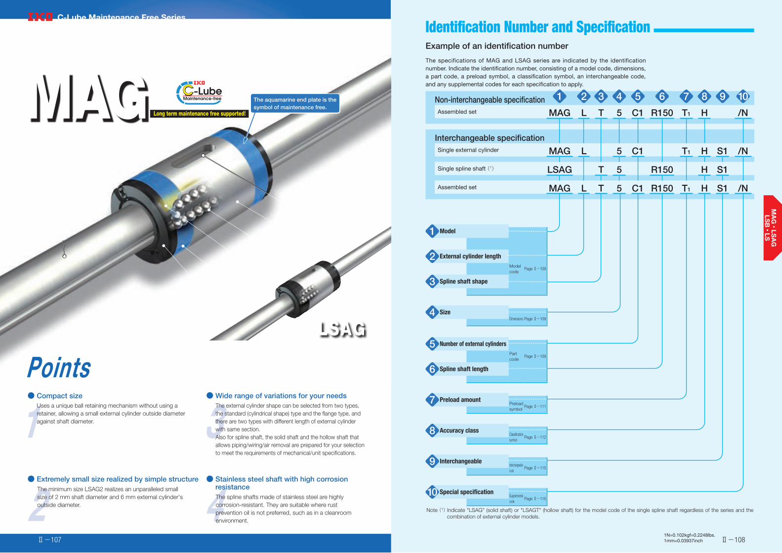
Load Rating and Life Identification Number and Specification
2● Extremely small size realized by simple structure
The minimum size LSAG2 realizes an unparalleled small size of 2 mm shaft diameter and 6 mm external cylinder's outside diameter.
1Points● Compact size
Uses a unique ball retaining mechanism without using a retainer, allowing a small external cylinder outside diameter against shaft diameter. 3
● Wide range of variations for your needsThe external cylinder shape can be selected from two types, the standard (cylindrical shape) type and the flange type, and there are two types with different length of external cylinder with same section.Also for spline shaft, the solid shaft and the hollow shaft that allows piping/wiring/air removal are prepared for your selection to meet the requirements of mechanical/unit specifications.
4The spline shafts made of stainless steel are highly corrosion-resistant. They are suitable where rust prevention oil is not preferred, such as in a cleanroom environment.
LSAGLinear Ball Spline G
C-Lube Linear Ball Spline MAG
MAG
C-Lube Maintenance Free Series
Long term maintenance free supported!
The aquamarine end plate is the symbol of maintenance free.
● Stainless steel shaft with high corrosion resistance
External cylinder
Keyway
External cylinder body
Ball
C-Lube
End Plate
Seal
Spline shaft
Ⅱ-108Ⅱ-1071N=0.102kgf=0.2248lbs.1mm=0.03937inch
Example of an identification number
The specifications of MAG and LSAG series are indicated by the identification number. Indicate the identification number, consisting of a model code, dimensions, a part code, a preload symbol, a classification symbol, an interchangeable code, and any supplemental codes for each specification to apply.
Non-interchangeable specification 1 2 3 4 5 6 7 8 9 10Assembled set MAG L T 5 C1 R150 T1 H /N
Interchangeable specificationSingle external cylinder MAG L 5 C1 T1 H S1 /N
Single spline shaft (1) LSAG T 5 R150 H S1
Assembled set MAG L T 5 C1 R150 T1 H S1 /N
Model1
External cylinder length2Modelcode
Page Ⅱ-109
Spline shaft shape3
Size4Dimensions Page Ⅱ-109
Number of external cylinders5Partcode
Page Ⅱ-109
Spline shaft length6
Preload amount7 Preloadsymbol
Page Ⅱ-111
Accuracy class8 Classificationsymbol
Page Ⅱ-112
Interchangeable9 Interchangeablecode
Page Ⅱ-115
Special specification10 Supplementalcode
Page Ⅱ-115
Note (1) Indicate "LSAG" (solid shaft) or "LSAGT" (hollow shaft) for the model code of the single spline shaft regardless of the series and the combination of external cylinder models.

Spline Shaft Shape・Size・Number of External Cylinders・Spline Shaft Length-Identification Number and Specification -Model・External Cylinder Length・
Ⅱ-109 Ⅱ-1101N=0.102kgf=0.2248lbs.1mm=0.03937inch
C-Lube Linear Ball Spline MAG(MAG series)
Standard typeFlange type
:MAG:MAGF
Linear Ball Spline G(1)(LSAG series)
Standard typeFlange type
:LSAG:LSAGF
For applicable models and sizes, see Table 1.Indicate "LSAG" (solid shaft) or "LSAGT" (hollow shaft) for the model code of the single spline shaft regardless of the series and the combination of external cylinder models.
Note (1) This model has no built-in C-Lube.
StandardLong
:No symbol:L
For applicable models and sizes, see Table 1.
Solid shaftHollow shaft
:No symbol:T
For applicable models and sizes, see Table 1.
2, 3, 4, 5, 6, 8, 10, 12, 1520, 25, 30, 40, 50
For applicable models and sizes, see Table 1.
:C○ For an assembled set, indicates the number of external cylinders assembled on a spline shaft. For a single external cylinder, only "C1" is specified.
:R○ The spline shaft length is indicated in mm.For standard and maximum lengths, see the dimension table.
Model1
External cylinder length2
Spline shaft shape3
Size4
Number of external cylinders5
Spline shaft length6
Table 1 Models and sizes of MAG and LSAG series
ShapeExternal cylinder
lengthModel
Size
2 3 4 5 6 8 10 12 15 20 25 30 40 50
Standard typeSolid shaft
MAG - - ○ ○ ○ ○ ○ ○ - - - - - -
LSAG ○ ○ ○ ○ ○ ○ ○ ○ ○ ○ ○ ○ ○ ○
MAGL - - ○ ○ ○ ○ - - - - - - - -
LSAGL - - - ○ ○ ○ ○ ○ ○ ○ ○ ○ - -
Standard typeHollow shaft
MAGT - - ○ ○ ○ ○ ○ ○ - - - - - -
LSAGT - - ○ ○ ○ ○ ○ ○ - - - - - -
MAGLT - - ○ ○ ○ ○ - - - - - - - -
LSAGLT - - - ○ ○ ○ ○ ○ - - - - - -
Flange typeSolid shaft
MAGF - - - ○ ○ ○ ○ ○ - - - - - -
LSAGF ○ ○ ○ ○ ○ ○ ○ ○ ○ ○ ○ ○ ○ -
LSAGFL - - - ○ ○ ○ ○ ○ ○ ○ ○ ○ - -
Flange typeHollow shaft
MAGFT - - - ○ ○ ○ ○ ○ - - - - - -
LSAGFT - - ○ ○ ○ ○ ○ ○ - - - - - -
LSAGFLT - - - ○ ○ ○ ○ ○ - - - - - -
Remark: For the models indicated in , the interchangeable specification is available.
Standard
Long
Standard
Long
Standard
Long
Standard
Long
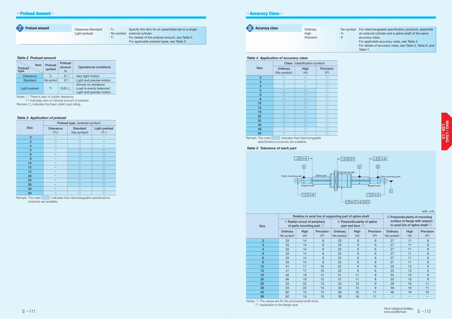
-Preload Amount- -Accuracy Class-
Ⅱ-111 Ⅱ-1121N=0.102kgf=0.2248lbs.1mm=0.03937inch
OrdinaryHighPrecision
:No symbol:H:P
For interchangeable specification products, assemble an external cylinder and a spline shaft of the same accuracy class.For applicable accuracy class, see Table 4.For details of accuracy class, see Table 5, Table 6, and Table 7.
Accuracy class8Clearance Standard Light preload
:T0
:No symbol:T1
Specify this item for an assembled set or a single external cylinder.For details of the preload amount, see Table 2.For applicable preload types, see Table 3.
Preload amount7
Table 4 Application of accuracy class
Size
Class(classification symbol)
Ordinary(No symbol)
High(H)
Precision(P)
2 ○ ○ ○3 ○ ○ ○4 ○ ○ ○5 ○ ○ ○6 ○ ○ ○8 ○ ○ ○
10 ○ ○ ○12 ○ ○ ○15 ○ ○ ○20 ○ ○ ○25 ○ ○ ○30 ○ ○ ○40 ○ ○ ○50 ○ ○ ○
Remark: The mark indicates that interchangeable specifications products are available.
Table 2 Preload amount
ItemPreload type
Preload symbol
Preload amount
NOperational conditions
Clearance T0 0(1) ・ Very light motionStandard (No symbol) 0(2) ・ Light and precise motion
Light preload T1 0.02 C0
・ Almost no vibrations・ Load is evenly balanced・ Light and precise motion
Notes (1) There is zero or subtle clearance. (2) Indicates zero or minimal amount of preload.
Remark: C0 indicates the basic static load rating.
Table 5 Tolerance of each part
unit: μm
Size
Relative to axial line of supporting part of spline shaft ③ Perpendicularity of mounting surface of flange with respect to axial line of spline shaft(2)
① Radial runout of periphery of parts mounting part(1)
② Perpendicularity of spline part end face(1)
Ordinary High Precision Ordinary High Precision Ordinary High Precision(No symbol) (H) (P) (No symbol) (H) (P) (No symbol) (H) (P)
2 33 14 8 22 9 6 27 11 83 33 14 8 22 9 6 27 11 84 33 14 8 22 9 6 27 11 85 33 14 8 22 9 6 27 11 86 33 14 8 22 9 6 27 11 88 33 14 8 22 9 6 27 11 8
10 41 17 10 22 9 6 33 13 912 41 17 10 22 9 6 33 13 915 46 19 12 27 11 8 33 13 920 46 19 12 27 11 8 33 13 925 53 22 13 33 13 9 39 16 1130 53 22 13 33 13 9 39 16 1140 62 15 15 39 16 11 46 19 1350 62 15 15 39 16 11 - - -
Notes (1) The values are for the processed shaft ends. (2) Applicable to the flange type.
A-B
A D B
C
A-B
A-B
Table 7
A-B
A-B
2 3 2
11
Parts mounting part
Support part
Spline partExternal cylinder
Parts mounting part
Support part
D C
D C
Table 3 Application of preload
Size
Preload type(preload symbol)
Clearance(T0)
Standard(No symbol)
Light preload(T1)
2 ○ ○ -3 ○ ○ -4 ○ ○ -5 - ○ ○6 - ○ ○8 - ○ ○
10 - ○ ○12 - ○ ○15 - ○ ○20 - ○ ○25 - ○ ○30 - ○ ○40 - ○ ○50 - ○ ○
Remark: The mark indicates that interchangeable specifications products are available.
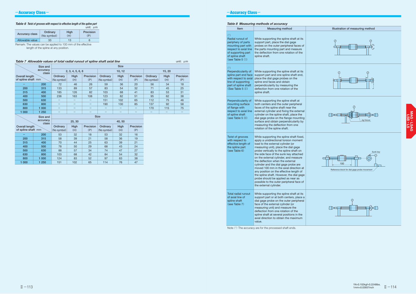
-Accuracy Class- -Accuracy Class-
Ⅱ-113 Ⅱ-1141N=0.102kgf=0.2248lbs.1mm=0.03937inch
Table 6 Twist of grooves with respect to effective length of the spline part unit: μm
Accuracy classOrdinary
(No symbol)High(H)
Precision(P)
Allowable value 33 13 6
Remark: The values can be applied to 100 mm of the effective length of the spline at any position.
Table 8 Measuring methods of accuracyItem Measuring method Illustration of measuring method
(1)Radial runout of periphery of parts mounting part with respect to axial line of supporting part of spline shaft(see Table 5 ①)
While supporting the spline shaft at its support part, place the dial gage probes on the outer peripheral faces of the parts mounting part and measure the deflection from one rotation of the spline shaft.
(1)Perpendicularity of spline part end face with respect to axial line of supporting part of spline shaft(See Table 5 ②)
While supporting the spline shaft at its support part and one spline shaft end, place the dial gage probes on the spline end faces and obtain perpendicularity by measuring the deflection from one rotation of the spline shaft.
Perpendicularity of mounting surface of flange with respect to axial line of spline shaft(see Table 5 ③)
While supporting the spline shaft at both centers and the outer peripheral faces of the spline shaft near the external cylinder and fixing the external cylinder on the spline shaft, place the dial gage probe on the flange mounting surface and obtain perpendicularity by measuring the deflection from one rotation of the spline shaft.
Twist of grooves with respect to effective length of the spline part(see Table 6)
While supporting the spline shaft fixed, apply a unidirectional torsion moment load to the external cylinder (or measuring unit), place the dial gage probe vertically to the spline shaft on the side face of the sunk key attached on the external cylinder, and measure the deflection when the external cylinder and the dial gage probe are moved 100 mm in the axial direction at any position on the effective length of the spline shaft. However, the dial gage probe should be applied as near as possible to the outer peripheral face of the external cylinder.
Total radial runout of axial line of spline shaft(see Table 7)
While supporting the spline shaft at its support part or at both centers, place a dial gage probe on the outer peripheral face of the external cylinder (or measuring unit) and measure the deflection from one rotation of the spline shaft at several positions in the axial direction to obtain the maximum value.
Note (1) The accuracy are for the processed shaft ends.
Jig fixture
Reference block for dial gage probe movement
Sunk key
100
Table 7 Allowable values of total radial runout of spline shaft axial line unit: μm
Size and accuracy
classOverall length of spline shaft mm
Size
2, 3, 4, 5, 6, 8 10, 12 15, 20
Ordinary(No symbol)
High(H)
Precision(P)
Ordinary(No symbol)
High(H)
Precision(P)
Ordinary(No symbol)
High(H)
Precision(P)
- 200 72 46 26 59 36 20 56 34 18200 315 133 89 57 83 54 32 71 45 25315 400 185 126 82 103 68 41 83 53 31400 500 236 163 108 123 82 51 95 62 38500 630 - - - 151 102 65 112 75 46630 800 - - - 190 130 85 137 92 58800 1 000 - - - - - - 170 115 75
1 000 1 250 - - - - - - - - -
Size and accuracy
classOverall length of spline shaft mm
Size
25, 30 40, 50
Ordinary(No symbol)
High(H)
Precision(P)
Ordinary(No symbol)
High(H)
Precision(P)
- 200 53 32 18 53 32 16200 315 58 39 21 58 36 19315 400 70 44 25 63 39 21400 500 78 50 29 68 43 24500 630 88 57 34 74 47 27630 800 103 68 42 84 54 32800 1 000 124 83 52 97 63 38
1 000 1 250 151 102 65 114 76 47

-Special Specification--Interchangeable Specification・Special Specification-
Ⅱ-115 Ⅱ-1161N=0.102kgf=0.2248lbs.1mm=0.03937inch
Table 11.1 Location and diameter of oil hole on a standard type external cylinder (Supplemental code /OH)
unit: mm
Identification number
F HIdentification
numberF H
LSAG 3 5 1.2 - - -LSAG 4 6
1.5
- - -LSAG 5 9 LSAGL 5 13
1.5LSAG 6 10.5 LSAGL 6 15LSAG 8 12.5 LSAGL 8 18.5LSAG10 15
2LSAGL10 23.5
2LSAG12 17.5 LSAGL12 27LSAG15 20 LSAGL15 32.5LSAG20 25
3
LSAGL20 35.53LSAG25 30 LSAGL25 42
LSAG30 35 LSAGL30 49LSAG40
50- - -
LSAG50 - - -Remark: A typical identification number is indicated, but is applied to
all LSAG series standard type models of the same size.
LSAG3, LSAG4
LSAG40, LSAG50
(F) Oil hole (H)
Oil hole (H)(F)
Oil hole
Oil hole
45°
Oil hole
Table 11.2 Location and diameter of oil hole on a flange type external cylinder (Supplemental code /OH)
unit: mm
Identification number
F HIdentification
numberF H
LSAGF 3 2.1 1.2 - - -LSAGF 4
2.81.5
- - -LSAGF 5 LSAGFL 5 5.8
1.5LSAGF 63.5
LSAGFL 6 8LSAGF 8 LSAGFL 8 9.5LSAGF10 5
2LSAGFL10 13.3
2LSAGF12 7.5 LSAGFL12 17LSAGF15 9 LSAGFL15 21.5LSAGF20 11
3
LSAGFL20 21.53LSAGF25 13 LSAGFL25 25
LSAGF30 14 LSAGFL30 28LSAGF40 23.4 - - -
Remark: A typical identification number is indicated, but is applied to all LSAG series flange type models of the same size.
LSAGF3, LSAGF4
F Oil hole (H)
F Oil hole (H) Oil hole
LSAGF(L)30 LSAGF40
Oil hole
Oil hole
45°
S1 specificationS2 specificationNon-interchangeable specification
:S1:S2:No symbol
This is specified for the interchangeable specifications. Assemble a spline shaft and an external cylinder with the same interchangeable code. Performance and accuracy of "S1" and "S2" are the same.For applicable models and sizes, see Table 1."No symbol" is indicated for non-interchangeable specification.
/BS, /N, /OH, /Q, /RE, /S,/Y
For applicable special specifications, see Table 9.1 and Table 9.2.For combination of multiple special specifications, see Table 10.For details of special specifications, see pages Ⅱ-116 and Ⅱ-117.
Interchangeable9
Special specification10
Stainless steel end plate /BS
The standard synthetic resin end plates are replaced with stainless steel end plates. The total length of the external cylinder remains unchanged.
No seal /N
Seals at both ends of the external cylinder can be replaced with end pressure plates, which do not come in contact with the spline shaft, to reduce frictional resistance.This specification is not effective for dust protection.
Oil hole /OH
An oil hole is created on the external cylinder. For dimensions, see Table 11.1 and Table 11.2.
Stainless steel end plate
End pressure plate End pressure plate
Oil hole (H)(F) Oil hole (H)F
Table 9.1 Application of special specifications (Interchangeable specification, single external cylinder, and assembled set)
Special specificationSupplemental
code
Size
2 3 4 5 6 8 10 12 15 20 25 30 40 50
No seal /N - - - ○ ○ ○ ○ ○ ○ ○ ○ ○ - -Oil hole(1) /OH - - - ○ ○ ○ ○ ○ ○ ○ ○ ○ - -With C-Lube plate(1) /Q - - - ○ ○ ○ ○ ○ - - - - - -
Note (1) Applicable to LSAG series.
Table 9.2 Application of special specifications (Non-interchangeable specification)
Special specificationSupplemental
code
Size
2 3 4 5 6 8 10 12 15 20 25 30 40 50
Stainless steel end plate(1) /BS - - - ○ ○ ○ ○ ○ ○ - - - - -No seal /N - - - ○ ○ ○ ○ ○ ○ ○ ○ ○ ○ ○Oil hole(1) /OH - ○ ○ ○ ○ ○ ○ ○ ○ ○ ○ ○ ○ ○With C-Lube plate(1) /Q - - - ○ ○ ○ ○ ○ - - - - - -Special environment seal(1) /RE - - - ○ ○ ○ ○ ○ ○ - - - - -Stainless steel spline shaft(2) /S - - - ○ ○ ○ ○ ○ ○ ○ ○ ○ - -Specified grease(1) /Y - - - ○ ○ ○ ○ ○ ○ - - - - -
Notes (1) Applicable to LSAG series. (2) Applicable to solid shaft.
Table 10 Combination of supplemental codesN ●
OH ● ○Q ● ○ ○
RE ● - ● ●S ● ● ● ● ●Y ● ● ● - ● ●
BS N OH Q RE S
Remarks 1. The combination of "-" shown in the table is not available. 2. Contact for the combination of the interchangeable specification marked with ●. 3. When using multiple types for combination, please indicate by arranging the symbols in alphabetical order.

-Special Specification-
Ⅱ-117 Ⅱ-1181N=0.102kgf=0.2248lbs.1mm=0.03937inch
With C-Lube plate /Q
The C-Lube impregnated with lubrication oil is attached inside the seal of the external cylinder, so that the interval for reapplicating lubricant can be extended. For the total length of the external cylinder with C-Lube plate, see Table 12.
C-Lube C-Lube
Table 12 Dimension of external cylinder with C-Lube plate (Supplemental code /Q)
unit: mm
Identification number
L1
Identification number
L1
LSAG 5 24 LSAGL 5 32LSAG 6 27 LSAGL 6 36LSAG 8 33 LSAGL 8 45LSAG10 38 LSAGL10 55LSAG12 43 LSAGL12 62
Remarks 1. The dimensions of the external cylinder with C-Lube at both ends are indicated.
2. A typical identification number is indicated, but is applied to all LSAG series models of the same size.
C-Lube C-Lube(L1)
Special environment seal /RE
The standard seals are replaced with seals for special environment that can be used at high temperatures. The total length of the external cylinder remains unchanged.
Stainless steel spline shaft /S
The material of the solid spline shaft is changed to stainless steel. The load rating will change to a value obtained by multiplying the load rating for the steel spline shaft by a factor of 0.8.
Specified grease /YCG /YCL /YAF /YBR /YNG
The type of pre-packed grease can be changed by the supplemental code.
① /YCG Low Dust-Generation Grease for Clean Environment CG2 is pre-packed.② /YCL Low Dust-Generation Grease for Clean Environment CGL is pre-packed.③ /YAF Anti-Fretting Corrosion Grease AF2 is pre-packed.④ /YBR MOLYCOTE BR2 Plus Grease [Dow Corning] is pre-packed.⑤ /YNG No grease is pre-packed.
Special environment seal
Special environment seal
L
θ
L
θ
L
θ
L
θ
Linear Ball Spline spline shafts can receive loads in all directions. Therefore, attention must be paid to spline shaft strength.
For bending load
For bending load on the spline shaft, select a shaft diameter that fulfills the conditions in formula (1).
M=σ × Z (1)
M :Maximum bending moment acting on spline shaft N·mmσ :Spline shaft allowable bending stress 98 N/mm2
Z :Section modulus of spline shaft mm3 (See Table 13)
For torsion load
For torsion load on the spline shaft, select a shaft diameter that fulfills the conditions in formula (2).
T=τa × Zp (2)
For simultaneous torsion and bending load
For simultaneous torsion and bending load on the spline shaft, calculate the shaft diameters from the equivalent bending moment formula (3) and the equivalent torsion moment formula (4) and use the larger value.
Equivalent bending moment Me
Me = 1(M + M2+T 2)
(3)2
Me =σ × Z
Equivalent torsion moment Te
Te = M 2+T 2
(4) Te =τa × Zp
Stiffness of spline shaft
The torsion angle of the spline shaft caused by torsion moment must not exceed 0.25°per 1 meter.
θ =T × L
×360
(5)G × Ip 2π
0.25°≧1000 θ
L
T :Maximum torsion moment N·mmτa :Spline shaft allowable torsion stress 49 N/mm2
Zp :Polar section modulus of spline shaft mm3 (See Table 13)
θ :Torsion angle °L :Spline shaft length mmG :Young's modulus 7.9×10⁴ N/mm2
Ip :Polar moment of inertia of section area of spline shaft mm4 (See Table 13)
√
√
Spline shaft strength
M :Maximum bending moment
T :Maximum torsion moment

Load Rating and Life
Ⅱ-119 Ⅱ-1201N=0.102kgf=0.2248lbs.1mm=0.03937inch
Dimensions of Attached Key
Table 15 Dimensions and tolerance of attached key
unit: mm
Size R r Cb
Dim. b tolerance
hDim. h
tolerance
5 2
+0.016+0.006
2
0-0.025
3.81
0.16~0.25
65.8
8 2.5 2.5 1.2510
3 37.8
1.512 11.815 3.5
+0.024+0.012
3.50-0.030
16 1.7520 4 4 21.5 225 5 5 23.5 2.5
0.25~0.430 7 +0.030
+0.0157
0-0.036
27.5 3.540 10 8 44.3 5
0.4 ~0.650 15
+0.036+0.018
10 34.3 7.5
Remark: No key is attached to the Size 2, 3, and 4 series. For details of how to fix the key, see page Ⅱ-121.
r
r
h
b
C
The MAG and LSAG series standard types have keys shown in Table 15 attached.
Interchangeable specificationSingle external cylinder Example of identification number indication
MAGF 10 C1 T1 H S○ /N
Non-interchangeable specification
Only C1 can be specified.Please specify S1 or S2.
Order quantity
2 pieces
Assembled setExample of identification number indication
MAGF 10 C2 R200 T1 H /N
Single spline shaft Example of identification number indication
LSAG 10 R200 H S○ 1 unit
Assembled setExample of identification number indication
MAGF 10 C2 R200 T1 H S○ /N 1 set
Order quantity
Order quantity
1 setOrder quantity
(When 2 pieces are needed)
(When 1 unit is needed)
(When 1 set is needed)
(When 1 set is needed)
Please specify S1 or S2.
Please specify S1 or S2.
Identification number and quantity for ordering To order an assembled set of MAG and LSAG series, please specify the number of sets based on the number of spline shafts. For single external cylinder or single spline shaft of the interchangeable specification, please specify the number of units.
Load Direction and Load Rating The MAG and LSAG series must be used with their load rating corrected in accordance to the load direction. The basic dynamic load rating and basic static load rating shown in the dimension table should be corrected to values in Table 14.
Table 14 Load ratings corrected for load direction
Load rating and load direction
Size
Basic dynamic load rating Basic static load rating
Load direction Load direction
Downward Upward Lateral Downward Upward Lateral
2~12 C C 1.47C C0 C0 1.73C0
15~50 C C 1.13C C0 C0 1.19C0
Upward load
Downward load
Lateral load
Spline shaft sectional characteristics Table 13 Spline shaft sectional characteristics
Size
Moment of inertia ofsectional area
mm4
Section modulus : Zmm3
Polar moment of inertia of section area of spline shaft: IP
mm4
Polar section modulus : ZP
mm3
Solid shaft Hollow shaft Solid shaft Hollow shaft Solid shaft Hollow shaft Solid shaft Hollow shaft 2 0.60 - 0.65 - 1.4 - 1.4 - 3 3.6 - 2.5 - 7.5 - 5.0 - 4 12 12 6.0 6.0 24 24 12 12 5 29 28 12 11 59 58 24 23 6 61 60 21 20 120 120 41 41 8 190 190 49 47 390 380 98 96 10 470 460 95 93 960 940 190 19012 990 920 170 160 2 010 1 880 330 31015 1 580 - 240 - 3 260 - 480 -20 5 100 - 570 - 10 500 - 1 150 -25 12 000 - 1 080 - 24 800 - 2 200 -30 25 300 - 1 890 - 52 200 - 3 840 -40 91 000 - 4 930 - 185 000 - 9 940 -50 223 000 - 9 660 - 455 000 - 19 500 -
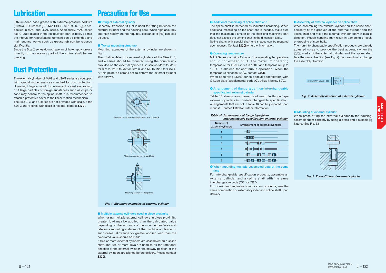
Lubrication Precaution for Use
Dust Protection
Ⅱ-121 Ⅱ-1221N=0.102kgf=0.2248lbs.1mm=0.03937inch
Lithium-soap base grease with extreme-pressure additive (Alvania EP Grease 2 [SHOWA SHELL SEKIYU K. K.]) is pre-packed in MAG and LSAG series. Additionally, MAG series has C-Lube placed in the recirculation part of balls, so that the interval for reapplicating lubricant can be extended and maintenance works such as grease job can be reduced significantly.Since the Size 2 series do not have an oil hole, apply grease directly to the raceway part of the spline shaft for re-greasing.
The external cylinders of MAG and LSAG series are equipped with special rubber seals as standard for dust protection. However, if large amount of contaminant or dust are floating, or if large particles of foreign substances such as chips or sand may adhere to the spline shaft, it is recommended to attach a protective cover to the linear motion mechanism.The Size 2, 3, and 4 series are not provided with seals. If the Size 3 and 4 series with seals is needed, contact .
❶Fitting of external cylinderGenerally, transition fit (J7) is used for fitting between the external cylinder and the housing bore. When high accuracy and high rigidity are not required, clearance fit (H7) can also be used.
❷ Typical mounting structureMounting examples of the external cylinder are shown in Fig. 1.The rotation detent for external cylinders of the Size 2, 3, and 4 series should be mounted using the countersink provided on the external cylinder. Use screws M1.2 to M1.6 for Size 2, M1.6 to M2 for Size 3, and M2 to M2.5 for Size 4. At this point, be careful not to deform the external cylinder with screws.
Fig. 1 Mounting examples of external cylinder
❸ Multiple external cylinders used in close proximityWhen using multiple external cylinders in close proximity, greater load may be applied than the calculated value depending on the accuracy of the mounting surfaces and reference mounting surfaces of the machine or device. In such cases, allowance for greater applied load than the calculated value should be made.If two or more external cylinders are assembled on a spline shaft and two or more keys are used to fix the rotational direction of the external cylinder, the keyway position of the external cylinders are aligned before delivery. Please contact
.
Rotation detent for external cylinder for size 2, 3 and 4
Mounting example for standard type
Mounting example for flange type
❹ Additional machining of spline shaft endThe spline shaft is hardened by induction hardening. When additional machining on the shaft end is needed, make sure that the maximum diameter of the shaft end machining part does not exceed the dimension d1 in the dimension table.Spline shafts with special shaft end shapes can be prepared upon request. Contact for further information.
❺ Operating temperatureMAG Series contains C-Lube. The operating temperature should not exceed 80˚C. The maximum operat ing temperature for LSAG series is 120˚C and temperature up to 100˚C is allowed for continuous operation. When the temperature exceeds 100˚C, contact .When specifying LSAG series special specification with C-Lube plate (supplemental code /Q), utilize it below 80˚C.
❻ Arrangement of flange type (non-interchangeable specification) external cylinder
Table 16 shows arrangements of multiple flange type external cylinders in non-interchangeable specification. Arrangements that are not in Table 16 can be prepared upon request. Contact for further information.
Table 16 Arrangement of flange type (Non-interchangeable specification) external cylinder
Number of external cylinders
Arrangement of external cylinders
1
2
3
4
5
6
❼ When mounting multiple assembled sets at the same time
For interchangeable specification products, assemble an external cyl inder and a spline shaft with the same interchangeable code ("S1" or "S2").For non-interchangeable specification products, use the same combination of external cylinder and spline shaft upon delivery.
❽ Assembly of external cylinder on spline shaftWhen assembling the external cylinder on the spline shaft, correctly fit the grooves of the external cylinder and the spline shaft and move the external cylinder softly in parallel direction. Rough handling may result in damaging of seals or dropping of steel balls.The non-interchangeable specification products are already adjusted so as to provide the best accuracy when the
marks of the external cylinder and the spline shaft face the same direction (see Fig. 2). Be careful not to change the assembly direction.
Fig. 2 Assembly direction of external cylinder
❾ Mounting of external cylinderWhen press-fitting the external cylinder to the housing, assemble them correctly by using a press and a suitable jig fixture. (See Fig. 3.)
Fig. 3 Press-fitting of external cylinder
JAPAN LSAG 10 H MAG10T1 H
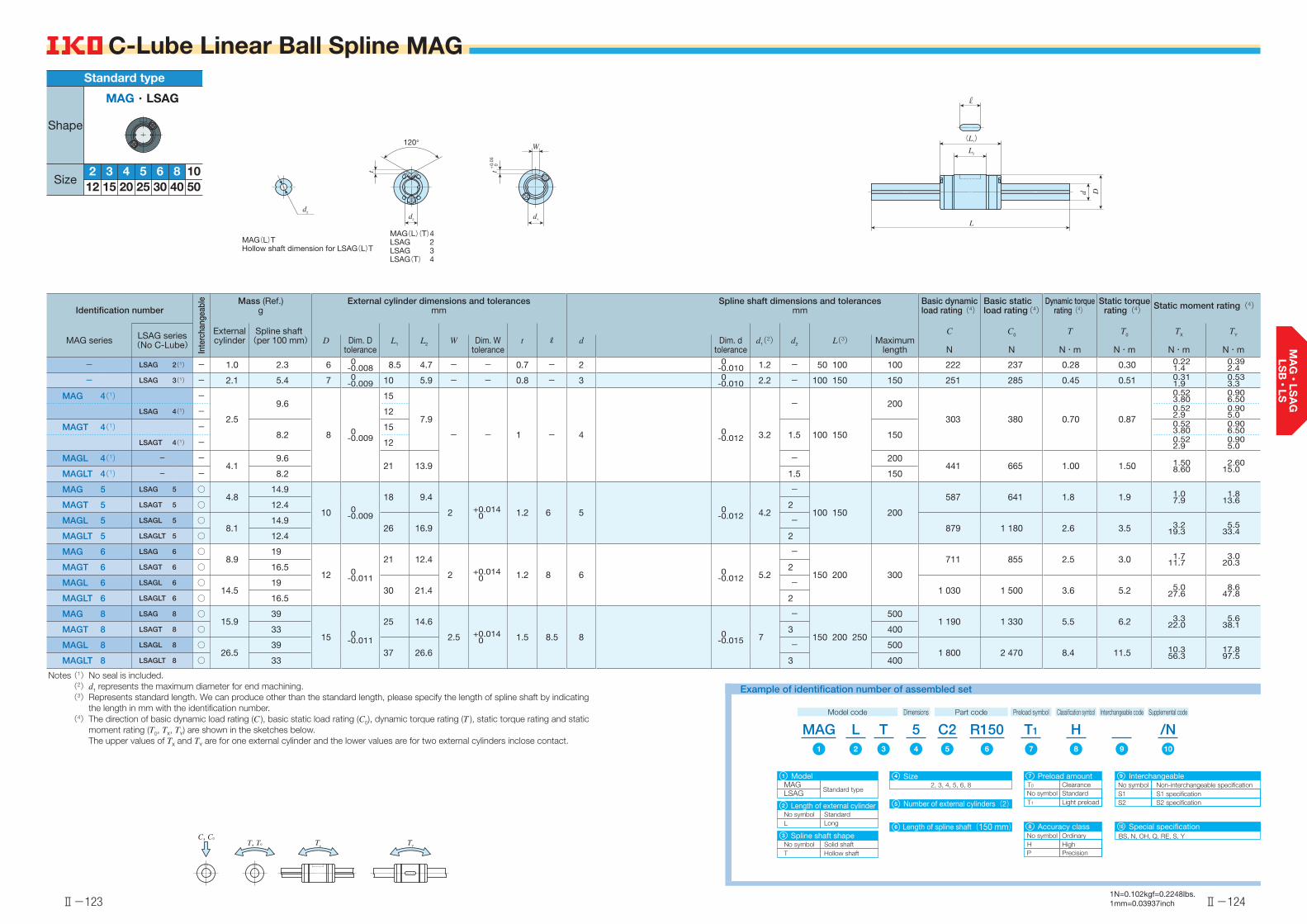
Ⅱ-123
C-Lube Linear Ball Spline MAG
TYTx
C, C0
T, T0
Ⅱ-124
C-Lube Linear Ball Spline MAG
Identification number
Inte
rcha
ngea
ble Mass (Ref.)
gExternal cylinder dimensions and tolerances
mmSpline shaft dimensions and tolerances
mmBasic dynamic load rating(4)
Basic static load rating(4)
Dynamic torquerating(4)
Static torquerating(4) Static moment rating(4)
MAG series LSAG series(No C-Lube)
External cylinder
Spline shaft(per 100 mm) L1 L2
R d1(2) d2
C
N
C0
N
T
N・m
T0
N・m
TX
N・m
TY
N・mD Dim. D
toleranceW Dim. W
tolerancet d Dim. d
toleranceL(3) Maximum
length
- LSAG 2(1) - 1.0 2.3 6 0-0.008 8.5 4.7 - - 0.7 - 2 0
-0.010 1.2 - 50 100 100 222 237 0.28 0.30 0.221.4
0.392.4
- LSAG 3(1) - 2.1 5.4 7 0-0.009 10 5.9 - - 0.8 - 3 0
-0.010 2.2 - 100 150 150 251 285 0.45 0.51 0.311.9
0.533.3
MAG 4(1) -
2.5
9.6
8 0-0.009
15
7.9
- - 1 - 4 0-0.012 3.2
-
100 150
200
303 380 0.70 0.87
0.523.80
0.906.50
LSAG 4(1) - 12 0.522.9
0.905.0
MAGT 4(1) -8.2
151.5 150
0.523.80
0.906.50
LSAGT 4(1) - 12 0.522.9
0.905.0
MAGL 4(1) - -4.1
9.621 13.9
- 200 441 665 1.00 1.50 1.50
8.602.60
15.0MAGLT 4(1) - - 8.2 1.5 150
MAG 5 LSAG 5 ○4.8
14.9
10 0-0.009
18 9.4
2 +0.0140 1.2 6 5 0
-0.012 4.2
-
100 150 200
587 641 1.8 1.9 1.07.9
1.813.6MAGT 5 LSAGT 5 ○ 12.4 2
MAGL 5 LSAGL 5 ○8.1
14.926 16.9
- 879 1 180 2.6 3.5 3.2
19.35.5
33.4MAGLT 5 LSAGLT 5 ○ 12.4 2
MAG 6 LSAG 6 ○8.9
19
12 0-0.011
21 12.4
2 +0.0140 1.2 8 6 0
-0.012 5.2
-
150 200 300
711 855 2.5 3.0 1.711.7
3.020.3MAGT 6 LSAGT 6 ○ 16.5 2
MAGL 6 LSAGL 6 ○14.5
1930 21.4
-1 030 1 500 3.6 5.2 5.0
27.68.6
47.8MAGLT 6 LSAGLT 6 ○ 16.5 2
MAG 8 LSAG 8 ○15.9
39
15 0-0.011
25 14.6
2.5 +0.0140 1.5 8.5 8 0
-0.015 7
-
150 200 250
5001 190 1 330 5.5 6.2 3.3
22.05.6
38.1MAGT 8 LSAGT 8 ○ 33 3 400
MAGL 8 LSAGL 8 ○26.5
3937 26.6
- 5001 800 2 470 8.4 11.5 10.3
56.317.897.5MAGLT 8 LSAGLT 8 ○ 33 3 400
Notes (1) No seal is included.(2) d1 represents the maximum diameter for end machining.(3) Represents standard length. We can produce other than the standard length, please specify the length of spline shaft by indicating
the length in mm with the identification number.(4) The direction of basic dynamic load rating (C ), basic static load rating (C0), dynamic torque rating (T ), static torque rating and static
moment rating (T0, TX, TY) are shown in the sketches below. The upper values of TX and TY are for one external cylinder and the lower values are for two external cylinders inclose contact.
(L1)
L2
L
d D
MAG(L)(T)4LSAG 2LSAG 3LSAG(T) 4
MAG(L)THollow shaft dimension for LSAG(L)T
d2
t
120°
d1
W
t+0.
05
0
d2
1N=0.102kgf=0.2248lbs.1mm=0.03937inch
MAG・LSAG
52 35040302520151210864
Shape
Size
Standard type
MAG R150C25 /NH
MAGModel
Standard typeLSAGNumber of external cylinders(2)
2, 3, 4, 5, 6, 8
Length of spline shaft(150 mm)
S1S2
No symbolNo symbol
Light preloadStandard
Special specificationBS, N, OH, Q, RE, S, YNo symbol
Accuracy class
H HighOrdinary
P Precision
T
Length of external cylinderStandardLongL
No symbol
L
Spline shaft shapeSolid shaftHollow shaftT
No symbol
Clearance
Example of identification number of assembled set
Model code Dimensions Part code Preload symbol
T1
Classification symbol Supplemental codeInterchangeable code
1
2
3
Interchangeable
S2 specificationS1 specificationNon-interchangeable specification
9Preload amount
T1
T0
7
108
1 72 1098543 6
4
5
6
Size

Ⅱ-125
C-Lube Linear Ball Spline MAG
TYTx
C, C0
T, T0
Ⅱ-126
C-Lube Linear Ball Spline MAG
Identification number
Inte
rcha
ngea
ble Mass (Ref.)
gExternal cylinder dimensions and tolerances
mmSpline shaft dimensions and tolerances
mmBasic dynamic load rating(3)
Basic static load rating(3)
Dynamic torquerating(3)
Static torquerating(3) Static moment rating(3)
MAG series LSAG series(No C-Lube)
External cylinder
Spline shaft(per 100 mm) L1 L2
R d1(1) d2
C
N
C0
N
T
N・m
T0
N・m
TX
N・m
TY
N・mD Dim. D
toleranceW Dim. W
tolerancet d Dim. d
toleranceL(2) Maximum
length
MAG 10 LSAG 10 ○31.5
60.5
19 0-0.013
30 18.2
3 +0.0140 1.8 11 10 0
-0.015 8.9
-
200 300 600
1 880 2 150 10.9 12.5 7.041.5
12.171.9MAGT 10 LSAGT 10 ○ 51 4
- LSAGL 10 ○56.5
60.547 34.9
- 2 850 4 040 16.6 23.4 22.7
11539.3
200- LSAGLT 10 ○ 51 4
MAG 12 LSAG 12 ○44
87.5
21 0-0.013
35 23
3 +0.0140 1.8 15 12 0
-0.018 10.9
-
200 300 400 800
2 180 2 690 14.8 18.3 10.659.1
18.3102MAGT 12 LSAGT 12 ○ 66 6
- LSAGL 12 ○76.8
87.554 42
- 3 220 4 850 21.9 33.0 32.2
15755.7
272- LSAGLT 12 ○ 66 6
- LSAG 15 ○ 59.5111 23 0
-0.01340 27
3.5 +0.0180 2 20 13.6 0
-0.018 11.6-
200 300 400 1 000 4 180 6 070 31.3 45.6 27.8
15233.2
181
- LSAGL 15 ○ 110 65 52 - 6 400 11 500 48.0 86.5 94.0449
112535
- LSAG 20 ○ 130202 30 0
-0.01650 33
4 +0.0180 2.5 26 18.2 0
-0.021 15.7- 300 400 500
600 1 000 6 600 9 040 66.0 90.4 48.6
28858.0
343
- LSAGL 20 ○ 198 71 54 - 9 270 15 100 92.7 151 127650
151774
- LSAG 25 ○ 220310 37 0
-0.01660 39.2
5 +0.0180 3 29 22.6 0
-0.021 19.4- 300 400 500
600 800 1 20011 200 14 300 139 178 92.8
551111656
- LSAGL 25 ○ 336 84 63.2 - 15 400 23 200 193 290 2291 190
2731 420
- LSAG 30 ○ 430450 45 0
-0.01670 43
7 +0.0220 4 35 27.2 0
-0.021 23.5- 400 500 600
700 1 100 1 20015 400 19 400 231 292 147
874176
1 040
- LSAGL 30 ○ 634 98 71 - 21 300 31 600 320 474 3641 900
4342 260
- LSAG 40 - 760 808 60 0-0.019 100 70.8 10 +0.022
0 4.5 55 37.2 0-0.025 33.5 - 400 500 600
700 1 100 1 200 21 300 31 600 426 632 3641 940
4342 310
- LSAG 50 - 1 140 1 320 75 0-0.019 100 66.4 15 +0.027
0 5 50 46.6 0-0.025 42.0 - 400 500 600
700 1 100 1 200 28 300 36 100 707 904 3892 300
4642 740
Notes (1) d1 represents the maximum diameter for end machining.(2) Represents standard length. We can produce other than the standard length, please specify the length of spline shaft by indicating
the length in mm with the identification number.(3) The direction of basic dynamic load rating (C ), basic static load rating (C0), dynamic torque rating (T ), static torque rating and static
moment rating (T0, TX, TY) are shown in the sketches below. The upper values of TX and TY are for one external cylinder and the lower values are for two external cylinders inclose contact.
(L1)
L2
L
d D
d1
d2
W
t+0.
05
0
MAGTHollow shaft dimension for LSAG(L)T
1N=0.102kgf=0.2248lbs.1mm=0.03937inch
52 35040302520151210864
MAG・LSAG
Shape
Size
Standard type
MAG C2 /NH
MAGModel
Standard typeLSAGNumber of external cylinders(2)
Size
Length of spline shaft(300 mm)
S1S2
No symbolNo symbolLight preloadStandard
Special specificationBS, N, OH, Q, RE, S, YNo symbol
Accuracy class
H HighOrdinary
P PrecisionPrecision
T
Length of external cylinderStandardLongL
No symbol
Spline shaft shapeSolid shaftHollow shaftT
No symbol
Example of identification number of assembled set
Model code Dimensions Part code Preload symbol
T1
Classification symbol Supplemental codeInterchangeable code
1
2
3
Interchangeable
S2 specificationS1 specificationNon-interchangeable specification
9Preload amount
T1
7
108
1 72 1098543 6
4
5
6
R30012
10, 12, 15, 20, 25, 30, 40, 50
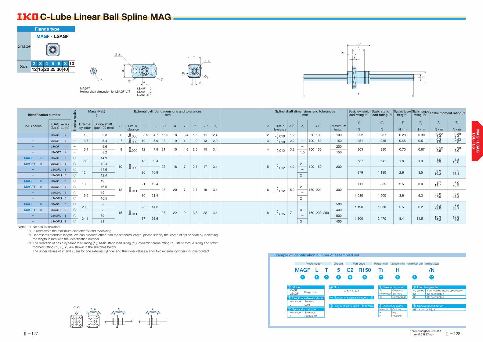
Ⅱ-127
C-Lube Linear Ball Spline MAG
C, C0
T, T0 TYTX
Ⅱ-128
C-Lube Linear Ball Spline MAG
Identification number
Inte
rcha
ngea
ble Mass (Ref.)
gExternal cylinder dimensions and tolerances
mmSpline shaft dimensions and tolerances
mmBasic dynamic load rating(4)
Basic static load rating(4)
Dynamic torquerating(4)
Static torquerating(4) Static moment rating(4)
MAG series LSAG series(No C-Lube)
External cylinder
Spline shaft(per 100 mm) L1 L2 D1 B E T pcd d3 d1(2) d2
C
N
C0
N
T
N・m
T0
N・m
TX
N・m
TY
N・mD Dim. D
toleranced Dim. d
toleranceL(3) Maximum
length
- LSAGF 2(1) - 1.9 2.3 6 0-0.008 8.5 4.7 15.5 8 3.4 1.5 11 2.4 2 0
-0.010 1.2 - 50 100 100 222 237 0.28 0.30 0.221.4
0.392.4
- LSAGF 3(1) - 3.7 5.4 7 0-0.009 10 5.9 18 9 4 1.9 13 2.9 3 0
-0.010 2.2 - 100 150 150 251 285 0.45 0.51 0.311.9
0.533.3
- LSAGF 4(1) -5.1
9.6 8 0
-0.009 12 7.9 21 10 4.6 2.5 15 3.4 4 0-0.012 3.2
-100 150
200 303 380 0.70 0.87 0.52
2.90.905.0- LSAGFT 4(1) - 8.2 1.5 150
MAGF 5 LSAGF 5 ○8.9
14.9
10 0-0.009
18 9.4
23 18 7 2.7 17 3.4 5 0-0.012 4.2
-
100 150 200
587 641 1.8 1.9 1.07.9
1.813.6MAGFT 5 LSAGFT 5 ○ 12.4 2
- LSAGFL 5 ○12
14.926 16.9
- 879 1 180 2.6 3.5 3.2
19.35.5
33.4- LSAGFLT 5 ○ 12.4 2
MAGF 6 LSAGF 6 ○13.9
19
12 0-0.011
21 12.4
25 20 7 2.7 19 3.4 6 0-0.012 5.2
-
150 200 300
711 855 2.5 3.0 1.711.7
3.020.3MAGFT 6 LSAGFT 6 ○ 16.5 2
- LSAGFL 6 ○19.5
1930 21.4
-1 030 1 500 3.6 5.2 5.0
27.68.6
47.8- LSAGFLT 6 ○ 16.5 2
MAGF 8 LSAGF 8 ○23.5
39
15 0-0.011
25 14.6
28 22 9 3.8 22 3.4 8 0-0.015 7
-
150 200 250
5001 190 1 330 5.5 6.2 3.3
22.05.6
38.1MAGFT 8 LSAGFT 8 ○ 33 3 400
- LSAGFL 8 ○34.1
3937 26.6
- 5001 800 2 470 8.4 11.5 10.3
56.317.897.5- LSAGFLT 8 ○ 33 3 400
Notes (1) No seal is included.(2) d1 represents the maximum diameter for end machining.(3) Represents standard length. We can produce other than the standard length, please specify the length of spline shaft by indicating
the length in mm with the identification number.(4) The direction of basic dynamic load rating (C ), basic static load rating (C0), dynamic torque rating (T ), static torque rating and static
moment rating (T0, TX, TY) are shown in the sketches below. The upper values of TX and TY are for one external cylinder and the lower values are for two external cylinders inclose contact.
(L1)
(E)
L2
T
L
d D
LSAGF 2LSAGF 3LSAGF(T) 4
MAGFTHollow shaft dimension for LSAGF(L)T
pcd
2−d3
B
d1
D 1
B
4−d3
d1
pcdD 1
d2
1N=0.102kgf=0.2248lbs.1mm=0.03937inch
52 3403025201512
10864
Flange type
MAGF・LSAGF
Shape
Size
MAGFModel
Flange typeLSAGFNumber of external cylinders(2)
Size2, 3, 4, 5, 6, 8
Length of spline shaft(150 mm)
S1S2
No symbolNo symbol
Light preloadStandard
Special specificationBS, N, OH, Q, RE, S, YNo symbol
Accuracy class
H HighOrdinary
P Precision
Length of external cylinderStandardLongL
No symbol
Spline shaft shapeSolid shaftHollow shaftT
No symbol
Clearance
Example of identification number of assembled set
Model code Dimensions Part code Preload symbol Classification symbol Supplemental codeInterchangeable code
1
2
3
Interchangeable
S2 specificationS1 specificationNon-interchangeable specification
9Preload amount
T1
T0
7
108
MAGF1
T1
7
L2
/N109
H8
C25
54
T3
R1506
4
5
6

Ⅱ-129
C-Lube Linear Ball Spline MAG
C, C0
T, T0 TYTX
Ⅱ-130
C-Lube Linear Ball Spline MAG
Identification number
Inte
rcha
ngea
ble Mass (Ref.)
gExternal cylinder dimensions and tolerances
mmSpline shaft dimensions and tolerances
mmBasic dynamic load rating(3)
Basic static load rating(3)
Dynamic torquerating(3)
Static torquerating(3) Static moment rating(3)
MAG series LSAG series(No C-Lube)
External cylinder
Spline shaft(per 100 mm) L1 L2 D1 B E T pcd d3 d1(1) d2
C
N
C0
N
T
N・m
T0
N・m
TX
N・m
TY
N・mD Dim. D
toleranced Dim. d
toleranceL(2) Maximum
length
MAGF 10 LSAGF 10 ○45
60.5
19 0-0.013
30 18.2
36 28 10 4.1 28 4.5 10 0-0.015 8.9
-
200 300 600
1 880 2 150 10.9 12.5 7.041.5
12.171.9MAGFT 10 LSAGFT 10 ○ 51 4
- LSAGFL 10 ○70.1
60.547 34.9
- 2 850 4 040 16.6 23.4 22.7
11539.3
200- LSAGFLT 10 ○ 51 4
MAGF 12 LSAGF 12 ○59
87.5
21 0-0.013
35 23
38 30 10 4 30 4.5 12 0-0.018 10.9
-
200 300 400 800
2 180 2 690 14.8 18.3 10.659.1
18.3102MAGFT 12 LSAGFT 12 ○ 66 6
- LSAGFL 12 ○91.8
87.554 42
- 3 220 4 850 21.9 33.0 32.2
15755.7
272- LSAGFLT 12 ○ 66 6
- LSAGF 15 ○ 77111 23 0
-0.01340 27
40 31 11 4.5 32 4.5 13.6 0-0.018 11.6
-200 300 400 1 000
4 180 6 070 31.3 45.6 27.8152
33.2181
- LSAGFL 15 ○ 128 65 52 - 6 400 11 500 48.0 86.5 94.0449
112535
- LSAGF 20 ○ 150202 30 0
-0.01650 33
46 35 14 5.5 38 4.5 18.2 0-0.021 15.7
- 300 400 500600 1 000
6 600 9 040 66.0 90.4 48.6288
58.0343
- LSAGFL 20 ○ 218 71 54 - 9 270 15 100 92.7 151 127650
151774
- LSAGF 25 ○ 255310 37 0
-0.01660 39.2
57 43 17 6.6 47 5.5 22.6 0-0.021 19.4
- 300 400 500600 800 1 200
11 200 14 300 139 178 92.8551
111656
- LSAGFL 25 ○ 371 84 63.2 - 15 400 23 200 193 290 2291 190
2731 420
- LSAGF 30 ○ 476450 45 0
-0.01670 43
65 50 21 7.5 54 6.6 27.2 0-0.021 23.5
- 400 500 600700 1 100 1 200
15 400 19 400 231 292 147874
1761 040
- LSAGFL 30 ○ 680 98 71 - 21 300 31 600 320 474 3641 900
4342 260
- LSAGF 40 - 962 808 60 0-0.019 100 70.8 93 73 26.6 12 73 9 37.2 0
-0.025 33.5 - 400 500 600700 1 100 1 200 21 300 31 600 426 632 364
1 940434
2 310
Notes (1) d1 represents the maximum diameter for end machining.(2) Represents standard length. We can produce other than the standard length, please specify the length of spline shaft by indicating
the length in mm with the identification number.(3) The direction of basic dynamic load rating (C ), basic static load rating (C0), dynamic torque rating (T ), static torque rating and static
moment rating (T0, TX, TY) are shown in the sketches below. The upper values of TX and TY are for one external cylinder and the lower values are for two external cylinders inclose contact.
(L1)
(E)
L2
T
L
d D
LSAGF(L) 30LSAGF 40
MAGFTHollow shaft dimension for LSAGF(L)T
D 1
d1
B
pcd
4−d3
B
4−d3
d1
pcdD 1
d2
1N=0.102kgf=0.2248lbs.1mm=0.03937inch
10, 12, 15, 20, 25, 30, 40
MAGF R300C212 /NH
MAGFModel
Flange typeLSAGFNumber of external cylinders(2)
Size
Length of spline shaft(300 mm)
S1S2
No symbolNo symbolLight preloadStandard
Special specificationBS, N, OH, Q, RE, S, YNo symbol
Accuracy class
H HighOrdinary
P Precision
T
Length of external cylinderStandardLongL
No symbol
Spline shaft shapeSolid shaftHollow shaftT
No symbol
Example of identification number of assembled set
Model code Dimensions Part code Preload symbol
T1
Classification symbol Supplemental codeInterchangeable code
1
2
3
Interchangeable
S2 specificationS1 specificationNon-interchangeable specification
9Preload amount
T1
7
108
1 72 1098543 6
4
5
6
52 3403025201512
10864
Flange type
MAGF・LSAGF
Shape
Size
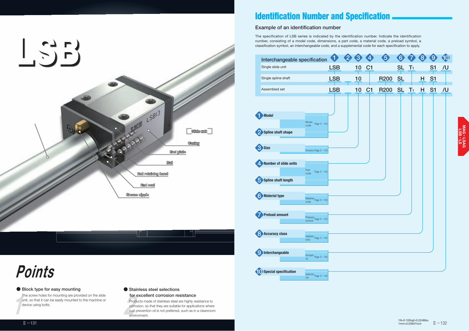
LSBBlock Type Linear Ball Spline
1Points● Block type for easy mounting
The screw holes for mounting are provided on the slide unit, so that it can be easily mounted to the machine or device using bolts. 2
● Stainless steel selections for excellent corrosion resistance
Products made of stainless steel are highly resistance to corrosion, so that they are suitable for applications where rust prevention oil is not preferred, such as in a cleanroom environment.
Spline shaft
Slide unit
Casing
End plate
Ball
Ball retaining band
Grease nipple
End seal
Slide unit
Casing
End plate
Ball
Ball retaining band
Grease nipple
End seal
Ⅱ-132Ⅱ-131
Identification Number and Specification Example of an identification number
The specification of LSB series is indicated by the identification number. Indicate the identification number, consisting of a model code, dimensions, a part code, a material code, a preload symbol, a classification symbol, an interchangeable code, and a supplemental code for each specification to apply.
1N=0.102kgf=0.2248lbs.1mm=0.03937inch
Interchangeable specification 1 2 3 4 5 6 7 8 9 10Single slide unit LSB 10 C1 SL T1 S1 /U
Single spline shaft LSB 10 R200 SL H S1
Assembled set LSB 10 C1 R200 SL T1 H S1 /U
Model1Modelcode
Page Ⅱ-133
Spline shaft shape2
Size3 Dimensions Page Ⅱ-133
Number of slide units4Partcode
Page Ⅱ-133
Spline shaft length5
Material type6 Materialcode
Page Ⅱ-133
Preload amount7 Preloadsymbol
Page Ⅱ-134
Accuracy class8 Classificationsymbol
Page Ⅱ-134
Interchangeable9 Interchangeablecode
Page Ⅱ-136
Special specification10 Supplementalcode
Page Ⅱ-136

Ⅱ-133 Ⅱ-134
Identification Number and Specification -Model・Spline Shaft Shape・Size・Slide Unit・ Number of Slide Unit・Spline Shaft Length・Material Type・Preload Amount・Accuracy Class-
1N=0.102kgf=0.2248lbs.1mm=0.03937inch
Block Type Linear Ball Spline(LSB series)
:LSB
For applicable models and sizes, see Table 1.
Solid shaftHollow shaft
:No symbol:T
For applicable models and sizes, see Table 1.
6, 8, 10, 13, 16, 20, 25 For applicable models and sizes, see Table 1.
:C○ For an assembled set, indicates the number of slide units assembled on a spline shaft. For a single slide unit, only "C1" is specified.
:R○ The spline shaft length is indicated in mm.For standard and maximum lengths, see the dimension table.
High carbon steel madeStainless steel made
:No symbol:SL
For applicable models and sizes, see Table 1.
Model1
Spline shaft shape2
Size3
Number of slide units4
Spline shaft length5
Material type6
StandardLight preload
:No symbol:T1
Specify this item for an assembled set or a single slide unit.For details of the preload amount, see Table 2.For applicable preload types, see Table 3.
Preload amount7
Table 1 Models and sizes of LSB series
Material Shape ModelSize
6 8 10 13 16 20 25
Hig
h ca
rbon
ste
el
mad
e
LSB ○(1) ○(1) ○(1) ○ ○ ○ ○
LSBT ○(1) ○(1) ○(1) ○ ○ ○ ○
Sta
inle
ss s
teel
m
ade
LSB…SL ○ ○ ○ - - - -
Note (1) Slide units of size 6, 8, and 10 series are stainless steel-made only. When high carbon steel-made is specified for an assembled set, only the spline shaft will be high carbon steel-made.
Remark: The LSB series are all interchangeable specification. Non-interchangeable specification is not available.
Solid shaft
Hollow shaft
Solid shaft
Table 2 Preload amountItem
Preloadtype
Preload symbol
Preload amount
NOperational conditions
Standard (No symbol) 0(1) ・ Light and precise motion
Light preload T1 0.02 C0
・ Almost no vibrations・ Load is evenly balanced・ Light and precise motion
Note (1) Indicates zero or minimal amount of preload.Remark: C0 indicates the basic static load rating.
Table 3 Application of preload
Size
Preload type(preload symbol)
Standard Light preload(No symbol) (T1)
6 ○ - 8 ○ ○10 ○ ○13 ○ ○16 ○ ○20 ○ ○25 ○ ○
OrdinaryHigh
:No symbol:H
Specify this item for an assembled set or a single spline shaft.For details of accuracy class, see Fig. 1, Table 4 and Table 5.
Accuracy class8
Fig. 1 Accuracy
H±0
.015
N±0.020
unit: mm
C
D
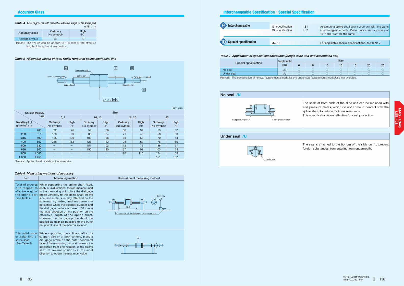
Ⅱ-135 Ⅱ-136
-Accuracy Class- -Interchangeable Specification・Special Specification-
1N=0.102kgf=0.2248lbs.1mm=0.03937inch
No seal /N
End seals at both ends of the slide unit can be replaced with end pressure plates, which do not come in contact with the spline shaft, to reduce frictional resistance.This specification is not effective for dust protection.
Under seal /U
The seal is attached to the bottom of the slide unit to prevent foreign substances from entering from underneath.
End pressure plate End pressure plate
Under seal
S1 specificationS2 specification
:S1:S2
Assemble a spline shaft and a slide unit with the same interchangeable code. Performance and accuracy of "S1" and "S2" are the same.
/N, /U For applicable special specifications, see Table 7.
Interchangeable9
Special specification10
Table 7 Application of special specifications (Single slide unit and assembled set)
Special specificationSupplemental
code
Size
6 8 10 13 16 20 25
No seal /N ○ ○ ○ ○ ○ ○ ○Under seal /U ○ ○ ○ ○ ○ ○ ○
Remark: The combination of no seal (supplemental code/N) and under seal (supplemental code/U) is not available.
Table 4 Twist of grooves with respect to effective length of the spline part unit: μm
Accuracy classOrdinary
(No symbol)High(H)
Allowable value 33 13
Remark: The values can be applied to 100 mm of the effective length of the spline at any position.
Table 5 Allowable values of total radial runout of spline shaft axial line
unit: μm
Size and accuracy class
Overall length ofspline shaft mm
Size
6, 8 10, 13 16, 20 25
Ordinary(No symbol)
High(H)
Ordinary(No symbol)
High(H)
Ordinary(No symbol)
High(H)
Ordinary(No symbol)
High(H)
- 200 72 46 59 36 56 34 53 32200 315 133 89 83 54 71 45 58 39315 400 185 126 103 68 83 53 70 44400 500 236 163 123 82 95 62 78 50500 630 - - 151 102 112 75 88 57630 800 - - 190 130 137 92 103 68800 1 000 - - - - 170 115 124 83
1 000 1 250 - - - - - - 151 102
Remark: Applied to all models of the same size.
Measuring unitA D B
C
A-B
Parts mounting part
Support part
Spline part Parts mounting part
Support part
D C
Table 6 Measuring methods of accuracyItem Measuring method Illustration of measuring method
Twist of grooves with respect to effective length of the spl ine part (see Table 4)
While supporting the spline shaft fixed, apply a unidirectional torsion moment load to the measuring unit, place the dial gage probe vertically to the spline shaft on the side face of the sunk key attached on the externa l cy l inder, and measure the deflection when the external cylinder and the dial gage probe are moved 100 mm in the axial direction at any position on the effect ive length of the spl ine shaft . However, the dial gage probe should be applied as near as possible to the outer peripheral face of the external cylinder.
Total radial runout of ax ia l l ine of spline shaft(See Table 5)
While supporting the spline shaft at its support part or at both centers, place a dial gage probe on the outer peripheral face of the measuring unit and measure the deflection from one rotation of the spline shaft at several positions in the axial direction to obtain the maximum value.
Reference block for dial gage probe movement
Sunk key
100
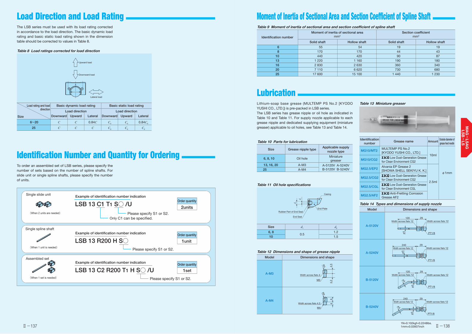
Ⅱ-137 Ⅱ-138
Load Direction and Load Rating
Identification Number and Quantity for Ordering
Lubrication
Moment of Inertia of Sectional Area and Section Coefficient of Spline Shaft
Lithium-soap base grease (MULTEMP PS No.2 [KYODO YUSHI CO., LTD.]) is pre-packed in LSB series.The LSB series has grease nipple or oil hole as indicated in Table 10 and Table 11. For supply nozzle applicable to each grease nipple and dedicated supplying equipment (miniature greaser) applicable to oil holes, see Table 13 and Table 14.
The LSB series must be used with its load rating corrected in accordance to the load direction. The basic dynamic load rating and basic static load rating shown in the dimension table should be corrected to values in Table 8.
To order an assembled set of LSB series, please specify the number of sets based on the number of spline shafts. For slide unit or single spline shafts, please specify the number of units.
Table 8 Load ratings corrected for load direction
Load rating and load direction
Size
Basic dynamic load rating Basic static load rating
Load direction Load direction
Downward Upward Lateral Downward Upward Lateral
6~20 C C 0.84C C0 C0 0.84C0
25 C C C C0 C0 C0
Lateral load
Upward load
Downward load
1N=0.102kgf=0.2248lbs.1mm=0.03937inch
Table 10 Parts for lubrication
Size Grease nipple typeApplicable supply
nozzle type
6, 8, 10 Oil holeMiniaturegreaser
13, 16, 20 A-M3 A-5120V A-5240VB-5120V B-5240V25 A-M4
Table 11 Oil hole specifications
Size d1 d2
6, 80.5
1.210 1.5
Rubber Part of End Seal
End Seal
Casing
End Plate
d 1
d 2
Table 14 Types and dimensions of supply nozzleModel Dimensions and shape
A-5120V
A-5240V
B-5120V
B-5240V
φ5 PT1/8
120 29Width across flats 12Width across flats 12
φ5
PT1/8
240 29Width across flats 12Width across flats 12
φ5
φ5
PT1/8
120 29Width across flats 12Width across flats 12
φ5 PT1/8
240 29Width across flats 12Width across flats 12
φ5
Table 12 Dimensions and shape of grease nippleModel Dimensions and shape
A-M3
A-M4
Width across flats 4
R3
M3
4.5
4.2
Width across flats 4.5
R3
M4
64
Single slide unit Example of identification number indication
LSB 13 C1 T1 S○ /U
Only C1 can be specified.
Order quantity
2units
Single spline shaftExample of identification number indication
LSB 13 R200 H S○ 1unit
Assembled setExample of identification number indication
LSB 13 C2 R200 T1 H S○ /U 1set
Order quantity
Order quantity
(When 2 units are needed)
(When 1 unit is needed)
(When 1 set is needed)
Please specify S1 or S2.
Please specify S1 or S2.
Please specify S1 or S2.
Table 9 Moment of inertia of sectional area and section coefficient of spline shaft
Identification number
Moment of inertia of sectional areamm4
Section coefficientmm3
Solid shaft Hollow shaft Solid shaft Hollow shaft
6 55 54 19 19 8 170 170 44 4310 440 420 90 8713 1 220 1 160 190 18016 2 830 2 630 360 34020 7 110 6 620 730 68025 17 600 15 100 1 440 1 230
Table 13 Miniature greaser
Identification number
Grease name AmountOutside diameter of grease feed needle
MG10/MT2MULTEMP PS No.2[KYODO YUSHI CO., LTD.]
10ml
φ1mm
MG10/CG2 Low Dust-Generation Grease
for Clean Environment CG2
MG2.5/EP2Alvania EP Grease 2[SHOWA SHELL SEKIYU K. K.]
2.5mlMG2.5/CG2
Low Dust-Generation Grease for Clean Environment CG2
MG2.5/CGL Low Dust-Generation Grease
for Clean Environment CGL
MG2.5/AF2 Anti-Fretting Corrosion
Grease AF2

Ⅱ-139 Ⅱ-140
Precaution for Use Dust Protection ❶ Mounting surface, reference mounting surface and
typical mounting structureWhen mounting the LSB, properly align the reference mounting surface D of the slide unit with the reference mounting surface of the table and fix it. (See Fig. 2)Outside diameter surface of the spline shaft, reference mounting surface D and mounting surface C are precisely ground. Machining the mounting surface of the table and bed, such as machine or device, to high accuracy and mounting them properly will ensure stable linear motion with high accuracy.Reference mounting surface of the slide unit is the opposite side of the mark. (See Fig. 3)
Fig. 2 Reference mounting surface and typical mounting structure
Fig. 3 Reference mounting surface
D
C
Slide unit
Spline shaft Mark
Reference mounting surface
D
❷ Shoulder height of reference mounting surfaceFor the opposite corner of the mating reference mounting, it is recommended to have relieved fillet as indicated in Fig. 4. Recommended value for the shoulder height on the mating side is indicated in Table 15.
Fig. 4 Corner of the mating reference mounting
Table 15 Shoulder height
unit: mm
Size Shoulder height
6 2
8 2.510 313 3.5
16 4
20 525 6
❸ Additional machining of spline shaft endThe spline shaft is hardened by induction hardening. When additional machining on the shaft end is needed, make sure that the maximum diameter of the shaft end machining part does not exceed the dimension d1 in the dimension table.Spline shafts with special shaft end shapes can be prepared upon request. Contact for further information.
❹ Multiple slide units used in close proximityWhen using multiple slide units in close proximity, greater load may be applied than the calculated value depending on the accuracy of the mounting surfaces and reference mounting surfaces of the machine or device. In such cases, allowance for greater applied load than the calculated value should be made.In addition, special products with variation between H and N dimensions aligned can be prepared upon request. Contact
for further information.
h 1
❺ Operating temperatureThe maximum operating temperature is 120°C and temperature up to 100°C is allowed for continuous operation. When the temperature exceeds 100°C, contact
.
❻ When mounting multiple assembled sets at the same time
Assemble a slide unit and a spline shaft with the same interchangeable code ("S1" or "S2").
❼ Assembly of slide unit on spline shaftWhen inserting a slide unit to the spline shaft, handle with care not to pry open the shaft and drop the balls.
❽ Tightening torque for fixing screwTypical tightening torque for mounting of the LSB series to the steel mating member material is indicated in Table 16. When vibration and shock of the machine or device are large, fluctuating load is large, or moment load is applied, fix it by using the torque 1.2 to 1.5 times larger than the value indicated in the table as necessary. If the mating member material is cast iron or aluminum alloy, reduce the tightening torque depending on the strength characteristics of the mating member material.
Table 16 Tightening torque for fixing screw
Bolt size
Tightening torque N・m
High carbon steel-made screw
Stainless steel-made screw
M2×0.4 0.50 0.31M3×0.5 1.8 1.1M4×0.7 4.1 -M5×0.8 8.0 -M6×1 13.6 -
Note (1) The tightening torque is calculated based on strength division 12.9 and property division A2-70.
The slide units of LSB series are equipped with end seals as standard for dust protection. However, if large amount of contaminant or dust are floating, or if large particles of foreign substances such as chips or sand may adhere to the spline shaft, it is recommended to attach a protective cover to the linear motion mechanism.
1N=0.102kgf=0.2248lbs.1mm=0.03937inch

Ⅱ-141
Block Type Linear Ball Spline
C, C0 T, T0 TX TY
Ⅱ-142
Block Type Linear Ball Spline
Identification number
Inte
rcha
ngea
ble Mass (Ref.)
gDimensions of assembly
mmDimensions of slide unit
mmSpline shaft dimensions and tolerances
mmBasic dynamic(4)
load ratingBasic static(4)
load ratingDynamic(4)torque rating
Static(4)torque rating Static moment rating(4)
Slide unit Spline shaft
(per 100 mm) H H1 H2 N W2 W3 W4 L1 L2 L3 L4
nーM1×depth
H3 d1(2) d2
C
N
C0
N
T
N・m
T0
N・m
TX
N・m
TY
N・md Dim. d
tolerance(1)L(3) Maximum
length
LSB 6 ○
7.6
21.2
6 1.1 9 6.5 13 8 2.5 20 12.5 ー 2ーM2× 3 1.5 6 0-0.012 3.7
ー
150 200 300675 1 090 2.0 3.3 2.3
13.61.9
11.4LSBT 6 ○ 18.8 2
LSB 6 …SL ○ 21.2 ー 540 875 1.6 2.6 1.810.9
1.59.1
LSB 8 ○
18
37.6
8 1.3 12 9 18 12 3 25 8 15.6 ー 4ーM3× 3 1.5 8 0-0.015 5
ー
150 200 250
5001 340 1 890 5.4 7.6 4.7
30.23.9
25.4LSBT 8 ○ 32.1 3 400
LSB 8 …SL ○ 37.6 ー 500 1 070 1 510 4.3 6.1 3.724.2
3.120.3
LSB 10 ○
34
59.7
10 1.9 15 10.5 21 15 3 31 10 21.2 ー 4ーM3× 4 2.5 10 0-0.015 6.9
ー
200 300 6001 810 2 760 9.1 13.8 9.1
53.07.6
44.5LSBT 10 ○ 49.8 4
LSB 10 …SL ○ 59.7 ー 1 450 2 200 7.3 11.0 7.342.4
6.135.6
LSB 13 ○62
10013 3.2 19.5 14 28 20 4 35 15 22.4 40 4ーM3× 5 3.2 13 0
-0.018 9ー
200 300 400 800 3 330 4 290 21.7 27.9 15.496.3
12.980.8LSBT 13 ○ 77.9 6
LSB 16 ○112
15216 4.2 24 16.5 33 25 4 43 20 28.8 48 4ーM4× 6 4 16 0
-0.018 11.4ー
200 300 400 1 000 4 980 6 490 39.9 51.9 29.7176
24.9148LSBT 16 ○ 113 8
LSB 20 ○215
24020 5.8 30 20 40 30 5 53 25 37.3 58 4ーM5×10 5 20 0
-0.021 15ー 300 400 500
600 1 000 6 670 9 080 66.7 90.8 52.7299
44.2251LSBT 20 ○ 178 10
LSB 25 ○403
37625 6 37.5 26 52 40 6 67 30 41.8 70 4ーM6×12 6 25 0
-0.021 19.3ー 300 400 500
600 800 1 200 10 500 13 400 136 175 95.6566
95.6566LSBT 25 ○ 237 15
Notes (1) This does not apply to hollow shaft (LSBT). (2) d1 represents the maximum diameter for end machining. (3) Represents standard length. We can produce other than the standard length, please specify the length of spline shaft by indicating
the length in mm with the identification number. (4) The direction of basic dynamic load rating (C), basic static load rating (C0), dynamic torque rating (T), static torque rating and static
moment rating (T0, TX, TY) are shown in the sketches below.The upper values of TX and TY are for one slide unit and the lower values are for two slide units in close contact.
Remarks 1. Block type Linear Ball Spline are all interchangeable specification. 2. LSB 6, LSBT 6, LSB 6…SL, LSB 8, LSBT 8, LSB 8…SL, LSB 10, LSBT 10, and LSB 10…SL are provided with oil holes.
The specifications of grease nipple and oil hole are shown in Table 11 and Table 12 on page Ⅱ-138.
d2
N
H1
H
H2
W2
W3W4
H3
n−M1×depth
d1
Hollow shaft dimension for LSBT
(L4)
(L1)
L3
L2
L
d
1N=0.102kgf=0.2248lbs.1mm=0.03937inch
Number of slide units (2 pcs.)
Length of spline shaft(300 mm)
S1S2
No symbolLight preloadStandard
Special specificationNo symbol
Accuracy class
H HighOrdinary
T1
Interchangeable
S2 specificationS1 specification
9Preload amount
T1
7
108
1 72 1098543 6
4
5
Model code
LSBDimensions Part code Preload symbol Classification symbol Supplemental code
R300C210 /NHInterchangeable code
S1
LSBModel
N, U
Spline shaft shapeSolid shaftHollow shaftT
No symbol
Size6, 8, 10, 13, 16, 20, 25
Material code
SL
Material typeHigh carbon steel madeStainless steel madeSL
No symbol
1
2
3
6
Example of identification number of assembled set
13
Shape
Size 6 8 25201610
LSB
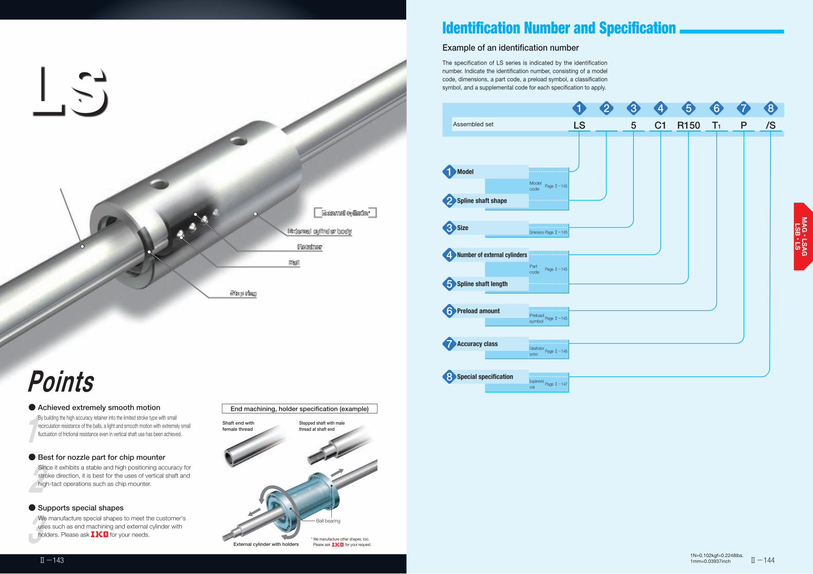
Ball bearing
LSStroke Ball Spline
3● Supports special shapes
We manufacture special shapes to meet the customer's uses such as end machining and external cylinder with holders. Please ask for your needs.
1Points● Achieved extremely smooth motion
By building the high accuracy retainer into the limited stroke type with small recirculation resistance of the balls, a light and smooth motion with extremely small fluctuation of frictional resistance even in vertical shaft use has been achieved.
End machining, holder specification (example)
2● Best for nozzle part for chip mounter
Since it exhibits a stable and high positioning accuracy for stroke direction, it is best for the uses of vertical shaft and high-tact operations such as chip mounter.
External cylinder
External cylinder body
Retainer
Ball
Stop ring
External cylinder
External cylinder body
Retainer
Ball
Stop ring
Spline shaft
External cylinder with holders
Stepped shaft with male thread at shaft end
* We manufacture other shapes, too. Please ask for your request.
Shaft end with female thread
Ⅱ-1441N=0.102kgf=0.2248lbs.1mm=0.03937inchⅡ-143
Identification Number and Specification Example of an identification number
The specification of LS series is indicated by the identification number. Indicate the identification number, consisting of a model code, dimensions, a part code, a preload symbol, a classification symbol, and a supplemental code for each specification to apply.
1 2 3 4 5 6 7 8Assembled set LS 5 C1 R150 T1 P /S
Model1Model code
Page Ⅱ-145
Spline shaft shape2
Size3 Dimensions Page Ⅱ-145
Number of external cylinders4Part code
Page Ⅱ-145
Spline shaft length5
Preload amount6 Preload symbol
Page Ⅱ-145
Accuracy class7 Classification symbol
Page Ⅱ-146
Special specification8 Supplemental code
Page Ⅱ-147
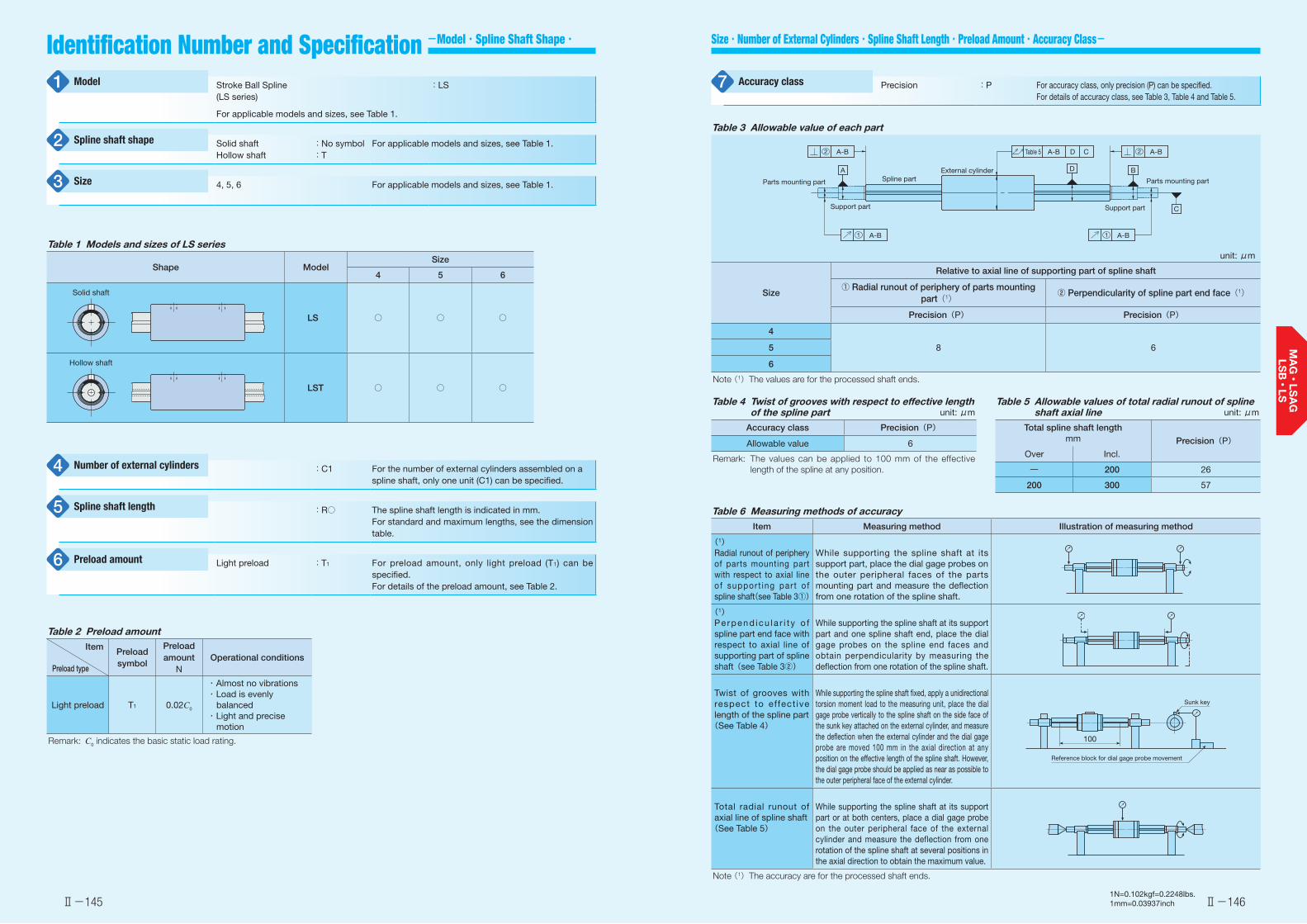
Ⅱ-145 Ⅱ-1461N=0.102kgf=0.2248lbs.1mm=0.03937inch
Size・Number of External Cylinders・Spline Shaft Length・Preload Amount・Accuracy Class-Identification Number and Specification -Model・Spline Shaft Shape・
Stroke Ball Spline(LS series)
:LS
For applicable models and sizes, see Table 1.
Solid shaftHollow shaft
:No symbol:T
For applicable models and sizes, see Table 1.
4, 5, 6 For applicable models and sizes, see Table 1.
Model1
Spline shaft shape2
Size3
:C1 For the number of external cylinders assembled on a spline shaft, only one unit (C1) can be specified.
:R○ The spline shaft length is indicated in mm.For standard and maximum lengths, see the dimension table.
Light preload :T1 For preload amount, only light preload (T1) can be specified.For details of the preload amount, see Table 2.
Number of external cylinders4
Spline shaft length5
Preload amount6
Table 1 Models and sizes of LS series
Shape ModelSize
4 5 6
LS ○ ○ ○
LST ○ ○ ○
Solid shaft
Hollow shaft
Precision :P For accuracy class, only precision (P) can be specified.For details of accuracy class, see Table 3, Table 4 and Table 5.
Accuracy class7
Table 3 Allowable value of each part
unit: μm
Size
Relative to axial line of supporting part of spline shaft
① Radial runout of periphery of parts mounting part(1)
② Perpendicularity of spline part end face(1)
Precision(P) Precision(P)
4
8 65
6
Note (1) The values are for the processed shaft ends.
Support part
Parts mounting part
External cylinderSpline part
Support part
Parts mounting part
A-BA-B
A-B
A
A-B
A-BTable 5
D
D
B
C
C2
1 1
2
Table 4 Twist of grooves with respect to effective length of the spline part unit: μm
Accuracy class Precision(P)
Allowable value 6
Remark: The values can be applied to 100 mm of the effective length of the spline at any position.
Table 5 Allowable values of total radial runout of spline shaft axial line unit: μm
Total spline shaft lengthmm Precision(P)
Over Incl.
― 200 26
200 300 57
Table 6 Measuring methods of accuracyItem Measuring method Illustration of measuring method
(1)Radial runout of periphery of parts mounting part with respect to axial line o f suppor t ing par t o f spline shaft(see Table 3①)
While supporting the spline shaft at its support part, place the dial gage probes on the outer peripheral faces of the parts mounting part and measure the deflection from one rotation of the spline shaft.
(1)Perpend icu l a r i t y o f spline part end face with respect to axial line of supporting part of spline shaft(see Table 3②)
While supporting the spline shaft at its support part and one spline shaft end, place the dial gage probes on the spline end faces and obtain perpendicularity by measuring the deflection from one rotation of the spline shaft.
Twist of grooves with respect to effect ive length of the spline part(See Table 4)
While supporting the spline shaft fixed, apply a unidirectional torsion moment load to the measuring unit, place the dial gage probe vertically to the spline shaft on the side face of the sunk key attached on the external cylinder, and measure the deflection when the external cylinder and the dial gage probe are moved 100 mm in the axial direction at any position on the effective length of the spline shaft. However, the dial gage probe should be applied as near as possible to the outer peripheral face of the external cylinder.
Total radial runout of axial line of spline shaft(See Table 5)
While supporting the spline shaft at its support part or at both centers, place a dial gage probe on the outer peripheral face of the external cylinder and measure the deflection from one rotation of the spline shaft at several positions in the axial direction to obtain the maximum value.
Note (1) The accuracy are for the processed shaft ends.
Reference block for dial gage probe movement
Sunk key
100
Table 2 Preload amountItem
Preload type
Preload symbol
Preload amount
NOperational conditions
Light preload T1 0.02C0
・ Almost no vibrations・ Load is evenly
balanced・ Light and precise
motion
Remark: C0 indicates the basic static load rating.

Ⅱ-147 Ⅱ-1481N=0.102kgf=0.2248lbs.1mm=0.03937inch
Precaution for Use
-Special Specification- Lubrication Dust Protection
Moment of Inertia of Sectional Area and Section Coefficient of Spline Shaft
Allowable Load
Load Direction and Load Rating
Grease is not pre-packed in the LS series, so please perform adequate lubrication as needed.Upon delivery, anti-rust oil is applied. Therefore, perform cleaning with clean solution before mounting and apply high-quality lubrication oil or grease before use. For grease lubrication, use of high-quality lithium-soap base grease is recommended.Since no grease nipple or oil hole is provided, apply grease directly to the raceway part of the spline shaft when supplying the grease.
No dust protection seal is provided for LS series. For applications in other than clean environment, cover the entire unit with a protective case, etc. to prevent harmful foreign substances such as dust and particles from outside from entering.
❶ Fitting of external cylinderGenerally, transition fit (J7) is used for fitting between the external cylinder and the housing bore. When high accuracy and high rigidity are not required, clearance fit (H7) can also be used.
❷ Typical mounting structureMounting examples of the external cylinder are shown in Fig. 1.The rotation detent for external cylinder can be made by using the screw hole provided on the external cylinder. The fixing thread depth must not exceed the maximum fixing thread depth indicated in the dimension table. Since the screw hole for the external cylinder is penetrated, the spline shaft or retainer will be pushed by the screw if the fixing thread depth is too deep, and the running accuracy and life will be adversely affected.Since there is no built-in mechanical stopper to regulate linear motion, install a stopper mechanism in proximity if risk of overstroke exists.
Fig. 1 Mounting example
❸ Handling upon operationStroke should be used within the effective stroke range shown in the dimension table.The retainer may be deviated from the right position due to offset load or irregular and high-velocity motion, etc. Fully stroke it once in certain operating time or certain number of reciprocating motion to correct the retainer position.
❹ Additional machining of spline shaft endThe spline shaft is hardened by induction hardening. When additional machining on the shaft end is needed, make sure that the maximum diameter of the shaft end machining part does not exceed the dimension d1 in the dimension table.Spline shafts with special shaft end shapes can be prepared upon request. Contact for further information.
❺ Operating temperatureThe maximum operating temperature for LS series is 120°C and temperature up to 100°C is allowed for continuous operation. When the temperature exceeds 100°C, contact .
❻ Assembly of external cylinder on spline shaftWhen assembling the external cylinder on the spline shaft, correctly fit the grooves of the external cylinder and the spline shaft and move the external cylinder softly in parallel direction. Rough handling may result in dropping of steel balls. After assembling, correct the position of the retainer to be in the center of the external cylinder. After assembling the external cylinder to the housing, insert the shaft softly. Move the retainer as well as the shaft until they contact one side of the surface and stop. Then push the shaft softly not to damage balls or raceway to the position a half of the maximum stroke length and return it by the same length (a half of the maximum stroke) so that the retainer is positioned regularly at the center of the external cylinder.The products are already adjusted so as to provide the best accuracy when the marks of the external cylinder and the spline shaft face the same direction. Be careful not to change the assembly direction. (See Fig. 2)
Fig. 2 Mounting direction of external cylinder
❼ Mounting of external cylinderWhen press-fitting the external cylinder to the housing, assemble them correctly by using a press and a suitable jig fixture. (See Fig. 3)
Fig. 3 Press-fitting of external cylinder
Allowable load refers to load of smooth rolling motion on contact surface to which maximum contact stress is applied and the sum of whose elastic deformation of rolling elements and raceway is small.Therefore, use applied load within the allowable load range if very smooth rolling motion and high accuracy are required.
The LS series must be used with its load rating corrected in accordance to the load direction. The basic dynamic load rating and basic static load rating shown in the dimension table should be corrected to values in Table 7.
Stainless steel spline shaft /S Applicable to the solid shaft of size 5 and 6.Special specification8
Table 8 Moment of inertia of sectional area and section coefficient of spline shaft
Size
Moment of inertia of sectional area
mm4
Section coefficientmm3
Solid shaftHollow shaft
Solid shaftHollow shaft
4 12 12 6 6
5 29 29 12 12
6 61 61 21 21
Stainless steel spline shaft /S
The material of the solid spline shaft is changed to stainless steel. The load rating will change to a value obtained by multiplying the load rating for the steel spline shaft by a factor of 0.8.
Table 7 Load ratings corrected for load direction
Load rating and load direction
Size
Basic dynamic load rating Basic static load rating
Load direction Load direction
Downward Upward Lateral Downward Upward Lateral
4, 5, 6 C C 1.47C C0 C0 1.73C0
Upward load
Downward load
Lateral load

Ⅱ-149
Stroke Ball Spline
Ⅱ-150
Stroke Ball Spline
T, T0C, C0, F TX TY
Identification number
Inte
rcha
ngea
ble Mass (Ref.)
gExternal cylinder dimensions and tolerances
mm
Spline shaft dimensions and tolerances
mm
Effective stroke length
Maximum stroke length
MountingMaximum
dimensions
Basic dynamic
load rating(3)
Basic static load rating(3)
Allowable load(3)
Dynamic torque
rating(3)
Static torque
rating(3)
Static moment rating(3)
External cylinder
Spline shaft(per 100 mm) L1 L2 M
Maximum fixing thread
depthd1(1) d2
mm mm
Da
mm
C
N
C0
N
F
N
T
N・m
T0
N・m
TX
N・m
TY
N・mD Dim. D
toleranced Dim. d
toleranceL(2) Maximum
length
LS 4 -5.7
9.6 8 0
-0.009 24 10 M2 1.3 4 0-0.012 3.2
-100 150
20010 13.2 5 285 380 127 0.66 0.87 0.88 1.5
LST 4 - 8.6 1.5 150
LS 5 -8.9
14.910 0
-0.009 27 12 M2 1.4 5 0-0.012 4.2
-100 150 200 10 14 7 616 748 249 1.8 2.2 2.0 3.5
LST 5 - 12.4 2
LS 6 -10.9
1911 0
-0.011 29 15 M2 1.4 6 0-0.012 5.2
-150 200 300 10 13.6 8 673 855 285 2.4 3.0 2.6 4.4
LST 6 - 16.5 2
Notes (1) d1 represents the maximum diameter for end machining.(2) Represents standard length. We can produce other than the standard length, please specify the length of spline shaft by indicating
the length in mm with the identification number.(3) The direction of basic dynamic load rating (C), basic static load rating (C0), allowable load (F), dynamic torque rating (T ), static torque
rating and static moment rating (T0, TX, TY) are shown in the sketches below.Remark: Grease is not pre-packed, so please perform adequate lubrication as needed.
L2
L1
L
M
d D Da
d2
d1
Hollow shaft dimension for LST
1N=0.102kgf=0.2248lbs.1mm=0.03937inch
5
Shape
Size 4 6
LS
Model code
LSDimensions Part code Preload symbol Classification symbol Supplemental code
R150C15 /SP
LSModel
Length of spline shaft(150 mm) Special specificationS
PAccuracy class
Precision
Spline shaft shapeSolid shaftHollow shaftT
No symbol
Size4, 5, 6
Light preload
Number of external cylinders(1)
T1
1 65432 87
T1
1 4
5
6
2
3
7
8
Preload amount
Example of identification number of assembled set

Ⅱ-151 Ⅱ-152
Linear Bushing
Linear Bushing GLinear BushingMiniature Linear Bushing
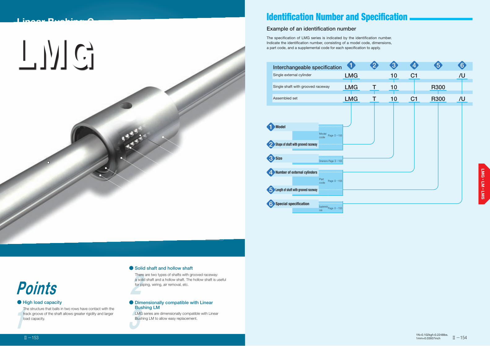
1N=0.102kgf=0.2248lbs.1mm=0.03937inch
2● Solid shaft and hollow shaft
There are two types of shafts with grooved raceway: a solid shaft and a hollow shaft. The hollow shaft is useful for piping, wiring, air removal, etc.
1Points● High load capacity
The structure that balls in two rows have contact with the track groove of the shaft allows greater rigidity and larger load capacity. 3LMG series are dimensionally compatible with Linear
Bushing LM to allow easy replacement.
Linear Bushing G
LMG
● Dimensionally compatible with Linear Bushing LM
External cylinder body
Retainer
Ball
Ring
End plate
Stop ring
External cylinder
Shaft with grooved raceway
1N=0.102kgf=0.2248lbs.1mm=0.03937inch
Identification Number and Specification
Ⅱ-154Ⅱ-153
Example of an identification number
The specification of LMG series is indicated by the identification number. Indicate the identification number, consisting of a model code, dimensions, a part code, and a supplemental code for each specification to apply.
Interchangeable specification 1 2 3 4 5 6Single external cylinder LMG 10 C1 /U
Single shaft with grooved raceway LMG T 10 R300
Assembled set LMG T 10 C1 R300 /U
Model1Model code
Page Ⅱ-155
Shape of shaft with grooved raceway2
Size3 Dimensions Page Ⅱ-155
Number of external cylinders4Part code
Page Ⅱ-155
Length of shaft with grooved raceway5
Special specification6 Supplemental code
Page Ⅱ-155

1N=0.102kgf=0.2248lbs.1mm=0.03937inchⅡ-155 Ⅱ-156
Accuracy
Internal Clearance
Identification Number and Specification -Model・Shape of Shaft・Size・Number of External Cylinders・Length of Shaft・Special Specification-
The internal clearance of LMG series is approximately 10 μm.
Linear Bushing G(LMG series)
: LMG
For applicable models and sizes, see Table 1.
Solid shaftHollow shaft
: No symbol: T
For applicable models and sizes, see Table 1.
6, 8, 10, 13, 16, 20 Indicate the shaft diameter in mm.For applicable models and sizes, see Table 1.
Model1
Shape of shaft with grooved raceway2
Size3
: C○ For an assembled set, indicates the number of external cylinders assembled on a shaft with grooved raceway. For a single external cylinder, only "C1" is specified.
: R○ Indicate the length of the shaft with grooved raceway in mm.For standard and maximum lengths, see the dimension table.
With end seal /U Applicable to all models and sizes.
Number of external cylinders4
Length of shaft with grooved raceway5
Special specification6
Table 1 Models and sizes of LMG series
Shape ModelSize
6 8 10 13 16 20
LMG ○ ○ ○ ○ ○ ○
LMGT ○ ○ ○ ○ ○ ○
Remark: LMG series are all interchangeable specification. Non-interchangeable specification is not available.
Solid shaft
Hollow shaft
Table 3 Allowable values of total radial runout of shaft with grooved raceway axial line unit: μm
Overall length of shaft with grooved raceway mm
Size
Over Incl. 6 8 10 13 16, 20
- 200 142 142 129 129 126
200 315 203 203 153 153 141
315 400 - 255 173 173 153
400 500 - 306 193 193 165
500 630 - - 221 221 182
630 800 - - - 260 207
800 1 000 - - - - 240
Remark: These are values when an internal clearance is 0 μm.
Table 2 Twist of grooves with respect to effective length of track groove
unit: μm
Allowable value 33
Remark: The values can be applied to 100 mm of the effective length of the track groove part at any position.
Table 4 Measuring methods of accuracyItem Measuring method Illustration of measuring method
Twist of grooves with respect to effective length of track groove(See Table 2)
While supporting the shaft with grooved raceway, apply a unidirectional torsion moment load to the external cylinder, place the dial gage probe vertically to the shaft with grooved raceway on the side face of the measuring block of twist of grooves attached on the external cylinder, and measure the deflection when the external cylinder and the dial gage probe are moved 100 mm in the axial direction at any position on the effective length of track groove of the shaft with grooved raceway. However, the dial gage probe should be applied as near as possible to the outer peripheral face of the external cylinder.
Total radial runout of axial line of shaft with grooved raceway(See Table 3)
While supporting the shaft with grooved raceway at its supporting parts or at both centers, place a dial gage probe on the outer peripheral face of the external cylinder, and measure the deflection from one rotation of the shaft with grooved raceway at several positions in the axial direction to obtain the maximum value.
Measuring block of twist of grooves
Reference block for dial gage probe movement
100
With end seal /U
End seals are attached to both ends of the external cylinder to prevent foreign substances from entering.
End seal End seal

1N=0.102kgf=0.2248lbs.1mm=0.03937inchⅡ-157 Ⅱ-158
Precaution for Use Identification number and quantity for ordering
Load Direction and Load Rating Moment of Inertia of Sectional Area and Section Coefficient of Shaft with Grooved Raceway
Lubrication Dust Protection
To order an assembled set of LMG series, please specify the number of sets based on the number of shafts with grooved raceway. For external cylinders or single shafts with grooved raceway, please specify the number of units.
Grease is not pre-packed in the LMG series, so please perform adequate lubrication as needed.Both oil lubrication and grease lubrication are available in the LMG series. For grease lubrication, use of high-quality lithium-soap base grease is recommended.
No dust protection seal is provided for LMG series. For applications in other than clean environment, cover the entire unit with a protective case, etc. to prevent harmful foreign substances such as dust and particles from outside from entering.The special specification with end seals (supplemental code / U) has a dust protection effect. However, if large amount of contaminant or dust are floating, or if large particles of foreign substances such as chips or sand may adhere to the shaft with grooved raceway, it is recommended to attach a protective cover to the linear motion mechanism.
❶ Fitting of external cylinderGenerally, clearance fit (H7) is recommended for fitting between the external cylinder and the housing bore. The transition fit (J7) may be applied for special use.
❷ Typical mounting structureMounting examples of the external cylinder are shown in Fig. 1.The fixing thread depth of mounting screws for the external cylinder must not exceed the maximum fixing thread depth indicated in the dimension table. Since the screw hole for the external cylinder is penetrated, the shaft with grooved raceway will be pushed by the screw if the fixing thread depth is too deep, and the running accuracy and life will be adversely affected.
Fig. 1 Mounting examples of external cylinder
❸ Multiple external cylinders used in close proximityWhen using multiple external cylinders in close distance to the same housing, it is recommended to ensure that the distance between the external cylinders is three times as long as the length of the external cylinder. When using multiple external cylinders in closer distance, contact .
❹ Loaded condition with rotating torqueUse Linear Ball Spline G under loaded conditions with a rotating torque bi-directionally or repeatedly.
❺ Operating temperatureThe maximum operating temperature is 120˚C and temperature up to 100˚C is allowed for continuous operation. When the temperature exceeds 100˚C, contact .
❻ Mounting of external cylinderWhen press-fitting the external cylinder to the housing, assemble them correctly by using a press and a suitable jig fixture. (See Fig. 2.)
Fig. 2 Press-fitting of external cylinder
The LMG series must be used with its load rating corrected in accordance to the load direction. The basic dynamic load rating and basic static load rating shown in the dimension table should be corrected to values in Table 4.
Table 4 Load ratings corrected for load direction
Load rating and load direction
Size
Basic dynamic load rating Basic static load rating
Load direction Load direction
Downward Upward Lateral Downward Upward Lateral
6~20 C C 1.43C C0 C0 1.73C0
Torque
Lateral load
Upward load
Downward load
Table 5 Moment of inertia of sectional area and section coefficient of shaft with grooved raceway
Size
Moment of inertia of sectional area Section coefficientmm4 mm3
Solid shaft Hollow shaft Solid shaft Hollow shaft
6 60 59 20 20
8 190 190 49 48
10 470 460 95 93
13 1 360 1 300 210 200
16 3 130 2 930 390 360
20 7 720 7 230 770 720
LMG T 10 C2 R300 /U
LMG T 10 R300
Example of identification number indication
Only C1 can be specified.
Single external cylinder
(When 2 pieces are needed)
LMG 10 C1 /U
Example of identification number indicationShaft with grooved raceway
(When 1 unit is needed)
Example of identification number indicationAssembled set
Order quantity
2 pieces
1 unit
1 set
Order quantity
Order quantity
(When 1 set is needed)
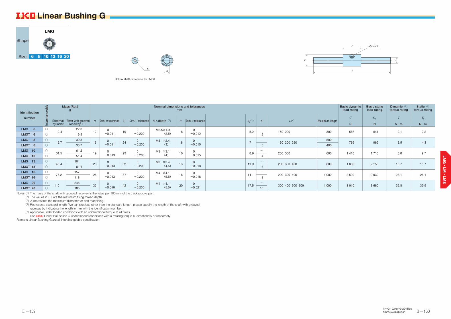
Ⅱ-159
Linear Bushing G
Ⅱ-160
Linear Bushing G
Identification
number
Inte
rcha
ngea
ble Mass (Ref.)
gNominal dimensions and tolerances
mmBasic dynamic
load ratingBasic static load rating
Dynamic(5)torque rating
Static(5)torque rating
d2(3) K L(4) Maximum lengthC
N
C0
N
T
N・m
T0
N・mExternal cylinder
Shaft with grooved raceway(1)
D Dim. D tolerance C Dim. C tolerance M×depth(2) d Dim. d tolerance
LMG 6 ○9.4
22.012
0-0.011
190-0.200
M2.5×1.9(2.5) 6
0-0.012
5.2-
150 200 300 587 641 2.1 2.2LMGT 6 ○ 19.5 2
LMG 8 ○15.7
39.315
0-0.011
240-0.200
M3 ×2.4(3) 8
0-0.015
7-
150 200 250500
769 962 3.5 4.3LMGT 8 ○ 33.7 3 400
LMG 10 ○31.5
61.219
0-0.013
290-0.200
M3 ×3.1(4) 10
0-0.015
8.9-
200 300 600 1 410 1 710 8.0 9.7LMGT 10 ○ 51.4 4
LMG 13 ○45.4
10423
0-0.013
320-0.200
M3 ×3.4(4.5) 13
0-0.018
11.9-
200 300 400 800 1 880 2 150 13.7 15.7LMGT 13 ○ 81.4 6
LMG 16 ○78.2
15728
0-0.013
370-0.200
M4 ×4.1(5.5) 16
0-0.018
14-
200 300 400 1 000 2 590 2 930 23.1 26.1LMGT 16 ○ 118 8
LMG 20 ○110
24632
0-0.016
420-0.200
M4 ×4.1(5.5) 20
0-0.021
17.5-
300 400 500 600 1 000 3 010 3 660 32.8 39.9LMGT 20 ○ 185 10
Notes (1) The mass of the shaft with grooved raceway is the value per 100 mm of the track groove part.(2) The values in ( ) are the maximum fixing thread depth.(3) d2 represents the maximum diameter for end machining.(4) Represents standard length. We can produce other than the standard length, please specify the length of the shaft with grooved
raceway by indicating the length in mm with the identification number.(5) Applicable under loaded conditions with an unidirectional torque at all times.
Use Linear Ball Spline G under loaded conditions with a rotating torque bi-directionally or repeatedly.Remark: Linear Bushing G are all interchangeable specification.
136 8 201610
LMG
Shape
Size
1N=0.102kgf=0.2248lbs.1mm=0.03937inch
Hollow shaft dimension for LMGT
d2
M×depthC
L
dD
K
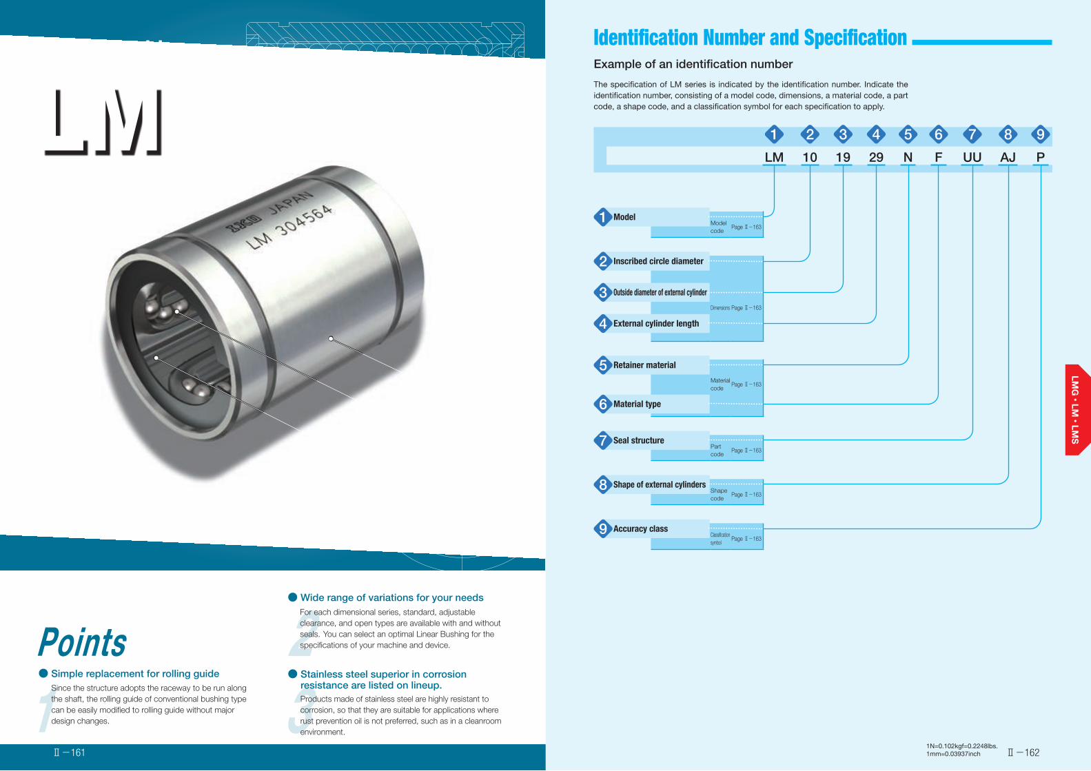
Identification Number and Specification
LMLinear Bushing
2● Wide range of variations for your needs
For each dimensional series, standard, adjustable clearance, and open types are available with and without seals. You can select an optimal Linear Bushing for the specifications of your machine and device.
1Points● Simple replacement for rolling guide
Since the structure adopts the raceway to be run along the shaft, the rolling guide of conventional bushing type can be easily modified to rolling guide without major design changes. 3Products made of stainless steel are highly resistant to
corrosion, so that they are suitable for applications where rust prevention oil is not preferred, such as in a cleanroom environment.
● Stainless steel superior in corrosion resistance are listed on lineup.
External cylinder
Ball
Retainer
Ⅱ-162Ⅱ-1611N=0.102kgf=0.2248lbs.1mm=0.03937inch
Example of an identification number
The specification of LM series is indicated by the identification number. Indicate the identification number, consisting of a model code, dimensions, a material code, a part code, a shape code, and a classification symbol for each specification to apply.
1 2 3 4 5 6 7 8 9
LM 10 19 29 N F UU AJ P
Model1 Model code
Page Ⅱ-163
Inscribed circle diameter2
Outside diameter of external cylinder3Dimensions Page Ⅱ-163
External cylinder length4
Retainer material5Material code
Page Ⅱ-163
Material type6
Seal structure7 Part code
Page Ⅱ-163
Shape of external cylinders8 Shape code
Page Ⅱ-163
Accuracy class9 Classification symbol
Page Ⅱ-163
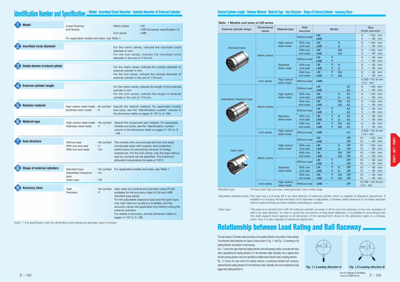
External Cylinder Length・Retainer Material・Material Type・Seal Structure・Shape of External Cylinder・Accuracy Class-Identification Number and Specification -Model・Inscribed Circle Diameter・Outside Diameter of External Cylinder・
Ⅱ-163 Ⅱ-1641N=0.102kgf=0.2248lbs.1mm=0.03937inch
The load rating of LM series varies according to the loading direction and position of ball raceway. The dimension table describes two types of values shown in Fig. 1.1 and Fig. 1.2 according to the loading direction and position of ball raceway.Fig. 1.1 shows the case where the loading direction and ball raceway position coincides with each other, representing the loading direction A in the dimension table. Generally, this is applied when the ball raceway position cannot be specified to indeterminate direction load or loading direction.Fig. 1.2 shows the case where the loading direction is positioned between ball raceways, representing the loading direction B in the dimension table. Generally, this can be subjected to load bigger than loading direction A.
Fig. 1.1 Loading direction A Fig. 1.2 Loading direction B
LoadShaft
LoadShaft
Linear Bushing(LM Series)
Metric series
Inch series
: LM: LME (European specification (1)): LMB
For applicable models and sizes, see Table 1.
For the metric series, indicate the inscribed circle diameter in mm.For the inch series, indicate the inscribed circle diameter in the unit of 1/16 inch.
For the metric series, indicate the outside diameter of external cylinder in mm.For the inch series, indicate the outside diameter of external cylinder in the unit of 1/16 inch.
For the metric series, indicate the length of the external cylinder in mm.For the inch series, indicate the length of external cylinder in the unit of 1/16 inch.
High carbon steel madeSynthetic resin made
:No symbol:N
Specify the retainer material. For applicable models and sizes, see the "Identification number" column in the dimension table on pages Ⅱ-167 to Ⅱ-188.
High carbon steel madeStainless steel made
:No symbol:F
Specify the component part material. For applicable models and sizes, see the "Identification number" column in the dimension table on pages Ⅱ-167 to Ⅱ-188.
Without sealWith one end sealWith two end seals
:No symbol:U:UU
The models with one end seal and two end seals incorporate seals with superior dust protection performance for preventing intrusion of foreign substances. For the inch series, only the type without seal (no symbol) can be specified. The maximum allowable temperature for seals is 120°C.
Standard typeAdjustable clearance typeOpen type
:No symbol:AJ
:OP
For applicable models and sizes, see Table 1.
HighPrecision
:No symbol:P
High class (no symbol) and precision class (P) are available for the accuracy class of LM and LMB standard type series.For the adjustable clearance type and the open type, only high class (no symbol) is available, and the accuracy values are applicable only before cutting the external cylinders.For details of accuracy, see the dimension table on pages Ⅱ-167 to Ⅱ-188.
Note (1) It is specification with the dimensions and tolerances generally used in Europe.
Model1
Inscribed circle diameter2
Outside diameter of external cylinder3
External cylinder length4
Retainer material5
Material type6
Seal structure7
Shape of external cylinders8
Accuracy class9
Table. 1 Models and sizes of LM series
External cylinder shapeDimensional
seriesMaterial type
Seal structure
ModelSize
(Shaft diameter)
Standard type
Metric series
High carbon steel made
Without sealLM LME
6 ~ 150 mm 5 ~ 80 mm
With one end seal
LM … ULME … U
6 ~ 150 mm 5 ~ 80 mm
With two end seals
LM … UULME … UU
6 ~ 150 mm 5 ~ 80 mm
Stainless steel made
Without sealLM … FLME … F
6 ~ 60 mm 5 ~ 60 mm
With one end seal
LM … F ULME … F U
6 ~ 60 mm 5 ~ 60 mm
With two end seals
LM … F UULME … F UU
6 ~ 60 mm 5 ~ 60 mm
Inch seriesHigh carbon steel made
Without seal LMB 6.350 ~ 101.6 mm (1/4~ 4in)
Adjustable clearance type
Metric series
High carbon steel made
Without sealLM … AJLME … AJ
6 ~ 150 mm 5 ~ 80 mm
With one end seal
LM … U AJLME … U AJ
6 ~ 150 mm 5 ~ 80 mm
With two end seals
LM … UU AJLME … UU AJ
6 ~ 150 mm 5 ~ 80 mm
Stainless steel made
Without sealLM … F AJLME … F AJ
6 ~ 60 mm 5 ~ 60 mm
With one end seal
LM … F U AJLME … F U AJ
6 ~ 60 mm 5 ~ 60 mm
With two end seals
LM … F UU AJLME … F UU AJ
6 ~ 60 mm 5 ~ 60 mm
Inch seriesHigh carbon steel made
Without seal LMB … AJ 6.350 ~ 101.6 mm (1/4~ 4in)
Open type
Metric series
High carbon steel made
Without sealLM … OPLME … OP
10 ~ 150 mm 12 ~ 80 mm
With one end seal
LM … U OPLME … U OP
10 ~ 150 mm 12 ~ 80 mm
With two end seals
LM … UU OPLME … UU OP
10 ~ 150 mm 12 ~ 80 mm
Stainless steel made
Without sealLM … F OPLME … F OP
10 ~ 60 mm 12 ~ 60 mm
With one end seal
LM … F U OPLME … F U OP
10 ~ 60 mm 12 ~ 60 mm
With two end seals
LM … F UU OPLME … F UU OP
10 ~ 60 mm 12 ~ 60 mm
Inch seriesHigh carbon steel made
Without seal LMB … OP 12.700 ~ 101.6 mm (1/2~ 4in)
Standard type : Product with high accuracy used generally over a wide range
Adjustable clearance type : This type has a cut-away slit in an axial direction of external cylinder, which is capable of clearance adjustment. If installed in a housing whose inscribed circle diameter is adjustable, it enables radial clearance to be freely adjusted without optional fitting and also enables preloading to operate.
Open type : This type is in sectoral form with the external cylinder cut away in slit by one-row raceway or two-row raceways of ball in an axial direction. In order to avoid the occurrence of long shaft deflection, it is possible to accordingly add the shaft support block tailored to (E) dimension of the sectoral form shown in the dimension table, in a midway point. And, it is also capable of clearance adjustment.
Relationship between Load Rating and Ball Raceway
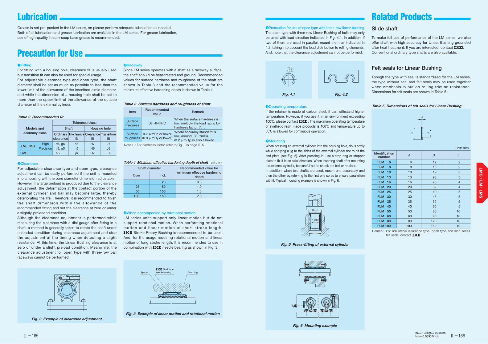
Lubrication Related Products
Ⅱ-165 Ⅱ-1661N=0.102kgf=0.2248lbs.1mm=0.03937inch
Grease is not pre-packed in the LM series, so please perform adequate lubrication as needed.Both of oil lubrication and grease lubrication are available in the LM series. For grease lubrication, use of high-quality lithium-soap base grease is recommended.
❶FittingFor fitting with a housing hole, clearance fit is usually used but transition fit can also be used for special usage.For adjustable clearance type and open type, the shaft diameter shall be set as much as possible to less than the lower limit of the allowance of the inscribed circle diameter, and while the dimension of a housing hole shall be set to more than the upper limit of the allowance of the outside diameter of the external cylinder.
Table 2 Recommended fit
Models and accuracy class
Tolerance class
Shaft Housing hole
Ordinary clearance
Interference fit
Clearance fit
Transition fit
LM, LMBHigh f6, g6 h6 H7 J7
Precision f5, g5 h5 H6 J6LME - h6 j6 H7 J7
❷ClearanceFor adjustable clearance type and open type, clearance adjustment can be easily performed if the unit is mounted into a housing with the bore diameter dimension adjustable.However, if a large preload is produced due to the clearance adjustment, the deformation at the contact portion of the external cylinder and ball may become large, thereby deteriorating the life. Therefore, it is recommended to finish the shaf t d imens ion wi th in the a l lowance of the recommended fitting and set the clearance at zero or under a slightly-preloaded condition.Although the clearance adjustment is performed while measuring the clearance with a dial gauge after fitting in a shaft, a method is generally taken to rotate the shaft under unloaded condition during clearance adjustment and stop the adjustment at the timing when detecting a slight resistance. At this time, the Linear Bushing clearance is at zero or under a slight preload condition. Meanwhile, the clearance adjustment for open type with three-row ball raceways cannot be performed.
Fig. 2 Example of clearance adjustment
❸RacewaySince LM series operates with a shaft as a raceway surface, the shaft should be heat-treated and ground. Recommended values for surface hardness and roughness of the shaft are shown in Table 3 and the recommended value for the minimum effective hardening depth is shown in Table 4.
Table 3 Surface hardness and roughness of shaft
ItemRecommended
valueRemark
Surface hardness
58~64HRCWhen the surface hardness is low, multiply the load rating by hardness factor (1).
Surface roughness
0.2 μmRa or lower(0.8 μmRy or lower)
Where accuracy standard is low, around 0.8 μmRa (3.2 μmRy) is also allowed.
Note (1) For hardness factor, refer to Fig. 3 in page Ⅲ-5.
Table 4 Minimum effective hardening depth of shaft unit : mm
Shaft diameter Recommended value for minimum effective hardening
depthOver Incl.
- 28 0.8 28 50 1.0 50 100 1.5100 150 2.0
❹When accompanied by rotational motionLM series units support only linear motion but do not support rotational motion. When performing rotational mot ion and l inear mot ion of short st roke length,
Stroke Rotary Bushing is recommended to be used. And, for the usage requiring rotational motion and linear motion of long stroke length, it is recommended to use in combination with needle bearing as shown in Fig. 3.
Fig. 3 Example of linear motion and rotational motion
Stop ringSpacer Shell typeNeedle bearing
❺ Precaution for use of open type with three-row linear bushingThe open type with three-row Linear Bushing of balls may only be used with load direction indicated in Fig. 4.1. In addition, if two of them are used in parallel, mount them as indicated in 4.2, taking into account the load distribution to rolling elements. And, note that the clearance adjustment cannot be performed.
Fig. 4.1 Fig. 4.2
❻Operating temperatureIf the retainer is made of carbon steel, it can withstand higher temperature. However, if you use it in an environment exceeding 100˚C, please contact . The maximum operating temperature of synthetic resin made products is 100˚C and temperature up to 80˚C is allowed for continuous operation.
❼MountingWhen pressing an external cylinder into the housing hole, do is softly while applying a jig to the sides of the external cylinder not to hit the end plate (see Fig. 5). After pressing-in, use a stop ring or stopper plate to fix it in an axial direction. When inserting shaft after mounting the external cylinder, be careful not to shock the ball or retainer.In addition, when two shafts are used, mount one accurately and then the other by referring to the first one so as to ensure parallelism with it. Typical mounting example is shown in Fig. 6.
Fig. 5 Press-fitting of external cylinder
Fig. 6 Mounting example
Load
D-0.3
Fw-0.03
Slide shaft
To make full use of performance of the LM series, we also offer shaft with high accuracy for Linear Bushing grounded after heat treatment. If you are interested, contact .Conventional ordinary type shafts are also available.
Felt seals for Linear Bushing
Though the type with seal is standardized for the LM series, the type without seal and felt seals may be used together when emphasis is put on rolling friction resistance. Dimensions for felt seals are shown in Table 5.
Table 5 Dimensions of felt seals for Linear Bushing
unit: mm
Identification number d D B
FLM 6 6 12 2
FLM 8 8 15 2
FLM 10 10 19 3
FLM 13 13 23 3
FLM 16 16 28 4
FLM 20 20 32 4
FLM 25 25 40 5
FLM 30 30 45 5
FLM 35 35 52 5
FLM 40 40 60 5
FLM 50 50 80 10
FLM 60 60 90 10
FLM 80 80 120 10
FLM 100 100 150 10
Remark: For adjustable clearance type, open type and inch series felt seals, contact .
B
D d
Precaution for Use

Ⅱ-167
Linear Bushing
Ⅱ-168
Linear Bushing
Identification number Nominal dimensions and tolerances mm Eccentricity Basic dynamic load rating
Basic static load rating
Shaft
diameterStandard type
Bal
l rac
eway
Mass
(Ref.)Adjustable clearance type
Bal
l rac
eway
Mass
(Ref.)Open type
Bal
l rac
eway
Mass
(Ref.)Maximumμm
C C0Dim. F w toleranceμm
Fw D Dim. D tolerance C Dim. C
tolerance C1(1)Dim. C1 tolerance C2 D1 h E α Load
direction ALoad
direction BLoad
direction ALoad
direction Bmm g g g P H μm μm μm Degree P H N N N N
6LM 61219 4 8 ―――― - -
―――― - - 6
0
-6
0
- 9
12
0
-11
19
0
-200
13.5
0
-200
1.1 11.5-
- -
8 12
80.7 92.7 167 237LM 61219 N 4 7.6 LM 61219 N AJ* 4 7.5 1
8
LM 81517 4 13 ―――― - -―――― - - 8 15 17 11.5 1.1 14.3
-- - 87.4 100 160 226
LM 81517 N 4 10.4 LM 81517 N AJ* 4 10 1
LM 81524 4 18 ―――― - -―――― - - 8 15 24 17.5 1.1 14.3
-- - 121 139 255 361
LM 81524 N 4 15 LM 81524 N AJ* 4 14.7 1
10LM 101929 4 30 ―――― - - ―――― - -
10 19
0
-13
29 22 1.3 18- - -
179 206 354 501LM 101929 N 4 27.5 LM 101929 N AJ* 4 26.5 LM 101929 N OP* 3 18 1 6.8 80
12LM 122130 4 29 LM 122130 AJ* 4 28 LM 122130 OP* 3 19
12 21 30 23 1.3 20 1.5 8 80 259 298 503 711LM 122130 N 4 31.5 LM 122130 N AJ* 4 30.5 LM 122130 N OP* 3 22
13LM 132332 4 43 LM 132332 AJ* 4 42 LM 132332 OP* 3 31
13 23 32 23 1.3 22 1.5 9 80 266 306 506 716LM 132332 N 4 42.5 LM 132332 N AJ* 4 41.5 LM 132332 N OP* 3 31
16LM 162837 4 70 LM 162837 AJ* 4 69.5 LM 162837 OP* 3 58
16 28 37 26.5 1.6 27 1.5 11 80 426 489 766 1 080LM 162837 N 4 69 LM 162837 N AJ* 4 68 LM 162837 N OP* 3 52
20LM 203242 5 92 LM 203242 AJ* 5 91 LM 203242 OP* 4 79
20
0
-7
0
-10
32
0
-16
42 30.5 1.6 30.5 1.5 11 60
10 15
562 668 1 010 1 470LM 203242 N 5 87 LM 203242 N AJ* 5 85 LM 203242 N OP* 4 69
25LM 254059 6 226 LM 254059 AJ* 6 222 LM 254059 OP* 5 203
25 40 59
0
-300
41
0
-300
1.85 38 2 12 50 920 974 1 780 2 280LM 254059 N 6 220 LM 254059 N AJ* 6 216 LM 254059 N OP* 5 188
30LM 304564 6 253 LM 304564 AJ* 6 250 LM 304564 OP* 5 228
30 45 64 44.5 1.85 43 2.5 15 50 1 350 1 430 2 500 3 200LM 304564 N 6 250 LM 304564 N AJ* 6 245 LM 304564 N OP* 5 210
35LM 355270 6 388 LM 355270 AJ* 6 380 LM 355270 OP* 5 355
35
0
-8
0
-12
52
0
-19
70 49.5 2.1 49 2.5 17 50
12 20
1 610 1 710 3 080 3 940LM 355270 N 6 380 LM 355270 N AJ* 6 375 LM 355270 N OP* 5 335
40LM 406080 6 596 LM 406080 AJ* 6 585 LM 406080 OP* 5 546
40 60 80 60.5 2.1 57 3 20 50 2 030 2 150 3 620 4 640LM 406080 N 6 585 LM 406080 N AJ* 6 579 LM 406080 N OP* 5 500
50LM 5080100 6 1 615 LM 5080100 AJ* 6 1 595 LM 5080100 OP* 5 1 420
50 80 100 74 2.6 76.5 3 25 50 3 940 4 180 7 130 9 120LM 5080100 N 6 1 580 LM 5080100 N AJ* 6 1 560 LM 5080100 N OP* 5 1 340
Note (1) The width of hub for fixing with circlip should be the value obtained by subtracting a circlip width value times two from the C1 dimension.
Remarks 1. "P" and "H" in Dim. Fw tolerance and Eccentricity represent precision and high, respectively. 2. Standard type and adjustable clearance type end plates are fixed with stop ring for holes. 3. The identification numbers with * are our semi-standard items.
12
Standard type
6 8 161310
LM
3520 25 50403012060 80 150100
LM…N
12
Adjustable clearance type
6 8 161310
LM… AJ
3520 25 50403012060 80 150100
LM…N AJ
12
Open type
161310
LM… OP
3520 25 50403012060 80 150100
LM…N OP
--
Shape
Shaft diameter
1N=0.102kgf=0.2248lbs.1mm=0.03937inch
LM LM…OPLM…AJ
D1
C
D
C2 C2
C1
FW
h
E
α
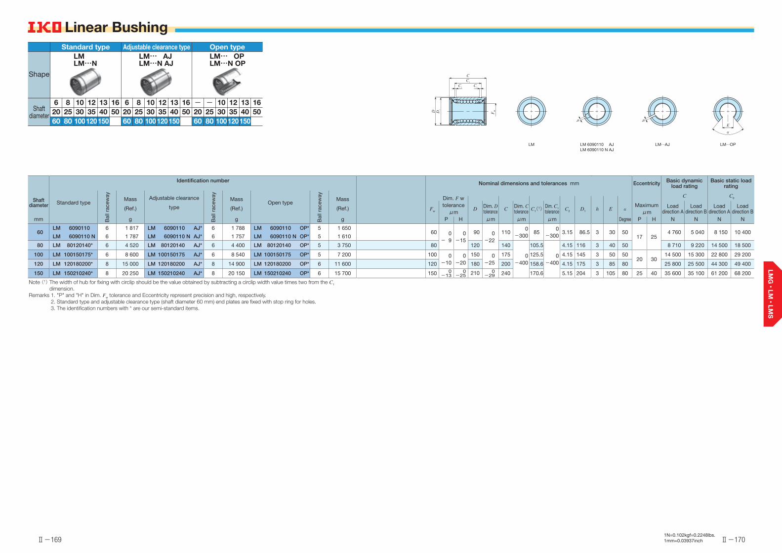
Ⅱ-169
Linear Bushing
Ⅱ-170
Linear Bushing
Identification number Nominal dimensions and tolerances mm Eccentricity Basic dynamic load rating
Basic static load rating
Shaft diameter Standard type
Bal
l rac
eway
Mass
(Ref.)
Adjustable clearance
typeB
all r
acew
ay
Mass
(Ref.)Open type
Bal
l rac
eway
Mass
(Ref.)
Dim. F w toleranceμm
Maximumμm
C C0
Fw D Dim. D tolerance C Dim. C
tolerance C1(1)Dim. C1 tolerance C2 D1 h E α Load
direction ALoad
direction BLoad
direction ALoad
direction Bmm g g g P H μm μm μm Degree P H N N N N
60LM 6090110 6 1 817 LM 6090110 AJ* 6 1 788 LM 6090110 OP* 5 1 650
60 0- 9
0-15
90 0-22
1100
-30085
0-300
3.15 86.5 3 30 5017 25
4 760 5 040 8 150 10 400LM 6090110 N 6 1 787 LM 6090110 N AJ* 6 1 757 LM 6090110 N OP* 5 1 610
80 LM 80120140* 6 4 520 LM 80120140 AJ* 6 4 400 LM 80120140 OP* 5 3 750 80 120 140
0-400
105.5
0-400
4.15 116 3 40 50 8 710 9 220 14 500 18 500
100 LM 100150175* 6 8 600 LM 100150175 AJ* 6 8 540 LM 100150175 OP* 5 7 200 100 0-10
0-20
150 0-25
175 125.5 4.15 145 3 50 5020 30
14 500 15 300 22 800 29 200
120 LM 120180200* 8 15 000 LM 120180200 AJ* 8 14 900 LM 120180200 OP* 6 11 600 120 180 200 158.6 4.15 175 3 85 80 25 800 25 500 44 300 49 400
150 LM 150210240* 8 20 250 LM 150210240 AJ* 8 20 150 LM 150210240 OP* 6 15 700 150 0-13
0-25 210 0
-29 240 170.6 5.15 204 3 105 80 25 40 35 600 35 100 61 200 68 200
Note (1) The width of hub for fixing with circlip should be the value obtained by subtracting a circlip width value times two from the C1 dimension.
Remarks 1. "P" and "H" in Dim. Fw tolerance and Eccentricity represent precision and high, respectively. 2. Standard type and adjustable clearance type (shaft diameter 60 mm) end plates are fixed with stop ring for holes. 3. The identification numbers with * are our semi-standard items.
12
Standard type
6 8 161310
LM
3520 25 50403012060 80 150100
LM…N
12
Adjustable clearance type
6 8 161310
LM… AJ
3520 25 50403012060 80 150100
LM…N AJ
12
Open type
161310
LM… OP
3520 25 50403012060 80 150100
LM…N OP
--
Shape
Shaft diameter
1N=0.102kgf=0.2248lbs.1mm=0.03937inch
LM LM 6090110 AJLM 6090110 N AJ
LM…OPLM…AJ
D1
C
D
C2
C2
C1
FW
h
E
α
h
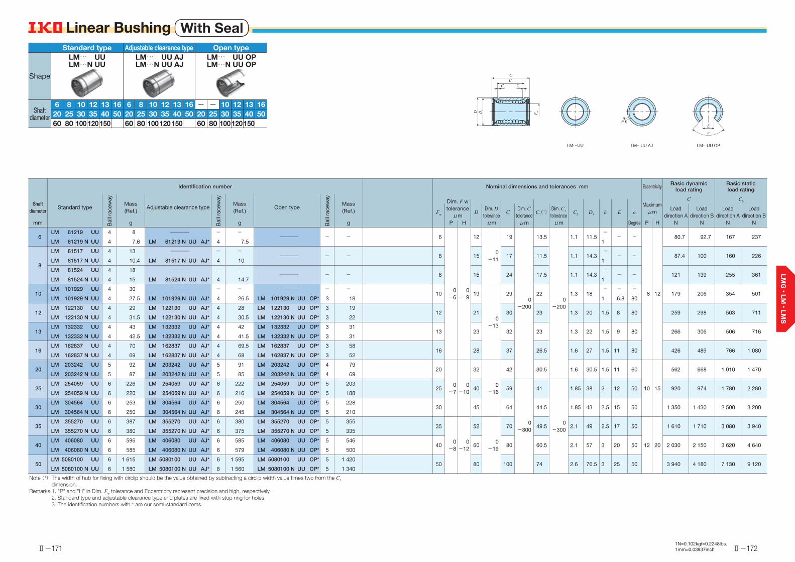
Ⅱ-171
Linear Bushing With Seal
Ⅱ-172
Linear Bushing
Identification number Nominal dimensions and tolerances mm Eccentricity Basic dynamic load rating
Basic static load rating
Shaft diameter
Standard type
Bal
l rac
eway
Mass(Ref.)
Adjustable clearance type
Bal
l rac
eway
Mass(Ref.)
Open type
Bal
l rac
eway
Mass(Ref.)
Maximumμm
C C0Dim. F w toleranceμm
Fw DDim. D
toleranceC
Dim. C tolerance
C1(1)Dim. C1 tolerance
C2 D1 h E αLoad
direction ALoad
direction BLoad
direction ALoad
direction Bmm g g g P H μm μm μm Degree P H N N N N
6LM 61219 UU 4 8 ―――― - -
―――― - - 6
0-6
0- 9
12
0-11
19
0-200
13.5
0-200
1.1 11.5-
- -
8 12
80.7 92.7 167 237LM 61219 N UU 4 7.6 LM 61219 N UU AJ* 4 7.5 1
8
LM 81517 UU 4 13 ―――― - -―――― - - 8 15 17 11.5 1.1 14.3
-- - 87.4 100 160 226
LM 81517 N UU 4 10.4 LM 81517 N UU AJ* 4 10 1
LM 81524 UU 4 18 ―――― - -―――― - - 8 15 24 17.5 1.1 14.3
-- - 121 139 255 361
LM 81524 N UU 4 15 LM 81524 N UU AJ* 4 14.7 1
10LM 101929 UU 4 30 ―――― - - ―――― - -
10 19
0-13
29 22 1.3 18- - -
179 206 354 501LM 101929 N UU 4 27.5 LM 101929 N UU AJ* 4 26.5 LM 101929 N UU OP* 3 18 1 6.8 80
12LM 122130 UU 4 29 LM 122130 UU AJ* 4 28 LM 122130 UU OP* 3 19
12 21 30 23 1.3 20 1.5 8 80 259 298 503 711LM 122130 N UU 4 31.5 LM 122130 N UU AJ* 4 30.5 LM 122130 N UU OP* 3 22
13LM 132332 UU 4 43 LM 132332 UU AJ* 4 42 LM 132332 UU OP* 3 31
13 23 32 23 1.3 22 1.5 9 80 266 306 506 716LM 132332 N UU 4 42.5 LM 132332 N UU AJ* 4 41.5 LM 132332 N UU OP* 3 31
16LM 162837 UU 4 70 LM 162837 UU AJ* 4 69.5 LM 162837 UU OP* 3 58
16 28 37 26.5 1.6 27 1.5 11 80 426 489 766 1 080LM 162837 N UU 4 69 LM 162837 N UU AJ* 4 68 LM 162837 N UU OP* 3 52
20LM 203242 UU 5 92 LM 203242 UU AJ* 5 91 LM 203242 UU OP* 4 79
20
0-7
0-10
32
0-16
42 30.5 1.6 30.5 1.5 11 60
10 15
562 668 1 010 1 470LM 203242 N UU 5 87 LM 203242 N UU AJ* 5 85 LM 203242 N UU OP* 4 69
25LM 254059 UU 6 226 LM 254059 UU AJ* 6 222 LM 254059 UU OP* 5 203
25 40 59
0-300
41
0-300
1.85 38 2 12 50 920 974 1 780 2 280LM 254059 N UU 6 220 LM 254059 N UU AJ* 6 216 LM 254059 N UU OP* 5 188
30LM 304564 UU 6 253 LM 304564 UU AJ* 6 250 LM 304564 UU OP* 5 228
30 45 64 44.5 1.85 43 2.5 15 50 1 350 1 430 2 500 3 200LM 304564 N UU 6 250 LM 304564 N UU AJ* 6 245 LM 304564 N UU OP* 5 210
35LM 355270 UU 6 387 LM 355270 UU AJ* 6 380 LM 355270 UU OP* 5 355
35
0-8
0-12
52
0-19
70 49.5 2.1 49 2.5 17 50
12 20
1 610 1 710 3 080 3 940LM 355270 N UU 6 380 LM 355270 N UU AJ* 6 375 LM 355270 N UU OP* 5 335
40LM 406080 UU 6 596 LM 406080 UU AJ* 6 585 LM 406080 UU OP* 5 546
40 60 80 60.5 2.1 57 3 20 50 2 030 2 150 3 620 4 640LM 406080 N UU 6 585 LM 406080 N UU AJ* 6 579 LM 406080 N UU OP* 5 500
50LM 5080100 UU 6 1 615 LM 5080100 UU AJ* 6 1 595 LM 5080100 UU OP* 5 1 420
50 80 100 74 2.6 76.5 3 25 50 3 940 4 180 7 130 9 120LM 5080100 N UU 6 1 580 LM 5080100 N UU AJ* 6 1 560 LM 5080100 N UU OP* 5 1 340
Note (1) The width of hub for fixing with circlip should be the value obtained by subtracting a circlip width value times two from the C1 dimension.
Remarks 1. "P" and "H" in Dim. Fw tolerance and Eccentricity represent precision and high, respectively.2. Standard type and adjustable clearance type end plates are fixed with stop ring for holes.3. The identification numbers with * are our semi-standard items.
LM…UU OPLM…UU AJLM…UU
E
α
h
D1
D
C
C2
C2
C1
FW
1N=0.102kgf=0.2248lbs.1mm=0.03937inch
126 8 1613103520 25 50403012060 80 150100
Standard typeLM… UULM…N UU
12 1613103520 25 50403012060 80 150100
Open typeLM… UU OPLM…N UU OP
126 8 1613103520 25 50403012060 80 150100
Adjustable clearance typeLM… UU AJLM…N UU AJ
--
Shape
Shaft diameter

Ⅱ-173
Linear Bushing With Seal
Ⅱ-174
Linear Bushing
Identification number Nominal dimensions and tolerances mm Eccentricity Basic dynamic load rating
Basic static load rating
Shaft diameter
Standard type
Bal
l rac
eway
Mass(Ref.)
Adjustable clearance type
Bal
l rac
eway
Mass(Ref.)
Open type
Bal
l rac
eway
Mass(Ref.)
Maximumμm
C C0Dim. Fw toleranceμm
Fw DDim. D
toleranceC
Dim. C tolerance
C1(1)Dim. C1 tolerance
C2 D1 h E αLoad
direction ALoad
direction BLoad
direction ALoad
direction Bmm g g g P H μm μm μm Degree P H N N N N
60LM 6090110 UU 6 1 817 LM 6090110 UU AJ* 6 1 788 LM 6090110 UU OP* 5 1 650
60 0- 9
0-15
90 0-22
1100
-30085
0-300
3.15 86.5 3 30 5017 25
4 760 5 040 8 150 10 400LM 6090110 N UU 6 1 787 LM 6090110 N UU AJ* 6 1 757 LM 6090110 N UU OP* 5 1 610
80 LM 80120140 UU* 6 4 400 LM 80120140 UU AJ* 6 4 360 LM 80120140 UU OP* 5 3 640 80 120 140
0-400
105.5
0-400
4.15 116 3 40 50 8 710 9 220 14 500 18 500
100 LM 100150175 UU* 6 8 500 LM 100150175 UU AJ* 6 8 450 LM 100150175 UU OP* 5 7 120 100 0-10
0-20
150 0-25
175 125.5 4.15 145 3 50 5020 30
14 500 15 300 22 800 29 200
120 LM 120180200 UU* 8 14 700 LM 120180200 UU AJ* 8 14 600 LM 120180200 UU OP* 6 11 400 120 180 200 158.6 4.15 175 3 85 80 25 800 25 500 44 300 49 400
150 LM 150210240 UU* 8 19 900 LM 150210240 UU AJ* 8 19 800 LM 150210240 UU OP* 6 15 400 150 0-13
0-25 210 0
-29 240 170.6 5.15 204 3 105 80 25 40 35 600 35 100 61 200 68 200
Note (1) The width of hub for fixing with circlip should be the value obtained by subtracting a circlip width value times two from the C1 dimension.
Remarks 1. "P" and "H" in Dim. Fw tolerance and Eccentricity represent precision and high, respectively.2. Standard type and adjustable clearance type (shaft diameter 60 mm) end plates are fixed with stop ring for holes.3. The identification numbers with * are our semi-standard items.
LM 6090110 UU AJLM 6090110 N UU AJ
LM…UU LM…UU OPLM…UU AJ
E
α
h
D1
D
C
C2 C2
C1
FW
h
1N=0.102kgf=0.2248lbs.1mm=0.03937inch
126 8 1613103520 25 50403012060 80 150100
Standard typeLM… UULM…N UU
126 8 1613103520 25 50403012060 80 150100
Adjustable clearance typeLM… UU AJLM…N UU AJ
12 1613103520 25 50403012060 80 150100
Open typeLM… UU OPLM…N UU OP
--
Shape
Shaft diameter
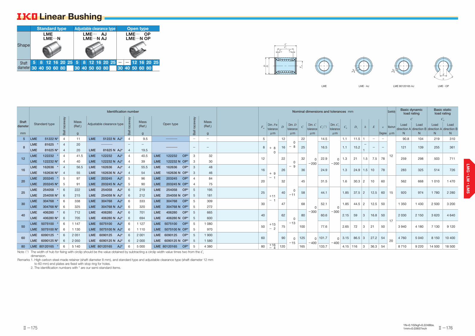
Ⅱ-175
Linear Bushing
Ⅱ-176
Linear Bushing
Identification number Nominal dimensions and tolerances mm Eccentricity Basic dynamic load rating
Basic static load rating
Shaft diameter
Standard type
Bal
l rac
eway
Mass(Ref.)
Adjustable clearance type
Bal
l rac
eway
Mass(Ref.)
Open type
Bal
l rac
eway
Mass(Ref.)
C C0
Fw
Dim. Fw tolerance
DDim. D
toleranceC
Dim. C tolerance
C1(1)Dim. C1 tolerance
C2 D1 h E α MaximumLoad
direction ALoad
direction BLoad
direction ALoad
direction Bmm g g g μm μm μm μm Degree μm N N N N
5 LME 51222 N* 4 11 LME 51222 N AJ* 4 9.5 ―――― - - 5
+ 80
120
- 8
22
0-200
14.5
0-200
1.1 11.5 1 - -
12
90.8 104 219 310
8LME 81625 * 4 20 ―――― - -
―――― - - 8 16 25 16.5 1.1 15.2-
- - 121 139 255 361LME 81625 N* 4 20 LME 81625 N AJ* 4 19.5 1
12LME 122232 * 4 41.5 LME 122232 AJ* 4 40.5 LME 122232 OP* 3 32
12 220
- 9
32 22.9 1.3 21 1.5 7.5 78 259 298 503 711LME 122232 N* 4 40 LME 122232 N AJ* 4 39 LME 122232 N OP* 3 30
16LME 162636 * 4 56.5 LME 162636 AJ* 4 55.5 LME 162636 OP* 3 48
16+ 9- 1
26 36 24.9 1.3 24.9 1.5 10 78 283 325 514 726LME 162636 N* 4 55 LME 162636 N AJ* 4 54 LME 162636 N OP* 3 46
20LME 203245 * 5 97 LME 203245 AJ* 5 96 LME 203245 OP* 4 84
20 32
0-11
45 31.5 1.6 30.3 2 10 60
15
562 668 1 010 1 470LME 203245 N* 5 91 LME 203245 N AJ* 5 90 LME 203245 N OP* 4 75
25LME 254058 * 6 222 LME 254058 AJ* 6 219 LME 254058 OP* 5 195
25+11- 1
40 58
0-300
44.1
0-300
1.85 37.5 2 12.5 60 920 974 1 780 2 280LME 254058 N* 6 215 LME 254058 N AJ* 6 212 LME 254058 N OP* 5 181
30LME 304768 * 6 338 LME 304768 AJ* 6 333 LME 304768 OP* 5 309
30 47 68 52.1 1.85 44.5 2 12.5 50 1 350 1 430 2 500 3 200LME 304768 N* 6 325 LME 304768 N AJ* 6 320 LME 304768 N OP* 5 272
40LME 406280 * 6 712 LME 406280 AJ* 6 701 LME 406280 OP* 5 665
40
+13- 2
620
-13
80 60.6 2.15 59 3 16.8 50
17
2 030 2 150 3 620 4 640LME 406280 N* 6 705 LME 406280 N AJ* 6 694 LME 406280 N OP* 5 600
50LME 5075100 * 6 1 147 LME 5075100 AJ* 6 1 127 LME 5075100 OP* 5 1 080
50 75 100 77.6 2.65 72 3 21 50 3 940 4 180 7 130 9 120LME 5075100 N* 6 1 130 LME 5075100 N AJ* 6 1 110 LME 5075100 N OP* 5 970
60LME 6090125 * 6 2 051 LME 6090125 AJ* 6 2 001 LME 6090125 OP* 5 1 900
60 90 0-15
125 0-400
101.7 0-400
3.15 86.5 3 27.2 5420
4 760 5 040 8 150 10 400LME 6090125 N* 6 2 050 LME 6090125 N AJ* 6 2 000 LME 6090125 N OP* 5 1 580
80 LME 80120165 * 6 5 140 LME 80120165 AJ* 6 5 000 LME 80120165 OP* 5 4 380 80 +16- 4 120 165 133.7 4.15 116 3 36.3 54 8 710 9 220 14 500 18 500
Note (1) The width of hub for fixing with circlip should be the value obtained by subtracting a circlip width value times two from the C1 dimension.
Remarks 1. High carbon steel-made retainer (shaft diameter 8 mm), and standard type and adjustable clearance type (shaft diameter 12 mm to 60 mm) end plates are fixed with stop ring for holes.
2. The identification numbers with * are our semi-standard items.
LME LME…AJ LME…OPLME 80120165 AJ
D1
C
D
C2 C2
C1
FW
h
E
α
h
1N=0.102kgf=0.2248lbs.1mm=0.03937inch
16
Standard type
5 8 252012
LME
6030 40 8050
LME…N
16
Adjustable clearance type
5 8 252012
LME… AJ
6030 40 8050
LME…N AJ
16
Open type
252012
LME… OP
6030 40 8050
LME…N OP
--
Shape
Shaft diameter

Ⅱ-177
Linear Bushing With Seal
Ⅱ-178
Linear Bushing
Identification number Nominal dimensions and tolerances mm Eccentricity Basic dynamic load rating
Basic static load rating
Shaft diameter
Standard type
Bal
l rac
eway
Mass(Ref.)
Adjustable clearance type
Bal
l rac
eway
Mass(Ref.)
Open type
Bal
l rac
eway
Mass(Ref.)
C C0
Fw
Dim. Fw tolerance
DDim. D
toleranceC
Dim. C tolerance
C1(1)Dim. C1 tolerance
C2 D1 h E α MaximumLoad
direction ALoad
direction BLoad
direction ALoad
direction Bmm g g g μm μm μm μm Degree μm N N N N
5 LME 51222 N UU* 4 11 LME 51222 N UU AJ* 4 9.5 ―――― - - 5
+ 80
120
- 8
22
0-200
14.5
0-200
1.1 11.5 1 - -
12
90.8 104 219 310
8LME 81625 UU* 4 20 ―――― - -
―――― - - 8 16 25 16.5 1.1 15.2-
- - 121 139 255 361LME 81625 N UU* 4 20 LME 81625 N UU AJ* 4 19 1
12LME 122232 UU* 4 41.5 LME 122232 UU AJ* 4 40.5 LME 122232 UU OP* 3 32
12 220
- 9
32 22.9 1.3 21 1.5 7.5 78 259 298 503 711LME 122232 N UU* 4 40 LME 122232 N UU AJ* 4 39 LME 122232 N UU OP* 3 30
16LME 162636 UU* 4 56.5 LME 162636 UU AJ* 4 55.5 LME 162636 UU OP* 3 48
16+ 9- 1
26 36 24.9 1.3 24.9 1.5 10 78 283 325 514 726LME 162636 N UU* 4 55 LME 162636 N UU AJ* 4 54 LME 162636 N UU OP* 3 46
20LME 203245 UU* 5 97 LME 203245 UU AJ* 5 96 LME 203245 UU OP* 4 84
20 32
0-11
45 31.5 1.6 30.3 2 10 60
15
562 668 1 010 1 470LME 203245 N UU* 5 91 LME 203245 N UU AJ* 5 90 LME 203245 N UU OP* 4 75
25LME 254058 UU* 6 222 LME 254058 UU AJ* 6 219 LME 254058 UU OP* 5 195
25+11- 1
40 58
0-300
44.1
0-300
1.85 37.5 2 12.5 60 920 974 1 780 2 280LME 254058 N UU*(2) 6 215 LME 254058 N UU AJ*(2) 6 212 LME 254058 N UU OP*(2) 5 181
30LME 304768 UU* 6 338 LME 304768 UU AJ* 6 333 LME 304768 UU OP* 5 309
30 47 68 52.1 1.85 44.5 2 12.5 50 1 350 1 430 2 500 3 200LME 304768 N UU* 6 325 LME 304768 N UU AJ* 6 320 LME 304768 N UU OP* 5 272
40LME 406280 UU* 6 712 LME 406280 UU AJ* 6 701 LME 406280 UU OP* 5 665
40
+13- 2
620
-13
80 60.6 2.15 59 3 16.8 50
17
2 030 2 150 3 620 4 640LME 406280 N UU* 6 705 LME 406280 N UU AJ* 6 694 LME 406280 N UU OP* 5 600
50LME 5075100 UU* 6 1 147 LME 5075100 UU AJ* 6 1 127 LME 5075100 UU OP* 5 1 080
50 75 100 77.6 2.65 72 3 21 50 3 940 4 180 7 130 9 120LME 5075100 N UU* 6 1 130 LME 5075100 N UU AJ* 6 1 110 LME 5075100 N UU OP* 5 970
60LME 6090125 UU* 6 2 051 LME 6090125 UU AJ* 6 2 001 LME 6090125 UU OP* 5 1 900
60 90 0-15
125 0-400
101.7 0-400
3.15 86.5 3 27.2 5420
4 760 5 040 8 150 10 400LME 6090125 N UU* 6 2 050 LME 6090125 N UU AJ* 6 2 000 LME 6090125 N UU OP* 5 1 580
80 LME80120165 UU* 6 5 030 LME80120165 UU AJ* 6 4 930 LME80120165 UU OP* 5 4 210 80 +16- 4 120 165 133.7 4.15 116 3 36.3 54 8 710 9 220 14 500 18 500
Notes (1) The width of hub for fixing with circlip should be the value obtained by subtracting a circlip width value times two from the C1 dimension.
(2) The seal is slightly off from the external cylinder end.Remarks 1. High carbon steel-made retainer (shaft diameter 8 mm), and standard type and adjustable clearance type (shaft diameter 12 mm
to 60 mm) end plates are fixed with stop ring for holes.2. The identification numbers with * are our semi-standard items.
LME…UU OPLME…UU AJLME…UU LME 80120165 UU AJ
C
E
α
h
D1
D
C2 C2
C1
FW
h
1N=0.102kgf=0.2248lbs.1mm=0.03937inch
16
Standard type
5 8 252012
LME… UU
6030 40 8050
LME…N UU
16
Adjustable clearance type
5 8 252012
LME… UU AJ
6030 40 8050
LME…N UU AJ
16
Open type
252012
LME… UU OP
6030 40 8050
LME…N UU OP
--
Shape
Shaft diameter

Ⅱ-179
Linear Bushing Inch Series
Ⅱ-180
Linear Bushing
Identification number Nominal dimensions and tolerances inch/mm Eccentricity Basic dynamic load rating
Basic static load rating
Shaft diameter
Standard type
Bal
l rac
eway
Mass(Ref.)
Adjustable clearance type
Bal
l rac
eway
Mass(Ref.)
Open type
Bal
l rac
eway
Mass(Ref.)
Maximumμm
C C0Dim. Fw toleranceμm
mmFw D
Dim. D tolerance
CDim. C
toleranceC1(1)
Dim. C1 tolerance
C2 D1 h E αLoad
direction ALoad
direction BLoad
direction ALoad
direction B(inch) g g g P H μm μm μm Degree P H N N N N
6.350 LMB 4812 * 4 10.5 ―――― - -―――― - -
1/4
0- 6
0- 9
1/2 0-11
3/4
0-200
12.98
0-200
0.992 11.906-
- -
8 12
82.6 94.9 168 238(1/4) LMB 4812 N* 4 8.5 LMB 4812 N AJ* 4 8 6.350 12.700 19.050 1
9.525 LMB 61014 * 4 16.5 ―――― - -―――― - -
3/8 5/8
0-13
7/8
16.15 0.992 14.935-
- - 94.8 109 174 246(3/8) LMB 61014 N* 4 12.5 LMB 61014 N AJ* 4 12 9.525 15.875 22.225 1
12.700 LMB 81420 * 4 37.5 LMB 81420 AJ* 4 36.5 LMB 81420 OP* 3 28 1/2 7/8 11/4
24.46 1.168 20.853 1.5 7.9 80 264 303 505 714(1/2) LMB 81420 N* 4 37 LMB 81420 N AJ* 4 36 LMB 81420 N OP* 3 27 12.700 22.225 31.750
15.875 LMB 101824 * 4 79.6 LMB 101824 AJ* 4 77.6 LMB 101824 OP* 3 64 5/8 11/8 11/2
28.04 1.422 26.899 1.5 9.5 80 424 488 766 1 080(5/8) LMB 101824 N* 4 76 LMB 101824 N AJ* 4 74 LMB 101824 N OP* 3 57 15.875 28.575 38.100
19.050 LMB 122026 * 5 99.5 LMB 122026 AJ* 5 97.5 LMB 122026 OP* 4 86 3/4
0- 7
0-10
11/4
0-16
15/8
29.61 1.422 29.870 1.5 11.1 60
10 15
554 659 1 000 1 470(3/4) LMB 122026 N* 5 95 LMB 122026 N AJ* 5 93 LMB 122026 N OP* 4 76 19.050 31.750 41.275
25.400 LMB 162536 * 6 207 LMB 162536 AJ* 6 205 LMB 162536 OP* 5 190 1 19/16 21/4
0-300
44.57
0-300
1.727 37.306 1.5 14.3 50 923 978 1 780 2 280(1) LMB 162536 N* 6 200 LMB 162536 N AJ* 6 198 LMB 162536 N OP* 5 170 25.400 39.688 57.150
31.750 LMB 203242 * 6 434 LMB 203242 AJ* 6 424 LMB 203242 OP* 5 390 11/4
0- 8
0-12
2
0-19
25/8
50.92 1.727 47.904 2.5 15.9 50
12 20
1 370 1 450 2 510 3 210(11/4) LMB 203242 N* 6 421 LMB 203242 N AJ* 6 411 LMB 203242 N OP* 5 375 31.750 50.800 66.675
38.100 LMB 243848 * 6 662 LMB 243848 AJ* 6 652 LMB 243848 OP* 5 610 11/2 23/8 361.26 2.184 56.870 3 19.1 50 2 010 2 130 3 610 4 620(11/2) LMB 243848 N* 6 646 LMB 243848 N AJ* 6 636 LMB 243848 N OP* 5 595 38.100 60.325 76.200
50.800 LMB 324864 * 6 1 185 LMB 324864 AJ* 6 1 165 LMB 324864 OP* 5 1 120 2 3
0-22
481.07 2.616 72.085 3 25.4 50
17 25
3 960 4 190 7 140 9 130(2) LMB 324864 N* 6 1 140 LMB 324864 N AJ* 6 1 120 LMB 324864 N OP* 5 980 50.800 76.200 101.600
63.500LMB 406080 * 6 2 600 LMB 406080 AJ* 6 2 560 LMB 406080 OP* 5 2 230
21/2
0- 9
0-15
33/4 5100.99 3.048 90.220 3 31.8 50 5 190 5 490 9 090 11 600(21/2) 63.500 95.250 127.000
76.200LMB 487296 * 6 4 380 LMB 487296 AJ* 6 4 350 LMB 487296 OP* 5 3 750
3 41/2 6
0-400
120.040
-400
3.048 109.474 3 38.1 50 8 620 9 120 14 500 18 500(3) 76.200 114.300 152.400
101.600LMB 6496128 * 6 10 200 LMB 6496128 AJ* 6 10 150 LMB 6496128 OP* 5 8 740
4 0-10
0-20
6 0-25
8158.95 3.53 145.923 3 50.8 50 20 30 17 000 18 000 28 600 36 500(4) 101.600 152.400 203.200
Notes (1) The width of hub for fixing with circlip should be the value obtained by subtracting a circlip width value times two from the C1 dimension.
Remarks 1. "P" and "H" in Dim. Fw tolerance and Eccentricity represent precision and high, respectively.2. High carbon steel-made retainer (shaft diameter 6.350 mm and 9.525 mm), and standard type and adjustable clearance type
(shaft diameter 12.700 mm to 50.800 mm) end plates are fixed with stop ring for holes.3. The identification numbers with * are our semi-standard items.
LMB LMB…OPLMB…AJ LMB 406080 AJLMB 487296 AJLMB 6496128 AJ
D1
C
D
C2 C2
C1
FW
h
E
α
h
1N=0.102kgf=0.2248lbs.1mm=0.03937inch
15.875
Standard type
6.350 9.52525.40019.050
12.700
LMB
63.50031.750 38.100
101.60076.20050.800
LMB…N
15.875
Adjustable clearance type
6.350 9.52525.40019.050
12.700
LMB… AJ
63.50031.750 38.100
101.60076.20050.800
LMB…N AJ
15.875
Open type
− −25.40019.050
12.700
LMB… OP
63.50031.750 38.100
101.60076.20050.800
LMB…N OPShape
Shaft diameter

Ⅱ-181
Linear Bushing Stainless Steel Made
Ⅱ-182
Linear Bushing
Identification number Nominal dimensions and tolerances mm Eccentricity Basic dynamic load rating
Basic static load rating
Shaft diameter
Standard type
Bal
l rac
eway
Mass(Ref.)
Adjustable clearance type
Bal
l rac
eway
Mass(Ref.)
Open type
Bal
l rac
eway
Mass(Ref.)
Maximumμm
C C0Dim. Fw toleranceμm
Fw DDim. D
toleranceC
Dim. C tolerance
C1(1)Dim. C1 tolerance
C2 D1 h E αLoad
direction ALoad
direction BLoad
direction ALoad
direction Bmm g g g P H μm μm μm Degree P H N N N N
6LM 61219 F 4 8 ―――― - -
―――― - - 6
0-6
0- 9
12
0-11
19
0-200
13.5
0-200
1.1 11.5-
- -
8 12
80.7 92.7 167 237LM 61219 N F 4 7.6 LM 61219 N F AJ* 4 7.5 1
8
LM 81517 F 4 13 ―――― - -―――― - - 8 15 17 11.5 1.1 14.3
-- - 87.4 100 160 226
LM 81517 N F 4 10.4 LM 81517 N F AJ* 4 10 1
LM 81524 F 4 18 ―――― - -―――― - - 8 15 24 17.5 1.1 14.3
-- - 121 139 255 361
LM 81524 N F 4 15 LM 81524 N F AJ* 4 14.7 1
10LM 101929 F 4 30 ―――― - - ―――― - -
10 19
0-13
29 22 1.3 18- - -
179 206 354 501LM 101929 N F 4 27.5 LM 101929 N F AJ* 4 26.5 LM 101929 N F OP* 3 18 1 6.8 80
12LM 122130 F 4 29 LM 122130 F AJ* 4 28 LM 122130 F OP* 3 19
12 21 30 23 1.3 20 1.5 8 80 259 298 503 711LM 122130 N F 4 31.5 LM 122130 N F AJ* 4 30.5 LM 122130 N F OP* 3 22
13LM 132332 F 4 43 LM 132332 F AJ* 4 42 LM 132332 F OP* 3 31
13 23 32 23 1.3 22 1.5 9 80 266 306 506 716LM 132332 N F 4 42.5 LM 132332 N F AJ* 4 41.5 LM 132332 N F OP* 3 31
16LM 162837 F 4 70 LM 162837 F AJ* 4 69.5 LM 162837 F OP* 3 58
16 28 37 26.5 1.6 27 1.5 11 80 426 489 766 1 080LM 162837 N F 4 69 LM 162837 N F AJ* 4 68 LM 162837 N F OP* 3 52
20LM 203242 F 5 92 LM 203242 F AJ* 5 91 LM 203242 F OP* 4 79
20
0-7
0-10
32
0-16
42 30.5 1.6 30.5 1.5 11 60
10 15
562 668 1 010 1 470LM 203242 N F 5 87 LM 203242 N F AJ* 5 85 LM 203242 N F OP* 4 69
25LM 254059 F 6 226 LM 254059 F AJ* 6 222 LM 254059 F OP* 5 203
25 40 59
0-300
41
0-300
1.85 38 2 12 50 920 974 1 780 2 280LM 254059 N F 6 220 LM 254059 N F AJ* 6 216 LM 254059 N F OP* 5 188
30LM 304564 F 6 253 LM 304564 F AJ* 6 250 LM 304564 F OP* 5 228
30 45 64 44.5 1.85 43 2.5 15 50 1 350 1 430 2 500 3 200LM 304564 N F 6 250 LM 304564 N F AJ* 6 245 LM 304564 N F OP* 5 210
35LM 355270 F 6 387 LM 355270 F AJ* 6 380 LM 355270 F OP* 5 355
35
0-8
0-12
52
0-19
70 49.5 2.1 49 2.5 17 50
12 20
1 610 1 710 3 080 3 940LM 355270 N F 6 380 LM 355270 N F AJ* 6 375 LM 355270 N F OP* 5 335
40LM 406080 F 6 596 LM 406080 F AJ* 6 585 LM 406080 F OP* 5 546
40 60 80 60.5 2.1 57 3 20 50 2 030 2 150 3 620 4 640LM 406080 N F 6 585 LM 406080 N F AJ* 6 579 LM 406080 N F OP* 5 500
50LM 5080100 F 6 1 615 LM 5080100 F AJ* 6 1 595 LM 5080100 F OP* 5 1 420
50 80 100 74 2.6 76.5 3 25 50 3 940 4 180 7 130 9 120LM 5080100 N F 6 1 580 LM 5080100 N F AJ* 6 1 560 LM 5080100 N F OP* 5 1 340
60LM 6090110 F 6 1 817 LM 6090110 F AJ* 6 1 788 LM 6090110 F OP* 5 1 650
600-9
0-15
900
-22110 85 3.15 86.5 3 30 50 17 25 4 760 5 040 8 150 10 400
LM 6090110 N F 6 1 787 LM 6090110 N F AJ* 6 1 757 LM 6090110 N F OP* 5 1 610
Note (1) The width of hub for fixing with circlip should be the value obtained by subtracting a circlip width value times two from the C1 dimension.
Remarks 1. "P" and "H" in Dim. Fw tolerance and Eccentricity represent precision and high, respectively.2. Standard type and adjustable clearance type end plates are fixed with stop ring for holes.3. The identification numbers with * are our semi-standard items.
LM…F LM…F OPLM…F AJ
D1
C
D
C2 C2
C1
FW
h
E
α
1N=0.102kgf=0.2248lbs.1mm=0.03937inch
12
Standard type
6 816
1310
LM… F
3520 255040
3060
LM…N F
126 816
13103520 25
504030
60
Adjustable clearance typeLM… F AJLM…N F AJ
1216
13103520 25
504030
60
Open typeLM… F OPLM…N F OP
--
Shape
Shaft diameter
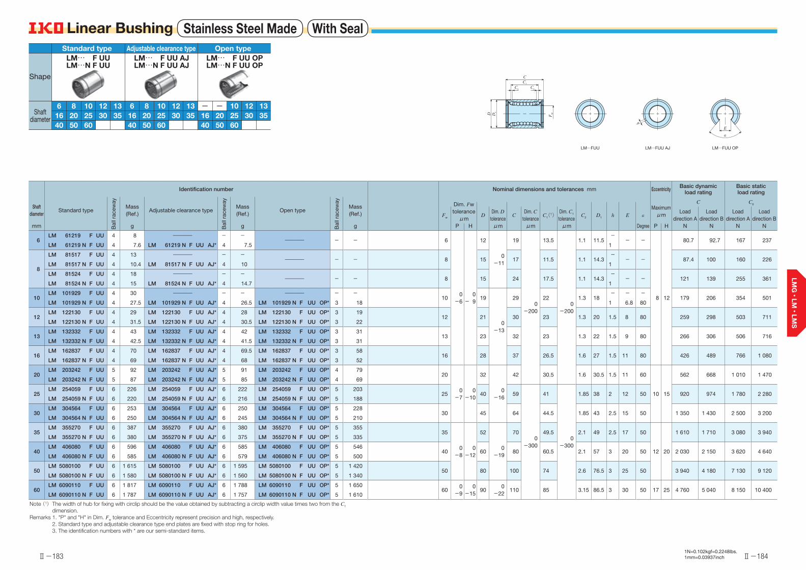
Ⅱ-183
Linear Bushing Stainless Steel Made With Seal
Ⅱ-184
Linear Bushing
Identification number Nominal dimensions and tolerances mm Eccentricity Basic dynamic load rating
Basic static load rating
Shaft diameter
Standard type
Bal
l rac
eway
Mass(Ref.)
Adjustable clearance type
Bal
l rac
eway
Mass(Ref.)
Open type
Bal
l rac
eway
Mass(Ref.)
Maximumμm
C C0Dim. Fw toleranceμm
Fw DDim. D
toleranceC
Dim. C tolerance
C1(1)Dim. C1 tolerance
C2 D1 h E αLoad
direction ALoad
direction BLoad
direction ALoad
direction Bmm g g g P H μm μm μm Degree P H N N N N
6LM 61219 F UU 4 8 ―――― - -
―――― - - 6
0-6
0- 9
12
0-11
19
0-200
13.5
0-200
1.1 11.5-
- -
8 12
80.7 92.7 167 237LM 61219 N F UU 4 7.6 LM 61219 N F UU AJ* 4 7.5 1
8
LM 81517 F UU 4 13 ―――― - -―――― - - 8 15 17 11.5 1.1 14.3
-- - 87.4 100 160 226
LM 81517 N F UU 4 10.4 LM 81517 N F UU AJ* 4 10 1
LM 81524 F UU 4 18 ―――― - -―――― - - 8 15 24 17.5 1.1 14.3
-- - 121 139 255 361
LM 81524 N F UU 4 15 LM 81524 N F UU AJ* 4 14.7 1
10LM 101929 F UU 4 30 ―――― - - ―――― - -
10 19
0-13
29 22 1.3 18- - -
179 206 354 501LM 101929 N F UU 4 27.5 LM 101929 N F UU AJ* 4 26.5 LM 101929 N F UU OP* 3 18 1 6.8 80
12LM 122130 F UU 4 29 LM 122130 F UU AJ* 4 28 LM 122130 F UU OP* 3 19
12 21 30 23 1.3 20 1.5 8 80 259 298 503 711LM 122130 N F UU 4 31.5 LM 122130 N F UU AJ* 4 30.5 LM 122130 N F UU OP* 3 22
13LM 132332 F UU 4 43 LM 132332 F UU AJ* 4 42 LM 132332 F UU OP* 3 31
13 23 32 23 1.3 22 1.5 9 80 266 306 506 716LM 132332 N F UU 4 42.5 LM 132332 N F UU AJ* 4 41.5 LM 132332 N F UU OP* 3 31
16LM 162837 F UU 4 70 LM 162837 F UU AJ* 4 69.5 LM 162837 F UU OP* 3 58
16 28 37 26.5 1.6 27 1.5 11 80 426 489 766 1 080LM 162837 N F UU 4 69 LM 162837 N F UU AJ* 4 68 LM 162837 N F UU OP* 3 52
20LM 203242 F UU 5 92 LM 203242 F UU AJ* 5 91 LM 203242 F UU OP* 4 79
20
0-7
0-10
32
0-16
42 30.5 1.6 30.5 1.5 11 60
10 15
562 668 1 010 1 470LM 203242 N F UU 5 87 LM 203242 N F UU AJ* 5 85 LM 203242 N F UU OP* 4 69
25LM 254059 F UU 6 226 LM 254059 F UU AJ* 6 222 LM 254059 F UU OP* 5 203
25 40 59
0-300
41
0-300
1.85 38 2 12 50 920 974 1 780 2 280LM 254059 N F UU 6 220 LM 254059 N F UU AJ* 6 216 LM 254059 N F UU OP* 5 188
30LM 304564 F UU 6 253 LM 304564 F UU AJ* 6 250 LM 304564 F UU OP* 5 228
30 45 64 44.5 1.85 43 2.5 15 50 1 350 1 430 2 500 3 200LM 304564 N F UU 6 250 LM 304564 N F UU AJ* 6 245 LM 304564 N F UU OP* 5 210
35LM 355270 F UU 6 387 LM 355270 F UU AJ* 6 380 LM 355270 F UU OP* 5 355
35
0-8
0-12
52
0-19
70 49.5 2.1 49 2.5 17 50
12 20
1 610 1 710 3 080 3 940LM 355270 N F UU 6 380 LM 355270 N F UU AJ* 6 375 LM 355270 N F UU OP* 5 335
40LM 406080 F UU 6 596 LM 406080 F UU AJ* 6 585 LM 406080 F UU OP* 5 546
40 60 80 60.5 2.1 57 3 20 50 2 030 2 150 3 620 4 640LM 406080 N F UU 6 585 LM 406080 N F UU AJ* 6 579 LM 406080 N F UU OP* 5 500
50LM 5080100 F UU 6 1 615 LM 5080100 F UU AJ* 6 1 595 LM 5080100 F UU OP* 5 1 420
50 80 100 74 2.6 76.5 3 25 50 3 940 4 180 7 130 9 120LM 5080100 N F UU 6 1 580 LM 5080100 N F UU AJ* 6 1 560 LM 5080100 N F UU OP* 5 1 340
60LM 6090110 F UU 6 1 817 LM 6090110 F UU AJ* 6 1 788 LM 6090110 F UU OP* 5 1 650
600
-90
-1590
0-22
110 85 3.15 86.5 3 30 50 17 25 4 760 5 040 8 150 10 400LM 6090110 N F UU 6 1 787 LM 6090110 N F UU AJ* 6 1 757 LM 6090110 N F UU OP* 5 1 610
Note (1) The width of hub for fixing with circlip should be the value obtained by subtracting a circlip width value times two from the C1 dimension.
Remarks 1. "P" and "H" in Dim. Fw tolerance and Eccentricity represent precision and high, respectively.2. Standard type and adjustable clearance type end plates are fixed with stop ring for holes.3. The identification numbers with * are our semi-standard items.
LM…FUU OPLM…FUU AJLM…FUU
E
α
h
D1
D
C
C2 C2
C1
FW
1N=0.102kgf=0.2248lbs.1mm=0.03937inch
126 816
13103520 25
504030
60
Standard typeLM… F UULM…N F UU
126 816
13103520 25
504030
60
Adjustable clearance typeLM… F UU AJLM…N F UU AJ
1216
13103520 25
504030
60
Open typeLM… F UU OPLM…N F UU OP
--
Shape
Shaft diameter
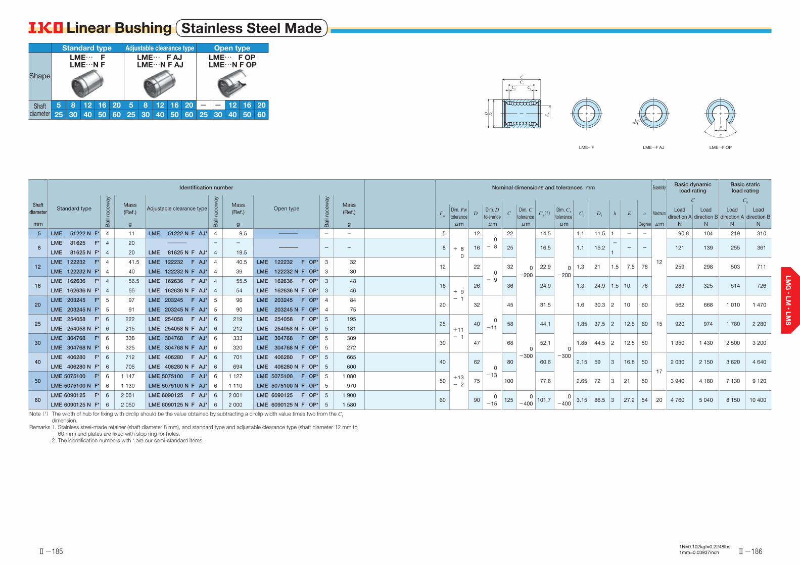
Ⅱ-185
Linear Bushing Stainless Steel Made
Ⅱ-186
Linear Bushing
Identification number Nominal dimensions and tolerances mm Eccentricity Basic dynamic load rating
Basic static load rating
Shaft diameter
Standard type
Bal
l rac
eway
Mass(Ref.)
Adjustable clearance typeB
all r
acew
ay
Mass(Ref.)
Open type
Bal
l rac
eway
Mass(Ref.)
C C0
Fw
Dim. Fw tolerance
DDim. D
toleranceC
Dim. C tolerance
C1(1)Dim. C1 tolerance
C2 D1 h E α MaximumLoad
direction ALoad
direction BLoad
direction ALoad
direction Bmm g g g μm μm μm μm Degree μm N N N N
5 LME 51222 N F* 4 11 LME 51222 N F AJ* 4 9.5 ―――― - - 5
+ 80
120
- 8
22
0-200
14.5
0-200
1.1 11.5 1 - -
12
90.8 104 219 310
8LME 81625 F* 4 20 ―――― - -
―――― - - 8 16 25 16.5 1.1 15.2-
- - 121 139 255 361LME 81625 N F* 4 20 LME 81625 N F AJ* 4 19.5 1
12LME 122232 F* 4 41.5 LME 122232 F AJ* 4 40.5 LME 122232 F OP* 3 32
12 220
- 9
32 22.9 1.3 21 1.5 7.5 78 259 298 503 711LME 122232 N F* 4 40 LME 122232 N F AJ* 4 39 LME 122232 N F OP* 3 30
16LME 162636 F* 4 56.5 LME 162636 F AJ* 4 55.5 LME 162636 F OP* 3 48
16+ 9- 1
26 36 24.9 1.3 24.9 1.5 10 78 283 325 514 726LME 162636 N F* 4 55 LME 162636 N F AJ* 4 54 LME 162636 N F OP* 3 46
20LME 203245 F* 5 97 LME 203245 F AJ* 5 96 LME 203245 F OP* 4 84
20 32
0-11
45 31.5 1.6 30.3 2 10 60
15
562 668 1 010 1 470LME 203245 N F* 5 91 LME 203245 N F AJ* 5 90 LME 203245 N F OP* 4 75
25LME 254058 F* 6 222 LME 254058 F AJ* 6 219 LME 254058 F OP* 5 195
25+11- 1
40 58
0-300
44.1
0-300
1.85 37.5 2 12.5 60 920 974 1 780 2 280LME 254058 N F* 6 215 LME 254058 N F AJ* 6 212 LME 254058 N F OP* 5 181
30LME 304768 F* 6 338 LME 304768 F AJ* 6 333 LME 304768 F OP* 5 309
30 47 68 52.1 1.85 44.5 2 12.5 50 1 350 1 430 2 500 3 200LME 304768 N F* 6 325 LME 304768 N F AJ* 6 320 LME 304768 N F OP* 5 272
40LME 406280 F* 6 712 LME 406280 F AJ* 6 701 LME 406280 F OP* 5 665
40
+13- 2
620
-13
80 60.6 2.15 59 3 16.8 50
17
2 030 2 150 3 620 4 640LME 406280 N F* 6 705 LME 406280 N F AJ* 6 694 LME 406280 N F OP* 5 600
50LME 5075100 F* 6 1 147 LME 5075100 F AJ* 6 1 127 LME 5075100 F OP* 5 1 080
50 75 100 77.6 2.65 72 3 21 50 3 940 4 180 7 130 9 120LME 5075100 N F* 6 1 130 LME 5075100 N F AJ* 6 1 110 LME 5075100 N F OP* 5 970
60LME 6090125 F* 6 2 051 LME 6090125 F AJ* 6 2 001 LME 6090125 F OP* 5 1 900
60 900
-15125
0-400
101.70
-4003.15 86.5 3 27.2 54 20 4 760 5 040 8 150 10 400
LME 6090125 N F* 6 2 050 LME 6090125 N F AJ* 6 2 000 LME 6090125 N F OP* 5 1 580
Note (1) The width of hub for fixing with circlip should be the value obtained by subtracting a circlip width value times two from the C1 dimension.
Remarks 1. Stainless steel-made retainer (shaft diameter 8 mm), and standard type and adjustable clearance type (shaft diameter 12 mm to 60 mm) end plates are fixed with stop ring for holes.
2. The identification numbers with * are our semi-standard items.
LME…F LME…F OPLME…F AJ
D1
C
D
C2 C2
C1
FW
h
E
α
1N=0.102kgf=0.2248lbs.1mm=0.03937inch
16
Standard type
5 8 2012
LME… F
5025 30 6040
LME…N F
165 8 20125025 30 6040
Adjustable clearance typeLME… F AJLME…N F AJ
16 20125025 30 6040
Open typeLME… F OPLME…N F OP
--
Shape
Shaft diameter
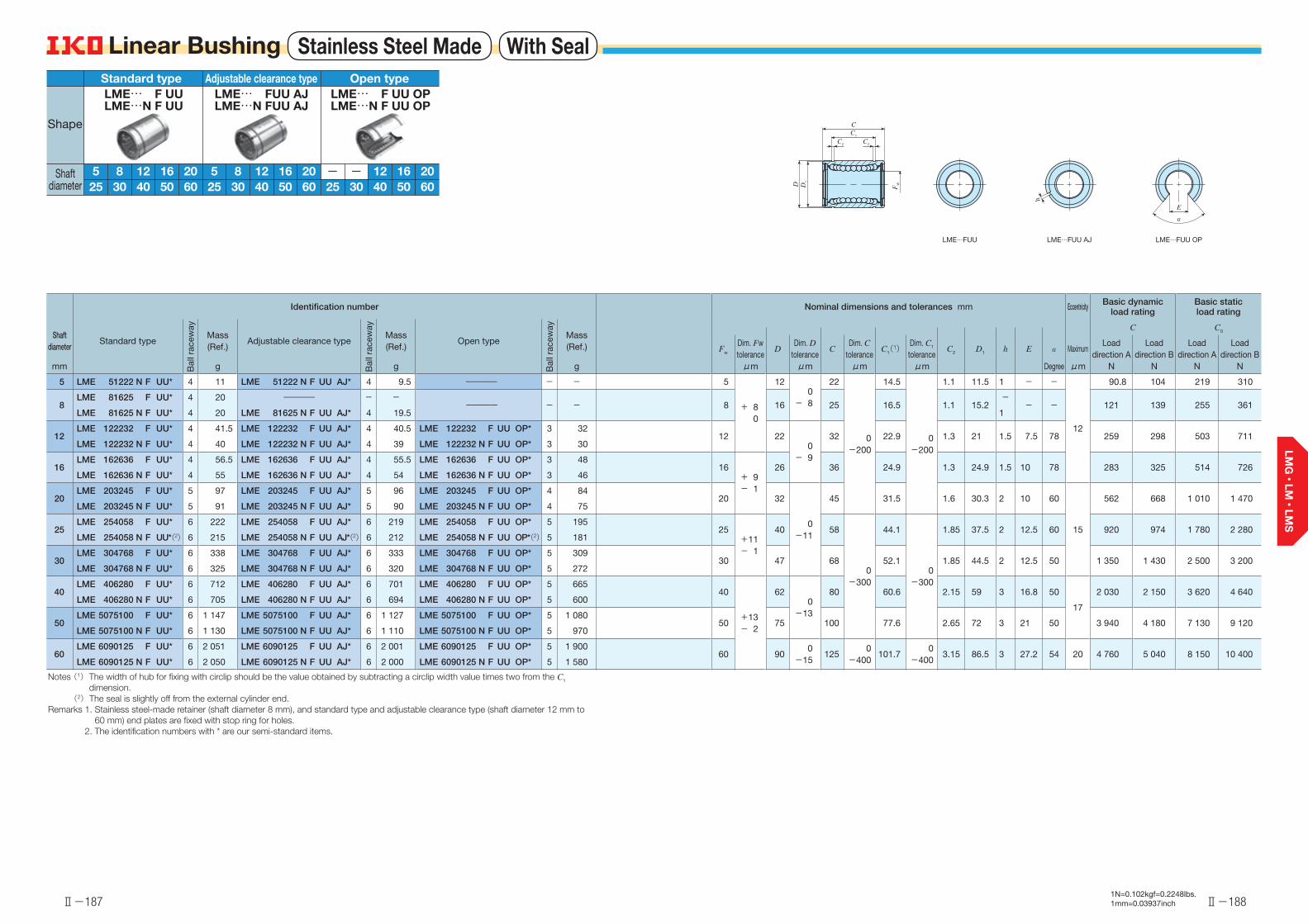
Ⅱ-187
Linear Bushing Stainless Steel Made With Seal
Ⅱ-188
Linear Bushing
Identification number Nominal dimensions and tolerances mm Eccentricity Basic dynamic load rating
Basic static load rating
Shaft diameter
Standard type
Bal
l rac
eway
Mass(Ref.)
Adjustable clearance type
Bal
l rac
eway
Mass(Ref.)
Open type
Bal
l rac
eway
Mass(Ref.)
C C0
Fw
Dim. Fw tolerance
DDim. D
toleranceC
Dim. C tolerance
C1(1)Dim. C1 tolerance
C2 D1 h E α MaximumLoad
direction ALoad
direction BLoad
direction ALoad
direction Bmm g g g μm μm μm μm Degree μm N N N N
5 LME 51222 N F UU* 4 11 LME 51222 N F UU AJ* 4 9.5 ―――― - - 5
+ 80
120
- 8
22
0-200
14.5
0-200
1.1 11.5 1 - -
12
90.8 104 219 310
8LME 81625 F UU* 4 20 ―――― - -
―――― - - 8 16 25 16.5 1.1 15.2-
- - 121 139 255 361LME 81625 N F UU* 4 20 LME 81625 N F UU AJ* 4 19.5 1
12LME 122232 F UU* 4 41.5 LME 122232 F UU AJ* 4 40.5 LME 122232 F UU OP* 3 32
12 220
- 9
32 22.9 1.3 21 1.5 7.5 78 259 298 503 711LME 122232 N F UU* 4 40 LME 122232 N F UU AJ* 4 39 LME 122232 N F UU OP* 3 30
16LME 162636 F UU* 4 56.5 LME 162636 F UU AJ* 4 55.5 LME 162636 F UU OP* 3 48
16+ 9- 1
26 36 24.9 1.3 24.9 1.5 10 78 283 325 514 726LME 162636 N F UU* 4 55 LME 162636 N F UU AJ* 4 54 LME 162636 N F UU OP* 3 46
20LME 203245 F UU* 5 97 LME 203245 F UU AJ* 5 96 LME 203245 F UU OP* 4 84
20 32
0-11
45 31.5 1.6 30.3 2 10 60
15
562 668 1 010 1 470LME 203245 N F UU* 5 91 LME 203245 N F UU AJ* 5 90 LME 203245 N F UU OP* 4 75
25LME 254058 F UU* 6 222 LME 254058 F UU AJ* 6 219 LME 254058 F UU OP* 5 195
25+11- 1
40 58
0-300
44.1
0-300
1.85 37.5 2 12.5 60 920 974 1 780 2 280LME 254058 N F UU*(2) 6 215 LME 254058 N F UU AJ*(2) 6 212 LME 254058 N F UU OP*(2) 5 181
30LME 304768 F UU* 6 338 LME 304768 F UU AJ* 6 333 LME 304768 F UU OP* 5 309
30 47 68 52.1 1.85 44.5 2 12.5 50 1 350 1 430 2 500 3 200LME 304768 N F UU* 6 325 LME 304768 N F UU AJ* 6 320 LME 304768 N F UU OP* 5 272
40LME 406280 F UU* 6 712 LME 406280 F UU AJ* 6 701 LME 406280 F UU OP* 5 665
40
+13- 2
620
-13
80 60.6 2.15 59 3 16.8 50
17
2 030 2 150 3 620 4 640LME 406280 N F UU* 6 705 LME 406280 N F UU AJ* 6 694 LME 406280 N F UU OP* 5 600
50LME 5075100 F UU* 6 1 147 LME 5075100 F UU AJ* 6 1 127 LME 5075100 F UU OP* 5 1 080
50 75 100 77.6 2.65 72 3 21 50 3 940 4 180 7 130 9 120LME 5075100 N F UU* 6 1 130 LME 5075100 N F UU AJ* 6 1 110 LME 5075100 N F UU OP* 5 970
60LME 6090125 F UU* 6 2 051 LME 6090125 F UU AJ* 6 2 001 LME 6090125 F UU OP* 5 1 900
60 900
-15125
0-400
101.70
-4003.15 86.5 3 27.2 54 20 4 760 5 040 8 150 10 400
LME 6090125 N F UU* 6 2 050 LME 6090125 N F UU AJ* 6 2 000 LME 6090125 N F UU OP* 5 1 580
Notes (1) The width of hub for fixing with circlip should be the value obtained by subtracting a circlip width value times two from the C1 dimension.
(2) The seal is slightly off from the external cylinder end.Remarks 1. Stainless steel-made retainer (shaft diameter 8 mm), and standard type and adjustable clearance type (shaft diameter 12 mm to
60 mm) end plates are fixed with stop ring for holes.2. The identification numbers with * are our semi-standard items.
LME…FUU OPLME…FUU AJLME…FUU
E
α
h
D1
D
C
C2 C2
C1
FW
1N=0.102kgf=0.2248lbs.1mm=0.03937inch
165 8 20125025 30 6040
Standard typeLME… F UULME…N F UU
165 8 20125025 30 6040
Adjustable clearance typeLME… FUU AJLME…N FUU AJ
16 20125025 30 6040
Open typeLME… F UU OPLME…N F UU OP
--
Shape
Shaft diameter
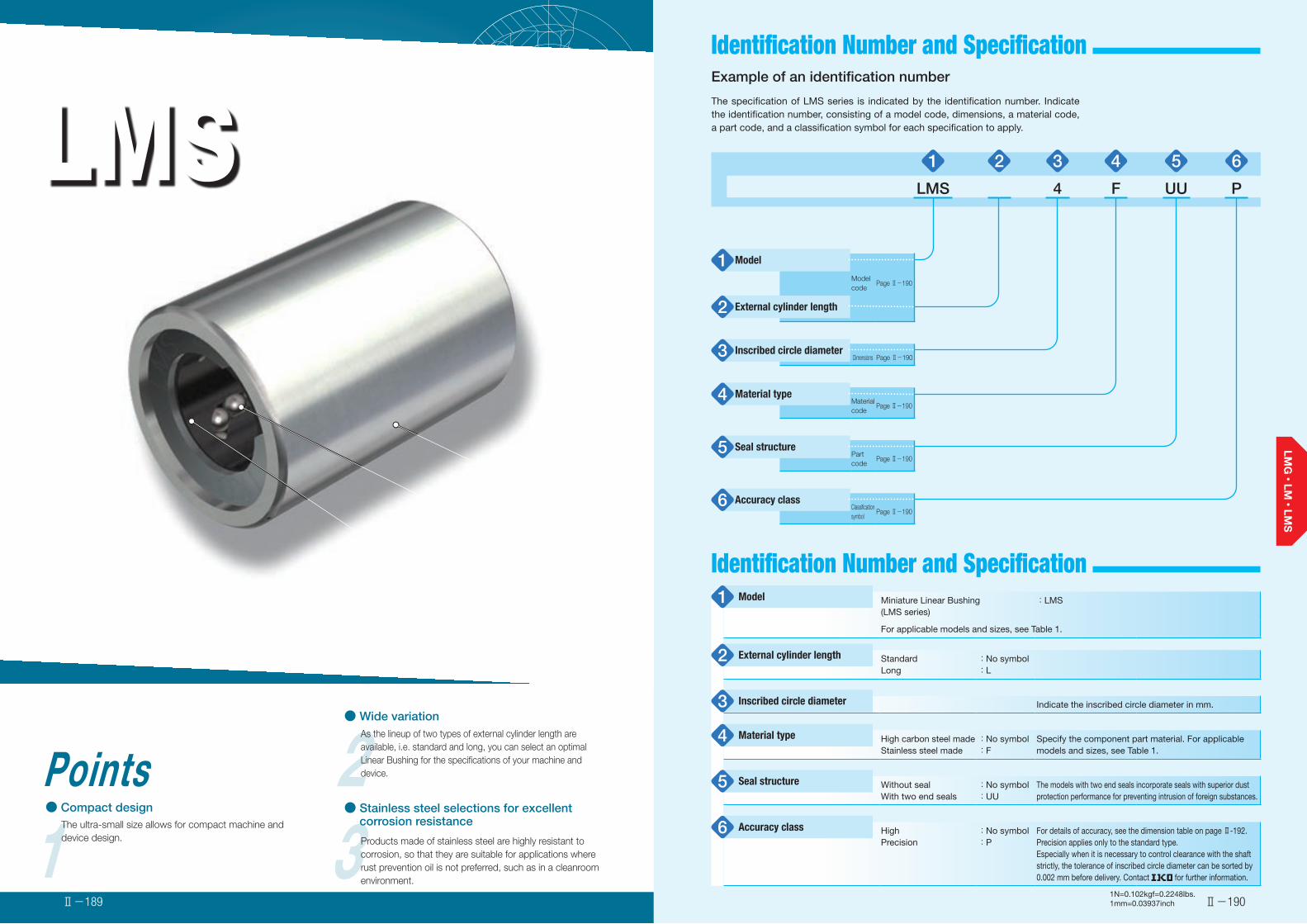
LMSMiniature Linear Bushing
2● Wide variation
As the lineup of two types of external cylinder length are available, i.e. standard and long, you can select an optimal Linear Bushing for the specifications of your machine and device.
1Points● Compact design
The ultra-small size allows for compact machine and device design. 3Products made of stainless steel are highly resistant to
corrosion, so that they are suitable for applications where rust prevention oil is not preferred, such as in a cleanroom environment.
● Stainless steel selections for excellent corrosion resistance
External cylinder
Ball
Retainer
Identification Number and Specification
Ⅱ-190Ⅱ-189
Identification Number and Specification
Example of an identification number
The specification of LMS series is indicated by the identification number. Indicate the identification number, consisting of a model code, dimensions, a material code, a part code, and a classification symbol for each specification to apply.
1 2 3 4 5 6
LMS 4 F UU P
Model1Model code
Page Ⅱ-190
External cylinder length2
Inscribed circle diameter3 Dimensions Page Ⅱ-190
Material type4 Material code
Page Ⅱ-190
Seal structure5 Part code
Page Ⅱ-190
Accuracy class6 Classification symbol
Page Ⅱ-190
Miniature Linear Bushing(LMS series)
:LMS
For applicable models and sizes, see Table 1.
StandardLong
:No symbol:L
Indicate the inscribed circle diameter in mm.
High carbon steel madeStainless steel made
:No symbol:F
Specify the component part material. For applicable models and sizes, see Table 1.
Without sealWith two end seals
:No symbol:UU
The models with two end seals incorporate seals with superior dust protection performance for preventing intrusion of foreign substances.
HighPrecision
:No symbol:P
For details of accuracy, see the dimension table on page Ⅱ-192. Precision applies only to the standard type.Especially when it is necessary to control clearance with the shaft strictly, the tolerance of inscribed circle diameter can be sorted by 0.002 mm before delivery. Contact for further information.
Model1
External cylinder length2
Inscribed circle diameter3
Material type4
Seal structure5
Accuracy class6
1N=0.102kgf=0.2248lbs.1mm=0.03937inch
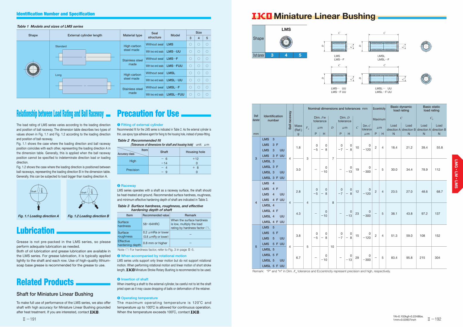
Identification number
Bal
l rac
eway
Mass(Ref.)
Nominal dimensions and tolerances mm Eccentricity Basic dynamic load rating
Basic static load rating
Shaft diameter
C C0Dim. Fw tolerance
Dim. D tolerance Maximum
Fw μm D μm CDim. C
toleranceμm
Load direction A
Load direction B
Load direction A
Load direction B
mm g P H P H μm P H N N N N
3
LMS 3
4
1.8
3
0-5
0- 8
7
0-7
0- 8
100
-1202 4 18.4 21.2 39.4 55.8
LMS 3 F
LMS 3 UU
LMS 3 F UU
LMSL 3
3.0 -0
-10-
0-13
190
-300- 5 30.0 34.4 78.9 112
LMSL 3 F
LMSL 3 UU
LMSL 3 F UU
4
LMS 4
4
2.8
4
0-5
0- 8
8
0-7
0- 8
120
-1202 4 23.5 27.0 48.6 68.7
LMS 4 F
LMS 4 UU
LMS 4 F UU
LMSL 4
4.3 -0
-10-
0-13
230
-300- 5 38.1 43.8 97.2 137
LMSL 4 F
LMSL 4 UU
LMSL 4 F UU
5
LMS 5
4
3.8
5
0-5
0- 8
10
0-7
0- 8
150
-1202 4 51.3 59.0 108 152
LMS 5 F
LMS 5 UU
LMS 5 F UU
LMSL 5
6.7 -0
-10-
0-13
290
-300- 5 83.4 95.8 215 304
LMSL 5 F
LMSL 5 UU
LMSL 5 F UU
Remark: "P" and "H" in Dim. Fw tolerance and Eccentricity represent precision and high, respectively.
Ⅱ-191 Ⅱ-192
Identification Number and Specification
Lubrication
Precaution for Use Relationship between Load Rating and Ball Raceway
Related Products
The load rating of LMS series varies according to the loading direction and position of ball raceway. The dimension table describes two types of values shown in Fig. 1.1 and Fig. 1.2 according to the loading direction and position of ball raceway.Fig. 1.1 shows the case where the loading direction and ball raceway position coincides with each other, representing the loading direction A in the dimension table. Generally, this is applied when the ball raceway position cannot be specified to indeterminate direction load or loading direction.Fig. 1.2 shows the case where the loading direction is positioned between ball raceways, representing the loading direction B in the dimension table. Generally, this can be subjected to load bigger than loading direction A.
Fig. 1.1 Loading direction A Fig. 1.2 Loading direction B
LoadShaft
LoadShaft
Miniature Linear Bushing
Grease is not pre-packed in the LMS series, so please perform adequate lubrication as needed.Both of oil lubrication and grease lubrication are available in the LMS series. For grease lubrication, it is typically applied lightly to the shaft and each row. Use of high-quality lithium-soap base grease is recommended for the grease to use.
Shaft for Miniature Linear Bushing
To make full use of performance of the LMS series, we also offer shaft with high accuracy for Miniature Linear Bushing grounded after heat treatment. If you are interested, contact .
❶ Fitting of external cylinderRecommended fit for the LMS series is indicated in Table 2. As the external cylinder is thin, use epoxy type adhesive agent for fixing to the housing hole, instead of press-fitting.
Table 2 Recommended fit(Tolerances of dimensions for shaft and housing hole) unit: μm
ltemAccuracy class
Shaft Housing hole
High- 6 +12-14 0
Precision- 4 + 8- 9 0
❷ RacewayLMS series operates with a shaft as a raceway surface, the shaft should be heat-treated and ground. Recommended surface hardness, roughness, and minimum effective hardening depth of shaft are indicated in Table 3.
Table 3 Surface hardness, roughness, and effective hardening depth of shaft
Item Recommended value Remark
Surface hardness
58~64HRCWhen the surface hardness is low, multiply the load rating by hardness factor (1).
Surface roughness
0.2 μmRa or lower-
(0.8 μmRy or lower)Effective hardening depth
0.8 mm or higher -
Note (1) For hardness factor, refer to Fig. 3 in page Ⅲ-5.
❸ When accompanied by rotational motionLMS series units support only linear motion but do not support rotational motion. When performing rotational motion and linear motion of short stroke length, Miniature Stroke Rotary Bushing is recommended to be used.
❹ Insertion of shaftWhen inserting a shaft to the external cylinder, be careful not to let the shaft pried open as it may cause dropping of balls or deformation of the retainer.
❺ Operating temperatureThe maximum operating temperature is 120˚C and temperature up to 100˚C is allowed for continuous operation. When the temperature exceeds 100˚C, contact .
Table 1 Models and sizes of LMS series
Shape External cylinder length Material typeSeal
structureModel
Size
3 4 5
High carbon steel made
Without seal LMS ○ ○ ○
With two end seals LMS…UU ○ ○ ○
Stainless steel made
Without seal LMS…F ○ ○ ○
With two end seals LMS…FUU ○ ○ ○
High carbon steel made
Without seal LMSL ○ ○ ○
With two end seals LMSL…UU ○ ○ ○
Stainless steel made
Without seal LMSL…F ○ ○ ○
With two end seals LMSL…FUU ○ ○ ○
Standard
Long
43 5
LMS
Shape
Shaft diameter LMSLMS…F
LMS… UULMS…F UU
LMSLLMSL…F
LMSL… UULMSL…F UU
D D
D D
C
C
C
FW
FW
C
FW
FW
1N=0.102kgf=0.2248lbs.1mm=0.03937inch
Ⅱ-193 Ⅱ-194
Stroke Rotary Bushing
Stroke Rotary BushingMiniature Stroke Rotary BushingStroke Rotary Cage
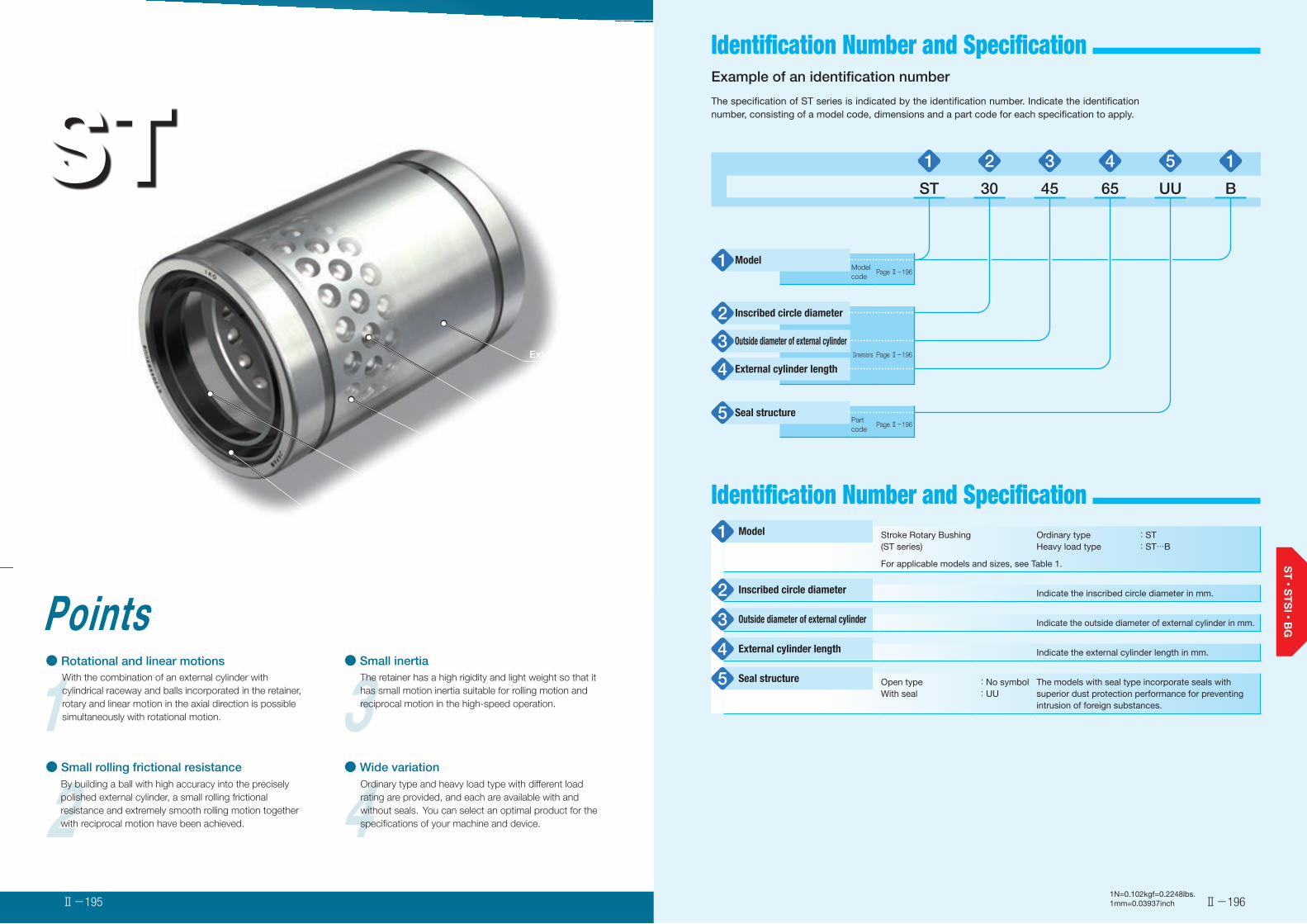
2● Small rolling frictional resistance
By building a ball with high accuracy into the precisely polished external cylinder, a small rolling frictional resistance and extremely smooth rolling motion together with reciprocal motion have been achieved. 4
● Wide variationOrdinary type and heavy load type with different load rating are provided, and each are available with and without seals. You can select an optimal product for the specifications of your machine and device.
1Points● Rotational and linear motions
With the combination of an external cylinder with cylindrical raceway and balls incorporated in the retainer, rotary and linear motion in the axial direction is possible simultaneously with rotational motion. 3
● Small inertiaThe retainer has a high rigidity and light weight so that it has small motion inertia suitable for rolling motion and reciprocal motion in the high-speed operation.
STStroke Rotary Bushing
Ball
External cylinder
Retainer
Seal
End plate
Ⅱ-196Ⅱ-195
Identification Number and Specification
Identification Number and Specification
Example of an identification number
The specification of ST series is indicated by the identification number. Indicate the identification number, consisting of a model code, dimensions and a part code for each specification to apply.
1 2 3 4 5 1
ST 30 45 65 UU B
Model1 Model code
Page Ⅱ-196
Inscribed circle diameter2Outside diameter of external cylinder3
Dimensions Page Ⅱ-196
External cylinder length4
Seal structure5 Part code
Page Ⅱ-196
Stroke Rotary Bushing(ST series)
Ordinary typeHeavy load type
:ST:ST…B
For applicable models and sizes, see Table 1.
Indicate the inscribed circle diameter in mm.
Indicate the outside diameter of external cylinder in mm.
Indicate the external cylinder length in mm.
Open typeWith seal
:No symbol:UU
The models with seal type incorporate seals with superior dust protection performance for preventing intrusion of foreign substances.
Model1
Inscribed circle diameter2
Outside diameter of external cylinder3
External cylinder length4
Seal structure5
1N=0.102kgf=0.2248lbs.1mm=0.03937inch
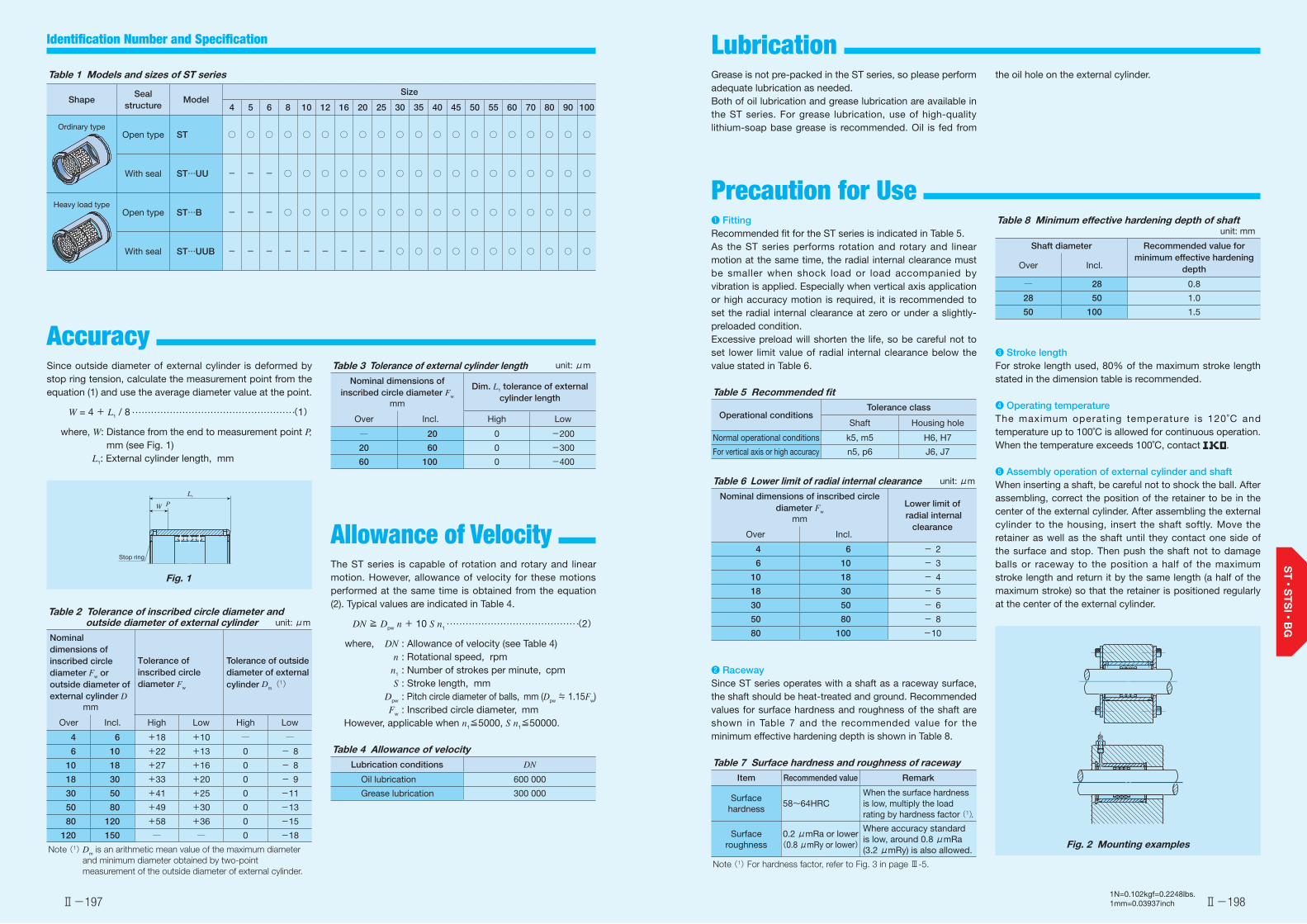
Ⅱ-197 Ⅱ-198
Identification Number and Specification Lubrication
Precaution for Use
Accuracy
Grease is not pre-packed in the ST series, so please perform adequate lubrication as needed.Both of oil lubrication and grease lubrication are available in the ST series. For grease lubrication, use of high-quality lithium-soap base grease is recommended. Oil is fed from
❶ FittingRecommended fit for the ST series is indicated in Table 5.As the ST series performs rotation and rotary and linear motion at the same time, the radial internal clearance must be smaller when shock load or load accompanied by vibration is applied. Especially when vertical axis application or high accuracy motion is required, it is recommended to set the radial internal clearance at zero or under a slightly-preloaded condition.Excessive preload will shorten the life, so be careful not to set lower limit value of radial internal clearance below the value stated in Table 6.
Table 5 Recommended fit
Operational conditionsTolerance class
Shaft Housing hole
Normal operational conditions k5, m5 H6, H7
For vertical axis or high accuracy n5, p6 J6, J7
Table 6 Lower limit of radial internal clearance unit: μm
Nominal dimensions of inscribed circle diameter Fw
mm
Lower limit of radial internal
clearanceOver Incl.
4 6 - 2
6 10 - 3
10 18 - 4
18 30 - 5
30 50 - 6
50 80 - 8
80 100 -10
❷ RacewaySince ST series operates with a shaft as a raceway surface, the shaft should be heat-treated and ground. Recommended values for surface hardness and roughness of the shaft are shown in Table 7 and the recommended value for the minimum effective hardening depth is shown in Table 8.
Table 7 Surface hardness and roughness of racewayItem Recommended value Remark
Surface hardness
58~64HRCWhen the surface hardness is low, multiply the load rating by hardness factor (1).
Surface roughness
0.2 μmRa or lower(0.8 μmRy or lower)
Where accuracy standard is low, around 0.8 μmRa (3.2 μmRy) is also allowed.
Note (1) For hardness factor, refer to Fig. 3 in page Ⅲ-5.
Since outside diameter of external cylinder is deformed by stop ring tension, calculate the measurement point from the equation (1) and use the average diameter value at the point.
W = 4 + L1 / 8 (1)
where, W: Distance from the end to measurement point P, mm (see Fig. 1)
L1: External cylinder length, mm
L1
W P
Stop ring
Fig. 1
Table 2 Tolerance of inscribed circle diameter and outside diameter of external cylinder unit: μm
Nominal dimensions of inscribed circle diameter Fw or outside diameter of external cylinder D
mm
Tolerance of inscribed circle diameter Fw
Tolerance of outside diameter of external cylinder Dm
(1)
Over Incl. High Low High Low
4 6 +18 +10 ─ ─
6 10 +22 +13 0 - 8
10 18 +27 +16 0 - 8
18 30 +33 +20 0 - 9
30 50 +41 +25 0 -11
50 80 +49 +30 0 -13
80 120 +58 +36 0 -15
120 150 ─ ─ 0 -18
Note (1) Dm is an arithmetic mean value of the maximum diameter
and minimum diameter obtained by two-point measurement of the outside diameter of external cylinder.
Allowance of Velocity The ST series is capable of rotation and rotary and linear motion. However, allowance of velocity for these motions performed at the same time is obtained from the equation (2). Typical values are indicated in Table 4.
DN ≧ Dpw n + 10 S n1 (2)
where, DN : Allowance of velocity (see Table 4) n : Rotational speed, rpm n1 : Number of strokes per minute, cpm S : Stroke length, mm Dpw : Pitch circle diameter of balls, mm (Dpw ≒ 1.15Fw) Fw : Inscribed circle diameter, mm However, applicable when n1≦5000, S n1≦50000.
Table 4 Allowance of velocityLubrication conditions DN
Oil lubrication 600 000
Grease lubrication 300 000
Table 8 Minimum effective hardening depth of shaftunit: mm
Shaft diameter Recommended value for minimum effective hardening
depthOver Incl.
─ 28 0.8
28 50 1.0
50 100 1.5
❸ Stroke lengthFor stroke length used, 80% of the maximum stroke length stated in the dimension table is recommended.
❹ Operating temperatureThe maximum operating temperature is 120˚C and temperature up to 100˚C is allowed for continuous operation. When the temperature exceeds 100˚C, contact .
❺ Assembly operation of external cylinder and shaftWhen inserting a shaft, be careful not to shock the ball. After assembling, correct the position of the retainer to be in the center of the external cylinder. After assembling the external cylinder to the housing, insert the shaft softly. Move the retainer as well as the shaft until they contact one side of the surface and stop. Then push the shaft not to damage balls or raceway to the position a half of the maximum stroke length and return it by the same length (a half of the maximum stroke) so that the retainer is positioned regularly at the center of the external cylinder.
Fig. 2 Mounting examples
the oil hole on the external cylinder.Table 1 Models and sizes of ST series
ShapeSeal
structureModel
Size
4 5 6 8 10 12 16 20 25 30 35 40 45 50 55 60 70 80 90 100
Open type ST ○ ○ ○ ○ ○ ○ ○ ○ ○ ○ ○ ○ ○ ○ ○ ○ ○ ○ ○ ○
With seal ST…UU - - - ○ ○ ○ ○ ○ ○ ○ ○ ○ ○ ○ ○ ○ ○ ○ ○ ○
Open type ST…B - - - ○ ○ ○ ○ ○ ○ ○ ○ ○ ○ ○ ○ ○ ○ ○ ○ ○
With seal ST…UUB - - - - - - - - - ○ ○ ○ ○ ○ ○ ○ ○ ○ ○ ○
Ordinary type
Heavy load type
Table 3 Tolerance of external cylinder length unit: μm
Nominal dimensions of inscribed circle diameter Fw
mm
Dim. L1 tolerance of external cylinder length
Over Incl. High Low
─ 20 0 -200
20 60 0 -300
60 100 0 -400
1N=0.102kgf=0.2248lbs.1mm=0.03937inch

Ⅱ-199
Stroke Rotary Bushing Open Type
Ⅱ-200
Stroke Rotary Bushing
Shaft diameter
mm
Identification number Nominal dimensions ST ST…Bmm Maximum
stroke length
mm
Basic dynamic load rating
C
N
Basic static load rating
C0
N
Maximum stroke length
mm
Basic dynamicload rating
C
N
Basic staticload rating
C0
N
Ordinary type Mass (Ref.)
g
Heavy load type Mass (Ref.)
gFw D L1 L2 T t r
4 ST 4814 2.9 ―――― ――― 4 8 14 9 1.1 0.25 0.3 10 112 59.5 ――― ――― ―――
5 ST 51016 5.6 ―――― ――― 5 10 16 10.6 1.1 0.25 0.3 13 121 68.3 ――― ――― ―――
6 ST 61219 8.9 ―――― ――― 6 12 19 13.2 1.1 0.25 0.3 15 278 168 ――― ――― ―――
8 ST 81524 15.6 ST 81524 B 16.8 8 15 24 17.1 1.5 0.5 0.5 24 315 211 8 512 422
10 ST 101930 28.8 ST 101930 B 31.2 10 19 30 22.7 1.5 0.5 0.5 30 659 466 8 1 070 932
12 ST 122332 42 ST 122332 B 46 12 23 32 24.5 1.5 0.5 0.5 32 1 110 822 8 1 800 1 640
16 ST 162837 71 ST 162837 B 75 16 28 37 29.1 1.5 0.5 0.5 40 1 230 998 16 1 990 2 000
20 ST 203245 99 ST 203245 B 106 20 32 45 35.8 2 0.5 0.5 54 1 390 1 250 28 2 250 2 500
25 ST 253745 117 ST 253745 B 125 25 37 45 35.8 2 0.5 1 54 1 450 1 430 28 2 360 2 850
30 ST 304565 205 ST 304565 B 220 30 45 65 53.5 2.5 0.5 1 82 3 110 3 160 44 5 060 6 320
35 ST 355270 329 ST 355270 B 346 35 52 70 58.5 2.5 0.7 1.5 92 3 290 3 550 54 5 340 7 100
40 ST 406080 516 ST 406080 B 540 40 60 80 68.3 2.5 0.7 1.5 108 4 340 4 810 66 7 050 9 630
45 ST 456580 563 ST 456580 B 588 45 65 80 68.3 2.5 0.7 1.5 108 4 550 5 330 66 7 390 10 700
50 ST 5072100 827 ST 5072100 B 862 50 72 100 86.4 3 1 1.5 138 5 790 6 970 88 9 400 13 900
55 ST 5580100 1 160 ST 5580100 B 1 200 55 80 100 86.4 3 1 2 138 6 030 7 630 88 9 800 15 300
60 ST 6085100 1 240 ST 6085100 B 1 290 60 85 100 86.4 3 1 2 138 6 260 8 300 88 10 200 16 600
70 ST 7095100 1 400 ST 7095100 B 1 450 70 95 100 86.4 3 1 2 138 6 510 9 320 88 10 600 18 600
80 ST 80110100 2 050 ST 80110100 B 2 110 80 110 100 86 3 1.5 2 132 8 230 12 200 76 13 400 24 400
90 ST 90120100 2 250 ST 90120100 B 2 330 90 120 100 86 3 1.5 2 132 8 550 13 500 76 13 900 27 000
100 ST 100130100 2 440 ST 100130100 B 2 520 100 130 100 86 3 1.5 2 132 8 820 14 800 76 14 300 29 500
1N=0.102kgf=0.2248lbs.1mm=0.03937inch
ST
50164
4540353025201210865
10090807060555016
45403530252012108
1009080706055
ST…B
---
Ordinary type Heavy load type
Shape
Size
T T
D
tr
r
r
r
T T
D
tr
r
r
r
ST…B
L1
L2
L1
L2
Fw
ST
Fw
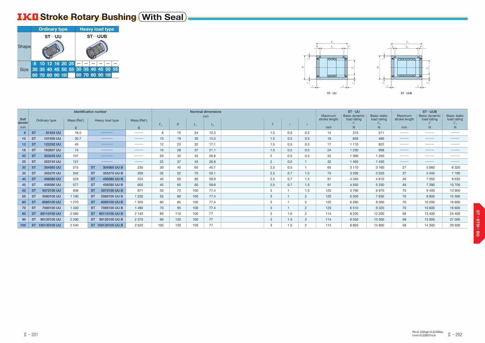
Ⅱ-201
Stroke Rotary Bushing With Seal
Ⅱ-202
Stroke Rotary Bushing
Shaft diameter
mm
Identification number Nominal dimensions ST…UU ST…UUBmm Maximum
stroke length
mm
Basic dynamic load rating
C
N
Basic static load rating
C0
N
Maximum stroke length
mm
Basic dynamicload rating
C
N
Basic staticload rating
C0
N
Ordinary type Mass (Ref.)
g
Heavy load type Mass (Ref.)
gFw D L1 L2 T t r
8 ST 81524 UU 16.5 ―――― ――― 8 15 24 12.3 1.5 0.5 0.5 14 315 211 ――― ――― ―――
10 ST 101930 UU 30.7 ―――― ――― 10 19 30 15.5 1.5 0.5 0.5 16 659 466 ――― ――― ―――
12 ST 122332 UU 45 ―――― ――― 12 23 32 17.1 1.5 0.5 0.5 17 1 110 822 ――― ――― ―――
16 ST 162837 UU 74 ―――― ――― 16 28 37 21.1 1.5 0.5 0.5 24 1 230 998 ――― ――― ―――
20 ST 203245 UU 107 ―――― ――― 20 32 45 26.8 2 0.5 0.5 32 1 390 1 250 ――― ――― ―――
25 ST 253745 UU 121 ―――― ――― 25 37 45 26.8 2 0.5 1 32 1 450 1 430 ――― ――― ―――
30 ST 304565 UU 215 ST 304565 UU B 230 30 45 65 45.1 2.5 0.5 1 65 3 110 3 160 27 5 060 6 320
35 ST 355270 UU 342 ST 355270 UU B 359 35 52 70 50.1 2.5 0.7 1.5 75 3 290 3 550 37 5 340 7 100
40 ST 406080 UU 529 ST 406080 UU B 553 40 60 80 59.9 2.5 0.7 1.5 91 4 340 4 810 49 7 050 9 630
45 ST 456580 UU 577 ST 456580 UU B 602 45 65 80 59.9 2.5 0.7 1.5 91 4 550 5 330 49 7 390 10 700
50 ST 5072100 UU 836 ST 5072100 UU B 871 50 72 100 77.4 3 1 1.5 120 5 790 6 970 70 9 400 13 900
55 ST 5580100 UU 1 190 ST 5580100 UU B 1 230 55 80 100 77.4 3 1 2 120 6 030 7 630 70 9 800 15 300
60 ST 6085100 UU 1 270 ST 6085100 UU B 1 320 60 85 100 77.4 3 1 2 120 6 260 8 300 70 10 200 16 600
70 ST 7095100 UU 1 430 ST 7095100 UU B 1 480 70 95 100 77.4 3 1 2 120 6 510 9 320 70 10 600 18 600
80 ST 80110100 UU 2 080 ST 80110100 UU B 2 140 80 110 100 77 3 1.5 2 114 8 230 12 200 58 13 400 24 400
90 ST 90120100 UU 2 290 ST 90120100 UU B 2 370 90 120 100 77 3 1.5 2 114 8 550 13 500 58 13 900 27 000
100 ST 100130100 UU 2 540 ST 100130100 UU B 2 620 100 130 100 77 3 1.5 2 114 8 820 14 800 58 14 300 29 500
1N=0.102kgf=0.2248lbs.1mm=0.03937inch
ST…UU
501645403530
252012108
1009080706055 5045403530
1009080706055
ST…UUB
------
Ordinary type Heavy load type
Shape
Size
T T
D
t
T T
t
D
r
r
r
r
r
r
r
r
ST…UU ST…UUB
Fw
Fw
L2
L1
L2
L1

Identification Number and Specification
2● Super small size
With the ultra-small sized balls incorporated in a thin external cylinder, small diameter and small sectional height are realized. 4
● Extremely smooth operationSince each component is precisely grounded and adjusted to ideal preload condition, extremely smooth and stable operation with small frictional resistance for long term can be achieved.
1Points● Rotational and linear motions
With the combination of an external cylinder with cylindrical raceway and balls incorporated in the retainer, rotary and linear motion in the axial direction is possible simultaneously with rotational motion. 3
● Super precisionBalls of high accuracy are incorporated with super-finished external cylinder and shaft to be adjusted to zero or minimal amount of preload, which realizes rotational motion and rotary and linear motion of high accuracy.
STSIMiniatureStroke Rotary Bushing
External cylinder
Ball
Retainer
Shaft
Ball cage
Ⅱ-204Ⅱ-203
Example of an identification number
The specification of STSI series is indicated by the identification number. Indicate the identification number, consisting of a model code, dimensions, length, and a selection code for each specification to apply.
1N=0.102kgf=0.2248lbs.1mm=0.03937inch
1 2 3 4 5 6 7 1 8Assembled set
With a shaft STSI 4 20 - 15 - 50
Without a shaft STS 4 20 - 15 /M1
Part
External cylinder OR 6 8 20 A /M1
Ball cage BK 4 6 15 A
Shaft SF 4 50 A /M1
Model1 Model code
Page Ⅱ-205
Shaft diameter(1)2
Bore diameter of external cylinder(2)3
Dimensions Page Ⅱ-205
Outside diameter of external cylinder4
External cylinder length5
Ball cage length6Length Page Ⅱ-205
Shaft length7
Selection class8 Selection code
Page Ⅱ-205
Notes (1) Indicates inscribed circle diameter for assembled set without a shaft or ball cage.(2) Indicates circumscribed circle diameter for ball cage.

Identification Number and Specification
Ⅱ-205 Ⅱ-206
Table 2 Tolerance and allowanceNominal
dimensions of outside diameter of
external cylindermm
Tolerance of outside diameter
of external cylinderμm
Radial runout of outside
diameter of external cylinder
μm
Tolerance of length of external
cylinder and shaft
mmOver Incl. High Low
3 6 0 -58
±0.1 6 10 0 -610 18 0 -818 30 0 -9 9
Table 3 Selection code and tolerance unit: μm
Selection code
Tolerance of bore diameter
of external cylinder
Tolerance of inscribed circle
diameter
Tolerance of shaft diameter
High Low High Low High Low
M1 -1 -3 -1 -3 0 -1M2 -2 -4 -2 -4 -1 -2M3 -3 -5 -3 -5 -2 -3
Accuracy ❶ FittingThe STSI series is assembled to slight preload state to obtain high motion accuracy. Use external cylinder and housing hole of the STSI series with clearance fit to avoid any effect of press-fitting on inscribed circle diameter. In addition, for combination of an external cylinder, a ball cage and a shaft, select an external cylinder and a shaft with the same selection code to be combined with a ball cage.
❷ Operating temperatureThe maximum operating temperature is 120˚C and temperature up to 100˚C is allowed for continuous operation. When the temperature exceeds 100˚C, contact .
❸ MountingTypically, to fix the external cylinder and housing hole, the external cylinder end is fixed to the axial direction with stop ring or adhesive agent is used.The ball cage is mounted through the shaft after the external cylinder is fixed to the housing hole. At this point, mounting becomes easier if the ball cage is shifted by one half of assembly insertion amount of the shaft in insert direction of the shaft so that the ball cage is positioned at the regular position after mounting.
❹ Insertion of shaftWhen inserting a shaft into an external cylinder, be careful not to pry open or give shock to the shaft.
Precaution for Use
Load rating of the STSI series represents the value obtained when load is evenly distributed without the ball incorporated in the ball cage being dropped from the external cylinder and shaft end.
Load Rating
Grease is not pre-packed in the STSI series, so please perform adequate lubrication as needed.Both of oil lubrication and grease lubrication are available in the STSI series. For grease lubrication, it is typically applied lightly to the shaft and raceway of the external cylinder. Use of high-quality lithium-soap base grease is recommended for the grease to use.
Lubrication
1N=0.102kgf=0.2248lbs.1mm=0.03937inch
Miniature Stroke Rotary Bushing(STSI series)
Assembled set with a shaftAssembled set without a shaftExternal cylinderBall cageShaft
:STSI:STS:OR …A:BK …A:SF …A
Indicate the shaft diameter in mm. Indicates inscribed circle diameter for assembled set without a shaft or ball cage.
Indicate the bore diameter of external cylinder in mm.Indicates circumscribed circle diameter for ball cage.
Indicate the outside diameter of external cylinder in mm.
Indicate the external cylinder length in mm.
Indicate the ball cage length in mm.
Indicate the shaft length in mm.
M1 classM2 classM3 class
:M1:M2:M3
Selection code and tolerances are shown in Table 3.For combination of each part, assemble parts with the same selection code.
Model1
Shaft diameter 2
Bore diameter of external cylinder 3
Outside diameter of external cylinder4
External cylinder length5
Ball cage length6
Shaft length7
Selection class8
Miniature Stroke Rotary BushingWith a shaftSTSI
External cylinderOR…A
Ball cageBK…A
ShaftSF…A
Miniature Stroke Rotary BushingWithout a shaftSTS
Table 1 Models of STSI seriesAssembled set Part

Ⅱ-207
Miniature Stroke Rotary Bushing
Ⅱ-208
Miniature Stroke Rotary Bushing
Shaft diameter
mm
Identification number of
assembled set without a shaft
External cylinder Ball cage Basic static load rating(1)
Shaft
Identification number of assembled set with a shaftIdentification
numberMass (Ref.)
g
Nominal dimensions mm Identification number
Mass (Ref.)
g
Nominal dimensions mm C0
N
Identification number
Mass (Ref.)
g
Nominal dimensions mm
E D L1 Fw Ew Lb F L
2 STS 2 L1-Lb
OR 3 5 10 A
OR 3 5 15 A
0.9
1.33.2 5
10
15
BK 2 3 5 A
BK 2 3 10 A
0.1
0.32 3.2
5
10
10.5
21.0
SF 2 20 A
SF 2 30 A
0.5
0.72
20
30STSI 2 L1-Lb-L
3 STS 3 L1-Lb
OR 5 7 10 A
OR 5 7 20 A
OR 5 7 30 A
1.5
2.9
4.4
5 7
10
20
30
BK 3 5 10 A
BK 3 5 15 A
BK 3 5 20 A
0.7
1.1
1.4
3 5
10
15
20
38.4
57.7
76.9
SF 3 50 A
SF 3 60 A
2.8
3.33
50
60STSI 3 L1-Lb-L
4 STS 4 L1-Lb
OR 6 8 10 A
OR 6 8 20 A
OR 6 8 30 A
1.7
3.4
5.2
6 8
10
20
30
BK 4 6 10 A
BK 4 6 15 A
BK 4 6 20 A
0.9
1.3
1.8
4 6
10
15
20
59.5
89.3
119
SF 4 50 A
SF 4 60 A
4.9
5.94
50
60STSI 4 L1-Lb-L
5 STS 5 L1-Lb
OR 7 10 10 A
OR 7 10 20 A
OR 7 10 30 A
3.1
6.3
9.4
7 10
10
20
30
BK 5 7 10 A
BK 5 7 15 A
BK 5 7 20 A
1.0
1.6
2.0
5 7
10
15
20
81
121
162
SF 5 50 A
SF 5 80 A
7.7
12.35
50
80STSI 5 L1-Lb-L
6 STS 6 L1-Lb
OR 8 11 20 A
OR 8 11 30 A
OR 8 11 40 A
7.0
10.5
14.1
8 11
20
30
40
BK 6 8 10 A
BK 6 8 15 A
BK 6 8 20 A
1.2
1.8
2.3
6 8
10
15
20
103
154
206
SF 6 50 A
SF 6 80 A
11.1
17.76
50
80STSI 6 L1-Lb-L
8 STS 8 L1-Lb
OR 10 13 20 A
OR 10 13 30 A
OR 10 13 40 A
8.5
12.7
17.0
10 13
20
30
40
BK 8 10 10 A
BK 8 10 15 A
BK 8 10 20 A
1.6
2.4
3.2
8 10
10
15
20
105
157
209
SF 8 50 A
SF 8 80 A
SF 8 90 A
19.7
31.5
35.5
8
50
80
90
STSI 8 L1-Lb-L
10 STS 10 L1-Lb
OR 12 18 20 A
OR 12 18 30 A
OR 12 18 43 A
22.2
33.3
47.7
12 18
20
30
43
BK 10 12 15 A
BK 10 12 20 A
BK 10 12 25 A
2.8
3.8
4.8
10 12
15
20
25
191
254
318
SF 10 80 A
SF 10 100 A
SF 10 120 A
49.3
61.6
74.0
10
80
100
120
STSI 10 L1-Lb-L
12 STS 12 L1-Lb
OR 14 20 25 A
OR 14 20 30 A
OR 14 20 35 A
OR 14 20 40 A
31.4
37.7
44.0
50.3
14 20
25
30
35
40
BK 12 14 20 A
BK 12 14 25 A
BK 12 14 30 A
4.3
5.4
6.1
12 14
20
25
30
341
427
512
SF 12 80 A
SF 12 100 A
SF 12 120 A
71.0
88.8
106.5
12
80
100
120
STSI 12 L1-Lb-L
Note (1) Represents the value when load is evenly distributed without the ball incorporated in the ball cage being dropped from the external cylinder end.
Remark: L1, Lb, and L in the identification number field of assembled set without a shaft and assembled set with a shaft represent length of the external cylinder, length of the ball cage, and length of the shaft in the dimension table.
1N=0.102kgf=0.2248lbs.1mm=0.03937inch
Assembled set with a shaft
STSI
2121086543
Assembled set without a shaft
STS
2121086543
External cylinder
OR…A
2121086543
Ball cage
BK…A
2121086543
Shaft
SF…A
2121086543
Shape
Size
L1
E D
External cylinder
Lb
Ball cage
L
F
Shaft
Fw
Ew

Identification Number and Specification
2● Superior high speed operation
As the retainers have high rigidity and light in weight with low inertia, this series is suitable for abrupt operations such as high-speed rotary and linear motion in axial direction. 4
● Long lifeEach ball held in the retainer is arranged in a spiral formation in order to prevent the balls from tracing the same path. Rolling contact fatigue of the shaft and housing raceways is thereby minimized, and stable high accuracy can be assured for long periods of time.
1Points● Rotational and linear motions
High-accuracy balls incorporated into the retainer make use of the raceway accuracy to allow high-accuracy rotational motion and rotary and linear motion. 3
● Large load rating and high rigidityIn the retainer, balls are incorporated as many as possible. So the load ratings are large and the rigidity is high with small elastic deformation even under fluctuating load or offset load.
BGStroke Rotary Cage
Retainer
Ball
Ⅱ-210Ⅱ-2091N=0.102kgf=0.2248lbs.1mm=0.03937inch
Example of an identification number
The specification of BG series is indicated by the identification number. Indicate the identification number, consisting of a model code and dimensions.
The BG series is capable of rotation and rotary and linear motion. However, allowance of velocity for these motions performed at the same time is obtained from the equation (1). Typical values are indicated in Table 1.
DN ≧ Dpw n+10 S n1 (1)
where, DN : Allowance of velocity (see Table 1) n : Rotational speed, rpm n1 : Number of strokes per minute, cpm S : Stroke length, mm Dpw : Pitch circle diameter of balls, mm
(Dpw=Fw+Ew )2
Fw : Inscribed circle diameter, mm Ew : Circumscribed circle diameter, mm
However, applicable when n1≦5000, S n1≦50000.
Table 1 Allowance of velocityLubrication conditions DN
Oil lubrication 600 000Grease lubrication 300 000
1 2 3 4
BG 25 31 65
Model1 Model code
Page Ⅱ-210
Inscribed circle diameter2
Circumscribed circle diameter3Dimensions Page Ⅱ-210
Length of retainer4
Stroke Rotary Cage(BG series)
:BG
Indicate the inscribed circle diameter in mm.
Indicate the circumscribed circle diameter in mm.
Indicate the length of retainer in mm.
Model1
Inscribed circle diameter2
Circumscribed circle diameter3
Length of retainer4
Identification Number and Specification
Allowance of Velocity
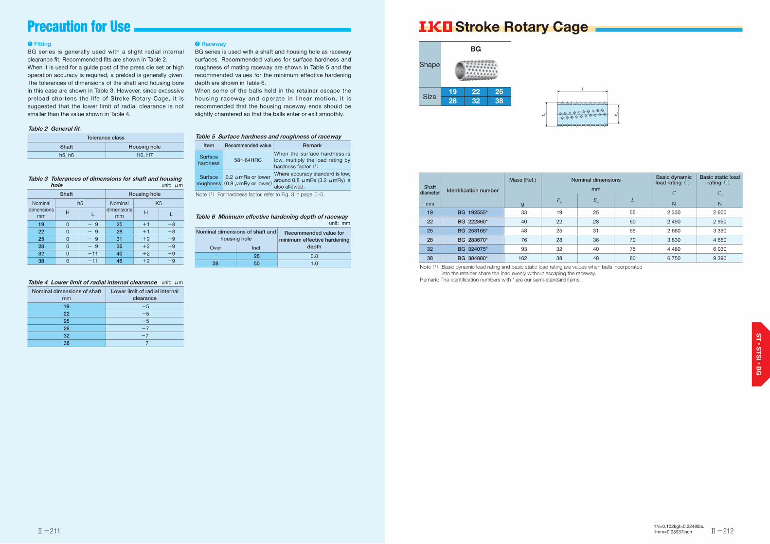
Stroke Rotary Cage
Ⅱ-211 Ⅱ-2121N=0.102kgf=0.2248lbs.1mm=0.03937inch
❶ FittingBG series is generally used with a slight radial internal clearance fit. Recommended fits are shown in Table 2.When it is used for a guide post of the press die set or high operation accuracy is required, a preload is generally given. The tolerances of dimensions of the shaft and housing bore in this case are shown in Table 3. However, since excessive preload shortens the life of Stroke Rotary Cage, it is suggested that the lower limit of radial clearance is not smaller than the value shown in Table 4.
Table 2 General fitTolerance class
Shaft Housing hole
h5, h6 H6, H7
Table 3 Tolerances of dimensions for shaft and housing hole unit: μm
Shaft Housing hole
Nominal dimensions
mm
h5 Nominal dimensions
mm
K5
H L H L
19 0 - 9 25 +1 -822 0 - 9 28 +1 -825 0 - 9 31 +2 -928 0 - 9 36 +2 -932 0 -11 40 +2 -938 0 -11 48 +2 -9
Table 4 Lower limit of radial internal clearance unit: μm
Nominal dimensions of shaftmm
Lower limit of radial internal clearance
19 -522 -525 -528 -732 -738 -7
❷ RacewayBG series is used with a shaft and housing hole as raceway surfaces. Recommended values for surface hardness and roughness of mating raceway are shown in Table 5 and the recommended values for the minimum effective hardening depth are shown in Table 6.When some of the balls held in the retainer escape the housing raceway and operate in linear motion, it is recommended that the housing raceway ends should be slightly chamfered so that the balls enter or exit smoothly.
Table 5 Surface hardness and roughness of racewayItem Recommended value Remark
Surface hardness
58~64HRCWhen the surface hardness is low, multiply the load rating by hardness factor (1).
Surface roughness
0.2 μmRa or lower(0.8 μmRy or lower)
Where accuracy standard is low, around 0.8 μmRa (3.2 μmRy) is also allowed.
Note (1) For hardness factor, refer to Fig. 3 in page Ⅲ-5.
Table 6 Minimum effective hardening depth of raceway unit: mm
Nominal dimensions of shaft and housing hole
Recommended value for minimum effective hardening
depthOver Incl.
- 28 0.828 50 1.0
Shaft diameter
mm
Identification number
Mass (Ref.) Nominal dimensions Basic dynamic load rating(1)
Basic static load rating(1)
mmC
N
C0
NFw Ew L
g
19 BG 192555* 33 19 25 55 2 330 2 600
22 BG 222860* 40 22 28 60 2 490 2 950
25 BG 253165* 48 25 31 65 2 660 3 390
28 BG 283670* 76 28 36 70 3 830 4 660
32 BG 324075* 93 32 40 75 4 480 6 030
38 BG 384880* 162 38 48 80 6 750 9 390
Note (1) Basic dynamic load rating and basic static load rating are values when balls incorporated into the retainer share the load evenly without escaping the raceway.
Remark: The identification numbers with * are our semi-standard items.
Precaution for Use
L
Fw
Ew
Shape
Size
BG
193832282522
Ⅱ-213
Roller Way & Flat Roller Cage
Roller WayFlat Roller Cage
Ⅱ-214

RW
SR
GSN
Roller Way
1Points● High rigidity and accuracy
Since the high accuracy roller is built into the highly flat surface way finished by accurate ground, the product has a high rigidity and high accuracy. Also because the variation of operation height can be selected in the unit of 2 μm, the load can be evenly distributed even in the multiple-use environment.
The structure of all models lets the roller to be guided accurately without creating skew, yielding an extremely stable and smooth linear motion.2
● Smooth motion
Cap
Cover
Wiper seal
Retaining plate
Way
Hollow cylindrical roller
Way
Roller
Retaining band
End plate
Ⅱ-216Ⅱ-215
Identification Number and Specification
Identification Number and Specification -Model・Size-
Example of an identification number
The specifications of RW, SR and GSN are indicated by the identification number. Indicate the identification number, consisting of a model code, dimensions, a part code, a classification symbol, and a selection code for each specification to apply.
1N=0.102kgf=0.2248lbs.1mm=0.03937inch
1 2 3 4 5
RW 40 UU SP B4
SR 2050 SP B4
GSN 20 SP B4
Model1 Model code
Page Ⅱ-216
Size2 Dimensions Page Ⅱ-216
Wiper seal3 Part code
Page Ⅱ-217
Accuracy class4 Classification symbol
Page Ⅱ-217
Selection class5 Selection code
Page Ⅱ-217
Roller Way RWRoller Way RW inch seriesRoller Way SRRoller Way GSN
:RW:RWB:SR:GSN
For applicable models and sizes, see Table 1.1 and Table 1.2.
Indicate the representative width in mm. For the inch series, indicate the width in the unit of 1/16 inch.For applicable models and sizes, see Table 1.1 and Table 1.2.
Model1
Size2

Ⅱ-217 Ⅱ-218
-Accuracy Class・Selection Class-- Wiper Seal・Accuracy Class・Selection Class -
1N=0.102kgf=0.2248lbs.1mm=0.03937inch
Without wiper sealWith wiper seal
:No symbol:UU
Applicable to Roller Way RW.Attach the wiper seal in the linear motion direction. This wiper seal is made of special synthetic rubber in double-lipped shape and has high removal performance against foreign substances.
Wiper seal3
OrdinaryHighPrecisionSuper precision
:No symbol:H:P:SP
For applicable accuracy class, see Table 2.1 and Table 2.2.For details of accuracy class, see Table 3.1, Table 3.2, and Table 4.
When many are used on the same surface, it is required to use those with the same selection code from tolerances of dimensions in H of Table 4 to evenly distribute the load. When tolerances of dimensions of H is not specified, please specify a classification symbol only.
Accuracy class4
Selection class5
Table 1.1 Models and sizes of RW, SR and GSN (Metric series)
Shape ModelSize
15 20 25 26 30 32 40 50 70 95
RW - - - ○ ○ - ○ ○ ○ ○
SR ○ ○ ○ - - ○ ○ ○ - -
GSN ○ ○ ○ - - ○ ○ ○ - -
Table 1.2 Models and sizes of RWB (Inch series)
Shape ModelSize
14 16 24 32 48 64
RWB ○ ○ ○ ○ ○ ○
Wiper sealWiper seal
Fig. 1 Wiper seal
Table 2.1 Application of accuracy class of RW, SR and GSN (Metric series)
Size
Class (classification symbol)
Ordinary (1) High PrecisionSuper
precision(No symbol) (H) (P) (SP)
15 ○ ○ ○ ○20 ○ ○ ○ ○25 ○ ○ ○ ○26 - ○ ○ ○30 - ○ ○ ○32 ○ ○ ○ ○40 ○ ○ ○ ○50 ○ ○ ○ ○(2)70 - ○ ○ -95 - ○ ○ -
Notes (1) Applicable to SR and GSN. (2) Applicable to RW.
Table 3.1 Tolerances of RW and RWB width W
RW RWB
SizeDim. W tolerance
SizeDim. W tolerance
inchmm
263040
0-0.05
141624
0-0.002
5070
0-0.07
3248
0-0.003
950
-0.1064
0-0.004
W
Table 2.2 Application of accuracy class of RWB (Inch series)
Size
Class (classification symbol)
Ordinary High PrecisionSuper
precision(No symbol) (H) (P) (SP)
14 - ○ ○ ○20 - ○ ○ ○24 - ○ ○ ○32 - ○ ○ ○48 - ○ ○ -64 - ○ ○ -
Table 3.2 Tolerances of SR and GSN width W1 , and length L1
unit: mm
Size Dim. W1 tolerance Dim. L1 tolerance
1520253240
0-0.2
0-0.2
500
-0.30-0.3
SR GSN
L1
W1
L1
W1
Table 4 Selection code, and tolerance of height H and operation height A
Item
Accuracy class
Selection code
Dim. tolerance of height H and operation height A
Metric series Inch seriesmm inch
Ordinary(no symbol) - 0 ~ -0.010 -
High(H)E 5E10
0-0.005
~~-0.005-0.010
0-0.0002
~~-0.0002-0.0004
Precision(P)C 3C 6C 9
0-0.003-0.006
~~~
-0.003-0.006-0.009
0-0.00012-0.00024
~~~
-0.00012-0.00024-0.00036
Super precision(SP)
B 2B 4B 6B 8B10
0-0.002-0.004-0.006-0.008
~~~~~
-0.002-0.004-0.006-0.008-0.010
0-0.00008-0.00016-0.00024-0.00032
~~~~~
-0.00008-0.00016-0.00024-0.00032-0.00040
RW SR GSN
A A
H

Ⅱ-219 Ⅱ-220
Precaution for Mounting Precaution for Use ❶ RacewayRecommended values for surface hardness and roughness of mating raceway are shown in Table 5 and the recommended value for the minimum effective hardening depth is shown in Table 6.1 and Table 6.2.
Table 5 Surface hardness and roughness of racewayItem Recommended value Remark
Surface hardness
58~64HRCWhen the surface hardness is low, multiply the load rating by hardness factor (1).
Surface roughness
0.2 μmRa or lower(0.8 μmRy or
lower)
Where accuracy standard is low, around 0.8 μmRa (3.2 μmRy) is also allowed.
Note (1) For hardness factor, refer to Fig. 3 in page Ⅲ-5.
Table 6.1 Minimum effective hardening depth of raceway (RW and RWB) unit: mm
Identification numberRecommended value for
minimum effective hardening depth
RW 26 RWB 14 0.8RW 30 RWB 16 1.0RW 40 RWB 24 1.5RW 50 RWB 32 2.0RW 70 RWB 48 2.5RW 95 RWB 64 3.0
Table 6.2 Minimum effective hardening depth of raceway (SR and GSN) unit: mm
Identification numberRecommended value for
minimum effective hardening depth
SR 15 GSN 150.8
SR 20 GSN 20SR 25 GSN 25
1.0SR 32 GSN 32SR 40 GSN 40 1.5SR 50 GSN 50 2.0
❷ Accuracy of mounting surfaceFor accuracy of mounting surface, values in Table 7.1 and Table 7.2 are recommended.
Table 7.1 Accuracy of mounting surface (RW and RWB)Item Recommended value
0.02/100 or lower
0.015/100 or lower
0.05/100 or lower
Permissible tilt
Reference mounting surface
Reference mounting surface
Permissible tilt
Reference surface
Reference line
Motion direction
Table 7.2 Accuracy of mounting surface (SR and GSN)Item Recommended value
0.02/100 or lower
0.015/100 or lower
0.05/100 or lower
❸ Groove machining on SR and GSN mounting surfaceWhen mounting SR and GSN to the groove-machined mounting surface, the groove depth E should be deeper than the height from the bottom surface of the way to the bottom of the SR and GSN to provide clearance for oil pool. (See Fig. 2.)Other than the above, groove width W corresponding to the width W1 for SR should be as wide as clearance fit and the relation between the clearance and the groove position on the reference surface side must be considered.
Fig. 2 Shape of groove on the mounting surface
❹ Operating temperatureThe maximum operating temperature is 120˚C and temperature up to 100˚C is allowed for continuous operation. When the temperature exceeds 100˚C, contact .
Permissible tiltReference mounting surface
Permissible tiltReference mounting surface
Reference surface
Reference lineMotion
direction
W1
W
E
❶ Reference mounting surfaceTo mount RW, RWB, SR, and GSN in the linear motion direction, mount them by referring the opposite side of the
mark on the way end as reference surface. (See Fig. 3.)In addition, the surface under load is the upside of the
mark on the way end seen as the normal position.
❷ How to mount SR and GSNTo mount it, fix the way directly to a table or a bed with bolts, or fix it with pressure plate as indicated in Fig. 4. For SR, mounting with pressure plate is recommended.
Applied load surface
Mark
MarkReference mounting surface
Reference mounting surface
Fig. 3 Mounting examples
Pressure plate
Fig. 4 Mounting with pressure plate
1N=0.102kgf=0.2248lbs.1mm=0.03937inch

Ⅱ-221 Ⅱ-2221N=0.102kgf=0.2248lbs.1mm=0.03937inch1N=0.102kgf=0.2248lbs.1mm=0.03937inch
Roller Way Inch Series Roller Way
Identification number
Mass(Ref.)
Nominal dimensionsmm
Basic dynamic load rating
Basic static load rating
gW H L ℓ F W1 h d
C
N
C0
N
RW 26 74 26 14 50 6 19 16 10 3.4 25 000 40 100
RW 30 179 30 19 70 7.5 25.4 19 14 4.5 39 800 71 200
RW 40 740 40 28 100 11.3 38.1 26 21 5.5 85 700 160 000
RW 50 1 750 50 38 140 15 50.8 35 28.5 6.6 154 000 314 000
RW 70 5 260 70 57 200 22.5 76.2 48 42.5 9.0 306 000 638 000
RW 95 12 700 95 76 270 30 101.6 65 56.5 11.0 514 000 1 130 000
Identification number
Mass(Ref.)
Nominal dimensionsinch / mm
Basic dynamic load rating
Basic static load rating
gW H L ℓ F W1 h d
C
N
C0
N
RWB 14* 91 7/8 9/16 1.97 0.236 3/4 43/64 0.41 0.125 25 000 40 10022.225 14.288 50 6 19.050 17.066 10.4 3.2
RWB 16* 227 1 3/4 2.76 0.295 1 13/16 0.56 0.125 39 800 71 20025.400 19.050 70 7.5 25.400 20.638 14.2 3.2
RWB 24* 730 1 1/2 1 1/8 3.94 0.445 1 1/2 1 7/32 0.85 0.180 85 700 160 00038.100 28.575 100 11.3 38.100 30.956 21.5 4.6
RWB 32* 1 770 2 1 1/2 5.51 0.591 2 1 5/8 1.12 0.206 154 000 314 00050.800 38.100 140 15 50.800 41.275 28.5 5.2
RWB 48* 5 670 3 2 1/4 7.88 0.886 3 2 7/16 1.68 0.266 306 000 638 00076.200 57.150 200 22.5 76.200 61.912 42.8 6.8
RWB 64* 13 500 4 3 10.63 1.181 4 3 1/4 2.24 0.328 514 000 1 130 000101.600 76.200 270 30 101.600 82.550 57.0 8.3
Remark: The identification numbers with * are our semi-standard items.
L
F 4-d
W1
W
h H
ℓ
L
F 4-d
W1
W
h H
ℓ
RW
26 3095705040
Shape
Size
RWB
14 1664483224
Shape
Size
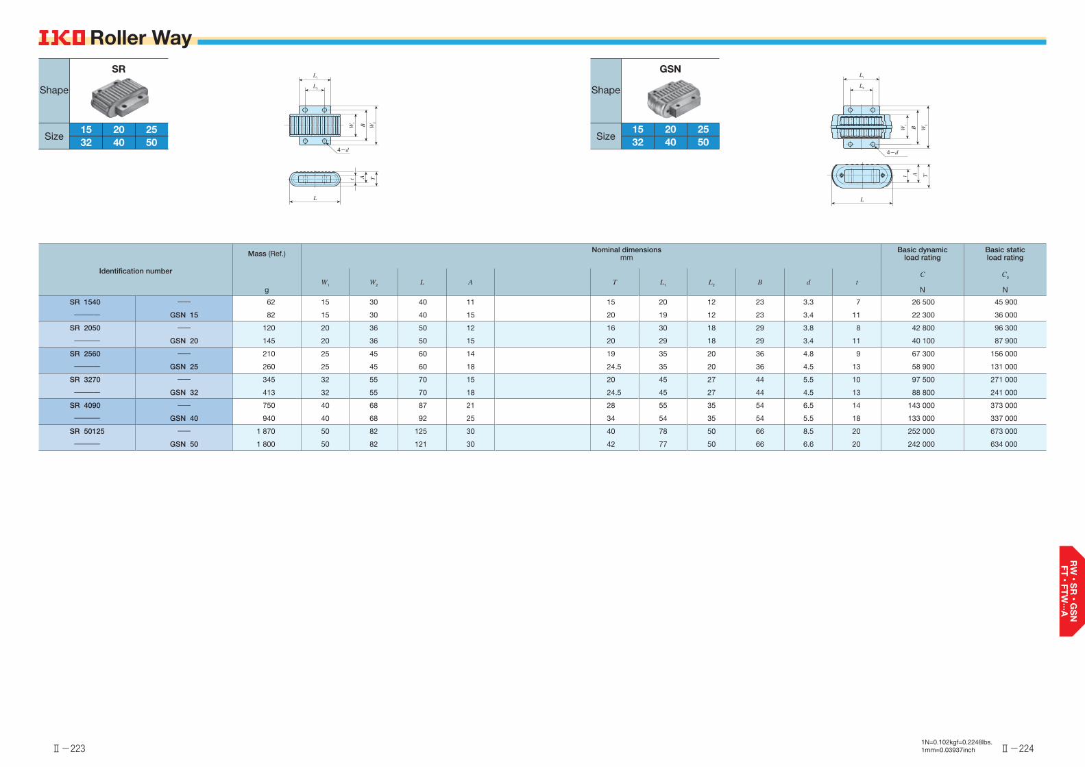
Ⅱ-223
Roller Way
Ⅱ-224
Roller Way
1N=0.102kgf=0.2248lbs.1mm=0.03937inch
Identification number
Mass (Ref.) Nominal dimensionsmm
Basic dynamic load rating
Basic static load rating
gW1 W2 L A T L1 L2 B d t
C
N
C0
N
SR 1540 ―― 62 15 30 40 11 15 20 12 23 3.3 7 26 500 45 900
―――― GSN 15 82 15 30 40 15 20 19 12 23 3.4 11 22 300 36 000
SR 2050 ―― 120 20 36 50 12 16 30 18 29 3.8 8 42 800 96 300
―――― GSN 20 145 20 36 50 15 20 29 18 29 3.4 11 40 100 87 900
SR 2560 ―― 210 25 45 60 14 19 35 20 36 4.8 9 67 300 156 000
―――― GSN 25 260 25 45 60 18 24.5 35 20 36 4.5 13 58 900 131 000
SR 3270 ―― 345 32 55 70 15 20 45 27 44 5.5 10 97 500 271 000
―――― GSN 32 413 32 55 70 18 24.5 45 27 44 4.5 13 88 800 241 000
SR 4090 ―― 750 40 68 87 21 28 55 35 54 6.5 14 143 000 373 000
―――― GSN 40 940 40 68 92 25 34 54 35 54 5.5 18 133 000 337 000
SR 50125 ―― 1 870 50 82 125 30 40 78 50 66 8.5 20 252 000 673 000
―――― GSN 50 1 800 50 82 121 30 42 77 50 66 6.6 20 242 000 634 000
L
t A T
4-d
L1
L2
W1
B W2
L
t A T
4-d
L1
L2
W1
B W2
SR
15 205040322515 2050403225
Shape
Size
GSN
15 2050403225
Shape
Size
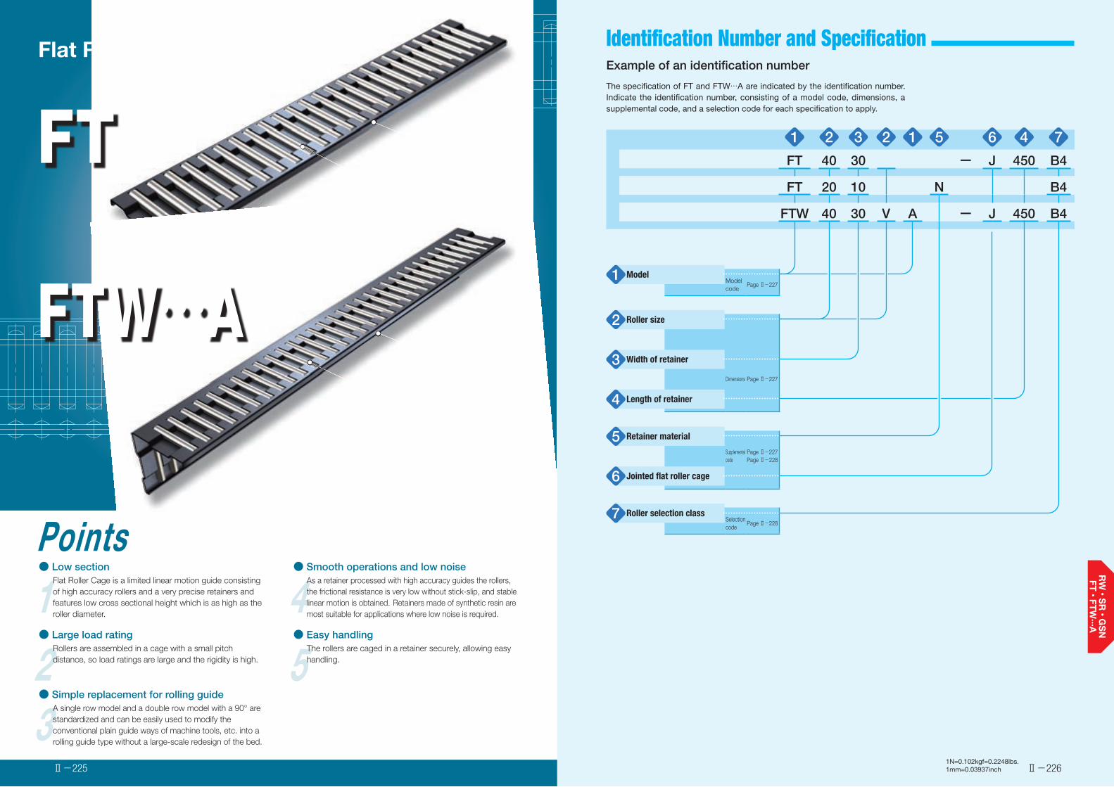
Identification Number and Specification
1Points● Low section
Flat Roller Cage is a limited linear motion guide consisting of high accuracy rollers and a very precise retainers and features low cross sectional height which is as high as the roller diameter.
2● Large load rating
Rollers are assembled in a cage with a small pitch distance, so load ratings are large and the rigidity is high.
3● Simple replacement for rolling guide
A single row model and a double row model with a 90° are standardized and can be easily used to modify the conventional plain guide ways of machine tools, etc. into a rolling guide type without a large-scale redesign of the bed.
4● Smooth operations and low noise
As a retainer processed with high accuracy guides the rollers, the frictional resistance is very low without stick-slip, and stable linear motion is obtained. Retainers made of synthetic resin are most suitable for applications where low noise is required.
5● Easy handling
The rollers are caged in a retainer securely, allowing easy handling.
FT
FTW…A
Flat Roller Cage
Retainer
Roller
Retainer
Roller
Ⅱ-226Ⅱ-225
Example of an identification number
The specification of FT and FTW…A are indicated by the identification number. Indicate the identification number, consisting of a model code, dimensions, a supplemental code, and a selection code for each specification to apply.
1N=0.102kgf=0.2248lbs.1mm=0.03937inch
1 2 3 2 1 5 6 4 7
FT 40 30 ー J 450 B4
FT 20 10 N B4
FTW 40 30 V A ー J 450 B4
Model1 Model code
Page Ⅱ-227
Roller size2
Width of retainer3Dimensions Page Ⅱ-227
Length of retainer4
Retainer material5Supplemental code
Page Ⅱ-227Page Ⅱ-228
Jointed flat roller cage6
Roller selection class7 Selection code
Page Ⅱ-228
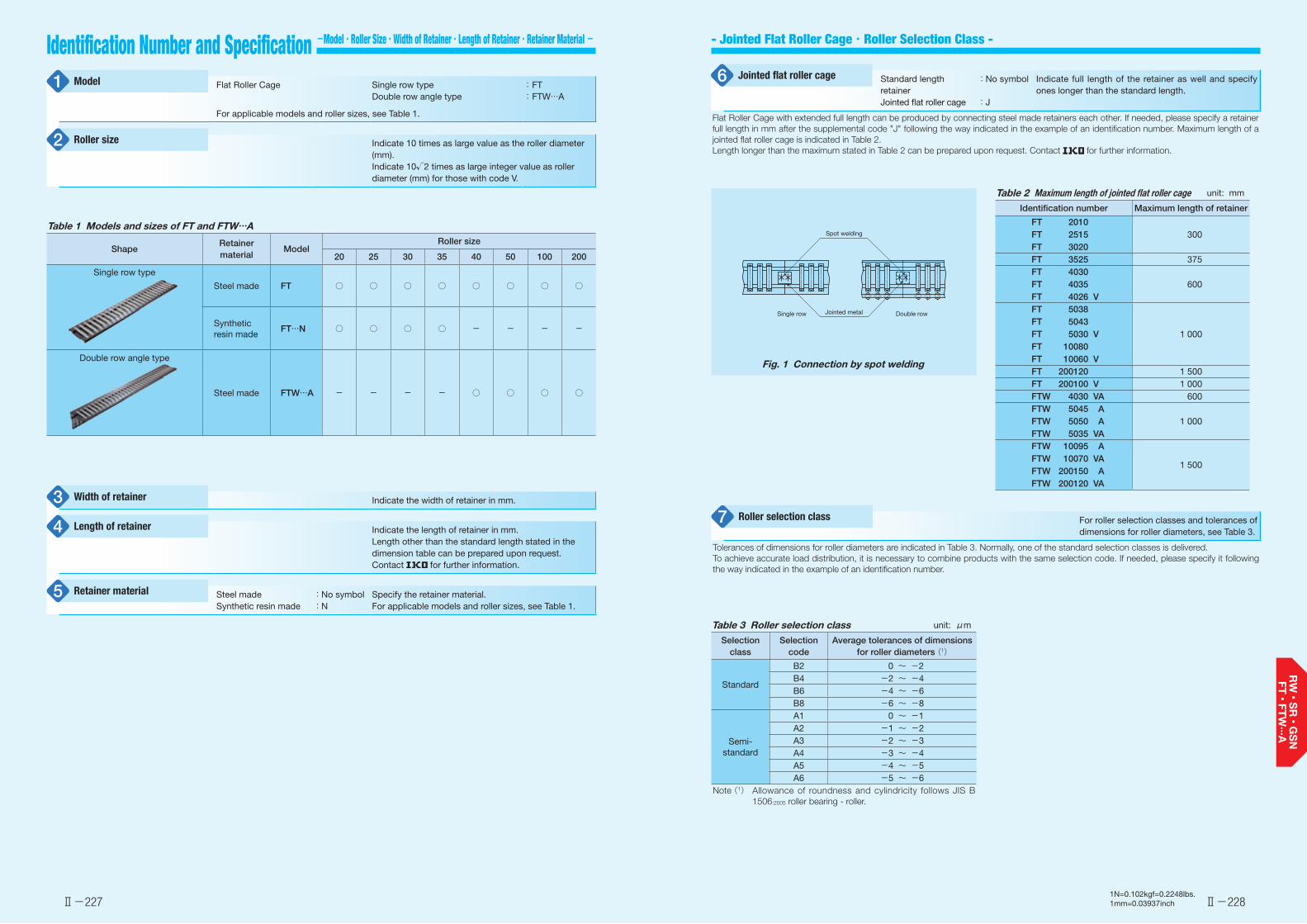
- Jointed Flat Roller Cage・Roller Selection Class -Identification Number and Specification -Model・Roller Size・Width of Retainer・Length of Retainer・Retainer Material -
Ⅱ-227 Ⅱ-2281N=0.102kgf=0.2248lbs.1mm=0.03937inch
Flat Roller Cage Single row typeDouble row angle type
: FT: FTW…A
For applicable models and roller sizes, see Table 1.
Indicate 10 times as large value as the roller diameter (mm).Indicate 10√2 times as large integer value as roller diameter (mm) for those with code V.
Model1
Roller size2
Indicate the width of retainer in mm.
Indicate the length of retainer in mm.Length other than the standard length stated in the dimension table can be prepared upon request. Contact for further information.
Steel madeSynthetic resin made
:No symbol:N
Specify the retainer material.For applicable models and roller sizes, see Table 1.
Width of retainer3
Length of retainer4
Retainer material5
Table 1 Models and sizes of FT and FTW…A
ShapeRetainer material
ModelRoller size
20 25 30 35 40 50 100 200
Single row type
Steel made FT ○ ○ ○ ○ ○ ○ ○ ○
Synthetic resin made
FT…N ○ ○ ○ ○ - - - -
Double row angle type
Steel made FTW…A - - - - ○ ○ ○ ○
Standard length retainerJointed flat roller cage
:No symbol
:J
Indicate full length of the retainer as well and specify ones longer than the standard length.
Flat Roller Cage with extended full length can be produced by connecting steel made retainers each other. If needed, please specify a retainer full length in mm after the supplemental code "J" following the way indicated in the example of an identification number. Maximum length of a jointed flat roller cage is indicated in Table 2.Length longer than the maximum stated in Table 2 can be prepared upon request. Contact for further information.
Jointed flat roller cage6
Table 2 Maximum length of jointed �at roller cage unit: mm
Identification number Maximum length of retainer
FT 2010300FT 2515
FT 3020FT 3525 375FT 4030
600FT 4035FT 4026 VFT 5038
1 000FT 5043FT 5030 VFT 10080FT 10060 VFT 200120 1 500FT 200100 V 1 000FTW 4030 VA 600FTW 5045 A
1 000FTW 5050 AFTW 5035 VAFTW 10095 A
1 500FTW 10070 VAFTW 200150 AFTW 200120 VA
Fig. 1 Connection by spot welding
Spot welding
Jointed metalSingle row Double row
For roller selection classes and tolerances of dimensions for roller diameters, see Table 3.
Tolerances of dimensions for roller diameters are indicated in Table 3. Normally, one of the standard selection classes is delivered.To achieve accurate load distribution, it is necessary to combine products with the same selection code. If needed, please specify it following the way indicated in the example of an identification number.
Roller selection class7
Table 3 Roller selection class unit: μm
Selection class
Selection code
Average tolerances of dimensions for roller diameters (1)
Standard
B2 0 ~ -2B4 -2 ~ -4B6 -4 ~ -6B8 -6 ~ -8
Semi-standard
A1 0 ~ -1A2 -1 ~ -2A3 -2 ~ -3A4 -3 ~ -4A5 -4 ~ -5A6 -5 ~ -6
Note (1) Allowance of roundness and cylindricity follows JIS B 1506:2005 roller bearing - roller.

Precaution for Mounting Precaution for Use
Ⅱ-229 Ⅱ-230
❶ RacewayRecommended values for surface hardness and roughness of mating raceway are shown in Table 4 and the recommended value for the minimum effective hardening depth is shown in Table 5.
Table 4 Surface hardness and roughness of racewayItem Recommended value Remark
Surface hardness
58~64HRCWhen the surface hardness is low, multiply the load rating by hardness factor (1).
Surface roughness
0.2 μmRa or lower(0.8 μmRy or
lower)
Where accuracy standard is low, around 0.8 μmRa (3.2 μmRy) is also allowed.
Note (1) For hardness factor, refer to Fig. 3 in page Ⅲ-5.
Table 5 Minimum effective hardening depth of raceway unit: mm
Roller diameter Recommended value for minimum effective hardening
depthOver Incl.
- 3 0.53 4 0.84 5 1.05 8 1.58 10 2.0
10 14.142 2.514.142 20 3.5
❷ When used for bed surface and 90° V surfaceAfter complete lapping as indicated in Fig. 2, mount FT to FTW…VA, or FT…V to FTW…A. Combination of Flat Roller Cage at this point is indicated in Table 6.
90°
FT5043FTW5035VA
Fig. 2 Example of use on �at surface and 90° V surface
❸ Stroke length and retainer lengthMovement in a linear direction as in Fig. 3 will move the Flat Roller Cage in the same direction by one half of the movement amount. Therefore, way length, stroke length and retainer length are correlated as follows:
L1=S2+L (1)
where, L1 : Way length, mm
S : Stroke length, mmL : Retainer length, mm
Fig. 3
❹ Operating temperatureIf the retainer is made of steel, it can withstand higher temperature. However, if you use it in an environment exceeding 100˚C, please contact .The retainer made of synthetic resin can withstand up to 100˚C. For continuous operation, please keep it under 80˚C.
L S
S/2
L1
FT and FTW…A are typically mounted as indicated in Fig. 4. When the heat-treated and polished way is mounted to the device body, you must be careful not to make deformation by tightening.
① General case
② When a way is used
③ When overhanging load is applied
Fig. 4 Mounting examples
1N=0.102kgf=0.2248lbs.1mm=0.03937inch
Table 6 Combination of Flat Roller Cage unit: mm
Combination Number
For flat surface For 90° V surface
Identification number Roller diameter Dw Identification number Roller diameter Dw
1 FT 4030 4 FTW 4030 VA 2.8282 FT 4035 4 FTW 4030 VA 2.8283 FT 5038 5 FTW 5035 VA 3.5354 FT 5043 5 FTW 5035 VA 3.5355 FT 10060 V 7.071 FTW 5045 A 56 FT 10060 V 7.071 FTW 5050 A 57 FT 10080 10 FTW 10070 VA 7.0718 FT 200100 V 14.142 FTW 10095 A 109 FT 200120 20 FTW 200120 VA 14.142

Ⅱ-231
Flat Roller Cage
Ⅱ-232
Flat Roller Cage
Identification number Mass (Ref.) Nominal dimensionsmm
Basic dynamic load rating
Basic static load rating
Steel retainer Synthetic resin retainer g
DW b L aC
N
C0
N
―――― FT 2010 N 1.6332
2 8 660 19 800
FT 2010 - 32 ―― 1.91 2 10-
9 710 22 900
FT 2010 - 100 ―― 5.8 100 22 900 68 700
―――― FT 2515 N 4.345
2.5 17 300 41 100
FT 2515 - 45 ―― 5.6 2.5 15-
22 000 56 200
FT 2515 - 100 ―― 11.6 100 37 900 112 000
―――― FT 3020 N 9.73 20 60
3 31 600 78 800
FT 3020 - 60 ―― 12.5 - 37 100 96 700
―――― FT 3525 N 18.63.5 25 75
3.5 51 400 132 000
FT 3525 - 75 ―― 23 - 58 400 155 000
FT 4030 - 150 ―― 734
30150 -
127 000 382 000
FT 4035 - 150 ―― 86 35 143 000 446 000
FT 4026V - 150 ―― 45 2.828 26 150 - 97 300 347 000
FT 5038 - 250 ―― 1955
38250 -
267 000 851 000
FT 5043 - 250 ―― 200 43 306 000 1 020 000
FT 5030V - 250 ―― 103 3.535 30 250 - 180 000 652 000
FT 10080 - 500 ―― 1 610 10 80 500 - 1 390 000 4 370 000
FT 10060V - 500 ―― 870 7.071 60 500 - 838 000 2 900 000
FT 200120 - 500 ―― 4 940 20 120 500 - 3 120 000 7 670 000
FT 200100V - 500 ―― 2 860 14.142 100 500 - 2 090 000 5 820 000
Identification number
Mass (Ref.) Nominal dimensionsmm
Basic dynamic load rating
Basic static load rating
gDW b L b1
C
N
C0
N
FTW 4030 VA - 150 94 2.828 30 150 24.5 118 000 491 000
FTW 5045 A - 250 4105
45250
35.5 332 000 1 240 000
FTW 5050 A - 250 460 50 40.5 371 000 1 440 000
FTW 5035 VA - 250 220 3.535 35 250 29 218 000 922 000
FTW 10095 A - 500 3 360 10 95 500 77 1 680 000 6 180 000
FTW 10070 VA - 500 1 790 7.071 70 500 56.5 1 020 000 4 110 000
FTW 200150 A - 500 10 200 20 150 500 118 3 790 000 10 800 000
FTW 200120 VA - 500 5 940 14.142 120 500 96 2 530 000 8 220 000
L DW
La DW
b
FT…N
FT
b
b 1
b
L DW
1N=0.102kgf=0.2248lbs.1mm=0.03937inch
FT
3520 255040
30100 200
Shape
Size
Single row type Flat Roller Cage
FTW…A
5040 100 200- ---
Double row angle type Flat Roller Cage
Shape
Size
Ⅲ-1 Ⅲ-2
General Explanation
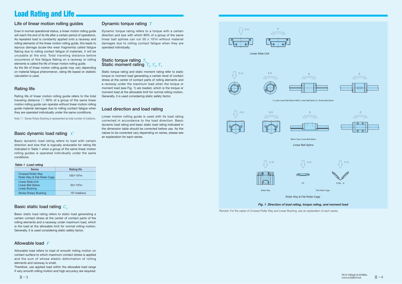
Ⅲ-3 Ⅲ-41N=0.102kgf=0.2248lbs.1mm=0.03937inch
Load Rating and Life Life of linear motion rolling guides
Even in normal operational status, a linear motion rolling guide will reach the end of its life after a certain period of operations. As repeated load is constantly applied onto a raceway and rolling elements of the linear motion rolling guide, this leads to leprous damage (scale-like wear fragments) called fatigue flaking due to rolling contact fatigue of materials, it will be unusable at the end. Total traveling distance before occurrence of this fatigue flaking on a raceway or rolling elements is called the life of linear motion rolling guide.As the life of linear motion rolling guide may vary depending on material fatigue phenomenon, rating life based on statistic calculation is used.
Rating life
Rating life of linear motion rolling guide refers to the total traveling distance (1) 90% of a group of the same linear motion rolling guide can operate without linear motion rolling guide material damages due to rolling contact fatigue when they are operated individually under the same conditions.
Note (1) Stroke Rotary Bushing is represented as total number of rotations.
Basic dynamic load rating C
Basic dynamic load rating refers to load with certain direction and size that is logically endurable for rating life indicated in Table 1 when a group of the same linear motion rolling guides is operated individually under the same conditions.
Table 1 Load ratingSeries Rating life
Crossed Roller WayRoller Way & Flat Roller Cage
100×103m
Linear Slide UnitLinear Ball SplineLinear Bushing
50×103m
Stroke Rotary Bushing 106 rotations
Basic static load rating C0
Basic static load rating refers to static load generating a certain contact stress at the center of contact parts of the rolling elements and a raceway under maximum load, which is the load at the allowable limit for normal rolling motion. Generally, it is used considering static safety factor.
Allowable load F
Allowable load refers to load of smooth rolling motion on contact surface to which maximum contact stress is applied and the sum of whose elastic deformation of rolling elements and raceway is small.Therefore, use applied load within the allowable load range if very smooth rolling motion and high accuracy are required.
Dynamic torque rating T
Dynamic torque rating refers to a torque with a certain direction and size with which 90% of a group of the same linear ball splines can run 50 x 103m without material damages due to rolling contact fatigue when they are operated individually.
Static torque rating T0Static moment rating T0, TX, TY
Static torque rating and static moment rating refer to static torque or moment load generating a certain level of contact stress at the center of contact parts of rolling elements and a raceway under the maximum load when the torque or moment load (see Fig. 1) are loaded, which is the torque or moment load at the allowable limit for normal rolling motion. Generally, it is used considering static safety factor.
Load direction and load rating
Linear motion rolling guide is used with its load rating corrected in accordance to the load direction. Basic dynamic load rating and basic static load rating indicated in the dimension table should be corrected before use. As the values to be corrected vary depending on series, please see an explanation for each series.
Fig. 1 Direction of load rating, torque rating, and moment load
Remark: For the cases of Crossed Roller Way and Linear Bushing, see an explanation of each series.
T0C, C0
Linear Slide Unit
C, C0 T, T0 TYTX
C-Lube Linear Ball Spline MAG, Linear Ball Spline G, Stroke Ball Spline
T, T0 TX TYC, C0
Block Type Linear Ball Spline
Linear Ball Spline
C, C0 C, C0 C, C0
Roller Way Flat Roller Cage
FT FTW…A
Roller Way & Flat Roller Cage
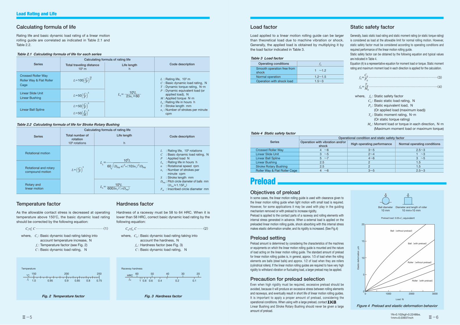
Ⅲ-5 Ⅲ-61N=0.102kgf=0.2248lbs.1mm=0.03937inch
Preload
Calculating formula of life
Rating life and basic dynamic load rating of a linear motion rolling guide are correlated as indicated in Table 2.1 and Table 2.2.
Temperature factor
As the allowable contact stress is decreased at operating temperature above 150°C, the basic dynamic load rating should be corrected by the following equation:
Ct=ft C (1)
where, Ct : Basic dynamic load rating taking into account temperature increase, N
ft : Temperature factor (see Fig. 2) C : Basic dynamic load rating, N
Load factor
Load applied to a linear motion rolling guide can be larger than theoretical load due to machine vibration or shock. Generally, the applied load is obtained by multiplying it by the load factor indicated in Table 3.
Table 3 Load factorOperating conditions fw
Smooth operation free from shock
1 ~1.2
Normal operation 1.2~1.5Operation with shock load 1.5~3
Objectives of preloadIn some cases, the linear motion rolling guide is used with clearance given to the linear motion rolling guide when light motion with small load is required. However, for some applications it may be used with play in the guiding mechanism removed or with preload to increase rigidity.Preload is applied to the contact parts of a raceway and rolling elements with internal stress generated in advance. When a external load is applied on the preloaded linear motion rolling guide, shock absorbing with this internal stress makes elastic deformation smaller, and its rigidity is increased. (See Fig.4)
Preload settingPreload amount is determined by considering the characteristics of the machines or equipments on which the linear motion rolling guide is mounted and the nature of load acting on the linear motion rolling guide. The standard amount of preload for linear motion rolling guides is, in general, approx. 1/3 of load when the rolling elements are balls (steel balls) and approx. 1/2 of load when they are rollers (cylindrical rollers). If the linear motion rolling guides are required to have very high rigidity to withstand vibration or fluctuating load, a larger preload may be applied.
Precaution for preload selectionEven when high rigidity must be required, excessive preload should be avoided, because it will produce an excessive stress between rolling elements and raceways, and eventually result in short life of linear motion rolling guides. It is important to apply a proper amount of preload, considering the operational conditions. When using with a large preload, contact .Linear Bushing and Stroke Rotary Bushing should never be given a large amount of preload.
Hardness factor
Hardness of a raceway must be 58 to 64 HRC. When it is lower than 58 HRC, correct basic dynamic load rating by the following equation:
CH=fH C (2)
where, CH : Basic dynamic load rating taking into account the hardness, N
fH : Hardness factor (see Fig. 3) C : Basic dynamic load rating, N
Table 2.1 Calculating formula of life for each series
Series
Calculating formula of rating life
Code descriptionTotal traveling distance103 m
Life lengthh
Crossed Roller Way
Roller Way & Flat Roller
Cage
L=100( C―P ) 3―10
Lh=106L
2Sn1×60
L : Rating life, 103 mC : Basic dynamic load rating, NT : Dynamic torque rating, N・mP : Dynamic equivalent load (or
applied load), NM : Applied torque N・mLh : Rating life in hours hS : Stroke length mmn1 : Number of strokes per minute
cpm
Linear Slide Unit
Linear BushingL=50( C―P )
3
Linear Ball SplineL=50( C―P )
3
L=50( T―M )3
Load Rating and Life
Table 4 Static safety factor
SeriesOperational condition and static safety factor
Operation with vibration and/or shock
High operating performance Normal operating conditions
Crossed Roller Way 4 ~6 3~5 2.5~3Linear Slide Unit 3 ~5 2~4 1 ~3Linear Ball Spline 5 ~7 4~6 3 ~5Linear Bushing 2.5 2 1.5Stroke Rotary Bushing 2.5 2 1.5Roller Way & Flat Roller Cage 4 ~6 3~5 2.5~3
Table 2.2 Calculating formula of life for Stroke Rotary Bushing
Series
Calculating formula of rating life
Code descriptionTotal number of rotation
106 rotations
Life length
h
Rotational motion
L=( C―P )3
Lh=
(DPW n)2+(10Sn1)2/DPW60
106L
L : Rating life, 106 rotationsC : Basic dynamic load rating, NP : Applied load NLh : Rating life in hours hn : Rotational speed rpmn1 : Number of strokes per
minute cpmS : Stroke length mmDPW : Pitch circle diameter of balls mm (DPW≒1.15FW)FW : Inscribed circle diameter mm
Rotational and rotary compound motion
Rotary andlinear motion Lh=
106L600Sn1/(πDPW)
Ball(without preload)
Roller(without preload)
Roller(with preload)
Ball(with preload)
20
15
10
5
00 1000 2000 3000
Load N
Ela
stic
def
orm
atio
n μ
m
Ball diameter10 mm
Preload load: 0.05×C0 equivalent
Diameter and length of roller10 mm×10 mm
Figure 4 Preload and elastic deformation behavior
Static safety factor
Generally, basic static load rating and static moment rating (or static torque rating) is considered as load at the allowable limit for normal rolling motion. However, static safety factor must be considered according to operating conditions and required performance of the linear motion rolling guide.Static safety factor can be obtained by the following equation and typical values are indicated in Table 4.Equation (4) is a representative equation for moment load or torque. Static moment rating and maximum moment load in each direction is applied for the calculation.
fS=C0―P0
(3)
fS=T0―M0
(4)
where, fS : Static safety factor C0 : Basic static load rating, N P0 : Static equivalent load, N
(Or applied load (maximum load))T0 : Static moment rating, N・m
(Or static torque rating)M0 : Moment load or torque in each direction, N・m
(Maximum moment load or maximum torque)
ft
150°C
1.0 0.95 0.9 0.85 0.8 0.75
200 250
Temperature
Fig. 2 Temperature factor
60HRC
50 40 30 20
1 0.8 0.6 0.4 0.2 0.1fH
Raceway hardness
Fig. 3 Hardness factor
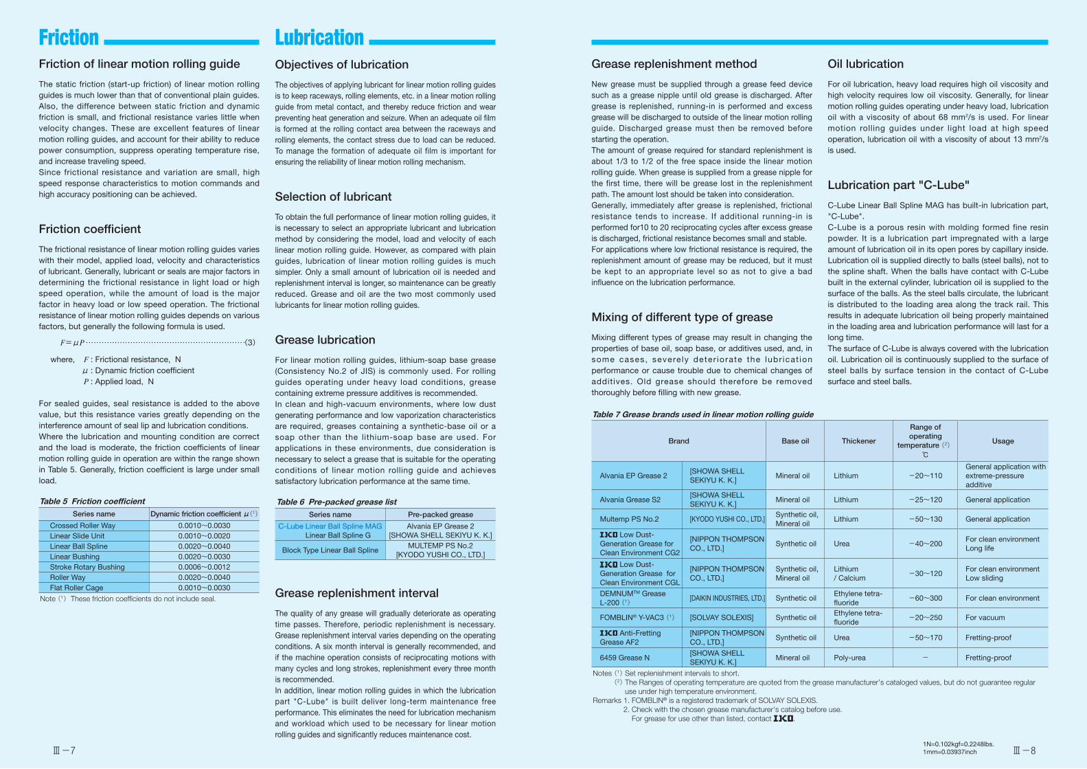
Ⅲ-7 Ⅲ-81N=0.102kgf=0.2248lbs.1mm=0.03937inch
Friction Lubrication Friction of linear motion rolling guide
The static friction (start-up friction) of linear motion rolling guides is much lower than that of conventional plain guides. Also, the difference between static friction and dynamic friction is small, and frictional resistance varies little when velocity changes. These are excellent features of linear motion rolling guides, and account for their ability to reduce power consumption, suppress operating temperature rise, and increase traveling speed.Since frictional resistance and variation are small, high speed response characteristics to motion commands and high accuracy positioning can be achieved.
Friction coefficient
The frictional resistance of linear motion rolling guides varies with their model, applied load, velocity and characteristics of lubricant. Generally, lubricant or seals are major factors in determining the frictional resistance in light load or high speed operation, while the amount of load is the major factor in heavy load or low speed operation. The frictional resistance of linear motion rolling guides depends on various factors, but generally the following formula is used.
F=μP (3)
where, F : Frictional resistance, N μ : Dynamic friction coefficient P : Applied load, N
For sealed guides, seal resistance is added to the above value, but this resistance varies greatly depending on the interference amount of seal lip and lubrication conditions.Where the lubrication and mounting condition are correct and the load is moderate, the friction coefficients of linear motion rolling guide in operation are within the range shown in Table 5. Generally, friction coefficient is large under small load.
Table 5 Friction coefficientSeries name Dynamic friction coefficient μ(1)
Crossed Roller Way 0.0010~0.0030Linear Slide Unit 0.0010~0.0020Linear Ball Spline 0.0020~0.0040Linear Bushing 0.0020~0.0030Stroke Rotary Bushing 0.0006~0.0012Roller Way 0.0020~0.0040Flat Roller Cage 0.0010~0.0030
Note (1) These friction coefficients do not include seal.
Objectives of lubrication
The objectives of applying lubricant for linear motion rolling guides is to keep raceways, rolling elements, etc. in a linear motion rolling guide from metal contact, and thereby reduce friction and wear preventing heat generation and seizure. When an adequate oil film is formed at the rolling contact area between the raceways and rolling elements, the contact stress due to load can be reduced. To manage the formation of adequate oil film is important for ensuring the reliability of linear motion rolling mechanism.
Selection of lubricant
To obtain the full performance of linear motion rolling guides, it is necessary to select an appropriate lubricant and lubrication method by considering the model, load and velocity of each linear motion rolling guide. However, as compared with plain guides, lubrication of linear motion rolling guides is much simpler. Only a small amount of lubrication oil is needed and replenishment interval is longer, so maintenance can be greatly reduced. Grease and oil are the two most commonly used lubricants for linear motion rolling guides.
Grease lubrication
For linear motion rolling guides, lithium-soap base grease (Consistency No.2 of JIS) is commonly used. For rolling guides operating under heavy load conditions, grease containing extreme pressure additives is recommended.In clean and high-vacuum environments, where low dust generating performance and low vaporization characteristics are required, greases containing a synthetic-base oil or a soap other than the lithium-soap base are used. For applications in these environments, due consideration is necessary to select a grease that is suitable for the operating conditions of linear motion rolling guide and achieves satisfactory lubrication performance at the same time.
Table 6 Pre-packed grease listSeries name Pre-packed grease
C-Lube Linear Ball Spline MAGLinear Ball Spline G
Alvania EP Grease 2[SHOWA SHELL SEKIYU K. K.]
Block Type Linear Ball SplineMULTEMP PS No.2
[KYODO YUSHI CO., LTD.]
Grease replenishment interval
The quality of any grease will gradually deteriorate as operating time passes. Therefore, periodic replenishment is necessary. Grease replenishment interval varies depending on the operating conditions. A six month interval is generally recommended, and if the machine operation consists of reciprocating motions with many cycles and long strokes, replenishment every three month is recommended.In addition, linear motion rolling guides in which the lubrication part "C-Lube" is built deliver long-term maintenance free performance. This eliminates the need for lubrication mechanism and workload which used to be necessary for linear motion rolling guides and significantly reduces maintenance cost.
Grease replenishment method
New grease must be supplied through a grease feed device such as a grease nipple until old grease is discharged. After grease is replenished, running-in is performed and excess grease will be discharged to outside of the linear motion rolling guide. Discharged grease must then be removed before starting the operation.The amount of grease required for standard replenishment is about 1/3 to 1/2 of the free space inside the linear motion rolling guide. When grease is supplied from a grease nipple for the first time, there will be grease lost in the replenishment path. The amount lost should be taken into consideration.Generally, immediately after grease is replenished, frictional resistance tends to increase. If additional running-in is performed for10 to 20 reciprocating cycles after excess grease is discharged, frictional resistance becomes small and stable.For applications where low frictional resistance is required, the replenishment amount of grease may be reduced, but it must be kept to an appropriate level so as not to give a bad influence on the lubrication performance.
Mixing of different type of grease
Mixing different types of grease may result in changing the properties of base oil, soap base, or additives used, and, in some cases, severe ly deter iorate the lubr icat ion performance or cause trouble due to chemical changes of additives. Old grease should therefore be removed thoroughly before filling with new grease.
Oil lubrication
For oil lubrication, heavy load requires high oil viscosity and high velocity requires low oil viscosity. Generally, for linear motion rolling guides operating under heavy load, lubrication oil with a viscosity of about 68 mm2/s is used. For linear motion rolling guides under light load at high speed operation, lubrication oil with a viscosity of about 13 mm2/s is used.
Lubrication part "C-Lube"
C-Lube Linear Ball Spline MAG has built-in lubrication part, "C-Lube".C-Lube is a porous resin with molding formed fine resin powder. It is a lubrication part impregnated with a large amount of lubrication oil in its open pores by capillary inside.Lubrication oil is supplied directly to balls (steel balls), not to the spline shaft. When the balls have contact with C-Lube built in the external cylinder, lubrication oil is supplied to the surface of the balls. As the steel balls circulate, the lubricant is distributed to the loading area along the track rail. This results in adequate lubrication oil being properly maintained in the loading area and lubrication performance will last for a long time.The surface of C-Lube is always covered with the lubrication oil. Lubrication oil is continuously supplied to the surface of steel balls by surface tension in the contact of C-Lube surface and steel balls.
Table 7 Grease brands used in linear motion rolling guide
Brand Base oil Thickener
Range of operating
temperature (2) Usage
℃
Alvania EP Grease 2[SHOWA SHELL SEKIYU K. K.]
Mineral oil Lithium -20~110General application with extreme-pressure additive
Alvania Grease S2[SHOWA SHELL SEKIYU K. K.]
Mineral oil Lithium -25~120 General application
Multemp PS No.2 [KYODO YUSHI CO., LTD.]Synthetic oil, Mineral oil
Lithium -50~130 General application
Low Dust-Generation Grease for Clean Environment CG2
[NIPPON THOMPSON CO., LTD.]
Synthetic oil Urea -40~200For clean environmentLong life
Low Dust-Generation Grease for Clean Environment CGL
[NIPPON THOMPSON CO., LTD.]
Synthetic oil, Mineral oil
Lithium/ Calcium
-30~120For clean environmentLow sliding
DEMNUMTM Grease L-200 (1) [DAIKIN INDUSTRIES, LTD.] Synthetic oil
Ethylene tetra-fluoride
-60~300 For clean environment
FOMBLIN® Y-VAC3 (1) [SOLVAY SOLEXIS] Synthetic oilEthylene tetra-fluoride
-20~250 For vacuum
Anti-FrettingGrease AF2
[NIPPON THOMPSON CO., LTD.]
Synthetic oil Urea -50~170 Fretting-proof
6459 Grease N[SHOWA SHELL SEKIYU K. K.]
Mineral oil Poly-urea - Fretting-proof
Notes (1) Set replenishment intervals to short. (2) The Ranges of operating temperature are quoted from the grease manufacturer's cataloged values, but do not guarantee regular
use under high temperature environment.Remarks 1. FOMBLIN® is a registered trademark of SOLVAY SOLEXIS.
2. Check with the chosen grease manufacturer's catalog before use.For grease for use other than listed, contact .
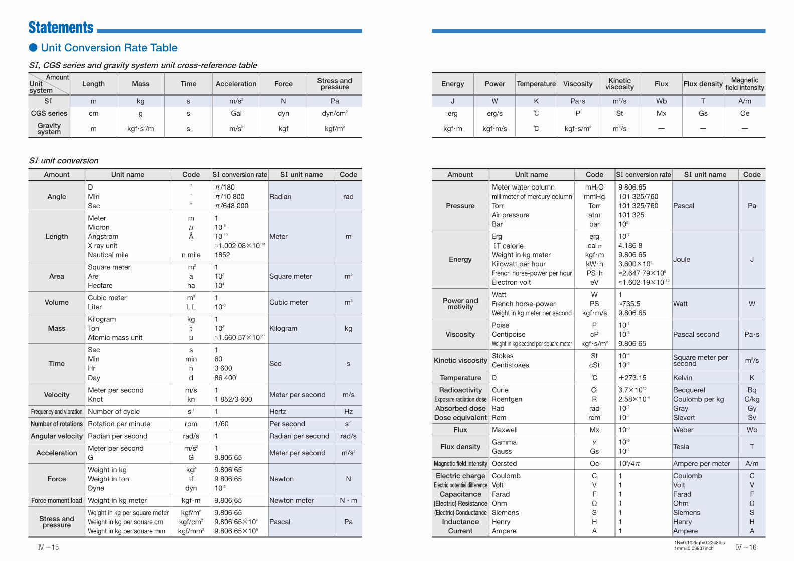
Ⅳ-15
Statements
Ⅳ-161N=0.102kgf=0.2248lbs.1mm=0.03937inch
SⅠ, CGS series and gravity system unit cross-reference tableAmount
Unit system
Length Mass Time Acceleration Force Stress and pressure Energy Power Temperature Viscosity Kinetic
viscosity Flux Flux density Magnetic field intensity
SⅠ m kg s m/s2 N Pa J W K Pa・s m2/s Wb T A/m
CGS series cm g s Gal dyn dyn/cm2 erg erg/s ℃ P St Mx Gs Oe
Gravity system m kgf・s2/m s m/s2 kgf kgf/m2 kgf・m kgf・m/s ℃ kgf・s/m2 m2/s ― ― ―
Amount Unit name Code SⅠ conversion rate SⅠ unit name Code
AngleD ° π/180
Radian radMin ′ π/10 800Sec ″ π/648 000
Length
Meter m 1
Meter mMicron μ 10-6
Angstrom Å 10-10
X ray unit ≈1.002 08×10-13
Nautical mile n mile 1852
AreaSquare meter m2 1
Square meter m2Are a 102
Hectare ha 104
VolumeCubic meter m3 1
Cubic meter m3
Liter l, L 10-3
MassKilogram kg 1
Kilogram kgTon t 103
Atomic mass unit u ≈1.660 57×10-27
Time
Sec s 1
Sec sMin min 60Hr h 3 600Day d 86 400
VelocityMeter per second m/s 1
Meter per second m/sKnot kn 1 852/3 600
Frequency and vibration Number of cycle s-1 1 Hertz Hz
Number of rotations Rotation per minute rpm 1/60 Per second s-1
Angular velocity Radian per second rad/s 1 Radian per second rad/s
AccelerationMeter per second m/s2 1
Meter per second m/s2
G G 9.806 65
ForceWeight in kg kgf 9.806 65
Newton NWeight in ton tf 9 806.65Dyne dyn 10-5
Force moment load Weight in kg meter kgf・m 9.806 65 Newton meter N・m
Stress and pressure
Weight in kg per square meter kgf/m2 9.806 65Pascal PaWeight in kg per square cm kgf/cm2 9.806 65×104
Weight in kg per square mm kgf/mm2 9.806 65×106
Amount Unit name Code SⅠ conversion rate SⅠ unit name Code
Pressure
Meter water column mH2O 9 806.65
Pascal Pamillimeter of mercury column mmHg 101 325/760Torr Torr 101 325/760Air pressure atm 101 325Bar bar 105
Energy
Erg erg 10-7
Joule J
ⅠT calorie calⅠT 4.186 8Weight in kg meter kgf・m 9.806 65Kilowatt per hour kW・h 3.600×10⁶
French horse-power per hour PS・h ≈2.647 79×106
Electron volt eV ≈1.602 19×10-19
Power and motivity
Watt W 1Watt WFrench horse-power PS ≈735.5
Weight in kg meter per second kgf・m/s 9.806 65
ViscosityPoise P 10-1
Pascal second Pa・sCentipoise cP 10-3
Weight in kg second per square meter kgf・s/m2 9.806 65
Kinetic viscosityStokes St 10-4
Square meter per second m2/s
Centistokes cSt 10-6
Temperature D ℃ +273.15 Kelvin K
Radioactivity Curie Ci 3.7×10¹⁰ Becquerel BqExposure radiation dose Roentgen R 2.58×10⁻⁴ Coulomb per kg C/kgAbsorbed dose Rad rad 10-2 Gray GyDose equivalent Rem rem 10-2 Sievert Sv
Flux Maxwell Mx 10-8 Weber Wb
Flux densityGamma γ 10-9
Tesla TGauss Gs 10-4
Magnetic field intensity Oersted Oe 103/4π Ampere per meter A/m
Electric charge Coulomb C 1 Coulomb CElectric potential difference Volt V 1 Volt V
Capacitance Farad F 1 Farad F(Electric) Resistance Ohm Ω 1 Ohm Ω(Electric) Conductance Siemens S 1 Siemens S
Inductance Henry H 1 Henry HCurrent Ampere A 1 Ampere A
SⅠ unit conversion
● Unit Conversion Rate Table

Statements
Ⅳ-17 Ⅳ-181N=0.102kgf=0.2248lbs.1mm=0.03937inch
1 inch=25.4mm
inch
0″ 1″ 2″ 3″ 4″ 5″ 6″ 7″ 8″Fractional number
Decimal number
0 25.400 50.800 76.200 101.600 127.000 152.400 177.800 203.2001 / 64″ 0.015625 0.397 25.797 51.197 76.597 101.997 127.397 152.797 178.197 203.5971 / 32″ 0.031250 0.794 26.194 51.594 76.994 102.394 127.794 153.194 178.594 203.9943 / 64″ 0.046875 1.191 26.591 51.991 77.391 102.791 128.191 153.591 178.991 204.3911 / 16″ 0.062500 1.588 26.988 52.388 77.788 103.188 128.588 153.988 179.388 204.788
5 / 64″ 0.078125 1.984 27.384 52.784 78.184 103.584 128.984 154.384 179.784 205.1843 / 32″ 0.093750 2.381 27.781 53.181 78.581 103.981 129.381 154.781 180.181 205.5817 / 64″ 0.109375 2.778 28.178 53.578 78.978 104.378 129.778 155.178 180.578 205.9781 / 8″ 0.125000 3.175 28.575 53.975 79.375 104.775 130.175 155.575 180.975 206.375
9 / 64″ 0.140625 3.572 28.972 54.372 79.772 105.172 130.572 155.972 181.372 206.7725 / 32″ 0.156250 3.969 29.369 54.769 80.169 105.569 130.969 156.369 181.769 207.169
11 / 64″ 0.171875 4.366 29.766 55.166 80.566 105.966 131.366 156.766 182.166 207.5663 / 16″ 0.187500 4.762 30.162 55.562 80.962 106.362 131.762 157.162 182.562 207.962
13 / 64″ 0.203125 5.159 30.559 55.959 81.359 106.759 132.159 157.559 182.959 208.3597 / 32″ 0.218750 5.556 30.956 56.356 81.756 107.156 132.556 157.956 183.356 208.756
15 / 64″ 0.234375 5.953 31.353 56.753 82.153 107.553 132.953 158.353 183.753 209.1531 / 4″ 0.250000 6.350 31.750 57.150 82.550 107.950 133.350 158.750 184.150 209.550
17 / 64″ 0.265625 6.747 32.147 57.547 82.947 108.347 133.747 159.147 184.547 209.9479 / 32″ 0.281250 7.144 32.544 57.944 83.344 108.744 134.144 159.544 184.944 210.344
19 / 64″ 0.296875 7.541 32.941 58.341 83.741 109.141 134.541 159.941 185.341 210.7415 / 16″ 0.312500 7.938 33.338 58.738 84.138 109.538 134.938 160.338 185.738 211.138
21 / 64″ 0.328125 8.334 33.734 59.134 84.534 109.934 135.334 160.734 186.134 211.53411 / 32″ 0.343750 8.731 34.131 59.531 84.931 110.331 135.731 161.131 186.531 211.93123 / 64″ 0.359375 9.128 34.528 59.928 85.328 110.728 136.128 161.528 186.928 212.328
3 / 8″ 0.375000 9.525 34.925 60.325 85.725 111.125 136.525 161.925 187.325 212.725
25 / 64″ 0.390625 9.922 35.322 60.722 86.122 111.522 136.922 162.322 187.722 213.12213 / 32″ 0.406250 10.319 35.719 61.119 86.519 111.919 137.319 162.719 188.119 213.51927 / 64″ 0.421875 10.716 36.116 61.516 86.916 112.316 137.716 163.116 188.516 213.916
7 / 16″ 0.437500 11.112 36.512 61.912 87.312 112.712 138.112 163.512 188.912 214.312
29 / 64″ 0.453125 11.509 36.909 62.309 87.709 113.109 138.509 163.909 189.309 214.70915 / 32″ 0.468750 11.906 37.306 62.706 88.106 113.506 138.906 164.306 189.706 215.10631 / 64″ 0.484375 12.303 37.703 63.103 88.503 113.903 139.303 164.703 190.103 215.503
1 / 2″ 0.500000 12.700 38.100 63.500 88.900 114.300 139.700 165.100 190.500 215.900
1 inch=25.4mm
inch
0″ 1″ 2″ 3″ 4″ 5″ 6″ 7″ 8″Fractional number
Decimal number
33 / 64″ 0.515625 13.097 38.497 63.897 89.297 114.697 140.097 165.497 190.897 216.29717 / 32″ 0.531250 13.494 38.894 64.294 89.694 115.094 140.494 165.894 191.294 216.69435 / 64″ 0.546875 13.891 39.291 64.691 90.091 115.491 140.891 166.291 191.691 217.091
9 / 16″ 0.562500 14.288 39.688 65.088 90.488 115.888 141.288 166.688 192.088 217.488
37 / 64″ 0.578125 14.684 40.084 65.484 90.884 116.284 141.684 167.084 192.484 217.88419 / 32″ 0.593750 15.081 40.481 65.881 91.281 116.681 142.081 167.481 192.881 218.28139 / 64″ 0.609375 15.478 40.878 66.278 91.678 117.078 142.478 167.878 193.278 218.678
5 / 8″ 0.625000 15.875 41.275 66.675 92.075 117.475 142.875 168.275 193.675 219.075
41 / 64″ 0.640625 16.272 41.672 67.072 92.472 117.872 143.272 168.672 194.072 219.47221 / 32″ 0.656250 16.669 42.069 67.469 92.869 118.269 143.669 169.069 194.469 219.86943 / 64″ 0.671875 17.066 42.466 67.866 93.266 118.666 144.066 169.466 194.866 220.26611 / 16″ 0.687500 17.462 42.862 68.262 93.662 119.062 144.462 169.862 195.262 220.662
45 / 64″ 0.703125 17.859 43.259 68.659 94.059 119.459 144.859 170.259 195.659 221.05923 / 32″ 0.718750 18.256 43.656 69.056 94.456 119.856 145.256 170.656 196.056 221.45647 / 64″ 0.734375 18.653 44.053 69.453 94.853 120.253 145.653 171.053 196.453 221.853
3 / 4″ 0.750000 19.050 44.450 69.850 95.250 120.650 146.050 171.450 196.850 222.250
49 / 64″ 0.765625 19.447 44.847 70.247 95.647 121.047 146.447 171.847 197.247 222.64725 / 32″ 0.781250 19.844 45.244 70.644 96.044 121.444 146.844 172.244 197.644 223.04451 / 64″ 0.796875 20.241 45.641 71.041 96.441 121.841 147.241 172.641 198.041 223.44113 / 16″ 0.812500 20.638 46.038 71.438 96.838 122.238 147.638 173.038 198.438 223.838
53 / 64″ 0.828125 21.034 46.434 71.834 97.234 122.634 148.034 173.434 198.834 224.23427 / 32″ 0.843750 21.431 46.831 72.231 97.631 123.031 148.431 173.831 199.231 224.63155 / 64″ 0.859375 21.828 47.228 72.628 98.028 123.428 148.828 174.228 199.628 225.028
7 / 8″ 0.875000 22.225 47.625 73.025 98.425 123.825 149.225 174.625 200.025 225.425
57 / 64″ 0.890625 22.622 48.022 73.422 98.822 124.222 149.622 175.022 200.422 225.82229 / 32″ 0.906250 23.019 48.419 73.819 99.219 124.619 150.019 175.419 200.819 226.21959 / 64″ 0.921875 23.416 48.816 74.216 99.616 125.016 150.416 175.816 201.216 226.61615 / 16″ 0.937500 23.812 49.212 74.612 100.012 125.412 150.812 176.212 201.612 227.012
61 / 64″ 0.953125 24.209 49.609 75.009 100.409 125.809 151.209 176.609 202.009 227.40931 / 32″ 0.968750 24.606 50.006 75.406 100.806 126.206 151.606 177.006 202.406 227.80663 / 64″ 0.984375 25.003 50.403 75.803 101.203 126.603 152.003 177.403 202.803 228.203
● Inch-mm Conversion Table

Statements
Ⅳ-19
Ⅳ-201N=0.102kgf=0.2248lbs.1mm=0.03937inch
Rockwell Vickers hardness Brinell hardness Rockwell hardness Shore
hardnessC scale
hardnessStandard ball Tungsten
Carbide ball
A scale B scale
Load 1471N Load 588.4N Load 980.7N
HRC HVDiamond
circular coneDiameter 1/16in ball
HS
68 940 ― ― 85.6 ― 9767 900 ― ― 85.0 ― 9566 865 ― ― 84.5 ― 9265 832 ― (739) 83.9 ― 9164 800 ― (722) 83.4 ― 88
63 772 ― (705) 82.8 ― 8762 746 ― (688) 82.3 ― 8561 720 ― (670) 81.8 ― 8360 697 ― (654) 81.2 ― 8159 674 ― (634) 80.7 ― 80
58 653 ― 615 80.1 ― 7857 633 ― 595 79.6 ― 7656 613 ― 577 79.0 ― 7555 595 ― 560 78.5 ― 7454 577 ― 543 78.0 ― 72
53 560 ― 525 77.4 ― 7152 544 (500) 512 76.8 ― 6951 528 (487) 496 76.3 ― 6850 513 (475) 481 75.9 ― 6749 498 (464) 469 75.2 ― 66
48 484 451 455 74.7 ― 6447 471 442 443 74.1 ― 6346 458 432 432 73.6 ― 6245 446 421 421 73.1 ― 6044 434 409 409 72.5 ― 58
43 423 400 400 72.0 ― 5742 412 390 390 71.5 ― 5641 402 381 381 70.9 ― 5540 392 371 371 70.4 ― 5439 382 362 362 69.9 ― 52
Rockwell Vickers hardness Brinell hardness Rockwell hardness Shore
hardnessC scale
hardnessStandard ball Tungsten
Carbide ball
A scale B scale
Load 1471N Load 588.4N Load 980.7N
HRC HVDiamond
circular coneDiameter 1/16in ball
HS
38 372 353 353 69.4 ― 5137 363 344 344 68.9 ― 5036 354 336 336 68.4 (109.0) 4935 345 327 327 67.9 (108.5) 4834 336 319 319 67.4 (108.0) 47
33 327 311 311 66.8 (107.5) 4632 318 301 301 66.3 (107.0) 4431 310 294 294 65.8 (106.0) 4330 302 286 286 65.3 (105.5) 4229 294 279 279 64.7 (104.5) 41
28 286 271 271 64.3 (104.0) 4127 279 264 264 63.8 (103.0) 4026 272 258 258 63.3 (102.5) 3825 266 253 253 62.8 (101.5) 3824 260 247 247 62.4 (101.0) 37
23 254 243 243 62.0 100.0 3622 248 237 237 61.5 99.0 3521 243 231 231 61.0 98.5 3520 238 226 226 60.5 97.8 34
(18) 230 219 219 ― 96.7 33(16) 222 212 212 ― 95.5 32(14) 213 203 203 ― 93.9 31(12) 204 194 194 ― 92.3 29
(10) 196 187 187 ― 90.7 28 (8) 188 179 179 ― 89.5 27 (6) 180 171 171 ― 87.1 26 (4) 173 165 165 ― 85.5 25 (2) 166 158 158 ― 83.5 24 (0) 160 152 152 ― 81.7 24
● Hardness Conversion Table (Reference)
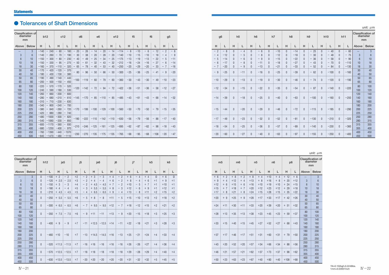
Statements
Ⅳ-21
Ⅳ-221N=0.102kgf=0.2248lbs.1mm=0.03937inch
unit: μm
Classification of diameter b12 c12 d6 e6 e12 f5 f6 g5 g6 h5 h6 h7 h8 h9 h10 h11
Classification of diameter
mm mm
Above Below H L H L H L H L H L H L H L H L H L H L H L H L H L H L H L H L Above Below
3 -140 - 240 - 60 - 160 - 20 - 26 - 14 - 20 - 14 -114 - 6 -10 - 6 - 12 - 2 - 6 - 2 - 8 0 - 4 0 - 6 0 -10 0 -14 0 - 25 0 - 40 0 - 60 3 3 6 -140 - 260 - 70 - 190 - 30 - 38 - 20 - 28 - 20 -140 -10 -15 -10 - 18 - 4 - 9 - 4 -12 0 - 5 0 - 8 0 -12 0 -18 0 - 30 0 - 48 0 - 75 3 6 6 10 -150 - 300 - 80 - 230 - 40 - 49 - 25 - 34 - 25 -175 -13 -19 -13 - 22 - 5 -11 - 5 -14 0 - 6 0 - 9 0 -15 0 -22 0 - 36 0 - 58 0 - 90 6 10 10 18 -150 - 330 - 95 - 275 - 50 - 61 - 32 - 43 - 32 -212 -16 -24 -16 - 27 - 6 -14 - 6 -17 0 - 8 0 -11 0 -18 0 -27 0 - 43 0 - 70 0 -110 10 18 18 30 -160 - 370 -110 - 320 - 65 - 78 - 40 - 53 - 40 -250 -20 -29 -20 - 33 - 7 -16 - 7 -20 0 - 9 0 -13 0 -21 0 -33 0 - 52 0 - 84 0 -130 18 30 30 40 -170 - 420 -120 - 370
- 80 - 96 - 50 - 66 - 50 -300 -25 -36 -25 - 41 - 9 -20 - 9 -25 0 -11 0 -16 0 -25 0 -39 0 - 62 0 -100 0 -160 30 40
40 50 -180 - 430 -130 - 380 40 50 50 65 -190 - 490 -140 - 440
-100 -119 - 60 - 79 - 60 -360 -30 -43 -30 - 49 -10 -23 -10 -29 0 -13 0 -19 0 -30 0 -46 0 - 74 0 -120 0 -190 50 65
65 80 -200 - 500 -150 - 450 65 80
80 100 -220 - 570 -170 - 520-120 -142 - 72 - 94 - 72 -422 -36 -51 -36 - 58 -12 -27 -12 -34 0 -15 0 -22 0 -35 0 -54 0 - 87 0 -140 0 -220
80 100100 120 -240 - 590 -180 - 530 100 120120 140 -260 - 660 -200 - 600
-145 -170 - 85 -110 - 85 -485 -43 -61 -43 - 68 -14 -32 -14 -39 0 -18 0 -25 0 -40 0 -63 0 -100 0 -160 0 -250120 140
140 160 -280 - 680 -210 - 610 140 160160 180 -310 - 710 -230 - 630 160 180180 200 -340 - 800 -240 - 700
-170 -199 -100 -129 -100 -560 -50 -70 -50 - 79 -15 -35 -15 -44 0 -20 0 -29 0 -46 0 -72 0 -115 0 -185 0 -290180 200
200 225 -380 - 840 -260 - 720 200 225225 250 -420 - 880 -280 - 740 225 250250 280 -480 -1000 -300 - 820
-190 -222 -110 -142 -110 -630 -56 -79 -56 - 88 -17 -40 -17 -49 0 -23 0 -32 0 -52 0 -81 0 -130 0 -210 0 -320250 280
280 315 -540 -1060 -330 - 850 280 315315 355 -600 -1170 -360 - 930
-210 -246 -125 -161 -125 -695 -62 -87 -62 - 98 -18 -43 -18 -54 0 -25 0 -36 0 -57 0 -89 0 -140 0 -230 0 -360315 355
355 400 -680 -1250 -400 - 970 355 400400 450 -760 -1390 -440 -1070
-230 -270 -135 -175 -135 -765 -68 -95 -68 -108 -20 -47 -20 -60 0 -27 0 -40 0 -63 0 -97 0 -155 0 -250 0 -400400 450
450 500 -840 -1470 -480 -1110 450 500
unit: μm
Classification of diameter h12 js5 j5 js6 j6 j7 k5 k6 m5 m6 n5 n6 p6
Classification of diameter
mm mm
Above Below H L H L H L H L H L H L H L H L H L H L H L H L H L Above Below
3 0 -100 + 2 - 2 +2 - 2 + 3 - 3 + 4 - 2 + 6 - 4 + 4 0 + 6 0 + 6 + 2 + 8 + 2 + 8 + 4 +10 + 4 + 12 + 6 3 3 6 0 -120 + 2.5 - 2.5 +3 - 2 + 4 - 4 + 6 - 2 + 8 - 4 + 6 +1 + 9 +1 + 9 + 4 +12 + 4 +13 + 8 +16 + 8 + 20 +12 3 6 6 10 0 -150 + 3 - 3 +4 - 2 + 4.5 - 4.5 + 7 - 2 +10 - 5 + 7 +1 +10 +1 +12 + 6 +15 + 6 +16 +10 +19 +10 + 24 +15 6 10 10 18 0 -180 + 4 - 4 +5 - 3 + 5.5 - 5.5 + 8 - 3 +12 - 6 + 9 +1 +12 +1 +15 + 7 +18 + 7 +20 +12 +23 +12 + 29 +18 10 18 18 30 0 -210 + 4.5 - 4.5 +5 - 4 + 6.5 - 6.5 + 9 - 4 +13 - 8 +11 +2 +15 +2 +17 + 8 +21 + 8 +24 +15 +28 +15 + 35 +22 18 30 30 40
0 -250 + 5.5 - 5.5 +6 - 5 + 8 - 8 +11 - 5 +15 -10 +13 +2 +18 +2 +20 + 9 +25 + 9 +28 +17 +33 +17 + 42 +26 30 40
40 50 40 50 50 65
0 -300 + 6.5 - 6.5 +6 - 7 + 9.5 - 9.5 +12 - 7 +18 -12 +15 +2 +21 +2 +24 +11 +30 +11 +33 +20 +39 +20 + 51 +32 50 65
65 80 65 80
80 1000 -350 + 7.5 - 7.5 +6 - 9 +11 -11 +13 - 9 +20 -15 +18 +3 +25 +3 +28 +13 +35 +13 +38 +23 +45 +23 + 59 +37
80 100100 120 100 120120 140
0 -400 + 9 - 9 +7 -11 +12.5 -12.5 +14 -11 +22 -18 +21 +3 +28 +3 +33 +15 +40 +15 +45 +27 +52 +27 + 68 +43120 140
140 160 140 160160 180 160 180180 200
0 -460 +10 -10 +7 -13 +14.5 -14.5 +16 -13 +25 -21 +24 +4 +33 +4 +37 +17 +46 +17 +51 +31 +60 +31 + 79 +50180 200
200 225 200 225225 250 225 250250 280
0 -520 +11.5 -11.5 +7 -16 +16 -16 +16 -16 +26 -26 +27 +4 +36 +4 +43 +20 +52 +20 +57 +34 +66 +34 + 88 +56250 280
280 315 280 315315 355
0 -570 +12.5 -12.5 +7 -18 +18 -18 +18 -18 +29 -28 +29 +4 +40 +4 +46 +21 +57 +21 +62 +37 +73 +37 + 98 +62315 355
355 400 355 400400 450
0 -630 +13.5 -13.5 +7 -20 +20 -20 +20 -20 +31 -32 +32 +5 +45 +5 +50 +23 +63 +23 +67 +40 +80 +40 +108 +68400 450
450 500 450 500
● Tolerances of Shaft Dimensions
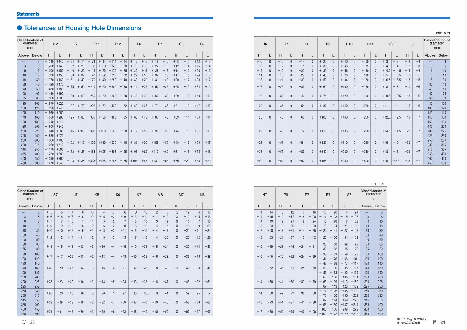
Statements
Ⅳ-23
Ⅳ-241N=0.102kgf=0.2248lbs.1mm=0.03937inch
unit: μm
Classification of diameter B12 E7 E11 E12 F6 F7 G6 G7 H6 H7 H8 H9 H10 H11 JS6 J6
Classification of diameter
mm mm
Above Below H L H L H L H L H L H L H L H L H L H L H L H L H L H L H L H L Above Below
3 + 240 +140 + 24 + 14 + 74 + 14 +114 + 14 + 12 + 6 + 16 + 6 + 8 + 2 +12 + 2 + 6 0 +10 0 +14 0 + 25 0 + 40 0 + 60 0 + 3 - 3 + 2 -4 3 3 6 + 260 +140 + 32 + 20 + 95 + 20 +140 + 20 + 18 +10 + 22 +10 +12 + 4 +16 + 4 + 8 0 +12 0 +18 0 + 30 0 + 48 0 + 75 0 + 4 - 4 + 5 -3 3 6 6 10 + 300 +150 + 40 + 25 +115 + 25 +175 + 25 + 22 +13 + 28 +13 +14 + 5 +20 + 5 + 9 0 +15 0 +22 0 + 36 0 + 58 0 + 90 0 + 4.5 - 4.5 + 5 -4 6 10 10 18 + 330 +150 + 50 + 32 +142 + 32 +212 + 32 + 27 +16 + 34 +16 +17 + 6 +24 + 6 +11 0 +18 0 +27 0 + 43 0 + 70 0 +110 0 + 5.5 - 5.5 + 6 -5 10 18 18 30 + 370 +160 + 61 + 40 +170 + 40 +250 + 40 + 33 +20 + 41 +20 +20 + 7 +28 + 7 +13 0 +21 0 +33 0 + 52 0 + 84 0 +130 0 + 6.5 - 6.5 + 8 -5 18 30 30 40 + 420 +170
+ 75 + 50 +210 + 50 +300 + 50 + 41 +25 + 50 +25 +25 + 9 +34 + 9 +16 0 +25 0 +39 0 + 62 0 +100 0 +160 0 + 8 - 8 +10 -6 30 40
40 50 + 430 +180 40 50 50 65 + 490 +190
+ 90 + 60 +250 + 60 +360 + 60 + 49 +30 + 60 +30 +29 +10 +40 +10 +19 0 +30 0 +46 0 + 74 0 +120 0 +190 0 + 9.5 - 9.5 +13 -6 50 65
65 80 + 500 +200 65 80
80 100 + 570 +220+107 + 72 +292 + 72 +422 + 72 + 58 +36 + 71 +36 +34 +12 +47 +12 +22 0 +35 0 +54 0 + 87 0 +140 0 +220 0 +11 -11 +16 -6
80 100100 120 + 590 +240 100 120120 140 + 660 +260
+125 + 85 +335 + 85 +485 + 85 + 68 +43 + 83 +43 +39 +14 +54 +14 +25 0 +40 0 +63 0 +100 0 +160 0 +250 0 +12.5 -12.5 +18 -7120 140
140 160 + 680 +280 140 160160 180 + 710 +310 160 180180 200 + 800 +340
+146 +100 +390 +100 +560 +100 + 79 +50 + 96 +50 +44 +15 +61 +15 +29 0 +46 0 +72 0 +115 0 +185 0 +290 0 +14.5 -14.5 +22 -7180 200
200 225 + 840 +380 200 225225 250 + 880 +420 225 250250 280 +1000 +480
+162 +110 +430 +110 +630 +110 + 88 +56 +108 +56 +49 +17 +69 +17 +32 0 +52 0 +81 0 +130 0 +210 0 +320 0 +16 -16 +25 -7250 280
280 315 +1060 +540 280 315315 355 +1170 +600
+182 +125 +485 +125 +695 +125 + 98 +62 +119 +62 +54 +18 +75 +18 +36 0 +57 0 +89 0 +140 0 +230 0 +360 0 +18 -18 +29 -7315 355
355 400 +1250 +680 355 400400 450 +1390 +760
+198 +135 +535 +135 +765 +135 +108 +68 +131 +68 +60 +20 +83 +20 +40 0 +63 0 +97 0 +155 0 +250 0 +400 0 +20 -20 +33 -7400 450
450 500 +1470 +840 450 500
unit: μm
Classification of diameter JS7 J7 K5 K6 K7 M6 M7 N6 N7 P6 P7 R7 S7
Classification of diameter
mm mm
Above Below H L H L H L H L H L H L H L H L H L H L H L H L H L Above Below
3 + 5 - 5 + 4 - 6 0 - 4 0 - 6 0 -10 - 2 - 8 -2 -12 - 4 -10 - 4 -14 - 6 -12 - 6 - 16 - 10 - 20 - 14 - 24 3 3 6 + 6 - 6 + 6 - 6 0 - 5 +2 - 6 + 3 - 9 - 1 - 9 0 -12 - 5 -13 - 4 -16 - 9 -17 - 8 - 20 - 11 - 23 - 15 - 27 3 6 6 10 + 7 - 7 + 8 - 7 +1 - 5 +2 - 7 + 5 -10 - 3 -12 0 -15 - 7 -16 - 4 -19 -12 -21 - 9 - 24 - 13 - 28 - 17 - 32 6 10 10 18 + 9 - 9 +10 - 8 +2 - 6 +2 - 9 + 6 -12 - 4 -15 0 -18 - 9 -20 - 5 -23 -15 -26 -11 - 29 - 16 - 34 - 21 - 39 10 18 18 30 +10 -10 +12 - 9 +1 - 8 +2 -11 + 6 -15 - 4 -17 0 -21 -11 -24 - 7 -28 -18 -31 -14 - 35 - 20 - 41 - 27 - 48 18 30 30 40
+12 -12 +14 -11 +2 - 9 +3 -13 + 7 -18 - 4 -20 0 -25 -12 -28 - 8 -33 -21 -37 -17 - 42 - 25 - 50 - 34 - 59 30 40
40 50 40 50 50 65
+15 -15 +18 -12 +3 -10 +4 -15 + 9 -21 - 5 -24 0 -30 -14 -33 - 9 -39 -26 -45 -21 - 51- 30 - 60 - 42 - 72 50 65
65 80 - 32 - 62 - 48 - 78 65 80
80 100+17 -17 +22 -13 +2 -13 +4 -18 +10 -25 - 6 -28 0 -35 -16 -38 -10 -45 -30 -52 -24 - 59
- 38 - 73 - 58 - 93 80 100100 120 - 41 - 76 - 66 - 101 100 120120 140
+20 -20 +26 -14 +3 -15 +4 -21 +12 -28 - 8 -33 0 -40 -20 -45 -12 -52 -36 -61 -28 - 68- 48 - 88 - 77 -117 120 140
140 160 - 50 - 90 - 85 -125 140 160160 180 - 53 - 93 - 93 -133 160 180180 200
+23 -23 +30 -16 +2 -18 +5 -24 +13 -33 - 8 -37 0 -46 -22 -51 -14 -60 -41 -70 -33 - 79- 60 -106 -105 -151 180 200
200 225 - 63 -109 -113 -159 200 225225 250 - 67 -113 -123 -169 225 250250 280
+26 -26 +36 -16 +3 -20 +5 -27 +16 -36 - 9 -41 0 -52 -25 -57 -14 -66 -47 -79 -36 - 88- 74 -126 -138 -190 250 280
280 315 - 78 -130 -150 -202 280 315315 355
+28 -28 +39 -18 +3 -22 +7 -29 +17 -40 -10 -46 0 -57 -26 -62 -16 -73 -51 -87 -41 - 98- 87 -144 -169 -226 315 355
355 400 - 93 -150 -187 -244 355 400400 450
+31 -31 +43 -20 +2 -25 +8 -32 +18 -45 -10 -50 0 -63 -27 -67 -17 -80 -55 -95 -45 -108-103 -166 -209 -272 400 450
450 500 -109 -172 -229 -292 450 500
● Tolerances of Housing Hole Dimensions
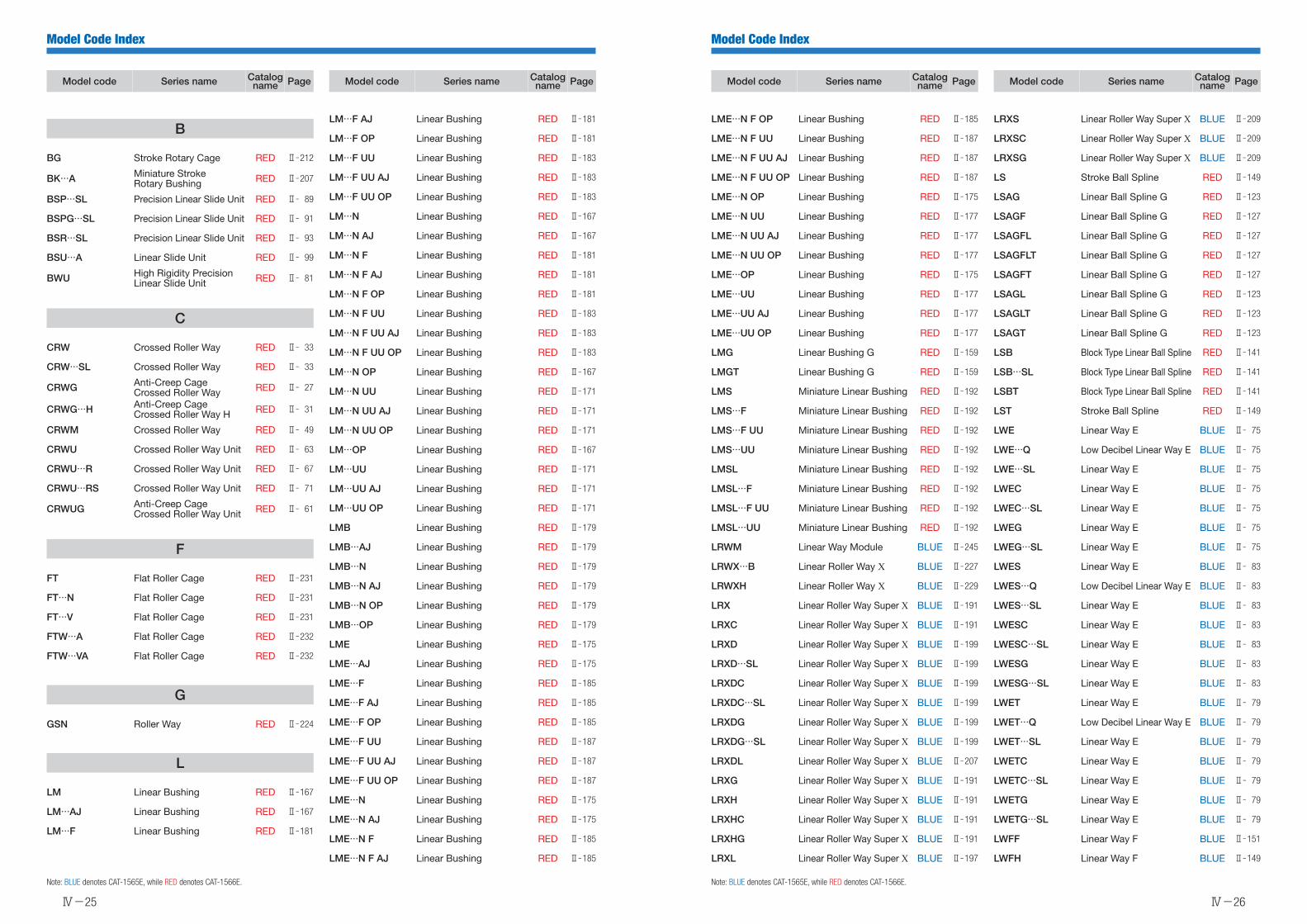
Model Code Index
Ⅳ-25
Model Code Index
Ⅳ-26
Model code Series name Catalog name Page
B
BG Stroke Rotary Cage RED Ⅱ212
BK…A Miniature StrokeRotary Bushing RED Ⅱ207
BSP…SL Precision Linear Slide Unit RED Ⅱ 89
BSPG…SL Precision Linear Slide Unit RED Ⅱ 91
BSR…SL Precision Linear Slide Unit RED Ⅱ 93
BSU…A Linear Slide Unit RED Ⅱ 99
BWU High Rigidity Precision Linear Slide Unit RED Ⅱ 81
C
CRW Crossed Roller Way RED Ⅱ 33
CRW…SL Crossed Roller Way RED Ⅱ 33
CRWG Anti-Creep CageCrossed Roller Way RED Ⅱ 27
CRWG…H Anti-Creep CageCrossed Roller Way H RED Ⅱ 31
CRWM Crossed Roller Way RED Ⅱ 49
CRWU Crossed Roller Way Unit RED Ⅱ 63
CRWU…R Crossed Roller Way Unit RED Ⅱ 67
CRWU…RS Crossed Roller Way Unit RED Ⅱ 71
CRWUG Anti-Creep CageCrossed Roller Way Unit RED Ⅱ 61
F
FT Flat Roller Cage RED Ⅱ231
FT…N Flat Roller Cage RED Ⅱ231
FT…V Flat Roller Cage RED Ⅱ231
FTW…A Flat Roller Cage RED Ⅱ232
FTW…VA Flat Roller Cage RED Ⅱ232
G
GSN Roller Way RED Ⅱ224
L
LM Linear Bushing RED Ⅱ167
LM…AJ Linear Bushing RED Ⅱ167
LM…F Linear Bushing RED Ⅱ181
Model code Series name Catalog name Page
LM…F AJ Linear Bushing RED Ⅱ181
LM…F OP Linear Bushing RED Ⅱ181
LM…F UU Linear Bushing RED Ⅱ183
LM…F UU AJ Linear Bushing RED Ⅱ183
LM…F UU OP Linear Bushing RED Ⅱ183
LM…N Linear Bushing RED Ⅱ167
LM…N AJ Linear Bushing RED Ⅱ167
LM…N F Linear Bushing RED Ⅱ181
LM…N F AJ Linear Bushing RED Ⅱ181
LM…N F OP Linear Bushing RED Ⅱ181
LM…N F UU Linear Bushing RED Ⅱ183
LM…N F UU AJ Linear Bushing RED Ⅱ183
LM…N F UU OP Linear Bushing RED Ⅱ183
LM…N OP Linear Bushing RED Ⅱ167
LM…N UU Linear Bushing RED Ⅱ171
LM…N UU AJ Linear Bushing RED Ⅱ171
LM…N UU OP Linear Bushing RED Ⅱ171
LM…OP Linear Bushing RED Ⅱ167
LM…UU Linear Bushing RED Ⅱ171
LM…UU AJ Linear Bushing RED Ⅱ171
LM…UU OP Linear Bushing RED Ⅱ171
LMB Linear Bushing RED Ⅱ179
LMB…AJ Linear Bushing RED Ⅱ179
LMB…N Linear Bushing RED Ⅱ179
LMB…N AJ Linear Bushing RED Ⅱ179
LMB…N OP Linear Bushing RED Ⅱ179
LMB…OP Linear Bushing RED Ⅱ179
LME Linear Bushing RED Ⅱ175
LME…AJ Linear Bushing RED Ⅱ175
LME…F Linear Bushing RED Ⅱ185
LME…F AJ Linear Bushing RED Ⅱ185
LME…F OP Linear Bushing RED Ⅱ185
LME…F UU Linear Bushing RED Ⅱ187
LME…F UU AJ Linear Bushing RED Ⅱ187
LME…F UU OP Linear Bushing RED Ⅱ187
LME…N Linear Bushing RED Ⅱ175
LME…N AJ Linear Bushing RED Ⅱ175
LME…N F Linear Bushing RED Ⅱ185
LME…N F AJ Linear Bushing RED Ⅱ185
Model code Series name Catalog name Page
LME…N F OP Linear Bushing RED Ⅱ185
LME…N F UU Linear Bushing RED Ⅱ187
LME…N F UU AJ Linear Bushing RED Ⅱ187
LME…N F UU OP Linear Bushing RED Ⅱ187
LME…N OP Linear Bushing RED Ⅱ175
LME…N UU Linear Bushing RED Ⅱ177
LME…N UU AJ Linear Bushing RED Ⅱ177
LME…N UU OP Linear Bushing RED Ⅱ177
LME…OP Linear Bushing RED Ⅱ175
LME…UU Linear Bushing RED Ⅱ177
LME…UU AJ Linear Bushing RED Ⅱ177
LME…UU OP Linear Bushing RED Ⅱ177
LMG Linear Bushing G RED Ⅱ159
LMGT Linear Bushing G RED Ⅱ159
LMS Miniature Linear Bushing RED Ⅱ192
LMS…F Miniature Linear Bushing RED Ⅱ192
LMS…F UU Miniature Linear Bushing RED Ⅱ192
LMS…UU Miniature Linear Bushing RED Ⅱ192
LMSL Miniature Linear Bushing RED Ⅱ192
LMSL…F Miniature Linear Bushing RED Ⅱ192
LMSL…F UU Miniature Linear Bushing RED Ⅱ192
LMSL…UU Miniature Linear Bushing RED Ⅱ192
LRWM Linear Way Module BLUE Ⅱ245
LRWX…B Linear Roller Way X BLUE Ⅱ227
LRWXH Linear Roller Way X BLUE Ⅱ229
LRX Linear Roller Way Super X BLUE Ⅱ191
LRXC Linear Roller Way Super X BLUE Ⅱ191
LRXD Linear Roller Way Super X BLUE Ⅱ199
LRXD…SL Linear Roller Way Super X BLUE Ⅱ199
LRXDC Linear Roller Way Super X BLUE Ⅱ199
LRXDC…SL Linear Roller Way Super X BLUE Ⅱ199
LRXDG Linear Roller Way Super X BLUE Ⅱ199
LRXDG…SL Linear Roller Way Super X BLUE Ⅱ199
LRXDL Linear Roller Way Super X BLUE Ⅱ207
LRXG Linear Roller Way Super X BLUE Ⅱ191
LRXH Linear Roller Way Super X BLUE Ⅱ191
LRXHC Linear Roller Way Super X BLUE Ⅱ191
LRXHG Linear Roller Way Super X BLUE Ⅱ191
LRXL Linear Roller Way Super X BLUE Ⅱ197
Model code Series name Catalog name Page
LRXS Linear Roller Way Super X BLUE Ⅱ209
LRXSC Linear Roller Way Super X BLUE Ⅱ209
LRXSG Linear Roller Way Super X BLUE Ⅱ209
LS Stroke Ball Spline RED Ⅱ149
LSAG Linear Ball Spline G RED Ⅱ123
LSAGF Linear Ball Spline G RED Ⅱ127
LSAGFL Linear Ball Spline G RED Ⅱ127
LSAGFLT Linear Ball Spline G RED Ⅱ127
LSAGFT Linear Ball Spline G RED Ⅱ127
LSAGL Linear Ball Spline G RED Ⅱ123
LSAGLT Linear Ball Spline G RED Ⅱ123
LSAGT Linear Ball Spline G RED Ⅱ123
LSB Block Type Linear Ball Spline RED Ⅱ141
LSB…SL Block Type Linear Ball Spline RED Ⅱ141
LSBT Block Type Linear Ball Spline RED Ⅱ141
LST Stroke Ball Spline RED Ⅱ149
LWE Linear Way E BLUE Ⅱ 75
LWE…Q Low Decibel Linear Way E BLUE Ⅱ 75
LWE…SL Linear Way E BLUE Ⅱ 75
LWEC Linear Way E BLUE Ⅱ 75
LWEC…SL Linear Way E BLUE Ⅱ 75
LWEG Linear Way E BLUE Ⅱ 75
LWEG…SL Linear Way E BLUE Ⅱ 75
LWES Linear Way E BLUE Ⅱ 83
LWES…Q Low Decibel Linear Way E BLUE Ⅱ 83
LWES…SL Linear Way E BLUE Ⅱ 83
LWESC Linear Way E BLUE Ⅱ 83
LWESC…SL Linear Way E BLUE Ⅱ 83
LWESG Linear Way E BLUE Ⅱ 83
LWESG…SL Linear Way E BLUE Ⅱ 83
LWET Linear Way E BLUE Ⅱ 79
LWET…Q Low Decibel Linear Way E BLUE Ⅱ 79
LWET…SL Linear Way E BLUE Ⅱ 79
LWETC Linear Way E BLUE Ⅱ 79
LWETC…SL Linear Way E BLUE Ⅱ 79
LWETG Linear Way E BLUE Ⅱ 79
LWETG…SL Linear Way E BLUE Ⅱ 79
LWFF Linear Way F BLUE Ⅱ151
LWFH Linear Way F BLUE Ⅱ149
Note: BLUE denotes CAT-1565E, while RED denotes CAT-1566E. Note: BLUE denotes CAT-1565E, while RED denotes CAT-1566E.

Model Code Index
Ⅳ-27
Model Code Index
Ⅳ-28
Model code Series name Catalog name Page
L
LWFS Linear Way F BLUE Ⅱ153
LWFS…SL Linear Way F BLUE Ⅱ153
LWH…B Linear Way H BLUE Ⅱ107
LWH…M Linear Way H BLUE Ⅱ107
LWH…MU Linear Way H BLUE Ⅱ107
LWH…SL Linear Way H BLUE Ⅱ107
LWHD Linear Way H BLUE Ⅱ121
LWHD…B Linear Way H BLUE Ⅱ123
LWHD…M Linear Way H BLUE Ⅱ123
LWHD…MU Linear Way H BLUE Ⅱ123
LWHD…SL Linear Way H BLUE Ⅱ121
LWHDC…SL Linear Way H BLUE Ⅱ121
LWHDG Linear Way H BLUE Ⅱ123
LWHDG…SL Linear Way H BLUE Ⅱ121
LWHG Linear Way H BLUE Ⅱ107
LWHS…B Linear Way H BLUE Ⅱ127
LWHS…M Linear Way H BLUE Ⅱ127
LWHS…MU Linear Way H BLUE Ⅱ127
LWHS…SL Linear Way H BLUE Ⅱ127
LWHSG Linear Way H BLUE Ⅱ127
LWHT Linear Way H BLUE Ⅱ113
LWHT…B Linear Way H BLUE Ⅱ113
LWHT…M Linear Way H BLUE Ⅱ113
LWHT…MU Linear Way H BLUE Ⅱ113
LWHT…SL Linear Way H BLUE Ⅱ113
LWHTG Linear Way H BLUE Ⅱ115
LWHY Linear Way H BLUE Ⅱ131
LWL Linear Way L BLUE Ⅱ 23
LWL…B Linear Way L BLUE Ⅱ 25
LWL…B CS Linear Way L BLUE Ⅱ 27
LWL…N Linear Way L BLUE Ⅱ 25
LWL…Y Linear Way L BLUE Ⅱ 23
LWLC Linear Way L BLUE Ⅱ 23
LWLC…B Linear Way L BLUE Ⅱ 25
LWLC…N Linear Way L BLUE Ⅱ 25
LWLF Linear Way L BLUE Ⅱ 31
LWLF…B Linear Way L BLUE Ⅱ 31
Model code Series name Catalog name Page
LWLF…BCS Linear Way L BLUE Ⅱ 35
LWLF…N Linear Way L BLUE Ⅱ 31
LWLFC Linear Way L BLUE Ⅱ 31
LWLFC…B Linear Way L BLUE Ⅱ 31
LWLFC…N Linear Way L BLUE Ⅱ 31
LWLFG…B Linear Way L BLUE Ⅱ 33
LWLFG…N Linear Way L BLUE Ⅱ 33
LWLG…B Linear Way L BLUE Ⅱ 25
LWLG…N Linear Way L BLUE Ⅱ 25
LWLM Linear Way Module BLUE Ⅱ241
LWM Linear Way Module BLUE Ⅱ243
LWU…B Linear Way U BLUE Ⅱ167
M
MAG C-Lube Linear Ball Spline MAG RED Ⅱ123
MAGF C-Lube Linear Ball Spline MAG RED Ⅱ127
MAGFT C-Lube Linear Ball Spline MAG RED Ⅱ127
MAGL C-Lube Linear Ball Spline MAG RED Ⅱ123
MAGLT C-Lube Linear Ball Spline MAG RED Ⅱ123
MAGT C-Lube Linear Ball Spline MAG RED Ⅱ123
ME C-Lube Linear Way ME BLUE Ⅱ 75
ME…SL C-Lube Linear Way ME BLUE Ⅱ 75
MEC C-Lube Linear Way ME BLUE Ⅱ 75
MEC…SL C-Lube Linear Way ME BLUE Ⅱ 75
MEG C-Lube Linear Way ME BLUE Ⅱ 75
MEG…SL C-Lube Linear Way ME BLUE Ⅱ 75
MES C-Lube Linear Way ME BLUE Ⅱ 83
MES…SL C-Lube Linear Way ME BLUE Ⅱ 83
MESC C-Lube Linear Way ME BLUE Ⅱ 83
MESC…SL C-Lube Linear Way ME BLUE Ⅱ 83
MESG C-Lube Linear Way ME BLUE Ⅱ 83
MESG…SL C-Lube Linear Way ME BLUE Ⅱ 83
MET C-Lube Linear Way ME BLUE Ⅱ 79
MET…SL C-Lube Linear Way ME BLUE Ⅱ 79
METC C-Lube Linear Way ME BLUE Ⅱ 79
METC…SL C-Lube Linear Way ME BLUE Ⅱ 79
METG C-Lube Linear Way ME BLUE Ⅱ 79
METG…SL C-Lube Linear Way ME BLUE Ⅱ 79
Model code Series name Catalog name Page
MH C-Lube Linear Way MH BLUE Ⅱ 107
MH…M C-Lube Linear Way MH BLUE Ⅱ107
MH…MU C-Lube Linear Way MH BLUE Ⅱ107
MHD C-Lube Linear Way MH BLUE Ⅱ121
MHD…M C-Lube Linear Way MH BLUE Ⅱ123
MHD…MU C-Lube Linear Way MH BLUE Ⅱ123
MHD…SL C-Lube Linear Way MH BLUE Ⅱ121
MHDC…SL C-Lube Linear Way MH BLUE Ⅱ121
MHDG C-Lube Linear Way MH BLUE Ⅱ123
MHDG…SL C-Lube Linear Way MH BLUE Ⅱ121
MHDL C-Lube Linear Way MH BLUE Ⅱ123
MHG C-Lube Linear Way MH BLUE Ⅱ107
MHS C-Lube Linear Way MH BLUE Ⅱ127
MHS…M C-Lube Linear Way MH BLUE Ⅱ129
MHS…MU C-Lube Linear Way MH BLUE Ⅱ129
MHS…SL C-Lube Linear Way MH BLUE Ⅱ127
MHSG C-Lube Linear Way MH BLUE Ⅱ127
MHT C-Lube Linear Way MH BLUE Ⅱ113
MHT…M C-Lube Linear Way MH BLUE Ⅱ115
MHT…MU C-Lube Linear Way MH BLUE Ⅱ115
MHT…SL C-Lube Linear Way MH BLUE Ⅱ113
MHTG C-Lube Linear Way MH BLUE Ⅱ113
MHTL C-Lube Linear Way MH BLUE Ⅱ117
ML C-Lube Linear Way ML BLUE Ⅱ 25
MLC C-Lube Linear Way ML BLUE Ⅱ 25
MLF C-Lube Linear Way ML BLUE Ⅱ 31
MLFC C-Lube Linear Way ML BLUE Ⅱ 31
MLFG C-Lube Linear Way ML BLUE Ⅱ 33
MLG C-Lube Linear Way ML BLUE Ⅱ 25
MLL C-Lube Linear Way ML BLUE Ⅱ 27
MLV C-Lube Linear Way MLV BLUE Ⅱ 47
MUL C-Lube Linear Way MUL BLUE Ⅱ167
MV C-Lube Linear Way MV BLUE Ⅱ 59
MX C-Lube Linear Roller Way Super MX BLUE Ⅱ191
MXC C-Lube Linear Roller Way Super MX BLUE Ⅱ191
MXD C-Lube Linear Roller Way Super MX BLUE Ⅱ199
MXD…SL C-Lube Linear Roller Way Super MX BLUE Ⅱ199
MXDC C-Lube Linear Roller Way Super MX BLUE Ⅱ199
MXDG C-Lube Linear Roller Way Super MX BLUE Ⅱ199
Model code Series name Catalog name Page
MXDL C-Lube Linear Roller Way Super MX BLUE Ⅱ201
MXG C-Lube Linear Roller Way Super MX BLUE Ⅱ191
MXH C-Lube Linear Roller Way Super MX BLUE Ⅱ191
MXHC C-Lube Linear Roller Way Super MX BLUE Ⅱ191
MXHG C-Lube Linear Roller Way Super MX BLUE Ⅱ191
MXHL C-Lube Linear Roller Way Super MX BLUE Ⅱ191
MXL C-Lube Linear Roller Way Super MX BLUE Ⅱ191
MXN C-Lube Linear Roller Way Super MX BLUE Ⅱ213
MXNG C-Lube Linear Roller Way Super MX BLUE Ⅱ213
MXNL C-Lube Linear Roller Way Super MX BLUE Ⅱ213
MXNS C-Lube Linear Roller Way Super MX BLUE Ⅱ215
MXNSG C-Lube Linear Roller Way Super MX BLUE Ⅱ215
MXNSL C-Lube Linear Roller Way Super MX BLUE Ⅱ215
MXS C-Lube Linear Roller Way Super MX BLUE Ⅱ209
MXSC C-Lube Linear Roller Way Super MX BLUE Ⅱ209
MXSG C-Lube Linear Roller Way Super MX BLUE Ⅱ209
MXSL C-Lube Linear Roller Way Super MX BLUE Ⅱ209
O
OR…A Miniature StrokeRotary Bushing RED Ⅱ207
R
RW Roller Way RED Ⅱ221
RWB Roller Way RED Ⅱ222
S
SF…A Miniature StrokeRotary Bushing RED Ⅱ207
SR Roller Way RED Ⅱ223
ST Stroke Rotary Bushing RED Ⅱ199
ST…B Stroke Rotary Bushing RED Ⅱ199
ST…UU Stroke Rotary Bushing RED Ⅱ201
ST…UU B Stroke Rotary Bushing RED Ⅱ201
STS Miniature StrokeRotary Bushing RED Ⅱ207
STSI Miniature StrokeRotary Bushing RED Ⅱ207
Note: BLUE denotes CAT-1565E, while RED denotes CAT-1566E. Note: BLUE denotes CAT-1565E, while RED denotes CAT-1566E.
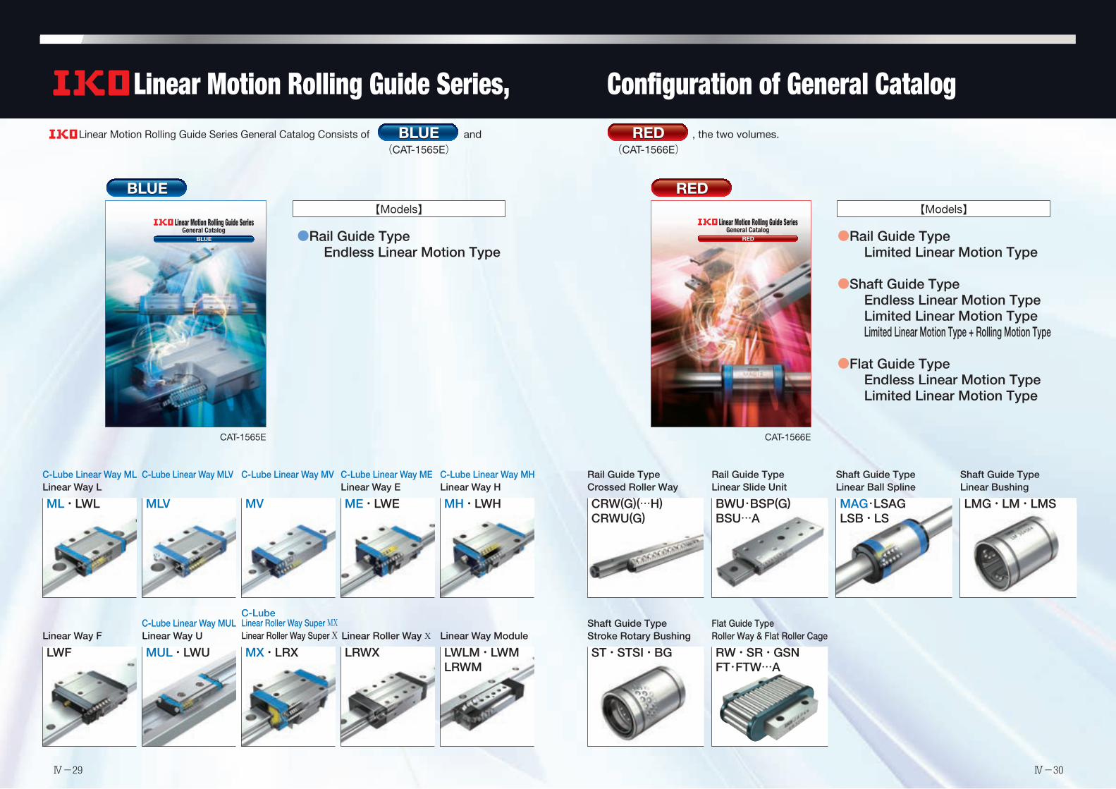
Linear Motion Rolling Guide Series, Configuration of General Catalog
REDRED
Linear Motion Rolling Guide Series General Catalog Consists of and , the two volumes.REDRED(CAT-1566E)
BLUEBLUE(CAT-1565E)
BLUEBLUE
●Rail Guide TypeEndless Linear Motion Type
●Rail Guide TypeLimited Linear Motion Type
●Shaft Guide TypeEndless Linear Motion TypeLimited Linear Motion TypeLimited Linear Motion Type + Rolling Motion Type
●Flat Guide TypeEndless Linear Motion TypeLimited Linear Motion Type
【Models】
Rail Guide TypeCrossed Roller Way
CRW(G)(…H)CRWU(G)
Rail Guide TypeLinear Slide Unit
BWU・BSP(G)BSU…A
Shaft Guide TypeLinear Ball Spline
MAG・LSAGLSB・LS
Shaft Guide TypeLinear Bushing
LMG・LM・LMS
Shaft Guide TypeStroke Rotary Bushing
ST・STSI・BG
Flat Guide TypeRoller Way & Flat Roller Cage
RW・SR・GSNFT・FTW…A
【Models】
CAT-1565E CAT-1566E
REDRED
Linear Motion Rolling Guide Series General Catalog R
ED
Linear Motion Rolling Guide Series General Catalog
Printed in Korea © 2013.07 (AKA)
Recognizing that conservation of the global environment is the top-priority challenge for the world’s population, Nippon Thompson will conduct its activities with consideration of the environment as a corporate social responsibility, reduce its negative impact on the environment, and help foster a rich global environment.
ISO 9001 & 14001 Quality system registration certificate
• The specifications and dimensions of products in this catalog are subject to change without prior notice.
• When these products are exported, the exporter should confirm a forwarding country and a use, and, in case of falling under the customer's requirements, take necessary procedures such as export permission application.
• Although all data in this catalog has been carefully complied to make the information as complete as possible, NIPPON THOMPSON CO., LTD. shall not be liable for any damages whatsoever, direct or indirect, based upon any information in this catalog. NIPPON THOMPSON CO., LTD. makes no warranty, either express or impiled, including the impiled warranty of merchantability or fitness for a particular purpose.
• Reproduction and conversion without permission are prohibited.
NIPPON THOMPSON CO., LTD. (JAPAN)
Head office : 19-19 Takanawa 2-chome Minato-ku Tokyo 108-8586, Japan Phone : +81 (0)3-3448-5850 Fax : +81 (0)3-3447-7637 E-mail : [email protected] URL : http://www.ikont.co.jp/eg Plant : Gifu, Kamakura
IKO-THOMPSON (SHANGHAI) LTD. (CHINA)Shanghai Sales Head Office 1608-10 MetroPlaza No.555 LouShanGuan Road ChangNing District Shanghai People's Republic of China 200051 Phone : +86 (0)21-3250-5525 Fax : +86 (0)21-3250-5526 E-mail : [email protected] Branch Room 609 Scitech Tower No.22 Jianguomenwai Avenue, Chaoyang District, Beijing People's Republic of China 100004 Phone : +86 (0)10-6515-7681 Fax : +86 (0)10-6515-7689 E-mail : [email protected] Branch Room 834, Garden Tower, Garden Hotel 368 Huanshi East Road, Yuexiu District, Guangzhou, Guangdong People's Republic of China 510064 Phone : +86 (0)20-8384-0797 Fax : +86 (0)20-8381-2863 E-mail : [email protected] Branch Room 0233, Novotel Wuhan Xinhua 558 Jianshe Avenue, Jiang Han District, Wuhan, Hubei People's Republic of China 430022 Phone : +86 (0)27-8556-1610 Fax : +86 (0)27-8556-1630 E-mail : [email protected]
Xi'an Office Room 1613, Building B, Jinqiao International Plaza No.50 Keji Road, Gaoxin District, Xi'an, Shanxi People’s Republic of China 710075 Phone : +86 (0)29-8882-3225 Fax : +86 (0)29-8882-3215 E-mail : [email protected] Shenzhen Office Room 507, Oriental Plaza, 1072 Jianshe Road, Luohu District, Shenzhen, Guangdong People’s Republic of China 518001 Phone : +86 (0)20-8384-0797 Fax : +86 (0)20-8381-2863 E-mail : [email protected] Chengdu Office Room 01-A, 12F of Tower 1, Central Plaza 8 Shuncheng Avenue, Jinjiang District ,Chengdu, Sichuan People’s Republic of China 610016 Phone : +86 (0)28-6250-5159 Fax : +86 (0)28-6250-5259 E-mail : [email protected] Ningbo Office Room 3406, Zhongnongxin Building, No.181 Zhongshan East Road, Haishu Ward, Ningbo, Zhejiang People’s Republic of China 315000 Phone : +86 (0)574-8718-9535 Fax : +86 (0)574-8718-9533 E-mail : [email protected] Qingdao Office 2107 Block A,World Trade Center Building, No.230 Changjiang Middle Road, Development Zone Qingdao 266555, CHINA TEL : +86 (0)532-8670-2246 FAX : +86 (0)532-8670-2242 E-mail : [email protected] Shenyang Office 2-1203 Tower I.City Plaza Shenyang NO.206 Nanjing North Street Heping District, Shenyang 110001, P.R. CHINA TEL : +86 (0)24-2334-2662 FAX : +86 (0)24-2334-2442 E-mail : [email protected]
NIPPON THOMPSON CO., LTD. (THAILAND) ASEAN REPRESENTATIVE OFFICE (BANGKOK) 1-7 Zuellig House, 5th Floor Silom Road, Silom, Bangrak Bangkok 10500, Thailand Phone : +66 (0)2-637-5115 FAX : +66 (0)2-637-5116 E-mail : [email protected]
IKO INTERNATIONAL, INC. (U.S.A.)
East Coast Operation (Sales Head Office) 91 Walsh Drive Parsippany, NJ 07054 U.S.A. Phone : +1 973-402-0254 Toll Free : 1-800-922-0337 Fax : +1 973-402-0441 E-mail : [email protected] Operation 500 East Thorndale Avenue, Suite K Wood Dale, IL 60191 U.S.A. Phone : +1 630-766-6464 Toll Free : 1-800-323-6694 Fax : +1 630-766-6869 E-mail : [email protected] Coast Operation 9830 Norwalk Boulevard, Suite 198 Santa Fe Springs, CA 90670 U.S.A. Phone : +1 310-609-3988 Toll Free : 1-800-252-3665 Fax : +1 310-609-3916 E-mail : [email protected]
Silicon Valley Sales Office 3333 Bowers Avenue, Suite 155 Santa Clara, CA 95054 U.S.A. Phone : +1 408-492-0240 Toll Free : 1-800-252-3665 Fax : +1 408-492-0245 E-mail : [email protected] Operation 2150 Boggs Road, Suite 100 Duluth, GA 30096 U.S.A. Phone : +1 770-418-1904 Toll Free : 1-800-874-6445 Fax : +1 770-418-9403 E-mail : [email protected] Operation 8105 N. Beltline Road, Suite 130 lrving, TX 75063 U.S.A. Phone : +1 972-929-1515 Toll Free : 1-800-295-7886 Fax : +1 972-915-0060 E-mail : [email protected]
NIPPON THOMPSON EUROPE B.V. (EUROPE)
The Netherlands Sales Head Office Sheffieldstraat 35-39 3047 AN Rotterdam The Netherlands Phone : +31 (0)10-462 68 68 Fax : +31 (0)10-462 60 99 E-mail : [email protected] Branch Mündelheimer Weg 56 40472 Düsseldorf Germany Phone : +49 (0)211-41 40 61 Fax : +49 (0)211-42 76 93 E-mail : [email protected]
Regensburg Sales Office Im Gewerbepark D 30 93059 Regensburg Germany Phone : +49 (0)941-20 60 70 Fax : +49 (0)941-20 60 719 E-mail : [email protected]
Neunkirchen Sales Office Gruben Str.95c 66540 Neunkirchen Germany Phone : +49 (0)6821-99 98 60 Fax : +49 (0)6821-99 98 626 E-mail : [email protected]. Branch 2 Vincent Avenue, Crownhill Milton Keynes, Bucks, MK8 0AB United Kingdom Phone : +44 (0)1908-566144 Fax : +44 (0)1908-565458 E-mail : [email protected] Branch Autovia Madrid-Barcelona, Km. 43,700 Polig. Ind. AIDA - Nove A-8, Ofic. 2-1 19200 Azuqueca de Henares (Guadalajara) Spain Phone : +34 949-26 33 90 Fax : +34 949-26 31 13 E-mail : [email protected] Branch Roissypole Le Dôme 2 rue de La Haye BP 15950 Tremblay en France 95733 Roissy C. D. G. Cedex France Phone : +33 (0)1-48 16 57 39 Fax : +33 (0)1-48 16 57 46 E-mail : [email protected]
BLUEBLUE
Printed in Korea © 2013.07 (AKA)
Linear Motion Rolling Guide Series General Catalog B
LUE
Linear Motion Rolling Guide Series General Catalog
Recognizing that conservation of the global environment is the top-priority challenge for the world’s population, Nippon Thompson will conduct its activities with consideration of the environment as a corporate social responsibility, reduce its negative impact on the environment, and help foster a rich global environment.
ISO 9001 & 14001 Quality system registration certificate
notice.
permission application.
possible, NIPPON THOMPSON CO., LTD. shall not be liable for any damages whatsoever, direct or indirect, based upon any information in this catalog. NIPPON THOMPSON CO., LTD. makes no
particular purpose.
NIPPON THOMPSON CO., LTD. (JAPAN)
Head office : 19-19 Takanawa 2-chome Minato-ku Tokyo 108-8586, Japan Phone : +81 (0)3-3448-5850
Plant : Gifu, Kamakura
IKO-THOMPSON (SHANGHAI) LTD. (CHINA)Shanghai Sales Head Office 1608-10 MetroPlaza No.555 LouShanGuan Road ChangNing District Shanghai People's Republic of China 200051 Phone : +86 (0)21-3250-5525
Beijing Branch Room 609 Scitech Tower
People's Republic of China 100004 Phone : +86 (0)10-6515-7681
106
Guangzhou Branch Room 834, Garden Tower, Garden Hotel People's Republic of China 510064 Phone : +86 (0)20-8384-0797
Wuhan Branch
People's Republic of China 430033 Phone : +86 (0)27-8556-1610
Xi'an Office Room 1613, Building B, Jinqiao International Plaza
People’s Republic of China 710075 Phone : +86 (0)29-8882-3225
Shenzhen Office Room 507, Oriental Plaza, 1072 Jianshe Road, Luohu District, Shenzhen, Guangdong People’s Republic of China 518001 Phone : +86 (0)20-8384-0797
Chengdu Office Room 01-A, 12F of Tower 1, Central Plaza
People’s Republic of China 610016 Phone : +86 (0)28-6250-5159
Ningbo Office
People’s Republic of China 315000 Phone : +86 (0)574-8718-9535
Qingdao Office
People's Republic of China 266555 Phone : +86 (0)532-8670-2246
Shenyang Office 2-1203 Tower I.City Plaza Shenyang, No.206
People's Republic of China 110001 Phone : +86 (0)24-2334-2662
NIPPON THOMPSON CO., LTD. (THAILAND) ASEAN REPRESENTATIVE OFFICE (BANGKOK) 1-7 Zuellig House, 5th Floor Silom Road, Silom, Bangrak Bangkok 10500, Thailand Phone : +66 (0)2-637-5115
IKO INTERNATIONAL, INC. (U.S.A.)
East Coast Operation (Sales Head Office)
Parsippany, NJ 07054 U.S.A. Phone : +1 973-402-0254 Toll Free : 1-800-922-0337
Midwest Operation 500 East Thorndale Avenue, Suite K
U.S.A. Phone : +1 630-766-6464 Toll Free : 1-800-323-6694
West Coast Operation 9830 Norwalk Boulevard, Suite 198 Santa Fe Springs, CA 90670 U.S.A. Phone : +1 310-609-3988 Toll Free : 1-800-252-3665
Silicon Valley Sales Office 3333 Bowers Avenue, Suite 155 Santa Clara, CA 95054 U.S.A. Phone : +1 408-492-0240 Toll Free : 1-800-252-3665
Southeast Operation 2150 Boggs Road, Suite 100 Duluth, GA 30096 U.S.A. Phone : +1 770-418-1904 Toll Free : 1-800-874-6445
Southwest Operation 8105 N. Beltline Road, Suite 130
U.S.A. Phone : +1 972-929-1515 Toll Free : 1-800-295-7886
NIPPON THOMPSON EUROPE B.V. (EUROPE)
The Netherlands Sales Head Office Sheffieldstraat 35-39 3047 AN Rotterdam The Netherlands Phone : +31 (0)10-462 68 68
Germany Branch
40472 Düsseldorf Germany Phone : +49 (0)211-41 40 61
Regensburg Sales Office Im Gewerbepark D 30 93059 Regensburg Germany Phone : +49 (0)941-20 60 70
E-mail : [email protected]
Neunkirchen Sales Office Gruben Str.95c 66540 Neunkirchen Germany Phone : +49 (0)6821-99 98 60
E-mail : [email protected]. Branch 2 Vincent Avenue, Crownhill Milton Keynes, Bucks, MK8 0AB United Kingdom Phone : +44 (0)1908-566144
E-mail : [email protected] Branch Autovia Madrid-Barcelona, Km. 43,700 Polig. Ind. AIDA - Nove A-8, Ofic. 2-1 19200 Azuqueca de Henares
Phone : +34 949-26 33 90
France Branch Roissypole Le Dôme 2 rue de La Haye BP 15950 Tremblay en France
France Phone : +33 (0)1-48 16 57 39
E-mail : [email protected]
IKO-BLUE_H1H4_13mm.indd 1 2013/06/25 9:54:30
C-Lube Linear Way MLLinear Way L
ML・LWL
C-Lube Linear Way MLV
MLV
C-Lube Linear Way MV
MV
C-Lube Linear Way MELinear Way E
ME・LWE
C-Lube Linear Way MHLinear Way H
MH・LWH
Linear Way F
LWF
C-Lube Linear Way MULLinear Way U
MUL・LWU
C-Lube Linear Roller Way Super MXLinear Roller Way Super X
MX・LRXLinear Roller Way X
LRWXLinear Way Module
LWLM・LWMLRWM
Ⅳ-29 Ⅳ-30

Introduction of Technical Service Site
" Technical Service Site" can be accessed from our home page . The site also distributes
various tools, etc., to select Linear ways/Linear roller ways, and please utilize the site for the assistance
to select products. Additionally the site also provides CAD data and product catalog of needle series,
linear motion rolling guide series and mechatronics series for you to download. Please consider to use
for enhancing your design efficiency.
1. Technical calculationsFor Linear Way/Linear Roller Way load and life calculation, you
can obtain the calculated load and the rating life by entering the
operating conditions. Also you can derive the motor torque
required for operation and the effective thrust force during
operation in the sections of motor torque calculation and calcu-
lation of effective thrust force of linear motor tables respectively,
and output the calculation results in PDF format, as well as save
the histories.
2. Selection of Identification NumberBy selecting such specification as model code, dimensions, part code, material
code, preload symbol, classification symbol, interchangeable code and
supplemental code of Linear ways/Linear roller ways, you can easily specify
the identification number used for ordering.
Also you can browse the CAD data of the selected products, calculate the load,
and output the selection results in PDF format, as well as save the histories.
4. Downloading Catalog and Operation Manual
3. Downloading CAD data
There are two types of figures, brief figure and detailed figure. The
brief figure shows only the external view lines, and the detailed
figure shows the detailed lines. The drawing consists of three
drawings: front view, side view and plain view. The scale shows
only the original size (1:1), and it does not show dimension lines.
2-dimensional CAD data (DXF file)
It is linked to the mechanical parts CAD library
"PART community". Entering the rail dimension
and option contents to the detail, you can view
the 2D/3D CAD data suitable for the specification
for free of charge.
3-dimensional CAD data
You can download product catalogs of needle series, linear motion rolling guide series and mechatronics
series, operation manuals of precision positioning tables and various electrical components in PDF format,
as well as support software for precision positioning tables. If you would like a copy of our catalog, please
visit the official website and apply for the catalog, or contact our regional office or sales office nearby.
Ⅳ-31 Ⅳ-32

Linear Motion Rolling Guides are manufactured through a control
system that alleviates their impact on the global environment to meet the
quality requirements of ISO 14001 in compliance with the quality require-
ments level of ISO 9001 for quality improvement.
The standard products listed in this catalog comply with the specifications of
the six hazardous materials mentioned cited in the European RoHS Directive.
●
●
Gentle to The EarthNippon Thompson Co., Ltd. is working to develop global environment-friendly products.
It is committed to developing products that make its customers’ machinery and
equipment more reliable, thereby contributing to preserving the global environment.
This development stance manifests well in the keyword “Oil Minimum.”
Our pursuit of Oil Minimum has led to the creation of
’s proprietary family of lubricating parts as “C-Lube.”
Products Underpin SustainTechnology LeapsNippon Thompson Co., Ltd. was the first Japanese manufacturer to develop needle bearings on its own and has since expanded into the arena of linear motion rolling guides (Linear Motion Series and Mechatro Series) on the support of its advanced expertise. The company now offers a vast assortment of ingenious products, including the world’s first C-Lube Maintenance-Free Series, to address increasingly diversified customer needs and thus sustain technology leaps.
C-Lube Maintenance-Free Series Products Evolving from the “Oil Minimum” ConceptWe have developed lubricating parts impregnated with a large amount of lubricant as C-Lube Series to save the customer’s oiling management workload and built them into bearings and linear motion rolling guides.The C-Lube Series not only keeps products maintenance-free for long by giving them an optimal and minimal amount of a lubricant for an extended period of time but also contributes greatly to preserving the global environment.
Needle BearingsMachine elements essential to any industry
Linear Motion Rolling Guides/Linear Motion SeriesAvailable in broad sizes, from minimum to extra-large
Linear Motion Rolling Guides/Mechatro SeriesA merger of precision machining expertise and electronics
Ⅳ-33 Ⅳ-34