ijms-12-03263.pdf
DESCRIPTION
paperTRANSCRIPT
Int. J. Mol. Sci. 2011, 12, 3263-3287; doi:10.3390/ijms12053263
International Journal of
Molecular Sciences ISSN 1422-0067
www.mdpi.com/journal/ijms
Review
Microfluidic Mixing: A Review
Chia-Yen Lee 1, Chin-Lung Chang
2, Yao-Nan Wang
2 and Lung-Ming Fu
1,*
1 Department of Materials Engineering, National Pingtung University of Science and Technology,
Pingtung 912, Taiwan; E-Mail: [email protected] 2
Department of Vehicle Engineering, National Pingtung University of Science and Technology,
Pingtung 912, Taiwan; E-Mails: [email protected] (C.-L.C.);
[email protected] (Y.-N.W.)
* Author to whom correspondence should be addressed; E-Mail: [email protected];
Tel.: +886-8-77032020 ext. 7553; Fax: +886-8-7740552.
Received: 25 March 2011; in revised form: 2 May 2011 / Accepted: 5 May 2011 /
Published: 18 May 2011
Abstract: The aim of microfluidic mixing is to achieve a thorough and rapid mixing of
multiple samples in microscale devices. In such devices, sample mixing is essentially
achieved by enhancing the diffusion effect between the different species flows. Broadly
speaking, microfluidic mixing schemes can be categorized as either “active”, where an
external energy force is applied to perturb the sample species, or “passive”, where the
contact area and contact time of the species samples are increased through
specially-designed microchannel configurations. Many mixers have been proposed to
facilitate this task over the past 10 years. Accordingly, this paper commences by providing
a high level overview of the field of microfluidic mixing devices before describing some of
the more significant proposals for active and passive mixers.
Keywords: active mixer; microfluidic mixing; passive micromixer
1. Introduction
Microfluidic devices have had a considerable impact on the fields of biomedical diagnostics and
drug development, and are extensively applied in the food and chemical industries. The diminutive
scale of the flow channels in microfluidic systems increases the surface to volume ratio, and is
therefore advantageous for many applications. However, the specific Reynolds number (Re = 1 ρv/η)
OPEN ACCESS

Int. J. Mol. Sci. 2011, 12
3264
of liquid flows in such microchannels is very small. For example, the Reynolds number is of the order
of 0.1 in a typical water-based microfluidic system with a channel width of 100 µm, a liquid flow rate
of 1 mm/s, a fluid density of 1 g/cm3
and a viscosity of 0.001 Ns/m2. In such low Reynolds number
regimes, turbulent mixing does not occur, and hence diffusive species mixing plays an important role
but is an inherently slow process. Consequently, the aim of microfluidic mixing schemes is to enhance
the mixing efficiency such that a thorough mixing performance can be achieved within shorter mixing
channels, which can reduce the characteristic size of microfluidic devices. Furthermore, the
development of efficient mixing schemes is essential for increasing the throughput of microfluidic
systems and to realize the concept of micro-total-analysis systems and lab-on-a-chip systems.
Increasing the contact area between the species to be mixed is one of the most efficient means of
enhancing the diffusive mixing effect. Accordingly, previous studies presented mixing schemes by
feeding the samples of interest through discrete via holes, cantilever plate-valves or multi-channels in
the microfluidic device. An alternative approach is to increase the contact area between the mixing
species by designing the microchannel configurations so that the species are folded multiple times as
they flow along the mixing channel. In passive mixing devices such as those described above, samples
can typically be mixed within 55–300 ms, and hence the requirement for high device throughputs can
be readily achieved. Besides increasing the contact area, the mixing performance can also be improved
by increasing the time of contact between the multiple species. However, such schemes typically result
in a lower mixing efficiency, and thus require a longer mixing channel to achieve a satisfactory mixing
result (Table 1).
Table 1. Performance of active micromixers in recent five years [1–11].
Categories Mixing Technique Mixing
Time (ms)
Mixing
Length (μm)
Mixing
Index Reference
Acoustic/Ultrasonic
Acoustically driven sidewall-
trapped microbubbles 120 650 0.025 [1]
Acoustic streaming induced by
surface acoustic wave 600 10,000 0.9 [2]
Dielectrophoretic Chaotic advection based on
Linked Twisted Map - 1000 0.85 [3]
Electrokinetic
time-pulsed
Chaotic electric fields 100 Width * 5.0 0.95 [4]
Periodic electro-osmotic flow - 200 0.88 [5]
Electrohydrodynamic
force
Staggered herringbone structure - 825 0.2 [6]
Staggered herringbone structure - 2300 0.5 [7]
Thermal actuation Thermal - 6000 - [8]
Magneto-
hydrodynamic flow High operating frequency 1100 500 0.977 [9]
Electrokinetic
instability
Low Reynolds number - 1200 0.98 [10]
Low Reynolds number - 1200 0..98 [11]
In contrast to the passive mixing schemes presented above in which the microchannel configuration
is specifically designed to increase either the contact area or the contact time (or both) of the multiple
species, active mixing schemes improve the mixing performance by applying external forces to the
Int. J. Mol. Sci. 2011, 12
3265
sample flows to accelerate the diffusion process [12]. Typically, active mixing schemes are
implemented by incorporating some form of mechanical transducer within the microfluidic device
using microfabrication techniques. For example, microfluidic mixers, which use embedded ultrasonic
transducers to generate acoustic waves to stir the samples, have been shown to achieve a high mixing
performance. However, acoustic vibrations also generate considerable heat that may lead to unwanted
reactions between the samples. Various microfluidic devices with embedded microelectrodes for
mixing the sample fluids dielectrophoretically have also been presented. The use of embedded
electrode pairs has been shown to change the surface energy of the microchannel walls, providing an
efficient means of enhancing species mixing by inducing local instabilities in the flow stream. The use
of embedded electrode pairs has many of the advantages of active mixing schemes but does not require
moving components, and hence results in cheaper and more reliable microfluidic devices (Table 2).
Table 2. Performance of passive micromixers in recent five years [13–25].
Categories Mixing Technique Mixing Time
(ms)
Mixing Length
(μm)
Mixing
Index Reference
Lamination Wedged shaped inlets 1 1 0.9 [13]
90° rotation - - 0.95 [14]
Zigzag channels Elliptic-shape barriers - 10,000 0.96 [15]
3-D serpentine
structure
Folding structure 489 - 0.01 [16]
Creeping structure - - 0.015 [17]
Stacked shim structure - - - [18]
Multiple splitting,
stretching and
recombining flows
- - - [19]
Unbalanced driving force - 815ψ 0.91 [20]
Embedded
barriers
SMX - - - [21]
Multidirectional vortices - 4255 0.72 [22]
Twisted channels Split-and-recombine 730 96,000 ~1 [23]
Surface-
chemistry
Obstacle shape - 1000 0.98 [24]
T-/Y- mixer - 1000 0.95 [25]
The microfluidic mixers presented above are all considered for the mixing of continuous bulk
liquids. However, various discrete droplet-based mixing platforms have also been proposed. One such
scheme involves the use of air pressure to form, actuate and mix two liquid droplets in a hydrophobic
microcapillary valve device. Recently, many studies have presented mixing devices using liquid
droplets based on electro-wetting phenomena. In these schemes, electro-wetting actuation is applied to
separate liquid droplets from the bulk and to drive them to specific locations where they are repeatedly
combined, mixed and separated. The microfluidic mixing of liquid droplets through the application of
electro-wetting-induced droplet oscillations has also been demonstrated. These microfluidic mixing
schemes take advantage of the open structure of the flow channel, allowing the mixed sample to be
more easily transported to its required destination.

Int. J. Mol. Sci. 2011, 12
3266
2. Active Microfluidic Mixers
Active microfluidic mixers enhance the mixing performance by stirring or agitating the fluid flow
using some form of external energy supply. As shown in Figure 1, active mixers typically use
acoustic/ultrasonic, dielectrophoretic, electrokinetic time-pulse, pressure perturbation, electro-hydrodynamic,
magnetic or thermal techniques to enhance the mixing performance [1–11,26–57].
Figure 1. Categories of active microfluidic mixer.
Active microfluidic mixer
Acoustic / Ultrasonic
Dielectrophoretic
Electrokinetic time plus
Pressure perturbation
Magnetic
Thermal
Electrohydrodynamic force
time-pulsed
Magneto-hydrodynamic flow
Electrokinetic instability
Active microfluidic mixer
Acoustic / Ultrasonic
Dielectrophoretic
Electrokinetic time plus
Pressure perturbation
Magnetic
Thermal
Electrohydrodynamic force
time-pulsed
Magneto-hydrodynamic flow
Electrokinetic instability
2.1. Acoustic/Ultrasonic Actuation [26–30]
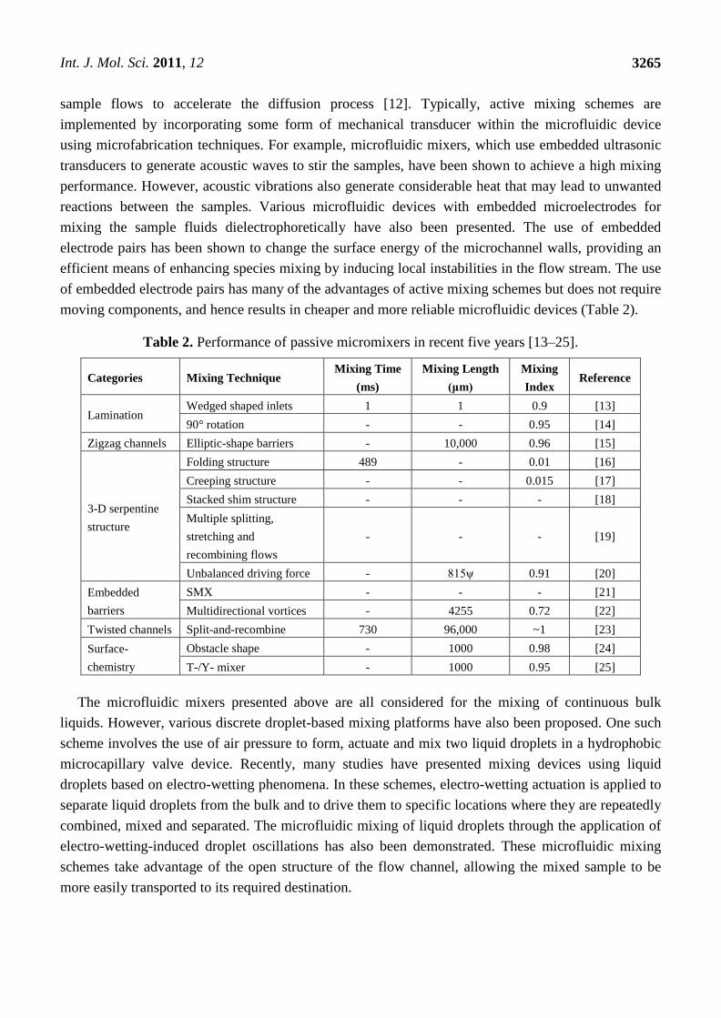
Liu et al. [26] demonstrated the use of acoustically-induced microstreams to achieve mixing in a
micro-chamber. In the design, a piezoelectric disk was used to excite air bubbles trapped in the top
layer of the chamber at a frequency of 5 kHz. The mixing time was reported to be 6 s for a 40 V
peak-to-peak excitation. Adopting a similar configuration, Yang et al. [27] employed a higher
frequency of approximately 60 kHz and a 50 V peak-to-peak excitation in an attempt to accelerate the
mixing process. However, the increased agitation of the fluid samples resulted in a temperature rise of
16 °C in the chamber. Tsao et al. [28] presented a Lamb wave micromixer in which Lamb waves were
induced in the mixing species by a thin plate formed at one side of the mixing chamber and integrated
with interdigitated transducers. Rife et al. [29] proposed a radio frequency-based microfluidic device
with an operational frequency of 50 MHz that applied acoustic streaming to both pump and mix the
sample species. Yaralioglu et al. [30] presented a micromixer featuring a simple microfluidic channel
with embedded piezoelectric transducers and an operational frequency of 450 MHz. Through the
application of an external electrical field, the transducers generated a strong acoustic streaming effect,
enhancing species mixing within the channel.
Int. J. Mol. Sci. 2011, 12
3267
Figure 2. Schematic showing a number of air pockets in the top layer of the DNA biochip
chamber: (a) overview; and (b) side view [26].
(a) (b)
2.2. Dielectrophoretic Force Actuation [31,32]
When the dielectrophoretic (DEP) force is applied to mixing, non-uniform alternating electrical
fields induce the motion of polarized particles/cells [31]. The electrical field generates a dipole
moment on the particles and the interaction between the induced dipole charges and the electrical field
generates a net force which drives the particles either towards or away from the electrode. In a DEP
micromixer, when the electrical field is combined appropriately in space and time with the velocity
field, saddle point regions are generated within which sets of particles are stretched and folded about a
virtual quasi-static point. The resulting chaotic motion leads to a rapid and efficient mixing effect.
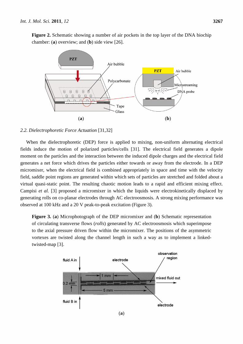
Campisi et al. [3] proposed a micromixer in which the liquids were electrokinetically displaced by
generating rolls on co-planar electrodes through AC electroosmosis. A strong mixing performance was
observed at 100 kHz and a 20 V peak-to-peak excitation (Figure 3).
Figure 3. (a) Microphotograph of the DEP micromixer and (b) Schematic representation
of circulating transverse flows (rolls) generated by AC electroosmosis which superimpose
to the axial pressure driven flow within the micromixer. The positions of the asymmetric
vortexes are twisted along the channel length in such a way as to implement a linked-
twisted-map [3].
(a)
Int. J. Mol. Sci. 2011, 12
3268
Figure 3. Cont.
(b)
2.3. Electrokinetic Time-Pulsed Actuation [4,5,33–39]
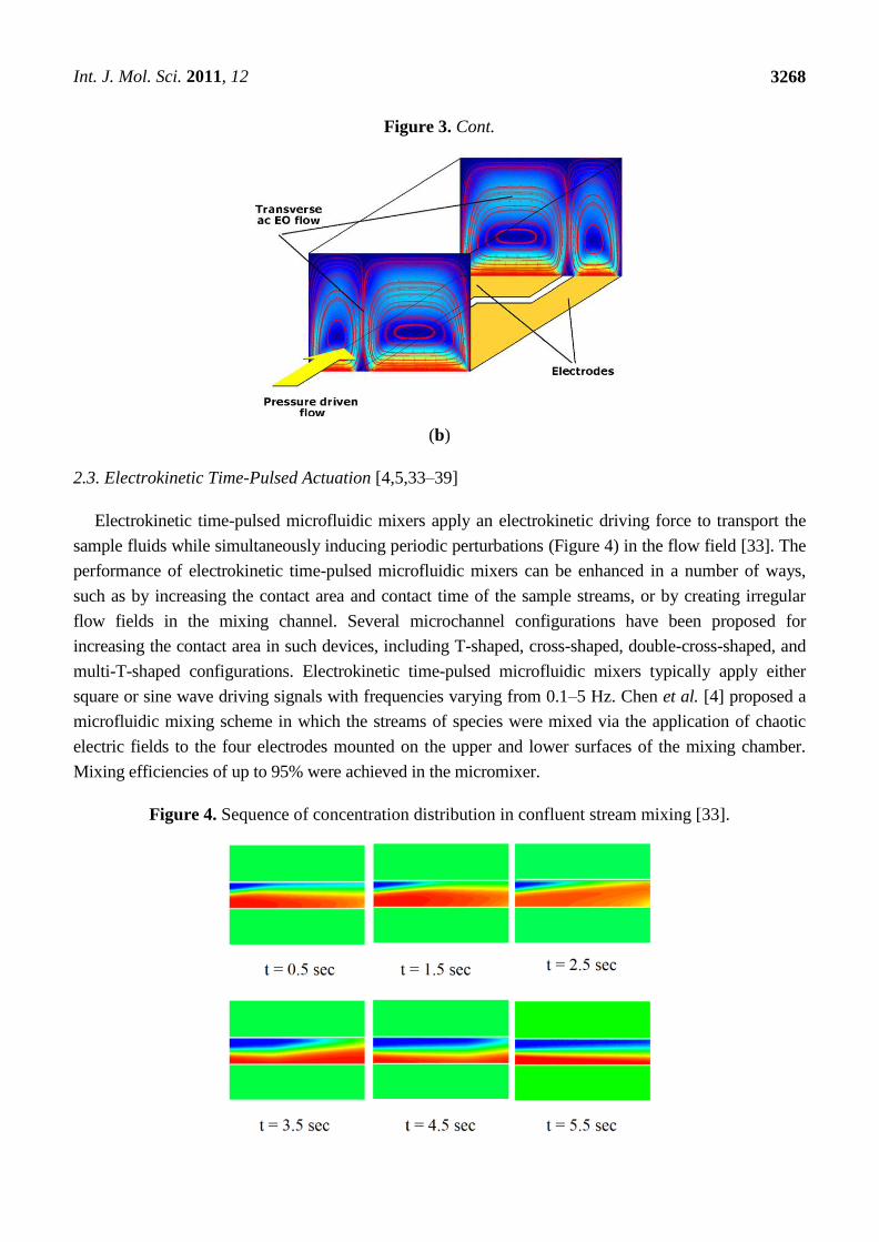
Electrokinetic time-pulsed microfluidic mixers apply an electrokinetic driving force to transport the
sample fluids while simultaneously inducing periodic perturbations (Figure 4) in the flow field [33]. The
performance of electrokinetic time-pulsed microfluidic mixers can be enhanced in a number of ways,
such as by increasing the contact area and contact time of the sample streams, or by creating irregular
flow fields in the mixing channel. Several microchannel configurations have been proposed for
increasing the contact area in such devices, including T-shaped, cross-shaped, double-cross-shaped, and
multi-T-shaped configurations. Electrokinetic time-pulsed microfluidic mixers typically apply either
square or sine wave driving signals with frequencies varying from 0.1–5 Hz. Chen et al. [4] proposed a
microfluidic mixing scheme in which the streams of species were mixed via the application of chaotic
electric fields to the four electrodes mounted on the upper and lower surfaces of the mixing chamber.
Mixing efficiencies of up to 95% were achieved in the micromixer.
Figure 4. Sequence of concentration distribution in confluent stream mixing [33].

Int. J. Mol. Sci. 2011, 12
3269
2.4. Pressure Perturbation [40]
In pressure perturbation mixers, perturbations within the fluid streams are generated by velocity
pulsing [40]. In a typical device, the mixer comprises a single main channel and multiple side channels,
and the fluids within the main channel are stirred by velocity pulsing of the fluids flowing through the
side channels. The resulting stretching and folding of the fluids in the main and side channels induce a
chaotic advection effect, which enhances species mixing (Figure 5).
Figure 5. Model of a chaotic mixer with multiple side channels. (a) Experimental results
of mixing in the device with one pair of side channels. The pressure perturbations induce
lobe-like distortions of the interface and facilitate rapid mixing; (b) Schematic showing the
new mixer with multiple side channels [40].
2.5. Electrohydrodynamic (EHD) Force [6,7,41]
In the micromixer presented by El Moctar et al. [41], two fluids with identical viscosity and density,
but different electrical properties, were injected by syringe pumps, and the electrodes were arranged
such that the electrical field was perpendicular to the interface between the fluid streams, creating a
transversal secondary flow. The effects of both DC and AC electrical fields were investigated in a
series of experimental trials. The results revealed that by applying an appropriate voltage and
frequency to the electrodes, a satisfactory mixing performance could be achieved after less than 0.1 sec
over a short mixing distance, even at a low Reynolds number of 0.02.
2.6. Thermal Actuation [8,42]
Tsai et al. [42] presented a microfluidic mixer incorporating a thermal bubble actuated
nozzle-diffuser micropump, a meander-shape liquid mixing channel and a gas bubble filter (Figure 6).

Int. J. Mol. Sci. 2011, 12
3270
The intrinsically oscillatory flow generated by the bubble actuated nozzle-diffuser micropump was
shown to induce a wavy liquid interface, accelerating the mixing process. Xu et al. [8] showed the
thermal mixing characteristics of two miscible fluids in a T-shaped microchannel .Thermal mixing
processes in a T-shaped microchannel are divided into two zones, consisting of a T-junction and a
mixing channel. The results show that the heat transfer process in the T-shaped microchannel can be
divided into two heat transfer zones: The T-junction and the mixing channel. The flow rate ratio plays
an important role in the thermal mixing process.
Figure 6. Schematic of the microfluidic system that includes a nozzle-diffuser-based
bubble pump, a meander-shape fluid mixing channel and a gas bubble filter [42].
2.7. Magneto-Hydrodynamic Flow [43–45]
The magneto-hydrodynamic (MHD) flow effect has been used by various researchers to realize
micromixers. For example, Bau et al. [43] developed an active micromixer that used either DC or AC
electrical and magnetic fields to generate Lorentz forces. These forces induce MHD flows in an
electrolyte solution and result in a stretching and folding of the fluid in the mixing chamber, mixing
the species within several seconds. An elaborate micromixer based on MHD, reminiscent of the
original arrangement of two blinking vortices used to demonstrate chaotic advection, was proposed by
Yi et al. [44]. The device consisted of a small cylindrical chamber with an electrode deposited on its
side wall and two copper-wire electrodes placed eccentrically inside the chamber on its lower surface.
The chamber was positioned within a uniform magnetic field orientated parallel to the axis of the
cylinder, and mixing was induced by alternately applying a potential difference for a period T between
one of the wire electrodes and the circular side-wall electrode and then between the second wire
electrode and the side-wall electrode. Particle tracing revealed that chaotic flows were induced and
resulted in a satisfactory mixing result within 40 periods. Wang et al. [9] developed a magnetic particle
driven micromixer in which mixing was induced by alternating the actuation of magnetic particles
suspended in the fluid (Figure 7). The numerical results revealed that maximum efficiency was
obtained at a relatively high operating frequency for large magnetic actuation forces and
narrow microchannels.

Int. J. Mol. Sci. 2011, 12
3271
Figure 7. Schematic diagram of: (a) magnetic micromixer; (b) time-dependent current
applied to the electromagnets and (c) mixing microchannel [9].
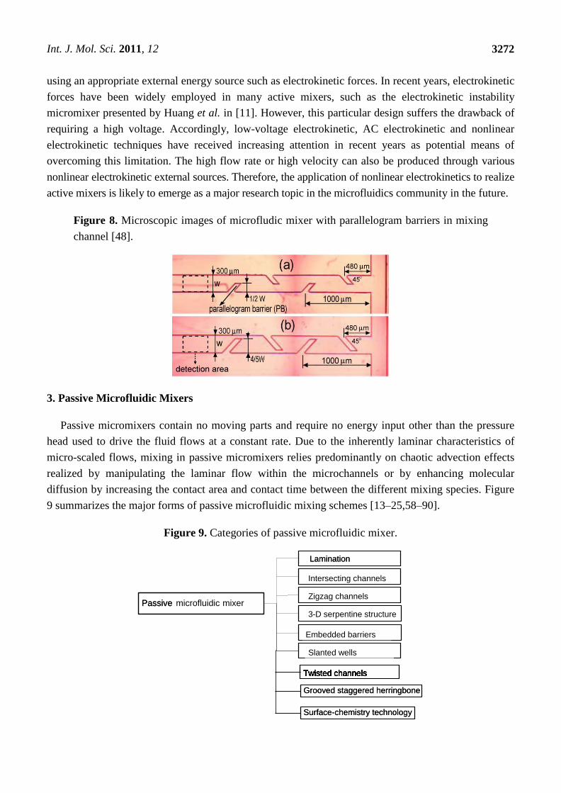
2.8. Electrokinetic Instability [10,11,46–48]
The use of electrokinetic instability (EKI) as a mixing technique for electrokinetically-driven
microfluidic flows with conductivity gradients has received considerable attention in recent
years [46,47]. In an attempt to improve the mixing performance of micromixers, Tai et al. [48]
developed a T-type mixer with parallelogram barriers formed within the microchannels (Figure 8). The
authors presented experimental results for the sample concentration distribution in a micromixer for a
parallelogram barrier length (PB) of 4/5 W (where W is the channel width), a 10:1 conductivity ratio,
and electrical field intensities of 150 V/cm, 300 V/cm and 500 V/cm. The results indicated that the
electrokinetic instability phenomenon was induced when high electrical field intensity was applied to
drive the flow streams. When the electrokinetic instability effect was not induced, the mixing
efficiency at a cross-section located 2.3 mm downstream of the T-junction was 60%. However, when
the parallelogram barrier was established, the mixing efficiency increased to 91.25% at the same
location. Recent years have witnessed many developments in active mixing approaches for
microfluidic devices. Micromixer design appears to be moving towards active chaotic mixers with no
moving parts. To avoid complicated microfabrication processes, and to reduce the cost and complexity
involved in integrating active mixers in microfluidic systems, the species samples should be driven
Int. J. Mol. Sci. 2011, 12
3272
using an appropriate external energy source such as electrokinetic forces. In recent years, electrokinetic
forces have been widely employed in many active mixers, such as the electrokinetic instability
micromixer presented by Huang et al. in [11]. However, this particular design suffers the drawback of
requiring a high voltage. Accordingly, low-voltage electrokinetic, AC electrokinetic and nonlinear
electrokinetic techniques have received increasing attention in recent years as potential means of
overcoming this limitation. The high flow rate or high velocity can also be produced through various
nonlinear electrokinetic external sources. Therefore, the application of nonlinear electrokinetics to realize
active mixers is likely to emerge as a major research topic in the microfluidics community in the future.
Figure 8. Microscopic images of microfludic mixer with parallelogram barriers in mixing
channel [48].
3. Passive Microfluidic Mixers
Passive micromixers contain no moving parts and require no energy input other than the pressure
head used to drive the fluid flows at a constant rate. Due to the inherently laminar characteristics of
micro-scaled flows, mixing in passive micromixers relies predominantly on chaotic advection effects
realized by manipulating the laminar flow within the microchannels or by enhancing molecular
diffusion by increasing the contact area and contact time between the different mixing species. Figure
9 summarizes the major forms of passive microfluidic mixing schemes [13–25,58–90].
Figure 9. Categories of passive microfluidic mixer.
Dielectrophoretic
Pressure perturbation
Magnetic
Thermal
Embedded barriers
Twisted channels
Lamination
Intersecting channels
3-D serpentine structure
Zigzag channels
Slanted wells
Dielectrophoretic
Pressure perturbation
Magnetic
Thermal
Embedded barriers
Twisted channels
Grooved staggered herringbone
Intersecting channels
3-D serpentine structure
Zigzag channels
Slanted wells
Dielectrophoretic
Pressure perturbation
Magnetic
Thermal
Embedded barriers
Twisted channels
Intersecting channels
3-D serpentine structure
Zigzag channels
Slanted wells
Passive microfluidic mixer
Surface-chemistry technology
Dielectrophoretic
Pressure perturbation
Magnetic
Thermal
Embedded barriers
Twisted channels
Lamination
Intersecting channels
3-D serpentine structure
Zigzag channels
Slanted wells
Dielectrophoretic
Pressure perturbation
Magnetic
Thermal
Embedded barriers
Twisted channels
Grooved staggered herringbone
Intersecting channels
3-D serpentine structure
Zigzag channels
Slanted wells
Dielectrophoretic
Pressure perturbation
Magnetic
Thermal
Embedded barriers
Twisted channels
Intersecting channels
3-D serpentine structure
Zigzag channels
Slanted wells
Passive microfluidic mixer
Surface-chemistry technology

Int. J. Mol. Sci. 2011, 12
3273
3.1. Lamination [13,14,58–60]
In miniaturized flow systems with Reynolds numbers varying from 2 to 100, flow structures can be
artificially induced, assisting flow segmentation through inertia effects. In the zigzag channel
considered in [58], segmentation was achieved through shear forces. The results showed that mixing
was achieved within 1 s for fluid flows with a Reynolds number of 33 for two fluid streams
flowing alongside each other in a microchannel of dimensions 300 μm × 600 μm × 100 mm containing
80 zigzags [58]. Another example of mixing via inertia forces was demonstrated by
Scampavia et al. [59] who fabricated a coaxial mixer containing an inner core liquid stream with a low
flow rate and an outer flow stream with a higher flow rate. The authors showed that the design
achieved an acceptable mixing result within 55 ms for fluid flows with a Reynolds number of 5.
Wong et al. [60] presented a micro T-mixer fabricated on a silicon substrate and bonded to a Pyrex
glass plate (Figure 10). The experimental results revealed that a mixing channel with a hydraulic
diameter of 67 μm and an applied pressure of 5.5 bar was sufficient to achieve complete species
mixing in less than 1 ms after the initial contact between the two species flows with Reynolds numbers
of 400–500. Buchegger et al. [13] proposed a horizontal multi-lamination micromixer based on wedge
shaped inlet channels. The experimental results revealed highly uniform fluid mixing in the low
millisecond second range. Tofteberg et al. [14] fabricated a passive micromixer that made a controlled
900 rotation of a flow cross-section followed by a split into several channels (Figure 11). The flow in
each of these channels was rotated a further 90° before a recombination doubled the interfacial area
between the two fluids, and the process was repeated the desired degree of mixing was achieved.
Figure 10. Schematic diagram of micro T-mixer [60].

Int. J. Mol. Sci. 2011, 12
3274
Figure 11. Simulated flow field in one mixing module showing lamination [14].
3.2. Intersecting Channels [61–63]
Micromixers with intersecting channels can be used to split, rearrange and combine component
streams to enhance mixing [61]. He et al. [62] proposed a picoliter-volume mixer with intersecting
channels of various lengths and a bimodal width distribution (Figure 12). In the proposed design, all of
the channels running parallel to the flow direction had a width of 5 μm, while those intersecting the
parallel channel network had a width of 27 μm and were aligned at an angle of 450. The microchannels
were designed so that the two species streams merged into one larger stream and then flowed together
along a mixing channel of length 300 μm. The results showed that this configuration enabled complete
species mixing within a distance of 200 μm, representing a considerable improvement compared to the
mixing distance of 3000 μm required to fully mix the two streams in a conventional straight channel.
Melin et al. [63] presented a micromixer in which a constantly changing, time-dependent flow pattern
was created within a two sample liquid plug as the plug passed through a planar mixing chamber
(Figure 13). The micromixer was shown to create a larger mass transfer within the liquid plug than that
achieved in many of the passive devices presented previously. The proposed mixing chamber
contained a main meandering channel with perforated walls that formed connecting channels between
parallel segments of the main meandering channel. In the mixing process, two discrete liquid samples
were fed into the mixing chamber laminarly. When the liquid wetted one side of the first perforated
wall segment, it entered the perforation, but was prevented from exiting by surface tension effects.
However, as the bulk of the liquid proceeded on to the next main channel segment, the other side of the
perforated wall was wetted. As a result, the liquid/air interface at the exit of the perforation was
replaced by a liquid/liquid interface, and hence the liquid flowed freely through the perforation. The
same phenomenon was repeated in each of the main channel segments as the liquid flowed
progressively through the mixing chamber. As a result, the constantly-changing flow lines within the
liquid plug caused a self-folding effect within the plug, yielding a significant improvement in
mixing performance.

Int. J. Mol. Sci. 2011, 12
3275
Figure 12. Photomicrograph of picoliter-volume mixer [62].
Figure 13. Top view of micromixer as two samples enter the first main channel segment [63].
3.3. Zigzag Channels [64,65]
Mengeaud et al. [64] presented a 100 μm wide zigzag microchannel integrating a “Y” inlet junction
(Figure 14). The effect of the periodic step value s on the mixing efficiency was investigated in a series
of experimental trials. The results indicated that for Re = 0.26, the mixing efficiency increased from
65% to 83.8% as the geometry ratio s/w was increased from 1 to 8. For low values of s/w, the number
of angles increased, resulting in an increase in the effective width and a reduction in the effective
length. For low Reynolds number flows, the most efficient zigzag configuration corresponding to
s = 800 μm obtained a mixing efficiency of 83.8%. For Re = 267, the mixing efficiency increased
rapidly to 98.6% as the geometry ratio was increased to 4, but reduced slightly to 88.1% as the
geometry ratio was further increased, thus indicating the existence of an optimal zigzag geometry.
In [65], Hong et al. presented a passive micromixer with a modified Tesla structure. In the proposed
design, the species streams flowed close to the angled surface due to the Coanda effect, and this effect
was used to guide the fluid streams to collide with one another. Mixing cells in opposite directions
were then used to repeat the transverse dispersion caused by the flow impact. In the micromixer, one of
the fluids was divided into two sub-streams and one of these two sub-streams was then merged with
the second fluid stream from the main channel in the micromixer. The two streams were then mixed

Int. J. Mol. Sci. 2011, 12
3276
with the second sub-stream, resulting in a strong impact around the sub-channel of the micromixer.
The results showed that the micromixer attained an excellent mixing performance at higher flow rates,
and was characterized by a pressure drop of less than 10 kPa for flow rates of approximately
10 μL min−1
. However, at lower flow rates, the mixer was constrained to the diffusive mixing regime,
and hence the mixing performance was limited.
Figure 14. Dimensions of the microfluidic system integrating a “Y” junction with
channel width w, linear length of the periodic step s, and linear length of the zigzag
microchannel L [64].
3.4. Three-Dimensional Serpentine Structures [16–18,66–70]
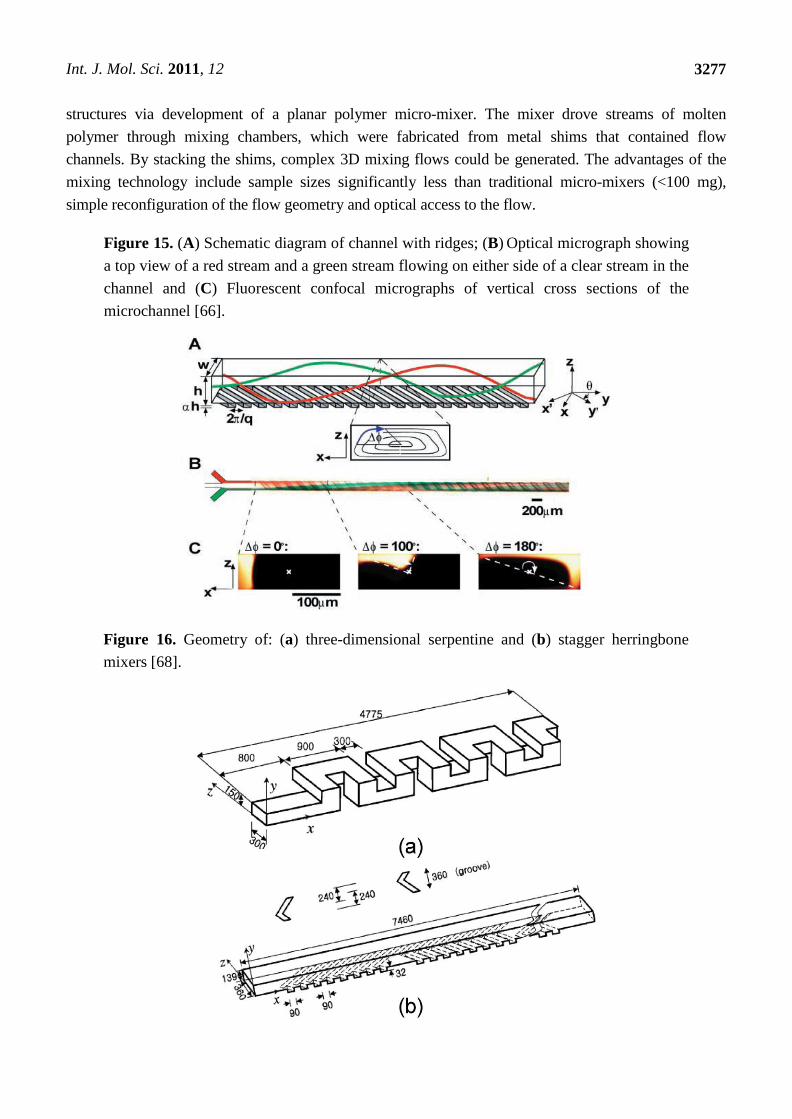
Stroock et al. [66] proposed an active micromixer based on electrohydrodynamic (EDH) forces. In
such mixers, an EDH force is created by applying an electrical field to a bulk flow in which both an
electrical conductivity gradient and a permittivity gradient exist (Figure 15). Vijayendran et al. [67]
presented a three-dimensional serpentine micromixer designed to induce a chaotic mixing effect. The
mixing efficiency of the serpentine microchannel was observed to be twice that obtained in a
conventional straight microchannel. Liu et al. [68] considered a three-dimensional serpentine mixer, and
a staggered herringbone mixer (Figure 16), and performed numerical simulations to investigate the
mixing characteristics of the two devices for different Reynolds number regimes and fluorescent sample
mass fractions. At Re = 1, the mixing performance of both mixers varied inversely with the mass fraction
of the sample due to the dominance of molecular diffusion. However, when the Reynolds number was
increased to 10, the inverse trend was observed in the serpentine mixer. This phenomenon was attributed
to an enhanced flow advection effect at large sample mass fractions. However, this effect was not
observed in the herringbone mixer when the Reynolds number was increased over a similar range.
Liu et al. [69] fabricated a three-dimensional serpentine micromixer featuring a “C-shaped” repeating
unit designed to induce chaotic advection. The results showed that for flows with a Reynolds number of
70, the mixing efficiency in the serpentine channel was 16 times higher than in a conventional straight
channel and 1.6 times better than in a zigzag channel. Chen et al. [16] investigated a folding flow
micromixer in the Stokes flow regime (Figure 17). Both the simulated and experimental results revealed
a significant effect on mixing from a small misalignment of the glass layers that formed the mixer
geometry. A layer offset of 5 μm (1.5% of channel width) produced a variation of up to a 26% in the
measurement of the mixture uniformity, and improved or worsened depending on the precise offsets of
the layers. In 2009, Kamg et al. [17] simulated and optimized a set of variables (i.e., sense of rotation of
two rotational flows, aspect ratio of channel and ratio of bypass channel to whole width) and found at
proper combination of the variables, almost global chaotic mixing was observed in the Stoke flow regime.
Moon et al. [18] presented a strategy for the forced assembly of immiscible polymer into targeted
Int. J. Mol. Sci. 2011, 12
3277
structures via development of a planar polymer micro-mixer. The mixer drove streams of molten
polymer through mixing chambers, which were fabricated from metal shims that contained flow
channels. By stacking the shims, complex 3D mixing flows could be generated. The advantages of the
mixing technology include sample sizes significantly less than traditional micro-mixers (<100 mg),
simple reconfiguration of the flow geometry and optical access to the flow.
Figure 15. (A) Schematic diagram of channel with ridges; (B) Optical micrograph showing
a top view of a red stream and a green stream flowing on either side of a clear stream in the
channel and (C) Fluorescent confocal micrographs of vertical cross sections of the
microchannel [66].
Figure 16. Geometry of: (a) three-dimensional serpentine and (b) stagger herringbone
mixers [68].

Int. J. Mol. Sci. 2011, 12
3278
Figure 17. Composite microscope image of fluorescence intensity and profiles of
measured concentration at selected element outlets (k) derived from the images [16].
3.5. Embedded Barriers [21,71–73]
Keoschkerjan et al. [71] fabricated a micro-reaction unit for chemical engineering applications
based on the combination of multi-lamination and chaotic advection effects. In the proposed design, a
mixing zone with a three-dimensional geometry was formed through overlapping microrestrictions.
The mixing zone of the second micromixer was formed through cavities in the two wafer levels. The
cavities were arranged to form a continuous three-dimensional channel. The geometry of the
three-dimensional channel forced the fluid to follow a tortuous path and induced a permanent change
in the flow direction. The mixing performance was further enhanced by the turbulence-like and
restriction effects induced at the corners of the three-dimensional channel. Kim et al. [72,73]
developed barrier embedded micromixers for pressure-driven flow in which chaotic flow was induced
by applying periodic perturbations to the velocity field via periodically inserted barriers along the
upper surface and helical type flow structures were induced by slanted grooves on the lower surface of
the microchannel (Figure 18). Observations using a confocal microscope revealed cross-sectional
mixing behaviors in several locations in the micromixer. The proposed design was validated
experimentally at a flow rate corresponding to a Reynolds number of 2.28 (corresponding to

Int. J. Mol. Sci. 2011, 12
3279
Re = 1.24 × 10⁴ with a Rhodamine diffusivity of 2.8 × 10
−10 m
2s
−1). Laser scanning of the entrance
zone of the micromixer identified a bright image only in the half-zone containing Rhodamine. Bright
images were also observed at the no-barrier zone in the first half-cycle, thus confirming the
cross-sectional rotating flow effect induced by the slanted grooves. When the streams entered the
barrier zone in the next half-cycle, laser scanning showed that the flow had rotated yet further. The
experimental results confirmed that the barrier embedded micromixer yielded excellent species mixing
within a short length of channel. Recently, Singh et al. [21] analyzed and optimized different designs
of SMX motionless mixers based on the Mapping Method. Three design parameters that constituted
the number of cross-bars over the width of channel, Nx, the number of parallel cross-bars per element,
Np, and the angle between opposite cross-bars. An optimum series for all possible SMX(n) designs to
obey the universal design rule is Np = (2/3) Nx − 1, for Nx = 3, 6, 9, 12…
Figure 18. Schematic diagrams of barrier embedded Kenics micromixer [72].
3.6. Slanted Wells [74–76]
Johnson et al. [74,75] presented a micromixer incorporating slanted wells at the inlet junction. The
presence of these wells led to a high degree of lateral transport within the channel and ensured a rapid
mixing of two confluent streams undergoing electroosmotic flow (Figure 19). The micromixer was
shown to successfully mix streams with a low flow rate (0.06 cm/s, ≥75% mixing), but had varying
degrees of success mixing streams traveling at a higher flow rate (0.81 cm/s, 45–80% mixing).
Yang et al. [76] investigated the effects of the asymmetry index p and depth ratio α of the groove on
the mixing performance of a staggered herringbone mixer with patterned grooves. Because the two
vortices within the mixing channel are determined by the asymmetry index p, vortices with dissimilar
scales were shown to provide a better mixing performance than two equally-sized vortices.
Furthermore, the results showed that the intensity of the vertical fluid motions at the side edges of the
grooves increased with increasing groove depth α, resulting in a significant improvement in the
mixing effect.

Int. J. Mol. Sci. 2011, 12
3280
Figure 19. (a) Top-view schematic of the simulation geometry for T-channel;
(b) End-view schematic of the simulation geometry as viewed down the line of sight of (a)
along with arrows depicting the general direction of the electric field within the slanted
wells. Ex, Ey, and Ez are the components of the electric field and d is the depth of the
channel [75].
3.7. Twisted Channels [23,77–79]
Jen et al. [77] presented a micromixer featuring a three-dimensional structure of twisted
microchannels designed to induce a chaotic mixing effect within the fluid streams. In addition to the
conventional T-mixer configuration, the authors also investigated three other types of micromixer
featuring inclined, oblique and wavelike microchannels (Figure 20). The twisted microchannels were
designed such that the angle of the channels’ lower surfaces alternated in each longitudinal subsection
of the mixing channel. Hence, the fluid flow sways from side to side as it travels along the
microchannel, resulting in a chaotic advection effect. Park et al. [78] presented a breakup method
based on passive rotation for enhancing the mixing efficiency of micromixers. The proposed method
not only actively generated interfaces between the mixing species, but also enhanced the diffusion
process at the interface. The micromixer actually incorporated two separate mixing regions, one region
with shorter segments of length 200 μm and a second region with longer segments of length 400 μm.
The results showed that this design caused a rotation of the fluids flowing through the channel. The
fluids were observed to mix well and the interface was distorted at high Reynolds numbers.
Conversely, at low Reynolds numbers, the fluids were hardly mixed and the interface was not distorted;
only the respective positions of the two fluid streams were changed. Hardt et al. [23] presented a low-
Reynolds number split-and-recombine mixer. In their design, when fluid 1(2) entered the upper (lower)
half of the stream, it was directed into the left (right) branch. The two streams were then recombined and
directed into a channel with a cross-section identical to that of the inlet of the mixing element. In this way,
the number of fluid lamellae doubled after each step and the average lamella thickness halved. In 2005,
Aubin et al. [79] presented staggered herringbone groove micromixers that had an off-centered herringbone
pattern on the lower surface of the microchannel, creating a transverse velocity component in the flow field.
Such mixers comprised several mixing cycles, where each cycle comprised two sequential regions of
grooves, (two half-cycles). The asymmetry direction of the herringbone pattern switched with respect to the
centerline of the microchannel every half cycle. For improved mixing efficiency, the depth of the grooves
in staggered herringbone micromixers was specified at 30% of the channel height. This promoted both
spatial homogenization and a reduction of the striation thickness without increasing the pressure drop
across the mixer.

Int. J. Mol. Sci. 2011, 12
3281
Figure 20. (a) Schematic diagrams (upside down) of (a) T-mixer; (b) inclined mixer;
(c) oblique mixer and (d) wavelike mixer [77].
3.8. Surface-Chemistry Technology in Microchannels [80–83]
In microfluidic systems, very high pressure gradients are generally required to drive and manipulate
the fluid flow. Due to the small characteristic scale of the microchannels in typical microfluidic
devices, surface forces dominate, and high friction effects are generated. Conventionally,
microchannels are fabricated using silicon dioxide. Silicon dioxide surfaces are typically negatively
charged due to their deprotonated silanol groups (≡Si–O−). When these surfaces come into contact with
a solution containing ions, the positive ions are attracted to the surface, forming an important diffuse
layer [80]. If an electrical field is then applied, the diffuse layer of positive ions moves in the direction
of the applied field. The movement of the diffuse layer drags the bulk fluid into motion via momentum
coupling, resulting in the so-called electro-osmotic flow (EOF) phenomenon [81]. Mixing in
electroosmotic flow is generally diffusion-dominated. However, the introduction of electrically
charged surface heterogeneities enhances the mixing efficiency by creating localized flow circulation
regions (Figure 21) [82]. By selectively patterning positively charged molecules on a negatively
charged channel wall, flow vortices can be induced from the differences in electrostatic potential
between the homogeneous and heterogeneous surfaces. These localized flow vortices can be exploited
to yield a significant improvement in mixing performance over a variety of microchannel
configurations, including in-line, staggered, serpentine, herringbone and diagonal arrays [83]. In
numerical investigations, the authors specified the patch length and spacing parameters required to
maintain a constant ratio of heterogeneous-to-homogeneous surface areas over a channel length of 1.8
mm. The results revealed that the nonsymmetrical heterogeneous patterns, namely the staggered and
diagonal patterns, generated a higher mixing performance than either the symmetrical herringbone
pattern or the in-line arrangement. With a theoretical mixing efficiency of 96%, the staggered

Int. J. Mol. Sci. 2011, 12
3282
configuration provided the highest mixing performance, outperforming the diagonal, herringbone and
serpentine configurations by 8%, 31% and 36%, respectively. Furthermore, compared to the
homogeneous case, the staggered configuration provided a 61% improvement in mixing efficiency.
The use of heterogeneous surface charge patches to manipulate electrokinetic flows provides a simple,
low-cost solution to mixing problems in lab-on-a-chip systems, and is therefore likely to receive
increasing attention in future studies.
Figure 21. Schematic illustration of electrical double layer (EDL) and electroosmotic flow
near the EDL: (a) the EDL next to a negatively charged solid surface (ψ is the EDL
potential, ψ0 is the surface electric potential, ζ is the zeta potential); (b) a homogeneous
surface (ζ = −ζ0) and (c) a homogeneous surface with a heterogeneous region (ζ = +ζ0),
ζ0 > 0 [82].
4. Conclusions
Advances in MEMS techniques in recent decades have enabled the fabrication of sophisticated
biochips for a diverse range of applications. Compared to their traditional macro-scale counterparts,
micromixers have a shorter operation time, a lower cost, an improved portability and a more
straightforward integration with other planar bio-medical chips. This paper has presented a systematic
review of the major micro-mixers presented in the literature over the past 20 years or so. It has been
shown that depending on their mode of operation, these micromixers can be broadly categorized as
either active or passive. The operational principles and mixing performance of each type of
micromixer have been systematically discussed, and their relative advantages and disadvantages
highlighted where appropriate. Overall, the results presented in this review confirm the applicability of
micromixers for a diverse range of low-cost, high-performance microfluidic applications.
Acknowledgements
The authors would like to thank the financial support provided by the National Science Council
in Taiwan.

Int. J. Mol. Sci. 2011, 12
3283
References
1. Ahmed, D.; Mao, X.; Juluri, B.; Huang, T. A fast microfluidic mixer based on acoustically driven
sidewall-trapped microbubbles. Microfluid. Nanofluid. 2009, 7, 727–731.
2. Luong, T.; Phan, V.; Nguyen, N. High-throughput micromixers based on acoustic streaming
induced by surface acoustic wave. Microfluid. Nanofluid. 2011, 10, 619–625.
3. Campisi, M.; Accoto, D.; Damiani, F.; Dario, P. A soft-lithographed chaotic electrokinetic
micromixer for efficient chemical reactions in lab-on-chips. J. Micro-Nano Mech. 2009, 5,
69–76.
4. Chen, C.K.; Cho, C.C. Electrokinetically driven flow mixing utilizing chaotic electric fields.
Microfluid. Nanofluid. 2008, 5, 785–793.
5. Lim, C.; Lam, Y.; Yang, C. Mixing enhancement in microfluidic channel with a constriction
under periodic electro-osmotic flow. Biomicrofluidics 2010, 4, 014101.
6. Du, Y.; Zhang, Z.; Yim, C.; Lin, M.; Cao, X. A simplified design of the staggered herringbone
micromixer for practical applications. Biomicrofluidics 2010, 4, 024105.
7. Zhang, Z.; Yim, C.; Lin, M.; Cao, X. Quantitative characterization of micromixing simulation.
Biomicrofluidics 2008, 2, 034104.
8. Xu, B.; Wong, T.; Nguyen, N.; Che, Z.; Chai, J. Thermal mixing of two miscible fluids in a
T-shaped microchannel. Biomicrofluidics 2010, 4, 044102.
9. Wang, Y.; Zhe, J.; Chung, B.T.F.; Dutta, P. A rapid magnetic particle driven micromixer.
Microfluid. Nanofluid. 2008, 4, 375–389.
10. Lam, Y.; Gan, H.; Nguyen, N.; Lie, H. Micromixer based on viscoelastic flow instability at low
Reynolds number. Biomicrofluid 2009, 3, 014106.
11. Huang, M.Z.; Yang, R.J.; Tai, C.H.; Tsai, C.H.; Fu, L.M. Application of electrokinetic instability
flow for enhanced micromixing in cross-shaped microchannel. Biomed. Microdevices 2006, 8,
309–315.
12. Meijer, H.E.H.; Singh, M.K.; Kang, T.G.; den Toonder, J.M.J.; Anderson, P.D. Passive and active
mixing in microfluidic devices. Macromol. Symp. 2009, 279, 201–209.
13. Buchegger, W.; Wagner, C.; Lendl, B.; Kraft, M.; Vellekoop, M. A highly uniform lamination
micromixer with wedge shaped inlet channels for time resolved infrared spectroscopy. Microfluid.
Nanofluid. 2011, 10, 889–897.
14. Tofteberg, T.; Skolimowski, M.; Andreassen, E.; Geschke, O. A novel passive micromixer:
Lamination in a planar channel system. Microfluid. Nanofluid. 2010, 8, 209–215.
15. Lee, C.Y.; Lin, C.F.; Hung, M.F.; Tsai, C.H.; Fu, L.M. Experimental and numerical investigation
into mixing efficiency of micromixers with different geometric barriers. Mater. Sci. Forum 2006,
505–507, 391–396.
16. Chen, Z.; Bown, M.R.; O’Sullivan, B.; MacInnes, J.M.; Allen, R.W.K.; Mulder, M.; Blom, M.;
van’t Oever, R. Performance analysis of a folding flow micromixer. Microfluid. Nanofluid. 2009,
7, 783–794.
17. Kang, T.G.; Singh, M.K.; Anderson, P.D.; Meijer, H.E.H. A Chaotic Serpentine Mixer Efficient
in th eCreeping Flow Regime: From Design Concept to Optimization. Microfluid. Nanofluid.
2009, 6, 763–774.

Int. J. Mol. Sci. 2011, 12
3284
18. Moon, D.; Migler, K.B. Forced assembly and mixing of melts via planar polymer micro-mixing.
Polymer 2010, 51, 3147–3155.
19. Neerincx, P.E.; Denteneer, R.P.J.; Peelen, S.; Meijer, H.E.H. Compact mixing using multiple
splitting, stretching, and recombining flows. Macromol. Mater. Eng. 2011, 296, 349–361.
20. Lin, C.H.; Tsai, C.H.; Fu, L.M. A rapid three-dimensional vortex micromixer utilizing
self-rotation effects under low Reynolds number conditions. J. Micromech. Microeng. 2005, 15,
935–943.
21. Singh, M.K.; Anderson, P.D.; Meijer, H.E.H. Understanding and optimizing the SMX static mixer.
Macromol. Rapid Commun. 2009, 30, 362–376.
22. Tsai, R.; Wu, C. An efficient micromixer based on multidirectional vortices due to baffles and
channel curvature. Biomicrofluidics 2011, 5, 014103.
23. Hardt, S.; Pennemann, H.; Schonfeld, F. Theoretical and experimental characterization of a
low-Reynolds number split-and-recombine mixer. Microfluid. Nanofluid. 2006, 2, 237–248.
24. Jain, M.; Yeung, A.; Nandakumar, K. Induced charge electro osmotic mixer: Obstacle shape
optimization. Biomicrofluidics 2009, 3, 022413.
25. Jain, M.; Nandakumar, K. Novel index for micromixing characterization and comparative analysis.
Biomicrofluidics 2010, 4, 031101.
26. Liu, R.H.; Lenigk, R.; Druyor S.R.L.; Yang, J.; Grodzinski, P. Hybridization enhancement using
cavitation microstreaming. Anal. Chem. 2003, 75, 1911–1917.
27. Yang, Z.; Matsumoto, S.; Goto, H.; Matsumoto, M.; Maeda, R. Ultrasonic micromixer for
microfluidic systems. Sens. Actuators A 2001, 93, 266–272.
28. Tsao, T.R.; Moroney, R.M.; Martin, B.A.; White, R.M. Electrochemical detection of localized
mixing produced by ultrasonic flexural waves. Proc. IEEE Ultrasonic Symp. 1991, 1, 937–940.
29. Rife, J.C.; Bell, M.I.; Horwitz, J.S.; Kabber, M.N.; Auyeung, R.C.Y.; Kim, W.J. Miniature
valveless ultrasonic pumps and mixers. Sens. Actuators A 2000, 86, 135–140.
30. Yaralioglu, G.G.; Wygant, I.O.; Marentis, T.C.; Khuri-Yakub, T. Ultrasonic mixing in
microfluidic channels using integrated transducers. Anal. Chem. 2004, 76, 3694–3698.
31. Choi, E.; Kim, B.; Park, J. High-throughput microparticle separation using gradient traveling
wave dielectrophoresis. J. Micromech. Microeng. 2009, 19, 125014.
32. Zhao, C.; Yang, C. AC field induced-charge electroosmosis over leaky dielectric blocks
embedded in a microchannel. Electrophoresis 2011, 32, 629–637.
33. Lee, C.Y.; Lee, G.B.; Fu, L.M.; Lee, K.H.; Yang, R.J. Electrokinetically driven active
micro-mixers utilizing zeta potential variation induced by field effect. J. Micromech. Microeng.
2004, 14, 1390–1398.
34. Lin, C.H.; Fu, L.M.; Chien, Y.S. Microfluidic T-form mixer utilizing switching electroosmotic
flow. Anal. Chem. 2004, 76, 5265–5272.
35. Fu, L.M.; Yang, R.J.; Lin, C.H.; Chien, Y.S. A novel microfluidic mixer utilizing electrokinetic
driving forces under low switching frequency. Electrophoresis 2005, 26, 1814–1824.
36. Fu, L.M.; Lin, C.H. A rapid DNA digestion system. Biomed. Microdevices 2007, 9, 277–286.
37. Fu, L.M.; Tsai, C.H. Design of interactively time-pulsed microfluidic mixers in microchips using
numerical simulation. Jpn. J. Appl. Phys. 2007, 46, 420–429.

Int. J. Mol. Sci. 2011, 12
3285
38. Leong, J.C.; Tsai, C.H.; Chang, C.L.; Lin, C.F.; Fu, L.M. Rapid microfluidic mixers utilizing
dispersion effect and interactively time-pulsed injection. Jpn. J. Appl. Phys. 2007, 46,
5345–5352.
39. Yan, D.; Yang, C.; Miao, J.; Lam, Y.; Huang, X. Enhancement of electrokinetically driven
microfluidic T-mixer using frequency modulated electric field and channel geometry effects.
Electrophoresis 2009, 30, 3144–3152.
40. Niu, X.; Lee, Y.K. Efficient spatial-temporal chaotic mixing in microchannels. J. Micromech.
Microeng. 2003, 13, 454–462.
41. El Moctar, A.O.; Aubry, N.; Batton, J. Electro-hydrodynamic micro-fluidic mixer. Lab Chip 2003,
3, 273–280.
42. Tsai, J.H.; Lin, L. Active micofluidic mixer and gas bubble filter driven by thermal bubble
micropump. Sens. Actuators, A 2002, 97–98, 665–671.
43. Bau, H.H.; Zhong, J.; Yi, M. A minute magneto hydro dynamic (MHD) mixer. Sens. Actuators B
2001, 79, 207–215.
44. Yi, M.; Qian, S.; Bau, H.H. A minute magneto hydro dynamic (MHD) chaotic stirrer. J. Fluid
Mech. 2002, 468, 153–177.
45. Wen, C.Y.; Lee, T.L.; Tsai, C.H.; Fu, L.M. Rapid magnetic microfluidic mixer utilizing AC
electromagnetic field. Electrophoresis 2009, 30, 4179–4186.
46. Chen, C.H.; Lin, H.; Lele, S.K.; Santiago, J.G. Convective and absolute electrokinetic instability
with conductivity gradients. J. Fluid Mech. 2005, 524, 263–303.
47. Fu, L.; Hong, T.; Wen, C.; Tsai, C.; Lin, C. Electrokinetic instability effects in microchannels
with and without nanofilm coatings. Electrophoresis 2008, 29, 4871–4879.
48. Tai, C.H.; Yang, R.J.; Huang, M.Z.; Liu, C.W.; Tsai, C.H.; Fu, L.M. Micromixer utilizing
electrokinetic instability induced shedding effect. Electrophoresis 2006, 27, 4982–4990.
49. Yang, S.; Cheng, F.; Yeh, C.; Lee, G. Size-controlled synthesis of gold nanoparticles using a
micro-mixing system. Microfluid. Nanofluid. 2010, 8, 303–311.
50. Guo, W.; Lau, K.; Fung, Y. Microfluidic chip-capillary electrophoresis for two orders extension
of adjustable upper working range for profiling of inorganic and organic anions in urine.
Electrophoresis 2010, 31, 3044–3052.
51. Oh, K.; Smith, B.; Devasia, S.; Riley, J.; Chung, J. Characterization of mixing performance for
bio-mimetic silicone cilia. Microfluid. Nanofluid. 2010, 9, 645–655.
52. Sun, C.; Sie, J. Active mixing in diverging microchannels. Microfluid. Nanofluid. 2010, 8,
485–495.
53. Mahalanabis, M.; Do, J.; Almuayad, H.; Zhang, J.; Klapperich, C. An integrated disposable
device for DNA extraction and helicase dependent amplification. Biomed. Microdevices 2010, 12,
353–359.
54. Weng, C.; Lien, K.; Yang, S.; Lee, G. A suction-type, pneumatic microfluidic device for liquid
transport and mixing. Microfluid. Nanofluid. 2011, 10, 301–310.
55. Wang, J.; Wang, C.; Lin, C.; Lei, H.; Lee, G. An integrated microfluidic system for counting of
CD4+/CD8
+ T lymphocytes. Microfluid. Nanofluid. 2011, 10, 531–541.
Int. J. Mol. Sci. 2011, 12
3286
56. Elizarov, A.; Meinhart, C.; Miraghaie, R.; van Dam, R.; Huang, J.; Daridon, A.; Heath, J.;
Kolb, H. Flow optimization study of a batch microfluidics PET tracer synthesizing device.
Biomed. Microdevices 2011, 13, 231–242.
57. den Toonder, J.; Bos, F.; Broer, D.; Fillippini, L.; Gillies, M.; de Geode, J.; Mol, T.;
Reijme, M.; Talen, W.; Wildebeek, H.; Khatavkar, V.; Anderson, P. Artificial cilia for active
micro-fluidic mixing. Lab Chip 2008, 4, 533–541.
58. Branebjerg, J. From microfluidic components to micro-TAS. In Proceedings of Micro Total
Analysis System Workshop, Enschede, The Netherlands, 21–22 November 1994.
59. Scampavia, L.D.; Blankenstein, G.; Ruzicka, J.; Christian, G.D. A coaxial jet mixer for rapid
kinetic analysis for chemical and biological microreactors. Anal. Chem. 1995, 67, 2743–2749.
60. Wong, S.H.; Ward. M.C.L.; Wharton, C.W. Micro T-mixer as rapid mixing micromixer. Sens.
Actuators B 2004, 100, 359–379.
61. Bertsch, A.; Heimgartner, S.; Cousseau, P.; Renaud, P. Static micromixers based on large-scale
industrial mixer geometry. Lab Chip 2001, 1, 56–60.
62. He, B.; Burke, B.J.; Zhang, X.; Zhang, R.; Regnier, F.E. A picoliter-volume mixer for
microfluidic analytical systems. Anal. Chem. 2001, 73, 1942–1947.
63. Melin, J.; Gimenez, G.; Roxhed, N.; van der Wijngaart, W.; Stemme, G. A fast passive and planar
liquid sample micromixer. Lab Chip 2004, 4, 214–219.
64. Mengeaud, V.; Josserand, J.; Girault, H.H. Mixing processes in a zigzag microchannel: Finite
element simulations and optical study. Anal. Chem. 2002, 174, 4279–4286.
65. Hong, C.C.; Choi, J.W.; Ahn, C.H. A novel in-plane passive microfluidic mixer with modified
Tesla structures. Lab Chip 2003, 4, 109–113.
66. Stroock, A.D.; Dertinger, S.K.W.; Ajdari, A.; Mezic, I.; Stone, H.A.; Whitesides, G.M. Chaotic
mixer for microchannels. Science 2002, 295, 647–651.
67. Vijayendran, R.A.; Motsegood, K.M.; Beebe, D.J.; Leckband, D.E. Evaluation of a
three-dimensional micromixer in a surface-based biosensor. Langmuir 2003, 19, 1824–1828.
68. Liu, Y.Z.; Kim, B.J.; Sung, H.J. Two-fluid mixing in a microchannel. Int. J. Heat Fluid Flow
2004, 25, 986–995.
69. Liu, R.H.; Stremler, M.A.; Sharp, K.V.; Olsen, M.G.; Santiago, J.G.; Adrian, R.J.;
Aref, H.; Beebe, D.J. Passive mixing in a three-dimensional serpentine microchannel.
J. Microelectromech. Syst. 2000, 9, 190–197.
70. Lin, C.H.; Tsai, C.H.; Pan, C.W.; Fu, L.M. Rapid circular microfluidic mixer utilizing unbalanced
driving force. Biomed. Microdevices 2007, 9, 43–50.
71. Keoschkerjan, R.; Richter, M.; Boskovic, D.; Schnürer, F.; Lobbecke, S. Novel multifunctional
microreaction unit for chemical engineering. Chem. Eng. J. 2004, 101, 469–475.
72. Kim, D.S.; Lee, S.W.; Kwon, T.H.; Lee, S.S. A barrier embedded chaotic micromixer.
J. Micromech. Microeng. 2004, 14, 798–805.
73. Kim, D.S.; Lee, I.H.; Know, T.H.; Cho, D.W. A barrier embedded Kenics micromixer.
J. Micromech. Microeng. 2004, 14, 1294–1301.
74. Johnson, T.J.; Ross, D.; Locascio, L.E. Rapid Microfluidic Mixing. Anal. Chem. 2002, 74, 45–51.
75. Johnson, T.J.; Locascio, L.E. Characterization and optimization of slanted well designs for
microfluidic mixing under electroosmotic flow. Lab Chip 2002, 2, 135–140.
Int. J. Mol. Sci. 2011, 12
3287
76. Yang, J.T.; Huang, K.J.; Lin, Y.C. Geometric effects on fluid mixing in passive grooved
micromixers. Lab Chip 2005, 5, 1140–1147.
77. Jen, C.P.; Wu, C.Y.; Lin, Y.C.; Wu, C.Y. Design and simulation of the micromixer with chaotic
advection in microchannels. Lab Chip 2003, 3, 77–81.
78. Park, S.J.; Kim, J.K.; Park, J.; Chung, S.; Chung, C.; Chang, J.K. Rapid three-dimensional passive
rotation micromixer using the breakup process. J. Micromech. Microeng. 2004, 14, 6–14.
79. Aubin, J.; Fletcher, D.F.; Xuereb, C. Design of micromixers using CFD modelling. Chem. Eng.
Sci. 2005, 60, 2503–2516.
80. Hunter, R.J. Zeta Potential in Colloid Science: Principles and Applications; Academic Press:
London, UK, 1981.
81. Zeng, S.; Chen, C.H.; Mikkelsen, J.; Santiago, J.G. Fabrication and characterization of
electrokinetic micro pumps. In Proceedings of 7th International Conference on Thermal and
Thermomechanical Phenomenon in Electronic Systems (ITherm), Las Vegas, NV, USA,
23–26 May 2000; Volume 2, pp. 31–36.
82. Chang, C.C.; Yang, R.J. Computational analysis of electrokinetically driven flow mixing in
microchannels with patterned blocks. J. Micromech. Microeng. 2004, 14, 550–558.
83. Biddiss, E.; Erickson, D.; Li, D. Heterogeneous surface charge enhanced micromixing for
electrokinetic flows. Anal. Chem. 2004, 76, 3208–3213.
84. Kawabata, T.; Wada, H.; Watanabe, M.; Satomura, S. Electrokinetic analyte transport assay: For
A-fetoprotein immunoassay integrates mixing, reaction and separation on-chip. Electrophoresis
2008, 29, 1399–1406.
85. Chen, L.; Wang, G.; Lim, C.; Seong, G.; Choo, J.; Kang S.; Song J. Evaluation of passive mixing
behaviors in a pillar obstruction poly(dimethylsiloxane) microfluidic mixer using fluorescence
microscopy. Microfluid. Nanofluid. 2009, 7, 267–273.
86. Hong, T.F.; Ju, W.J.; Wu, M.; Tai, C.H.; Tsai, C.H.; Fu, L.M. Rapid prototyping of PMMA
microfluidic chips utilizing a CO2 laser. Microfluid. Nanofluid. 2010, 9, 1125–1133.
87. Lee, M.; Choi, S.; Park, J. Rapid multivortex mixing in an alternately formed contraction-expansion
array microchannel. Biomed. Microdevices 2010, 12, 1019–1026.
88. Mao, X.; Juluri, B.; Lapsley, M.; Stratton, Z.; Huang, T. Milliseconds microfluidic chaotic bubble
mixer. Microfluid. Nanofluid. 2010, 8, 139–144.
89. Jännig, O.; Nguyen, N. A polymeric high-throughput pressure-driven micromixer using a
nanoporous membrane. Microfluid. Nanofluid. 2011, 10, 513–519.
90. Marasso, S.; Giuri, E.; Canavese, G.; Castagna, R.; Quaglio, M.; Ferrante, I.; Perrone, D.;
Cocuzza, M. A multilevel Lab on chip platform for DNA analysis. Biomed. Microdevices 2011,
13, 19–27.
© 2011 by the authors; licensee MDPI, Basel, Switzerland. This article is an open access article
distributed under the terms and conditions of the Creative Commons Attribution license
(http://creativecommons.org/licenses/by/3.0/).