ﺔﺜﻟﺎﺜﻟﺍ ﺔﻠﺣﺮﻤﻟﺍ · poundal = ibm ×32.17 ft/sec2 f= lbw m=slug lbw =...
TRANSCRIPT

الجامعة التكنولوجية
قسم الهندسة الكيمياوية الثالثةالمرحلة
خزن ونقل النفط ومشتقاته
م.د. علي عبد الرحمن
Save from: http://www.uotechnology.edu.iq/dep-chem-eng/index.htm

Storage & Transport of Crude Oil and Petroleum Products
1- Units
2- Classification of process
3- Fluids – Definitions , properties
4- Classification of fluids
5- Forms of Energy
6- Energy balance on closed system
7- Energy balance on flow system
8- Bernoulli's Equation
9- Examples on applied energy equation
10- Pressure drop in a pipe
11- Pressure drop at points in system
12- Pressure drop in non-isothermal liquid flow
13- Fittings and valves
14- Calculation of pressure drop in short gas lines
15- Calculation of pipe diameter for given pressure drop and flow
rate
16- Complex liquid gathering systems
17- Design gathering system for liquid hydrocarbon

2
Dr. Ali Abdulrahman Al-Ezzi
Storage & Transport of Crude Oil and Petroleum Products
The transfer of fluids through piping and equipment is accompanied by
friction and may result in changes in pressure, velocity, and elevation. These effects
require input of energy to maintain flow at desired rates.
Any think that is derived from the primary
Means
TANKS
Piping &Pumps,
Compressor
Liquid Gas
Fluids
Process
PROCESS
Physical Chemical
M1 M2
E1
U1, EK1, EP1, P1V1
W
Surrounding
Surrounding
Q E2
U2, EK2, EP2, P2V2
Liquid + Gas + Solid
Physical System
Dimension or Quantities or Fundamental
QqQuantities or Secondary
Primary
Force (F)
Time (T)
Temp (∅)
Mass (M)
Length (L)

3
Dr. Ali Abdulrahman Al-Ezzi
Units: Can be defined as the means of expressing dimensions according to the systems of
measurements.
MEASUREMENTS SYSTEMS
S.I (international or metric) ENGLISH
CgS MKS Absolute Poundal
FPS
Gravitational
F (primary) mass (secondary)
American British
gc : Correction Factor (for Newton's law)
Fα m × a F=c × m × a C=F/m × a , In (SI unit ) C= N × sec2/ Kg × m
In (English unit) C= lbf × sec2/32.17. lbm.ft [ gC = 1/c] = Kg. m/N. sec or 32.17 lbm .ft /
lbf.sec2, F= (m/gc).a
Note: g/gc=lbm
lbf
g
g
ftlbm
lbfft
lbfftlbm
ft
C
1sec
secsec/
sec/ 2
22
2
Note: kg
Jm
2
2
sec Prove:
2
2
2 secsec
m
Kg
mmkg
Kg
mN
Kg
J
cm
Pound
Kg
F= dyne
M= gm
Dyne=gm× cm/sec2
F= N
M=Kg
N= Kg × m/sec2
F= poundal
M= Ibm
poundal = Ibm × ft/sec2
F= lbf
M=lbm
poundal = Ibm ×32.17 ft/sec2
F= lbw
M=slug
lbw = slug ×ft/sec2

4
Dr. Ali Abdulrahman Al-Ezzi
For example: EK= mNJm
KEg
VmgK
C
2
22
sec2
Note: Btu→Cal→ft. lbf→J
1 Btu = 778 ft.lbf 1 Cal = 4.184 J KW = 737.56 ft.lbf/sec
1 Btu = 252 Cal 1hp = 550 ft.lbf/sec
PROCESS
Unsteady State Steady Stat
d parameter/ d time ≠ zero d parameter/ d time = zero
Reversible Irreversible
It’s the process that doesn't that takes in consideration
Take into consideration the the loss by energy due to
Loss of energy fraction and fraction
Its imaginary process and the Efficiency may be equal 100% Throttling Adiabatic
Reversible Reversible
Open system, flow, continuous closed, non-flow
Turbine Boiler Condenser Pump
T=constant polytrophic Q= 0 V=constant p=constant
Isothermal adiabatic isometric isobaric
Insulated system
isochoric
H,T,P,U,S,V

5
Dr. Ali Abdulrahman Al-Ezzi
1-Definition of Fluids
A fluid is defined as a substance that deforms continuously whilst acted upon
by any force tangential to the area on which it acts. Such a force is termed a shear
force, and the ratio of the shear force to the area on which it acts is known as the shear
stress (see fig. 1). The characteristic that distinguishes a fluid from a solid is its
inability to resist deformation under an applied shear stress (a tangential force per unit
area). When a fluid is at rest neither shear forces nor shear stresses exist in it. A solid,
on the other hand, can resist a shear force while at rest. In a solid, the shear force may
cause some initial displacement of one layer over another, but the material does not
continue to move indefinitely and a position of stable equilibrium is reached.
Definition 1 Fluid is any substance that deforms continuously when
subjected to a shear stress, no matter how small.
Shear forces are possible only while relative movement between layers is taking
place.
Fluids may be sub-divided into liquids and gases. A fixed amount of a liquid
has a definite volume which varies only slightly with temperature and pressure. If the
capacity of the containing vessel is greater than this definite volume, the liquid
occupies only part of the container, and it forms an interface separating it from its
own vapor, the atmosphere or any other gas present.
Gas- a fixed amount of a gas, by itself in a closed container, will always
expand until its volume equals that of the container. Only then can it be in
equilibrium.
In the analysis of the behavior of fluids an important difference between
liquids and gases is that, whereas under ordinary conditions liquids are so difficult to
compress that they may for most purposes be regarded as incompressible, gases may
be compressed much more readily. Where conditions are such that an amount of gas
undergoes a negligible change of volume, its behavior is similar to that of a liquid and
it may then be regarded as incompressible. If, however, the change in volume is not
negligible, the compressibility of the gas must be taken into account in examining its
behavior.

6
Dr. Ali Abdulrahman Al-Ezzi
Figure 1: (A) The displacement and the corresponding shear strain increase linearly
with time. For a fluid, the relationship between shear stress and shear strain is
proportional. (B) The fluid velocity in the x direction, u, is a function of the y
coordinate. The velocity u(y) varies linearly from 0 at the bottom plate to U0 at the
top plate.
Liquids have much greater densities than gases. As a consequence, when considering
forces and pressures that occur in fluid mechanics, the weight of a liquid has an
important role to play. Conversely, effects due to weight can usually be ignored when
gases are considered. The different characteristics of solids, liquids and gases result
from differences in their molecular structure.
Figure 2: The liquid occupies only part of the container, and it forms an interface
separating it from its own vapor.

7
Dr. Ali Abdulrahman Al-Ezzi
Figure 3: A fixed amount of a gas, by itself in a closed container, will always expand
until its volume equals that of the container.
All substances consist of vast numbers of molecules separated by empty space.
The molecules have an attraction for one another, but when the distance between them
becomes very small (of the order of the diameter of a molecule) there is a force of
repulsion between them which prevents them all gathering together as a solid lump.
2-Fluid properties Definition 2 The density of a fluid (or any other form of matter) is the amount of
mass per unit volume.
V
M
or the density at a point in fluid as
V
MLim
0
The unit of density is kg/m3.
The density r (rho) or more strictly, mass density, of a fluid is its mass per unit
volume, while the specific weight 𝛾 (gamma) is its weight per unit volume. In the
British Gravitational (BG) system density 𝜌 will be in slugs per cubic foot (kg/m3 in
SI units), which can also be expressed as units of lb_sec2/ft4 (N_s2/m4 in SI units)
Specific weight 𝛾 represents the force exerted by gravity on a unit volume of fluid,
and therefore must have the units of force per unit volume, such as pounds per cubic

8
Dr. Ali Abdulrahman Al-Ezzi
foot (N/m3 in SI units). Density and specific weight of a fluid are related as:
Since the physical equations are dimensionally homogeneous, the dimensions of
density are
Note that density 𝜌 is absolute, since it depends on mass, which is independent of
location. Specific weight 𝛾, on the other hand, is not absolute, since it depends on the
value of the gravitational acceleration g, which varies with location, primarily
latitude and elevation above mean sea level.
Specific volume v is the volume occupied by a unit mass of fluid. We
commonly apply it to gases, and usually express it in cubic feet per slug (m3/kg in
SI units).
Specific volume is the reciprocal of density. Thus
Specific gravity s of a liquid is the dimensionless ratio
Physicists use 4°C (39.2°F) as the standard, but engineers often use 60°F
(15.56°C). In the metric system the density of water at 4°C is 1.00 g/cm3 (or 1.00
g/mL), equivalent to (1000 kg/m3, 62.4 lb/ft3, 8.34 lb/gal) and hence the specific
gravity (which is dimensionless) of a liquid has the same numerical value as its
density expressed in g/mL or Mg/m3.
The specific gravity of a gas is the ratio of its density to that of either
hydrogen or air at some specified temperature and pressure, but there is no general

9
Dr. Ali Abdulrahman Al-Ezzi
agreement on these standards, and so we must explicitly state them in any given case.
Since the density of a fluid varies with temperature, we must determine and specify
specific gravities at particular temperatures.
Compressible and Incompressible Fluids
Fluid mechanics deals with both incompressible and compressible fluids, that
is, with liquids and gases of either constant or variable density. Although there is no
such thing in reality as an incompressible fluid, we use this term where the change in
density with pressure is so small as to be negligible. This is usually the case with
liquids. We may also consider gases to be incompressible when the pressure variation
is small compared with the absolute pressure.
Ordinarily we consider liquids to be incompressible fluids, yet sound waves,
which are really pressure waves, travel through them. This is evidence of the elasticity
of liquids. In problems involving water hammer we must consider the compressibility
of the liquid.
The flow of air in a ventilating system is a case where we may treat a gas as
incompressible, for the pressure variation is so small that the change in density is of
no importance. But for a gas or steam flowing at high velocity through a long
pipeline, the drop in pressure may be so great that we cannot ignore the change in
density. For an airplane flying at speeds below (100 m/s), we may consider the air to
be of constant density. But as an object moving through the air approaches the
velocity of sound, which is of the order of (1200 km/h) depending on temperature, the
pressure and density of the air adjacent to the body become materially different from
those of the air at some distance away, and we must then treat the air as a
compressible fluid.
Compressibility of Liquids
The compressibility (change in volume due to change in pressure) of a liquid
is inversely proportional to its volume modulus of elasticity, also known as the bulk
modulus. This modulus is defined as
K) =)

10
Dr. Ali Abdulrahman Al-Ezzi
where v = specific volume and p= pressure. As v/dv is a dimensionless ratio, the units
of Ev and p are identical. The bulk modulus is analogous to the modulus of elasticity
for solids; however, for fluids it is defined on a volume basis rather than in terms of
the familiar one-dimensional stress–strain relation for solid bodies. The bulk modulus
is a property of the fluid and for liquids is a function of temperature and pressure. At
any temperature we see that the value of Ev increases continuously with pressure, but
at any one pressure the value of Ev is a maximum at about 120°F (50°C). Thus water
has a minimum compressibility at about 120°F (50°C). By rearranging the definition
of Ev, as an approximation we may use for the case of a fixed mass of liquid at
constant temperature
where Ev is the mean value of the modulus for the pressure range and the
subscripts 1 and 2 refer to the before and after conditions.
VISCOSITY
Is a measure of the resistance of a fluid which is being deformed by either
shear stress or tensile stress. In everyday terms (and for fluids only), viscosity is
"thickness" or "internal friction". Thus, water is "thin", having a lower viscosity,
while honey is "thick", having a higher viscosity. Put simply, the less viscous the fluid
is, the greater its ease of movement (fluidity). Viscosity escribes a fluid's internal
resistance to flow and may be thought of as a measure of fluid friction. For example,
high-viscosity felsic magma will create a tall, steep stratovolcano, because it cannot

11
Dr. Ali Abdulrahman Al-Ezzi
flow far before it cools, while low-viscosity mafic lava will create a wide, shallow-
sloped shield volcano. All real fluids (except super fluids) have some resistance to
stress and therefore are viscous, but a fluid which has no resistance to shear stress is
known as an ideal fluid or inviscid fluid.
NOTE: ideal fluids don't have (compressibility, viscosity, surface tension)
In general, in any flow, layers move at different velocities and the fluid's
viscosity arises from the shear stress between the layers that ultimately oppose any
applied force. The relationship between the shear stress and the velocity gradient can
be obtained by considering two plates closely spaced at a distance y, and separated by
a homogeneous substance. Assuming that the plates are very large, with a large area
A, such that edge effects may be ignored, and that the lower plate is fixed, let a force
F be applied to the upper plate. If this force causes the substance between the plates to
undergo shear flow with a velocity gradient u (as opposed to just shearing elastically
until the shear stress in the substance balances the applied force), the substance is
called a fluid. The applied force is proportional to the area and velocity gradient in the

12
Dr. Ali Abdulrahman Al-Ezzi
fluid and inversely proportional to the distance between the plates. Combining
these three relations results in the equation:
where μ is the proportionality factor called viscosity.
This equation can be expressed in terms of shear stress.
Thus as expressed in differential form by Isaac Newton for straight, parallel
and uniform flow, the shear stress between layers is proportional to the velocity
gradient in the direction perpendicular to the layers:
Laminar shear, the non-constant gradient, is a result of the geometry the fluid is
flowing through (e.g. a pipe).

13
Dr. Ali Abdulrahman Al-Ezzi
Hence, through this method, the relation between the shear stress and the velocity
gradient can be obtained. Note that the rate of shear deformation is which
can be also written as a shear velocity,
Viscosity coefficients can be defined in two ways:
• Dynamic viscosity, also absolute viscosity, the more usual one (typical units
Pa·s, Poise, P);
• Kinematic viscosity is the dynamic viscosity divided by the density (typical
units m2/s, Stokes, St).
Intensive and Extensive Properties
Thermodynamic properties can be divided into two general classes, intensive
and extensive properties. An intensive property is independent of the amount of mass.
The value of an extensive property varies directly with the mass. Thus, if a quantity of
matter in a given state is divided into two equal parts, each part will have the same
value of intensive property as the original and half the value of the extensive property.
Soap, sludge

14
Dr. Ali Abdulrahman Al-Ezzi
State Functions and State Properties
The state of a system can be changed, for example by increasing its
temperature or changing its composition. Properties of the system, whose change
depends only on the initial (before) and final states of the system, but not on the
manner used to realize the change from the initial to the final state, are referred to as
state properties or state functions. In other words, the change in a state function or
state property X, between some final (state 2) and initial (state 1) situations, can be
expressed as
In equation 1, Xfinal only depends on the final state of the system, and Xinitial only
on the initial state of the system. Equation 1 does not require any information
whatsoever as to how the system got from the initial to the final state, since X does
not depend on the details of the path followed.
ENERGY FORMS
A fluid may possess several forms of energy. All fluids possess energy due to
their temperature and this is called INTERNAL ENERGY. All possess
GRAVITATIONAL or POTENTIAL ENERGY due to their elevation relative to
some datum level. If the fluid is moving it will possess KINETIC ENERGY due to its
velocity. If it has pressure then it will possess FLOW ENERGY. Often pressure and
temperature are the main two governing factors and we add internal energy to flow
energy in order to produce a single entity called ENTHALPY. Let us look at each in
more detail.
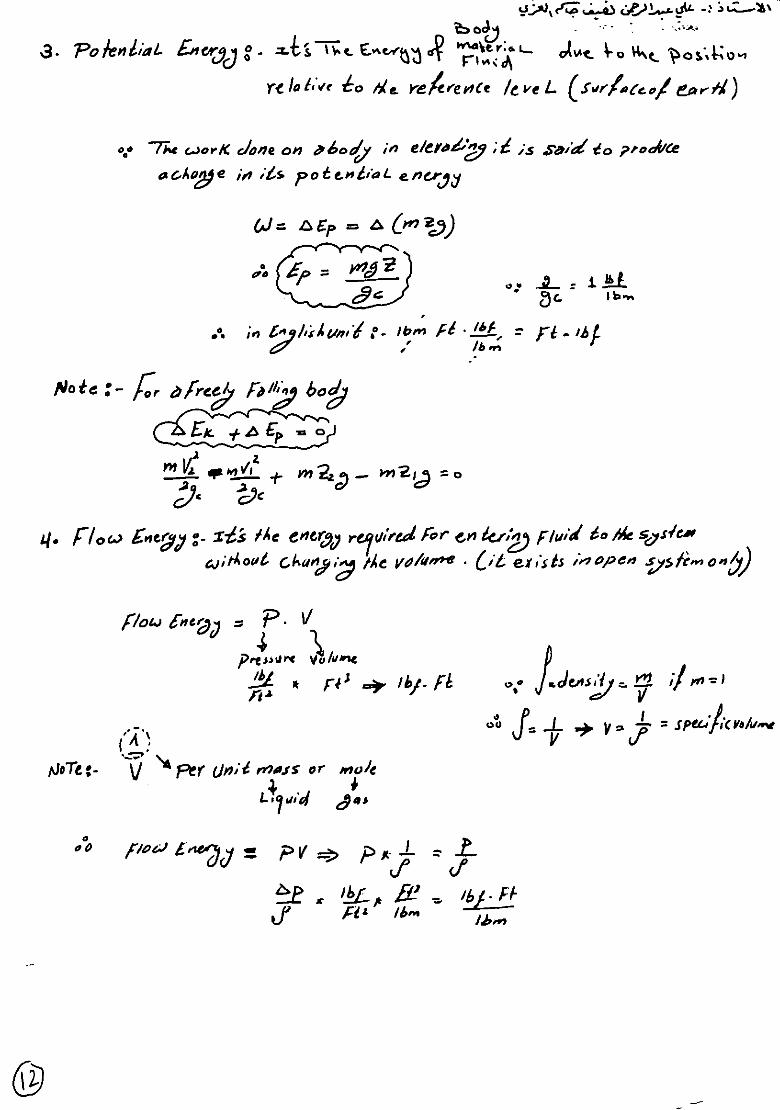
GRAVITATIONAL or POTENTIAL ENERGY
In order to raise a mass m kg a height z meters, a lifting force is required
which must be at least equal to the weight mg.
The work done raising the mass is as always, force x distance moved so
Work = mgz
Since energy has been used to do this work and energy cannot be destroyed, it follows
that the energy must be stored in the mass and we call this gravitational energy or

15
Dr. Ali Abdulrahman Al-Ezzi
potential energy P.E. There are many examples showing how this energy may be got
back, e.g. a hydro-electric power station. P.E. = mgz
KINETIC ENERGY
When a mass m kg is accelerated from rest to a velocity of v m/s, a force is needed to
accelerate it. This is given by Newton's 2nd Law of Motion F= ma.
After time t seconds the mass travels x meters and reaches a velocity
V= m/s.
The laws relating these quantities are
a = v/t and x = vt/2
The work done is W = Fx = max = mv2/2
Energy has been used to do this work and this must be stored in the mass
and carried along with it. This is KINETIC ENERGY. K.E. = mv2/2W

16
Dr. Ali Abdulrahman Al-Ezzi
FLOW ENERGY
When fluid is pumped along a pipe, energy is used to do the pumping. This
energy is carried along in the fluid and may be recovered (as for example with an air
tool or a hydraulic motor). Consider a piston pushing fluid into a cylinder.
The fluid pressure is p N/m2. The force needed on the piston is
F= PA
The piston moves a distance x meters. The work done is
W = Fx = PAx
Since Ax =V and is the volume pumped into the cylinder the work done is
W = PV
Since energy has been used doing this work, it must now be stored in the fluid and
carried along with it as FLOW ENERGY.
F.E. = PV
INTERNAL ENERGY
This is covered in more detail later. The molecules of a fluid possess kinetic
energy and potential energy relative to some internal datum. Usually this is regarded
simply as the energy due to the temperature and very often the change in internal
energy in a fluid which undergoes a change in temperature is given by
ΔU = mcΔT

17
Dr. Ali Abdulrahman Al-Ezzi
The symbol for internal energy is U kJ or u kJ/kg. Note that a change in
temperature is the same in degrees Celsius or Kelvin. The law which states internal
energy is a function of temperature only is known as JOULE'S LAW.
ENTHALPY
When a fluid has pressure and temperature, it must possess both flow and
internal energy. It is often convenient to add them together and the result is
ENTHALPY. The symbol is H kJ or h kJ/kg.
H = F.E. + U
Next you need to study the properties of fluids and the laws relating them.
GAS LAWS
A gas is made of molecules which move around with random motion. In a
perfect gas, the molecules may collide but they have no tendency at all to stick
together or repel each other. In other words, a perfect gas in completely inviscid. In
reality there is a slight force of attraction between gas molecules but this is so small
that gas laws formulated for an ideal gas work quite well for real gas.
Each molecule in the gas has an instantaneous velocity and hence has kinetic
energy. The sum of this energy is the internal energy U. The velocity of the molecules
depends upon the temperature. When the temperature changes, so does the internal
energy. The internal energy is for all intents and purposes zero at - 273o C. This is the
absolute zero of temperature. Remember that to convert from Celsius to absolute, add
on 273. For example 40oC is 40 + 273= 313 Kelvins.
PRESSURE
If a gas is compressed it obtains pressure. This is best explained by
considering a gas inside a vessel as shown. The molecules bombard the inside of the
container. Each produces a momentum force when it bounces. The force per unit area
is the pressure of the gas. Remember that Pressure = Force/area
p = F/A N/m2 or Pascal's: Note that 103 Pa = 1 kPa 106 Pa = 1 MPa 105 Pa = 1 bar

18
Dr. Ali Abdulrahman Al-Ezzi
Absolute pressure: The actual pressure at a given position. It is measured relative
to absolute vacuum (i.e., absolute zero pressure).
Gage pressure: The difference between the absolute pressure and the local
atmospheric pressure. Most pressure-measuring devices are
calibrated to read zero in the atmosphere, and so they indicate gage
pressure.
Vacuum pressures: Pressures below atmospheric pressure.
Pressure instruments
A- Piezometer
B- Manometers
1. Simple Manometer
2. Micro manometer
3. Differential manometer
4. Inverted differential manometer
C- Mechanical Gauge
1. Bourdon
2. Diaphragm
3. Dead weight
19
Dr. Ali Abdulrahman Al-Ezzi
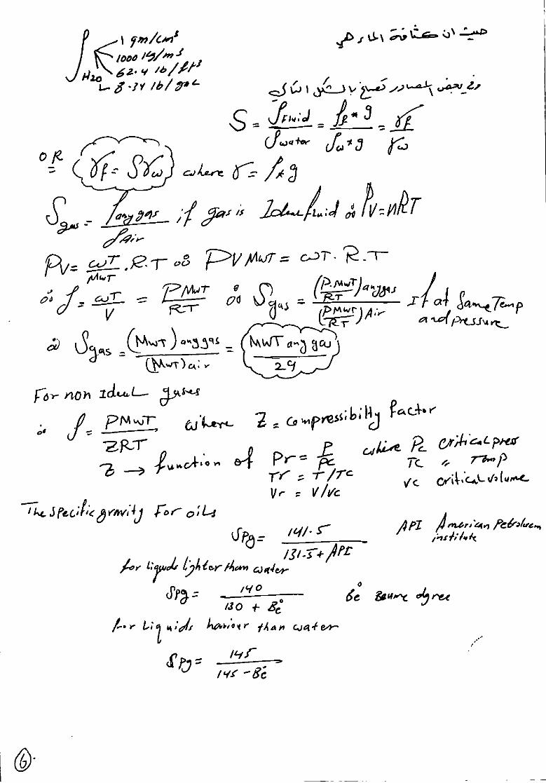
Specific gravity for ideal gas = S = 𝜌 𝑎𝑛𝑦 𝑔𝑎𝑠
𝜌 𝑎𝑖𝑟 for ideal gas PV = NRT
PV = Wt/Mwt×RT but 𝝆 =𝑾𝒕
𝑽=
𝒑 𝑴𝑾𝒕
𝑹𝑻
S = [𝒑 𝑴𝑾𝒕
𝑹𝑻]𝐺𝐴𝑆/[
𝒑 𝑴𝑾𝒕
𝑹𝑻]𝐴𝐼𝑅 if same temp &pressure
S = [𝑴𝑾𝒕]𝒂𝒏𝒚 𝒈𝒂𝒔
[𝑴𝑾𝒕]𝒂𝒊𝒓 =
[𝑴𝑾𝒕]𝒂𝒏𝒚 𝒈𝒂𝒔
𝟐𝟖.𝟗𝟔
If non ideal gases 𝝆 = 𝒑 𝑴𝑾𝒕
𝒛𝑹𝑻 where z = compressibility factor
Z is function of Pr, Tr, Vr where Pr=𝑷
𝑷𝑪 , Tr=
𝑻
𝑻𝑪 , Vr=
𝑽
𝑽𝑪
PC: critical pressure, TC: critical temperature, VC: critical volume
According “API” Gravity
Specific gravity and API (American Petroleum Institute) gravity are
expressions of the density or weight of a unit volume of material.
The specific gravity is the ratio of the weight of a unit volume of oil to the weight of
the same volume of water at a standard; both specific gravity and API gravity refer to
these constants at 60 ⁰F (16 ⁰ C).
• Light Crude Oil >31
Mixed Based 22-31
Heavy crude<22 API is a major factor for Crude pricing
For liquids lighter than water
𝒔𝒑𝒈 = ( 𝟏𝟒𝟎)/(𝟏𝟑𝟎 − 𝑩𝒆𝟎) 𝑩𝒆𝟎 Baume dgree
For liquids heavier than water
𝒔𝒑𝒈 = 𝟏𝟒𝟓
𝟏𝟒𝟓 − 𝑩𝒆𝟎
NOTE: IF TC < Troom GAS
IF TC > 𝑇𝑟𝑜𝑜𝑚 Vapor

20
Dr. Ali Abdulrahman Al-Ezzi
Many P-V-T equations of state are available for example:
1- Van der Waals equation was the first equation capable of representing vapor-
liquid coexistence. The pressure (p) is related to the temperature (T), ideal gas
constant (R) and molar volume (V) via:
where
2-
EXAMPLE
Density of a Nonideal Gas from Its Equation of State the Redlich-Kwong equation
of carbon dioxide is
(P + 63.72(106)/ √𝑇V2))(V - 29.664) = 82.05T
with P in atm, V in mL/gmol and T in K. The density will be found at P = 20 and
T = 400. Rearrange the equation to
V = 29.664 + (82.05) (400)/ (20 + 63.72(106)/√𝟒𝟎𝟎V
2).
Substitute the ideal gas volume on the right, V = 1641; then find V on the left;
substitute that value on the right, and continue. The successive values of V are
V = 1641, 1579, 1572.1, 1571.3, 1571.2, . . . mL/gmol and converge at 1571.2.
Therefore, the density is p = l/V = 111571.2, or 0.6365gmol/L or 28.00g/L.
21
Dr. Ali Abdulrahman Al-Ezzi
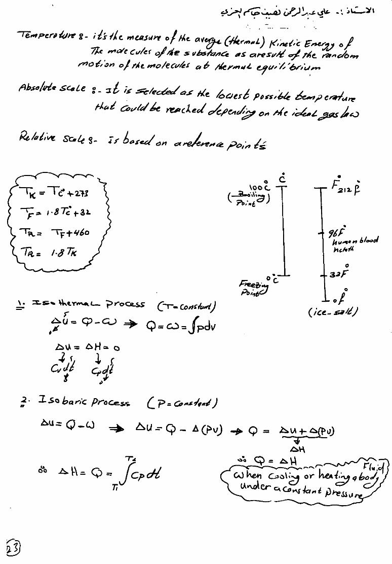
Temperature: - It’s the measure of the average (thermal) Kinetic Energy of the
molecules of the substance as a result of the random motion of the
molecules at thermal equilibrium.
Absolute scale: - It is selected as the lowest possible temperature that could be
reached depending on the ideal gas law.
Relative scale: - Is based on a reference points.

22
Dr. Ali Abdulrahman Al-Ezzi

23
Dr. Ali Abdulrahman Al-Ezzi
Systems and boundaries
Any engineering device can be denoted as a
system, separated from the rest of the universe by a
system boundary.
Interactions between the system and the rest of the
universe can be exchange of mass and/or energy.
The part of the universe that interacts with the
system is called the surroundings, or environment.
Isolated systems: no exchange of mass or energy with the surroundings
for example: thermos bottle (Dewar flask).
Closed systems: exchange of energy with the surroundings, but no exchange of
mass for example: light bulb, space station.
Open systems: exchange of energy and mass with the surroundings for example:
combustion engines, pumps, distillation columns, living organisms.
← An isolated system
is a special kind of
closed system
Q = heat W = work

24
Dr. Ali Abdulrahman Al-Ezzi
Work
Definitions
From Newtonian mechanics, we know going from state 1 to state 2, which the work
1W2 is done by a force moving through a distance. The word “work” was first used in
this sense by the French mechanician Gaspard-Gustave Coriolis
Note that we have anticipated that the work differential is inexact. This is an
important point, as work integrals will be path-dependent, and work will not be a state
variable for a system. Here, F is a three-dimensional force vector, x is a three-
dimensional distance vector, and · is the dot product operator. Recall that the dot
product of two vectors yields a scalar.
The terms F and x are scalar equivalents valid for one-dimensional systems. The units
of force are N, those of distance are m, so the units of work are N m, which have been
defined as Joules (J).
Work is done by a system if the sole effect on the surroundings (i.e. everything
external to the system) could be the raising of a weight. We take the following sign
convention:
• + work done by the system,
• − work done on the system.
This sign convention is not universal. Many physicists use precisely the opposite
convention. Probably the reason for this convention is that thermodynamics is a
science that was invented by engineers in the nineteenth century. And those engineers
wanted to produce work from steam engines. Systems doing work were viewed
favorably and endowed with a positive sign. We associate energy with the ability to
do work. We define
• Power: the time rate of doing work = δW/dt.

25
Dr. Ali Abdulrahman Al-Ezzi
• Specific work: the work per unit mass w = W/m. Because work is path-dependent,
the intensive quantity w is not a thermodynamic state variable.
Work for a simple compressible substance
Consider the scenario sketched in Fig. below In state 1, we have a material at pressure
P confined in a cylinder of cross-sectional area A. The height of the piston in the
cylinder is x. The pressure force of the material on the piston is just balanced by
weights on top of the piston.
The figure above represent sketch of piston-cylinder arrangement as work is done as
the material expands when weights are removed.
Now, remove one of the weights. We notice a motion of the piston to a new
height x+dx.We let a long time elapse so the system comes to rest at its new
equilibrium. We notice there is a new pressure in the chamber, P + dP sufficient to
balance the new weight force. Obviously work was done as a force acted through a
distance. Let us calculate how much work was done. The differential work is given
from this Eq
δW = Fdx.
Now, F varies during the process. At state 1, we have F = PA. At state 2, we
have F = (P + dP)A. Let us approximate F by its average value:

26
Dr. Ali Abdulrahman Al-Ezzi
Let us only retain terms which are differential and neglect the square of differential
terms, so δW = PAdx.
Now, since Adx = dV, the differential volume, we get the important formula:
δW = PdV.
We can integrate this and get the equally important
Note we employ the unusual notation 1W2 to emphasize that the work
depends on the path from state 1 to state 2. We are tempted to write the incorrect form
R 2 1 δW = W2 −W1, but this would imply the work is a state function, which it is
not, as shown directly.
EXAMPLE
An ideal gas undergoes a two-step process. Beginning at state 1, it is
isothermally compressed to state 2. Then it is isobaric ally compressed to state 3. Find
the work. The process is sketched in Fig. below
The figure represents Sketch of two-step, isothermal-isobaric, compression of an ideal
gas.

27
Dr. Ali Abdulrahman Al-Ezzi
Note that 1W3 < 0, since V2 < V1 and V3 < V2. So work is done on the system in
compressing it. Note also that even though we do not know T, we can solve the
problem. This is because work only requires information about the P-V state of the
system and the nature of the process.
Heat
Let us make the following definition:
• Heat: a form of energy transferred across the boundary of a system at a given
temperature to another system (or the surroundings) at a different temperature by
virtue of the temperature difference between the two.
We adopt the notion that bodies do not contain heat, but that heat only has relevance
as a type of energy that crosses system boundaries. Note that work is in a similar
class; it is not contained within a system, but can be identified when it crosses system
boundaries. We will make a distinction between heat and work energy transfers.
We also note that when two bodies are at the same temperature, there can be no heat
transferred between the two bodies. The subject of heat transfer considers the details
of the heat transfer process. There are three fundamental classes of heat transfer:
• heat diffusion, also called conduction. Physically this is due to local effects. Bacon
is fried via conduction effects as a culinary example.
This is characterized by Fourier’s law
q = −k∇T,

28
Dr. Ali Abdulrahman Al-Ezzi
where q is the heat flux vector with units J/s/m2 = W/m2, k is the thermal
conductivity with units J/s/m/K = W/m/K, and ∇T is the vector representing the
gradient of temperature. Recall that ∇T is a vector pointing in the direction in which T
rises most rapidly. Because of the minus sign, we see then that the thermal energy
flows in the direction of most rapid temperature decrease. This law was developed by
Joseph Fourier, who built an elegant and correct theory of a special case of non-
equilibrium thermodynamics before the laws of equilibrium thermodynamics were
formulated, let alone fully understood.
In one dimension, we get
If we multiply by the local cross-sectional area, we find ˙Q = qA, and
Here, ˙Q has units J/s or W (Watts).
• convection. This is actually a version of conduction, albeit enhanced by fluid flow.
For some systems, convective effects are well modeled by Newton’s law of cooling :
Here, σ is the Stefan-Boltzmann constant, σ = 5.67 × 10⁻⁸ W/m2/K4.
We adopt the traditional engineering sign convention for heat:
• + heat enters the system,
• - heat leaves the system.
The sign convention again is motivated by nineteenth century steam engines. Heat
had to be added into a system to get work out of the system. Since engineers were and
are concerned with this problem, this convention is taken.

29
Dr. Ali Abdulrahman Al-Ezzi
Energy Balance on Closed System
For a closed system, the energy balance relates two states of the
system, an initial state and a final state. The changes in energy between
initial and final states of the system are brought about by additions of
energy through heat (Qin) and additions of energy through work done on
the system (Won).
in

30
Dr. Ali Abdulrahman Al-Ezzi
Energy Balance on open System
A mole balance can be written as the following
for a nonreacting system at steady-state,
Flow work is the work the inlet fluid
must do on the system to displace fluid within

31
Dr. Ali Abdulrahman Al-Ezzi

32
Dr. Ali Abdulrahman Al-Ezzi
Summary of Calculating First Law Quantities at Steady-State when Shaft-
Work, Kinetic Energy, and Potential Energy are ignored for an Ideal Gas

33
Dr. Ali Abdulrahman Al-Ezzi

34
Dr. Ali Abdulrahman Al-Ezzi
Mechanical Energy Balance and the Bernoulli Equation
The general energy balance derived previously can be recast into a
“mechanical energy balance.” The mechanical energy balance is most
useful for processes in which changes in the potential and kinetic energies
are of primary interest, rather than changes in internal energy or heat
associated with the process. Thus the mechanical energy balance is
mainly used for purely-mechanical flow problems -i.e. problems in which
heat transfer, chemical reactions, or phase changes are not present. We
start from equation 1, in which we have reverted from specific enthalpy
notation back to internal energy and PV work using H j ˆ = U j ˆ + Pj V j ˆ
..(1)
Now we make several additional assumptions. First, we assume steady
state, so that all terms on the left hand side become zero. Second, we
assume that the system has only a single inlet and a single outlet.
Moreover, steady state implies that the inlet mass flowrate must equal the
outlet mass flowrate, in order to avoid accumulation of material in the
system. These adjustments lead to
..(2)
In the above equation, subscript "in" refers to the inlet port, and
subscript "out" to the outlet port. Next, we divide the entire equation by
m&, and write specific volume (volume/mass) as Vˆ = 1/, where is the
density (mass/volume) of the flowing material. Moreover, we assume that
the flow is incompressible, so that density is constant. A constant density

35
Dr. Ali Abdulrahman Al-Ezzi
means that Vˆ in = Vˆ out = 1/. Also, we define U ˆ = U ˆout - U ˆ in, P =
Pout - Pin, etc. With these changes, equation 2 becomes
…….(3)
The term (DUˆ −Q/m ) – in the absence of chemical reactions, phase
changes, or other sources of large amounts of heat transfer; i.e. under
typical conditions of usage for the mechanical balance equation – will
mostly represent heat generated due to the viscous friction in the fluid. In
such situations, this term is called the friction loss and we will write it as
F ˆ. With this last change, equation 3 assumes the usual form of the
mechanical energy balance
……(4)
Note that WS/m is the shaft work performed by the system on the
surroundings, per unit mass of material passing through the system.
In many instances, the amount of energy lost to viscous dissipation
in the fluid is small compared to magnitudes of the other terms in
equation 4. In such a case, F ˆ = 0. Moreover, many common flows (e.g.
fluid flow through a pipe; what is the system in this case?) do not have
any appreciable shaft work associated with them, so that _WS/m=0 for
such inviscid (i.e. frictionless) flows with no shaft work, the mechanical
energy balance simplifies to Bernoulli’s equation:
The formal derivation holds that in steady flow the sum of the kinetic,
potential, and flow energies of a fluid particle is constant along a
streamline, when compressibility and frictional effects can be neglected.
Also: total pressure along a streamline is constant.

36
Dr. Ali Abdulrahman Al-Ezzi
Bernoulli’s equation has a wide range of application, despite its
simplifying assumptions.
Fluid Flow in Pipes
We will be looking here at the flow of real fluid in pipes – real
meaning a fluid that possesses viscosity hence loses energy due to friction
as fluid particles interact with one another and the pipe wall.
The shear stress induced in a fluid flowing near a boundary is
given by Newton's law of viscosity:
𝜏∝ du /dy
This tells us that the shear stress, τ, in a fluid is proportional to the
velocity gradient - the rate of change of velocity across the fluid path. For
a “Newtonian” fluid we can write:
𝜏 = μ du/dy
Where the constant of proportionality, μ, is known as the coefficient of
viscosity (or simply viscosity).
Recall also that flow can be classified into one of two types, laminar or
turbulent flow (with a small transitional region between these two). The
non-dimensional number, the Reynolds number, Re, is used to determine
which type of flow occurs:
Re = ρ u d /μ
For a pipe
Laminar flow: Re < 2000
Transitional flow: 2000 < Re < 4000
Turbulent flow: Re > 4000

37
Dr. Ali Abdulrahman Al-Ezzi
It is important to determine the flow type as this governs how the amount
of energy lost to friction relates to the velocity of the flow. And hence
how much energy must be used to move the fluid.
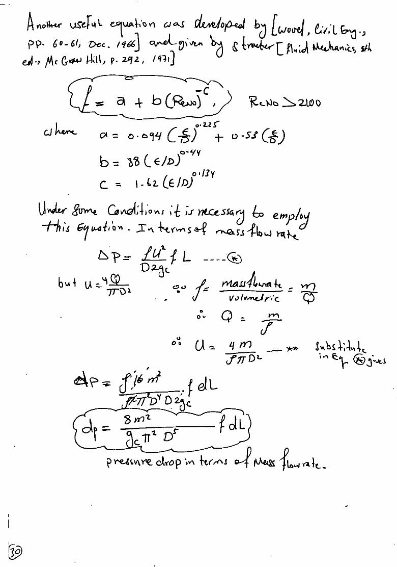
Q: - Derive Darcy or Weisbach Equation
Q: - Derive General Equation for head loss in pipe due to friction
Q: - Derive an Equation for pressure drop along circular pipe
Consider a cylindrical element of incompressible fluid flowing in the
Figure: Element of fluid in a pipe
The pressure at the upstream end, 1, is p, and at the downstream
end, 2, the pressure has fallen by Δp to (p-Δp).
The driving force due to pressure (F = Pressure x Area) can then be
written driving:
Force = Pressure force at 1 - pressure force at 2
𝑝𝐴 − (𝑝 − 𝛥𝑝)𝐴 = 𝛥𝑝𝐴 = 𝛥𝑝 ×𝜋𝑑2
4
The retarding force is that due to the shear stress by the walls
= shear stress × area over which it acts
= τw × area of pipe wall
= τw π dL
As the flow is in equilibrium,
𝝉𝒘 𝝉𝒘
dL
P1 FLUID
U average velocity
P2 Direction of
flow

38
Dr. Ali Abdulrahman Al-Ezzi
driving force = retarding force
𝛥𝑝 ×𝝅𝒅𝟐
𝟒 = τw π dL
𝛥𝑝 =𝟒𝜏𝑤 𝑳
𝒅………………… (1)
This equation (1) giving an expression for pressure loss in a pipe in terms
of the pipe diameter and the shear stress at the wall on the pipe.
𝛥𝑝 =𝟒𝜏𝑤 𝑳
𝒅 Multiply and divided
𝝆𝑼𝟐/𝟐
𝝆𝑼𝟐/𝟐
𝛥𝑝 =𝟖𝝉𝒘
𝝆𝑼𝟐 ×𝑳
𝑫×
𝝆𝑼𝟐
𝟐
𝛥𝑝 = 𝟖𝒋𝑭 ×𝑳
𝑫×
𝝆𝑼𝟐
𝟐
𝒋𝑭 𝑴𝒐𝒅𝒂𝒚 𝒇𝒓𝒂𝒄𝒕𝒊𝒐𝒏 𝒇𝒂𝒄𝒕𝒐𝒓 =𝟏
𝟐𝒇(𝒇𝒂𝒏𝒏𝒊𝒏𝒈 𝒇𝒓𝒂𝒄𝒕𝒊𝒐𝒏,𝐃𝐚𝐫𝐜𝐲−𝐖𝐞𝐢𝐬𝐛𝐚𝐜𝐡 =
𝝉𝒘
𝝆𝑼𝟐
𝛥𝑝 = 𝟒𝒇 ×𝑳
𝑫×
𝝆𝑼𝟐
𝟐
but 𝛥𝑝 = 𝝆 × 𝑔 × Δℎ
𝛥ℎ = 𝟒𝒇 ×𝑳
𝑫×
𝑼𝟐
𝟐𝒈
𝛥𝑝 = 𝟒𝒇 ×𝑳
𝑫×
𝝆𝑼𝟐
𝟐𝒈𝒄
SI readers may ignore gc in all equations,
if they wish.

39
Dr. Ali Abdulrahman Al-Ezzi
When a fluid flows in a pipe, some of its mechanical energy is
dissipated by friction. The ratio of this frictional loss to the
kinetic energy of the flowing fluid is defined as the Fanning
friction factor, ft. Thus
For flow through noncircular
pipes, the Reynolds number is based on the hydraulic
diameter

40
Dr. Ali Abdulrahman Al-Ezzi
Table: Flow Quantities, Reynolds Number, and Friction
Factor

41
Dr. Ali Abdulrahman Al-Ezzi
Fig.1 This figure is useful for finding the pumping requirement or
frictional loss when you are given the flow rate of fluid in a pipe
(Adapted from Moody (1944)) or given d and u, find Ws or Δp

42
Dr. Ali Abdulrahman Al-Ezzi
Fig.2 This figure is useful for finding the flow rate when you are
given the driving force for flow (gravitational head, pumping energy
input, etc.) (Adapted from H. Rouse; see discussion after Moody
(1944)) or given d and Δp or Ws, find u
The pipe roughness, needed in these charts, is given in Table below
for various common pipe materials.
Table : Roughness of clean pipe

43
Dr. Ali Abdulrahman Al-Ezzi
Fig. Development of the mechanical energy balance for flow in pipes
For laminar flow (Re<2,100), the friction factor and the frictional
loss can be found either from Fig. 1 or 2 or from the following simple
theoretical expressions derived by Poiseuille:
Two different friction factors are in common use today:
(i) fF, the Fanning friction factor
(ii) fD, the Darcy friction factor

44
Dr. Ali Abdulrahman Al-Ezzi
For the range of flows from Re=4,000 to 10
8, these expressions were
cleverly combined by Colebrook (1939) to give
The above expressions reduce to a number of special cases. Thus for fully
developed turbulence in rough pipes, where fF is independent of Re,
equations above becomes
Piping systems have contractions, expansions, valves, elbows, and all
sorts of fittings. Each has its own particular frictional loss. A convenient
way to account for this is to put this loss in terms of an equivalent length
45
Dr. Ali Abdulrahman Al-Ezzi
of straight pipe. Thus, the equivalent length of a piping system as a whole
is given by
In turbulent flow the equivalent lengths of pipe fittings are independent of
the Reynolds number, and Table below shows these values for various
fittings. Unfortunately, in laminar flow the equivalent length varies
strongly with the Reynolds number is distinctive for each fitting. Thus,
simple generalizations such as Table below cannot be prepared for the
laminar flow regime.
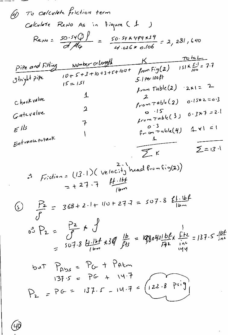
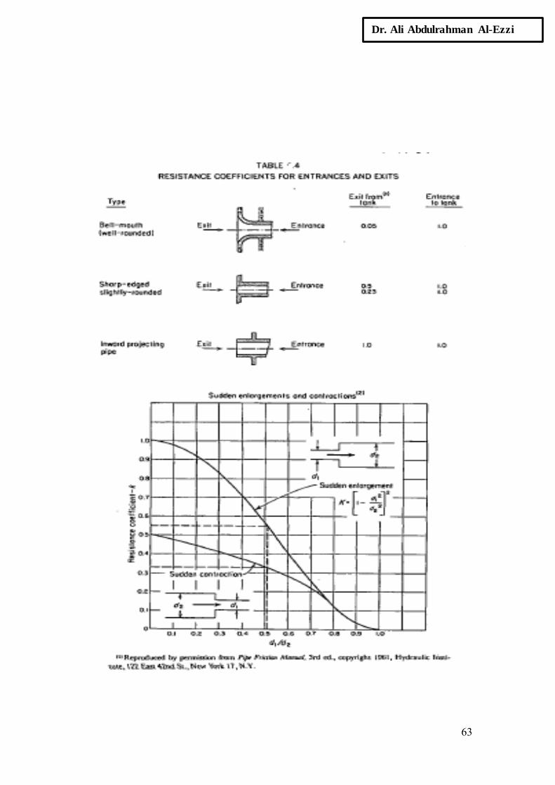
FITTINGS AND VALVES
Friction due to fittings, valves and other disturbances of flow in pipe
line is accounted for by the concepts of either their equivalent lengths of
pipe or multiples of the velocity head. Accordingly, the pressure drop
equation assumes either of the forms
Values of equivalent lengths Li and coefficients K, are given in Table
below. Another well-documented table of Ki is in the Chemical
Engineering Handbook (McGraw-Hill, New York, 1984 p. 5.38).
Comparing the two kinds of parameters,
O R I F I C E S
In pipe lines, orifices are used primarily for measuring flow rates but
sometimes as mixing devices. The volumetric flow rate through a thin
plate orifice is

46
Dr. Ali Abdulrahman Al-Ezzi
TABLE: Equivalent pipe length for various pipe fittings (turbulent flow only)
Pressure Drop in Non isothermal Liquid Flow
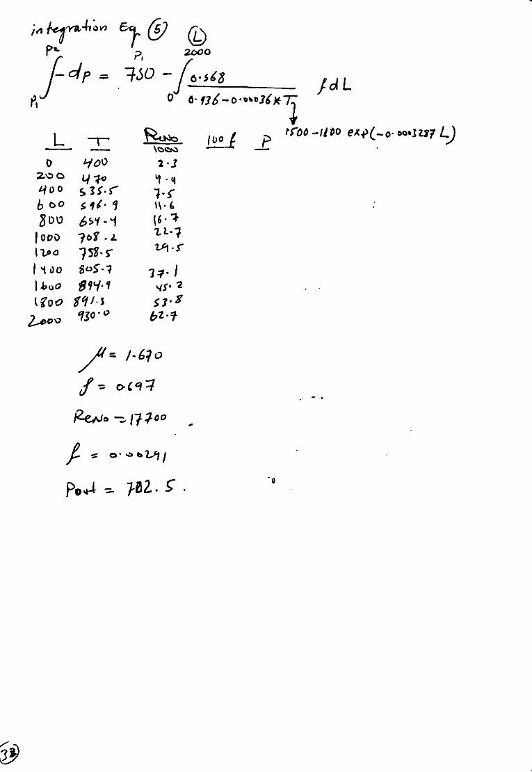
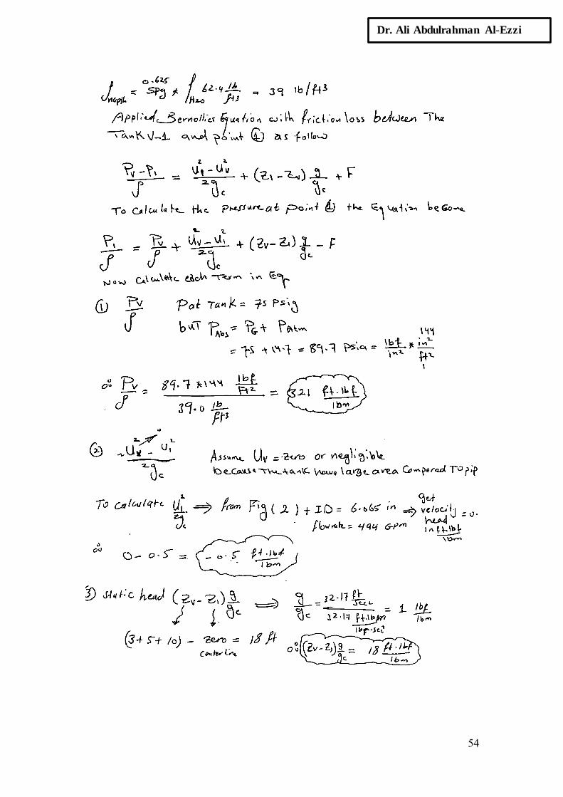
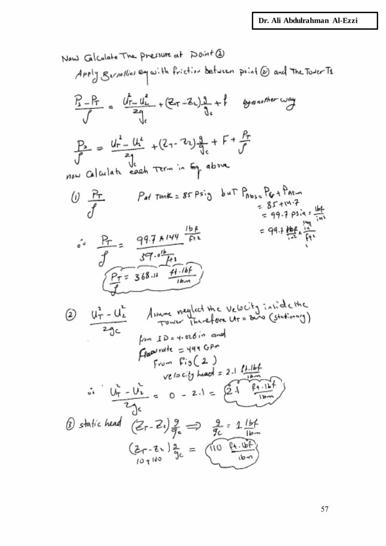
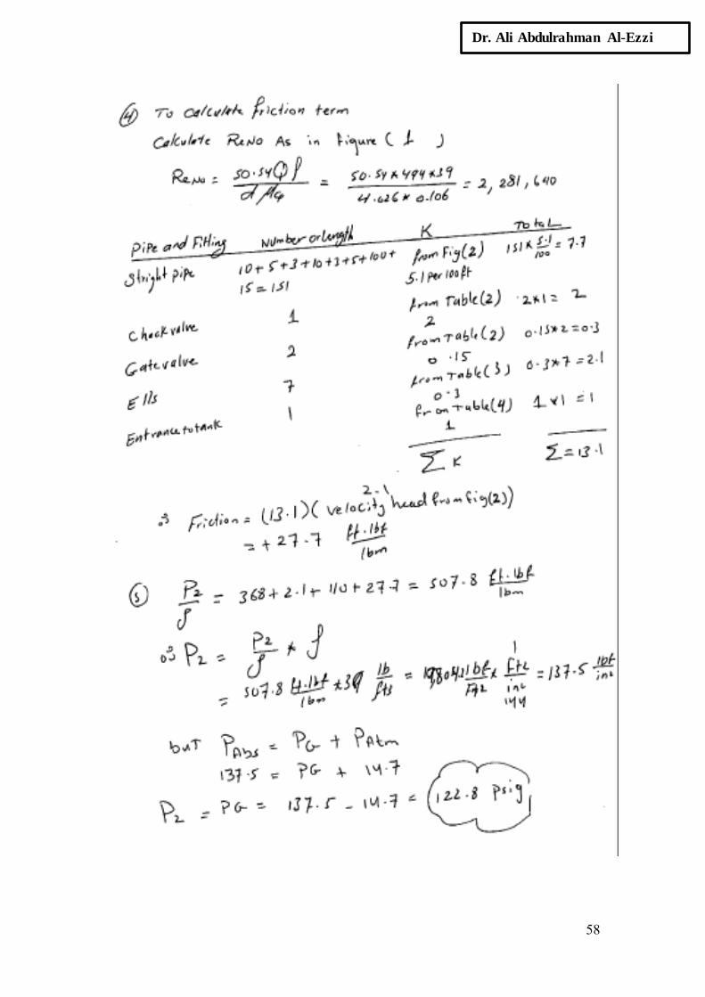
EXAMPLE: Oil is pumped at the rate of 6000 lb/hr through a reactor
made of commercial steel pipe 1.278in. ID and 2000ft long. The inlet
condition is 400°F and 750psia. The temperature of the outlet is 930°F
and the pressure is to be found. The temperature varies with the distance,
L ft, along the reactor according to the equation
T = 1500 - 1100 exp (-0.0003287L) (oF) ……… (1)
The viscosity and density vary with temperature according to the equations
…… (2)
…… (3)

47
Dr. Ali Abdulrahman Al-Ezzi

48
Dr. Ali Abdulrahman Al-Ezzi

49
Dr. Ali Abdulrahman Al-Ezzi

50
Dr. Ali Abdulrahman Al-Ezzi

51
Dr. Ali Abdulrahman Al-Ezzi

52
Dr. Ali Abdulrahman Al-Ezzi

53
Dr. Ali Abdulrahman Al-Ezzi
54
Dr. Ali Abdulrahman Al-Ezzi

55
Dr. Ali Abdulrahman Al-Ezzi

56
Dr. Ali Abdulrahman Al-Ezzi
57
Dr. Ali Abdulrahman Al-Ezzi
58
Dr. Ali Abdulrahman Al-Ezzi

59
Dr. Ali Abdulrahman Al-Ezzi

60
Dr. Ali Abdulrahman Al-Ezzi
TABLE 2

61
Dr. Ali Abdulrahman Al-Ezzi

62
Dr. Ali Abdulrahman Al-Ezzi
63
Dr. Ali Abdulrahman Al-Ezzi

64
Dr. Ali Abdulrahman Al-Ezzi

65
Dr. Ali Abdulrahman Al-Ezzi
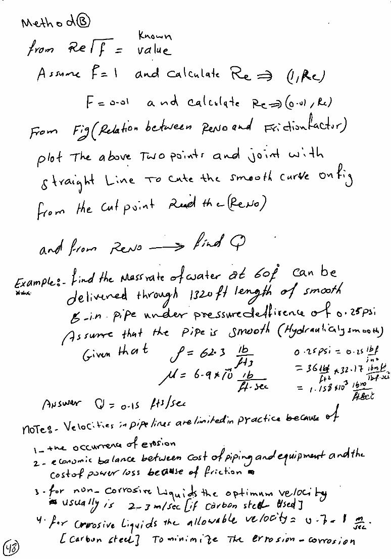
EXAMPLE: Find the mass rate of water at 60 0F can be delivered
through 1320 ft length of smooth 6-in pipe under pressure
deference of 0.25 psi. Assume that the pipe is smooth (Hydraulically smooth).
Given that 𝜌 = 62.4 lb/ft3
,
µ = 6.9× 10⁻⁴
lb/ft.sec,
0.25 psi = 025 lbf/in2= 36 lbf/ft
2×32.17 lbm.ft/lbf.sec
2 = 1.158×10
3
lbm/ft.sec2

66
Dr. Ali Abdulrahman Al-Ezzi
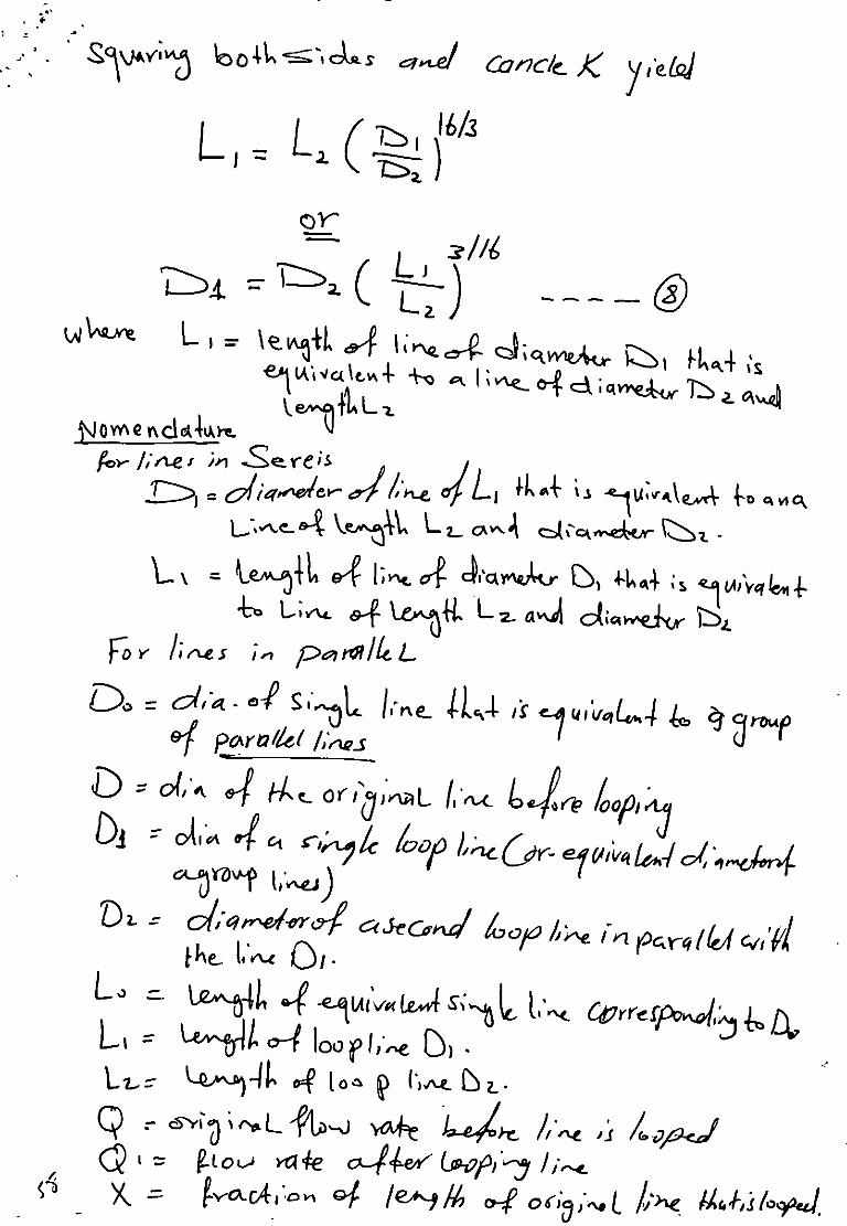
A more flexible and convenient solution is afforded by determining a
single-diameter line that is equivalent to the system shown. From the
equation of
𝛥𝑝 = 𝟐𝒇 ×𝑳
𝒅×
𝝆𝑼𝟐
𝒈𝒄
But 𝑣 = 𝑄/𝝅𝒅𝟐
𝟒 = 4𝑄/𝜋𝑑2 substitute the value of velocity in above
𝜟𝒑 = 𝟐𝒇 ×𝑳
𝒅×
𝝆𝟏𝟔𝑸𝟐
𝒅𝟒𝝅𝟐𝒈𝒄 = 𝒇 ×
𝑳
𝒅𝟓×
𝟑𝟐𝑸𝟐𝝆
𝝅𝟐𝒈𝒄
Another form
𝜟𝒑𝒇 = 𝑪× 𝑳
𝒅𝟓 Where C = 𝟑𝟐𝑸𝟐𝝆
𝝅𝟐𝒈𝒄
𝜟𝒑𝑭𝑨− = C ×
𝑳−
𝒅𝑨𝟓 = 𝜟𝒑𝒇𝑩= C ×
𝑳
𝒅𝑩𝟓

67
Dr. Ali Abdulrahman Al-Ezzi
Where 𝑳−= length of line of diameter dA that will give the same friction
loss as LB feet of line dB.
The term C could be taken constant if diameter difference is not large
(Since same fluid and f function of d).
Diameter exponent of 4.828 should be used instead of 5 highest precision
Now if constants are canceled from equation and rearranged it
𝑳− = 𝐿𝑒 = 𝐿𝐵 {𝑑𝐴
𝑑𝐵}
5
If 𝑑𝑒 is defined as the diameter of line of length 𝐿𝐴 that will give the
same friction loss as 𝐿𝐵 feet of line𝑑𝐵. The above equation may be
rearranged to yield
𝒅𝒆 = 𝒅𝑩 {𝑳𝑨
𝑳𝑩}
𝟏/𝟓
When 𝐿𝑒 is calculated the system become: equivalent total length
𝐿𝐵+ 𝐿𝐴 with diameter 𝑑𝐴 then the 𝜟𝒑𝒇 of the system could be calculated.

68
Dr. Ali Abdulrahman Al-Ezzi
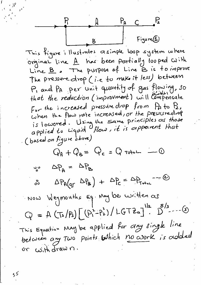
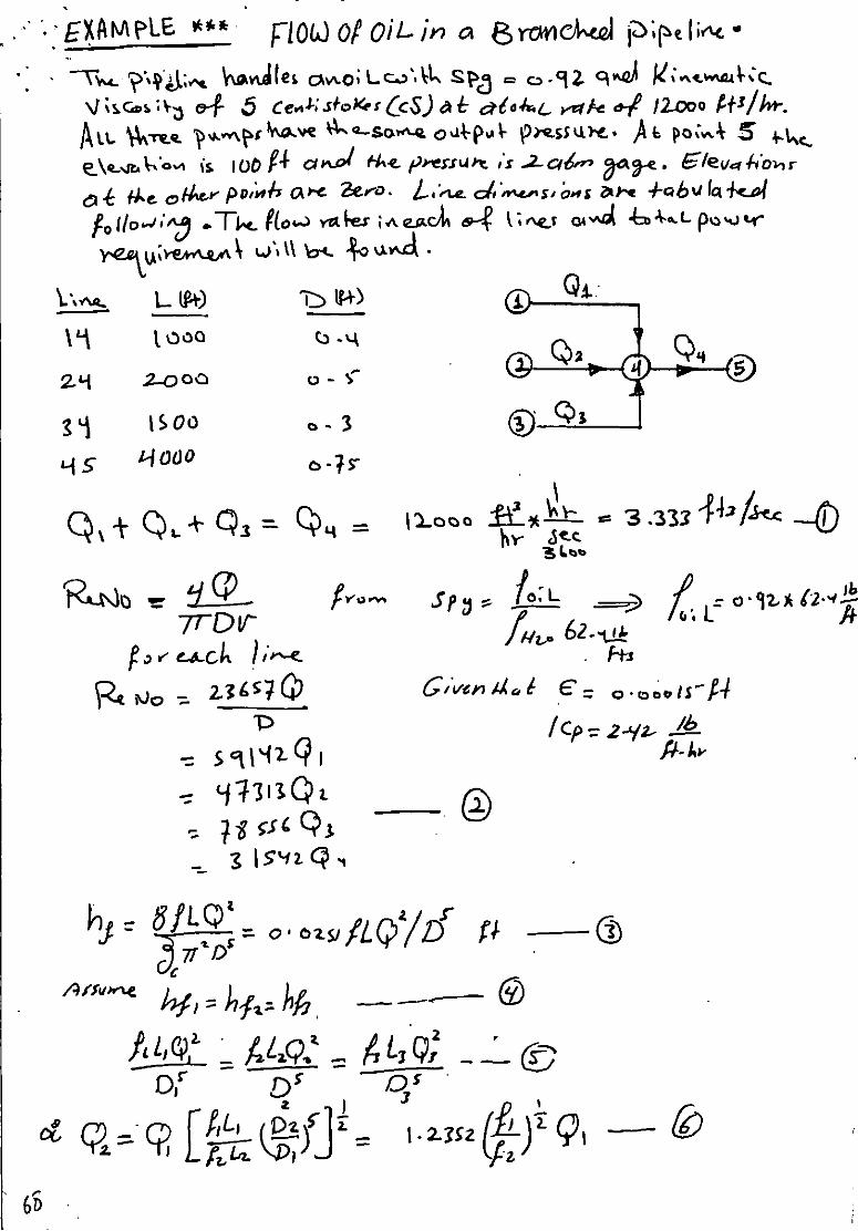
EXAMPLE:
Therefore, the system shown may be considered as equivalent to one
consisting of 1423 m of 10 cm pipe.

69
Dr. Ali Abdulrahman Al-Ezzi