iicl tb 007 april 2012 · 2019-03-22 · a second, but less common, repair involves cutting relief...
TRANSCRIPT

IICL TB 007, 5 April 2012
Title: LIMITATIONS ON CROSSMEMBER REPAIRS
Reference IICL “Repair Manual for Steel Freight Containers (fifth edition)
Section 8.2.3 Crossmember Inserting
Section 8.4.3 Forklift Pocket Side Inserting
The IICL has revised its criteria for crossmember / forklift pocket side wall) inserting as
outlined below:
Revised Criteria Weld repairs to members (crossmember / forklift pocket side wall) are not allowed within the
center one half of two adjacent members. The center one half of a member is defined as that
part of the member that is greater than 600mm from the nearest bottom side rail. If two
adjacent members have weld repairs within the center halves, either one of the members must
either be replaced or the inserts must be lengthened such that they do not terminate within
the center half of the member.

BACKGROUND
The IICL has recently become aware of weld cracking in two repair techniques used to
repair downward bowed members.
The most common repair involves the installation of a series of inserts at or near the
centers of several adjacent members. The vertical welds—located near the members
centers in the area of maximum bending stress and subject to the residual tension
resulting from jacking the member’s straight prior to installing the inserts—may have
been, in a few cases, below IICL standards.
If the sub standard weld pulls apart, the floor load is passed to the adjacent member, and
the adjacent insert welds may also pull apart, resulting in a series of weld failures until all
inserted members have pulled apart.
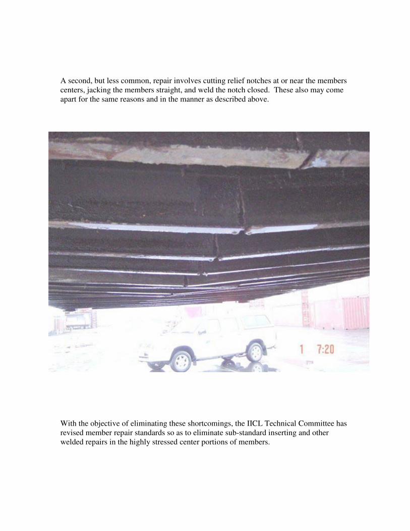
A second, but less common, repair involves cutting relief notches at or near the members
centers, jacking the members straight, and weld the notch closed. These also may come
apart for the same reasons and in the manner as described above.
With the objective of eliminating these shortcomings, the IICL Technical Committee has
revised member repair standards so as to eliminate sub-standard inserting and other
welded repairs in the highly stressed center portions of members.

EXAMPLES
In addition to above real life photographs, please also find related examples and
explanations below, for a clearer understanding of this technical bulletin.
NOT ACCEPTABLE
NOT ACCEPTABLE
The insert on the right side is acceptable because it
is the 1st crossmember with an insert. But the 2
nd
insert on the left is not acceptable because the weld
seam terminates in the center half of the container.
NOT ACCEPTABLE
The insert on the right side is acceptable because it
is the 1st crossmember with an insert. The 2
nd insert
on the left is not acceptable because the weld seams
terminate in the center half of the container.
ACCEPTABLE
ACCEPTABLE
The insert on the right side is acceptable because it
is the 1st crossmember with an insert. The 2
nd insert
on the left is also acceptable because the weld
seams terminate within 600mm from the bottom
side rail.
ACCEPTABLE
The insert on the right side is acceptable because it
is the 1st crossmember with an insert. The 2
nd insert
on the left is also acceptable because the weld
seams terminate within 600mm from the bottom
side rail.
ACCEPTABLE
The insert on the right side is acceptable because it
is the 1st crossmember with an insert. The 2
nd insert
on the left is also acceptable because the weld
seams terminate within 600mm from the bottom
side rails.
ACCEPTABLE
The insert on the right side is acceptable because it
is the 1st crossmember with an insert. The 2
nd cross
member is also acceptable because it is actually a
full replacement.

FULL CONTAINER EXAMPLE
AN EXAMPLE of new damage locations and pre-existing inserts.
Acceptable inserts based on new damage locations and pre-existing inserts, as shown
above. It is important to note that this is one EXAMPLE of a possible combination of
damage and acceptable repair inserts. There may be many different possibilities. This
drawing should only be used as a guide to determine the safest and most economical type
of repair on a case by case basis.
In addition to the above limitation requirements and illustrations for weld repairs to
ADJACENT members, crossmember and forklift pocket inserting to also continue to
follow other insert repair instructions per paragraph 8.2.3 and 8.4.3, IICL Repair Manual
for Steel Freight Containers, 5th
edition.
IICL TB 007 was prepared under the supervision of the IICL Technology Committee.