ii struers - labmakelaarcording to the knuth-rotor principle screws on the underside of the...
TRANSCRIPT
~DAP ' App. NO.: '10'1 / ~ 0 0 1
Voltage: ..2..20 -.2'10/6-0-' 0
1991.05
Grinding and Polishing MachinesInstruction Manual
rr Sch(eif- und PoliermaschinenGebrauchsanweisung
I' Machines de prepolissage et polissageMode d'emploi
!,"
,,
II Struers

CAP 1. DESCRIPTIONInstruction Manual
In technical enquiries and in orders 2. TECHNICAL DATAfor spare parts, please state app. No.and voltage (see cover).
All . f . " 3. INSTALLATIONIn ormation and data In this In-
struction Manual were valid when itwas printed. The Struers policy 3.1 Contents of packing casebeing, however. to make current im- 3.2 Connection to water (not DAP-6)provements of our products, we 3.3 Connection to the mainsreserve ourselves the right to modifyour products without notice. Besides,~e ask you to note that this Instruc- 4. OPERA TIONtlOn Manual concerns apparatus andall a~essories. Consequently, it mayhappen that the Manual mentionsequipment which is not of relevance 5. ACCESSORIESfor your purpose at the present time.
6. MAINTENANCE
7. SPARE PART LIST
Struers TechVaJh0js AIle 176DK-261 0 R0dovre/CopenhagenDenmark
Telephone +45 31 708090Telex 19625Telefax +45 31 41 6544
Struers Techis 8 division of Struers A/S

~1. DESCRIPTION 2. TECHNICAL DATA
DAP is a complete programme of reI a- Motor: Single phasetively ~m~l motor-driven ~achines ~or Voltage, frequencywet grIn~In~ and for alumIna ,and dIa- DAP-7 and DAP-8:lTI,ond POIIshI.ng of ~etallogra~hIc, cera- 110 V, 50 HzmiC .and mIneralogIcal specImens. All 115 V, 60 HzmachInes m~y be, u~ed for both manual 220-240 V, 50 Hzand automatIc polIshIng. 220 V, 60 Hz
A DAP machine consists of a circular DAP-V and DAP-6:tu~nt~ble on. which can b,e ,moun:ed 110-115 V, 50-60 HzgrInding, lappIng and/or polIshIng dISCS 220-240 V 50-60 Hzof diameters up to 250 mm. The turn- ,table is supported by precision ball bear- Output:ings and driven by an electric motor via DAP-7: 30/50 Wa belt drive which ensures uniform and DAP-8: 80/120 Wsilent running. DAP-6: 120 W
DAP-V: 180 WThe motor and the turntable are mount-ed on sturdy bearing plates which are Rotational speeds:clamped in the lower cabinet. Spillpan DAP-6: 250 rpmand outlet are incorporated in the upper DAP-7: 125/250 rpmcabinet-unit on which are also mounted DAP-8: 300/600 rpmwater tap and nozzle (except for DAP-V: 40-600 rpm (stepless)DAP-6). The left side of the control Maximal diameter of polishing/grindingpa~el of ~AP-7 and D.A~-8 has a rotary disc: 250 mmswItch wIth three posItIons for off, lowspeed and high speed. Having just one Recommanded diameter of the grinding-speed, DAP-6 is only provided with an and polishing discs: 200 mmon/off switch. DAP-V has a turnbutton Dimensions.fo~ preselectio~ 0: speed, an ON/OFF Width 350 ~m, Depth 590 mm,swItch and an IndJcator for control of Height 245 mmthe speed. The servo-controlled motorensures constant speed at all loads. Weight:
DAP-6: 14 kgOn DAP-6, D~P-7, DAP-8 and DAP-V, a DAP-7: 16 kgthermo-f,use I~ mounted on the fro~t DAP-8: 16 kgplate WhICh swItches off the apparatus In DAP-V: 17 kgcase of overload.
3
-

3. INST ALLA TION DAP-V:
3.1 Contents of packing case 1 DAP-V
DAP-6: 1 cover
1 DAP-6 1 splash ring, 210 mm dia.
1 cover 1 splash ring, 240 mm dia.
1 splash ring, 210 mm dia. 1 drain hose 111 x 1,5 m
1 splash ring, 240 mm dia. 1 drain elbow pipe
1 drain hose I" x 1,5 m 3 hose clips 20-32 mm
1 drain elbow pipe 1 hose connection
3 hose clips 20-32 mm 1 coupling nut
1 Allen key (4 mm) 1 gasket
1 hose clip 13 mmDAP-?:
1 Allen key (4 mm)1 DAP-71 cover 3.2 Connection to water (not DAP-6) t1 splash rin 210 mm dia. Place t~e machine close t~ water outlet '
g, and draIn. Connect the thIn hose to the1 splash ring, 240 mm dia. water outlet and fit it with the 13 mm1 d . h 1" 1 5 hose clip. If not present already, theraIn ose x, m h . . h k d .ose connection WIt gas et an coupling1 drain elbow pipe nut supplied with the machine may be
, 3 hose clips 20-32 mm mounted on the .water outlet (t" pipeI thread, BS 2779:62), I! 1 hose connection ..'"
I Lead the thIck hose to draIn and be1 coupling nut absolutely sure to place the hose with a1 gasket steady downward slope to prevent the
water from being discharged too slowly1 hose clip 13 mm which may cause overflow or blocking of1 Allen key (4 mm) the water outlet.
In order to avoid elbows on the tubing,DAP-8: the enclosed elbow pipe can be mounted1 DAP-8 on the tubing in an appropriate place.
1 cover 3 3 C . h .. onnectlon to t e mams1 splash ring 210 mm dia. ., Mount a plug on the electrIc cable, con-I splash ring, 240 mm dia. necting it as follows:
; 1 drain hose 1" X 1,5 m yellow / green lead to earth1 d . Ib . blue lead to neutral
raIn e ow pIpebrown lead to phase
3 hose clips 20-32 mm (blue and brown lead are freely mter-1 hose connection changeable).1 cou lin nut Before connectin~ the machine, check
p g that the local maIns voltage corresponds1 gasket to the voltage stated on the machine1 hose clip 13 mm type plate.
: 1 Allen key (4 mm)
~1 !! !i ,
~4

@4. OPERA nON 6. MAINTENANCE
To start DAP-7 and DAP-8 turn the The DAP-machines are designed androtary switch one or two steps, cor res- constructed for many years of trouble-ponding to low or high speed. free running without much attention toDAP-6 is started by means of the their function as all bearings are sealedON/OFF switch. and no further lubrication is needed.
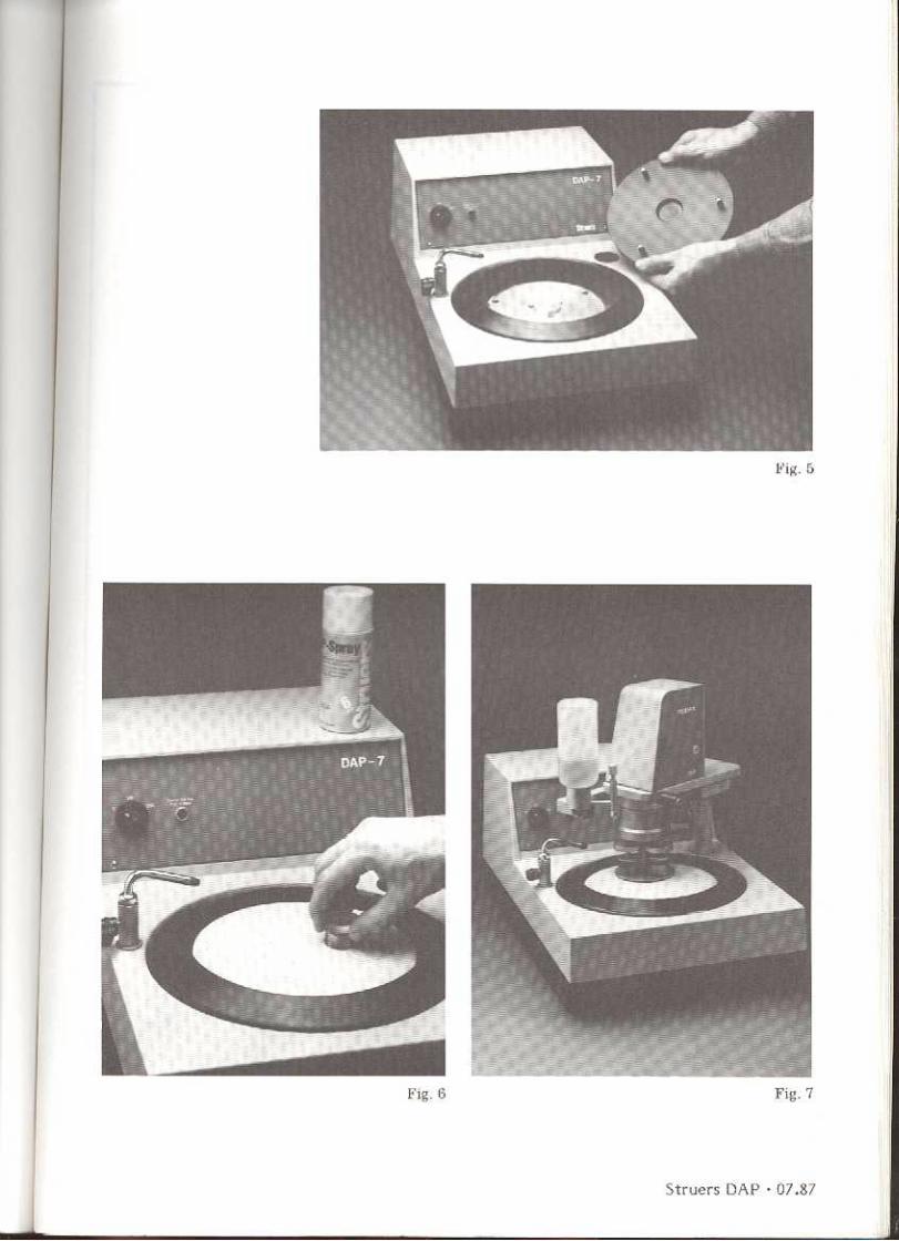
Thus maintenance will generally be li-DAP-V is started by preadjustment of mited to cleaning the exterior of thethe speed by setting the ~urn button and machines, the spill pan and the drainthen turn the ON/OFF swItch to ON. The hose. Where the machines are used, say,speed can be fine-adjusted accordin? ~o for alumina polishing or SiC lapping thethe tachometer. At start and stop It IS spill pan should be kept clean so as tonot necessary to operate the speed prevent the suspension from drying andselector if the speed has not to be thus blocking the hose. To avoid erraticchanged. movement the contact surface betweenThe grinding, lapping or polishing disc is disc and turntable should be kept clean.mounted on the turntable by inserting .the three pins of the disc in the cor res- Generaly Cleaningponding holes in the turntable (fig. 5). The best way to clean the machine is toBefore mounting the disc, make sure use ordinary soapy water with subsequentthat the contact surface are clean and wiping off.smooth. ,
Note: Never use solvents (for Inst.Now the machine is ready for use (fig. Xylene)~y kind.6).
The belt may need tightening from timeto time, the transmission being less effi-
,. ACCESSORIES cient with inadequate belt tension. Inorder to tighten (or to replace) the belt,
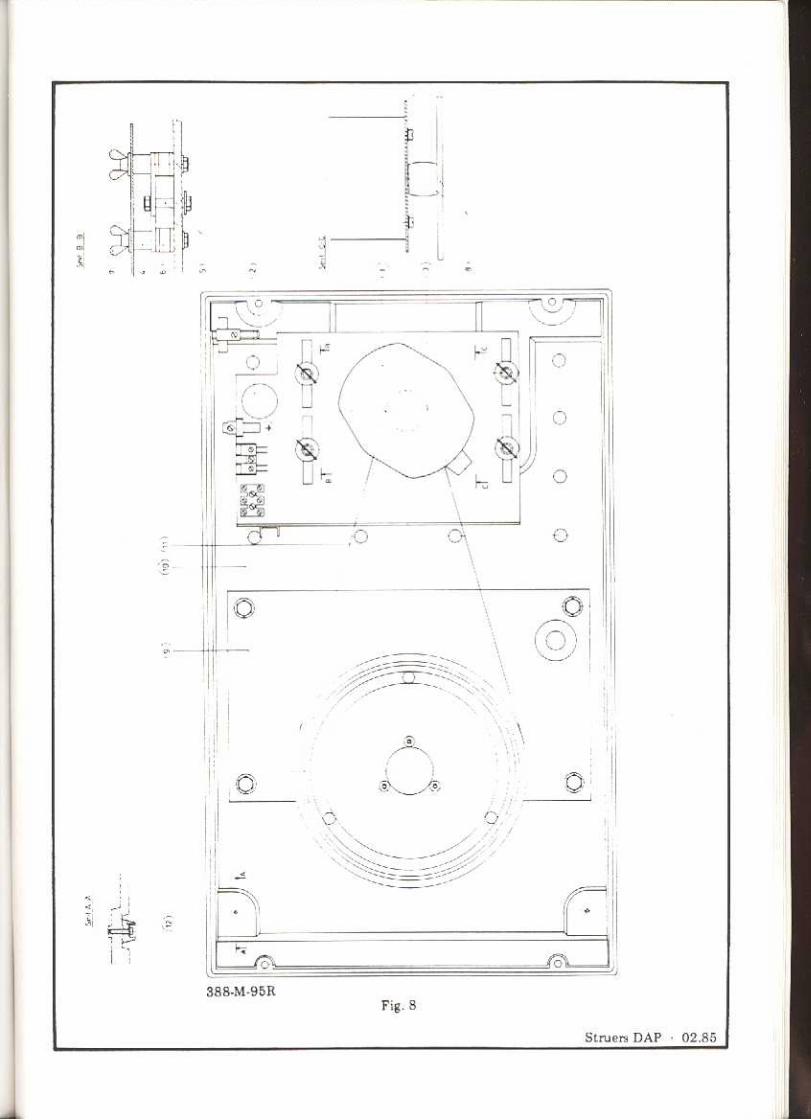
The range of discs comprises grinding remove the turntable (300 MP 26) anddisc for affixation of grinding paper ac- unscrew the upper cabinet-unit (4 Allencording to the Knuth-Rotor principle screws on the underside of the apparatus(Codeword: ROTTO/cl> 200 mm, are unscrewed by means of the Allen keyDEPRO/cl> 230 mm), polishing disc for (4 mm». Tighten the belt by pushing theself-adhesive (Codeword: DEPKI) or motorplate backwards after havingclamped-on polishing cloth (Codeword: loosened the wing-nuts. The belt must beDEPKI and CLAMP) and further a num- tightened in such a way that a pressureber of special lapping or lapping/grinding of 100 N in the middle between thedisc of various materials. In addition, a pulleys makes the belt bend 10-20 mm.complete programme of consumables is
available, including grinding paper, po-lishing cloths, diamond paste/spray, alu-mina, lapping powders and cooling-lubri-cating media.DAP-7 and DAP-V are prepared for ' '"
mounting of Pedemin (fig. 7), an automa-tic specimen mover to,be used at fine-grinding and polishing of I, 2 or 3 speci-mens. Pedemin can prepare specimens of '7 "p 1diameter up to 40 mm, with individual g ;\i!"O ',-\pressure on all three specimens. '... 1
Refer to special leaflets. 3 MP 15
If grinding paper is used on DAP-6 it is \~P it)recommended to use water as coolent. 17Therefore it is possible to mount a watertap on the mashine (Codeword: DAPT A).
5

~7. SPARE PART LIST
Please state apparatus No. and Spare Part No.
Fig. andPOSe No. Description Spare Part No.
Apparatus: DAP-6
Electrical parts
8.1 Motor, state voltage 326 MP 76
8.2 Capacitor, state voltage 326 MP 77
1.1 Switch 388\~Pl
1.2 Thermal cut-out, 110-115V, 3.5 A 388 1\~P 2
1.2 Thermal cut-out, 220-240V, 1.8 A 388 1\~P 3
Motorbridge assembly
8.3 Motor mounting plate 388 MP 4
8.4 Spacer 388 r..~P 5
8.5 Chock reducer, complete 388 r..~P 6
8.6 Chock absorber 300 ~~P 39
8.7 Wing nut 388 MP 7
8.8 Pulley for motor 354 MP 6
8.11 Drive belt 300 \~P 3
Turntable assembly
11.1 Turntable with screws 300 1\~P 26
8.9 Bridge for turntable assembly 388 MP 8
11.2 Pulley 388 MP 9
11.3 Axle journal 388r..~PI0
11.4 Distance bush 388 MP 11
11.5 Ball bearing kit 388 MP 12
Clamping ring for grinding discROTTO (~ 200) 404 \~P 23
Driving pins, all disc's,set of 3 144 \~P 18
Cabinet
1.4 Upper cabinet part withoutlet pipe 388 ~~P 13
8.10 Lower cabinet part 388 MP 14
1.3 Frontplate 388 MP 15
1.8 Splash ring, 210 mm dia. 388 MP 16
Lid 388 ~~P 17
1.5 Cover plug 388 MP 18
rFig. andPOSe No. Description Spare Part No.
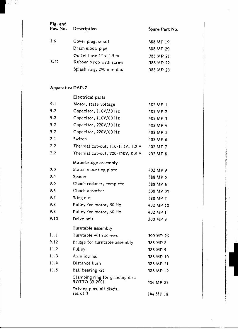
1.6 Cover plug, small '388 MP 19
Drain elbow pipe 388 MP 20
Outlet hose I" x 1.5 m 388 MP 21
8.12 Rubber Knob with screw 388 ~P 22
Splash ring, 240 mm dia. 388 r..~P 23
Apparatus: DAP-7
Electrical parts
9.1 ~'otor, state voltage 402 MP 1
9.2 Capacitor, 11 OV /50 Hz 402 MP 2
9.2 Capacitor, 110V/60 Hz 402 MP 3
9.2 Capacitor, 220V /50 Hz 402 MP 4
9.2 Capacitor, 220V/60 Hz 402 MP 5
2.1 Switch 402 \-1P 6
2.2 Thermal cut-out, 11 0-115V, 1.2 A 402 ~~ P 7
2.2 Thermal cut-out, 220-240V, 0.6 A 402 ~P 8
Motorbridge assembly9.3 Motor mounting plate 402 MP 9
9.4 Spacer 388 r..~P 5 !f.9.5 Chock reducer, complete 388 ~~P 6 !
9.6 Chock absorber 300 MP 39
9.7 Wing nut 388 MP 7
9.8 Pulley for motor, 50 Hz 402 MP 10
9.8 Pulley for motor, 60 Hz 402 MP 11
9.10 Drive belt 300 MP 3
Turntable assembly
11.1 Turntable with screws 300 MP 26
9.12 Bridge for turntable assembly 388 r..~P 8
11.2 Pulley 388 ~~p 9
11.3 Axle journal 388 ~~p 10
11.4 Distance bush 388 MP 11
11.5 Ball bearing kit 388 MP 12
Clamping ring for grinding discROTTO (0 200) 404 ~~P 23
Driving pins, all disc's,set of 3 144 '~P 18
.
@Fig. andPos. No. Description Spare Part No.
Cabinet
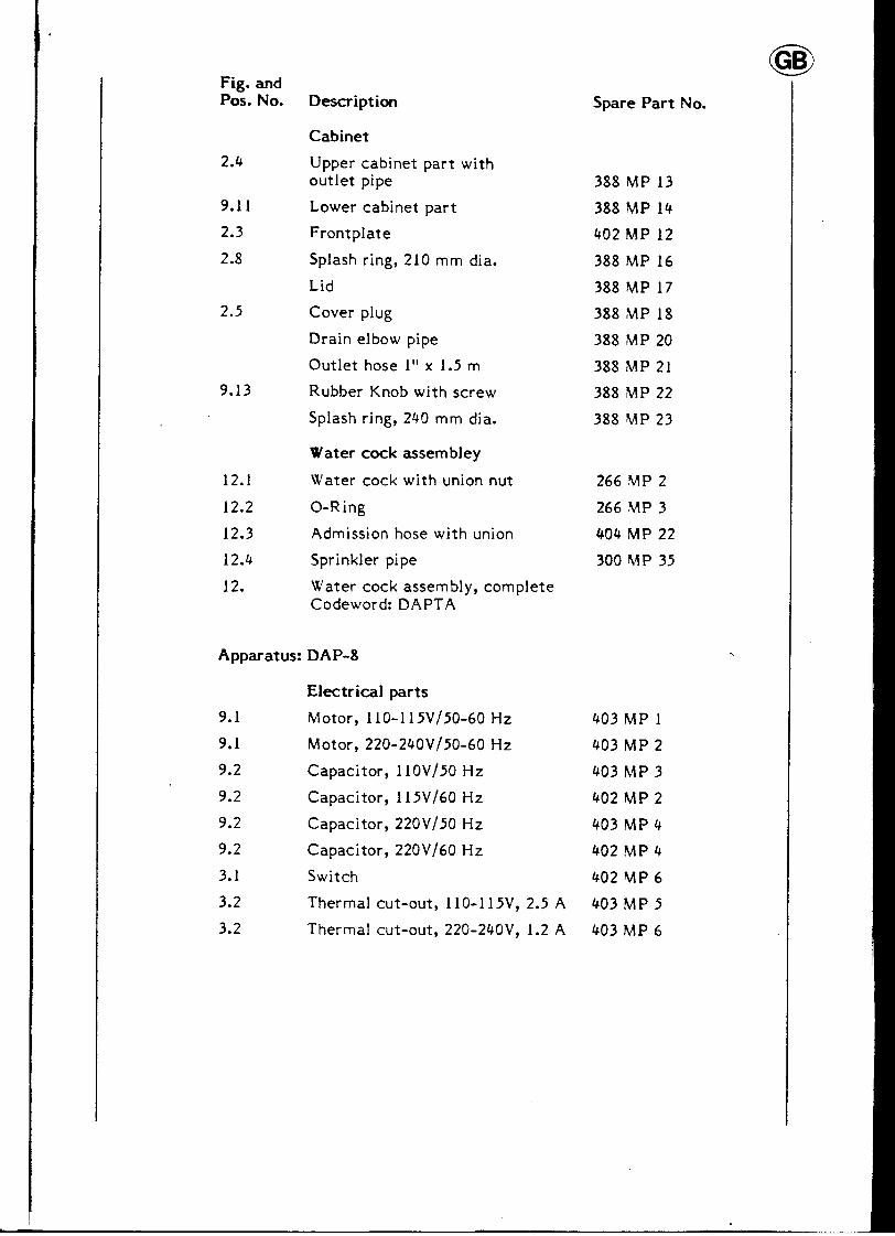
2.4 Upper cabinet part withoutlet pipe 388 MP 13
9.11 Lower cabinet part 388 MP 14
2.3 Frontplate 402 MP 12
2.8 Splash ring, 210 mm dia. 388 MP 16
Lid 388 MP 17
2.5 Cover plug 388 MP 18
Drain elbow pipe 388 MP 20
Outlet hose I" x 1.5 m 388 MP 21
9.13 Rubber Knob with screw 388 MP 22
Splash ring, 240 mm dia. 388 MP 23
Water cock assem bley
12.1 Water cock with union nut 266 r..~P 2
12.2 O-Ring 266 r..~P 3
12.3 Admission hose with union 404 MP 22
12.4 Sprinkler pipe 300 \~P 35
12. Water cock assembly, completeCodeword: DAPT A
Apparatus: DAP-8
Electrical parts
9.1 Motor, 110-115V/50-60 Hz 403 MP 1
9.1 Motor, 220-240V/50-60 Hz 403 MP 2
9.2 Capacitor, 110V /50 Hz 403 MP 3
9.2 Capacitor, 115V /60 Hz 402 MP 2
9.2 Capacitor, 220V/50 Hz 403 MP 4
9.2 Capacitor, 220V/60 Hz 402 MP 4
3.1 Switch 402 MP 6
3.2 Thermal cut-out, 110-115V, 2.5 A 403 MP 5
3.2 Thermal cut-out, 220-240V, 1.2 A 403 MP 6

Fig. andPos. No. Description Spare Part No.
Motorbridge assembly9.3 Motor mounting plate 402 MP 9 f
9.4 Spacer 388 MP 5
,9.5 Chock reducer, complete 388 MP 6 c
9.6 Chock absorber 300 MP 39,
1 9.7 Wing nut 388 MP 7 tj 9.8 Pulley for motor, 50 Hz 402 MP 10 f
9.8 Pulley for motor, 60 Hz 403 M P 7
9.10 Drive belt 300 MP 3
Turntable assembly
11.1 Turntable with screws 300 MP 26
9.12 Bridge for turntable assembly 388 MP 8 r11.2 Pulley 388 MP 9
11.3 Axle journal 388 MP 10
11.4 Distance bush 388 MP 11
11.5 Ball bearing ki t 388 MP 12
Clamping ring for grinding discROTTO (0 200) 404 MP 23
Driving pins, all disc's,set of 3 144 MP 18
Cabinet
3.4 IJpper cabinet part withoutlet pipe 388 MP 13
9.11 Lower cabinet part 388 MP 14
3.3 Frontplate 403 \~P 83.8 Splash ring, 210 mm dia. 388 MP 16 I
Lid 388 1\~P 17
3.5 Cover pI ug 388 ~~ P 18
Drain elbow pipe 388 MP 20
Outlet hose 1" x 1.5 m 388 MP 21
9.13 Rubber knob with screw 388 MP 22
Splash ring, 240 mm dia. 388 MP 23
Water cock assembly
12.1 Water cock with union nut 266 MP 2
12.2 O-ring 266 MP 3
12.3 Admisssion hose with union 404 MP 22
12.4 Sprinkler pipe 300 MP 35
12. Water cock assembly, completeCodeword: DAPT A
.il
- -

@Fig. andPos. No. Description Spare Part No.
Apparatus: DAP-V
Electrical parts
10.1 Motor 110-115Y/50-60 Hz 404 MP I
10.1 Motor 220-240Y /50-60 Hz 404 MP 2
10.2 Tachometer circuit board 404 MP 3
10.3 Motor control circuit board 404 MP 4
Fuse F 1 404 MP 5
10.4 Noise suppressor, Z 1 404 M P 6
10.5 Choke coit, L 1 404 MP 7
4.1 Switch 388 MP 1
4.4 Lamp, 110Y 404 MP 8
4.4 Lamp, 220Y 404 MP 9
4.2 Speed selector potentiometer 404 MP 10
4.2 Knob for speed selector 404 MP 11
4.3 Tachometer 404 MP 12
Thermal cut-out, 110-115Y, 4 A 404 !\"P 20
Thermal cut-out, 220-240Y, 1.5 A 404 MP 21
Motorbridge assembly10.6 Motor mounting bridge 404 MP 13
10.7 Spacer 404 MP 14
10.8 Chock reducer, complete 388 MP 6
10.9 Chock absorber 300 MP 39
10.10 Wing nut 388 MP 7
10.11 Mounting plate for 404 MP 4 404 MP 15
10.12 Mounting stay for pcb 404 MP 16
10.13 Connector 404 MP 17
10.14 Pulley for motor 404 MP 18
10.15 Drive belt 300 MP 3
Turntable assembly
11.1 Turntable with screws 300 MP 26
10.16 Bridge for turntable assembly 388 MP 8
11.2 Pulley 388 MP 9
11.3 Axle journal 388 MP 10
11.4 Distance bush 388 MP 11
11.5 Ball bearing kit 388MP12

Fig. andPOSe No. Description Spare Part No.
Clamping ring for grinding discROTTO (0 200) 404 MP 23
Driving pins, all disc's,set of 3 144 MP 18
Cabinet
4.6 Upper cabinet part withoutlet pipe 388 MP 13
10.17 Lower cabinet 388 MP 14
4.5 Frontplate 404 MP 19
4.10 Splash ring, 210 mm dia. 388 MP 16
Lid 388 \t\P 17
4.7 Cover plug 388 MP 18
Drain elbow pipe 388 MP 20
Outlet hose 1" x 1.5 m 388 MP 21 ,i10.18 Rubber knob with screw 388 MP 22 t
Splash ring, 240 mm dia. 388 MP 23 r; li. r
Water cock assembly
12.1 Water cock 266~~P2
12.2 O-ring 266 \~P 3 .
12.3 Admission hose with union 404 MP 22
12.4 Sprinkler pipe 300 MP 35
12. Water cock assembly, completeCodeword: DAPT A
~