ifd air cleaner service manual - amick racing cleaners/ifd servicemanual.pdf · sf 3 service manual...
TRANSCRIPT

IFD AIR CLEANER SERVICE MANUAL
PUB NO. 34-3446-01

© 2005 American Standard Inc. All Rights Reserved SF
Service Manual
1) Pre-filter - traps large particles such as hair and lint beforethey can enter the cell section.
2) Field Charger - Charges the contaminants
3) Collector Cell (2) - removes and collects small impuritiesfrom the air.
4) Cabinet - mounts between the furnace/air handler andreturn air duct work and houses the collector cells, fieldcharger and pre-filter.
COMPONENTS OF THE AIR CLEANER
11111
22222
33333
44444
55555
77777
66666
88888
33333
1111122222 33333AIR
FLOW
1
5) Power Door - the solid state power supply componentsthat convert the 24 Volt AC to the high-voltage, directcurrent required to power the field charger and cells. Allowsaccess to the fluted collector cells, field charger and pre-filter.
6) Transformer - supplies 24 Volts to the indoor unit and aircleaner
7) 24 Volt Power / Control Cable
8) Gasket, Literature and Hardware Packet
THEORY OF OPERATIONAir in the home is circulated through the heating and cooling system, maintaining the temperature at a comfortablelevel. At the same time, the circulated return air is passing through the indoor equipment millions of small air-bornparticles such as smoke and pollen, most of them are to small to be visible, are carried by the returning air to theElectronic Air Cleaner. The reasons this Electronic Air Cleaner efficiency is so superior to previous models is the newdesign of the ionizing section call the field charger section and the radical departure from charged metal collectorplates to charged insulated collector cells. The air-born particles in the return air pass through the field charger sectionwhere the positive high voltage ionizer pins are located. The positive high voltage on the field charger pins will causethe air-born particles passing by them to become positively charged. The collector cells surfaces are insulated from thehigh voltage, which will reduce electrical arcing noise. These charged collector cells attract and hold the positivelycharged air-born particles to their negative insulated charged surfaces. An electrostatic electronic air cleaner makesuse of the basic law of attraction, opposite charges attract.
▲ WARNING!RISK OF ELECTRIC SHOCK: These servicing instructionsare for use by qualified personnel only. To reduce the risk ofelectric shock, do not perform any servicing other than thatcontained in these operating instructions unless you arequalified to do so.
SF 3
Service Manual
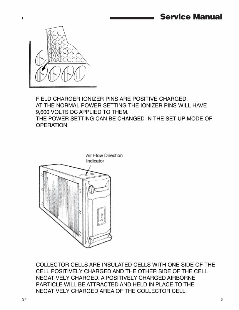
FIELD CHARGER IONIZER PINS ARE POSITIVE CHARGED.AT THE NORMAL POWER SETTING THE IONIZER PINS WILL HAVE9,600 VOLTS DC APPLIED TO THEM.THE POWER SETTING CAN BE CHANGED IN THE SET UP MODE OFOPERATION.
COLLECTOR CELLS ARE INSULATED CELLS WITH ONE SIDE OF THECELL POSITIVELY CHARGED AND THE OTHER SIDE OF THE CELLNEGATIVELY CHARGED. A POSITIVELY CHARGED AIRBORNEPARTICLE WILL BE ATTRACTED AND HELD IN PLACE TO THENEGATIVELY CHARGED AREA OF THE COLLECTOR CELL.

4 SF
Service ManualCOLLECTOR CELL CONSTRUCTIONCollector cells start out as a strip of corrugated box plastic strips. On the top and bottom of the strip a conductiveink strip is applied. These inked plastic strips are then glued together, one on top of the other forming the collectorcells. Electrically the cell is now a capacitor.
Capacitor Symbol
10 meg ohm resistors are placed in each leg of the cell to limit high current surges.
The standard Digital Ohm Meter will not read over 10 meg Ohms. The total resistance from the Collector HighVoltage input terminal to it’s High Voltage output terminal is 20 Meg Ohms.
10 Meg Ohms 10 Meg Ohms
10 Meg Ohms 10 Meg Ohms
Cell StripsOUTPUT INPUT
SF 5
Service Manual
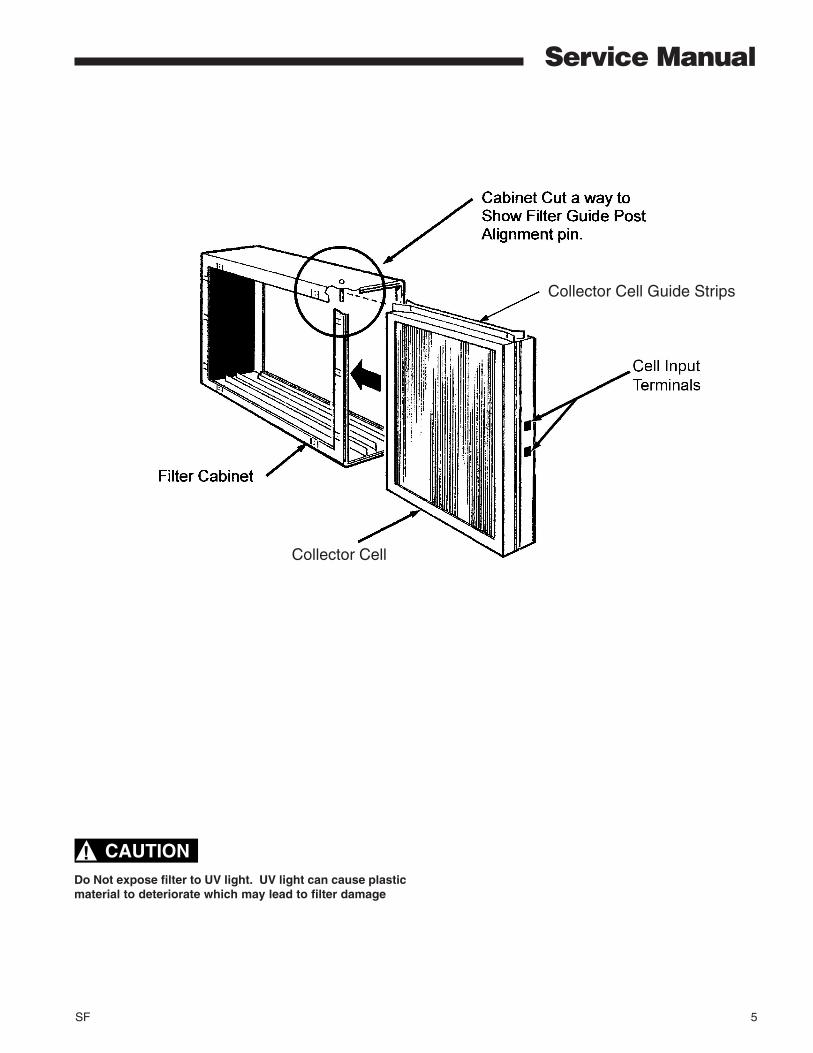
Collector Cell
Collector Cell Guide Strips
CAUTION!Do Not expose filter to UV light. UV light can cause plasticmaterial to deteriorate which may lead to filter damage
© 2005 American Standard Inc. All Rights Reserved SF
Service Manual
BLUE
RED
GROUND (BLK)
TRANSFORMER
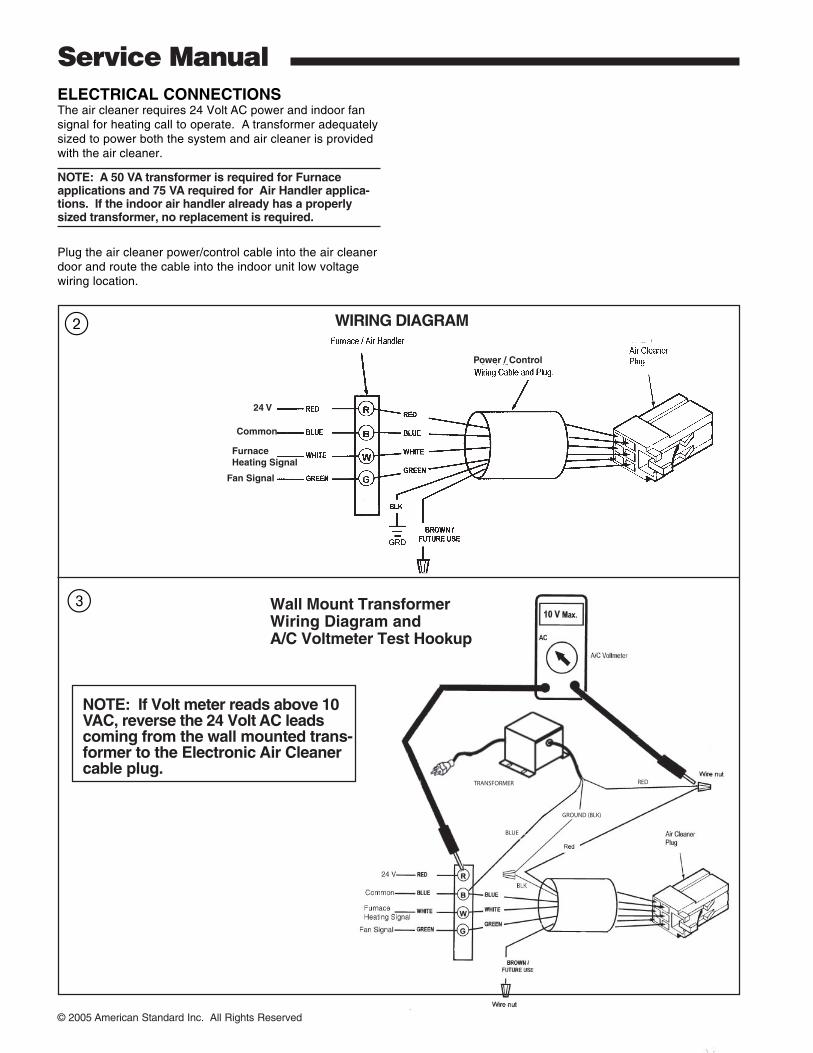
Wall Mount TransformerWiring Diagram andA/C Voltmeter Test Hookup
Power / Control
24 V
Common
Furnace Heating Signal
Fan Signal
WIRING DIAGRAM
ELECTRICAL CONNECTIONSThe air cleaner requires 24 Volt AC power and indoor fansignal for heating call to operate. A transformer adequatelysized to power both the system and air cleaner is providedwith the air cleaner.
NOTE: A 50 VA transformer is required for Furnaceapplications and 75 VA required for Air Handler applica-tions. If the indoor air handler already has a properlysized transformer, no replacement is required.
Plug the air cleaner power/control cable into the air cleanerdoor and route the cable into the indoor unit low voltagewiring location.
NOTE: If Volt meter reads above 10VAC, reverse the 24 Volt AC leadscoming from the wall mounted trans-former to the Electronic Air Cleanercable plug.
2
3
SF 7
Service Manual
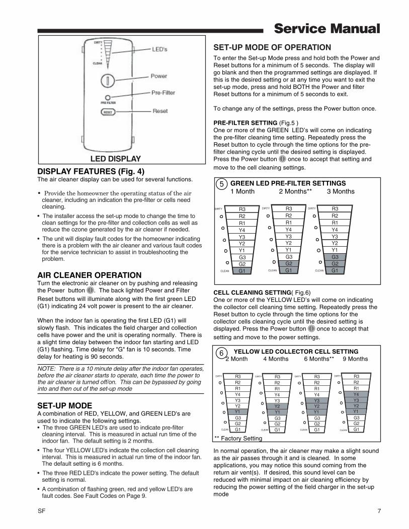
DISPLAY FEATURES (Fig. 4)The air cleaner display can be used for several functions.
• Provide the homeowner the operating status of the aircleaner, including an indication the pre-filter or cells needcleaning.
• The installer access the set-up mode to change the time toclean settings for the pre-filter and collection cells as well asreduce the ozone generated by the air cleaner if needed.
• The unit will display fault codes for the homeowner indicatingthere is a problem with the air cleaner and various fault codesfor the service technician to assist in troubleshooting theproblem.
AIR CLEANER OPERATIONTurn the electronic air cleaner on by pushing and releasingthe Power button . The back lighted Power and FilterReset buttons will illuminate along with the first green LED(G1) indicating 24 volt power is present to the air cleaner.
When the indoor fan is operating the first LED (G1) willslowly flash. This indicates the field charger and collectioncells have power and the unit is operating normally. There isa slight time delay between the indoor fan starting and LED(G1) flashing. Time delay for "G" fan is 10 seconds. Timedelay for heating is 90 seconds.
NOTE: There is a 10 minute delay after the indoor fan operates,before the air cleaner starts to operate, each time the power tothe air cleaner is turned off/on. This can be bypassed by goinginto and then out of the set-up mode
SET-UP MODEA combination of RED, YELLOW, and GREEN LED's areused to indicate the following settings.• The three GREEN LED's are used to indicate pre-filter
cleaning interval. This is measured in actual run time of theindoor fan. The default setting is 2 months.
• The four YELLOW LED's indicate the collection cell cleaninginterval. This is measured in actual run time of the indoor fan.The default setting is 6 months.
• The three RED LED's indicate the power setting. The defaultsetting is normal.
• A combination of flashing green, red and yellow LED's arefault codes. See Fault Codes on Page 9.
SET-UP MODE OF OPERATIONTo enter the Set-up Mode press and hold both the Power andReset buttons for a minimum of 5 seconds. The display willgo blank and then the programmed settings are displayed. Ifthis is the desired setting or at any time you want to exit theset-up mode, press and hold BOTH the Power and filterReset buttons for a minimum of 5 seconds to exit.
To change any of the settings, press the Power button once.
PRE-FILTER SETTING (Fig.5 )One or more of the GREEN LED’s will come on indicatingthe pre-filter cleaning time setting. Repeatedly press theReset button to cycle through the time options for the pre-filter cleaning cycle until the desired setting is displayed.Press the Power button once to accept that setting andmove to the cell cleaning settings.
GREEN LED PRE-FILTER SETTINGS 1 Month 2 Months** 3 Months
G1G2G3Y1
Y3Y4R1R2R3
Y2
CLEAN
DIRTY
G1G2G3Y1
Y3Y4R1R2R3
Y2
CLEAN
DIRTY
G1G2G3Y1
Y3Y4R1R2R3
Y2
CLEAN
DIRTY
CELL CLEANING SETTING( Fig.6)One or more of the YELLOW LED’s will come on indicatingthe collector cell cleaning time setting. Repeatedly press theReset button to cycle through the time options for thecollector cells cleaning cycle until the desired setting isdisplayed. Press the Power button once to accept thatsetting and move to the power settings.
YELLOW LED COLLECTOR CELL SETTING 2 Month 4 Months 6 Months** 9 Months
G1G2G3
Y3Y4R1R2R3
Y2
CLEAN
DIRTY
G1G2G3
Y3Y4R1R2R3
Y2
CLEAN
DIRTY
Y1
G1G2G3
Y3Y4R1R2R3
Y2
CLEAN
DIRTY
Y1 Y1
G1G2G3
Y3Y4R1R2R3
Y2
CLEAN
DIRTY
Y1
5
6
LED DISPLAY
** Factory Setting
In normal operation, the air cleaner may make a slight soundas the air passes through it and is cleaned. In someapplications, you may notice this sound coming from thereturn air vent(s). If desired, this sound level can bereduced with minimal impact on air cleaning efficiency byreducing the power setting of the field charger in the set-upmode
8 SF
Service Manual
LitePort DATAWhen the air cleaner has detected a fault and it is flashing it’sthree RED LEDs on and off it will also be sending the fault datato the pre-filter LED causing it to flash on and off. This fault datacan be read using a LitePort Optical Coupler. To activate theLitePort data port during normal operation remove 24VAC powerfrom the electronic air cleaner. Push and hold in the reset buttonwhile applying the 24VAC power to the electronic air cleaner. TheLitePort data will then be outputted via the prefilter LED. TheLitePort data will now be continuously outputted until the 24 VACpower is remover from the electronic air cleaner.
THREE RED LEDs & THE Pre-filter LED FLASHINGThis means service is needed. For these THREE RED LEDs tobe flash on and off the control must have detected the SAMEFAULT, see Fault Code Table on page 9, THREE TIMES in a rowafter an automatic High Voltage Shut Down cycle.
FAULT CODES RETRIEVALTo retrieve the last three faults that the Air Cleaner Controlhas detected enter the Set Up Mode of operation.Press and hold the Power/On button and the Reset buttonfor a minimum of five seconds. When the control enters theSET UP MODE of operation some of the Green, Yellow andRed LEDs will be on. The color and number of LEDs that areon indicates how the control is presently programmed. (SeeSET UP CHARTS on a previous page). To enter the FaultCodes section press and hold the Reset Button for tenseconds. After ten seconds the main LED display will go outfor one second and then some of the LEDs may began toflash on and off. If no fault has been detected then only thefirst Green LED will be flashing on and off. The flashing GreenLED or LEDS identifies the fault number being reported out.One Green Led flashing on and off means the last faultdetected is being reported out, two Green LEDs flashingmeans the second fault detected is being reported out andthree Green LEDs flashing means the last fault stored in thecontrol memory is being reported out. The last three faultsdetected will be stored in the control’s memory and the lastfault detected will be the first fault reported out.
You are now in the Fault Log report section and the last faultdetected is now being reported out.To step through the faults press the Power/On button againto get the second fault and again pressing the Power/On button will take you to the last fault stored in the control’smemory. Push the Power/On button again and the controlwill again display the last fault detected.
To exit the Set-up mode, press and hold both thePower/On and Filter reset buttons for a minimum of 5 seconds.
FAULT CODESWhen a fault is being reported out check the position numberof any of the Yellow and Red LEDs flashing on and off.Compare this combination of flashing LEDs position numbersto the Fault Code chart to see which fault has been detected.The number one Yellow LED will always be out in the FaultCode report section.
SETTING THE POWER LEVELAll electronic air cleaners produce a small amount ofozone that is within established limits. Some customersmay notice an odor especially at high altitudes and low airflow rates.
The average person can detect the odor of ozone in therange of 3 to 10 parts per billion (ppb) The air cleaner willcontribute 5 ppb of ozone to the indoor air on theNORMAL setting. The U.S. Food and Drug Administrationrecommends indoor ozone concentrations should notexceed 50 ppb.
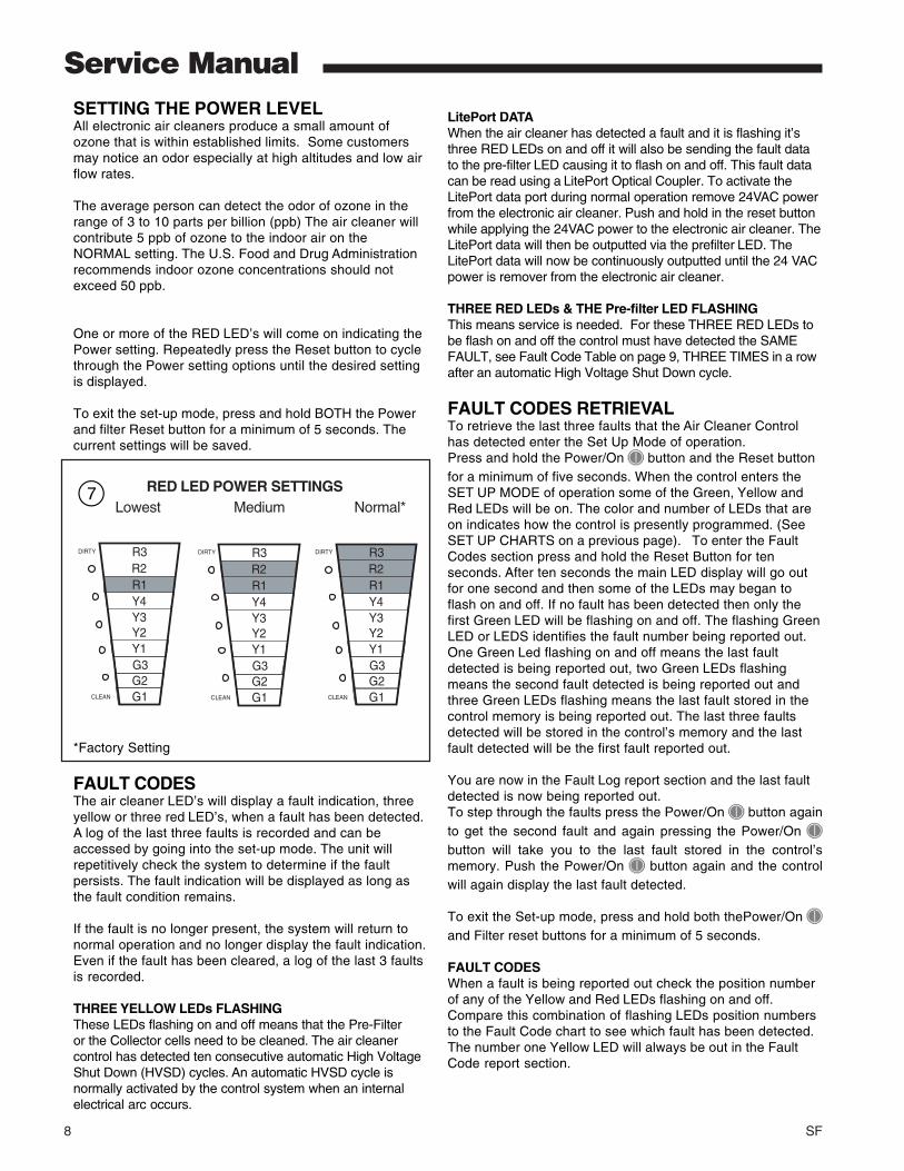
One or more of the RED LED’s will come on indicating thePower setting. Repeatedly press the Reset button to cyclethrough the Power setting options until the desired settingis displayed.
To exit the set-up mode, press and hold BOTH the Powerand filter Reset button for a minimum of 5 seconds. Thecurrent settings will be saved.
RED LED POWER SETTINGS Lowest Medium Normal*
G1G2G3Y1
Y3Y4R1R2R3
Y2
CLEAN
DIRTY
G1G2G3Y1
Y3Y4R1R2R3
Y2
CLEAN
DIRTY
G1G2G3Y1
Y3Y4R1R2R3
Y2
CLEAN
DIRTY
*Factory Setting
FAULT CODESThe air cleaner LED’s will display a fault indication, threeyellow or three red LED’s, when a fault has been detected.A log of the last three faults is recorded and can beaccessed by going into the set-up mode. The unit willrepetitively check the system to determine if the faultpersists. The fault indication will be displayed as long asthe fault condition remains.
If the fault is no longer present, the system will return tonormal operation and no longer display the fault indication.Even if the fault has been cleared, a log of the last 3 faultsis recorded.
THREE YELLOW LEDs FLASHINGThese LEDs flashing on and off means that the Pre-Filteror the Collector cells need to be cleaned. The air cleanercontrol has detected ten consecutive automatic High VoltageShut Down (HVSD) cycles. An automatic HVSD cycle isnormally activated by the control system when an internalelectrical arc occurs.
7
SF 9
Service Manual
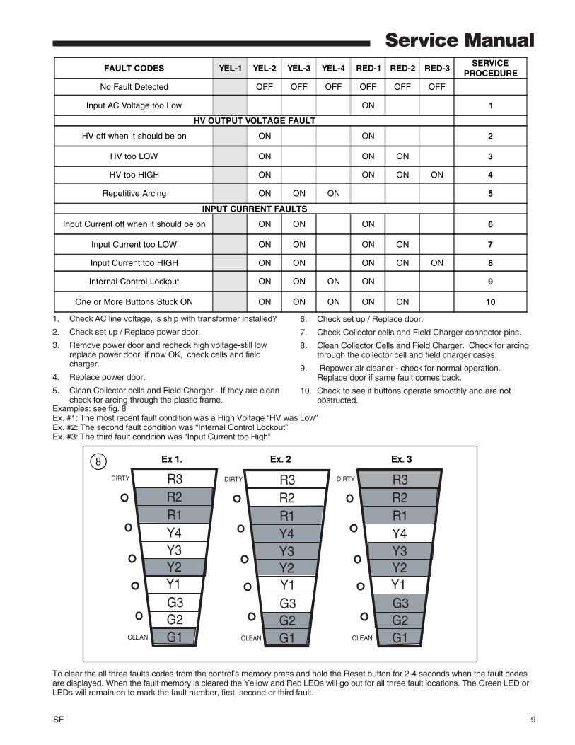
Examples: see fig. 8Ex. #1: The most recent fault condition was a High Voltage “HV was Low”Ex. #2: The second fault condition was “Internal Control Lockout”Ex. #3: The third fault condition was “Input Current too High”
To clear the all three faults codes from the control’s memory press and hold the Reset button for 2-4 seconds when the fault codesare displayed. When the fault memory is cleared the Yellow and Red LEDs will go out for all three fault locations. The Green LED orLEDs will remain on to mark the fault number, first, second or third fault.
1. Check AC line voltage, is ship with transformer installed?
2. Check set up / Replace power door.
3. Remove power door and recheck high voltage-still lowreplace power door, if now OK, check cells and fieldcharger.
4. Replace power door.
5. Clean Collector cells and Field Charger - If they are cleancheck for arcing through the plastic frame.
6. Check set up / Replace door.
7. Check Collector cells and Field Charger connector pins.
8. Clean Collector Cells and Field Charger. Check for arcingthrough the collector cell and field charger cases.
9. Repower air cleaner - check for normal operation.Replace door if same fault comes back.
10. Check to see if buttons operate smoothly and are notobstructed.
G1G2G3
Y3Y4R1R2R3
Y2
CLEAN
DIRTY
G1G2G3
Y3Y4R1R2R3
Y2
CLEAN
DIRTY
Y1
G1G2G3
R1R2R3
CLEAN
DIRTY
Y1
Y4Y3Y2Y1
Ex 1. Ex. 2 Ex. 38
FAULT CODES YEL-1 YEL-2 YEL-3 YEL-4 RED-1 RED-2 RED-3SERVICE
PROCEDURE
No Fault Detected OFF OFF OFF OFF OFF OFF
Input AC Voltage too Low ON 1
HV OUTPUT VOLTAGE FAULT
HV off when it should be on ON ON 2
HV too LOW ON ON ON 3
HV too HIGH ON ON ON ON 4
Repetitive Arcing ON ON ON 5
INPUT CURRENT FAULTS
Input Current off when it should be on ON ON ON 6
Input Current too LOW ON ON ON ON 7
Input Current too HIGH ON ON ON ON ON 8
Internal Control Lockout ON ON ON ON 9
One or More Buttons Stuck ON ON ON ON ON ON 10

10 SF
Service ManualTESTING COMPONENTS USING THE UNIT’S OWN MICRO & LEDsThere are four tests that can be performed in the field. These Tests are for testing the High Voltage Relay, LEDs,High Voltage Output and the Thermostat Inputs.
To enter the TEST Mode of this control perform the following.1.Push and hold the Power Button until all ten LED come on, then release the Power Button . The air-cleaner is
now off and the LEDs should step off one at a time. 2.Press the Reset Button three times in a row within 20 seconds and the Prefilter LED will come on.
3.Quickly push and hold the Power Button and the Reset Button at the same time, the Prefilter LED will then go outand then come back on flashing. The Prefilter LED will continue to flash as long as the control is in the test mode.The Prefilter LED is now sending LitePort data.
4.There are three ways to exit the test mode, (1)remove power, (2)press the Power Button and the Reset Button inand hold them in for five seconds or (3)do not push any buttons for five minutes.
5.The Green LEDs chart, below, will show which of the four tests you are in.
At this time the first Green LED should be on. This indicates that you are in the HV(HIGH VOLTAGE) Relay Testmode.
6.There are three tests in the HV Relay Test section. See Chart below. A Yellow LED will show which test you are in.Test 1 the 1st Yellow LED will be on, Test 2 the 2nd Yellow LED will be on and in Test 3 the 3rd Yellow LED will be on.Push the Reset Button once to move to the next test in this section.
7.One of the three Red LED will indicate the condition of the each test.When the Third Red LED is on this indicates that the High Voltage measured is out of range.When the Second Red LED is on indicates that the High Voltage Current and Voltage are in their proper operating range.When the First Red LED is on indicates that the High Voltage Input Current is out of range.
8.Push the Power Button once, this will move the control into the LED test Mode. All 10 barograph LEDs and the twobacklight LEDs below the two buttons should come on. The communication LED on the main printed circuit boardwill light also.
9.By pushing the Reset Button you can cause one of the 12 LEDs after another to come on and go off.
10.Push the Power Button once, this will move the control into the High Voltage Output Test. There are four HV (HighVoltage) tests in this section. See chart below. A Yellow LED will show which test you are in. For Test 1 the first YellowLED will be on, Test 2 the 2nd Yellow LED will be on, Test 3 the 3rd Yellow LED will be on and Test 4 the 4th YellowLED will be on. Push the Reset Button once will move you in to the next test of this section.
TEST 1st Green LED 2nd Green LED 3rd Green LED
HV Relay Test ON
LED Test (All LEDs will initially energize upon entry into LED Test mode.)
HV Output Test ON ON
Thermostat Input Test ON
TEST Yellow LEDs Description
0% Duty Cycle on HVRelay PWM output
1st YellowHV relay should remain off. The control willcheck the HV. It should be 0 volts.
HV Input Current Test 2nd YellowHV relay should remain off after brief doubleclick. The control will expect the HV output tobe 0 volts.
90% stepping down to 75%Duty Cycle on HV RelayPWM output
3rd YellowControl will check the HV supply, it should be9.6KV. +/- 600 volts
SF 11
Service Manual
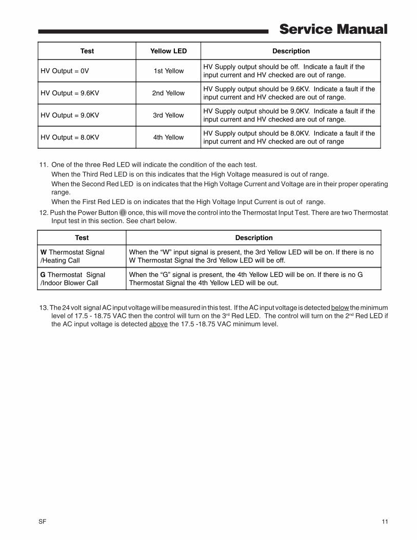
11. One of the three Red LED will indicate the condition of the each test.When the Third Red LED is on this indicates that the High Voltage measured is out of range.When the Second Red LED is on indicates that the High Voltage Current and Voltage are in their proper operatingrange.When the First Red LED is on indicates that the High Voltage Input Current is out of range.
12. Push the Power Button once, this will move the control into the Thermostat Input Test. There are two ThermostatInput test in this section. See chart below.
13. The 24 volt signal AC input voltage will be measured in this test. If the AC input voltage is detected below the minimumlevel of 17.5 - 18.75 VAC then the control will turn on the 3rd Red LED. The control will turn on the 2nd Red LED ifthe AC input voltage is detected above the 17.5 -18.75 VAC minimum level.
Test Yellow LED Description
HV Output = 0V 1st YellowHV Supply output should be off. Indicate a fault if theinput current and HV checked are out of range.
HV Output = 9.6KV 2nd YellowHV Supply output should be 9.6KV. Indicate a fault if theinput current and HV checked are out of range.
HV Output = 9.0KV 3rd YellowHV Supply output should be 9.0KV. Indicate a fault if theinput current and HV checked are out of range.
HV Output = 8.0KV 4th YellowHV Supply output should be 8.0KV. Indicate a fault if theinput current and HV checked are out of range
Test Description
W Thermostat Signal/Heating Call
When the “W” input signal is present, the 3rd Yellow LED will be on. If there is noW Thermostat Signal the 3rd Yellow LED will be off.
G Thermostat Signal/Indoor Blower Call
When the “G” signal is present, the 4th Yellow LED will be on. If there is no GThermostat Signal the 4th Yellow LED will be out.
12 SF
Service ManualTESTING THE POWER DOORHIGH VOLTAGE POWER SUPPLYTools RequiredA High voltage Probe and a compatible Volt /Ohm Meter or aScrewdriver, Jumper Wire with Alligator Clips on each end, tapeand dry paper.
TESTING WITH A HIGH VOLTAGE PROBE
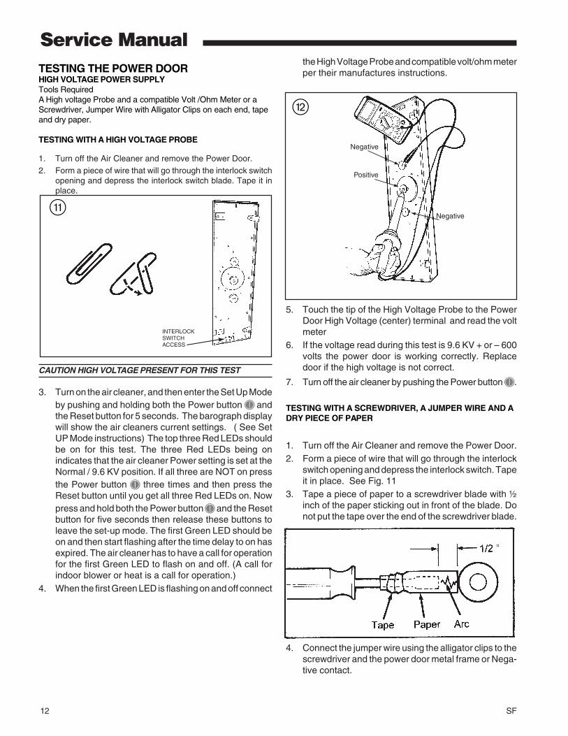
1. Turn off the Air Cleaner and remove the Power Door.2. Form a piece of wire that will go through the interlock switch
opening and depress the interlock switch blade. Tape it inplace.
CAUTION HIGH VOLTAGE PRESENT FOR THIS TEST
3. Turn on the air cleaner, and then enter the Set Up Modeby pushing and holding both the Power button andthe Reset button for 5 seconds. The barograph displaywill show the air cleaners current settings. ( See SetUP Mode instructions) The top three Red LEDs shouldbe on for this test. The three Red LEDs being onindicates that the air cleaner Power setting is set at theNormal / 9.6 KV position. If all three are NOT on pressthe Power button three times and then press theReset button until you get all three Red LEDs on. Nowpress and hold both the Power button and the Resetbutton for five seconds then release these buttons toleave the set-up mode. The first Green LED should beon and then start flashing after the time delay to on hasexpired. The air cleaner has to have a call for operationfor the first Green LED to flash on and off. (A call forindoor blower or heat is a call for operation.)
4. When the first Green LED is flashing on and off connect
the High Voltage Probe and compatible volt/ohm meterper their manufactures instructions.
5. Touch the tip of the High Voltage Probe to the PowerDoor High Voltage (center) terminal and read the voltmeter
6. If the voltage read during this test is 9.6 KV + or – 600volts the power door is working correctly. Replacedoor if the high voltage is not correct.
7. Turn off the air cleaner by pushing the Power button .
TESTING WITH A SCREWDRIVER, A JUMPER WIRE AND ADRY PIECE OF PAPER
1. Turn off the Air Cleaner and remove the Power Door.2. Form a piece of wire that will go through the interlock
switch opening and depress the interlock switch. Tapeit in place. See Fig. 11
3. Tape a piece of paper to a screwdriver blade with ½inch of the paper sticking out in front of the blade. Donot put the tape over the end of the screwdriver blade.
4. Connect the jumper wire using the alligator clips to thescrewdriver and the power door metal frame or Nega-tive contact.
INTERLOCKSWITCHACCESS
q
w
Negative
Positive
Negative

SF 13
Service ManualFUSE REPLACEMENTA fuse, located inside the power door, protects the powersupply components against damaging electrical currents.This fuse has a rating of 3 amps and is a Purple colorautomobile style fuse.
TO CHECK OR REPLACE THE FUSEDisconnect the power cord from the front of the power packdoor. On the inside of the door remove the screws along theouter edge to separate the metal door from the plastic cover.
The Purple Colored 3 amp fuse is located on the main printedcircuit board. Replace the fuse if blown and reassemble thepower door.
NOTE: When reassembling the inter panel to the powerpack door, ensure that the wiring is positioned to avoidinterference.
Re-install the door on the cabinet, plug in the power/controlcable and check for proper operation of the electronic aircleaner.
The other electrical components inside the power door arenot field replaceable, the power door is available a completeassembly from your distributor.
FUSE
CAUTION HIGH VOLTAGE PRESENT FOR THIS TEST5. Turn on the air cleaner, and then enter the Set Up
Mode by pushing and holding both the Power button and the Reset button for 5 seconds. The barographdisplay will show the air cleaners current settings. (See Set UP Mode instructions) The top three RedLEDs should be on for this test. The three Red LEDsbeing on indicates that the air cleaner Power setting isset at the Normal / 9.6 KV position. If all three are NOTon press the Power button three times and thenpress the Reset button until you get all three Red LEDson. Now press and hold both the Power button andthe Reset button for five seconds then release thesebuttons. The first Green LED should be on and thenstart flashing after the time delay to on has expired.The air cleaner has to have a call for operation for thefirst Green LED to flash on and off. (A call for indoorblower or heat is a call for operation.)
6. When the first Green LED is flashing on and off take thescrewdriver by the plastic handle and move the bladeend of the screwdriver near the Power Door HighVoltage terminal. When the end of the paper touchesthe High Voltage terminal the High Voltage should arcacross the paper. When the arc occurs the HighVoltage Supply will shut down and stay off for tenminutes.
7. Turn off the air cleaner by pushing the Power button .8. If the arc occurred when the end of the paper was near
or touching the Power Door High Voltage terminalduring this test the Power Door assembly is OK, if noarc occurred replace Power Door.
e
r
r

14 SF
Service Manual
400 CFM 600 CFM 800 CFM 1000 CFM 1200 CFM 1400 CFM 1600 CFM 1800 CFM 2000 CFM*FD145ALFR 0.04 0.09 0.14 0.20 0.27*FD175ALFR 0.03 0.06 0.10 0.14 0.19 0.24 0.30*FD210ALFR 0.02 0.04 0.07 0.10 0.13 0.17 0.21 0.26 0.31*FD245ALFR 0.01 0.03 0.05 0.07 0.10 0.13 0.16 0.19 0.23
*FD14DALFR 0.07 0.14 0.22 0.32 0.44*FD17DALFR 0.05 0.09 0.15 0.22 0.30 0.39 0.49*FD21DALFR 0.03 0.07 0.11 0.15 0.21 0.27 0.34 0.42 0.50*FD24DALFR 0.02 0.05 0.08 0.12 0.16 0.20 0.25 0.31 0.37
*FD215ALAH 0.03 0.06 0.10 0.15 0.20*FD235ALAH 0.02
* May be "A" or "T"
0.05 0.09 0.12 0.17 0.22 0.27*FD260ALAH 0.02 0.04 0.07 0.10 0.14 0.18 0.23 0.28 0.33
PRESSURE DROP AT SPECIFIC AIRFLOW PER MODEL
SF 15
Service Manual
CAUTION!High Voltage is present within the air cleaner for operation.Before removing the door, turn the power off and wait atleast 15 seconds to allow voltage to discharge.
CLEANING
1. Turn the air conditioning system off at the thermostat
2. Turn off power to the air cleaner by pushing and holding thepower button for three seconds. The LED's will remain onuntil the voltage has discharged and it is safe to remove thedoor. This requires approximately 15 seconds. Do notremove the door till all lights are off.
3. Disconnect the power/control cable if required to place thedoor in a secure location.
PRE-FILTER CLEANINGThe pre-filter may be vacuumed or washed to clean. The pre-filter should be completely dry before re-installing.
NOTE: Do not replace the plastic pre-filter with a metaltype pre-filter. A metal pre-filter will cause reduction inefficiency and potential failure of the electronics in theair cleaner
COLLECTION CELL CLEANINGThe collection cells may be cleaned either by vacuuming(recommended method) or by washing.
VACUUM CLEANINGVacuum both sides of the collection cells to clean.
WASHINGUse low-pressure water spray, such as a sink sprayer orgarden hose to clean the cells. Some residue may requirewarm water to be removed.
• Do NOT use soap or detergent in cleaningthe collection cells.
• Do NOT immerse the cells completely inwater.
• DO NOT PLACE THE CELLS INTO A DISH-WASHER TO CLEAN
Slightly tap the collection cells to remove water retained inthe filter. Allow the collection cells to dry before re-installing.
Re-install the pre-filter and collection cells. Be sure to foldthe collection cell handles flat. Install the door and plug in thepower/control cable if removed. Turn on power to the aircleaner. by pressing and releasing the Power button .
NOTE: The first green LED will be on but will not flash forthe first 10 minutes the indoor fan is operating. This is adrying cycle for the pre-filter and collection cells.
RESET TIMERSTo reset the pre-filter timer, press and hold the RESET buttonuntil the pre-filter LED turns off. (1 to 2 seconds)To reset the collection cell timer, press and hold the RESETbutton until the collection cell LED’s turn off. (4 to 5 seconds)
CLEANING THE FIELD CHARGER
1. Turn off the air cleaner and remove the power door.
2. Bend the field charger metal locking tabs down against thecase.
3. Remove the field charger from the case. Lay the fieldcharger on a secured flat surface.
CAUTION FIELD CHARGER PINS ARE SHARP.DO NOT BEND FIELD CHARGER PINS. WEAR APPROPRI-ATE GLOVES WHEN HANDLING THE FIELD CHARGER.
4. Wipe down the face Plate of the field charger with a dryshop towel or use a vacuum cleaner. Do not disassemblethe field charger.
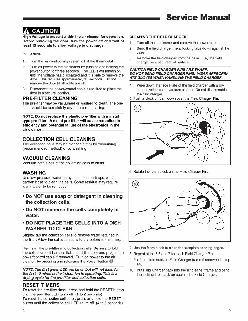
5. Push a block of foam down over the Field Charger Pin.
6. Rotate the foam block on the Field Charger Pin.
9
0
7. Use the foam block to clean the faceplate opening edges.
8. Repeat steps 5,6 and 7 for each Field Charger Pin.
9. Put face plate back on Field Charger frame if removed in step#4.
10. Put Field Charger back into the air cleaner frame and bendthe locking tabs back up against the Field Charger.

American Standard Inc.6200 Troup HighwayTyler, TX 75707
For more information contactyour local dealer (distributor)
Service Manual
TROUBLESHOOTING
Service Indications Service ChecksIndoor Blower ON/
1. Check that the Power Door is installed correctly and the latches closed. The actuator tab has engaged the door switch.2. Check the air cleaner power/control cable. 3. Push the power button once.Button back light should be on.4. Check for 24 Volts AC at the Air Cleaner Power plug.5. Check the Fuse inside the Power Door.
Indoor Blower ON/Air Cleaner FirstGreen LED ON, Not Flashing 1. Air Cleaner is in the 10 minute DRY CYCLE.
2. No call for Air Cleaner Operation due to no24 volts AC call going to G or W from the Furnace or Air Handler.3. There is no High Voltage being provided to the Field Charger or the Collection Cells. Inspectthe Field Charger assembly and Collection Cellsfor any foreign material that may be lodged in them.Clean as needed, reassemble and test.4. If the Air Cleaner still does not work, remove Power Door from the Air Cleaner housing.
CAUTION HIGH VOLTAGE WILL BEPRESENT FOR THE REMAINDER OF
THIS TEST.
5. With the indoor blower running and the power cord plugged into the Air Cleaner, use a tool to activate the Power Door interlock switch. Push the power button once. The first green LED should come on and after the time delay it should start to flash. If the LED starts to flash then the fault is with the Collection Cells or the Field Charger.If the first Green LED does not start to flash the fault is with the Power Door.
Indoor Blower ON/ Four Yellow 1. Remove the Power Door, Field Charger & LEDs Flashing Collection Cells. Inspect for foreign
material, clean if needed.
Indoor Blower ON 1. This indicates service is needed.three Red LEDs Flashing See Service Facts for fault code information.
Air Cleaner First Green LED OFF