ieee/asme transactions on mechatronics 1 design and ...allen/papers/irep_journal_2012.pdf ·...
TRANSCRIPT

This article has been accepted for inclusion in a future issue of this journal. Content is final as presented, with the exception of pagination.
IEEE/ASME TRANSACTIONS ON MECHATRONICS 1
Design and Coordination Kinematics of an InsertableRobotic Effectors Platform for Single-Port
Access SurgeryJienan Ding, Member, IEEE, Roger E. Goldman, Member, IEEE, Kai Xu, Member, IEEE,
Peter K. Allen, Member, IEEE, Dennis L. Fowler, and Nabil Simaan, Member, IEEE
Abstract—Single port access surgery (SPAS) presents surgeonswith added challenges that require new surgical tools and surgi-cal assistance systems with unique capabilities. To address thesechallenges, we designed and constructed a new insertable roboticend-effectors platform (IREP) for SPAS. The IREP can be insertedthrough a Ø15 mm trocar into the abdomen and it uses 21 actu-ated joints for controlling two dexterous arms and a stereo-visionmodule. Each dexterous arm has a hybrid mechanical architec-ture comprised of a two-segment continuum robot, a parallelogrammechanism for improved dual-arm triangulation, and a distal wristfor improved dexterity during suturing. The IREP is unique be-cause of the combination of continuum arms with active and passivesegments with rigid parallel kinematics mechanisms. This paperpresents the clinical motivation, design considerations, kinemat-ics, statics, and mechanical design of the IREP. The kinematics ofcoordination between the parallelogram mechanisms and the con-tinuum arms is presented using the pseudo-rigid-body model of thebeam representing the passive segment of each snake arm. Kine-matic and static simulations and preliminary experiment resultsare presented in support of our design choices.
Index Terms—Continuum robots, kinematics, medical robotics,parallel mechanisms, single-port access surgery (SPAS).
Manuscript received August 22, 2010; revised February 23, 2012; ac-cepted May 19, 2012. Recommended by Technical Editor A. Menciassi. Thiswork was supported by the National Institutes of Health (NIH) under Grant5R21EB007779-02. The work of N. Simaan was supported by the NationalScience Foundation Career Award IIS-0844969.
J. Ding was with the Advanced Robotics and Mechanism Applications Lab-oratory, Columbia University, New York, NY 10027 USA. He is now withHstar Technologies, Inc., Cambridge, MA 02138 USA (e-mail: [email protected]).
R. E. Goldman is with the College of Physicians and Surgeons, ColumbiaUniversity, New York, NY 10027 USA (e-mail: [email protected]).
K. Xu was with the Advanced Robotics and Mechanism Applications Lab-oratory, Columbia University, New York, NY 10027 USA. He is now with theUniversity of Michigan–Shanghai Jiao Tong University Joint Institute, ShanghaiJiao Tong University, Shanghai 200030, China (e-mail: [email protected]).
P. K. Allen is with the Department of Computer Science, Columbia Univer-sity, New York, NY 10027 USA (e-mail: [email protected]).
D. L. Fowler is with the Department of Surgery, Columbia University, NewYork, NY 10032 USA (e-mail: [email protected]).
N. Simaan (corresponding author) is with the Advanced Roboticsand Mechanism Applications Laboratory, Department of Mechanical En-gineering, Vanderbilt University, Nashville, TN 37212 USA (e-mail:[email protected]).
Color versions of one or more of the figures in this paper are available onlineat http://ieeexplore.ieee.org.
Digital Object Identifier 10.1109/TMECH.2012.2209671
I. INTRODUCTION
ROBOTIC assistance in minimally invasive surgery (MIS)extended the capabilities of surgeons via improved preci-
sion, dexterity, and computer assistance [1], [2]. Recently, novelsingle port access surgery (SPAS) and natural orifice translumi-nal endoscopic surgery (NOTES) have been investigated by theauthors in [3]–[6] for their potential benefits in reducing patienttrauma and shortening their recovery time compared to tradi-tional multiport laparoscopic MIS. However, SPAS and NOTESalso set strict requirements for instrument miniaturization, dex-terity, and collision avoidance between surgical tools operatingin confined spaces. Existing surgical robots for MIS cannot sat-isfy these requirements due to either dexterity deficiency or thesize of their actuation mechanisms that prohibit a multitude ofarms from operating through a single port. Therefore, to date,SPAS is still limited to a small number of academic centersusing instruments that are not clinically proven to be able tofacilitate SPAS [7]–[9].
Surgeons and engineers tried to overcome the single-portconstraint by using multiport trocars (Triport R© from AdvancedSurgical Concepts, Wicklow, Ireland) and single incision laparo-scopic surgery port from (Covidien, Inc.), which allow multipleinstruments to pass through a single port. Others (Realhand R©
from Novare and Cambridge Endo) used instruments which canarticulate to avoid the collision between the operator hands [9].Animal studies of single-port access laparoscopic cholecystec-tomy have been carried out using these instruments [8]. How-ever, the use of manual instruments requires surgeons to operatewith crossed hands and relies on exceptional hand–eye coordi-nation and substantial training.
Other researchers developed robotic assistance tools forNOTES. Abbott [4] developed a wire-actuated dual-arm roboticsystem for NOTES which has 16 DoF and a diameter larger than20 mm. Phee et al. [6] presented a 9 DoF Ø22 mm dual-armrobot. Lehman et al. [5] developed NOTES robot that may beinserted into the abdomen via a Ø20 mm overtube. This robotrequires surgeon intervention to switch it from a folded configu-ration to a working configuration. It is also fixed to the abdomenusing external magnets. More recently, Harada et al. [10] intro-duced a novel concept of reconfigurable self-assembling robotfor NOTES. This concept has yet to be experimentally proven.Lee et al. [11] presented a stackable four-bar mechanism forsingle SPAS. Picciagallo et al. [12] presented a dual-arm robotfor SPAS. This design used embedded motors inside the links; ithas a diameter of 23 mm. Finally, intuitive surgical is developing
1083-4435/$31.00 © 2012 IEEE
This article has been accepted for inclusion in a future issue of this journal. Content is final as presented, with the exception of pagination.
2 IEEE/ASME TRANSACTIONS ON MECHATRONICS
a dual-arm SPAS system [13] that uses wire-actuated snake-likearticulated linkages.
This paper addresses the need for self-deploying robots thatprovide adequate dexterity in a diameter smaller than 20 mm,while seamlessly supporting 3-D vision feedback during all op-eration phases (deployment and work). The contributions ofthis paper are 1) mechanical design of an insertable robotic end-effector platform (IREP) as an enabling technology for SPAS.This novel design incorporates parallel mechanisms and con-tinuum robots with active and passive segments. A unique andnovel feature of this design is the improved ability to triangulatethe two robotic arms to a surgical site through the use of a hybridmechanical architecture that incorporates parallel mechanismsand continuum robots with passive and active segments; 2) akinematic coordination algorithm that coordinates the motionof the parallel mechanisms and the flexible passive segmentof each continuum robot; thus, achieving increased workspacewhile eliminating mechanical overconstraint; and 3) a completekinematic and static model of the IREP system is used for task-based design and determination of actuator specifications.
II. CLINICAL MOTIVATION
The clinical rationale for SPAS is based on the principle thatreduced abdominal wall trauma results in better outcomes forthe patient. As opposed to traditional MIS, SPAS requires asingle incision, usually in the umbilicus, rather than multiple in-cisions. In SPAS, all necessary imaging and instrumentation areinserted through this single incision. In addition to the reductionor the elimination of visible scars, there is potential for less painand less stress response during and after surgery [3]–[6]. Fur-thermore, the surgical site infection (SSI) rate is significantlyless when using a laparoscopic approach, and a reduction in thenumber of incisions at risk has the potential to further reduce theincidence of SSI [14]. These benefits suggest that SPAS offerssignificant benefit to candidates of abdominal surgery.
The hypothesis driving our research is that minimizing thenumber and size of incisions will lead to patient benefits inrecovery time, stress response, SSI incidence, and improvedcosmesis. To validate this hypothesis, we designed and con-structed the first prototype of the IREP. We believe that success-ful augmentation of vision feedback combined with telemanip-ulation assistance will simplify SPAS procedures and increaseadoption of this surgical approach in a manner similar to thegrowth and adoption of MIS supported by the development ofMIS instrumentation.
While the IREP prototype is being developed as a SPAS plat-form for general abdominal procedures, gall bladder removal,termed cholecystectomy, serves as a benchmark procedure be-cause it presents the typical abdominal surgical challenges ofsuturing, dissection, and specimen extraction.
III. IREP AND ITS DESIGN SPECIFICATIONS
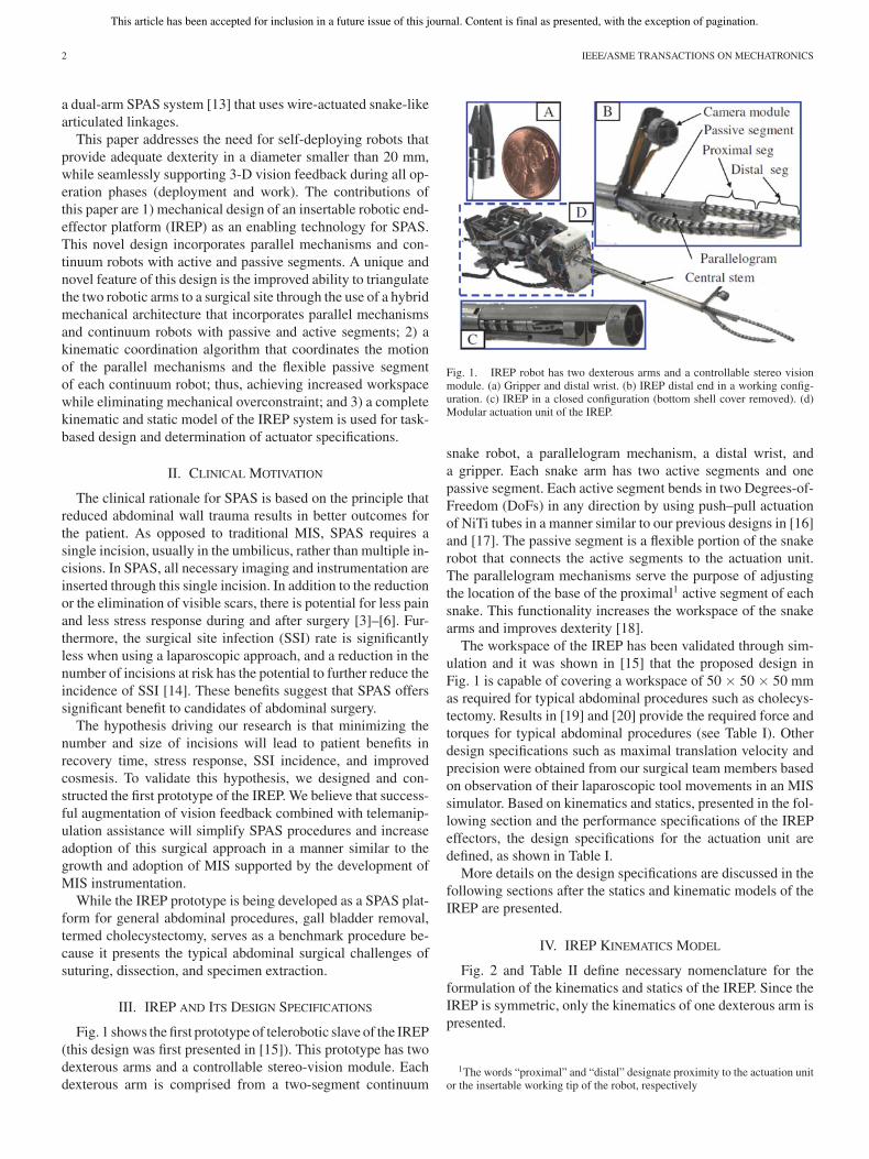
Fig. 1 shows the first prototype of telerobotic slave of the IREP(this design was first presented in [15]). This prototype has twodexterous arms and a controllable stereo-vision module. Eachdexterous arm is comprised from a two-segment continuum
Fig. 1. IREP robot has two dexterous arms and a controllable stereo visionmodule. (a) Gripper and distal wrist. (b) IREP distal end in a working config-uration. (c) IREP in a closed configuration (bottom shell cover removed). (d)Modular actuation unit of the IREP.
snake robot, a parallelogram mechanism, a distal wrist, anda gripper. Each snake arm has two active segments and onepassive segment. Each active segment bends in two Degrees-of-Freedom (DoFs) in any direction by using push–pull actuationof NiTi tubes in a manner similar to our previous designs in [16]and [17]. The passive segment is a flexible portion of the snakerobot that connects the active segments to the actuation unit.The parallelogram mechanisms serve the purpose of adjustingthe location of the base of the proximal1 active segment of eachsnake. This functionality increases the workspace of the snakearms and improves dexterity [18].
The workspace of the IREP has been validated through sim-ulation and it was shown in [15] that the proposed design inFig. 1 is capable of covering a workspace of 50 × 50 × 50 mmas required for typical abdominal procedures such as cholecys-tectomy. Results in [19] and [20] provide the required force andtorques for typical abdominal procedures (see Table I). Otherdesign specifications such as maximal translation velocity andprecision were obtained from our surgical team members basedon observation of their laparoscopic tool movements in an MISsimulator. Based on kinematics and statics, presented in the fol-lowing section and the performance specifications of the IREPeffectors, the design specifications for the actuation unit aredefined, as shown in Table I.
More details on the design specifications are discussed in thefollowing sections after the statics and kinematic models of theIREP are presented.
IV. IREP KINEMATICS MODEL
Fig. 2 and Table II define necessary nomenclature for theformulation of the kinematics and statics of the IREP. Since theIREP is symmetric, only the kinematics of one dexterous arm ispresented.
1The words “proximal” and “distal” designate proximity to the actuation unitor the insertable working tip of the robot, respectively

This article has been accepted for inclusion in a future issue of this journal. Content is final as presented, with the exception of pagination.
DING et al.: DESIGN AND COORDINATION KINEMATICS OF AN INSERTABLE ROBOTIC EFFECTORS PLATFORM 3
Fig. 2. Dimensions and nomenclature used for forward kinematics.
TABLE IDESIGN SPECIFICATIONS
In this section, the forward and inverse and the instantaneousinverse kinematics of the parallelogram linkage are first derived.The complete instantaneous kinematics model of the IREP armis subsequently presented.
A. Forward Kinematics of the Parallelogram Mechanism
The forward kinematics of the parallelogram mechanism pro-vides the position of the moving base ring (point b1 in Fig. 4)as a function of joint values q1 and q2 . During our real-timecontrol implementation, we do not use this forward kinematicssince we use a resolved-rated solution for the rate kinematicsof the dexterous arm as a whole. This solution is used in theinitialization step immediately after deployment of the jointsq1 and q2 to predetermined values that correspond to a definedhome position of the robot. To solve the forward kinematics,we define the auxiliary coordinates α and β as shown in Fig. 2.Point b1 is then given by tracing a path b0 ,p3 ,p6 ,b1 . Using b1x
and b1z to denote the Cartesian coordinates of b1 in {B0}, oneobtains these constraint equations
b1x − d1 sin (α) − d6 − d7 = 0 (1)
b1z − q1 − d5 − d1 cos (α) = 0. (2)
TABLE IINOMENCLATURE USED IN THIS PAPER
The vector loop p1 ,p2 ,p7 ,p4 ,p1 is next used for solving forα while introducing an additional auxiliary unknown β. Thevector loop equations are
d10 − d2 sin (α) − d3 cos (α) + d4 sin (β) = 0 (3)
q1 − d8 − q2 + d2 cos (α) − d3 sin (α) − d4 cos (β) = 0. (4)
Equations (1)–(4) constitute four nonlinear equations withunknowns b1x, b1y , α, and β. The trigonometric functions of αand β can be parameterized as a function of t and u, respectively,with the substitution
sin (α) =2t
1 + t2, cos (α) =
1 − t2
1 + t2(5)
sin (β) =2u
1 + u2 , cos (β) =1 − u2
1 + u2 . (6)
After substitution and simplification, β is eliminated by form-ing the Sylvester resultant (see [21] and [22] for details about

This article has been accepted for inclusion in a future issue of this journal. Content is final as presented, with the exception of pagination.
4 IEEE/ASME TRANSACTIONS ON MECHATRONICS
Fig. 3. Direct kinematics solutions that correspond to Table III.
resultants) of (3) and (4)
R1 =
⎡⎢⎢⎢⎢⎣
κ1 κ2 κ1 0
0 κ1 κ2 κ1
κ3 0 κ4 0
0 κ3 0 κ4
⎤⎥⎥⎥⎥⎦
(7)
κ1 = d10 + d10t2 − 2d2t − d3 + d3t
2 (8)
κ2 = 2d4t2 + 2d4 (9)
κ3 = q1 + q1t2 − d8 − d8t
2 − q2 − q2t2 + d2 − d2t
2
− 2d3t + d4 + d4t2 (10)
κ4 = κ3 − κ2 . (11)
The vanishing of the determinant of R1 gives a quadraticequation η1t
2 + η2t + η3 = 0 that has two solutions
t1 =−η2 +
√η2
2 − 4η1η3
2η1, t2 =
−η2 −√
η22 − 4η1η3
2η1(12)
where the variables η1 to η3 are given by
η1 = −2q1d2 + 2d8d2 + 2q2d2 + 2d8q2 − 2q1d8 + 2d10d3
− 2q1q2 + q21 + d2
2 + d23 + d2
8 − d24 + q2
2 + d210
η2 = 4q2d3 − 4d3q1 + 4d8d3 − 4d2d10
η3 = −2q1d8 − 2q1q2 + 2q1d2 + 2d8q2 − 2d10d3 + d28 + d2
2
+ q21 − 2d8d2 − d2
4 + d23 + d2
10 + q22 − 2q2d2 . (13)
The corresponding values for α are given by αi =2arctan (ti). We note that t = t2 is the only physically meaning-ful solution since it corresponds to the assembly configurationshown in Fig. 2(a). By substituting the result t = t2 and (5) into(1) and (2), the solutions for b1x and b1z are obtained
b1x =d6t
2 + d7 + 2d1t + d6 + d7t2
1 + t2(14)
b1z =d1t
2 − d5 − d5t2 − q1 − q1t
2 − d1
1 + t2. (15)
TABLE IIISOLUTIONS OF THE DIRECT KINEMATICS USING q1 = 20 AND q2 = 13.5 mm
The corresponding value of β are obtained by using (3) and(4) and solving for sin(β) and cos(β) then using Atan22 function
β = A tan 2
(d2 sin (α) + d3 cos (α) − d10 ,
q1 − d8 − q2 + d2 cos (α) − d3 sin (α)
).
(16)Fig. 3 shows the two assembly modes for q1 = 20 mm and
q2 = 13.5 mm. The corresponding values for the solution aregiven in Table III.
B. Inverse Kinematics of the Parallelogram Mechanism
Noting an explicit closed form of the inverse kinematics ofthe IREP arm is unavailable, a resolved-rated solution is used tocalculate IREP inverse kinematics, whereas the velocity of thesnake arm and the velocity b1 are calculated and integrated togive the desired b1 . This value of b1 is used to calculate q1 andq2 via the parallelogram’s inverse kinematics.
Unlike the direct kinematics, the inverse kinematics of theparallel linkage has only one solution. This solution is ob-tained first by solving (1) for sin(α) and then calculating αusing Atan2 function with two possible solutions for cos(α) =√
1 − sin (α)2
α = Atan2(
b1x − d6 − d7 , d1
√1 − (b1x − d6 − d7)2
/d2
1
).
(17)Note that (17) disregards the extraneous solution cos(α) =
−√
1 − sin (α)2 . Joint value q1 is then solved from (2)
q1 = b1z − d5 − d1 cos (α) . (18)
Next, sin(β) is solved from (3) and β is calculated us-ing Atan2 function with two possible solutions for cos(β) =±√
1 − sin(β)2 . The extraneous solution with cos(β) =−√
1 − sin(β)2 is excluded and β is given by
β = Atan2
⎛⎝
d2 sin(α)d3 cos(α) − d10 ,
d4
√1 − (d10 − d2 sin(α)d3 cos(α)2
/d2
4
⎞⎠ .
(19)q2 is then found from (4)
q2 = q1 − d8 + d2 cos (α) − d3 sin (α) − d4 cos (β) . (20)
C. Instantaneous Kinematics of the Parallelogram Linkage
Instantaneous Jacobian was derived to calculate the jointspeed for parallelogram to achieve the required end tip velocityas listed in Table I. The parallelogram’s instantaneous inverse
2We use the Atan2 notation such that θ = Atan2 (sin (θ) , cos (θ)).
This article has been accepted for inclusion in a future issue of this journal. Content is final as presented, with the exception of pagination.
DING et al.: DESIGN AND COORDINATION KINEMATICS OF AN INSERTABLE ROBOTIC EFFECTORS PLATFORM 5
kinematics is obtained by taking the time derivative of (1)–(4)
b1x− d1 cos (α) α = 0 (21)
b1z− q1 + d1 sin (α) α = 0 (22)
d3 sin (α) α − d2 cos(α)α + d4 cos (β) β = 0 (23)
q1 − q2 − d2 sin(α)α − d3 cos (α) α + d4 sin (β) β = 0. (24)
Using (21) and (22), we solve for α and β
[α
β
]=
[1/d1 cos (α) 0
tan (α) 1
]b (25)
and using (25) and substituting in (22) and (24), we obtain
q =
⎡⎢⎢⎢⎢⎢⎣
tan (α) 1
tan (α) − d2
d1tan (α) − d3
d1+
tan (β)d2 cos (α) − d3 sin (α)
d1 cos (α)
1
⎤⎥⎥⎥⎥⎥⎦
b = Jqb b. (26)
The inverse of Jqb is simplified as follows:
Jbq =[
ρ −ρ
1 − ρ tan (α) ρ tan (α)
](27)
where ρ is given by
ρ =d1cαcβ
d2sαcβ + d3cαcβ − d2sβ cα + d3sβ sα(28)
and the shorthand notation cα , sα stand for the cosine and sineof α and β, respectively.
D. Direct Kinematics of the IREP
A base frame {B0} is defined at the tip of the central stem,Fig. 4(a). The position of the gripper described in {B0} is givenby
B0 pe/b0 = B0 pb1 /b0 + B0 pg1 /b1 + B0 RG1G1pg2 /b2
+B0 RG2G2 pe/g2 . (29)
The vectors B0 pb1 /b0 , B0 pg1 /b1 , and G1 pg2 /b2 are defined bythe direct kinematics of the parallelogram linkage and the indi-vidual snake segments. The parallelogram is simplified as twolinear joints in order to avoid the calculation of parallelogramJacobian which is numerically ill-conditioned in real time. Thesimplified parallelogram’s direct kinematics can be expressedas B0 pb1 /b0 = [ e1 0 e3 ]T and B0 RB1 = I. The direct kine-matics of each snake segment subject to circular bending as-sumption is given by [16]
Bi pei /bi=
Li
(π/2 − θi)e−δi [e3 ]
⎡⎢⎣
1 − sin (θi)
0
cos (θi)
⎤⎥⎦ , i = 1, 2 (30)
Bi RGi= e−δi [e3 ] e(
π2 −θi )[e2 ] eδi [e3 ], i = 1, 2 (31)
where ei (i = 1, 2, 3) are basis unit vectors for R3×1 .
Using the order O = [b0 < b1 < g1 < g2 < e], the rotationmatrices in (29) are given by
kRj = kRk+1k+1Rk+1 ....
j−1Rj where i, j ∈ O. (32)
The rotational wrist is accounted for using its direct kinemat-ics
G2pe/g2 = ‖e − g2‖ e3 ,G2RE = eq7 [e3 ]. (33)
E. Instantaneous Kinematics of the IREP
Let Z tX/Y denote the twist of frame {X}with respect to {Y }expressed in frame {Z}. The absolute twist of the end-effectoris given by
B0 tE/B0 = B0 tB1 /B0 + S1B1 tG1 /B1 + S2
B2 tG2 /B2
+ S3G2 tE/G2 (34)
where Sj j = 1, 2, 3 are transformations given by
S1 =
[I3×3
[(g1 − e)∧
]
03×3 I3×3
]
S2 =[ B0 RB2
[(g2 − e)∧
]B0 RB2
03×3B0 RB2
]
S3 =
[ B0 RG2B0 RG2
03×3B0 RG2
]. (35)
The twist contribution of the parallelogram is given by
B0 tB1 /B0 =
[e1 e3
03×1 03×1
]
︸ ︷︷ ︸Jp
[b1x
b1z
]= Jp b1 . (36)
Given configuration speeds ψi = [θi , δi ]T for each active seg-ment of the snake, the relative twist of the end disk with respectto the base disk of the segment is calculated through the JacobianJxψi
as
Bi tGi /Bi= Jxψi
ψi where i = 1, 2 (37)
and the Jacobian Jxψiis given by [23]
Jxψi=
⎡⎢⎢⎢⎢⎢⎢⎢⎢⎢⎢⎢⎢⎢⎢⎣
cδiLi
(θi − θ0)cθi− sθi
+ 1(θi − θ0)2 −Li
sδi(sθi
− 1)θi − θ0
−Lisδi
(θi − θ0)cθi− sθi
+ 1(θi − θ0)2 −Li
cδi(sθi
− 1)θi − θ0
Li(θi − θ0)sθi
+ cθi
(θi − θ0)2 0
−sδicδi
cθi
−cδi−sδicθi
0 −1 + sθi
⎤⎥⎥⎥⎥⎥⎥⎥⎥⎥⎥⎥⎥⎥⎥⎦
(38)where sθi
= sin (θi), sδi= sin (δi), cθi
= cos (θi), and cδi=
cos (δi), i = 1,2.The twist contribution of the wrist joint is given by
G2 tE/G2 = Jw q7 where Jw =
[03×1
e3
]. (39)
This article has been accepted for inclusion in a future issue of this journal. Content is final as presented, with the exception of pagination.
6 IEEE/ASME TRANSACTIONS ON MECHATRONICS
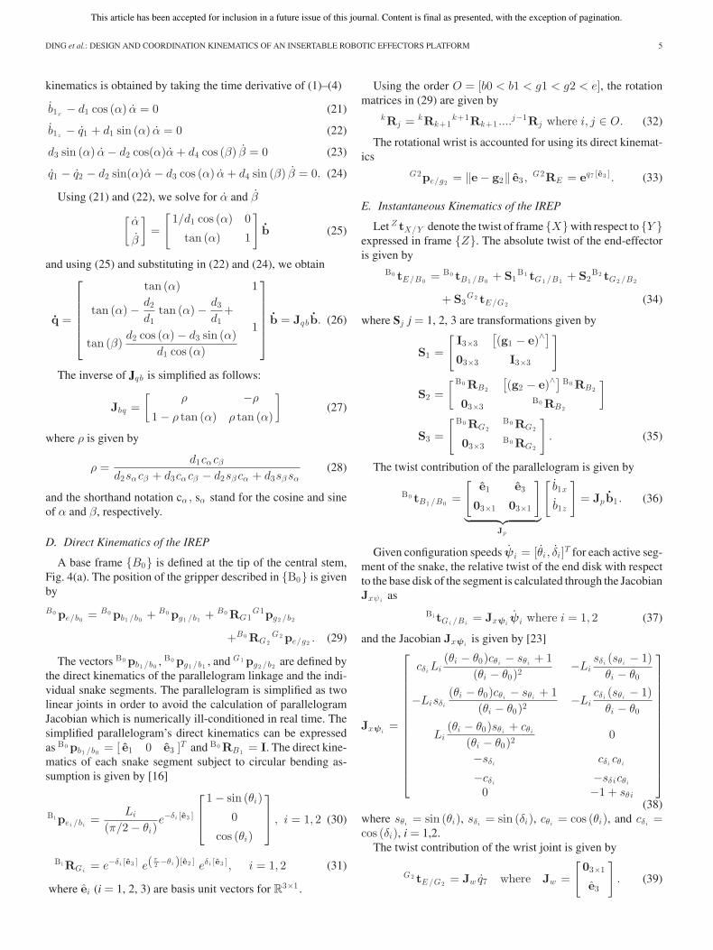
Fig. 4. Nomenclature of a single dexterous arm of the IREP: (a) definition ofpoints, (b) definition of the tip frame and the wrist rotation angle q7 , and (c)definition of local frames for the ith segment of the continuum robot.
Fig. 5. (a) Parallelogram mechanism with the passive snake segment. (b)Corresponding pseudo-rigid-body model (bottom).
By using the definition of the augmented configuration vectorξ and substituting (36)–(39) into (34), the instantaneous kine-matics Jacobian Jtξ is obtained
B0 tE/B0 = Jp b1 + S1Jxψ1 ψ1 + S2Jxψ2 ψ2 + S3Jw q7
= [Jp |S1Jxψ1 |S2Jxψ2 |S3Jw ]︸ ︷︷ ︸Jt ξ
= Jtξ ξ. (40)
F. Kinematic Coordination Between the ParallelogramMechanism and the Passive Segment of the Snake
The continuum robot of each arm has a passive segment thatconnects the active segments to the external actuation unit. Thebase disk of the first active segment in each arm is captured ina moving base ring controlled by the parallelogram mechanism(see Fig. 5). Proper control of the IREP robot requires solvingthe coordination kinematics between the parallelogram and thepassive stem.
The goal of the coordination control is to minimize the tensionforce along the passive snake segment. The coordination controlcalculates the required axial insertion length of the passive seg-ment as a function of the position of the parallelogram’s moving
base ring and then feed it axially through the IREP central stem.To solve the coordination problem, we use the pseudo-rigid-body approach as developed by Howell [24]. We solve for therequired length of the deflected passive stem as a function ofa desired position of the parallelogram’s moving base ring. Let(a,b) be the coordinates of point b1 in the xz plane of frame{B0}, Fig. 5. According to the pseudo-rigid-body model, thecoordinates of the beam tip are given as a function of the beamtip deflection angle, a characteristic radius factor γ, and the di-rection of the external load in xz plane of frame {B0}. We useparameter n to designate the direction of force that the parallel-ogram’s moving base ring applies on the passive segment of thesnake such that p is the x-component, np is the z–component, and√
1 + n2p is the force magnitude. The passive stem is only sub-jected to x-direction force. The characteristic radius γ = 0.8517is used in the pseudo-rigid-body model to describe the shape.Therefore, the coordinates of point b1 are given by
b1 − b0 =
⎡⎢⎣
a
0
b
⎤⎥⎦ =
⎡⎢⎣
lγ sin (Θ)
0
l (1 − γ (1 − cos (Θ)))
⎤⎥⎦ (41)
where l designates the length of the passive segment of the snakerobot measured from point b0 to b1 and the pseudo-rigid-bodybeam angle Θ is shown in Fig. 5(b) and defined in [24, eq.(5.58)].
By solving for sin (Θ) and cos (Θ) from the first and thirdequation in (41) and substituting in the identity cos2 (Θ) +sin2 (Θ) = 1, a quadratic equation for the length of the pas-sive stem is obtained
l2 (1 − 2γ) + l (2aγ − 2a) + a2 + b2 = 0. (42)
The only physically valid solution to this equation leads to apositive length
l =−a + aγ +
√a2γ2 − b2 + 2γb2
2γ − 1. (43)
Equation (43) is used to control the length of the passive stemby feeding the snake actuation unit with the passive stem alongthe axis of the central stem, as shown in Fig. 14.
V. DESIGN SPECIFICATIONS FOR THE ACTUATION UNIT
The dimensions of the IREP snake arms are listed in Ta-ble IV. The length of the two active segments of each snake andthe travel of the parallelogram mechanism were determined bythe required surgical workspace via iterated direct kinematicssimulations that validated the coverage of the desired surgicalworkspace as listed in Table I.
A. Snake Joint Actuation Speed Requirements
The end-effector of IREP should be able to move fast to pro-vide end-effector speeds congruent with manual surgeon per-formance in open surgery. Being more conservative in derivingthe design requirements for the actuation unit, we calculatedthe required joint speed by using only four bending joints fromthe two active segments of snake. The two-stage snake Jacobian

This article has been accepted for inclusion in a future issue of this journal. Content is final as presented, with the exception of pagination.
DING et al.: DESIGN AND COORDINATION KINEMATICS OF AN INSERTABLE ROBOTIC EFFECTORS PLATFORM 7
TABLE IVGEOMETRIC DIMENSIONS OF THE IREP SNAKE ARMS
can be easily derived by taking columns 3–6 out of (34), thusresulting in
B1 tE/B1 = [S1Jx1 ψ1 |S2Jx2 ψ2 ][θ1 δ1 θ2 δ2
]T. (44)
To calculate the desired joint speeds, we first sample the 4-Dspace of all possible combinations of configuration space speedsmi = ( θ1i , δ1i , θ2i , δ2i )T where ‖mi‖ = 1. Unit vectorsmi , i = 1, . . ., n, are parameterized by three angles νj ∈ [0, 2π],j = 1,. . ., 3
mi = [cν1 isν2 i
sν3 i, sν1 i
sν2 isν3 i
, cν2 isν3 i
, cν3 i]T (45)
where cνjand sνj
stand for cosine and sine of νj . These columnvectors are augmented in a matrix M4×n .
The resulting end-effector velocity ˙x corresponding to unitvector configuration speeds along each ray in M is given by
˙x3×n = [S1Jx1 ψ1 |S2Jx2 ψ2 ]M4×n . (46)
Then, the required configuration space speeds that result inmaximal desired velocity ‖x‖max = 30mm/s can be calcu-lated by scaling up the column unit vectors in M as ψψ4×n =[ a1m1 · · · , anmn ] where the scaling factors are calculatedby ai = ‖x‖max /
∥∥ ˜xi
∥∥, i = 1, . . ., n.Given the required configuration speed, the required joint
speeds are given by
Q = Jψq ψψ4×n where
Jψq =
⎡⎢⎢⎣
sin (δ + β)r sin (β)
− sin (δ)r sin (β)
cos (δ) cos (δ + β)q1 sin (β)
− cos2 (δ)q1 sin (β)
⎤⎥⎥⎦ . (47)
For the minimalistic case, only two secondary backbonesare used to control the segment. Fig. 6 shows the maximal re-quired joint speeds for two stages of snake to achieve 30 mm/sand 60 ◦/s. The simulation sweeps the two-stage snake over itsworkspace. The x-axis shows the configuration number of thesnake. The RMS value of joint speed to provide the desiredlinear velocity is 10.84 mm/s and the RMS value of joint speedto provide the rotation velocity is 8 mm/s. Although the figureshows high values of instantaneous speeds, we use the RMSvalue as a more realistic design value since we know that thesnake segments are singular at straight configuration and theseconfigurations can be easily avoided using redundancy resolu-tion with maximal joint speed avoidance. Therefore, the valueof 30 mm/s (as shown in Table I), which exceeds the RMS value,is chosen as snake actuation speed for motor selection.
Fig. 6. Maximal required joint speed for a two-stage continuum robot.
Fig. 7. Estimation of the required snake segment actuation force.
B. Force Requirements for the Snake Segments
To estimate the required actuation forces, a sweep of theworkspace of the IREP arm was conducted in simulation whilesubjecting the gripper to forces in a plane perpendicular to itslongitudinal axis. The norm of these forces was assumed to be2 N in accordance with our design specifications in Table I.The required actuation forces were estimated using a worstcase scenario in which the first segment is bent in the rangeψ1 ∈ ([0, π/2] , [−π, π]) while maintaining the second segmentfully extended (θ2 = π/2). Details of the statics calculationwere provided in [18]. For brevity, we present the results of oursimulation in Fig. 7. The figure shows that a maximal actuationforce of 56.2 N is required. Hence, the actuation unit forcespecification was set to 60 N as shown in Table I.
C. Parallelogram Joint Speed Estimation
The continuum segments are axially inextensible. Hence, thetranslational movement along the zb0 axis is predominantlyprovided by the parallelogram. Therefore, the parallelogramneeds to provide 30-mm/s speed along the z-axis. For eachconfiguration of the parallelogram, we used (26) to calculate therequired joint speeds corresponding to sampling of all possiblemovement directions in a 2-D circle with a speed of 30 mm/s.
Fig. 8 shows the required minimal joint velocity for parallelo-gram to move its base ring at 30 mm/s. The maximal joint speedis 21.07 mm/s. This value agrees with the design specificationsin Table I since the parallelogram actuation unit is built suchthat the stem insertion speed of 60 mm/s and the parallelogramrelative speed of 5 mm/s are combined together.

This article has been accepted for inclusion in a future issue of this journal. Content is final as presented, with the exception of pagination.
8 IEEE/ASME TRANSACTIONS ON MECHATRONICS
Fig. 8. Minimal joint velocity for parallelogram to carry out 30 mm/s velocity.
Fig. 9. Applied force and moment to bend the passive snake stem.
D. Estimation of the Required Actuation Forcesfor the Parallelogram Mechanisms
Using the pseudo-rigid-body model in Section IV-F, one mayobtain the reaction forces between the passive segment of thesnake and the parallelogram’s moving base ring. Using thepseudo-rigid-body static model in [24], the required force Pand moment M to bend the passive snake segment is given by
p = (2kΘΘ)/(
γl sin(π
2− Θ
))(48)
M = pl (1 + γ (1 − cos (Θ))) (49)
where kΘ = γkθEI/l is the stiffness of the equivalent torsionspring of the pseudo-rigid-body model. We calculated the bend-ing rigidity using an equivalent beam model that represents thefive NiTi backbones of the snake and their guiding Teflon tube(passive snake stem) as shown in Fig. 5(a). The Teflon tubewas laser cut to create many flexure joints at fixed intervals of3.5 mm as shown in the inset in Fig. 5. The bending stiffnesswas calculated using
kΘ = kΘ1 + 5kΘ2 + 5kΘ3 (50)
where kΘ1 , kΘ2 , and kΘ3 are the bending rigidity coefficientsof the Teflon passive stem, the five NiTi backbones of the firstsegment, and the five NiTi backbones of the second segment.
According to our calculations, we found that the maximalrequired force and moment occurred when the passive segmentwas at its shortest length and deployed a maximal amount alongxb0 . Fig. 9 shows the maximal lateral force p was calculated as2.26 N and the maximal moment M was 69.7 mN·m. ).
The required joint forces to actuate the parallelogram werefound by solving the static model of the parallelogram whileneglecting frictional forces as a first-order simplification. Wemake the simplifying assumption that the reaction force p ap-plied by the passive stem on the parallelogram’s moving base
Fig. 10. Free body diagram of the forces acting on the moving base ring ofthe parallelogram linkage.
Fig. 11. Plot of the required joint forces throughout the workspace of theparallelogram linkage for minimal q2 .
ring is concentrated at the midpoint b2 = (b1 + b1)/2. Referringto the inset in Fig. 10, the static equilibrium equations are⎧⎪⎪⎨⎪⎪⎩
p cos (μ) − R1 cos (σ) − F cos (ξ) = 0
R1 sin (σ) + F sin (ξ) + p sin (μ) = 0
M − R1 sin (σ) ‖p5 − p6‖ − p(b2 − p5
)T
yb0 = 0.
(51)
Equilibrium conditions on link p2p4p5 result in
R2 cos (β) − F cos (α − (σ − ξ)) + R3y = 0 (52)
R2 sin (β) + F sin (α − (σ − ξ)) + R3x = 0 (53)
R2 sin (β − α) ‖p2 − p7‖ − F sin (σ − ξ) ‖p2 − p5‖ = 0 (54)
where R1 , R2 , and F are internal reaction forces and angles μ,ξ, and σ are defined in Fig. 10.
Equations (51)–(54) comprise six linear equations with sixunknowns R1 , R2 , Fx = Fcos(ξ), Fy = Fsin(ξ), R3x , R3y . Therequired joint actuation forces τ 1 and τ 2 are found via projectionof R1 and R2 along the axis of joints q1 and q2
τ1 = R1 cos (α) + R3y
τ2 = R2 cos (β) . (55)
Fig. 11 shows a simulation of (55) throughout the workspaceof the parallelogram. The figure shows that the maximalactuation forces are less than 16 N for both joints. To be con-servative, we used 100 N as a design specification (as shown inTable I) for the actuation unit in order to account for frictionaleffects and applied load at the tip of the snake.
This article has been accepted for inclusion in a future issue of this journal. Content is final as presented, with the exception of pagination.
DING et al.: DESIGN AND COORDINATION KINEMATICS OF AN INSERTABLE ROBOTIC EFFECTORS PLATFORM 9
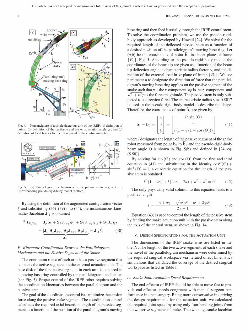
Fig. 12. Iterations of the distal wrist-gripper assembly.
VI. SYSTEM DESIGN AND DEVELOPMENT
A. Distal End Design
The IREP arms are equipped with a dexterous wrist and grip-per assembly providing fine manipulation capability to the tele-operator. The previously reported prototype wrist and gripperdesign, [25], has undergone revision to improve performancebased on initial testing. The original and modified assembliesare shown in Fig. 12.
1) Gripper: The multifunction IREP gripper serves as a tis-sue grasper, needle driver, and general manipulator. Referringto Fig. 12, a Ø0.4 mm NiTi wire linearly actuates an actuationblock along the longitudinal axis of the fixed jaw. A slot in themoving jaw constrains the motion of the moving jaw. This slotis designed with two inclination angles to provide a large jawopening angle of 35◦ while offering y large mechanical advan-tage for opening angles smaller than 7◦. The maximal grippingforce for this gripper is 40 N as presented in [15].
The initial proposed gripper design, presented in [25], used astepped contact area between the gripper halves and an asym-metrical alignment of teeth in order to ensure a stable three-pointcontact, Fig. 12(a) (inset). Initial testing suggested that the grip-per successfully constrained a circular needle with respect toforces in the plane defined by the needle and therefore couldbe advanced through tissue. However, the design could not con-strain the needle when subjected to forces out of the plane ofthe needle. Also, the small width of gripper tip was deemed notclinically useful by the surgical team.
A second iteration of the gripper was designed and fabricatedto address the limitations identified in the initial design. Theopposing gripper halves are curved to achieve local parallelfaces for needle sizes common to SPAS, Fig. 12(b) (inset) andthe distal tip size was increased.
2) Distal Wrist Design: While previous work [26], [27]demonstrated transmission of axial rotation through a contin-uum robot with proper compensation for model imperfections,a dedicated distal wrist simplifies the design and control of theoverall IREP arms. Design considerations and alternatives pre-sented in [18] showed that the use of a distal wrist increasesthe dexterity compared to using transmission of rotation about
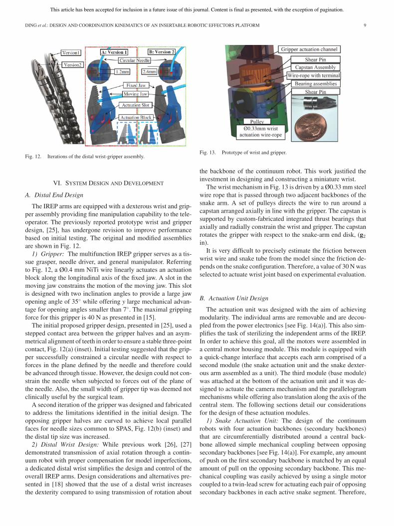
Fig. 13. Prototype of wrist and gripper.
the backbone of the continuum robot. This work justified theinvestment in designing and constructing a miniature wrist.
The wrist mechanism in Fig. 13 is driven by a Ø0.33 mm steelwire rope that is passed through two adjacent backbones of thesnake arm. A set of pulleys directs the wire to run around acapstan arranged axially in line with the gripper. The capstan issupported by custom-fabricated integrated thrust bearings thataxially and radially constrain the wrist and gripper. The capstanrotates the gripper with respect to the snake-arm end disk, (g2in).
It is very difficult to precisely estimate the friction betweenwrist wire and snake tube from the model since the friction de-pends on the snake configuration. Therefore, a value of 30 N wasselected to actuate wrist joint based on experimental evaluation.
B. Actuation Unit Design
The actuation unit was designed with the aim of achievingmodularity. The individual arms are removable and are decou-pled from the power electronics [see Fig. 14(a)]. This also sim-plifies the task of sterilizing the independent arms of the IREP.In order to achieve this goal, all the motors were assembled ina central motor housing module. This module is equipped witha quick-change interface that accepts each arm comprised of asecond module (the snake actuation unit and the snake dexter-ous arm assembled as a unit). The third module (base module)was attached at the bottom of the actuation unit and it was de-signed to actuate the camera mechanism and the parallelogrammechanisms while offering also translation along the axis of thecentral stem. The following sections detail our considerationsfor the design of these actuation modules.
1) Snake Actuation Unit: The design of the continuumrobots with four actuation backbones (secondary backbones)that are circumferentially distributed around a central back-bone allowed simple mechanical coupling between opposingsecondary backbones [see Fig. 14(a)]. For example, any amountof push on the first secondary backbone is matched by an equalamount of pull on the opposing secondary backbone. This me-chanical coupling was easily achieved by using a single motorcoupled to a twin-lead screw for actuating each pair of opposingsecondary backbones in each active snake segment. Therefore,

This article has been accepted for inclusion in a future issue of this journal. Content is final as presented, with the exception of pagination.
10 IEEE/ASME TRANSACTIONS ON MECHATRONICS
Fig. 14. Actuation unit of the IREP. (a) Actuation elements for the dexterousarms and the camera mechanism. (b) Routing of actuation lines from the actu-ation unit to the passive stem of each snake arm. (C) Three DoF actuation unitcarrying the snake arm actuation unit and actuating the parallelogram linkage.
the actuation unit of each snake arm has four twin-lead screwsfor actuating the snake segments. Fig. 14(b) shows one snakeactuation unit with only two twin-lead screws for clarity. Anadditional two lead screws were used for the wrist and gripper.
The bottom portion of this actuation unit has an assembly[the “cone” in Fig. 14(b)] that routes the NiTi actuation lines ofthe continuum robots such that they all converge into a flexibleTeflon multilumen extrusion that serves as the passive flexiblestem of each dexterous continuum robot [see Fig. 5(a)]. The conein Fig. 14(b) has a feature that allows a quick latch connectioninto the motor housing module of Fig. 14(a).
The overall weight of the snake actuation unit is 1.85 kgand fits within a 70mm ×140 mm × 220 mm volume (an initialestimate of 2.25 kg was reported in [18] based on a Pro/E model,a conservative estimates of component weights, and includingthe parallelogram actuation unit weight). This weight and sizeallow the surgeon or surgical technician to easily pull out theactuation unit and snake if a replacement is needed.
The total weight of the actuation unit shown in Fig. 14(a) isapproximately 8.20 kg (18 lb). This small weight enables easyfixation on a surgical bed such that reorientation of the pa-tient during surgery is possible without interrupting the surgicalworkflow to readjust the robot with respect to the patient.
Fig. 15. Cross section of the IREP central stem.
TABLE VRATED SPECIFICATION OF ACTUATION COMPONENTS OF IREP ACTUATION UNIT
2) Central Stem: Fig. 15 shows the cross section of the cen-tral stem previously shown in Fig. 14(a). Only 15 mm in di-ameter, this stem provides access to two dexterous arms, theactuation linkages for the camera and the parallelogram mech-anisms, and the electronic wiring for light and for the cameramodule.
3) Component Selection: The actuation components wereselected by considering multiple factors such as dimensions,power, stroke, maximal load capacity, and cost. Most of IREPjoints are actuated by pushing and pulling. Hence, we chosevarious linear actuator units to carry out IREP movement. Thespecifications of these actuators are listed in Table V. The par-allelogram joints and central stem insertion axis are actuatedby high-efficiency ball screws due to their required high loads.The joints for the snake segments are special, because they re-quire mechanical coupling using twin-lead screws as shown inFig. 14(b). Customizing a twin-lead ball screw is expensive;therefore, we chose Kerk twin-lead screws with 6.35-mm pitchand an efficiency of 79%.
Table V shows the power requirements for each axis. The mo-tor selection was made as uniform as possible for interchange-ability and cost reduction. We chose a 4.5 W Maxon motor RE16, with 29:1 gear reduction for all joints except the central steminsertion axis, which used a 6.5 W RE-max 24 with 4.3:1 gearreduction and ball screw with 2-mm pitch in order to accom-modate the gravitation forces due to the weight of the actuationunit.
VII. STEREO CAMERA SYSTEM DESIGN
A. Camera and Illumination
Although transferring internal images to an externallymounted charge-coupled device (CCD) camera using fiber op-tics is a design alternative, the cost of developing custom fiberoptics, the problems of routing them through mechanical joints,
This article has been accepted for inclusion in a future issue of this journal. Content is final as presented, with the exception of pagination.
DING et al.: DESIGN AND COORDINATION KINEMATICS OF AN INSERTABLE ROBOTIC EFFECTORS PLATFORM 11
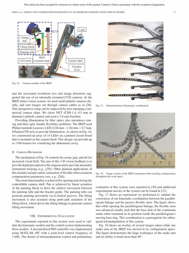
Fig. 16. Camera module of the IREP.
and the associated resolution loss and image distortion sug-gested the use of an internally mounted CCD cameras. In theIREP stereo-vision system, we used small pinhole cameras dis-tally, and sent images out through camera cables as in [28].This inexpensive setup can be improved by new emerging com-mercial camera chips. We chose NET (CSH-1.4, 6.5 mm indiameter) pinhole camera and used a 7.6-mm baseline.
Providing illumination by fiber optics also introduces rout-ing and fiber-optic bundle flexibility problems. The IREP usedPhilips lumileds Luxeon c LED (2.04 mm×1.64 mm× 0.7 mm,85lumen/350 mA) to provide illumination. As shown in Fig. 16,we constructed an array of 14 LEDs on a printed circuit boardthat is mounted on the camera head. This design can provide upto 1190 lumens for visualizing the abdominal cavity.
B. Camera Mechanism
The mechanism of Fig. 16 controls the zoom, pan, and tilt forincreased visual field. The aim of this 3-D vision feedback is toprovide depth perception to the surgeon and to provide automaticinstrument tracking (e.g., [29]). Other planned applications ofthis module include online estimation of flexible robot actuationcompensation parameters (see, e.g., [26]).
The zoom functionality is achieved by opening and closing thecontrollable camera shell. Pan is achieved by linear actuationof the panning block to drive the relative movement betweenthe panning tube and the bracket guide. The panning tube cangenerate panning movement via its helical grooves. The tiltingmovement is also actuated using push–pull actuation of thetilting block, which drives the tilting linkage to generate cameratilting movement.
VIII. EXPERIMENTAL EVALUATION
The experiments reported in this section were used to vali-date the kinematic models and the control system implementingthese models. A decentralized PID controller was implementedusing MATLAB xPC with a joint-level control frequency of1 kHz. The details of telemanipulation control and preliminary
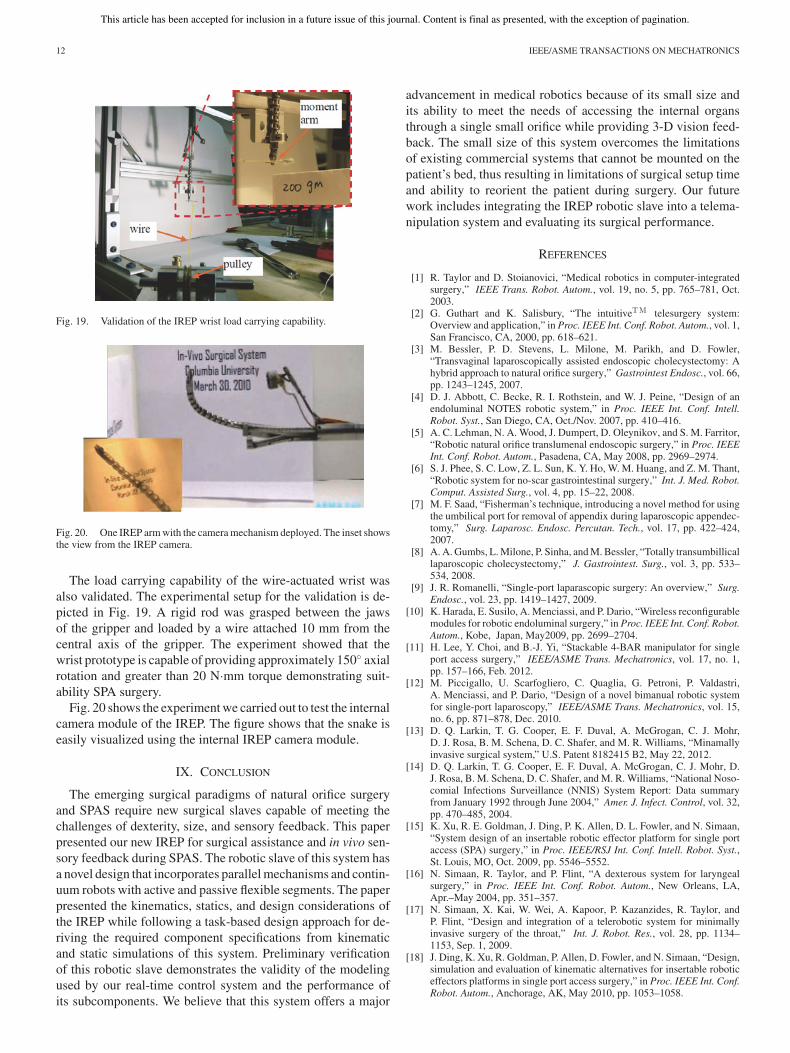
Fig. 17. Demonstration of kinematic coordination.
Fig. 18. Image overlay of the IREP continuum robot reaching configurationsthroughout the work space.
evaluation of this system were reported in [30] and additionalexperimental movies of the system can be found in [31].
Fig. 17 shows an experiment we performed to validate thecorrectness of our kinematic coordination between the parallel-ogram linkage and the passive flexible stem. The figure showsthat while opening the parallelogram linkage, the flexible stemwas advanced axially such that the base disk of the continuumsnake robot remained in its position inside the parallelogram’smoving base ring. This coordination is a prerequisite for subse-quent telemanipulation of this system.
Fig. 18 shows an overlay of several images taken while onesnake arm of the IREP was moved in its configuration space.The figure demonstrates the large workspace of the snake armand its ability to bend more than 90◦.
This article has been accepted for inclusion in a future issue of this journal. Content is final as presented, with the exception of pagination.
12 IEEE/ASME TRANSACTIONS ON MECHATRONICS
Fig. 19. Validation of the IREP wrist load carrying capability.
Fig. 20. One IREP arm with the camera mechanism deployed. The inset showsthe view from the IREP camera.
The load carrying capability of the wire-actuated wrist wasalso validated. The experimental setup for the validation is de-picted in Fig. 19. A rigid rod was grasped between the jawsof the gripper and loaded by a wire attached 10 mm from thecentral axis of the gripper. The experiment showed that thewrist prototype is capable of providing approximately 150◦ axialrotation and greater than 20 N·mm torque demonstrating suit-ability SPA surgery.
Fig. 20 shows the experiment we carried out to test the internalcamera module of the IREP. The figure shows that the snake iseasily visualized using the internal IREP camera module.
IX. CONCLUSION
The emerging surgical paradigms of natural orifice surgeryand SPAS require new surgical slaves capable of meeting thechallenges of dexterity, size, and sensory feedback. This paperpresented our new IREP for surgical assistance and in vivo sen-sory feedback during SPAS. The robotic slave of this system hasa novel design that incorporates parallel mechanisms and contin-uum robots with active and passive flexible segments. The paperpresented the kinematics, statics, and design considerations ofthe IREP while following a task-based design approach for de-riving the required component specifications from kinematicand static simulations of this system. Preliminary verificationof this robotic slave demonstrates the validity of the modelingused by our real-time control system and the performance ofits subcomponents. We believe that this system offers a major
advancement in medical robotics because of its small size andits ability to meet the needs of accessing the internal organsthrough a single small orifice while providing 3-D vision feed-back. The small size of this system overcomes the limitationsof existing commercial systems that cannot be mounted on thepatient’s bed, thus resulting in limitations of surgical setup timeand ability to reorient the patient during surgery. Our futurework includes integrating the IREP robotic slave into a telema-nipulation system and evaluating its surgical performance.
REFERENCES
[1] R. Taylor and D. Stoianovici, “Medical robotics in computer-integratedsurgery,” IEEE Trans. Robot. Autom., vol. 19, no. 5, pp. 765–781, Oct.2003.
[2] G. Guthart and K. Salisbury, “The intuitiveTM telesurgery system:Overview and application,” in Proc. IEEE Int. Conf. Robot. Autom., vol. 1,San Francisco, CA, 2000, pp. 618–621.
[3] M. Bessler, P. D. Stevens, L. Milone, M. Parikh, and D. Fowler,“Transvaginal laparoscopically assisted endoscopic cholecystectomy: Ahybrid approach to natural orifice surgery,” Gastrointest Endosc., vol. 66,pp. 1243–1245, 2007.
[4] D. J. Abbott, C. Becke, R. I. Rothstein, and W. J. Peine, “Design of anendoluminal NOTES robotic system,” in Proc. IEEE Int. Conf. Intell.Robot. Syst., San Diego, CA, Oct./Nov. 2007, pp. 410–416.
[5] A. C. Lehman, N. A. Wood, J. Dumpert, D. Oleynikov, and S. M. Farritor,“Robotic natural orifice translumenal endoscopic surgery,” in Proc. IEEEInt. Conf. Robot. Autom., Pasadena, CA, May 2008, pp. 2969–2974.
[6] S. J. Phee, S. C. Low, Z. L. Sun, K. Y. Ho, W. M. Huang, and Z. M. Thant,“Robotic system for no-scar gastrointestinal surgery,” Int. J. Med. Robot.Comput. Assisted Surg., vol. 4, pp. 15–22, 2008.
[7] M. F. Saad, “Fisherman’s technique, introducing a novel method for usingthe umbilical port for removal of appendix during laparoscopic appendec-tomy,” Surg. Laparosc. Endosc. Percutan. Tech., vol. 17, pp. 422–424,2007.
[8] A. A. Gumbs, L. Milone, P. Sinha, and M. Bessler, “Totally transumbillicallaparoscopic cholecystectomy,” J. Gastrointest. Surg., vol. 3, pp. 533–534, 2008.
[9] J. R. Romanelli, “Single-port laparascopic surgery: An overview,” Surg.Endosc., vol. 23, pp. 1419–1427, 2009.
[10] K. Harada, E. Susilo, A. Menciassi, and P. Dario, “Wireless reconfigurablemodules for robotic endoluminal surgery,” in Proc. IEEE Int. Conf. Robot.Autom., Kobe, Japan, May2009, pp. 2699–2704.
[11] H. Lee, Y. Choi, and B.-J. Yi, “Stackable 4-BAR manipulator for singleport access surgery,” IEEE/ASME Trans. Mechatronics, vol. 17, no. 1,pp. 157–166, Feb. 2012.
[12] M. Piccigallo, U. Scarfogliero, C. Quaglia, G. Petroni, P. Valdastri,A. Menciassi, and P. Dario, “Design of a novel bimanual robotic systemfor single-port laparoscopy,” IEEE/ASME Trans. Mechatronics, vol. 15,no. 6, pp. 871–878, Dec. 2010.
[13] D. Q. Larkin, T. G. Cooper, E. F. Duval, A. McGrogan, C. J. Mohr,D. J. Rosa, B. M. Schena, D. C. Shafer, and M. R. Williams, “Minamallyinvasive surgical system,” U.S. Patent 8182415 B2, May 22, 2012.
[14] D. Q. Larkin, T. G. Cooper, E. F. Duval, A. McGrogan, C. J. Mohr, D.J. Rosa, B. M. Schena, D. C. Shafer, and M. R. Williams, “National Noso-comial Infections Surveillance (NNIS) System Report: Data summaryfrom January 1992 through June 2004,” Amer. J. Infect. Control, vol. 32,pp. 470–485, 2004.
[15] K. Xu, R. E. Goldman, J. Ding, P. K. Allen, D. L. Fowler, and N. Simaan,“System design of an insertable robotic effector platform for single portaccess (SPA) surgery,” in Proc. IEEE/RSJ Int. Conf. Intell. Robot. Syst.,St. Louis, MO, Oct. 2009, pp. 5546–5552.
[16] N. Simaan, R. Taylor, and P. Flint, “A dexterous system for laryngealsurgery,” in Proc. IEEE Int. Conf. Robot. Autom., New Orleans, LA,Apr.–May 2004, pp. 351–357.
[17] N. Simaan, X. Kai, W. Wei, A. Kapoor, P. Kazanzides, R. Taylor, andP. Flint, “Design and integration of a telerobotic system for minimallyinvasive surgery of the throat,” Int. J. Robot. Res., vol. 28, pp. 1134–1153, Sep. 1, 2009.
[18] J. Ding, K. Xu, R. Goldman, P. Allen, D. Fowler, and N. Simaan, “Design,simulation and evaluation of kinematic alternatives for insertable roboticeffectors platforms in single port access surgery,” in Proc. IEEE Int. Conf.Robot. Autom., Anchorage, AK, May 2010, pp. 1053–1058.

This article has been accepted for inclusion in a future issue of this journal. Content is final as presented, with the exception of pagination.
DING et al.: DESIGN AND COORDINATION KINEMATICS OF AN INSERTABLE ROBOTIC EFFECTORS PLATFORM 13
[19] A. Dubrowski, R. Sidhu, J. Park, and H. Carnahan, “Quantification of mo-tion characteristics and forces applied to tissues during suturing,” Amer.J. Surg., vol. 190, pp. 131–136, 2004.
[20] J. Peirs, J. Clijnen, D. Reynaerts, H. V. Brussel, P. Herijgers, B. Corteville,and S. Boone, “A micro optical force sensor for force feedback duringminimally invasive robotic surgery,” Sens. Actuators A, Phys., vol. 115,pp. 447–455, 2004.
[21] G. Salmon, “Expressions of eliminants as determinants,” in LessonsIntroductory to the Modern Higher Algebra. 4th ed. London, U.K.:Elibron Classics, 1885, pp. 76–91.
[22] D. Kapur and Y. Lakshman, “Elimination methods: An introduction,” inSymbolic and Numerical Computation for Artificial Intelligence. NewYork: Academic, 1992, p. 45–87.
[23] X. Kai and N. Simaan, “An investigation of the intrinsic force sensingcapabilities of continuum robots,” IEEE Trans. Robot., vol. 24, no. 3,pp. 576–587, Jun 2008.
[24] L. L. Howell, Compliant Mechanisms. New York: Wiley, 2001.[25] K. Xu, R. Goldman, J. Ding, P. Allen, D. Fowler, and N. Simaan, “Design
and deployment animation of an insertable robotic effector platform forsingle port access (SPA) surgery,” presented at the IEEE/RSJ Int. Conf.Intell. Robot. Syst., St. Louis, MO, Oct. 2009.
[26] K. Xu and N. Simaan, “Actuation compensation for flexible surgical snake-like robots with redundant remote actuation,” in Proc. IEEE Int. Conf.Robot. Autom., May 2006, pp. 4148–4154.
[27] D. B. Camarillo, C. R. Carlson, and J. K. Salisbury, “Configuration track-ing for continuum manipulators with coupled tendon drive,” IEEE Trans.Robot., vol. 25, no. 4, pp. 798–808, Aug. 2009.
[28] T. Hu, P. K. Allen, N. Hogle, and D. Fowler, “Surgical imaging device withpan, tilt, zoom, and lighting,” Int. J. Robot. Res., vol. 28, pp. 1373–1386,2009.
[29] T. Hu, P. Allen, T. Nadkarni, N. Hogle, and D. Fowler, “Insertable stereo-scopic 3D surgical imaging device with pan and tilt,” in Proc. 2nd IEEERAS EMBS Int. Conf. Biomed. Robot. Biomechatron., Scottsdale, AZ, Oct.2008, pp. 311–316.
[30] A. Bajo, R. E. Goldman, L. Wang, D. Fowler, and N. Simaan, “Integrationand preliminary evaluation of an insertable robotic effectors platform forsingle port access surgery,” in Proc. IEEE Int. Conf. Robot. Autom., St.Paul, MN, May2012, pp. 3381–3387.
[31] Telemanipulation movies of the IREP. (2012). [Online]. Available:http://www.youtube.com/watch?v = WRfUG94CBvo.
Jienan Ding (M’09) received the B.E., M.E., andPh.D. degrees in mechatronics from the Departmentof Mechanical Engineering, Tianjin University, Tian-jin, China, in 2002, 2004, and 2008, respectively.
From 2008 to 2010, he was a Postdoctoral Re-search Scientist at Columbia University, New York,NY. In 2010, he was at Meka Robotic as a ResearchEngineer. Since 2011, he has been a Senior ControlEngineer at Hstar Technologies, Inc., Boston, MA.His research interests include medical applicationsof robotic technologies which includes surgical robot,
rehabilitation robots, and humanoid robots for hospital and home care.
Roger E. Goldman (M’07) received the B.Sc. de-gree in mechanical engineering from Stanford Uni-versity, Stanford, CA, in 2002, and the Ph.D. degreein biomedical engineering from Columbia Univer-sity, New York, NY, in 2012, where he is currentlyworking toward the M.D. degree in the College ofPhysicians and Surgeons.
In 2003, he joined Foxhollow Technologies, Inc.,Redwood City, CA, as a Research and DevelopmentEngineer, where he developed catheters for endovas-cular procedures. He is currently a National Institutes
of Health Medical Scientist Training Program Fellow at Columbia University.His current research interests include novel robotic instruments for applicationsin medical diagnosis and therapy.
Kai Xu (S’06–M’11) received the B.E. and M.S.degrees from the Department of Precision Instru-ments and Mechanology, Tsinghua University, Bei-jing, China, in 2001 and 2004, respectively, and thePh.D. degree (with distinction) from the Departmentof Mechanical Engineering, Columbia University,New York, NY, in 2009.
Since 2010, he has been with the University ofMichigan–Shanghai Jiao Tong University Joint Insti-tute, Shanghai Jiao Tong University, Shanghai, China,where he is currently an Assistant Professor and the
Director of the Robotics Innovation and Intervention Laboratory. His researchinterests include medical and surgical robotics, humanoid and service robotics,production automation, mechanism design, and continuum mechanics.
Peter K. Allen (S’82–M’85) received the A.B. de-gree in mathematics economics from Brown Univer-sity, Providence, RI, the M.S. degree in computerscience from the University of Oregon, Eugene, andthe Ph.D. degree in computer science from the Uni-versity of Pennsylvania, Philadelphia.
He is currently a Professor of computer science atColumbia University, New York, NY. His current re-search interests include robotic grasping, 3-D visionand modeling, and medical robotics.
Dr. Allen was the recipient of the CBS Founda-tion Fellowship, Army Research Office Fellowship, and the Rubinoff Award forinnovative uses of computers. In recognition of his research, he has been nameda Presidential Young Investigator by the National Science Foundation.
Dennis L. Fowler received the M.D. degree from theUniversity of Kansas School of Medicine, KansasCity, in 1973.
He is currently the Gerald and Janet Carrus Profes-sor of Clinical Surgery and the Director of the Sim-ulation Center, Columbia University Medical Cen-ter, and New York Presbyterian Hospital/CU. He isalso the Director of the Reemtsma Center for Innova-tion and Outcomes Research, Department of Surgery,Columbia University. He has recently completed aterm on the GI Advisory Council of the American
Board of Surgery. As a clinical surgeon, his research is focused on minimallyinvasive surgery and surgical education and on outcomes research, technologydevelopment, and the use of simulation for training and assessment in health-care.
Dr. Fowler is a Fellow of the American College of Surgeons and a memberof the Society of American Gastrointestinal Endoscopic Surgeons.
Nabil Simaan (M’04) received the B.Sc., M.Sc., andPh.D. degrees in mechanical engineering from theTechnion—Israel Institute of Technology, Haifa, Is-rael, in 1996, 1999, and 2002, respectively.
During 2003, he was a Postdoctoral Research Sci-entist at The Johns Hopkins University National Sci-ence Foundation (NSF) Engineering Research Centerfor Computer-Integrated Surgical Systems and Tech-nology, where he was involved in research on mini-mally invasive robotic assistance in confined spaces.In 2005, he joined Columbia University, New York,
NY, as an Assistant Professor of mechanical engineering and the Director ofthe Advanced Robotics and Mechanisms Applications Laboratory, where hebecame an Associate Professor in 2010. He subsequently joined VanderbiltUniversity, Nashville, TN, in Fall 2010.
Dr. Simaan received an NSF Career Award for young investigators to designnew algorithms and robots for safe interaction with the anatomy in 2009.