ieee transactions on smart grid 1 a hybrid simulation
TRANSCRIPT

This article has been accepted for inclusion in a future issue of this journal. Content is final as presented, with the exception of pagination.
IEEE TRANSACTIONS ON SMART GRID 1
A Hybrid Simulation Model for VSC HVDCYury S. Borovikov, Alexandr S. Gusev, Almaz O. Sulaymanov, Ruslan A. Ufa, Aleksey S. Vasilev,
Mikhail V. Andreev, Nikolay Yu. Ruban, and Aleksey A. Suvorov
Abstract—The motivation for the presented research is basedon the needs to develop new methods and tools for obtaining theinformation required to evaluate the mutual influence of HVDCand HVAC systems. This paper presents the specialized concept ofa hybrid simulation for advanced modeling of VSC HVDC. Theresults obtained by the prototype of specialized hybrid processorof VSC HVDC model confirm the effectiveness of the proposedapproach with respect to the detailed representation of com-mutation process of real power semiconductors and possibilityof real-time simulation of all the processes in VSC and EPSas a whole without any decomposition and limitation on theirduration.
Index Terms—Power system simulation, real-time systems,hybrid simulation technology, VSC HVDC.
I. INTRODUCTION
THE GROWING complexity of EPS (electric power sys-tem) poses new challenges to ensure its reliability and
stability. At the same time, the progress achieved in powerelectronics has demonstrated the HVDC (High-voltage directcurrent) technologies effectiveness in solution of conventionaltasks such as asynchronous interconnection, long distancetransmission, increasing the local and systemic controllabil-ity of EPS, as well as the relatively new challenges relatedwith integration of the distributed renewable energy sourcesinto HVAC (High-voltage alternating current) system [1]–[3].
Converter based on power semiconductors is the main ele-ment of these technologies. Currently, the scheme of HVDCbased on two types of converters - line commutated con-verter (LCC) and voltage-source converter (VSC) - is usedin EPS. It should be noted that VSC based on fully con-trolled high-speed power switches (IGBT, GTO) has severaladvantages compared to LCC [2], [4], [5], such as:
• the independent control of active and reactive power;• the provision of reverse of power flow without changing
the polarity of the voltage.
Manuscript received December 17, 2014; revised April 25, 2015 andSeptember 12, 2015; accepted November 23, 2015. This work was supportedin part by the Framework of Realisation of Strategic Programme on NationalResearch Tomsk Polytechnic University Competitiveness Enhancement inthe Group of Top Level World Research and Academic Institutions,and in part by the Competitiveness Enhancement Program of TomskPolytechnic University (Project_Leading Research University_Institute ofPower Engineering_138_2014). Paper no. TSG-01233-2014.
The authors are with the Department of Electrical Power System, Instituteof Power Engineering, Tomsk Polytechnic University, Tomsk 634050, Russia(e-mail: [email protected]; [email protected]; [email protected]; [email protected];[email protected]; [email protected]; [email protected]; [email protected]).
Color versions of one or more of the figures in this paper are availableonline at http://ieeexplore.ieee.org.
Digital Object Identifier 10.1109/TSG.2015.2510747
At the same time, the possibility of parallel-series connec-tions and a high speed commutation of power semiconductors(switching time of the IGBT (Insulated-gate bipolar transistor)is 5 µs) allow the formation of a more sinusoidal wave of volt-age, which consequently reduces the Total harmonic distortion,and as a result, the optimization of parameters of the HVDCfilter on the AC (alternating current) side.
The flexibility and high speed controllability of VSC HVDCenable to use them as additional voltage regulation and damp-ing of low frequency oscillations in the EPS, caused by a shortcircuit, disconnection of generators and etc. [1], [6].
Nevertheless, the practical necessity of relevant research andanalysis to ensure safe and reliable operation of these tech-nologies and EPS in general are emphasized by many researchgroups and engineers [7]–[9].
The most complex and urgent tasks include [10], [11]:• the analysis of the mutual influence of HVDC and HVAC
systems, including their control and protection upon eachother and the EPS as the whole, especially in transientconditions;
• the development, testing and adjustment of thelocal and systemic automatic control and protectionsystems.
A solution of these tasks requires full-scale experiments inreal EPS, which cannot be conducted. Therefore, the controland monitoring system (like a Wide Area Control System)and hard- and software simulation tools are the main sourcesused to obtain the information required for analysis of theEPS operation [8]. Study of experience of their applicationin practice allows us to define advantages and disadvantagesof these approaches and identify promising directions of thedevelopment of methods and tools of EPS analysis. One ofthe most striking examples of the application of the controland monitoring system for the EPS analysis containing HVDCtechnologies can be viewed in the EPS of South China [8].According to [8], the received for several years emergencyshutdown data of HVDC, that led to cascading failures andseparation of EPS, ensured the development of effective con-figuration of automatic control system (ACS) of hybrid HVACand HVDC systems and the prevention of similar accidents inthe future.
There are some weaknesses in this approach:• the high complexity associated with the analysis of
disturbance processes in case of low observability ofthe EPS;
• the limited applicability of the measurement results to setup the ACS of hybrid HVAC and HVDC systems;
• the occurrence of previously unobserved disturbances;
1949-3053 c© 2016 IEEE. Personal use is permitted, but republication/redistribution requires IEEE permission.See http://www.ieee.org/publications_standards/publications/rights/index.html for more information.

This article has been accepted for inclusion in a future issue of this journal. Content is final as presented, with the exception of pagination.
2 IEEE TRANSACTIONS ON SMART GRID
• the existence of a wide range of all possible pre-emergency modes of EPS;
• the significant time resources required for the variousexperiments in a real EPS and further analysis of obtainedresults.
That is why the control and monitoring system can not beregarded as a primary source of information for the analysis ofthe mutual influence of HVDC and HVAC systems. However,it can be used to verify the results of EPS simulation [8], [9].At the same time, the reliability and adequacy of the simu-lation results will depend on the chosen simulation methodsand tools.
The rest of this paper is organized as follows. Section IIintroduces the HVDC simulation challenges and proposesalternative tools based on hybrid real time simulation concept.Section III presents the VSC HVDC simulation includingadequate representation of commutation process of real IGBTand experimental research of the 2-level VSC HVDC modelin EPS. Conclusions are stated in Section IV.
II. THE SIMULATION CHALLENGES
To solve the problem of the reliability and adequacy of thesimulation processes in a real VSC HVDC the modeling sys-tem should take into account the specifics of the operation ofthese devices, in particular:
• the phase-phase operation of VSC;• the use of high-speed fully controlled power
semiconductors;• the continuous high-speed operation in all possible nor-
mal, emergency and post-emergency operating conditionsof EPS.
Furthermore, to solve the above mentioned prob-lems, the simulation systems should meet the followingrequirements [10], [12], [13]:
• the models of EPS elements must be three-phase(or more) to account properly for all the unbalancedconditions;
• the simulator must be capable (scalable) to implement anEPS model of any size;
• the simulation of EPS must exclude the decompositionof processes and limitations on their duration (withoutseparation of electromagnetic and electromechanical tran-sient processes modeling in power equipment and EPS asa whole);
• the real-time simulation and the possibility of intercon-nection with external devices and systems.
Currently, digital modeling complexes are widely used foranalysis of the EPS (RTDS, HYPERSIM [9], [14] and others).These complexes have shown to be successful in the simula-tion of electromagnetic transients and closed loop testing ofACS, but the numerical integration methods used in digitalsimulation tools do not enable to perform real time simu-lations of EPS without processes of decomposition over anunlimited period of time because of the integration time stepissue.
Additionally, the digital simulation of large EPS is affectedby problems associated with the limitations on the size of
a model solved by a single processor. Thus, the model par-titioning and application of the travelling wave transmissionline models to connect the parts of a power system modeldistributed between several processors is required. A trick ofthe application of the travelling wave model is that a travelingtime of a transmission line has to be greater or equal to anintegration time step which is not always accessible and thusmay require forced correction of inductance and capacitancevalues of a transmission line model.
The distribution of EPS model limits the number of pro-cessors, that can be connected to one node, and leads toforced simplifications and equivalent representations of powerequipment and EPS models. These limitations of digital mod-eling complexes are shown in simulation of short transmissionline (in back-to-back HVDC system), or simulation of Multi-terminal HVDC projects with a short DC (direct current)link [15].
At the same time the issue of simulating in real time largeEPS without separation of electromagnetic and electromechan-ical transient processes is not solved in full [16], [17]. Thisstatement is confirmed by observed trends in research anddevelopment of hybrid simulation tools, based on applicationof different numerical simulation methods [7], [15]–[17].
However, after the detailed analysis of some of mentionedin [16] and [17] hybrid complexes obviously that requireddetailed and comprehensive modeling of EPS is not fullyachieved. Thus, in [17] to analyze the processes caused byfaults in HVDC convertors authors used simulation time steparound 50 µs, whereas the switching time of Gate turn-off thyristor is about 30 µs, for IGBT 5 µs. Besides thedata exchange between the used complexes is carried out withbigger simulation time step than the simulation time step ofelectromagnetic transients modeling.
To solve mentioned issue of real time simulation of HVDCsystems and EPS as a whole, the hybrid simulation technologybased on the application of analog, digital and physical model-ing approaches and realized in Hybrid Real-time Simulator ofEPS (HRTSim), developed in Tomsk Polytechnic University,is proposed.
The results of the development and research of the VSCmodel, realized in HRTSim, are shown in this article.
A. The Concepts of Hybrid Simulation of EPS
The concept of hybrid simulation is based on the use ofthree modeling approaches: analog, digital and physical, eachof which achieves maximum efficiency in solving individualsubtasks. A detailed description of the concepts and tools ispresented in [18] and [19].
The basic points of the concepts are:• the power equipment of EPS is described via complete
systems of differential equations adequately representingthe whole significant range of quasi-steady and transientprocesses in this equipment and forming comprehen-sive mathematical models of corresponding types of thesimulated equipment;
• the methodologically accurate with guaranteed instrumen-tal error solution of differential equation systems in real

This article has been accepted for inclusion in a future issue of this journal. Content is final as presented, with the exception of pagination.
BOROVIKOV et al.: HYBRID SIMULATION MODEL FOR VSC HVDC 3
Fig. 1. The structural diagram of the SHP of the VSC HVDC model:MPU - microprocessor unit; CPU - central processing unit; P1 ADC andP2 ADC - processors of analog-to-digital converters; PC 1-4 - commutationprocessors; HCP R&F - reactor and filter hybrid coprocessors; HCP Tr -transformer hybrid coprocessors; HCP DC - hybrid coprocessor of the directcurrent circuit; U/i - integrated microelectronic voltage-current converters;L&TCo - longitudinal-transverse commutators, VSC 1 and VSC 2 - physi-cal models of the power semiconductors of VSC topology simulated at thephysical model level via integrated microelectronic digitally controlled analogswitches (DCAS).
time and over an unlimited period of time are carried outby means of the continuous implicit integration method;
• all types of commutation of power equipment, includingthe power semiconductors, are carried out on a modelphysical level;
• the interconnection between a physical model and math-ematical simulation levels is provided by means ofappropriate voltage-current converters;
• a mutual conversion of mathematical and model phys-ical variables in conjunction with simulation on thephysical model level of the commutation of power equip-ment provides the ability of unlimited scalability of thesimulated EPS;
• all informational and control functions, as well as mod-eling control and protection systems are implemented ona digital level using a digital-to-analog, analog-to-digitalconversion and specialized local and server software.
The given concept is realized in the specialized soft-ware and hardware hybrid complex - Hybrid Real-TimeSimulator (HRTSim) of EPS.
Specialized hybrid processor (SHP) is the basic element ofthe modular structure of the HRTSim and provides an adequatecomprehensive simulation in the real-time of power equipmentmodels, as well as control and protection systems.
In Figure 1 and 2 the structure and appearance of the devel-oped experimental SHP of the 2-level VSC HVDC modelare shown.
According to the above concept, the solution of compre-hensive mathematical models of the simulated equipment iscarried out via the hybrid coprocessors (HCP). The resultof solution is transmitted to the MPU (microprocessor unit)via the PADC (processors of analog-to-digital converter). Thewhole range of data transformations required to oversee the
Fig. 2. Appearance of the experimental SHP of the VSC HVDC model.
process of simulation, as well as real-time control of param-eters of the modeled power equipment, depending on thedesired solution speed of a control algorithm, are implementedin the MPU.
The universality of the concept and modular structure ofthe HTRSim allow the development of a model of any ele-ment of EPS, including devices and HVDC, and to integratethem into the HTRSim, as well as to provide interconnectionwith various external software and hardware tools: operationalinformation systems, SCADA system etc. [20].
III. VSC SIMULATION
To create an adequate model of HVDC it is necessary to pro-vide completeness and accuracy of the process description inthe steady-state and transient operating conditions, determinedby modeling implementation errors at all the mentioned digital,analog, and physical levels of simulation. Digital simulationis carried out only for the control system of HVDC.
Modeling errors at the physical model level lead to a devia-tion of loss level, distortion of voltage and current waveformson both the DC and AC side in the significant frequencyspectrum of the EPS. Based on this, the simulation of pro-cess at the physical model level is critical to the modelingresults, especially for the pulse mode of VSC. Errors at thislevel can be caused by incorrect characteristics of powersemiconductors or parameters of the DC circuit. The latterproblem is successfully solved by the selection of components.The characteristics of the physical models of power semicon-ductors require additional analysis and will be addressed infuture works.
A. Simulation of Commutation Process
As mentioned above, the physical model level is particularlyimportant, because at this level an operation of power switchesis modeled via integrated microelectronic digitally controlledanalog switches (DCAS).
This article has been accepted for inclusion in a future issue of this journal. Content is final as presented, with the exception of pagination.
4 IEEE TRANSACTIONS ON SMART GRID
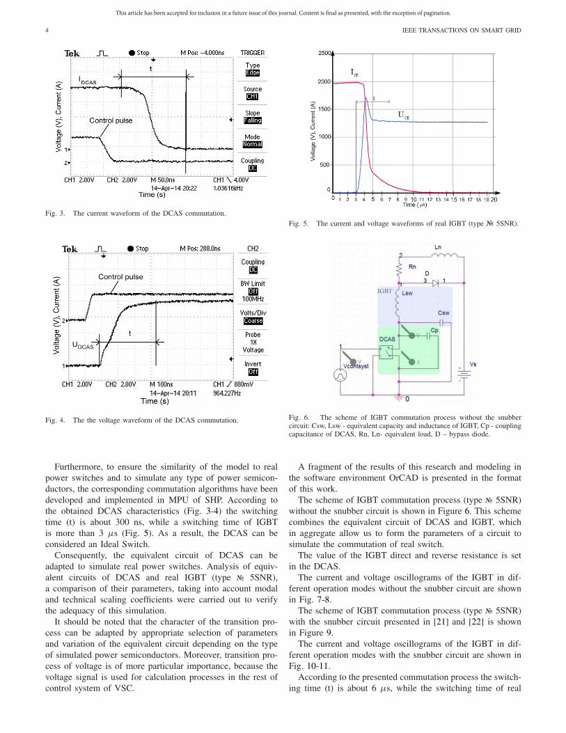
Fig. 3. The current waveform of the DCAS commutation.
Fig. 4. The the voltage waveform of the DCAS commutation.
Furthermore, to ensure the similarity of the model to realpower switches and to simulate any type of power semicon-ductors, the corresponding commutation algorithms have beendeveloped and implemented in MPU of SHP. According tothe obtained DCAS characteristics (Fig. 3-4) the switchingtime (t) is about 300 ns, while a switching time of IGBTis more than 3 µs (Fig. 5). As a result, the DCAS can beconsidered an Ideal Switch.
Consequently, the equivalent circuit of DCAS can beadapted to simulate real power switches. Analysis of equiv-alent circuits of DCAS and real IGBT (type 5SNR),a comparison of their parameters, taking into account modaland technical scaling coefficients were carried out to verifythe adequacy of this simulation.
It should be noted that the character of the transition pro-cess can be adapted by appropriate selection of parametersand variation of the equivalent circuit depending on the typeof simulated power semiconductors. Moreover, transition pro-cess of voltage is of more particular importance, because thevoltage signal is used for calculation processes in the rest ofcontrol system of VSC.
Fig. 5. The current and voltage waveforms of real IGBT (type 5SNR).
Fig. 6. The scheme of IGBT commutation process without the snubbercircuit: Csw, Lsw - equivalent capacity and inductance of IGBT, Cp - couplingcapacitance of DCAS, Rn, Ln- equivalent load, D – bypass diode.
A fragment of the results of this research and modeling inthe software environment OrCAD is presented in the formatof this work.
The scheme of IGBT commutation process (type 5SNR)without the snubber circuit is shown in Figure 6. This schemecombines the equivalent circuit of DCAS and IGBT, whichin aggregate allow us to form the parameters of a circuit tosimulate the commutation of real switch.
The value of the IGBT direct and reverse resistance is setin the DCAS.
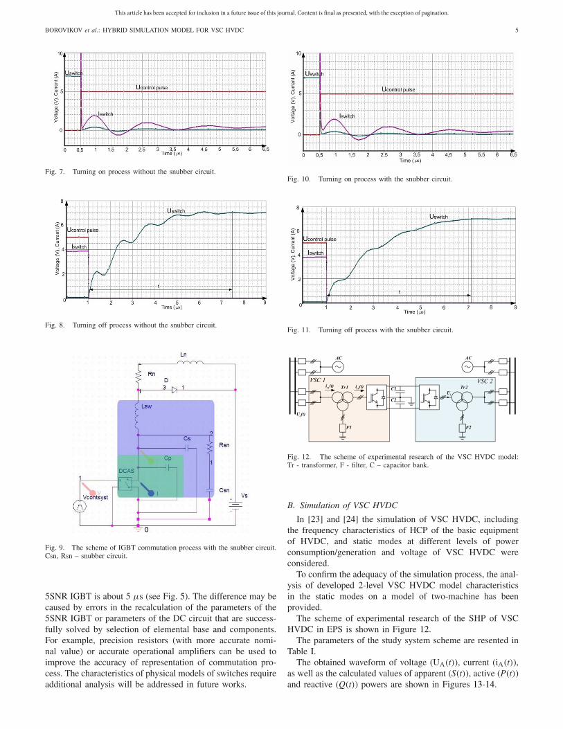
The current and voltage oscillograms of the IGBT in dif-ferent operation modes without the snubber circuit are shownin Fig. 7-8.
The scheme of IGBT commutation process (type 5SNR)with the snubber circuit presented in [21] and [22] is shownin Figure 9.
The current and voltage oscillograms of the IGBT in dif-ferent operation modes with the snubber circuit are shown inFig. 10-11.
According to the presented commutation process the switch-ing time (t) is about 6 µs, while the switching time of real
This article has been accepted for inclusion in a future issue of this journal. Content is final as presented, with the exception of pagination.
BOROVIKOV et al.: HYBRID SIMULATION MODEL FOR VSC HVDC 5
Fig. 7. Turning on process without the snubber circuit.
Fig. 8. Turning off process without the snubber circuit.
Fig. 9. The scheme of IGBT commutation process with the snubber circuit.Csn, Rsn – snubber circuit.
5SNR IGBT is about 5 µs (see Fig. 5). The difference may becaused by errors in the recalculation of the parameters of the5SNR IGBT or parameters of the DC circuit that are success-fully solved by selection of elemental base and components.For example, precision resistors (with more accurate nomi-nal value) or accurate operational amplifiers can be used toimprove the accuracy of representation of commutation pro-cess. The characteristics of physical models of switches requireadditional analysis will be addressed in future works.
Fig. 10. Turning on process with the snubber circuit.
Fig. 11. Turning off process with the snubber circuit.
Fig. 12. The scheme of experimental research of the VSC HVDC model:Tr - transformer, F - filter, C – capacitor bank.
B. Simulation of VSC HVDC
In [23] and [24] the simulation of VSC HVDC, includingthe frequency characteristics of HCP of the basic equipmentof HVDC, and static modes at different levels of powerconsumption/generation and voltage of VSC HVDC wereconsidered.
To confirm the adequacy of the simulation process, the anal-ysis of developed 2-level VSC HVDC model characteristicsin the static modes on a model of two-machine has beenprovided.
The scheme of experimental research of the SHP of VSCHVDC in EPS is shown in Figure 12.
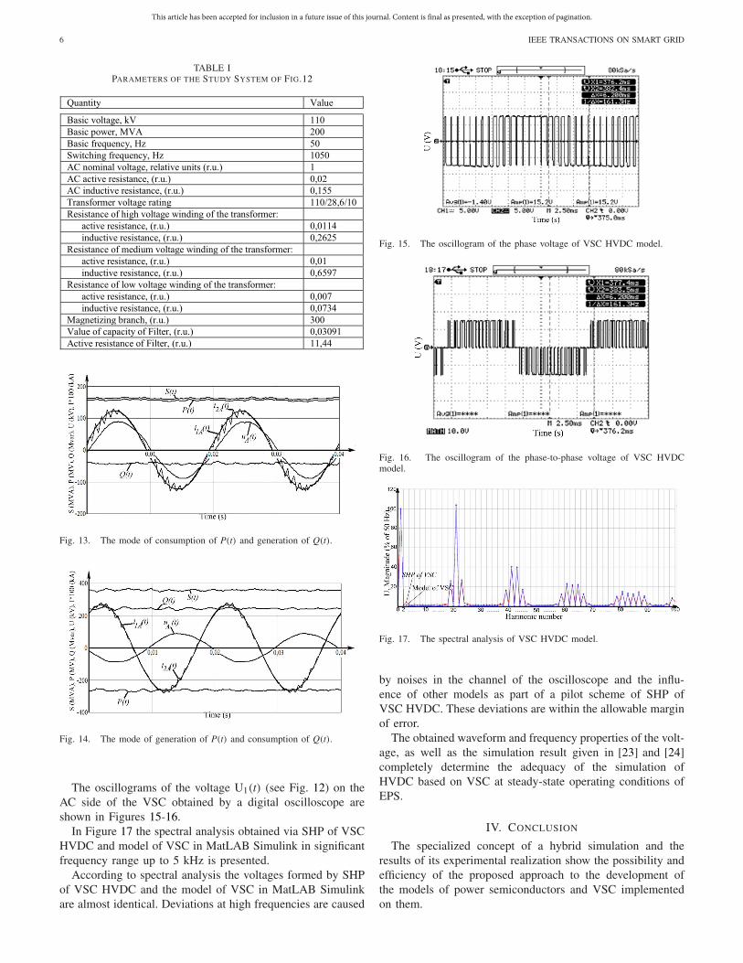
The parameters of the study system scheme are resented inTable I.
The obtained waveform of voltage (UA(t)), current (iA(t)),as well as the calculated values of apparent (S(t)), active (P(t))and reactive (Q(t)) powers are shown in Figures 13-14.
This article has been accepted for inclusion in a future issue of this journal. Content is final as presented, with the exception of pagination.
6 IEEE TRANSACTIONS ON SMART GRID
TABLE IPARAMETERS OF THE STUDY SYSTEM OF FIG.12
Fig. 13. The mode of consumption of P(t) and generation of Q(t).
Fig. 14. The mode of generation of P(t) and consumption of Q(t).
The oscillograms of the voltage U1(t) (see Fig. 12) on theAC side of the VSC obtained by a digital oscilloscope areshown in Figures 15-16.
In Figure 17 the spectral analysis obtained via SHP of VSCHVDC and model of VSC in MatLAB Simulink in significantfrequency range up to 5 kHz is presented.
According to spectral analysis the voltages formed by SHPof VSC HVDC and the model of VSC in MatLAB Simulinkare almost identical. Deviations at high frequencies are caused
Fig. 15. The oscillogram of the phase voltage of VSC HVDC model.
Fig. 16. The oscillogram of the phase-to-phase voltage of VSC HVDCmodel.
Fig. 17. The spectral analysis of VSC HVDC model.
by noises in the channel of the oscilloscope and the influ-ence of other models as part of a pilot scheme of SHP ofVSC HVDC. These deviations are within the allowable marginof error.
The obtained waveform and frequency properties of the volt-age, as well as the simulation result given in [23] and [24]completely determine the adequacy of the simulation ofHVDC based on VSC at steady-state operating conditions ofEPS.
IV. CONCLUSION
The specialized concept of a hybrid simulation and theresults of its experimental realization show the possibility andefficiency of the proposed approach to the development ofthe models of power semiconductors and VSC implementedon them.

This article has been accepted for inclusion in a future issue of this journal. Content is final as presented, with the exception of pagination.
BOROVIKOV et al.: HYBRID SIMULATION MODEL FOR VSC HVDC 7
The obtained results allow us to carry out a detailed rep-resentation of commutation process of IGBT and adequatemodeling of spectral analysis of VSC, as well as comprehen-sive real-time simulation of all the processes in HVDC andEPS as a whole without any decomposition and limitation ontheir duration.
REFERENCES
[1] P. Thepparat, D. Retzmann, E. Ogée, and M. Wiesinger, “Smart trans-mission system by HVDC and FACTS,” in Proc. IEEE Towards CarbonFree Soc. Through Smarter Grids, Grenoble, France, Jun. 2013, pp. 1–6.
[2] A. L’Abbate et al., “The role of facts and HVDC in the future paneu-ropean transmission system development,” in Proc. IEEE 9th IET Int.Conf. AC DC Power Transm., London, U.K., 2010, pp. 1–8.
[3] D. Povh, “Use of HVDC and FACTS,” Proc. IEEE, vol. 88, no. 2,pp. 235–245, Feb. 2000.
[4] J. Zhu and C. Booth, “Future multi-terminal HVDC transmission sys-tems using voltage source converters,” in Proc. 45th Int. Univ. PowerEng. Conf., Cardiff, Wales, 2010, pp. 1–6.
[5] L. Bertling and J. Setreus, “Introduction to HVDC technology for reli-able electrical power systems,” in Proc. 10th Int. Conf. Probabilist.Methods Appl. Power Syst., Rincón, Puerto Rico, 2008, pp. 1–8.
[6] N. M. Tabatabaei, N. Taheri, and N. S. Boushehri, “Damping functionof back to back HVDC based voltage source converter,” Int. J. Tech.Phys. Probl. Eng., vol. 2, no. 3, pp. 82–87, Sep. 2010.
[7] L. Chen, K.-J. Zhang, Y.-J. Xia, and G. Hu, “Hybrid simulation of±500kV HVDC power transmission project based on advanced digi-tal power system simulator,” J. Electron. Sci. Technol., vol. 11, no. 1,pp. 66–71, Mar. 2013.
[8] D. Qi, “Defense schema against large disturbances in China SouthernPowerGrid,” Electra, vol. 257, pp. 4–16, Aug. 2011.
[9] B. M. Yang, C.-K. Kim, G. J. Jung, and Y. H. Moon, “Verification ofhybrid real time HVDC simulator in Cheju-Haenam HVDC system,”J. Elect. Eng. Technol., vol. 1, no. 1, pp. 23–27, 2006.
[10] L. Zhi-Hui et al., “Modeling and simulation research of large-scaleAC/DC hybrid power grid based on ADPSS,” in Proc. IEEE PES Asia-Pac. Power Energy Eng. Conf. (APPEEC), Hong Kong, Dec. 2014,pp. 1–6.
[11] K. Ou et al., “MMC-HVDC simulation and testing based on real-timedigital simulator and physical control system,” IEEE J. Emerg. Sel.Topics Power Electron., vol. 2, no. 4, pp. 1109–1116, Dec. 2014.
[12] L. Xu, Y. H. Tang, W. Pu, and Y. Han, “Hybrid electromechanical-electromagnetic simulation to SVC controller based on ADPSS plat-form,” J. Energy South Africa, vol. 25, no. 4, pp. 112–122, Nov. 2014.
[13] O. Nayak, S. Santoso, and P. Buchanan, “Power electronics spark newsimulation challenges,” IEEE Comput. Appl. Power, vol. 15, no. 4,pp. 37–44, Oct. 2002.
[14] L. Snider, J. Bélanger, and G. Nanjundaiah, “Today’s power sys-tem simulation challenge: High-performance, scalable, upgradable andaffordable COTS-based real-time digital simulators,” in Proc. JointInt. Conf. Power Electron. Drives Energy Syst. (PEDES) Power India,New Delhi, India, Dec. 2010, pp. 1–10.
[15] P. A. Forsyth, T. L. Maguire, D. Shearer, and D. Rydmell, “Testingfiring pulse controls for a VSC based HVDC scheme with a real timetimestep < 3 µs,” in Proc. Int. Conf. Power Syst. Transients, Kyoto,Japan, Jun. 2009, pp. 1–5.
[16] Y. Zhang, A. M. Gole, W. Wu, B. Zhang, and H. Sun, “Developmentand analysis of applicability of a hybrid transient simulation platformcombining TSA and EMT elements,” IEEE Trans. Power Syst., vol. 28,no. 1, pp. 357–366, Feb. 2013.
[17] Z. Xiao-Xin et al., “Concept and mechanism on full-process dynamicreal-time simulation of power system with parallel-in-time-space,” inProc. Int. Conf. Power Syst. Technol. (POWERCON), Hangzhou, China,Oct. 2010, pp. 1–7.
[18] A. Prokhorov, Yu. Borovikov, and A. Gusev, “Real time hybrid simu-lation of electrical power systems: Concept, tools, field experience andsmart grid challenges,” Int. J. Smart Grid Clean Energy, vol. 1, no. 1,pp. 67–68, Sep. 2012.
[19] M. Andreev and A. Sulaymanov, “Platform based on hybrid real-timepower system simulator for development and research of intelligentpower systems with active-adaptive networks,” in Proc. IEEE EindhovenPowerTech, Eindhoven, The Netherlands, 2015, pp. 1–6.
[20] A. Prokhorov, Y. S. Borovikov, and A. S. Gusev, “Hardware-in-the-looptestbed based on hybrid real time simulator,” in Proc. IEEE Innov. SmartGrid Technol. Europe, Lyngby, Denmark, 2013, pp. 1–5.
[21] A. A. Andreas, “A novel test method for minimising energy costsin IGBT power cycling studies,” Ph.D. dissertation, Dept. Fac. Eng.Built Environ., Univ. Witwatersrand, Johannesburg, South Africa, 2006,pp. 1–207.
[22] L. Max, “Energy evaluation for DC/DC converters in DC-Based windfarms,” M.S. thesis, Dept. Energy Environ., Chalmers Univ. Technol.,Gothenburg, Sweden, 2007, pp. 1–151.
[23] A. Prokhorov, R. Ufa, and A. Vasilev, “Synthesis of hybrid modelsfor advanced simulation of HVDC systems,” Int. J. Smart Grid CleanEnergy, vol. 3, no. 2, pp. 207–213, Apr. 2014.
[24] R. Ufa, V. Sulaymanova, and A. Gusev, “Hard- and software of realtime simulation tools of electric power system for adequate modelingpower semiconductors in voltage source convertor based HVDC andFACTS,” in Proc. MATEC Web of Conf., vol. 19. Les Ulis, France, 2014,Art. ID. 01029.
Yury S. Borovikov was born in Ust-Kamenogorsk,Kazakhstan, in 1978. He received the D.Sc.(Tech.) degree in electrical engineering from TomskPolytechnic University, Tomsk, Russia, in 2014.
He is currently an Associate Professor ofElectrical Power System Department, Institute ofPower Engineering, Tomsk Polytechnic University.His research interests include simulation of powersystems based on FACTS controllers and active-adaptive networks.
Alexandr S. Gusev was born in Dushanbe,Tajikistan, in 1947. He received the D.Sc. (Tech.)degree in electrical engineering from TomskPolytechnic University, Tomsk, Russia, in 2000.
He is an Associate Professor of Electrical PowerSystem Department, Institute of Power Engineering,Tomsk Polytechnic University. His main fields ofinterest are hybrid simulation technology of powersystem and smart grids.
Almaz O. Sulaymanov was born in Frunze,Kyrgyzstan, in 1967. He received the Engineeringand Ph.D. degrees from Tomsk PolytechnicUniversity, in 1991 and 2009, respectively.
He is an Associate Professor and the Headof Research Laboratory Electrical Power SystemSimulation of Electrical Power System Department,Institute of Power Engineering, Tomsk PolytechnicUniversity. His main fields of interest are powersystem simulation, protection, automation, andcontrol system.
Ruslan A. Ufa was born in Nikitinka, Kazakhstan,in 1988. He received the M.Sc. degree from TomskPolytechnic University, in 2012.
He is currently an Assistant of Electrical PowerSystem Department and an Engineer of ResearchLaboratory Electrical Power System Simulation,Tomsk Polytechnic University. His research inter-ests include simulation of power systems based onHVDC system and smart grids.

This article has been accepted for inclusion in a future issue of this journal. Content is final as presented, with the exception of pagination.
8 IEEE TRANSACTIONS ON SMART GRID
Aleksey S. Vasilev was born in Tomsk, Russia, in1986. He received the M.Sc. and Ph.D. degrees fromTomsk Polytechnic University, in 2009 and 2013,respectively.
He is currently a Lecturer of Electrical PowerSystem Department, Institute of Power Engineering,Tomsk Polytechnic University. His research inter-ests include simulation of power systems based onFACTS controllers and active-adaptive networks.
Mikhail V. Andreev was born in Sorsk, Russia,in 1987. He received the Engineering and Ph.D.degrees from Tomsk Polytechnic University, in 2010and 2013, respectively. He is currently an AssociateProfessor of Electrical Power System Departmentand an Engineer of Research Laboratory ElectricalPower System Simulation, Institute of PowerEngineering, Tomsk Polytechnic University. Hisresearch interests include simulation of smart grids,control systems, relay protection, and automation.
Nikolay Yu. Ruban was born in Ust-Kamchatsk,Russia, in 1988. He received the Engineering andPh.D. degrees from Tomsk Polytechnic University,in 2010 and 2014, respectively. He is cur-rently a Senior Lecturer of Electrical PowerSystem Department and an Engineer of ResearchLaboratory Electrical Power System Simulation,Institute of Power Engineering, Tomsk PolytechnicUniversity. His research interests include simulationof smart grids, control systems, relay protection, andautomation.
Aleksey A. Suvorov was born in Tomsk, Russia,in 1990. He received the Diploma degree in engi-neering from Tomsk Polytechnic University, in 2014.He is currently an Assistant of Electrical PowerSystem Department and a Postgraduate Student ofTomsk Polytechnic University. His research inter-ests include simulation electric power systems andvalidation of electric power system simulation tools.