ieee transactions on services computing,...
TRANSCRIPT

1939-1374 (c) 2017 IEEE. Personal use is permitted, but republication/redistribution requires IEEE permission. See http://www.ieee.org/publications_standards/publications/rights/index.html for moreinformation.
This article has been accepted for publication in a future issue of this journal, but has not been fully edited. Content may change prior to final publication. Citation information: DOI 10.1109/TSC.2017.2723006,IEEE Transactions on Services Computing
IEEE TRANSACTIONS ON SERVICES COMPUTING, MANUSCRIPT ID 1
Research on the Architecture and its Implementation for Instrumentation and
Measurement Cloud Hengjing He, Wei Zhao, Songling Huang, Geoffrey C. Fox, and Qing Wang
Abstract—Cloud computing has brought a new method of resource utilization and management. Nowadays some researchers
are working on cloud-based instrumentation and measurement systems designated as Instrumentation and Measurement
Clouds (IMCs). However, until now, no standard definition or detailed architecture with an implemented system for IMC has
been presented. This paper adopts the philosophy of cloud computing and brings forward a relatively standard definition and a
novel architecture for IMC. The architecture inherits many key features of cloud computing, such as service provision on
demand, scalability and so on, for remote Instrumentation and Measurement (IM) resource utilization and management. In the
architecture, instruments and sensors are virtualized into abstracted resources, and commonly used IM functions are wrapped
into services. Users can use these resources and services on demand remotely. Platforms implemented under such
architecture can reduce the investment for building IM systems greatly, enable remote sharing of IM resources, increase
utilization efficiency of various resources, and facilitate processing and analyzing of Big Data from instruments and sensors.
Practical systems with a typical application are implemented upon the architecture. Results demonstrate that the novel IMC
architecture can provide a new effective and efficient framework for establishing IM systems.
Index Terms—Architecture, cloud computing, distributed computing, instrumentation and measurement cloud, parallel
processing, power system state estimation, cloud service
—————————— ——————————
1 INTRODUCTION
INCE instrumentation and measurement (IM) technol-ogy is closely combined with information technology,
development in information technology (IT) can lead to the advance of IM technology. In the early stages, com-puters were used to control instruments and sensors for local data acquisition and analysis. Later on, virtual in-strumentation technology was developed and many of the functions that were implemented by hardware in in-struments can now be achieved by computer software. With the development of networks and the internet, re-mote instrumentation and measurement (RIM) emerged as a new technology in IM field [1]. Such RIM technology has brought many benefits to related areas, especially to those areas that involve large distributed systems [2]. It can greatly facilitate instrument control and data acquisi-tion and processing. Additionally, new computing para-digms, such as grid computing, can be integrated into IM technology to further improve the ability for data pro-cessing, and resource sharing and management of dis-tributed IM systems [3]. Grid-enabled instrumentation
and measurement system (GEIS) is a typical type of those systems. GEIS brings many advantages to data intensive IM applications and heterogeneous IM resource man-agement. However, due to some limitations of grid com-puting, IM systems that integrate a grid are eventually not widely adopted in practical use.
Currently, most IM systems are built upon local archi-tecture or traditional client/server (C/S) architecture as explained in [4]. In a local IM architecture, such as the main architecture of the NI LabVIEW platform, instru-ments and sensors are connected directly to the computer and it is difficult to build large IM systems. As for C/S architecture, instruments and sensors simply provide remote access interfaces through gateway servers to cli-ents. However, both architectures require the user to build the entire IT system and to maintain all resources. Thus, there has to be a great investment in building the whole IM system and, besides, system stability, scalability and fault tolerance can be serious problems for both ar-chitectures. Moreover, to satisfy resource requirement for peak and valley load, the IM system should be built ac-cording to the peak load at the very beginning and, even if the load drops, the system cannot scale down accord-ingly. Therefore, the utilization rate of resource in the IM system can be quite low, especially for those systems with great load dynamics. In addition to the problems men-tioned above, large amounts of data collected from vari-ous devices need much more powerful computing re-sources for processing and analyzing, and traditional computing paradigms may be incapable of dealing with such scenarios.
xxxx-xxxx/0x/$xx.00 © 200x IEEE Published by the IEEE Computer Society
————————————————
Hengjing He is with the State Key Lab. of Power System, Department of Electrical Engineering, Tsinghua University, Beijing, 100084, China. E-mail: [email protected].
Wei Zhao is with the State Key Lab. of Power System, Department of Electrical Engineering, Tsinghua University, Beijing, 100084, China. E-mail: [email protected].
Songling Huang is with the State Key Lab. of Power System, Department of Electrical Engineering, Tsinghua University, Beijing, 100084, China. E-mail: [email protected].
Geoffrey C. Fox is with the School of Informatics and Computing and CGL, Indiana University, Bloomington, USA. E-mail: [email protected].
Qing Wang is with the School of Engineering and Computing Sciences, Durham University, Durham, UK. E-mail: [email protected]
S

1939-1374 (c) 2017 IEEE. Personal use is permitted, but republication/redistribution requires IEEE permission. See http://www.ieee.org/publications_standards/publications/rights/index.html for moreinformation.
This article has been accepted for publication in a future issue of this journal, but has not been fully edited. Content may change prior to final publication. Citation information: DOI 10.1109/TSC.2017.2723006,IEEE Transactions on Services Computing
2 IEEE TRANSACTIONS ON SERVICES COMPUTING, MANUSCRIPT ID
In recent years, the emergence of cloud computing has brought many new approaches for resource utilization and management [5]. Cloud manages all resources as a resource pool and provides those resources as online ser-vices to end users according to their demand. Such modes can greatly increase the utilization efficiency of resources and, at the same time, save the investment of users on both hardware and software resources [6]. Moreover, big data processing and analysis technologies developed along with cloud computing make data analysis much easier and faster in the IM field [7]. Motivated by these benefits, many researchers are exploring novel cloud based IM technologies to solve the problems above [8]. Until now, most of the work carried out in the interdisci-plinary area of IM and cloud computing mainly focuses on the application of cloud computing in IM systems, which can only deal with a few aspects of related prob-lems. Little research has been carried out to build novel IM modes and architectures that can inherit the essence of cloud computing for IM systems.
This paper introduces a novel IMC architecture with detailed system implementations. The architecture ab-stracts instruments and sensors into resources, and en-capsulates frequently used modules and functions into services. Services are deployed in the cloud and users can consume these services on demand. IM applications are also deployed and run in the IMC platform. All IT re-sources are allocated and managed by the IAAS (Infra-structure as A Service) cloud platform, which will reduce investments for users and also increase resource utiliza-tion efficiency. By integrating cloud computing and big data processing technologies, IMC can benefit a lot from advantages such as system scalability, fault tolerance, distributed and parallel computing, and so on. An actual system based on this architecture is implemented using various cloud computing and big data processing frame-works. Applications and experiments are designed to test the system. Results show that the IMC architecture de-signed in this paper can properly integrate cloud compu-ting with IM technologies and greatly facilitate building, managing and using IM systems.
The remainder of this paper is organized as follows: section 2 presents related work; section 3 introduces key concepts of IMC; section 4 describes the detailed IMC architecture designed by this paper; section 5 illustrates the implementation of the architecture; section 6 provides some applications and tests over the IMC system; section 7 discusses challenges and limitations of IMC; and finally, section 8 concludes the whole paper.
2 RELATED WORK
Most of the work related to IMC mainly focuses on the following areas: Grid-enabled instrumentation systems (GEIS) [9], sensor clouds [10] and instrumentation clouds [11].
GEIS mainly focuses on converting instruments into grid services [12], so that heterogeneous instrumentation resources can be accessed and managed through a grid, which can facilitate data intensive applications to use var-
ious grid resources and provide distributed instrumenta-tion and experiment collaborations over the grid [13]. In GEIS, instruments are abstracted into unified services through middleware technologies and standard models. Typical GEISs include Instrument Element [14] architec-ture from the GridCC project, common instrument mid-dleware architecture [15], e-infrastructure for remote in-strumentation from the DORII project [3] and virtual la-boratory architecture [16].
Although GEIS provides a good way for distributed instrumentation and collaborative experiments over the grid, limitations of grid computing, such as complexity, constrained accessibility and so on, prevented it from prevailing among scientific and industrial areas. However, some of the research work in GEIS, regarding common aspects, can guide the study of IMC. Data retrieval and transmission approach in distributed IM systems is an important one of those aspects. Through comprehensive research, [12] and [17] demonstrated that pub-lish/subscribe mechanisms are more efficient for real-time data collecting and transmitting in a distributed IM environment. Thus, in the work of this paper, a message-based publish/subscribe mechanism is adopted as the information and data dissemination method.
Just like IMC, sensor cloud is also a very new concept. In [18] a sensor cloud infrastructure is developed and physical sensors are abstracted into virtual sensor objects. Such virtual sensor objects combined with related sensor definition templates can provide measurement services to end users. Besides, service and accounting models are designed, which makes the sensor cloud infrastructure conform to the philosophy of cloud computing. Another project working on cloud-based sensing systems is S4T (Stack4Things) [19]. This project is the base for the #SmartME [20] project, which mainly focuses on morph-ing a city into a smart city. The S4T project is trying to build up a cloud platform for managing a large number of sensors and actuators deployed in a distributed envi-ronment. One of the main ideas of the S4T project is vir-tualizing sensors and actuators into abstract resources similar to those resources in cloud computing and providing sensing and actuating services through the S4T platform. Thus, the S4T platform is also viable for build-ing a sensor cloud but it is more focused on building a cloud on the edge of a sensor network. Some other re-searchers also use the terminology ‘sensor cloud’, but most of them only concentrate on the application of cloud computing technology in sensor control and management [21],[22],[23],[24]. Sensors are much simpler than instru-ments, however they can also be treated as instruments, only with less functions.
Current studies of instrumentation clouds only bring forward conceptual models and architectures with few details or implementations provided [11],[25],[26]. Some other research work is mainly about applications of cloud computing in massive data storage and processing [27],[28],[29], which, as explained before, only provide solutions for a few of the problems faced by current IM systems.
Compared with the above research, the work of this

1939-1374 (c) 2017 IEEE. Personal use is permitted, but republication/redistribution requires IEEE permission. See http://www.ieee.org/publications_standards/publications/rights/index.html for moreinformation.
This article has been accepted for publication in a future issue of this journal, but has not been fully edited. Content may change prior to final publication. Citation information: DOI 10.1109/TSC.2017.2723006,IEEE Transactions on Services Computing
HENGJING HE ET AL.: RESEARCH ON THE ARCHITECTURE AND ITS IMPLEMENTATION FOR INSTRUMENTATION AND MEASUREMENT CLOUD 3
paper has the following advantages: (1) the IMC platform developed in this paper is more open and easier to access than GEIS; (2) the IMC platform can manage both sensors and instruments, and provide commonly used IM func-tions as on-demand, scalable services to end users; (3) the IMC system implemented according to the IMC architec-ture in this paper is a real cloud platform for the IM field, rather than just an application of cloud computing tech-nologies in the IM field. All these advantages are achieved by adopting a cloud-based resource manage-ment and usage mode, and using state-of-the-art technol-ogies from cloud computing and big data fields. Details will be presented in the following sections.
3 INSTRUMENTATION AND MEASUREMENT CLOUD
Currently, no standard definition for IMC is presented. This section brings up a relatively standard definition for IMC and related elements by adopting key ideas of cloud computing in the IM field.
3.1 Definition of IMC
The key ideas of cloud computing are: resource abstrac-tion and virtualization, services delivered on demand, and scalability [30]. Owing to these ideas, cloud compu-ting can provide scalable, on-demand hardware and software resources remotely. As introduced in Section 1, traditional IM systems and modes do not own such ad-vantages. To inherit these merits, it is necessary to inte-grate cloud computing and related big data technologies into IM field, and establish a novel Instrumentation and Measurement Cloud (IMC). Based on our previous work [31], a definition for IMC is brought forward below:
Definition 1. Instrumentation and Measurement Cloud(IMC) is a model, based upon cloud computing and big data frameworks, for enabling on-demand, convenient, ubiqui-tous network access to a shared pool of Instrumentation and Measurement(IM) resources(e.g. instruments, sensors, ac-tuators) and services that can be rapidly provided and re-leased with minimal interaction with resource provider and end user.
From definition 1, it can be seen that IMC contains two direct entities, resource and service, and a third hidden entity which is the IM application designed by users. To distinguish these entities from similar concepts in the tra-ditional IM field, IMC resource, IMC service and IMC application are used to feature these three entities of IMC. In this paper, IMC resource, IMC service and IMC appli-cation are also called IMC elements in general.
3.2 Definition of IMC resource
Definition 2. Instrumentation and Measurement Cloud re-source stands for virtualized instrument, sensor or actuator resources that are connected to IMC through the network for online sharing and management.
As can be seen from the above definition, computing resources are not included in IMC resources. The reason why we define IMC resource this way is that computing
resources, such as the CPU, storage and the network, are managed and provided by cloud computing frameworks of IMC, and, to IMC, they play the role of service.
Unlike computing, storage and networking resources, instruments and sensors have heterogeneous software and hardware architectures, which means it is very diffi-cult to virtualize them into a unified resource pool and at the same time keep their full features. However, thanks to virtual instrumentation (VI) technology and standard sensor models, many of the modern instruments and sen-sors can provide unified access interfaces. However, such interfaces are designed just for local drivers. To virtualize those IM devices into IMC resources, interface remapping through the network is required. Generally, there are two ways to remap the interfaces, as shown in Fig. 1.
Instruments and sensors
Virtual Instrumentation
Drivers/Sensor model
Local
RP
C F
ram
ew
ork
Network
Remote access interfaces
Physical interfaces
RPC Server
RPC Client
Instruments and sensors
Local
Physical interfaces
Physical interface
remapping server
Physical interface
remapping client
Network
Ph
ysi
cal
inte
rface r
em
app
ing
Drivers
(a) Software interface remapping (b) Physical interface remapping
Fig. 1. Remote instrument or sensor interface remapping
Fig. 1(a) shows a software interface remapping scheme using the remote procedure call (RPC) approach. Such a scheme is more data-oriented, since it mainly focuses on manipulating data exchanged between physical devices and up-level applications. This method is easier but less flexible. For different VI frameworks or sensor models, corresponding RPC modules should be developed.
The second method, illustrated in Fig. 1(b), remotely maps physical interfaces, such as USB [32], RS-232, GPIB and many others, to the cloud side, thus IM device con-nections to those interfaces will be forwarded to the cloud. Physical interface remapping is a device-oriented design which is more concerned about the device itself rather than the data generated from the device and it supports full features of the device. However, implementation of this method is much more difficult, especially for high-speed interfaces such as PCIE, than that of the software interface remapping approach. Furthermore, in this method, each IMC resource should be attached to a VM in the cloud. An IM system based on physical interface re-mapping is more like a traditional IM system. Unless there are special requirements, it is better to use software interface remapping for IM device virtualization.
3.3 Definition of IMC service
Definition 3. Instrumentation and Measurement Cloud ser-vice stands for online, scalable, shared IM functions, cloud computing resource services and big data processing services that can be consumed through IMC by IMC applications on demand.
The definition of IMC service is close to the concept of

1939-1374 (c) 2017 IEEE. Personal use is permitted, but republication/redistribution requires IEEE permission. See http://www.ieee.org/publications_standards/publications/rights/index.html for moreinformation.
This article has been accepted for publication in a future issue of this journal, but has not been fully edited. Content may change prior to final publication. Citation information: DOI 10.1109/TSC.2017.2723006,IEEE Transactions on Services Computing
4 IEEE TRANSACTIONS ON SERVICES COMPUTING, MANUSCRIPT ID
SAAS (Software as a Service) in cloud computing [33]. In IMC, commonly used IM functions are encapsulated into online services. Users can consume those services on de-mand and all those services are running in IMC. When consuming IMC services, users just need to send data to input interfaces of IMC services and retrieve results from output interfaces.
3.4 Definition of IMC application
Definition 3. Instrumentation and Measurement Cloud appli-cation is the application program that consumes IMC re-sources and IMC services, and carries out custom logics to fulfill user defined IM tasks.
Although the IMC platform can provide remote access to IMC services and IMC resources, it still requires the user to organize those services and manipulate related resources to carry out specific IM tasks. Since most of the computation-intensive data processing procedures can be implemented into IMC services deployed in IMC plat-forms, IMC applications are normally light-weighted. By developing web-based online IDE (Integrated Develop-ment Environment), IMC can provide PAAS (Platform as a Service) services to users, so that end users can develop, deploy and run IMC applications online through a web browser. In this case, building a distributed IM system will be much easier, since all IM resources and commonly used IM functions can be obtained online through IMC.
3.5 Instrumentation and Measurement mode in the IMC
The instrumentation and measurement mode in the IMC can be depicted as in Fig. 2.
Instrument
Sensor
Other IM
device
Instrumentation and Measurement Cloud
IMC resource 1
IMC resource 2
IMC resource 3
IMC
application 1
IMC
application 2
IMC service 1
IMC service 2
IMC service 3
Cloud computing platform and big data framework
Acc
ess c
ontro
l
Web b
ase
d u
ser in
terfa
ces
IMC user
IMC administrator
IMC resource owner
Fig. 2 Instrumentation and measurement mode in the IMC
In Fig. 2, there is an IMC user, an IMC administrator and an IMC resource owner. The IMC user normally con-sumes IMC resources and IMC services, and develops IMC applications to carry out IM tasks. The IMC adminis-trator is responsible for building and maintaining the IMC platform. All IMC resources are provided and main-tained by IMC resource owners. While IMC services can be developed by any of them, it is the IMC administra-tor’s responsibility to check the quality of services and decide whether to deploy and publish them or not. As shown in Fig. 2, with a web-based user interface and ac-cess control, IMC users can request IMC resources and IMC services, and develop IMC applications online. By deploying IMC applications in the IMC platform, IMC users no longer need to invest in, establish and maintain the whole ICT (Information and Communication Tech-nology) system for their IM tasks. Instead, they can use
resources and services provided by the IMC platform according to their need.
The above definitions have clarified the basic function requirements and characteristics of IMC. In the following section, a novel IMC architecture, which owns the above important characteristics, will be presented.
4 NOVEL ARCHITECTURE FOR INSTRUMENTATION
AND MEASUREMENT CLOUD
The overall IMC architecture designed in this paper is shown in Fig. 3. This architecture mainly consists of six parts, which are coordination system, message broker, IMC resource agent, IMC service pool, IMC application executor and IMC manager. Details of each part will be presented in the following sections.
Running on IAAS platforms
Coordination system
Streaming
processing
services
Batch
processing
services
Other services
IMC service pool IMC
application
executor
IMC
application 1
IMC
application 2
...Message
broker
...
Conn
ecte
d b
y n
etw
ork
Sensors Instruments
IMC resource agent
RPC framework
Device drivers:
VISA/IVI/Other
Instrumentation and Measurement Cloud
Sensors Instruments
IMC resource agent
RPC framework
Device drivers:
VISA/IVI/Other
IMC
resource
manager
IMC
service
manager
IMC
application
manager
IMC manager
IMC scheduler
Fig. 3 Novel architecture for IMC
4.1 Coordination system and Message broker
The Coordination system records all configuration data and management data of living IMC services, IMC resources and IMC applications. As the IMC architecture in Fig. 3 is distributed, the coordination system should have a distributed synchronization mechanism for data manipulation. The coordination system should also support event notification, so that events from the three IMC elements can be discovered across the architecture and corresponding actions can be taken.
The message broker is the core component for data transmission. Data exchanges between IMC applications, IMC services and IMC resources are mainly achieved by the message broker. As illustrated in section 2, the effective and efficient way to transmit data in a distributed environment is via a publish/subscribe based messaging mechanism, thus a publish/subscribe based message broker is a good choice for data transmission in IMC. To transmit data over the message broker, a related client of the message broker should be integrated into IMC elements.
4.2 IMC resource agent
The IMC resource agent is responsible for instrument and sensor virtualization and IMC resource registration.

1939-1374 (c) 2017 IEEE. Personal use is permitted, but republication/redistribution requires IEEE permission. See http://www.ieee.org/publications_standards/publications/rights/index.html for moreinformation.
This article has been accepted for publication in a future issue of this journal, but has not been fully edited. Content may change prior to final publication. Citation information: DOI 10.1109/TSC.2017.2723006,IEEE Transactions on Services Computing
HENGJING HE ET AL.: RESEARCH ON THE ARCHITECTURE AND ITS IMPLEMENTATION FOR INSTRUMENTATION AND MEASUREMENT CLOUD 5
As illustrated in section 3.2, instruments and sensors can be virtualized through VI frameworks and standard sensor models. By virtualization, instruments and sensors are encapsulated into IMC resources with standard access interfaces. Assisted by RPC frameworks, these interfaces can be called remotely from IMC applications in the cloud, which will bring much convenience for building distrib-uted IM systems.
Once virtualized, these IM resources can be registered into IMC by the IMC resource agent, so that users can use them over networks. To use IMC resources, users should first make a reservation for each resource through the IMC manager. After reservation, an access id with start and end time stamps will be allocated to IMC applica-tions and the IMC resource agent, and also, the entry of the resource, such as the URL of the IMC resource agent, will be sent to IMC applications. When IMC applications want to access the reserved resources, firstly, they will have to send the access id to the IMC resource agent through that entry, and the IMC resource agent will then check if it also has the same access id and whether the current time is between the reserved time span. If all re-quirements are satisfied, the IMC resource agent will allo-cate a resource handler for the IMC application and allow the IMC application to use the IMC resource through RPC interfaces for instrumentation and measurement tasks.
The complete procedure for registering and using IMC resources in the IMC is depicted through the UML activi-ty diagram shown in Fig. 4.
IMC resource
agent
IMC resource
manager
IMC application
manager
IMC
application Coordination
system
Register
IMC resource Write management data of the IMC resource
Return data writing status
Write dataReturn
registration
status
Schedule
IMC resource
Return IMC
resource entry
IMC
scheduler
Write
schedule
Return IMC
resource
entry
Write data
Activate IMC resourceActivate
IMC resource
IM
resource
Bind IM resource
Return IM resource instance
Request IMC resource
Return IMC
resource entry
Reserve IMC resource
Activate IM resource
Use IMC
resource
Return
IM data
Release IMC resourceRelease IMC
resource
Release IM resource
Fig. 4 Steps required for registering and consuming IMC resources in the IMC
4.3 IMC service pool
In IMC, services represent modularized function blocks implemented in big data analyzing and cloud computing frameworks. Such IMC services include stream data pro-cessing modules, batch processing modules and other function modules. IMC services are normally developed and deployed in parallel with distributed big data pro-cessing platforms. Each type of service can serve multiple IM applications and the platform or framework running these services will provide scaling, parallel processing and fault tolerance abilities. Services and applications in
IMC are connected by a publish/subscribe based message broker.
The message broker is used to transmit data between IMC services, IMC resources and IMC applications. Cur-rently, many message brokers support clustering, which means brokers can support fault tolerance. However, overheads from message headings and message routing can degrade data transmission performance. To deal with this problem, some message brokers support light mes-sage headings and a simple message routing scheme. This can increase message processing and transmission speed, but at the same time reduce flexibility and functionality of the broker. Other brokers can provide more flexible con-trol over message transmission and fault tolerance by adding extra information to messages, but this will bring more overheads. IMC service providers should choose the broker according to their needs.
All services in IMC should register themselves through the IMC manager. When registering, the IMC manager will create data entries for each IMC service in the coor-dination system and write management data of services into those entries. Normally, each IMC service has several input and output interfaces. For input interfaces of a ser-vice, the IMC manager will write message broker topics to which they are listening to their data entries and, if IMC applications are to consume this service, they can get those topics through the IMC manager and then publish messages to those topics. To get processed data from the IMC service, IMC applications need to write topics to which their sink modules are listening to data entries of the service’s output interfaces.
As for stream data processing services, each of them has several input and output interfaces. Input interfaces will listen to dedicated message topics and, as for output interfaces, they will watch on a cache that stores destina-tion message topics for outputting data.
For batch processing services, file systems and data-bases constitute the data sources. In most cases, batch processing is an off-line post-processing approach, but IM systems normally deal with real-time stream data; thus, batch-processing services will not be studied in this paper. However, batch-processing services are still indispensable to the whole IMC architecture.
To enable the parallel and distributed computing par-adigm and enhance the ability of fault tolerance for IMC services, three key roles should be followed when devel-oping IMC services:
1. Reduce coupling and dependency between data. On-ly in this way can the service be implemented in a parallel computing paradigm.
2. Make data self-descriptive. This is very important for multiple IMC applications to share the same service instance.
3. Try to avoid state caching for IMC applications in services and use dedicated memory cache systems. Most distributed and parallel cloud computing frameworks support fault tolerance. It means that when some pro-cessing nodes go down, the system can still run in a nor-mal state by shifting tasks to other nodes. However, if those nodes cached states of IMC applications that they

1939-1374 (c) 2017 IEEE. Personal use is permitted, but republication/redistribution requires IEEE permission. See http://www.ieee.org/publications_standards/publications/rights/index.html for moreinformation.
This article has been accepted for publication in a future issue of this journal, but has not been fully edited. Content may change prior to final publication. Citation information: DOI 10.1109/TSC.2017.2723006,IEEE Transactions on Services Computing
6 IEEE TRANSACTIONS ON SERVICES COMPUTING, MANUSCRIPT ID
serve, all these states will be lost and restoring the service process can be difficult, especially for streaming pro-cessing applications. Moreover, avoiding state caching in service instances can facilitate online load transfer, which is vital to load balancing.
4.4 IMC application executor
The IMC application executor is responsible for running IMC applications that are deployed in the IMC. It often consists of a script interpreter or runtime engine. By de-ploying IMC applications into IMC, users can save the trouble of maintaining the client side. With proper user interfaces, users can access their IMC applications even through mobile terminals.
4.5 IMC manager
The kernel of the whole architecture is the IMC manager. The IMC manager contains four main components: the resource manager, the service manager, the application manager and the scheduler. All IMC resources, IMC ser-vices and IMC applications are registered and managed by the corresponding component of the IMC manager. Fig. 5 shows how the IMC manager works.
IMC resource
manager
Coordination system
IMC resource agent
Register IMC resource
Write management data
IMC application
manager
Request IMC services and IMC resources
Listen on IMC resource requests
Consume
IMC resources
IMC service
Manager
Register IMC service
Write management data
IMC application
Register IMC application and
get entries of IMC services and IMC resources
IMC serviceConsume
IMC services
IMC scheduler
Activate\Release
IMC resource
Schedule IMC services and IMC resources
Fig. 5 Details of IMC manager
As shown in Fig. 5, when registering IMC resources, the resource manager will create a data entry for each IMC resource and store their management data. Under a RPC framework, management data often contains the URL of the resource side RPC server. Another data entry that caches all reservation information of the IMC re-source is also created upon registration. Such reservation information will also be sent to the IMC resource agent for authorization purposes. A similar process happens when the service manager is registering services. Howev-er, the service manager mainly maintains management data about interfaces of each service. Service and resource requests from IMC applications are processed by the ap-plication manager. When IMC applications request ser-vices or resources, the application manager will query the coordination system, get all related management data and send these data back to applications. At the same time, some of the message broker’s context of sink modules in IMC applications will be written into data entries to which output interfaces of services are listening.
The tasks of the scheduler are IMC resource and ser-vice scheduling, load balancing and scaling of IMC ser-vices. When an IMC application requests IMC resources, the
scheduler will call related algorithms to calculate a valid time span for each IMC resource and make reservations. Load balancing and service scaling is done by online load transfer and scaling the cluster that runs the service. Howev-er, online load transfer needs the support from both the framework that runs the IMC service and the IMC service itself.
Whenever an IMC application is registered in the IMC, the IMC application manager will record all consumed ser-vices and resources. If the state of services or resources changes, an event will be sent to the application manager to trigger the state transition process of the IMC application. In addition, a change of the IMC application state can trigger state transition of related IMC resources. State transition models for IMC service, IMC resource and IMC application in IMC are shown in Fig. 6.
Reserved
Registered
Activated
Unregistered
Registered
Unregistered
Pending
Registered
Running
Unregisterede1
e2
e6
e3e4
e8
e7 e8e5e1
e2
e10
e1
e2
e8 e5 e10
e6
e9e5 e7
e8 e11
IMC Resource IMC Service IMC Application
CreatedDestroyed CreatedDestroyed CreatedDestroyed
e0e0e0e12
e12
e12
Fig. 6 State transition models of IMC service, IMC resource and IMC application in IMC. In the figure events are: e0-add element, e1-register, e2-unregister, e3-reserve, e4-cancel reservation, e5-resource invalid, e6-resrouce available, e7-resource expired, e8-application invalid, e9-application start, e10-service inva-lid, e11-application terminated, e12-destroy element.
Fig. 6 shows only very basic state transition models for the IMC architecture; however, implementation of the IMC architecture will need detailed models to handle situations that are more complicated.
To demonstrate the feasibility and advantages of the IMC architecture brought forward by this paper, a practical sys-tem implemented upon this architecture is presented.
5 IMPLEMENTATION OF THE IMC ARCHITECTURE
5.1 Coordination system and Message broker
The coordination system is used to record important con-figuration data and management data about IMC re-sources, IMC services and IMC applications in the IMC. Here, Zookeeper, which is a distributed coordination sys-tem with fault tolerance ability, is utilized to store various data. Zookeeper uses a data structure called Zookeeper path that is similar to the directory of a file system and where each node of a path can store data.
Various message brokers can be used in the IMC and, in this paper, Rabbitmq is adopted just for demonstration.
5.2 VISA based IMC resource agent
First, to verify that the architecture is viable for instru-ment and sensor virtualization, a VISA (Virtual Instru-ment Software Architecture) based IMC resource agent is implemented. The agent uses Apache Thrift RPC frame-work and all VISA driver interfaces are remotely mapped. Since Thrift supports cross language service development,

1939-1374 (c) 2017 IEEE. Personal use is permitted, but republication/redistribution requires IEEE permission. See http://www.ieee.org/publications_standards/publications/rights/index.html for moreinformation.
This article has been accepted for publication in a future issue of this journal, but has not been fully edited. Content may change prior to final publication. Citation information: DOI 10.1109/TSC.2017.2723006,IEEE Transactions on Services Computing
HENGJING HE ET AL.: RESEARCH ON THE ARCHITECTURE AND ITS IMPLEMENTATION FOR INSTRUMENTATION AND MEASUREMENT CLOUD 7
it is also used as the service framework between all serv-ers and clients in the IMC. Fig. 7 shows the details of the implemented IMC resource agent.
IMC resource manager
IMC
reso
urc
e a
gent
VISA RPC
server
IMC resource management
RPC server
IMC application
VISA RPC client
Instrument Instrument Instrument
VISA instrument driver
IMC resource activate/release
RPC client
IMC resource activate/release
RPC server
IMC resource management
RPC client
VISA resource manager
VISA instrument
resource
VISA instrument
resource
VISA instrument
resource
Fig. 7 Implementation of the IMC resource agent
As shown in Fig. 7, instrument resources are registered through IMC resource management RPC services, which are implemented in the Thrift framework. To access the instrument, each IMC resource agent needs to run a VISA RPC server and it wraps all VISA driver interfaces. How-ever, those interfaces are extended to include a third pa-rameter, which is the access ID. Such access ID contains both the name of the IMC resource and the reserved time span. The IMC resource agent will also store a set of <ac-cess ID, VISA instrument resource> maps and these maps are built up when IMC applications request IMC re-sources managed by this IMC resource agent.
Once the IMC application in the IMC needs to control an IMC resource, it will make a remote call with the ac-cess ID. On the IMC resource agent side, the agent will get the corresponding VISA instrument resource through this ID and call a local VISA instrument driver to control the instrument and then return the result to the IMC ap-plication. To make the agent as independent with OS platforms as possible, pyvisa, which is a python imple-mented frontend of VISA driver, is used as the VISA re-source manager. Although instruments and sensors are diverse in their hardware architectures and software in-terfaces, the similar implementation method can be ap-plied to virtualize them into an IMC resource as long as their interfaces are available.
As for IMC resources, the Zookeeper data paths used to record their information are shown in Fig. 8. The /instcloud/resources path is the root path for IMC resource management. When registering an IMC resource, the re-source manager of the IMC manager will create a data path according to the domain, site and the resource name. Here domain and site are used to constitute a two-level naming convention so that resource management can be more convenient and flexible. Whenever a reservation is made for an IMC resource, a duration node with a start
/instcloud/resources/[domain]/[site]/[resource]/[duration]
Resource
Management
Application
Management
Listened by
Resource Agent
Fig. 8 Management data for the IMC resource
and an end timestamp will be added as a child to the re-source node as long as the reservation is valid. The IMC resource manager will listen to such child-adding event and call the PRC client to activate the IMC resource.
5.3 Storm based IMC service for stream data processing
The next stage is to implement IM services. As explained before, IM tasks normally need to process real-time stream data, thus a stream data processing engine is re-quired and related IM function modules need to be de-veloped. In the work of this paper, Apache Storm [34] is used as the real-time stream data processing engine. Storm is a distribute parallel stream data processing en-gine, whose maximum processing speed can reach around 1 million messages per second, with fault toler-ance ability. Storm contains two types of components, which are Spout and Bolt. Spout is the data source and it can be connected to a message broker to subscribe mes-sage topics. Bolt is the process component. Spouts and Bolts compose a Topology, which carries out the stream data processing logic. Each Spout or Bolt can run multiple instances so that they can process data in parallel. In the IMC, topologies are wrapped into IMC services, with cer-tain Spouts functioning as input interfaces and some Bolts as output interfaces. Fig. 9 presents a simple example for computing electrical power to show how services in the IMC interact with IMC applications and the IMC manag-er in the cloud.
IMC service
IMC application
Coordination system
Physical
data stream
Configuration for output
interfaces of IMC services
IMC
applicatio
n m
anag
er
IMC service manager
App_A
Producer
Consume(Power_M, Input)
Power_M
Consume(Consumer, Output)
Consumer
Listen(Queue_Out_A)
App_B
Producer
Consume(Power_M, Input)
Power_M
Consume(Consumer, Output)
Consumer
Listen(Queue_Out_A)
Power, Instance1
Tuple
(<ID, A>
<v, 1>
<i, 2>)
Tuple
(<ID, A>
<p, 2>)
Tuple
(<ID, B>
<v, 2>
<i, 2>)
Tuple
(<ID, B>
<p, 4>)
Compute
Instance 1: v*i Instance 2: v*i
Input
Queue_In
Output
A->Queue_Out_A,
B->Queue_Out_B
Message
broker
Queue_In
Queue_Out_A
Queue_Out_B
Logic
connection
Configuration for output
interfaces of IMC applications
Fig. 9 An IMC service implemented through Storm to compute elec-trical power
In Fig. 9, input interfaces of an IMC service are imple-mented by instances of IMCSpout class, which is an ex-tended Spout class with a service management RPC client. When an IMC service is submitted, each IMCSpout in-stance will register the context of the message topic that this IMCSpout is listening to through the RPC client. Since Rabbitmq is used as the message broker, the de-tailed context of a message topic is wrapped into the RMQContext class. To consume an IMC service, an IMC application just needs to get the RMQContext instance of

1939-1374 (c) 2017 IEEE. Personal use is permitted, but republication/redistribution requires IEEE permission. See http://www.ieee.org/publications_standards/publications/rights/index.html for moreinformation.
This article has been accepted for publication in a future issue of this journal, but has not been fully edited. Content may change prior to final publication. Citation information: DOI 10.1109/TSC.2017.2723006,IEEE Transactions on Services Computing
8 IEEE TRANSACTIONS ON SERVICES COMPUTING, MANUSCRIPT ID
each input interface, create a Rabbitmq client correspond-ing to that context, and send data to the IMC service input interface through that Rabbitmq client.
Output interfaces are instances of an extended Bolt class named IMCBolt class with a service management client, and they will also create management data entries in Zookeeper and listen to those data paths. However, it is the IMC application manager that is responsible for writing message topic contexts to those paths. Whenever data on those paths are updated, output interfaces of an IMC service will update destination contexts. Each desti-nation context in an output interface is combined with a session ID and a module ID, which will be introduced in the following part, and each message passed to an output interface will also contain these IDs. With these IDs, out-put interfaces will know which message topic the data should be sent to. Data paths for IMC services are shown in Fig. 10.
/instcloud/services/[service name]/[service instance]
Transport Context
/in/[InputInterfaces]
/session/[sessionID]/[moduleID]
/out/[OutputInterfaces]/[sessionID]
/capacity
Transport URL
Destination
Load Capacity
Fig. 10 Management data for IMC services
In Fig. 10, /instcloud/services is the root data path for IMC service management. Under the root path are service name and instance name data path. Children under /in node are input interfaces of the IMC service and, similarly, children under /out node are output interfaces. Each child node under /in node will store a Transport Context which records the context of the message topic that the interface is listening to. Each child node under /out will store a Transport URL that tells the output interface which mes-sage broker is used for data transmission. Under each node of output interface, there are child nodes represent-ing IMC application sessions that consume output data from the output interface and each of the child nodes will store a Destination Object that records contexts of mes-sage topics for output data transmission.
The /session node and its children under each topology or service instance node are used for IMC service state management. For example, when an IMC application ses-sion releases a service, the corresponding session ID and module ID will be deleted and such deleting events will be listened to by the IMC service manager and related IMC service instances. Once such event happens, both the IMC service manager and related IMC service instances will clear cached data for that session.
The /capacity node stores load capacity of this service and the IMC manager will use this data for load balance and scaling.
5.4 IMC application developing mode
IMC applications are implemented through text program-ing language and currently only Java APIs (Application Programming Interfaces) have been developed. Four clas-
ses are defined according to entities in the IMC, which are ICResource, ICService, StreamProducer and StreamCon-sumer. ICResource and ICService are wrappers of the IMC resource and the IMC service respectively.
When creating an ICResource object, the domain, site, resource name and time span should be specified, but for the ICService object, only service name is required. The ICResource class is normally wrapped with a RPC client that is used to control IMC resources.
StreamProducer is used to publish data to the input in-terfaces of an IMC service, while StreamConsumer is re-sponsible for receiving data from an IMC service. How-ever, all related message broker contexts are automatical-ly set when submitting the IMC application. A complete IM process is wrapped into a session task and all related IMC resources, IMC services and other modules are man-aged through a Session object. All the four types of com-ponents in an IMC application session have their module IDs and each session has a universally unique ID. How-ever, each module ID is only unique to a session. Fig. 11 shows a diagram of a simple IMC application, which is also referred to in Fig. 9, just for illustration.
StreamConsumer
-ModuleID: Consumer
SessionTask
SessionID:1ICService
-ServiceName: Power
-ModuleID: Power_M
-In: Input
-Out: Output
-consumeService(
Interface: Output
ModuleID: Consumer)
CustomLogic
Method: Combine
:VOLT:IMM:AMPL?
v:CURR:IMM:AMPL?
i
StreamProducer
-ModuleID: Producer
-send()
-consumeService(
ModuleID: Power_M
Interface: Input)
Current
Meter
Voltage
Meter
ICResource
-Name: VoltMeter
-Domain: test
-Site: site1
-Resource: ASRL3::INSTR
-Duration:0:00-1:00
-Query()
ICResource
-Name: CurrentMeter
-Domain: test
-Site: site1
-Resource:
TCPIP0::localhost::2222
::inst0::INSTR
-Duration:0:00-1:00
-Query()
i v
Session ID: 1
Module ID: Producer
Data: <v:1,i:2>
Data: <p:2>
Fig. 11 An IMC application example
In Fig. 11, there is a consumeService method that is used to decide which module and interface the data of the current module should be sent to. For the StreamProduc-er object, the name of the next module and the interface should also be provided, while for the consumeService method of the ICService object, the name of the service output interface and the next module and its input inter-face, if any, should be defined.
5.5 Implementation of the IMC Manager
Implementation of the IMC manager is shown in Fig. 12. In Fig. 12, the IMC manager needs to interact with Zookeep-er, IMC resource agents, IMC applications and IMC services. In the implementation of this paper, Curator Framework is used to interact with Zookeeper. Most of the other remote
IMC resource manager
Curator Framework
IMC application manager
Zookeeper
Load
Capacity
Storm REST
server
RPC server RPC client
Curator Framework RPC client
RPC server
IMC service
RPC client
IMC service manager
Curator Framework
RPC server
IMC scheduler
RPC server
Curator Framework
IMC application
RPC client
Event Bus
IMC manager
IMC resource agent
RPC client RPC server
Fig. 12 Implementation of the IMC manager

1939-1374 (c) 2017 IEEE. Personal use is permitted, but republication/redistribution requires IEEE permission. See http://www.ieee.org/publications_standards/publications/rights/index.html for moreinformation.
This article has been accepted for publication in a future issue of this journal, but has not been fully edited. Content may change prior to final publication. Citation information: DOI 10.1109/TSC.2017.2723006,IEEE Transactions on Services Computing
HENGJING HE ET AL.: RESEARCH ON THE ARCHITECTURE AND ITS IMPLEMENTATION FOR INSTRUMENTATION AND MEASUREMENT CLOUD 9
management operations are carried out through the Apache Thrift RPC framework.
To obtain load capacities of Storm-based IMC services and schedule IT resources for those IMC services, the IMC scheduler will call the Storm REST (Representational State Transfer) API. Each module of the IMC manager in Fig. 12 can run a thread pool for its RPC server, so that it can serve multiple RPC clients.
Currently, the IMC manager is implemented in a central-ized way just to verify the feasibility and functionality of the IMC architecture in this paper. As shown in Fig. 12, the IMC resource manager, the IMC service manager, the IMC appli-cation manager and the IMC scheduler are loosely coupled through an event bus. In this way, the IMC manager can manage the state of each IMC element according to Fig. 6.
However, each module of the IMC manager is relative-ly independent, thus it will be very easy to implement the IMC manager in a distributed way, e.g. substitute event bus with message broker.
6 APPLICATION AND EXPERIMENT
To test the designed IMC architecture, an application for power system state estimation (SE) [35] is developed based on the implemented system.
6.1 Distributed parallel power system state estimation
In a power system, not all states of the system are monitored and some measured states may not be correct. However, all real states of a power system should always obey the law of electric circuits. Thus, using these electric circuit laws and measured data, a group of measurement equations can be built up. With these equations, a mathematic model can be developed to estimate the true states of the whole power system. The most fundamental state estimation method is the WLS (Weighted least square) method [36], also referred to as the NE (Normal equation) method. The mathematical model for the WLS method can be formulated through Eqs. (1) - (4) below:
𝐳 = 𝐡(𝐱) + 𝐯 (1) where z is the 𝑚 -dimensional measurement vector, 𝐱 is the 2n-2 dimensional state variable vector, 𝐯 is the 𝑚 -dimensional measurement error vector and 𝐡(𝐱) is the relation function of measurements and the state variable 𝐱.
{𝐽(x) = [z − 𝐡(𝐱)]T𝐖[𝐳 − 𝐡(𝐱)]
𝐖 = diag[1
𝜎12 , ⋯ ,
1
𝜎𝑖2 , ⋯ ,
1
𝜎𝑚2 ]
(2)
where 𝐽(𝐱) is the objective function, 𝐖 is the 𝑚 × 𝑚 diag-onal weight matrix, and σ𝑖
2 is the covariance of the 𝑖th measurement error.
∆𝐳(𝐱) = 𝐳 − 𝐡(𝐱) (3) where ∆𝐳(𝐱) is the measurement residual vector.
{𝐇T(𝐱𝒌)𝐖𝐇(𝐱𝒌)∆𝐱𝒌+𝟏 = 𝐇T(𝐱𝒌)𝐖∆𝐳(𝐱𝒌)
H(𝐱𝒌)=∂h(𝐱𝒌)
∂x
(4)
where 𝐇(𝐱𝒌) is the value of the Jacobian matrix of 𝐡(𝐱) in which 𝐱 = 𝐱𝒌 , ∆𝐱𝒌+𝟏 is the correction vector for the esti-mated state 𝐱𝒌 and 𝒌 is the iteration index.
The WLS state estimation method is carried out by iterat-
ing (4). As there are bad data among measurements, a bad data
recognition process is required to find and eliminate bad measurements. A commonly used method is the normalized residual recognition method [37]. This method uses Eqs. (5)-(6) below to detect and identify bad measurement data.
𝐫N = (𝐖 − 𝐇(𝐱)(𝐇T(𝐱)𝐖−𝟏𝐇(𝐱))−𝟏
𝐇T(𝐱))−
𝟏
𝟐∆z(x) (5)
where 𝐫N is the normalized residual vector for measure-ment vector z.
𝛾 = (∑ 𝜎𝑖2𝑚
𝑖=1 )1
2 (6)
where 𝛾 is the threshold for bad data recognition. If the 𝑖th element 𝑟N𝑖 of 𝐫N is greater than 𝛾, then the cor-
responding measurement 𝑧𝑖 is taken as the bad data sus-pect. The measurement, which has the largest normalized residual larger than 𝛾, is taken as the prime bad data suspect. Once bad measurement data are detected, they should be discarded and the state estimation process should restart. Normally, bad measurement data will not be discarded at one time, instead, only the bad data that has the prime sus-pect is discarded. The procedure of state estimation with bad data recognition for power systems is shown in Fig. 13.
Get
measurements
Initialize SE
related parameters
State
estimation
Bad data
recognition
elseRemove bad
dataNo bad data
Output
result
Fig. 13 Power system state estimation procedure
In Fig. 13, the state estimation step is actually carrying out the iteration process formulated in (4), while the bad data recognition step is calculating 𝐫N and comparing its ele-ments to 𝛾.
Nevertheless, the estimation process is quite computa-tion-intensive and consumes lots of memory, especially when the system is large. Still, the state estimation process is required to be as fast as possible. To achieve this goal, the parallel state estimation method [38] is introduced.
The parallel state estimation method is based on system partitioning. To implement a parallel state estimation algo-rithm, a large system should, firstly, be partitioned into sev-eral subsystems where all subsystems can estimate their own state in parallel. Each subsystem can use the aforemen-tioned WLS method to estimate state except that the iteration process is different. In a parallel state estimation algorithm, after each iteration, all subsystems should share the states of boundary buses before the next iteration. The basic proce-dure of parallel state estimation algorithm is depicted in Fig. 14.
In Fig. 14, Step 2 carries out the iteration process formu-lated in (4) while Step 6 calculates 𝐫N and compares its ele-ments to 𝛾. Iteration and bad data recognition tasks from multiple subsystems can be distributed in a cluster to accel-erate the overall estimation speed.
6.2 IMC-based power system state estimation
Since the IMC platform can greatly facilitate building dis-tributed IM systems and provide efficient big data pro-cessing frameworks, this section tries to establish an

1939-1374 (c) 2017 IEEE. Personal use is permitted, but republication/redistribution requires IEEE permission. See http://www.ieee.org/publications_standards/publications/rights/index.html for moreinformation.
This article has been accepted for publication in a future issue of this journal, but has not been fully edited. Content may change prior to final publication. Citation information: DOI 10.1109/TSC.2017.2723006,IEEE Transactions on Services Computing
10 IEEE TRANSACTIONS ON SERVICES COMPUTING, MANUSCRIPT ID
Initialize
Compute h(x) and H(x)
Share states of boundary buses
Iterate one time for a
subsystem
Compute h(x) and H(x)
Iterate one time for a
subsystem
Compute h(x) and H(x)
Iterate one time for a
subsystem
Bad data recognition
for a subsystem
Bad data recognition
for a subsystem
Bad data recognition
for a subsystem
Output result
Remove bad data
All subsystems are iterated once
All subsystems are converged
Else
No bad data
Else
Else
Iteration in parallel
Bad data recognition
in parallel
Step 1
Step 2
Step 4
Step 6
Step 8
Step 9
Step 3
Step 5
Step 7
Fig. 14 Parallel state estimation for a large power system
IMC-based power system state estimation system. Such a system will not only make state estimation easier and more efficient, but can also test the functionalities of the IMC ar-chitecture brought up in this paper.
According to the IMC architecture elaborated on before, three aspects should be considered when developing an IMC-based state estimation system: (1) Virtualizing the measurement system into an IMC resource; (2) Implement-ing the parallel state estimation algorithm into an IMC ser-vice; (3) Developing the state estimation IMC application.
(1) Virtualizing the measurement system into an IMC resource
There are eight types of electric variables that need to be measured for state estimation. Since the test cannot be carried out in a real power system for safety reasons, all measurements are simulated by adding Gaussian noise to system power flow data.
As the implemented IMC resource agent is based on VISA, here, a meter that conforms to VISA standard is implemented for each power system through pyvisa-sim, which is an instrument simulation software for pyvisa, and custom defined instrument commands, such as ?MEA, are used to retrieve measurement data from the simulated meter. In this way, the measurement system of each power system can be virtualized into an IMC re-source. However, in practical applications, a correspond-ing IMC resource agent should be developed according to the physical measurement system.
Once the measurement system of a power grid is vir-tualized into an IMC resource, a state estimation IMC application can retrieve all measured data by sending instrumentation commands through the RPC framework.
(2) Implementing the parallel state estimation algo-rithm into an IMC service
The parallel state estimation algorithm is implemented in-
to an IMC service, which can be consumed by different state estimation IMC applications to estimate states of multiple power systems simultaneously. According to Fig. 14, a Storm-based state estimation IMC service can be developed as shown in Fig. 15.
System
Partitioning Bolt
Initialization
Bolt
Measurement Data
Converting Bolt
Measurement Data
Caching Bolt
Trigger Command
Handling Bolt
First SE
Bolt
Bad Data
Discarding Bolt
Single Iterating
Bolt
Convergence
Checking Bolt
Bad Data
Recognition Bolt
Estimated State
Checking Bolt
Output Data
Converting Bolt
Output
Bolt
Redis
Mes
sag
e b
rok
er
System
Configuration Spout
Measurement
Data Spout
Cached Command
Triggering Spout
Triggering
Spout
IMCBolt
IMCSpout
Bolt
Spout
Fig. 15 Storm-based IMC service for power system state estimation
The IMC service mainly contains three subsystems. The first one is the system partitioning subsystem. This subsystem receives the configuration data of a power sys-tem from the SE IMC application through the System Configuring Spout. It is responsible for partitioning a large power system into small subsystems and initializing various parameters for SE. In this test, KaHIP [39], which is an effective and fast graph partitioning tool, is used to partition the power system. Also the topology is imple-mented through JAVA; however, JAVA is not quite suita-ble for matrix computation, thus all matrix-related com-putations are carried out by Matlab. Partitioned data and initialized parameters are all stored in Redis [40], which is an in-memory database, so that computation processes can be separated from data, which is one of the rules for developing an IMC service. Redis uses the key-value data structure, and it is fast and very suitable for big data pro-cessing. As an IMC service is shared by multiple IMC applications, when caching data, a key should be attached to each data to identify its origin and that is why Redis is chosen as the caching database. Here, most of the inter-mediate data are cached in Redis.
The second subsystem is the measurement subsystem. It converts raw measurement data into formatted data, so that they can be used for state estimation. Raw measure-ment data are acquired from the IMC resource corre-sponding to the virtualized measurement system of a power system by the SE IMC application, and then sent to the Measurement Data Spout through the message broker. The Measurement Data Converting Bolt will convert the data and then send the converted data to the Measure-ment Data Caching Bolt to store the data into Redis.
The third subsystem is the SE subsystem. This subsys-tem implements the parallel SE algorithm as shown in Fig. 14. Whenever a power system needs to estimate state, it can just send a trigger command with the ID of the power sys-tem to the SE subsystem through the Triggering Spout. After receiving the trigger command, the Trigger Command Han-dling Bolt of the SE subsystem will check if the power sys-tem that requested SE is currently being estimated. If so, the Trigger Command Handling Bolt will cache the command for the latter SE triggering, otherwise it forwards the com-mand to the First SE Bolt. The Cached Command Triggering Spout will check all cached commands similar to the Com-

1939-1374 (c) 2017 IEEE. Personal use is permitted, but republication/redistribution requires IEEE permission. See http://www.ieee.org/publications_standards/publications/rights/index.html for moreinformation.
This article has been accepted for publication in a future issue of this journal, but has not been fully edited. Content may change prior to final publication. Citation information: DOI 10.1109/TSC.2017.2723006,IEEE Transactions on Services Computing
HENGJING HE ET AL.: RESEARCH ON THE ARCHITECTURE AND ITS IMPLEMENTATION FOR INSTRUMENTATION AND MEASUREMENT CLOUD 11
mand Handling Bolt periodically and send a valid command to the First SE Bolt. The First SE Bolt will then compute 𝐽(𝐱) and compare it to the corresponding threshold to see if the initial state is the estimated state. If 𝐽(𝐱) is below the threshold, the initial state is the estimated state and it will be forwarded to the Output Data Converting Bolt to convert the data for output, otherwise the SE trigger command will be sent to the Bad Data Discarding Bolt to start a new state es-timation process.
The Single Iterating Bolt, the Convergence Checking Bolt, the Bad Data Recognition Bolt, the Estimated State Checking Bolt and the Bad Data Discarding Bolt implement step 2, steps 3-5, step 6, step 7 and step 8 in Fig. 14, respectively. However, there are three main differences.
Firstly, the Bad Data Discarding Bolt has two inputs, which are from the First SE Bolt and the Estimated State Checking Bolt. If the input is from the First SE Bolt, the Bad Data Discarding Bolt will do nothing but send the input command to the Single Iterating Bolt, otherwise it will dis-card bad measurement data and send a command to the Single Iterating Bolt for new SE.
Secondly, as estimated states from each iteration are cached in Redis, all states will be updated immediately, which means states of boundary buses are shared in time by the Single Iterating Bolt and that is why no Bolt for step 4 in Fig. 14 is implemented.
Thirdly, each of the Bolts in the SE subsystem can serve different power systems and do not bind to one specific power system. Such a loosely coupled processing character-istic is achieved by caching data in Redis and retrieving cor-responding data of each power system through keys such as the ID of a power system.
Parallel iteration and bad data estimation are implement-ed by running multiple instances of corresponding Bolts. Once the state of a power system is estimated, it will be sent back to the corresponding SE IMC application through the Output Bolt.
Once the topology of the SE IMC service is developed, it can be deployed onto the IMC platform, and the SE IMC service can be started.
(3) Developing the state estimation IMC application With the measurement system being virtualized and
the SE IMC service running, to carry out state estimation, end users just need to develop a very simple SE IMC ap-plication to acquire measurement data of a power system from the corresponding IMC resource and send those data to the SE IMC service for SE online. Detailed activities of the SE IMC application are shown in Fig. 16.
In Fig. 16, IMC resources and IMC services are defined through instances of ICResource class and ICService class respectively. Data are sent by instances of StreamProduc-er class and are received by instances of StreamConsumer class.
6.3 System deployment and test scenarios
The whole system runs on an Openstack IaaS cloud plat-form. Each VM that runs a supervisor node of Storm is configured with E3-12XX/2.3GHz CPU and 8GB RAM.
Initialize the IMC resource corresponding to
the measurement system and SE IMC service
Send configuration data of the power
system to the SE IMC service
Get measurement data from the IMC resource
Stop estimation
Send raw measurement data
to the SE IMC service
Send SE trigger command
Receive estimated state and process it
Continue next estimation
Stop the IMC application and exit
Fig. 16 Activity diagram of the SE IMC application
VMs for other nodes in the IMC platform are configured with the same type of CPU as Storm supervisor node but with only 4GB RAM. Detailed physical and logical con-figurations of the system are shown in Fig. 17.
Network
Node
Switch 1000Mbps
Control
Node
Computing
Node1
Computing
Node3
Computing
Node2
Openstack IAAS Cloud
IMC application IMC resource agent and simulated
devices
IMC manager and
message broker
Supervisor1 Supervisor2 Nimbus
and Zookeeper
Redis
IMC services on Storm cluster
...
E3-1246/16GB/NIC1000Mbps E5-2620*2/32GB/NIC1000Mbps*2
Virtual machinesCPU2.3GHz/8GB CPU2.3GHz/4GB
Fig. 17 Detailed configurations of the IMC system
In this test, case data from Matpower [41] are used and two test scenarios are set. In the first test scenario, state estimation for case3120sp is tested and the SE IMC service is exclusive to case3120sp. The number in the case name represents the number of buses in the system. This sce-nario is used to test the functionality of the implemented IMC platform to test the IMC architecture brought up in this paper. In the second test scenario, state estimations for case2869pegase, case3012wp and case3120sp are test-ed simultaneously and the SE IMC service is shared by multiple cases. This scenario is used to test the service sharing ability of the IMC architecture. Systems of these cases are very large in the electrical engineering field and, when running the parallel SE algorithm, each system is split into several subsystems. The number of buses in each subsystem is limited to 300 when splitting the sys-tem.
The most computation intensive Bolts are the Single It-erating Bolt and the Bad Data Recognition Bolt, and, while these two Bolts are under full load, all load capaci-ties of other Bolts in Fig. 15 are less than 5%. Thus, multi-ple workers are set for the instances of these two Bolts. To find out which Bolt plays a more important role in deter-mining the total estimation time 𝑇se, different numbers of workers are set for each of the Bolts.
1939-1374 (c) 2017 IEEE. Personal use is permitted, but republication/redistribution requires IEEE permission. See http://www.ieee.org/publications_standards/publications/rights/index.html for moreinformation.
This article has been accepted for publication in a future issue of this journal, but has not been fully edited. Content may change prior to final publication. Citation information: DOI 10.1109/TSC.2017.2723006,IEEE Transactions on Services Computing
12 IEEE TRANSACTIONS ON SERVICES COMPUTING, MANUSCRIPT ID
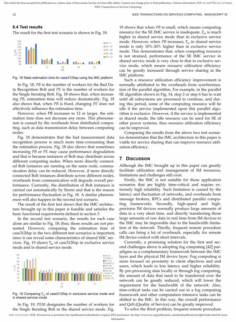
6.4 Test results
The result for the first test scenario is shown in Fig. 18.
Fig. 18 State estimation time for case3120sp using the IMC platform
In Fig. 18, PB is the number of workers for the Bad Da-ta Recognition Bolt and PE is the number of workers for the Single Iterating Bolt. Fig. 18 shows that, when increas-ing PB, estimation time will reduce dramatically. Fig. 18 also shows that, when PB is fixed, changing PE does not effectively influence the estimation time.
However, when PB increases to 12 or larger, the esti-mation time does not decrease any more. This phenome-non is caused by the overheads from distributed compu-ting, such as data transmission delay between computing nodes.
Fig. 18 demonstrates that the bad measurement data recognition process is much more time-consuming than the estimation process. Fig. 18 also shows that sometimes increasing PB or PE may cause performance degradation and that is because instances of Bolt may distribute across different computing nodes. When more directly connect-ed Bolt instances are running on the same node, commu-nication delay can be reduced. However, if more directly connected Bolt instances distribute across different nodes, overheads from communication will degrade overall per-formance. Currently, the distribution of Bolt instances is carried out automatically by Storm and that is the reason for performance fluctuation in Fig. 18. A similar phenom-enon will also happen in the second test scenario.
The result of the first test shows that the IMC architec-ture brought up in this paper is feasible and satisfies the basic functional requirements defined in section 3.
In the second test scenario, the results for each case alone are similar to Fig. 18; thus, those results are not pre-sented. However, comparing the estimation time of case3120sp in the two different test scenarios is important, since it can reveal some characteristics of shared IMC ser-vices. Fig. 19 shows 𝑇se of case3120sp in exclusive service mode and in shared service mode.
Fig. 19 Comparing 𝑇se of case3120sp in exclusive service mode and in shared service mode
In Fig. 19, PEM designates the number of workers for the Single Iterating Bolt in the shared service mode. Fig.
19 shows that when PB is small, which means computing resource for the SE IMC service is inadequate, 𝑇se is much higher in shared service mode than in exclusive service mode. However, when PB increases, 𝑇se in shared service mode is only 10%-20% higher than in exclusive service mode. This demonstrates that, when computing resource is not strained, performance of the SE IMC service in shared service mode is very close to that in exclusive ser-vice mode, which means resource utilization efficiency can be greatly increased through service sharing in the IMC platform.
Such a resource utilization efficiency improvement is normally attributed to the overheads from synchroniza-tion of the parallel algorithm. For example, in the parallel SE algorithm shown in Fig. 14, step 2 or step 6 has to wait until all subsystems are processed to continue, and dur-ing this period, some of the computing resource will be idle if the service implemented upon this parallel algo-rithm is exclusive. However, if the service is implemented in shared mode, the idle resource can be used for SE of other power systems, thus resource utilization efficiency can be improved.
Comparing the results from the above two test scenar-ios demonstrates that the IMC architecture in this paper is viable for service sharing that can improve resource utili-zation efficiency.
7 DISCUSSION
Although the IMC brought up in this paper can greatly facilitate utilization and management of IM resources, limitations and challenges still exist.
Firstly, the IMC is not suitable for those application scenarios that are highly time-critical and require ex-tremely high reliability. Such limitation is caused by the latency and fluctuation of networks, and overheads from message brokers, RPCs and distributed parallel compu-ting frameworks. Secondly, high-speed and high-precision IM devices normally produce large amounts of data in a very short time, and directly transferring those large amounts of raw data in real time from IM devices to the IMC may be impossible due to the bandwidth limita-tion of the network. Thirdly, frequent remote procedure calls can bring a lot of overheads, especially for remote IM device control with short intervals.
Currently, a promising solution for the first and sec-ond challenges above is adopting fog computing [42] par-adigms as a complementary framework between the IMC layer and the physical IM device layer. Fog computing is more focused on proximity to client objectives and end users, which leads to less latency and higher reliability. By pre-processing data locally or through fog computing, the amount of data that need to be transferred over the network can be greatly reduced, which will lower the requirement for the bandwidth of the network. Also, time-critical tasks can be carried out in a fog computing framework and other computation intensive tasks can be shifted to the IMC. In this way, the overall performance and QoS (Quality of Service) can be greatly improved.
To solve the third problem, frequent remote procedure

1939-1374 (c) 2017 IEEE. Personal use is permitted, but republication/redistribution requires IEEE permission. See http://www.ieee.org/publications_standards/publications/rights/index.html for moreinformation.
This article has been accepted for publication in a future issue of this journal, but has not been fully edited. Content may change prior to final publication. Citation information: DOI 10.1109/TSC.2017.2723006,IEEE Transactions on Services Computing
HENGJING HE ET AL.: RESEARCH ON THE ARCHITECTURE AND ITS IMPLEMENTATION FOR INSTRUMENTATION AND MEASUREMENT CLOUD 13
calls can be substituted by direct interaction between local devices and the IMC services. RPCs can just be used to manipulate the interaction process rather than relay data between IM devices and the IMC.
8 CONCLUSION AND FUTURE WORK
The instrumentation and measurement cloud can
greatly facilitate management of instruments and sen-
sors and, at the same time, allows users to utilize those
resources and related IM services on demand remotely. The IMC architecture brought forward in this paper
provides efficient guidance for developing a practical IMC platform. With IM device virtualization and service wrapping, building a remote IM system just requires only very simple coding work. Most of the investment in IT facilities and system development work can be saved. Furthermore, with the ability to scale and to dynamically transfer load, the IMC can increase the utilization effi-ciency of various resources to a much higher level. Dis-tributed parallel computing paradigms of the IMC will accelerate the processing speed, which brings lots of ben-efits for large-scale remote IM systems and, also, for anal-ysis of big data coming from huge numbers of instru-ments and sensors. The application developed upon the implemented system has demonstrated the advantages of the work in this paper.
However, more research work is still required to deal with some challenges. Such challenges include latency and stability of networks, geographic characteristics of the physical object that is being measured, and so on. These challenges are not proprietary to the IMC but common in the remote instrumentation and measurement field. But with more effort, problems caused by these challenges can eventually be solved.
ACKNOWLEDGMENT
This work was funded by the State Key Laboratory of Power System award SKLD15M02, Department of Elec-trical Engineering, Tsinghua University, Beijing, China. Wei Zhao is the corresponding author.
REFERENCES
[1] M. Bertocco, "Architectures For Remote Measurement," Distributed
Cooperative Laboratories: Networking, Instrumentation, and Meas-
urements, F. Davoli, S. Palazzo, and S. Zappatoreed, eds: Springer US,
pp. 349-362, 2006.
[2] A. Roversi, A. Conti, D. Dardari, and O. Andrisano, "A WEB-Based
Architecture Enabling Cooperative Telemeasurements," Distributed
Cooperative Laboratories: Networking, Instrumentation, and Meas-
urements, F. Davoli, S. Palazzo, and S. Zappatoreed, eds: Springer US,
pp. 395-407, 2006.
[3] A. Cheptsov, B. Koller, D. Adami, F. Davoli, S. Mueller, N. Meyer, P.
Lazzari, S. Salon, J. Watzl, M. Schiffers, and D. Kranzlmueller, "E-
Infrastructure for Remote Instrumentation," Computer Standards & In-
terfaces, vol. 34, no. 2012, pp. 476-484, 2012.
[4] S. Qin, X. Liu, and L. Bo, "Study on the Networked Virtual Instrument
and Its Application," Intelligent Data Acquisition and Advanced Com-
puting Systems: Technology and Applications, 2005. IDAACS 2005.
IEEE, pp. 337-339, 2005.
[5] Y. Jadeja and K. Modi, "Cloud computing - concepts, architecture and
challenges," Computing, Electronics and Electrical Technologies (IC-
CEET), 2012 International Conference on, pp. 877-880, 2012.
[6] I. Foster, Z. Yong, I. Raicu, and L. Shiyong, "Cloud Computing and
Grid Computing 360-Degree Compared," Grid Computing Environ-
ments Workshop, pp. 1-10, 2008.
[7] M. Fazio, M. Paone, A. Puliafito, and M. Villari, "Huge amount of het-
erogeneous sensed data needs the cloud," Systems, Signals and Devices
(SSD), 2012 9th International Multi-Conference on, pp. 1-6, 2012.
[8] W. Rekik, M. Mhiri, and M. Khemakhem, "A smart cloud repository for
online instrument," 2012 International Conference on Education and e-
Learning Innovations (ICEELI), pp. 1-4, 2012.
[9] A. S. McGough and D. J. Colling, "The GRIDCC Project," First Interna-
tional Conference on Communication System Software and Middle-
ware, pp. 1-4, 2006.
[10] M. Yuriyama and T. Kushida, "Sensor-Cloud Infrastructure - Physical
Sensor Management with Virtualized Sensors on Cloud Computing,"
13th International Conference on Network-Based Information Systems
(NBiS), pp. 1-8, 2010.
[11] R. Di Lauro, F. Lucarelli, and R. Montella, "SIaaS - Sensing Instrument
as a Service Using Cloud Computing to Turn Physical Instrument into
Ubiquitous Service," IEEE 10th International Symposium on Parallel
and Distributed Processing with Applications (ISPA), pp. 861-862, 2012.
[12] F. Lelli, "Bringing Instruments to a Service-Oriented Interactive Grid,"
Ph.D Thesis, Dipartimento di Informatica, Università Ca’ Foscari di Ve-
nezia, Venice,Italy, 2007.
[13] G. C. Fox, R. Guha, D. F. McMullen, A. F. Mustacoglu, M. E. Pierce, A. E.
Topcu, and D. J. Wild, "Web 2.0 for Grids and e-Science," Grid Enabled
Remote Instrumentation, F. Davoli, N. Meyer, R. Pugliese, and S. Zap-
patoreed, eds: Springer US, pp. 409-431, 2009.
[14] E. Frizziero, M. Gulmini, F. Lelli, G. Maron, A. Oh, S. Orlando, A.
Petrucci, S. Squizzato, and S. Traldi, "Instrument Element: a new grid
component that enables the control of remote instrumentation," Sixth
IEEE International Symposium on Cluster Computing and the Grid, pp.
44-52, 2006.
[15] I. M. Atkinson, D. d. Boulay, C. Chee, K. Chiu, P. Coddington, A. Ger-
son, T. King, D. F. McMullen, R. Quilici, P. Turner, A. Wendelborn, M.
Wyatt, and D. Zhang, "Developing CIMA-based cyberinfrastructure for
remote access to scientific instruments and collaborative e-Research,"
Conferences in Research and Practice in Information Technology Series,
Ballarat, Australia, pp. 3-10, 2007.
[16] M. Okon, D. Kaliszan, M. Lawenda, D. Stokosa, T. Rajtar, N. Meyer,
and M. Stroinski, "Virtual laboratory as a remote and interactive access
to the scientific instrumentation embedded in Grid environment," 2nd
IEEE International Conference on e-Science and Grid Computing, Am-
sterdam, Netherlands, pp. 1-5, 2006.
[17] L. Berruti, F. Davoli, and S. Zappatore, "Performance evaluation of
measurement data acquisition mechanisms in a distributed computing
environment integrating remote laboratory instrumentation," Future
Generation Computer Systems, vol. 29, no. 2, pp. 460-471, 2013.
[18] M. Yuriyama, T. Kushida, and M. Itakura, "A New Model of Accelerat-
ing Service Innovation with Sensor-Cloud Infrastructure," Annual SRII
Global Conference (SRII), pp. 308-314, 2011.
[19] G. Merlino, D. Bruneo, S. Distefano, F. Longo, and A. Puliafito,
"Stack4Things: integrating IoT with OpenStack in a Smart City context,"
Smart Computing Workshops (SMARTCOMP Workshops), 2014 In-
ternational Conference on, pp. 21-28, 2014.
[20] G. Merlino, D. Bruneo, S. Distefano, F. Longo, A. Puliafito, and A. Al-
Anbuky, "A smart city lighting case study on an openstack-powered in-

1939-1374 (c) 2017 IEEE. Personal use is permitted, but republication/redistribution requires IEEE permission. See http://www.ieee.org/publications_standards/publications/rights/index.html for moreinformation.
This article has been accepted for publication in a future issue of this journal, but has not been fully edited. Content may change prior to final publication. Citation information: DOI 10.1109/TSC.2017.2723006,IEEE Transactions on Services Computing
14 IEEE TRANSACTIONS ON SERVICES COMPUTING, MANUSCRIPT ID
frastructure," Sensors, vol. 15, no. 7, pp. 16314-16335, 2015.
[21] K. Ahmed and M. Gregory, "Integrating Wireless Sensor Networks
with Cloud Computing," 2011 Seventh International Conference on
Mobile Ad-hoc and Sensor Networks, pp. 364-366, 2011.
[22] M. S. Aslam, S. Rea, and D. Pesch, "Service Provisioning for the WSN
Cloud," Cloud Computing (CLOUD), 2012 IEEE 5th International Con-
ference on, pp. 962-969, 2012.
[23] Y. Byunggu, A. Cuzzocrea, J. Dong, and S. Maydebura, "On Managing
Very Large Sensor-Network Data Using Bigtable," Cluster, Cloud and
Grid Computing (CCGrid), 2012 12th IEEE/ACM International Sym-
posium on, pp. 918-922, 2012.
[24] Y. Chang Ho, H. Hyuck, J. Hae-Sun, Y. Heon Young, and L. Yong-Woo,
"Intelligent Management of Remote Facilities through a Ubiquitous
Cloud Middleware," IEEE International Conference on Cloud Compu-
ting, pp. 65-71, 2009.
[25] S. Distefano, G. Merlino, and A. Puliafito, "Sensing and Actuation as a
Service: A New Development for Clouds," 11th IEEE International
Symposium on Network Computing and Applications (NCA), pp. 272-
275, 2012.
[26] Y. Kang, Z. Wei, and H. Song-ling, "Discussion on a new concept of
measuring instruments-Instrument Cloud," China measurement and
test, vol. 38, no. 2, pp. 1-5, 2012.
[27] V. Rajesh, O. Pandithurai, and S. Mageshkumar, "Wireless sensor node
data on cloud," IEEE International Conference on Communication Con-
trol and Computing Technologies (ICCCCT), pp. 476-481, 2010.
[28] Y. Takabe, K. Matsumoto, M. Yamagiwa, and M. Uehara, "Proposed
Sensor Network for Living Environments Using Cloud Computing,"
15th International Conference on Network-Based Information Systems
(NBiS), pp. 838-843, 2012.
[29] G. Zhongwen, L. Chao, F. Yuan, and H. Feng, "CCSA: A Cloud Com-
puting Service Architecture for Sensor Networks," International Con-
ference on Cloud and Service Computing (CSC), pp. 25-31, 2012.
[30] M. Armbrust, A. Fox, R. Griffith, A. D. Joseph, R. Katz, A. Konwinski, G.
Lee, D. Patterson, A. Rabkin, I. Stoica, and M. Zaharia, "A view of cloud
computing," Communications of the ACM, vol. 53, no. 4, pp. 50-58,
2010.
[31] H. He, Z. Wei, and S. Huang, "Future trend of integrating instrumenta-
tion into the cloud," Proceedings of International Workshop on Cloud
Computing & Information Security, vol. 52, no. 2, pp. 359-365, 2013.
[32] T. Hirofuchi, E. Kawai, K. Fujikawa, and H. Sunahara, "USB/IP: A
Transparent Device Sharing Technology over IP Network," IPSJ Digital
Courier, vol. 1, pp. 394-406, 2005.
[33] P. Kalagiakos and P. Karampelas, "Cloud Computing learning," Appli-
cation of Information and Communication Technologies (AICT), 2011
5th International Conference on, pp. 1-4, 2011.
[34] A. Toshniwal, S. Taneja, A. Shukla, K. Ramasamy, J. M. Patel, S. Kul-
karni, J. Jackson, K. Gade, M. Fu, J. Donham, N. Bhagat, S. Mittal, and D.
Ryaboy, "Storm@twitter," Proceedings of the 2014 ACM SIGMOD In-
ternational Conference on Management of Data, Snowbird, Utah, USA,
pp. 147-156, 2014.
[35] H. Karimipour and V. Dinavahi, "Parallel Domain Decomposition
Based Distributed State Estimation for Large-scale Power Systems,"
IEEE Transactions on Industry Applications, no. 99, pp. 1-6, 2015.
[36] M. Shahidehpour and Y. Wang, "Communication and control in electric
power systems: applications of parallel and distributed processing," 1
ed: John Wiley & Sons, pp. 235-249, 2004.
[37] Y. Erkeng, "Power system state estimation," Beijing: Hydroelectric Pow-
er publishingcompany, 1985.
[38] H. Karimipour and V. Dinavahi, "Parallel domain decomposition based
distributed state estimation for large-scale power systems," IEEE/IAS
51st Industrial & Commercial Power Systems Technical Conference
(I&CPS), 2015.
[39] P. Sanders and C. Schulz, "Think locally, act globally: Highly balanced
graph partitioning," Experimental Algorithms, 1 ed: Springer, pp. 164-
175, 2013.
[40] J. Zawodny, "Redis: Lightweight key/value store that goes the extra
mile," Linux Magazine, vol. 79, 2009.
[41] R. D. Zimmerman, S. Murillo, x, C. E. nchez, and R. J. Thomas,
"MATPOWER: Steady-State Operations, Planning, and Analysis Tools
for Power Systems Research and Education," IEEE Transactions on
Power Systems, vol. 26, no. 1, pp. 12-19, 2011.
[42] F. Bonomi, R. Milito, J. Zhu, and S. Addepalli, "Fog computing and its
role in the internet of things," Proceedings of the first edition of the
MCC workshop on Mobile cloud computing, pp. 13-16, 2012.
Hengjing He received his master’s degree from Shanghai Jiao Tong University in China in 2011. He is now a PhD student in Tsinghua University. His research interests include Computerized Measurement and Instrumenta-tion, Cloud based Instrumentation and real-time big on data processing in Measurement systems.
Wei Zhao received his Ph.D. from Moscow Energy Institute, Russia, in 1991. He is now a professor of Tsinghua University. His research areas include electromagnetic measurement, virtual instrumentation, networked instrumenta-tion system, cloud based instrumentation.
Songling Huang received his Ph.D. from Tsinghua University in 2001. Currently, he is a professor in the Department of Electrical Engi-neering at Tsinghua University. His current research interests are electromagnetic meas-urement and nondestructive evaluation. Geoffrey C. Fox received a Ph.D. in Theoreti-cal Physics from Cambridge University in 1967 and is now the Associate Dean for Research and Graduate Studies at the School of Infor-matics and Computing at Indiana University, Bloomington, and professor of Computer Sci-ence, Informatics, and Physics at Indiana Uni-versity where he is director of the Community Grids Laboratory. His research interests in-clude data science, parallel and distributed computing.
Qing Wang received her Ph.D. from the De Montfort University, UK in 2001. She is now a lecturer with the School of Engineering and Computing Sciences at Durham University. Her research interests include electronic instru-ments and measurement, computer simulation and advanced manufacturing technology. Dr Wang is a Charted Engineer (CEng), a senior member of IEEE (SMIEEE), a member of IMechE (MIMechE), a member of ASME (MASME) and a Fellow of the Higher Educa-tion Academy (FHEA).