ieee transactions on pattern analysis and machine ...lyu/paper_pdf/tpami-2007-09-0574.r2.pdf · (a)...
TRANSCRIPT

IEEE TRANSACTIONS ON PATTERN ANALYSIS AND MACHINE INTELLIGENCE MANUSCRIPT, JUNE 2008 1
A Fast 2D Shape Recovery Approach by FusingFeatures and Appearance
Jianke Zhu, Michael R. Lyu, Fellow, IEEE and Thomas S. Huang, Life Fellow, IEEE
Abstract—In this paper, we present a fusion approach to solve the nonrigid shape recovery problem, which takes advantage of both the
appearance information and the local features. We have two major contributions. First, we propose a novel progressive finite Newton
optimization scheme for the feature-based nonrigid surface detection problem, which is reduced to only solving a set of linear equations.
The key is to formulate the nonrigid surface detection as an unconstrained quadratic optimization problem which has a closed-form
solution for a given set of observations. Second, we propose a deformable Lucas-Kanade algorithm which triangulates the template
image into small patches and constrains the deformation through the second order derivatives of the mesh vertices. We formulate it
into a sparse regularized least squares problem, which is able to reduce the computational cost and the memory requirement. The
inverse compositional algorithm is applied to efficiently solve the optimization problem. We have conducted extensive experiments
for performance evaluation on various environments, whose promising results show that the proposed algorithm is both efficient and
effective.
Index Terms—Image processing and computer vision, nonrigid detection, real-time deformable registration, nonrigid augmented reality,
medical image registration
F
1 INTRODUCTION
Recovering nonrigid shapes is an interesting and beneficial
research problem for computer vision and image analysis [1],
[2], [3]. An effective nonrigid shape recovery technique can be
applied in a variety of applications for digital entertainment,
medical imaging [2] and augmented reality, such as the re-
texturing of images and videos [4], [5], [6], [7].
Nonrigid shape recovery can usually be regarded as the
problem of recovering the explicit surface with a few deforma-
tion parameters. In contrast to nonrigid shape recovery, non-
rigid surface detection [8] does not require any initialization
or a priori pose information. Furthermore, the goal of nonrigid
surface detection is to extract the deformable shape’s structure
from an input image and find out the correct correspondences
from noisy data automatically.
Many applications have been investigated for deformable
object tracking [9], [10], [11] and registration, such as face
tracking and modelling [12], [13], [14], [15], and also more
generic and more deformable objects [2]. The major problem
of these methods is that they tend to be computationally
expensive and mainly aim at object recognition and image
segmentation tasks rather than nonrigid shape recovery. How-
ever, a real-time and automated solution has recently been
proposed [8], [16], which takes advantage of an iterative semi-
• Jianke Zhu and Michael R. Lyu are with the department of Computer
Science and Engineering, The Chinese University of Hong Kong, Shatin,
Hong Kong, Tel: +852 31634257, Fax: +852 26035302, E-mail: {jkzhu,
lyu}@cse.cuhk.edu.hk.
• Thomas S. Huang is with the Beckman Institute, University of Illinois at
Urbana Champaign, 405 N. Mathews Ave., Urbana, IL 61801. E-mail:
The short version of this article appeared in our previous work published
in IEEE Computer Society Conference on Computer Vision and Pattern
Recognition (CVPR2007).
implicit optimization scheme.
Since the nonrigid shape is usually highly dynamic and
represented by many deformation parameters, the nonrigid
shape recovery problem is far more complex than the rigid
object detection. Moreover, it requires a sufficient number of
correct correspondences in order to obtain high registration
accuracy. Therefore, it is difficult to directly employ a robust
estimator used in the rigid object pose estimation, such as
RANSAC [17] or Hough transform [18], to remove the spu-
rious matches for nonrigid surface detection. An alternative
strategy is to iteratively solve for both the correspondence and
the transformation [19], [20]. However, these methods tend to
be computationally expensive, and few of them can be applied
to point sets extracted from real images; an exception is the
most recent part-based approach [21].
Most of the current nonrigid shape recovery methods can
be divided into two categories. The first is dependent on
local feature correspondences [8], [22]. The second is based
on the appearance, which directly minimizes the residual
image between the synthesized template image and the input
image [12], [13], [23]. As for the feature-based methods, it is
difficult to guarantee the registration accuracy in regions lack-
ing texture. On the other hand, the appearance-based approach
can exploit more of the texture information, and therefore
achieves better registration accuracy. However, it tends to be
computationally expensive and requires good initialization to
avoid the local optima, and only a few automated solutions
have been proposed in the literature. Since both the feature
and appearance based methods have limitations, there is a
need for an automated method which can make use of both
the appearance information and the local features.
In this paper, we propose a novel automated approach to
efficiently handle the nonrigid shape recovery problem, as
shown in Fig. 1. Also, the proposed fusion approach is able

IEEE TRANSACTIONS ON PATTERN ANALYSIS AND MACHINE INTELLIGENCE MANUSCRIPT, JUNE 2008 2
(a) Starbucks pad (b) T-shirt (c) Cover (d) Paper
Fig. 1. Recovering nonrigid shapes in real-time video (a-d). (a) The contour is overlaid on the Starbucks pad. (b)T-shirt. (c) The cover of a magazine. (d) A piece of paper.
to take advantage of both the appearance information and the
local features.
Our first major contribution is the proposed progressive
finite Newton optimization scheme for nonrigid surface detec-
tion, which has the advantage of solving only a fixed number
of linear equations. The previous method [8] is currently gen-
erally accepted as the most effective methods of solving this
kind of problem. It employs an implicit iterative scheme for the
first order partial differential equation; however, this requires a
large number of iterations to solve the problem and remove the
outliers simultaneously. We tackle this critical problem from
two angles. First, the nonrigid surface detection is formulated
as an unconstrained quadratic optimization problem, which has
a closed-form solution for a given set of observations. Thus,
it can be efficiently solved through LU factorization. Then, a
progressive sample [24] scheme is employed to initialize the
optimization scheme, which can decrease the number of trials
significantly. Therefore, the present approach requires much
fewer iterations than the semi-implicit iterative optimization
scheme [16].
Our second contribution is the proposed deformable Lucas-
Kanade algorithm, which triangulates the template image
into small patches and preserves the regularity of the mesh
through the second order derivatives of the mesh vertices.
Moreover, the optimization of our proposed deformable Lucas-
Kanade algorithm is formulated into a sparse regularized least
squares problem, which is able to reduce the computational
cost and the memory requirement. The inverse compositional
algorithm [25] is applied to efficiently solve the optimization
problem. Furthermore, we solve the optimization for our
fusion approach with a modified deformable Lucas-Kanade
algorithm.
The rest of this paper is organized as follows. Section 2
reviews the previous approaches employed for the nonrigid
surface detection and recovery. In Section 3, we present
the proposed fusing features and appearance approach for
nonrigid shape recovery. Section 4 provides the details of our
experimental implementation and describes our experimental
results. We discuss limitations and future work in Section 5.
Section 6 sets out our conclusion.
2 RELATED WORK
Considerable research effort has been devoted to nonrigid
shape recovery problems in the computer vision and image
analysis domain [1], [2], [7], [12]. However, only a few
approaches are automatic and can achieve real-time results.
In a recent study, the repeating properties of a near regular
texture were exploited to track new texture tiles in video
frames [26]. Well-designed markers widely used in motion
capture are also applied to recover the structure of a nonrigid
surface, such as cloth and paper [6], [7]. As these methods
rely on the physical markers, they require the placing of pre-
defined patterns on the target surface. Nevertheless, they are
capable of high accuracy.
In fact, a large number of the appearance-based meth-
ods [12], [15], [23] can be viewed as extensions of the
original Lucas-Kanade algorithm [25] which has been one of
the most widely used techniques in computer vision. These
approaches directly minimize the residual image between the
input image and the synthesized model image [12], [27]. An
inverse compositional method [25] has recently been proposed
to efficiently solve the optimization problem in the Lucas-
Kanade algorithm, reducing the computational cost by pre-
computing the Hessian matrix. In [28], a feature-driven method
is described to make use of the compositional algorithms for
the parametric warps. In addition, optical flow information [2],
[15] can be incorporated into the optimization scheme to
obtain better results. The major limitation of these methods
is that they tend to become stuck at a local minimum and
hence require good initialization.
On the other hand, feature-based methods [8], [19], [29]
try to find out the transformation from the correspondences
built by feature matching methods. Thus, these methods can
benefit from the recent advances in the feature detection and
matching. In [8], [16], J. Pilet et al. proposed an iterative
approach to attack the nonrigid surface detection problem.
Physical constraints based on the Finite Element Model [3] are
employed for regularization. A semi-implicit iterative scheme
is proposed to solve the optimization problem.
The feature matching algorithm plays a very important
role for the feature-based nonrigid surface recovery method.
Recently, several sophisticated feature descriptors [30], [31]
have been proposed to handle the wide-baseline matching
problem, including images with large deformation [32]. In
addition, machine learning methods, such as random classi-
fication trees [33], are also employed to find the point cor-
respondences. These methods can take advantage of shifting
part of the computational load from the matching phase to the
IEEE TRANSACTIONS ON PATTERN ANALYSIS AND MACHINE INTELLIGENCE MANUSCRIPT, JUNE 2008 3
training phase.
It is more complex to handle a large amount of deformation
parameters for detecting the nonrigid surface rather than only
a few pose parameters used in rigid object detection. There-
fore, there are several challenges when applying conventional
robust estimators, such as RANSAC and M-estimator, for the
nonrigid surface detection task. One is the lack of a concise
function which can estimate the deformed mesh from the
correspondences directly. Obviously, the semi-implicit iterative
approach [8] is not efficient enough to deal with this problem.
Another challenge is that the RANSAC-based approach re-
quires a large number of trials. To the best of our knowledge,
there is still a lack of criteria for selecting the number
of samples for each trial in nonrigid surface detection. We
tackle the initialization problem through a modified RANSAC
method. The key is to draw from progressively larger sets
of top-ranked correspondences [24]. Thus, our progressive
sample scheme affords large computational savings, and the
conventional robust estimator can be engaged for initializing
the nonrigid surface detection.
3 FUSING FEATURES AND APPEARANCE
3.1 Overview
In this section, we describe the fusion approach to dealing with
the nonrigid shape recovery, which takes advantage of both
the local features and appearance information. For tackling
the challenges, a 2D nonrigid shape model is introduced.
We formulate the proposed algorithm into an optimization
problem which minimizes the correspondence error, the texture
difference and the surface energy. The key of our fusion
approach is to solve this problem in the following. First, we
present a progressive finite Newton method that employs the
feature correspondences to detect the nonrigid surface. Then,
we describe a novel deformable Lucas-Kanade algorithm to
handle the appearance error. Based on these two algorithms,
the optimization scheme for our fusion approach is formulated.
3.2 Mesh Model
(a) Model mesh s0 (b) Reference image
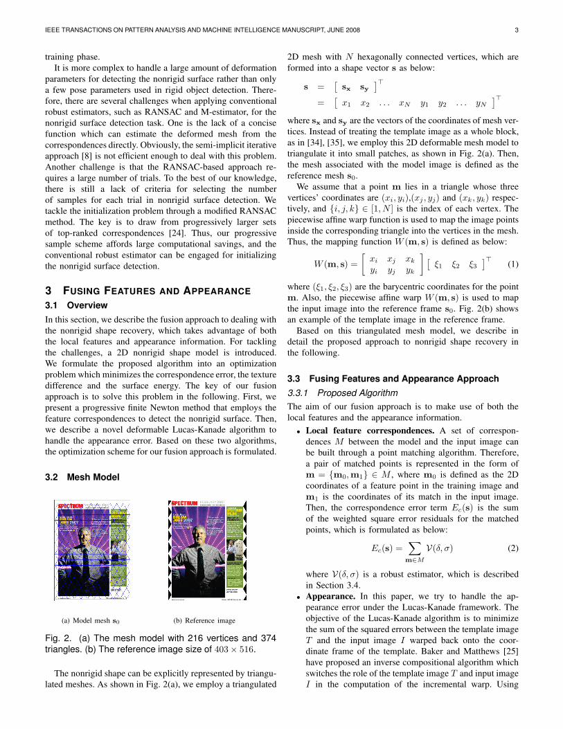
Fig. 2. (a) The mesh model with 216 vertices and 374
triangles. (b) The reference image size of 403× 516.
The nonrigid shape can be explicitly represented by triangu-
lated meshes. As shown in Fig. 2(a), we employ a triangulated
2D mesh with N hexagonally connected vertices, which are
formed into a shape vector s as below:
s =[
sx sy]⊤
=[
x1 x2 . . . xN y1 y2 . . . yN
]⊤
where sx and sy are the vectors of the coordinates of mesh ver-
tices. Instead of treating the template image as a whole block,
as in [34], [35], we employ this 2D deformable mesh model to
triangulate it into small patches, as shown in Fig. 2(a). Then,
the mesh associated with the model image is defined as the
reference mesh s0.
We assume that a point m lies in a triangle whose three
vertices’ coordinates are (xi, yi),(xj , yj) and (xk, yk) respec-
tively, and {i, j, k} ∈ [1, N ] is the index of each vertex. The
piecewise affine warp function is used to map the image points
inside the corresponding triangle into the vertices in the mesh.
Thus, the mapping function W (m, s) is defined as below:
W (m, s) =
[
xi xj xk
yi yj yk
]
[
ξ1 ξ2 ξ3
]⊤(1)
where (ξ1, ξ2, ξ3) are the barycentric coordinates for the point
m. Also, the piecewise affine warp W (m, s) is used to map
the input image into the reference frame s0. Fig. 2(b) shows
an example of the template image in the reference frame.
Based on this triangulated mesh model, we describe in
detail the proposed approach to nonrigid shape recovery in
the following.
3.3 Fusing Features and Appearance Approach
3.3.1 Proposed Algorithm
The aim of our fusion approach is to make use of both the
local features and the appearance information.
• Local feature correspondences. A set of correspon-
dences M between the model and the input image can
be built through a point matching algorithm. Therefore,
a pair of matched points is represented in the form of
m = {m0,m1} ∈ M , where m0 is defined as the 2D
coordinates of a feature point in the training image and
m1 is the coordinates of its match in the input image.
Then, the correspondence error term Ec(s) is the sum
of the weighted square error residuals for the matched
points, which is formulated as below:
Ec(s) =∑
m∈M
V(δ, σ) (2)
where V(δ, σ) is a robust estimator, which is described
in Section 3.4.
• Appearance. In this paper, we try to handle the ap-
pearance error under the Lucas-Kanade framework. The
objective of the Lucas-Kanade algorithm is to minimize
the sum of the squared errors between the template image
T and the input image I warped back onto the coor-
dinate frame of the template. Baker and Matthews [25]
have proposed an inverse compositional algorithm which
switches the role of the template image T and input image
I in the computation of the incremental warp. Using

IEEE TRANSACTIONS ON PATTERN ANALYSIS AND MACHINE INTELLIGENCE MANUSCRIPT, JUNE 2008 4
this approach, the computational cost can be reduced by
pre-computing the Hessian matrix. Instead of using the
affine transformation or homography, as in [34], [35], we
directly employ the parameterization of the mesh model
vertices s in this paper. Due to the direct parameterization,
∆s is defined as the increments to the mesh vertices. We
employ the inverse compositional method to formulate
the energy for the appearance Ea. Following the notation
in [25], [27], Ea is defined as follows:
Ea(s) =∑
x
[T (W (x; ∆s))− I(W (x; s))]2 (3)
In general, the nonrigid shape recovery problem approxi-
mates a 2D mesh with 2N free variables, which is usually ill-
posed. One effective way to attack this problem is to introduce
regularization, which preserves the regularity of a deformable
surface. This leads to the following energy function:
E(s) = Ea(s) + αEc(s) + λrEr(s) (4)
where α is a weight coefficient, and λr is a regularization co-
efficient. The regularization term Er(s) represents the surface
deformation energy. Also, Er(s), known as internal force in
Snakes [36], is composed of the sum of the squared second-
order derivatives of the mesh vertex coordinates.
As the mesh is regular, Er(s) can be formulated through a
finite difference:
Er = s⊤Ks (5)
where matrix K ∈ R2N×2N is defined as below:
K =
[
K 00 K
]
where K is a sparse and banded matrix which is determined
by the structure of the explicit mesh model [37].
Fig. 3. Overview of our 2D shape recovery algorithm.
3.3.2 Optimization Framework
To enable an automated solution, we employ the result of
minimizing the feature correspondences error to initialize the
optimization for the fusion approach. This is because the Ec(s)is independent of the image during the optimization, and so it
can be computed very efficiently. More specifically, the initial
result is obtained by the nonrigid surface detection method,
which deals with the following energy minimization problem:
EF (s) = Ec(s) + λrEr(s) (6)
We describe the details of solution for the above optimization
problem in Section 3.4.
In this paper, the optimization for our fusion approach
is based on the Lucas-Kanade framework. To simplify the
formulation, we start from only taking consideration of the
texture difference Ea(s). Also, the regularization term Er(s)is introduced to preserve the surface regularity. Thus, we can
obtain the following regularized least squares problem:
EA(s) = Ea(s) + λrEr(s) (7)
We name this approach the deformable Lucas-Kanade algo-
rithm, which can be used to solve the optimization for our
fusion approach with slight modification.
Therefore, the essence of our fusion approach is to first
detect the nonrigid shape using feature correspondences, and
then solve the fusion optimization based on the modified
deformable Lucas-Kanade algorithm. We will describe it in
detail in the following subsections. The overview of our
method is shown in Fig. 3 where each step is highlighted
using a shaded box.
3.4 Feature-based Nonrigid Surface Detection
To tackle the nonrigid surface detection problem in Eqn. 6, we
first present our finite Newton formulation. Then, a progressive
optimization scheme is proposed to deal with outliers and
find out as many correct correspondences as possible. The
complete feature-based nonrigid surface detection algorithm
is summarized in Fig. 4.
ALGORITHM: PROGRESSIVE NEWTON APPROACH TO NON-RIGID SURFACE DETECTION
• Given: mesh model s0, ν, λr, σ0
• Pre-compute: K and (ξ1, ξ2, ξ3) for each keypoint m0
• Detection: for a given image
Obtain M by feature matchingSelect active set by modified RANSACWhile σ > 2
Compute A and b
Solve linear system: Eqn. 16 and Eqn. 17Calculate residual error δ and inlier set M1
σ = ν · σ
• Output: mesh vertices s
Fig. 4. Progressive Newton approach to nonrigid surfacedetection.
3.4.1 Finite Newton Formulation
In this paper, we employ a robust estimator V(δ, σ) with
compact support size σ. Moreover, δ is the residual error,
which is defined as follows:
δ = m1 −Ws(m0) (8)
The robust estimator function V(δ, σ) that assesses a fixed
penalty for residuals larger than a threshold σ is employed
in the present work; this approach is relatively insensitive to
outliers [38]:
V(δ, σ) =
{
‖δ‖σn , M1 = {m| ‖δ‖ ≤ σ2}
σ2−n, M2 = M1
(9)
where the set M1 contains the inlier matches, and M2 is the
set of the outliers. In addition, the order n determines the scale
of the residual. As shown in Fig. 5, the most correspondences

IEEE TRANSACTIONS ON PATTERN ANALYSIS AND MACHINE INTELLIGENCE MANUSCRIPT, JUNE 2008 5
−35 −25 −15 −5 5 15 25 3516
4
1
0
0.2
0.4
0.6
0.8
1
Reprojection Error in pixel
Support size σ
Penalty function v
alu
e
Fig. 5. The robust estimator that assesses a fixed penalty
to residuals larger than a threshold σ.
are included when the support σ is large. As σ decreases, the
robust estimator becomes narrower and more selective.
Since the robust estimator function is not convex, the
associated penalty function approximation problem becomes
a hard combinational optimization problem. We tackle this
problem under the finite Newton optimization framework.
An augmented vector t ∈ RN containing the barycentric
coordinates is defined as below:
ti = ξ1 tj = ξ2 tk = ξ3
while the remaining elements in the vector t are all set to zero.
Therefore, the residuals for the inlier correspondences can be
rewritten as follows:
‖δ‖ = (u− t⊤x)2 + (v − t⊤y)2
= u2 + v2 − 2(ut⊤x + vt⊤y) + x⊤tt⊤x + y⊤tt⊤y
where (u, v) are the coordinates of m1. Therefore, the error
term in Eqn. 6 turns out to be
Ec =∑
m∈M1
1
σn
(
u2 + v2 − 2
[
ut
vt
]⊤
s
+ s⊤[
tt⊤ 00 tt⊤
]
s
)
+ qσ2−n
where q is the number of outliers.
Let b ∈ R2N be defined as below:
b =
[
bx
by
]
=∑
m∈M1
1
σn
[
ut
vt
]
(10)
and a matrix A ∈ RN×N is equal to
A =∑
m∈M1
1
σntt⊤ (11)
Thus, the energy function Eqn. 6 is formulated into an uncon-
strained quadratic optimization problem, which can be solved
by the modified finite Newton method [39], [40].
EF = s⊤[
λrK + A 00 λrK + A
]
s− 2b⊤s
+∑
m∈M1
ωm
σn(u2 + v2) + qσ2−n
The finite gradient of the energy function EF with respect to
s can be derived as below:
∇ = 2
([
λrK + A 00 λrK + A
]
s−
[
bx
by
])
(12)
and the Hessian [38] can also be computed by
H1 = 2
[
λrK + A 00 λrK + A
]
(13)
Thus the gradient can be rewritten as below:
∇ = H1s− 2b (14)
Each Newton step will perform the following operation:
s← s− γH−1
1∇ (15)
where γ is the step size. We simply set γ equal to one, and
no convergence problem occurs in our experiments. Since K
is regular, we find that update of the state vector s can be
computed by the following linear equation:[
λrK + A 00 λrK + A
]
s =
[
bx
by
]
Moreover, the problem can be further simplified into two
linear equations which can be efficiently solved via LU
decomposition:
sx = (λrK + A)−1bx (16)
sy = (λrK + A)−1by (17)
The overall complexity is thus the complexity of one Newton
step. Note that the complexity of one step for the proposed
method is same as [41].
3.4.2 Progressive Finite Newton Optimization
Generally speaking, the incorrect matches cannot be avoided
in the first stage of the matching process where only local
image descriptors are compared. We introduce a coarse-to-fine
scheme to deal with those outliers. The support σ of robust
estimator V(δ, σ) is progressively decayed at a constant rate ν.
Since the derivatives of V(δ, σ) are inversely proportional to
the support σ, the regularization coefficient λr is kept constant
during the optimization. For each value of σ, the object func-
tion EF is minimized through the finite Newton step and the
result is employed as the initial state for the next minimization.
The minimization of EF is directly solved through Eqn. 16
and Eqn. 17 for a given initial state, and one step is enough to
achieve convergence. The optimization procedure stops when
σ reaches a value close to the expected precision, which is
usually one or two pixels. The algorithm reports a successful
detection when the number of inlier matches is above a given
threshold. Thus, the whole optimization problem can be solved
within a fixed number of steps. This is in contrast to the

IEEE TRANSACTIONS ON PATTERN ANALYSIS AND MACHINE INTELLIGENCE MANUSCRIPT, JUNE 2008 6
semi-implicit optimization scheme [16], which involves a few
iterations for each σ, and at least 40 iterations in total to ensure
the convergence.
In order to select most of the correspondences into the
initial active set and avoid getting stuck at local minima,
the initial value of σ is usually set to a sufficiently large
value σ0. However, this requires a fixed initial state. The
method is dependent on the object position, and needs a
few iterations to compensate for the errors generated by the
pose variations. In the present work, we solve this problem
through a modified RANSAC approach. Taking advantage
of our concise finite Newton formulation and closed-form
solution, the explicit mesh can be directly estimated from
a given set of correspondences. Moreover, we draw from
progressively larger sets of top-ranked correspondences, which
decreases the number of trials significantly. In the experiments,
the sampling process stopped within 5 trials. In the worst case,
such as when an object does not appear in the scene, it still
behaves as RANSAC. Therefore, the output of the proposed
progressive sample can be employed as the initial state for
the finite Newton optimization. Since the result of progressive
sample estimation is quite close to the solution, σ is relatively
small. Thus, the proposed progressive scheme requires fewer
stages, and is somewhat invariant to the initial position.
3.5 Deformable Lucas-Kanade Algorithm
Taking consideration of appearance information only, we try
to solve the optimization problem in Eqn. 7 using the inverse
compositional method. The deformable Lucas-Kanade algo-
rithm is summarized in Fig. 6.
ALGORITHM: DEFORMABLE LUCAS-KANADE ALGORITHM
• Given: T , s0, λr
• Pre-compute: K, ∇T ∂W
∂s, and the Hessian matrix H2
• Iterate:
Warp I with W (x; s) to compute I(W (x; s))Compute the residual image I(W (x; s))− TCompute ∆s using Eqn. 19Update the shape vector s← s−∆s
• Until ‖∆s‖ < threshold• Output: mesh vertices s
Fig. 6. Deformable Lucas-Kanade algorithm.
3.5.1 Deformable Lucas-Kanade Algorithm
The warp update equation can be defined as follows:
W (x)← W (x) ◦W (x; ∆s)−1
Performing the first order Taylor expansion on the Eqn. 7
gives:
∑
x
[
T (W (x; s0)) +∇T∂W
∂s∆s− I(W (x; s))
]2
+λr(s + ∆s)⊤K(s + ∆s) (18)
where ∇T is the gradient of the template image evaluated at
W (x; s0), and ∂W∂s
is the Jacobian of the warp parameters
evaluated at s. Note that ∇T ∂W∂s
is the gradient, and s0 is the
reference mesh shown in Fig. 2(a).
Assuming that W (x; s0) is the identity warp, the gradient
of Eqn. 18 with respect to ∆s can be derived as below:
∑
x
[
∇T∂W
∂s
]⊤[
T (W (x; s0)) +∇T∂W
∂s∆s− I(W (x; s))
]
+λrK(s + ∆s)
As the above gradient vanishes for optimality, this leads to the
following closed-form solution:
∆s = H−1
2
∑
x
[
∇T∂W
∂s
]⊤
[I(W (x; s))− T (W (x; s0))]
−λrH−1
2Ks (19)
where H2 is the 2N × 2N Hessian matrix:
H2 =∑
x
[
∇T∂W
∂s
]⊤ [
∇T∂W
∂s
]
+ λrK (20)
Note that the Hessian matrix H2 is independent of the
parameter vector s, and it is kept constant across iterative
optimization and can be pre-computed, and also independent
of the gradient matrix ∇T ∂W∂s
. Therefore, the warp update of
the shape parameters ∆s can be computed very efficiently.
Since the coordinates of the mesh vertices s are directly
employed as the warp parameter in the deformable Lucas-
Kanade algorithm, the computation of the warp inversion be-
comes much easier than the linear combination model method
in AAMs [27]. Specifically, the shape vector s is updated by:
s← s−∆s (21)
Link to Lucas-Kanade algorithm: The proposed method
can be viewed as a natural extension of the Lucas-Kanade
algorithm, which is able to handle the deformations rather than
the affine transformation. Since the 2D coordinates of the mesh
vertices s is employed as the parameters in deformable Lucas-
Kanade algorithm, the degree of freedom is increased. This is
useful for handling the image alignment when the deformation
is large. Furthermore, the efficient optimization methods for
the Lucas-Kanade algorithm [25] can also be applied for the
proposed method.
Link to Active Appearance Models (AAMs) [27]: The
deformable Lucas-Kanade algorithm can be treated as a kind
of AAMs. It employs a single training example along with
certain physical constraints, while AAMs need to build both
texture and shape models to constrain the searching space.
3.5.2 Computing Gradient ∇T ∂W∂s
Recall that the destination of the pixel x under the piecewise
affine warp W (x; s) depends on the vertices of the mesh s.
According to the definition in Eqn. 1, the Jacobian of the
warp W (x; s) with respect to the mesh vertices v(xi, yi) can
be derived as below:
∂W
∂xi
=[
ξ1 0]⊤
and∂W
∂yi
=[
0 ξ1
]⊤
It can easily be found that the non-zero parts of ∂W∂xi
and ∂W∂yi
are equal. The Jacobians can be illustrated as the images with

IEEE TRANSACTIONS ON PATTERN ANALYSIS AND MACHINE INTELLIGENCE MANUSCRIPT, JUNE 2008 7
the same size of reference frame; in fact, each image is the
Jacobian with respect to the vertex v. Moreover, it can also be
observed that the warp Jacobian is quite sparse, having non-
zero values only in the triangles around the vertex v. Next, we
compute ∇T ∂W∂s
by multiplying the gradient of the template
image with the warp Jacobian matrix.
Remark Since the dimensionality of the texture is usually
very high, the gradient ∇T ∂W∂s
becomes quite a large matrix.
Fortunately, both the gradient and the Hessian H2 are the
sparse matrices in the proposed deformable Lucas-Kanade
algorithm, and this can greatly reduce the computational cost
and memory requirement and make the problem tractable.
Moreover, this also leads to a sparse regularized least squares
problem in Eqn. 7.
3.5.3 Lighting
In order to minimize the effect of global lighting variation,
we apply a scaling a and an offset o to the template image
T . Therefore, the energy function of the proposed deformable
Lucas-Kanade algorithm can be rewritten as follows:∑
x
[aT (W (x; ∆s)) + o · 1− I(W (x; s))]2 + λrs⊤Ks (22)
Similarly, we can employ an extended inverse compositional
algorithm [35], [42] to solve this optimization problem. See
Appendix A for the details.
3.6 Fusion Approach Optimization
Based on the deformable Lucas-Kanade algorithm, we de-
scribe the optimization scheme for the proposed fusion ap-
proach in Section 3.3.
We define a matrix B ∈ R2N×2N , which is equal to
B =1
σn
[
A 00 A
]
(23)
Therefore, we can rewrite Ec as below:
Ec = s⊤Bs− 2b⊤s + qσ2−n +∑
m∈M1
1
σn(u2 + v2)
Performing the first order Taylor expansion on the energy
function Eqn. 4 gives:
∑
x
[
T (W (x; s0)) +∇T∂W
∂s∆s− I(W (x; s))
]2
+α(s + ∆s)⊤B(s + ∆s)− 2αb⊤(s + ∆s) + qσ2−n
+∑
m∈M1
1
σn(u2 + v2) + λr(s + ∆s)⊤K(s + ∆s) (24)
The solution to this problem is:
∆s = H−1
3
∑
x
[
∇T∂W
∂s
]⊤
[I(W (x; s)) − T (W (x; s0))]
−αH−1
3(Bs− b)− λrH
−1
3Ks (25)
where H3 is the Hessian matrix:
H3 =∑
x
[
∇T∂W
∂s
]⊤ [
∇T∂W
∂s
]
+ αB + λrK (26)
Again, we can compute the warp update through Eqn. 21.
In order to reduce the computational cost, we pre-compute
the gradient and part of the Hessian for the deformable Lucas-
Kanade algorithm. Since the inlier set is slightly changed in
the fusion optimization phase, matrix B can be viewed as
a constant. Therefore, we compute the Hessian H3 once for
each input image through Eqn. 26. The optimization procedure
stops when ‖∆s‖ is close to the given threshold or the number
of iterations exceeds the limit.
To tackle the lighting variations, we only need make slight
modification on the method described in Fig 6. Specifically, we
add the initialization step, and pre-compute the matrix B and
H3 for each input image. Furthermore, Eqn. 25 is employed
to compute the update for the shape vector s.
4 EXPERIMENTAL RESULTS
In this section, we discuss the details of our experimental
implementation and report the results of performance eval-
uation on nonrigid shape recovery. First, we perform the
various evaluations on the feature-based method. Then, both
the deformable Lucas-Kanade algorithm and fusion approach
are tested. Videos illustrating the results can be obtained from
webpage at http://www.cse.cuhk.edu.hk/∼lyu/fusion.
4.1 Experimental Setup
In order to register the mesh model conveniently, a model
image is acquired when the nonrigid surface contains no
deformation. In order to facilitate real-time augmented reality
applications, a random-trees based method [33] is used to
build the correspondences between the model image and the
input image. We also implemented a semi-implicit iterative
method [16], which is regarded as the state-of-the-art ap-
proach. All the experiments reported in this paper were carried
out on a Pentium-4 3.0GHz PC with 1GB RAM, and a DV
camera was engaged to capture videos.
4.2 Evaluation on Feature-based Nonrigid Surface
Detection
In this subsection, we show that the proposed feature-based
approach is very efficient for real-time tracking. In addition,
same convincing results are obtained for medical image reg-
istration, even with missing data.
4.2.1 Parameter Settings
Since the number of free variables for nonrigid surface recov-
ery is usually quite large (even up to one thousand), the sample
size of each RANSAC iteration becomes a tricky issue. We
compare the performance with different sample sizes. In our
experiments, the support σ is empirically set to 30, and λr is
set to a large value to ensure the regularity of the nonrigid
surface. Interestingly, we find that the best sample size is
three. This is because the nonrigid surface degenerates into
a rigid one, and only three points are necessary to determine
the position of a rigid surface. Moreover, when the sample
size increases, the probability of selecting the inlier data is
decreased. Thus, three is the best choice for the sample size.

IEEE TRANSACTIONS ON PATTERN ANALYSIS AND MACHINE INTELLIGENCE MANUSCRIPT, JUNE 2008 8
0 1 2 3 4 5 60
0.1
0.2
0.3
0.4
0.5
0.6
0.7
0.8
0.9
1
n
Su
cce
ss p
rob
ility
Fig. 7. Probability of success with different order n of the
robust estimator function.
A set of synthetic data is used to select the parameters, and
the reference mesh is manually registered. The performance
is evaluated by the percentage of mesh vertices within two
pixels of those in the reference mesh. The best regularization
coefficient is found to be around 3× 10⁻⁴ by grid searching.
Similarly, the initial support σ0 is set to 80, and decay rate ν
is 0.5. Fig. 7 plots the success probability with different orders
n of the robust estimator function. Based on these results, n
is set to 4.
4.2.2 Computational Efficiency
The complexity of the proposed method is mainly dominated
by the order of Eqn. 16 and Eqn. 17, which is equal to the num-
ber of vertices N in the mesh model. Another important factor
is the number of inlier matches, which affects the sparseness
of matrix A. This usually differs from one frame to another.
For the coffee mat with 120 vertices, as shown in Fig. 8, the
proposed method runs at 18 frames per second on real-time
video with the size of 720 × 576. As depicted in Table 1,
the proposed optimization scheme requires around 8 iterations
and only takes half of the time of the feature matching
algorithm, which is the bottleneck of the whole system. Our
implementation1 of semi-implicit iterative approach [16] needs
around 40 iterations to reach the convergence, and runs about
9 frames per second. The improvement is more significant
for high resolution mesh. Thus, the proposed method requires
far less iterations, and is efficient for real-time applications.
We also conduct the experiments without using the modified
RANSAC initialization, and start the optimization scheme
from a sufficiently large support σ = 1000. This requires 11
iterations, and the fitting accuracy is worse than the proposed
method. In addition, the modified RANSAC initialization can
also be used for a semi-implicit method, in which case the
number of iterations is reduced to around 25.
TABLE 1Computational time of proposed method at each step.
Total Match Optimization Iteration Other
57ms 27ms 14ms ∼ 1.9ms 16ms
1. We use the same parameters setting as [16]. The convergence conditionis set to 0.9995, with at most 5 iterations for each support value σ.
(a) Result (b) Plastic cup
Fig. 8. The first row shows the initialization resultsusing the modified RANSAC method, and the second
row shows the results. We show the images with inliermatches in (a).
Fig. 9. Re-texturing of a shirt print. The first row showsthe images captured by a camera. The second row shows
the results of replacing the bunny with the CVPR logo.
4.2.3 Performance of Nonrigid Surface Recovery
We use a coffee mat as the deformable object. As shown in
Fig. 8, the proposed method is robust to large deformations
and perspective distortion. In practice, the whole process runs
at around 18 frames per second. Fig. 9 describes the result of
detecting the pattern on a T-shirt, where similar performance is
achieved. As another feature-based method, the performance
of the proposed method is closely related to the texture of
objects. Better results can be obtained for objects with more
texture, because it is easy to find more correct correspondences
than with those lacking texture. Therefore, we present a fusion
approach to handle this issue.
4.2.4 Augmented Reality
Once the nonrigid surface is recovered, an immediate appli-
cation is to re-texture an image. In order to obtain realistic
results, the texture should be correctly relighted. As suggested
in [16], a re-textured input image is generated by directly

IEEE TRANSACTIONS ON PATTERN ANALYSIS AND MACHINE INTELLIGENCE MANUSCRIPT, JUNE 2008 9
(a) Source (b) Target (c) Before (d) Registered (e) Registered (f) After
Fig. 10. Applying the proposed method to medical image registration. A pair of sagittal images from two differentpatients is shown. (a,b,e) are the source, target and registered source respectively. (d) is the registered source with
mesh model. (c) and (f) are the overlaid images before and after registration. The second row displays the syntheticexample with missing data.
multiplying a blank shaded image, which is the quotient of
the input image and the warped reference image. The refer-
ence image is acquired when the nonrigid surface is lighted
uniformly. Moreover, the quotient image is normalized through
multiplying the intensity of white color in the reference image.
This relighting procedure is easily done by the GPU and
requires only a short OpenGL shading language program; and
the whole process runs at about 17 frames per second. Fig. 9
shows the results of re-texturing a T-shirt with a Lambertian
surface. It is difficult to estimate a blank shaded image due
to dividing near zero intensity values and the use of an
uncontrolled optical sensor. However, the visual effect is that
the bunny in the input video is re-textured by the CVPR logo.
4.2.5 Medical Image
We also evaluate the proposed approach for medical image
registration. A pair of sagittal images [43] with the size of
256× 256 from two different patients are used in the experi-
ments. The source and target images differ in both geometry
and intensity. The results are plotted in Fig. 10; it can be seen
that the source image is successfully registered. In comparison
with the locally affine but globally smooth method [43], which
takes about 4 minutes, our proposed method only needs 0.2
seconds. Moreover, the sparse correspondences based method
can naturally handle the missing data and partial occlusion
problem. As shown in the second row of Fig. 10, when the
source images come with a region removed, the nonrigid shape
can still be recovered.
4.3 Evaluation on the Deformable Lucas-Kanade Al-
gorithm
4.3.1 Deformable Lucas-Kanade Fitting
Similarly, the parameters for deformable Lucas-Kanade al-
gorithm are found by grid searching; and the regularization
parameter λ is set to 105. Moreover, the texture mapping
is efficiently done by OpenGL. In Fig. 11, we include an
example of the proposed deformable Lucas-Kanade algorithm
fitting to a single image, and employ the template image and
mesh model illustrated in Fig. 2. Fig. 11(a) displays the initial
configuration, Fig. 11(b) the result after 30 iterations, and
Fig. 11(c) the final converged result after 58 iterations.
We also perform the experiment using the conventional
Lucas-Kanade algorithm with the inverse compositional
method, using the same initial position as our method. How-
ever, this fails to converge in this case due to the the large
non-affine deformation. Fig. 12 plots the root mean square
error (RMSE) curve for the proposed method. In the case
of the deformable Lucas-Kanade algorithm, the RMSE is
relatively large (28.5), which is mainly due to the difference
between the optical sensor and the printing device. However,
we can observe that the mesh was accurately registered on
the input image in Fig. 11(c). Since the lighting variations
are considered in the proposed method, the RMSE dropped
rapidly in the first few iterations .
Fig. 12. The Root Mean Square Error between the tem-
plate and input images against the number of iterations.

IEEE TRANSACTIONS ON PATTERN ANALYSIS AND MACHINE INTELLIGENCE MANUSCRIPT, JUNE 2008 10
(a) Initialized (b) 30 iterations (c) Converged
Fig. 11. An example of the deformable Lucas-Kanade fitting to a single image. The first row is the result mesh overlaid
on the input image. The second row displays the residual images; the inverted image is used for better illustration.
4.3.2 Computational Efficiency
The complexity of the proposed method is mainly dominated
by the size of the template image and the number of the
vertices N in the mesh model. Another factor is the number of
inlier feature matches, which affects the sparseness of matrix
B. In our experiments, three models are built to perform the
evaluation, as summarized in Table 2. The mesh model C1 is
shown in Fig. 2. C2 is obtained by increasing the edge length,
giving fewer mesh vertices than C1. C3 is built by reducing
both the template image and the mesh size to 75% of C1.
We evaluate the computational cost of the proposed method
for the nonrigid surface recovery task on realtime videos with
the size of 720 × 576. Table 2 summarizes the experimental
results on different models. We observe that the dimensionality
of the appearance determines the time complexity of the
deformable Lucas-Kanade algorithm. Therefore, gray images
are easier to track. The number of mesh vertices N has a great
influence on the initialization step, but a limited impact on the
computational time in the optimization.
TABLE 2Computational time of the deformable Lucas-Kanade
algorithm on different 2D mesh models.
Vertices Size FPS Initialization Iteration
C1 (color) 216 198660 2.4 84ms ∼ 35.7msC1 (gray) 216 198660 4.4 84ms ∼ 16.7msC2 (gray) 96 194670 4.7 68ms ∼ 16.2msC3 (gray) 216 109538 6.1 77ms ∼ 10.2ms
4.4 Fusion Approach
We demonstrate here that the proposed fusion approach is able
to be used for nonrigid shape recovery tasks.
4.4.1 Parameter Settings
We consider two datasets for searching the parameters. One
is the magazine cover as illustrated in Fig. 15, and the other
is a piece of paper in Fig. 16. For each dataset, we select
ten testing images containing deformations, and then evaluate
the proposed fusion approach using different λr and α. In the
experiment, RMSE is used as the performance measurement.
Also, we employ a condition (‖∆s‖ < 2.0) as the success
criteria, and set the failure cases with the highest RMSE.
Fig. 13 plots the mean RMSE of ten tests. We can observe
that there is a broad area with low RMSE for selecting λr
and α; the lowest RMSE is found in the middle dark region.
Therefore, the local features are useful to improve the fitting
accuracy, and there is a large range for choosing the weight
coefficient α. When α becomes larger, the result is more
similar to those from the feature-based method; and there is a
constant ratio between λr and α. It can also be found that the
optimization seldom converges with small λr. Furthermore, as
shown in the upper part of each figure, large λr may lead to
oversmoothing. We set λr = 2 × 10⁴ and α = 106 in the
following experiments.
4.4.2 Performance Evaluation
Two videos were captured for performance evaluation, which
are the magazine cover and a piece of paper. To investigate
the occlusion problem, the magazine cover is occluded by
hand in some frames. For simplicity, the feature-based method

IEEE TRANSACTIONS ON PATTERN ANALYSIS AND MACHINE INTELLIGENCE MANUSCRIPT, JUNE 2008 11
18.7
22.1
18.7
19.8
20.9
25.5
24.4
24.4
19.2
19.2
24.4
24.4
33.432.9
33.4
31.7 33.4
30.6
18.7
19.218.7
18.719.2
18.719.8
19.2
30
24.9
22.1 22.1
31.7
18.7
22.1
18.7
19.8
20.9
25.5
24.4
24.4
19.219.2
24.4
24.4
33.432.9
33.4
31.7 33.4
30.6
18.7
19.218.7
18.719.2
18.719.8
19.2
30
24.9
22.1 22.1
31.731.7
22.122.1
24.9
30
19.2
19.818.7
19.218.7
18.719.2
18.7
30.6
33.431.7
33.4
32.9 33.4
24.4
24.4
19.219.2
24.4
24.4
25.5
20.9
19.8
18.7
22.1
18.7
log2 α
log
2λ
r
λr and α − RMSE
−4 1 6 11 16 21 26 31 36
5
10
15
20
25
30
35
20
22
24
26
28
30
32
(a) Magazine cover
15.6
28.5
26.4
27.4
33.9
15.6
14.5 14.5
15.6
13.415.6
28.5
26.4
27.4
33.9
15.6
14.5 14.5
15.6
13.413.4
15.6
14.514.5
15.6
33.9
27.4
26.4
28.5
15.6
log2 α
log
2 λ
r
λr and α − RMSE
−4 1 6 11 16 21 26 31 36
5
10
15
20
25
30
35
14
16
18
20
22
24
26
28
30
32
(b) Paper
Fig. 13. The Root Mean Square Error (RMSE) with given regularization parameter λr and weight coefficient α. Two
sets of data are used for evaluation.
0 50 100 150 200 250 30010
20
30
40
50
60
70
Frame #
RM
SE
(Pix
el)
PFN
J. Pilet[8]
DLK
Fusion
(a) Magazine cover video sequence
0 100 200 300 400 500 600
10
15
20
25
30
Frame #
RM
SE
(Pix
el)
PFN
J. Pilet[8]
DLK
Fusion
(b) Paper video sequence
Fig. 14. The Root Mean Square Error (RMSE) comparison of the progressive finite Newton (PFN) method, the semi-
implicit method [8], the deformable Lucas-Kanade (DLK) method and fusion approach on two videos. (a) As the modelimage and input video are from different sources, RMSE for the feature-based method is much larger than that for the
fusion method. (b) Both the model image and input video are captured by the same device and under similar lightingconditions, so RMSE is relatively low. Sample frames are shown in Fig. 15 and Fig. 16.
(a) Frame 80 (b) Frame 229 (c) Frame 249 (d) Frame 271
Fig. 15. Comparison of the deformable Lucas-Kanade (DLK) method (blue) and Fusion approach (red) on themagazine video. The magazine cover is occluded by hand in (c-d).

IEEE TRANSACTIONS ON PATTERN ANALYSIS AND MACHINE INTELLIGENCE MANUSCRIPT, JUNE 2008 12
in Section 3.4 is denoted as “PFN”. The deformable Lucas-
Kanade algorithm in Section 3.5 is denoted as “DLK”, which
is equivalent to the fusion approach with α = 0. The proposed
fusion approach is denoted as “Fusion”. Fig. 14 shows the
results of the comparison between two feature-based methods
(PFN and J. Pilet [8]) and two appearance-based methods
(DLK and Fusion). From the experimental results, we first
observe that fusion approach consistently obtains the lowest
RMSE. Second, we find that PFN is slightly better than our
own implementation of the J. Pilet [8]. Further, comparing the
two appearance-based methods, DLK may suffer drift problem
in some frames as shown in Fig. 15 and Fig. 16. For those
frames containing small deformations, the two methods obtain
very similar results. Also, the proposed fusion approach and
DLK method are able to handle the partial occlusion well
without other treatment such as the robust loss functions,
which is mainly due to our direct parameterizations and the
regularization method. In addition, we use a piece of paper to
occlude the patterns on the paper, and the results are shown
in Fig. 17. Since the inverse compositional optimization starts
from a good initialization, the optimization for the fusion
approach usually requires around 8 iterations.
(a) Frame 251 (b) Zoomed region
Fig. 16. Comparison of the deformable Lucas-Kanade
(DLK) method (blue) and Fusion approach (red) on the
paper video. Results are shown at frame 251.
(a) Detected (b) Failed
Fig. 17. Pattern occluded by a piece of paper.
Fig. 18 illustrates the results of recovering the nonrigid
shape from a real-time video. We can observe that the fusion
method is robust to large deformations and perspective distor-
tions. In Fig. 19, we show the results of erasing the patterns
on the recovered surfaces using the method in [16]. It can be
seen that both the shadows and the specular regions are also
correctly estimated. In addition, the artifacts in the resulting
images are mainly due to an uncontrolled optical sensor.
5 DISCUSSIONS AND FUTURE WORK
5.1 Feature-based Method
We have proposed a novel scheme for non-rigid surface detec-
tion by progressive finite Newton optimization. In comparison
with semi-implicit optimization methods [16], the proposed
method inherits several advantages. First, we need not solve
the optimization iteratively for every σ, because it can be
solved in one step directly. Second, the iterative method starts
from a sufficiently large support value in order to estimate the
location and pose of an object, which leads to a large number
of iterations. Thus, the proposed method is far more efficient
than the semi-implicit method. In our experiments, both meth-
ods achieved similar accuracy that is mainly determined by the
performance of the feature matching algorithm. Additionally,
it is easy to implement the proposed approach, which only
involves solving the sparse linear equation, and does not
require tuning the viscosity parameters and a sophisticated
Levenberg-Marquardt optimization algorithm.
5.2 Deformable Lucas-Kanade algorithm
We discuss several major differences of our proposed de-
formable Lucas-Kanade algorithm compared with the previous
work. In contrast to the conventional Lucas-Kande algorithm
for image alignment [25], our proposed deformable Lucas-
Kanade algorithm can handle the large deformations rather
than the affine transformation or the homography. Different
from the AAMs [12], [27], we do not need a set of represen-
tative training examples to build the shape and the texture
models. Compared to other deformable template matching
methods, such as Active blob [23], the proposed deformable
Lucas-Kanada algorithm has several advantages. First, our
deformable model is more flexible. Second, the optimization
of the proposed approach is an efficient sparse problem, which
is able to reduce the computational cost by pre-computing the
gradient and Hessian.
5.3 Fusion Approach
In contrast to the feature-based image alignment methods [44],
the fusion approach can deal with large deformations and per-
spective distortions, in which correct feature correspondences
are difficult to obtain. Also, the jitter is greatly reduced in
the fusion approach. Furthermore, the proposed fusion method
can handle the partial occlusion, which is mainly due to the
triangulated mesh model and the regularization method. In
this paper, however, we have not discussed the illumination
issue for the appearance and fusion approaches, which may
be tackled by employing an illumination model [14].
5.4 Future Work
Although promising experimental results have validated the
efficiency of our methodology, some limitations and future
directions should be addressed. First of all, we have focused
our attention only on single deformable surface detection,
whereas it is also interesting to study the multiple case.
Moreover, small errors did occur in the boundary region.
In future work, global bundle-adjustment will be introduced

IEEE TRANSACTIONS ON PATTERN ANALYSIS AND MACHINE INTELLIGENCE MANUSCRIPT, JUNE 2008 13
Fig. 18. Recovering the cover of a magazine in a real-time video with the size of 720 × 576. The first row shows theinitialization results using feature correspondences only. The second row shows the results with the fusion approach.
Moreover, Root Mean Square Error (RMSE) is shown at the left corner in each image.
Fig. 19. Diminishing a picture on a piece of paper. The first row shows the 720×576 images captured by a DV camera.The second row shows the results of diminishing the texture on the paper.
to improve the performance. Furthermore, a second order
approximation method [45] can be used to compute the warp
update. Finally, we may consider extending the proposed
scheme to 3D environments which will be effective to handle
the self-occlusion problem.
6 CONCLUSION
This paper presented a fusion approach to solve the non-
rigid shape recovery problem, which takes advantage of both
the appearance information and the local features. Firstly,
a progressive finite Newton method is proposed to detect
the nonrigid surface, which directly solves the unconstrained
quadratic optimization problem by an efficient factorization
method. Our modified RANSAC scheme takes advantage of
our concise formulation and progressive sampling of the top-
ranked correspondences, and can handle high-dimensional
spaces with noisy data. Secondly, the deformable Lucas-
Kanade algorithm can handle image alignment when the
deformation is large. We formulated the proposed deformable
Lucas-Kanade algorithm into a sparse regularized least squares
problem, which can be efficiently solved by the inverse com-
positional method. Finally, we solve the optimization problem
for the fusion approach under the deformable Lucas-Kanade
algorithm framework.
We have conducted extensive experimental evaluations on
diverse objects with different materials. The proposed progres-
sive finite Newton method is very fast and robust, and can han-
dle large deformations and illumination changes. It was tested

IEEE TRANSACTIONS ON PATTERN ANALYSIS AND MACHINE INTELLIGENCE MANUSCRIPT, JUNE 2008 14
in several applications, such as real-time Augmented Reality
and medical image registration. The promising experimental
results showed that the approach is more efficient and effective
than previous methods. Furthermore, the fusion approach can
improve the accuracy for the nonrigid shape recovery.
APPENDIX AOPTIMIZATION WITH LIGHTING
Performing the first order Taylor expansion on Eqn. 22 gives:
∑
x
[
(a + ∆a)
(
T (W (x; s0)) +∇T∂W
∂s∆s
)
+ (o + ∆o) · 1
−I(W (x; s))]2
+ λr(s + ∆s)⊤K(s + ∆s)
Let D denote ∇T ∂W∂s
, the gradient of the above equation
can be derived as below:
∂EA
∂∆s= aD⊤ [(a + ∆a) (T + D∆s) + (o + ∆o) · 1− I]
+λrK(s + ∆s)
∂EA
∂∆a= T⊤ [(a + ∆a) (T + D∆s) + (o + ∆o) · 1− I]
∂EA
∂∆o= 1⊤ [(a + ∆a) (T + D∆s) + (o + ∆o) · 1− I]
The texture difference ∆I is compute by: ∆I = I−aT−o.
Also, we define T =[
T 1]
, ∆g =[
∆a ∆o]
and
H4 = D⊤D + λr
a2K. Thus, we can obtain the following
equation by neglecting second-order terms:[
a2H4 aD⊤TaT ⊤D T ⊤T
] [
∆s
∆g
]
=
[
aD⊤∆I − λrKs
T ⊤∆I
]
As in [18], [35], we multiply a full-rank matrix L ∈R4N×4N to the left side of the above equation:
L
[
a2H4 aD⊤TaT ⊤D T ⊤T
] [
∆s
∆g
]
= L
[
aD⊤∆I − λrKs
T ⊤∆I
]
(27)
where L is defined as below:
L =
[
diag(12N ) 0− 1
aT ⊤DH−1
4diag(12N )
]
Simplifying Eqn. 27, we can obtain ∆g by solving the
following equation:
(
Q−G⊤H−1
4G)
∆g = T ⊤∆I−G⊤H−1
4
(
D⊤∆I −λr
aKs
)
where G = D⊤T and Q = T ⊤T . Also, ∆s can be computed
by:
∆s =1
a
[
H−1
4
(
D⊤∆I −λr
aKs
)
−H−1
4G∆g
]
Similarly, we compute the warp update through Eqn. 21. Note
that we can pre-compute G and Q in order to reduce the
computational cost. As the regularization coefficient λr can
be chosen in a very wide range without significantly affecting
the results [8], [16], we treat the H4 as constant (set a = 1)
and ignore the changes of a during the optimization.
ACKNOWLEDGMENTS
The authors appreciate the reviewers for their extensive
and informative comments for the the improvement of this
manuscript. Also, the authors would like to thank Dr. Guangyu
Wang and Mr. Xiaopei Liu for their fruitful discussions on
the GPU programming. The work was fully supported by
two Hong Kong Government grants: the Innovation and Tech-
nology Fund (ITS/084/07), and the Research Grants Council
Earmarked Grant (CUHK4150/07E).
REFERENCES
[1] L. Brown, “A survey of image registration techniques,” vol. 24, no. 4,pp. 325–376, December 1992.
[2] A. Bartoli and A. Zisserman, “Direct estimation of non-rigid registra-tion,” in Proc. British Machine Vision Conference, Kingston, Sep. 2004.
[3] L. V. Tsap, D. B. Goldgof, and S. Sarkar, “Nonrigid motion analysisbased on dynamic refinement of finite element models,” IEEE Trans. on
Pattern Analysis and Machine Intelligence, vol. 22, no. 5, pp. 526–543,2000.
[4] H. Fang and J. C. Hart, “Rototexture: Automated tools for texturing rawvideo,” IEEE Trans. Vis. Comput. Graph., vol. 12, no. 6, pp. 1580–1589,2006.
[5] ——, “Textureshop: texture synthesis as a photograph editing tool,”ACM Trans. Graph., vol. 23, no. 3, pp. 354–359, 2004.
[6] R. White and D. Forsyth, “Retexturing single views using texture andshading,” in Proc. European Conf. Computer Vision, 2006, pp. 70–81.
[7] R. White and D. A. Forsyth, “Combining cues: Shape from shading andtexture.” in Proc. Conf. Computer Vision and Pattern Recognition, 2006,pp. 1809–1816.
[8] J. Pilet, V. Lepetit, and P. Fua, “Real-time non-rigid surface detection.”in Proc. Conf. Computer Vision and Pattern Recognition, 2005, pp. 822–828.
[9] M. J. Black and Y. Yacoob, “Tracking and recognizing rigid and non-rigid facial motions using local parametric models of image motion,” inProc. Int’l Conf. Computer Vision, 1995, pp. 374–381.
[10] M. Brand and R. Bhotika, “Flexible flow for 3d nonrigid trackingand shape recovery,” in Proc. Conf. Computer Vision and Pattern
Recognition, 2001, pp. 315–322.[11] L. Torresani, D. Yang, E. Alexander, and C. Bregler, “Tracking and
modeling non-rigid objects with rank constraints,” in IEEE Proc. Conf.
Computer Vision and Pattern Recognition, vol. 1, 2001, pp. 493–500.[12] T. Cootes, G. Edwards, and C. Taylo, “Active appearance models,” IEEE
Trans. on Pattern Analysis and Machine Intelligence, vol. 23, no. 6, Jun.2001.
[13] J. Zhu, S. C. Hoi, and M. R. Lyu, “Real-time non-rigid shape recoveryvia active appearance models for augmented reality,” in Proc. European
Conf. Computer Vision, 2006, pp. 186–197.[14] V. Blanz and T. Vetter, “Face recognition based on fitting a 3d morphable
model,” IEEE Trans. on Pattern Analysis and Machine Intelligence,vol. 25, no. 9, 2003.
[15] D. DeCarlo and D. N. Metaxas, “Optical flow constraints on deformablemodels with applications to face tracking,” Int’l J. Computer Vision,vol. 38, no. 2, pp. 99–127, 2000.
[16] J. Pilet, V. Lepetit, and P. Fua, “Fast non-rigid surface detection,registration and realistic augmentation,” Int’l J. Computer Vision, vol. 76,no. 2, pp. 109–122, 2008.
[17] M. A. Fischler and R. C. Bolles, “Random sample consensus: Aparadigm for model fitting with applications to image analysis andautomated cartography,” CACM, vol. 24, no. 6, pp. 381–395, 1981.
[18] R. I. Hartley and A. Zisserman, Multiple View Geometry in Computer
Vision. Cambridge University Press, 2000.[19] S. Belongie, J. Malik, and J. Puzicha, “Shape matching and object
recognition using shape contexts,” IEEE Trans. on Pattern Analysis and
Machine Intelligence, vol. 24, no. 4, pp. 509–522, 2002.[20] H. Chui and A. Rangarajan, “A new point matching algorithm for non-
rigid registration,” Comput. Vis. and Image Underst., vol. 89, no. 2-3,pp. 114–141, 2003.
[21] G. McNeill and S. Vijayakumar, “Part-based probabilistic point matchingusing equivalence constraints,” in Advances in Neural Information
Processing Systems 19. MIT Press, 2007, pp. 969–976.[22] M. Salzmann, J. Pilet, S. Ilic, and P. Fua, “Surface deformation models
for non-rigid 3-d shape recovery,” IEEE Transactions on Pattern Anal-
ysis and Machine Intelligence, vol. 29, no. 8, pp. 1481–1487, 2007.

IEEE TRANSACTIONS ON PATTERN ANALYSIS AND MACHINE INTELLIGENCE MANUSCRIPT, JUNE 2008 15
[23] S. Sclaroff and J. Isidoro, “Active blobs: region-based, deformableappearance models,” Comput. Vis. Image Underst., vol. 89, no. 2-3, pp.197–225, 2003.
[24] O. Chum and J. Matas, “Matching with prosac- progressive sampleconsensus,” in Proc. Conf. Computer Vision and Pattern Recognition,vol. 1, 2005, pp. 220–226.
[25] S. Baker and I. Matthews, “Lucas-kanade 20 years on: A unifyingframework,” Int’l J. Computer Vision, vol. 56, no. 3, pp. 221–255, March2004.
[26] W.-C. Lin and Y. Liu, “Tracking dynamic near-regular texture underocclusion and rapid movements.” in Proc. European Conf. Computer
Vision, 2006, pp. 44–55.[27] I. Matthews and S. Baker, “Active appearance models revisited,” Int’l J.
Computer Vision, vol. 60, no. 2, pp. 135–164, 2004.[28] V. Gay-Bellile, A. Bartoli, and P. Sayd, “Feature-driven direct non-rigid
image registration,” in Proc. British Machine Vision Conference, 2007.[29] S. Granger and X. Pennec, “Multi-scale em-icp: A fast and robust
approach for surface registration,” in Proc. European Conf. Computer
Vision, 2002, pp. 418–432.[30] D. G. Lowe, “Distinctive Image Features from Scale-Invariant Key-
points,” Int’l J. Computer Vision, vol. 60, no. 2, pp. 91–110, 2004.[31] K. Mikolajczyk and C. Schmid, “A performance evaluation of local
descriptors,” IEEE Trans. on Pattern Analysis and Machine Intelligence,vol. 27, no. 10, pp. 1615–1630, 2005.
[32] H. Ling and D. W. Jacobs, “Deformation invariant image matching,” inProc. Int’l Conf. Computer Vision, 2005, pp. 1466–1473.
[33] V. Lepetit and P. Fua, “Keypoint recognition using randomized trees,”IEEE Trans. on Pattern Analysis and Machine Intelligence, vol. 28,no. 9, pp. 1465–1479, 2006.
[34] B. D. Lucas and T. Kanade, “An iterative image registration techniquewith an application to stereo vision,” in IJCAI’81, 1981, pp. 674–679.
[35] A. Bartoli, “Groupwise geometric and photometric direct image regis-tration,” in Proc. British Machine Vision Conference, Sep. 2006.
[36] M. Kass, A. Witkin, and D. Terzopoulos, “Snakes: Active contourmodels,” Int’l J. Computer Vision, vol. 1, no. 4, pp. 321–331, Jan. 1988.
[37] P. Fua and Y. Leclerc, “Object-centered surface reconstruction: Combin-ing multi-image stereo and shading,” Int’l J. Computer Vision, vol. 16,no. 1, pp. 35–56, Sep. 1995.
[38] S. Boyd and L. Vandenberghe, Convex Optimization. CambridgeUniversity Press, 2004.
[39] O. L. Mangasarian, “A finite newton method for classification,” Opti-
mization Methods and Software, vol. 17, no. 5, pp. 913–929, 2002.[40] S. S. Keerthi and D. DeCoste, “A modified finite newton method for
fast solution of large scale linear svms,” Journal of Machine Learning
Research, vol. 6, pp. 341–361, 2005.[41] S. Ilic, M. Salzmann, and P. Fua, “Implicit meshes for effective silhouette
handling,” Int’l J. Computer Vision, vol. 72, no. 2, pp. 159–178, 2007.[42] A. Bartoli, “Groupwise geometric and photometric direct image reg-
istration,” IEEE Trans. on Pattern Analysis and Machine Intelligence,2008.
[43] S. Periaswamy and H. Farid, “Medical image registration with partialdata,” Medical Image Analysis, no. 10, pp. 452–464, 2006.
[44] J. Zhu and M. R. Lyu, “Progressive finite newton approach to real-timenonrigid surface detection.” in Proc. Conf. Computer Vision and Pattern
Recognition, 2007, pp. 1–8.[45] S. Benhimane and E. Malis, “Real-time image-based tracking of planes
using efficient second-order minimization,” in IROS, 2004, pp. 943–948.
Jianke Zhu obtained Bachelor degree inMechatronics and Computer Engineering fromBeijing University of Chemical Technology in2001. He received his Master degree in Electri-cal and Electronics Engineering from Universityof Macau in 2005. He is currently a PhD candi-date in the Computer Science and Engineeringdepartment at the Chinese University of HongKong. His research interests are in computer vi-sion, pattern recognition and statistical machinelearning. He is a student member of the IEEE.
Michael Rung-Tsong Lyu received his B.S. De-gree in Electrical Engineering from National Tai-wan University, Taipei, Taiwan, China, in 1981;his M.S. Degree in Computer Engineering fromUniversity of California, Santa Barbara, in 1985;and his Ph.D. Degree in Computer Science fromUniversity of California, Los Angeles, in 1988.He was with Jet Propulsion Laboratory from1988 to 1990; with the Department of Electricaland Computer Engineering, University of Iowa,from 1990 to 1992; with Bell Communications
Research (Bellcore), Morristown from 1992 to 1995; and with Bell Labo-ratories, Murray Hill, from 1995 to 1997. In 1998 he joined The ChineseUniversity of Hong Kong, where he is now a Professor in the Departmentof Computer Science & Engineering. He is also Founder and Director ofthe Video over InternEt and Wireless (VIEW) Technologies Laboratory.
Dr Lyu’s research interests include software reliability engineering,distributed systems, fault-tolerant computing, mobile and sensor net-works, Web technologies, multimedia information processing and re-trieval, and machine learning. He has published 300 refereed journaland conference papers in these areas. He was the editor of two bookvolumes: Software Fault Tolerance (New York: Wiley, 1995) and TheHandbook of Software Reliability Engineering (Piscataway, NJ: IEEEand New York: McGraw-Hill, 1996). He initiated the First InternationalSymposium on Software Reliability Engineering (ISSRE) in 1990. Hewas the Program Chair for ISSRE’96 and General Chair for ISSRE’2001.He was also PRDC’99 Program Co-Chair, WWW10 Program Co-Chair,SRDS’2005 Program Co-Chair, PRDC’2005 General Co-Chair, andICEBE’2007 Program Co-Chair. He was on the Editorial Board of IEEETransactions on Knowledge and Data Engineering, IEEE Transactionson Reliability, Journal of Information Science and Engineering, andWiley Software Testing, Verification & Reliability Journal. Dr. Lyu is anIEEE Fellow, an AAAS Fellow, and a Croucher Senior Research Fellow.
Thomas S. Huang received his B.S. Degree inElectrical Engineering from National Taiwan Uni-versity, Taipei, Taiwan, China; and his M.S. andSc.D. Degrees in Electrical Engineering fromthe Massachusetts Institute of Technology, Cam-bridge, Massachusetts. He was on the Facultyof the Department of Electrical Engineering atMIT from 1963 to 1973; and on the Faculty ofthe School of Electrical Engineering and Direc-tor of its Laboratory for Information and SignalProcessing at Purdue University from 1973 to
1980. In 1980, he joined the University of Illinois at Urbana-Champaign,where he is now William L. Everitt Distinguished Professor of Electricaland Computer Engineering, and Research Professor at the CoordinatedScience Laboratory, and Head of the Image Formation and ProcessingGroup at the Beckman Institute for Advanced Science and Technologyand Co-Chair of the Institute’s major research theme Human ComputerIntelligent Interaction.
Dr. Huang’s professional interests lie in the broad area of informationtechnology, especially the transmission and processing of multidimen-sional signals. He has published 20 books, and over 500 papers in Net-work Theory, Digital Filtering, Image Processing, and Computer Vision.He is a Member of the National Academy of Engineering; a ForeignMember of the Chinese Academies of Engineering and Sciences; anda Fellow of the International Association of Pattern Recognition, IEEE,and the Optical Society of American; and has received a GuggenheimFellowship, an A.V. Humboldt Foundation Senior U.S. Scientist Award,and a Fellowship from the Japan Association for the Promotion ofScience. He received the IEEE Signal Processing Society’s TechnicalAchievement Award and the Society Award, the IEEE Third MillenniumMedal, Honda Lifetime Achievement Award, the IEEE Jack S. KilbyMedal, the King-Sun Fu Prize of International Association of PatternRecognition, the Pan Wen-Yuan Outstanding Research Award, and theOkawa Prize.