ieee transactions on circuits and …bionet.github.io/papers/lazar_tcasi_08.pdfieee transactions on...
TRANSCRIPT

IEEE TRANSACTIONS ON CIRCUITS AND SYSTEMS—I: REGULAR PAPERS, VOL. 55, NO. 9, OCTOBER 2008 2619
An Overcomplete Stitching Algorithm for TimeDecoding Machines
Aurel A. Lazar, Fellow, IEEE, Ernö K. Simonyi, and László T. Tóth
Abstract—We investigate a class of finite-dimensional time de-coding algorithms that: 1) is insensitive with respect to the time-en-coding parameters; 2) is highly efficient and stable; and 3) can beimplemented in real time. These algorithms are based on the ob-servation that the recovery of time encoded signals given a finitenumber of observations has the property that the quality of signalrecovery is very high in a reduced time range. We show how to ob-tain a local representation of the time encoded signal in an efficientand stable manner using a Vandermonde formulation of the re-covery algorithm. Once the signal values are obtained from a finitenumber of possibly overlapping observations, the reduced-rangesegments are stitched together. The signal obtained by segmentstitching is subsequently filtered for improved performance in re-covery. Finally, we evaluate the complexity of the algorithms andtheir computational requirements for real-time implementation.
Index Terms—Asynchronous communications, frames, irregularsampling, real-time stitching algorithms, time decoding machines(TDMs), time encoding machines (TEMs).
I. INTRODUCTION
T IME encoding [12] is a real-time asynchronous mecha-nism of mapping the amplitude of a bandlimited signal
, into a strictly increasing time sequence ,where and denote the sets of real numbers and integers, re-spectively. A time encoding machine (TEM) is the realizationof an asynchronous time encoding mechanism. A time decodingmachine (TDM) is the realization of an algorithm for signal re-covery with arbitrary accuracy.
The interest in time encoding in signal processing is drivenby the expected paradigm shift in the design and implementa-tion of future analog to digital converters from information rep-resentation in the amplitude domain to information representa-tion in the time domain. Due to the ever decreasing size of inte-grated circuits and the attendant low-voltage, amplitude-domain
Manuscript received June 07, 2007; revised November 10, 2007 and February11, 2008. First published March 21, 2008; current version published October29, 2008. This work was supported in part by the National Science Foundationunder Grant CCF-06-35252 (AAL) and in part by the National Office for Re-search and Technology (NKTH Hungary) as part of the project Time-encodedAsynchronous Mobile Communications for Development of Integrated Moni-toring Systems, INTMON05 (EKS and LTT). This paper was recommended byAssociate Editor B. C. Levy.
A. A. Lazar is with the Department of Electrical Engineering, Columbia Uni-versity, New York, NY 10027 USA (e-mail: [email protected]).
E. K. Simonyi is with Ministry of Defense Electronics, Logistic and PropertyManagement Company, Budapest 1101, Hungary (e-mail: [email protected]).
L. T. Tóth is with the Department of Telecommunications and Media In-formatics, Budapest University of Technology and Economics, Budapest 1111,Hungary (e-mail: [email protected]).
Digital Object Identifier 10.1109/TCSI.2008.920982
Fig. 1. TEM with multiplicative coupling.
Fig. 2. IAF neuron with variable threshold.
high-precision quantizers are more and more difficult to imple-ment. TEMs leverage the phenomenal device speeds that a tem-poral code can take advantage of [18]. The interest in temporalencoding in neuroscience is closely linked with the natural rep-resentation of sensory stimuli (signals) as a sequence of actionpotentials (spikes). Spikes are discrete time events that carry in-formation about stimuli.
A general class of TEMs that exhibit multiplicative coupling,and, feedforward and feedback was introduced in [15]. Thebasic underlying circuit consists of a garden variety oscillatorwhose output feeds a zero crossings detector (see Fig. 1).The detector generates the time sequence of the zeros of theoscillator waveform. The oscillator is in turn modulated by aninput bandlimited signal. The analysis in [15] demonstratedthat TEMs with multiplicative coupling are I/O equivalentwith simple nonlinear circuits. The TEM shown in Fig. 1 isinput–output (I/O) equivalent with an integrate-and-fire (IAF)neuron with variable threshold depicted in Fig. 2. The variablethreshold sequence is given by the difference between theconsecutive zeros of the waveform generated by the oscillatorfor unit input. The same result holds for a TEM with feedfor-ward while a TEM with feedback (see Fig. 3) is I/O equivalentwith an asynchronous sigma–delta modulator (see Fig. 4) withvariable thresholds [15].
For all TEMs considered, the bandlimited signal at the inputcan be perfectly recovered from the zero crossings of the mod-ulated signal and the threshold sequence. Perfect reconstructioncan be achieved provided that a Nyquist-type rate condition issatisfied. Although methods used in frame theory [3], [11] andirregular sampling [4], [20] are needed to establish these condi-tions [12], [13], the algorithms are often easy to find and only
1549-8328/$25.00 © 2008 IEEE
Authorized licensed use limited to: Columbia University. Downloaded on October 31, 2008 at 17:51 from IEEE Xplore. Restrictions apply.
2620 IEEE TRANSACTIONS ON CIRCUITS AND SYSTEMS—I: REGULAR PAPERS, VOL. 55, NO. 9, OCTOBER 2008
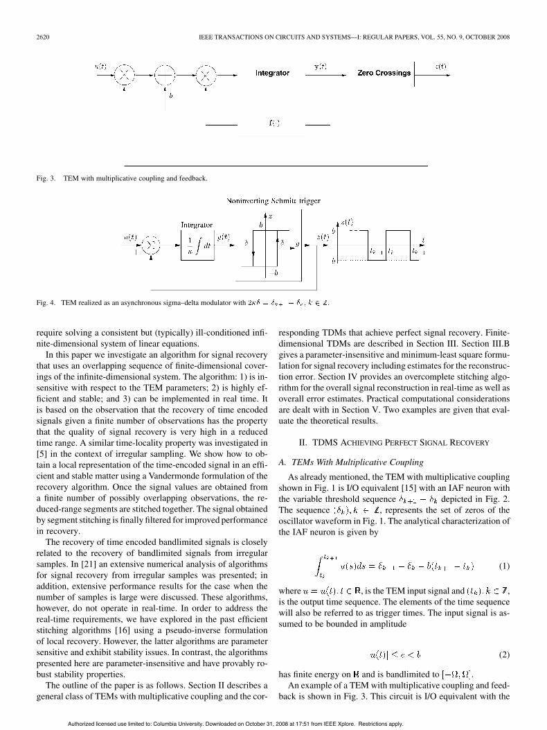
Fig. 3. TEM with multiplicative coupling and feedback.
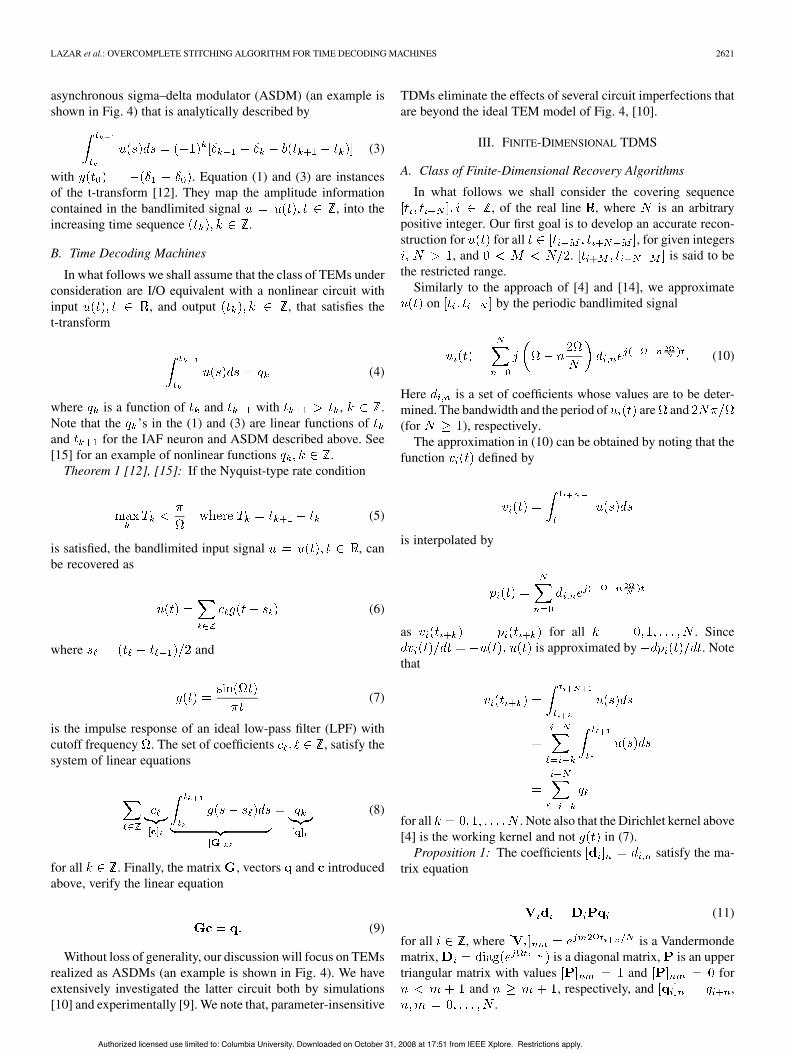
Fig. 4. TEM realized as an asynchronous sigma–delta modulator with .
require solving a consistent but (typically) ill-conditioned infi-nite-dimensional system of linear equations.
In this paper we investigate an algorithm for signal recoverythat uses an overlapping sequence of finite-dimensional cover-ings of the infinite-dimensional system. The algorithm: 1) is in-sensitive with respect to the TEM parameters; 2) is highly ef-ficient and stable; and 3) can be implemented in real time. Itis based on the observation that the recovery of time encodedsignals given a finite number of observations has the propertythat the quality of signal recovery is very high in a reducedtime range. A similar time-locality property was investigated in[5] in the context of irregular sampling. We show how to ob-tain a local representation of the time-encoded signal in an effi-cient and stable matter using a Vandermonde formulation of therecovery algorithm. Once the signal values are obtained froma finite number of possibly overlapping observations, the re-duced-range segments are stitched together. The signal obtainedby segment stitching is finally filtered for improved performancein recovery.
The recovery of time encoded bandlimited signals is closelyrelated to the recovery of bandlimited signals from irregularsamples. In [21] an extensive numerical analysis of algorithmsfor signal recovery from irregular samples was presented; inaddition, extensive performance results for the case when thenumber of samples is large were discussed. These algorithms,however, do not operate in real-time. In order to address thereal-time requirements, we have explored in the past efficientstitching algorithms [16] using a pseudo-inverse formulationof local recovery. However, the latter algorithms are parametersensitive and exhibit stability issues. In contrast, the algorithmspresented here are parameter-insensitive and have provably ro-bust stability properties.
The outline of the paper is as follows. Section II describes ageneral class of TEMs with multiplicative coupling and the cor-
responding TDMs that achieve perfect signal recovery. Finite-dimensional TDMs are described in Section III. Section III.Bgives a parameter-insensitive and minimum-least square formu-lation for signal recovery including estimates for the reconstruc-tion error. Section IV provides an overcomplete stitching algo-rithm for the overall signal reconstruction in real-time as well asoverall error estimates. Practical computational considerationsare dealt with in Section V. Two examples are given that eval-uate the theoretical results.
II. TDMS ACHIEVING PERFECT SIGNAL RECOVERY
A. TEMs With Multiplicative Coupling
As already mentioned, the TEM with multiplicative couplingshown in Fig. 1 is I/O equivalent [15] with an IAF neuron withthe variable threshold sequence depicted in Fig. 2.The sequence , represents the set of zeros of theoscillator waveform in Fig. 1. The analytical characterization ofthe IAF neuron is given by
(1)
where , is the TEM input signal and ,is the output time sequence. The elements of the time sequencewill also be referred to as trigger times. The input signal is as-sumed to be bounded in amplitude
(2)
has finite energy on and is bandlimited to .An example of a TEM with multiplicative coupling and feed-
back is shown in Fig. 3. This circuit is I/O equivalent with the
Authorized licensed use limited to: Columbia University. Downloaded on October 31, 2008 at 17:51 from IEEE Xplore. Restrictions apply.
LAZAR et al.: OVERCOMPLETE STITCHING ALGORITHM FOR TIME DECODING MACHINES 2621
asynchronous sigma–delta modulator (ASDM) (an example isshown in Fig. 4) that is analytically described by
(3)
with . Equation (1) and (3) are instancesof the t-transform [12]. They map the amplitude informationcontained in the bandlimited signal , into theincreasing time sequence .
B. Time Decoding Machines
In what follows we shall assume that the class of TEMs underconsideration are I/O equivalent with a nonlinear circuit withinput , and output , that satisfies thet-transform
(4)
where is a function of and with , .Note that the ’s in the (1) and (3) are linear functions ofand for the IAF neuron and ASDM described above. See[15] for an example of nonlinear functions .
Theorem 1 [12], [15]: If the Nyquist-type rate condition
(5)
is satisfied, the bandlimited input signal , canbe recovered as
(6)
where and
(7)
is the impulse response of an ideal low-pass filter (LPF) withcutoff frequency . The set of coefficients , satisfy thesystem of linear equations
(8)
for all . Finally, the matrix , vectors and introducedabove, verify the linear equation
(9)
Without loss of generality, our discussion will focus on TEMsrealized as ASDMs (an example is shown in Fig. 4). We haveextensively investigated the latter circuit both by simulations[10] and experimentally [9]. We note that, parameter-insensitive
TDMs eliminate the effects of several circuit imperfections thatare beyond the ideal TEM model of Fig. 4, [10].
III. FINITE-DIMENSIONAL TDMS
A. Class of Finite-Dimensional Recovery Algorithms
In what follows we shall consider the covering sequence, of the real line , where is an arbitrary
positive integer. Our first goal is to develop an accurate recon-struction for for all , for given integers
, and . is said to bethe restricted range.
Similarly to the approach of [4] and [14], we approximateon by the periodic bandlimited signal
(10)
Here is a set of coefficients whose values are to be deter-mined. The bandwidth and the period of are and(for ), respectively.
The approximation in (10) can be obtained by noting that thefunction defined by
is interpolated by
as for all . Sinceis approximated by . Note
that
for all . Note also that the Dirichlet kernel above[4] is the working kernel and not in (7).
Proposition 1: The coefficients satisfy the ma-trix equation
(11)
for all , where is a Vandermondematrix, is a diagonal matrix, is an uppertriangular matrix with values and for
and , respectively, and ,.
Authorized licensed use limited to: Columbia University. Downloaded on October 31, 2008 at 17:51 from IEEE Xplore. Restrictions apply.
2622 IEEE TRANSACTIONS ON CIRCUITS AND SYSTEMS—I: REGULAR PAPERS, VOL. 55, NO. 9, OCTOBER 2008
Proof: The matrix (11) is a compact notation of thelinear systems of equations where
, and .It is known [8] that is nonsingular if
for . This condition is satisfied since. Note that with (5)
. As a result, the values offor all , are distinct and located within one pe-riod of the complex exponential. The Vandermonde systemin (11) can be solved for by the Björk-Pereyra algorithm ina numerically very stable way with flops [1], [8]. Forconvenience, it is given below.
Algorithm 1: Let where, and . The system of linear (11)
can be solved with flops as follows:
At the end of the procedure .With this approach our numerical experiments were similar
to those of [16], [14]: increasing the accuracy of the recon-struction improves, that is, the error
(12)
decreases. However, the conditioning of the system gets worse.As a consequence of Gautschi’s classic results [6]–[8], esti-mates for , the infinite-norm condition number of ,are given by the following lemma.
Lemma 1:
(13)
Proof: The definition of -norm of gives:
(14)
Let be an by Vandermonde matrix generated bythe arbitrary distinct nodes as where
. The lower bound [6] and the upper bound [7] forare given by
and
respectively. Since in our case and, the statement of the
lemma in (13) follows from simple algebraic manipulations.
As described in detail in [8], the error in the solution of aVandermonde system due to parameter inaccuracies can be es-timated based on the condition number.
Remark 1: Multiplying both sides of (11) by , wherethe superscript stands for conjugate-transposition, transforms(11) into the normal equations
(15)
Since is a Toeplitz matrix with elementsthe above equation is essen-
tially equivalent with the Toeplitz formulation used in [4] and[14]. The representation in (15) offers significant benefit interms of computational complexity for larger linear systems,when the matrix-vector multiplications in the recursive solution(such as the accelerated conjugate gradient method in [4])can be sped up by using the FFT algorithm on an augmentedcircular system. The main disadvantage of this method is thatthe conditioning of the Toeplitz system can be much worsethan that of the Vandermonde system due to the relationship
between the 2-norm conditionnumbers [8]. Since we use small matrices, the natural choice isto use the better-conditioned Vandermonde representation.
B. Parameter-Insensitive TDM
In what follows we shall assume that the oscillator in Fig. 3 isdescribed by a periodic orbit in the phase space. Then, the TEMwith multiplicative coupling and feedback can be described bythe ASDM [15] shown in Fig. 4 where the integrator’s time con-stant and the Schmitt-trigger’s height and width are thecircuit parameters. Since holds [see (3)–(5)]
(16)
In addition, the bounds for [see also (5)] give
and
(17)
is a sufficient condition for perfect reconstruction [12]. SuchTEMs offer a natural way for developing TDMs that are insen-sitive with respect to the TEM circuit parameters. The compen-sation principle of [12] takes the form
(18)
for all . Note that the right-hand side of equality (18)above does not depend on . In addition, an inaccurate value for
merely introduces a constant scaling error in the reconstructedsignal. Therefore, any recovery algorithm based on (18), i.e.,
, does not have knowledge of the parameters of theTEM and is, thereby, parameter-insensitive.
The TDM coefficients in (11) directly depend onthe circuit parameters , and through , since
Authorized licensed use limited to: Columbia University. Downloaded on October 31, 2008 at 17:51 from IEEE Xplore. Restrictions apply.
LAZAR et al.: OVERCOMPLETE STITCHING ALGORITHM FOR TIME DECODING MACHINES 2623
. We note that the compo-nents of are given by [14]
(19)
This expression does not depend on for even . For odd ,the terms can be eliminated by subtracting from
an appropriate rank-one matrix as detailed below.Algorithm 2: The Vandermonde system in (11) can be re-
duced to an underdetermined linear system whose minimum-least-square and minimim-norm solution is given by
(20)
where and, and denote the solutions of theVandermonde systems
(21)
and
(22)
respectively, where does not depend, and .
Proof: The relationship in (19) and the definitions of ,and imply:
(23)
Denoting the identity matrix of size by and using, we have . It is easy to show
that is a projection matrix with rank .Therefore, by using (23) and (11), we obtain the underdeter-
mined linear system
After rearranging terms, we have
(24)
where and. A minimum-least-square and minimum-norm solution
of (24) is given by
where the superscript stands for the pseudo-inverse [8], [2].Since (24) is a linear system modified by the rank-one matrix
can be calculated by the general formulas
(6 possible cases) presented in [2] (Theorem 3.1.3). Note alsothat since is nonsingular and
the corresponding result of [2] (case (vi)) gives (20) after sim-plifications (and using the fact that ).
Lemma 2: Algorithm 2 is robust in the sense that division by“very small” is safely avoided and
(25)
for all .Proof: Clearly . Also, im-
plies . Finally, from, (14), and (see [8. p. 53]) , (25) follows.As illustrated in the example of Section III-D, for large
numerical inaccuracies might occur if . Fi-nally, since in the parameter-insensitive case two Vandermondesystems have to be solved, the overall computational load isaround (the rest of the computations in (20) only need
flops).
C. Error Estimate of the Parameter-Insensitive TDM
As shown above, the coefficients in (20) are found in theparameter insensitive case by a projection on an -dimensionalsubspace of the column space of (of dimension ).Therefore, the accuracy of the reconstruction based on (20),(21), and (22) is certainly below that obtained by solving (11)directly.
Lemma 3: The error in the parameter-insensitive case
(26)
is given by
(27)
where
(28)
Proof: Recall that is the error without using theparameter-insensitive formulation [see also (12)]. Then, with
with elementswe have
(29)
Authorized licensed use limited to: Columbia University. Downloaded on October 31, 2008 at 17:51 from IEEE Xplore. Restrictions apply.
2624 IEEE TRANSACTIONS ON CIRCUITS AND SYSTEMS—I: REGULAR PAPERS, VOL. 55, NO. 9, OCTOBER 2008
where is the solution of (11). Likewise, the error in the pa-rameter-insensitive formulation is given by
(30)
With (23) and (11), (21) can be rewritten as
and therefore, with (22)
Substituting above into (30) and using (29) gives
This concludes the proof.Remark 2: Ignoring the term in (27) gives the approx-
imation
(31)
The formula for can be used only when accurate values forand are known. Since generally this is not the case, we definethe average consecutive error .Assuming furthermore that the sum on the right-hand side of(31) is the same for and , the error estimate becomes
(32)
where
(33)
As the example in Section III below demonstrates, this error es-timate gives reasonable results with the additional benefit thatthe interval-reducing parameter can also be estimated. Fi-nally, since this error estimate is proportional to , an accuratevalue for is not needed.
D. Example
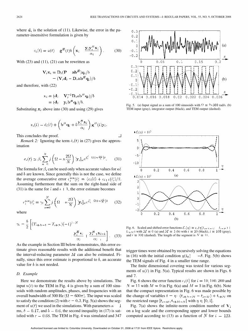
Here we demonstrate the results above by simulations. Theinput to the TEM in Fig. 4 is given by a sum of 100 sinu-soids with random amplitudes, phases, and frequencies with anoverall bandwidth of 300 Hz . The input was scaledto satisfy the condition (2) with . Fig. 5(a) shows the seg-ment of we used in the simulations. With parametersms, , and , the second inequality in (17) is sat-isfied with . The TEM in Fig. 4 was simulated and 347
Fig. 5. (a) Input signal as a sum of 100 sinusoids with rad/s. (b)TEM input (gray), integrator output (black), and TEM output (dashed).
Fig. 6. Scaled and shifted error functionswith (a) and (b) with (black), (gray),
and (dashed). The length of the segment is .
trigger times were obtained by recursively solving the equationsin (16) with the initial condition . Fig. 5(b) showsthe TEM signals of Fig. 4 in a smaller time range.
The finite dimensional covering was tested for various seg-ments of in Fig. 5(a). Typical results are shown in Figs. 6and 7.
Fig. 6 shows the error function for andwith in Fig. 6(a) and in Fig. 6(b). Note
that the compact representation in Fig. 6 was made possible bythe change of variables onthe restricted range with .
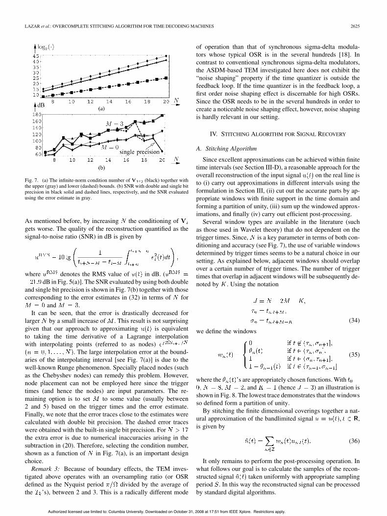
Fig. 7(a) shows the infinite-norm condition number ofon a log scale and the corresponding upper and lower boundscomputed according to (13) as a function of for .
Authorized licensed use limited to: Columbia University. Downloaded on October 31, 2008 at 17:51 from IEEE Xplore. Restrictions apply.
LAZAR et al.: OVERCOMPLETE STITCHING ALGORITHM FOR TIME DECODING MACHINES 2625
Fig. 7. (a) The infinite-norm condition number of (black) together withthe upper (gray) and lower (dashed) bounds. (b) SNR with double and single bitprecision in black solid and dashed lines, respectively, and the SNR evaluatedusing the error estimate in gray.
As mentioned before, by increasing the conditioning ofgets worse. The quality of the reconstruction quantified as thesignal-to-noise ratio (SNR) in dB is given by
where denotes the RMS value of in dB. (dB in Fig. 5(a)]. The SNR evaluated by using both double
and single bit precision is shown in Fig. 7(b) together with thosecorresponding to the error estimates in (32) in terms of for
and .It can be seen, that the error is drastically decreased for
larger by a small increase of . This result is not surprisinggiven that our approach to approximating is equivalentto taking the time derivative of a Lagrange interpolationwith interpolating points (referred to as nodes)
. The large interpolation error at the bound-aries of the interpolating interval [see Fig. 7(a)] is due to thewell-known Runge phenomenon. Specially placed nodes (suchas the Chebyshev nodes) can remedy this problem. However,node placement can not be employed here since the triggertimes (and hence the nodes) are input parameters. The re-maining option is to set to some value (usually between2 and 5) based on the trigger times and the error estimate.Finally, we note that the error traces close to the estimates werecalculated with double bit precision. The dashed error traceswere obtained with the built-in single bit precision. Forthe extra error is due to numerical inaccuracies arising in thesubtraction in (20). Therefore, selecting the condition number,shown as a function of in Fig. 7(a), is an important designchoice.
Remark 3: Because of boundary effects, the TEM inves-tigated above operates with an oversampling ratio (or OSRdefined as the Nyquist period divided by the average ofthe ’s), between 2 and 3. This is a radically different mode
of operation than that of synchronous sigma-delta modula-tors whose typical OSR is in the several hundreds [18]. Incontrast to conventional synchronous sigma-delta modulators,the ASDM-based TEM investigated here does not exhibit the“noise shaping” property if the time quantizer is outside thefeedback loop. If the time quantizer is in the feedback loop, afirst order noise shaping effect is discernable for high OSRs.Since the OSR needs to be in the several hundreds in order tocreate a noticeable noise shaping effect, however, noise shapingis hardly relevant in our setting.
IV. STITCHING ALGORITHM FOR SIGNAL RECOVERY
A. Stitching Algorithm
Since excellent approximations can be achieved within finitetime intervals (see Section III-D), a reasonable approach for theoverall reconstruction of the input signal on the real line isto (i) carry out approximations in different intervals using theformulation in Section III, (ii) cut out the accurate parts by ap-propriate windows with finite support in the time domain andforming a partition of unity, (iii) sum up the windowed approx-imations, and finally (iv) carry out efficient post-processing.
Several window types are available in the literature (suchas those used in Wavelet theory) that do not dependent on thetrigger times. Since, is a key parameter in terms of both con-ditioning and accuracy (see Fig. 7), the use of variable windowsdetermined by trigger times seems to be a natural choice in oursetting. As explained below, adjacent windows should overlapover a certain number of trigger times. The number of triggertimes that overlap in adjacent windows will be subsequently de-noted by . Using the notation
(34)
we define the windows
(35)
where the ’s are appropriately chosen functions. With, , and (hence ) an illustration is
shown in Fig. 8. The lowest trace demonstrates that the windowsso defined form a partition of unity.
By stitching the finite dimensional coverings together a nat-ural approximation of the bandlimited signal ,is given by
(36)
It only remains to perform the post-processing operation. Inwhat follows our goal is to calculate the samples of the recon-structed signal taken uniformly with appropriate samplingperiod . In this way the reconstructed signal can be processedby standard digital algorithms.
Authorized licensed use limited to: Columbia University. Downloaded on October 31, 2008 at 17:51 from IEEE Xplore. Restrictions apply.

2626 IEEE TRANSACTIONS ON CIRCUITS AND SYSTEMS—I: REGULAR PAPERS, VOL. 55, NO. 9, OCTOBER 2008
Fig. 8. Illustration of the windows defined in (35) with, and .
Since the windows , have finite support,in (36) is very well suited for real-time uniform samplingin an overlap-add fashion (see also Fig. 8). In addition, theFourier-series representation of the finite dimensional coveringsin (10) allows calculating the samples via the FFT(see Section V). The bandwidth of determines the valuesof the sampling time that avoids (or minimizes) aliasing. Inparticular, denoting the Fourier transform of by ,let be such that for all and . Sincethe bandwidth of is [see (10)], the bandwidth of theproduct in (36), and thus that of is .Therefore, for
(37)
aliasing is (practically) avoided.Algorithm 3: The reconstructed signal in discrete-time (DT)
is given by , where the is the impulse responseof a DT LPF with (digital) cutoff frequency anddenotes the convolution.
Since the reconstruction error spreads over the range, low-pass filtering further improves the overall
accuracy. In addition, the Nyquist rate of the samples can be re-covered via decimating the filtered reconstructed samples. How-ever, it depends on the application if an (even accurate) approxi-mation of the filtered samples is acceptable insteadof approximating the original samples .
Remark 4: Increasing not only improves the accuracy ofthe reconstruction [see Fig. 7(b)], but also broadens inthe time domain, and hence decreases . This technique clearlyhas its limitations since by increasing , the condition numberof the Vandermonde systems also increases [see Fig. 7(a)]. Byappropriately choosing the parameter and in (35), canbe decreased for fixed and . For example, a good frequencylocalization for can be achieved by using
(38)
while both and its derivative are continuous.
B. Overall Error Estimation
The DT reconstruction error is given by
(39)
and if filtering is used the error amounts to
(40)
Lemma 4: The DT reconstruction estimated error amounts to
(41)
where is given by (32).Proof: Since , forms a partition of unity, using
(36) and (26) the overall reconstruction errorcan be written as
Approximating by and setting , the resultfollows.
Remark 5: If postfiltering is employed, then the filtered errorestimation sequence
(42)
can be used.The error estimates in (41) and (42) assume accurate values
for the trigger times. In practice the trigger times certainlyexhibit jitter as a result of the TEM circuit imperfections [10]and the unavoidable quantization of the ’s. The jitter-inducederror often dominates the reconstruction error obtained withperfect trigger times. Modeling the jitter as a sequence ofindependent random variables uniformly distributed within
with given , the error estimate (defined in [dB])
(43)
was developed in [12] for the ideal TDM of Section II-B, withand
. As demonstrated in the example of Section IV-Cbelow, this rough estimate gives acceptable results for the pro-posed TDM, although the jitter-processing mechanism in thispaper is not exactly the same as the one in [12]. The behavior ofthe error estimate in (41) with corrupted trigger times is ratherimportant. Since the error estimate does not incorporate knowl-edge about jitter, it relies on the existence of an input that exactlygenerates the available trigger times. Because of this built-in“tolerance,” the error estimate saturates for larger values of
Authorized licensed use limited to: Columbia University. Downloaded on October 31, 2008 at 17:51 from IEEE Xplore. Restrictions apply.
LAZAR et al.: OVERCOMPLETE STITCHING ALGORITHM FOR TIME DECODING MACHINES 2627
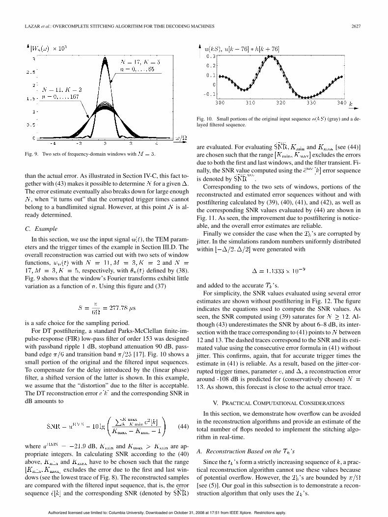
Fig. 9. Two sets of frequency-domain windows with .
than the actual error. As illustrated in Section IV-C, this fact to-gether with (43) makes it possible to determine for a given .The error estimate eventually also breaks down for large enough
, when “it turns out” that the corrupted trigger times cannotbelong to a bandlimited signal. However, at this point is al-ready determined.
C. Example
In this section, we use the input signal , the TEM param-eters and the trigger times of the example in Section III.D. Theoverall reconstruction was carried out with two sets of windowfunctions, with and
, respectively, with defined by (38).Fig. 9 shows that the window’s Fourier transforms exhibit littlevariation as a function of . Using this figure and (37)
s
is a safe choice for the sampling period.For DT postfiltering, a standard Parks-McClellan finite-im-
pulse-response (FIR) low-pass filter of order 153 was designedwith passband ripple 1 dB, stopband attenuation 90 dB, pass-band edge and transition band [17]. Fig. 10 shows asmall portion of the original and the filtered input sequences.To compensate for the delay introduced by the (linear phase)filter, a shifted version of the latter is shown. In this example,we assume that the “distortion” due to the filter is acceptable.The DT reconstruction error and the corresponding SNR indB amounts to
(44)
where dB, and are ap-propriate integers. In calculating SNR according to the (40)above, and have to be chosen such that the range
excludes the error due to the first and last win-dows (see the lowest trace of Fig. 8). The reconstructed samplesare compared with the filtered input sequence, that is, the errorsequence and the corresponding SNR (denoted by )
Fig. 10. Small portions of the original input sequence (gray) and a de-layed filtered sequence.
are evaluated. For evaluating and [see (44)]are chosen such that the range excludes the errorsdue to both the first and last windows, and the filter transient. Fi-nally, the SNR value computed using the error sequenceis denoted by .
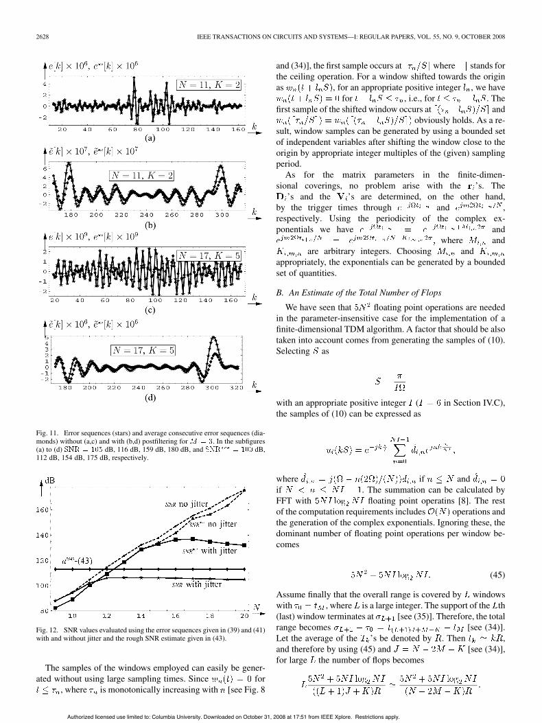
Corresponding to the two sets of windows, portions of thereconstructed and estimated error sequences without and withpostfiltering calculated by (39), (40), (41), and (42), as well asthe corresponding SNR values evaluated by (44) are shown inFig. 11. As seen, the improvement due to postfiltering is notice-able, and the overall error estimates are reliable.
Finally we consider the case when the ’s are corrupted byjitter. In the simulations random numbers uniformly distributedwithin were generated with
and added to the accurate ’s.For simplicity, the SNR values evaluated using several error
estimates are shown without postfiltering in Fig. 12. The figureindicates the equations used to compute the SNR values. Asseen, the SNR computed using (39) saturates for . Al-though (43) underestimates the SNR by about 6–8 dB, its inter-section with the trace corresponding to (41) points to between12 and 13. The dashed traces correspond to the SNR and its esti-mated value using the consecutive error formula in (41) withoutjitter. This confirms, again, that for accurate trigger times theestimate in (41) is reliable. As a result, based on the jitter-cor-rupted trigger times, parameter , and , a reconstruction erroraround -108 dB is predicted for (conservatively chosen)
. As shown, this forecast is close to the actual error trace.
V. PRACTICAL COMPUTATIONAL CONSIDERATIONS
In this section, we demonstrate how overflow can be avoidedin the reconstruction algorithms and provide an estimate of thetotal number of flops needed to implement the stitching algo-rithm in real-time.
A. Reconstruction Based on the ’s
Since the ’s form a strictly increasing sequence of , a prac-tical reconstruction algorithm cannot use these values becauseof potential overflow. However, the ’s are bounded by[see (5)]. Our goal in this subsection is to demonstrate a recon-struction algorithm that only uses the ’s.
Authorized licensed use limited to: Columbia University. Downloaded on October 31, 2008 at 17:51 from IEEE Xplore. Restrictions apply.
2628 IEEE TRANSACTIONS ON CIRCUITS AND SYSTEMS—I: REGULAR PAPERS, VOL. 55, NO. 9, OCTOBER 2008
Fig. 11. Error sequences (stars) and average consecutive error sequences (dia-monds) without (a,c) and with (b,d) postfiltering for . In the subfigures(a) to (d) dB, 116 dB, 159 dB, 180 dB, and dB,112 dB, 154 dB, 175 dB, respectively.
Fig. 12. SNR values evaluated using the error sequences given in (39) and (41)with and without jitter and the rough SNR estimate given in (43).
The samples of the windows employed can easily be gener-ated without using large sampling times. Since for
, where is monotonically increasing with [see Fig. 8
and (34)], the first sample occurs at where stands forthe ceiling operation. For a window shifted towards the originas , for an appropriate positive integer , we have
for , i.e., for . Thefirst sample of the shifted window occurs at and
obviously holds. As a re-sult, window samples can be generated by using a bounded setof independent variables after shifting the window close to theorigin by appropriate integer multiples of the (given) samplingperiod.
As for the matrix parameters in the finite-dimen-sional coverings, no problem arise with the ’s. The
’s and the ’s are determined, on the other hand,by the trigger times through and ,respectively. Using the periodicity of the complex ex-ponentials we have and
where andare arbitrary integers. Choosing and
appropriately, the exponentials can be generated by a boundedset of quantities.
B. An Estimate of the Total Number of Flops
We have seen that floating point operations are neededin the parameter-insensitive case for the implementation of afinite-dimensional TDM algorithm. A factor that should be alsotaken into account comes from generating the samples of (10).Selecting as
with an appropriate positive integer ( in Section IV.C),the samples of (10) can be expressed as
where if andif . The summation can be calculated byFFT with floating point operatins [8]. The restof the computation requirements includes operations andthe generation of the complex exponentials. Ignoring these, thedominant number of floating point operations per window be-comes
(45)
Assume finally that the overall range is covered by windowswith , where is a large integer. The support of the th(last) window terminates at [see (35)]. Therefore, the totalrange becomes [see (34)].Let the average of the ’s be denoted by . Then ,and therefore by using (45) and [see (34)],for large the number of flops becomes
Authorized licensed use limited to: Columbia University. Downloaded on October 31, 2008 at 17:51 from IEEE Xplore. Restrictions apply.
LAZAR et al.: OVERCOMPLETE STITCHING ALGORITHM FOR TIME DECODING MACHINES 2629
Finally, as in [12], can be approximated by the arithmeticmean of the lower and upper bound for in (17) as
. Using the expression for in(17)
easily follows. Therefore, we have the followingLemma 5: The number of flops for realizing the stitching
algorithm is given by
VI. CONCLUSION
We investigated the implementation of a signal recovery algo-rithm that consists of an overlapping sequence of finite-dimen-sional coverings of an infinite-dimensional space. The recoveryof the signal on finite dimensional coverings calls for solving aVandermonde system.
The main focus of our work was on developing efficient pa-rameter-insensitve TDM algorithms that can be implemented inreal-time and that are stable. In order to construct such algo-rithms, we have developed a novel solution method that callsfor projecting the -dimensional space generated by thecolumn of the Vandermonde matrix onto dimensional space.The algorithm was shown to be provably stable.
The real-time algorithm stitches finite-dimensional cover-ings together using a set of variable-size windows that aredata driven. A linear filtering of the output of the real-timealgorithm further improves its performance. The complexity ofthe stitching algorithm is linear in size of the finite-dimensionalcoverings. It is, therefore, amenable to real-time implementa-tions.
Currently, we are evaluating the stitching algorithm de-scribed here in experimental body area networks. The stringentenergy constraints at the transmitter (sensor) side can be ad-dressed by using ultrawide-wide-band wireless communicationchannels [19] or the skin surface as a communication medium[9]. The trigger times can be readily transmitted through eitherof these channels while the decoding complexity can be easilyimplemented at the receiver.
ACKNOWLEDGMENT
The authors would like to thank two of the reviewers for bothcarefully reading the paper and making detailed suggestions forimproving its presentation.
REFERENCES
[1] A. Björk and V. Pereyra, “Solution of Vandermonde systems of equa-tions,” Math. Comp., vol. 24, pp. 893–903, 1970.
[2] S. L. Campbell and C. D. Meyer Jr:, Generalized Inverses of LinearTransformations. New York: Dove, 1979.
[3] O. Christensen, “Frames Riesz basis, and discrete Gabor/wavelet ex-pansions,” in Bull. Amer. Math. Soc., Mar. 27, 2001, vol. 38, no. 3, pp.273–291.
[4] H. G. Feichtinger, K. Gröchenig, and T. Strohmer, “Efficient numericalmethods in non-uniform sampling theory,” Numer. Math., vol. 69, pp.423–440, 1995.
[5] H. G. Feichtinger and T. Werther, “Improved locality for irregular sam-pling algorithms,” in Proc. ICASSP, Istanbul, Turkey, 2000.
[6] W. Gautschi, “Norm estimates for the inverses of Vandermonde ma-trices,” Numer. Math., vol. 23, pp. 337–347, 1975.
[7] W. Gautschi, “On the inverses of vandermonde and confluent vander-monde matrices,” Numer. Math., vol. 29, pp. 445–450, 1978.
[8] G. H. Golub and C. F. Van Loan, Matrix Computations, 3rd ed. Bal-timore, MD: The John Hopkins University Press, 1996.
[9] C. Káldi, A. A. Lazar, E. K. Simonyi, and L. T. Tóth, “Time EncodedCommunications for Human Area Network Biomonitoring,” Depart-ment of Elec. Eng., Columbia University, New York, BNET Tech.Rep.#2-07, Jun. 2007.
[10] P. R. Kinget, A. A. Lazar, and L. T. Tóth, “On the robustness of ananalog VLSI implementation of a time encoding machine,” in Proc.ISCAS, Kobe, Japan, May 23–26, 2005, pp. 4221–4224.
[11] J. Kovacevic, P. L. Dragotti, and V. K. Goyal, “Filter bank frame ex-pansions with erasures, invited paper,” IEEE Trans. Inf. Theory, vol.48, no. 6, pp. 1439–1450, Jun. 2002.
[12] A. A. Lazar and L. T. Tóth, “Perfect recovery and sensitivity analysisof time encoded bandlimited signals,” IEEE Trans. Circuits Syst. I, Reg.Papers, vol. 51, no. 10, pp. 2060–2073, Oct. 2004.
[13] A. A. Lazar, “Time encoding with an integrate-and-fire neuron with arefractory period,” Neurocomput., vol. 58–60, pp. 53–58, 2004.
[14] A. A. Lazar, E. K. Simonyi, and L. T. Tóth, “Fast recovery algorithmsof time encoded bandlimited signals,” in Proc ICASSP, Philadelphia,PA, Mar. 19–23, 2005, vol. 4, pp. 237–240, 2005.
[15] A. A. Lazar, “Time encoding machines with multiplicative coupling,feedforward and feedback,” IEEE Trans. Circuits Syst. II, Exp. Briefs,vol. 53, no. 8, pp. 672–676, Aug. 2006.
[16] A. A. Lazar, E. K. Simonyi, and L. T. Tóth, “A real-time algorithm fortime decoding machines,” in Proc. 14th Eur. Signal Process. Conf. ,Florence, Italy, Sep. 4–8, 2006.
[17] Parks-McClellan FIR Filter Design [Online]. Available: http://www.dsptutor.freeuk.com/remez/RemezFIRFilterDesign.html Java 1.1 Ver-sion
[18] E. Roza, “Analog-to-digital conversion via duty-cycle modulation,”IEEE Trans. Circuits Syst. II, Analog Digit. Signal Process., vol. 44,no. 11, pp. 907–917, Nov. 1997.
[19] J. Ryckaert, C. Desset, A. Fort, M. Badaroglu, V. De Heyn, P.Wambacq, G. Van der Plas, S. Donnay, B. Van Poucke, and B. Gy-selinckx, “Ultra-wide-band transmitter for low-power wireless bodyarea networks: Design and evaluation,” IEEE Trans. Circuits Syst. I,Reg. Papers, vol. 52, no. 12, pp. 2515–2525, Dec. 2005.
[20] T. Strohmer, “Irregular Sampling, Frames, and Pseudoinverse,” Masterthesis, Dep. Math. , Univ. Vienna, Vienna, Austria, 1991.
[21] T. Strohmer, “Numerical analysis of the non-uniform samplingproblem,” J. Comput. Appl. Math., vol. 122, pp. 297–316, 2000.
Aurel A. Lazar is a Professor of Electrical Engi-neering at Columbia University, New York. In themid 1980s and 1990s, he pioneered investigationsinto networking games and programmable networks.In addition, he conducted research in broadbandnetworking with quality of service constraints; andin architectures, network management and control oftelecommunications networks. His current researchinterests are at the intersection of ComputationalNeuroscience, Information/Communications Theoryand Systems Biology. In silico, his focus is on
time encoding and information representation in sensory systems, and, spikeprocessing and neural computation in the cortex. In vivo, his focus is on theolfactory system of the drosophila.
Authorized licensed use limited to: Columbia University. Downloaded on October 31, 2008 at 17:51 from IEEE Xplore. Restrictions apply.
2630 IEEE TRANSACTIONS ON CIRCUITS AND SYSTEMS—I: REGULAR PAPERS, VOL. 55, NO. 9, OCTOBER 2008
Ernö K. Simonyi received the M.Sc. and the Uni-versity Doctor degrees both in electrical engineeringfrom the Technical University of Budapest (BME) in1968 and 1974, respectively, the Candidate’s (Ph.D.)degree in microelectronics from the HungarianAcademy of Sciences, Budapest, Hungary, in 1980.
Since 1984 he has been with BME as TitularUniversity Associate Professor. He joined the Re-search Institute for Telecommunications (TKI) in1968. Throughout 1978 he was with the Universityof California, Los Angeles. From 1982 till 1990 he
was the head of Signal Processing & Computer Science Department in TKI.In 1991–1992 he was the Deputy General Director of the TKI. From 1993 till2008 he was the Managing Director of his own consulting firms specializingon large nationwide ICT projects. Since 2005 he has been with Ministry ofDefence Electronics, Logistics and Property Management Co.
Dr. Simonyi was the Editor-in-Chief of the Journal of Communications (Hi-radástechnika) during 1998–2000. During 2001–2004, he was the President ofthe National Council of Hungary for Information and Communications Tech-nology.
László T. Tóth received the M.S. degree in 1982from the Technical University of Budapest, Hungary,the Habilitation degree from the Budapest Universityof Technology and Economics,Budapest, Hungary,in 2005, and the Candidate’s (Ph.D.) and D.Sc.degrees from Hungarian Academy of Sciences,Budapest, Hungary, in 1987 and 2005, respectively.
He worked for the Research Institute for Telecom-munications (1982–93, Budapest, Hungary), BellLaboratories (1996–1997, Murray Hill, NJ, USA),and Columbia University (1989–90, 1995–96). He
taught at the Technical University of Budapest (1993–99) and ColumbiaUniversity (1999–2002). Currently he is a Full Professor at the Departmentof Telecommunications and Media Informatics, Budapest University of Tech-nology and Economics, Hungary.
Dr. Tóth was an Associate Editor of the Journal of Communications (Hi-radástechnika, 1998–2000) and the IEEE TRANSACTIONS ON CIRCUITS ANDSYSTEMS—II: ANALOG DIGITAL SIGNAL PROCESSING (1999–2002).
Authorized licensed use limited to: Columbia University. Downloaded on October 31, 2008 at 17:51 from IEEE Xplore. Restrictions apply.