ieee standard for qualifying class 1 e equipment for...
TRANSCRIPT

P323D1
PP IEEE Std 323TM-2003
(Revision of IEEE Std 323TM-1983)
323TM
IEEE Standard for Qualifying Class 1 E Equipment for Nuclear Power Generating Stations
IEEE Power Engineering Society
Sponsored by the Nuclear Power Engineering Committee
Published by The Institute of Electrical and Electronics Engineers, Inc. 3 Park Avenue, New York, NY 10016-5997, USA
Print: SH95169 PDF: SS95169 23 January 2004

P323D1
P323D1 IEEE Std 323TM-2003 (R2008) (Revision of IEEE
Std 323-1983)
IEEE Standard for Qualifying Class 1 E Equipment for Nuclear Power Generating Stations
Sponsor
Nuclear Power Engineering Committee of the IEEE Power Engineering Society
Reaffirmed 25 September 2008 Approved 11 September 2003
IEEE-SA Standards Board
Abstract: The basic requirements for qualifying Class 1 E equipment and interfaces that are to be used in nuclear power generating stations are described in this standard. The principles, methods, and procedures described are intended to be used for qualifying equipment, maintaining and extending qualification, and updating qualification, as required, if the equipment is modified. The qualification requirements in this standard, when met, demonstrate and document the ability of equipment to perform safety function(s) under applicable service conditions including design basis events, reducing the risk of common-cause equipment failure. Keywords: age conditioning, aging, condition monitoring, design basis events, equipment qualification, harsh environment, margin, mild environment, qualification methods, qualified life, radiation, safety related function, significant aging mechanism, test plan, test sequence, type testing
No part of this publication may be reproduced in any form, in an electronic retrieval system or otherwise, without the prior written permission of the publisher.
The Institute of Electrical and Electronics Engineers, Inc. 3 Park Avenue, New York, NY 10016-5997, USA
Copyright © 2004 by the Institute of Electrical and Electronics Engineers, Inc. All rights reserved. Published 23 January 2004. Printed in the United States of America.
IEEE is a registered trademark in the U.S. Patent & Trademark Office, owned by the Institute of Electrical and Electronics Engineers, Incorporated.
Print: ISBN 0-7381-3812-6 SH95169 PDF: ISBN 0-7381-3813-4 SS95169

IEEE Standards documents are developed within the IEEE Societies and the Standards Coordinating Committees of the IEEE Standards Association (IEEE-SA) Standards Board. The IEEE develops its standards through a consensus develop-ment process, approved by the American National Standards Institute, which brings together volunteers representing varied viewpoints and interests to achieve the final product. Volunteers are not necessarily members of the Institute and serve without compensation. While the IEEE administers the process and establishes rules to promote fairness in the consensus development process, the IEEE does not independently evaluate, test, or verify the accuracy of any of the information con-tained in its standards.
Use of an IEEE Standard is wholly voluntary. The IEEE disclaims liability for any personal injury, property or other dam-age, of any nature whatsoever, whether special, indirect, consequential, or compensatory, directly or indirectly resulting from the publication, use of, or reliance upon this, or any other IEEE Standard document.
The IEEE does not warrant or represent the accuracy or content of the material contained herein, and expressly disclaims any express or implied warranty, including any implied warranty of merchantability or fitness for a specific purpose, or that the use of the material contained herein is free from patent infringement. IEEE Standards documents are supplied “AS IS.”
The existence of an IEEE Standard does not imply that there are no other ways to produce, test, measure, purchase, market, or provide other goods and services related to the scope of the IEEE Standard. Furthermore, the viewpoint expressed at the time a standard is approved and issued is subject to change brought about through developments in the state of the art and comments received from users of the standard. Every IEEE Standard is subjected to review at least every five years for revision or reaffirmation. When a document is more than five years old and has not been reaffirmed, it is reasonable to conclude that its contents, although still of some value, do not wholly reflect the present state of the art. Users are cautioned to check to determine that they have the latest edition of any IEEE Standard.
In publishing and making this document available, the IEEE is not suggesting or rendering professional or other services for, or on behalf of, any person or entity. Nor is the IEEE undertaking to perform any duty owed by any other person or entity to another. Any person utilizing this, and any other IEEE Standards document, should rely upon the advice of a com-petent professional in determining the exercise of reasonable care in any given circumstances.
Interpretations: Occasionally questions may arise regarding the meaning of portions of standards as they relate to specific applications. When the need for interpretations is brought to the attention of IEEE, the Institute will initiate action to pre-pare appropriate responses. Since IEEE Standards represent a consensus of concerned interests, it is important to ensure that any interpretation has also received the concurrence of a balance of interests. For this reason, IEEE and the members of its societies and Standards Coordinating Committees are not able to provide an instant response to interpretation requests except in those cases where the matter has previously received formal consideration.
Comments for revision of IEEE Standards are welcome from any interested party, regardless of membership affiliation with IEEE. Suggestions for changes in documents should be in the form of a proposed change of text, together with appropriate supporting comments. Comments on standards and requests for interpretations should be addressed to:
Secretary, IEEE-SA Standards Board
445 Hoes Lane
P.O. Box 1331
Piscataway, NJ 08855-133 1
USA
Note: Attention is called to the possibility that implementation of this standard may require use of subject mat-ter covered by patent rights. By publication of this standard, no position is taken with respect to the existence or validity of any patent rights in connection therewith. The IEEE shall not be responsible for identifying patents for which a license may be required by an IEEE standard or for conducting inquiries into the legal validity or scope of those patents that are brought to its attention.
Authorization to photocopy portions of any individual standard for internal or personal use is granted by the Institute of

No part of this publication may be reproduced in any form, in an electronic retrieval system or otherwise, without the prior written permission of the publisher.
Electrical and Electronics Engineers, Inc., provided that the appropriate fee is paid to Copyright Clearance Center. To arrange for payment of licensing fee, please contact Copyright Clearance Center, Customer Service, 222 Rosewood Drive, Danvers, MA 01923 USA; +1 978 750 8400. Permission to photocopy portions of any individual standard for educational classroom use can also be obtained through the Copyright Clearance Center.

vi Copyright © 2004 IEEE. All rights reserved.
Introduction
(This introduction is not part of IEEE Std 323-201203, IEEE Standard for Qualifying Class 1E Equipment for Nuclear Power Generating Stations.)
IEEE Std 323-201203, a revision of IEEE Std 323-20031983, is the result of a review of IEEE Std 323-20031983 and present practices in equipment qualification. This revision incorporates current practices and lessons learned from the implementation of previous versions of this standard by the nuclear industry.
Several issues are clarified or changed in this revision:
— This standard defines the methods for equipment qualification when it is desired to qualify equipment for the applications and the environments to which it may be exposed. This standard is generally utilized for qualification of Class 1E (safety-related electric) equipment located in harsh environments, and for certain post-accident monitoring equipment, but it may also be utilized for the qualification of equipment in mild environments. The documentation requirements are, however, more rigorous for equipment located in a harsh environment.
— The term design basis event has been generally used instead of the acronyms DBE, DBA, LOCA, and HELB, and the term design basis accident in order to reduce the complexity of the text.
— Seismic events are identified as design basis events.
— The test margins have been updated to better identify the parameters that achieve test margin on design basis event profiles. Since quantitative margin can be adequately identified by increases in temperature, pressure, radiation, and operating time, the performance of two transients is no longer recommended.
— New digital systems and new advanced analog systems may require susceptibility testing for EMI/ RFI and power surges, if the environments are significant to the equipment being qualified. Since existing instrument and control (I&C) systems were less vulnerable and have the benefit of successful operation under nuclear power plant EMI/RFI and power surge environments, qualification to EMI/RFI and power surges was not previously significant enough to be considered in environmental equipment qualification. As existing I&C
equipment in nuclear power plants may be replaced with computer-based digital I&C systems or advanced analog systems, these new technologies may exhibit greater vulnerability to the nuclear power plant
EMI/RFI and power surges environments. Documents such as NUREG/CR-5700-1992 [B32],a NUREG/CR-5904-1994 [B33], NUREG/CR6384-1996, Volumes 1 and 2 ([B34], [B35]), NUREG/CR-6406-1996 [B36], NUREG/CR-6579- 1998 [37], and NRC IN 94-20 [B3 1] have documented the environmental
influence of EMI/RFI and power surges on safety-related electric equipment. This version of the standard adds EMI/RFI and power surge qualification requirements for new digital systems and new advanced
analog systems
— An important concept in equipment qualification is the recognition that significant degradation could be caused by aging mechanisms occurring from the environments during the service life, and therefore safety-related electric equipment should be in a state of degradation prior to imposing design basis event simulations. Previous versions recognized that the period of time for which acceptable performance was demonstrated is the qualified life. The concept of qualified life continues in this revision. The lastis revision also recognizeds that the condition of the equipment for which acceptable performance was demonstrated is the qualified condition. This version adds the process for using condition monitoring for us, new license renewal and life extension options are available by assuring that qualified equipment continues to remains in a qualified condition.
— An important element in equipment qualification is the qualification to environments and natural phenomenon hazards postulated for the equipment. Previous versions have identified submergence as a qualification element under Design Basis Accidents. This version adds qualification for environments and natural phenomenon such as flood, tsunami, extreme wind, tornado and hurricane.
- An annex has been added that discusses aging and seismic correlation research.
Industry research in the area of equipment qualification and decades of its application have greatly benefited this standard. Future activities of the working group to update this standard will consider the following:
aThe numbers in brackets correspond to those of the bibliography in Annex A.
Formatted: Justified, Indent: Left: 0.15",Line spacing: single
Formatted: Bulleted + Level: 1 + Aligned at: 0.15" + Indent at: 0.4"

vi Copyright © 2004 IEEE. All rights reserved.
bInformation on references can be found in Clause 2.

vi Copyright © 2004 IEEE. All rights reserved.
— Risk-informed approaches and impact of condition monitoring, performance, safety function assess-ment, and qualified life precision.
— Significance of refinements in aging mechanisms, equipment sealing, interfaces, extrapolation, simi-larity, test sequence and parameters (such as ramp rates, time duration, timing of spray initiation and its duration), and qualification documentation.
Participants
This standard was prepared by Working Group (SC 2.1) of the Subcommittee on Qualification (SC 2) of the Nuclear Power Engineering Committee of the IEEE Power Engineering Society. At the time of completion, SC 2.1 had the following membership:
James F. Gleason, Chair
Satish K. Aggarwal Christopher M. Gleason Robert J. Lofaro Anup K. Behera Patrick Gove Bruce M. Lory Thomas Brewington Tom Hencey Edward Mohtashemi Nissen M. Burstein Jerrell C. Henley Nathalie Nadeau Mike Dougherty David A. Horvath Paul Shemanski Quang H. Duong Serena A. Jagtiani-Krause John Wheless Wells D. Fargo Sushant Kapur John White Artur J. Faya Byung-Ryung Koh Michael J. Wylie
Henry Leung
At the time this revised standard was completed, the Nuclear Power Engineering Committee/Subcommittee on Qualification (SC 2) had the following membership:
James F. GleasonSatish K. Aggarwal, Chair
vi Copyright © 2004 IEEE. All rights reserved.
The following members of the balloting committee voted on this standard. Balloters may have voted for approval, disapproval, or abstention.
When the IEEE-SA Standards Board approved this standard on 11 September 2003, it had the following membership:
Don Wright, Chair Howard M. Frazier, Vice Chair
Judith Gorman, Secretary
Also included are the following nonvoting IEEE-SA Standards Board liaisons:
Alan Cookson, NIST Representative Satish K. Aggarwal, NRC Representative
Savoula Amanatidis IEEE Standards Managing Editor

Copyright © 2004 IEEE. All rights reserved. vii
Contents
1 . S c o p e . . . . . . . . . . . . . . . . . . . . . . . . . . . . . . . . . . . . . . . . . . . . . . . . . . . . . . . . . . . . . . . . . . . . . . . . . . . . . . . . . . . . 1
2 . R e f e r e n c e s . . . . . . . . . . . . . . . . . . . . . . . . . . . . . . . . . . . . . . . . . . . . . . . . . . . . . . . . . . . . . . . . . . . . . . . . . . . . . . . . . 1
3 . Definitions . . . . . . . . . . . . . . . . . . . . . . . . . . . . . . . . . . . . . . . . . . . . . . . . . . . . . . . . . . . . . . . . . . . . . . . . . . . . . . . . . . . . . . . . . . . . . . . . . 2
4 . Principles of equipment qualification .......................................................................... 3
4.1 Qualification objective ................................................................................................................... 3 4.2 Qualified life and qualified condition ............................................................................................. 3 4.3 Qualification elements .................................................................................................................... 3 4.4 Qualification documentation .......................................................................................................... 4
5 . Qualification methods .. . . . . . . . .. . . . . . . . . . . .. . . . . . . . . . . .. . . . . . . . . . . .. . . . . . . . . . . .. . . . . . . . . . . .. . . . . . . . . . . .. . . . 4
5.1 Initial qualification ......................................................................................................................... 4 5.2 Extension of qualified life .............................................................................................................. 5 5.3 Condition monitoring ..................................................................................................................... 5
6 . Qualification program ... . . . . . . .. . . . . . . . . . . .. . . . . . . . . . . .. . . . . . . . . . . .. . . . . . . . . . . .. . . . . . . . . . . .. . . . . . . . . . . .. . . . 5
6.1 Equipment specification ................................................................................................................. 5 6.2 Qualification program plan ............................................................................................................. 7 6.3 Qualification program implementation ........................................................................................... 8 6.4 Modifications ..................................................................................................................... 14
7 . Docu ment a t i on . . . . . . . . . . . . . . . . . . . . . . . . . . . . . . . . . . . . . . . . . . . . . . . . . . . . . . . . . . . . . . . . . . . . . . . . . . . . . . . . . . 15
7.1 Mild environment documentation ....................................................................................... 15 7.2 Harsh environment documentation ..................................................................................... 15
Annex A (informative) Bibliography .................................................................................................................... 17


Copyright © 2004 IEEE. All rights reserved. 1
IEEE Standard for Qualifying Class 1 E Equipment for Nuclear Power Generating Stations
1. Scope
This standard describes the basic requirements for qualifying Class 1E equipment and interfaces that are to be used in nuclear power generating stations. The principles, methods, and procedures described are intended to be used for qualifying equipment, maintaining and extending qualification, and updating qualification, as required, if the equipment is modified. The qualification requirements in this standard, when met, demonstrate and document the ability of equipment to perform safety function(s) under applicable service conditions including design basis events, reducing the risk of common-cause equipment failure. This standard does not provide environmental stress levels and performance requirements.
NOTE—Other IEEE standards that present qualification methods for specific equipment, specific environments, or specific parts of the qualification program may be used to supplement this standard, as applicable. Annex A lists other standards related to equipment qualification.
2. References
This standard shall be used in conjunction with the following standards. When the following standards are superseded by an approved version, the revision shall apply.
IEEE Std 344 TM -20041987 (Reaff 20091993), IEEE Recommended Practice for Seismic Qualification of Class 1E Equipment for Nuclear Power Generating Stations.1,2
IEEE Std 497 TM -2010, IEEE Standard Criteria for Accident Monitoring Instrumentation for Nuclear Power Generating Stations
IEEE Std 603 TM -20091998, IEEE Standard Criteria for Safety Systems for Nuclear Power Generating Stations.
IEEE Std 7-4.3.2 TM -20103, IEEE Standard Criteria for Digital Computers in Safety Systems of Nuclear Power Generating Stations.
1The IEEE standards or products referred to in Clause 2 are trademarks owned by the Institute of Electrical and Electronics Engineers, Incorporated. 2IEEE publications are available from the Institute of Electrical and Electronics Engineers, 445 Hoes Lane, P.O. Box 1331, Piscataway,

NJ 08855-133 1, USA (http://standards.ieee.org/).

IEEE Std 323-2003 IEEE STANDARD FOR QUALIFYING CLASS 1 E EQUIPMENT
3 Copyright © 2004 IEEE. All rights reserved.
3. Definitions
The following terms are considered important for accurate interpretation of this standard. Definitions of 3
terms are given in The Authoritative Dictionary of IEEE Standards Terms, Seventh Edition [B3] , and are repeated here for convenience in using this standard.
3.1 age conditioning: Exposure of sample equipment to environmental, operational, and system conditions to simulate these conditions for a period of time; design basis events are not included.
3.2 Class 1E: The safety classification of the electric equipment and systems that are essential to emergency reactor shutdown, containment isolation, reactor core cooling, and containment and reactor heat removal, or are otherwise essential in preventing significant release of radioactive material to the environment.
NOTE—The terms Class 1E equipment and safety-related electric equipment are synonymous.
3.3 components: Items from which the equipment is assembled, e.g., resistors, capacitors, wires, connec-tors, transistors, tubes, switches, and springs.
3.4 condition-based qualification: Qualification based on measurement of one or more condition indica-tors of equipment, its components, or materials for which an acceptance criterion can be correlated to the equipment’s ability to function as specified during an applicable design basis event.
3.5 condition indicator: A measurable physical property of equipment, its components, or materials that changes monotonically with time and can be correlated with its safety function performance under design basis event conditions.
3.6 design basis events: Postulated events used in the design to establish the acceptable performance requirements for the structures, systems, and components.
3.7 design life: The time period during which satisfactory performance can be expected for a specific set of service conditions.
3.8 end condition: Value(s) of equipment condition indicator(s) at the conclusion of age conditioning.
3.9 equipment: An assembly of components designed and manufactured to perform specific functions.
3.10 equipment qualification: The generation and maintenance of evidence to ensure that equipment will operate on demand to meet system performance requirements during normal and abnormal service condi-tions and postulated design basis events.
NOTE—Equipment qualification includes environmental and seismic qualification.
3.11 harsh environment: An environment resulting from a design basis event, i.e., loss-of-coolant accident (LOCA), high-energy line break (HELB), and main steam line break (MSLB).
3.12 interfaces: Physical attachments, mounting, auxiliary components, and connectors (electrical and mechanical) to the equipment at the equipment boundary.
3.13 margin: The difference between service conditions and the conditions used for equipment qualification.
3.14 mild environment: An environment that would at no time be significantly more severe than the envi-ronment that would occur during normal plant operation, including anticipated operational occurrences.
3The numbers in brackets correspond to those of the bibliography in Annex A.

IEEEFOR NUCLEAR POWER GENERATING STATIONS Std 323-2003
4 Copyright © 2004 IEEE. All rights reserved.
3.15 qualified condition: The condition of equipment, prior to the start of a design basis event, for which the equipment was demonstrated to meet the design requirements for the specified service conditions.
3.16 qualified life: The period of time, prior to the start of a design basis event, for which the equipment was demonstrated to meet the design requirements for the specified service conditions.
3.17 service conditions: Environmental, loading, power, and signal conditions expected as a result of normal operating requirements, expected extremes (abnormal) in operating requirements, and postulated conditions appropriate for the design basis events of the station.
3.18 service life: The time period from initial operation to removal from service.
3.19 significant aging mechanism: An aging mechanism that, under normal and abnormal service condi-tions, causes degradation of equipment that progressively and appreciably renders the equipment vulnerable to failure to perform its safety function(s) during the design basis event conditions.
4. Principles of equipment qualification
4.1 Qualification objective
The primary objective of qualification is to demonstrate with reasonable assurance that Class 1E equipment for which a qualified life or condition has been established can perform its safety function(s) without experi-encing common-cause failures before, during, and after applicable design basis events. Class 1E equipment, with its interfaces, must meet or exceed the equipment specification requirements. This continued capability is ensured through a program that includes, but is not limited to, design control, quality control, qualifica-tion, installation, maintenance, periodic testing, and surveillance. The focus of this standard is on qualifica-tion, although it affects the other parts of the program.
For equipment located in a mild environment for meeting its functional requirements during normal environ-mental conditions and anticipated operational occurrences, the requirements shall be specified in the design/ purchase specifications. A qualified life is not required for equipment located in a mild environment and which has no significant aging mechanisms. When seismic testing is used to qualify equipment located in a mild environment, pre-aging prior to the seismic tests is required only where significant aging mechanisms exist (see 6.2.1.1). A maintenance/surveillance program based on a vendor’s recommendations, which may be supplemented with operating experience, should ensure that equipment meets the specified requirements.
4.2 Qualified life and qualified condition
Degradation with time followed by exposure to environmental extremes of temperature, pressure, humidity, radiation, vibration and, if applicable, chemical spray and submergence resulting from a design basis event condition can precipitate common-cause failures of Class 1E equipment. For this reason, it is necessary to establish a qualified life for equipment with significant aging mechanisms. The qualified life determination must consider degradation of equipment capability prior to and during service. Inherent in establishing a qualified life is that a qualified condition is also established. This qualified condition is the state of degrada-tion for which successful performance during a subsequent design basis event was demonstrated.
4.3 Qualification elements
The essential elements of equipment qualification include the following:
a) Equipment specification including definition of the safety function(s)

IEEE Std 323-2003 IEEE STANDARD FOR QUALIFYING CLASS 1 E EQUIPMENT
5 Copyright © 2004 IEEE. All rights reserved.
b) Acceptance criteria
c) Description of the service conditions, including applicable design basis events and their duration
d) Qualification program plan
e) Implementation of the plan
f) Documentation demonstrating successful qualification, including maintenance activities required to maintain qualification. The equipment user is responsible for specifying performance requirements and verifying that the documentation demonstrates that the requirements have been satisfied.
4.4 Qualification documentation
The result of a qualification program shall be documented to demonstrate the equipment’s ability to perform its safety function(s) during its qualified life and applicable design basis events. The documentation shall allow verification by competent personnel, other than the qualifier, that the equipment is qualified.
5. Qualification methods
Methods for acquiring data in support of equipment qualification are listed in 5.1.1, 5.1.2, 5.1.3, and 5.1.4. Equipment is generally qualified by a combination of methods.
5.1 Initial qualification
5.1.1 Type testing
A type test subjects a representative sample of equipment, including interfaces, to a series of tests, simulating the effects of significant aging mechanisms during normal operation. The sample is subsequently subjected to design basis event testing that simulates and thereby establishes the tested configuration for installed equipment service, including mounting, orientation, interfaces, conduit sealing, and expected environments. A successful type test demonstrates that the equipment can perform the intended safety function(s) for the required operating time before, during, and/or following the design basis event, as appropriate.
5.1.2 Operating experience
Performance data from equipment of similar design that has successfully operated under known service con-ditions may be used in qualifying other equipment to equal or less severe conditions. Applicability of this data depends on the adequacy of documentation establishing past service conditions, equipment perfor-mance, and similarity against the equipment to be qualified and upon which operating experience exists. A demonstration of required operability during applicable design basis event(s) shall be included in equipment qualification programs based on operating experience, when design basis event qualification is required.
5.1.3 Analysis
Qualification by analysis requires a logical assessment or a valid mathematical model of the equipment to be qualified. The bases for analysis typically include physical laws of nature, results of test data, operating experience, and condition indicators. Analysis of data and tests for material properties, equipment rating, and environmental tolerance can be used to demonstrate qualification. However, analysis alone cannot be used to demonstrate qualification.

IEEEFOR NUCLEAR POWER GENERATING STATIONS Std 323-2003
Copyright © 2004 IEEE. All rights reserved. 6
5.1.4 Combined methods
Equipment may be qualified by combinations of type test, operating experience, and analysis. For example, where type test of a complete assembly is not possible, component testing supplemented by analysis may be used.
5.2 Extension of qualified life
Initial environmental qualification may yield a qualified life that is less than the anticipated service life of the equipment. For example, the qualified life may be limited due to the use of moderate aging acceleration factors to achieve more realistic simulation of degradation in service during available testing time. Such moderate aging acceleration factors could result in the equipment’s condition being excessively far from its end-of-life condition. The methods for extension of the qualified life are as follows:
a) Retain and continue aging the test sample from the initial program or begin aging a new sample while the qualified equipment is in service. Subsequent demonstration of equipment safety function performance during applicable design basis event(s) increases the qualified life by the additional life simulated.
b) Install additional equipment in identical service conditions, remove before the end of the qualified life of equipment in service, and type test with further age conditioning to establish additional quali-fied life.
c) Evaluation of conservatisms in original assumptions for environmental conditions, failure criteria, and acceleration factors may identify that actual conditions are less severe, and the qualified life may be adjusted accordingly.
d) Identify age-sensitive components and replace them with new, like components.
5.3 Condition monitoring
Condition monitoring may be used in place of a qualified life to determine if qualified equipment is suitable for further service. Condition monitoring for equipment qualification purposes monitors one or more condition indicators to determine whether equipment remains in a qualified condition. The trend of the condition indicator is determined during the performance of age conditioning of the test specimen during qualification testing. The condition indicator must be measurable, linked to the functional degradation of the qualified equipment, and have a consistent trend from unaged through the limit of the qualified pre-accident condition. Condition monitoring may be used with or independently from the concept of qualified life. As the qualified equipment approaches the end of its theoretical qualified life, periodic condition monitoring may be implemented to determine if actual aging is occurring at a slower rate, and if further qualified service is possible based on the condition monitoring results.
6. Qualification program
The major elements of a qualification program are described in 4.3. Clause 6 provides additional details for these elements.
6.1 Equipment specification
Documentation in this category provides essential information about the equipment to be qualified. At a minimum, it shall contain the items specified in 6.1.1, 6.1.2, 6.1.3, 6.1.4, and 6.1.5.
IEEE Std 323-2003 IEEE STANDARD FOR QUALIFYING CLASS 1 E EQUIPMENT
7 Copyright © 2004 IEEE. All rights reserved.
6.1.1 Identification
A technical description of the equipment to be qualified, including applicable performance and qualification standards, shall be provided.
6.1.2 Interfaces
Loadings at interfaces [i.e., physical attachments, mounting, auxiliary components, connectors (electrical and mechanical) to the equipment at the equipment boundary] shall be specified. Motive power or control signal inputs and outputs, and the physical manner by which they are supplied (e.g., connectors, terminal blocks), shall be specified. Control, indicating, and other auxiliary components mounted internal or external to the equipment and required for proper operation shall be included. Material incompatibilities at interfaces shall be considered and evaluated.
6.1.3 Qualified life objective
Where applicable, the equipment qualified life objective of the program shall be stated.
6.1.4 Safety function(s)
The equipment specification shall identify the equipment’s safety function(s) including the required operat-ing times.
NOTE—Components not involved in the equipment’s safety function(s) may be excluded from the qualification process if it can be demonstrated and documented that assumed failures, including spurious operation, have no adverse effect on any and all safety functions, have no adverse effect on the safety function of interfaced equipment, would not mislead an operator, and shall not fail in a manner as to fail other safety-related electric equipment.
6.1.5 Service conditions
6.1.5.1 Normal and abnormal service conditions
The service conditions for the equipment shall be specified. These conditions shall include the nominal val-ues and their expected durations, as well as extreme values and their expected durations. Examples include, but are not limited to, the following:
a) Ambient pressure and temperature
b) Relative humidity
c) Radiation environment
d) Seismic operating basis earthquake (OBE) and nonseismic vibration
e) Operating cycles
f) Electrical loading and signals
g) Condensation, chemical spray, and submergence
h) EMI/RFI and power surges
h)i) Other natural phenomenon hazards (extreme wind, flood, tsunami, hurricane, and tornado)
6.1.5.2 Design basis event conditions
The postulated design basis event conditions including specified high-energy line break, loss-of-coolant accident, main steam line break, and/or safe shutdown seismic events, during or after which the equipment is required to perform its safety function(s), shall be specified. Equipment shall be qualified for the duration of its operational performance requirement for each applicable design basis event condition, including any required post design basis event operability period.

IEEEFOR NUCLEAR POWER GENERATING STATIONS Std 323-2003
Copyright © 2004 IEEE. All rights reserved. 8
6.1.5.3 Margin
If the equipment specification identifies qualification margins (see 3.13 for the definition of margin), their values shall be stated.
6.2 Qualification program plan
A qualification program plan shall define tests, inspections, performance evaluation, acceptance criteria, and required analysis to demonstrate that, when called upon, the equipment can perform its specified safety function(s). The required elements of the program plan are provided in 6.2.1, 6.2.2, 6.2.3, 6.2.4, and 6.2.5. The optional element of condition monitoring is provided in 6.2.6.
6.2.1 Aging
The ability of Class 1E equipment to perform its safety function(s) might be affected by changes due to environmental and operational conditions over time. The qualification program shall specifically address effects of aging to evaluate their significance. The techniques available to address the effects of aging include operating experience, testing, analysis, in-service surveillance, condition monitoring, and mainte-nance activities.
6.2.1.1 Significant aging mechanisms
Equipment shall be reviewed in terms of design, function, materials, and environment for its specified appli-cation to identify potentially significant aging mechanisms. An aging mechanism is significant if subsequent to manufacture, while in storage, and/or in the normal and abnormal service environment, it results in degradation of the equipment that progressively and appreciably renders the equipment vulnerable to failure to perform its safety function(s) under design basis event conditions. Examples of significant aging mechanisms include wear and tear, oxidation, and loss of material strength. Additional information on potentially significant aging mechanisms can be found in IEEE Std 1205 TM -2000 [B23].
6.2.1.2 Aging considerations
If the equipment is determined to have a significant aging mechanism, then the mechanism shall be accounted for in the qualification program. Aging, as part of the qualification program, may be addressed by age conditioning of a test sample prior to design basis event testing. Age conditioning is not required for equipment without significant aging mechanisms. The technique used to address aging may affect ongoing requirements to maintain equipment in a qualified condition.
6.2.2 Qualified life objective
The qualified life objective shall be based on a specified set of service conditions. Pre-service conditions shall be considered if significant aging occurs before equipment is placed into service. Qualified life can be demonstrated by age conditioning a test sample to simulate effects of significant aging mechanisms during a time equal to the qualified life objective. An adjunct to establishing a qualified life objective is to establish an end-condition objective (as described in 6.3.5) of equipment condition indicators that correlate to the ability of equipment to perform its safety function. In this case, the end condition is the basis of qualification, and the time to reach that end condition in service may be more or less than the qualified life established by age conditioning.
6.2.3 Margin
Margin shall be included in qualification programs. This will account for reasonable uncertainties in demonstrating satisfactory performance and normal variations in commercial production and uncertainties in measurement and test equipment, thereby providing assurance that the equipment can perform under

IEEE Std 323-2003 IEEE STANDARD FOR QUALIFYING CLASS 1 E EQUIPMENT
9 Copyright © 2004 IEEE. All rights reserved.
adverse service conditions. Increasing the severity of test parameter values, number of tests, or test duration (but not necessarily all at the same time) are acceptable methods of adding margin in testing, where necessary. If the specified service conditions contain the requisite margins, no additional margin is needed. Guidance for margin in design basis event testing is provided in 6.3.1.6.
6.2.4 Maintenance
Periodic maintenance/replacements required during the aging portion of the qualification program shall be identified.
NOTE—Maintenance may contribute to aging if it is necessary to exercise equipment during maintenance activity.
6.2.5 Acceptance criteria
The value(s) of performance parameters and other criteria to demonstrate that equipment can perform the safety function(s) shall be identified.
6.2.6 Condition monitoring
The applicability and effectiveness of any condition monitoring technique chosen must be eveluatedevaluated for effectiveness as part of a qualification program, unless the effectiveness has been previously determined.
Adding condition-based qualification to the qualification process involves assessing the condition of the test specimens at different stages of the qualification test. This includes measurements made at the beginning of the qualification test, at intervals during the accelerated aging used to simulate operational aging, and prior to the accident simulation, to record the actual equipment condition.
The IEC/IEEE 62582-series of standards contain background and guidelines for application of methods for condition monitoring of some types of electrical equipment important to safety of nuclear power plants.
The IEC/IEEE 62582-series of standards are issued with a joint logo which makes it applicable to management of aging of electrical equipment qualified to IEEE as well as IEC Standards.
Condition monitoring is a developing field and more methods will be added to the IEC/IEEE 62582-series of standards when they are considered widely applied and a good reproducibility of the condition monitoring method can be demonstrated.
Condition monitoring methods addressed in the IEC/IEEE 62582-series of standards must be determined to be applicable for the equipment being qualified.
Condition monitoring methods not addressed in the IEC/IEEE 62582-series of standards must be determined to be effective in a qualification test program.
6.3 Qualification program implementation
6.3.1 Type testing
The type test shall demonstrate that Class 1E equipment performance meets or exceeds the safety function requirements. Type test conditions shall meet or exceed specified service conditions. Appropriate margin shall be added to design basis event parameters (see 6.3.1.3) if not otherwise included in the specified ser-vice conditions.
6.3.1.1 Test plan
The test plan describes the required tests and shall include the following:
a) Identification, description, and quantity of the samples to be tested including significant informa-tion—such as manufacturer, model(s), and serial numbers—to uniquely identify the sample

IEEEFOR NUCLEAR POWER GENERATING STATIONS Std 323-2003
Copyright © 2004 IEEE. All rights reserved. 10
b) Equipment safety function(s) to be demonstrated and qualified life objective
c) Mounting, connection, and other interface requirements
d) Test sequence
e) Age conditioning procedure, if required
f) Specified service conditions and margins or test levels
g) Performance and environmental conditions to be measured, including measurement accuracy
h) Operating conditions and measurement sequence in detail, including monitoring requirements
i) General acceptance criteria (ultimate acceptance criteria are plant-specific based on application of the equipment)
j) Maintenance/replacement during age conditioning, if required
k) Provisions for control of modifications during tests
l) Required documentation
m) Quality assurance requirements
n) Condition monitoring during age conditioning, if required
m)o) Other natural phenomenon hazards (extreme wind, flood, tsunami, hurricane, and tornado), if required
6.3.1.2 Simulated test profiles
The user shall furnish sufficient environmental data to allow the simulation of the design basis event envi- ronmental qualification profile for the equipment being qualified. The test profile may be a single event or a profile that envelops multiple design basis events. If not included in the service environmental conditions,
IEEE Std 323-2003 IEEE STANDARD FOR QUALIFYING CLASS 1 E EQUIPMENT
11 Copyright © 2004 IEEE. All rights reserved.
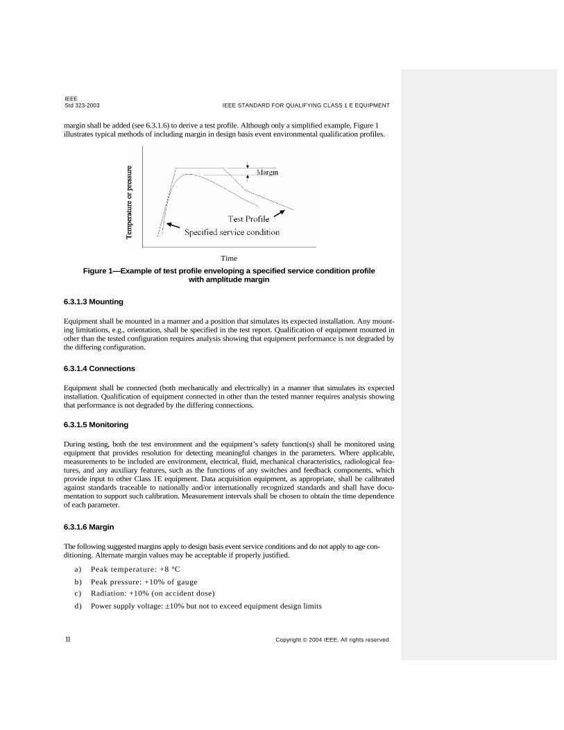
margin shall be added (see 6.3.1.6) to derive a test profile. Although only a simplified example, Figure 1 illustrates typical methods of including margin in design basis event environmental qualification profiles.
Time
Figure 1—Example of test profile enveloping a specified service condition profile with amplitude margin
6.3.1.3 Mounting
Equipment shall be mounted in a manner and a position that simulates its expected installation. Any mount-ing limitations, e.g., orientation, shall be specified in the test report. Qualification of equipment mounted in other than the tested configuration requires analysis showing that equipment performance is not degraded by the differing configuration.
6.3.1.4 Connections
Equipment shall be connected (both mechanically and electrically) in a manner that simulates its expected installation. Qualification of equipment connected in other than the tested manner requires analysis showing that performance is not degraded by the differing connections.
6.3.1.5 Monitoring
During testing, both the test environment and the equipment’s safety function(s) shall be monitored using equipment that provides resolution for detecting meaningful changes in the parameters. Where applicable, measurements to be included are environment, electrical, fluid, mechanical characteristics, radiological fea-tures, and any auxiliary features, such as the functions of any switches and feedback components, which provide input to other Class 1E equipment. Data acquisition equipment, as appropriate, shall be calibrated against standards traceable to nationally and/or internationally recognized standards and shall have docu-mentation to support such calibration. Measurement intervals shall be chosen to obtain the time dependence of each parameter.
6.3.1.6 Margin
The following suggested margins apply to design basis event service conditions and do not apply to age con-ditioning. Alternate margin values may be acceptable if properly justified.
a) Peak temperature: +8 ºC
b) Peak pressure: +10% of gauge
c) Radiation: +10% (on accident dose)
d) Power supply voltage: ±10% but not to exceed equipment design limits
IEEEFOR NUCLEAR POWER GENERATING STATIONS Std 323-2003
Copyright © 2004 IEEE. All rights reserved. 12
e) Equipment operating time: +10% of the period of time the equipment is required to operate following the start of the design basis event
f) Seismic vibration: +10% added to the acceleration requirements at the mounting point of the equipment
g) Line frequency: ±5% of rated value
Margin may be positive or negative to increase the severity of the test. For example, generally it is necessary to use higher temperatures; while in the case of equipment supply voltage, higher or lower values that cause the most degradation should be chosen. Based on factors such as product design control, test sample size, and test measurement accuracy, lesser values may be adequate.
6.3.1.7 Test sequence
The steps in type testing shall be completed in a sequence that places the sample in the worst state of degra-dation that can occur in service during the qualified life, prior to application of design basis events. All steps in the sequence shall be performed on the same test sample. The test sample shall be representative of the same design, materials, and manufacturing process as the installed equipment. For most equipment, the fol-lowing steps and sequence are acceptable:
a) Inspection shall identify the test sample and ensure that it is not damaged.
b) Specified baseline functional tests shall be performed under normal conditions.
c) The test sample shall be operated to the extremes of all performance, operating, surge voltages, and electrical characteristics given in the equipment specifications, excluding design basis event and post-design basis event conditions, unless these data are available from other tests (e.g., design veri-fication tests) on identical or similar equipment.
NOTE—Information on susceptibility testing for EMI/RFI and surge voltages is given in Annex B of IEEE Std 603- 1998 and Annex C of IEEE Std 7-4.3.2-2003. 4 EMI/RFI susceptibility testing may be performed on a separate test specimen.
d) When required, the test sample shall be age conditioned to simulate its functional capability at the end of its qualified life. Measurements made during, or baseline tests following, age conditioning can verify that the test sample is performing satisfactorily prior to subsequent testing. If condition monitoring is to be used in service, measurements after age conditioning would establish the quali-fied end condition.
NOTE—If the qualification program is establishing a qualified life only, normal and design basis event radiation may be combined in age conditioning. However, if condition monitoring is contemplated, an accurate end condition is needed before design basis event simulation.
e) The test sample shall be subjected to specified nonseismic mechanical vibration.
f) The test sample shall be subjected to simulated OBE and safe shutdown earthquake (SSE) seismic vibration in accordance with IEEE Std 344-1987.
NOTE—A seismic event is not assumed to occur in conjunction with a loss-of-coolant accident. Rather, the sequence described previously has been developed as the basis of a conservative qualification, not one indicative of a sequence of expected plant events.
g) The test sample shall perform its required safety function(s) while exposed to simulated accident conditions, including conditions following the accident for the period of required equipment operability, as applicable. Accident radiation may have been included in step d). Safety function performance during testing shall be monitored. Note that safety function can be different in different stages of an accident.
h) Post-test inspection shall be performed on the test sample, and all findings shall be recorded.
i) EMI/RFI susceptibility testing may be performed on a separate test specimen.
NOTE—Information on susceptibility testing for EMI/RFI and surge voltages is given in Annex B of IEEE Std Formatted: Space Before: 3.6 pt, No bulletsor numbering

IEEE Std 323-2003 IEEE STANDARD FOR QUALIFYING CLASS 1 E EQUIPMENT
13 Copyright © 2004 IEEE. All rights reserved.
603- 1998 and Annex C of IEEE Std 7-4.3.2-2003. 4
h)j) Other natural phenomenon hazard tests (extreme wind, flood, tsunami, hurricane, tornado) may be performed on a separate test specimen
4Information on references can be found in Clause 2.
Formatted: Font: 10 pt, Character scale:105%, Expanded by 0.05 pt

IEEEFOR NUCLEAR POWER GENERATING STATIONS Std 323-2003
Copyright © 2004 IEEE. All rights reserved. 14
6.3.1.8 Aging
The assessment of equipment aging effects in connection with a type test program is required to determine if aging has a significant effect on operability. The types of aging include, but are not necessarily limited to, thermal, radiation, wear, and vibration. The assessment shall identify potentially significant aging mecha-nisms related to equipment performance for the design basis events under consideration. Where significant aging mechanisms are identified, suitable age conditioning shall be included in the type test.
6.3.1.8.1 Natural aging
Use of a naturally aged test sample is an age conditioning method which avoids the need to identify signifi-cant aging mechanisms. Naturally aged equipment may be used for type testing provided that
a) Equipment has been operated under service, loading, and environmental conditions at least as severe as those that apply to the intended application, and sufficient documentation exists.
b) Operating and maintenance/replacement records are available.
Natural aging may be supplemented by analysis or age conditioning, or both, to account for differences between the specified service and the natural aging conditions to justify the qualified life of the sample.
6.3.1.8.2 Age conditioning
Age conditioning is a process that replicates in a test sample, as accurately as possible, the degradation of equipment over a period of time due to significant aging mechanisms. This process generally involves applying simulated in-service stresses, typically thermal, radiation, wear, and vibration, as appropriate, at magnitudes or rates that are more severe than expected in-service levels, but less severe than levels that cause aging mechanisms not present in normal service. It is the intent of the age conditioning process to put the test sample in the worst state of degradation that it would experience during the qualified life, prior to the design basis event. The sequence of age conditioning should consider sequential, simultaneous, and syner-gistic effects in order to achieve the worst state of degradation. When condition-based qualification is employed, condition indicator measurements should be performed at the beginning, during, and the end of age conditioning in order to document that the trend of the condition indicator is monotonically changing. Arrhenius methodology is an acceptable method for accelerating time-temperature aging effects during type testing. Sample thermal aging times of a minimum of 100 h are recommended. Dose rate acceleration, within equipment limits, is an acceptable method for accelerating radiation degradation effects. The dose rate for radiation aging should be as low as can be accommodated within reasonable cost and schedule. Information on condition monitoring and aging assessment can be found in IEEE Std 1205-2000 [B23].
6.3.1.8.3 Condition monitoring during age conditioning
Condition monitoring during age conditioning should include an initial condition monitoring measurement to establish the baseline value of the condition indicator for the new, unaged equipment.
Aging can be performed with simultaneous thermal and radiation aging or sequentially. If sequential testing is used, the worst-case aging sequence should be chosen, based on the materials of construction and the degardationdegradation effect on DBE performance. Operational aging rates should ensure homogeneous degradation of the samples and as such, limits for the temperature and dose rate, specifications on the activation energy, and aging time should be properly evaluated. At intervals during operational aging, functional tests and condition monitoring (depending on the type of technique) should be performed nearly at the same time to ensure the performance operability and condition indicators are representative of the actual aging degradation.
The aging should be divided up into at least six segments. The aging duration of the first five segments should be approximately equal and the last segment should contain a time margin of 10% of the aging segment.

CM measurements can be non-destructive or destructive. Non-destructive measurements can be repeated on the same sample or sample set. Destructive CM measurements will require multiple samples in the aging process and cannot be performed on the actual samples that will experience the DBE testing.
A CM measurement should be performed at the end of aging and prior to DBE conditions. After DBE and post DBE testing is completed, the CM measurement should be repeated.
A conclusion will be made on the applicability and effectiveness of the CM to the equipment being qualified.
6.3.1.9 Radiation
In the type test, all materials or components, for which radiation causes significant aging, shall be irradiated to simulate the effects of the radiation exposure. If normal and accident radiation doses and dose rate are demonstrated to have no effect on the safety function(s) of the equipment, then radiation testing may be excluded, and the justification should be documented. A gamma radiation source may be used to simulate the expected effects of the radiation environment.
6.3.1.10 Seismic and nonseismic vibration
The equipment shall be qualified for expected seismic events in accordance with IEEE Std 344-1987 follow-ing any required aging. Nonseismic vibration, which may produce significant degradation (fatigue, wear) during normal and abnormal use, shall be simulated prior to the seismic tests. Vibration to be simulated includes self-induced vibration and vibration from piping, pumps, and motors. Other vibration such as hydrodynamic loadings should be simulated, where applicable, and should be included with the seismic qualification.

IEEE Std 323-2003 IEEE STANDARD FOR QUALIFYING CLASS 1 E EQUIPMENT
16 Copyright © 2004 IEEE. All rights reserved.
6.3.1.11 Operation under normal and design basis event conditions
It shall be demonstrated that equipment can adequately perform its safety function(s) under the identified service conditions.
6.3.1.12 Inspection
Upon completion of type testing, the equipment shall be visually inspected, including disassembly when required, and a description of its physical condition shall be included in the qualification documentation.
6.3.1.13 EMI/RFI and Surge Testing
EMI/RFI and Surge Testing applied to advanced analog and digital instrumentation and can be performed on a separate test specimen with laboratory procedures or insitu. The electromagnetic conditions at the point of installation for safety-related I&C systems should be assessed to identify any unique EMI/RFI sources that may generate local interference. The EMI/RFI sources could include both portable and fixed equipment (e.g., portable transceivers, arc welders, power supplies, and generators).
To ensure that the operating envelopes are being used properly, equipment should be tested in the same physical configuration as that specified for its actual installation in the nuclear power plant. In addition, the equipment should be in its normal mode of operation (i.e., performing its intended function) during the testing. Following the tests, the physical configuration of the safety-related I&C system should be maintained and all changes in the configuration controlled. The design specifications that should be maintained and controlled include wire and cable separations, shielding techniques, shielded enclosure integrity, apertures, gasketing, grounding techniques, EMI/RFI filters, circuit board layouts, and other design parameters that may impact the EMC qualification testing results.
MIL-STD-461E, “Requirements for the Control of Electromagnetic Interference Characteristics of Subsystems and Equipment,” contains test practices that can be applied to characterize EMI/RFI emissions. IEC 61000-6, “Electromagnetic Compatibility (EMC) – Part 6: Generic Standards,” also specifies test practices that can be applied to characterize EMI/RFI emissions for industrial environments.
The specific test methods for emissions testing for safety-related I&C systems in nuclear power plants are presented in Tables 2 and 3. Table 2 lists the EMI/RFI emissions test methods in MIL-STD-461E while Table 3 lists the corresponding criteria in IEC 61000-6- 4, “Electromagnetic Compatibility (EMC) – Part 6: Generic Standards – Section 4: Emission standard for industrial environments.” These test methods cover conducted (along power leads) and radiated interference emitted from equipment under test.
MIL-STD-461E Test Methods for EMI/RFI Emissions
IEC 61000-6-4 Test Methods for EMI/RFI Emissions
CE101 Conducted emissions, low-frequency, 30 Hz to 10 kHz
Conducted emissions, low-frequency, 30 Hz to 10 kHz
CE101 Conducted emissions, low-frequency, 30 Hz to 10 kHz
CISPR 11Conducted emissions, high-frequency, 150 kHz to 30 MHz
CE102 Conducted emissions, high-frequency, 10 kHz to 2 MHz
Radiated emissions, magnetic field, 30 Hz to 100 kHz
RE101 Radiated emissions, magnetic field, 30 Hz to 100 kHz
CISPR 11 Radiated emissions, electric field, 30 MHz to 1 GHz

RE102 Radiated emissions, electric field, 2 MHz to 1 GHz
6.3.1.14 Other natural phenomenon hazards (extreme wind, flood, tsunami, hurricane, and tornado),
6.3.1.14.1 Extreme wind
The uniform approach to design for wind loads treats the types of windstorms (straight, hurricane and tornado) the same.
Equipment required to be qualified for extreme wind can be qualified by analysis or test.
For analysis, the equipment is qualified if the load is less than either allowable stress design (ASD) or strength design (SD). Load combinations shall be considered to determine the most unfavorable effect on the equipment being considered. When using ASD methods, customary allowable stresses appropriate for the material shall be used as given in the applicable material design standard. The SD method requires that the nominal strength provided be greater than or equal to the strength required to carry the factored loads. Appropriate material strength reduction factors should be applied to the nominal strength of the material being used.
For test, an equivalent static load corresponding to the extreme wind load should be applied at the point of most unfavorable effect on the equipment.
6.3.1.14.2 Flood
Equipment required to be qualified for flood can be qualified by analysis or test.
For analysis, the equipment is qualified if the hydraulic load is less than either allowable stress design (ASD) or strength design (SD). Load combinations shall be considered to determine the most unfavorable effect on the equipment being considered. When using ASD methods, customary allowable stresses appropriate for the material shall be used as given in the applicable material design standard. The SD method requires that the nominal strength provided be greater than or equal to the strength required to carry the factored loads. Appropriate material strength reduction factors should be applied to the nominal strength of the material being used.
For test, an equivalent hydraulic load corresponding to the design basis flood load should be applied by submerging the equipment at the design basis flood depth and verifying successful performance during or after flooding, as required from the design.
6.3.1.14.3 Tsunami
Equipment required to be qualified for tsunami can be qualified by analysis or test.
For analysis, the equipment is qualified if the hydraulic and horizontal load is less than either allowable stress design (ASD) or strength design (SD). Load combinations shall be considered to determine the most unfavorable effect on the equipment being considered. When using ASD methods, customary allowable stresses appropriate for the material shall be used as given in the applicable material design standard. The SD method requires that the nominal strength provided be greater than or equal to the strength required to carry the factored loads. Appropriate material strength reduction factors should be applied to the nominal strength of the material being used.
For test, an equivalent hydraulic load c and horizontal load corresponding to the design basis tsunami load

should be applied by submerging the equipment at the design basis tsunami depth, applying the horizontal load at the point of most unfavorable effect on the equipment, and verifying successful performance during or after test, as required from the design.
6.3.1.14.4 Tornado and Hurricane Missile and Pressure
In addition to wind effects, covered in 6.3.1.14.1, tornadoes and hurricanes produce atmospheric pressure change effects and missile impacts from windborne debris (tornado-generated missiles). Equipment required being qualified for tornado and hurricane missile and pressure can be qualified by analysis or test.
Atmospheric pressure change (APC) only affects sealed structures. Natural porosity, openings or breach of the structure envelope permit the inside and outside pressures of an unsealed structure to equalize. Openings of one sq ft per 1000 cu ft volume are sufficiently large to permit equalization of inside and outside pressure as a tornado passes. SSCs that are purposely sealed will experience the net pressure difference caused by APC.
For analysis, the equipment is qualified if the load is less than either allowable stress design (ASD) or strength design (SD). Load combinations shall be considered to determine the most unfavorable effect on the equipment being considered. When using ASD methods, customary allowable stresses appropriate for the material shall be used as given in the applicable material design standard. The SD method requires that the nominal strength provided be greater than or equal to the strength required to carry the factored loads. Appropriate material strength reduction factors should be applied to the nominal strength of the material being used.
For test, the equipment is subjected to the following missile tests:
Missile Criteria 2x4 timber plank 15 lb @150 mph (horizontal.), max. height 200 ft.; 100 mph (vertical.)
3 in. dia. std. steel pipe, 75 lb @ 75 mph (horizontal.); max. height 100 ft, 50 mph (vertical.)
3,000 lb automobile @ 25 mph, rolls and tumbles
6.3.2 Operating experience
Portions or all of an equipment qualification program may be satisfied by documented operating experience. Equipment can be considered for qualification if the same or similar equipment has functioned successfully under service conditions at least as severe as those postulated for the new application. If the operating expe-rience data do not encompass the entire qualified life objective and a design basis event, additional testing of the equipment is required. The similarity of the equipment in service to the equipment designated for a new application shall be established. Service conditions established from operating experience shall envelop the proposed service condition, plus appropriate design basis event margin. Differences shall be evaluated and justified. Documentation shall include the results of measurement or determination of performance charac-teristics required in the equipment qualification program, test records, and analyses of failures. Trends that have occurred during the operating period and a description of periodic maintenance (including adjustments, modifications, and calibration) and inspections shall be included. The documentation shall also include physical locations and mounting arrangements of the equipment in the operating facilities.
6.3.2.1 Operating history
The auditable data to be used to establish the equipment qualification shall consist of the following:
a) Verification that equipment with operating experience is the same as the equipment to be qualified, or that the differences do not unacceptably reduce equipment capability to perform the safety function(s).
b) A record establishing that equipment with operating experience has been exposed to levels of environment and service conditions at least as severe as those for which the equipment being
Formatted: Indent: Left: 0.25"

qualified is required to function and that the equipment satisfactorily performed the function(s) required.
6.3.2.2 Determination of qualification
Operating experience may be the primary basis for qualification only if the qualification documentation includes auditable data demonstrating that the equipment has satisfactorily performed its safety function(s) during conditions at least as severe as the specified service conditions plus appropriate margin. Use of oper-ating experience data from equipment performing nonsafety functions may also be acceptable if adequately justified. The qualified life determination shall evaluate the time that the equipment operated under normal and abnormal service condition levels prior to the occurrence of the design basis event (if the design basis event is simulated, type test requirements apply to the testing). The duration of the qualified life for the equipment being qualified shall be based on the analysis of the conditions of the operating history equip-ment in relation to the conditions of service for the qualified equipment.
6.3.3 Analysis
Qualification by analysis requires a logical assessment, similarity evaluations, or a valid mathematical model to establish that the equipment to be qualified can perform its safety function(s) when subjected to the specified service conditions. Such an analysis shall account for all time-dependent environmental

IEEEFOR NUCLEAR POWER GENERATING STATIONS Std 323-2003
Copyright © 2004 IEEE. All rights reserved. 20
parameters originating from the qualification criteria. Analytical techniques are limited for many types of equipment, and analysis supplemented by test data or operating experience is usually needed for a comprehensive qualification program. Justification is required for the technique used.
6.3.4 Extrapolation and interpolation
Extrapolation and interpolation are analytical techniques that may be used to qualify equipment by extend-ing the application of test data. The following two types of extrapolation and interpolation are possible:
a) Extrapolation or interpolation of successful performance at a specified service condition to a differ-ent service condition
b) Extrapolation or interpolation of successful performance of a specific piece of equipment to similar equipment
Extrapolation or interpolation of a service condition requires analysis using established physical principles. Extrapolation or interpolation to other equipment by similarity can be used when the following criteria in 6.3.4.1, 6.3.4.2, 6.3.4.3, 6.3.4.4, 6.3.4.5, and 6.3.4.6 are met.
6.3.4.1 Material
Materials of construction shall either be the same or equivalent. Any identified differences shall be shown to not adversely affect performance of the safety function(s).
6.3.4.2 Size
Size may vary if the basic configuration remains the same and dimensions are related by known scale fac-tors. Consideration shall be taken of such factors as thermal effects of different surface areas and seismic effects of different masses and modes.
6.3.4.3 Shape
The shape shall be the same or similar (subject to restrictions of size), and any differences shown shall not adversely affect the performance of safety function(s).
6.3.4.4 Stress
Operating and environmental stresses on the new equipment shall be equal or less than those experienced on the qualified equipment under normal and abnormal conditions.
6.3.4.5 Aging mechanisms
The aging mechanisms that apply to the tested equipment encompass those that apply to the similar equipment.
6.3.4.6 Function
The safety function(s) as evaluated shall be the same (e.g., activate to operate or deactivate to operate).
6.3.5 Extension of qualified life
The qualified life of a piece of equipment may be extended by a) An evaluation of the conservatisms in the environments to which the equipment is actually exposed.
b) An evaluation of the conservatisms utilized to determine qualified life, such as Arrhenius activation energies.
IEEE Std 323-2003 IEEE STANDARD FOR QUALIFYING CLASS 1 E EQUIPMENT
Copyright © 2004 IEEE. All rights reserved. 21
c) Verification that the actual condition of equipment in service is less severe than the condition dem-onstrated during qualification prior to the application of design basis events.
d) Similarity to qualified equipment, which has a longer qualified life.
e) Type testing a piece of equipment of the same or similar design and construction that has been age conditioned for a period longer than the qualified life of the installed equipment.
f) Type testing a piece of equipment of the same or similar design and construction that has been natu-rally aged in an environment more severe than the installed equipment. The qualified life will be extended by the amount of time that the period of natural aging exceeds the initially established qualified life.
g) Testing a piece of equipment of the same or similar design and construction that has undergone a combination of natural aging and age conditioning for a period longer than the qualified life of the installed equipment. The natural aging and age conditioning may be done in any order.
6.3.6 Condition-based qualification
Condition-based qualification is an adjunct to type testing described in 6.3.1. To use condition-based qualification, age conditioning is performed incrementally and condition indicators are measured at each increment to establish data for comparison with observations of the same indicators during service. In particular, it is required to establish an end condition of the condition indicator(s) at the conclusion of age conditioning, prior to design basis event testing. If the qualification program has been completed, age conditioning may be replicated on another sample with incremental condition indicator measurements. Condition indicators must be leading indicators of adverse change in condition, either directly related to equipment ability to function or directly related to the degree of aging performed in the program. Measured changes must be large enough to distinguish the degree of aging and be consistent enough to establish a qualified condition. If condition data is taken during conventional qualification, the user may choose whether to base qualification on qualified life from the traditional methodology or on condition-based results, or a combination of the two. When condition-based qualification is used, the equipment remains qualified until it reaches the end condition. If trending of condition indicators proves to be impractical, the basis for qualification may be reverted to qualified life. The documentation for condition-based qualification must contain a full description of the test methods, limitations on use of the results, and the age conditioning methods used.
6.3.7 Acceptance criteria
The equipment being qualified shall demonstrate that it can perform the safety-related function specified in the acceptance criteria. Any failure to meet the acceptance criteria shall be analyzed to determine the modi-fication needed to the equipment or the limitation that shall be imposed on its use.
6.4 Modifications
Modifications to the equipment or to the qualification basis made during or after completion of the qualification program shall be evaluated to determine whether additional qualification steps are required. Modifications to the equipment include changes in its design, materials, manufacturing process, clearances, lubricant, or mounting conditions. Modifications to the qualification bases include changes in the equipment’s safety function(s), acceptance criteria, dielectric stress levels, mechanical stresses, postulated service conditions, or plant life extensions. If the evaluation concludes that additional qualification steps are not required, the evaluation, including supporting information, shall be included in the qualification documentation. Otherwise, steps shall be taken to verify and document that modified equipment is qualified.

IEEEFOR NUCLEAR POWER GENERATING STATIONS Std 323-2003
Copyright © 2004 IEEE. All rights reserved. 22
7. Documentation
The documentation shall be retained throughout the qualified life of the equipment or its installed life.
7.1 Mild environment documentation
The documents required to demonstrate the qualification of Class 1E equipment located in a mild environ-ment are the design/purchase specifications, seismic test reports (if applicable), and an evaluation and/or certificate of conformance. The design/purchase specifications,specifications shall contain a description of the functional requirements for a specific environmental zone during normal environmental conditions and anticipated operational occurrences.
7.2 Harsh environment documentation
The qualification documentation shall provide evidence that the Class 1E equipment is qualified for its application, meets its specification requirements, and has its qualified life and periodic surveillance, mainte-nance, and/or condition monitoring interval established. Data used to demonstrate the qualification of the equipment shall be pertinent to the application and shall be organized in a readily understandable and trace-able manner that permits independent auditing of the conclusions presented.
The harsh environment documentation requirements are as follows:
a) Identification of the equipment being qualified, including manufacturer, model, and model family, if applicable
b) Identification of the safety-related function(s)
c) Identification and description of the qualification method utilized
d) Identification of test sample equipment, if applicable
e) Identification of normal environmental conditions, including those resulting from anticipated opera-tional occurrences, as applicable, for temperature, pressure, radiation, relative humidity, EMI/RFI, power surge environment, and operational cycling, and design basis events to which the equipment is qualified
f) Identification of the acceptance criteria and performance results
g) Identification of the test sequence, if applicable
h) Identification of installation considerations and requirements for mounting, orientation, interfaces, and conduit sealing
i) Identification of tested configuration (whether any connections within the test chamber are exposed to simulated accident effects)
j) Justification of how test sample equipment is representative of the qualified equipment
k) Evaluation of significant aging mechanisms and the method for addressing these in the qualification program
l) Identification of the qualified life of the equipment and its basis
m) Identification of age conditioning test results, as applicable
n) Identification of the design basis event test results, as applicable, including temperature versus time curve, pressure versus time curve, humidity, chemical spray, water spray, electrical loading, mechanical loading, applied voltage, applied frequency, and submergence
o) Identification of radiation test results, as applicable, including radiation type, dose rate, and total dose
p) Identification of seismic test results, as applicable
IEEE Std 323-2003 IEEE STANDARD FOR QUALIFYING CLASS 1 E EQUIPMENT
23 Copyright © 2004 IEEE. All rights reserved.
q) Identification of margin, as applicable, for peak temperature, peak pressure, radiation, power supply voltage, operating time, and seismic level
r) Identification of any scheduled surveillance, maintenance, periodic testing, or component replace-ment required to maintain qualification
s) Evaluation of test anomalies, including effect on qualification t) Summary and conclusions, including limitations or caveats, and qualified life, and any periodic sur-
veillance/maintenance interval determination

IEEEFOR NUCLEAR POWER GENERATING STATIONS Std 323-2003
Copyright © 2004 IEEE. All rights reserved. 24
Annex A
(informative)
Bibliography
Other standards and documents related to equipment qualification are as follows:
[B1] IAEA TECDOC-932, Pilot Study on the Management of Aging of Instrumentation and Control Cables, Results of a Co-coordinated Research Program 1993–1995.5
[B2] IEC 60780 1998-10, Nuclear Power Plants—Electrical Equipment of the Safety System— Qualification.
[B3] IEEE 100, The Authoritative Dictionary of IEEE Standards Terms, Seventh Edition.
[B4] IEEE Std 99TM-1980 (Reaff 2000), IEEE Recommended Practice for the Preparation of Test Procedures for the Thermal Evaluation of Insulation Systems for Electric Equipment.6
[B5] IEEE Std 101TM-1987 (Reaff 1995), IEEE Guide for the Statistical Analysis of Thermal Life Test Data.
[B6] IEEE Std 308TM-2001, IEEE Standard Criteria for Class 1E Power Systems for Nuclear Power Generat-ing Stations.
[B7] IEEE Std 31 7TM-1983 (Reaff 1996), IEEE Standard for Electric Penetration Assemblies in Containment Structures for Nuclear Power Generating Stations.
[B8] IEEE Std 334TM-1999, IEEE Standard for Qualifying Continuous Duty Class 1E Motors for Nuclear Power Generating Stations.
[B9] IEEE Std 338TM-1987 (Reaff 2000), IEEE Standard Criteria for the Periodic Surveillance Testing of Nuclear Power Generating Station Safety Systems.
[B 10] IEEE Std 382TM-1996, IEEE Standard for Qualification of Actuators for Power-Operated Valve Assemblies with Safety-Related Functions for Nuclear Power Plants.
[B11] IEEE Std 383TM-1974 (Reaff 1992), IEEE Standard for Type Test of Class 1E Electric Cables, Field Splices, and Connections for Nuclear Power Generating Stations.
[B12] IEEE Std 387TM-1995 (Reaff 2001), IEEE Standard Criteria for Diesel-Generator Units Applied as Power Standby Supplies for Nuclear Power Generating Stations.
[B 13] IEEE Std 420TM-2001, IEEE Standard for the Design and Qualification of Class 1E Control Boards, Panels, and Racks Used in Nuclear Power Generating Stations.
[B14] IEEE Std 535TM-1986 (Reaff 1994), IEEE Standard for Qualification of Class 1E Lead Storage Batteries for Nuclear Power Generating Stations.
5IAEA publications are available from the INIS Clearinghouse, International Atomic Energy Agency, Wagramer Strasse 5, P.O. Box 100, A-1400 Vienna, Austria, tel +43 1 2600 22880 (http:\\www.iaea.org\inis\dd_srv.htm). 6The IEEE standards or products referred to in Annex A are trademarks owned by the Institute of Electrical and Electronics Engineers, Incorporated.

IEEE Std 323-2003 IEEE STANDARD FOR QUALIFYING CLASS 1 E EQUIPMENT
25 Copyright © 2004 IEEE. All rights reserved.
[B15] IEEE Std 572TM-1985 (Reaff 1992), IEEE Standard for Qualification of Class 1E Connection Assemblies for Nuclear Power Generating Stations.
[B 16] IEEE Std 628TM-2001, IEEE Standard Criteria for the Design, Installation, and Qualification of Raceway Systems for Class 1E Circuits for Nuclear Power Generating Stations.
[B17] IEEE Std 638TM-1992 (Reaff 1999), IEEE Standard for Qualification of Class 1E Transformers for Nuclear Power Generating Stations.
[B18] IEEE Std 649TM-1991 (Reaff 1999), IEEE Standard for Qualifying Class 1E Motor Control Centers for Nuclear Power Generating Stations.
[B19] IEEE Std 650TM-1990 (Reaff 1998), IEEE Standard for Qualification of Class 1E Static Battery Chargers and Inverters for Nuclear Power Generating Stations.
[B20] IEEE Std 775TM-1993 (W 2000), IEEE Guide for Designing Multistress Aging Tests of Electrical Insulation in a Radiation Environment.7
[B21] IEEE Std 943TM-1986 (Reaff 1992), IEEE Guide for Aging Mechanisms and Diagnostic Procedures in Evaluating Electrical Insulation Systems.
[B22] IEEE Std 1 064TM-1 991, IEEE Guide for Multifactor Stress Functional Testing of Electrical Insulation Systems.
[B23] IEEE Std 1205-2000, IEEE Guide for Assessing, Monitoring, and Mitigating Aging Effects on Class 1E Equipment Used in Nuclear Power Generating Stations.
[B24] IEEE Std C37.81TM-1989 (Reaff 1994), IEEE Guide for Seismic Qualification of Class 1E Metal- Enclosed Power Switchgear Assemblies.
[B25] IEEE Std C37.82TM-1987 (Reaff 1998), IEEE Standard for the Qualification of Switchgear Assemblies for Class 1E Applications in Nuclear Power Generating Stations.
[B26] IEEE Std C37.98TM-1987 (Reaff 1999), IEEE Standard Seismic Testing of Relays.
[B27] IEEE Std C37.105TM-1987 (Reaff 1999), IEEE Standard for Qualifying Class 1E Protective Relays and Auxiliaries for Nuclear Power Generating Stations.
[B28] IEEE Std C57.1 14TM-1990 (W 1996), IEEE Seismic Guide for Power Transformers and Reactors.8
[B29] IEEE Std C62.41TM-1991 (Reaff 1995), IEEE Recommended Practice on Surge Voltages in Low- Voltage AC Power Circuits.
[B30] IEEE Std C62.45TM-2002, IEEE Recommended Practice on Surge Testing for Equipment Connected to Low-Voltage (1000 V and Less) AC Power Circuits.
7IEEE Std 775-1993 has been withdrawn; however, copies can be obtained from Global Engineering, 15 Inverness Way East, Engle-wood, CO 80112-5704, USA, tel +1 303 792 2181 (http://global.ihs.com). 8IEEE Std C57. 114-1990 has been withdrawn; however, copies can be obtained from Global Engineering, 15 Inverness Way East, Englewood, CO 80112-5704, USA, tel +1 303 792 2181 (http://global.ihs.com).


1
[B31] NRC IN 94-20, Common-Cause Failures Due to Inadequate Design Control and Dedication, March 1994.9
[B32] NUREG/CR-5700, Aging Assessment of Reactor Instrumentation and Protection System Components, July 1992.10
[B33] NUREG/CR-5904, Functional Issues and Environmental Qualification of Digital Protection Systems of Advanced Light-Water Nuclear Reactors, April 1994.
[B34] ]NUREG/CR-6384, BNL-NUREG-52480, Volume 1, Literature Review of Environmental Qualification of Safety-Related Electric Cables, April 1996.
[B35] NUREG/CR-6384, BNL-NUREG-52480, Volume 2, Literature Review of Environmental Qualification of Safety-Related Electric Cables: Literature Analyses and Appendices, April 1996.
[B36] NUREG/CR-6406, Environmental Testing of an Experimental Digital Safety Channel, September 1996.
[B37] NUREG/CR-6579, Digital I&C Systems in Nuclear Power Plants: Risk-Screening of Environmental Stressors and a Comparison of Hardware Unavailability with an Existing Analog System, January 1998.
Formatted: Left: 0.98", Right: 0.98", Top: 1.06", Bottom: 0.79", Width: 8.27", Height: 11.69"

2
9NRC Information Notices can be obtained from the U.S. Regulatory Commission, Office of Public Affairs (OPA), Washington, DC 20555, USA, tel +1 301 415 8200 (http://www.nrc.gov). 10NUREG publications are available from the Superintendent of Documents, U.S. Government Printing Office, P.O. Box 37802, Washington, DC 20013-7082, USA (http://www.access.gpo.gov/).

3
Annex B (informative) Electromagnetic compatibility B.1 Background The need to consider the electromagnetic environment is due to the sensitivity and vulnerability of components (analog and digital) to electromagnetic interference (EMI). This could result in the component’s incorrect operation or damage. Qualification requires consideration of the electromagnetic environment in the definition of the safety system design basis conditions .Equipment qualification requires that equipment perform its safety function when subjected to all conditions, external or internal, that create hazards, including EMI. This annex provides guidance for this consideration and references other documents for definition and performance. Previously this information was included in IEEE Std 603 and has been relocated herein as an element of equipment qualification. B.2 Discussion EMI may result from several coupling mechanisms. These coupling mechanisms should be considered in the definition of the electromagnetic environment, in the EMI testing of equipment, and in the instrumentation and control system design. B.2.1 Definition of the electromagnetic environment The electromagnetic environment may be determined by measurements and/or analysis. Guidance for measuring the electromagnetic environment may be found in the following standards and guides: IEEE Std 473-1985 (Reaff 1997), IEEE Recommended Practice for Electromagnetic Site Survey (10 kHz to 10 GHz). MIL-STD-462 INT Notice 5, Measurement of Electromagnetic Interference Characteristics. B.2.2 Evaluation of the electromagnetic environment Safety system equipment must be designed to perform its safety function when subjected to the nuclear power generating station’s electromagnetic environment. This requires consideration of the following four coupling mechanisms-conductive, radiative, inductive, and capacitive, as well as electrostatic discharge (ESD). a) Conductive coupling. A significant majority of all noise is conductively coupled. There are three properties with conductive coupling. They are as follows: 1) Metallic contact is required.
Formatted: Font color: Red

4
2) Noise is unaffected by people or cable movement. 3) Noise waveform will have a non-zero average value (dc signal component). 4) Conductive coupling can be eliminated by breaking or removing the metallic contact or by filtering out the noise. b) Radiative coupling. Radiative coupling is known as electromagnetic radiation or radio frequency coupling, which occurs at distances one-sixth of a wavelength or greater. This coupling is usually only a high-frequency concern where wavelengths are small enough to be coupled over short distances, such as a cable or any antenna like device. The electromagnetic field strength is inversely proportional to the distance of the source and proportional to the square root of the transmitted power. The only method for preventing radiative coupling noise is through shielding techniques, which either absorb or reflect the propagated wave. To have effective shielding, the shield shall completely encompass the conductors in order to shield against any propagating waves. c) Inductive coupling. Inductive or electromagnetic coupling occurs when the noise and signal circuits or conductors experience changing currents and have mutual inductance. The energy (induced voltage) produced by this electromagnetic field is proportional to the change in current divided by the change in time (di/dt), and the length and axial displacement of the conductors. Some identifiable properties of inductive coupling noise are as follows:
- It has high noise frequency or current (power cables) - It has excessive wiring inductance - It is not affected by nonconducting materials - It provides a detectable magnetic field
Methods for eliminating inductive coupling noise include the following:
- Reduce the noise frequency or current sources - Reduce mutual inductance (loop area and proximity of the conductors) - Filter or shield against the noise
d) Capacitive coupling. Capacitive coupling is due to an electric field (changing voltage) between metal surfaces in the signal and noise circuits. Therefore, capacitive coupling is dependent on the surface area of the metals, spacing, impedance, and dielectric. Some identifying properties are as follows:
- High noise voltage relative to signal voltage - Metal surfaces forming capacitance - High impedance signal circuit - Noise is affected by cable or people movement
There are several solutions for eliminating capacitive coupling noise. They are as follows:
- Attenuate the voltage or reduce the frequency of the noise source
Formatted: Indent: Left: 0.07"

5
- Reduce the coupling capacitance (surface area) - Reduce the circuit impedance - Use shielding
Performance may be demonstrated by a combination of testing, analysis, or documented operating experience in a similar environment. These activities need to consider the total system design, including design features that reduce equipment susceptibilities such as twisted cable, shielded cable, Fiber optic communications cable and others. Test levels should be sufficient to demonstrate coverage of the expected environment and include sufficient margin for abnormal conditions and events. Guidance for testing methods may be found in the following:
- EPRI TR-102323, Guidance for Electromagnetic Interference testing in Power Plants, September 1994. - -IEC 60255-3 (1989-06), Electrical Relays Part 3: Single input energizing quantity measuring relays with dependent or independent time.
IEC 61000-4-1 (1992-12), Electromagnetic Compatibility (EMC) Part 4: Testing and measurement techniques IEC 61000-4-2 (1995-01), Electromagnetic Compatibility (EMC) Part 4: Testing and measurement techniques Section 2: Electrostatic discharge immunity test. IEC 61000-4-3 (1995-03), Electromagnetic compatibility (EMC) Part 4: Testing and measurement techniques Section 3: Radiated, radio-frequency, electromagnetic field immunity test. IEC 61000-4-4 (1995-01), Electromagnetic compatibility (EMC) Part 4: Testing and measurement techniques Section 4: Electrical fast transient/burst immunity test. IEC 61000-4-5 (1995-03), Electromagnetic compatibility (EMC) Part 4: Testing and measurement techniques Section 5: Surge immunity test. IEC 61000-4-6 (1996-04), Electromagnetic compatibility (EMC) Part 4: Testing and measurement techniques Section 6: Immunity to conducted disturbances, induced by radio-frequency fields. IEC 61000-4-7 (1991-08), Electromagnetic compatibility (EMC) Part 4: Testing and measurement techniques Section 7: General guide on harmonics and interharmonics measurements and instrumentation, for power supply systems and equipment connected thereto. IEC 61000-4-8 (1993-06), Electromagnetic compatibility (EMC) Part 4: Testing and measurement techniques Section 8: Power frequency magnetic field immunity test. IEC 61000-4-9 (1993-06), Electromagnetic compatibility (EMC) Part 4: Testing and measurement techniques Section 9: Pulse magnetic field immunity test. IEC 61000-4-10 (1993-06), Electromagnetic compatibility (EMC) Part 4: Testing and measurement techniques Section 10: Damped oscillatory magnetic field immunity test. IEC 61000-4-11 (1994-06), Electromagnetic compatibility (EMC) Part 4: Testing and measurement techniques Section 11: Voltage dips, short interruptions and voltage variations immunity tests. IEC 61000-4-12 (1995-05), Electromagnetic compatibility (EMC) Part 4: Testing and measurement techniques Section 12: Oscillatory waves immunity test. IEEE Std C62.45-1992 (Reaff 1997), IEEE Guide on Surge Testing for Equipment Connected to Low-Voltage AC Power Circuits. MIL-STD-461C Notice 2, Electromagnetic Emission and Susceptibility Requirements for control of Electromagnetic Interference. B.2.3 System design for electromagnetic interference System design to provide protection from electromagnetic interference requires the application of appropriate design techniques. These techniques include the following:
- Shielding

6
- Grounding wire selection - Wire routing - Suppression - Filtering - Data quality checking - Software handling (e.g., software bandpass filtering)
Guidance for design may be found in the following standards:
- IEEE Std 1050-1996, IEEE Guide for Instrumentation and Control Equipment Grounding in Generating Stations. - IEEE Std 518-1982 (Reaff 1996), IEEE Guide for the Installation of Electrical Equipment to Minimize Electrical Noise Inputs to Controllers from External
Sources.

7
Annex C (informative) Condition Monitoring B.1 Background The need to consider Condition Monitoring in qualification is the result of experience gained from the past decades in qualification studies, aging experiments, technology innovations, and considerations for extending the qualified life of equipment. Adding condition-based qualification to the qualification process involves assessing the condition of the test specimens at different stages of the qualification test. This includes measurements made at the beginning of the qualification test, at intervals during the accelerated aging used to simulate operational aging and prior to the accident simulation, to record the actual equipment condition. This equipment condition prior to the accident simulation can then be compared with the actual condition of equipment in a plant during the operational phase to confirm the
qualified condition of the equipment. Condition monitoring activities measure and record the level of degradation to keep track of the rate of degradation. Fig C.1 “Condition-Based Qualification” indicates the Critical Level of Degradation (CLD) that a specific type of equipment can withstand while retaining its capability to withstand a DBE environment. The CLD becomes the degradation management limit for actual plant applications. The CLD point could be the ideal performance capability indicator that will closely reflect and account for environmental effects at the plant.
Formatted: Font color: Red
Formatted: Font color: Red
Formatted: Font color: Red
Formatted: Font color: Red
Formatted: Font color: Red


1
Annex D (informative) Aging before Seismic Qualification D.1 Background Research into the correlation between age-sensitivity and the seismic performance of safety-related equipment was initiated in 1982. The purpose of the research was to analytically and experimentally evaluate the correlation between the effects of thermal aging and operational cycling on the ability of selected electronic and electrical components to perform in a seismic environment. The results of this research provide the technical justification for exempting from aging, prior to seismic testing those component types for which it has been demonstrated that no significant aging and seismic coupling exists. Reference D 2.1 notes that seismic tests on new and artificially aged components mounted in a typical electrical cabinet have shown that, for certain electrical and electronic components comonly used in safety related nuclear plant equipment, deterioration due to aging does not significantly affect the ability of the components to function during and after a seismic event. This result applies to the seven main component types in the program: resistors, diodes, integrated circuits, transistors, optical couplers, capacitors, and terminal blocks, as well as their interfacing hardware. Sample groups of each type contained 20 to 228 items, each group included components from several manufacturers. The samples were subgrouped as to aging treatment: unaged, thermally aged, cycle aged, and thermally/cycle aged. (In supplementary tests, radiation aging was also applied to some of the test samples.) Although both the aging and seismic stresses applied were purposely more severe than typically required for qualification of safety related equipment, all of the components functioned throughout seismic tests. On the other hand, one aged relay out of the twenty aged and unaged relays in the tests experienced contact chatter. In the supplementary seismic tests, after radiation exposure, all components performed properly except for two aged relays out of nineteen aged and unaged relays. Therefore, the conclusion that aging does not degrade the seismic performamcne of relays was not reached from the results of these tests. Additional reasearch into aging-seismic correlation was performed and results presented in Reference D.2.3. The scope of equipment studied was extended to cover a broader range of equipment types than has previously been reported. Age sensitive materials were identified and specific manufacturers and models of these equipment types were selected which had age sensitive materials in critical applications. Many of the test specimens are, therefore, considered to be a worst case for addressing aging and seismic correlation since the most age sensitive materials were
Formatted: Widow/Orphan control, Don'tadjust space between Latin and Asian text,Don't adjust space between Asian text andnumbers

2
evaluated in their typical applications. The testing program consisted of seismic tests performed on aged and unaged devices. Both aged and unaged devices of the same type, e.g. pressure switches, were tested at the same time and were subjected to the same seismic environment. The total devices tested was 2709. Samples of each device type were artificially aged for the equivalent of fifty years to the aging mechanisms of time/temperature effects, radiation and operational cycling. The seismic testing was performed triaxially using random multifrequency input. Each device was mounted simulating its typical mounting in nuclear plants. All devices were subjected to six earthquake simulations of increasing magnitude, the majority of which envelopes response spectra used by the laboratory in equipment tests for plant specific applications. The results of the seismic testing were that there was no statistically significant difference in the seismic performance of the following aged and unaged devices noted during or after seismic testing: transformers, solenoid valves, RTDs, pressure transmitters, power supplies, meters, control station assemblies, time delay relays, contactors, electronic alarms, motors, circuit breakers (molded case), inductors, relays, snap acting switches, terminal blocks, electronics (integrated circuits, SCRs, resistors), PC boards, connectors, capacitors (aluminum, mylar, polyester, paper, metalized polycarbonate), terminal blocks, fuses and fuse blocks. The following devices did exhibit a statistically significant difference in seismic performance, but only during the seismic testing: pressure switches, limit switches and rotary switches. For these devices the primary differences were noted to be momentary circuit interruption or changes of state. After seismic testing, even these devices operated properly. This result is not necessarily indicative of all manufacture models of pressure switches, rotary switches and limit switches because of a variety of factors. Some of these factors are, first, the specific devices tested have age sensitive materials in critical applications. Most of these models are available with less age sensitive materials. Also, the failure mode of contact chatter may not effect the safety function of these devices in actual applications. They may only have to operate after seismic. D.2 References D 2.1 “EPRI Sponsored correlation of Age Sensitivity and Seismic Qualification,” J. F. Gleason, Presented at Workshop on Workshop on Nuclear Power Plant Aging, 1982 D 2.2 NP-3326, “Correlation Between Aging and Seismic Qualification for Nuclear Plant Electrical Components,” J.F. Gleason

3
D.2.3 “Aging/Seismic Correlation Research Phase 2 Results”, J. F. Gleason, presented at American Nuclear Society Winter Meeting, 1985

IEEEFOR NUCLEAR POWER GENERATING STATIONS Std 323-2003
Copyright © 2004 IEEE. All rights reserved. 4
Formatted: Indent: Left: 0", Right: 0"