ieee peds 2017, honolulu, usa 12 – 15 december 2017 ... · optimization of low voltage...
TRANSCRIPT
Optimization of Low Voltage SynchronousReluctance Machines Using Different Modulation
SchemesStefan Staudt, Johannes Teigelkotter, Alexander Stock
Laboratory of Electrical Machines, Power Electronics and DrivesUniversity of Applied Sciences Aschaffenburg
Aschaffenburg, GermanyEmail: [email protected]
Abstract—This paper presents different possibilities to increasethe efficiency and operating range of synchronous reluctancemachines in low-voltage traction applications. The maximumpower is defined based on the limit of the maximum DC-linkvoltage level. By using different modulation and control schemes,it is possible to optimize the complete drive train. Moreover, thecontrol schemes will be presented with flow diagrams. Finally,the theory will be approved based on the dynamic and staticmeasurement results.
I. INTRODUCTION
The synchronous reluctance machine (SynRM) isincreasingly being used in different traction applicationsand industrial areas. In combination with an extra-low-voltagesystem (IEC 60449, DC ≤ 120 V), it is an attractive alternativeto induction and permanent magnet synchronous machines(PMSM) [1]. The advantages are obvious: low manufacturingcosts and the possibility of a sensorless control strategy [2].But the mathematical description is much more complicatedbecause of the non-linear magnetization characteristic ofthe SynRM [3] [4]. Yet, these machine properties make itpossible to realize rotor position detection without having touse an additional encoder. On the one hand, the productioncosts are reduced, while the failure rate gets minimized onthe other hand. The use of a low-voltage battery systemresults in some safety benefits—the risk of an electric shockgets reduced. The electrical setup and the design of thebattery management system have become much simpler(e.g. EMC, isolation distance, semiconductor). To realize aSynRM traction system with the same power as an equivalent400 V machine, much more current will be required. Butthis is limited by the maximum DC-link voltage. For thisreason, different modulation and control schemes are used atvarying speeds. Hence, it is possible to shift the maximumpower-operating point to higher speed ranges. To avoid torquepeaks, a smooth transition between the different controlschemes is essential. Owing to the modulation methods, thelosses are shifted and therefore it is important to consider theentire drive train.
II. DESCRIPTION OF THE DIFFERENT CONTROL SCHEMES
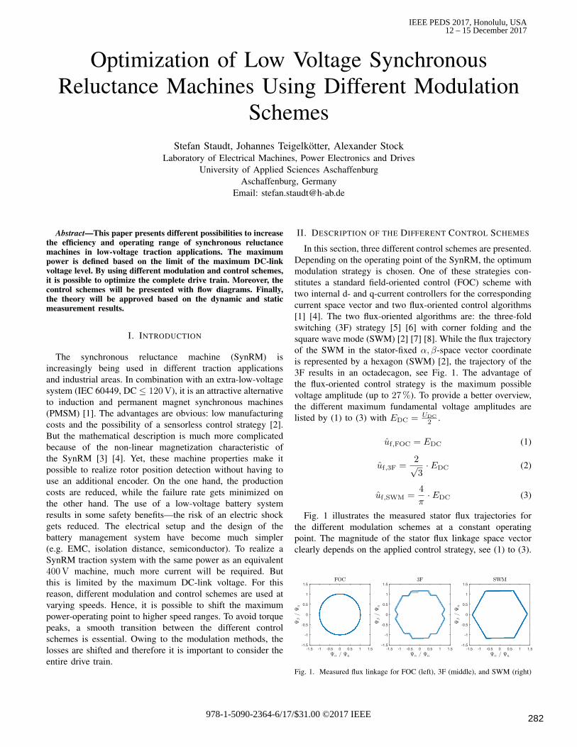
In this section, three different control schemes are presented.Depending on the operating point of the SynRM, the optimummodulation strategy is chosen. One of these strategies con-stitutes a standard field-oriented control (FOC) scheme withtwo internal d- and q-current controllers for the correspondingcurrent space vector and two flux-oriented control algorithms[1] [4]. The two flux-oriented algorithms are: the three-foldswitching (3F) strategy [5] [6] with corner folding and thesquare wave mode (SWM) [2] [7] [8]. While the flux trajectoryof the SWM in the stator-fixed α, β-space vector coordinateis represented by a hexagon (SWM) [2], the trajectory of the3F results in an octadecagon, see Fig. 1. The advantage ofthe flux-oriented control strategy is the maximum possiblevoltage amplitude (up to 27 %). To provide a better overview,the different maximum fundamental voltage amplitudes arelisted by (1) to (3) with EDC = UDC
2 .
uf,FOC = EDC (1)
uf,3F =2√3· EDC (2)
uf,SWM =4
π· EDC (3)
Fig. 1 illustrates the measured stator flux trajectories forthe different modulation schemes at a constant operatingpoint. The magnitude of the stator flux linkage space vectorclearly depends on the applied control strategy, see (1) to (3).
Fig. 1. Measured flux linkage for FOC (left), 3F (middle), and SWM (right)
IEEE PEDS 2017, Honolulu, USA12 – 15 December 2017
978-1-5090-2364-6/17/$31.00 ©2017 IEEE 282
In traction drive systems, it is absolutely essential to switchbetween the different modulation schemes without any torqueor current peaks [6]. The influence of an overcurrent can bededuced with (4).
Mi =3
2· p · ((Ld − Lq) · iSd · iSq) (4)
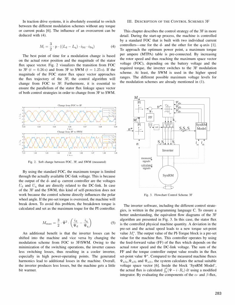
The best point of time for a modulation change is basedon the actual rotor position and the magnitude of the statorflux space vector. Fig. 2 visualizes the transition from FOCto 3F (t = 0.26 s) and from 3F to SWM (t = 1.25 s). If themagnitude of the FOC stator flux space vector approachesthe flux trajectory of the 3F, the control algorithm willchange from FOC to 3F. Furthermore, it is essential toensure the parallelism of the stator flux linkage space vectorof both control strategies in order to change from 3F to SWM.
Fig. 2. Soft change between FOC, 3F, and SWM (measured)
By using the standard FOC, the maximum torque is limitedthrough the actually available DC-link voltage. This is becausethe output of the d- and q- current controller are the voltagesUd and Uq that are directly related to the DC-link. In caseof the 3F and the SWM, this kind of self-protection does notwork because the control scheme directly influences the polarwheel angle. If the pre-set torque is oversized, the machine willbreak down. To avoid this problem, the breakdown torque iscalculated and set as the maximum toque for the PI controller.
Mmax =3
2· Ψ2 ·
(idΨd− iq
Ψq
)(5)
An additional benefit is that the inverter losses can beshifted into the machine and vice versa by changing themodulation scheme from FOC to 3F/SWM. Owing to theminimization of the switching operations, the inverter causesless switching losses, thus resulting in a cooler inverter,especially in high power-operating points. The generatedharmonics lead to additional losses in the machine. Overall,the inverter produces less losses, but the machine gets a littlebit warmer.
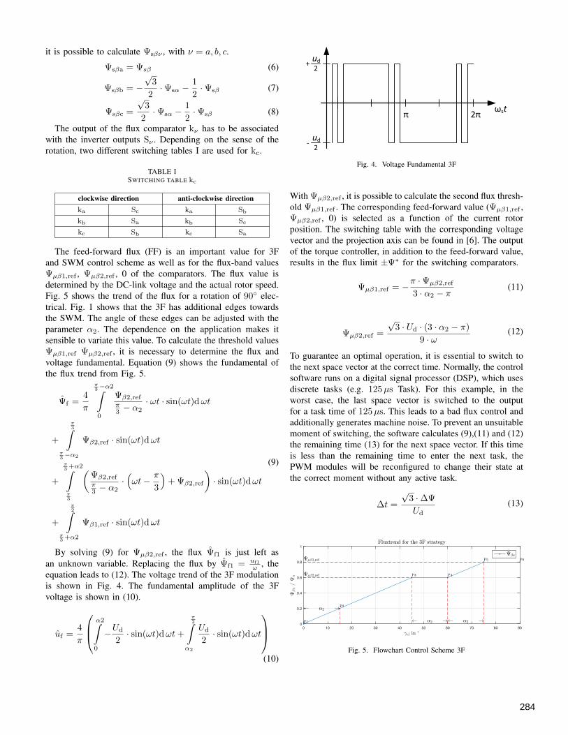
III. DESCRIPTION OF THE CONTROL SCHEMES 3F
This chapter describes the control strategy of the 3F in moredetail. During the start-up process, the machine is controlledby a standard FOC that is built with two individual currentcontrollers—one for the d- and the other for the q-axis [1].To approach the optimum power point, a maximum torqueper ampere (MTPA) table is pre-connected. By increasingthe rotor speed and thus reaching the maximum space vectorvoltage (FOC), depending on the battery voltage and therequired torque, the inverter switches to the 3F modulationscheme. At least, the SWM is used in the higher speedranges. The different possible maximum voltage levels forthe modulation schemes are already mentioned in (1).
PI
n*
n
M *i
ψs aβ
S S Sa b c, ,
Inverter
SynRM
S Sa b, S
c isa
isb
measuredsignals
calculatedsignals
SynRMModel
k c
ψψ
PI- *ψ
ψ*
0
1ψ*
FF
+
-
Mi
≥01/x
s bβ
s cβ
Fig. 3. Flowchart Control Scheme 3F
The inverter software, including the different control strate-gies, is written in the programming language C. To ensure abetter understanding, the equivalent flow diagrams of the 3Falgorithm are presented in Fig. 3. In this case, the stator fluxis the controlled physical machine quantity. A deviation in thepre-set and the actual speed leads to a new torque set-pointvalue M∗
i . The output value of the PI-Torque block is a pre-setvalue for the machine flux. This controller operates by usingthe feed-forward value (FF) of the flux which depends on theactual rotor speed and the DC-link voltage. The sum of theFF and the torque controller output value results in the fluxset-point value Ψ∗. Compared to the measured machine fluxesΨsβa,Ψsβb and Ψsβc, the system calculates the actual suitablevoltage space vector [6]. Inside the block ‘SynRM Model’,the actual flux is calculated
∫ t0(Ψ− i ·Rs) dt using a modified
integrator. By evaluating the components of the α- and β-flux,
283
it is possible to calculate Ψsβν , with ν = a, b, c.
Ψsβa = Ψsβ (6)
Ψsβb = −√
3
2·Ψsα −
1
2·Ψsβ (7)
Ψsβc =
√3
2·Ψsα −
1
2·Ψsβ (8)
The output of the flux comparator kν has to be associatedwith the inverter outputs Sν . Depending on the sense of therotation, two different switching tables I are used for kc.
TABLE ISWITCHING TABLE kc
clockwise direction anti-clockwise directionka Sc ka Sb
kb Sa kb Sc
kc Sb kc Sa
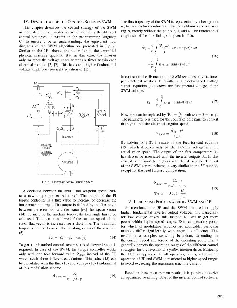
The feed-forward flux (FF) is an important value for 3Fand SWM control scheme as well as for the flux-band valuesΨµβ1,ref , Ψµβ2,ref , 0 of the comparators. The flux value isdetermined by the DC-link voltage and the actual rotor speed.Fig. 5 shows the trend of the flux for a rotation of 90◦ elec-trical. Fig. 1 shows that the 3F has additional edges towardsthe SWM. The angle of these edges can be adjusted with theparameter α2. The dependence on the application makes itsensible to variate this value. To calculate the threshold valuesΨµβ1,ref Ψµβ2,ref , it is necessary to determine the flux andvoltage fundamental. Equation (9) shows the fundamental ofthe flux trend from Fig. 5.
Ψf =4
π
π3 −α2∫0
Ψβ2,refπ3 − α2
· ωt · sin(ωt)dωt
+
π3∫
π3 −α2
Ψβ2,ref · sin(ωt)dωt
+
π3 +α2∫π3
(Ψβ2,refπ3 − α2
·(ωt− π
3
)+ Ψβ2,ref
)· sin(ωt)dωt
+
π2∫
π3 +α2
Ψβ1,ref · sin(ωt)dωt
(9)
By solving (9) for Ψµβ2,ref , the flux Ψf1 is just left asan unknown variable. Replacing the flux by Ψf1 = uf1
ω , theequation leads to (12). The voltage trend of the 3F modulationis shown in Fig. 4. The fundamental amplitude of the 3Fvoltage is shown in (10).
uf =4
π
α2∫0
−Ud
2· sin(ωt)dωt+
π2∫
α2
Ud
2· sin(ωt)dωt
(10)
π 2π ωst
ud
2+
ud
2-
Fig. 4. Voltage Fundamental 3F
With Ψµβ2,ref , it is possible to calculate the second flux thresh-old Ψµβ1,ref . The corresponding feed-forward value (Ψµβ1,ref ,Ψµβ2,ref , 0) is selected as a function of the current rotorposition. The switching table with the corresponding voltagevector and the projection axis can be found in [6]. The outputof the torque controller, in addition to the feed-forward value,results in the flux limit ±Ψ∗ for the switching comparators.
Ψµβ1,ref = −π ·Ψµβ2,ref
3 · α2 − π(11)
Ψµβ2,ref =
√3 · Ud · (3 · α2 − π)
9 · ω(12)
To guarantee an optimal operation, it is essential to switch tothe next space vector at the correct time. Normally, the controlsoftware runs on a digital signal processor (DSP), which usesdiscrete tasks (e.g. 125µs Task). For this example, in theworst case, the last space vector is switched to the outputfor a task time of 125µs. This leads to a bad flux control andadditionally generates machine noise. To prevent an unsuitablemoment of switching, the software calculates (9),(11) and (12)the remaining time (13) for the next space vector. If this timeis less than the remaining time to enter the next task, thePWM modules will be reconfigured to change their state atthe correct moment without any active task.
∆t =
√3 ·∆Ψ
Ud
(13)
Fig. 5. Flowchart Control Scheme 3F
284
IV. DESCRIPTION OF THE CONTROL SCHEMES SWM
This chapter describes the control strategy of the SWMin more detail. The inverter software, including the differentcontrol strategies, is written in the programming languageC. To ensure a better understanding, the equivalent flowdiagrams of the SWM algorithm are presented in Fig. 6.Similar to the 3F scheme, the stator flux is the controlledphysical machine quantity. But in this case, the inverteronly switches the voltage space vector six times within eachelectrical rotation [2] [7]. This leads to a higher fundamentalvoltage amplitude (see right equation of (1)).
PI
n*
n
M *i
ψs aβ
S S Sa b c, ,
Inverter
SynRM
S Sa b, S
c isa
isb
measuredsignals
calculatedsignals
SynRMModel
k c
ψψ
PI- *ψ
ψ*
0
1ψ*
Ud
___
+
-
Mi
≥01/x
s bβ
s cβ
6 3 p
Fig. 6. Flowchart control scheme SWM
A deviation between the actual and set-point speed leadsto a new torque pre-set value M∗
i . The output of the PItorque controller is a flux value to increase or decrease theinner machine torque. The torque is defined by the flux anglebetween the rotor |ψr| and the stator |ψs| flux space vector(14). To increase the machine torque, the flux angle has to beenhanced. This can be achieved if the rotation speed of thestator flux vector is increased for a short time. The maximumtorque is limited to avoid the breaking down of the machine(5).
Mi = |ψr| · |ψs| · cos(γ) (14)
To get a undisturbed control scheme, a feed-forward value isrequired. In case of the SWM, the torque controller worksonly with one feed-forward value Ψβset instead of the 3F,which needs three different calculations. This value (15) canbe calculated with the flux (16) and voltage (15) fundamentalof this modulation scheme.
Ψβset =Ud
6 ·√
3 · p(15)
The flux trajectory of the SWM is represented by a hexagon inα,β-space vector coordinates. Thus, one obtains a course, as inFig. 9, merely without the points 2, 3, and 4. The fundamentalamplitude of the flux linkage is given in (16).
Ψf =4
π
π3∫
0
Ψβ,refπ3
· ωt · sin(ωt)dωt
+4
π
π2∫
π3
Ψβ,ref · sin(ωt)dωt
(16)
In contrast to the 3F method, the SWM switches only six timesper electrical rotation. It results in a block-shaped voltagesignal. Equation (17) shows the fundamental voltage of theSWM scheme.
uf =4
π
π2∫
0
EDC · sin(ωt)dωt (17)
Now Ψf1 can be replaced by Ψf1 = uf1
ωelwith ωel = 2 ·π ·n ·p.
The parameter p is used for the counts of pole pairs to convertthe signal into the electrical angular speed.
Ψβ,ref =Ψf1 · π2
6√
3(18)
By solving of (18), it results in the feed-forward equation(19) which depends only on the DC-link voltage and theactual rotor speed. The output of the flux comparators kνhas also to be associated with the inverter outputs Sν . In thiscase, it is the same table (I) as with the 3F scheme. The restof the SWM control scheme is very similar to the 3F method,except for the feed-forward computation.
Ψβ,ref =2EDC
6√
3 · n · p
Ψβ,ref = 0.604 · Ud
ωel
(19)
V. INCREASING PERFORMANCE BY SWM AND 3F
As mentioned, the 3F and the SWM are used to applyhigher fundamental inverter output voltages (1). Especiallyfor low voltage drives, this method is used to get morepower within higher speed ranges. Even at operating pointsfor which all modulation schemes are applicable, particularmethods differ significantly with regard to efficiency. Thisresults in a complex switching behaviour, depending onthe current speed and torque of the operating point. Fig. 7generally depicts the operating ranges of the different controlstrategies for a conventional SynRM traction drive. Basically,the FOC is applicable to all operating points, whereas theoperation of 3F and SWM is restricted to higher speed rangesto avoid exceeding the maximum machine current.
Based on these measurement results, it is possible to derivean optimized switching table for the inverter control software.
285

Fig. 7. Measured comparison between the three modulation methods
By using the 3F or the SWM, the inverter losses are shiftedinto the machine. The switching number of the MOSFETsis significantly lower than that of the FOC with a 8 kHzPWM. However, harmonic disturbances in the machine willbe greater. Thus, to measure the efficiency of the drive train,the complete system has to be considered. This includes thereluctance machine, the inverter, and the battery.
Efficiency measurements have shown that the FOC does notalways provide the best results in areas where all three controlschemes work. Fig. 8 illustrates two different operating pointswith the corresponding efficiency trends for FOC, 3F, andSWM. The left plot demonstrates that the FOC is the bestchoice until M
Mn≥ 1.6. For higher torque levels, the inverter
should change to the SWM control scheme. The second plotshows that the point of modulation change is a bit earlierMMn
= 0.8 because of the higher speed-operating point.
Fig. 8. Efficiency measurement for a stationary speed
In addition, the 3F and SWM methods offer the possibilityof a sensorless control strategy. Since in this case no parktransformation is needed, the flux is just guided within theboundaries of ±Ψβ,ref and therefore no rotor position isnecessary.
VI. CONCLUSION
In this paper, highly efficient control strategies and suitablemodulation schemes optimized for SynRMs in low-voltagetraction drive applications are presented. As a result ofcalculations, simulations, and measurements, depending onthe current speed and torque values of the SynRM, theoptimum control strategy for any operating point can bedetermined. By means of these methods, additional operationpoints can be approached and the efficiency of the entiredrive train can be improved. Furthermore, it is possible toshift the losses within the whole powertrain. This results indifferent possibilities for the extension of a drive train (e.g.dimensioning of the inverter / machine).
In particular the transitions (including accompanyingchallenges) between those different control / modulationstrategies are described in detail. It is absolutely necessaryto fulfil certain side conditions to change smoothly betweentwo different control strategies without generating transientcurrent or torque peaks. With the modulation methods of 3Fand SWM, it is possible to operate the machine without anyposition sensor.
REFERENCES
[1] Kilthau A. and Pacas J. M., ”Appropriate models for the control ofthe synchronous reluctance machine” in Conference Record of the 37thIAS Annual Meeting, Industry Applications Conference, 2002.vol. 4,pp. 2289-2295, 2002
[2] U. Baader, M. Depenbrock, G. Gierse, ”Direct Self Control (DSC) ofInverter-Fed Induction Machine: A Basis for Speed Control WithoutSpeed Measurement” in IEEE Transactions on Industry Applications (Volume: 28, Issue: 3, May/Jun 1992 )
[3] P. Guglielmi, M. Pastorelli, A. Vagati, ”Impact of Cross-Saturation inSensorless Control of Transverse-Laminated Synchronous ReluctanceMotors” in IEEE TRANSACTIONS ON INDUSTRIAL ELECTRON-ICS, VOL. 53, NO. 2, APRIL 2006
[4] Staudt S., Stock A., Kowalski T., Teigelkotter J., Lang K., ”Raw DataBased Model and High Dynamic Control Concept for Traction Drivespowered by Synchronous Reluctance Machines”, Electrical MachinesDesign, Control and Diagnosis (WEMDCD), 2015 IEEE Workshop on
[5] Staudt V. and Steimel A., ”Stator-Flux-Oriented Control for TractionDrives” in Electrical Machines & Power Electronics (ACEMP), 2015Intl Conference on Optimization of Electrical & Electronic Equipment(OPTIM) & 2015 Intl Symposium on Advanced ElectromechanicalMotion Systems (ELECTROMOTION), 2015 Intl Aegean Conference
[6] Worner K.: Quasi-synchrone statorflussgefuhrte Pulsverfahren fr diewechselrichtergespeiste Induktionsmaschine, VDI, Dusseldorf 2007
[7] Depenbrock M., ”Direct Self-Control (DSC) of Inverter-Fed InductionMachine” in IEEE Transactions on Power Electronics, vol. 3, no 4, pp.420-429, 1988
[8] Janecke M.: Die Direkte Selbstregelung bei Anwendung im Traktions-bereich, VDI, Duisburg 1991
[9] Kilthau, A.; Pacas, J.M.: Parameter-Measurement and Control of theSynchronous Reluctance Machine including Cross Saturation, 2001IEEE Industry Application Conference 36th Annual Meeting, Chicago,IL, USA, 30 Sep.?4 Oct. 2001
[10] T. Windisch and W. Hofmann, ”Loss Minimization of an IPMSM DriveUsing Precalculated Optimized Current References” in 37th AnnualConference on IEEE Industrial Electronics Society (IECON 2011), pp4704-4709, 2011
286