ieee oc 57.152 field test guide
DESCRIPTION
Induced Voltage TestTRANSCRIPT
Hauschild/Thiede/ Herron 1
IEEE Transformer Committee Spring Meeting, San Diego, California, April 2011
IEEE PC 57.152 Field Test GuideProposed Draft of Chapter 6.1.7: Induced Voltage Test
6.1.7.1 General
6.1.7.2 Preliminary test procedures6.1.7.3 Special precautions before test
6.1.7.4 Power factor pre-tests for excitation by M/G sets
6.1.7.5 Pre-tests for excitation by static frequency converters6.1.7.6 Test procedure
6.1.7.7 Test parameters and test acceptance criteria
Wolfgang Hauschild Andreas ThiedeSenior Member
HIGHVOLT Prüftechnik Dresden GmbH Germany
John HerronReinhausen Manufacturing Inc.
USA

Hauschild/Thiede/ Herron 2
6.1.7.1 General
Withstand AC voltage test with PD monitoring (f = 80….240 Hz, THD ≤ 5%, three-phase test, single phase acceptable) shall be applied as
- installation test when assembled on site,
- on-site test after repair,
- test for condition assessment,
- test for failure identification.
PD measurement according to IEEE Standard C57.113 (2010), measures to reduce the PD noise.
Voltage source:
a) motor-generator (M/G) set
for one or two fixed frequencies,
three and single phase operation.
b) static frequency converter (SFC)
for continuously variable frequency, e.g. 80…240 Hz,
three and single phase operation.

Hauschild/Thiede/ Herron 3
Recommended diagnostic characteristics:
ProcedureNew transformer
Service-aged transformer
Power factor < 0.5 % < 2.0 %
Total dissolved gasa < 0.5 % < 0.8 %
Moisture content < 10 ppm < 15 ppm
Turns ratioWithin 0.5 % of
nameplateWithin 0.5 % of
nameplate
6.1.7.2 Preliminary test procedures
Low-voltage tests, to show that the transformer under test is suitable for energizing:
- insulation resistance,
- power factor ,
- turns ratio ,
- oil dielectric strength,
- oil moisture content,
- dissolved gases in fluid

Hauschild/Thiede/ Herron 4
6.1.7.3 Special precautions before test
A low PD noise level is difficult to reach on site, but all precautions should be made to reach it. This means especially a very compact PD measuring circuit of PD-free, low-impedance HV and earth connections.
Furthermore, reduce the PD noise level by:
1.Avoid corona discharges at transformer under test by shielding points of high field concentration!
2.Apply corona rings also to sharp edges of nearby earthed or grounded objects!
3.Avoid not-grounded nearby objects!
4.Take care for good electrical contact of PD-free test voltage connections!
5.Clean the surfaces of the bushings!
Disconnect any transformer-mounted surge arrester before energizing!
Have in mind, that corona discharges may even influence the withstand voltage!

Hauschild/Thiede/ Herron 5
6.1.7.4 Power factor pre-test for ecitation by M/G sets
Aim: Avoid generator runaways by sufficient inductive compensation for protection against dangerous over-voltages due to capacitive load.
Procedure: Apply a protection spark gap and operate at a voltage V ≤ 30% Vtest(rated test voltage) for accurate power factor measurement. The inductive compensation shall be adjusted to a value that will allow the test at 100% Vtest without exceeding the generator limits.
Match the step-up transformer output to the test voltage level (optimum adaptation). Check all settings and remove the protection spark gap.
Check: Check the THD and the PD basic noise level.
Hauschild/Thiede/ Herron 6
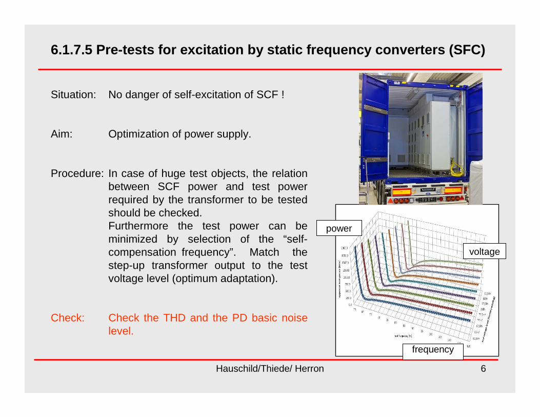
6.1.7.5 Pre-tests for excitation by static frequency converters (SFC)
Situation: No danger of self-excitation of SCF !
Aim: Optimization of power supply.
Procedure: In case of huge test objects, the relation between SCF power and test power required by the transformer to be tested should be checked. Furthermore the test power can be minimized by selection of the “self-compensation frequency”. Match the step-up transformer output to the test voltage level (optimum adaptation).
Check: Check the THD and the PD basic noise level.
power
voltage
frequency
Hauschild/Thiede/ Herron 7
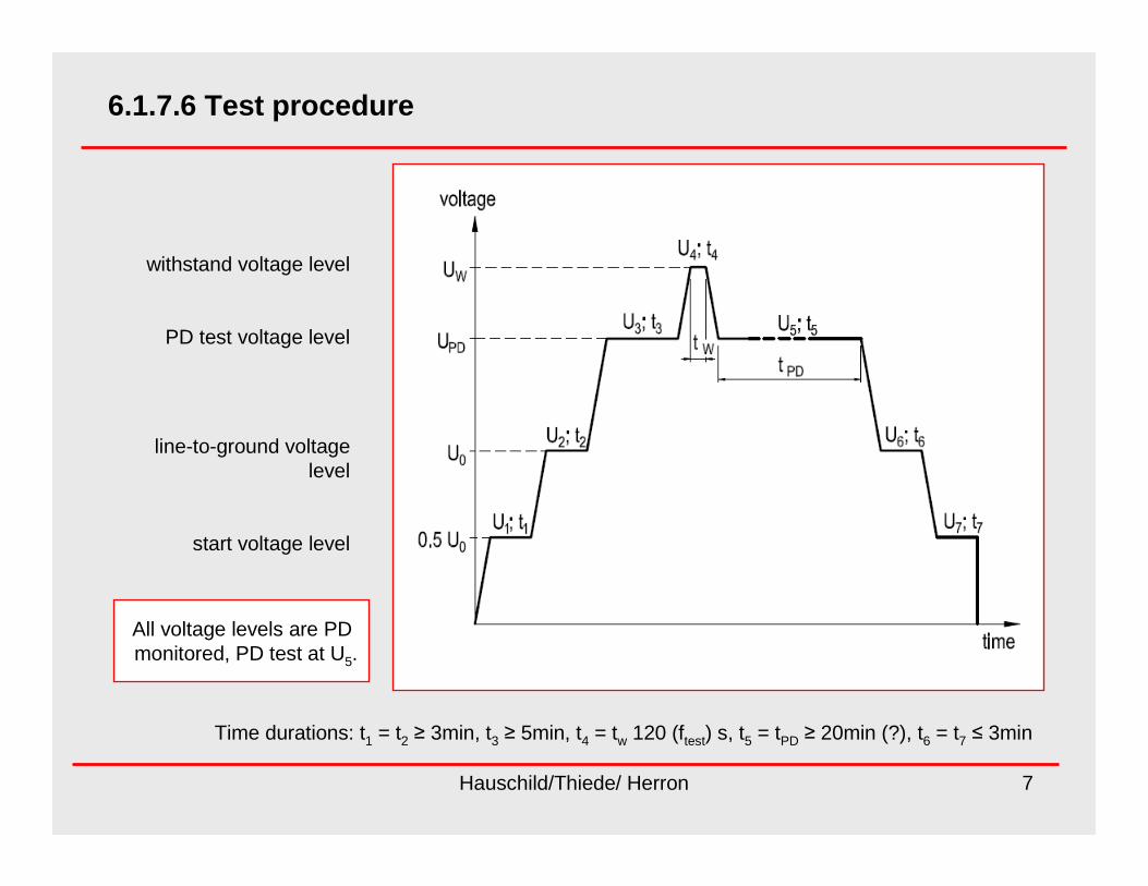
6.1.7.6 Test procedure
withstand voltage level
PD test voltage level
line-to-ground voltage level
start voltage level
Time durations: t1 = t2 ≥ 3min, t3 ≥ 5min, t4 = tw 120 (ftest) s, t5 = tPD ≥ 20min (?), t6 = t7 ≤ 3min
All voltage levels are PD monitored, PD test at U5.

Hauschild/Thiede/ Herron 8
6.1.7.7 Test parameters and test acceptance criteria
Test parameters:
The withstand test voltage level U4 = UW as well as the PD measuring voltage level U5 = UPD, its duration t5 = tPD and the PD acceptance level qPD are usually subject to
negotiation:UW = 1.2U0 ……UT
UPD = 0.8 …0.9 UWtPD = 20 …60 minqPD = 500 …1000 pC
Acceptance criteria:
1) No breakdown of the test voltage occurs during the whole cycle.2) None of the PD levels recorded at the test voltage UPD exceeds the agreed PD limit.3) The PD level measured during the PD test does not exhibit any steady raising trend or
sudden sustained increase by more than 100 pC.4) The PD levels at identical voltage levels before and after the withstand test (Fig. 1):
U2 and U6: U3 and U5) shall not increase by more than 100 pC.

Hauschild/Thiede/ Herron 9
Next steps
We ask for your comments, proposals, changes or extensions!
We are sure that field testing of power transformers will play an important role for the power systems of the future.
Thank you for your attention!