ieee communications surveys & tutorials, accepted …
TRANSCRIPT

IEEE COMMUNICATIONS SURVEYS & TUTORIALS, ACCEPTED FOR PUBLICATION 1
Self-Concatenated Code Design and itsApplication in Power-Efficient Cooperative
CommunicationsMuhammad Fasih Uddin Butt, Member, IEEE, Soon Xin Ng, Senior Member, IEEE, and
Lajos Hanzo, Fellow, IEEE
Abstract—In this tutorial, we have focused on the designof binary self-concatenated coding schemes with the help ofEXtrinsic Information Transfer (EXIT) charts and Union boundanalysis. The design methodology of future iteratively decodedself-concatenated aided cooperative communication schemes ispresented. In doing so, we will identify the most importantmilestones in the area of channel coding, concatenated codingschemes and cooperative communication systems till date andsuggest future research directions.
Index Terms—Near-Capacity Code Design, Self-ConcatenatedConvolutional Codes, SECCC, EXIT charts, Iterative Decoding,Cooperation Diversity, Distributed Coding.
I. INTRODUCTION
THE NEED for high-rate wireless communication systemsdesigned for supporting broadband wireless Internet and
multimedia services has been growing over the past decade.However, the available radio spectrum is limited and thewireless channel is extremely hostile. Therefore, there is a de-mand for flexible and bandwidth-efficient transceivers [1], [2].Shannon quantified the capacity of wireless communicationsystems in 1948 [3]. Advances in coding have made it feasibleto approach Shannon’s capacity limit for the case of a single-user system [4], [5]. Multiple-Input Multiple-Output (MIMO)communication systems create multiple wireless links by em-ploying multiple transmit and receive antennas, hence they arecapable of supporting high-integrity, high data rate communi-cations [6]. However, MIMOs cannot be readily implementedin shirt-pocket-sized mobile stations (MS), which hence havea limited antenna spacing and impose correlation of thesignals. Cooperative communications is capable of eliminatingthis correlation, while still achieving MIMO-like diversitygains for the system [7]. This is achieved by introducing arelay between the source and the destination with the aidof an independently faded path created by the relay. Coded
Manuscript received 2 August 2010; revised 19 April 2011. The finan-cial support of CIIT under the auspices of Higher Education Commission,Pakistan, and that of the EU Optimix Project of the RC-UK under theauspicies of the IU-ATC, as well as of Dr. Wali Mohammad Trust, is gratefullyacknowledged. The authors would like to thank the anonymous reviewersfor their valuable comments, which greatly improved the presentation of thepaper.
M. F. U. Butt is with the Department of Electrical Engineering, COM-SATS Institute of Information Technology (CIIT), Islamabad 44000, Pakistan(e-mail: [email protected]).
S. X. Ng and L. Hanzo are with the School of Electronics and ComputerScience, University of Southampton, SO17 1BJ, Southampton, U.K. (e-mail:{sxn, lh}@ecs.soton.ac.uk).
Digital Object Identifier 10.1109/SURV.2011.081511.00104
cooperation [8] is potentially capable of flawlessly recoveringthe original source signal at the relays and then retransmittingit to the destination from a reduced distance.
In this tutorial, we have presented a brief history of channelcoding and then highlighted the differences between iterativelydecoded Parallel Concatenated Convolutional Coding (PCCC),Serial Concatenated Convolutional Coding (SCCC) and Self-Concatenated Convolutional Coding (SECCC) schemes. Wethen explored SECCC schemes that are designed for trans-mission over Additive White Gaussian Noise (AWGN) anduncorrelated Rayleigh fading channels. We designed bothbit-based SECCC and SECCC employing Iterative Decoding(SECCC-ID), using a Recursive Systematic Convolutional(RSC) constituent encoder. On the other hand, Low DensityParity Check (LDPC) codes constitute another attractive codefamily which can be described based on the sparse-graph [9]–[11]. It was shown in [9] that it is possible to describe thePCCC schemes using the sparse-graph as well. However, weonly consider trellis-based decoding in this paper.
EXtrinsic Information Transfer (EXIT) charts were usedas our main design tools. We will exemplify the proposeddesign procedures and demonstrate that some of the proposedschemes are capable of operating within about 1 dB from theAWGN and Rayleigh fading channels’ capacity. The unionbound analysis of SECCCs was carried out for finding thecorresponding Bit Error Ratio (BER) floors. In order to furtherexploit the benefits of the low complexity design offeredby SECCCs we explored their application in a distributedcoding scheme designed for cooperative communications,where iterative detection is employed by exchanging extrinsicinformation between the decoders of SECCC and RSC atthe destination. It was shown that the DSECCC-ID is a low-complexity scheme, yet capable of approaching the Discrete-input Continuous-output Memoryless Channels’s (DCMC) ca-pacity. Our discussions demonstrate that the proposed schemeis capable of reliably operating at a low BER for transmissionover uncorrelated Rayleigh fading channels. In our cooperativecommunication schemes considered we assume that decodingerrors may be encountered at the relay nodes and successfullymitigate their effects.
The outline of the paper is as follows. Section II dis-cusses iterative detection aided coded modulation schemesdesigned for transmission over non-dispersive propagationenvironments. SECCC and SECCC-ID schemes using itera-tive detection are designed with the aid of EXIT charts in
1553-877X/11/$25.00 c© 2011 IEEE

2 IEEE COMMUNICATIONS SURVEYS & TUTORIALS, ACCEPTED FOR PUBLICATION
EncoderA
EncoderBπ
Input bits
MU
X Encoded Symbols
(a) PCCC Encoder
π−1 π
Decoded bits
DeM
UX From Channel
Decoder B
Decoder A
(b) PCCC decoder
Fig. 1. The schematic of a PCCC encoder and decoder.
Section III. In order to mitigate the effects of large-scaleshadow fading on the performance of wireless communicationsystems, we present a distributed coding scheme in Section IVfor cooperative communications employing SECCCs that iscapable of providing substantial diversity-, throughput- aswell as coding-gains for a single-user scenario. Finally, inSection V the main findings of the paper are summarised,general design guidelines are presented and future researchdirections are discussed.
II. ITERATIVE DECODING AND CONVERGENCE ANALYSIS
OF CONCATENATED CODES
Forward Error Correction (FEC) or Channel Coding in thecontext of digital communication has a history dating back tothe middle of the twentieth century. In recent years, the fieldhas been revolutionized by iterative detection aided codes,which are capable of approaching the theoretical limits of per-formance, namely the channel capacity. Important milestonesin the area of channel coding are described in Table I.
When the concatenated coding philosophy [25] was con-ceived back in 1966, it was deemed to have an excessivecomplexity and hence the resultant codes failed to stimulateimmediate research interests. It was not until the discovery ofTurbo Codes (TC) by Berrou et al. in 1993 [4], that efficientiterative decoding of concatenated codes became a reality ata low complexity by employing low-complexity constituentcodes. There are three major types of iteratively decodedconcatenated coding schemes, as discussed below:
A. Parallel Concatenated Convolutional Codes
Classic TCs [4] consist of two or more parallel constituentcodes [80]. The component codes are usually systematiccodes, because their systematic nature simplifies the iterativeexchange of information between the constituent decoders. Ingeneral, each component encoder independently encodes itsinput information and an interleaver (π) - also often termed asa scrambler - is used between the two constituent encoders tomake both their input data and their encoded data statisticallyindependent of each other, as shown in Fig. 1(a).
Again, the encoders used in classic TCs are almost alwaysRSC encoders, which output both the original information
TABLE IMILESTONES IN CHANNEL CODING (1948-2008)
Year Milestone1948 Shannon’s Capacity Theorem [3].1950 Hamming codes were discovered by Hamming [12].1954 Reed [13] and Muller [14] present Reed-Muller (RM) codes.1955 Elias introduces convolutional codes [15].1957 Prange introduces cyclic codes [16].1959 Hocquenghem [17] and ...1960 Bose and Chaudhuri [18] proposed BCH codes.
Reed and Solomon defined (RS) codes over certain finite Galois fields [19].Peterson designed a BCH decoder [20].
1961 Peterson’s book on Error Correction Codes (ECC) [21].1962 Gallager invents LDPC codes [22].1963 Fano algorithm introduced for decoding convolutional codes [23].
Massey describes threshold decoding [24].1966 Forney’s introduction of concatenated codes [25]
and generalized minimum distance decoding [26].1967 Berlekamp designs an efficient algorithm for BCH/RS decoding [27].
Rudolph initiates the study of finite geometries for coding [28].1968 Berlekamp, documents Algebraic Coding Theory [29].
Gallager publishes, Information theory and reliable communications [30].1969 Jelinek defines the stack algorithm for decoding convolutional codes [31].
Massey introduces his BCH decoding algorithm [32].Reed-Muller code used on Mariner deep space probes.
1971 Viterbi algorithm for Maximum Likelihood (ML) decoding of convolutionalcodes [33].
1972 Bahl et al. invents the Maximum A-Posteriori (MAP) algorithm [34].Chase introduces his soft-decision-based block decoding algorithm [35].Peterson and Weldon revise their book [36].
1973 Forney further interprets the Viterbi algorithm [37].1974 Bahl et al. describe the symbol based MAP algorithm [38].1975 Sugiyama et al. invokes the Euclidean algorithm for decoding [39].1977 MacWilliams and Sloane write The Theory of Error Correcting Codes [40].
Voyager deep space mission uses a concatenated RS/convolutional code(see [41]).
1978 Wolf introduces trellis-decoding of block codes [42].1980 Sony and Phillips standardize the compact disc, including
a shortened RS code.1981 Goppa introduces Algebraic-Geometry (AG) codes [43], [44].1982 Ungerbock invents trellis-coded modulation (TCM) [45].1983 Textbook on Error control coding by Lin and Costello [46].
Blahut publishes his channel coding book [47].1988 Divsalar and Simon discover multiple trellis-coded modulation [48].1989 Hagenauer and Hoeher present the Soft-Output Viterbi Algorithm (SOVA) [49].1990 Koch and Baier describe a reduced complexity MAP algorithm [50].1992 Zehavi introduces Bit-Interleaved Coded Modulation (BICM) [51].1993 Berrou, Glavieux, and Thitimajshima discover turbo codes [4].
Honary, Markarian and Farrell et al. presented low complexity trellisdecodingof array [52] and Hamming codes [53].
1994 The Z4 linearity of certain families of nonlinear codes is announced [54].Erfanian, Pasupathy and Gulak describe the Max-log-MAP algorithm [55].
1995 MacKay revives LDPC codes [56].Wicker publishes his textbook [57].Robertson, Villebrun and Hoeher desribe Log-MAP algorithm [58].
1996 Hagenauer, Offer and Papke propose turbo-BCH codes [59].Sidorenko, Markarian and Honary presented a novel trellis design technique[60] for block and convolutional codes resulting in low complexity Viterbidecoding.
1997 Tarokh, Seshadri and Calderbank introduce space-time trellis coding (STTC)scheme [61].Nickl, Hagenauer and Burkett report approaching the Shannon limit overGaussian channels [62] within 0.27 dB.Schlegel writes his book on trellis coding [63].Ritcey and Li introduce Bit-Interleaved Coded Modulation with IterativeDecoding (BICM-ID) [64].
1998 Turbo trellis-coded modulation (TTCM) introduced by Robertson and Worz [65].Alamouti introduces space-time block coding [66].Guruswami and Sudan present a list decoder for RS and AG codes [67].
1999 Ritcey and Li combine TCM with BICM-ID [68].2000 Aji and McEliece [69] (and others [70]) synthesize
several decoding algorithms using message passing ideas.Proakis publishes fourth edition of his textbook [71].
2002 Hanzo, Liew, and Yeap characterize turbo algorithms in [5].Siwamogsatham and Fitz introduce MTCM assisted STBC [72].
2003 Jafarkhani and Seshadri propose super-orthogonal STTC (SOSTTC) [73].Koetter and Vardy extend the GS algorithm for soft-decisiondecoding of RS codes [74].
2004 Lin and Costello publish second edition of their textbook [75].2005 Moon publishes his textbook [76].
Simon and Alouini write Digital Communications over Fading Channels [77].Song et al. introduce SOSTTC combined with QAM [78].
2008 Arıkan [79] introduce capacity-achieving Polar codes which are a extensionof RM codes for symmetric binary-input discrete memoryless channels.

BUTT et al.: SELF-CONCATENATED CODE DESIGN AND ITS APPLICATION IN POWER-EFFICIENT COOPERATIVE COMMUNICATIONS 3
OuterEncoder
InnerEncoder
A Bπ
Encoded SymbolsInput bits
(a) SCCC Encoder
Decoded bits From Channel
π−1
π InnerOuterDecoder Decoder
A B
(b) SCCC decoder
Fig. 2. The schematic of an SCCC encoder and decoder.
bits that are also referred to as systematic bits and thecorresponding parity bits. Hence two codewords are generatedby the two RSC codes, both of which contain the same originalinformation bits, but typically these bits are only transmittedfrom one of the output streams. If both RSC encoders arehalf-rate encoders, the resultant TC becomes a third-rate code.However, the number of parity bits transmitted from the twostreams can be appropriately adjusted by simply discardingthe required fraction of parity bits. This so-called puncturingoperation tacitly assumes that these bits were set to zero andhence the corresponding zeros have to be inserted in the rightbit-positions at the decoder’s input. In a nutshell, the redundantparity bits of both encoders may be transmitted, plus a singlecopy of the systematic information bit. At the decoder shownin Fig. 1(b), two RSC decoders are used, which iterativelyexchange their so-called soft-information, before making ahard-decision after a sufficiently high number of iterations.
The RSC constituent codes of classic TCs may also bereplaced by other constituent codes. Inspired by this turbocoding concept various other coding arrangements, such asTurbo Trellis Coded Modulation (TTCM) schemes were pro-posed in [81], [82] and [65], which have a similar architectureto classic TCs, but employ Trellis Coded Modulation (TCM)constituent codes [83]. The appealing philosophy of TCMschemes is that they combine channel coding and modulationin an ingenious way, where the modulated signal constellationis extended to an increased number of constellation points,so that more bits per symbol can be transmitted for thesake of absorbing the parity bits. This way the constellationpoints have a reduced Eucledian distance amongst them, whichpotentially results in an increased Bit Error Ratio (BER),but this is more than compensated by the error correctioncapability of the Forward Error Correction (FEC) codec. Itwas also shown by Robertson et al. in [65] that TTCM iscapable of outperforming classic TC.
B. Serial Concatenated Convolutional Codes
The serial concatenation of an outer and an inner encoderis shown in Fig. 2(a). These codes were discovered byBenedetto et al. [84]. Typically the inner code is a weaker codeand the outer code is a stronger code, which are separated byan interleaver as shown in Fig. 2(a). The SCCCC decoder isshown in Fig. 2(b).
To obtain higher code rates we may employ puncturing.SCCC codes have been shown to yield a performance com-parable, and in some cases superior, to TC.
πEncoder
Encoded SymbolsInput bits
(a) SECCC Encoder
π−1 π−1ππ
From Channel
Decoder 2Component
Decoder 1Component
Decoded bits
(b) SECCC decoder
Fig. 3. The schematic of an SECCC encoder and decoder.
C. Self-Concatenated Convolutional Codes
Self-concatenated convolutional codes (SECCC) for BPSKmodulation were proposed by [85], [86]. SECCC is similar toPCCC when two component codes are replaced by one compo-nent code employing an odd-even separated turbo interleaveras discovered in [87]. SECCCs exhibit a low complexity, sincethey invoke only a single encoder as depicted in Fig. 3(a) anda single decoder as shown in Fig. 3(b).
Iterative decoding works by exchanging extrinsic infor-mation between the component decoders 1 and 2. The softextrinsic information of one decoder is fed to the otherconstituent decoder as its a priori input which improves itsknowledge and hence performance. The decoders iterate untilthere is no improvement achieved from the feedback andat that point correct decoding of the bits is possible. Thispoint is called the convergence point. Iteratively-Decoded Self-Concatenated Trellis Coded Modulation (SECTCM) schemesfor higher modulation were proposed by Benedetto et al. [88]and Loeliger [89]. It can be seen from Fig. 4 that theperformance of the SECTCM code improves by increas-ing the number of self-iterations, hence exhibiting a turbo-like behaviour for the case of uncorrelated Rayleigh fadingchannels. Since the pioneering work by Berrou et al. [4],the appealing iterative decoding of concatenated codes hasinspired numerous researchers to extend the technique to othertransmission schemes consisting of a concatenation of two ormore constituent decoding stages.
The concept of EXIT charts was proposed by ten Brinkin [90], [91] as a tool designed for analysing the convergencebehaviour of iteratively decoded systems. Their attractiveproperties are listed below:
• EXIT charts constitute an efficient tool created for in-dependently analysing each component of an iterativesystem.
• Amongst their other benefits detailed inSections III-A1, III-B2 and IV-D they are capableof predicting the specific SNR value, where aninfinitesimally low BER can be achieved withoutperforming time-consuming bit-by-bit decodingemploying a high number of iterations of the actualsystem.
• They analyse the input/output mutual information char-acteristics of a Soft-Input-Soft-Output (SISO) constituent

4 IEEE COMMUNICATIONS SURVEYS & TUTORIALS, ACCEPTED FOR PUBLICATION
0 2 4 6 8 10 12 14 16 18 20Eb/N0(dB)
10-5
10-4
10-3
10-2
10-1
1
BE
R
. . . .........
1 iteration2 iteration. 3 iteration4 iteration5 iteration6 iteration
Fig. 4. Simulations results for 8-state, rate-1/2 SECTCM code, whencommunicating over uncorrelated Rayleigh fading channels.
decoder by modelling the a priori Log-Likelihood Ratio(LLR) values and computing the corresponding mutualinformation between the hard-decision based bits and theextrinsic LLRs.
• The SNR value, where a ’waterfall-like’ decay of theBER curve, called turbo-cliff [4], is observed for aconcatenated code may be successfully predicted withthe aid of EXIT charts.
• The SNR-distance from capacity is commensurate withthe area of the open EXIT-chart tunnel, hence nearcapacity designs exhibit a marginally open tunnel. Thistypically imposes a high complexity associated with ahigh number of iterations and a long interleaver delay.
• If the Monte-Carlo simulation based stair-case shapeddecoding trajectory reaches the (1,1) point in the EXIT-chart, a vanishingly low BER may be achieved.
However, the EXIT chart based BER performance-predictionaccuracy erodes, unless we assume the employment of asufficiently long interleaver, so that the extrinsic LLRs canbe rendered Gaussian distributed.
The EXIT chart analysis of the SECTCM decoder of [92]is shown in Fig. 5, which allows us to determine the numberof self-iterations required by the SECTCM decoder to achieveconvergence. The reason for the EXIT chart mismatch in Fig. 5will be explained in Section III. An EXIT chart comprisesof two EXIT curves for the two component decoders in thesystem, as shown in Fig. 5. Each curve plots the mutualinformation of the extrinsic LLRs versus the mutual infor-mation of the a priori LLRs of one decoder in the system,which is basically to measure the quality of the input and theoutput of the decoder. In order to achieve a vanishingly lowBER at a specific Eb/N0 value, component decoders’ EXITcurves should only intersect at the (IA, IE)=(2,2) point of theEXIT chart for the case of Symbol-based SECTCM (Fig. 5)and (IA, IE)=(1,1) point for bit-based schemes of Section III
0.0 0.2 0.4 0.6 0.8 1.0 1.2 1.4 1.6 1.8 2.0IA
0.0
0.2
0.4
0.6
0.8
1.0
1.2
1.4
1.6
1.8
2.0
I E
. . . . . . . . . . . . . ..
..
..
..
.. . . .
.............
..
..
..
..
..
...
Parity Gen Poly [77 2 10]8
Estimated Eb/N0 = 3.02dB. EXIT curveTrajectory of snapshot # 6Trajectory of snapshot # 19
Fig. 5. EXIT chart and two snapshot decoding trajectories for half-rateQPSK-assisted SECTCM using a block length of 104 symbols and ν = 5 atEb/N0 = 3.02 dB [92].
and IV. Since these are identical components, we only haveto compute the EXIT curve of one component and the otheris its mirror image with respect to the diagonal line. Thestair-case-shaped trajectories correspond to the Monte-Carlosimulation based decoding trajectories, when iterating betweenthe two component decoders of the SECCC scheme. We willshow in Section III-C that a self-concatenated decoder can beviewed as a parallel-concatenated decoder having two identical’hypothetical’ component decoders each exchanging extrinsicinformation with the other, although physically there is onlyone decoder. The EXIT curves of the hypothetical decodercomponents are plotted within the same EXIT chart togetherwith their corresponding decoding trajectory for the sakeof visualizing the transfer of extrinsic information betweenthe decoders. The major scientific contributions on iterativedetection and its convergence analysis are summarised inTables II and III.
Symbol-based EXIT charts of non-binary serial and paral-lel concatenated schemes have been studied in [122], [123]and [124], respectively. Near-capacity codes have been de-signed with the aid of EXIT charts in [108] and [125]. Atutorial introduction to EXIT charts may be found in [126].The concept of EXIT chart analysis has been extended tothree-stage concatenated systems in [105], [110], [114].
III. ITERATIVELY DECODED BINARY
SELF-CONCATENATED CONVOLUTIONAL CODES
In this section we will design various SECCC and SECCC-ID schemes. We invoke 2D- and 3D-bit-based EXIT charts,respectively. It will be shown that flexible bit-based SECCCschemes can be designed using the proposed method, which isnot possible for the symbol-based SECTCM schemes of [92].

BUTT et al.: SELF-CONCATENATED CODE DESIGN AND ITS APPLICATION IN POWER-EFFICIENT COOPERATIVE COMMUNICATIONS 5
TABLE IIMAJOR CONCATENATED SCHEMES AND ITERATIVE DETECTION
(1962-2000).
Year Milestone1962 Gallager invented LDPC codes [22].1966 Forney [25] proposed a novel concatenated coding scheme.1974 Bahl et al. [38] invented the Maximum A-Posteriori Probability
(MAP) algorithm.1990 Koch and Baier describe a reduced complexity MAP algorithm [50].1993 Berrou, Glavieux, and Thitimajshima invented the TCs [4].1994 Erfanian, Pasupathy and Gulak describe the Max-log-MAP algorithm
[55].1995 Robertson et al. [58] proposed the log-MAP algorithm that results in
similar performance to the MAP algorithm but at a significantly lowercomplexity.Divsalar et al. [93] applied turbo principle to multiple PCCCs.Douillard et al. [94] presented turbo equalisation, where iterativedecoding was invoked for exchanging extrinsic information between asoft-output symbol detector and an outer channel decoder in order toovercome the multipath propagation effects in Gaussian and Rayleighchannels.
1996 Benedetto et al. [95] extended the turbo principle to seriallyconcatenated block and convolutional codes.
1997 Loeliger proposed turbo-like codes using a single trellis for theirdecoding [89].Benedetto et al. [96] proposed an iterative detection scheme whereiterations were carried out between the outer convolutional code and aninner TCM decoder.Caire et al. [97], [98] presented the BICM concept along with itsdesign rules.Ritcey and Li [64] introduced Bit-Interleaved Coded Modulation usingIterative Decoding (BICM-ID).
1998 Robertson and Worz introduced turbo trellis-coded modulation (TTCM)[65].
Benedetto et al. [84], [88] studied multiple SCCCs combined withinterleavers.Benedetto et al. proposed self-concatenated trellis coded modulation(SECTCM) schemes [88].ten Brink et al. [99] introduced a soft demapper between themultilevel demodulator and the channel decoder in an iteratively detectedcoded system.
1999 Wang et al. [100] proposed iterative multiuser detection and channeldecoding for coded CDMA systems.Acikel and Ryan [101] designed high-rate punctured TCs.
2000 Divsalar et al. [102], [103] employed unity-rate inner codes for designinglow-complexity iterative schemes for bandwidth/power limitedsystems having stringent BER requirements.ten Brink [90] proposed the employment of EXIT charts for analysingthe convergence behaviour of iteratively detected systems.several decoding algorithms using message passing ideas.
We detail the proposed design procedure using 2D-EXITcharts in Section III-A1 and 3D-EXIT charts in Section III-B2.It will be argued that bit-based SECCCs lend themselves tomore accurate EXIT-chart-based design than their symbol-based SECTCM counterparts shown in Figure 5, because thebits of a SECTCM symbol are not uncorrelated with eachother, although this independence would be a prerequiste forhaving an accurate match between the EXIT curves and theMonte-Carlo simulation based decoding trajectories. Finally,in Section III-C we derive the union bounds for an SECCCscheme, which constitutes an upper bound on the bit errorprobability. Our derivation is based on the concept of the so-called uniform interleavers used in [127] for PCCC [4] andSCCC [65], [82], [84] in order to analyse their error floor.
A. Binary SECCC
SECCCs constitute low-complexity schemes involving onlya single encoder and a single decoder. An EXIT chart basedanalysis of the iterative decoder provides an insight into itsdecoding convergence behaviour and hence it is helpful forfinding the best coding schemes for creating SECCCs. AnSECTCM scheme was designed using TCM as constituent
TABLE IIIMAJOR CONCATENATED SCHEMES AND ITERATIVE DETECTION
(2001-2009).
Year Milestone2001 Lee [104] studied the effect of precoding on SCCC systems for
transmission over ISI channels.ten Brink [91], [105] extended the employment of EXIT charts to three-stage PCCCs.El Gamal et al. [106] used SNR measures for studying the convergencebehaviour of iterative decoding.Ramamurthy and Ryan [107] proposed the serial concatenation ofconvolutional differential encoders (accumulate codes), whoseperformance is better than those of PCCCs.
2002 Tuchler et al. [108] simplified the computation of EXIT charts.Tuchler et al. [109] compared several algorithms predicting thedecoding convergence of iterative decoding schemes.Tuchler et al. [110] extended the EXIT chart analysis to three-stageSCCCs.
2003 Sezgin et al. [111] proposed an iterative detection scheme, where ablock code was used as an outer code and STBC as an inner code.
2004 Tuchler et al. [112] proposed a design procedure for creatingsystems exhibiting beneficial decoding convergence depending on theblock length.
2005 Lifang et al. [113] showed that non-square QAM constellationscan be decomposed into a parity-check block encoder having arecursive nature and a memoryless modulator. Iterative decoding wasimplemented in combination with an outer code for improving thesystem performance.Brannstrom et al. [114] considered EXIT chart analysis for multipleconcatenated codes using 3-dimensional charts and proposed a way forfinding the optimal activation order.Luo and Sweeney proposed the employment of cross-entropy as a novelmethod of predicting the convergence threshold of a TC, which achievedwithout imposing the usual conditions of either having a Gaussiandistribution for the a priori/extrinsic information or perfect knowledgeof the source information [115].Douillard and Berrou [116] showed that double-binary TCs are capableof achieving a better performance in comparison to classic TCs [4].
2006 Chatzigeorgiou et al. proposed a novel technique of finding the transferfunction of a punctured TC designed for optimal performance [117].
2008 Carson et al. proposed a novel optimal bit-to-symbol mapping schemefor an 8PSK modulated BICM-ID system for transmission over quasi-static fading channels [118].Ng et al. [119] used EXIT charts and union bound analysis tocompare the performance of near-capacity TTCM schemes.Maunder et al. [120] designed irregular variable length codes forthe near-capacity operation of joint source and channel coding aidedsystems.
2009 Berrou et al. [121] proposed a low-complexity decoding algorithm forimproving the performance of TCs in the ’turbo-cliff’ region with theintroduction of a rate-1 post-encoder applied in a classic TC schemeat the cost of imposing 10% increase in complexity.
codes with the aid of EXIT charts in [92]. The proposed designwas symbol-based, therefore it had the inherent problem ofexhibiting a mismatch between the EXIT curve and the bit-by-bit decoding trajectory as shown in Figure 5. The main reasonfor the mismatch was that the EXIT charts were generatedbased on the assumption that the extrinsic information andthe systematic information part of each TCM encoded symbolare independent of each other, which had a limited validity,since both the systematic and the parity bits were transmittedtogether as a single 2n+1-ary symbol. More explicitly, thecoded bits in each TCM symbol are correlated [123], [124],hence they cannot convey the maximum possible mutualinformation, which results in an entropy- or capacity-loss.Nonetheless, we found that the EXIT charts of the symbol-based SECCC scheme can be beneficially used, since theactual EXIT chart tunnel is always wider than the predictedEXIT chart tunnel [92]. Hence, the analysis was still valid,since it assisted us in finding the SNR value, where thedecoder became capable of operating at an infinitesimally lowBER. In the following section we describe the binary SECCCphilosophy [128], which eliminates the mismatch inherited by

6 IEEE COMMUNICATIONS SURVEYS & TUTORIALS, ACCEPTED FOR PUBLICATION
−
−+
+SISO
SECCC DecoderSECCC Encoder
Mapper MAPDemapper
DepuncturerSoft
h n
Le(b2)
Le(b1)
Lo(b2)
Lo(b1)
La(b2)
La(b1)
La(b2)
La(b1)
b1
yxb2
b1b1
P/
R2R1S
Puncturerπ2
RSCπ−1
2
π1
Encoder
Decoder
c
π1
π−11
P (y|x)
R = R1/(2 ∗ R2)
R−12
L(c)
Fig. 6. Binary SECCC scheme [128], which is different from the SECTCM schematic of [92], since the RSC constituent encoder is followed by an interleaver,a puncturer and a modulator. By contrast, in the case of the SECTCM scheme of [92] the TCM constituent encoder generates its output after puncturing thesystematic bits. This makes the SECCC scheme more flexible.
the symbol-based TCM design.
The scheme employs binary RSC codes as constituent codesto eliminate the mismatch inherited by the symbol-based TCMdesign of [92] by proposing a bit-based SECCC design [128]in order to create flexible SECCC schemes capable of effi-ciently operating over both AWGN and uncorrelated Rayleighfading channels. Note that when bit-based channel interleaveris employed, each coded bit experiences uncorrelated fad-ing. By contrast, when symbol-based channel interleaver isemployed as in the SECTCM scheme, each complex-valuedmodulated symbol experiences uncorrelated fading but thebits within the modulated symbol experience the same fading.EXIT charts have been used to characterize the convergencebehaviour of these schemes. It will be shown that some of theproposed SECCC schemes perform within about 1 dB from theAWGN and Rayleigh fading channels’ capacity. The SECCCschemes considered in Section III-A employ Gray-Mapping(GM) based QPSK modulation. Note that the GM based QPSKcan be viewed as two parallel BPSK when communicatingover AWGN channel. However, our approach can be extendedto higher order modulation schemes including 16QAM and64QAM, which cannot be viewed as parallel BPSK schemes.The SECCC system model is depicted in Figure 6.
We consider a rate R = 1/2 SECCC scheme as an example,in order to highlight the various system concepts considered inthis section. Again, both the AWGN and uncorrelated Rayleighfading channels are considered. The notation L(.) in Figure 6represents the LLR of the bit probabilities. The notations b andc in the round brackets (.) in Figure 6 denote the informationbits and the coded symbols, respectively. The specific natureof the probabilities and LLRs is represented by the subscriptsa, o and e, which denote in Figure 6, a priori, a posterioriand extrinsic information, respectively. As shown in Figure 6,the input bit sequence {b1} of the self-concatenated encoder isinterleaved for yielding the bit sequence {b2}. The resultant bitsequences are parallel-to-serial converted and then fed to theRSC encoder using the generator polynomials (gr = 13, g1 =15, g2 = 17)8 expressed in octal format and having a rateof R1 = 1/3 and memory ν = 3, where gr specifies thefeedback polynomial [71]. Hence for every bit input to theSECCC encoder there are six output bits of the RSC encoder.At the output of the encoder there is an interleaver and then
a rate R2 = 1/3 puncturer, which punctures (obliterates i.e.does not transmit) two bits out of three encoded bits. Hence,the overall code rate, R can be derived based on [129] as:
R =R1
2 × R2=
12
(1
3(
13
))
=12. (1)
Therefore, at the output of the puncturer the number ofencoded bits reduces from six to two bits, namely to (c1c0).Puncturing is used in order to increase the achievable band-width efficiency η. It can be observed that different codescan be designed by changing R1 and R2. These bits are thenmapped to a QPSK symbol as x = μ(c1c0), where μ(.)is the Gray-coded mapping function. Hence the bandwidthefficiency is given by η = R× log2(4) = 1 bit/s/Hz assuminga zero Nyquist roll-off-factor. The QPSK symbol x is thentransmitted over the communication channel. At the receiverside the received symbol is given by:
y = hx + n, (2)
where h is the channel’s non-dispersive fading coefficient andn is the AWGN having a variance of N0/2 per dimension. Weassumed that the receiver knows perfectly the channel fadingcoefficient and the noise variance throughout this paper. Thissignal is then used by a soft demapper for calculating theconditional PDF of receiving y, when a complex-value xm
was transmitted, yielding
P (y|x(m)) =1
πN0exp
(−∣∣y − hx(m)
∣∣2N0
), (3)
where x(m) = μ(c1c0) is the hypothetically transmittedQPSK symbol for m ∈ {0, 1, 2, 3}. Then these PDFs arepassed to a soft depuncturer, which converts the PDFs tobit-based LLRs and inserts zero LLRs at the punctured bitpositions. These LLRs are then deinterleaved and fed to theSISO MAP decoder. The decoder of Figure 6 is a self-concatenated decoder. It first calculates the extrinsic LLRs ofthe information bits, namely Le(b1) and Le(b2). Then theyare appropriately interleaved to yield the a priori LLRs ofthe information bits, namely La(b1) and La(b2), as shown inFigure 6. Self-concatenated decoding proceeds, until a fixednumber of iterations is reached.
BUTT et al.: SELF-CONCATENATED CODE DESIGN AND ITS APPLICATION IN POWER-EFFICIENT COOPERATIVE COMMUNICATIONS 7
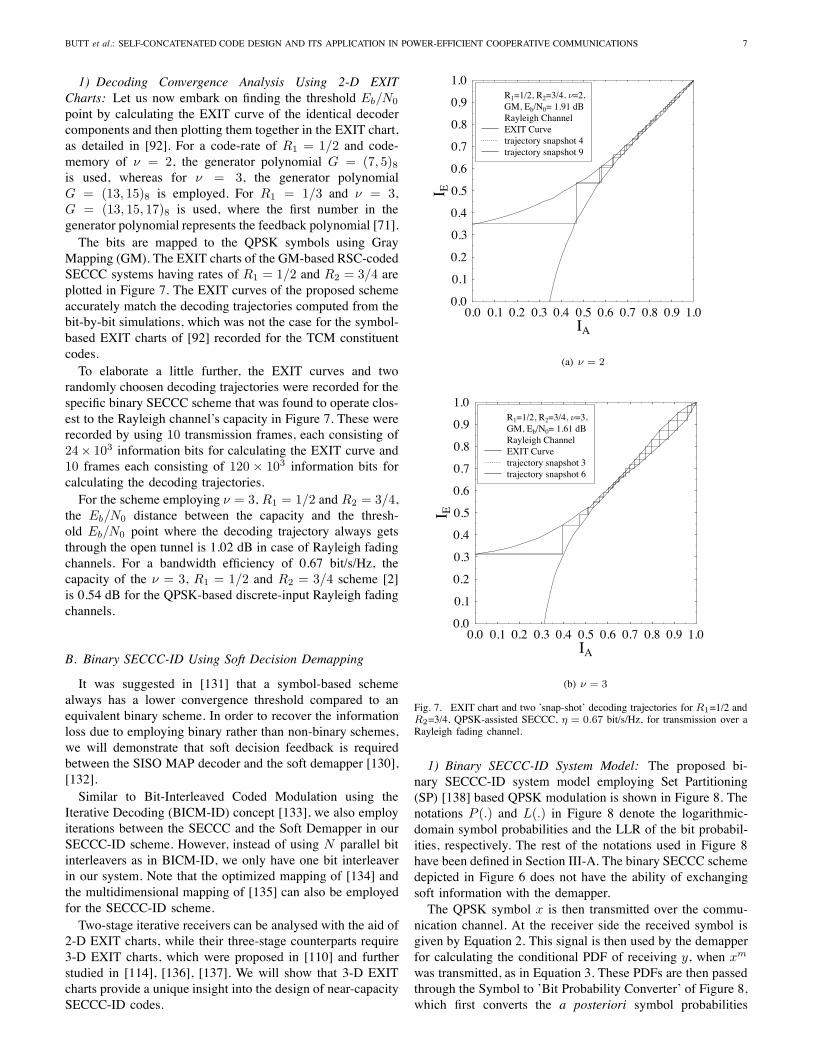
1) Decoding Convergence Analysis Using 2-D EXITCharts: Let us now embark on finding the threshold Eb/N0
point by calculating the EXIT curve of the identical decodercomponents and then plotting them together in the EXIT chart,as detailed in [92]. For a code-rate of R1 = 1/2 and code-memory of ν = 2, the generator polynomial G = (7, 5)8is used, whereas for ν = 3, the generator polynomialG = (13, 15)8 is employed. For R1 = 1/3 and ν = 3,G = (13, 15, 17)8 is used, where the first number in thegenerator polynomial represents the feedback polynomial [71].
The bits are mapped to the QPSK symbols using GrayMapping (GM). The EXIT charts of the GM-based RSC-codedSECCC systems having rates of R1 = 1/2 and R2 = 3/4 areplotted in Figure 7. The EXIT curves of the proposed schemeaccurately match the decoding trajectories computed from thebit-by-bit simulations, which was not the case for the symbol-based EXIT charts of [92] recorded for the TCM constituentcodes.
To elaborate a little further, the EXIT curves and tworandomly choosen decoding trajectories were recorded for thespecific binary SECCC scheme that was found to operate clos-est to the Rayleigh channel’s capacity in Figure 7. These wererecorded by using 10 transmission frames, each consisting of24× 103 information bits for calculating the EXIT curve and10 frames each consisting of 120 × 103 information bits forcalculating the decoding trajectories.
For the scheme employing ν = 3, R1 = 1/2 and R2 = 3/4,the Eb/N0 distance between the capacity and the thresh-old Eb/N0 point where the decoding trajectory always getsthrough the open tunnel is 1.02 dB in case of Rayleigh fadingchannels. For a bandwidth efficiency of 0.67 bit/s/Hz, thecapacity of the ν = 3, R1 = 1/2 and R2 = 3/4 scheme [2]is 0.54 dB for the QPSK-based discrete-input Rayleigh fadingchannels.
B. Binary SECCC-ID Using Soft Decision Demapping
It was suggested in [131] that a symbol-based schemealways has a lower convergence threshold compared to anequivalent binary scheme. In order to recover the informationloss due to employing binary rather than non-binary schemes,we will demonstrate that soft decision feedback is requiredbetween the SISO MAP decoder and the soft demapper [130],[132].
Similar to Bit-Interleaved Coded Modulation using theIterative Decoding (BICM-ID) concept [133], we also employiterations between the SECCC and the Soft Demapper in ourSECCC-ID scheme. However, instead of using N parallel bitinterleavers as in BICM-ID, we only have one bit interleaverin our system. Note that the optimized mapping of [134] andthe multidimensional mapping of [135] can also be employedfor the SECCC-ID scheme.
Two-stage iterative receivers can be analysed with the aid of2-D EXIT charts, while their three-stage counterparts require3-D EXIT charts, which were proposed in [110] and furtherstudied in [114], [136], [137]. We will show that 3-D EXITcharts provide a unique insight into the design of near-capacitySECCC-ID codes.
0.0 0.1 0.2 0.3 0.4 0.5 0.6 0.7 0.8 0.9 1.0IA
0.0
0.1
0.2
0.3
0.4
0.5
0.6
0.7
0.8
0.9
1.0
I E
R1=1/2, R2=3/4, =2,GM, Eb/N0= 1.91 dBRayleigh ChannelEXIT Curvetrajectory snapshot 4trajectory snapshot 9
(a) ν = 2
0.0 0.1 0.2 0.3 0.4 0.5 0.6 0.7 0.8 0.9 1.0IA
0.0
0.1
0.2
0.3
0.4
0.5
0.6
0.7
0.8
0.9
1.0
I E
R1=1/2, R2=3/4, =3,GM, Eb/N0= 1.61 dBRayleigh ChannelEXIT Curvetrajectory snapshot 3trajectory snapshot 6
(b) ν = 3
Fig. 7. EXIT chart and two ’snap-shot’ decoding trajectories for R1=1/2 andR2=3/4, QPSK-assisted SECCC, η = 0.67 bit/s/Hz, for transmission over aRayleigh fading channel.
1) Binary SECCC-ID System Model: The proposed bi-nary SECCC-ID system model employing Set Partitioning(SP) [138] based QPSK modulation is shown in Figure 8. Thenotations P (.) and L(.) in Figure 8 denote the logarithmic-domain symbol probabilities and the LLR of the bit probabil-ities, respectively. The rest of the notations used in Figure 8have been defined in Section III-A. The binary SECCC schemedepicted in Figure 6 does not have the ability of exchangingsoft information with the demapper.
The QPSK symbol x is then transmitted over the commu-nication channel. At the receiver side the received symbol isgiven by Equation 2. This signal is then used by the demapperfor calculating the conditional PDF of receiving y, when xm
was transmitted, as in Equation 3. These PDFs are then passedthrough the Symbol to ’Bit Probability Converter’ of Figure 8,which first converts the a posteriori symbol probabilities

8 IEEE COMMUNICATIONS SURVEYS & TUTORIALS, ACCEPTED FOR PUBLICATION
Puncturer
Depuncturer
RSCEncoder
SECCC Encoder
PuncturerMapper
Symbol toBit Prob.Converter
Demapper
Soft Demapper
+−
+−
SECCC Decoder
+ SISO
MAP
Decoder
−y
R2b1
π1
/S
P cR1 π2 R2
R = R1/(2 ∗ R2)
b2
b1
d P (y|x)
nh
x
Le(b1)
Le(b2)
S/P
/S
PLa(b2)
La(b1)
Lo(b1)
Lo(b2)
La(b2)
La(b1)
La(c)R−1
2
Le(c) Lo(c)
LLR
LLR−1
π1
π2
π−12
π−11
d db1
P e(c)
P a(c)
Fig. 8. Binary SECCC-ID system, which is different from the SECCC scheme of Figure 6, since the Soft Demapper in this case exchanges extrinsicinformation with the SISO MAP decoder [130].
to bit probabilities and then converts those to extrinsic bitprobabilities. The extrinsic bit probabilities are then convertedto the corresponding bit-based LLRs by the block denotedas LLR in Figure 8, which are then passed through a softdepuncturer inserting zero LLRs at the punctured bit positions.The LLRs are then deinterleaved and fed to the SISO MAPdecoder [96].
The self-concatenated decoding procedure is similar tothat described in Section III-A. The extrinsic LLRs of thecodeword denoted by Le(c) at the output of the SISO decoderare fed back to the Soft Demapper of Figure 8, which areinterleaved by π2 and then punctured according to R2. Theseare then converted to the a priori bit probabilities P a
b (c)by the block denoted as LLR−1 in Figure 8, to be fedto the APP demapper, which first converts them to symbolprobabilities and then provides the improved extrinsic LLRLe(c) of the codeword at its output, thus completing the outeriteration between the SISO decoder and Soft Demapper. Apartfrom having inner self-concatenated iterations in the outerSECCC decoder of Figure 8, a fixed number of outer iterationsexchange extrinsic information between the decoder and soft-demapper to yield the decoded bits b1.2) Decoding Convergence Analysis Using 3-D EXIT
Charts: Again, EXIT charts constitute powerful tools de-signed for analysing the convergence behaviour of concate-nated codes without time-consuming bit-by-bit simulationof the actual system. Recall that they analyse the mutualinformation exchange between the input and output of boththe inner and outer components of an iterative decoder andfind its convergence threshold. The a priori LLRs are mod-elled either by an AWGN process or by its experimentallydetermined histogram and then computing the correspondingmutual information between the extrinsic LLRs as well as thecorresponding bit-decisions. To make extrinsic LLRs Gaussiandistributed EXIT charts require a sufficiently high interleaverlength.
EXIT charts [91] are again employed to visualize theinput/output characteristics of the constituent SECCC-IDscheme in terms of the average mutual information transfer.The mutual information exchange between the componentsof an SECCC-ID scheme is portrayed in Figure 9, whichshows the SECCC decoder of Figure 8 as two hypotheticalcomponent decoders.
As depicted in Figure 9, component 1 and 2 of the
SECCC decoder seen in Figure 8 are associated with fourmutual information transfers. Hence two three-dimensionalEXIT charts [110], [137] are required for visualising themutual information transfer between the hypothetical SECCCcomponent decoders (namely for portraying each of the twooutputs as a function of two inputs) and the EXIT curve ofthe combined SECCC decoder and the soft demapper (a twoinput, single output block).
The Eb/N0 value, where the two EXIT curves touch eachother is termed as the threshold Eb/N0 point denoted by Λ,which is the point where the ’turbo-cliff’ [4] region starts andbeyond which the EXIT tunnel becomes ’just’ open, as shownin Figure 7. If uncorrelated extrinsic information is available,then all of the symbol-by-symbol decoding trajectories willreach the (IA, IE) = (1, 1) point [91] for Eb/N0 valueshigher than Λ. The various coding schemes considered in thissection are characterised in Table IV. They are identified bythe code rate (R1), puncturing rate (R2), the overall code rate(R), code memory ν and bandwidth efficiency η, expressed inbit/s/Hz. Furthermore, O denotes the total number of iterationsof SECCC-ID scheme and I denotes the total number ofiterations of SECCC scheme. In all the codes consideredin Table IV the thresholds are calculated for O = 40 andI = 40 for the SECCC and SECCC-ID schemes, respectively.In the case of SECCC the two identical code componentsiterate 20 times exchanging extrinsic information with eachother, while in the case of SECCC-ID the two identical codecomponents iterate 20 times with the demapper. Finally, thechannel capacity limit ω is also expressed in dBs [2], astabulated in Table IV.
The EXIT charts recorded for the binary SECCC-IDschemes of Table IV are shown in Figures 10, 11 and 12(b).The hypothetical component 2 of the SECCC decoder ofFigure 9 receives inputs from and provides outputs for boththe soft demapper and the hypothetical component 1 SECCCdecoder of Figure 9. Hence we have two EXIT surfaces inFigure 10, the first one corresponding to the component 2decoder’s average mutual information IE3(C) provided for thesoft demapper, while the second one corresponding to IE3(D)is supplied for the component 1 SECCC decoder, as shownin Figure 9. The same procedure can be used to calculate thetwo EXIT surfaces for the average mutual information of thecomponent 1 decoder. One of the EXIT surfaces correspondsto the mutual information IE2(C) provided for the soft demap-

BUTT et al.: SELF-CONCATENATED CODE DESIGN AND ITS APPLICATION IN POWER-EFFICIENT COOPERATIVE COMMUNICATIONS 9
P
S/
S/P
P
S/
S/Pπ2
(1)
(2)
(3)
Component 1
Component 2
Soft Demapper
π−12 π1
π−11
π1
IA3(D)
IA2(D)
IE2(D)
IE2(C)
IE3(D)
IE3(C)
IA2,3(C)π−1
1
SECCC Decoder
y
IE1(C)
IA1(C)
Fig. 9. Mutual information exchange between the three components of an SECCC-ID scheme.
TABLE IVVARIOUS SECCC AND SECCC-ID SCHEMES AND THEIR THRESHOLDS.
SECCC/ Mapping ν η AWGN Channel Rayleigh ChannelSECCC-ID (bit/s Eb/N0 (dB) Eb/N0 (dB)Schemes /Hz)
Λ ω Λ ω
R1=1/2, GM 2 0.67 0.71 -0.49 1.81 0.54R2=3/4, SP 0.25 1.35R=1/3 GM 3 0.44 1.56
SP 0.5 1.55R1=1/2, GM 2 1 1.45 0.19 3.4 1.83R2=1/2, SP 1.0 3.4R=1/2 GM 3 1.2 3.2
SP 1.25 3.3R1=1/2, GM 2 1.5 3.44 1.65 8.54 4.98R2=1/3, SP 3.2 8.4R=3/4 GM 3 3.24 8.09
SP 3.2 8.1R1=1/3, GM 3 0.5 0.17 -0.86 0.96 -0.09R2=2/3, SP 0.07 0.82R=1/4R1=1/3, GM 3 1 1.28 0.19 3.3 1.83R2=1/3, SP 1.23 3.4R=1/2R1=1/3, GM 3 1.33 2.43 1.06 5.95 3.65R2=1/4, SP 2.37 5.7R=2/3
per (not used) in Figure 9. Similarly, the component 1 SECCCdecoder has the other EXIT surface characterising its averagemutual information IE2(D) forwarded to the hypotheticalcomponent 2 SECCC decoder of Figure 9. By contrast, thesoft demapper has a single EXIT surface characterising itsaverage mutual information IE1(C) forwarded to component1 and 2 of the SECCC decoder of Figure 9.
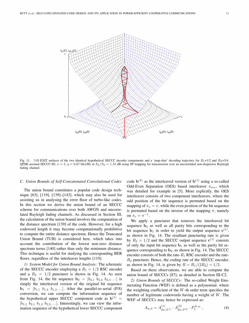
The scheme using R1 = 1/2, R2 = 3/4, ν = 2 andemploying the SP based Soft Demapper is shown in Figures 10and 11. Specifically, the EXIT surface marked with trianglesin Figure 10 was computed based on the Soft Demapper’soutput IE1(C) at the given IE3(D) value of the component2 SECCC Decoder and IA1(C) of the Soft Demapper’sabscissa values. By contrast, the steeply rising EXIT surfacedrawn using dotted lines in Figure 10 was computed basedon the component 2 decoder’s outputs IE3(C) and IE3(D)at the given IA2,3(C) value. Note that the Soft Demappercharacteristic is independent of IE3(D) gleaned from theoutput of the component 2 decoder, as seen in Figure 9. As wecan see from Figure 10, the decoding trajectory is computed
at Eb/N0 = 1.55 dB1. The Monte-Carlo simulation-basedsymbol-by-symbol decoding trajectory (solid line) relies onthe average mutual information of the component 2 SECCCdecoder’s output, namely on IE3(C), and it evolves within thespace under the EXIT surface marked with triangles but abovethe EXIT surface drawn using dotted lines, which means thatit matches the 3-D EXIT curves.
Similarly, the EXIT surface of Figure 11 spanning fromthe horizontal line [IA2(D) = {0 → 1}, IE2(D) = 0,IA2,3 (C) = 0] to the horizontal line [IA2(D) = {0 → 1},IE2(D) = 1, IA2,3(C) = 1], represents the first hypotheticalSECCC decoder component. Since in case of SECCCs theseare identical components, we only have to compute the EXITsurface of a single component and the other is its mirror im-age [92]. The EXIT surfaces of the two hypothetical decodercomponents are plotted within the same EXIT chart togetherwith their corresponding decoding trajectory for the sake ofvisualizing the exchange of extrinsic information between thedecoders. The EXIT surfaces of the proposed scheme matchexactly the decoding trajectories computed from the bit-by-bitsimulations.
The 2-D EXIT curves recorded for a Rayleigh fadingchannel are shown in Figure 12(a). These exemplify themethod of finding thresholds for the Gray mapped SECCC-IDscheme using ν = 2, R1 = 1/2 and R2 = 3/4. 2-D EXITcurves have been used for the case of Gray mapping, becausethere is no mutual information exchange gain between the softdemapper and the decoder. Hence, the decoder’s convergencethreshold can be calculated using 2-D EXIT charts for the caseof Gray mapping. The threshold of Eb/N0=1.81 dB is shownin Figure 12(a) and in Table IV, which is 1.27 dB away fromthe Rayleigh fading channel’s capacity.
By contrast, to calculate the threshold of a given SPmapping based SECCC-ID scheme, we have to rely on 3-DEXIT charts to analyse the mutual information exchange gainachieved, while iterating between the soft demapper and thedecoder. This is shown in Figures 10 and 11. The intersectionof the surfaces in Figure 10 represents the points of con-vergence between the SNR-dependent soft demapper and theSNR-independent SECCC-ID decoder. At these intersectionpoints we have shown a solid line. The corresponding IE2(D)
1Note that there is a small but still beneficial vertical step in the decodingtrajectory (Figs. 10 and 11) after each iteration of the SECCC decoder andthe Soft Demapper. This justifies the use of 3-D EXIT charts as compared to2-D EXIT charts, where this gain cannot be observed.

10 IEEE COMMUNICATIONS SURVEYS & TUTORIALS, ACCEPTED FOR PUBLICATION
0
1
IE3(C), IA1(C)
0
1
IE3(D), IA2(D)
0
1
IE1(C), IA2,3(C)
Fig. 10. 3-D EXIT surfaces of SECCC decoder (dotted) and Soft Demapper (triangles) along with a ’snap-shot’ decoding trajectory for R1=1/2 and R2=3/4,QPSK-assisted SECCC-ID, ν = 2, η = 0.67 bit/s/Hz at Eb/N0 = 1.55 dB using SP mapping, for transmission over an uncorrelated non-dispersive Rayleighfading channel.
values associated with the curve of intersection between thesurfaces in Figure 10 and its mirror image are projected ontothe surfaces seen in Figure 11. Figure 11 also shows theMonte-Carlo-simulation based decoding trajectory matchingthese EXIT curves. These EXIT curves are projected ontoIE1(C) = 0 for yielding Figure 12(b). The 2-D projectionseen in Figure 12(b) for the Rayleigh fading channel hasa threshold of 1.35 dB. Hence, an overall gain of 0.46 dBis attained compared to the Gray mapping performance seenin Figure 12(a). The uncorrelated Rayleigh fading channel’scapacity is 0.54 dB for this scheme, hence, it operates 0.81 dBaway from capacity.
The interleaver, π1 of Figure 8 is used in all of the schemesconsidered in Table IV, which renders the information bits,more-or-less uncorrelated. This is a necessary requirement forthe generation of accurate EXIT charts, because they requirethe LLRs of the information bits to be Gaussian distributed.The interleaver used after the RSC encoder of Figure 8,namely π2, randomises the coded bits before the puncturer.
3) Results and Discussions: The EXIT charts discussedin Section III-B2 were used to find the different-rate nearcapacity SECCC-ID schemes of Table IV designed for ν ={2, 3}, when communicating over AWGN and uncorrelatednon-dispersive Rayleigh fading channels.
The vanishingly-low BER threshold predicted by the EXITchart analysis detailed in Section III-B2 closely matches withthe actual Monte-Carlo-simulation-based threshold observed
in the BER curve given by the specific Eb/N0 value, wherethere is a sudden drop of the BER after a certain number ofdecoding iterations, as shown in Figure 13. Hence it becomespossible to attain an infinitesimally low BER beyond thethreshold Eb/N0 value, provided that the block length issufficiently long and the number of decoding iterations issufficiently high.
Again, the BER versus Eb/N0 performance curves of thebest performing QPSK-assisted SECCC-ID schemes havingR1 = 1/2 and R2 = 3/4, recorded from our bit-by-bit Monte-Carlo simulations are shown in Figure 13. Explicitly, Figure 13portrays the Eb/N0 difference between the channel capacityand the system operating at a BER of 10−3 marked by dottedlines, which was recorded for the SECCC-ID scheme havinga code memory of ν = 2. The SP mapping scheme operates0.93 dB away from capacity, which is 0.35 dB better comparedto the Gray mapping scheme at a BER of 10−3.
As we can see by studying Table IV and Figure 13, the BERthresholds are accurately predicted by the EXIT charts. Hence,the binary EXIT chart is useful for finding the best SECCC-ID schemes that are capable of decoding convergence to avanishingly low BER at the lowest possible Eb/N0 value. Weapply the same method of calculating the BER thresholds fora range of SECCC-ID schemes, as detailed in Table IV.
BUTT et al.: SELF-CONCATENATED CODE DESIGN AND ITS APPLICATION IN POWER-EFFICIENT COOPERATIVE COMMUNICATIONS 11
0
1
IE2(D), IA3(D)
0
1
IE3(D), IA2(D)
0
1
IE1(C), IA2,3(C)
Fig. 11. 3-D EXIT surfaces of the two identical hypothetical SECCC decoder components and a ’snap-shot’ decoding trajectory for R1=1/2 and R2=3/4,QPSK-assisted SECCC-ID, ν = 2, η = 0.67 bit/s/Hz at Eb/N0 = 1.55 dB using SP mapping for transmission over an uncorrelated non-dispersive Rayleighfading channel.
C. Union Bounds of Self-Concatenated Convolutional Codes
The union bound constitutes a popular code design tech-nique [63], [119], [139]–[143], which may also be used forassisting us in analysing the error floor of turbo-like codes.In this section we derive the union bound of an SECCCscheme for communications over both AWGN and uncorre-lated Rayleigh fading channels. As discussed in Section III,the calculation of the union bound involves the computation ofthe distance spectrum [139] of the code. However, for a highcodeword length it may become computationally prohibitiveto compute the entire distance spectrum. Hence the TruncatedUnion Bound (TUB) is considered here, which takes intoaccount the contribution of the lowest non-zero distancespectrum terms [140] rather than only the minimum distance.This technique is useful for studying the corresponding BERfloors, regardless of the interleaver lengths [119].
1) System Model for Union Bound Analysis: The schematicof the SECCC encoder employing a R1 = 1/2 RSC encoderand a R2 = 1/2 puncturer is shown in Fig. 14. As seenfrom Fig. 14, the bit sequence b2 = [b2,1 b2,2 b2,3 . . .] issimply the interleaved version of the original bit sequenceb1 = [b1,1 b1,2 b1,3 . . .]. After the parallel-to-serial (P/S)conversion, we can compute the information sequence ofthe hypothetical upper SECCC component code as b(1) =[b1,1 b2,1 b1,2 b2,2 . . .]. Interestingly, we can view the infor-mation sequence of the hypothetical lower SECCC component
code b(2) as the interleaved version of b(1) using a so-calledOdd-Even Separation (OES) based interleaver πoes, whichwas detailed for example in [5]. More explicitly, the OESinterleaver consists of two component interleavers, where theodd position of the bit sequence is permuted based on themapping of πo = π, while the even position of the bit sequenceis permuted based on the inverse of the mapping π, namelyon πe = π−1.
We apply a puncturer that removes the interleaved bitsequence b2 as well as all parity bits corresponding to thebit sequence b1 in order to yield the output sequence c(1),as shown in Fig. 14. The resultant puncturing rate is givenby R2 = 1/2 and the SECCC output sequence c(1) consistsof only the input bit sequence b1 as well as the parity bit se-quence corresponding to b2, as shown in Fig. 14. The SECCCencoder consists of both the rate-R1 RSC encoder and the rate-R2 puncturer. Hence, the coding rate of the SECCC encoder,as shown in Fig. 14, is given by R = R1/(2R2) = 1/2.
Based on these observations, we are able to compute theunion bound of SECCCs [87], as detailed in Section III-C2.2) Union Bounds of SECCCs: The so-called Weight Enu-
merating Function (WEF) is defined as a polynomial, wherethe weighting coefficient of the W -th order term specifies thenumber of legitimate codewords having a weight of W . TheWEF of SECCCs may hence be expressed as:
Aw,δ = A(1)
2w,δ(1) · A(2)
2w,δ(2) · PN,wπ , (4)

12 IEEE COMMUNICATIONS SURVEYS & TUTORIALS, ACCEPTED FOR PUBLICATION
0.0 0.1 0.2 0.3 0.4 0.5 0.6 0.7 0.8 0.9 1.0IA3(D),IE2(D)
0.0
0.1
0.2
0.3
0.4
0.5
0.6
0.7
0.8
0.9
1.0
I A2(
D),
I E3(
D)
. . . . . . . . . . . . . . . . . . . . . . . . . .Eb/N0=1.81dB, GMRayleigh ChannelEXIT Curve component 1EXIT Curve component 2
.
(a) Gray mapping
0.0 0.1 0.2 0.3 0.4 0.5 0.6 0.7 0.8 0.9 1.0IA3(D), IE2(D)
0.0
0.1
0.2
0.3
0.4
0.5
0.6
0.7
0.8
0.9
1.0
I A2(
D),
I E3(
D)
. . . . . . . . . . . . . . .. . .
. . . . . . . .Eb/N0=1.35 dB, SPRayleigh ChannelEXIT Curve component 1EXIT Curve component 2
.
(b) 2D projection of SP mapping
Fig. 12. EXIT curves of the R1=1/2 and R2=3/4, ν = 2, SECCC-IDscheme to find the corresponding thresholds, operating over an uncorrelatednon-dispersive Rayleigh fading channel.
0.4 0.8 1.2 1.6 2.0Eb/N0(dB)
10-7
10-6
10-5
10-4
10-3
10-2
10-1
BE
R
R1=1/2,R2=3/4, = 2, GMR1=1/2,R2=3/4, = 2, SP
0.35dB
=0.
54dB
,=
0.67
0.93dB
Fig. 13. The BER versus Eb/N0 performance of Gray and SP mappedQPSK-assisted SECCC-ID schemes, R1 = 1/2, R2=3/4, and I = 40 decodingiterations for ν = 2, operating over an uncorrelated Rayleigh fading channel.
SECCC Encoder
b1,1 b1,2 b1,3 b1,4 b1,5b2,1 b2,2 b2,3 b2,4 b2,5b(1) =
b2,2 b2,3 b2,4 b2,5b1,1 b1,2 b1,3 b1,4 b1,5
R = R1
2R2= 1
2
b2
b1b1
P/S
π
b(1)
b2,1
Encoder
R1 = 12
RSC
c(1)
PuncturerR2 = 1
2
c(1) =
c(2) =
b(2) =
b1,1 b1,2 b1,3 b1,4 b1,5b2,1 b2,2 b2,3 b2,4 b2,5
p(1)1,2 p
(1)1,3 p
(1)1,4 p
(1)1,5p
(1)1,1 p
(1)2,5
b2,2 b2,3 b2,4 b2,5b1,1 b1,2 b1,3 b1,4 b1,5
p(2)2,2 p
(2)2,3 p
(2)2,4 p
(2)2,5
b2,1
p(2)2,1
p(1)2,1 p
(1)2,2 p
(1)2,3 p
(1)2,4
p(2)1,1 p
(2)1,2 p
(2)1,3 p
(2)1,4 p
(2)1,5
πoes b1 = π−1(b2)b2 = π(b1)
Fig. 14. Schematic of the SECCC encoder. The notations b(1) andb(2) denote the information sequences of the hypothetical upper and lowercomponent encoder, respectively, while the puncturer output sequences of thehypothetical upper and lower component encoder are denoted as c(1) andc(2) , respectively [87].
where A(1)
2w,δ(1) and A(2)
2w,δ(2) are the WEFs of the hypotheticalupper and lower component codes, respectively. The effectiveparity weight of an SECCC is given by:
δ = δ(1) + δ(2), (5)
where δ(1) and δ(2) are the parity weights of the hypotheticalupper and lower component codes, respectively. The aboveprocedure is similar to that devised for the TTCM schemeof [119] employing two TCM constituent codes, where theparity bits of the upper and lower TCM encoded symbols arepunctured at the even and odd symbol indices, respectively. Aswe can see from Fig. 14, the information sequence of the uppercomponent encoder b(1) consists of the original informationsequence b1 and its interleaved version b2. Hence, if theoriginal information sequence b1 has an information weightof w, then the information sequence of the upper componentencoder b(1) will have an information weight of 2w. The samealso applies to the lower component code.
The term PN,wπ denotes the probability of occurrence for
all the associated error events having w information bit errors,when employing a self-concatenated bit-interleaver having alength of N bits. The evaluation of PN,w
π is based on the noveluniform self-interleaver concept, which may be interpreted asthe extension of the uniform bit-interleaver concept proposedin [127]. A uniform self-interleaver of length N bits is aprobabilistic device, which maps a given input sequence of

BUTT et al.: SELF-CONCATENATED CODE DESIGN AND ITS APPLICATION IN POWER-EFFICIENT COOPERATIVE COMMUNICATIONS 13
scc-m3-bpsk-awgn.gle
0 1 2 3 4 5 6 7 8Eb/N0 [dB]
10-8
10-7
10-6
10-5
10-4
10-3
10-2
10-1
1B
ER
. . . . .0 1 2 3 4 5 6 7 8
Eb/N0 [dB]
10-8
10-7
10-6
10-5
10-4
10-3
10-2
10-1
1B
ER
CC BPSKSimulationBound
SECCC BPSKSimulation. Bound
Fig. 15. Simulations and TUBs of BPSK-assisted CC and SECCC, whencommunicating over AWGN channels. The union bounds are truncated at amaximum Hamming distance of ΔH max = 20. The SECCC employs aninterleaver of length 12 000 bits and 16 decoding iterations.
length N bits having an information weight of w bits intoall possible permutations in the odd and even partitions of anequivalent odd-even-separation based interleaver of length 2Nhaving an information weight of 2w, with equal probabilityof:
PN,wπ = PN,w · PN,w , (6)
where PN,w = 1/(Nw
), which characterizes the traditional N -
bit uniform interleaver having an information weight of w bits.If there are w bit errors in the information sequence, then therewill be w bit errors in the ’odd’ sequence b1 as well as anotherw bit errors in the ’even’ sequence b2, since b2 is simply theinterleaved version of the b1 sequence.
The WEF Aw,δ of an SECCC having a block length of Nencoded symbols and a total of M trellis states can be calcu-lated as follows. We can define the State Input-RedundancyWEF (SIRWEF) for a block of N SECCC-encoded symbolsas:
A(N, S, W, Z) =∑w
∑δ
AN,S,w,δ · WwZδ , (7)
where AN,S,w,δ is the number of paths in the trellis enteringstate S at symbol index N , which have an information weightof w and a parity weight of δ. The notations W and Zrepresent dummy variables. For each n-bit coded symbolat index t, the term At,S,w,δ =
∑S′,S:ut
At−1,S′,w′,δ′ for1 ≤ t ≤ N is calculated recursively, where ut represents thespecific k-bit input symbol that triggers the transition fromstate S′ at index (t− 1) to state S at index t, while the termsw = w′ + i(S′, S) and δ = δ′ + Φ(S′, S),
where w′ and δ′ are the information weight and the parityweight, respectively, of the trellis paths entering state S′ atindex (t − 1). Furthermore, i(S′, S) ∈ {0, 1, . . . , k} is theinformation weight of the k-bit information symbol ut thattriggers the transition from state S′ to S and Φ(S′, S) ∈{0, 1, . . . , n − k} is the parity weight between ct and ct,where ct is the encoded n-bit symbol corresponding to thetrellis branch in the transition from state S′ to S, while ct
scc-m3-bpsk-ray.gle
0 2 4 6 8 10 12 14 16Eb/N0 [dB]
10-8
10-7
10-6
10-5
10-4
10-3
10-2
10-1
1
BE
R . . . . . . . . . .0 2 4 6 8 10 12 14 16
Eb/N0 [dB]
10-8
10-7
10-6
10-5
10-4
10-3
10-2
10-1
1
BE
R
CC BPSKSimulationBound
SECCC BPSKSimulation. Bound
Fig. 16. Simulations and TUBs of BPSK-assisted CC and SECCC,when communicating over uncorrelated Rayleigh fading channels. The unionbounds are truncated at a maximum Hamming distance of ΔH max = 20.The SECCC employs an interleaver of length 12 000 bits and 16 decodingiterations.
is the actual encoded n-bit symbol at index t. Again, all theparity bits in {ct} (or {ct}) corresponding to the odd-positioninformation bits are punctured. Note that the parity weightcontribution corresponding to a punctured parity bit equals tozero.
Let the encoding process commence from state 0 at index0 and terminate at any of the M possible states at indexN . Then the WEF is given by: Aw,δ =
∑S AN,S,w,δ. Note
that for linear codes [75] the distance profile of the codeis independent of which particular encoded symbol sequenceis considered to be the correct one. Hence, for the sake ofsimplicity, we can assume that the all-zero encoded symbolsequence is transmitted.
The union bound of an SECCC employing BPSK modula-tion can be shown to be [87]:
Pb ≤∑ΔH
∑w
A(1)
2w,δ(1) · A(2)
2w,δ(2)(Nw
)·(Nw
) ·w · Q
(√2γΔH
)kN
, (8)
when communicating over AWGN channels and
Pb ≤∑ΔH
∑w
A(1)
2w,δ(1) · A(2)
2w,δ(2)(Nw
)·(Nw
) · w · (1 + γ)−ΔH
2kN, (9)
when communicating over uncorrelated Rayleigh fading chan-nels, where ΔH = w + δ(1) + δ(2).3) Results and Discussions: Let us now compare the BER
performance of CCs and SECCCs to their union boundstruncated at a maximum Hamming distance of ΔH max =wmax + δmax = 20, where the maximum information andparity weights considered are wmax = 10 and δmax = 10,respectively. Figures 15 and 16 shows the BERs of our sim-ulations and the corresponding union bounds of the CCs andSECCCs employing BPSK modulation, when communicatingover both AWGN and uncorrelated Rayleigh fading channels.Both the CC and SECCC employ an RSC code based ona generator polynomial of G = [13 15] expressed in octalformat.

14 IEEE COMMUNICATIONS SURVEYS & TUTORIALS, ACCEPTED FOR PUBLICATION
BS 1MS B
MS A
BS 2
MS A
Fig. 17. An example of a cooperative communication scenario.
As shown in Figures 15 and 16, the truncated union boundquantifies the BER floor of SECCCs quite accurately. Hence,we can design SECCCs having various desired BER floorsusing the proposed TUB.
IV. DISTRIBUTED SELF-CONCATENATED CODING FOR
COOPERATIVE COMMUNICATIONS
In this section, we propose a Distributed Binary Self-Concatenated Coding scheme using Iterative Decoding(DSECCC-ID) for cooperative communications [144], whichis designed with the aid of binary EXIT charts using theSECCCs of Section III. The benefits of cooperative commu-nications are detailed below.
A. Cooperative Communications
Traditional direct transmission has its shortfalls, becausewhen the MS roams at the fringe of the cell’s coverageregion while a conversation is in progress, initiating a handoffmight not be possible due to the unavailability of unusedchannels or the lack of sufficient signal level at the adjacentcell. The call may be dropped in that scenario. Cooperativecommunication comes to our help in this case. It has thepotential of extending the coverage area of a cell by creating analternative transmission path from the MS to the base station(BS) via the introduction of a relay, as shown in Figure 17.Another advantage of this is the creation of independent pathsbetween the MS and the BS, namely the direct path betweenthe two and the one via the relay.
There are various protocols that may be implemented at therelay channel. These can generally be organised into fixed andadaptive relaying schemes [7]. In fixed relaying schemes thechannel resources are shared between the source and the relayin a time-invariant manner. They can be further divided intoAmplify-And-Forward (AAF), Decode-And-Forward (DAF),Compress-And-Forward (CAF) and Coded Cooperation [7],[145]. The AAF scheme relies on a relay, which amplifiesthe received signal and then transmits it to the destination.Although the noise is also amplified along with the signal,we still gain spatial diversity by transmitting the signal overtwo spatially independent channels [146]. The DAF schemehas a relay which decodes the received signal transmittedby the source, re-encodes it and then forwards it to the
destination, which combines all the independently faded signalreplicas [146]. In CAF relaying [147], [148] the relay transmitsa quantised and compressed version of the received signalin the form of source encoded symbols. At the destination,the source encoded i.e. compressed version of the relay’stransmitted signal is decoded by mapping the received bitsinto a set of values that estimate the source’s transmittedmessage, which are then combined with the message directlyreceived from the source. Finally, in coded cooperation [149]incremental redundancy is introduced by the relay, which isthen combined at the destination with the codeword sent by thesource, resulting in a codeword benefitting from an increasedamount of redundancy. While in some codes the informationand redundancy are encoded in such a way that they areinseparable and only perfectly error-free decoding can separatethem, some redundancy can be removed from the codewordin the case of punctured concatenated codes.
Major cooperative communications techniques have beenoutlined in Table V. The basic idea behind cooperative com-munications can be traced back to the philosophy of therelay channel, which was introduced in 1971 by van derMeulen [150]. Although full-duplex relaying and the asso-ciated capacity theorem derived for the discrete memorylessrelay channel model have been proposed by Cover and ElGamal [147], practical cooperative diversity schemes wereonly proposed much later in [146], [151]–[153]. In [154]Sendonaris et al. generalised the conventional relay model,where there is one source, one relay and one destination, tomultiple nodes that transmit their own data as well as serveas relays for each other. The scheme of [154] was referred toas “user cooperation diversity”. Sendonaris et al. presentedin [151], [155] a simple user-cooperation methodology basedon a DAF signalling scheme using CDMA. Dohler et al. [156]introduced the concept of VAAs that emulates Alamouti’sSTBC for single-antenna-aided cooperating users. Space-timecoded cooperative diversity protocols designed for exploitingspatial diversity in a cooperative scenario were proposedin [157]. In practice, each mobile collaborates with eithera single or with a few partners for the sake of reliablytransmitting both its own information and that of its partners ina concerted action, which emulates a virtual MIMO scheme.
Cooperative communications have been shown to offersignificant performance gains in terms of various performancemetrics, including improved diversity gains [146], [157], [158]as well as multiplexing gains [159]. Hunter et al. [149]proposed the novel philosophy of coded cooperation schemes,which combine the idea of cooperation with the family of clas-sic channel coding methods. Its extension to the framework ofcoded cooperation was presented in [8], where the diversitygain of coded cooperation was increased with the aid of ideasborrowed from the area of space-time codes. Additionally, aturbo coded scheme was proposed in [8] in the frameworkof cooperative communications. The performance benefits ofchannel codes in a coded cooperation aided scenario werequantified in [160]. Laneman et al. proposed fixed (DAFand AAF), selection and incremental relaying protocols andcompared them in [146].

BUTT et al.: SELF-CONCATENATED CODE DESIGN AND ITS APPLICATION IN POWER-EFFICIENT COOPERATIVE COMMUNICATIONS 15
TABLE VMAJOR COOPERATIVE COMMUNICATIONS TECHNIQUES (1971-2011).
Year Milestone1971 van de Meulen [150] introduced a simple relay channel modeled by three
terminals: a source, a destination and a relay. He studied the problem oftransmission of information as effectively as possible from the source to thedestination assuming that the relay cooperate in the transmission process [161].
1979 Cover and El Gamal [147] provided a thorough capacity analysis of the full-duplex relay channel.
1998 Sendonaris et al. [154] generalised the relay model to multiple nodes thattransmit their own data as well as serve as relays for each other.
2002 Hunter et al. [149] introduced coded cooperation to achieve diversity in whichthe idea of cooperation was combined with the classic error-control-coding.Dohler et al. [156] introduced the concept of virtual antenna arrays thatemulates Alamouti’s STBC for single-antenna-aided cooperating users.
2003 Sendonaris et al. [151], [155] presented a simple user-cooperation diversitybased algorithm, where a cooperative CDMA system is implemented.Laneman et al. [157] developed different cooperative diversity protocols forexploiting spatial diversity in a cooperation scenario.Valenti and Zhao [162], [163] proposed a turbo coding scheme in a relaynetwork.
2004 Laneman et al. [146] developed cooperative diversity protocols and comparedthe performance of DAF, AAF, selection relaying and incremental relaying interms of their outage behaviour.Nabar et al. [164] analysed the spatial diversity performance of varioussignalling protocols.Janani et al. [8] presented two extensions to the coded cooperation framework[149]: increased the diversity of coded cooperation via ideas borrowed fromspace-time codes and applied turbo codes in the proposed relay framework.Stefanov et al. [160] analysed the performance of channel codes that arecapable of achieving the full diversity provided by user cooperation in thepresence of noisy interuser channels.
2005 Azarian et al. [159] proposed cooperative signalling protocols that are capableof striking an attractive diversity-multiplexing tradeoff.Sneessens et al. [165] proposed a soft decode-and-forward signalling strategythat can outperform the conventional DAF and AAF.Hu et al. [166] advocated Slepian-Wolf cooperation that exploits distributedsource coding in wireless cooperative communication.Yu [167] compared the AAF and DAF signalling schemes in practical scenarios.Kramer et al. [148] addressed the information-theoretic aspects and consideredDAF and CAF schemes for the wireless relay channels with many relays.
2006 Hunter et al. [168], [169] further developed the idea of coded cooperation[149] by computing BER and FER bounds as well as the outage probability ofcoded cooperation.Li et al. [170] employed soft information relaying in a BPSK modulated relayaided system employing turbo coding.Hu et al. [171] proposed Wyner-Ziv cooperation as a generalisation of theSlepian-Wolf cooperation [166] combined with a compress-and-forwardsignalling strategy.Hφst-Madsen [172] derived upper and lower bounds for the capacity of four-node ad hoc networks having two transmitters and two receivers usingcooperative diversity.
2007 Bui et al. [173] proposed soft information relaying where the relay’s LLRvalues are quantised, encoded and superimposed, before being forwarded tothe destination.Khormuji et al. [174] improved the performance of the conventional DAFstrategy by employing constellation rearrangement in the source and the relay.Bao et al. [175] combined the benefits of AAF as well as DAF and proposeda new signalling strategy referred to as decode-amplify-forward.Xiao et al. [176] introduced the concept of network coding in cooperativecommunications.
2008 Yue et al. [177] compared the multiplexed coding and superposition coding inthe coded cooperation system.Zhang et al. [178] proposed a distributed space-frequency coded cooperationscheme for communication over frequency-selective channels.Wang et al. [179] introduced the complex field network coding approach thatcan mitigate the throughput loss in conventional cooperative signalling schemesand attain full diversity gain.
2009 Hanzo et al. [6] presented low-complexity cooperative MIMO codes anddistributed turbo codes designed for two users cooperating for the sake ofimproving their attainable BER performance.Liu et al. [7] authored a book on cooperative communications and networking.
2010 Badia et al. [180] analysed coded cooperation and cooperation on mediumaccess control (MAC) and networking layers. They argue that for crowdednetworks coded cooperation suffers due to increase in interference fromneighboring nodes. Similarly, for sparse networks opportunistic routing maybe difficult to achieve. They showed that by combining cooperative routingwith coded cooperation overall system performance can be improved.Tourki et al. [181] presented a cooperative space-time transmission schemewhere relays cooperate only if the source-relay channel is of an acceptablequality alongwith suitable power allocation strategies to improve performance.
2011 Rossetto and Zorzi [182] shed light on the role of coding schemes such assphere packing etc. for MIMO aided network coding. They further pointtowards several unaddressed issues arising from cross-layer design such as,building a supportive MAC for physical layer, improving NC encoding phase,symbol synchronization and modulation schemes to deal with collidingsignals, while keeping the complexity low.
B. Distributed Coding Techniques
Distributed coding [183] constitutes another attractive co-operative diversity technique, where joint signal design and
coding are invoked at the source and relay nodes. Distributedturbo codes [8], [163] have also been proposed for cooperativecommunications, although typically under the simplifying as-sumption of having a perfect communication link between thesource and the relay nodes. These are half-duplex relay-aidedsystems, where the source transmits to both the relay and desti-nation during the first transmission period and after decodingthe information from the source the relay re-encodes it andsends it to the destination in the second transmission period.Hence half-duplex systems do not suffer from multiple-accessinterference, which results in a simplified receiver structureat the cost of halving the spectral efficiency. As a morerealistic design alternative, a turbo coded cooperation aidedsystem having an imperfect source-relay (SR) communicationlink has been proposed in [184], [185]. In [184] the sourcenode continues its transmission of the rest of the codeword inthe second transmission period with the aim of achieving animproved bandwidth efficiency. Still referring to [184], the sig-nals arriving from the source and relay are superimposed at thedestination, where a Maximum A Posteriori Probability (MAP)detector and a turbo decoder exchange extrinsic information,which were shown to be capable of operating near the capacityof ergodic flat fading channels. The scheme proposed in [185]considers a more complex irregular Low-Density Parity-Check(LDPC) coded near-capacity system designed using EXITcharts and a design-procedure similar to that of [184]. It isdemonstrated in [6], [186] that in the presence of Rayleighfading, DAF cooperation-assisted systems are expected tooutperform their non-cooperative counterparts. However, anerror floor is observed in [6], which may be mitigated byusing soft-relaying [165], [170].
C. DSECCC-ID System Overview
The schematic of a two-hop half-duplex relay-aided systemis shown in Fig. 18, where the source node (s) transmits aframe of coded symbols xs to both the relay node (r) and thedestination node (d) during the first transmission period T1,while the relay node first decodes the information, then re-encodes it and finally transmits a frame of coded symbols xr tothe destination node during the second transmission period T2.In the Time-Division Multiple Access (TDMA) protocol used,the source transmits to both the relay and destination duringT1, while in T2, only the relay transmits to the destination. Thecommunication links seen in Fig. 18 are subject to both free-space path loss as well as to short-term uncorrelated Rayleighfading.
In our half-duplex DAF system design study of Fig. 19 thesource-destination (SD) link employs a simple SECCC code,while the relay node employs simple RSC encoder insteadof SECCC encoder. Therefore, the iterative decoding at thedestination exchanges information between the SECCC MAPdecoder and an RSC MAP decoder. The source employs aSECCC encoder, which reuses the same component instead ofhaving two separate constituent codes. First SECCC iterativedecoding is employed at the relay, which then re-encodesthe decoded symbols by a low-complexity RSC encoder.The relay frame is shorter than the source frame becauseof the puncturing of the systematic bits. Hence, the overall

16 IEEE COMMUNICATIONS SURVEYS & TUTORIALS, ACCEPTED FOR PUBLICATION
DestinationSource
Relay
R
S
hsr
D
SrdSsr
hsdxs = {xs,k}
Ssd
hrd
xr = {xr,(k+Ns)}
Fig. 18. Schematic of a two-hop relay-aided system, where Sab is thegeographical distance between node a and node b.
throughput is higher. The motivation for using the proposed3-stage decoder architecture is to effectively reduce the error-floor documented in Figs. 15.6-15.10 of [6] for the conven-tional two-stage architecture of Fig. 15.3 in [6]. The proposedscheme is designed by a systematic and widely applicableprocedure using EXIT charts. The SR link is imperfect, yetthis simplified scheme is capable of approaching capacity.We derive the theoretical lower and upper bounds on theContinuous-input Continuous-output Memoryless Channels’s(CCMC) capacity as well as of the DCMC [147], [187]–[189]capacity (constrained information rate) for independent anduniformly distributed (i.u.d.) sources.
Let Sab denote the geometrical distance between nodes aand b. The path loss between these nodes can be modelledby [153], [162] as P (ab) = K/Sα
ab, where K is a constantthat depends on the environment and α is the path lossexponent. For a free-space path loss model we have α = 2.The relationship between the energy Esr received at the relaynode and that of the destination node Esd can be expressed as:
Esr =P (sr)P (sd)
Esd = GsrEsd, where Gsr is the power-gain
(or geometrical gain) [153] experienced by the SR link withrespect to the SD link as a benefit of its reduced distance andpath loss, which can be computed as:
Gsr =(
Ssd
Ssr
)2
. (10)
Similarly, the power-gain for the relay-destination (RD) link
with respect to the SD link is given by Grd =(
Ssd
Srd
)2
.
1) DSECCC-ID Encoder: In our DSECCC-ID scheme ofFig. 19, we consider the QPSK-assisted SECCC encoder ofFig. 6 in Section III-A at the source and a QPSK-assistedRSC encoder at the relay. As seen in Fig. 19, the relaydetects the signals received from the source node using aSECCC scheme during the first transmission period. Thenotation πr in Fig. 19 denotes the random bit interleaverused at the relay to interleave the decoded bits before theRSC encoder. The encoders employed at both the source andrelay transceiver nodes may be viewed as a three-componentparallel-concatenated SECCC encoder2, which is depicted in
2An SECCC encoder can be viewed as a two-component parallel-concatenated encoder [87]
RSCEncoder
Puncturer
Mapper
Relay Transeiver
SECCC Encoder
RSCEncoder
Puncturer
Mapper
SECCC Decoder
xs
b2
b1
π1
/S
P cR1 π2 R2
b1
y(T1)d
n(T1)dh
(T1)sd
xrc0 p0 p1π−1
r
n(T2)d
R3 R4
y(T2)d
h(T2)rd
R = R1/(2R2)
πr
h(T1)sr
n(T1)r
y(T1)r
b0
b1
Fig. 19. The schematic of the three-component arrangement using theself-concatenated encoder of Fig. 6. This figure applies to the DSECCC-IDscheme [144], when the relay decodes the received symbols using the SECCCdecoder of Fig. 6 and then forwards the decoded symbols to the destinationin the second phase.
Fig. 19.The notation xr used in Fig. 19 denotes the 2-bit QPSK
symbol at the relay node. The puncturer denoted as R4 inFig. 19 is used to improve the overall throughput of the schemeby minimizing the number of redundant transmitted bits. Wefound that a good performance can be achieved by transmittingonly the parity bits generated at the output of the RSC encoderat the relay node, while puncturing all the original informationbits.
At the source node we consider the rate R = 1/3SECCC scheme of Fig. 6 in Section III-A operating closeto the uncorrelated Rayleigh fading channel’s capacity andemploying QPSK modulation. As shown in Fig. 19 anddiscussed in Section III-A, the input bit sequence {b1} ofthe self-concatenated encoder is interleaved for yielding thebit sequence {b2}. The resultant bit sequences are parallel-to-serial converted and then fed to the RSC encoder havinga rate of R1 = 1/2. This stream is then passed through aninterleaver and then a rate R2 = 3/4 puncturer, as seen inFig. 19. Hence, the overall code rate evaluated from Equation 1becomes R = 1/3. These bits are then mapped to a QPSKsymbol as x = μ(c1c0), where μ(.) is the bit-to-symbolmapping function. Hence the bandwidth efficiency is given byη = R × log2(4) = 0.67 bits/symbol (bps), assuming a zeroNyquist roll-off-factor. The QPSK symbol xs is then transmit-ted over the channel. The overall throughput of this two-hop
cooperative scheme can be formulated as: η =Ni
Ns + Nr[bps],
where Ni is the number of information bits transmitted withina duration of (Ns + Nr) symbol periods. Again, Ns is thenumber of modulated symbols per frame transmitted from thesource node and Nr is the number of modulated symbols perframe arriving from the relay node. For our case we have Ni
= 120,000 bits. Therefore, we transmit a total of Ns = 180,000symbols. Note that the number of symbols per transmissionburst at the relay node is given by Nr = 60, 000 due to the

BUTT et al.: SELF-CONCATENATED CODE DESIGN AND ITS APPLICATION IN POWER-EFFICIENT COOPERATIVE COMMUNICATIONS 17
+−
++
Depuncturer
+
++
Demapper
+
+
Demapper RSC Decoder
−
(2)Decoder
MAP
RSC
Decoder
MAP
SISO
(1)SECCC Decoder
π−11
La(b1)P
S
/Le(d)
S
P/
Le(b1)
La(b2)
Lo(d)
R−12 π−1
2
π1
π−11
La(c)
La1(b2)
π1
b1
P (y(T1)d |xs)
La2(b2)
La(d)La
1(b1) Le(b2)
πr
πr
La(b0)
P (y(T2)d |xr)
y(T2)d
La2(b1) Le
1(b1)
π−1r
Le(b0)
R−14
Lo(b0)
y(T1)d
Fig. 20. The schematic of the DSECCC-ID decoder [144]. Note that theSECCC decoder is a modified version of the decoder of Fig. 6 in order tomake it capable of exchanging extrinsic information with the RSC decoder.The input of the SECCC decoder is generated by the QPSK demapper for theSD link, while the input of the RSC decoder is output by the QPSK demapperof the RD link.
employment of 2 bps QPSK modulation and a rate R4 = 1/2puncturer that removes all systematic bits from the outputof the RSC encoder of rate R3 = 1/2. Hence, the overalleffective throughput of the DSECCC-ID scheme of Fig. 19 isgiven by η = (Ni)/(Ns+Nr) = 0.5 bps. The Signal to NoiseRatio (SNR) per bit is given by Eb/N0 = SNR/η. Hence, theDSECCC-ID scheme suffers from a penalty of 1.25 dB interms of Eb/N0, when compared to the conventional SECCCscheme having a somewhat higher throughput of 0.67 bit/s/Hz.2) DSECCC-ID Decoder: The decoder structure of the
DSECCC-ID scheme is illustrated in Fig. 20.For the SECCC decoder of Fig. 6 and detailed in Section III,
which was denoted as component (1) in Fig. 20, the receivedsignal arrives at the soft demapper. This signal is then used bythe demapper for calculating the conditional PDF of receivingy(T1)
d , when xms was transmitted, where xm
s = μ(c1c0) is thehypothetically transmitted QPSK symbol for m ∈ {0, 1, 2, 3},while the received signal that arrives at the soft demapperof the RSC decoder, which is denoted as component (2) inFig. 20 is used for calculating the conditional PDF of receivingy(T2)
d , when xmr was transmitted.
The bit probabilities are then passed through a soft depunc-turer, which converts them to the corresponding bit-basedLLRs and subsequently inserts zero LLRs at the puncturedbit positions. The LLRs are then deinterleaved and fed tothe Soft-Input Soft-Output (SISO) RSC MAP decoder [96]of Fig. 20.
There are two inputs to the RSC MAP decoder block,which is denoted as component (2) in Fig. 20. The first isthe extrinsic information of bit b1 provided by the SECCCdecoder, which is denoted as component (1). As seen inFig. 20, this is obtained from the addition of Le(b1) and thedeinterleaved version of Le(b2). The resultant Le
1(b1) streamis interleaved by πr to generate La(b0). The second input ofthe RSC MAP decoder component (2) is the interleaved anddepunctured version of the soft information provided by theQPSK demapper denoted as P (yT2
d |xr) in Fig. 20. The RSCdecoder of the relay seen in Fig. 20 then provides the improvedextrinsic LLR of the data bit b0, namely Le(b0) as its output,which is deinterleaved by π−1
r to yield La2(b1). The LLR
La2(b1) can be further interleaved using π1 to generate La
2(b2).These a priori LLRs output by the RSC can be added to theSECCC decoder’s a priori LLRs of b1 and b2, thus completingthe iteration between the RSC and SECCC decoders of Fig. 20.
It has been shown in [87] that an SECCC scheme may beviewed as two parallel-concatenated codes separated by anodd-even turbo interleaver. Hence the SECCC Decoder (1)of Fig. 20 employed at the destination may be viewed asa two-component PCCC decoder, which exchanges extrinsicinformation with another parallel-concatenated RSC Decoder(2) as shown in Fig. 20. Therefore, our proposed scheme canbe viewed as a three-component parallel-concatenated scheme.
D. EXIT Chart Analysis
Our three-step design procedure using EXIT charts devel-oped for the proposed distributed coded system is as follows:Step 1: Our code design procedure commences by calculat-
ing the decoding convergence threshold of the SECCC schemeat the output of the SR link using EXIT charts. Recall thatthe near-capacity QPSK-assisted SECCC scheme of Fig. 6in Section III employs R1 = 1/2, R2 = 3/4 and has athroughput of η = 0.67 bit/s/Hz. As seen in Fig. 21, wecompare the SECCC scheme using ν = 2 and ν = 3 ata receive SNR of about -0.15 dB. For the ν = 3-SECCCcode a receive SNR of about -0.15 dB is needed in orderto attain a decoding convergence to the (1,1) point of theEXIT chart, since at a receive SNR of −0.2 dB the EXIT-tunnel remains closed. By contrast, the EXIT tunnel for theν = 2-SECCC code, employing the generator polynomial(gr = 7, g1 = 5)8, remains closed at −0.15 dB. This canalso be confirmed from Table IV, where the Gray mappedν = 3 SECCC scheme performs 0.25 dB better than theν = 2 scheme. Recall from Table IV that the successful-decoding convergence threshold ω of a ν = 2 code is 1.81 dBin terms of Eb/N0, whereas the ν = 3 code requires anEb/N0 value of 1.56 dB. Consequently, we opted for ν = 3,employing the octally represented generator polynomial of(gr = 13, g1 = 15)8, as it requires a marginally reducedtransmission power. We hasten to add that this may be deemedan unfavourable tradeoff, since it implies doubling the numberof trellis states, i.e. the complexity.
Fig. 21 also corresponds to the performance of the SECCCscheme of the SR link. The receive SNR can be computedas: SNRr = SNRe + 10 log10(Gsr) [dB]. When there is

18 IEEE COMMUNICATIONS SURVEYS & TUTORIALS, ACCEPTED FOR PUBLICATION
0.0 0.1 0.2 0.3 0.4 0.5 0.6 0.7 0.8 0.9 1.0IA
0.0
0.1
0.2
0.3
0.4
0.5
0.6
0.7
0.8
0.9
1.0
I E
. . . . . . . . . . . . . . . .
............
... .
R1=1/2, R2 = 3/4SNRr = -0.15 dB. EXIT Curve, = 2EXIT Curve, = 3Trajectory, = 3
Fig. 21. EXIT curves for ν = 2 and ν = 3, R1=1/2 and R2=3/4, QPSK-assisted SECCC using Gray mapping, η = 0.67 bit/s/Hz at SNRr = -0.15 dBfor transmission over an uncorrelated Rayleigh channel. A decoding trajectoryfor ν = 3 is also depicted. The 2-D EXIT chart is similar to that calculatedfor the SECCC scheme in Fig. 7(b) at an equivalent Eb/N0 value of 1.61 dB.
no path-loss, the receive SNR equals the equivalent SNR3,denoted by SNRe and Gsr was defined in Equation 10. Hence,a receive SNR of −0.15 dB can be achieved by variouscombinations of SNRe and Gsr. For the ν = 3 SECCCcode the successful decoding convergence threshold4 is at−0.2 dB, when employing I = 40 self-concatenated iterations,which is 1.05 dB away from the Rayleigh fading SR link’scapacity calculated as −1.20 dB at 0.67 bps from [2]. Thecorresponding capacity curve will be discussed later in detailin the context of Fig. 24. This scheme acquires an open EXITtunnel5 at SNRr=−0.15 dB, when communicating over anuncorrelated Rayleigh fading channel.
In our analysis the relay node of the DSECCC-ID isassumed to be placed half-way between the source and relaynodes, i.e. we have Gsr = Grd = 4, hence the minimumrequired equivalent SNR at the source node is SNRe =−0.15 − 6.02 = −6.17 dB.Step 2: In this section the decoding convergence of the
three-component DSECCC-ID decoder used at the destinationnode is analysed. The EXIT curves of the SECCC decoder atthe SD link employing Isd = 2 self-concatenated iterations
3To simply our analysis the term “equivalent SNR” is introduced, whichis the ratio of the signal power at the transmitter (source/relay node) withrespect to the noise level at the receiver (relay/destination node).
4The decoding threshold is the SNR value beyond which the EXIT tunnelbecomes ’just’ open, although this does not necessarily imply that the (IA,IE)=(1,1) point of ’perfect convergence’ can be reached because some ofthe decoding trajectories are curtailed owing to the limited interleaver lengthused.
5An open EXIT tunnel specifies the receive SNR value where there is amore widely open EXIT tunnel leading to the (1,1) point and where decodingconvergence to an infinitesimally low BER value can always be achieved,provided that the interleaver length is beyond a certain value and the numberof iterations is sufficiently high [91].
0.0 0.1 0.2 0.3 0.4 0.5 0.6 0.7 0.8 0.9 1.0IA
0.0
0.1
0.2
0.3
0.4
0.5
0.6
0.7
0.8
0.9
1.0
I E
EXIT Curve SD linkEXIT Curve RD link
=2=3=4
Fig. 22. The EXIT curves for the DSECCC-ID scheme for a SNRe =−3.5 dB both at the source as well as at the relay nodes. We portray the RDlink’s EXIT curves for three different values of ν.
as well as that of the RSC decoder recorded at the RDlink are plotted in Fig. 22. Since this EXIT-chart reflectsthe destination decoder’s convergence after the completionof the SECCC iterations, only one of the pair of symmetriccurves is shown. Our goal at this stage is to examine theextrinsic information exchange between the SECCC decoderand RSC decoder having different memory lengths. The RDlink employs rates of R3 = 1/2, R4 = 1/2. As explicityshown in Fig. 22, we varied the memory of the RSC encoderin order to find the specific code memory, which has a lowcomplexity, while simultaneoulsy matching the EXIT curveof the SECCC decoder of the SD link. It can be seen fromFig. 22 that the EXIT curves associated with ν = 2 and ν = 3do not intersect the EXIT curve of the SD link when we haveSNRe = −3.5 dB at both the SD and at the RD link, while theν = 4-curve does intersect it at the same SNR. Since ν = 2represents a lower-complexity code, we opted for ν = 2 inour proposed scheme.
The EXIT curves and corresponding decoding trajectoryare shown in Fig. 23. The number of iterations exchangingextrinsic information between the SECCC decoder of theSD link and the RSC decoder of the RD link is limited toIsd,rd = 10.Step 3: The successful decoding convergence threshold of
the DSECCC-ID system may be calculated with the aid of theEXIT curves, which intersect each other at SNRe of −3.65 dB.Hence the staircase-shaped decoding trajectory will not reachthe (1,1) point of perfect convergence to a vanishingly lowBER. But once the system is operating at SNRe = −3.5 dBin the SD link and again at SNRe = −3.5 dB in the RD link,an open tunnel emerges. Since SNRe = −3.5 dB is higherthan the threshold of SNRe = −6.17 dB, which guarantees anSECCC decoding convergence at the relay, the SR link maybe deemed near-perfect. Another reason why we configurethe system to operate an SNR higher than the minimumsuccessful decoding SNR is because we want to have less

BUTT et al.: SELF-CONCATENATED CODE DESIGN AND ITS APPLICATION IN POWER-EFFICIENT COOPERATIVE COMMUNICATIONS 19
0.0 0.1 0.2 0.3 0.4 0.5 0.6 0.7 0.8 0.9 1.0IA
0.0
0.1
0.2
0.3
0.4
0.5
0.6
0.7
0.8
0.9
1.0I E
EXIT Curve SD linkEXIT Curve RD link
=2Trajectory, SNRe = -3.5dB
Fig. 23. The EXIT curves and a decoding trajectory of the DSECCC-IDscheme for SNRe = −3.5 dB both at the source as well as at the relaynodes. The number of iterations exchanging extrinsic information between theSECCC and RSC decoders at the destination node is limited to Isd,rd = 10.
self-concatenated iterations at the SR link’s receiver, namelyIsr = 8 in this case.
The EXIT chart analysis is verified by computing the cor-responding Monte-Carlo simulation based decoding trajectoryfor the DSECCC-ID scheme. The distinct decoding trajectorybased on a frame length of 120 000 bits is shown in Fig. 23for an equivalent SNR of -3.5 dB both at the source and atthe relay. It matches the EXIT curves generated for the SDlink, which employs the SECCC scheme and the RD linkemploying the RSC scheme, hence verifying the predictedresults.
E. Relay Capacity
The two-hop half-duplex constrained relay-aided networkcapacity may be calculated by considering the capacity of thechannel between the source, relay and the destination.
We first derive the upper and lower bounds on our half-duplex constrained relay-aided system’s CCMC capacity aswell as those of the DCMC capacity (constrained informationrate) based on the approach proposed for full-duplex relaychannels in [147]. The signals X1 and X2 are transmitted fromthe source S seen in Fig. 18 during T1 and T2, respectively,while Y1 and Y2 represent the corresponding signals receivedat the destination D of Fig. 18 during the consecutive timeslots. Furthermore, X and Y are the transmitted and receivedsignals at the relay R of Fig. 18, respectively. The upper andlower bound on the CCMC and DCMC capacity of a half-duplex relay-aided system can then be derived by setting X2 =0, because the source does not transmit in T2. Consequently,the upper bound may be expressed as:
CUCoop ≤ max
p(x1,x)min
{λE[I(X1; Y1, Y )], λE[I(X1; Y1)] +
(1 − λ)E[I(X ; Y2)]}
, (11)
and the lower bound as:
CLCoop ≥ max
p(x1,x)min
{λE[I(X1; Y )], λE[I(X1; Y1)] +
(1 − λ)E[I(X ; Y2)]}
, (12)
where I(A; B) represents the mutual information for thechannel having the i.u.d. input A and the corresponding outputB for the case of CCMC capacity. By contrast, for theDCMC scenario the input A is constituted by PSK/QuadratureAmplitude Modulated (QAM) symbols. Still referring to Equa-tions 11 and 12, E(.) denotes the expectation with respect tothe fading coefficients, p(x1, x) represents the joint probabilityof the signals transmitted from the source and the relay, whileλ is the ratio of T1 to the total frame duration, which is given
byNs
Ns + Nr=
34
. Similarly, we have (1− λ) =Nr
Ns + Nr=
14
. The term E[I(X1; Y1, Y )] in Equation 11 represents theexpected value of the mutual information between the signaltransferred from the source node S and the signals received atboth the relay and destination nodes during T1, while the termE[I(X1; Y )] in Equation 12 considers the link spanning fromthe source node S to the relay node R in T1. Furthermore, theterm E[I(X1; Y1)] considers the transmission from the sourcenode to the destination node in T1. Finally, E[I(X ; Y2)] repre-sents the expected value of the mutual information between thesignals transferred from the relay node and the signal receivedat the destination node during T2.
The corresponding constrained information rates ofE[I(X1; Y1, Y )], E[I(X1; Y1)], E[I(X ; Y2)] and E[I(X1; Y )]may be computed by using the Monte-Carlo averagingmethod [188]. Using Equations 11 and 12 we can calculatethe DCMC and CCMC capacity of the two-hop relay-aidednetwork, which is graphically shown in Fig. 24.
coop-div-scc.gle
-10 -5 0 5 10 15 20SNR (dB)
0.0
0.5
1.0
1.5
2.0
2.5
C(b
it/sy
mbo
l)
.........
......
......
......
..................................
.........
......
....
....
....
.......
QPSKNon-cooperative. Cooperative: lower boundCooperative: upper bound
DCMCCCMC
-5dB
0.67 bps
-1.2dB
Fig. 24. The DCMC and CCMC capacity curves of cooperative networkand non-cooperative QPSK assisted schemes. It can be seen that the DCMCof a cooperative network is −5 dB at 0.5 bps. DCMC of a non-cooperativeQPSK assisted scheme is −1.20 dB at 0.67 bps.
F. Results and Discussions
Finally, we compare the achievable performance of theDSECCC-ID scheme employing a realistic relay node, which

20 IEEE COMMUNICATIONS SURVEYS & TUTORIALS, ACCEPTED FOR PUBLICATION
-5 -4 -3 -2 -1 0 1SNRe(dB)
10-8
10-7
10-6
10-5
10-4
10-3
10-2
10-1
1B
ER
SECCC, R1=1/2,R2=3/4, = 3DSECCC-ID, perfect relayDSECCC-ID, realistic relay
1.5dB
DCMCRelayCapacity
1.05dB2.3dB
RayleighChannelCapacity
Fig. 25. BER versus equivalent SNR performance of the DSECCC-ID andSECCC schemes for a frame length of 120, 000 bits. The DCMC relay-aidednetwork capacity is −0.5 dB at 0.5 bps as calculated from Fig. 24.
potentially induces error propagation, to that of the non-cooperative SECCC scheme. The BER versus equivalent SNRperformance of the DSECCC-ID and SECCC schemes isshown in Fig. 25.
The SECCC scheme has a decoding threshold at −0.2 dBand the tunnel at −0.15 dB. It performs 1.05 dB away from theRayleigh fading channels’s capacity calculated as −1.20 dBfrom [2] and Fig. 24 at a BER of 10−5. The DSECCC-IDsystem has been analysed at −3.5 dB stipulated at both thesource and the relay employing the RSC encoder. Thus theDSECCC-ID outperforms the SECCC scheme by about 3.3 dBin SNR terms at a BER of 10−5, which corresponds to 3.3−1.25 = 2.05 dB in terms of Eb/N0.
As shown in Fig. 25, the proposed DSECCC-ID systemis capable of performing within about 1.5 dB from the two-hop relay-aided network’s DCMC capacity of −5 dB at0.5 bps, as inferred from Fig. 24 at a BER of 10−5. Bycomparison, for the scheme proposed in [184], the signalsarriving from the source and relay are superimposed at thedestination, where a MAP detector and a turbo decoder ofmemory ν = 4 exchange extrinsic information, which wereshown to be capable of achieving a BER of 10−5, at about1.43 dB away from the capacity of the ergodic flat-fadingchannel at an overall effective throughput of 0.44 bps. Wecompare the two schemes’ complexity by calculating the totalnumber of trellis states, multiplied by the number of iterationsat the corresponding decoders. This determines the number ofAdd-Compare-Select (ACS) arithmetic operations of a systolicarray based silicon chip. The total complexity of our proposeddecoder is estimated as follows.
The number of decoding iterations at the SR link’s memory-ν = 3 decoder are Isr = 8, therefore Isr × 2ν = 8 × 8 = 64ACS operations are required at the relay. The SD link employsIsd = 2 iterations of a memory-3 decoder, whereas theRD link employs a ν = 2 code. The number of iterationsexchanging extrinsic information between the SECCC andRSC decoders at the destination node is limited to Isd,rd = 10.
Hence, the number of ACS operations at the destination isgiven by Isd × 23× 22 × Isd,rd = 640. The overall number ofACS operations is therefore 64 + 640 = 704.
For the case of [184] the turbo decoder used in the RD linkemploys 15 iterations between the two parallel concatenatedturbo codes, while 15 iterations exchange extrinsic informationbetween the MAP decoder and the turbo decoder of memoryν = 4 at the destination. Hence the total number of ACSoperations required in [184] is (15 + 15) × 2 × 24 = 960.We note however that the complexity incurred by the MAPdetector has not been included in the calculations. Hence ourproposed system is capable of exhibiting a similar perfor-mance, while incurring a reduced overall complexity comparedto the scheme advocated in [184].
V. CONCLUSIONS, DESIGN GUIDELINES AND FUTURE
RESEARCH
A. Summary and Conclusions
We have presented a suite of novel transceiver designs em-ploying iteratively detected self-concatenated coding schemesin order to achieve a near-capacity performance, when operat-ing in AWGN and Rayleigh fading channels. In order to elim-inate the mismatch between the EXIT-chart and the Monte-Carlo-simulation based decoding trajectory experienced inthe context of the TCM based scheme discussed in [92],we proposed bit-based SECCCs. The mapper utilised Graymapping, which mitigated the above-mentioned EXIT-chartmismatch. However, some information was lost, because thecoded bits in each coded symbol are correlated. To recover thislost information, in Section III-B soft decision demapping wasused. It was observed in Figure 13 that the SECCC-ID schemeof Figure 8 employing the SP demapper outperformed someof the GM based SECCC schemes. To analyse the exchangeof extrinsic information between the SISO MAP decoder andthe soft demapper of Figure 8, we employed 3-D EXIT chartsin Figures 10 and 11. The accuracy of the 3-D EXIT chartbased design was confirmed by the corresponding bit-by-bitMonte-Carlo BER simulations of Figure 13. Finally, in Sec-tion III-C we derived the union bound of SECCCs employingBPSK modulation for communication over both AWGN anduncorrelated Rayleigh fading channels, based on the noveluniform self-interleaver concept. In Section IV we proposeda power-efficient distributed scheme employing SECCCs forcooperative communications in order to mitigate the effectsof large-scale shadow fading on the performance of wirelesscommunication systems. The scheme is capable of providingsubstantial diversity-, throughput- as well as coding-gains forthe case of a single-user scenario. Again, the novel three-component parallel concatenated decoder of Figure 20 wasinvoked. The proposed scheme was designed by conceivingthe widely applicable design procedure of Section IV-D usingEXIT charts. The related complexity analysis was carried outin Section IV-F and it was demonstrated that the proposedscheme has a low complexity. Despite the fact that the SRlink was prone to decision errors, this simplified scheme wascapable of approaching the DCMC capacity.

BUTT et al.: SELF-CONCATENATED CODE DESIGN AND ITS APPLICATION IN POWER-EFFICIENT COOPERATIVE COMMUNICATIONS 21
B. Design Guidelines
• The first step in the design of FEC coding schemes ingeneral and in SECCC and SECCC-ID coding schemes inparticular is that of determining the code’s specifications,such as the affordable decoding complexity expressedfor example in terms of the number of ACS arithematicoperations. This predetermines the resultant chip areaversus decoding speed trade-offs, hence ultimately themaximum supported transmission rate.
• Another fundamental specification is the affordable de-lay, which determines the maximum tolerable interleaverlength.
• Then the specific choice of the most appropriate SECCCcomponent has to be resolved. As discussed in Sec-tion III, bit-based SECCC schemes designed with theaid of 2-D EXIT charts are accurate in predicting theconvergence thresholds and they have flexible coding-and puncturing-rates. Furthermore, more flexible three-stage SECCC-ID schemes may be designed with the aidof 3-D EXIT charts. We demonstrated in Section III-Cthat in order to have a complete and accurate codedesign procedure the Truncated Union Bound (TUB) isnecessary, which can be used to predict the error-floors,while EXIT charts may be invoked to predict the turbo-cliff-SNR in the design of near-capacity SECCCs.
• In the light of the inherent trade-off between the lowestpossible turbo-cliff SNR and the lowest achievable resid-ual error floor, we can use the EXIT-chart based code-design procedure of Section III-B2 and the generatorpolynomials exemplified in Table IV to meet the data-integrity requirements, such as the BER, SER or PERspecifications.
• SECCCs provide the designer with a high degree ofdesign-freedom, since they offer a vast range of options.These design options are exemplified by the type ofcomponent codes, their generator polynomials, code rate,puncturer schemes, interleaver designs and memory, bit-to-symbol mapping schemes (such as Gray mapping,Anti-Gray mapping, Set-Partitioning), the choice of mod-ulation schemes (such as coherent and non-coherentmodems), irregular code designs, etc.
• When near-capacity operation is the over-riding designcriterion, rather than that of minimizing the overall delayor complexity, the EXIT-chart-matching based designs ofSection III suggest that 3-stage concatenated designs mayhave to be invoked. This is, because they are capable ofreducing the area of the open EXIT-tunnel and hence theyfacilitate decoding convergence to an infinitesimally lowBER at near-capacity SNRs.
• Hence it is important to emphasize that maximizing theminimum distance of the code or directly searching forthe code having the best distance profile or weight-distribution is no longer the most paramount design crite-rion. The EXIT-charts provide us with a more insightfultool for designing codes for near-capacity operation.
• When designing SECCCs for supporting wireless cell-edge users for example, the distributed code designprinciples of Section IV may be relied upon. More specif-
ically, the distributed codes may move the constituentcodes to separate relay nodes which have independentlyfading channels and hence provide a diversity gain.However, a powerful code is needed for all links of arelay-aided system, but especially for the SR link, inorder to prevent error propagation. This suggests thatthe employment of a concatenated component code isof paramount importance at all nodes, particularly. Hencethe coding scheme of the SR link has to be designed usingEXIT charts, as detailed in Section IV-D. The propagationof decoding errors also has to be prevented along the RDlink, which is achieved with the aid of another EXIT-chartmatching procedure detailed in Section IV-D. Thus usingDSECCC-ID schemes by employing a 3-stage decoderarchitecture, effectively reduces the potential error-flooroften encountered in conventional 2-stage architectures.DSECCC-ID schemes impose a low complexity, wherethe ACS operations are distributed between the relayand destination nodes. Similarly to co-located constituentcodes, it was demonstrated that EXIT charts are needed todesign DSECCC-ID schemes using a widely applicable3-step procedure:
– Decoding convergence threshold of the SECCCscheme of the SR link is calculated.
– EXIT curve of the SD link is matched against thatof a suitable RD link EXIT curve.
– Convergence threshold of the DSECCC-ID schemeis then calculated. More explicity, by plotting the de-coding trajectory of the DSECCC-ID scheme we candetermine the number of iterations required betweenthe SECCC and RSC decoders at the destinationnode in order to achieve perfect convergence to aninfinitesimally low BER.
C. Future Work
Our future research will focus on designing reduced-complexity SECCC-ID schemes. Furthermore, 3-D EXITcharts may also be used to design a SECCC-ID schemeconcatenated with an outer codec, such as a video codec forenabling soft information exchange between the SECCC-IDdecoder and the video decoder. Another area to explore isthat of finding the union bound for various coding rates ofthe SECCCs combined with higher-order modulation schemes,using the uniform puncturing concept of Section III-C. Ourfuture research will focus on enhancing the DSECCC-IDscheme of Section IV designed for cooperative communica-tions in order to operate near the capacity, while imposing alow complexity using differential encoding and non-coherentdetection, and dispensing with channel estimation [1], [6].The next challenging issue will be that of reducing the totalpower, including the transmit power and the DSP-relatedpower consumption in a relay-aided network. The questionarises in a multi-hop network without line of sight propagation,as to how we can better utilize distributed coding in thiscooperative network. Soft relaying has been proposed as apowerful method of combining the main advantages of bothAAF and DAF signalling strategies. In [165], [170], [173]soft DAF has been shown to outperform the DAF and AAF

22 IEEE COMMUNICATIONS SURVEYS & TUTORIALS, ACCEPTED FOR PUBLICATION
signalling, where it was argued that the DAF signalling losessoft information and hence all operations were performed inthe LLR domain. Similarly, another beneficial extension toconsider is to create a hybrid of the DAF or AAF as theoptimal relaying scheme according to the specific positionof relays. If the available relay is closer to the source, thenDAF gives a better performance, while if the relay is closerto the destination, then AAF is preferable [190]. Therefore,based on the performance improvements reported in the litera-ture [190] while using soft information relaying, the DSECCC-ID scheme designed for a single user and the SPC-SECCC-ID conceived for two users will transmit soft estimates of theother users’ data instead of performing hard decoding, sincethe hard-decoding solution would lose the advantage of softinformation. Finally, the successive relaying principle of [191]may be invoked for mitigating the throughput loss imposed bythe provision of the separate broadcast and cooperative phase.In order to avoid the complications of relay-synchronization,the asynchronous relaying regime of [192] may be invoked.
REFERENCES
[1] L. Hanzo, L.-L. Yang, E.-L. Kuan and K. Yen, Single and multi-carrierDS-CDMA: Multi-user detection, space-time spreading, synchronisa-tion, networking and standards. Chichester, England: John Wiley andSons Ltd and IEEE Press, 2003.
[2] L. Hanzo, S.X. Ng, T. Keller and W. Webb, Quadrature amplitudemodulation: From basics to adaptive trellis-coded, turbo equalisedand space-time coded OFDM, CDMA and MC-CDMA systems, 2ndEdition. Chichester, England: John Wiley and Sons Ltd and IEEEPress, 2004.
[3] C. E. Shannon, “A mathematical theory of communication,” BellSystems Technical Journal, vol. 27, pp. 379/623–423/656, July/October1948.
[4] C. Berrou, A. Glavieux and P. Thitimajshima, “Near Shannon limiterror-correcting coding and decoding: Turbo-codes (1),” in IEEEInternational Conference on Communications, vol. 2, Geneva, May1993, pp. 1064–1070.
[5] L. Hanzo, T.H. Liew and B.L. Yeap, Turbo coding, turbo equalisationand space time coding for transmission over fading channels. Chich-ester, UK: Wiley: IEEE Press, 2002.
[6] L. Hanzo, O. Alamri, M. El-Hajjar and N. Wu, Near-capacity multi-functional MIMO systems. IEEE Press - John Wiley, April 2009.
[7] K.J.R. Liu, A.K. Sadek, W. Su and A. Kwasinski, Cooperative com-munications and networking. Cambridge University Press, 2009.
[8] M. Janani, A. Hedayat, T. Hunter and A. Nosratinia, “Coded coopera-tion in wireless communications: space-time transmission and iterativedecoding,” IEEE Trans. Signal Process., vol. 52, no. 2, pp. 362–371,February 2004.
[9] J. C. MacKay, Information theory, inference and learning algorithms.Cambridge University Press, 2003.
[10] R. Gallager, Low-density Parity-check Codes. Cambridge, MA: MITPress, 1963.
[11] T.J. Richardson, A. Shokrollahi and R. Urbanke, “Design of capacity-approaching low-density parity-check codes,” IEEE Trans. Inf. Theory,vol. 47, pp. 619–637, February 2001.
[12] R.W. Hamming, “Error detecting and error correcting codes,” Bell Syst.Tech. Journal, vol. 29, pp. 41–56, 1950.
[13] I. Reed, “A class of multiple-error-correcting codes and the decodingscheme,” IEEE Trans. Inf. Theory, vol. 4, no. 4, pp. 38–49, September1954.
[14] D. E. Muller, “Application of boolean switching algebra to switchingcicuit design,” IEEE Trans. Comput., vol. 3, pp. 6–12, September 1954.
[15] P. Elias, “Coding for noisy channels,” IRE Conv. Rept., pp. 37–47,1955.
[16] E. Prange, “Cyclic error-correcting codes in two symbols,” AFCRC-TN-57, 103, Air Force Cambridge Research Center, Cambridge, Mass.,1972.
[17] A. Hocquenghem, “Codes correcteurs d‘erreurs,” Chiffres, vol. 2, pp.147–156, 1959.
[18] R.C. Bose and D.K. Ray-Chaudhuri, “On a class of error correctingbinary group codes,” Information and Control, vol. 3, pp. 68–79, March1960.
[19] I.S. Reed and G. Solomon, “Polynomial codes over certain finitefields,” J. Soc. Ind. Appl. Math., vol. 8, pp. 300–304, June 1960.
[20] W.W. Peterson, “Encoding and error correction procedures for theBose-Chaudhuri codes,” IRE Trans. Inform. Theory, vol. IT-6, pp. 459–470, September 1960.
[21] , Error-correcting codes. Cambridge, MA and New York MITPress and Wiley, 1961.
[22] R. Gallager, “Low-density parity-check codes,” IRE Transactions onInformation Theory, vol. 8, no. 1, pp. 21–28, January 1962.
[23] R. Fano, “A heuristic discussion of probabilistic decoding,” IEEETrans. Inf. Theory, vol. 9, no. 2, pp. 64–74, April 1963.
[24] J.L. Massey, Threshold decoding. MIT Press: Cambridge, Mass.,1963.
[25] G. Forney, Concatenated codes. Cambridge: MIT Press, 1966.[26] ——, “Generalized minimum distance decoding,” IEEE Trans. Inf.
Theory, vol. 12, no. 2, pp. 125–131, April 1966.[27] E. Berlekamp, “Nonbinaty BCH decoding,” Intl. Symp. on. Info. Th.,
1967.[28] L. D. Rudolph, “A class of majority logic decodable codes,” IEEE
Trans. Inf. Theory, vol. 13, pp. 305–307, May 1967.[29] E. Berlekamp, Algebraic coding theory. McGraw-Hill, New York,
1968.[30] R. Gallager, Information theory and reliable communication. New
York: Wiley, 1968.[31] F. Jelinek, “Fast sequential decoding algorithm using a stack,” IBM J.
Res. Develop., pp. 675–685, Nov 1969.[32] J.L. Massey, “Shift-register synthesis and BCH decoding,” IEEE Trans.
Inf. Theory, vol. IT-15, pp. 122–127, 1969.[33] A. Viterbi, “Convolutional codes and their performance in communi-
cation systems,” IEEE Trans. Commun. [legacy, pre - 1988], vol. 19,pp. 751–772, October 1971.
[34] L. Bahl, C. Cullum, W. Frazer and F. Jelinek, “An efficient algorithmfor computing free distance,” IEEE Trans. Inf. Theory, vol. 18, no. 3,pp. 437–439, May 1972.
[35] D. Chase, “A class of algorithms for decoding block codes with channelmeasurement information,” IEEE Trans. Inf. Theory, vol. IT-18, no. 1,pp. 170–182, January 1972.
[36] W.W. Peterson and E.J. Jr. Weldon, Error-correcting codes, 2nd ed.MIT Press: Cambridge, Mass., 1972.
[37] G.D. Jr. Forney, “The Viterbi algorithm,” Proc. IEEE, vol. 61, no. 3,pp. 268–278, March 1973.
[38] L. Bahl, J. Cocke, F. Jelinek and J. Raviv, “Optimal decoding of linearcodes for minimizing symbol error rate,” IEEE Trans. Inf. Theory,vol. 20, no. 2, pp. 284–287, March 1974.
[39] Y. Sugiyama, M. Kasahara, S. Hirasawa and T. Namekawa, “A methodfor solving key equation for Goppa codes,” Inf. and Control, vol. 27,pp. 87–99, 1975.
[40] F.J. MacWilliams and J.A. Sloane, The theory of error-correctingcodes. North-Holland, Amsterdam, 1977.
[41] R. McEliece and L. Swanson, Reed-Solomon codes and their applica-tions. IEEE Press, New York, 1994.
[42] J. Wolf, “Efficient maximum likelihood decoding of linear block codesusing a trellis,” IEEE Trans. Inf. Theory, vol. 24, no. 1, pp. 76–80,January 1978.
[43] V. Goppa, “Codes on algebraic curves,” Soviet Math. Dokl., vol. 24,pp. 170–172, 1981.
[44] V.D. Goppa, Geometry and codes. Dordrecht [Netherlands] ; Boston: Kluwer Academic Publishers, 1988.
[45] G. Ungerbock, “Channel coding with multilevel/phase signals,” IEEETrans. Inf. Theory, vol. 28, no. 1, pp. 55–67, 1982.
[46] S. Lin and D.J. Jr. Costello, Error control coding: Fundamentals andapplications. Englewood Cliffs, N.J.: Prentice-Hall, 1983.
[47] R.E. Blahut, Theory and practice of error control codes. Reading,MA, USA: Addison-Wesley, 1983.
[48] D. Divsalar and M.K. Simon, “Multiple trellis coded modulation(MTCM),” IEEE Trans. Commun., vol. 36, no. 4, pp. 410–419, April1988.
[49] J. Hagenauer and P. Hoeher, “A Viterbi algorithm with soft-decisionoutputs and its applications,” in IEEE Global TelecommunicationsConference, GLOBECOM ’89., Dallas, TX, November 1989, pp. 1680–1686.
[50] W. Koch and A. Baier, “Optimum and sub-optimum detection of codeddata disturbed by time-varying intersymbol interference,” in IEEEGlobal Telecommunications Conference, GLOBECOM ’90., San Diego,CA, USA, December 1990, pp. 1679–1684.

BUTT et al.: SELF-CONCATENATED CODE DESIGN AND ITS APPLICATION IN POWER-EFFICIENT COOPERATIVE COMMUNICATIONS 23
[51] E. Zehavi, “8-PSK trellis codes for a Rayleigh fading channel,” IEEETrans. Commun., vol. 40, pp. 873–883, May 1992.
[52] B. Honary, G. S. Markarian and P. G. Farrell, “Generalised array codesand their trellis structure,” Electronics Letters, vol. 29, no. 6, pp. 541–542, March 1993.
[53] B. Honary and G. Markarian, “Low-complexity trellis decoding ofHamming codes,” Electronics Letters, vol. 29, no. 12, pp. 1114 –1116,June 1993.
[54] A.R. Hammons, P.V. Kumar, A.R. Calderbank, N.J.A. Sloane and P.Sole, “The Z4-linearity of Kerdock, Preparata, Goethals and relatedcodes,” IEEE Trans. Inf. Theory, vol. 40, p. 301, 1994.
[55] J.A. Erfanian, S. Pasupathy and G. Gulak, “Reduced complexitysymbol dectectors with parallel structures for ISI channels,” IEEETrans. Commun., vol. 42, pp. 1661–1671, 1994.
[56] MacKay and Neal, “Good codes based on very sparse matrices,” inIMA: IMA Conference on Cryptography and Coding, LNCS lately(earlier: Cryptography and Coding II, Edited by Chris Mitchell,Clarendon Press, 1992), 1995.
[57] S.B. Wicker, Error control systems for digital communication andstorage. Englewood Cliffs, NJ, USA: Prentice-Hall, 1994.
[58] P. Robertson, E. Villebrun and P. Hoeher, “A comparison of optimaland sub-optimal MAP decoding algorithms operating in the Log do-main,” in Proceedings of International Conference on Communications,Seattle, USA, June 1995, pp. 1009–1013.
[59] J. Hagenauer, E. Offer and L. Papke, “Iterative decoding of binaryblock and convolutional codes,” IEEE Trans. Inf. Theory, vol. 42, no. 2,pp. 429–445, March 1996.
[60] V. Sidorenko, G. Markarian and B. Honary, “Minimal trellis design forlinear codes based on the Shannon product,” IEEE Trans. Inf. Theory,vol. 42, no. 6, pp. 2048–2053, November 1996.
[61] V. Tarokh, N. Seshadri and A. Calderbank, “Space-time codes for highdata rate wireless communications: Performance criterion and codeconstruction,” in Proc IEEE International Conference on Communica-tions ’97, Montreal, Canada, 1997, pp. 299–303.
[62] H. Nickl, J. Hagenauer and F. Burkett, “Approaching Shannon’s capac-ity limit by 0.27 dB using simple Hamming codes,” IEEE Commun.Lett., vol. 1, no. 5, pp. 130–132, September 1997.
[63] C. Schlegel, Trellis coding. New York: John Wiley & Sons, September1997.
[64] X. Li and J.A. Ritcey, “Bit-interleaved coded modulation with iterativedecoding,” IEEE Commun. Lett., vol. 1, no. 6, pp. 169–171, November1997.
[65] P. Robertson and T. Worz, “Bandwidth-efficient turbo trellis-codedmodulation using punctured component codes,” IEEE J. Sel. AreasCommun., vol. 16, no. 2, pp. 206–218, February 1998.
[66] S.M. Alamouti, “A simple transmit diversity technique for wirelesscommunications,” IEEE J. Sel. Areas Commun., vol. 16, no. 8, pp.1451–1458, 1998.
[67] V. Guruswami and M. Sudan, “Improved decoding of Reed-Solomonand algebraic-geometric codes,” in IEEE Symposium on Foundationsof Computer Science, 1998, pp. 28–39.
[68] X. Li and J.A. Ritcey, “Trellis-coded modulation with bit interleavingand iterative decoding,” IEEE J. Sel. Areas Commun., vol. 17, no. 4,pp. 715–724, April 1999.
[69] S.M. Aji and R.J. McEliece, “The generalized distributive law,” IEEETrans. Inf. Theory, vol. 46, no. 2, pp. 325–343, March 2000.
[70] F.R. Kschischang, B.J. Frey and H.-A. Loeliger, “Factor graphs andthe sum-product algorithm,” IEEE Trans. Inf. Theory, vol. 47, no. 2,pp. 498–519, February 2001.
[71] J.G. Proakis, Digital communications, 4th edition ed. McGraw HillHigher Education, December 1, 2000.
[72] S. Siwamogsatham and M. Fitz, “Robust space-time coding for corre-lated Rayleigh fading channels,” IEEE Trans. Signal Process., vol. 50,no. 10, pp. 2408–2416, October 2002.
[73] H. Jafarkhani and N. Seshadri, “Super-orthogonal space-time trelliscodes,” IEEE Trans. Inf. Theory, vol. 49, no. 4, pp. 937–950, April2003.
[74] R. Koetter and A. Vardy, “Algebraic soft-decision decoding of Reed-Solomon codes,” IEEE Trans. Inf. Theory, vol. 49, no. 11, pp. 2809–2825, November 2003.
[75] S. Lin and D.J. Jr. Costello, Error control coding: Second edition.Upper Saddle River, New Jersey: Prentice-Hall, 2004.
[76] T.K. Moon, Error correction coding: Mathematical methods andalgorithms, 1st edition ed. John Wiley Sons, Inc., 2005.
[77] M.K. Simon and M.-S. Alouini, Digital communications over fadingchannels, 2nd edition ed. John Wiley Sons, Inc., 2005.
[78] A. Song, G. Wang and X.G. Xia, “Some super-orthogonal space-time trellis codes based on non-PSK MTCM,” IEEE Trans. WirelessCommun., vol. 4, no. 3, pp. 1214–1221, May 2005.
[79] E. Arıkan, “A Performance Comparison of Polar Codes and Reed-Muller Codes,” IEEE Commun. Lett., vol. 12, no. 6, pp. 447–449,June 2008.
[80] C. Berrou and A. Glavieux, “Near optimum error correcting codingand decoding: turbo-codes,” IEEE Trans. Commun., vol. 44, no. 10,pp. 1261–1271, October 1996.
[81] S.L. Goff, A. Glavieux and C. Berrou, “Turbo-codes and high spectralefficiency modulation,” in IEEE International Conference on Commu-nications, New Orleans, LA, 1994, pp. 645–649.
[82] S. Benedetto, D. Divsalar, G. Montorsi and F. Pollara, “Bandwidthefficient parallel concatenated coding schemes,” Electronics Letters,vol. 31, no. 24, pp. 2067–2069, November 1995.
[83] S.X. Ng, T.H. Liew, L-L. Yang and L. Hanzo, “Comparative studyof TCM, TTCM, BICM and BICM-ID schemes,” in IEEE VehicularTechnology Conference, Rhodes, Greece, May 2001, pp. 2450–2454.
[84] S. Benedetto, D. Divsalar, G. Montorsi and F. Pollara, “Serial concate-nation of interleaved codes: performance analysis, design and iterativedecoding,” IEEE Trans. Inf. Theory, vol. 44, no. 3, pp. 909–926, May1998.
[85] D. Divsalar and F. Pollara, “Serial and Hybrid Concatenated Codeswith Applications,” in International Symposium on Turbo Codes andRelated Topics, Brest, France, September 1997.
[86] , “Hybrid Concatenated Codes and Iterative Decoding,” JetPropulsion Laboratory, Pasadena, CA, TDA Progress Report 42-130,August 1997.
[87] S.X. Ng, M.F.U. Butt and L. Hanzo, “On the union bounds of self-concatenated convolutional codes,” IEEE Signal Process. Lett., vol. 16,no. 9, pp. 754–757, September 2009.
[88] S. Benedetto, D. Divsalar, G. Montorsi and F. Pollara, “Self-concatenated trellis coded modulation with self-iterative decoding,” inIEEE Global Telecommunications Conference, vol. 1, Sydney, NSW,Australia, 1998, pp. 585–591.
[89] H.-A. Loeliger, “New turbo-like codes,” in IEEE International Sympo-sium on Information Theory, Ulm, Jun/Jul 1997, p. 109.
[90] S. ten Brink, “Designing iterative decoding schemes with the extrinsicinformation transfer chart,” AEU International Journal of Electronicsand Communications, vol. 54, no. 6, pp. 389–398, November 2000.
[91] , “Convergence behavior of iteratively decoded parallel concate-nated codes,” IEEE Trans. Commun., vol. 49, no. 10, pp. 1727–1737,October 2001.
[92] M.F.U. Butt, S.X. Ng and L. Hanzo, “EXIT chart aided design ofnear-capacity self-concatenated trellis coded modulation using iterativedecoding,” in 67th IEEE Vehicular Technology Conference, VTC-’08Spring, Marina Bay, Singapore, May 2008, pp. 734–738.
[93] D. Divsalar and F. Pollara, “Multiple turbo codes for deep-spacecommunications,” Jet Propulsion Laboratory, Pasadena, CA, TDAProgress Report 42-121, May 1995.
[94] C. Douillard, M. Jezequel, C. Berrou, A. Picart, P. Didier and A.Glavieux, “Iterative correction of intersymbol interference: turbo equal-ization,” European Transaction on Telecommunications, vol. 6, pp.507–511, September/October 1995.
[95] S. Benedetto and G. Montorsi, “Iterative decoding of serially concate-nated convolutional codes,” Electronics Letters, vol. 32, no. 13, pp.1186–1188, June 1996.
[96] S. Benedetto, D. Divsalar, G. Montorsi and F. Pollara, “A soft-inputsoft-output APP module for iterative decoding of concatenated codes,”IEEE Communications Letters, vol. 1, no. 1, pp. 22–24, January 1997.
[97] G. Caire, G. Taricco and E. Biglieri, “Bit-interleaved coded modula-tion,” in Proc. IEEE International Symposium on Information Theory(ISIT), Ulm, Germany, June/July 1997, p. 96.
[98] , “Bit-interleaved coded modulation,” IEEE Transactions on In-formation Theory, vol. 44, no. 3, pp. 927–946, May 1998.
[99] S. ten Brink, J. Speidel and R.-H. Yan, “Iterative demapping and de-coding for multilevel modulation,” in IEEE Global TelecommunicationsConference (GLOBCOM), vol. 1, Sydney,NSW, 1998, pp. 579–584.
[100] X. Wang and H.V. Poor, “Iterative (turbo) soft interference cancellationand decoding for coded CDMA,” IEEE Trans. Commun., vol. 47, no. 7,pp. 1046–1061, July 1999.
[101] O. F. Acikel and W. E. Ryan, “Punctured turbo-codes for BPSK/QPSKchannels,” IEEE Trans. Commun., vol. 47, no. 9, pp. 1315–1323,September 1999.
[102] D. Divsalar, S. Dolinar and F. Pollara, “Low complexity turbo-likecodes,” in 2nd International Symposium on Turbo Codes and RelatedTopics, Brest, France, September 2000, pp. 73–80.
24 IEEE COMMUNICATIONS SURVEYS & TUTORIALS, ACCEPTED FOR PUBLICATION
[103] , “Serial concatenated trellis coded modulation with rate-1 innercode,” in IEEE Global Telecommunications Conference (GLOBE-COM), vol. 2, San Francisco, CA, 2000, pp. 777–782.
[104] I. Lee, “The effect of a precoder on serially concatenated codingsystems with an ISI channel,” IEEE Trans. Commun., vol. 49, no. 7,pp. 1168–1175, July 2001.
[105] S. ten Brink, “Convergence of multidimensional iterative decodingschemes,” in Conference Record of the Thirty-Fifth Asilomar Confer-ence on Signals, Systems and Computers, vol. 1, Pacific Grove, CA,USA, 2001, pp. 270–274.
[106] H. El Gamal and A.R. Hammons, “Analyzing the turbo decoder usingthe Gaussian approximation,” IEEE J. Sel. Areas Commun., vol. 47,pp. 671–686, February 2001.
[107] R. Ramamurthy and W.E. Ryan, “Convolutional double accumulatecodes (or double turbo DPSK),” IEEE Commun. Lett., vol. 5, no. 4,pp. 157–159, April 2001.
[108] M. Tuchler and J. Hagenauer, “EXIT charts of irregular codes,” inConference on Information Science and Systems, Princtone, NJ, March2002, pp. 748–753.
[109] M. Tuchler, S. ten Brink and J. Hagenauer, “Measures for tracing con-vergence of iterative decoding algorithms,” in Proc. 4th InternationalITG Conference on Source and Channel Coding, Berlin, Germany,January 2002, pp. 53–60.
[110] M. Tuchler, “Convergence prediction for iterative decoding of threefoldconcatenated systems,” in IEEE Global Telecommunications Confer-ence (GLOBECOM ), vol. 2, Taipei, Taiwan, November 2002, pp.1358–1362.
[111] A. Sezgin, D. Wuebben and V. Kuehn, “Analysis of mapping strategiesfor turbo-coded space-time block codes,” in Proc. IEEE InformationTheory Workshop, Paris, France, March/April 2003, pp. 103–106.
[112] M. Tuchler, “Design of serially concatenated systems depending onthe block length,” IEEE Trans. Commun., vol. 52, no. 2, pp. 209–218,2004.
[113] L. Lifang, D. Divsalar and S. Dolinar, “Iterative demodulation, demap-ping and decoding of coded non-square QAM,” in IEEE Trans.Commun., vol. 53, January 2005, pp. 16–19.
[114] F. Brannstrom, L.K. Rasmussen and A.J. Grant, “Convergence analysisand optimal scheduling for multiple concatenated codes,” IEEE Trans.Inf. Theory, vol. 51, no. 9, pp. 3354–3364, September 2005.
[115] Q. Luo and P. Sweeney, “Method to analyse convergence of turbocodes,” Electronics Letters, vol. 41, no. 13, pp. 757 – 758, June 2005.
[116] C. Douillard and C. Berrou, “Turbo codes with rate-m/(m+1) con-stituent convolutional codes,” IEEE Trans. Commun., vol. 53, no. 10,pp. 1630 – 1638, October 2005.
[117] I. Chatzigeorgiou, M.R.D. Rodrigues, I.J. Wassell and R. Carrasco, “Anovel technique to evaluate the transfer function of punctured turbocodes,” in IEEE International Conference on Communications, ICC’06., vol. 3, June 2006, pp. 1166–1171.
[118] W.R. Carson, I.J. Wassell and M. Rodrigues, “Optimal 8PSK mappingsfor BICM-ID over quasi-static fading channels,” in 5th InternationalSymposium on Turbo Codes and Related Topics, September 2008, pp.128–133.
[119] S.X. Ng, O.R. Alamri, Y. Li, J. Kliewer and L. Hanzo, “Near-capacityturbo trellis coded modulation design based on EXIT charts and unionbounds,” IEEE Trans. Commun., vol. 56, no. 12, pp. 2030–2039,December 2008.
[120] R.G. Maunder, J. Wang, S.X. Ng, L.-L. Yang and L. Hanzo, “Onthe performance and complexity of irregular variable length codes fornear-capacity joint source and channel coding,” IEEE Trans. WirelessCommun., vol. 7, no. 4, pp. 1338–1347, April 2008.
[121] C. Berrou, A. Graell i Amat, Y. Ould-Cheikh-Mouhamedou and Y.Saouter, “Improving the distance properties of turbo codes using athird component code: 3D turbo codes,” IEEE Trans. Commun., vol. 57,no. 9, pp. 2505 – 2509, September 2009.
[122] A. Grant, “Convergence of non-binary iterative decoding,” in IEEEGlobal Telecommunications Conference, vol. 2, San Antonio, TX,USA, November 2001, pp. 1058–1062.
[123] H. Chen and A. Haimovich, “EXIT charts for turbo trellis-codedmodulation,” IEEE Commun. Lett., vol. 8, no. 11, pp. 668–670,November 2004.
[124] J. Kliewer, S.X. Ng and L. Hanzo, “Efficient computation of EXITfunctions for non-binary iterative decoding,” IEEE Trans. Commun.,vol. 54, no. 12, pp. 2133–2136, December 2006.
[125] S. ten Brink, “Rate one-half code for approaching the Shannon limitby 0.1 dB,” Electronics Letters, vol. 36, no. 15, pp. 1293–1294, July2000.
[126] J. Hagenauer, “The EXIT chart - Introduction to extrinsic informa-tion transfer in iterative processing,” in European Signal ProcessingConference, Vienna, Austria, September 2004, pp. 1541–1548.
[127] S. Benedetto and G. Montorsi, “Unveiling turbo codes: Some resultson parallel concatenated coding schemes,” IEEE Trans. Inf. Theory,vol. 42, no. 2, pp. 409–428, March 1996.
[128] M.F.U. Butt, R.A. Riaz, S.X. Ng and L. Hanzo, “Near-capacityiteratively decoded binary self-concatenated code design using EXITcharts,” in IEEE Global Communications Conference, GLOBECOM’08, New Orleans, USA, Nov/Dec 2008.
[129] J. Hagenauer, “Rate-compatible punctured convolutional codes (RCPCcodes) and their applications,” IEEE Trans. Commun., vol. 36, no. 4,pp. 389–400, April 1988.
[130] M.F.U. Butt, R.A. Riaz, S.X. Ng and L. Hanzo, “Near-capacityiterative decoding of binary self-concatenated codes using soft decisiondemapping and 3-D EXIT charts,” IEEE Trans. Wireless Commun.,vol. 9, no. 5, pp. 1608–1616, May 2010.
[131] B. Scanavino, G. Montorsi and S. Benedetto, “Convergence propertiesof iterative decoders working at bit and symbol level,” in IEEE GlobalTelecommunications Conference, 2001. GLOBECOM ’01., vol. 2, SanAntonio, TX, USA, 2001, pp. 1037–1041.
[132] S.X. Ng, S. Das, J. Wang and L. Hanzo, “Near-capacity iterativelydecoded space-time block coding,” in 67th IEEE Vehicular TechnologyConference, VTC-’08 Spring, Marina Bay, Singapore, May 2008.
[133] X. Li, A. Chindapol and J.A. Ritcey, “Bit-interleaved coded modulationwith iterative decoding and 8PSK signaling,” IEEE Trans. Commun.,vol. 50, no. 8, pp. 1250–1257, August 2002.
[134] F. Schreckenbach, N. Gortz, J. Hagenauer and G. Bauch, “Optimizationof symbol mappings for bit-interleaved coded Modulation with iterativedecoding,” IEEE Commun. Lett., vol. 7, no. 12, pp. 593–595, December2003.
[135] N.H. Tran and H.H. Nguyen, “A novel multi-dimensional mapping of8-PSK for BICM-ID,” IEEE Trans. Wireless Commun., vol. 6, no. 3,pp. 1133–1142, March 2007.
[136] J. Wang, S. X. Ng, L. L. Yang and L. Hanzo, “Combined seriallyconcatenated codes and MMSE equalization: An EXIT chart aidedperspective,” in IEEE 64th Vehicular Technology Conference, VTC-’06 Fall, September 2006, pp. 1–5.
[137] S.X. Ng, J. Wang, M. Tao, L.-L. Yang and L. Hanzo, “Iteratively de-coded variable-length space-time coded modulation: code constructionand convergence analysis,” IEEE Trans. Wireless Commun., vol. 6,no. 5, pp. 1953–1963, May 2007.
[138] D. Divsalar and M.K. Simon, “The design of trellis coded MPSKfor fading channels: Set partitioning for optimum code design,” IEEETrans. Commun., vol. 36, pp. 1013–1021, September 1988.
[139] L.C. Perez, J. Seghers and D.J. Jr. Costello, “A distance spectruminterpretation of turbo codes,” IEEE Trans. Inf. Theory, vol. 42, no. 6,pp. 1698–1709, November 1996.
[140] Garello, R. and Pierleoni, P. and Benedetto, S., “Computing thefree distance of turbo codes and serially concatenated codes withinterleavers: algorithms and applications,” IEEE J. Sel. Areas Commun.,vol. 19, no. 5, pp. 800–812, May 2001.
[141] Y. Li and B. Vucetic, “Optimization of space-time block codes basedon multidimensional super-set partitioning,” IEEE Signal Process. Lett.,vol. 12, no. 4, pp. 317–320, April 2005.
[142] I. Chatzigeorgiou, M.R.D. Rodrigues, I.J. Wassell and R. Carrasco,“A union bound approximation for rapid performance evaluation ofpunctured turbo codes,” in 41st Annual Conference on InformationSciences and Systems (CISS ’07), March 2007, pp. 474–479.
[143] A. Graell i Amat, F. Brannstrom and L.K. Rasmussen, “On thedesign of rate-compatible serially concatenated convolutional codes,”European Transactions on Telecommunications, vol. 18, no. 5, pp. 519–527, 2007.
[144] M.F.U. Butt, R.A. Riaz, S.X. Ng and L. Hanzo, “Distributed Self-Concatenated Coding for Cooperative Communication,” IEEE Trans.Veh. Technol., vol. 59, no. 6, pp. 3097–3104, July 2010.
[145] J. Abouei, H. Bagheri and A. Khandani, “An efficient adaptive dis-tributed space-time coding scheme for cooperative relaying,” IEEETrans. Wireless Commun., vol. 8, no. 10, pp. 4957–4962, October 2009.
[146] J.N. Laneman, D.N. Tse and G.W. Wornell, “Cooperative diversityin wireless networks: Efficient protocols and outage behavior,” IEEETrans. Inf. Theory, vol. 50, no. 12, pp. 3062–3080, December 2004.
[147] T. Cover and A. El Gamal, “Capacity theorems for the relay channel,”IEEE Trans. Inf. Theory, vol. 25, no. 5, pp. 572–584, 1979.
[148] G. Kramer, M. Gastpar and P. Gupta, “Cooperative strategies andcapacity theorems for relay networks,” IEEE Trans. Inf. Theory, vol. 51,no. 9, pp. 3037–3063, September 2005.

BUTT et al.: SELF-CONCATENATED CODE DESIGN AND ITS APPLICATION IN POWER-EFFICIENT COOPERATIVE COMMUNICATIONS 25
[149] T.E. Hunter and A. Nosratinia, “Cooperation diversity through coding,”in IEEE International Symposium on Information Theory, 2002.
[150] E. C. van der Meulen, “Three-terminal communication channels,”Advanced Applied Probability, vol. 3, no. 1, pp. 120–154, 1971.
[151] A. Sendonaris, E. Erkip and B. Aazhang, “User cooperation diversitypart I: System description,” IEEE Trans. Commun., vol. 51, no. 11, pp.1927–1938, 2003.
[152] E. Zimmermann, P. Herhold and G. Fettweis, “On the performanceof cooperative relaying protocols in wireless networks,” EuropeanTransactions on Telecommunications, vol. 16, no. 1, pp. 5–16, 2005.
[153] H. Ochiai, P. Mitran and V. Tarokh, “Design and analysis of col-laborative diversity protocols for wireless sensor networks,” in IEEEVehicular Technology Conference, VTC-’04 Fall, Los Angeles, USA,September 2004, pp. 4645–4649.
[154] A. Sendonaris, E. Erkip and B. Aazhang, “Increasing uplink capacityvia user cooperation diversity,” in IEEE International Symposium onInformation Theory, Cambridge, MA, August 1998.
[155] , “User cooperation diversity part II: Implementation aspects andperformance analysis,” IEEE Trans. Commun., vol. 51, no. 11, pp.1939–1948, 2003.
[156] M. Dohler, E. Lefranc and H. Aghvami, “Space-time block codes forvirtual antenna arrays,” in The 13th IEEE International Symposium onPersonal, Indoor and Mobile Radio Communications, vol. 1, September2002, pp. 414–417.
[157] J.N. Laneman and G.W. Wornell, “Distributed space-time-coded pro-tocols for exploiting cooperative diversity in wireless networks,” IEEETrans. Inf. Theory, vol. 49, no. 10, pp. 2415–2425, 2003.
[158] P. Mitran, H. Ochiai and V. Tarokh, “Space-time diversity enhance-ments using collaborative communications,” IEEE Trans. Inf. Theory,vol. 51, no. 6, pp. 2041–2057, June 2005.
[159] K. Azarian, H. El Gamal and P. Schniter, “On the achievable diversity-multiplexing tradeoff in half-duplex cooperative channels,” IEEETrans. Inf. Theory, vol. 51, no. 12, pp. 4152–4172, December 2005.
[160] A. Stefanov and E. Erkip, “Cooperative coding for wireless networks,”IEEE Trans. Commun., vol. 52, no. 9, pp. 1470–1476, September 2004.
[161] E. C. van der Meulen, “A survey of multi-way channels in informationtheory: 1961-1976,” IEEE Trans. Inf. Theory, vol. 23, no. 1, pp. 1–37,January 1977.
[162] M.C. Valenti and B. Zhao, “Distributed turbo codes: towards the capac-ity of the relay channel,” in IEEE Vehicular Technology Conference,VTC-’03 Fall, vol. 1, October 2003, pp. 322–326.
[163] B. Zhao and M.C. Valenti, “Distributed turbo coded diversity for relaychannel,” IEE Electronics Letters, vol. 39, pp. 786–787, May 2003.
[164] R.U. Nabar, H. Bolcskei and F.W. Kneubuhler, “Fading relay channels:performance limits and space-time signal design,” IEEE J. Sel. AreasCommun., vol. 22, no. 6, pp. 1099–1109, August 2004.
[165] H.H. Sneessens and L. Vandendorpe, “Soft decode and forward im-proves cooperative communications,” in 6th IEE International Confer-ence on 3G and Beyond, Washington, DC, November 2005, pp. 1–4.
[166] R. Hu and J. Li, “Exploiting Slepian-Wolf codes in wireless usercooperation,” in IEEE 6th Workshop on Signal Processing Advancesin Wireless Communications, June 2005, pp. 275–279.
[167] M. Yu and J. Li, “Is amplify-and-forward practically better thandecode-and-forward or vice versa?” in IEEE International Conferenceon Acoustics, Speech and Signal Processing, vol. 3, March 2005.
[168] T.E. Hunter and A. Nosratinia, “Diversity through coded cooperation,”IEEE Trans. Wireless Commun., vol. 5, no. 2, pp. 283–289, February2006.
[169] T.E. Hunter, S. Sanayei and A. Nosratinia, “Outage analysis of codedcooperation,” IEEE Trans. Inf. Theory, vol. 52, no. 2, pp. 375–391,February 2006.
[170] Y. Li, B. Vucetic, T.F. Wong and M. Dohler, “Distributed turbo codingwith soft information relaying in multihop relay networks,” IEEE J.Sel. Areas Commun., vol. 24, no. 11, pp. 2040–2050, November 2006.
[171] R. Hu and J. Li, “Practical compress-forward in user cooperation:Wyner-Ziv Cooperation,” in IEEE International Symposium on Infor-mation Theory, Seattle, WA, July 2006, pp. 489–493.
[172] A. Host-Madsen, “Capacity bounds for cooperative diversity,” IEEETrans. Inf. Theory, vol. 52, no. 4, pp. 1522–1544, April 2006.
[173] T. Bui and J. Yuan, “A decode and forward cooperation scheme withsoft relaying in wireless communication,” in IEEE 8th Workshop onSignal Processing Advances in Wireless Communications (SPAWC),Helsinki, June 2007, pp. 1–5.
[174] M.N. Khormuji and E.G. Larsson, “Improving collaborative transmitdiversity by using constellation rearrangement,” in IEEE WirelessCommunications and Networking Conference, Kowloon, March 2007,pp. 803–807.
[175] X. Bao and J. Li, “Efficient message relaying for wireless usercooperation: Decode-Amplify-Forward (DAF) and Hybrid DAF andcoded-cooperation,” IEEE Trans. Wireless Commun., vol. 6, no. 11,pp. 3975–3984, November 2007.
[176] L. Xiao, T. Fuja, J. Kliewer and D. Costello, “A network codingapproach to cooperative diversity,” IEEE Trans. Inf. Theory, vol. 53,no. 10, pp. 3714–3722, October 2007.
[177] G. Yue, X. Wang, Z. Yang and A. Host-Madsen, “Coding schemes foruser cooperation in low-power regimes,” IEEE Trans. Signal Process.,vol. 56, no. 5, pp. 2035–2049, May 2008.
[178] W. Zhang, Y. Li, X.-G. Xia, P.C. Ching and K.B. Letaief, “Distributedspace-frequency coding for cooperative diversity in broadband wirelessAd Hoc networks,” IEEE Trans. Wireless Commun., vol. 7, no. 3, pp.995–1003, March 2008.
[179] T. Wang and G.B. Giannakis, “Complex field network coding formultiuser cooperative communications,” IEEE J. Sel. Areas Commun.,vol. 26, no. 3, pp. 561–571, April 2008.
[180] L. Badia, M. Levorato, F. Librino, and M. Zorzi, “Cooperation tech-niques for wireless systems from a networking perspective,” IEEEWireless Commun. Magazine, vol. 17, no. 2, pp. 89–96, April 2010.
[181] K. Tourki, M.-S. Alouini and L. Deneire, “Blind cooperative diversityusing distributed space-time coding in block fading channels,” IEEETransactions on Communications, vol. 58, no. 8, pp. 2447–2456 ,August 2010.
[182] F. Rossetto and M. Zorzi, “Mixing network coding and cooperationfor reliable wireless communications,” IEEE Wireless Communications,vol. 18, no. 1, pp. 15–21, February 2011.
[183] Y. Li, “Distributed coding for cooperative wireless networks: Anoverview and recent advances,” IEEE Commun. Mag., vol. 47, no. 8,pp. 71–77, August 2009.
[184] Z. Zhang and T.M. Duman, “Capacity-approaching turbo coding forhalf-duplex relaying,” IEEE Trans. Commun., vol. 55, no. 10, pp.1895–1906, October 2007.
[185] J. Hu and T. M. Duman, “Low density parity check codes over wirelessrelay channels,” IEEE Trans. Wireless Commun., vol. 6, no. 9, pp.3384–3394, September 2007.
[186] M. Elfituri, W. Hamouda and A. Ghrayeb, “A convolutional-baseddistributed coded cooperation scheme for relay channels,” IEEE Trans.Veh. Technol., vol. 58, no. 2, pp. 655–669, February 2009.
[187] A. Host-Madsen and J. Zhang, “Capacity bounds and power allocationfor wireless relay channels,” IEEE Trans. Inf. Theory, vol. 51, no. 6,pp. 2020–2040, June 2005.
[188] S.X. Ng and L. Hanzo, “On the MIMO channel capacity of multidi-mensional signal sets,” IEEE Trans. Veh. Technol., vol. 55, no. 2, pp.528–536, March 2006.
[189] S.X. Ng, J. Wang and L. Hanzo, “Unveiling near-capacity codedesign: The realization of Shannon’s communication theory for MIMOchannels,” in IEEE International Conference on Communications, ICC’08, May 2008, pp. 1415–1419.
[190] L. Wang and L. Hanzo, “The resource-optimized differentially modu-lated Hybrid AF/DF cooperative cellular uplink using multiple-symboldifferential sphere detection,” IEEE Signal Process. Lett., vol. 16,no. 11, pp. 965–968, November 2009.
[191] L. Kong, S. X. Ng, R. G. Maunder and L. Hanzo, “Successive RelayingAided Near-Capacity Irregular Distributed Space-Time Coding,” inIEEE Global Telecommunications Conference GLOBECOM, Honolulu,Hawaii, November 2009.
[192] S. Sugiura, S. Chen and L. Hanzo, “Distributed differential space-time spreading for the asynchronous relay aided interference-freecooperative CDMA uplink,” in IEEE International Conference onCommunications, ICC ’10, Cape Town, South Africa, May 2010, pp.1–5.
[193] P. Liu, Z. Tao, S. Narayanan, T. Korakis and S. Panwar, “CoopMAC:A cooperative MAC for wireless LANs,” IEEE J. Sel. Areas Commun.,vol. 25, no. 2, pp. 340–354, February 2007.
Muhammad Fasih Uddin Butt (S’08-M’10)received his B.E. degree from National Uni-versity of Sciences & Technology (NUST),Pakistan in 1999. He received his M.E. degreefrom Center for Advanced Studies in Engi-neering, UET Taxila, Pakistan with special-ization in Digital Communication/ComputerNetworks in 2003 and his Ph.D. degree fromCommunications Research Group, School ofElectronics and Computer Science, University
26 IEEE COMMUNICATIONS SURVEYS & TUTORIALS, ACCEPTED FOR PUBLICATION
of Southampton, U.K in June 2010. Since 2002 he has been serv-ing as a faculty member in Department of Electrical Engineering,COMSATS Institute of Information Technology (CIIT), Islamabad,Pakistan. His research interests include Channel Coding, EXIT ChartAnalysis and Distributed Coding for Cooperative Communications.He has published 15 research papers in IEEE journals and conferenceproceedings.
Soon Xin Ng (S’99-M’03-SM’08) receivedthe B.Eng. degree (First class) in electronicsengineering and the Ph.D. degree in wirelesscommunications from the University ofSouthampton, Southampton, U.K., in 1999and 2002, respectively. From 2003 to 2006,he was a postdoctoral research fellowworking on collaborative European researchprojects known as SCOUT, NEWCOMand PHOENIX. Since August 2006, he has
been a lecturer in wireless communications at the University ofSouthampton. He has been part of a team working on the OPTIMIXEuropean project since March 2008. His research interests aremainly in adaptive coded modulation, channel coding, space-timecoding, joint source and channel coding, OFDM, MIMO, cooperativecommunications and distributed coding. He has published numerouspapers and coauthored a book in this field.
Lajos Hanzo (M’91-SM’92-F’04) FREng,FIEEE, FIET, received his degree inelectronics in 1976 and his doctorate in1983. In 2004 he was awarded the Doctorof Sciences (DSC) degree by the Universityof Southampton and in 2009 the honorarydoctorate “Doctor Honaris Causa” by theTechnical University of Budapest. Duringhis 35-year career in telecommunications hehas held various research and academic postsin Hungary, Germany and the UK. Since
1986 he has been with the School of Electronics and ComputerScience, University of Southampton, UK, where he holds thechair in telecommunications. He has co-authored 20 John Wiley- IEEE Press books on mobile radio communications totallingin excess of 10,000 pages, published in excess of 1000 researchpapers and book chapters at IEEE Xplore, acted as TPC Chair ofIEEE conferences, presented keynote lectures and been awardeda number of distinctions. Currently he is directing an academicresearch team, working on a range of research projects in the fieldof wireless multimedia communications sponsored by industry, theEngineering and Physical Sciences Research Council (EPSRC) UK,the European IST Programme and the Mobile Virtual Centre ofExcellence (VCE), UK. He is an enthusiastic supporter of industrialand academic liaison and he offers a range of industrial courses.He is also an IEEE Distinguished Lecturer as well as a Governorof both the IEEE VTS. He is the Editor-in-Chief of the IEEE Pressand a Chaired Prof. also at Tsinghua University, Beijing. For furtherinformation on research in progress and associated publicationsplease refer to http://www-mobile.ecs.soton.ac.uk