iec 62368-1 and pluggable mains powered equipment surge
TRANSCRIPT
IEC 62368-1 and Pluggable Mains Powered Equipment Surge Protection
Mick Maytum

Contents
• IEC 62368-1 overview
• Perceived varistor hazards and necessary safeguards
• Pluggable mains-powered equipment surge protection function• GDT tests and parameters• Varistor or GDT and varistor combination tests and parameters
• Protection circuit design examples.

IEC 62368-1 — Scope• IEC 62368-1 Ed.3, Audio/video, information and communication
technology equipment - Part 1: Safety requirements hazard-based standard was published 2018-10-04.
• The standard covers the safety of electrical and electronic equipment within the field of audio, video, information and communication technology, and business and office machines with a rated voltage not exceeding 600 V. The standard does not include requirements for performance or functional characteristics of equipment.

IEC 62368-1 — Components and remarks• IEC 62368-1 is also applicable to components and subassemblies
intended for incorporation in the equipment. Such components and subassemblies need not comply with every requirement of IEC 62368-1, provided that the complete equipment, incorporating such components and subassemblies, does comply.
• The standard is nearly 400 pages long, often building a given safety requirement from multiple clauses or referenced standards.
• The PEG 2016 “Bilingual Safety Language in ITU-T Recommendations” presentation gave a comparison of associated IEC 60950-1 and IEC 62368-1 terms and definitions. https://www.pegconference.com/wp-content/uploads/2018/08/bilingualsafety-mmaytum.pdf
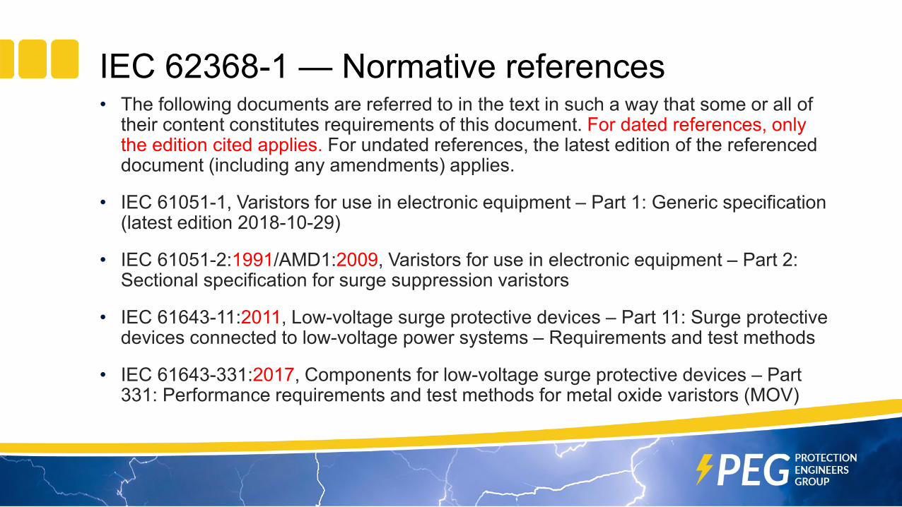
IEC 62368-1 — Normative references• The following documents are referred to in the text in such a way that some or all of
their content constitutes requirements of this document. For dated references, only the edition cited applies. For undated references, the latest edition of the referenced document (including any amendments) applies.
• IEC 61051-1, Varistors for use in electronic equipment – Part 1: Generic specification (latest edition 2018-10-29)
• IEC 61051-2:1991/AMD1:2009, Varistors for use in electronic equipment – Part 2: Sectional specification for surge suppression varistors
• IEC 61643-11:2011, Low-voltage surge protective devices – Part 11: Surge protective devices connected to low-voltage power systems – Requirements and test methods
• IEC 61643-331:2017, Components for low-voltage surge protective devices – Part 331: Performance requirements and test methods for metal oxide varistors (MOV)
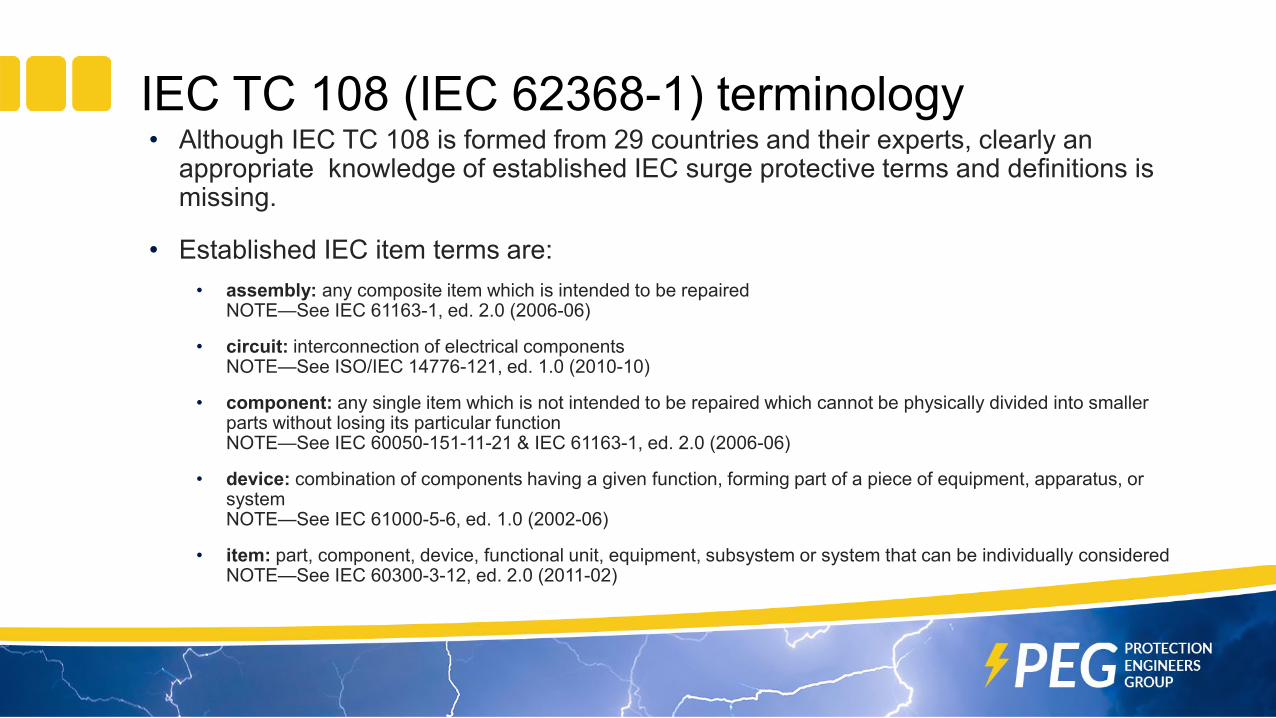
IEC TC 108 (IEC 62368-1) terminology• Although IEC TC 108 is formed from 29 countries and their experts, clearly an
appropriate knowledge of established IEC surge protective terms and definitions is missing.
• Established IEC item terms are:• assembly: any composite item which is intended to be repaired
NOTE—See IEC 61163-1, ed. 2.0 (2006-06)
• circuit: interconnection of electrical componentsNOTE—See ISO/IEC 14776-121, ed. 1.0 (2010-10)
• component: any single item which is not intended to be repaired which cannot be physically divided into smaller parts without losing its particular functionNOTE—See IEC 60050-151-11-21 & IEC 61163-1, ed. 2.0 (2006-06)
• device: combination of components having a given function, forming part of a piece of equipment, apparatus, or systemNOTE—See IEC 61000-5-6, ed. 1.0 (2002-06)
• item: part, component, device, functional unit, equipment, subsystem or system that can be individually consideredNOTE—See IEC 60300-3-12, ed. 2.0 (2011-02)

IEC surge protection terminology• For overvoltage and overcurrent protective item terms, IEC TC 37 and TC 42 are the
lead committees. Item terms are:• protective function: function to implement protective actions
NOTE—See IEC 60050-395-07-87
• surge protective component, SPC: component primarily intended to provide a protective functionNOTE 1—Overvoltage mitigation component examples are GDTs, MOVs, thyristors and PN-junction diodes.NOTE 2—Overcurrent mitigation component examples are positive temperature coefficient thermistors and 2-teminal electronic current limiters
• surge protective device, SPD: device that restricts the voltage of a designated port or ports, caused by a surge, when it exceeds a predetermined levelNOTE 1—Secondary functions may be incorporated, such as a current-limiting to restrict a terminal current.NOTE 2—Typically, the protective circuit has at least one non-linear voltage-limiting surge protective component.NOTE 3—An SPD is a complete assembly, having terminals to connect to the circuit conductors.NOTE 4—See IEC 61643-21, ed. 1.0, amd. 1 (2008-04)
• surge suppressor: device designed to limit the surge voltage between two parts within the space to be protected, such as spark gap, surge diverter or semiconductor deviceNOTE—See IEC 60728-11, ed. 3.0 (2010-06)
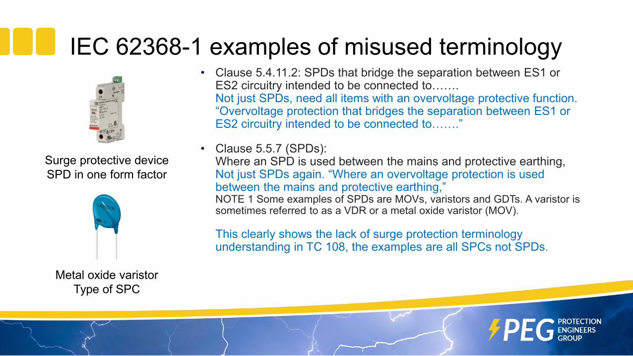
IEC 62368-1 examples of misused terminology• Clause 5.4.11.2: SPDs that bridge the separation between ES1 or
ES2 circuitry intended to be connected to…….Not just SPDs, need all items with an overvoltage protective function. “Overvoltage protection that bridges the separation between ES1 or ES2 circuitry intended to be connected to…….”
• Clause 5.5.7 (SPDs): Where an SPD is used between the mains and protective earthing,Not just SPDs again. “Where an overvoltage protection is used between the mains and protective earthing,”NOTE 1 Some examples of SPDs are MOVs, varistors and GDTs. A varistor is sometimes referred to as a VDR or a metal oxide varistor (MOV).
This clearly shows the lack of surge protection terminology understanding in TC 108, the examples are all SPCs not SPDs.
Surge protective deviceSPD in one form factor
Metal oxide varistorType of SPC

Perceived varistor hazards, tests and safeguards
• Clause G.8.2.1: A varistor shall be regarded as a PIS (potential ignition source).• Tests according to G.8.2.2 (overload) and G.8.2.3 (temporary
overvoltage) applied as listed in Table G.10.• Clause 6.4: is referenced for safeguards against fire under single fault
conditions
• Clause 5.5.7: Electric shock hazard resulting from overvoltage protection used between the mains and an unreliable protective earth.• Protection shall consist of a varistor and a (safeguard) GDT connected
in series
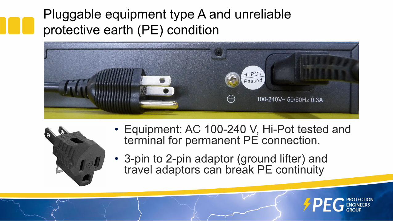
Pluggable equipment type A and unreliable protective earth (PE) condition
• Equipment: AC 100-240 V, Hi-Pot tested and terminal for permanent PE connection.
• 3-pin to 2-pin adaptor (ground lifter) and travel adaptors can break PE continuity
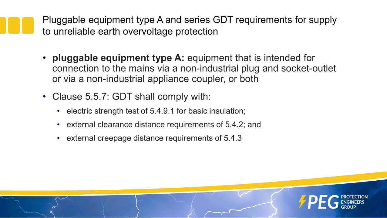
Pluggable equipment type A and series GDT requirements for supply to unreliable earth overvoltage protection
• pluggable equipment type A: equipment that is intended for connection to the mains via a non-industrial plug and socket-outlet or via a non-industrial appliance coupler, or both
• Clause 5.5.7: GDT shall comply with:• electric strength test of 5.4.9.1 for basic insulation;• external clearance distance requirements of 5.4.2; and• external creepage distance requirements of 5.4.3

5.4.9.1 Test procedure for type testing of solid insulation - 1
• Prerequisite information on AC mains overvoltage category• overvoltage category: numeral defining a transient overvoltage condition
See IEC 60664-2-1, ed. 2.0 (2011-01)• Clause 5.4.2.3.2.2: In general, clearances in equipment intended to be
connected to the AC mains, shall be designed for overvoltage category II.• Table I.1 – Overvoltage categories: Overvoltage category II applies to
pluggable or permanently connected equipment that will be supplied from the building wiring such as household appliances, portable tools, home electronics and most ITE used in the building.
• In general IEC 62368-1 seems to favour overvoltage category II

5.4.9.1 Test procedure for type testing of solid insulation - 2
• Table 12 gives overvoltage category voltagesAC mains voltage up
to and includingMains transient voltage V peak
Test generator is normally a 1.2/50-8/20
Overvoltage Category
V a.c. I II III IV
150 800 1500 2500 4000
300 1500 2500 4000 6000
• Overvoltage category II is 1.5 kV for up to 150 V a.c. and 2.5 kV for up to 300 V a.c.

5.4.9.1 Test procedure for type testing of solid insulation - 3• Highest voltage from Tables 25, 26 and 27 is the insulation test voltage
• For 1.5 kV & up to 150 V a.c. – test voltage is 2 kV (Table 27)
• For 2.5 kV & up to 300 V a.c. – test voltage is 2.5 kV (Tables 25 and 27)
Required withstand voltage
up to and including
Table 25 Test voltage for basic insulation
Peak of the working voltages
and recurring peak voltages
Table 26 Test voltage forbasic insulation
kV peak kV peak or DC kV peak kV peak or DC0.33 0.430.5 0.650.8 1.04
1.5 1.52.5 2.54 4
Nominal mains system voltage
Table 27 Test voltage for
basic insulationV a.c. kV peak or DC
Up to and including 250 2Over 250 up to and
including 600 2.5
5.4.9.1 Test procedure for type testing of solid insulation - 4
• During the AC or DC insulation test:• There shall be no insulation breakdown. Insulation breakdown is considered
to have occurred when the current that flows as a result of the application of the test voltage, rapidly increases in an uncontrolled manner, that is, the insulation does not restrict the flow of the current. Corona discharge or a single momentary flashover is not regarded as insulation breakdown.
• For a GDT this means that sparkover or breakdown does not occur.• Makes AC or DC breakdown > 2 kV for up to 150 V AC mains and 2.5 kV for
up to 300 V AC mains.

5.4.2 clearance distance requirements and5.4.3 creepage distance requirements• Clause 5.4.2 Clearances:
• There are several procedures that can be used for clearance determination. A table for two of the procedures are shown below.
Voltage up to and including Table 10 Minimum clearances for Basic insulation
Withstand voltage up to and including
Table 14 Minimum clearances for Basic insulation
peak mm V peak or DC mm1500 0.76 1500 0.52000 1.27 2000 1.02500 1.8 2500 1.53000 2.4 3000 2.04000 3.8 4000 3.0
• Clause 5.4.3 Creepage:• For glass, mica, glazed ceramic or similar inorganic materials, if the
minimum creepage distance is greater than the applicable minimum clearance, the value of minimum clearance may be applied as the minimum creepage distance.

Clause G.8: Varistor or GDT and varistor combination tests and parameters• A varistor or GDT and varistor combination has the following
requirements:• G.8.1 General – for varistor only. References IEC 61051-2:1991/
AMD1:2009 or IEC 61643-331:2017 and IEC 60695-11-5:2016 (Needle-flame test).
• G.8.2 Safeguards against fire • G.8.2.1 General – for varistor (PIS) only. References 6.4.1 (General -
safeguards against fire), G.8.2.2 and G.8.2.3 testing.• G.8.2.2 Overload test applied to either a varistor or a surge suppression circuit
containing varistors connected L to L or L to N or L to PE, or N to PE.• G.8.2.3 Temporary overvoltage test applied to surge suppression circuit
containing varistors connected between L to E, or N to E. References IEC 61643-11:2011 (compliance criteria of B.4.8 may be used as an alternative)

G.8.1 General – for varistor only• Preferred climatic categories
• Maximum continuous voltage• >1.25 times the equipment rated voltage; or• >1.25 times the equipment voltage range rating upper limit
• Nominal 230 V AC mains is ±10 % making the varistor maximum continuous operating voltage, MCOV, either 288 V a.c. (nominal) or 316 V a.c. (upper range) depending on equipment voltage marking (IEC 61293:1994, Marking of electrical equipment with ratings related to electrical supply - Safety requirements)
IEC standard IEC 61051-2 IEC 61643-331Temperature range −10 °C to +85 °C −40 °C to +85 °CHumidity damp heat, steady state 21 days
(IEC 60068-2-30:2005)25 % to 75 %

G.8.1 General – for varistor only, continued• Test with combination wave impulse generator
• Selected from 2.3.6 in IEC 61051-2/AMD1
• or from 8.1.1 of IEC 61643-331, Figure 4.• There isn’t a clause 8.1.1 in IEC 61643-331:2017, but there is a Figure 4!
• Table 12 (overvoltage categories) mains voltage is overridden by “Mains under 300 V is considered to be 300 V.”
• IEC 60695-11-5 body needle flame test• Duration of test flame: 10 s, after flame time: 5 s
• Needle flame test not performed if body of surge suppression varistor is V-1 class material.
Voltage line to neutral derived from nominal voltage a.c. or d.c. up to and including
Combination wave generator 61051-2 Amend. 1 values(based on overvoltage category I, II and III of IEC 60664-1)
I II III300 V 1.5 kV / 0.75 kA 2.5 kV / 1.25 kA 4.0 kV / 2.0 kA

G.8.2 Safeguards against fireG.8.2.1 General – for varistor only
• G.8.2.1 General – for varistor (PIS) only. References 6.4.1 (General - safeguards against fire), G.8.2.2 and G.8.2.3 testing.
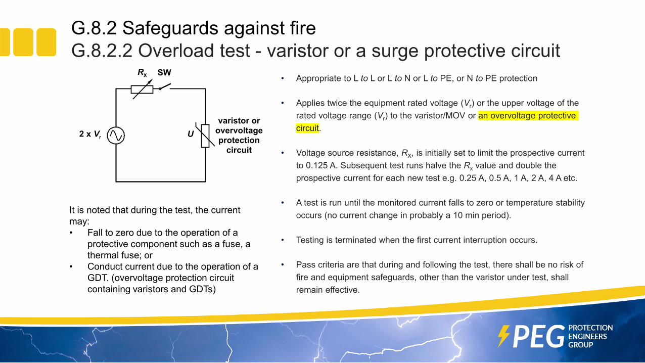
G.8.2 Safeguards against fireG.8.2.2 Overload test - varistor or a surge protective circuit
• Appropriate to L to L or L to N or L to PE, or N to PE protection
• Applies twice the equipment rated voltage (Vr) or the upper voltage of the rated voltage range (Vr) to the varistor/MOV or an overvoltage protective circuit.
• Voltage source resistance, RX, is initially set to limit the prospective current to 0.125 A. Subsequent test runs halve the Rx value and double the prospective current for each new test e.g. 0.25 A, 0.5 A, 1 A, 2 A, 4 A etc.
• A test is run until the monitored current falls to zero or temperature stability occurs (no current change in probably a 10 min period).
• Testing is terminated when the first current interruption occurs.
• Pass criteria are that during and following the test, there shall be no risk of fire and equipment safeguards, other than the varistor under test, shall remain effective.
RX SW
varistor orovervoltageprotection
circuit
U2 x Vr
It is noted that during the test, the current may:• Fall to zero due to the operation of a
protective component such as a fuse, a thermal fuse; or
• Conduct current due to the operation of a GDT. (overvoltage protection circuit containing varistors and GDTs)

G.8.2 Safeguards against fireG.8.2.2 Overload test - observations
• If the purpose of G.8.2.2 is to induce varistor failure through overdissipation, choosing a varistor with a maximum continuous voltage rating of >2xVr renders the test ineffectual.
• To cause overdissipation, the source voltage should be based on the varistor rating not the equipment rating. Logically, a source voltage like twice the varistor maximum continuous voltage rating should be used.
• Noted was the circuit current may conduct current due to the operation of a GDT. (overvoltage protection circuit containing a series GDT and varistor elements).
• With a 5.5.7 compliant GDT this cannot happen as the GDT breakdown voltage is >2 kV and the 2xVr voltage source is not likely to exceed 500 V a.c.
• Use of a series connected 5.5.7 compliant GDT and varistor renders G.8.2.2 a no test

G.8.2 Safeguards against fireG.8.2.3 Temporary overvoltage (TOV) tests - surge protective circuit
• Appropriate to an overvoltage protection circuit containing varistor element connected between L to E, or N to E.
• Testing details are in: • IEC 61643-11:2011: 8.3.8.1 TOVs caused by faults in the low
voltage system• IEC 61643-11:2011: 8.3.8.2 TOVs caused by faults in the high
(medium) voltage system

G.8.2 Safeguards against fireG.8.2.3 Temporary overvoltage (TOV) tests – test values• International TOV L-PE and N-PE test values (excludes USA and Japan)
Derived from IEC 61643-11 Tables A.1 and B.1 for single phase 230 V a.c.
AC System SPDsconnectedbetween
NominalAC
voltageV
Uref for TOVtestV
LV faults (8.3.8.1) HV faults (8.3.8.2)in consumerinstallation
must withstandtest time tT = 5 s
in distribution andN conductor break
can fail safely.test time
tT = 120 min
can fail safely.test time tT = 0.2 s
TOV test voltage, U(TOV) VTN-C L-PE 230 255 367 442 n/a
N-PE n/a n/a n/aTT L-PE 230 255 442 367 1455
N-PE n/a n/a 1200IT L-PE 230 255 n/a n/a 1455
N-PE n/a n/a 1455Maximumvalue
L-PEN-PE 230 255 442 442 1455
For an overview of AC system designations see ITU-T K Suppl. 7 (05/2017): ITU-T K.44 – AC supply configurations
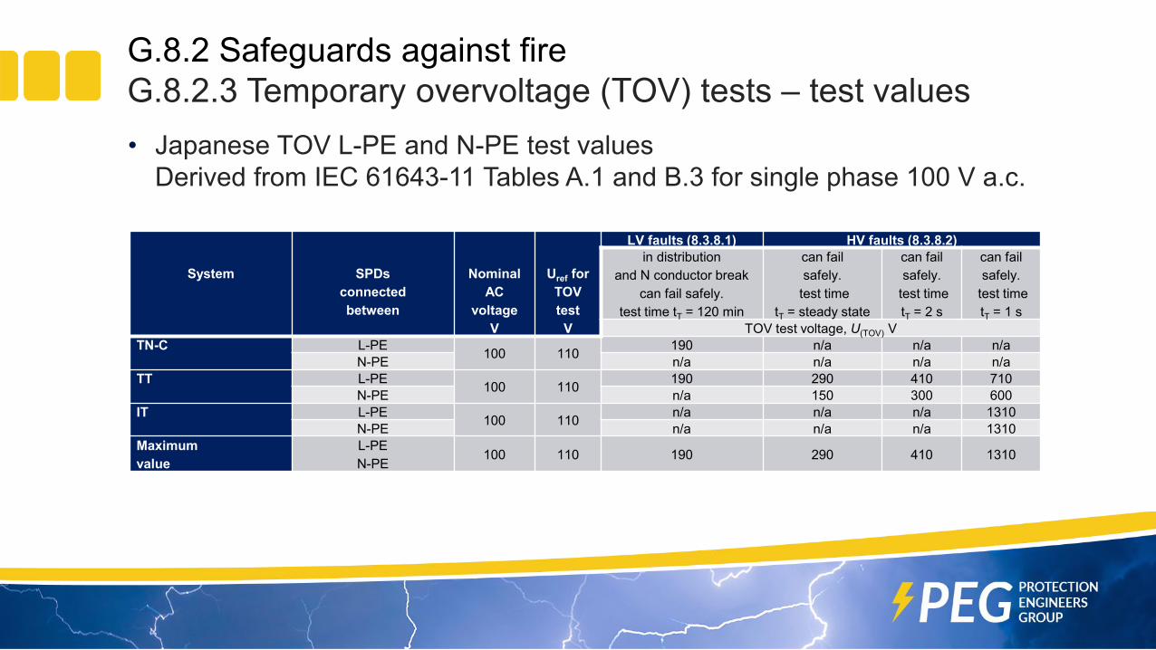
G.8.2 Safeguards against fireG.8.2.3 Temporary overvoltage (TOV) tests – test values• Japanese TOV L-PE and N-PE test values
Derived from IEC 61643-11 Tables A.1 and B.3 for single phase 100 V a.c.
System SPDsconnectedbetween
NominalAC
voltageV
Uref for TOVtest
V
LV faults (8.3.8.1) HV faults (8.3.8.2)in distribution
and N conductor breakcan fail safely.
test time tT = 120 min
can failsafely.
test time tT = steady state
can failsafely.
test timetT = 2 s
can failsafely.
test timetT = 1 s
TOV test voltage, U(TOV) VTN-C L-PE 100 110 190 n/a n/a n/a
N-PE n/a n/a n/a n/aTT L-PE 100 110 190 290 410 710
N-PE n/a 150 300 600IT L-PE 100 110 n/a n/a n/a 1310
N-PE n/a n/a n/a 1310Maximumvalue
L-PEN-PE 100 110 190 290 410 1310

G.8.2 Safeguards against fireG.8.2.3 Temporary overvoltage (TOV) tests – test values• North American systems TOV L-PE and N-PE test values
Derived from IEC 61643-11:2011 Tables A.1 and B.2 for split phase 120 V a.c.
System SPDsconnectedbetween
NominalAC voltage
V
Uref for TOV test
V
LV faults (8.3.8.1) HV faults (8.3.8.2)
TOV test voltage, U(TOV) VSplit phase TN system
L-PE 120 / 240 (L-L) 132 / 264 (L-L) Values are under consideration Values are under considerationN-PE
General reading on overvoltages:TOV effects on surge-protective devices by Dalibor Kladar, François Martzloff, and Doni NastasiTransient control levels - A Proposal for Insulation Coordination in Low-Voltage Systems by F.A. Fisher and F. D. Martzloff IEC TR 62066:2002, Surge overvoltages and surge protection in low-voltage a.c. power systems - General basic informationArresterFacts 028 Understanding temporary overvoltage behaviour of arresters Ed 2.0 by Jonathan Woodworth
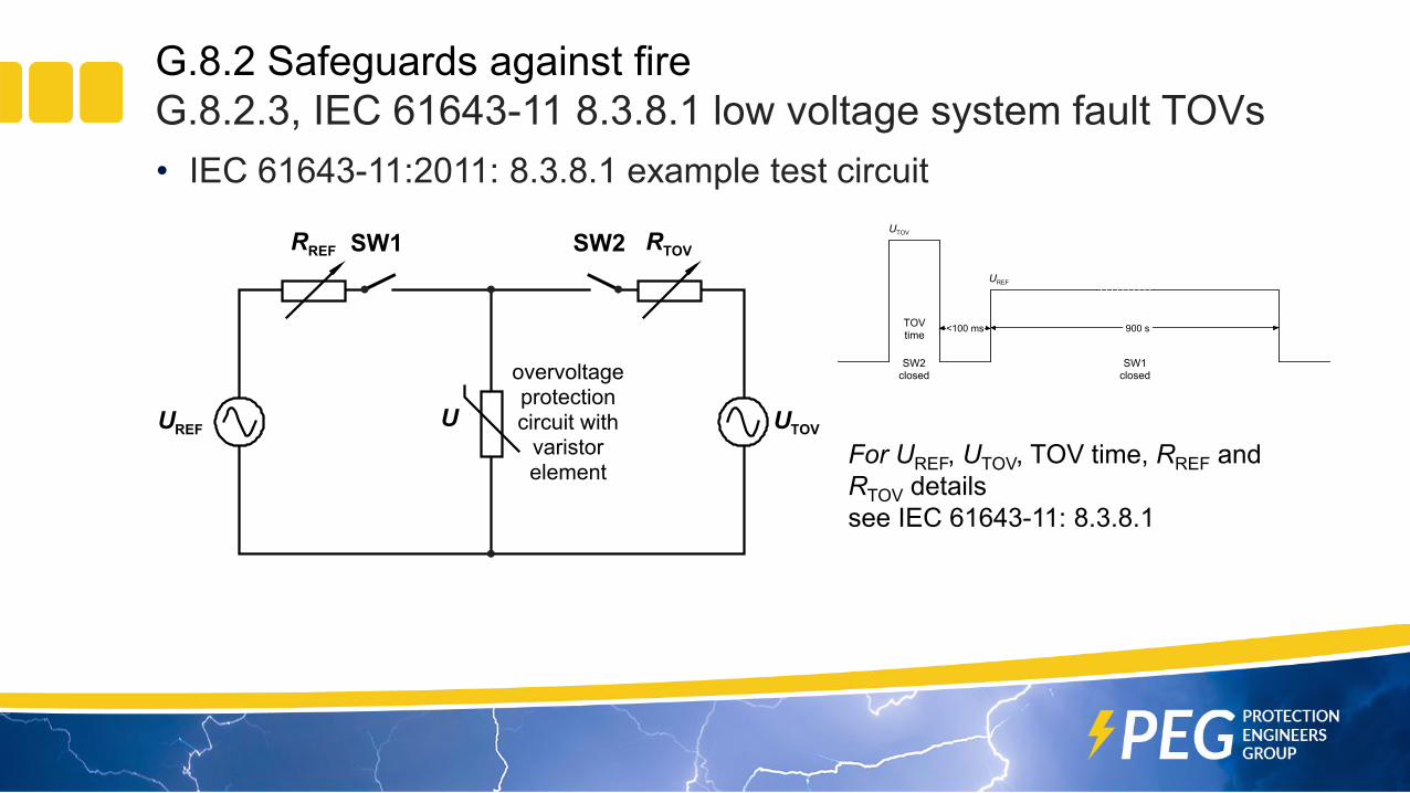
G.8.2 Safeguards against fireG.8.2.3, IEC 61643-11 8.3.8.1 low voltage system fault TOVs• IEC 61643-11:2011: 8.3.8.1 example test circuit
overvoltageprotectioncircuit with
varistor element
RREF SW1 RTOVSW2
UREF U UTOV
UREF
UTOV
<100 ms 900 s
SW1closed
SW2closed
TOVtime
For UREF, UTOV, TOV time, RREF and RTOV detailssee IEC 61643-11: 8.3.8.1
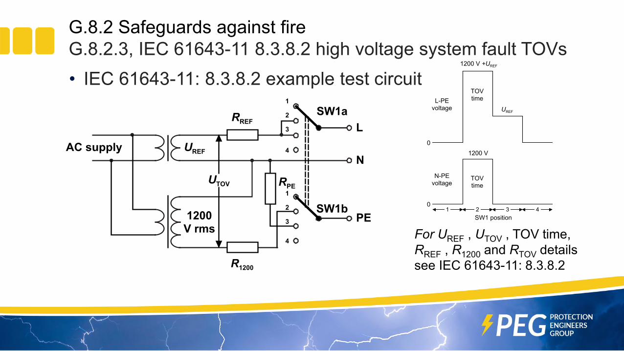
G.8.2 Safeguards against fireG.8.2.3, IEC 61643-11 8.3.8.2 high voltage system fault TOVs• IEC 61643-11: 8.3.8.2 example test circuit
1
L-PEvoltage
SW1 position
UREF
TOVtime
1200 V +UREF
TOVtime
1200 V
N-PEvoltage
2 3 40
0
For UREF , UTOV , TOV time, RREF , R1200 and RTOV detailssee IEC 61643-11: 8.3.8.2
UREF
RREF
UTOV
1200V rms
AC supplyN
SW1a
PESW1b
L
R1200
RPE
2
1
3
2
1
3
4
4

G.8.2 Safeguards against fireTable G.10 summarizes G.8.2.2 and G8.2.3 testing
Maximum continuous AC voltage of varistor
Connection between
L to N or L to L L to PE N to PE1.25×Vr to 2×Vr G.8.2.2 G.8.2.2 and G.8.2.3 G.8.2.2 and G.8.2.3
> 2×Vr to 1200+1.1×Vr No test G.8.2.3 G.8.2.3
> 1200+1.1×Vr No test No test No test
Overvoltage protection circuit with series 5.5.7 GDT and varistor
No test No test No test
Vr is the equipment rated voltage or the upper voltage of the rated voltage range

B.4 Simulated single fault conditionsThe effect of a single component failure simulated by short-circuiting any two leads and open-circuiting any one lead of the component one at a time needs to be considered. These single fault conditions do not apply to components that serve as a safeguard (interposing a barrier between a body part and the energy source, see 4.1.2 Use of components) complying with the relevant requirements of Annex G Components or with the safety requirements of the relevant IEC component standard. Component evaluations include:
B.4.5 Short-circuit and interruption of electrodes in tubes and semiconductors and tubes andB.4.6 Short-circuit or disconnection of passive components (includes VDRs).
Excluded from these single fault simulations are components that serve as a safeguard complying with the relevant requirements of Annex G. Based on this, the series 5.5.7 GDT should be excluded because it is a mandated basic (insulation) safeguard against an unreliable PE connection. Varistors are not safeguards being classified a PIS (also covered as VDRs in B.4.6) and should be safety evaluated for open- and short-circuit connections.

Protection circuit design example 1
2-terminal designvaristor1
U
PE
NL
varistor2bU
Uvaristor2a
5.5.7GDT1b
5.5.7GDT1a
L to N protection: path varistor1. Standard varistor if MCOV > 2Vr. If 1.25Vr < MCOV <2Vr , the G.8.2.2 test results determine varistor type and required support items. To cope with B.4 simulated single fault conditions some form of equipment overcurrent protection needed.
L to PE and N to PE protection: series paths varistor 2a plus 5.5.7 GDT1a and varistor 2b plus 5.5.7 GDT1b. Standard varistor with a clamping voltage sufficient to prevent any continuous GDT conduction. The GDT is a safeguard and avoids B.4 simulated single fault conditions examination.
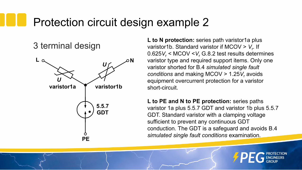
Protection circuit design example 2
3 terminal design
PE
NL
varistor1aU
U
varistor1b
5.5.7GDT
L to N protection: series path varistor1a plus varistor1b. Standard varistor if MCOV > Vr. If 0.625Vr < MCOV <Vr G.8.2 test results determines varistor type and required support items. Only one varistor shorted for B.4 simulated single fault conditions and making MCOV > 1.25Vr avoids equipment overcurrent protection for a varistor short-circuit.
L to PE and N to PE protection: series paths varistor 1a plus 5.5.7 GDT and varistor 1b plus 5.5.7 GDT. Standard varistor with a clamping voltage sufficient to prevent any continuous GDT conduction. The GDT is a safeguard and avoids B.4 simulated single fault conditions examination.

Equipment insulation withstand voltage
• AC dielectric strength/withstand (HiPot) testing after equipment manufacture typically uses 1.5 kV a.c. (2.1 kV peak). Disconnecting overvoltage protection across the insulation barrier is allowed, but is inconvenient.
• The 5.5.7 GDT allows such testing to be done without disconnections. It means that 230 V a.c. insulation must rated above 2.5 kV peak and IEC 60664-1 recommends an impulse verification level near to 2.9 kV peak for a 2.5 kV peak insulation rating
• Some designs may put the protection cost into insulation and increase the withstand rating from overvoltage category II (2.5 kV) to overvoltage category III (4 kV) or IV (6 kV). L to N overvoltage protection would still need to be considered.

Interpretations
• There are certain situations where a standard isn’t sufficiently definitive or plain wrong. In those cases interpretations can be made based on the spirit of the standard and its normative documents. Interpretations may vary depending on who makes them.
• The content of this presentation is of a general nature only and is not intended to address the specific circumstances of any particular individual or entity; nor be necessarily comprehensive, complete, accurate or up to date; nor represent professional or legal advice.
Questions?