ie1204 digital design f12: asynchronous sequential ...ie1204 digital design f12: asynchronous...
TRANSCRIPT

IE1204 Digital Design
F12: AsynchronousSequential Circuits
(Part 1)
Masoumeh (Azin) Ebrahimi ([email protected])
Elena Dubrova ([email protected])KTH / ICT / ES

• BV pp. 584-640
This lecture
IE1204 Digital Design, Autumn2016

Asynchronous SequentialMachines
• An asynchronous sequential machine isa sequential machine without flip-flops
• Asynchronous sequential machines areconstructed by analyzing combinationallogic circuits with feedback
• Assumption: Only one signal in acircuit can change its value at anytime
IE1204 Digital Design, Autumn2016

Golden rule
IE1204 Digital Design, Autumn2016

Asynchronous state machines
• Asynchronous state machines are usedwhen it is necessary to keep theinformation about a state, but no clockis available– All flip-flops and latches are asynchronous
state machines– Useful to synchronize events in situations
where metastability is/can be a problem
IE1204 Digital Design, Autumn2016
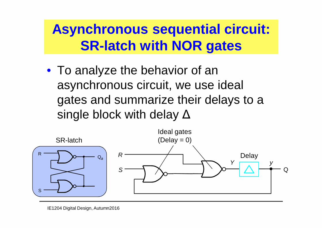
• To analyze the behavior of anasynchronous circuit, we use idealgates and summarize their delays to asingle block with delay Δ
Asynchronous sequential circuit:SR-latch with NOR gates
IE1204 Digital Design, Autumn2016
R
S QY y
Delay
Ideal gates(Delay = 0)
QaR
S
SR-latch

• By using a delay block, we can treat– y as the current state– Y as the next state
Analysis of a sequentialasynchronous circuit
IE1204 Digital Design, Autumn2016
R
S QY y

• Thus, we can produce a state table where thenext state Y depends on the inputs and thecurrent state y
State table
IE1204 Digital Design, Autumn2016
R
S QY y
)( ySRY ++=

State table
IE1204 Digital Design, Autumn2016
)( ySRY ++=
Present Next state
state SR = 00 01 10 11y Y Y Y Y
0 0 0 1 0
1 1 0 1 0
)11(10111)11(01011)10(10101)10(01001)01(10110)01(11010)00(10100)00(00000)(
++=++=++=++=++=++=++=++=++= ySRYRSy
From statefunction totruth table Note: BV uses this binary code

• Since we do not have flip-flops, but onlycombinational circuits, a state change can causeadditional state changes
• A state is– stable if Y(t) = y(t + Δ)– unstable if Y(t) ≠ y(t + Δ)
Stable states
IE1204 Digital Design, Autumn2016
Present Next state
state SR = 00 01 10 11y Y Y Y Y
0 0 0 1 0
1 1 0 1 0
yY = stable

• Stable states (next state = present state) arecircled
Excitation table
IE1204 Digital Design, Autumn2016
Present Next state
state SR = 00 01 10 11y Y Y Y Y
0 0 0 1 0
1 1 0 1 0
R
S QY y
0
00
1
0
R
S QY y
1
00
0
1

• When dealing with asynchronoussequential circuits, a differentterminology is used– The state table called flow table– The state-assigned state table is called
excitation table
Terminology
IE1204 Digital Design, Autumn2016

Flow table (Moore)
IE1204 Digital Design, Autumn2016
Present Next state Outputstate SR = 00 01 10 11 Q
A A A B A 0
B B A B A 1
1000
110100
10
A 0¤ B 1¤
1101
SR

Flow Table (Mealy)
IE1204 Digital Design, Autumn2016
Present Next state Output,Qstate SR = 00 01 10 11 00 01 10 11
A A A B A 0 0 0
B B A B A 1 1-
-
-
10/100/1
11/001/000/0
10 /-
A B
01 -¤11 -¤
SR/ Q
Do not care ('-') has been chosen for output decoder since output changesdirectly after the state transition (basic implementation)

Asynchronous Moore compatible
IE1204 Digital Design, Autumn2016
·Asynchronous sequential circuits have similarstructure as synchronous sequential circuits· Instead of flip-flops one have a "delay block"
R
S QY y
1
0
0
1 0

Asynchronous Mealy compatible
IE1204 Digital Design, Autumn2016
·Asynchronous sequential circuits have similarstructure as synchronous sequential circuits· Instead of flip-flops one have a "delay block"

Analysis of Asynchronous Circuits
• The analysis is done using the following steps:1) Replace the feedbacks in the circuit with a
delay element D. The input of the delay elementrepresents the next state Y while the output yrepresents the current state.
2) Find out the next-state and output expressions3) Set up the corresponding excitation table4) Create a flow table and replace the encoded
states with symbolic states5) Draw a state diagram if necessary
IE1204 Digital Design, Autumn2016

D-latch state function
IE1204 Digital Design, Autumn2016
Q1D
C1
QD
CQD
C
Y y
CyCDY ×+×=

• Master-slave D flip-flop is designedusing two D-latches
ExampleMaster-slave D flip-flop
IE1204 Digital Design, Autumn2016
D
Clk
Q
Q
D
C
Qysym
Master Slave
Q
D
Clk
Q
Q
s
ss
mm
yQCyDCY
yCCDY
=+=
+=
The equations for the next state:

• From these equations, we can directlydeduce excitation table
Excitation table
IE1204 Digital Design, Autumn2016
Present Nextstatestate CD = 00 01 10 11 Outputym ys Ym Ys Q
00 00 00 00 10 0
01 00 00 01 11 1
10 11 11 00 10 0
11 11 11 01 11 1
s
ss
mm
yQCyDCY
yCCDY
=+=
+=
Excitation table

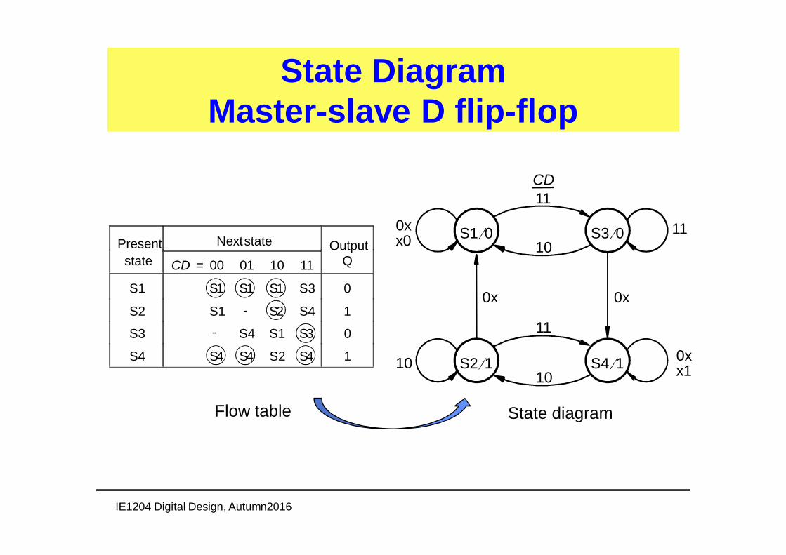
• We define four states S1, S2, S3, S4and get the following flow table
Flow table
IE1204 Digital Design, Autumn2016
Present Nextstate Outputstate CD = 00 01 10 11 Q
S1 S1 S1 S1 S3 0
S2 S1 S1 S2 S4 1
S3 S4 S4 S1 S3 0
S4 S4 S4 S2 S4 1
Present Nextstatestate CD = 00 01 10 11 Outputym ys Ym Ys Q
00 00 00 00 10 001 00 00 01 11 110 11 11 00 10 011 11 11 01 11 1
Excitation table Flow table

• Remember: Only one input can bechanged simultaneously
• Thus, some transitions never occur!
Flow table
IE1204 Digital Design, Autumn2016
Present Nextstate Outputstate CD = 00 01 10 11 Q
S1 S1 S1 S1 S3 0
S2 S1 S1 S2 S4 1
S3 S4 S4 S1 S3 0
S4 S4 S4 S2 S4 1

• State S3– The only stable state is S3 with input combination 11– Only one input can be changed => possible transitions are (11 =>
01, 11 => 10)• These transitions originate in S3!• The input combination 00 in S3 is not possible!• The input combination 00 is set to don’t care!
Flow table(Impossible transitions)
IE1204 Digital Design, Autumn2016
Present Nextstate Outputstate CD = 00 01 10 11 Q
S1 S1 S1 S1 S3 0
S2 S1 S1 S2 S4 1
S3 S4 S4 S1 S3 0
S4 S4 S4 S2 S4 1

• State S2– The only stable state is S2 with input combination 10– Only one entry can be changed => possible transitions are (10 =>
11, 10 => 00)• These transitions originate in S2!• The input combination 01 in S2 is not possible!• The input combination 01 is set to don’t care!
Flow table(Impossible transitions)
IE1204 Digital Design, Autumn2016
Present Nextstate Outputstate CD = 00 01 10 11 Q
S1 S1 S1 S1 S3 0
S2 S1 S2 S4 1
S3 S4 S1 S3 0
S4 S4 S4 S2 S4 1
S1
-
State DiagramMaster-slave D flip-flop
IE1204 Digital Design, Autumn2016
x10x10
11
S2 1¤ S4 1¤10
11x00x
11
S1 0¤ S3 0¤10
0x0x
CD
Present Nextstate Outputstate CD = 00 01 10 11 Q
S1 S1 S1 S1 S3 0
S2 S1 S2 S4 1
S3 S4 S1 S3 0
S4 S4 S4 S2 S4 1
-
-
Flow table State diagram

Synthesis of asynchronouscircuits
• The synthesis is carried out using the followingsteps:1) Create a state diagram according to the functional
description2) Create a flow table and reduce the number of states
if possible3) Assign codes to the states and create excitations table4) Determine expressions (transfer functions) for the
next state and outputs5) Construct a circuit that implements the above
expressions
IE1204 Digital Design, Autumn2016

• Input x• Output z• z = 1 if the number of pulses applied to x is odd• z = 0 if the number of pulses applied to x is even
Example: Serial Parity GeneratorStep 1: Create a state diagram
IE1204 Digital Design, Autumn2016
A/0 B/1
D/0 C/1
x = 0x = 1
x = 1
x = 0
x = 0x = 1
x = 1
x = 0A/0
B/1C/1
D/0A/0
1 0x
zodd even

Step 2: Flow table
Presstate
Next State z
x=0 x=1
A A B 0
B C B 1
C C D 1
D A D 0
IE1204 Digital Design, Autumn2016
Flow tableState diagram

Step 3: Assign state codes
Presstate
Next State z
x=0 x=1
A A B 0
B C B 1
C C D 1
D A D 0
IE1204 Digital Design, Autumn2016
Flow table Excitation table
Presstate
Next State z
x=0 x=1
y2y1 Y2Y1
00 00 01 0
01 10 01 1
10 10 11 1
11 00 11 0
A:00, B:01, C:10, D:11 - binary code?Which encoding is good?

Step 3: Assign state codesWhich encoding is good?
IE1204 Digital Design, Autumn2016
Next StatePresstate
X=0 1
Q
y2y1 Y2Y1
00 00 01 0
01 10 01 1
10 10 11 1
11 00 11 0
Bad encoding (HD=2!)
SupposeX = 1 Y2Y1 = 11ThenX ® 0 ® Y2Y1 = 00?
11 ® 10!11 ® 01 ® 10! ? ® 00
We will never reach 00?
AssumeàA:00, B:01, C:10, D:11

Step 3: Assign state codesWhich encoding is good?
Presstate
Next State z
x=0 x=1
y2y1 Y2Y1
00 00 01 0
01 10 01 1
10 10 11 1
11 00 11 0
Presstate
Next State z
x=0 x=1
y2y1 Y2Y1
00 00 01 0
01 11 01 1
11 11 10 1
10 00 10 0
Poor encoding (HD = 2)If we are in 11 under input w = 1 andinput change to w = 0, the circuitshould change to 00
Good encoding (HD = 1)
IE1204 Digital Design, Autumn2016
A:00, B:01, C:11, D:10A:00, B:01, C:10, D:11

Step 4:Draw Karnaugh maps
Presstate
Next State z
x=0 x=1
y2y1 Y2Y1
00 00 01 0
01 11 01 1
11 11 10 1
10 00 10 0
Y2 = xy1+ y2y1 + xy2
0 1 1 0
0 0 1 1
y2y1x 00 01 11 1001
0 1 1 0
1 1 0 0
y2y1x 00 01 11 1001
Y1 = xy2+y2y1 + xy1
0 1
0 1
y1y2
01
0 1
z = y1
IE1204 Digital Design, Autumn2016
They red circles are needed to avoid hazards (see later Section)!

What is a Hazard?
• Hazard is a term that means that there is adanger that the output value is not stable, butit can have glitches at certain inputcombinations
• Hazard occurs when paths from differentinputs to the output have different lengths
• To avoid this, we must add implicants tocover the ”dangerous” transitions
IE1204 Digital Design, Autumn2016

Examples of hazard: MUX
0 1 1 0
0 0 1 1
x 00 01 11 100
1
Y2 = x y1+ y2y1 + x y2
Q
x
y1
y2
Q
x
y1
y2
During the transition from the (xy2y1) = (111) to (011), the output Q hasa glitch, as the path from x to Q is longer through the upper AND gatethan through the lower AND gate (racing).
MORE ABOUT hazard in the next lecture!
IE1204 Digital Design, Autumn2016
y2y1

Step 5: Complete circuit
0 1 1 0
0 0 1 1
y2y1x 00 01 11 1001
0 1 1 0
1 1 0 0
y2y1x 00 01 11 1001
Y1 = xy2+y2y1+xy1
0 1
0 1
y1y2
01
0 1
z = y1
IE1204 Digital Design, Autumn2016
Y2= x y1+ y2y1 + x y2
y2
y1 z
x

• In asynchronous sequential circuits, it is impossible toguarantee that the two state variables change valuesimultaneously– Thus, a transition 00 => 11 results in
• a transition 00 => 01 => ???• a transition 00 => 10 => ???
• To ensure correct operation, all state transitionsMUST have Hamming distance 1– The Hamming distance is the number of bits in which two
binary numbers differ• Hamming distance between 00 and 11 is 2• Hamming distance between 00 and 01 is 1
More on state encoding
IE1204 Digital Design, Autumn2016

State encoding
• Procedure to obtain good codes:1) Draw the transition diagram along the
edges of the hypercube defined by thecodes
2) Remove any crossing lines bya) swapping two adjacent nodesb) exploiting available unused statesc) introducing more dimensions in the hypercube
IE1204 Digital Design, Autumn2016

State encodingExample: Serial Parity Generator
C = 10 D = 11
A = 00 B = 01
x = 1
x = 1
x = 0 x = 0
Poor coding -Hamming Distance = 2(Intersecting lines)
IE1204 Digital Design, Autumn2016
Presstate
Next State z
x=0 x=1
y2y1 Y2Y1
00 00 01 0
01 10 01 1
10 10 11 1
11 00 11 0
10 11
00 01
A:00, B:01, C:10, D:11

State encodingExample: Serial Parity Generator
D = 10 C = 11
A = 00 B = 01
x = 1
x = 1
x = 0 x = 0
Good codingHamming Distance = 1(No intersecting lines)
IE1204 Digital Design, Autumn2016
Presstate
Next State z
x=0 x=1
y2y1 Y2Y1
00 00 01 0
01 11 01 1
11 11 10 1
10 00 10 0
A:00, B:01, C:11, D:10
10 11
00 01
swapping two adjacent nodes

State encodingExploiting unused states
C = 10
A = 00 B = 01
01
01
00 10
Poor coding
00
IE1204 Digital Design, Autumn2016
Present Nextstate Outputstate r 2r 1 = 00 01 10 11 g2g1
A A B C 00
B A B C B 01
C A B C C 10
-
In the transition from B to C (or C to B) has the Hamming distance 2!Danger to get stuck in an unspecified state (with code 11)!
Flow table from Fig. 9.21a of BV textbook
10 11
00 01Note: BV uses this binary code

• Solution: Introduce a transition state thatensures that you do not end up in anunspecified state!
State encodingExploiting aunused states
IE1204 Digital Design, Autumn2016
Good coding
C = 10
A = 00 B = 01
01
01
0010
0001
10
Present Nextstatestate r2r 1 = 00 01 Outputy2y1 Y2Y1 g2g1
A 00 00 01 00B 01 00 01 01D 11 01 dd-C 10 00 11 10
11
01-
-10
10
10111010
Transition state
Present Nextstate Outputstate r2r 1 = 00 01 11 10 g2g1
A A B C 00B A B CB 01C A B CC 10
-D = 11
exploiting available unused states

• One can increase the number of dimensionsin order to implement stable state transitions
State encoding: Additional states(more dimensions)
IE1204 Digital Design, Autumn2016
A B
D CC, F
A B
D E
GA B
D CG
E F
If it is not possible to redraw a diagram for HD = 1, we can add more statesby adding extra dimensions. We take the nearest largesthypercube and draw the transitions through the available non steadystates.
more dimensions

State encoding: Additional states(more dimensions)
IE1204 Digital Design, Autumn2016
• It's easier to draw a "flat" 3D cube(perspective, is then from the front)
000 100
010110
101
011 111
001
011 111
000 100
010 110
001 101
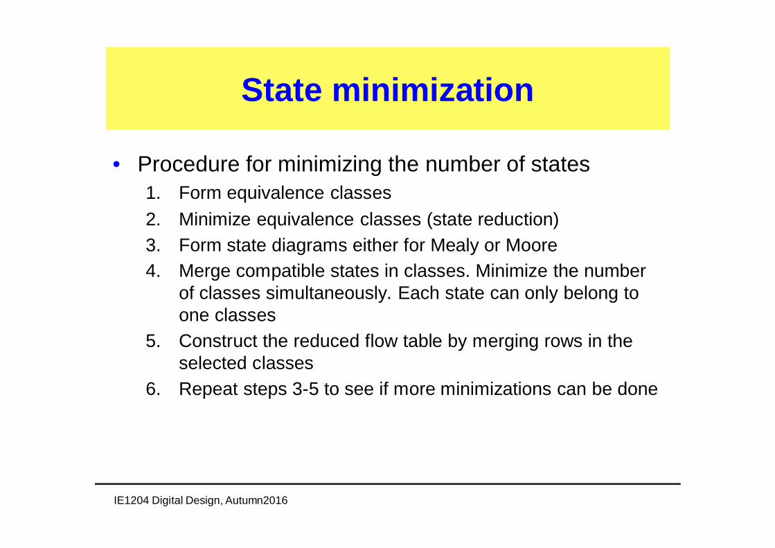
State minimization
• Procedure for minimizing the number of states1. Form equivalence classes2. Minimize equivalence classes (state reduction)3. Form state diagrams either for Mealy or Moore4. Merge compatible states in classes. Minimize the number
of classes simultaneously. Each state can only belong toone classes
5. Construct the reduced flow table by merging rows in theselected classes
6. Repeat steps 3-5 to see if more minimizations can be done
IE1204 Digital Design, Autumn2016

• Candy machine has two inputs:– N: nickel (5 cents)– D: dime (10 cents)
• A candy bar costs 10 cents• The machine will not return any change if
there is 15 cents in the candy machine (acandy bar returned)
• The output z is active if there is enoughmoney for a piece of candy
ExampleCandy Machine (BV page 610)
IE1204 Digital Design, Autumn2016

State Diagram and Flow Chart
Presstate
Next State zX=00 01 10 11
A A B C - 0
B D B - - 0
C A - C - 1
D D E F - 0
E A E - - 1
F A - F - 1
A flow table that contains onlyone stable state per row is calledprimitive flow table.
IE1204 Digital Design, Autumn2016
(X = DN)
A/00
B/0N
N
C/1D
D
D/00
E/1N
N
F/1D
D
0
0 0 0
0 means N=D=0,i.e. no coin isdeposited
· You can’t insert two coins at the same time!

State Diagram and Flow Chart
IE1204 Digital Design, Autumn2016
A/00
B/0N
N
C/1D
D
D/00
E/1N
N
F/1D
D
0
0 0 0
0 means N=D=0,i.e. no coin isdeposited
State Minimization means thattwo states may be equivalent,and if so, replaced by one stateto simplify the state diagram,and network.One can easily see that state Cand F could be replaced by onestate, as a candy always beejected after a Dime regardlessof previous state.

1. Forming equivalence classes. To be in the sameclass, the following should hold for states:– Outputs must have the same value– Stable states must be at the same positions– Don’t cares for next state must be in the same positions
2. Minimize equivalence classes (state-reduction)
Step 1: Form and minimizeequivalence classes
IE1204 Digital Design, Autumn2016

State reduction
Next State QPresstate X=00 01 10 11
A A B C - 0
B D B - - 0
C A - C - 1
D D E F - 0
E A E - - 1
F A - F - 1
Primitive flow table
IE1204 Digital Design, Autumn2016
• Outputs must have the samevalue
• Stable states must be at the samepositions
• Don’t cares for next state must bein the same positionsP2 = (AD)(B)(CF)(E)
P2 = (AD)(B)(CF)(E)
P1 = (ABD)(CEF)

State reduction
IE1204 Digital Design, Autumn2016
P2 = (AD)(B)(CF)(E)P3 = (A)(D)(B)(CF)(E)P3 = P4
• Successors must be in the same class
C,F00 ® (AD), (AD)C,F01 ® -, -C,F10 ® (CF), (CF)C,F11 ® -, -
A,D00 ® (AD), (AD)A,D01 ® (B),(E)A,D10 ® (CF), (CF)A,D11 ® -, -
Next State QPresstate X=00 01 10 11
A A B C - 0
B D B - - 0
C A - C - 1
D D E F - 0
E A E - - 1
F A - F - 1
Primitive flow tableNext State QPres
state X=00 01 10 11
A A B C - 0B D B - - 0
C A - C - 1
D D E C - 0
E A E - - 1
Resulting flow table

3. Construct state diagram either for Mealy or Moore4. Merge compatible states in groups. Minimize the
number of groups simultaneously. Each state maybelong to one group only.
5. Construct the reduced flow table by merging rows inthe selected groups
6. Repeat steps 3-5 to see if more minimizations canbe done
Step 2:Merging states
IE1204 Digital Design, Autumn2016

• Two states are compatible and can bemerged if the following applies1. at least one of the following conditions apply to
all input combinations• both Si and Sj have the same successor, or• both Si and Sj are stable, or• the successor of Si or Sj, or both, is unspecified
2. For a Moore machine, in addition the followingshould hold
• both Si and Sj have the same output values wheneverspecified (not necessary for a Mealy machine)
Merging states
IE1204 Digital Design, Autumn2016

Merging states
Next State QPresstate X=00 01 10 11
A A B C - 0B D B - - 0
C A - C - 1
D D E C - 0
E A E - - 1
Resulting flow table
C
A
E
B D
Compatibility graph
Mealy-compatible: In state A (X = 00) theoutput is 0, in state C the output is 1
Moorecompatible
Each row will be a pointin a compatibility graph
IE1204 Digital Design, Autumn2016
• both Si and Sj have the same successor, or• both Si and Sj are stable, or• the successor of Si or Sj, or both, is unspecifiedMoreover, both Si and Sj must have the same outputwhenever specified

An illustrative example
Primitive flow tablePresstate
Next State QX=00 01 10 11
A A F C - 0
B A B - H 1
C G - C D 0
D - F - D 1
E G - E D 1
F - F - K 0
G G B J - 0
H - L E H 1
J G - J - 0
K - B E K 1
L A L - K 1
P1= (AG) (BL) (C) (D) (E) (F) (HK) (J)P2= (A) (G) (BL) (C) (D) (E) (F) (HK) (J)P3= P2
Equivalence classes
Presstate
Next State QX=00 01 10 11
A A F C - 0
B A B - H 1
C G - C D 0
D - F - D 1
E G - E D 1
F - F - H 0
G G B J - 0
H - B E H 1
J G - J - 0
Reduced flow table
IE1204 Digital Design, Autumn2016

An illustrative example (cont'd)
Next State QPresstate X=00 01 10 11
A A F C - 0
B A B - H 1
C G - C D 0
D - F - D 1
E G - E D 1
F - F - H 0
G G B J - 0
H - B E H 1
J G - J - 0
Reduced flow table
IE1204 Digital Design, Autumn2016
B A C D
H F J G E
Next State QPresstate X=00 01 10 11
A A A C B 0
B A B D B 1
C G - C D 0
D G A D D 1
G G B G - 0

An illustrative example (cont'd)
Reduced flow tableNext State QPres
state X=00 01 10 11
A A A C B 0
B A B D B 1
C G - C D 0
D G A D D 1
G G B G - 0
Final flow tableNext State QPres
state X=00 01 10 11
A A A C B 0
B A B D B 1
C C B C D 0
D C A D D 1
IE1204 Digital Design, Autumn2016
B A D C G

Summary
• Asynchronous state machines– Based on analysis of combinational circuits with feedback– All flip-flops and latches are asynchronous state machines
• A similar theory as for synchronous statemachines can be applied– Only one input or state variable can be changed at a time!– We must also take into account the problem with hazards
• Next lecture: BV pp. 640-648, 723-724
IE1204 Digital Design, Autumn2016