idp administration guide, version 4.1r3 - juniper networks
TRANSCRIPT

Intrusion Detection and Prevention
Administration Guide
Version 4.1r3
Juniper Networks, Inc.1194 North Mathilda Avenue
Sunnyvale, California 94089
USA
408-745-2000
www.juniper.net

Copyright © 2009, Juniper Networks, Inc.All rights reserved. Printed in USA.
Revision HistoryJune 2009— 1
The information in this document is current as of the date listed in the revision history.
ii ■

END USER LICENSE AGREEMENT
READ THIS END USER LICENSE AGREEMENT (“AGREEMENT”) BEFORE DOWNLOADING, INSTALLING, OR USING THE SOFTWARE. BY DOWNLOADING,INSTALLING, OR USING THE SOFTWARE OR OTHERWISE EXPRESSING YOUR AGREEMENT TO THE TERMS CONTAINED HEREIN, YOU (AS CUSTOMEROR IF YOU ARE NOT THE CUSTOMER, AS A REPRESENTATIVE/AGENT AUTHORIZED TO BIND THE CUSTOMER) CONSENT TO BE BOUND BY THISAGREEMENT. IF YOU DO NOT OR CANNOT AGREE TO THE TERMS CONTAINED HEREIN, THEN (A) DO NOT DOWNLOAD, INSTALL, OR USE THE SOFTWARE,AND (B) YOU MAY CONTACT JUNIPER NETWORKS REGARDING LICENSE TERMS.
1. The Parties. The parties to this Agreement are (i) Juniper Networks, Inc. (if the Customer’s principal office is located in the Americas) or Juniper Networks(Cayman) Limited (if the Customer’s principal office is located outside the Americas) (such applicable entity being referred to herein as “Juniper”), and (ii)the person or organization that originally purchased from Juniper or an authorized Juniper reseller the applicable license(s) for use of the Software (“Customer”)(collectively, the “Parties”).
2. The Software. In this Agreement, “Software” means the program modules and features of the Juniper or Juniper-supplied software, for which Customerhas paid the applicable license or support fees to Juniper or an authorized Juniper reseller, or which was embedded by Juniper in equipment which Customerpurchased from Juniper or an authorized Juniper reseller. “Software” also includes updates, upgrades and new releases of such software. “EmbeddedSoftware” means Software which Juniper has embedded in or loaded onto the Juniper equipment and any updates, upgrades, additions or replacementswhich are subsequently embedded in or loaded onto the equipment.
3. License Grant. Subject to payment of the applicable fees and the limitations and restrictions set forth herein, Juniper grants to Customer a non-exclusiveand non-transferable license, without right to sublicense, to use the Software, in executable form only, subject to the following use restrictions:
a. Customer shall use Embedded Software solely as embedded in, and for execution on, Juniper equipment originally purchased by Customer from Juniperor an authorized Juniper reseller.
b. Customer shall use the Software on a single hardware chassis having a single processing unit, or as many chassis or processing units for which Customerhas paid the applicable license fees; provided, however, with respect to the Steel-Belted Radius or Odyssey Access Client software only, Customer shall usesuch Software on a single computer containing a single physical random access memory space and containing any number of processors. Use of theSteel-Belted Radius or IMS AAA software on multiple computers or virtual machines (e.g., Solaris zones) requires multiple licenses, regardless of whethersuch computers or virtualizations are physically contained on a single chassis.
c. Product purchase documents, paper or electronic user documentation, and/or the particular licenses purchased by Customer may specify limits toCustomer’s use of the Software. Such limits may restrict use to a maximum number of seats, registered endpoints, concurrent users, sessions, calls,connections, subscribers, clusters, nodes, realms, devices, links, ports or transactions, or require the purchase of separate licenses to use particular features,functionalities, services, applications, operations, or capabilities, or provide throughput, performance, configuration, bandwidth, interface, processing,temporal, or geographical limits. In addition, such limits may restrict the use of the Software to managing certain kinds of networks or require the Softwareto be used only in conjunction with other specific Software. Customer’s use of the Software shall be subject to all such limitations and purchase of all applicablelicenses.
d. For any trial copy of the Software, Customer’s right to use the Software expires 30 days after download, installation or use of the Software. Customermay operate the Software after the 30-day trial period only if Customer pays for a license to do so. Customer may not extend or create an additional trialperiod by re-installing the Software after the 30-day trial period.
e. The Global Enterprise Edition of the Steel-Belted Radius software may be used by Customer only to manage access to Customer’s enterprise network.Specifically, service provider customers are expressly prohibited from using the Global Enterprise Edition of the Steel-Belted Radius software to support anycommercial network access services.
The foregoing license is not transferable or assignable by Customer. No license is granted herein to any user who did not originally purchase the applicablelicense(s) for the Software from Juniper or an authorized Juniper reseller.
4. Use Prohibitions. Notwithstanding the foregoing, the license provided herein does not permit the Customer to, and Customer agrees not to and shallnot: (a) modify, unbundle, reverse engineer, or create derivative works based on the Software; (b) make unauthorized copies of the Software (except asnecessary for backup purposes); (c) rent, sell, transfer, or grant any rights in and to any copy of the Software, in any form, to any third party; (d) removeany proprietary notices, labels, or marks on or in any copy of the Software or any product in which the Software is embedded; (e) distribute any copy ofthe Software to any third party, including as may be embedded in Juniper equipment sold in the secondhand market; (f) use any ‘locked’ or key-restrictedfeature, function, service, application, operation, or capability without first purchasing the applicable license(s) and obtaining a valid key from Juniper, evenif such feature, function, service, application, operation, or capability is enabled without a key; (g) distribute any key for the Software provided by Juniperto any third party; (h) use the Software in any manner that extends or is broader than the uses purchased by Customer from Juniper or an authorized Juniperreseller; (i) use Embedded Software on non-Juniper equipment; (j) use Embedded Software (or make it available for use) on Juniper equipment that theCustomer did not originally purchase from Juniper or an authorized Juniper reseller; (k) disclose the results of testing or benchmarking of the Software toany third party without the prior written consent of Juniper; or (l) use the Software in any manner other than as expressly provided herein.
5. Audit. Customer shall maintain accurate records as necessary to verify compliance with this Agreement. Upon request by Juniper, Customer shall furnishsuch records to Juniper and certify its compliance with this Agreement.
■ iii

6. Confidentiality. The Parties agree that aspects of the Software and associated documentation are the confidential property of Juniper. As such, Customershall exercise all reasonable commercial efforts to maintain the Software and associated documentation in confidence, which at a minimum includesrestricting access to the Software to Customer employees and contractors having a need to use the Software for Customer’s internal business purposes.
7. Ownership. Juniper and Juniper’s licensors, respectively, retain ownership of all right, title, and interest (including copyright) in and to the Software,associated documentation, and all copies of the Software. Nothing in this Agreement constitutes a transfer or conveyance of any right, title, or interest inthe Software or associated documentation, or a sale of the Software, associated documentation, or copies of the Software.
8. Warranty, Limitation of Liability, Disclaimer of Warranty. The warranty applicable to the Software shall be as set forth in the warranty statement thataccompanies the Software (the “Warranty Statement”). Nothing in this Agreement shall give rise to any obligation to support the Software. Support servicesmay be purchased separately. Any such support shall be governed by a separate, written support services agreement. TO THE MAXIMUM EXTENT PERMITTEDBY LAW, JUNIPER SHALL NOT BE LIABLE FOR ANY LOST PROFITS, LOSS OF DATA, OR COSTS OR PROCUREMENT OF SUBSTITUTE GOODS OR SERVICES,OR FOR ANY SPECIAL, INDIRECT, OR CONSEQUENTIAL DAMAGES ARISING OUT OF THIS AGREEMENT, THE SOFTWARE, OR ANY JUNIPER ORJUNIPER-SUPPLIED SOFTWARE. IN NO EVENT SHALL JUNIPER BE LIABLE FOR DAMAGES ARISING FROM UNAUTHORIZED OR IMPROPER USE OF ANYJUNIPER OR JUNIPER-SUPPLIED SOFTWARE. EXCEPT AS EXPRESSLY PROVIDED IN THE WARRANTY STATEMENT TO THE EXTENT PERMITTED BY LAW,JUNIPER DISCLAIMS ANY AND ALL WARRANTIES IN AND TO THE SOFTWARE (WHETHER EXPRESS, IMPLIED, STATUTORY, OR OTHERWISE), INCLUDINGANY IMPLIED WARRANTY OF MERCHANTABILITY, FITNESS FOR A PARTICULAR PURPOSE, OR NONINFRINGEMENT. IN NO EVENT DOES JUNIPERWARRANT THAT THE SOFTWARE, OR ANY EQUIPMENT OR NETWORK RUNNING THE SOFTWARE, WILL OPERATE WITHOUT ERROR OR INTERRUPTION,OR WILL BE FREE OF VULNERABILITY TO INTRUSION OR ATTACK. In no event shall Juniper’s or its suppliers’ or licensors’ liability to Customer, whetherin contract, tort (including negligence), breach of warranty, or otherwise, exceed the price paid by Customer for the Software that gave rise to the claim, orif the Software is embedded in another Juniper product, the price paid by Customer for such other product. Customer acknowledges and agrees that Juniperhas set its prices and entered into this Agreement in reliance upon the disclaimers of warranty and the limitations of liability set forth herein, that the samereflect an allocation of risk between the Parties (including the risk that a contract remedy may fail of its essential purpose and cause consequential loss),and that the same form an essential basis of the bargain between the Parties.
9. Termination. Any breach of this Agreement or failure by Customer to pay any applicable fees due shall result in automatic termination of the licensegranted herein. Upon such termination, Customer shall destroy or return to Juniper all copies of the Software and related documentation in Customer’spossession or control.
10. Taxes. All license fees payable under this agreement are exclusive of tax. Customer shall be responsible for paying Taxes arising from the purchase ofthe license, or importation or use of the Software. If applicable, valid exemption documentation for each taxing jurisdiction shall be provided to Juniper priorto invoicing, and Customer shall promptly notify Juniper if their exemption is revoked or modified. All payments made by Customer shall be net of anyapplicable withholding tax. Customer will provide reasonable assistance to Juniper in connection with such withholding taxes by promptly: providing Juniperwith valid tax receipts and other required documentation showing Customer’s payment of any withholding taxes; completing appropriate applications thatwould reduce the amount of withholding tax to be paid; and notifying and assisting Juniper in any audit or tax proceeding related to transactions hereunder.Customer shall comply with all applicable tax laws and regulations, and Customer will promptly pay or reimburse Juniper for all costs and damages relatedto any liability incurred by Juniper as a result of Customer’s non-compliance or delay with its responsibilities herein. Customer’s obligations under thisSection shall survive termination or expiration of this Agreement.
11. Export. Customer agrees to comply with all applicable export laws and restrictions and regulations of any United States and any applicable foreignagency or authority, and not to export or re-export the Software or any direct product thereof in violation of any such restrictions, laws or regulations, orwithout all necessary approvals. Customer shall be liable for any such violations. The version of the Software supplied to Customer may contain encryptionor other capabilities restricting Customer’s ability to export the Software without an export license.
12. Commercial Computer Software. The Software is “commercial computer software” and is provided with restricted rights. Use, duplication, or disclosureby the United States government is subject to restrictions set forth in this Agreement and as provided in DFARS 227.7201 through 227.7202-4, FAR 12.212,FAR 27.405(b)(2), FAR 52.227-19, or FAR 52.227-14(ALT III) as applicable.
13. Interface Information. To the extent required by applicable law, and at Customer's written request, Juniper shall provide Customer with the interfaceinformation needed to achieve interoperability between the Software and another independently created program, on payment of applicable fee, if any.Customer shall observe strict obligations of confidentiality with respect to such information and shall use such information in compliance with any applicableterms and conditions upon which Juniper makes such information available.
14. Third Party Software. Any licensor of Juniper whose software is embedded in the Software and any supplier of Juniper whose products or technologyare embedded in (or services are accessed by) the Software shall be a third party beneficiary with respect to this Agreement, and such licensor or vendorshall have the right to enforce this Agreement in its own name as if it were Juniper. In addition, certain third party software may be provided with theSoftware and is subject to the accompanying license(s), if any, of its respective owner(s). To the extent portions of the Software are distributed under andsubject to open source licenses obligating Juniper to make the source code for such portions publicly available (such as the GNU General Public License(“GPL”) or the GNU Library General Public License (“LGPL”)), Juniper will make such source code portions (including Juniper modifications, as appropriate)available upon request for a period of up to three years from the date of distribution. Such request can be made in writing to Juniper Networks, Inc., 1194N. Mathilda Ave., Sunnyvale, CA 94089, ATTN: General Counsel. You may obtain a copy of the GPL at http://www.gnu.org/licenses/gpl.html, anda copy of the LGPL at http://www.gnu.org/licenses/lgpl.html.
15. Miscellaneous. This Agreement shall be governed by the laws of the State of California without reference to its conflicts of laws principles. The provisionsof the U.N. Convention for the International Sale of Goods shall not apply to this Agreement. For any disputes arising under this Agreement, the Partieshereby consent to the personal and exclusive jurisdiction of, and venue in, the state and federal courts within Santa Clara County, California. This Agreementconstitutes the entire and sole agreement between Juniper and the Customer with respect to the Software, and supersedes all prior and contemporaneous
iv ■

agreements relating to the Software, whether oral or written (including any inconsistent terms contained in a purchase order), except that the terms of aseparate written agreement executed by an authorized Juniper representative and Customer shall govern to the extent such terms are inconsistent or conflictwith terms contained herein. No modification to this Agreement nor any waiver of any rights hereunder shall be effective unless expressly assented to inwriting by the party to be charged. If any portion of this Agreement is held invalid, the Parties agree that such invalidity shall not affect the validity of theremainder of this Agreement. This Agreement and associated documentation has been written in the English language, and the Parties agree that the Englishversion will govern. (For Canada: Les parties aux présentés confirment leur volonté que cette convention de même que tous les documents y compris toutavis qui s'y rattaché, soient redigés en langue anglaise. (Translation: The parties confirm that this Agreement and all related documentation is and will bein the English language)).
■ v

vi ■

Table of Contents
Preface xix
Objectives .....................................................................................................xixAudience ......................................................................................................xixDocumentation Conventions ........................................................................xixRelated Documentation ................................................................................xxiRequesting Technical Support ......................................................................xxii
Part 1 Implementing IDP Features
Chapter 1 Getting Started 3
Deploying an IDP Device in Sniffer Mode ........................................................3Deploying an IDP Appliance in Transparent Mode ..........................................4
Chapter 2 Using Profiler 7
Profiler Task Summary ....................................................................................7Configuring Profiler Options (NSM Procedure) .................................................7
Specifying General Options .......................................................................8Specifying Tracked Hosts ..........................................................................9Specifying Context Targets .....................................................................10Specifying Alert Options .........................................................................11
Starting and Stopping the Profiler (NSM Procedure) ......................................12Using Profiler Viewer (NSM Procedure) .........................................................12
Application Profiler View ........................................................................12Network Profiler .....................................................................................13Violation Viewer .....................................................................................15
Managing the Profiler Database (NSM Procedure) .........................................16Modifying Profiler Database Preferences ................................................16Displaying Profiler Database Information ...............................................16Querying the Profiler Database ...............................................................17Purging the Profiler Database .................................................................17
Chapter 3 Using Security Explorer 19
Security Explorer Task Summary ..................................................................19
Table of Contents ■ vii

Chapter 4 Using Application Volume Tracking 21
Application Volume Tracking Task Summary ................................................21Enabling Application Volume Tracking ..........................................................21Viewing Application Volume Tracking Reports ..............................................22
Chapter 5 Security Policies Overview 23
Developing Security Policies Task Summary .................................................23Using Predefined Security Policies .................................................................25Using the New Policy Wizard (NSM Procedure) .............................................26
Chapter 6 Configuring the IDP Rulebase 29
Modifying IDP Rulebase Rules (NSM Procedure) ............................................29Specifying Rule Match Conditions (NSM Procedure) ......................................30Specifying IDP Rulebase Attack Objects (NSM Procedure) .............................32Specifying Rule Session Action (NSM Procedure) ...........................................33Specifying Rule IP Action (NSM Procedure) ...................................................34Specifying Rule Notification Options (NSM Procedure) ..................................35Specifying Rule VLAN Matches (NSM Procedure) ...........................................36Specifying Rule Targets (NSM Procedure) ......................................................37Specifying Rule Severity (NSM Procedure) .....................................................37Specifying Rule Optional Fields .....................................................................38Specifying Rule Comments (NSM Procedure) ................................................38
Chapter 7 Configuring Additional Security Policy Rulebases 39
Configuring Exempt Rulebase Rules (NSM Rulebase) .....................................39Configuring Backdoor Rulebase Rules (NSM Procedure) ................................40Configuring SYN Protector Rulebase Rules (NSM Procedure) .........................41Configuring Traffic Anomalies Rulebase Rules (NSM Procedure) ...................42Configuring Network Honeypot Rulebase Rules (NSM Procedure) .................44
Chapter 8 Managing Security Policies 47
Managing Security Policies Task Summary ....................................................47Assigning a Security Policy to a Device (NSM Procedure) ..............................47Validating a Security Policy (NSM Procedure) ................................................48Troubleshooting Security Policy Validation Errors (NSM Procedure) ..............48Pushing Security Policy Updates to an IDP Device (NSM Procedure) .............49Troubleshooting Configuration Push Errors (NSM Procedure) ........................51Disabling Rules (NSM Procedure) ..................................................................52Exporting Security Policies (NSM Procedure) .................................................52
viii ■ Table of Contents
IDP Administration Guide

Chapter 9 Working With Attack Objects 53
Attack Objects Task Summary .......................................................................53Loading J-Security Center Updates (NSM Procedure) .....................................54Viewing Predefined Attack Objects (NSM Procedure) ....................................56Working with Attack Groups (NSM Procedure) ..............................................56
Creating Dynamic Groups .......................................................................57Creating Static Groups ............................................................................58
Creating Custom Attack Objects ....................................................................59Configuring General Properties for Attack Objects ..................................59Creating a Signature Attack Object ..........................................................62Creating a Protocol Anomaly Attack Object ............................................68Creating a Compound Attack Object .......................................................69
Part 2 Managing IDP Devices
Chapter 10 Using NSM to Manage the IDP Device Configuration 75
NSM Device Configuration Management Task Summary ...............................75Adding IDP Devices to NSM Device Manager ................................................76
NSM Device Management Overview .......................................................76Adding a Reachable Device (NSM Procedure) .........................................76Adding an Unreachable Device (NSM Procedure) ....................................77Modeling an IDP Device Configuration (NSM Procedure) ........................79Adding Device Clusters (NSM Procedure) ................................................79
Activating Devices (NSM Procedure) ..............................................................81Activating a Reachable IDP Device (NSM Procedure) ..............................81Activating an Unreachable IDP Device (NSM Procedure) .........................82
Pulling or Pushing Configuration Updates (NSM Procedure) ..........................83Modifying the IDP Device Configuration (NSM Procedure) ............................84
Modifying NSM Informational Properties ................................................85Modifying Anti-Spoof Settings .................................................................86Modifying Run-Time Parameters ............................................................87Modifying Load-Time Parameters ...........................................................92Modifying Router Parameters .................................................................93Modifying Protocol Handling ...................................................................94
Chapter 11 Using NSM to Update IDP Software, the IDP Detector Engine, andthe NSM Attack Object Database 109
Updating IDP Software (NSM Procedure) .....................................................109Loading J-Security Center Updates (NSM Procedure) ...................................110
Table of Contents ■ ix
Table of Contents

Chapter 12 Using the Appliance Configuration Manager 113
ACM Task Summary ....................................................................................113Connecting to ACM (ACM Procedure) ..........................................................114Troubleshooting ACM Access (ACM Procedure) ...........................................114
Chapter 13 Using the scio Command-Line Utility 115
scio Task Summary .....................................................................................115
Chapter 14 Restarting the IDP Process Engine 117
idp.sh Task Summary ..................................................................................117
Chapter 15 Rebooting and Shutting Down an IDP Device 119
Rebooting and Shutting Down the IDP Device .............................................119
Part 3 Monitoring Your Network
Chapter 16 Working with NSM Logs and Reports 123
IDP Logs and Reports in NSM Task Summary .............................................123Viewing Device Status (NSM Procedure) ......................................................124Using NSM Logs ..........................................................................................126
NSM Logs Overview ..............................................................................126Using NSM Log Viewer (NSM Procedure) ..............................................127Using NSM Log Investigator (NSM Procedure) .......................................131Using NSM Audit Log Viewer (NSM Procedure) .....................................131
Viewing NSM Predefined Reports (NSM Procedure) .....................................133Creating NSM Custom Reports (NSM Procedure) .........................................135Configuring Log Suppression (NSM Procedure) ............................................137Configuring Interface Aliasing (ACM Procedure) ..........................................138Configuring an SNMP Agent (NSM Procedure) .............................................138Configuring Syslog Collection (NSM Procedure) ...........................................139
Chapter 17 Using IDP Reporter Reports 141
IDP Reporter Task Summary .......................................................................141Creating an IDP Reporter User ....................................................................141Connecting to IDP Reporter (IDP Reporter Procedure) ................................142Troubleshooting IDP Reporter Access (IDP Reporter Procedure) .................143
x ■ Table of Contents
IDP Administration Guide

Chapter 18 Using the statview Command-Line Utility 145
statview Task Summary ..............................................................................145
Chapter 19 Using the sctop Command-Line Utility 147
sctop Task Summary ...................................................................................147Using the sctop Utility (CLI Procedure) ........................................................147Understanding sctop Flow Table Reports ....................................................149
Chapter 20 Using the bypassStatus Command-Line Utility 151
bypassStatus Utility Task Summary .............................................................151
Part 4 Additional Deployment Topics
Chapter 21 Enabling IDP Processing of Encrypted and Encapsulated Traffic 155
Enabling SSL Decryption .............................................................................155Enabling GRE Decapsulation .......................................................................156Enabling Inspection of GTP Traffic ..............................................................157
Chapter 22 Configuring Traffic Interfaces 159
Traffic Interfaces Task Summary .................................................................159Configuring Virtual Routers (ACM Procedure) ..............................................160Configuring VLAN Tagging (ACM Procedure) ...............................................160Configuring Internal Bypass (ACM Procedure) .............................................161Configuring External Bypass (ACM Procedure) ............................................162Enabling Peer Port Modulation (ACM Procedure) .........................................163
Chapter 23 Configuring IDP Appliances in Advanced Deployment Modes 165
Configuring IDP in Bridge Mode (ACM Procedure) .......................................165Configuring IDP in Proxy-ARP Mode (ACM Procedure) ................................167Configuring IDP in Router Mode (ACM Procedure) ......................................169
Chapter 24 Enabling Spanning Tree Protocol 173
Using STP in Bridge Mode Deployments .....................................................173Enabling STP (CLI Procedure) ......................................................................173Monitoring STP (CLI Procedure) ..................................................................174Disabling STP (CLI Procedure) .....................................................................174
Table of Contents ■ xi
Table of Contents

Chapter 25 High Availability Deployments 175
Configuring Standalone High Availability .....................................................175Configuring a Third-Party Device to Manage Hot Standby or Load
Balancing ..............................................................................................179Verifying High Availability Communication (CLI Procedure) ........................180
Chapter 26 Configuring Interoperability with Juniper Secure Access and InfranetController Devices 183
Generating a One-Time Password for Communication for Coordinated ThreatControl (ACM Procedure) ......................................................................183
IDP Configuration Requirements for Coordinated Threat Control ................184
Chapter 27 Troubleshooting 185
Troubleshooting Tools Overview .................................................................185IDP Processes Reference .............................................................................186
Part 5 Appendixes
Appendix A bypassStatus Commands 191
Connecting to the Command-Line Interface (CLI Procedure) .......................191bypassStatus Command Reference .............................................................192
Appendix B idp.sh Commands 195
Connecting to the Command-Line Interface (CLI Procedure) .......................195idp.sh Command Reference ........................................................................196
Appendix C scio Commands 197
Connecting to the Command-Line Interface (CLI Procedure) .......................197scio agentconfig ..........................................................................................199scio const ....................................................................................................201scio getsystem .............................................................................................211scio ha .........................................................................................................212scio nic ........................................................................................................213scio ssl .........................................................................................................214scio subs .....................................................................................................215scio sysconf .................................................................................................219scio vc .........................................................................................................220scio version .................................................................................................221scio vr .........................................................................................................222
xii ■ Table of Contents
IDP Administration Guide

Appendix D statview Commands 225
Connecting to the Command-Line Interface (CLI Procedure) .......................225statview chart ..............................................................................................226statview meta ..............................................................................................227statview query .............................................................................................228statview view ..............................................................................................229statview -d ...................................................................................................230
Appendix E IDP MIB Object ID Reference 231
IDP MIB Object ID Reference ......................................................................231
Part 6 Index
Index ...........................................................................................................235
Table of Contents ■ xiii
Table of Contents

xiv ■ Table of Contents
IDP Administration Guide
List of Tables
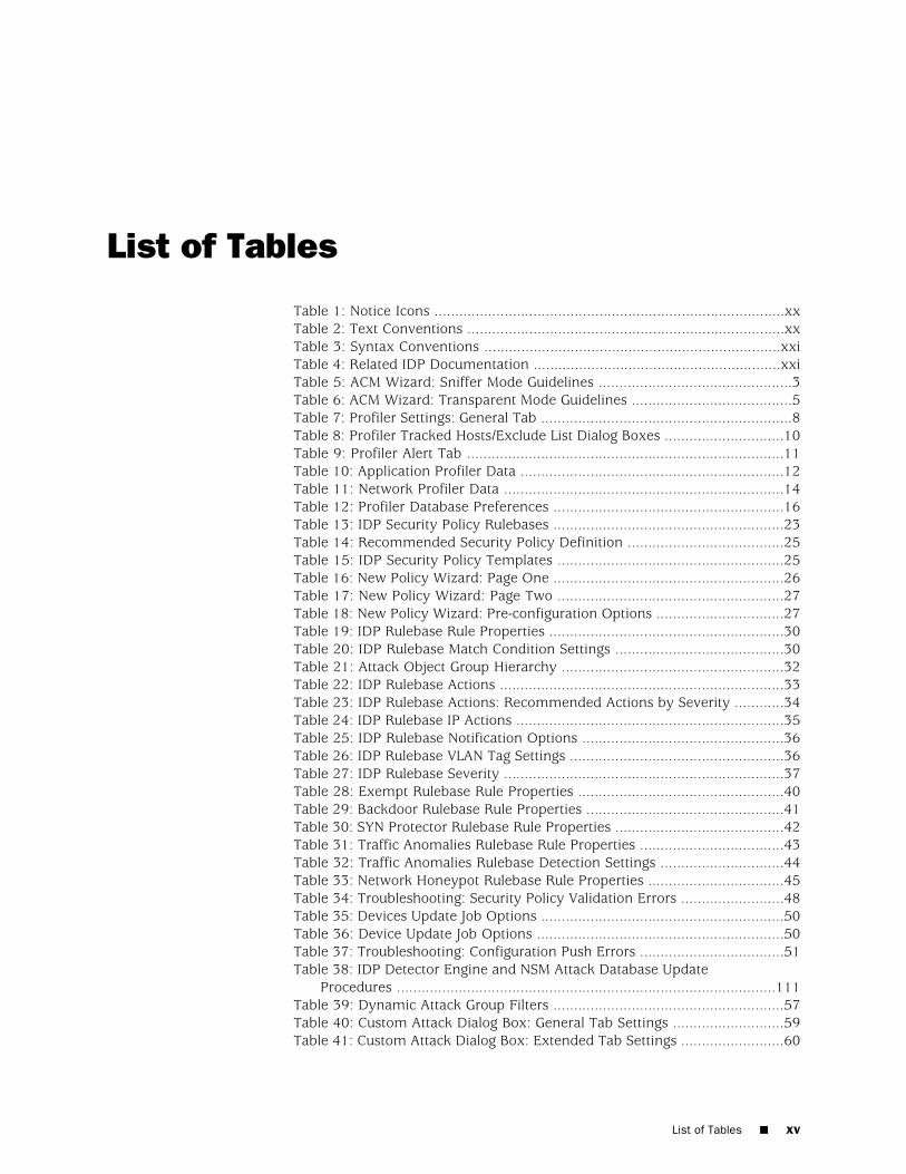
Table 1: Notice Icons .....................................................................................xxTable 2: Text Conventions .............................................................................xxTable 3: Syntax Conventions ........................................................................xxiTable 4: Related IDP Documentation ............................................................xxiTable 5: ACM Wizard: Sniffer Mode Guidelines ...............................................3Table 6: ACM Wizard: Transparent Mode Guidelines .......................................5Table 7: Profiler Settings: General Tab .............................................................8Table 8: Profiler Tracked Hosts/Exclude List Dialog Boxes .............................10Table 9: Profiler Alert Tab .............................................................................11Table 10: Application Profiler Data ................................................................12Table 11: Network Profiler Data ....................................................................14Table 12: Profiler Database Preferences ........................................................16Table 13: IDP Security Policy Rulebases ........................................................23Table 14: Recommended Security Policy Definition ......................................25Table 15: IDP Security Policy Templates .......................................................25Table 16: New Policy Wizard: Page One ........................................................26Table 17: New Policy Wizard: Page Two .......................................................27Table 18: New Policy Wizard: Pre-configuration Options ...............................27Table 19: IDP Rulebase Rule Properties .........................................................30Table 20: IDP Rulebase Match Condition Settings .........................................30Table 21: Attack Object Group Hierarchy ......................................................32Table 22: IDP Rulebase Actions .....................................................................33Table 23: IDP Rulebase Actions: Recommended Actions by Severity ............34Table 24: IDP Rulebase IP Actions .................................................................35Table 25: IDP Rulebase Notification Options .................................................36Table 26: IDP Rulebase VLAN Tag Settings ....................................................36Table 27: IDP Rulebase Severity ....................................................................37Table 28: Exempt Rulebase Rule Properties ..................................................40Table 29: Backdoor Rulebase Rule Properties ................................................41Table 30: SYN Protector Rulebase Rule Properties .........................................42Table 31: Traffic Anomalies Rulebase Rule Properties ...................................43Table 32: Traffic Anomalies Rulebase Detection Settings ..............................44Table 33: Network Honeypot Rulebase Rule Properties .................................45Table 34: Troubleshooting: Security Policy Validation Errors .........................48Table 35: Devices Update Job Options ...........................................................50Table 36: Device Update Job Options ............................................................50Table 37: Troubleshooting: Configuration Push Errors ...................................51Table 38: IDP Detector Engine and NSM Attack Database Update
Procedures ............................................................................................111Table 39: Dynamic Attack Group Filters ........................................................57Table 40: Custom Attack Dialog Box: General Tab Settings ...........................59Table 41: Custom Attack Dialog Box: Extended Tab Settings .........................60
List of Tables ■ xv

Table 42: Attack Object Types .......................................................................61Table 43: Custom Attack – General Properties ..............................................62Table 44: Custom Attack – Attack Patterns ....................................................64Table 45: Custom Attack: IP Settings and Header Matches ............................66Table 46: TCP Header Match Settings ............................................................67Table 47: UDP Header Match Settings ...........................................................67Table 48: ICMP Header Match Settings ..........................................................68Table 49: Custom Attack – General Properties ..............................................68Table 50: Custom Attack – General Properties ..............................................69Table 51: Compound Attack Parameters .......................................................71Table 52: Pulling and Pushing Configuration Updates ....................................83Table 53: Device Update Job Options ............................................................84Table 54: IDP Device Configuration: Info Settings .........................................85Table 55: IDP Device Configuration: Anti-Spoof Settings ...............................86Table 56: IDP Device Configuration: Run-Time Parameters ...........................87Table 57: IDP Device Configuration: Load Time Parameters .........................92Table 58: IDP Device Configuration: Router Parameter Settings ....................93Table 59: IDP Device Configuration: Protocol Thresholds and Configuration
Settings ...................................................................................................95Table 60: IDP Detector Engine and NSM Attack Database Update
Procedures ............................................................................................111Table 61: Troubleshooting Access to ACM ...................................................114Table 62: Tasks Requiring Use of the scio Command-Line Utlity .................115Table 63: Operations Requiring Use of the idp.sh Command-Line Utlity .....117Table 64: IDP Reboot and Shutdown Commands ........................................119Table 65: NSM Device Monitor Status Data .................................................124Table 66: NSM Device Monitor: Details .......................................................125Table 67: Log Viewing Options ....................................................................127Table 68: NSM Log Viewer: Log Columns ....................................................127Table 69: NSM Log Viewer: Predefined Views .............................................130Table 70: NSM Audit Log Viewer Table ........................................................131Table 71: NSM Audit Log Viewer: Target View Table ...................................132Table 72: NSM Audit Log Viewer: Device View Table ...................................133Table 73: NSM DI/IDP Predefined Reports ...................................................133Table 74: NSM Profiler Predefined Reports .................................................134Table 75: NSM: Application Volume Tracking Reports .................................135Table 76: Custom Report Configuration Options .........................................136Table 77: IDP Configuration: Log Suppression Settings ................................137Table 78: IDP Configuration: SNMP Settings ................................................139Table 79: Troubleshooting: IDP Reporter .....................................................143Table 80: Command Key Reference: sctop Utility .......................................148Table 81: sctop Flow Table Report ..............................................................149Table 82: sctop Flow Table: Flag Column ....................................................150Table 83: ACM Wizard: Bridge Mode Guidelines ..........................................166Table 84: ACM Wizard: Proxy-ARP Guidelines .............................................168Table 85: ACM Wizard: Router Mode Guidelines .........................................170Table 86: Standalone High Availability ACM Settings ...................................175Table 87: Third-Party High Availability ACM Settings ..................................179Table 88: IDP Troubleshooting Tools ...........................................................185Table 89: Troubleshooting: IDP Processes Reference ..................................186Table 90: Command Reference: bypassStatus Command-Line Utility ..........192
xvi ■ List of Tables
IDP Administration Guide
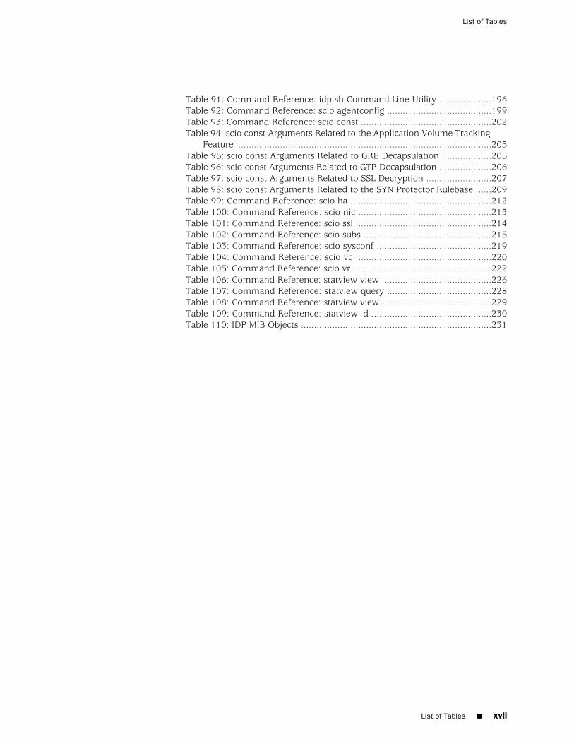
Table 91: Command Reference: idp.sh Command-Line Utility ....................196Table 92: Command Reference: scio agentconfig ........................................199Table 93: Command Reference: scio const ..................................................202Table 94: scio const Arguments Related to the Application Volume Tracking
Feature .................................................................................................205Table 95: scio const Arguments Related to GRE Decapsulation ...................205Table 96: scio const Arguments Related to GTP Decapsulation ....................206Table 97: scio const Arguments Related to SSL Decryption .........................207Table 98: scio const Arguments Related to the SYN Protector Rulebase ......209Table 99: Command Reference: scio ha ......................................................212Table 100: Command Reference: scio nic ...................................................213Table 101: Command Reference: scio ssl ....................................................214Table 102: Command Reference: scio subs .................................................215Table 103: Command Reference: scio sysconf ............................................219Table 104: Command Reference: scio vc ....................................................220Table 105: Command Reference: scio vr .....................................................222Table 106: Command Reference: statview view ..........................................226Table 107: Command Reference: statview query ........................................228Table 108: Command Reference: statview view ..........................................229Table 109: Command Reference: statview -d ..............................................230Table 110: IDP MIB Objects .........................................................................231
List of Tables ■ xvii
List of Tables

xviii ■ List of Tables
IDP Administration Guide

Preface
■ Objectives on page xix
■ Audience on page xix
■ Documentation Conventions on page xix
■ Related Documentation on page xxi
■ Requesting Technical Support on page xxii
Objectives
The purpose of this guide is to provide complete procedures for the administrationtasks related to use of Juniper Networks Intrusion Detection and Prevention (IDP)devices in your network.
For in-depth descriptions of features and examples, see the IDP Concepts and ExamplesGuide.
For details on using features of the Network and Security Manager user interfacefeatures, see the NSM documentation.
Audience
This guide is intended for network administrators who are familiar with TCP/IPnetworks and network security issues.
Documentation Conventions
This section provides all the documentation conventions that are followed in thisguide. Table 1 on page xx defines notice icons used in this guide.
Objectives ■ xix

Table 1: Notice Icons
DescriptionMeaningIcon
Indicates important features or instructions.Informational note
Indicates a situation that might result in loss of data or hardware damage.Caution
Alerts you to the risk of personal injury or death.Warning
Alerts you to the risk of personal injury from a laser.Laser warning
Table 2 on page xx defines text conventions used in this guide.
Table 2: Text Conventions
ExamplesDescriptionConvention
■ Issue the clock source command.
■ Specify the keyword exp-msg.
■ Click User Objects
■ Represents commands and keywordsin text.
■ Represents keywords
■ Represents UI elements
Bold typeface like this
user inputRepresents text that the user must type.Bold typeface like this
host1# show ip ospfRouting Process OSPF 2 with Router ID 5.5.0.250Router is an area Border Router (ABR)
Represents information as displayed onthe terminal screen.
fixed-width font
Ctrl + dIndicates that you must press two or morekeys simultaneously.
Key names linked with a plus (+)sign
■ The product supports two levels ofaccess, user and privileged.
■ clusterID, ipAddress.
■ Emphasizes words
■ Identifies variables
Italics
Object Manager > User Objects > LocalObjects
Indicates navigation paths through the UIby clicking menu options and links.
The angle bracket (>)
Table 3 on page xxi defines syntax conventions used in this guide.
xx ■ Documentation Conventions
IDP Administration Guide

Table 3: Syntax Conventions
ExamplesDescriptionConvention
terminal lengthRepresent keywordsWords in plain text
mask, accessListNameRepresent variablesWords in italics
diagnostic | lineRepresent a choice to select one keyword orvariable to the left or right of this symbol. Thekeyword or variable can be optional orrequired.
Words separated by the pipe ( | )symbol
[ internal | external ]Represent optional keywords or variables.Words enclosed in brackets ( [ ] )
[ level1 | level2 | 11 ]*Represent optional keywords or variables thatcan be entered more than once.
Words enclosed in brackets followedby and asterisk ( [ ]*)
{ permit | deny } { in | out } {clusterId | ipAddress }
Represent required keywords or variables.Words enclosed in braces ( { } )
Related Documentation
Table 4 on page xxi lists related IDP documentation.
Table 4: Related IDP Documentation
DescriptionDocument
Contains information about what is included in a specific product release:supported features, unsupported features, changed features, known problems,and resolved problems. If the information in the release notes differs fromthe information found in the documentation set, follow the release notes.
Release notes
Provides instructions for installing, configuring, updating, and servicing IDP8200.
IDP 8200 Installation Guide
Provides instructions for installing, configuring, updating, and servicing IDP75, IDP 250, and IDP 800.
IDP 75/250/800 Installation Guide
Provides instructions for installing, configuring, updating, and servicing IDP50, IDP 200, IDP 600, and IDP 1100.
IDP 50/200/600/1100 Installation Guide
Explains IDP features and provides examples of how to use the system.Intrusion Detection and Prevention Concepts &Examples Guide
Provides in-depth examples and reference information for creating customattack objects.
IDP Custom Attack Objects Reference andExamples Guide
Describes how to use IDP Reporter.IDP Reporter User’s Guide
Describes how to install and use Juniper Networks Application Usage Manager.Juniper Networks Application Usage ManagerInstallation and User’s Guide
Related Documentation ■ xxi
Preface

Requesting Technical Support
Technical product support is available through the Juniper Networks TechnicalAssistance Center (JTAC). If you are a customer with an active J-Care or JNASC supportcontract, or are covered under warranty, and need post-sales technical support, youcan access our tools and resources online or open a case with JTAC.
■ JTAC policies—For a complete understanding of our JTAC procedures and policies,review the JTAC User Guide located athttp://www.juniper.net/customers/support/downloads/710059.pdf.
■ Product warranties—For product warranty information, visithttp://www.juniper.net/support/warranty/.
■ JTAC Hours of Operation —The JTAC centers have resources available 24 hoursa day, 7 days a week, 365 days a year.
Self-Help Online Tools and Resources
For quick and easy problem resolution, Juniper Networks has designed an onlineself-service portal called the Customer Support Center (CSC) that provides you withthe following features:
■ Find CSC offerings: http://www.juniper.net/customers/support/
■ Search for known bugs: http://www2.juniper.net/kb/
■ Find product documentation: http://www.juniper.net/techpubs/
■ Find solutions and answer questions using our Knowledge Base:http://kb.juniper.net/
■ Download the latest versions of software and review release notes:http://www.juniper.net/customers/csc/software/
■ Search technical bulletins for relevant hardware and software notifications:https://www.juniper.net/alerts/
■ Join and participate in the Juniper Networks Community Forum:http://www.juniper.net/company/communities/
■ Open a case online in the CSC Case Management tool: http://www.juniper.net/cm/
To verify service entitlement by product serial number, use our Serial NumberEntitlement (SNE) Tool located at https://tools.juniper.net/SerialNumberEntitlementSearch/.
Opening a Case with JTAC
You can open a case with JTAC on the Web or by telephone.
■ Use the Case Management tool in the CSC at http://www.juniper.net/cm/ .
■ Call 1-888-314-JTAC (1-888-314-5822 toll-free in the USA, Canada, and Mexico).
For international or direct-dial options in countries without toll-free numbers, seehttp://www.juniper.net/support/requesting support.html
xxii ■ Requesting Technical Support
IDP Administration Guide

Part 1
Implementing IDP Features
■ Getting Started on page 3
■ Using Profiler on page 7
■ Using Security Explorer on page 19
■ Using Application Volume Tracking on page 21
■ Security Policies Overview on page 23
■ Configuring the IDP Rulebase on page 29
■ Configuring Additional Security Policy Rulebases on page 39
■ Managing Security Policies on page 47
■ Working With Attack Objects on page 53
Implementing IDP Features ■ 1

2 ■ Implementing IDP Features
IDP Administration Guide
Chapter 1
Getting Started
This chapter contains the following topics:
■ Deploying an IDP Device in Sniffer Mode on page 3
■ Deploying an IDP Appliance in Transparent Mode on page 4
Deploying an IDP Device in Sniffer Mode
You deploy an IDP device in sniffer mode if you want to learn about security threatsin your network but not disrupt connections.
For an overview of sniffer mode, see the IDP Concepts and Examples Guide.
To deploy the device in sniffer mode:
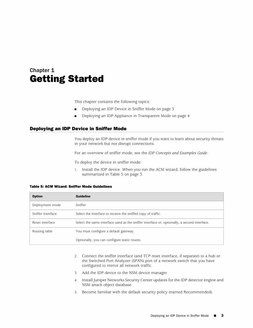
1. Install the IDP device. When you run the ACM wizard, follow the guidelinessummarized in Table 5 on page 3.
Table 5: ACM Wizard: Sniffer Mode Guidelines
GuidelineOption
SnifferDeployment mode
Select the interface to receive the sniffed copy of traffic.Sniffer interface
Select the same interface used as the sniffer interface or, optionally, a second interface.Reset interface
You must configure a default gateway.
Optionally, you can configure static routes.
Routing table
2. Connect the sniffer interface (and TCP reset interface, if separate) to a hub orthe Switched Port Analyzer (SPAN) port of a network switch that you haveconfigured to mirror all network traffic.
3. Add the IDP device to the NSM device manager.
4. Install Juniper Networks Security Center updates for the IDP detector engine andNSM attack object database.
5. Become familiar with the default security policy (named Recommended).
Deploying an IDP Device in Sniffer Mode ■ 3

6. Run Profiler to discover the network hosts you want to protect.
7. Review logs to verify the initial deployment.
8. Use the documentation to become familiar with the product features and userinterface:
■ Use the IDP Concepts and Examples Guide to become familiar with IDPfeatures.
■ Use this guide, the IDP Administration Guide, to learn the steps to implementIDP features and monitor security events.
■ Use the Application Control Manager (ACM) online help for information aboutusing ACM.
■ Use CLI man pages for syntax and parameter hints for CLI commands.
■ Use the NSM online help for information about using the NSM user interface.
Related Topics ■ Adding IDP Devices to NSM Device Manager on page 76
■ Loading J-Security Center Updates (NSM Procedure) on page 54
■ Developing Security Policies Task Summary on page 23
■ Profiler Task Summary on page 7
■ IDP Logs and Reports in NSM Task Summary on page 123
Deploying an IDP Appliance in Transparent Mode
You deploy an IDP device in transparent mode to take action against security threatsin your network.
For an overview of transparent mode, see the IDP Concepts and Examples Guide.
4 ■ Deploying an IDP Appliance in Transparent Mode
IDP Administration Guide

To deploy the device in transparent mode:
1. Install the IDP device. When you run the ACM wizard, follow the guidelinessummarized in Table 6 on page 5.
Table 6: ACM Wizard: Transparent Mode Guidelines
GuidelineOption
TransparentDeployment mode
You have the option to enable Layer 2 bypass.
In transparent mode, for Layer 2 connections, interfaces either select traffic for inspection, dropit, or pass it through (uninspected), according to the following rules:
Layer 2 bypass
■ The interfaces select address resolution protocol (ARP) and internet protocol (IPv4) trafficfor inspection and process according to security policy rules.
■ By default, the interfaces drop all other Layer 2 traffic.
■ If you enable Layer 2 bypass, the interfaces pass through pass through IPv6, internetworkpacket exchange (IPX), Cisco Discovery Protocol (CDP), and interior gateway routing protocol(IGRP).
■ If you enable internal bypass, the interfaces do not pass through NSRP packets even if Layer2 bypass is enabled.
■ If you enable external bypass, all interfaces pass through the NetScreen Redundancy Protocol(NSRP) packets that are used in communication with the external bypass unit.
Options are limited to third-party failover/load balancing.High availability
Non-configurable. In transparent mode, when IDP receives traffic, it reads the VLAN tags, processespackets based on matching criteria (including VLAN tag), and then passes the tags throughunaltered.
VLAN tagging
You must enable multiple virtual routers if you want to use more than one pair of interfaces. Ifyou do not enable multiple virtual routers, you are limited to one pair.
In transparent mode, adjacent interfaces are automatically paired and belong to the same virtualrouter. For example, by default, interfaces eth2 and eth3 belong to virtual router vr0.
Virtual routers
You can set NIC state to NICs off, NIC bypass (to implement internal bypass, or External bypass(to support external bypass).
Set NIC state to NICs off if you do not want to use internal bypass or external bypass.
NIC state
Set NIC state to NIC bypass to enable internal bypass,Internal bypass
Set NIC state to External bypass unit to enable support for an external bypass solution.External bypass
Configurable. Disabled by default.Peer port modulation
You do not set IP addresses for traffic interfaces in transparent mode.Traffic interfaces
You must configure a default gateway.
Optionally, you can configure static routes.
Routing table
Deploying an IDP Appliance in Transparent Mode ■ 5
Chapter 1: Getting Started

2. Connect traffic interface network cables to network switches and/or firewalls.
3. Add the IDP device to the NSM device manager.
4. Install Juniper Networks Security Center updates for the IDP detector engine andNSM attack object database.
5. Become familiar with the default security policy (named Recommended).
6. Run Profiler to discover the network hosts you want to protect.
7. Review logs to verify the initial deployment.
8. Use the documentation to become familiar with the product features and userinterface:
■ Use the IDP Concepts and Examples Guide to become familiar with IDPfeatures.
■ Use this guide, the IDP Administration Guide, to learn the steps to implementIDP features and monitor security events.
■ Use the Application Control Manager (ACM) online help for information aboutusing ACM.
■ Use CLI man pages for syntax and parameter hints for CLI commands.
■ Use the NSM online help for information about using the NSM user interface.
Related Topics ■ Adding IDP Devices to NSM Device Manager on page 76
■ Loading J-Security Center Updates (NSM Procedure) on page 54
■ Developing Security Policies Task Summary on page 23
■ Profiler Task Summary on page 7
■ IDP Logs and Reports in NSM Task Summary on page 123
6 ■ Deploying an IDP Appliance in Transparent Mode
IDP Administration Guide

Chapter 2
Using Profiler
This chapter contains the following topics:
■ Profiler Task Summary on page 7
■ Configuring Profiler Options (NSM Procedure) on page 7
■ Starting and Stopping the Profiler (NSM Procedure) on page 12
■ Using Profiler Viewer (NSM Procedure) on page 12
■ Managing the Profiler Database (NSM Procedure) on page 16
Profiler Task Summary
You use the Profiler to learn about your internal network so you can create effectivesecurity policies and minimize unnecessary log records. The Profiler queries andcorrelates information from multiple IDP devices.
The Profiler feature is available only through Network and Security Manager (NSM).
IDP administration includes the following tasks related to the Profiler feature:
■ Configuring Profiler options
■ Starting and stopping the Profiler
■ Viewing Profiler reports
■ Managing the Profiler database
For examples of how to use Profiler to learn about your network, see the IDP Conceptsand Examples Guide.
Related Topics ■ Configuring Profiler Options (NSM Procedure) on page 7
■ Starting and Stopping the Profiler (NSM Procedure) on page 12
■ Using Profiler Viewer (NSM Procedure) on page 12
■ Managing the Profiler Database (NSM Procedure) on page 16
Configuring Profiler Options (NSM Procedure)
You configure Profiler options to enable Profiler features, set network addresses andapplications subject to profiling, and set alerts.
Profiler Task Summary ■ 7

The following topics describe how to configure Profiler options:
■ Specifying General Options on page 8
■ Specifying Tracked Hosts on page 9
■ Specifying Context Targets on page 10
■ Specifying Alert Options on page 11
Specifying General Options
You configure Profiler general options to enable Profiler features.
To specify Profiler general options:
1. From NSM Device Manager, double-click a device and then click Profiler Settings.
2. Click the General tab.
3. Configure Profiler general options as described in Table 7 on page 8.
4. Click Apply.
NOTE: If you change Profiler settings, you must push a configuration update to thedevice before the new settings take effect. From the Device Manager, right-click thedevice, select Update Device, select the Restart IDP Profiler After Device Updatecheck box, and click OK.
Table 7: Profiler Settings: General Tab
DescriptionSetting
Enables the Profiler.Enable Profiling
Enables the Profiler to collect and track application data.
This setting is enabled automatically when you start the Profiler and becomes automatically disabledwhen you stop the Profiler.
Enable ApplicationProfiling
Enables the Profiler to collect and track specific probes and attempts.Include Probe andAttempt
Enables the Profiler to collect and track data from external hosts.Include Non-tracked IPProfiles
Sets the maximum Profiler database size. By default, the maximum database size is 3 GB.db limit (in MB)
8 ■ Specifying General Options
IDP Administration Guide

Table 7: Profiler Settings: General Tab (continued)
DescriptionSetting
Enables the Profiler to perform OS fingerprinting.
OS fingerprinting detects the operating system of an end-host by analyzing TCP handshake packets.
The OS fingerprinting process depends on an established TCP connection (one that has a SYN, aSYN/ACK, and a FIN connection).
The OS fingerprinting process is capable of detecting the operating systems listed in/usr/idp/device/cfg/fingerprints.set.
Enable OS Fingerprinting
Sets the time interval (in seconds) that the Profiler refreshes OS fingerprinting. By default, theProfiler refreshes OS fingerprinting data every 3600 seconds (60 minutes).
Refresh Interval (in secs)
Specifying Tracked Hosts
You configure Profiler tracked host and excluded host settings to determine thenetwork segments where Profiler gathers data.
To configure the tracked host and exclude lists:
1. From NSM Device Manager, double-click a device and then click Profiler Settings.
2. Click the Tracked Hosts tab.
3. Click the + icon and select one of the following options to display a dialog boxto build a tracked host list:
■ Add Host
■ Add Network
■ Add Group
4. Configure tracked host settings as described in Table 8 on page 10.
5. Click the Exclude tab.
6. Click the + icon and select one of the following options to display a dialog boxto build a exclude host list:
■ Add Host
■ Add Network
■ Add Group
7. Configure exclude host settings as described in Table 8 on page 10.
8. Click Apply.
Specifying Tracked Hosts ■ 9
Chapter 2: Using Profiler

NOTE: If you change Profiler settings, you must push a configuration update to thedevice before the new settings take effect. From the Device Manager, right-click thedevice, select Update Device, select the Restart IDP Profiler After Device Updatecheck box, and click OK.
Table 8: Profiler Tracked Hosts/Exclude List Dialog Boxes
DescriptionDialog Box
Name–Specify the hostname.Add Host
Color–Select a color to help you monitor the host.
Comment–Specify a comment to identify the host.
IP/IP Address–Specify the IP address.
Domain/Domain name–Specify the domain name.
Resolve–Select to use DNS to resolve hostnames/IP addresses.
Name–Specify an object name.Add Network
IP Address–Specify an IP address that specifies the network address space.
Netmask–Specify a netmask that specifies the network address space.
Color–Select a color to help you monitor the network.
Comment–Specify a comment to describe the network.
Name–Specify an object name.Add Group
Color–Select a color to help you monitor the group.
Comment–Specify a comment to describe the group.
Member List–Select hosts to belong to the group.
Specifying Context Targets
You configure Profiler context settings to determine whether Profiler logs includenot only host and application data but also data pulled from application contexts.For example, if you specify context targets for FTP usernames, the Profiler logs willinclude the username specified for the FTP connection in addition to the hostnameand service (FTP).
To specify Profiler context targets:
1. From NSM Device Manager, double-click a device and then click Profiler Settings.
2. Click the Contexts to Profile tab.
10 ■ Specifying Context Targets
IDP Administration Guide

3. Browse and select from the predefined list of contexts.
4. Click Apply.
NOTE: If you change Profiler settings, you must push a configuration update to thedevice before the new settings take effect. From the Device Manager, right-click thedevice, select Update Device, select the Restart IDP Profiler After Device Updatecheck box, and click OK.
Specifying Alert Options
You configure Profiler alert options to determine whether you receive alerts whenProfiler detects new hosts, protocols, or ports in use.
If you are configuring the Profiler for the first time, do not enable the new host,protocol, or port alerts. As the Profiler runs, the device views all network componentsas new, which can generate unnecessary log records. After the Profiler has learnedabout your network and has established a baseline of network activity, you shouldreconfigure the device to record new hosts, protocols, or ports discovered on yourinternal network.
To specify Profiler alert options:
1. From NSM Device Manager, double-click a device and then click Profiler Settings.
2. Click the Alert tab.
3. Configure alert settings as described in Table 9 on page 11.
NOTE: If you change Profiler settings, you must push a configuration update to thedevice before the new settings take effect. From the Device Manager, right-click thedevice, select Update Device, select the Restart IDP Profiler After Device Updatecheck box, and click OK.
Table 9: Profiler Alert Tab
DescriptionSetting
Sends an alert when Profiler detects a new host.New Host Detected
Sends an alert when Profiler detects a new protocol.New Protocol Detected
Sends an alert when Profiler detects a new port.New Port Detected
Sends an alert to indicate the maximum database size has been reached. After a device reachesthis limit, it begins purging the database.
Database Limit Exceeded
Specifying Alert Options ■ 11
Chapter 2: Using Profiler

Related Topics ■ Profiler Task Summary on page 7
Starting and Stopping the Profiler (NSM Procedure)
You use Network and Security Manager (NSM) to start and stop the Profiler.
The Profiler is a service, located on the IDP device at /usr/idp/device/bin/profiler.sh.
To start the Profiler:
1. From the NSM main menu, select Devices > IDP Profiler > Start Profiler.
2. Select the devices on which you want to start the Profiler.
3. Click OK.
To stop the Profiler:
1. From the NSM main menu, select Devices > IDP Profiler > Stop Profiler.
2. Select the devices on which you want to stop the Profiler.
3. Click OK.
Related Topics ■
Using Profiler Viewer (NSM Procedure)
The Profiler Viewer contains multiple tabs with different views of Profiler data. Thefollowing topics describe these views:
■ Application Profiler View on page 12
■ Network Profiler on page 13
■ Violation Viewer on page 15
Application Profiler View
The Application Profiler view is a table of information that, like the NSM Log Viewer,enables you to view and analyze dynamic application (Layer-7) traffic within a specificcontext.
Table 10 on page 12 describes Application Profiler data.
Table 10: Application Profiler Data
DescriptionColumn
Source IP address of the traffic profiled.Src IP
Destination IP address of the traffic profiled.Dst IP
The user associated with the traffic profiled.User
12 ■ Starting and Stopping the Profiler (NSM Procedure)
IDP Administration Guide

Table 10: Application Profiler Data (continued)
DescriptionColumn
The role group to which the user that is associated with the traffic profiled belongs.Role
All contexts of traffic that the devices selected in the Device table recorded.Context
When you select a context, the values that your devices recorded for a selected context.Value
Source MAC addresses of traffic profiled.Src MAC
Destination MAC addresses of traffic profiled.Dst MAC
Source OUIs of traffic profiled.
NOTE: The Organizationally Unique Identifier (OUI) value is a mapping of the first three bytes ofthe MAC address and the organization that owns the block of MACs. You can obtain a list of OUIsat http://standards.ieee.org/regauth/oui/oui.txt.
Src OUI
Destination OUIs of traffic profiled.Dst OUI
Operating-system version running on the source IP of the traffic profiled.Src OS Name
Operating-system version running on the destination IP of the traffic profiled.Dst OS Name
Number of occurrences that match the traffic profiled.Hits
Timestamp for the first time the device logged the event (within the specified time interval).First Time
Timestamp for the last time the device logged the event (within the specified time interval).Last Time
Domain in which the device is managed in NSM.Domain
Device that profiled the data displayed.Device
By default, the Application Profiler view contains only the data collected during theconfigured time interval.
To display the Application Profiler view:
1. In the NSM navigation tree, select Investigate > Security Monitor > Profiler.
2. Click the Application Profiler tab.
TIP: For information about using NSM features to sort, filter, and drill down onrecords, see the NSM online help.
Network Profiler
The Network Profiler view is a table of information that, like the NSM Log Viewer,enables you to view and analyze data related to static traffic (Layer-3, Layer-4, and
Network Profiler ■ 13
Chapter 2: Using Profiler

RPC protocols, ports, and program numbers) within the context of data correspondingto peer, host, and operating system.
Table 11 on page 14 describes Network Profiler data.
Table 11: Network Profiler Data
DescriptionColumn
Source IP address of the traffic profiled.Src IP
Destination IP address of the traffic profiled.Dst IP
The user associated with the traffic profiled.User
The role group to which the user that is associated with the traffic profiled belongs.Role
All services of traffic profiled.Service
Type of the traffic profiled:
■ Access indicates a successful connection, during which the device recorded valid requests andresponses from the server to a client.
■ Attempt indicates a request that did not receive a reply. The device recorded a packet from aclient to a server, but never saw a reply.
■ Probe indicates a request that does not expect a reply. For non-TCP sessions, the device recordedan ICMP error; for TCP sessions, the device recorded a SYN packet from the client followed bya RST from the server.
Access Type
Source MAC addresses of traffic profiled.Src MAC
Destination MAC addresses of traffic profiled.Dst MAC
Source OUIs of traffic profiled.
NOTE: OUI stands for Organizationally Unique Identifier. This value is a mapping of the first threebytes of the MAC address and the organization that owns the block of MACs. You can obtain a listof OUIs at http://standards.ieee.org/regauth/oui/oui.txt.
Src OUI
Destination OUIs of traffic profiled.Dst OUI
Operating-system version running on the source IP of the traffic profiled.Src OS Name
Operating-system version running on the destination IP of the traffic profiled.Dst OS Name
Number of occurrences that match the traffic profiled.Hits
Timestamp for the first time the device logged the event (within the specified time interval).First Time
Timestamp for the last time the device logged the event (within the specified time interval).Last Time
Domain in which the device is managed in NSM.Domain
Device that profiled the data displayed.Device
14 ■ Network Profiler
IDP Administration Guide

To display the Network Profiler view:
1. In the NSM navigation tree, select Investigate > Security Monitor > Profiler.
2. Click the Network Profiler tab.
TIP: For information about using NSM features to sort, filter, and drill down onrecords, see the NSM online help.
Violation Viewer
The Violation Viewer is a filtered view of the Network Profiler view. In the ViolationViewer, you configure permitted objects. Permitted objects are filtered from thedisplay, allowing you to focus on unpermitted traffic.
To configure permitted objects:
1. In the NSM navigation tree, select Investigate > Security Monitor > Profiler.
2. Click the Network Profiler tab.
3. Click on the + icon that appears on the top of the right-hand window to displaythe New Permitted Object dialog box.
4. Type a name for the permitted object.
5. Within the New Permitted Object dialog box, click the + icon to add a rule tomatch source, destination, and services values for the permitted object.
6. To change the source, destination, or service value from Any, right-click thevalue and select Add Source, Add Destination, or Add Service.
7. Use the selection controls to select the desired address objects or service objectsand click OK.
8. Click OK to save the permitted object.
The object appears in the filters windows within the Violation Viewer tab.
9. Select the object and click Apply to hide all matching objects from the ViolationViewer.
TIP: For information about using additional NSM features to sort, filter, and drilldown on records, see the NSM online help.
Violation Viewer ■ 15
Chapter 2: Using Profiler

Related Topics ■ Profiler Task Summary on page 7
Managing the Profiler Database (NSM Procedure)
The following topics provide procedures for managing the Profiler database:
■ Modifying Profiler Database Preferences on page 16
■ Displaying Profiler Database Information on page 16
■ Querying the Profiler Database on page 17
■ Purging the Profiler Database on page 17
Modifying Profiler Database Preferences
Data discovered by Profiler is stored in a database located on the NSM GUI server.
To modify Profiler database preferences:
1. From the NSM main menu, select Tools > Preferences.
2. Click Profiler Settings.
3. Modify database preferences as described in Table 12 on page 16.
4. Click OK.
Table 12: Profiler Database Preferences
DescriptionSetting
Default is 1000 MB.Purge Profiler Database if Size Exceeds
Default is 750 MB.Max Profiler Database Size After Purging
Default is 120 seconds.Profiler Query Timeout
Default is 00:00 GMT.Hour of Day to Perform Database Optimization
Displaying Profiler Database InformationPurpose Data discovered by Profiler is stored in a database located on the NSM GUI server.
Use the steps in this procedure to display information about the Profiler database.
Action To display Profiler database information:
1. In the NSM navigation tree, select Investigate > Security Monitor > Profiler.
2. Click the Show DB Information icon in the upper right corner to view specificdetails about the Profiler database, including the database size.
16 ■ Managing the Profiler Database (NSM Procedure)
IDP Administration Guide

Querying the Profiler DatabasePurpose Data discovered by Profiler is stored in a database located on the NSM GUI server.
Use the steps in this procedure to query the Profiler database.
Action To query records in the database:
1. Log into the NSM GUI server as the Postgres SQL user. By default, the PostgresSQL user is netscreen.
2. Navigate to the directory where the Profiler DB is located: /usr/local/nsmpsql/bin.
3. Run any Postgres SQL command. For example, you can type the followingcommand:
./psql -d profilerDb
Purging the Profiler Database
Data discovered by Profiler is stored in a database located on the NSM GUI server.When the database reaches a maximum size (4 GB by default), it begins purgingrecords (oldest first) automatically. The Profiler stops purging records when it reachesa certain set minimum size (3 GB by default).
Use the steps in this procedure to purge the Profiler database, if needed.
To change automatic purge settings, from the NSM main menu, select Tools >Preferences and modify the Profiler database settings.
To purge the database immediately:
1. In the NSM navigation tree, select Investigate > Security Monitor > Profiler.
2. Click the Clear All DB icon in the upper right corner.
Related Topics ■ Profiler Task Summary on page 7
Querying the Profiler Database ■ 17
Chapter 2: Using Profiler

18 ■ Purging the Profiler Database
IDP Administration Guide

Chapter 3
Using Security Explorer
The purpose of this chapter is to make you aware of the Network and SecurityManager (NSM) Security Explorer.
This chapter contains the following topics:
■ Security Explorer Task Summary on page 19
Security Explorer Task Summary
The Network and Security Manager (NSM) Security Explorer is a graphical tool thatenables you to visualize and correlate network behavior based on data collected inthe Profiler, Log Viewer, and Report Manager. You can use the Security Explorer to:
■ Get a dynamic, interactive view of your network.
■ Drill down on a particular host or server and view all the different attacks, openports, destination or peer IP addresses, and so on.
■ Move between hosts and peers and trace a connection or attack.
■ Toggle between different views or slices of the network, as well as explore thecontextual information (logs, reports, IDP attacks, IP addresses, and so on) withinthe Security Explorer panel.
For information on using Security Explorer, see the NSM documentation.
Security Explorer Task Summary ■ 19

20 ■ Security Explorer Task Summary
IDP Administration Guide

Chapter 4
Using Application Volume Tracking
This chapter contains the following topics:
■ Application Volume Tracking Task Summary on page 21
■ Enabling Application Volume Tracking on page 21
■ Viewing Application Volume Tracking Reports on page 22
Application Volume Tracking Task Summary
You use the application volume tracking (AVT) feature to collect aggregated trafficvolume statistics. AVT requires Profiler to be enabled and running.
IDP administration includes the following tasks related to AVT:
■ Enabling AVT
■ Using statview to view AVT data
■ Using IDP Reporter to view AVT data
For detailed information about AVT, see the IDP Concepts and Examples Guide.
Related Topics Enabling Application Volume Tracking on page 21■
■ statview Task Summary on page 145
■ IDP Reporter Task Summary on page 141
Enabling Application Volume Tracking
You use the application volume tracking (AVT) feature to collect aggregated trafficvolume statistics. AVT requires Profiler to be enabled and running.
To enable AVT:
1. From the IDP command-line, run the following command to see whether AVTis already running:
scio const -s s0:flow get sc_periodic_stat_update
If AVT is running, the console displays a message that sc_periodic_stat_updateis set to 0x1.
Application Volume Tracking Task Summary ■ 21

If AVT is not running, run the following command to turn it on:
scio const -s s0:flow set sc_periodic_stat_update 1
2. In NSM, start the Profiler for the IDP device.
a. Select Devices >IDP Profiler > Start Profiler.
b. Select the devices on which to start the Profiler.
c. Click OK.
NOTE:
Changes you make to kernel constants with the CLI to not persist across restarts. Tomake your change persistent:
1. Open the /usr/idp/device/bin/user_funcs file in a text editor, such as vi.
2. Add the constant below the line user_start_end(). For example:
user_start_end(){$SCIO const -s s0:flow set sc_periodic_stat_update 1[...]
}
3. Save the file.
4. Restart the IDP process engine:
[root@defaulthost admin]# idp.sh restart
Restarting the IDP process engine can take several moments.
Related Topics Application Volume Tracking Task Summary on page 21■
■ scio const
Viewing Application Volume Tracking Reports
Purpose You can view application volume tracking (AVT) statistics with the statviewcommand-line utility or IDP Reporter.
Related Topics ■ statview Task Summary on page 145
■ IDP Reporter Task Summary on page 141
22 ■ Viewing Application Volume Tracking Reports
IDP Administration Guide

Chapter 5
Security Policies Overview
This chapter contains the following topics:
■ Developing Security Policies Task Summary on page 23
■ Using Predefined Security Policies on page 25
■ Using the New Policy Wizard (NSM Procedure) on page 26
Developing Security Policies Task Summary
An IDP security policy defines how the IDP device handles network traffic. It allowsyou to enforce various attack detection and prevention techniques on traffic thattraverses your network.
For a detailed explanation of security policy features and components, and forexamples, see the IDP Concepts and Examples Guide.
To create an effective security policy, follow these basic steps:
1. Run the New Policy wizard to create a new security policy object. The newsecurity policy can be based on a predefined template.
2. Use the Security Policy editor to add one or more rulebases.
A rulebase is an ordered set of rules that use a particular detection method toidentify and prevent attacks.
Table 13 on page 23 describes the IDP security policy rulebases. A security policycan contain only one instance of any rulebase type.
Table 13: IDP Security Policy Rulebases
DescriptionRulebase
Protects your network from attacks by using attack objects to detect known and unknown attacks.Juniper Networks provides predefined attack objects that you can use in IDP rules. You can alsoconfigure your own custom attack objects.
See “Modifying IDP Rulebase Rules (NSM Procedure)” on page 29.
IDP Rulebase
Developing Security Policies Task Summary ■ 23

Table 13: IDP Security Policy Rulebases (continued)
DescriptionRulebase
You configure rules in this rulebase to exclude known false positives or to exclude a specific source,destination, or source/destination pair from matching an IDP rule. If traffic matches a rule in theIDP rulebase, IDP attempts to match the traffic against the Exempt rulebase before performingthe action specified.
See “Configuring Exempt Rulebase Rules (NSM Rulebase)” on page 39.
Exempt Rulebase
Protects your network from mechanisms installed on a host computer that facilitates unauthorizedaccess to the system. Attackers who have already compromised a system typically install backdoors(such as Trojans) to make future attacks easier. When attackers send and retrieve information toand from the backdoor program (as when typing commands), they generate interactive trafficthat IDP can detect.
See “Configuring Backdoor Rulebase Rules (NSM Procedure)” on page 40.
Backdoor Rulebase
Protects your network from SYN-floods by ensuring that the three-way handshake is performedsuccessfully for specified TCP traffic. If you know that your network is vulnerable to a SYN-flood,use the SYN-Protector rulebase to prevent it.
See “Configuring SYN Protector Rulebase Rules (NSM Procedure)” on page 41.
SYN Protector Rulebase
Protects your network from attacks by using traffic flow analysis to identify attacks that occurover multiple connections and sessions (such as scans).
See “Configuring Traffic Anomalies Rulebase Rules (NSM Procedure)” on page 42.
Traffic AnomaliesRulebase
Protects your network by impersonating open ports on existing servers on your network, alertingyou to attackers performing port scans and other information-gathering activities.
See “Configuring Network Honeypot Rulebase Rules (NSM Procedure)” on page 44.
Network HoneypotRulebase
3. Within rulebases, configure rules.
Rules are instructions that provide context to detection methods. Rules specify:
■ A source/destination/service match condition that determines which trafficto inspect
■ Attack objects that determine what to look for (IDP rulebase and Exemptrulebase)
■ Actions that determine what to do when an attack is detected
■ Notification options, including logs, alerts, and packet captures
Each rulebase can contain up to 40,000 rules.
4. Fine-tune your security policy as you learn more about your network and securityrequirements and IDP capabilities. For a suggested process for fine-tuning, seethe IDP Concepts and Examples Guide.
Related Topics Using Predefined Security Policies on page 25■
24 ■ Developing Security Policies Task Summary
IDP Administration Guide

■ Using the New Policy Wizard (NSM Procedure) on page 26
Using Predefined Security Policies
The highly respected Juniper Networks Security Center team (J-Security Center)provides the default IDP security policy—named Recommended. We advise that youuse this policy to protect your network from the likeliest and most dangerous attacks.
Table 14 on page 25 summarizes the properties of the Recommended security policy.
Table 14: Recommended Security Policy Definition
ValueProperty
IDP RulebaseRulebase
9 rules, distinguished by attack objectRules
AnyTraffic source
Default, meaning the matching property is based on the service bindings of the attack objectspecified by the rule
Service
AnyDestination
Recommended IP, Recommended TCP, Recommended ICMP, Recommended HTTP, RecommendedSMTP, Recommended DNS, Recommended FTP, Recommended POP3, Recommended IMAP,Recommended Trojan, Recommended Virus, Recommended Worm
Attacks
Recommended, meaning the action is specified by the attack objectAction
LoggingNotification
If you prefer, you can copy this security policy and use it as a template for a customsecurity policy tailored for your network. You use the New Security Policy wizard tocreate a custom security policy based on a template.
Table 15 on page 25 describes other IDP security policy templates.
Table 15: IDP Security Policy Templates
DescriptionTemplate
Includes all attack objects and enables packet logging for all rules.all_with_logging
Includes all attack objects but does not enable packet logging.all_without_logging
Protects a typical DMZ environment.dmz_services
Protects DNS services.dns_server
Protects file sharing services, such as SMB, NFS, FTP, and others.file_server
Using Predefined Security Policies ■ 25
Chapter 5: Security Policies Overview

Table 15: IDP Security Policy Templates (continued)
DescriptionTemplate
Contains very open rules. Useful in controlled lab environments, but should not be deployed onheavy traffic live networks.
getting_started
Contains a good blend of security and performance.idp_default
Protects HTTP servers from remote attacks.web_server
If you use these templates, we advise you customize them for your deployment. Ata minimum, you should change the destination IP setting from Any to the IP addressesfor specific servers you want to protect.
Related Topics ■ Developing Security Policies Task Summary on page 23
Using the New Policy Wizard (NSM Procedure)
You use the security policy wizard to create a new security policy. The security policiesyou create with the wizard must have a new name but can be based on existingpolicies or templates.
To create a new security policy:
1. From the NSM main menu, select File > New Policy to display the New Policywizard.
2. On the first page, complete the settings described in Table 16 on page 26 andthen click Next.
Table 16: New Policy Wizard: Page One
DescriptionSetting
A string to identify the policy.Name
Text to further identify the policy. In the security policy list, you can sort on comments.Comments
3. On the second page, complete the settings described in Table 17 on page 27and then click Next.
26 ■ Using the New Policy Wizard (NSM Procedure)
IDP Administration Guide

Table 17: New Policy Wizard: Page Two
DescriptionSetting
Select this option to create a new security policy.
If you select this option, the wizard displays the following set of device types:
■ Firewall/VPN
■ Firewall/VPN with IDP
■ Standalone IDP
Select Standalone IDP.
Create new Policy for
Use this option to assign an existing policy to one or more IDP devices.
If you select this option, the wizard displays a drop-down list of existing policies.
Select a policy from the list.
NOTE: This procedure involves creating a new policy. For this procedure, do not select Use ExistingPolicy.
Use Existing Policy
4. On the next pages, complete the pre-configuration options described inTable 18 on page 27. Click Next to advance through the pages.
Table 18: New Policy Wizard: Pre-configuration Options
DescriptionSetting
Select this option to create a new security policy based on a predefined template.
If you select this option, the wizard displays a drop-down list of predefined templates.
Select one and click Next.
Use Predefined PolicyTemplate
Select this option and complete the rule properties on the next page to generate a policy with thefollowing features:
■ IDP rulebase
■ Multiple rules matching any source, any destination, and default services
■ Multiple rules are distinguished by the attack object severity group, action, and notificationoption you configure in the next wizard page.
Configure IDP Policy
Select this option to create an empty policy that you can later modify.Empty Policy
5. On the next to last page, select the IDP devices you want to assign this policyand then click Next.
6. Click Finish to save the policy.
The new policy appears in the security policy list.
Using the New Policy Wizard (NSM Procedure) ■ 27
Chapter 5: Security Policies Overview

Related Topics ■ Developing Security Policies Task Summary on page 23
28 ■ Using the New Policy Wizard (NSM Procedure)
IDP Administration Guide

Chapter 6
Configuring the IDP Rulebase
The IDP rulebase is the primary rulebase that protects your network from attacks.The IDP rulebase is included in an IDP security policy by default. This chapter containsthe following topics related to configuring IDP rulebase rules:
■ Modifying IDP Rulebase Rules (NSM Procedure) on page 29
■ Specifying Rule Match Conditions (NSM Procedure) on page 30
■ Specifying IDP Rulebase Attack Objects (NSM Procedure) on page 32
■ Specifying Rule Session Action (NSM Procedure) on page 33
■ Specifying Rule IP Action (NSM Procedure) on page 34
■ Specifying Rule Notification Options (NSM Procedure) on page 35
■ Specifying Rule VLAN Matches (NSM Procedure) on page 36
■ Specifying Rule Targets (NSM Procedure) on page 37
■ Specifying Rule Severity (NSM Procedure) on page 37
■ Specifying Rule Optional Fields on page 38
■ Specifying Rule Comments (NSM Procedure) on page 38
Modifying IDP Rulebase Rules (NSM Procedure)
This procedure assumes you have used the New Policy wizard to create a basic policythat you can modify.
The primary IDP security policy rulebase is the IDP rulebase. The IDP rulebase enablesthe IDP process engine to inspect matching traffic for attack signatures and protocolanomalies.
For background on and examples of IDP rulebase rules, see the IDP Concepts andExamples Guide.
To modify IDP rulebase rules:
1. In the NSM navigation tree, select Policy Manager > Security Policies.
2. Select the security policy you want to edit.
3. In the security policy pane, click the IDP tab to display the IDP rulebase table.
4. To add, delete, copy, or reorder rules, right-click the table cell for the rule numberand make your selection.
Modifying IDP Rulebase Rules (NSM Procedure) ■ 29

5. To modify the property of a rule, right-click the table cell for the property andmake your selection. Table 19 on page 30 lists the rule properties you can modifyand provides references to documentation for these properties.
6. Click OK to save your changes.
Table 19: IDP Rulebase Rule Properties
ReferenceProperty
“Specifying Rule Match Conditions (NSM Procedure)” on page 30Match
“Specifying IDP Rulebase Attack Objects (NSM Procedure)” on page 32Look For
“Specifying Rule Session Action (NSM Procedure)” on page 33Action
“Specifying Rule IP Action (NSM Procedure)” on page 34IP Action
“Specifying Rule Notification Options (NSM Procedure)” on page 35Notification
“Specifying Rule VLAN Matches (NSM Procedure)” on page 36VLAN Tag
“Specifying Rule Severity (NSM Procedure)” on page 37Severity
“Specifying Rule Targets (NSM Procedure)” on page 37Install On
“Specifying Rule Optional Fields” on page 38Optional Fields
“Specifying Rule Comments (NSM Procedure)” on page 38Comments
Related Topics ■ Developing Security Policies Task Summary on page 23
Specifying Rule Match Conditions (NSM Procedure)
To specify rule match conditions, right-click the table cell and select your setting.
Table 20 on page 30 describes match condition columns for IDP rulebase rules.
Table 20: IDP Rulebase Match Condition Settings
DescriptionColumn
Not applicable for standalone IDP devices.From zone / To zone
30 ■ Specifying Rule Match Conditions (NSM Procedure)
IDP Administration Guide

Table 20: IDP Rulebase Match Condition Settings (continued)
DescriptionColumn
Select Address–Displays the Select Address dialog box where you can select address objects fortraffic sources.
Source
Any–Matches any source of traffic. To guard against incoming attacks, you typically specify Any.
Negate–Matches any except those specified.
To use address negation:
1. Add the address object.
2. Right-click the address object and select Negate.
Select Address–Displays the Select Address dialog box where you can select address objects fordestination servers.
Destination
Any–Matches any destination address.
Negate–Specifies any except those specified.
To use address negation:
1. Add the address object.
2. Right-click the address object and select Negate.
Default–Matches the service(s) specified in the rule attack object(s).
If you have enabled the Application Identification (AI) feature, the IDP process engine identifiesservices even if they are running on nonstandard ports.
If you have not enabled AI and specify Default, the IDP process engine assumes that standardports are used for the service.
NOTE: If you do not enable AI and your service uses nonstandard ports, you must create a customservice objects.
Service
Any–Matches any service.
Select Service–Displays the Select Service dialog box where you can select predefined or customservice objects.
Enable or Disable–Marks the rule a terminal rule (or clears the mark). If a session matches aterminal rule, the IDP process engine does not process any subsequent rules. It takes action, ifany, according to the terminal rule.
Terminate
Specifying Rule Match Conditions (NSM Procedure) ■ 31
Chapter 6: Configuring the IDP Rulebase

Related Topics ■ Modifying IDP Rulebase Rules (NSM Procedure) on page 29
Specifying IDP Rulebase Attack Objects (NSM Procedure)
To add attack objects:
1. Right-click the table cell for attacks and select Select Attacks.
2. In the All Attacks/Groups box, expand Attack Groups.
3. To add attack objects recommended by Juniper Networks Security Center(J-Security Center), expand Recommended Attacks, browse groups, and selectgroups or individual attack objects. Table 21 on page 32 describes the hierarchyof recommended attack groups.
4. To add other predefined attack objects, expand All Attacks, browse groups, andselect groups or individual attack objects. Table 21 on page 32 describes thehierarchy of predefined attack groups.
5. To add attack objects that belong to custom groups, expand the node for thecustom group, browse subgroups, and select groups or individual attack objects.
6. To add custom attack objects that do not belong to groups, expand Attack Listand select from custom attack objects.
7. Click OK to save your changes.
Table 21 on page 32 describes the attack object group hierarchy for recommendedand predefined attack objects provided by J-Security Center.
Table 21: Attack Object Group Hierarchy
ContentsGroup
Contains two subgroups: anomaly and signature. Within each subgroup, attack objects are groupedby severity.
Attack Type
Contains subgroups based on category. Within each category, attack objects are grouped by severity.Category
Contains the following subgroups: BSD, Linux, Solaris, and Windows. Within each operating system,attack objects are grouped by services and severity.
Operating System
Contains the following subgroups: Critical, Major, Minor, Warning, Info. Within each severity,attack objects are grouped by category.
NOTE: Our severity rating is not based on CVSS (Common Vulnerability Scoring System). We doinclude data from Bugtraq (Symantec) and CVE (Common Vulnerabilities and Exposures).
Severity
Contains subgroups based on Web services. Within services, attacked objects are grouped byseverity.
Web Services
Contains attack objects that have a significant affect on IDP performance.Miscellaneous
Related Topics Attack Objects Task Summary on page 53■
■ Modifying IDP Rulebase Rules (NSM Procedure) on page 29
32 ■ Specifying IDP Rulebase Attack Objects (NSM Procedure)
IDP Administration Guide

Specifying Rule Session Action (NSM Procedure)
Actions are responses to sessions that match the source/destination condition andattack object pattern. Actions are what protect your network from attacks.
If a packet triggers multiple rule actions, the IDP device will take the most severeaction. For example, if the rules dictate that a packet will receive a DiffServ markingand be dropped, and then the packet will be dropped.
To specify a rule action, right-click the table cell and select your setting.
Table 22 on page 33 describes the actions you can set for IDP rulebase rules.
Table 22: IDP Rulebase Actions
DescriptionAction
Predefined attack objects include a recommended action. The recommended action is related toseverity. Table 23 on page 34 lists the recommended actions by severity.
Recommended
IDP inspects the session but takes no action against the connection.None
IDP ignores the match and does not inspect the remainder of the connection.Ignore
IDP assigns the indicated service-differentiation value to the packet, and then passes it on normally.Set the service-differentiation value in the dialog box that appears when you select this action inthe rulebase.
NOTE: The marking has no effect in sniffer mode.
Diffserv Marking
IDP drops a matching packet before it can reach its destination but does not close the connection.Use this action to drop packets for attacks in traffic that is prone to spoofing, such as UDP traffic.Dropping a connection for such traffic could result in a DoS that prevents you from receiving trafficfrom a legitimate source address.
Drop Packet
IDP drops the connection without sending an RST packet to the sender, preventing the traffic fromreaching its destination. Use this action to drop connections for traffic that is not prone to spoofing.
Drop Connection
IDP closes the connection and sends an RST packet to both the client and the server. If IDP is insniffer mode, IDP sends an RST packet to both the client and server but does not close theconnection.
Close Client and Server
IDP closes the connection to the client but not to the server.Close Client
IDP closes the connection to the server but not to the client.Close Server
Table 23 on page 34 describes the logic applied to the value Recommended, a settingcoded in predefined attack objects provided by Juniper Networks Security Center.
Specifying Rule Session Action (NSM Procedure) ■ 33
Chapter 6: Configuring the IDP Rulebase

Table 23: IDP Rulebase Actions: Recommended Actions by Severity
Recommended ActionDescriptionSeverity
Drop Packet, DropConnection
Attacks attempt to evade an IPS, crash a machine, or gain system-levelprivileges.
Critical
Drop Packet, DropConnection
Attacks attempt to crash a service, perform a denial of service, installor use a Trojan, or gain user-level access to a host.
Major
NoneAttacks attempt to obtain critical information through directory traversalor information leaks.
Minor
NoneAttacks attempt to obtain noncritical information or scan the network.They can also be obsolete attacks (but probably harmless) traffic.
Warning
NoneAttacks are normal, harmless traffic containing URLs, DNS lookupfailures, and SNMP public community strings. You can use informationalattack objects to obtain information about your network.
Info
NOTE: Our severity rating is not based on CVSS (Common Vulnerability ScoringSystem). We do include data from Bugtraq (Symantec) and CVE (CommonVulnerabilities and Exposures).
Related Topics ■ Modifying IDP Rulebase Rules (NSM Procedure) on page 29
Specifying Rule IP Action (NSM Procedure)
If the IDP device matches an attack, it can take action not only against the currentsession but also against future network traffic that uses the same IP address. Suchactions are called IP actions. By default, the specified IP action is permanent (timeout= 0). If you prefer, you can set a timeout.
To specify an IP action, right-click the table cell and configure options.
Table 24 on page 35 describes IDP rulebase IP actions.
34 ■ Specifying Rule IP Action (NSM Procedure)
IDP Administration Guide

Table 24: IDP Rulebase IP Actions
DescriptionIP Action
IDP blocks the matching connection and future connections that match combinations of thefollowing properties you specify:
■ Source IP address
■ Source subnet
■ Protocol
■ Destination IP Address
■ Destination Subnet
■ Destination Port
■ From Zone
IP Block
IDP closes the matching connection and future connections that match combinations of thefollowing properties you specify:
■ Source IP address
■ Source subnet
■ Protocol
■ Destination IP Address
■ Destination Subnet
■ Destination Port
■ From Zone
IP Close
IDP does not take any action against future traffic but logs the event or sends an alert.IP Notify
Related Topics ■ Modifying IDP Rulebase Rules (NSM Procedure) on page 29
Specifying Rule Notification Options (NSM Procedure)
Notification options determine how events that match the rule are logged.
To specify notification options, right-click the table cell and configure options.
Table 25 on page 36 describes IDP rulebase notification options.
Specifying Rule Notification Options (NSM Procedure) ■ 35
Chapter 6: Configuring the IDP Rulebase

Table 25: IDP Rulebase Notification Options
DescriptionOption
You can enable the following delivery and handling options for logs:
■ Send to NSM Log Viewer
■ Send to NSM Log Viewer and flag as an alert
■ Send to an e-mail address list
■ Send to syslog
■ Send to SNMP trap
■ Save in XML format
■ Save in CVS format
■ Process with a script
Event logs and alerts
Viewing the packets used in an attack on your network can help you determine the extent of theattempted attack, its purpose, whether or not the attack was successful, and any possible damageto your network.
If multiple rules with packet capture enabled match the same attack, IDP captures the maximumspecified number of packets. For example, you configure rule 1 to capture 10 packets before andafter the attack, and you configure rule 2 to capture 5 packets before and after the attack. If bothrules match the same attack, IDP attempts to capture 10 packets before and after the attack.
You can capture up to 256 packets before the event and 256 packets after the event.
NOTE: If necessary, you can improve performance by logging only the packets received after theattack.
Packet captures
Related Topics ■ Modifying IDP Rulebase Rules (NSM Procedure) on page 29
Specifying Rule VLAN Matches (NSM Procedure)
If you deploy an IDP device in a virtual local area network (VLAN), you can specifyVLAN tags for traffic in IDP rulebase rules.
Normally, rules match source, destination, and service. If your rule specifies a VLANtag, then the rule must also match the VLAN tag.
To specify that rules match a VLAN tag, right-click the table cell and configure yoursetting.
Table 26 on page 36 describes VLAN tag settings.
Table 26: IDP Rulebase VLAN Tag Settings
DescriptionOption
Matches only traffic that has no VLAN tag.None
Matches traffic with any or no VLAN tag (default).Any
36 ■ Specifying Rule VLAN Matches (NSM Procedure)
IDP Administration Guide

Table 26: IDP Rulebase VLAN Tag Settings (continued)
DescriptionOption
Displays the Select VLAN Tags dialog box where you can set a single VLAN tag or a range of VLANtags.
Select VLAN Tags
Displays a dialog box that prompts you to confirm you want to delete the VLAN tag match setting.Delete VLAN Tags
Related Topics ■ Modifying IDP Rulebase Rules (NSM Procedure) on page 29
Specifying Rule Targets (NSM Procedure)
By default, IDP security policy rules can be applied to any IDP device. If you desire,you can specify that the rule applies to only specified IDP devices.
To specify that the rule only applies to specified devices, right-click the table cell andselect Select Target to display the Select Targeted Devices dialog box, where youcan select the specify devices on which the rule is to be applied.
Related Topics ■ Modifying IDP Rulebase Rules (NSM Procedure) on page 29
Specifying Rule Severity (NSM Procedure)
Severity is a rating of the danger posed by the threat the rule is designed to prevent.
To specify a rule severity, right-click the table cell and select a severity.
Table 27 on page 37 describes rule severity settings.
Table 27: IDP Rulebase Severity
DescriptionSeverity
Select Default to inherit severity from that specified in the attack object.Default
Attacks that attempt to evade an IPS, crash a machine, or gain system-level privileges.
We recommend that you drop the packets or drop the connection for such attacks.
Critical
Attacks that attempt to crash a service, perform a denial of service, install or use a Trojan, or gainuser-level access to a host.
We recommend that you drop the packets or drop the connection for such attacks.
Major
Attacks that attempt to obtain critical information through directory traversal or information leaks.
We recommend that you log such attacks.
Minor
Specifying Rule Targets (NSM Procedure) ■ 37
Chapter 6: Configuring the IDP Rulebase

Table 27: IDP Rulebase Severity (continued)
DescriptionSeverity
Attacks that attempt to obtain noncritical information or scan the network. They can also be obsoleteattacks (but probably harmless) traffic.
We recommend that you log such attacks.
Warning
Attacks that are normal, harmless traffic containing URLs, DNS lookup failures, and SNMP publiccommunity strings. You can use informational attack objects to obtain information about yournetwork.
We recommend that you log such attacks.
Info
NOTE: Our severity rating is not based on CVSS (Common Vulnerability ScoringSystem). We do include data from Bugtraq (Symantec) and CVE (CommonVulnerabilities and Exposures).
Related Topics ■ Modifying IDP Rulebase Rules (NSM Procedure) on page 29
Specifying Rule Optional Fields
Optional fields are user-defined name-value pairs you can configure if you want tobe able to sort rules based on these fields. Optional fields do not affect thefunctionality of the security policy rule.
To specify optional fields, right-click the table cell and select Edit Options to displaythe Select Policy Custom Options dialog box, where you can configure name-valuepairs.
Related Topics ■ Modifying IDP Rulebase Rules (NSM Procedure) on page 29
Specifying Rule Comments (NSM Procedure)
Comments are notations about the rule. Comments do not affect the functionalityof the security policy rule.
To specify comments, right-click the table cell and select Edit Comments to displaythe Edit Comments dialog box, where you can enter a comment up to 1024 charactersin length.
Related Topics ■ Modifying IDP Rulebase Rules (NSM Procedure) on page 29
38 ■ Specifying Rule Optional Fields
IDP Administration Guide

Chapter 7
Configuring Additional Security PolicyRulebases
In addition to the IDP rulebase, your IDP security policy can include additionalrulebases and rules. This chapter contains the following topics that provide proceduresfor configuring additional security policy rulebases and rules:
■ Configuring Exempt Rulebase Rules (NSM Rulebase) on page 39
■ Configuring Backdoor Rulebase Rules (NSM Procedure) on page 40
■ Configuring SYN Protector Rulebase Rules (NSM Procedure) on page 41
■ Configuring Traffic Anomalies Rulebase Rules (NSM Procedure) on page 42
■ Configuring Network Honeypot Rulebase Rules (NSM Procedure) on page 44
Configuring Exempt Rulebase Rules (NSM Rulebase)
The Exempt rulebase enhances manageability of the IDP solution by enabling youto categorically exempt traffic segments you know to be safe from IDP rulebaseprocessing.
For background and examples of Exempt rulebase rules, see the IDP Concepts andExamples Guide.
To create Exempt rulebase rules:
1. In the NSM navigation tree, select Policy Manager > Security Policies.
2. Select the security policy you want to which you want to add Exempt rulebaserules.
3. To add the Exempt rulebase, click the + icon in the upper right region of thepolicy viewer and select Add Exempt Rulebase.
4. To add a rule, click the + icon within the rules viewer.
5. To modify the property of a rule, right-click the table cell for the property andmake your selection.
Table 28 on page 40 describes the rule properties you can modify.
6. Click OK to save your changes.
Configuring Exempt Rulebase Rules (NSM Rulebase) ■ 39

Table 28: Exempt Rulebase Rule Properties
ReferenceProperty
To add, delete, copy, or reorder rules, right-click the table cell for the rule number and make yourselection.
No.
Set source, destination, and service matches.Match
Set attack matches.Look For
If applicable, add VLAN tag matches.VLAN Tag
By default, IDP security policy rules can be applied to any IDP device. If you desire, you can specifythat the rule applies to only specified IDP devices.
Install On
Optional fields are user-defined name-value pairs you can configure if you want to be able to sortrules based on these fields. Optional fields do not affect the functionality of the security policy rule.
Optional Fields
Comments are notations about the rule. Comments do not affect the functionality of the securitypolicy rule.
Comments
Related Topics ■ Developing Security Policies Task Summary on page 23
Configuring Backdoor Rulebase Rules (NSM Procedure)
The Backdoor rulebase detects the kind of interactive traffic produced during backdoorattacks.
For background and examples of Backdoor rulebase rules, see the IDP Concepts andExamples Guide.
To create Backdoor rulebase rules:
1. In the NSM navigation tree, select Policy Manager > Security Policies.
2. Select the security policy to which you want to add Backdoor rulebase rules.
3. To add the Backdoor rulebase, click the + icon in the upper right region of thepolicy viewer and select Add Backdoor Rulebase.
4. To add a rule, click the + icon within the rules viewer.
5. To modify the property of a rule, right-click the table cell for the property andmake your selection.
Table 29 on page 41 describes the rule properties you can modify.
6. Click OK to save your changes.
40 ■ Configuring Backdoor Rulebase Rules (NSM Procedure)
IDP Administration Guide

Table 29: Backdoor Rulebase Rule Properties
DescriptionProperty
To add, delete, copy, or reorder rules, right-click the table cell for the rule number and make yourselection.
No.
Set source, destination, and service matches.Match
Detect–Enables detection of interactive traffic.Operation
Ignore–Disables detection of interactive traffic.
Accept–IDP accepts the interactive traffic.Action
Drop Connection–IDP drops the interactive connection without sending an RST packet to thesender, preventing the traffic from reaching its destination. Use this action to drop connectionsfor traffic that is not prone to spoofing.
Close Client and Server–IDP closes the interactive connection and sends an RST packet to boththe client and the server. If the IDP is in sniffer mode, IDP sends an RST packet to both the clientand server but does not close the connection.
Close Client–IDP closes the interactive connection to the client but not to the server.
Close Server–IDP closes the interactive connection to the server but not to the client.
Set logging and packet capture options.Notification
If applicable, add VLAN tag matches.VLAN Tag
Set severity ratings.Severity
By default, IDP security policy rules can be applied to any IDP device. If you desire, you can specifythat the rule applies to only specified IDP devices.
Install On
Optional fields are user-defined name-value pairs you can configure if you want to be able to sortrules based on these fields. Optional fields do not affect the functionality of the security policy rule.
Optional Fields
Comments are notations about the rule. Comments do not affect the functionality of the securitypolicy rule.
Comments
Related Topics ■ Developing Security Policies Task Summary on page 23
Configuring SYN Protector Rulebase Rules (NSM Procedure)
The SYN-Protector rulebase protects your network from malicious SYN-flood attacks.
For background and examples of SYN Protector rulebase rules, see the IDP Conceptsand Examples Guide.
To create SYN Protector rulebase rules:
1. In the NSM navigation tree, select Policy Manager > Security Policies.
2. Select the security policy to which you want to add SYN Protector rulebase rules.
Configuring SYN Protector Rulebase Rules (NSM Procedure) ■ 41
Chapter 7: Configuring Additional Security Policy Rulebases

3. To add the SYN Protector rulebase, click the + icon in the upper right region ofthe policy viewer and select Add SYN Protector Rulebase.
4. To add a rule, click the + icon within the rules viewer.
5. To modify the property of a rule, right-click the table cell for the property andmake your selection.
Table 30 on page 42 describes the rule properties you can modify.
6. Click OK to save your changes.
Table 30: SYN Protector Rulebase Rule Properties
DescriptionProperty
To add, delete, copy, or reorder rules, right-click the table cell for the rule number and make yourselection.
No.
Set source, destination, and service matches.
NOTE: We recommend you do not change from the default setting in the Services field: TCP-Any.
Match
None–The IDP device takes no action and does not participate in the three-way handshake.Mode
Passive–The IDP device monitors session startup. If the client does not send and ACK within acertain period of time, the IDP device sends a TCP reset.
Relay–The IDP performs the three-way handshake with the client host on behalf of the server.Relay mode guarantees that the server allocates resources only to connections that are already inan ESTABLISHED state. The relay is transparent to both the client host and the server.
Set logging options.
NOTE: Packet capture is not available for SYN Protector rulebase rules.
Notification
If applicable, set VLAN tag matches.VLAN Tag
Set severity ratings.Severity
By default, IDP security policy rules can be applied to any IDP device. If you desire, you can specifythat the rule applies to only specified IDP devices.
Install On
Optional fields are user-defined name-value pairs you can configure if you want to be able to sortrules based on these fields. Optional fields do not affect the functionality of the security policy rule.
Optional Fields
Comments are notations about the rule. Comments do not affect the functionality of the securitypolicy rule.
Comments
Related Topics ■ Developing Security Policies Task Summary on page 23
Configuring Traffic Anomalies Rulebase Rules (NSM Procedure)
The Traffic Anomalies rulebase employs a traffic flow analysis method to detectattacks that occur over multiple connections and sessions (such as scans).
42 ■ Configuring Traffic Anomalies Rulebase Rules (NSM Procedure)
IDP Administration Guide

For background and examples of Traffic Anomalies rulebase rules, see the IDPConcepts and Examples Guide.
To create Traffic Anomalies rulebase rules:
1. In the NSM navigation tree, select Policy Manager > Security Policies.
2. Select the security policy to which you want to add Traffic Anomalies rulebaserules.
3. To add the Traffic Anomalies rulebase, click the + icon in the upper right regionof the policy viewer and select Add Traffic Anomalies Rulebase.
4. To add a rule, click the + icon within the rules viewer.
5. To modify the property of a rule, right-click the table cell for the property andmake your selection.
Table 31 on page 43 describes the rule properties you can modify.
6. Click OK to save your changes.
Table 31: Traffic Anomalies Rulebase Rule Properties
DescriptionProperty
To add, delete, copy, or reorder rules, right-click the table cell for the rule number and make yourselection.
No.
Set source, destination, and service matches.Match
Ignore–Turns off traffic anomaly detection for traffic that matches the rule.Traffic Anomalies
Detect–Turns on detection for traffic that matches the rule and displays the View Detect Optionsdialog box where you can set detection settings.
Table 32 on page 44 describes the Traffic Anomalies rulebase detection settings that you can setin the View Detection Options dialog box.
Set IP block, close connection, or notify settings.IP Action
Set logging settings.
NOTE: Packet capture is not available for Traffic Anomalies rulebase rules.
Notification
If applicable, set VLAN tag matches.VLAN Tag
Set severity ratings.Severity
By default, IDP security policy rules can be applied to any IDP device. If you desire, you can specifythat the rule applies to only specified IDP devices.
Install On
Optional fields are user-defined name-value pairs you can configure if you want to be able to sortrules based on these fields. Optional fields do not affect the functionality of the security policy rule.
Optional Fields
Comments are notations about the rule. Comments do not affect the functionality of the securitypolicy rule.
Comments
Configuring Traffic Anomalies Rulebase Rules (NSM Procedure) ■ 43
Chapter 7: Configuring Additional Security Policy Rulebases

Table 32 on page 44 describes Traffic Anomalies rulebase detection settings.
Table 32: Traffic Anomalies Rulebase Detection Settings
DescriptionGroup
Set a port count (number of ports scanned) and the time threshold (the time period that ports arecounted) in seconds.
The default port count is 20. The default time threshold is 120 seconds. The rule is matched if thesame source scans 20 TCP ports on your internal network within 120 seconds or if the same sourcescans 20 UDP ports on your internal network within 120 seconds.
TCP scans, UDP PortScans
A distributed port scan is an attack that uses multiple source IP addresses to scan ports.
Set a port count (number of ports scanned) and the time threshold (the time period that ports arecounted) in seconds.
The default IP count is 50. The default time threshold is 120 seconds. The rule is matched if 50 IPaddresses attempt to scan ports on your internal network within 120 seconds.
Distributed Port Scan
An ICMP sweep is an attack where a single source IP pings multiple IP addresses.
Set a port count (number of ports scanned) and the time threshold (the time period that ports arecounted) in seconds.
The default IP count is 50. The default time threshold is 120 seconds. The rule is matched if thesame source IP attempts to ping 50 IP addresses within 120 seconds.
ICMP Sweep
A network scan is an attack where a single source IP scans multiple IP addresses
Set a port count (number of ports scanned) and the time threshold (the time period that ports arecounted) in seconds.
The default IP count is 50. The default time threshold is 120 seconds. The rule is matched if thesame source IP attempts to scan 50 IP addresses within 120 seconds.
Network Scan
Set a threshold number sessions allowed from a single host within a second. The default is 100sessions.
For example, assume your internal network typically has a low volume traffic. To detect a suddenincrease in traffic from a specific host (which might indicate a worm), configure a rule that matchestraffic over your internal network and configure limit of 200. To block traffic that exceeds thesession limit, set an IP action of IDP Block and chose Source, Protocol from the Blocking Optionsmenu.
Session Limit
Related Topics ■ Developing Security Policies Task Summary on page 23
Configuring Network Honeypot Rulebase Rules (NSM Procedure)
The Network Honeypot rulebase is a method to detect reconnaissance activities.
For background and examples of Network Honeypot rulebase rules, see the IDPConcepts and Examples Guide.
44 ■ Configuring Network Honeypot Rulebase Rules (NSM Procedure)
IDP Administration Guide

To create Network Honeypot rulebase rules:
1. In the NSM navigation tree, select Policy Manager > Security Policies.
2. Select the security policy to which you want to add Network Honeypot rulebaserules.
3. To add the Network Honeypot rulebase, click the + icon in the upper right regionof the policy viewer and select Add Network Honeypot Rulebase.
4. To add a rule, click the + icon within the rules viewer.
5. To modify the property of a rule, right-click the table cell for the property andmake your selection.
Table 33 on page 45describes the rule properties you can modify.
6. Click OK to save your changes.
Table 33: Network Honeypot Rulebase Rule Properties
DescriptionProperty
To add, delete, copy, or reorder rules, right-click the table cell for the rule number and make yourselection.
No.
Set source, destination, and service matches.Match
Ignore–Turns off the network honeypot.Operation
Impersonate–Turns on the network honeypot. If the Network Honeypot rulebase is turned on, anattacker attempts to connect to an impersonated port, and the rule matches, the IDP deviceresponds with a TCP SYN/ACK.
Set IP block, close, or notify actions.IP Action
Set logging and packet capture settings.Notification
If applicable, add VLAN tag matches.VLAN Tag
Set severity ratings.Severity
By default, IDP security policy rules can be applied to any IDP device. If you desire, you can specifythat the rule applies to only specified IDP devices.
Install On
Optional fields are user-defined name-value pairs you can configure if you want to be able to sortrules based on these fields. Optional fields do not affect the functionality of the security policy rule.
Optional Fields
Comments are notations about the rule. Comments do not affect the functionality of the securitypolicy rule.
Comments
Related Topics ■ Developing Security Policies Task Summary on page 23
Configuring Network Honeypot Rulebase Rules (NSM Procedure) ■ 45
Chapter 7: Configuring Additional Security Policy Rulebases

46 ■ Configuring Network Honeypot Rulebase Rules (NSM Procedure)
IDP Administration Guide

Chapter 8
Managing Security Policies
This chapter contains the following topics:
■ Managing Security Policies Task Summary on page 47
■ Assigning a Security Policy to a Device (NSM Procedure) on page 47
■ Validating a Security Policy (NSM Procedure) on page 48
■ Troubleshooting Security Policy Validation Errors (NSM Procedure) on page 48
■ Pushing Security Policy Updates to an IDP Device (NSM Procedure) on page 49
■ Troubleshooting Configuration Push Errors (NSM Procedure) on page 51
■ Disabling Rules (NSM Procedure) on page 52
■ Exporting Security Policies (NSM Procedure) on page 52
Managing Security Policies Task Summary
IDP administration includes the following tasks related to managing IDP securitypolicies:
Related Topics ■ Assigning a Security Policy to a Device (NSM Procedure) on page 47
■ Validating a Security Policy (NSM Procedure) on page 48
■ Pushing Security Policy Updates to an IDP Device (NSM Procedure) on page 49
■ Exporting Security Policies (NSM Procedure) on page 52
■ Disabling Rules (NSM Procedure) on page 52
Assigning a Security Policy to a Device (NSM Procedure)
When you create a security policy, you can designate an IDP device target. Followthis procedure if you did not complete the assignment when you created the securitypolicy, or if you want to change the assignment.
To assign a security policy to a device:
1. In the NSM navigation tree, navigate to Policy Manager > Security Policies.
2. Right-click the security policy you want to assign and select Assign Policy todisplay the Assign Policies to Devices dialog box, where you can select IDPdevices to which the policy should be assigned.
Managing Security Policies Task Summary ■ 47

3. Click OK.
Related Topics ■ Managing Security Policies Task Summary on page 47
Validating a Security Policy (NSM Procedure)
We recommend you validate the integrity of a security policy before pushing thesecurity policy to a device.
To validate a security policy:
1. Select Devices > Policy > Validate IDP Policy to display the Validate IDP Policydialog box.
2. Select IDP devices to which the validation job applies.
3. Click OK.
Related Topics Troubleshooting Security Policy Validation Errors (NSM Procedure) on page 48■
■ Managing Security Policies Task Summary on page 47
Troubleshooting Security Policy Validation Errors (NSM Procedure)
Problem Table 34 on page 48 describes security policy validation errors and how to resolvethem.
Table 34: Troubleshooting: Security Policy Validation Errors
DescriptionError
Rule appears more than once.
To resolve this problem, delete the duplicate.
Rule Duplication
Rule shadowing occurs when two rules are designed to detect the same attack, and the firstrule is either a terminal match rule or contains a more severe action than the second rule.In these cases, the second rule will never be applied.
To resolve this problem, modify or delete one of the rules.
Rule Shadowing
Protocol mismatches occur when a service object that is specified in the Service column ofthe security policy uses a different protocol from that specified by the default service bindingof the attack object for that rule. Remember that the service binding specifies the serviceand port that the attack uses. Because two different protocols are specified, IDP cannotmatch attacks for the attack object.
To resolve this problem, set Service to Default.
Protocol Mismatches
48 ■ Validating a Security Policy (NSM Procedure)
IDP Administration Guide

Table 34: Troubleshooting: Security Policy Validation Errors (continued)
DescriptionError
Any-Any-None rules are rules that specify any for the source and destination and none forattacks. Because IDP must log all packets for all connections, this rule can cause severe IDPperformance penalties.
To resolve this problem, specify network objects for the destination and attack objects forthe attacks.
Any-Any-None Rules
Any-Any-One rules are rules that specify any for the source and destination and a singleattack object for attacks. Because IDP must look at all network traffic, this rule can causesevere IDP performance penalties.
To resolve this problem, specify network objects for the destination.
Any-Any-One Rules
Rule contains options that are not supported on the target device.
To resolve this problem, upgrade the target device or remove the option from the rule.
Unsupported Options
Related Topics ■ Validating a Security Policy (NSM Procedure) on page 48
Pushing Security Policy Updates to an IDP Device (NSM Procedure)
You must run a device configuration update job (also called pushing an update) inthe following cases:
■ After you have revised the security policy assigned to an IDP device. Theconfiguration changes you make in NSM do not affect the IDP device until youhave successfully pushed the configuration to the IDP device.
■ If you have deleted the device from NSM and subsequently re-add it. In thesecases, the IDP device does not retain the previous security policy assignment.
■ If you use the NSM Device Manager to change IDP device settings.
To push configuration updates to multiple IDP devices:
1. From the NSM main menu, select Devices > Configuration > Update DeviceConfig to display the Update Devices dialog box.
2. Select devices to which to push configuration updates.
3. Set update job options as described in Table 35 on page 50.
4. Click OK.
Pushing Security Policy Updates to an IDP Device (NSM Procedure) ■ 49
Chapter 8: Managing Security Policies

Table 35: Devices Update Job Options
DescriptionTab
Run Summarize Delta Config–Displays a summary of the delta config. The delta config isthe difference between the IDP running configuration and the NSM configuration object.
General
Lock configuration during update–Not applicable.Netconf
Update to candidate config first before commit to running config–Not applicable.
Use confirmed commit–Not applicable.
Rollback candidate config to running config in error–Not applicable.
Discard uncommitted changes when exclusive lock is available–Not applicable.
Show unconnected devices–Displays devices that are not connected to NSM in the UpdateDevices dialog box
ScreenOS and IDP
Update when device connects–Attempts to update a previously unconnected device withpending changes stored in NSM.
Firewall Device Options–Not applicable.
Standalone IDP device options–includes the following option:
■ Restart IDP Profiler after Device Update–Restarts the Profiler after the update.
ISG Device Options–Not applicable.
To push an update to a specific, single device:
1. In Device Manager, right-click the device to which to push the update and selectUpdate Device to display the Update Device dialog box.
2. Set update job options. Table 36 on page 50 describes these update job options.
Table 36: Device Update Job Options
DescriptionOption
Attempts to update a previously unconnected device with pending changes storedin NSM.
Update When Device Connects
Restarts the Profiler after the update.Restart IDP Profiler After Device Update
Updates only the IDP rulebase, Exempt rulebase, and Backdoor rulebase. Selectthis option if you are updating only the these rulebases or attack objects.
Update IDP Rulebase Only
Does not display this dialog box in the future.Don’t Show This Dialog
3. Click OK.
50 ■ Pushing Security Policy Updates to an IDP Device (NSM Procedure)
IDP Administration Guide

Related Topics Troubleshooting Configuration Push Errors (NSM Procedure) on page 51■
■ Managing Security Policies Task Summary on page 47
Troubleshooting Configuration Push Errors (NSM Procedure)
Problem Table 37 on page 51provides tips for troubleshooting errors related to NSMconfiguration push jobs.
Table 37: Troubleshooting: Configuration Push Errors
DescriptionError
The default timeout for IDP policy is 2400000 milliseconds (40 minutes).
When you first push a policy to a newly deployed IDP device, NSM must send a lot ofinformation (mostly attack definitions). In some cases, the update job can time out before itcompletes.
To modify the timeout setting:
1. On the NSM Device Server, open the following file in a text editor:
/usr/netscreen/DevSvr/var/devSvr.cfg
2. Modify the following setting:
devSvrDirectiveHandler.idpPolicyPush.timeout 2400000
Timeout
Different versions of IDP use different detector engines. Not all attack objects are valid for allversions of the detector engine. IDP indicates which attack objects in the security policy werenot valid for the loaded detector engine and, therefore, not loaded.
This message is for information purposes only and does not indicate a problem with the IDPdevice or the policy.
The following attacks/groupscannot be updated. Notsupported for version.
You try to load a policy that contains a firewall rulebase onto a standalone IDP device.
This message just means that IDP cannot process the firewall rulebase. The IDP rulebasesare still processed normally, assuming no other errors.
No firewall rules can beupdated for device in assignedpolicy policyName.
Setting the rule to log packets causes IDP to save packets until it is sure that they will not beneeded for a log entry. A rule that has any in the Source IP column and any in the DestinationIP column examines all traffic. So, IDP has to save a lot of packets all the time, which impactsperformance.
Rule #: Packet logging withany/any rule has seriousperformance implications.
For performance reasons, IDP does not spend resources recompiling a security policy thathas not changed.
Policy has not changed andhence will not be updated.
Something has gone wrong with the policy compilation. Other error messages may indicatewhy.
Failed to update device. Failedto compile policy.
The device does not have a valid license. Unlicensed devices do not accept policy uploads.No license for idp.
Troubleshooting Configuration Push Errors (NSM Procedure) ■ 51
Chapter 8: Managing Security Policies

Related Topics ■ Pushing Security Policy Updates to an IDP Device (NSM Procedure) on page 49
Disabling Rules (NSM Procedure)
You can disable a rule without deleting it in cases where you run tuning experiments,troubleshoot an issue, or otherwise need to make a quick or temporary modification.
To disable a rule, right-click the rule number and select Disable.
NOTE: You cannot disable an entire security policy or a rulebase.
Related Topics ■ Managing Security Policies Task Summary on page 47
Exporting Security Policies (NSM Procedure)
You can export a security policy rulebase to an HTML file.
To export a security policy to an HTML file:
1. Select File > Export Policy to display the Export Policy dialog box.
2. Select the rulebases you want to export.
3. Select a directory in which to save the exported file.
4. Click Export to complete the operation.
Each export creates a new directory. The default directory name ispolicyname_YYMMDD_HHMMSS. The export process puts each rulebase in a separateHTML file in that directory.
Use an HTML browser to view the exported file.
Related Topics ■ Managing Security Policies Task Summary on page 47
52 ■ Disabling Rules (NSM Procedure)
IDP Administration Guide

Chapter 9
Working With Attack Objects
This chapter contains the following topics:
■ Attack Objects Task Summary on page 53
■ Loading J-Security Center Updates (NSM Procedure) on page 54
■ Viewing Predefined Attack Objects (NSM Procedure) on page 56
■ Working with Attack Groups (NSM Procedure) on page 56
■ Creating Custom Attack Objects on page 59
Attack Objects Task Summary
You use the NSM Object Manager to manage NSM administrative objects, includingthe attack objects used in IDP security policies.
IDP administration can include the following tasks related to attack objects:
■ Updating IDP detector engine and the NSM attack database
■ Viewing predefined attack object definitions
■ Working with attack object groups
■ Creating custom attack objects
For an explanation of custom attack objects and examples, see the IDP Custom AttackObject Reference and Examples Guide.
For details on how to use NSM Object Manager features to copy objects, findreferences to objects, search for unused objects, or configure object versions, seethe NSM online help.
Related Topics ■ Loading J-Security Center Updates (NSM Procedure) on page 54
■ Viewing Predefined Attack Objects (NSM Procedure) on page 56
■ Working with Attack Groups (NSM Procedure) on page 56
■ Creating Custom Attack Objects on page 59
Attack Objects Task Summary ■ 53

Loading J-Security Center Updates (NSM Procedure)
The Juniper Networks Security Center (J-Security Center) routinely makes importantupdates available to IDP security policy components, including updates to the IDPdetector engine and NSM attack database.
The IDP detector engine is a dynamic protocol decoder that includes support fordecoding more than 60 protocols and more than 500 service contexts. You shouldupdate IDP detector engine when you first install the IDP device, whenever youupgrade IDP software, and whenever alerted to do so by Juniper Networks.
The NSM attack database stores data definitions for attack objects. Attack objectsare key components of IDP security policies. J-Security Center updates can includenew attack objects, revised severity settings, or removed attack objects. You shouldschedule daily updates to the NSM attack database.
After you have completed the update, any new attack objects are available in thesecurity policy editor. If you use dynamic groups in IDP rulebase rules and a newattack object belongs to the dynamic group, the rule automatically inherits the newattacks.
Table 38 on page 111 provides procedures for updating IDP detector engine and theNSM attack database.
Table 38: IDP Detector Engine and NSM Attack Database Update Procedures
ProcedureTask
In the NSM Device Manager, double-click the IDP device to display the IDPconfiguration editor. The Info node displays version information, including theIDP detector engine version.
To view version information for theinstalled IDP detector engine
From the NSM main menu, select Tools > View/Update NSM attack databaseand complete the wizard steps.
NOTE: The default URL from which to obtain updates ishttps://services.netscreen.com/restricted/sigupdates/nsm-updates/NSM-SecurityUpdateInfo.dat.If you encounter connection errors, ensure this setting has not been inadvertentlychanged.
1. From the NSM main menu, select Tools > Preferences.
2. Click Attack Object.
3. Click Restore Defaults.
NSM restores the URL in the Download URL for ScreenOS Devices text box.
4. Click OK.
To download IDP detector engine andNSM attack database updates to the NSMGUI server
From the NSM main menu, select Devices > IDP Detector Engine > Load IDPDetector Engine and complete the wizard steps.
NOTE: Updating the IDP detector engine on a device does not require a rebootof the device.
To push an IDP detector engine updatefrom the NSM GUI server to IDP devices
54 ■ Loading J-Security Center Updates (NSM Procedure)
IDP Administration Guide

Table 38: IDP Detector Engine and NSM Attack Database Update Procedures (continued)
ProcedureTask
1. From the NSM main menu, select Devices > Configuration > UpdateDevice Config.
2. Select the devices that you want to push configuration updates to and setupdate job options.
3. Click OK.
NOTE: Only the attack objects that are used in IDP rules for the device are pushedfrom the GUI server to the device.
To push predefined attack object updatesfrom the NSM GUI server to IDP devices
1. Log in to the NSM GUI server command line.
2. Change directory to /usr/netscreen/GuiSvr/utils.
3. Create a shell script called attackupdates.sh with the following contents:
■ Set the NSMUSER environment variable with an NSM domain/user pair.The command for setting environment variables depends on your OS.Example:
export NSMUSER=domain/user
■ Set the NSMPASSWD environment variable with an NSM password. Thecommand for setting environment variables depends on your OS andshell. Example:
export NSMPASSWD=password
■ Specify a guiSvrCli command string. Example:
/usr/netscreen/GuiSvr/utils/guiSvrCli.sh --update-attacks --post-action--update-devices --skip
4. Make the script executable by the user associated with the cron job:
chmod 700 attackupdates.sh
5. Run the crontab editor:
crontab -e
6. Add an entry for the shell script:
minutes_after_hourhour * * * /usr/netscreen/GuiSvr/utils/attackupdates.sh
During the update, the guiSvrCli utility updates the attack object database, thenperforms the post actions. After updating and executing actions, the systemgenerates an exit status code of 0 (no errors) or 1 (errors).
To schedule regular updates
Loading J-Security Center Updates (NSM Procedure) ■ 55
Chapter 9: Working With Attack Objects

Related Topics ■ Attack Objects Task Summary on page 53
Viewing Predefined Attack Objects (NSM Procedure)
Purpose Juniper Networks Security Center (J-Security Center) develops predefined attackobjects and attack object groups for IDP rulebase rules.
In most cases, the predefined attack objects are the only attack objects you need toprotect your network.
The predefined attack object list in the NSM Object Manager provides the followingsummary of each attack object:
■ Name of the attack object
■ Severity of the attack: critical, major, minor, warning, info
■ Category
■ Keywords
■ Common Vulnerabilities and Exposures database (CVE) number
■ Security Focus Bugtraq database number
Action To view predefined attack object details:
1. In the Object Manager, select Attack Objects > IDP Objects.
2. Click either the Predefined Attacks or Predefined Attack Groups tab to viewthe predefined attack object list.
3. Double-click the table row entry for the attack object to display its details.
NOTE: You cannot create, edit, or delete predefined attack objects.
Related Topics ■ Attack Objects Task Summary on page 53
Working with Attack Groups (NSM Procedure)
NSM groups are administrative objects that facilitate configuration and monitoringtasks. You can add attack groups or individual attack objects to IDP rulebase rulesand Exempt rulebase rules.
This section includes the following topics:
■ Creating Dynamic Groups on page 57
■ Creating Static Groups on page 58
56 ■ Viewing Predefined Attack Objects (NSM Procedure)
IDP Administration Guide

Creating Dynamic Groups
A dynamic group contains attack objects that are automatically added or deletedbased on specified criteria for the group. The NSM Object Manager includes predefineddynamic groups that work with recommended attack objects, predefined attackobjects, the recommended security policy, and predefined policy templates.
When you run an NSM attack database update job, the process automatically performsthe following tasks:
■ For all new attack objects, compares the predefined attributes of each attackobject to each dynamic group criteria and adds the attack objects that match.
■ For all updated attack objects, determines if they meet dynamic group criteriaand adds or removes them, as appropriate.
■ For all deleted attack objects, removes the attack objects from their dynamicgroups.
Use of dynamic groups eliminates the need to review each new signature to determineif you need to use it in your existing security policy.
A predefined or custom dynamic group can contain only attack objects and not attackgroups. Dynamic group members can be either predefined or custom attack objects.
To create a custom dynamic group:
1. In Object Manager, select Attack Objects > IDP Objects to display the IDPObjects dialog box.
2. Click the Custom Attack Groups tab, then click the + icon and select AddDynamic Group to display the New Dynamic Group dialog box.
3. Enter a name and description for the static group. Select a color for the groupicon.
4. In the Filters tab, click the + icon and add select filters as described inTable 39 on page 57.
2. Click the Members tab to view the attack objects now belonging to the group.
3. Click OK to save your settings.
Table 39: Dynamic Attack Group Filters
DescriptionFilter
Filters attack objects based on the application that is vulnerable to the attack.Add Products Filter
Filters attack objects based on attack severity.
NOTE: All predefined attack objects are assigned a severity level by Juniper Networks. However,you can edit this setting to match the needs of your network.
Add Severity Filter
Filters attack objects based on category.Add Category Filter
Creating Dynamic Groups ■ 57
Chapter 9: Working With Attack Objects

Table 39: Dynamic Attack Group Filters (continued)
DescriptionFilter
Filters attack objects based on their last modification date.Add Last Modified Filter
Filters attack objects based on whether they have been marked Recommended.Add Recommended Filter
Creating Static Groups
A static group contains a specific, finite set of attack objects or groups. There are twotypes of static groups: predefined static groups and custom static groups.
A custom static group can include the same members as a predefined static group(predefined attack objects, predefined static groups, and predefined dynamic groups),plus the following members:
■ Custom attack objects
■ Custom dynamic groups
■ Other custom static groups
Use custom static groups when you do not want NSM attack object database updatesto affect group members.
Static groups require more maintenance than dynamic groups because you mustmanually add or remove attack objects in a static group to change the members.However, you can include a dynamic group within a static group to automaticallyupdate some attack objects. For example, the predefined attack object groupOperating System is a static group that contains four predefined static groups: BSD,Linux, Solaris, and Windows. The BSD group contains the predefined dynamic groupBSD-Services-Critical, to which attack objects can be added during an attack databaseupdate.
To create a custom static group:
1. In Object Manager, select Attack Objects > IDP Objects to display the IDPObjects dialog box.
2. Click the Custom Attack Groups tab, then click the + icon and select Add StaticGroup to display the New Static Group dialog box.
3. Enter a name and description for the static group.
4. Select a color for the group icon.
5. Select the attack or group from the Attacks/Group list and click Add .
6. Click OK.
58 ■ Creating Static Groups
IDP Administration Guide

Related Topics ■ Attack Objects Task Summary on page 53
Creating Custom Attack Objects
In most cases, the predefined attack objects are the only attack objects you need toprotect your network. In some networks, you might need to create additional attackobjects. This section provides the following topics related to custom attack objects:
■ Configuring General Properties for Attack Objects on page 59
■ Creating a Signature Attack Object on page 62
■ Creating a Protocol Anomaly Attack Object on page 68
■ Creating a Compound Attack Object on page 69
Configuring General Properties for Attack Objects
Creating a custom attack object is a two part process:
1. Configure general attack object properties.
2. Complete specific attack object properties using one of the following workflows:
■ Creating a Signature Attack Object on page 62
■ Creating a Protocol Anomaly Attack Object on page 68
■ Creating a Compound Attack Object on page 69
To configure general properties for an attack object:
1. In the Object Manager, select Attack Objects > IDP Objects.
2. Click the Custom Attacks tab.
3. Click the + icon to display the Custom Attack dialog box.
4. Configure attack object settings on the General tab as described inTable 40 on page 59.
Table 40: Custom Attack Dialog Box: General Tab Settings
DescriptionSetting
Specifies the name to be displayed in the UI.
TIP: You might want to include the protocol the attack uses as part of the attack name.
Name
Specifies details about the attack. Entering a description is optional when creating a new attackobject, but it can help you remember important information about the attack. View the attackdescriptions for predefined attacks for examples.
Description
Specifies a severity rating: Info, Warning, Minor, Major, or Critical. Critical attacks are the mostdangerous—typically these attacks attempt to crash your server or gain control of your network.Informational attacks are the least dangerous and typically are used by network administratorsto discover holes in their own security system.
Severity
Creating Custom Attack Objects ■ 59
Chapter 9: Working With Attack Objects

Table 40: Custom Attack Dialog Box: General Tab Settings (continued)
DescriptionSetting
Specifies a predefined category or defines a new category.Category
Specifies keywords—unique identifiers that can be used to search and sort log records.Keywords
Specifies that this attack object is among your highest risk set of attack objects. Later, when youadd this attack object to dynamic groups, you can specify whether only recommended attackobjects will be included.
Recommended
Skip this for now.Attack Versions
Select High, Medium, Low, or Not Defined.Detection Performance
5. Configure additional attack details on the Extended tab as described inTable 41 on page 60.
Table 41: Custom Attack Dialog Box: Extended Tab Settings
DescriptionSetting
Enter up to three URLs (primary, secondary, tertiary) for external references you used whenresearching the attack.
Primary URL
Secondary URL
Tertiary URL
Enter the Common Vulnerabilities and Exposures (CVE) ID the attack object addresses. CVE is astandardized list of vulnerabilities and other information security exposures. The CVE number isan alphanumeric code, such as CVE-2209
CVE
Enter the BugTraq ID number the attack object addresses. BugTraq is moderated mailing list thatdiscusses and announces computer security vulnerabilities. The BugTraq ID number is a three-digitcode, such as 831 or 120.
Bugtraq
Enter details about the impact of a successful attack, including information on system crashesand access granted to the attacker.
Impact
Enter additional details.Description
Enter details on the vulnerability, the commands used to execute the attack, which files areattacked, registry edits, and other low-level information.
Tech Info
List any patches available from the product vendor, as well as information on how to prevent theattack.
Patches
6. Return to the General tab.
7. Under Attack Versions, click the + icon to display the New Attack wizard.
8. On the Target Platform and Type page, select a device platform (IDP 4.0, forexample) and attack type.
60 ■ Configuring General Properties for Attack Objects
IDP Administration Guide

Table 42 on page 61 summarizes attack types and provides references to thenext steps required to implement the technical configuration of the attack objectsfor each type.
Table 42: Attack Object Types
DescriptionType
Uses a stateful attack signature (a pattern that always exists within a specific section of the attack)to detect known attacks.
Stateful signature attack objects also include the protocol or service used to perpetrate the attackand the context in which the attack occurs.
If you know the exact attack signature, the protocol, and the attack context used for a knownattack, select this option.
Signature
Detects unknown or sophisticated attacks that violate protocol specifications (RFCs and commonRFC extensions).
You cannot create new protocol anomalies, but you can configure a new attack object that controlshow the security device handles a predefined protocol anomaly when detected.
If you do not know that exact attack signature, but you do know the protocol anomaly that detectsthe attack, select this option.
Protocol Anomaly
Detects attacks that use multiple methods to exploit a vulnerability. This object combines multiplesignatures and/or protocol anomalies into a single attack object, forcing traffic to match all combinedsignatures and/or anomalies within the compound attack object before traffic is identified as anattack.
By combining and even specifying the order in which signatures or anomalies must match, youcan be very specific about the events that need to take place before IDP identifies traffic as anattack.
If you need to detect an attack that uses several benign activities to attack your network, or if youwant to enforce a specific sequence of events to occur before the attack is considered malicious,select this option
Compound Attack
9. Complete specific attack object properties using one of the following workflows:
■ Creating a Signature Attack Object on page 62
■ Creating a Protocol Anomaly Attack Object on page 68
■ Creating a Compound Attack Object on page 69
Configuring General Properties for Attack Objects ■ 61
Chapter 9: Working With Attack Objects

Creating a Signature Attack Object
To configure a signature attack object:
1. Configure general attack object properties. See “Configuring General Propertiesfor Attack Objects” on page 59.
On the Target Platform and Type page, select Signature and click Next.
2. On the Custom Attack – General Properties page, configure the settings describedin Table 43 on page 62.
Table 43: Custom Attack – General Properties
DescriptionProperty
Select the frequency that the attack object produces a false positive on your network: Unknown,Rarely, Occasionally, Frequently.
False Positives
62 ■ Creating a Signature Attack Object
IDP Administration Guide

Table 43: Custom Attack – General Properties (continued)
DescriptionProperty
Any–If you are unsure of the correct service, select Any to match the signature in all services.Because some attacks use multiple services to attack your network, you might want to select theAny service binding to detect the attack regardless of which service the attack selects for aconnection.
NOTE: You must select a service binding other than Any if you want to select a context for theattack.
Service Binding
IP–If you are not sure of the correct service, but know the IP protocol type, select IP protocol typefor the service binding.
Specify the protocol type number.
If you select this option, you should also specify an attack pattern and IP header values later inthe wizard. However, if you use a context binding of first packet, you must leave the attack patternempty.
For a list of protocol type numbers, see the IDP Custom Attack Objects Reference and ExamplesGuide.
TCP, UDP, or ICMP–Attacks that do not use a specific service might use a specific protocol toattack your network. Some TCP and UDP attacks use standard ports to enter your network andestablish a connection.
For TCP and UDP protocol types, specify the port ranges.
RPC–The remote procedure call (RPC) protocol is used by distributed processing applications tohandle interaction between processes remotely. When a client makes a remote procedure call toan RPC server, the server replies with a remote program; each remote program uses a differentprogram number.
To detect attacks that use RPC, configure the service binding as RPC and specify the RPC programID.
Service–Most attacks use a specific service to attack your network.
If you select Service, the wizard displays a second selection box where you specify the serviceused for the attack.
If you select this option, you are restricted to general attack contexts (packet, first packet, stream,stream 256, or line context).
For a list of supported services, see the IDP Custom Attack Objects Reference and Examples Guide.
Creating a Signature Attack Object ■ 63
Chapter 9: Working With Attack Objects

Table 43: Custom Attack – General Properties (continued)
DescriptionProperty
Enable–Time attributes control how the attack object identifies attacks that repeat for a certainnumber of times.
Time Binding
Scope–Select the scope within which the count occurs:
■ Source– Detects attacks from the source IP address for the specified number of times,regardless of the destination IP address.
■ Destination–Detects attacks to the destination IP address for the specified number of times,regardless of the source IP address.
■ Peer–Detects attacks between source and destination IP addresses of the sessions for thespecified number of times.
Count/Min–Enter the number of times per minute that the attack object must detect an attackwithin the specified scope before the device considers the attack object to match the attack.
Click Next.
3. On the Custom Attack – Attack Patterns page, configure the settings describedin Table 44 on page 64.
Table 44: Custom Attack – Attack Patterns
DescriptionSetting
For a direct binary match.\0 <octal_number>Pattern
For a direct binary match.\X<hexadecimal-number>\X
For case insensitive matches.\[<character-set>\]
To match any symbol..
To match 0 or more symbols.*
To match 1 or more symbols.+
To match 0 or 1 symbols.?
Grouping of expressions.()
Alternation. Typically used with ().|
Character range.[<start>-<end>]
Negation of character range.[^<start>-<end>]
Select this option to negate the attack pattern.Negate
64 ■ Creating a Signature Attack Object
IDP Administration Guide

Table 44: Custom Attack – Attack Patterns (continued)
DescriptionSetting
Select the context used by the attack to enter your network.
If you know the service and the specific service context, select that service and then select theappropriate service contexts.
If you know the service, but are unsure of the specific service context, select Other and then selectone of the following general contexts:
■ Packet–Detects the pattern at the packet level. When you select this option, you should alsospecify the Service Binding (in the General tab) and define the service header options (in theHeader Match tab). Although not required, specifying these additional parameters helps toimprove the accuracy of the attack object.
■ First Packet–Inspects only the first packet of a stream. When the flow direction for the AttackObject is set to any, IDP checks the first packet of both the server-to-client (STC) andclient-to-server (CTS) flows. If you know that the attack signature appears in the first packetof a session, choosing first packet instead of packet reduces the amount of traffic the securitydevice needs to monitor, which improves performance.
■ Stream Select–Reassembles packets and extracts the data to search for a pattern match.However, IDP does not recognize packet boundaries for stream contexts, so data for multiplepackets is combined. Select this option only when no other context option contains the attack.
■ Stream 256–Reassembles packets and searches for a pattern match within the first 256 bytesof a traffic stream. When the flow direction is set to any, DI checks the first 256 bytes of boththe STC and CTS flows. If you know that the attack signature will appear in the first 256 bytesof a session, choosing stream 256 instead of stream reduces the amount of traffic that thesecurity device must monitor and cache, improving performance.
■ Line–Detects a pattern match within a specific line within your network traffic.
Context
Select the direction in which to detect the attack:
■ Client to Server–Detects the attack only in client-to-server traffic.
■ Server to Client–Detects the attack only in server-to-client traffic.
■ Any–Detects the attack in either direction.
Direction
Select the flow in which to detect the attack:
■ Control–Detects the attack in the initial connection that is established persistently to issuecommands, requests, and the like.
■ Auxiliary–Detects the attack in the response connection established intermittently to transferrequested data.
■ Both–Detects the attack in the initial and response connections.
TIP: Using a single flow (instead of Both) improves performance and increases detection accuracy.
Flow
Click Next.
4. On the Custom Attack – IP Settings and Header Matches page, specify signaturesettings as described in Table 45 on page 66.
Creating a Signature Attack Object ■ 65
Chapter 9: Working With Attack Objects

NOTE: The IP tab specifies the contents of the IP header in a malicious packet. Youcannot specify IP header contents if you selected a line, stream, stream 256, or aservice context in the Attack Patterns tab.
TIP: If you are unsure of the IP flags and IP fields for the malicious packet, leave allfields blank. If not values are set, IDP attempts to match the signature for all IP headercontents.
Table 45: Custom Attack: IP Settings and Header Matches
DescriptionSetting
Enter the service type. Common service types are:
■ 0000 Default
■ 0001 Minimize Cost
■ 0002 Maximize Reliability
■ 0003 Maximize Throughput
■ 0004 Minimize Delay
■ 0005 Maximize Security
Type of Service
Enter the number of bytes in the packet, including all header fields and the data payload.Total Length
Enter the unique value used by the destination system to reassemble a fragmented packet.ID
Enter the time-to-live (TTL) value of the packet. This value represents the number of routers thepacket can pass through. Each router that processes the packet decrements the TTL by 1; whenthe TTL reaches 0, the packet is discarded.
Time-to-live
Enter the protocol used in the attack.Protocol
Specify the IP address of the attacking device.Source
Specify the IP address of the attack target.Destination
Reserved bit. Specifies that IDP looks for a pattern match whether or not the IP flag is set (none),only if the flag is set (set), or only if the flag is not set (unset).
RB
More fragments. Specifies that IDP looks for a pattern match whether or not the IP flag is set(none), only if the flag is set (set), or only if the flag is not set (unset).
MF
Don’t fragment. Specifies that IDP looks for a pattern match whether or not the IP flag is set(none), only if the flag is set (set), or only if the flag is not set (unset).
DF
5. If you selected TCP for Service Binding and packet or first-data-packet as thecontext, click the Protocols tab, select TCP, and configure TCP header matchsettings as described in Table 46 on page 67.
66 ■ Creating a Signature Attack Object
IDP Administration Guide

Table 46: TCP Header Match Settings
DescriptionSetting
The port number on the attacking device.Source Port
The port number of the attack target.Destination Port
The sequence number of the packet. This number identifies the location of the data in relation tothe entire data sequence.
Sequence Number
The ACK number of the packet. This number identifies the next sequence number; the ACK flagmust be set to activate this field.
ACK Number
The number of bytes in the TCP header.Header Length
The number of bytes in the TCP window size.Window Size
The number of bytes in the data payload. For SYN, ACK, and FIN packets, this field should beempty.
Data Length
The data in the packet is urgent; the URG flag must be set to activate this field.Urgent Pointer
When set, the urgent flag indicates that the packet data is urgent.URG Bit
When set, the acknowledgment flag acknowledges receipt of a packet.ACK Bit
When set, the push flag indicates that the receiver should push all data in the current sequenceto the destination application (identified by the port number) without waiting for the remainingpackets in the sequence.
PSH Bit
When set, the reset flag resets the TCP connection, discarding all packets in an existing sequence.RST Bit
When set, the final flag indicates that the packet transfer is complete and the connection can beclosed.
FIN Bit
Reserved bit. Unused.R1 Bit, R2 Bit
6. If you selected UDP for Service Binding and packet or first-data-packet as thecontext, click the Protocols tab, select UDP, and configure UDP header matchsettings as described in Table 47 on page 67.
Table 47: UDP Header Match Settings
DescriptionSetting
Enter the port number on the attacking device.Source Port
Enter the port number of the attack target.Destination Port
Enter the number of bytes in the data payload.Data Length
Creating a Signature Attack Object ■ 67
Chapter 9: Working With Attack Objects

7. If you selected ICMP for Service Binding and packet or first-data-packet as thecontext, click the Protocols tab, select ICMP, and configure ICMP header matchsettings as described in Table 48 on page 68.
Table 48: ICMP Header Match Settings
DescriptionSetting
Enter the primary code that identifies the function of the request/reply.ICMP Type
Enter the secondary code that identifies the function of the request/reply within a given type.ICMP Code
Enter the sequence number of the packet. This number identifies the location of the request/replyin relation to the entire sequence.
Sequence Number
Enter the identification number, which is a unique value used by the destination system to associaterequests and replies.
ICMP ID
8. Click Finish.
Creating a Protocol Anomaly Attack Object
To configure a protocol anomaly attack:
1. Configure general attack object properties. See “Configuring General Propertiesfor Attack Objects” on page 59.
On the Target Platform and Type page, select Protocol Anomaly and click Next.
2. On the Custom Attack – General Properties page, configure the settings describedin Table 49 on page 68.
Table 49: Custom Attack – General Properties
DescriptionProperty
Select the frequency that the attack object produces a false positive on your network: Unknown,Rarely, Occasionally, Frequently.
False Positives
Select a protocol anomaly from a list of known protocol anomalies: AIM, DHCP, IDENT, RUSERS,TFTP, FINGER, CHARGEN, IMAP, Gnutella, RLOGIN, FTP, DISCARD, IP Packet, Gopher, RPC, HTTP,DNS, POP3, IRC, RSH, ICMP, ECHO, REXEC MSN, RTSP, MSN, LPR, NFS, VNC, NNTP, SNMP,SMTP, SMB, SNMP, TRAP, YMSG, TCP segment, SYSLOG, SSH, TELNET
Anomaly
68 ■ Creating a Protocol Anomaly Attack Object
IDP Administration Guide

Table 49: Custom Attack – General Properties (continued)
DescriptionProperty
Enable–Time attributes control how the attack object identifies attacks that repeat for a certainnumber of times.
Time Binding
Scope–Select the scope within which the count occurs:
■ Source–Detects attacks from the source IP address for the specified number of times,regardless of the destination IP address.
■ Destination–Detects attacks to the destination IP address for the specified number of times,regardless of the source IP address.
■ Peer–Detects attacks between source and destination IP addresses of the sessions for thespecified number of times.
Count/Min–Enter the number of times per minute that the attack object must detect an attackwithin the specified Scope before the device considers the attack object to match the attack.
3. Click Finish.
Creating a Compound Attack Object
To configure a compound attack object:
1. Configure general attack object properties. See “Configuring General Propertiesfor Attack Objects” on page 59.
On the Target Platform and Type page, select Compound Attack and click Next.
2. On the Custom Attack – General Properties page, configure the settings describedin Table 50 on page 69.
Table 50: Custom Attack – General Properties
DescriptionProperty
Select the frequency that the attack object produces a false positive on your network: Unknown,Rarely, Occasionally, Frequently.
False Positives
Creating a Compound Attack Object ■ 69
Chapter 9: Working With Attack Objects

Table 50: Custom Attack – General Properties (continued)
DescriptionProperty
Any–If you are unsure of the correct service, select Any to match the signature in all services.Because some attacks use multiple services to attack your network, you might want to select theAny service binding to detect the attack regardless of which service the attack selects for aconnection.
NOTE: You must select a service binding other than Any if you want to select a context for theattack.
Service Binding
IP–If you are not sure of the correct service, but know the IP protocol type, select IP protocol typefor the service binding.
Specify the protocol type number.
If you select this option, you should also specify an attack pattern and IP header values later inthe wizard. However, if you use a context binding of first packet, you must leave the attack patternempty.
For a list of protocol type numbers, see the IDP Custom Attack Objects Reference and ExamplesGuide.
TCP, UDP, or ICMP–Attacks that do not use a specific service might use a specific protocol toattack your network. Some TCP and UDP attacks use standard ports to enter your network andestablish a connection.
For TCP and UDP protocol types, specify the port ranges.
RPC–The remote procedure call (RPC) protocol is used by distributed processing applications tohandle interaction between processes remotely. When a client makes a remote procedure call toan RPC server, the server replies with a remote program; each remote program uses a differentprogram number.
To detect attacks that use RPC, configure the service binding as RPC and specify the RPC programID.
Service–Most attacks use a specific service to attack your network.
If you select Service, the wizard displays a second selection box where you specify the serviceused for the attack.
If you select this option, you are restricted to general attack contexts (packet, first packet, stream,stream 256, or line context).
For a list of supported services, see the IDP Custom Attack Objects Reference and Examples Guide.
70 ■ Creating a Compound Attack Object
IDP Administration Guide

Table 50: Custom Attack – General Properties (continued)
DescriptionProperty
Enable–Time attributes control how the attack object identifies attacks that repeat for a certainnumber of times.
Time Binding
Scope–Select the scope within which the count occurs:
■ Source– Detects attacks from the source IP address for the specified number of times,regardless of the destination IP address.
■ Destination–Detects attacks to the destination IP address for the specified number of times,regardless of the source IP address.
■ Peer–Detects attacks between source and destination IP addresses of the sessions for thespecified number of times.
Count/Min–Enter the number of times per minute that the attack object must detect an attackwithin the specified Scope before the device considers the attack object to match the attack.
Click Next.
3. On the Compound Members page, specify compound attack parameters andadd members as described in Table 51 on page 71.
Table 51: Compound Attack Parameters
DescriptionSetting
Select one of the following:
■ Session–Allows multiple matches for the object within the same session.
■ Transaction–Matches the object across multiple transactions that occur within the samesession.
Scope
Specifies the compound attack should be matched more than once within a single session ortransaction. If you select this option, multiple matches can be made within a single session ortransaction.
Reset
Matches each member signature or protocol anomaly in the order you specify. If you do not specifyan ordered match, the compound attack object still must match all members, but the attack patternor protocol anomalies can appear in the attack in random order.
Ordered Match
Creating a Compound Attack Object ■ 71
Chapter 9: Working With Attack Objects

Table 51: Compound Attack Parameters (continued)
DescriptionSetting
Type a Boolean expression using the following Boolean operators:
■ or–if either of the member name patterns match, the expression matches.
■ and–if both of the member name patterns mach, the expression matches. It does not matterwhich order the members appear in.
■ oand–if both of the member name patterns match, and if they appear in the same order asin the Boolean expression, the expression matches.
For example, the Boolean expression ((s1 oand s2) or (s1 oand s3)) and (s4 and s5) would matchan attack that contains s1 followed by either s2 or s3, and that also contains s4 and s5 in anylocation.
NOTE: If both the Ordered Match check box is selected and a Boolean expression is entered, IDPignores the Ordered Match check box and uses the Boolean expression.
Boolean Expression
4. Click Finish.
72 ■ Creating a Compound Attack Object
IDP Administration Guide

Part 2
Managing IDP Devices
■ Using NSM to Manage the IDP Device Configuration on page 75
■ Using NSM to Update IDP Software, the IDP Detector Engine, and the NSM AttackObject Database on page 109
■ Using the Appliance Configuration Manager on page 113
■ Using the scio Command-Line Utility on page 115
■ Restarting the IDP Process Engine on page 117
■ Rebooting and Shutting Down an IDP Device on page 119
Managing IDP Devices ■ 73

74 ■ Managing IDP Devices
IDP Administration Guide

Chapter 10
Using NSM to Manage the IDP DeviceConfiguration
This chapter contains the following topics:
■ NSM Device Configuration Management Task Summary on page 75
■ Adding IDP Devices to NSM Device Manager on page 76
■ Activating Devices (NSM Procedure) on page 81
■ Pulling or Pushing Configuration Updates (NSM Procedure) on page 83
■ Modifying the IDP Device Configuration (NSM Procedure) on page 84
NSM Device Configuration Management Task Summary
Juniper Networks Network and Security Manager (NSM) is a central managementserver capable of managing hundreds of IDP devices and other Juniper Networksdevices, such as Juniper Networks ScreenOS firewalls, Juniper Networks Secure Accessdevices, and Juniper Networks Infranet Controller devices. You typically deploy NSMin a management subnet accessible to NSM-managed devices.
The IDP device configuration, security policies, attack objects, and log records arestored in NSM server databases and administered using the NSM user interface.
You use NSM to perform the following tasks related management of the IDP deviceconfiguration:
■ Adding the IDP device to the NSM device manager
■ Pushing for pulling configuration updates
■ Modifying the IDP device configuration
Related Topics ■ Adding IDP Devices to NSM Device Manager on page 76
■ Activating Devices (NSM Procedure) on page 81
■ Pulling or Pushing Configuration Updates (NSM Procedure) on page 83
■ Modifying the IDP Device Configuration (NSM Procedure) on page 84
■ Deleting an IDP Device Configuration from NSM Device Manager (NSM Procedure)
NSM Device Configuration Management Task Summary ■ 75

Adding IDP Devices to NSM Device Manager
This section includes the following topics:
■ NSM Device Management Overview on page 76
■ Adding a Reachable Device (NSM Procedure) on page 76
■ Adding an Unreachable Device (NSM Procedure) on page 77
■ Modeling an IDP Device Configuration (NSM Procedure) on page 79
■ Adding Device Clusters (NSM Procedure) on page 79
NSM Device Management Overview
Before you can use Network and Security Manager (NSM) to manage an IDP device,you must add the IDP device to NSM device manager. When you add the device,you set up the network communication between the IDP device and NSM.
To add a device, you use NSM to create an object that represents the physical device,and then create a connection between NSM and the physical device so that theirinformation is linked. When you make a change to the NSM device object, you canpush that information to the real device so the two remain synchronized.
When importing configuration information from a device, NSM connects to the deviceand imports Data Model (DM) information that contains details of the deviceconfiguration. The connection is secured using Secure Server Protocol (SSP), aproprietary encryption method. An always-on connection exists between themanagement system and device.
NOTE: The connection between NSM and a managed device must be at least 28.8Kbps.
Adding a Reachable Device (NSM Procedure)
A reachable device is a device you have installed and completed the initialconfiguration, including configuring an IP address for the management interface andconnecting the management interface to the network. You complete the reachabledevice workflow in cases where you set up the IDP device first and the NSM deviceobject second.
To import an IDP device with a known IP address:
1. From the domain menu, select the domain in which to import the device.
2. In the NSM navigation tree, select Device Manager > Devices.
3. Click the + icon and select Device to display the Add Device wizard. Configurethe following properties:
■ Name–Specify a string to identify the IDP device. The string may containletters, numbers, spaces, dashes, and underscores.
76 ■ Adding IDP Devices to NSM Device Manager
IDP Administration Guide

■ Color–Select a color. Some administrators use colors to distinguish devicesby type, region, software version, and so forth.
■ Select Device Is Reachable (default)
4. Click Next.
5. In the Specify Connection Settings dialog box, enter the following connectioninformation:
■ Enter the IP Address of the IDP device.
■ Enter the username of the device admin user.
■ Enter the password for the device admin user.
■ Enter the password for the device root user.
NOTE: In NSM, passwords are case-sensitive.
■ Select SSH Version 2 and port 22.
Click Next.
6. On the Verify Device Authenticity page, use an out-of-band method to verify theRSA Key FingerPrint information to prevent man-in-the-middle attacks.
Click Next.
In response, NSM connects to the IDP device to retrieve device information. Thisprocess takes a moment.
7. Verify that the device type, OS version, device serial number, and device modeare correct.
8. Click Next to add the device to NSM.
9. Click Next to import the configuration from the IDP device.
10. Click Finish.
For IDP 4.1 and later devices, NSM next runs a job to update the IDP device withthe Recommended IDP security policy. The Job Information dialog box showsthe status of the Update Device job.
11. After the job is complete, double-click the device in Device Manager to view theimported configuration.
To check the device configuration status, mouse over the device and verify thatthe device status displays Managed.
Adding an Unreachable Device (NSM Procedure)
An unreachable device is a device that has not been set up and so does not have anIP address for the management interface. You complete the unreachable device
Adding an Unreachable Device (NSM Procedure) ■ 77
Chapter 10: Using NSM to Manage the IDP Device Configuration

workflow in cases where you set up the NSM device object first and the IDP devicesecond.
To add an IDP device with an unknown IP address:
1. From the domain menu, select the domain in which to import the device.
2. In the NSM navigation tree, select Device Manager > Devices.
3. Click the + icon and select Device to display the Add Device wizard.
4. Configure the following properties:
■ Name–Specify a string to identify the IDP device. The string may containletters, numbers, spaces, dashes, and underscores.
■ Color–Select a color. Some administrators use colors to distinguish devicesby type, region, software version, and so forth.
■ Select Device Is Not Reachable.
5. Click Next.
6. On the Specify One Time Password page:
■ Make a note of the unique external ID for the device. The device administratorwill need it to connect the device to NSM. This ID number represents thedevice within the management system. The wizard automatically providesthis value.
■ Specify the first connection one time password (OTP) that authenticates thedevice.
■ Click Show Device Commands to display the list of CLI commands thatmust be executed on the device to connect to NSM. The commands enablemanagement and set the management IP address to the Device Server IPaddress, enable the Management Agent, set the Unique External ID, and setthe device OTP.
Copy these commands to a text file.
Click Finish to complete the Add Device wizard and include the new device inthe Device Manager list.
7. Log into the IDP device as the user root and run the CLI commands.
8. In the NSM Device Manager, mouse over the device to track its configurationstatus. The first status message is Waiting for 1st connect. After the connectionhas been established, the status displays Import Needed.
9. Right-click the device and select Import Device.
The Job Information box displays the job type and status for the import; whenthe job status displays successful completion, click Close.
78 ■ Adding an Unreachable Device (NSM Procedure)
IDP Administration Guide

For IDP 4.1 and later devices, NSM next runs a job to update the IDP device withthe Recommended IDP security policy. The Job Information dialog box showsthe status of the Update Device job.
10. After the job is complete, double-click the device in Device Manager to view theimported configuration.
To check the device configuration status, mouse over the device and verify thatthe device status displays Managed.
Modeling an IDP Device Configuration (NSM Procedure)
You model an IDP device configuration when the IDP device is not online, and youintend to push the configuration to the IDP device when it is ready to be put onlineand configured.
To model an IDP device
1. From the domain menu, select the domain in which you want to model thedevice.
2. In the NSM navigation tree, select Device Manager > Devices.
3. Click the + icon and then select Device to display the Add Device wizard.
4. Configure the following properties:
■ Name–Specify a string to identify the IDP device. The string may containletters, numbers, spaces, dashes, and underscores.
■ Color–Select a color. Some administrators use colors to distinguish devicesby type, region, software version, and so forth.
■ Select Model Device
5. In the Specify OS Name, Version, and Platform page, enter the followingconnection information:
■ In the OS Name list, select the device family that the modeled device belongsto.
■ In the platform list, select the device platform name.
■ In the OS version list, select the version of the operating system or firmwarethat runs on the device.
6. Click Finish.
7. Double-click the device to display the device configuration editor.
8. When you have completed the model configuration, check the deviceconfiguration status. Mouse over the device and verify that the device statusdisplays Modeled.
Adding Device Clusters (NSM Procedure)
In a high-availability (HA) deployment, an IDP device cluster is a set of two IDPdevices deployed for the same purpose–to provide intrusion detection and prevention
Modeling an IDP Device Configuration (NSM Procedure) ■ 79
Chapter 10: Using NSM to Manage the IDP Device Configuration

for a particular network segment. You use Application Control Manager (ACM) toconfigure HA. You use Network and Security Manager (NSM) to create a cluster objectthat will help you ensure the nodes (IDP devices) maintain the same featureconfiguration, which is a requirement of HA deployments.
To configure clusters in NSM, follow these basic steps:
1. Add the cluster object.
2. Add cluster members to the cluster object.
To add a cluster object:
1. From the domain menu, select the domain in which you want to model thedevice.
2. In the NSM navigation tree, select Device Manager > Devices.
3. Click the + icon and then select Cluster to display the New Cluster wizard.
4. Configure the following properties:
■ Cluster Name–Specify a string to identify the IDP device. The string maycontain letters, numbers, spaces, dashes, and underscores.
■ Color–Select a color. Some administrators use colors to distinguish devicesby type, region, software version, and so forth.
■ In the OS Name list, select ScreenOS/IDP.
■ In the platform list, select the device model number.
■ In the Managed OS version list, select the IDP OS version.
5. Click OK.
To add cluster members:
1. From the domain menu, select the domain in which you want to model thedevice.
2. In the NSM navigation tree, select Device Manager > Devices.
3. Right-click the cluster object and then select New > Cluster Member to displaythe Add Cluster Member wizard.
4. Complete the wizard steps.
5. Repeat to add the second cluster member.
NOTE: An IDP cluster contains exactly two members.
80 ■ Adding Device Clusters (NSM Procedure)
IDP Administration Guide

Related Topics ■ NSM Device Configuration Management Task Summary on page 75
Activating Devices (NSM Procedure)
This section includes the following topics:
■ Activating a Reachable IDP Device (NSM Procedure) on page 81
■ Activating an Unreachable IDP Device (NSM Procedure) on page 82
Activating a Reachable IDP Device (NSM Procedure)
To activate an IDP device:
1. In the NSM Device Manager, right-click the device and select Activate Device todisplay the Activate Device wizard.
2. Select Device deployed and IP is reachable.
3. In the Specify Connection Settings dialog box, enter the following connectioninformation:
■ Enter the IP Address of the IDP device.
■ Enter the username of the device admin user.
■ Enter the password for the device admin user.
■ Enter the password for the device root user.
NOTE: In NSM, passwords are case-sensitive.
■ Select SSH Version 2 as the connection method and port 22.
Click Next.
Activating Devices (NSM Procedure) ■ 81
Chapter 10: Using NSM to Manage the IDP Device Configuration

4. On the Verify Device Authenticity page, use an out-of-band method to verify theRSA Key FingerPrint information to prevent man-in-the-middle attacks. Forexample:
a. Connect to the IDP Sensor via the Console port.
b. Log in as root.
c. Type cd /etc/ssh and press Enter.
d. Type ssh-keygen -l -f ssh_host_dsa_key and press Enter.
e. After you have verified the key, click Next.
In response, NSM connects to the IDP device to retrieve device information. Thisprocess takes a moment.
5. Verify that the device type, OS version, device serial number, and device modeare correct.
6. Click Next to add the device to NSM.
7. Click Next to import the configuration from the IDP device.
8. Click Finish.
For IDP 4.1 and later devices, NSM next runs a job to update the IDP device withthe Recommended IDP security policy. The Job Information dialog box showsthe status of the Update Device job.
9. After the job is complete, double-click the device in Device Manager to view theimported configuration.
To check the device configuration status, mouse over the device and verify thatthe device status displays Managed.
Activating an Unreachable IDP Device (NSM Procedure)
To activate an IDP device:
1. In the NSM Device Manager, right-click the device and select Activate Device todisplay the Activate Device wizard.
2. Select Device deployed, but IP is reachable.
3. On the Specify One Time Password page:
■ Make a note of the unique external ID for the device. The device administratorwill need it to connect the device to NSM. This ID number represents thedevice within the management system. The wizard automatically providesthis value.
■ Specify the first connection one-time password (OTP) that authenticates thedevice.
■ Click Show Device Commands to display the list of CLI commands thatmust be executed on the device to connect to NSM. The commands enable
82 ■ Activating an Unreachable IDP Device (NSM Procedure)
IDP Administration Guide

management, set the unique external ID, set the management IP addressto the device server IP address, and set the device OTP.
Copy these commands to a text file.
Click Finish to complete the Add Device wizard and include the new device inthe Device Manager list.
4. Log into the IDP device as the user root and run the CLI commands.
5. In the NSM Device Manager, mouse over the device to track its configurationstatus. The first status message is Waiting for 1st connect. After the connectionhas been established, the status displays Import Needed.
6. Right-click the device and select Import Device.
The Job Information box displays the job type and status for the import; whenthe job status displays successful completion, click Close.
For IDP 4.1 and later devices, NSM next runs a job to update the IDP device withthe Recommended IDP security policy. The Job Information dialog box showsthe status of the Update Device job.
7. After the job is complete, double-click the device in Device Manager to view theimported configuration.
To check the device configuration status, mouse over the device and verify thatthe device status displays Managed.
Related Topics ■ NSM Device Configuration Management Task Summary on page 75
Pulling or Pushing Configuration Updates (NSM Procedure)
The IDP device configuration stored in NSM is not an active configuration. The activeconfiguration is the one running on the IDP device. In some cases, the twoconfigurations can be out of sync. To synchronize them, you can pull the runningconfiguration from the IDP device into NSM or push the NSM device configurationonto the IDP device.
Table 52 on page 83 describes the cases when you pull and the cases where youpush.
Table 52: Pulling and Pushing Configuration Updates
Push a ConfigurationPull a Configuration
After you model an IDP device in NSM.When you add an IDP device to NSM.
After you update the IDP detector engine, NSM attack database,or security policy.
After you use ACM to change deployment mode.
After you use the NSM device editor to enable features or changefeature settings.
After you use the CLI to enable or disable a feature orchange feature settings.
Pulling or Pushing Configuration Updates (NSM Procedure) ■ 83
Chapter 10: Using NSM to Manage the IDP Device Configuration

To import the running configuration from the IDP device into NSM:
1. In the NSM Device Manager, right-click the device and select Import Device.
2. Select the Run Delta Config check box.
A delta config summary displays the differences between the current IDP deviceconfiguration and the running configuration (on the IDP device).
3. Click OK.
To push an update from the NSM device manager to an IDP device:
1. In the NSM Device Manager, right-click the device you want to push the updateto and select Update Device to display the Update Device dialog box.
2. Set update job options as described in Table 53 on page 84.
Table 53: Device Update Job Options
DescriptionOption
If the IDP device is not currently connected to NSM, queues the update so thatit happens when the IDP device reconnects to NSM.
Update When Device Connects
Restarts the Profiler after the update.Restart IDP Profiler After Device Update
Updates only the IDP rulebase. Select this option if you are updating only theIDP rulebase or attack objects.
Update IDP Rulebase Only
Does not display this dialog box in the future.Don’t Show This Dialog
3. Click OK.
Related Topics ■ NSM Device Configuration Management Task Summary on page 75
Modifying the IDP Device Configuration (NSM Procedure)
You do not need to modify the IDP device configuration to get started with your IDPdeployment. As you learn how the IDP device performs in your network, you canuse Network and Security Manager (NSM) to modify the IDP device propertiesdescribed in this section to optimize performance and reduce false positives.
This section includes the following topics:
■ Modifying NSM Informational Properties on page 85
■ Modifying Anti-Spoof Settings on page 86
■ Modifying Run-Time Parameters on page 87
■ Modifying Load-Time Parameters on page 92
84 ■ Modifying the IDP Device Configuration (NSM Procedure)
IDP Administration Guide

■ Modifying Router Parameters on page 93
■ Modifying Protocol Handling on page 94
Modifying NSM Informational Properties
NSM informational properties are management object parameters you created whenyou added the device to the NSM device manager, as well as inventory data, includingthe installed software and firmware versions.
To modify NSM informational properties:
1. In NSM Device Manager, double-click the IDP device you want to modify todisplay the device configuration editor, which opens by default to the Info page.
2. Configure the informational settings described in Table 54 on page 85.
3. Click Apply.
4. Click OK.
Table 54: IDP Device Configuration: Info Settings
DescriptionSetting
The name of the IDP device in NSM. Editable.Name
The color of the IDP device icon in NSM. Editable.Color
The IDP device hardware model number.Platform
The IDP OS version.Managed OS Version
The IDP device management port IP address.
NOTE: Can only be changed with ACM.
IP Address
The product serial number.Serial Number
The running version of IDP detector engine.IDP Detector Version
Deployment mode: sniffer, transparent, bridge, proxy-ARP, or router.
Can only be changed with ACM.
IDP Mode
The IP address that the IDP device contacts if it cannot reach the current NSM server.Secondary ManagementServer IP
The type of license currently loaded on the IDP device. An evaluation license is good for one year.Software License Type
The expiration date of the license currently loaded on the IDP device.Software LicenseExpiration Date
The IDP software branch, major release number, minor release number, and build number.Version
The security policy assigned to the device. Editable.Policy for Device
Modifying NSM Informational Properties ■ 85
Chapter 10: Using NSM to Manage the IDP Device Configuration

Table 54: IDP Device Configuration: Info Settings (continued)
DescriptionSetting
Device templates associated with the IDP device. Editable.
For information on device templates, see the NSM online help.
Templates
Modifying Anti-Spoof Settings
You can use IDP to detect attacks that attempt to spoof the addresses of hosts inyour protected network by associating IDP traffic interfaces with the addresses ofhosts in your protected network. IDP then detects an IP spoof attack if:
■ An incoming packet uses an IP address that belongs to a network object on yourinternal network.
■ An outgoing packet uses an IP address that does not belong to a network objecton your internal network.
To modify anti-spoof settings:
1. In NSM Device Manager, double-click the IDP device you want to modify todisplay the device configuration editor.
2. Click Anti-Spoof Settings.
3. Click the + icon to display the Anti-Spoof Settings dialog box.
4. Configure the anti-spoof settings described in Table 55 on page 86.
5. Click Apply.
6. Click OK.
Table 55: IDP Device Configuration: Anti-Spoof Settings
DescriptionSetting
Select a forwarding interface to configure.Interface Name
Enable logging for spoofed IP address.Logging
Enable alerts for spoofed IP addresses.Alarm
Indicate whether the device should check the status of other interfaces when determining spoofing.Check Other Interfaces
Specify the action for the IDP device to take: None or Drop Packet.Action
Browse and select the address objects you associate with the selected interface.Network Objects
86 ■ Modifying Anti-Spoof Settings
IDP Administration Guide

Modifying Run-Time Parameters
Run-time parameters include options for tuning IDP detection methods. In general,you modify these settings only if you encounter false positives or performance issues.
To modify run-time parameters:
1. In NSM Device Manager, double-click the IDP device you want to modify todisplay the device configuration editor.
2. Click Sensor Settings.
3. Click the Run-time Parameters tab.
4. Modify the run-time settings described in Table 56 on page 87.
5. Click Apply.
6. Click OK.
Table 56: IDP Device Configuration: Run-Time Parameters
DescriptionSetting
Minimum interval between consecutive small packets / Maximum interval between consecutivesmall packets–Controls the minimum and maximum intervals (in microseconds) between thearrival of two consecutive small packets in suspected interactive traffic. If the IDP device seessmall packets arrive in less than the minimum or more than the maximum number ofmicroseconds, it does not consider the traffic to be interactive.
The defaults are 20,000 and 20,000,000. This means that consecutive small packets must arrivewithin 20,000 to 20,000,000 microseconds to be considered interactive.
Backdoor Detection
Byte threshold for packet sizes in a backdoor connection–Controls the maximum number ofbytes a TCP packet must contain before the IDP device uses the packet for backdoor detectionheuristics. The default is 20 bytes.
Minimum number of data carrying TCP packets–Controls the minimum number of data-carryingTCP packets in suspected interactive traffic. The default is 20 packets.
Minimum percentage of back-to-back small packets–Controls the minimum percentage ofconsecutive small packets in suspected interactive traffic. If the IDP device sees less than thispercentage, it does not report a backdoor event. The default is 20%.
Ratio of small packets to the total packets–Controls the minimum percentage of small packetsthat the IDP device uses for backdoor detection heuristics. If the IDP device sees less than thisminimum, it does not report a backdoor event. The default is 20%.
Modifying Run-Time Parameters ■ 87
Chapter 10: Using NSM to Manage the IDP Device Configuration

Table 56: IDP Device Configuration: Run-Time Parameters (continued)
DescriptionSetting
Timeout for non-UDP/TCP/ICMP flows–Each connection through the security module typicallyhas two flows, one in each direction. If IDP does not see flow activity for the specified timeout, itremoves the idle flow from the flow table. The default is 30 seconds.
Flow Management
Timeout for UDP flows–Each connection through the security module typically has two flows,one in each direction. If IDP does not see flow activity for the specified timeout, it removes theidle flow from the flow table. The default is 30 seconds.
Timeout for TCP flows–Each connection through the security module typically has two flows,one in each direction. If IDP does not see flow activity for the specified timeout, it removes theidle flow from the flow table. The default is 30 seconds.
Timeout for ICMP flows–Each connection through the security module typically has two flows,one in each direction. If IDP does not see flow activity for the specified timeout, it removes theidle flow from the flow table. The default is 30 seconds.
Maximum UDP Sessions–Controls the maximum number of sessions that IDP maintains. If IDPreaches the maximum, it drops all new sessions and writes a SESSION_LIMIT_EXCEEDED log.Defaults vary according to model.
Maximum TCP Sessions–Controls the maximum number of sessions that IDP maintains. If IDPreaches the maximum, it drops all new sessions and writes a SESSION_LIMIT_EXCEEDED log.Defaults vary according to model.
Maximum ICMP Sessions–Controls the maximum number of sessions that IDP maintains. If IDPreaches the maximum, it drops all new sessions and writes a SESSION_LIMIT_EXCEEDED log.Defaults vary according to model.
Maximum IP Sessions (non-UDP/TCP/ICMP)–Controls the maximum number of sessions thatIDP maintains. If IDP reaches the maximum, it drops all new sessions and writes aSESSION_LIMIT_EXCEEDED log. Defaults vary according to model.
Reset flow table with policy load/unload–Resets the flow table each time you load or unload asecurity policy. If you do not enable this option, IDP maintains the flow table until all flowsreferencing that security policy go away. This setting is enabled by default. We recommend thatyou keep this setting enabled to preserve memory.
Log flow related errors–Enables logging for flow-relatd errors. This setting is not enabled bydefault.
Reset block table with policy load/unload–Resets the block table each time a security policy isloaded or unloaded. The block table maintains the state of active IP actions. This setting is enabledby default.
IP Actions
88 ■ Modifying Run-Time Parameters
IDP Administration Guide

Table 56: IDP Device Configuration: Run-Time Parameters (continued)
DescriptionSetting
Buffer flow emulator–Turns on buffer overflow emulation.Intrusion Detection
Attack matches per packet when Signature Hierarchy take effect–Sets the threshold for activatingsignature hierarchy calculations.
Common attack can be composed of several known vulnerabilities. Each vulnerability has anattack object, and each would generate a separate log entry if the signature hierarchy feature weredisabled.
For example, for a policy with critical, high, medium, low, and info attacks and logging enabled,a single detection of HTTP:IIS:COMMAND-EXEC attack generates the following logs:
■ HTTP:IIS:COMMAND-EXEC [wininnt/system32/cmd.exe] (medium)
■ HTTP:WIN-CMD:WIN-CMD-EXE [cmd.exe] (medium)
■ HTTP:REQERR:REQ-MALFORMED-URL [anomaly for %xx] (medium)
■ HTTP:DIR:TRAVERSE-DIRECTORY (anomaly for ../) (medium)
■ HTTP:REQERR:REQ-LONG-UTF8CODE (anomaly for oe) (medium)
■ TCP:AUDIT:BAD-SYN-NONSYN (info)
■ HTTP:AUDIT:URL (info)
■ TCP:AUDIT:BAD-SYN-NONSYN (info)
If the number of attacks in a packet exceeds the set value, IDP examines its signature hierarchyto see if some attacks are actually part of a larger attack. If so, only the parent attack is displayedin the logs. In this example, if the value was set to 9 or lower, only a log forHTTP:IIS:COMMAND-EXEC would be generated.
An attack in the signature hierarchy may have multiple parents or multiple children. If a childattack is part of two discovered parents, IDP takes action based on the parent with the highestseverity.
Specify 0 to disable.
Modifying Run-Time Parameters ■ 89
Chapter 10: Using NSM to Manage the IDP Device Configuration

Table 56: IDP Device Configuration: Run-Time Parameters (continued)
DescriptionSetting
RPC program timeout–IDP performs a stateful inspection of all RPC messages on port 111, thenbuilds a table of program-to-port mapping for each RPC server that it finds on the network. Thissetting controls how long an entry in the table is maintained. The default is 300 seconds.
Run-Time Parameters
RPC transaction timeout–All RPC messages (port 111) are based on a request/response protocol.When the IDP receives a request, it adds the request to a request table. If IDP does not receivean RPC reply in the specified timeout, the RPC entry times out. The default is 5 seconds.
Exempt management server flows–Exempts NSM connections from IDP processing. This settingis enabled by default.
Fragment timeout –Controls when IDP drops an incomplete fragment chain because one or morefragments did not arrive. If IDP does not receive missing fragments in the specified timeout, itgenerates a log (FRAGMENT_TIME_EXCEEDED). The default is 5 seconds.
Minimum fragment size –IDP drops all IP fragments less than the specified size (bytes). Thedefault is 0 bytes (no fragments are dropped).
Maximum fragments per IP datagram–An IP datagram can be broken into many fragmentswhich, when assembled, should not exceed 64 K. Because IP fragment processing is CPU andmemory intensive, this setting controls the size of the IP fragment chain. If the number of fragmentsin a chain exceeds this number, IDP drops the entire fragment chain. The default is 65,535 bytes.
Maximum concurrent fragments in queue–IDP can perform pseudo reassembly of IP fragmentchains. This setting controls the maximum number of reassembled fragment chains. Once thislimit is reached, IDP drops all new IP fragment chains and generates a log(TOO_MANY_FRAGMENTS). If your network produces a large number of IP fragments, such asthose produced by Network File System (NFS), increase the number of fragments per chain toeliminate unnecessary logs. The default is 16 fragments.
Log fragment related errors–Logs fragment related errors. This setting is not enabled by default.
Enable GRE decapsulation support–Enables decapsulation and inspection of generic routingencapsulation (GRE) traffic. IDP supports inspection of IP-in-GRE or PPP-in-GRE encapsulatedtraffic. GRE decapsulation is not enabled by default.
Enable GTP decapsulation support–Enables decapsulation and inspection of GPRS TunnelingProtocol (GTP) traffic. IDP supports decapsulation of UDP GTPv0 and GTPv1 only. GTP decapsulationis not enabled by default.
Enable SSL decryption support–Enables SSL decryption and inspection. SSL decryption is notenabled by default.
90 ■ Modifying Run-Time Parameters
IDP Administration Guide

Table 56: IDP Device Configuration: Run-Time Parameters (continued)
DescriptionSetting
Timeout for half-open SYN protected flows–A half-open SYN flow occurs during the TCP three-wayhandshake, after the client has sent a SYN/ACK packet to the server. The half-open connection isnow in the SYN_RECV state, and is placed into a connection queue while it waits for an ACK orRST packet. The connection remains in the queue until the connection-establishment timeoutexpires and the half-open connection is deleted. This setting controls the connection establishmenttimer, which determines the number of seconds that the security module maintains a half-openSYN protected flow. The default is 5 seconds.
SYN-Protector
Lower SYNs-per-second threshold below which SYN Protector will be deactivated / UpperSYNs-per-second threshold above which SYN Protector will be activated–The SYN Protectorrulebase is activated when the number of SYN packets per second is greater than the sum of thelower SYNs-per-second threshold and the upper SYNs-per-second threshold.
The SYN Protector rulebase is deactivated when the number of SYN packets per second is lessthan the lower SYNs-per-second threshold.
The defaults are 1000 and 20. The SYN Protector is activated when SYNs-per-second reach 1020and deactivated when SYNs-per-second fall below 1000.
Ignore packets in TCP flows where a SYN hasn't been seen–The absence of SYN flags in TCPflows is suspect, yet still a very common occurrence. IDP can ignore packets within TCP flowsthat do not yet contain a SYN flag. This is enabled by default.
TCP Reassembler
Timeout for connected, idle TCP flows–Controls the number of seconds that IDP maintainsconnected (but idle) TCP flows. The default is 3600 seconds.
Timeout for closed TCP flows–Controls the number of seconds that closed TCP flows aremaintained in the flow table.
When IDP sees a RST packet or FIN/FIN+ACK packets on a TCP connection, it closes the connectionflows. IDP drops any further packets for the closed flow, but does not delete existing, closed flowsfrom the flow table.
The default is 5 seconds.
Timeout for CLOSE-WAIT/LAST-ACK TCP flows–Controls the number of seconds a connectionis maintained while waiting for the final ACK.
When a TCP connection closes, IDP sees a FIN packet from each side of the connection followedby an ACK packet from each side of the connection. However, TCP does not guarantee deliveryof the final ACK.
To improve IDP performance during heavy loads, decrease the timeout—this reduces the size ofthe flow table by closing connections sooner. The default is 120 seconds.
Close flows as soon as a FIN is seen–Enables IDP to quickly close a TCP connection after receivinga FIN packet.
When a TCP connection closes, IDP sees a FIN packet from each side of the connection followedby an ACK packet from each side of the connection. However, TCP does not guarantee deliveryof the final ACK.
When enabled, IDP maintains a connection waiting for a final ACK for 5 seconds, then closes theconnection. This is enabled by default and recommended.
Modifying Run-Time Parameters ■ 91
Chapter 10: Using NSM to Manage the IDP Device Configuration

Table 56: IDP Device Configuration: Run-Time Parameters (continued)
DescriptionSetting
Byte threshold for suspicious flows–Specifies a threshold for what IDP considers a small packet.
A scan typically uses small packets to access its targets. You can exclude suspicious flows thatcontain large packets to prevent false positives when detecting scans.
If IDP sees more than this maximum, it does not consider the connection to be a scan. The defaultis 20 bytes.
Traffic Signatures
Reporting frequency when scan is in progress –Controls how often IDP generates "in progress"logs for a stealthy scan.
Attackers can perform blatant scans very quickly, mapping your network in just a few seconds,but these scans typically trigger intrustion detection systems and leave evidence behind. Stealthyscans are performed over much longer time periods, lasting hours, days, or even weeks, makingthem more difficult to detect. The default is 30 seconds.
The number of IP tracked for session rate –Controls the number of IP addresses tracked by thesession rate counter. If IDP sees more addresses than the maximum, it does not track the additionalIP addresses. The default is 32,767 IP addresses.
Modifying Load-Time Parameters
Load-time parameters include options for tuning IDP performance. In general, youmodify these settings only if you encounter performance issues.
To modify load-time parameters:
1. In NSM Device Manager, double-click the IDP device you want to modify todisplay the device configuration editor.
2. Click Sensor Settings.
3. Click the Load Time Parameters tab.
4. Configure load-time parameters as described in Table 57 on page 92.
5. Click Apply.
6. Click OK.
Table 57: IDP Device Configuration: Load Time Parameters
DescriptionSetting
For improved IDP performance, set the flow table size to limit the size of the connection table.This setting should reflect the maximum number of concurrent flows you expect to have at anyone time. A TCP connection has about two flows per session, and a UDP connection has aboutthree flows per session. The default setting is 100,000 concurrent flows. If you change this value,you have to restart the IDP device.
Flow table size
92 ■ Modifying Load-Time Parameters
IDP Administration Guide

Table 57: IDP Device Configuration: Load Time Parameters (continued)
DescriptionSetting
Log suppression reduces the number of logs displayed in the Log Viewer by displaying a singlerecord for multiple occurrences of the same event.
NOTE: If the reporting interval is set too high, log suppression can negatively impact IDPperformance.
Enable log suppression
When log suppression is enabled, multiple occurrences of events with the same source IP, Service,and matching attack object generate a single log record with a count of occurrences. If you enablethis option, log suppression combines log records for events with the same destination IP.
Include destination IPswhen performing logsuppression
This number represents the number of identical log records received before suppression starts.The default is 1 (meaning log suppression begins with the first redundancy).
Number of logoccurrences after whichlog suppression begins
When log suppression is enabled, IDP must cache log records so that it can identify when multipleoccurrences of the same event occur. This number represents the number of log records in theIDP Management Server that IDP tracks for log suppression. The default is 16384 log records.
Maximum number of logsthat log suppression canoperate on
When log suppression is enabled, the IDP device maintains a count of multiple occurrences ofthe same event. This number represents the number of seconds that pass before IDP reports asingle log entry containing the count of occurrences. The default is 10 seconds.
Time (seconds) afterwhich suppressed logswill be reported
Modifying Router Parameters
Router parameters control how the security module handles address resolutionprotocol (ARP) requests/replies and media access control (MAC) address issues. Thesesettings apply to proxy-ARP and bridge mode deployments.
To modify router parameters:
1. In NSM Device Manager, double-click the IDP device you want to modify todisplay the device configuration editor.
2. Click Sensor Settings.
3. Click the Router Parameters tab.
4. Complete the configuration for router parameters as described inTable 58 on page 93.
5. Click Apply.
6. Click OK.
Table 58: IDP Device Configuration: Router Parameter Settings
DescriptionSetting
When the virtual router is in proxy-ARP mode, this setting controls how long an ARP entry ismaintained in the virtual router. If IDP does not receive an ARP reply before the timeout expires,the ARP entry times out. The default is 3600 seconds.
ARP timeout
Modifying Router Parameters ■ 93
Chapter 10: Using NSM to Manage the IDP Device Configuration

Table 58: IDP Device Configuration: Router Parameter Settings (continued)
DescriptionSetting
In proxy-ARP mode, IDP sends out proxy ARPs on all interfaces except the one on which an ARPrequest was received. This setting indicates how long the original ARP entry is maintained in thevirtual router if IDP does not receive an ARP reply through that interface. The default is 20 seconds.
ARP proxy timeout
When selected, IDP detects and logs all spoofed ARP requests/replies and other ARP anomalies.This setting is enabled by default.
Log ARP attacks
When the virtual router is in bridge mode, this setting controls how long a MAC entry is maintainedin the virtual router. The default is 3600 seconds.
MAC timeout
In bridge mode, IDP performs MAC discovery if the target MAC address is not in its MAC table.This setting controls how long the entry is maintained in the virtual router until a reply comesback. The default is 20 seconds.
MAC proxy timeout
Modifying Protocol Handling
The protocol anomaly detection methods identify traffic that deviates from RFCspecifications. In general, you modify protocol thresholds and configuration settingsonly if you encounter false positives or performance issues.
To tune protocol anomaly detection thresholds:
1. In NSM Device Manager, double-click the IDP device you want to modify todisplay the device configuration editor.
2. Click Sensor Settings.
3. Click the Protocol Thresholds and Configuration tab.
4. Complete the configuration for protocol thresholds as described inTable 59 on page 95.
5. Click Apply.
6. Click OK.
94 ■ Modifying Protocol Handling
IDP Administration Guide

Table 59: IDP Device Configuration: Protocol Thresholds and Configuration Settings
DescriptionSetting
Maximum header length–Raises a protocol anomaly if IDP detects a header containing more bytes thanthe specified maximum. The default is 10,000 bytes.
AIM
Maximum type-length-value length–Raises a protocol anomaly if IDP detects an AIM/ICQ type-length-value(TLV) containing more bytes than the specified maximum. A TLV is a tuple used for passing typed informationto the protocol. The default is 8000 bytes.
Maximum inter-client-message-block length–Raises a protocol anomaly if IDP detects an AIM/ICQinter-client-message-block (ICMB) containing more bytes than the specified maximum. The default is 2000bytes.
Maximum filename length–Raises a protocol anomaly if IDP detects an AIM/ICQ filename containing morebytes than the specified maximum. The default is 10,000 bytes.
Check to see if the source port of client's packets is 68–Raises a protocol anomaly if IDP detects DHCPtraffic that originates from a port other than 68. This setting is not enabled by default.
DHCP
Report unknown DNS parameters (high noise)–Detects and reports unknown DNS parameters.
You must also configure an IDP rulebase rule to detect DNS anomalies. This setting is not enabled by default.
DNS
Report unexpected DNS parameters (high noise) –Detects and reports unexpected DNS parameters. Thissetting is not enabled by default.
You must also configure an IDP rulebase rule to detect DNS anomalies.
Maximum length of a DNS UDP packet –Raises a protocol anomaly if IDP detects a DNS UDP packetcontaining more bytes than the specified maximum. The default is 512 bytes.
Maximum size of an NXT resource record –Raises a protocol anomaly if IDP detects an NXT resource recordin a DNS request or response message of a greater size. The default is 4096 bytes.
This setting tunes the following protocol anomaly attack object: DNS_BIND_NXT_OVERFLOW (key isDNS:OVERFLOW:NXT-OVERFLOW).
Maximum time of a DNS cache –Controls the maximum amount of time for a DNS query and reply. Thedefault is 60 seconds.
Maximum size of a DNS cache –Controls the maximum number of DNS queries kept to match a reply. Thedefault is 100 queries.
Modifying Protocol Handling ■ 95
Chapter 10: Using NSM to Manage the IDP Device Configuration

Table 59: IDP Device Configuration: Protocol Thresholds and Configuration Settings (continued)
DescriptionSetting
Maximum line length–Raises a protocol anomaly if IDP detects an FTP username containing more bytesthan the specified maximum. The default is 32 bytes.
FTP
Maximum Username length–Raises a protocol anomaly if IDP detects an FTP password containing morebytes than the specified maximum. The default is 64 bytes.
Maximum Password length –Raises a protocol anomaly if IDP detects an FTP pathname containing morebytes than the specified maximum. The default is 512 bytes.
Maximum Pathname length –Raises a protocol anomaly if IDP detects an FTP pathname containing morebytes than the specified maximum. The default is 512 bytes.
Maximum Sitestring length –Raises a protocol anomaly if IDP detects an FTP sitestring containing morebytes than the specified maximum. The default is 512 bytes.
Maximum number of login failures per minute–Raises a protocol anomaly if IDP detects more FTP loginfailures in one minute than the specified maximum. The default is 4 FTP login failures per minute.
Maximum TTL hops–Raises a protocol anomaly if IDP detects a number of TTL hops that is higher than thespecified maximum. The default is 8 TTL hopes.
GNUTELLA
Maximum line length–Raises a protocol anomaly if IDP detects, in a Gnutella connection, a line that containsmore bytes than the specified maximum. The default is 2048 bytes.
Maximum query size–Raises a protocol anomaly if IDP detects a Gnutella client query that contains morebytes than the specified maximum. The default is 256 bytes.
Maximum line length–Raises a protocol anomaly if IDP detects, in a Gopher server-to-client connection, aline sent by a Gopher server to a client that contains more bytes than the specified maximum. The defaultis 512 bytes.
GOPHER
Maximum hostname length–Raises a protocol anomaly if IDP detects, in a Gopher server-to- client connection,a hostname that contains more bytes than the specified maximum. The default is 64 bytes.
96 ■ Modifying Protocol Handling
IDP Administration Guide

Table 59: IDP Device Configuration: Protocol Thresholds and Configuration Settings (continued)
DescriptionSetting
Maximum request length–Raises a protocol anomaly if IDP detects an HTTP request that contains morebytes than the specified maximum. The default is 8192 bytes.
HTTP
Maximum header length–Raises a protocol anomaly if IDP detects an HTTP header that contains morebytes than the specified maximum. The default is 8192 bytes.
Maximum Cookie length –Raises a protocol anomaly if IDP detects a cookie that contains more bytes thanthe specified maximum. The default is 8192 bytes.
Cookies that exceed the cookie length setting can match the protocol anomaly ”r;HTTP-HEADER-OVERFLOW”and produce unnecessary log records. If you are getting too many log records for theHTTP-HEADER-OVERFLOW protocol anomaly, increase the maximum cookie length.
Maximum Authorization length–Raises a protocol anomaly if IDP detects an HTTP header authorizationline that contains more bytes than the specified maximum. The default is 512 bytes.
Use this setting to tune results from the Auth Overflow attack object (key is HTTP:OVERFLOW:AUTH-OVFLW).
Maximum Content-type length–Raises a protocol anomaly if IDP detects an HTTP header content-type thatcontains more bytes than the specified maximum. The default is 512 bytes.
Maximum User-agent length–Raises a protocol anomaly if IDP detects an HTTP header user-agent thatcontains more bytes than the specified maximum. The default is 256 bytes.
Maximum Host length–Raises a protocol anomaly if IDP detects an HTTP header host that contains morebytes than the specified maximum. The default is 64 bytes.
Maximum Referrer length –Raises a protocol anomaly if IDP detects an HTTP header referrer that containsmore bytes than the specified maximum. The default is 8192 bytes.
Use alternate ports as http service–If selected, the security module watches for HTTP traffic on the followingports in addition to tcp/80: 7001; 8000; 8001; 8100; 8200; 8080; 8888; 9080. This setting is enabled bydefault.
Maximum number of login failures per-minute–Raises a protocol anomaly if IDP detects, between a uniquepair of hosts, more login failures than the specified maximum. The default is 4 HTTP authentication failuresper minute.
This setting tunes the BRUTE_FORCE attack object.
Maximum number of 301/403/404 or 405 errors per-minute–Raises a protocol anomaly if IDP detects,between a unique pair of hosts, more 301/403/404/405 errors than the specified maximum. The default is16 HTTP errors per minute.
Maximum Packets per second to trigger a flood–Raises a protocol anomaly if IDP detects more ICMPpackets than the specified maximum. The default is 250 packets per second.
ICMP
Minimum time interval (in seconds) between packets–Raises a protocol anomaly if IDP detects ICMPpackets that have less than the specified minimum time interval between them. The default is 1 second.
Use this setting to tune the Flood attack object (ICMP:EXPLOIT:FLOOD).
Modifying Protocol Handling ■ 97
Chapter 10: Using NSM to Manage the IDP Device Configuration

Table 59: IDP Device Configuration: Protocol Thresholds and Configuration Settings (continued)
DescriptionSetting
Maximum requests per session–Raises a protocol anomaly if IDP detects more IDENT (identification protocol)requests than the specified maximum. The default is 1 request per session.
This setting tunes the Too Many Requests attack object (key is IDENT:OVERFLOW:REQUEST-NUM).
IDENT
Maximum Request length–Raises a protocol anomaly if IDP detects an IDENT request containing morebytes than the specified maximum. The default is 15 bytes.
This setting tunes the Request Too Long attack object (key is IDENT:OVERFLOW:REQUEST).
Maximum Reply length–Raises a protocol anomaly if IDP detects an IDENT reply containing more bytesthan the specified maximum. The default is 128 bytes.
This setting tunes the Reply Too Long attack object (key is IDENT:OVERFLOW:REPLY).
Maximum number of payloads in an IKE message–Raises a protocol anomaly if IDP detects an IKE messagewith a higher number of payloads. The default is 57 payloads.
This setting tunes detection with the TOO-MANY-PAYLOADS attack object (key isIKE:MALFORMED:2MANY-PAYLOAD).
IKE
Maximum line length–Raises a protocol anomaly if IDP detects an IMAP line containing more bytes thanthe maximum. The default is 2048 bytes.
IMAP
Maximum Username length–Raises a protocol anomaly if IDP detects an IMAP username containing morebytes than the maximum. The default is 64 bytes.
Maximum Password length–Raises a protocol anomaly if IDP detects an IMAP password containing morebytes than the specified maximum. The default is 64 bytes.
Maximum Mailbox length–Raises a protocol anomaly if IDP detects an IMAP mailbox containing more thanthe maximum. The default is 64 bytes.
Maximum Reference length –Raises a protocol anomaly if IDP detects an IMAP reference containing morebytes than the specified maximum. The default is 64 bytes.
Maximum Flag length–Raises a protocol anomaly if IDP detects an IMAP flag containing more bytes thanthe specified maximum. The default is 64 bytes.
Maximum Literal length–Raises a protocol anomaly if IDP detects a literal with more octets than the specifiedmaximum. In IMAP4 protocol, a string can be in one of two forms: literal and quoted. As defined in RFC2060 4.3, a literal is a sequence of zero or more octets (including CR and LF), prefix-quoted with an octetcount in the form of an open brace ("{"), the number of octets, close brace ("}"), and CRLF. Valid range is1 to 16,777,215. The default is 65,535 bytes.
This setting tunes detection with the imap_literal_length_overflow attack object (key isIMAP:OVERFLOW:LIT_LENGTH_OFLOW).
Maximum number of login failures per minute–Raises a BRUTE_FORCE protocol anomaly if IDP detectsmore login failures than the maximum. The default is 4 IMAP login failures per minute.
98 ■ Modifying Protocol Handling
IDP Administration Guide

Table 59: IDP Device Configuration: Protocol Thresholds and Configuration Settings (continued)
DescriptionSetting
Maximum Password length –Raises a protocol anomaly if IDP detects an Internet Relay Chat (IRC) passwordcontaining more bytes than the specified maximum. The default is 16 bytes.
IRC
Maximum Username length–Raises a protocol anomaly if IDP detects an IRC username containing morebytes than the specified maximum. The default is 16 bytes.
Maximum Channel length–Raises a protocol anomaly if IDP detects an IRC channel name containing morebytes than the specified maximum. The default is 64 bytes.
Maximum Nickname length–Raises a protocol anomaly if IDP detects an IRC nickname containing morebytes than the specified maximum. The default is 16 bytes.
Modifying Protocol Handling ■ 99
Chapter 10: Using NSM to Manage the IDP Device Configuration

Table 59: IDP Device Configuration: Protocol Thresholds and Configuration Settings (continued)
DescriptionSetting
Maximum length of integer representation in BER encoding–Raises a protocol anomaly if IDP detects aninteger field of the LDAP BER containing more bytes than the specified maximum. The default is 4 bytes.
LDAP
Maximum number of left zeros for tag in BER encoding–Raises a protocol anomaly if IDP detects moreleft zeros in any tag in LDAP BER encoding than the specified maximum. The default is 4 left zeros.
Maximum value of any LDAP tag in BER encoding–Raises a protocol anomaly if IDP detects a value for atag that can be seen in the LDAP BER encoding that is greater than the specified maximum. LDAP tags arerepresented using 1 byte, with the top 3 bits reserved. The default is 31.
Maximum number of left zeros for length in BER encoding–Raises a protocol anomaly if IDP detects moreleft zeros in any length field in LDAP BER encoding than the specified maximum. The default is 64 left zeros.
Maximum number of search results requested by LDAP client–Raises a protocol anomaly if IDP detectsan LDAP client request for more matching entries than the specified maximum. The default is 0 (indicatingno limit).
Maximum timelimit for search result requested by LDAP client–Raises a protocol anomaly if IDP detectsa time limit greater than the specified maximum. The time limit is the number of seconds before a clientrequest times out waiting for a response from the server. The default is 0 (indicating no limit).
Maximum length of an LDAP Attribute Descriptor–Raises a protocol anomaly if IDP detects a length of anattribute descriptor field in an LDAP message containing more bytes than the specified maximum. The defaultis 512 bytes.
Maximum length of an LDAP Distinguished Name–Raises a protocol anomaly if IDP detects a length of adistinguished name field in the LDAP message containing more bytes than the specified maximum. Thedefault is 512 bytes.
Maximum value of Message id in any LDAP Message –Raises a protocol anomaly if IDP detects a messageID greater than the specified maximum. The default is 2147483647.
Maximum length of an LDAP message–Raises a protocol anomaly if IDP detects a LDAP message that willbe processed by the LDAP subsystem larger than the specified maximum. The default is 8100 bytes.
This setting tunes the MESSAGE_TOO_LONG attack object. If IDP raises this anomaly, it logs the event andskips the message.
Maximum number of nested operators in an LDAP search request–Raises a protocol anomaly if IDP detectsa number of nested levels allowed in an LDAP search request filter argument greater than the specifiedmaximum. The default is 8 nested operators.
Maximum Number of Login Failures Per Minute–Raises a BRUTE_FORCE protocol anomaly if IDP detectsmore login failures than the maximum. The default is 4 LDAP login failures per minute.
100 ■ Modifying Protocol Handling
IDP Administration Guide

Table 59: IDP Device Configuration: Protocol Thresholds and Configuration Settings (continued)
DescriptionSetting
Maximum Sub-command length in RECEIVE-JOB Command–Raises a protocol anomaly if IDP detects ina Line Printer Protocol (LPR) control file a sub-command line containing more bytes than the specifiedmaximum. LPR is a TCP-based print server protocol used by line printer daemons (client and server) tocommunicate over networks. An LPR client uses the LPR protocol to send a print command to an LPR server(a line printer) at TCP/515. After the print command is received by the server, the client can issuesubcommands to the server and send control and data files. Control files tell the line printer which functionsto perform when printing the file; data files carry the payload. The default is 256 bytes.
LPR
Maximum Reply length from server–Raises a protocol anomaly if IDP detects an LPR control filenamecontaining more bytes than the specified maximum. The default is 64 bytes.
Maximum Control filename length–Raises a protocol anomaly if IDP detects an LPR control filenamecontaining more bytes than the specified maximum. The default is 64 bytes.
Maximum Data filename length–Raises a protocol anomaly if IDP detects a data filename containing morebytes than the specified maximum. The default is 64 bytes.
Maximum Control file size–Raises a protocol anomaly if IDP detects an LPR control file size greater thanthe specified maximum. The default is 1024 bytes.
Maximum Data file size–Raises a protocol anomaly if IDP detects an LPR data file size greater than thespecified maximum. The default is 64 bytes.
Maximum Banner string length–Raises a protocol anomaly if IDP detects an LPR banner string containingmore bytes than the specified maximum. A banner string is typically the filename of the print job. The defaultis 32 bytes.
Maximum E-mail length –Raises a protocol anomaly if IDP detects an LPR control file e-mail addresscontaining more bytes than the specified maximum. After the file has printed, it is sent to the e-mail addressspecified in the control file. The default is 32 bytes.
Maximum Symbolic link length –Raises a protocol anomaly if IDP detects in an LPR control file a symboliclink containing more bytes than the specified maximum. A symbolic link is a file that points to another file(entry) in a UNIX file system, but does not contain the data in the target file. When the LPR protocol receivesa symbolic link command in a control file, it records the symbolic link data for the print job filename toprevent directory entry changes from reprinting the file. The default maximum is 128 bytes.
Maximum font length –Raises a protocol anomaly if IDP detects in an LPR control file a font name containingmore bytes than the specified maximum. The default is 64 bytes.
Maximum filename length for format related sub commands–Raises a protocol anomaly if IDP detects inan LPR control file a format-related filename containing more bytes than the specified maximum. The defaultis 32 bytes.
Modifying Protocol Handling ■ 101
Chapter 10: Using NSM to Manage the IDP Device Configuration

Table 59: IDP Device Configuration: Protocol Thresholds and Configuration Settings (continued)
DescriptionSetting
Maximum Username length–Raises a protocol anomaly if IDP detects an MSN (Microsoft Instant Messaging)username containing more bytes than the specified maximum. The default is 84 bytes.
MSN
Maximum Display name length–Raises a protocol anomaly if IDP detects an MSN display name containingmore bytes than the specified maximum. The default is 128 bytes.
Maximum Group name length–Raises a protocol anomaly if IDP detects an MSN group name containingmore bytes than the specified maximum. The default is 84 bytes.
Maximum User state length–Raises a protocol anomaly if IDP detects an MSN user state containing morebytes than the specified maximum. A user state is a three-letter code that indicates the status of the user'sconnection (online, offline, idle, and the like). The default is 10 bytes.
Maximum Phone number length –Raises a protocol anomaly if IDP detects a phone number containingmore bytes than the specified maximum. The default is 20 bytes.
Maximum Length of IP:port–Raises a protocol anomaly if IDP detects an IP:port parameter containing morebytes than the specified maximum. An IP:port parameter indicates the IP address and port number of theMSN server for a switchboard session. The default is 30 bytes.
Maximum URL length–Raises a protocol anomaly if IDP detects a URL containing more bytes than thespecified maximum. The default is 1024 bytes.
Maximum fragment length in MSRPC message–Raises a protocol anomaly if IDP detects an MSRPC (MicrosoftRemote Procedure Call) message with a fragment length greater than the specified maximum. The defaultis 8192.
MSRPC
Maximum tower data length in endpoint mapper messages–Raises a protocol anomaly if IDP detects anendpoint mapper message with a tower data length greater than the specified maximum. The default is8192.
Maximum number of entries in an insert message–Raises a protocol anomaly if IDP detects an MSRPCinsert message with more entries than the specified maximum. The default is 100 entries.
Maximum name length –Raises a protocol anomaly if IDP detects an NFS packet name containing morebytes than the specified maximum. The default is 256 bytes.
NFS
Maximum path length–Raises a protocol anomaly if IDP detects an NFS packet pathname containing morebytes than the specified maximum. The default is 1024 bytes.
Maximum buffer length for read/write–Raises a protocol anomaly if IDP detects an NFS read/writer bufferlarger than the specified maximum. The default is 32,768 bytes.
102 ■ Modifying Protocol Handling
IDP Administration Guide

Table 59: IDP Device Configuration: Protocol Thresholds and Configuration Settings (continued)
DescriptionSetting
Minimum time (in seconds) between two requests–Raises a protocol anomaly if IDP detects the timebetween two client-to-server NTP requests is greater than the specified maximum. Valid values range from64 to 1024 seconds. The default is 0 seconds (which turns the feature off).
NTP
Maximum length for NTPv3 message–Raises a protocol anomaly if IDP detects an NTPv3 message containingmore bytes than the specified maximum. The default is 68 bytes.
Maximum length for NTPv4 message–Raises a protocol anomaly if IDP detects an NTPv4 message containingmore bytes than the specified maximum. The default is 68 bytes.
Maximum stratum value for any NTP peer–Raises a protocol anomaly if IDP detects a stratum value largerthan the specified maximum. The default is 15 bytes.
Maximum time since last update of Reference clock–Raises a protocol anomaly if IDP detects that theNTP reference clock has not been updated in more time than the specified maximum. The default is 86,400seconds.
Match timestamps on NTP request and response–Enables IDP to perform timestamp matching on clientrequests and server responses. With this setting enabled, IDP expects the server response original timestampto match the client request transmit timestamp; otherwise IDP considers the packet a possible protocolanomaly. This setting is enabled by default.
Maximum Authorization field length in NTP control message–Raises a protocol anomaly if IDP detectsthat the length of the Authentication field in an NTP control message is larger than the specified maximum.The default is 20 bytes.
Maximum length of any NTP control variable–Raises a protocol anomaly if IDP detects that the length ofthe NTP control data variable name is larger than the specified maximum. The default is 128 bytes.
Maximum length of any NTP variable value–Raises a protocol anomaly if IDP detects that the length ofany NTP control data variable value is larger than the specified maximum. The default is 255 bytes.
Maximum length of buffer to store between control packets–Raises a protocol anomaly if IDP detects thatthe buffer used to store NTP control messages is greater than the specified maximum. NTP control messagescan be split across multiple UDP packets. The default is 255 bytes.
Maximum time for an NTP Symmetric passive association to dissolve–Specifies the duration in secondsafter which IDP considers an NTP symmetric passive association as expired. A symmetric passive associationbetween two NTP peers must be dissolved after sending one reply. The default is 900 seconds.
Modifying Protocol Handling ■ 103
Chapter 10: Using NSM to Manage the IDP Device Configuration

Table 59: IDP Device Configuration: Protocol Thresholds and Configuration Settings (continued)
DescriptionSetting
Maximum Line length–Raises a protocol anomaly if IDP detects a POP3 line containing more bytes thanthe specified maximum. The default is 512 bytes.
POP3
Maximum Username length–Raises a protocol anomaly if IDP detects a POP3 username containing morebytes than the specified maximum. The default is 64 bytes.
Maximum Password length–Raises a protocol anomaly if IDP detects a POP3 password containing morebytes than the specified maximum. The default is 64 bytes.
Maximum APOP length –Raises a protocol anomaly if IDP detects an APOP containing more bytes than thespecified maximum. The default is 100 bytes.
Maximum message number–Raises a protocol anomaly if IDP detects a POP3 message number that ishigher than the specified maximum. The default is 1,000,000.
Maximum Number of Login Failures Per Minute–Raises a BRUTE_FORCE protocol anomaly if IDP detectsmore login failures than the specified maximum. The default is 4 POP3 login failures per minute.
Maximum Number of Authenticated Failures Per Minute–Raises a BRUTE_FORCE protocol anomaly ifIDP detects more login failures than the specified maximum. The default is 4 RADIUS login failures perminute.
RADIUS
Max Forwards Threshold–SIP
Maximum registry key length–Raises a protocol anomaly if IDP detects an SMB registry key containingmore bytes than the specified maximum. The default is 8192 bytes.
SMB
Maximum Number of Login Failures Per Minute–Raises a BRUTE_FORCE protocol anomaly if IDP detectsmore login failures than the specified maximum. The default is 4 SMB login failures per minute.
104 ■ Modifying Protocol Handling
IDP Administration Guide

Table 59: IDP Device Configuration: Protocol Thresholds and Configuration Settings (continued)
DescriptionSetting
Maximum Number of mail recipients–Raises a protocol anomaly if IDP detects an SMTP message containingmore recipients than the specified maximum. The default is 100 recipients.
SMTP
Maximum Username length in RCPT and MAIL–Raises a protocol anomaly if IDP detects an SMTP messagewith a username containing more bytes than the specified maximum. The default is 256 bytes.
Maximum Domain name length in RCPT and MAIL–Raises a protocol anomaly if IDP detects an SMTPmessage with a domain name containing more bytes than the specified maximum. The default is 64 bytes.
Maximum Path length in RCPT and MAIL–Raises a protocol anomaly if IDP detects an SMTP message witha pathname containing more bytes than the specified maximum. The default is 256 bytes.
Maximum Command line length (before DATA)–Raises a protocol anomaly if IDP detects an SMTP messagewith a command-line entry containing more bytes than the specified maximum. The default is 1024 bytes.
Maximum Reply line length from server (default)–Raises a protocol anomaly if IDP detects an SMTPmessage with a reply line from the server containing more bytes than the specified maximum. The defaultis 512 bytes.
Maximum Text line length (after DATA)–Raises a protocol anomaly if IDP detects an SMTP text linecontaining more bytes than the specified maximum. The default is 1024 bytes.
Maximum number of nested mime multi-part attachments–Raises a protocol anomaly if IDP detects morenested attachments than the specified maximum. The default is 4 nested mime multi-part attachments.
Maximum number of base-64 bytes to decode–Raises a protocol anomaly if IDP detects more bytes ofencoded mime data than the specified maximum. The default is 64 bytes.
Maximum length of the value for content-type's name attribute–Raises a protocol anomaly if IDP detectsa name attribute in the content-type header containing more bytes than the specified maximum. The defaultis 128 bytes.
Maximum length of the value for the content-disposition's filename attribute–Raises a protocol anomalyif IDP detects a filename attribute in the content-disposition header containing more bytes than the specifiedmaximum. The default is 128 bytes.
Look for email headers in message data–Controls whether IDP looks for e-mail headers in the messagedata, which can occur when a bounced e-mail contains an attachment. This setting is not enabled by default.
Validate RFC-3164 compliant timestamp format–Raises a protocol anomaly if the timestamp in syslogtraffic is not compliant with RFC 3164. This setting is not enabled by default.
SYSLOG
Maximum Number of Login Failures Per Minute–Raises a BRUTE_FORCE protocol anomaly if IDP detectsmore login failures than the specified maximum. The default is 4 TELNET login failures per minute.
TELNET
Maximum filename length–Raises a protocol anomaly if IDP detects a filename containing more bytes thanthe specified maximum. The default is 128 bytes.
TFTP
Modifying Protocol Handling ■ 105
Chapter 10: Using NSM to Manage the IDP Device Configuration

Table 59: IDP Device Configuration: Protocol Thresholds and Configuration Settings (continued)
DescriptionSetting
Maximum Reason string length–Raises a protocol anomaly if IDP detects a VNC (Virtual Network Computing)reason string length greater than the specified maximum. A reason string contains the text that describeswhy a connection between a VNC server and client failed. The default is 512 bytes.
VNC
Maximum Display name length–Raises a protocol anomaly if IDP detects a VNC display name containingmore bytes than the specified maximum. The default is 128 bytes.
Maximum cut text length–Raises a protocol anomaly if IDP detects a VNC cut text buffer containing morebytes than the specified maximum. The default is 4096 bytes.
Verify message after the initial handshake–Enables IDP to verify VNC connections after the initial handshake.This setting is not enabled by default.
Maximum Number of Login Failures Per Minute–Raises a BRUTE_FORCE protocol anomaly if IDP detectsmore login failures than the specified maximum. The default is 4 VNC login failures per minute.
Maximum Request length–Raises a protocol anomaly if IDP detects a WHOIS request containing more bytesthan the specified maximum. The default is 128 bytes.
WHOIS
106 ■ Modifying Protocol Handling
IDP Administration Guide

Table 59: IDP Device Configuration: Protocol Thresholds and Configuration Settings (continued)
DescriptionSetting
Maximum Message length–Raises a protocol anomaly if IDP detects a Yahoo! Messenger message with aheader that indicates more bytes for the total message than the specified maximum. The default is 8192bytes.
YMSG
Maximum Username length–Raises a protocol anomaly if IDP detects a Yahoo! Messenger ID containingmore bytes than the specified maximum. The default is 84 bytes.
Maximum Groupname length–Raises a protocol anomaly if IDP detects a Yahoo! Messenger group namecontaining more bytes than the specified maximum. The default is 84 bytes.
Maximum Crypt length–Raises a protocol anomaly if IDP detects a Yahoo! Messenger encrypted passwordcontaining more bytes than the specified maximum. The default is 124 bytes.
Maximum Instant message length–Raises a protocol anomaly if IDP detects a Yahoo! Messenger messagecontaining more bytes than the specified maximum. The default is 1024 bytes.
Maximum Activity string length–Raises a protocol anomaly if IDP detects a Yahoo! Messenger activity datatype containing more bytes than the specified maximum. The default is 8000 bytes.
Maximum Challenge length–Raises a protocol anomaly if IDP detects a Yahoo! Messenger challengecontaining more bytes than the specified maximum. The default is 15 bytes.
Maximum Cookie length–Raises a protocol anomaly if IDP detects a Yahoo! Messenger cookie containingmore bytes than the specified maximum. The default is 84 bytes.
Maximum URL length–Raises a protocol anomaly if IDP detects a Yahoo! Messenger Web Name containingmore bytes than the specified maximum. The default is 400 bytes.
Maximum Conference message length–Raises a protocol anomaly if IDP detects a Yahoo! Messenger joinconference message containing more bytes than the specified maximum. The default is 1024 bytes.
Maximum Conference name length –Raises a protocol anomaly if IDP detects a Yahoo! Messenger conferencename containing more bytes than the specified maximum. The default is 1024 bytes.
Maximum E-mail length–Raises a protocol anomaly if IDP detects a Yahoo! Messenger new e-mail alertcontaining an e-mail that has more bytes than the specified maximum. The default is 84 bytes.
Maximum E-mail subject length–Raises a protocol anomaly if IDP detects an Yahoo! Messenger subjectline containing more bytes than the specified maximum. The default is 128 bytes.
This setting tunes the Mail Subject Overflow attack object (key is CHAT:YIM:OVERFLOW:MAIL-SUBJECT).
Maximum Filename length–Raises a protocol anomaly if IDP detects a Yahoo! Messenger file transfercontaining a filename that has more bytes than the specified maximum. The default is 1000 bytes.
Maximum Chatroom name length–Raises a protocol anomaly if IDP detects a Yahoo! Messenger chat roomname containing more bytes than the specified maximum. The default is 1024 bytes.
Maximum Chatroom message length–Raises a protocol anomaly if IDP detects a Yahoo! Messenger chatroom message containing more bytes than the specified maximum. The default is 2000 bytes.
Maximum buddy list length–Raises a protocol anomaly if IDP detects a Yahoo! Messenger buddy listcontaining more bytes than the specified maximum. The default is 8000 bytes.
Modifying Protocol Handling ■ 107
Chapter 10: Using NSM to Manage the IDP Device Configuration

Table 59: IDP Device Configuration: Protocol Thresholds and Configuration Settings (continued)
DescriptionSetting
Maximum webcam key length –Raises a protocol anomaly if IDP detects an Yahoo! Messenger Webcamkey containing more bytes than the specified maximum. The default is 124 bytes.
108 ■ Modifying Protocol Handling
IDP Administration Guide

Chapter 11
Using NSM to Update IDP Software, theIDP Detector Engine, and the NSM AttackObject Database
The purpose of this chapter is to provide procedures for updating IDP software, theIDP detector engine, and the NSM attack object database.
This chapter includes the following topics:
■ Updating IDP Software (NSM Procedure) on page 109
■ Loading J-Security Center Updates (NSM Procedure) on page 110
Updating IDP Software (NSM Procedure)
To update IDP device software, follow these basic steps:
1. Add the IDP software to the NSM GUI server.
2. Push the IDP software from the NSM GUI server to one or more IDP devices.
To add an IDP software image to the NSM GUI server:
1. Download the software image:
a. Go to https://www.juniper.net/customers/csc/software/ and log in with yourcustomer user name and password.
b. Enter the IDP device serial number to display a view of applicable softwarereleases available for download.
c. Click the applicable link to display the software download page.
d. Download the software to a location you can access from your NSM client.
2. From the NSM main menu, select Tools > Software Manager to display theSoftware Manager dialog box.
3. Click the + button to display the Open dialog box.
4. Select the IDP software image you just downloaded and click Open to add thesoftware image to the NSM GUI server.
6. Click OK.
Updating IDP Software (NSM Procedure) ■ 109

To push the software image from the NSM GUI server to IDP devices:
1. From the NSM main menu, select Devices > Software > Install Device Softwareto display the Install Device Software dialog box.
2. From the Select OS Name list, select ScreenOS/IDP.
3. From the Select Software Image list, select the image file you just added to theNSM GUI server.
4. In the Select Devices list, select the IDP devices on which to install the softwareupdate.
5. Click Next and complete the wizard steps.
6. Select Automate ADM Transformation to automatically update the AbstractData Model (ADM) for the device after NSM installs the update.
NOTE: If you clear this setting, the update is installed onto the device, but you cannotmanage the device from NSM until the device ADM is updated.
7. Click Finish to display upgrade status in the Job Information dialog box.
8. When the upgrade finishes, click Close to exit the Job Information dialog box.
Related Topics ■ Loading J-Security Center Updates (NSM Procedure) on page 110
Loading J-Security Center Updates (NSM Procedure)
The Juniper Networks Security Center (J-Security Center) routinely makes importantupdates available to IDP security policy components, including updates to the IDPdetector engine and NSM attack database.
J-Security Center updates are packaged separately from IDP software and releasemore frequently so that IDP protects your network against recently discovered attacks.
The IDP detector engine is a dynamic protocol decoder that includes support fordecoding more than 60 protocols and more than 500 service contexts. You shouldupdate IDP detector engine when you first install the IDP device, whenever youupgrade IDP software, and whenever alerted to do so by Juniper Networks.
The NSM attack database stores data definitions for attack objects. Attack objectsare key components of IDP security policies. J-Security Center updates can includenew attack objects, revised severity settings, or removed attack objects. You shouldschedule daily updates to the NSM attack database.
After you have completed the update, any new attack objects are available in thesecurity policy editor. If you use dynamic groups in IDP rulebase rules and a newattack object belongs to the dynamic group, the rule automatically inherits the newattacks.
Table 38 on page 111 provides procedures for updating IDP detector engine and theNSM attack database.
110 ■ Loading J-Security Center Updates (NSM Procedure)
IDP Administration Guide

Table 60: IDP Detector Engine and NSM Attack Database Update Procedures
ProcedureTask
In the NSM device manager, double-click the IDP device to display the IDPconfiguration editor. The Info node displays version information, including theIDP detector engine version.
To view version information for theinstalled IDP detector engine
Updating the IDP detector engine is a three part process.
To update IDP detector engine:
1. Download IDP detector engine and NSM attack database updates to the NSMGUI server:
From the NSM main menu, select Tools > View/Update NSM attack databaseand complete the wizard steps.
2. Push the updated IDP detector engine to IDP devices:
From the NSM main menu, select Devices > IDP Detector Engine > LoadIDP Detector Engine and complete the wizard steps.
NOTE: Updating the IDP detector engine on a device does not require a rebootof the device.
3. Run a security policy update job to initialize the IDP detector engine update:
a. From the NSM main menu, select Devices > Configuration > UpdateDevice Config.
b. Select devices to which to push the updates and set update job options.
c. Click OK.
To update IDP detector engine
Updating attack objects is a two part process:
To update predefined attack objects:
1. Download NSM attack database updates to the NSM GUI server:
From the NSM main menu, select Tools > View/Update NSM attack databaseand complete the wizard steps.
2. Push the updates to IDP devices:
a. From the NSM main menu, select Devices > Configuration > UpdateDevice Config.
b. Select devices you want to update and set update job options.
c. Click OK.
NOTE: Only the attack objects that are used in IDP rules for the device are pushedfrom the GUI server to the device.
To update predefined attack objects
Loading J-Security Center Updates (NSM Procedure) ■ 111
Chapter 11: Using NSM to Update IDP Software, the IDP Detector Engine, and the NSM Attack Object Database

Table 60: IDP Detector Engine and NSM Attack Database Update Procedures (continued)
ProcedureTask
1. Log in to the NSM GUI server command line.
2. Change directory to /usr/netscreen/GuiSvr/utils.
3. Create a shell script called attackupdates.sh with the following contents:
■ Set the NSMUSER environment variable with an NSM domain/user pair.The command for setting environment variables depends on your OS.Example:
export NSMUSER=domain/user
■ Set the NSMPASSWD environment variable with an NSM password. Thecommand for setting environment variables depends on your OS andshell. Example:
export NSMPASSWD=password
■ Specify a guiSvrCli command string. Example:
/usr/netscreen/GuiSvr/utils/guiSvrCli.sh --update-attacks --post-action--update-devices --skip
4. Make the script executable by the user associated with the cron job:
chmod 700 attackupdates.sh
5. Run the crontab editor:
crontab -e
6. Add an entry for the shell script:
minutes_after_hourhour * * * /usr/netscreen/GuiSvr/utils/attackupdates.sh
During the update, the guiSvrCli utility updates the attack object database, thenperforms the post actions. After updating and executing actions, the systemgenerates an exit status code of 0 (no errors) or 1 (errors).
NOTE: For information on connecting to the NSM command line, see the NSMdocumentation.
To schedule regular updates
Related Topics ■ Attack Objects Task Summary on page 53
112 ■ Loading J-Security Center Updates (NSM Procedure)
IDP Administration Guide

Chapter 12
Using the Appliance ConfigurationManager
This chapter contains the following topics:
■ ACM Task Summary on page 113
■ Connecting to ACM (ACM Procedure) on page 114
■ Troubleshooting ACM Access (ACM Procedure) on page 114
ACM Task Summary
Application Configuration Manager (ACM) is a Web-based configuration editor thathas been preinstalled on standalone IDP devices.
You use ACM to perform the following tasks:
■ Set IP addresses for the IDP management interface
■ Set IDP host and network information, such as fully qualified domain name,default gateway, DNS server, and so forth
■ Set IDP access, such as passwords for users root and admin, SSH requirements,and so forth
■ Configure credentials for interoperability with Network and Security Manager,Infranet Controller, and Secure Access
■ Set the IDP deployment mode
■ Enable Layer 2 processing
■ Configure settings related to traffic interfaces, such as virtual router, VLAN tagging,NIC state, internal bypass, external bypass, and peer port modulation
■ Configure high availability
■ Save the running configuration to a file
■ Upload a configuration file and activate it
For information on using ACM to perform these tasks, refer to the ACM online help.
Related Topics Connecting to ACM (ACM Procedure) on page 114■
■ Traffic Interfaces Task Summary on page 159
ACM Task Summary ■ 113

Connecting to ACM (ACM Procedure)
You use the Application Control Manager (ACM) to configure IDP device networksettings.
To connect to ACM:
1. In the Address or Location box of your Web browser, enter https://IP, where IPis the IP address you assigned to the management interface. For example, if youconfigured the IP address 10.100.200.1, enter https://10.100.200.1.
NOTE: ACM access uses SSL, so you must type https:// and not http://.
2. Log in as user root. If you do not know the root password, contact theadministrator who ran the initial setup for the IDP device.
Related Topics ■ ACM Task Summary on page 113
Troubleshooting ACM Access (ACM Procedure)
Problem Table 61 on page 114 provides tips for troubleshooting access to ACM.
Table 61: Troubleshooting Access to ACM
Troubleshooting StepSymptom
ACM access uses SSL, so you must type https:// and not http://.HTTP 501 error.
Contact the administrator who ran the initial setup for the IDP device.Cannot remember root password.
Related Topics ■ ACM Task Summary on page 113
114 ■ Connecting to ACM (ACM Procedure)
IDP Administration Guide

Chapter 13
Using the scio Command-Line Utility
This chapter contains the following topics:
■ scio Task Summary on page 115
scio Task Summary
You use the scio command-line utility to get or set device configuration values.
The scio utility is located in /usr/bin.
Table 62 on page 115 identifies tasks you perform with the scio command-line utility.
Table 62: Tasks Requiring Use of the scio Command-Line Utlity
NSMACMCLITask
NoNoYesConfigure IDP subscriber.
NoRecommendedYesConfigure virtual routers.
NoRecommendedYesConfigure virtual circuits (also called traffic interfaces).
NoYesNoConfigure internal or external bypass.
NoRecommendedYesConfigure the NSM agent.
NoRecommendedYesConfigure high availability.
NoRecommendedYesSet IDP deployment mode.
RecommendedNoYesManage security policies.
RecommendedNoYesConfigure SYN Protector rulebase thresholds.
NoNoYesEnable application volume tracking (AVT).
YesNoNoEnable and run Profiler.
RecommendedNoYesEnable SSL decryption.
NoNoYesConfigure SSL decryption.
RecommendedNoYesEnable GRE decapsulation.
scio Task Summary ■ 115

Table 62: Tasks Requiring Use of the scio Command-Line Utlity (continued)
NSMACMCLITask
NoNoYesConfigure GRE decapsulation.
RecommendedNoYesEnable GTP decapsulation.
NoNoYesConfigure GTP decapsulation.
Related Topics ■ scio Commands on page 197
116 ■ scio Task Summary
IDP Administration Guide

Chapter 14
Restarting the IDP Process Engine
This chapter contains the following topics:
■ idp.sh Task Summary on page 117
idp.sh Task Summary
You use the idp.sh command-line utility to start, stop, or restart the main IDP process.
The idp.sh utility is located in /usr/idp/device/bin.
Table 63 on page 117 identifies operations you perform with the idp.sh command-lineutility.
Table 63: Operations Requiring Use of the idp.sh Command-Line Utlity
NSMACMCLITask
NoNoYesStart the IDP main process.
NoNoYesStop the IDP main process.
NoNoYesRestart the IDP main process.
NoYesNoReboot the IDP device.
NoNoYesReload all IDP processes.
YesNoNoStart the Profiler.
Related Topics ■ idp.sh Commands on page 195
idp.sh Task Summary ■ 117

118 ■ idp.sh Task Summary
IDP Administration Guide

Chapter 15
Rebooting and Shutting Down an IDPDevice
This chapter includes the following topic:
■ Rebooting and Shutting Down the IDP Device on page 119
Rebooting and Shutting Down the IDP Device
Table 64 on page 119 describes the commands you use to start, reboot, and shutdownthe IDP device.
Table 64: IDP Reboot and Shutdown Commands
UsageCommand
Reboots the IDP device.
You reboot in the following circumstances:
■ After installing software updates
■ After changing interface settings
You do not need to reboot in the following circumstances:
■ Installing customer service patches
■ Pushing IDP detector engine updates
■ Pushing attack object updates
■ Pushing attack object updates
■ Pushing configuration updates
TIP: If you are not sure whether the IDP device requires a reboot, log in to ACM.The ACM home page indicates whether the IDP device is in a state that requires ordoes not require a reboot.
NOTE: The reboot command is different from idp.sh restart, which restarts IDPprocesses.
reboot
Rebooting and Shutting Down the IDP Device ■ 119

Table 64: IDP Reboot and Shutdown Commands (continued)
UsageCommand
Shuts down the IDP device.
You shut down the IDP device in the following circumstances:
■ Before replacing cold-swappable components, such as I/O modules on high-endmodels and power supplies on low-end models.
■ To take the IDP device out of use.
NOTE: You do not need to shut down to replace hot-swappable components.
NOTE: If you have enabled internal bypass, traffic passes through the IDP deviceuninspected when IDP is shut down.
shutdown
Related Topics ■ Connecting to ACM (ACM Procedure) on page 114
■ Configuring Internal Bypass (ACM Procedure) on page 161
120 ■ Rebooting and Shutting Down the IDP Device
IDP Administration Guide

Part 3
Monitoring Your Network
■ Working with NSM Logs and Reports on page 123
■ Using IDP Reporter Reports on page 141
■ Using the statview Command-Line Utility on page 145
■ Using the sctop Command-Line Utility on page 147
■ Using the bypassStatus Command-Line Utility on page 151
Monitoring Your Network ■ 121

122 ■ Monitoring Your Network
IDP Administration Guide

Chapter 16
Working with NSM Logs and Reports
This chapter contains the following topics:
■ IDP Logs and Reports in NSM Task Summary on page 123
■ Viewing Device Status (NSM Procedure) on page 124
■ Using NSM Logs on page 126
■ Viewing NSM Predefined Reports (NSM Procedure) on page 133
■ Creating NSM Custom Reports (NSM Procedure) on page 135
■ Configuring Log Suppression (NSM Procedure) on page 137
■ Configuring Interface Aliasing (ACM Procedure) on page 138
■ Configuring an SNMP Agent (NSM Procedure) on page 138
■ Configuring Syslog Collection (NSM Procedure) on page 139
IDP Logs and Reports in NSM Task Summary
IDP devices generate logs about device status based on built-in criteria and aboutsecurity events based on the security policy notification settings. These logs areautomatically sent to the NSM GUI server and can be viewed in the NSM log viewer.
IDP administration includes the following log-related tasks:
■ Viewing device status, logs, and reports
■ Configuring interface aliasing, if you want to identify IDP traffic interfaces byname in logs and reports
■ Configuring log suppression, if you want to reduce the number of identical logfiles
■ Configuring communication with an SNMP or syslog server, if you use externallog programs to analyze or archive log data
Related Topics ■ Viewing Device Status (NSM Procedure) on page 124
■ Using NSM Logs on page 126
■ Viewing NSM Predefined Reports (NSM Procedure) on page 133
■ Configuring Interface Aliasing (ACM Procedure) on page 138
■ Configuring Log Suppression (NSM Procedure) on page 137
IDP Logs and Reports in NSM Task Summary ■ 123

■ Configuring an SNMP Agent (NSM Procedure) on page 138
■ Configuring Syslog Collection (NSM Procedure) on page 139
Viewing Device Status (NSM Procedure)
Purpose You monitor NSM device status to see whether there are any issues with thecommunication between NSM and the IDP device. Within the NSM Device Monitor,you can also drill-down to status for IDP device CPU, memory, and session utilization.
Action To display device status:
■ In the NSM navigation tree, select Investigate > Realtime Monitor > DeviceMonitor.
Table 65 on page 124 describes NSM device monitor status data.
Table 65: NSM Device Monitor Status Data
DescriptionColumn
The NSM name for the device. The NSM name is a value you specify when you add the device tothe NSM Device Manager.
Name
The NSM domain to which the device is a member.Domain
The device model number.Platform
The operating system version.OS version
Displays the status of the NSM device configuration compared to the IDP device running configuration:
■ Managed—Indicates that the device is managed by NSM.
■ Modeled—Indicates that the security device exists in NSM but has not been pushed to the IDPdevice.
■ RMA—Indicates a device that has been reverted to a modeled state.
■ Waiting for 1st connect—Indicates that NSM is waiting for the device to connect.
■ Import Needed—Indicates the running configuration has changed and you should import theconfiguration from the IDP device to synchronize the NSM device configuration.
■ Update Needed—Indicates a change to the NSM device configuration that needs to be pushedto the IDP device.
■ OS Version Adjustment Needed—Indicates that the firmware version detected on the deviceis different from what was previously detected by NSM.
Configuration state
Displays the status of the connection between the device and NSM:
■ Up
■ Down
■ Never Connected
Connection status
Displays the most severe alarm for the device (if applicable. Double-click an alarm to view the AlarmDetails dialog box, which lists all alarms and their polling time for that device.
Alarm
124 ■ Viewing Device Status (NSM Procedure)
IDP Administration Guide

Table 65: NSM Device Monitor Status Data (continued)
DescriptionColumn
Displays the status of hardware inventory data:
■ In Sync—The NSM device configuration data matches the IDP device running configurationdata.
■ Reconciliation needed—The NSM device configuration data does not match the IDP devicerunning configuration data.
■ Unknown--Inventory information is unknown (the device might not be deployed yet).
■ N/A—Inventory information is not available.
Hardware inventorystatus
Displays the status of software inventory data:
■ In Sync—The NSM device configuration data matches the IDP device running configurationdata.
■ Reconciliation needed—The NSM device configuration data does not match the IDP devicerunning configuration data.
■ Unknown--Inventory information is unknown (the device might not be deployed yet).
■ N/A—Inventory information is not available.
Software inventorystatus
Displays hardware inventory information:
■ In Sync—The NSM device configuration data matches the IDP device running configurationdata.
■ Reconciliation needed—The NSM device configuration data does not match the IDP devicerunning configuration data.
■ Unknown--Inventory information is unknown (the device might not be deployed yet).
■ N/A—Inventory information is not available.
License inventory status
Date and time the device first connected to NSM.First connect
Date and time the device last connected to NSM.Latest connect
Date and time the device last disconnected from NSM.Latest disconnect
To display current CPU, memory, and session utilization:
1. In the NSM navigation tree, select Investigate > Realtime Monitor > DeviceMonitor.
2. Right-click the name of the device and select View Details.
Table 66 on page 125 describes the NSM device monitor details.
Table 66: NSM Device Monitor: Details
DescriptionColumn
The IDP operating system version.OS Version
Current operation mode of the device.Mode
Viewing Device Status (NSM Procedure) ■ 125
Chapter 16: Working with NSM Logs and Reports

Table 66: NSM Device Monitor: Details (continued)
DescriptionColumn
Percentage of the time the CPU was idle.CPU Idle
Percentage of CPU utilization that occurred while executing at the user level.CPU User
Percentage of CPU utilization that occurred while executing at the system level.CPU Usage
One-minute load average.One Min Load
Five-minute load average.5 Min Load
Fifteen-minute load average.15 Min Load
Total amount (in megabytes) of memory.Total Mem
Amount (in megabytes) of used memory.Used Mem
Percentage of used memory.Mem Usage
Total amount (in megabytes) of swap space.Total Swap
Amount (in megabytes) of used swap space.Used Swap
Percentage of used swap space.Swap Usage
Related Topics ■ IDP Logs and Reports in NSM Task Summary on page 123
Using NSM Logs
You use NSM to view logs related to IDP device status and IDP security events. Thissection includes the following topics:
■ NSM Logs Overview on page 126
■ Using NSM Log Viewer (NSM Procedure) on page 127
■ Using NSM Log Investigator (NSM Procedure) on page 131
■ Using NSM Audit Log Viewer (NSM Procedure) on page 131
NSM Logs Overview
NSM collects logs from managed IDP devices and stores them in a central logdatabase. You can use NSM to view, manipulate, and export logs.
Table 67 on page 127 provides a reference of log views.
126 ■ Using NSM Logs
IDP Administration Guide

Table 67: Log Viewing Options
DescriptionLog Views
Logs based on notification options you set for security policy rules.
Logs related to device events, such as changes in the state of a traffic interface.
NSM Log Viewer / LogInvestigator
Logs produced by the Profiler feature.NSM Log Viewer / LogInvestigator
NSM Security Monitor
Logs generated by NSM related to the use of NSM to manage the IDP device.NSM Audit Log Viewer
Using NSM Log Viewer (NSM Procedure)Purpose You use the NSM Log Viewer to access logs generated when traffic matches a security
policy rule.
Table 68 on page 127 describes the columns in the NSM Log Viewer table display.
Table 68: NSM Log Viewer: Log Columns
DescriptionColumn
Unique ID for the log entry, derived from the combination of the date and log number.Log ID
Date and time that the management system received the log entry.Time Received
NSM-defined alert for this type of log entry. Configure alerts in policy rules.Alert
User-defined flag:
■ High
■ Medium
■ Low
■ Closed
■ False Positive
■ Assigned
■ Investigate
■ Follow-up
■ Pending
User Flag
Source IP address of the packet that generated the log entry.Src Addr
Destination IP address of the packet that generated the log entry.Dst Addr
Using NSM Log Viewer (NSM Procedure) ■ 127
Chapter 16: Working with NSM Logs and Reports

Table 68: NSM Log Viewer: Log Columns (continued)
DescriptionColumn
Action the security device performed on the packet/connection that generated this log entry:
■ Accepted—The device did not block the packet.
■ Closed Client—The device closed the connection and sent a RST packet to the client, but didneither to the server.
■ Closed Server—The device closed the connection and sent a RST packet to the server, but didneither to the client.
■ Closed—The device closed the connection and sent a RST packet to both the client and the server.
■ Dropped—The device dropped the connection without sending a RST packet to the sender,preventing the traffic from reaching its destination.
■ Dropped Packet—The device dropped a matching packet before it could reach its destinationbut did not close the connection.
■ Ignored—The device ignored the remainder of the connection after it matched an attack.
Action
Protocol that the packet that generated the log entry used.Protocol
Destination port of the packet that generated the log entry.Dst Port
The rule in a policy rulebase (in a specific version of a domain) that generated the log entry.Rule #
The NAT source address of the packet that generated the log entry.Nat Src Addr
The NAT destination address of the packet that generated the log entry.Nat Dst Addr
Miscellaneous string associated with log entry.Details
Type of log entry:
■ Admin
■ Alarm. The device generates event alarms for any security event that has a predefined severitylevel of emergency, critical, or alert. Additionally, the device generates traffic alarm log entrieswhen it detects network traffic that exceeds the specified alarm threshold in a rule (the trafficalarm log entry describes the security event that triggered the alarm).
■ Config. A configuration change occurred on the device.
■ Custom. A match with a custom attack object was detected.
■ Implicit. An implicit rule was matched.
■ Info. General system information.
■ Predefined
■ Profiler. Traffic matches a Profiler alert setting.
■ Screen. Not applicable for IDP devices. Screen alarms are generated by ScreenOS firewall devices.
■ Self. The device generated this log for a non-traffic related reason.
■ Sensors
■ Traffic. Traffic matches a rule you have configured for harmless traffic.
■ URL Filtering.
■ User
Category
Category-specific type of log entry (examples are "Reboot" or message ID).Subcategory
128 ■ Using NSM Log Viewer (NSM Procedure)
IDP Administration Guide

Table 68: NSM Log Viewer: Log Columns (continued)
DescriptionColumn
Severity rating associated (if any) with this type of log entry:
■ Not Set = The device could not determine a severity for this log entry.
■ Info
■ Device_warning_log
■ Minor
■ Major
■ Device_critical_log
■ Emergency
■ Critical
■ Error
■ Warning
■ Notice
■ Informational
■ Debug
Severity
Device that generated this log entry.Device
User defined comment about the log entry.Comment
Indicates the application associated with the current log.Application Name
For sessions, specifies the number of inbound bytes.Bytes In
For sessions, specifies the number of outbound bytes.Bytes Out
For sessions, specifies the combined number of inbound and outbound bytes.Bytes Total
Domain version that generated this log entry.Dev Domain Ver
Domain for the device that generated this log entry.Device Domain
Family of the device that generated this log entry.Device family
Name of the outbound interface of the packet that generated this log entry.Dst Intf
Destination zone associated with a traffic log entry.Dst Zone
For sessions, specifies how long the session lasted.Elapsed Secs
Indicates whether the log entry has associated packet data.Has Packet Data
The NAT destination port of the packet that generated the log entry.NAT Dst Port
The NAT source port of the packet that generated the log entry.NAT Src Port
For sessions, specifies the number of inbound packets.Packets In
For sessions, specifies the number of outbound packets.Packets Out
For sessions, specifies the combined number of inbound and outbound packets.Packets Total
Using NSM Log Viewer (NSM Procedure) ■ 129
Chapter 16: Working with NSM Logs and Reports

Table 68: NSM Log Viewer: Log Columns (continued)
DescriptionColumn
The security policy (in a specific version of a domain) whose rule generated the log entry.Policy
Role group associated with this log entry.Roles
The domain of the rule that generated the log entry.Rule Domain
The domain version of the rule that generated the log entry.Rule Domain Ver
The security policy rulebase (in a specific version of a domain) that generated the log entry.Rulebase
Name of the inbound interface of the packet that generated this log entry.Src Intf
Source port of the packet that generated the log entry.Src Port
Source zone associated with a traffic log entry.Src Zone
Date and time the device generated the log entry.Time Generated
User associated with this log entry.User
Action To display logs in NSM Log Viewer:
1. In the NSM navigation tree, navigate to Investigate > Log Viewer > Predefined.
2. Click a predefined category to display a filtered view of logs.
Table 69 on page 130 describes the predefined views.
Table 69: NSM Log Viewer: Predefined Views
DescriptionView
Displays events that match security policy rules marked with severity of critical.Critical
Displays events that match security policy rules with notification options set to mark the event asan alarm event.
Alarm
Displays all log entries with signature, anomaly, or custom in the sub category column. IDP logentries provide information about an attack match against an IDP attack object. DI log entries provideinformation about an attack match against a deep inspection profile object.
DI/IDP
Not applicable for IDP devices. Screen alarms are generated by ScreenOS firewall devices.Screen
Displays logs for traffic that matches a rule but the severity is low and notification option is log only.Traffic
Displays info log entries. Info log entries provide general system information.Info
Displays all config log entries. Config log entries provide information about a configuration oroperational state change in Network and Security Manager.
Config
130 ■ Using NSM Log Viewer (NSM Procedure)
IDP Administration Guide

Table 69: NSM Log Viewer: Predefined Views (continued)
DescriptionView
Displays all logs generated for non-traffic related reasons.Self
Displays Profiler logs.Profiler
Displays log records generated by rules in the Backdoor rulebase.Backdoor
Displays log records with a scan entry in the sub category column, such as port scan.Scans
TIP: For details on using NSM to create custom views, see the NSM online help.
Using NSM Log Investigator (NSM Procedure)Purpose You use the NSM Log Investigator to analyze aggregations of logs and drill down
based on properties of interest.
Action To display logs in NSM Log Investigator, in the NSM navigation tree, select Investigate> Log Investigator .
TIP: For details on using NSM to modify aggregation or display options, see the NSMonline help.
Using NSM Audit Log Viewer (NSM Procedure)Purpose You use the NSM Audit Log Viewer to view logs generated by NSM related to the use
of NSM to manage the IDP device.
Action To display the NSM Audit Log Viewer table, in the NSM navigation tree, selectInvestigate > Audit Log Viewer .
Table 70 on page 131 describes the columns in the Audit Log Viewer table.
Table 70: NSM Audit Log Viewer Table
DescriptionColumn
The time the object was changed. The Audit Log Viewer displays log entries in order of time generated byGreenwich Mean Time (GMT).
Time Generated
The name of the NSM administrator who changed the object.Admin Name
Using NSM Log Investigator (NSM Procedure) ■ 131
Chapter 16: Working with NSM Logs and Reports

Table 70: NSM Audit Log Viewer Table (continued)
DescriptionColumn
The name of the domain (global or subdomain) that contains the changed object.Admin LoginDomain
The final access-control status of activities is either success or failure.AuthorizationStatus
The command applied to the object or system, for example, sys_logout or modify.Command
For changes made to a device configuration or object, the Audit Log Viewer displays the object type, anobject name, and object domain.
Targets
For changes made to a device, the Audit Log Viewer displays the device name, object type, and devicedomain.
For changes made to the management system, such as administrator login or logout, the Audit Log Viewerdoes not display target or device data.
Devices
Additional information that is not displayed in other audit log columns.Miscellaneous
To display details of a configuration change, such as a changed IP address or renameddevice, select the audit log entry for that change in the Audit Log table and viewdetails in the Target View table, which appears below the Audit Log Viewer table.
Table 71 on page 132describes the Target View table.
Table 71: NSM Audit Log Viewer: Target View Table
DescriptionColumn
To see additional details for an target view entry, double-click the entry. NSM displays the configurationscreen that the change was made in and marks the changed field with a solid green triangle.
Target Name
To set the table details for the target view entry, double-click the table. Enter or update the options.Table
Specifies the domain ID of the target view.Domain ID
To display details of a non-configuration event, such as adding the device,auto-detecting a device, or rebooting a device, select the audit log entry for thatchange in the Audit Log table and view details in the Device View table, which isdisplayed below the Audit Log Viewer table.
Table 72 on page 133 describes the Device View table.
132 ■ Using NSM Audit Log Viewer (NSM Procedure)
IDP Administration Guide

Table 72: NSM Audit Log Viewer: Device View Table
DescriptionColumn
To see additional details for an device view entry, double-click the entry. NSM displays the Job Managerinformation window for the job task.
Device Name
To set the table details for the device view entry, double-click the table. Enter or update the options.Table
Specifies the domain ID of the device view.Domain ID
Related Topics ■ IDP Logs and Reports in NSM Task Summary on page 123
Viewing NSM Predefined Reports (NSM Procedure)
Purpose You can use the predefined reports to validate the effectiveness of your securitypolicies.
Table 74 on page 134 describes NSM DI/IDP predefined reports. These reports arerelated to attacks.
Table 73: NSM DI/IDP Predefined Reports
DescriptionReport
Those attacks that are detected most frequently within the last 24 hours.Top 100 Attacks (last 24 hours)
Those attacks that are prevented most frequently within the last 24 hours.Top 100 Attacks Prevented (last 24 hours)
20 IP addresses that have most frequently been the source of an attack duringthe last 24 hours.
Top 20 Attackers (All Attacks - last 24hours)
20 IP addresses that have most frequently been prevented from attacking thenetwork during the last 24 hours.
Top 20 Attackers Prevented (All Attacks -last 24 hours)
20 IP addresses that have most frequently been the target of an attack during thelast 24 hours.
Top 20 Targets (last 24 hours)
20 IP addresses that have most frequently prevented attacks during the last 24hours.
Top 20 Targets Prevented (last 24 hours)
Number of attacks by severity level (set in attack objects).All Attacks by Severity (last 24 hours)
Number of attacks by severity level (set in attack objects).All Attacks Prevented by Severity (last 24hours)
All attacks detected during the last 7 days.All Attacks Over Time (last 7 days)
All attacks prevented during the last 7 days.All Attacks Prevented Over Time (last 7days)
All attacks detected during the last 30 days.All Attacks Over Time (last 30 days)
Viewing NSM Predefined Reports (NSM Procedure) ■ 133
Chapter 16: Working with NSM Logs and Reports

Table 73: NSM DI/IDP Predefined Reports (continued)
DescriptionReport
All attacks prevented during the last 30 days.All Attacks Prevented Over Time (last 30days)
All attacks categorized as “critical” detected during the past 24 hours.Critical Attacks (last 24 hours)
All attacks categorized as “critical” prevented during the past 24 hours.Critical Attacks Prevented (last 24 hours)
All attacks categorized as either “critical” or “ medium” detected during the past24 hours.
Critical through Medium Attacks (last 24hours)
All attacks categorized as either “critical” or “medium” prevented during the past24 hours.
Critical through Medium Attacks Prevented(last 24 hours) (last 24 hours)
50 IP addresses that have most frequently performed a scan of a managed device.Top 50 Scan Sources (last 7 days)
50 IP addresses that have most frequently been the target of a scan over the last7 days.
Top 50 Scan Targets (last 7 days)
New Hosts listed in the Profiler over the last 7 days.Profiler - New Hosts (last 7 days)
New Ports listed in the Profiler over the last 7 days.Profiler - New Ports (last 7 days)
New Protocols listed in the Profiler over the last 7 days.Profiler - New Protocols (last 7 days)
The total number of log entries generated by specific rules in your IDP policies.You can use the Top Rules report to identify those rules that are generating themost log events. This enables you to better optimize your rulebases by identifyingthose rules that are most and least effective. You can then modify or removethose rules from your security policies.
Top IDP Rules
Table 73 on page 133 describes Profiler predefined reports. These reports are relatedto activity by hosts in your network.
Table 74: NSM Profiler Predefined Reports
DescriptionReport
Ten source and destination IP addresses that appeared most frequently in theProfiler logs.
Top 10 Peers by Count
Ten source and destination IP addresses that had highest number of hits in theProfiler logs.
Top 10 Peers with maximum hits
Table 75 on page 135 describes the predefined application volume tracking (AVT)reports. The reports are related to application use in your network.
134 ■ Viewing NSM Predefined Reports (NSM Procedure)
IDP Administration Guide

Table 75: NSM: Application Volume Tracking Reports
DescriptionReport
Applications with highest volume in bytes in the past 24 hours.Top 10 Applications by Volume
Application categories with the highest volume in bytes in the past 24 hours.Top 10 Application Categories byVolume
Applications with highest volume in bytes in the past 1 hour.Top 5 Applications by Volume overTime (last 1 hour)
Application categories with the highest volume in bytes in the past 1 hour.Top 5 Application Categories byVolume (last 1 hour)
Source IP addresses with the highest volume in bytes in the past 1 hour.Top 5 Source by Volume over Time(last 1 hour)
Destination IP addresses with highest volume in bytes in the past 1 hour.Top 5 Destination by Volume overTime (last 1 hour)
Action To view predefined reports:
1. In the NSM navigation tree, navigate to Investigate > Report Manager.
2. Expand one of the following report nodes related to IDP events.
■ DI/IDP Reports
■ Profiler
■ AVT
3. Click the name of a report to display its contents.
TIP: For details on modifying report options, see the NSM online help.
Related Topics ■ IDP Logs and Reports in NSM Task Summary on page 123
Creating NSM Custom Reports (NSM Procedure)
Purpose You use custom reports if you require a view of data not covered by predefinedreports.
Action To create a custom report:
1. In the NSM navigation tree, select Investigate > Report Manager.
2. Select a predefined report with data similar to what you ultimately want to save.
3. Select File > Save As.
Creating NSM Custom Reports (NSM Procedure) ■ 135
Chapter 16: Working with NSM Logs and Reports

4. Use the predefined report as a template and example. Complete the configurationoptions described in Table 76 on page 136.
5. Click OK.
Table 76: Custom Report Configuration Options
DescriptionFieldTab
Specify a name for the report as you would like it to appear in the NSM navigation tree.NameGeneral
Specify a name for the report as you would like it to appear at the top of the report.Report Title
Select a report type:
■ Count-Based—Displays total current activity to date. For example, the Top ScanTargets report is a count-based report that displays the total number of scanscurrently recorded against a specified number of destination IP addresses.
■ Time-Based—Displays activity over time. For example, the Attacks Over Timereport is a time-based report that measures the top attacks recorded in log recordsover a specified period.
■ Sum-Based—
Type of Report
In reports, columns are the same as log fields.Columns forReport
You can configure a report to display all available data from either a specific date andtime or during a specific time interval. For example, if you suspect that your networkwas attacked on September 15 at 6:00 PM, you could set the Starting At Time PeriodDuration report field in the options on a Top Screen Attacks report to that time, thengenerate the report. If you are not sure of the exact date or time of the attack, but knowit occurred during the past 2 days, set the Duration field in the Time Period Durationreport options on a Top Screen Attacks report to two days, then generate the report.
NOTE: The data that you can display in each report is limited by the amount of loginformation available.
Time Period
Typically, the top 50 occurrences of each data type are displayed in each report. Youcan configure a report to display more or fewer data points depending upon the levelof detail you need. For example, if you want to obtain a more precise view of the topoccurrences of events, you would configure a lower data point count (such as 25).
NOTE: The minimum data point count that you can configure in all reports is 5; themaximum data point count is 200.
Data point count
Select from the following choices:
■ Horizontal bar (default)
■ Pie
■ Line
■ Vertical bar
Chart type
In the first selection box, specify whether to save in the My Reports or Shared Reportsnode.
In the second box, select the Others folder or type a new folder name.
Save Report In
136 ■ Creating NSM Custom Reports (NSM Procedure)
IDP Administration Guide

Table 76: Custom Report Configuration Options (continued)
DescriptionFieldTab
The columns you selected on the General tab are passed through. Select the columnwith the cursor to display the corresponding Filter Settings controls.
Columns forReport
Filter
Specify filter values related to column settings.Filter Settings
TIP: For information on deleting custom reports, organizing report folders, exportingreports, and using the NSM guiSvrCli.sh command line utility and Linux cron utilityto automate reporting jobs, see the NSM online help.
Related Topics Viewing NSM Predefined Reports (NSM Procedure) on page 133■
■ IDP Logs and Reports in NSM Task Summary on page 123
Configuring Log Suppression (NSM Procedure)
You configure log suppression if you want to reduce the number of logs displayedin the NSM log viewer. If you enable log suppression, NSM displays a single recordfor multiple occurrences of similar events, along with a count of all such occurrences.
To enable and configure log suppression:
1. In the NSM Device Manager, double-click the IDP device to display theconfiguration editor.
2. Click Sensor Settings.
3. Click Load-Time Parameters.
4. Complete the settings related to log suppression described in Table 77 on page 137.
Table 77: IDP Configuration: Log Suppression Settings
DescriptionSetting
Log suppression is enabled by default. Use this setting to turn log suppression off and on.Enable log suppression
When log suppression is enabled, multiple occurrences of events with the same source IP,service, and matching attack object generate a single log record with a count of occurrences.If you enable this option, log suppression combines log records for events with the samedestination IP.
Include destination IPs whenperforming log suppression
This number represents the number of identical log records received before suppressionstarts. The default is 1 (meaning log suppression begins with the first redundancy).
Number of log occurrences afterwhich log suppression begins
Configuring Log Suppression (NSM Procedure) ■ 137
Chapter 16: Working with NSM Logs and Reports
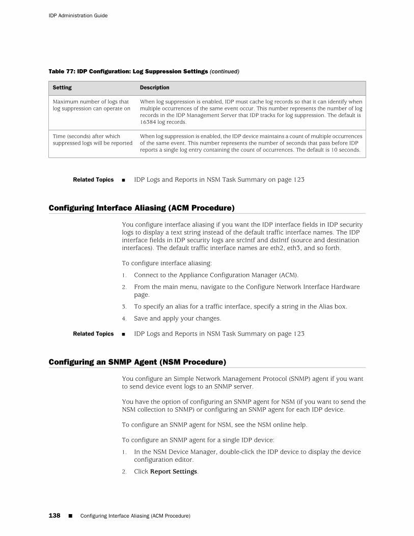
Table 77: IDP Configuration: Log Suppression Settings (continued)
DescriptionSetting
When log suppression is enabled, IDP must cache log records so that it can identify whenmultiple occurrences of the same event occur. This number represents the number of logrecords in the IDP Management Server that IDP tracks for log suppression. The default is16384 log records.
Maximum number of logs thatlog suppression can operate on
When log suppression is enabled, the IDP device maintains a count of multiple occurrencesof the same event. This number represents the number of seconds that pass before IDPreports a single log entry containing the count of occurrences. The default is 10 seconds.
Time (seconds) after whichsuppressed logs will be reported
Related Topics ■ IDP Logs and Reports in NSM Task Summary on page 123
Configuring Interface Aliasing (ACM Procedure)
You configure interface aliasing if you want the IDP interface fields in IDP securitylogs to display a text string instead of the default traffic interface names. The IDPinterface fields in IDP security logs are srcIntf and dstIntf (source and destinationinterfaces). The default traffic interface names are eth2, eth3, and so forth.
To configure interface aliasing:
1. Connect to the Appliance Configuration Manager (ACM).
2. From the main menu, navigate to the Configure Network Interface Hardwarepage.
3. To specify an alias for a traffic interface, specify a string in the Alias box.
4. Save and apply your changes.
Related Topics ■ IDP Logs and Reports in NSM Task Summary on page 123
Configuring an SNMP Agent (NSM Procedure)
You configure an Simple Network Management Protocol (SNMP) agent if you wantto send device event logs to an SNMP server.
You have the option of configuring an SNMP agent for NSM (if you want to send theNSM collection to SNMP) or configuring an SNMP agent for each IDP device.
To configure an SNMP agent for NSM, see the NSM online help.
To configure an SNMP agent for a single IDP device:
1. In the NSM Device Manager, double-click the IDP device to display the deviceconfiguration editor.
2. Click Report Settings.
138 ■ Configuring Interface Aliasing (ACM Procedure)
IDP Administration Guide

3. Complete SNMP settings as described in Table 78 on page 139.
Table 78: IDP Configuration: SNMP Settings
DescriptionSetting
Enables forwarding to a network management system that reads SNMP.Enable SNMP
Specifies the read-only community string, which is like a password used for the exchangebetween the IDP device and the network management system.
SNMP Read Only Community
Specifies the IP address of the SNMP server.SNMP Manager IP
Specifies an e-mail address for the IDP administrator contact. The contact is included in SNMPcommunications. If the network management system encounters a problem with the SNMPcommunication, an administrator can use the contact information to follow up.
SNMP Contact
Specifies a location of the IDP device. Location is included in SNMP communications.SNMP Location
4. Click OK.
Related Topics ■ IDP Logs and Reports in NSM Task Summary on page 123
Configuring Syslog Collection (NSM Procedure)
You configure syslog settings if you want to forward a copy of IDP logs to a syslogserver.
You have the option of configuring NSM to forward a copy of its log collection to asyslog server or configuring syslog settings for each IDP device.
To configure syslog forwarding for NSM, see the NSM online help.
To configure syslog forwarding for a single IDP device:
1. In the NSM Device Manager, double-click the IDP device to display the deviceconfiguration editor.
2. Click Report Settings.
3. Select Enable Syslog.
4. Specify the syslog server IP address.
5. Specify whether to forward packet logs to the syslog server.
6. Click OK.
Related Topics ■ IDP Logs and Reports in NSM Task Summary on page 123
Configuring Syslog Collection (NSM Procedure) ■ 139
Chapter 16: Working with NSM Logs and Reports

140 ■ Configuring Syslog Collection (NSM Procedure)
IDP Administration Guide

Chapter 17
Using IDP Reporter Reports
This chapter contains the following topics:
■ IDP Reporter Task Summary on page 141
■ Creating an IDP Reporter User on page 141
■ Connecting to IDP Reporter (IDP Reporter Procedure) on page 142
■ Troubleshooting IDP Reporter Access (IDP Reporter Procedure) on page 143
IDP Reporter Task Summary
IDP Reporter collects logs related to attacks and application volume tracking, parsesthem, and presents them as reports in HTML, PDF, or text formats.
You can use IDP Reporter to perform the following tasks:
■ View predefined reports on attacks
■ View predefined summaries of application volume statistics
■ Generate reports based on criteria you specify
■ Create jobs that regularly generate predefined or custom reports and E-mail themto customers or other interested parties
Related Topics Creating an IDP Reporter User on page 141■
■ Connecting to IDP Reporter (IDP Reporter Procedure) on page 142
Creating an IDP Reporter User
You can access IDP Reporter with the same credentials you use to access ACM.Alternatively, to distribute access to IDP Reporter only, you can create users withpermission to access IDP Reporter only.
To create an IDP Reporter user:
1. Log in to the IDP device as root.
2. Run the following command to create a user named reports:
useradd reports
IDP Reporter Task Summary ■ 141

3. Run the following command to change the password for the user named reports:
passwd reports
4. Edit /etc/httpd/conf/idphttp.conf to give the user reports access to the /reportsdirectory. Add the following line under <Location /reports>:
require user root reports
For example:
[root@defaulthost conf]# vi idphttpd.confetEnv PATH_TRANSLATED "/usr/idp/reporter/\1\2"SetEnv FWA_TEMPDIR "/usr/idp/reporter/temp/" <Location> /reports> require user root reports SetHandler perl-script PerlHandler WebConf::LaunchReports </Location>
5. Restart the httpd process by entering the following command:
service httpd restart
Related Topics ■ IDP Reporter Task Summary on page 141
Connecting to IDP Reporter (IDP Reporter Procedure)
You can access the IDP Reporter user interface with the following browsers:
■ Internet Exporer 6.x, 7.x
■ Mozilla Firefox 2.x
NOTE: IDP Reporter does not support Mozilla Firefox 3.x.
To access the IDP Reporter user interface:
1. If you have not already done so:
■ Download the latest Java virtual machine from the following location:
http://www.java.com/en/download/index.jsp
■ Install the Java software on your client host.
■ Ensure you have enabled Java and JavaScript in your Web browser. Do notblock pop-ups.
2. Type the following URL in your browser’s Address box:
https://mgmt-port_IP-address/reports
142 ■ Connecting to IDP Reporter (IDP Reporter Procedure)
IDP Administration Guide

Where mgmt-port_IP-address is the IP address for the management port on theIDP device.
3. Specify the credentials set for the Appliance Configuration Manager (ACM) whenprompted for a user name and password.
TIP: You can create reports-only users to distribute access to IDP Reporter to non-rootusers. See “Creating an IDP Reporter User” on page 141.
For information on using IDP Reporter, see the IDP Reporter User’s Guide.
Related Topics Troubleshooting IDP Reporter Access (IDP Reporter Procedure) on page 143■
■ Creating an IDP Reporter User on page 141
Troubleshooting IDP Reporter Access (IDP Reporter Procedure)
Problem Table 79 on page 143 provides tips for troubleshooting access to IDP Reporter andstatistics collection.
Table 79: Troubleshooting: IDP Reporter
Troubleshooting StepsSymptom
In your browser, you must enable Java and JavaScript and allow pop-ups.Display errors.
We recommend you set the JRE maximum heap space to 256 MB. If your heap space isbetween 128 MB and 256 MB, IDP Reporter can be launched but displays a messagenoting the recommended heap space. If the heap space is set to less than 128 MB, IDPReporter cannot be launched.
To set the Java heap space on a Windows client:
1. Click Start > Control Panel > Java to display the Java Control Panel.
2. Click the Java tab.
3. Click the View button in the Java Applet Runtime Settings area.
4. Click the cell in the Java Runtime Parameters column and type the following values:
-Xms256M -Xmx256M
Java heap space errors.
To eliminate certificate authority warnings:
1. Click Start > Control Panel > Java to display the Java Control Panel.
2. Click the Advanced tab.
3. Clear the following options under the Security section:
■ Warn if certificate authority cannot be verified
■ Warn if site certificate does not match hostname
Certificate authority warnings
Troubleshooting IDP Reporter Access (IDP Reporter Procedure) ■ 143
Chapter 17: Using IDP Reporter Reports

Table 79: Troubleshooting: IDP Reporter (continued)
Troubleshooting StepsSymptom
To restart the service:
1. Connect to IDP device using SSH and log in as the admin user.
2. Run the following command:
/etc/init.d/idprepservice restart
IDP service is unreachable.
Ensure you have enabled AVT and started Profiler.Reports do not contain statistics.
Use the idp.sh utility to ensure the IDP process is up and running. Restart if necessary
Use the statview meta command to ensure the AVT feature is regularly generating AVTdata. If the history shows collection stopped at some point, review your AVT and Profilersettings.
Review IDP Reporter log messages in the following locations:
■ /var/idp/reporter/logs/
■ /usr/idp/reporter/diaglogs/mainengine.log
■ /usr/idp/reporter/diaglogs/Parserdiag.log
If logs indicate IDP Reporter has stopped or is in a problematic state, restart it with thefollowing command:
/etc/inet.d/idprepservice [start|stop|restart]
If data collection is functioning but you do not see expected statistics in particular reports,check your IDP Reporter filter settings. Try removing filters to validate statistics aregenerated for a particular report. Then reapply filters and verify the report data haschanged to reflect the logic of the filter.
Related Topics ■ IDP Reporter Task Summary on page 141
144 ■ Troubleshooting IDP Reporter Access (IDP Reporter Procedure)
IDP Administration Guide

Chapter 18
Using the statview Command-Line Utility
This chapter contains the following topics:
■ statview Task Summary on page 145
statview Task Summary
You use the statview command-line utility to view and manage application volumetracking (AVT) statistics.
The statview utility is located in /usr/bin.
You use the statview utility to perform the following tasks:
■ Display AVT statistics tables
■ Query AVT tables
■ Display information about AVT statistic collections
TIP: You can also view application volume tracking (AVT) statistics with IDP Reporter.See the IDP Reporter User’s Guide.
Related Topics ■ statview Commands on page 225
statview Task Summary ■ 145

146 ■ statview Task Summary
IDP Administration Guide

Chapter 19
Using the sctop Command-Line Utility
This chapter contains the following topics:
■ sctop Task Summary on page 147
■ Using the sctop Utility (CLI Procedure) on page 147
■ Understanding sctop Flow Table Reports on page 149
sctop Task Summary
You use the sctop command-line utility to monitor the IDP connection tables andview IDP status.
The sctop utility is located in /usr/bin.
You use the sctop utility to perform the following tasks:
■ Display the ARP and MAC tables
■ Display the IP, ICMP, TCP, and UDP flow tables
■ Display STP information
■ Display RPC information
■ Display performance statistics for traffic, IDP security policies, and IDP processors
Related Topics ■ Using the sctop Utility (CLI Procedure) on page 147
Using the sctop Utility (CLI Procedure)
Purpose You use the sctop utility to monitor session information.
Action To connect to the command-line interface and use the sctop utility:
1. Use SSH to connect to the IP address or host name for the management interface.
2. Log in as the user admin.
3. Switch to the user root. For example:
# su -u root
4. At the secure shell, define the IDPDIR:
sctop Task Summary ■ 147

IDPDIR=/usr/idp export IDPDIR
NOTE: Bash is the default shell and bash commands are shown in the example. Ifyou use a different shell, use the equivalent commands.
5. At the command-line, type sctop to enter the sctop utility.
6. Press alphabetic keyboard keys to display the desired report. You can pressnumeric keys to sort report data.
Table 80 on page 148 describes the function of keyboard keys within the sctoputility.
Table 80: Command Key Reference: sctop Utility
FunctionKey
Displays help for the sctop utilityh
Displays the ARP/MAC table.a
Displays the IP flows.i
Displays the ICMP flows.c
Displays the UDP flows.u
Displays the TCP flows.t
Displays the RPC program table.r
Displays the RPC XID table.x
Displays status information about the .s
Displays system memory statistics.m
Displays qmodule statistics.l
Displays rulebase statistics.e
Displays aggregate statistics.g
Displays attack statistics.k
Displays Spanning Tree Protocol (STP) information.p
Displays the IP Action table.b
Displays packet distribution.z
Displays the strip chart, a text-based chart for packet/second, kbits/second, and the sessions that the UI sees.d
Displays fragment chain.f
148 ■ Using the sctop Utility (CLI Procedure)
IDP Administration Guide

Table 80: Command Key Reference: sctop Utility (continued)
FunctionKey
Displays HA status.w
Displays IDS cache statistics.y
Sorts in reverse order.v
Disables sorting.0
Sorts by bytes per session.1
Sorts by packets per session.2
Sorts by expiration.3
Sort by service.4
Sorts by destination port.5
Sorts by source address.6
Sorts by destination address.7
Related Topics Understanding sctop Flow Table Reports on page 149■
■ sctop Task Summary on page 147
Understanding sctop Flow Table Reports
Table 81 on page 149 is a sample sctop flow table report.
Table 81: sctop Flow Table Report
TimeoutServiceStateDirectionFlagPortDestination-IPPortSource-IP
30/30SMBLtn->>R----13910.150.20.43413710.150.98.62
30/30-Close<<-R----413710.150.98.6213910.150.20.43
30/30-Ltn->>R----4311710.150.20.242600010.150.73.39
The Flag column includes 5 bits. Table 82 on page 150 describes the sctop flow tableflag column.
Understanding sctop Flow Table Reports ■ 149
Chapter 19: Using the sctop Command-Line Utility

Table 82: sctop Flow Table: Flag Column
Position 5Position 4Position 3Position 2Position 1
Flow sync. One of thefollowing:
■ - (normal flow)
■ f (flow from failover)
■ s (flow synced fromanother IDP device)
Packet logging. Oneof the following:
■ P (packetlogging)
■ - (not packetlogging)
Auxiliary flow. Oneof the following:
■ a (auxiliaryflow)
■ - (not auxiliaryflow)
Management flow. Oneof the following:
■ m (managementflow)
■ – (notmanagementflow)
Flow state. One of thefollowing:
■ R (ready)
■ A (anticipated)
■ V (virtual)
■ X (rejected)
■ U (unknown)
For example, the flag R– – – – – signifies ready, nonmanagement, nonauxiliary, nopacket logging, normal; the flag A--ps signifies anticipated, nonmanagement,nonauxiliary, with packet logging, and synced over from another IDP.
Related Topics ■ sctop Task Summary on page 147
150 ■ Understanding sctop Flow Table Reports
IDP Administration Guide

Chapter 20
Using the bypassStatus Command-LineUtility
This chapter contains the following topics:
■ bypassStatus Utility Task Summary on page 151
bypassStatus Utility Task Summary
You use the bypassStatus command-line utility to monitor internal bypass for trafficinterfaces with copper ports. The bypassStatus utility displays the state of the bypassdaemon, the watchdog timer setting, the watchdog timer reset interval, and the stateof each copper pair.
The bypassStatus utility is located in /usr/idp/device/utils/.
Related Topics ■ bypassStatus Commands on page 191
bypassStatus Utility Task Summary ■ 151

152 ■ bypassStatus Utility Task Summary
IDP Administration Guide

Part 4
Additional Deployment Topics
■ Enabling IDP Processing of Encrypted and Encapsulated Traffic on page 155
■ Configuring Traffic Interfaces on page 159
■ Configuring IDP Appliances in Advanced Deployment Modes on page 165
■ Enabling Spanning Tree Protocol on page 173
■ High Availability Deployments on page 175
■ Configuring Interoperability with Juniper Secure Access and Infranet ControllerDevices on page 183
■ Troubleshooting on page 185
Additional Deployment Topics ■ 153

154 ■ Additional Deployment Topics
IDP Administration Guide

Chapter 21
Enabling IDP Processing of Encrypted andEncapsulated Traffic
This chapter contains the following topics:
■ Enabling SSL Decryption on page 155
■ Enabling GRE Decapsulation on page 156
■ Enabling Inspection of GTP Traffic on page 157
Enabling SSL Decryption
You can enable inspection of SSL traffic by first adding keys for the target SSL serversto the IDP keystore and then enabling the IDP SSL decryption feature.
For an overview of the IDP SSL decryption feature and lists of supported encryptionalgorithms and SSL ciphers, see the IDP Concepts and Examples Guide.
To add keys for target SSL servers to the IDP keystore:
1. Use SCP or FTP to copy your private key file to the IDP device. IDP does not runan FTP server, so you have to initiate the FTP session from the IDP device.
2. Add the key to the IDP keystore:
■ Use the following command syntax to add a key that does not have apassword:
scio ssl add key key_path server server_IP
■ Use the following command syntax to add a key with a password:
scio ssl add key key_path password password server server_IP
3. Retrieve the key ID from the IDP keystore:
scio ssl list all
4. Add any other servers that use the same key:
scio ssl add server server_IP key key_ID
Enabling SSL Decryption ■ 155

To enable SSL decryption:
1. In the NSM Device Manager, double-click the IDP device to display the deviceconfiguration editor.
2. Click Settings.
3. Click the Run-Time Parameters tab.
4. Expand the Run-Time Parameters group.
5. Select Enable SSL decryption support.
6. Click OK.
7. Push the updated configuration from NSM to the IDP device.
TIP: You can also use the scio const command to enable SSL decryption and changedefaults for the SSL session timeout and maximum number of SSL sessions handledby IDP.
Related Topics scio ssl■
■ scio const
Enabling GRE Decapsulation
You can use Network and Security Manager (NSM) or the CLI to enable inspectionof Generic Routing Encapsulation (GRE) encapsulated traffic.
To enable GRE decapsulation:
1. In the NSM Device Manager, double-click the IDP device to display the deviceconfiguration editor.
2. Click Settings.
3. Click the Run-Time Parameters tab.
4. Expand the Run-Time Parameters group.
5. Select Enable GRE decapsulation support.
6. Click OK.
7. Push the updated configuration from NSM to the IDP device.
TIP: You can also use the scio const command to enable GRE decapsulation andchange the default for the number of layers that can be decapsulated.
156 ■ Enabling GRE Decapsulation
IDP Administration Guide

Related Topics ■ scio const
Enabling Inspection of GTP Traffic
You can use Network and Security Manager (NSM) or the CLI to enable inspectionof GPRS Tunnel Protocol (GTP) encapsulated traffic.
To enable GTP decapsulation:
1. In the NSM Device Manager, double-click the IDP device to display the deviceconfiguration editor.
2. Click Settings.
3. Click the Run-Time Parameters tab.
4. Expand the Run-Time Parameters group.
5. Select Enable GTP decapsulation support.
6. Click OK.
7. Push the updated configuration from NSM to the IDP device.
TIP: You can also use the scio const command to enable GTP decapsulation andchange defaults for the number of layers that can be decapsulated, the timeout atwhich IDP closes the GTP tunnel, and the maximum number of concurrent GTPtunnels IDP can handle.
Related Topics ■ scio const
Enabling Inspection of GTP Traffic ■ 157
Chapter 21: Enabling IDP Processing of Encrypted and Encapsulated Traffic

158 ■ Enabling Inspection of GTP Traffic
IDP Administration Guide

Chapter 22
Configuring Traffic Interfaces
This chapter contains the following topics:
■ Traffic Interfaces Task Summary on page 159
■ Configuring Virtual Routers (ACM Procedure) on page 160
■ Configuring VLAN Tagging (ACM Procedure) on page 160
■ Configuring Internal Bypass (ACM Procedure) on page 161
■ Configuring External Bypass (ACM Procedure) on page 162
■ Enabling Peer Port Modulation (ACM Procedure) on page 163
Traffic Interfaces Task Summary
Typically, you use the Application Configuration Manager (ACM) wizard to configuretraffic interfaces when you initially set up the IDP device. If your deployment needschange, you can use ACM to reconfigure traffic interfaces.
IDP administration can include the following tasks related to configuration of trafficinterfaces:
■ Configure the number of virtual routers or the virtual router member interfaces(bridge, proxy-ARP, and router modes only)
■ Configure VLAN tagging (bridge, proxy-ARP, and router deployment modes only)
■ Configure internal bypass (transparent deployment mode only)
■ Configure external bypass (transparent or bridge mode only)
■ Configure peer port modulation
■ Configure interface aliasing, so that a string you specify appears in logs ratherthan default names (default names are eth0, eth1, eth2, and so forth)
Related Topics ■ Configuring Virtual Routers (ACM Procedure) on page 160
■ Configuring VLAN Tagging (ACM Procedure) on page 160
■ Configuring Internal Bypass (ACM Procedure) on page 161
■ Configuring External Bypass (ACM Procedure) on page 162
■ Enabling Peer Port Modulation (ACM Procedure) on page 163
■ Configuring Interface Aliasing (ACM Procedure) on page 138
Traffic Interfaces Task Summary ■ 159
Configuring Virtual Routers (ACM Procedure)
You use virtual routers to group traffic interfaces together for administrative androuting purposes. For background information, see the IDP Concepts and ExamplesGuide.
NOTE: Virtual routers are non-configurable in transparent mode. You can configurevirtual routers in bridge, proxy-ARP, router, and router modes only.
To configure virtual routers:
1. Connect to ACM.
2. On the ACM menu page, click Reconfigure VLAN/Virtual-Router Support.
3. Select Enable Virtual Routers.
4. Click Next to advance the wizard until you reach the Configure Forward Interfacesand Virtual Routers page.
5. On the Configure Forward Interfaces and Virtual Routers page:
■ Add or delete virtual routers to populate the virtual router list.
■ Assign traffic interfaces to virtual routers
For details, see the online help.
6. Click Next to advance the wizard until you reach the Brief Configuration Reportpage.
7. Review, save, and apply your configuration changes.
Related Topics Connecting to ACM (ACM Procedure) on page 114■
■ Traffic Interfaces Task Summary on page 159
Configuring VLAN Tagging (ACM Procedure)
You configure VLAN tagging if you deploy the IDP device in a VLAN. For backgroundinformation, see the IDP Concepts and Examples Guide.
NOTE: VLAN tagging is non-configurable in transparent mode. You can configureVLAN tagging in bridge, proxy-ARP, router, and router modes only.
To configure VLAN tagging:
1. Connect to ACM.
2. On the ACM menu page, click Reconfigure VLAN/Virtual-Router Support.
3. Select Enable 802.1Q VLAN Tags and click Next to advance the wizard.
160 ■ Configuring Virtual Routers (ACM Procedure)
IDP Administration Guide

4. On the Configure VLAN Tags page, use the controls to assign VLAN tags to trafficinterfaces.
5. Click Next to advance the wizard.
6. On the Choose Forwarding Interfaces page, the VLAN tagged interfaces appearas separate interfaces. Select them.
7. On the Configure Forwarding Interfaces and Virtual Routers page, the VLANtagged interfaces appear as separate interfaces. Assign the VLAN tagged interfacesto virtual routers.
8. Click Next to advance the wizard until you reach the Brief Configuration Reportpage.
9. Review, save, and apply your configuration changes.
Related Topics Connecting to ACM (ACM Procedure) on page 114■
■ Traffic Interfaces Task Summary on page 159
Configuring Internal Bypass (ACM Procedure)
You configure internal bypass to prevent the IDP device from becoming a point offailure in your network. For background, see the IDP Concepts and Examples Guide.
NOTE: IDP supports internal bypass for deployments in transparent mode only.
To configure internal bypass:
1. Connect to ACM.
2. On the ACM menu page, click Reconfigure Network Interface Hardware.
3. Click Next to advance the wizard until you reach the Choose ForwardingInterfaces page.
4. Use the controls to set NIC state for applicable interfaces to NIC bypass.
For details, see the online help.
5. Click Next to advance the wizard until you reach the Brief Configuration Reportpage.
6. Review, save, and apply your configuration changes.
Related Topics Connecting to ACM (ACM Procedure) on page 114■
■ Traffic Interfaces Task Summary on page 159
Configuring Internal Bypass (ACM Procedure) ■ 161
Chapter 22: Configuring Traffic Interfaces

Configuring External Bypass (ACM Procedure)
You configure external bypass if your model or deployment mode does not supportinternal bypass and you want to prevent the IDP device from becoming a point offailure in your network. For background, see the IDP Concepts and Examples Guide.
NOTE: IDP supports external bypass for deployments in transparent mode or bridgemode only.
To configure external bypass for transparent mode:
1. Connect to ACM.
2. On the ACM menu page, click Reconfigure Deployment mode.
3. Click Transparent to ensure you are configuring the device in transparent mode.
4. Click Next to advance the wizard until you reach the Choose ForwardingInterfaces page.
5. Use the controls to set NIC state for applicable interfaces to External bypassunit.
For details, see the online help.
6. Click Next to advance the wizard until you reach the Brief Configuration Reportpage.
7. Review, save, and apply your configuration changes.
To configure external bypass for bridge mode:
1. Connect to ACM.
2. On the ACM menu page, click Reconfigure Deployment Mode.
3. Click Bridge to ensure you are configuring the device in bridge mode.
4. Click Next to advance the wizard until you reach the Choose ForwardingInterfaces page.
5. On the Choose Forwarding Interfaces page, select Enable External bypass unit.
For details, see the online help.
6. Click Next to advance the wizard until you reach the Brief Configuration Reportpage.
7. Review, save, and apply your configuration changes.
Related Topics Connecting to ACM (ACM Procedure) on page 114■
■ Traffic Interfaces Task Summary on page 159
162 ■ Configuring External Bypass (ACM Procedure)
IDP Administration Guide

Enabling Peer Port Modulation (ACM Procedure)
You configure peer port modulation (PPM) if you want all traffic interfaces in a virtualrouter to reflect the state of a downed interface. When the downed interface isbrought back on line, PPM propagates the up state to all interfaces in the virtualrouter.
To enable peer port modulation:
1. Connect to ACM.
2. On the ACM menu page, click Reconfigure Network Interface Hardware.
3. Click Next to advance the wizard until you reach the Choose ForwardingInterfaces page.
4. Select Enable Peer Port Modulator.
For details, see the online help.
5. Click Next to advance the wizard until you reach the Brief Configuration Reportpage.
6. Review, save, and apply your configuration changes.
Related Topics ■ Connecting to ACM (ACM Procedure) on page 114
■ Traffic Interfaces Task Summary on page 159
Enabling Peer Port Modulation (ACM Procedure) ■ 163
Chapter 22: Configuring Traffic Interfaces

164 ■ Enabling Peer Port Modulation (ACM Procedure)
IDP Administration Guide

Chapter 23
Configuring IDP Appliances in AdvancedDeployment Modes
This chapter contains the following topics:
■ Configuring IDP in Bridge Mode (ACM Procedure) on page 165
■ Configuring IDP in Proxy-ARP Mode (ACM Procedure) on page 167
■ Configuring IDP in Router Mode (ACM Procedure) on page 169
Configuring IDP in Bridge Mode (ACM Procedure)
In bridge mode, IDP acts as a networking bridge, forwarding packets between thephysical parts of a logical network subnet.
You do not need to configure other network devices to be aware of the IDP device,but you can assign the forwarding interfaces an IP address, if needed.
Configuring IDP in Bridge Mode (ACM Procedure) ■ 165

To deploy the device in bridge mode:
1. Install the IDP device. When you run the ACM wizard, follow the guidelines inTable 83 on page 166.
Table 83: ACM Wizard: Bridge Mode Guidelines
GuidelineOption
BridgeDeployment mode
Non-configurable: in bridge mode, traffic interfaces pass through Layer 2 ARP and DHCPbroadcasts.
Layer 2 bypass
Third-Party Failover/LoadbalancingHigh Availability
In bridge, proxy-ARP, and router modes, IDP removes VLAN tags from incoming frames,processes the packet. If you configure IDP VLAN tagged interfaces, IDP retags the outgoingframes. If you do not configure IDP VLAN tagged interfaces, IDP generates normal (untagged)Ethernet frames.
VLAN Tagging
You can configure virtual routers, including non-contiguous pairs.Virtual Routers
Non-configurable: in bridge mode, in case of failure of graceful shutdown, interfaces followNICs off behavior–that is, in case of failure or graceful shutdown, the NIC state is set to offand interfaces are unavailable to receive connections.
NIC state
Not available.Internal bypass
If you want to implement external bypass, select Enable external bypass unit so that allinterfaces pass through the NetScreen Redundancy Protocol (NSRP) packets that are used tocommunicate with an external bypass unit
External bypass
Configurable. Disabled by default.Peer port modulation
Optionally, specify an IP address and netmask.Traffic interfaces
You must configure a default gateway.
Optionally, you can configure static routes.
Routing table
2. Connect traffic interfaces to network switches or firewalls.
3. Add the IDP device to the NSM device manager.
4. Update the NSM attack object database.
5. Become familiar with the default, recommended security policy.
6. Run the Profiler to become learn about the network hosts you want to protect.
166 ■ Configuring IDP in Bridge Mode (ACM Procedure)
IDP Administration Guide

7. Review logs to verify the initial deployment.
8. Use the documentation to become familiar with the product features and userinterface:
■ Use the IDP Concepts and Examples Guide to become familiar with IDPfeatures.
■ Use this guide, the IDP Administration Guide, to learn the steps to implementIDP features and monitor security events.
■ Use the NSM online help for information about using the NSM user interface.
■ Use CLI man pages for syntax and parameter hints for CLI commands.
Related Topics ■ Connecting to ACM (ACM Procedure) on page 114
■ Adding IDP Devices to NSM Device Manager on page 76
■ Loading J-Security Center Updates (NSM Procedure) on page 54
■ Developing Security Policies Task Summary on page 23
■ Profiler Task Summary on page 7
■ IDP Logs and Reports in NSM Task Summary on page 123
Configuring IDP in Proxy-ARP Mode (ACM Procedure)
In proxy-ARP mode, the IDP device acts as a proxy, sending ARP requests and repliesbetween networks.
An ARP request or reply is a mechanism to resolve IP addresses. Network devicescoming online send out ARP requests to determine if a particular IP address is beingused. In IDP deployments, network nodes use the IDP MAC address to send networktraffic across segments. The IDP device relays ARP requests between networks andproxies replies by issuing its own ARP replies.
Configuring IDP in Proxy-ARP Mode (ACM Procedure) ■ 167
Chapter 23: Configuring IDP Appliances in Advanced Deployment Modes

To deploy the device in proxy-ARP mode:
1. Install the IDP device. When you run the ACM wizard, follow these guidelinesrelated to proxy-ARP deployments.
Table 84: ACM Wizard: Proxy-ARP Guidelines
GuidelineOption
Proxy-ARPDeployment mode
Non-configurable: in proxy-ARP mode, traffic interfaces drop Layer 2 traffic and cannot passit through.
Layer 2 bypass
The following options are available:High Availability
■ Standalone Failover
■ Standalone Loadbalancing
■ Third-Party Failover/Loadbalancing
In bridge, proxy-ARP, and router modes, IDP removes VLAN tags from incoming frames,processes the packet. If you configure IDP VLAN tagged interfaces, IDP retags the outgoingframes. If you do not configure IDP VLAN tagged interfaces, IDP generates normal (untagged)Ethernet frames.
VLAN Tagging
You can configure virtual routers, including non-contiguous pairs.Virtual Routers
Non-configurable: in proxy-ARP mode, in case of failure of graceful shutdown, interfacesfollow NICs off behavior–that is, in case of failure or graceful shutdown, the NIC state is setto off and interfaces are unavailable to receive connections.
NIC state
Not available.Internal bypass
Not configurable.External bypass
Configurable. Disabled by default.Peer port modulation
Require an IP address and netmask.Traffic interfaces
You must configure a default gateway.
Optionally, you can configure static routes.
Routing table
2. Connect traffic interfaces to network switches or firewalls.
3. Add the IDP device to the NSM device manager.
4. Update the NSM attack object database.
5. Become familiar with the default security policy (named Recommended).
6. Run the Profiler to learn about the network hosts you want to protect.
168 ■ Configuring IDP in Proxy-ARP Mode (ACM Procedure)
IDP Administration Guide

7. Review logs to verify the initial deployment.
8. Use the documentation to become familiar with the product features and userinterface:
■ Use the IDP Concepts and Examples Guide to become familiar with IDPfeatures.
■ Use this guide, the IDP Administration Guide, to learn the steps to implementIDP features and monitor security events.
■ Use the NSM online help for information about using the NSM user interface.
■ Use CLI man pages for syntax and parameter hints for CLI commands.
Related Topics ■ Adding IDP Devices to NSM Device Manager on page 76
■ Loading J-Security Center Updates (NSM Procedure) on page 54
■ Developing Security Policies Task Summary on page 23
■ Profiler Task Summary on page 7
■ IDP Logs and Reports in NSM Task Summary on page 123
Configuring IDP in Router Mode (ACM Procedure)
You deploy IDP in router mode in networks where you want the IDP device to connectIP networks with different address spaces.
In router mode, the IDP acts as a traditional IP router. The IDP device accepts packetsfrom an attached network, examines the destination address, consults its routingtables, and forwards the packets accordingly.
You do not need to configure other network devices to be aware of the IDP device,but you can assign the forwarding interfaces an IP address, if needed.
Configuring IDP in Router Mode (ACM Procedure) ■ 169
Chapter 23: Configuring IDP Appliances in Advanced Deployment Modes

To deploy the device in router mode:
1. Install the IDP device. When you run the ACM wizard, follow these guidelinesrelated to router mode deployments.
Table 85: ACM Wizard: Router Mode Guidelines
GuidelineOption
RouterDeployment mode
Non-configurable: in router mode, traffic interfaces drop Layer 2 traffic and cannot pass itthrough.
Layer 2 bypass
The following options are available:High Availability
■ Standalone Failover
■ Standalone Loadbalancing
■ Third-Party Failover/Loadbalancing
In bridge, proxy-ARP, and router modes, IDP removes VLAN tags from incoming frames,processes the packet. If you configure IDP VLAN tagged interfaces, IDP retags the outgoingframes. If you do not configure IDP VLAN tagged interfaces, IDP generates normal (untagged)Ethernet frames.
VLAN Tagging
You can configure virtual routers, including non-contiguous pairs.Virtual Routers
Non-configurable: in router mode, in case of failure of graceful shutdown, interfaces followNICs off behavior–that is, in case of failure or graceful shutdown, the NIC state is set to offand interfaces are unavailable to receive connections.
NIC state
Not available.Internal bypass
Not configurable.External bypass
Configurable. Disabled by default.Peer port modulation
Require an IP address and netmask.Traffic interfaces
You must configure a default gateway.
Optionally, you can configure static routes.
NOTE: You must also update the network routing tables to reflect that the IDP device is agateway.
Routing table
2. Connect traffic interfaces to network switches or firewalls.
3. Add the IDP device to the NSM device manager.
4. Update the NSM attack object database.
5. Become familiar with the default security policy (named Recommended).
6. Run the Profiler to learn about the network hosts you want to protect.
170 ■ Configuring IDP in Router Mode (ACM Procedure)
IDP Administration Guide

7. Review logs to verify the initial deployment.
8. Use the documentation to become familiar with the product features and userinterface:
■ Use the IDP Concepts and Examples Guide to become familiar with IDPfeatures.
■ Use this guide, the IDP Administration Guide, to learn the steps to implementIDP features and monitor security events.
■ Use the NSM online help for information about using the NSM user interface.
■ Use CLI man pages for syntax and parameter hints for CLI commands.
Related Topics ■ Connecting to ACM (ACM Procedure) on page 114
■ Adding IDP Devices to NSM Device Manager on page 76
■ Loading J-Security Center Updates (NSM Procedure) on page 54
■ Developing Security Policies Task Summary on page 23
■ Profiler Task Summary on page 7
■ IDP Logs and Reports in NSM Task Summary on page 123
Configuring IDP in Router Mode (ACM Procedure) ■ 171
Chapter 23: Configuring IDP Appliances in Advanced Deployment Modes

172 ■ Configuring IDP in Router Mode (ACM Procedure)
IDP Administration Guide

Chapter 24
Enabling Spanning Tree Protocol
This chapter contains the following topics:
■ Using STP in Bridge Mode Deployments on page 173
■ Enabling STP (CLI Procedure) on page 173
■ Monitoring STP (CLI Procedure) on page 174
■ Disabling STP (CLI Procedure) on page 174
Using STP in Bridge Mode Deployments
IDP supports Spanning Tree Protocol (STP) when IDP is deployed in the followingmodes:
■ In bridge mode, IDP devices can actively participate in STP.
■ In transparent mode, IDP devices do not actively participate in STP, but they dopass the BPDUs used by STP.
IDP does not support STP in other deployment modes.
Related Topics Enabling STP (CLI Procedure) on page 173■
■ Disabling STP (CLI Procedure) on page 174
■ Monitoring STP (CLI Procedure) on page 174
Enabling STP (CLI Procedure)
To enable STP:
1. Open the /usr/idp/device/bin/user_funcs file in a text editor, such as vi.
2. Locate the line user_start_end() and add the following line below it:
$SCIO const -v vr0 set sc_stp_enabled 1
3. Save the file and exit the editor.
4. Reboot the IDP device.
Related Topics Using STP in Bridge Mode Deployments on page 173■
■ scio const
Using STP in Bridge Mode Deployments ■ 173

Monitoring STP (CLI Procedure)
Purpose You can use the sctop utility to monitor the spanning tree protocol (STP) state foreach forwarding interface.
Action To monitor the STP state, use the sctop command-line utility with option p.
Related Topics Using the sctop Utility (CLI Procedure) on page 147■
■ Using STP in Bridge Mode Deployments on page 173
Disabling STP (CLI Procedure)
To disable STP:
1. Open the /usr/idp/device/bin/user_funcs file in a text editor, such as vi.
2. Locate the line user_start_end() and add the following line below it:
$SCIO const -v vr0 set sc_stp_enabled 0
3. Save the file and exit the editor.
4. Reboot the IDP device.
TIP: If you want to disable STP only temporarily (for troubleshooting, for example),you can use the scio const command to disable STP. Use the following command:
scio const -v vr0 set sc_stp_enabled 0
Note that if you use the command line to start and stop STP, the STP state is notpersistent across restarts. Upon restart, the setting in the user_funcs file is applied.
Related Topics ■ Using STP in Bridge Mode Deployments on page 173
■ scio const
174 ■ Monitoring STP (CLI Procedure)
IDP Administration Guide

Chapter 25
High Availability Deployments
This chapter contains the following topics:
■ Configuring Standalone High Availability on page 175
■ Configuring a Third-Party Device to Manage Hot Standby or LoadBalancing on page 179
■ Verifying High Availability Communication (CLI Procedure) on page 180
Configuring Standalone High Availability
You configure standalone high availability (HA) when you deploy a cluster of IDPdevices to provide failover or loadbalancing and you want to use IDP HA features toimplement the HA-related network communication.
For an overview of standalone high availability requirements and examples ofstandalone high availability deployments, see the IDP Concepts and Examples Guide.
To configure standalone HA:
1. Install the IDP devices into the equipment rack as described in the installationguide for your IDP model.
2. Connect the HA interface ports of the devices with a crossover cable.
3. When you use ACM to configure the devices, configure the HA-related settingsdescribed in Table 86 on page 175.
Table 86: Standalone High Availability ACM Settings
GuidelineACM Page
Select one of the following modes:
■ Proxy-ARP
■ Router
NOTE: IDP does not support standalone HA in bridge, transparent, or sniffer modes.
NOTE: Must be the same for all IDP nodes in the cluster.
Choose DeploymentMode
Configuring Standalone High Availability ■ 175

Table 86: Standalone High Availability ACM Settings (continued)
GuidelineACM Page
Select one of the following modes:
■ Standalone Hot Standby–In this deployment, a primary node handles all network traffic whilea secondary node stands by. If the primary node fails, network traffic is redirected to thesecondary node.
■ Standalone Load Balancing–In this deployment, all nodes in the cluster share network trafficequally. If a node fails, network traffic is redirected to the other nodes in the cluster.
NOTE: Must be the same for all IDP nodes in the cluster.
Configure HighAvailability
Select the interface to use for state-sync communications with the cluster peer.IDP uses this interface to send state-sync traffic only; no other traffic may pass.
If your IDP model includes a dedicated HA interface, the interface is eth1 andis the only interface listed.
InterfaceConfigure HAState-Sync
Complete the following fields to assign an IP address to the HA interface:
■ IP. Type the IP address for the HA interface. The IP address must be in adedicated broadcast domain that is used by all nodes in the HA cluster.When IDP sends traffic through the HA interface, the data is broadcast toall nodes in the cluster.
■ Netmask. Type the netmask to be associated with HA interface IP address.
IP Configuration
Assign a unique identifier to this node (0-15). For hot-standby, the device withthe lowest unique identifier is the primary device. For load balancing, thisassignment is arbitrary and is used only to differentiate sensors in the clusterfrom each other.
TIP: There are exactly two IDP nodes in a cluster. Follow a convention whereyou always use unique IDs 1 and 2.
Choose a uniqueidentifier for thissensor
176 ■ Configuring Standalone High Availability
IDP Administration Guide

Table 86: Standalone High Availability ACM Settings (continued)
GuidelineACM Page
The forwarding mode is the broadcast method your switch uses to forward trafficto the IDP cluster. Select one of the following modes:
■ unicast. Select if your network switch supports unicast traffic to multipleports. You can use unicast if your Layer 3 devices cannot learn multicastARP.
■ multicast. Select if your network switch supports multicast traffic to multipleports. However, if your Layer 3 devices cannot learn multicast ARP, werecommend you not use multicast.
NOTE: Must be the same for all IDP nodes in the cluster.
ForwardingMode
Configure StandaloneHA
Select an ID number from the list. A cluster ID is the unique identifier of an HAcluster. This assignment is arbitrary and is used only to differentiate HA clustersfrom each other.
NOTE: Must be the same for all IDP nodes in the cluster.
Cluster ID
Select an interval (seconds) from the list.
Nodes in an HA cluster communicate using a heartbeat protocol. At the intervalyou specify, a node sends one or more heartbeats to other nodes in the HAcluster. If a node fails to send a heartbeat for the specified number of times ina row (the failure count), the other nodes consider that node inactive.
The default is 1.
NOTE: Must be the same for all IDP nodes in the cluster.
Test/HeartbeatInterval
Select a number from the list. The failure count is:
■ The number of intervals during which a heartbeat is not received before asensor is considered to be inactive by other sensors in the cluster.
■ The number of intervals during which a ping can fail before the sensorinforms the other sensors in the cluster that it is inactive.
The default is 3.
NOTE: Must be the same for all IDP nodes in the cluster.
Failure Count
Select a number from the list. A reintegrate count is the number of times theset of link-checks for a previously inactive node must succeed before it isreintegrated into the system.
The reintegration process gives a newly active node the opportunity tosynchronize its state table with other nodes before it begins accepting traffic.This prevents the node from accepting existing connections without the properstate table entry, which can cause improper analysis. The threshold also helpsprevent network disruption (or "flapping") in cases where a node joins andleaves the cluster repeatedly over a short period of time.
The default is 5.
NOTE: Must be the same for all IDP nodes in the cluster.
ReintegrateCount
Configuring Standalone High Availability ■ 177
Chapter 25: High Availability Deployments
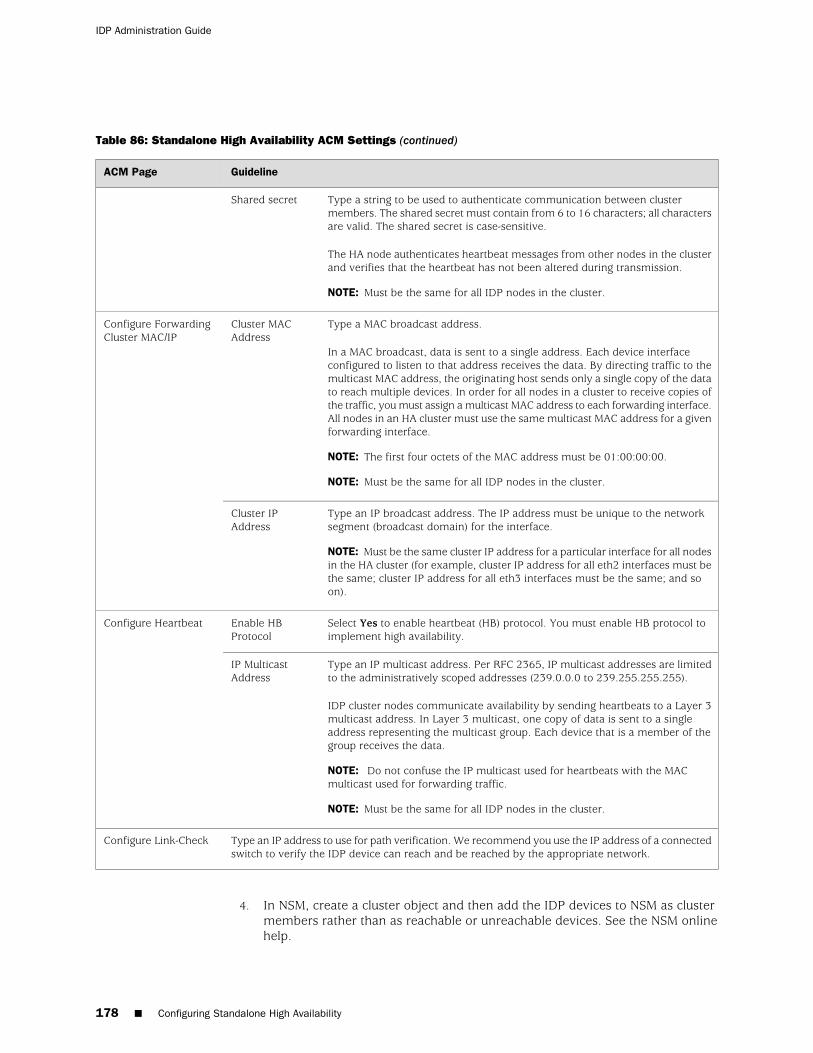
Table 86: Standalone High Availability ACM Settings (continued)
GuidelineACM Page
Type a string to be used to authenticate communication between clustermembers. The shared secret must contain from 6 to 16 characters; all charactersare valid. The shared secret is case-sensitive.
The HA node authenticates heartbeat messages from other nodes in the clusterand verifies that the heartbeat has not been altered during transmission.
NOTE: Must be the same for all IDP nodes in the cluster.
Shared secret
Type a MAC broadcast address.
In a MAC broadcast, data is sent to a single address. Each device interfaceconfigured to listen to that address receives the data. By directing traffic to themulticast MAC address, the originating host sends only a single copy of the datato reach multiple devices. In order for all nodes in a cluster to receive copies ofthe traffic, you must assign a multicast MAC address to each forwarding interface.All nodes in an HA cluster must use the same multicast MAC address for a givenforwarding interface.
NOTE: The first four octets of the MAC address must be 01:00:00:00.
NOTE: Must be the same for all IDP nodes in the cluster.
Cluster MACAddress
Configure ForwardingCluster MAC/IP
Type an IP broadcast address. The IP address must be unique to the networksegment (broadcast domain) for the interface.
NOTE: Must be the same cluster IP address for a particular interface for all nodesin the HA cluster (for example, cluster IP address for all eth2 interfaces must bethe same; cluster IP address for all eth3 interfaces must be the same; and soon).
Cluster IPAddress
Select Yes to enable heartbeat (HB) protocol. You must enable HB protocol toimplement high availability.
Enable HBProtocol
Configure Heartbeat
Type an IP multicast address. Per RFC 2365, IP multicast addresses are limitedto the administratively scoped addresses (239.0.0.0 to 239.255.255.255).
IDP cluster nodes communicate availability by sending heartbeats to a Layer 3multicast address. In Layer 3 multicast, one copy of data is sent to a singleaddress representing the multicast group. Each device that is a member of thegroup receives the data.
NOTE: Do not confuse the IP multicast used for heartbeats with the MACmulticast used for forwarding traffic.
NOTE: Must be the same for all IDP nodes in the cluster.
IP MulticastAddress
Type an IP address to use for path verification. We recommend you use the IP address of a connectedswitch to verify the IDP device can reach and be reached by the appropriate network.
Configure Link-Check
4. In NSM, create a cluster object and then add the IDP devices to NSM as clustermembers rather than as reachable or unreachable devices. See the NSM onlinehelp.
178 ■ Configuring Standalone High Availability
IDP Administration Guide

Related Topics Connecting to ACM (ACM Procedure) on page 114■
■ Verifying High Availability Communication (CLI Procedure) on page 180
Configuring a Third-Party Device to Manage Hot Standby or Load Balancing
You configure third-party high availability (HA) when you deploy a cluster of IDPdevices to provide failover or loadbalancing and you want to use third-party HAfeatures to implement the HA-related network communication.
For an overview of third-party high availability requirements and examples ofthird-party high availability deployments, see the IDP Concepts and Examples Guide.
To configure third-party HA:
1. Install the IDP devices into the equipment rack as described in the installationguide for your IDP model.
2. Connect the HA interface ports of the devices with a crossover cable.
3. When you use ACM to configure the devices, configure the HA-related settingsdescribed in Table 87 on page 179.
Table 87: Third-Party High Availability ACM Settings
GuidelineACM Page
Select one of the following modes:
■ Bridge
■ Proxy-ARP
■ Router
■ Transparent
NOTE: IDP does not support third-party HA in sniffer mode.
Choose DeploymentMode
Select Third-Party Hot Standby/Load Balancing. In this deployment, external third-party deviceshandle the hot-standby configuration, load balancing configuration, or both.
Configure HighAvailability
Configuring a Third-Party Device to Manage Hot Standby or Load Balancing ■ 179
Chapter 25: High Availability Deployments

Table 87: Third-Party High Availability ACM Settings (continued)
GuidelineACM Page
Select the interface to use for state-sync communications with the cluster peer.IDP uses this interface to send state-sync traffic only; no other traffic may pass.
If your IDP model includes a dedicated HA interface, it is the only interfacelisted–eth1.
InterfaceConfigure HAState-Sync
Complete the following fields to assign an IP address to the HA interface:
■ IP. Type the IP address for the HA interface. The IP address must be in adedicated broadcast domain that is used by all nodes in the HA cluster.When IDP sends traffic through the HA interface, the data is broadcast toall nodes in the cluster.
■ Netmask. Type the netmask to be associated with HA interface IP address.
IP Configuration
Assign a unique identifier to this node (0-15).
TIP: There are exactly two IDP nodes in a cluster. Follow a convention whereyou always use unique IDs 1 and 2.
Choose a uniqueidentifier for thissensor
4. In NSM, create a cluster object and then add the IDP devices to NSM as clustermembers rather than as reachable or unreachable devices.
5. Implement failover or loadbalancing according to the documentation for thethird-party HA solution.
Related Topics Connecting to ACM (ACM Procedure) on page 114■
■ Verifying High Availability Communication (CLI Procedure) on page 180
Verifying High Availability Communication (CLI Procedure)
Purpose This topic provides steps to verify the status of the HA function.
Action To verify HA communication with sctop:
1. Connect to the CLI and start the sctop utility.
2. Type w to display status of the HA function.
UP indicates that the node is functioning normally.
DOWN indicates that the node is not sending heartbeats, not receiving heartbeats,or there is a switch problem.
To verify HA communication with NSM Realtime Monitor, in the NSM navigationtree, select Realtime Monitor > IDP Cluster Monitor.
To view HA-related logs in NSM:
1. In the NSM navigation tree, select Investigate > Log Viewer > Predefined.
180 ■ Verifying High Availability Communication (CLI Procedure)
IDP Administration Guide

2. Click Config to view configuration-related logs.
The following logs pertain to IDP HA:
■ HA_DISABLED–The IDP kernel module has been reconfigured to disablestandalone HA. The IDP is handling all incoming traffic.
■ HA_WAIT_HA–The IDP kernel module is waiting for the standalone highavailability daemon (schad) to start. The IDP does not forward traffic until theHA daemon starts.
■ HA_INIT_FORWARD–The schad daemon has started. The IDP is forwardingtraffic.
■ HA_INIT_BLOCK–The schad daemon has started. The IDP is not forwardingtraffic.
■ HA_OKAY–The schad daemon has moved from the INIT state to the OK state.The IDP is forwarding traffic.
■ HA_LOCAL_FAILED–The schad daemon is experiencing difficulties trying toreach a verify IP. The link or the verify IP host may be down. To resolve, lookat the destination address.
■ HA_REMOTE_FAILED–A remote node in the HA cluster has failed and has eithersent a heartbeat FAIL message or is no longer sending heartbeats. To resolve,look at the destination port number for the node ID of the remote node.
■ HA_SHUTDOWN–The schad daemon has shut down with no problems. The IDPis no longer forwarding traffic.
NOTE: If necessary, you can enable local logging on the IDP device. For details,contact Juniper Networks Technical Assistance Center (JTAC).
Related Topics ■ Connecting to the Command-Line Interface (CLI Procedure) on page 191
■ Configuring Standalone High Availability on page 175
■ Configuring a Third-Party Device to Manage Hot Standby or LoadBalancing on page 179
Verifying High Availability Communication (CLI Procedure) ■ 181
Chapter 25: High Availability Deployments

182 ■ Verifying High Availability Communication (CLI Procedure)
IDP Administration Guide

Chapter 26
Configuring Interoperability with JuniperSecure Access and Infranet ControllerDevices
This chapter contains the following topics:
■ Generating a One-Time Password for Communication for Coordinated ThreatControl (ACM Procedure) on page 183
■ IDP Configuration Requirements for Coordinated Threat Control on page 184
Generating a One-Time Password for Communication for Coordinated Threat Control(ACM Procedure)
In a Juniper Networks coordinated threat control (CTC) deployment, the IDP devicesends logs to a Secure Access (SA) or Infranet Controller (IC) device. To enableauthenticated communication between IDP and SA or IC, you use Application ControlManager (ACM) to set a one-time password (OTP) used by SA or IC to establish theinitial session.
For details on how IDP is used in a CTC deployment, see the IDP Concepts andExamples Guide.
To generate an OTP for the SA or IC connection to IDP:
1. Connect to ACM.
2. In the ACM menu, click Reconfigure Management Server and IDP IVECommunication.
3. Select Reset IVE OPT?.
4. Click Next Step.
A new OTP is generated and displayed in the IVE OTP field of the FinalConfiguration Report.
5. Click Confirm Configuration to save the new IVE OTP.
6. If you are not the SA or IC administrator, give the one-time password to them.
The IDP device forwards logs to the SA or IC device based on the SA or ICconfiguration.
Generating a One-Time Password for Communication for Coordinated Threat Control (ACM Procedure) ■ 183

Related Topics Connecting to ACM (ACM Procedure) on page 114■
■ IDP Configuration Requirements for Coordinated Threat Control on page 184
IDP Configuration Requirements for Coordinated Threat Control
Coordinated threat control (CTC) depends on attack logs sent from the IDP deviceto a Secure Access (SA) or Infranet Controller (IC) device. To support CTC, ensurethe following settings in IDP:
■ Log suppression for the IDP device must be disabled. UTC depends on notificationto the SA or IC device of each event. If log suppression is enabled, IDP mightonly report one occurrence for numerous virtual connections coming throughthe SA or IC device.
■ Relevant security policy rules must have logging enabled (configure notificationoptions).
■ IP actions (such as IP Block and IP Close) are not advised in policies that examinetraffic from an SA or IC device. Closing or blocking a connection based on IPaddress might shut down numerous VPN sessions.
Related Topics ■ Generating a One-Time Password for Communication for Coordinated ThreatControl (ACM Procedure) on page 183
184 ■ IDP Configuration Requirements for Coordinated Threat Control
IDP Administration Guide

Chapter 27
Troubleshooting
This chapter contains the following topics:
■ Troubleshooting Tools Overview on page 185
■ IDP Processes Reference on page 186
Troubleshooting Tools Overview
Table 88 on page 185 summarizes IDP troubleshooting tools.
Table 88: IDP Troubleshooting Tools
DescriptionTool
The tech-support utility runs the following commands in the background and saves the output to a zippedtemporary file you can e-mail to JTAC:
■ getplatform
■ ps
■ df
■ lsof
■ du
■ ifconfig
■ netstat
■ scio sysconf all
■ scio const list
■ scio vr list
■ scio vs list
■ ping
■ tcpdump
If you want to view the contents of the zip files, use the bunzip2 command.
tech-support
The tcpdump utility captures traffic and saves it to a file. For example, to perform a packet capture andsave SMTP packets on interface eth1 to a file, use the following command:
# tcpdump -iI eth1 -s 0 -w /tmp/smtp.pcap tcp port 25
tcpdump
Troubleshooting Tools Overview ■ 185

Table 88: IDP Troubleshooting Tools (continued)
DescriptionTool
In some cases, packet captures might be helpful to reproduce an issue so that it can be analyzed andresolved. The following command captures all services and contexts from all sessions:
scio ccap all
scio ccap all
IDP supports the Linux ethtool utility (the IDP kernel is Linux-based). You can use ethtool to query andconfigure network interfaces.
ethtool
In some cases, JTAC might recommend you run a special build of the IDP kernel in order to generatedebugging information that can be used to determine the root cause of an issue.
IDP debug build
If necessary, you can revert to the factory image of the IDP device. For information, see the installationguide for your IDP device.
Reimaging
Related Topics ■ IDP Processes Reference on page 186
IDP Processes Reference
Specific IDP processes generate error messages. Knowing the process thatencountered the error can often help you isolate and resolve the issue.
Table 89 on page 186 provides a reference of IDP processes.
Table 89: Troubleshooting: IDP Processes Reference
DescriptionProcess
Establishes the transport layer security (TLS) channel to Network and Security Manager (NSM). Sends IDPstatus, logs, and profiled data to NSM. Receives policy, detector, and configuration commands from NSM.
agent
Purges logs when disk is full or nearly full.dLogPurger
Kernel module that is the core IDP engine.idp
Health monitoring alerts daemon. Generates SNMP alerts when thresholds are crossed for tracked resourceson the device. Responds to SNMP poll requests. Resources are CPU, memory, hard disk space, and sessioncount.
idpHMD
Reads IDP logs and writes them to local hard disk.idpLogReader
Controls the internal bypass feature.nicBypass
Controls peer port modulation.peerPortModulator
Inspects SSL traffic, if SSL inspection is turned on.pkid
Profiles network and application data collected by the device.profiler
Performs load balancing and failover between sensors in a high availability (HA) configuration.schad
186 ■ IDP Processes Reference
IDP Administration Guide

Table 89: Troubleshooting: IDP Processes Reference (continued)
DescriptionProcess
Handles policy push, information retrieval, Profiler status, and so on.sciod
When packet logging is enabled, retrieves session data and sends it to NSM.sessionFetcher
Logs packet captures to the IDP hard disk.slogd
IDP Processes Reference ■ 187
Chapter 27: Troubleshooting

188 ■ IDP Processes Reference
IDP Administration Guide

Part 5
Appendixes
■ bypassStatus Commands on page 191
■ idp.sh Commands on page 195
■ scio Commands on page 197
■ statview Commands on page 225
■ IDP MIB Object ID Reference on page 231
Appendixes ■ 189

190 ■ Appendixes
IDP Administration Guide

Appendix A
bypassStatus Commands
This appendix provides the following reference information:
■ Connecting to the Command-Line Interface (CLI Procedure) on page 191
Connecting to the Command-Line Interface (CLI Procedure)
You use the command-line interface (CLI) to use CLI utilities, such as bypassStatus,scio, sctop, statview, idp.sh; or Linux diagnostic commands, such as ethtool.
To connect to the command-line interface:
1. Use SSH to connect to the IP address or host name for the management interface.
2. Log in as the user admin.
3. Switch to the user root. For example:
# su -u root
4. At the secure shell, define the IDPDIR:
IDPDIR=/usr/idp export IDPDIR
NOTE: Bash is the default shell and bash commands are shown in the example. Ifyou use a different shell, use the equivalent commands.
Connecting to the Command-Line Interface (CLI Procedure) ■ 191

bypassStatus Command Reference
Syntax bypassStatus interval iterations
Description Displays status of internal bypass processes.
Options Table 90 on page 192 describes bypassStatus options and arguments and providesexamples of command syntax.
Table 90: Command Reference: bypassStatus Command-Line Utility
Usage and ExamplesOptions
Displays the status of the NIC bypass daemon, settings for watchdog timer, and status trafficinterfaces.
[root@defaulthost admin]# bypassStatusBYPASS STATUS: Wed Oct 22 18:38:59 EDT 2008Status for nicBypass daemon : onWatchdog timer setting(sec) : 3Watchdog loop reset interval(sec): 200000
NIC Status Current State WD Time Left(ms)---------------------------------------------------------------eth2,eth3 ENABLED Normal 3080eth4,eth5 disabled Normal (wdt inactive)eth6,eth7 disabled Normal (wdt inactive)eth8,eth9 disabled Normal (wdt inactive)eth10,eth11 disabled Normal (wdt inactive)[root@defaulthost admin]#
[none]
Specifies a number of seconds at which to refresh the status display. you specify an interval,the status is reposted every interval seconds until you press Ctrl-C.
[root@defaulthost admin]# bypassStatus 3
interval
192 ■ bypassStatus Command Reference
IDP Administration Guide

Table 90: Command Reference: bypassStatus Command-Line Utility (continued)
Usage and ExamplesOptions
If you specify an interval, you can also specify a number of iterations after which the statusdisplay exits and returns to the command prompt.
[root@defaulthost admin]# bypassStatus 3 3BYPASS STATUS: Wed Oct 22 18:47:03 EDT 2008Status for nicBypass daemon : onWatchdog timer setting(sec) : 3Watchdog loop reset interval(sec): 200000
NIC Status Current State WD Time Left(ms)---------------------------------------------------------------eth2,eth3 ENABLED Normal 3110eth4,eth5 disabled Normal (wdt inactive)eth6,eth7 disabled Normal (wdt inactive)eth8,eth9 disabled Normal (wdt inactive)eth10,eth11 disabled Normal (wdt inactive)---------------------------------------------------------------eth2,eth3 ENABLED Normal 3060eth4,eth5 disabled Normal (wdt inactive)eth6,eth7 disabled Normal (wdt inactive)eth8,eth9 disabled Normal (wdt inactive)eth10,eth11 disabled Normal (wdt inactive)---------------------------------------------------------------eth2,eth3 ENABLED Normal 3000eth4,eth5 disabled Normal (wdt inactive)eth6,eth7 disabled Normal (wdt inactive)eth8,eth9 disabled Normal (wdt inactive)eth10,eth11 disabled Normal (wdt inactive)[root@defaulthost admin]#
iterations
bypassStatus Command Reference ■ 193
Appendix A: bypassStatus Commands

194 ■ bypassStatus Command Reference
IDP Administration Guide

Appendix B
idp.sh Commands
This appendix provides the following reference information:
■ Connecting to the Command-Line Interface (CLI Procedure) on page 195
■ idp.sh Command Reference
Connecting to the Command-Line Interface (CLI Procedure)
You use the command-line interface (CLI) to use CLI utilities, such as bypassStatus,scio, sctop, statview, idp.sh; or Linux diagnostic commands, such as ethtool.
To connect to the command-line interface:
1. Use SSH to connect to the IP address or host name for the management interface.
2. Log in as the user admin.
3. Switch to the user root. For example:
# su -u root
4. At the secure shell, define the IDPDIR:
IDPDIR=/usr/idp export IDPDIR
NOTE: Bash is the default shell and bash commands are shown in the example. Ifyou use a different shell, use the equivalent commands.
Connecting to the Command-Line Interface (CLI Procedure) ■ 195

idp.sh Command Reference
Syntax idp.sh option
Description Starts, stops, and restarts the main IDP process.
Options Table 91 on page 196 describes idp.sh options.
Table 91: Command Reference: idp.sh Command-Line Utility
Usage and ExamplesOption
Starts the main IDP process.start
Stops the main IDP process.stop
Restarts the main IDP process.restart
Reloads all IDP processes.reload
Displays status information for IDP processors.
The following example shows the output of the idp.sh status command:
[root@defaulthost admin]# idp.sh statusRetrieving status...using IDPDIR = /usr/idpIDP kernel module is runningidpLogReader (pid 2846)............................ONagent (pid 2772)...................................ONidpHMD (pid 2804)..................................ONsciod (pid 2788)...................................ONdLogPurger (pid 2970)..............................ONpkid (pid 3118)....................................ON[root@defaulthost admin]#[root@defaulthost admin]# idp.sh restart[root@defaulthost admin]#
status
Displays version information for IDP processors.
The following example shows the output of the idp.sh version command:
[root@defaulthost admin]# idp.sh versionRetrieving version information...using IDPDIR = /usr/idpscio 4.1.115771kernel 4.1.115771idpLogReader 4.1.115771agent 4.1.115771idpHMD 4.1.115771sciod 4.1.115771dLogPurger 4.1.115771pkid 4.1.115771[root@defaulthost admin]#
version
196 ■ idp.sh Command Reference
IDP Administration Guide

Appendix C
scio Commands
This appendix provides the following reference information:
■ Connecting to the Command-Line Interface (CLI Procedure) on page 197
■ scio agentconfig
■ scio const
■ scio counter
■ scio getsystem
■ scio ha
■ scio nic
■ scio ssl
■ scio subs
■ scio sysconf
■ scio var
■ scio vc
■ scio version
■ scio vr
Connecting to the Command-Line Interface (CLI Procedure)
You use the command-line interface (CLI) to use CLI utilities, such as bypassStatus,scio, sctop, statview, idp.sh; or Linux diagnostic commands, such as ethtool.
To connect to the command-line interface:
1. Use SSH to connect to the IP address or host name for the management interface.
2. Log in as the user admin.
3. Switch to the user root. For example:
# su -u root
4. At the secure shell, define the IDPDIR:
IDPDIR=/usr/idp
Connecting to the Command-Line Interface (CLI Procedure) ■ 197

export IDPDIR
NOTE: Bash is the default shell and bash commands are shown in the example. Ifyou use a different shell, use the equivalent commands.
198 ■ Connecting to the Command-Line Interface (CLI Procedure)
IDP Administration Guide

scio agentconfig
Syntax scio agentconfig options arguments
Description Displays or sets values for the Network and Security Manager (NSM) agentconfiguration. The NSM agent is installed on the IDP device and used to communicatewith the NSM device server.
The following example shows how to use scio agentconfig options to display andthen set values for the NSM agent configuration:
[root@defaulthost admin]# scio agentconfig listPrimary management IP: 10.158.111.2Primary management port: 7803No secondary management IP definedSecondary management port: 7803Device id: device_idOne time password is erased[root@defaulthost admin]#[root@defaulthost admin]# scio agentconfig server1-ip 10.158.131.2[root@defaulthost admin]#[root@defaulthost admin]# scio agentconfig server1-ip listPrimary management IP address: 10.158.131.2[root@defaulthost admin]#
Options Table 92 on page 199 describes command options and arguments.
Table 92: Command Reference: scio agentconfig
DescriptionOptions
list–Specify list as an option to display current settings for all NSM agent parameters.list
list–Specify list as an option argument to display the current setting for the NSM agent option.server1-ip {list | IPaddress}
IPaddress–Specify the IP address for the primary NSM server.
list–Specify list as an option argument to display the current setting for the NSM agent option.server1-port {list | port}
port–Specify the port number for the primary NSM server.
list–Specify list as an option argument to display the current setting for the NSM agent option.server2-ip {list | IPaddress}
IPaddress–Specify the IP address for the secondary NSM server.
list–Specify list as an option argument to display the current setting for the NSM agent option.server2-port {list | port}
port–Specify the port number for the primary NSM server.
list–Specify list as an option argument to display the current setting for the NSM agent option.otp {list | password}
password–Specify a password to be used by NSM to make a connection to the IDP device.
scio agentconfig ■ 199
Appendix C: scio Commands

Table 92: Command Reference: scio agentconfig (continued)
DescriptionOptions
list–Specify list as an option argument to display the current setting for the NSM agent option.deviceid {list | id}
id–Specify a device ID string. The ID must be 42 hexadecimal characters.
200 ■ scio agentconfig
IDP Administration Guide

scio const
Syntax scio const [list] [-v name | -s s0:qmodule | -c name | -p service] [list | get constant | setconstant value]
Description Displays or sets values for IDP kernel constants. Kernel constants determine whetherfeatures are enabled or disabled, as well as feature configuration parameters.
Changes you make to kernel constants with the CLI to not persist across restarts. Tomake your change persistent:
1. Open the /usr/idp/device/bin/user_funcs file in a text editor, such as vi.
2. Add the constant below the line user_start_end(). For example:
user_start_end(){$SCIO const -s s0:flow set sc_periodic_stat_update 1[...]
}
3. Save the file.
4. Restart the IDP process engine:
[root@defaulthost admin]# idp.sh restart
Restarting the IDP process engine can take several moments.
Options Table 93 on page 202 describes the basic parameters of scio const commands.
scio const ■ 201
Appendix C: scio Commands

Table 93: Command Reference: scio const
Usage and ExamplesOptions and Arguments
When specified with no other options or arguments, the scio const list command lists constantsrelated to memory, logging, storage, and debugging.
[root@defaulthost admin]# scio const list sc_debug_features = 0x10 [ 0...ffffffff ] sc_debug_qmodules = 0x0 [ 0...ffffffff ] sc_debug_services = 0x0 [ 0...ffffffff ] sc_debug_services2 = 0x0 [ 0...ffffffff ] sc_debug_level = 0x1 [ 0...3 ] sc_debug_detail = 0x0 [ 0...1 ] sc_panic_on_assert = 0x0 [ 0...1 ] sc_malloc_debug = 0x0 [ 0...1 ] sc_malloc_debug_size = 0x200 [ 0...f4240 ] sc_malloc_fail_report_freq = 0xc350 [ 0...ffffffff ] sc_log_cache_size = 0x3200 [ 1...ffff ] sc_log_chunk_size = 0x4000 [ 400...4000 ] sc_log_chunk_timeout = 0x186a0 [ 1...f4240 ] sc_pktlog_cache_size = 0x100000 [ 400...ffffffff ] sc_pktlog_chunk_size = 0x1f82e [ 400...ffffffff ] sc_pktlog_chunk_timeout = 0x186a0 [ 1...f4240 ] sc_pktlog_capture_timeout = 0x5 [ 1...708 ] [...]
list
Specify the -v option for commands related to virtual routers.
[root@defaulthost admin]# scio const -v vr1 list sc_arp_timeout = 0xe10 [ 1...ffffffff ] sc_arp_proxy_timeout = 0x14 [ 1...ffffffff ] sc_arp_logging = 0x1 [ 0...1 ] sc_arp_spoof_detect = 0x1 [ 0...1 ] sc_mac_timeout = 0xe10 [ 1...ffffffff ] sc_mac_unknown_timeout = 0x14 [ 1...ffffffff ] sc_stp_enabled = 0x0 [ 0...1 ] sc_stp_bridge_priority = 0x8000 [ 0...ffff ] sc_stp_bridge_max_age = 0x14 [ 6...28 ] sc_stp_bridge_hello_time = 0x2 [ 1...a ] sc_stp_bridge_forward_delay = 0xf [ 4...1e ] sc_stp_check_interval_ticks = 0xa [ 1...3e8 ] sc_stp_logging = 0x1 [ 0...1 ] sc_arp_request_record = 0x1 [ 0...1 ] sc_arp_spoof_pass_thru = 0x1 [ 0...1 ]
-v name
202 ■ scio const
IDP Administration Guide

Table 93: Command Reference: scio const (continued)
Usage and ExamplesOptions and Arguments
Specify the -s option for commands related to subscriber settings.
s0 specifies subscriber s0, the only valid argument for scio const -s.
In some cases, scio const syntax requires you specify the subscriber qmodule. The examplecommands in this reference use the construction s0:qmodule to include the subscriber qmodulewhen it is required. The example commands do not include the subscriber qmodule when it isnot required.
[root@defaulthost admin]# scio const -s s0 list sc_rpc_xid_timeout = 0x5 [ 1...3c ] sc_rpc_program_timeout = 0x12c [ 1...12c ] sc_exempt_mgt_traffic = 0x1 [ 0...1 ] sc_enable_statistics = 0x0 [ 0...1 ] sc_bypass_dfa = 0x0 [ 0...1 ] sc_enable_packet_count = 0x1 [ 0...1 ] sc_enable_rule_stats = 0x0 [ 0...1 ] sc_ip_fragment_timeout = 0x5 [ 1...3c ] sc_ip_fragment_min_size = 0x0 [ 0...ffff ] sc_ip_fragment_max_ppf = 0xffff [ 8...ffff ]
[...]
-s s0:qmodule
Specify the -c option for commands related to virtual circuits.
[root@defaulthost admin]# scio const -c eth2 list sc_stp_port_enabled = 0x1 [ 0...1 ] sc_stp_change_detection_enabled = 0x1 [ 0...1 ] sc_stp_port_priority = 0x80 [ 0...ff ] sc_stp_port_path_cost = 0x64 [ 1...ffff ] sc_xmit_queue_size = 0x400 [ 0...4000 ]
-c name
Specify the -p option for commands related to service settings.
[root@defaulthost admin]# scio const -p http list sc_http_request_length = 0x2000 [ 1...2000 ] sc_http_header_length = 0x2000 [ 1...2000 ] sc_http_cookie_length = 0x2000 [ 1...2000 ] sc_http_auth_length = 0x200 [ 1...400 ] sc_http_content_type_length = 0x200 [ 1...2000 ] sc_http_user_agent_length = 0x100 [ 1...2000 ] sc_http_soapaction_length = 0x400 [ 1...2000 ] sc_http_host_length = 0x40 [ 1...2000 ] sc_http_referer_length = 0x2000 [ 1...2000 ] sc_http_alternate_ports = 0x1 [ 0...1 ] sc_http_failed_logins = 0x4 [ 2...64 ] sc_http_brute_search = 0x10 [ 2...64 ] sc_http_ignore = 0x0 [ 0...4 ] sc_http_jpeg_depth = 0x1000 [ 0...1000 ] sc_http_min_html_tag_len = 0xa [ 0...2000 ] sc_http_enable_parse_html = 0x1 [ 0...1 ] sc_http_enable_parse_html_tags = 0x1 [ 0...1 ] sc_http_enable_chunk_contexts = 0x1 [ 0...1 ] sc_http_chunk_min_len = 0xa [ 0...32 ]
-p service
scio const ■ 203
Appendix C: scio Commands

Table 93: Command Reference: scio const (continued)
Usage and ExamplesOptions and Arguments
When specified in syntax after the -c, -p, -s, or -v options, lists all constants related to the classspecified by the flag.
[root@defaulthost admin]# scio const -s s0 list sc_rpc_xid_timeout = 0x5 [ 1...3c ] sc_rpc_program_timeout = 0x12c [ 1...12c ] sc_exempt_mgt_traffic = 0x1 [ 0...1 ] sc_enable_statistics = 0x0 [ 0...1 ] sc_bypass_dfa = 0x0 [ 0...1 ] sc_enable_packet_count = 0x1 [ 0...1 ] sc_enable_rule_stats = 0x0 [ 0...1 ] sc_ip_fragment_timeout = 0x5 [ 1...3c ] sc_ip_fragment_min_size = 0x0 [ 0...ffff ] sc_ip_fragment_max_ppf = 0xffff [ 8...ffff ]
[...]
list
Gets values for the specified kernel constant.
[root@defaulthost admin]# scio const -s s0 get sc_gre_decapsulationscio: sc_gre_decapsulation = 0x0[root@defaulthost admin]#
get constant
Sets values for the specified kernel constant.
[root@defaulthost admin]# scio const -s s0 get sc_gre_decapsulationscio: sc_gre_decapsulation = 0x0[root@defaulthost admin]# scio const -s s0 set sc_gre_decapsulation 1scio: setting sc_gre_decapsulation to 0x1[root@defaulthost admin]# scio const -s s0 get sc_gre_decapsulationscio: sc_gre_decapsulation = 0x1[root@defaulthost admin]#
For information on particular constants, refer to the following tables:
■ Table 94 on page 205 provides usage and examples of kernel constants related to theapplication volume tracking (AVT) feature.
■ [Unresolved xref] provides usage and examples of kernel constants related to the flowbypass feature.
■ Table 95 on page 205 provides usage and examples of kernel constants related to GREdecapsulation.
■ Table 96 on page 206 provides usage and examples of kernel constants related to GTPdecapsulation.
■ Table 97 on page 207 provides usage and examples of kernel constants related to SSLdecryption.
■ Table 98 on page 209 provides usage and examples of kernel constants related to the SYNProtector rulebase.
set constant value
Table 94 on page 205 provides usage and examples of kernel constants related to theapplication volume tracking (AVT) feature.
204 ■ scio const
IDP Administration Guide

Table 94: scio const Arguments Related to the Application Volume Tracking Feature
Usage and ExamplesConstants and Values
Gets or sets the constant that determines whether the application volume tracking feature isenabled or disabled.
The default is 0 (off). 1 turns AVT on.
[root@defaulthost admin]# scio const -s s0:flow get sc_periodic_stat_updatescio: sc_periodic_stat_update = 0x0[root@defaulthost admin]#[root@defaulthost admin]# scio const -s s0:flow set sc_periodic_stat_update 1scio: setting sc_periodic_stat_update to 0x1[root@defaulthost admin]# scio const -s s0:flow get sc_periodic_stat_updatescio: sc_periodic_stat_update = 0x1[root@defaulthost admin]#
sc_periodic_stat_update
Table 95 on page 205 provides usage and examples of kernel constants related toGRE decapsulation.
Table 95: scio const Arguments Related to GRE Decapsulation
Usage and ExamplesConstants and Values
Gets or sets the constant that determines whether GRE encapsulation is enabled or disabled.
The default is 0 (off). 1 turns GRE decapsulation on.
[root@defaulthost admin]# scio const -s s0 get sc_gre_decapsulationscio: sc_gre_decapsulation = 0x0[root@defaulthost admin]# scio const -s s0 set sc_gre_decapsulation 1scio: setting sc_gre_decapsulation to 0x1[root@defaulthost admin]# scio const -s s0 get sc_gre_decapsulationscio: sc_gre_decapsulation = 0x1[root@defaulthost admin]#
sc_gre_decapsulation
Gets or sets the constant that determines how many layers can be decapsulated.
The default is 1 (1 layer).
Possible values 1, 2.
[root@defaulthost admin]# scio const -s s0 get sc_max_decapsulationscio: sc_max_decapsulation = 0x1[root@defaulthost admin]# scio const -s s0 set sc_max_decapsulation 2scio: setting sc_max_decapsulation to 0x2[root@defaulthost admin]# scio const -s s0 get sc_max_decapsulationscio: sc_max_decapsulation = 0x2[root@defaulthost admin]#
NOTE: The sc_max_decapsulation constant is used with both GRE and GTP decapsulation.
sc_max_decapsulation
scio const ■ 205
Appendix C: scio Commands

Table 96 on page 206 provides usage and examples of kernel constants related toGTP decapsulation.
Table 96: scio const Arguments Related to GTP Decapsulation
Usage and ExamplesConstants and Values
Gets or sets the constant that determines whether GTP encapsulation is enabled or disabled.
The default is 0 (off). 1 turns GTP decapsulation on.
[root@defaulthost admin]# scio const -s s0 get sc_gtp_decapsulationscio: sc_gtp_decapsulation = 0x0[root@defaulthost admin]# scio const -s s0 set sc_gtp_decapsulation 1scio: setting sc_gtp_decapsulation to 0x1[root@defaulthost admin]# scio const -s s0 get sc_gtp_decapsulationscio: sc_gtp_decapsulation = 0x1[root@defaulthost admin]#
sc_gtp_decapsulation
Gets or sets the constant that determines how many layers can be decapsulated.
The default is 1 (1 layer).
Possible values 1, 2.
[root@defaulthost admin]# scio const -s s0 get sc_max_decapsulationscio: sc_max_decapsulation = 0x1[root@defaulthost admin]# scio const -s s0 set sc_max_decapsulation 2scio: setting sc_max_decapsulation to 0x2[root@defaulthost admin]# scio const -s s0 get sc_max_decapsulationscio: sc_max_decapsulation = 0x2[root@defaulthost admin]#
NOTE: The sc_max_decapsulation constant is used with both GRE and GTP decapsulation.
sc_max_decapsulation
Gets or sets the constant that determines the time in seconds that IDP should maintain the GTPtunnel. If the time elapses before IDP detects another GTP packet, IDP considers the tunnelclosed.
The default is 3600 (seconds).
Possible values: 1-0xFFFFFFFF.
[root@defaulthost admin]# scio const -s s0 get sc_gtp_timeoutscio: sc_gtp_timeout = 0xe10[root@defaulthost admin]# scio const -s s0 set sc_gtp_timeout 7200scio: setting sc_gtp_timeout to 0x1c20[root@defaulthost admin]#
sc_gtp_timeout
206 ■ scio const
IDP Administration Guide

Table 96: scio const Arguments Related to GTP Decapsulation (continued)
Usage and ExamplesConstants and Values
Gets or sets the constant that determines maximum number of GTP tunnels IDP can handle atonce.
The default is 0x30D40 (200000).
Possible values: 2-0x61A80 (2-400000).
[root@defaulthost admin]# scio const -s s0 get sc_gtp_max_flowsscio: sc_gtp_max_flows = 0x30d40[root@defaulthost admin]#[root@defaulthost admin]# scio const -s s0 set sc_gtp_max_flows 100000scio: setting sc_gtp_max_flows to 0x186a0[root@defaulthost admin]#
sc_gtp_max_flows
Table 97 on page 207 provides usage and examples of kernel constants related to SSLdecryption.
Table 97: scio const Arguments Related to SSL Decryption
Usage and ExamplesConstants and Values
Gets or sets the constant that determines whether SSL decryption is enabled or disabled.
The default is 0 (off). 1 turns SSL decryption.
[root@defaulthost admin]# scio const -s s0 get sc_ssl_decryptionscio: sc_ssl_decryption = 0x0[root@defaulthost admin]#[root@defaulthost admin]# scio const -s s0 set sc_ssl_decryption 1scio: setting sc_ssl_decryption to 0x1[root@defaulthost admin]# scio const -s s0 get sc_ssl_decryptionscio: sc_ssl_decryption = 0x1[root@defaulthost admin]#
sc_ssl_decryption
Gets or sets the constant that determines the SSL session security parameter cache timeout value(seconds).
The default is 60.
Possible values: 1–120.
[root@defaulthost admin]# scio const -s s0 get sc_ssl_sessid_timeoutscio: sc_ssl_sessid_timeout = 0x3c[root@defaulthost admin]#[root@defaulthost admin]# scio const -s s0 set sc_ssl_sessid_timeout 45scio: setting sc_ssl_sessid_timeout to 0x2d[root@defaulthost admin]# scio const -s s0 get sc_ssl_sessid_timeoutscio: sc_ssl_sessid_timeout = 0x2d[root@defaulthost admin]#
sc_ssl_sessid_timeout
scio const ■ 207
Appendix C: scio Commands

Table 97: scio const Arguments Related to SSL Decryption (continued)
Usage and ExamplesConstants and Values
Gets or sets the constant that determines the SSL pending session security parameter cachetimeout value (seconds).
The default is 30.
Possible values: 1–60.
[root@defaulthost admin]# scio const -s s0 get sc_ssl_pending_sessid_timeoutscio: sc_ssl_pending_sessid_timeout = 0x1e[root@defaulthost admin]# scio const -s s0 set sc_ssl_pending_sessid_timeout 45scio: setting sc_ssl_pending_sessid_timeout to 0x2d[root@defaulthost admin]# scio const -s s0 get sc_ssl_pending_sessid_timeoutscio: sc_ssl_pending_sessid_timeout = 0x2d[root@defaulthost admin]#
sc_ssl_pending_sessid_timeout
Gets or sets the constant that determines the maximum number of sessions that can be decryptedconcurrently.
The default is 10000.
Possible values: 1-100000.
[root@defaulthost admin]# scio const -s s0 get sc_ssl_num_decrypt_sessionsscio: sc_ssl_num_decrypt_sessions = 0x2710[root@defaulthost admin]#[root@defaulthost admin]# scio const -s s0 set sc_ssl_num_decrypt_sessions 20000scio: setting sc_ssl_num_decrypt_sessions to 0x4e20[root@defaulthost admin]# scio const -s s0 get sc_ssl_num_decrypt_sessionsscio: sc_ssl_num_decrypt_sessions = 0x4e20[root@defaulthost admin]#
sc_ssl_num_decrypt_sessions
Table 98 on page 209 provides usage and examples of kernel constants related to theSYN Protector rulebase.
208 ■ scio const
IDP Administration Guide

Table 98: scio const Arguments Related to the SYN Protector Rulebase
Usage and ExamplesConstants and Values
Gets or sets the value for the constant that determines the timeout for the SYN protector rulebasein passive mode. The timeout specifies how many seconds IDP holds an incomplete SYN-ACKhandshake before purging it.
The default is 5 (seconds).
Possible values: 1-0xFFFF.
[root@defaulthost admin]# scio const -s s0:syndef get sc_syndef_timeoutscio: sc_syndef_timeout = 0x5[root@defaulthost admin]# scio const -s s0:syndef set sc_syndef_timeout 10scio: setting sc_syndef_timeout to 0xa[root@defaulthost admin]# scio const -s s0:syndef get sc_syndef_timeoutscio: sc_syndef_timeout = 0xa[root@defaulthost admin]#
sc_syndef_timeout
Gets or sets the value for the constant that determines the threshold that lower threshold of SYNsper second that activates the SYN Protector rulebase. For relay mode, this is the only value thatmatters. For passive mode, you also set sc_syndef_threshhold_delta.
The default is 0x3E8 (1000).
Possible values: 1-0xFFFF.
[root@defaulthost admin]# scio const -s s0:syndef get sc_syndef_threshholdscio: sc_syndef_threshhold = 0x3e8[root@defaulthost admin]# scio const -s s0:syndef set sc_syndef_threshhold 1020scio: setting sc_syndef_threshhold to 0x3fc[root@defaulthost admin]# scio const -s s0:syndef get sc_syndef_threshholdscio: sc_syndef_threshhold = 0x3fc[root@defaulthost admin]#
sc_syndef_threshhold
Gets or sets the value for the constant that sets the upper threshold of SYNs per second thatactivates the SYN Protector rulebase. In passive mode, SYN Protection activates once the numberof SYN packets per second for a given destination IP exceeds this number plus the lower thresholdnumber. Passive mode protection deactivates once the value drops below the lower threshold.
The default is 0x14 (20).
Possible values: 1-0xFFFF.
[root@defaulthost admin]# scio const -s s0:syndef get sc_syndef_threshhold_deltascio: sc_syndef_threshhold_delta = 0x14[root@defaulthost admin]#[root@defaulthost admin]# scio const -s s0:syndef set sc_syndef_threshhold_delta 25scio: setting sc_syndef_threshhold_delta to 0x19[root@defaulthost admin]# scio const -s s0:syndef get sc_syndef_threshhold_deltascio: sc_syndef_threshhold_delta = 0x19[root@defaulthost admin]#
sc_syndef_threshhold_delta
scio const ■ 209
Appendix C: scio Commands

Table 98: scio const Arguments Related to the SYN Protector Rulebase (continued)
Usage and ExamplesConstants and Values
Gets or sets the value for the constant that determines how often a SYN flood attempt is reported,in seconds.
The default is 30 (seconds).
Possible values: 1-86,400 (86,400 seconds is 1 day).
[root@defaulthost admin]# scio const -s s0:syndef get sc_syndef_report_freqscio: sc_syndef_report_freq = 0x1e[root@defaulthost admin]#[root@defaulthost admin]# scio const -s s0:syndef set sc_syndef_report_freq 60scio: setting sc_syndef_report_freq to 0x3c[root@defaulthost admin]# scio const -s s0:syndef get sc_syndef_report_freqscio: sc_syndef_report_freq = 0x3c[root@defaulthost admin]#
sc_syndef_report_freq
Gets or sets the constant that determines whether or not the destination IP address appears inthe log variable data.
The default is 1 (on).
Possible values: 0-1 (0 = off, 1 = on).
[root@defaulthost admin]# scio const -s s0:syndef get sc_syndef_log_detailscio: sc_syndef_log_detail = 0x0[root@defaulthost admin]# scio const -s s0:syndef set sc_syndef_log_detail 1scio: setting sc_syndef_log_detail to 0x1[root@defaulthost admin]# scio const -s s0:syndef get sc_syndef_log_detailscio: sc_syndef_log_detail = 0x1[root@defaulthost admin]#
sc_syndef_log_detail
Gets or sets the value for the constant that determines whether or not the destination port appearsin the log variable data. If both sc_syndef_log_detail and sc_syndef_log_ports are set to 1 (on),the sc_syndef_log_ports value takes precedence and is displayed, not the IP.
The default is 0 (off).
Possible values: 0-1 (0 = off, 1 = on).
[root@defaulthost admin]# scio const -s s0:syndef get sc_syndef_log_portsscio: sc_syndef_log_ports = 0x0[root@defaulthost admin]# scio const -s s0:syndef set sc_syndef_log_ports 1scio: setting sc_syndef_log_ports to 0x1[root@defaulthost admin]# scio const -s s0:syndef get sc_syndef_log_portsscio: sc_syndef_log_ports = 0x1[root@defaulthost admin]#
sc_syndef_log_ports
210 ■ scio const
IDP Administration Guide

scio getsystem
Syntax scio getsystem
Description Displays IDP device model information, software version, and license information.
The following example shows the output of the scio getsystem command:
[root@defaulthost admin]# scio getsystemProduct Name: NS-IDP-600CSerial Number: 0147032005000002Software Version: 4.1.115771IDP Mode: transparentHA Mode: DisabledDetector Version: 4.1.104259Software License: EvaluationSoftware Expiration Date: 4/25/2009[root@defaulthost admin]#
Options None
scio getsystem ■ 211
Appendix C: scio Commands

scio ha
Syntax scio ha option argument
Description Manages high availability (HA) clusters.
Options Table 99 on page 212 describes scio ha options and arguments and provides examplesyntax.
Table 99: Command Reference: scio ha
Usage and ExamplesOptions
Creates an HA cluster, setting name, ID (integer [0..3]), and subs assignment (s0).
[root@defaulthost admin]# scio ha define clusterA 0 s0[root@defaulthost admin]#
define ha-cluster-name ha-idsubs-name
Clears a cluster set with scio ha define.
[root@defaulthost admin]# scio ha undef clusterA[root@defaulthost admin]#
undef ha-cluster-name
Specifies a virtual circuit to use for HA communication.
[root@defaulthost admin]# scio ha use clusterA eth3[root@defaulthost admin]#
use ha-cluster-name vc-name
Clears the setting specified by scio ha use.
[root@defaulthost admin]# scio ha unuse clusterA eth3[root@defaulthost admin]#
unuse ha-cluster-name vc-name
Displays the status of the IDP device.
[root@defaulthost admin]# scio ha status s0[14:03:50] Error: ha_status: operation not yet supported[root@defaulthost admin]#
status subs-name
Displays the status of standalone HA nodes.
[root@defaulthost admin]# scio ha loadbalance statusStandalone HA is not enabled[root@defaulthost admin]#
loadbalance status
212 ■ scio ha
IDP Administration Guide

scio nic
Syntax scio nic option argument
Description Attach or release the attachment of the IDP kernel module to an IDP traffic interfacenetwork interface card (NIC). By default, the IDP kernel module is attached to alltraffic interfaces but not the management interface or high availability (HA) interface.We recommend you retain the defaults. These commands are provided fortroubleshooting.
Options Table 100 on page 213 describes scio nic options and arguments and provides examplesyntax.
Table 100: Command Reference: scio nic
Usage and ExamplesOptions
Attaches the IDP kernel module to the specified NIC. To attach the IDP kernel module to allNICs, do not specify an argument.
[root@defaulthost admin]# scio nic attach[root@defaulthost admin]#
attach argument
Releases the attachment of the IDP kernel module to the specified NIC. To release theattachment for all NICs, do not specify an argument.
[root@defaulthost admin]# scio nic release eth1[root@defaulthost admin]#
release argument
scio nic ■ 213
Appendix C: scio Commands

scio ssl
Syntax scio ssl option argument
Description Manages RSA keys required to detect attacks in SSL traffic. Each IDP device can store100 server private keys and 100 servers per key.
Options Table 101 on page 214 describes scio ssl options and arguments and providesexamples of command syntax.
Table 101: Command Reference: scio ssl
Usage and ExamplesOptions
Lists all stored SSL keys.
[root@defaulthost admin]# scio ssl list all[root@defaulthost admin]#
list all
Lists all servers associated with a particular key.
[root@defaulthost admin]# scio ssl list key Key-1[root@defaulthost admin]#
list key key-id
Adds a key with optional password and associated server.
[root@defaulthost admin]# scio ssl add key /usr/idp/device/bin/ssl/ password pass-strong server 10.1.1.1[root@defaulthost admin]#
add key key-path [passwordpassword-string] [serverserver-ip]
Associates the specified server with the specified key.
[root@defaulthost admin]# scio ssl list allKey–1[root@defaulthost admin]# scio ssl add server 10.1.1.1 key Key–1[root@defaulthost admin]#
add server server-ip key key-id
Clears the SSL key store.
[root@defaulthost admin]# scio ssl delete all[root@defaulthost admin]#
delete all
Deletes a particular SSL key from the SSL key store. To delete a key-server association butnot the key, use the server option.
[root@defaulthost admin]# scio ssl delete key Key-1 server 10.1.1.1[root@defaulthost admin]#
delete key key-id [serverserver-ip ]
214 ■ scio ssl
IDP Administration Guide

scio subs
Syntax scio subs option argument
Description Manages the IDP subscriber. The IDP subscriber is a process that associates trafficthat passes IDP traffic interfaces with the IDP process engine. By default, all virtualcircuits belong to the subscriber named s0.
Options Table 102 on page 215 describes scio subs options and arguments and providesexamples of command syntax.
Table 102: Command Reference: scio subs
Usage and ExamplesOptions
Lists the subscribers and associated virtual circuits and NICs.
[root@defaulthost admin]# scio subs listDefined Subscribers:
Subscriber V-Circuit NIC---------- --------- ----s0 eth3 eth3 eth2 eth2
[root@defaulthost admin]#
list
Provides a summary of IDP status and performance statistics aggregated by subscriber.
[root@defaulthost admin]# scio subs status s0Status for subs 's0' up since - Wed Aug 6 15:55:53 2008 Packets/second: 0 peak: 0 @ Wed Aug 6 15:55:53 2008 KBits/second: 0 peak: 0 @ Wed Aug 6 15:55:53 2008 Packets received: icmp 0, tcp 0, udp 0, other 0 Current flows: icmp 0, tcp 0, udp 0, other 0 Current sessions: icmp 0, tcp 0, udp 0, other 0 Latency Statistics (time in micro seconds): Min: 0 Max: 0 Ave: 0 Performance statistics Average packet lifetime: Cycles: 0 Instructions: 0 CPI: 0.00 Cache misses: 0 hits: 0 Current policy: Recommended v0[root@defaulthost admin]#
status subscriber
scio subs ■ 215
Appendix C: scio Commands

Table 102: Command Reference: scio subs (continued)
Usage and ExamplesOptions
Displays a counter of security policy rules that matched traffic.
[root@defaulthost admin]# scio subs rulestats s0 ids 1 0 2 0 3 0 4 0 5 0 6 0[root@defaulthost admin]#
rulestats subscriber
Lists qmodules associated with a subscriber. A qmodule is a module of code related to anIDP function or feature.
[root@defaulthost admin]# scio subs qmodules s0Qmodules for subs 's0'
flow - Performs flow lookups, flow/session creation and policy lookupsipblocker - IDS ip action modulepre-ids filter - Weeds out unwanted sessions before entering the IDS modulestsig - Performs Traffic Signature detectionseqack - Translates TCP SEQ/ACK numberssyndef - Provides defense against SYN attackportfaker - Fakes active ports on the network to catch hackersreass - Tracks a TCP connection and reorders packetsptype - Detects protocol type using content and statistical analysisids - Detects intrusion attempts based on a library of attack signaturesbackdoor - Detects backdoor activity using statistical analysisiprouter - Routes packets to the appropriate virtual circuit
[root@defaulthost admin]#
qmodules subscriber
216 ■ scio subs
IDP Administration Guide

Table 102: Command Reference: scio subs (continued)
Usage and ExamplesOptions
Displays statistics and counters aggregated by qmodule.
[root@defaulthost admin]# scio subs qmodstats s0Qmodules Statistics for subs 's0' (time in micro seconds) Q-Module Min.Time Max.Time Ave.Time #Pkt. #Pkt.Drop #Pkt.Error flow 0 0 0 0 0 0 ipblocker 0 0 0 0 0 0 pre-ids filter 0 0 0 0 0 0 tsig 0 0 0 0 0 0 seqack 0 0 0 0 0 0 syndef 0 0 0 0 0 0 portfaker 0 0 0 0 0 0 reass 0 0 0 0 0 0 ptype 0 0 0 0 0 0 ids 0 0 0 0 0 0 backdoor 0 0 0 0 0 0 iprouter 0 0 0 0 0 0
Qmodules Performance Monitor Counters for subs 's0' (average count per packet) Q-Module Cycles Insts CPI Misses Hits #Pkt. flow 0 0 0.00 0 0 0 ipblocker 0 0 0.00 0 0 0 pre-ids filter 0 0 0.00 0 0 0 tsig 0 0 0.00 0 0 0 seqack 0 0 0.00 0 0 0 syndef 0 0 0.00 0 0 0 portfaker 0 0 0.00 0 0 0 reass 0 0 0.00 0 0 0 ptype 0 0 0.00 0 0 0 ids 0 0 0.00 0 0 0 backdoor 0 0 0.00 0 0 0 iprouter 0 0 0.00 0 0 0
[root@defaulthost admin]#
qmodstats subscriber
Defines a new subscriber instance on the IDP device.
[root@defaulthost admin]# scio subs define s1[root@defaulthost admin]# scio subs listDefined Subscribers:
Subscriber V-Circuit NIC---------- --------- ----s0 eth3 eth3 eth2 eth2
s1 n/a n/a
[root@defaulthost admin]#
define subscriber
scio subs ■ 217
Appendix C: scio Commands

Table 102: Command Reference: scio subs (continued)
Usage and ExamplesOptions
Deletes a subscriber created with scio subs define.
[root@defaulthost admin]# scio subs undef s1[root@defaulthost admin]# scio subs listDefined Subscribers:
Subscriber V-Circuit NIC---------- --------- ----s0 eth3 eth3 eth2 eth2
[root@defaulthost admin]#
undef subscriber
Associates a virtual circuit with a subscriber instance.
[root@defaulthost admin]# scio subs attach s0 eth2[root@defaulthost admin]#
attach subscriber vc-name
Releases the association created with scio subs attach.
[root@defaulthost admin]# scio subs release s0 eth2[root@defaulthost admin]#
release subscriber vc-name
218 ■ scio subs
IDP Administration Guide

scio sysconf
Syntax scio sysconf option
Description Displays supported protocols, attacks, and contexts.
Options Table 103 on page 219 describes scio sysconf options and provides examples ofcommand syntax.
Table 103: Command Reference: scio sysconf
Usage and ExamplesOptions
Displays a complete list of supported protocols, attacks, and contexts.
[root@defaulthost admin]# scio sysconf all
all
Displays protocols that can be decoded.
[root@defaulthost admin]# scio sysconf protocols
protocols
Displays protocols the kernel can detect.
[root@defaulthost admin]# scio sysconf ptypes
ptypes
Displays attacks that can be detected.
[root@defaulthost admin]# scio sysconf attacks
attacks
Displays contexts that can be isolated in attack searches.
[root@defaulthost admin]# scio sysconf contexts
contexts
scio sysconf ■ 219
Appendix C: scio Commands

scio vc
Syntax scio vc option arguments
Description Enables you to create and manage virtual circuits.
Options Table 104 on page 220 describes scio vc options and arguments and provides examplesof command syntax.
Table 104: Command Reference: scio vc
Usage and ExamplesOptions
Lists virtual circuits.
[root@defaulthost admin]# scio vc listDefined Virtual Circuits:
V-Circuit NIC V-Router Subscriber IP Address Network Mask Sniff HA--------- ---- -------- ---------- --------------- --------------- ----- ---eth2 eth2 vr1 s0 n/a n/a yes noeth3 eth3 vr1 s0 n/a n/a yes no
[root@defaulthost admin]#
list
Sets or unsets the external bit for the virtual circuit.
[root@defaulthost admin]# scio vc external eth2 set[root@defaulthost admin]#
external virtual-circuit[set|unset]
Sets or unsets sniffer mode for the specified virtual circuit.
[root@defaulthost admin]# scio vc sniff eth2 enable[root@defaulthost admin]#
sniff virtual-circuit [enable |disable]
Creates a new virtual circuit with the specified name and type.
[root@defaulthost admin]# scio vc define eth4 sniff[root@defaulthost admin]#
define virtual-circuit vc-type
Deletes the specified virtual circuit.
[root@defaulthost admin]# scio vc undef eth4 [root@defaulthost admin]#
undef virtual-circuit
220 ■ scio vc
IDP Administration Guide

scio version
Syntax scio version
Description Displays the version of the scio utility and IDP kernel. You might need to display theprecise version numbers in cases where you troubleshoot issues with Juniper NetworksTechnical Assistance Center (J-TAC).
The following example shows output of the scio version command:
[root@defaulthost admin]# scio versionscio 4.1.115771kernel 4.1.115771[root@defaulthost admin]#
Options None
scio version ■ 221
Appendix C: scio Commands

scio vr
Syntax scio vr option arguments
Description Enables you to create and manage virtual routers.
Options Table 105 on page 222 describes scio vr options and arguments and provides examplecommand syntax.
Table 105: Command Reference: scio vr
Usage and ExamplesOptions
Lists virtual routers.
[root@defaulthost admin]# scio vr listAttached Virtual Routers:V-Router V-Circuit NIC-------- --------- ----vr1 eth3 eth3 eth2 eth2[root@defaulthost admin]#
list
Creates a virtual router.
[root@defaulthost admin]# scio vr define vr2[root@defaulthost admin]# scio vr listAttached Virtual Routers:V-Router V-Circuit NIC-------- --------- ----vr1 eth3 eth3 eth2 eth2
vr2 n/a n/a[root@defaulthost admin]#
define virtual-router
Deletes a virtual router.
[root@defaulthost admin]# scio vr undef vr2[root@defaulthost admin]# scio vr listAttached Virtual Routers:V-Router V-Circuit NIC-------- --------- ----vr1 eth3 eth3 eth2 eth2[root@defaulthost admin]#
undef virtual-circuit
Associates a virtual circuit with a virtual router..
[root@defaulthost admin]# scio vr attach vr1 eth4[root@defaulthost admin]#
attach virtual-routervirtual-circuit
222 ■ scio vr
IDP Administration Guide

Table 105: Command Reference: scio vr (continued)
Usage and ExamplesOptions
Sets the deployment mode.
[root@defaulthost admin]# scio vr mode vr1 transparent [root@defaulthost admin]#
mode virtual-router [proxyarp| router | bridge | transparent]
Displays multicast addresses for a virtual router.
[root@defaulthost admin]# scio vr listmac vr1Mac addresses added to Virtual Router 'vr1'MAC ADDRESS V-Circuit------------------- ----------[root@defaulthost admin]#
listmac virtual-router
Assigns a multicast address to a virtual router.
[root@defaulthost admin]# scio vr addmac vr1 00-0C-F1-56-98-AD eth4 [root@defaulthost admin]#
addmac virtual-router mac-addrvirtual-circuit
Deletes the multicast address assigned to a virtual circuit.
[root@defaulthost admin]# scio vr delmac vr1 00-0C-F1-56-98-AD eth4 [root@defaulthost admin]#
delmac virtual-router mac-addrvirtual-circuit
Adds a MAC address to a the virtual router MAC table.
[root@defaulthost admin]# scio vr addstaticmac vr1 00-0C-F1-56-98-AD[root@defaulthost admin]#
addstaticmac virtual-routermac-addr
Deletes a MAC address from the virtual router MAC table.
[root@defaulthost admin]# scio vr delstaticmac vr1 00-0C-F1-56-98-AD [root@defaulthost admin]#
delstaticmac virtual-routermac-addr
Adds an ARP entry to the virtual router ARP table.
[root@defaulthost admin]# scio vr addarp vr1 10.1.1.1 00-0C-F1-56-98-AD eth4 [root@defaulthost admin]#
addarp virtual-router ip-addrmac-addr virtual-circuit
Releases the association between a virtual circuit and a virtual router.
[root@defaulthost admin]# scio vr delarp vr1 10.1.1.1[root@defaulthost admin]#
delarp virtual-router ip-addr
Shows spanning treel protocol (STP) settings.
[root@defaulthost admin]# scio vr showspan vr1 [root@defaulthost admin]#
showspan virtual-router
[root@defaulthost admin]# scio vr reset vr1 eth4 enable[root@defaulthost admin]#
reset virtual-router[virtual-circuit {enable |disable}]
scio vr ■ 223
Appendix C: scio Commands

224 ■ scio vr
IDP Administration Guide

Appendix D
statview Commands
This appendix provides the following reference information:
■ Connecting to the Command-Line Interface (CLI Procedure) on page 225
■ statview chart
■ statview meta
■ statview query
■ statview view
■ statview -d
Connecting to the Command-Line Interface (CLI Procedure)
You use the command-line interface (CLI) to use CLI utilities, such as bypassStatus,scio, sctop, statview, idp.sh; or Linux diagnostic commands, such as ethtool.
To connect to the command-line interface:
1. Use SSH to connect to the IP address or host name for the management interface.
2. Log in as the user admin.
3. Switch to the user root. For example:
# su -u root
4. At the secure shell, define the IDPDIR:
IDPDIR=/usr/idp export IDPDIR
NOTE: Bash is the default shell and bash commands are shown in the example. Ifyou use a different shell, use the equivalent commands.
Connecting to the Command-Line Interface (CLI Procedure) ■ 225

statview chart
Syntax statview chart interval
Description Displays an aggregate of bytes and packets per collection of the specified interval.
Options Table 106 on page 226 describes statview chart options and provides an example ofcommand syntax.
Table 106: Command Reference: statview view
DescriptionOption
1H or 15M.
The following example lists all the one-hour intervals currently saved, along with theirtotal bytes and packets:
# statview chart 1H
interval
226 ■ statview chart
IDP Administration Guide

statview meta
Syntax statview meta
Description Run this command to display timestamps for collected intervals. The followingexample shows the statview meta syntax:
# statview meta
Options None
statview meta ■ 227
Appendix D: statview Commands

statview query
Syntax statview query [-a criteria] start_time interval
Description Displays bytes and packets for a collected interval, collated by IP address, protocol,or destination port.
The following example displays the total byte and packet counts for each destination portover one hour starting at 4 PM daylight savings time on August 8, 2008:
# statview query -a port 0:16:8:7:2008:dst 1H
Options Table 107 on page 228 describes statview query options.
Table 107: Command Reference: statview query
DescriptionParameter
Specifies the collation you want: ip (IP address), proto (protocol), or port (destination port).
Omit the -a criteria option to display all.
criteria
Must match the timestamp of a collected interval. To display the timestamp, use the statviewmeta command.
start_time has the following format:
mm:hh:DD:MM:YYYY:[dst|std]
Where:
■ mm = minute of the hour (00-59)
■ hh = hour of the day (0-23)
■ DD = day of the month (1-31)
■ MM = month (0-11, with 0 = January and 11 = December)
■ YYYY = year (four-digit year)
■ [dst|std] = daylight savings time indicator (dst = daylight savings time, std = standardtime)
start_time
1H or 15M.interval
228 ■ statview query
IDP Administration Guide

statview view
Syntax statview view start_time interval
Description Displays the raw data collected for the specified period of time.
The following example displays one hour of data starting at 4 PM daylight savings timeon August 8, 2008:
# statview view 0:16:8:7:2008:dst 1H
Options Table 108 on page 229 describes statview view options.
Table 108: Command Reference: statview view
DescriptionOption
Must match the timestamp of a collected interval. To display the timestamp, use the statview metacommand.
start_time has the following format:
mm:hh:DD:MM:YYYY:[dst|std]
Where:
■ mm = minute of the hour (00-59)
■ hh = hour of the day (0-23)
■ DD = day of the month (1-31)
■ MM = month (0-11, with 0 = January and 11 = December)
■ YYYY = year (four-digit year)
■ [dst|std] = daylight savings time indicator (dst = daylight savings time, std = standard time)
start_time
1H or 15M.interval
statview view ■ 229
Appendix D: statview Commands

statview -d
Syntax statview -d db_dir command -r filename command_options
Description Enables you to run staview commands against archived statview files.
The Applicating Volume Tracking (AVT) database stores up to four sets of each intervalat a time (four 15-minute intervals and four 1-hour intervals). After it has accumulatedfour intervals, it begins dropping the oldest interval when it collects a new one.
You can save older files by copying them to another location before they are deleted.To copy files on a regular basis, create a script and a cron job to copy the files.
You can redirect command output using Linux redirect syntax. For example:
statview -d db_dir command -r filename command_options > file.txt
Options Table 109 on page 230 describes statview –d options and arguments.
Table 109: Command Reference: statview -d
DescriptionOption
Specifies the directory where the statistic files are located.db_dir
Specifies a statview command: meta, view, query, or chart.command
Specifies the data filename.filename
Specifies parameters for the statview meta, statview view, statview query, or statviewchartcommands.
command_options
230 ■ statview -d
IDP Administration Guide

Appendix E
IDP MIB Object ID Reference
■ IDP MIB Object ID Reference on page 231
IDP MIB Object ID Reference
You can use SNMP manager or SNMP query tools to get data from the IDPmanagement information base (MIB). The IDP MIB is the JUNIPER-IDP-MIB.txt file in/usr/share/snmp/mibs/.
For information on using SNMP manager or SNMP query tools, refer to thedocumentation provided by your vendor. Table 110 on page 231 lists IDP MIB objects.
Table 110: IDP MIB Objects
Object TyeObject IdentifierObject Name
MODULE-IDENTITY1.3.6.1.4.1.2636.3.9jnxIdpMIB
OBJECT IDENTIFIER1.3.6.1.4.1.2636.3.9.1jnxIdpSensor
OBJECT-TYPE1.3.6.1.4.1.2636.3.9.1.1jnxIdpSensorCpuUsage
OBJECT-TYPE1.3.6.1.4.1.2636.3.9.1.2jnxIdpSensorMemUsage
OBJECT-TYPE1.3.6.1.4.1.2636.3.9.1.3jnxIdpSensorSessAllocated
OBJECT-TYPE1.3.6.1.4.1.2636.3.9.1.4jnxIdpSensorSessMaximum
OBJECT-TYPE1.3.6.1.4.1.2636.3.9.1.5jnxIdpSensorFreeDiskSpace
OBJECT-TYPE1.3.6.1.4.1.2636.3.9.1.6jnxIdpSensorCpuThreshold
OBJECT-TYPE1.3.6.1.4.1.2636.3.9.1.7jnxIdpSensorMemThreshold
OBJECT-TYPE1.3.6.1.4.1.2636.3.9.1.8jnxIdpSensorSessThreshold
OBJECT-TYPE1.3.6.1.4.1.2636.3.9.1.9jnxIdpSensorDiskSpaceThreshold
IDP MIB Object ID Reference ■ 231

232 ■ IDP MIB Object ID Reference
IDP Administration Guide

Part 6
Index
■ Index on page 235
Index ■ 233

234 ■ Index
IDP Administration Guide

Index
AACM...........................................................................113actions
IDP rulebase.........................................................33IP action...............................................................34Recommended.....................................................33
activating devices in NSM............................................81adding a device to NSM................................................76anti-spoof settings........................................................86Application Control Manager. See ACM.Application Usage Manager Installation and User’s
Guide.......................................................................xxiapplication volume tracking.................................21, 145attack objects
creating custom....................................................59groups...................................................................56specifying in Exempt rulebase..............................40specifying in IDP rulebase rules............................32task list.................................................................53updating predefined......................................54, 110viewing predefined...............................................56
Audit Log Viewer........................................................131AVT. See application volume tracking.
Bbackdoor rulebase........................................................40bridge mode..............................................................165bypass, configuring....................................................161bypassStatus utility....................................................151
CCLI.............................................................................115clusters, adding to NSM................................................79compound attack objects, creating...............................69configuration updates..................................................83coordinated threat control..........................................183CTC. See coordinated threat control.customer support.......................................................xxii
contacting JTAC...................................................xxii
Ddetector engine, updating....................................54, 110device status..............................................................124disabling rules..............................................................52dynamic groups...........................................................57
EExempt rulebase..........................................................39external bypass, configuring......................................162
GGRE inspection...........................................................156GTP inspection...........................................................157
HHA. See high availability.high availability
standalone..........................................................175third-party...........................................................179
IIDP 50/200/600/1100 Installation Guide......................xxiIDP 75/250/800 Installation Guide...............................xxiIDP 8200 Installation Guide.........................................xxiIDP Custom Attack Objects Reference and Examples
Guide.......................................................................xxiIDP detector engine, updating..............................54, 110IDP Reporter..............................................................141IDP Reporter User’s Guide...........................................xxiIDP rulebase.................................................................29idp.sh.................................................................117, 196interface aliasing........................................................138internal bypass, configuring.......................................161Intrusion Detection and Prevention Concepts &
Examples Guide.......................................................xxiIP actions.....................................................................34
JJ-Security Center........................................................110
Index ■ 235

LLayer 2 processing, enabling......................................113load-time parameters...................................................92Log Investigator.........................................................131log suppression..........................................................137logs............................................................................123
NNetwork Honeypot rulebase.........................................44notification options......................................................35NSM
managing device configuration with ....................75modifying device configuration with.....................84updating IDP detector engine with......................110updating predefined attack objects with.............110updating software with.......................................109viewing logs and reports with.............................123viewing logs with................................................126viewing reports with...........................................133
NSM Audit Log Viewer...............................................131NSM Log Investigator.................................................131NSM Log Viewer.........................................................127NSM reports...............................................................133
Oone-time password, for Secure Access.......................183
Ppeer port modulation. See PPM.PPM...........................................................................163Profiler
reports................................................................134using.......................................................................7
protocol anomaly attack objects, creating....................68protocol handling parameters......................................94proxy-ARP mode........................................................167pulling configuration updates.......................................83pushing configuration updates.....................................83
RRecommended action..................................................33Recommended attack objects................................32, 58Recommended security policy.....................................25release notes...............................................................xxireports.......................................................................123router mode...............................................................169router parameters........................................................93rule match conditions..................................................30rule severity.................................................................37rule target....................................................................37run-time parameters....................................................87
Sscio
agentconfig.........................................................199const...................................................................201getsystem...........................................................211ha.......................................................................212nic......................................................................213ssl.......................................................................214subs....................................................................215sysconf...............................................................219vc........................................................................220version................................................................221vr........................................................................222
scio utility..................................................................115sctop..........................................................................147Secure Access, interoperability with...........................183security explorer..........................................................19security policies
assigning...............................................................47creating.................................................................23exporting..............................................................52pushing to IDP devices..........................................49validating..............................................................48
severity, rule................................................................37signature attack objects, creating.................................62sniffer mode..................................................................3SNMP.........................................................................138spanning tree protocol...............................................173SSL inspection............................................................155standalone high availability........................................175static groups.................................................................58statview utility............................................................145STP. See spanning tree protocol.support, technical See technical supportSYN Protector rulebase................................................41syslog.........................................................................139
Ttech-support script.....................................................185technical support
contacting JTAC...................................................xxiitech-support script..............................................185
templates, security policy.............................................25terminal match............................................................30third-party high availability........................................179Traffic Anomalies rulebase...........................................42traffic interfaces, configuring.....................................159transparent mode..........................................................4
Uupdating software......................................................109updating the configuration...........................................83
236 ■ Index
IDP Administration Guide

Vvirtual routers, configuring.........................................160VLAN
match in security policy rules...............................36tagging................................................................160
Index ■ 237
Index

238 ■ Index
IDP Administration Guide