identifying technical publication sheet trc 170 tropo/an trc-170 v2,v3 tms... · adaptive receiver...
TRANSCRIPT
TO 31R2-2TRC170-11-1-1 TM 11-5820-1196-13
TM 08658A-OR IDENTIFYING TECHNICAL PUBLICATION SHEET
PURPOSE: This technical publication is issued for the purpose of identifying an authorized commercial manual for Air Force use and for providing supplemental technical information thereto.
MANUFACTURER: COMTECH SYSTEMS, INC.
CONTRACT NUMBER: N/A
EQUIPMENT: DIGITAL TROPO CS6716 MODEM UPGRADE FOR THE AN/TRC-170 (V3/V5) TERMINAL
MODEL NUMBERS: 404F009900-1 AND 404F009900-2
TITLE: TECHNICAL MANUAL FOR THE DIGITAL TROPO CS6716 MODEM UPGRADE FOR THE AN/TRC-170 (V3/V5) TERMINAL
MANUFACTURERS PUBLICATION DATE: 1 JULY 2010
ADDITIONAL IDENTIFICATION: MANUAL NO. 142F009900-1, REVISION L, JULY 2010
This publication supersedes TO 31R2-2TRC170-11-1-1 dated 1 March 2007 and TO 31R2-2TRC170-11-1-1C dated 20 April 2011.
DISCLOSURE NOTICE - This information is furnished upon the condition that it will not be released to another nation without the specific authority of the Department of the Air Force of the United States, that it will be used for military purposes only, that individual or corporate rights originating in the information, whether patented or not, will be respected, that the recipient will report promptly to the United States, any known or suspected compromise, and that the information will be provided substantially the same degree of security afforded it by the Department of Defense of the United States. Also, regardless of any other markings on the document, it will not be downgraded or declassified without written approval of the originating United States agency.
DISTRIBUTION STATEMENT B - Distribution authorized to U.S. Government Agencies only (Proprietary Information) (1 March 2007). Other requests for this document shall be referred to 406 SCMS/GUEE, Robins AFB, GA 31098. Questions concerning technical contentshould be directed to WR-ALC/WNYBBC, Robins AFB GA 31098.
WARNING - This document contains technical data whose export is restricted by the Arms Export Control Act (Title 22, U.S.C., Sec 2751 et seq) or the Export Administration Act of 1979, as amended (Title 50, U.S.C., App. 2401 et seq). Violations of these export laws are subject to severe criminal penalties. Disseminate in accordance with provisions of DoD Directive 5230.25.
HANDLING AND DESTRUCTION NOTICE - Comply with distribution statement and destroy by any method that will prevent disclosure of the contents or reconstruction of the document.
Published Under Authority of the Secertary of the Air Force, Army and Marines
25 January 2013


SUPPLEMENTAL DATA.
1) LIST OF AFFECTED PAGES IN BASIC MANUAL. N/A
2) SUPPLEMENTARY INFORMATION. The information contained in the above identified commercial manual is supplemented as follows:
a) Manual 142F009901-1, Page 2-2, Paragraph 2.2 Caution should be a Warning and read as follows:
OBSERVE ALL SAFETY PROCEDURES WHILE USING THESE INSTRUCTIONS. FAILURE TO OBSERVE SAFETY PROCEDURES COULD RESULT IN SEVERE INJURY.
b) Manual 142F009901-1, Page 2-9, Paragraph 2.2.23. Add “INJURY TO PERSONNEL MAY OCCUR.” to Warning and should have a border.
c) Manual 142F009901-1, Page 2-25, Paragraph 2.3.46. Warning should be a Caution.
d) Manual 142F009700-1, Page 2-2, Paragraph 2.5 Caution should be a Note.
e) Manual 142F009700-1, Page 7-4, Paragraph 7.5.2 Add Warning “ALWAYS REMOVE METAL JEWELRY, WATCHES, RINGS OR LOOSE CLOTHING ETC., BEFORE WORKING ON ELECTRICAL CIRCUITS OR ANY ELECTRICAL EQUIPMENT. INJURY TO PERSONNEL MAY OCCUR.”
f) Manual 142F009700-1, Page 7-4, Paragraph 7.5.2 Caution should read “REVIEW ESD REQUIRMENTS PRIOR TO OPENING THE MODEM FRONT PANEL. DAMAGE TO EQUIPMENT MAY OCCUR.”
g) VersaMux-4000 Operation & Installation Guide, Chapter 1: Safety Statements, Page 1-3 Add “INJURY TO PERSONNEL MAY OCCUR.” to all Warnings.
h) VersaMux-4000 Operation & Installation Guide, Chapter 1: Safety Statements, Page 1-4 Add “DEATH OR INJURY TO PERSONNEL MAY OCCUR.” to Warning.
i) VersaMux-4000 Operation & Installation Guide, Chapter 2: Introduction, Page 2-3 Warning should be a Note.
j) VersaMux-4000 Operation & Installation Guide, Chapter 7: Maintenance, Page 7-1 Add “DAMAGE TO EQUIPMENT MAY OCCUR.” to Caution.
k) VersaMux-4000 Operation & Installation Guide, Chapter 7: Maintenance, Page 7-3 Add “DEATH AND INJURY TO PERSONNEL MAY OCCUR.” to Warning.
THE END


2900 Titan Row Orlando, Florida 32809 Telephone: (407) 854-1950 Fax: (407) 851-6960 URL Address: www.comtechsystems.com
Manual No. 142F009900-1 Revision L July 2010
Technical Manual for the Digital Tropo Modem Upgrade
for the AN/TRC-170 (V3/V5) Terminal
The information in this document contains Technical Data subject to the controls of ITAR, 22 C.F.R. §120-§130 and should not be further
disseminated without the appropriate license or license exemption from the document originator.

TECHNICAL MANUAL FOR THE MODEM UPGRADE MANUAL NO. 142F009900-1 AN/TRC-170 (V3/V5) TERMINAL
COMTECH SYSTEMS, INC. PROPRIETARY ii Use or disclosure is subject to the restriction on the ITAR CONTROLLED PER RESTRICTIONS ON COVER proprietary/confidential notice page of this document.
Proprietary/Confidential Notice
The information disclosed in this document, including all designs and related materials, is the valuable property of Comtech Systems Inc. (hereinafter “Comtech”) and/or its licensors. Comtech and/or its licensors, as appropriate, reserve all patent, copyright and other proprietary rights to this document, including all design, manufacturing, reproduction, use, and sales rights thereto, except to the extent said rights are expressly granted to others. Reproduction of this document or portions thereof without prior written approval of Comtech is prohibited.

TECHNICAL MANUAL FOR THE MODEM UPGRADE MANUAL NO. 142F009900-1 AN/TRC-170 (V3/V5) TERMINAL
COMTECH SYSTEMS, INC. PROPRIETARY iii Use or disclosure is subject to the restriction on the ITAR CONTROLLED PER RESTRICTIONS ON COVER proprietary/confidential notice page of this document.
Contents1.0 INTRODUCTION.......................................................................................................... 1-1 1.1 General Description ......................................................................................................... 1-1 1.2 System Block Diagram .................................................................................................... 1-2 1.3 Items Furnished................................................................................................................ 1-3 1.4 Modem Upgrade Features................................................................................................ 1-3 1.4.1 CS6716 Modem ............................................................................................................... 1-3 1.4.2 Versamux ......................................................................................................................... 1-4 1.4.3 Shelter Interface Panel ..................................................................................................... 1-5 1.4.4 OAC-170D Interface Unit................................................................................................ 1-6 1.4.5 Data / IF Patch Panel........................................................................................................ 1-6 1.4.6 48 VDC Power Supply..................................................................................................... 1-7
2.0 INSTALLATION OVERVIEW ................................................................................... 2-1
3.0 OPERATION ................................................................................................................. 3-1 3.1 System Turn On ............................................................................................................... 3-1 3.2 System Configuration (Select CS6716 Modem Operation)............................................. 3-3 3.3 System Configuration (Select DAR Modem Operation) ................................................. 3-3 3.4 Initial Modem Upgrade Kit Configuration ...................................................................... 3-3 3.5 Initial VersaMux Configuration....................................................................................... 3-8
4.0 MAINTENANCE........................................................................................................... 4-1 4.1 Maintenance and Diagnostics .......................................................................................... 4-1 4.2 OAC-170D Gain Setting.................................................................................................. 4-2 4.3 OAC-170D Equalization Procedure ................................................................................ 4-4
5.0 DRAWINGS ................................................................................................................... 5-1
6.0 SAFETY/GENERAL INFORMATION ...................................................................... 6-1 6.1 Electrical Safe Work Practices......................................................................................... 6-1 6.2 Electrostatic Discharge (ESD) ......................................................................................... 6-2 6.3 Hazardous Materials ........................................................................................................ 6-2 6.4 Lockout/Tagout Policy..................................................................................................... 6-3 6.5 Return Material Authorization (RMA) Procedures ......................................................... 6-4 6.6 RMA Information Form................................................................................................... 6-5
TECHNICAL MANUAL FOR THE MODEM UPGRADE MANUAL NO. 142F009900-1 AN/TRC-170 (V3/V5) TERMINAL
COMTECH SYSTEMS, INC. PROPRIETARY iv Use or disclosure is subject to the restriction on the ITAR CONTROLLED PER RESTRICTIONS ON COVER proprietary/confidential notice page of this document.
AppendicesA Installation Manual B OAC-170D Manual C CS6716 Digital Troposcatter Modem Manual D VersaMux 4000 Manual E +48 Volt Power Supply Manual F Acronyms
IllustrationsFigure 1-1. AN/TRC-170 V3/V5 Modification ........................................................................... 1-1 Figure 1-2. System Block Diagram with the CS6716 Modem Upgrade ..................................... 1-2 Figure 1-3. CS6716 Modem ........................................................................................................ 1-3 Figure 1-4. Versamux Front View............................................................................................... 1-5 Figure 1-5. Versamux Rear View ................................................................................................ 1-5 Figure 1-6. Shelter Interface Panel .............................................................................................. 1-5 Figure 1-7. OAC-170D Interface Unit......................................................................................... 1-6 Figure 1-8. Patch Panel ................................................................................................................ 1-7 Figure 1-9. Redundant +48 VDC Power Supply ......................................................................... 1-7 Figure 2-1. Upgrade Assembly Rack Elevation .......................................................................... 2-1 Figure 2-2. TRC-170 Modem Upgrade Assembly ...................................................................... 2-2 Figure 3-1. ADC Data/IF Patching for CS6716 Modem Operation ............................................ 3-1 Figure 3-2. CS6716 Modem with Front Display Panel Open...................................................... 3-2 Figure 3-3. DAR Modem Operational Patches............................................................................ 3-3 Figure 3-4. CS6716 Modem Front Panel..................................................................................... 3-4 Figure 4-1. Front Panel Display Alarm Results Example............................................................ 4-1 Figure 4-2. Calibration Procedure Setup ..................................................................................... 4-3
TablesTable 1-1. Upgrade Components ................................................................................................. 1-3 Table 1-2. Aggregate Data Rate Options (Programmable).......................................................... 1-4 Table 3-1. CS6716 Default Configuration................................................................................... 3-4

TECHNICAL MANUAL FOR THE MODEM UPGRADE MANUAL NO. 142F009900-1 AN/TRC-170 (V3/V5) TERMINAL
COMTECH SYSTEMS, INC. PROPRIETARY 1-1 Use or disclosure is subject to the restriction on the ITAR CONTROLLED PER RESTRICTIONS ON COVER proprietary/confidential notice page of this document.
1.0 INTRODUCTION
1.1 General Description
The Comtech Systems, Inc. CS6716 Digital Troposcatter Modem Upgrade (Figure 1-1) increases the data handling capability of the AN/TRC-170 Troposcatter Communications Terminal from 4 Mbps to 16 Mbps.
The CS6716 Digital Troposcatter Modem Upgrade Assembly is supplied in two variations:
404F009900-1 AN/TRC-170 CS6716 Modem Upgrade Assembly with Desert Tan I/O Panel
404F009900-2 AN/TRC-170 CS6716 Modem Upgrade Assembly with Green I/O Panel
The upgrade allows the AN/TRC-170 to be configured for operation with the existing Digital Adaptive Receiver (DAR) modem or with the CS6716 Modem.
Patch Panel
CS6716 Modem
DNE Multiplexer
OAC-170D
Redundant +48 VDC
Power Supply
Figure 1-1. AN/TRC-170 V3/V5 Modification
The Installation Overview (Section 3.0) gives a general description of the Modem Upgrade installation in the AN/TRC-170 (V3) or AN/TRC-170 (V5) Terminals.

TECHNICAL MANUAL FOR THE MODEM UPGRADE MANUAL NO. 142F009900-1 AN/TRC-170 (V3/V5) TERMINAL
COMTECH SYSTEMS, INC. PROPRIETARY 1-2 Use or disclosure is subject to the restriction on the ITAR CONTROLLED PER RESTRICTIONS ON COVER proprietary/confidential notice page of this document.
1.2 System Block Diagram
Refer to Figure 1-2 for a block diagram of the AN/TRC-170 system with the modem upgrade. Solid lines represent equipment supplied as part of the modem upgrade kit. Dashed lines indicate existing equipment.
DATAPATCH
4-PORTMUX
SHELTER I/OPANEL
UPCONV
DOWNCONVERTERS
ORDER-WIRE
O.W. DATA
PATCH
DARMODEM
TRITAC / RS-422
10 MHZREF
OAC-170D
IF / DATA PATCH PANEL
TO O.WDATA PATCH
DAR MODEM SERV. CH
SERVCH
SERVCH
IF INIF OUT
CS6716 MODEM
USERDATA CHAN
TRITAC
FIBER / CDI
Figure 1-2. System Block Diagram with the CS6716 Modem Upgrade
TECHNICAL MANUAL FOR THE MODEM UPGRADE MANUAL NO. 142F009900-1 AN/TRC-170 (V3/V5) TERMINAL
COMTECH SYSTEMS, INC. PROPRIETARY 1-3 Use or disclosure is subject to the restriction on the ITAR CONTROLLED PER RESTRICTIONS ON COVER proprietary/confidential notice page of this document.
1.3 Items Furnished
Table 1-1 provides a list of items that are part of the Modem Upgrade Kit: Table 1-1. Upgrade Components
Item Qty Description 1 1 CS6716 Modem Modem Upgrade Assembly consisting of:
CS6716 Tropo Modem +48 VDC Power Supply 4-Port Multiplexer OAC-170D Oscillator/Amplifier/Converter Data / IF patch panel assembly Cable harness assembly Rack mount assembly kit
2 1 Shelter Interface Panel 3 1 Lot Cables 4 1 Digital Tropo Modem Upgrade Manual
1.4 Modem Upgrade Features
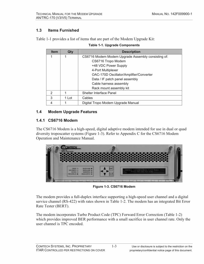
1.4.1 CS6716 Modem
The CS6716 Modem is a high-speed, digital adaptive modem intended for use in dual or quad diversity troposcatter systems (Figure 1-3). Refer to Appendix C for the CS6716 Modem Operation and Maintenance Manual.
Figure 1-3. CS6716 Modem
The modem provides a full-duplex interface supporting a high-speed user channel and a digital service channel (RS-422) with rates shown in Table 1-2. The modem has an integrated Bit Error Rate Tester (BERT).
The modem incorporates Turbo Product Code (TPC) Forward Error Correction (Table 1-2) which provides improved BER performance with a small sacrifice in user channel rate. Only the user channel is TPC encoded.

TECHNICAL MANUAL FOR THE MODEM UPGRADE MANUAL NO. 142F009900-1 AN/TRC-170 (V3/V5) TERMINAL
COMTECH SYSTEMS, INC. PROPRIETARY 1-4 Use or disclosure is subject to the restriction on the ITAR CONTROLLED PER RESTRICTIONS ON COVER proprietary/confidential notice page of this document.
Table 1-2. Aggregate Data Rate Options (Programmable)
User Channel Rate without TPC FEC
(Kbps)
User Channel Rate with TPC FEC(Kbps)
Maximum Combined SC1, SC2 & BERT Bandwidth
(Kbps) 2048 1856 804096 3776 808192 7808 8010240 9824 8012288 11840 8016384 15616 160
The modem also provides Adaptive Link Power Control (ALPC) which automatically controls the transmitted RF power based on the minimum levels required by the distant end RF receivers to achieve error free performance. This feature will minimize the required transmit power and reduces the possibility of interference with systems beyond the receiving station.
The modem is also fully redundant. In the unlikely event that a fault should occur that could affect user data traffic, the modem automatically switches to the redundant modem. The failed unit can then be hot-swapped without interrupting communications.
1.4.2 Versamux
The Versamux 4000 (VM-4000) provides the ability to multiplex up to four input ports into a single aggregate channel using time division multiplexing (TDM). The product is modular at both the port and aggregate interface levels, consisting of a base system containing five interface slots, station clock input, management ports, AC power input and front panel user interface (Figure 1-4). Interface modules populate the slot positions within the base chassis to meet specific customer requirements.
One interface slot within the base chassis is designated as the aggregate, and the other four are designated as port slots. Each interface slot of the unit is capable of supporting all of the current interfaces including Fiber Optic, Unbalanced Copper CDI, and NRZ (DTE/DCE capable). The interface slots are located on the rear panel (Figure 1-5) of the VM-4000 and interface modules are hot swap capable.
The aggregate of the VM-4000 supports the DNE high efficiency frame format. The front panel user interface will include an LCD display, a keypad and light-emitting diodes (LEDs).
The VM-4000 provides a station clock input that supports RS-422, TTL and zero crossing inputs at 1, 5 and 10 MHz. The VM-4000 can base system timing off of any of the input ports, the aggregate, or the external clock input. A KG Resync function is provided for the aggregate slot of the VM-4000 should a Trunk Encryption Devices (TED) be required.

TECHNICAL MANUAL FOR THE MODEM UPGRADE MANUAL NO. 142F009900-1 AN/TRC-170 (V3/V5) TERMINAL
COMTECH SYSTEMS, INC. PROPRIETARY 1-5 Use or disclosure is subject to the restriction on the ITAR CONTROLLED PER RESTRICTIONS ON COVER proprietary/confidential notice page of this document.
A user Bit Error Rate Test (BERT) is provided that is front panel accessible and isolates faults at the Interface Module, and Base System card levels. Diagnostic loopback capabilities are provided for testing the user interfaces on the port modules as well as the aggregate port to the CS6716 modem. The VM-4000 Multiplexer is shipped from the factory with a default setting of 2.048 mbps in support of the CS6716 modem default settings to facilitate setting up the initial communications link. Final configuration of the aggregate and port rates depends on user requirements and link performance.
Figure 1-4. Versamux Front View
Figure 1-5. Versamux Rear View
1.4.3 Shelter Interface Panel
The AN/TRC-170 Modem Upgrade includes a shelter interface panel (Figure 1-6) with four CX-11295 fiber optic connectors and four CX-11230 conditioned diphase connectors. These connectors are connected directly to the 4-Port Multiplexer. The multiplexer combines up to four user channels into a single aggregate data channel. The aggregate data channel connects to the CS6716 Modem User Data Channel.
Figure 1-6. Shelter Interface Panel
CDI 1-4
FO 1-4
TECHNICAL MANUAL FOR THE MODEM UPGRADE MANUAL NO. 142F009900-1 AN/TRC-170 (V3/V5) TERMINAL
COMTECH SYSTEMS, INC. PROPRIETARY 1-6 Use or disclosure is subject to the restriction on the ITAR CONTROLLED PER RESTRICTIONS ON COVER proprietary/confidential notice page of this document.
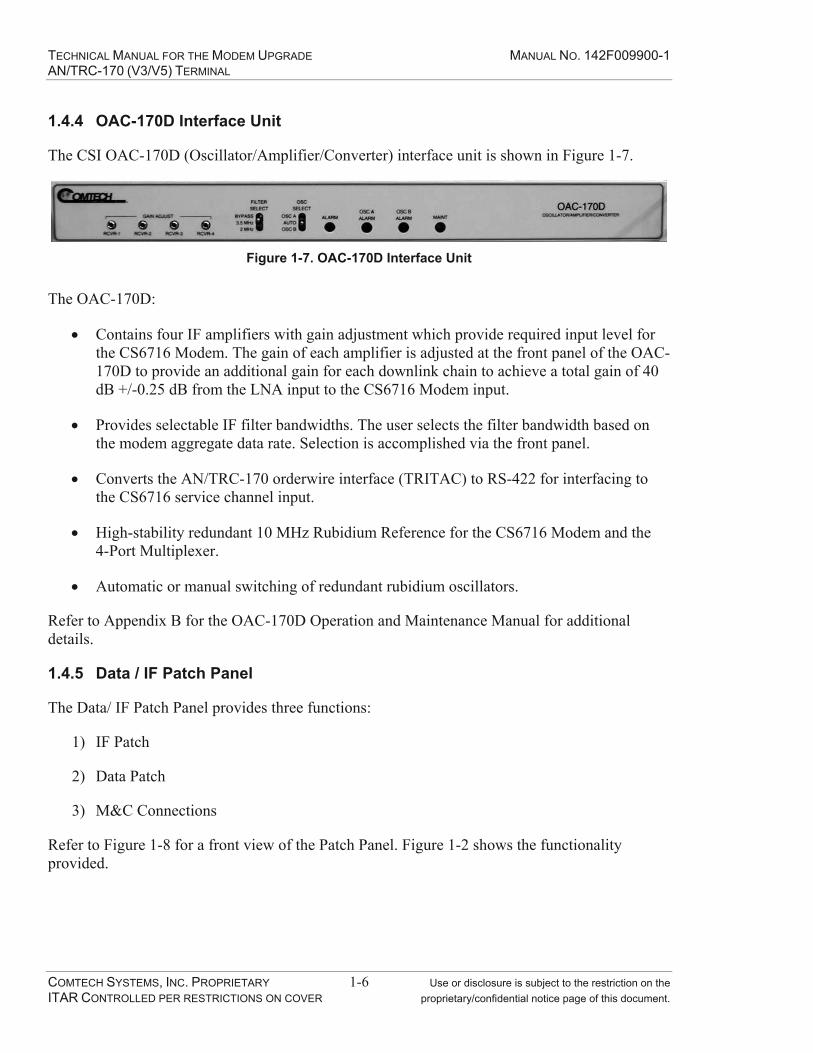
1.4.4 OAC-170D Interface Unit
The CSI OAC-170D (Oscillator/Amplifier/Converter) interface unit is shown in Figure 1-7.
Figure 1-7. OAC-170D Interface Unit
The OAC-170D:
Contains four IF amplifiers with gain adjustment which provide required input level for the CS6716 Modem. The gain of each amplifier is adjusted at the front panel of the OAC-170D to provide an additional gain for each downlink chain to achieve a total gain of 40 dB +/-0.25 dB from the LNA input to the CS6716 Modem input.
Provides selectable IF filter bandwidths. The user selects the filter bandwidth based on the modem aggregate data rate. Selection is accomplished via the front panel.
Converts the AN/TRC-170 orderwire interface (TRITAC) to RS-422 for interfacing to the CS6716 service channel input.
High-stability redundant 10 MHz Rubidium Reference for the CS6716 Modem and the 4-Port Multiplexer.
Automatic or manual switching of redundant rubidium oscillators.
Refer to Appendix B for the OAC-170D Operation and Maintenance Manual for additional details.
1.4.5 Data / IF Patch Panel
The Data/ IF Patch Panel provides three functions:
1) IF Patch
2) Data Patch
3) M&C Connections
Refer to Figure 1-8 for a front view of the Patch Panel. Figure 1-2 shows the functionality provided.

TECHNICAL MANUAL FOR THE MODEM UPGRADE MANUAL NO. 142F009900-1 AN/TRC-170 (V3/V5) TERMINAL
COMTECH SYSTEMS, INC. PROPRIETARY 1-7 Use or disclosure is subject to the restriction on the ITAR CONTROLLED PER RESTRICTIONS ON COVER proprietary/confidential notice page of this document.
MUXCS6716 DATA
DVOWCS6716 SC1
DAR ORDERWIRE
Figure 1-8. Patch Panel
The IF Patch includes looping plugs for selection of the CS6716 Modem or the DAR Modem. Installation of the IF plugs connects the desired modem to the AN/TRC-170 up converter inputs, down converter outputs and IF loop test panel.
The data patch connects the AN/TRC-170 orderwire to the CS6716 Modem or the DAR Modem. No patch cables are needed for connection to the CS6716 Modem since the patch is “normally through”. Patch cables must be installed to operate with the DAR Modem.
Connections to the CS6716 Modem Ethernet and RS-232 M&C ports are available at the patch panel.
1.4.6 48 VDC Power Supply
The +48 VDC Power Supply (Figure 1-9) has 1:1 redundant, hot-swappable power supply modules. The modules have current sharing capability for normal operation.
If one module fails, the remaining module handles the current load of the Modem Upgrade Assembly. Since the modules are designed to be hot swappable, the failed unit is removed and replaced without affecting system operation.
CSI050055
Figure 1-9. Redundant +48 VDC Power Supply

TECHNICAL MANUAL FOR THE MODEM UPGRADE MANUAL NO. 142F009900-1 AN/TRC-170 (V3/V5) TERMINAL
COMTECH SYSTEMS, INC. PROPRIETARY 1-8 Use or disclosure is subject to the restriction on the ITAR CONTROLLED PER RESTRICTIONS ON COVER proprietary/confidential notice page of this document.
This Page Intentionally Left Blank

TECHNICAL MANUAL FOR THE MODEM UPGRADE MANUAL NO. 142F009900-1 AN/TRC-170 (V3/V5) TERMINAL
COMTECH SYSTEMS, INC. PROPRIETARY 2-1 Use or disclosure is subject to the restriction on the ITAR CONTROLLED PER RESTRICTIONS ON COVER proprietary/confidential notice page of this document.
2.0 INSTALLATION OVERVIEW
Detailed installation instructions and diagrams are included in Appendix A of this manual (Installation Manual for the AN/TRC-170 Modem Upgrade). This section provides a brief overview of the installation.
The Modem Upgrade is accomplished without modifying existing AN/TRC-170 parts or equipment racks. The Upgrade Assembly is installed in AN/TRC-170 (V3/V5) Rack 5. The existing equipment shelf is removed to allow installation of the upgrade kit. Figure 2-1 shows the front view of the upgrade kit.
Patch Panel (A1)
CS6716 Modem (A2)
DNE Multiplexer (A3)
OAC-170D (A4)
Redundant +48 VDC
Power Supply (A5)
A1A1
A1A2A1A6
A1A3A1A7
Figure 2-1. Upgrade Assembly Rack Elevation
The Modem Upgrade installation utilizes existing hole-patterns on the rack front and interior side K-rails. The Upgrade Assembly is installed permanently in the rack directly above the IF loop test panel location.
The new Shelter Interface Panel replaces the existing blank I/O panel behind Rack 5 on the exterior wall. The panel has four CX-11230 conditioned di-phase and four CX-11295 fiber optic (TFOCA-I) connectors which connect to the 4-Port Multiplexer in the Modem Upgrade shelf.
TECHNICAL MANUAL FOR THE MODEM UPGRADE MANUAL NO. 142F009900-1 AN/TRC-170 (V3/V5) TERMINAL
COMTECH SYSTEMS, INC. PROPRIETARY 2-2 Use or disclosure is subject to the restriction on the ITAR CONTROLLED PER RESTRICTIONS ON COVER proprietary/confidential notice page of this document.
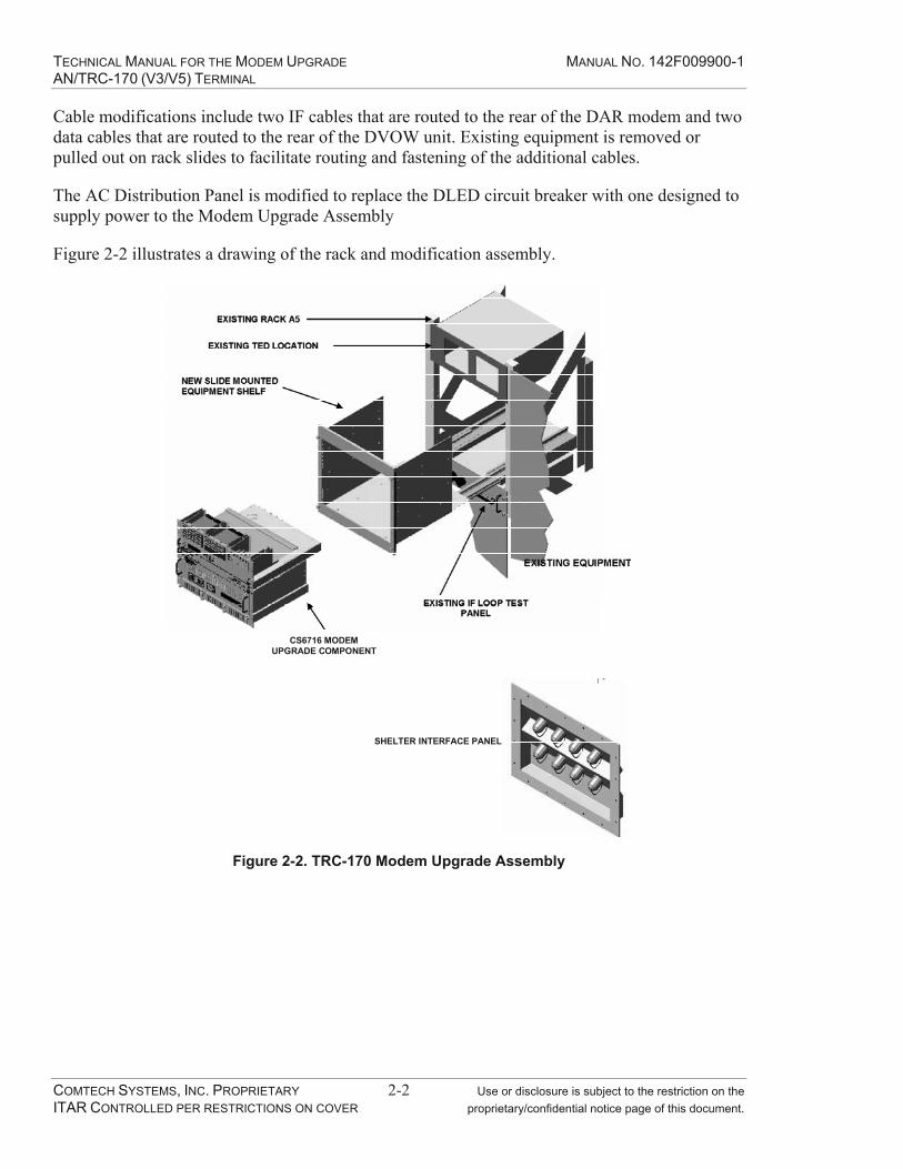
Cable modifications include two IF cables that are routed to the rear of the DAR modem and two data cables that are routed to the rear of the DVOW unit. Existing equipment is removed or pulled out on rack slides to facilitate routing and fastening of the additional cables.
The AC Distribution Panel is modified to replace the DLED circuit breaker with one designed to supply power to the Modem Upgrade Assembly
Figure 2-2 illustrates a drawing of the rack and modification assembly.
CS6716 MODEM UPGRADE COMPONENT
SHELTER INTERFACE PANEL
Figure 2-2. TRC-170 Modem Upgrade Assembly

TECHNICAL MANUAL FOR THE MODEM UPGRADE MANUAL NO. 142F009900-1 AN/TRC-170 (V3/V5) TERMINAL
COMTECH SYSTEMS, INC. PROPRIETARY 3-1 Use or disclosure is subject to the restriction on the ITAR CONTROLLED PER RESTRICTIONS ON COVER proprietary/confidential notice page of this document.
3.0 OPERATION
This section describes the plugs, switches and settings required for normal operation of the CS6716 Modem Upgrade Assembly. Refer to the appropriate appendix for additional information on the setup or operation of the equipment that is part of the CS6716 Modem Upgrade Assembly.
3.1 System Turn On
The following power up procedure should be followed:
1. Select the CS6716 Modem for operation by placing the IF patch plugs in vertical position as shown in Figure 3-1. Remove any digital data patch cables.
Figure 3-1. ADC Data/IF Patching for CS6716 Modem Operation
2. At the AC distribution panel, switch the CS6716 Modem circuit breaker ON.
3. Ensure Versamux power switch is ON.
4. Allow the 10 MHz reference oscillators to reach stability by observing the Alarm LEDs on the OAC-170D front panel.
Note It may take up to ten minutes for the rubidium oscillators to stabilize for normal operation.
5. Open the CS6716 Modem front panel. SIMULTANEOUSLY turn on the top two PCBs (Analog Boards) followed by the bottom two PCBs (Processor Boards). The power switches are at the front right edge of each board (refer to Figure 3-2).
6. The CS6716 Modem automatically performs diagnostics and AGC calibration at power-on. If a modem alarm LED illuminates the operator can view detailed alarm status via the modem front-panel interface.

TECHNICAL MANUAL FOR THE MODEM UPGRADE MANUAL NO. 142F009900-1 AN/TRC-170 (V3/V5) TERMINAL
COMTECH SYSTEMS, INC. PROPRIETARY 3-2 Use or disclosure is subject to the restriction on the ITAR CONTROLLED PER RESTRICTIONS ON COVER proprietary/confidential notice page of this document.
7. Once the power-up sequence is complete, configure the modems on both ends of the link for the DEFAULT configuration setting. This configuration is recommended for the following reasons:
a. It ensures that the modem configuration is identical at both ends of the link.
b. The DEFAULT configuration is optimum for establishing communications on new troposcatter links.
c. It provides the optimum settings for antenna pointing.
8. When the receive signal levels are sufficient to support user traffic, configure the user data rate of the modems on both ends of the link as desired.
9. Final configuration of the modem and multiplexer bit rates and capacity depends on user requirements and link performance. The communications link has been successfully established when the modem ONLINE, DATA TRAFFIC and RX SYNC LEDs are illuminated.
Modem A Set
Modem B Set
A1 and A2Analog Board
A3 and A4Processor Board
Power Switches
Figure 3-2. CS6716 Modem with Front Display Panel Open

TECHNICAL MANUAL FOR THE MODEM UPGRADE MANUAL NO. 142F009900-1 AN/TRC-170 (V3/V5) TERMINAL
COMTECH SYSTEMS, INC. PROPRIETARY 3-3 Use or disclosure is subject to the restriction on the ITAR CONTROLLED PER RESTRICTIONS ON COVER proprietary/confidential notice page of this document.
3.2 System Configuration (Select CS6716 Modem Operation)
The Modem Upgrade Assembly is designed with the CS6716 Modem as the primary modem. Figure 3-1 illustrates the patching required to select the CS6716 Modem. The data patch panel is designed to select the CS6716 Modem without patch cords. The bottom center module (A1A6) provides connection to the Modem Ethernet and remote M&C Terminal ports. These interfaces provide monitor and control of the CS6716 Modem.
The top center module (labeled “MUX” and “CS6716 DATA”) connects the 4-Port Multiplexer aggregate data port to the CS6716 Modem. This data patch allows a bulk encryption device to be patched in between the Mulitplexer and the Modem. No patch cable is normally required to connect the multiplexer directly to the modem.
The top right module (labeled “DVOW” and “CS6716 SC1”) connects the TOCU (DVOW) to the CS6716 Modem Service Channel #1. No patch cable should be installed
3.3 System Configuration (Select DAR Modem Operation)
Figure 3-3 illustrates the patching required to select the DAR Modem. The Modem Upgrade Accessories Kit includes cables for the data patching and for calibration of the Upgrade Assembly. The bottom center module allows connection to the Modem Ethernet and Terminal (RS-232) ports. These interfaces provide monitor and control of the CS6716 Modem.
The top center module is not applicable in when operating with the DAR Modem.
The right patch locations (labeled “DVOW” and “DAR ORDERWIRE”) are shown with a patch cable that connects the DVOW to the DAR Modem.
Figure 3-3. DAR Modem Operational Patches
3.4 Initial Modem Upgrade Kit Configuration
The CS6716 Modem is shipped with the upgrade assembly pre-configured for operation utilizing an aggregate data rate of 2 Mbps (the DEFAULT setting is with FEC ON for a data rate of 1.856 Mbps). The 4-Port DNE Multiplexer is factory configured for Port 1-relay mode and a 1.856 Mbps aggregate data rate. Also in this configuration, the OAC-170D Filter Select Switch is set for 2 MHz for optimal system sensitivity.

TECHNICAL MANUAL FOR THE MODEM UPGRADE MANUAL NO. 142F009900-1 AN/TRC-170 (V3/V5) TERMINAL
COMTECH SYSTEMS, INC. PROPRIETARY 3-4 Use or disclosure is subject to the restriction on the ITAR CONTROLLED PER RESTRICTIONS ON COVER proprietary/confidential notice page of this document.
The CS6716 Modem “DEFAULT” configuration command provides a convenient method of setting the modem to a known state before starting a new configuration. The operator should execute the “DEFAULT” command which changes the modem configuration to the configuration shown in Table 3-1. This configuration provides the maximum receive sensitivity for initial link acquisition.
Table 3-1. CS6716 Default Configuration
Configuration Option Default Setting
Rate 2 Mb/s
Service Channel #1 16 kb/s
Service Channel #2 OFF
Loopback NORMAL
ALPC OFF
Forward Error Correction ON
Bit Error Rate Tester ON
Note Follow instructions in Step 16 to turn FEC off for initial link acquisition.
Configuration and operation of the CS6716 Modem and the 4-Port Multiplexer for various data rates and options are described in the equipment manuals (Appendix C and D).
Refer to Appendix C, CS6716 Modem Operations and Maintenance Manual, for additional information on modem configuration.
The CS6716 Modem front panel has an alphanumeric display, a keypad and LED indicators (Figure 3-4). The / keys scroll menus while the / keys scroll available configuration options. Pressing the ENT key selects the item. Pressing the CLR key will clear the current display or revert to the next higher menu.
LED Display Keypad Alphanumeric Display
Figure 3-4. CS6716 Modem Front Panel
TECHNICAL MANUAL FOR THE MODEM UPGRADE MANUAL NO. 142F009900-1 AN/TRC-170 (V3/V5) TERMINAL
COMTECH SYSTEMS, INC. PROPRIETARY 3-5 Use or disclosure is subject to the restriction on the ITAR CONTROLLED PER RESTRICTIONS ON COVER proprietary/confidential notice page of this document.
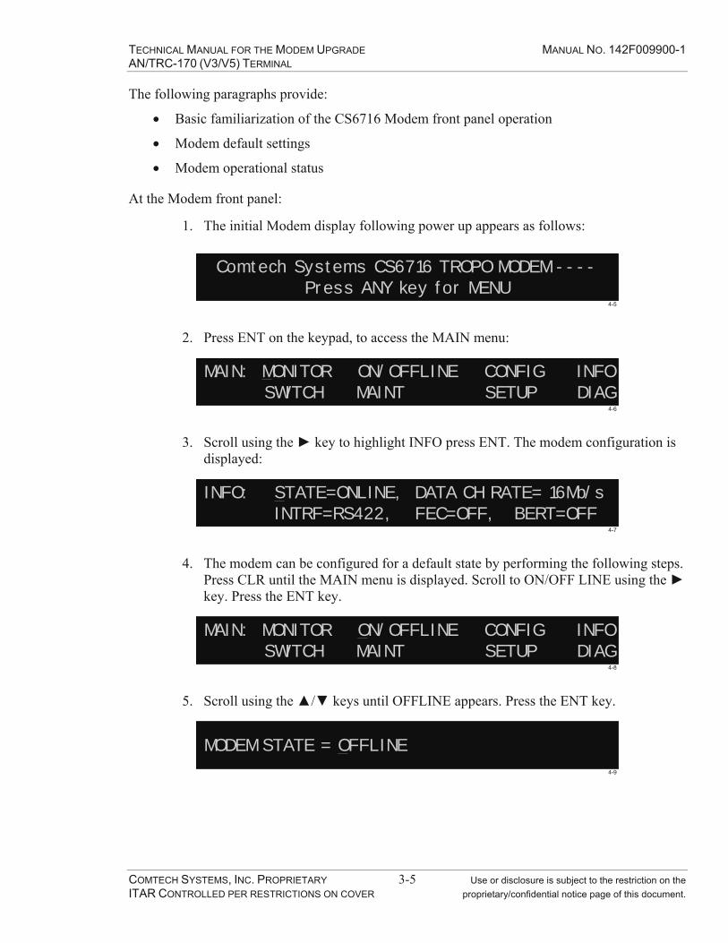
The following paragraphs provide:
Basic familiarization of the CS6716 Modem front panel operation
Modem default settings
Modem operational status
At the Modem front panel:
1. The initial Modem display following power up appears as follows:
Comtech Systems CS6716 TROPO MODEM ----Press ANY key for MENU
4-5
2. Press ENT on the keypad, to access the MAIN menu:
MAIN: MONITOR ON/OFFLINE CONFIG INFOSWITCH MAINT SETUP DIAG
4-6
3. Scroll using the key to highlight INFO press ENT. The modem configuration is displayed:
INFO: STATE=ONLINE, DATA CH RATE= 16Mb/sINTRF=RS422, FEC=OFF, BERT=OFF
4-7
4. The modem can be configured for a default state by performing the following steps. Press CLR until the MAIN menu is displayed. Scroll to ON/OFF LINE using the key. Press the ENT key.
MAIN: MONITOR ON/OFFLINE CONFIG INFOSWITCH MAINT SETUP DIAG
4-8
5. Scroll using the / keys until OFFLINE appears. Press the ENT key.
MODEM STATE = OFFLINE4-9
TECHNICAL MANUAL FOR THE MODEM UPGRADE MANUAL NO. 142F009900-1 AN/TRC-170 (V3/V5) TERMINAL
COMTECH SYSTEMS, INC. PROPRIETARY 3-6 Use or disclosure is subject to the restriction on the ITAR CONTROLLED PER RESTRICTIONS ON COVER proprietary/confidential notice page of this document.
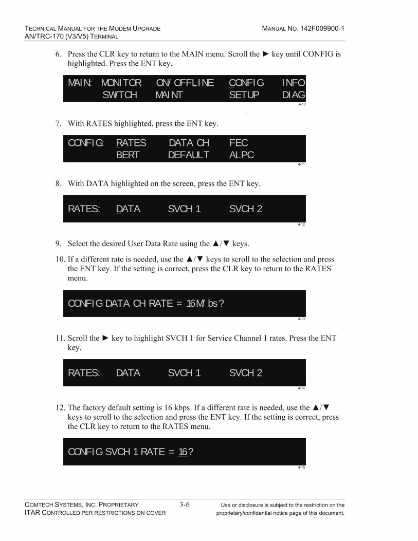
6. Press the CLR key to return to the MAIN menu. Scroll the key until CONFIG is highlighted. Press the ENT key.
MAIN: MONITOR ON/OFFLINE CONFIG INFOSWITCH MAINT SETUP DIAG
4-10
7. With RATES highlighted, press the ENT key.
CONFIG: RATES DATA CH FECBERT DEFAULT ALPC
4-11
8. With DATA highlighted on the screen, press the ENT key.
RATES: DATA SVCH 1 SVCH 24-12
9. Select the desired User Data Rate using the / keys.
10. If a different rate is needed, use the / keys to scroll to the selection and press the ENT key. If the setting is correct, press the CLR key to return to the RATES menu.
CONFIG DATA CH RATE = 16M/bs?4-13
11. Scroll the key to highlight SVCH 1 for Service Channel 1 rates. Press the ENT key.
RATES: DATA SVCH 1 SVCH 24-14
12. The factory default setting is 16 kbps. If a different rate is needed, use the / keys to scroll to the selection and press the ENT key. If the setting is correct, press the CLR key to return to the RATES menu.
CONFIG SVCH 1 RATE = 16?4-15

TECHNICAL MANUAL FOR THE MODEM UPGRADE MANUAL NO. 142F009900-1 AN/TRC-170 (V3/V5) TERMINAL
COMTECH SYSTEMS, INC. PROPRIETARY 3-7 Use or disclosure is subject to the restriction on the ITAR CONTROLLED PER RESTRICTIONS ON COVER proprietary/confidential notice page of this document.
13. Repeat the same procedure for Service Channel 2 rates, verifying that SVCH 2 is set to 0 kbps. Press the CLR key to return to the CONFIG menu.
14. On the CONFIG menu, scroll the key to highlight DATA CH and press the ENT key. The factory default setting is RS422.
DATA INTRF TYPE = RS4224-17
15. If the setting is correct, press the CLR key to return to the CONFIG menu. Scroll the key to highlight FEC, press the ENT key.
CONFIG: RATES DATA CH FECBERT DEFAULT ALPC
4-18
16. The factory default setting is ON. If the setting needs to be changed, toggle the available options with the / keys, press ENT to activate the selection. Modem must be OFFLINE to change this setting.
DATA CH FEC: = OFF4-19
17. Press the CLR key to return to the CONFIG menu and scroll using the key to highlight ALPC.
CONFIG: RATES DATA CH FECBERT DEFAULT ALPC
4-16
18. The factory default setting should be OFF. If the setting has to be changed, toggle the available options with the / keys, press ENT to activate the selection. Press the CLR key to return to the MAIN menu. Scroll using the key to highlight ON/OFF LINE, press the ENT key.
MAIN: MONITOR ON/OFFLINE CONFIG INFOSWITCH MAINT SETUP DIAG
4-20
19. Toggle the available selections to ONLINE, press the ENT key to activate the selection.
TECHNICAL MANUAL FOR THE MODEM UPGRADE MANUAL NO. 142F009900-1 AN/TRC-170 (V3/V5) TERMINAL
COMTECH SYSTEMS, INC. PROPRIETARY 3-8 Use or disclosure is subject to the restriction on the ITAR CONTROLLED PER RESTRICTIONS ON COVER proprietary/confidential notice page of this document.
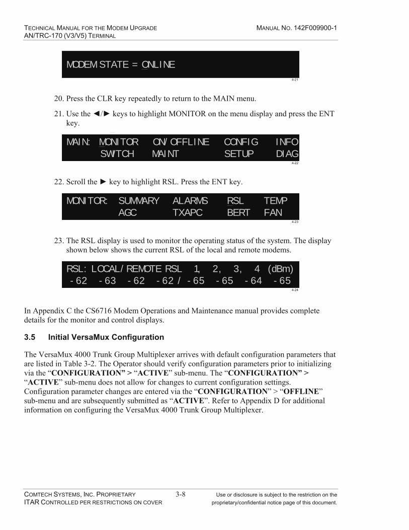
MODEM STATE = ONLINE4-21
20. Press the CLR key repeatedly to return to the MAIN menu.
21. Use the / keys to highlight MONITOR on the menu display and press the ENT key.
MAIN: MONITOR ON/OFFLINE CONFIG INFOSWITCH MAINT SETUP DIAG
4-22
22. Scroll the key to highlight RSL. Press the ENT key.
MONITOR: SUMMARY ALARMS RSL TEMPAGC TXAPC BERT FAN
4-23
23. The RSL display is used to monitor the operating status of the system. The display shown below shows the current RSL of the local and remote modems.
RSL: LOCAL/REMOTE RSL 1, 2, 3, 4 (dBm)-62 -63 -62 -62 / -65 -65 -64 -65
4-24
In Appendix C the CS6716 Modem Operations and Maintenance manual provides complete details for the monitor and control displays.
3.5 Initial VersaMux Configuration
The VersaMux 4000 Trunk Group Multiplexer arrives with default configuration parameters that are listed in Table 3-2. The Operator should verify configuration parameters prior to initializing via the “CONFIGURATION” > “ACTIVE” sub-menu. The “CONFIGURATION” > “ACTIVE” sub-menu does not allow for changes to current configuration settings. Configuration parameter changes are entered via the “CONFIGURATION” > “OFFLINE” sub-menu and are subsequently submitted as “ACTIVE”. Refer to Appendix D for additional information on configuring the VersaMux 4000 Trunk Group Multiplexer.

TECHNICAL MANUAL FOR THE MODEM UPGRADE MANUAL NO. 142F009900-1 AN/TRC-170 (V3/V5) TERMINAL
COMTECH SYSTEMS, INC. PROPRIETARY 3-9 Use or disclosure is subject to the restriction on the ITAR CONTROLLED PER RESTRICTIONS ON COVER proprietary/confidential notice page of this document.
Table 3-2. Versamux Default Configuration
Configuration Option Default Setting
System [Clk-ref] Ext-10MHzAggregate [Function] Port-1-relay Aggregate [Mode] DTEAggregate [Rate] 1856KPort 1 Mode Fiber FOM Port 2 Mode Disabled Port 3 Mode Disabled Port 4 Mode Disabled
The following paragraphs provide:
Basic familiarization of the Versamux front panel operation
Versamux default settings
Versamux operational status
Configure the VersaMux in both assemblies as follows:
1. Press until Configure appears on the display
2. Press until System appears in the display
3. Press until Offline appears in the display
4. Press until Aggregate appears in the display
5. Press until Rate appears in the display. Press ENT.
6. Press until 1856k appears in the display. Press ENT.
7. Press until Configure appears in the display.
8. Press until Activate appears in the display.
9. Press until Configuration appears in the display. Press ENT.
10. Press until Offline appears in the display. Press ENT.

TECHNICAL MANUAL FOR THE MODEM UPGRADE MANUAL NO. 142F009900-1 AN/TRC-170 (V3/V5) TERMINAL
COMTECH SYSTEMS, INC. PROPRIETARY 3-10 Use or disclosure is subject to the restriction on the ITAR CONTROLLED PER RESTRICTIONS ON COVER proprietary/confidential notice page of this document.
On the OAC-170D, select 2 MHz bandwidth with the Filter Select Switch.
Enter COMPLETED on the Test Data Sheet.

TECHNICAL MANUAL FOR THE MODEM UPGRADE MANUAL NO. 142F009900-1 AN/TRC-170 (V3/V5) TERMINAL
COMTECH SYSTEMS, INC. PROPRIETARY 4-1 Use or disclosure is subject to the restriction on the ITAR CONTROLLED PER RESTRICTIONS ON COVER proprietary/confidential notice page of this document.
4.0 MAINTENANCE
Maintenance procedures are divided into two categories; routine and corrective.
Routine maintenance includes the cleaning of equipment and filters, checking connectors to ensure they are tight, and inspecting for frayed or damaged cables. Refer to the appropriate appendix for routine maintenance procedures for each piece of equipment.
Corrective maintenance is performed in response to an equipment alarm or interruption of traffic. In extreme situations, it may be necessary to interrupt user traffic to perform diagnostic and repair procedures.
The CS6716 Modem Major and Minor Alarm LEDs are available on the CS6716 front panel (Figure 4-1) to reflect the current alarm status. Detailed status can be obtained via the front panel menu or through the remote M&C terminal interface.
TRC0501203/3/2005
ONLINEDATA TRAFFIC
RX SYNCPWR CNTRL ON
MAJOR ALARMMINOR ALARMDIAGNOSTICS
MANUAL SWITCH
Figure 4-1. Front Panel Display Alarm Results Example
A Major Alarm is issued when a fault is detected that could affect user data traffic. An automatic switchover to the redundant modem will be initiated unless a Major Alarm is already present on the redundant card set.
A Minor Alarm is issued when a fault is detected that normally does not affect user data traffic and there is no automatic switchover on Minor Alarms.
Note If the redundant modem is already in alarm or unavailable no switch will occur.
4.1 Maintenance and Diagnostics
The CS6716 Modem provides state-of-the-art alarm monitoring and reporting capabilities. The modem provides four methods of alarm reporting:
Front Panel Display –Alarm detail can be obtained via the Modem front panel alarm menu.
Remote Monitoring – The Modem RS-232 Terminal interface provides remote M&C capability. The severity, nature and source of the alarm can be determined. The

TECHNICAL MANUAL FOR THE MODEM UPGRADE MANUAL NO. 142F009900-1 AN/TRC-170 (V3/V5) TERMINAL
COMTECH SYSTEMS, INC. PROPRIETARY 4-2 Use or disclosure is subject to the restriction on the ITAR CONTROLLED PER RESTRICTIONS ON COVER proprietary/confidential notice page of this document.
information available via the Terminal port is similar to the information available via the Modem front panel display. Refer to the modem manual in the appendix for more details.
Depending on the severity and nature of a reported alarm, the modem will:
1. Continue operation.
2. Continue operation under reduced capability.
3. Switch to the redundant modem.
Maintenance on the CS6716 Modem includes:
1. Routine Maintenance – Includes cleaning filters, inspecting for frayed, loose, broken or damaged cables/connectors.
2. Corrective Maintenance – Occurs in response to an indicated alarm. There are no user-replaceable components in the CS6716 Modem. When a fault occurs, corrective action includes replacing one or more of the following subassemblies:
a. Analog Board
b. Processor Board
c. Front panel display board
d. Fans
If replacing one or more of these subassemblies did not correct the indicated fault, the entire modem will require replacement.
If the modem is able to continue operating (Minor Alarm), repairs can be delayed until a convenient maintenance period. If the fault has forced the modem to switch to the redundant set (Major Alarm), repairs should be scheduled for a more convenient time to replace the faulty LRU. An additional failure on the on-line set of boards could prevent the ability of the modem to maintain communications.
Fatal errors require immediate attention. Refer to the maintenance section of the CS6716 O&M manual, Appendix C, for maintenance procedures. Neither the Processor Board nor the Analog Board is field repairable. If any failure occurs on the backplane, the front panel, or the front panel ribbon cable, the entire modem will have to be replaced.
4.2 OAC-170D Gain Setting
The OAC-170D provides additional gain between the down converter outputs and the CS6716 modem inputs. This procedure is not normally required in the field; however, it should be performed after replacement of any LNA and/or downconverter in the receive chain.
1. Connect the equipment as illustrated in Figure 4-2.

TECHNICAL MANUAL FOR THE MODEM UPGRADE MANUAL NO. 142F009900-1 AN/TRC-170 (V3/V5) TERMINAL
COMTECH SYSTEMS, INC. PROPRIETARY 4-3 Use or disclosure is subject to the restriction on the ITAR CONTROLLED PER RESTRICTIONS ON COVER proprietary/confidential notice page of this document.
16 dBAttenuators
A1ADC Patch Panel
(IF Section)
A4OAC-170D Oscillator / Amplifier
A2CS6716 Digital
Troposcatter Modem
TX1
RX1RX2RX3RX4
RCVR1 RCVR2 RCVR3 RCVR4
Figure 4-2. Calibration Procedure Setup
2. Remove all looping plugs from the ADC Patch Panel IF Section.
3. Select BYPASS on the OAC-170D front panel Filter Select switch.
4. Connect the TX1 IF output of the CS6716 modem on the ADC Patch panel IF section to a BNC patch cable and the supplied in-line attenuators.(total 16 dB of attenuation)
5. Connect to RX1 at the ADC Patch panel.
6. On the modem front panel keypad, Select ENT for Menu, select MONITOR, then select RSL. This will display the Receive Signal Level (RSL) for all four receive channels.
7. Adjust the OAC-170D front panel RCVR1 potentiometer for a reading of -40 dBm on the modem RSL1 display.
Note This level applies ONLY to an OAC-170D installed in an AN/TRC-170V3/V5.
8. Repeat this procedure for RX IF inputs 2 through 4 and RCVR adjust potentiometers 2 through 4 to match their corresponding RSL indications on the modem front panel display.
9. Restore the equipment to its original configuration.
10. Perform the Gain adjustment procedure in Section 4.3 of this manual
STOP. You have completed this procedure

TECHNICAL MANUAL FOR THE MODEM UPGRADE MANUAL NO. 142F009900-1 AN/TRC-170 (V3/V5) TERMINAL
COMTECH SYSTEMS, INC. PROPRIETARY 4-4 Use or disclosure is subject to the restriction on the ITAR CONTROLLED PER RESTRICTIONS ON COVER proprietary/confidential notice page of this document.
4.3 OAC-170D Equalization Procedure
This procedure is performed to overcome the gain differences found in different receivers and converters.
WarningBefore proceeding, check HPA control panel 1A1A4 and 2A1A4 to ensure CONTROL-BEAM VOLTAGE toggle switch is OFF. DO NOTremove waveguide port covers when power is applied to High Power Amplifier. Physical contact with an exposed waveguide port with RF output will result in serious injury or even death.
1. If the antenna and waveguide have not been installed, place waveguide terminators or cover plates on the receive ports of waveguide entry panel unit 12.
2. If the antenna and waveguide have been installed, then adjust the receiver amplifier-converter and frequency synthesizer receive frequency at least 200 MHz away from the normal receive frequency and at least 100MHz from the transmit frequency.
3. On the CS6716 modem, select MONITOR from the MAIN menu, and then RSL.
4. On each Down Converter turn the Noise Test Switch to the PRESELECT. Check the CS6716 modem front panel display, and make any necessary adjustments using the RCVR 1 through RCVR 4 adjustment potentiometers on the OAC-170D to balance the RSL levels to the highest RSL to within +/- 0.25 dB. (This compensates for any variations in the gain of the individual LNA/Receiver combinations.)
5. On each Down Converter turn the Noise Test Switch to OFF and remove waveguide terminators or tune receiver amplifier-converter and frequency synthesizer receive frequency back to the normal receive frequency.
STOP. You have completed this procedure.
TECHNICAL MANUAL FOR THE MODEM UPGRADE MANUAL NO. 142F009900-1 AN/TRC-170 (V3/V5) TERMINAL
COMTECH SYSTEMS, INC. PROPRIETARY 5-1 Use or disclosure is subject to the restriction on the ITAR CONTROLLED PER RESTRICTIONS ON COVER proprietary/confidential notice page of this document.
5.0 DRAWINGS
111F009327-3 AN/TRC-170 CS6716 Modem Upgrade Wire Run List
115F009327-3 TRC-170 Modem Upgrade Top Assembly Parts List
115F009450-3 TRC-170 (Modem Upgrade) Installation Kit Parts List
115F009900-1 AN/TRC-170 CS6716 Modem Upgrade Parts List with Desert Tan I/O Panel
115F009900-2 AN/TRC-170 CS6716 Modem Upgrade Parts List with Green I/O Panel
410F009327-3 TRC-170 Modem Upgrade Interconnect Drawing

TECHNICAL MANUAL FOR THE MODEM UPGRADE MANUAL NO. 142F009900-1 AN/TRC-170 (V3/V5) TERMINAL
COMTECH SYSTEMS, INC. PROPRIETARY 5-2 Use or disclosure is subject to the restriction on the ITAR CONTROLLED PER RESTRICTIONS ON COVER proprietary/confidential notice page of this document.
This Page Intentionally Left Blank

03/09/07 JHSH Change W1011 (8147)
APPLICATION REVISIONS
USED ON LTR APPROVEDDATEDESCRIPTION
A Initial Release per IER 7924
08/23/06 TLB Change W306 to W317, W1009, W001, W006 (9016)
07/06/06 RD07/18/06 JS
08/25/06 TLD Change W301-305, W317, W1000, W1001, W1003-W1008, W1010(9105)
C Change W301-W310, W317, W1002, W1005-W1008, W1010, W001, W005, W007 (9093)
E Add W1011 (9162)
J Change W315, W316, W318, W1006-W1007, Add W335 (9412)
09/08/06 TL
04/30/07 TL
12/05/06 TL
G Change W1000 (8146)
L02/12/08 TLK Change W319 thru W334 (9584)04/08/09Change W315 and W319 through W326 (9908) TL
M Add ITAR Statement, Change W1000, W1001, W1003, W319-W334, W007 (10162)
08/20/10 TL
07/06/06A. Maldonado
CHECKED BY:R. Dohlstrom
PROJECT ENGINEER:THIS DRAWING IS NOT TO BE REPRODUCED OR USED IN ANY
MANNER WITHOUT WRITTEN AUTHORIZATION FROM
WIRE RUN LIST
The information in this document contains Technical Data subject to the controls of ITAR, 22 C.F.R. §120-§130 and should not be further disseminated without the appropriate license or license exemption from the document originator.
111F009327-3
NUMBER
AN/TRC-170 CS6716 Modem Upgrade
Wire Run List
TITLE:
CODE IDENT NO.
24854
07/07/06
COMTECH SYSTEMS, INC.
07/06/06
DATE:
T. Lowry
DIRECTOR OF ENGINEERING:
F Change W301-W305, W317, W311-W314, W1002, W1005-W1007, W319-W334, W002, W003 (8144)
01/26/07 TL
SHEET 1 of 8

SHEET 2 of 8
P2 1001-037-N005
1 DBC-25P
14 DBC-25P
1208-037-N005 RD316
DBC-25P
1001-037-N005 1201-037-N005 RD3161001-037-N005 1201-037-N005 RD316 TRC-170 RX IF 3 OUTPUT
W311 A1A1
W312 A1A1
W313 A1A1
1201-037-N005 RD316
10'
10'
10'
10'
CABLESIZE
AWGSIZE COLOR
RG188
1201-037-N005 RD316
SYMBOLNUMBER LENGTH
WIRE RUN LIST
PINSYMBOLNUMBER PIN
CONNECTOR OR TERMINAL LUG
CONNECTOR OR TERMINAL LUG
REV M
FROM TO FROM TO
W301 A2J1 4 A4J10 5 CBD5W5F0000X (FC4102D-Contact)
CBD5W5M00Z0Z(MC4102D-Contact)
RG188
W302 A2J1 3 A4J10 4 CBD5W5F0000X (FC4102D-Contact)
CBD5W5M00Z0Z(MC4102D-Contact)
RG188
CS6716 RX IF 3 INW303 A2J1 2 A4J10 2 CBD5W5F0000X (FC4102D-Contact)
CBD5W5M00Z0Z(MC4102D-Contact)
1 CBD5W5F0000X (FC4102D-Contact)
CBD5W5M00Z0Z(MC4102D-Contact)
RG188 CS6716 RX IF 4 IN
W305 A2J2 A3 A1A1
W304 A2J1 1 A4J10
J1 CBD3W3F0000X (FC4102D-Contact)
C-6035 RG188 CS6716 TX IF 1 OUT
W317 A2J2 A1 A4 J4 CBD3W3F0000X (FC4102D-Contact)
C-6035 RG188 CS6716 10MHz INPUT
W307 A4J11 5 A1A1 J3 CDB5W5F0000X (FC4102D-Contact)
1001-037-N005 RG179 TRC-170 RX IF 1 IN
W308 A4J11 4 A1A1 J4 CDB5W5F0000X (FC4102D-Contact)
1001-037-N005 RG179 TRC-170 RX IF 2 IN
W309 A4J11 2 A1A1 J5 CDB5W5F0000X (FC4102D-Contact)
1001-037-N005 RG179 TRC-170 RX IF 3 IN
W310 A4J11 1 A1A1 J6 CDB5W5F0000X (FC4102D-Contact)
1001-037-N005 RG179 TRC-170 RX IF 4 IN
J9 5A4 J9 1001-037-N005
J10 5A4 J6 1001-037-N005
J7W314 A1A1 J12 5A4 J8
A1A1 J7 W242
J11 5A4
18'W316 A1A1 J13 4A1 J13 1001-037-N005 1201-037-N005W315
RD316 18'
9732 24 DRAINW1000 A1A2J1 1 A3J20DBC-25P DBC-25P 9732 24A1A2J1 2 A3J20 2 BLK
W1000 A1A2J1 14 A3J20 DBC-25P 9732 24W1000
RED
W1000 A1A2J1 16 A3J20 16 DBC-25P DBC-25P 9732 24 WHTGRN
FUNCTION AND / OR REMARKSCS6716 RX IF 1 IN
CS6716 RX IF 2 IN
TX DATA OUT -
RX DATA IN -
COMTECH SYSTEMS, INC.
WIRE NO AND/ORSYMBOL
W1000 A1A2J1 3 A3J20
TRC-170 RX IF 1 OUTPUT
TRC-170 RX IF 2 OUTPUT
TRC-170 RX IF 4 OUTPUTTRC-170 TX 1 IF OUTDAR MODEM TX IF IN
SHIELDTRC-170 SYNTH 10 MHz Input
TX DATA OUT +
WRL # 111F009327-3
24 BLK
20'
3 DBC-25P DBC-25P 9732 RX DATA IN+
W1000 A1A2J1 17 A3J20 17 DBC-25P DBC-25P 9732 24 RX CLK IN +
W335 A4 J6 W244 P1 1001-037-N005 1208-037-N005 RD316W318 A4 J5 A3 J2 1001-037-N005 1001-037-N005 RD316 MUX EXT CLOCK IN
ITAR controlled per restrictions on cover. COMPANY PROPRIETARY

SHEET 3 of 8
CABLESIZE
AWGSIZE COLOR
SYMBOLNUMBER LENGTH
WIRE RUN LIST
PINSYMBOLNUMBER PIN
CONNECTOR OR TERMINAL LUG
CONNECTOR OR TERMINAL LUG
REV M
FROM TO FROM TO
FUNCTION AND / OR REMARKS
COMTECH SYSTEMS, INC.
WIRE NO AND/ORSYMBOL
WRL # 111F009327-3
9732
DBC-25P DBC-25P 9732 BLK24A1A2J1 9 A3J20 9W1000 A1A2J1 12 A3J20 12 DBC-25P DBC-25P BLU9732 24W1000
W1000 A1A2J1 15 A3J20 15 DBC-25P DBC-25P BLKW1000 A1A2J1 18 A3J20
21 DBC-25P DBC-25P18 DBC-25P DBC-25P 24
9732 24
W1000 A1A2J1 21 A3J20 YELBLK
9732 249732 24
10 DBC-25P DBC-25PW1000 A1A2J1 5 A3J20 8 DBC-25P DBC-25PW1000 A1A2J1 13 A3J20 BRN
BLK
DBC-25P 9732 249732 24
BLK
RX CLK IN -
TED RESYNC OUT -
TX CLOCK IN -
W1000 A1A2J1 11 A3J20 11 DBC-25P
TX CLOCK IN +
SOURCE CLOCK OUT -
FRAME SYNC INH. IN +FRAME SYNC INH. IN -
TED RESYNC OUT +
W1000 A1A2J1 24 A3J20 24 DBC-25P DBC-25P 9732 24 ORG SOURCE CLOCK OUT +
W1001 A1A2P1 1 A2J6 24 DRAIN SHIELD1 DBC-25S DBC-25P 9732TX AGGR DATA IN +W1001 A1A2P1 2 A2J6 2 DBC-25S DBC-25P 9732 24
W1001 A1A2P1 14 A2J6 14 DBC-25S DBC-25P 9732 24 REDBLK
W1001 A1A2P1 11 A2J6 11 DBC-25S DBC-25P 9732 24 BLK TX AGGR CLK DTE -W1001 A1A2P1 3 A2J6 RX AGGR DATA OUT +3 DBC-25S DBC-25P 9732W1001 A1A2P1 16 A2J6 16 DBC-25S DBC-25P 9732
W1001 A1A2P1 9 A2J6 9 DBC-25S DBC-25P 9732 24 BLK
TX AGGR DATA IN -
WHT RX AGGR DATA OUT -2424 BLK
W1001 A1A2P1 12 A2J6 12 DBC-25S DBC-25P 9732 24 BLU AGGR CLK OUT -W1001 A1A2P1 15 A2J6 15 DBC-25S DBC-25P 9732 24 BLK AGGR CLK OUT +W1001 A1A2P1 5 A2J6 5 DBC-25S DBC-25P 9732 24 BLK FRAME SYNC INH. OUT +W1001 A1A2P1 13 A2J6 13 DBC-25S DBC-25P 9732 24 BRN FRAME SYNC INH. OUT -
W1002 A1A3J1 1 7A3J4 U DBC-25P MS27473T14B18S 9506 24 DRAIN 13'6" SHIELDW1002 A1A3J1 2 7A3J4 D DBC-25P MS27473T14B18S 9506 24 BLK 13'6" TOCU TX DATA OUT +W1002 A1A3J1 14 7A3J4 C DBC-25P MS27473T14B18S 9506 24 RED 13'6" TOCU TX DATA OUT -W1002 A1A3J1 15 7A3J4 B DBC-25P MS27473T14B18S 9506 24 BLK 13'6" TOCU TX CLOCK IN +W1002 A1A3J1 12 7A3J4 A DBC-25P MS27473T14B18S 9506 24 WHT 13'6" TOCU TX CLOCK IN -W1002 A1A3J1 3 7A3J4 H DBC-25P MS27473T14B18S 9506 24 BLK 13'6" TOCU RX DATA IN +W1002 A1A3J1 16 7A3J4 G DBC-25P MS27473T14B18S 9506 24 GRN 13'6" TOCU RX DATA IN -W1002 A1A3J1 17 7A3J4 F DBC-25P MS27473T14B18S 9506 24 BLK 13'6" TOCU RX CLOCK IN +W1002 A1A3J1 9 7A3J4 E DBC-25P MS27473T14B18S 9506 24 BLU 13'6" TOCU RX CLOCK IN -
W1003 A1A3P1 1 A4J2 1 DBC-25S DBC-25S 9506 24 DRAIN SHIELDW1003 A1A3P1 2 A4J2 2 DBC-25S DBC-25S 9506 24 BLK OAC170D TX DATA IN +
W1001 A1A2P1 24 A2J6 24 DBC-25S DBC-25P 9732 24 ORG TX AGGR CLK DTE +
W1001 A1A2P1 17 A2J6 17 DBC-25S DBC-25P 9732RX AGGR CLK OUT -
24 GRN RX AGGR CLK OUT +
ITAR controlled per restrictions on cover. COMPANY PROPRIETARY

SHEET 4 of 8
CABLESIZE
AWGSIZE COLOR
SYMBOLNUMBER LENGTH
WIRE RUN LIST
PINSYMBOLNUMBER PIN
CONNECTOR OR TERMINAL LUG
CONNECTOR OR TERMINAL LUG
REV M
FROM TO FROM TO
FUNCTION AND / OR REMARKS
COMTECH SYSTEMS, INC.
WIRE NO AND/ORSYMBOL
WRL # 111F009327-3
W1003 A1A3P1 14 A4J2 14 DBC-25S DBC-25S 9506 24 RED OAC170D TX DATA IN -W1003 A1A3P1 15 A4J2 15 DBC-25S DBC-25S 9506 24 BLK OAC170D TX CLK OUT +W1003 A1A3P1 12 A4J2 12 DBC-25S DBC-25S 9506 24 WHT OAC170D TX CLK OUT -
W1003 A1A3P13
A4J23 DBC-25S DBC-25S
950624 BLK OAC170D RX DATA OUT+
W1003 A1A3P116
A4J216 DBC-25S DBC-25S
950624 GRN OAC170D RX DATA OUT-
W1003 A1A3P1 17 A4J2 17 DBC-25S DBC-25S 9506 24 BLK OAC170D RX CLK OUT +W1003 A1A3P1 9 A4J2 9 DBC-25S DBC-25S 9506 24 BLU OAC170D RX CLK OUT -
W1004 A4J3 1 A2J5 1 DBC-25P DBM-25P 9506 24 DRAIN SHIELDW1004 A4J3 2 A2J5 2 DBC-25P DBM-25P 9506 24 BLK SC 1 TX DATA IN + W1004 A4J3 14 A2J5 14 DBC-25P DBM-25P 9506 24 RED SC 1 TX DATA IN -W1004 A4J3 15 A2J5 15 DBC-25P DBM-25P 9506 24 BLK SC1 TX CLK OUT +W1004 A4J3 12 A2J5 12 DBC-25P DBM-25P 9506 24 WHT SC1 TX CLK OUT -W1004 A4J3 3 A2J5 3 DBC-25P DBM-25P 9506 24 BLK SC1 RX DATA OUT +W1004 A4J3 16 A2J5 16 DBC-25P DBM-25P 9506 24 GRN SC1 RX DATA OUT -W1004 A4J3 17 A2J5 17 DBC-25P DBM-25P 9506 24 BLK SC1 RX CLK OUT +W1004 A4J3 9 A2J5 9 DBC-25P DBM-25P 9506 24 BLUE SC1 RX CLK OUT -W1004 A2J5 15 A2J5 24 DBM-25P 24 WHT JUMPERW1004 A2J5 11 A2J5 12 DBM-25P 24 WHT JUMPER
W1005 A1A7P1 2 W186P2 D DBC-25S MS27474E14B18P 9506 24 BLK 13'6" TOCU TX DATA OUT +W1005 A1A7P1 14 W186P2 C DBC-25S MS27474E14B18P 9506 24 RED 13'6" TOCU TX DATA OUT -W1005 A1A7P1 15 W186P2 B DBC-25S MS27474E14B18P 9506 24 BLK 13'6" TOCU TX CLOCK IN +W1005 A1A7P1 12 W186P2 A DBC-25S MS27474E14B18P 9506 24 WHT 13'6" TOCU TX CLOCK IN -W1005 A1A7P1 3 W186P2 H DBC-25S MS27474E14B18P 9506 24 BLK 13'6" TOCU RX DATA IN +W1005 A1A7P1 16 W186P2 G DBC-25S MS27474E14B18P 9506 24 GRN 13'6" TOCU RX DATA IN -W1005 A1A7P1 17 W186P2 F DBC-25S MS27474E14B18P 9506 24 BLK 13'6" TOCU RX CLOCK IN +W1005 A1A7P1 9 W186P2 E DBC-25S MS27474E14B18P 9506 24 BLUE 13'6" TOCU RX CLOCK IN -W1005 A1A7P1 1 W186P2 U DBC-25S MS27474E14B18P 9506 24 DRAIN 13'6" SHIELD
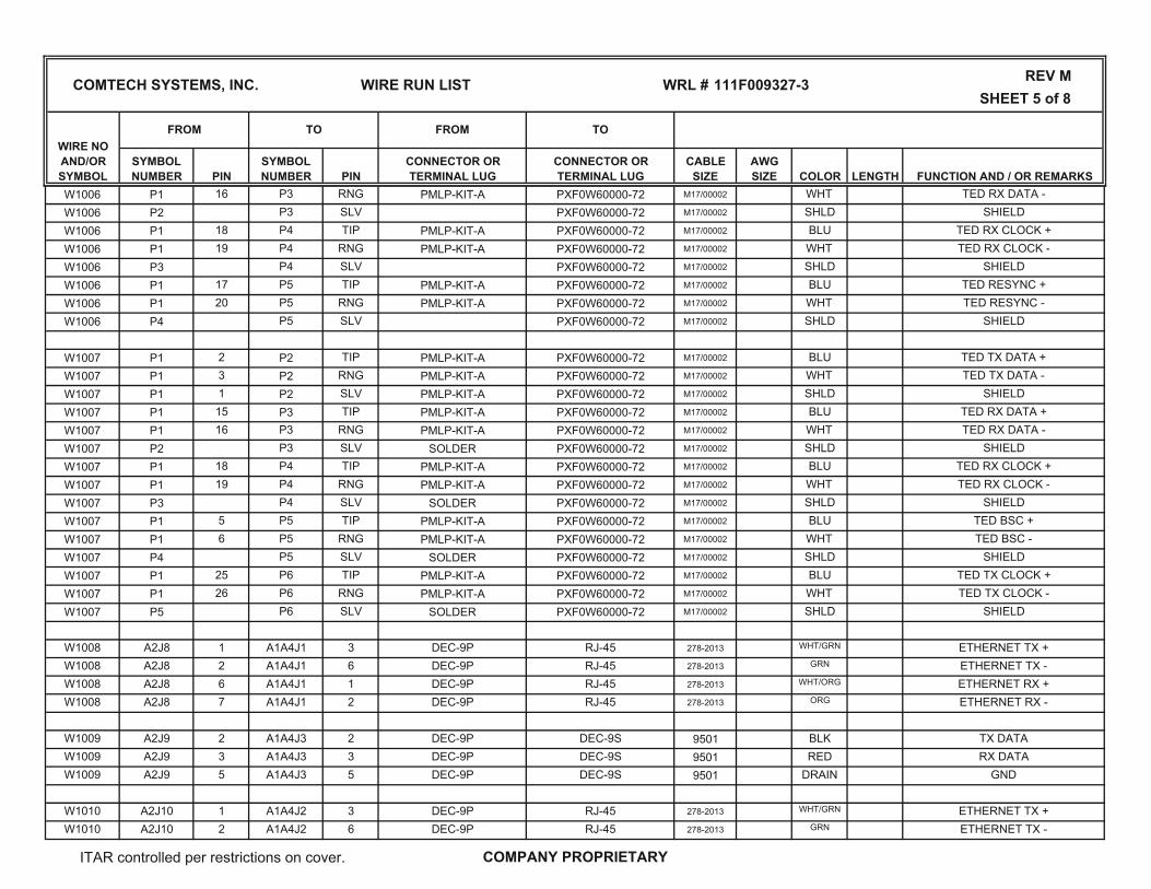
W1006 P1 2 P2 TIP PMLP-KIT-A PXF0W60000-72 M17/00002 BLU TED TX DATA +W1006 P1 3 P2 RNG PMLP-KIT-A PXF0W60000-72 M17/00002 WHT TED TX DATA -W1006 P1 1 P2 SLV PMLP-KIT-A PXF0W60000-72 M17/00002 SHLD SHIELDW1006 P1 15 P3 TIP PMLP-KIT-A PXF0W60000-72 M17/00002 BLU TED RX DATA +
ITAR controlled per restrictions on cover. COMPANY PROPRIETARY
SHEET 5 of 8
CABLESIZE
AWGSIZE COLOR
SYMBOLNUMBER LENGTH
WIRE RUN LIST
PINSYMBOLNUMBER PIN
CONNECTOR OR TERMINAL LUG
CONNECTOR OR TERMINAL LUG
REV M
FROM TO FROM TO
FUNCTION AND / OR REMARKS
COMTECH SYSTEMS, INC.
WIRE NO AND/ORSYMBOL
WRL # 111F009327-3
W1006 P1 16 P3 RNG PMLP-KIT-A PXF0W60000-72 M17/00002 WHT TED RX DATA -W1006 P2 P3 SLV PXF0W60000-72 M17/00002 SHLD SHIELDW1006 P1 18 P4 TIP PMLP-KIT-A PXF0W60000-72 M17/00002 BLU TED RX CLOCK +W1006 P1 19 P4 RNG PMLP-KIT-A PXF0W60000-72 M17/00002 WHT TED RX CLOCK -W1006 P3 P4 SLV PXF0W60000-72 M17/00002 SHLD SHIELDW1006 P1 17 P5 TIP PMLP-KIT-A PXF0W60000-72 M17/00002 BLU TED RESYNC +W1006 P1 20 P5 RNG PMLP-KIT-A PXF0W60000-72 M17/00002 WHT TED RESYNC -W1006 P4 P5 SLV PXF0W60000-72 M17/00002 SHLD SHIELD
W1007 P1 2 P2 TIP PMLP-KIT-A PXF0W60000-72 M17/00002 BLU TED TX DATA +W1007 P1 3 P2 RNG PMLP-KIT-A PXF0W60000-72 M17/00002 WHT TED TX DATA -W1007 P1 1 P2 SLV PMLP-KIT-A PXF0W60000-72 M17/00002 SHIELDW1007 P1 15 P3 TIP PMLP-KIT-A PXF0W60000-72 BLU
SHLD
W1007 P1 16 P3SLV SOLDER PXF0W60000-72
TED RX DATA +RNG PMLP-KIT-A PXF0W60000-72 M17/00002
M17/00002
W1007 P2 P3 SHLDWHT
W1007 P1 18 P4RNG PMLP-KIT-A PXF0W60000-72
SHIELDTIP PMLP-KIT-A PXF0W60000-72 M17/00002
M17/00002
W1007 P1 19 P4 WHTBLU
W1007 P3 P4TIP PMLP-KIT-A PXF0W60000-72
TED RX CLOCK -SLV SOLDER PXF0W60000-72 M17/00002
M17/00002
W1007 P1 5 P5SHLD SHIELD
M17/00002 BLUWHTRNG PMLP-KIT-A PXF0W60000-72 M17/00002W1007 P1 6 P5 TED BSC -
W1007 P4 P5 SLV SOLDER PXF0W60000-72 M17/00002
26
SHLDPMLP-KIT-A PXF0W60000-72 M17/00002 BLU
PXF0W60000-72W1007
M17/00002
P1 25 P6 TIPW1007 P1
M17/00002
P6 WHTRNG PMLP-KIT-ASLV SOLDER PXF0W60000-72W1007 P5 P6
TED TX CLOCK -
SHIELD
TED BSC +
TED RX CLOCK +
TED TX CLOCK +
TED RX DATA -
SHLD SHIELD
W1008 A2J8 1 A1A4J1 3 DEC-9P RJ-45 278-2013 WHT/GRN ETHERNET TX +W1008 A2J8 2 A1A4J1 6 DEC-9P RJ-45 278-2013 GRN ETHERNET TX -W1008 A2J8 6 A1A4J1 1 DEC-9P RJ-45 278-2013 WHT/ORG ETHERNET RX +W1008 A2J8 7 A1A4J1 2 DEC-9P RJ-45 278-2013 ORG ETHERNET RX -
W1009 A2J9 2 A1A4J3 2 DEC-9P DEC-9S 9501 BLK TX DATAW1009 A2J9 3 A1A4J3 3 DEC-9P DEC-9S 9501 RED RX DATAW1009 A2J9 5 A1A4J3 5 DEC-9P DEC-9S 9501 DRAIN GND
W1010 A2J10 1 A1A4J2 3 DEC-9P RJ-45 278-2013 WHT/GRN ETHERNET TX +W1010 A2J10 2 A1A4J2 6 DEC-9P RJ-45 278-2013 GRN ETHERNET TX -
ITAR controlled per restrictions on cover. COMPANY PROPRIETARY

SHEET 6 of 8
CABLESIZE
AWGSIZE COLOR
SYMBOLNUMBER LENGTH
WIRE RUN LIST
PINSYMBOLNUMBER PIN
CONNECTOR OR TERMINAL LUG
CONNECTOR OR TERMINAL LUG
REV M
FROM TO FROM TO
FUNCTION AND / OR REMARKS
COMTECH SYSTEMS, INC.
WIRE NO AND/ORSYMBOL
WRL # 111F009327-3
72" TX DATACTX UG1837/U C-6039 RD316W319 PORT 1 RX A3J7W320 PORT 1 TX A3J5 CRX UG1837/U C-6039 RD316 72" RX DATA
W321 PORT 2 RX A3J11 CTX UG1837/U C-6039 RD316 72" TX DATAW322 PORT 2 TX A3J9 CRX UG1837/U C-6039 RD316 72" RX DATA
W323 PORT 3 RX A3J15 CTX UG1837/U C-6039 RD316 72" TX DATAW324 PORT 3 TX A3J13 CRX UG1837/U C-6039 RD316 72" RX DATA
W325 PORT 4 RX A3J19 CTX UG1837/U C-6039 RD316 72" TX DATAW326 PORT 4 TX A3J17 CRX UG1837/U C-6039 RD316 72" RX DATA
W327 PORT 1 TX A3J4 FRX 223F009812-1 ST FIBER ORG 72" TX DATAW328 PORT 1 RX A3J6 FTX 223F009812-1 ST FIBER BLU 72" RX DATA
W329 PORT 2 TX A3J8 FRX 223F009812-1 ST FIBER ORG 72" TX DATAW330 PORT 2 RX A3J10 FTX 223F009812-1 ST FIBER BLU 72" RX DATA
W331 PORT 3 TX A3J12 FRX 223F009812-1 ST FIBER ORG 72" TX DATAW332 PORT 3 RX A3J14 FTX 223F009812-1 ST FIBER BLU 72" RX DATA
W333 PORT 4 TX A3J16 FRX 223F009812-1 ST FIBER ORG 72" TX DATAW334 PORT 4 RX A3J18 FTX 223F009812-1 ST FIBER BLU 72" RX DATA
W001 A1-CB6 LOAD J1 GOLD PN10-10R HBL4729C 19206 12 BLK 20' 115 VAC
W001 A1-W1-GND 3 J1 GRN PN10-10R HBL4729C 19206 12 GRN20'
GND
W001A1-W2-NEUT 3 J1 SILVER PN10-10R HBL4729C 19206 12 WHT
20'115 VAC NEUTRAL
W002 TB1 1 A5P1 1 PN18-10R IEC 86610100 18 BRN PS1 115 VACW002 TB1 3 A5P1 2 PN18-10R IEC 86610100 18 BLU NEUTRALW002 TB1 5 A5P1 3 PN18-10R IEC 86610100 18 GRN GND
W1010 A2J10 6 A1A4J2 1 DEC-9P RJ-45 278-2013 WHT/ORG ETHERNET RX +W1010 A2J10 7 A1A4J2 2 DEC-9P RJ-45 278-2013 ORG ETHERNET RX -
ITAR controlled per restrictions on cover. COMPANY PROPRIETARY

SHEET 7 of 8
CABLESIZE
AWGSIZE COLOR
SYMBOLNUMBER LENGTH
WIRE RUN LIST
PINSYMBOLNUMBER PIN
CONNECTOR OR TERMINAL LUG
CONNECTOR OR TERMINAL LUG
REV M
FROM TO FROM TO
FUNCTION AND / OR REMARKS
COMTECH SYSTEMS, INC.
WIRE NO AND/ORSYMBOL
WRL # 111F009327-3
GNDNEUTRAL
MUX 115 VAC
12 GRN GND5 HBL4716 PN10-10R THHNW007 TB1NEUTW007 TB1 3 HBL4716 PN10-10R THHN 12
12 BLK
WHT115VAC1 HBL4716 PN10-10R THHNW007 TB1
12 GRN/YEL CHASSIS GROUNDPN10-14R PN10-10RA5 GND CHASSISCHASSIS GROUNDA4 GND CHASSIS PN10-8R PN10-10R 12
12 GRN/YEL
GRN/YELCHASSIS GROUNDPN10-10R PN10-10RA3 GND CHASSISCHASSIS GROUNDA2 GND CHASSIS PN10-8R PN10-10R 12
12 GRN/YEL
GRN/YELCHASSIS GROUNDPN10-6R PN10-10RAI GND CHASSIS
18 BLK
18 WHT
18 GRN
RTN2PN18-10R 39-01-2040
(39-00-0039 Contact)8489W006 TB2
3 A4J1
OAC-170D +48 VDC INPUT #1W006 TB2
7 A4J1 1PN18-10R 39-01-2040
(39-00-0039 Contact)8489
18
18 GRN
RED
3 PN18-10R IEC FURNISHEDW004 TB1 6 A3J1W004 TB1 4 A3J1 2 PN18-10R IEC FURNISHED 18
18 BRNBLU
1 PN18-10R IEC FURNISHEDW004 TB1 2 A3J1
18 BLK RTNA1PN18-10R CDB7W2F20Z0X
(FS4008D-Contact)9409W005 TB2
1 A2J3
CS6716 +48 VDCW005 TB2
5 A2J3 A2PN18-10R CDB7W2F20Z0X
(FS4008D-Contact)9409
18 RED
48 VDC RTNA5TB1 - TB2 4 PN14-14R PN14-10R 1616 RED
BLK48 VDC5 PN14-14R PN14-10RA5TB1 + TB2
W003 TB1 1 A5P2 1 PN18-10R IEC 86610100 18 BRN PS2 115 VACW003 TB1 3 A5P2 2 PN18-10R IEC 86610100 18 BLU NEUTRALW003 TB1 5 A5P2 3 PN18-10R IEC 86610100 18 GRN GND
W006 TB26 A4J1 3
PN18-10R 39-01-2040(39-00-0039 Contact)
8489OAC-170D +48 VDC INPUT #2
W006 TB22 A4J1 4
PN18-10R 39-01-2040(39-00-0039 Contact)
8489RTN
ITAR controlled per restrictions on cover. COMPANY PROPRIETARY
SHEET 8 of 8
CABLESIZE
AWGSIZE COLOR
SYMBOLNUMBER LENGTH
WIRE RUN LIST
PINSYMBOLNUMBER PIN
CONNECTOR OR TERMINAL LUG
CONNECTOR OR TERMINAL LUG
REV M
FROM TO FROM TO
FUNCTION AND / OR REMARKS
COMTECH SYSTEMS, INC.
WIRE NO AND/ORSYMBOL
WRL # 111F009327-3
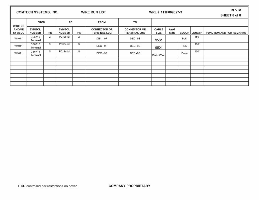
W1011 CS6716 Terminal
2 PC Serial
3 PC Serial
150'2DEC - 9P DEC -9S BLK9501
3DEC - 9P DEC -9S RED9501
150'W1011 CS6716
Terminal5 PC Serial
150'W1011 CS6716
Terminal5
DEC - 9P DEC -9S DrainDrain Wire
ITAR controlled per restrictions on cover. COMPANY PROPRIETARY

1 OF 4
C
E
Change 902, 12
Add 12, 18, 38, 40, 55; Change 7, 24, 36, 39, 41, 42, 43, 45, 49, 50, 55; Delete 22, 37
TITLE
TRC-170 Modem UpgradeTop Assembly
Parts List07/06/06
ECN# APPROVED
THIS DRAWING IS NOT TO BE REPRODUCED OR USED IN ANY MANNER
WITHOUT WRITTEN AUTHORIZATION FROM COMTECH SYSTEMS, INC.
PARTS LISTSHEET
COMTECH SYSTEMS, INC. CODE IDENT NO.24854 * 115F009327-3 *
PROJECT ENGINEER DATE
R. Dohlstrom 07/06/06
CHECKED BY DATE
A. Maldonado
SALES ORDER DIRECTOR OF ENGINEERING DATE
T. Lowry 07/07/06
07/07/06 -----
APPLICATION REVISIONSUSED ON LTR DESCRIPTION DATE
TLB Change 8, 44; Add 21, 69-71 08/22/06 9093 TLA Initial Release per IER 7924
08/24/06 9106 TLD Add 906, 907; Change 8, 33, 49-54; Delete 12, 18, 38, 40, 55-71 09/06/06 8140 TL
09/29/06 9179 TL
F Add 908, 909 06/02/09 9978 TL
FORM 0010 REV A
9327-3RVF.xls.xls(H:\Server)

SHEET 2 OF 4REV F
REF ITEM OR QTY/ CODE IDENT PART NO OR NOMENCLATUREDES FIND NO UM ASSY MANUFACTURER IDENTIFYING NO OR DESCRIPTION
900 REF CSI 404F009327-3 TRC-170 Modem Upgrade Assembly
901 REF CSI 111F009327-3 TRC-170 Modem Upgrade Wire Run List
902 REF CSI 410F009327-3 TRC-170 Modem Upgrade Interconnect Diagram
903 REF CSI 232F009327-3 TRC-170 Modem Upgrade Drawing Tree
904 REF CSI 142F009900-1 TRC-170 Modem Upgrade O&M Manual
905 REF CSI 112F009776-[ ] Cable Assembies, TRC-170 Modem Upgrade
906 REF CSI 117F009327-3
907 REF CSI 137F009327-3
908 REF CSI 117F009900-1 TRC-170 Modem Upgrade Link Stability Test Procedure
909 REF CSI 137F009900-1 TRC-170 Modem Upgrade Link Stability Test Data Sheet
910
911
912
913
914
915
916
917
918
919
920
921
922
923
924
925
TRC-170 Modem Upgrade System Level Production Test Procedure
TRC-170 Modem Upgrade System Level Production Test Data Sheets
PARTS LIST COMTECH SYSTEMS, INC. CODE IDENT NO. 24854 * 115F009327-3 *
9327-3RVF.xls.xls(H:\Server)

SHEET 3 OF 4REV F
REF ITEM OR QTY/ CODE IDENT PART NO OR NOMENCLATUREDES FIND NO UM ASSY MANUFACTURER IDENTIFYING NO OR DESCRIPTION
A2 1 EA 1 CSI 204F009700-1 CS6716 Digital Adaptive Modem
A4 2 EA 1 CSI 404F009770-1 OAC-170D Oscillator/Amplifier/Converter
A3 3 EA 1 DNE 113F009447-1 Versamux 4000, 4-Channel Multiplexer
A1 4 EA 1 ADC 404F009342-2 Chassis, Patchmate, 9-position
5 EA 1 CSI 209F009764-1 Guide Pin Bar
6 EA 4 CSI 209F009763-1 Guide Pin Block
7 EA 6 CSI 209F009762-1 Guide PinA2J2-A2 8 EA 1 CSI 123F009841-1 50 Ohm Termination
9 EA 1 CSI 624F009775-1 Assembly, Cable Harness
10 EA 1 CSI 424F009811-1 Assembly, Power Harness
11 EA 1 CSI 235F009766-1 Bracket, Power Connector
12 EA 3 Electronic Fasteners #10-32 Hex Nut, SS
13 EA 1 CSI 209F009351-1 TRC-170 Modem Upgrade, Cable Support Bar
14 EA 1 CSI 435F009306-2 TRC-170 Modem Upgrade, Main Slide Shelf
15 EA 1 CSI 435F009316-2 TRC-170 Modem Upgrade, Equipment Shelf
16 EA 1 CSI 435F009313-2 TRC-170 Modem Upgrade, Front Panel Assembly
17 EA 2 CSI 209F009317-2 TRC-170 Modem Upgrade Kit, Mounting Bar
18 EA 3 Electronic Fasteners #10 Washer, Lock, SS
19 EA 2 General Devices C-938-20 Rack Slide, Bottom Mount
A5 20 EA 1 CSI 113F009229-1 Hot-swap Redundant Power Supply, 48VDC
21 EA 2 Electronic Fasteners Screw, #10-32 x .5 Lg, Pan Hd, Phillips, SS
22 EA
23 EA 2 Electronic Fasteners #6 Washer, Flat, SS
24 EA 2 Electronic Fasteners Screw, #6-32 x .375 Lg, Pan HD, Phillips, SS
25 EA 12 Electronic Fasteners Screw, #8-32 x .375 Lg., Flat HD, Phillips, SS
TB1 26 EA 1 Mouser Electronics 538-06142 Terminal Board, 6 Position
TB2 27 EA 1 Mouser Electronics 538-8142 Terminal Board, 8 Position
28 EA 1 CSI 209F009367-1 Cover, TRC-170 AC Terminal Board
PARTS LIST COMTECH SYSTEMS, INC. CODE IDENT NO. 24854 * 115F009327-3 *
9327-3RVF.xls.xls(H:\Server)

SHEET 4 OF 4REV F
REF ITEM OR QTY/ CODE IDENT PART NO OR NOMENCLATUREDES FIND NO UM ASSY MANUFACTURER IDENTIFYING NO OR DESCRIPTION
PARTS LIST COMTECH SYSTEMS, INC. CODE IDENT NO. 24854 * 115F009327-3 *
29 EA 1 CSI 209F009368-1 Cover, TRC-170 DC Terminal Board
30 EA 1 CSI 209F000377-3 Label, 120 Volts
31 EA 1 CSI 209F000377-13 Label, 48VDC
32 EA 1 CSI 209F000377-5 Label, DANGER
33 EA 4 CSI 209F009838-1 Standoff, Hex, M/F, Threaded 8-32, 1.00 Lg.
34 EA 1 Mouser Electronics 538-MS6142 Marker Strip, 6-position
35 EA 1 Mouser Electronics 538-MS8142 Marker Strip, 8 Position
36 EA 9 Mouser Electronics 142J-2 Jumper, Terminal Block
3738 EA 1 CSI 109F001442-2 Comtech Logo Label
39 EA 22 Emcor HW-104 Screw, Ph.,#10-32 x .5 lg., W/Nylon washer
40 EA 2 Electronic Fasteners Screw, #8-32 x .625Lg, FL Hd, Phillips, SS 100°
41 EA 13 Electronic Fasteners #8 Washer, Flat, SS
42 EA 10 Electronic Fasteners #8 Washer, Lock, SS
43 EA 5 Electronic Fasteners #8-32 x .75Lg Screw, Pan HD, Phillips, SS
44 EA 30 Electronic Fasteners Screw, #10-32 x .5 Lg, Flat Hd, Phillips, SS, 100°
45 EA 14 Electronic Fasteners Screw, #6-32 x .375 Lg, Flat Hd, Phillips, SS, 100°
46 EA 10 Electronic Fasteners Screw, #4-40 x .375 Lg, Flat Hd, Phillips, SS, 100°
47 OZ A/R Loctite Loctite #262 Adhesive, Loctite, Red
48 EA 2 4750-5 Jack Socket
49 EA 5 Electronic Fasteners #10 Flat washer, SS
50 EA 4 Electronic Fasteners #8-32 x .375 Lg, Pan Hd, Phillips, SS
51 EA 3 08415 Screwdown Tie-Wrap
52 EA 1 Anixter 12 AWG, Stranded, Green/Yellow
53 EA 1 Panduit PN10-14R Lug
54 EA 1 Panduit PN10-10R Lug
55 EA 4 Electronic Fasteners #8-32 Hex Nut, SS
9327-3RVF.xls.xls(H:\Server)

1 OF 4
C
E
Change 30, 41; Add 42-45
Add 46
TITLE
TRC-170(Modem Upgrade) Installation Kit
Parts List09/11/06
ECN# APPROVED
THIS DRAWING IS NOT TO BE REPRODUCED OR USED IN ANY MANNER
WITHOUT WRITTEN AUTHORIZATION FROM COMTECH SYSTEMS, INC.
PARTS LISTSHEET
COMTECH SYSTEMS, INC. CODE IDENT NO.24854 115F009450-3
PROJECT ENGINEER DATE
R. Dolhstrom 09/11/06
CHECKED BY DATE
B. Hodges
SALES ORDER DIRECTOR OF ENGINEERING DATE
T. Lowry 09/08/06
09/08/06 -----
APPLICATION REVISIONSUSED ON LTR DESCRIPTION DATE
TLB Add 29-41 11/14/06 9261 TLA Initial Release per IER 9157
11/28/06 9278 TLD Changed 31,32,33,34,35 & 36 04/24/07 9405 TL
04/30/07 9414 TL
FORM 0010 REV A
9450-3RVE.xls.xls(H:\Server)
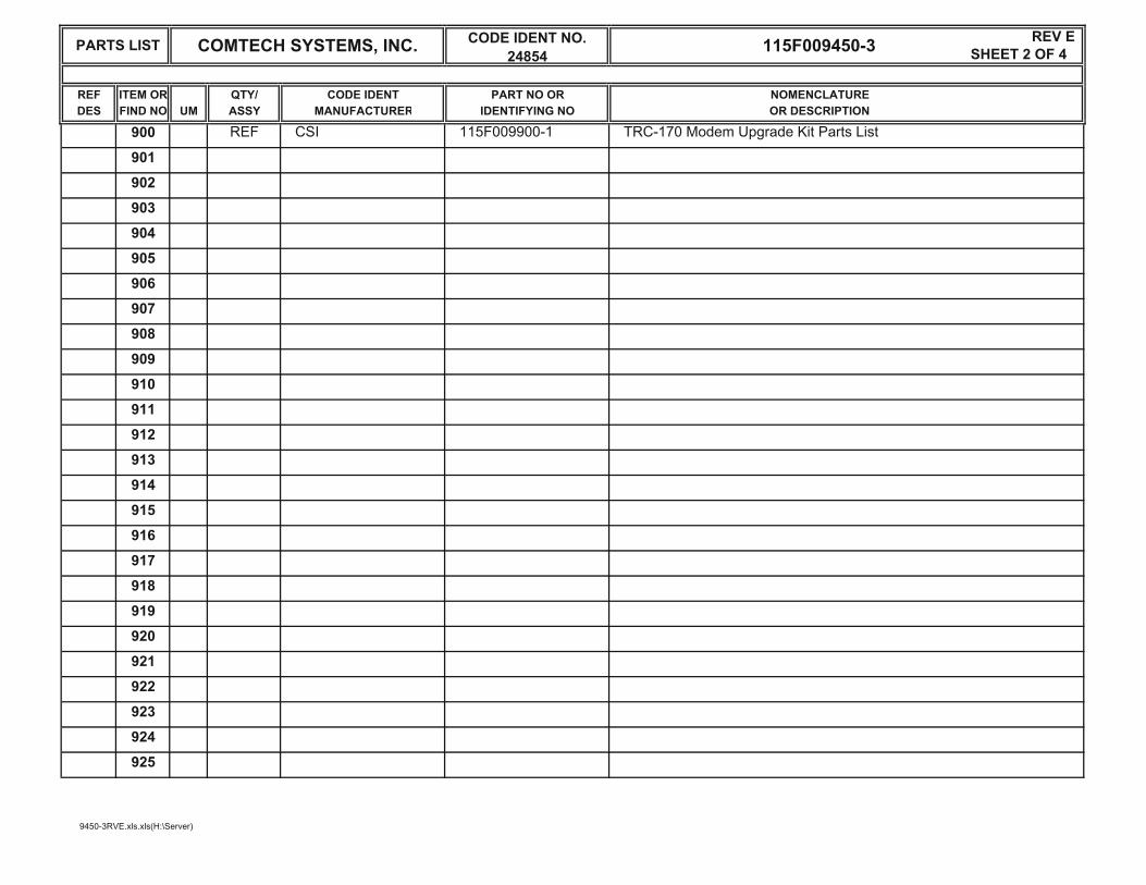
SHEET 2 OF 4REV E
REF ITEM OR QTY/ CODE IDENT PART NO OR NOMENCLATUREDES FIND NO UM ASSY MANUFACTURER IDENTIFYING NO OR DESCRIPTION
900 REF CSI 115F009900-1 TRC-170 Modem Upgrade Kit Parts List
901
902
903
904
905
906
907
908
909
910
911
912
913
914
915
916
917
918
919
920
921
922
923
924
925
PARTS LIST COMTECH SYSTEMS, INC. CODE IDENT NO. 24854 115F009450-3
9450-3RVE.xls.xls(H:\Server)

SHEET 3 OF 4REV E
REF ITEM OR QTY/ CODE IDENT PART NO OR NOMENCLATUREDES FIND NO UM ASSY MANUFACTURER IDENTIFYING NO OR DESCRIPTION
1 EA 1 CSI 115F009450-2 Accessories Kit
W001 2 EA 1 CSI 112F009776-15 AC Power Cord
W1002 3 EA 1 CSI 112F009776-13 Multiconductor Cable
W1005 4 EA 1 CSI 112F009776-14 Multiconductor Cable
W315 5 EA 1 CSI 112F009776-11 Coaxial Cable
W316 6 EA 1 CSI 112F009776-12 Coaxial Cable
W311 7 EA 1 CSI 112F009776-16 Coaxial Cable
W312 8 EA 1 CSI 112F009776-17 Coaxial Cable
W313 9 EA 1 CSI 112F009776-18 Coaxial Cable
W314 10 EA 1 CSI 112F009776-19 Coaxial Cable
CB6 11 EA 1 Newark W91-X112-7 Circuit Breaker, 250 VAC, 7A
12 EA 1 CSI 235F009817-1 Filler Plate, Circuit Breaker
13 EA 1 CSI 207F009818-6 Label "CS6716 MODEM"
14 EA 1 Jonathan CRS-30 Cable retractor
15 EA 1 CSI 209F009350-1 TRC-170 Modem Upgrade Assembling Bracket
16 EA 1 pkg. Bar-Lok 08376 Ty-Wrap, Nylon, 5.5"
17 EA 1 pkg. Bar-Lok 08387 Ty-Wrap, Nylon, 7.5"
18 EA 1 pkg. Bar-Lok 08432 Ty-Wrap, Nylon, 4.0"
19 EA 6 Emcor HW-103 Screw, PH, #10-32 x 1.125 Lg, w/Nylon Washer
20 EA 14 Electronic Fasteners Screw, PH, #10-32 x 0.75 Lg, SS
21 EA 24 Electronic Fasteners Washer, Flat, #10, SS
22 EA 14 Electronic Fasteners Washer, Lock, #10, SS
23 EA 14 Electronic Fasteners Nut, Hex, #10-32, SS
24 EA 1 CSI 209F000377-1 Label "CAUTION"
25 EA 1 CSI 209F000377-16 Label "50/60 Hz ONLY"
26 EA 1 CSI 142F009900-1 TRC-170 Modem Upgrade System Manual
W1011 27 EA 1 CSI 112F009776-21 Cable Assy
PARTS LIST COMTECH SYSTEMS, INC. CODE IDENT NO. 24854 115F009450-3
9450-3RVE.xls.xls(H:\Server)

SHEET 4 OF 4REV E
REF ITEM OR QTY/ CODE IDENT PART NO OR NOMENCLATUREDES FIND NO UM ASSY MANUFACTURER IDENTIFYING NO OR DESCRIPTION
PARTS LIST COMTECH SYSTEMS, INC. CODE IDENT NO. 24854 115F009450-3
28 EA 1 CSI 207F009843-1 Label, Electrical Caution 50/60 Hz Only
29 EA 2 Electronic Fasteners HW-104 Screw, PH, #10-32 x .50 Lg., w/nylon washer
30 EA 2 CSI Heat shrink tubing, .75 lg x 3/8 dia.
31 EA 1 CSI W273 Wrap-around label W273-5A4J16
32 EA 1 CSI W274 Wrap-around label W274-5A4J17
33 EA 1 CSI W159 Wrap-around label W159-A1A1J15
34 EA 1 CSI W160 Wrap-around label W160-A1A1J16
35 EA 1 CSI W161 Wrap-around label W161-A1A1J17
36 EA 1 CSI W162 Wrap-around label W162-A1A1J18
37 EA 3 Electronic Fasteners Screw, #8-32 x .50 Lg, Phillips, SS
38 EA 6 Electronic Fasteners Washer, Flat, #8, SS
39 EA 3 Electronic Fasteners Washer, Lock, #8, SS
40 EA 3 Electronic Fasteners Nut, Hex, #8-32, SS
41 REF 1 CSI 115F009450-3 Parts List, TRC-170 Modem Upgrade Installation Kit
42 EA 2 Electronic Fasteners Screw, #6-32 x .3125 Lg, Phillips, PH, SS
43 EA 2 Electronic Fasteners Washer, Flat, #6
44 EA 2 Electronic Fasteners Washer, Lock, #6
45 EA 1 Panduit GEE36F-C Grommet
46 EA 1 CSI 112F009776-22 Cable Assy
47
48
49
50
9450-3RVE.xls.xls(H:\Server)

1 OF 3
TITLE
AN/TRC-170CS6716 Modem Upgrade
Parts List08/29/06
ECN# APPROVED
THIS DRAWING IS NOT TO BE REPRODUCED OR USED IN ANY MANNER
WITHOUT WRITTEN AUTHORIZATION FROM COMTECH SYSTEMS, INC.
PARTS LISTSHEET
COMTECH SYSTEMS, INC. CODE IDENT NO.24854 * 115F009900-1 *
PROJECT ENGINEER DATE
R. Dohlstrom 08/30/06
CHECKED BY DATE
J. Rodriguez
SALES ORDER DIRECTOR OF ENGINEERING DATE
T. Lowry 08/30/06
08/30/06 -----
APPLICATION REVISIONSUSED ON LTR DESCRIPTION DATE
TLB Change Item 3, Delete Item 4 - 29 09/08/06 8142 RDA Initial Release per IER 9128
FORM 0010 REV A
9900-1RVB.xls(H:\Server)

SHEET 2 OF 3REV B
REF ITEM OR QTY/ CODE IDENT PART NO OR NOMENCLATUREDES FIND NO UM ASSY MANUFACTURER IDENTIFYING NO OR DESCRIPTION
900 REF CSI 232F009327-3 AN/TRC-170 CS6716 Modem Upgrade Drawing Tree
901
902
903
904
905
906
907
908
909
910
911
912
913
914
915
916
917
918
919
920
921
922
923
924
925
PARTS LIST COMTECH SYSTEMS, INC. CODE IDENT NO. 24854 * 115F009900-1 *
9900-1RVB.xls(H:\Server)

SHEET 3 OF 3REV B
REF ITEM OR QTY/ CODE IDENT PART NO OR NOMENCLATUREDES FIND NO UM ASSY MANUFACTURER IDENTIFYING NO OR DESCRIPTION
1 EA 1 CSI 404F009327-3 TRC-170 Modem Upgrade Assembly
2 EA 1 CSI 404F009318-1 TRC-170 Modem Upgrade I/O Panel Connector Plate Assembly - Desert Tan
3 EA 1 CSI 115F009450-3 Installation Kit
PARTS LIST COMTECH SYSTEMS, INC. CODE IDENT NO. 24854 * 115F009900-1 *
9900-1RVB.xls(H:\Server)

Comtech Systems, Inc.
This Page Intentionally Left Blank.

1 OF 3
TITLE
AN/TRC-170CS6716 Modem Upgrade
Parts List11/02/06
ECN# APPROVED
THIS DRAWING IS NOT TO BE REPRODUCED OR USED IN ANY MANNER
WITHOUT WRITTEN AUTHORIZATION FROM COMTECH SYSTEMS, INC.
PARTS LISTSHEET
COMTECH SYSTEMS, INC. CODE IDENT NO.24854 * 115F009900-2 *
PROJECT ENGINEER DATE
R. Dohlstrom 11/03/06
CHECKED BY DATE
F. Blankenbicker
SALES ORDER DIRECTOR OF ENGINEERING DATE
T. Lowry 11/06/06
11/06/06 -----
APPLICATION REVISIONSUSED ON LTR DESCRIPTION DATE
TLA Initial Release per IER 9246
FORM 0010 REV A
9900-2RVA.xls(H:\Server)
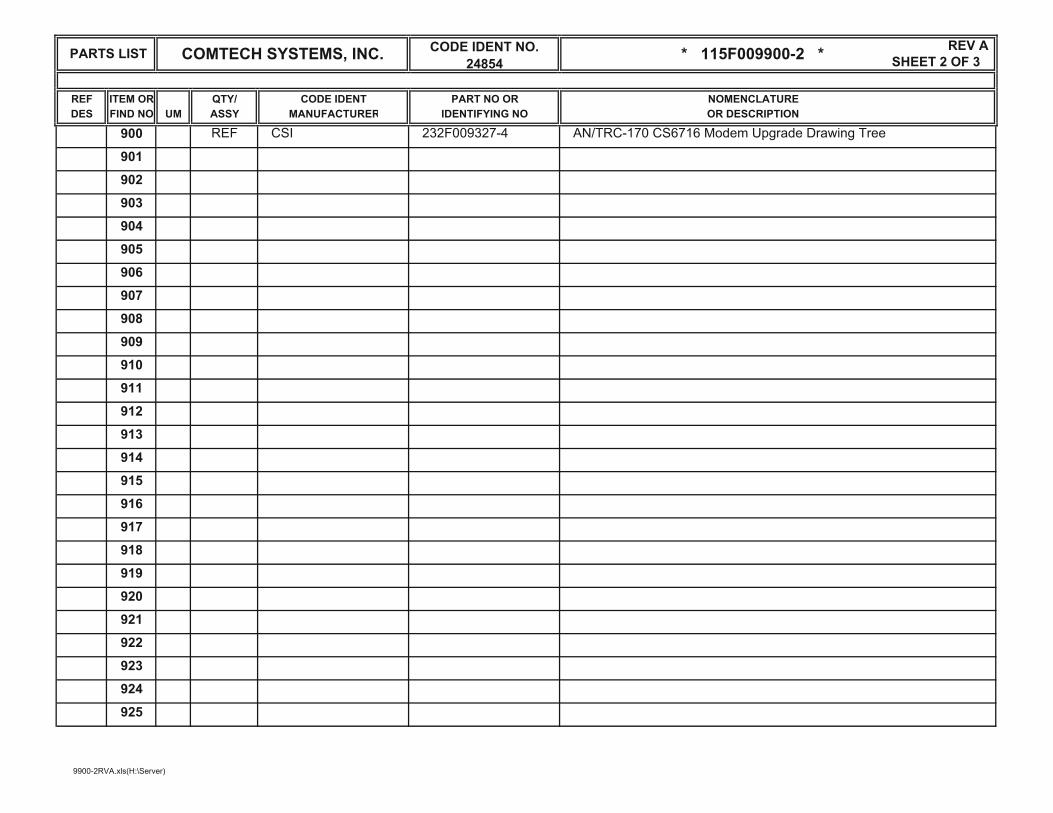
SHEET 2 OF 3REV A
REF ITEM OR QTY/ CODE IDENT PART NO OR NOMENCLATUREDES FIND NO UM ASSY MANUFACTURER IDENTIFYING NO OR DESCRIPTION
900 REF CSI 232F009327-4 AN/TRC-170 CS6716 Modem Upgrade Drawing Tree
901
902
903
904
905
906
907
908
909
910
911
912
913
914
915
916
917
918
919
920
921
922
923
924
925
PARTS LIST COMTECH SYSTEMS, INC. CODE IDENT NO. 24854 * 115F009900-2 *
9900-2RVA.xls(H:\Server)

SHEET 3 OF 3REV A
REF ITEM OR QTY/ CODE IDENT PART NO OR NOMENCLATUREDES FIND NO UM ASSY MANUFACTURER IDENTIFYING NO OR DESCRIPTION
1 EA 1 CSI 404F009327-3 TRC-170 Modem Upgrade Assembly
2 EA 1 CSI 404F009318-2 TRC-170 Modem Upgrade I/O Panel Connector Plate Assembly - Green
3 EA 1 CSI 115F009450-3 Installation Kit
4
5
6
7
8
9
10
11
12
13
14
15
16
17
18
19
20
21
22
23
24
25
26
PARTS LIST COMTECH SYSTEMS, INC. CODE IDENT NO. 24854 * 115F009900-2 *
9900-2RVA.xls(H:\Server)

Comtech Systems, Inc.
This Page Intentionally Left Blank.

TECHNICAL MANUAL FOR THE MODEM UPGRADE MANUAL NO. 142F009900-1 AN/TRC-170 (V3/V5) TERMINAL
COMTECH SYSTEMS, INC. PROPRIETARY 6-1 Use or disclosure is subject to the restriction on the ITAR CONTROLLED PER RESTRICTIONS ON COVER proprietary/confidential notice page of this document.
6.0 SAFETY/GENERAL INFORMATION
6.1 Electrical Safe Work PracticesAccidents involving electricity can cause burns, explosions, shocks and death. Only trained and qualified personnel should service, install or repair electrical equipment.
The general safety procedures for personnel servicing electronic and electrical equipment include: 1. Always turn off or disconnect power before working on electric equipment, electronic
circuits or any type of electrical item.
2. Turn off and disconnect power before checking, or replacing fuses.
3. Locate and correct the cause of a blown fuse, or tripped circuit breaker before replacing the fuse or resetting the circuit breaker.
4. Never defeat the purpose of a fuse or circuit breaker. Always install a fuse with the correct amperage rating for the circuit. Never install a fuse with a higher rating.
5. Always have a second trained and qualified person present when working on electrical systems (protected or unprotected).
6. Always remove metal jewelry, watches, rings, etc., before working on electrical circuits or any electrical equipment.
7. Do not work on electrical equipment in a wet area. Never place containers of liquid on electrical equipment.
8. Do not touch an object that may provide a hazardous path to earth ground.
9. Safely discharge capacitors in equipment before working on the circuits (refer to the ESD procedures).
10. Inspect cabling for defects including frayed wiring, loose connections, or cracked insulation. Replace defective cords and plugs.
11. Always check the electrical ratings of equipment and verify the ratings are correct.
12. Never overload circuits.
13. Verify grounding of equipment chassis/cabinets. Never cut off or defeat the ground connection on a plug.
14. When working at any site, always observe all safety signs and safety procedures. They exist to protect personnel from injuries.
15. All persons working on or around electrical/electronic equipment should have first aid training including resuscitation procedures and external cardiac compression.

TECHNICAL MANUAL FOR THE MODEM UPGRADE MANUAL NO. 142F009900-1 AN/TRC-170 (V3/V5) TERMINAL
COMTECH SYSTEMS, INC. PROPRIETARY 6-2 Use or disclosure is subject to the restriction on the ITAR CONTROLLED PER RESTRICTIONS ON COVER proprietary/confidential notice page of this document.
6.2 Electrostatic Discharge (ESD)
Electrostatic discharge (ESD) can cause fatal errors to sensitive components located on printed circuit cards. Electrostatic discharge measurements as high as 35,000 volts, can occur from walking across a carpet.
To avoid potential damages to electronic equipment, follow correct electrostatic discharge preventive procedures when handling or working with the hardware.
1. Always wear an electrostatic discharge wrist strap when handling electronic hardware.
2. Connect the wrist strap to a reliable earth ground.
3. Replace worn or frayed wrist straps and connecting cords.
4. Check your electrostatic discharge strap every month.
5. Do not use ESD straps that are out of calibration.
6. Place printed circuit cards in an electrostatic discharge bag or other ESD container to avoid damage from stray static charge.
7. Do not place printed circuit cards on any surface that is not an approved electrostatic discharge surface correctly connected to earth ground.
8. Always handle printed circuit cards by the edges. Avoid touching any of the sensitive circuits on the card.
9. Avoid exposing an unprotected PC card to radio frequency (RF) radiation for long periods without shielding.
6.3 Hazardous Materials
Hazardous materials may be present at the maintenance facility. Many of the following substances are toxic (causing illness or death): flammable materials, explosive materials, corrosive materials that cause the skin or eyes to burn on contact, reactive materials when exposed to heat, air, water, or certain other chemicals can cause burning or the release of toxic vapors.

TECHNICAL MANUAL FOR THE MODEM UPGRADE MANUAL NO. 142F009900-1 AN/TRC-170 (V3/V5) TERMINAL
COMTECH SYSTEMS, INC. PROPRIETARY 6-3 Use or disclosure is subject to the restriction on the ITAR CONTROLLED PER RESTRICTIONS ON COVER proprietary/confidential notice page of this document.
Some hazardous substances are obvious, for example: adhesives, solvents, abrasives, fuels, and pesticides. Other substances are less obvious, for example: the toner in office copiers and printers, or heavy-duty cleaning and disinfectant products. The list of substances identified as hazardous in the workplace is constantly increasing as new processes and new technologies create new chemicals.
Each work area should have a posted list of hazardous materials. In the United States, hazardous materials include a material safety data sheet, describing the material, the health/safety risks, correct usage procedures, recommended storage facilities, and the method(s) to treat exposure. If local codes do not require the use of a material safety data sheet, a simple list may describe the type of material, correct usage and storage methods, and its hazard(s). Emergency first aid procedures should be included in the event that personnel experience exposure to the material.
6.4 Lockout/Tagout Policy
Lockout/Tagout refers to the complete isolation of equipment during maintenance or service work. It is good practice to require the use of locks or tags as warning devices to prevent injuries to service personnel from accidental machine start-ups.
While servicing equipment, place a red or yellow tag on the equipment, indicating it is out of use for repairs or maintenance. Treat these tags as a lockout tag. To obtain information regarding when that piece of equipment will become available for use, contact the person who signed the tag.
Examples of equipment to lock/tag out during servicing include:
Power supplies (especially high voltage power supplies)
Transmitters Antennas
RF equipment Generators
Motors Fan systems
Work situations where unexpected application of power or starting of equipment could occur include:
New construction Installation or set-up of equipment Equipment that is being:
Adjusted Inspected Serviced Repaired
TECHNICAL MANUAL FOR THE MODEM UPGRADE MANUAL NO. 142F009900-1 AN/TRC-170 (V3/V5) TERMINAL
COMTECH SYSTEMS, INC. PROPRIETARY 6-4 Use or disclosure is subject to the restriction on the ITAR CONTROLLED PER RESTRICTIONS ON COVER proprietary/confidential notice page of this document.
Power types include:
Electrical Mechanical Hydraulic Pneumatic Chemical Thermal
Do not attempt to start, energize, or use a machine or equipment locked out for service or maintenance.
6.5 Return Material Authorization (RMA) Procedures
To return an item for repair or replacement, a Return Material Authorization (RMA) is required.
Refer to the Return Material Authorization Information Form (Section 6.6) for the information required to request the RMA.
When the information is completed contact Comtech Systems, Inc., by either email or telephone:
Email: [email protected]
Telephone: (407) 854-1950, ext. 4050, or ext. 4010
When you receive the RMA number, carefully pack the item(s) and ship to: Comtech Systems, Inc.
2900 Titan Row, Suite 142 Orlando, FL 32809
USA Attn: Receiving
IMPORTANT INFORMATION
Write the RMA number prominently on the outside of the shipping container. The sender should retain a copy of all information sheets included with the packaging.

TECHNICAL MANUAL FOR THE MODEM UPGRADE MANUAL NO. 142F009900-1 AN/TRC-170 (V3/V5) TERMINAL
COMTECH SYSTEMS, INC. PROPRIETARY 6-5 Use or disclosure is subject to the restriction on the ITAR CONTROLLED PER RESTRICTIONS ON COVER proprietary/confidential notice page of this document.
6.6 RMA Information Form To return an item(s) for repair or replacement, contact CSI to obtain an RMA number. Contact CSI by email or telephone. Email: [email protected] Telephone: (407) 854-1950. Please have the following information available for each item when contacting CSI for an RMA number.
Product Information Product Name: Serial Number: Freight Charges Prepaid
Kit and Shelter ID Kit # Shelter # Description of failure:
Ambient Temperature of equipment operation:
24C 24-29C 29-35C 35-41C 41-46C 46-52C >52C <75F, 76-85F, 86-95F, 96-105F, 106-115F, 116-125F, >126F
Environmental Conditions:
Clean Slightly Dusty Very Dusty Extremely Dusty Dusty 1 2 3 4 5
Equipment Status when Failure occurred
Turn On After Installation Initial Programming Software Upgrade Turn On After Transport LRU Replacement Hardware Upgrade Power Failure Mission Programming Normal Operation Other:
Mailing Information: US Army___ US Marines___ US Air Force___ Contact Name: Job Title: Street City State/Province Zip/Postal Code Country Telephone No. Fax No.: Email Address:
When you have the RMA number, follow these steps to return the item(s):
1. Insert this form inside the package (keep a copy for your records).
2. Carefully pack the item(s)
3. Prominently mark the RMA number on the outside of the package
4. Ship the package to: Comtech Systems, Inc. 2900 Titan Row, Suite 142 Orlando, FL 32809, USA Attn: Receiving RMA# _______________________________________________

TECHNICAL MANUAL FOR THE MODEM UPGRADE MANUAL NO. 142F009900-1 AN/TRC-170 (V3/V5) TERMINAL
COMTECH SYSTEMS, INC. PROPRIETARY 6-6 Use or disclosure is subject to the restriction on the ITAR CONTROLLED PER RESTRICTIONS ON COVER proprietary/confidential notice page of this document.
This Page Intentionally Left Blank

2900 Titan Row Orlando, Florida 32809 Telephone: (407) 854-1950 Fax: (407) 851-6960 URL Address: www.comtechsystems.com
Manual No. 142F009901-1 Revision F July 2010
Installation Manual forAN/TRC-170 (V3/V5) Modem Upgrade
The information in this document contains Technical Data subject to the controls of ITAR, 22 C.F.R. §120-§130 and should not be further
disseminated without the appropriate license or license exemption from the document originator.

INSTALLATION MANUAL FOR MANUAL NO. 142F009901-1 AN/TRC-170 (V3/V5) MODEM UPGRADE
COMTECH SYSTEMS, INC. PROPRIETARY ii Use or disclosure is subject to the restriction on the ITAR CONTROLLED PER RESTRICTIONS ON COVER proprietary/confidential notice page of this document.
Proprietary/Confidential Notice
The information disclosed in this document, including all designs and related materials, is the valuable property of Comtech Systems Inc. (hereinafter “Comtech”) and/or its licensors. Comtech and/or its licensors, as appropriate, reserve all patent, copyright, and other proprietary rights to this document, including all design, manufacturing, reproduction, use, and sales rights thereto, except to the extent said rights are expressly granted to others. Reproduction of this document or portions thereof without prior written approval of Comtech is prohibited.

INSTALLATION MANUAL FOR MANUAL NO. 142F009901-1 AN/TRC-170 (V3/V5) MODEM UPGRADE
COMTECH SYSTEMS, INC. PROPRIETARY iii Use or disclosure is subject to the restriction on the ITAR CONTROLLED PER RESTRICTIONS ON COVER proprietary/confidential notice page of this document.
Contents
1.0 Safety/General.............................................................................................................1-11.1 Electrical Safe Work Practices ..................................................................................... 1-1 1.2 Electrostatic Discharge (ESD) ...................................................................................... 1-2 1.3 Hazardous Materials ..................................................................................................... 1-21.4 Lockout/Tagout Policy ................................................................................................. 1-3 1.5 Return Material Authorization (RMA) Procedures ...................................................... 1-4 2.0 Installation...................................................................................................................2-12.1 Required Tools.............................................................................................................. 2-1 2.2 Installation Preparation................................................................................................. 2-22.3 Installation Procedure ................................................................................................. 2-10Appendix A RMA Information Form..................................................................................... A-1Appendix B Acronyms and Terms .......................................................................................... B-1
Illustrations
Figure 2-1. AN/TRC-170 Modem Upgrade Assembly................................................................ 2-1 Figure 2-2. Blank Panel removed from Shelter Wall .................................................................. 2-3 Figure 2-3. Blank Panel removed from Below the DLED........................................................... 2-4 Figure 2-4. Panel 5A3 to be Removed......................................................................................... 2-4Figure 2-5. Remove the DLED Panel .......................................................................................... 2-5 Figure 2-6. Remove Phillips Screws............................................................................................ 2-5Figure 2-7. Remove Rear Support Bar ........................................................................................ 2-6 Figure 2-8. Disconnected and Bundled DLED Cables ................................................................ 2-6 Figure 2-9. Cabling Harness Disassembled from Cable Retractor ............................................. 2-7 Figure 2-10. Stored Unused Cables (Side View of K-rail)......................................................... 2-8 Figure 2-11. Store Unused Cables (Above I/O Panel Opening)................................................. 2-8 Figure 2-12. Cable Retractor Inserted on K-rail .......................................................................... 2-8 Figure 2-13. Remove Front Fan Assembly.................................................................................. 2-9 Figure 2-14. Remove Front Vent Cover ...................................................................................... 2-9 Figure 2-15. Remove Rear Cable Trough Covers ....................................................................... 2-9 Figure 2-16. Remove Front Cable Trough Covers ...................................................................... 2-9 Figure 2-17. Remove Units at 6A2, 6A3 and 7A2 .................................................................... 2-10 Figure 2-18. Cable W001 inside Rack 5.................................................................................... 2-10 Figure 2-19. Cable W001 Routed Along Top Rear Signal Entry Panels of Racks 6 and 7....... 2-11 Figures 2-20a and b. Cable W001 Routed Through Bulkhead of Rack 7 ................................ 2-11 Figure 2-21. Cable W001 Routed Across and Through the Shelter Cable Trough .................. 2-12

INSTALLATION MANUAL FOR MANUAL NO. 142F009901-1 AN/TRC-170 (V3/V5) MODEM UPGRADE
COMTECH SYSTEMS, INC. PROPRIETARY iv Use or disclosure is subject to the restriction on the ITAR CONTROLLED PER RESTRICTIONS ON COVER proprietary/confidential notice page of this document.
Figures 2-22a, b and c. W001 Installed Inside Power Panel ..................................................... 2-12 Figures 2-23a, b and c. Routing Cables W315 and W316......................................................... 2-13 Figure 2-24. Routing Cables along DAR Modem Cable Retractor .......................................... 2-13 Figure 2-25. Connect Cables to Transmit (DAR) Modem ........................................................ 2-14 Figure 2-26. Cables W315, W316 and W335 Secured to Front Wiring Harness..................... 2-14 Figure 2-27. Route Multi-conductor Cables .............................................................................. 2-15 Figure 2-28. Connect W1005 to W186...................................................................................... 2-15 Figure 2-29. Connect W1002 to 7A3J4 ..................................................................................... 2-16 Figure 2-30. Cables W311 – W314 Connected to IF Loop Panel ............................................. 2-16 Figure 2-31. Install Slide Shelf .................................................................................................. 2-17 Figure 2-32. Connect W001 to the Slide Shelf .......................................................................... 2-17 Figure 2-33. Remove Protective Cover ..................................................................................... 2-18 Figure 2-34. Remove Leads From CB7A, B and C................................................................... 2-18 Figure 2-35. Apply heat shrink to Lugs From CB6................................................................... 2-19 Figure 2-36 Remove Buss Bars ................................................................................................. 2-19Figure 2-37. Remove CB6 ......................................................................................................... 2-20 Figure 2-38. Install Circuit Breaker filler Plate ......................................................................... 2-20 Figure 2-39.Install New Circuit Breaker CB6 with screws supplied in the Installation
Kit hardware....................................................................................................... 2-21 Figure 2-40. Re-install Buss Bars .............................................................................................. 2-21Figure 2-41. Connect W001 Power Cable (Ground and Neutral Wires from Cable
W001 Connected to Inside Power Panel) .......................................................... 2-22 Figure 2-42. Connect W001 Power Cable Black Wire to CB6 LOAD Side ............................ 2-23 Figure 2-43. Fasten CS6716 Modem Label above CB6........................................................... 2-23 Figure 2-44. Fasten CAUTION Labels above MAIN Circuit Breaker..................................... 2-24 Figure 2-45. Fasten CAUTION Label Below External Shelter Input Power Connector.......... 2-24 Figure 2-46. Install Equipment Shelf......................................................................................... 2-25Figure 2-47. Modem Upgrade Assembly Resting on Slides...................................................... 2-25 Figure 2-48. Push Inner Section of the Rack Slide Forward .................................................... 2-25 Figure 2-49. Align Access Holes in Equipment Shelf and Insert the 3/8 inch Bolts................ 2-26 Figure 2-50. Re-install Looping Plugs....................................................................................... 2-26Figure 2-51. Connect AC Power Cables.................................................................................... 2-27 Figure 2-52. Extract IF Patch Panel Section.............................................................................. 2-28 Figure 2-53.Secure Cables using Cable Ties Toward Rear of Equipment Shelf....................... 2-29 Figure 2-54. Secure Cables to Cable Retractor.......................................................................... 2-29 Figure 2-55. Mount I/O Connector Panel and Mounting Bracket. ........................................... 2-30 Figure 2-56. I/O Connector Cable Terminated to Multiplexer ................................................. 2-31
INSTALLATION MANUAL FOR MANUAL NO. 142F009901-1 AN/TRC-170 (V3/V5) MODEM UPGRADE
COMTECH SYSTEMS, INC. PROPRIETARY v Use or disclosure is subject to the restriction on the ITAR CONTROLLED PER RESTRICTIONS ON COVER proprietary/confidential notice page of this document.
Figure 2-57. Dress I/O Cables on Right Lower Arm of the Retractor....................................... 2-31 Figure 2-58. Continue Routing Cables on the Top Arm of the Retractor.................................. 2-31 Figure 2-59. Dress I/O Cables From the Panel Back Toward K rail ......................................... 2-32 Figure 2-60. Loosely Fasten Excess Cable Along the K-rail..................................................... 2-32 Figure 2-61. Shelter I/O Connector Panel Attached to Shelter.................................................. 2-33
Tables
Table 2-1. IF and Multi-Cable Terminations............................................................................. 2-28 Table 2-2. Shelter I/O Panel Terminations ................................................................................ 2-30

INSTALLATION MANUAL FOR MANUAL NO. 142F009901-1 AN/TRC-170 (V3/V5) MODEM UPGRADE
COMTECH SYSTEMS, INC. PROPRIETARY vi Use or disclosure is subject to the restriction on the ITAR CONTROLLED PER RESTRICTIONS ON COVER proprietary/confidential notice page of this document.
This Page Intentionally Left Blank

INSTALLATION MANUAL FOR MANUAL NO. 142F009901-1 AN/TRC-170 (V3/V5) MODEM UPGRADE
COMTECH SYSTEMS, INC. PROPRIETARY 1-1 Use or disclosure is subject to the restriction on the ITAR CONTROLLED PER RESTRICTIONS ON COVER proprietary/confidential notice page of this document.
1.0 SAFETY/GENERAL
1.1 Electrical Safe Work Practices
Accidents involving electricity can cause burns, explosions, shocks and death. Only trained and qualified personnel should service, install or repair electrical equipment.
The general safety procedures for personnel servicing electronic and electrical equipment include: 1. Always turn off or disconnect power before working on electric equipment, electronic
circuits or any type of electrical item.
2. Turn off and disconnect power before checking, or replacing fuses.
3. Locate and correct the cause of a blown fuse, or tripped circuit breaker before replacing the fuse or resetting the circuit breaker.
4. Never defeat the purpose of a fuse or circuit breaker. Always install a fuse with the correct amperage rating for the circuit. Never install a fuse with a higher rating.
5. Always have a second trained and qualified person present when working on electrical systems (protected or unprotected).
6. Always remove metal jewelry, watches, rings, etc., before working on electrical circuits or any electrical equipment.
7. Do not work on electrical equipment in a wet area. Never place containers of liquid on electrical equipment.
8. Do not touch an object that may provide a hazardous path to earth ground.
9. Inspect cabling for defects including frayed wiring, loose connections, or cracked insulation. Replace defective cords and plugs.
10. Always check the electrical ratings of equipment and verify the ratings are correct.
11. Never overload circuits.
12. Verify grounding of equipment chassis/cabinets. Never cut off or defeat the ground connection on a plug.
13. When working at any site, always observe all safety signs and safety procedures. They exist to protect personnel from injuries.
14. All persons working on or around electrical/electronic equipment should have first aid training including resuscitation procedures and external cardiac compression.

INSTALLATION MANUAL FOR MANUAL NO. 142F009901-1 AN/TRC-170 (V3/V5) MODEM UPGRADE
COMTECH SYSTEMS, INC. PROPRIETARY 1-2 Use or disclosure is subject to the restriction on the ITAR CONTROLLED PER RESTRICTIONS ON COVER proprietary/confidential notice page of this document.
1.2 Electrostatic Discharge (ESD)
Electrostatic discharge (ESD) can cause fatal errors to sensitive components located on printed circuit cards. Electrostatic discharge measurements as high as 35,000 volts, can occur from walking across a carpet.
To avoid potential damages to electronic equipment, follow correct electrostatic discharge preventive procedures when handling or working with the hardware.
1. Always wear an electrostatic discharge wrist strap when handling electronic hardware.
2. Connect the wrist strap to a reliable earth ground.
3. Replace worn or frayed wrist straps and connecting cords.
4. Check your electrostatic discharge strap every month.
5. Do not use ESD straps that are out of calibration.
6. Place printed circuit cards in an electrostatic discharge bag or other ESD container to avoid damage from stray static charge.
7. Do not place printed circuit cards on any surface that is not an approved electrostatic discharge surface correctly connected to earth ground.
8. Always handle printed circuit cards by the edges. Avoid touching any of the sensitive circuits on the card.
9. Avoid exposing an unprotected PC card to radio frequency (RF) radiation for long periods without shielding.
1.3 Hazardous Materials
Hazardous materials may be present at the maintenance facility. Many of the following substances are toxic (causing illness or death): flammable materials, explosive materials, corrosive materials that cause the skin or eyes to burn on contact, reactive materials when exposed to heat, air, water, or certain other chemicals can cause burning or the release of toxic vapors.
Some hazardous substances are obvious, for example: adhesives, solvents, abrasives, fuels, and pesticides. Other substances are less obvious, for example: the toner in office copiers and printers, or heavy-duty cleaning and disinfectant products. The list of substances identified as

INSTALLATION MANUAL FOR MANUAL NO. 142F009901-1 AN/TRC-170 (V3/V5) MODEM UPGRADE
COMTECH SYSTEMS, INC. PROPRIETARY 1-3 Use or disclosure is subject to the restriction on the ITAR CONTROLLED PER RESTRICTIONS ON COVER proprietary/confidential notice page of this document.
hazardous in the workplace is constantly increasing as new processes and new technologies create new chemicals.
Each work area should have a posted list of hazardous materials. In the United States, hazardous materials include a material safety data sheet, describing the material, the health/safety risks, correct usage procedures, recommended storage facilities, and the method(s) to treat exposure. If local codes do not require the use of a material safety data sheet, a simple list may describe the type of material, correct usage and storage methods, and its hazard(s). Emergency first aid procedures should be included in the event that personnel experience exposure to the material.
1.4 Lockout/Tagout Policy
Lockout/Tagout refers to the complete isolation of equipment during maintenance or service work. It is good practice to require the use of locks or tags as warning devices to prevent injuries to service personnel from accidental machine start-ups.
While servicing equipment, place a red or yellow tag on the equipment, indicating it is out of use for repairs or maintenance. Treat these tags as a lockout tag. To obtain information regarding when that piece of equipment will become available for use, contact the person who signed the tag.
Examples of equipment to lock/tag out during servicing include:
Power supplies (especially high voltage power supplies)
Transmitters Antennas
RF equipment Generators
Motors Fan systems
Work situations where unexpected application of power or starting of equipment could occur include:
New construction Installation or set-up of equipment Equipment that is being:
Adjusted Inspected Serviced Repaired
Power types include:
Electrical MechanicalHydraulic Pneumatic Chemical Thermal
Do not attempt to start, energize, or use a machine or equipment locked out for service or maintenance.
INSTALLATION MANUAL FOR MANUAL NO. 142F009901-1 AN/TRC-170 (V3/V5) MODEM UPGRADE
COMTECH SYSTEMS, INC. PROPRIETARY 1-4 Use or disclosure is subject to the restriction on the ITAR CONTROLLED PER RESTRICTIONS ON COVER proprietary/confidential notice page of this document.
1.5 Return Material Authorization (RMA) Procedures
To return an item for repair or replacement, a Return Material Authorization (RMA) is required.
Refer to the Return Material Authorization Information Form (Appendix A) for the information required to request the RMA.
When the information is completed contact Comtech Systems, Inc., by either email or telephone:
Email: [email protected]
Telephone: (407) 854-1950, ext. 4050, or ext. 4010
When you receive the RMA number, carefully pack the item(s) and ship to: Comtech Systems, Inc.
2900 Titan Row, Suite 142 Orlando, FL 32809
USAAttn: Receiving
IMPORTANT INFORMATION
Write the RMA number prominently on the outside of the shipping container. The sender should retain a copy of all information sheets included with the packaging.

INSTALLATION MANUAL FOR MANUAL NO. 142F009901-1 AN/TRC-170 (V3/V5) MODEM UPGRADE
COMTECH SYSTEMS, INC. PROPRIETARY 2-1 Use or disclosure is subject to the restriction on the ITAR CONTROLLED PER RESTRICTIONS ON COVER proprietary/confidential notice page of this document.
2.0 INSTALLATION
The AN/TRC-170 Modem Upgrade Assembly provides new functionality to the capability of the AN/TRC-170 Troposcatter Communications System.The installation procedures provided in this manual are to facilitate the installation of the equipment illustrated in Figure 2-1.
Patch Panel
CS6716 Modem
DNE Multiplexer
OAC-170D
Redundant +48 VDC
Power Supply
Figure 2-1. AN/TRC-170 Modem Upgrade Assembly
2.1 Required Tools
The AN/TRC-170 Modem upgrade assembly requires the following tools to install: (Refer to Installation Kit Parts List 115F009450-3 for included installation hardware)
5/16 inch wrench, ratchet, standard box
Screwdriver, Phillips #1 and #2 tip
Screwdriver, flat tip
3/8 inch nut driver
5/16 inch ratchet, socket, hex head
3/8 inch hex wrench
Diagonal cutters
Utility lamp

INSTALLATION MANUAL FOR MANUAL NO. 142F009901-1 AN/TRC-170 (V3/V5) MODEM UPGRADE
COMTECH SYSTEMS, INC. PROPRIETARY 2-2 Use or disclosure is subject to the restriction on the ITAR CONTROLLED PER RESTRICTIONS ON COVER proprietary/confidential notice page of this document.
Screwdriver, Offset, Phillips #1
Heatshrink Gun
5/16 inch open-end/box combo wrench
3/8 inch open-end/box combo wrench
Standard slip-joint pliers
NoteRemove the AN/TRC-170 from service during the upgrade. Remove power when indicated in the procedure to safely install the power cabling for the upgrade assembly.
The following describes the procedures for integrating the AN/TRC-170 Modem Upgrade. The accompanying photographs illustrate a typical AN/TRC-170. The cable routing in several AN/TRC-170s will differ, and may effect the time required to perform the upgrade.
NoteREAD ALL THE DIRECTIONS PRIOR TO INSTALLATION. Follow all instructions as written and in sequence. DO NOT proceed to the next instruction prior to completing the previous instruction.
The AN/TRC-170 has two basic configurations. The blank panel requiring removal in one configuration may include the 5A3 panel, mounting and connector assembly. The presence of this panel will require more work in the preparation process. All steps are applicable for both configurations.
2.2 Installation Preparation
CautionObserve ALL safety procedures while using these instructions. Failure to observe safety procedures could result in severe injury/equipment damage.
NoteThe terms front, forward, rear, back, left and right describe locations in or around the shelter. For the purposes of correct orientation, the terms front and forward are interchangeable to describe the part of the shelter adjacent or closest to the cab of the vehicle. The terms back and rear are interchangeable to describe the part of the shelter adjacent or closest to the vehicle's tailgate. The term left describes the driver's side of the shelter and right describes the passenger side of the vehicle.
NoteRetain all fastening hardware removed during disassembly. Fastening hardware will be used during upgrade.

INSTALLATION MANUAL FOR MANUAL NO. 142F009901-1 AN/TRC-170 (V3/V5) MODEM UPGRADE
COMTECH SYSTEMS, INC. PROPRIETARY 2-3 Use or disclosure is subject to the restriction on the ITAR CONTROLLED PER RESTRICTIONS ON COVER proprietary/confidential notice page of this document.
1. Remove the exterior blank I/O panel from the shelter wall, located behind the trunk encryption device/dedicated loop encryption device (TED/DLED) cabinet (refer to Figure 2-2).
TRC000001bw
Figure 2-2. Blank Panel removed from Shelter Wall
2. Retain all hardware to fasten the new I/O connector panel.
CautionUse care to avoid damaging the electromagnetic interface (EMI/RF1) gasket.
Should damage occur to the original gasket during the preparation for this installation, an EMI/RFI gasket has been supplied within the Installation Kit to replace it.
NoteDepending on configuration, there will either be a blank panel or a 5A3 panel. If a blank panel is present, proceed to step 3. If a 5A3 panel is present, proceed to step 4.

INSTALLATION MANUAL FOR MANUAL NO. 142F009901-1 AN/TRC-170 (V3/V5) MODEM UPGRADE
COMTECH SYSTEMS, INC. PROPRIETARY 2-4 Use or disclosure is subject to the restriction on the ITAR CONTROLLED PER RESTRICTIONS ON COVER proprietary/confidential notice page of this document.
3. 5A3 Blank Panel: (skip to Step 4 if 5A3 Connector panel is installed) Remove the interior blank panel below the unused DLED panel (refer to Figure 2-3). Proceed to step 5.
Figure 2-3. Blank Panel removed from Below the DLED
4. 5A3 Connector Panel: (if applicable) Remove the 5A3 connector panel and disconnect all cables (refer to Figure 2-4). Steps 17 and 20 detail additional procedures.
Figure 2-4. Panel 5A3 to be Removed

INSTALLATION MANUAL FOR MANUAL NO. 142F009901-1 AN/TRC-170 (V3/V5) MODEM UPGRADE
COMTECH SYSTEMS, INC. PROPRIETARY 2-5 Use or disclosure is subject to the restriction on the ITAR CONTROLLED PER RESTRICTIONS ON COVER proprietary/confidential notice page of this document.
5. Unfasten all cables attached to the DLED frame to remove the DLED panel (refer to Figures 2-3 and 2-4).
6. Remove the front panel support chain hardware.
7. Remove the lower front bolts, from inside the U-channel side rails on both the right and left sides, using the 5/16 inch ratchet box end wrench (refer to Figure 2-5).
Figure 2-5. Remove the DLED Panel
8. Remove the eight Phillips screws from the underside of the rear support bar (refer to Figure 2-6).
Figure 2-6. Remove Phillips Screws
9. Remove the final front bolts from both sides.
10. Remove the DLED panel assembly.

INSTALLATION MANUAL FOR MANUAL NO. 142F009901-1 AN/TRC-170 (V3/V5) MODEM UPGRADE
COMTECH SYSTEMS, INC. PROPRIETARY 2-6 Use or disclosure is subject to the restriction on the ITAR CONTROLLED PER RESTRICTIONS ON COVER proprietary/confidential notice page of this document.
NoteExercise care when removing the DLED assembly. Use caution not to drop the shims or hardware into the lower part of the assembly when removing them from the front flanges and rear support bars.
11. Remove the rear support bar by removing both the upper and lower bolts from inside the rear U-channels, using the 5/16 inch ratchet box end wrench (refer to Figure 2-7).
Figure 2-7. Remove Rear Support Bar
12. Carefully disconnect and extend the cable assemblies from the DLED panel.
13. Bundle these cables and fasten them to the existing cable harnesses or rear K-rails at the rear shelter wall (refer to Figure 2-8).
K-rail
TRC05007bw
Figure 2-8. Disconnected and Bundled DLED Cables
14. Fasten these cables to avoid interfering with the installation of the new assemblies and I/O panel.

INSTALLATION MANUAL FOR MANUAL NO. 142F009901-1 AN/TRC-170 (V3/V5) MODEM UPGRADE
COMTECH SYSTEMS, INC. PROPRIETARY 2-7 Use or disclosure is subject to the restriction on the ITAR CONTROLLED PER RESTRICTIONS ON COVER proprietary/confidential notice page of this document.
15. Disassemble the cabling harness from the cable retractor for the IF loop test panel 5A4.
16. Remove all cable ties and cable bundling boots (refer to Figure 2-9).
TRC05008bw
Figure 2-9. Cabling Harness Disassembled from Cable Retractor
17. 5A3 Panel (if applicable)a. After completing Steps 15 and 16, disassemble the cabling harness removed from
the 5A3 connector panel
b. Remove and discard cables numbered W164 and W166, from the 5A3 cables to the IF loop test panel.
c. Re-route cables numbered W273 and W274 to connect them at the IF loop panel J16 and J17 respectively. Wrap-around labels are supplied in the Installation Kit to re-designate the cable terminations.
18. Remove cables numbered W159 through W162 from the IF loop panel cable harness.
19. Remove all necessary covering and cable ties for these cables to the top of the new opening in the rack. Route these cables to the upgrade assembly.
20. 5A3 Panel: (if applicable) Bundle the remaining cables from the 5A3 connector panel, and fasten them to the existing cable harnesses or the rear K-rails at the rear shelter wall.
NoteThe installer may determine the best method for storing the unused cables (refer to Figures 2-10 and 2-11) because the routing of the cable harnesses in the AN/TRC-170 will differ.

INSTALLATION MANUAL FOR MANUAL NO. 142F009901-1 AN/TRC-170 (V3/V5) MODEM UPGRADE
COMTECH SYSTEMS, INC. PROPRIETARY 2-8 Use or disclosure is subject to the restriction on the ITAR CONTROLLED PER RESTRICTIONS ON COVER proprietary/confidential notice page of this document.
Figure 2-10. Stored Unused Cables (Side View of K-rail)
TRC0500010
Figure 2-11. Store Unused Cables (Above I/O Panel Opening)
21. Install the cable retractor in the holes at the left rear of the K-rails as illustrated in Figure 2-12 using 2 #10-32 x .5 Lg. screws, 2 #10 flat and 2 #10 lock washers in the Installation Kit hardware. (#8-32 hardware is supplied in the Installation Kit hardware in the event smaller hardware is required to utilize the existing holes in the K-rail.)
Figure 2-12. Cable Retractor Inserted on K-rail

INSTALLATION MANUAL FOR MANUAL NO. 142F009901-1 AN/TRC-170 (V3/V5) MODEM UPGRADE
COMTECH SYSTEMS, INC. PROPRIETARY 2-9 Use or disclosure is subject to the restriction on the ITAR CONTROLLED PER RESTRICTIONS ON COVER proprietary/confidential notice page of this document.
22. If applicable, Remove the front fan assembly (refer to Figure 2-13).
23. Remove both front vent covers (refer to Figure 2-14).
WarningDisconnect power to the terminal at the power entry panel. Retain earth ground connection.
Figure 2-13. Remove Front Fan Assembly
Figure 2-14. Remove Front Vent Cover
24. Remove the Cable Trough Covers at the front and rear walls of the shelter (refer to Figures 2-15 and 2-16).
25. Removal of the rear vent assemblies may facilitate this step.
Figure 2-15. Remove Rear Cable Trough Covers
Figure 2-16. Remove Front Cable Trough Covers

INSTALLATION MANUAL FOR MANUAL NO. 142F009901-1 AN/TRC-170 (V3/V5) MODEM UPGRADE
COMTECH SYSTEMS, INC. PROPRIETARY 2-10 Use or disclosure is subject to the restriction on the ITAR CONTROLLED PER RESTRICTIONS ON COVER proprietary/confidential notice page of this document.
26. Remove the loop group multiplexer (LGM#1) at 6A2, and the alarm monitor panel at 7A2 the Transmit (DAR) Modem at 4A1, Line Replaceable Unit (LRU) support arm and the TD-1235(P)/TTC and the MD-1026(P)/G at 6A3 from the racks to facilitate running the digital voice orderwire (DVOW) cables and power cable through the racks (refer to Figure 2-17).
CautionExercise care when extending the Transmit (DAR) Modem to avoid damaging the front cable trough.
Figure 2-17. Remove Units at 6A2, 6A3 and 7A2
2.3 Installation Procedure
1. Route the taped end of W001 power cable, included in the Installation Kit hardware, through the rear right K-rail in Rack 5 and temporarily secure to the K-rail. Leave approximately 12 inches of cable protruding) (Refer to Figures 2-18).
Figure 2-18. Cable W001 inside Rack 5

INSTALLATION MANUAL FOR MANUAL NO. 142F009901-1 AN/TRC-170 (V3/V5) MODEM UPGRADE
COMTECH SYSTEMS, INC. PROPRIETARY 2-11 Use or disclosure is subject to the restriction on the ITAR CONTROLLED PER RESTRICTIONS ON COVER proprietary/confidential notice page of this document.
2. Continue to route the cable behind the K-rails in Racks 6 and 7 above both Signal Entry Panels. (refer to Figure 2-19.)
Figure 2-19. Cable W001 Routed Along Top Rear Signal Entry Panels of Racks 6 and 7
3. Continue to route the cable through the rear K-rails in Racks 6 and 7, to the hole through the bulkhead in Rack 7, into the storage compartment and behind the waveguide. Install gasket material supplied in the Installation Kit hardware in the cabinet wall opening. (refer to Figures 2-20a and b).
Figures 2-20a and b. Cable W001 Routed Through Bulkhead of Rack 7
CautionThe wiring harness port through the bulkhead into Rack 7 may be very tight. Use care when inserting cable W001 to avoid damaging the cable or the other wires in the existing wiring harness.
4. Continue to route the cable through the front shelter cable trough and behind the shelter AC distribution panel (refer to Figures 2-21 and 2-22a, b and c.)
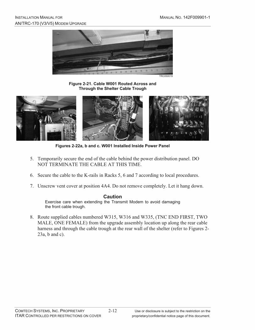
INSTALLATION MANUAL FOR MANUAL NO. 142F009901-1 AN/TRC-170 (V3/V5) MODEM UPGRADE
COMTECH SYSTEMS, INC. PROPRIETARY 2-12 Use or disclosure is subject to the restriction on the ITAR CONTROLLED PER RESTRICTIONS ON COVER proprietary/confidential notice page of this document.
TRC050019
Figure 2-21. Cable W001 Routed Across and Through the Shelter Cable Trough
Figures 2-22a, b and c. W001 Installed Inside Power Panel
5. Temporarily secure the end of the cable behind the power distribution panel. DO NOT TERMINATE THE CABLE AT THIS TIME.
6. Secure the cable to the K-rails in Racks 5, 6 and 7 according to local procedures.
7. Unscrew vent cover at position 4A4. Do not remove completely. Let it hang down.
CautionExercise care when extending the Transmit Modem to avoid damaging the front cable trough.
8. Route supplied cables numbered W315, W316 and W335, (TNC END FIRST, TWO MALE, ONE FEMALE) from the upgrade assembly location up along the rear cable harness and through the cable trough at the rear wall of the shelter (refer to Figures 2-23a, b and c).
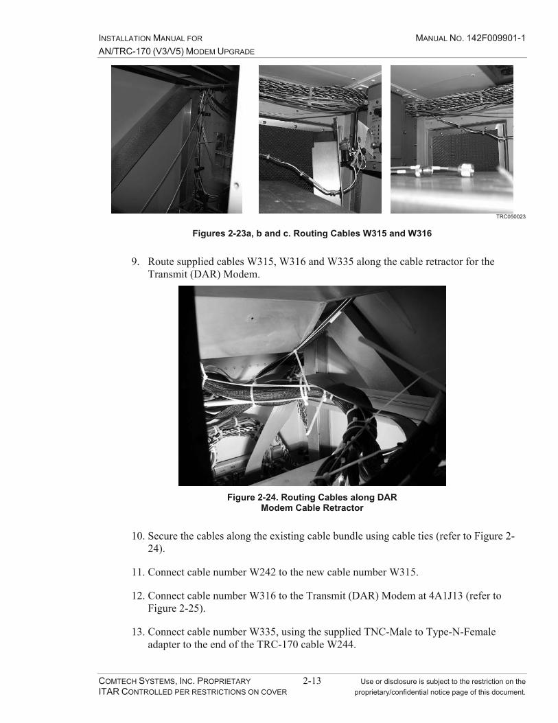
INSTALLATION MANUAL FOR MANUAL NO. 142F009901-1 AN/TRC-170 (V3/V5) MODEM UPGRADE
COMTECH SYSTEMS, INC. PROPRIETARY 2-13 Use or disclosure is subject to the restriction on the ITAR CONTROLLED PER RESTRICTIONS ON COVER proprietary/confidential notice page of this document.
TRC050023
Figures 2-23a, b and c. Routing Cables W315 and W316
9. Route supplied cables W315, W316 and W335 along the cable retractor for the Transmit (DAR) Modem.
Figure 2-24. Routing Cables along DAR Modem Cable Retractor
10. Secure the cables along the existing cable bundle using cable ties (refer to Figure 2-24).
11. Connect cable number W242 to the new cable number W315.
12. Connect cable number W316 to the Transmit (DAR) Modem at 4A1J13 (refer to Figure 2-25).
13. Connect cable number W335, using the supplied TNC-Male to Type-N-Female adapter to the end of the TRC-170 cable W244.

INSTALLATION MANUAL FOR MANUAL NO. 142F009901-1 AN/TRC-170 (V3/V5) MODEM UPGRADE
COMTECH SYSTEMS, INC. PROPRIETARY 2-14 Use or disclosure is subject to the restriction on the ITAR CONTROLLED PER RESTRICTIONS ON COVER proprietary/confidential notice page of this document.
W315 Connected to Cable W242
W316 Connected to DAR Modem
Figure 2-25. Connect Cables to Transmit (DAR) Modem
14. Insert the other ends of cables W315, W316 and W335 through the wiring harness port on the right side of the shelter.
15. Route the cables to the outside wall of Rack 5A, down along the cable harness on the left rear K-Rail and allow the loose ends to extend out the open I/O signal panel.
16. Dress the cables with cable ties (refer to Figure 2-26).
TRC050026
Figure 2-26. Cables W315, W316 and W335 Secured to Front Wiring Harness
17. Reinstall front Cable Trough Cover and Transmit (DAR) Modem.

INSTALLATION MANUAL FOR MANUAL NO. 142F009901-1 AN/TRC-170 (V3/V5) MODEM UPGRADE
COMTECH SYSTEMS, INC. PROPRIETARY 2-15 Use or disclosure is subject to the restriction on the ITAR CONTROLLED PER RESTRICTIONS ON COVER proprietary/confidential notice page of this document.
18. Route the multi-conductor cables numbered W1002 and W1005 along the rear shelter wall from Rack 5A to the rear of the voice orderwire control unit (VOCU), (refer to Figure 2-27).
TRC0501078/21/2006
W1002 and W1005 securedto cable retractor.
TRC
0500
27
Figure 2-27. Route Multi-conductor Cables
19. Disconnect existing cable numbered W186 from VOCU 7A3J4.
20. Connect supplied cable numbered W1005 to W186 (refer to Figure 2-28).
TRC050028
Figure 2-28. Connect W1005 to W186

INSTALLATION MANUAL FOR MANUAL NO. 142F009901-1 AN/TRC-170 (V3/V5) MODEM UPGRADE
COMTECH SYSTEMS, INC. PROPRIETARY 2-16 Use or disclosure is subject to the restriction on the ITAR CONTROLLED PER RESTRICTIONS ON COVER proprietary/confidential notice page of this document.
21. Connect supplied cable numbered W1002 to the VOCU 7A3J4 (refer to Figure 2-29).
TRC050029
Figure 2-29. Connect W1002 to 7A3J4
22. Secure cabling to retractor and K-rails according to local requirements. Re-insert the VOCU and secure the unit to the rack.
23. Dress the cables back to Rack 5A and up the left rear K-Rail to the new cable retractor.
24. Allow the loose ends to extend out the I/O signal panel.
25. Connect cables W311 through W314 to the IF loop test panel as follows: (refer to Figure 2-30):
a. W311 to IF loop panel 5A4J9
b. W312 to IF loop panel 5A4J6
c. W313 to IF loop panel 5A4J7
d. W314 to IF loop panel 5A4J8
TRC0501088/18/2006
Cables W311 –314 dressed to cable retractor.
TRC
0500
30
Figure 2-30. Cables W311 – W314 Connected to IF Loop Panel

INSTALLATION MANUAL FOR MANUAL NO. 142F009901-1 AN/TRC-170 (V3/V5) MODEM UPGRADE
COMTECH SYSTEMS, INC. PROPRIETARY 2-17 Use or disclosure is subject to the restriction on the ITAR CONTROLLED PER RESTRICTIONS ON COVER proprietary/confidential notice page of this document.
26. Dress the cables along the existing cable retractor and allow the excess to hang out through the I/O panel opening.
27. Loosely install quantity of 2 front panel screws, #10 x 0.50 with nylon washer from the Installation Kit hardware..
28. Install the AN/TRC-170 Modem Upgrade Main Slide Shelf. Use the existing threaded holes in the front and rear K-rails with existing #10-32 x 0.625 Hex bolts, #10 washers and #10 lock washers. For convenience, allow the pre-terminated stubby power cables to hang outside the shelter until you are ready to connect them to the upgrade assembly shelf (refer to Figure 2-31).
Note: Picture shows only 4 places, one side
Figure 2-31. Install Slide Shelf
29. Connect cable W001 on the modem upgrade assembly slide shelf (refer to Figure 2-32).
Figure 2-32. Connect W001 to the Slide Shelf

INSTALLATION MANUAL FOR MANUAL NO. 142F009901-1 AN/TRC-170 (V3/V5) MODEM UPGRADE
COMTECH SYSTEMS, INC. PROPRIETARY 2-18 Use or disclosure is subject to the restriction on the ITAR CONTROLLED PER RESTRICTIONS ON COVER proprietary/confidential notice page of this document.
30. At the power panel, remove the rear protective cover (refer to Figure 2-33).
Figure 2-33. Remove Protective Cover
31. Remove the lugs from the line side of CB7A, B and C (refer to Figure 2-34).
Figure 2-34. Remove Leads From CB7A, B and C

INSTALLATION MANUAL FOR MANUAL NO. 142F009901-1 AN/TRC-170 (V3/V5) MODEM UPGRADE
COMTECH SYSTEMS, INC. PROPRIETARY 2-19 Use or disclosure is subject to the restriction on the ITAR CONTROLLED PER RESTRICTIONS ON COVER proprietary/confidential notice page of this document.
32. Remove lugs from CB6 and heatshrink terminals completely. Pinch end of heatshrink with pliers during heating process to seal the ends. These lugs will no longer be used (refer to Figure 2-35). Heatshrink is supplied in the Installation Kit.
Figure 2-35. Apply heat shrink to Lugs From CB6
33. Remove all of the buss bars and lugs to access the circuit breakers (refer to Figure 2-36).
Figure 2-36 Remove Buss Bars

INSTALLATION MANUAL FOR MANUAL NO. 142F009901-1 AN/TRC-170 (V3/V5) MODEM UPGRADE
COMTECH SYSTEMS, INC. PROPRIETARY 2-20 Use or disclosure is subject to the restriction on the ITAR CONTROLLED PER RESTRICTIONS ON COVER proprietary/confidential notice page of this document.
34. Remove circuit breaker CB6 (refer to Figure 2-37).
Figure 2-37. Remove CB6
35. Install circuit breaker filler plate next to CB4 using existing hardware. (refer to Figure 2-38).
Figure 2-38. Install Circuit Breaker filler Plate
CautionUse the #6-32 x .3125 screws supplied in the Installation Kit hardware. Use of screws longer than .3125 will result in damage to the circuit breaker CB6.
36. Install new circuit breaker CB6 using quantity 2 #6-32 x .3125 with #6 flat and #6 lock washers supplied in the Installation Kit hardware. (refer to Figure 2-39).

INSTALLATION MANUAL FOR MANUAL NO. 142F009901-1 AN/TRC-170 (V3/V5) MODEM UPGRADE
COMTECH SYSTEMS, INC. PROPRIETARY 2-21 Use or disclosure is subject to the restriction on the ITAR CONTROLLED PER RESTRICTIONS ON COVER proprietary/confidential notice page of this document.
Figure 2-39.Install New Circuit Breaker CB6 with screws supplied in the Installation Kit hardware
37. Re-install the buss bars and leads to the original circuit breakers (refer to Figure 2-40).
Figure 2-40. Re-install Buss Bars
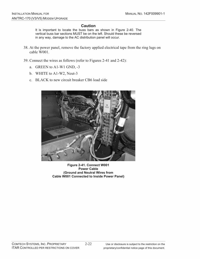
INSTALLATION MANUAL FOR MANUAL NO. 142F009901-1 AN/TRC-170 (V3/V5) MODEM UPGRADE
COMTECH SYSTEMS, INC. PROPRIETARY 2-22 Use or disclosure is subject to the restriction on the ITAR CONTROLLED PER RESTRICTIONS ON COVER proprietary/confidential notice page of this document.
CautionIt is important to locate the buss bars as shown in Figure 2-40. The vertical buss bar sections MUST be on the left. Should these be reversed in any way, damage to the AC distribution panel will occur.
38. At the power panel, remove the factory applied electrical tape from the ring lugs on cable W001.
39. Connect the wires as follows (refer to Figures 2-41 and 2-42):
a. GREEN to A1-W1 GND, -3
b. WHITE to A1-W2, Neut-3
c. BLACK to new circuit breaker CB6 load side
Figure 2-41. Connect W001 Power Cable
(Ground and Neutral Wires from Cable W001 Connected to Inside Power Panel)
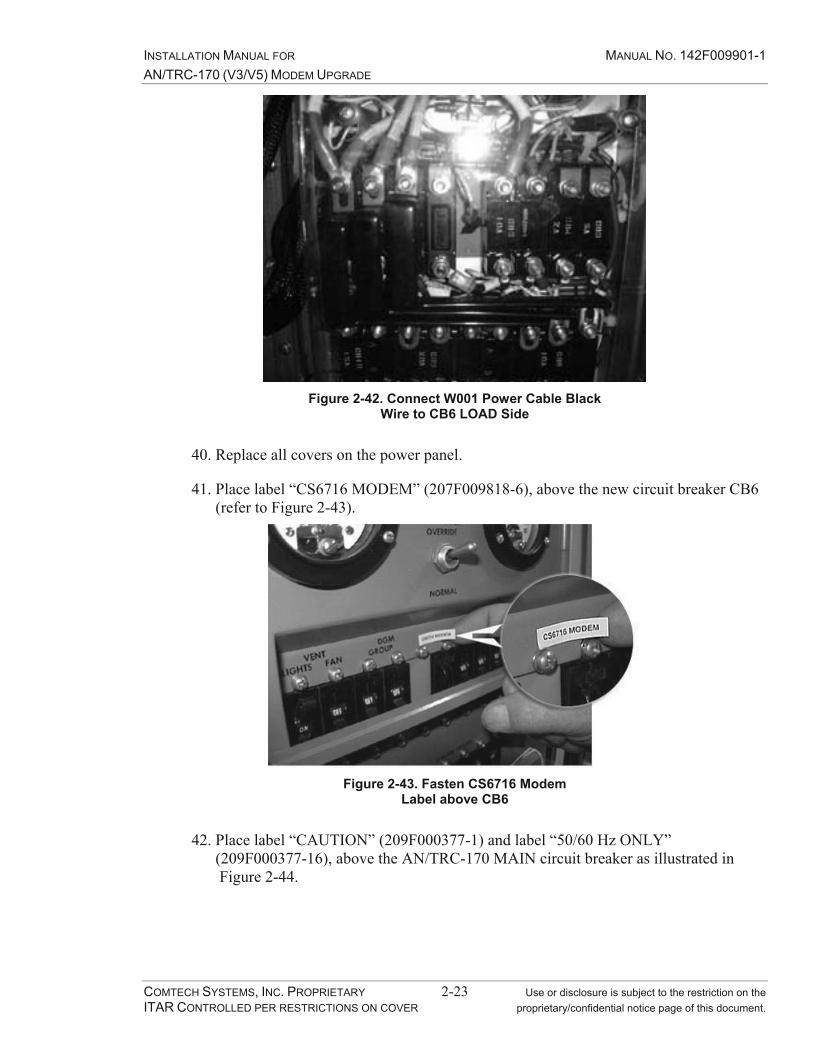
INSTALLATION MANUAL FOR MANUAL NO. 142F009901-1 AN/TRC-170 (V3/V5) MODEM UPGRADE
COMTECH SYSTEMS, INC. PROPRIETARY 2-23 Use or disclosure is subject to the restriction on the ITAR CONTROLLED PER RESTRICTIONS ON COVER proprietary/confidential notice page of this document.
Figure 2-42. Connect W001 Power Cable Black Wire to CB6 LOAD Side
40. Replace all covers on the power panel.
41. Place label “CS6716 MODEM” (207F009818-6), above the new circuit breaker CB6 (refer to Figure 2-43).
Figure 2-43. Fasten CS6716 Modem Label above CB6
42. Place label “CAUTION” (209F000377-1) and label “50/60 Hz ONLY” (209F000377-16), above the AN/TRC-170 MAIN circuit breaker as illustrated in Figure 2-44.
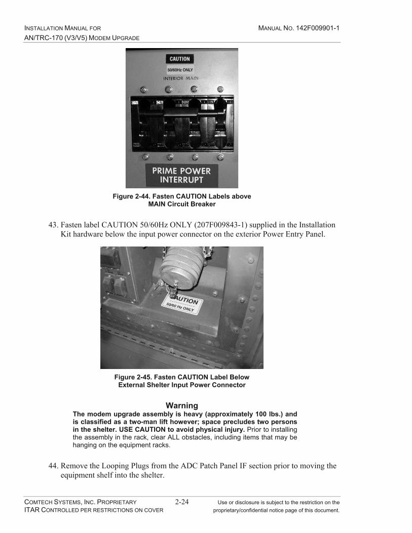
INSTALLATION MANUAL FOR MANUAL NO. 142F009901-1 AN/TRC-170 (V3/V5) MODEM UPGRADE
COMTECH SYSTEMS, INC. PROPRIETARY 2-24 Use or disclosure is subject to the restriction on the ITAR CONTROLLED PER RESTRICTIONS ON COVER proprietary/confidential notice page of this document.
Figure 2-44. Fasten CAUTION Labels above MAIN Circuit Breaker
43. Fasten label CAUTION 50/60Hz ONLY (207F009843-1) supplied in the Installation Kit hardware below the input power connector on the exterior Power Entry Panel.
Figure 2-45. Fasten CAUTION Label Below External Shelter Input Power Connector
WarningThe modem upgrade assembly is heavy (approximately 100 lbs.) and is classified as a two-man lift however; space precludes two persons in the shelter. USE CAUTION to avoid physical injury. Prior to installing the assembly in the rack, clear ALL obstacles, including items that may be hanging on the equipment racks.
44. Remove the Looping Plugs from the ADC Patch Panel IF section prior to moving the equipment shelf into the shelter.

INSTALLATION MANUAL FOR MANUAL NO. 142F009901-1 AN/TRC-170 (V3/V5) MODEM UPGRADE
COMTECH SYSTEMS, INC. PROPRIETARY 2-25 Use or disclosure is subject to the restriction on the ITAR CONTROLLED PER RESTRICTIONS ON COVER proprietary/confidential notice page of this document.
45. CAREFULLY lift the equipment shelf into position aligned on the rack slides, and push into the rack, taking care not to damage the loose cables (refer to Figures 2-46 and 2-47).
Figure 2-46. Install Equipment Shelf Figure 2-47. Modem Upgrade Assembly Resting on Slides
46. From the exterior shelter opening, CAREFULLY push the inner section of the rack slide forward to the stop, while supporting the equipment shelf (refer to Figure 2-48).
Figure 2-48. Push Inner Section of the Rack Slide Forward
WarningExtreme caution should be taken while completing the mounting of the equipment shelf onto the rack slides! It is possible to slide the equipment shelf beyond the mounting holes and possibly drop the equipment or damage the slides.

INSTALLATION MANUAL FOR MANUAL NO. 142F009901-1 AN/TRC-170 (V3/V5) MODEM UPGRADE
COMTECH SYSTEMS, INC. PROPRIETARY 2-26 Use or disclosure is subject to the restriction on the ITAR CONTROLLED PER RESTRICTIONS ON COVER proprietary/confidential notice page of this document.
47. CAREFULLY pull the equipment shelf forward to align the access holes with the threaded hardware holes, and insert the two 3/8 inch socket head bolts as illustrated. The assembly should now be secure (refer to Figure 2-49).
Figure 2-49. Align Access Holes in Equipment Shelf and Insert the 3/8 inch Bolts
48. Re-install the Looping Plugs in the patch panel.
Figure 2-50. Re-install Looping Plugs

INSTALLATION MANUAL FOR MANUAL NO. 142F009901-1 AN/TRC-170 (V3/V5) MODEM UPGRADE
COMTECH SYSTEMS, INC. PROPRIETARY 2-27 Use or disclosure is subject to the restriction on the ITAR CONTROLLED PER RESTRICTIONS ON COVER proprietary/confidential notice page of this document.
49. Connect W004 AC power cord to the VersaMux.
50. Connect W002 and W003 AC power cords from TB1 to the 48VDC power supplies A5 (refer to Figure 2-51).
51. Secure the power cords to the bolt-down cable tie on the rear of the equipment shelf (refer to Figure 2-51) and connect the safety ground wire from the new modem assembly to the K-rail.
Figure 2-51. Connect AC Power Cables
52. Gather cables W315, 316, W335 and W311 through W314, W1002, W1005, and cables W159 through W162 and route them over the top of the cable retractor installed in Step 21 of Section 2.2, Installation Preparation.
53. Route cable W335 to the rear of the OAC-170D (A4).
54. Remove the termination located on J6 and connect W335.
55. Dress cable along existing bundle in the upgrade kit and secure with cable ties.
56. Extract the IF patch panel section of the ADC patch panel (A1A1) to make the connections (refer to Figure 2-52).

INSTALLATION MANUAL FOR MANUAL NO. 142F009901-1 AN/TRC-170 (V3/V5) MODEM UPGRADE
COMTECH SYSTEMS, INC. PROPRIETARY 2-28 Use or disclosure is subject to the restriction on the ITAR CONTROLLED PER RESTRICTIONS ON COVER proprietary/confidential notice page of this document.
Figure 2-52. Extract IF Patch Panel Section
57. Connect all of the cables according to Table 2-1.
NOTE: Attach new cable labels for W159 thru W162 found in the Installation kit prior to install.
Table 2-1. IF and Multi-Cable Terminations
Cable TerminationW311 to A1A1J9 RADIO RX1 W312 to A1A1J10 RADIO RX2 W313 to A1A1J11 RADIO RX3 W314 to A1A1J12 RADIO RX4 W315 to A1A1J7 RADIO TX1 W316 to A1A1J13 DAR TX1 W159 to A1A1J15 DAR RX1 W160 to A1A1J16 DAR RX2 W161 to A1A1J17 DAR RX3 W162 to A1A1J18 DAR RX4 W1002 to A1A3J1 W1005 to A1A7P1
58. Re-install the IF patch panel section.
59. Secure the cables using cable ties, towards the rear of the equipment shelf (refer to Figure 2-53).
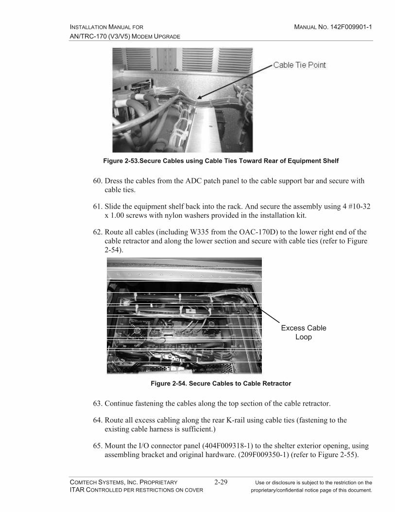
INSTALLATION MANUAL FOR MANUAL NO. 142F009901-1 AN/TRC-170 (V3/V5) MODEM UPGRADE
COMTECH SYSTEMS, INC. PROPRIETARY 2-29 Use or disclosure is subject to the restriction on the ITAR CONTROLLED PER RESTRICTIONS ON COVER proprietary/confidential notice page of this document.
Figure 2-53.Secure Cables using Cable Ties Toward Rear of Equipment Shelf
60. Dress the cables from the ADC patch panel to the cable support bar and secure with cable ties.
61. Slide the equipment shelf back into the rack. And secure the assembly using 4 #10-32 x 1.00 screws with nylon washers provided in the installation kit.
62. Route all cables (including W335 from the OAC-170D) to the lower right end of the cable retractor and along the lower section and secure with cable ties (refer to Figure 2-54).
Excess CableLoop
Figure 2-54. Secure Cables to Cable Retractor
63. Continue fastening the cables along the top section of the cable retractor.
64. Route all excess cabling along the rear K-rail using cable ties (fastening to the existing cable harness is sufficient.)
65. Mount the I/O connector panel (404F009318-1) to the shelter exterior opening, using assembling bracket and original hardware. (209F009350-1) (refer to Figure 2-55).

INSTALLATION MANUAL FOR MANUAL NO. 142F009901-1 AN/TRC-170 (V3/V5) MODEM UPGRADE
COMTECH SYSTEMS, INC. PROPRIETARY 2-30 Use or disclosure is subject to the restriction on the ITAR CONTROLLED PER RESTRICTIONS ON COVER proprietary/confidential notice page of this document.
I/O Panel AssemblyBracket
Figure 2-55. Mount I/O Connector Panel and Mounting Bracket.
66. Terminate the I/O panel cables according to Table 2-2 and as illustrated in Figure 2-56.
Table 2-2. Shelter I/O Panel Terminations
PORT 3
J14
FRX CRX FTX CTX
FIBER/CUFRX CRX FTX CTX
FIBER/CU
J2
J1J4
J3J5
J6
PORT 1
FRX CRX FTX CTX
J10J8
J7 J9
J12
J11 J13
PORT 2FIBER/CU
J20
NRZFRX CRX FTX CTX
J18
J15 J17
J16
J19
PORT 4FIBER/CU
Wire Number From ToW319 Shelter I/O panel CDI connector, Port A Multiplexer (Mux) Port 1 CTX-J7 W320 Shelter I/O panel CDI connector, Port A MUX Port 1 CRX-J5
W321 Shelter I/O panel CDI connector, Port B MUX Port 2 CTX-J11 W322 Shelter I/O panel CDI connector, Port B MUX Port 2 CRX-J9 W323 Shelter I/O panel CDI connector, Port C MUX Port 3 CTX-J15 W324 Shelter I/O panel CDI connector, Port C MUX Port 3 CRX-J13 W325 Shelter I/O panel CDI connector, Port D MUX Port 4 CTX-J19 W326 Shelter I/O panel CDI connector, Port D MUX Port 4 CRX-J17 W327 Shelter I/O panel fiber optic connector, Port A MUX Port 1 FRX-J4 W328 Shelter I/O panel fiber optic connector, Port A MUX Port 1 FTX-J6 W329 Shelter I/O panel fiber optic connector, Port B MUX Port 2 FRX-J8

INSTALLATION MANUAL FOR MANUAL NO. 142F009901-1 AN/TRC-170 (V3/V5) MODEM UPGRADE
COMTECH SYSTEMS, INC. PROPRIETARY 2-31 Use or disclosure is subject to the restriction on the ITAR CONTROLLED PER RESTRICTIONS ON COVER proprietary/confidential notice page of this document.
Wire Number From ToW330 Shelter I/O panel fiber optic connector, Port B MUX Port 2 FTX-J10 W331 Shelter I/O panel fiber optic connector, Port C MUX Port 3 FRX-J12 W332 Shelter I/O panel fiber optic connector, Port C MUX Port 3 FTX-J14 W333 Shelter I/O panel fiber optic connector, Port D MUX Port 4 FRX-J16 W334 Shelter I/O panel fiber optic connector, Port D MUX Port 4 FTX-J18
Figure 2-56. I/O Connector Cable Terminated to Multiplexer
67. Dress the shelter I/O connector panel cables installed in Step 57 to the cable retractor and K-rail (refer to Figures 2-57, 2-58, 2-59 and 2-60).
Figure 2-57. Dress I/O Cables on Right Lower Arm of the Retractor Figure 2-58. Continue Routing Cables on the
Top Arm of the Retractor

INSTALLATION MANUAL FOR MANUAL NO. 142F009901-1 AN/TRC-170 (V3/V5) MODEM UPGRADE
COMTECH SYSTEMS, INC. PROPRIETARY 2-32 Use or disclosure is subject to the restriction on the ITAR CONTROLLED PER RESTRICTIONS ON COVER proprietary/confidential notice page of this document.
Figure 2-59. Dress I/O Cables From the Panel Back Toward K rail
Figure 2-60. Loosely Fasten Excess Cable Along the K-rail
CautionWhile tying the I/O cables in place on the retractor or K-rails, take care to not overtighten the cable ties to prevent damage to the fiber optic cables.
68. Remove the shelter I/O connector panel assembly and bracket from the shelter and remove the bracket from the shelter I/O panel assembly.
NoteTRC-170 Modem Upgrade Assembling Bracket (209F009350-1) for future maintenance use
69. Attach the shelter I/O connector panel assembly to the shelter. Be careful not to pinch the wires between the panel and the shelter (refer to Figure 2-61).
NoteShould damage occur to the original gasket during the preparation for this installation, an EMI/RFI gasket has been supplied to replace it.

INSTALLATION MANUAL FOR MANUAL NO. 142F009901-1 AN/TRC-170 (V3/V5) MODEM UPGRADE
COMTECH SYSTEMS, INC. PROPRIETARY 2-33 Use or disclosure is subject to the restriction on the ITAR CONTROLLED PER RESTRICTIONS ON COVER proprietary/confidential notice page of this document.
Figure 2-61. Shelter I/O Connector Panel Attached to Shelter
70. Replace all removed panels, equipment and covers.
71. Verify all cables are dressed and secured.
72. Restore shelter power.
73. Ensure the upgrade assembly is operational.
STOP.You have completed this procedure.
CDI 1-4
FO 1-4

INSTALLATION MANUAL FOR MANUAL NO. 142F009901-1 AN/TRC-170 (V3/V5) MODEM UPGRADE
COMTECH SYSTEMS, INC. PROPRIETARY 2-34 Use or disclosure is subject to the restriction on the ITAR CONTROLLED PER RESTRICTIONS ON COVER proprietary/confidential notice page of this document.
This Page Intentionally Left Blank.

INSTALLATION MANUAL FOR MANUAL NO. 142F009901-1 AN/TRC-170 (V3/V5) MODEM UPGRADE
COMTECH SYSTEMS, INC. PROPRIETARY A-1 Use or disclosure is subject to the restriction on the ITAR CONTROLLED PER RESTRICTIONS ON COVER proprietary/confidential notice page of this document.
APPENDIX A RMA INFORMATION FORM To return an item(s) for repair or replacement, contact CSI to obtain an RMA number. Contact CSI by email or telephone.
Email: [email protected] Telephone: (407) 854-1950. Please have the following information available for each item when contacting CSI for an RMA number.
Product Information Product Name: Serial Number: Freight Charges Prepaid Kit and Shelter ID Kit # Shelter # Description of failure:
Ambient Temperature of equipment operation:
24C 24-29C 29-35C 35-41C 41-46C 46-52C >52C <75F, 76-85F, 86-95F, 96-105F, 106-115F, 116-125F, >126F
Environmental Conditions:
Clean Slightly Dusty Very Dusty Extremely Dusty Dusty 1 2 3 4 5
Equipment Status when Failure occurred
Turn On After Installation Initial Programming Software Upgrade Turn On After Transport LRU Replacement Hardware Upgrade Power Failure Mission Programming Normal Operation Other:
Mailing Information: US Army___ US Marines___ US Air Force___ Contact Name: Job Title: StreetCity State/Province Zip/Postal Code Country Telephone No. Fax No.: Email Address:
When you have the RMA number, follow these steps to return the item(s):
1. Insert this form inside the package (keep a copy for your records).
2. Carefully pack the item(s)
3. Prominently mark the RMA number on the outside of the package
4. Ship the package to: Comtech Systems, Inc. 2900 Titan Row, Suite 142 Orlando, FL 32809, USA Attn: Receiving RMA# _______________________________________________

INSTALLATION MANUAL FOR MANUAL NO. 142F009901-1 AN/TRC-170 (V3/V5) MODEM UPGRADE
COMTECH SYSTEMS, INC. PROPRIETARY A-2 Use or disclosure is subject to the restriction on the ITAR CONTROLLED PER RESTRICTIONS ON COVER proprietary/confidential notice page of this document.
This Page Intentionally Left Blank

INSTALLATION MANUAL FOR MANUAL NO. 142F009901-1 AN/TRC-170 (V3/V5) MODEM UPGRADE
COMTECH SYSTEMS, INC. PROPRIETARY B-1 Use or disclosure is subject to the restriction on the ITAR CONTROLLED PER RESTRICTIONS ON COVER proprietary/confidential notice page of this document.
APPENDIX B ACRONYMS AND TERMS Acronym/Term Meaning A AC alternating current; air conditioning
D DAR digital adaptive radio DLED dedicated loop encryption device
E EMI electromagnetic interference ESD electrostatic discharge
I I/O input/output
L LGM loop group multiplexer
R RF radio frequency RMA return material authorization
T TED trunk encryption device TGM trunk group multiplexer TOCU transmit orderwire control unit

INSTALLATION MANUAL FOR MANUAL NO. 142F009901-1 AN/TRC-170 (V3/V5) MODEM UPGRADE
COMTECH SYSTEMS, INC. PROPRIETARY B-2 Use or disclosure is subject to the restriction on the ITAR CONTROLLED PER RESTRICTIONS ON COVER proprietary/confidential notice page of this document.
This Page Intentionally Left Blank

2900 Titan Row Orlando, Florida 32809 Telephone: (407) 854-1950 Fax: (407) 851-6960 URL Address: www.comtechsystems.com
Manual No. 142F009770-1 August 2010 Revision B
OAC-170DOperation and Maintenance Manual
The information in this document contains Technical Data subject to the controls of ITAR, 22 C.F.R. §120-§130 and should not be further
disseminated without the appropriate license or license exemption from the document originator.

OAC-170D OPERATION AND MAINTENANCE MANUAL MANUAL NO. 142F009770-1
COMTECH SYSTEMS, INC. PROPRIETARY ii Use or disclosure is subject to the restriction on the ITAR CONTROLLED PER RESTRICTIONS ON COVER proprietary/confidential notice page of this document.
Proprietary/Confidential NoticeThe information disclosed in this document, including all designs and related materials, is the valuable property of Comtech Systems Inc. (hereinafter “Comtech”) and/or its licensors. Comtech and/or its licensors, as appropriate, reserve all patent, copyright, and other proprietary rights to this document, including all design, manufacturing, reproduction, use, and sales rights thereto, except to the extent said rights are expressly granted to others. Reproduction of this document or portions thereof without prior written approval of Comtech is prohibited.

OAC-170D OPERATION AND MAINTENANCE MANUAL MANUAL NO. 142F009770-1
COMTECH SYSTEMS, INC. PROPRIETARY iii Use or disclosure is subject to the restriction on the ITAR CONTROLLED PER RESTRICTIONS ON COVER proprietary/confidential notice page of this document.
Table of Contents
1.0 INTRODUCTION.......................................................................................................... 1-11.1 General............................................................................................................................. 1-1 1.2 Manual Conventions ........................................................................................................ 1-11.3 General Description ......................................................................................................... 1-1 1.4 Items Furnished................................................................................................................ 1-4 1.5 Environmental.................................................................................................................. 1-4
2.0 INSTALLATION........................................................................................................... 2-12.1 Introduction...................................................................................................................... 2-1 2.2 Mechanical Installation.................................................................................................... 2-12.3 Rear Panel Connections ................................................................................................... 2-2
3.0 OPERATION ................................................................................................................. 3-13.1 Introduction...................................................................................................................... 3-1 3.2 Initial Setup...................................................................................................................... 3-1 3.3 Initial Power-Up............................................................................................................... 3-1
3.3.1 Rubidium Oscillator Warm Up...................................................................... 3-1 3.3.2 70 MHz Amplifier Gain Adjustment ............................................................. 3-2
3.4 Normal Operation ............................................................................................................ 3-2 3.5 Monitor and Control ........................................................................................................ 3-3
3.5.1 Indicators and Relays..................................................................................... 3-3 3.5.2 Controls.......................................................................................................... 3-3
4.0 FUNCTIONAL DESCRIPTION.................................................................................. 4-14.1 Station Clock Distribution and Alarm Monitor ............................................................... 4-1 4.2 70 MHz Amplifiers .......................................................................................................... 4-24.3 RS-422/ICD-2 DATA Converter..................................................................................... 4-2 4.4 Power Distribution........................................................................................................... 4-3
5.0 MAINTENANCE........................................................................................................... 5-15.1 Introduction...................................................................................................................... 5-1 5.2 Maintenance Procedures .................................................................................................. 5-1
5.2.1 In-Service Maintenance ................................................................................. 5-1 5.2.2 Inspection....................................................................................................... 5-1 5.2.3 Cleaning ......................................................................................................... 5-2 5.2.4 Station Clock Output Power Adjustment and Frequency Verification.......... 5-2
5.3 Corrective Maintenance ................................................................................................... 5-65.3.1 Rubidium Removal and Replacement ........................................................... 5-6 5.3.2 OAC-170D System Board Removal and Replacement ................................. 5-7
5.4 OAC-170D Troubleshooting ........................................................................................... 5-8

OAC-170D OPERATION AND MAINTENANCE MANUAL MANUAL NO. 142F009770-1
COMTECH SYSTEMS, INC. PROPRIETARY iv Use or disclosure is subject to the restriction on the ITAR CONTROLLED PER RESTRICTIONS ON COVER proprietary/confidential notice page of this document.
6.0 SPARE PARTS LIST .................................................................................................... 6-16.1 Introduction...................................................................................................................... 6-1 6.2 Spare Parts List ................................................................................................................ 6-1 6.3 Correspondence and Ordering of Spare Parts.................................................................. 6-1
7.0 DIAGRAMS ................................................................................................................... 7-17.1 Introduction...................................................................................................................... 7-1 APPENDIX A ASSEMBLY CABLE AND WIRE RUN LIST............................................. A-1 APPENDIX B ACRONYMS AND TERMS............................................................................B-1

OAC-170D OPERATION AND MAINTENANCE MANUAL MANUAL NO. 142F009770-1
COMTECH SYSTEMS, INC. PROPRIETARY v Use or disclosure is subject to the restriction on the ITAR CONTROLLED PER RESTRICTIONS ON COVER proprietary/confidential notice page of this document.
List of Figures
Figure 1-1. OAC-170D Assembly ............................................................................................... 1-2Figure 2-1. OAC-170D Dimensions ............................................................................................ 2-1Figure 2-2. OAC-170D Rear Panel Interfaces............................................................................. 2-2 Figure 3-1. OAC-170D Front Panel Indicators............................................................................ 3-3 Figure 4-1. Station Clock Distribution and Alarm Monitoring ................................................... 4-1 Figure 4-2. 70 MHz Amplifiers with Gain Control ..................................................................... 4-2 Figure 4-3. RS-422/ICD-2 Converter .......................................................................................... 4-3Figure 4-4. Power Distribution .................................................................................................... 4-4 Figure 5-1. System Board Oscillator Connections and Adjustments Pots................................... 5-5 Figure 5-2. Exploded View of Connections and Adjustment Pots of Figure 5-1 ........................ 5-6 Figure 7-1. Assembly, OAC-170D (404F009770-1) Page 1 of 2 - SK7342 ............................... 7-2 Figure 7-2. Assembly, OAC-170D (404F009770-1) Page 2 of 2 - SK7343 ............................... 7-3
List of Tables
Table 1-1. OAC-170D Specifications.......................................................................................... 1-3Table 2-1. OAC-170D Interfaces................................................................................................. 2-2 Table 2-2. OAC-170D J1 Pinout, 48VDC Power Interface (Suggested Molex mating
connector: 39-01-2040, contact: 39-010-0039) ................................................... 2-3 Table 2-3. OAC-170D J2 Pinout, ICD-2 Interface (Mating connector type: D-sub 25
pin female) ........................................................................................................... 2-3 Table 2-4. OAC-170D J3 Pinout (1 of 2), RS-422 Interface (Mating connector type: D-
sub 25 pin male)................................................................................................... 2-3 Table 2-5. OAC-170D J3 Pinout (2 of 2), Alarm Interface (Mating connector type: D-
sub 25 pin male)................................................................................................... 2-3 Table 2-6. OAC-170D J10 Pinout, IF Amplifier Outputs (Suggested Positronic mating
connector: CBD5W5M00Z0Z, contact: MC4102D) ........................................... 2-4 Table 2-7. OAC-170D J11 Pinout, IF Amplifier Inputs (Suggested Positronic mating
connector: CBD5W5F00Z0X, contact: FC4102D) ............................................. 2-4 Table 5-1. In-Service Maintenance Schedule .............................................................................. 5-1 Table 5-2. Inspection ................................................................................................................... 5-2 Table 5-3. Test Equipment........................................................................................................... 5-2 Table 5-4. OAC-170D Troubleshooting ...................................................................................... 5-8 Table 6-1. Spares LRU Parts List ................................................................................................ 6-1
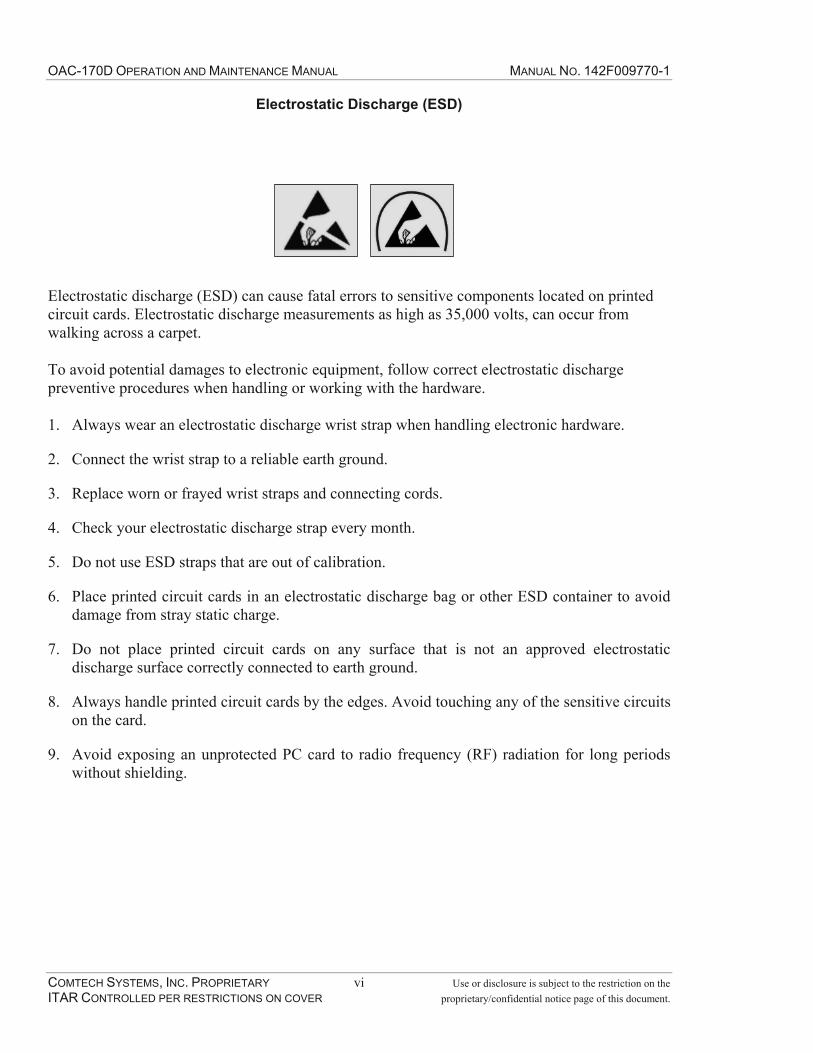
OAC-170D OPERATION AND MAINTENANCE MANUAL MANUAL NO. 142F009770-1
COMTECH SYSTEMS, INC. PROPRIETARY vi Use or disclosure is subject to the restriction on the ITAR CONTROLLED PER RESTRICTIONS ON COVER proprietary/confidential notice page of this document.
Electrostatic Discharge (ESD)
Electrostatic discharge (ESD) can cause fatal errors to sensitive components located on printed circuit cards. Electrostatic discharge measurements as high as 35,000 volts, can occur from walking across a carpet.
To avoid potential damages to electronic equipment, follow correct electrostatic discharge preventive procedures when handling or working with the hardware.
1. Always wear an electrostatic discharge wrist strap when handling electronic hardware.
2. Connect the wrist strap to a reliable earth ground.
3. Replace worn or frayed wrist straps and connecting cords.
4. Check your electrostatic discharge strap every month.
5. Do not use ESD straps that are out of calibration.
6. Place printed circuit cards in an electrostatic discharge bag or other ESD container to avoid damage from stray static charge.
7. Do not place printed circuit cards on any surface that is not an approved electrostatic discharge surface correctly connected to earth ground.
8. Always handle printed circuit cards by the edges. Avoid touching any of the sensitive circuits on the card.
9. Avoid exposing an unprotected PC card to radio frequency (RF) radiation for long periods without shielding.

OAC-170D OPERATION AND MAINTENANCE MANUAL MANUAL NO. 142F009770-1
COMTECH SYSTEMS, INC. PROPRIETARY 1-1 Use or disclosure is subject to the restriction on the ITAR CONTROLLED PER RESTRICTIONS ON COVER proprietary/confidential notice page of this document.
1.0 INTRODUCTION
1.1 General
This document provides the operating and maintenance procedures for the Comtech Systems, Inc., OAC-170D Assembly. It includes the following information:
General description
Installation
Operating procedures, front panel operator controls and status messages
Maintenance procedures, diagnostics and line replaceable unit (LRU) replacement procedures
Installation procedures for rack and cabinet configurations
For additional literature about Comtech Systems products, contact the Marketing department at Comtech Systems, Inc., 2900 Titan Row, Suite 142, Orlando, FL 32809, USA, (407) 854-1950, or (407) 851-6960 (fax), Email: [email protected].
1.2 Manual Conventions
This manual incorporates the following conventions:
Notes – Notes provide additional information about a topic that may materially affect operational decisions.
Cautions – Cautions provide notification that failure to adhere to recommended procedures could cause equipment damage or system malfunction.
Warnings – Warnings provide notification that failure to adhere to recommended procedures could cause severe injury or death as well as equipment damage.
1.3 General Description
The OAC-170D Assembly includes the following major sub-units:
Two Rubidium frequency standards, 10 MHz oscillators
OAC-170D system board
The OAC-170D Assembly provides the following functions:
Six 10 MHz outputs at 0 dBm
Automatic redundancy switching between oscillators

OAC-170D OPERATION AND MAINTENANCE MANUAL MANUAL NO. 142F009770-1
COMTECH SYSTEMS, INC. PROPRIETARY 1-2 Use or disclosure is subject to the restriction on the ITAR CONTROLLED PER RESTRICTIONS ON COVER proprietary/confidential notice page of this document.
Manual switching between oscillators
Four identical 70MHz amplifiers each with their own front panel gain control
Band pass filters available for manual switching, 2.0 MHz and 3.5 MHz
RS-422/ICD-2 Interface Converter for data and clock signals
Dual +48VDC power inputs
Redundant internal DC/DC converters
Alarm and power indicators
Form C alarm relays
Refer to Figure 1-1 for the OAC-170D Assembly and Table 1-1 for the OAC-170D Specifications.
Figure 1-1. OAC-170D Assembly

OAC-170D OPERATION AND MAINTENANCE MANUAL MANUAL NO. 142F009770-1
COMTECH SYSTEMS, INC. PROPRIETARY 1-3 Use or disclosure is subject to the restriction on the ITAR CONTROLLED PER RESTRICTIONS ON COVER proprietary/confidential notice page of this document.
Table 1-1. OAC-170D Specifications
OAC-170D Assembly Specifications IF Interface Minimum gain at maximum gain setting 16 dB Maximum input -10 dBm Center frequency 70 MHz Maximum output +10 dBm Input impedance 75 ohm Output impedance 50 ohmBandwidth (SW1) Bypass >15 MHz 3.5 MHz filter 3.5 MHz 2.0 MHz filter 2.0 MHz Reference Output Frequency 10 MHz Output 6 outputs, 50 ohm, 0 dBm, sine wave Stability over temperature ±1 x 10⁻¹⁰
Stability (aging) 5x10⁻¹⁰/year
RS-422/ICD-2 Converter ICD-2 DB-25P, TX clock & data, RX clock & data RS-422 DB-25S, TX clock & data, RX clock & data Switches SW1 70 MHz filtering selection: Bypass, 3.5 MHz BPF or 2 MHz
BPF SW2 Rubidium selection: A, B or Auto Potentiometers Multi-turn potentiometer that adjusts the gain of the IF
amplifierGeneral Alarm indications LED - Front panel 4 Indicators: Oscillator A (red), Oscillator B (red), summary
(red) & maintenance (yellow) Form C relay 3 Relays: Oscillator A, Oscillator B and Summary Power 48 VDC, 100 watts max, 40 watts nominal Mechanical
Height 1.73" (1 RU) Width 19" rack mount Depth 18" Weight 9 pounds

OAC-170D OPERATION AND MAINTENANCE MANUAL MANUAL NO. 142F009770-1
COMTECH SYSTEMS, INC. PROPRIETARY 1-4 Use or disclosure is subject to the restriction on the ITAR CONTROLLED PER RESTRICTIONS ON COVER proprietary/confidential notice page of this document.
1.4 Items Furnished
Furnished with the OAC-170D Assembly:
OAC-170D Assembly
OAC-170D Assembly Operating and Maintenance Manual
1.5 Environmental
The OAC-170D Assembly will operate in the following environmental conditions:
1. Temp: -4°F to 131°F (-20°C to 55°C)
2. Humidity: 5% to 85% relative humidity non-condensing (RHNC)
3. Altitude: Up to 10,000 ft (3,000m)
The OAC-170D Assembly may be stored for extended periods in the following environmental conditions:
1. Temperature: -58°F to 158°F (-50°C to 70°C)
2. Humidity: 5% to 100% RHNC
3. Altitude: Up to 40,000 ft (12,000m)

OAC-170D OPERATION AND MAINTENANCE MANUAL MANUAL NO. 142F009770-1
COMTECH SYSTEMS, INC. PROPRIETARY 2-1 Use or disclosure is subject to the restriction on the ITAR CONTROLLED PER RESTRICTIONS ON COVER proprietary/confidential notice page of this document.
2.0 INSTALLATION
2.1 Introduction
This section includes the requirements to install the OAC-170D.
2.2 Mechanical Installation
The design of the OAC-170D is a 1RU chassis mounted in a standard 19-inch equipment cabinet. There are slots on the front of the chassis for four mounting screws and the rear of the chassis has two 0.250" diameter (6.35 mm) alignment holes for 0.218" diameter (5.54 mm) alignment pins. The alignment pins also provide support for the rear of the chassis. Both sides of the chassis have three #8-32 self-locking fasteners for an optional rail attachment. Refer to Figure 2-1 for the OAC-170D dimensions.
Figure 2-1. OAC-170D Dimensions

OAC-170D OPERATION AND MAINTENANCE MANUAL MANUAL NO. 142F009770-1
COMTECH SYSTEMS, INC. PROPRIETARY 2-2 Use or disclosure is subject to the restriction on the ITAR CONTROLLED PER RESTRICTIONS ON COVER proprietary/confidential notice page of this document.
2.3 Rear Panel Connections
Connections to the OAC-170D Assembly are via the connectors on the rear panel (refer to Figure 2-2). Table 2-1 defines each interface and Tables 2-2 through 2-7 define the pinouts of the multi-pin connectors. The rear panel has a #8-32 chassis ground stud to connect the chassis to the cabinet ground.
Figure 2-2. OAC-170D Rear Panel Interfaces
Table 2-1. OAC-170D Interfaces
Connectors on rear panel Description Connector type
J1 48V input Molex 39-29-4049 J2 ICD-2 interface Amp 2-440394-3 (D-sub 25 pin male) J3 RS-422 & alarm interface Amp 2-440394-3 (D-sub 25 pin female) J4 10 MHz clock out Bomar 364A2595 (BNC-F) J5 10 MHz clock out Bomar 364A2595 (BNC-F) J6 10 MHz clock out Bomar 364A2595 (BNC-F) J7 10 MHz clock out Bomar 364A2595 (BNC-F) J8 10 MHz clock out Bomar 364A2595 (BNC-F) J9 10 MHz clock out Bomar 364A2595 (BNC-F) J10 IF amplifier outputs Positronic CBD5W5F85R5NT2X-691.33 J11 IF amplifier inputs Positronic CBD5W5M85R5NT2Z-691.33

OAC-170D OPERATION AND MAINTENANCE MANUAL MANUAL NO. 142F009770-1
COMTECH SYSTEMS, INC. PROPRIETARY 2-3 Use or disclosure is subject to the restriction on the ITAR CONTROLLED PER RESTRICTIONS ON COVER proprietary/confidential notice page of this document.
Table 2-2. OAC-170D J1 Pinout, 48VDC Power Interface (Suggested Molex mating connector: 39-01-2040, contact: 39-010-0039)
Pin Description Pin Description 1 48 VDC - Input A 2 48 VDC RTN 3 48VDC - Input B 4 48VDC RTN
Table 2-3. OAC-170D J2 Pinout, ICD-2 Interface (Mating connector type: D-sub 25 pin female)
Pin Description Pin Description 1 Gnd 2 TX DATA P - Input 14 TX DATA N - Input 3 RX DATA P - Output 16 RX DATA N - Output 15 TX CLK P - Output 12 TX CLK N - Output 17 RX CLK P - Output 9 RX CLK N - Output 24 Terminal CLK P - Input 11 Terminal CLK N - Input
Table 2-4. OAC-170D J3 Pinout (1 of 2), RS-422 Interface (Mating connector type: D-sub 25 pin male)
Pin Description Pin Description 1 Gnd 2 TX DATA P - Output 14 TX DATA N - Output 3 RX DATA P - Input 16 RX DATA N - Input 15 TX CLK P - Input 12 TX CLK N - Input 17 RX CLK P - Input 9 RX CLK N - Input 24 Terminal CLK P - Output 11 Terminal CLK N - Output
Table 2-5. OAC-170D J3 Pinout (2 of 2), Alarm Interface (Mating connector type: D-sub 25 pin male)
Pin Description Pin Description 4 Summary Alarm - NO 18 Oscillator A Alarm - COM 5 Summary Alarm - NC 19 Oscillator B Alarm - NO 6 Summary Alarm - COM 20 Oscillator B Alarm - NC 7 Oscillator A Alarm - NO 21 Oscillator B Alarm - COM8 Oscillator A Alarm - NC 22 Gnd 10 Gnd

OAC-170D OPERATION AND MAINTENANCE MANUAL MANUAL NO. 142F009770-1
COMTECH SYSTEMS, INC. PROPRIETARY 2-4 Use or disclosure is subject to the restriction on the ITAR CONTROLLED PER RESTRICTIONS ON COVER proprietary/confidential notice page of this document.
Table 2-6. OAC-170D J10 Pinout, IF Amplifier Outputs (Suggested Positronic mating connector: CBD5W5M00Z0Z, contact: MC4102D)
Pin Description Pin Description 1 Receiver #4 Output 4 Receiver #2 Output 2 Receiver #3 Output 5 Receiver #1 Output 3 Not Used
Table 2-7. OAC-170D J11 Pinout, IF Amplifier Inputs (Suggested Positronic mating connector: CBD5W5F00Z0X, contact: FC4102D)
Pin Description Pin Description 1 Receiver #4 Input 4 Receiver #2 Input 2 Receiver #3 Input 5 Receiver #1 Input 3 Not Used
OAC-170D OPERATION AND MAINTENANCE MANUAL MANUAL NO. 142F009770-1
COMTECH SYSTEMS, INC. PROPRIETARY 3-1 Use or disclosure is subject to the restriction on the ITAR CONTROLLED PER RESTRICTIONS ON COVER proprietary/confidential notice page of this document.
3.0 OPERATION
3.1 Introduction
This section of the manual describes the initial setup and operation of the OAC-170D Assembly.
3.2 Initial Setup
Prior to applying power to OAC-170D Assembly, take precautions to ensure the chassis has equalized to its surrounding environment. If the chassis has been stored in an extreme environment prior to placing in service, allow adequate stabilization time for the assembly to equalize to its new environment. In addition, excessive condensation can result from storing or transporting the assembly from a cool, non-operating environment to a warmer, more humid operating environment.
All unused 70 MHz amplifiers must have their 75 ohms inputs and 50 ohms outputs terminated during operation.
Set FILTER SELECT switch, SW1, to the desired bandwidth. Set the switch to the top or BYPASS position for data rates of 8 Mbps or faster. The center position, 3.5 MHz bandwidth is suitable for rates up to 4 Mbps and the bottom position 2 MHz is suitable for rates to 2 Mbps.
Set OSC SELECT switch, SW2, to the middle position, AUTO, to enable automatic redundancy switching.
3.3 Initial Power-Up
Apply the +48 VDC power to the J1 connector of the OAC-170D Assembly. After power is applied, the ALARM LED will illuminate. If it is green, it indicates the output of the DC/DC converters is normal and the internal temperature is below 149oF (65oC). If it is red, it indicates the unit is in an alarm condition and one of the DC/DC converters has failed or the internal temperature is above 149oF (65oC).
The yellow MAINT LED will flash at a one-second rate to indicate there are no 10 MHz outputs during the oscillator warm up.
3.3.1 Rubidium Oscillator Warm Up
The two internal rubidium oscillators provide redundant 10 MHz inputs to the system board. The 10 MHz outputs are disabled for a maximum of ten minutes following power-up to allow the oscillators to stablize. When the OSC SELECT switch is in the AUTO position, the system board checks the lock status and output power level from both rubidium oscillators at one-minute intervals. During this check interval, if the lock status and output power level of one of the Rubidium oscillators is within tolerance, the system will put that oscillator on-line and enable the 10 MHz outputs. If both oscillators are still in a fault condition when the ten-minute time delay is complete, the 10 MHz outputs enable with OSC A.
OAC-170D OPERATION AND MAINTENANCE MANUAL MANUAL NO. 142F009770-1
COMTECH SYSTEMS, INC. PROPRIETARY 3-2 Use or disclosure is subject to the restriction on the ITAR CONTROLLED PER RESTRICTIONS ON COVER proprietary/confidential notice page of this document.
When the OSC SELECT switch is in either the OSC A or OSC B position, the system board waits the full ten-minutes before it puts the selected oscillator on-line.
Ten-minutes after power is applied, the operator should verify there are no alarm indicators illuminated on the front panel.
3.3.2 70 MHz Amplifier Gain Adjustment
The OAC-170D Assembly provides four 70 MHz amplifiers, with each providing up to 16 dB of gain. The gain of each amplifier is individually adjustable from the front panel. The 70 MHz amplifiers are designed to be used in radio systems when the LNAs and down converters do not provide sufficient gain of the received signal for the connected microwave modem. This lack of gain would result in lost of sensitivity for the modem and reduce the overall system performance. The Comtech Systems, Inc. troposcatter microwave modems are designed for a system gain of 40 dB from the receiver input to the IF input of the modem. Systems that provide a typical range of gain from 28 to 32 dB have the amplifiers adjusted to provide the additional 12 to 8 dB of gain for the required system gain of 40 dB.
3.4 Normal Operation
The OAC-170D Assembly has redundant DC/DC converters and redundant rubidium oscillators. If one of the DC/DC converters or one of the two rubidium oscillators fail, the system will maintain normal operation. When the assembly is operating normally, the power level of the six 10 MHz outputs is 0 dBm ± -1 dB.
SW2 has three positions: OSC A, AUTO and OSC B. To disable the automatic redundancy switching, the operator positions the switch to either the OSC A or OSC B position. Manual switching of the non-synchronized oscillators should only occur during routine maintenance periods.
NoteSwitching oscillators may cause a momentary loss of the link. Only perform oscillator switching during routine maintenance periods.
SW1 has three positions: BYPASS, 3.5 MHz and 2 MHz. This switch allows selection of smaller band pass filters for increased system performance at lower data rates. When the system is operating using an aggregate rate of 2 MB, the operator can flip the switch to the 2 MHz BPF position. If the aggregate rate is 4 MB, the operator can flip the switch to the 3.5 MHz BPF position. At any greater rate, the operator should select the bypass position.
NoteSwitching filters may cause a momentary loss of the link. Only perform filter switching during routine maintenance periods.

OAC-170D OPERATION AND MAINTENANCE MANUAL MANUAL NO. 142F009770-1
COMTECH SYSTEMS, INC. PROPRIETARY 3-3 Use or disclosure is subject to the restriction on the ITAR CONTROLLED PER RESTRICTIONS ON COVER proprietary/confidential notice page of this document.
3.5 Monitor and Control
3.5.1 Indicators and Relays
The OAC-170D Assembly has four front panel LEDs and three Form 'C' alarm relays. The front panel LEDs are: ALARM, OSC A ALARM, OSC B ALARM and MAINT. The Form 'C' relays are: Oscillator A Alarm, Oscillator B Alarm and Summary Alarm.
The front panel ALARM LED is a summary alarm LED that illuminates green when there is no alarm and illuminates red when any of the following alarms occur:
Any DC/DC converter below threshold
Internal temperature is above 149oF (65oC) and
MAINT SW is not in the AUTO position.
Any of these alarms will also cause the summary alarm relay to de-energize to indicate an alarm condition.
The front panel OSC A ALARM and OSC B ALARM LEDs illuminate red when the output power of the oscillators is low or the oscillator has not locked. This will also cause the respective alarm relay, Oscillator A alarm or Oscillator B alarm, to de-energize to indicate an alarm condition.
The front panel MAINT LED illuminates a solid yellow when the OSC SELECT switch is not in the AUTO position. When the OSC SELECT switch is in OSC A or OSC B, the selected oscillator goes on-line and disables automatic redundancy switching. When the MAINT LED is flashing yellow, the 10 MHz oscillator outputs are disabled.
Figure 3-1. OAC-170D Front Panel Indicators
3.5.2 Controls
The OAC-170D provides one multi-turn potentiometer for each 70 MHz IF amplifier to adjust the gain of the respective amplifier for a system gain of 40 dB on each receive path. Once these

OAC-170D OPERATION AND MAINTENANCE MANUAL MANUAL NO. 142F009770-1
COMTECH SYSTEMS, INC. PROPRIETARY 3-4 Use or disclosure is subject to the restriction on the ITAR CONTROLLED PER RESTRICTIONS ON COVER proprietary/confidential notice page of this document.
have been set, no further adjustment is needed unless changes in the receive path have been made.
The FILTER SELECT switch, SW1, has three positions: BYPASS, 3.5 MHz and 2 MHz. This switch allows selection of smaller band pass filters for increased system performance at lower data rates. The filter setting is based upon modem rate configuration. The setting should only be changed when the modem rate configuration changes.
The OSC SELECT Switch, SW2, has three positions: OSC A, AUTO and OSC B. This switch allows selection of a specific oscillator to put on-line or to enable the automatic redundancy switching. Manual switching of the non-synchronized oscillators should only occur during routine maintenance periods.

OAC-170D OPERATION AND MAINTENANCE MANUAL MANUAL NO. 142F009770-1
COMTECH SYSTEMS, INC. PROPRIETARY 4-1 Use or disclosure is subject to the restriction on the ITAR CONTROLLED PER RESTRICTIONS ON COVER proprietary/confidential notice page of this document.
4.0 FUNCTIONAL DESCRIPTION
4.1 Station Clock Distribution and Alarm Monitor
Refer to Figure 4-1 for the block diagram for this section.
Figure 4-1. Station Clock Distribution and Alarm Monitoring
The 10 MHz output and lock status of two rubidium oscillators connect to the OAC-170D System Board. The nominal output power of the oscillators is +14 dBm (1.12 Vrms). The CPLD on the OAC-170D system board controls which rubidium will be online.
The clock signals route to DPDT switches and to power level detector circuits. From the DPDT switches, the online rubidium routes through a 6-way power divider and 4 dB padding to provide six 0 dBm outputs on the rear panel through three dual BNC connectors. The offline rubidium signal routes to a 50 ohm termination.
When the output power level drops to -2 dBM ±-0.5 dB the power detection circuit will indicate an alarm to the CPLD. All 10MHz outputs must be terminated for this measurement to be accurate. If SW2 is in AUTO mode, based on the lock status and power detectors, the CPLD will send control signals to the two DPDT switches, to put the non-faulty oscillator online. If SW2 is in either OSC A or OSC B, the CPLD will put online the selected oscillator and not switch when it has failed. The CPLD will also turn on the MAINT LED and will activate the front panel ALARM LED and de-energize the summary alarm relay to indicate an alarm. This notifies the operator of the disabling of the automatic redundancy switching.
The OAC-170D System Board has a high temperature detector circuit that will indicate an alarm to the CPLD when the internal temperature of the chassis is above 149oF (65oC). The CPLD will

OAC-170D OPERATION AND MAINTENANCE MANUAL MANUAL NO. 142F009770-1
COMTECH SYSTEMS, INC. PROPRIETARY 4-2 Use or disclosure is subject to the restriction on the ITAR CONTROLLED PER RESTRICTIONS ON COVER proprietary/confidential notice page of this document.
activate the front panel ALARM LED and de-energize the summary alarm relay to indicate there is an alarm.
The system board has redundant +15V and +5.1V DC/DC converters and a single -5.1V DC/DC converter. Power monitor circuits are in place to detect a low output voltage level from any DC/DC converter and indicate an alarm to the CPLD. The CPLD will then activate the front panel ALARM LED and de-energize the summary alarm relay to indicate there is an alarm.
4.2 70 MHz Amplifiers
Refer to Figure 4-2 for the block diagram for this section.
Figure 4-2. 70 MHz Amplifiers with Gain Control (only one circuit is illustrated)
The OAC-170D System Board provides four 70 MHz amplifiers. The gain of each amplifier is individually adjustable up to 16 dB, from the front panel, using 10K ohm trimmers. The input impedance of each amplifier is 75 ohms and the output impedance is 50 ohms. The circuit allows the operator to choose either a 3.5 MHz or 2.0 MHz BPF for additional filtering needed at low data rates. The tuning of the circuit for minimal difference in the gain value, when switching in the optional band pass filters occurs at the factory. This prevents adjusting the gain values each time the operator selects a different filter. The BYPASS path has no filtering and is used for data dates of 8mbps or higher where the modem provides sufficient filtering.
4.3 RS-422/ICD-2 DATA Converter
The RS-422/ICD-2 Converter provides the electrical conversion between an RS-422 circuit and an ICD-2 circuit for the data and clock signals only. Refer to Figure 4-3 for a block diagram of the converter.

OAC-170D OPERATION AND MAINTENANCE MANUAL MANUAL NO. 142F009770-1
COMTECH SYSTEMS, INC. PROPRIETARY 4-3 Use or disclosure is subject to the restriction on the ITAR CONTROLLED PER RESTRICTIONS ON COVER proprietary/confidential notice page of this document.
Figure 4-3. RS-422/ICD-2 Converter
4.4 Power Distribution
The OAC-170D Assembly has two prime power inputs of +48 VDC with negative ground. If the supply voltage sags or surges, the OAC-170D can provide continuous service from a minimum voltage of 36 VDC to a high of 56 VDC. The power consumption of the unit is 100 watts maximum during power up and 40 watts nominal. The system board has redundant +15V and +5.1V DC/DC converters and a single -5.1V DC/DC converter. Refer to Figure 4-4 for a block diagram of the power distribution.
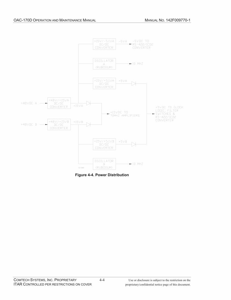
OAC-170D OPERATION AND MAINTENANCE MANUAL MANUAL NO. 142F009770-1
COMTECH SYSTEMS, INC. PROPRIETARY 4-4 Use or disclosure is subject to the restriction on the ITAR CONTROLLED PER RESTRICTIONS ON COVER proprietary/confidential notice page of this document.
Figure 4-4. Power Distribution
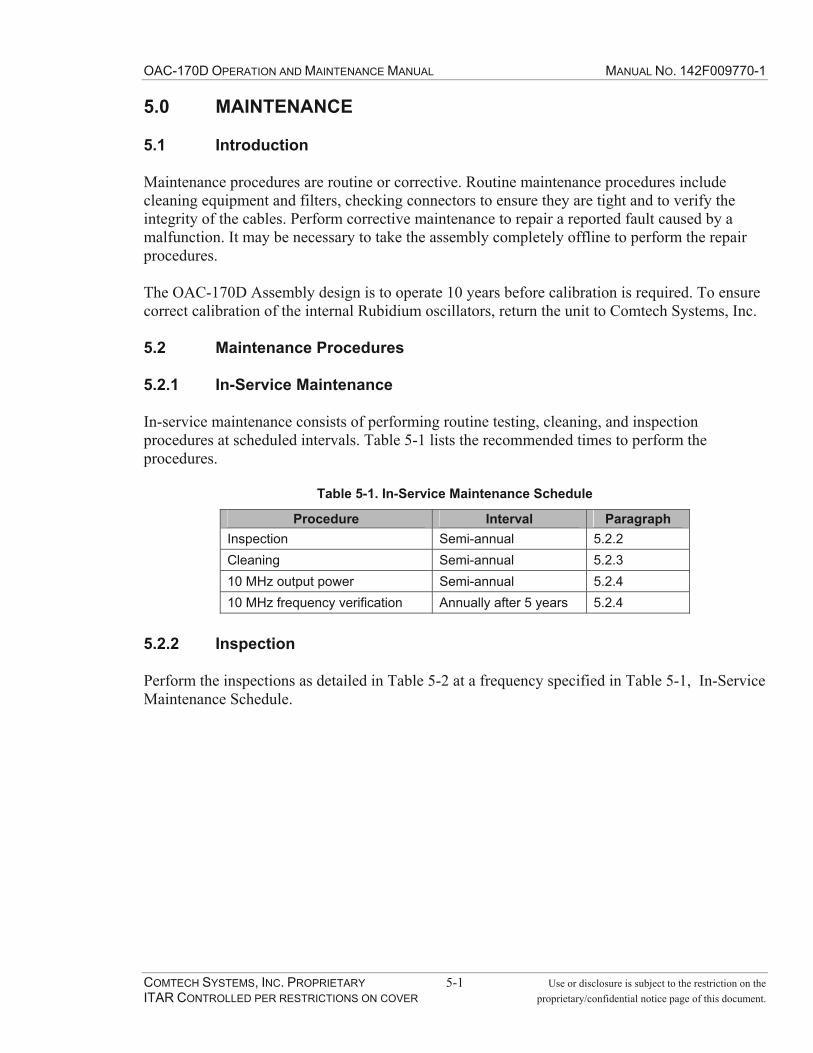
OAC-170D OPERATION AND MAINTENANCE MANUAL MANUAL NO. 142F009770-1
COMTECH SYSTEMS, INC. PROPRIETARY 5-1 Use or disclosure is subject to the restriction on the ITAR CONTROLLED PER RESTRICTIONS ON COVER proprietary/confidential notice page of this document.
5.0 MAINTENANCE
5.1 Introduction
Maintenance procedures are routine or corrective. Routine maintenance procedures include cleaning equipment and filters, checking connectors to ensure they are tight and to verify the integrity of the cables. Perform corrective maintenance to repair a reported fault caused by a malfunction. It may be necessary to take the assembly completely offline to perform the repair procedures.
The OAC-170D Assembly design is to operate 10 years before calibration is required. To ensure correct calibration of the internal Rubidium oscillators, return the unit to Comtech Systems, Inc.
5.2 Maintenance Procedures
5.2.1 In-Service Maintenance
In-service maintenance consists of performing routine testing, cleaning, and inspection procedures at scheduled intervals. Table 5-1 lists the recommended times to perform the procedures.
Table 5-1. In-Service Maintenance Schedule
Procedure Interval Paragraph Inspection Semi-annual 5.2.2Cleaning Semi-annual 5.2.310 MHz output power Semi-annual 5.2.410 MHz frequency verification Annually after 5 years 5.2.4
5.2.2 Inspection
Perform the inspections as detailed in Table 5-2 at a frequency specified in Table 5-1, In-Service Maintenance Schedule.

OAC-170D OPERATION AND MAINTENANCE MANUAL MANUAL NO. 142F009770-1
COMTECH SYSTEMS, INC. PROPRIETARY 5-2 Use or disclosure is subject to the restriction on the ITAR CONTROLLED PER RESTRICTIONS ON COVER proprietary/confidential notice page of this document.
Table 5-2. Inspection
Inspection Possible Trouble Connectors and Receptacles
• Loose or incorrect mounting • Bent or missing pins • Damaged shells or clamps
Cables • Damaged or deteriorated insulation • Improper routing or placement • Kinking or twisting
Wiring • Frayed, broken, or damaged insulation • Pinched or broken leads • Loose connections • Disconnected leads
Panel • Loose or missing hardware • Physical damage • Illegible labels
Grounds • Corrosion or dirt on contact surfaces • Pitted or worn contact surfaces
5.2.3 Cleaning
Perform the following routine cleaning procedures, as required and determined by the Maintenance Schedule in Table 5-1.
Using a water-dampened, soft, non-abrasive cloth, wipe the front panel to remove accumulated dirt.
5.2.4 10 MHz Station Clock Output Power Adjustment and Frequency Verification
NoteSwitching oscillators may briefly interrupt communications.
Table 5-3. Test Equipment
Description Qty Make/Model 10 MHz frequency standard with an accuracy of at least 1 x 10⁻¹⁰. 1 Power meter 1 Boonton 42BOscilloscope 1 HP1746A Multimeter 1 Fluke 8050A Timing Device (watch) to count seconds 1

OAC-170D OPERATION AND MAINTENANCE MANUAL MANUAL NO. 142F009770-1
COMTECH SYSTEMS, INC. PROPRIETARY 5-3 Use or disclosure is subject to the restriction on the ITAR CONTROLLED PER RESTRICTIONS ON COVER proprietary/confidential notice page of this document.
Adhere to the following procedures to perform the 10 MHz output power measurement and adjustment.
NoteThe oscillators require a 1-hour warm up period.
10 MHz Output Power Adjustment
1. Remove the 12 #6-32 flathead screws from the cover and remove the cover. Retain the hardware.
2. Connect the power meter to one of the 10 MHz BNC(F) outputs (J4 thru J9) on the OAC-170D Assembly.
3. Verify the termination of the other five outputs with 50 ohms.
4. Position the OSC SELECT Switch on the OAC-170D Assembly to OSC A.
5. Adjust VR15 for 0 dBm output. Refer to Figure 5-1 for the VR15 location.
6. Verify the output is 0 dBm ± 1 dB.
7. Position the OSC SELECT Switch on the OAC-170D Assembly to OSC B.
8. Adjust VR16 for 0 dBm output. Refer to Figure 5-1 for the VR16 location.
9. Verify the output is 0 dBm ± 1 dB.
10. Return the OSC SELECT switch to the AUTO position.
11. Install the cover using the 12 #6-32 flat head screws previously removed.
10 MHz Frequency Verification
NoteTo ensure stability, the reference oscillator and the oscillator under test must have a 24-hour warm up period.
1. Configure the oscilloscope as follows:
a. Trigger on Channel B
b. Set time base to 5 ns/div
c. Set Channel A vertical to 0.02 V/div
d. Set Channels A and B impedance to 50 ohms
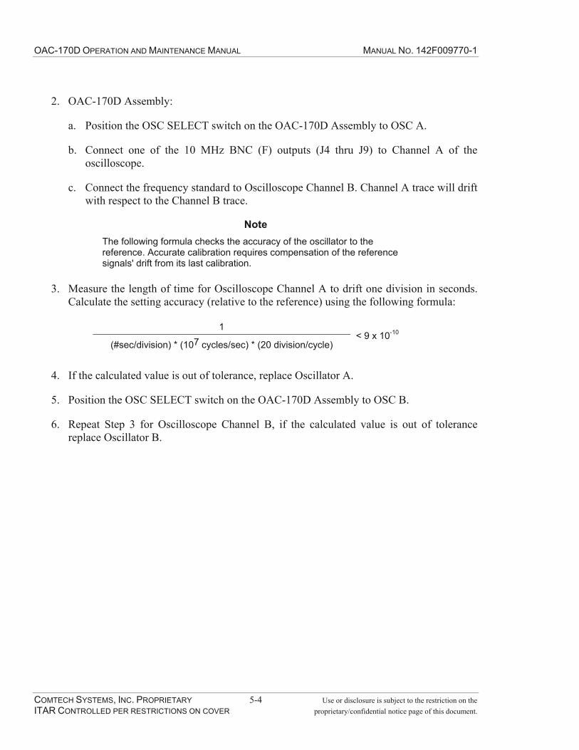
OAC-170D OPERATION AND MAINTENANCE MANUAL MANUAL NO. 142F009770-1
COMTECH SYSTEMS, INC. PROPRIETARY 5-4 Use or disclosure is subject to the restriction on the ITAR CONTROLLED PER RESTRICTIONS ON COVER proprietary/confidential notice page of this document.
2. OAC-170D Assembly:
a. Position the OSC SELECT switch on the OAC-170D Assembly to OSC A.
b. Connect one of the 10 MHz BNC (F) outputs (J4 thru J9) to Channel A of the oscilloscope.
c. Connect the frequency standard to Oscilloscope Channel B. Channel A trace will drift with respect to the Channel B trace.
NoteThe following formula checks the accuracy of the oscillator to the reference. Accurate calibration requires compensation of the reference signals' drift from its last calibration.
3. Measure the length of time for Oscilloscope Channel A to drift one division in seconds. Calculate the setting accuracy (relative to the reference) using the following formula:
1
(#sec/division) * (107 cycles/sec) * (20 division/cycle) < 9 x 10⁻¹⁰
4. If the calculated value is out of tolerance, replace Oscillator A.
5. Position the OSC SELECT switch on the OAC-170D Assembly to OSC B.
6. Repeat Step 3 for Oscilloscope Channel B, if the calculated value is out of tolerance replace Oscillator B.

OAC-170D OPERATION AND MAINTENANCE MANUAL MANUAL NO. 142F009770-1
COMTECH SYSTEMS, INC. PROPRIETARY 5-5 Use or disclosure is subject to the restriction on the ITAR CONTROLLED PER RESTRICTIONS ON COVER proprietary/confidential notice page of this document.
Figure 5-1. System Board Oscillator Connections and Adjustments Pots

OAC-170D OPERATION AND MAINTENANCE MANUAL MANUAL NO. 142F009770-1
COMTECH SYSTEMS, INC. PROPRIETARY 5-6 Use or disclosure is subject to the restriction on the ITAR CONTROLLED PER RESTRICTIONS ON COVER proprietary/confidential notice page of this document.
Figure 5-2. Exploded View of Connections and Adjustment Pots of Figure 5-1
5.3 Corrective Maintenance
5.3.1 Oscillator Removal and Replacement
To remove and replace the oscillator, follow steps 1 through 6 and save all hardware.
1. Remove the 12 #6-32 flat head screws from the cover and remove the cover.
2. Refer to Figure 5-1 for the location of the rubidium oscillator requiring removal.
3. Remove the two electrical connections from the rubidium oscillator.
4. Remove the four #6-32 hex nuts, flat washers and lock washer from the oscillator mounting plate and remove the rubidium oscillator from the chassis.
5. Remove screws as required from the mounting plate and remove the rubidium oscillator from the mounting plate.
6. Reverse 3 thru 5 to install the new rubidium.
7. After replacement and prior to installing the cover, perform rubidium output power measurement and adjustment per paragraph 5.2.4.
8. Install the cover using hardware previously removed.

OAC-170D OPERATION AND MAINTENANCE MANUAL MANUAL NO. 142F009770-1
COMTECH SYSTEMS, INC. PROPRIETARY 5-7 Use or disclosure is subject to the restriction on the ITAR CONTROLLED PER RESTRICTIONS ON COVER proprietary/confidential notice page of this document.
5.3.2 OAC-170D System Board Removal and Replacement
To remove and place the OAC-170D system board, follow steps 1 through 7 and save all hardware.
1. Remove power from the chassis.
2. Disconnect all electrical connections from the chassis including the ground cable.
3. Remove the 12 #6-32 flat head screws from the cover and remove the cover.
4. Disconnect the four electrical connections on the System Board from the two oscillators. Refer to Figure 5-1 for the location of the connections.
5. Remove the four #6-32 screws securing the rear panel and remove the rear panel.
6. Remove the fourteen #6-32 screws securing the System Board and remove the System Board.
7. Re-install the System Board by reversing steps 4 thru 6.
8. After replacement and prior to installing the cover, perform rubidium output power measurement and adjustment per paragraph 5.2.4.
9. Re-install cover using retained hardware.
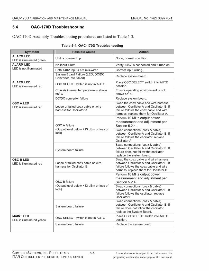
OAC-170D OPERATION AND MAINTENANCE MANUAL MANUAL NO. 142F009770-1
COMTECH SYSTEMS, INC. PROPRIETARY 5-8 Use or disclosure is subject to the restriction on the ITAR CONTROLLED PER RESTRICTIONS ON COVER proprietary/confidential notice page of this document.
5.4 OAC-170D Troubleshooting
OAC-170D Assembly Troubleshooting procedures are listed in Table 5-3.
Table 5-4. OAC-170D Troubleshooting
Symptom Possible Cause Action ALARM LED LED is illuminated green Unit is powered up None, normal condition
No input +48V Verify +48V is connected and turned on. Both +48V inputs are mis-wired Correct input wiring.
ALARM LEDLED is not illuminated
System Board Failure (LED, DC/DC Converter, etc. failed) Replace system board.
OSC SELECT switch is not in AUTO Place OSC SELECT switch into AUTO position.
Chassis internal temperature is above 65o C
Ensure operating environment is not above 55o C.
ALARM LEDLED is illuminated red
DC/DC converter failure Replace system board.
Loose or failed coax cable or wire harness for Oscillator A
Swap the coax cable and wire harness between Oscillator A and Oscillator B. If failure follows the coax cable and wire harness, replace them for Oscillator A. Perform 10 MHz output power measurement and adjustment per Section 5.2.4.OSC A failure
(Output level below +13 dBm or loss of lock)
Swap connections (coax & cable) between Oscillator A and Oscillator B. If failure follows the oscillator, replace Oscillator A.
OSC A LEDLED is illuminated red
System board failure
Swap connections (coax & cable) between Oscillator A and Oscillator B. If failure does not follow the oscillator, replace the system board.
Loose or failed coax cable or wire harness for Oscillator B
Swap the coax cable and wire harness between Oscillator A and Oscillator B. If failure follows the coax cable and wire harness, replace them for Oscillator B. Perform 10 MHz output power measurement and adjustment per Section 5.2.4.OSC B failure
(Output level below +13 dBm or loss of lock)
Swap connections (coax & cable) between Oscillator A and Oscillator B. If failure follows the oscillator, replace Oscillator B.
OSC B LEDLED is illuminated red
System board failure
Swap connections (coax & cable) between Oscillator A and Oscillator B. If failure does not follow the oscillator, replace the System Board.
OSC SELECT switch is not in AUTO Place OSC SELECT switch into AUTO position.
MAINT LEDLED is illuminated yellow
System board failure Replace the system board.

OAC-170D OPERATION AND MAINTENANCE MANUAL MANUAL NO. 142F009770-1
COMTECH SYSTEMS, INC. PROPRIETARY 6-1 Use or disclosure is subject to the restriction on the ITAR CONTROLLED PER RESTRICTIONS ON COVER proprietary/confidential notice page of this document.
6.0 SPARE PARTS LIST
6.1 Introduction
This chapter contains the equipment spare parts list and information necessary for ordering spare or replacement parts. The primary operator maintenance action in the event of a fault is the isolation of the fault, removal of the faulty module and replacement of the faulty module with a spare module. The modules are Line-Replaceable Units (LRU). This chapter provides a listing of the LRUs available to the operator as spares.
6.2 Spare Parts List
Table 6-1 lists the spare LRUs by description and assembly part number. Refer to Section 7 Diagrams, for spare parts location.
Table 6-1. Spares LRU Parts List
Item Description Part Number 1 OAC-170D System Board Assembly 304F009765-1A 2 10 MHz Rubidium Oscillator 113F009732-1 3 Cable Assembly, W101 112F009770-1 4 Cable Assembly, W102 112F009770-2 5 Termination-BNC (M) 50 Ohm, w/chain USP-CTB50
6.3 Correspondence and Ordering of Spare Parts
Order all parts from Comtech System, Inc. When requesting information, ordering spares or replacements parts, provide the following information:
1. Site location of equipment
2. Name, part number and serial number of equipment drawer
3. Comtech part number and serial number of LRU
4. Reference description of LRU
5. Line number provided in Spare LRU Parts List, Table 6-1
6. To obtain parts for this equipment, or service information contact:
Comtech Systems, Inc. 2900 Titan Row, Suite 142 Orlando, FL 32809 Telephone: (407) 854-1950 Fax: (407) 851-6960

OAC-170D OPERATION AND MAINTENANCE MANUAL MANUAL NO. 142F009770-1
COMTECH SYSTEMS, INC. PROPRIETARY 6-2 Use or disclosure is subject to the restriction on the ITAR CONTROLLED PER RESTRICTIONS ON COVER proprietary/confidential notice page of this document.
This Page Intentionally Left Blank

OAC-170D OPERATION AND MAINTENANCE MANUAL MANUAL NO. 142F009770-1
COMTECH SYSTEMS, INC. PROPRIETARY 7-1 Use or disclosure is subject to the restriction on the ITAR CONTROLLED PER RESTRICTIONS ON COVER proprietary/confidential notice page of this document.
7.0 DIAGRAMS
7.1 Introduction
This chapter contains various diagrams useful to the operator or maintenance technician. Refer to Section 6.0 Spare Parts list, for part number of referenced items. The diagrams included are as follows:
Figure Title PageFigure 7-1 Assembly, OAC-170D Page 1 of 2 - SK7342A 7-2Figure 7-2 Assembly, OAC-170D Page 2 of 2 - SK7343B 7-3

OAC-170D OPERATION AND MAINTENANCE MANUAL MANUAL NO. 142F009770-1
COMTECH SYSTEMS, INC. PROPRIETARY 7-2 Use or disclosure is subject to the restriction on the ITAR CONTROLLED PER RESTRICTIONS ON COVER proprietary/confidential notice page of this document.
Figure 7-1. Assembly, OAC-170D (404F009770-1) Page 1 of 2 - SK7342
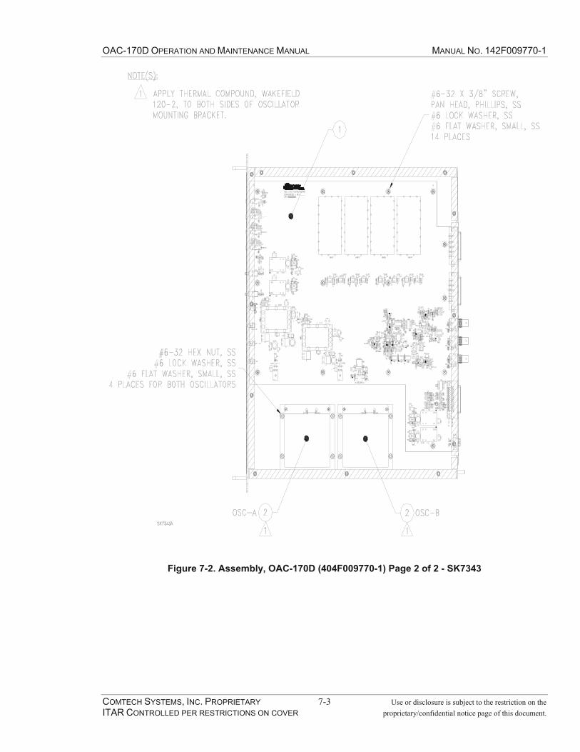
OAC-170D OPERATION AND MAINTENANCE MANUAL MANUAL NO. 142F009770-1
COMTECH SYSTEMS, INC. PROPRIETARY 7-3 Use or disclosure is subject to the restriction on the ITAR CONTROLLED PER RESTRICTIONS ON COVER proprietary/confidential notice page of this document.
Figure 7-2. Assembly, OAC-170D (404F009770-1) Page 2 of 2 - SK7343

OAC-170D OPERATION AND MAINTENANCE MANUAL MANUAL NO. 142F009770-1
COMTECH SYSTEMS, INC. PROPRIETARY 7-4 Use or disclosure is subject to the restriction on the ITAR CONTROLLED PER RESTRICTIONS ON COVER proprietary/confidential notice page of this document.
This Page Intentionally Left Blank

OAC-170D OPERATION AND MAINTENANCE MANUAL MANUAL NO. 142F009770-1
COMTECH SYSTEMS, INC. PROPRIETARY A-1 Use or disclosure is subject to the restriction on the ITAR CONTROLLED PER RESTRICTIONS ON COVER proprietary/confidential notice page of this document.
APPENDIX A ASSEMBLY CABLE AND WIRE RUN LIST
Description Document Number Wire Run List, OAC-170D Chassis Assembly 111F009770-1

OAC-170D OPERATION AND MAINTENANCE MANUAL MANUAL NO. 142F009770-1
COMTECH SYSTEMS, INC. PROPRIETARY A-2 Use or disclosure is subject to the restriction on the ITAR CONTROLLED PER RESTRICTIONS ON COVER proprietary/confidential notice page of this document.
This Page Intentionally Left Blank

APPLICATION REVISIONS
USED ON LTR APPROVEDDATEDESCRIPTION
A Initial Release per IER 7907B Change 001-006 (8141)
06/02/06 JW09/11/06 TL
06/02/06A. Maldonado
CHECKED BY:T. Lowry
PROJECT ENGINEER:THIS DRAWING IS NOT TO BE REPRODUCED OR USED IN ANY
MANNER WITHOUT WRITTEN AUTHORIZATION FROM
111F009770-1
NUMBER
OAC-170D Chassis Assembly Wire Run List
TITLE:
CODE IDENT NO.
24854
06/02/06
COMTECH SYSTEMS, INC.
06/02/06
DATE:
J. Wilson
DIRECTOR OF ENGINEERING:
9770-1RVB.xls.xls(L:\Wire Run Lists) SHEET 1 of 2
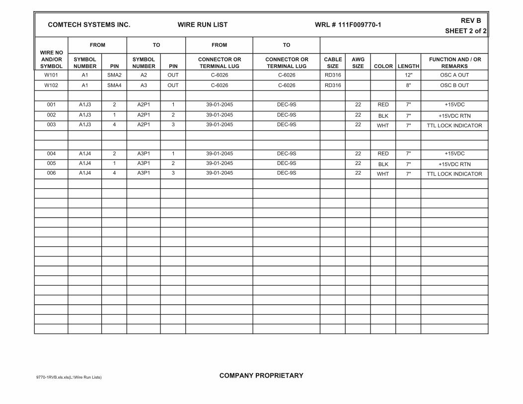
SHEET 2 of 2WIRE RUN LIST
PINSYMBOLNUMBER PIN
CONNECTOR OR TERMINAL LUG
CONNECTOR OR TERMINAL LUG
8"
OUT
SYMBOLNUMBER LENGTH
FROM TO FROM TO
CABLESIZE
AWGSIZE COLOR
C-6026 C-6026 RD316
W101 A1 SMA2 A2
W102 A1 SMA4 A3
DEC-9S 221 39-01-2045
FUNCTION AND / OR REMARKSOSC A OUT
OSC B OUTOUT
+15VDC
C-6026 C-6026
COMTECH SYSTEMS INC.
WIRE NO AND/ORSYMBOL
001 A1J3 2 A2P1
WRL # 111F009770-1
RED 7"
12"RD316
REV B
002 A1J3 1 A2P1 2 39-01-2045 DEC-9S 22 BLK 7" +15VDC RTN003 A1J3 4 A2P1 3 39-01-2045 DEC-9S 22 WHT 7" TTL LOCK INDICATOR
004 A1J4 2 A3P1 1 39-01-2045 DEC-9S 22 RED 7" +15VDC
005 A1J4 1 A3P1 2 39-01-2045 DEC-9S 22 BLK 7" +15VDC RTN006 A1J4 4 A3P1 3 39-01-2045 DEC-9S 22 WHT 7" TTL LOCK INDICATOR
9770-1RVB.xls.xls(L:\Wire Run Lists) COMPANY PROPRIETARY

OAC-170D OPERATION AND MAINTENANCE MANUAL MANUAL NO. 142F009770-1
COMTECH SYSTEMS, INC. PROPRIETARY B-1 Use or disclosure is subject to the restriction on the ITAR CONTROLLED PER RESTRICTIONS ON COVER proprietary/confidential notice page of this document.
APPENDIX B ACRONYMS AND TERMS
A AGC automatic gain control ALM alarm AUX auxiliary
B BER bit error rate BERT bit error rate test/tester BPF band pass filter bps bits per second BW bandwidth
C CLK clock CMD command COM common COTS commercial-off-the-shelf CPLD Complex Programmable
Logic Devices CPU central processing unit CSI Comtech Systems, Inc. CW continuous wave
D dBW decibels referenced to one
wattDC direct current DC/DC direct current to direct current DMM digital multimeter DTE data terminal equipment DUT device under test DVM digital voltmeter
E Eb/No The ratio of bit energy per
symbol to noise power spectral density, in decibels.
G gnd ground
H Hz Hertz
I I&C installation and checkout I/O input/output IF intermediate frequency INF interface
K k kilo Kbps kilobits per second KHz kilohertz kVA kilovolt ampere kW kilowatt
L LED light emitting diode LNA low noise amplifier LRU line-replaceable unit LVL level
M m milli M mega mA milliampere max maximum Mbps megabits per second (military
M B/S or MBPS) MHz megahertz min minimum MTBF mean time between failure MTTR mean time to repair

OAC-170D OPERATION AND MAINTENANCE MANUAL MANUAL NO. 142F009770-1
COMTECH SYSTEMS, INC. PROPRIETARY B-2 Use or disclosure is subject to the restriction on the ITAR CONTROLLED PER RESTRICTIONS ON COVER proprietary/confidential notice page of this document.
NNC normally closed NO normally open NO/NC normally open/normally
closedO on-line in service OSC oscillator
PPA power amplifier PS power supply PWR power
Q QPSK quadrature phase shift keying
RR&D research and development RF radio frequency RMS/rms root mean square RSL receive signal level Rx receive
SS/N signal to noise SCADA supervisory control and data
acquisitionSEL select SNR signal-to-noise ratio SPDT single pole double throw STBY standby
TTBD to be determined TMP temperature Tropo troposcatter; tropospheric
scatterTx transmit
VVDC voltage direct current VSWR voltage standing wave ratio

2900 Titan Row Orlando, Florida 32809 Telephone: (407) 854-1950 Fax: (407) 851-6960 URL Address: www.comtechsystems.com
Manual No. 142F009700-1 September 2010
Revision F
CS6716 Modem
Operation and Maintenance Manual
The information in this document contains Technical Data subject to the controls of ITAR,
22 C.F.R. §120-§130 and should not be further disseminated without the appropriate license or license exemption from the document originator.

CS6716 MODEM OPERATION AND MANUAL NO. 142F009700-1 MAINTENANCE MANUAL
COMTECH SYSTEMS, INC. PROPRIETARY ii Use or disclosure is subject to the restriction on the ITAR CONTROLLED PER RESTRICTIONS ON COVER proprietary/confidential notice page of this document.
Proprietary/Confidential Notice
The information disclosed in this document, including all designs and related materials, is the valuable property of Comtech Systems Inc. (hereinafter "Comtech") and/or its licensors. Comtech and/or its licensors, as appropriate, reserve all patent, copyright and other proprietary rights to this document, including all design, manufacturing, reproduction, use, and sales rights thereto, except to the extent said rights are expressly granted to others. Reproduction of this document or portions thereof without prior written approval of Comtech is prohibited.
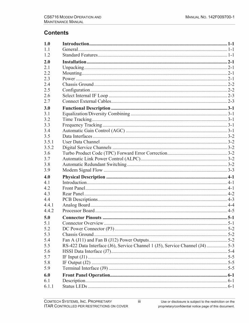
CS6716 MODEM OPERATION AND MANUAL NO. 142F009700-1 MAINTENANCE MANUAL
COMTECH SYSTEMS, INC. PROPRIETARY iii Use or disclosure is subject to the restriction on the ITAR CONTROLLED PER RESTRICTIONS ON COVER proprietary/confidential notice page of this document.
Contents
1.0 Introduction ................................................................................................................. 1-1 1.1 General .......................................................................................................................... 1-1 1.2 Standard Features .......................................................................................................... 1-1 2.0 Installation ................................................................................................................... 2-1 2.1 Unpacking ..................................................................................................................... 2-1 2.2 Mounting ....................................................................................................................... 2-1 2.3 Power ............................................................................................................................ 2-1 2.4 Chassis Ground ............................................................................................................. 2-2 2.5 Configuration ................................................................................................................ 2-2 2.6 Select Internal IF Loop ................................................................................................. 2-3 2.7 Connect External Cables ............................................................................................... 2-3 3.0 Functional Description ............................................................................................... 3-1 3.1 Equalization/Diversity Combining ............................................................................... 3-1 3.2 Time Tracking............................................................................................................... 3-1 3.3 Frequency Tracking ...................................................................................................... 3-1 3.4 Automatic Gain Control (AGC) ................................................................................... 3-1 3.5 Data Interfaces .............................................................................................................. 3-2 3.5.1 User Data Channel ........................................................................................................ 3-2 3.5.2 Digital Service Channels .............................................................................................. 3-2 3.6 Turbo Product Code (TPC) Forward Error Correction ................................................. 3-2 3.7 Automatic Link Power Control (ALPC) ....................................................................... 3-2 3.8 Automatic Redundant Switching .................................................................................. 3-2 3.9 Modem Signal Flow ..................................................................................................... 3-3 4.0 Physical Description ................................................................................................... 4-1 4.1 Introduction ................................................................................................................... 4-1 4.2 Front Panel .................................................................................................................... 4-1 4.3 Rear Panel ..................................................................................................................... 4-2 4.4 PCB Descriptions .......................................................................................................... 4-3 4.4.1 Analog Board ................................................................................................................ 4-4 4.4.2 Processor Board ............................................................................................................ 4-5 5.0 Connector Pinouts ...................................................................................................... 5-1 5.1 Connector Overview ..................................................................................................... 5-1 5.2 DC Power Connector (P3) ............................................................................................ 5-2 5.3 Chassis Ground ............................................................................................................. 5-2 5.4 Fan A (J11) and Fan B (J12) Power Outputs ................................................................ 5-2 5.5 RS-422 Data Interface (J6), Service Channel 1 (J5), Service Channel (J4) ................. 5-3 5.6 HSSI Data Interface (J7) ............................................................................................... 5-4 5.7 IF Input (J1) .................................................................................................................. 5-5 5.8 IF Output (J2) ............................................................................................................... 5-5 5.9 Terminal Interface (J9) ................................................................................................. 5-5 6.0 Front Panel Operation................................................................................................ 6-1 6.1 Description .................................................................................................................... 6-1 6.1.1 Status LEDs .................................................................................................................. 6-1

CS6716 MODEM OPERATION AND MANUAL NO. 142F009700-1 MAINTENANCE MANUAL
COMTECH SYSTEMS, INC. PROPRIETARY iv Use or disclosure is subject to the restriction on the ITAR CONTROLLED PER RESTRICTIONS ON COVER proprietary/confidential notice page of this document.
6.1.2 Alphanumeric Display .................................................................................................. 6-2 6.1.3 Keypad .......................................................................................................................... 6-2 6.2 Initial Modem Power-Up Procedure ............................................................................. 6-2 6.3 Opening Screen ............................................................................................................. 6-3 6.4 Main Menu .................................................................................................................... 6-3 6.4.1 MONITOR .................................................................................................................... 6-4 6.4.2 ON/OFFLINE ............................................................................................................... 6-9 6.4.3 CONFIG ....................................................................................................................... 6-9 6.4.4 INFO ........................................................................................................................... 6-13 6.4.5 SWITCH ..................................................................................................................... 6-13 6.4.6 MAINT ....................................................................................................................... 6-14 6.4.7 SETUP ........................................................................................................................ 6-15 6.4.8 DIAG .......................................................................................................................... 6-19 7.0 Maintenance ................................................................................................................ 7-1 7.1 Introduction ................................................................................................................... 7-1 7.2 Maintenance Philosophy ............................................................................................... 7-1 7.3 Return Material Authorization (RMA) Procedures ...................................................... 7-3 7.4 Periodic Maintenance ................................................................................................... 7-3 7.5 LRU Faults .................................................................................................................... 7-4 7.5.1 Information on Modem Fault Indications ..................................................................... 7-4 7.5.2 Major Alarms ................................................................................................................ 7-4 7.5.3 Minor Alarms ................................................................................................................ 7-4 7.5.4 Front Panel Display Fault ............................................................................................. 7-6 7.5.5 Fan Failure .................................................................................................................... 7-9 Appendix A Summary of Specifications ................................................................................. A-1 Appendix B Lowest Replaceable Units (LRU) ....................................................................... B-1 Appendix C Front Panel Menu Tree ....................................................................................... C-1 Appendix D Command Line Interface (for ASCII Terminal) .............................................. D-1 D.1 Setup/Initialization of Terminal Interface .................................................................... D-3 D.2 Introduction .................................................................................................................. D-3 D.3 Commands ................................................................................................................... D-5 Appendix E Modem Alarms .................................................................................................... E-1 Appendix F Acronyms .............................................................................................................. F-1 Appendix G RMA Information Sheet ..................................................................................... G-1

CS6716 MODEM OPERATION AND MANUAL NO. 142F009700-1 MAINTENANCE MANUAL
COMTECH SYSTEMS, INC. PROPRIETARY v Use or disclosure is subject to the restriction on the ITAR CONTROLLED PER RESTRICTIONS ON COVER proprietary/confidential notice page of this document.
List of Illustrations
Figure 1-1. CS6716 Digital Troposcatter Modem ....................................................................... 1-1 Figure 2-1. Front View of Modem, Door Open ........................................................................... 2-3 Figure 2-2. Rear Panel Connectors .............................................................................................. 2-3 Figure 3-1. CS6716 System Block Diagram................................................................................ 3-3 Figure 4-1. CS6716 Digital Troposcatter Front Panel Monitor and Control Interface ................ 4-1 Figure 4-2. Front Panel Keypad and Display............................................................................... 4-2 Figure 4-3. Rear View of the Front Panel Display ...................................................................... 4-2 Figure 4-4. CS6716 Modem Rear Panel ...................................................................................... 4-2 Figure 4-5. Front View of Modem, Door Open ........................................................................... 4-3 Figure 4-6. Analog Board ............................................................................................................ 4-4 Figure 4-7. Processor Board ........................................................................................................ 4-5 Figure 5-1. CS6716 Modem Rear Panel ...................................................................................... 5-1 Figure 6-1. Modem Front Panel ................................................................................................... 6-1 Figure 7-1. Alarm Display Example ............................................................................................ 7-2 Figure 7-2. Front Panel Display Printed Circuit Board ............................................................... 7-7 Figure 7-3. Analog Board and Processor Board Power Switch ................................................... 7-8 Figure 7-4. Rear View of CS6716 Modem illustrating Fan A and B .......................................... 7-9 List of Tables
Table 5-1. Rear Panel Connections .............................................................................................. 5-1 Table 5-2. Power Input Connector Pin Assignments ................................................................... 5-2 Table 5-3. Fan Power Out Connector Pin Assignments .............................................................. 5-2 Table 5-4. RS-530 / RS-422 Connector Pin Assignments ........................................................... 5-3 Table 5-5. HSSI Connector Pin Assignments .............................................................................. 5-4 Table 5-6. IF Input Connector Pin Assignments ......................................................................... 5-5 Table 5-7. IF Output Connector Pin Assignments ....................................................................... 5-5 Table 5-8. Terminal Interface Connector Pin Assignments ......................................................... 5-5 Table 6-1. Front Panel LED Indicators ........................................................................................ 6-1 Table 6-2. Alphanumeric Display Menu /Sub-menu Options ..................................................... 6-2 Table 6-3. Main Menu Description .............................................................................................. 6-4 Table 6-4. Monitor Sub-Branches................................................................................................ 6-4 Table 6-5. CONFIG Sub-Branches ............................................................................................ 6-10 Table 6-6. Default Configuration ............................................................................................... 6-12 Table 6-7. SETUP Description .................................................................................................. 6-16

CS6716 MODEM OPERATION AND MANUAL NO. 142F009700-1 MAINTENANCE MANUAL
COMTECH SYSTEMS, INC. PROPRIETARY vi Use or disclosure is subject to the restriction on the ITAR CONTROLLED PER RESTRICTIONS ON COVER proprietary/confidential notice page of this document.
Electrical Safe Work Practices
Accidents involving electricity can cause burns, explosions, shocks and death. Only trained and qualified personnel should service, install or repair electrical equipment.
The general safety procedures for personnel servicing electronic and electrical equipment include: 1. Always turn off or disconnect power before working on electric equipment, electronic
circuits or any type of electrical item.
2. Turn off and disconnect power before checking, or replacing fuses.
3. Locate and correct the cause of a blown fuse, or tripped circuit breaker before replacing the fuse or resetting the circuit breaker.
4. Never defeat the purpose of a fuse or circuit breaker. Always install a fuse with the correct amperage rating for the circuit. Never install a fuse with a higher rating.
5. Always have a second trained and qualified person present when working on electrical systems (protected or unprotected).
6. Always remove metal jewelry, watches, rings, etc., before working on electrical circuits or any electrical equipment.
7. Do not work on electrical equipment in a wet area. Never place containers of liquid on electrical equipment.
8. Do not touch an object that may provide a hazardous path to earth ground.
9. Safely discharge capacitors in equipment before working on the circuits (refer to the ESD procedures).
10. Inspect cabling for defects including frayed wiring, loose connections, or cracked insulation. Replace defective cords and plugs.
11. Always check the electrical ratings of equipment and verify the ratings are correct.
12. Never overload circuits.
13. Verify grounding of equipment chassis/cabinets. Never cut off or defeat the ground connection on a plug.
14. When working at any site, always observe all safety signs and safety procedures. They exist to protect personnel from injuries.
15. All persons working on or around electrical/electronic equipment should have first aid training including resuscitation procedures and external cardiac compression.

CS6716 MODEM OPERATION AND MANUAL NO. 142F009700-1 MAINTENANCE MANUAL
COMTECH SYSTEMS, INC. PROPRIETARY vii Use or disclosure is subject to the restriction on the ITAR CONTROLLED PER RESTRICTIONS ON COVER proprietary/confidential notice page of this document.
Hazardous Materials
Hazardous materials may be present at the maintenance facility. Many of the following substances are toxic (causing illness or death): flammable materials, explosive materials, corrosive materials that cause the skin or eyes to burn on contact, reactive materials when exposed to heat, air, water, or certain other chemicals can cause burning or the release of toxic vapors.
Some hazardous substances are obvious, for example: adhesives, solvents, abrasives, fuels, and pesticides. Other substances are less obvious, for example: the toner in office copiers and printers, or heavy-duty cleaning and disinfectant products. The list of substances identified as hazardous in the workplace is constantly increasing as new processes and new technologies create new chemicals.
Each work area should have a posted list of hazardous materials. In the United States, hazardous materials include a material safety data sheet, describing the material, the health/safety risks, correct usage procedures, recommended storage facilities, and the method(s) to treat exposure. If local codes do not require the use of a material safety data sheet, a simple list may describe the type of material, correct usage and storage methods, and its hazard(s). Emergency first aid procedures should be included in the event that personnel experience exposure to the material.

CS6716 MODEM OPERATION AND MANUAL NO. 142F009700-1 MAINTENANCE MANUAL
COMTECH SYSTEMS, INC. PROPRIETARY viii Use or disclosure is subject to the restriction on the ITAR CONTROLLED PER RESTRICTIONS ON COVER proprietary/confidential notice page of this document.
Electrostatic Discharge (ESD)
Electrostatic discharge (ESD) can cause fatal errors to sensitive components located on printed circuit cards. Electrostatic discharge measurements as high as 35,000 volts, can occur from walking across a carpet.
To avoid potential damages to electronic equipment, follow correct electrostatic discharge preventive procedures when handling or working with the hardware.
1. Always wear an electrostatic discharge wrist strap when handling electronic hardware.
2. Connect the wrist strap to a reliable earth ground.
3. Replace worn or frayed wrist straps and connecting cords.
4. Check your electrostatic discharge strap every month.
5. Do not use ESD straps that are out of calibration.
6. Place printed circuit cards in an electrostatic discharge bag or other ESD container to avoid damage from stray static charge.
7. Do not place printed circuit cards on any surface that is not an approved electrostatic discharge surface correctly connected to earth ground.
8. Always handle printed circuit cards by the edges. Avoid touching any of the sensitive circuits on the card.
9. Avoid exposing an unprotected PC card to radio frequency (RF) radiation for long periods without shielding.
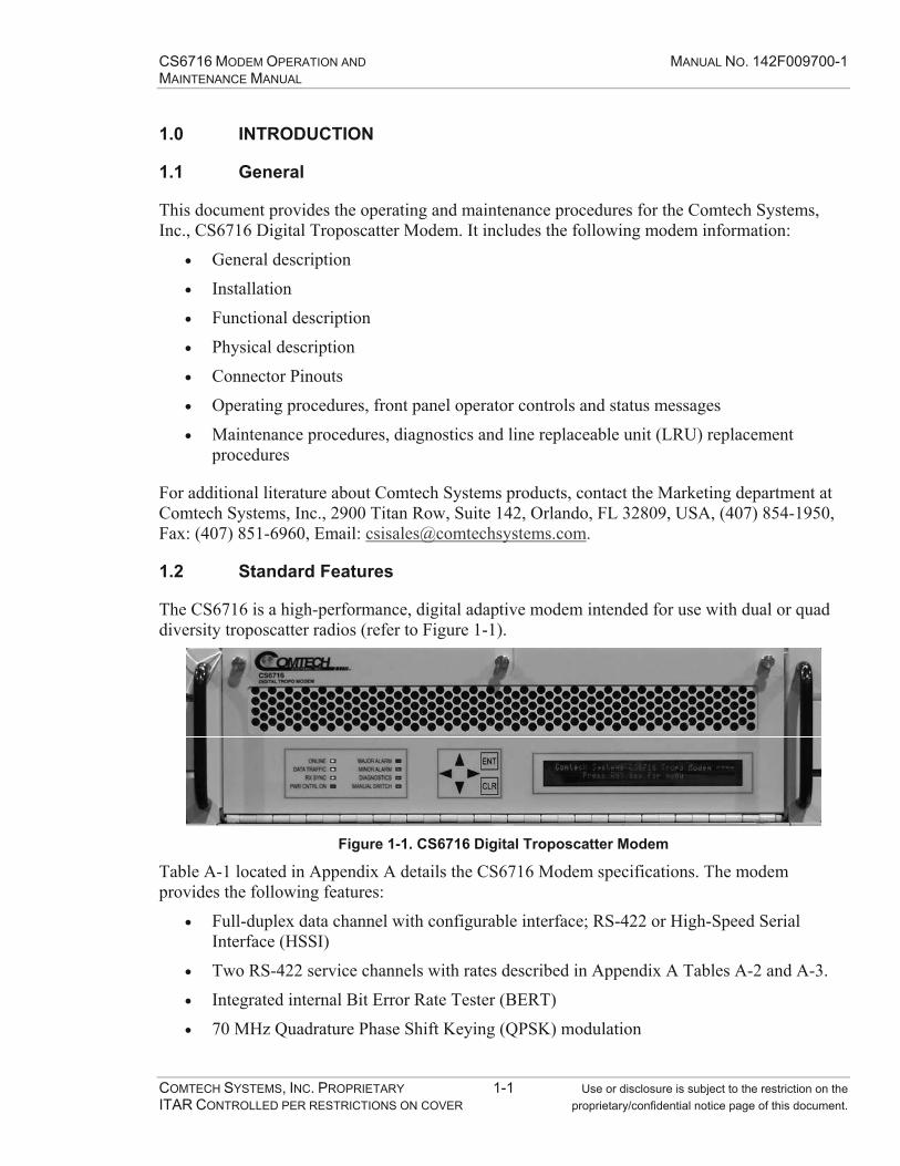
CS6716 MODEM OPERATION AND MANUAL NO. 142F009700-1 MAINTENANCE MANUAL
COMTECH SYSTEMS, INC. PROPRIETARY 1-1 Use or disclosure is subject to the restriction on the ITAR CONTROLLED PER RESTRICTIONS ON COVER proprietary/confidential notice page of this document.
1.0 INTRODUCTION
1.1 General
This document provides the operating and maintenance procedures for the Comtech Systems, Inc., CS6716 Digital Troposcatter Modem. It includes the following modem information:
General description
Installation
Functional description
Physical description
Connector Pinouts
Operating procedures, front panel operator controls and status messages
Maintenance procedures, diagnostics and line replaceable unit (LRU) replacement procedures
For additional literature about Comtech Systems products, contact the Marketing department at Comtech Systems, Inc., 2900 Titan Row, Suite 142, Orlando, FL 32809, USA, (407) 854-1950, Fax: (407) 851-6960, Email: [email protected].
1.2 Standard Features
The CS6716 is a high-performance, digital adaptive modem intended for use with dual or quad diversity troposcatter radios (refer to Figure 1-1).
Figure 1-1. CS6716 Digital Troposcatter Modem
Table A-1 located in Appendix A details the CS6716 Modem specifications. The modem provides the following features:
Full-duplex data channel with configurable interface; RS-422 or High-Speed Serial Interface (HSSI)
Two RS-422 service channels with rates described in Appendix A Tables A-2 and A-3.
Integrated internal Bit Error Rate Tester (BERT)
70 MHz Quadrature Phase Shift Keying (QPSK) modulation

CS6716 MODEM OPERATION AND MANUAL NO. 142F009700-1 MAINTENANCE MANUAL
COMTECH SYSTEMS, INC. PROPRIETARY 1-2 Use or disclosure is subject to the restriction on the ITAR CONTROLLED PER RESTRICTIONS ON COVER proprietary/confidential notice page of this document.
Turbo Product Code (TPC) Forward Error Correction (FEC) is available in all rate modes as detailed in Appendix A Table A-3. Only the user channel is TPC encoded.
Adaptive Link Power Control (ALPC) supported by a modem-to-modem overhead communications link
Front panel configuration and status
1:1 redundancy with automatic (or manual) hot-standby switching
Drop down front panel to access the modem circuit boards
Housed in a 19" EIA rack mount chassis

CS6716 MODEM OPERATION AND MANUAL NO. 142F009700-1 MAINTENANCE MANUAL
COMTECH SYSTEMS, INC. PROPRIETARY 2-1 Use or disclosure is subject to the restriction on the ITAR CONTROLLED PER RESTRICTIONS ON COVER proprietary/confidential notice page of this document.
2.0 INSTALLATION
2.1 Unpacking
Inspect the shipping containers for damage. If shipping containers are damaged, keep them until the contents of the shipment have been carefully inspected and checked for normal operation.
Unpack the modem as follows:
1. Cut the tape at the top of the carton.
2. Remove the packing material covering the modem.
3. Save the packing material for storage or reshipment purposes.
4. Inspect the equipment for any possible damage incurred during shipment.
5. Check the equipment against the packing list to ensure the shipment is correct.
6. Refer to the following sections for further installation instructions.
2.2 Mounting
The modem is optionally equipped with slides that allow installation in a 19" (48.26 cm) cabinet. Each slide is disassembled into two pieces; the cabinet slide attachment and the modem slide attachment. The cabinet slide attachment is affixed to the front vertical rail of the 19" (48.26 cm) cabinet. A separate rear-mounting bracket attaches to the cabinet slide attachment and the rear vertical rail. The connection between the rear-mounting bracket and the cabinet slide attachment is adjustable.
1. Remove the cabinet slide attachment from the modem slide attachment by fully extending them and releasing the safety catch.
2. Loosen the rear mounting brackets to allow adjustment and connect the cabinet slide attachment to the cabinet rails.
3. Position the modem at the correct height in front of the cabinet and extend the cabinet slide attachment to connect with the modem. Make fine vertical adjustments by adjusting the screws that attach the modem slide attachment to the modem.
2.3 Power
The modem prime power input is 48 VDC, which can have either positive or negative reference. The polarity of the input pins must be followed. The modem can operate with a minimum voltage of 36 VDC and a maximum of 56 VDC.

CS6716 MODEM OPERATION AND MANUAL NO. 142F009700-1 MAINTENANCE MANUAL
COMTECH SYSTEMS, INC. PROPRIETARY 2-2 Use or disclosure is subject to the restriction on the ITAR CONTROLLED PER RESTRICTIONS ON COVER proprietary/confidential notice page of this document.
The following power protection features are provided:
Diodes on the power input to protect against reverse polarity
Short circuit protection for the fan power outputs
Short circuit protection on each circuit board
Note The LRU must be returned to the factory if a fuse is blown.
Modem power consumption:
1:1 redundant configuration: 200 W maximum
Non-redundant configuration: 100 W maximum
2.4 Chassis Ground
The modem chassis has a ground stud on the rear panel that must be connected to the station ground. It is recommended that the DC supply be tied to station ground.
2.5 Configuration
Condensation results when transporting the modem from a low temperature environment to a warmer, more humid environment. Therefore, the operator must observe the following before applying power.
Caution Prior to activating the modem power, allow a minimum of 35 minutes stabilization time for each 9°F (5°C) difference between the modem and surrounding environment.
There are no internal jumpers to configure or options to install.
Open the front panel and verify the CS6716 Modem Processor Board and CS6716 Modem Analog Board are installed as required. References to the specific PCBs for the CS6716 Modem hereafter are the "Processor Board" and the "Analog Board." Three captive screw fasteners secure the front panel that swings out and downward on hinges for access to the card slots. Redundant configuration requires installation of boards in all four card slots. Non-redundant configuration requires one set of boards (one Analog and one Processor) to be installed in slots A1/A3 or A2/A4 (see Figure 2-1). Close the front panel and secure the screw fasteners.
Note A 48 VDC power supply and a 10 MHz station clock must be connected before the modem will operate.
The unit is configured using the front panel keypad and display. Please refer to the FRONT PANEL OPERATION section for details on how to fully configure the unit for the desired operating parameters.

CS6716 MODEM OPERATION AND MANUAL NO. 142F009700-1 MAINTENANCE MANUAL
COMTECH SYSTEMS, INC. PROPRIETARY 2-3 Use or disclosure is subject to the restriction on the ITAR CONTROLLED PER RESTRICTIONS ON COVER proprietary/confidential notice page of this document.
Slot A1
Slot A2
Slot A3
Slot A4
Analog Board A
Analog Board B
Processor Board A
Processor Board B
Front Panel PCB
Figure 2-1. Front View of Modem, Door Open
2.6 Select Internal IF Loop
Correct operation of the unit may be verified rapidly, without the need for externally connected equipment, by enabling IF Loopback diagnostic mode. From the top level menu, select DIAG, followed by LOOPBACK, then LOCAL IF (refer to the Front Panel Operation section of this document for more details). The modem should synchronize, the front panel RX SYNC LED should illuminate green and the MAJOR ALARM LED should be extinguished. If the unit does not pass this test, troubleshooting is required.
2.7 Connect External Cables
All electrical connections are made at the rear of the modem (refer to Figure 2-2).
Figure 2-2. Rear Panel Connectors
Note The modulator output at the rear panel is 0 to -40 dBm. The four demodulator inputs expect a signal in the range +10 to -60 dBm.

CS6716 MODEM OPERATION AND MANUAL NO. 142F009700-1 MAINTENANCE MANUAL
COMTECH SYSTEMS, INC. PROPRIETARY 2-4 Use or disclosure is subject to the restriction on the ITAR CONTROLLED PER RESTRICTIONS ON COVER proprietary/confidential notice page of this document.
This Page Intentionally Left Blank

CS6716 MODEM OPERATION AND MANUAL NO. 142F009700-1 MAINTENANCE MANUAL
COMTECH SYSTEMS, INC. PROPRIETARY 3-1 Use or disclosure is subject to the restriction on the ITAR CONTROLLED PER RESTRICTIONS ON COVER proprietary/confidential notice page of this document.
3.0 FUNCTIONAL DESCRIPTION
3.1 Equalization/Diversity Combining
Troposcatter communication is feasible only through diversity. Each troposcatter terminal has typically two (or four) receivers and down converters. The troposcatter modem receives the IF (70 MHz) signals from the down converters. The modem adaptively filters these signals and sums them. The adaptive filtering also helps remove intersymbol interference (ISI). Further ISI removal is accomplished using a backward equalizer which weight decisions based on previous symbols. The output of the backward equalizer is then added to the sum of the adaptive filter outputs which removes the interference of past symbols. Thus, the backward equalizer removes past ISI, and the adaptive filters on the diversity branches (also called forward equalizers), remove future ISI.
3.2 Time Tracking
Each end of the troposcatter link has its own time standard, so the bit stream transmitted by one end slides relative to the time standard at the other end. The clock on the receive side of the modem must be pulled to keep it synchronous with the transmit clock at the other end of the link. The clock must be adjusted in spite of the affects of troposcatter delay dispersion. The clock must also be capable of traversing deep fades.
3.3 Frequency Tracking
The received troposcatter signal also has a frequency or Doppler offset due to the slight difference in the up and down converter local oscillator (LO) frequencies. This is caused by the use of different station clocks at each end of the link.
An adaptive equalizer automatically removes some frequency offset. However, if the frequency offset is too large, the adaptive equalizer may not be fast enough to track it. In this case, it is necessary to remove the Doppler offset by shifting the modem receive LO to roughly track the difference in frequency of the two station clocks.
3.4 Automatic Gain Control (AGC)
The received troposcatter signal experiences Rayleigh fading that causes the received signal strength to fluctuate greatly. Each diversity channel varies independently of the other diversity channels. The AGC continuously monitors the receive signal strength of each diversity channel and independently adjusts the gain of the amplifiers preceding the demodulator to maintain a constant signal at the demodulator. Each diversity channel has a 70 dB dynamic range.

CS6716 MODEM OPERATION AND MANUAL NO. 142F009700-1 MAINTENANCE MANUAL
COMTECH SYSTEMS, INC. PROPRIETARY 3-2 Use or disclosure is subject to the restriction on the ITAR CONTROLLED PER RESTRICTIONS ON COVER proprietary/confidential notice page of this document.
3.5 Data Interfaces
3.5.1 User Data Channel
The CS6716 Modem provides one high-speed user data channel. The interface is programmable for either EIA RS-422 or HSSI. The channel rate is programmable from 2 to 16 Mbps. DCE timing is provided. Flow control is provided as an option.
3.5.2 Digital Service Channels
The CS6716 Modem provides two EIA RS-422 digital service channels programmable from 0 kbps to the total available service channel bandwidth in 8 kbps steps up to a maximum of 80 kbps per channel. The available service channel bandwidth is dependant on the user data channel rate selected. The modem service channel interfaces provide DCE timing.
3.6 Turbo Product Code (TPC) Forward Error Correction
The CS6716 Modem is equipped with TPC forward error correction coders/decoders. The addition of TPC represents a significant performance improvement in troposcatter communications. Enabling TPC greatly improves bit error rate performance with a small sacrifice in user data throughput.
Traditional FEC techniques have suffered from a very pronounced threshold effect – a small reduction in Eb/No results in total loss of demodulator and decoder synchronization. One outstanding feature of TPC is its immunity to the threshold effect. TPC has the ability to maintain decoder synchronization in severely degraded Eb/No environments that would be impossible for other FEC techniques.
3.7 Automatic Link Power Control (ALPC)
ALPC is a programmable feature that automatically controls the transmitted RF power based on the minimum levels required by the distant end RF receivers. This feature reduces the possibility that the troposcatter transmitter will interfere with systems beyond the receiving station.
The modem accomplishes ALPC by monitoring the receive signal level of the diversities. The controller compares the levels to a preset threshold and then makes a decision to either increase or decrease the distant end transmit power levels. The new transmit level value is then fed back to the distant end modem where the modem IF output level is adjusted accordingly.
3.8 Automatic Redundant Switching
The modem contains extensive Built-In-Test (BIT) capability. This BIT is fully contained within the modem and requires no external test equipment. Any fault detected in the system will be isolated to an LRU level, and the front panel will display the faulty module. If the fault is major “switchable” fault then an automatic switch is made to the hot-standby modem. A major “switchable” fault means there is a high probability that link communications are affected.
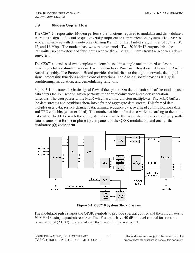
CS6716 MODEM OPERATION AND MANUAL NO. 142F009700-1 MAINTENANCE MANUAL
COMTECH SYSTEMS, INC. PROPRIETARY 3-3 Use or disclosure is subject to the restriction on the ITAR CONTROLLED PER RESTRICTIONS ON COVER proprietary/confidential notice page of this document.
3.9 Modem Signal Flow
The CS6716 Troposcatter Modem performs the functions required to modulate and demodulate a 70 MHz IF signal of a dual or quad diversity troposcatter communications system. The CS6716 Modem interfaces with data networks utilizing RS-422 or HSSI interfaces, at rates of 2, 4, 8, 10, 12, and 16 Mbps. The modem has two service channels. Two 70 MHz IF outputs drive the transmitter up converters and four inputs receive the 70 MHz IF inputs from the receiver’s down converters.
The CS6716 consists of two complete modems housed in a single rack mounted enclosure, providing a fully redundant system. Each modem has a Processor Board assembly and an Analog Board assembly. The Processor Board provides the interface to the digital network, the digital signal processing functions and the control functions. The Analog Board provides IF signal conditioning, modulation, and demodulating functions.
Figure 3-1 illustrates the basic signal flow of the system. On the transmit side of the modem, user data enters the INF section which performs the format conversion and clock generation functions. The data passes to the MUX which is a time-division multiplexer. The MUX buffers the data streams and combines them into a framed aggregate data stream. This framed data includes user data, service channel data, training sequence data, overhead communications data and TPC code bits (when enabled). The number of bits in the frame varies according to the input data rates. The MUX sends the aggregate data stream to the modulator in the form of two parallel data streams, one for the in-phase (I) component of the QPSK modulation, and one for the quadrature (Q) component.
Figure 3-1. CS6716 System Block Diagram
The modulator pulse shapes the QPSK symbols to provide spectral control and then modulates to 70 MHz IF using a quadrature mixer. The IF outputs have 40 dB of level control for transmit power control (ALPC). The signals are then routed to the rear panel.

CS6716 MODEM OPERATION AND MANUAL NO. 142F009700-1 MAINTENANCE MANUAL
COMTECH SYSTEMS, INC. PROPRIETARY 3-4 Use or disclosure is subject to the restriction on the ITAR CONTROLLED PER RESTRICTIONS ON COVER proprietary/confidential notice page of this document.
The modem has four identical demodulator channels. Each channel has two IF filters; 12 MHz and 7 MHz. The filter selection is based on transmission bandwidth. An AGC amplifier with 70 dB dynamic range follows the filters to provide gain control into the QPSK demodulators. The demodulator I and Q outputs are digitally sampled by 8-bit Analog-to-Digital (A/D) converters.
The I and Q data streams (8 bits each) go to the AFE. The AFE adaptively filters and down samples the data stream. The DEG receives the outputs of the AFE and then sums the diversities with the backward equalizer output. The DEG generates a decision and an error signal used to adapt the forward and backward equalizers. The decisions from the DEG section are then demultiplexed by the MUX section into the original data streams. The user INF section regenerates the various digital data channel clocks and converts the data to the correct output format.
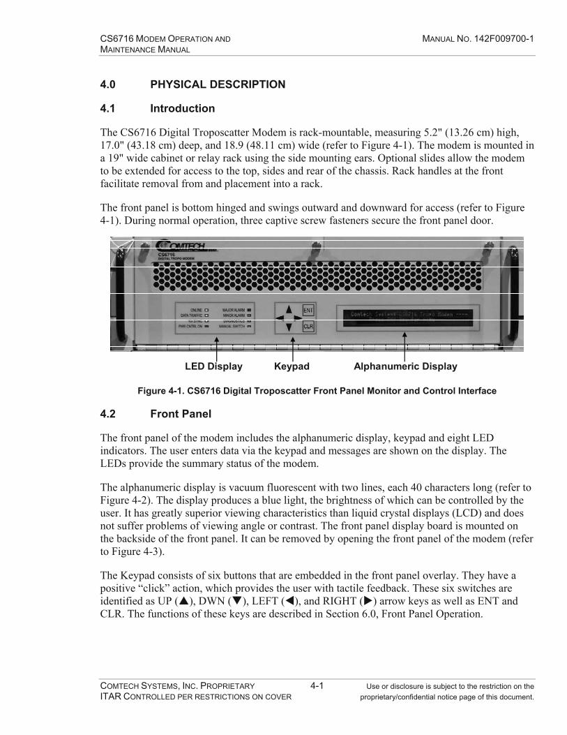
CS6716 MODEM OPERATION AND MANUAL NO. 142F009700-1 MAINTENANCE MANUAL
COMTECH SYSTEMS, INC. PROPRIETARY 4-1 Use or disclosure is subject to the restriction on the ITAR CONTROLLED PER RESTRICTIONS ON COVER proprietary/confidential notice page of this document.
4.0 PHYSICAL DESCRIPTION
4.1 Introduction
The CS6716 Digital Troposcatter Modem is rack-mountable, measuring 5.2" (13.26 cm) high, 17.0" (43.18 cm) deep, and 18.9 (48.11 cm) wide (refer to Figure 4-1). The modem is mounted in a 19" wide cabinet or relay rack using the side mounting ears. Optional slides allow the modem to be extended for access to the top, sides and rear of the chassis. Rack handles at the front facilitate removal from and placement into a rack.
The front panel is bottom hinged and swings outward and downward for access (refer to Figure 4-1). During normal operation, three captive screw fasteners secure the front panel door.
LED Display Keypad Alphanumeric Display
Figure 4-1. CS6716 Digital Troposcatter Front Panel Monitor and Control Interface
4.2 Front Panel
The front panel of the modem includes the alphanumeric display, keypad and eight LED indicators. The user enters data via the keypad and messages are shown on the display. The LEDs provide the summary status of the modem.
The alphanumeric display is vacuum fluorescent with two lines, each 40 characters long (refer to Figure 4-2). The display produces a blue light, the brightness of which can be controlled by the user. It has greatly superior viewing characteristics than liquid crystal displays (LCD) and does not suffer problems of viewing angle or contrast. The front panel display board is mounted on the backside of the front panel. It can be removed by opening the front panel of the modem (refer to Figure 4-3).
The Keypad consists of six buttons that are embedded in the front panel overlay. They have a positive “click” action, which provides the user with tactile feedback. These six switches are identified as UP ( ), DWN ( ), LEFT ( ), and RIGHT ( ) arrow keys as well as ENT and CLR. The functions of these keys are described in Section 6.0, Front Panel Operation.

CS6716 MODEM OPERATION AND MANUAL NO. 142F009700-1 MAINTENANCE MANUAL
COMTECH SYSTEMS, INC. PROPRIETARY 4-2 Use or disclosure is subject to the restriction on the ITAR CONTROLLED PER RESTRICTIONS ON COVER proprietary/confidential notice page of this document.
Figure 4-2. Front Panel Keypad and Display
Figure 4-3. Rear View of the Front Panel Display
4.3 Rear Panel
Rear panel connections are shown in Figure 4-4. The connectors are detailed in Section 5.0.
Figure 4-4. CS6716 Modem Rear Panel

CS6716 MODEM OPERATION AND MANUAL NO. 142F009700-1 MAINTENANCE MANUAL
COMTECH SYSTEMS, INC. PROPRIETARY 4-3 Use or disclosure is subject to the restriction on the ITAR CONTROLLED PER RESTRICTIONS ON COVER proprietary/confidential notice page of this document.
4.4 PCB Descriptions
The CS6716 Modem houses two types of printed circuit boards (PCBs); the Analog Board and the Processor Board.
The modem chassis provides four PCB slots (refer to Figure 4-5). The numbering of the slots is from top to bottom, A1 to A4. Slots A1 and A2 accept the Analog Board and slots A3 and A4 accept the Processor Board.
Modem A consists of one Analog Board in slot A1 and one Processor Board in slot A3.
Modem B consists of an Analog Board in slot A2 and a Processor Board in slot A4.
Redundant operation requires installation of both board sets. The PCBs are keyed to prevent insertion of a board into the wrong slot.
There are no user adjustments or replaceable components on the PCBs. If a failure occurs, return the PCB to Comtech Systems, Inc., for replacement or repair.
Slot A1
Slot A2
Slot A3
Slot A4
Analog Board A
Analog Board B
Processor Board A
Processor Board B
Front Panel PCB
Figure 4-5. Front View of Modem, Door Open

CS6716 MODEM OPERATION AND MANUAL NO. 142F009700-1 MAINTENANCE MANUAL
COMTECH SYSTEMS, INC. PROPRIETARY 4-4 Use or disclosure is subject to the restriction on the ITAR CONTROLLED PER RESTRICTIONS ON COVER proprietary/confidential notice page of this document.
4.4.1 Analog Board
Figure 4-6 illustrates the Analog Board.
Dimensions: 15.8" wide and 11.5" deep
One 128-pin high-density connector and one coaxial combo connector mate to the chassis backplane. The “combo” connector provides interconnects for the four IF inputs, the two IF outputs and the 10 MHz station clock.
Locking card ejectors – facilitate insertion, removal and locking the board in the chassis
Card edge power switch (SW1) – turns board power on and off
Power LED – indicates board power switch is on
Card edge test points – +5 Vcc and Ground;
Fused 48 VDC input
Ejectors
SW1Power LED
Figure 4-6. Analog Board
(with RF Covers Removed)
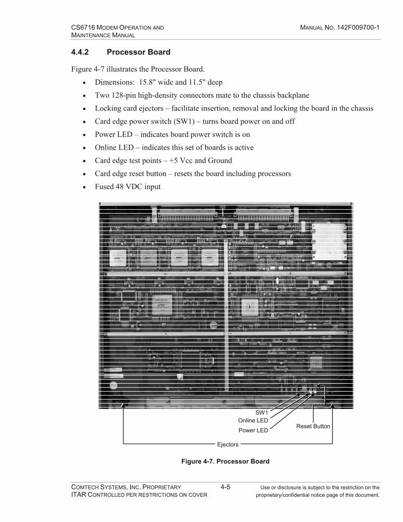
CS6716 MODEM OPERATION AND MANUAL NO. 142F009700-1 MAINTENANCE MANUAL
COMTECH SYSTEMS, INC. PROPRIETARY 4-5 Use or disclosure is subject to the restriction on the ITAR CONTROLLED PER RESTRICTIONS ON COVER proprietary/confidential notice page of this document.
4.4.2 Processor Board
Figure 4-7 illustrates the Processor Board.
Dimensions: 15.8" wide and 11.5" deep
Two 128-pin high-density connectors mate to the chassis backplane
Locking card ejectors – facilitate insertion, removal and locking the board in the chassis
Card edge power switch (SW1) – turns board power on and off
Power LED – indicates board power switch is on
Online LED – indicates this set of boards is active
Card edge test points – +5 Vcc and Ground
Card edge reset button – resets the board including processors
Fused 48 VDC input
Ejectors
SW1
Power LED
Online LEDReset Button
Figure 4-7. Processor Board

CS6716 MODEM OPERATION AND MANUAL NO. 142F009700-1 MAINTENANCE MANUAL
COMTECH SYSTEMS, INC. PROPRIETARY 4-6 Use or disclosure is subject to the restriction on the ITAR CONTROLLED PER RESTRICTIONS ON COVER proprietary/confidential notice page of this document.
This Page Intentionally Left Blank

CS6716 MODEM OPERATION AND MANUAL NO. 142F009700-1 MAINTENANCE MANUAL
COMTECH SYSTEMS, INC. PROPRIETARY 5-1 Use or disclosure is subject to the restriction on the ITAR CONTROLLED PER RESTRICTIONS ON COVER proprietary/confidential notice page of this document.
5.0 CONNECTOR PINOUTS
5.1 Connector Overview
The rear panel connectors (illustrated in Figure 5-1) provide all necessary external connections between the modem and other equipment. Table 5-1 provides connector details.
Figure 5-1. CS6716 Modem Rear Panel
Table 5-1. Rear Panel Connections
Name Ref Connector Type Function
IF Input J1 Combo-D, 5 Contact (female) IF Input
IF Output J2 Combo-D, 3 Contact (female) IF Out, 10 MHz In
Power P3 Combo-D, 7 Contact (Male) 48 V Power Input
SC2 J4 25 pin D (female) Service Channel #2
SC1 J5 25 pin D (female) Service Channel #1
RS-422 Data Interface J6 25 pin D (female) RS-530 Data Channel
HSSI Data Interface J7 25 pin D (female) HSSI Data Channel
10BaseT (A) J8 9 pin D (female) Modem A Ethernet
Terminal J9 9 pin D (female) Remote Serial M&C
10BaseT (B) J10 9 pin D (female) Modem B Ethernet
Fan A J11 9 pin D (female) Fan A Power Output
Fan B J12 9 pin D (female) Fan B Power Output
-------- GND Stud Chassis Ground
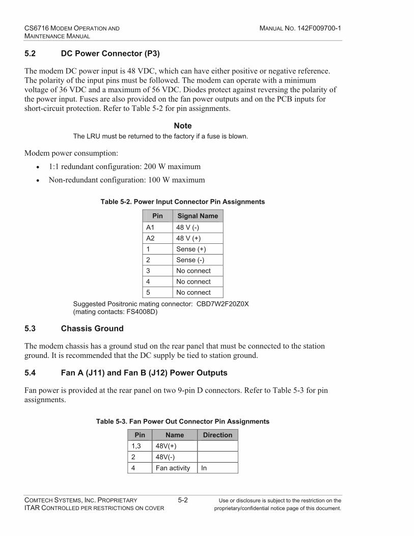
CS6716 MODEM OPERATION AND MANUAL NO. 142F009700-1 MAINTENANCE MANUAL
COMTECH SYSTEMS, INC. PROPRIETARY 5-2 Use or disclosure is subject to the restriction on the ITAR CONTROLLED PER RESTRICTIONS ON COVER proprietary/confidential notice page of this document.
5.2 DC Power Connector (P3)
The modem DC power input is 48 VDC, which can have either positive or negative reference. The polarity of the input pins must be followed. The modem can operate with a minimum voltage of 36 VDC and a maximum of 56 VDC. Diodes protect against reversing the polarity of the power input. Fuses are also provided on the fan power outputs and on the PCB inputs for short-circuit protection. Refer to Table 5-2 for pin assignments.
Note The LRU must be returned to the factory if a fuse is blown.
Modem power consumption:
1:1 redundant configuration: 200 W maximum
Non-redundant configuration: 100 W maximum
Table 5-2. Power Input Connector Pin Assignments
Pin Signal Name A1 48 V (-) A2 48 V (+) 1 Sense (+) 2 Sense (-) 3 No connect 4 No connect 5 No connect
Suggested Positronic mating connector: CBD7W2F20Z0X (mating contacts: FS4008D)
5.3 Chassis Ground
The modem chassis has a ground stud on the rear panel that must be connected to the station ground. It is recommended that the DC supply be tied to station ground.
5.4 Fan A (J11) and Fan B (J12) Power Outputs
Fan power is provided at the rear panel on two 9-pin D connectors. Refer to Table 5-3 for pin assignments.
Table 5-3. Fan Power Out Connector Pin Assignments
Pin Name Direction 1,3 48V(+) 2 48V(-) 4 Fan activity In

CS6716 MODEM OPERATION AND MANUAL NO. 142F009700-1 MAINTENANCE MANUAL
COMTECH SYSTEMS, INC. PROPRIETARY 5-3 Use or disclosure is subject to the restriction on the ITAR CONTROLLED PER RESTRICTIONS ON COVER proprietary/confidential notice page of this document.
5.5 RS-422 Data Interface (J6), Service Channel 1 (J5), Service Channel (J4)
The Data Interface and the two service channels are RS-530 DCE interfaces that use RS-422 balanced electrical circuits and are located on the rear panel. These connectors are keyed to prevent inadvertent connection to a HSSI cable. Flow control is optionally provided. Refer to Table 5-4 for pin assignments.
Table 5-4. RS-530 / RS-422 Connector Pin Assignments
Pin Name Direction 1 GND 2 TX DATA P In 3 RX DATA P Out 4 RTS P In 5 CTS P Out 6 Tied internally to pin 20 7 GND 8 Not Used 9 RX CLK S Out 10 -- Keying Plug -- 11 TX CLKDTE S In 12 CLKOUT S Out 13 CTS S Out 14 TX DATA S In 15 CLKOUT P Out 16 RX DATA S Out 17 RX CLK P Out 18 -- Keying Plug -- 19 RTS S In 20 Tied internally to pin 6 21 Not Used 22 Tied internally to pin 23 23 Tied internally to pin 22 24 TX CLKDTE P In 25 Not Used

CS6716 MODEM OPERATION AND MANUAL NO. 142F009700-1 MAINTENANCE MANUAL
COMTECH SYSTEMS, INC. PROPRIETARY 5-4 Use or disclosure is subject to the restriction on the ITAR CONTROLLED PER RESTRICTIONS ON COVER proprietary/confidential notice page of this document.
5.6 HSSI Data Interface (J7)
The HSSI DCE Data Interface is provided on the rear panel as shown in Table 5-5. The connector is keyed to prevent inadvertent connection to a RS-530 cable. Flow control is optionally provided. The Reframe Inhibit signal can be used to prevent external equipment from reacquiring during periods of deep troposcatter fades.
Table 5-5. HSSI Connector Pin Assignments
Pin Name Direction 1 HSSI CLKOUT P Out 2 HSSI TXCLK P In 3 HSSI TXDATA P In 4 HSSI RTS P In 5 HSSI RXCLK P Out 6 HSSI RXDATA P Out 7 HSSI CTS P Out 8 GND 9 -- Keying Plug -- 10 Reframe Inhibit Out 11 Reserved No Connect 12 GND 13 Reserved No Connect 14 HSSI CLKOUT S Out 15 HSSI TXCLK S In 16 HSSI TXDATA S In 17 HSSI RTS S In 18 HSSI RXCLK S Out 19 HSSI RXDATA S Out 20 HSSI CTS S Out 21 GND 22 -- Keying Plug -- 23 Reserved No Connect 24 Reserved No Connect 25 GND

CS6716 MODEM OPERATION AND MANUAL NO. 142F009700-1 MAINTENANCE MANUAL
COMTECH SYSTEMS, INC. PROPRIETARY 5-5 Use or disclosure is subject to the restriction on the ITAR CONTROLLED PER RESTRICTIONS ON COVER proprietary/confidential notice page of this document.
5.7 IF Input (J1)
The four IF Inputs to the modem are through a 5-contact combo-D connector. Refer to Table 5-6 for pin assignments.
Table 5-6. IF Input Connector Pin Assignments
Pin Name Direction 4 RX1 In 3 RX2 In 2 RX3 In 1 RX4 In 5 Not used ----
Suggested Positronic mating connector: CBD5W5F0000X (mating contacts: FC4102D (RG-179))
5.8 IF Output (J2)
The two IF outputs and the 10 MHz input to the modem are through a 3-contact combo-D connector. Refer to Table 5-7 for pin assignments.
Table 5-7. IF Output Connector Pin Assignments
Pin Name Direction A1 10 MHz Clock Input In A3 IF Output 1 Out A2 IF Output 2 Out
Suggested Positronic mating connector: CBD3W3F0000X (mating contacts: FC4102D (RG-179))
5.9 Terminal Interface (J9)
The RS-232 Terminal Interface and Form C alarm contacts are provided on the rear panel Terminal Interface connector. Refer to Table 5-8 for pin assignments.
Table 5-8. Terminal Interface Connector Pin Assignments
Pin Name Direction 1 GND 2 TERM RX Out 3 TERM TX In 4 GND 5 GND 6 RELAY NC 7 RELAY NO 8 RELAY COM 9 GND

CS6716 MODEM OPERATION AND MANUAL NO. 142F009700-1 MAINTENANCE MANUAL
COMTECH SYSTEMS, INC. PROPRIETARY 5-6 Use or disclosure is subject to the restriction on the ITAR CONTROLLED PER RESTRICTIONS ON COVER proprietary/confidential notice page of this document.
This Page Intentionally Left Blank

CS6716 MODEM OPERATION AND MANUAL NO. 142F009700-1 MAINTENANCE MANUAL
COMTECH SYSTEMS, INC. PROPRIETARY 6-1 Use or disclosure is subject to the restriction on the ITAR CONTROLLED PER RESTRICTIONS ON COVER proprietary/confidential notice page of this document.
6.0 FRONT PANEL OPERATION
6.1 Description
The user can fully control and monitor the operation of the CS6716 from the front panel using the keypad and display. Figure 6-1 illustrates the front panel. Nested menus are used, which display all available options, and prompt the user to carry out a required action.
The front panel interface consists of status LEDs, an alphanumeric display, and a keypad.
LED Display Keypad Alphanumeric Display
Figure 6-1. Modem Front Panel
6.1.1 Status LEDs
The status LEDs provide a visual indication of the health and operating status of the modem. Refer to Table 6-1 for the meaning of each LED indicator when it is illuminated.
Table 6-1. Front Panel LED Indicators
Indicators Meaning Status Indications ONLINE Modem is in an online state DATA TRAFFIC Data channel interface activity monitor RX SYNC Modem is synchronized to receive aggregate data PWR CNTRL ON ALPC is enabled Alarm Indications MAJOR ALARM A major alarm exists within the modem MINOR ALARM A minor alarm exists within the modem DIAGNOSTICS The modem is configured in a diagnostics mode MANUAL SWITCH Automatic redundancy switching has been disabled

CS6716 MODEM OPERATION AND MANUAL NO. 142F009700-1 MAINTENANCE MANUAL
COMTECH SYSTEMS, INC. PROPRIETARY 6-2 Use or disclosure is subject to the restriction on the ITAR CONTROLLED PER RESTRICTIONS ON COVER proprietary/confidential notice page of this document.
6.1.2 Alphanumeric Display
The Alphanumeric Display provides a textual menu structure that allows the operator to configure and obtain modem status. The Alphanumeric Display has two lines each of 40 characters. On most menu screens, the user will observe a flashing solid block cursor, which blinks at a one-second rate. This indicates the currently selected item, digit or field. In the cases that the cursor would obscure the item being edited (for example a numeric field) the cursor will automatically change to an underline cursor.
The display has a ‘screen saver’ feature which activates after a few minutes of non-use. The screen dims and begins moving from left to right. Pressing any key will restore the previous screen.
6.1.3 Keypad
The keypad allows the operator to traverse the menu structure. The / keys provide navigation through the menu options. The / keys are used to change the value of the option selected. The ENT key selects, saves or sets a new value. The CLR key returns to the previous menu level. Some of the settings are followed by a "?". This indicates the displayed setting is not the current setting.
Appendix C provides a detailed tree structure of the menus and submenus.
Table 6-2 provides a list of the Alphanumeric Display menus and sub-menus.
Table 6-2. Alphanumeric Display Menu /Sub-menu Options
Menu Sub-Menus MONITOR SUMMARY, ALARMS, RSL, TEMP, AGC, TX APC, BERT, FAN ON/OFFLINE Modem State: OFF LINE or ON LINE CONFIG RATES, DATA CH, FEC, BERT, DEFAULT, ALPC INFO CONFIGURATION INFORMATION SWITCH AUTOMODE, SWITCH TO MODEM A/B , MANUAL MODE MAINT CALIBRATION, VERSIONS SETUP RXGAIN, DIVERSITY, MISC, FLOWCTL, CLKINV DIAG LOOPBACKS, F.P. LED TEST, F.P. DISPLAY TEST
6.2 Initial Modem Power-Up Procedure
The following steps are recommended for powering-up and establishing link communications:
1) Power-up the station clock (reference oscillator) and wait for the clock to stabilize.
2) Open the CS6716 Modem front panel. First, turn on the top two PCBs (Analog Boards “A” & “B”) by moving the card edge switch to the “ON” position. Refer to Figure 4-6 for the location of the power switch.

CS6716 MODEM OPERATION AND MANUAL NO. 142F009700-1 MAINTENANCE MANUAL
COMTECH SYSTEMS, INC. PROPRIETARY 6-3 Use or disclosure is subject to the restriction on the ITAR CONTROLLED PER RESTRICTIONS ON COVER proprietary/confidential notice page of this document.
3) Turn on Processor Board “A” followed by Processor Board “B”. Refer to Figure 4-7 for the location of the power switch.
4) The CS6716 Modem automatically performs diagnostics and AGC calibration at power-on. If a modem alarm LED illuminates the operator can view detailed alarm status via the modem front-panel interface.
5) Once the power-up sequence is complete, configure the modems on both ends of the link for the DEFAULT configuration setting (refer to paragraph 6.4.3.5). This configuration is the recommended for the following reasons:
a. It ensures that the modem configuration is identical at both ends of the link.
b. The DEFAULT configuration is optimum for establishing communications on new troposcatter links.
c. It provides the optimum settings for antenna pointing.
6) When the receive signal levels are sufficient to support user traffic, configure the user data rate of the modems on both ends of the link as desired.
7) Final configuration of the modem and multiplexer bit rates and capacity depends on user requirements and link performance. The communications link has been successfully established when the modem ONLINE, DATA TRAFFIC and RX SYNC LEDs are illuminated.
6.3 Opening Screen
This screen is displayed whenever power is first applied to the unit:
--- Comtech Systems CS6716 Tropo Modem –
Press ANY key for menu
Press any key to go to the Main Menu screen.
6.4 Main Menu
MAIN: MONITOR ON/OFFLINE CONFIG INFO
SWITCH MAINT SETUP DIAG
The main menu choices are described in Table 6-3. Use the and keys to scroll through the screens. Press the ENT key to select a submenu or press the CLR key to return to the MAIN menu.
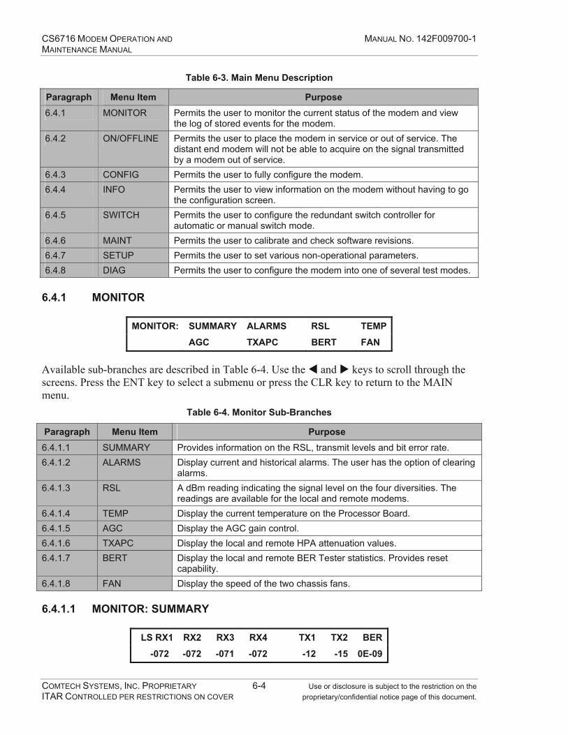
CS6716 MODEM OPERATION AND MANUAL NO. 142F009700-1 MAINTENANCE MANUAL
COMTECH SYSTEMS, INC. PROPRIETARY 6-4 Use or disclosure is subject to the restriction on the ITAR CONTROLLED PER RESTRICTIONS ON COVER proprietary/confidential notice page of this document.
Table 6-3. Main Menu Description
Paragraph Menu Item Purpose 6.4.1 MONITOR Permits the user to monitor the current status of the modem and view
the log of stored events for the modem. 6.4.2 ON/OFFLINE Permits the user to place the modem in service or out of service. The
distant end modem will not be able to acquire on the signal transmitted by a modem out of service.
6.4.3 CONFIG Permits the user to fully configure the modem. 6.4.4 INFO Permits the user to view information on the modem without having to go
the configuration screen. 6.4.5 SWITCH Permits the user to configure the redundant switch controller for
automatic or manual switch mode. 6.4.6 MAINT Permits the user to calibrate and check software revisions. 6.4.7 SETUP Permits the user to set various non-operational parameters. 6.4.8 DIAG Permits the user to configure the modem into one of several test modes.
6.4.1 MONITOR
MONITOR: SUMMARY ALARMS RSL TEMP AGC TXAPC BERT FAN
Available sub-branches are described in Table 6-4. Use the and keys to scroll through the screens. Press the ENT key to select a submenu or press the CLR key to return to the MAIN menu.
Table 6-4. Monitor Sub-Branches
Paragraph Menu Item Purpose 6.4.1.1 SUMMARY Provides information on the RSL, transmit levels and bit error rate. 6.4.1.2 ALARMS Display current and historical alarms. The user has the option of clearing
alarms. 6.4.1.3 RSL A dBm reading indicating the signal level on the four diversities. The
readings are available for the local and remote modems. 6.4.1.4 TEMP Display the current temperature on the Processor Board. 6.4.1.5 AGC Display the AGC gain control. 6.4.1.6 TXAPC Display the local and remote HPA attenuation values. 6.4.1.7 BERT Display the local and remote BER Tester statistics. Provides reset
capability. 6.4.1.8 FAN Display the speed of the two chassis fans.
6.4.1.1 MONITOR: SUMMARY
LS RX1 RX2 RX3 RX4 TX1 TX2 BER
-072 -072 -071 -072 -12 -15 0E-09
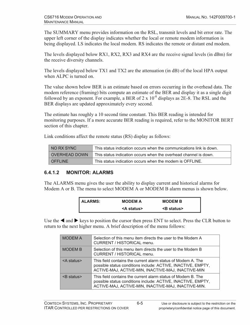
CS6716 MODEM OPERATION AND MANUAL NO. 142F009700-1 MAINTENANCE MANUAL
COMTECH SYSTEMS, INC. PROPRIETARY 6-5 Use or disclosure is subject to the restriction on the ITAR CONTROLLED PER RESTRICTIONS ON COVER proprietary/confidential notice page of this document.
The SUMMARY menu provides information on the RSL, transmit levels and bit error rate. The upper left corner of the display indicates whether the local or remote modem information is being displayed. LS indicates the local modem. RS indicates the remote or distant end modem.
The levels displayed below RX1, RX2, RX3 and RX4 are the receive signal levels (in dBm) for the receive diversity channels.
The levels displayed below TX1 and TX2 are the attenuation (in dB) of the local HPA output when ALPC is turned on.
The value shown below BER is an estimate based on errors occurring in the overhead data. The modem reference (framing) bits compute an estimate of the BER and display it as a single digit followed by an exponent. For example, a BER of 2 x 10⁻⁸ displays as 2E-8. The RSL and the BER displays are updated approximately every second.
The estimate has roughly a 10 second time constant. This BER reading is intended for monitoring purposes. If a more accurate BER reading is required, refer to the MONITOR BERT section of this chapter.
Link conditions affect the remote status (RS) display as follows:
NO RX SYNC This status indication occurs when the communications link is down. OVERHEAD DOWN This status indication occurs when the overhead channel is down. OFFLINE This status indication occurs when the modem is OFFLINE.
6.4.1.2 MONITOR: ALARMS
The ALARMS menu gives the user the ability to display current and historical alarms for Modem A or B. The menu to select MODEM A or MODEM B alarm menus is shown below.
ALARMS: MODEM A MODEM B
<A status> <B status>
Use the and keys to position the cursor then press ENT to select. Press the CLR button to return to the next higher menu. A brief description of the menu follows:
MODEM A Selection of this menu item directs the user to the Modem A CURRENT / HISTORICAL menu.
MODEM B Selection of this menu item directs the user to the Modem B CURRENT / HISTORICAL menu.
<A status> This field contains the current alarm status of Modem A. The possible status conditions include: ACTIVE, INACTIVE, EMPTY, ACTIVE-MAJ, ACTIVE-MIN, INACTIVE-MAJ, INACTIVE-MIN
<B status> This field contains the current alarm status of Modem B. The possible status conditions include: ACTIVE, INACTIVE, EMPTY, ACTIVE-MAJ, ACTIVE-MIN, INACTIVE-MAJ, INACTIVE-MIN.
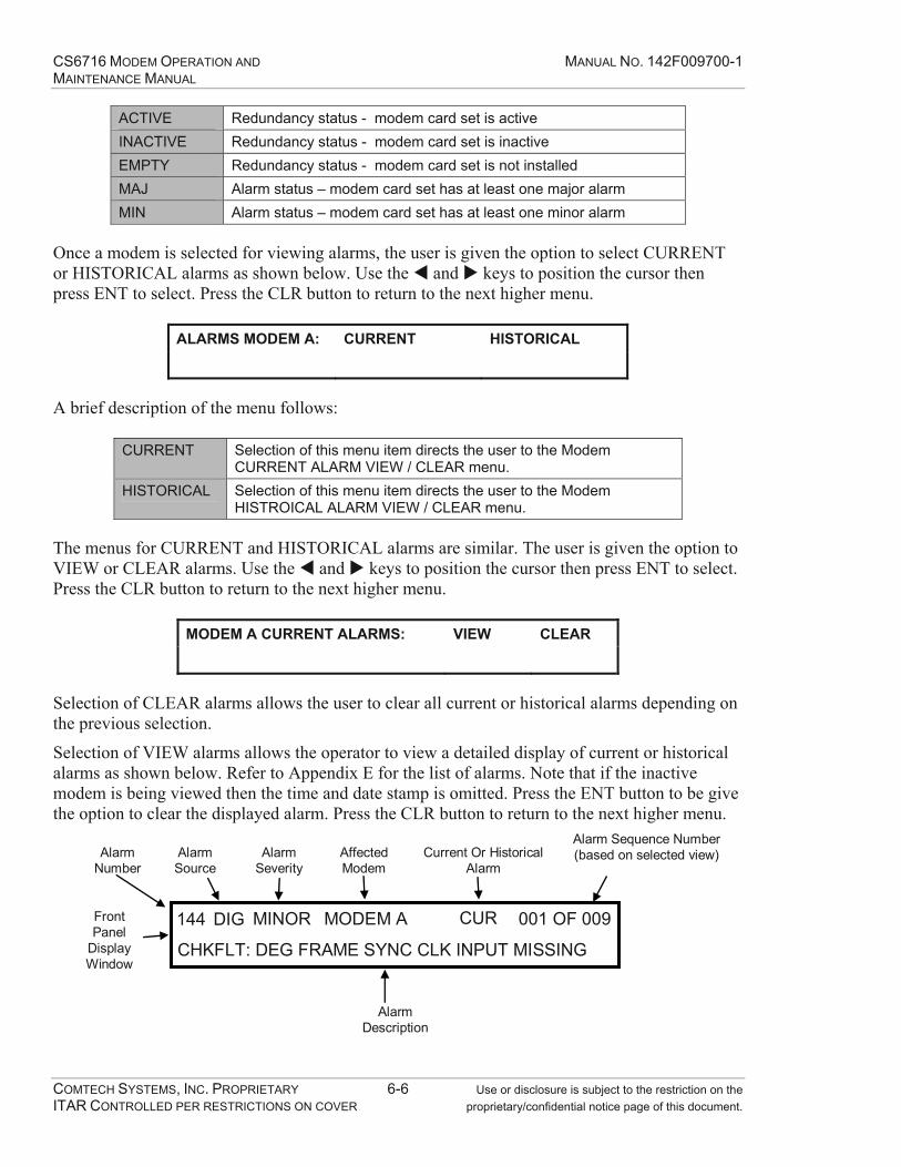
CS6716 MODEM OPERATION AND MANUAL NO. 142F009700-1 MAINTENANCE MANUAL
COMTECH SYSTEMS, INC. PROPRIETARY 6-6 Use or disclosure is subject to the restriction on the ITAR CONTROLLED PER RESTRICTIONS ON COVER proprietary/confidential notice page of this document.
ACTIVE Redundancy status - modem card set is active INACTIVE Redundancy status - modem card set is inactive EMPTY Redundancy status - modem card set is not installed MAJ Alarm status – modem card set has at least one major alarm MIN Alarm status – modem card set has at least one minor alarm
Once a modem is selected for viewing alarms, the user is given the option to select CURRENT or HISTORICAL alarms as shown below. Use the and keys to position the cursor then press ENT to select. Press the CLR button to return to the next higher menu.
ALARMS MODEM A: CURRENT HISTORICAL
A brief description of the menu follows:
CURRENT Selection of this menu item directs the user to the Modem CURRENT ALARM VIEW / CLEAR menu.
HISTORICAL Selection of this menu item directs the user to the Modem HISTROICAL ALARM VIEW / CLEAR menu.
The menus for CURRENT and HISTORICAL alarms are similar. The user is given the option to VIEW or CLEAR alarms. Use the and keys to position the cursor then press ENT to select. Press the CLR button to return to the next higher menu.
MODEM A CURRENT ALARMS: VIEW CLEAR
Selection of CLEAR alarms allows the user to clear all current or historical alarms depending on the previous selection.
Selection of VIEW alarms allows the operator to view a detailed display of current or historical alarms as shown below. Refer to Appendix E for the list of alarms. Note that if the inactive modem is being viewed then the time and date stamp is omitted. Press the ENT button to be give the option to clear the displayed alarm. Press the CLR button to return to the next higher menu.
144 DIG MINOR MODEM A CUR 001 OF 009
CHKFLT: DEG FRAME SYNC CLK INPUT MISSING
Alarm Number
Alarm Source
Alarm Severity
Affected Modem
Current Or Historical Alarm
Alarm Sequence Number(based on selected view)
Alarm Description
Front Panel
Display Window

CS6716 MODEM OPERATION AND MANUAL NO. 142F009700-1 MAINTENANCE MANUAL
COMTECH SYSTEMS, INC. PROPRIETARY 6-7 Use or disclosure is subject to the restriction on the ITAR CONTROLLED PER RESTRICTIONS ON COVER proprietary/confidential notice page of this document.
6.4.1.3 MONITOR: RSL Local and remote receive signal levels for each active diversity are displayed. The displayed RSL values reflect the signal level at the input to the LNA’s. Refer to section 6.4.7.1 for viewing the receiver gain settings.
LOCAL/REMOTE RSL 1,2,3,4 (dBm)
-042 -041 -042 -041 / -043 -042 -043 -043
The first four values represent the RSLs for local diversity #1, #2, #3 and #4. The second four values represent the RSLs for remote diversity #1, #2, #3 and #4.
Link conditions affect the remote RSL display as follows:
NO RX SYNC This status indication occurs when the communications link is down. OVERHEAD DOWN This status indication occurs when the overhead channel is down. OFFLINE This status indication occurs when the modem is OFFLINE.
Note If a diversity is disabled due to the diversity setting
(SETUP: DIVMODE), the RSL value is not displayed.
6.4.1.4 MONITOR: TEMP The temperature within the chassis is given in degrees Celsius and Fahrenheit. A temperature sensor is located on each Processor Board. A temperature alarm will be generated if the alarm threshold is exceeded. The threshold is factory set for +55 degrees C.
TEMPERATURE: 029C 085F
6.4.1.5 MONITOR: AGC The AGC gain control values are displayed for each active diversity. These values are a relative indication of signal strength.
LOCAL AGC: RX1 RX2 RX3 RX4
049 052 050 049
6.4.1.6 MONITOR: TXAPC The TXAPC display gives the operator the current transmit signal attenuation in dB. Transmit attenuation occurs automatically if the ALPC feature has been enabled via the CONFIG menu.
LOCAL: TX1 TX2 REMOTE: TX1 TX2 (dB)
-14 -12 -17 -15

CS6716 MODEM OPERATION AND MANUAL NO. 142F009700-1 MAINTENANCE MANUAL
COMTECH SYSTEMS, INC. PROPRIETARY 6-8 Use or disclosure is subject to the restriction on the ITAR CONTROLLED PER RESTRICTIONS ON COVER proprietary/confidential notice page of this document.
ALPC is a programmable feature that automatically controls the transmitted RF power based on receive signal levels at the distant-end RF receivers. This feature reduces the possibility that the troposcatter transmitter will interfere with systems beyond the receiving station.
This reduction in unnecessarily high transmit power levels is accomplished by sensing power levels at the receiver and then feeding the information back to the transmitting station. The feedback from the remote station causes the local HPA power level to be automatically reduced.
6.4.1.7 MONITOR: BERT
The user has the option to pick one of the options shown in the following screen:
BERT: VIEW LOCAL RESET LOCAL
VIEW REMOTE RESET REMOTE
Selection of RESET LOCAL or RESET REMOTE will restart the respective BERT error count and test period. Viewing the local or remote BERT will result in the display of the following two screens. The screens automatically alternate every few seconds:
LCL BERT: AVG BER ERRORS FEC BER
8.52E-8 0014 OFF
LCL BERT: AVG BER PERIOD
8.52E-8 000:14:28:04
LCL BERT Local BERT status REM BERT Remote BERT status AVG BER Average BER for the test period ERRORS Number of bit errors that have occurred during the period FEC BER Estimate of the bit error rate with FEC enabled PERIOD Elapsed time since the beginning of the BER test
Link conditions affect the BERT status display as follows:
BERT OFF The BERT has been automatically disabled. The current configuration does not have enough bandwidth necessary for the 32 kbps BERT.
BERT LOST SYNC The communication link is up but signal quality is poor. The BERT is unable to acquire.
RX LOSS OF SYNC The communications link is down. OFFLINE The modem is OFFLINE.

CS6716 MODEM OPERATION AND MANUAL NO. 142F009700-1 MAINTENANCE MANUAL
COMTECH SYSTEMS, INC. PROPRIETARY 6-9 Use or disclosure is subject to the restriction on the ITAR CONTROLLED PER RESTRICTIONS ON COVER proprietary/confidential notice page of this document.
6.4.1.8 MONITOR: FAN
The fan display gives the operator the RPM speed of the two rear panel fans. Press the CLR key to return to the MONITOR menu. An alarm is generated if the speed of either fan drops below the fan speed alarm threshold. The fan speed alarm threshold is factory set.
FAN SPEED: FAN1 FAN2
(RPM) 4290 4320
6.4.2 ON/OFFLINE
This command places the modem ONLINE or OFFLINE. The normal operating mode of the modem is ONLINE. The modem must be configured OFFLINE before configuration changes are made. Data traffic is inhibited when the modem is OFFLINE. Use the and keys to select the desired mode.
ONLINE Normal operational mode. OFFLINE User traffic is inhibited. The modem must be OFFLINE to change configuration.
Note Selecting OFFLINE will display the following message:
WARNING TRAFFIC WILL BE INTERRUPTED ENT=PROCEED, CLR=CANCEL
6.4.3 CONFIG The CONFIG menu provides the capability of changing the operating mode of the modem. The modem must be configured OFFLINE to change configuration (except ALPC mode). The CONFIG menu is available from the top level menu.
CONFIG: RATES DATA CH FEC
BERT DEFAULT ALPC
The configuration of the remote modem must be identical to the local modem. When the configuration of both modems are the same, link communications can be established. The local and remote modems should remain OFFLINE until configuration changes are complete on both ends of the link.
Note The configuration of the inactive redundant board set follows the configuration of the active board set. Whenever a configuration change is made to the active board set, it is transmitted to the inactive. This may take up to two minutes to occur.

CS6716 MODEM OPERATION AND MANUAL NO. 142F009700-1 MAINTENANCE MANUAL
COMTECH SYSTEMS, INC. PROPRIETARY 6-10 Use or disclosure is subject to the restriction on the ITAR CONTROLLED PER RESTRICTIONS ON COVER proprietary/confidential notice page of this document.
The CONFIG sub-branches available are described in Table 6-5. Table 6-5. CONFIG Sub-Branches
Paragraph Menu Item Purpose 6.4.3.1 RATES Selection of operating rate for the high speed Data Channel, Service
Channel #1, and Service Channel #2 6.4.3.2 DATA CH Selection of the Data Channel Interface type – RS-422 or HSSI 6.4.3.3 FEC Selection of ON/OFF state for Forward Error Correction 6.4.3.4 BERT Select of BERT ON/OFF status as well as current BERT status 6.4.3.5 DEFAULT Restores the standard operating configuration 6.4.3.6 ALPC Selection of the ON/OFF state of Adaptive Link Power Control
The CONFIG menu gives the user the ability to change the most frequently used options of the modem. Other, more infrequently used operating parameters can be found in the SETUP menu. Use the and keys to scroll through the screens. Press the ENT key to select a submenu or press the CLR key to return to the MAIN menu. The CONFIG menu is shown below. Use the
and keys to position the cursor on the desired menu item, then press ENT to select. Press the CLR button to return to the next higher menu item.
The user may receive an error message if the Modem is currently in the ONLINE state as follows:
MODEM MUST BE OFFLINE TO ALLOW CHANGE! GO TO MAIN MENU TO TAKE MODEM OFFLINE
6.4.3.1 CONFIG: RATES
The RATES menu gives the user the ability to change the rates for the high speed Data Channel, Service Channel #1, and Service Channel #2. The modem must be configured OFFLINE before selecting different Data or Service Channel rates. Use the and keys to position the cursor on the desired menu item, then press ENT to select. Press the CLR button to return to the next higher menu item.
RATES: DATA SVCH1 SVCH2
Selection of DATA from the RATES menu results in the following screen:
CONFIG DATA CH RATE: = 16Mb/s?
The user is given a range of data rates to select from the following rates: 2Mb/s, 4Mb/s, 8Mb/s, 10Mb/s, 12Mb/s and 16Mb/s. Use the and keys to select the desired rate. A question mark appears after the options that are not active (as shown in the screen above). Press ENT to activate

CS6716 MODEM OPERATION AND MANUAL NO. 142F009700-1 MAINTENANCE MANUAL
COMTECH SYSTEMS, INC. PROPRIETARY 6-11 Use or disclosure is subject to the restriction on the ITAR CONTROLLED PER RESTRICTIONS ON COVER proprietary/confidential notice page of this document.
the selection (the question mark disappears). Press the CLR button to return to the next higher menu item.
Note The AGC/RSL calibration of the four receive data channels, occurs after setting the new option.
Selection of SVCH1 or SVCH2 from the RATES menu results in the following screen:
CONFIG SVCHX RATE: = 8Kb/s
The user is given a range of data rates to select from the following rates: 0, 8Kb/s, 16Kb/s, 24Kb/s, 32Kb/s, 40Kb/s, 48Kb/s, 56Kb/s, 64Kb/s, 72Kb/s, and 80Kb/s. Use the and keys to select the desired rate. Press ENT to activate your selection. Press the CLR button to return to the next higher menu item.
Notes The combined rate for Service Channel #1, Service Channel #2, and the BERT cannot exceed the available bandwidth. If an attempt is made to exceed the bandwidth a message will indicate that the service channel and BERT rates have been automatically changed. The user should check the service channel rates to verify proper configuration. Setting SVCH1 or SVCH2 data rate to zero turns the associated channel off. The service channel rate must be configured for the operating rate of the external equipment connected to the service channel interface.
6.4.3.2 CONFIG: DATA CH (Interface)
The DATA CH menu gives the user the ability to change the interface type for the Data Channel. The modem must be configured OFFLINE before selecting a different data interface type. The available interface types are RS-422 and HSSI. Use the and keys to select the desired interface type then press ENT to activate the selection. Press the CLR button to return to the next higher menu item.
DATA INTRF TYPE: = RS422
Note A data interface alarm will be generated if the Data Interface is not cabled to active user equipment.

CS6716 MODEM OPERATION AND MANUAL NO. 142F009700-1 MAINTENANCE MANUAL
COMTECH SYSTEMS, INC. PROPRIETARY 6-12 Use or disclosure is subject to the restriction on the ITAR CONTROLLED PER RESTRICTIONS ON COVER proprietary/confidential notice page of this document.
6.4.3.3 CONFIG: FEC
The FEC menu gives the user the ability to turn Forward Error Correction ON or OFF. The modem must be configured OFFLINE before changing the FEC mode.
Use the and keys to select the desired mode. Press ENT to activate the selection. Press the CLR button to return to the next higher menu item.
DATA CH FEC: = ON
6.4.3.4 CONFIG: BERT
The BERT menu gives the user the ability to view the ON / OFF status of the BERT. Press the CLR button to return to the next higher menu item. The BERT is automatically turned on or off as a function of available bandwidth. Refer to paragraph 6.4.3.1 for more details.
BERT STATUS: ON
6.4.3.5 CONFIG: DEFAULT
The DEFAULT menu item gives the user the ability to restore a standard operating configuration. The modem must be configured OFFLINE before selecting the DEFAULT configuration. See Table 6-6 below for details of the default configuration.
Table 6-6. Default Configuration
RATE 2 Mb/s Service Channel #1 Rate 16 Kb/s Service Channel #2 Rate 0 Kb/s Loopback NORMAL Adaptive Link Power Control OFF Forward Error Correction ON Bit Error Rate Tester ON
When the DEFAULT menu is selected, the user will be prompted with a screen to warn the user that the configuration will change to the default configuration.
WARNING! STANDARD CONFIG WILL BE SET
ENT=PROCEED, CLR=CANCEL
The subsequent pressing of the ENT key will cause the default configuration to be set. Pressing CLR will cancel the DEFAULT command.

CS6716 MODEM OPERATION AND MANUAL NO. 142F009700-1 MAINTENANCE MANUAL
COMTECH SYSTEMS, INC. PROPRIETARY 6-13 Use or disclosure is subject to the restriction on the ITAR CONTROLLED PER RESTRICTIONS ON COVER proprietary/confidential notice page of this document.
6.4.3.6 CONFIG: ALPC
Adaptive Link Power Control (ALPC) provides automatic transmit power control of the HPA(s). The modem accomplishes ALPC by monitoring the receive signal level of the diversities. The controller compares the levels to a preset threshold and then makes a decision to either increase or decrease the distant end transmit power levels. The new transmit level value is then fed back to the distant end modem where the modem IF output level is adjusted accordingly.
The ALPC menu allows the user to select the operating mode. The modem does not need to be configured OFFLINE when changing the ALPC mode. Use the and keys to select the desired mode. Press ENT to activate the selection. Press the CLR button to return to the next higher menu item.
ALPC: = AUTOMATIC
6.4.4 INFO
The INFO screen permits the user to view information on the modem without having to go the the configuration screens. The content of the screen is dependent on the current configuration of the modem. Press the CLR button to return to the next higher menu item. An example screen follows:
STATE=ONLINE, DATA CH RATE=16Mb/s
INTRF=RS422, FEC=OFF, BERT=OFF
6.4.5 SWITCH
The SWITCH menu provides control over the Redundant Switch Controller. The controller operates in one of two modes; automatic and manual.
SWITCH: = AUTO MODE
The menu options include the following: AUTO MODE, SWITCH TO MODEM B (if Modem A is active) and MANUAL MODE.
Automatic mode allows the controller to force a redundant switch based on alarm status. If a major alarm occurs on the active board, and it is also classified as “switchable”, then the controller will force the inactive board to the active state. The exception to this would be if the inactive modem already had a major-switchable alarm. In that case no switch would occur.
Manual mode inhibits automatic switching and allows the user to select the active modem.
Depending on which redundant board set is active, the menu will change to the appropriate selection i.e. if board set A is active, then the menu item would be “SWITCH TO MODEM B”.
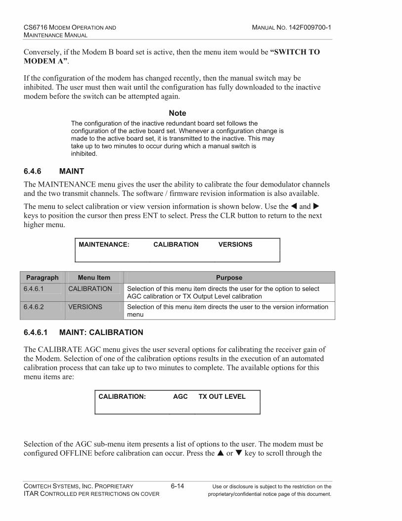
CS6716 MODEM OPERATION AND MANUAL NO. 142F009700-1 MAINTENANCE MANUAL
COMTECH SYSTEMS, INC. PROPRIETARY 6-14 Use or disclosure is subject to the restriction on the ITAR CONTROLLED PER RESTRICTIONS ON COVER proprietary/confidential notice page of this document.
Conversely, if the Modem B board set is active, then the menu item would be “SWITCH TO MODEM A”.
If the configuration of the modem has changed recently, then the manual switch may be inhibited. The user must then wait until the configuration has fully downloaded to the inactive modem before the switch can be attempted again.
Note The configuration of the inactive redundant board set follows the configuration of the active board set. Whenever a configuration change is made to the active board set, it is transmitted to the inactive. This may take up to two minutes to occur during which a manual switch is inhibited.
6.4.6 MAINT The MAINTENANCE menu gives the user the ability to calibrate the four demodulator channels and the two transmit channels. The software / firmware revision information is also available.
The menu to select calibration or view version information is shown below. Use the and keys to position the cursor then press ENT to select. Press the CLR button to return to the next higher menu.
MAINTENANCE: CALIBRATION VERSIONS
Paragraph Menu Item Purpose
6.4.6.1 CALIBRATION Selection of this menu item directs the user for the option to select AGC calibration or TX Output Level calibration
6.4.6.2 VERSIONS Selection of this menu item directs the user to the version information menu
6.4.6.1 MAINT: CALIBRATION
The CALIBRATE AGC menu gives the user several options for calibrating the receiver gain of the Modem. Selection of one of the calibration options results in the execution of an automated calibration process that can take up to two minutes to complete. The available options for this menu items are:
CALIBRATION: AGC TX OUT LEVEL
Selection of the AGC sub-menu item presents a list of options to the user. The modem must be configured OFFLINE before calibration can occur. Press the or key to scroll through the

CS6716 MODEM OPERATION AND MANUAL NO. 142F009700-1 MAINTENANCE MANUAL
COMTECH SYSTEMS, INC. PROPRIETARY 6-15 Use or disclosure is subject to the restriction on the ITAR CONTROLLED PER RESTRICTIONS ON COVER proprietary/confidential notice page of this document.
list of options then press ENT to select. Press the CLR button to return to the next higher menu. The available options for this sub-menu are shown in the table below.
CHANNEL #1 Perform AGC calibration on channel #1 only CHANNEL #2 Perform AGC calibration on channel #2 only CHANNEL #3 Perform AGC calibration on channel #3 only CHANNEL #4 Perform AGC calibration on channel #4 only ALL CHANNELS Perform AGC calibration on all 4 channels
Any errors that occur during calibration will be displayed on the front panel.
Selection of the TX OUT LEVEL sub-menu gives the user the ability to calibrate the power monitor circuit for both TX1 and TX2. Press the or key to scroll through the list of options and then press ENT to select. Press the CLR button to return to the next higher menu.
The available options for this sub-menu are:
TX1 Calibrate the power monitor circuit for Transmitter #1 TX2 Calibrate the power monitor circuit for Transmitter #2
If an error occurs during calibration, it will be indicated on the front panel.
6.4.6.2 MAINT: VERSIONS
This menu item displays the current firmware version with a time/date stamp of the release. Press “ENT” to view the next screen of version information. Press the “CLR” key to return to the menu. For example, the version screen appears as follows:
F.W. Ver 1.05b – Jan 17 2006 14:42:06
RTOS Ver 276
Press ENT to view the second screen:
SCC/INF PLD Version 4.0
TCP/IP Stack Version 161
6.4.7 SETUP
The SETUP sub-branches available are described in Table 6-7. Use the and keys to scroll through the screens. Press the ENT key to select a submenu or press the CLR key to return to the MAIN menu.
SETUP: RXGAIN DIVERSITY MISC
FLOWCTL CLKINV DIVMODE
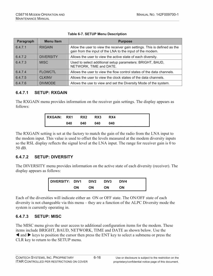
CS6716 MODEM OPERATION AND MANUAL NO. 142F009700-1 MAINTENANCE MANUAL
COMTECH SYSTEMS, INC. PROPRIETARY 6-16 Use or disclosure is subject to the restriction on the ITAR CONTROLLED PER RESTRICTIONS ON COVER proprietary/confidential notice page of this document.
Table 6-7. SETUP Menu Description
Paragraph Menu Item Purpose 6.4.7.1 RXGAIN Allow the user to view the receiver gain settings. This is defined as the
gain from the input of the LNA to the input of the modem. 6.4.7.2 DIVERSITY Allows the user to view the active state of each diversity. 6.4.7.3 MISC Used to select additional setup parameters: BRIGHT, BAUD,
NETWORK, TIME and DATE. 6.4.7.4 FLOWCTL Allows the user to view the flow control states of the data channels. 6.4.7.5 CLKINV Allows the user to view the clock states of the data channels. 6.4.7.6 DIVMODE Allows the use to view and set the Diversity Mode of the system.
6.4.7.1 SETUP: RXGAIN
The RXGAIN menu provides information on the receiver gain settings. The display appears as follows:
RXGAIN: RX1 RX2 RX3 RX4
040 040 040 040
The RXGAIN setting is set at the factory to match the gain of the radio from the LNA input to the modem input. This value is used to offset the levels measured at the modem diversity inputs so the RSL display reflects the signal level at the LNA input. The range for receiver gain is 0 to 50 dB.
6.4.7.2 SETUP: DIVERSITY
The DIVERSITY menu provides information on the active state of each diversity (receiver). The display appears as follows:
DIVERSITY: DIV1 DIV2 DIV3 DIV4
ON ON ON ON
Each of the diversities will indicate either an ON or OFF state. The ON/OFF state of each diversity is not changeable via this menu – they are a function of the ALPC Diversity mode the system is currently operating in.
6.4.7.3 SETUP: MISC
The MISC menu gives the user access to additional configuration items for the modem. These items include BRIGHT, BAUD, NETWORK, TIME and DATE as shown below. Use the
and keys to position the cursor then press the ENT key to select a submenu or press the CLR key to return to the SETUP menu.

CS6716 MODEM OPERATION AND MANUAL NO. 142F009700-1 MAINTENANCE MANUAL
COMTECH SYSTEMS, INC. PROPRIETARY 6-17 Use or disclosure is subject to the restriction on the ITAR CONTROLLED PER RESTRICTIONS ON COVER proprietary/confidential notice page of this document.
MISC SETUP: BRIGHT BAUD NETWORK
TIME DATE
Menu Item Purpose BRIGHT Allows the user to set the display brightness. BAUD Allows the user to view and set the baud rate of the Terminal Interface. NETWORK Allows the user to view network parameters. TIME Allows the user to view and set the system time. DATE Allows the user to view and set the system date.
The BRIGHT submenu provides the user the option to change the brightness of the display as shown below. The user has four options to choose from: 100%, 75%, 50% and 25%. Use the
and keys to display the desired value and then press the ENT key to select it. Press the CLR key to return to the MISC menu.
BRIGHTNESS: = 100%
The BAUD submenu provides the user the option to change the baud rate of the RS-232 Terminal Interface as shown below. The user has nine options to choose from: 115200, 57600, 38400, 19200, 9600, 4800, 2400, 1200 and 600. Use the and keys to display the desired value and then press the ENT key to select it. Press the CLR key to return to the MISC menu.
M&C BAUD RATE: = 38400
The NETWORK submenu provides the user the option to view the IP, MAC NETMASK, GATEWAY and DNS addresses. The submenu is shown below. Use the and keys to position the cursor then press the ENT key to select a submenu or press the CLR key to return to the MISC menu.. The values may be changed via the Terminal interface.
NETWORK: IP MAC NETMASK GATEWAY DNS
The TIME menu provides the user the option to change the system time. The submenu is shown below. Use the and keys to select the parameter to change and then use the and keys to display the desired value. When the desired time is displayed, press the ENT key to select it. Press the CLR key to return to the MISC menu. Enter the time in the format of HH:MM, where HH represents hours on a twenty-four hour clock and MM represents the minutes.
ENTER TIME (HH:MM): 14:58

CS6716 MODEM OPERATION AND MANUAL NO. 142F009700-1 MAINTENANCE MANUAL
COMTECH SYSTEMS, INC. PROPRIETARY 6-18 Use or disclosure is subject to the restriction on the ITAR CONTROLLED PER RESTRICTIONS ON COVER proprietary/confidential notice page of this document.
The DATE menu provides the user the option to change the system date. The submenu is shown below. Use the and keys to select the parameter to change and then use the and keys to display the desired value. When the desired date is displayed, press the ENT key to select it. Press the CLR key to return to the MISC menu. Enter the date in the format of MM:DD:YY, where MM represents the month, DD represents the day and YY represents the last two digits of the year.
ENTER DATE (MM:DD:YY): 08/18/06
6.4.7.4 SETUP: FLOWCTL
The FLOWCTL menu provides the user the option to view information on the RTS Loopback and CTS Inversion for each of the user data channels. The display appears below.
FLOW CONTROL: RTS LOOPBACK CTS INVERSION
Use the and keys to position the cursor then press the ENT key to select a submenu or press the CLR key to return to the SETUP menu. The user channels will either be OFF or ON and are configured at the factory to meet the system requirements. The RTS LOOPBACK and CTS INVERSION displays follow.
RTS LOOPBACK: DATA CH SVCH1 SVCH2
OFF OFF OFF
CTS INVERSION: DATA CH SVCH1 SVCH2
OFF OFF OFF
Press the CLR key from either of these submenus to return to the FLOW CONTROL menu.
6.4.7.5 SETUP: CLKINV
The CLKINV menu provides the user the option to view information on the Clock Inversion for each of the user data channels. The user channels will either be OFF or ON and are configured at the factory to meet the system requirements. The display appears below.
CLOCK INVERSION: DATA CH SVCH1 SVCH2
OFF OFF OFF
Press the CLR key to return to the SETUP menu.

CS6716 MODEM OPERATION AND MANUAL NO. 142F009700-1 MAINTENANCE MANUAL
COMTECH SYSTEMS, INC. PROPRIETARY 6-19 Use or disclosure is subject to the restriction on the ITAR CONTROLLED PER RESTRICTIONS ON COVER proprietary/confidential notice page of this document.
6.4.7.6 SETUP: DIVMODE
The DIVMODE menu provides the user the option to change the diversity mode of the modem. There are three Diversity Modes: QUAD, DUAL – 2 RECEIVER and DUAL – 4 RECEIVER. The display appears below with a table that describes each option.
DIVERSITY MODE: = QUAD
Option Purpose ALPC TARGET RSL
Data Channel Rate 12 MB ALPC TARGET RSL
Data Channel Rate >12 MB QUAD All four diversities and power
control for both transmitters are active. This mode is designed for commercial quad diversity systems.
-69 dBm -65 dBm
DUAL – 2 RECEIVER
Diversity 1, diversity 3 and power control for transmitter 1 are active. This mode is designed for commercial dual diversity systems.
-50 dBm -46 dBm
DUAL – 4 RECEIVER
All four receivers are active. Power control for transmitter 1 is active. -50 dBm -46 dBm
Use the and keys to display the desired mode and then press the ENT key to select it. Press the CLR key to return to the SETUP menu.
6.4.8 DIAG
The DIAG menu provides the user with three types of diagnostic tests run on the modem. These tests include LOOPBACK, F.P. LED TEST and F.P. DISPLAY TEST as shown in Table 6-8. Use the and keys to position the cursor to the desired test and then press the ENT key. Use the CLR key to return to the SETUP menu.
DIAG: LOOPBACKS F.P. LED TEST
F.P. DISPLAY TEST
Table 6-8. DIAG Description
Paragraph Menu Item Purpose 6.4.8.1 LOOPBACK Used to perform diagnostic loopbacks in the modem. 6.4.8.2 F.P. LED TEST Tests the front panel LEDs. 6.4.8.3 F.P. DISPLAY TEST Tests the front panel display.
6.4.8.1 DIAG: LOOPBACK
The LOOPBACK menu provides the user with five different loopback options to test the modem. These options are: DATA CHANNEL, SERVICE CHANNEL 1, SERVICE CHANEL
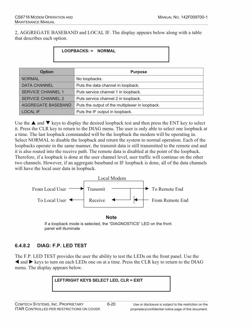
CS6716 MODEM OPERATION AND MANUAL NO. 142F009700-1 MAINTENANCE MANUAL
COMTECH SYSTEMS, INC. PROPRIETARY 6-20 Use or disclosure is subject to the restriction on the ITAR CONTROLLED PER RESTRICTIONS ON COVER proprietary/confidential notice page of this document.
2, AGGREGATE BASEBAND and LOCAL IF. The display appears below along with a table that describes each option.
LOOPBACKS: = NORMAL
Option Purpose
NORMAL No loopbacks. DATA CHANNEL Puts the data channel in loopback. SERVICE CHANNEL 1 Puts service channel 1 in loopback. SERVICE CHANNEL 2 Puts service channel 2 in loopback. AGGREGATE BASEBAND Puts the output of the multiplexer in loopback. LOCAL IF Puts the IF output in loopback.
Use the and keys to display the desired loopback test and then press the ENT key to select it. Press the CLR key to return to the DIAG menu. The user is only able to select one loopback at a time. The last loopback commanded will be the loopback the modem will be operating in. Select NORMAL to disable the loopback and return the system to normal operation. Each of the loopbacks operate in the same manner, the transmit data is still transmitted to the remote end and it is also routed into the receive path. The remote data is disabled at the point of the loopback. Therefore, if a loopback is done at the user channel level, user traffic will continue on the other two channels. However, if an aggregate baseband or IF loopback is done, all of the data channels will have the local user data in loopback.
Transmit
Receive
To Remote End
From Remote End
Local Modem
From Local User
To Local User
Note If a loopback mode is selected, the “DIAGNOSTICS” LED on the front panel will illuminate
6.4.8.2 DIAG: F.P. LED TEST
The F.P. LED TEST provides the user the ability to test the LEDs on the front panel. Use the and keys to turn on each LEDs one on at a time. Press the CLR key to return to the DIAG
menu. The display appears below.
LEFT/RIGHT KEYS SELECT LED, CLR = EXIT
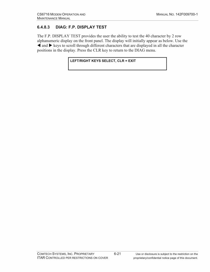
CS6716 MODEM OPERATION AND MANUAL NO. 142F009700-1 MAINTENANCE MANUAL
COMTECH SYSTEMS, INC. PROPRIETARY 6-21 Use or disclosure is subject to the restriction on the ITAR CONTROLLED PER RESTRICTIONS ON COVER proprietary/confidential notice page of this document.
6.4.8.3 DIAG: F.P. DISPLAY TEST
The F.P. DISPLAY TEST provides the user the ability to test the 40 character by 2 row alphanumeric display on the front panel. The display will initially appear as below. Use the
and keys to scroll through different characters that are displayed in all the character positions in the display. Press the CLR key to return to the DIAG menu.
LEFT/RIGHT KEYS SELECT, CLR = EXIT

CS6716 MODEM OPERATION AND MANUAL NO. 142F009700-1 MAINTENANCE MANUAL
COMTECH SYSTEMS, INC. PROPRIETARY 6-22 Use or disclosure is subject to the restriction on the ITAR CONTROLLED PER RESTRICTIONS ON COVER proprietary/confidential notice page of this document.
This Page Intentionally Left Blank
CS6716 MODEM OPERATION AND MANUAL NO. 142F009700-1 MAINTENANCE MANUAL
COMTECH SYSTEMS, INC. PROPRIETARY 7-1 Use or disclosure is subject to the restriction on the ITAR CONTROLLED PER RESTRICTIONS ON COVER proprietary/confidential notice page of this document.
7.0 MAINTENANCE
7.1 Introduction
Maintenance procedures are routine or corrective. Routine maintenance procedures include cleaning equipment and filters, and checking connectors to ensure they are secure.
Perform corrective maintenance to repair a reported fault caused by a malfunction. In extreme situations, it may be necessary to take the modem completely off line to perform diagnostic/repair procedures. Corrective actions may or may not affect modem operation.
The CS6716 Modem has an estimated mean time between failure (MTBF) rate of 100,000 hours, causing a mission failure approximately every 11.4 years.
The CS6716 Modem provides two types of alarms, major and minor.
A major alarm occurs when mission traffic is affected. The modem will switch to the redundant set if it was set in the AUTO mode.
Note No switch will occur, if the redundant modem is already in alarm or unavailable.
A minor alarm occurs when performance has degraded in non-mission traffic circuitry.
Alarm states are latched by a relay and available at the RS-232 port (J9) for display at a remote monitoring center.
7.2 Maintenance Philosophy
Comtech Systems’ Model CS6716 Digital Troposcatter Modem provides state-of-the-art alarm monitoring and reporting capabilities, combined with simplified field maintenance procedures. The modem provides four methods of alarm reporting:
1. Local – The front panel LEDs display the status/alarms severity.
2. Keypad and Display – Using the Command/Control keypad or keys and viewing the display menu options allows interrogation to determine the source and nature of the reported fault (refer to Figure 7-1).
3. Remote terminal – All alarms status is available.
4. Summary alarm relay monitoring
Summary alarm monitoring requires an external monitoring circuit. The interface is part of the J9 rear interface connector. An alarm de-energizes the relay.

CS6716 MODEM OPERATION AND MANUAL NO. 142F009700-1 MAINTENANCE MANUAL
COMTECH SYSTEMS, INC. PROPRIETARY 7-2 Use or disclosure is subject to the restriction on the ITAR CONTROLLED PER RESTRICTIONS ON COVER proprietary/confidential notice page of this document.
144 DIG MINOR MODEM A CUR 001 OF 009
CHKFLT: DEG FRAME SYNC CLK INPUT MISSING
Alarm Number
Alarm Source
Alarm Severity
Affected Modem
Current Or Historical Alarm
Alarm Sequence Number(based on selected view)
Alarm Description
Front Panel
Display Window
Figure 7-1. Alarm Display Example
Depending on the severity and nature of a reported alarm, the modem will:
Continue operation.
Continue operation under reduced capability.
Automatically switch to the redundant modem.
Be unable to maintain communications.
The CS6716 Modem has routine and corrective maintenance.
1. Routine maintenance - Consists of cleaning filters, inspecting the unit for frayed, loose, broken or damaged cables/connectors, and ensuring the fans are operating correctly.
2. Corrective – Occurs in response to an indicated alarm. There are no user-replaceable components in the CS6716 Modem. When a fault occurs, corrective action consists of replacing one of the following sub-assemblies:
Analog Board
Processor Board
Front panel display board
Fans
If replacing one or more of the sub-assemblies does not correct the indicated fault, the entire modem will require replacement.
If the fault has forced the modem to switch to the redundant set (major alarm), the repair can wait until a more convenient time to replace the faulty LRU.
Note However, another failure on the online set could be fatal to the ability of the modem to maintain communications.
CS6716 MODEM OPERATION AND MANUAL NO. 142F009700-1 MAINTENANCE MANUAL
COMTECH SYSTEMS, INC. PROPRIETARY 7-3 Use or disclosure is subject to the restriction on the ITAR CONTROLLED PER RESTRICTIONS ON COVER proprietary/confidential notice page of this document.
Fatal errors require immediate attention. Refer to Section 7.4 for the maintenance procedures. The CS6716 Modem employs simplified field maintenance procedures to maintain reliability and constant communications. If a failure affects the backplane, the front panel, or the ribbon cable connecting the front panel to the backplane, replace the entire modem.
Users should maintain a maintenance log of all routine maintenance and repair actions, for trend analysis and tracking the repairs required for each modem.
7.3 Return Material Authorization (RMA) Procedures
To return an item for repair or replacement, a Return Material Authorization (RMA) is required.
Refer to the Return Material Authorization Information Sheet (Appendix G) for the information required to request the RMA.
When the information is completed contact Comtech Systems, Inc., by either email or telephone:
Email: [email protected]
Telephone: (407) 854-1950, ext. 4055 or ext. 4010
When you receive the RMA number, carefully pack the item(s) and ship to:
Comtech Systems, Inc. 2900 Titan Row, Suite 142
Orlando, FL 32809 USA
Attn: RMA Department
IMPORTANT INFORMATION Write the RMA number prominently on the outside of the shipping container.
The sender should retain a copy of all information sheets included with the packaging.
7.4 Periodic Maintenance
Dust and sand can clog the front panel filter, restricting air flow, which could then cause over-heating. The front panel filter must be cleaned more frequently in a sandy or dusty environment. The filter is accessed by loosening the front panel retaining screws to open the panel. Remove the six screws the hold the front panel and put them in a safe place. Clean and dry the filter. Replace the filter and use the six screws to secure it in place. Close and secure the front panel. Also, verify the cables are not frayed or damaged.
CS6716 MODEM OPERATION AND MANUAL NO. 142F009700-1 MAINTENANCE MANUAL
COMTECH SYSTEMS, INC. PROPRIETARY 7-4 Use or disclosure is subject to the restriction on the ITAR CONTROLLED PER RESTRICTIONS ON COVER proprietary/confidential notice page of this document.
7.5 LRU Faults
7.5.1 Information on Modem Fault Indications
The BIT in the CS6716 Modem is extensive and capable of detecting a vast number of faults that may have a minimal effect on modem operation. Refer to Appendix E for a list of the alarms reported by the modem. Most minor faults will allow the modem to continue functioning until corrective action occurs.
When a fault occurs, the keypad display indicates the fault severity. Specific information about the source and nature of the fault is obtained through the front panel interface. Refer to the Front Panel Operation section of this manual.
7.5.2 Major Alarms
If a major alarm occurs, the redundancy controller will cause an automatic switch to the hot-standby modem.
The LRUs in the modem are hot swappable. The power to the modem can remain on while replacing an LRU.
Caution Review all safety procedures and ESD requirements prior to opening the modem front panel. If the power to the modem is on, take precautions when placing hands inside an operating unit. Always remove metal jewelry, watches, rings, or loose clothing etc., before working on electrical circuits or any electrical equipment.
When replacing an LRU, disengage it from the modem’s backplane using only the ejectors on the unit’s front corners.
Caution Do not use any tools to remove an LRU or grab the LRU with your hands. If one or both ejectors are damaged or broken, replace the ejectors before using the LRU.
7.5.3 Minor Alarms
To eliminate an LRU fault, replace the faulty LRU. If the indication is a minor alarm and the modem did not switch to the redundant set, perform the following steps to clear the alarm:
Note Verify you are wearing a correctly grounded electrostatic wrist strap prior to performing the following steps.
1. Record the alarm number, modem set (A or B) and the alarm description.
2. Use the front keypad to force the modem to switch to the redundant set.

CS6716 MODEM OPERATION AND MANUAL NO. 142F009700-1 MAINTENANCE MANUAL
COMTECH SYSTEMS, INC. PROPRIETARY 7-5 Use or disclosure is subject to the restriction on the ITAR CONTROLLED PER RESTRICTIONS ON COVER proprietary/confidential notice page of this document.
3. To force the modem to switch to the redundant set from the MAIN MENU use the or key to navigate to SWITCH and press the ENT key to select the sub-menu.
4. Use the or key to change the SWITCH value and press the ENT key to select the option.
5. After the switching, allow the redundant modem approximately two minutes to stabilize. When the online set is stable, open the front panel by unscrewing the three captive screws at the top of the front panel and lower the front panel to expose the LRU.
6. Turn the POWER switches (SW1) OFF on the faulty modem.
7. Use the ejectors to remove the faulty unit from the modem chassis. When ejecting the faulty unit from the backplane, remove it from the chassis. Handle the PCB by the edges. Do not touch the circuits or traces on the PCB surface.
8. Place the faulty unit in an ESD bag. Do not place the unit on a non-ESD-protected surface if it is not in an ESD bag.
9. Remove the replacement LRU from its ESD bag. Verify the POWER switch is OFF. If the switch is not OFF, turn it OFF.
10. Handle the replacement LRU by the edges while inserting it in the modem chassis. To secure the LRU in the chassis, use the ejectors to lock it in position.
11. After firmly seating the replacement LRU in the modem chassis, turn the Processor Board’s POWER switch ON. Verify the LEDs illuminate.
Note After replacing an LRU, first switch power ON to the Processor Board then the associated Analog Board. This ensures clearing the alarm associated with the faulty LRU.
12. Ensure the power switches of BOTH LRUs in the inactive modem are ON and the power LEDs are illuminated. Raise the front panel door and verify the front panel alarm has extinguished.
13. If the alarm has cleared then this procedure is completed.
14. If the alarm did not clear, use the navigation keys to select the alarm from the front panel display and menu options to manually clear it.
15. If the alarm returns, verify the alarm is identical to the original alarm. Verify this is not multiple cascading alarms.
16. If the alarm is the same alarm, repeat Steps 1 to 9 using replacement LRUs for the entire modem set (Analog Board and Processor Board) to eliminate the possibility the replacement LRU was faulty. If the alarm clears then this procedure is completed. Return the LRUs using the RMA procedure defined in Section 7.3.
CS6716 MODEM OPERATION AND MANUAL NO. 142F009700-1 MAINTENANCE MANUAL
COMTECH SYSTEMS, INC. PROPRIETARY 7-6 Use or disclosure is subject to the restriction on the ITAR CONTROLLED PER RESTRICTIONS ON COVER proprietary/confidential notice page of this document.
17. If the alarm is still present, there are three possible causes:
a. The backplane has failed.
b. The alarm is from a faulty input signal from another assembly.
c. An input cable on the backplane has failed.
18. Use Steps 4 to 7 to remove both LRUs in the modem set. With the LRUs removed, use a flashlight to examine the backplane and the LRU connectors for signs of damage.
Note Damage to the backplane may not be visible. The damage could be under a connector or on a subsurface trace. Carefully examine the connectors for bent or damaged pins.
19. If the damaged backplane caused the alarm, replace the modem using the RMA procedure defined in Section 7.3.
20. If the alarm is still present, examine the cables on the backplane for a loose, broken or damaged connection. If there is a loose, damaged or broken connection, make the appropriate repair and check the status panel on the modem. If the alarm has cleared then this procedure is completed. If the alarm is still present, follow local procedures to contact Technical Support.
7.5.4 Front Panel Display Fault
A display error has missing characters in the display, or the entire display does not illuminate. Front panel display repairs involve replacing the front panel display printed circuit board, located directly behind the front panel display.
1. Use the navigation keys and the front panel display menu option settings to force the other modem set online. If the front panel display alarm clears, then replace the faulty Processor Board. If the alarm does not clear, go to step 9.
2. To replace the faulty Processor Board, open the hinged front panel door using the three captive screws at the top. Lower the door to expose the inside of the modem chassis.
3. Ensure you are wearing an ESD wrist strap and verify its connection to earth ground.
4. Turn the POWER switches on the offline modem set OFF.
5. Use the ejectors to eject the Processor Board from the backplane.
6. Handling the Processor Board by its edges, remove it from the modem chassis and place it in an ESD bag or place it on an ESD surface.
7. Verify the POWER switch (SW1) is turned OFF before locking the replacement Processor Board into position. Insert the replacement Processor Board, using the ejectors to lock the Processor Board in position.

CS6716 MODEM OPERATION AND MANUAL NO. 142F009700-1 MAINTENANCE MANUAL
COMTECH SYSTEMS, INC. PROPRIETARY 7-7 Use or disclosure is subject to the restriction on the ITAR CONTROLLED PER RESTRICTIONS ON COVER proprietary/confidential notice page of this document.
8. Turn the POWER switches on for the offline modem set, beginning with the Processor Board first, then the Analog Board. If the alarm has cleared then this procedure is completed.
9. If the alarm did not clear, locate the front panel display PCB. The front panel display PCB is mounted on the inside of the hinged front panel door.
10. Ensure you are wearing an ESD wrist strap and verify its connection to earth ground.
11. Use a Phillips screwdriver to remove the four screws securing the Lexan cover over the front panel display PCB (refer to Figure 7-2). Place the screws and the washers in a safe location (they may be reused).
Screws
Lexan Cover
Ribbon Cable ConnectorBeneath Metal Plate
Screws
198F4000046/22/2006
Figure 7-2. Front Panel Display Printed Circuit Board
12. Carefully grasp the ribbon cable connector on the left end of the PCB and remove it. Fingers hold the ribbon cable in place and connect it to the Lexan cover. When the cover and the ribbon cable are loose, move them out of the way.
13. Unscrew the four plastic standoffs securing the front panel display PCB to the front door panel. Place the standoffs with the four Phillips screws.
14. Carefully lift the front panel display PCB off the studs. Handle the PCB by its edges while lifting it and insert it into an ESD bag. Do not place the PCB on any non-ESD surface unless it is in an ESD bag.
15. Carefully position the replacement front panel display PCB on the four studs. Verify the connector is on the left side.
16. Screw the four standoffs previously removed (in Step 13) onto the studs to secure the replacement PCB. Do not over-tighten the standoffs.
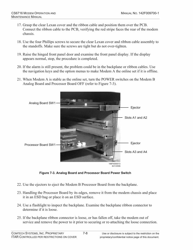
CS6716 MODEM OPERATION AND MANUAL NO. 142F009700-1 MAINTENANCE MANUAL
COMTECH SYSTEMS, INC. PROPRIETARY 7-8 Use or disclosure is subject to the restriction on the ITAR CONTROLLED PER RESTRICTIONS ON COVER proprietary/confidential notice page of this document.
17. Grasp the clear Lexan cover and the ribbon cable and position them over the PCB. Connect the ribbon cable to the PCB, verifying the red stripe faces the rear of the modem chassis.
18. Use the four Phillips screws to secure the clear Lexan cover and ribbon cable assembly to the standoffs. Make sure the screws are tight but do not over-tighten.
19. Raise the hinged front panel door and examine the front panel display. If the display appears normal, stop, the procedure is completed.
20. If the alarm is still present, the problem could be in the backplane or ribbon cables. Use the navigation keys and the option menus to make Modem A the online set if it is offline.
21. When Modem A is stable as the online set, turn the POWER switches on the Modem B Analog Board and Processor Board OFF (refer to Figure 7-3).
198F40000138/21/2006
Slots A1 and A2
EjectorAnalog Board SW1
Slots A3 and A4
EjectorProcessor Board SW1
Figure 7-3. Analog Board and Processor Board Power Switch
22. Use the ejectors to eject the Modem B Processor Board from the backplane.
23. Handling the Processor Board by its edges, remove it from the modem chassis and place it in an ESD bag or place it on an ESD surface.
24. Use a flashlight to inspect the backplane. Examine the backplane ribbon connector to determine if it is loose.
25. If the backplane ribbon connector is loose, or has fallen off, take the modem out of service and remove the power to it prior to securing or re-attaching the loose connection.
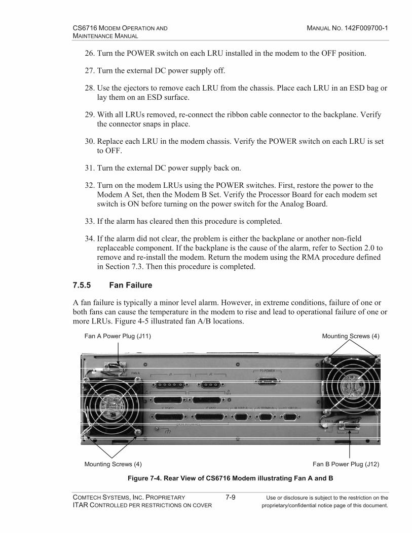
CS6716 MODEM OPERATION AND MANUAL NO. 142F009700-1 MAINTENANCE MANUAL
COMTECH SYSTEMS, INC. PROPRIETARY 7-9 Use or disclosure is subject to the restriction on the ITAR CONTROLLED PER RESTRICTIONS ON COVER proprietary/confidential notice page of this document.
26. Turn the POWER switch on each LRU installed in the modem to the OFF position.
27. Turn the external DC power supply off.
28. Use the ejectors to remove each LRU from the chassis. Place each LRU in an ESD bag or lay them on an ESD surface.
29. With all LRUs removed, re-connect the ribbon cable connector to the backplane. Verify the connector snaps in place.
30. Replace each LRU in the modem chassis. Verify the POWER switch on each LRU is set to OFF.
31. Turn the external DC power supply back on.
32. Turn on the modem LRUs using the POWER switches. First, restore the power to the Modem A Set, then the Modem B Set. Verify the Processor Board for each modem set switch is ON before turning on the power switch for the Analog Board.
33. If the alarm has cleared then this procedure is completed.
34. If the alarm did not clear, the problem is either the backplane or another non-field replaceable component. If the backplane is the cause of the alarm, refer to Section 2.0 to remove and re-install the modem. Return the modem using the RMA procedure defined in Section 7.3. Then this procedure is completed.
7.5.5 Fan Failure
A fan failure is typically a minor level alarm. However, in extreme conditions, failure of one or both fans can cause the temperature in the modem to rise and lead to operational failure of one or more LRUs. Figure 4-5 illustrated fan A/B locations.
Mounting Screws (4)
Mounting Screws (4)Fan A Power Plug (J11)
Fan B Power Plug (J12) Figure 7-4. Rear View of CS6716 Modem illustrating Fan A and B

CS6716 MODEM OPERATION AND MANUAL NO. 142F009700-1 MAINTENANCE MANUAL
COMTECH SYSTEMS, INC. PROPRIETARY 7-10 Use or disclosure is subject to the restriction on the ITAR CONTROLLED PER RESTRICTIONS ON COVER proprietary/confidential notice page of this document.
1. To replace one or both modem fans, first determine if rear panel access is available in the rack or cabinet.
2. If back panel access is not available, slide the modem out of the rack or cabinet on the slide rails to access the fans on the rear of the modem chassis.
Caution Use care when sliding the modem out on the rails to ensure the cables connected to the rear panel of the modem are not pinched, damaged or dislodged.
3. Carefully remove the faulty fan’s power plug from the rear panel.
4. Use a Phillips screwdriver to unscrew the four screws securing the fan to the rear panel. Place the screw, washers and other associated hardware in a safe location.
Note The four Phillips screws secure several individual parts to the modem rear panel. Those parts include washers, fan grill and standoffs inside the "wings" of the fan as well as the fan, itself. When removing the screws, use caution to make sure that none of those parts drop or fall where they could damage other equipment.
5. Remove the faulty fan and discard.
6. Take one screw and insert two washers, the fan grill mounting ear and an additional washer over the fan grill-mounting ear.
7. Insert the screw and hardware partially into one of the fan’s mounting wings. Slide a standoff between the fan’s wings and insert the screw fully through it.
8. Orient the fan to its rear panel power plug.
9. Insert the screw into the appropriate rear panel-mounting hole and do not tighten the screw.
10. Repeat Steps 6 to 9 for the remaining screws.
11. Tighten the four loosely attached screws into the rear panel to make the fan secure and prevent vibration. Do not over-tighten the screws.
There are no additional maintenance procedures to perform. If your modem is still in alarm status and none of the preceding maintenance procedures have succeeded in clearing the alarm, either contact Technical Support for assistance or replace the modem using the procedures in Section 2.0.

CS6716 MODEM OPERATION AND MANUAL NO. 142F009700-1 MAINTENANCE MANUAL
COMTECH SYSTEMS, INC. PROPRIETARY A-1 Use or disclosure is subject to the restriction on the ITAR CONTROLLED PER RESTRICTIONS ON COVER proprietary/confidential notice page of this document.
APPENDIX A SUMMARY OF SPECIFICATIONS

CS6716 MODEM OPERATION AND MANUAL NO. 142F009700-1 MAINTENANCE MANUAL
COMTECH SYSTEMS, INC. PROPRIETARY A-2 Use or disclosure is subject to the restriction on the ITAR CONTROLLED PER RESTRICTIONS ON COVER proprietary/confidential notice page of this document.
This Page Intentionally Left Blank

CS6716 MODEM OPERATION AND MANUAL NO. 142F009700-1 MAINTENANCE MANUAL
COMTECH SYSTEMS, INC. PROPRIETARY A-3 Use or disclosure is subject to the restriction on the ITAR CONTROLLED PER RESTRICTIONS ON COVER proprietary/confidential notice page of this document.
Table A-1. Summary of Modem Specifications
CS6716 Standard Specifications User Interface Data channel rates Refer to Table A-2 and Table A-3 Data channel interface (programmable) Single synchronous interface, EIA RS-530 / RS-422 or
HSSI (Flow control is optional) Data channel clock source DCE timing (modem is the source of data timing) Service channel rates Two each, up to 160 kbps (Flow control is optional)
Refer to Table A-2 and Table A-3 for available bandwidth Service channel interface EIA RS-530 / RS-422 Service channel clock source DCE timing (modem is the source of data timing) Integrated BERT 32 kbps (when enabled) Monitor & Control Monitor and control port EIA RS-232 Front panel Operator control and status capability Redundancy control Automatic and manual modes IF Interface IF interface 70 MHz, 50 ohm Transmit power out (TX1 and TX2) 0 dBm ±1 dB (w/o power control) Modulation QPSK Receive IF bandwidth 7 MHz (data rates 2 to 8 Mbps),
12 MHz (data rates up to 16.384 Mbps) Receive dynamic range +10 to -60 dBm Forward Error Correction Turbo Product Code Code rate : 0.95 ALPC Attenuation range 0 to 40 dB in 1 dB Steps Control modes Automatic/disabled Troposcatter Performance Multi path adaptive channel equalization Dispersion up to 3.0 /T Maximum receive carrier fade duration
without loss of sync 10 Seconds
Diversity combining Maximal-ratio General Major alarm indication LED and alphanumeric front panel display
Form 'C' contacts Station clock Requirement 10 MHz external, 1 x 10⁻⁹ accuracy Power 48 VDC (36 VDC min., 56 VDC max.), 200 watts maximum Size
Height 5.25" (3 RU) Width 19" rack mount Depth 17" including front carrying handles
Weight 25 pounds

CS6716 MODEM OPERATION AND MANUAL NO. 142F009700-1 MAINTENANCE MANUAL
COMTECH SYSTEMS, INC. PROPRIETARY A-4 Use or disclosure is subject to the restriction on the ITAR CONTROLLED PER RESTRICTIONS ON COVER proprietary/confidential notice page of this document.
Table A-2. Aggregate Data Frame Options (Programmable)
Data Channel Rate with TPC Disabled (kbps)
Maximum Combined SC1 & SC2 & BERT
Bandwidth Total Aggregate
Rate (Kbps) 2048 80 2276 4096 80 4584 8192 80 8804 10240 80 10852 12288 80 12900 16384 160 17608
Table A-3. Aggregate Data Frame Options with TPC (Programmable)
Data Channel Rate with TPC (Kbps)
Maximum Combined SC1 & SC2 & BERT
Bandwidth Total Aggregate
Rate (Kbps) 1856 80 2276 3776 80 4584 7808 80 8804 9824 80 10852 11840 80 12900 15616 160 17608

CS6716 MODEM OPERATION AND MANUAL NO. 142F009700-1 MAINTENANCE MANUAL
COMTECH SYSTEMS, INC. PROPRIETARY B-1 Use or disclosure is subject to the restriction on the ITAR CONTROLLED PER RESTRICTIONS ON COVER proprietary/confidential notice page of this document.
APPENDIX B LOWEST REPLACEABLE UNITS (LRU)

CS6716 MODEM OPERATION AND MANUAL NO. 142F009700-1 MAINTENANCE MANUAL
COMTECH SYSTEMS, INC. PROPRIETARY B-2 Use or disclosure is subject to the restriction on the ITAR CONTROLLED PER RESTRICTIONS ON COVER proprietary/confidential notice page of this document.
This Page Intentionally Left Blank
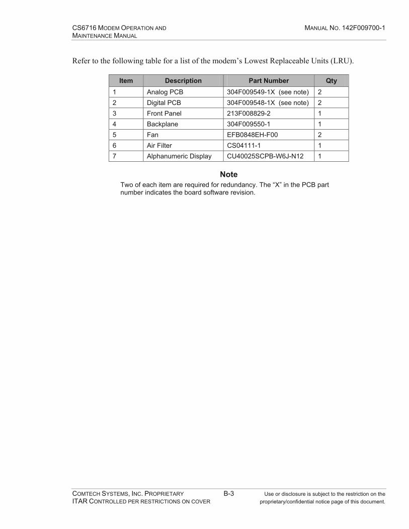
CS6716 MODEM OPERATION AND MANUAL NO. 142F009700-1 MAINTENANCE MANUAL
COMTECH SYSTEMS, INC. PROPRIETARY B-3 Use or disclosure is subject to the restriction on the ITAR CONTROLLED PER RESTRICTIONS ON COVER proprietary/confidential notice page of this document.
Refer to the following table for a list of the modem’s Lowest Replaceable Units (LRU).
Item Description Part Number Qty 1 Analog PCB 304F009549-1X (see note) 2 2 Digital PCB 304F009548-1X (see note) 2 3 Front Panel 213F008829-2 1 4 Backplane 304F009550-1 1 5 Fan EFB0848EH-F00 2 6 Air Filter CS04111-1 1 7 Alphanumeric Display CU40025SCPB-W6J-N12 1
Note Two of each item are required for redundancy. The “X” in the PCB part number indicates the board software revision.

CS6716 MODEM OPERATION AND MANUAL NO. 142F009700-1 MAINTENANCE MANUAL
COMTECH SYSTEMS, INC. PROPRIETARY B-4 Use or disclosure is subject to the restriction on the ITAR CONTROLLED PER RESTRICTIONS ON COVER proprietary/confidential notice page of this document.
This Page Intentionally Left Blank

CS6716 MODEM OPERATION AND MANUAL NO. 142F009700-1 MAINTENANCE MANUAL
COMTECH SYSTEMS, INC. PROPRIETARY C-1 Use or disclosure is subject to the restriction on the ITAR CONTROLLED PER RESTRICTIONS ON COVER proprietary/confidential notice page of this document.
APPENDIX C FRONT PANEL MENU TREE

CS6716 MODEM OPERATION AND MANUAL NO. 142F009700-1 MAINTENANCE MANUAL
COMTECH SYSTEMS, INC. PROPRIETARY C-2 Use or disclosure is subject to the restriction on the ITAR CONTROLLED PER RESTRICTIONS ON COVER proprietary/confidential notice page of this document.
This Page Intentionally Left Blank

CS6716 MODEM OPERATION AND MANUAL NO. 142F009700-1 MAINTENANCE MANUAL
COMTECH SYSTEMS, INC. PROPRIETARY C-3 Use or disclosure is subject to the restriction on the ITAR CONTROLLED PER RESTRICTIONS ON COVER proprietary/confidential notice page of this document.
MAINMONITOR
SUMMARY
MONITOR SUMMARY: LOCAL REMOTE
LOCAL
LS RX1 RX2 RX3 RX4 TX1 TX2 BER-40 -40 -40 -40 000 000 0E-9
REMOTE
RS RX1 RX2 RX3 RX4 TX1 TX2 BER-40 -40 -40 -40 000 000 0E-9
ALARMS
MODEM A
ALARMS MODEM A: CURRENT HISTORICAL
MODEM A: HISTORICAL ALARMS: VIEW CLEAR
VIEW
CLEAR
MODEM A CURRENT ALARMS: VIEW CLEAR
See Section 6.4.1.2
VIEW
CLEAR
See Section 6.4.1.2
MODEM B
ALARMS MODEM B: CURRENT HISTORICAL
MODEM B CURRENT ALARMS: VIEW CLEAR
MODEM B: HISTORICAL ALARMS: VIEW CLEAR
VIEW
CLEAR
See Section 6.4.1.2
VIEW
CLEAR
See Section 6.4.1.2
RSLLOCAL/REMOTE RSL 1, 2, 3, 4 (dBm)-047 -047 -046 -047 / -047 -046 -046 -047
TEMP
TEMPERATURE: 030C 086F
AGC
LOCAL AGC: RX1 RX2 RX3 RX4053 054 055 049

CS6716 MODEM OPERATION AND MANUAL NO. 142F009700-1 MAINTENANCE MANUAL
COMTECH SYSTEMS, INC. PROPRIETARY C-4 Use or disclosure is subject to the restriction on the ITAR CONTROLLED PER RESTRICTIONS ON COVER proprietary/confidential notice page of this document.
MAINMONITOR (cont.)
TXAPC
BERT
FAN
LOCAL TX1 TX2 REMOTE TX1 TX2 (dB)- 00 -00 -00 -00
VIEW LOCAL
VIEW REMOTE
RESET LOCAL
RESET REMOTE
FAN SPEED: FAN1 FAN2(RPM) 4260 4230
LCL BERT: AVE BER ERRORS/PERIODS FEC BER0.00E-04 000005/ 3:28:40 0.00E-99
REM BERT: AVE BER ERRORS/PERIODS FEC BER0.00E-04 000005/ 3:28:40 0.00E-99
CONFIG
ON/OFFLINE
MODEM STATE: = OFF LINE
RATES
MODEM STATE: = ON LINE
DATA
SVCH 1
CONFIG DATA CH RATE
CONFIG SVCH1 RATE
2Mb/s4Mb/s8Mb/s10Mb/s12Mb/s16Mb/s
081624324048566480

CS6716 MODEM OPERATION AND MANUAL NO. 142F009700-1 MAINTENANCE MANUAL
COMTECH SYSTEMS, INC. PROPRIETARY C-5 Use or disclosure is subject to the restriction on the ITAR CONTROLLED PER RESTRICTIONS ON COVER proprietary/confidential notice page of this document.
MAINCONFIG (cont.)
RATES
SVCH 2
CONFIG SVCH2 RATE081624324048566480
(cont.)
DATA CH
DATA INTRF TYPE = RS422
TYPE
DATA INTRF TYPE = HSSI
INTERFACE
FEC
ON
OFF
BERT
DEFAULT
ALPC
OFF
AUTOMATIC
ON
OFF
INFO
Displays current modem configuration parameters. Press ENT to scroll.

CS6716 MODEM OPERATION AND MANUAL NO. 142F009700-1 MAINTENANCE MANUAL
COMTECH SYSTEMS, INC. PROPRIETARY C-6 Use or disclosure is subject to the restriction on the ITAR CONTROLLED PER RESTRICTIONS ON COVER proprietary/confidential notice page of this document.
MAINSWITCH
AUTOMATIC
SWITCH TO MODEM B/A
MANUAL MODE
CALIBRATION
TX CAL := TX1TX CAL := TX2
AGC
TX OUT LEVEL
MAINT
VERSIONS
F.W. VER. 1.02 – AUG 23 2006 10:41:45RTOS VER. 276
SETUP
RXGAIN
RXGAIN: RX1 RX2 RX3 RX4040 040 040 040
CHANNEL #1CHANNEL #2CHANNEL #3CHANNEL #4ALL CHANNELS
DIV 1 DIV 2 DIV 3 DIV 4ON ON ON ON
DIVERSITY
MISC
BRIGHT
BRIGHTNESS = 100%BRIGHTNESS = 75%BRIGHTNESS = 50%BRIGHTNESS = 25%
BAUD1152005760038400192009600480024001200600

CS6716 MODEM OPERATION AND MANUAL NO. 142F009700-1 MAINTENANCE MANUAL
COMTECH SYSTEMS, INC. PROPRIETARY C-7 Use or disclosure is subject to the restriction on the ITAR CONTROLLED PER RESTRICTIONS ON COVER proprietary/confidential notice page of this document.
MAINSETUP (cont.)
ENTER GATEWAY ADDRESS: 000.000.000.000
MISC (cont.)
TIMEENTER TIME (HH:MM): 00:00
DATEENTER DATE (MM/DD/YY): 00/00/00
NETWORK
NETMASK
IP
ENTER IP ADDRESS: 000.000.000.000
ENTER MAC: 00:00:00:00:00:00
MAC
ENTER NETMASK: 000.000.000.000
GATEWAY
ENTER DNS ADDRESS: 000.000.000.000
DNS
LOOPBACK
F.P. LED TEST
F.P. DISPLAY TEST
DIAG
LEFT/RIGHT KEYS SELECT LED, CLR=EXIT
LEFT/RIGHT KEYS SELECT, CLR=EXIT
NORMALCHANNEL 1SERVICE CHANNEL 1SERVICE CHANNEL 2AGGREGATE BASEBANDLOCAL IF
FLOWCTL
RTS LOOPBACK
RTS LOOPBACK: DATA CH SVCH1 SVCH2OFF OFF OFF
CTS INVERSION:
CTS INVERSION: DATA CH SVCH1 SVCH2OFF OFF OFF
CLKINV
CLOCK INVERSION: DATA CH SVCH1 SVCH2OFF OFF OFF
QUADAN/TRC-170 V2AN/TRC-170 V3/V5DUAL
DIVMODE

CS6716 MODEM OPERATION AND MANUAL NO. 142F009700-1 MAINTENANCE MANUAL
COMTECH SYSTEMS, INC. PROPRIETARY C-8 Use or disclosure is subject to the restriction on the ITAR CONTROLLED PER RESTRICTIONS ON COVER proprietary/confidential notice page of this document.
This Page Intentionally Left Blank

CS6716 MODEM OPERATION AND MANUAL NO. 142F009700-1 MAINTENANCE MANUAL
COMTECH SYSTEMS, INC. PROPRIETARY D-1 Use or disclosure is subject to the restriction on the ITAR CONTROLLED PER RESTRICTIONS ON COVER proprietary/confidential notice page of this document.
APPENDIX D COMMAND LINE INTERFACE
(FOR ASCII TERMINAL)

CS6716 MODEM OPERATION AND MANUAL NO. 142F009700-1 MAINTENANCE MANUAL
COMTECH SYSTEMS, INC. PROPRIETARY D-2 Use or disclosure is subject to the restriction on the ITAR CONTROLLED PER RESTRICTIONS ON COVER proprietary/confidential notice page of this document.
This Page Intentionally Left Blank
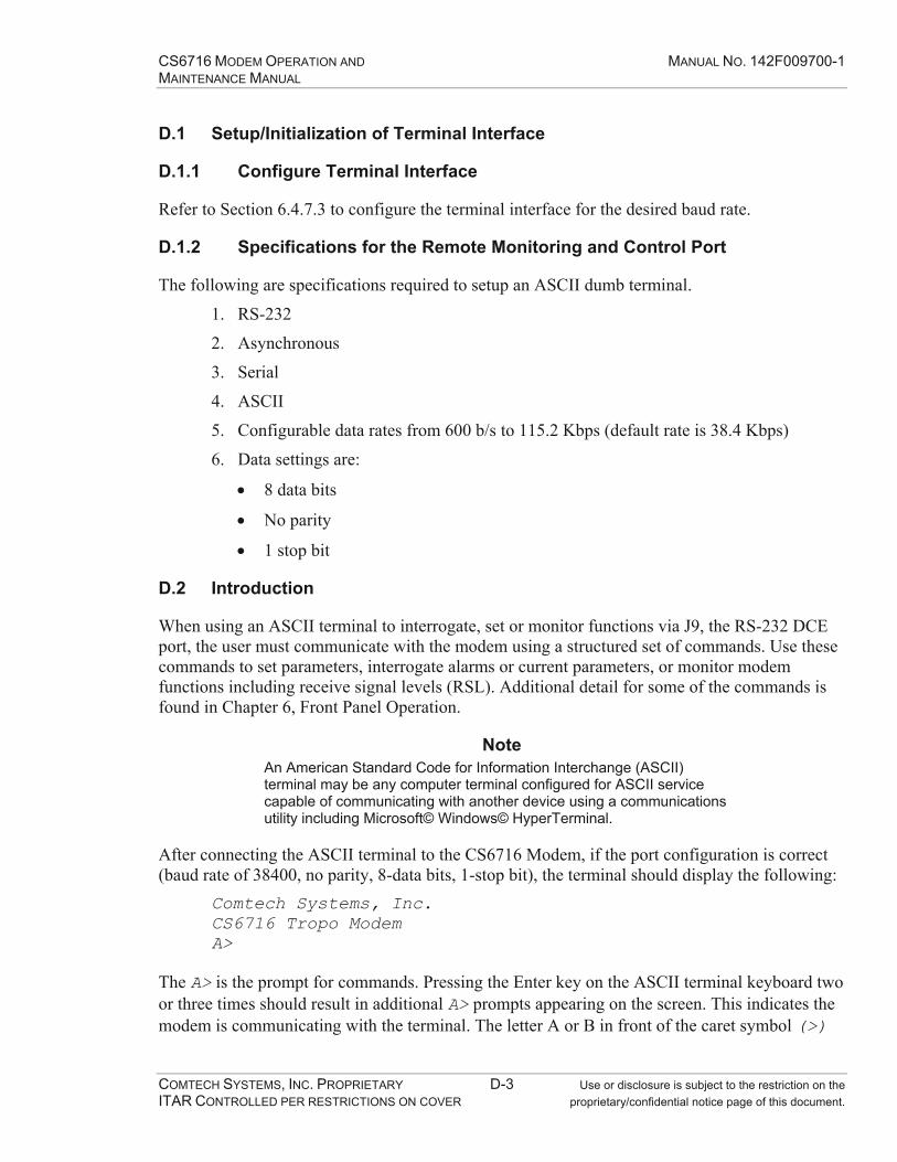
CS6716 MODEM OPERATION AND MANUAL NO. 142F009700-1 MAINTENANCE MANUAL
COMTECH SYSTEMS, INC. PROPRIETARY D-3 Use or disclosure is subject to the restriction on the ITAR CONTROLLED PER RESTRICTIONS ON COVER proprietary/confidential notice page of this document.
D.1 Setup/Initialization of Terminal Interface
D.1.1 Configure Terminal Interface
Refer to Section 6.4.7.3 to configure the terminal interface for the desired baud rate.
D.1.2 Specifications for the Remote Monitoring and Control Port
The following are specifications required to setup an ASCII dumb terminal.
1. RS-232
2. Asynchronous
3. Serial
4. ASCII
5. Configurable data rates from 600 b/s to 115.2 Kbps (default rate is 38.4 Kbps)
6. Data settings are:
8 data bits
No parity
1 stop bit
D.2 Introduction
When using an ASCII terminal to interrogate, set or monitor functions via J9, the RS-232 DCE port, the user must communicate with the modem using a structured set of commands. Use these commands to set parameters, interrogate alarms or current parameters, or monitor modem functions including receive signal levels (RSL). Additional detail for some of the commands is found in Chapter 6, Front Panel Operation.
Note An American Standard Code for Information Interchange (ASCII) terminal may be any computer terminal configured for ASCII service capable of communicating with another device using a communications utility including Microsoft© Windows© HyperTerminal.
After connecting the ASCII terminal to the CS6716 Modem, if the port configuration is correct (baud rate of 38400, no parity, 8-data bits, 1-stop bit), the terminal should display the following:
Comtech Systems, Inc. CS6716 Tropo Modem A>
The A> is the prompt for commands. Pressing the Enter key on the ASCII terminal keyboard two or three times should result in additional A> prompts appearing on the screen. This indicates the modem is communicating with the terminal. The letter A or B in front of the caret symbol (>)

CS6716 MODEM OPERATION AND MANUAL NO. 142F009700-1 MAINTENANCE MANUAL
COMTECH SYSTEMS, INC. PROPRIETARY D-4 Use or disclosure is subject to the restriction on the ITAR CONTROLLED PER RESTRICTIONS ON COVER proprietary/confidential notice page of this document.
identifies the active modem card set. The letter A indicates Modem A is active. The letter B indicates Modem B is active.
To perform operations with the ASCII terminal, enter one of the following commands at the A> prompt and press the Enter key to execute the command. At any time, the operator may enter HELP for a list of the commands currently available.
Note To execute each command press the Enter key after typing it into the modem.
To enter the command line function, the operator must login to the system. The default login for the operator is:
A>login operator operator
When the username is operator (lower case) the password is operator. The term Login tells the system the operator is logging in to the command line function. If the operator does not login, he/she will not be able to perform any command line functions. Attempting to perform command line functions without logging in to the modem will result in the following message display:
Not Logged In! Please log in using LOGIN command as follows: LOGIN username password
Note There are additional logon levels that give access to command features that are not described in this manual. For more information, contact the system administrator.
After logging in to the modem, whenever the operator needs help with available commands at the operator level, type the following command:
A>help
The system will display the list of commands available for use at the operator logged in level. For assistance using any command, type the command at the prompt. The system will respond with the correct usage.
An asterisk (*) will appear next to the current setting. To change a setting, select a different option. If a command option does not have an asterisk then it does not have a current setting, for the selection.
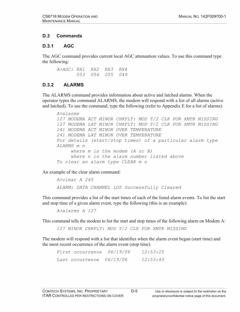
CS6716 MODEM OPERATION AND MANUAL NO. 142F009700-1 MAINTENANCE MANUAL
COMTECH SYSTEMS, INC. PROPRIETARY D-5 Use or disclosure is subject to the restriction on the ITAR CONTROLLED PER RESTRICTIONS ON COVER proprietary/confidential notice page of this document.
D.3 Commands
D.3.1 AGC
The AGC command provides current local AGC attenuation values. To use this command type the following:
A>AGC: RX1 RX2 RX3 RX4 053 054 055 049
D.3.2 ALARMS
The ALARMS command provides information about active and latched alarms. When the operator types the command ALARMS, the modem will respond with a list of all alarms (active and latched). To use the command, type the following (refer to Appendix E for a list of alarms):
A>alarms127 MODEMA ACT MINOR CHKFLT: MOD T/2 CLK FOR XMTR MISSING 127 MODEMA LAT MINOR CHKFLT: MOD T/2 CLK FOR XMTR MISSING 241 MODEMA ACT MINOR OVER TEMPERATURE 241 MODEMA LAT MINOR OVER TEMPERATURE For details (start/stop times) of a particular alarm type ALARMS m n where m is the modem (A or B) where n is the alarm number listed above To clear an alarm type CLEAR m n
An example of the clear alarm command: A>clear A 245
ALARM: DATA CHANNEL LOS Successfully Cleared
This command provides a list of the start times of each of the listed alarm events. To list the start and stop time of a given alarm event, type the following (this is an example):
A>alarms A 127
This command tells the modem to list the start and stop times of the following alarm on Modem A: 127 MINOR CHKFLT: MOD T/2 CLK FOR XMTR MISSING
The modem will respond with a list that identifies when the alarm event began (start time) and the most recent occurrence of the alarm event (stop time).
First occurrence 06/19/06 12:53:25
Last occurrence 06/19/06 12:53:43
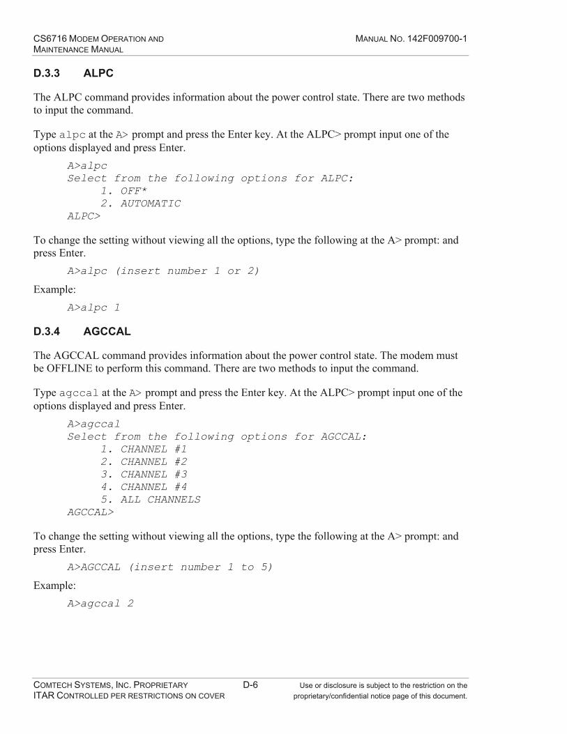
CS6716 MODEM OPERATION AND MANUAL NO. 142F009700-1 MAINTENANCE MANUAL
COMTECH SYSTEMS, INC. PROPRIETARY D-6 Use or disclosure is subject to the restriction on the ITAR CONTROLLED PER RESTRICTIONS ON COVER proprietary/confidential notice page of this document.
D.3.3 ALPC
The ALPC command provides information about the power control state. There are two methods to input the command.
Type alpc at the A> prompt and press the Enter key. At the ALPC> prompt input one of the options displayed and press Enter.
A>alpcSelect from the following options for ALPC:
1. OFF* 2. AUTOMATIC
ALPC>
To change the setting without viewing all the options, type the following at the A> prompt: and press Enter.
A>alpc (insert number 1 or 2)
Example: A>alpc 1
D.3.4 AGCCAL
The AGCCAL command provides information about the power control state. The modem must be OFFLINE to perform this command. There are two methods to input the command.
Type agccal at the A> prompt and press the Enter key. At the ALPC> prompt input one of the options displayed and press Enter.
A>agccalSelect from the following options for AGCCAL:
1. CHANNEL #12. CHANNEL #23. CHANNEL #34. CHANNEL #45. ALL CHANNELS
AGCCAL>
To change the setting without viewing all the options, type the following at the A> prompt: and press Enter.
A>AGCCAL (insert number 1 to 5)
Example: A>agccal 2
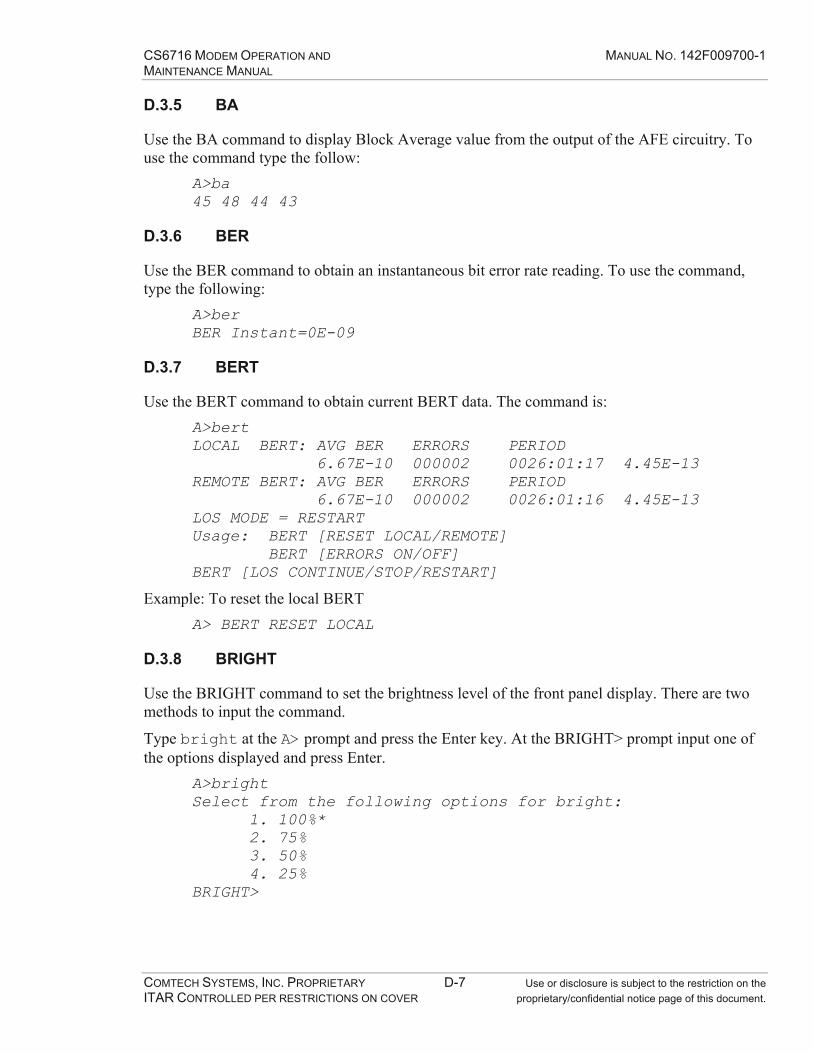
CS6716 MODEM OPERATION AND MANUAL NO. 142F009700-1 MAINTENANCE MANUAL
COMTECH SYSTEMS, INC. PROPRIETARY D-7 Use or disclosure is subject to the restriction on the ITAR CONTROLLED PER RESTRICTIONS ON COVER proprietary/confidential notice page of this document.
D.3.5 BA
Use the BA command to display Block Average value from the output of the AFE circuitry. To use the command type the follow:
A>ba45 48 44 43
D.3.6 BER
Use the BER command to obtain an instantaneous bit error rate reading. To use the command, type the following:
A>berBER Instant=0E-09
D.3.7 BERT
Use the BERT command to obtain current BERT data. The command is: A>bertLOCAL BERT: AVG BER ERRORS PERIOD 6.67E-10 000002 0026:01:17 4.45E-13 REMOTE BERT: AVG BER ERRORS PERIOD 6.67E-10 000002 0026:01:16 4.45E-13 LOS MODE = RESTART Usage: BERT [RESET LOCAL/REMOTE] BERT [ERRORS ON/OFF] BERT [LOS CONTINUE/STOP/RESTART]
Example: To reset the local BERT A> BERT RESET LOCAL
D.3.8 BRIGHT
Use the BRIGHT command to set the brightness level of the front panel display. There are two methods to input the command.
Type bright at the A> prompt and press the Enter key. At the BRIGHT> prompt input one of the options displayed and press Enter.
A>brightSelect from the following options for bright: 1. 100%* 2. 75% 3. 50% 4. 25% BRIGHT>
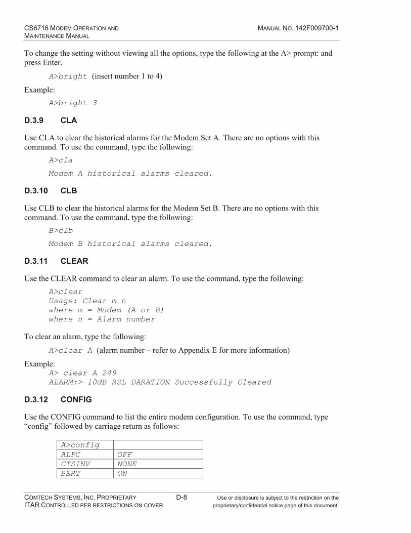
CS6716 MODEM OPERATION AND MANUAL NO. 142F009700-1 MAINTENANCE MANUAL
COMTECH SYSTEMS, INC. PROPRIETARY D-8 Use or disclosure is subject to the restriction on the ITAR CONTROLLED PER RESTRICTIONS ON COVER proprietary/confidential notice page of this document.
To change the setting without viewing all the options, type the following at the A> prompt: and press Enter.
A>bright (insert number 1 to 4)
Example: A>bright 3
D.3.9 CLA
Use CLA to clear the historical alarms for the Modem Set A. There are no options with this command. To use the command, type the following:
A>cla
Modem A historical alarms cleared.
D.3.10 CLB
Use CLB to clear the historical alarms for the Modem Set B. There are no options with this command. To use the command, type the following:
B>clb
Modem B historical alarms cleared.
D.3.11 CLEAR
Use the CLEAR command to clear an alarm. To use the command, type the following: A>clearUsage: Clear m n where m = Modem (A or B) where n = Alarm number
To clear an alarm, type the following:
A>clear A (alarm number – refer to Appendix E for more information)
Example: A> clear A 249 ALARM:> 10dB RSL DARATION Successfully Cleared
D.3.12 CONFIG
Use the CONFIG command to list the entire modem configuration. To use the command, type “config” followed by carriage return as follows:
A>configALPC OFF CTSINV NONE BERT ON

CS6716 MODEM OPERATION AND MANUAL NO. 142F009700-1 MAINTENANCE MANUAL
COMTECH SYSTEMS, INC. PROPRIETARY D-9 Use or disclosure is subject to the restriction on the ITAR CONTROLLED PER RESTRICTIONS ON COVER proprietary/confidential notice page of this document.
BRIGHT 100% DBAUD 9600 DIV1 ON DIV2 ON DIV3 ON DIV4 ON DNS 0.0.0.0 FEC ON G1 40 G2 40 G3 40 G4 40 GW 0.0.0.0 HPA RS-232 INTERVAL 300 IP 192.168.2.13 IT RS422 LOOPBACK NORMAL MAC 00:50:C2:44:80:17MBAUD 38400 MASK 255.255.255.0 TX1 OFF TX2 OFF RATE 16mb/s REACQ 240 RTSLOOP NORMAL SC1RATE 24 SC2RATE 24 SCRAMBLER ON STATE ONLINE SWITCH AUTO MODE VERBOSE OFF
Note The parameter will vary from modem to modem depending on the settings.
D.3.13 CTSINV
Note This command is only viewable at the operator level.
Use the CTSINV command for CTS inversion control. To use the command, type the following: A> CTSINV:

CS6716 MODEM OPERATION AND MANUAL NO. 142F009700-1 MAINTENANCE MANUAL
COMTECH SYSTEMS, INC. PROPRIETARY D-10 Use or disclosure is subject to the restriction on the ITAR CONTROLLED PER RESTRICTIONS ON COVER proprietary/confidential notice page of this document.
D.3.14 DATE
Use the DATE command to verify or change the current system date set in the modem. To display the current setting, type the following command:
A>dateThe current date is mm/dd/yyyy
The date uses this format:
mm are the two numbers for the month (example, 01 is January)
dd is the day of the month (examples, 09, 14, 25)
yyyy is the year (examples, 2005, 2007)
To change the system date, type the following: A>date mm/dd/yyyy
D.3.15 DEFAULT
See SCONFIG command.
D.3.16 DIVERSITY
Use the DIVERSITY command to sets the mode of operation for Automatic Link Power Control. A>diveristySelect from the following options for DIVERSITY:
1. QUAD* 2. DUAL – 2 RECEIVER 3. DUAL – 4 RECEIVER
DIVERSITY >
D.3.17 DIV1
Use DIV1 command to view the operating mode of diversity #1. Refer to the DIVERSITY command for setting diversity modes.
D.3.18 DIV2
Use DIV2 command to view the operating mode of diversity #2. Refer to the DIVERSITY command for setting diversity modes.
D.3.19 DIV3
Use DIV3 command to view the operating mode of diversity #3. Refer to the DIVERSITY command for setting diversity modes.

CS6716 MODEM OPERATION AND MANUAL NO. 142F009700-1 MAINTENANCE MANUAL
COMTECH SYSTEMS, INC. PROPRIETARY D-11 Use or disclosure is subject to the restriction on the ITAR CONTROLLED PER RESTRICTIONS ON COVER proprietary/confidential notice page of this document.
D.3.20 DIV4
Use DIV4 command to view the operating mode of diversity #4. Refer to the DIVERSITY command for setting diversity modes.
D.3.21 DNS
Use the DNS command to verify or change the system name server address. To display the current DNS setting, type the following command:
A>DNSDNS Address is 0.0.0.0
To change the DNS value, type the following: A>DNS x.x.x.x (where x.x.x.x is the value assigned)
D.3.22 FACTORY RESTORE
Use the RESTORE FACTORY command to restore the modem to the factory configuration. The modem must be OFFLINE to perform this command. There are no options in this command. To use the command, type the following:
A>factory restore
Note Use caution when executing this command. All modem settings will be affected.
D.3.23 FEATURE
Use the command FEATURE to enable/disable features for the modem. A key number generated by the factory needs to be entered after the FEATURE command. To use the command, type the following after receiving the key code from the factory:
A>feature xxxxyyyyzzzz 16Mbps data rate is enabled.
Depending on the feature(s) the customer purchases, the key could vary.
D.3.24 FEC
Use the FEC command to turn on/off the FEC function. The modem must be OFFLINE to perform this command. There are two methods to input the command.
Type fec at the A> prompt and press the Enter key. At the FEC> prompt input one of the options displayed and press Enter.
A>fecSelect from the following options for FEC: 1. ON* 2. OFF

CS6716 MODEM OPERATION AND MANUAL NO. 142F009700-1 MAINTENANCE MANUAL
COMTECH SYSTEMS, INC. PROPRIETARY D-12 Use or disclosure is subject to the restriction on the ITAR CONTROLLED PER RESTRICTIONS ON COVER proprietary/confidential notice page of this document.
FEC>
To change the setting without viewing all the options, type the following at the A> prompt: and press Enter.
A>FEC (insert number 1 or 2)
Example: A> fec 1
D.3.25 G1
Note This command is only viewable at the operator level.
Use the G1 command to view the Receiver 1 gain. A>G1Receiver #1 gain is XX
D.3.26 G2
Note This command is only viewable at the operator level.
Use the G2 command to view the Receiver 2 gain. A>G2Receiver #2 gain is XX
D.3.27 G3
Note This command is only viewable at the operator level.
Use the G3 command to view the Receiver 3 gain. A>G3Receiver #3 gain is XX
D.3.28 G4
Note This command is only viewable at the operator level.
Use the G4 command to view the Receiver 4 gain. A>G4Receiver #4 gain is XX
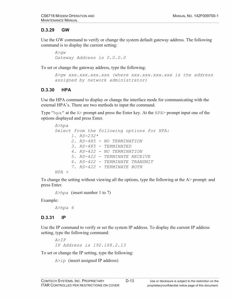
CS6716 MODEM OPERATION AND MANUAL NO. 142F009700-1 MAINTENANCE MANUAL
COMTECH SYSTEMS, INC. PROPRIETARY D-13 Use or disclosure is subject to the restriction on the ITAR CONTROLLED PER RESTRICTIONS ON COVER proprietary/confidential notice page of this document.
D.3.29 GW
Use the GW command to verify or change the system default gateway address. The following command is to display the current setting:
A>gwGateway Address is 0.0.0.0
To set or change the gateway address, type the following: A>gw xxx.xxx.xxx.xxx (where xxx.xxx.xxx.xxx is the address assigned by network administrator)
D.3.30 HPA
Use the HPA command to display or change the interface mode for communicating with the external HPA’s. There are two methods to input the command.
Type “hpa” at the A> prompt and press the Enter key. At the HPA> prompt input one of the options displayed and press Enter.
A>hpaSelect from the following options for HPA: 1. RS-232* 2. RS-485 - NO TERMINATION 3. RS-485 - TERMINATED 4. RS-422 - NO TERMINATION 5. RS-422 - TERMINATE RECEIVE 6. RS-422 - TERMINATE TRANSMIT 7. RS-422 - TERMINATE BOTH HPA >
To change the setting without viewing all the options, type the following at the A> prompt: and press Enter.
A>hpa (insert number 1 to 7)
Example: A>hpa 6
D.3.31 IP
Use the IP command to verify or set the system IP address. To display the current IP address setting, type the following command:
A>IPIP Address is 192.168.2.13
To set or change the IP setting, type the following:
A>ip (insert assigned IP address)

CS6716 MODEM OPERATION AND MANUAL NO. 142F009700-1 MAINTENANCE MANUAL
COMTECH SYSTEMS, INC. PROPRIETARY D-14 Use or disclosure is subject to the restriction on the ITAR CONTROLLED PER RESTRICTIONS ON COVER proprietary/confidential notice page of this document.
D.3.32 IT
Use the IT command to set or change the system data interface type. The modem must be OFFLINE to perform this command. There are two methods to input the command.
Type it at the A> prompt and press the Enter key. At the IT> prompt input one of the options displayed and press Enter.
A>ITSelect from the following options for IT: 1. RS422* 2. HSSI IT >
To change the setting without viewing all the options, type the following at the A> prompt: and press Enter.
A>it (insert number 1 or 2)
Example: A>it 1
D.3.33 LOGIN Use the LOGIN command to log a user into the modem and establish a set of permissions that control functions at each of the three available user levels. To use the command, type the following:
A>login username password
Depending on the level of the account the user has, the username and password may vary. To perform commands on the modem you must log in.
Note The LOGIN command performs a direct action. DO NOT USE this command, unless you are prepared to perform the associated action.
D.3.34 LOGOFF Use the LOGOFF command to end a user’s session with the modem and prevent unauthorized access to the modem. Use the LOGOFF command when the session is completed. To use the command, type the following:
A>logoffLog Off Successful
Note The LOGOFF command performs a direct action. DO NOT USE this command, unless you are prepared to perform the associated action.
D.3.35 LOOPBACK Use the LOOPBACK command to set or change the loopback settings. There are two methods to input the command.

CS6716 MODEM OPERATION AND MANUAL NO. 142F009700-1 MAINTENANCE MANUAL
COMTECH SYSTEMS, INC. PROPRIETARY D-15 Use or disclosure is subject to the restriction on the ITAR CONTROLLED PER RESTRICTIONS ON COVER proprietary/confidential notice page of this document.
Type loopback at the A> prompt and press the Enter key. At the LOOPBACK> prompt input one of the options displayed and press Enter.
A>loopbackSelect from the following options for LOOPBACK: 1. NORMAL* 2. CHANNEL 1 3. SERVICE CHANNEL 1 4. SERVICE CHANNEL 2 5. AGGREGATE BASEBAND 6. LOCAL IF LOOPBACK >
To change the setting without viewing all the options, type the following at the A> prompt: and press Enter.
A>loopback (insert number 1 to 6)
Example: Loopback 3
D.3.36 MBAUD
Use the MBAUD command to display or change the M&C baud rate. There are two methods to input the command.
Type mbaud at the A> prompt and press the Enter key. At the MBAUD> prompt input one of the options displayed and press Enter.
A>mbaudSelect from the following options for MBAUD: 1. 115200 2. 57600 3. 38400* 4. 19200 5. 9600 6. 4800 7. 2400 8. 1200 9. 600 MBAUD >
To change the setting without viewing all the options, type the following at the A> prompt: and press Enter.
A>mbaud (insert number 1 to 9)
Example: A>mbaud 8
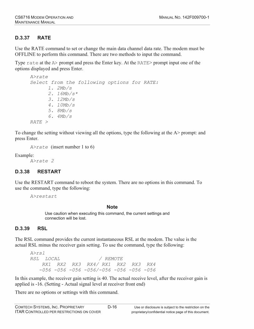
CS6716 MODEM OPERATION AND MANUAL NO. 142F009700-1 MAINTENANCE MANUAL
COMTECH SYSTEMS, INC. PROPRIETARY D-16 Use or disclosure is subject to the restriction on the ITAR CONTROLLED PER RESTRICTIONS ON COVER proprietary/confidential notice page of this document.
D.3.37 RATE
Use the RATE command to set or change the main data channel data rate. The modem must be OFFLINE to perform this command. There are two methods to input the command.
Type rate at the A> prompt and press the Enter key. At the RATE> prompt input one of the options displayed and press Enter.
A>rateSelect from the following options for RATE: 1. 2Mb/s 2. 16Mb/s* 3. 12Mb/s 4. 10Mb/s 5. 8Mb/s 6. 4Mb/s RATE >
To change the setting without viewing all the options, type the following at the A> prompt: and press Enter.
A>rate (insert number 1 to 6)
Example: A>rate 2
D.3.38 RESTART
Use the RESTART command to reboot the system. There are no options in this command. To use the command, type the following:
A>restart
Note Use caution when executing this command, the current settings and connection will be lost.
D.3.39 RSL
The RSL command provides the current instantaneous RSL at the modem. The value is the actual RSL minus the receiver gain setting. To use the command, type the following:
A>rslRSL LOCAL / REMOTE RX1 RX2 RX3 RX4/ RX1 RX2 RX3 RX4 -056 -056 -056 -056/-056 -056 -056 -056
In this example, the receiver gain setting is 40. The actual receive level, after the receiver gain is applied is -16. (Setting - Actual signal level at receiver front end)
There are no options or settings with this command.
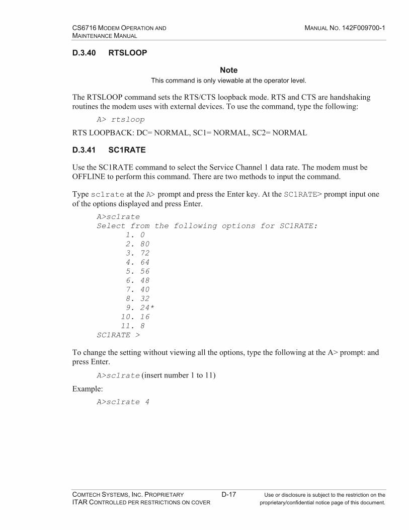
CS6716 MODEM OPERATION AND MANUAL NO. 142F009700-1 MAINTENANCE MANUAL
COMTECH SYSTEMS, INC. PROPRIETARY D-17 Use or disclosure is subject to the restriction on the ITAR CONTROLLED PER RESTRICTIONS ON COVER proprietary/confidential notice page of this document.
D.3.40 RTSLOOP
Note This command is only viewable at the operator level.
The RTSLOOP command sets the RTS/CTS loopback mode. RTS and CTS are handshaking routines the modem uses with external devices. To use the command, type the following:
A> rtsloop
RTS LOOPBACK: DC= NORMAL, SC1= NORMAL, SC2= NORMAL
D.3.41 SC1RATE
Use the SC1RATE command to select the Service Channel 1 data rate. The modem must be OFFLINE to perform this command. There are two methods to input the command.
Type sc1rate at the A> prompt and press the Enter key. At the SC1RATE> prompt input one of the options displayed and press Enter.
A>sc1rateSelect from the following options for SC1RATE: 1. 0 2. 80 3. 72 4. 64 5. 56 6. 48 7. 40 8. 32 9. 24* 10. 16 11. 8 SC1RATE >
To change the setting without viewing all the options, type the following at the A> prompt: and press Enter.
A>sc1rate (insert number 1 to 11)
Example: A>sc1rate 4
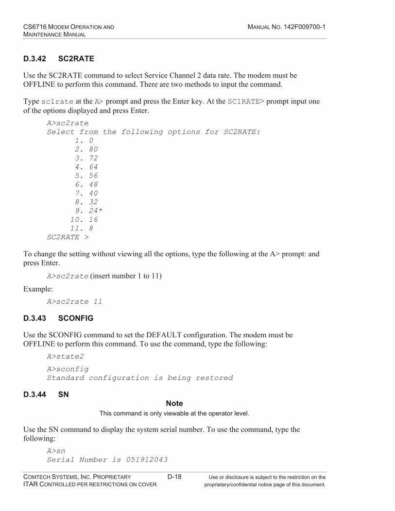
CS6716 MODEM OPERATION AND MANUAL NO. 142F009700-1 MAINTENANCE MANUAL
COMTECH SYSTEMS, INC. PROPRIETARY D-18 Use or disclosure is subject to the restriction on the ITAR CONTROLLED PER RESTRICTIONS ON COVER proprietary/confidential notice page of this document.
D.3.42 SC2RATE
Use the SC2RATE command to select Service Channel 2 data rate. The modem must be OFFLINE to perform this command. There are two methods to input the command.
Type sc1rate at the A> prompt and press the Enter key. At the SC1RATE> prompt input one of the options displayed and press Enter.
A>sc2rateSelect from the following options for SC2RATE: 1. 0 2. 80 3. 72 4. 64 5. 56 6. 48 7. 40 8. 32 9. 24* 10. 16 11. 8 SC2RATE >
To change the setting without viewing all the options, type the following at the A> prompt: and press Enter.
A>sc2rate (insert number 1 to 11)
Example: A>sc2rate 11
D.3.43 SCONFIG
Use the SCONFIG command to set the DEFAULT configuration. The modem must be OFFLINE to perform this command. To use the command, type the following:
A>state2
A>sconfigStandard configuration is being restored
D.3.44 SN Note
This command is only viewable at the operator level.
Use the SN command to display the system serial number. To use the command, type the following:
A>snSerial Number is 051912043
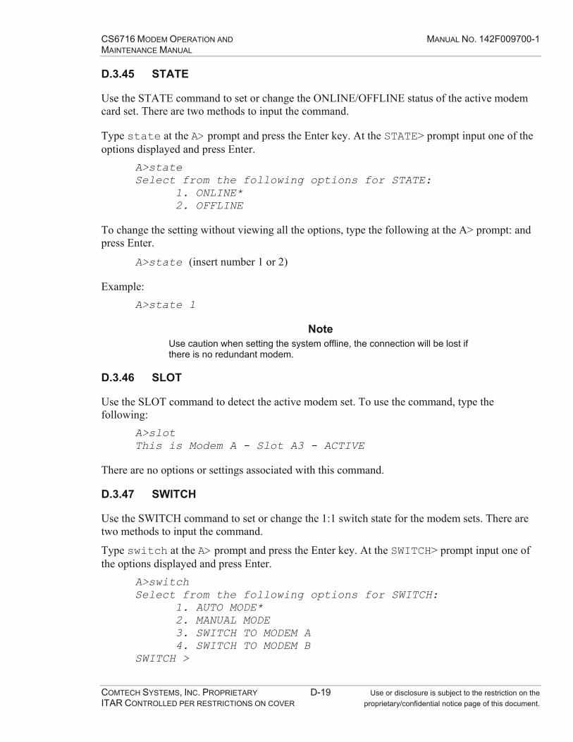
CS6716 MODEM OPERATION AND MANUAL NO. 142F009700-1 MAINTENANCE MANUAL
COMTECH SYSTEMS, INC. PROPRIETARY D-19 Use or disclosure is subject to the restriction on the ITAR CONTROLLED PER RESTRICTIONS ON COVER proprietary/confidential notice page of this document.
D.3.45 STATE
Use the STATE command to set or change the ONLINE/OFFLINE status of the active modem card set. There are two methods to input the command.
Type state at the A> prompt and press the Enter key. At the STATE> prompt input one of the options displayed and press Enter.
A>stateSelect from the following options for STATE: 1. ONLINE* 2. OFFLINE
To change the setting without viewing all the options, type the following at the A> prompt: and press Enter.
A>state (insert number 1 or 2)
Example: A>state 1
Note Use caution when setting the system offline, the connection will be lost if there is no redundant modem.
D.3.46 SLOT
Use the SLOT command to detect the active modem set. To use the command, type the following:
A>slotThis is Modem A - Slot A3 - ACTIVE
There are no options or settings associated with this command.
D.3.47 SWITCH
Use the SWITCH command to set or change the 1:1 switch state for the modem sets. There are two methods to input the command.
Type switch at the A> prompt and press the Enter key. At the SWITCH> prompt input one of the options displayed and press Enter.
A>switchSelect from the following options for SWITCH: 1. AUTO MODE* 2. MANUAL MODE 3. SWITCH TO MODEM A 4. SWITCH TO MODEM B SWITCH >
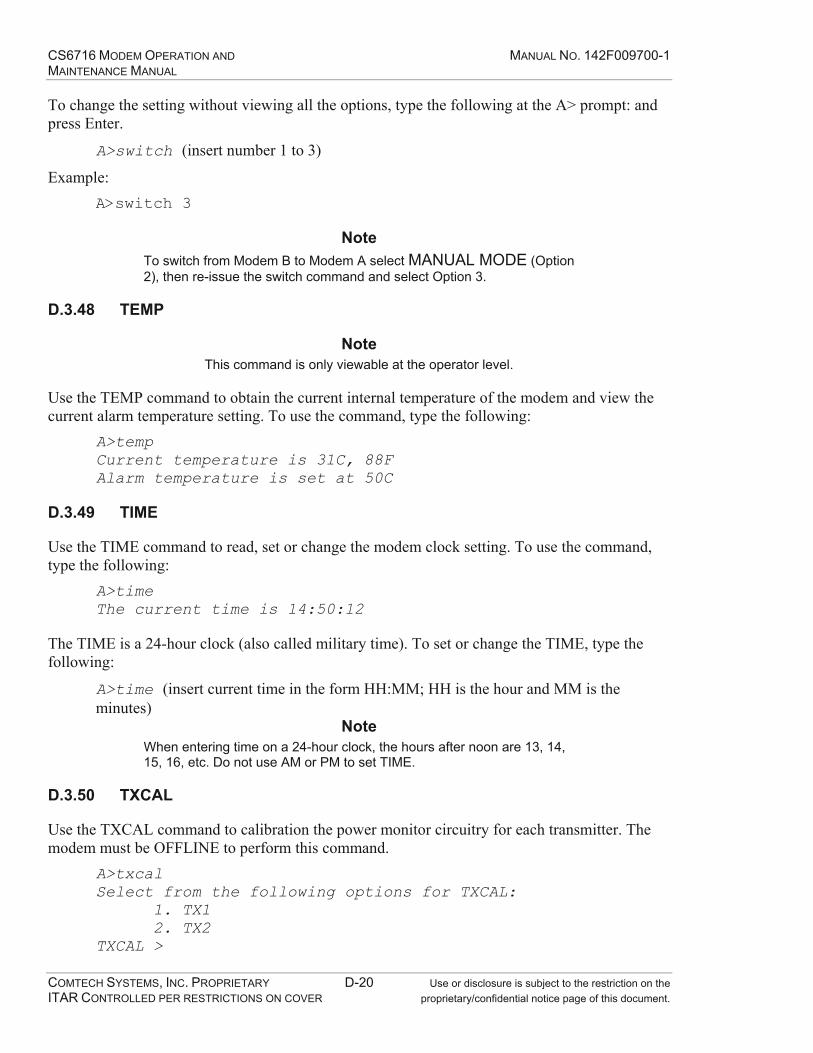
CS6716 MODEM OPERATION AND MANUAL NO. 142F009700-1 MAINTENANCE MANUAL
COMTECH SYSTEMS, INC. PROPRIETARY D-20 Use or disclosure is subject to the restriction on the ITAR CONTROLLED PER RESTRICTIONS ON COVER proprietary/confidential notice page of this document.
To change the setting without viewing all the options, type the following at the A> prompt: and press Enter.
A>switch (insert number 1 to 3)
Example: A>switch 3
Note To switch from Modem B to Modem A select MANUAL MODE (Option 2), then re-issue the switch command and select Option 3.
D.3.48 TEMP
Note This command is only viewable at the operator level.
Use the TEMP command to obtain the current internal temperature of the modem and view the current alarm temperature setting. To use the command, type the following:
A>tempCurrent temperature is 31C, 88F Alarm temperature is set at 50C
D.3.49 TIME
Use the TIME command to read, set or change the modem clock setting. To use the command, type the following:
A>timeThe current time is 14:50:12
The TIME is a 24-hour clock (also called military time). To set or change the TIME, type the following:
A>time (insert current time in the form HH:MM; HH is the hour and MM is the minutes)
Note When entering time on a 24-hour clock, the hours after noon are 13, 14, 15, 16, etc. Do not use AM or PM to set TIME.
D.3.50 TXCAL
Use the TXCAL command to calibration the power monitor circuitry for each transmitter. The modem must be OFFLINE to perform this command.
A>txcalSelect from the following options for TXCAL: 1. TX1 2. TX2 TXCAL >

CS6716 MODEM OPERATION AND MANUAL NO. 142F009700-1 MAINTENANCE MANUAL
COMTECH SYSTEMS, INC. PROPRIETARY D-21 Use or disclosure is subject to the restriction on the ITAR CONTROLLED PER RESTRICTIONS ON COVER proprietary/confidential notice page of this document.
D.3.51 UP
Use the UP command to report how long the modem has had power applied. To use the command, type the following:
B>upUptime is 0 Days, 00:35:04
There are no options or settings available with the UP command.
D.3.52 VER
Use the VER command to report the current software versions used in the modem. To use the command, type the following:
A>verF.W. Ver. 7.07 - Jan 6 2006, 13:39:35 RTOS Ver. 276 SCC/INF PLD Version 4.0 TCP/IP Stack Version 161
There are no options or settings available with this command.

CS6716 MODEM OPERATION AND MANUAL NO. 142F009700-1 MAINTENANCE MANUAL
COMTECH SYSTEMS, INC. PROPRIETARY D-22 Use or disclosure is subject to the restriction on the ITAR CONTROLLED PER RESTRICTIONS ON COVER proprietary/confidential notice page of this document.
This Page Intentionally Left Blank

CS6716 MODEM OPERATION AND MANUAL NO. 142F009700-1 MAINTENANCE MANUAL
COMTECH SYSTEMS, INC. PROPRIETARY E-1 Use or disclosure is subject to the restriction on the ITAR CONTROLLED PER RESTRICTIONS ON COVER proprietary/confidential notice page of this document.
APPENDIX E MODEM ALARMS

CS6716 MODEM OPERATION AND MANUAL NO. 142F009700-1 MAINTENANCE MANUAL
COMTECH SYSTEMS, INC. PROPRIETARY E-2 Use or disclosure is subject to the restriction on the ITAR CONTROLLED PER RESTRICTIONS ON COVER proprietary/confidential notice page of this document.
This Page Intentionally Left Blank

CS6716 MODEM OPERATION AND MANUAL NO. 142F009700-1 MAINTENANCE MANUAL
COMTECH SYSTEMS, INC. PROPRIETARY E-3 Use or disclosure is subject to the restriction on the ITAR CONTROLLED PER RESTRICTIONS ON COVER proprietary/confidential notice page of this document.
Alarm
Number Alarm Type Switch
Affected Unit Alarm Description
1 MAJOR YES ANA CH1 FAILED AGC CALIBRATION 2 MAJOR YES ANA CH2 FAILED AGC CALIBRATION 3 MAJOR YES ANA CH3 FAILED AGC CALIBRATION 4 MAJOR YES ANA CH4 FAILED AGC CALIBRATION 5 MAJOR YES DIG FAULT: AFE DIVERSITY 1 6 MAJOR YES DIG FAULT: AFE DIVERSITY 2 7 MAJOR YES DIG FAULT: AFE DIVERSITY 3 8 MAJOR YES DIG FAULT: AFE DIVERSITY 4 9 MAJOR YES DIG FAULT: DEG 10 MAJOR YES ANA FAULT: DEM DIV1&DIV2 11 MAJOR YES ANA FAULT: DEM DIV3&DIV4 12 MAJOR YES DIG FAULT: INF 13 MAJOR YES ANA FAULT: MODULATOR 14 MAJOR YES ANA FAULT: MUX 15 MAJOR YES DIG FAULT: SCC 16 MAJOR YES DIG FATAL: AFE DIVERSITY 1 17 MAJOR YES DIG FATAL: AFE DIVERSITY 2 18 MAJOR YES DIG FATAL: AFE DIVERSITY 3 19 MAJOR YES DIG FATAL: AFE DIVERSITY 4 20 MAJOR YES DIG FATAL: DEG 21 MAJOR YES ANA FATAL: DEM DIV1&DIV2 22 MAJOR YES ANA FATAL: DEM DIV3&DIV4 23 MAJOR YES DIG FATAL: INF 24 MAJOR YES ANA FATAL: MODULATOR 25 MAJOR YES DIG FATAL: MUX 26 MAJOR YES DIG FATAL: SCC 27 MAJOR YES DIG MISSING: AFE DIVERSITY 1 28 MAJOR YES DIG MISSING: AFE DIVERSITY 2 29 MAJOR YES DIG MISSING: AFE DIVERSITY 3 30 MAJOR YES DIG MISSING: AFE DIVERSITY 4 31 MAJOR YES DIG MISSING: DEG 32 MAJOR YES ANA MISSING: DEM DIV1&DIV2 33 MAJOR YES ANA MISSING: DEM DIV3&DIV4 34 MAJOR YES DIG MISSING: INF 35 MAJOR YES ANA MISSING: MODULATOR 36 MAJOR YES DIG MISSING: MUX 37 MAJOR NO DIG MISSING: SCC
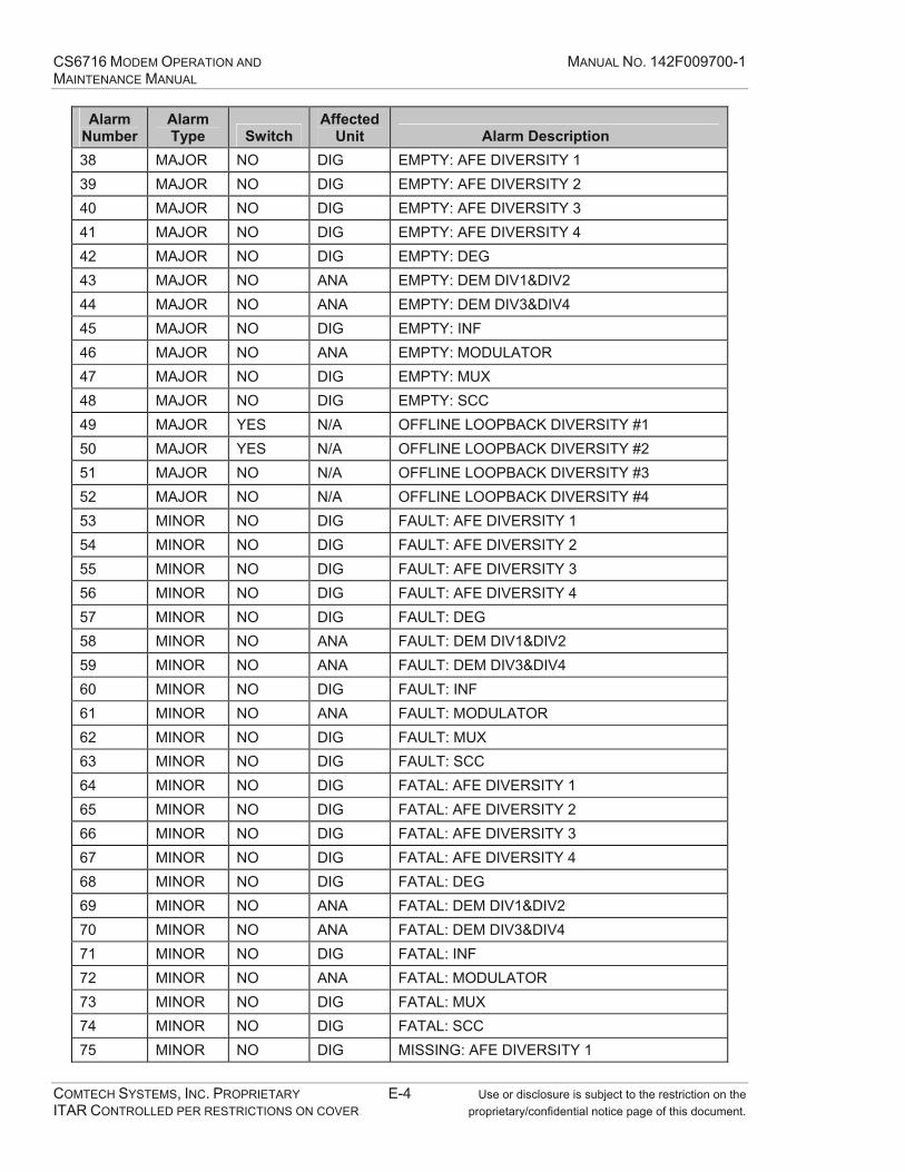
CS6716 MODEM OPERATION AND MANUAL NO. 142F009700-1 MAINTENANCE MANUAL
COMTECH SYSTEMS, INC. PROPRIETARY E-4 Use or disclosure is subject to the restriction on the ITAR CONTROLLED PER RESTRICTIONS ON COVER proprietary/confidential notice page of this document.
Alarm Number
Alarm Type Switch
Affected Unit Alarm Description
38 MAJOR NO DIG EMPTY: AFE DIVERSITY 1 39 MAJOR NO DIG EMPTY: AFE DIVERSITY 2 40 MAJOR NO DIG EMPTY: AFE DIVERSITY 3 41 MAJOR NO DIG EMPTY: AFE DIVERSITY 4 42 MAJOR NO DIG EMPTY: DEG 43 MAJOR NO ANA EMPTY: DEM DIV1&DIV2 44 MAJOR NO ANA EMPTY: DEM DIV3&DIV4 45 MAJOR NO DIG EMPTY: INF 46 MAJOR NO ANA EMPTY: MODULATOR 47 MAJOR NO DIG EMPTY: MUX 48 MAJOR NO DIG EMPTY: SCC 49 MAJOR YES N/A OFFLINE LOOPBACK DIVERSITY #1 50 MAJOR YES N/A OFFLINE LOOPBACK DIVERSITY #2 51 MAJOR NO N/A OFFLINE LOOPBACK DIVERSITY #3 52 MAJOR NO N/A OFFLINE LOOPBACK DIVERSITY #4 53 MINOR NO DIG FAULT: AFE DIVERSITY 1 54 MINOR NO DIG FAULT: AFE DIVERSITY 2 55 MINOR NO DIG FAULT: AFE DIVERSITY 3 56 MINOR NO DIG FAULT: AFE DIVERSITY 4 57 MINOR NO DIG FAULT: DEG 58 MINOR NO ANA FAULT: DEM DIV1&DIV2 59 MINOR NO ANA FAULT: DEM DIV3&DIV4 60 MINOR NO DIG FAULT: INF 61 MINOR NO ANA FAULT: MODULATOR 62 MINOR NO DIG FAULT: MUX 63 MINOR NO DIG FAULT: SCC 64 MINOR NO DIG FATAL: AFE DIVERSITY 1 65 MINOR NO DIG FATAL: AFE DIVERSITY 2 66 MINOR NO DIG FATAL: AFE DIVERSITY 3 67 MINOR NO DIG FATAL: AFE DIVERSITY 4 68 MINOR NO DIG FATAL: DEG 69 MINOR NO ANA FATAL: DEM DIV1&DIV2 70 MINOR NO ANA FATAL: DEM DIV3&DIV4 71 MINOR NO DIG FATAL: INF 72 MINOR NO ANA FATAL: MODULATOR 73 MINOR NO DIG FATAL: MUX 74 MINOR NO DIG FATAL: SCC 75 MINOR NO DIG MISSING: AFE DIVERSITY 1
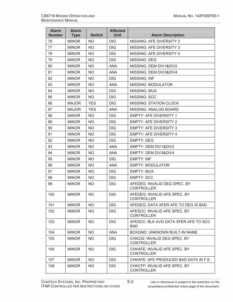
CS6716 MODEM OPERATION AND MANUAL NO. 142F009700-1 MAINTENANCE MANUAL
COMTECH SYSTEMS, INC. PROPRIETARY E-5 Use or disclosure is subject to the restriction on the ITAR CONTROLLED PER RESTRICTIONS ON COVER proprietary/confidential notice page of this document.
Alarm Number
Alarm Type Switch
Affected Unit Alarm Description
76 MINOR NO DIG MISSING: AFE DIVERSITY 2 77 MINOR NO DIG MISSING: AFE DIVERSITY 3 78 MINOR NO DIG MISSING: AFE DIVERSITY 4 79 MINOR NO DIG MISSING: DEG 80 MINOR NO ANA MISSING: DEM DIV1&DIV2 81 MINOR NO ANA MISSING: DEM DIV3&DIV4 82 MINOR NO DIG MISSING: INF 83 MINOR NO ANA MISSING: MODULATOR 84 MINOR NO DIG MISSING: MUX 85 MINOR NO DIG MISSING: SCC 86 MAJOR YES DIG MISSING: STATION CLOCK 87 MAJOR YES ANA MISSING: ANALOG BOARD 88 MINOR NO DIG EMPTY: AFE DIVERSITY 1 89 MINOR NO DIG EMPTY: AFE DIVERSITY 2 90 MINOR NO DIG EMPTY: AFE DIVERSITY 3 91 MINOR NO DIG EMPTY: AFE DIVERSITY 4 92 MINOR NO DIG EMPTY: DEG 93 MINOR NO ANA EMPTY: DEM DIV1&DIV2 94 MINOR NO ANA EMPTY: DEM DIV3&DIV4 95 MINOR NO DIG EMPTY: INF 96 MINOR NO ANA EMPTY: MODULATOR 97 MINOR NO DIG EMPTY: MUX 98 MINOR NO DIG EMPTY: SCC 99 MINOR NO DIG AFEDEG: INVALID DEG SPEC. BY
CONTROLLER 100 MINOR NO DIG AFEDEG: INVALID AFE SPEC. BY
CONTROLLER 101 MINOR NO DIG AFEDEG: DATA XFER AFE TO DEG IS BAD 102 MINOR NO DIG AFESCC: INVALID AFE SPEC. BY
CONTROLLER 103 MINOR NO DIG AFESCC: BLK AVG DATA XFER AFE TO SCC
BAD 104 MINOR NO ANA BCKGND: UNKNOWN BUILT-IN NAME 105 MINOR NO DIG CHK232: INVALID DEG SPEC. BY
CONTROLLER 106 MINOR NO DIG CHKAFE: INVALID AFE SPEC. BY
CONTROLLER 107 MINOR NO DIG CHKAFE: AFE PRODUCED BAD DATA IN F.E. 108 MINOR NO DIG CHKCFF: INVALID AFE SPEC. BY
CONTROLLER

CS6716 MODEM OPERATION AND MANUAL NO. 142F009700-1 MAINTENANCE MANUAL
COMTECH SYSTEMS, INC. PROPRIETARY E-6 Use or disclosure is subject to the restriction on the ITAR CONTROLLED PER RESTRICTIONS ON COVER proprietary/confidential notice page of this document.
Alarm Number
Alarm Type Switch
Affected Unit Alarm Description
109 MINOR NO DIG CHKCFF: AFE EQUAL. TAP DECAY CONTROL BAD
110 MINOR NO DIG CHKCFF: AFE EQUAL. TAP-SELECT CONT. BAD
111 MINOR NO DIG CHKCFF: AFE EQUAL. TAP WEIGHT UPDATE BAD
112 MINOR NO DIG CHKDEG: INVALID DEG SPEC. BY CONTROLLER
113 MINOR NO DIG CHKDEG: DEG EQUAL. TAP-SELECT CONT. BAD
114 MINOR NO DIG CHKDEG: DEG EQUAL. TAP DECAY CONT. BAD
115 MINOR NO DIG CHKDEG: DEG EQUAL. TAP WEIGHT UPDATE BAD
116 MINOR NO DIG CHKDEG: DEG BACKWARD EQUAL/DECISION BAD
117 MINOR NO ANA CHKDEM: INVALID DEM SPEC. BY CONTROLLER
118 MINOR NO ANA CHKDEM: DEM HAS EXCESSIVE DC OFFSET CH A
119 MINOR NO ANA CHKDEM: DEM HAS EXCESSIVE DC OFFSET CH B
120 MINOR NO DIG CHKMUX: INVALID MUX SPEC. BY CONTROLLER
121 MINOR NO DIG CHKMUX: MUX DESCRAMBLING AGG. DATA BAD
122 MINOR NO DIG CHKFIR: INVALID AFE SPEC. BY CONTROLLER
123 MINOR NO DIG CHKFIR: INVALID DECIMATION RATE IN CONT.
124 MINOR NO DIG CHKFIR: AFE PRODUCED FIR FILTER BAD DATA
125 MINOR NO ANA CHKFLT: MOD T CLK FOR XMTR MISSING 126 MINOR NO ANA CHKFLT: MOD T CLK FOR RCVR MISSING 127 MINOR NO ANA CHKFLT: MOD T/2 CLK FOR XMTR MISSING 128 MINOR NO ANA CHKFLT: MOD T/2 CLK FOR RCVR IS
MISSING 129 MINOR NO ANA CHKFLT: MOD A/D SAMPLE CLK IS MISSING 130 MINOR NO ANA CHKFLT: MOD CLK GEN PLL FAULTY 131 MINOR NO ANA CHKFLT: MOD 10MHz STATION CLK MISSING 132 MAJOR YES ANA CHKFLT: MOD 70MHz PLL NOT LOCKED 133 MINOR NO ANA CHKFLT: MOD XMTR OUT LEVEL TOO LOW 134 MINOR NO ANA CHKFLT: MOD XMTR CARRIER NOT
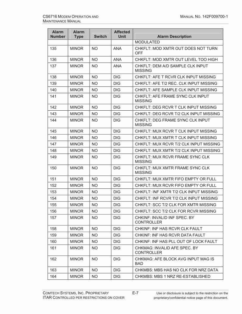
CS6716 MODEM OPERATION AND MANUAL NO. 142F009700-1 MAINTENANCE MANUAL
COMTECH SYSTEMS, INC. PROPRIETARY E-7 Use or disclosure is subject to the restriction on the ITAR CONTROLLED PER RESTRICTIONS ON COVER proprietary/confidential notice page of this document.
Alarm Number
Alarm Type Switch
Affected Unit Alarm Description
MODULATED 135 MINOR NO ANA CHKFLT: MOD XMTR OUT DOES NOT TURN
OFF 136 MINOR NO ANA CHKFLT: MOD XMTR OUT LEVEL TOO HIGH 137 MINOR NO ANA CHKFLT: DEM A/D SAMPLE CLK INPUT
MISSING 138 MINOR NO DIG CHKFLT: AFE T RCVR CLK INPUT MISSING 139 MINOR NO DIG CHKFLT: AFE T/2 REC. CLK INPUT MISSING 140 MINOR NO DIG CHKFLT: AFE SAMPLE CLK INPUT MISSING 141 MINOR NO DIG CHKFLT: AFE FRAME SYNC CLK INPUT
MISSING 142 MINOR NO DIG CHKFLT: DEG RCVR T CLK INPUT MISSING 143 MINOR NO DIG CHKFLT: DEG RCVR T/2 CLK INPUT MISSING 144 MINOR NO DIG CHKFLT: DEG FRAME SYNC CLK INPUT
MISSING 145 MINOR NO DIG CHKFLT: MUX RCVR T CLK INPUT MISSING 146 MINOR NO DIG CHKFLT: MUX XMTR T CLK INPUT MISSING 147 MINOR NO DIG CHKFLT: MUX RCVR T/2 CLK INPUT MISSING 148 MINOR NO DIG CHKFLT: MUX XMTR T/2 CLK INPUT MISSING 149 MINOR NO DIG CHKFLT: MUX RCVR FRAME SYNC CLK
MISSING 150 MINOR NO DIG CHKFLT: MUX XMTR FRAME SYNC CLK
MISSING 151 MINOR NO DIG CHKFLT: MUX XMTR FIFO EMPTY OR FULL 152 MINOR NO DIG CHKFLT: MUX RCVR FIFO EMPTY OR FULL 153 MINOR NO DIG CHKFLT: INF XMTR T/2 CLK INPUT MISSING 154 MINOR NO DIG CHKFLT: INF RCVR T/2 CLK INPUT MISSING 155 MINOR NO DIG CHKFLT: SCC T/2 CLK FOR XMTR MISSING 156 MINOR NO DIG CHKFLT: SCC T/2 CLK FOR RCVR MISSING 157 MINOR NO DIG CHKINF: INVALID INF SPEC. BY
CONTROLLER 158 MINOR NO DIG CHKINF: INF HAS RCVR CLK FAULT 159 MINOR NO DIG CHKINF: INF HAS RCVR DATA FAULT 160 MINOR NO DIG CHKINF: INF HAS PLL OUT OF LOCK FAULT 161 MINOR NO DIG CHKMAG: INVALID AFE SPEC. BY
CONTROLLER 162 MINOR NO DIG CHKMAG: AFE BLOCK AVG INPUT MAG IS
BAD 163 MINOR NO DIG CHKMBS: MBS HAS NO CLK FOR NRZ DATA 164 MINOR NO DIG CHKMBS: MBS 1 NRZ RE-ESTABLISHED
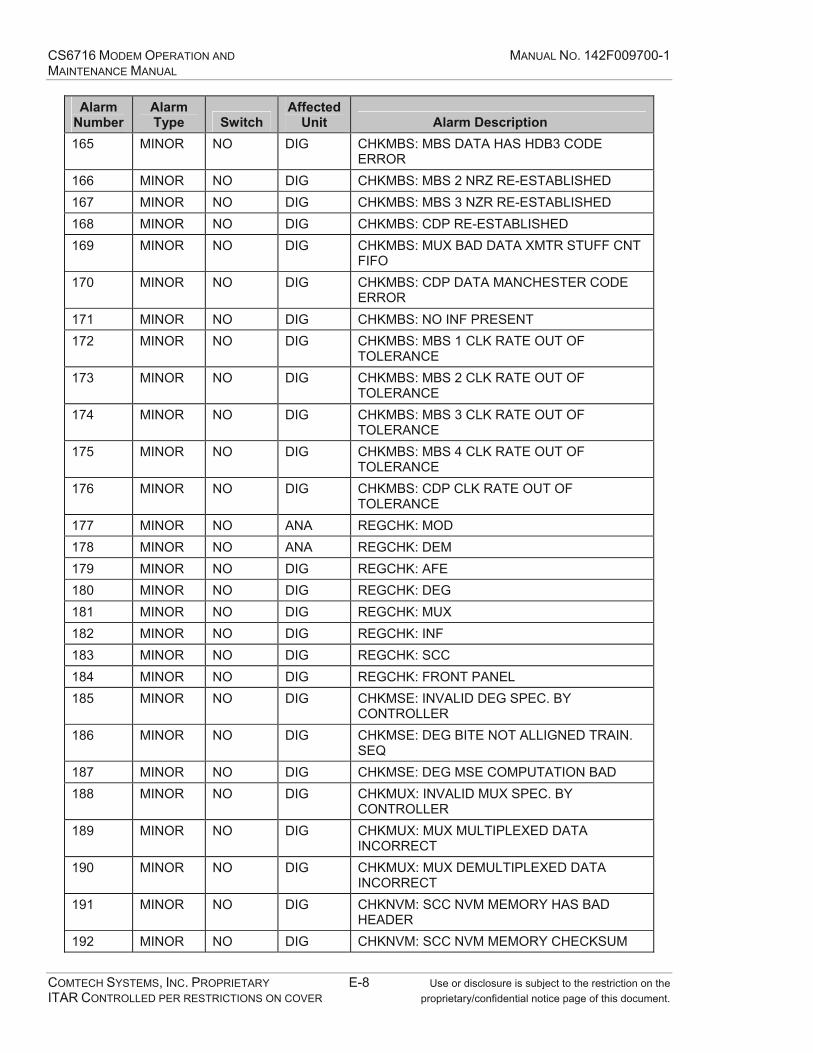
CS6716 MODEM OPERATION AND MANUAL NO. 142F009700-1 MAINTENANCE MANUAL
COMTECH SYSTEMS, INC. PROPRIETARY E-8 Use or disclosure is subject to the restriction on the ITAR CONTROLLED PER RESTRICTIONS ON COVER proprietary/confidential notice page of this document.
Alarm Number
Alarm Type Switch
Affected Unit Alarm Description
165 MINOR NO DIG CHKMBS: MBS DATA HAS HDB3 CODE ERROR
166 MINOR NO DIG CHKMBS: MBS 2 NRZ RE-ESTABLISHED 167 MINOR NO DIG CHKMBS: MBS 3 NZR RE-ESTABLISHED 168 MINOR NO DIG CHKMBS: CDP RE-ESTABLISHED 169 MINOR NO DIG CHKMBS: MUX BAD DATA XMTR STUFF CNT
FIFO 170 MINOR NO DIG CHKMBS: CDP DATA MANCHESTER CODE
ERROR 171 MINOR NO DIG CHKMBS: NO INF PRESENT 172 MINOR NO DIG CHKMBS: MBS 1 CLK RATE OUT OF
TOLERANCE 173 MINOR NO DIG CHKMBS: MBS 2 CLK RATE OUT OF
TOLERANCE 174 MINOR NO DIG CHKMBS: MBS 3 CLK RATE OUT OF
TOLERANCE 175 MINOR NO DIG CHKMBS: MBS 4 CLK RATE OUT OF
TOLERANCE 176 MINOR NO DIG CHKMBS: CDP CLK RATE OUT OF
TOLERANCE 177 MINOR NO ANA REGCHK: MOD 178 MINOR NO ANA REGCHK: DEM 179 MINOR NO DIG REGCHK: AFE 180 MINOR NO DIG REGCHK: DEG 181 MINOR NO DIG REGCHK: MUX 182 MINOR NO DIG REGCHK: INF 183 MINOR NO DIG REGCHK: SCC 184 MINOR NO DIG REGCHK: FRONT PANEL 185 MINOR NO DIG CHKMSE: INVALID DEG SPEC. BY
CONTROLLER 186 MINOR NO DIG CHKMSE: DEG BITE NOT ALLIGNED TRAIN.
SEQ 187 MINOR NO DIG CHKMSE: DEG MSE COMPUTATION BAD 188 MINOR NO DIG CHKMUX: INVALID MUX SPEC. BY
CONTROLLER 189 MINOR NO DIG CHKMUX: MUX MULTIPLEXED DATA
INCORRECT 190 MINOR NO DIG CHKMUX: MUX DEMULTIPLEXED DATA
INCORRECT 191 MINOR NO DIG CHKNVM: SCC NVM MEMORY HAS BAD
HEADER 192 MINOR NO DIG CHKNVM: SCC NVM MEMORY CHECKSUM
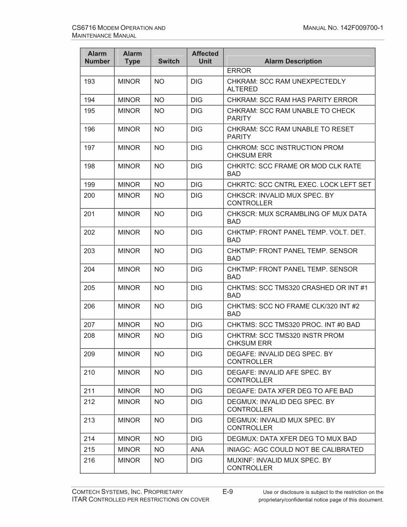
CS6716 MODEM OPERATION AND MANUAL NO. 142F009700-1 MAINTENANCE MANUAL
COMTECH SYSTEMS, INC. PROPRIETARY E-9 Use or disclosure is subject to the restriction on the ITAR CONTROLLED PER RESTRICTIONS ON COVER proprietary/confidential notice page of this document.
Alarm Number
Alarm Type Switch
Affected Unit Alarm Description
ERROR 193 MINOR NO DIG CHKRAM: SCC RAM UNEXPECTEDLY
ALTERED 194 MINOR NO DIG CHKRAM: SCC RAM HAS PARITY ERROR 195 MINOR NO DIG CHKRAM: SCC RAM UNABLE TO CHECK
PARITY 196 MINOR NO DIG CHKRAM: SCC RAM UNABLE TO RESET
PARITY 197 MINOR NO DIG CHKROM: SCC INSTRUCTION PROM
CHKSUM ERR 198 MINOR NO DIG CHKRTC: SCC FRAME OR MOD CLK RATE
BAD 199 MINOR NO DIG CHKRTC: SCC CNTRL EXEC. LOCK LEFT SET200 MINOR NO DIG CHKSCR: INVALID MUX SPEC. BY
CONTROLLER 201 MINOR NO DIG CHKSCR: MUX SCRAMBLING OF MUX DATA
BAD 202 MINOR NO DIG CHKTMP: FRONT PANEL TEMP. VOLT. DET.
BAD 203 MINOR NO DIG CHKTMP: FRONT PANEL TEMP. SENSOR
BAD 204 MINOR NO DIG CHKTMP: FRONT PANEL TEMP. SENSOR
BAD 205 MINOR NO DIG CHKTMS: SCC TMS320 CRASHED OR INT #1
BAD 206 MINOR NO DIG CHKTMS: SCC NO FRAME CLK/320 INT #2
BAD 207 MINOR NO DIG CHKTMS: SCC TMS320 PROC. INT #0 BAD 208 MINOR NO DIG CHKTRM: SCC TMS320 INSTR PROM
CHKSUM ERR 209 MINOR NO DIG DEGAFE: INVALID DEG SPEC. BY
CONTROLLER 210 MINOR NO DIG DEGAFE: INVALID AFE SPEC. BY
CONTROLLER 211 MINOR NO DIG DEGAFE: DATA XFER DEG TO AFE BAD 212 MINOR NO DIG DEGMUX: INVALID DEG SPEC. BY
CONTROLLER 213 MINOR NO DIG DEGMUX: INVALID MUX SPEC. BY
CONTROLLER 214 MINOR NO DIG DEGMUX: DATA XFER DEG TO MUX BAD 215 MINOR NO ANA INIAGC: AGC COULD NOT BE CALIBRATED 216 MINOR NO DIG MUXINF: INVALID MUX SPEC. BY
CONTROLLER

CS6716 MODEM OPERATION AND MANUAL NO. 142F009700-1 MAINTENANCE MANUAL
COMTECH SYSTEMS, INC. PROPRIETARY E-10 Use or disclosure is subject to the restriction on the ITAR CONTROLLED PER RESTRICTIONS ON COVER proprietary/confidential notice page of this document.
Alarm Number
Alarm Type Switch
Affected Unit Alarm Description
217 MINOR NO DIG MUXINF: INVALID INF SPEC. BY CONTROLLER
218 MINOR NO DIG MUXINF: DATA XFER MUX TO INF BAD 219 MINOR NO DIG MUXMOD: INVALID MUX SPEC. BY
CONTROLLER 220 MINOR NO DIG MUXMOD: INVALID MOD SPEC. BY
CONTROLLER 221 MINOR NO DIG MUXMOD: DATA XFER MUX TO MOD BAD 222 MINOR NO ANA OFFTST: MUX MISC FRAME BITS BAD 223 MINOR NO ANA OFFTST: OFFLINE ACQ(LOOPBK TEST)
FAILED 224 MINOR NO ANA ONLTST: BKGRND ACQ (LOOPBK TEST)
FAILED 225 MINOR NO ANA TMLOAD: COULD NOT LOAD TMS320 PROG
RAM 226 MINOR NO DIG TSTCOR: TMS320 DOES NOT ASSERT
HOLDACK 227 MINOR NO DIG TSTCOR: CORRELATION RAM OF TMS320 IS
BAD 228 MINOR NO DIG TSTDPR: TMS320 DOES NOT ASSERT
HOLDACK 229 MINOR NO DIG TSTDPR: DUAL PORT RAM FOR TMS320 IS
BAD 230 MINOR NO DIG TSTINF: INF LOOPBACK DATA IS BAD 231 MINOR NO DIG TSTPRG: SCC PROG RAM FOR TMS320 IS
BAD 232 MINOR NO DIG SSTART: SCC NVM EMPTY; NOW
FORMATTED 233 MINOR NO DIG SSTART: SCC NVM BAD - LOST SETUP 234 MINOR NO DIG SSTART: SCC NVM BAD UNABLE TO
RELOCATE 235 MINOR NO DIG SSTART: SCC TMS320 INTERNAL MEMORY
BAD 236 MINOR NO DIG SSTART: SCC TMS320 AGC CONT. REG BAD 237 MINOR NO DIG SSTART: SCC TMS320 DIV. CORR. MEMORY
BAD 238 MINOR NO DIG SSTART: SCC TMS320 DUAL-PORT MEMORY
BAD 239 MINOR NO DIG FAULT: CDP PORT 240 MINOR NO DIG FATAL: FRONT PANEL 241 MINOR NO DIG OVER TEMPERATURE 242 MINOR NO ANA TEMPERATURE READ FAILURE

CS6716 MODEM OPERATION AND MANUAL NO. 142F009700-1 MAINTENANCE MANUAL
COMTECH SYSTEMS, INC. PROPRIETARY E-11 Use or disclosure is subject to the restriction on the ITAR CONTROLLED PER RESTRICTIONS ON COVER proprietary/confidential notice page of this document.
Alarm Number
Alarm Type Switch
Affected Unit Alarm Description
243 MINOR NO DIG FAN #1 SPEED 244 MINOR NO DIG FAN #2 SPEED 245 MINOR NO DIG DATA CHANNEL LOS 246 MINOR NO DIG SERVICE CHANNEL #1 LOS 247 MINOR NO DIG SERVICE CHANNEL #2 LOS 248 MINOR NO NON STANDARD ALPC INTERVAL 249 MINOR NO ANA >11dB RSL VARIATION RSL1-RSL3 250 MINOR NO ANA >11dB RSL VARIATION RSL2-RSL4 251 MINOR NO ANA >11dB RSL VARIATION 252 MINOR NO AGC AUTO CALIBRATION OFF 253 MINOR NO POOR SIGNAL QUALITY 254 MAJOR NO DIG MODEM A BOARD SET NOT RESPONDING 255 MAJOR NO DIG MODEM B BOARD SET NOT RESPONDING 256 MINOR NO DIG MUX CH1 TX FIFO UNDER/OVER FLOW 257 MINOR NO DIG MUX SC1 TX FIFO UNDER/OVER FLOW 258 MINOR NO DIG MUX SC2 TX FIFO UNDER/OVER FLOW 259 MINOR NO DIG MUX CH1 RX FIFO UNDER/OVER FLOW 260 MINOR NO DIG MUX SC1 RX FIFO UNDER/OVER FLOW 261 MINOR NO DIG MUX SC2 RX FIFO UNDER/OVER FLOW 262 MAJOR YES ANA TX1 OUTPUT POWER LEVEL 263 MAJOR YES ANA TX2 OUTPUT POWER LEVEL 264 MAJOR NO FEATURE KEY MISMATCH 265 MAJOR NO ALPC DISABLED - HIGH BER 266 MAJOR YES DIG BUS ERROR

CS6716 MODEM OPERATION AND MANUAL NO. 142F009700-1 MAINTENANCE MANUAL
COMTECH SYSTEMS, INC. PROPRIETARY E-12 Use or disclosure is subject to the restriction on the ITAR CONTROLLED PER RESTRICTIONS ON COVER proprietary/confidential notice page of this document.
This Page Intentionally Left Blank

CS6716 MODEM OPERATION AND MANUAL NO. 142F009700-1 MAINTENANCE MANUAL
COMTECH SYSTEMS, INC. PROPRIETARY F-1 Use or disclosure is subject to the restriction on the ITAR CONTROLLED PER RESTRICTIONS ON COVER proprietary/confidential notice page of this document.
APPENDIX F ACRONYMS

CS6716 MODEM OPERATION AND MANUAL NO. 142F009700-1 MAINTENANCE MANUAL
COMTECH SYSTEMS, INC. PROPRIETARY F-2 Use or disclosure is subject to the restriction on the ITAR CONTROLLED PER RESTRICTIONS ON COVER proprietary/confidential notice page of this document.
This Page Intentionally Left Blank

CS6716 MODEM OPERATION AND MANUAL NO. 142F009700-1 MAINTENANCE MANUAL
COMTECH SYSTEMS, INC. PROPRIETARY F-3 Use or disclosure is subject to the restriction on the ITAR CONTROLLED PER RESTRICTIONS ON COVER proprietary/confidential notice page of this document.
Acronym/Term Meaning
AAFE adaptive forward equalizer AGC automatic gain control ALPC adaptive link power control ASCII American Standard Code of Information Interchange BBER bit error rate BERT bit error rate test/tester BITE built-in-test-equipment bps bits per second CCSI Comtech Systems, Inc. DDCE data communications equipment DEMOD demodulator DEG decision error generator EEb/No The ratio of bit energy per symbol to noise power spectral density, in decibels. FFEC forward error correction FIFO first in first out (buffer) HHPA high power amplifier HSSI high speed serial interface IINF interface ISI intersymbol interference KKbps kilobits per second

CS6716 MODEM OPERATION AND MANUAL NO. 142F009700-1 MAINTENANCE MANUAL
COMTECH SYSTEMS, INC. PROPRIETARY F-4 Use or disclosure is subject to the restriction on the ITAR CONTROLLED PER RESTRICTIONS ON COVER proprietary/confidential notice page of this document.
LLCD liquid crystal display LO local oscillator LRU line-replaceable unit PPCB printed circuit board QQPSK quadrature phase shift keying RRF radio frequency RSL receive signal level TTPC Turbo Product Code

CS6716 MODEM OPERATION AND MANUAL NO. 142F009700-1 MAINTENANCE MANUAL
COMTECH SYSTEMS, INC. PROPRIETARY G-1 Use or disclosure is subject to the restriction on the ITAR CONTROLLED PER RESTRICTIONS ON COVER proprietary/confidential notice page of this document.
APPENDIX G RMA INFORMATION SHEET

CS6716 MODEM OPERATION AND MANUAL NO. 142F009700-1 MAINTENANCE MANUAL
COMTECH SYSTEMS, INC. PROPRIETARY G-2 Use or disclosure is subject to the restriction on the ITAR CONTROLLED PER RESTRICTIONS ON COVER proprietary/confidential notice page of this document.
This Page Intentionally Left Blank
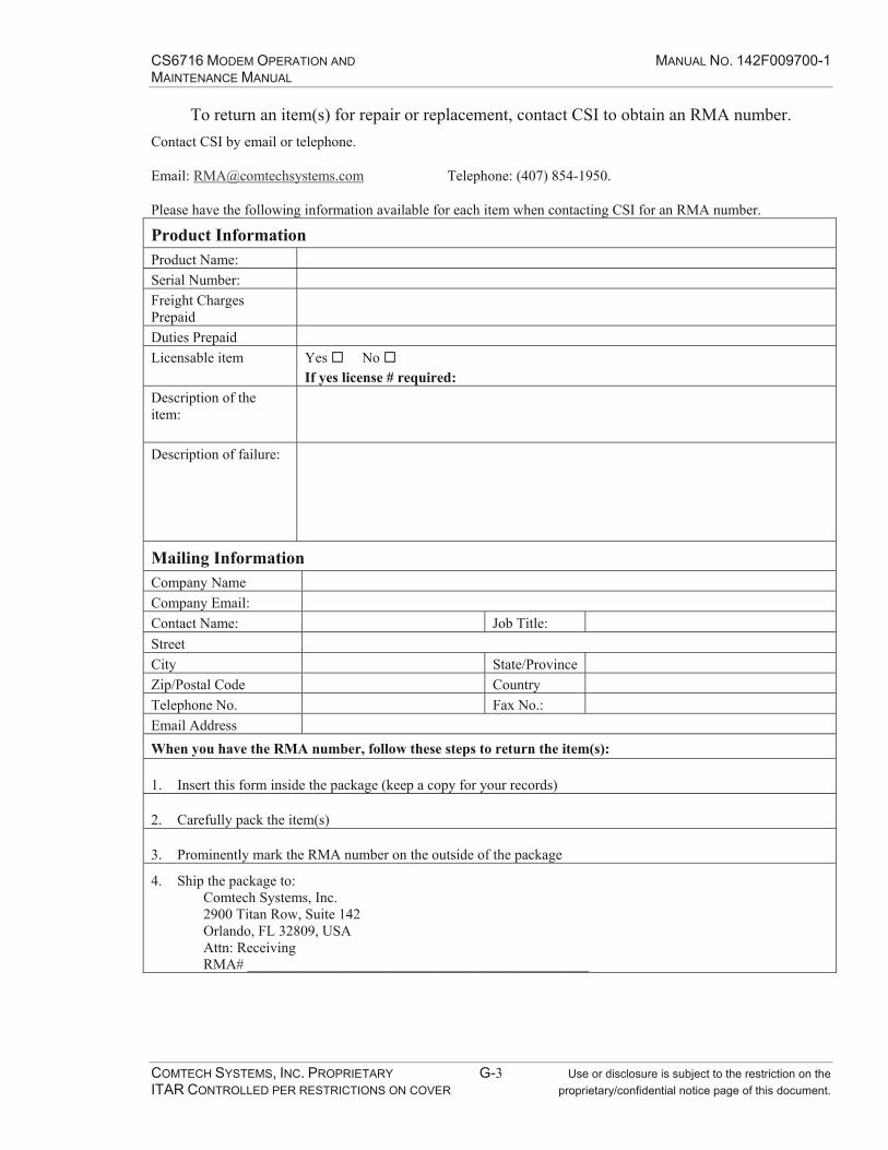
CS6716 MODEM OPERATION AND MANUAL NO. 142F009700-1 MAINTENANCE MANUAL
COMTECH SYSTEMS, INC. PROPRIETARY G-3 Use or disclosure is subject to the restriction on the ITAR CONTROLLED PER RESTRICTIONS ON COVER proprietary/confidential notice page of this document.
To return an item(s) for repair or replacement, contact CSI to obtain an RMA number. Contact CSI by email or telephone.
Email: [email protected] Telephone: (407) 854-1950.
Please have the following information available for each item when contacting CSI for an RMA number.
Product Information Product Name: Serial Number: Freight Charges Prepaid
Duties Prepaid Licensable item Yes No
If yes license # required: Description of the item:
Description of failure:
Mailing Information Company Name Company Email: Contact Name: Job Title: Street City State/Province Zip/Postal Code Country Telephone No. Fax No.: Email Address When you have the RMA number, follow these steps to return the item(s):
1. Insert this form inside the package (keep a copy for your records)
2. Carefully pack the item(s)
3. Prominently mark the RMA number on the outside of the package
4. Ship the package to: Comtech Systems, Inc. 2900 Titan Row, Suite 142 Orlando, FL 32809, USA Attn: Receiving RMA# _______________________________________________

CS6716 MODEM OPERATION AND MANUAL NO. 142F009700-1 MAINTENANCE MANUAL
COMTECH SYSTEMS, INC. PROPRIETARY G-4 Use or disclosure is subject to the restriction on the ITAR CONTROLLED PER RESTRICTIONS ON COVER proprietary/confidential notice page of this document.
This Page Intentionally Left Blank

VersaMux-4000
DNE Technologies
DNE TechnologiesDNE Technologies
Trunk Group Multiplexer
System POWER AGGR CLK REF PORTS FAULT
VersaMux-4000
0 I
This document, and the technical data within, is controlled for exportby the United States Department of State. It, or any part thereof, maynot be exported or transferred to any foreign person either in theUnited States or abroad, or disclosed to a national of another countrywithout the prior written approval of the United States Department ofState.
VersaMux-4000Trunk Group MultiplexerOperation & Installation Guide
Part No. 24001157Revision B

Trademarks
All brand or product names are trademarks or registered trademarks of their respective companies or organizations.
Copyright
©2007 Ultra Electronics, DNE Technologies. ALL RIGHTS RESERVED.
No part of this document may be copied, photocopied, reproduced, translated or reduced to any electronic or machine-readable format without prior written permission of Ultra Electronics, DNE Technologies.
This document, and the technical data within, is controlled for export by the United States Department of State. It, or any part thereof, may not be exported or transferred to any foreign person either in the United States or abroad, or disclosed to a national of another country without the prior written approval of the United States Department of State.
The information in this document is subject to change without notice. Ultra Electronics, DNE Technologies assumes no responsibility for any damages arising from the use of this document, including but not limited to, lost revenue, lost data, claims by third parties, or other damages.
Revision History
Revision Date Description
A 7/2006 First Issue
B 3/2007 Revised for Software Version 2.18. Added Fiber-Timing parameter to Table 5-6 on page 5-21. Added note about Sync-Inhibit parameter removal to Table 5-5 on page 5-17.
Part No. 24001157 VersaMux-4000 Operation & Installation Guide Page -iiiRevision B
Contents
Document Formats ........................................................................................... P-2Bold Paragraph Text .................................................................................. P-2Bold Courier Font....................................................................................... P-2Notes......................................................................................................... P-2Warning Formats ....................................................................................... P-2
Chapter-1 Safety StatementsPersonal Safety Warnings .................................................................................1-3Lightning Protection .........................................................................................1-4
Chapter-2 IntroductionReceiving and Inspection .................................................................................2-3
Receiving................................................................................................... 2-3Inspection.................................................................................................. 2-3
Description ......................................................................................................2-4Front Panel ................................................................................................ 2-4Rear Panel.................................................................................................. 2-5Interface Modules ...................................................................................... 2-5Ordering Options....................................................................................... 2-6
Specifications ...................................................................................................2-7Supported Rates by Interface ..................................................................... 2-7Drive Distances ......................................................................................... 2-8Electrical.................................................................................................... 2-9Physical ..................................................................................................... 2-9Environmental ......................................................................................... 2-10
Chapter-3 InstallationRequirements ...................................................................................................3-3
Mounting................................................................................................... 3-3Temperature.............................................................................................. 3-3
Rack Mounting .................................................................................................3-4Rear Support Kit ...............................................................................................3-5
Rear Support Kit Parts List ......................................................................... 3-5Rear Support Kit Illustrated Parts ............................................................... 3-6
Rear Support Bracket Kit Installation ................................................................3-8Grounding .....................................................................................................3-18Power Cord ....................................................................................................3-19System Interconnects .....................................................................................3-20
NRZ ......................................................................................................... 3-20NRZ Control Leads ................................................................................... 3-21NRZ DTE Operation.................................................................................. 3-22
Table of Contents T

Table of Contents
Page -iv VersaMux-4000 Operation & Installation Guide Part No. 24001157Revision B
NRZ DCE Operation .................................................................................. 3-23Unbalanced CDI ....................................................................................... 3-24Control Port ............................................................................................. 3-25Fiber Optic Connectors ............................................................................ 3-25External Clock Input................................................................................. 3-26
Chapter-4 Getting StartedPower-Up and Basic Navigation .........................................................................4-3
Port Numbering Convention....................................................................... 4-3Front Panel Interface .................................................................................. 4-3Terminal Interface...................................................................................... 4-5
Planning the Timing .......................................................................................4-13Aggregate Timing .................................................................................... 4-13External Clock Input Timing ..................................................................... 4-15Port Timing.............................................................................................. 4-18
Chapter-5 Operating InstructionsMain Menu .......................................................................................................5-3
Terminal Interface...................................................................................... 5-3Front Panel Interface .................................................................................. 5-4
Alarm-Status .....................................................................................................5-5Terminal Interface...................................................................................... 5-6Front Panel Interface .................................................................................. 5-7
Configure .........................................................................................................5-8Terminal Interface...................................................................................... 5-8Front Panel Interface .................................................................................. 5-9System....................................................................................................... 5-9Offline ..................................................................................................... 5-14Active ...................................................................................................... 5-24CAU ......................................................................................................... 5-27Management ............................................................................................ 5-31
Activate ..........................................................................................................5-34Terminal Interface.................................................................................... 5-35Front Panel Interface ................................................................................ 5-35
System-Info ....................................................................................................5-36Conditions ............................................................................................... 5-36Inventory ................................................................................................. 5-36Terminal Interface.................................................................................... 5-37Front Panel Interface ................................................................................ 5-41
Statistics ........................................................................................................5-42Front Panel Interface ................................................................................ 5-42Terminal Interface.................................................................................... 5-43Alarm-Stats .............................................................................................. 5-44Aggregate-Stats ....................................................................................... 5-44Bandwidth-Stats ....................................................................................... 5-45
Chapter-6 DiagnosticsLED Indicators ..................................................................................................6-3
LED Descriptions........................................................................................ 6-3LED States.................................................................................................. 6-5
Diagnostics Menu .............................................................................................6-6

Table of Contents
Part No. 24001157 VersaMux-4000 Operation & Installation Guide Page -vRevision B
Terminal Interface ..................................................................................... 6-6Front Panel Interface.................................................................................. 6-7Loopbacks ................................................................................................. 6-7BERT........................................................................................................ 6-11Hot-swap................................................................................................. 6-15Test ......................................................................................................... 6-17
Chapter-7 MaintenancePreventive Maintenance ...................................................................................7-3
Cleaning Electrical Connectors................................................................... 7-3Cleaning Optical Connectors...................................................................... 7-3
Replacing/Installing a Module ..........................................................................7-5Hot-Swapping a Module ............................................................................. 7-5Removing a Module ................................................................................... 7-6Installing a module .................................................................................... 7-7Procedure .................................................................................................. 7-9
Software Upgrade Procedure ..........................................................................7-10
Chapter-8 Warranty StatementsStatement of Warranty ......................................................................................8-3Service Requests ..............................................................................................8-4Returning Defective Equipment ........................................................................8-5
Obtaining an RMA and Returning Equipment.............................................. 8-5Preparing Items for Return......................................................................... 8-5

Table of Contents
Page -vi VersaMux-4000 Operation & Installation Guide Part No. 24001157Revision B

Preface
Part No. 24001157 VersaMux-4000 Operation & Installation Guide Page P-1Revision B
Preface PAbout this Document
This manual provides a description, installation and operating instructions, and troubleshooting and maintenance procedures for the DNE Technologies VersaMux-4000 Trunk Group Multiplexer. Topics covered in this manual include:
• General description, features and specifications
• Unpacking, inspection, and installation
• Unit hardware configuration
• Equipment operating instructions
• System diagnostics and tests
• Maintenance
• Warranty statements
This document is available as an Adobe PDF on the VersaMux-4000 CDROM, DNE Part Number 24001158 or via the Ultra Electronics, DNE Technologies web site (http://www.ultra-dne.com). Note that the web site requires registration and is subject to ITAR regulations.
Document Formats Preface
Page P-2 VersaMux-4000 Operation & Installation Guide Part No. 24001157Revision B
Document FormatsThis section briefly describes the use of fonts (type faces), styles, and symbols, used throughout this document.
Bold ParagraphText
Bold text in the document body text represents names and symbols that appear on the user interface screens. For example:
• Select Administration from the Main Menu. The System Administration screen appears.
In this example “Administration” is a parameter on a screen and “Main Menu” and “System Administration“ are screen titles that appear on the screens.
Bold Courier Font Courier font, also referred to as “typewriter font” appears in this document as something you type into the User Interface. For example:
• Type the following into the field:connect1
where “connect1” is what you actually type.
Notes Important information and tips appear as notes. Notes have a special format and appearance. The following is an example of the Note format:
NOTE: This is how a note appears in this document.
Warning Formats This document may use warnings for various potential conditions. The following are the warning formats with descriptions of their use:
WARNING: This format is used for an electrical danger that may Injure or kill the user.

Preface Document Formats
Part No. 24001157 VersaMux-4000 Operation & Installation Guide Page P-3Revision B
WARNING: This format is used for a hazardous condition that may cause personal Injury to the user.
DANGER: This format is used for a condition that is potentially fatal.
CAUTION: This format is used for a condition that may damage equipment but the personal injury risk is low.

Document Formats Preface
Page P-4 VersaMux-4000 Operation & Installation Guide Part No. 24001157Revision B
This page intentionally left blank.

Part No. 24001157 VersaMux-4000 Operation & Installation Guide Page 1-1Revision B
Chapter
Safety Statements 1About this Chapter This chapter provides important safety information. You must become familiar
with this information before installing and operating the VersaMux-4000.
Chapter Contents This chapter contains the following topics:
Personal Safety Warnings ................................................................................ 1-3
Lightning Protection ........................................................................................ 1-4

Chapter 1: Safety Statements
Page 1-2 VersaMux-4000 Operation & Installation Guide Part No. 24001157Revision B
Do not try to pull or grab the individual.
If possible, turn off the electrical power.
If you cannot turn off the electrical power, pull, push or lift the person to safety using a dry wooden pole or a dry rope or some other insulating material.
Send for help as soon as possible.
After the injured person is free of contact with the source of electrical shock, move the person a short distance away and immediately start artificial resuscitation. Refer to FM 21-11.
Safety steps to follow if someone is the victim of electrical shock.
1
2
3
4
5

Chapter 1: Safety Statements Personal Safety Warnings
Part No. 24001157 VersaMux-4000 Operation & Installation Guide Page 1-3Revision B
Personal Safety Warnings
WARNING HIGH VOLTAGE: High voltage is used in the operation of this equipment. Be careful when working near AC power distribution. Observe warning notes in this technical manual and warning decals on equipment. Death on contact may result if safety precautions are not observed. Never work on electronic equipment unless there is another person nearby who is familiar with the operation and hazards of the equipment and who is competent in administering first aid. When the technicians are aided by operators, they must be warned about dangerous areas. Whenever possible, the power supply to the equipment must be shut off before beginning work on the equipment.
WARNING: Be careful not to contact high-voltage connections or AC input connections when installing or operating this equipment.
WARNING: Whenever the nature of the operation permits, keep one hand away from the equipment to reduce the hazard of current flowing through the body.
WARNING: Do not be misled by the term “low voltage.” Potentials as low as 50 volts may cause death under adverse conditions.
WARNING: To avoid electrical shock and damage to equipment, be certain POWER ON/OFF switch is set to OFF and power cable is disconnected at power source before disconnecting signal cables.

Lightning Protection Chapter 1: Safety Statements
Page 1-4 VersaMux-4000 Operation & Installation Guide Part No. 24001157Revision B
Lightning Protection
WARNING: CDI inputs/outputs are protected against indirect lightning strikes provided sufficient earth grounding is established.
When using this product, it is recommended that the chassis be directly connected to a good earth ground using an appropriate cable as described in “Grounding” on page 3-18.
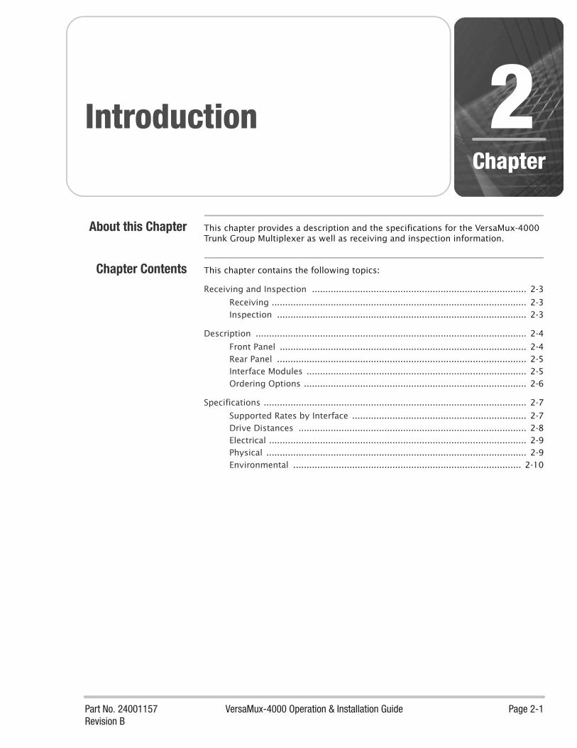
Part No. 24001157 VersaMux-4000 Operation & Installation Guide Page 2-1Revision B
Chapter
Introduction 2About this Chapter This chapter provides a description and the specifications for the VersaMux-4000
Trunk Group Multiplexer as well as receiving and inspection information.
Chapter Contents This chapter contains the following topics:
Receiving and Inspection ................................................................................ 2-3
Receiving ............................................................................................... 2-3Inspection ............................................................................................. 2-3
Description ..................................................................................................... 2-4
Front Panel ............................................................................................ 2-4Rear Panel ............................................................................................. 2-5Interface Modules .................................................................................. 2-5Ordering Options ................................................................................... 2-6
Specifications .................................................................................................. 2-7
Supported Rates by Interface ................................................................. 2-7Drive Distances ..................................................................................... 2-8Electrical ................................................................................................ 2-9Physical ................................................................................................. 2-9Environmental ..................................................................................... 2-10

Chapter 2: Introduction
Page 2-2 VersaMux-4000 Operation & Installation Guide Part No. 24001157Revision B
This page intentionally left blank
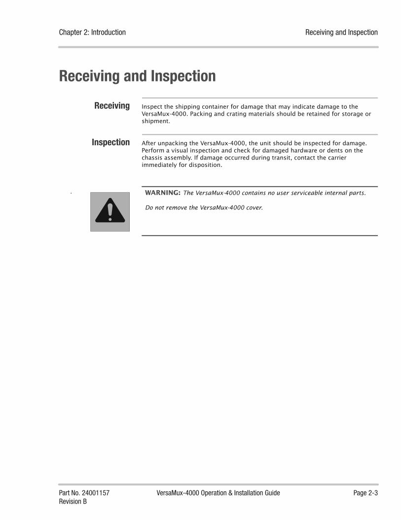
Chapter 2: Introduction Receiving and Inspection
Part No. 24001157 VersaMux-4000 Operation & Installation Guide Page 2-3Revision B
Receiving and Inspection
Receiving Inspect the shipping container for damage that may indicate damage to the VersaMux-4000. Packing and crating materials should be retained for storage or shipment.
Inspection After unpacking the VersaMux-4000, the unit should be inspected for damage. Perform a visual inspection and check for damaged hardware or dents on the chassis assembly. If damage occurred during transit, contact the carrier immediately for disposition.
WARNING: The VersaMux-4000 contains no user serviceable internal parts.
Do not remove the VersaMux-4000 cover.

Description Chapter 2: Introduction
Page 2-4 VersaMux-4000 Operation & Installation Guide Part No. 24001157Revision B
DescriptionThe VersaMux-4000 extends the current DNE CV product line by providing the ability to multiplex up to four ports of trunk group traffic onto a single aggregate channel for transport to a remote site. The VersaMux-4000 provides aggregate speeds up to 16-Mbps for use with modern high-speed radio and satellite equipment. The aggregate utilizes a highly efficient time division multiplexing (TDM) algorithm derived from the DNE AN/FCC-100 product line.
The VersaMux-4000 system consists of a base chassis that contains five interface slots (four user slots and one aggregate), external (station) clock input, control (craft) port, AC power input, and the front panel control interface. Interface modules populate the slot positions within the base chassis to meet specific customer requirements. The VersaMux-4000 mounts in a standard 19” rack or can operate as a “table-top” unit. Version 1.0 supports only the NRZ aggregate module and the Combo Fiber-Copper (user input) Modules.
The VersaMux-4000 provides circuit level modularity providing you with convenient upgrade and maintenance procedures while maintaining live operational links. The modular architecture also provides sparing capability for each interface. The VersaMux-4000 supports interoperability with all existing CV product line interfaces as well as JTC3A-9109 compliant equipment such as the AN/GSC-54 and MD-1272. In addition to operating with converter products, the VersaMux-4000 is interoperable with NRZ-based serial data equipment.
Hot Swap
The VersaMux-4000 modules are “hot swappable.” The interface modules can be replaced with another supported interface module without powering down the system. User interface modules can be “hot-swapped” without losing the other active user links. See “Hot-swap” on page 6-15.
Flash Memory
All VersaMux-4000 models store configuration information in flash memory. This enables the VersaMux-4000 to maintain the configuration through power cycles.
Front Panel The front panel of the VersaMux-4000 chassis provides an on/off switch, front panel display with keypad, and status LED indicators as shown in Figure 2-1.
Figure 2-1 VersaMux-4000 Front Panel
System POWER AGGR CLK REF PORTS FAULT
VersaMux-4000
0 I

Chapter 2: Introduction Description
Part No. 24001157 VersaMux-4000 Operation & Installation Guide Page 2-5Revision B
Rear Panel The VersaMux-4000 chassis is capable of accepting up to five interface modules (one aggregate module and up to four user input modules). The module slots are located on the rear panel of the chassis along with a craft (control) port, an external clock input (BNC connector), and a grounding post as shown in Figure 2-2.
Figure 2-2 VersaMux-4000 Rear Panel (Fully Populated- DNE Part Number 97680100)
Interface Modules Figure 2-3 shows a straight-on view of the NRZ Aggregate Module.
Figure 2-3 VersaMux-4000 NRZ Aggregate Module
Figure 2-4 shows a straight-on view of the Combo Fiber-Copper Module.
Figure 2-4 Versamux-4000 Combo Fiber-Copper Module
EXT CLK
FIBER / CUFRX CRX FTX CTX
FIBER / CUFRX CRX FTX CTX
FIBER / CUFRX CRX FTX CTX
FIBER / CUFRX CRX FTX CTX
NRZ
NRZ
FIBER / CUFRX CRX FTX CTX

Description Chapter 2: Introduction
Page 2-6 VersaMux-4000 Operation & Installation Guide Part No. 24001157Revision B
Ordering Options Table 2-1lists the VersaMux-4000 ordering options.
Table 2-1 VersaMux-4000 Ordering Options
Part Number Description
97680100 Versamux-4000 system. Includes a VersaMux-4000 Base Chassis, 4 Combo Modules, and an NRZ Aggregate Module
97680001 Versamux-4000 Chassis
97680008 Versamux-4000 Combo Fiber-Copper Module
97680003 Versamux-4000 NRZ Aggregate Module
24001157-000 Optional/Replacement Printed & Bound VersaMux-4000 User Guide (latest revision).
24001158-000 Optional/Replacement VersaMux-4000 User Guide on CD (latest revision).
61060214 Optional Blank Port Cover Plate. Use this plate to cover the chassis opening when you “permanently” remove a port module from the VersaMux-4000 chassis.
Table 2-1
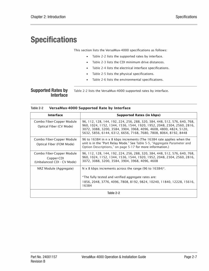
Chapter 2: Introduction Specifications
Part No. 24001157 VersaMux-4000 Operation & Installation Guide Page 2-7Revision B
SpecificationsThis section lists the VersaMux-4000 specifications as follows:
• Table 2-2 lists the supported rates by interface.
• Table 2-3 lists the CDI minimum drive distances.
• Table 2-4 lists the electrical interface specifications.
• Table 2-5 lists the physical specifications.
• Table 2-6 lists the environmental specifications.
Supported Rates byInterface
Table 2-2 lists the VersaMux-4000 supported rates by interface.
Table 2-2 VersaMux-4000 Supported Rate by Interface
Interface Supported Rates (in kbps)
Combo Fiber-Copper Module
Optical Fiber (CV Mode)
96, 112, 128, 144, 192, 224, 256, 288, 320, 384, 448, 512, 576, 640, 768, 960, 1024, 1152, 1344, 1536, 1544, 1920, 1952, 2048, 2304, 2560, 2816, 3072, 3088, 3200, 3584, 3904, 3968, 4096, 4608, 4800, 4824, 5120, 5632, 5856, 6144, 6312, 6656, 7168, 7680, 7808, 8064, 8192, 8448
Combo Fiber-Copper Module
Optical Fiber (FOM Mode)
96 to 16384 in n x 8 kbps increments (The 16384 rate applies when the unit is in the “Port Relay Mode.” See Table 5-5, “Aggregate Parameter and Option Descriptions,” on page 5-17 for more information.)
Combo Fiber-Copper Module
Copper-CDI (Unbalanced CDI - CV Mode)
96, 112, 128, 144, 192, 224, 256, 288, 320, 384, 448, 512, 576, 640, 768, 960, 1024, 1152, 1344, 1536, 1544, 1920, 1952, 2048, 2304, 2560, 2816, 3072, 3088, 3200, 3584, 3904, 3968, 4096, 4608
NRZ Module (Aggregate) N x 8 kbps increments across the range (96 to 16384)*.
*The fully tested and verified aggregate rates are:
1856, 2048, 3776, 4096, 7808, 8192, 9824, 10240, 11840, 12228, 15616, 16384
Table 2-2

Specifications Chapter 2: Introduction
Page 2-8 VersaMux-4000 Operation & Installation Guide Part No. 24001157Revision B
Drive Distances Table 2-3 lists the minimum specified drive distances for the VersaMux-4000 supported rates.
*Up to this distance, minimum. Actual drive distance may be greater.** See “Port-1, Port-2, Port-3 or Port-4” on page 5-21 for an explanation of the OW-Filter parameter.
Table 2-3 Minimum Specified * Drive Distances
Rates (kbps) Minimum** Distance Interface Medium
96 to 576 3.2 km (2.0 miles) Unbalanced
OW-Filter disabled
CX-11230 Cable
640 to 768 2.4 km (1.5 miles) Unbalanced
OW-Filter Disabled
CX-11230 Cable
960 to 1544 1.6 km (1.0 miles) Unbalanced
OW-Filter Disabled
CX-11230 Cable
1920 to 2304 1.2 km (0.75 miles) Unbalanced
OW-Filter Disabled
CX-11230 Cable
2560 to 4096 0.8 km (0.5 miles) Unbalanced
OW-Filter Disabled
CX-11230 Cable
4608 0.4 km (0.25 miles) Unbalanced
OW-Filter Disabled
CX-11230 Cable
256 to 1024 1.6 km (1.0 miles) Unbalanced
OW-Filter Enabled**
CX-11230 Cable
1152 to 1536 1.2 km (0.75 miles) Unbalanced
OW-Filter Enabled**
CX-11230 Cable
2048 to 2304 0.8 km (0.5 miles) Unbalanced
OW-Filter Enabled**
CX-11230 Cable
96 to 16,384 Approximately 2.0 km (1.2 miles) to 4.0 km (2.5 miles).
optical fiber 62.5μm Multimode fiber (1310 nm).
96 to 16,384 Approximately 2.0 km (1.2 miles) to 4.0 km (2.5 miles).
optical fiber 50μm Tactical fiber(1310 nm).
96 to 16,384 Approximately 20 km (12.4 miles) to 30 km (18.6 miles).
optical fiber 9/125μm Single-Mode, zero dispersion fiber
(1310 nm).
Table 2-3

Chapter 2: Introduction Specifications
Part No. 24001157 VersaMux-4000 Operation & Installation Guide Page 2-9Revision B
Electrical Table 2-4 lists the electrical specifications for the VersaMux-4000.
Physical Table 2-5 lists the physical specifications for the VersaMux-4000. Note that these dimensions do not include the space required for user connectors
Table 2-4 Electrical Interfaces Specifications
Characteristic Specification
NRZ Digital Interface EIA-530 physical, RS-422 (Balanced) using a female DB-25 connector.
Electrical (copper) CDI Interface SMA Connector
Input Voltage 110/220 VAC (90-132/180-264), 47 to 63 Hz, single phase.
External Clock Input Accepts the following:
Zero-Crossing clock signal (1.0 MHz, 5.0 MHz, or 10 MHz.) which provides a sine wave at 1V RMS minimum, 2V RMS maximum.
TTL clock signal running at 1.0 MHz, 5.0 MHz, or 10 MHz.
RS-422 clock signal running at 1.0 MHz, 5.0 MHz, or 10 MHz.
Table 2-4
Table 2-5 VersaMux-4000 Physical Specifications
Characteristic Specification
Height 1.75 inches
Width 17.4 inches
Depth 17.0 inches (including UG-1837)
Weight 8 pounds fully configured
Table 2-5

Specifications Chapter 2: Introduction
Page 2-10 VersaMux-4000 Operation & Installation Guide Part No. 24001157Revision B
Environmental Table 2-6 lists the environmental specifications for the VersaMux-4000.
Table 2-6 Environmental Specifications
Characteristic Specification
Operating Temperature -10oC to +50oC
Storage Temperature -30oC to +70oC
Humidity Up to 95%, non-condensing
Altitude Operates up to 15,000 feet and non-operating to 40,000 feet.
Electromagnetic Emissions
(FCC PART 15:2004)
The VersaMux-4000 conforms to the requirements of CFR47 (FCC) PART 15, SUBPART B, CLASS A, 2004 for conducted emissions and radiated emissions.
Table 2-6
Part No. 24001157 VersaMux-4000 Operation & Installation Guide Page 3-1Revision B
Chapter
Installation 3About this Chapter This chapter lists the site installation requirements and connection information.
Chapter Contents This chapter contains the following topics:
Requirements .................................................................................................. 3-3
Mounting ............................................................................................... 3-3Temperature .......................................................................................... 3-3
Rack Mounting ................................................................................................ 3-4
Rear Support Kit .............................................................................................. 3-5
Rear Support Kit Parts List ..................................................................... 3-5Rear Support Kit Illustrated Parts ........................................................... 3-6
Rear Support Bracket Kit Installation ............................................................... 3-8
Grounding ..................................................................................................... 3-18
Power Cord ................................................................................................... 3-19
System Interconnects .................................................................................... 3-20
NRZ ..................................................................................................... 3-20NRZ Control Leads ............................................................................... 3-21NRZ DTE Operation .............................................................................. 3-22NRZ DCE Operation ............................................................................. 3-23Unbalanced CDI ................................................................................... 3-24Control Port ......................................................................................... 3-25Fiber Optic Connectors ........................................................................ 3-25External Clock Input ............................................................................ 3-26

Chapter 3: Installation
Page 3-2 VersaMux-4000 Operation & Installation Guide Part No. 24001157Revision B
This page intentionally left blank

Chapter 3: Installation Requirements
Part No. 24001157 VersaMux-4000 Operation & Installation Guide Page 3-3Revision B
Requirements
Mounting The VersaMux-4000 can be either rack mounted in a standard 19-inch rack or desk-top mounted.
Temperature The VersaMux-4000 requires no external cooling as long as the ambient operating
temperature is between -10oC (14oF) and 50oC (122oF).

Rack Mounting Chapter 3: Installation
Page 3-4 VersaMux-4000 Operation & Installation Guide Part No. 24001157Revision B
Rack MountingThe VersaMux-4000 chassis installs in a standard 19-inch rack and requires a pair of rear support brackets.
Use the following procedure to install the VersaMux-4000 chassis:
1. Secure the front of the VersaMux-4000 chassis to the front rack mount rails as shown in Figure 3-1 using the provided #10 flat washers, #10 lock washers and 10-32 x 5/8-inch screws (four of each).
Note that the chassis front mounting screws and washers are included with the Rear Support Bracket Kit (see “Rear Support Kit Parts List” on page 3-5).
2. Become familiar with the rear support kit parts by reviewing “Rear Support Kit Parts List” on page 3-5 and “Rear Support Kit Illustrated Parts” on page 3-6 then assemble and install the rear support brackets as described in “Rear Support Bracket Kit Installation” on page 3-8.
Figure 3-1 Installing the VersaMux-4000 Chassis
POWER AGGR CLK REF PORTS FAULT
VersaMux-4000
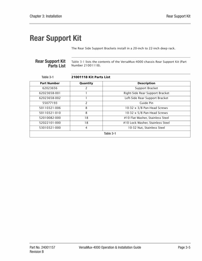
Chapter 3: Installation Rear Support Kit
Part No. 24001157 VersaMux-4000 Operation & Installation Guide Page 3-5Revision B
Rear Support KitThe Rear Side Support Brackets install in a 20-inch to 22-inch deep rack.
Rear Support KitParts List
Table 3-1 lists the contents of the VersaMux-4000 chassis Rear Support Kit (Part Number 21001118).
Table 3-1 21001118 Kit Parts List
Part Number Quantity Description
62023656 2 Support Bracket
62023658-001 1 Right-Side Rear Support Bracket
62023658-002 1 Left-Side Rear Support Bracket
55077193 2 Guide Pin
50110321-006 8 10-32 x 3/8 Pan-Head Screws
50110321-010 8 10-32 x 5/8 Pan-Head Screws
52010082-000 18 #10 Flat Washer, Stainless Steel
52022101-000 18 #10 Lock Washer, Stainless Steel
53010321-000 4 10-32 Nut, Stainless Steel
Table 3-1
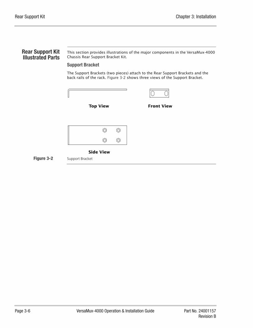
Rear Support Kit Chapter 3: Installation
Page 3-6 VersaMux-4000 Operation & Installation Guide Part No. 24001157Revision B
Rear Support KitIllustrated Parts
This section provides illustrations of the major components in the VersaMux-4000 Chassis Rear Support Bracket Kit.
Support Bracket
The Support Brackets (two pieces) attach to the Rear Support Brackets and the back rails of the rack. Figure 3-2 shows three views of the Support Bracket.
Figure 3-2 Support Bracket
Top View
Side View
Front View
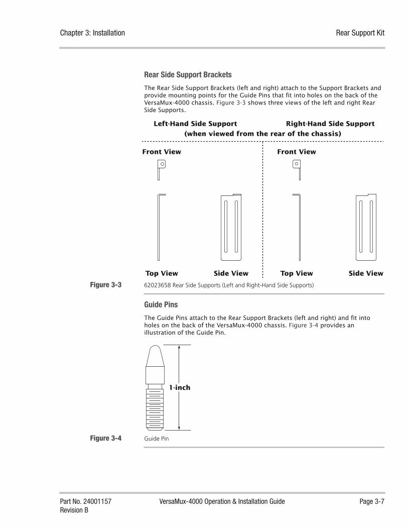
Chapter 3: Installation Rear Support Kit
Part No. 24001157 VersaMux-4000 Operation & Installation Guide Page 3-7Revision B
Rear Side Support Brackets
The Rear Side Support Brackets (left and right) attach to the Support Brackets and provide mounting points for the Guide Pins that fit into holes on the back of the VersaMux-4000 chassis. Figure 3-3 shows three views of the left and right Rear Side Supports.
Figure 3-3 62023658 Rear Side Supports (Left and Right-Hand Side Supports)
Guide Pins
The Guide Pins attach to the Rear Support Brackets (left and right) and fit into holes on the back of the VersaMux-4000 chassis. Figure 3-4 provides an illustration of the Guide Pin.
Figure 3-4 Guide Pin
Right-Hand Side SupportLeft-Hand Side Support
Top View Side View
Front View
Top View Side View
Front View
(when viewed from the rear of the chassis)
1-inch
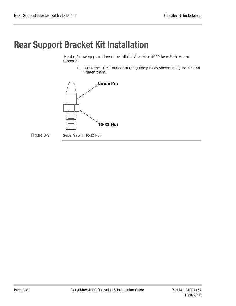
Rear Support Bracket Kit Installation Chapter 3: Installation
Page 3-8 VersaMux-4000 Operation & Installation Guide Part No. 24001157Revision B
Rear Support Bracket Kit InstallationUse the following procedure to install the VersaMux-4000 Rear Rack Mount Supports:
1. Screw the 10-32 nuts onto the guide pins as shown in Figure 3-5 and tighten them.
Figure 3-5 Guide Pin with 10-32 Nut
10-32 Nut
Guide Pin

Chapter 3: Installation Rear Support Bracket Kit Installation
Part No. 24001157 VersaMux-4000 Operation & Installation Guide Page 3-9Revision B
2. Secure the Guide Pin and nut assembly to the selected Rear Support Brackets using #10 flat washers, #10 lock washers, and 10-32 nuts as shown in Figure 3-6.
Figure 3-6 Securing the Guide Pin Assemblies to the Rear Support Brackets
The complete Rear Support Bracket assemblies are shown in Figure 3-7.
Right-Hand Side (when viewed from the rear of the chassis)Rear Support Bracket
Guide Pin& Nut
Left-Hand Side (when viewed from the rear of the chassis)Rear Support Bracket
Guide Pin & Nut

Rear Support Bracket Kit Installation Chapter 3: Installation
Page 3-10 VersaMux-4000 Operation & Installation Guide Part No. 24001157Revision B
Figure 3-7 Complete Rear Support Bracket Assemblies
Right-Hand Side (when viewed from the rear of the chassis)Rear Support Bracket Assembly
Left-Hand Side (when viewed from the rear of the chassis)Rear Support Bracket Assembly
Guide Pin
Guide Pin

Chapter 3: Installation Rear Support Bracket Kit Installation
Part No. 24001157 VersaMux-4000 Operation & Installation Guide Page 3-11Revision B
3. Mount the Rear Support Brackets to the Support Brackets using #10 flat washers, #10 lock washers, and 10-32 x 3/8-inch screws as shown in Figure 3-8.; leave them loose enough for the Support Brackets to slide back and forth. Figure 3-9 shows the completed bracket assemblies.
Figure 3-8 Assembling the Rear Mounting Brackets
Right-Hand Side (when viewed from the rear of the chassis)Support Bracket and Rear Support Bracket
Left-Hand Side (when viewed from the rear of the chassis)Support Bracket and Rear Support Bracket

Rear Support Bracket Kit Installation Chapter 3: Installation
Page 3-12 VersaMux-4000 Operation & Installation Guide Part No. 24001157Revision B
Figure 3-9 Completed Bracket Assemblies
Right-Hand Side (when viewed from the rear of the chassis)Bracket Assembly
Left-Hand Side (when viewed from the rear of the chassis)Bracket Assembly
Guide Pin
Guide Pin
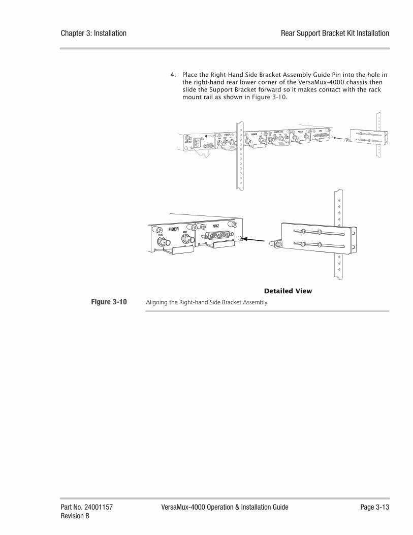
Chapter 3: Installation Rear Support Bracket Kit Installation
Part No. 24001157 VersaMux-4000 Operation & Installation Guide Page 3-13Revision B
4. Place the Right-Hand Side Bracket Assembly Guide Pin into the hole in the right-hand rear lower corner of the VersaMux-4000 chassis then slide the Support Bracket forward so it makes contact with the rack mount rail as shown in Figure 3-10.
Figure 3-10 Aligning the Right-hand Side Bracket Assembly
NRZFIBERRCV
XMT
EXT CLK
FIBER / CU
FRX CRX FTX CTXFIBERRCV
XMTFIBER / CU
FRX CRX FTX CTX
NRZFIBER
RCVXMT
Detailed View

Rear Support Bracket Kit Installation Chapter 3: Installation
Page 3-14 VersaMux-4000 Operation & Installation Guide Part No. 24001157Revision B
5. Secure the right-hand bracket assembly to the rack using #10 flat washers, #10 lock washers, and 10-32 x 5/8-inch screws as shown in Figure 3-11.
Figure 3-11 Securing the Right-Hand Bracket Assembly
NRZFIBERRCV
XMT
EXT CLK
FIBER / CU
FRX CRX FTX CTXFIBERRCV
XMTFIBER / CU
FRX CRX FTX CTX
NRZFIBER
RCVXMT
Detailed View

Chapter 3: Installation Rear Support Bracket Kit Installation
Part No. 24001157 VersaMux-4000 Operation & Installation Guide Page 3-15Revision B
6. Place the Left-Hand Side Bracket Assembly Guide Pin into the hole in the left-hand rear lower corner of the VersaMux-4000 chassis then slide the Support Bracket forward so it makes contact with the rack mount rail as shown in Figure 3-12.
Figure 3-12 Aligning the Left-Hand Side Bracket Assembly
NRZFIBERRCV
XMT
EXT CLK
FIBER / CU
FRX CRX FTX CTXFIBERRCV
XMTFIBER / CU
FRX CRX FTX CTX
EXT CLK
Detailed View

Rear Support Bracket Kit Installation Chapter 3: Installation
Page 3-16 VersaMux-4000 Operation & Installation Guide Part No. 24001157Revision B
7. Secure the left-hand bracket assembly to the rack using #10 flat washers, #10 lock washers, and 10-32 x 5/8-inch screws as shown in Figure 3-13.
Figure 3-13 Securing the Left-Hand Bracket Assembly
NRZFIBERRCV
XMT
EXT CLK
FIBER / CU
FRX CRX FTX CTXFIBERRCV
XMTFIBER / CU
FRX CRX FTX CTX
EXT CLK
Detailed View
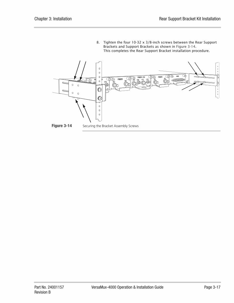
Chapter 3: Installation Rear Support Bracket Kit Installation
Part No. 24001157 VersaMux-4000 Operation & Installation Guide Page 3-17Revision B
8. Tighten the four 10-32 x 3/8-inch screws between the Rear Support Brackets and Support Brackets as shown in Figure 3-14. This completes the Rear Support Bracket installation procedure.
Figure 3-14 Securing the Bracket Assembly Screws
NRZFIBERRCV
XMT
EXT CLK
FIBER / CU
FRX CRX FTX CTXFIBERRCV
XMTFIBER / CU
FRX CRX FTX CTX

Grounding Chapter 3: Installation
Page 3-18 VersaMux-4000 Operation & Installation Guide Part No. 24001157Revision B
GroundingVersaMux-4000 units must be connected to sufficient earth grounding.
Use 12-AWG wire and a ring lug to connect the VersaMux-4000 to earth ground.
Figure 3-15 VersaMux-4000 Chassis Ground Location
EXT CLK
FIBER / CUFRX CRX FTX CTX
FIBER / CUFRX CRX FTX CTX
FIBER / CUFRX CRX FTX CTX
Ring Lug
12 AWG Ground Wire Connected to Earth Ground

Chapter 3: Installation Power Cord
Part No. 24001157 VersaMux-4000 Operation & Installation Guide Page 3-19Revision B
Power CordThe VersaMux-4000 units use 110/220 VAC, 47 to 63-Hz, single phase input power. A 6-ft. power cord with polarized plug is supplied with each VersaMux-4000. The VersaMux-4000 is equipped with a power cord retainer.
The following describes how to secure the power cord:
1. Insert the power cord into the VersaMux-4000 power receptacle as shown in Figure 3-16.
Figure 3-16 Inserting the Power Cord
2. Swing the power retainer clip up and press it onto the power cord as shown in Figure 3-17.
Figure 3-17 Securing the Power Cord
RCV
EXT CLK
FIBER / CU
FRX CRX FTX CTXFIBER
RCVXMTFIBER / CU
FRX CRX FTX CTX
RCV
EXT CLK
FIBER / CU
FRX CRX FTX CTXFIBER
RCVXMTFIBER / CU
FRX CRX FTX CTX

System Interconnects Chapter 3: Installation
Page 3-20 VersaMux-4000 Operation & Installation Guide Part No. 24001157Revision B
System InterconnectsAll I/O connections are made through the back of the VersaMux-4000. Pin-outs and connector identifications are provided in Figure 3-18 to Figure 3-24.
NOTE: Copper communications cables that attach to DNE products should be shielded and the drain wire tied to the metal shell of the connector body (if applicable). If required, place a split-core Fair-Rite, part number 0444167281 or equivalent, on the NRZ cable, close to the EUT to be compliant with FCC Part 15, Subpart B, Class A, 2004.
NRZ The NRZ interface of the VersaMux-4000 accepts and generates RS-422 (Balanced) signals using an EIA-530 DB-25 connector (the pin numbers are EIA-530, DCE).
Figure 3-18 provides a pin diagrams for the DCE NRZ connector with EIA-530 signal nomenclature. Figure 3-19 provides a pin diagrams for the DTE NRZ connector with EIA-530 signal nomenclature.
Figure 3-18 NRZ Input/Output Connector with EIA-530 Signal Nomenclature (DCE)
DCE Mode
Shield
Transmitted Data (A) +
Transmitted Data (B) -
Transmit Signal Element Timing DCE Source (B) -
Transmit Signal Element Timing DTE Source (A) +
Transmit Signal Element Timing DTE Source (B) -
Receiver Signal Element Timing DCE Source (A) +
Receiver Signal Element Timing DCE Source (B) -
Transmit Signal Element Timing DCE Source (A) +
Pin 1
Pin 2
Pin 3
Pin 7
Pin 9
Received Line Signal Detector (A) +
Received Line Signal Detector (B) -
Pin 8
Pin 10
Pin 11
Pin 12
Pin 13
Pin 14
Pin 15
Pin 16
Pin 17
Pin 19
Pin 24
Pin 23
Received Data (A) +
Received Data (B)-
Signal Common
Signal Common
Pin 4
Pin 5
Pin 6
Pin 20
NRZ EIA-530A (DCE)
Clear To Send -
Request To Send (A) +
Clear To Send (A) +
DCE Ready
Request To Send (RTS) -
DTE Ready
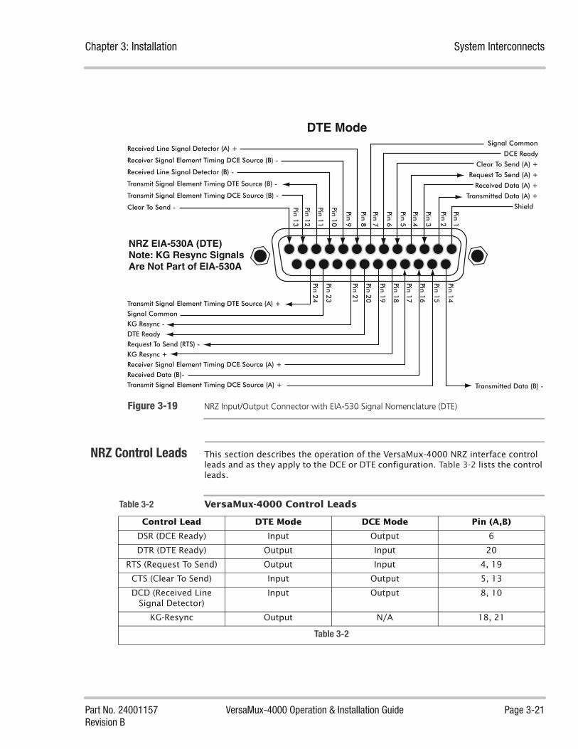
Chapter 3: Installation System Interconnects
Part No. 24001157 VersaMux-4000 Operation & Installation Guide Page 3-21Revision B
Figure 3-19 NRZ Input/Output Connector with EIA-530 Signal Nomenclature (DTE)
NRZ Control Leads This section describes the operation of the VersaMux-4000 NRZ interface control leads and as they apply to the DCE or DTE configuration. Table 3-2 lists the control leads.
DTE Mode
NRZ EIA-530A (DTE)Note: KG Resync SignalsAre Not Part of EIA-530A
Shield
Transmitted Data (A) +
Transmitted Data (B) -
Transmit Signal Element Timing DCE Source (B) -
Clear To Send -
Transmit Signal Element Timing DTE Source (A) +
Transmit Signal Element Timing DTE Source (B) -
Receiver Signal Element Timing DCE Source (A) +
Receiver Signal Element Timing DCE Source (B) -
Transmit Signal Element Timing DCE Source (A) +
Pin 1
Pin 2
Pin 3
Pin 7
Pin 9
Received Line Signal Detector (A) +
Received Line Signal Detector (B) -
Pin 8
Pin 10
Pin 11
Pin 12
Pin 13
Pin 14
Pin 15
Pin 16
Pin 17
Pin 24
Pin 23
Received Data (A) +
Request To Send (A) +
Clear To Send (A) +
DCE Ready
Received Data (B)-
KG Resync +
KG Resync -
Signal Common
Signal Common
Pin 4
Pin 5
Pin 6Pin 1
8
Pin 19
Pin 20
Request To Send (RTS) -DTE Ready
Pin 21
Table 3-2 VersaMux-4000 Control Leads
Control Lead DTE Mode DCE Mode Pin (A,B)
DSR (DCE Ready) Input Output 6
DTR (DTE Ready) Output Input 20
RTS (Request To Send) Output Input 4, 19
CTS (Clear To Send) Input Output 5, 13
DCD (Received Line Signal Detector)
Input Output 8, 10
KG-Resync Output N/A 18, 21
Table 3-2
System Interconnects Chapter 3: Installation
Page 3-22 VersaMux-4000 Operation & Installation Guide Part No. 24001157Revision B
NRZ DTE Operation This section describes the function of the VersaMux-4000 control leads when the NRZ interface is in the DTE mode (Mode parameter set to DTE).
DSR (DCE Ready)
When configured in the DTE mode, the DSR control lead is an input to the VersaMux. The VersaMux ignores the state of this control lead.
DTR (DTE Ready)
When configured in the DTE mode, the DTR control lead is an output from the VersaMux. The VersaMux asserts the DTR control lead at the beginning of the activation sequence during power-up. It remains asserted during normal VersaMux operation.
RTS (Request To Send)
When configured in the DTE mode, the RTS control lead is an output from the VersaMux. The VersaMux de-asserts the RTS control lead at the beginning of the activation sequence and asserts it at the end of the activation sequence. The activation sequence typically takes several seconds to complete.
CTS (Clear To Send)
When configured in the DTE mode, the CTS control lead is an input to the VersaMux. The VersaMux-4000 ignores the state of this control lead.
DCD (Received Line Signal Detector)
When configured in the DTE mode, the DCD control lead is an input to the VersaMux. If the Sync-Inhibit parameter is Disabled, the VersaMux ignores the DCD control lead. If the Sync-Inhibit parameter is Enabled, the Versamux interprets the DCD control lead as follows:
During activation the VersaMux disables its multiplexing (mux) and de-multiplexing (demux) functionality. When the VersaMux enables the demux functionality, it ignores the DCD control lead for a minimum of one second to allow the VersaMux demux to find frame. Once the VersaMux demux has successfully found frame it will then monitor the DCD control lead. If the DCD control lead is asserted, the VersaMux demux will operate normally (I.E. using its normal criteria to determine/declare Loss-Of-Frame). If the DCD control lead is de-asserted the VersaMux demux will ignore its normal criteria to determine/declare Loss-Of-Frame, and continue to distribute data to the ports normally.
KG-Resync
When configured in the DTE mode, the KG-Resync control lead is an output from the VersaMux. The VersaMux de-asserts the KG-Resync control lead at the beginning of the activation sequence.
When the KG-Resync parameter is Enabled and the VersaMux de-multiplexer is in the Loss-Of-Frame state for the period of time set by the Resync-Delay parameter value, the VersaMux asserts the KG-Resync control lead for a period of 6-8 milliseconds (+/- 500 microseconds).
The VersaMux repeats this cycle of Resync-Delay followed by the KG-Resync pulse for as long as the VersaMux de-multiplexer remains in the Loss-Of-Frame state.

Chapter 3: Installation System Interconnects
Part No. 24001157 VersaMux-4000 Operation & Installation Guide Page 3-23Revision B
NRZ DCE Operation This section describes the function of the VersaMux-4000 control leads when the NRZ interface is in the DCE mode (Mode parameter set to DCE).
DSR (DCE Ready)
When configured in the DCE mode, the DSR control lead is an output from the VersaMux. The VersaMux asserts the DSR control lead at the beginning of the activation sequence during power-up. It remains asserted during normal VersaMux operation.
DTR (DTE Ready)
When configured in the DCE mode, the DTR control lead is an input to the VersaMux. The VersaMux ignores the state of this control lead.
RTS (Request To Send)
When configured in the DCE mode, the RTS control lead is an input to the VersaMux. The VersaMux ignores the state of this control lead.
CTS (Clear To Send)
When configured in the DCE mode, the CTS control lead is an output from the VersaMux. The VersaMux asserts the CTS control lead at the beginning of the activation sequence during power-up. It remains asserted during normal VersaMux operation.
DCD (Received Line Signal Detector)
When configured in the DCE mode, the DCD control lead is an output from the VersaMux. The VersaMux asserts the DCD control lead at the beginning of the activation sequence during power-up. It remains asserted during normal VersaMux operation.
KG-Resync
When configured in the DCE mode, the KG-Resync control lead is an input to the VersaMux. The VersaMux ignores the state of this control lead.

System Interconnects Chapter 3: Installation
Page 3-24 VersaMux-4000 Operation & Installation Guide Part No. 24001157Revision B
Unbalanced CDI Figure 3-20 provides a pin diagram for the unbalanced CDI connector (Amphenol SMA connector, Amphenol Part Number 901-143-6RFX) found on the Versamux-4000 Combo Fiber-Copper Module.
Figure 3-20 Unbalanced CDI Input/Output Connector
Figure 3-21 calls out the unbalanced transmit and receive connectors on the Versamux-4000 Combo Fiber-Copper Module.
Figure 3-21 Combo Fiber-Copper Module Unbalanced CDI Transmit and Receive Connectors
Data Signal +
Data Signal - ("Return": VM-4000 ties this signal to chassis ground)
FIBER / CUFRX CRX FTX CTX
Copper (Unbalanced CDI)Transmit
Copper (Unbalanced CDI) Receive

Chapter 3: Installation System Interconnects
Part No. 24001157 VersaMux-4000 Operation & Installation Guide Page 3-25Revision B
Control Port Figure 3-22 provides a pin diagram for the control port found on the VersaMux-4000 rear panel. Use a DB-9M to DB-9F “straight-through” cable when connecting the VersaMux-4000 control port to the serial port of a PC.
Figure 3-22 Config Port (Control Terminal)
Fiber OpticConnectors
The Combo Fiber-Copper Module uses ST fiber optic connectors.
Figure 3-23 calls out the fiber optic transmit and receive connectors on the Versamux-4000 Combo Fiber-Copper Module.
Figure 3-23 Combo Fiber-Copper Module Fiber Optic Transmit and Receive Connectors
Control Port (DB9 Female)
Pin 2
Data to PC
Pin 3
Data from PC
Pin 5
Signal Ground
FIBER / CUFRX CRX FTX CTX
Fiber (Optic) ReceiveFiber (Optic) Transmit

System Interconnects Chapter 3: Installation
Page 3-26 VersaMux-4000 Operation & Installation Guide Part No. 24001157Revision B
External ClockInput
Figure 3-24 provides a diagram of the External Clock Input connectors found on the VersaMux-4000 rear panel.
Figure 3-24 External Clock Input Connector (BNC)
NOTE: The VersaMux-4000 External Clock Input does not support a “multi-drop” configuration.
When the Ext-Clk-Type parameter (see “Ext-Clk-Type Parameter” on page 5-13) is set to RS-422 the impedance between the A and B leads is 100-ohms.
When the Ext-Clk-Type parameter is set to Zero-Crossing the differential impedance of the external input is 50-ohms, single ended (center lead only).
When the Ext-Clk-Type parameter is set to Ttl the input is “High Impedance” between the center and shield (ground).
NOTE: The External Clock Input requires a timing signal accuracy of +/- 50 ppm from the nominal value.
Clock Signal -
Clock Signal +

Part No. 24001157 VersaMux-4000 Operation & Installation Guide Page 4-1Revision B
Chapter
Getting Started 4About this Chapter This chapter describes the VersaMux-4000 power-up procedure, basic software
navigation, and planning your timing configuration.
Chapter Contents This chapter contains the following topics:
Power-Up and Basic Navigation ....................................................................... 4-3
Port Numbering Convention .................................................................. 4-3Front Panel Interface .............................................................................. 4-3Terminal Interface .................................................................................. 4-5
Planning the Timing ...................................................................................... 4-13
Aggregate Timing ................................................................................ 4-13External Clock Input Timing ................................................................. 4-15Port Timing .......................................................................................... 4-18

Chapter 4: Getting Started
Page 4-2 VersaMux-4000 Operation & Installation Guide Part No. 24001157Revision B
This page intentionally left blank.

Chapter 4: Getting Started Power-Up and Basic Navigation
Part No. 24001157 VersaMux-4000 Operation & Installation Guide Page 4-3Revision B
Power-Up and Basic NavigationThe VersaMux-4000 operation and diagnostics are described in Chapter 5, “Operating Instructions” and Chapter 6, “Diagnostics”.
You can operate the VersaMux-400 via either the front panel interface or the terminal interface (control port).
Port NumberingConvention
The VersaMux-4000 menus refer to the ports by number. Figure 4-1 shows the VersaMux-4000 ports and the numbers the system assigns to them.
Figure 4-1 VersaMux-4000 Port Numbering (Rear View)
Front PanelInterface
The VersaMux-4000 front panel comes equipped with a power switch, LED status indicators, LCD display, and a control keypad. On power-up, the VersaMux-4000 performs a series of self tests. When the VersaMux-4000 completes the self tests (may take up to 15-seconds) the display turns on and displays the first Main Menu selection (Alarm-Status) as shown in Figure 4-2.
Figure 4-2 VersaMux-4000 Front Panel Illustrating Main Menu Starting Point (Alarm Status)
The control keypad has 5 keys (shown in Figure 4-2):
• Up Arrow Key
• Down Arrow Key
• Left Arrow Key
• Right Arrow Key
• Enter Key
EXT CLK
FIBER / CUFRX CRX FTX CTX
FIBER / CUFRX CRX FTX CTX
FIBER / CUFRX CRX FTX CTX
FIBER / CUFRX CRX FTX CTX
NRZ
Port 1 Port 2 Port 3 Port 4Port 5
(Aggregate)
Alarm-Status POWER

Power-Up and Basic Navigation Chapter 4: Getting Started
Page 4-4 VersaMux-4000 Operation & Installation Guide Part No. 24001157Revision B
Basic Front Panel Navigation
The LCD display has two lines with up to 16-characters on each line. The system displays Main Menu selections on the top line of the display with the bottom line left blank.
You can use the right and left arrow keys to navigate through the Main Menu selections. The system wraps around when you reach the end of the menu.Figure 4-3 shows the Main Menu and its navigation.
Figure 4-3 Main Menu, Front Panel Display
Pressing the down arrow key at a menu selection displays its sub-menu selections or parameters. The system displays the currently configured option for each parameter on the second line of the display as shown in Figure 4-4. In this example the option is informational (read-only) so the option is “right justified” on the display.
Figure 4-4 Informational Item (read-only option) Right Justified on the Display
If you can edit the option (read-write) it appears left justified and an asterisk appears in the top right corner of the display as shown in Figure 4-5.
Figure 4-5 Editable Option Left Justified with Asterisk
Pressing the right arrow key with a read-only or read-write option displayed returns the system to the previous menu selection. This enables you to quickly exit a long list of parameters or options. Note that pressing the right arrow key does not return to the menu selection when you are in the edit mode.
To enter the edit mode, press the Enter key when a read-write option appears on the display. The asterisk disappears indicating that the system is in the edit mode. When in the edit mode, the left and right arrow keys navigate through the options for the parameter. To select an option, press the Enter key. The asterisk reappears and pressing the right arrow key returns you to the menu selection.
Alarm-Status Configure Activate System-Info Statistics Diagnostics
Card-TypeNRZ-Card
POWER AGGR CLK R
Function *4-Port-Mux
POWER AGGR CLK R
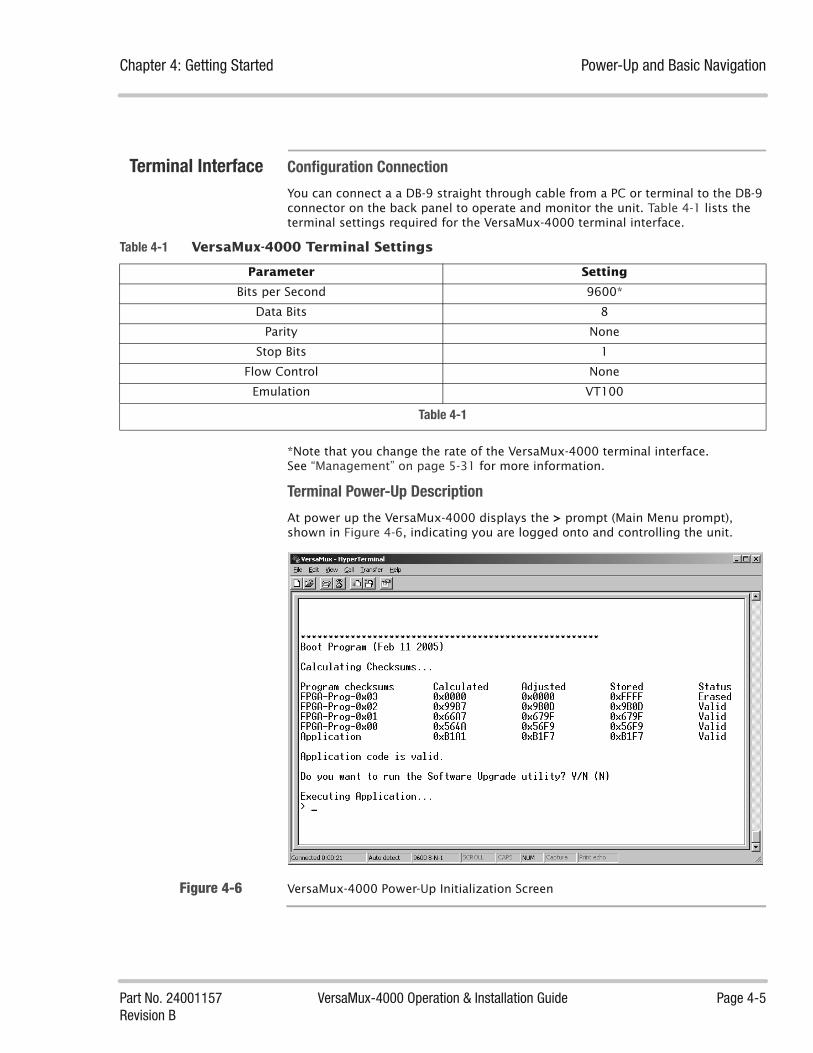
Chapter 4: Getting Started Power-Up and Basic Navigation
Part No. 24001157 VersaMux-4000 Operation & Installation Guide Page 4-5Revision B
Terminal Interface Configuration Connection
You can connect a a DB-9 straight through cable from a PC or terminal to the DB-9 connector on the back panel to operate and monitor the unit. Table 4-1 lists the terminal settings required for the VersaMux-4000 terminal interface.
*Note that you change the rate of the VersaMux-4000 terminal interface.See “Management” on page 5-31 for more information.
Terminal Power-Up Description
At power up the VersaMux-4000 displays the > prompt (Main Menu prompt), shown in Figure 4-6, indicating you are logged onto and controlling the unit.
Figure 4-6 VersaMux-4000 Power-Up Initialization Screen
Table 4-1 VersaMux-4000 Terminal Settings
Parameter Setting
Bits per Second 9600*
Data Bits 8
Parity None
Stop Bits 1
Flow Control None
Emulation VT100
Table 4-1

Power-Up and Basic Navigation Chapter 4: Getting Started
Page 4-6 VersaMux-4000 Operation & Installation Guide Part No. 24001157Revision B
Displaying Items
Type a ? (question mark) at the prompt to show all the items in a menu or list. Figure 4-7 shows the Main Menu parameters (items) when you type a question mark at the Main Menu prompt.
Figure 4-7 Main Menu Displayed After Typing a Question Mark (?)

Chapter 4: Getting Started Power-Up and Basic Navigation
Part No. 24001157 VersaMux-4000 Operation & Installation Guide Page 4-7Revision B
Figure 4-8 shows using the ? (question mark) command to display the options for the aggregate function parameter.
Figure 4-8 Displaying the Options for the Aggregate Function
Accessing Items
To access a parameter, enter the first characters that make the parameter name “unique.” For example, if you enter:Alat the Main Menu the system will access and display the parameter (in this example it will access the Alarm-Status parameter.
If you simply type an A the system responds that the entry is “ambiguous” since “a” is not unique. It can be either the Alarm-Status or the Activate parameter. Figure 4-9 shows the ambiguous response for this example.
Note that you can also enter the full entry name or any portion that makes it unique. For example, the system accepts “al”, “alar”, “alarm”, “alarm-st”, “alarm-status”, and so forth for the Alarm-Status parameter.

Power-Up and Basic Navigation Chapter 4: Getting Started
Page 4-8 VersaMux-4000 Operation & Installation Guide Part No. 24001157Revision B
Figure 4-9 Ambiguous Entry Response
The system displays an asterisk next to any editable item (option). For example, Figure 4-10 shows the options for the aggregate card. Note that the Card Type parameter is not editable and no asterisk appears before the NRZ Card option.

Chapter 4: Getting Started Power-Up and Basic Navigation
Part No. 24001157 VersaMux-4000 Operation & Installation Guide Page 4-9Revision B
Figure 4-10 Aggregate Sub-Menu Showing Editable and Non-Editable Options

Power-Up and Basic Navigation Chapter 4: Getting Started
Page 4-10 VersaMux-4000 Operation & Installation Guide Part No. 24001157Revision B
Changing Parameter Values
Figure 4-11 shows changing the Aggregate Function from the Port-1-Relay function to a 4-Port-Mux.
Figure 4-11 Changing the Aggregate Function Parameter
Exiting Menus
Enter a q (for quit) to exit a sub-menu. Figure 4-12 shows using the q command to return to the Main Menu from the aggregate function parameter.

Chapter 4: Getting Started Power-Up and Basic Navigation
Part No. 24001157 VersaMux-4000 Operation & Installation Guide Page 4-11Revision B
Figure 4-12 Using the q Command to Return to the Main Menu

Power-Up and Basic Navigation Chapter 4: Getting Started
Page 4-12 VersaMux-4000 Operation & Installation Guide Part No. 24001157Revision B
Concatenating Commands
You can concatenate commands to the VersaMux through the terminal interface.
For example, if you want to view or configure the offline aggregate from the Main Menu prompt, enter the following:
c o a
This concatenated command uses the minimum characters required to make each command unique (Configure then Offline then Aggregate).
If you want to return to the Main Menu prompt, enter the following:
q q q
This concatenated command represents Quit, Quit, Quit.
NOTE: Concatenated commands require a space (space bar on the keyboard) between characters. For example, enter the “c o a“ command as “c space o space a”. The system views “coa” (without spaces) as an ambiguous command.
Figure 4-13 illustrates this example.
Figure 4-13 Concatenating the Configure, Offline, Aggregate Command and Returning
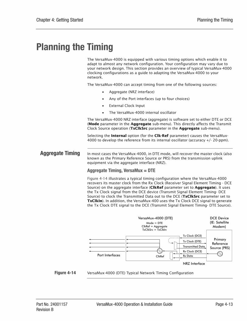
Chapter 4: Getting Started Planning the Timing
Part No. 24001157 VersaMux-4000 Operation & Installation Guide Page 4-13Revision B
Planning the TimingThe VersaMux-4000 is equipped with various timing options which enable it to adapt to almost any network configuration. Your configuration may vary due to your network design. This section provides an overview of typical VersaMux-4000 clocking configurations as a guide to adapting the VersaMux-4000 to your network.
The VersaMux-4000 can accept timing from one of the following sources:
• Aggregate (NRZ interface)
• Any of the Port interfaces (up to four choices)
• External Clock Input
• The VersaMux-4000 internal oscillator
The VersaMux-4000 NRZ interface (aggregate) is software set to either DTE or DCE (Mode parameter in the Aggregate sub-menu). This directly affects the Transmit Clock Source operation (TxClkSrc parameter in the Aggregate sub-menu).
Selecting the Internal option (for the Clk-Ref parameter) causes the VersaMux-4000 to develop the reference from its internal oscillator (accuracy +/- 20-ppm).
Aggregate Timing In most cases the VersaMux-4000, in DTE mode, will recover the master clock (also known as the Primary Reference Source or PRS) from the transmission uplink equipment via the aggregate interface (NRZ).
Aggregate Timing, VersaMux = DTE
Figure 4-14 illustrates a typical timing configuration where the VersaMux-4000 recovers its master clock from the Rx Clock (Receiver Signal Element Timing - DCE Source) on the aggregate interface (ClkRef parameter set to Aggregate). It uses the Tx Clock signal from the DCE device (Transmit Signal Element Timing- DCE Source) to clock the Transmitted Data out to the DCE (TxClkSrc parameter set to TxClkIn). In addition, the VersaMux-400 uses the Tx Clock DCE signal to generate the Tx Clock DTE signal to the DCE (Transmit Signal Element Timing- DTE Source).
Figure 4-14 VersaMux-4000 (DTE) Typical Network Timing Configuration
DCE Device(IE: Satellite
Modem)
ClkRef
NRZ Interface
Transmitted Data
Tx Clock (DCE)
Tx Clock (DTE)
Rx Clock (DCE)
Rx Data
Primary Reference
Source (PRS)
VersaMux-4000 (DTE)Mode = DTE
ClkRef = AggregateTxClkSrc = TxClkIn
Port Interfaces
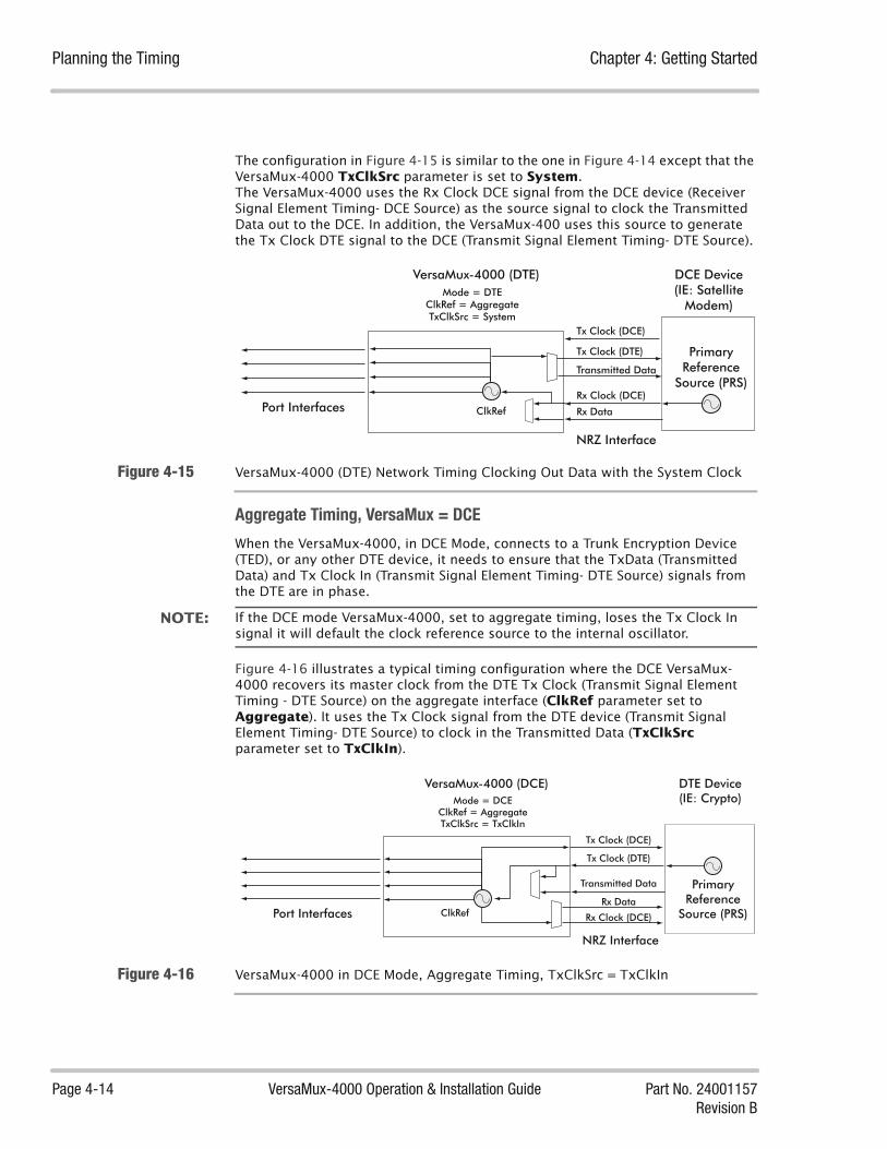
Planning the Timing Chapter 4: Getting Started
Page 4-14 VersaMux-4000 Operation & Installation Guide Part No. 24001157Revision B
The configuration in Figure 4-15 is similar to the one in Figure 4-14 except that the VersaMux-4000 TxClkSrc parameter is set to System.The VersaMux-4000 uses the Rx Clock DCE signal from the DCE device (Receiver Signal Element Timing- DCE Source) as the source signal to clock the Transmitted Data out to the DCE. In addition, the VersaMux-400 uses this source to generate the Tx Clock DTE signal to the DCE (Transmit Signal Element Timing- DTE Source).
Figure 4-15 VersaMux-4000 (DTE) Network Timing Clocking Out Data with the System Clock
Aggregate Timing, VersaMux = DCE
When the VersaMux-4000, in DCE Mode, connects to a Trunk Encryption Device (TED), or any other DTE device, it needs to ensure that the TxData (Transmitted Data) and Tx Clock In (Transmit Signal Element Timing- DTE Source) signals from the DTE are in phase.
NOTE: If the DCE mode VersaMux-4000, set to aggregate timing, loses the Tx Clock In signal it will default the clock reference source to the internal oscillator.
Figure 4-16 illustrates a typical timing configuration where the DCE VersaMux-4000 recovers its master clock from the DTE Tx Clock (Transmit Signal Element Timing - DTE Source) on the aggregate interface (ClkRef parameter set to Aggregate). It uses the Tx Clock signal from the DTE device (Transmit Signal Element Timing- DTE Source) to clock in the Transmitted Data (TxClkSrc parameter set to TxClkIn).
Figure 4-16 VersaMux-4000 in DCE Mode, Aggregate Timing, TxClkSrc = TxClkIn
DCE Device(IE: Satellite
Modem)
ClkRef
NRZ Interface
Transmitted Data
Tx Clock (DCE)
Tx Clock (DTE)
Rx Clock (DCE)
Rx Data
Primary Reference
Source (PRS)
VersaMux-4000 (DTE)Mode = DTE
ClkRef = AggregateTxClkSrc = System
Port Interfaces
DTE Device(IE: Crypto)
ClkRef
NRZ Interface
Transmitted Data
Tx Clock (DCE)
Tx Clock (DTE)
Rx Clock (DCE)
Rx Data
Primary Reference
Source (PRS)
VersaMux-4000 (DCE)Mode = DCE
ClkRef = AggregateTxClkSrc = TxClkIn
Port Interfaces
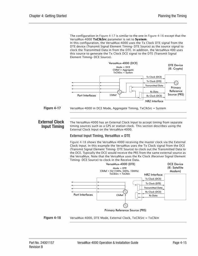
Chapter 4: Getting Started Planning the Timing
Part No. 24001157 VersaMux-4000 Operation & Installation Guide Page 4-15Revision B
The configuration in Figure 4-17 is similar to the one in Figure 4-16 except that the VersaMux-4000 TxClkSrc parameter is set to System.In this configuration, the VersaMux-4000 uses the Tx Clock DTE signal from the DTE device (Transmit Signal Element Timing- DTE Source) as the source signal to clock the Transmitted Data in from the DTE. In addition, the VersaMux-400 uses this source to generate the Tx Clock DCE signal to the DTE (Transmit Signal Element Timing- DCE Source).
Figure 4-17 VersaMux-4000 in DCE Mode, Aggregate Timing, TxClkSrc = System
External ClockInput Timing
The VersaMux-4000 has an External Clock Input to accept timing from separate timing sources such as a GPS or station clock. This section describes using the External Clock Input on the VersaMux-4000.
External Input Timing, VersaMux = DTE
Figure 4-18 shows the VersaMux-4000 receiving the master clock via the External Clock Input. In this example the VersaMux uses the Tx Clock signal from the DCE (Transmit Signal Element Timing- DTE Source) to clock out the Transmitted Data to the DCE. Typically the DCE would receive the PRS from the same external source as the VersaMux. Note that the VersaMux uses the Rx Clock (Receiver Signal Element Timing- DCE Source) to clock in the Receive Data.
Figure 4-18 VersaMux-4000, DTE Mode, External Clock, TxClkSrc = TxClkIn
DTE Device(IE: Crypto)
ClkRef
NRZ Interface
Transmitted Data
Tx Clock (DCE)
Tx Clock (DTE)
Rx Clock (DCE)
Rx Data
Primary Reference
Source (PRS)
VersaMux-4000 (DCE)Mode = DCE
ClkRef = AggregateTxClkSrc = System
Port Interfaces
DCE Device(IE: Satellite
Modem)
ClkRef
NRZ Interface
Transmitted Data
Tx Clock (DCE)
Tx Clock (DTE)
Rx Clock (DCE)
Rx Data
Primary Reference Source (PRS)
VersaMux-4000 (DTE)Mode = DTE
ClkRef = Ext (1MHz, 5MHz, 10MHz) TxClkSrc = TxClkIn
Port Interfaces
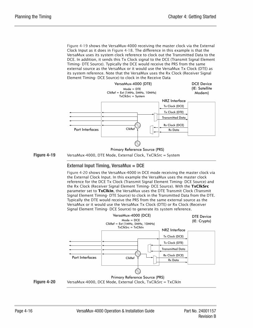
Planning the Timing Chapter 4: Getting Started
Page 4-16 VersaMux-4000 Operation & Installation Guide Part No. 24001157Revision B
Figure 4-19 shows the VersaMux-4000 receiving the master clock via the External Clock Input as it does in Figure 4-18. The difference in this example is that the VersaMux uses its system clock reference to clock out the Transmitted Data to the DCE. In addition, it sends this Tx Clock signal to the DCE (Transmit Signal Element Timing- DTE Source). Typically the DCE would receive the PRS from the same external source as the VersaMux or it would use the VersaMux Tx Clock (DTE) as its system reference. Note that the VersaMux uses the Rx Clock (Receiver Signal Element Timing- DCE Source) to clock in the Receive Data
Figure 4-19 VersaMux-4000, DTE Mode, External Clock, TxClkSrc = System
External Input Timing, VersaMux = DCE
Figure 4-20 shows the VersaMux-4000 in DCE mode receiving the master clock via the External Clock Input. In this example the VersaMux uses the master clock reference for the DCE Tx Clock (Transmit Signal Element Timing- DCE Source) and the Rx Clock (Receiver Signal Element Timing- DCE Source). With the TxClkSrc parameter set to TxClkIn, the VersaMux uses the DTE Transmit Clock (Transmit Signal Element Timing- DTE Source) to clock in the Transmitted Data from the DTE. Typically the DTE would receive the PRS from the same external source as the VersaMux or it would use the VersaMux Tx Clock (DTE) or Rx Clock (Receiver Signal Element Timing- DCE Source) to generate its system reference.
Figure 4-20 VersaMux-4000, DCE Mode, External Clock, TxClkSrc = TxClkIn
DCE Device(IE: Satellite
Modem)
ClkRef
NRZ Interface
Transmitted Data
Tx Clock (DCE)
Tx Clock (DTE)
Rx Clock (DCE)
Rx Data
VersaMux-4000 (DTE)Mode = DTE
ClkRef = Ext (1MHz, 5MHz, 10MHz) TxClkSrc = System
Port Interfaces
Primary Reference Source (PRS)
DTE Device(IE: Crypto)
ClkRef
NRZ Interface
Transmitted Data
Tx Clock (DCE)
Tx Clock (DTE)
Rx Clock (DCE)
Rx Data
Primary Reference Source (PRS)
VersaMux-4000 (DCE)Mode = DCE
ClkRef = Ext (1MHz, 5MHz, 10MHz) TxClkSrc = TxClkIn
Port Interfaces

Chapter 4: Getting Started Planning the Timing
Part No. 24001157 VersaMux-4000 Operation & Installation Guide Page 4-17Revision B
Figure 4-21 is similar to Figure 4-20 except that with the TxClkSrc parameter set to System, the VersaMux uses the system reference to clock the Transmitted Data in from the DTE. In addition, the VersaMux uses the system reference for the (Transmit Signal Element Timing- DCE Source) and Rx Clock (Receiver Signal Element Timing- DCE Source) signals to the DTE. Typically the DTE would receive the PRS from the same external source as the VersaMux or it would use the VersaMux Tx Clock (DTE) or Rx Clock (Receiver Signal Element Timing- DCE Source) to generate its system reference.
Figure 4-21 VersaMux-4000, DCE Mode, External Clock, TxClkSrc = System
DTE Device(IE: Crypto)
ClkRef
NRZ Interface
Transmitted Data
Tx Clock (DCE)
Tx Clock (DTE)
Rx Clock (DCE)
Rx Data
VersaMux-4000 (DCE)Mode = DCE
ClkRef = Ext (1MHz, 5MHz, 10MHz) TxClkSrc = System
Port Interfaces
Primary Reference Source (PRS)
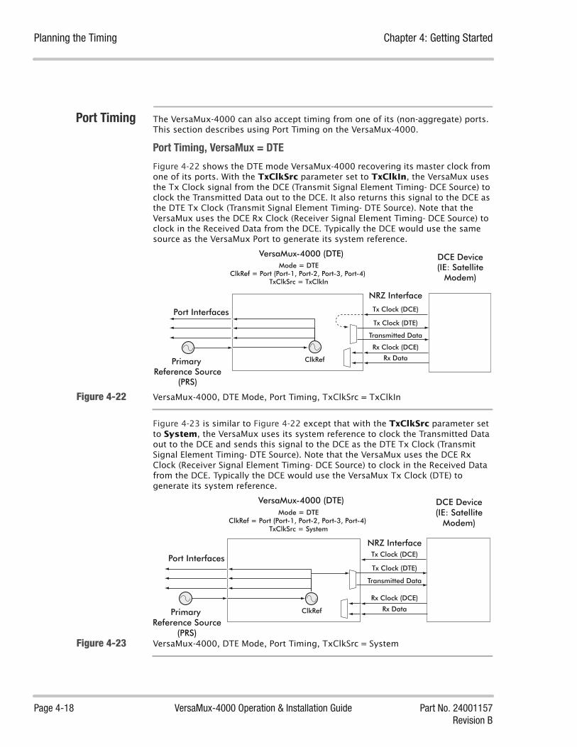
Planning the Timing Chapter 4: Getting Started
Page 4-18 VersaMux-4000 Operation & Installation Guide Part No. 24001157Revision B
Port Timing The VersaMux-4000 can also accept timing from one of its (non-aggregate) ports. This section describes using Port Timing on the VersaMux-4000.
Port Timing, VersaMux = DTE
Figure 4-22 shows the DTE mode VersaMux-4000 recovering its master clock from one of its ports. With the TxClkSrc parameter set to TxClkIn, the VersaMux uses the Tx Clock signal from the DCE (Transmit Signal Element Timing- DCE Source) to clock the Transmitted Data out to the DCE. It also returns this signal to the DCE as the DTE Tx Clock (Transmit Signal Element Timing- DTE Source). Note that the VersaMux uses the DCE Rx Clock (Receiver Signal Element Timing- DCE Source) to clock in the Received Data from the DCE. Typically the DCE would use the same source as the VersaMux Port to generate its system reference.
Figure 4-22 VersaMux-4000, DTE Mode, Port Timing, TxClkSrc = TxClkIn
Figure 4-23 is similar to Figure 4-22 except that with the TxClkSrc parameter set to System, the VersaMux uses its system reference to clock the Transmitted Data out to the DCE and sends this signal to the DCE as the DTE Tx Clock (Transmit Signal Element Timing- DTE Source). Note that the VersaMux uses the DCE Rx Clock (Receiver Signal Element Timing- DCE Source) to clock in the Received Data from the DCE. Typically the DCE would use the VersaMux Tx Clock (DTE) to generate its system reference.
Figure 4-23 VersaMux-4000, DTE Mode, Port Timing, TxClkSrc = System
DCE Device(IE: Satellite
Modem)
ClkRef
NRZ Interface
Transmitted Data
Tx Clock (DCE)
Tx Clock (DTE)
Rx Clock (DCE)
Rx DataPrimary Reference Source
(PRS)
VersaMux-4000 (DTE)Mode = DTE
ClkRef = Port (Port-1, Port-2, Port-3, Port-4) TxClkSrc = TxClkIn
Port Interfaces
DCE Device(IE: Satellite
Modem)
ClkRef
NRZ Interface
Transmitted Data
Tx Clock (DCE)
Tx Clock (DTE)
Rx Clock (DCE)
Rx Data
VersaMux-4000 (DTE)Mode = DTE
ClkRef = Port (Port-1, Port-2, Port-3, Port-4) TxClkSrc = System
Port Interfaces
Primary Reference Source
(PRS)

Chapter 4: Getting Started Planning the Timing
Part No. 24001157 VersaMux-4000 Operation & Installation Guide Page 4-19Revision B
Port Timing, VersaMux = DCE
Figure 4-24 shows the VersaMux-4000 in DCE mode and receiving its master clock from one of its ports. The VersaMux uses the system reference (ClkRef) to generate the DCE Tx Clock (Transmit Signal Element Timing- DCE Source) and Rx Clock (Receiver Signal Element Timing- DCE Source) signals. With the TxClkSrc set to TxClkIn, the VersaMux uses the Tx Clock signal from the DTE (Transmit Signal Element Timing- DTE Source) to clock the Transmitted Data in from the DTE. Typically the DTE would use the VersaMux DCE Tx Clock or DCE Rx Clock to generate its system reference.
Figure 4-24 VersaMux-4000, DCE Mode, Port Timing, TxClkSrc = TxClkIn
Figure 4-25 is similar to Figure 4-24 except that with the TxClkSrc set to System, the VersaMux uses its system reference to clock the Transmitted Data in from the DTE.
Figure 4-25 VersaMux-4000, DCE Mode, Port Timing, TxClkSrc = System
DTE Device
ClkRef
NRZ Interface
Transmitted Data
Tx Clock (DCE)
Tx Clock (DTE)
Rx Clock (DCE)
Rx Data
Primary Reference Source
(PRS)
VersaMux-4000 (DCE)Mode = DCE
ClkRef = Port (Port-1, Port-2, Port-3, Port-4) TxClkSrc = TxClkIn
Port Interfaces
Mode = DCEClkRef = Port (Port-1, Port-2, Port-3, Port-4)
TxClkSrc = System DTE Device
ClkRef
NRZ Interface
Transmitted Data
Tx Clock (DCE)
Tx Clock (DTE)
Rx Clock (DCE)
Rx Data
Primary Reference Source
(PRS)
VersaMux-4000 (DCE)
Port Interfaces

Planning the Timing Chapter 4: Getting Started
Page 4-20 VersaMux-4000 Operation & Installation Guide Part No. 24001157Revision B
This page intentionally left blank

Part No. 24001157 VersaMux-4000 Operation & Installation Guide Page 5-1Revision B
Chapter
Operating Instructions 5About this Chapter This chapter describes the VersaMux-4000 menu structure and how to use it to
program the VersaMux-4000.
Chapter Contents This chapter contains the following topics:
Main Menu ...................................................................................................... 5-3
Terminal Interface .................................................................................. 5-3Front Panel Interface .............................................................................. 5-4
Alarm-Status ................................................................................................... 5-5
Terminal Interface .................................................................................. 5-6Front Panel Interface .............................................................................. 5-7
Configure ........................................................................................................ 5-8
Terminal Interface .................................................................................. 5-8Front Panel Interface .............................................................................. 5-9System .................................................................................................. 5-9Offline ................................................................................................. 5-14Active .................................................................................................. 5-24CAU ..................................................................................................... 5-27Management ....................................................................................... 5-31
Activate ........................................................................................................ 5-34
Terminal Interface ................................................................................ 5-35Front Panel Interface ............................................................................ 5-35
System-Info ................................................................................................... 5-36
Conditions ........................................................................................... 5-36Inventory ............................................................................................. 5-36Terminal Interface ................................................................................ 5-37Front Panel Interface ............................................................................ 5-41
Statistics ....................................................................................................... 5-42
Front Panel Interface ............................................................................ 5-42Terminal Interface ................................................................................ 5-43Alarm-Stats .......................................................................................... 5-44Aggregate-Stats ................................................................................... 5-44Bandwidth-Stats ................................................................................... 5-45

Chapter 5: Operating Instructions
Page 5-2 VersaMux-4000 Operation & Installation Guide Part No. 24001157Revision B
This page intentionally left blank.

Chapter 5: Operating Instructions Main Menu
Part No. 24001157 VersaMux-4000 Operation & Installation Guide Page 5-3Revision B
Main MenuThe VersaMux-4000 is equipped with a keypad and LCD display (often referred to as the Front Panel Interface). To configure the operational parameters you can use the Front Panel Interface or you can establish a terminal session with the unit.
The Main Menu is comprised of the following selections:
• Alarm-Status (see “Alarm-Status” on page 5-5)
• Configure (see “Configure” on page 5-8)
• Activate (see “Activate” on page 5-34)
• System-Info(see “System-Info” on page 5-36)
• Statistics(see “Statistics” on page 5-42)
• Diagnostics(see Chapter 6, Diagnostics)
Terminal Interface Figure 5-1 shows the Main Menu displayed on the terminal interface (HyperTerminal).
Figure 5-1 Main Menu Displayed After Typing a Question Mark (?)

Main Menu Chapter 5: Operating Instructions
Page 5-4 VersaMux-4000 Operation & Installation Guide Part No. 24001157Revision B
Front PanelInterface
The LCD display has two lines with up to 16-characters on each line. The system displays menu items on the top line of the display with the bottom line left blank.
The LCD displays contains either “menu items” (parameters) or “list items” (options).
You can use the right and left arrow keys to navigate through menu items. The system wraps around when you reach the either end of the menu. Figure 5-2 shows the Main Menu and its navigation.
Figure 5-2 Main Menu Navigation, Front Panel Display
Alarm-Status Configure Activate System-Info Statistics Diagnostics

Chapter 5: Operating Instructions Alarm-Status
Part No. 24001157 VersaMux-4000 Operation & Installation Guide Page 5-5Revision B
Alarm-StatusSelecting the Alarm-Status parameter from the Main Menu displays a list of the active alarms.
Table 5-1 provides a list of the alarms their descriptions, and the interfaces they apply to.
Table 5-1 Alarm Descriptions
Alarm Description
Syste
m
Port
-1
Port
-2
Port
-3
Port
-4
Ag
gre
gate
POST-Fail One or more of the Power-On-Self-Tests failed. X
BIST-Fail One or more of the Built-In-Self-Tests failed one or more. X
FTM-Fail One or more of the Factory-Test-Mode tests failed. X
Stack-Low The Operating-System-Stack is low. X
Hot-Swap The Hot-Swap mode is enabled. X
Incompat-HW The interface card in this slot is incompatible with the configured mode.
X X X X X
RefClk_Fail The Reference-Clock has failed. This failure could be caused by; no signal present, poor signal present, reference signal at the wrong rate.
X
SystFPGA The System FPGA is not programmed. X
TxAggrFPGA The Tx-Aggregate FPGA is not programmed. X
RxAggrFPGA The Rx-Aggregate FPGA is not programmed. X
Insuff-BW The sum of the individual port bandwidths exceeds the available aggregate bandwidth.
X
LOF The aggregate is in a Loss-Of-Frame condition. X
PLL-Lock The interface card PLL is not locked to the reference. X X X X X
Sync-Loss The interface card receiver is not in sync. X X X X X
BERT-Active The active BERT is affecting port or aggregate user traffic. X
FIFO-Err The interface card FIFO has overflowed or has an under-run condition.
X X X X X
Table 5-1

Alarm-Status Chapter 5: Operating Instructions
Page 5-6 VersaMux-4000 Operation & Installation Guide Part No. 24001157Revision B
Terminal Interface Figure 5-3 shows how to access and view the active alarms from the terminal interface.
Figure 5-3 Active Alarms Alarm-Status

Chapter 5: Operating Instructions Alarm-Status
Part No. 24001157 VersaMux-4000 Operation & Installation Guide Page 5-7Revision B
Front PanelInterface
You can scroll through the active alarms using the Up and Down arrow keys on the front panel interface. The system displays one alarm at a time.
Figure 5-4 shows how to navigate the Alarm-Status parameter from the front panel interface.
Figure 5-4 Alarm Status Front Panel Navigation
Alarm-Status
Operation Alarm
Alarm-System LOF (example)
Additional Active Alarms

Configure Chapter 5: Operating Instructions
Page 5-8 VersaMux-4000 Operation & Installation Guide Part No. 24001157Revision B
Configure
NOTE: Two VersaMux units connected end-to-end must have matched aggregate rate and port rate configurations.
The Configure sub-menu contains the following selections:
• System(see “System” on page 5-9)
• Offline(see “Offline” on page 5-14)
• Active(see “Active” on page 5-24)
• CAU(see “CAU” on page 5-27)
• Management(see “Management” on page 5-31)
Terminal Interface Figure 5-5 shows how to access the Configure sub-menu from the terminal interface.
Figure 5-5 Configure Menu Displayed on the Terminal Interface

Chapter 5: Operating Instructions Configure
Part No. 24001157 VersaMux-4000 Operation & Installation Guide Page 5-9Revision B
Front PanelInterface
Figure 5-6 shows how to navigate the Configure sub-menu from the front panel interface.
Figure 5-6 Configure Menu Navigation from the Front Panel Interface
System Selecting System from the Configure sub-menu displays the System parameters and their current values. The System parameters are:
• Clk-Ref (see “Clk-Ref Parameter” on page 5-12)
• Ext-Clk-Type (see “Ext-Clk-Type Parameter” on page 5-13)
• FP-Lighting (see “FP-Lighting Parameter” on page 5-14)
Terminal Interface
Figure 5-7 shows how to access the System parameters from the terminal interface.
Figure 5-7 Accessing the System Sub-Menu
Configure
System Offline Active CAU Management
System Parameters Offline Parameters Active Parameters CAU Parameters Management Parameters

Configure Chapter 5: Operating Instructions
Page 5-10 VersaMux-4000 Operation & Installation Guide Part No. 24001157Revision B
Figure 5-8 shows how to access the System parameter options from the terminal interface (this example shows the Clk-Ref parameter options).
Figure 5-8 Accessing the Clk Ref Options from the Terminal Interface
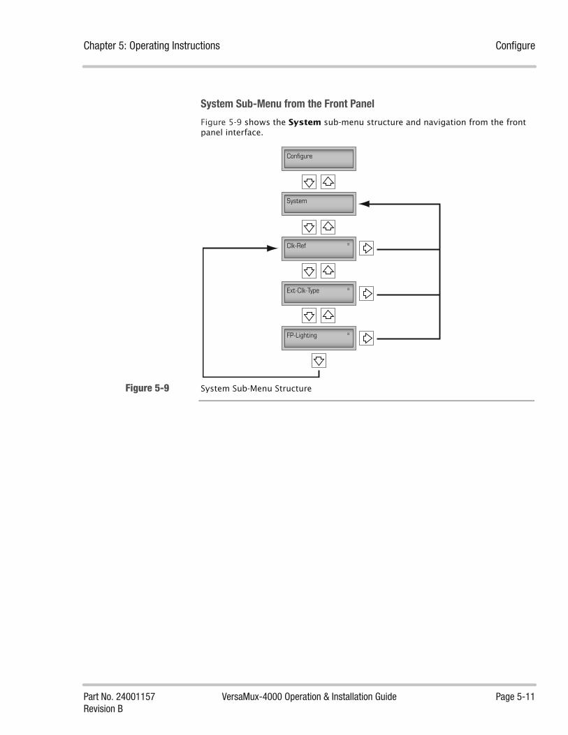
Chapter 5: Operating Instructions Configure
Part No. 24001157 VersaMux-4000 Operation & Installation Guide Page 5-11Revision B
System Sub-Menu from the Front Panel
Figure 5-9 shows the System sub-menu structure and navigation from the front panel interface.
Figure 5-9 System Sub-Menu Structure
Configure
System
Clk-Ref *
Ext-Clk-Type *
FP-Lighting *

Configure Chapter 5: Operating Instructions
Page 5-12 VersaMux-4000 Operation & Installation Guide Part No. 24001157Revision B
Figure 5-10 shows how to access the System parameter options from the Front Panel Interface.
Figure 5-10 Accessing System Sub-Menu Parameter Options
Clk-Ref Parameter
The Clk-Ref parameter specifies the source the VersaMux-4000 uses as the reference for the system timing.
Table 5-2 provides descriptions of the Clk-Ref options.
Configure
System
Clk-Ref *
Ext-Clk-Type *
FP-Lighting * ENTER
ENTER
ENTER Clock-Reference Options
External-Clock-Type Options
Front Panel-Lighting Options
Table 5-2 Clk-Ref Option Descriptions
Option Description
Ext-1MHz The VersaMux uses either a 1-MHz Bipolar, a 1-MHz TTL, or a 1-MHz RS-422, signal from the External Clock Input to generate the System Timing Clock Reference.
Ext-5MHz The VersaMux uses either a 5-MHz Bipolar, a 5-MHz TTL, or a 5-MHz RS-422, signal from the External Clock Input to generate the System Timing Clock Reference.
Ext-10MHz The VersaMux uses either a 10-MHz Bipolar, a 10-MHz TTL, or a 10-MHz RS-422, signal from the External Clock Input to generate the System Timing Clock Reference.
Aggregate The VersaMux uses the recovered timing signal from the Aggregate interface to generate the System Timing Clock Reference.
Port-1 The VersaMux uses the recovered timing signal from the Port 1 interface to generate the System Timing Clock Reference.
Table 5-2 (page 1 of 2)

Chapter 5: Operating Instructions Configure
Part No. 24001157 VersaMux-4000 Operation & Installation Guide Page 5-13Revision B
NOTE: The External Clock Input requires a timing signal accuracy of +/- 50 ppm from the nominal value.CV-2048 and CV-8448 internal oscillators have a specified accuracy of +/-100 ppm while the VersaMux has a tracking tolerance of +/-50 ppm. Therefore, when connecting a VersaMux to a CV-2048 or CV-8448 do not use the CV-2048 or CV-8448 internal oscillators as a timing reference for the system.
Ext-Clk-Type Parameter
The Ext-Clk-Type parameter specifies the type of signal presented to the Ext-Clk BNC connector (For more information about the External Clock Input, see “External Clock Input” on page 3-26 and “Electrical” on page 2-9).
You need to set the Ext-Clk-Type parameter if the Clk-Ref parameter is set to Ext-1MHz, Ext-5MHz, or Ext-10MHz. Table 5-3 provides descriptions of the Ext-Clk-Type options.
Port-2 The VersaMux uses the recovered timing signal from the Port 2 interface to generate the System Timing Clock Reference.
Port-3 The VersaMux uses the recovered timing signal from the Port 3 interface to generate the System Timing Clock Reference.
Port-4 The VersaMux uses the recovered timing signal from the Port 4 interface to generate the System Timing Clock Reference.
Internal Internal mode bases system timing off of an on-board oscillator with a frequency accuracy of better than +/- 20 ppm.
Table 5-2 Clk-Ref Option Descriptions
Option Description
Table 5-2 (page 2 of 2)
Table 5-3 Ext-Clk-Type Option Descriptions
Option Description
RS-422 Use this option for a RS-422 clock (the impedance between the A and B leads is 100-ohms).
Zero-Crossing Use this option for a station clock (1.0 MHz or 5.0 MHz) which provides a sine wave (1V RMS minimum and 2V RMS maximum). If the external input is single ended (center lead only), then the impedance of the external input is 50-ohms (assuming a common ground between the Versamux and the external clock source).
TTL Use this option for a digital TTL (Transistor-Transistor Logic) clock input.The Station Clock Interface input impedance is 50 +/-10% to ground in TTL mode.
Table 5-3

Configure Chapter 5: Operating Instructions
Page 5-14 VersaMux-4000 Operation & Installation Guide Part No. 24001157Revision B
FP-Lighting Parameter
The FP-Lighting parameter specifies the front panel display lighting mode. Table 5-4 describes the options for the FP-Lighting parameter.
Offline The Offline sub-menu allows you to provision a configuration without disturbing a unit while in operation. When you complete the offline configuration, you can use the Activate parameter to apply the offline configuration to the active configuration (see “Activate” on page 5-34).
The Offline sub-menu contains the following items:
• Aggregate (See “Aggregate” on page 5-16)
• Port-1 (see “Port-1, Port-2, Port-3 or Port-4” on page 5-21)
• Port-2 (see “Port-1, Port-2, Port-3 or Port-4” on page 5-21)
• Port-3 (see “Port-1, Port-2, Port-3 or Port-4” on page 5-21)
• Port-4 (see “Port-1, Port-2, Port-3 or Port-4” on page 5-21)
• Copy-Config (see “Copy-Config” on page 5-23)
Table 5-4 FP-Lighting Option Descriptions
Option Description
Off Selecting this option disables both the LCD backlighting and the status LEDs.
On Selecting this option illuminates the LCD backlighting and the status LEDs.
30-seconds Selecting this option enables the LCD backlighting and illuminates the status LEDs during keypad activity. The backlighting and LEDs turns off after 30 seconds of keypad inactivity.
Table 5-4

Chapter 5: Operating Instructions Configure
Part No. 24001157 VersaMux-4000 Operation & Installation Guide Page 5-15Revision B
Terminal Interface
Figure 5-11 shows the Offline sub-menu structure and how to access it from the terminal interface
Figure 5-11 Accessing the Offline Parameters from the Terminal Interface

Configure Chapter 5: Operating Instructions
Page 5-16 VersaMux-4000 Operation & Installation Guide Part No. 24001157Revision B
Front Panel Interface
Figure 5-12 shows the Offline sub-menu structure and navigation from the front panel interface.
Figure 5-12 Accessing Offline Sub-Menu Parameter Options
Aggregate
When you select Aggregate from the Offline sub-menu, the system displays the aggregate parameters and the current value for each.
The Aggregate parameters are:
• Card-Type (read-only for Release 1.0 software)
• Function
• Mode
• Rate
• RxClkSense
• TxClkSense
• TxClkSrc
• Mark-Sense
• Sync-Inhibit
Table 5-5 provides descriptions for the Aggregate parameters and options.
Configure
Offline
Aggregate Port-1 Copy-Config
AggregateParameters
ParameterOptions
ENTER
PortParameters Port
OptionsENTER Copy_Config
Options
Options
Ports 2, 3 & 4
ENTER

Chapter 5: Operating Instructions Configure
Part No. 24001157 VersaMux-4000 Operation & Installation Guide Page 5-17Revision B
Table 5-5 Aggregate Parameter and Option Descriptions
Parameter Options and Description
Card Type The system displays the card type installed. NOTE: Release 1.0 software only supports an NRZ module as the aggregate.
Function NOTE: Changing and activating this parameter resets the port rates to 0 (zero) kbps.
The options for the Function parameter are:
4-Port-Mux - The VersaMux-4000 functions as a trunk group multiplexer. This option configures the VersaMux-4000 to multiplex the traffic from each port onto the aggregate.
Port-1-Relay - The VersaMux-4000 relays the traffic between Port-1 and the aggregate. This option configures the VersaMux-4000 as a protocol converter with the port running at the aggregate rate.
Port-2-Relay - The VersaMux-4000 relays the traffic between Port-2 and the aggregate. This option configures the VersaMux-4000 as a protocol converter with the port running at the aggregate rate.
Port-3-Relay - The VersaMux-4000 relays the traffic between Port-3 and the aggregate. This option configures the VersaMux-4000 as a protocol converter with the port running at the aggregate rate.
Port-4-Relay - The VersaMux-4000 relays the traffic between Port-4 and the aggregate. This option configures the VersaMux-4000 as a protocol converter with the port running at the aggregate rate.
Mode The options for the Mode parameter are:
Disabled – The system disables the aggregate interface.
DCE - The NRZ connector uses the DCE signals as described in the EIA-530-A specification. See “NRZ” on page 3-20 and Figure 3-18 on page 3-20. Also see “NRZ DCE Operation” on page 3-23 for a description of the NRZ control lead behavior when in DCE mode.
DTE The NRZ connector uses the DTE signals as described in the EIA-530-A specification. See “NRZ” on page 3-20 and Figure 3-19 on page 3-21. Also see “NRZ DCE Operation” on page 3-23 for a description of the NRZ control lead behavior when in DTE mode.
Table 5-5 (page 1 of 3)
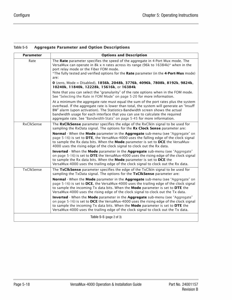
Configure Chapter 5: Operating Instructions
Page 5-18 VersaMux-4000 Operation & Installation Guide Part No. 24001157Revision B
Rate The Rate parameter specifies the speed of the aggregate in 4-Port Mux mode. The VersaMux can operate in 8k x n rates across its range (96k to 16384k)* when in the port relay mode or the Fiber FOM mode. *The fully tested and verified options for the Rate parameter (in the 4-Port-Mux mode) are:
0 (zero, Mode = Disabled), 1856k, 2048k, 3776k, 4096k, 7808k, 8192k, 9824k, 10240k, 11840k, 12228k, 15616k, or 16384k
Note that you can select the “granularity” of the rate options when in the FOM mode. See “Selecting the Rate in FOM Mode” on page 5-20 for more information.
At a minimum the aggregate rate must equal the sum of the port rates plus the system overhead. If the aggregate rate is lower than total, the system will generate an “Insuff BW” alarm (upon activation). The Statistics-Bandwidth screen shows the actual bandwidth usage for each interface that you can use to calculate the required aggregate rate. See “Bandwidth-Stats” on page 5-45 for more information.
RxClkSense The RxClkSense parameter specifies the edge of the RxClkIn signal to be used for sampling the RxData signal. The options for the Rx Clock Sense parameter are:
Normal - When the Mode parameter in the Aggregate sub-menu (see “Aggregate” on page 5-16) is set to DTE, the VersaMux-4000 uses the falling edge of the clock signal to sample the Rx data bits. When the Mode parameter is set to DCE the VersaMux-4000 uses the rising edge of the clock signal to clock out the Rx data.
Inverted - When the Mode parameter in the Aggregate sub-menu (see “Aggregate” on page 5-16) is set to DTE the VersaMux-4000 uses the rising edge of the clock signal to sample the Rx data bits. When the Mode parameter is set to DCE the VersaMux-4000 uses the trailing edge of the clock signal to clock out the Rx data.
TxClkSense The TxClkSense parameter specifies the edge of the TxClkIn signal to be used for sampling the TxData signal. The options for the TxClkSense parameter are:
Normal - When the Mode parameter in the Aggregate sub-menu (see “Aggregate” on page 5-16) is set to DCE, the VersaMux-4000 uses the trailing edge of the clock signal to sample the incoming Tx data bits. When the Mode parameter is set to DTE the VersaMux-4000 uses the rising edge of the clock signal to clock out the Tx data.
Inverted - When the Mode parameter in the Aggregate sub-menu (see “Aggregate” on page 5-16) is set to DCE the VersaMux-4000 uses the rising edge of the clock signal to sample the incoming Tx data bits. When the Mode parameter is set to DTE the VersaMux-4000 uses the trailing edge of the clock signal to clock out the Tx data.
Table 5-5 Aggregate Parameter and Option Descriptions
Parameter Options and Description
Table 5-5 (page 2 of 3)

Chapter 5: Operating Instructions Configure
Part No. 24001157 VersaMux-4000 Operation & Installation Guide Page 5-19Revision B
TxClkSrc The TxClkSrc parameter specifies the timing source to clock Tx data into the VersaMux-4000 or to clock Tx data out of the VersaMux-4000. The options for the TxClkSrc parameter are:
TxClkIn - In DCE mode, the VersaMux-4000 uses the Tx Clock signal from the DTE device (Transmit Signal Element Timing- DTE Source) to clock in the Transmitted Data. In DTE mode, the VersaMux-4000 uses the Tx Clock signal from the DCE device (Transmit Signal Element Timing- DCE Source) to clock the Transmitted Data out to the DCE.
System - In DCE mode, the VersaMux-4000 uses its internal clock reference (set by the ClkRef parameter) to clock in the Transmitted Data from the DTE device. In DTE mode, the VersaMux-4000 uses its internal clock reference (set by the ClkRef parameter) to clock out the Transmitted Data to the DCE device.
See “Planning the Timing” on page 4-13 for detailed explanation of this parameter.
Mark-Sense The Mark-Sense parameter specifies the mark sense of the Tx and Rx data. The options for the Mark Sense parameter are:
Normal - The Tx Data In signal (NRZ pins 2 and 14) is set for negative mark and the Rx Data Out signal (NRZ pins 3 and 16) is set for negative (normal) mark.
Inverted - The Tx Data In signal (NRZ pins 2 and 14) is set for positive mark and the Rx Data Out signal (NRZ pins 3 and 16) is set for positive (inverted) mark.
Sync-Inhibit NOTE: This parameter only appears in Software Versions less than Version 2.18 (DNE Part Number 25400645-011).
The Sync-Inhibit parameter specifies how the VersaMux monitors the aggregate DCD signal with respect to declaring a Loss Of Frame (LOF) state. The options for the Sync-Inhibit parameter are:
Enabled - The VersaMux monitors the NRZ aggregate DCD signal. With DCD inactive, the VersaMux continues to distribute received aggregate data to the ports without declaring a LOF state. This maintains Bit Count Integrity (BCI) during tropospheric fades.
With DCD active the VersaMux declares LOF normally according to its frame loss criteria.
Select the Enabled option for applications that require periods of DCD inactivity from devices connected to the VersaMux aggregate (without the VersaMux declaring a LOF).
For example: Some satellite modems can detect an impending tropospheric fade condition. In response, these modems set DCD to the inactive state to alert the connected device (VersaMux in this case) of the impending tropospheric fade condition. When the fade condition passes, the modem sets DCD to the active state.
Disabled - The VersaMux does not monitor the DCD signal for activity and declares LOF normally according to its frame loss criteria. Disabled is the default setting.
Table 5-5 Aggregate Parameter and Option Descriptions
Parameter Options and Description
Table 5-5 (page 3 of 3)

Configure Chapter 5: Operating Instructions
Page 5-20 VersaMux-4000 Operation & Installation Guide Part No. 24001157Revision B
Selecting the Rate in FOM Mode
Being able to select any “N x 8k” rate between 96k and 16384k creates over 2,000 possible rate selections. The VersaMux system enables you to select the granularity of the rate options when you are in Fiber FOM mode. The rate menus (in FOM mode) enables you to use the following rate filter options:
• <N x 8K>
• <N x 64K>
• <N x 256K>
• <N x 1024K>
For example, suppose you want to change the rate from 1024K to 2064K with the minimum amount of key “strokes.” You would first press the Enter key to switch to edit mode. Next use the down key to select the <N x 1024K> filter option, then press the right arrow key once to change the rate to 2048K. Use the down arrow key to select the <N x 8K> filter option and press the right arrow key twice (to reach 2064k).
Note that pressing the up arrow key returns to the Rate sub-menu parameter without making changes to the rate.
Figure 5-13 shows the sub-menu structure and navigation for the rate filter (from the front panel interface).
Figure 5-13 Rate Filter Operation
Rate *1024k
Rate 1024k <Nx64K>
Rate 1024k <Nx256K>
Rate 1024k <Nx1024K>
Rate 1024k <Nx8K>
Up Key Returns Without ChangeChanges Rate
Changes Rate
Changes Rate
ENTER
Enter Sets Rate Then ReturnsENTER

Chapter 5: Operating Instructions Configure
Part No. 24001157 VersaMux-4000 Operation & Installation Guide Page 5-21Revision B
Port-1, Port-2, Port-3 or Port-4
Selecting the Port-X (X=1,2,3 or 4) parameter displays a list Port parameters for the selected port and their current values. The port parameters are:
• Card-Type (Read-only).
• Mode
• Rate (Note that the Rate parameter does not appear when the VersaMux is in Port Relay Mode)
• OW-Filter (appears for the Combination Module Only)
Table 5-6 provides descriptions for the Port-X (1, 2, 3 and 4) parameters and options.
Table 5-6 Port Parameter and Option Descriptions
Parameter Options and Description
Card-Type The card type (Fiber/Cu) will be displayed. NOTE: Release 1.0 software supports only the Combo module as a user interface.
Mode The Mode parameter specifies the interface type used for the port interface. Values for the Mode parameter are:
Disabled - This option disables the Port(s) on the Card.
Cu-CDI - This option sets the Combo Card to use the Copper CDI interface.
Fiber-CV - This option sets the Combo Card to use the optical port interface operating “unframed” (CV mode). Use this option when the Port is connected to a CDI or Manchester encoded (unframed) signal on the optical interface such as a CV-8448 or a CV-FOM-D/CV-HTU-16M with its Fiber-Encoding parameter set to CV.
Fiber-FOM - This option sets the Combo Card to use the optical port interface operating in a “framed” format compliant with JTC3A-9109C. Use this option when the Port is connected to a framed signal on the optical interface such as a MD1272/G, GSC-54, or a CV-FOM-D/CV-HTU-16M with its Fiber-Encoding parameter set to FOM.
Table 5-6 (page 1 of 3)

Configure Chapter 5: Operating Instructions
Page 5-22 VersaMux-4000 Operation & Installation Guide Part No. 24001157Revision B
Rate NOTE: Changing the Aggregate function resets all the port interfaces to 0 K (zero k).
NOTE: When the VersaMux is in Port Relay Mode the Rate parameter does not appear and the port operates at the aggregate rate.
NOTE: If you select a port rate that makes the sum of the port rates greater than the aggregate rate the system will generate an “Insuff BW” alarm (upon activation). You need to increase the aggregate rate or decrease the sum of the port rates before you can successfully activate the configuration. In addition the system will not enable you to select a rate for a single port that is greater than the aggregate rate (albeit the sum of the port rates may exceed the aggregate rate). The Statistics-Bandwidth screen shows the actual bandwidth usage for each interface that you can use to calculate the required aggregate rate. See “Bandwidth-Stats” on page 5-45 for more information.
The Rate parameter specifies the rate of the port interface. The values for the Rate parameter are:
0 (Mode = Disabled)
Supported Rates for Fiber-CV Mode (kbps):96, 112, 128, 144, 192, 224, 256, 288, 320, 384, 448, 512, 576, 640, 768, 960, 1024, 1152, 1344, 1536, 1544, 1920, 1952, 2048, 2304, 2560, 2816, 3072, 3088, 3200, 3584, 3904, 3968, 4096, 4608, 4800, 4824, 5120, 5632, 5856, 6144, 6312, 6656, 7168, 7680, 7808, 8064, 8192, 8448
Supported Rates for Fiber-FOM Mode (kbps):96 to 16384 in n x 8 kbps increments (The 16384 rate applies when the unit is in the “Port Relay Mode.” See Table 5-5, “Aggregate Parameter and Option Descriptions,” on page 5-17 and “Selecting the Rate in FOM Mode” on page 5-20 for more information.)
Supported Rates for Cu-CDI Mode (kbps):96, 112, 128, 144, 192, 224, 256, 288, 320, 384, 448, 512, 576, 640, 768, 960, 1024, 1152, 1344, 1536, 1544, 1920, 1952, 2048, 2304, 2560, 2816, 3072, 3088, 3200, 3584, 3904, 3968, 4096, 4608
OW-Filter Version 1.0 of the VersaMux does not support order-wire functionality on the unbalanced electrical interface. The OW-Filter parameter controls the Order-Wire filter and is only available on the combination module (the VersaMux can “pass through” the order-wire signal in an optical FOM frame).
Enabled - This option enables the Order-Wire filter which prevents the order-wire signal from entering the VersaMux processing system. The order-wire signal may cause bit errors in the VersaMux system.
Disabled - This option disables the Order-Wire filter and enables greater drive distances on the unbalanced electrical interface with all rates except 4,608 kbps (the 4,608 kbps rate drive distance is not affected by the order-wire filter).
The fully tested and verified CDI Balanced OW-Filter enabled rates are (in kbps):
256, 288, 512, 576, 768, 1024, 1152, 1536, 2048, 2304 (note that these are the most common rates used by end-devices that support order-wire).
Table 5-6 Port Parameter and Option Descriptions
Parameter Options and Description
Table 5-6 (page 2 of 3)
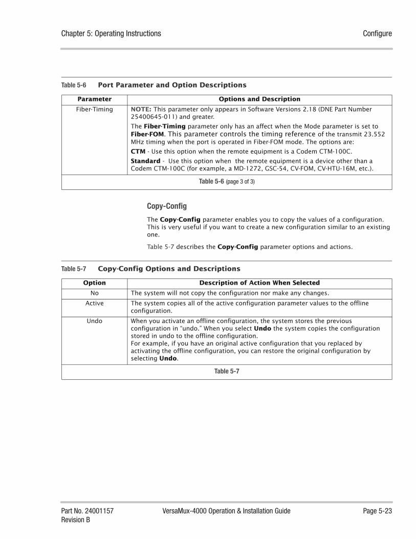
Chapter 5: Operating Instructions Configure
Part No. 24001157 VersaMux-4000 Operation & Installation Guide Page 5-23Revision B
Copy-Config
The Copy-Config parameter enables you to copy the values of a configuration. This is very useful if you want to create a new configuration similar to an existing one.
Table 5-7 describes the Copy-Config parameter options and actions.
Fiber-Timing NOTE: This parameter only appears in Software Versions 2.18 (DNE Part Number 25400645-011) and greater.
The Fiber-Timing parameter only has an affect when the Mode parameter is set to Fiber-FOM. This parameter controls the timing reference of the transmit 23.552 MHz timing when the port is operated in Fiber-FOM mode. The options are:
CTM - Use this option when the remote equipment is a Codem CTM-100C.
Standard - Use this option when the remote equipment is a device other than a Codem CTM-100C (for example, a MD-1272, GSC-54, CV-FOM, CV-HTU-16M, etc.).
Table 5-6 Port Parameter and Option Descriptions
Parameter Options and Description
Table 5-6 (page 3 of 3)
Table 5-7 Copy-Config Options and Descriptions
Option Description of Action When Selected
No The system will not copy the configuration nor make any changes.
Active The system copies all of the active configuration parameter values to the offline configuration.
Undo When you activate an offline configuration, the system stores the previous configuration in “undo.” When you select Undo the system copies the configuration stored in undo to the offline configuration.For example, if you have an original active configuration that you replaced by activating the offline configuration, you can restore the original configuration by selecting Undo.
Table 5-7

Configure Chapter 5: Operating Instructions
Page 5-24 VersaMux-4000 Operation & Installation Guide Part No. 24001157Revision B
Active The Active selection from the Configure sub-menu allows you to review the current configuration. The Active configuration parameters and their current values appear as they do for the Offline sub-menu (described in “Offline” on page 5-14).
The difference is that you cannot directly change the parameters of the active configuration. To make changes you need to make them to the offline configuration first, then “activate the offline configuration.”
Selecting Active displays a sub-menu that contains the following items:
• Aggregate
• Port-1
• Port-2
• Port-3
• Port-4
Terminal Interface
Figure 5-14 shows how to access the Active sub-menu from the terminal interface.
Figure 5-14 Accessing the Active Sub-Menu

Chapter 5: Operating Instructions Configure
Part No. 24001157 VersaMux-4000 Operation & Installation Guide Page 5-25Revision B
Figure 5-15 shows how to view the active Aggregate parameter option values from the terminal interface.
Figure 5-15 Viewing the Active Configuration for the Aggregate

Configure Chapter 5: Operating Instructions
Page 5-26 VersaMux-4000 Operation & Installation Guide Part No. 24001157Revision B
Front Panel Interface
Figure 5-16 shows how to navigate the Active sub-menu from the front panel interface.
Figure 5-16 Active Sub-Menu Navigation from the Front Panel Interface
Configure
Active
Aggregate Port-1 Port-4
AggregateParameterSettings
Port-1ParameterSettings
Port-4ParameterSettings
Port-2 & Port-3

Chapter 5: Operating Instructions Configure
Part No. 24001157 VersaMux-4000 Operation & Installation Guide Page 5-27Revision B
CAU Selecting the CAU (Crypto Ancillary Unit) parameter displays the CAU sub-menu parameters and their current values. The CAU sub-menu parameters are:
• KG-Resync
• Resync-Delay
Table 5-8 describes the options for the CAU parameters and options.
Table 5-8 CAU Parameter Options and Descriptions
Parameter Option Description
KG-Resync Disabled - This option disables the VersaMux-4000 from sending resync pulses.
Enabled - This option enables the resync feature. When the VersaMux-4000 detects a loss of synchronization it generates a 6 to 8 millisecond resync pulse and sends it to the cryptographic device.on pins 18 and 21 of the VersaMux-4000 NRZ (aggregate). Note that this option is only available when the Aggregate, Mode parameter is set to DTE (see “KG-Resync” on page 3-22 for more information).
See “Crypto Setup” on page 5-28 for information on configuring the cryptographic device to operate with the VersaMux-4000 resync pulse width.
Resync-Delay The Resync-Delay parameter sets the time delay (in seconds the VersaMux-4000 system waits for synchronization after it sends a resync pulse. If the delay period expires before synchronization the VersaMux-4000 system issues another pulse. See “Resync-Delay Explanation” on page 5-28 and “KG-Resync” on page 3-22 for more information.
The options are:
1-Sec, 2-Sec, 3-Sec, 4-Sec, 5-Sec, 6-Sec, 7-Sec, 8-Sec, 9-Sec, 10-Sec, 20-Sec, 30-Sec, 40-Sec, 50-Sec, 60-Sec.
Table 5-8

Configure Chapter 5: Operating Instructions
Page 5-28 VersaMux-4000 Operation & Installation Guide Part No. 24001157Revision B
Resync-Delay Explanation
End Around Delay is the period of time for a transmitted signal to travel to the remote VersaMux-4000 unit and then back to the local unit. Figure 5-17 illustrates the end around delay in a typical satellite system.
Figure 5-17 End Around Delay Example
In this example it may take 240 milliseconds for the signal to travel over the satellite link from the local VersaMux-4000 unit to the remote unit. Therefore, not including any delays from the cryptos, the total end around delay would be 480 milliseconds (about half a second).
If the Resync-Delay parameter period is less than the time required for the local and remote cryptos to communicate and re-synchronize the VersaMux-4000 unit will continuously issue resync commands preventing re-synchronization.
Increase the Resync-Delay period if you observe that the cryptos continuously attempt to resync without achieving re-synchronization.
Crypto Setup
Upon loss of synchronization (with the KG-Resync parameter enabled), the VersaMux-4000 initiates a resync pulse to the crypto (red-side) which lasts between 6 to 8 milliseconds.Therefore, the crypto resync level "time-out-period" must be shorter than 6 milliseconds to ensure the resync occurs.
Trunk Encryption Device (TED)
240 milliseconds 240 milliseconds
Trunk Encryption Device (TED)
End Around Delay(240 ms + 240 ms = 480 ms)
VERSAMUX 4000NO ALARMS
POWER AGGR CLK REF PORTS FAULT
VersaMux-4000
VersaMux-4000
VERSAMUX 4000NO ALARMS
POWER AGGR CLK REF PORTS FAULT
VersaMux-4000
VersaMux-4000

Chapter 5: Operating Instructions Configure
Part No. 24001157 VersaMux-4000 Operation & Installation Guide Page 5-29Revision B
For example, if the crypto resync level "time-out-period" is 220 (1,048,576 bit times) and the bit rate is 1.2-Kbps (1,200 bits per second or 8.3 microseconds per bit) then the time out period equals 874 seconds. In this extreme example the VersaMux-4000 resync pulse would expire before the time out period and the resync would not occur.
At a 128 kbps rate and using 220 bit times, the time out period would be 8
seconds (too long for the resync to occur). Using 210 bit times the time out period is 8 milliseconds which may or may not be long enough to initiate the resync.
NOTE: To ensure that the VersaMux-4000 resync pulse is long enough for all bit rates, we
recommend that you set (strap) the crypto to the 20 (one bit time) resync level "time-out-period".
Accessing the CAU Sub-Menu from the Terminal Interface
Figure 5-18 shows how to access the CAU sub-menu from the terminal interface.
Figure 5-18 Accessing the CAU Sub-Menu from the Terminal Interface
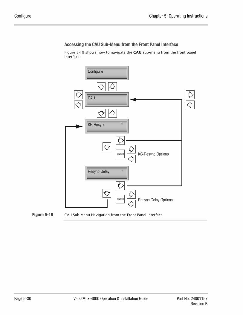
Configure Chapter 5: Operating Instructions
Page 5-30 VersaMux-4000 Operation & Installation Guide Part No. 24001157Revision B
Accessing the CAU Sub-Menu from the Front Panel Interface
Figure 5-19 shows how to navigate the CAU sub-menu from the front panel interface.
Figure 5-19 CAU Sub-Menu Navigation from the Front Panel Interface
Configure
CAU
KG-Resync *
Resync-Delay *
KG-Resync Options
Resync Delay OptionsENTER
ENTER

Chapter 5: Operating Instructions Configure
Part No. 24001157 VersaMux-4000 Operation & Installation Guide Page 5-31Revision B
Management Selecting Management from the Configure sub-menu displays a list of the craft port parameters and their current values. These parameters require specification when connecting a terminal interface to the craft port.The craft port parameters are:
• Card-Type (read-only)
• Rate
Note that the VersaMux has fixed values for the following:
• Data-Bits Data-Bits = 8-bits
• Stop-BitsStop-Bits = 1-bit
• ParityParity = None
Management Parameters and Options
Table 5-9 describes the options for the Management parameters and options.
Table 5-9 Management Parameter Options and Descriptions
Parameter Option Description
Card-Type Read-Only - The system displays the card type (Craft-Port).
Rate The options for the Rate parameter are:
• 1200
• 2400
• 4800
• 9600*
• 19200
• 38400
• 57600
• 115200
*Default Value
Table 5-9
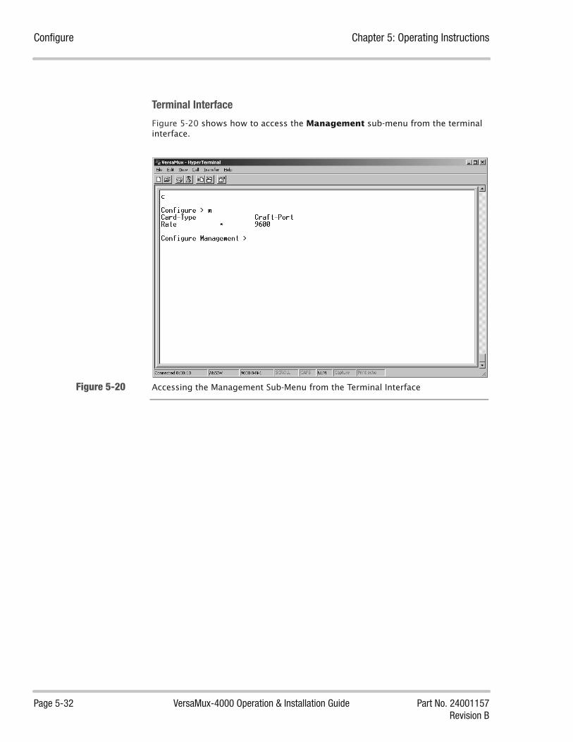
Configure Chapter 5: Operating Instructions
Page 5-32 VersaMux-4000 Operation & Installation Guide Part No. 24001157Revision B
Terminal Interface
Figure 5-20 shows how to access the Management sub-menu from the terminal interface.
Figure 5-20 Accessing the Management Sub-Menu from the Terminal Interface

Chapter 5: Operating Instructions Configure
Part No. 24001157 VersaMux-4000 Operation & Installation Guide Page 5-33Revision B
Front Panel Interface
Figure 5-21 shows how to access and navigate the Management sub-menu from the front panel interface.
Figure 5-21 Accessing the Management Sub-Menu from the Front panel Interface
Configure
Management
Card-Type Craft-Port
Rate * ENTER Rate Options

Activate Chapter 5: Operating Instructions
Page 5-34 VersaMux-4000 Operation & Installation Guide Part No. 24001157Revision B
Activate
NOTE: Two VersaMux units connected end-to-end must have matched aggregate rate and port rate configurations.
The Activate parameter enables you to make the “offline” configuration or “undo” configuration active.
Selecting the Activate parameter enables you to access the Configuration (to activate) confirmation parameter. The (Activate) Configuration parameter options are:
• No - Selecting this option exits back to the Activate parameter (prompt) without making any changes.
• Offline - Selecting this option activates the offline configuration (see “Offline” on page 5-14 for a description of the offline configuration parameters). This makes the “offline” configuration the “active” configuration.
• Undo - When you activate an offline configuration, the VersaMux system stores the previous configuration in “undo.”When you select Undo, the system copies the configuration stored in undo to the active configuration.For example, if you have an original active configuration that you replaced by activating the offline configuration, you can restore the original configuration by selecting Undo.
Table 5-10 describes the Activate options and actions the VersaMux performs when you select them.
Table 5-10 Activate Options and Actions
Option Action Description
No The VersaMux cancels the activation and does not make any changes.
Offline The VersaMux copies the Active configuration parameters to the Undo configuration, and copies the Offline configuration parameters to the Active configuration. The VersaMux then re-initializes using the “new” Active configuration parameters.
Undo The VersaMux copies the “Undo” configuration parameters to the Active configuration. The VersaMux then re-initializes using the “undo” Active configuration parameters.
Table 5-10
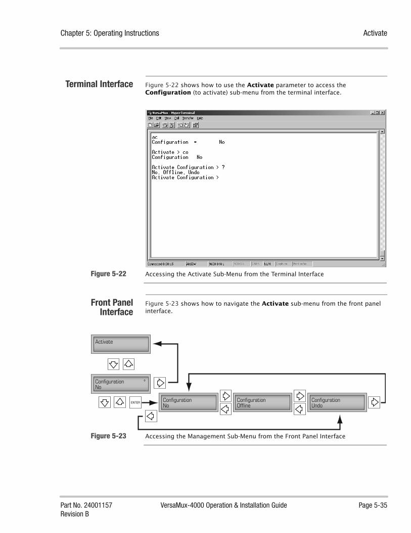
Chapter 5: Operating Instructions Activate
Part No. 24001157 VersaMux-4000 Operation & Installation Guide Page 5-35Revision B
Terminal Interface Figure 5-22 shows how to use the Activate parameter to access the Configuration (to activate) sub-menu from the terminal interface.
Figure 5-22 Accessing the Activate Sub-Menu from the Terminal Interface
Front PanelInterface
Figure 5-23 shows how to navigate the Activate sub-menu from the front panel interface.
Figure 5-23 Accessing the Management Sub-Menu from the Front Panel Interface
Activate
Configuration *No
Configuration No
Configuration Offline
ENTER Configuration Undo

System-Info Chapter 5: Operating Instructions
Page 5-36 VersaMux-4000 Operation & Installation Guide Part No. 24001157Revision B
System-InfoThe System-Info sub-menu contains the following items:
• Conditions
• Inventory
Conditions Selecting the Conditions parameter displays a list of the system conditions as follows:
• Internal-Temp - indicates the current internal temperature of the VersaMux-4000 in degrees Celsius.
• System-Up-Time - Indicates the length of time the VersaMux-4000 has been operating since the last power-up.
• Switch-Settings - indicates the states of internal switch settings of the VersaMux-4000. These are used for factory and repair information only.
Inventory The Inventory sub-menu contains the following items:
• System
• Aggregate
• Port-1
• Port-2
• Port-3
• Port-4
• Management
• Order-Wire (Note: Release 1.0 does not support this option)
When you select a Inventory sub-menu item, the VersaMux displays a list of the inventory information for the item. The inventory information listed includes:
• Card Type
• HW-Part # (Hardware Part Number)
• HW-Rev (Hardware Revision)
• Mfg-Date (Manufacture Date)
• Serial # (Serial Number)
• Prog-Dev_Revs (Programmable Device Revisions)
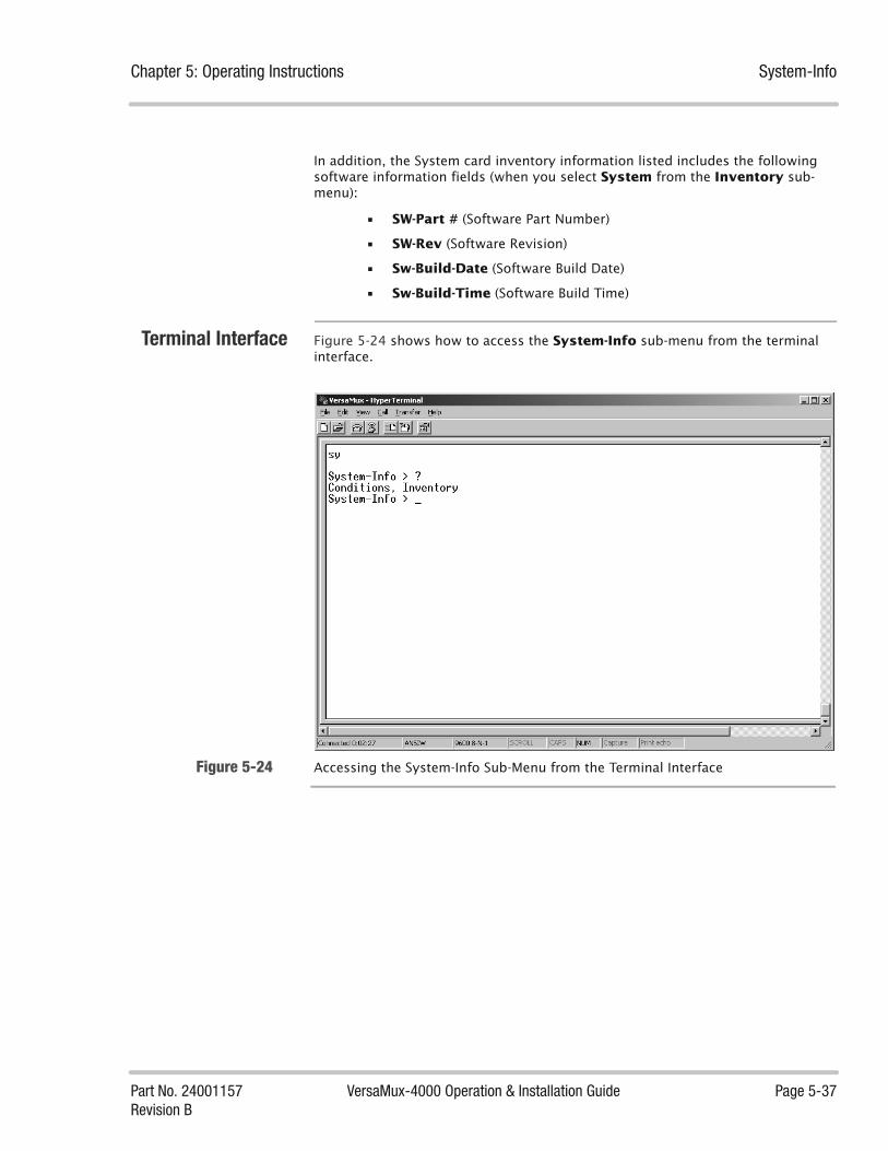
Chapter 5: Operating Instructions System-Info
Part No. 24001157 VersaMux-4000 Operation & Installation Guide Page 5-37Revision B
In addition, the System card inventory information listed includes the following software information fields (when you select System from the Inventory sub-menu):
• SW-Part # (Software Part Number)
• SW-Rev (Software Revision)
• Sw-Build-Date (Software Build Date)
• Sw-Build-Time (Software Build Time)
Terminal Interface Figure 5-24 shows how to access the System-Info sub-menu from the terminal interface.
Figure 5-24 Accessing the System-Info Sub-Menu from the Terminal Interface
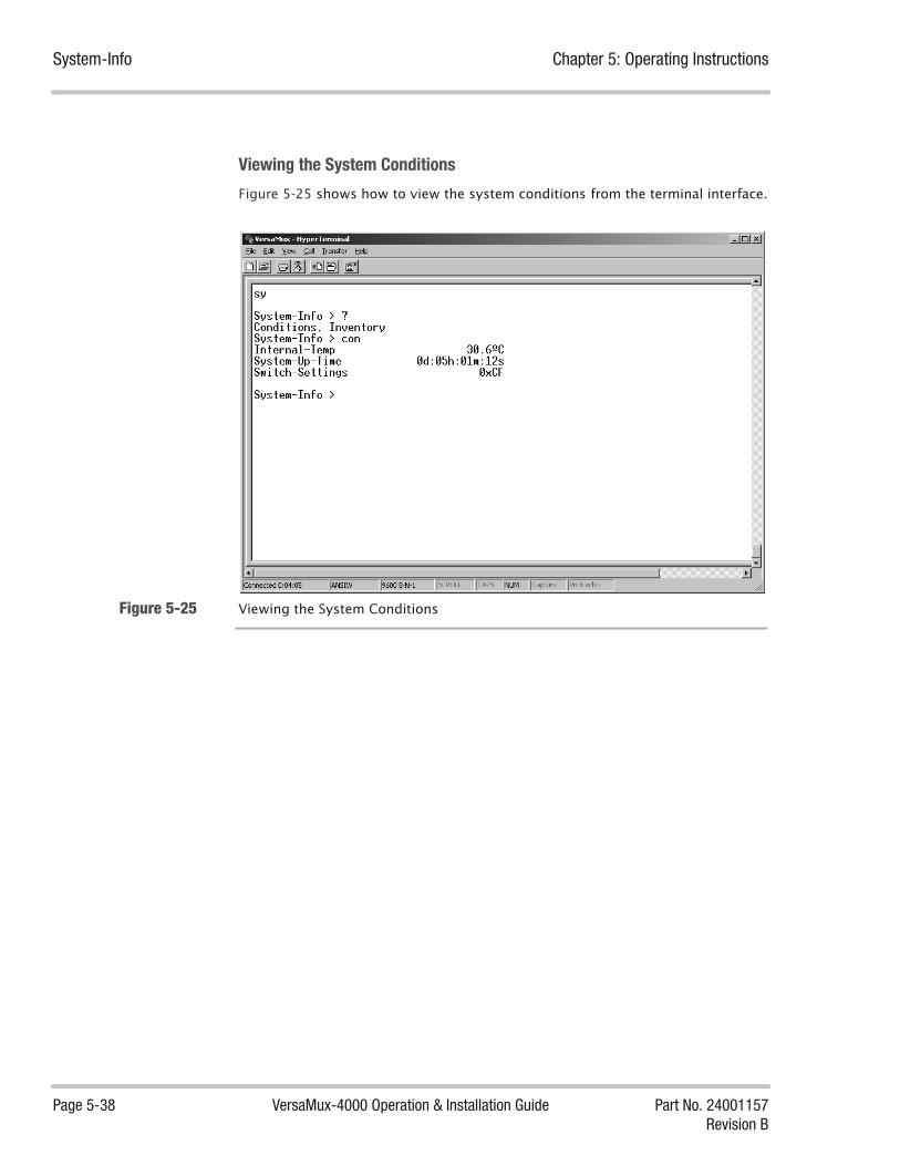
System-Info Chapter 5: Operating Instructions
Page 5-38 VersaMux-4000 Operation & Installation Guide Part No. 24001157Revision B
Viewing the System Conditions
Figure 5-25 shows how to view the system conditions from the terminal interface.
Figure 5-25 Viewing the System Conditions

Chapter 5: Operating Instructions System-Info
Part No. 24001157 VersaMux-4000 Operation & Installation Guide Page 5-39Revision B
System-Info Inventory Sub-Menu
Figure 5-26 shows how to view the system inventory from the terminal interface.
Figure 5-26 Viewing the System-Info Inventory from the Terminal Interface
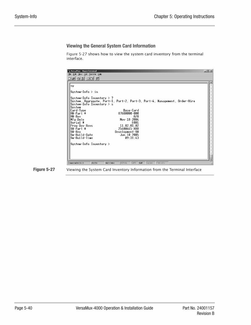
System-Info Chapter 5: Operating Instructions
Page 5-40 VersaMux-4000 Operation & Installation Guide Part No. 24001157Revision B
Viewing the General System Card Information
Figure 5-27 shows how to view the system card inventory from the terminal interface.
Figure 5-27 Viewing the System Card Inventory Information from the Terminal Interface
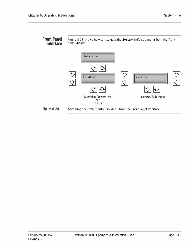
Chapter 5: Operating Instructions System-Info
Part No. 24001157 VersaMux-4000 Operation & Installation Guide Page 5-41Revision B
Front PanelInterface
Figure 5-28 shows how to navigate the System-Info sub-menu from the front panel display.
Figure 5-28 Accessing the System-Info Sub-Menu from the Front Panel Interface
System-Info
Conditions Inventory
Condition Parametersand
Status
Inventory Sub-Menu

Statistics Chapter 5: Operating Instructions
Page 5-42 VersaMux-4000 Operation & Installation Guide Part No. 24001157Revision B
StatisticsSelecting Statistics displays a sub-menu with the following items:
• Alarms-Stats - displays a list of the alarms, and the number of occurrences of each, that have occurred since the last reset. In addition, this item enables you to reset the alarm statistics. See “Alarm-Stats” on page 5-44.
• Aggregate-Stats - displays the number of frame losses, the number of frames transmitted, and the number of frames received. In addition, this item enables you to reset the alarm statistics.See “Aggregate-Stats” on page 5-44.
• Bandwidth-Stats - displays the overall bandwidth that includes; Aggregate bandwidth, Total bandwidth utilized (ports + overhead), Spare bandwidth, Overhead bandwidth, Port-1 bandwidth, Port-2 bandwidth, Port-3 bandwidth, Port-4 bandwidth.See “Bandwidth-Stats” on page 5-45.
Front PanelInterface
Figure 5-29 shows how to navigate the Statistics sub-menu from the front panel interface.
Figure 5-29 Statistics Sub-Menu Navigation from the Front Panel Interface
Statistics
Alarm-Stats
Reset-Stats *No
Reset-Stats *No
Aggregate-Stats Bandwidth
Alarm Statistics Aggregate Statistics
Return toAggregate-Stats
Bandwidth Statistics
ENTER No/Yes
Return toAlarm-Stats
ENTER No/Yes
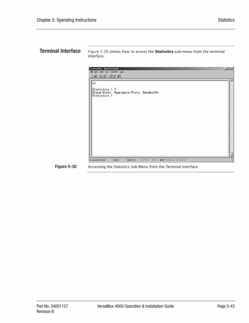
Chapter 5: Operating Instructions Statistics
Part No. 24001157 VersaMux-4000 Operation & Installation Guide Page 5-43Revision B
Terminal Interface Figure 5-30 shows how to access the Statistics sub-menu from the terminal interface.
Figure 5-30 Accessing the Statistics Sub-Menu from the Terminal Interface

Statistics Chapter 5: Operating Instructions
Page 5-44 VersaMux-4000 Operation & Installation Guide Part No. 24001157Revision B
Alarm-Stats Selecting Alarm-Stats displays a list of the alarms, and the number of occurrences of each, that have occurred since the last reset. In addition, you can reset the alarm statistics after viewing them. See “Alarm-Status” on page 5-5 for the alarm descriptions.
Resetting the Alarm-Statistics from the Terminal Interface
Figure 5-31 shows how to reset the alarm statistics from the terminal interface.
Figure 5-31 Resetting the Alarm-Statistics from the Terminal Interface
Aggregate-Stats Selecting Aggregate-Statistics displays the following:
• Frame-Losses - the number of frame losses
• Tx-Frames - the number of frames transmitted
• Rx-Frames - the number of frames received
• Reset-Stats - enables you to reset the aggregate statistics.

Chapter 5: Operating Instructions Statistics
Part No. 24001157 VersaMux-4000 Operation & Installation Guide Page 5-45Revision B
Figure 5-32 shows how to reset the aggregate statistics from the terminal interface.
Figure 5-32 Resetting the Aggregate-Statistics from the Terminal Interface
Bandwidth-Stats Selecting Bandwidth-Statistics displays the following:
• Aggr-BW - the Aggregate bandwidth
• Total-BW - the total bandwidth utilized (ports + overhead)
• Spare-BW - the spare bandwidth
• Ovhd-BW - the Overhead bandwidth
• Port-1-BW - Port-1 bandwidth
• Port-2-BW - Port-2 bandwidth
• Port-3-BW - Port-3 bandwidth
• Port-4-BW - Port-4 bandwidth

Statistics Chapter 5: Operating Instructions
Page 5-46 VersaMux-4000 Operation & Installation Guide Part No. 24001157Revision B
Figure 5-33 shows how to view the overall bandwidth statistics from the terminal interface.
Figure 5-33 Viewing the Overall Bandwidth Statistics from the Terminal Interface

Part No. 24001157 VersaMux-4000 Operation & Installation Guide Page 6-1Revision B
Chapter
Diagnostics 6About this Chapter This chapter describes alarms, system status and statistics information, loopback
procedures, system self-tests, and the VersaMux-4000 BERT operation.
Chapter Contents This chapter contains the following topics:
LED Indicators ................................................................................................. 6-3
LED Descriptions ................................................................................... 6-3LED States ............................................................................................. 6-5
Diagnostics Menu ........................................................................................... 6-6
Terminal Interface .................................................................................. 6-6Front Panel Interface .............................................................................. 6-7Loopbacks ............................................................................................. 6-7BERT .................................................................................................... 6-11Hot-swap ............................................................................................. 6-15Test ..................................................................................................... 6-17

Chapter 6: Diagnostics
Page 6-2 VersaMux-4000 Operation & Installation Guide Part No. 24001157Revision B
This page intentionally left blank.
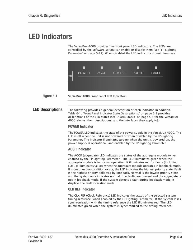
Chapter 6: Diagnostics LED Indicators
Part No. 24001157 VersaMux-4000 Operation & Installation Guide Page 6-3Revision B
LED IndicatorsThe VersaMux-4000 provides five front panel LED indicators. The LEDs are controlled by the software so you can enable or disable them (see “FP-Lighting Parameter” on page 5-14). When disabled the LED indicators do not illuminate.
Figure 6-1 VersaMux-4000 Front Panel LED Indicators
LED Descriptions The following provides a general description of each indicator. In addition, Table 6-1, “Front Panel Indicator State Descriptions,” on page 6-5 provides descriptions of the LED states (see “Alarm-Status” on page 5-5 for the VersaMux-4000 alarms, their descriptions, and the interfaces they apply to).
POWER Indicator
The POWER LED indicates the state of the power supply in the VersaMux-4000. The LED is off when the unit is not powered or when disabled by the FP-Lighting Parameter. The indicator illuminates (green) when the unit is powered on, the power supply is operational, and enabled by the FP-Lighting Parameter.
AGGR Indicator
The AGGR (aggregate) LED indicates the status of the aggregate module (when enabled by the FP-Lighting Parameter). The LED illuminates green when the aggregate module is in normal operation. It illuminates red for faults (including LOF). It illuminates yellow when the aggregate module operates in loopback mode. If more than one condition exists, the LED indicates the highest priority state. Fault is the highest priority, followed by loopback. Normal is the lowest priority state and the system only indicates normal if no faults are present and the aggregate is not in loopback mode. If the system detects a fault during loopback mode, it displays the fault indication (red).
CLK REF Indicator
The CLK REF (Clock Reference) LED indicates the status of the selected system timing reference (when enabled by the FP-Lighting Parameter). If the system loses synchronization with the timing reference the LED illuminates red. The LED illuminates green when the system is synchronized to the timing reference.
POWER AGGR CLK REF PORTS FAULT

LED Indicators Chapter 6: Diagnostics
Page 6-4 VersaMux-4000 Operation & Installation Guide Part No. 24001157Revision B
PORTS Indicator
The PORTS LED provides a status summary for all of the port modules (when enabled by the FP-Lighting Parameter). The LED illuminates green to indicate that no faults are present on the port cards (normal operation). It illuminates red to indicate that at least a single fault exists on one or more port cards. It illuminates yellow to indicate that one or more port cards are in loopback mode. If more than one condition exists, the LED indicates the highest priority state. Fault is the highest priority, followed by loopback. Normal is the lowest priority state and the system only indicates normal if no faults are present and none of the port cards are in loopback mode. If the system detects a fault during loopback mode, it displays the fault indication (red).
FAULT Indicator
The FAULT LED provides a summary of faults on the unit (when enabled by the FP-Lighting Parameter). It illuminates red to indicate at least one fault exists on the VersaMux-4000 or that the unit is in “hot-swap” mode (see “Hot-swap” on page 6-15). The LED is off when there are no active faults within the VersaMux-4000 (or when the FP-Lighting Parameter disables the indicators).

Chapter 6: Diagnostics LED Indicators
Part No. 24001157 VersaMux-4000 Operation & Installation Guide Page 6-5Revision B
LED States Table 6-1 provides descriptions of the front panel status LED indicator states.
Table 6-1 Front Panel Indicator State Descriptions
LED Label State Description
Power Green AC power to the system is present.
Off The unit is not powered or the FP-Lighting Parameter disabled the indicators.
Aggr Red At least one fault exists on the aggregate.
Yellow Aggregate operating in loopback mode.
Green The aggregate operation is normal with no faults.
Clk Ref Red The system lost synchronization with the timing reference.
Green The system has synchronization with the timing reference.
Ports Green All ports are in normal operation (no faults, not in loopback).
Red At least one fault exists on one or more ports.
Yellow One or more ports operating in loopback mode.
Fault Red One or more system faults exist on the VersaMux-4000.
In addition, this indicator illuminates when the Hot-swap parameter is Enabled.
Off The VersaMux-4000 system operation is normal (no faults).
Table 6-1

Diagnostics Menu Chapter 6: Diagnostics
Page 6-6 VersaMux-4000 Operation & Installation Guide Part No. 24001157Revision B
Diagnostics MenuSelecting Diagnostics displays a sub-menu with the following items:
• Loopbacks
• BERT
• Hot-swap
• Test
Terminal Interface Figure 6-2 shows accessing the Diagnostics sub-menu from the terminal interface.
Figure 6-2 Diagnostics Sub-Menu from the Terminal Interface

Chapter 6: Diagnostics Diagnostics Menu
Part No. 24001157 VersaMux-4000 Operation & Installation Guide Page 6-7Revision B
Front PanelInterface
Figure 6-3 shows how to navigate the Diagnostics sub-menu from the front panel interface.
Figure 6-3 Diagnostics Sub-Menu from the Front Panel Interface
Loopbacks The Loopbacks sub-menu enables you to initiate a loopback for diagnostic purposes. Selecting Loopbacks enters a sub-menu with the following items:
• Aggregate
• Port-1
• Port-2
• Port-3
• Port-4
When you chose an interface (aggregate, or one of the ports), the following loopback types can be chosen:
• No Loop – This option terminates the current loopback operation.
• Bi-directional – This option provides a loopback both toward:
• the user port and aggregate on a port module.
• the aggregate port and the multiplexer/demultiplexer (mux/demux) circuitry on an aggregate module.
• Internal - This option provides a loopback toward:
• the aggregate on a port module.
• the multiplexer/demultiplexer (mux/demux) circuitry on an aggregate module.
• External - This option provides a loopback toward:
• the user port on a port module.
• the aggregate port on an aggregate module.
See “Internal Loopbacks” on page 6-8 and “External Loopbacks” on page 6-9 for loopback diagrams and more information.
Diagnostics
Loopbacks BERT Hot-Swap Test
Loopbacks Sub-Menu BERT Sub-Menu Hot-Swap Options Test Sub-Menu

Diagnostics Menu Chapter 6: Diagnostics
Page 6-8 VersaMux-4000 Operation & Installation Guide Part No. 24001157Revision B
Internal Loopbacks
Figure 6-4 illustrates an internal loopback on a port module. The internal loopback sends the transmit data from the aggregate back to the aggregate as the receive data. In addition the transmit data continues on to the user port.
Figure 6-4 Internal Loopback Diagram for a Port Module
Figure 6-5 illustrates an internal loopback on an aggregate module. The internal loopback sends the transmit data from the multiplexer/demultiplexer back to the multiplexer/demultiplexer as the receive data. In addition the transmit data continues on to the aggregate port.
Figure 6-5 Internal Loopback Diagram for an Aggregate Module
Tx Data
Rx Data
Aggregate Port Module User Port
Tx Data
Rx Data
Mux/Demux Aggregate Module Aggregate Port

Chapter 6: Diagnostics Diagnostics Menu
Part No. 24001157 VersaMux-4000 Operation & Installation Guide Page 6-9Revision B
External Loopbacks
Figure 6-6 illustrates an external loopback on a port module. The external loopback sends the receive data from the user port back to the user port as the transmit data. In addition the receive data continues on to the aggregate.
Figure 6-6 External Loopback Diagram for a Port Module
Figure 6-7 illustrates an external loopback on an aggregate module. The external loopback sends the receive data from the aggregate port back to the aggregate port as the transmit data. In addition the receive data continues on to the multiplexer/demultiplexer.
Figure 6-7 External Loopback Diagram for an Aggregate Module
Tx Data
Rx Data
Aggregate Port Module User Port
Tx Data
Rx Data
Mux/Demux Aggregate Module Aggregate Port
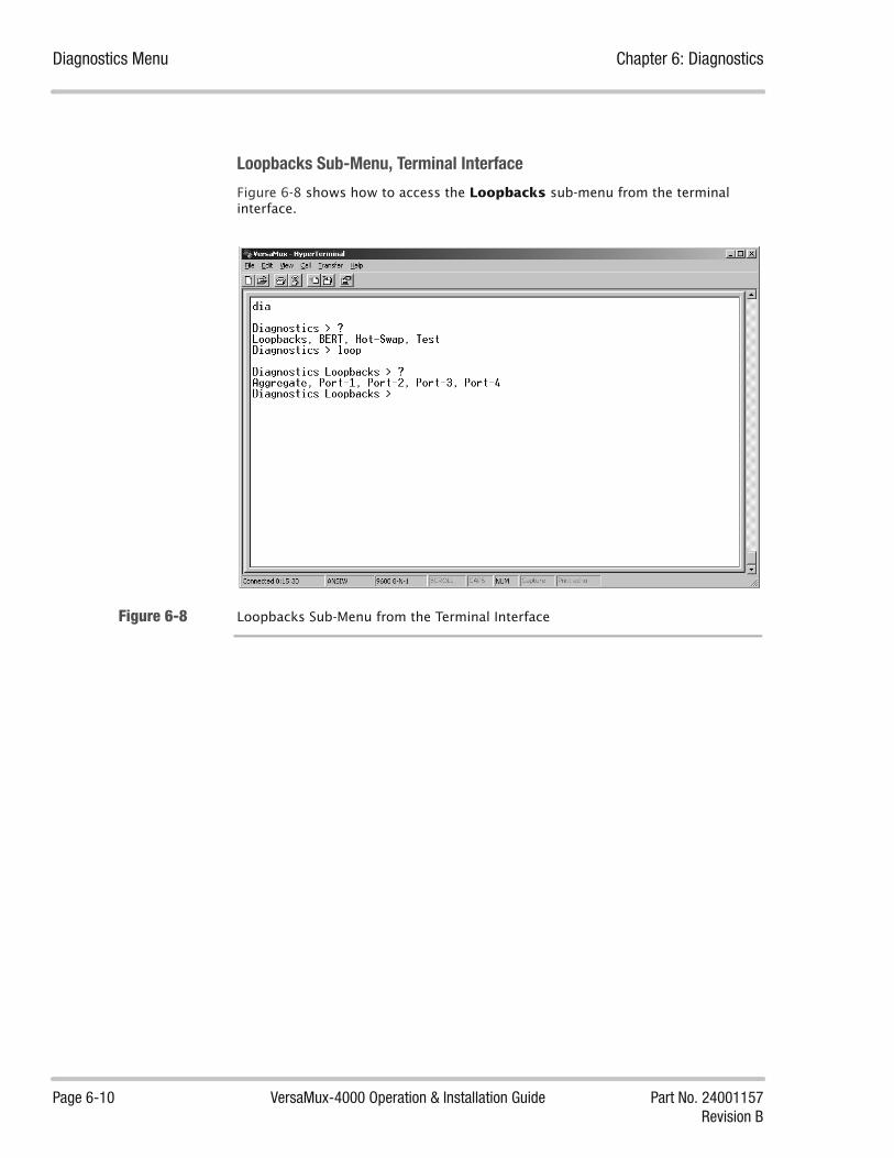
Diagnostics Menu Chapter 6: Diagnostics
Page 6-10 VersaMux-4000 Operation & Installation Guide Part No. 24001157Revision B
Loopbacks Sub-Menu, Terminal Interface
Figure 6-8 shows how to access the Loopbacks sub-menu from the terminal interface.
Figure 6-8 Loopbacks Sub-Menu from the Terminal Interface

Chapter 6: Diagnostics Diagnostics Menu
Part No. 24001157 VersaMux-4000 Operation & Installation Guide Page 6-11Revision B
Loopbacks Sub-Menu, Front Panel Interface
Figure 6-8 shows how to navigate the Loopbacks sub-menu from the front panel interface.
Figure 6-9 Loopbacks Sub-Menu from the Front Panel Interface
BERT The VersaMux-4000 is equipped with an internal Bit Error Rate Tester (BERT) capable of providing link quality statistics. Only one slot (either aggregate or port) may be connected to the BERT at any one time.
Table 6-2 describes the BERT parameters and options.
Diagnostics
Loopbacks
Aggregate Port-1 Port-2
AggregateLoopbackSelection
Aggregate Loopback Options
ENTER
Port-1LoopbackSelection
Port-1 Loopback Options
ENTER
Port-2LoopbackSelection
Port-2 Loopback Options
Ports 3 & 4
ENTER
Table 6-2 BERT Parameter and Option Descriptions
Parameter Type Description
BERT-Sync-State Read Only This parameter displays the BERT synchronization state.
BERT-Sync-Losses Read Only This parameter displays the number of BERT synchronization losses.
BERT-Bit-Errors Read Only This parameter displays the number of Bit-Errors.
BERT-Bits-Tested Read Only This parameter displays the number of Bits tested.
BERT-BER Read Only This parameter displays the Bit-Error-Rate of the test in progress.
BERT-Avg-BER Read Only This parameter displays the Average Bit-Error-Rate.
Table 6-2 (page 1 of 3)

Diagnostics Menu Chapter 6: Diagnostics
Page 6-12 VersaMux-4000 Operation & Installation Guide Part No. 24001157Revision B
Connection Read Write This parameter specifies the interface that the BERT connects to.
Note: When the BERT is applied to a port, the port data will be interrupted on the aggregate. All other ports not connected to the BERT shall be unaffected. The aggregate data from the port connected to the BERT shall be set to the IDLE condition.
The Connection options are:
Disabled - This option disables the VersaMux-4000 BERT.
Aggr-Spare-BW - This option enables BERT traffic on the spare bandwidth of the aggregate.
Aggr-Full-BW - This option enables BERT traffic on the entire bandwidth of the aggregate.
Port-1 - This option enables BERT traffic on Port-1.
Port-2 - This option enables BERT traffic on Port-2.
Port-3 - This option enables BERT traffic on Port-3.
Port-4 - This option enables BERT traffic on Port-4.
Pattern Read Write This parameter specifies the traffic pattern used by the BERT. The Pattern options are:
511 - The BERT generates a 29-1 (511) pseudorandom pattern.
2047 - The BERT generates a 211-1 (2047) pseudorandom pattern.
2^15-1 - The BERT generates a 215-1 (32,767) pseudorandom pattern.
2^20-1 - The BERT generates a 220-1 (1,048,575) pseudorandom pattern.
2^23-1 - The BERT generates a 223-1 (8,338,607) pseudorandom pattern.
Test-Length Read Write This parameter specifies the length of the BERT test (i.e. how many bits of traffic are used). The Test-Length options are:
1E6 - The BERT test length is 106 (1,000,000) bits.
1E7 - The BERT test length is 107 (10,000,000) bits.
1E8 - The BERT test length is 108 (100,000,000) bits.
1E9 - The BERT test length is 109 (1,000,000,000) bits.
Err-Insert Read Write This parameter specifies the number of errors inserted on the interface defined by the Connection parameter. The Err-Insert options are:
Off - This option disables error insertion by the VersaMux-4000 BERT.
Single- When selected, this option inserts a single error.
1.0E-3 - Inserts a 10-3 bit error pattern (one error bit every 1,000).
Table 6-2 BERT Parameter and Option Descriptions
Parameter Type Description
Table 6-2 (page 2 of 3)

Chapter 6: Diagnostics Diagnostics Menu
Part No. 24001157 VersaMux-4000 Operation & Installation Guide Page 6-13Revision B
Terminal Interface
Figure 6-10 shows how to access the BERT sub-menu from the terminal interface.
Figure 6-10 Accessing the BERT sub-menu from the Terminal Interface
Reset-Stats Read Write The Reset-Stats? parameter allows you to reset the BERT statistics. The Reset-Stats? options are:
No - Select this option to exit the Reset-Stats? parameter without changing the statistics log.
Yes - Select this option to clear (reset) the BERT statistics log.
Table 6-2 BERT Parameter and Option Descriptions
Parameter Type Description
Table 6-2 (page 3 of 3)

Diagnostics Menu Chapter 6: Diagnostics
Page 6-14 VersaMux-4000 Operation & Installation Guide Part No. 24001157Revision B
Front Panel Interface
Figure 6-11 shows the BERT sub-menu structure and navigation from the front panel interface.
Figure 6-11 BERT Sub-Menu Navigation from the Front Panel Interface
Diagnostics
BERTLoopbacks
BERT-Sync-State
BERT-Sync-Losses
BERT-Bit-Errors
BERT-Bits-Tested
BERT-BER
BERT-Avg-BER
Connection *
Pattern *
Test-Length *
Err-Insert *
Reset-Stats *
ENTER Connection Options
ENTER Pattern Options
ENTER Test Length Options
ENTER Error Insertion Options
ENTER Reset Options

Chapter 6: Diagnostics Diagnostics Menu
Part No. 24001157 VersaMux-4000 Operation & Installation Guide Page 6-15Revision B
Hot-swap The Hot-swap parameter controls the interface module hot-swap feature. Basically you want to enable this parameter just before you hot-swap a module and disable it as soon are you are done.
The Hot-swap options are:
• Enabled - Select this option to enable the interface module hot-swap feature. Note that when you select this option the VersaMux-4000 system disables status and alarms reporting. We recommend that you set this parameter to Disabled once you’ve hot-swapped the interface module. Note that hot-swapping the aggregate module will interrupt all the data regardless but this option prevents the system from crashing.
• Disabled - Select this option to disable the interface module hot-swap feature. Note that if you remove or insert a port interface module with this option, the system cannot prevent data loss on the aggregate interface. In addition to data loss the system may reboot or crash when you remove or insert an interface module with this option selected.
Terminal Interface
Figure 6-12 shows how to access the Hot-Swap sub-menu from the terminal interface. Note that you need to confirm the Hot-Swap selection before you access the Hot-Swap parameter options.
Figure 6-12 Accessing the Hot-Swap Options from the Terminal Interface
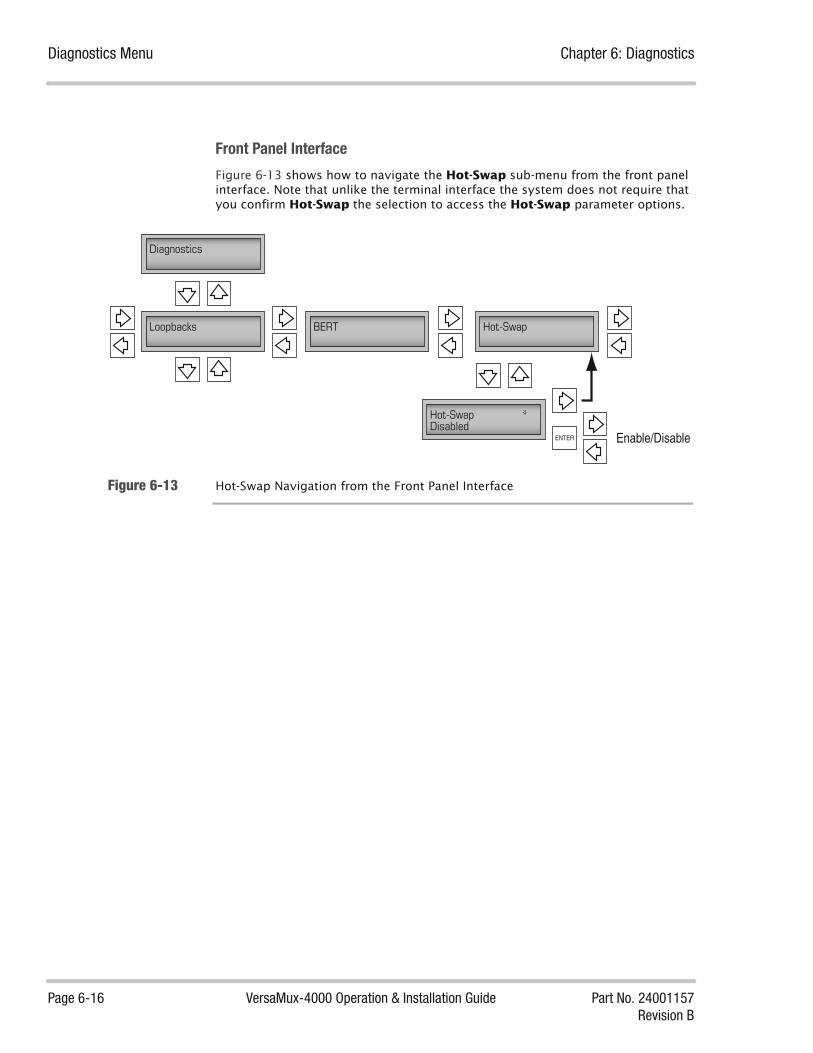
Diagnostics Menu Chapter 6: Diagnostics
Page 6-16 VersaMux-4000 Operation & Installation Guide Part No. 24001157Revision B
Front Panel Interface
Figure 6-13 shows how to navigate the Hot-Swap sub-menu from the front panel interface. Note that unlike the terminal interface the system does not require that you confirm Hot-Swap the selection to access the Hot-Swap parameter options.
Figure 6-13 Hot-Swap Navigation from the Front Panel Interface
Diagnostics
Loopbacks Hot-Swap
Hot-Swap *Disabled
BERT
ENTER Enable/Disable

Chapter 6: Diagnostics Diagnostics Menu
Part No. 24001157 VersaMux-4000 Operation & Installation Guide Page 6-17Revision B
Test On power-up, the VersaMux-4000 performs a series of Power-On Self Tests (POST) as described in Table 6-3. In addition, you can run additional test by selecting Test from the Diagnostics menu. This accesses a sub-menu with the following items:
• Test-Status - Selecting this parameter provides you with the following information about the current test:
• Test-State (Active or Idle)
• Test-Mode
• Tests-Performed
• Tests-Passed
• Tests-Failed
• Test-Results - Selecting this parameter accesses a sub-menu with the following options:
• Errors-Only – Selecting this option displays a list of the failed test(s) from the most recent “Start-Test.”
• All-Results – Selecting this option displays a list of every test result from the most recent “Start-Test.”.
• Start-Test - Selecting this parameter displays the following sub-menu (note that you need to confirm the Start-Test selection in the terminal interface to enter the sub-menu selection mode):
• No - Selecting this option exits the Start-Test option without initiating any tests.
• BIST - Selecting this option commands the VersaMux-4000 to run the Built-In Self Tests as described in Table 6-3.
• Factory - Selecting this option runs an extensive series of tests but produces no end-user information. This option is intended for DNE factory and field service specialists only.
• Stop-Test - Selecting this parameter accesses the following sub-menu (note that you need to confirm the Stop-Test selection in the terminal interface to enter the sub-menu selection mode):
• No - Selecting this option exits the stop-test selection mode and allows the current test to continue uninterrupted.
• Yes - Selecting this option terminates the current test.

Diagnostics Menu Chapter 6: Diagnostics
Page 6-18 VersaMux-4000 Operation & Installation Guide Part No. 24001157Revision B
Table 6-3 VersaMux-4000 Tests Performed
Type of Test Test Items
POST -Power-On Self Tests
RAM data bus test
RAM address bus test
RAM device test
Checksum calculation hardware test
FLASH checksum tests
I/O Register tests
BIST -Built-In Self Tests
Base Card Tests:
• I/O register tests
• Power supply tests
• IIC hardware test
• Clock measurement hardware test
• Reference clock tests
• BERT chip tests
• Display test
NRZ module tests:
• I/O register tests
• PLL lock test
• Clock generation test
• Data Sync found test
• Data Sync losses test
• Data Bit errors test
Combo module tests
• I/O register tests
• PLL lock test
• Clock generation test
• Data Sync found test
• Data Sync losses test
• Data Bit errors test
• FOM tests
Factory Tests These extensive tests produce no end-user information. They are intended for DNE factory and field service specialists only.
Table 6-3

Chapter 6: Diagnostics Diagnostics Menu
Part No. 24001157 VersaMux-4000 Operation & Installation Guide Page 6-19Revision B
Terminal Interface
Figure 6-14 shows how to access the Test sub-menu from the terminal interface.
Figure 6-14 Accessing the Test Sub-Menu from the Terminal Interface
Figure 6-15 shows how to access the test Status report from the terminal interface.
Figure 6-15 Accessing the Test Status Report from the Terminal Interface

Diagnostics Menu Chapter 6: Diagnostics
Page 6-20 VersaMux-4000 Operation & Installation Guide Part No. 24001157Revision B
Figure 6-16 shows how to access the Test-Results sub-menu from the terminal interface.
Figure 6-16 Accessing the Test Results Sub-Menu from the Terminal Interface
Figure 6-17 shows how to display the results for all tests from the terminal interface
Figure 6-17 Displaying All the Test Results on the Terminal Interface

Chapter 6: Diagnostics Diagnostics Menu
Part No. 24001157 VersaMux-4000 Operation & Installation Guide Page 6-21Revision B
Figure 6-18 shows how to access the Start-Test sub-menu from the terminal interface.
Figure 6-18 Accessing the Start-Test Sub-Menu from the Terminal Interface
Figure 6-18 shows how to access the Stop-Test sub-menu from the terminal interface.
Figure 6-19 Accessing the Stop-Test Sub-Menu from the Terminal Interface

Diagnostics Menu Chapter 6: Diagnostics
Page 6-22 VersaMux-4000 Operation & Installation Guide Part No. 24001157Revision B
Front Panel Interface
Figure 6-20 shows how to access the Test sub-menu from the front panel Interface.
Figure 6-20 Accessing the Test Sub-Menu from the Front Panel Interface
Figure 6-21 shows how to navigate the Status sub-menu from the front panel interface.
Diagnostics
Test
Status Results Start-Test Stop-Test
Status List Results Sub-Menu Start-Test Sub-Menu Stop-Test Sub-Menu

Chapter 6: Diagnostics Diagnostics Menu
Part No. 24001157 VersaMux-4000 Operation & Installation Guide Page 6-23Revision B
Figure 6-21 Navigating the Test Status List from the Front Panel Interface
Diagnostics
Test
Status
Test-State Idle
Test-Mode BIST
Test-Performed 0
Test-Passed Idle
Test-Failed Idle

Diagnostics Menu Chapter 6: Diagnostics
Page 6-24 VersaMux-4000 Operation & Installation Guide Part No. 24001157Revision B
Figure 6-21 shows how to navigate the Test Results sub-menu from the front panel interface.
Figure 6-22 Navigating the Test Results Sub-Menu from the Front Panel Interface
Figure 6-23 shows how to navigate the Start-Test sub-menu from the front panel interface.
Figure 6-23 Navigating Start-Test Sub-Menu from the Front Panel Interface
Diagnostics
Test
Status Results
Errors-Only All-Results
Errors-Only List All Test Results List
Diagnostics
Test
No
Start-Test
Start-Test *No
BIST FactoryENTER
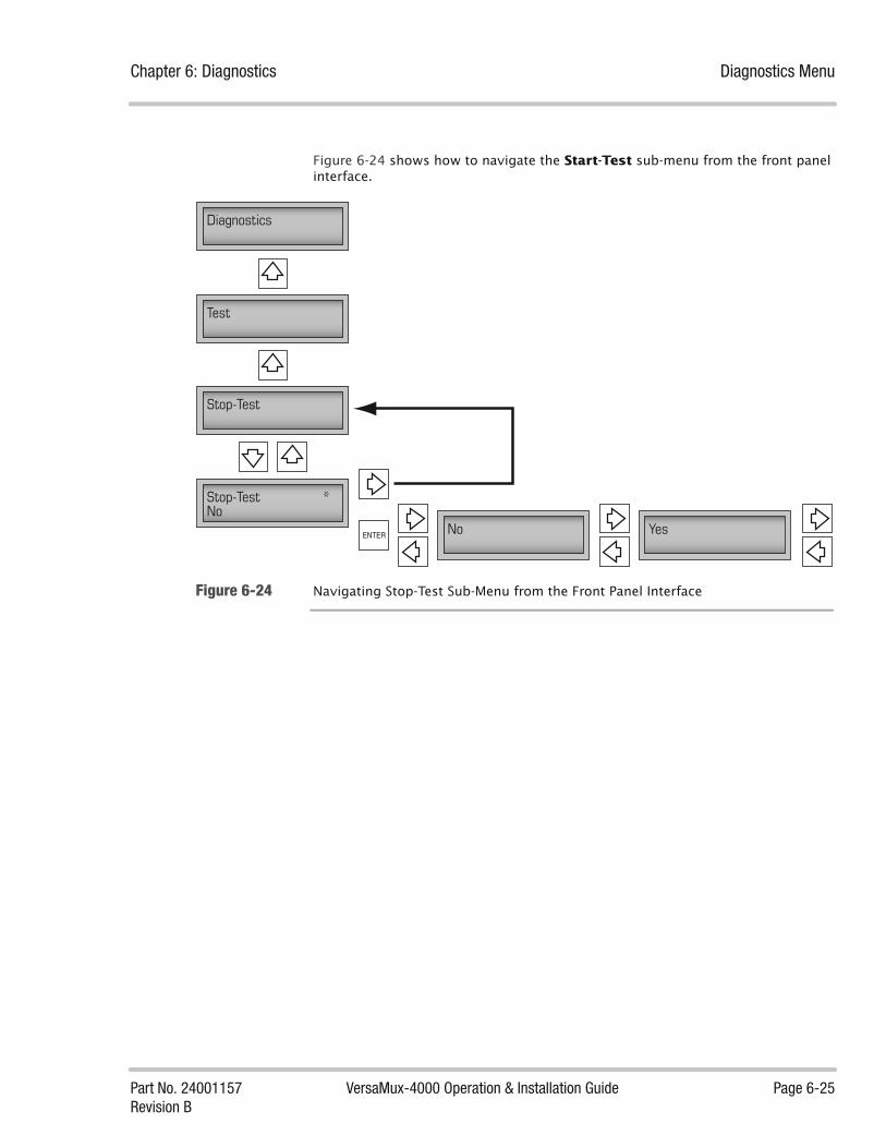
Chapter 6: Diagnostics Diagnostics Menu
Part No. 24001157 VersaMux-4000 Operation & Installation Guide Page 6-25Revision B
Figure 6-24 shows how to navigate the Start-Test sub-menu from the front panel interface.
Figure 6-24 Navigating Stop-Test Sub-Menu from the Front Panel Interface
Diagnostics
Test
No
Stop-Test
Stop-Test *No
YesENTER

Diagnostics Menu Chapter 6: Diagnostics
Page 6-26 VersaMux-4000 Operation & Installation Guide Part No. 24001157Revision B
This page intentionally left blank

Part No. 24001157 VersaMux-4000 Operation & Installation Guide Page 7-1Revision B
Chapter
Maintenance 7About this Chapter This chapter describes the maintenance of the VersaMux-4000.
Chapter Contents This chapter contains the following topics:
Preventive Maintenance .................................................................................. 7-3
Cleaning Electrical Connectors ............................................................... 7-3Cleaning Optical Connectors .................................................................. 7-3
Replacing/Installing a Module ......................................................................... 7-5
Hot-Swapping a Module ......................................................................... 7-5Removing a Module ............................................................................... 7-6Installing a module ................................................................................ 7-7Procedure .............................................................................................. 7-9
Software Upgrade Procedure ......................................................................... 7-10
CAUTION: Be sure to follow ESD (ElectroStatic Discharge) precautions when handling the VersaMux-4000 and its related equipment.

Chapter 7: Maintenance
Page 7-2 VersaMux-4000 Operation & Installation Guide Part No. 24001157Revision B
This page intentionally left blank.

Chapter 7: Maintenance Preventive Maintenance
Part No. 24001157 VersaMux-4000 Operation & Installation Guide Page 7-3Revision B
Preventive MaintenanceThere is no preventive maintenance schedule for the VersaMux-4000 units. Upon receipt of the VersaMux-4000 from DNE (or distributor), we recommended that you visually inspect the unit. Scheduled cleaning of the VersaMux-4000 unit is determined by the environmental conditions of the installation site. Exterior surfaces may be cleaned with an antistatic cloth using a commercially available nonabrasive cleaning agent.
Cleaning ElectricalConnectors
Dirty electrical connectors may be cleaned with a brush dipped in isopropyl alcohol (industrial grade). Allow the connector to air dry before use.
Cleaning OpticalConnectors
Fiber optical cable consists of two main components; an outer “cladding” and an extremely thin glass “core”. For single-mode, the core can be as small as 8 to 9 μm in diameter. For reference, a human hair is typically greater than 50 μm in diameter. Light travels down the core of the fiber reflecting off the mirror-like
interface where the core and cladding meet1. Dust particles as small as 1 μm diameter on the optical fiber end, obscuring the core, can significantly degrade performance. Particles 8 μm in diameter or larger on the end of the core can cause a complete failure of the optical system.
NOTE: Avoid touching the ends of optical cables or ports. If touched, they must be cleaned.
Optical connectors must be cleaned immediately before being mated even if dust protectors were installed.
To clean the optical connectors you will need:
• Lens-grade, lint-free tissue (the type sold for eyeglasses or camera lenses works well)
• Industrial grade isopropyl alcohol (note that the type sold for medicinal use is not suitable since it is diluted with water, mineral oil and other contaminants)
• Canned dry air (used for optical transmitter or receiver ports)
WARNING: Remove the power cable from the VersaMux-4000 unit before attempting to clean the electrical connectors.
1. The mirror-like characteristics are due to the difference in refractive indices of the core and cladding material.

Preventive Maintenance Chapter 7: Maintenance
Page 7-4 VersaMux-4000 Operation & Installation Guide Part No. 24001157Revision B
Use the following procedure to clean the end of an optical connector:
1. Fold the lint-free tissue so that it is at least 4-layers thick.
2. Saturate the tissue with isopropyl alcohol (industrial grade).
3. Use the tissue to thoroughly clean the outside of the optical cable connector ferrule.
4. Move to a clean spot of the tissue ensuring it is still saturated with alcohol and is still at least 4-layers thick.
5. Put the clean part of the tissue against the end of the connector ferrule.
6. Place your fingernail against the tissue directly over the connector end and “scrape” the end so that it is thoroughly clean.
7. Use the compressed air to remove any dust from the optical transmitter or receiver port that the cable is to be mated to. Do not insert any liquids into the ports.
8. Mate the cable to the port immediately (before it can collect any dust).
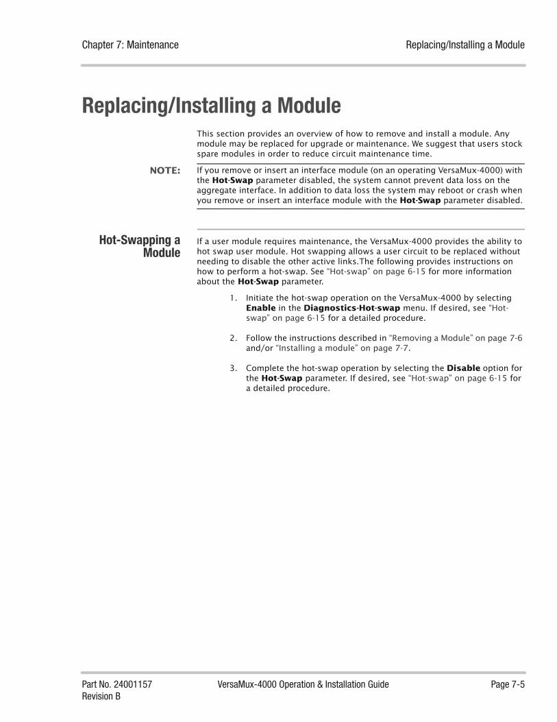
Chapter 7: Maintenance Replacing/Installing a Module
Part No. 24001157 VersaMux-4000 Operation & Installation Guide Page 7-5Revision B
Replacing/Installing a ModuleThis section provides an overview of how to remove and install a module. Any module may be replaced for upgrade or maintenance. We suggest that users stock spare modules in order to reduce circuit maintenance time.
NOTE: If you remove or insert an interface module (on an operating VersaMux-4000) with the Hot-Swap parameter disabled, the system cannot prevent data loss on the aggregate interface. In addition to data loss the system may reboot or crash when you remove or insert an interface module with the Hot-Swap parameter disabled.
Hot-Swapping aModule
If a user module requires maintenance, the VersaMux-4000 provides the ability to hot swap user module. Hot swapping allows a user circuit to be replaced without needing to disable the other active links.The following provides instructions on how to perform a hot-swap. See “Hot-swap” on page 6-15 for more information about the Hot-Swap parameter.
1. Initiate the hot-swap operation on the VersaMux-4000 by selecting Enable in the Diagnostics-Hot-swap menu. If desired, see “Hot-swap” on page 6-15 for a detailed procedure.
2. Follow the instructions described in “Removing a Module” on page 7-6 and/or “Installing a module” on page 7-7.
3. Complete the hot-swap operation by selecting the Disable option for the Hot-Swap parameter. If desired, see “Hot-swap” on page 6-15 for a detailed procedure.

Replacing/Installing a Module Chapter 7: Maintenance
Page 7-6 VersaMux-4000 Operation & Installation Guide Part No. 24001157Revision B
Removing aModule
If you are performing a module “Hot-Swap” or are removing a module from an operating VersaMux-4000, perform the procedure described in “Hot-Swapping a Module” on page 7-5 before proceeding with this procedure.
Use the following procedure to remove a module from the VersaMux-4000 chassis:
1. Unscrew the thumbscrews located at the top corners of the module as shown in Figure 7-1.
Figure 7-1 Loosening the Captive Thumb-Screws on the Module
EXT CLK
FIBER
FRX CRX FFIBER / CU
CRX FTX CTXFIBER / CU
FRX CRX FTX CTX

Chapter 7: Maintenance Replacing/Installing a Module
Part No. 24001157 VersaMux-4000 Operation & Installation Guide Page 7-7Revision B
2. Slide the module out of the chassis using the pull tab provided at the bottom of the module as shown in Figure 7-2.
Figure 7-2 Removing the Module
Installing a module If you are performing a module “Hot-Swap” or are removing a module from an operating VersaMux-4000, perform the procedure described in “Hot-Swapping a Module” on page 7-5 before proceeding with this procedure.
Use this procedure to install a module in the VersaMux-4000 chassis:
1. Carefully align the module with the guides located on the side of the user or aggregate slot as shown in Figure 7-3.
Figure 7-3 Aligning the Module in the Chassis Slot
RCV
EXT CLK
FIBER / CU
FRX CRX FTX CTXFIBER / CU
CRX FTX CTXFIBER / CU
FRX CRX FTX CTX
NRZFIBER
RCVXMT
CLK
FIBER / CU
FRX CRX FTX CTXFIBER / CU
CRX FTX CTX
FIBER / CU
FRX CRX FTX CTX
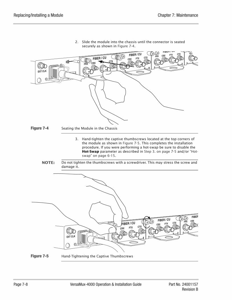
Replacing/Installing a Module Chapter 7: Maintenance
Page 7-8 VersaMux-4000 Operation & Installation Guide Part No. 24001157Revision B
2. Slide the module into the chassis until the connector is seated securely as shown in Figure 7-4.
Figure 7-4 Seating the Module in the Chassis
3. Hand-tighten the captive thumbscrews located at the top corners of the module as shown in Figure 7-5. This completes the installation procedure. If you were performing a hot-swap be sure to disable the Hot-Swap parameter as described in Step 3. on page 7-5 and/or “Hot-swap” on page 6-15.
NOTE: Do not tighten the thumbscrews with a screwdriver. This may stress the screw and damage it.
Figure 7-5 Hand-Tightening the Captive Thumbscrews
RCV
EXT CLK
FIBER / CU
FRX CRX FTX CTXFIBER / CU
CRX FTX CTXFIBER / CU
FRX CRX FTX CTX
EXT CLK
FIBER
FRX CRXFIBER / CU
CRX FTX CTXFIBER / CU
FRX CRX FTX CTX

Chapter 7: Maintenance Replacing/Installing a Module
Part No. 24001157 VersaMux-4000 Operation & Installation Guide Page 7-9Revision B
Procedure

Software Upgrade Procedure Chapter 7: Maintenance
Page 7-10 VersaMux-4000 Operation & Installation Guide Part No. 24001157Revision B
Software Upgrade ProcedureThe VersaMux-400 has the capacity to accept software upgrades. Contact DNE Technologies, Technical Support at(203) 265-7151 x400 or (800) 370-4485 x400 for upgrade files and availability.
Use the following procedure to upgrade the software on the VersaMux-4000:
1. Start a HyperTerminal session and connect a serial cable from the computer to the control port on the back of the VersaMux-4000. The HyperTerminal settings for the connection are (as shown in Figure 7-6):
• Bits per second: = 9600
• Data bits: = 8
• Parity: = None
• Stop bits: = 1
• Flow control: = XON/XOFF
Figure 7-6 HyperTerminal Setting for the VersaMux-4000 Terminal Interface

Chapter 7: Maintenance Software Upgrade Procedure
Part No. 24001157 VersaMux-4000 Operation & Installation Guide Page 7-11Revision B
2. Power the VM-4000 on (or cycle the power).
3. Enter a “y” (type y and then press Enter key) when prompted with Do you want to run the Software Upgrade utility? Y/N (N) as shown in Figure 7-7.
Figure 7-7 Confirming the Software Upgrade Utility Program
4. Select option one, Set Terminal Rate, from the SOFTWARE UPGRADE UTILITY menu (enter a 1) to access the Set Terminal Rate menu as shown in Figure 7-8.

Software Upgrade Procedure Chapter 7: Maintenance
Page 7-12 VersaMux-4000 Operation & Installation Guide Part No. 24001157Revision B
Figure 7-8 Terminal Rate Menu (Selecting the Terminal Rate)
5. Select option one, 115200, (enter a 1) from the SET TERMINAL RATE menu to set the terminal rate to 115200.
6. Disconnect the HyperTerminal connection and change the COM1 properties to 115200 bps as shown in Figure 7-9 and reconnect the session. Press any key to continue as shown in Figure 7-10.

Chapter 7: Maintenance Software Upgrade Procedure
Part No. 24001157 VersaMux-4000 Operation & Installation Guide Page 7-13Revision B
Figure 7-9 Changing the HyperTerminal Rate to 115,200 Bits per Second
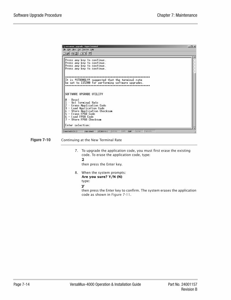
Software Upgrade Procedure Chapter 7: Maintenance
Page 7-14 VersaMux-4000 Operation & Installation Guide Part No. 24001157Revision B
Figure 7-10 Continuing at the New Terminal Rate
7. To upgrade the application code, you must first erase the existing code. To erase the application code, type: 2 then press the Enter key.
8. When the system prompts:Are you sure? Y/N (N)type:ythen press the Enter key to confirm. The system erases the application code as shown in Figure 7-11.

Chapter 7: Maintenance Software Upgrade Procedure
Part No. 24001157 VersaMux-4000 Operation & Installation Guide Page 7-15Revision B
Figure 7-11 The System Erasing the Application Code
9. When the system completes erasing the application code it displays the SOFTWARE UPGRADE UTILITY menu as shown in Figure 7-12. (enter a 3) to select the Load Application Code option then press the Enter key to start loading the new application code.Enter a y at the prompt to confirm and the system prompts you for the file as shown in Figure 7-12.

Software Upgrade Procedure Chapter 7: Maintenance
Page 7-16 VersaMux-4000 Operation & Installation Guide Part No. 24001157Revision B
Figure 7-12 Selecting the Load Application Code Option from the Software Upgrade Utility
10. Go to the Transfer “drop-down” menu in the HyperTerminal window and select Send Text File...Browse to location of the software upgrade file and select the Mux Application Hexidecimal file (for example, Mux-App-Rel-02-11.Hex).
Note that you need to set the Files of type: field in the Send Text File dialog box to All files (*.*), as shown in Figure 7-13, to access the hex file.

Chapter 7: Maintenance Software Upgrade Procedure
Part No. 24001157 VersaMux-4000 Operation & Installation Guide Page 7-17Revision B
Figure 7-13 Send Text File Dialog Box
The transfer takes a few minutes with lines of code scrolling in the HyperTerminal window as shown in Figure 7-14.
Figure 7-14 Application Code File being Sent to the VersaMux-4000

Software Upgrade Procedure Chapter 7: Maintenance
Page 7-18 VersaMux-4000 Operation & Installation Guide Part No. 24001157Revision B
11. When the file transfer completes, select the Store Application Checksum option (enter a 4) from the SOFTWARE UPGRADE UTILITY menu to store the application checksum.
Enter a y at the prompt to confirm the storage command.
12. You can upgrade three of the VersaMux-4000 FPGAs. To begin upgrading the FPGAs, select the Erase FPGA Code option (enter a 5) from the SOFTWARE UPGRADE UTILITY menu to access the “Erase FPGA Selection Menu” (Which FPGA Program? menu) as shown in Figure 7-15. Note that you can upgrade only one FPGA at a time.
Figure 7-15 Erase FPGA Selection Menu
13. Select 0 (zero) for the system FPGA, 1 for the mux FPGA, or 2 for the demux FGPA. Enter a y at the prompt to confirm the selection.
14. Once the code has been erased, select the Load FPGA Code option (enter a 6) from the SOFTWARE UPGRADE UTILITY menu to load new FPGA code.Again enter either 0, 1, or 2. Enter a y at the prompt to confirm and proceed with the load operation.
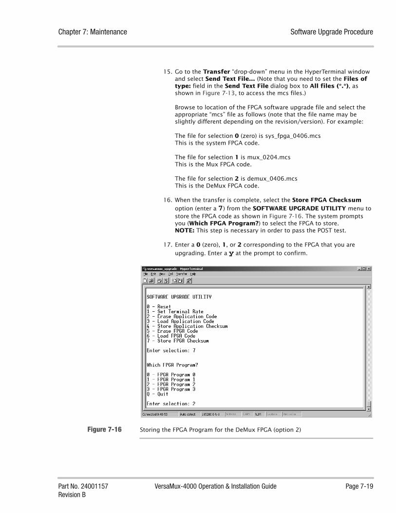
Chapter 7: Maintenance Software Upgrade Procedure
Part No. 24001157 VersaMux-4000 Operation & Installation Guide Page 7-19Revision B
15. Go to the Transfer “drop-down” menu in the HyperTerminal window and select Send Text File... (Note that you need to set the Files of type: field in the Send Text File dialog box to All files (*.*), as shown in Figure 7-13, to access the mcs files.)
Browse to location of the FPGA software upgrade file and select the appropriate “mcs” file as follows (note that the file name may be slightly different depending on the revision/version). For example:
The file for selection 0 (zero) is sys_fpga_0406.mcs This is the system FPGA code.
The file for selection 1 is mux_0204.mcs This is the Mux FPGA code.
The file for selection 2 is demux_0406.mcs This is the DeMux FPGA code.
16. When the transfer is complete, select the Store FPGA Checksum option (enter a 7) from the SOFTWARE UPGRADE UTILITY menu to store the FPGA code as shown in Figure 7-16. The system prompts you (Which FPGA Program?) to select the FPGA to store.NOTE: This step is necessary in order to pass the POST test.
17. Enter a 0 (zero), 1, or 2 corresponding to the FPGA that you are upgrading. Enter a y at the prompt to confirm.
Figure 7-16 Storing the FPGA Program for the DeMux FPGA (option 2)
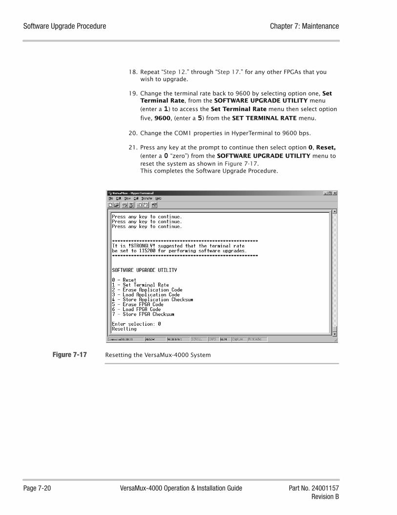
Software Upgrade Procedure Chapter 7: Maintenance
Page 7-20 VersaMux-4000 Operation & Installation Guide Part No. 24001157Revision B
18. Repeat “Step 12.” through “Step 17.” for any other FPGAs that you wish to upgrade.
19. Change the terminal rate back to 9600 by selecting option one, Set Terminal Rate, from the SOFTWARE UPGRADE UTILITY menu (enter a 1) to access the Set Terminal Rate menu then select option
five, 9600, (enter a 5) from the SET TERMINAL RATE menu.
20. Change the COM1 properties in HyperTerminal to 9600 bps.
21. Press any key at the prompt to continue then select option 0, Reset, (enter a 0 “zero”) from the SOFTWARE UPGRADE UTILITY menu to reset the system as shown in Figure 7-17. This completes the Software Upgrade Procedure.
Figure 7-17 Resetting the VersaMux-4000 System

Part No. 24001157 VersaMux-4000 Operation & Installation Guide Page 8-1Revision B
Chapter
Warranty Statements 8About this Chapter This chapter states the warranty and support policies for the VersaMux-4000.
Chapter Contents This chapter includes the following topics:
Statement of Warranty ..................................................................................... 8-3
Service Requests ............................................................................................. 8-4
Returning Defective Equipment ....................................................................... 8-5
Obtaining an RMA and Returning Equipment ......................................... 8-5Preparing Items for Return ..................................................................... 8-5

Chapter 8: Warranty Statements
Page 8-2 VersaMux-4000 Operation & Installation Guide Part No. 24001157Revision B
This page intentionally left blank

Chapter 8: Warranty Statements Statement of Warranty
Part No. 24001157 VersaMux-4000 Operation & Installation Guide Page 8-3Revision B
Statement of WarrantyThe Company (Ultra Electronics, DNE Technologies) warrants to the Purchaser that the equipment to be delivered hereunder will be free from defects in material and workmanship for a period of one year from the date of shipment by DNE Technologies, Incorporated.
Any equipment which fails to conform to specification or becomes defective by reason of material or workmanship during the Warranty period will be promptly repaired or replaced by DNE Technologies at its option. Items repaired or replaced by DNE Technologies under this clause will be free from defects in material and workmanship for ninety (90) days from date of shipment by Ultra Electronics, DNE Technologies, or the balance of the warranty period for the equipment, whichever is longer. Equipment found not to be defective will be returned to the Purchaser, freight charges collect, and charges will be forwarded to the Purchaser for inspection and test time. Transportation charges for equipment found to be defective within the Warranty period will be paid by Ultra Electronics, DNE Technologies, to and from the original point of acceptance.
The liability of Ultra Electronics, DNE Technologies to the Purchaser arising out of the supplying of the said equipment shall not in any case exceed the cost of correcting defects in the equipment as provided herein or the price paid to Ultra Electronics, DNE Technologies by the Purchaser, whichever is less.
Upon expiration of Warranty period, all such Warranty liability shall terminate. The foregoing shall constitute the sole remedy of the Purchaser and the sole liability of Ultra Electronics, DNE Technologies and shall be in lieu of any other Warranty, implied, statutory, or otherwise, including the Warranty of merchantability. Ultra Electronics, DNE Technologies shall not be liable for (incidental, special, indirect or) consequential damages.

Service Requests Chapter 8: Warranty Statements
Page 8-4 VersaMux-4000 Operation & Installation Guide Part No. 24001157Revision B
Service RequestsOur Technical Support Operation may be contacted regarding on-site service requests or for additional information by:
• Telephone: (203) 265-7151 extension 400
Toll Free: (800) 370-4485extension 400
• E-mail: [email protected]
• FAX: (203) 265-9101

Chapter 8: Warranty Statements Returning Defective Equipment
Part No. 24001157 VersaMux-4000 Operation & Installation Guide Page 8-5Revision B
Returning Defective Equipment
Obtaining an RMAand Returning
Equipment
To obtain an RMA number, contact DNE Technologies, Technical Support at (203) 265-7151 x400 or (800) 370-4485 x400. Do not return material without this number.
Send defective equipment for repair to:
DNE Technologies, Inc.50 Barnes Park NorthWallingford, CT 06492Attn: Technical Support
Mark the RMA number on the outside of the package and any other paperwork included with the shipment.
Preparing Items forReturn
Damaged or defective VersaMux-4000 units should be repacked in the original containers or re-crated.
Your service request must include the following information:
• A copy of your Purchase Order.
• Shipping instructions.
• DNE part number and description.
• Brief failure description.
• Your phone number and who to contact if questions arise.
• For Government customers, be sure to use a Form DD1149 to ensure prompt processing.
The customer is responsible for freight charges for shipment of material to DNE. DNE will pay for shipping (via surface, UPS Standard) from DNE to the customer (FOB origin).

Returning Defective Equipment Chapter 8: Warranty Statements
Page 8-6 VersaMux-4000 Operation & Installation Guide Part No. 24001157Revision B
This page intentionally left blank.

Index
Part No. 24001157 VersaMux-4000 Operation & Installation Guide Page IX-1Revision B
A
AccuracyExternal Clock Input Requirement ..............................5-13
ActivateParameter Description ...................................................5-34Parameter, Terminal Interface ......................................5-35Sub-Menu Navigation, Front Panel Interface .............5-35
ActiveConfigure Sub-Menu Selection Description ...............5-24Offline, Copy-Config Parameter Option Description 5-23Sub-Menu Navigation, Front Panel Interface .............5-26Sub-Menu, Terminal Interface ......................................5-24
AGGRLED Description ................................................................6-3
Aggr-BWStatistics, Description ....................................................5-45
AggregateClk-Ref Option Description ...........................................5-12Function Description .....................................................5-17Loopback ...........................................................................6-7Offline Parameters .........................................................5-16Viewing Active Options, Terminal Interface ..............5-25
Aggregate -StatsDescription ......................................................................5-42
Aggregate Sync-Inhibit Parameter ................................5-19
Aggregate-StatisticsViewing, Terminal Interface .........................................5-44
AlarmDescriptions ......................................................................5-5Insufficient Bandwidth ......................................... 5-18, 5-22LOF and Aggregate Sync-Inhibit ..................................5-19
Alarms-StatsDescription ......................................................................5-42
Alarm-StatsViewing, Terminal Interface .........................................5-44
Alarm-StatusParameter, Front Panel Interface ...................................5-7
Parameter, Terminal Interface ........................................5-5
All-ResultsTest Menu Option ...........................................................6-17
AltitudeSpecification ....................................................................2-10
AssembliesOptional ..............................................................................2-6
B
BalancedCDI Input/Output Connector ........................................3-24Connector Pinouts ..........................................................3-24RS-422 ..............................................................................3-20
BandwidthStatistics ...........................................................................5-45
Bandwidth -StatsDescription ......................................................................5-42
Bandwidth-StatisticsDescription ......................................................................5-45
BERTDescription ......................................................................6-11Sub-Menu, Front Panel Interface ..................................6-14Sub-Menu, Terminal Interface ......................................6-13
BERT-Avg-BERParameter Description ...................................................6-11
BERT-BERParameter Description ...................................................6-11
BERT-Bit-ErrorsParameter Description ...................................................6-11
BERT-Bits-TestedParameter Description ...................................................6-11
BERT-Sync-LossesParameter Description ...................................................6-11
BERT-Sync-StateParameter Description ...................................................6-11
Index IX

Index
Page IX-2 VersaMux-4000 Operation & Installation Guide Part No. 24001157Revision B
Bi-directionalLoopback Option Description .........................................6-7
BISTOption Description .........................................................6-17
Bit Error Rate TesterDescribed .........................................................................6-11
Black Station ClockInput Specification ............................................................2-9
BNCExternal Clock Pinouts ...................................................3-26
BSCInput Specification ............................................................2-9
C
CablesCopper Cable Requirements .........................................3-20
Card TypeOffline Aggregate Parameter Description ..................5-17
Card-TypeManagement Parameter Option ...................................5-31Offline Port Parameter Description ..............................5-21
CAUSub-Menu Parameters ....................................................5-27Sub-Menu, Front Panel Interface ..................................5-30Sub-Menu, Terminal Interface ......................................5-29
CDIInput/Output Connector Pinouts .................................3-24Physical Interface ..............................................................2-9
CharacteristicsVersaMux-4000 Physical .................................................2-9
CleaningElectrical Connectors .......................................................7-3Exterior Surfaces ...............................................................7-3Optical Connectors ...........................................................7-3
CLK REFLED Description .................................................................6-3
Clk-RefCV-2048 / CV-8448
Internal Oscillator Consideration ..................................5-13
Clk-Ref ParameterDescription .......................................................................5-12
ClockExternal Input Specification ............................................2-9Multi-Drop ........................................................................3-26
ClockingInternal .............................................................................4-13
Combo Fiber-Copper ModuleIllustration ......................................................................... 2-5
CommandsConcatenating on the Terminal Interface .................. 4-12
ConcatenatingTerminal Interface Commands .................................... 4-12
ConditionsSystem-Info Parameter Description ............................ 5-36Viewing, Terminal Interface ......................................... 5-38
Config PortPinouts ............................................................................. 3-25
ConfigurationMatched End-to-End ................................................5-8, 5-34Port Pin Assignments .................................................... 3-25Saved .................................................................................. 2-4
Configuration Port ............................................................. 3-25Pinouts ............................................................................. 3-25Terminal Settings ............................................................. 4-5
ConfigureSub-Menu Selections ....................................................... 5-8Sub-Menu, Front Panel Interface ................................... 5-9Sub-Menu, Terminal Interface ....................................... 5-8
ConnectionBERT Parameter Description ........................................ 6-12Terminal Settings ............................................................. 4-5
ConnectorBalanced Pinouts ............................................................ 3-24CDI Input/Output Connector ....................................... 3-24Cleaning Electrical ........................................................... 7-3DB-9 Balanced CDI ......................................................... 3-24EIA-530 DCE .................................................................... 3-20EIA-530 DTE .................................................................... 3-21Ext Clock Pinouts ........................................................... 3-26Fiber Optic Tx/Rx Assignments .................................. 3-25NRZ Pinouts ..................................................................... 3-20Unbalanced Tx/Rx Assignments ................................. 3-24
Control LeadBehavior, DCE ................................................................. 3-23Behavior,DTE .................................................................. 3-22
Control LeadsList, NRZ .......................................................................... 3-21
Control PortPin Assignments ............................................................. 3-25Terminal Pinouts ............................................................ 3-25
CoolingRequirements ................................................................... 3-3
CopperUnbalanced Connector Assignments ......................... 3-24
Copy-ConfigOffline Parameter Description ..................................... 5-23

Index
Part No. 24001157 VersaMux-4000 Operation & Installation Guide Page IX-3Revision B
Copyright .................................................................................. -ii
Crypto Ancillary UnitSub-Menu Parameters ....................................................5-27
Crypto SetupDescription of Requirements .......................................5-28KG-Resync ........................................................................5-28
CTSNRZ Control Lead Behavior, DCE .................................3-23NRZ Control Lead Behavior, DTE .................................3-22
CV-2048Internal Oscillator Consideration ................................5-13
CV-8448Internal Oscillator Consideration ................................5-13
D
DamageShipping .............................................................................2-3
DB-9 ConnectorBalanced CDI Pinouts .....................................................3-24CDI Input/Output Pinouts .............................................3-24
DCDNRZ Control Lead Behavior ...........................................3-22NRZ Control Lead Behavior, DCE .................................3-23
DCEMode Parameter ..............................................................5-17NRZ Pinouts .....................................................................3-20
DCE ModeExternal Input Timing ....................................................4-16Port Timing ......................................................................4-19
DCE Mode Aggregate Timing .........................................4-14
Defective EquipmentReturning ...........................................................................8-5
DepthVersaMux-4000 ................................................................2-9
DescriptionAlarms ................................................................................5-5VersaMux-4000 ................................................................2-4
DiagnosticsSub-Menu ...........................................................................6-6Sub-Menu, Front Panel Interface ....................................6-7Sub-Menu, Terminal Interface ........................................6-6
DisableHot-Swap ............................................................................7-5
DisabledHot-swap Option Described .........................................6-15
DisplayLCD .....................................................................................4-3
DistanceMinimum Drive .................................................................2-8Specified .............................................................................2-8
DocumentFormats & Styles ...............................................................P-2
Drive DistancesSpecification ......................................................................2-8Specifications ....................................................................2-8
DSRNRZ Control Lead Behavior, DCE .................................3-23NRZ Control Lead Behavior, DTE .................................3-22
DTEAggregate Timing ...........................................................4-13Mode Option ....................................................................5-17Mode Parameter ..............................................................5-17
DTE ModeAggregate Timing ...........................................................4-13External Input Timing ....................................................4-15Port Timing ......................................................................4-18
DTRNRZ Control Lead Behavior, DCE .................................3-23NRZ Control Lead Behavior, DTE .................................3-22
E
EarthGrounding ........................................................................3-18
Earth GroundWarning ..............................................................................1-4
EIA-530 DCEConnector ........................................................................3-20
EIA-530 DTEConnector ........................................................................3-21
ElectricalInterfaces ...........................................................................2-9Shock Warning ..................................................................1-3
Electrical ShockMedical Procedures ..........................................................1-2
ElectromagneticEmissions Specification .................................................2-10
EmissionsSpecification ....................................................................2-10
EnableHot-Swap ............................................................................7-5
EnabledHot-swap Option Described .........................................6-15
End Around DelayDescription ......................................................................5-28

Index
Page IX-4 VersaMux-4000 Operation & Installation Guide Part No. 24001157Revision B
EnvironmentalSpecifications ..................................................................2-10
Err-InsertBERT Parameter Description .........................................6-12
ErrorBuilt In Error Rate Tester ...............................................6-11
Errors-OnlyTest Menu Option ...........................................................6-17
Ext-10MHzOption Description .........................................................5-12
Ext-1MHzOption Description .........................................................5-12
Ext-5MHzOption Description .........................................................5-12
Ext-Clk-TypeParameter Description ...................................................5-13
ExternalAggregate Loopback Diagram ........................................6-9Loopback Option Description .........................................6-7Port Loopback Diagram ...................................................6-9
External ClockConnector Pinouts ..........................................................3-26Input Specifications ..........................................................2-9
External Clock InputAccuracy Requirement ...................................................5-13Connector Pin Assignments ..........................................3-26Required Signal Accuracy ..............................................3-26Timing, DCE Mode ..........................................................4-16Timing, DTE Mode ..........................................................4-15
External CoolingRequirements ....................................................................3-3
F
FactoryTest Option Description ................................................6-17
FAULTLED Indicator Description ...............................................6-4
FCC part 15Specification ....................................................................2-10
FiberOptical Connector Assignments ..................................3-25
FilterFOM Mode Rates .............................................................5-20
Flash MemorySaved Configuration .........................................................2-4
FormatsDocument Styles ...............................................................P-2
FP-LightingParameter Description .................................................. 5-14
Frame-LossesAggregate Statistics, Terminal Interface ................... 5-44
FreightCharges .............................................................................. 8-5
Front PanelBasic Menu Navigation .................................................... 4-4Components ..................................................................... 4-3KeyPad ............................................................................... 4-3Lighting Options ............................................................ 5-14
FunctionOffline Aggregate Parameter Description ................. 5-17
G
GroundLocation ........................................................................... 3-18Warning .............................................................................. 1-4Wire Requirement .......................................................... 3-18
GroundingRequirements ................................................................. 3-18
Guide PinRear Support Brackets ..................................................... 3-7
H
HeightVersaMux-4000 ................................................................ 2-9
High VoltageSafety Warning ................................................................. 1-3
Hot SwapDescription ........................................................................ 2-4
Hot-SwapDisable ............................................................................... 7-5Enable ................................................................................ 7-5Sub-Menu, Front Panel Interface ................................. 6-16Sub-Menu, Terminal Interface ..................................... 6-15
Hot-swapParameter Description .................................................. 6-15
HumiditySpecification ................................................................... 2-10
HyperTerminalSettings .............................................................................. 4-5
I
ImpedanceExternal Clock Input ...................................................... 3-26

Index
Part No. 24001157 VersaMux-4000 Operation & Installation Guide Page IX-5Revision B
Indicator StatesDescribed ...........................................................................6-5
InputExternal Clock Specification ...........................................2-9
InspectionUpon Receiving Unit ........................................................2-3
InstallingProcedure for Module ......................................................7-7
Insufficient BandwidthAlarm ...................................................................... 5-18, 5-22
InterfaceRates ...................................................................................2-7
InterfacesElectrical .............................................................................2-9
InternalAggregate Loopback Diagram .......................................6-8Clk-Ref Option Description ...........................................5-13Loopback Option Description ........................................6-7Port Loopback Diagram ...................................................6-8
Internal PartsNon-Serviceable ................................................................2-3
Internal-TempViewing Status ................................................................5-36
InventorySub-Menu Description ...................................................5-36Viewing, Terminal Interface .........................................5-39
J
JTC3A-9109CInteroperability ...............................................................5-21
K
KeypadFront Panel .........................................................................4-3
KG-ResyncCrypto Setup ...................................................................5-28NRZ Control Lead Behavior, DCE .................................3-23NRZ Control Lead Behavior,DTE ..................................3-22Parameter Options Described ......................................5-27
L
LCDDisplay ...............................................................................4-3Lighting Options .............................................................5-14
LCD DisplayBasic Function ...................................................................4-4
LED IndicatorsDescriptions ......................................................................6-3State Descriptions ............................................................6-5
LiabilityWarranty .............................................................................8-3
LightingFront Panel, Parameter Description .............................5-14
LightningProtection ...........................................................................1-4Warning ..............................................................................1-4
LOF Alarm ..............................................................................5-19
LoopbackExternal Aggregate Diagram ..........................................6-9External Port Diagram .....................................................6-9Internal Aggregate Diagram ...........................................6-8Internal Port Diagram ......................................................6-8
LoopbacksSub-Menu ...........................................................................6-7Sub-Menu, Front Panel Interface ..................................6-11Sub-Menu, Terminal Interface ......................................6-10
M
Main Menu PromptTerminal Interface ............................................................4-5
ManagementParameters, Configure Sub-Menu ................................5-31Sub-Menu, Front Panel Interface ..................................5-33Sub-Menu, Terminal Interface ......................................5-32
Mark-SenseOffline Aggregate Parameter Description ..................5-19
Medical ProceduresElectrical Shock .................................................................1-2
ModeDCE Option ......................................................................5-17Offline Aggregate Parameter Description ..................5-17Offline Port Parameter Description .............................5-21
ModuleFiber-Copper Combo Illustration ...................................2-5Installation Procedure ......................................................7-7NRZ Aggregate Illustration .............................................2-5Procedure for Removing .................................................7-6Replacing, Installing, Hot-Swapping .............................7-5
MonitoringSystem Conditions .........................................................5-36
MountingRack or Desk-Top .............................................................3-3
Multi-DropClock Not Supported ......................................................3-26

Index
Page IX-6 VersaMux-4000 Operation & Installation Guide Part No. 24001157Revision B
N
NavigationBasic, Front Panel ..............................................................4-4
NoActivate Configuration Option .....................................5-34Offline, Copy-Config Parameter Option Description 5-23
No LoopLoopback Option Description .........................................6-7
NRZConnector Pinouts ..........................................................3-20Physical Specification .......................................................2-9
NRZ Aggregate ModuleIllustration ..........................................................................2-5
NRZ DCEControl Lead Behavior ...................................................3-23
NRZ DTEControl Lead Behavior ...................................................3-22
NRZ PinoutsDCE EIA-530 .....................................................................3-20DCE with AN/FCC-100 Nomenclature .........................3-20EIA-530 Pinouts DTE ......................................................3-21
NumberingPorts ....................................................................................4-3
O
OfflineActivate Configuration Option .....................................5-34Sub-Menu Description ....................................................5-14Sub-Menu, Front Panel Interface ..................................5-16Sub-Menu, Terminal Interface ......................................5-15
OpticFiber Connector Assignments ......................................3-25
Optical ConnectorsCleaning .............................................................................7-3
OptionsDisplay Differences Between Read-Only and Edit .......4-4Ordering .............................................................................2-6
OrderingOptions ...............................................................................2-6
Ovhd-BWStatistics, Description ....................................................5-45
OW-FilterOffline Port Parameter Description ..............................5-22
P
ParameterAccessing on Terminal Interface ....................................4-7
Part NumberVersaMux-4000 Chassis ................................................. 2-6VersaMux-4000 Combo Module .................................... 2-6VersaMux-4000 NRZ Module ......................................... 2-6VersaMux-4000 System .................................................. 2-6
PartsNon-Serviceable Internal ................................................. 2-3
Parts ListRear Support Bracket Kit ................................................. 3-5
PatternBERT Parameter Description ........................................ 6-12
Phone NumbersService ................................................................................ 8-4
Physical CharacteristicsVersaMux-4000 ................................................................ 2-9
Pin Assignments ................................................................. 3-25External Clock Input ...................................................... 3-26
PinoutsBalanced CDI (DB-9) ....................................................... 3-24Balanced Connector ....................................................... 3-24CDI Input/Output Connector ....................................... 3-24Config Port ...................................................................... 3-25Ext Clock Connector ...................................................... 3-26NRZ Connector ............................................................... 3-20NRZ DCE With EIA-530 Nomenclature ........................ 3-20NRZ DTE ........................................................................... 3-21NRZ DTE With AN/FCC-100 Nomenclature ................ 3-21
PortLoopback ........................................................................... 6-7Numbering ........................................................................ 4-3Offline Port Parameter Description ............................. 5-21
Port RateInsufficient Bandwidth Alarm .............................5-18, 5-22
Port TimingDCE Mode ........................................................................ 4-19DTE Mode ........................................................................ 4-18
Port-1Clk-Ref Option Description .......................................... 5-12
Port-1-BWStatistics, Description ................................................... 5-45
Port-2Clk-Ref Option Description .......................................... 5-13
Port-2-BWStatistics, Description ................................................... 5-45
Port-3Clk-Ref Option Description .......................................... 5-13
Port-3-BWStatistics, Description ................................................... 5-45
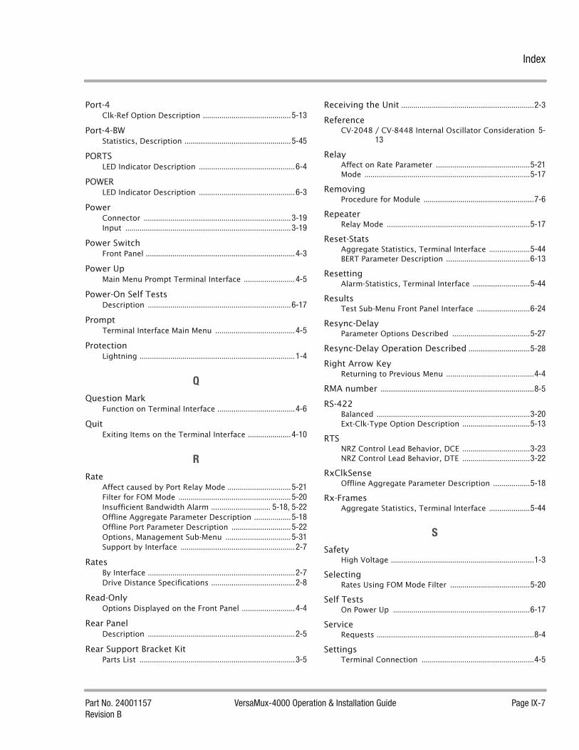
Index
Part No. 24001157 VersaMux-4000 Operation & Installation Guide Page IX-7Revision B
Port-4Clk-Ref Option Description ...........................................5-13
Port-4-BWStatistics, Description ....................................................5-45
PORTSLED Indicator Description ...............................................6-4
POWERLED Indicator Description ...............................................6-3
PowerConnector ........................................................................3-19Input .................................................................................3-19
Power SwitchFront Panel .........................................................................4-3
Power UpMain Menu Prompt Terminal Interface .........................4-5
Power-On Self TestsDescription ......................................................................6-17
PromptTerminal Interface Main Menu .......................................4-5
ProtectionLightning ............................................................................1-4
Q
Question MarkFunction on Terminal Interface ......................................4-6
QuitExiting Items on the Terminal Interface .....................4-10
R
RateAffect caused by Port Relay Mode ...............................5-21Filter for FOM Mode .......................................................5-20Insufficient Bandwidth Alarm ............................. 5-18, 5-22Offline Aggregate Parameter Description ..................5-18Offline Port Parameter Description .............................5-22Options, Management Sub-Menu ................................5-31Support by Interface ........................................................2-7
RatesBy Interface ........................................................................2-7Drive Distance Specifications .........................................2-8
Read-OnlyOptions Displayed on the Front Panel ..........................4-4
Rear PanelDescription ........................................................................2-5
Rear Support Bracket KitParts List ............................................................................3-5
Receiving the Unit .................................................................2-3
ReferenceCV-2048 / CV-8448 Internal Oscillator Consideration 5-
13
RelayAffect on Rate Parameter ..............................................5-21Mode .................................................................................5-17
RemovingProcedure for Module ......................................................7-6
RepeaterRelay Mode ......................................................................5-17
Reset-StatsAggregate Statistics, Terminal Interface ....................5-44BERT Parameter Description .........................................6-13
ResettingAlarm-Statistics, Terminal Interface ............................5-44
ResultsTest Sub-Menu Front Panel Interface ..........................6-24
Resync-DelayParameter Options Described ......................................5-27
Resync-Delay Operation Described ..............................5-28
Right Arrow KeyReturning to Previous Menu ...........................................4-4
RMA number ...........................................................................8-5
RS-422Balanced ...........................................................................3-20Ext-Clk-Type Option Description .................................5-13
RTSNRZ Control Lead Behavior, DCE .................................3-23NRZ Control Lead Behavior, DTE .................................3-22
RxClkSenseOffline Aggregate Parameter Description ..................5-18
Rx-FramesAggregate Statistics, Terminal Interface ....................5-44
S
SafetyHigh Voltage ......................................................................1-3
SelectingRates Using FOM Mode Filter .......................................5-20
Self TestsOn Power Up ...................................................................6-17
ServiceRequests .............................................................................8-4
SettingsTerminal Connection .......................................................4-5
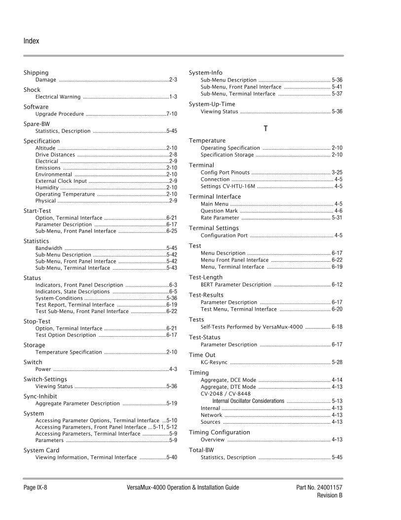
Index
Page IX-8 VersaMux-4000 Operation & Installation Guide Part No. 24001157Revision B
ShippingDamage ..............................................................................2-3
ShockElectrical Warning .............................................................1-3
SoftwareUpgrade Procedure .........................................................7-10
Spare-BWStatistics, Description ....................................................5-45
SpecificationAltitude .............................................................................2-10Drive Distances .................................................................2-8Electrical .............................................................................2-9Emissions .........................................................................2-10Environmental .................................................................2-10External Clock Input .........................................................2-9Humidity ...........................................................................2-10Operating Temperature .................................................2-10Physical ...............................................................................2-9
Start-TestOption, Terminal Interface ............................................6-21Parameter Description ...................................................6-17Sub-Menu, Front Panel Interface ..................................6-25
StatisticsBandwidth ........................................................................5-45Sub-Menu Description ....................................................5-42Sub-Menu, Front Panel Interface ..................................5-42Sub-Menu, Terminal Interface ......................................5-43
StatusIndicators, Front Panel Description ...............................6-3Indicators, State Descriptions ........................................6-5System-Conditions ..........................................................5-36Test Report, Terminal Interface ...................................6-19Test Sub-Menu, Front Panel Interface .........................6-22
Stop-TestOption, Terminal Interface ............................................6-21Test Option Description ................................................6-17
StorageTemperature Specification ............................................2-10
SwitchPower ..................................................................................4-3
Switch-SettingsViewing Status .................................................................5-36
Sync-InhibitAggregate Parameter Description ...............................5-19
SystemAccessing Parameter Options, Terminal Interface ...5-10Accessing Parameters, Front Panel Interface ... 5-11, 5-12Accessing Parameters, Terminal Interface ...................5-9Parameters .........................................................................5-9
System CardViewing Information, Terminal Interface ...................5-40
System-InfoSub-Menu Description ................................................... 5-36Sub-Menu, Front Panel Interface ................................. 5-41Sub-Menu, Terminal Interface ..................................... 5-37
System-Up-TimeViewing Status ................................................................ 5-36
T
TemperatureOperating Specification ................................................ 2-10Specification Storage ..................................................... 2-10
TerminalConfig Port Pinouts ........................................................ 3-25Connection ........................................................................ 4-5Settings CV-HTU-16M ...................................................... 4-5
Terminal InterfaceMain Menu ......................................................................... 4-5Question Mark .................................................................. 4-6Rate Parameter ............................................................... 5-31
Terminal SettingsConfiguration Port ........................................................... 4-5
TestMenu Description ........................................................... 6-17Menu Front Panel Interface .......................................... 6-22Menu, Terminal Interface ............................................. 6-19
Test-LengthBERT Parameter Description ........................................ 6-12
Test-ResultsParameter Description .................................................. 6-17Test Menu, Terminal Interface .................................... 6-20
TestsSelf-Tests Performed by VersaMux-4000 .................. 6-18
Test-StatusParameter Description .................................................. 6-17
Time OutKG-Resync ....................................................................... 5-28
TimingAggregate, DCE Mode ................................................... 4-14Aggregate, DTE Mode ................................................... 4-13CV-2048 / CV-8448
Internal Oscillator Considerations ............................... 5-13Internal ............................................................................. 4-13Network ........................................................................... 4-13Sources ............................................................................ 4-13
Timing ConfigurationOverview ......................................................................... 4-13
Total-BWStatistics, Description ................................................... 5-45
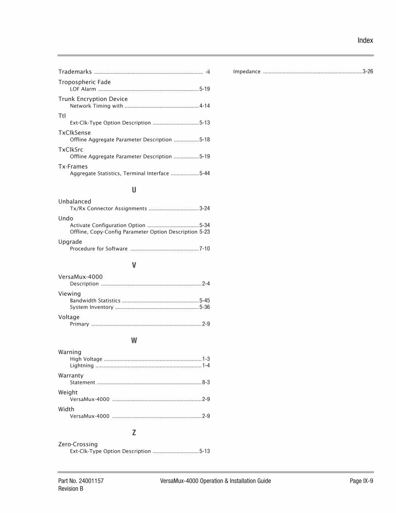
Index
Part No. 24001157 VersaMux-4000 Operation & Installation Guide Page IX-9Revision B
Trademarks .............................................................................. -ii
Tropospheric FadeLOF Alarm ........................................................................5-19
Trunk Encryption DeviceNetwork Timing with .....................................................4-14
TtlExt-Clk-Type Option Description .................................5-13
TxClkSenseOffline Aggregate Parameter Description ..................5-18
TxClkSrcOffline Aggregate Parameter Description ..................5-19
Tx-FramesAggregate Statistics, Terminal Interface ....................5-44
U
UnbalancedTx/Rx Connector Assignments ....................................3-24
UndoActivate Configuration Option .....................................5-34Offline, Copy-Config Parameter Option Description 5-23
UpgradeProcedure for Software .................................................7-10
V
VersaMux-4000Description ........................................................................2-4
ViewingBandwidth Statistics .......................................................5-45System Inventory ............................................................5-36
VoltagePrimary ...............................................................................2-9
W
WarningHigh Voltage ......................................................................1-3Lightning ............................................................................1-4
WarrantyStatement ...........................................................................8-3
WeightVersaMux-4000 ................................................................2-9
WidthVersaMux-4000 ................................................................2-9
Z
Zero-CrossingExt-Clk-Type Option Description .................................5-13
Impedance .......................................................................3-26

Index
Page IX-10 VersaMux-4000 Operation & Installation Guide Part No. 24001157Revision B

This page intentionally left blank.

W www.ultra-dne.com50 Barnes Park NorthWallingford, CT USA 06492
T (203) 265-7151T (800) 370-4485 (toll free)
F (203) 284-9101E [email protected]
VersaMux-4000Trunk Group MultiplexerOperation & Installation GuidePart No. 24001157Revision B

Mercury 1U Power Shelves
InstallationManual138854 Rev A
THIS DOCUMENT AND THE INFORMATION CONTAINED HEREON IS RESTRICTED AND IS THE PROPERTY OF TRANSISTOR DEVICES INC. AND SHALL NOT BE REPRODUCED OR USED WITHOUT THE WRITTEN PERMISSION OF TRANSISTOR DEVICES INC
M E R C U R Y 1 U P O W E R S H E L F I N S T A L L T I O N M A N U A L
138854 Rev A Page 2
M E R C U R Y 1 U P O W E R S H E L F
Installation Manual
Rev A
Transistor Devices, Inc36 Newburgh Road
Hackettstown, NJ 07840Phone 908-850-5088 • Fax 908-850-1607

M E R C U R Y 1 U P O W E R S H E L F I N S T A L L T I O N M A N U A L
138854 Rev A Page 3
Table of Contents
1.0 Introduction.................................................................................................................................. 5
1.1 Description ................................................................................................................................... 5
1.2 Part Numbers ............................................................................................................................... 6
2.0 Installation ................................................................................................................................... 7
2.1 Mounting ...................................................................................................................................... 7
2.1.1 Flush Mounting....................................................................................................................... 7
2.1.2 Mid Mounting.......................................................................................................................... 7
3.0 Connections.................................................................................................................................. 8
3.1 AC Connections............................................................................................................................ 8
3.1.1 IEC Connections ..................................................................................................................... 8
3.1.2 Individual Terminal Blocks..................................................................................................... 8
3.1.2 Single AC Input Terminal Block ............................................................................................. 8
3.2 Power Connections ...................................................................................................................... 9
3.2.1 -48V Shelves............................................................................................................................ 9
3.2.2 +24V Shelves .......................................................................................................................... 9
3.3 Ground Connections .................................................................................................................. 10
3.3.1 Chassis Ground..................................................................................................................... 10
3.4 Alarms ........................................................................................................................................ 10
3.4.1 System Alarms....................................................................................................................... 10
3.4.2 Remote Voltage Sense........................................................................................................... 11
3.4.3 Current Share........................................................................................................................ 11
4.0 Start-up & Commissioning......................................................................................................... 12
4.1 Installing Rectifiers .................................................................................................................... 12
4.2 Power up .................................................................................................................................... 12
4.3 Voltage Reading ......................................................................................................................... 12
4.4 Connecting Loads....................................................................................................................... 12
4.5 Alarms ........................................................................................................................................ 12
5.0 Maintenance ............................................................................................................................... 13

M E R C U R Y 1 U P O W E R S H E L F I N S T A L L T I O N M A N U A L
138854 Rev A Page 4
5.1 Removing Rectifiers.................................................................................................................... 13
5.2 Replacing Rectifiers ................................................................................................................... 13
6.0 Vendor Support and Service....................................................................................................... 14
6.1 Sales Support.............................................................................................................................. 14
6.2 Service Support .......................................................................................................................... 14
6.3 Internet Support.......................................................................................................................... 15
7.0 Revision History ......................................................................................................................... 16
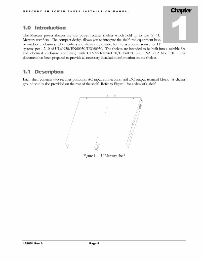
M E R C U R Y 1 U P O W E R S H E L F I N S T A L L T I O N M A N U A L
138854 Rev A Page 5
1.0 IntroductionThe Mercury power shelves are low power rectifier shelves which hold up to two (2) 1UMercury rectifiers. The compact design allows you to integrate the shelf into equipment baysor outdoor enclosures. The rectifiers and shelves are suitable for use as a power source for IT systems per 1.7.10 of UL60950/EN60950/IEC60950. The shelves are intended to be built into a suitable fireand electrical enclosure complying with UL60950/EN60950/IEC60950 and CSA 22.2 No. 950. Thisdocument has been prepared to provide all necessary installation information on the shelves.
1.1 DescriptionEach shelf contains two rectifier positions, AC input connections, and DC output terminal block. A chassisground stud is also provided on the rear of the shelf. Refer to Figure 1 for a view of a shelf.
Figure 1 – 1U Mercury shelf
Chapter
M E R C U R Y 1 U P O W E R S H E L F I N S T A L L T I O N M A N U A L
138854 Rev A Page 6
1.2 Part NumbersMODEL NUMBER PART NUMBER DESCRIPTION
MES050A-60AAB00 139619-60AAB00 60VDC Max Power Shelf with two IEC AC inputsMES050A-60BAB00 139619-60BAB00 60VDC Max Power Shelf with two Terminal Block AC inputs
MeR12WRA-P24D00 136653-P24D00 1200W, Wide range input, positive 24V output, Droop share
MeR12WRA-P24A00 136653-P24A00 1200W, Wide range input, positive 24V output, Active share
MeR12WRA-P27D00 136653-P27D00 1200W, Wide range input, positive 27V output, Droop share
MeR12WRA-P27A00 136653-P27A00 1200W, Wide range input, positive 27V output, Active share
MeR12WRA-P48D00 136653-P48D00 1200W, Wide range input, positive 48V output, Droop share
MeR12WRA-P48A00 136653-P48A00 1200W, Wide range input, positive 48V output, Active share
MeR12WRA-N48D00 136653-N48D00 1200W, Wide range input, negative 48V output, Droop share
MeR12WRA-N48A00 136653-N48A00 1200W, Wide range input, negative 48Voutput, Active share
MeR12WRA-N54D00 136653-N54D00 1200W, Wide range input, negative 54V output, Droop share
MeR12WRA-N54A00 136653-N54A00 1200W, Wide range input, negative 54V output, Active share
MeR12WRA-N56D00 136653-N56D00 1200W, Wide range input, negative 56V output, Droop share
MeR12WRA-N56A00 136653-N56A00 1200W, Wide range input, negative 56V output, Active share

M E R C U R Y 1 U P O W E R S H E L F I N S T A L L T I O N M A N U A L
138854 Rev A Page 7
2.0 InstallationThe 1U mercury power shelves are designed to be installed into 19” rails. The shelf hasmounting holes for flush and mid mounting options. Do not mount shelf flush withoutproviding additional support to the rear of the shelf.
2.1 MountingThere are six (6) mounting holes on each side of the shelf used to attach the mounting ears to the shelf. Themounting holes are marked A in Figure 2. The mounting ear can be attached with the mounting flange toward the front of the shelf for flush mounting or with the mounting flange toward the middle of the shelf for midmounting.
Figure 2 – Right side view of shelf
2.1.1 Flush MountingFor flush mounting attach the mounting ears in the desired position with the mounting flange toward the front of the shelf as shown in Figure 2. Slide the shelf into the 19” rails and position the shelf in the desired location.Line up the holes in the mounting ears to the mounting holes in the rails and secure the mounting ears to therails using appropriate hardware. After the shelf is secured into the rails, it is recommended to support the rear of the shelf before installing rectifiers.
2.1.2 Mid MountingFor mid mounting attach the mounting ears in the desired position with the mounting flange toward the rear of the shelf as shown in Figure 3. Slide the shelf into the 19” rails and position the shelf in the desired location.Line up the holes in the mounting ears to the mounting holes in the rails and secure the mounting ears to therails using appropriate hardware.
Figure 2 – Right side view of shelf
Chapter
For flush mounting, position the mounting ear with the mounting flange toward the front of the shelf.
For mid mounting, position the mounting ear with the mounting flange toward the rear of the shelf.

M E R C U R Y 1 U P O W E R S H E L F I N S T A L L T I O N M A N U A L
138854 Rev A Page 8
3.0 Connections
3.1 AC ConnectionsThe AC connections to the power shelf will depend on the version of shelf. The shelves are available withindividual IEC connections for each rectifier or individual terminal blocks for each rectifier. The AC inputvoltage and frequency range is 90-275 VAC, 47-63 Hz. All AC wiring should be performed by a licensedelectrician.
3.1.1 IEC ConnectionsThe IEC version of the power shelf provides an IEC receptacle for each rectifier. Refer to Figure 4 for a view of the rear of the shelf with the IEC receptacles. The IEC cord used to plug into the receptacle on the rear of the shelf should be rated for 20A. Plug the female end of the IEC cord into the desired position on the back of the shelf. Plug the male end of the IEC cord into an outlet. Each rectifier required a circuit protected at 20Afeed. Repeat for all rectifier positions.
Figure 4 – Rear view of shelf with IEC connectors
3.1.2 Individual Terminal BlocksThe individual terminal block version of the power shelf provides two terminal blocks for the AC input to the rectifiers. Refer to Figure 5 for a view of the rear of the shelf with individual AC input terminal blocks. All wiring to the terminal block shall be rated for 20A. Connect one line of the AC input to the position labeled L in Figure 5. Connect the neutral (or other line) from the AC input to the position labeled N in Figure 5.Connect the ground from the AC feed to the position labeled G in Figure 5. Repeat for all rectifier positions.Each AC input should be individually protected by a 20A circuit breaker of fuse.
Figure 5 – Rear view of shelf with individual terminal blocks
Chapter

M E R C U R Y 1 U P O W E R S H E L F I N S T A L L T I O N M A N U A L
138854 Rev A Page 9
3.2 Power Connections3.2.1 -48V ShelvesConnections to the DC output of the shelf are provided on the rear of the shelf. Connections to the DC output terminal block require a two hole lug with 1/4” holes and 1” hole spacing. Refer to Figure 6 for a view of the DC terminal block. All wiring to the terminal block should be rated for 50A. The output (negative bus) of the terminal block is on the left as shown in Figure 6. The return (positive bus) of the terminal block is on the right as shown in Figure 6.
Figure 6 – -48V DC connections
3.2.2 +24V ShelvesConnections to the DC output of the shelf are provided on the rear of the shelf. Connections to the DC output terminal block require a two hole lug with 1/4” holes and 1” hole spacing. Refer to Figure 7 for a view of the DC terminal block. All wiring to the terminal block should be rated for 100A. The output (positive bus) of the terminal block is on the right as shown in Figure 7. The return (negative bus) of the terminal block is on the left as shown in Figure 7.
Figure 7 – +24V DC connections
Return connection (positive bus)
Ground stud
Output connection (negative bus)
Output connection (positive bus)
Ground stud
Return connection (negative bus)

M E R C U R Y 1 U P O W E R S H E L F I N S T A L L T I O N M A N U A L
138854 Rev A Page 10
3.3 Ground Connections3.3.1 Chassis GroundThe chassis ground of the power shelf is located next to the DC terminal block. Refer to Figures 6 & 7 for views of the ground stud location. The required lug for connecting to the ground stud is a single hole lug with 1/4” hole. The chassis ground must be connected to earth ground for safety and to ensure proper operation.
3.4 Alarms3.4.1 System AlarmsAll system alarms are terminated on a 24 pin ribbon cable header (J2) on the rear of the shelf. Refer to Table 1 for a detailed pinout of the 24 pin ribbon cable header. The fan fail alarms and margin low feature are optional features of the rectifier and are only available if the rectifiers contain these options. All alarm outputs are opto isolated, open collector outputs. The maximum current for the alarm outputs is .5mA. Refer to Figure 8 for required connections to alarm outputs.
Pin # Description Pin # Description Pin # Description1 Output OK (Bay 1) 9 N/U 17 N/U2 AC OK (Bay 1) 10 N/U 18 N/U3 Fan Fail Option (Bay 1) 11 N/U 19 N/U4 Module Present (Bay 1) 12 N/U 20 N/U5 Output OK (Bay 2) 13 N/U 21 N/U6 AC OK (Bay 2) 14 N/U 22 Fault/Signal Rtn7 Fan Fail Option (Bay 2) 15 N/U 23 Remote Adjust8 Module Present (Bay 2) 16 N/U 24 Margin Low
Table 1 – Pinout on system alarm connector J2
Figure 8 – Alarm connection schematic
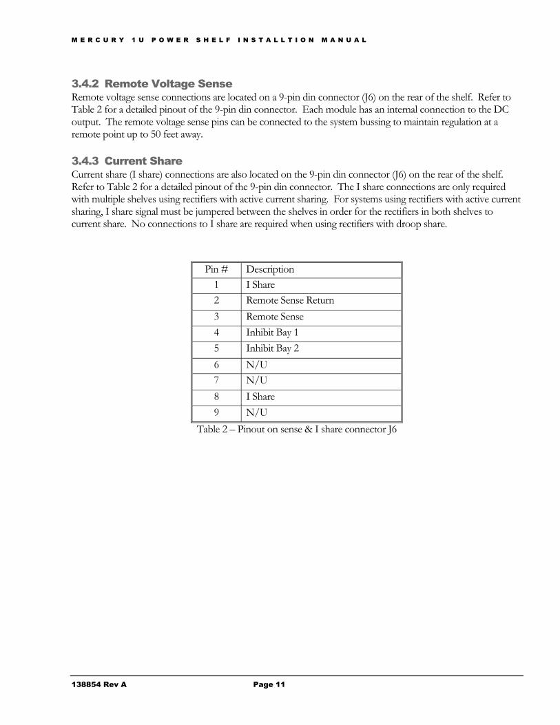
M E R C U R Y 1 U P O W E R S H E L F I N S T A L L T I O N M A N U A L
138854 Rev A Page 11
3.4.2 Remote Voltage SenseRemote voltage sense connections are located on a 9-pin din connector (J6) on the rear of the shelf. Refer to Table 2 for a detailed pinout of the 9-pin din connector. Each module has an internal connection to the DC output. The remote voltage sense pins can be connected to the system bussing to maintain regulation at a remote point up to 50 feet away.
3.4.3 Current ShareCurrent share (I share) connections are also located on the 9-pin din connector (J6) on the rear of the shelf.Refer to Table 2 for a detailed pinout of the 9-pin din connector. The I share connections are only requiredwith multiple shelves using rectifiers with active current sharing. For systems using rectifiers with active current sharing, I share signal must be jumpered between the shelves in order for the rectifiers in both shelves to current share. No connections to I share are required when using rectifiers with droop share.
Pin # Description1 I Share2 Remote Sense Return3 Remote Sense4 Inhibit Bay 15 Inhibit Bay 26 N/U7 N/U8 I Share9 N/U
Table 2 – Pinout on sense & I share connector J6

M E R C U R Y 1 U P O W E R S H E L F I N S T A L L T I O N M A N U A L
138854 Rev A Page 12
4.0 Start-up & Commissioning
4.1 Installing RectifiersLocate and unpack the rectifiers. Verify the AC feed circuit breakers are turned off. Slide each rectifier into the desired position in the shelf. Firmly push the rectifier in to fully seat the connector into the back plane of the power system. Secure the rectifier into the power system by tightening the hold down screw in the middle of the shelf.
4.2 Power upVerify all of the DC loads are turned off. Turn on the AC feed breakers to the power system. Wait until allrectifiers have powered up. Note: Rectifier alarms may be present when rectifiers are initially powering up but will clear once rectifier has reached full output voltage.
4.3 Voltage ReadingOnce the rectifiers are running verify the system is running at the desired voltage. Using a multi-meter, checkthe system voltage across the DC terminal block.
4.4 Connecting LoadsOnce the rectifiers are running at the proper voltage, the DC loads can be applied. Turn on the DC loads oneat a time and verify for proper operation.
4.5 AlarmsTest all required system alarms for proper operation.
Chapter

M E R C U R Y 1 U P O W E R S H E L F I N S T A L L T I O N M A N U A L
138854 Rev A Page 13
5.0 Maintenance
5.1 Removing RectifiersAll mercury series rectifiers are hot swappable. To remove a rectifier for test ormaintenance, loosen the two hold down screw in the middle of the shelf and pull therectifier out of the shelf. The rectifier will automatically power down once theconnector on the rear of the rectifier is removed from the backplane of the shelf. Donot open the rectifier or attempt any repairs. User replacement of worn or damaged parts is not required orrecommended. All adjustments have been factory set for optimum performance. Opening the rectifierexposes high voltage parts which are hazardous. If any internal adjustment or servicing is required, contact the factory to arrange a return authorization or field service by an approved factory representative.
5.2 Replacing RectifiersSlide the rectifier into the desired position in the shelf. Firmly push the rectifier in to fully seat the connectorinto the back plane of the power system. Once the connector on the rear of the rectifiers makes contact withthe backplane of the shelf, the rectifier will power up. Once the rectifier is operating, secure the rectifier into the shelf by tightening the two hold down screw in the middle of the shelf.
Chapter

M E R C U R Y 1 U P O W E R S H E L F I N S T A L L T I O N M A N U A L
138854 Rev A Page 14
6.0 Vendor Support and Service
6.1 Sales SupportAll sales support for purchases, proposals, spares, etc. is provided from ourHackettstown, New Jersey facility. Normal hours of operation are 8:00 a.m. to 5:00p.m. Monday through Friday. If you should have an urgent requirement for productsor services after these hours, a message may be left with our answering service at (908)979-0088, and one of our representatives will return your call.
6.2 Service SupportTDI provides 24-hour response to your field service needs utilizing our infrastructure of offices andrepresentatives strategically located throughout the United States. Should an emergency arise during normalbusiness hours, please call (908) 979-0088 and request service or technical assistance.
If you are calling after our normal business hours, please use one of the following technical assistance numbers:
1-888-575-8875
Or when calling Internationally
1-973-283-7236
Your call will be returned as soon as possible by one of our field service technicians.
As stated previously in the General Terms and Conditions, all components of the TDI DC power system arewarranted to be free of defects in material and workmanship for a period of two (2) years from date ofshipment to the original purchaser. In the unlikely event a component of the TDI DC power system shouldfail, the following procedures should be followed to expedite the repair and/or replacement of the failedmodule.
1. Contact the authorized TDI repair facility at the address and phone number shown below to obtain aReturn Authorization Number for the failed unit.
TDI - Telecommunication Power Systems Division
RMA# ____________
36 Newburgh Road
Hackettstown, NJ 07840
(908) 979-0088
Chapter
M E R C U R Y 1 U P O W E R S H E L F I N S T A L L T I O N M A N U A L
138854 Rev A Page 15
2. Please have the following information available when you call:
Description of component including serial no. (if available)
In service date
Nature of the failure
3. The TDI authorized factory representative will determine the method of return/replacement basedupon the information provided.
4. Ship the failed unit back to the designated repair facility per the instructions from the authorizedrepresentative, transportation charges PREPAID.
Components which fail after the warranty period has expired, or which fail due to misuse or abnormaloperating conditions, will be repaired at the purchaser's expense. In such cases, an estimate will be made andsubmitted prior to repair. In cases where it is determined that no fault or malfunction exists in the returnedunit, there will be a nominal handling and verification charge.
6.3 Internet SupportAll manuals provided by Telecommunications Power Systems Division are available on the Internet.
Please visit www.tdi-tps.com for on-line access to all of our manuals. Once on the site click onDocumentation. From the Documentation menu click on Manuals. Click on the product you desire for a list of manuals to view & download for that specific product.
Other information also available on www.tdi-tps.com
Application Notes
Power Plant Manager Demo
Technical Support Request Form
Software & Firmware downloads
EF&I Services Information
For specification on other products please visit our corporate web site at www.tdipower.com

M E R C U R Y 1 U P O W E R S H E L F I N S T A L L T I O N M A N U A L
138854 Rev A Page 16
7.0 Revision History
Revision ECN # Description of Change Date Change By Checked By
P1 - Created Document 3/3/03 FQA 25298 Release to Production 3/21/05 DJ GB
-
Chapter

TECHNICAL MANUAL FOR THE MODEM UPGRADE MANUAL NO. 142F009900-1 TRC-170 (V3/V5) TERMINAL
COMTECH SYSTEMS, INC. PROPRIETARY F-1 Use or disclosure is subject to the restriction on the proprietary/confidential notice page of this document.
APPENDIX F ACRONYMS
Acronym/Term Meaning AAC alternating current; air conditioning AGC automatic gain control ALPC adaptive link power control
B BER bit error rate BERT bit error rate test/tester BITE built-in-test-equipment BPSK binary phase-shift key
C CDI conditioned di-phase CDP conditional di-phase cm centimeter CSI Comtech Systems, Inc.
D DAR digital adaptive receiver DC direct current DCE data communications equipment DLED dedicated loop encryption device DTE data terminal equipment DVOW digital voice orderwire unit
E EMI electromagnetic interference ESD electrostatic discharge
F FEC forward error correction FET field effect transistor FOM fiber optic multiplexer
H HSSI high speed serial interface
I I/O input/output IEC International Electrotechnical Commission IF intermediate frequency ISI intersymbol interference

TECHNICAL MANUAL FOR THE MODEM UPGRADE MANUAL NO. 142F009900-1 TRC-170 (V3/V5) TERMINAL
COMTECH SYSTEMS, INC. PROPRIETARY F-2 Use or disclosure is subject to the restriction on the proprietary/confidential notice page of this document.
K Kbps kilobits per second
L LED light emitting diode LNA low noise amplifier LRU line-replaceable unit
M Mbps megabits per second (military M B/S or MBPS ) MHz megahertz mm millimeter MTBF mean time between failure
N NRZ non return to zero
O O&M operation and maintenance
Q QPSK quadrature phase shift keying
R RF radio frequency RMS/rms root mean square RSL receive signal level
T TDM time division multiplexing TPC Turbo Product Code TTL transistor-transistor logic
V VAC voltage alternating current VDC voltage direct current

RECOMMENDED CHANGES TO PUBLICATIONS AND
BLANK FORMS For use of this form, see AR 25-30; the proponent agency is OAASA
Use Part II (reverse) for Repair Parts and Special Tool Lists (RPSTL) and Supply Catalogs/Supply Manuals (SC/SM).
DATE 21 Nov 2011
TO: (Forward to proponent of publication or form) (Include ZIP Code) Commander, U.S. Army Communications-Electronics Command, ATTN: AMSEL-LCL-ECM, 6001 Combat Drive, Aberdeen Proving Ground, MD 21005-1846
FROM: (Activity and location) (Include ZIP Code) Jane Q. Doe, SFC 1234 Any Street Anytown, AL 34565
PART I - ALL PUBLICATIONS (EXCEPT RPSTL AND SC/SM) AND BLANK FORMS PUBLICATION/FORM NUMBER TM 11-1234-567-14
DATE 15 Jan 2011
TITLE Operator, Field and Sustainment Support Maintenance Manual for Radio, AN/ABC-123
ITEM PAGE PARA- GRAPH LINE FIGURE
NO. TABLE RECOMMENDED CHANGES AND REASON 1 WP0005
PG 3 2 Test or Corrective Action column should identify a different WP number.
TYPED NAME, GRADE OR TITLE Jane Q. Doe, SFC
TELEPHONE EXCHANGE/AUTOVON, PLUS EXTENSION 123-4567
SIGNATURE
DA FORM 2028, FEB 74 REPLACES DA FORM 2028, 1 DEC 68, WHICH WILL BE USED.

TO: (Forward to proponent of publication or form) (Include ZIP Code)
FROM: (Activity and location) (Include ZIP Code)
DATE
PART II- REPAIR PARTS AND SPECIAL TOOL LISTS AND SUPPLY CATALOGS/SUPPLY MANUALS PUBLICATION/FORM NUMBER
DATE
TITLE
PAGE NO.
COLM NO.
LINE NO.
NATIONAL STOCK
NUMBER
REFERENCE
NO.
FIGURE
NO.
ITEM NO.
TOTAL NO. OF MAJOR
ITEMS SUPPORTED
RECOMMENDED ACTION
PART III - REMARKS (Any general remarks or recommendations, or suggestions for improvement of publications and blank forms. Additional blank sheets may be used if more space is needed.)
TYPED NAME, GRADE OR TITLE
TELEPHONE EXCHANGE/AUTOVON, PLUS EXTENSION
SIGNATURE
APD V4.00

RECOMMENDED CHANGES TO PUBLICATIONS AND
BLANK FORMS For use of this form, see AR 25-30; the proponent agency is OAASA
Use Part II (reverse) for Repair Parts and Special Tool Lists (RPSTL) and Supply Catalogs/Supply Manuals (SC/SM).
DATE
TO: (Forward to proponent of publication or form) (Include ZIP Code)
FROM: (Activity and location) (Include ZIP Code)
PART I - ALL PUBLICATIONS (EXCEPT RPSTL AND SC/SM) AND BLANK FORMS PUBLICATION/FORM NUMBER
DATE
TITLE
ITEM PAGE PARA- GRAPH LINE FIGURE
NO. TABLE RECOMMENDED CHANGES AND REASON
TYPED NAME, GRADE OR TITLE
TELEPHONE EXCHANGE/AUTOVON, PLUS EXTENSION
SIGNATURE
DA FORM 2028, FEB 74 REPLACES DA FORM 2028, 1 DEC 68, WHICH WILL BE USED.
TO: (Forward to proponent of publication or form) (Include ZIP Code)
FROM: (Activity and location) (Include ZIP Code)
DATE
PART II- REPAIR PARTS AND SPECIAL TOOL LISTS AND SUPPLY CATALOGS/SUPPLY MANUALS PUBLICATION/FORM NUMBER
DATE
TITLE
PAGE NO.
COLM NO.
LINE NO.
NATIONAL STOCK
NUMBER
REFERENCE
NO.
FIGURE
NO.
ITEM NO.
TOTAL NO. OF MAJOR
ITEMS SUPPORTED
RECOMMENDED ACTION
PART III - REMARKS (Any general remarks or recommendations, or suggestions for improvement of publications and blank forms. Additional blank sheets may be used if more space is needed.)
TYPED NAME, GRADE OR TITLE
TELEPHONE EXCHANGE/AUTOVON, PLUS EXTENSION
SIGNATURE
APD V4.00
RECOMMENDED CHANGES TO PUBLICATIONS AND
BLANK FORMS For use of this form, see AR 25-30; the proponent agency is OAASA
Use Part II (reverse) for Repair Parts and Special Tool Lists (RPSTL) and Supply Catalogs/Supply Manuals (SC/SM).
DATE
TO: (Forward to proponent of publication or form) (Include ZIP Code)
FROM: (Activity and location) (Include ZIP Code)
PART I - ALL PUBLICATIONS (EXCEPT RPSTL AND SC/SM) AND BLANK FORMS PUBLICATION/FORM NUMBER
DATE
TITLE
ITEM PAGE PARA- GRAPH LINE FIGURE
NO. TABLE RECOMMENDED CHANGES AND REASON
TYPED NAME, GRADE OR TITLE
TELEPHONE EXCHANGE/AUTOVON, PLUS EXTENSION
SIGNATURE
DA FORM 2028, FEB 74 REPLACES DA FORM 2028, 1 DEC 68, WHICH WILL BE USED.

TO: (Forward to proponent of publication or form) (Include ZIP Code)
FROM: (Activity and location) (Include ZIP Code)
DATE
PART II- REPAIR PARTS AND SPECIAL TOOL LISTS AND SUPPLY CATALOGS/SUPPLY MANUALS PUBLICATION/FORM NUMBER
DATE
TITLE
PAGE NO.
COLM NO.
LINE NO.
NATIONAL STOCK
NUMBER
REFERENCE
NO.
FIGURE
NO.
ITEM NO.
TOTAL NO. OF MAJOR
ITEMS SUPPORTED
RECOMMENDED ACTION
PART III - REMARKS (Any general remarks or recommendations, or suggestions for improvement of publications and blank forms. Additional blank sheets may be used if more space is needed.)
TYPED NAME, GRADE OR TITLE
TELEPHONE EXCHANGE/AUTOVON, PLUS EXTENSION
SIGNATURE
APD V4.00

TM 11-5820-1196-13 By Order of the Secretary of the Army: Official: RAYMOND T. ODIERNO General, United States Army Chief of Staff JOYCE E. MORROW Administrative Assistant to the Secretary of the Army 1304610 By Order of the Secretary of the Air Force Official: TIMOTHY A. BEYLAND MARK A. WELSH III Administrative Assistant to General, United States Air Force the Secretary of the Air Force Chief of Staff DISTRIBUTION:
To be distributed in accordance with the initial distribution number (IDN) 345210 requirements for TM 11-5820-1187-13.


