identification - jumil instructions manual 2 warranty certificate 1. justino de morais, irmÃos s/a...
TRANSCRIPT

1
CULTIMAX Instructions Manual
Owner: ...................................................................................... .
................................................................................................. .
Address .................................................................................... .
............................................................................... No ............ .
City ......................................................................... State ........ .
Machine Model .......................................................................... .
Serial Number........................................................................... .
Year of Manufacture .................................................................. .
Invoice No ................................................................................. .
Date ............. / ........... / ................ .
Authorized Distributor
IDENTIFICATION

CULTIMAX Instructions Manual
2
WARRANTY CERTIFICATE1. JUSTINO DE MORAIS, IRMÃOS S/A - JUMIL, guarantees that
the agricultural instruments and their respective parts, manufactured by Jumilitself, herein simply referred to as PRODUCT, are free of manufacturing ormaterial quality defects.
2. The issues pertaining to the granting of Warranty shall be ruled bythe following principles:
2.1. The warranty contained in this Certificate will be valid:a) For the period of 6 (six) months, beginning from the date of the
effective delivery of the PRODUCT to the farmer;b) Only for a brand new PRODUCT directly purchased by the farmer
from an Authorized Dealer or JUMIL, with the exception of what is defined initem 2.3
2.2. With the exception of the following subitem, the warranty grantedto the farmer will be provided through an Authorized JUMIL Dealer.
2.3. If the PRODUCT is sold to the farmer by a dealer that is not anAuthorized Jumil Dealer, the Warranty right shall subsist, and therefore bedirectly claimed before JUMIL, pursuant to the terms of this Certificate
2.4. The warranty shall not be granted in the event of any damage tothe product or its performance caused by:
a) operator negligence, imprudence or lack of skill;b) failure to obey use and maintenance instructions and
recommendations contained in the Instructions Manual.
2.5. Likewise, the Warranty shall not be granted if the PRODUCT,after sold, undergoes any transformation or modification, or is employed forany purposes other than the ones for which the PRODUCT is originallydestined.
2.6. The PRODUCT, when changed or substituted under this Warrantyshall be of the property of JUMIL, and must be surrendered, upon fulfillmentof the applicable legal requirements
2.7. In the fulfillment of its policy toward permanent evolution, JUMILsubjects its products to constant improvements or modifications, withoutsuch fact constituting in JUMIL'S obligation to extend said improvements /modifications to previously sold products or models.
2.8. JUMIL will not be liable to pay indemnities of any kind in respectto harvest losses resulting from the inadequate setting of devices comprisingthe product in relation to the distribution of seeds or fertilizer.
Note.) Upon detection of bad use of equipment, manufacturerwarranty will be cancelled.

3
CULTIMAX Instructions Manual
Table of contents
1 - INTRODUCTION .............................................................................................................. 42 - PRODUCT PRESENTATION ............................................................................................ 53 - SAFETY NORMS ............................................................................................................ 64 - TECHNICAL SPECIFICATIONS ..................................................................................... 84.1 - FERTILIZER DISTRIBUTOR CULTIVATOR ................................................................. 84.2 - FERTILIZER DISTRIBUTOR WITH MISMATCHED DOUBLE DISK ............................ 84.3 - FERTILIZER DISTRIBUTOR WITH FERTILIZER CONDUCTOR ................................. 84.4 - CULTIVATOR ...............................................................................................................95 - OPTIONAL ITEMS ........................................................................................................ 105.1 - ROTATIONAL PROTECTOR ..................................................................................... 105.2 - PROTECTOR TUNNEL .............................................................................................. 115.3 - MISMATCHED DOUBLE DISK .................................................................................. 115.4 - PANTOGRAPHIC FERTILIZER DISTRIBUTOR UNIT ............................................... 125.5 - FURROWING HOES ................................................................................................... 126 - PRODUCT COMPOSITION .......................................................................................... 137 - PRODUCT ASSEMBLY ................................................................................................ 137.1 - TRACTION WHEEL ASSEMBLY ............................................................................... 138 - PREPARATION FOR USE .............................................................................................. 148.1 - ACTUATION .............................................................................................................. 148.1.1 - SPEED REDUCER .................................................................................................... 148.1.2 - ACTUATION WHEEL .............................................................................................. 148.1.3 - TIRE PRESSURE ..................................................................................................... 158.2 - PREPARING THE TRACTOR ..................................................................................... 158.2.1 - BALLASTING THE TRACTOR'S FRONT .............................................................. 158.2.2 - GAUGE ADJUSTMENT .......................................................................................... 168.2.3 - COUPLING THE MACHINE TO THE TRACTOR ................................................... 168.2.4 - ADJUSTING THE CARDAN TO THE TRACTOR AND THE MACHINE ................. 178.2.5 - CARDAN ASSEMBLY ............................................................................................ 188.3 - LEVELING THE MACHINE ........................................................................................ 199 - ADJUSTMENTS ............................................................................................................ 209.1 - QUANTITY OF FERTILIZER DISTRIBUTION ............................................................ 209.2 - INSTALLATION SCHEMES OF THE BELT STRETCHER ......................................... 229.3 - PRACTICAL EXAMPLE OF FERTILIZER DISTRIBUTION CALCULATION............ 239.3.1 - CALCULATION FOR FERTILIZER DISTRIBUTION ............................................... 239.3.2- HOW TO USE THE FERTILIZER DISTRIBUTION TABLE ....................................... 249.4 - FERTILIZING SYSTEM .............................................................................................. 259.5 - ADJUSTMENT OF FURROWING HOES .................................................................... 259.6 - DEPTH CONTROL ADJUSTMENT ............................................................................ 279.7 - ALIGNMENT ADJUSTMENT OF FERTILIZER DISTRIBUTOR DRIVE CHAIN ......... 289.8 - REDUCER CHAIN ADJUSTMENT ............................................................................. 299.9 - FERTILIZER CONDUCTOR SUPPORT ADJUSTMENT ............................................ 299.10 - SPACINGS ............................................................................................................... 3010 - MAINTENANCE .......................................................................................................... 3910.1 - CLEANING THE FERTILIZER TANKS ..................................................................... 3910.2 - GENERAL CLEANING OF THE CULTIMAX ............................................................ 4011 - LUBRICATION ............................................................................................................. 4111.1 - LUBRICATION OBJECTIVES .................................................................................. 4111.2 - LUBRICATION SYMBOLS....................................................................................... 4111.3 - TABLE OF LUBRICANTS ........................................................................................ 4211.4 - LUBRICATION POINTS ........................................................................................... 4312 – INCIDENTS AND TROUBLESHOOTING .................................................................... 45

CULTIMAX Instructions Manual
4
1 - INTRODUCTION
Congratulations, you have purchased an implement manufacturedwith the latest technology and efficiency available in the market, guaranteedby the renowned brand JUMIL.
The purpose of this manual is to guide you in the correct operation ofthis product, allowing you to obtain the best performance and benefits fromthe equipment. It is for this reason that we recommend you read this manualattentively before starting to use it.
Keep this manual in a secure place for it to be easily consulted.JUMIL and its dealer network will always be ready to provide you with
the required technical clarifications and orientations needed for yourequipment.

5
CULTIMAX Instructions Manual
2 - PRODUCT PRESENTATIONCULTIMAX is a machine that works attached to a tractor by means
of a three-point hydraulic system.It is constituted of a Tool Carrier Bar measuring 4.20 m, 6.00 m and
6.80 m in length with a three-point interlocking system, which can be suppliedin the following versions:
CULTIVATOR, FERTILIZER DISTRIBUTOR CULTIVATOR ANDFERTILIZER DISTRIBUTOR.
As CULTIVATOR, its active elements are hoes (of different sizes, atyour choice, according to the culture and infestation level), fixed onVIBRATORY RODS made of special steel, which print a HIGH FREQUENCYvibratory motion on the hoes, thus UNEARTHING THE WEEDS ANDSHAKING THE ROOTS, LOOSENING THE EARTH AND EXPOSING THEMTO SUNLIGHT, ALLOWING FOR THEIR ELIMINATION.
For these active elements to perform their function properly,PANTOGRAPHIC MODULES are fixed, which fully follow the soil's profile,ensuring the same work depth throughout the land's extension.
In addition to the function of controlling weeds, your CULTIMAX canalso be used in breaking the superficial crust of the soil and thus prevent theevaporation of water. In a "VERANICO" condition, quite common and harmfulabove all in the first days of the culture, you can pass the CULTIMAX adjustedto the least depth possible. On breaking the ground's superficial crust, itprevents the evaporation of water and its culture will immediately present amuch better aspect.
It can be supplied in modules of 3 or 5 furrowing hoes, for the cultivationof 3,4,5,6,7,8,9 and 10 lines, with the Tool Carrier Bar (TCB) measuring4.20m and for 5 to 12 lines, with a TCB of 6.00m or 6.80 m.
The distribution of fertilizer is made by means of worm thread system,and can be deposited on the soil by conductor tubes, or incorporated (inconventional or direct planting) by means of mismatched double disks'furrowers. The system used in CULTIMAX allows lateral or double-lateralfertilizer distribution.
As CULTIVATOR FERTILIZER DISTRIBUTOR, it can be supplied forlateral or double-lateral fertilizer distribution, with modules of 3 or 5 hoes,and with 2 to 8 fertilizer deposits for the cultivation and fertilizer distributionof 3 to 8 lines according to you needs.
As a FERTILIZER DISTRIBUTOR, it can be equally supplied forfertilizer distribution. Instructions Manual for Lateral or bi-lateral cultimaxwith conductor system for the depositing of fertilizer on the soil, or systemof mismatched double disk furrowers for the incorporation of the fertilizerinto the soil in both direct planting and conventional planting, with 2 to 8fertilizer tanks for fertilizer distribution of 3 to 8 lines, according to yourneeds.

CULTIMAX Instructions Manual
6
3 - SAFETY NORMS
JUMIL, by building its Agricultural Machines and Equipment, has themain objective of assisting MANKIND in developing a better QUALITY OFLIFE. However, at the use of these machines, there are two main cares tobe RESPECTED:
DO NOT DESTROY THE UNIVERSAL BIOLOGICAL BALANCEBY EXECUTING INCORRECT AGRICULTURAL JOBS.
DO NOT CONSENT TO THE MACHINE DESTROYING IT.STRICTLY FOLLOW THE SAFETY NORMS. DO NOT NEGLECT THEM!
1) Always use the proper footboards to climb onto or down from thetractor;
2) Upon putting the engine into operation, be properly seated on theoperator's seat and ABSOLUTELY AWARE of the full knowledge of managingthe tractor and the equipment. Always leave the gear on neutral position,disconnect the power socket and place the hydraulic commands on neutralposition;
3) Do not run the engine in closed spaces as the exhaust fumes aretoxic;
4) When maneuvering the tractor to interlock with implements ormachines, ensure that there is enough space and that no person is closeby; execute the maneuvers at IDLING SPEED and be prepared to brake inan emergency;
5) When operating machines ACTUATED BY THE POWER SOCKET,(couple, uncouple, or regulate) TURN OFF THE POWER SOCKET, STOPTHE ENGINE AND REMOVE THE KEY FROM THE IGNITION. NEVERFAIL TO OBSERVE THESE NORMS!
6) Demand from your Dealer the CARDAN SHAFT PROTECTIVECOVERS;
7) When using slack or loose clothing, do not go too near the MOVINGCARDAN SHAFT, BELTS, CHAINS OR GEARS;
8) Do not conduct adjustments while the machine is in motion;9) When working with implements or machines, it is expressly
prohibited to transport anyone other than the operator on both the tractorand the implement, except in the existence of a suitable seat or platform forsuch purpose;
10) When working in slopy terrain, proceed with extra caution, seekingto always maintain the required stability; and in case of an unbalance settingin, reduce acceleration, keep the equipment on the ground and turn thetractor's wheel toward the direction of descent;
11) On descents, keep the truck on gear always, using the gear youwould use when going up;
7
CULTIMAX Instructions Manual
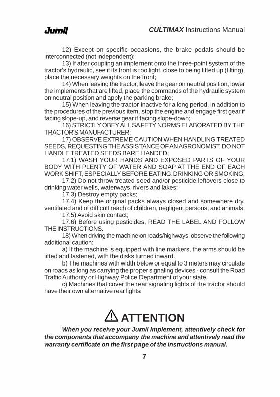
12) Except on specific occasions, the brake pedals should beinterconnected (not independent);
13) If after coupling an implement onto the three-point system of thetractor's hydraulic, see if its front is too light, close to being lifted up (tilting),place the necessary weights on the front;
14) When leaving the tractor, leave the gear on neutral position, lowerthe implements that are lifted, place the commands of the hydraulic systemon neutral position and apply the parking brake;
15) When leaving the tractor inactive for a long period, in addition tothe procedures of the previous item, stop the engine and engage first gear iffacing slope-up, and reverse gear if facing slope-down;
16) STRICTLY OBEY ALL SAFETY NORMS ELABORATED BY THETRACTOR'S MANUFACTURER;
17) OBSERVE EXTREME CAUTION WHEN HANDLING TREATEDSEEDS, REQUESTING THE ASSISTANCE OF AN AGRONOMIST. DO NOTHANDLE TREATED SEEDS BARE HANDED;
17.1) WASH YOUR HANDS AND EXPOSED PARTS OF YOURBODY WITH PLENTY OF WATER AND SOAP AT THE END OF EACHWORK SHIFT, ESPECIALLY BEFORE EATING, DRINKING OR SMOKING;
17.2) Do not throw treated seed and/or pesticide leftovers close todrinking water wells, waterways, rivers and lakes;
17.3) Destroy empty packs;17.4) Keep the original packs always closed and somewhere dry,
ventilated and of difficult reach of children, negligent persons, and animals;17.5) Avoid skin contact;17.6) Before using pesticides, READ THE LABEL AND FOLLOW
THE INSTRUCTIONS.18) When driving the machine on roads/highways, observe the following
additional caution:a) If the machine is equipped with line markers, the arms should be
lifted and fastened, with the disks turned inward.b) The machines with width below or equal to 3 meters may circulate
on roads as long as carrying the proper signaling devices - consult the RoadTraffic Authority or Highway Police Department of your state.
c) Machines that cover the rear signaling lights of the tractor shouldhave their own alternative rear lights
ATTENTIONWhen you receive your Jumil Implement, attentively check for
the components that accompany the machine and attentively read thewarranty certificate on the first page of the instructions manual.

CULTIMAX Instructions Manual
8
4 - TECHNICAL SPECIFICATIONS
4.1 - Fertilizer Distributor Cultivator
4.2 - Fertilizer Distributor With Mismatched Double Disk
4.3 - Fertilizer Distributor with Fertilizer Conductor
Model
No.
Of
lines
No.
Of
hoes
Hea
der
(Met
ers)
No.
Of
Tank
s
Wei
ght
(Kg) Spacing
(Meters)Type of
fertilization
Min. Required
PowerJM 3203 CAB 3 16 4,20 3 633 0,80 to 1,10 Bilateral 50 hpJM 3203 CAL 3 16 4,20 2 600 0,80 to 1,10 Lateral 50 hpJM 3204 CAB 4 21 4,20 4 748 0,80 to 1,10 Bilateral 50 hpJM 3204 CAL 4 21 4,20 2 678 0,75 to 1,10 Lateral 50 hpJM 3205 CAB 5 26 6,00 5 926 0,80 to 1,10 Bilateral 65 hpJM 3205 CAL 5 26 6,00 3 856 0,75 to 1,10 Lateral 60 hpJM 3206 CAB 6 31 6,00 6 1041 0,80 to 1,00 Bilateral 70 hpJM 3206 CAL 6 31 6,00 3 936 0,75 to 1,00 Lateral 65 hp
Model
No.
Of
lines
No.
of
D. D
isk
head
er
(Met
ers)
No.
Of
Tank
s
Wei
ght
(Kg) Spacing
(Meters)Type of
fertilization
Min. Required
Power JM 3203 ABD 3 6 4,20 3 3 0,80 to 1,10 Bilateral 50 hpJM 3203 ALD 3 3 4,20 2 2 0,75 to 1,10 Lateral 50 hpJM 3204 ABD 4 8 4,20 4 4 0,80 to 1,10 Bilateral 50 hpJM 3204 ALD 4 4 4,20 2 2 0,75 to 1,10 Lateral 50 hpJM 3205 ABD 5 10 6,00 5 5 0,80 to 1,10 Bilateral 65 hpJM 3205 ALD 5 5 6,00 3 3 0,75 to 1,10 Lateral 60 hpJM 3206 ABD 6 12 6,00 6 6 0,80 to 1,00 Bilateral 70 hpJM 3206 ALD 6 6 6,00 3 3 0,75 to 1,00 Lateral 65 hp
Model
No.
Of
lines
No.
Of
Tank
s
head
er
(Met
ers)
No.
Of
Tank
s
Wei
ght
Kg Spacing
(Meters)Type of
fertilization
Min. Required
Power JM 3203 ABC 3 3 4,20 3 250 0,80 to 1,10 Bilateral 50 hpJM 3203 ALC 3 2 4,20 2 250 0,75 to 1,10 Lateral 50 hpJM 3204 ABC 4 4 4,20 4 280 0,80 to 1,10 Bilateral 50 hpJM 3204 ALC 4 2 4,20 2 280 0,75 to 1,10 Lateral 50 hpJM 3205 ABC 5 5 6,00 5 310 0,80 to 1,10 Bilateral 65 hpJM 3205 ALC 5 3 6,00 3 310 0,75 to 1,10 Lateral 60 hpJM 3206 ABC 6 6 6,00 6 400 0,80 to 1,00 Bilateral 70 hpJM 3206 ALC 6 3 6,00 3 390 0,75 to 1,00 Lateral 65 hp

9
CULTIMAX Instructions Manual
4.4 - Cultivator
INTERPRETATION OF PRODUCT CODEThe CULTIMAX identification system is as follows: JM 32 XX - XXX
MODEL - CULTIMAXNUMBER OF LINESCULTIMAX MODEL
CAB - Bi-lateral Fertilizer Distributor CultivatorCAL - Lateral Fertilizer Distributor CultivatorABD - Double Disk Bi-lateral Fertilizer DistributorALD - Double Disk Lateral Fertilizer DistributorABC - Bi-lateral Fertilizer Distributor with ConductorALC - Lateral Fertilizer Distributor with ConductorC - Cultivator
3 Hoes 5 Hoes
JM 3203 C 3 16 4,20 438 0,60 to 1,10 - 2 50 hpJM 3204 C 4 21 4,20 518 0,60 to 1,10 - 3 50 hpJM 3205 C 5 26 6,00 661 0,60 to 1,10 - 4 60 hpJM 3206 C 6 19 4,20 602 0,40 to 0,55 5 - 60 hpJM 3206 C 6 31 6,00 741 0,60 to 0,95 - 5 65 hpJM 3207 C 7 22 4,20 670 0,40 to 0,55 6 - 65 hpJM 3207 C 7 36 6,00 821 0,60 to 0,75 - 6 70 hp JM 3208 C 8 25 4,20 738 0,40 to 0,50 7 - 70 hp JM 3208 C 8 25 6,00 801 0,55 7 - 70 hp JM 3208 C 8 41 6,00 901 0,60 to 0,65 - 7 80 hpJM 3209 C 9 28 4,20 806 0,40 to 0,45 8 - 75 hpJM, 3209 C 9 28 6,00 826 0,55 8 - 75 hpJM 3210 C 10 31 4,20 874 0,4 9 - 75 hpJM 3210 C 10 31 6,00 937 0,45 to 0,55 9 - 80 hpJM 3211 C 11 34 6,00 1005 0,40 to 0,50 10 - 80 hpJM 3212 C 12 37 6,00 1073 0,40 to 0,45 11 - 80 hp
Min. Required
Power
Qty modulesModel
No.
Of
lines
No.
Of
hoes
head
er
(Met
ers
)W
eigh
t K
g Spacing (Meters)

CULTIMAX Instructions Manual
10
5 - OPTIONAL ITEMS
5.1 - Rotational ProtectorThe rotational protector is used in the cultivation when the land has
remnants of plantation or lumps of soil, and has the purpose of protectingthe plants by preventing them frombeing covered (Fig.01).
The rotational protector isassembled by fixing the fasteningclamp "a" on pipe "b", with thedistances between lines to becultivated (01). Pressure of thewheels is adjusted through rod "c"(Fig.01).
Note: The protectors are alsoused in treatment with herbicides inrange; thus avoiding the placing oflumps of soil with infesting plant seedstogether with the plants.
a
b
c
Fig.01
DESCRIPTION CODE3-HOE CULTIVATION UNIT 17.32.0335-HOE CULTIVATION UNIT 17.32.034ROTATING PROTECTOR SET 17.32.070PROTECTOR TUNNEL 17.32.0902-HOE CULTIVATION SIDE UNIT 17.32.1033-HOE CULTIVATION SIDE UNIT 17.32.104DDD 15" FERTILIZING UNIT 17.32.117REDUCER SET 17.32.236COMPLETE FERTILIZER TANK SHAFT 840 SET 17.32.264COMPLETE FERTILIZER TANK SHAFT 900 SET 17.32.266FERTILIZER CULTIVATOR ADAPTATION KIT 17.32.268COMPLETE CAB WHEEL SET 4.20/6.00M 17.32.277COMPLETE CAB Wheel SET 6.80M 17.32.278FERTILIZER UNIT WITH PANTOGRAPH DDD15" SUPPORT 17.32.371

11
CULTIMAX Instructions Manual
5.2 - Protector TunnelThe protective tunnel protects the plants of the cultivation operation,
preventing the earth from coveringthem (Fig. 02).
The installation of theprotective tunnel is made by fixingthe "a" tube on the module's supportbase by fixing the clamp "b".
The adjustment is made bymeans of rightward or leftwardmovement according to the distancebetween the lines (Fig. 02). Fig.02
5.3 - Mismatched Double Disk
The mismatched double disk is recommended for coverage fertilizerdistribution in the direct plantingsystem (over straw) and / orconventional planting, allowing theincorporation of fertilizer directly intothe soil.
The set has 15" mismatcheddisks "a" (Fig. 03), which allow for thecutting of straw, opening the furrow forthe depositing of fertilizer next to theplant's roots. It also has adjustableinternal cleaners "b", with the functionof removing the earth that accumulatesin its internal part (Fig. 03).
Fig.03

CULTIMAX Instructions Manual
12
5.4 - Pantographic Fertilizer Distributor Unit
The double disk set is installedon a pantograph or articulatedparallelogram with the conditions toperfectly accompany groundundulations, placing the fertilizer at apreviously determined uniform debt.
ATTENTIONDo make maneuvers orreverse with the double diskssupported on the floor.
Fig.04
The furrowing hoes are suppliedoptionally in sizes 1 3/8",2 3/4",4",7"and 9" (Fig. 05).
1.1/2" 2.1/2" 7" Esq
7" 7" Dir
Fig.05
5.5 - Furrowing Hoes

13
CULTIMAX Instructions Manual
6 - PRODUCT COMPOSITIONJUMIL'S CULTIMAX is supplied in the models CULTIVATOR,
FERTILIZER DISTRIBUTOR CULTIVATOR OR FERTILIZERDISTRIBUTOR, with the cultivation options of 3 to 12 lines. Upon acquiringyour CULTIMAX, attentively verify that all components accompany theequipment.
7 - PRODUCT ASSEMBLYJUMIL'S CULTIMAX already comes assembled from the factory and
only requires its preparation for use.
The traction wheel is comprised of the traction wheel, with gears andchain, and a simple wheel for sustaining and supporting the equipment.
When assembling, consider the spacing between the lines in order tohave the wheels remain in a position between the lines, and if necessary,allowing them to be put in front of the tool carrier bar.
If the equipment has more than eight tanks, we recommend the useof two traction wheels with two gear sticks,thus dividing the equipment in two, each halfbeing actuated by a traction wheel.
Installation is quite simple, installedon the tool carrier bar by means of claspsfastened by the respective nuts, as well asthe sustaining wheel.
The gearshift stick should be installedin such a way to receive the motiontransmitted by the drive wheel, thus allowingfor its change in position.
Fig.06
a
7.1 - Traction Wheel Assembly
DESCRIPTION CODECARDAN SET 10.01.230DEFLECTOR SET WITH PF 17.32.478FERTILIZER OUTPUT COVER SET 17.32.479

CULTIMAX Instructions Manual
14
8 - PREPARATION FOR USEBefore beginning the job, carry out a general adjustment of your
equipment, especially in the fastening bolts of the furrower module claws.Check the pins and keys also.
Check if there any object inside the tanks and remove them to preventdamaging the distributor sets. Lubricate the product according to theinstructions.
ATTENTIONBefore placing the
CULTIMAX into operation, removethe plug "a" from the reducer, andreplace with the vented plug thatcomes with the equipment (Fig.07).
a
Fig.07
8.1.2 - Actuation Wheel
The CULTIMAX fertilizer distributorcan also be actuated by an actuation wheelsystem substituting the cardan/reducer typetransmission. Actuation by means of thewheel has the advantage of keeping constantfertilizer output regardless of the tractor'sspeed and engine regime, which is not thecase in the other system.
Actuation is made by means of achain "d" (Fig. 08) that transmits the motionof the actuation wheel to the equipment'sgearbox.
Fig.08
8.1 - Actuation8.1.1 - Speed Reducer

15
CULTIMAX Instructions Manual
8.2 - Preparing The Tractor
Before starting to work with the equipment, proceed with the preparationof the tractor. Usually, the tractor is equipped with a set of wheel adequatefor cultivation, with high wheel and narrower tires in order not to damage theculture during work. As the compacting rate of the narrower tire is higher,and as there is no need to obtain good traction, the rear tires do not requireballasts, and the water and /or weights are removed from the rear wheels.
8.2.1 - Ballasting The Tractor's Front
Working with an implement installed in the three-point system oftractor, as is Cultimax's case, it is absolutely natural that the tractor's front,in given circumstances, tends to lift off the ground. To compensate thistendency, the tractor manufacturers place a support on the front to supportweights which are used in balancing the tractor, and should be removedwhen not required. A practical way of determining the minimum quantity ofthe weights to balance the tractor is as follows:
On scale, weight only the front wheels of the tractor without interlockingthe implement. After interlocking the implement, put it in transport position(fully lifted by the hydraulic system) and weigh the front wheels again.
Install the necessary weights to obtain at least over half of the initialweight.
8.1.3 - Tire Pressure
For a lasting service life, the tires should contain the correct pressure.Lack or excess of pressure lead to premature tire wear. Check if the tires ofthe Cultimax are with their pressure within the range of 30 pounds/inch.
Much pressure Little pressure Correct pressure
CULTIMAX Instructions Manual
16
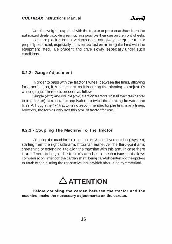
8.2.2 - Gauge Adjustment
In order to pass with the tractor's wheel between the lines, allowingfor a perfect job, it is necessary, as it is during the planting, to adjust it'swheel gauge. Therefore, proceed as follows:
Simple (4x2) and double (4x4) traction tractors: Install the tires (centerto trail center) at a distance equivalent to twice the spacing between thelines. Although the 4x4 tractor is not recommended for planting, many times,however, the farmer only has this type of tractor for use.
8.2.3 - Coupling The Machine To The Tractor
Coupling the machine into the tractor's 3-point hydraulic lifting system,starting from the right side arm. If too far, maneuver the third-point arm,shortening or extending it to align the machine with this arm. In case thereis a different in height, the tractor's arm has a mechanisms that allowscompensation. Interlock the cardan shaft, being careful to interlock the spidersto each other, putting the respective locks which should be symmetrical.
ATTENTIONBefore coupling the cardan between the tractor and the
machine, make the necessary adjustments on the cardan.
Use the weights supplied with the tractor or purchase them from theauthorized dealer, avoiding as much as possible their use on the front wheels.
Caution: placing frontal weights does not always keep the tractorproperly balanced, especially if driven too fast on an irregular land with theequipment lifted. Be prudent and drive slowly, especially under suchconditions.

17
CULTIMAX Instructions Manual
8.2.4 - Adjusting the cardan to the tractor and the machineFor the proper functioning of the cardan, we recommend following the
instructions below before starting the job:1- With the machine installed on the tractor, detach the shaft from the
cardan pipe. By means of the respective pressure buttons, fasten thecorresponding ends on the tractor and the machine.
2- Overlap one on the other and mark each to delimit the excess tobe cutoff. In addition to this marking, consider a 40 mm slack (Fig. 09). Donot cut yet.
3- Raise and lower the machine with the cardan disarmed (pipe andshaft overlapped) through the tractor's hydraulic system, verifying if themarked slack - 40mm does not exceed the limit established, causinginterference on the fork bodies, i.e. it should maintain a slack in any workingposition of the machine (Fig. 10).
Fig.09
Fig.10
Slack
Slack

CULTIMAX Instructions Manual
18
4- After defining the spots to cut, shorten the internal and externalprotective pipes equally. Shorten the internal and external sliding profiles bythe same length as of the protective pipes. Remove all tips and rough edgesand grease the sliding profiles.
40mm40 mm
For the installation of the cardan (pipe and sliding profile), observethat the internal and external forks always remain aligned in the same plan.Otherwise, the cardan will be subjected to vibration, leading to prematurewear of the crosspieces
ATTENTIONThe size of the cardan should be verified and/or adjusted
if required, whenever the tractor model and/or brand ischanged. Failure to observe this may damage the machine and/or cardan.
8.2.5 - Cardan assembly

19
CULTIMAX Instructions Manual
8.3 - Leveling The Machine
For a perfect operation of the CULTIMAX, it should be level in bothdirections. To achieve this, use the third point arm and the right side armcrank of the tractor.
After leveling, if possible, on a shed or flat land, adjust the stabilizersin order to have the equipment stay with the least slack possible.
To do this, lift the equipment to the highest position of the hydraulicsystem and adjust the stabilizers equally, while the equipment is centralized.
By adjusting while the equipment is on the floors and the stabilizersstretched, when lifting the hydraulic system for transport, you run the risk ofdamaging the stabilizers.

CULTIMAX Instructions Manual
20
9 - ADJUSTMENTS
The fertilizer output is made bymeans of individual conducting wormthreads.
The different dosages areobtained by means of the change inthe positioning of the chain betweenthe reducer "a" and the drive shaft"b" (Fig. 11).
In case an outlet is not used,close the fertilizer distributor with aplug "a" (Fig. 12). To put the plug,remove the worm threat "b" and the*deflector "c" (Fig. 12).
*Deflector - present only inequipment manufactured until Dec/1997.
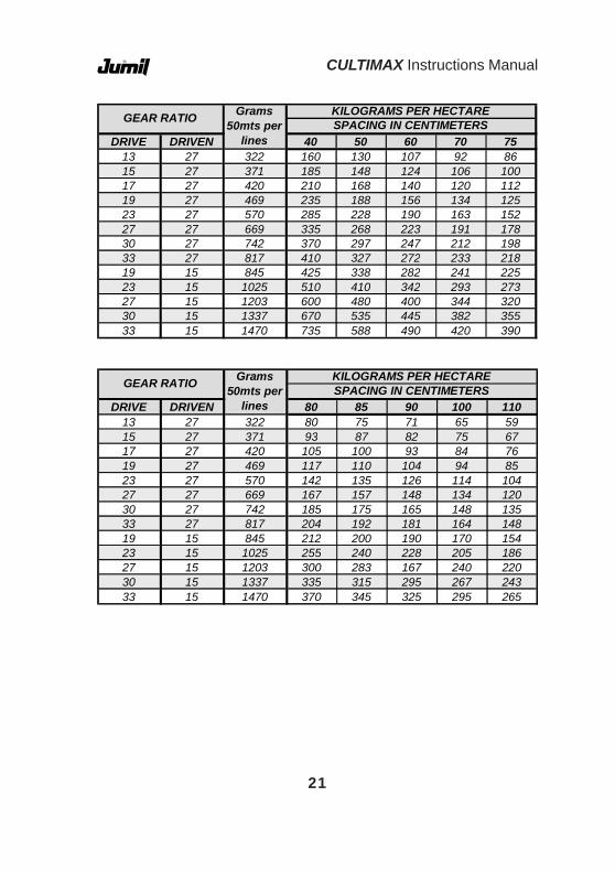
The indicative table that followswas developed for an estimate, andgives an idea of how to beginadjustment, seen that there arevariations in terms of brands, density
and humidity of the fertilizer, tractor skidding and cultivation operational speed.The fertilizer distribution table indicates the ratio of gears to be used,
as well as the quantity of fertilizer to be distributed according to the culture'sspacing.
The fertilizer distribution table was defined considering that work isdone at 5 km/h.
Fig.11
ab
a
b
c
Fig.12
9.1 - Quantity Of Fertilizer Distribution
21
CULTIMAX Instructions Manual
DRIVE DRIVEN 40 50 60 70 7513 27 322 160 130 107 92 8615 27 371 185 148 124 106 10017 27 420 210 168 140 120 11219 27 469 235 188 156 134 12523 27 570 285 228 190 163 15227 27 669 335 268 223 191 17830 27 742 370 297 247 212 19833 27 817 410 327 272 233 21819 15 845 425 338 282 241 22523 15 1025 510 410 342 293 27327 15 1203 600 480 400 344 32030 15 1337 670 535 445 382 35533 15 1470 735 588 490 420 390
Grams 50mts per
lines
KILOGRAMS PER HECTARESPACING IN CENTIMETERSGEAR RATIO
DRIVE DRIVEN 80 85 90 100 11013 27 322 80 75 71 65 5915 27 371 93 87 82 75 6717 27 420 105 100 93 84 7619 27 469 117 110 104 94 8523 27 570 142 135 126 114 10427 27 669 167 157 148 134 12030 27 742 185 175 165 148 13533 27 817 204 192 181 164 14819 15 845 212 200 190 170 15423 15 1025 255 240 228 205 18627 15 1203 300 283 167 240 22030 15 1337 335 315 295 267 24333 15 1470 370 345 325 295 265
Grams 50mts per
lines
KILOGRAMS PER HECTARESPACING IN CENTIMETERSGEAR RATIO

CULTIMAX Instructions Manual
22
9.2 - Installation Schemes Of The Belt Stretcher
Z-15
Z-27
Z-27
POSITIONING THE BELT STRETCHERFOR DIFFERENT GEAR RATIOS.
Z-33 X Z-15Z-30 X Z-15Z-27 X Z-15Z-23 X Z-15Z-19 X Z-15
Z-13 X Z-27Z-15 X Z-27Z-17 X Z-27
Z-33 X Z-27Z-30 X Z-27Z-27 X Z-27Z-23 X Z-27Z-19 X Z-27
Driver Driven
Driver Driven
Driver Driven

23
CULTIMAX Instructions Manual
To obtain a good regulation for the distribution of the fertilizer, proceedas follows:
1- Run 50 meters exactly at 540 RPM on the TDP shaft.2- Record the time taken. Dividing 180 by the number of seconds you
will obtain the speed in km/hour. Set it to obtain 5km/hour, if it spends 36seconds to run 50 meters, it goes at a speed of 5 km/hour.
3- With the tractor parked, set it for the desired fertilizer quantity, putin the outlets of the hoses a recipient to collect the fertilizer;
4- Connect the shaft of the power socket. When the fertilizer drop isnormalized, collect the fertilizer the fallen fertilizer during the same recordedtime. In theory, it means that you covered the same space;
5 - Next, weigh the collected fertilizer;6 - Check on the fertilizer distribution table if the quantity of fertilizer
is the one recommended according to the spacing of the culture.
9.3.1 - Calculation For Fertilizer Distribution
To calculate fertilizer distribution:1- Check the spacing between the lines:2- Define the quantity of fertilizer to be distributed per hectare;3- Calculate according to the example below:
Formula data:E - Spacing between linesQ - Quantity of fertilizer to be distributedA - Area to be fertilizedD - Distance of 50 meters for the testX - Fertilizer grams in 50 meters
Fórmula:
X = E x Q x D A
9.3 - Practical Example Of Fertilizer Distribution Calculation
CULTIMAX Instructions Manual
24
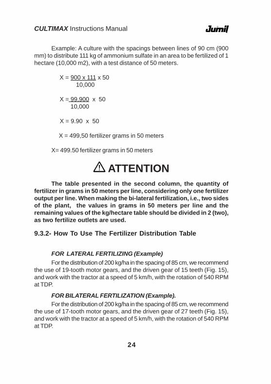
ATTENTIONThe table presented in the second column, the quantity of
fertilizer in grams in 50 meters per line, considering only one fertilizeroutput per line. When making the bi-lateral fertilization, i.e., two sidesof the plant, the values in grams in 50 meters per line and theremaining values of the kg/hectare table should be divided in 2 (two),as two fertilize outlets are used.
9.3.2- How To Use The Fertilizer Distribution Table
FOR LATERAL FERTILIZING (Example)For the distribution of 200 kg/ha in the spacing of 85 cm, we recommend
the use of 19-tooth motor gears, and the driven gear of 15 teeth (Fig. 15),and work with the tractor at a speed of 5 km/h, with the rotation of 540 RPMat TDP.
FOR BILATERAL FERTILIZATION (Example).For the distribution of 200 kg/ha in the spacing of 85 cm, we recommend
the use of 17-tooth motor gears, and the driven gear of 27 teeth (Fig. 15),and work with the tractor at a speed of 5 km/h, with the rotation of 540 RPMat TDP.
Example: A culture with the spacings between lines of 90 cm (900mm) to distribute 111 kg of ammonium sulfate in an area to be fertilized of 1hectare (10,000 m2), with a test distance of 50 meters.
X = 900 x 111 x 50 10,000
X = 99,900 x 50 10,000
X = 9.90 x 50
X = 499,50 fertilizer grams in 50 meters
X= 499.50 fertilizer grams in 50 meters

25
CULTIMAX Instructions Manual
9.5 - Adjustment of Furrowing HoesThe adjustment of the distances of the furrowing hoes according to
the planting line can be done by means of the support tube "a" or the furrowerarms "b" (Fig. 14).
To move the support tube "a" to the right or to the left, loosen theclamps "c" and move the tube until the desired distance. To adjust thevibrator arm, loosen the bolt and clamp "d" (Fig. 14).
b
d
a
c
9.4 - Fertilizing System
Lateral Bi-Lateral CentralFig.13
Fig.14

CULTIMAX Instructions Manual
26
ATTENTIONWhen refastening the support tubes of the furrower arm, make
sure to tighten the nuts of clamps "c" equally to prevent any of thearms staying higher than the other (Fig. 14).
ATTENTIONWhen cultivating a plant with a given size, see that the
adjustment tube of the furrower arms do not touch the plants anddamage them (Fig. 15).
ATTENTIONUse the hoes of the cut wing next to the plant

27
CULTIMAX Instructions Manual
9.6 - Depth Control Adjustment
The depth control of thecultivation is made individually bymeans of a depth control systemcomposed of a controller bar and rodthat is firmly supported on the floor,allowing for cultivation at thedetermined and uniform height, evenwith ground undulations.
Adjustment is made by meansof a lever "a" (Fig.15) over the courseof the indicative scale (Fig. 15)observing the individual adjustment ofall furrower modules, ensuring theuniformity of the depth.
The scale indicates from 1 in 1 cm the depth desired, or according tothe cultivation.
There are three- holes in the module of the board "a" (Fig. 15) used toallow for the adjustment with the adjustment tube of the compactor wheel,allowing the adjustment of 1 in 1 centimeter.
Fig.15
a
b
c
ATTENTIONUpon making the adjustment of the depth control, ensure that
all modules are equally adjusted.
CULTIMAX Instructions Manual
28
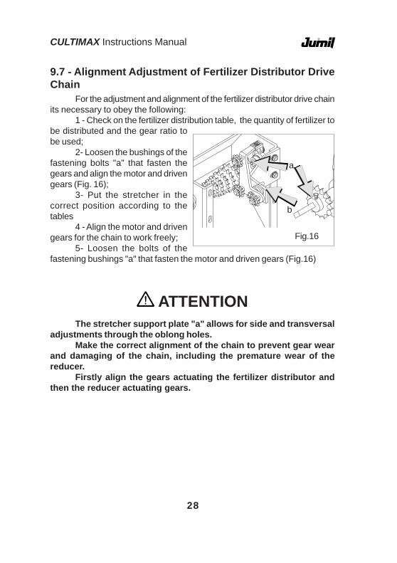
For the adjustment and alignment of the fertilizer distributor drive chainits necessary to obey the following:
1 - Check on the fertilizer distribution table, the quantity of fertilizer tobe distributed and the gear ratio tobe used;
2- Loosen the bushings of thefastening bolts "a" that fasten thegears and align the motor and drivengears (Fig. 16);
3- Put the stretcher in thecorrect position according to thetables
4 - Align the motor and drivengears for the chain to work freely;
5- Loosen the bolts of thefastening bushings "a" that fasten the motor and driven gears (Fig.16)
9.7 - Alignment Adjustment of Fertilizer Distributor DriveChain
Fig.16
a
b
ATTENTIONThe stretcher support plate "a" allows for side and transversal
adjustments through the oblong holes.Make the correct alignment of the chain to prevent gear wear
and damaging of the chain, including the premature wear of thereducer.
Firstly align the gears actuating the fertilizer distributor andthen the reducer actuating gears.

29
CULTIMAX Instructions Manual
9.8 - Reducer Chain Adjustment
To make the alignment adjustment of the speed reducer drive chainwith the gear box shaft, proceed as follows:
1- Put the chain on the drivengear "a" and in the drive gear 'b" (Fig.17);
2- Use a ruler to align thechain, fasten the driven gear "a" bymeans of the fastening bolt of thebushing 'c" (Fig. 17);
3 - Adjust the chain stretcherin such manner that the chain staysstretched by means of a fasteningbolt "d" of the stretcher (Fig. 17)
9.9 - Fertilizer Conductor Support Adjustment
The fertilizer conductor support allowsthe directioning of fertilizer close to the plantaccording to the desired requirement (Fig. 18)
Fig.17
a
b
c
d
Fig.18
CULTIMAX Instructions Manual
30
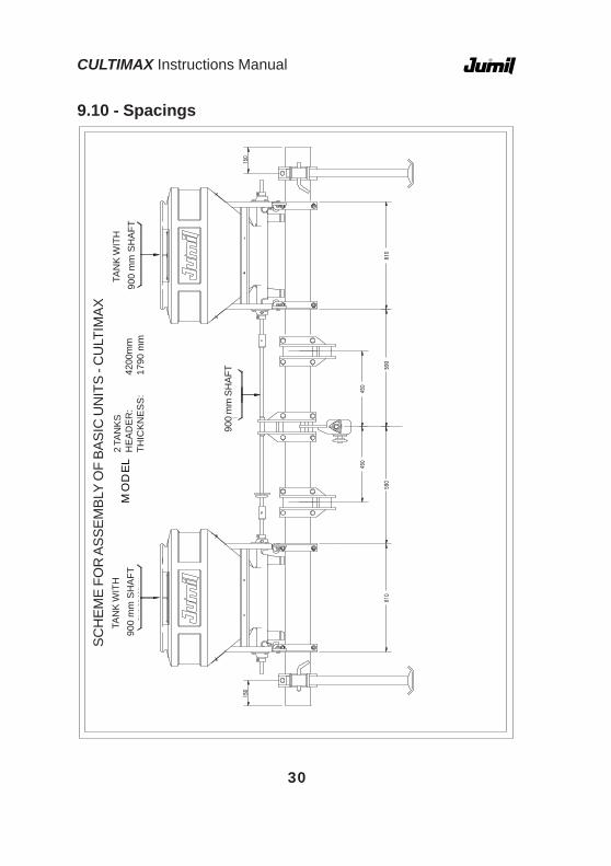
9.10 - SpacingsE
SQ
UE
MA
PA
RA
MO
NT
AG
EM
DA
S U
NID
AD
ES B
AS
ICA
S -
CU
LTIM
AX
MO
DEL
O
SCH
EME
FOR
ASS
EMBL
Y O
F BA
SIC
UN
ITS
- CU
LTIM
AX2
TAN
KSH
EA
DE
R:
4200
mm
THIC
KN
ES
S:
1790
mm
TAN
K W
ITH
900
mm
SH
AFT
TAN
K W
ITH
900
mm
SH
AFT
900
mm
SH
AFT

31
CULTIMAX Instructions Manual
ES
QU
EM
A P
AR
A M
ON
TA
GEM
DA
S U
NID
AD
ES B
AS
ICA
S -
CU
LTIM
AX
MO
DEL
O
SCH
EME
FOR
ASS
EMBL
Y O
F BA
SIC
UN
ITS
- CU
LTIM
AX3
TAN
KSH
EA
DE
R:
4200
mm
THIC
KN
ES
S:
1310
mm
400
mm
SH
AFT
400
mm
SH
AFT
TAN
K W
ITH
900
mm
SH
AFT
TAN
K W
ITH
900
mm
SH
AFT
TAN
K W
ITH
900
mm
SH
AFT

CULTIMAX Instructions Manual
32
ES
QU
EMA
PA
RA
MO
NTA
GE
M D
AS
UN
IDA
DES
BA
SIC
AS
- C
ULT
IMA
X
MO
DEL
O
SCH
EME
FOR
ASS
EMBL
Y O
F BA
SIC
UN
ITS
- CU
LTIM
AX
17.3
2.27
5TA
NK
WIT
H 9
00 m
m S
HA
FT
17.3
2.27
5TA
NK
WIT
H 9
00 m
m S
HA
FT
17.3
2.27
5TA
NK
WIT
H 9
00 m
m S
HA
FT
17.3
2.27
5TA
NK
WIT
H 9
00 m
m S
HA
FT
4 TA
NKS
HE
AD
ER
:42
00m
m

33
CULTIMAX Instructions Manual
ES
QU
EMA
PA
RA
MO
NT
AG
EM D
AS
UN
IDA
DE
S B
AS
ICA
S -
CU
LTIM
AX
MO
DE
LO5
TAN
KSH
EA
DE
R:
4200
mm
17.3
2.27
5TA
NK
WIT
H 9
00 m
m S
HA
FT
17.3
2.27
5TA
NK
WIT
H 8
50 m
m S
HA
FT
17.3
2.27
5TA
NK
WIT
H 9
00 m
m S
HA
FT
17.3
2.27
5TA
NK
WIT
H 8
50 m
m S
HA
FT
17.3
2.27
5TA
NK
WIT
H 9
00 m
m S
HA
FT

CULTIMAX Instructions Manual
34
MO
DEL
O
ESQ
UEM
A P
ARA
MO
NTA
GEM
DA
S U
NID
AD
ES B
ASI
CA
S - C
ULT
IMA
XSC
HEM
E FO
R A
SSEM
BLY
OF
BASI
C U
NIT
S - C
ULT
IMAX
3 TA
NKS
HE
AD
ER
:60
00m
mTH
ICK
NE
SS
:17
90 m
m
900
mm
SH
AFT
900
mm
SH
AFT
TAN
K W
ITH
900
mm
SH
AFT
TAN
K W
ITH
900
mm
SH
AFT
TAN
K W
ITH
900
mm
SH
AFT

35
CULTIMAX Instructions Manual
MO
DE
LO
ES
QU
EM
A P
AR
A M
ON
TAG
EM D
AS
UN
IDA
DE
S B
AS
ICA
S -
CU
LTIM
AX
SCH
EME
FOR
ASS
EMBL
Y O
F BA
SIC
UN
ITS
- CU
LTIM
AX4
TAN
KSH
EA
DE
R:
6000
mm
TAN
K W
ITH
900
mm
SH
AFT
TAN
K W
ITH
900
mm
SH
AFT
TAN
K W
ITH
900
mm
SH
AFT
TAN
K W
ITH
900
mm
SH
AFT
760
mm
SHAF
T80
0 m
mSH
AFT
760
mm
SHAF
T

CULTIMAX Instructions Manual
36
ES
QU
EM
A P
AR
A M
ON
TA
GE
M D
AS
UN
IDA
DE
S B
AS
ICA
S -
CU
LTIM
AX
MO
DE
LO
SCH
EME
FOR
ASS
EMBL
Y O
F BA
SIC
UN
ITS
- CU
LTIM
AX5
TAN
KSH
EA
DE
R:
6000
mm
THIC
KN
ES
S:
910
mm
TAN
K W
ITH
900
mm
SH
AFT
TAN
K W
ITH
900
mm
SH
AFT
TAN
K W
ITH
900
mm
SH
AFT
TAN
K W
ITH
900
mm
SH
AFT
TAN
K W
ITH
900
mm
SH
AFT

37
CULTIMAX Instructions Manual
SCH
EME
FOR
ASS
EMBL
Y O
F BA
SIC
UN
ITS
- CU
LTIM
AX6
TAN
KS
WIT
H 9
00m
m S
HA
FTH
EA
DE
R:
6000
mm
THIC
KN
ES
S:
800
mm
TAN
K W
ITH
900
mm
SH
AFT
TAN
K W
ITH
900
mm
SH
AFT
TAN
K W
ITH
900
mm
SH
AFT
TAN
K W
ITH
900
mm
SH
AFT
TAN
K W
ITH
900
mm
SH
AFT
TAN
K W
ITH
900
mm
SH
AFT

CULTIMAX Instructions Manual
38
MO
DE
LO
ES
QU
EMA
PA
RA
MO
NT
AG
EM
DA
S U
NID
AD
ES
BA
SIC
AS
- C
ULT
IMA
XSC
HEM
E FO
R A
SSEM
BLY
OF
BASI
C U
NIT
S - C
ULT
IMAX
8 TA
NKS
HE
AD
ER
:68
00m
m
TAN
K W
ITH
860
mm
SH
AFT
TAN
K W
ITH
860
mm
SH
AFT
TAN
K W
ITH
860
mm
SH
AFT
TAN
K W
ITH
880
mm
SH
AFT
TAN
K W
ITH
860
mm
SH
AFT
TAN
K W
ITH
860
mm
SH
AFT
TAN
K W
ITH
860
mm
SH
AFT
TAN
K W
ITH
860
mm
SH
AFT

39
CULTIMAX Instructions Manual
10 - MAINTENANCE
We suggest some care with the maintenance, which will allow for alonger service life of the equipment and better performance.
Periodically, the equipment should require some repair and the itemsbelow are of extreme importance for the perfect, interruption-free operation.
10.1 - Cleaning The Fertilizer Tanks
After covering, do not leaving thefertilizer inside the tank. Werecommend totally emptying the tank,scarping the fertilizer off the wormthread and wash it with running water.
To clean it, loosen the pegs "a",remove the drive shaft connectionbushing "b" to free the tank and thentilt the tank, facilitating cleaning (Fig.19)
aFig.19
ATTENTIONBy the end of each workday, remove the rest of the fertilizer
from the tanks and carefully clean the equipment. Retighten the boltsperiodically.

CULTIMAX Instructions Manual
40
10.2 - General Cleaning Of The Cultimax
When storing your CULTIMAX until the next planting year, give it ageneral cleaning. Remove the fertilizer conductors from the tanks, washthem and keep them.
Check if all moving parts do not present wear, and replace, leavingthe CULTIMAX ready for the next job. Retouch the paint, especially partsthat come in contact with the fertilizer.
Protect the plastic tanks and spray the CULTIMAX with conservingoil, making sure not to use burnt oil.
Having carried out all the maintenance repairs, store the CULTIMAXin an adequate place, away from intemperate weather. Use the support feetto keep it standing and not overload the machine on the furrower arms.

41
CULTIMAX Instructions Manual
11.1 - Lubrication Objectives
The running efficiency of any machine relies much on the suitablelubrication and it is therefore fundamental to ensure proper and qualitylubrication is made to prevent reduction in the equipment's efficiency, leadingalso to premature wear of parts.
In heavy duty conditions, we recommend reducing the lubricationintervals indicated in the Figures.
ATTENTIONBefore beginning lubrication, clean the grease fittings and
replace the damaged ones.
11.2 - Lubrication Symbols
Lubricate with lithium soap based grease, NLGI-2consistence at 8-hour work intervals
Lubricate with SAE 30 API-CD oil at 8-hour workintervals
Lubrication intervals in worked hours
11 - LUBRICATION
Cleaning the belt
Check the oil in every 50 work hours and use SAE140 API-GL5 oil or the equivalent.
CULTIMAX Instructions Manual
42
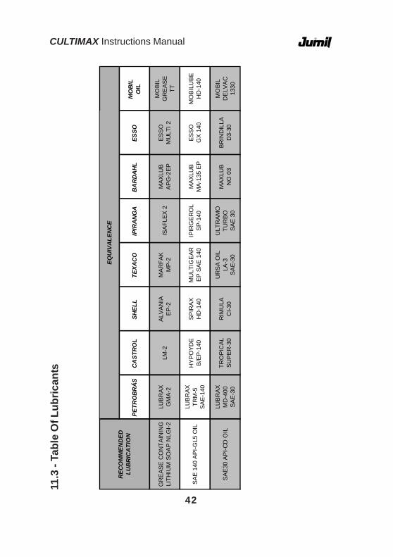
11.3
- Ta
ble
Of L
ubric
ants
MO
BIL
OIL
MO
BIL
GR
EA
SE
TT
MO
BILU
BE
HD
-140
MO
BIL
DE
LVA
C13
30
ESSO
ES
SO
MU
LTI 2
ES
SO
GX
140
BRIN
DIL
LAD
3-30
BA
RD
AH
L
MA
XLU
BA
PG
-2E
P
MA
XLU
BM
A-13
5 E
P
MA
XLU
BN
O 0
3
IPIR
AN
GA
ISA
FLE
X 2
IPIR
GE
RO
LS
P-1
40
ULT
RA
MO
TUR
BO
SAE
30
TEXA
CO
MA
RFA
KM
P-2
MU
LTIG
EAR
EP
SA
E 14
0
UR
SA
OIL
LA-3
SA
E-3
0
SHEL
L
ALV
AN
IAE
P-2
SP
IRA
XH
D-1
40
RIM
ULA
CI-3
0
CA
STR
OL
LM-2
HY
PO
YD
EB
/EP
-140
TRO
PIC
ALS
UP
ER
-30
PETR
OB
RÁ
S
LUB
RA
XG
MA
-2
LUB
RA
X
TRM
-5SA
E-1
40
LUB
RA
XM
D-4
00S
AE
-30
GR
EAS
E C
ON
TAIN
ING
LITH
IUM
SO
AP
NLG
I-2
SA
E 1
40 A
PI-G
L5 O
IL
SA
E30
AP
I-CD
OIL
REC
OM
MEN
DED
LU
BR
ICA
TIO
N
EQU
IVA
LEN
CE

43
CULTIMAX Instructions Manual
11.4 - Lubrication Points
30 30
30
30
30

CULTIMAX Instructions Manual
44
50
50
30
100

45
CULTIMAX Instructions Manual
The Cultimax line was developed and tested with the utmost care andas such, it is ready to perform a perfect service in order to completely satisfyyour needs.
Anything that is out of its perfect running is an incident caused by acircumstance unrelated to the machine. With the intention of preventingsuch circumstances, we have listed below some of the commonest incidents,their causes and how to solve them. However, if after having verified andperformed the rectifications accordingly your equipment fails to work perfectly,contact your dealer or Jumil through the Customer Technical AssistanceCenter.1 - The cultivator is moving too much earth.
a) The hoes are penetrating too deeply.Check the arm of the third point; it is probably too short.Solution: Put the cultivator on a plane place and extend the arm until
the Cultimax is leveled. In this case, it probably just needs to extend thearm.
Check the depth limiter wheels. it may be that they are adjusted fora deeper depth than the one recommended.
Solution: Adjust the depth accordingly.b) The hoes are penetrating deeper on one side.Check the hydraulic arm on the right side of the tractor: its length is
probably different from the left arm's.Solution: As the left arm does not have a system to alter its height, it
is common that the right arm stay with a different height. Actuate over thesystem and extend or shorten2 - The spaces to which the active bodies of the Cultimax are adjusteddo not coincide with the spaces of the culture.
Ensure that the planter was correctly adjusted for the desired spacing.Possibly, the spacing is different, causing this maladjustment.
Solution: Subject the spacing of the Cultimax to that of the planter.It is possible that it is "entering" a different planting sequence and
although the line marker has been used, whose function is precisely toprevent different spacing between the lines, such fact may occur by failureon the part of the operator during planting.
Solution: Enter into the same planting sequence and train the operator.
12 – INCIDENTS AND TROUBLESHOOTING

CULTIMAX Instructions Manual
46
3 - The hoes sometimes touch the plants, at times on one side, at timeson the other.
The stretchers of the hydraulic arms are probably too loose, allowingthis "play" of the Cultimax.
Solution: Equally adjust the stretchers with the equipment raised bythe hydraulic system. In case you proceed with this adjustment of the machineon he ground, you will run the risk of damaging the stretchers by actuatingthe lifting through the hydraulic system.
The operator cannot keep the tractor's steering firm. Probably, thetractor's front is too light and steering becomes difficult.
Solution: Put the appropriate weights on the front and on the wheelsof the tractor.4 - The arms are not "shaking" the weeds, which run the risk of notdying.
You are probably moving too slow, which makes the vibratory actionof the springs difficult.
Solution: Increase the speed until you obtain the vibratory effect. Theinfestation is probably too large, having gone past the suitable period formechanical cultivation.
Solution: You may carry out the mechanical cultivation but accordingto the weather (rainy), you may run the risk of the weeds not dying.
You may be working with the hoes in too deep.Solution: Reduce the depth, actuating on the depth control wheels.