icon student experiment john westerhoff, gary swenson university of illinois at urbana- champaign
TRANSCRIPT

ICON Student Experiment
John Westerhoff, Gary SwensonUniversity of Illinois at Urbana-Champaign

Overview• Student Collaboration Phase A Requirements
and Evaluation• Science Objectives• Hardware Implementation• ICON Mission Requirements• Phase A Tasks

Phase A Requirements for the SC

Phase A Requirements for the SC

Phase A Requirements – SC• Funding may be outside PI-Managed Mission cost up to SC
incentive: 1% of PI-Managed Mission Cost Cap ($200M)• CSR Section I: Student Collaboration
– 5 page limit for SC – Identify SC as an E/PO element– Detail development schedule of SC, including decision points for
determining SC readiness for flight– Demonstrate how SC can be incorporated into baseline mission
on nonimpact basis– Demonstrate that SC is clearly separable for rest of proposed
effort– Plan for mentoring and oversight of students– Identify funding set aside for SC

CSR Evaluation of SC• Along with E/PO, SDB, 5% weighting• SC Merit factors:
– Science/engineering alignment of proposed SC investigation– Implementation merit of SC based on technical,
management, and cost feasibility, including cost risk– Educational merit of SC
• Quality, scope, realism, appropriateness of educational objectives• Continuity: SC involves students interested in NASA and engages
them in the next level of involvement in E/PO• Evaluation: plan and methods• Diversity (Program Balance Factor): engaging underrepresented
groups

Phase A Tasks• Science requirements and instrument simulation• SC development schedule• Environmental testing of PMT– Vacuum testing– Vibration testing
• Develop conformal coating procedure for PMT• Evaluate alternative PMT for NIR channels:
Hamamatsu H10770PA-50– Improves S/N 150%– Adds ~0.4kg, 1.6W to budgets, may require larger volume
(11x19x23cm)

Science Objectives• Investigate Atmospheric Gravity Waves (GW) via remote sensing
of mesosphere, including high frequency waves (λx > 30 km).• Provide global measurement context for small to medium scale
(λx > 30 km) LWBs (large waves or bores)• Observe large amplitude (A > 10%) LWBs and determine their
intrinsic properties (A, λx, λz)• Observe packets of small amplitude (A > 1%) waves and
determine their intrinsic properties• Categorize horizontal and vertical wavelengths into small,
medium, large scale• Determine rotational temperature perturbations (T’/T) of waves

Measurement Approach• Observe O2 (0-0) rotational emission and O2 Herzberg
emission (nadir viewing)• Brightness perturbation measurement (I’/I) provides wave
amplitudes• Ratio of O2 P and R branch provides rotational temperature
perturbations (T’/T)• Phase differences between (I’/I) and (T’/T), and between O2
(0-0) and Herzberg bands, provide vertical wavelength measurements
• Cross-track measurements of (0-0) atmospheric band provides azimuthal wave orientation and horizontal wavelengths

Science RequirementsScience requirement Measurement Sensor
channelS/N
RequiredMargin
Determine amplitude of LWB (A>10%)
I’/I O2 A, H 10 1050%
Categorize λx, λz of LWBs as small, med, large scale
Vertical and horizontal phase,
I’/I-T’/T ratio
O2 A, H 10 210%
Determine LWB wave orientation within 30°
4ch-horizontal phase
4-ch O2 A 12 TBD
Determine rotational temperature (T’/T) of LWBs
I’/I, P/R branch ratio
O2 A, H 10 TBD
Secondary science requirement to conduct these same measurements for small amplitude (A>1%) wave packets (5+ waves)

Image taken from ATLAS-1 mission by the AEPI experiment, March 24, 1992. The image was taken with an O2 Atmospheric (0,0) band filter at 762.0 nm, similar to that proposed for the ICON Student Experiment (Mende et al., 1994)

Quasi-monochromatic (left) and chaos (right)


O2 Herzberg, I’95.5 km
O2 A, I’92.5 km
HWL
VWLphase difference observed
GW phase fronts and wave phase information versus altitude
GW phase fronts


TOMEX
Potential Energy vs. Altitude, Four Nights Data

Hardware Implementation: Sensors• Photomultiplier tubes: 7 Hamamatsu H10862 PMTs• 1nm filters centered at 760.5, 763.5nm for (0-0)
band P and R branch• 2nm filter centered at 770nm (background channel)• Bandpass filter from 255-292nm to measure O2
Hertzberg band, with notch at 280nm to block Mg emissions
• 4 PMTs used on (0-0) R branch with FOVs across 8° perpendicular to orbit plane: obtains cross-track measurements

Coarse 2D imager using PMTs
4 PMT modules
Optics assembly, with filter and lens
Fiber optic coupling
4 viewing directions,8o full angle, perpendicular to orbit plane
• Coarse 2D imager using 4-channel PMT
• Fiber coupling to focal plane• Use R branch of (0-0) band• View angles oriented
perpendicular to orbit plane (-2.25°, 0°, 2.25°, 4.5° from nadir)
• Adds ~250g and 0.22W power, 6.9 Mbit/day data

O2 emission and P-R branch filters

A 1% uncertainty in R yields~ 1% uncertainty in T

Signal Analysis: PMTsCenter wavelength (nm) 760.5 763.5 770 273.5
Sensor H10682-01 H10682-01 H10682-01 H10682-110
Source brightness (Rayleigh) 6000 6000 40+ 600
Subject distance (km) 460 460 460 460
Lens diameter (mm) 38 38 38 75
Aperture diameter (mm) 1.0 1.0 1.0 2.0
Dark count @ 25°C (Hz) 600 600 600 50
Effective band transmission (%) 20 13 n/a 15
Quantum efficiency (%) 1.6 1.6 1.6 21
Footprint width (km) 12.1 12.1 12.1 12.3
Integration time (sec) 1.0 1.0 1.0 1.0
S/N ratio (for 1.0 sec IT) 91 72 n/a 189
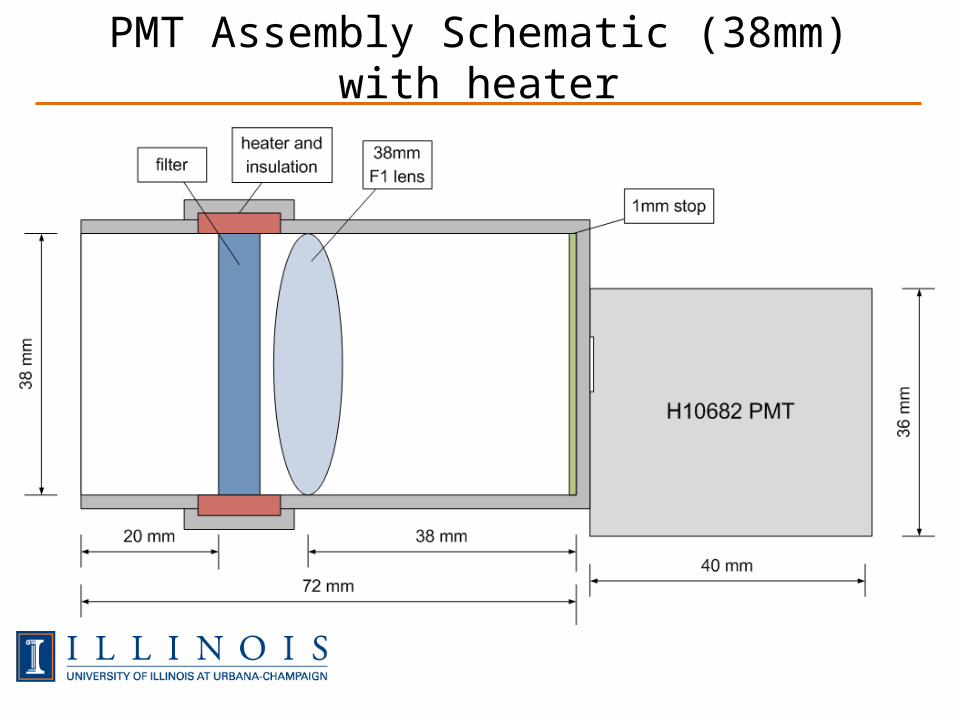
PMT Assembly Schematic (38mm) with heater

PMT Assembly Schematic (75mm)

Solid model of student experiment
Volume: 11x19x20cm
O2 Herzberg channel75mm aperture
O2 atmospheric channelswith temperature regulated filters38mm apertures
4-pixel O2 A channelassembly with fiber coupling
C&DH andPower boards
O2 A background channel38mm aperture

Test PMT Assembly

Mass BudgetData source Mass (g)H10682 PMT modules 525PMT optics assemblies 840C&DH board 125Power board 75Engineering sensors 110Structural and mounting hardware 650Integration hardware and wiring 300Total Mass 2625 g

Power Budget
Component Power (W)
Qty Duty cycle
Avg Power (W)
H10682 PMT 0.2 7 0.37 0.5238mm filter heater 0.4 2 1.00 0.80C&DH board (day) 0.3 1 0.63 0.19C&DH board (night) 1.0 1 0.37 0.37Power load 1.88 WDC-DC converter efficiency 80%Total power 2.35 W

Datalink Budget
Data source Data rate (Mbit/day)
PMT Sensors 9.97Engineering data 0.13Data rate 10.1 Mbit/dayOverhead 10%Total data rate 11.1 Mbit/day

SC Subsystem Cost (Illinois)
Project Phase CostPhase A $13,146Phase B $235,798Phase C/D $648,836Phase E $348,141Phase F $28,480Total subsystem cost $1,274,400

SC Requirements on ICON Mission• Bottom plate mounting for SC instruments, nadir
pointing• 19x11cm bottom plate footprint requirement• Power and data connector to ICD• Spacecraft provided command and data interface– Command signals from spacecraft– Data upload to spacecraft– Time synchronization
• SC mission data analysis requires access to ICON mission data (position, attitude of spacecraft)

Backup Slides

λz measurement
• Vertical wavelength measurement (λz) from phase difference between (0-0) and Herzberg bands
• Best difference signal at zero phase in one of the channels:
• Error in brightness measurement:
• λz calculation:
• Error in λz calculation:

λz error vs. I’/I for λz=20,30km

O2 A band

Proposal Requirements – SC• SC must depend on baseline mission being implemented• SC must not impact baseline mission in the event that:– SC is not funded;– SC fails during flight operations;– or SC encounters technical, schedule, or cost problems in
development• SC must include plans for mentoring and oversight of
students• SC may have the potential to add value to science or
engineering of the baseline mission