icf-1180i series quick installation guide · there are two variations of profibus protocol,...
TRANSCRIPT

P/N: 1802011800017
*1802011800017*
ICF-1180I Series Quick Installation Guide
Edition 7.1, May 2016
Technical Support Contact Information www.moxa.com/support
Moxa Americas: Toll-free: 1-888-669-2872 Tel: 1-714-528-6777 Fax: 1-714-528-6778
Moxa China (Shanghai office): Toll-free: 800-820-5036 Tel: +86-21-5258-9955 Fax: +86-21-5258-5505
Moxa Europe: Tel: +49-89-3 70 03 99-0 Fax: +49-89-3 70 03 99-99
Moxa Asia-Pacific: Tel: +886-2-8919-1230 Fax: +886-2-8919-1231
Moxa India: Tel: +91-80-4172-9088 Fax: +91-80-4132-1045
2016 Moxa Inc. All rights reserved. Fl.4, No. 135, Lane 235, Baoqiao Rd., Xindian Dist., New Taipei City,
Taiwan, R.O.C

- 2 -
Introduction
There are two variations of PROFIBUS protocol, PROFIBUS DP (Decentralized Peripherals) and PROFIBUS PA (Process Automation). PROFIBUS PA is used with applications for which the end device needs a power supply from the PROFIBUS PA device and where an intrinsic safe mechanism is also required. Due to the power supply criteria, the number of attached devices is limited. PROFIBUS DP is used in production automation and when centralized controllers are used to manage the system. It supports up to 126 attached devices and is the most commonly used PROFIBUS specification.
The ICF-1180I series PROFIBUS-to-fiber converters are based on PROFIBUS DP. ICF-1180I products are used to convert PROFIBUS signals from copper to optical fiber. ICF-1180I multi-mode models can be used to extend PROFIBUS signal transmission up to 4 km and ICF-1180I single-mode models can extend PROFIBUS signal transmission up to 45 km. ICF-1180I converters provide 2 kV isolation protection for the PROFIBUS system and have dual power inputs to ensure uninterrupted operation of the PROFIBUS device.
Why Convert PROFIBUS to Fiber?
Optical fiber communication not only extends the communication distance, but also provides many advantageous features.
IMMUNITY FROM ELECTRICAL INTERFERENCE: Fiber is immune from electromagnetic interference or radio frequency interference. It provides a clean communication path and is immune to cross-talk.
INSULATION: Optical fiber is an insulator interface; the glass fiber eliminates the need for using electric currents as the communication medium.
SECURITY: Fiber cannot be tapped by conventional electronic means and is very difficult to tap into optically while radio and satellite communication signals can be captured easily for decoding.
RELIABILITY & MAINTENANCE: Fiber is immune from adverse temperature and moisture conditions; hence, it does not corrode or lose its signal, and is not affected by short circuits, power surges, or static electricity.
Auto/Manual Baudrate Settings
The ICF-1180I series converts signals back and forth between PROFIBUS and fiber and supports baudrates from 9.6 kbps to 12 Mbps. Engineers do not need to know the baudrate of the connected PROFIBUS device since the ICF-1180I can automatically detect the baudrate of the PROFIBUS device and apply this baudrate directly. This is an extremely convenient feature. If necessary, baudrates can be set to a fixed value via DIP switches.

- 3 -
PROFIBUS Fail Safe
When the PROFIBUS device malfunctions or the serial interface fails, it will generate electrical noise that can cause bus failure. Traditional media converters will let the noise signal pass through the fiber and on to the other converter, disrupting data communication between the two buses and eventually causing communication to cease across the entire system. When this occurs, engineers will not be able to easily locate the failed device because the entire PROFIBUS network is down. To avoid this situation, the ICF-1180I is designed to detect and recognize noise signals. If the bus fails on one side, the noise signal will not propagate through the ICF-1180I and affect additional bus segments. In addition, the ICF-1180I will also trigger an alarm notification to the field engineer on the location of the failure.
Fiber Link Monitor
The ICF-1180I series’ Fiber Link Monitor function detects communication errors on either the fiber side or the PROFIBUS side. When a communication error occurs, the corresponding LED will shine red and the relay alarm will activate.
Reverse Power Protection
The Reverse Power Protection feature provides extra protection against accidentally connecting the power cables to the wrong terminal. The converter is designed to detect automatically which power wire is positive and which is negative, and then adjust the power supply accordingly.
Remote Fiber Diagnosis
Fiber optic cables are often deployed for long distance communication and a fiber optic inspection pen is used by engineers to detect communication quality issues. ICF-1180I series converters eliminate the need for a fiber optic inspection pen by providing a Fiber Test function that uses DIP switch adjustments. By using the Fiber Test function, users can determine which side (Tx or Rx) is causing the problem on the converter. Fiber cable abnormalities can be automatically detected and identified by the LED indicator.

- 4 -
Using Remote Fiber Diagnosis: Set DIP switch SW8 to the ON position on any ICF-1180I converter and then look at the Ready LED status. A flashing green Ready LED indicates that the Fiber Test has finished. The P1 (Fiber port) LED indicates which side (Tx or Rx) is causing the problem. If there are no fiber connection errors in the entire topology, the related LEDs will shine green or remain OFF. If the fiber connection error is adjacent to the converter, the status will also be indicated by the P1 LEDs. A flashing red light on P1 means that the Rx fiber cable connected to this port is broken. Similarly, a solid red light on P1 means that the Tx fiber cable in this port is broken. Further descriptions and troubleshooting can be found in the Troubleshooting table.
Features
• Auto baudrate detection and data speed up to 12 Mbps • PROFIBUS bus fail safe • Alarm by relay output • 2 kV galvanic isolation • Power polarity protection • Extends PROFIBUS transmission distance:
Up to 45 km with single-mode—ICF-1180I-S series Up to 4 km with multi-mode—ICF-1180I-M series
• Remote Fiber Diagnosis • Topology: Point-to-Point mode, Linear mode (as the head or tail
converter with ICF-1280I) • Dual power inputs for redundancy • Wide operating temperature range: -40 to 75°C (for “T” models) • Supports Fiber Signal Intensity Diagnosis
Package Checklist
Before installing the ICF-1180I converter, verify that the package contains the following items:
• ICF-1180I PROFIBUS-to-fiber converter • Quick installation guide (printed) • Warranty card
Note: Please notify your sales representative if any of the above items are missing or damaged.

- 5 -
Mounting Dimensions (unit: mm)

- 6 -
ICF-1180I Panel Layouts
Top View
Bottom View
Front View
ATTENTION
Electrostatic Discharge Warning!
To protect the product from damage due to electrostatic discharge, we recommend wearing a grounding device when handling your ICF-1180I.

- 7 -
Mounting
The aluminum DIN rail attachment plate should be fixed to the back panel of the ICF-1180I when you take it out of the box. If you need to reattach the DIN rail attachment plate to the ICF-1180I, make sure the stiff metal spring is situated towards the top, as shown in the figures below.
STEP 1: Insert the top of the DIN rail into the slot just below the stiff metal spring.
STEP 2: The DIN-rail attachment unit will snap into place as shown below.
To remove the ICF-1180I series from the DIN rail, simply reverse Steps 1 and 2 above.
Wiring the Alarm Contact
The alarm contact is made up of the two middle contacts of the terminal block on the ICF-1180I’s top panel. Refer to the next section for detailed instructions on how to connect the wires to the terminal block connector, and how to attach the terminal block connector to the terminal block receptor.
In this section, we explain the meaning of the two contacts used to connect the alarm contact.
FAULT: The two middle contacts of the 6-contact terminal block connector are used to detect both power faults and port faults. The two wires attached to the Fault contacts form an open circuit when:
1. The ICF-1180I has lost power from one of the DC power inputs.
OR 2. One of the ports for which the
corresponding PORT ALARM Dip Switch is set to ON is not properly connected.
If neither of these two conditions occurs, the Fault circuit will be closed.

- 8 -
Wiring the Redundant Power Inputs
STEP 1: Insert the negative/positive DC wires into the V-/V+ terminals.
STEP 2: To keep the DC wires from pulling loose, use a small flat-blade screwdriver to tighten the wire-clamp screws on the front of the terminal block connector.
STEP 3: Insert the plastic terminal block connector prongs into the terminal block receptor, which is located on the ICF-1280I’s top panel.
ATTENTION
Before connecting the ICF-1180I to the DC power inputs, make sure the DC power source voltage is stable.
You should also pay attention to the following:
• The temperature rating of the input connection cable should be higher than 91°C.
• The cross sectional area of the ground wire should be at least 3.31 mm2.
• The terminal block plug should be suitable for 28-12 AWG (0.0804-3.31 mm2) wire and a torque of 4.5 lb-in.
Fiber Cable
ST-Port Pinouts ST-Port to ST-Port Cable Wiring
Pin Assignment
PIN Signal Name 1 N.C. 2 N.C. 3 PROFIBUS D+ 4 RTS 5 Signal common 6 5 V 7 N.C. 8 PROFIBUS D- 9 N.C.

- 9 -
Federal Communications Commission Statement
FCC: This device complies with part 15 of the FCC Rules. Operation is subject to the following two conditions:
1. This device may not cause harmful interference, and 2. This device must accept any interference received, including
interference that may cause undesired operation.
ATEX and IECEx Information
1. Certificate number ATEX: DEMKO 14 ATEX 1384X IECEx: IECEx UL 14.0094X
2. Ambient range
-40°C ≤ Tamb ≤ 75°C for models with suffix of “-T” -10°C ≤ Tamb ≤ 60°C for models without suffix of “-T”
3. Certification string: ATEX: Ex nA nC IIC T4 Gc, Ex nA nC op is IIC T4 Gc IECEx: Ex nA nC IIC T4 Gc
4. Standards covered: EN 60079-0:2012+A11:2013/IEC 60079-0:2011 Ed.6 EN 60079-15:2010/IEC 60079-15:2010 Ed.4
5. Conditions of safe usage: • This equipment must be installed in an enclosure that can only
be accessed with a key or other tool, and which provides a degree of protection not less than IP54 in accordance with IEC 60079-15.
• These devices are designed for use in an area of not more than pollution degree 2 in accordance with IEC 60664-1.
• Transient protection must be provided and set at a level not exceeding 140% of the peak rated voltage value at the supply terminals to the equipment.
Slot Time Settings
When ICF-1180I converters are used as part of a PROFIBUS network, frame delays can occur, with the time of the delays determined by the total cable length and network topology. In this case, a sufficient “slot time” should be configured to prevent the PROFIBUS master from timing out. We recommend using the following formula to calculate the preferred PROFIBUS master’s slot time.
For a point-to-point topology:
Slot time = A + B × L + 13 × N
Transmission Speed (kbps) A B 12000 811 120 6000 461 60 3000 261 30 1500 161 15 500 111 5 187.5 71 1.875 93.75 71 0.9375 45.45 411 0.4545 19.2 71 0.192 9.6 71 0.096

- 10 -
L: The length of the fiber optic cable in kilometers. N: The number of converters in the system. A and B: Parameters determined by the transmission speed.
Note: To avoid frame conflicts, we recommend setting the PROFIBUS command retry limit ≥ 3, and the slot time < 262128.
DIP Switch Settings
There are 8 DIP switches on the top panel of the ICF-1180I. The factory default setting for all DIP switches, except SW5, is OFF.
Transmission Speed (kbps) SW1 SW2 SW3 SW4 Auto (default) OFF OFF OFF OFF 12000 OFF OFF OFF ON 6000 OFF OFF ON OFF 3000 OFF OFF ON ON 1500 OFF ON OFF OFF 500 OFF ON OFF ON 187.5 OFF ON ON OFF 93.75 OFF ON ON ON 45.45 ON OFF OFF OFF 19.2 ON OFF OFF ON 9.6 ON OFF ON OFF Setting ON OFF SW5 Fiber Link Monitor Disable SW6 Reserved Reserved SW7 Reserved Reserved SW8 Remote Fiber Diagnosis* Disable * Refer to the Remote Fiber Diagnosis section for instructions.
ATTENTION
If you connect an ICF-1180I converter running firmware version 1.2 to (a) an ICF-1180I converter running firmware version 1.3 or above, or (b) an ICF-1280I converter, the built-in Fiber Link Monitor and Fiber Test functions may not work properly. Users must disable the Fiber Link Monitor function through the DIP switch and the Fiber Test function will work in this situation. Version 1.3 of the ICF-1180I converter is fully compatible with the ICF-1280I series for the Fiber Link Monitor function and the Remote Fiber Diagnosis function.
Version 1.4 of ICF-1180I converter change the function name "Fiber Test" to "Remote Fiber Diagnosis"
- 11 -
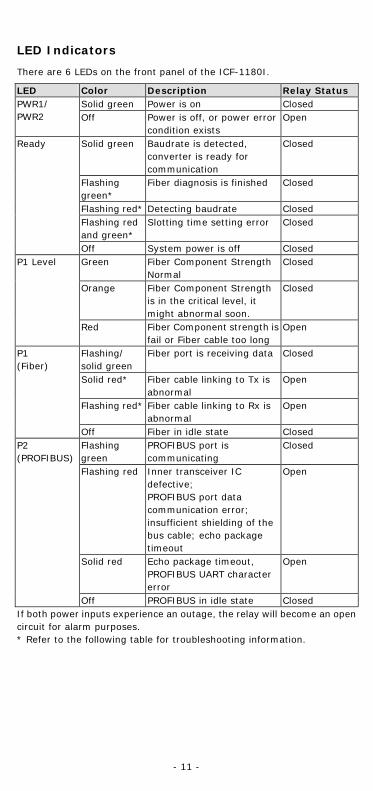
LED Indicators
There are 6 LEDs on the front panel of the ICF-1180I.
LED Color Description Relay Status PWR1/ PWR2
Solid green Power is on Closed Off Power is off, or power error
condition exists Open
Ready Solid green Baudrate is detected, converter is ready for communication
Closed
Flashing green*
Fiber diagnosis is finished Closed
Flashing red* Detecting baudrate Closed Flashing red and green*
Slotting time setting error Closed
Off System power is off Closed P1 Level Green Fiber Component Strength
Normal Closed
Orange Fiber Component Strength is in the critical level, it might abnormal soon.
Closed
Red Fiber Component strength is fail or Fiber cable too long
Open
P1 (Fiber)
Flashing/ solid green
Fiber port is receiving data Closed
Solid red* Fiber cable linking to Tx is abnormal
Open
Flashing red* Fiber cable linking to Rx is abnormal
Open
Off Fiber in idle state Closed P2 (PROFIBUS)
Flashing green
PROFIBUS port is communicating
Closed
Flashing red Inner transceiver IC defective; PROFIBUS port data communication error; insufficient shielding of the bus cable; echo package timeout
Open
Solid red Echo package timeout, PROFIBUS UART character error
Open
Off PROFIBUS in idle state Closed If both power inputs experience an outage, the relay will become an open circuit for alarm purposes. * Refer to the following table for troubleshooting information.

- 12 -
Troubleshooting LED Indicators and Fiber Test
LED Color Description Status/Troubleshooting Ready Flashing
green Fiber diagnosis finished
At least one converter is in Fiber Diagnosis mode; Check PROFIBUS master settings; Tx and Rx cables crossed
Flashing red
Detecting baudrate
No PROFIBUS node; No PROFIBUS signal received; Tx and RX crossed over; Baudrate setting is incorrect.
Flashing green/red
Slot time setting error
Recalculate the slot time; Set TSDR ≥ 11; Set HAS = greatest PROFIBUS node address + 1; Check consistency of operation mode for DIP switch 6/7; Check consistency of Fiber Link Monitor Mode for DIP switch 5
P1 Flashing red
Rx fiber cable abnormality
Check the Rx fiber cable connecting to this port*; Tx and Rx cables crossed over; Partner module is powered OFF or defective
Solid red Tx fiber cable abnormality
Check the fiber cable linking to Tx of this port*
P2 OFF PROFIBUS is idle Check the PROFIBUS device connection
Flashing red
PROFIBUS side error
RS-485 cable is not terminated or only terminated at one end; Open bus cable; PROFIBUS D+ and D- crossed over; Short circuit on PROFIBUS cable; RS-485 driver is defective; Check slot time setting, baudrate, and operation mode
If the abnormality indicated by the LED disappears in Fiber Diagnosis mode, check the consistency of the DIP switch settings on all the converters.
If the Tx and Rx cables are both abnormal, the P1 LED will shine red. Check the Rx cable first for troubleshooting.
*If the P1 LED and P2 LED are both lit/flashing red simultaneously, the Tx and Rx cables of P1 and P2 may be crossed.
ATTENTION
This is a Class 1 laser/LED product. Do not stare into the laser beam.

- 13 -
Fiber Signal Intensity Diagnosis
In some circumstances you may need to measure the receive level of fiber optic channels P1 and P2 with a voltmeter, which can be connected while the device is operating (doing so will not affect data transmission). The measurement can be taken with a voltmeter and read on a PLC that uses floating high impedance analog inputs, which allows you to do the following:
• The incoming optical power to be recorded for later measurement (e.g., to indicate aging or damage).
• You can carry out a good/bad test (limit value).
You must use a high-resistance, ungrounded voltmeter to conduct the measurements, but whatever you do, don’t connect the ground connector to the housing, since doing so could affect data transmission. In addition, the measuring cables must be less than 3 meters in length to meet EMC requirements. Refer to the diagrams below to estimate the quality of the bus traffic based on the receiving levels.
NOTE For a valid measurement, the partner ICF-1180I at the other end of the fiber-optic cable must send normal PROFIBUS frames. This can be recognized by the LED display of the partner ICF.
A number of different factors can affect the output voltages at the measurement sockets:
• The partner ICF-1180I’s optical transmit power • The optical transmitter and receiver’s ambient temperature • The transmission line attenuation • The transmission rate that’s in use
Keep in mind that these measurement sockets are not meant to replace a proper calibrated level measuring device that has a calibrated light source. The values obtained from the measurement sockets can only be used to classify the received optical signals into one of 4 categories:
• Good (normal operation, green), 3 V > U > 480 mV • Critical (optical link margin reduced, yellow), 330 mV ≤ U ≤ 480 mV • Bad (functionality not guaranteed, red), U < 330 mV • Fiber cable unplugged, U < 160 mV
- 14 -
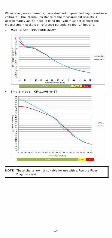
When taking measurements, use a standard ungrounded, high-resistance voltmeter. The internal resistance of the measurement sockets is approximately 30 kΩ. Keep in mind that you must not connect the measurement sockets or reference potential to the ICF housing.
• Multi-mode: ICF-1180I-M-ST
• Single-mode: ICF-1180I-S-ST
NOTE These charts are not suitable for use with a Remote Fiber Diagnosis test.
- 15 -
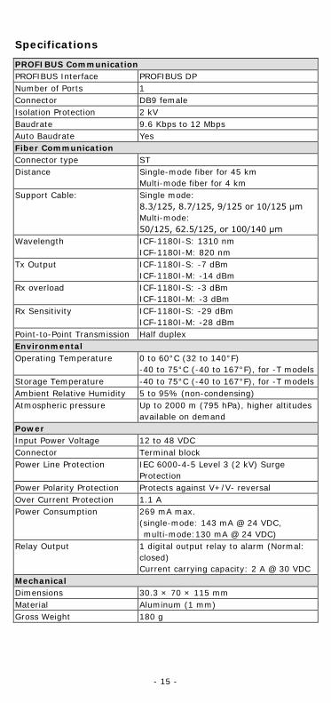
Specifications
PROFIBUS Communication PROFIBUS Interface PROFIBUS DP Number of Ports 1 Connector DB9 female Isolation Protection 2 kV Baudrate 9.6 Kbps to 12 Mbps Auto Baudrate Yes Fiber Communication Connector type ST Distance Single-mode fiber for 45 km
Multi-mode fiber for 4 km Support Cable: Single mode:
8.3/125, 8.7/125, 9/125 or 10/125 μm Multi-mode: 50/125, 62.5/125, or 100/140 μm
Wavelength ICF-1180I-S: 1310 nm ICF-1180I-M: 820 nm
Tx Output ICF-1180I-S: -7 dBm ICF-1180I-M: -14 dBm
Rx overload ICF-1180I-S: -3 dBm ICF-1180I-M: -3 dBm
Rx Sensitivity ICF-1180I-S: -29 dBm ICF-1180I-M: -28 dBm
Point-to-Point Transmission Half duplex Environmental Operating Temperature 0 to 60°C (32 to 140°F)
-40 to 75°C (-40 to 167°F), for -T models Storage Temperature -40 to 75°C (-40 to 167°F), for -T models Ambient Relative Humidity 5 to 95% (non-condensing) Atmospheric pressure Up to 2000 m (795 hPa), higher altitudes
available on demand Power Input Power Voltage 12 to 48 VDC Connector Terminal block Power Line Protection IEC 6000-4-5 Level 3 (2 kV) Surge
Protection Power Polarity Protection Protects against V+/V- reversal Over Current Protection 1.1 A Power Consumption 269 mA max.
(single-mode: 143 mA @ 24 VDC, multi-mode:130 mA @ 24 VDC)
Relay Output 1 digital output relay to alarm (Normal: closed) Current carrying capacity: 2 A @ 30 VDC
Mechanical Dimensions 30.3 × 70 × 115 mm Material Aluminum (1 mm) Gross Weight 180 g

- 16 -
Regulatory Approvals Safety UL 508 Hazardous Location UL/cUL Class I, Division 2, Groups A, B, C, and D
DNV.2.4 (not suitable for installation on a bridge) ATEX Zone 2: Ex nA nC IIC T4 Gc IECEx: IECEx UL 14.0094X IEC 60079-0:2011 Ed.6 IEC 60079-15:2010 Ed.4
EMC CE; FCC Part 15, sub part B, Class A EMI EN 55022, Class A; EN 55024 EMS EN 61000-4-2 (ESD), Level 3, Criteria A
EN 61000-4-3 (RS), Level 3, Criteria A EN 61000-4-4 (EFT), Level 3, Criteria B EN 61000-4-5 (Surge), Level 3, Criteria B EN 61000-4-6 (CS), Level 3, Criteria B
Freefall IEC 60068-2-32 MTBF 792,085 hrs.