icem cfd 5.1 new features workshop 15 hybrid meshing of a simple hvac assembly
TRANSCRIPT
ICEM CFD 5.1 New Features
Workshop 15
Hybrid meshing of a simple HVAC assembly
ICEM CFD 5.1 New Features
Workshop
ANSYS ICEM CFD v5.1
October 1, 2004Inventory #002157
WS15-2© 2004 ANSYS, Inc.
Create a Project
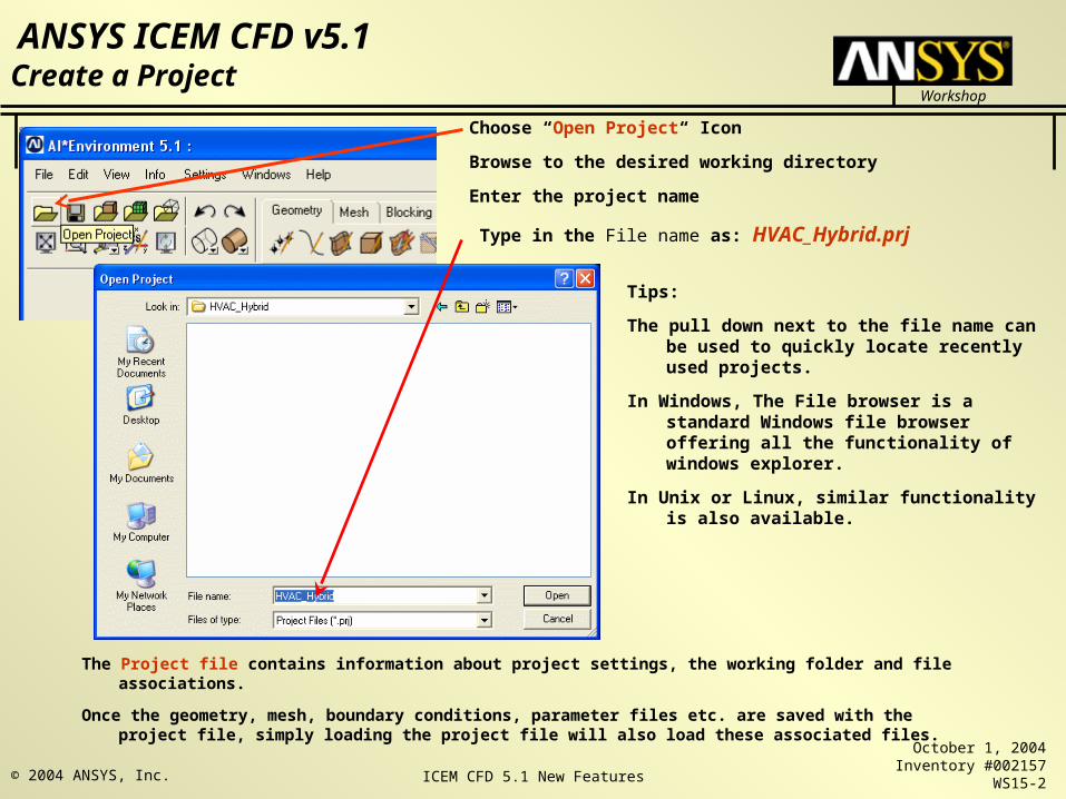
Choose “Open Project“ Icon
Browse to the desired working directory
Enter the project name
Type in the File name as: HVAC_Hybrid.prj
Tips:
The pull down next to the file name can be used to quickly locate recently used projects.
In Windows, The File browser is a standard Windows file browser offering all the functionality of windows explorer.
In Unix or Linux, similar functionality is also available.
The Project file contains information about project settings, the working folder and file associations.
Once the geometry, mesh, boundary conditions, parameter files etc. are saved with the project file, simply loading the project file will also load these associated files.
ICEM CFD 5.1 New Features
Workshop
ANSYS ICEM CFD v5.1
October 1, 2004Inventory #002157
WS15-3© 2004 ANSYS, Inc.
Open Geometry
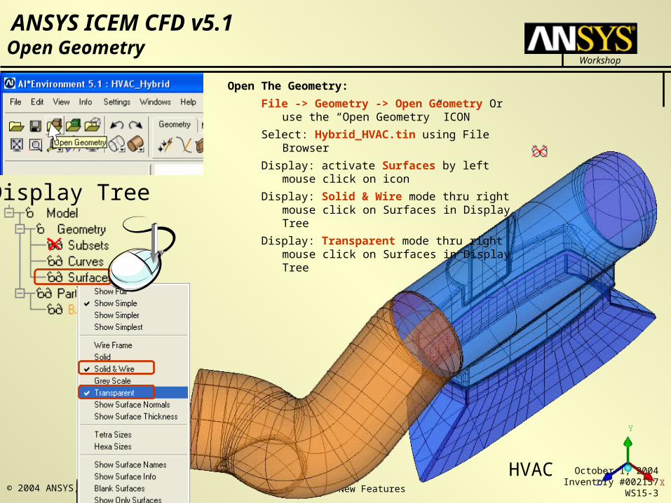
Open The Geometry:
File -> Geometry -> Open Geometry Or use the “Open Geometry” ICON
Select: Hybrid_HVAC.tin using File Browser
Display: activate Surfaces by left mouse click on icon
Display: Solid & Wire mode thru right mouse click on Surfaces in Display Tree
Display: Transparent mode thru right mouse click on Surfaces in Display Tree
Display Tree
HVAC
ICEM CFD 5.1 New Features
Workshop
ANSYS ICEM CFD v5.1
October 1, 2004Inventory #002157
WS15-4© 2004 ANSYS, Inc.
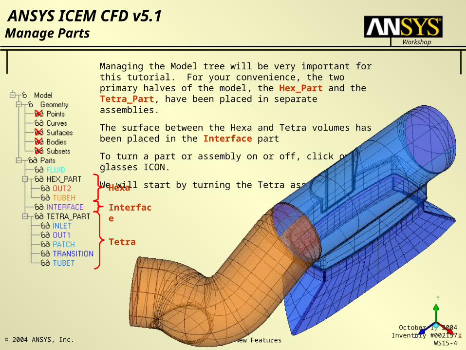
Managing the Model tree will be very important for this tutorial. For your convenience, the two primary halves of the model, the Hex_Part and the Tetra_Part, have been placed in separate assemblies.
The surface between the Hexa and Tetra volumes has been placed in the Interface part
To turn a part or assembly on or off, click on the glasses ICON.
We will start by turning the Tetra assembly OFF
Manage Parts
Hexa
Interface
Tetra
ICEM CFD 5.1 New Features
Workshop
ANSYS ICEM CFD v5.1
October 1, 2004Inventory #002157
WS15-5© 2004 ANSYS, Inc.
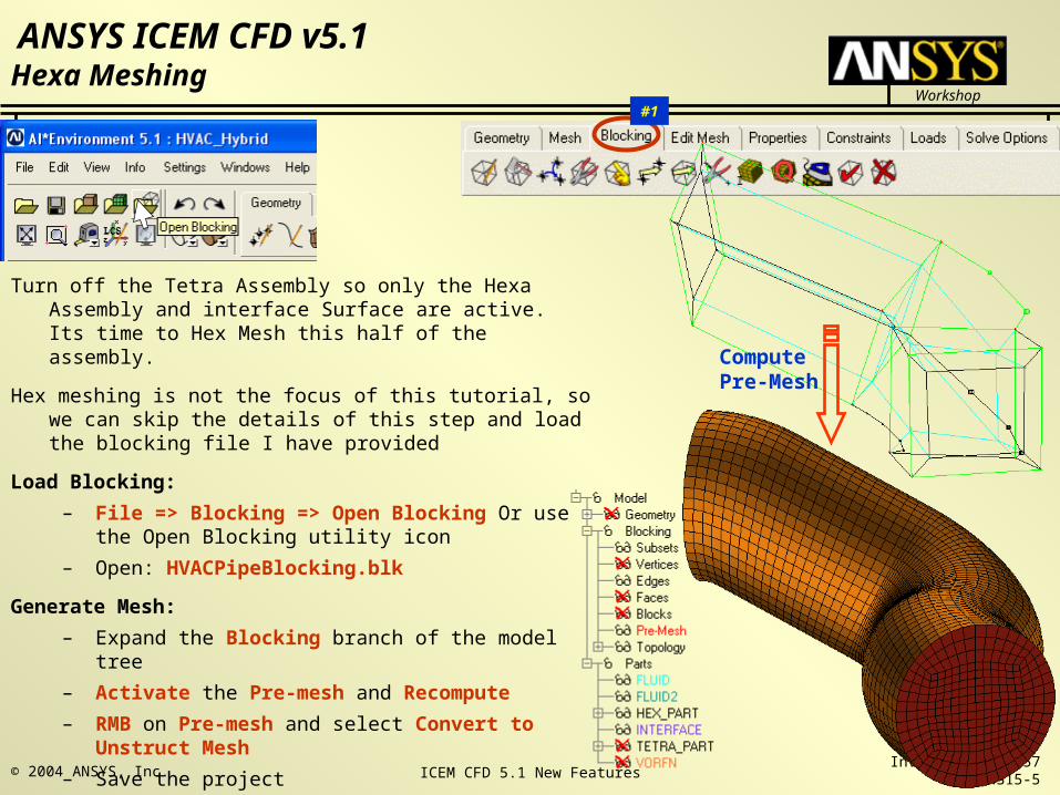
Turn off the Tetra Assembly so only the Hexa Assembly and interface Surface are active. Its time to Hex Mesh this half of the assembly.
Hex meshing is not the focus of this tutorial, so we can skip the details of this step and load the blocking file I have provided
Load Blocking:
– File => Blocking => Open Blocking Or use the Open Blocking utility icon
– Open: HVACPipeBlocking.blk
Generate Mesh:
– Expand the Blocking branch of the model tree
– Activate the Pre-mesh and Recompute
– RMB on Pre-mesh and select Convert to Unstruct Mesh
– Save the project
#1
Hexa Meshing
Compute Pre-Mesh
ICEM CFD 5.1 New Features
Workshop
ANSYS ICEM CFD v5.1
October 1, 2004Inventory #002157
WS15-6© 2004 ANSYS, Inc.
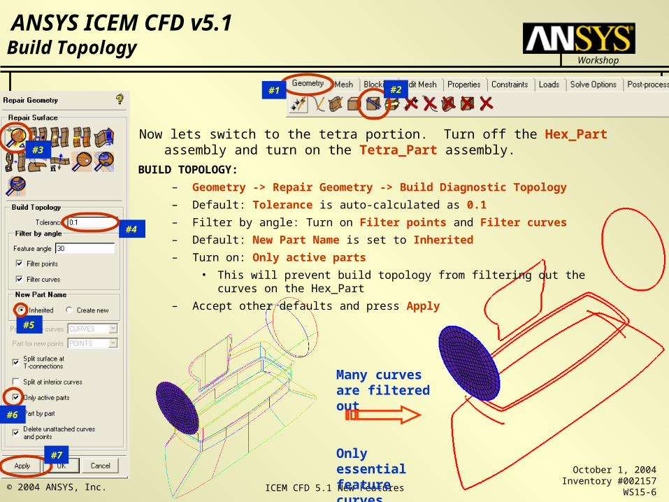
Many curves are filtered out
Only essential feature curves remain
Build Topology
BUILD TOPOLOGY:
– Geometry -> Repair Geometry -> Build Diagnostic Topology
– Default: Tolerance is auto-calculated as 0.1
– Filter by angle: Turn on Filter points and Filter curves
– Default: New Part Name is set to Inherited
– Turn on: Only active parts
• This will prevent build topology from filtering out the curves on the Hex_Part
– Accept other defaults and press Apply
#1 #2
#3
#5
#7
#4
#6
Now lets switch to the tetra portion. Turn off the Hex_Part assembly and turn on the Tetra_Part assembly.
ICEM CFD 5.1 New Features
Workshop
ANSYS ICEM CFD v5.1
October 1, 2004Inventory #002157
WS15-7© 2004 ANSYS, Inc.
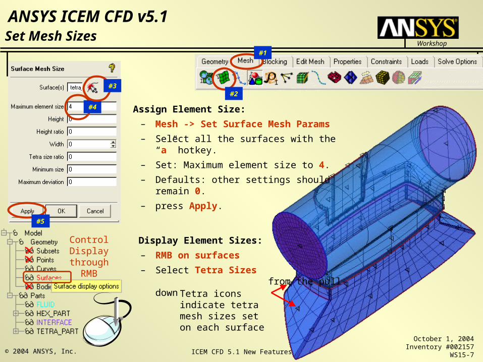
Assign Element Size:
– Mesh -> Set Surface Mesh Params
– Select all the surfaces with the “a” hotkey.
– Set: Maximum element size to 4.
– Defaults: other settings should remain 0.
– press Apply.
Display Element Sizes:
– RMB on surfaces
– Select Tetra Sizes from the pull-down
#1
#2
#5
#4
#3
Set Mesh Sizes
Control Display through
RMB
Tetra icons indicate tetra mesh sizes set on each surface
ICEM CFD 5.1 New Features
Workshop
ANSYS ICEM CFD v5.1
October 1, 2004Inventory #002157
WS15-8© 2004 ANSYS, Inc.
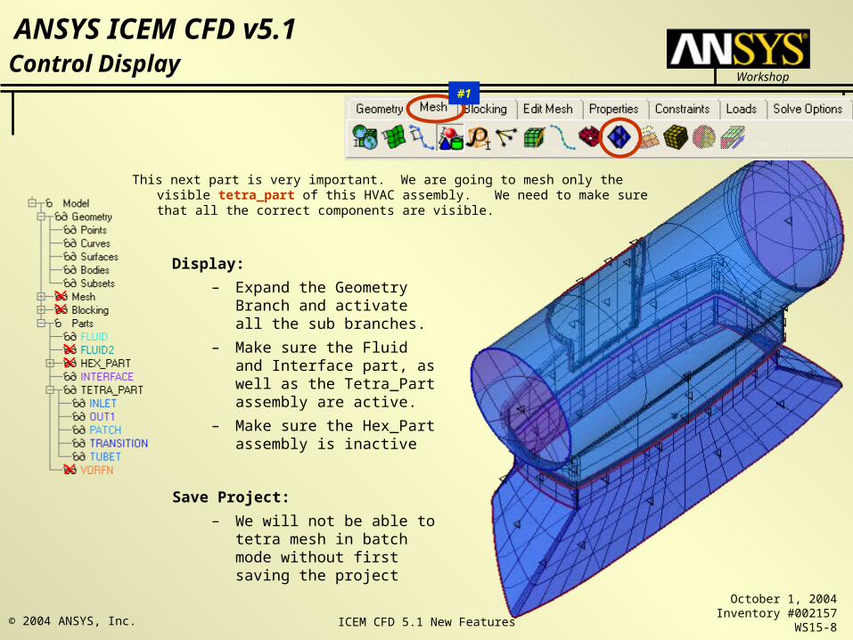
Display:
– Expand the Geometry Branch and activate all the sub branches.
– Make sure the Fluid and Interface part, as well as the Tetra_Part assembly are active.
– Make sure the Hex_Part assembly is inactive
Save Project:
– We will not be able to tetra mesh in batch mode without first saving the project
#1
Control Display
This next part is very important. We are going to mesh only the visible tetra_part of this HVAC assembly. We need to make sure that all the correct components are visible.
ICEM CFD 5.1 New Features
Workshop
ANSYS ICEM CFD v5.1
October 1, 2004Inventory #002157
WS15-9© 2004 ANSYS, Inc.
#1
#2
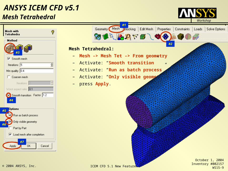
Mesh Tetrahedral
Mesh Tetrahedral:
– Mesh -> Mesh Tet -> From geometry
– Activate: “Smooth transition”
– Activate: “Run as batch process”
– Activate: “Only visible geometry”
– press Apply.
#3
#4
#6
#5
#7
ICEM CFD 5.1 New Features
Workshop
ANSYS ICEM CFD v5.1
October 1, 2004Inventory #002157
WS15-10© 2004 ANSYS, Inc.
#1
#2
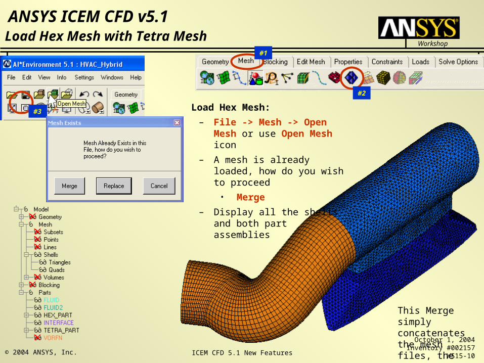
Load Hex Mesh with Tetra Mesh
Load Hex Mesh:
– File -> Mesh -> Open Mesh or use Open Mesh icon
– A mesh is already loaded, how do you wish to proceed
• Merge
– Display all the shells and both part assemblies
#3
This Merge simply concatenates the mesh files, the nodes are not connected
ICEM CFD 5.1 New Features
Workshop
ANSYS ICEM CFD v5.1
October 1, 2004Inventory #002157
WS15-11© 2004 ANSYS, Inc.
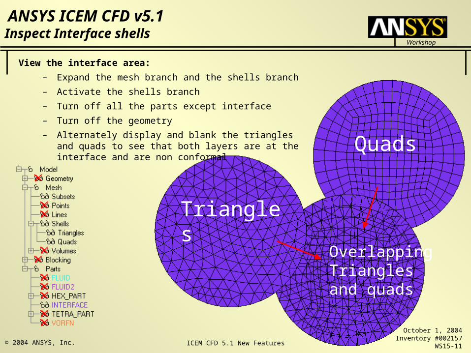
Inspect Interface shells
View the interface area:
– Expand the mesh branch and the shells branch
– Activate the shells branch
– Turn off all the parts except interface
– Turn off the geometry
– Alternately display and blank the triangles and quads to see that both layers are at the interface and are non conformal
Triangles
Overlapping Triangles and quads
Quads
ICEM CFD 5.1 New Features
Workshop
ANSYS ICEM CFD v5.1
October 1, 2004Inventory #002157
WS15-12© 2004 ANSYS, Inc.
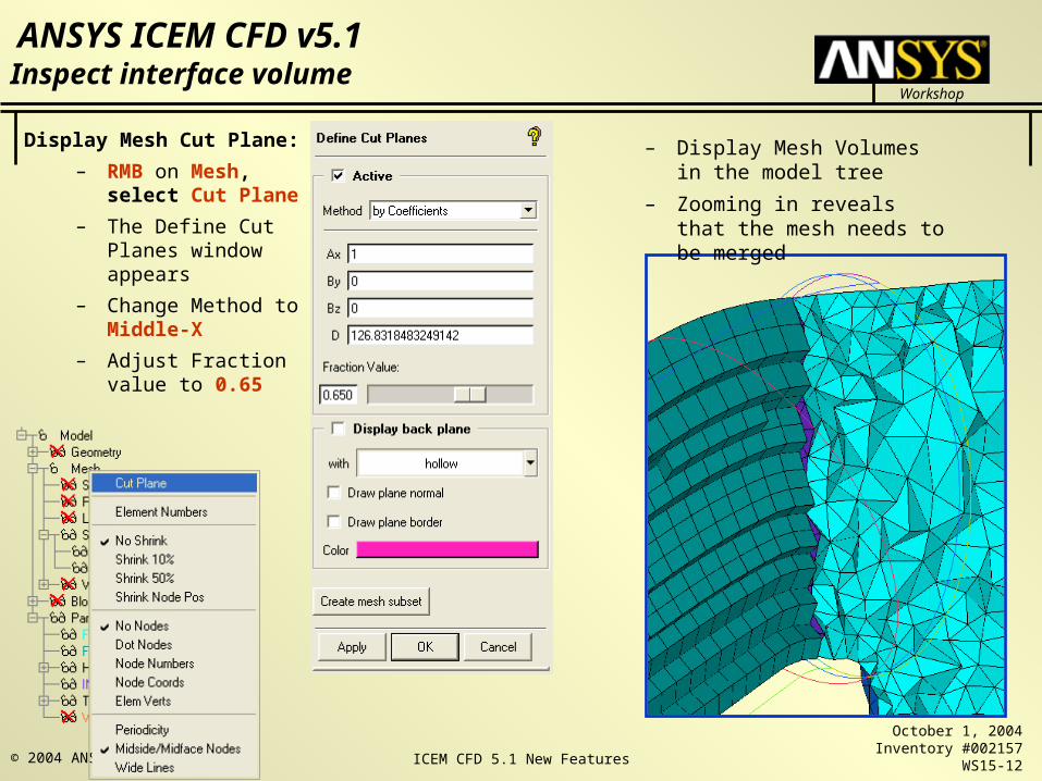
Inspect interface volume
Display Mesh Cut Plane:
– RMB on Mesh, select Cut Plane
– The Define Cut Planes window appears
– Change Method to Middle-X
– Adjust Fraction value to 0.65
– Display Mesh Volumes in the model tree
– Zooming in reveals that the mesh needs to be merged
ICEM CFD 5.1 New Features
Workshop
ANSYS ICEM CFD v5.1
October 1, 2004Inventory #002157
WS15-13© 2004 ANSYS, Inc.
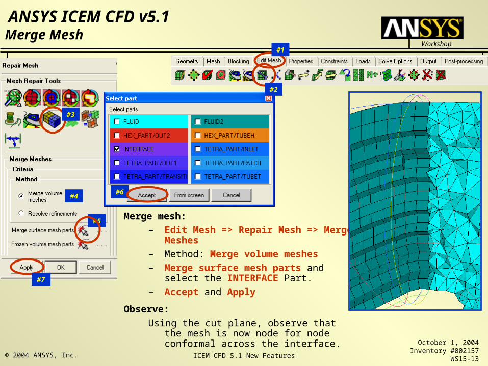
Merge mesh:
– Edit Mesh => Repair Mesh => Merge Meshes
– Method: Merge volume meshes
– Merge surface mesh parts and select the INTERFACE Part.
– Accept and Apply
Observe:
Using the cut plane, observe that the mesh is now node for node conformal across the interface.
#2
#1
#4
#3#3
#5
Merge Mesh
#7
#6
ICEM CFD 5.1 New Features
Workshop
ANSYS ICEM CFD v5.1
October 1, 2004Inventory #002157
WS15-14© 2004 ANSYS, Inc.
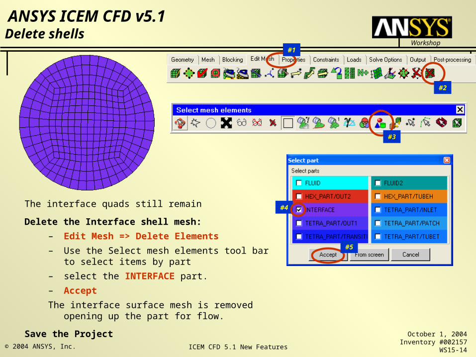
The interface quads still remain
Delete the Interface shell mesh:
– Edit Mesh => Delete Elements
– Use the Select mesh elements tool bar to select items by part
– select the INTERFACE part.
– Accept
The interface surface mesh is removed opening up the part for flow.
Save the Project
#2
#1
#4
#3#3
#5
Delete shells

ICEM CFD 5.1 New Features
Workshop
ANSYS ICEM CFD v5.1
October 1, 2004Inventory #002157
WS15-15© 2004 ANSYS, Inc.
Add Prism Layers:
– Mesh => Mesh Prism
– Name the New volume part “Prism”
• Normally, leave this blank and the prisms will inherit their volume part from the original volume
– Select parts to mesh
• From the popup, select all the parts except the inlet, outlets and interface
• Leave the other fields blank
• Accept
– Set: Initial height to 0.6
– Default: Height ratio of 1.2
– Set: Number of layers to 2
– Compute Params to calculate total height
– Accept the other defaults
– Apply
– Load the Prism Mesh!
#2
#1
#4
#3#3
#5
Mesh Prism
#6
#7
#8
ICEM CFD 5.1 New Features
Workshop
ANSYS ICEM CFD v5.1
October 1, 2004Inventory #002157
WS15-16© 2004 ANSYS, Inc.
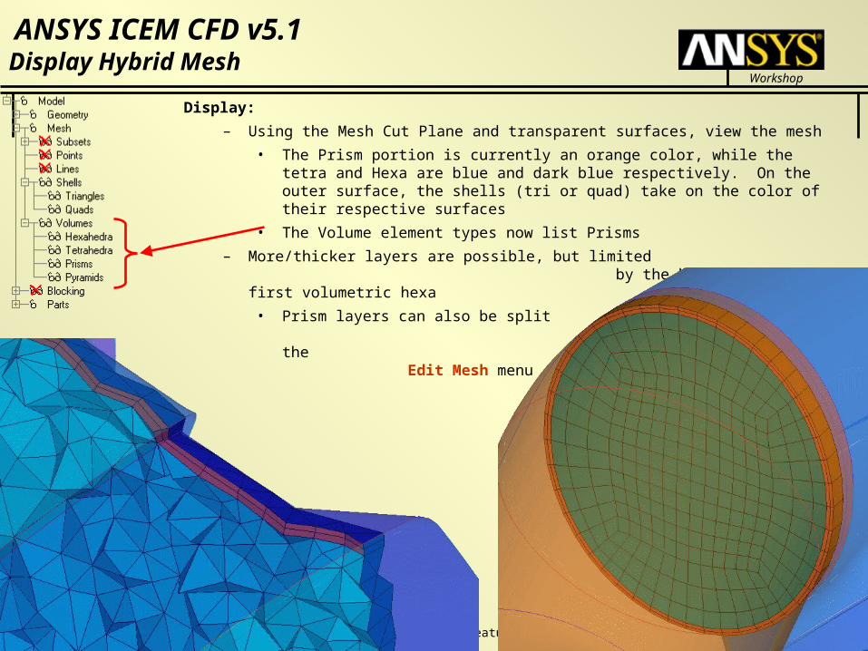
Display:
– Using the Mesh Cut Plane and transparent surfaces, view the mesh
• The Prism portion is currently an orange color, while the tetra and Hexa are blue and dark blue respectively. On the outer surface, the shells (tri or quad) take on the color of their respective surfaces
• The Volume element types now list Prisms
– More/thicker layers are possible, but limited by the height of the first volumetric hexa
• Prism layers can also be split and redistributed from the Edit Mesh menu
Display Hybrid Mesh
ICEM CFD 5.1 New Features
Workshop
ANSYS ICEM CFD v5.1
October 1, 2004Inventory #002157
WS15-17© 2004 ANSYS, Inc.
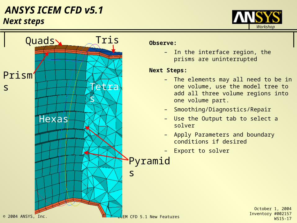
Observe:
– In the interface region, the prisms are uninterrupted
Next Steps:
– The elements may all need to be in one volume, use the model tree to add all three volume regions into one volume part.
– Smoothing/Diagnostics/Repair
– Use the Output tab to select a solver
– Apply Parameters and boundary conditions if desired
– Export to solver
Next steps
Hexas
TetrasPrisms
Quads Tris
Pyramids