icc.1:2004-10 international color consortium · ©icc 2004 – all rights reserved i icc.1:2004-10...
TRANSCRIPT

© ICC 2004 – All rights reserved i
ICC.1:2004-10
International Color Consortium®
SpecificationICC.1:2004-10
(Profile version 4.2.0.0)
Image technology colour management — Architecture, profile format, and data structure
[REVISION of ICC.1:2003-09]
With errata incorporated, 5/22/2006

ICC.1:2004-10
ii © ICC 2004 – All rights reserved
Copyright notice
Copyright © 2004 International Color Consortium®
Permission is hereby granted, free of charge, to any person obtaining a copy of this Specification (the “Specifi-cation”) to exploit the Specification without restriction including, without limitation, the rights to use, copy, mod-ify, merge, publish, distribute, and/or sublicense, copies of the Specification, and to permit persons to whom the Specification is furnished to do so, subject to the following conditions:
Elements of this Specification may be the subject of intellectual property rights of third parties throughout the world including, without limitation, patents, patent application, utility, models, copyrights, trade secrets or other proprietary rights (“Third Party IP Rights”). Although no Third Party IP Rights have been brought to the atten-tion of the International Color Consortium (the “ICC”) by its members, or as a result of the publication of this Specification in certain trade journals, the ICC has not conducted any independent investigation regarding the existence of Third Party IP Rights. The ICC shall not be held responsible for identifying Third Party IP Rights that may be implicated by the practice of this Specification or the permissions granted above, for conducting inquiries into the applicability, existence, validity, or scope of any Third Party IP Rights that are brought to the ICC’s attention, or for obtaining licensing assurances with respect to any Third Party IP Rights.
THE SPECIFICATION IS PROVIDED "AS IS", WITHOUT WARRANTY OF ANY KIND, EXPRESS, IMPLIED, OR OTHERWISE INCLUDING, BUT NOT LIMITED TO, WARRANTIES OF MERCHANTABILITY, FITNESS FOR A PARTICULAR PURPOSE, NONINFRINGEMENT, QUIET ENJOYMENT, SYSTEM INTEGRATION, AND DATA ACCURACY. IN NO EVENT SHALL THE ICC BE LIABLE FOR ANY CLAIM, DAMAGES, LOSSES, EXPENSES OR OTHER LIABILITY, WHETHER IN AN ACTION OF CONTRACT, TORT OR OTH-ERWISE, CAUSED BY, ARISING OR RESULTING FROM, OR THAT RELATE TO THE SPECIFICATION OR THE PRACTICE OR OTHER EXPLOITATION OF THE SPECIFICATION. FURTHER, YOU HEREBY AGREE TO DEFEND, INDEMNIFY AND HOLD HARMLESS THE ICC, AND ITS DIRECTORS AND EMPLOYEES, FROM AND AGAINST ANY AND ALL THIRD PARTY CLAIMS, ACTIONS SUITS, DAMAGES, LOSSES, COSTS, EXPENSES, OR OTHER LIABILITIES (INCLUDING REASONABLE ATTORNEY'S FEES AND EXPENSES) THAT WERE CAUSED BY, ARISE OR RESULT FROM, OR RELATE TO, YOUR PRACTICE OR OTHER EXPLOITATION OF THE SPECIFICATION (INCLUDING, WITHOUT LIMITATION, CLAIMS OF INFRINGEMENT).
The above copyright notice, permission, and conditions and disclaimers shall be included in all copies of any material portion of the Specification. Except as contained in this statement, the name “International Color Con-sortium” shall not be used in advertising or otherwise to promote the use or other dealings in this Specification without prior written authorization from the ICC.
Licenses and trademarks
International Color Consortium and the ICC logo are registered trademarks of the International Color Consor-tium.
Rather than put a trademark symbol in every occurrence of other trademarked names, we state that we are using the names only in an editorial fashion, and to the benefit of the trademark owner, with no intention of infringement of the trademark.
For additional information on the ICC
Visit the ICC Web site: http://www.color.org
ICC.1:2004-10
Contents Page
Foreword. . . . . . . . . . . . . . . . . . . . . . . . . . . . . . . . . . . . . . . . . . . . . . . . . . . . . . . . . . . . . . . . . . . . . . . . . . . . . . v
Introduction . . . . . . . . . . . . . . . . . . . . . . . . . . . . . . . . . . . . . . . . . . . . . . . . . . . . . . . . . . . . . . . . . . . . . . . . . . . vi
1 Scope . . . . . . . . . . . . . . . . . . . . . . . . . . . . . . . . . . . . . . . . . . . . . . . . . . . . . . . . . . . . . . . . . . . . . . . . . . . . . . 1
2 Conformance and registration. . . . . . . . . . . . . . . . . . . . . . . . . . . . . . . . . . . . . . . . . . . . . . . . . . . . . . . . . . 1
3 Normative references . . . . . . . . . . . . . . . . . . . . . . . . . . . . . . . . . . . . . . . . . . . . . . . . . . . . . . . . . . . . . . . . . 1
4 Terms and definitions. . . . . . . . . . . . . . . . . . . . . . . . . . . . . . . . . . . . . . . . . . . . . . . . . . . . . . . . . . . . . . . . . 2
5 Basic numeric types and abbreviations . . . . . . . . . . . . . . . . . . . . . . . . . . . . . . . . . . . . . . . . . . . . . . . . . . 45.1 Basic number types. . . . . . . . . . . . . . . . . . . . . . . . . . . . . . . . . . . . . . . . . . . . . . . . . . . . . . . . . . . . . . . . . 45.2 Abbreviations . . . . . . . . . . . . . . . . . . . . . . . . . . . . . . . . . . . . . . . . . . . . . . . . . . . . . . . . . . . . . . . . . . . . . . 7
6 Profile connection space and rendering intents . . . . . . . . . . . . . . . . . . . . . . . . . . . . . . . . . . . . . . . . . . . 86.1 Introduction . . . . . . . . . . . . . . . . . . . . . . . . . . . . . . . . . . . . . . . . . . . . . . . . . . . . . . . . . . . . . . . . . . . . . . . 86.2 Rendering intents . . . . . . . . . . . . . . . . . . . . . . . . . . . . . . . . . . . . . . . . . . . . . . . . . . . . . . . . . . . . . . . . . . 86.3 Profile connection space . . . . . . . . . . . . . . . . . . . . . . . . . . . . . . . . . . . . . . . . . . . . . . . . . . . . . . . . . . . 106.4 Converting between CIEXYZ and CIELAB encodings . . . . . . . . . . . . . . . . . . . . . . . . . . . . . . . . . . . . 13
7 Profile requirements . . . . . . . . . . . . . . . . . . . . . . . . . . . . . . . . . . . . . . . . . . . . . . . . . . . . . . . . . . . . . . . . . 137.1 General . . . . . . . . . . . . . . . . . . . . . . . . . . . . . . . . . . . . . . . . . . . . . . . . . . . . . . . . . . . . . . . . . . . . . . . . . . 137.2 Profile header . . . . . . . . . . . . . . . . . . . . . . . . . . . . . . . . . . . . . . . . . . . . . . . . . . . . . . . . . . . . . . . . . . . . . 157.3 Tag table . . . . . . . . . . . . . . . . . . . . . . . . . . . . . . . . . . . . . . . . . . . . . . . . . . . . . . . . . . . . . . . . . . . . . . . . . 207.4 Tag data . . . . . . . . . . . . . . . . . . . . . . . . . . . . . . . . . . . . . . . . . . . . . . . . . . . . . . . . . . . . . . . . . . . . . . . . . 21
8 Required tags . . . . . . . . . . . . . . . . . . . . . . . . . . . . . . . . . . . . . . . . . . . . . . . . . . . . . . . . . . . . . . . . . . . . . . 218.1 Overview . . . . . . . . . . . . . . . . . . . . . . . . . . . . . . . . . . . . . . . . . . . . . . . . . . . . . . . . . . . . . . . . . . . . . . . . . 218.2 Common requirements . . . . . . . . . . . . . . . . . . . . . . . . . . . . . . . . . . . . . . . . . . . . . . . . . . . . . . . . . . . . . 218.3 Input profiles . . . . . . . . . . . . . . . . . . . . . . . . . . . . . . . . . . . . . . . . . . . . . . . . . . . . . . . . . . . . . . . . . . . . . 228.4 Display profiles . . . . . . . . . . . . . . . . . . . . . . . . . . . . . . . . . . . . . . . . . . . . . . . . . . . . . . . . . . . . . . . . . . . 238.5 Output profiles . . . . . . . . . . . . . . . . . . . . . . . . . . . . . . . . . . . . . . . . . . . . . . . . . . . . . . . . . . . . . . . . . . . . 248.6 DeviceLink profile . . . . . . . . . . . . . . . . . . . . . . . . . . . . . . . . . . . . . . . . . . . . . . . . . . . . . . . . . . . . . . . . . 258.7 ColorSpace conversion profile. . . . . . . . . . . . . . . . . . . . . . . . . . . . . . . . . . . . . . . . . . . . . . . . . . . . . . . 268.8 Abstract profile . . . . . . . . . . . . . . . . . . . . . . . . . . . . . . . . . . . . . . . . . . . . . . . . . . . . . . . . . . . . . . . . . . . 268.9 Named colour profile . . . . . . . . . . . . . . . . . . . . . . . . . . . . . . . . . . . . . . . . . . . . . . . . . . . . . . . . . . . . . . . 268.10 Priority of tag usage . . . . . . . . . . . . . . . . . . . . . . . . . . . . . . . . . . . . . . . . . . . . . . . . . . . . . . . . . . . . . . 27
9 Tag definitions . . . . . . . . . . . . . . . . . . . . . . . . . . . . . . . . . . . . . . . . . . . . . . . . . . . . . . . . . . . . . . . . . . . . . 279.1 General . . . . . . . . . . . . . . . . . . . . . . . . . . . . . . . . . . . . . . . . . . . . . . . . . . . . . . . . . . . . . . . . . . . . . . . . . . 279.2 Tag listing . . . . . . . . . . . . . . . . . . . . . . . . . . . . . . . . . . . . . . . . . . . . . . . . . . . . . . . . . . . . . . . . . . . . . . . . 27
10 Tag type definitions . . . . . . . . . . . . . . . . . . . . . . . . . . . . . . . . . . . . . . . . . . . . . . . . . . . . . . . . . . . . . . . . 3610.1 Overview . . . . . . . . . . . . . . . . . . . . . . . . . . . . . . . . . . . . . . . . . . . . . . . . . . . . . . . . . . . . . . . . . . . . . . . . 3610.2 chromaticityType . . . . . . . . . . . . . . . . . . . . . . . . . . . . . . . . . . . . . . . . . . . . . . . . . . . . . . . . . . . . . . . . . 3710.3 colorantOrderType. . . . . . . . . . . . . . . . . . . . . . . . . . . . . . . . . . . . . . . . . . . . . . . . . . . . . . . . . . . . . . . . 3710.4 colorantTableType . . . . . . . . . . . . . . . . . . . . . . . . . . . . . . . . . . . . . . . . . . . . . . . . . . . . . . . . . . . . . . . . 3810.5 curveType . . . . . . . . . . . . . . . . . . . . . . . . . . . . . . . . . . . . . . . . . . . . . . . . . . . . . . . . . . . . . . . . . . . . . . . 3910.6 dataType . . . . . . . . . . . . . . . . . . . . . . . . . . . . . . . . . . . . . . . . . . . . . . . . . . . . . . . . . . . . . . . . . . . . . . . . 3910.7 dateTimeType. . . . . . . . . . . . . . . . . . . . . . . . . . . . . . . . . . . . . . . . . . . . . . . . . . . . . . . . . . . . . . . . . . . . 4010.8 lut16Type . . . . . . . . . . . . . . . . . . . . . . . . . . . . . . . . . . . . . . . . . . . . . . . . . . . . . . . . . . . . . . . . . . . . . . . 4010.9 lut8Type . . . . . . . . . . . . . . . . . . . . . . . . . . . . . . . . . . . . . . . . . . . . . . . . . . . . . . . . . . . . . . . . . . . . . . . . 4410.10 lutAtoBType . . . . . . . . . . . . . . . . . . . . . . . . . . . . . . . . . . . . . . . . . . . . . . . . . . . . . . . . . . . . . . . . . . . . 4610.11 lutBtoAType . . . . . . . . . . . . . . . . . . . . . . . . . . . . . . . . . . . . . . . . . . . . . . . . . . . . . . . . . . . . . . . . . . . . 4910.12 measurementType . . . . . . . . . . . . . . . . . . . . . . . . . . . . . . . . . . . . . . . . . . . . . . . . . . . . . . . . . . . . . . . 5210.13 multiLocalizedUnicodeType . . . . . . . . . . . . . . . . . . . . . . . . . . . . . . . . . . . . . . . . . . . . . . . . . . . . . . . 5310.14 namedColor2Type . . . . . . . . . . . . . . . . . . . . . . . . . . . . . . . . . . . . . . . . . . . . . . . . . . . . . . . . . . . . . . . 5410.15 parametricCurveType . . . . . . . . . . . . . . . . . . . . . . . . . . . . . . . . . . . . . . . . . . . . . . . . . . . . . . . . . . . . 55
© ICC 2004 – All rights reserved iii
ICC.1:2004-10
10.16 profileSequenceDescType . . . . . . . . . . . . . . . . . . . . . . . . . . . . . . . . . . . . . . . . . . . . . . . . . . . . . . . . 5710.17 responseCurveSet16Type . . . . . . . . . . . . . . . . . . . . . . . . . . . . . . . . . . . . . . . . . . . . . . . . . . . . . . . . . 5710.18 s15Fixed16ArrayType . . . . . . . . . . . . . . . . . . . . . . . . . . . . . . . . . . . . . . . . . . . . . . . . . . . . . . . . . . . . 6010.19 signatureType. . . . . . . . . . . . . . . . . . . . . . . . . . . . . . . . . . . . . . . . . . . . . . . . . . . . . . . . . . . . . . . . . . . 6010.20 textType . . . . . . . . . . . . . . . . . . . . . . . . . . . . . . . . . . . . . . . . . . . . . . . . . . . . . . . . . . . . . . . . . . . . . . . 6010.21 u16Fixed16ArrayType . . . . . . . . . . . . . . . . . . . . . . . . . . . . . . . . . . . . . . . . . . . . . . . . . . . . . . . . . . . . 6110.22 uInt16ArrayType. . . . . . . . . . . . . . . . . . . . . . . . . . . . . . . . . . . . . . . . . . . . . . . . . . . . . . . . . . . . . . . . . 6110.23 uInt32ArrayType. . . . . . . . . . . . . . . . . . . . . . . . . . . . . . . . . . . . . . . . . . . . . . . . . . . . . . . . . . . . . . . . . 6110.24 uInt64ArrayType. . . . . . . . . . . . . . . . . . . . . . . . . . . . . . . . . . . . . . . . . . . . . . . . . . . . . . . . . . . . . . . . . 6210.25 uInt8ArrayType. . . . . . . . . . . . . . . . . . . . . . . . . . . . . . . . . . . . . . . . . . . . . . . . . . . . . . . . . . . . . . . . . . 6210.26 viewingConditionsType. . . . . . . . . . . . . . . . . . . . . . . . . . . . . . . . . . . . . . . . . . . . . . . . . . . . . . . . . . . 6210.27 XYZType . . . . . . . . . . . . . . . . . . . . . . . . . . . . . . . . . . . . . . . . . . . . . . . . . . . . . . . . . . . . . . . . . . . . . . . 63
Annex A (informative) Colour spaces . . . . . . . . . . . . . . . . . . . . . . . . . . . . . . . . . . . . . . . . . . . . . . . . . . . . . 64
Annex B (normative) Embedding profiles . . . . . . . . . . . . . . . . . . . . . . . . . . . . . . . . . . . . . . . . . . . . . . . . . 67
Annex C (informative) Relationship between ICC profiles and PostScript CSAs and CRDs. . . . . . . . . 71
Annex D (informative) Profile Connection Space . . . . . . . . . . . . . . . . . . . . . . . . . . . . . . . . . . . . . . . . . . . 73
Annex E (informative) Chromatic adaptation tag. . . . . . . . . . . . . . . . . . . . . . . . . . . . . . . . . . . . . . . . . . . . 86
Annex F (normative) Profile computational models . . . . . . . . . . . . . . . . . . . . . . . . . . . . . . . . . . . . . . . . . 89
Annex G (informative) Tables of required tags and tag list . . . . . . . . . . . . . . . . . . . . . . . . . . . . . . . . . . . 91
Bibliography . . . . . . . . . . . . . . . . . . . . . . . . . . . . . . . . . . . . . . . . . . . . . . . . . . . . . . . . . . . . . . . . . . . . . . . . . . 97
iv © ICC 2004 – All rights reserved

© ICC 2004 – All rights reserved v
ICC.1:2004-10
Foreword
The International Color Consortium was formed with the primary intent of developing and administering a profile format standard, and for the registration of tag signatures and descriptions. The founding members of this consortium were: Adobe Systems Inc., Agfa-Gevaert N.V., Apple Computer, Inc., Eastman Kodak Company, FOGRA (Honorary), Microsoft Corporation, Silicon Graphics, Inc., Sun Microsystems, Inc., and Taligent, Inc. These companies committed to fully support the standard in their operating systems, platforms and applications. The consortium has since been expanded and now has over 60 members.
In 2003 the ICC entered into a “Co-operative Agreement between ISO/TC130 and the International Color Consortium” which established the detailed procedures whereby ISO/TC130 (Graphic technology) and the International Color Consortium (ICC) will cooperate to continue the development of a series of ISO standards based on the work of the ICC, including the ICC Profile Specification.
The initial version of the standard developed by the consortium has undergone various revisions and it was agreed by the ICC that this revision, ICC.1:2004-08, should be the first to be proposed as an International Standard under the Cooperative Agreement. The ISO version, whose technical content is identical to this document, is ISO 15076-1 Image technology colour management — Architecture, profile format, and data structure — Part 1: Based on ICC.1:2004-08.
Profiles created in compliance with this specification are identified as Version 4.2.0.0 profiles.

ICC.1:2004-10
Introduction
0.1 General
This International Standard specifies the profile format defined by the International Color Consortium® (ICC). The intent of this format is to provide a cross-platform device profile format. Such device profiles can be used to translate colour data created on one device into another device’s native colour space. The acceptance of this format by operating system vendors allows end users to transparently move profiles and images with embedded profiles between different operating systems. For example, this allows a printer manufacturer to create a single profile for multiple operating systems.
It is assumed that the reader has a nominal understanding of colour science, such as familiarity with the CIELAB colour space, general knowledge of device characterizations, and familiarity with at least one operating system level colour management system.
0.2 International Color Consortium
The International Color Consortium was formed with the primary intent of developing and administering a profile format standard, and for the registration of tag signatures and descriptions. The founding members of this consortium were: Adobe Systems Inc., Agfa-Gevaert N.V., Apple Computer, Inc., Eastman Kodak Company, FOGRA (Honorary), Microsoft Corporation, Silicon Graphics, Inc., Sun Microsystems, Inc., and Taligent, Inc. These companies committed to fully support the standard in their operating systems, platforms and applications. The consortium has since been expanded and now has over 60 members.
The initial version of the standard developed by the consortium has undergone various revisions and it was agreed by ICC that its revision 4.2 should be proposed as an International Standard. It is that revision which has formed the basis of this International Standard. The ICC will continue to administer its own version of the document and, if enhancements are made, they will be seriously considered for future revisions of this International Standard. ISO TC130 will work to ensure that there are no significant differences between the ICC and ISO versions of the document.
The ICC web site (www.color.org) provides supplementary information relevant to this International Standard and additional resources for developers and users. It also provides information on how to become a member of ICC.
0.3 Colour Management Architecture and Profile Connection Space
The underlying architecture assumed in this International Standard is based around a reference colour space that is unambiguously defined. The colour specification method selected was that defined by CIE which is internationally accepted. The CIE system enables a set of tristimulus values (XYZ) to be specified for a coloured stimulus. These tristimulus values enable a user to determine whether colours match, and the degree of mis-match between any that do not. It follows that it is possible to define the colour of a sample by these tristimulus values (or some defined transformation of them) for matching by colour reproduction.
Calculation of the XYZ values for transmitting or reflecting media is achieved from the spectral sum-product of the reflectance or transmittance of the sample, the relative spectral power distribution of the illuminant used to view it and the 'sensitivity' of the standard observer. However, as CIE defines two standard observers, two measurement geometries (for reflecting media) and a large number of illuminants, it is necessary to restrict these options in order to have a system that is not ambiguous for a particular application. For this International Standard ICC have defined such a restriction, based on ISO 13655:1996, Graphic Technology - Spectral measurement and colorimetric calculation for graphic arts images, and the resultant colour space is known as the Profile Connection Space (PCS). Furthermore, the simple CIE system (whether XYZ or the CIELAB values derived from them) does not accommodate the effect of surrounding stimuli to the sample being measured (which can be different for various types of media) or the level of illumination. Both of these affect appearance so the PCS values do not by themselves specify appearance. To overcome this problem the PCS is used in two different ways. The first simply describes the colorimetry of actual originals and their reproductions through the colorimetric rendering intents. The second, which describes the colorimetry of an image colour rendered to a
vi © ICC 2004 – All rights reserved

ICC.1:2004-10
standard reference medium under a specified viewing condition, is employed for the perceptual rendering intent. Thus it may incorporate corrections for appearance, and other desired rendering effects, as well as accommodating differences between the device and the reference PCS dynamic range. When required the viewing conditions may be specified to allow appearance to be determined for the colorimetric rendering intents.
So, in summary, the PCS is based on XYZ (or CIELAB) determined for a specific observer (CIE Standard 1931 Colorimetric Observer - often known colloquially as the 2 degree observer), relative to a specific illuminant (D50 - a chromatic adaptation transform is used if necessary), and measured with a specified measurement geometry (0o/45o or 45o/0o), for reflecting media. Measurement procedures are also defined for transmitting media. (Since the conversion from XYZ to CIELAB is quite unambiguous profile builders can use either, and the application is able to determine which has been used from a tag in the header).
For colorimetric renderings, where the measured data was not made relative to D50 the profile builder is expected to correct the data to achieve this. However a mechanism for identifying the chromatic adaptation used in such situations is provided. For the perceptual rendering intent the same viewing conditions are assumed, but an additional constraint is added in that a reference medium and illumination level is specified in order to provide a more robust mechanism for describing colour rendering (including gamut mapping). In the following paragraphs the reference colour space referred to should be taken to include the viewing conditions and reference medium when the perceptual intent is being considered. For the perceptual rendering intent profile builders are expected to undertake any corrections for appearance effects if the viewing conditions used for monitors and transmitting media (such as dark surrounds) differ from those typical for reflecting media.
Figure 1 shows how a reference colour space can be used to provide the common interface for colour specification between devices. Without it a separate transformation would be required for each pair of devices. If there are n devices in a system, and it is necessary to provide a transformation between each device and every other device, n2 transforms would need to be defined and n new transforms would need to be defined every time a new device is added. By use of a reference colour space only n transforms need be defined and only one new transform needs to be defined each time a new device is added.
Figure 1 — Use of a reference colour space
While images could be encoded directly in the reference colour space defined by the PCS this will not generally be the case. For precision reasons it is usually desirable to define the transformation between the device colour space and the PCS at a higher precision than the bit-depth of the image. So, the transformation between a device colour space and the PCS is usually defined at high precision. If this transformation is provided with any image file appropriate to that device it can be utilised when images are reproduced. By combining the profiles
© ICC 2004 – All rights reserved vii

ICC.1:2004-10
for the pair of devices for which image reproduction is required, using the common PCS as the interface as shown in Figure 1, appropriate colour reproduction is assured with a minimal loss of precision. In order that the transformation between the device colour space and the PCS can be interpreted by all applications it is important that it be defined in an open specification. The profile format defined in this International Standard provides that specification.
0.4 Rendering intents
In general, actual device colour gamuts will fail to match each other, and that of the reference medium, to varying degrees. Because of this mismatch, and because of the needs of different applications, four rendering intents (colour rendering styles) are defined in this specification. Each one represents a different colour reproduction compromise. The colorimetric rendering intents operate directly on measured colorimetric values, though possibly with correction for chromatic adaptation when the measured values were not calculated for the D50 PCS illuminant. The other rendering intents (perceptual and saturation) operate on colorimetric values which are corrected in an as-needed fashion to account for any differences between devices, media, and viewing conditions.
Two colorimetric rendering intents are specified in this International Standard, though only one is directly defined in the profile. The defined colorimetric intent (media-relative colorimetric intent) is based on media-relative colorimetry in which data is normalised relative to the media white point for reflecting and transmitting media. (Thus the media white will have the PCS CIELAB values (100, 0, 0)). However, because the profile is also required to contain the PCS values of the media white, relative to the perfect reflecting diffuser or transmitter under D50, it is possible for all the media-relative values to be re-calculated relative to these. When this is done the resultant rendering intent is known as the absolute colorimetric intent. The use of media-relative colorimetry enables colour reproductions to be defined which maintain highlight detail, while keeping the medium ‘white’, even when the original and reproduction media differ in colour. However, this procedure inevitably introduces some change in all colours in the reproduction. When an exact colour match is required for all within gamut colours the absolute colorimetric rendering intent will define this.
The colour rendering of the perceptual and saturation rendering intents is vendor specific. The former, which is useful for general reproduction of pictorial images, typically includes tone scale adjustments to map the dynamic range of one medium to that of another, and gamut warping to deal with gamut mismatches. The latter, which is useful for images which contain objects such as charts or diagrams, usually involves compromises such as trading off preservation of hue in order to preserve the vividness of pure colours.
For perceptual transforms it is desirable, in order to optimise colour rendering, to place some bounds on the colour gamut of the PCS values. For this reason a reference medium and reference viewing condition have been defined which apply only to the perceptual rendering. The reference medium is defined as a hypothetical print on a substrate with a white having a neutral reflectance of 89%, and a density range of 2,4593. The reference viewing condition is the P2 condition specified in ISO 3664 - Viewing conditions - for Photography and Graphic Technology, i.e. D50 at 500 lux for viewing reflecting media. A neutral surround, of 20% reflectance is assumed.
The choice of a reference medium with a realistic black point for the perceptual intent provides a well-defined aim when tonal remapping is required. Inputs with a dynamic range greater than a reflection print (for example, a slide film image, or the colorimetry of high-range scenes) can have their highlights and shadows smoothly compressed to the range of the print in such a way that these regions can be expanded again without undue loss of detail on output to wide-range media. Likewise, images from original media with limited dynamic range can be colour rendered to the expanded dynamic range of the reference medium, in order to ensure interoperability.
Profiles generally offer more than one transformation, each of which is applicable to a specific rendering intent. When the intent is selected the appropriate transformation is selected by the colour management application. The choice of rendering intent is highly dependent upon the intended use. In general the peceptual rendering intent is most applicable for the rendering of natural images, though not always. In particular, in a proofing environment - where the colour reproduction obtained on one device is simulated on another - colorimetric rendering is most appropriate.
viii © ICC 2004 – All rights reserved
ICC.1:2004-10
For those requiring further information an extended discussion of many of the issues described above is provided in Annex D.
0.5 Device profiles
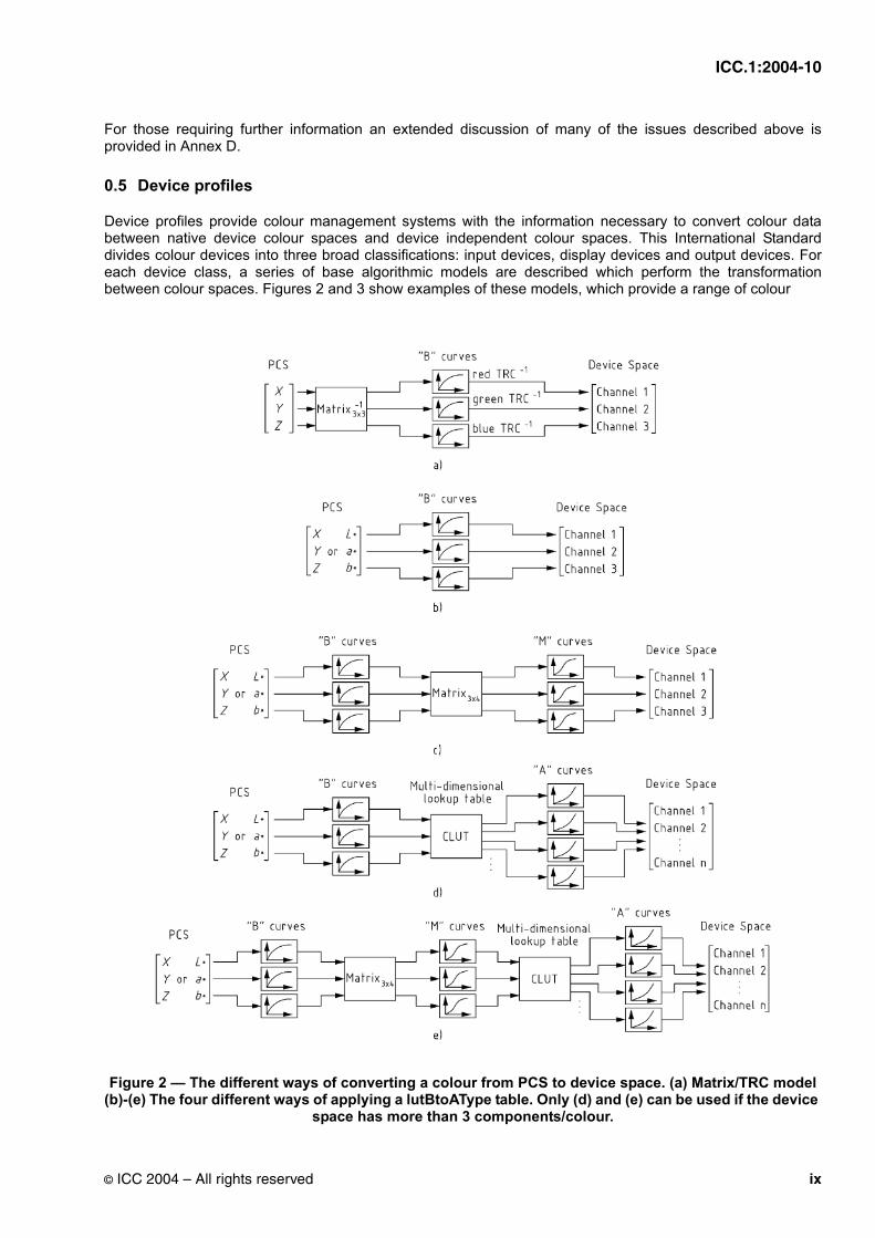
Device profiles provide colour management systems with the information necessary to convert colour data between native device colour spaces and device independent colour spaces. This International Standard divides colour devices into three broad classifications: input devices, display devices and output devices. For each device class, a series of base algorithmic models are described which perform the transformation between colour spaces. Figures 2 and 3 show examples of these models, which provide a range of colour
Figure 2 — The different ways of converting a colour from PCS to device space. (a) Matrix/TRC model (b)-(e) The four different ways of applying a lutBtoAType table. Only (d) and (e) can be used if the device
space has more than 3 components/colour.
© ICC 2004 – All rights reserved ix

ICC.1:2004-10
Figure 3 — Examples of converting a colour from device to PCS. (a) Matrix/TRC model (b)-(e) The four different ways of applying a lutAtoBType table. Only (d) and (e) can be used if the device space has
more than 3 components/colour.
quality and performance results. Each of the base models provides different trade-offs in memory footprint, performance and image quality. The necessary parameter data to implement these models is described in the appropriate tag type descriptions in clause 10. This required data provides the information for the colour management framework default colour management module (CMM) to transform colour information between native device colour spaces. A representative architecture using these components is illustrated in Figure 4.
x © ICC 2004 – All rights reserved

ICC.1:2004-10
.
Figure 4 — Colour management architecture
0.6 Profile element structure
The profile structure is defined as a header followed by a tag table followed by a series of tagged elements that can be accessed randomly and individually. This collection of tagged elements provides three levels of information for developers: required data, optional data and private data. An element tag table provides a table of contents for the tagging information in each individual profile. This table includes a tag signature, the beginning address offset and size of the data for each individual tagged element. Signatures in this International Standard are defined as a four-byte hexadecimal number. This tagging scheme allows developers to read in the element tag table and then randomly access and load into memory only the information necessary to their particular software application. Since some instances of profiles can be quite large, this provides significant savings in performance and memory. The detailed descriptions of the tags, along with their intent, are included later in this International Standard.
The required tags provide the complete set of information necessary for the default CMM to translate colour information between the Profile Connection Space and the native device space. Each profile class determines which combination of tags is required.
In addition to the required tags for each device profile, a number of optional tags are defined that can be used for enhanced colour transformations. Examples of these tags include PostScript Level 2 support, calibration support, and others. In the case of required and optional tags, all of the signatures, an algorithmic description (where appropriate), and intent are registered with the International Color Consortium. Private data tags allow CMM developers to add proprietary value to their profiles. By registering just the tag signature and tag type signature, developers are assured of maintaining their proprietary advantages while maintaining compatibility with this International Standard. However, since the overall philosophy of this format is to maintain an open, cross-platform standard, developers are encouraged to keep the use of private tags to an absolute minimum.
0.7 Embedded profiles
In addition to providing a cross-platform standard for the actual disk-based profile format, this International Standard also describes the convention for embedding these profiles within graphics documents and images. Embedded profiles allow users to transparently move colour data between different computers, networks and even operating systems without having to worry if the necessary profiles are present on the destination
© ICC 2004 – All rights reserved xi

ICC.1:2004-10
systems. The intention of embedded profiles is to allow the interpretation of the associated colour data. Embedding specifications are described in Annex B of this document.
0.8 Other profiles
Four profile types, in addition to the device profile types described above, are defined in this specification. DeviceLink profiles provide a dedicated transformation from one device space to another, which can be useful in situations where such a transformation is used frequently or has required optimisation to achieve specific objectives. (Figure 5 shows the various algorithmic models which may be used to construct a DeviceLink profile.) .
Figure 5 — Examples of converting a colour from device to device using a DeviceLink profile. (a) TRC model (b) Matrix/TRC model (c) CLUT, plus TRC model (d) CLUT, plus matrix, plus CRT model. Only (a),
(c) and (d) can be used if the device space has more than 3 components/colour.
ColorSpace conversion profiles provide a transformation between a non-device colour space and the PCS, which can prove useful in workflows in which reference colour spaces different from those selected by ICC are utilised. Abstract profiles are defined from PCS to PCS and enable colour transformations to be defined that
⎡⎢⎢⎢⎣
Channel 1Channel 2
...Channel n
⎤⎥⎥⎥⎦
Input Device Space⎡⎢⎢⎢⎣
Channel 1Channel 2
...Channel n
⎤⎥⎥⎥⎦
Output Device Space“B” curves
...(a)
Input Device Space
⎡⎣
Channel 1Channel 2Channel 3
⎤⎦
Output Device Space
“B” curves”M” curves
Matrix3×4
⎡⎣
Channel 1Channel 2Channel 3
⎤⎦
(b)
⎡⎢⎢⎢⎣
Channel 1Channel 2
...Channel n
⎤⎥⎥⎥⎦
Input Device Space
“A” curves
...
Multi-dimensionallookup table
CLUT
⎡⎢⎢⎢⎣
Channel 1Channel 2
...Channel m
⎤⎥⎥⎥⎦
Output Device Space“B” curves
...
(c)
⎡⎢⎢⎢⎣
Channel 1Channel 2
...Channel n
⎤⎥⎥⎥⎦
Input Device Space
⎡⎣
Channel 1Channel 2Channel 3
⎤⎦
Output Device Space“B” curves”M” curves“A” curves
...
Matrix3×4
Multi-dimensionallookup table
CLUT
(d)
xii © ICC 2004 – All rights reserved

ICC.1:2004-10
provide some specific colour effects. Named Colour profiles provide a mechanism for specifying the relationship between device values and the PCS for specific colours, rather than for general images
0.9 Organizational description of this Standard
This Standard addresses a very complex set of issues and the organization of this document strives to provide a clear, clean, and unambiguous explanation of the entire format. To accomplish this, the overall presentation is from a top-down perspective, beginning with the summary overview presented above, followed by the necessary background information and definitions needed for unambiguous interpretation of the text. A description of the Profile Connection Space and Rendering Intents is then provided before continuing down at increasing levels of detail into a byte stream description of the format. Clause 6 describes the Profile Connection Space and Rendering Intents; clause 7 describes the structure of the various fields required in a profile; and clause 8 describes the content of the required tags for each profile class. Clause 9 lists the various tag types (optional and required) and briefly summarises the function of the tag as well as listing the signature and allowed tag types for each. The tag types are defined in clause 10. Annex A provides additional information pertaining to the colour spaces and rendering intents used in this International Standard while Annex Bprovides the necessary details to embed profiles into PICT, EPS, TIFF, and JFIF files. Annex C provides a general description of the PostScript Level 2 tags used in this International Standard while Annex D provides some background material on the Profile Connection Space. Annex E provides additional information pertaining to Chromatic Adaptation and the chromaticAdaptationTag while Annex F describes some the computational models assumed in this International Standard. Annex G summarises in tabular form the required tags for each profile class as specified in clause 8.
0.10 Patent statement
The International Color Consortium (ICC) draws attention to the fact that it is claimed that compliance with this document may involve the use of a patent concerning the outputResponseTag, (support of the outputResponseTag is optional), given in subclause 9.2.27. ICC takes no position concerning the evidence, validity and scope of this patent right. Eastman Kodak Company, the holder of this patent right has assured the ICC that he/she is willing to negotiate licences under reasonable and non-discriminatory terms and conditions with applicants throughout the world. In this respect, the statement of the holder of this patent right is registered with ICC. Information may be obtained from Eastman Kodak Company, 343 State street, Rochester, NY 14650.
© ICC 2004 – All rights reserved xiii

ICC.1:2004-10
xiv © ICC 2004 – All rights reserved

INTERNATIONAL COLOR CONSORTIUM SPECIFICATION ICC.1:2004-10
Image technology colour management — Architecture, profile format, and data structure
1 Scope
This International Standard specifies a colour profile format and describes the architecture within which it can operate. This supports the exchange of information which specifies the intended colour image processing of digital data. Specification of the required reference colour spaces and the data structures (tags) are included.
NOTE Although this document is technically not an International Standard that term is used herein to maintain compatibility with the text of ISO 15706-1:200X.
2 Compliance and registration
Any colour management system, application, utility or device driver that claims conformance with this specification shall have the ability to read the profiles as they are defined in this specification. Any profile-generating software and/or hardware that claims conformance with this specification shall have the ability to create profiles as they are defined in this specification. ICC conforming software shall use the ICC profiles in an appropriate manner.
This specification requires that signatures for CMM type, device manufacturer, device model, profile tags and profile tag types shall be registered to insure that all profile data is uniquely defined. The registration authority for these data is the ICC Technical Secretary.
NOTE See the ICC Web Site (www.color.org) for contact information.
3 Normative references
The following referenced documents are indispensable for the application of this document. For dated references, only the edition cited applies. For undated references, the latest edition of the referenced document (including any amendments) applies.
ISO 5-3:1995, Photography — Density measurements — Part 3: Spectral conditions
ISO 639-1:2002, Codes for the representation of names of languages — Part 1: Alpha-2 code
ISO/IEC 646:1991, Information technology — ISO 7-bit coded character set for information interchange
ISO 3166-1:1997, Codes for the representation of names of countries and their subdivisions — Part 1: Country codes
ISO 3664:2000, Viewing conditions — Graphic Technology and Photography
ISO 13655:1996, Graphic technology — Spectral measurement and colorimetric computation for graphic arts images
IEC 61966-2-1 (1999-10), Multimedia systems and equipment — Colour measurement and management — Part 2-1: Colour management — Default RGB colour space — sRGB
© ICC 2004 – All rights reserved 1
ICC.1:2004-10
IEC 61966-3 (2000-03), Multimedia systems and equipment — Colour measurement and management — Part 3: Equipment using cathode ray tubes
DIN 16536-2:1995, Testing of prints and printing inks in graphic technology — Colour density measurements on on-press or off-press prints — Part 2: Instrument specifications for reflection densitometers and their calibration
EBU Tech. 3213-E: EBU standard for chromaticity tolerances for studio monitors
ITU-R BT.709-2, Parameter values for the HDTV standards for production and international programme exchange
SMPTE RP 145-1994: SMPTE C Color Monitor Colorimetry
PICT Standard Specifications, Apple Computer, Inc.
PostScript Language Reference Manual, Third Edition, Adobe Systems Incorporated
TIFF 6.0 Specification, Adobe Systems Incorporated
Internet RFC 1321, The MD5 Message-Digest Algorithm, R. Rivest, April 1992, Available from Internet <ftp://www.ietf.org/rfc/rfc1321.txt.>
4 Terms and definitions
For the purposes of this document, the following terms and definitions apply:
4.1aligneda data element is aligned with respect to a data type if the address of the data element is an integral multiple of the number of bytes in the data type
4.2ASCII text stringsequence of bytes, each containing a graphic character from ISO/IEC 646, the last character in the string being a NULL (character 0/0)
4.3big-endianaddressing the bytes within a 16, 32 or 64-bit value from the most significant to the least significant, as the byte address increases
4.4bit positionbits are numbered such that bit 0 is the least significant bit
4.5byte8-bit unsigned binary integer
4.6byte offsetnumber of bytes from the beginning of a field
4.7
2 © ICC 2004 – All rights reserved

ICC.1:2004-10
colour encoding generic term for a quantized digital encoding of a colour space, encompassing both colour space encodings and colour image encodings [ISO 22028-1]
NOTE Values specified by an encoding are the closest representation to the colour space or image values permitted by the encoding precision.
4.8colour management (digital imaging)communication of the associated data required for unambiguous interpretation of colour content data, and application of colour data conversions, as required, to produce the intended reproductions
NOTE 1 Colour content may consist of text, line art, graphics, and pictorial images, in raster or vector form, all of which may be colour managed.
NOTE 2 Colour management considers the characteristics of input and output devices in determining colour data conversions for these devices.
4.9fixed point method of encoding a real number into binary by putting an implied binary point at a fixed bit position
NOTE Many of the tag types defined in this International Standard contain fixed point numbers. Several references can be found (MetaFonts, etc.) illustrating the preferability of fixed point representation to pure floating point representation in very structured circumstances.
4.10hexadecimalnumber system used to represent the value of a 4-bit binary word
NOTE The notation used to represent hexadecimal numbers in this International Standard is xxh.
4.11NULLcharacter coded in position 0/0 of ISO/IEC 646
4.12Profile Connection Space (PCS)abstract colour space used to connect the source and destination profiles
NOTE See Annex D for a full description.
4.13rendering intentstyle of mapping colour values from one image description to another
NOTE See clause 6 and Annexes A and D for a description of the four rendering intents (ICC-absolute colorimetric, relative colorimetric, perceptual and saturation) used in ICC profiles.
4.14spot coloursingle colorant, identified by name, whose printing tone-values are specified independently from the colour values specified in a colour coordinate system
4.15signaturealphanumerical 4-byte value, registered with the ICC
NOTE Shorter values are padded at the end with 20h bytes.
© ICC 2004 – All rights reserved 3

ICC.1:2004-10
4.16viewing flare veiling glare that is observed in a viewing environment but not accounted for in radiometric measurements made using a prescribed measurement geometry [ISO 22028-1]
NOTE The viewing flare is expressed as a percentage of the luminance of adapted white.
4.17veiling glare light, reflected from an imaging medium, that has not been modulated by the means used to produce the image [ISO 22028-1]
5 Basic numeric types and abbreviations
5.1 Basic number types
For the purposes of this document, the following basic numeric types are used as defined below:
NOTE As defined in 7.1, all profile data is encoded as big-endian.
5.1.1 dateTimeNumber
A 12-byte value representation of the time and date, where the byte usage is assigned as specified in table 1. The actual values are encoded as 16-bit unsigned integers (uInt16Number - see 5.1.6).
All the dateTimeNumber values in a profile shall be in Coordinated Universal Time (UTC, also known as GMT or ZULU Time). Profile writers are required to convert local time to UTC when setting these values. Programmes that display these values may show the dateTimeNumber as UTC, show the equivalent local time (at current locale), or display both UTC and local versions of the dateTimeNumber.
5.1.2 response16Number
A 8-byte value, used to associate a normalized device code with a measurement value, where byte usage shall
Table 1 — dateTimeNumber
BytePosition
FieldLength(bytes)
Content Encoded as...
0..1 2 number of the year (actual year, e.g. 1994) uInt16Number
2..3 2 number of the month (1-12) uInt16Number
4..5 2 number of the day of the month (1-31) uInt16Number
6..7 2 number of hours (0-23) uInt16Number
8..9 2 number of minutes (0-59) uInt16Number
10..11 2 number of seconds (0-59) uInt16Number
4 © ICC 2004 – All rights reserved

ICC.1:2004-10
be assigned as specified in table 2.
5.1.3 s15Fixed16Number
A fixed signed 4-byte/32-bit quantity which has 16 fractional bits as shown in table 3.
5.1.4 u16Fixed16Number
A fixed unsigned 4-byte/32-bit quantity which has 16 fractional bits as shown in table 4.
5.1.5 u1Fixed15Number
A fixed unsigned 2-byte/16-bit quantity, which has 15 fractional bits as shown in table 5.
Table 2 — response16Number
BytePosition
FieldLength(bytes)
Content Encoded as...
0..1 2 16-bit number in the interval [DeviceMin to DeviceMax]. NOTE DeviceMin is encoded as 0000h and DeviceMax is encoded as FFFFh
uInt16Number
2..3 2 reserved, must be zero
4..7 4 measurement value s15Fixed16Number
Table 3 — s15Fixed16Number
Number Encoding
-32768,0 80000000h
0 00000000h
1,0 00010000h
32767 + (65535/65536) 7FFFFFFFh
Table 4 — u16Fixed16Number
Number Encoding
0 00000000h
1,0 00010000h
65535 + (65535/65536) FFFFFFFFh
Table 5 — u1Fixed15Number
Number Encoding
0 0000h
1,0 8000h
1 + (32767/32768) FFFFh
© ICC 2004 – All rights reserved 5

ICC.1:2004-10
5.1.6 u8Fixed8Number
A fixed unsigned 2-byte/16-bit quantity which has 8 fractional bitsas shown in table 6.
5.1.7 uInt16Number
A generic unsigned 2-byte/16-bit quantity.
5.1.8 uInt32Number
A generic unsigned 4-byte/32-bit quantity.
5.1.9 uInt64Number
A generic unsigned 8-byte/64-bit quantity.
5.1.10 uInt8Number
A generic unsigned 1-byte/8-bit quantity.
5.1.11 XYZNumber
A set of three fixed signed 4-byte/32-bit quantities used to encode CIEXYZ tristimulus values (which cannot be negative) where byte usage is assigned as specified in table 7. All XYZNumbers (other than those specifying luminance) shall be linearly scaled such that Y is specified over the range of 0 to 1,0.
NOTE 1 CIE specify that for reflecting and transmitting media Y should be normalized such that it has the value 100 for the perfect diffusing reflector or transmitter. In this International Standard, for reasons of coding efficiency, Y is specified such that it has the value 1 for the perfect diffusing reflector or transmitter.
NOTE 2 Signed numbers are employed for this type to accommodate negative values arisiing during calculations.
5.1.12 Seven-bit ASCII
Alpha-numeric values, and other input and output codes, shall conform to the American Standard Code for Information Interchange (ASCII) specified in ISO/IEC 646.
Table 6 — u8Fixed8Number
Number Encoding
0 0000h
1,0 0100h
255 + (255/256) FFFFh
Table 7 — XYZNumber
BytePosition
FieldLength(bytes)
Content Encoded as...
0..3 4 CIE X s15Fixed16Number
4..7 4 CIE Y s15Fixed16Number
8..11 4 CIE Z s15Fixed16Number
6 © ICC 2004 – All rights reserved

ICC.1:2004-10
5.2 Abbreviations
ANSI American National Standards Institute
CIE Commission Internationale de l’Éclairage (International Commission on Illumination)
CLUT Colour Lookup Table (multidimensional)
CMM Colour Management Module
CMY Cyan, Magenta, Yellow
CMYK Cyan, Magenta, Yellow, Key (black)
CRD Colour Rendering Dictionary
CRT Cathode-Ray Tube
EPS Encapsulated PostScript
ICC International Color Consortium
IEC International Electrotechnical Commission
ISO International Organization for Standardization
LCD Liquid Crystal Display
LUT Lookup Table
PCS Profile Connection Space
RGB Red, Green, Blue
TIFF Tagged Image File Format
TRC Tone Reproduction Curve
6 Profile connection space and rendering intents
6.1 Introduction
The Profile Connection Space (PCS) is the reference colour space in which colours are encoded in order to provide an interface for connecting source and destination transforms. The PCS values constitute an encoding of a CIE colorimetric specification.
Four rendering intents are specified in this International Standard - ICC-absolute colorimetric, media-relativecolorimetric, perceptual and saturation. Each represents a type of colour rendering (mapping of colour values) that is useful for various imaging workflows. The colorimetric intents preserve the colorimetry of in-gamut colours at the expense of out-of-gamut colours. The mapping of out-of-gamut colours is not specified but should be consistent with the intended use of the transform. The perceptual and saturation rendering intents modify colorimetric values to account for any differences between devices, media, and viewing conditions.
The media-relative colorimetric transform is useful for colours that have already been mapped to the intended reproduction media-relative colorimetry, whereas the ICC-absolute colorimetric transform is useful for spot
© ICC 2004 – All rights reserved 7

ICC.1:2004-10
colours, and when simulating one medium on another in proofing applications. However, for some proofing applications users prefer that the medium is not simulated and a media-relative rendering is preferred.
Perceptual rendering is useful for general reproduction of images, particularly pictorial or photographic-type images. Saturation rendering is useful for images which contain objects such as charts or diagrams.
The requirements for these rendering intents are given in clause 6.2 and discussed further in Annex D.
Profiles are required to contain transformations for one, or more, of these rendering intents. Which rendering intents are required, and which are optional, for the various classes of profile, is specified in clause 7.
6.2 Rendering intents
6.2.1 General
The colorimetric rendering intents operate on measurement-based colorimetric values as chromatically adapted to the PCS illuminant D50. This adaptation, when required, shall be indicated in the chromaticAdaptationTag. For the purposes of this International Standard chromatic adaptation should be calculated using the linear Bradford model. This recommended model is the same as the linearized CIECAM97s transformation given in CIE Publication 131, when full adaptation is assumed and a negligible non-linearity in the blue channel is omitted. Details of this model are provided in Annex E.
NOTE This tag is required, whenever actual illumination sources differ from those of D50, so that original measurement values can be determined from PCS values by applying the inverse chromatic adaptation transformation, if required. This inversion is not usually a CMM function, and since the PCS values are already adapted to D50 when constructing the profiles neither the forward or inverse chromatic adaptation transforms need to applied by the CMM in normal use of the profiles.
For the other intents transformations shall be assumed to be specified relative to the PCS illuminant D50.However, for these transformations profiles are not required to specify any chromatic adaptation that may have been employed in the calculation of the transformation data.
In transforms for the media-relative and ICC-absolute colorimetric intents, the PCS values may represent a colour rendering of the actual original captured for input profiles. Likewise for output profiles, the PCS values may be colour rendered by the output device to the actual medium. However, wherever ICC profiles are used, the PCS values resulting from such transforms shall be interpreted as the colorimetry of the original and reproduction, regardless of whether such colorimetry is the actual colorimetry.
6.2.2 Media-relative colorimetric intents
Transformations for this intent shall re-scale the in-gamut, chromatically adapted tristimulus values such that the white point of the actual medium is mapped to the PCS white point (for either input or output) as defined in clause 6.3.2.
NOTE Transforms for the media-relative colorimetric intent represent media-relative measurements of the captured original (for input profiles), or media-relative colour reproductions produced by the output device (for output profiles).
6.2.3 ICC-absolute colorimetric intent
Transformations for this intent shall leave the chromatically adapted tristimulus values of the in-gamut colours unchanged.
Profiles do not contain a separate transform for the ICC-absolute colorimetric intent. When this intent is needed, it shall be generated, as described in 6.3.2, using the mediaWhitePointTag, which specifies the CIE 1931 XYZ tristimulus values of the white point of the actual medium, as represented in the PCS. In practice ICC-absolute colorimetric rendering may be obtained by using the media-relative colorimetric intent transformations for the source and destination profiles and scaling the PCS values by the ratio of the destination profile mediaWhitePointTag to the source profile mediaWhitePointTag.
8 © ICC 2004 – All rights reserved

ICC.1:2004-10
As specified in clause 9.2.25, for monitor profiles the mediaWhitePointTag shall be set to the PCS white point, (defined in 6.3.4.3). If chromatic adaptation is being applied when obtaining the PCS values, the adaptation shall be applied to the mediaWhitePointTag values as well. If the viewer is assumed to completely adapt to the white point of the medium for any other media the mediaWhitePointTag should be set to the PCS white point.
NOTE 1 Transforms for the ICC-absolute colorimetric intent represent measurements of the captured original relative to a hypothetical perfectly reflecting or transmitting diffuser (for input profiles), or colour reproductions produced by the output device relative to a hypothetical perfectly reflecting or transmitting diffuser (for output profiles).
NOTE 2 This definition of ICC-absolute colorimetry is sometimes called “relative colorimetry” in CIE terminology, since the data has been normalized relative to the perfect diffuser viewed under the same illumination source as the sample.
6.2.4 Perceptual intent
In perceptual transforms the PCS values represent hypothetical measurements of a colour reproduction on a reference reflective medium. By extension, for the perceptual intent, the PCS represents the appearance of that reproduction as viewed in the reference viewing environment by a human observer adapted to that environment. The exact colour rendering of the perceptual intent is vendor specific.
NOTE 1 The reference medium and viewing environment are defined in 6.3.3.
NOTE 2 The perceptual intent is useful when it is not required to exactly maintain image colorimetry (such as with natural images), and the input and output media are substantially different.
NOTE 3 When using the perceptual intent, the colour rendering to the reference medium serves to ensure that input and output profiles from different manufacturers will work reasonably well together, although the results from different combinations of profiles will likely be different due to the proprietary nature of the colour rendering contained in this intent.
6.2.5 Saturation intent
The exact gamut mapping of the saturation intent is vendor specific and involves compromises such as trading off preservation of hue in order to preserve the vividness of pure colours.
6.3 Profile connection space
6.3.1 Chromatic adaptation
The chromaticity of the D50 illuminant defined in ISO 3664 shall define the chromatic adaptation state associated with the PCS.
6.3.2 Colorimetric specification
The measurement parameters for the Profile Connection Space (PCS), and all other colour spaces defined in this specification, shall be based on ISO 13655. The colorimetry shall be assumed not to contain any flare or other defect caused by inadequacies in the optical system of the instrument and illumination used to make the measurements, but shall be assumed to include the surface reflection component normally associated with the prescribed measurement geometry.
The PCS colour space encodings shall be based on media-relative colorimetry in which tristimulus values normalised with respect to the illuminant and a perfect diffuser for reflecting and transmitting media are normalised to those of the media under the reference illuminant. For the perceptual rendering intent the medium for calculation of the media-relative colorimetry shall be the reference medium defined in 6.3.3. The translation from media-relative colorimetry XYZ data, XYZr to ICC-absolute colorimetric data, XYZa, is given by:
(1)XaXmw
Xi------------
⎝ ⎠⎜ ⎟⎛ ⎞
Xr⋅=
© ICC 2004 – All rights reserved 9

ICC.1:2004-10
(2)
(3)
where XYZmw represents the media white point specified in the mediaWhitePointTag and XYZi represents the PCS illuminant white (which is D50 - X=0,9642, Y= 1, Z = 0,8249).
NOTE 1 For the perceptual rendering intent the media used for normalisation is the reference medium defined in 6.3.3.
When PCS values are encoded as CIELAB values these may be computed from the media-relative tristimulus values in the usual way (see Annex A), noting that:
is replaced by (or ) (4)
is replaced by (or ) (5)
is replaced by (or ) (6)
NOTE 2 Further explanation is provided in Annex A.
6.3.3 Reference viewing environment and medium for the perceptual rendering intent
Because perceptual rendering generally requires a gamut mapping that transforms the boundary of the input gamut to (or close to) the boundary of the gamut of the output device it is desirable that the gamut boundary of the PCS be reasonably well defined. Since the gamut is defined both by the media and viewing condition it is necessary to specify both of these in an unambiguous way. These are specified in the following:
The reference viewing environment shall be based on standard viewing condition P2, as specified for graphic arts and photography in ISO 3664, but extended as follows. It is characterized by an "average" surround, which means that the illumination of the image shall be assumed to be similar to the illumination of the rest of the environment. The surfaces immediately surrounding the image shall be assumed to be a uniform matt grey with a reflectance of 20%. The reference viewing environment shall also be assumed to have a level of viewing flare of 0,0075 (3/4%) of the luminance of the reference medium in the reference viewing environment (1,06 cd/m2). If the actual viewing environment differs from the reference viewing environment perceptual transforms must compensate for the differences in viewing environments.
NOTE 1 ISO 3664 describes the appropriate illumination level for practical appraisal of prints as 500 lux (P2), which is specified to be typical of actual home and office viewing environments. This was deemed to be most appropriate for the reference viewing environment.
The reference medium is defined as a hypothetical print on a substrate specified to have a neutral reflectance of 89%. The darkest printable colour on this medium is assumed to have a neutral reflectance of 0,30911%, which is 0,34731% of the substrate reflectance. These shall be assumed to be the white point and black point of the reference medium respectively.
NOTE 2 The reference medium therefore has a linear dynamic range of 287,9 :1 and a density range of 2,4593.
NOTE 3 The reference colour gamut defined in Annex B of ISO 12640-3 [14] has been suggested as the gamut of the perceptual rendering intent reference medium.
YaYmw
Yi------------
⎝ ⎠⎜ ⎟⎛ ⎞
Yr⋅=
ZaZmw
Zi------------
⎝ ⎠⎜ ⎟⎛ ⎞
Zr⋅=
XXn-------
XrXi------
XaXmw------------
YYn-------
YrYi------
YaYmw------------
ZZn------
ZrZi-----
ZaZmw------------
10 © ICC 2004 – All rights reserved

ICC.1:2004-10
6.3.4 Colour space encodings for the PCS
6.3.4.1 General
The colorimetric data defined in the above clauses may be specified either as CIEXYZ or CIELAB data. When specified as CIEXYZ data it shall be encoded using 16bits/component while when specified as CIELAB data it shall be encoded as either 8 or 16 bits/component.
NOTE 1 These alternative methods are provided in order to satisfy conflicting requirements for accuracy and storage space. The profile header specifies which has been used. While supporting multiple CIE encodings increases the complexity of colour management, it provides immense flexibility in addressing different user requirements such as colour accuracy and memory footprint.
NOTE 2 It is important to understand that the PCS encodings do not represent a quantization of the connection space. The purpose of the encodings is to allow points within the space to be specified. Since the processing models benefit from interpolation between table entries, the interpolated AToB results should be used as the inputs to the BToA transforms. The AToB results should not be rounded to the nearest encoding value. (AToB and BToA transforms are defined in clauses 10.10 and 10.11)
6.3.4.2 General PCS encoding
For the CIEXYZ encoding, each component (X, Y, and Z) is encoded as a u1Fixed15Number.
The largest valid XYZ values are those of the PCS illuminant specified in the profile header. This encoding was chosen to allow for PCS illuminants that have an X or Z greater than 1,0.
NOTE 1 For a D50 illuminant, the largest valid XYZ values are [0,9642 1,0 0,8249], or [7B6Bh, 8000h, 6996h] in encoded form. Note that the PCS illuminant values are stored in s15Fixed16Number format, so they must be translated to u1Fixed15Number format to find the encoded PCS limits.
For the CIELAB PCS encodings, the L* values have a different encoding than the a* and b* values. The L* encoding is shown in table 8.
The a* and b* encoding is shown in table 9.
NOTE 2 This is not "two’s complement" encoding, but a linear scaling after an offset of 128. This encoding was chosen to prevent discontinuities in CLUTs when going from negative to positive values.
NOTE 3 It is possible to convert between the 8-bit and 16-bit encodings by multiplying or dividing by 257. (See A.4.)
NOTE 4 Both the lut16Type and the namedColor2Type tag types (and ONLY those tag types) use a legacy 16 bit
Table 8 — CIELAB L* encoding
Value (L*) 8-bit 16-bit
0 00h 0000h
100,0 FFh FFFFh
Table 9 — CIELAB a* or b* encoding
Value (a* or b*) 8-bit 16-bit
-128,0 00h 0000h
0 80h 8080h
127,0 FFh FFFFh
© ICC 2004 – All rights reserved 11

ICC.1:2004-10
encoding of L*, a* and b* which is retained for backwards compatibility with an earlier profile version (version 2). To avoid confusion this encoding is specified in clause 10.8 “Lut16Type”.
6.3.4.3 PCS encodings for white and black
In transforms for the media-relative colorimetric, perceptual, and saturation rendering intents (all intents other than ICC-absolute colorimetric), the white point of the actual medium, and the white point of the reference medium, are represented in PCS XYZ and PCS Lab formats as shown in table 10.
In transforms for the media-relative colorimetric intent the perfect absorber (a theoretical medium that reflects absolutely no light) is represented in PCS XYZ and PCS L*a*b* formats as shown in table 11. Other reflectance values are mapped linearly to PCS XYZ.
Table 11 — Perfect absorber encodings
In transforms for the perceptual and saturation intents the black point of the reference medium is represented in PCS XYZ and PCS Lab formats as shown in table 12. This is here called the PCS perceptual black point.
NOTE 1 Due to limited numerical precision, Y encoded as 114 (0072h) does not exactly match L* encoded as 8 (08h).
NOTE 2 Perceptual transforms developed to meet ICC specifications prior to version 4.0 frequently use zero to represent the black point, and thus do not conform to this specification. Such transforms should be adjusted by scaling the black point as needed. The white point should remain unchanged and all other values should be mapped linearly in XYZ. The following equations can be used for the adjustment of such a transform to the above PCS encoding.
(7)
Table 10 — White point encodings
Component Value 8-bit Encoding
16-bit Encoding
Component Value Encoding
L* 100 FFh FFFFh X 0,9642 7B6Bh
a* 0 80h 8080h Y 1,0000 8000h
b* 0 80h 8080h Z 0,8249 6996h
Component Value 8-bit Encoding
16-bit Encoding
Component Value Encoding
L* 0 00h 0000h X 0,0 0000h
a* 0 80h 8080h Y 0,0 0000h
b* 0 80h 8080h Z 0,0 0000h
Table 12 — Black point encoding of reference media
Component Value 8-bit Encoding
16-bit Encoding
Component Value Encoding
L* 3,1373 08h 0808h X 0,003357 006Eh
a* 0 80h 8080h Y 0,003479 0072h
b* 0 80h 8080h Z 0,002869 005Eh
Xp Xt= 1XbXi-------–
⎝ ⎠⎜ ⎟⎛ ⎞
Xb+⋅
12 © ICC 2004 – All rights reserved

ICC.1:2004-10
(8)
(9)
where: Xt, Yt, Zt = original PCS XYZ value in the transform Xb, Yb, Zb = XYZ values for the PCS perceptual black point (X = 0,003357, Y = 0,003479, Z = 0,002869) Xi, Yi, Zi = XYZ values of the PCS white point (X = 0,9642, Y = 1,0000, Z = 0,8249) Xp, Yp, Zp = the adjusted PCS XYZ value
6.4 Converting between CIEXYZ and CIELAB encodings
Conversions between the CIEXYZ and CIELAB encodings shall use the equations specified in ISO 13655 (see A.3 in Annex A). Any colours in the PCS XYZ encoding range that are outside of the PCS LAB encoding range shall be clipped on a per-component basis to the outside limits of the range of PCS LAB when transforming from XYZ into LAB. Conversely, any colours that occur in the PCS LAB encoding range that are outside of the encoding range of PCS XYZ shall be clipped on a per-component basis to the PCS XYZ range when transforming from LAB into XYZ.
7 Profile requirements
7.1 General
An ICC profile shall include the following elements, in the order shown, as a single file.
a) a 128-byte profile header as defined in 7.2,
b) a profile tag table as defined in 7.3, and
c) profile tagged element data as defined in 7.4.
This is illustrated in Figure 6.
Yp Yt= 1YbYi-------–
⎝ ⎠⎜ ⎟⎛ ⎞
Yb+⋅
Zp Zt= 1ZbZi------–
⎝ ⎠⎜ ⎟⎛ ⎞
Zb+⋅
© ICC 2004 – All rights reserved 13

ICC.1:2004-10
Figure 6 — Profile header structure
The required tags for each profile type are tabulated in clause 8. The definition of all publicly available tags and their signatures is contained in clause 9 along with the allowed tag types for each tag. Tag types are defined in clause 10.
Within the profile structure:
a) All profile data shall be encoded as big-endian,
b) The first set of tagged element data shall immediately follow the tag table,
c) All tagged element data, including the last, shall be padded by no more than three following pad bytes to reach a 4-byte boundary, and
d) All pad bytes shall be NULL (ISO 646, character 0/0).
NOTE 1 This implies that the length must be a multiple of four.
NOTE 2 The above restrictions result in two key benefits. First, the likelihood of two profiles which contain the same tag
Profile
Tag
TaggedElement
Table
Header 128 bytes
Sig Size
Tag Count 4 bytes
12 bytes for
various sizes
each tag
Data
14 © ICC 2004 – All rights reserved

ICC.1:2004-10
data, yet have different checksum values, is reduced. Second, all profiles are reduced to a minimum size.
7.2 Profile header
7.2.1 General requirements
The profile header provides the necessary information to allow a receiving system to properly search and sort ICC profiles. The profile header is 128 bytes in length and contains 18 fields. Table 13 gives the byte position, field length, and content of each element in the profile header. The encoding of the field contents shall be as defined in 7.2.2 through 7.2.19.
NOTE 1 Having a fixed length header allows for performance enhancements in profile searching and sorting applications.
NOTE 2 For colour space conversion and abstract profiles (see clauses 8.7 and 8.8) some of these fields are not relevant. and may be set to zero..
Table 13 — Profile header fields
BytePosition
FieldLength (bytes)
Field Contents Encoded as
0..3 4 Profile size Ulnt32Number
4..7 4 Preferred CMM Type See 7.2.3
8..11 4 Profile version number See 7.2.4
12..15 4 Profile/Device Class See 7.2.5
16..19 4 Colour space of data (possibly a derived space) [i.e. “the canonical input space”]
See 7.2.6
20..23 4 Profile Connection Space (PCS) [i.e. “the canonical output space”]
See 7.2.7
24..35 12 Date and time this profile was first created dateTimeNumber
36..39 4 ‘acsp’ (61637370h) profile file signature See 7.2.9
40..43 4 Primary Platform signature See 7.2.10
44..47 4 Profile flags to indicate various options for the CMM such as distributed processing and caching options
See 7.2.11
48..51 4 Device manufacturer of the device for which this profile is created
See 7.2.12
52..55 4 Device model of the device for which this profile is created See 7.2.13
56..63 8 Device attributes unique to the particular device setup such as media type
See 7.2.14
64..67 4 Rendering Intent See 7.2.15
68..79 12 The XYZ values of the illuminant of the Profile Connection Space. This must correspond to D50.
XYZNumber
80..83 4 Profile Creator signature See 7.2.17
84..99 16 Profile ID See 7.2.18
100..127 28 Bytes reserved for future expansion - must be set to zero (3/0 of ISO 646)
© ICC 2004 – All rights reserved 15

ICC.1:2004-10
7.2.2 Profile size field (Bytes 0 to 3)
The value in the profile size field shall be the exact size obtained by combining the profile header, the tag table, and the tagged element data, including the pad bytes for the last tag. It shall be encoded as a ulnt32Number.
7.2.3 Preferred CMM type field (Bytes 4 to 7)
This field may be used to identify the preferred CMM to be used. If used, it shall match a CMM type signature registered in the ICC registry (see clause 2). If no preferred CMM is identified, this field shall be set to zero(00000000h).
7.2.4 Profile version field (Bytes 8 to 11)
The profile version with which the profile is compliant shall be encoded as binary-coded decimal in the profile version field. The first byte (byte 8) shall identify the major revision and byte 9 shall identify the minor revision and bug fix revision in each 4-bit half of the byte. Bytes 10 and 11 are reserved and shall be set to zero. The major and minor revision are set by the International Color Consortium. The profile version number consistent with this International Standard is "4.2.0.0" (encoded as 04200000h).
NOTE A major revision will occur only when changes made to the specification require that both CMMs and profile generating software be upgraded in order to correctly use or produce profiles conforming to the revised specification. A minor revision will occur when any changes to the specification are such that existing CMMs can still correctly process a new profile. For example, adding a required tag would require a major revision to the specification, whereas adding an optional tag would only require a minor revision.
7.2.5 Profile/device class field (Bytes 12 to15)
This field shall contain one of the profile class signatures shown in Table 14.
There are three basic classes of device profiles: Input, Display and Output profiles. In addition to the three basic device profile classes, four additional colour processing profiles are defined. These profiles provide a standard implementation for use by the CMM in general colour processing, or for the convenience of CMMs which may use these types to store calculated transforms. These four additional profile classes are DeviceLink, ColorSpace Conversion, Abstract, and Named colour profiles.
Table 14 — Profile classes
Profile Class Signature Hex Encoding
Input Device profile ‘scnr’ 73636E72h
Display Device profile ‘mntr’ 6D6E7472h
Output Device profile ‘prtr’ 70727472h
DeviceLink profile ‘link’ 6C696E6Bh
ColorSpace Conversion profile ‘spac’ 73706163h
Abstract profile ‘abst’ 61627374h
Named colour profile ‘nmcl’ 6E6D636Ch
16 © ICC 2004 – All rights reserved

ICC.1:2004-10
7.2.6 Data colour space field (Bytes 16 to 20)
This field shall contain the signature of the data colour space used. The names and signatures of the allowed data colour spaces are shown in Table 15. Signatures are left justified.
7.2.7 Profile connection space field (Bytes 20 to 23)
For all profile classes (see Table 14), other than a DeviceLink profile, the Profile Connection Space shall be either XYZData or labData and the signature shall be as defined in Table 15. When the profile/device class is a DeviceLink profile, the value of the Profile Connection Space shall be the appropriate colour space from Table 15.
Table 15 — Data colour spaces
Colour Space Signature Hex Encoding
XYZData ‘XYZ ’ 58595A20h
labData ‘Lab ’ 4C616220h
luvData ‘Luv ’ 4C757620h
YCbCrData ‘YCbr’ 59436272h
YxyData ‘Yxy ’ 59787920h
rgbData ‘RGB ’ 52474220h
grayData ‘GRAY’ 47524159h
hsvData ‘HSV ’ 48535620h
hlsData ‘HLS ’ 484C5320h
cmykData ‘CMYK’ 434D594Bh
cmyData ‘CMY ’ 434D5920h
2colourData ‘2CLR’ 32434C52h
3colourData (if not listed above) ‘3CLR’ 33434C52h
4colourData (if not listed above) ‘4CLR’ 34434C52h
5colourData ‘5CLR’ 35434C52h
6colourData ‘6CLR’ 36434C52h
7colourData ‘7CLR’ 37434C52h
8colourData ‘8CLR’ 38434C52h
9colourData ‘9CLR’ 39434C52h
10colourData ‘ACLR’ 41434C52h
11colourData ‘BCLR’ 42434C52h
12colourData ‘CCLR’ 43434C52h
13colourData ‘DCLR’ 44434C52h
14colourData ‘ECLR’ 45434C52h
15colourData ‘FCLR’ 46434C52h
© ICC 2004 – All rights reserved 17

ICC.1:2004-10
7.2.8 Date and time field (Bytes 24 to 35)
This header field shall contain the date and time that the profile was first created, encoded as a dateTimeNumber.
7.2.9 Profile file signature field (Bytes 36 to 39)
The profile file signature field shall contain the value “acsp” (61637379h) as a profile file signature.
7.2.10 Primary platform field (Bytes 40 to 43)
This field may be used to identify the primary platform/operating system framework for which the profile was created. The primary platforms that have been identified, and the signatures that shall be used are shown in Table 16. If there is no primary platform identified, this field shall be set to zero (00000000h).
7.2.11 Profile flags (Bytes 44 to 47)
The profile flags field shall contain flags to indicate various hints for the CMM such as distributed processing and caching options. The least-significant 16 bits are reserved for the ICC. Flags in bit positions 0 and 1 shall be used as indicated in Table 17.
7.2.12 Device manufacturer field (Bytes 48 to 51)
This field may be used to identify a device manufacturer. If used the signature shall match the signature contained in the appropriate section of the ICC signature registry found at www.color.org (see clause 2). If not used this field shall be set to zero (00000000h).
7.2.13 Device model field (Bytes 52 to 55)
This field may be used to identify a device model. If used the signature shall match the signature contained in the appropriate section of the ICC signature registry found at www.color.org (see clause 2). If not used this field shall be set to zero (00000000h).
Table 16 — Primary platforms
Primary Platform Signature Hex Encoding
Apple Computer, Inc. ‘APPL’ 4150504Ch
Microsoft Corporation ‘MSFT’ 4D534654h
Silicon Graphics, Inc. ‘SGI ’ 53474920h
Sun Microsystems, Inc. ‘SUNW’ 53554E57h
Table 17 — Profile flags
BitPosition
FieldLength (bits)
Field Contents
0 1 Embedded Profile (0 if not embedded, 1 if embedded in file)
1 1 Profile cannot be used independently from the embedded colour data (set to 1 if true, 0 if false)
18 © ICC 2004 – All rights reserved

ICC.1:2004-10
7.2.14 Device attributes field (Bytes 56 to 63)
The device attributes field shall contain flags used to identify attributes unique to the particular device setup for which the profile is applicable. The least-significant 32 bits of this 64-bit value are reserved for the ICC. Flags in bit positions 0 through 3 shall be used as shown in table 18.
NOTE Notice that bits 0, 1, 2, and 3 describe the media, not the device. For example, a profile for a colour scanner that has been loaded with black & white film will have bit 3 set on, regardless of the value in the data colour space field (see 7.2.6). If the media is not inherently "colour" or "black & white" (such as the paper in an inkjet printer), the reproduction takes on the property of the device. Thus, an inkjet printer loaded with a colour ink cartridge can be thought to have "colour" media.
7.2.15 Rendering intent field (Bytes 64 to 67)
The rendering intent field shall specify the rendering intent which should be used (or, in the case of a DeviceLink profile, was used) when this profile is (was) combined with another profile. In a sequence of more than two profiles, it applies to the combination of this profile and the next profile in the sequence and not to the entire sequence. Typically, the user or application will set the rendering intent dynamically at runtime or embedding time. Therefore, this flag may not have any meaning until the profile is used in some context, e.g in a DeviceLink or an embedded source profile.
The field is a uInt32Number in which the least-significant 16 bits shall be used to encode the rendering intent.The most significant 16 bits shall be set to zero (0000h).
The defined rendering intents are: perceptual, media-relative colorimetric, saturation and ICC-absolute colorimetric. These shall be identified using the values shown in Table 19.
7.2.16 Profile connection space illuminant field (Bytes 68 to 79)
The Profile Connection Space illuminant field shall contain the CIEXYZ values of the illuminant used for the Profile Connection Space encoded as an XYZNumber. At present the only illuminant permitted for the Profile Connection Space is D50 (where X= 0,9642; Y = 1,0 and z=0,8249). See Annex A for further details.
Table 18 — Device attributes
BitPosition
FieldLength (bits)
Attribute
0 1 Reflective (0) or Transparency (1)
1 1 Glossy (0) or Matte (1)
2 1 Media polarity - Positive (0) or Negative (1)
3 1 Colour media (0), Black & white media (1)
Table 19 — Rendering intents
Rendering Intent Value
Perceptual 0
Media-Relative Colorimetric 1
Saturation 2
ICC-Absolute Colorimetric 3
© ICC 2004 – All rights reserved 19

ICC.1:2004-10
7.2.17 Profile creator field (Bytes 80 to 83)
This field may be used to identify the creator of the profile. If used the signature should match the signature contained in the device manufacturer section of the ICC signature registry found at www.color.org. If not used this field shall be set to zero (00000000h).
7.2.18 Profile ID field (Bytes 84 to 99)
This field should be used to record a checksum value which, if used, shall be generated using the MD5 fingerprinting method as defined in Internet RFC 1321. The entire profile, based on the size field in the header, shall be used to calculate the ID after the values in the Profile Flags field (bytes 44 to 47 - see 7.2.11),Rendering intent field (Bytes 64 to 67 - see 7.2.15) and Profile ID field (Bytes 84 to 99 - see 7.2.18 ) in the profile header have been temporarily replaced with zeros. If a profile ID has not been calculated the value of the field shall be set to zero.
NOTE It is strongly recommended that profile creators compute and record a profile ID.
7.2.19 Reserved field (Bytes 100 to 127)
This field of the profile header is reserved for future ICC definition and shall be set to zero.
7.3 Tag table
7.3.1 Overview
The tag table acts as a table of contents for the tags and an index into the tag element data in the profiles. It shall consist of a four byte entry that contains a count of the number of tags in the table followed by a series of 12 byte entries - one entry for each tag. The tag table therefore contains 4 + 12n bytes where n is the number of tags contained in the profile. The entries for the tags within the table are not required to be in any particular order nor must they match the sequence of tag element data within the profile.
Each 12 byte tag entry following the tag count shall consist of a four-byte tag signature, a four-byte offset to define the beginning of the tag element data, and a four-byte entry identifying the length of the tag element data in bytes. Table 20 illustrates the structure for this tag table.
NOTE The Byte Offset shown in table 20 is with respect to the 128 byte header. Thus the tag table starts at byte position 128.
Clauses 7.3.2 to 7.3.5 below specify the position and content of the entries composing the tag table.
Table 20 — Tag table structure
Byte Offset Field Length (bytes)
Content Encoding
0 - 3 4 Tag count
4 - 7 4 Tag Signature
8 - 11 4 Offset to beginning of tag data element ulnt32Number
12 - 15 4 Size of tag data element ulnt32Number
16 - (12n+3) 12n Signature, offset and size respectively of subsequent n tags
20 © ICC 2004 – All rights reserved

ICC.1:2004-10
7.3.2 Tag count (Byte position 0 - 3)
Byte positions 0 to 3 shall specify the number of tags contained in the tag table, encoded as a uInt32Number.
7.3.3 Tag signature (Byte position 4 - 7 and repeating)
Byte positions 4 to 7 (and repeating at 12 byte intervals) shall specify the signature of a tag listed in Clause 9, or of a private tag. Signatures of private tags shall be registered with the ICC as defined in clause 2.
7.3.4 Offset to beginning of tag data element (Byte position 8 - 11 and repeating)
Byte positions 8 to 11 (and repeating at 12 byte intervals) shall specify the address of the beginning of the tag data element, with respect to the beginning of the profile data stream (which has an address of zero), encoded as a ulnt32Number.
NOTE For profiles that are not embedded, the number specified is the same as the file offset.
All tag data elements shall start on a 4-byte boundary (relative to the start of the profile data stream) and the two least-significant bits of each tag data offset must be zero. This means that a tag starting with a 32-bit value will be properly aligned without the tag handler needing to know the contents of the tag.
7.3.5 Tag data element size (Byte position 12 - 15 and repeating)
The tag data element size shall be the number of bytes in the tag data element encoded as a ulnt32Number. The value of the tag data element size shall be the number of actual data bytes and shall not include any padding at the end of the tag data element.
7.4 Tag data
The first set of tag data elements shall immediately follow the tag table and all tag data elements, including the last tag data element, shall be padded by no more than three following pad bytes to reach a 4-byte boundary.
The size of individual tag data elements and the accumulated size of all tag data elements shall only be restricted by the limits imposed by the 32-bit tag data offset value and the 32 bit tag data element size value.
8 Required tags
8.1 Overview
This clause identifies the tags that are required, in addition to the header defined in 7.2, for each profile type.(These required tags are also given in tabular form in Annex G.)
NOTE Profiles may include additional tags beyond those listed as required in this clause. The explicitly listed tags are those which are required in order to comprise a legal profile of each type.
The intent of requiring certain tags with each type of profile is to provide a common base level of functionality. If a custom CMM is not present, then the required tags will have enough information to allow the default CMM to perform the requested colour transformations. The particular models implied by the required data are identified for each profile type and described in detail in annex F. While the data provided by the required tags might not provide the level of quality obtainable with optional tags and private data, the data provided is adequate for sophisticated device modelling.
8.2 Common requirements
With the exception of DeviceLink profiles, all profiles shall contain the following tags:
© ICC 2004 – All rights reserved 21

ICC.1:2004-10
profileDescriptionTag (see 9.2.31)
copyrightTag (see 9.2.15)
mediaWhitePointTag (see 9.2.25)
chromaticAdaptationTag - when the measurement data used to calculate the profile was specified for an illuminant other than D50 (see 9.2.11)
NOTE A DeviceLink profile is not required to have either a mediaWhitePointTag or a chromaticAdaptationTag.
For all profiles it is permissible to reference the same tag data for all rendering intents, and to use the media-relative colorimetric intent tag when ICC-absolute colorimetry is specified.
8.3 Input profiles
8.3.1 General
Input profiles are generally used with devices such as scanners and digital cameras. The types of profiles available for use as input profiles are N-component LUT-based, Three-component matrix-based, and Monochrome.
8.3.2 N-component LUT-based input profiles
In addition to the tags listed in 8.2 an N-component LUT-based input profile shall contain the following tag:
AToB0Tag (see 9.2.1).
AToB1Tag (see 9.2.2), AToB2Tag (see 9.2.3), BToA0Tag (see 9.2.6), BToA1Tag (see 9.2.7), BToA2Tag (see 9.2.8) may also be included in an N-component LUT-based input profile. If these are present, their usage shall be as defined in Table 21 (see 9.1).
In addition a gamutTag (see 9.2.18) may be included. The usage of this tag is identical as in output profiles.
8.3.3 Three-component matrix-based input profiles
In addition to the tags listed in 8.2 a three-component matrix-based input profile shall contain the following tags:
redMatrixColumnTag (see 9.2.33),
greenMatrixColumnTag (see 9.2.20),
blueMatrixColumnTag (see 9.2.4),
redTRCTag (see 9.2.34),
greenTRCTag (see 9.2.21), and
blueTRCTag (see 9.2.5).
AToB0Tag (see 9.2.1), AToB1Tag (see 9.2.2), AToB2Tag (see 9.2.3), BToA0Tag (see 9.2.6), BToA1Tag (see 9.2.7), BToA2Tag (see 9.2.8) may also be included in a three-component matrix-based input profile. If these are present, their usage shall be as defined in Table 21 (see 9.1).
In addition a gamutTag (see 9.2.18) may be included. The usage of this tag is identical as in output profiles.
22 © ICC 2004 – All rights reserved

ICC.1:2004-10
Only the CIEXYZ encoding of the Profile Connection Space can be used with matrix/TRC models. This profile may be used for any device which has a three-component colour space suitably related to XYZ by this model.
NOTE If the CIELAB encoding of the Profile Connection Space is to be used the profile must be a N-component LUT-based input profile, which includes a AToB0Tag (see 8.3.2), instead of the matrix based profile.
The computational model supported by three-component matrix-based input profiles shall be that defined in F.2.
8.3.4 Monochrome input profiles
In addition to the tags listed in 8.2 a monochrome input profile shall contain the following tag:
grayTRCTag (see 9.2.19).
AToB0Tag (see 9.2.1), AToB1Tag (see 9.2.2), AToB2Tag (see 9.2.3), BToA0Tag (see 9.2.6), BToA1Tag (see 9.2.7), BToA2Tag (see 9.2.8) may also be included in monochrome input profiles. If these are present, their usage shall be as defined in Table 21 (see 9.1).
The computational model supported by the grayTRCTag shall be that defined in F.1.
8.4 Display profiles
8.4.1 General
This class of profiles represents display devices such as monitors. The types of profiles available for use as display profiles are N-component LUT-based, Three-component matrix-based, and Monochrome.
8.4.2 N-Component LUT-based display profiles
In addition to the tags listed in 8.2 an N-component LUT-based input profile shall contain the following tags:
AToB0Tag (see 9.2.1) and
BToA0Tag (see 9.2.6).
AToB1Tag (see 9.2.2), AToB2Tag (see 9.2.3), BToA1Tag (see 9.2.7), BToA2Tag (see 9.2.8) may also be included in an N-component LUT-based display profile. If these are present, their usage shall be as defined in Table 21 (see 9.1).
A gamutTag (see 9.2.18) may be included. The usage of this tag is identical as in output profiles.
8.4.3 Three-component matrix-based display profiles
In addition to the tags listed in 8.2 a three-component matrix-based display profile shall contain the following tags:
redMatrixColumnTag (see 9.2.33),
greenMatrixColumnTag (see 9.2.20),
blueMatrixColumnTag (see 9.2.4),
redTRCTag (see 9.2.34),
greenTRCTag (see 9.2.21), and
© ICC 2004 – All rights reserved 23

ICC.1:2004-10
blueTRCTag (see 9.2.5).
AToB0Tag (see 9.2.1), AToB1Tag (see 9.2.2), AToB2Tag (see 9.2.3), BToA0Tag (see 9.2.6), BToA1Tag (see 9.2.7), BToA2Tag (see 9.2.8) may also be included in three-component matrix-based display profiles. If these are present, their usage shall be as defined in Table 21 (see 9.1).
In addition a gamutTag (see 9.2.18) may be included. The usage of this tag is identical as in output profiles.
Only the CIEXYZ encoding of the Profile Connection Space can be used with matrix/TRC models. This profile may be used for any device which has a three-component colour space suitably related to XYZ by this model.
NOTE If the CIELAB encoding of the Profile Connection Space is to be used the profile must be a N-component LUT-based display profile instead of the matrix based profile.
The computational model supported by three-component matrix-based display profiles shall be that defined in F.2.
8.4.4 Monochrome display profiles
In addition to the tags listed in 8.2 a monochrome display profile shall contain the following tag:
grayTRCTag (see 9.2.19).
AToB0Tag (see 9.2.1), AToB1Tag (see 9.2.2), AToB2Tag (see 9.2.3), BToA0Tag (see 9.2.6), BToA1Tag (see 9.2.7), BToA2Tag (see 9.2.8) may also be included in monochrome display profiles. If these are present, their usage shall be as defined in Table 21 (see 9.1).
The computational model supported by the grayTRCTag shall be that defined in F.1.
8.5 Output profiles
8.5.1 General
Output profiles are used to support devices such as printers and film recorders. The types of profiles available for use as output profiles are N-component LUT-based and Monochrome.
8.5.2 N-component LUT-based output profiles
In addition to the tags listed in 8.2 a N-component LUT-based output profile shall contain the following tags:
AToB0Tag (see 9.2.1),
AToB1Tag (see 9.2.2),
AToB2Tag (see 9.2.3),
BToA0Tag (see 9.2.6),
BToA1Tag (see 9.2.7),
BToA2Tag (see 9.2.8),
gamutTag (see 9.2.18), and
colorantTableTag (see 9.2.14) - for the xCLR colour spaces (see 7.2.6)
24 © ICC 2004 – All rights reserved

ICC.1:2004-10
The colorantTableTag (9.2.14) is a required tag only for xCLR colour spaces. It enables the names and XYZ or L*a*b* values of the colorants to be specified for these colour spaces (Table 15), as these names are not otherwise implicit in the choice of the colour space.
8.5.3 Monochrome output profiles
In addition to the tags listed in 8.2 a monochrome output profile shall contain the following tag:
grayTRCTag (see 9.2.19).
AToB0Tag (see 9.2.1), AToB1Tag (see 9.2.2), AToB2Tag (see 9.2.3), BToA0Tag (see 9.2.6), BToA1Tag (see 9.2.7), BToA2Tag (see 9.2.8) may also be included in a monochrome output profile. If these are present, their usage shall be as defined in Table 21 (see 9.1).
The computational model supported by the grayTRCTag shall be that defined in F.1.
8.6 DeviceLink profile
A device link profile shall contain the following tags:
profileDescriptionTag (see 9.2.31),
copyrightTag (see 9.2.15),
profileSequenceDescTag (see 9.2.32), and
AToB0Tag (see 9.2.1)
colorantTableTag (see 9.2.14) - required only if the data colour space field is xCLR, where x is hexadecimal 2 to F (see 7.2.6)
colorantTableOutTag (see 9.2.14.1) - required only if the Profile Connection Space Field is xCLR, where x is hexadecimal 2 to F (see 7.2.6)
This profile contains a pre-evaluated transform that cannot be undone, which represents a one-way link or connection between devices. It does not represent any device model nor can it be embedded into images.
The single AToB0Tag may contain data for any one of the four possible rendering intents. The rendering intent used is indicated in the header of the profile.
The data colour space field (see 7.2.6) in the DeviceLink profile will be the same as the data colour space field of the first profile in the sequence used to construct the device link. The Profile Connection Space Field (see 7.2.7) will be the same as the data colour space field of the last profile in the sequence.
If the data colour space field is set to xCLR , where x is hexadecimal 2 to F, the colorantTableTag (9.2.14) is a required tag to specify the names and L*a*b* values of the input colorants (Table 15), as these names are not otherwise implicit in the choice of the colour space. These colorants represent the input values of the profile.
Correspondingly, if the Profile Connection Space Field is set to xCLR where x is hexadecimal 2 to F, the colorantTableOutTag (9.2.14.1) is required, and represents the output colorants (Table 15). Only L*a*b* values are allowed.
NOTE The colorantOrderType tag ‘clro’ specifies the laydown order of the output colorants.
© ICC 2004 – All rights reserved 25

ICC.1:2004-10
8.7 ColorSpace conversion profile
In addition to the tags listed in 8.2 a ColorSpace conversion profile shall contain the following tags:
BToA0Tag (see 9.2.6) and
AToB0Tag (see 9.2.1).
This profile provides the relevant information to perform a colour space transformation between the non-device colour spaces and the PCS. It does not represent any device model. ColorSpace Conversion profiles may be embedded in images.
For colour space conversion profiles, the device profile dependent fields are set to zero if irrelevant.
AToB1Tag (see 9.2.2), AToB2Tag (see 9.2.3), BToA1Tag (see 9.2.7), BToA2Tag (see 9.2.8) may also be included in a ColorSpace conversion profile. If these are present, their usage shall be as defined in Table 21(see 9.1).
A gamutTag (see 9.2.18) may be included. The usage of this tag is identical as in output profiles.
8.8 Abstract profile
In addition to the tags listed in 8.2 an abstract profile shall contain the following tag:
AToB0Tag (see 9.2.1).
This profile represents abstract transforms and does not represent any device model. Colour transformations using abstract profiles are performed from PCS to PCS. Abstract profiles cannot be embedded in images.
8.9 Named colour profile
In addition to the tags listed in 8.2 a named colour profile shall contain the following tags:
namedColor2Tag (see 9.2.26).
Named colour profiles can be thought of as sibling profiles to device profiles. For a given device there would be one or more device profiles to handle process colour conversions and one or more named colour profiles to handle named colours.
The namedColor2Tag provides a PCS and optional device representation for each named colour in a list of named colours. Named colour profiles are device-specific in that their data is shaped for a particular device.There might be multiple named colour profiles to account for different consumables or multiple named colour vendors. The PCS representation is provided to support general colour management functionality. It is very useful for display and emulation of the named colours.
When using a named colour profile with the device for which it is intended, the device representation of the colour specifies the exact device coordinates for each named colour, if available. The PCS representation in conjunction with the device’s output profile can provide an approximation of these exact coordinates. The exactness of this approximation is a function of the accuracy of the output profile and the colour management system performing the transformations.
The combination of the PCS and device representations provides for flexibility with respect to accuracy and portability.
26 © ICC 2004 – All rights reserved

ICC.1:2004-10
8.10 Priority of tag usage
There are several methods of colour rendering that can function within a single CMM. If data for more than one method are included in the same profile, the following selection algorithm shall be used by the software implementation.
For input, display, output, or colour space profile types, the priority of the tag usage for each rendering intent shall be:
1. BToA0Tag, BToA1Tag, BToA2Tag, AToB0Tag, AToB1Tag, or AToB2Tag designated for the rendering intent
2. BToA0Tag or AToB0Tag
3. TRCs (redTRCTag, greenTRCTag, blueTRCTag, or grayTRCTag) and colorants (redMatrixColumnTag, greenMatrixColumnTag, blueMatrixColumnTag)
The available valid tag with the lowest priority number defines the transform.
9 Tag definitions
9.1 General
The public tags currently defined by the ICC are listed in clause 9.2 in alphabetical order. All tags, including private tags, have as their first four bytes a tag signature to identify to profile readers what kind of data is contained within a tag. Each entry in clause 9.2 contains the tag signatures that shall be used for that tag, the allowed tag types for each tag (see clause 10), and a brief description of the purpose of each tag. A short form tabular listing of all publicly available tags is given in table G.12 - Annex G.
These individual tags are used to create all possible profiles. The tag signature indicates only the type of data and does not imply anything about the use or purpose for which the data is intended. Clause 8 specifies the tags that shall be included for each type of profile. Any other tag in clause 9.2 may be used as an optional tag as long as they are not specifically excluded in the definition of a profile class.
The interpretation of some tags is context dependent. This dependency is described in Table 21 which provides a useful summary of the rendering intent associated with each of the main profile classes and models. The term "undefined" means that the use of the tag in that situation is not specified by the ICC. The ICC recommends that such tags not be included in profiles. If the tag is present, its use is implementation dependent. In general, the BToAxTags represent the inverse operation of the AToBxTags. Note that the AToB1Tag and BToA1Tag are used to provide both of the colorimetric intents.
The AToBxTags and BToAxTags represent a model that can include a multi-dimensional lookup table. The model is described in detail in 10.10 and 10.11
9.2 Tag listing
9.2.1 AToB0Tag
Tag signature ‘A2B0’ (41324230h)
Allowed tag types: lut8Type or lut16Type or lutAtoBType
This tag defines a colour transform from Device to PCS using lookup table tag element structures. For most profile classes it defines the transform to achieve perceptual rendering (see table 21). The processing mechanisms are described in lut8Type or lut16Type or lutAtoBType (see 10.8, 10.9 and 10.10).
© ICC 2004 – All rights reserved 27
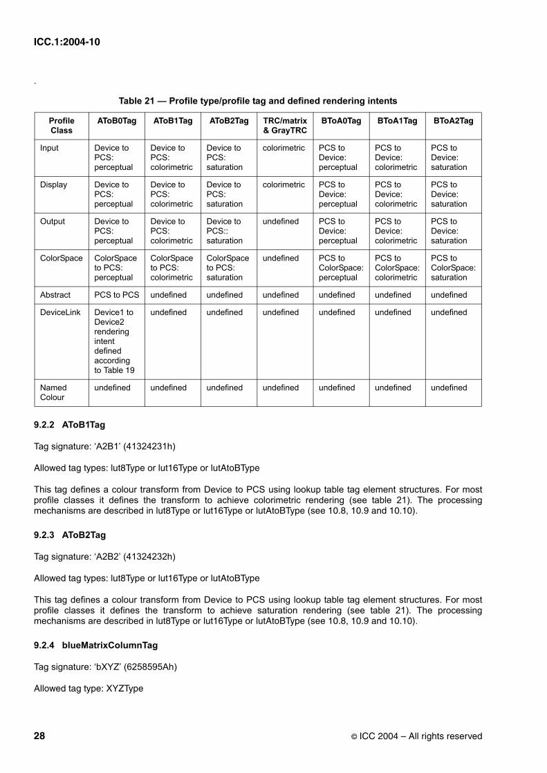
ICC.1:2004-10
.
9.2.2 AToB1Tag
Tag signature: ‘A2B1’ (41324231h)
Allowed tag types: lut8Type or lut16Type or lutAtoBType
This tag defines a colour transform from Device to PCS using lookup table tag element structures. For most profile classes it defines the transform to achieve colorimetric rendering (see table 21). The processing mechanisms are described in lut8Type or lut16Type or lutAtoBType (see 10.8, 10.9 and 10.10).
9.2.3 AToB2Tag
Tag signature: ‘A2B2’ (41324232h)
Allowed tag types: lut8Type or lut16Type or lutAtoBType
This tag defines a colour transform from Device to PCS using lookup table tag element structures. For most profile classes it defines the transform to achieve saturation rendering (see table 21). The processing mechanisms are described in lut8Type or lut16Type or lutAtoBType (see 10.8, 10.9 and 10.10).
9.2.4 blueMatrixColumnTag
Tag signature: ‘bXYZ’ (6258595Ah)
Allowed tag type: XYZType
Table 21 — Profile type/profile tag and defined rendering intents
Profile Class
AToB0Tag AToB1Tag AToB2Tag TRC/matrix & GrayTRC
BToA0Tag BToA1Tag BToA2Tag
Input Device to PCS: perceptual
Device to PCS: colorimetric
Device to PCS: saturation
colorimetric PCS to Device: perceptual
PCS to Device: colorimetric
PCS to Device: saturation
Display Device to PCS: perceptual
Device to PCS: colorimetric
Device to PCS: saturation
colorimetric PCS to Device: perceptual
PCS to Device: colorimetric
PCS to Device: saturation
Output Device to PCS: perceptual
Device to PCS: colorimetric
Device to PCS:: saturation
undefined PCS to Device: perceptual
PCS to Device: colorimetric
PCS to Device: saturation
ColorSpace ColorSpace to PCS: perceptual
ColorSpace to PCS: colorimetric
ColorSpace to PCS: saturation
undefined PCS to ColorSpace:perceptual
PCS to ColorSpace:colorimetric
PCS to ColorSpace: saturation
Abstract PCS to PCS undefined undefined undefined undefined undefined undefined
DeviceLink Device1 to Device2 rendering intent defined according to Table 19
undefined undefined undefined undefined undefined undefined
Named Colour
undefined undefined undefined undefined undefined undefined undefined
28 © ICC 2004 – All rights reserved

ICC.1:2004-10
The third column in the matrix used in TRC/matrix transforms.
9.2.5 blueTRCTag
Tag signature: ‘bTRC’ (62545243h)
Allowed tag types: curveType or parametricCurveType
Blue channel tone reproduction curve. The first element represents no colorant (white) or phosphor (black) and the last element represents 100 percent colorant (blue) or 100 percent phosphor (blue).
9.2.6 BToA0Tag
Tag signature: ‘B2A0’ (42324130h)
Allowed tag types: lut8Type or lut16Type or lutBtoAType
This tag defines a colour transform from PCS to Device using the lookup table tag element structures. For most profile classes it defines the transform to achieve perceptual rendering (see table 21). The processing mechanisms are described in lut8Type or lut16Type or lutBtoAType (see 10.8, 10.9 and 10.11).
9.2.7 BToA1Tag
Tag signature: ‘B2A1’ (42324131h)
Allowed tag types: lut8Type or lut16Type or lutBtoAType
This tag defines a colour transform from PCS to Device using the lookup table tag element structures. For most profile classes it defines the transform to achieve colorimetric rendering (see table 21). The processing mechanisms are described in lut8Type or lut16Type or lutBtoAType (see 10.8, 10.9 and 10.11).
9.2.8 BToA2Tag
Tag signature: ‘B2A2’ (42324132h)
Allowed tag types: lut8Type or lut16Type or lutBtoAType
This tag defines a colour transform from PCS to Device using the lookup table tag element structures. For most profile classes it defines the transform to achieve saturation rendering (see table 21). The processing mechanisms are described in lut8Type or lut16Type or lutBtoAType (see 10.8, 10.9 and 10.11).
9.2.9 calibrationDateTimeTag
Tag signature: ‘calt’ (63616C74h)
Allowed tag type: dateTimeType
Profile calibration date and time. This allows applications and utilities to verify if this profile matches a vendor’s profile and how recently calibration has been performed.
9.2.10 charTargetTag
Tag signature: ‘targ’ (74617267h)
Allowed tag type: textType
© ICC 2004 – All rights reserved 29

ICC.1:2004-10
This tag contains the name of the registered characterization data set, or it contains the measurement data for a characterization target. This tag is provided so that distributed utilities can identify the underlying characterization data, create transforms "on the fly" or check the current performance against the original device performance.
The first seven characters of the text shall identify the nature of the characterization data.
If the first seven characters are "ICCHDAT", then the remainder of the text shall be a single space followed by the Reference Name of a characterization data set in the Characterization Data Registry maintained by ICC, and terminated with a NULL byte (00h). The Reference Name in the text must match exactly (including case) the Reference Name in the registry which may be found on the ICC web site (www.color.org).
If the first seven characters match one of the identifiers defined in an ANSI or ISO standard, then the tag embeds the exact data file format defined in that standard. Each of these file formats contains an identifying character string as the first seven characters of the format, allowing an external parser to determine which data file format is being used. This provides the facilities to include a wide range of targets using a variety of measurement specifications in a standard manner.
NOTE It is highly recommended that the profileDescriptionTag also include an identification of the characterization data that was used in the creation of the profile (e.g. "Based on CGATS TR 001").
9.2.11 chromaticAdaptationTag
Tag signature: 'chad' (63686164h)
Allowed tag type: s15Fixed16ArrayType
This tag, which must be invertible, converts an XYZ colour, measured at a device's specific illumination conditions, to an XYZ colour in the PCS illumination conditions after complete adaptation.
The tag reflects a survey of the currently used methods of conversion, all of which can be formulated as a matrix transformation. The Bradford transform (see Annex E) is recommended for ICC profiles.
Such a 3 by 3 chromatic adaptation matrix is organized as a 9-element array of signed 15.16 numbers (s15Fixed16ArrayType tag). Similarly as in the other occurrences of a 3 by 3 matrix in the ICC tags, the dimension corresponding to the matrix rows varies least rapidly while the one corresponding to the matrix columns varies most rapidly.
where XYZsrc represents the measured value in the actual device viewing condition and XYZpcs represents the chromatically adapted value in the PCS.
The chromatic adaptation matrix is a combination of three separate conversions as defined in Annex E.
9.2.12 chromaticityTag
Tag signature: ‘chrm’ (6368726Dh)
array a0 a1 a2 a3 a4 a5 a6 a7 a8=
Xpcs
Ypcs
Zpcs
a0 a1 a2
a3 a4 a5
a6 a7 a8
Xsrc
Ysrc
Zsrc
=
30 © ICC 2004 – All rights reserved

ICC.1:2004-10
Allowed tag type: chromaticity type
The data and type of phosphor/colorant chromaticity set.
9.2.13 colorantOrderTag
Tag signature: ’clro’ (636C726Fh)
Allowed tag type: colorantOrderType
This tag specifies the laydown order of colorants.
9.2.14 colorantTableTag
Tag signature: ’clrt’ (636C7274h)
Allowed tag type: colorantTableType
This tag identifies the colorants used in the profile by a unique name and set of XYZ or L*a*b* values. When used in DeviceLink profiles only the L*a*b* values shall be permitted.
9.2.14.1 colorantTableOutTag
Tag signature: ‘clot’ (636C6F74h)
Allowed tag type: colorantTableType
This tag identifies the colorants used in the profile by a unique name and set of L*a*b* values. This tag is used for DeviceLink profiles only.
9.2.15 copyrightTag
Tag signature: ‘cprt’ (63707274h)
Allowed tag type: multiLocalizedUnicodeType
This tag contains the text copyright information for the profile.
9.2.16 deviceMfgDescTag
Tag signature: ‘dmnd’ (646D6E64h)
Allowed tag type: multiLocalizedUnicodeType
Structure containing invariant and localizable versions of the device manufacturer for display. The content of this structure is described in 10.13.
9.2.17 deviceModelDescTag
Tag signature: ‘dmdd’ (646D6464h)
Allowed tag type: multiLocalizedUnicodeType
Structure containing invariant and localizable versions of the device model for display. The content of this structure is described in 10.13.
© ICC 2004 – All rights reserved 31
ICC.1:2004-10
9.2.18 gamutTag
Tag signature: ‘gamt’ (67616D74h)
Allowed tag types: lut8Type or lut16Type or lutBtoAType
Out of gamut tag. The processing mechanisms are described in lut8Type or lut16Type or lutBtoAType.
This tag provides a table in which PCS values are the input and a single output value for each input value is the output. If the output value is 0, the PCS colour is in-gamut. If the output is non-zero, the PCS colour is out-of-gamut.
9.2.19 grayTRCTag
Tag signature: ‘kTRC’ (6B545243h)
Allowed tag types: curveType or parametricCurveType
Grey tone reproduction curve. The tone reproduction curve provides the necessary information to convert between a single device channel and the CIEXYZ or L*a*b* encoding of the Profile Connection Space. The first element represents black and the last element represents white. The computational model supported by the grayTRC tag is defined in F.1.
9.2.20 greenMatrixColumnTag
Tag signature: ‘gXYZ’ (6758595Ah)
Allowed tag type: XYZType
The second column in the matrix used in TRC/matrix transforms.
9.2.21 greenTRCTag
Tag signature: ‘gTRC’ (67545243h)
Allowed tag types: curveType or parametricCurveType
Green channel tone reproduction curve. The first element represents no colorant (white) or phosphor (black) and the last element represents 100 percent colorant (green) or 100 percent phosphor (green).
9.2.22 luminanceTag
Tag signature: ‘lumi’ (6C756D69h)
Allowed tag type: XYZType
Absolute luminance of emissive devices in candelas per square metre as described by the Y channel.
NOTE The X and Z values should be set to zero.
9.2.23 measurementTag
Tag signature: ‘meas’ (6D656173h)
Allowed tag type: measurementType
Alternative measurement specification, such as a D65 illuminant instead of the default D50.
32 © ICC 2004 – All rights reserved

ICC.1:2004-10
9.2.24 mediaBlackPointTag
Tag signature: ‘bkpt’ (626B7074h)
Allowed tag type: XYZType
This tag specifies the media black point and contains the CIE 1931 XYZ colorimetry of the black point of the actual medium. If the media is measured under an illumination source which has a chromaticity other than D50, the measured values must be adjusted to D50 using the chromaticAdaptationTag matrix before recording in the tag.
NOTE This tag is NOT used to calculate ICC-absolute colorimetry.
9.2.25 mediaWhitePointTag
Tag signature: ‘wtpt’ (77747074h)
Allowed tag type: XYZType
This tag, which is used for generating ICC-absolute colorimetric intent, specifies the XYZ tristimulus values of the media white point. If the media is measured under an illumination source which has a chromaticity other than D50, the measured values must be adjusted to D50 using the chromaticAdaptationTag matrix before recording in the tag. For reflecting and transmitting media, the tag values are specified relative to the perfect diffuser (which is normalized to a Y value of 1,0) for illuminant D50. For displays, the values specified must be those of D50 normalized such that Y = 1,0 (i.e. 0,9642 1,0 0,8249).
See Clause 6 and Annex A for a more complete description of the use of the media white point.
9.2.26 namedColor2Tag
Tag signature: ‘ncl2’ (6E636C32h)
Allowed tag type: namedColor2Type
Named colour information providing a PCS and optional device representation for a list of named colours.
9.2.27 outputResponseTag
Tag signature: ‘resp’ (72657370h)
Allowed tag type: responseCurveSet16Type
Structure containing a description of the device response for which the profile is intended. The content of this structure is described in 10.17.
NOTE The user’s attention is called to the possibility that the use of this tag for device calibration may require use of an invention covered by patent rights. By publication of this specification, no position is taken with respect to the validity of this claim or of any patent rights in connection therewith. The patent holder has, however, filed a statement of willingness to grant a license under these rights on reasonable and nondiscriminatory terms and conditions to applicants desiring to obtain such a license. Details may be obtained from the International Color Consortium (1899 Preston White Drive, Reston, Virginia 20191-4367, USA).
9.2.28 preview0Tag
Tag signature: ‘pre0’ (70726530h)
Allowed tag types: lut8Type or lut16Type or lutBtoAType
© ICC 2004 – All rights reserved 33

ICC.1:2004-10
Preview transformation from PCS to device space and back to the PCS. This tag contains the combination of tag B2A0 and tag A2B1, or equivalent transforms. The processing mechanisms are described in lut8Type or lut16Type or lut AToBType or lutBtoAType (see 10.8, 10.9, 10.10 and 10.11).
9.2.29 preview1Tag
Tag signature: ‘pre1’ (70726531h)
Allowed tag types: lut8Type or lut16Type or lutBtoAType
Preview transformation from PCS to device space and back to the PCS. This tag contains the combination of tag B2A1 and tag A2B1, or equivalent transforms. The processing mechanisms are described in lut8Type or lut16Type or lut AToBType or lutBtoAType (see 10.8, 10.9, 10.10 and 10.11).
9.2.30 preview2Tag
Tag signature: ‘pre2’ (70726532h)
Allowed tag types: lut8Type or lut16Type or lutBtoAType
Preview transformation from PCS to device space and back to the PCS. This tag contains the combination of tag B2A2 and tag A2B1, or equivalent transforms. The processing mechanisms are described in lut8Type or lut16Type or lut AToBType or lutBtoAType (see 10.8, 10.9, 10.10 and 10.11).
9.2.31 profileDescriptionTag
Tag signature: ‘desc’ (64657363h)
Allowed tag type: multiLocalizedUnicodeType
Structure containing invariant and localizable versions of the profile description for display. The content of this structure is described in 10.13. This invariant description has no fixed relationship to the actual profile disk file name.
9.2.32 profileSequenceDescTag
Tag signature: ‘pseq’ (70736571h)
Allowed tag type: profileSequenceDescType
Structure containing a description of the profile sequence from source to destination, typically used with the DeviceLink profile. The content of this structure is described in 10.16.
9.2.33 redMatrixColumnTag
Tag signature: ‘rXYZ’ (7258595Ah)
Allowed tag type: XYZType
The first column in the matrix used in TRC/matrix transforms.
9.2.34 redTRCTag
Tag signature: ‘rTRC’ (72545243h)
Allowed tag types: curveType or parametricCurveType
34 © ICC 2004 – All rights reserved

ICC.1:2004-10
Red channel tone reproduction curve. The first element represents no colorant (white) or phosphor (black) and the last element represents 100 percent colorant (red) or 100 percent phosphor (red).
9.2.35 technologyTag
Tag signature: ‘tech’ (74656368h)
Allowed tag type: signatureType
The device technology signatures that shall be used are listed Table 22:
9.2.36 viewingCondDescTag
Tag signature: ‘vued’ (76756564h)
Allowed tag type: multiLocalizedUnicodeType
Table 22 — Technology signatures
Technology Signature Hex Encoding
Film Scanner ‘fscn’ 6673636Eh
Digital Camera ‘dcam’ 6463616Dh
Reflective Scanner ‘rscn’ 7273636Eh
Ink Jet Printer ‘ijet’ 696A6574h
Thermal Wax Printer ‘twax’ 74776178h
Electrophotographic Printer ‘epho’ 6570686Fh
Electrostatic Printer ‘esta’ 65737461h
Dye Sublimation Printer ‘dsub’ 64737562h
Photographic Paper Printer ‘rpho’ 7270686Fh
Film Writer ‘fprn’ 6670726Eh
Video Monitor ‘vidm’ 7669646Dh
Video Camera ‘vidc’ 76696463h
Projection Television ‘pjtv’ 706A7476h
Cathode Ray Tube Display ‘CRT ’ 43525420h
Passive Matrix Display ‘PMD ’ 504D4420h
Active Matrix Display ‘AMD ’ 414D4420h
Photo CD ‘KPCD’ 4B504344h
PhotoImageSetter ‘imgs’ 696D6773h
Gravure ‘grav’ 67726176h
Offset Lithography ‘offs’ 6F666673h
Silkscreen ‘silk’ 73696C6Bh
Flexography ‘flex’ 666C6578h
© ICC 2004 – All rights reserved 35

ICC.1:2004-10
Structure containing invariant and localizable versions of the viewing conditions. The content of this structure is described in 10.13.
9.2.37 viewingConditionsTag
Tag signature: ‘view’ (76696577h)
Allowed tag type: viewingConditionsType
Viewing conditions parameters. The content of this structure is described in 10.26.
10 Tag type definitions
10.1 Overview
All tags, including private tags, have as their first four bytes a tag type signature to identify to profile readers what kind of data is contained within a tag. This encourages tag type reuse and allows profile parsers to reuse code when tags use common tag types. The second four bytes (4..7) are reserved for future expansion and must be set to 0 in this version of the specification. The tag signature for all private tags and any tag type signature not defined in clause 10 shall be registered with the International Color Consortium (see clause 2) in order to prevent signature collisions.
One or more tag types are associated with each tag defined in clause 9.2. The tag type definitions in clauses 10.2 through 10.27 specify the data structure that shall be used in creating the contents of the tag data element for each tag.
All tag data elements, including those of private tags, shall have a tag type signature in bytes 0 to 3. Bytes 4 to 7 are reserved for future expansion and must be set to 0.
Any private tag types used shall be registered with the International Color Consortium to prevent tag type signature collisions.
NOTE An effort was made to make sure one-byte, two-byte and four-byte data lies on one-byte, two-byte and four-byte boundaries respectively. This required occasionally including extra spaces indicated with “reserved for padding” in some tag type definitions.
Where not otherwise specified value 0 is defined to be of “unknown value” for all enumerated data structures.
Where not specified otherwise, the least-significant 16 bits of all 32-bit flags in the type descriptions below are reserved for use by the International Color Consortium.
When 7-bit ASCII text representation is specified in types below, each individual character is encoded in 8 bits with the most-significant bit set to zero. The details are presented in 10.20.
In many of the tables shown in clause 10 the following syntax is used in the encoding column for the various numeric types listed in 5.1: numerictype[X] where X represents the number of values in that position. Where [...] is used the number of values depends on the number of channels in the tag type or number of entries in a table.
36 © ICC 2004 – All rights reserved

ICC.1:2004-10
10.2 chromaticityType
The chromaticity tag type provides basic chromaticity data and type of phosphors or colorants of a monitor to applications and utilities. When used the byte assignment shall be as given in Table 23.
When using this type, it is necessary to assign each colour space component to a device channel. Table 31“lut16Type channel encodings” shows these assignments.
The encoding for byte positions 10 and 11 is shown in Table 24. If the value is 0001h through 0004h the number of channels shall be three and the phosphor chromaticities in byte positions 12 through 35 shall match those listed in the appropriate row of Table 24.
When the encoded value in byte position 10 and 11 is 0000h, the actual set of chromaticity values shall be described.
10.3 colorantOrderType
This is an optional tag which specifies the laydown order in which colorants will be printed on an n-colorant device. The laydown order may be the same as the channel generation order listed in the colorantTableTag or the channel order of a colour space such as CMYK, in which case this tag is not needed. When this is not the
Table 23 — chromaticityType encoding
Byte position
Field Length (bytes)
Content Encoded as.
0..3 4 ’chrm’ (6368726Dh) type signature
4..7 4 reserved, must be set to 0
8..9 2 Number of Device Channels (n) uInt16Number
10..11 2 encoded value of phosphor or colorant type see Table 24
12..19 8 CIE xy coordinate values of channel 1 u16Fixed16Number[2]
20..end (n-1) x 8 CIE xy coordinate values of other n channels (if needed)
u16Fixed16Number[...]
Table 24 — Colorant and phosphor encoding
Phosphor or Colorant Type
Encoded Value
Channel 1 x,y Channel 2 x,y Channel 3 x,y
unknown 0000h any any any
ITU-R BT.709 0001h (0,640, 0,330) (0,300, 0,600) (0,150, 0,060)
SMPTE RP145-1994 0002h (0,630, 0,340) (0,310, 0,595) (0,155, 0,070)
EBU Tech.3213-E 0003h (0,64 0,33) (0,29, 0,60) (0,15, 0,06)
P22 0004h (0,625, 0,340) (0,280, 0,605) (0,155, 0,070)
© ICC 2004 – All rights reserved 37
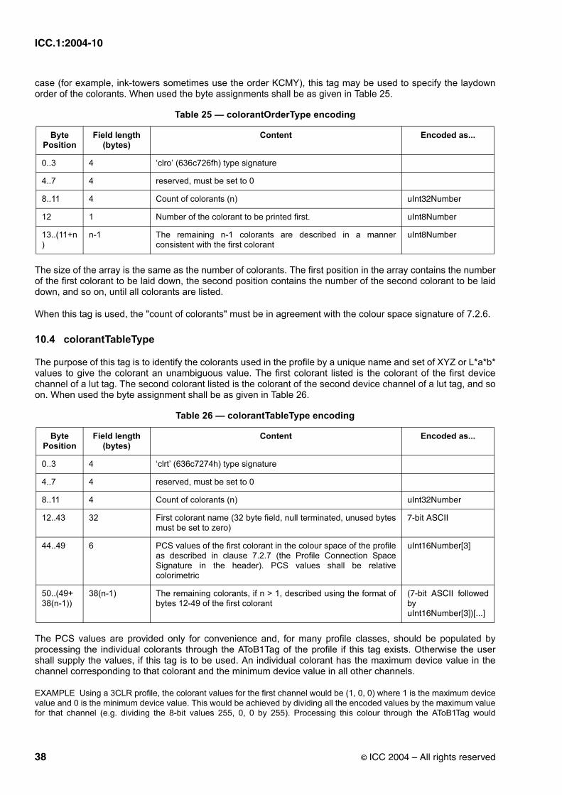
ICC.1:2004-10
case (for example, ink-towers sometimes use the order KCMY), this tag may be used to specify the laydown order of the colorants. When used the byte assignments shall be as given in Table 25.
The size of the array is the same as the number of colorants. The first position in the array contains the number of the first colorant to be laid down, the second position contains the number of the second colorant to be laid down, and so on, until all colorants are listed.
When this tag is used, the "count of colorants" must be in agreement with the colour space signature of 7.2.6.
10.4 colorantTableType
The purpose of this tag is to identify the colorants used in the profile by a unique name and set of XYZ or L*a*b* values to give the colorant an unambiguous value. The first colorant listed is the colorant of the first device channel of a lut tag. The second colorant listed is the colorant of the second device channel of a lut tag, and so on. When used the byte assignment shall be as given in Table 26.
The PCS values are provided only for convenience and, for many profile classes, should be populated by processing the individual colorants through the AToB1Tag of the profile if this tag exists. Otherwise the user shall supply the values, if this tag is to be used. An individual colorant has the maximum device value in the channel corresponding to that colorant and the minimum device value in all other channels.
EXAMPLE Using a 3CLR profile, the colorant values for the first channel would be (1, 0, 0) where 1 is the maximum device value and 0 is the minimum device value. This would be achieved by dividing all the encoded values by the maximum value for that channel (e.g. dividing the 8-bit values 255, 0, 0 by 255). Processing this colour through the AToB1Tag would
Table 25 — colorantOrderType encoding
Byte Position
Field length (bytes)
Content Encoded as...
0..3 4 ‘clro’ (636c726fh) type signature
4..7 4 reserved, must be set to 0
8..11 4 Count of colorants (n) uInt32Number
12 1 Number of the colorant to be printed first. uInt8Number
13..(11+n)
n-1 The remaining n-1 colorants are described in a manner consistent with the first colorant
uInt8Number
Table 26 — colorantTableType encoding
Byte Position
Field length (bytes)
Content Encoded as...
0..3 4 ‘clrt’ (636c7274h) type signature
4..7 4 reserved, must be set to 0
8..11 4 Count of colorants (n) uInt32Number
12..43 32 First colorant name (32 byte field, null terminated, unused bytes must be set to zero)
7-bit ASCII
44..49 6 PCS values of the first colorant in the colour space of the profile as described in clause 7.2.7 (the Profile Connection Space Signature in the header). PCS values shall be relative colorimetric
uInt16Number[3]
50..(49+38(n-1))
38(n-1) The remaining colorants, if n > 1, described using the format of bytes 12-49 of the first colorant
(7-bit ASCII followed by uInt16Number[3])[...]
38 © ICC 2004 – All rights reserved

ICC.1:2004-10
produce the PCS values listed in bytes 44-49.
When this tag is used, the "count of colorants" must be in agreement with the colour space signature of 7.2.6.
NOTE The XYZ or L*a*b* values may also be used to derive the visual density of the colorant, which trapping algorithms may then use to determine overlay values.
10.5 curveType
The curveType contains a 4-byte count value and a one-dimensional table of 2-byte values. When used the byte assignment shall be as given in Table 27.
The curveTag type embodies a one-dimensional function which maps an input value in the domain of the function to an output value in the range of the function. The domain and range values are in the range of 0,0 to 1,0.
when n is 0 an identity response is assumed,
when n is 1, then the curve value shall be interpreted as a gamma value, encoded as a u8Fixed8Number. Gamma shall be interpreted as the exponent in the equation y=xγ and not as an inverse.
when n is greater than 1 the curve values (which embody a sampled one-dimensional function) shall be defined as follows:
The first entry is located at 0,0, the last entry at 1,0, and intermediate entries are uniformly spaced using an increment of 1,0/(n-1). These entries are encoded as uInt16Numbers (i.e. the values represented by the entries, which are in the range 0,0 to 1,0 are encoded in the range 0,0 to 65535,0). Function values between the entries shall be obtained through linear interpolation.
If the input is the XYZ PCS, 1+(32767/32768) shall be mapped to the value 1,0. If the output is the XYZ PCS, the value 1,0 shall be mapped to 1+(32767/32768).
10.6 dataType
The dataType is a simple data structure that contains either 7-bit ASCII or binary data, i.e. textType data or transparent 8-bit bytes. The length of the string is obtained by subtracting 12 from the element size portion of
Table 27 — curveType encoding
Byte Position
Field Length (bytes)
Content Encoded as...
0..3 4 ‘curv’ (63757276h) type signature
4..7 4 reserved, must be set to 0
8..11 4 count value specifying the number of entries (n) that follow uInt32Number
12..end 2 x n** actual curve values starting with the zeroth entry and ending with the entry n-1
uInt16Number[...]**
**NOTE If n=1 the field length is 1 and the value is encoded as a u8Fixed8Number - see below
© ICC 2004 – All rights reserved 39

ICC.1:2004-10
the tag itself defined in 7.3.5. If this type is used for ASCII data, it shall be terminated with a 00h byte. When used the byte assignment shall be as given in Table 28.
10.7 dateTimeType
This dateTimeType is a 12-byte value representation of the time and date. The actual values are encoded as a dateTimeNumber described in 5.1.1. When used the byte assignment shall be as given in Table 29.
10.8 lut16Type
This structure represents a colour transform using tables with 16-bit precision. This type contains four processing elements: a 3 by 3 matrix (which shall be the identity matrix unless the input colour space is XYZ), a set of one dimensional input tables, a multidimensional lookup table, and a set of one dimensional output tables. Data is processed using these elements via the following sequence:
(matrix) ⇒ (1d input tables) ⇒ (multidimensional lookup table - CLUT) ⇒ (1d output tables).
Table 28 — dataType encoding
Byte Position
Field Length (bytes)
Content
0..3 4 ‘data’ (64617461h) type signature
4..7 4 reserved, must be set to 0
8..11 4 data flag, 00000000h represents ASCII data, 00000001h represents binary data, other values are reserved for future use
12..end element size - 12
a string of (element size - 12) ASCII characters or (element size - 12) bytes
Table 29 — dateTimeType encoding
Byte Position
Field Length (bytes)
Content Encoded as...
0..3 4 ‘dtim’ (6474696Dh) type signature
4..7 4 reserved, must be set to 0
8..19 12 date and time dateTimeNumber
40 © ICC 2004 – All rights reserved
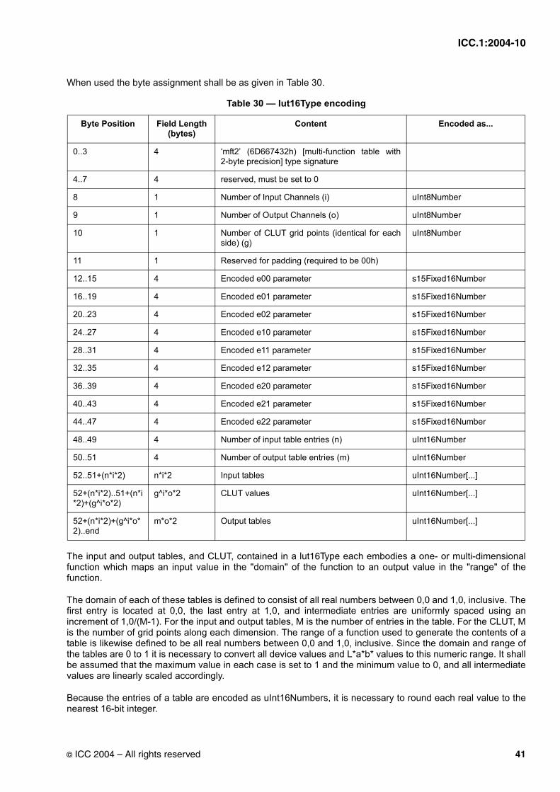
ICC.1:2004-10
When used the byte assignment shall be as given in Table 30.
The input and output tables, and CLUT, contained in a lut16Type each embodies a one- or multi-dimensional function which maps an input value in the "domain" of the function to an output value in the "range" of the function.
The domain of each of these tables is defined to consist of all real numbers between 0,0 and 1,0, inclusive. The first entry is located at 0,0, the last entry at 1,0, and intermediate entries are uniformly spaced using an increment of 1,0/(M-1). For the input and output tables, M is the number of entries in the table. For the CLUT, M is the number of grid points along each dimension. The range of a function used to generate the contents of a table is likewise defined to be all real numbers between 0,0 and 1,0, inclusive. Since the domain and range of the tables are 0 to 1 it is necessary to convert all device values and L*a*b* values to this numeric range. It shall be assumed that the maximum value in each case is set to 1 and the minimum value to 0, and all intermediate values are linearly scaled accordingly.
Because the entries of a table are encoded as uInt16Numbers, it is necessary to round each real value to the nearest 16-bit integer.
Table 30 — lut16Type encoding
Byte Position Field Length (bytes)
Content Encoded as...
0..3 4 ‘mft2’ (6D667432h) [multi-function table with 2-byte precision] type signature
4..7 4 reserved, must be set to 0
8 1 Number of Input Channels (i) uInt8Number
9 1 Number of Output Channels (o) uInt8Number
10 1 Number of CLUT grid points (identical for each side) (g)
uInt8Number
11 1 Reserved for padding (required to be 00h)
12..15 4 Encoded e00 parameter s15Fixed16Number
16..19 4 Encoded e01 parameter s15Fixed16Number
20..23 4 Encoded e02 parameter s15Fixed16Number
24..27 4 Encoded e10 parameter s15Fixed16Number
28..31 4 Encoded e11 parameter s15Fixed16Number
32..35 4 Encoded e12 parameter s15Fixed16Number
36..39 4 Encoded e20 parameter s15Fixed16Number
40..43 4 Encoded e21 parameter s15Fixed16Number
44..47 4 Encoded e22 parameter s15Fixed16Number
48..49 4 Number of input table entries (n) uInt16Number
50..51 4 Number of output table entries (m) uInt16Number
52..51+(n*i*2) n*i*2 Input tables uInt16Number[...]
52+(n*i*2)..51+(n*i*2)+(g^i*o*2)
g^i*o*2 CLUT values uInt16Number[...]
52+(n*i*2)+(g^i*o*2)..end
m*o*2 Output tables uInt16Number[...]
© ICC 2004 – All rights reserved 41

ICC.1:2004-10
Because the entries of lut16Type LUTs represent values in the range 0,0 to 1,0, encoded as uInt16Numbers, these entries should be divided by 65535,0 for the calculation of the actual output values.
See Annex A for additional guidance on this topic.
The matrix is organized as a 3 by 3 array. The dimension corresponding to the matrix rows varies least rapidly and the dimension corresponding to the matrix columns varies most rapidly and is shown in matrix form below.
(10)
When using the matrix of an output profile, and the input data is XYZ, we have:
(11)
Each matrix entry is encoded as a s15Fixed16Number. The domain and range of the matrix is 0,0 to 1,0.
NOTE 1 Since the PCS is XYZ if the matrix is present, and X, Y and Z are u1Fixed15Numbers, 1 + (32767/32768) is mapped to 1,0 as the matrix input value.
The matrix shall be an identity matrix unless the input is in the XYZ colour space.
The input tables are arrays of 16-bit unsigned values. Each input table consists of a minimum of two and a maximum of 4096 uInt16Number integers. Each input table entry is appropriately normalized to the range 0-65535. The inputTable is of size (InputChannels * inputTableEntries * 2) bytes. When stored in this tag, the one-dimensional lookup tables are packed one after another in the order described in Table 31.
The CLUT is organized as an i-dimensional array with a given number of grid points in each dimension, where i is the number of input channels (input tables) in the transform. The dimension corresponding to the first input channel varies least rapidly and the dimension corresponding to the last input channel varies most rapidly. Each grid point value contains o uInt16Number integers, where o is the number of output channels. The first sequential uInt16Number integer of the entry contains the function value for the first output function, the second sequential uInt16Number integer of the entry contains the function value for the second output function, and so on until all the output functions have been supplied. The equation for computing the byte size of the CLUT is:
CLUTSize = (GridPointsInputChannels * OutputChannels * 2) bytes (12)
The output tables are arrays of 16-bit unsigned values. Each output table consists of a minimum of two and a maximum of 4096 uInt16Number integers. Each output table entry is appropriately normalized to the range 0 - 65535. The outputTable is of size (OutputChannels * outputTableEntries * 2) bytes. When stored in this tag, the one-dimensional lookup tables are packed one after another in the order described in Table 31.
If the number of data points in a one-dimensional table, or in a particular dimension of the CLUT, is two, the data for those points shall be set so that the correct results are obtained when linear interpolation is used to generate intermediate values.
e01 e02 e03
e04 e05 e06
e07 e08 e09
X'
Y'
Z'
e01 e02 e03
e04 e05 e06
e07 e08 e09
XYZ
=
42 © ICC 2004 – All rights reserved

ICC.1:2004-10
When using this type, it is necessary to assign each colour space component to an input and output channel.These assignments shall be as shown in Table 31. The channels are numbered according to the order in which their table occurs.
NOTE 2 Additional xCLR colour spaces (up to 15 channels) can be added by specifying the appropriate signature from table 15, assigning the channels in numerical order and creating the tables.
The colour space used on the PCS side of a lut16Type tag (which may be either the input or output space, or both in the case of an abstract profile) is identified by the Profile Connection Space field in the profile header (see 7.2.7). This field does not distinguish between 8-bit and 16-bit PCS encodings. For the lut16Type tag, the 'Lab ' signature is defined to specify a legacy 16-bit CIELAB encoding and the 'XYZ ' signature is defined to specify the 16-bit XYZ encoding. Note that this definition only applies to the encoding used at the Profile Connection Space side of the tag. The definition does NOT apply when these signatures are used in the Data colour space field in the profile header (see 7.2.6), except in the case of an abstract profile.
For colour values that are in the Lab colour space on the PCS side of the tag, this tag uses the legacy 16-bit Lab encoding defined in Tables 33 and 34, not the 16-bit CIELAB PCS encoding defined in clause 6.3.4.2. This encoding is retained for backwards compatibility with profile version 2. The L* values have a different encoding than the a* and b* values.
The legacy L* encoding is shown in table 32.
Table 31 — Channel encodings
colour Space Channel 1 Channel 2 Channel 3 Channel 4
‘XYZ ’ X Y Z
‘Lab ’ L a b
‘Luv ’ L u v
‘YCbr’ Y Cb Cr
‘Yxy ’ Y x y
‘RGB ’ R G B
‘GRAY’ K
‘HSV ’ H S V
‘HLS ’ H L S
‘CMYK’ C M Y K
‘CMY ’ C M Y
‘2CLR’ Ch. 1 Ch. 2
‘3CLR’ Ch. 1 Ch. 2 Ch. 3
‘4CLR’ Ch. 1 Ch. 2 Ch. 3 Ch. 4
Table 32 — Legacy L* encoding
Value (L*) 16 bit
0 0000h
100,0 FF00h
100 + (25500/65280) FFFFh
© ICC 2004 – All rights reserved 43
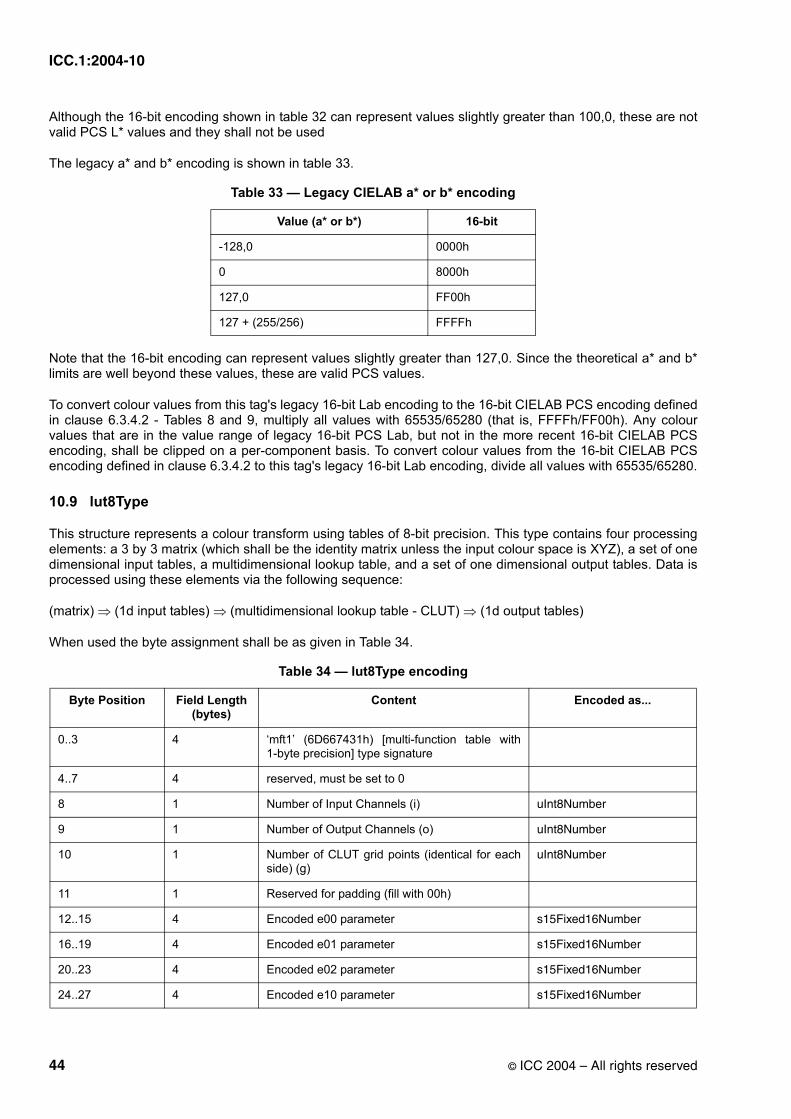
ICC.1:2004-10
Although the 16-bit encoding shown in table 32 can represent values slightly greater than 100,0, these are not valid PCS L* values and they shall not be used
The legacy a* and b* encoding is shown in table 33.
Note that the 16-bit encoding can represent values slightly greater than 127,0. Since the theoretical a* and b* limits are well beyond these values, these are valid PCS values.
To convert colour values from this tag's legacy 16-bit Lab encoding to the 16-bit CIELAB PCS encoding defined in clause 6.3.4.2 - Tables 8 and 9, multiply all values with 65535/65280 (that is, FFFFh/FF00h). Any colour values that are in the value range of legacy 16-bit PCS Lab, but not in the more recent 16-bit CIELAB PCS encoding, shall be clipped on a per-component basis. To convert colour values from the 16-bit CIELAB PCS encoding defined in clause 6.3.4.2 to this tag's legacy 16-bit Lab encoding, divide all values with 65535/65280.
10.9 lut8Type
This structure represents a colour transform using tables of 8-bit precision. This type contains four processing elements: a 3 by 3 matrix (which shall be the identity matrix unless the input colour space is XYZ), a set of one dimensional input tables, a multidimensional lookup table, and a set of one dimensional output tables. Data is processed using these elements via the following sequence:
(matrix) ⇒ (1d input tables) ⇒ (multidimensional lookup table - CLUT) ⇒ (1d output tables)
When used the byte assignment shall be as given in Table 34.
Table 33 — Legacy CIELAB a* or b* encoding
Value (a* or b*) 16-bit
-128,0 0000h
0 8000h
127,0 FF00h
127 + (255/256) FFFFh
Table 34 — lut8Type encoding
Byte Position Field Length (bytes)
Content Encoded as...
0..3 4 ‘mft1’ (6D667431h) [multi-function table with 1-byte precision] type signature
4..7 4 reserved, must be set to 0
8 1 Number of Input Channels (i) uInt8Number
9 1 Number of Output Channels (o) uInt8Number
10 1 Number of CLUT grid points (identical for each side) (g)
uInt8Number
11 1 Reserved for padding (fill with 00h)
12..15 4 Encoded e00 parameter s15Fixed16Number
16..19 4 Encoded e01 parameter s15Fixed16Number
20..23 4 Encoded e02 parameter s15Fixed16Number
24..27 4 Encoded e10 parameter s15Fixed16Number
44 © ICC 2004 – All rights reserved

ICC.1:2004-10
The input and output tables, and CLUT, contained in a lut8Type each embodies a one- or multi-dimensional function which maps an input value in the "domain" of the function to an output value in the "range" of the function.
The domain of each of these tables is defined to consist of all real numbers between 0,0 and 1,0, inclusive. The first entry is located at 0,0, the last entry at 1,0, and intermediate entries are uniformly spaced using an increment of 1,0/(M-1). For the input and output tables, M is 255. For the CLUT, M is the number of grid points along each dimension. The range of a function used to generate the contents of a table is likewise defined to be all real numbers between 0,0 and 1,0, inclusive. Since the domain and range of the tables are 0 to 1 it is necessary to convert all device values and L*a*b* values to this numeric range. It shall be assumed that the maximum value in each case is set to 1 and the minimum value to 0, and all intermediate values are linearly scaled accordingly.
Because the entries of a table are encoded as uInt8Numbers, it is necessary to round each real value to the nearest 8-bit integer.
Because the entries of lut8Type LUTs represent values in the range 0,0 to 1,0, encoded as uInt8Numbers, these entries should be divided by 255,0 for the calculation of the actual output values.
See Annex A for additional guidance on this topic.
The colour space used on the PCS side of a lut8Type tag (which may be either the input or output space, or both in the case of an abstract profile) is identified by the Profile Connection Space field in the profile header (see 7.2.7). This field does not distinguish between 8-bit and 16-bit PCS encodings. For the lut8Type tag, the 'Lab' signature is defined to specify the 8-bit CIELAB encoding. Note that this definition only applies to the encoding used as the Profile Connection Space side of the tag. It does NOT apply when these signatures are used in the Data colour space field in the profile header (see 7.2.6), except in the case of an abstract profile.
An 8-bit XYZ PCS has not been defined, so the interpretation of a lut8Type in a profile that uses the XYZ PCS is implementation specific. Because of the resulting ambiguity and because an 8-bit linear quantization of XYZ results in poor quality, it is recommended that the lut8Type tag not be used in profiles that employ the XYZ PCS.
The matrix is organized as a 3 by 3 array. The dimension corresponding to the matrix rows varies least rapidly and the dimension corresponding to the matrix columns varies most rapidly and is shown in matrix form below.
28..31 4 Encoded e11 parameter s15Fixed16Number
32..35 4 Encoded e12 parameter s15Fixed16Number
36..39 4 Encoded e20 parameter s15Fixed16Number
40..43 4 Encoded e21 parameter s15Fixed16Number
44..47 4 Encoded e22 parameter s15Fixed16Number
48..47+(n*i) n*i Input tables uInt8Number[...]
48+(n*i)..47+(n*i)+(g^i*o)
g^i*o CLUT values uInt8Number[...]
48+(n*i)+(g^i*o).. end
256*o Output tables uInt8Number[...]
Table 34 — lut8Type encoding(Continued)
Byte Position Field Length (bytes)
Content Encoded as...
© ICC 2004 – All rights reserved 45

ICC.1:2004-10
(13)
When using the matrix of an output profile, and the input data is XYZ, we have:
(14)
Each matrix entry is encoded as a s15Fixed16Number. The domain and range of the matrix is 0,0 to 1,0.
NOTE Since the PCS is XYZ if the matrix is present, and X, Y and Z are u1Fixed15Numbers, 1 + (32767/32768) is mapped to 1,0 as the matrix input value.
The matrix shall be an identity matrix unless the input is in the XYZ colour space.
The input tables are arrays of uInt8Number values. Each input table consists of 256 uInt8Number integers. Each input table entry is appropriately normalized to the range 0-255. The inputTable is of size (InputChannels * 256) bytes. When stored in this tag, the one-dimensional lookup tables are packed one after another in the order described in Table 31.
The CLUT is organized as an i-dimensional array with a given number of grid points in each dimension, where i is the number of input channels (input tables) in the transform. The dimension corresponding to the first input channel varies least rapidly and the dimension corresponding to the last input channel varies most rapidly. Each grid point value is an o-byte array, where o is the number of output channels. The first sequential byte of the entry contains the function value for the first output function, the second sequential byte of the entry contains the function value for the second output function, and so on until all the output functions have been supplied. Each byte in the CLUT is appropriately normalized to the range 0 - 255. The equation for computing the byte size of the CLUT is:
CLUTSize = (GridPointsInputChannels * OutputChannels) bytes (15)
The output tables are arrays of uInt8Number values. Each output table consists of 256 uInt8Number integers. Each output table entry is appropriately normalized to the range 0 - 255. The outputTable is of size (OutputChannels * 256) bytes. When stored in this tag, the one-dimensional lookup tables are packed one after another in the order described in Table 31.
If the number of data points in a one-dimensional table, or in a particular dimension of the CLUT, is two, the data for those points shall be set so that the correct results are obtained when linear interpolation is used to generate intermediate values.
When using this type, it is necessary to assign each colour space component to an input and output channel. These assignments shall be as shown in Table 31. The channels are numbered according to the order in which their table occurs.
10.10 lutAtoBType
10.10.1 General
This structure represents a colour transform. The type contains up to five processing elements which are stored in the AtoBTag tag in the following order: a set of one dimensional curves, a 3 by 3 matrix with offset terms, a set of one dimensional curves, a multidimensional lookup table, and a set of one dimensional output curves.Data are processed using these elements via the following sequence:
e00 e01 e02
e10 e11 e12
e20 e21 e22
X'
Y'
Z'
e00 e01 e02
e10 e11 e12
e20 e21 e22
XYZ
=
46 © ICC 2004 – All rights reserved
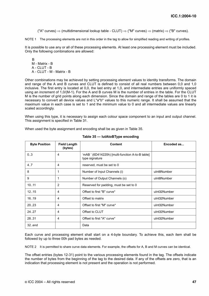
ICC.1:2004-10
("A" curves) ⇒ (multidimensional lookup table - CLUT) ⇒ ("M" curves) ⇒ (matrix) ⇒ ("B" curves).
NOTE 1 The processing elements are not in this order in the tag to allow for simplified reading and writing of profiles.
It is possible to use any or all of these processing elements. At least one processing element must be included.Only the following combinations are allowed:
B M - Matrix - B A - CLUT - B A - CLUT - M - Matrix - B
Other combinations may be achieved by setting processing element values to identity transforms. The domain and range of the A and B curves and CLUT is defined to consist of all real numbers between 0,0 and 1,0 inclusive. The first entry is located at 0,0, the last entry at 1,0, and intermediate entries are uniformly spaced using an increment of 1,0/(M-1). For the A and B curves M is the number of entries in the table. For the CLUT M is the number of grid points along each dimension. Since the domain and range of the tables are 0 to 1 it is necessary to convert all device values and L*a*b* values to this numeric range. It shall be assumed that the maximum value in each case is set to 1 and the minimum value to 0 and all intermediate values are linearly scaled accordingly.
When using this type, it is necessary to assign each colour space component to an input and output channel.This assignment is specified in Table 31.
When used the byte assignment and encoding shall be as given in Table 35.
Each curve and processing element shall start on a 4-byte boundary. To achieve this, each item shall be followed by up to three 00h pad bytes as needed.
NOTE 2 It is permitted to share curve data elements. For example, the offsets for A, B and M curves can be identical.
The offset entries (bytes 12-31) point to the various processing elements found in the tag. The offsets indicate the number of bytes from the beginning of the tag to the desired data. If any of the offsets are zero, that is an indication that processing element is not present and the operation is not performed.
Table 35 — lutAtoBType encoding
Byte Position Field Length (bytes)
Content Encoded as...
0..3 4 ‘mAB ’ (6D414220h) [multi-function A-to-B table] type signature
4..7 4 reserved, must be set to 0
8 1 Number of Input Channels (i) uInt8Number
9 1 Number of Output Channels (o) uInt8Number
10..11 2 Reserved for padding, must be set to 0
12..15 4 Offset to first "B" curve* uInt32Number
16..19 4 Offset to matrix uInt32Number
20..23 4 Offset to first "M" curve* uInt32Number
24..27 4 Offset to CLUT uInt32Number
28..31 4 Offset to first "A" curve* uInt32Number
32..end Data
© ICC 2004 – All rights reserved 47

ICC.1:2004-10
This tag type can be used with either the CIEXYZ or CIELAB Profile Connection Space. Which has been used shall be identified in the profile header.
10.10.2 "A" curves
There are the same number of "A" curves as there are input channels. The "A" curves may only be used when the CLUT is used. The curves are stored sequentially, with 00h bytes used for padding between them if needed. Each "A" curve is stored as an embedded curveType or a parametricCurveType (see 10.5 or 10.15).The length is as indicated by the convention of the respective curve type. Note that the entire tag type, including the tag type signature and reserved bytes, is included for each curve.
10.10.3 CLUT
The CLUT appears as an n-dimensional array, with each dimension having a number of entries corresponding to the number of grid points.
The CLUT values are arrays of 8 bit or 16 bit unsigned values, normalized to the range of 0-255 or 65535.
The CLUT is organized as an i-dimensional array with a variable number of grid points in each dimension, where i is the number of input channels in the transform. The dimension corresponding to the first channel varies least rapidly and the dimension corresponding to the last input channel varies most rapidly. Each grid point value is an o-integer array, where o is the number of output channels. The first sequential integer of the entry contains the function value for the first output function, the second sequential integer of the entry contains the function value for the second output function and so on until all of the output functions have been supplied.The equation for computing the byte size of the CLUT is defined below.
nGrid1 * nGrid2 *... * nGridN * number of output channels (o) * size of (channel component) (16)
When used the byte assignment and encoding for the CLUT shall be as given in Table 36.
If the number of input channels does not equal the number of output channels, the CLUT must be present.
If the number of grid points in a one-dimensional curve, or in a particular dimension of the CLUT, is two, the data for those points shall be set so that the correct results are obtained when linear interpolation is used to generate intermediate values.
10.10.4 "M" curves
There are the same number of "M" curves as there are output channels. The curves are stored sequentially, with 00h bytes used for padding between them if needed. Each "M" curve is stored as an embedded curveTypeor a parametricCurveType (see 10.5 or 10.15). The length is as indicated by the convention of the respective
Table 36 — lutAtoBType CLUT encoding
Byte Position Field Length (bytes)
Content Encoded as...
0..15 16 Number of grid points in each dimension. Only the first i entries are used, where i is the number of input channels. Unused entries shall be set to 00h.
uInt8Number[16]
16 1 Precision of data elements in bytes. Must be either 01h or 02h.
uInt8Number
17..19 3 Reserved for padding, must be set to 0
20..end See equation 16 above
CLUT data points (arranged as described in the text).
uInt8Number[...] or uInt16Number[...]
48 © ICC 2004 – All rights reserved
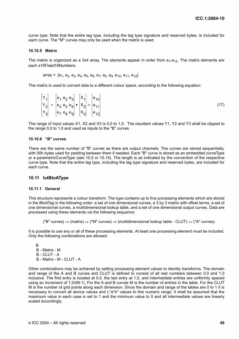
ICC.1:2004-10
curve type. Note that the entire tag type, including the tag type signature and reserved bytes, is included for each curve. The "M" curves may only be used when the matrix is used.
10.10.5 Matrix
The matrix is organized as a 3x4 array. The elements appear in order from e1-e12. The matrix elements are each s15Fixed16Numbers.
array = [e1, e2, e3, e4, e5, e6, e7, e8 ,e9 ,e10, e11, e12]
The matrix is used to convert data to a different colour space, according to the following equation:
(17)
The range of input values X1, X2 and X3 is 0,0 to 1,0. The resultant values Y1, Y2 and Y3 shall be clipped to the range 0,0 to 1,0 and used as inputs to the "B" curves.
10.10.6 “B" curves
There are the same number of "B" curves as there are output channels. The curves are stored sequentially, with 00h bytes used for padding between them if needed. Each "B" curve is stored as an embedded curveTypeor a parametricCurveType (see 10.5 or 10.15). The length is as indicated by the convention of the respective curve type. Note that the entire tag type, including the tag type signature and reserved bytes, are included for each curve.
10.11 lutBtoAType
10.11.1 General
This structure represents a colour transform. The type contains up to five processing elements which are stored in the BtoATag in the following order: a set of one dimensional curves, a 3 by 3 matrix with offset terms, a set of one dimensional curves, a multidimensional lookup table, and a set of one dimensional output curves. Data are processed using these elements via the following sequence:
("B" curves) ⇒ (matrix) ⇒ ("M" curves) ⇒ (multidimensional lookup table - CLUT) ⇒ ("A" curves).
It is possible to use any or all of these processing elements. At least one processing element must be included.Only the following combinations are allowed:
B B - Matrix - M B - CLUT - A B - Matrix - M - CLUT - A
Other combinations may be achieved by setting processing element values to identity transforms. The domain and range of the A and B curves and CLUT is defined to consist of all real numbers between 0,0 and 1,0 inclusive. The first entry is located at 0,0, the last entry at 1,0, and intermediate entries are uniformly spaced using an increment of 1,0/(M-1). For the A and B curves M is the number of entries in the table. For the CLUT M is the number of grid points along each dimension. Since the domain and range of the tables are 0 to 1 it is necessary to convert all device values and L*a*b* values to this numeric range. It shall be assumed that the maximum value in each case is set to 1 and the minimum value to 0 and all intermediate values are linearly scaled accordingly.
Y1
Y2
Y3
e1 e2 e3
e4 e5 e6
e7 e8 e9
X1
X2
X3
e10
e11
e12
+•=
© ICC 2004 – All rights reserved 49

ICC.1:2004-10
When using this type, it is necessary to assign each colour space component to an input and output channel.This assignment is specified in Table 31.
When used the byte assignment and encoding shall be as given in Table 37.
Each curve and processing element must start on a 4-byte boundary. To achieve this, each item may be followed by up to three 00h pad bytes as needed.
NOTE It is permitted to share curve data elements. For example, the offsets for A, B and M curves can be identical.
The offset entries (bytes 12-31) point to the various processing elements found in the tag. The offsets indicate the number of bytes from the beginning of the tag to the desired data. If any of the offsets are zero, that is an indication that processing element is not present and the operation is not performed.
This tag type can be used with either the CIEXYZ or CIELAB Profile Connection Space. Which has been used shall be identified in the profile header.
10.11.2 "B" curves
There are the same number of "B" curves as there are input channels. The curves are stored sequentially, with 00h bytes used for padding between them if needed. Each "B" curve is stored as an embedded curveType tag or a parametricCurveType (see 10.5 or 10.15). The length is as indicated by the convention of the proper curve type. Note that the entire tag type, including the tag type signature and reserved bytes, is included for each curve.
10.11.3 Matrix
The matrix is organized as a 3x4 array. The elements of the matrix appear in the type in order from e1-e12. The matrix elements are each s15Fixed16Numbers.
array = [e1, e2, e3, e4, e5, e6, e7, e8 ,e9 ,e10, e11, e12]
The matrix is used to convert data to a different colour space, according to the following equation:
Table 37 — lutBtoAType encoding
Byte Position Field Length (bytes)
Content Encoded as...
0..3 4 ‘mBA’ (6D424120h) [multi-function B-toA table] type signature
4..7 4 reserved, must be set to 0
8 1 Number of Input Channels (i) uInt8Number
9 1 Number of Output Channels (o) uInt8Number
10-11 2 Reserved for padding, must be set to 0
12..15 4 Offset to first "B" curve* uInt32Number
16..19 4 Offset to matrix uInt32Number
20..23 4 Offset to first "M" curve* uInt32Number
24..27 4 Offset to CLUT uInt32Number
28..31 4 Offset to first "A" curve* uInt32Number
32..end Data
50 © ICC 2004 – All rights reserved

ICC.1:2004-10
(18)
The range of input values X1, X2 and X3 is 0,0 to 1,0. The resultant values Y1, Y2 and Y3 shall be clipped to the range 0,0 to 1,0 and used as inputs to the "M" curves.
The matrix is allowed only if the number of output channels, or "M" curves, is 3.
10.11.4 "M" curves
There are the same number of "M" curves as there are input channels. The curves are stored sequentially, with 00h bytes used for padding between them if needed. Each "M" curve is stored as an embedded curveType or a parametricCurveType (see 10.5 or 10.15). The length is as indicated by the convention of the proper curve type. Note that the entire tag type, including the tag type signature and reserved bytes, are included for each curve. The "M" curves may only be used when the matrix is used.
10.11.5 CLUT
The CLUT appears as an n-dimensional array, with each dimension having a number of entries corresponding to the number of grid points.
The CLUT values are arrays of 8 bit or 16 bit unsigned values, normalized to the range of 0-255 or 65535.
The CLUT is organized as an i-dimensional array with a variable number of grid points in each dimension, where i is the number of input channels in the transform. The dimension corresponding to the first channel varies least rapidly and the dimension corresponding to the last input channel varies most rapidly. Each grid point value is an o-integer array, where o is the number of output channels. The first sequential integer of the entry contains the function value for the first output function, the second sequential integer of the entry contains the function value for the second output function and so on until all of the output functions have been supplied.The equation for computing the byte size of the CLUT is:
nGrid1 * nGrid2 *...* nGridN * number of output channels * size of (channel component) (19)
When used the byte assignment and encoding for the CLUT shall be as given in Table 38.
If the number of grid points in a one-dimensional curve, or in a particular dimension of the CLUT, is two, the data for those points shall be set so that the correct results are obtained when linear interpolation is used to generate intermediate values.
Table 38 — lutBtoAType CLUT encoding
Byte Position Field Length (bytes)
Content Encoded as...
0..15 16 Number of grid points in each dimension. Only the first i entries are used, where i is the number of input channels. Unused entries shall be set to 00h.
uInt8Number[16]
16 1 Precision of data elements in bytes. Must be either 01h or 02h.
uInt8Number
17..19 3 Reserved for padding.
20..end See equation 19 above
CLUT data points (arranged as described in the text).
uInt8Number[...] or uInt16Number[...]
Y1
Y2
Y3
e1 e2 e3
e4 e5 e6
e7 e8 e9
X1
X2
X3
e10
e11
e12
+•=
© ICC 2004 – All rights reserved 51

ICC.1:2004-10
If the number of input channels does not equal the number of output channels, the CLUT must be present.
10.11.6 "A" curves
There are the same number of "A" curves as there are output channels. The "A" curves may only be used when the CLUT is used. The curves are stored sequentially, with 00h bytes used for padding between them if needed. Each "A" curve is stored as an embedded curveType or a parametricCurveType (see 10.5 or 10.15).The length is as indicated by the convention of the proper curve type. Note that the entire tag type, including the tag type signature and reserved bytes, is included for each curve.
10.12 measurementType
The measurementType information refers only to the internal profile data and is meant to provide profile makers an alternative to the default measurement specifications. When used the byte assignment and encoding shall be as given in Table 39.
The encoding for the standard observer field is shown in Table 40.
The encoding for the measurement geometry field is shown in Table 41.
Table 39 — measurementType structure
Byte Position
Field Length (bytes)
Content Encoded as...
0..3 4 ‘meas’ (6D656173h) type signature
4..7 4 reserved, must be set to 0
8..11 4 encoded value for standard observer see Table 40 below
12..23 12 XYZ tristimulus values for measurement backing XYZNumber
24..27 4 encoded value for measurement geometry see Table 41 below
28..31 4 encoded value for measurement flare see Table 42 below
32..35 4 encoded value for standard illuminant see Table 43 below
Table 40 — Standard observer encodings
Standard Observer Encoded Value
unknown 00000000h
CIE 1931 standard colorimetric observer 00000001h
CIE 1964 standard colorimetric observer 00000002h
Table 41 — Measurement geometry encodings
Geometry Encoded Value
unknown 00000000h
0/45 or 45/0 00000001h
0/d or d/0 00000002h
52 © ICC 2004 – All rights reserved

ICC.1:2004-10
The encoding for the measurement flare value is shown in Table 42, and is equivalent to the basic numeric type u16Fixed16Number in 5.3.4.
The encoding for the standard illuminant field is shown in Table 43.
10.13 multiLocalizedUnicodeType
This tag structure contains a set of multilingual Unicode strings associated with a profile. Each string in the set is stored in a separate record with the information about what language and region the string is for.
When used the byte assignment and encoding shall be as given in Table 44.
Note that the third field of this tag, the name record size should, for the time being, contain the value 12, which corresponds to the size in bytes of each name record. Any code that needs to access the nth name record should determine the record’s offset by multiplying n by the contents of this size field and adding 16. This minor extra effort allows for future expansion of name records, should the need arise, without having to define yet another new tag type.
NOTE 1 Multiple strings within this tag are permitted to share storage locations. For example, en/US and en/UK can refer to the same string data.
For the specification of Unicode, see The Unicode Standard published by The Unicode Consortium or visit their website at http://www.unicode.org. For the definition of language code and region codes, see ISO-639 and ISO-3166. The Unicode strings in storage should be encoded as 16-bit big-endian, UTF-16BE, and should not be NULL terminated.
NOTE 2 For additional clarification on the encodings used see the ICC technical note 01-2002 available on www.color.org.
If the specific string for the desired region is not stored in the tag, the string with the same language code should be used. If the specific string for the desired language is not stored in the tag, the first string in the tag is used if no other user preference is available.
Table 42 — Measurement flare encodings
Flare Encoded Value
0 (0%) 00000000h
1,0 (or 100%) 00010000h
Table 43 — Standard illuminant encodings
Standard Illuminant Encoded Value
unknown 00000000h
D50 00000001h
D65 00000002h
D93 00000003h
F2 00000004h
D55 00000005h
A 00000006h
Equi-Power (E) 00000007h
F8 00000008h
© ICC 2004 – All rights reserved 53

ICC.1:2004-10
10.14 namedColor2Type
The namedColor2Type is a count value and array of structures that provide colour coordinates for 7-bit ASCIIcolour names. For each named colour, a PCS and optional device representation of the colour are given. Both representations are 16-bit values and PCS values shall be relative colorimetric. The device representation corresponds to the header’s “colour space of data” field. This representation should be consistent with the “number of device components” field in the namedColor2Type. If this field is 0, device coordinates are not provided. The PCS representation corresponds to the header’s PCS field. The PCS representation is always provided. Colour names are fixed-length, 32-byte fields including null termination. In order to maintain maximum portability, it is strongly recommended that special characters of the 7-bit ASCII set not be used.
When used the byte assignment and encoding shall be as given in Table 45.
Table 44 — multiLocalizedUnicodeType
Byte Position Field Length (bytes)
Content Encoded as...
0..3 4 ‘mluc’ (0x6D6C7563) type signature
4..7 4 reserved, must be set to 0
8..11 4 number of names (n): the number of name records that follow.
uInt32Number
12..15 4 name record size: the length in bytes of each name record that follows. Each name record currently consists of the field’s first name language code to first name offset.
uInt32Number
16..17 2 first name language code: language code from ISO-639
uInt16Number
18..19 2 first name country code: region code from ISO-3166 uInt16Number
20-23 4 first name length: the length in bytes of the string uInt32Number
24..27 4 first name offset: the offset from the start of the tag in bytes
uInt32Number
28..28+(12*(n-1))-1 (or 15+12*n)
12*(n-1) if more than one name record, store them here
28+(12*(n-1) (or (16+12*n))...end
Storage area of Unicode characters
Table 45 — namedColor2Type encoding(Sheet 1 of 2)
Byte Position Field Length (bytes)
Content Encoded as...
0..3 4 ‘ncl2’ (6E636C32h) type signature
4..7 4 reserved, must be set to 0
8..11 4 vendor specific flag (least-significant 16 bits reserved for ICC use)
12..15 4 count of named colours (n) uInt32Number
16..19 4 number of device coordinates (m) for each named colour
uInt32Number
54 © ICC 2004 – All rights reserved

ICC.1:2004-10
For colour values that are in the Lab colour space on the PCS side of the tag, this tag uses the legacy 16-bit Lab encoding defined in clause 10.8 - Tables 32 and 33, not the 16-bit CIELAB PCS encoding that is defined in 6.3.4.2 - Tables 8 and 9. This encoding is retained for backwards compatibility with profile version 2. The L* values have a different encoding than the a* and b* values. The 16 bit L* encoding shall be as shown in Table 32 and the a* and b* 16 bit encoding shall be as shown in Table 33. Note that though the 16-bit L* encoding can represent values slightly greater than 100,0, these are not valid PCS L* values and they should not be used.The 16-bit a* and b* encoding can represent values slightly greater than 127,0. Since the theoretical a* and b* limits are well beyond these values, these are valid PCS values.
To convert colour values from this tag's legacy 16-bit Lab encoding to the 16-bit CIELAB PCS encoding defined in clause 6.3.4.2 - Tables 8 and 9, multiply all values with 65535/65280 (that is, FFFFh/FF00h). Any colour values that are in the value range of legacy 16-bit PCS Lab, but not in the more recent 16-bit CIELAB PCS encoding, shall be clipped on a per-component basis. To convert colour values from the 16-bit CIELAB PCS encoding defined in clause 6.3.4.2 - Tables 8 and 9 to this tag's legacy 16-bit Lab encoding, divide all values with 65535/65280.
10.15 parametricCurveType
The parametricCurveType describes a one-dimensional curve by specifying one of a predefined set of functions using the parameters. When used the byte assignment and encoding shall be as given in Table 46
20..51 32 prefix for each colour name (32-byte field including null termination)
7-bit ASCII
52..83 32 suffix for each colour name (32-byte field including null termination)
7-bit ASCII
84..115 32 first colour root name (32-byte field including null termination)
7-bit ASCII
116..121 6 first named colour’s PCS coordinates. The encoding is the same as the encodings for the PCS colour spaces as described in 6.3.4.2 and 10.8. Only 16-bit L*a*b*, encoded using legacy 16-bit PCS Lab encoding, and XYZ are allowed. PCS values shall be relative colorimetric.
uInt16Number[3]
122..121+(m*2) m*2 first named colour’s device coordinates. For each coordinate, 0000h represents the minimum value for the device coordinate and FFFFh represents the maximum value for the device coordinate. The number of coordinates is given by the "number of device coordinates" field. If the "number of device coordinates" field is 0, this field is not given.
uInt16Number[...]
122+(m*2)..end (n-1)*(38+m*2)
if n > 1 the remaining n-1 colours are described in a manner consistent with the first named colour, see byte offsets 84..121+(m*2).
Table 45 — namedColor2Type encoding(Sheet 2 of 2)
© ICC 2004 – All rights reserved 55

ICC.1:2004-10
.
The encoding for the function type field and the parameters are shown in Table 47
NOTE More functions can be added as necessary.
The order of the parameters in the tag data, Table 46, follows the left-to-right order of the parameters in Table 47.
The domain and range of each function shall be [0,0 1,0]. Any function value outside the range shall be clipped to the range of the function. When unsigned integer data is supplied as input, it shall be converted to the domain be dividing it by a factor of (2N) -1, where N is the number of bits used to represent the input data. When unsigned integer data is required as output, it shall be converted from the range by multiplying it by a factor of (2M) -1, where M is the number of bits used to represent the output data.
If the input is the XYZ PCS, 1+(32767/32768) shall be mapped to the value 1,0. If the output is the XYZ PCS, the value 1,0 shall be mapped to 1+(32767/32768).
Table 46 — parametricCurveType encoding
Byte Position
Field Length (bytes)
Content Encoded as...
0..3 4 ‘para’ (70617261h) type signature
4..7 4 reserved, must be set to 0
8..9 2 encoded value of the function type uInt16Number (see table 47)
10..11 2 reserved, must be set to 0
12..end see table 47
one or more parameters (see table 47) s15Fixed16Number [...]
Table 47 — parametricCurveType function type encoding
Field length (bytes)
Function type Encoded value
Parameters Note
4 0000h
12 0001h CIE 122-1966
16 0002h IEC 61966-3
20 0003h IEC 61966-2.1 (sRGB)
28 0004h
Y Xγ
= γ
Y aX b+( )γ
= X b a⁄–≥( )Y 0= X b a⁄–<( )
γ a b
Y aX b+( )γ
c+= X b a⁄–≥( )Y c= X b a⁄–<( )
γ a b c
Y aX b+( )γ
= X d≥( )Y cX= X d<( )
γ a b c d
Y aX b+( )γ
e+= X d≥( )
Y cX f+( )= X d<( )
γ a b c d e f
56 © ICC 2004 – All rights reserved

ICC.1:2004-10
10.16 profileSequenceDescType
This type is an array of structures, each of which contains information from the header fields and tags from the original profiles which were combined to create the final profile. The order of the structures is the order in which the profiles were combined and includes a structure for the final profile. This provides a description of the profile sequence from source to destination, typically used with the DeviceLink profile.
When used the byte assignment and structure shall be as given in Table 48.
Each profile description structure has the format shown in Table 49.
If the deviceMfgDescTag and/or deviceModelDescTag is not present in a component profile, then a “placeholder” tag should be inserted. This tag should have a 0 in the number of names field in the multiLocalizedUnicodeType structure with no name record or strings.
Also note that the entire tag, including the tag type, should be stored.
If the technologyTag is not present, bytes 16..19 should be 00000000h.
10.17 responseCurveSet16Type
ICC profiles for display and output devices will produce the desired colour only while the device has a particular relationship between normalized device codes and physical colorant amount (the reference response). If the response of the device changes (the current response), the profile will no longer produce the correct result. In many cases it is impractical to produce a new profile for the current response, but the change can be compensated for by modifying the single channel device codes.
The purpose of this tag type is to provide a mechanism to relate physical colorant amounts with the normalized device codes produced by lut8Type, lut16Type, lutAToBType or lutBtoAType tags so that corrections can be
Table 48 — profileSequenceDescType structure
Byte Position
Field Length (bytes)
Content
0..3 4 ‘pseq’ (70736571h) type signature
4..7 4 reserved, must be set to 0
8..11 4 count value specifying number of description structures in the array
12..end variable count profile description structures - see Table 49
Table 49 — Profile Description structure
Byte Position
Field Length (bytes)
Content
0..3 4 Device manufacturer signature (from corresponding profile’s header)
4..7 4 Device model signature (from corresponding profile’s header)
8..15 8 Device attributes (from corresponding profile’s header)
16..19 4 Device technology information such as CRT, Dye Sublimation, etc. (corresponding to profile’s technology signature)
20..m variable displayable description of device manufacturer (profile’s deviceMfgDescTag)
m+1..n variable displayable description of device model (profile’s deviceModelDescTag)
© ICC 2004 – All rights reserved 57

ICC.1:2004-10
made for variation in the device without having to produce a new profile. The mechanism can be used by applications to allow users with relatively inexpensive and readily available instrumentation to apply corrections to individual output colour channels in order to achieve consistent results.
Two pieces of information are necessary for this compensation: the reference response and the current response. This tag type provides a mechanism that allows applications that create profiles to specify the reference response. The way in which applications determine and make use of the current response is not specified at this time.
The measurements are of the standard variety used in the photographic, graphic arts, and television industries for process control. The measurements are intended to represent colorant amounts and so different measurement techniques are appropriate for different device types.
It is the job of the profile creator to provide reference response data in as many measurement units as practical and appropriate so that applications may select the same units that are measured by the user’s instrument. Since it is not possible in general to translate between measurement units, and since most instruments only measure in one unit, providing a wide range of measurement units is vital. The profile originator must decide which measurement units are appropriate for the device.
Here are some examples of suitable measurement units: For process colours, density should be reported. Red-filter density should be reported for the cyan channel, green-filter for the magenta channel, blue-filter for the yellow channel, and visual for the black channel. For other colorants, such as Spot colours or Hi-Fi colours, it is the responsibility of the profile creator to select the appropriate units of measure for the system being profiled. Several different density standards are used around the world, so it is important that profile creators report in as many different density units as possible. See Table 52 Examples of suitable density measurements are: Status T, Status E, Status I and DIN.
This structure relates normalized device codes that would result from a lut16Type tag with density measurements of the resulting colorant amount. Normalized device codes resulting from a lut8Type tag should first be multiplied by 257 (101h).
For those fields that have been structured in arrays of channel data, the channels are ordered as specified for the appropriate colour space in Table 31, “lut16Type channel encodings”.
When used the byte assignment and structure shall be as given in Table 50.
Each response curve structure has the format shown in Table 51
Table 50 — responseCurveSet16Type structure
Byte Position Field Length (bytes)
Content Encoded as...
0..3 4 ‘rcs2’ (72637332h) [response curve set with 2-byte precision] type signature
4..7 4 reserved, must be set to 0
8..9 2 number of channels uInt16Number
10..11 2 count of measurement types uInt16Number
12..m an array of offsets, each relative to byte 0 of this structure, with one entry for each measurement type. Each will point to the response data for the measurement unit.
uInt32Number[...]
m+1..n count response curve structures see Table 51 below
58 © ICC 2004 – All rights reserved

ICC.1:2004-10
.
NOTE The XYZNumber values are CIEXYZ tristimulus values as described in 5.1.11, defined to be relative colorimetric. The response arrays must be ordered with normalized device code elements increasing.
The measurement unit is encoded as shown in Table 52.
Table 51 — Curve structure
Byte Position Field Length (bytes)
Content Encoded as...
0..3 4 measurement unit signature see Table 52 below
4..m number of measurements for each channel:This is an array with one entry for each channel. Each array element specifies the count of measurements for each channel.
uInt32Number[...]
m+1..n number-of-channels measurements of patch with the maximum colorant value. PCS values shall be relative colorimetric.
XYZNumber[...]
n+1..p number-of-channels response arrays. Each array contains number-of-measurementsresponse16Numbers appropriate to the channel. The arrays shall be ordered in the channel order specified in Table 31 for the appropriate colour space.
response16Number[...]
Table 52 — Curve measurement encodings
Measurement Unit Signature Hex Encoding
Status A: ISO 5-3 densitometer response. This is the accepted standard for reflection densitometers for measuring photographic colour prints.
‘StaA’ 53746141h
Status E: ISO 5-3 densitometer response which is the accepted standard in Europe for colour reflection densitometers.
‘StaE’ 53746145h
Status I: ISO 5-3 densitometer response commonly referred to as narrow band or interference-type response.
‘StaI’ 53746149h
Status T: ISO 5-3 wide band colour reflection densitometer response which is the accepted standard in the United States for colour reflection densitometers.
‘StaT’ 53746154h
Status M: ISO 5-3 densitometer response for measuring colour negatives.
‘StaM’ 5374614Dh
DIN E: DIN 16536-2 densitometer response, with no polarising filter.
‘DN ’ 434E2020h
DIN E: DIN 16536-2 densitometer response, with polarising filter.
‘DN P’ 434E2050h
DIN I: DIN 16536-2 narrow band densitometer response, with no polarising filter.
‘DNN ’ 434E4E20h
DIN I: DIN 16536-2 narrow band densitometer response, with polarising filter.
‘DNNP’ 434E4E50h
© ICC 2004 – All rights reserved 59

ICC.1:2004-10
10.18 s15Fixed16ArrayType
This type represents an array of generic 4-byte/32-bit fixed point quantity. The number of values is determined from the size of the tag.
When used the byte assignment and encoding shall be as given in Table 53.
10.19 signatureType
The signatureType contains a four-byte sequence, such as those defined in Table 22. Sequences of less than four characters are padded at the end with spaces, 20h. Typically this type is used for registered tags that can be displayed on many development systems as a sequence of four characters.
When used the byte assignment and encoding shall be as given in Table 54.
10.20 textType
The textType is a simple text structure that contains a 7-bit ASCII text string. The length of the string is obtained by subtracting 8 from the element size portion of the tag itself. This string must be terminated with a 00h byte.
When used the byte assignment and encoding shall be as given in Table 55.
Table 53 — s16Fixed16ArrayType encoding
Byte Position
Field Length (bytes)
Content
0..3 4 ‘sf32’ (73663332h) type signature
4..7 4 reserved, must be set to 0
8..end an array of s15Fixed16Number values
Table 54 — signatureType encoding
Byte Position
Field Length (bytes)
Content
0..3 4 ‘sig ’ (73696720h) type signature
4..7 4 reserved, must be set to 0
8..11 4 four-byte signature
Table 55 — textType encoding
Byte Position
Field Length (bytes)
Content
0..3 4 ‘text’ (74657874h) type signature
4..7 4 reserved, must be set to 0
8..end a string of (element size - 8) 7-bit ASCII characters
60 © ICC 2004 – All rights reserved

ICC.1:2004-10
10.21 u16Fixed16ArrayType
This type represents an array of generic 4-byte/32-bit quantity. The number of values is determined from the size of the tag.
When used the byte assignment and encoding shall be as given in Table 56.
10.22 uInt16ArrayType
This type represents an array of generic 2-byte/16-bit quantity. The number of values is determined from the size of the tag.
When used the byte assignment and encoding shall be as given in Table 57.
10.23 uInt32ArrayType
This type represents an array of generic 4-byte/32-bit quantity. The number of values is determined from the size of the tag.
When used the byte assignment and encoding shall be as given in Table 58.
Table 56 — u16Fixed16ArrayType encoding
Byte Position
Field Length (bytes)
Content
0..3 4 ‘uf32’ (75663332h) type signature
4..7 4 reserved, must be set to 0
8..end an array of u16Fixed16Number values
Table 57 — uInt16ArrayType encoding
Byte Position
Field Length (bytes)
Content
0..3 4 ‘ui16’ (75693136h) type signature
4..7 4 reserved, must be set to 0
8..end an array of unsigned 16-bit integers
Table 58 — uInt32ArrayType encoding
Byte Position
Field Length (bytes)
Content
0..3 4 ‘ui32’ (75693332h) type signature
4..7 4 reserved, must be set to 0
8..end an array of unsigned 32-bit integers
© ICC 2004 – All rights reserved 61

ICC.1:2004-10
10.24 uInt64ArrayType
This type represents an array of generic 8-byte/64-bit quantity. The number of values is determined from the size of the tag.
When used the byte assignment and encoding shall be as given in Table 59.
10.25 uInt8ArrayType
This type represents an array of generic 1-byte/8-bit quantity. The number of values is determined from the size of the tag.
When used the byte assignment and encoding shall be as given in Table 60.
10.26 viewingConditionsType
This type represents a set of viewing condition parameters including: CIE ’absolute’ illuminant white point tristimulus values and CIE ’absolute’ surround tristimulus values.
When used the byte assignment and encoding shall be as given in Table 61.
Table 59 — uInt64ArrayType encoding
Byte Position
Field Length (bytes)
Content
0..3 4 ‘ui64’ (75693634h) type signature
4..7 4 reserved, must be set to 0
8..end an array of unsigned 64-bit integers
Table 60 — uInt8ArrayType encoding
Byte Position
Field Length (bytes)
Content
0..3 4 ‘ui08’ (75693038h) type signature
4..7 4 reserved, must be set to 0
8..end an array of unsigned 8-bit integers
Table 61 — viewingConditionsType encoding
Byte Position
Field Length (bytes)
Content Encoded as...
0..3 4 ‘view’ (76696577h) type signature
4..7 4 reserved, must be set to 0
8..19 12 CIE ’absolute’ XYZ values for illuminant (in which Y is in cd/m2)
XYZNumber
20..31 12 CIE ’absolute’ XYZ values for surround (in which Y is in cd/m2)
XYZNumber
32..35 4 illuminant type as described in measurementType
62 © ICC 2004 – All rights reserved

ICC.1:2004-10
The viewing condition described in this tag is the actual viewing condition assumed for the media for which the profile is defined, specified in CIE ‘absolute’ units. Note that the luminanceTag must be the same as the Y value given in this tag.
10.27 XYZType
The XYZType contains an array of three encoded values for the XYZ tristimulus values. The number of sets of values is determined from the size of the tag. When used the byte assignment and encoding shall be as given in Table 62. Tristimulus values shall be non-negative. The signed encoding allows for implementation optimizations by minimizing the number of fixed formats.
Table 62 — XYZType encoding
Byte Position
Field Length (bytes)
Content Encoded as...
0..3 4 ‘XYZ ’ (58595A20h) type signature
4..7 4 reserved, must be set to 0
8..end an array of XYZ numbers XYZNumber
© ICC 2004 – All rights reserved 63
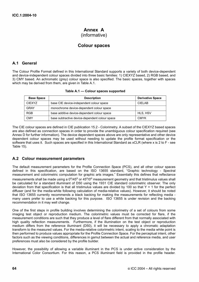
ICC.1:2004-10
Annex A(informative)
Colour spaces
A.1 General
The Colour Profile Format defined in this International Standard supports a variety of both device-dependent and device-independent colour spaces divided into three basic families: 1) CIEXYZ based, 2) RGB based, and 3) CMY based. An achromatic (grey) colour space is also specified. The basic spaces, together with spaces which may be derived from them, are given in Table A.1.
The CIE colour spaces are defined in CIE publication 15.2 - Colorimetry. A subset of the CIEXYZ based spaces are also defined as connection spaces in order to provide the unambiguous colour specification required (see Annex D for further information). The device dependent spaces above are only representative and other device dependent colour spaces may be used without needing to update the profile format specification or the software that uses it. Such spaces are specified in this International Standard as xCLR (where x is 2 to F - see Table 15).
A.2 Colour measurement parameters
The default measurement parameters for the Profile Connection Space (PCS), and all other colour spaces defined in this specification, are based on the ISO 13655 standard, “Graphic technology - Spectral measurement and colorimetric computation for graphic arts images.” Essentially this defines that reflectance measurements shall be made using a 0o/45o or 45o/0o measurement geometry and that tristimulus values shall be calculated for a standard illuminant of D50 using the 1931 CIE standard colorimetric observer. The only deviation from that specification is that all tristimulus values are divided by 100 so that Y = 1 for the perfect diffuser (and for the media-white following calculation of media-relative values). However, it should be noted that ISO 13655 currently recommends a black backing for making the measurements for reflecting media - many users prefer to use a white backing for this purpose. ISO 13655 is under revision and the backing recommendation in it may well change.
One of the first steps in profile building involves determining the colorimetry of a set of colours from some imaging test object or reproduction medium. The colorimetric values must be corrected for flare, if the measurement conditions are such that they produce a level of flare different from that normally associated with high quality reflection measurements. Furthermore, if the illumination on the test object or reproduction medium differs from the reference illuminant (D50), it will be necessary to apply a chromatic adaptation transform to the measured values. For the media-relative colorimetric intent, scaling to the media white point is then performed to produce values appropriate for the Profile Connection Space. For the perceptual intent, other factors such as the viewing conditions, differences in gamut between the actual and reference media, and user preferences must also be considered by the profile builder.
However, the possibility of allowing a variable illuminant in the PCS is under active consideration by the International Color Consortium. For this reason, a PCS illuminant field is provided in the profile header.
Table A.1 — Colour spaces supported
Base Space Description Derivative SpaceCIEXYZ base CIE device-independent colour space CIELAB
GRAY monochrome device-dependent colour space
RGB base additive device-dependent colour space HLS, HSV
CMY base subtractive device-dependent colour space CMYK
64 © ICC 2004 – All rights reserved

ICC.1:2004-10
However, for the purposes of this International Standard this must be set to the CIE Illuminant D50 [X=0,9642, Y=1,0000, Z=0,8249] as defined in 7.2.16. (Note that the PCS illuminant field should not be confused with the viewing conditions tag defined in viewingCondDescTag and viewingConditionsTag - see 9.2.36 and 9.2.37.)
As described in 6.3, the PCS is based on media-relative colorimetry. This is in comparison to ICC-absolute colorimetry. In ICC-absolute colorimetry colours are represented with respect to the illuminant, for example D50, and a perfect diffuser for reflecting and transmitting media. In media-relative colorimetry, colours are represented with respect to a combination of the illuminant and the media’s white, e.g. unprinted paper.
The actual media and viewing conditions used in practice will typically differ from the reference conditions. The profile specification defines tags which provide information about the actual white point and black point of a given media or display. These tags may be used by a CMM to provide functionality beyond that of the default. For example, an advanced CMM could use the tags to adjust colorimetry based on the Dmin (typically highest L*) of a specific media. A tag is also provided to describe the viewing environment. This information is useful in choosing a profile appropriate for the intended viewing method.
A.3 PCS encodings
There are many ways of encoding CIE colorimetry. This specification provides two methods in order to satisfy conflicting requirements for accuracy and storage space. These encodings, a CIELAB encoding and a 16-bit/component CIEXYZ encoding, are described in 6.3.4. The CIEXYZ space represents a linear transformation of the average colour matching data, obtained by mixing red, green and blue lights to match all spectral colours, derived experimentally in the 1920s. The CIELAB space represents a transformation of the CIEXYZ space into one that is more perceptually uniform. This uniformity allows colour errors to be approximately equally weighted throughout its domain. While supporting multiple CIE encodings increases the complexity of colour management, it provides immense flexibility in addressing different user requirements such as colour accuracy and memory footprint.
The relationship between PCS CIEXYZ and PCS CIELAB is given by the set of equations defined in ISO 13655:1996, Annex B, section B.1, but where the media white point (rather than the illuminant) is used as the relevant white point. Thus:
is replaced by (or ) (A.1)
is replaced by (or ) (A.2)
is replaced by (or ) (A.3)
where XYZa, XYZi, XYZmw and XYZr are as defined in 6.3.2.
The equations are as follows:
L* = 116 - 16 (A.4)
a* = 500 (A.5)
b* = 200 (A.6)
XXn-------
XrXi------
XaXmw------------
YYn-------
YrYi------
YaYmw------------
ZZn------
ZrZi-----
ZaZmw------------
fYYn------⎝ ⎠
⎛ ⎞
fXXn------⎝ ⎠
⎛ ⎞ fYYn------⎝ ⎠
⎛ ⎞–
fYYn------⎝ ⎠
⎛ ⎞ fZZn------⎝ ⎠
⎛ ⎞–
© ICC 2004 – All rights reserved 65
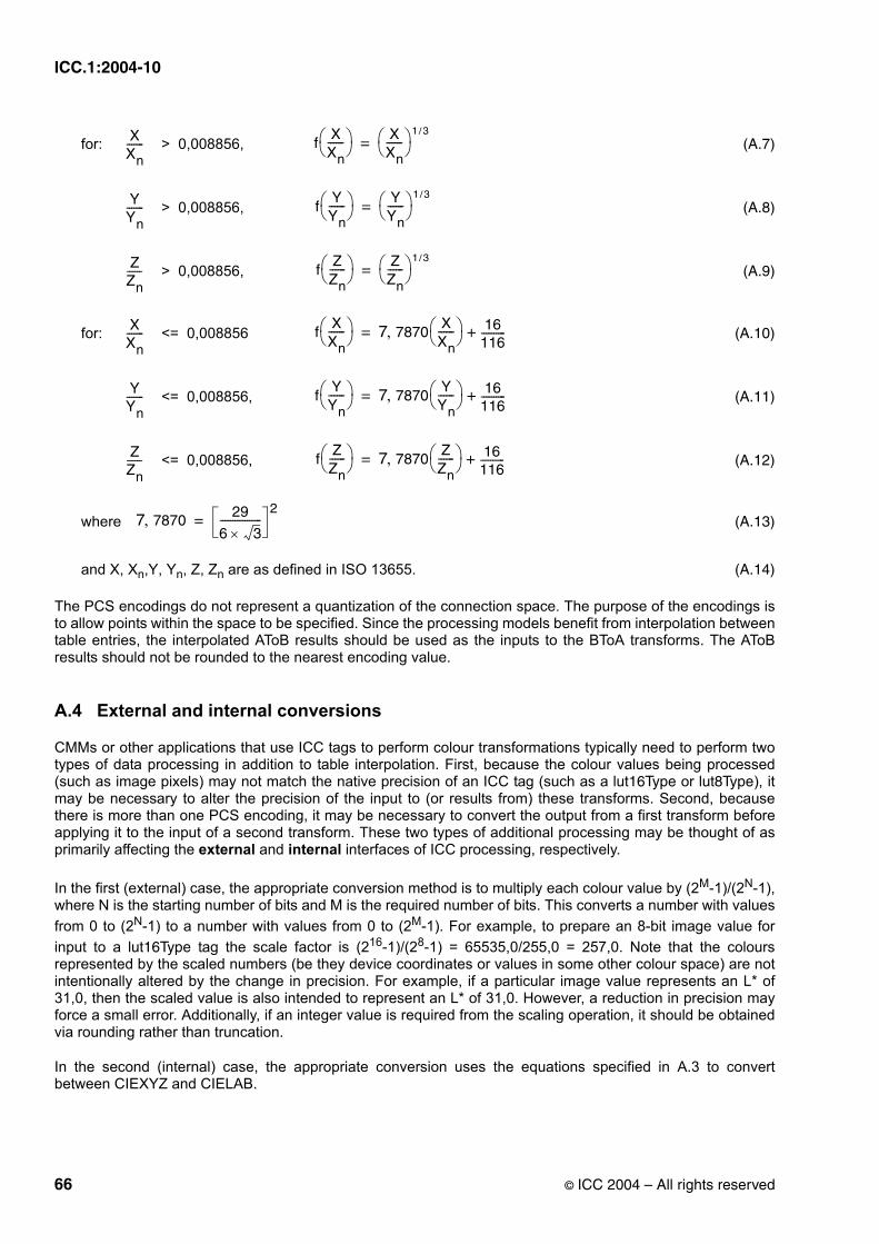
ICC.1:2004-10
for: > 0,008856, (A.7)
> 0,008856, (A.8)
> 0,008856, (A.9)
for: <= 0,008856 (A.10)
<= 0,008856, (A.11)
<= 0,008856, (A.12)
where (A.13)
and X, Xn,Y, Yn, Z, Zn are as defined in ISO 13655. (A.14)
The PCS encodings do not represent a quantization of the connection space. The purpose of the encodings is to allow points within the space to be specified. Since the processing models benefit from interpolation between table entries, the interpolated AToB results should be used as the inputs to the BToA transforms. The AToB results should not be rounded to the nearest encoding value.
A.4 External and internal conversions
CMMs or other applications that use ICC tags to perform colour transformations typically need to perform two types of data processing in addition to table interpolation. First, because the colour values being processed (such as image pixels) may not match the native precision of an ICC tag (such as a lut16Type or lut8Type), it may be necessary to alter the precision of the input to (or results from) these transforms. Second, because there is more than one PCS encoding, it may be necessary to convert the output from a first transform before applying it to the input of a second transform. These two types of additional processing may be thought of as primarily affecting the external and internal interfaces of ICC processing, respectively.
In the first (external) case, the appropriate conversion method is to multiply each colour value by (2M-1)/(2N-1), where N is the starting number of bits and M is the required number of bits. This converts a number with values from 0 to (2N-1) to a number with values from 0 to (2M-1). For example, to prepare an 8-bit image value for input to a lut16Type tag the scale factor is (216-1)/(28-1) = 65535,0/255,0 = 257,0. Note that the colours represented by the scaled numbers (be they device coordinates or values in some other colour space) are not intentionally altered by the change in precision. For example, if a particular image value represents an L* of 31,0, then the scaled value is also intended to represent an L* of 31,0. However, a reduction in precision may force a small error. Additionally, if an integer value is required from the scaling operation, it should be obtained via rounding rather than truncation.
In the second (internal) case, the appropriate conversion uses the equations specified in A.3 to convert between CIEXYZ and CIELAB.
XXn------- f
XXn------⎝ ⎠
⎛ ⎞ XXn------⎝ ⎠
⎛ ⎞ 1 3/=
YYn------- f
YYn------⎝ ⎠
⎛ ⎞ YYn------⎝ ⎠
⎛ ⎞ 1 3/=
ZZn------ f
ZZn------⎝ ⎠
⎛ ⎞ ZZn------⎝ ⎠
⎛ ⎞ 1 3/=
XXn------- f
XXn------⎝ ⎠
⎛ ⎞ 7 7870XXn------⎝ ⎠
⎛ ⎞, 16116----------+=
YYn------- f
YYn------⎝ ⎠
⎛ ⎞ 7 7870YYn------⎝ ⎠
⎛ ⎞, 16116----------+=
ZZn------ f
ZZn------⎝ ⎠
⎛ ⎞ 7 7870ZZn------⎝ ⎠
⎛ ⎞, 16116----------+=
7 7870, 29
6 3×-----------------
2=
66 © ICC 2004 – All rights reserved

ICC.1:2004-10
Annex B(normative)
Embedding profiles
B.1 General
This annex details the requirements and options for embedding device profiles within PICT, EPS, TIFF, JFIF, and GIF image files. All profiles except Abstract and DeviceLink profiles can be embedded. The complete profile shall be embedded with all tags intact and unchanged.
NOTE Other file formats, such as ISO 15444-2 and proprietray file formats such as PSD, specify the embedding of ICC profiles. The embedding requirements specified in this Annex are for file formats that do not specifically define how they should be embedded. File formats that support embedding of ICC profiles are given on www.color.org.
B.2 Embedding ICC profiles in PICT files
In the PICT standard specifications Apple Computer Inc. has defined a QuickDraw picture comment type for embedded ICC profiles. The picture comment value of 224 is followed by a 4-byte selector that describes the type of data in the comment. Using a selector allows the flexibility to embed more CMM related information in the future. The selectors shown in Table B.1 are currently defined:
Because the dataSize parameter of the PicComment procedure is a signed 16-bit value, the maximum amount of profile data that can be embedded in a single picture comment is 32763 bytes (32767 - 4 bytes for the selector). Larger profiles can be embedded by using multiple picture comments of selector type 1. The profile data shall be embedded in consecutive order, and the last piece of profile data shall be followed by a picture comment of selector type 2.
All embedded ICC profiles, including those that fit within a single picture comment, shall be followed by the end-of-profile picture comment (selector 2) as shown in the following examples.
EXAMPLE 1: Embedding a 20K profile. PicComment kind = 224, dataSize = 20K + 4, selector = 0, profile data = 20K PicComment kind = 224, dataSize = 4, selector = 2
EXAMPLE 2: Embedding a 50K profile.PicComment kind = 224, dataSize = 32K, selector = 0, profile data = 32K - 4 PicComment kind = 224, dataSize = 18K + 8, selector = 1, profile data = 18K + 4 PicComment kind = 224, dataSize = 4, selector = 2
In ColorSync 1.0, picture comment types CMBeginProfile (220) and CMEndProfile (221) are used to begin and end a picture comment. The CMBeginProfile comment is not supported for ICC profiles; however, the CMEndProfile comment can be used to end the current profile and begin using the System Profile for both ColorSync 1.0 and 2.0.
The CMEnableMatching (222) and CMDisableMatching (223) picture comments are used to begin and end colour matching in both ColorSync 1.0 and 2.0
Table B.1 — PICT selectors
Selector Description0 Beginning of an ICC profile. Profile data to follow.
1 Continuation of ICC profile data. Profile data to follow.
2 End of ICC profile data. No profile data follows.
© ICC 2004 – All rights reserved 67
ICC.1:2004-10
NOTE See “Advanced Color Imaging on the Mac OS”, Apple Computer 1995, [1] for more information about picture comments.
B.3 Embedding ICC profiles in EPS files
There are two places within EPS files that embedding ICC profiles are appropriate. 1) Associated with a screen preview. 2) Associated with the page description. Embedding ICC profiles within a screen preview is necessary so that applications using this screen preview to display a representation of the EPS page description can do so with accurate colours. Embedding ICC profiles within a page description is necessary so that sophisticated applications, such as OPI server software, can perform colour conversions along with image replacement. For general information concerning PostScript’s Document Structuring Conventions (DSC), the EPS file format, or specific PostScript operators, see the PostScript Language Reference Manual.
1) There are a variety of different methods of storing a screen preview within an EPS file depending on the intended environment. For cross platform applications with embedded ICC profiles, TIFF screen previews are recommended. The TIFF format has been extended to support the embedding of ICC profiles. ICC profiles can also be embedded in a platform specific manner. On the Macintosh, Apple has defined a method for embedding ICC profiles in PICT files (see B.2).
A given page description may use multiple distinct colour spaces. In such cases, colour conversions shall be performed to a single colour space to associate with the screen preview.
2) ICC profiles can also be embedded in the page description portion of an EPS file using the %%BeginICCProfile: / %%EndICCProfile comments. This convention is defined as follows.
%%BeginICCProfile: <profileid> <numberof> [<type> [<bytesorlines>]] <profileid> ::= <text> (Profile ID) <numberof> ::= <int> (Lines or physical bytes) <type> ::= Hex | ASCII (Type of data) <bytesorlines> ::= Bytes | Lines (Read in bytes or lines) %%EndICCProfile (no keywords)
These comments are designed to provide information about embedded ICC profiles. If the type argument is missing, ASCII data is assumed. ASCII refers to an ASCII base-85 representation of the data. If the bytesorlines argument is missing, <numberof> shall be considered to indicate bytes of data. If <numberof> = -1, the number of bytes of data are unknown. In this case, to skip over the profile it is necessary to read data until the encountering the %%EndICCProfile comment.
<profileID> provides the profile’s ID in order to synchronize it with PostScript’s setcolorspace and findcolorrendering operators and associated operands (see below). Note that <numberof> indicates the bytes of physical data, which vary from the bytes of virtual data in some cases. With hex, each byte of virtual data is represented by two ASCII characters (two bytes of physical data). Although the PostScript interpreter ignores white space and percent signs in hex and ASCII data, these count toward the byte count.
Each line of profile data shall begin with a single percent sign followed by a space (%). This makes the entire profile section a PostScript language comment so the file can be sent directly to a printer without modification. The space avoids confusion with the open extension mechanism associated with DSC comments.
ICC profiles can be embedded within EPS files to allow sophisticated applications, such as OPI server software, to extract the profiles, and to perform colour processing based on these profiles. In such situations it is desirable to locate the page description’s colour space and rendering intent, since this colour space and rendering intent may need to be modified based on any colour processing. The %%BeginSetColorSpace: / %%EndSetColorSpace and %%BeginRenderingIntent: / %%EndRenderingIntent comments are used to delimit the colour space and rendering intent respectively.
%%BeginSetColorSpace: <profileid> <profileid> ::= <text> (ICC Profile ID) %%EndSetColorSpace (no keywords)
68 © ICC 2004 – All rights reserved

ICC.1:2004-10
<profileid> provides the ICC profile’s ID corresponding to this colour space. The ICC profile with this profile ID must have occurred in the PostScript job using the %%BeginICCProfile: / %%EndICCProfile comment convention prior to this particular %%BeginSetColorSpace: comment.
NOTE 1 An example usage is shown here for CIE 1931 (XYZ)-space with D65 white point that refers to the ICC profile with <profileid> = XYZProfile.
%%BeginSetColorSpace: XYZProfile [/CIEBasedABC << /WhitePoint [0.9505 1 1.0890] /RangeABC [0 0.9505 0 1 0 1.0890] /RangeLMN [0 0.9505 0 1 0 1.0890] >>] setcolorspace %%EndSetColorSpace
The setcolorspace command is included within the comments. The PostScript enclosed in these comments shall not perform any other operations other than setting the colour space and shall have no side effects.
%%BeginRenderingIntent: <profileid> <profileid> ::= <text> (ICC Profile ID) %%EndRenderingIntent (no keywords)
<profileid> provides the ICC profile’s ID corresponding to this rendering intent. The ICC profile with this profile ID shall have occurred in the PostScript job using the %%BeginICCProfile: / %%EndICCProfilecomment convention prior to invocation of this particular %%BeginRenderingIntent: comment.
NOTE 2 An example usage is shown here for the Perceptual rendering intent that refers to the ICC profile with <profileid> = RGBProfile.
%%BeginRenderingIntent: RGBProfile /Perceptual findcolorrendering pop /ColorRendering findresource setcolorrendering %%EndRenderingIntent
The setcolorrendering command is included within the comments. The PostScript enclosed in these comments shall not perform any other operations other than setting the rendering intent and shall have no side effects.
B.4 Embedding ICC profiles in TIFF files
The discussion below assumes some familiarity with TIFF internal structure. It is beyond the scope of this document to detail the TIFF format, and readers are referred to the “TIFF™ Revision 6.0” specification, which is available from Adobe Systems Incorporated.
The International Color Consortium has been assigned a private TIFF tag for purposes of embedding ICC device profiles within TIFF image files. This is not a required TIFF tag, and Baseline TIFF readers are not currently required to read it. It is, however, strongly recommended that this tag be honored.
An ICC device profile is embedded, in its entirety, as a single TIFF field or Image File Directory (IFD) entry in the IFD containing the corresponding image data. An IFD should contain no more than one embedded profile. A TIFF file may contain more than one image, and so, more than one IFD. Each IFD may have its own embedded profile. Note, however, that Baseline TIFF readers are not required to read any IFDs beyond the first one.
© ICC 2004 – All rights reserved 69

ICC.1:2004-10
The structure of the ICC Profile IFD Entry is given in Table B.2.
Like all IFD entry values, the embedded profile must begin on a 2-byte boundary, so the Value Offset will always be an even number.
A TIFF reader should have no knowledge of the internal structure of an embedded ICC profile and should extract the profile intact.
B.5 Embedding ICC profiles in JPEG files
The JPEG standard (ISO/IEC 10918-1) supports application specific data segments. These segments may be used for tagging images with ICC profiles. The APP2 marker is used to introduce the tag. Given that there are only 15 supported APP markers, there is a chance of many applications using the same marker. ICC tags are thus identified by beginning the data with a special null terminated byte sequence, "ICC_PROFILE".
The length field of a JPEG marker is only two bytes long; the length of the length field is included in the total. Hence, the values 0 and 1 are not legal lengths. This would limit the maximum data length to 65533. The identification sequence would lower this even further. As it is quite possible for an ICC profile to be longer than this, a mechanism must exist to break the profile into chunks and place each chunk in a separate marker. A mechanism to identify each chunk in sequence order is therefore necessary.
The identifier sequence is followed by one byte indicating the sequence number of the chunk (counting starts at 1) and one byte indicating the total number of chunks. All chunks in the sequence must indicate the same total number of chunks. The one-byte chunk count limits the size of embeddable profiles to 16707345 bytes.
B.6 Embedding ICC profiles in GIF files
The GIF89a image file format supports Application Extension blocks, which are used for "application specific” information. These blocks may be used for tagging images with ICC profiles.
The Application Identifier for an embedded profile shall be the following 8 bytes: "ICCRGBG1". The Authentication Code shall be "012". The entire profile shall be embedded as application data, using the conventional technique of breaking the data into chunks of at most 255 bytes of data.
Table B.2 — ICC profile IFD entry structure
Byte Offset Field Length (bytes)
Content
0..1 2 The TIFFTag that identifies the field = 34675(8773.H)
2..3 2 The field Type = 7 = UNDEFINED (treated as 8-bit bytes).
4..7 4 The Count of values = the size of the embedded ICC profile in bytes.
8..11 4 The Value Offset = the file offset, in bytes, to the beginning of the ICC profile.
70 © ICC 2004 – All rights reserved

ICC.1:2004-10
Annex C(informative)
Relationship between ICC profiles and PostScript CSAs and CRDs
C.1 Introduction
When ICC profiles are used to generate PostScript colorspace arrays (CSAs) or colorrendering dictionaries (CRDs) it is useful to be able to identify the profile used to define the CSA or CRD. This can be achieved by adding the following keys to the CSA or CRD. This mechanism does not rely on comments, and enables a parser to obtain the original profile from outside the PostScript file.
C.2 Profile identification keys for a PostScript CSA
The following keys are recommended by Adobe Systems for inclusion in PostScript (and EPS) colorspace arrays:
/CreationDate (string): Identifies the date and time at which the colorspace array was created or most recently modified. The value of this entry should be coordinated with the calibrationDateTimeTag attribute of any associated ICC profile, and its syntax should conform to the international standard ASN.1, defined in ISO/IEC 8824, Information technology -- Abstract Syntax Notation One (ASN.1): Specification of basic notation.
/RenderingIntent (name or string): Identifies the rendering intent that this colorspace array is designed to achieve. This must be one of: AbsoluteColorimetric, RelativeColorimetric, Saturation or Perceptual.
/Description (string): 7-bit ASCII description string from the ICC profile ‘desc’ tag.
/Copyright (string): 7-bit ASCII copyright string from the ICC profile ‘cprt’ tag.
NOTE 1 In profiles conforming to this International Standard (ICC v4.0), the copyright and description strings are multi-lingual. Only the U.S. English string from the ICC Profile is present in the CSA/CRD. If the ICC Profile does not contain a U.S. English string, one should be computed from the first multi-lingual string.
/ColorSpace (string): Data colour space field of the profile data from the ICC profile header. This must be the 4-character ASCII string representing the colour space signature (see section 7.2.6).
/ProfileID (hexadecimal string): This is the Profile ID of the ICC Profile. This must be encoded as hexadecimal data, enclosed in < and >. For profiles conforming to ICC.1:2004-04, Profile ID is generally present in the profile header. For those ICC profiles not containing a Profile ID, a Profile ID should be computed using the method described in 7.2.18.
NOTE 2 Example Colorspace Array (CSA) from Photoshop:[ /CIEBasedABC<</CreationDate (19990603000000)/RenderingIntent (Perceptual)/Description (not Adobe RGB (1998))/ColorSpace (RGB )/Copyright (Copyright 1999 Adobe Systems Incorporated)/ProfileID <33BC7F1C156FA0D72F8F717AE5886BD4>/DecodeLMN [{2.1992 exp}bind {2.1992 exp}bind {2.1992 exp}bind]/MatrixLMN [0.3805 0.7083 0.99590.1282 0.0593 0.71440.4554 0.2324 0.0145]/WhitePoint [0.9642 1.0000 0.8249]>> ]
© ICC 2004 – All rights reserved 71

ICC.1:2004-10
C.3 Profile identification keys for a PostScript CRD
The following keys are recommended for inclusion in PostScript CRDs by Adobe Systems Inc. in the PostScript Language Reference Manual.
/CreationDate (string): Identifies the date and time at which the CRD was created or most recently modified. The value of this entry should be coordinated with the calibrationDateTimeTag attribute of any associated ICC profile, and its syntax should conform to the international standard ASN.1, defined in ISO/IEC 8824, Information technology -- Abstract Syntax Notation One (ASN.1): Specification of basic notation.
/RenderingIntent (name or string): Identifies the rendering intent that this CRD is designed to achieve. This must be one of: AbsoluteColorimetric, RelativeColorimetric, Saturation or Perceptual.
The use of the following additional keys is also recommended in cases where it is important to establish a clear relationship between the CRD and the ICC profile from which it was derived.
/Description (string): 7-bit ASCII description string from the ICC profile ‘desc’ tag.
/Copyright (string): 7-bit ASCII copyright string from the ICC profile ‘cprt’ tag.
NOTE In profiles conforming to this International Standard (ICC v4.0), the copyright and description strings are multi-lingual. Only the U.S. English string from the ICC Profile is present in the CSA/CRD. If the ICC Profile does not contain a U.S. English string, one should be computed from the first multi-lingual string.
/ColorSpace (string): Data colour space field of the profile data from the ICC profile header. This must be the 4-character ASCII string representing the colour space signature (see section 7.2.6).
/ProfileID (string): ASCII string representation of the hex-encoded Profile ID of the ICC Profile. For profiles conforming to this International Standard (ICC v4.0), Profile ID is generally present in the profile header. For those ICC profiles not containing a Profile ID, a Profile ID should be computed using the method described in 7.2.18.
72 © ICC 2004 – All rights reserved

ICC.1:2004-10
Annex D(informative)
Profile Connection Space
D.1 Introduction
The information necessary to adequately define the Profile Connection Space (PCS) is contained in clause 6 of this International Standard. While complete, this information is difficult to interpret without the additional explanation and background material, along with examples and suggestions, contained in this Annex.
The concept of a Profile Connection Space is a vital element in the ICC architecture. It allows the profile transforms for input, display, and output devices to be decoupled so that they can be produced independently. A well-defined PCS provides the common interface for the individual device profiles as illustrated in figure D.1 below. It is the virtual destination for input transforms and the virtual source for output transforms. If the input and output transforms are based on the same PCS definition, even though they are created independently, they can be paired arbitrarily at run time by the colour-management engine and will yield consistent and predictable results when applied to colour values.
Figure D.1 - Profile connection space illustration
The key to effective use of the profile specification is an unambiguous definition of the PCS. However, there is probably no definition that will yield optimal results for all possible colour-management scenarios involving all possible input media, all possible output media, and all possible market preferences. Where trade-offs are necessary, the preference has been to serve the needs of applications in graphic arts and desktop publishing. For this reason the PCS definition is biased somewhat toward scenarios that result in output to reflection-print media such as offset lithography, off-press proofing systems, computer-driven printers of various kinds, and photographic paper. Even with this bias, the PCS will provide good results in other applications such as video production, slide production, and presentation graphics.
An important point to be made is that the PCS is not necessarily intended for the storage of images. A separate series of “interchange colour spaces” may be defined in a future version of this specification for this purpose. The design choices made for these spaces (colorimetric encoding, reference media, viewing conditions, etc.) might be different than those made for the PCS.
© ICC 2004 – All rights reserved 73

ICC.1:2004-10
D.2 Encoding of PCS measurements
D.2.1 General
The Profile Connection Spaces defined in this International Standard are based on the CIE 1931 standard colorimetric observer. This experimentally derived standard observer provides a very good representation of the human visual system colour matching capabilities. Unlike device dependent colour spaces, if two colours have the same CIE colorimetry they will match if viewed under the conditions for which the CIE colorimetry was defined. Because the imagery is typically produced for a wide variety of viewing environments, it is necessary to go beyond simple application of the CIE system.
For all rendering intents, the Profile Connection Space is specified to be based on CIE colorimetry obtained according to ISO 13655:1996, “Graphic Technology - Spectral measurement and colorimetric calculation for graphic arts images”, for reflecting and transmitting media, and measurement data chromatically adapted to D50 for colour displays. However, it should be noted that ISO 13655 currently recommends a black backing for making the measurements for reflecting media - many users prefer to use a white backing for this purpose. ISO 13655 is under revision and the backing recommendation in it may well change. It should also be noted that the PCS is defined to be based on colorimetry relative to the media white point. These factors are accommodated by the encoding part of the PCS definition.
All transforms in an output profile should be able to process all values in the PCS, regardless of whether the values are outside of the destination device gamut.
D.2.2 PCS for perceptual rendering
The Profile Connection Space for the perceptual rendering intent is defined as the CIE colorimetry which will produce the desired colour appearance if rendered on a reference imaging media and viewed in a reference viewing environment, as described in 6.3.3. The reference medium is defined as a hypothetical print on a substrate with a white having a neutral reflectance of 89%, and a density range of 2,4593. The viewing reference corresponds to an ideal reflection print viewed in a standard viewing booth conforming to ISO 3664 viewing condition P2, using the recommended 20% surround reflectance. This is a graphics arts and photography print comparison environment using a D50 illuminant at an illumination level of 500 lux.
For the perceptual intent, part of the PCS encoding normalizes the reference medium's white point to the PCS white point. This procedure corresponds to using media-relative colorimetry when the reference medium's white point is the media white point (media-relative colorimetric intent). Furthermore, the normalized CIEXYZ values of the reference medium black point are used as the colour rendering target black point values. This provides a specific reference in the PCS for the black point and dynamic range of the target ideal reflection print.
The choice of a reference medium with a realistic black point for the perceptual intent provides a well-defined aim when tonal remapping is required. Inputs with a dynamic range greater than a reflection print (for example, a slide film image, or the colorimetry of high-range scenes) can have their highlights and shadows smoothly compressed to the range of the print in such a way that these regions can be expanded again without undue loss of detail on output to wide-range media. Note that while this does not impose a limit on the precision of the PCS values, it does require that appropriate precision be maintained in both the image data and the calculations using that data.
NOTE The PCS encoding defined here is different to that in version 2 of the ICC specification which defined the PCS as being the encoded colorimetry of an ideal reflection print on a spectrally non-selective substrate with 100% reflectance. This ideal print had an infinite dynamic range, since black could have 0% reflectance.
D.2.3 PCS for colorimetric renderings
In transforms for the colorimetric intents, the range of valid (but not necessarily physically realizable) PCS XYZ values is unrelated to the reference media white and black points. Instead they reflect instrument readings without tonal remapping, apart from the fact that they are defined relative to the actual media white as specified in the mediaWhitePointTag. In theory, the dynamic range of the PCS for colorimetric transforms is infinite.
74 © ICC 2004 – All rights reserved

ICC.1:2004-10
It is important to note, as specified above, that the PCS values for the colorimetric rendering intents are based on illuminant D50, as specified in ISO 13655. Where measurement data is obtained that does not conform to this standard, but has been produced for a different illuminant, a correction must be made for chromatic adaptation (see clauses D.3 and D.4 for more detail). The correction employed is defined in the chromaticAdaptationTag. Furthermore, measurement data for colour displays must be chromatically adapted to D50 from the white of the display - to which it is assumed for this purpose that the viewer is adapted.
D.3 Colour measurements
In order to establish the relationship between the colorimetry encoded in the PCS (and oriented toward the reference medium and reference environment) and the measured colorimetry of an actual medium, intended for an actual viewing environment, it is useful to describe the measurement conditions more precisely.
In general, the actual viewing illumination source may have a spectral power distribution different from D50. In such cases, the actual illumination source should be used in making the colour measurements, or, equivalently, the actual illumination spectrum should be used in calculating tristimulus values from the measured spectral reflectances or transmittances of the medium. For example, an Alexandrite stone appears to be a purple colour when viewed under tungsten illumination. The same stone appears to be sea-green when viewed under daylight. If an image of such a stone is captured under tungsten illumination, its PCS colorimetry (as produced by the input profile) should correspond to a purple colour. If the chromaticity of the illumination source is different from that of D50, corrections for chromatic adaptation may be needed and must be incorporated into the colorimetric transforms (see D.4 and D.6.1) by the profile builder.
For media intended for the graphic arts, it is best that the colour measurements conform to ISO 13655, Graphic technology - Spectral measurement and colorimetric computation for graphic arts images. Here, the spectral power distribution of the illumination source to be assumed for the calculation of colorimetry is specified to be that of D50. No corrections for chromatic adaptation are required in this case, since the chromaticity of the illumination source is that of D50. Other corrections, as discussed below, may still be applicable. Note that the fluorescent D50 simulators found in typical professional viewing booths, although their chromaticity may agree closely with standard D50, may have rather different spectral distributions (different from each other and different from the CIE definition) so that the measured, or calculated, tristimulus values can vary noticeably. Often, a better description of the observed colour can be obtained by basing the colorimetry on the actual, rather than the theoretical, illumination source (See [4]). The CIE colour rendering and metamerism index criteria specified in ISO 3664 can be used to determine if an actual source is sufficiently close to D50 to minimize spectrally caused visual effects. In critical applications, filtered tungsten D50 simulators may be the best choice to minimize these effects.
As specified in 6.3.2, the measurements are assumed not to be contaminated with flare due to the use of low quality instruments or poor measurement technique. This does not imply that it is necessary to remove any surface reflections that are a typical component of 0o/45o measurements of reflection materials. It is important to note that the difference in flare between the specifications for measurement and viewing is neither a contradiction nor does it add complexity. It is simply a statement of current practice. The measurement conditions have been chosen so as to not require any corrections to high quality measurements of the type typically collected for colour management purposes. Similarly, the 3/4% flare of the reference viewing environment was chosen since this is representative of the amount of stray light contributed by high quality, but realistic environments in actual use.
Because the PCS is more a specification of how to reproduce a desired appearance than it is a specification of the appearance itself, it is not necessary (or desirable) to add the 3/4% flare to the measurements before encoding a colour in the PCS. Instead, the 3/4% viewing flare is specified to allow compensation for any potential difference between the actual viewing environment and the reference environment.
D.4 Chromatic adaptation
When a person is looking at a real-world scene, the colour stimulus presented to the retina by any visible surface in the scene depends on the spectral composition of the light with which the surface is illuminated. This
© ICC 2004 – All rights reserved 75

ICC.1:2004-10
stimulus is what colorimetry attempts to measure, by stipulating how a mixture of three specified stimuli would match it, for a standard observer. If the illuminant is changed the stimulus will also change. Colorimetry measures the change in stimulus and predicts a different colour. However, because of adaptation the appearance of the colour does not usually change significantly - except for samples such as the Alexandrite stone mentioned above - despite the change in stimulus incident on the eye. This seems to indicate a serious limitation in colorimetry which was not created to measure appearance - but only whether two colours match. But this is not the case - because a change also occurs in the white point stimulus it can be used in defining metrics of appearance, of varying complexity, which can predict the change in appearance. To understand this we need some understanding of the way the visual system adapts so flexibly to the colour and intensity of the incident light.
The mechanism can be modeled as follows: Through some means, the system infers the colour and strength of the presumed illumination source. (In a normal scene, this inference may be based on specular highlights, or the apparent colours of known objects, or some kind of scene average, etc.; for reproductions, the inference may be made from the image itself or, as when viewing reflection prints, objects in the real world surrounding the image.) The system then uses this information to adjust the "gain" applied to the "cone responses" to the colour stimuli (the actual process is not well understood, and is most likely more complicated). The result of this adaptation is that the signals received by the brain are much less dependent on the brightness and chromaticity of the illumination source, so that objects can be more easily recognized, regardless of whether the light source is bright or dim, yellowish or bluish, etc. The adaptive mechanism does not compensate perfectly for the change of illuminant, however, so objects do appear somewhat different under different illumination. Note that this mechanism is operative in bright environments; adaptation to the dark is a separate phenomenon.
There are several available models which may be used to represent this process, among them XYZ scaling, the von Kries transformation, the Bradford transformation, and CMCCAT97. The choice of which model to use depends upon the device and the environment in which it is used. Often this choice depends upon the difference in chromaticity between the illumination sources. If the difference is small, a simple model may be suitable, but if the difference is large, a more complicated model may be needed. In some cases it may be necessary to consider the effects of the use of differing methods in the source and destination profiles and to minimise the risk of conflict the linear Bradford model is recommended in this International Standard where no reason exists to choose any other.
This aspect of the PCS definition provides some flexibility to the colour management system as a whole. For example, it is possible to transform data from a medium intended for tungsten illumination to a medium intended for cool-white-fluorescent: the input profile handles the adaptation from tungsten to D50, and the output profile handles the adaptation from D50 to cool-white.
D.5 Aesthetic considerations and the media white point
Aside from the adaptive effects mentioned above, there is frequently a strong aesthetic preference for maintaining highlight detail in all renderings of an image. One way to guarantee this result for typical reflection media is to modify the colorimetry of the reproduction so as to factor out the colorimetry of the substrate. This approach is called "media-relative colorimetry," i.e., colorimetry relative to the substrate. (In contrast, "ICC-absolute colorimetry" is called "relative colorimetry" in the CIE terminology, since the data are normalized relative to the perfect diffuser viewed under the same illumination source as the sample. (See CIE Publication 15.2-1986, Colorimetry (second edition).) According to this media-relative method the PCS colour [100, 0, 0] in CIELAB is associated with the blank substrate, regardless of its actual colorimetry, and all other colours are modified accordingly.
However, there are applications in which the goal is to reproduce the actual colours of an image (within the limitations of colour gamut and dynamic range), even if highlight detail must be sacrificed. For instance, the goal may be to simulate one medium on another, for proofing purposes. In these cases, the "ICC-absolute", or "CIE relative", colorimetry is required. The ICC specification provides a mechanism for converting "media-relative" into "ICC-absolute" colorimetry. The profile’s mediaWhitePointTag defines the colorimetry of the actual substrate, corrected for differences in the viewing conditions, in CIE 1931 XYZ coordinates. Clause 6.3 and Annex A describes the mechanism for using these coordinates in the required conversion.
76 © ICC 2004 – All rights reserved
ICC.1:2004-10
If the white point mapping discussed above is present in both the input and the output transforms, the white point of the input medium will be mapped, by way of the PCS illumination source, to the white point of the output medium (media-relative colorimetric intent). The ICC-absolute colorimetric rendering intent will also be accurately enabled through the use of the mediaWhitePointTags.
For the perceptual intent, just as it is necessary to correct for viewing environment differences, we need to convert the colorimetry of the actual medium to that desired for the reference medium. This can include mapping the white point of the actual medium to the white point of the reference medium. The white point of the reference medium is then mapped to the PCS white point (see clause D.2.2 and step 5 of clause D.6.2).
In other cases, the goal may be to introduce colour shifts which provide a unique aesthetic effect. (See [6] pp 425) In these cases the white point of the actual medium may be mapped to a colour other than the white point of the reference medium. This is another means by which unique value may be added to profiles while maintaining data interoperability.
D.6 Discussion of colorimetric intents
D.6.1 Relative and absolute intents
For ICC-absolute colorimetric transformations in the context of ICC profiles the media XYZ tristimulus values are reproduced relative to the illumination source or perfect diffuser. The reproduction provided by the ICC-absolute colorimetric intent is said to be illuminant-relative, and L* = 100 for the perfect diffuser. The PCS tristimulus values for an ICC-absolute colorimetric transform of course are also illuminant-relative, that is, PCS L* = 100 for the perfect diffuser. The profile format does not define an explicit transform for ICC-absolute colorimetric intent. For a given profile, the PCS-side XYZ tristimulus values for the ICC-absolute colorimetric intent are obtained from the media-relative colorimetric transform, see below.
For media-relative colorimetric transforms in the context of ICC profiles the media XYZ tristimulus values are reproduced relative to the media white point. The reproduction provided by the media-relative colorimetric intent is said to be media-relative, and L* = 100 for media white. The PCS tristimulus values for a media-relative colorimetric transform are also media-relative, that is, PCS L* = 100 for media white.
The PCS-side XYZ tristimulus values of a colorimetric transform (XYZmediawhite-relative for media-relative colorimetric transforms, XYZunder D50 for ICC-absolute colorimetric transforms) are calculated from CIEXYZ tristimulus values (XYZilluminant-relative) of the device under the actual illumination source (XYZilluminant).
When the actual illumination source differs from the PCS reference illumination source, CIE D50, chromatic adaptation as described in clause D.4 is required for transforming tristimulus values between the two illumination sources. The PCS-side tristimulus values are obtained as follows:
XYZunder D50 = ChromaticAdaptationMatrix (XYZD50, XYZilluminant) * XYZilluminant-relative (D.1)
XYZunder D50 mediawhite = ChromaticAdaptationMatrix (XYZD50, XYZilluminant) * XYZilluminant-relative mediawhite(D.2)
Xmediawhite-relative = XD50 / Xunder D50 mediawhite * Xunder D50 Ymediawhite-relative = YD50 / Yunder D50 mediawhite * Yunder D50 Zmediawhite-relative = Z D50 / Z under D50 mediawhite * Zunder D50 (D.3)
where: ChromaticAdaptationMatrix (illuminant 2, illuminant 1) is a 3 by 3 matrix that adjusts XYZ tristimulus values from illuminant 1 to illuminant 2 using chromatic adaptation, see clause D.4 and Annex E.
XYZunder D50 mediawhite must be stored in the mediaWhitePointTag, whether the illuminant is D50 or not.
ChromaticAdaptationMatrix must be stored in the chromaticAdaptationTag, 'chad' (63686164h), when the actual illumination source is not CIE D50.
© ICC 2004 – All rights reserved 77

ICC.1:2004-10
NOTE 1 The scaling between media-relative and ICC-absolute colorimetric values is performed under the assumption that the observer is adapted to the perfect diffuser under the PCS illumination source, not to the media white.
If the actual illumination source is CIE D50, that is, the same as the PCS illumination source, the above equations are simplified to:
Xunder D50 = Xilluminant-relative Yunder D50 = Yilluminant-relative Zunder D50 = Z illuminant-relative (D.4)
Xunder D50 mediawhite = Xilluminant-relative mediawhite Yunder D50 mediawhite = Yilluminant-relative mediawhite Zunder D50 mediawhite = Z illuminant-relative mediawhite (D.5)
X mediawhite-relative = X D50 / Xunder D50 mediawhite * Xunder D50 Y mediawhite-relative = Y D50 / Yunder D50 mediawhite * Yunder D50 Z mediawhite-relative = Z D50 / Zunder D50 mediawhite * Zunder D50 (D.6)
NOTE 2 Equations D.6 are equivalent to equations A.1 to A.3.
The ICC profile format does not include an explicit transform for the ICC-absolute colorimetric intent. On creating a profile only the XYZmediawhite-relative values are stored in a profile, not XYZunder D50. When using a profile, after obtaining the media-relative colorimetric transform of the profile, the PCS-side XYZ tristimulus values for the ICC-absolute colorimetric intent are calculated, if needed, from the media-relative colorimetric transform through a simple scaling operation:
Xunder D50 = Xunder D50 mediawhite / X D50 * X mediawhite-relative Yunder D50 = Yunder D50 mediawhite / YD50 * Ymediawhite-relative Zunder D50 = Zunder D50 mediawhite / Z D50 * Z mediawhite-relative (D.7)
NOTE 3 Equations D.7 are equivalent to equations A.1 to A.3.
Definitions of the symbols used above are summarised in Table D.1. The prefix XYZ identify tristimulus values in the form of a 3 rows by 1 column vector.
Table D.1 — Relative and absolute rendering intent equation symbols
ChromaticAdaptationMatrix a 3 by 3 matrix for chromatic adaptation between two illumination sourcesX, Y, Z, XYZ D50 relative CIEXYZ tristimulus values for the PCS illumination source, CIE D50.
X=0,9642, Y= 1, Z = 0,8249
X, Y, Z, XYZ illuminant relative CIEXYZ tristimulus values for the perfect reflecting diffuser under the actual illumination source. Y = 1
X, Y, Z, XYZ illuminant-relative relative CIEXYZ tristimulus values for a colour patch on the media under the actual illumination source, flare-free. Y = 1 for the perfect reflecting diffuser
X, Y, Z, XYZ illuminant-relative mediawhite relative CIEXYZ tristimulus values for the media white point under the mediawhite actual illumination source, flare-free. Y = 1 for the perfect reflecting diffuser
X, Y, Z, XYZunder D50 mediawhite relative CIEXYZ tristimulus values for the media white point under the PCS illumination source
X, Y, Z, XYZ mediawhite-relative PCS-side XYZ tristimulus values of a media-relative colorimetric transform
X, Y, Z, XYZunder D50 PCS-side XYZ tristimulus values for ICC-absolute colorimetry
78 © ICC 2004 – All rights reserved

ICC.1:2004-10
D.6.2 Procedural summary
The various colorimetric adjustments discussed above can be organized into a computational procedure for calculating PCS coordinates for device-profile transforms. The procedure presented here is applicable to reflection media input and output profiles; monitor transforms are typically computed in a simplified manner, although it is certainly possible to treat monitors in the same way as other input and output devices in order to achieve more accurate image display.
The procedure is given in the device-to-PCS direction for the media-relative colorimetric rendering intent (AToB1Tag) transform.
1. Obtain CIE 1931 XYZ tristimulus values for a set of colour patches on the device or media to be profiled. More information about measurement procedures is provided in clause D.3. There should be at least one measurement of the "media white" and the tristimulus values of the illumination source or perfect reflecting diffuser should be specified.
2. Remove flare from the measured XYZ values as needed to match the PCS measurement conditions, creating flare-free XYZ values (XYZ flare-free).
3. If necessary, scale the flare-free measurement values so they are relative to the actual illumination source by dividing all values by the measured Y value of the perfect diffuser. After scaling Y = 1 for the perfect diffuser.
X illuminant-relative = X flare-free / Y flare-free for perfect diffuser Y illuminant-relative = Y flare-free / Y flare-free for perfect diffuser Z illuminant-relative = Z flare-free / Y flare-free for perfect diffuser (D.8)
4. If the chromaticity of the illumination source is different from that of D50, convert the illuminant-relative XYZ values from the illumination source white point chromaticity to the PCS white point chromaticity using an appropriate chromatic adaptation transform and equation D.9 (which is the same as D.1). This may be done by applying one of the transformations described in clause D.4 and Annex E. The transform used must be specified in the chromaticAdaptationTag.
XYZunder D50 = ChromaticAdaptationMatrix * XYZ illuminant-relative (D.9)
5. Record the converted media white point in the mediaWhitePointTag. Optionally, record the converted black point in the mediaBlackPointTag.
6. Convert colorimetry from D50 illuminant-relative to mediawhite-relative values, by scaling each value by the ratio of the PCS D50 illumination source over the converted media white point, using equation D.10 (which is the same as D.3). After scaling, the XYZ values for the media white point measurement will be equal to the XYZ values of the PCS D50 illumination source.
X mediawhite-relative = Xunder D50 * X D50 / Xunder D50 mediawhite Y mediawhite-relative = Yunder D50 * Y D50 / Yunder D50 mediawhite Z mediawhite-relative = Zunder D50 * Z D50 / Zunder D50 mediawhite (D.10)
7. Optionally, convert the adjusted PCS XYZ coordinates to PCS L*a*b* as described in Annex A.
8. Encode the PCS XYZ coordinates or the PCS L*a*b* coordinates digitally in 8-bit or 16-bit representations, as defined in 6.3.4.
These values can now be used to populate the AToB1Tag.
D.6.3 Example
This example shows how the standard data for SWOP, as published in CGATS TR001, could be used when building a device to PCS transform for the media-relative colorimetric intent. The TR001 data can be used as
© ICC 2004 – All rights reserved 79

ICC.1:2004-10
the measurement data needed for step one in clause D.6.2. The example shows how white and black would be converted into PCS values for a transform implementing the media-relative colorimetric rendering intent of a profile.
1. The white (no colorant, Patch 26 of IT8.7/3) and black (100% of all colorants, Patch 24 of IT8.7/3) patches have the CIEXYZ values given in Table D.2.
2. These measurements do not need to be corrected for flare. The white and black values are unchanged.
3. These values are already relative to the illumination source, so they do not need to be scaled. The white and black values are unchanged.
4. This illumination source is D50, so no chromatic adaptation is needed. The white and black values are unchanged.
5. Record the white and black values in the media white and black point tags.
6. The CIEXYZ values are mapped to PCS by multiplying them by the ratio of the PCS white point to the actual media white point under D50 illumination source given in Table D.3:
7. Convert PCS XYZ to PCS L*a*b* which has the white and black point values given in Table D.4:
8. Convert PCS XYZ and PCS L*a*b* to PCS encodings where the encoded values for white and black are given in Table D.5:
NOTE The 8-bit L*a*b* encoding of black is imprecise because of the limited precision afforded by 8-bit data.
Table D.2 — CIEXYZ values
white blackX 0,7067 0,0097
Y 0,7346 0,0101
Z 0,5703 0,0080
Table D.3—CIEXYZ to PCS multipliers
ratio white blackX 0.9642 / 0.7067 0,9642 0,0134
Y 1 / 0.7346 1,0000 0,0138
Z 0.8249 / 0.5703 0,8249 0,0116
Table D.4 — PCS XYZ to PCS L*a*b* conversion
white blackL* 100 11,8
a* 0 0,28
b* 0 -0,3
Table D.5 —PCS XYZ and PCS L*a*b* to PCS conversion
16-bit white black 16-bit white black 8-bit white blackX 31595 439 L* 65535 7733 L* 255 30
Y 32768 452 a* 32896 32968 a* 128 128
Z 27030 380 b* 32896 32819 b* 128 128
80 © ICC 2004 – All rights reserved
ICC.1:2004-10
D.7 Discussion of perceptual rendering intent
D.7.1 Colorimetry and appearance
One possible definition for the PCS is that it specifies the colorimetry of an image reproduction. Colorimetry, as established by the CIE, is a system of measurement and quantification of visual colour stimuli. As such, it is independent of any particular device, medium, or process. This makes it a suitable candidate for a common interface. With this choice, the output reproduction of an image would present the same colour stimuli to an observer as the input, even if it employs a different process of colour reproduction. This seems to guarantee the same colours on all media, which would make it the right definition for the PCS for the purposes of colour management.
Unfortunately, this simple definition is inadequate for appearance matching as requested by the perceptual intent. The appearance of a colour depends not only on the colour stimulus presented to the retina, but also on the state of visual adaptation of the observer. In certain cases, different media require different visual colour stimuli because they will be viewed in different environments. For example, differences in surround condition or illumination source chromaticity will cause the observer to experience different visual adaptation effects. In order to preserve the same colour appearance in these environments, the colorimetry must be corrected to compensate for the adaptation of the human visual system and for physical differences in the viewing environments. By extension, these effects occur in images where the immediate surround of any colour in an image consists of other colours in the image. If the relationship between any of the colours in the image is changed, for example because of gamut limitations, the colour stimuli required to reproduce the image may change, even though the viewing environment for the whole image does not change. It should be noted that colour appearance is still an active research topic. Although colour appearance models for single stimuli function well, and are applicable to images when gamut limitations do not come into play, the science in support of generalized image appearance modeling is less well developed.
There are also aesthetic reasons why it may be necessary or desirable to alter the colorimetry for specific media. For instance, hard-copy media - even those intended for the same viewing environment - differ considerably in their dynamic range and colour gamut. A well-crafted rendering of an image on a specific medium will take advantage of the capabilities of that medium without creating objectionable artefacts imposed by its limitations. For instance, the tone reproduction of the image should attempt to provide sufficient contrast in the midtones without producing blocked-up shadows or washed-out highlights. The detailed shape of the tone curve will depend on the brightest and darkest tones (the maximum and minimum reflectances) attainable in the medium. Clearly, there is considerable art involved in shaping the tone reproduction and colour reproduction characteristics of different media and much of this art is based on subjective, aesthetic judgments. As a result, the substrate and the colorants used in a medium will be exploited to impart a particular personality to the reproduction that is characteristic of the medium. In reproducing an image on various types of media, it may be desirable to adjust the colorimetry to accommodate the differing characteristics of those media. In any case, it is necessary to accommodate the gamut differences. Such considerations go beyond the simplistic matching of colour stimuli or even of colour appearance.
These adjustments need to be incorporated in the colour transforms of the device profiles. Since the PCS is the common interface of these profiles, it has to be defined in a way that facilitates these adjustments. Thus, although the definition of the PCS may be based on the principles of colorimetry, it must also take into account various issues that lie outside the realm of colorimetry and that involve adaptive corrections, pragmatic considerations, and aesthetic judgments.
D.7.2 Purpose and intent of the PCS
These considerations led to the fundamental statement that the PCS for the perceptual rendering intent represents desired appearance. The term "desired" implies that the PCS is oriented towards colours to be produced on an output medium. Obviously, "desired" is open to various interpretations, but in order to enable the decoupling of input and output transforms, it must be interpreted in a way that, to the extent possible, transcends the capabilities and limitations of the specific colour-reproduction processes, devices, and media for which profiles are to be provided.
© ICC 2004 – All rights reserved 81

ICC.1:2004-10
For instance, an input profile for a slide scanner should attempt to yield "desired" colours, represented in the PCS, that are independent of the gamut and aesthetics of any specific output medium. This independence, which decouples the PCS colours from the device colours, allows the input profile to be used in conjunction with any output profile. These desired colours will be based on the colours of the input slide but are not necessarily identical to those colours or limited to the gamut of the slide medium. They are the colours that would be desired on output if the characteristics of the potential output media could be transcended.
Similarly, the output profile for a colour printer must reproduce the desired colours within the capabilities and limitations of the output medium and device. This reproduction may involve some adjustment of the colours, but it transcends the characteristics of any specific input medium and permits the use of the output profile in conjunction with a variety of different input profiles.
With this PCS definition, it is the responsibility of the profile transforms to handle any required corrections or modifications to the colorimetry of a reproduction. Input profiles are responsible for modifying the colorimetry of the input media to account for adaptation, flare, and gamut limitations. They also must provide the artistic intent implicit in the word "desired", which allows latitude for variation. For instance, the "desired" colours may be a close facsimile of the original, an aesthetic re-rendering of the original, or a simulation of a specific reproduction medium different from both the input and output media.
Output profiles for media that are viewed in environments different from the reference are responsible for modifying the colorimetry to account for the differences in the observer's state of adaptation as well as any substantial differences in viewing flare present in these environments. This is needed in order to preserve colour appearance. Profiles must also incorporate adjustments to the dynamic range and colour gamut of the image in order to accommodate the limitations of the actual medium.
D.7.3 Reference medium and reference viewing environment
While a profile is needed which represents desired appearance and transcends the actual device, it is difficult to know how to generate such a profile. It is helpful here to conceptualize a "reference medium" which is a hypothetical medium on which the colours are being rendered (see D.2.2). It has a large gamut and dynamic range which approximate the limits of current reflection-print technology. It is described using "realworld" specifications so that even though the medium is not real, it can be treated as if it were real.
It is also necessary to define a "reference viewing environment" which is the environment in which the reference medium is being viewed (see section D.2.2). This environment is used to determine the observer's adaptation state and establishes the connection between colour stimulus and colour appearance.
For the perceptual intent, the colorimetry represented in the PCS is that of the image as optimally colour rendered to the perceptual intent reference medium and viewing conditions. The concept of a reference medium viewed in the reference viewing environment helps the profile designer to understand how to produce "desired appearance" in the PCS. At the same time, it preserves the goal of decoupling the characteristics of actual media through a virtual intermediate reproduction description. Where the real viewing environment differs from that of the reference environment, such that the illumination source used to view the actual image has a chromaticity different from that of D50, chromatic adaptation may be an important component in the set of adaptation transforms that are applied to obtain conformance with the reference viewing environment. However, the colour rendering used to produce the reference medium image colorimetry will also consider other factors, such as dynamic range and gamut mapping, adaptation for other differences between the reference and actual viewing conditions, and preferential colour adjustments. For this reason, it may not make sense to invert the chromatic adaptation as specified in the chromaticAdaptationTag, because the result will be the reference medium colorimetry transformed to be relative to the actual illumination source, which may not produce the colorimetry of the actual image. There is no guarantee that the colorimetry produced by the inverse of the chromaticAdaptationTag will be optimal for the reference medium under the actual illumination source, since the colour rendering to the reference medium could include optimizations based on the D50 reference white.
82 © ICC 2004 – All rights reserved

ICC.1:2004-10
D.7.4 Aesthetic considerations and the media white point
As discussed in clause D.5, for the perceptual intent the white point of the actual medium can be mapped to the white point of the reference medium. On the other hand, based on aesthetic considerations, the white point of the actual medium can be mapped to a colour other than the white point of the reference medium.
In either case, the white point of the reference medium will correspond, after scaling, to the PCS white point (see section D.2.2 and step 6 of clause D.6.2). This is another means by which unique value may be added to profiles while maintaining data interoperability.
D.7.5 Brightness adaptation and tone-scale correction
One of the most fundamental corrections that must be applied to the measured colorimetry has to do with issues of tone reproduction and overall brightness level. These issues involve adaptive effects, as well as aesthetic and pragmatic considerations.
When viewing a reflection print under normal viewing conditions (i.e., where the print and the area surrounding the print are similarly illuminated), the observer becomes adapted to things perceived as white in the environment. A reflection print is perceived as an object in this environment. Now, the brightest areas in the image are those in which the paper (or other substrate) is blank (no colorant). Since the reflectance of any actual paper is limited (typically 85% to 90%), the medium viewed in this environment cannot realistically create the appearance of specular highlights or other very bright objects that may have existed in the original scene, which can be several times brighter than 100% diffuse white, let alone the paper substrate. Thus, the highlights must be considerably compressed in the reproduction.
On the other hand, slides or movies projected in a darkened room do not suffer from the same limitation. In the absence of dominant external references, the observer's state of adaptation is controlled by the bright image on the screen. Thus, these media are designed to reproduce diffuse white at a lower luminance than the maximum attainable, which leaves some headroom for the reproduction of specular highlights and other very bright tones. To the adapted observer, these tones actually have the appearance of being brighter than 100% diffuse white; they sparkle and shine with a more realistic intensity than is possible for a print viewed under normal conditions. Thus, their representation in the PCS would require an apparent luminance greater than that of the white reference (Y > 1, or L* > 100). The same illusion is possible with back-lit transparencies and video, as long as the viewing environment is sufficiently dim that the observer is adapted primarily to the image, rather than the surround.
Of course, there are limits to the apparent brightness that can be simulated by these media, but they are far higher than those of reflection prints in a normal surround - perhaps 200%, as compared with 90%, relative to diffuse white. The practical consequence of this difference is that the tonal compression of highlights is much less severe in the case of movies, slides, and video, than in the case of typical prints on paper.
All real media have a limit at the dark end of the tone scale, so that tonal compression is required in the shadows as well. Furthermore, the level of flare in the intended viewing environment has a strong effect on the apparent tone scale, particularly in the shadows and three-quarter tones; media designed for viewing conditions with different levels of flare tend to incorporate different amounts of flare compensation in their tone reproduction.
PCS colorimetry must also be corrected to account for the change in colour appearance caused by differences in the absolute luminance level. For example, the 500 lux illuminance of the reference viewing environment is specified to be typical of actual home and office viewing environments. Corrections will typically be needed to correct for the darker, less colourful appearance of reproductions when they are viewed at lower levels of illumination, or the lighter, more colourful appearance when they are viewed at higher levels of illumination.
In photographic systems, the tone-reproduction characteristics are implemented in the construction of the sensitized layers and the chemistry of the emulsions and developers, or in the case of digital photography, in the image processing. In video, they are implemented in the electronics of the camera and receiver. Thus, a colour management system usually deals with an image originating from a medium or device that has already imposed its own tone characteristic on the luminances captured from a scene, so that the highlights and
© ICC 2004 – All rights reserved 83

ICC.1:2004-10
shadows are already compressed. However, it is often necessary to reproduce the image on a different medium, for which the original compression may be less than ideal. In such cases, for best results, the tone scale of the image should be adjusted for the output medium.
D.7.6 The reference medium and tonal compression
The PCS and its reference medium provide a convenient interface for the tone-scale adjustments just discussed. Input transforms apply adjustments to map the tone scale of the original medium onto that of the reference; output transforms incorporate adjustments to map the tone scale of the reference medium onto that of the output medium.
These adjustments can take on many different forms, depending on the aesthetic effect to be achieved. In some cases, the appearance of the original may be accurately preserved; in others, it may be preferable to make deliberate alterations in the appearance, in order to optimize the rendering for the output medium or to simulate a third medium. This range of possibilities is implicit in the phrase "desired colour appearance" in the PCS definition for the perceptual intent.
Output to media with a dynamic range different from that of the reference medium may be handled by tone-shaping techniques which compress or expand the tone scale to the range the device can handle. Furthermore, in output profiles, the different "rendering intents" can incorporate different adjustments. Some perceptual transforms, for example, can be designed to preserve the tone scale of the reference medium, clipping abruptly at the minimum reflectance if necessary, while other perceptual transforms may apply a more subtle reshaping of the highlight and shadow tones.
Input from media with a dynamic range different from the reference medium also may have tone-shaping techniques applied, along with luminance scaling to maintain brightness balance. These adjustments should be invertible (in the sense that they match the precision of the data and the computation) for high-quality output to the same devices. For instance, images with an extended highlight range (such as those from scanned photographic transparencies) must be remapped for the reference medium, so that the highlights will be compressed to the range of the PCS.
The details of these techniques may vary with the intended market, the specified "rendering intent", and aesthetic choices made by the profile builder. If the intent is to preserve the appearance of the original, adjustments to the tone scale can be limited to those compensating for differences between the actual viewing conditions and those of the reference environment. These include the effects of brightness adaptation, surround adaptation, and viewing flare. In other cases, there is plenty of latitude for profile vendors to differentiate their products with respect to aesthetic choices, while still basing their profile transforms on the common definition of the PCS. Thus, proprietary art can be fostered and encouraged in a context of interoperability.
D.7.7 Procedural summary
The various colorimetric adjustments discussed above can be organized into a computational procedure for calculating PCS coordinates for device-profile transforms. The procedure presented here is applicable to reflection media input and output profiles; monitor transforms are typically computed in the simplified manner described in the next section, although it is certainly possible to treat monitors in the same way as other input and output devices in order to achieve more accurate image display.
The procedure is given in the device-to-PCS direction for the perceptual rendering intent (AToB0Tag) transform. This procedure is intended as a conceptual guide, recognizing that artistic preferences may result in significant variations on this procedure.
1. Obtain CIE 1931 XYZ tristimulus values for a set of colour patches on the device or media to be profiled (more information about measurement procedures is provided in section D.3). There should be at least one measurement of the "media white." Additionally, it is necessary to obtain the colorimetry of the adaptive white point (See [6] pp 356). Apply steps 2 and 3 from clause D.6.2.
84 © ICC 2004 – All rights reserved

ICC.1:2004-10
2. If the chromaticity of the adaptive white point is different from that of D50, convert the colorimetry from the device adaptive white point chromaticity to the PCS white point chromaticity using an appropriate chromatic adaptation transform. This may be done by applying one of the transformations mentioned in D.4, but preferably the recommended transformation defined in Annex E.
3. Other corrections must be applied to the data to account for any differences in viewing conditions between the actual environment and the reference environment. These include, but are not limited to, tonal adjustments for differences in viewing flare, general brightness adaptation, and surround effects.(See [6] pp 474)
4. Convert the corrected colorimetry to "desired" colours for the reference medium. The medium white and black points are mapped to the reference medium white and black points. In general, there is considerable freedom in this step, depending on aesthetic considerations. Optimal renderings will frequently require adjustments to the tone scale and colour reproduction, especially when there is a significant difference in dynamic range or colour gamut between the actual medium and the reference medium.
5. Scale the reference-medium CIEXYZ coordinates to PCS values, so that the reference medium white point maps to the PCS white point. This scaling is conceptually equivalent to transforming the "desired reference medium image" to media-relative PCS using a media-relative colorimetric intent mapping and equations D.4 through D.6 in section D.6.1.
6. Optionally, convert the PCS XYZ coordinates to PCS L*a*b* as described in 6.4 and Annex A.
7. Encode the PCS XYZ coordinates or the PCS L*a*b* coordinates digitally in 8-bit or 16-bit representations, as defined in 6.3.4.
D.7.8 Monitor display
Some special considerations apply to monitor profiles. Since a CRT monitor is a self-luminous display, the interpretation of tone is somewhat ambiguous: Should full-drive monitor white be regarded as 100% diffuse white? In terms of colour appearance, the answer to that question depends on the state of the observer's adaptation, which is influenced by the viewing environment. For example, in a brightly-lit office environment, the observer may adapt to the ambient illumination. In a dim environment, the observer may adapt to the monitor screen itself. In general, it is very difficult to predict the observer's actual state of adaptation.
However, for desktop applications the document editor or graphic artist typically has an expectation that monitor white will be associated with the blank paper (or other substrate) of the output medium, regardless of his or her actual state of adaptation. Thus, for practical reasons, it is important that the monitor profiles be designed to display paper white at full-drive monitor white (R = G = B = 255 on a typical 24-bit display). Similarly, there is an expectation that R = G = B = 0 corresponds to "black" and will be reproduced by the minimum reflectance of the output medium. These user expectations are based on common practice and convenience and lie outside of strict colorimetry and colour-appearance considerations.
Furthermore, the monitor profile transforms that are common on many systems are based on oversimplified mathematical models. Often they take the form of a linear transformation from XYZ to RGB (a 3 x 3 matrix) followed by a simple power law in each channel for gamma correction. Such transforms often fail to model the behavior of the monitor accurately in the shadows, since they ignore the biases that commonly occur in the CRT and support electronics. These biases are variable from unit to unit and are also dependent on the user-selectable settings of contrast and brightness. Fortunately, any departures from colorimetric accuracy that result from these simple models are relatively minor and are partially masked by face-plate reflections, often 3 to 5 percent, so that they are generally tolerated.
These simple monitor profiles will satisfy typical user expectations if monitor white is mapped to the XYZ values of the PCS white point and monitor black is mapped to the PCS black point. This means that monitor white maps to reference medium white and monitor black maps to reference medium black. When processed through a typical monitor profile transform, therefore, reference medium white will be displayed at monitor white and reference medium black will be displayed at monitor black. This provides a practical mapping between the monitor and the reference medium while permitting the use of simple monitor transforms to satisfy common user expectations.
© ICC 2004 – All rights reserved 85

ICC.1:2004-10
Annex E(informative)
Chromatic adaptation tag
E.1 General
This section describes the derivation and use of the Chromatic Adaptation Tag in more detail. The first part recommends a chromatic adaptation transform (CAT) for general use. The second part provides a mathematical description of this recommended CAT. The last part provides basic guidelines and instructions for possible use of the Chromatic Adaptation Tag.
The chromatic adaptation tag is required in order to allow measurement values relative to actual illumination sources other than D50 to be calculated from the profile data. Such values are not needed in the normal application of ICC colour management, since PCS values are relative to D50 (see 6.2.1). Also, the chromatic adaptation tag may not apply to the perceptual intent (see D.7.3).
Actual illumination relative measurement values may be useful for comparison, and to allow users (or software) to deal with chromatic adaptation directly (for example, to ensure the same CAT method is used in going from source to output). There are several possibilities when using the chromatic adaptation tag for this purpose.
E.2 Calculating the chromatic adaptation matrix
The ICC profile format specification allows the use of different linear (matrix-based) CATs. This flexibility allows profile creators to select the most appropriate CAT for their applications. Criteria for selection include visual performance, the gamut of the image as transformed to the D50 PCS, and other considerations. However, the use of different CATs will produce different results, which may be undesirable. Therefore, it is recommended that the linear Bradford CAT (which is the same as the linearized CIECAM97s transformation given in CIE Publication 131 but with the restriction specified in E.3) be used when there is no reason to use a different CAT. The linear Bradford CAT has been widely implemented in the digital imaging industry, with demonstrated excellent visual performance. If a profile creator decides to use a CAT other than linear Bradford, they should do so only to address specific known issues, recognizing that the resulting profile will most likely produce different results than profiles from other sources.
A chromatic adaptation matix for a linear CAT is a combination of three separate conversions:
1) Conversion of source CIEXYZ tristimulus values to cone response values.
2) Adjustment of the cone response values for an observer’s chromatic adaptation.
3) Conversion of the adjusted cone response tristimulus values back to CIEXYZ values.
Equations E.1 and E.2 in the following clause show how these conversions are used to produce the matrix.
E.3 Linearized Bradford/CIECAM97s transformation
When full adaptation is assumed and a negligible non-linearity in the blue channel is omitted, the Bradford transformation is identical to the CIECAM97s transformation. Under the above assumption both become the same variant of a cone-space transform. The cone response values can be found through the matrix equation:
86 © ICC 2004 – All rights reserved

ICC.1:2004-10
(E.1)
The calculation of corresponding (visually equivalent) CIEXYZ values between two white points is achieved by applying a chromatic adaptation matrix which can be derived as follows:
(E.2)
where:
(E.3)
(E.4)
XYZWPpcs are the tristimulus values of the illuminant in the reference viewing condition and XYZWPsrc are the tristimulus values of the illuminant in the device actual viewing condition.
E.4 Possible uses of the chromatic adaptation matrix
The application of the chromaticAdaptationTag is under active study by the ICC. The chromaticAdaptationTag may not apply to the perceptual intent (see D.7.3). The user may look at the set of profiles to determine what adjustments can be made. There are several possibilities:
1. No profile has the chromaticAdaptationTag. No action can be taken.
2. All profiles have the chromaticAdaptationTag. If the same method is used, no action should be taken. If different methods are used, the user may choose to undo them first before using a consistent method of their choice.
3. Only one profile has the chromaticAdaptationTag. Processing is implementation dependent.
Here is a step by step example of how to do the adjustments if the colour transformation is created from two RGB Display profiles containing the chromaticAdaptationTag.
Step 1. Determine if the two methods are the same. If the two matrices are identical, the chromatic adaptation methods are the same. If the matrices are different, the methods could still be the same while the actual viewing illuminants are different. One easy way to test this is: if M1 and M2 represent the chromatic adaptation matrices from profile 1 and 2 respectively, it can be proven that chromatic adaptation algorithms are the same if
ργβ
0 8951, 0 2664, 0 1614,( )–
0 7502,( )– 1 7135, 0 0367,0 0389, 0 0685,( )– 1 0296,
XYZ
MBFD
XYZ
==
Madapt MBFD1–
ρpcs ρsrc⁄ 0 0
0 γpcs γsrc⁄ 0
0 0 βpcs βsrc⁄
MBFD=
ρsrc
γsrc
βsrc
MBFD
XWPsrc
YWPsrc
ZWPsrc
=
ρpcs
γpcs
βpcs
MBFD
XWPpcs
YWPpcs
ZWPpcs
=
© ICC 2004 – All rights reserved 87

ICC.1:2004-10
the following matrix equation holds true: M1 * M2 == M2 * M1. (NOTE this conclusion is only correct so long as the diagonal coefficients of the matrices are all different - as is normally the case). We can stop here if two algorithms are the same.
Step 2. Determine the actual device viewing illuminant for profile 1. This can be achieved by applying the inverse chromatic adaptation matrix to the PCS D50 XYZ value.
Step 3. Invert the red, green, and blue values stored in the colorant tags to the actual device illuminant values. This is accomplished by applying the inverse of the chromatic adaptation matrix for each colorant.
Step 4. Calculate the new chromatic adaptation matrix. Although you may your use your favourite cone response matrix it is recommended that you use the Bradford Transform defined in E.3.
Step 5. Generate new D50-relative colorant values for red, green, and blue by applying the matrix calculated in step 4 to colorant values in the device illuminant derived in step 3.
Step 6. Repeat steps 2 to 5 for profile 2.
For profiles with LUT tags, the adjustments can be made after the values are converted into the PCS by adding an extra processing step of undoing and redoing the chromatic adaptation.
88 © ICC 2004 – All rights reserved

ICC.1:2004-10
Annex F(normative)
Profile computational models
F.1 grayTRCTag
The mathematical model represented by the data in a grayTRCTag is:
(F.1)
This represents a simple tone reproduction curve adequate for most monochrome input devices. The connection values in this equation should represent the achromatic channel of the Profile Connection Space in the range of 0 to 1,0 where 0 represents black and 1,0 represents white. The CIEXYZ or L*a*b* PCS value is derived by multiplying the D50 white point by the normalized TRC value between 0 and 1,0. If the inverse of this is desired, then the following equation is used:
(F.2)
NOTE The grayTRCTag is usually derived from the luminance channel of the PCS (either Y or L*).
F.2 Three-component matrix-based profiles
This model describes transformation from device colour space to PCS. The transformation is based on three non-interdependent per-channel tone reproduction curves to convert between non-linear and linear RGB values and a 3x3 matrix to convert between linear RGB values and relative XYZ values. The mathematical model represnted by this data is:
(F.3)
(F.4)
This represents a simple linearization followed by a linear mixing model. The three tone reproduction curves linearize the raw values with respect to the luminance (Y) dimension of the CIEXYZ encoding of the Profile Connection Space. The 3x3 matrix converts these linearized values into XYZ values which can then be encoded into CIEXYZ PCS values as specified in 6.3.4. The inverse model is given by the following equations:
(F.5)
connection grayTRC device[ ]=
device grayTRC 1– connection[ ]=
linearr redTRC devicer[ ]=
linearg greenTRC deviceg[ ]=
linearb blueTRC deviceb[ ]=
connectionXconnectionYconnectionZ
redMatrixColumnX greenMatrixColumnX blueMatrixColumnXredMatrixColumnY greenMatrixColumnY blueMatrixColumnYredMatrixColumnZ greenMatrixColumnZ blueMatrixColumnZ
linearrlinearglinearb
=
linearrlinearglinearb
redMatrixColumnX greenMatrixColumnX blueMatrixColumnXredMatrixColumnY greenMatrixColumnY blueMatrixColumnYredMatrixColumnZ greenMatrixColumnZ blueMatrixColumnZ
1–connectionXconnectionYconnectionZ
=
© ICC 2004 – All rights reserved 89
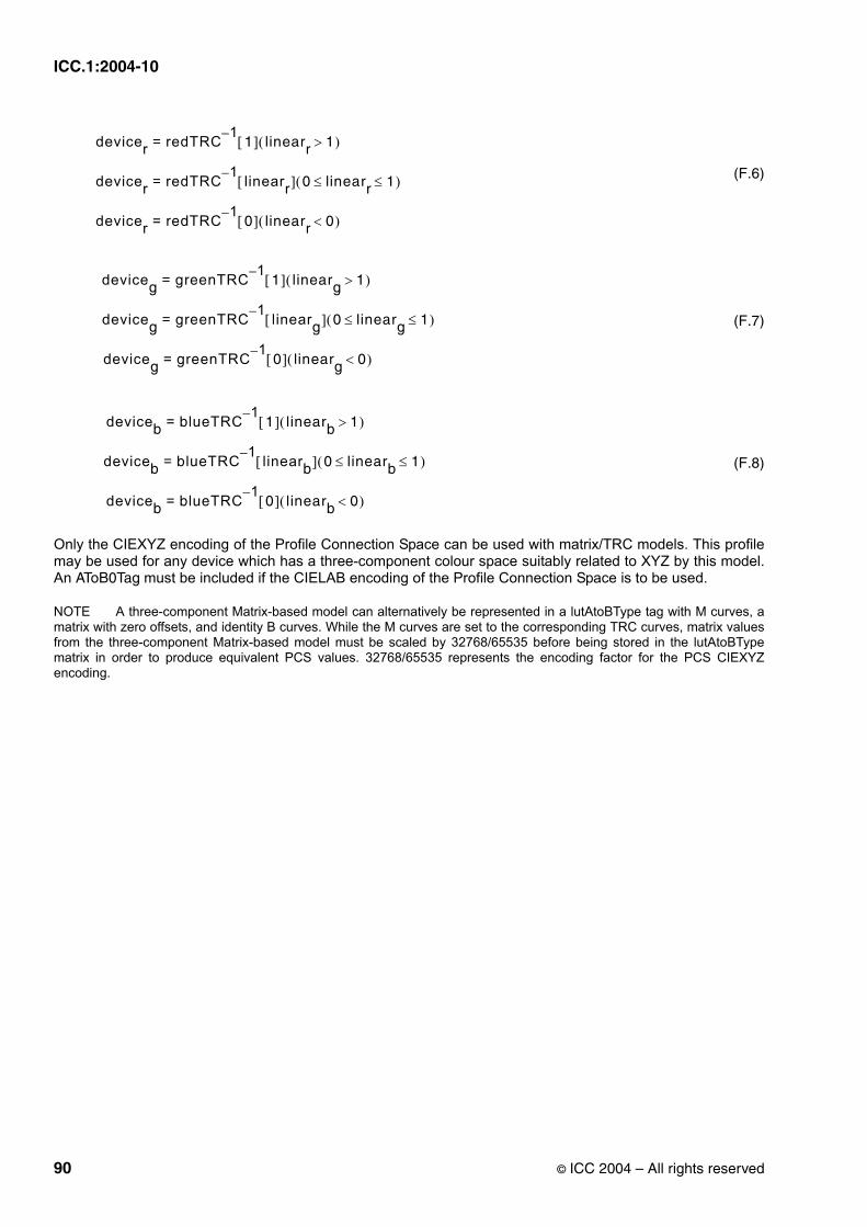
ICC.1:2004-10
(F.6)
(F.7)
(F.8)
Only the CIEXYZ encoding of the Profile Connection Space can be used with matrix/TRC models. This profile may be used for any device which has a three-component colour space suitably related to XYZ by this model. An AToB0Tag must be included if the CIELAB encoding of the Profile Connection Space is to be used.
NOTE A three-component Matrix-based model can alternatively be represented in a lutAtoBType tag with M curves, a matrix with zero offsets, and identity B curves. While the M curves are set to the corresponding TRC curves, matrix values from the three-component Matrix-based model must be scaled by 32768/65535 before being stored in the lutAtoBType matrix in order to produce equivalent PCS values. 32768/65535 represents the encoding factor for the PCS CIEXYZ encoding.
devicer redTRC 1–1[ ] linearr 1>( )=
devicer redTRC 1– linearr[ ] 0 linearr 1≤ ≤( )=
devicer redTRC 1–0[ ] linearr 0<( )=
deviceg greenTRC 1–1[ ] linearg 1>( )=
deviceg greenTRC 1– linearg[ ] 0 linearg 1≤ ≤( )=
deviceg greenTRC 1–0[ ] linearg 0<( )=
deviceb blueTRC 1–1[ ] linearb 1>( )=
deviceb blueTRC 1– linearb[ ] 0 linearb 1≤ ≤( )=
deviceb blueTRC 1–0[ ] linearb 0<( )=
90 © ICC 2004 – All rights reserved

ICC.1:2004-10
Annex G(informative)
Tables of required tags and tag list
The following tables summarize the required tags for each profile type and provide a complete listing of all currently registered tags:
NOTE Only the CIEXYZ encoding of the Profile Connection Space can be used with matrix/TRC models. If the CIELAB encoding of the Profile Connection Space is to be used the profile must be a N-component LUT-based input profile, which includes a AToB0Tag, instead of the matrix based profile.
Table G.1 — N-component LUT-based input profile required tags
Tag Name General DescriptionprofileDescriptionTag Structure containing invariant and localizable versions of the profile
name for display
AToB0Tag Device to PCS: 8-bit or 16-bit data
mediaWhitePointTag Media XYZ white point
copyrightTag Profile copyright information
chromaticAdaptationTag Converts XYZ colour from the actual illumination source to PCS illuminant. Required only if the actual illumination source is not D50.
Table G.2 — Three-component matrix-based input profile required tags
Tag Name General DescriptionprofileDescriptionTag Structure containing invariant and localizable versions of the profile
name for display
redMatrixColumnTag The first column in the matrix used in TRC/matrix transforms. (This column is combined with the linear red channel during the matrix multiplication)
greenMatrixColumnTag The second column in the matrix used in TRC/matrix transforms. (This column is combined with the linear green channel during the matrix multiplication)
blueMatrixColumnTag The third column in the matrix used in TRC/matrix transforms. (This column is combined with the linear blue channel during the matrix multiplication)
redTRCTag Red channel tone reproduction curve
greenTRCTag Green channel tone reproduction curve
blueTRCTag Blue channel tone reproduction curve
mediaWhitePointTag Media XYZ white point
copyrightTag Profile copyright information
chromaticAdaptationTag Converts XYZ colour from the actual illumination source to PCS illuminant. Required only if the actual illumination source is not D50.
© ICC 2004 – All rights reserved 91

ICC.1:2004-10
Table G.3 — Monochrome input profile required tags
Tag Name General DescriptionprofileDescriptionTag Structure containing invariant and localizable versions of the profile
name for display
grayTRCTag Grey tone reproduction curve (TRC)
mediaWhitePointTag Media XYZ white point
copyrightTag Profile copyright information
chromaticAdaptationTag Converts XYZ colour from the actual illumination source to PCS illuminant. Required only if the actual illumination source is not D50.
Table G.4 — N-component LUT-based display profile required tags
Tag Name General DescriptionprofileDescriptionTag Structure containing invariant and localizable versions of the profile
name for display
AToB0Tag Device to PCS: 8-bit or 16-bit data: intent of 0
BToA0Tag PCS to Device space: 8-bit or 16-bit data: intent of 0
mediaWhitePointTag Media XYZ white point
copyrightTag Profile copyright information
chromaticAdaptationTag Converts XYZ colour from the actual illumination source to PCS illuminant. Required only if the actual illumination source is not D50.
Table G.5 — Three-component matrix-based display profile required tags
Tag Name General DescriptionprofileDescriptionTag Structure containing invariant and localizable versions of the profile
name for display
redMatrixColumnTag The first column in the matrix used in TRC/matrix transforms. (This column is combined with the linear red channel during the matrix multiplication)
greenMatrixColumnTag The second column in the matrix used in TRC/matrix transforms. (This column is combined with the linear green channel during the matrix multiplication)
blueMatrixColumnTag The third column in the matrix used in TRC/matrix transforms. (This column is combined with the linear blue channel during the matrix multiplication)
redTRCTag Red channel tone reproduction curve
greenTRCTag Green channel tone reproduction curve
blueTRCTag Blue channel tone reproduction curve
mediaWhitePointTag Media XYZ white point
copyrightTag Profile copyright information
chromaticAdaptationTag Converts XYZ colour from the actual illumination source to PCS illuminant. Required only if the actual illumination source is not D50.
92 © ICC 2004 – All rights reserved

ICC.1:2004-10
Table G.6 — Monochrome display profile required tags
Tag Name General DescriptionprofileDescriptionTag Structure containing invariant and localizable versions of the profile
name for display
grayTRCTag Grey tone reproduction curve
mediaWhitePointTag Media XYZ white point
copyrightTag Profile copyright information
chromaticAdaptationTag Converts XYZ colour from the actual illumination source to PCS illuminant. Required only if the actual illumination source is not D50.
Table G.7 — N-component LUT based output profile required tags
Tag Name General DescriptionprofileDescriptionTag Structure containing invariant and localizable versions of the profile
name for display
AToB0Tag Device to PCS: 8-bit or 16-bit data: intent of 0
BToA0Tag PCS to Device space: 8-bit or 16-bit data: intent of 0
gamutTag Out of Gamut: 8-bit or 16-bit data
AToB1Tag Device to PCS: 8-bit or 16-bit data: intent of 1
BToA1Tag PCS to Device space: 8-bit or 16-bit data: intent of 1
AToB2Tag Device to PCS: 8-bit or 16 bit-data: intent of 2
BToA2Tag PCS to Device space: 8-bit or 16-bit data: intent of 2
mediaWhitePointTag Media XYZ white point
colorantTableTag Colorants used in the profile, required only if the data colour space field is xCLR (eg, 3CLR)
copyrightTag Profile copyright information
chromaticAdaptationTag Converts XYZ colour from the actual illumination source to PCS illuminant. Required only if the actual illumination source is not D50.
Table G.8 — Monochrome output profile required tags
Tag Name General DescriptionprofileDescriptionTag Structure containing invariant and localizable versions of the profile
name for display
grayTRCTag Grey tone reproduction curve
mediaWhitePointTag Media XYZ white point
copyrightTag Profile copyright information
chromaticAdaptationTag Converts XYZ colour from the actual illumination source to PCS illuminant. Required only if the actual illumination source is not D50.
© ICC 2004 – All rights reserved 93

ICC.1:2004-10
Table G.9 — DeviceLink profile required tags
Tag Name General DescriptionprofileDescriptionTag Structure containing invariant and localizable versions of the profile
name for display
AToB0Tag Actual transformation parameter structure; 8-bit or 16-bit data
profileSequenceDescTag An array of descriptions of the profile sequence
colorantTableTag Input colorants used in the profile, required only if the data colour space field is xCLR (eg, 3CLR)
colorantTableOutTag Output colorants used in the profile, required only if the Profile Connection Space Field is xCLR (eg, 3CLR)
copyrightTag Profile copyright information
Table G.10 — ColorSpace conversion profile required tags
Tag Name General DescriptionprofileDescriptionTag Structure containing invariant and localizable versions of the profile
name for display
BToA0Tag Inverse transformation parameter structure; 8-bit or 16-bit data
AToB0Tag Actual transformation parameter structure; 8-bit or 16-bit data
mediaWhitePointTag Media XYZ white point
copyrightTag Profile copyright information
chromaticAdaptationTag Converts XYZ colour from the actual illumination source to PCS illuminant. Required only if the actual illumination source is not D50.
Table G.11 — Abstract profile required tags
Tag Name General DescriptionprofileDescriptionTag Structure containing invariant and localizable versions of the profile
name for display
AToB0Tag Actual transformation parameter structure; 8-bit or 16-bit data
mediaWhitePointTag Media XYZ white point
copyrightTag Profile copyright information
chromaticAdaptationTag Converts XYZ colour from the actual illumination source to PCS illuminant. Required only if the actual illumination source is not D50.
94 © ICC 2004 – All rights reserved

ICC.1:2004-10
Table G.12 — Named colour profile required tags
Tag Name General DescriptionprofileDescriptionTag Structure containing invariant and localizable versions of the profile
name for display
namedColor2Tag PCS and optional device representation for named colours
mediaWhitePointTag Media XYZ white point
copyrightTag Profile copyright information
chromaticAdaptationTag Converts XYZ colour from the actual illumination source to PCS illuminant. Required only if the actual illumination source is not D50.
Table G.13 — Currently registered public tag list
Tag Name General DescriptionAToB0Tag Multidimensional transformation structure
AToB1Tag Multidimensional transformation structure
AToB2Tag Multidimensional transformation structure
blueMatrixColumnTag The third column in the matrix used in TRC/matrix transforms. (This column is combined with the linear blue channel during the matrix multiplication).
blueTRCTag Blue channel tone reproduction curve
BToA0Tag Multidimensional transformation structure
BToA1Tag Multidimensional transformation structure
BToA2Tag Multidimensional transformation structure
calibrationDateTimeTag Profile calibration date and time
charTargetTag Characterization target such as IT8/7.2
chromaticAdaptationTag Converts XYZ colour from the actual illumination source to PCS illuminant. Required only if the actual illumination source is not D50.
chromaticityTag Set of phosphor/colorant chromaticity
colorantOrderTag Identifies the laydown order of colorants
colorantTableTag Identifies the colorants used in the profile. Required for N-component based output profiles and DeviceLink profiles only if the data colour space field is xCLR (eg, 3CLR)
colorantTableOutTag Identifies the output colorants used in the profile, required only if the Profile Connection Space Field is xCLR (eg, 3CLR)
copyrightTag Profile copyright information
deviceMfgDescTag Displayable description of device manufacturer
deviceModelDescTag Displayable description of device model
gamutTag Out of gamut: 8-bit or 16-bit data
grayTRCTag Grey tone reproduction curve
greenMatrixColumnTag The second column in the matrix used in TRC/matrix transforms (This column is combined with the linear green channel during the matrix multiplication).
greenTRCTag Green channel tone reproduction curve
luminanceTag Absolute luminance for emissive device
© ICC 2004 – All rights reserved 95
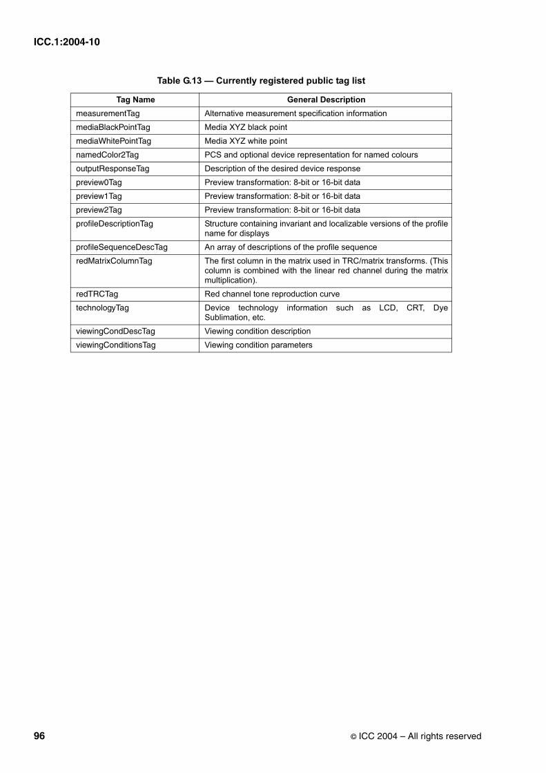
ICC.1:2004-10
measurementTag Alternative measurement specification information
mediaBlackPointTag Media XYZ black point
mediaWhitePointTag Media XYZ white point
namedColor2Tag PCS and optional device representation for named colours
outputResponseTag Description of the desired device response
preview0Tag Preview transformation: 8-bit or 16-bit data
preview1Tag Preview transformation: 8-bit or 16-bit data
preview2Tag Preview transformation: 8-bit or 16-bit data
profileDescriptionTag Structure containing invariant and localizable versions of the profile name for displays
profileSequenceDescTag An array of descriptions of the profile sequence
redMatrixColumnTag The first column in the matrix used in TRC/matrix transforms. (This column is combined with the linear red channel during the matrix multiplication).
redTRCTag Red channel tone reproduction curve
technologyTag Device technology information such as LCD, CRT, Dye Sublimation, etc.
viewingCondDescTag Viewing condition description
viewingConditionsTag Viewing condition parameters
Table G.13 — Currently registered public tag list
Tag Name General Description
96 © ICC 2004 – All rights reserved
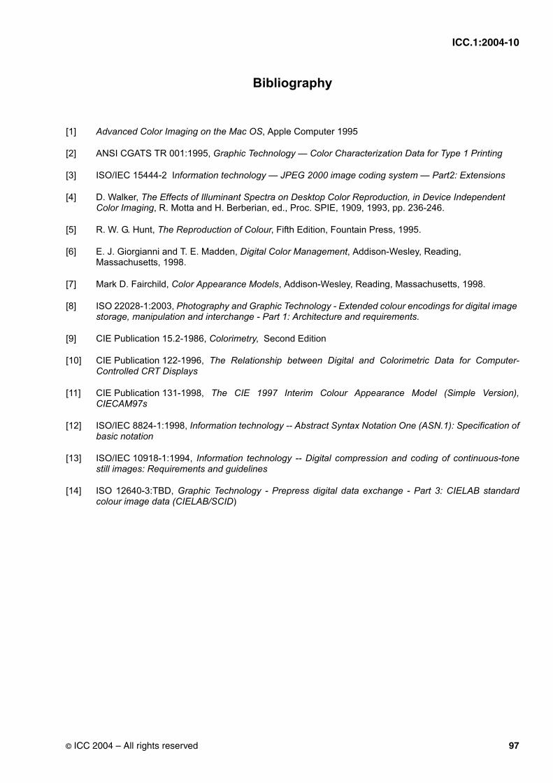
ICC.1:2004-10
Bibliography
[1] Advanced Color Imaging on the Mac OS, Apple Computer 1995
[2] ANSI CGATS TR 001:1995, Graphic Technology — Color Characterization Data for Type 1 Printing
[3] ISO/IEC 15444-2 Information technology — JPEG 2000 image coding system — Part2: Extensions
[4] D. Walker, The Effects of Illuminant Spectra on Desktop Color Reproduction, in Device Independent Color Imaging, R. Motta and H. Berberian, ed., Proc. SPIE, 1909, 1993, pp. 236-246.
[5] R. W. G. Hunt, The Reproduction of Colour, Fifth Edition, Fountain Press, 1995.
[6] E. J. Giorgianni and T. E. Madden, Digital Color Management, Addison-Wesley, Reading, Massachusetts, 1998.
[7] Mark D. Fairchild, Color Appearance Models, Addison-Wesley, Reading, Massachusetts, 1998.
[8] ISO 22028-1:2003, Photography and Graphic Technology - Extended colour encodings for digital image storage, manipulation and interchange - Part 1: Architecture and requirements.
[9] CIE Publication 15.2-1986, Colorimetry, Second Edition
[10] CIE Publication 122-1996, The Relationship between Digital and Colorimetric Data for Computer-Controlled CRT Displays
[11] CIE Publication 131-1998, The CIE 1997 Interim Colour Appearance Model (Simple Version), CIECAM97s
[12] ISO/IEC 8824-1:1998, Information technology -- Abstract Syntax Notation One (ASN.1): Specification of basic notation
[13] ISO/IEC 10918-1:1994, Information technology -- Digital compression and coding of continuous-tone still images: Requirements and guidelines
[14] ISO 12640-3:TBD, Graphic Technology - Prepress digital data exchange - Part 3: CIELAB standard colour image data (CIELAB/SCID)
© ICC 2004 – All rights reserved 97

ICC.1:2004-10
98 © ICC 2004 – All rights reserved