ic-a24e/ic-a6e instruction manual - icom€¦ · i foreword thank you for purchasing this icom...
TRANSCRIPT

INSTRUCTION MANUAL
iA6EiA24EVHF AIR BAND TRANSCEIVER
IC-A24E IC-A6E
i
FOREWORDThank you for purchasing this Icom product. The IC-A24E/A6E VHF AIR BAND TRANSCEIVER is designed and built with Icom’s state of the art technology and craftsmanship. With proper care this product should provide you with years of trouble-free operation.
IMPORTANTREAD ALL INSTRUCTIONS carefully and completely before using the transceiver.
SAVE THIS INSTRUCTION MANUAL— This in-struction manual contains important operating instructions for the IC-A24E/A6E.
EXPLICIT DEFINITIONS
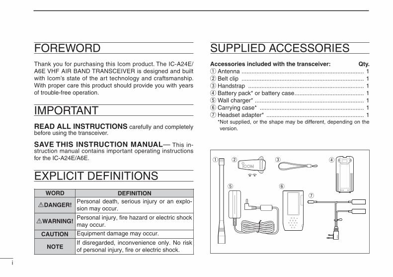
SUPPLIED ACCESSORIESAccessories included with the transceiver: Qty.q Antenna .......................................................................... 1w Belt clip .......................................................................... 1e Handstrap ...................................................................... 1r Battery pack* or battery case .......................................... 1t Wall charger* .................................................................. 1y Carrying case* ............................................................... 1u Headset adapter* ........................................................... 1 * Not supplied, or the shape may be different, depending on the
version.
q w e
t
r
y
uWORD DEFINITION
RWARNING!
CAUTION
NOTE
Personal injury, fire hazard or electric shock may occur.
RDANGER!Personal death, serious injury or an explo-sion may occur.
If disregarded, inconvenience only. No risk of personal injury, fire or electric shock.
Equipment damage may occur.

ii
FOREWORD ··················································································· iIMPORTANT ···················································································· iEXPLICIT DEFINITIONS ································································· iSUPPLIED ACCESSORIES ···························································· iTABLE OF CONTENTS ·································································· iiPRECAUTIONS ·············································································· iii
1 ACCESSORY ATTACHMENT ·················································· 1
2 PANEL DESCRIPTION ······················································ 2 – 7 Panel description ··································································· 2 Function display ···································································· 6
3 BASIC OPERATION ························································· 8 – 11 Setting a frequency ······························································· 8 Setting a squelch level ·························································· 8 ANL function ········································································· 8 Receiving ·············································································· 9 Transmitting ··········································································· 9 Low battery indicator ··························································· 10 Recall function ···································································· 10 Accessing the 121.5 MHz emergency frequency ················ 11 Lock function ······································································· 11 Side tone function ······························································· 11 Setting beep tone ································································ 11
4 MEMORY OPERATION ·················································· 12 – 15 Memory channel selection ·················································· 12 Transferring memory contents ············································· 12 Programming a memory channel ········································ 13 Memory names ··································································· 14 Clearing the memory contents ············································ 14
5 SCAN OPERATION ························································ 16 – 17 Scan types ·········································································· 16 COM band scan ·································································· 16 Memory scan ······································································ 16 “TAG” channel setting ························································· 17
6 VOR NAVIGATION (IC-A24E only) ································· 18 – 24 VOR indications ··································································· 18 VOR functions ····································································· 19 Flying to a VOR station ······················································· 20 Entering a desired course ··················································· 22 Crosschecking position ······················································· 22 Duplex operation ································································· 24
7 BATTERY PACKS ·························································· 25 – 27 Battery charging ·································································· 25 Battery cautions ·································································· 25 Optional battery case ·························································· 26 Optional battery chargers ···················································· 27
8 CLONING ··············································································· 29
9 TROUBLESHOOTING ··························································· 30
10 SPECIFICATIONS ·································································· 31
11 OPTIONS ················································································ 32
12 OPTIONAL HEADSET CONNECTION ·································· 33
13 COUNTRY CODE LIST ·························································· 34
TABLE OF CONTENTS 12345678910111213

iii
R DANGER! NEVER short the terminals of the battery pack. Also, current may flow into nearby metal objects, such as a necklace, etc. Therefore, be careful when carrying with, or placing near metal objects, carrying in handbags, etc.
R DANGER! Use and charge only specified Icom battery packs with Icom radios or Icom chargers. Only Icom battery packs are tested and approved for use with Icom radios or charged with Icom chargers. Using third-party or counterfeit battery packs or chargers may cause smoke, fire, or cause the battery to burst.
R WARNING! NEVER hold the transceiver so that the antenna is very close to, or touching exposed parts of the body, especially the face or eyes, while transmitting. The transceiver will perform best if the microphone is 5 to 10 cm away from the lips and the transceiver is vertical.
R WARNING! NEVER operate the transceiver with a headset or other audio accessories at high volume levels. Hearing experts advise against continuous high volume op-eration. If you experience a ringing in your ears, reduce the volume level or discontinue use.
CAUTION: NEVER connect the transceiver to an AC outlet or to a power source of more than 11.5 V DC. Such a connection will damage the transceiver.
CAUTION: NEVER connect the transceiver to a power source that is DC fused at more than 5 A. Accidental reverse connection will be protected by this fuse, higher fuse values will not give any protection against such accidents and the transceiver will be ruined.
DO NOT allow children to play with any radio equipment containing a transmitter.
DO NOT operate the transceiver near unshielded electri-cal blasting caps or in an explosive atmosphere.
DO NOT use or place the transceiver in direct sunlight or in areas with temperatures below –20°C or above +55°C.
CLEAN and wipe dry the battery terminals after using the transceiver in wet conditions. The terminals may rust if not dried.
Even when the transceiver power is OFF, a slight current still flows in the circuits. Remove the battery pack or case from the transceiver when not using it for a long time. Otherwise, the battery pack or installed Alkaline cell batteries will be-come exhausted.
IMPORTANT!: IC-A24E/A6E is for GROUND STATION USE ONLY. The IC-A24E/A6E CAN NOT and SHOULD NOT be used in an aircraft or as the MAIN RADIO.
Icom, Icom Inc. and the Icom logo are registered trademarks of Icom Incor-porated (Japan) in Japan, the United States, the United Kingdom, Germany, France, Spain, Russia and/or other countries.
PRECAUTION

1
1ACCESSORY ATTACHMENT
1D AntennaCAUTION: DO NOT transmit without an antenna. Other-wise the transceiver may be damaged.
Insert the supplied antenna into the antenna connector and screw down the antenna as shown below.
D Belt clipConveniently attaches to your belt.Attach the belt clip with the supplied screws as below.
NOTE: Use the supplied screws only.
D Battery pack replacementBefore replacing the battery pack, push [PWR] for 2 seconds to turn the power OFF.
Slide the battery release button forward, then pull the battery pack upward with the transceiver facing away from you.
Supplied screws
NOTE: About water resistant constructionThe water resistant construction provides reliable opera-tion in wet conditions.• Equivalent to IPX4 of corresponding international stand-
ard IEC 60529 (2001).

2
2 PANEL DESCRIPTION
Panel description
e r t
uy
i
o
Microphone
Speaker
!6
!5
!7
q
w
!1
!0
!2
!3
!4
IC-A24E
!7
!7
IC-A6E

3
2PANEL DESCRIPTION
q BACKLIGHT SWITCH [LIGHT] Turns the backlight for display and keypad ON or OFF.
w PTT SWITCH [PTT] (p. 9) Hold down to transmit; release to receive. • “ ” appears on the function display while transmitting.
e VOLUME [VOL] (p. 9) Adjusts the audio level.
r TUNING DIAL [DIAL] (pp. 8–12) Rotate [DIAL] to select the desired frequency, BANK
number and memory channel. Rotate [DIAL] to set the squelch level and beep tone
level.
t ANTENNA CONNECTOR [ANT] (p. 1) Connect the supplied antenna here.
y RECALL CHANNEL UP/DOWN KEYS [Ω]/[≈] (p. 10) Push to enter the recall function mode. Push to call the stored frequency in the recall
mode. Push , then push [Ω]/[≈]to replace stored
recall frequencies to back or front.
u SQUELCH KEY [SQL] (p. 8) Push [SQL], then rotate [DIAL] to select the
squelch level. • 24 squelch levels and squelch open (0) are available.
i POWER SWITCH [PWR] (pp. 9, 29) Hold down for 2 seconds to turn the power ON
or OFF. While holding down [MR•MW], push [PWR] to
enter the cloning function mode.
o EXTERNAL SPEAKER AND MICROPHONE JACKS [MIC/SP] (p. 33)
If desired, connect an OPC-499 HEADSET ADAPTER and headset.
!0 FUNCTION KEY [ ]Push to call up the function indicator, “ ”, then push another key to access its secondary func-tion.• “ ” appears for 3 seconds after is pushed; at this
time pushing again cancels the indication.
NOTE: In general, “ ” disappears when an-other key is pushed to activate a secondary function. However, some keys which have more than one secondary function, (such as [DUP]), do not cancel “ ”. In this case, “ ” automati-cally disappears after 3 seconds.
2

4
2 PANEL DESCRIPTION
!1 CLEAR KEY [CLR•DEL] (pp. 8–17) Push to return to the frequency mode, when
memory channel, 121.5 MHz, squelch level set-ting or beep tone setting is selected.
Push , then hold down [CLR•DEL] to delete a recall frequency data.
Push to clear the entered comment of memory name while programming.
Push to stop the scan function to return to the frequency mode while the scan function is op-erating.
!2 ANL KEY [ANL•SCAN] (pp. 9, 16, 17) Push to turn the ANL function ON or OFF. Push , then push [ANL•SCAN] to start the
scan function.
!3 EMERGENCY KEY [121.5 MHz] (p. 11) Push for 2 seconds to select the 121.5 MHz emer-gency frequency.
!4 DC POWER JACK Connect the AC adapter or optional cable, to charge the
battery pack or to operate by external power. (see right il-lustration)
!5 MEMORY MODE KEY [MR•MW] (pp. 12–15) Push to select the memory channel mode. Push , then push [MR•MW] to program the
contents into the memory channels.
!6 ENTER KEY [ENT] (pp. 8, 14) Push to store the numeral input. Enters con-
secutive zero digits. (p. 8) Push to program the memory name. (p. 14)
NOTE: Some functions may not be available depending on versions. Ask your authorized dealer for details.
To [DC 11V]
IC-A24E/A6E
Wall charger
CP-20 (for 11 24 V)(optional)
To the cigarette lighter socket
To AC outlet
The shape may differ depending on the version.
• DC POWER CONNECTION
R WARNING!• NEVER modify the CP-20. A modification
could cause a fire or electrocution.
• NEVER cut or fray the CP-20’s power cable when disconnecting/connecting the CP-20 from/to the cigarette lighter socket.

5
2PANEL DESCRIPTION
!7 DIGIT KEYS Input the specified digit during frequency input, mem-
ory channel selection, etc. In addition, each key has one or more secondary func-
tions after pushing as follows:
Push , then push [0•BANK], and rotate [DIAL] to select the memory BANK number during mem-ory mode operation. (p. 12)
Push , then push [1•DVOR] to select the DVOR display from the CDI display in the NAV band. (p. 19)*1
Push , then push [2•TO] to change the course indicator characteristics to a “TO” flag in the DVOR display in the NAV band. (p. 19)*1
Corrects the deviation while using the “TO” flag.*1
Push , then push [3•FROM] to change the course indicator characteristics to a “FROM” flag in the DVOR display in the NAV band. (p. 19)*1
Corrects the deviation while using the “FROM” flag.*1
Push , then push [4•CDI] to select the CDI dis-play from the DVOR display in the NAV band. (p. 19)*1
Push , then push [5•DUP-W] to set the duplex frequency in the NAV band. (p. 24)*1
Push , then push [6•DUP] to turn the duplex function ON or OFF in the NAV band. (p. 24)*1
Push , then push [7• ] to turn the key lock function ON or OFF. (p. 11)
Push , then push [8•BEEP] to turn the beep tone setting mode ON. (p. 11)• Adjustable level; 0 to 9
Push , then push [9•TAG] to set the displayed memory as a “TAG” channel. (p. 17)
*1 These functions are available on the IC-A24E only.
2

6
2 PANEL DESCRIPTION
Function display q FUNCTION INDICATOR (p. 3) Appears when is pushed.
w TX INDICATOR (p. 9) Appears while transmitting.
e RX INDICATOR (p. 9) Appears when receiving a signal, or when the squelch
opens.
r DUPLEX INDICATOR (IC-A24E only) (p. 24) “DUP” appears when the duplex function is activated in
the NAV mode. “DUP” blinks while setting the duplex frequency. t LOW BATTERY INDICATOR (p. 10) Appears when the battery is nearing exhaustion. The
attached battery pack requires recharging. Appears and flashes when battery replacement is nec-
essary.
y LOCK INDICATOR (p. 11) Appears while the lock function is in use.
u FREQUENCY DISPLAY (pp. 8, 14) Shows the operating frequency. Shows the channel name when the memory name
function is selected.
i
q w e r t y
o
!0!1!1 !2!3
!4
u
!5

7
2PANEL DESCRIPTION
i TAG CHANNEL INDICATOR (p. 17) “ ” appears when the selected memory channel is set
as a TAG channel.
o MEMORY CHANNEL INDICATOR (pp. 12–15) Shows the selected memory channel number.
!0 MEMORY BANK NUMBER INDICATOR (p. 12) Shows the selected memory bank number.
!1 OVERFLOW INDICATOR (IC-A24E only) (pp. 18–22) Appears when the deviation between the desired course
and flying course is over 10 degrees.
!2 ANL INDICATOR (p. 9) Appears while the ANL (Automatic Noise Limiter) function
is in use.
!3 COURSE DEVIATION NEEDLES (IC-A24E only) (pp. 18–22)
Indicates every 2 degree deviation between the desired course and your actual flying course.
!4 COURSE INDICATORS (IC-A24E only) (p. 19) Indicates where your aircraft is located on a VOR radial
in the DVOR mode. Indicates where your desired course is located on a
VOR radial in the CDI mode.
!5 TO-FROM INDICATOR (IC-A24E only) (p. 19) Indicates whether the VOR navigation information is
based on a course leading to the VOR station or leading away from the VOR station.
2

8
3 BASIC OPERATION
Setting a frequencyD Using keypadq Push [PWR] for 2 seconds to turn power ON, then push
[CLR•DEL] to select the frequency mode when memory CH number appears on the function display.
w Push 5 appropriate digit keys to input the frequency. • Push [1•DVOR] as the 1st digit. • When a wrong digit is input, push [CLR•DEL] to clear,
then repeat step w again. • Push [ENT] to enter consecutive zero digits. • Only [2•TO], [5•DUP-W], [7• ] and [0•BANK] can be
entered as the 5th and final digit. [EXAMPLE] • 111.225 MHz: Push • 117.250 MHz: Push • 120.000 MHz: Push • 125.300 MHz: Push
D Using the tuning dialq Push [PWR] for 2 seconds to turn power ON, then push
[CLR•DEL] to select the frequency mode when memory CH number appears on the function display.
w Rotate [DIAL] to set the desired frequency. • To select the 1 MHz tuning step, push , then rotate
[DIAL]. Push again to return to the normal tuning.
Setting a squelch levelThe transceiver has a noise squelch circuit to mute unde-sired noise while receiving no signal.q Push [SQL], then rotate [DIAL] to select the squelch level. • ‘SQL--0’ is open squelch and ‘SQL--24’ is tight squelch. • “ ” appears while the squelch is open.w Push [SQL] or [CLR•DEL] to exit the squelch set mode.
ANL functionWhile receiving, the ANL (Automatic Noise Limiter) function reduces noise components such as those that are caused by engine ignition systems.• Push [ANL•SCAN] to turn the ANL function ON or OFF. “ ” appears on the display while the ANL function is ON.

9
3BASIC OPERATION
Receivingq Push [PWR] for 2 seconds to turn the power ON.w Push [SQL], then rotate [DIAL] counterclockwise to select
the squelch level 0.e Rotate [VOL] to adjust the audio level.r Push [SQL], then rotate [DIAL] clockwise until the noise is
muted. • “ ” indicator disappears.t Set the desired frequency using [DIAL] or keypad.y When a signal is received on the set frequency: • “ ” indicator appears. • Squelch opens and audio is emitted from the speaker.
When squelch setting is too “tight,” squelch may not open for weak signals. To receive weaker signals, loosen the squelch.
Transmitting
q Set the desired frequency in COM band using [DIAL] or keypad.
• COM band frequency range: 118.00–136.975 MHzw Hold down [PTT] to transmit. • “ ” indicator appears.e Speak into the microphone at a normal voice level. • DO NOT hold the transceiver too close to your mouth or speak
too loudly. This may distort the signal.r Release [PTT] to return to receive.
CAUTION: Transmitting without an antenna may damage the transceiver.
NOTE: To prevent interference, listen on the frequency before transmitting. If the frequency is busy, wait until the channel is clear.
3
10
3 BASIC OPERATION
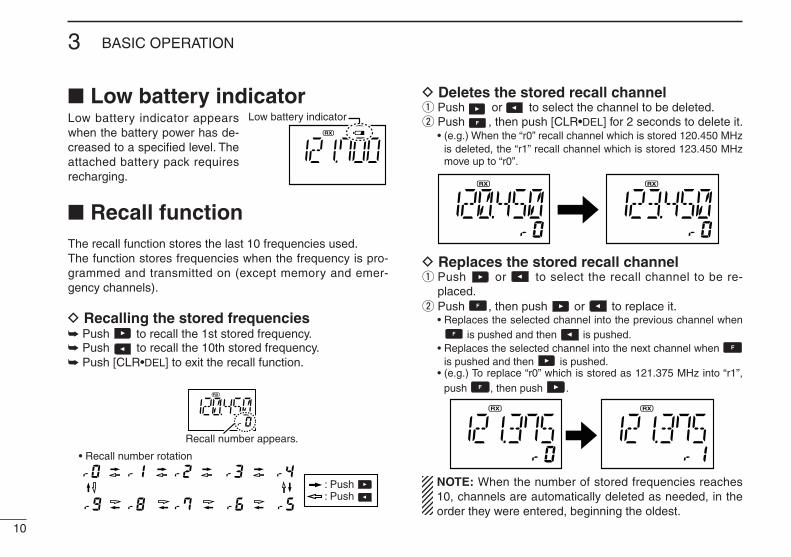
Low battery indicatorLow battery indicator appears when the battery power has de-creased to a specified level. The attached battery pack requires recharging.
Recall functionThe recall function stores the last 10 frequencies used.The function stores frequencies when the frequency is pro-grammed and transmitted on (except memory and emer-gency channels).
D Recalling the stored frequencies Push to recall the 1st stored frequency. Push to recall the 10th stored frequency. Push [CLR•DEL] to exit the recall function.
D Deletes the stored recall channelq Push or to select the channel to be deleted.w Push , then push [CLR•DEL] for 2 seconds to delete it. • (e.g.) When the “r0” recall channel which is stored 120.450 MHz
is deleted, the “r1” recall channel which is stored 123.450 MHz move up to “r0”.
D Replaces the stored recall channelq Push or to select the recall channel to be re-
placed.w Push , then push or to replace it. • Replaces the selected channel into the previous channel when
is pushed and then is pushed. • Replaces the selected channel into the next channel when
is pushed and then is pushed. • (e.g.) To replace “r0” which is stored as 121.375 MHz into “r1”,
push , then push .
NOTE: When the number of stored frequencies reaches 10, channels are automatically deleted as needed, in the order they were entered, beginning the oldest.
Low battery indicator
Recall number appears.
: Push : Push
• Recall number rotation

Accessing the 121.5 MHz emergency frequency
The IC-A24E and IC-A6E can set to the121.5 MHz emer-gency frequency quickly. This function can be activated even when the key lock function is in use.q Push [121.5] for 2 seconds to select the emergency fre-
quency.w Push [CLR•DEL] to exit the emergency frequency.
Lock functionThe lock function prevents accidental frequency changes and accidental function activation.
q Push , then push [7• ] to turn the lock function ON. • “ ” appears.w To turn the function OFF, repeat step q above. • “ ” disappears.
Setting beep toneIf desired, the beep tone, which sounds at the push of a switch, can be set.
q Push , then push [8•BEEP] to enter the beep tone setting mode.
w Rotate [DIAL] to set the beep level. • ‘BEP-- 0’ is OFF and ‘BEP-- 9’ is maximum level. • 2 beeps sound tone to verify set beep tone level.e Push [CLR•DEL] to exit the beep tone setting mode.
Side tone functionWhen using an headset (other manufacture’s product), the transceiver outputs your transmitted voice to the head-set for monitoring. Connect the optional headset with the transceiver when using this function (OPC-499 HEADSET ADAPTER and headset are required). (p. 33)
D Setting the side tone levelq Push [PTT] to turn the transmit mode ON.w During transmit mode, rotate [DIAL] to adjust the monitor-
ing level. • ‘ST--0’ is OFF and ‘ST--10’ is maximum level.
R WARNING! NEVER operate the transceiver with a headset at high volume levels for long period. A ringing in your ears may occur. If so, reduce the monitor level or discontinue use.
11
3BASIC OPERATION
3
12
4 MEMORY OPERATION
Memory channel selectionThe transceiver has 200 memory channels for storage of often-used frequencies, along with 6-character notes.
q Push [MR•MW] to select the memory mode. • The Memory BANK number and memory CH number appears.Using [DIAL]:w Push , then push [0•BANK], and rotate [DIAL] to select
the desired memory BANK number, then push [ENT] (or [CLR•DEL]) to exit the BANK selection mode.
e Rotate [DIAL] to select the desired memory CH number. • If no memory CH is programmed in the selected BANK, no
memory CH selection is available.
Using the Keypad:w Push , then push [0•BANK], and push the appropriate
digit key ([0•BANK] to [9•TAG]) to select the desired mem-ory BANK number, then push [ENT] (or [CLR•DEL]) to exit the BANK-selection mode.
e Push 2 appropriate digit key (00 to 19) to select the de-sired memory CH number.
• If no memory CH is programmed in the selected BANK, no memory CH selection is available.
NOTE: Comments appear first when programmed, how-ever, the transceiver can be programmed by your dealer to show the operating frequency first. Push [MR•MW] to display the comment in this case.
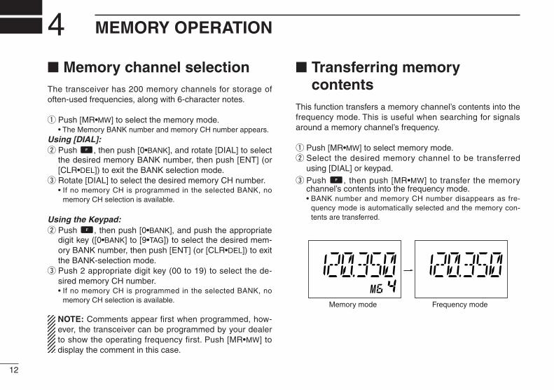
Transferring memory contents
This function transfers a memory channel’s contents into the frequency mode. This is useful when searching for signals around a memory channel’s frequency.
q Push [MR•MW] to select memory mode.w Select the desired memory channel to be transferred
using [DIAL] or keypad.
e Push , then push [MR•MW] to transfer the memory channel’s contents into the frequency mode.
• BANK number and memory CH number disappears as fre-quency mode is automatically selected and the memory con-tents are transferred.
Memory mode Frequency mode

13
4MEMORY OPERATION
Programming a memory channel
The transceiver has 200 (20 CH × 10 BANK) memory chan-nels for storage of often-used frequencies.
q Push [CLR•DEL] to select the frequency mode, if neces-sary.
w Select the desired frequency. • Set the desired frequency using [DIAL] or keypad.
e Push , then push [MR•MW] to enter the memory pro-gramming mode.
• “M”, memory BANK and memory channel number are blink.r Rotate [DIAL] to select the desired memory channel
number. • Push , then push [0•BANK], and rotate [DIAL] to select the
BANK number if desired. • Push [CLR•DEL], [ENT] or push then push [0•BANK] to exit
the BANK selection mode.t Push [ENT] to program the information into the channel
and return to the frequency mode.
(or rotate [DIAL])
(or rotate [DIAL])
Push
PushPush
Push
or
Push
Push
Push
or
• EXAMPLE: Programming 118.250 MHz into memory BANK 3/ memory channel 9.
4

NOTE: When programming the memory name to the pre-programmed memory channel do the following.
q Follow the same steps as in “Transferring memory con-tents” (see p. 12).
w Follow steps w–y in “Programming memory names” (see left column).
Clearing the memory contents
Unwanted memory channels can be cleared.
q Select the memory channel to be cleared.w Push , then hold down [CLR•DEL] for 1 second. • “-- -- -- -- -- --” appears momentarily, then the next selectable
channel appears.
14
4 MEMORY OPERATION
Memory namesD Programming memory names
The memory channel can display a 6-character name in-stead of the programmed frequency.
q In the frequency mode, rotate [DIAL] to select the desired frequency.
w Push , then push [MR•MW] to program the contents into the selected memory channel.
e Rotate [DIAL] to select the desired memory channel to be programmed.
• Push , then push [0•BANK], and rotate [DIAL] to select the BANK number, if desired. Push [CLR•DEL] to exit the BANK se-lection mode.
r Push [MR•MW] to enter the memory name programming mode.
• “-- -- -- -- -- -- ” appears on the display.t Push the appropriate digit key several times to select the
desired character, as listed to the right. • To erase a character, overwrite with a space (displayed as _). • To move the cursor forwards or backwards, use [DIAL].y Push [ENT] to program the name. • The memory name stops flashing. • When no name is programmed, the display shows the operat-
ing frequency. • To clear the entered memory names, push [CLR•DEL] before
pushing [ENT].
Key Character Key Character Key Character
1 1, Q, Z 2 2, A, B, C 3 3, D, E, F
4 4, G, H, I 5 5, J, K, L 6 6, M, N, O
7 7, P, R, S 8 8, T, U, V 9 9, W, X, Y
ENT Program 0 0, space, -

15
4MEMORY OPERATION
Push
Push
Push
Push
Push
Push
Push
Push Push
PushPush
(or rotate [DIAL])
(or rotate [DIAL])
• EXAMPLE: Programming 125.000 MHz into memory BANK 1/ memory channel 17 with “AIR-23” as a comment.
4
NOTE: Push , then push [0•BANK], and then rotate [DIAL] to select the BANK number, if desired. Push [CLR•DEL] to exit the BANK selection mode.

16
5 SCAN OPERATION
Scan typesThe transceiver has 2 scan types to suit your needs.
COM band scanq Push [CLR•DEL] to select the frequency mode.w Push [SQL], then rotate [DIAL] to set the squelch level to
the point where noise is just muted.e Push , then push [ANL•SCAN] to start the scan. • When a signal is received, the scan pauses until it disappears. • To change the scanning direction, rotate [DIAL].r To stop the scan, push [CLR•DEL].
Memory scanq Push [MR•MW] to select the memory mode. • Push , then push [0•BANK], and rotate [DIAL] to select the
BANK number, if desired. Push [CLR•DEL] to exit the BANK se-lection mode.
w Push [SQL], then rotate [DIAL] to set the squelch level to the point where noise is just muted.
e Push , then push [ANL•SCAN] to start the scan. • When a signal is received, the scan pauses until it disappears. • To change the scanning direction, rotate [DIAL].r To stop the scan, push [CLR•DEL].
NOTE: Program 2 or more memory channels to start the memory scan.
MEMORY SCANRepeatedly scans all se-lected memory BANK’s “TAG” memory channels. Used for checking often-used channels and bypass-ing usually busy channels such as control-tower fre-quencies.
COM BAND SCANRepeatedly scans a l l f requenc ies over the ent i re COM band.
108.00MHz
Scan
Jump
118.00MHz
136.975MHz
non-TAGchannel
non-TAG channel
Mch 2 Mch 4 Mch 6
Mch 7Mch 1
Mch 8Mch 10Mch 19

17
5SCAN OPERATION
“TAG” channel settingMemory channels can be specified to be skipped for the memory channel scans respectively. The “TAG” channel function is only available during the scan operation.
q Push [MR•MW] to select the memory mode.w Select the desired memory channel to be a “TAG” chan-
nel. • Push , then push [0•BANK], and rotate [DIAL] to select the
BANK number, if desired. Push [CLR•DEL] to exit the BANK se-lection mode.
e Push , then push [9•TAG] to set a “TAG.” • “TAG” appears. • Non-“TAG” channels are skipped during scan.r To cancel the “TAG” setting, repeat the above steps.
Memory channel 15 is scanned during memory scan.
Memory channel 15 is skipped during scan.
Push then
Appears the “TAG” indicator.
5

18
6 VOR NAVIGATION (IC-A24E ONLY)
VOR indicators
214
34
FROM
COM BAND(118.000 136.975 MHz)
NAV BAND (108.000 117.975 MHz)
DVOR MODE
Function display of the IC-A24EGeneral VOR equipment
To-from flag indicator
CDI MODE
Course indicator
Courseindicator
Course deviation needlesOverflow indicator
Push [F], then push [4 CDI].Push [F], then push [1 DVOR].
To-from flag indicator
Course indicator
Course deviation needle
To-from flag indicator
Two-degree deviation marks

19
6VOR NAVIGATION (IC-A24E ONLY)
VOR functionsD To select the CDI modeTo show the deviation between your flying course and the desired course, push , then push [4•CDI] to select the CDI mode.
D To select the DVOR modeWhen entering the NAV band, 108.000–117.975 MHz, the IC-A24E selects the DVOR mode automatically.
To show your aircraft’s direction to (or from) the VOR station, push , then push [1•DVOR] to select the DVOR mode.
D ‘TO’ or ‘FROM’ flag selectionThe to-from flag indicators indicate whether the VOR navi-gation information is based on a course leading to the VOR station or leading away from the VOR station.
Push , then push [3•FROM] or [2•TO] to change the flag from ‘TO’ to ‘FROM’ or vice versa, respectively.
NOTE: • When using the ‘TO’ flag and passing through the VOR station,
the ‘TO’ flag changes to the ‘FROM’ flag automatically. • When turning power ON, the ‘FROM’ flag is selected automati-
cally.
D Selecting the next VOR station when using CDI mode (when using the course deviation needle)
q Push , then push [1•DVOR] to select the DVOR mode.w Push the keypad or rotate [DIAL] to set the next VOR sta-
tion’s frequency.
e Push , then push [4•CDI] to select the CDI mode. • Select ‘TO’ or ‘FROM’ flag, if desired.
Operating frequency can not be changed.
Each course deviation arrow indicates a two-degree deviation.
Course indicator is fixed, but it can be changed with the tuning [DIAL] or keypad.
Operating frequency can not be changed.
Course deviation needle does not appear.
Course indicator shows your direction to (or from) the VOR station.
6

20
6 VOR NAVIGATION (IC-A24E ONLY)
Flying to a VOR stationThe IC-A24E shows the deviation from a VOR station.
q Select a VOR station on your aeronautical chart and push the keypad or rotate [DIAL] to set the frequency of the station.
• The course indicator indicates where you are located on a ra-dial from the VOR station.
• The course indicator shows ‘- -’ when either aircraft is too far away from the VOR station or the frequency is not set correctly at the VOR station.
w Select the ‘TO’ flag when flying to the VOR station, or se-lect the ‘FROM’ flag when flying away from the VOR sta-tion.
• Push , then push [2•TO] to select ‘TO’. • Push , then push [3•FROM] to select ‘FROM’.e Push , then push [4•CDI] to select the CDI (Course
Deviation Indicator) mode. • The course indicator shows ‘OF’ when the desired VOR signal
cannot be received.
NOTE: When the CDI mode is selected, the operating frequency cannot be changed. To set the operating fre-quency, select the DVOR mode in advance.
r The course deviation needle appears when your aircraft is off course from the VOR station.
• ‘Ω’ or ‘≈’ appears to indicate your aircraft is off course to the right or left, respectively. Correct your course until ‘Ω’ or ‘≈’ dis-appears. Each arrow represents a two-degree deviation.
t Push , then push [1•DVOR] to exit the CDI mode.
VOR INDICATOR NOTE‘loc’ appears on the function display as shown below when a localizer signal is received.
However, the function display does not indicate additional information about the localizer signal.

21
6VOR NAVIGATION (IC-A24E ONLY)
VORstation
0
10 20
30
40
50
60
70
80
90
100 110
120 130 140 150 160 170
180 190
200
210
220
230
240
250
260
270 280
290 300
310 320 330 340 350 N
Magneticnorth
Desired course
Aircraft heading 40
123.65VORTACSEATTLE
116.8 Ch 115 SEA
THE AIRCRAFT IS ON COURSE
VORstation
0
10 20
30
40
50
60
70
80
90
100 110
120 130 140 150 160 170
180 190
200
210
220
230
240
250
260
270 280
290 300
310 320 330 340 350 N
Magneticnorth
Aircraft should be
heading 40
Aircraft heading 46
(6 off course)
Flown course
123.65VORTACSEATTLE
116.8 Ch 115 SEA
THE AIRCRAFT IS OFF COURSE
NOTE: The course deviation indica-tor appears when the aircraft is off course. In this example, the aircraft is 6 degrees off course to the left. The pilot must turn more than 6 degrees right to get back on course.
6

22
6 VOR NAVIGATION (IC-A24E ONLY)
Entering a desired courseThe IC-A24E shows not only the deviation from the VOR sta-tion but the deviation from the desired course.
q Push the keypad or rotate [DIAL] to set the frequency for the desired VOR station.
• Push , then push [2•TO] or [3•FROM] to change the to-from flag.
w Push , then push [4•CDI] to select the CDI mode.e Set the desired course to the VOR station using the tun-
ing dial or keypad. • ‘Ω’ or ‘≈’ appears on the function display when your aircraft is
off the desired course. • When your heading is correct, the ABSS function (see right col-
umn for detail) may be useful instead of course input.r The course deviation needle points to the right when your
aircraft is off course to the left. • To get back on course, fly right more than the number of de-
grees indicated by the CDI arrows. • If the overflow indicator appears on the right side, select a
heading plus 10 degrees to the desired course; if the overflow indicator appears on the left side, select a heading minus 10 degrees.
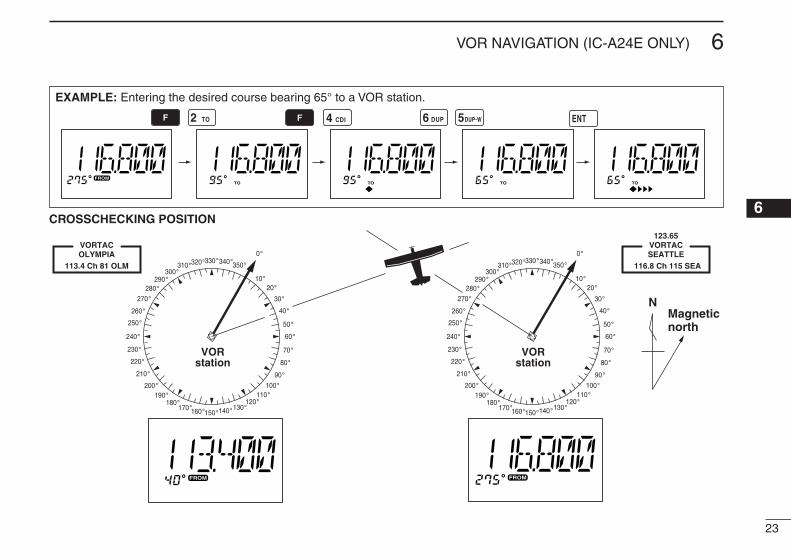
Crosschecking positionq Select 2 VOR stations on your aeronautical chart.w Push the keypad or rotate [DIAL] to set the frequency of
one of the VOR station in the DVOR mode. • The course indicator shows course deviation from the VOR ra-
dial. Note the radial you are on.e Push the keypad or rotate [DIAL] to set the frequency of
the other VOR station in DVOR mode. • Note the radial from the station you are on.r Extend the radials from each VOR station on the chart.
Your aircraft is located at the point where the lines inter-sect.
ABSS FUNCTIONIn the CDI mode, the Auto Bearing Set System (ABSS) adds or subtracts the number of degrees indicated by the CDI arrows from the Omni Bearing Selector (OBS).
To use ABSS, push , then push [2•TO] while using the ‘TO’ flag; or, push , then push [3•FROM] while using the ‘FROM’ flag.
Courseindicator
q
w
Overflow indicator (left)
Overflow indicator (right)
Course deviation needles (left)e
r
Course deviation needles (right)
To-from flag indicator
w e rq
23
6VOR NAVIGATION (IC-A24E ONLY)
EXAMPLE: Entering the desired course bearing 65° to a VOR station.
VORstation
0
10 20
30
40
50
60
70
80
90
100 110
120 130 140 150 160 170
180 190
200
210
220
230
240
250
260
270 280
290 300
310 320 330 340 350
NMagneticnorth
VORstation
0
10 20
30
40
50
60
70
80
90
100 110
120 130 140 150 160 170
180 190
200
210
220
230
240
250
260
270 280
290 300
310 320 330 340 350 113.4 Ch 81 OLM
VORTACOLYMPIA
116.8 Ch 115 SEA
123.65VORTACSEATTLE
CROSSCHECKING POSITION6
24
6 VOR NAVIGATION (IC-A24E ONLY)
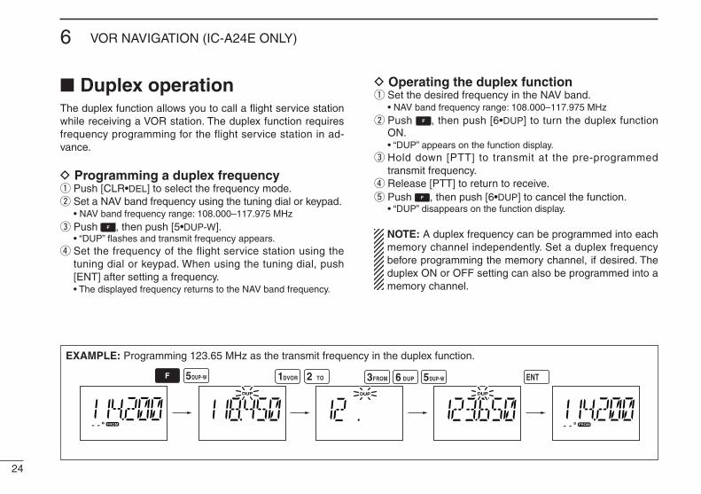
Duplex operationThe duplex function allows you to call a flight service station while receiving a VOR station. The duplex function requires frequency programming for the flight service station in ad-vance.
D Programming a duplex frequencyq Push [CLR•DEL] to select the frequency mode.w Set a NAV band frequency using the tuning dial or keypad. • NAV band frequency range: 108.000–117.975 MHze Push , then push [5•DUP-W]. • “DUP” flashes and transmit frequency appears.r Set the frequency of the flight service station using the
tuning dial or keypad. When using the tuning dial, push [ENT] after setting a frequency.
• The displayed frequency returns to the NAV band frequency.
D Operating the duplex functionq Set the desired frequency in the NAV band. • NAV band frequency range: 108.000–117.975 MHzw Push , then push [6•DUP] to turn the duplex function
ON. • “DUP” appears on the function display.e Hold down [PTT] to transmit at the pre-programmed
transmit frequency.r Release [PTT] to return to receive.t Push , then push [6•DUP] to cancel the function. • “DUP” disappears on the function display.
NOTE: A duplex frequency can be programmed into each memory channel independently. Set a duplex frequency before programming the memory channel, if desired. The duplex ON or OFF setting can also be programmed into a memory channel.
EXAMPLE: Programming 123.65 MHz as the transmit frequency in the duplex function.

25
7BATTERY PACKS
Battery chargingPrior to using the transceiver for the first time, the battery pack must be fully charged for optimum life and operation.
CAUTION: To avoid damage to the transceiver, turn the power OFF while charging.
• Recommended temperature range for charging: +10°C to +40°C• Use the supplied AC adapter on regular charging. NEVER
use another manufacture’s adapters.• Use the specified chargers (BC-119N, BC-121N and
BC-144N). NEVER use another manufacture’s charger.
NEVER connect DC power to the transceiver when in-stalling Alkaline batteries. Such a connection will damage the transceiver.
Battery cautionsR DANGER! NEVER incinerate used battery packs. Internal battery gas may cause an explosion.
R DANGER! NEVER immerse battery pack in water. If the battery pack becomes wet, be sure to wipe it dry im-mediately (particularly the battery terminals BEFORE at-taching it to the transceiver).
R DANGER! NEVER short the terminals of the bat-tery pack. Also, current may flow into nearby metal objects, such as a necklace, etc. Therefore, be careful when carrying with, or placing near metal objects, carrying in handbags, etc.
CAUTION: NEVER insert battery pack/transceiver (with the battery pack attached) with wet or soiled into the charger. This may result in corrosion of the charger terminals or damage to the charger. The charger is not waterproof and water can easily get into it.
If your battery pack seem to have no capacity even after being charged, completely discharge them by leaving the power ON overnight. Then, fully charge the battery pack again. If the batteries still do not retain a charge (or very lit-tle), the new battery pack must be purchased.
Turn the transceiver power OFF when charging the battery pack. Otherwise, the battery pack may not fully charge or charge properly.
67

26
7 BATTERY PACKS
D Regular chargingq Attach the battery pack to the transceiver.w Be sure to turn the transceiver power OFF.e Connect the Wall charger or optional cable (CP-20) as
shown below.r Charge the battery pack approximately 8 hours, depend-
ing on the remaining power condition.
DO NOT charge the BP-210N more than 12 hours. Other-wise, the BP-210N will be damaged.
Optional battery caseWhen using a battery case attached to the transceiver, install 6 × AA (LR6) size Alkaline batteries, as illustrated below.
q Remove the battery case from the transceiver.w Install 6 × AA (LR6) size Alkaline batteries. • Be sure to observe the correct polarity.
CAUTION: • When installing batteries, make sure they are all the
same brand, type and capacity. Also, do not mix new and old batteries together.
• Keep battery contacts clean. It’s a good idea to clean battery terminals once a week.
To [DC 11V]
IC-A24E/A6E with the attached battery pack
CP-20 (for 11 24 V)(optional)
To the cigarette lighter socket
To AC outlet
The shape may differ depending on the version.
Wall charger
Turn power OFF
R WARNING!• NEVER modify the CP-20. A modifica-
tion could cause a fire or electrocution.• NEVER cut or fray the CP-20’s power
cable when disconnecting/connecting the CP-20 from/to the cigarette lighter socket.

27
7BATTERY PACKS
7
Optional battery chargersD AD-101 installationThe AD-101 charger adapter must be installed into the BC-119N or BC-121N before battery charging.Connect the AD-101 charger adapter and the BC-119N/BC-121N as below (q), then install the AD-101 into the holder space of the BC-119N or BC-121N with the supplied screws (w).
D About AD-99NThe adapter (Spacer A) only is required for IC-A24E/A6E. When removing the spacer (Spacer B/C), push the latch carefully with your finger to remove the spacer (Spacer B/C) from the adapter (Spacer A).
CAUTION: • DO NOT push or force the latch with a screw driver, etc.,
to remove it. • DO NOT bend the latch when the adapter and spacer
are not joined together. This will cause weakening of the latch plastic.
• Both cases may break the latch and it may not be able to be reattached.
• BE CAREFUL not to lose the spacer (Spacer B/C) after removing it from the adapter (Spacer A).
Push the latchcarefully.
Remove the spacer (Spacer B/C) from the adapter.
Desktop charger adapterq
w
10-pin connector
3-pin connector
Suppliedscrews

28
7 BATTERY PACKS
D Rapid charging with the BC-119N+AD-101The optional BC-119N provides rapid charging of the battery packs. The following are additionally required.• AD-101 charger adapter.• An AC adapter (may be supplied with BC-119N depending on ver-
sions).
D Rapid charging with the BC-121N+AD-101The optional BC-121N allows up to 6 battery packs to be charged simultaneously. The following are additionally re-quired.• Six AD-101 charger adapters.• An AC adapter (BC-157) or the DC power cable (OPC-656).
AD-99N (suppliedwith AD-101)
IC-A24E/A6E
BP-210N
Turn power OFF
The AD-101 charger adapter is installed in the slot.
AC adapter
IC-A24E/A6E
BP-210N
AC adapter (BC-157: Purchase separately)
AD-101 charger adapters are installed in each slot.
DC power cable (OPC-656)(Connect with the DC power supply; 13.8 V/at least 7 A)
Turn power OFF
AD-99N (supplied with AD-101)
The adapter (Spacer A) only is required for IC-A24E/A6E. When removing the spacer (Spacer B/C), push the latch carefully with your finger to remove the spacer (Spacer B/C) from the adapter (Spacer A). See p. 27 for details.
The adapter (Spacer A) only is required for IC-A24E/A6E. When removing the spacer (Spacer B/C), push the latch carefully with your finger to remove the spacer (Spacer B/C) from the adapter (Spacer A). See p. 27 for details.

29
8CLONING
Cloning allows you to quickly and easily transfer the programmed data from one transceiver to another transceiver, or, data from a PC to a transceiver, using the optional CS-A24 cloning software.
D Transceiver to transceiver cloningq Connect the OPC-474 CLONING CABLE with adapter
plugs to the [SP/MIC] jack of the master and sub trans-ceivers.
• The master transceiver is used to send data to the sub trans-ceiver.
w While holding down [MR•MW], push [PWR] to enter the clon-ing mode (to operate the master transceiver only).
• “CLONE” appears and the transceiv-ers enter the clone standby condition.
e Push [MR•MW] on the master transceiver.
• “CL-OUT” appears in the master transceiver’s display.
• “COURSE DEVIATION NEEDLES” shows that cloning is taking place
• “CL-IN” appears automatically in the sub transceiver’s display.
r When cloning is finished, turn power OFF, then ON again to exit the cloning mode.
NOTE: DO NOT transfer the data from a IC-A24E to a IC-A6E, when the data contains the NAV band data. In such case, a cloning error may occur.
D Cloning using PCData can be cloned to and from a PC (Microsoft®, Windows® 98/98SE/Me/2000/XP) using the optional CS-A24 CLON-ING SOFTWARE and the optional OPC-478 (RS-232C type) or OPC-478U (USB type) CLONING CABLE. Consult the CS-A24 CLONING SOFTWARE HELP file for details.
D Cloning error NOTE: DO NOT push [ENT] on the sub transceiver during cloning. This will cause a cloning error.
When the display at right appears, a clon-ing error has occurred.
In this case, both transceivers automatically return to the clone standby condition and cloning must be repeated.
Microsoft and Windows are registered trademarks of Micro-soft Corporation in the U.S.A. and other countries.
“COURSE DEVIATION NEEDLES” shows that cloning is taking place.
87
30
9 TROUBLESHOOTING
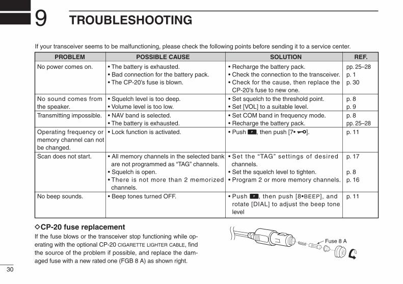
DCP-20 fuse replacementIf the fuse blows or the transceiver stop functioning while op-erating with the optional CP-20 cigarette lighter cable, find the source of the problem if possible, and replace the dam-aged fuse with a new rated one (FGB 8 A) as shown right.
Fuse 8 A
If your transceiver seems to be malfunctioning, please check the following points before sending it to a service center.
PROBLEM POSSIBLE CAUSE SOLUTION REF.
No power comes on. • The battery is exhausted. • Recharge the battery pack. pp. 25–28 • Bad connection for the battery pack. • Check the connection to the transceiver. p. 1 • The CP-20’s fuse is blown. • Check for the cause, then replace the p. 30
CP-20’s fuse to new one. No sound comes from • Squelch level is too deep. • Set squelch to the threshold point. p. 8 the speaker. • Volume level is too low. • Set [VOL] to a suitable level. p. 9Transmitting impossible. • NAV band is selected. • Set COM band in frequency mode. p. 8
• The battery is exhausted. • Recharge the battery pack. pp. 25–28 Operating frequency or • Lock function is activated. • Push , then push [7• ]. p. 11 memory channel can not be changed.Scan does not start. • All memory channels in the selected bank • Set the “TAG” sett ings of desired p. 17
are not programmed as “TAG” channels. channels. • Squelch is open. • Set the squelch level to tighten. p. 8 • There is not more than 2 memorized • Program 2 or more memory channels. p. 16 channels.
No beep sounds. • Beep tones turned OFF. • Push , then push [8•BEEP], and p. 11 rotate [DIAL] to adjust the beep tone level
31
10SPECIFICATIONS
89
D General• Frequency coverage (MHz): TX 118.000 to 136.975
RX 108.000 to 136.975* *: IC-A24E only, IC-A6E; 118.000 to 136.975 MHz• Mode : A3E• Channel spacing : 25 kHz• Number of memory channels : 200 (20 CH × 10 BANK)• Power supply requirement : Specified battery packs/case
or 11.0 V DC at external DC jack
• Usable temperature range : –20˚C to +55˚C• Current drain :Tx 1.5 A typical Rx 70 mA typical (at stand by)
300 mA typical (at AF maximum)
• Antenna connector : BNC 50 W (nominal)• Dimensions : 54(H) × 129.3(W) × 35.5(D) mm (projections not included)• Weight : Approximately 180 g (Without the battery pack and antenna.)
D Transmitter• Output power : 3.6 W (PEP) typical 1.0 W (CW) typical• Modulation : Low level modulation• Modulation depth : 85%• Audio harmonic distortion : Less than 10% (at 85% ±3 dB
modulation)• Harmonics spurious emissions : Less than –36 dBm (except
operating frequency ±1 MHz range)
• Microphone connector : 3-conductor 2.5(d) mm (1/10˝)/ more than 100 kW
• Frequency stability : ±5 ppm
D Receiver• Receive system : Double conversion
superheterodyne• Intermediate frequencies : 1st 30.05 MHz
2nd 450 kHz• Sensitivity VOR (AM 6dB S/N) : –3 dBµ typical COM (AM 12dB SINAD) : –3 dBµ typical (with CCITT)• Squelch sensitivity : Less than 0 dBµ (Threshold)• Selectivity : 6 dB (More than 7.5 kHz) 60 dB (Less than 25 kHz)• Spurious response : More than 70 dB rejection • Audio output power : 500 mW typical
( at 10% distortion with an 8 W load, 30% modulation)
• Hum and noise : More than 40 dB at 90% mod-ulation
• External speaker connector : 3-conductor 3.5 (d) mm (1/8˝)/8 W
All stated specifications are subject to change without notice or obligation.
10

32
11 OPTIONS
D BATTERY CASE AND PACKS• BP-208N battery case
Battery case for 6 × AA (LR6) Alkaline cells.• BP-210N Ni-MH battery pack
7.2 V/1650 mAh Ni-MH battery pack.
D CHARGERS• BC-167SD wall charger
The same as supplied with the transceiver.• BC-119N desktop charger + AD-101 charger adapter
+ BC-145 ac adapter
For rapid charging of battery packs. An AC adapter is supplied with the charger depending on versions. Charging time: approximately 1.5 to 2 hours.
• BC-121N multi-charger + AD-101 charger adapter (6 pcs.) + BC-157 ac adapter
For rapid charging of up to 6 battery packs (six AD-101’s are re-quired) simultaneously. An AC adapter should be purchased sepa-rately. Charging time: approximately 1.5 to 2 hours.
• BC-144N desktop charger
For rapid charging of BP-210N (Ni-MH).
D BELT CLIPS• MB-103 belt clip
The same as supplied with the transceiver.• MB-86 swivel belt clip
Belt clip for swivel type.• MB-96F/96N leather belt hanger
MB-96F: Attaches with the supplied belt clip (Fixed type). MB-96N: Belt hanger for swivel type.
D DC CABLES• CP-20 cigarette lighter cable
Charges the battery pack through a cigarette lighter socket*. Operates IC-A24E/A6E through a cigarette lighter socket*. *Both 12 V and 24 V batteries are available.• OPC-656 dc power cable for BC-121N Charges the battery pack using 13.8 V power source instead of the
AC adapter for BC-121N.
D OTHER OPTIONS• OPC-499 headset adapter cable
When using an optional headset (3rd party products) via the adapter, the transceiver outputs your transmitted voice to the head-set for monitoring.
• LC-159 carrying case
Helps protect the transceiver from scratches, etc.
Different versions of this radio use different options. Ask your authorized dealer for details.
Approved Icom optional equipment is designed for optimal performance when used with an Icom transceiver.Icom is not responsible for the destruction or damage to an Icom transceiver in the event the Icom transceiver is used with equipment that is not manufactured or approved by Icom.
33
12OPTIONAL HEADSET CONNECTION
11
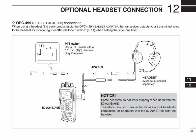
D OPC-499 (HEADSET ADAPTER) connectionWhen using a headset (3rd party products) via the OPC-499 HEADSET ADAPTER, the transceiver outputs your transmitted voice to the headset for monitoring. See “ Side tone function” (p. 11) when setting the side tone level.
PTT
OPC-499
IC-A24E/A6E
PTT switch
HEADSET(Must be purchasedseparately)
Use a PTT switch with a 3.5 mm (1/8") diameter plug, if required.
NOTICE!Some headsets do not work properly when used with the IC-A24E/A6E.Therefore, ask your dealer for details about headsets compatible for operation with the IC-A24E/A6E with the headset.
12

34
COUNTRY CODE LIST
• ISO 3166-1
Country Codes Country Codes
123456789
1011121314151617
AustriaBelgiumBulgariaCroatiaCzech RepublicCyprusDenmarkEstoniaFinlandFranceGermanyGreeceHungaryIcelandIrelandItalyLatvia
ATBEBGHRCZCYDKEEFIFRDEGRHUISIEITLV
18192021222324252627282930313233
LiechtensteinLithuaniaLuxembourgMaltaNetherlandsNorwayPolandPortugalRomaniaSlovakiaSloveniaSpainSwedenSwitzerlandTurkeyUnited Kingdom
LILTLUMTNLNOPLPTROSKSIESSECHTRGB
13

35
MEMO
13
1-1-32 Kamiminami, Hirano-ku, Osaka 547-0003, JapanPrinted on recycled paper with soy ink.
A-6404D-1EU-yPrinted in Japan© 2005–2011 Icom Inc.
< Intended Country of Use >ATFIITPLGBRO
BEFRLVPTISTR
CYDELTSKLIHR
CZGRLUSINO
DKHUMTESCH
EEIENLSEBG