ibusway for data center - apc.com · the addition of this symbol to a danger or warning safety...
TRANSCRIPT

iBusway for Data Center
Metered Feed Units and Metered Tap Off Units
Operation ManualConfiguration of Metering Solution
990-5313-001Publication Date: June 2014

Schneider Electric Legal DisclaimerThe information presented in this manual is not warranted by Schneider Electric to be authoritative, error free,
or complete. This publication is not meant to be a substitute for a detailed operational and site specific
development plan. Therefore, Schneider Electric assumes no liability for damages, violations of codes,
improper installation, system failures, or any other problems that could arise based on the use of this
Publication.
The information contained in this Publication is provided as is and has been prepared solely for the purpose of
evaluating data center design and construction. This Publication has been compiled in good faith by Schneider
Electric. However, no representation is made or warranty given, either express or implied, as to the
completeness or accuracy of the information this Publication contains.
IN NO EVENT SHALL SCHNEIDER ELECTRIC, OR ANY PARENT, AFFILIATE OR SUBSIDIARY COMPANY
OF SCHNEIDER ELECTRIC OR THEIR RESPECTIVE OFFICERS, DIRECTORS, OR EMPLOYEES BE
LIABLE FOR ANY DIRECT, INDIRECT, CONSEQUENTIAL, PUNITIVE, SPECIAL, OR INCIDENTAL
DAMAGES (INCLUDING, WITHOUT LIMITATION, DAMAGES FOR LOSS OF BUSINESS, CONTRACT,
REVENUE, DATA, INFORMATION, OR BUSINESS INTERRUPTION) RESULTING FROM, ARISING OUT,
OR IN CONNECTION WITH THE USE OF, OR INABILITY TO USE THIS PUBLICATION OR THE CONTENT,
EVEN IF SCHNEIDER ELECTRIC HAS BEEN EXPRESSLY ADVISED OF THE POSSIBILITY OF SUCH
DAMAGES. SCHNEIDER ELECTRIC RESERVES THE RIGHT TO MAKE CHANGES OR UPDATES WITH
RESPECT TO OR IN THE CONTENT OF THE PUBLICATION OR THE FORMAT THEREOF AT ANY TIME
WITHOUT NOTICE.
Copyright, intellectual, and all other proprietary rights in the content (including but not limited to software, audio,
video, text, and photographs) rests with Schneider Electric or its licensors. All rights in the content not expressly
granted herein are reserved. No rights of any kind are licensed or assigned or shall otherwise pass to persons
accessing this information.
This Publication shall not be for resale in whole or in part.

Table of Contents
Safety Precautions................................................................................................1Important Safety Information . . . . . . . . . . . . . . . . . . . . . . . . . . . . . . . . . . . . . . . .1Standard Application Precautions . . . . . . . . . . . . . . . . . . . . . . . . . . . . . . . . . . . .2
Labels . . . . . . . . . . . . . . . . . . . . . . . . . . . . . . . . . . . . . . . . . . . . . . . . . . . . . . . . . . . . . . . . .3
Tap Off Unit Nameplate . . . . . . . . . . . . . . . . . . . . . . . . . . . . . . . . . . . . . . . . . . . .3Busway Nameplate . . . . . . . . . . . . . . . . . . . . . . . . . . . . . . . . . . . . . . . . . . . . . . . .3
iBusway for Data Center Metering Overview.........................................................4Metering Connection . . . . . . . . . . . . . . . . . . . . . . . . . . . . . . . . . . . . . . . . . . . . . . . . . . . . .4
Serial Modbus Daisy Chain . . . . . . . . . . . . . . . . . . . . . . . . . . . . . . . . . . . . . . . . .4
Power Meter (PM5350xB)......................................................................................5PM5350xB Communication Setup . . . . . . . . . . . . . . . . . . . . . . . . . . . . . . . . . . . . . . . . . . .5
Setting Up the Modbus Address . . . . . . . . . . . . . . . . . . . . . . . . . . . . . . . . . . . . . .5
Power Feed Unit / EGX Tap Off Unit .....................................................................6EGX300 Configuration . . . . . . . . . . . . . . . . . . . . . . . . . . . . . . . . . . . . . . . . . . . . . . . . . . . .6
Ethernet Configuration . . . . . . . . . . . . . . . . . . . . . . . . . . . . . . . . . . . . . . . . . . . . .6Ethernet Setup Using a Web Browser . . . . . . . . . . . . . . . . . . . . . . . . . . . . . . . . .6Set Up the Device List . . . . . . . . . . . . . . . . . . . . . . . . . . . . . . . . . . . . . . . . . . . . .6Device Discovery . . . . . . . . . . . . . . . . . . . . . . . . . . . . . . . . . . . . . . . . . . . . . . . . .7Configure EGX300 IP address . . . . . . . . . . . . . . . . . . . . . . . . . . . . . . . . . . . . . . .7
Configure the Date and Time.................................................................................8Set the date and time of the EGX300 Ethernet Gateway . . . . . . . . . . . . . . . . . . .8Reset the date and time of a Power Meter at the EGX300 Web interface: . . . . .8Set the date and time of the Power Meter at its LCD interface . . . . . . . . . . . . . . .8
Reset Device Parameters ......................................................................................9Reset the Power Meter from the EGX300 Web interface . . . . . . . . . . . . . . . . . . .9Reset the Power Meter from its LCD interface . . . . . . . . . . . . . . . . . . . . . . . . . . .9
Reset Passwords.................................................................................................10Reset the Power Meter passwords . . . . . . . . . . . . . . . . . . . . . . . . . . . . . . . . . . .10Reset the EGX300 password . . . . . . . . . . . . . . . . . . . . . . . . . . . . . . . . . . . . . . .10
iBusway for Data Center User Manual i


Safety Precautions
Read the instructions carefully to become familiar with the device before trying to install, operate, service or maintain it. The following messages may appear throughout this manual or on the equipment to warn of potential hazards or to call attention to information that clarifies or simplifies a procedure.
Important Safety Information
This manual contains important instructions that must be followed during the installation and
customization of equipment.
The addition of this symbol to a Danger or Warning safety label indicates that an electrical hazard exists which will result in personal injury if the instructions are not followed.
This is the safety alert symbol. It is used to alert you to potential personal injury hazards. Obey all safety messages that follow this symbol to avoid possible injury or death.
DANGERDANGER indicates an imminently hazardous situation which, if not avoided, will result in death or serious injury.
WARNINGWARNING indicates a potentially hazardous situation which, if not avoided, can result in death or serious injury.
CAUTIONCAUTION indicates a potentially hazardous situation which, if not avoided, can result in minor or moderate injury.
CAUTIONCAUTION, used without the safety alert symbol, indicates a potentially hazardous situation which, if not avoided, can result in equipment damage.
NOTICENOTICE addresses practices not related to physical injury including certain environmental hazards, potential damage or loss of data.
1 iBusway for Data Center User Manual

Standard Application Precautions
DANGERHAZARD OF ELECTRIC SHOCK, EXPLOSION, OR ARC FLASH
• This tap off unit must be installed and serviced only by qualified electrical personnel.
• Turn off power to the busway before installing or removing the tap off unit.
• Always use a properly rated voltage tap off unit for the particular busway application.
• Only install tap off units on busway sections with the same bus bar configurations, for example: 3 A to 3 A, 4 A to 4 A, 4 B to 4 B, 5 A to 5 A, and 5 B to 5 B. Installing tap off units on busway with different bus bar configurations will cause a loss of electrical continuity.
• Always use a properly rated voltage sensing device to confirm the tap off unit is off.
Failure to follow these instructions will result in death or serious injury.
DANGERHAZARD OF ELECTRIC SHOCK, EXPLOSION, OR ARC FLASH
• The feed unit must be installed and serviced only by qualified electrical personnel.
• Do not remove any Metered Feed Unit compartment covers to complete the configuration tasks in this
Operation Manual. The procedures in this document can be completed without removing compartment
covers.
• Turning off the Metered Feed Unit's fused disconnect does not remove power from the busway run.
Turning off the fused disconnect only removes power from the PM5350 Power Meter and EGX300
Gateway.
Failure to follow these instructions will result in death or serious injury.
iBusway for Data Center User Manual2

LabelsLook for additional safety information affixed to hardware, in the form of safety labels. Follow all safety
label instructions on equipment and inside this manual.
Tap Off Unit Nameplate
Busway Nameplate
PBPQOD 4A 100CCCL515 240 VAC
15 A
3P4W
pdu0611a
PBCE 4A 400ST120B
600 VAC
400 A
35,000
35,000
35,000
100%
165 foot
5 foot
3P4W
pdu0612a
3 iBusway for Data Center User Manual
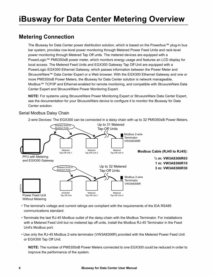
iBusway for Data Center Metering Overview
Metering ConnectionThe iBusway for Data Center power distribution solution, which is based on the Powerbus™ plug-in bus
bar system, provides row-level power monitoring through Metered Power Feed Units and rack-level
power monitoring through Metered Tap Off units. The metered devices are equipped with a
PowerLogic™ PM5350xB power meter, which monitors energy usage and features an LCD display for
local access. The Metered Feed Units and EGX300 Gateway Tap Off Unit are equipped with a
PowerLogic EGX300 Ethernet Gateway, which passes information between the Power Meter and
StruxureWare™ Data Center Expert or a Web browser. With the EGX300 Ethernet Gateway and one or
more PM5350xB Power Meters, the iBusway for Data Center solution is network manageable,
Modbus™ TCP/IP and Ethernet-enabled for remote monitoring, and compatible with StruxureWare Data
Center Expert and StruxureWare Power Monitoring Expert.
NOTE: For systems using StruxureWare Power Monitoring Expert or StruxureWare Data Center Expert,
see the documentation for your StruxureWare device to configure it to monitor the iBusway for Data
Center solution.
Serial Modbus Daisy Chain
2-wire Devices: The EGX300 can be connected in a daisy chain with up to 32 PM5350xB Power Meters.
NOTE: The number of PM5350xB Power Meters connected to one EGX300 could be reduced in order to
improve the performance of the system.
Shielded RJ45 to Shielded RJ45
Shielded RJ45 to Shielded RJ45
Up to 31 Metered Tap-Off Units
Metered Tap-Off Unit 1
Metered Tap-Off Unit 2
Metered Tap-Off Unit X
Modbus 2-wire Terminator VW3A8306R
PFU with Metering and EGX300 Gateway
Up to 32 Metered Tap-Off Units
EGX300 Tap-Off Unit
Metered Tap-Off Unit 1
Metered Tap-Off Unit X
Modbus 2-wire Terminator VW3A8306R
Power Feed UnitWithout Metering
pdu0
615a
• The terminal's voltage and current ratings are compliant with the requirements of the EIA RS485
communications standard.
• Terminate the last RJ-45 Modbus outlet of the daisy-chain with the Modbus Terminator. For installations
with a Metered Feed Unit but no metered tap off units, install the Modbus RJ-45 Terminator in the Feed
Unit's Modbus port.
• Use only the RJ-45 Modbus 2-wire terminator (VW3A8306R) provided with the Metered Power Feed Unit
or EGX300 Tap Off Unit.
Modbus Cable (RJ45 to RJ45):
⅓ m: VW3A8306R03
1 m: VW3A8306R10
3 m: VW3A8306R30
iBusway for Data Center User Manual4

Power Meter (PM5350xB)
PM5350xB Communication SetupTo begin power meter communication setup:
1. Scroll to “Maint” in the menu list by pressing the
rightmost arrow SCROLL button (►).
2. Press the “Maint” soft key.
3. Press the “Setup” soft key.
4. Enter your setup password, then press OK.NOTE: the default password is 0000.
5. Press “Comm”. The Comms Setup screen appears.
Setting Up the Modbus Address
To set up the Modbus address:
1. Press ▼ to select Address, then press (Edit).
2. Press + to increment the active digit through the numerals 0-9.
3. Press ◄ to enter the selected value for the active digit and move to the next digit to the left.
4. Continue until all values are selected, then press (OK) to set the address.
– For all PM5350xB Power Meters, the default communication parameters are:
• Modbus Address #1
• Baud rate: 19200
• Parity: Even
• Protocol: Modbus
NOTE: Each PM5350xB Power Meter in the daisy chain must have a unique
address, including the meter in the Metered Power Feed Unit. All other
communication parameters must match.
5. Press ▲ to exit Comm Port setup screen.
6. If changes have been made, a confirmation screen will prompt:- Press [Yes] to Save Changes- Press [No] to Discard Changes
pdu0
614a
5 iBusway for Data Center User Manual

Power Feed Unit / EGX Tap Off Unit
EGX300 Configuration
Ethernet Configuration
Before configuring the EGX, obtain a unique static IP address, subnet mask, and default gateway
address from your network administrator. Use a Web browser to configure the EGX with the information
obtained from your network administrator.
Ethernet Setup Using a Web Browser
1. Disconnect your computer from your network.NOTE: After disconnecting from your network, your computer should automatically use the
default IP address 169.254.###.### (### = 0 to 255) and the default subnet mask 255.255.0.0. If
the IP address is not automatically configured, contact your network administrator to set up a
static IP address.
2. Use an Ethernet crossover cable to connect your computer to the Ethernet jack on the Metered
Power Feed Unit or the EGX300 Tap Off Unit
3. Once connected to the EGX300, go to the Setup page to continue configuring the EGX300.
Set Up the Device List
To set up the Device List for the EGX:
1. Click Setup in the top menu bar.
2. Click Device List in the left navigation menu.
3. Select the number of viewable devices (1 to 32). The default number of devices is eight.
4. For each attached device on the daisy chain, enter the Local ID and Device Name. Select the
Device Type “PM5350xB” from the drop-down menu.
5. Click Apply.NOTE: The Power Meter must have a Modbus address before it can be added to the device list.
See “Setting Up the Modbus Address” on page 5 for more information.
The EGX300 arrives from
the factory with default
parameters:
IP: 169.254.0.10 User name: AdministratorPassword: Gateway
iBusway for Data Center User Manual6
Device Discovery
To automatically discover Metered Power Feed Units and Metered Tap Off Units and add them to the
EGX300 device list:
1. Click Setup in the top menu bar.
2. Click Device List in the left navigation menu.
3. Click Discover at the bottom of the page.
4. Enter the Modbus address range to scan.
5. Click Start Discover.NOTE: The Discover feature can also be used as a diagnostic tool to verify correct configuration
of devices, once all devices have been initially configured.NOTE: The Power Meters must have a Modbus address before they can be auto-discovered and
added to the device list. See “Setting Up the Modbus Address” on page 5 for more information.
Configure EGX300 IP address
When you finish making configuration changes to the EGX300, assign its IP address.
1. Click Setup in the top menu bar. By default, the left navigation menu option “Ethernet & TCP/IP”
is selected.
2. Enter the static IP address, Subnet Mask, and Default Gateway the network administrator
provided you.
3. Click Apply.
NOTE: To recover lost network settings, the TCSEAK0100 Configuration Kit is required. See the
EGX300 Installation Guide on www.schneider-electric.com for more information.
4. Log out of the EGX300 interface.
NOTICELOSS OF CONNECTIVITY
Record the new network settings and save them for future reference.
Failure to record and save the new network settings will result in loss of access to the system.
7 iBusway for Data Center User Manual

Configure the Date and Time
You can set the date and time of the EGX300, and the Power Meters it is monitoring, at the EGX300
Web interface.
Set the date and time of the EGX300 Ethernet Gateway
1. Click Setup in the top menu bar.
2. Select Date and Time in the left navigation menu.
3. Mark the Enable Network Time Synchronization check box or enter the date and time and click
Apply.
Reset the date and time of a Power Meter at the EGX300 Web interface:
1. Select Control in the top menu bar.
2. Select the device to modify.
3. Mark the Date/Time check box and click Reset.
Set the date and time of the Power Meter at its LCD interface
1. Scroll to [Maint] in the menu list.
2. Press [Maint].
3. Press [Setup].
4. Enter your setup password.NOTE: The default password is 0000.
5. Press [Clock]. The Clock setup screen appears.
6. Press [Edit] to select Date.
7. Press + to increment the active digit for the first character of the date.
8. Press ◄ to enter the selected character and move to the character to the left.
9. Continue until all values are selected, then press [OK] to set the date.
10.A confirmation screen will prompt:- Press [Yes] to Save Changes- Press [No] to Discard Changes
11. Press ▼ and follow Steps 7 to 9 to set the Time.
12.Press ▼ to select Meter Time, then press [Edit].
13.Press + and - to scroll through the meter time options.
14.Press [OK] to set the meter time.
The power meter stores all date and time stamps in GMT. If “Local” meter time is selected, the GMT
offset converts the GMT values to local date and time values for display on the display. There is also an
option to display the GMT values on the display.

Reset Device Parameters
At startup, a global reset is recommended. The reset can be performed at the power meter's LCD display
or from the EGX300 Web interface.
Reset the Power Meter from the EGX300 Web interface
1. Select Control in the top menu bar.
2. In the left navigation menu, select the device to reset.
3. Mark the check box of each parameter to reset, then click Reset.
Reset the Power Meter from its LCD interface
1. Scroll to [Maint] in the menu list.
2. Press [Maint].
3. Press [Reset]. The Resets screen appears.
4. Press [Select] to select Global Resets.
5. Press [Reset] to select Meter Initialization.
6. Enter the Energy Password (0000 by default), then press [OK].
7. A confirmation screen will prompt:— Press [Yes] to reset the power meter.— Press [No] to return to the previous screen.
NOTICESYSTEM DATA LOSS
The Meter Initialization option clears metering data (energy, demand, minimum/maximum values, counters, logs, timers, and input metering data).
The Global Reset option will cause permanent loss of PM5350xB Power Meter metering data.
9 iBusway for Data Center User Manual

Reset Passwords
Reset the Power Meter passwords
You can configure the Power Meter passwords. The passwords must use four numeric characters.
1. Press ▼ and ▲ to scroll through the passwords in the Passwords screen.
2. Press [Edit] to select a password.
3. Press + to increment the active digit through the numerals 0-9.
4. Press ◄ to enter the selected value for the active digit and move to the next digit to the left.
5. Continue until all values are selected, then press [OK] to set the password.
6. A confirmation screen will prompt:- Press [Yes] to Save Changes- Press [No] to Discard Changes
Reset the EGX300 password
You can configure the EGX300 passwords. User names and passwords are case-sensitive and can
contain only alphanumeric characters.
1. Select Setup in the top navigation menu.
2. Select User Accounts in the left navigation menu.
3. Enter a new Administrator password (0-12 characters), then click Apply.NOTE: For more information about user accounts, see the PowerLogic Ethernet Gateway
EGX300 User Guide, available on www.schneider-electric.com.
NOTICELOSS OF METER ACCESS
Record the new passwords and save them for future reference.
Failure to record and save the new passwords will result in loss of access to the Power Meter.
NOTICELOSS OF CONNECTIVITY
Record the new passwords and save them for future reference.
Failure to record and save the new passwords will result in loss of access to the iBusway for Data Center system.
iBusway for Data Center User Manual10


Worldwide Customer SupportCustomer support for this or any other product is available at no charge in any of the following ways:
• Visit the Schneider Electric Web site to access documents in the Schneider Electric Knowledge Base and to submit customer support requests.
– www.schneider-electric.com (Corporate Headquarters)Connect to localized Schneider Electric Web sites for specific countries, each of which provides customer support information.
– www.schneider-electric.com/support/Global support searching Schneider Electric Knowledge Base and using e-support.
• Contact the Schneider Electric Customer Support Center by telephone or e-mail.
– Local, country-specific centers: go to www.schneider-electric.com > Support > Operations around the world for contact information.
For information on how to obtain local customer support, contact the representative or other distributors from whom you purchased your product.
6/2014990-5313
Customer support and warranty information is available at www.apc.com.
© 2014 Schneider Electric. All Rights Reserved. Schneider Electric is a trademark owned by Schneider Electric Industries SAS or its
affiliated companies. All other trademarks are the property of their respective owners.