ibm totalstorage lto ultrium tape drive: scsi reference - oracle
TRANSCRIPT

IBM TotalStorage LTO UltriumTape Drive
SCSI Reference
GA32-0450-00
���

IBM TotalStorage LTO UltriumTape Drive
SCSI Reference
GA32-0450-00
���

NoteBefore using this manual and the product it supports, read the information under “Notices” on page 145.
First Edition (November 2002)
This edition applies to the IBM TotalStorage LTO Ultrium Tape Drive SCSI Reference and to all subsequent releasesand modifications unless otherwise indicated in new editions.
© Copyright International Business Machines Corporation 2002. All rights reserved.US Government Users Restricted Rights – Use, duplication or disclosure restricted by GSA ADP Schedule Contractwith IBM Corp.
Contents
Tables . . . . . . . . . . . . . . . . . . . . . . . . . . . . vii
Preface . . . . . . . . . . . . . . . . . . . . . . . . . . . . xiOrganization . . . . . . . . . . . . . . . . . . . . . . . . . . xiRelated Publications . . . . . . . . . . . . . . . . . . . . . . . xi
Chapter 1. Introduction . . . . . . . . . . . . . . . . . . . . . . 1Supported Servers and Operating Systems . . . . . . . . . . . . . . . 3
SCSI and Fibre Channel Attachment . . . . . . . . . . . . . . . . 3Supported Device Drivers . . . . . . . . . . . . . . . . . . . . . 4Supported Tape Cartridges . . . . . . . . . . . . . . . . . . . . . 5
Chapter 2. Summary of Drive Generation Differences . . . . . . . . . . 7Differences in Command Timeout Values. . . . . . . . . . . . . . . . 7New Commands and Parameters . . . . . . . . . . . . . . . . . . 9Data Changes . . . . . . . . . . . . . . . . . . . . . . . . . 9
Standard Inquiry Data . . . . . . . . . . . . . . . . . . . . . . 9REPORT DENSITY SUPPORT Command . . . . . . . . . . . . . . 9Mode Pages . . . . . . . . . . . . . . . . . . . . . . . . . 9READ POSITION Command . . . . . . . . . . . . . . . . . . . 9Cartridge Eject for Errors . . . . . . . . . . . . . . . . . . . . 10Queueing Issues . . . . . . . . . . . . . . . . . . . . . . . 10
Chapter 3. Command Support. . . . . . . . . . . . . . . . . . . 11ERASE. . . . . . . . . . . . . . . . . . . . . . . . . . . . 13INQUIRY . . . . . . . . . . . . . . . . . . . . . . . . . . . 14
Standard Inquiry Data Valid LUN . . . . . . . . . . . . . . . . . 15Standard Inquiry Data Invalid LUN. . . . . . . . . . . . . . . . . 17Supported Vital Product Data Page . . . . . . . . . . . . . . . . 19Unit Serial Number Page . . . . . . . . . . . . . . . . . . . . 19Device Identification Page . . . . . . . . . . . . . . . . . . . . 20Drive Component Revision Levels Pages . . . . . . . . . . . . . . 22
LOAD/UNLOAD . . . . . . . . . . . . . . . . . . . . . . . . 23LOCATE . . . . . . . . . . . . . . . . . . . . . . . . . . . 24LOG SELECT . . . . . . . . . . . . . . . . . . . . . . . . . 25LOG SENSE. . . . . . . . . . . . . . . . . . . . . . . . . . 26
Log Page Format . . . . . . . . . . . . . . . . . . . . . . . 27Supported Log Pages . . . . . . . . . . . . . . . . . . . . . 28Write Error Counters Log . . . . . . . . . . . . . . . . . . . . 29Read Error Counters Log . . . . . . . . . . . . . . . . . . . . 30Sequential Access Device Log . . . . . . . . . . . . . . . . . . 31TapeAlert Log . . . . . . . . . . . . . . . . . . . . . . . . 32Tape Usage Log . . . . . . . . . . . . . . . . . . . . . . . 38Tape Capacity Log . . . . . . . . . . . . . . . . . . . . . . 38Data Compression Log . . . . . . . . . . . . . . . . . . . . . 39
MODE SELECT . . . . . . . . . . . . . . . . . . . . . . . . 40MODE SENSE . . . . . . . . . . . . . . . . . . . . . . . . . 41
Mode Data Format . . . . . . . . . . . . . . . . . . . . . . 42Mode Parameter Header . . . . . . . . . . . . . . . . . . . . 43Mode Block Descriptor . . . . . . . . . . . . . . . . . . . . . 44Read-Write Error Recovery Page . . . . . . . . . . . . . . . . . 45Disconnect/Reconnect Page . . . . . . . . . . . . . . . . . . . 46Data Compression Mode Page . . . . . . . . . . . . . . . . . . 47
© Copyright IBM Corp. 2002 iii
Sequential Access Device Configuration Page . . . . . . . . . . . . 49Fibre Channel Logical Unit Control Page . . . . . . . . . . . . . . 50Fibre Channel Port Control Page . . . . . . . . . . . . . . . . . 51Information Exceptions Mode Page . . . . . . . . . . . . . . . . 52
PERSISTENT RESERVE IN . . . . . . . . . . . . . . . . . . . . 54PERSISTENT RESERVE OUT . . . . . . . . . . . . . . . . . . . 57PREVENT/ALLOW MEDIUM REMOVAL . . . . . . . . . . . . . . . 61READ . . . . . . . . . . . . . . . . . . . . . . . . . . . . 62READ ATTRIBUTE . . . . . . . . . . . . . . . . . . . . . . . 64
Format for the Attribute Values Service Action . . . . . . . . . . . . 66Format for the Attribute List Service Action. . . . . . . . . . . . . . 67Format for the Volume List Service Action . . . . . . . . . . . . . . 68Format for the Partition List Service Action. . . . . . . . . . . . . . 69Medium Auxiliary Memory . . . . . . . . . . . . . . . . . . . . 70
READ BLOCK LIMITS . . . . . . . . . . . . . . . . . . . . . . 79READ BUFFER . . . . . . . . . . . . . . . . . . . . . . . . 80
Error Log Buffer . . . . . . . . . . . . . . . . . . . . . . . 84Fibre Channel World Wide Name Buffer. . . . . . . . . . . . . . . 85SCSI Log Buffer . . . . . . . . . . . . . . . . . . . . . . . 85
READ POSITION . . . . . . . . . . . . . . . . . . . . . . . . 86RECEIVE DIAGNOSTIC RESULTS . . . . . . . . . . . . . . . . . 88RELEASE UNIT . . . . . . . . . . . . . . . . . . . . . . . . 89REPORT DENSITY SUPPORT . . . . . . . . . . . . . . . . . . . 90REPORT LUNs. . . . . . . . . . . . . . . . . . . . . . . . . 94REQUEST SENSE . . . . . . . . . . . . . . . . . . . . . . . 96
Sense Data Format . . . . . . . . . . . . . . . . . . . . . . 96RESERVE UNIT . . . . . . . . . . . . . . . . . . . . . . . . 99REWIND. . . . . . . . . . . . . . . . . . . . . . . . . . . 100SEND DIAGNOSTIC . . . . . . . . . . . . . . . . . . . . . . 101
SIM Data Structure . . . . . . . . . . . . . . . . . . . . . . 102MIM Data Structure . . . . . . . . . . . . . . . . . . . . . . 105Self-Test . . . . . . . . . . . . . . . . . . . . . . . . . . 107Post A Self Test Diagnostic . . . . . . . . . . . . . . . . . . . 108Post B Tape Test Diagnostic . . . . . . . . . . . . . . . . . . 109Post C Media Test Diagnostic . . . . . . . . . . . . . . . . . . 110Post D Head Test Diagnostic . . . . . . . . . . . . . . . . . . 111Force Dump . . . . . . . . . . . . . . . . . . . . . . . . 112Write Dump To Cartridge . . . . . . . . . . . . . . . . . . . . 113Set Traps . . . . . . . . . . . . . . . . . . . . . . . . . 115Remove Traps. . . . . . . . . . . . . . . . . . . . . . . . 116Reset Drive. . . . . . . . . . . . . . . . . . . . . . . . . 118
SET CAPACITY . . . . . . . . . . . . . . . . . . . . . . . . 119SPACE . . . . . . . . . . . . . . . . . . . . . . . . . . . 121TEST UNIT READY . . . . . . . . . . . . . . . . . . . . . . 123VERIFY . . . . . . . . . . . . . . . . . . . . . . . . . . . 123WRITE . . . . . . . . . . . . . . . . . . . . . . . . . . . 124WRITE ATTRIBUTE . . . . . . . . . . . . . . . . . . . . . . 125WRITE BUFFER . . . . . . . . . . . . . . . . . . . . . . . . 126WRITE FILE MARKS . . . . . . . . . . . . . . . . . . . . . . 128
Chapter 4. Error Sense Information . . . . . . . . . . . . . . . . 129Sense Data. . . . . . . . . . . . . . . . . . . . . . . . . . 129Sense Data Management . . . . . . . . . . . . . . . . . . . . 129Unit Attention Conditions . . . . . . . . . . . . . . . . . . . . . 129Persistent Errors . . . . . . . . . . . . . . . . . . . . . . . . 130
iv IBM TotalStorage LTO Ultrium Tape Drive: SCSI Reference
Chapter 5. Sense Keys and Additional Sense . . . . . . . . . . . . 131
Chapter 6. Attachment Features . . . . . . . . . . . . . . . . . 135Types of Interface Attachments . . . . . . . . . . . . . . . . . . 135Common Tape LUN Behaviors. . . . . . . . . . . . . . . . . . . 135
Power-On . . . . . . . . . . . . . . . . . . . . . . . . . 135Reset Strategy . . . . . . . . . . . . . . . . . . . . . . . 135Abort Handling . . . . . . . . . . . . . . . . . . . . . . . 136Multi-initiator Support . . . . . . . . . . . . . . . . . . . . . 138Status Codes . . . . . . . . . . . . . . . . . . . . . . . . 138
Features of the SCSI Interface . . . . . . . . . . . . . . . . . . 139LUN Identification . . . . . . . . . . . . . . . . . . . . . . 139Bus Parity Errors. . . . . . . . . . . . . . . . . . . . . . . 139Disconnect Strategy . . . . . . . . . . . . . . . . . . . . . 139Messages . . . . . . . . . . . . . . . . . . . . . . . . . 140
Features of the Fibre Channel Interface . . . . . . . . . . . . . . . 143
Appendix. Notices . . . . . . . . . . . . . . . . . . . . . . . 145Trademarks. . . . . . . . . . . . . . . . . . . . . . . . . . 145
Glossary . . . . . . . . . . . . . . . . . . . . . . . . . . 147
Index . . . . . . . . . . . . . . . . . . . . . . . . . . . . 155
Contents v

vi IBM TotalStorage LTO Ultrium Tape Drive: SCSI Reference
Tables
1. Features of the IBM Ultrium Tape Drives and the IBM 3580 Ultrium Tape Drive . . . . . . . . 22. Supported Servers and Operating Systems for SCSI and Fibre Channel Attachment . . . . . . 33. Differences in Command Timeout Values . . . . . . . . . . . . . . . . . . . . . . 74. Supported Common Commands . . . . . . . . . . . . . . . . . . . . . . . . . 115. ERASE Command . . . . . . . . . . . . . . . . . . . . . . . . . . . . . . 136. INQUIRY Command . . . . . . . . . . . . . . . . . . . . . . . . . . . . . 147. Standard Inquiry Data Valid LUN . . . . . . . . . . . . . . . . . . . . . . . . . 158. Standard Inquiry Data Invalid LUN . . . . . . . . . . . . . . . . . . . . . . . . 179. Supported Vital Product Data Inquiry Page . . . . . . . . . . . . . . . . . . . . . 19
10. Unit Serial Number Inquiry Page . . . . . . . . . . . . . . . . . . . . . . . . . 1911. Device Identification Inquiry Page. . . . . . . . . . . . . . . . . . . . . . . . . 2012. Device Identification Descriptor Format. . . . . . . . . . . . . . . . . . . . . . . 2013. Identifier Format . . . . . . . . . . . . . . . . . . . . . . . . . . . . . . . 2014. Fibre Channel Identification Descriptor . . . . . . . . . . . . . . . . . . . . . . . 2115. Drive Component Revision Levels Pages . . . . . . . . . . . . . . . . . . . . . . 2216. LOAD/UNLOAD Command . . . . . . . . . . . . . . . . . . . . . . . . . . . 2317. LOCATE Command . . . . . . . . . . . . . . . . . . . . . . . . . . . . . . 2418. LOG SELECT Command . . . . . . . . . . . . . . . . . . . . . . . . . . . . 2519. LOG SENSE Command . . . . . . . . . . . . . . . . . . . . . . . . . . . . 2620. Log Page Header Format. . . . . . . . . . . . . . . . . . . . . . . . . . . . 2721. Log Parameter Format. . . . . . . . . . . . . . . . . . . . . . . . . . . . . 2722. Supported Log Pages Log Page Format . . . . . . . . . . . . . . . . . . . . . . 2823. Write Error Log Parameters . . . . . . . . . . . . . . . . . . . . . . . . . . . 2924. Read Error Log Parameters . . . . . . . . . . . . . . . . . . . . . . . . . . . 3025. Sequential Access Device Log Parameters . . . . . . . . . . . . . . . . . . . . . 3126. TapeAlert Log Parameters . . . . . . . . . . . . . . . . . . . . . . . . . . . 3227. Tape Usage Log Parameters . . . . . . . . . . . . . . . . . . . . . . . . . . 3828. Tape Capacity Log Parameters . . . . . . . . . . . . . . . . . . . . . . . . . 3829. Data Compression Log Parameters . . . . . . . . . . . . . . . . . . . . . . . . 3930. 6-Byte MODE SELECT Command . . . . . . . . . . . . . . . . . . . . . . . . 4031. 10-Byte MODE SELECT Command . . . . . . . . . . . . . . . . . . . . . . . . 4032. 6-Byte MODE SENSE Command . . . . . . . . . . . . . . . . . . . . . . . . . 4133. 10-Byte MODE SENSE Command . . . . . . . . . . . . . . . . . . . . . . . . 4134. Mode Data Format . . . . . . . . . . . . . . . . . . . . . . . . . . . . . . 4235. Mode Parameter Header 6-Byte Command . . . . . . . . . . . . . . . . . . . . . 4336. Mode Parameter Header 10-Byte Command. . . . . . . . . . . . . . . . . . . . . 4337. Mode Block Descriptor. . . . . . . . . . . . . . . . . . . . . . . . . . . . . 4438. Read-Write Error Recovery Page . . . . . . . . . . . . . . . . . . . . . . . . . 4539. Disconnect/Reconnect Mode Page . . . . . . . . . . . . . . . . . . . . . . . . 4640. Data Compression Mode Page. . . . . . . . . . . . . . . . . . . . . . . . . . 4741. Responses to Data Boundaries . . . . . . . . . . . . . . . . . . . . . . . . . 4842. Sequential Access Device Configuration Page . . . . . . . . . . . . . . . . . . . . 4943. Fibre Channel Logical Unit Control Page . . . . . . . . . . . . . . . . . . . . . . 5044. Fibre Channel Port Control Page . . . . . . . . . . . . . . . . . . . . . . . . . 5145. Information Exceptions Mode Page . . . . . . . . . . . . . . . . . . . . . . . . 5246. PERSISTENT RESERVE IN Command . . . . . . . . . . . . . . . . . . . . . . 5447. PERSISTENT RESERVE IN Parameter Data for Read Keys . . . . . . . . . . . . . . . 5548. PERSISTENT RESERVE IN Parameter Data for Read Reservations . . . . . . . . . . . . 5549. PERSISTENT RESERVE IN Read Reservations Descriptor . . . . . . . . . . . . . . . 5650. PERSISTENT RESERVE OUT Command . . . . . . . . . . . . . . . . . . . . . 5751. Values for Service Action Codes in PERSISTENT RESERVE OUT Command . . . . . . . . 5752. Persistent Reservation Type Codes . . . . . . . . . . . . . . . . . . . . . . . . 5853. PERSISTENT RESERVE OUT Parameter List . . . . . . . . . . . . . . . . . . . . 60
© Copyright IBM Corp. 2002 vii
54. PREVENT/ALLOW MEDIUM REMOVAL Command . . . . . . . . . . . . . . . . . . 6155. READ Command . . . . . . . . . . . . . . . . . . . . . . . . . . . . . . . 6256. READ ATTRIBUTE Command . . . . . . . . . . . . . . . . . . . . . . . . . . 6457. Supported Service Action Codes . . . . . . . . . . . . . . . . . . . . . . . . . 6558. Parameter Data for an Attribute Values Service Action . . . . . . . . . . . . . . . . . 6659. Parameter Data for an Attribute List Service Action . . . . . . . . . . . . . . . . . . 6760. Parameter Data for a Volume List Service Action . . . . . . . . . . . . . . . . . . . 6861. Parameter Data for a Partition List Service Action . . . . . . . . . . . . . . . . . . . 6962. Types of MAM Attributes . . . . . . . . . . . . . . . . . . . . . . . . . . . . 7063. States for the Types of MAM Attributes. . . . . . . . . . . . . . . . . . . . . . . 7164. Format of a MAM Attribute . . . . . . . . . . . . . . . . . . . . . . . . . . . 7265. Values and Requirements for the Format Field . . . . . . . . . . . . . . . . . . . . 7366. Range of Values for MAM Attribute Identifiers . . . . . . . . . . . . . . . . . . . . 7367. Standard Device Type Attributes . . . . . . . . . . . . . . . . . . . . . . . . . 7468. Format for Device Vendor Identification/Product Serial Number Attribute, Device Vendor
Identification/Product Serial Number at Load-1 Attribute, Device Vendor Identification/ProductSerial Number at Load-2 Attribute, and Device Vendor Identification/Product Serial Number atLoad-3 Attribute . . . . . . . . . . . . . . . . . . . . . . . . . . . . . . . 75
69. Standard Medium Type Attributes . . . . . . . . . . . . . . . . . . . . . . . . . 7670. Values for Medium Type and Medium Type Information Attributes . . . . . . . . . . . . . 7771. Standard Host Type Attributes . . . . . . . . . . . . . . . . . . . . . . . . . . 7772. Values for the Text Localization Identifier Attribute . . . . . . . . . . . . . . . . . . . 7873. READ BLOCK LIMITS Command. . . . . . . . . . . . . . . . . . . . . . . . . 7974. READ BLOCK LIMITS Descriptor . . . . . . . . . . . . . . . . . . . . . . . . . 7975. READ BUFFER Command . . . . . . . . . . . . . . . . . . . . . . . . . . . 8076. Description of the Mode Field . . . . . . . . . . . . . . . . . . . . . . . . . . 8077. READ BUFFER Header . . . . . . . . . . . . . . . . . . . . . . . . . . . . 8278. READ BUFFER Descriptor . . . . . . . . . . . . . . . . . . . . . . . . . . . 8279. READ ECHO BUFFER Descriptor . . . . . . . . . . . . . . . . . . . . . . . . 8280. Drive Buffers . . . . . . . . . . . . . . . . . . . . . . . . . . . . . . . . 8381. Error Log Buffer Command . . . . . . . . . . . . . . . . . . . . . . . . . . . 8482. Fibre Channel World Wide Name Buffer . . . . . . . . . . . . . . . . . . . . . . 8583. SCSI Log Buffer Command . . . . . . . . . . . . . . . . . . . . . . . . . . . 8584. READ POSITION Command . . . . . . . . . . . . . . . . . . . . . . . . . . 8685. READ POSITION Data . . . . . . . . . . . . . . . . . . . . . . . . . . . . 8786. RECEIVE DIAGNOSTIC RESULTS Command . . . . . . . . . . . . . . . . . . . . 8887. 6-Byte RELEASE UNIT Command . . . . . . . . . . . . . . . . . . . . . . . . 8988. 10-Byte Release Unit Command . . . . . . . . . . . . . . . . . . . . . . . . . 8989. REPORT DENSITY SUPPORT Command . . . . . . . . . . . . . . . . . . . . . 9090. REPORT DENSITY SUPPORT Header . . . . . . . . . . . . . . . . . . . . . . 9191. REPORT DENSITY SUPPORT Descriptor Block . . . . . . . . . . . . . . . . . . . 9192. Density Information for LTO Formats . . . . . . . . . . . . . . . . . . . . . . . 9293. REPORT LUNs Command . . . . . . . . . . . . . . . . . . . . . . . . . . . 9494. Logical Unit Numbers Data . . . . . . . . . . . . . . . . . . . . . . . . . . . 9495. REQUEST SENSE Command . . . . . . . . . . . . . . . . . . . . . . . . . . 9696. Sense Data Format . . . . . . . . . . . . . . . . . . . . . . . . . . . . . . 9697. 6-Byte RESERVE UNIT Command . . . . . . . . . . . . . . . . . . . . . . . . 9998. 10-Byte Reserve Unit Command . . . . . . . . . . . . . . . . . . . . . . . . . 9999. REWIND Command . . . . . . . . . . . . . . . . . . . . . . . . . . . . . 100
100. SEND DIAGNOSTIC Command . . . . . . . . . . . . . . . . . . . . . . . . . 101101. Supported Diagnostics . . . . . . . . . . . . . . . . . . . . . . . . . . . . 101102. SIM Data Structure . . . . . . . . . . . . . . . . . . . . . . . . . . . . . 102103. MIM Data Structure . . . . . . . . . . . . . . . . . . . . . . . . . . . . . 105104. Post A Self Test Send Diagnostic Parameter Data . . . . . . . . . . . . . . . . . . 108105. Post A Self Test Receive Diagnostic Parameter Data . . . . . . . . . . . . . . . . . 108106. Post B Tape Test Send Diagnostic Parameter Data . . . . . . . . . . . . . . . . . . 109
viii IBM TotalStorage LTO Ultrium Tape Drive: SCSI Reference
107. Post B Tape Test Receive Diagnostic Parameter Data. . . . . . . . . . . . . . . . . 109108. Post C Media Test Send Diagnostic Parameter Data . . . . . . . . . . . . . . . . . 110109. Post C Media Test Receive Diagnostic Parameter Data . . . . . . . . . . . . . . . . 110110. Post D Head Test Send Diagnostic Parameter Data. . . . . . . . . . . . . . . . . . 111111. Post D Head Test Receive Diagnostic Parameter Data . . . . . . . . . . . . . . . . 111112. Force Dump Diagnostic Parameter Data . . . . . . . . . . . . . . . . . . . . . . 112113. Write Dump to Cartridge Send Diagnostic Parameter Data . . . . . . . . . . . . . . . 113114. Write Dump to Cartridge Receive Diagnostic Parameter Data . . . . . . . . . . . . . . 114115. Set Traps Diagnostic Parameter Data . . . . . . . . . . . . . . . . . . . . . . . 115116. Remove Traps Diagnostic Parameter Data . . . . . . . . . . . . . . . . . . . . . 116117. Reset Drive Diagnostic Results Data . . . . . . . . . . . . . . . . . . . . . . . 117118. Reset Drive Diagnostic Parameter Data . . . . . . . . . . . . . . . . . . . . . . 118119. SET CAPACITY Command. . . . . . . . . . . . . . . . . . . . . . . . . . . 119120. Minimum Supported Capacities for Each Cartridge Type . . . . . . . . . . . . . . . . 120121. SPACE Command . . . . . . . . . . . . . . . . . . . . . . . . . . . . . . 121122. TEST UNIT READY Command . . . . . . . . . . . . . . . . . . . . . . . . . 123123. VERIFY Command . . . . . . . . . . . . . . . . . . . . . . . . . . . . . 123124. WRITE Command . . . . . . . . . . . . . . . . . . . . . . . . . . . . . . 124125. WRITE ATTRIBUTE Command . . . . . . . . . . . . . . . . . . . . . . . . . 125126. Parameter Data for Attribute Values Service Action Request . . . . . . . . . . . . . . 125127. WRITE BUFFER Command . . . . . . . . . . . . . . . . . . . . . . . . . . 126128. Description of Mode Field . . . . . . . . . . . . . . . . . . . . . . . . . . . 126129. WRITE FILE MARKS Command. . . . . . . . . . . . . . . . . . . . . . . . . 128130. Sense Keys and Additional Sense . . . . . . . . . . . . . . . . . . . . . . . . 131131. Abort Condition Handling . . . . . . . . . . . . . . . . . . . . . . . . . . . 136132. Status Codes. . . . . . . . . . . . . . . . . . . . . . . . . . . . . . . . 138133. Supported Outbound Messages . . . . . . . . . . . . . . . . . . . . . . . . . 140134. Supported Inbound Messages . . . . . . . . . . . . . . . . . . . . . . . . . 141135. Supported Extended Messages . . . . . . . . . . . . . . . . . . . . . . . . . 142
Tables ix

x IBM TotalStorage LTO Ultrium Tape Drive: SCSI Reference
Preface
This publication contains information about how to use and program all models ofthe IBM® LTO Ultrium Tape Drive.
OrganizationThe information in this book is organized as follows:
v Chapter 1, “Introduction” on page 1 describes the features and supportedattachments for each type of tape drive.
v Chapter 2, “Summary of Drive Generation Differences” on page 7 lists thedifferences in command timeout values between the IBM Ultrium Internal TapeDrive and the IBM TotalStorage LTO Ultrium 2 Tape Drive (known respectively asthe Generation 1 and Generation 2 tape drive).
v Chapter 3, “Command Support” on page 11 lists the SCSI commands that aresupported by the tape drives.
v Chapter 4, “Error Sense Information” on page 129 describes the error senseinformation for the tape drives.
v Chapter 5, “Sense Keys and Additional Sense” on page 131 describes the sensekeys and additional sense information for the tape drives.
v Chapter 6, “Attachment Features” on page 135 describes the features of theSCSI and Fibre Channel tape drives.
Related Publicationsv IBM 3580 Ultrium Tape Drive Setup, Operator, and Service Guide, GA32-0415,
tells how to install and run the IBM 3580 Ultrium Tape Drive. The guide alsodescribes how to administer basic service procedures.
v IBM TotalStorage LTO Ultrium 2 Tape Drive Models T400 and T400F Setup,Operator, and Service Guide, GA32-0455, tells how to install and run the IBMUltrium 2 Tape Drive. The guide also describes how to administer basic serviceprocedures.
v IBM Ultrium Internal Tape Drive Models T200 and T200F Setup, Operator, andService Guide, GA32-0435, tells how to install and run the IBM Ultrium InternalTape Drive. The guide also describes how to administer basic serviceprocedures.
v IBM Ultrium Device Drivers Installation and User’s Guide, GA32-0430, providesinstructions for attaching IBM-supported hardware to open-systems operatingsystems. It indicates what devices and levels of operating systems aresupported, gives the requirements for adapter cards, and tells how to configureservers to use the device driver with the Ultrium family of devices.
v IBM Ultrium Device Drivers Programming Reference, GC35-0483, suppliesinformation to application owners who want to integrate their open-systemsapplications with IBM-supported Ultrium hardware. The reference containsinformation about the application programming interfaces (APIs) for each of thevarious supported operating-system environments.
v Fibre Channel Arbitrated Loop (FC-AL-2), published by the American NationalStandards Institute (ANSI) as NCITS 332:1999.
v Fibre Channel Tape and Tape Medium Changers (FC-TAPE), published by theAmerican National Standards Institute. Final draft available as T11/99-069v4 onthe web at http://www.t11.org; actual document available from ANSI as NCITSTR-24:1999.
© Copyright IBM Corp. 2002 xi
v Fibre Channel Protocol for SCSI, Second Version (FCP-2), published by theAmerican National Standards Institute and available on the web athttp://www.t10.org.
v SCSI Parallel Interface-3 (SPI-3), published by InterNational Committee onInformation Technology Standards (INCITS) and available on the web athttp://www.t10.org.
v SCSI-3 Stream Commands (SSC), published by the American NationalStandards Institute and available on the web at http://www.t10.org.
v SCSI Stream Commands-2 (SSC-2), published by the American NationalStandards Institute and available on the web at http://www.t10.org.
v SCSI Primary Commands-2 (SPC-2), published by the American NationalStandards Institute and available on the web at http://www.t10.org.
v SCSI Primary Commands-3 (SPC-3), published by the American NationalStandards Institute and available on the web at http://www.t10.org.
Portions of this manual were adapted from documentation provided by theInterNational Committee on Information Technology Standards (INCITS).
xii IBM TotalStorage LTO Ultrium Tape Drive: SCSI Reference
Chapter 1. Introduction
The products that are discussed in this book are high-performance, high-capacitydata-storage devices that connect to and provide additional storage for supportedservers. They include all models of the IBM LTO Ultrium Tape Drive, such as:
v IBM Ultrium Internal Tape Drive Models T200 and T200F (known as Generation1)
v IBM TotalStorage LTO Ultrium 2 Tape Drive Models T400 and T400F (known asGeneration 2)
v IBM 3580 Ultrium External Tape Drive
Certain of the products use a Small Computer Systems Interface (SCSI); others usea Fibre Channel interface. Table 1 on page 2 lists the type of interface and otherfeatures for each product.
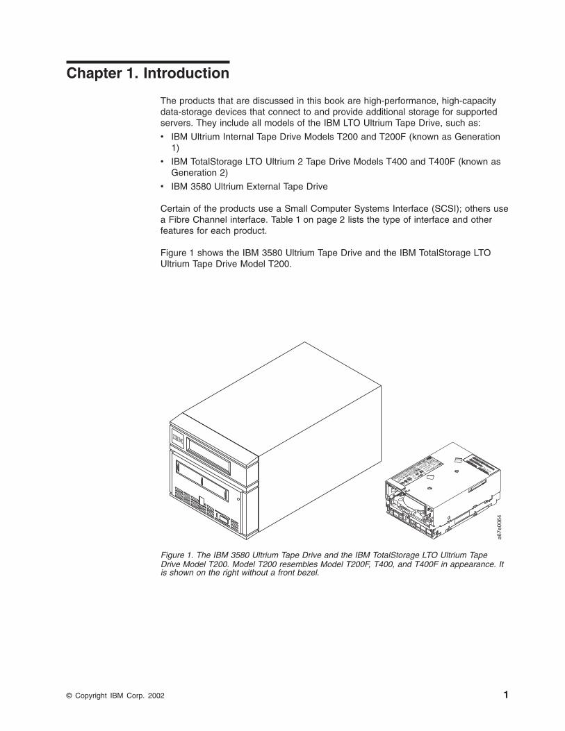
Figure 1 shows the IBM 3580 Ultrium Tape Drive and the IBM TotalStorage LTOUltrium Tape Drive Model T200.
Figure 1. The IBM 3580 Ultrium Tape Drive and the IBM TotalStorage LTO Ultrium TapeDrive Model T200. Model T200 resembles Model T200F, T400, and T400F in appearance. Itis shown on the right without a front bezel.
© Copyright IBM Corp. 2002 1
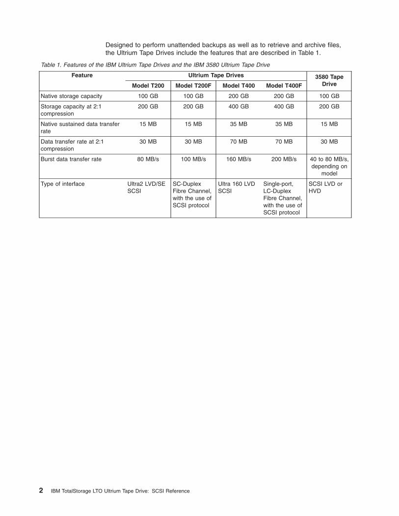
Designed to perform unattended backups as well as to retrieve and archive files,the Ultrium Tape Drives include the features that are described in Table 1.
Table 1. Features of the IBM Ultrium Tape Drives and the IBM 3580 Ultrium Tape Drive
Feature Ultrium Tape Drives 3580 TapeDriveModel T200 Model T200F Model T400 Model T400F
Native storage capacity 100 GB 100 GB 200 GB 200 GB 100 GB
Storage capacity at 2:1compression
200 GB 200 GB 400 GB 400 GB 200 GB
Native sustained data transferrate
15 MB 15 MB 35 MB 35 MB 15 MB
Data transfer rate at 2:1compression
30 MB 30 MB 70 MB 70 MB 30 MB
Burst data transfer rate 80 MB/s 100 MB/s 160 MB/s 200 MB/s 40 to 80 MB/s,depending on
model
Type of interface Ultra2 LVD/SESCSI
SC-DuplexFibre Channel,with the use ofSCSI protocol
Ultra 160 LVDSCSI
Single-port,LC-DuplexFibre Channel,with the use ofSCSI protocol
SCSI LVD orHVD
2 IBM TotalStorage LTO Ultrium Tape Drive: SCSI Reference
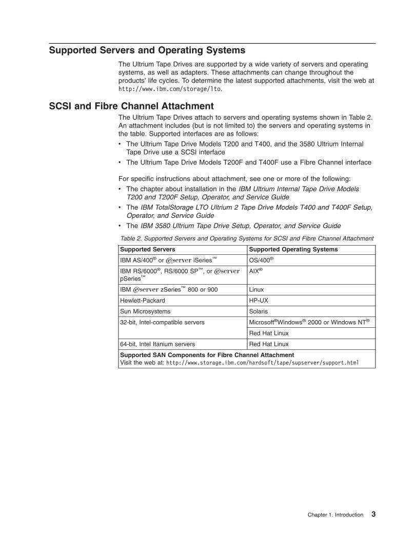
Supported Servers and Operating SystemsThe Ultrium Tape Drives are supported by a wide variety of servers and operatingsystems, as well as adapters. These attachments can change throughout theproducts’ life cycles. To determine the latest supported attachments, visit the web athttp://www.ibm.com/storage/lto.
SCSI and Fibre Channel AttachmentThe Ultrium Tape Drives attach to servers and operating systems shown in Table 2.An attachment includes (but is not limited to) the servers and operating systems inthe table. Supported interfaces are as follows:
v The Ultrium Tape Drive Models T200 and T400, and the 3580 Ultrium InternalTape Drive use a SCSI interface
v The Ultrium Tape Drive Models T200F and T400F use a Fibre Channel interface
For specific instructions about attachment, see one or more of the following:
v The chapter about installation in the IBM Ultrium Internal Tape Drive ModelsT200 and T200F Setup, Operator, and Service Guide
v The IBM TotalStorage LTO Ultrium 2 Tape Drive Models T400 and T400F Setup,Operator, and Service Guide
v The IBM 3580 Ultrium Tape Drive Setup, Operator, and Service Guide
Table 2. Supported Servers and Operating Systems for SCSI and Fibre Channel Attachment
Supported Servers Supported Operating Systems
IBM AS/400® or ERserver iSeries™ OS/400®
IBM RS/6000®, RS/6000 SP™, or Eserver
pSeries™AIX®
IBM Eserver zSeries™ 800 or 900 Linux
Hewlett-Packard HP-UX
Sun Microsystems Solaris
32-bit, Intel-compatible servers Microsoft®Windows® 2000 or Windows NT®
Red Hat Linux
64-bit, Intel Itanium servers Red Hat Linux
Supported SAN Components for Fibre Channel AttachmentVisit the web at: http://www.storage.ibm.com/hardsoft/tape/supserver/support.html
Chapter 1. Introduction 3
Supported Device DriversIBM maintains the latest levels of device drivers and driver documentation for theIBM Ultrium Tape Drives on the Internet. You can access this material from yourbrowser or through the IBM FTP site by performing one of the following procedures.(Note: If you do not have Internet access and you need information aboutdevice drivers, contact your Marketing Representative.)
v Using a browser, type one of the following:
– http://www.ibm.com/storage
– ftp://ftp.software.ibm.com/storage/devdrvr
– ftp://207.25.253.26/storage/devdrvr
v Using an IBM FTP site, enter the following specifications:
– FTP site: ftp.software.ibm.com
– IP Addr: 207.25.253.26
– Userid: anonymous
– Password: (use your current e-mail address)
– Directory: /storage/devdrvr
IBM provides PostScript- and PDF-formatted versions of its documentation in the/storage/devdrvr/doc directory:
v IBM_ultrium_tape_IUG.ps and IBM_ultrium_tape_IUG.pdf contain the currentversion of the IBM Ultrium Device Drivers Installation and User’s Guide
v IBM_ultrium_tape_PROGREF.ps and IBM_ultrium_tape_PROGREF.pdf containthe current version of the IBM Ultrium Device Drivers Programming Reference
Device drivers and utilities for each supported server are beneath /storage/devdrvr/in the following directories (the device driver for the iSeries or AS/400 server isincluded in the OS/400 operating system):
v AIX
v HPUX
v Linux
v Solaris
v Tru64
v WinNT
v Win2000
For more information about device drivers, refer to any of the preceding directories.
4 IBM TotalStorage LTO Ultrium Tape Drive: SCSI Reference
Supported Tape CartridgesThe Ultrium 2 Tape Drive (Generation 2) uses the IBM TotalStorage LTO Ultrium200 GB Data Cartridge and is compatible with the cartridges of its predecessor, theIBM Ultrium Internal Tape Drive (called Generation 1). The Ultrium 2 Tape Driveperforms the following functions:
v Reads and writes Generation 2 cartridges to Generation 2 format
v Reads and writes Generation 1 cartridges to Generation 1 format
v Does not write Generation 2 cartridges to Generation 1 format
v Does not write Generation 1 cartridges to Generation 2 format
The Ultrium 2 Tape Drive reads tapes that have been written by other licensedUltrium 2 drives. It also writes to tapes that can be read by other licensed Ultrium 2drives.
Both generations of Ultrium Tape Drive offer read/write capability for certified LTOUltrium tape cartridges that have capacities of 100, 50, 30, and 10 GB.
Chapter 1. Introduction 5

6 IBM TotalStorage LTO Ultrium Tape Drive: SCSI Reference
Chapter 2. Summary of Drive Generation Differences
This chapter provides a summary of the differences in host attachment protocolbetween the Ultrium Internal Tape Drive (Generation 1) and the TotalStorage LTOUltrium 2 Tape Drive (Generation 2). The features of the Generation 2 drive thatdiffer from the Generation 1 drive include:
v Reduced nominal power consumption
v 64-MB read-and-write cache
v Speed matching
v Channel calibration
v SET CAPACITY SCSI command
v Ultra160 SCSI interface
v Drive external SCSI termination required
v Fibre Channel 2-Gb/s interface
v Fibre Channel support for direct connection to an F port (for example, a McDataswitch)
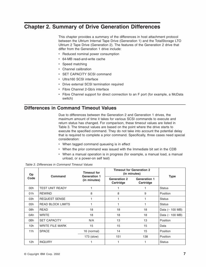
Differences in Command Timeout ValuesDue to differences between the Generation 2 and Generation 1 drives, themaximum amount of time it takes for various SCSI commands to execute andreturn status has changed. For comparison, these timeout values are listed inTable 3. The timeout values are based on the point where the drive starts toexecute the specified command. They do not take into account the potential delaythat is required to complete a prior command. Specifically, three cases need specialconsideration:
v When tagged command queueing is in effect
v When the prior command was issued with the Immediate bit set in the CDB
v When a manual operation is in progress (for example, a manual load, a manualunload, or a power-on self test)
Table 3. Differences in Command Timeout Values
OpCode
CommandTimeout for
Generation 1(in minutes)
Timeout for Generation 2(in minutes)
TypeGeneration 2
CartridgeGeneration 1
Cartridge
00h TEST UNIT READY 1 1 1 Status
01h REWIND 8 8 9 Position
03h REQUEST SENSE 1 1 1 Status
05h READ BLOCK LIMITS 1 1 1 Status
08h READ 18 18 18 Data (∼ 100 MB)
0Ah WRITE 18 18 18 Data (∼ 100 MB)
0Bh SET CAPACITY N/A 13 13 Position
10h WRITE FILE MARK 15 15 15 Data
11h SPACE 16 (normal) 14 15 Position
173 (slow) 151 138 Position
12h INQUIRY 1 1 1 Status
© Copyright IBM Corp. 2002 7
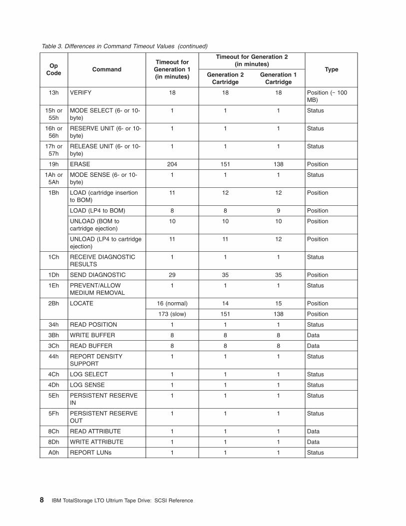
Table 3. Differences in Command Timeout Values (continued)
OpCode
CommandTimeout for
Generation 1(in minutes)
Timeout for Generation 2(in minutes)
TypeGeneration 2
CartridgeGeneration 1
Cartridge
13h VERIFY 18 18 18 Position (∼ 100MB)
15h or55h
MODE SELECT (6- or 10-byte)
1 1 1 Status
16h or56h
RESERVE UNIT (6- or 10-byte)
1 1 1 Status
17h or57h
RELEASE UNIT (6- or 10-byte)
1 1 1 Status
19h ERASE 204 151 138 Position
1Ah or5Ah
MODE SENSE (6- or 10-byte)
1 1 1 Status
1Bh LOAD (cartridge insertionto BOM)
11 12 12 Position
LOAD (LP4 to BOM) 8 8 9 Position
UNLOAD (BOM tocartridge ejection)
10 10 10 Position
UNLOAD (LP4 to cartridgeejection)
11 11 12 Position
1Ch RECEIVE DIAGNOSTICRESULTS
1 1 1 Status
1Dh SEND DIAGNOSTIC 29 35 35 Position
1Eh PREVENT/ALLOWMEDIUM REMOVAL
1 1 1 Status
2Bh LOCATE 16 (normal) 14 15 Position
173 (slow) 151 138 Position
34h READ POSITION 1 1 1 Status
3Bh WRITE BUFFER 8 8 8 Data
3Ch READ BUFFER 8 8 8 Data
44h REPORT DENSITYSUPPORT
1 1 1 Status
4Ch LOG SELECT 1 1 1 Status
4Dh LOG SENSE 1 1 1 Status
5Eh PERSISTENT RESERVEIN
1 1 1 Status
5Fh PERSISTENT RESERVEOUT
1 1 1 Status
8Ch READ ATTRIBUTE 1 1 1 Data
8Dh WRITE ATTRIBUTE 1 1 1 Data
A0h REPORT LUNs 1 1 1 Status
8 IBM TotalStorage LTO Ultrium Tape Drive: SCSI Reference
New Commands and ParametersThe following are new commands and parameters:
Set Capacity Command The SET CAPACITY command is supported onUltrium 2 tape drives. For more information, see“SET CAPACITY” on page 119.
Echo Buffer Support Ultrium 2 drives support the Echo Buffer mode ofthe READ BUFFER and WRITE BUFFERcommands (see pages 80 and 126, respectively).
Data ChangesThe sections that follow describe the data changes.
Standard Inquiry DataThe length of Standard Inquiry data increased to 57 bytes. The Standard Inquirydata that is reported includes information about the new DT mode support. Formore information, see “Standard Inquiry Data Valid LUN” on page 15.
REPORT DENSITY SUPPORT CommandThe REPORT DENSITY SUPPORT command added Generation 2 density values.For more information, see “REPORT DENSITY SUPPORT” on page 90.
Mode PagesFibre Channel Port Control Page (19h) Page Length changed from 0Eh (on Ultrium1 drives) to 06h (on Ultrium 2 drives). This matches the current definition in theSCSI standards (FCP-2). For more information, see “Fibre Channel Port ControlPage” on page 51.
READ POSITION CommandThe READ POSITION command changed to behave as described in the SCSIstandards (SPC-2). For more information, see “READ POSITION” on page 86.
The First Block Location specifies the block address that is associated with thecurrent logical position. The value indicates the block address of the next data blockto be transferred between the initiator and the target if a READ or WRITE commandis issued.
The Last Block Location is specified by the following procedure:
1. After a WRITE command, this field specifies the block address that isassociated with the next data block to be transferred from the buffer to themedium.
2. After a READ command, this field specifies the block address that is associatedwith the last (most recent) data block to be transferred from the medium to thebuffer. For any case where the buffer no longer contains a whole block of dataor is empty, the value that is reported for the Last Block Location is equal to thevalue that is reported for the First Block Location.
A block count unknown (BCU) field of 1 indicates that the Number of Blocks inBuffer field does not represent the actual number of blocks in the buffer. A BCU fieldof 0 indicates that the Number of Blocks in Buffer field is valid.
Chapter 2. Drive Generation Differences 9
The byte count unknown (BYCU) field is always set to 1 and indicates that theNumber of Bytes in Buffer field does not represent the actual number of bytes in thebuffer.
Cartridge Eject for ErrorsGeneration 2 drives no longer automatically eject data cartridges when errors occurduring loads.
Queueing IssuesIt is the expectation of Generation 2 drives that when a cartridge is inserted into thedrive through means other than SCSI commands to LUN 0, that the host will pollthe drive with TEST UNIT READY commands to determine its readiness beforeissuing in-order commands (for examples, commands other than INQUIRY, TESTUNIT READY, REQUEST SENSE, or REPORT LUNS). If this is not the case, thesecommands may timeout in ERP (Error Recovery Procedure) situations.
10 IBM TotalStorage LTO Ultrium Tape Drive: SCSI Reference
Chapter 3. Command Support
In the sections that follow, each SCSI command includes a table that describes thefields in the Command Descriptor Block (CDB). The table is similar to thosepublished by the InterNational Committee for Information Technology Standards(INCITS). It includes bit numbering conventions that conform to ANSI standards.The conventions are as follows:
v Bit 0 is the least significant bit (LSB) and occupies the right bit position in thetable
v Bits 1-6 continue from right to left in ascending order
v Bit 7 is the most significant bit (MSB) and occupies the left bit position in thetable
The LUN field in the CDB has been obsoleted in SCSI-3 and is ignored for everycommand.
Notes:
1. For this chapter, a megabyte (MB) is equal to 1 048 576 bytes.
2. Binary numbers are represented by numbers followed by b. Hexadecimalnumbers are represented by 0-9 and A-F followed by h. Numbers with no suffixcan be assumed to be decimal.
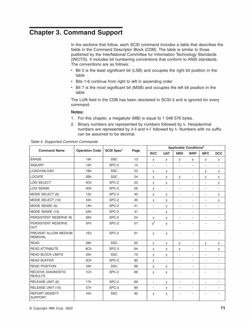
Table 4. Supported Common Commands
Command Name Operation Code SCSI Spec1 PageApplicable Conditions2
RVC UAT NRD WRP MFC DCC
ERASE 19h SSC 13 y y y y y y
INQUIRY 12h SPC-2 14 - - - - - -
LOAD/UNLOAD 1Bh SSC 23 y y - - y y
LOCATE 2Bh SSC 24 y y y - y y
LOG SELECT 4Ch SPC-2 25 y y - - - y
LOG SENSE 4Dh SPC-2 26 y - - - - -
MODE SELECT (6) 15h SPC-2 40 y y - - - y
MODE SELECT (10) 55h SPC-2 40 y y - - - y
MODE SENSE (6) 1Ah SPC-2 41 - y - - - -
MODE SENSE (10) 5Ah SPC-2 41 - y - - - -
PERSISTENT RESERVE IN 5Eh SPC-2 54 y y - - - -
PERSISTENT RESERVEOUT
5Fh SPC-2 57 y3 y - - - -
PREVENT ALLOW MEDIUMREMOVAL
1Eh SPC-2 61 y y - - - -
READ 08h SSC 62 y y y - y y
READ ATTRIBUTE 8Ch SPC-3 64 y y y - - y
READ BLOCK LIMITS 05h SSC 79 y y - - - -
READ BUFFER 3Ch SPC-2 80 y - - - - -
READ POSITION 34h SSC 86 y y - - - -
RECEIVE DIAGNOSTICRESULTS
1Ch SPC-2 88 y y - - - -
RELEASE UNIT (6) 17h SPC-2 89 - y - - - -
RELEASE UNIT (10) 57h SPC-2 89 - y - - - -
REPORT DENSITYSUPPORT
44h SSC 90 y y - - - -
© Copyright IBM Corp. 2002 11
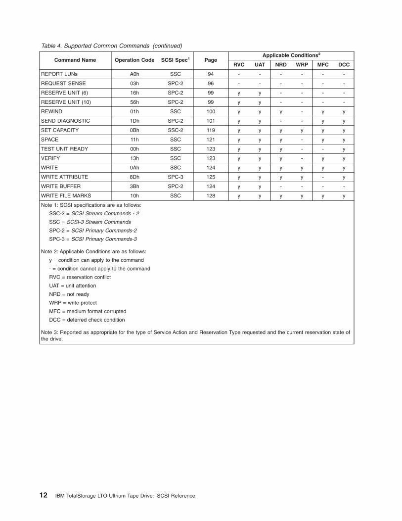
Table 4. Supported Common Commands (continued)
Command Name Operation Code SCSI Spec1 PageApplicable Conditions2
RVC UAT NRD WRP MFC DCC
REPORT LUNs A0h SSC 94 - - - - - -
REQUEST SENSE 03h SPC-2 96 - - - - - -
RESERVE UNIT (6) 16h SPC-2 99 y y - - - -
RESERVE UNIT (10) 56h SPC-2 99 y y - - - -
REWIND 01h SSC 100 y y y - y y
SEND DIAGNOSTIC 1Dh SPC-2 101 y y - - y y
SET CAPACITY 0Bh SSC-2 119 y y y y y y
SPACE 11h SSC 121 y y y - y y
TEST UNIT READY 00h SSC 123 y y y - - y
VERIFY 13h SSC 123 y y y - y y
WRITE 0Ah SSC 124 y y y y y y
WRITE ATTRIBUTE 8Dh SPC-3 125 y y y y - y
WRITE BUFFER 3Bh SPC-2 124 y y - - - -
WRITE FILE MARKS 10h SSC 128 y y y y y y
Note 1: SCSI specifications are as follows:
SSC-2 = SCSI Stream Commands - 2
SSC = SCSI-3 Stream Commands
SPC-2 = SCSI Primary Commands-2
SPC-3 = SCSI Primary Commands-3
Note 2: Applicable Conditions are as follows:
y = condition can apply to the command
- = condition cannot apply to the command
RVC = reservation conflict
UAT = unit attention
NRD = not ready
WRP = write protect
MFC = medium format corrupted
DCC = deferred check condition
Note 3: Reported as appropriate for the type of Service Action and Reservation Type requested and the current reservation state ofthe drive.
12 IBM TotalStorage LTO Ultrium Tape Drive: SCSI Reference
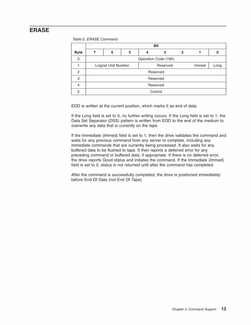
ERASETable 5. ERASE Command
Byte
Bit
7 6 5 4 3 2 1 0
0 Operation Code (19h)
1 Logical Unit Number Reserved Immed Long
2 Reserved
3 Reserved
4 Reserved
5 Control
EOD is written at the current position, which marks it as end of data.
If the Long field is set to 0, no further writing occurs. If the Long field is set to 1, theData Set Separator (DSS) pattern is written from EOD to the end of the medium tooverwrite any data that is currently on the tape.
If the Immediate (Immed) field is set to 1, then the drive validates the command andwaits for any previous command from any server to complete, including anyimmediate commands that are currently being processed. It also waits for anybuffered data to be flushed to tape. It then reports a deferred error for anypreceding command or buffered data, if appropriate. If there is no deferred error,the drive reports Good status and initiates the command. If the Immediate (Immed)field is set to 0, status is not returned until after the command has completed.
After the command is successfully completed, the drive is positioned immediatelybefore End Of Data (not End Of Tape).
Chapter 3. Command Support 13
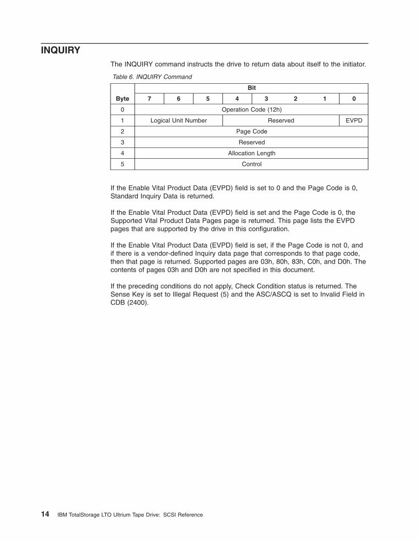
INQUIRYThe INQUIRY command instructs the drive to return data about itself to the initiator.
Table 6. INQUIRY Command
Byte
Bit
7 6 5 4 3 2 1 0
0 Operation Code (12h)
1 Logical Unit Number Reserved EVPD
2 Page Code
3 Reserved
4 Allocation Length
5 Control
If the Enable Vital Product Data (EVPD) field is set to 0 and the Page Code is 0,Standard Inquiry Data is returned.
If the Enable Vital Product Data (EVPD) field is set and the Page Code is 0, theSupported Vital Product Data Pages page is returned. This page lists the EVPDpages that are supported by the drive in this configuration.
If the Enable Vital Product Data (EVPD) field is set, if the Page Code is not 0, andif there is a vendor-defined Inquiry data page that corresponds to that page code,then that page is returned. Supported pages are 03h, 80h, 83h, C0h, and D0h. Thecontents of pages 03h and D0h are not specified in this document.
If the preceding conditions do not apply, Check Condition status is returned. TheSense Key is set to Illegal Request (5) and the ASC/ASCQ is set to Invalid Field inCDB (2400).
14 IBM TotalStorage LTO Ultrium Tape Drive: SCSI Reference
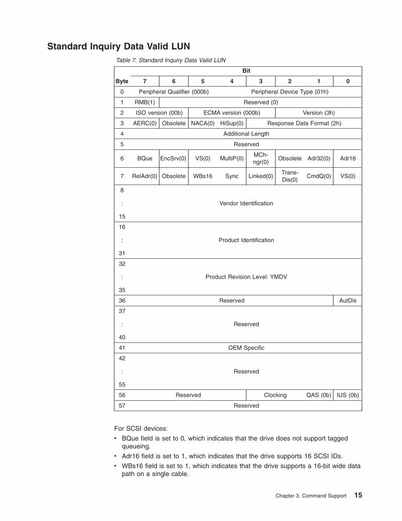
Standard Inquiry Data Valid LUNTable 7. Standard Inquiry Data Valid LUN
Byte
Bit
7 6 5 4 3 2 1 0
0 Peripheral Qualifier (000b) Peripheral Device Type (01h)
1 RMB(1) Reserved (0)
2 ISO version (00b) ECMA version (000b) Version (3h)
3 AERC(0) Obsolete NACA(0) HiSup(0) Response Data Format (2h)
4 Additional Length
5 Reserved
6 BQue EncSrv(0) VS(0) MultiP(0)MCh-ngr(0)
Obsolete Adr32(0) Adr16
7 RelAdr(0) Obsolete WBs16 Sync Linked(0)Trans-Dis(0)
CmdQ(0) VS(0)
8
:
15
Vendor Identification
16
:
31
Product Identification
32
:
35
Product Revision Level: YMDV
36 Reserved AutDis
37
:
40
Reserved
41 OEM Specific
42
:
55
Reserved
56 Reserved Clocking QAS (0b) IUS (0b)
57 Reserved
For SCSI devices:
v BQue field is set to 0, which indicates that the drive does not support taggedqueueing.
v Adr16 field is set to 1, which indicates that the drive supports 16 SCSI IDs.
v WBs16 field is set to 1, which indicates that the drive supports a 16-bit wide datapath on a single cable.
Chapter 3. Command Support 15

v Sync field is set to 1, which indicates that the drive supports synchronous datatransfers.
v Clocking field is supported on Ultrium 2 devices only and is set to 11b becausethe drive supports both ST and DT modes.
For Fibre Channel devices:
v BQue field is set to 1, which indicates that the drive supports tagged (simplecommand) queueing.
v Adr16 field is set to 0.
v WBs16 field is set to 0.
v Sync field is set to 0.
v Clocking field is set to 00b (the Clocking field is not used in Fibre Channeldevices).
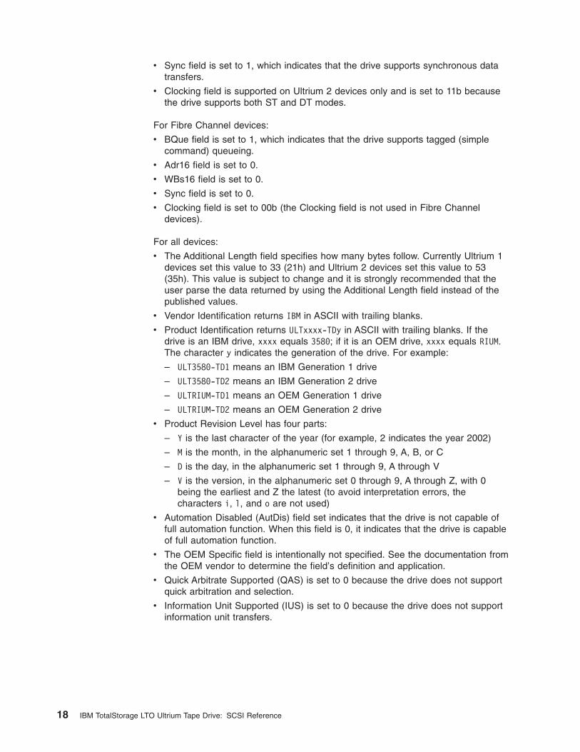
For all devices:
v The Additional Length field specifies how many bytes follow. Currently Ultrium 1devices set this value to 33 (21h) and Ultrium 2 devices set this value to 53(35h). This value is subject to change and it is strongly recommended that theuser parse the data returned by using the Additional Length field instead of thepublished values.
v Vendor Identification returns IBM in ASCII with trailing blanks.
v Product Identification returns ULTxxxx-TDy in ASCII with trailing blanks. If thedrive is an IBM drive, xxxx equals 3580; if it is an OEM drive, xxxx equals RIUM.The character y indicates the generation of the drive. For example:
– ULT3580-TD1 means an IBM Generation 1 drive
– ULT3580-TD2 means an IBM Generation 2 drive
– ULTRIUM-TD1 means an OEM Generation 1 drive
– ULTRIUM-TD2 means an OEM Generation 2 drive
v Product Revision Level has four parts:
– Y is the last character of the year (for example, 2 indicates the year 2002)
– M is the month, in the alphanumeric set 1 through 9, A, B, or C
– D is the day, in the alphanumeric set 1 through 9, A through V
– V is the version, in the alphanumeric set 0 through 9, A through Z, with 0being the earliest and Z the latest (to avoid interpretation errors, thecharacters i, l, and o are not used)
v Automation Disabled (AutDis) field set indicates that the drive is not capable offull automation function. When this field is 0, it indicates that the drive is capableof full automation function.
v The OEM Specific field is intentionally not specified. See the documentation fromthe OEM vendor to determine the field’s definition and application.
v Quick Arbitrate Supported (QAS) is set to 0 because the drive does not supportquick arbitration and selection.
v Information Unit Supported (IUS) is set to 0 because the drive does not supportinformation unit transfers.
16 IBM TotalStorage LTO Ultrium Tape Drive: SCSI Reference
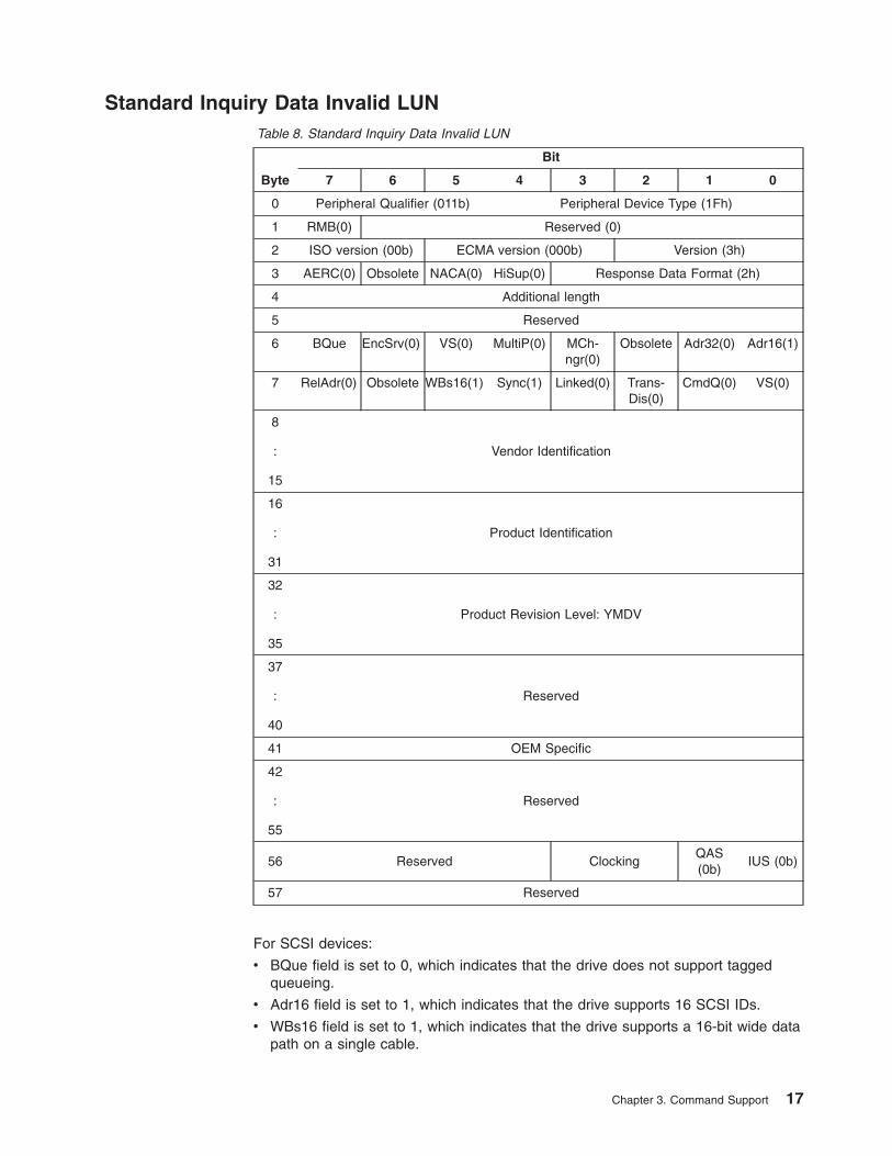
Standard Inquiry Data Invalid LUNTable 8. Standard Inquiry Data Invalid LUN
Byte
Bit
7 6 5 4 3 2 1 0
0 Peripheral Qualifier (011b) Peripheral Device Type (1Fh)
1 RMB(0) Reserved (0)
2 ISO version (00b) ECMA version (000b) Version (3h)
3 AERC(0) Obsolete NACA(0) HiSup(0) Response Data Format (2h)
4 Additional length
5 Reserved
6 BQue EncSrv(0) VS(0) MultiP(0) MCh-ngr(0)
Obsolete Adr32(0) Adr16(1)
7 RelAdr(0) Obsolete WBs16(1) Sync(1) Linked(0) Trans-Dis(0)
CmdQ(0) VS(0)
8
:
15
Vendor Identification
16
:
31
Product Identification
32
:
35
Product Revision Level: YMDV
37
:
40
Reserved
41 OEM Specific
42
:
55
Reserved
56 Reserved ClockingQAS(0b)
IUS (0b)
57 Reserved
For SCSI devices:
v BQue field is set to 0, which indicates that the drive does not support taggedqueueing.
v Adr16 field is set to 1, which indicates that the drive supports 16 SCSI IDs.
v WBs16 field is set to 1, which indicates that the drive supports a 16-bit wide datapath on a single cable.
Chapter 3. Command Support 17
v Sync field is set to 1, which indicates that the drive supports synchronous datatransfers.
v Clocking field is supported on Ultrium 2 devices only and is set to 11b becausethe drive supports both ST and DT modes.
For Fibre Channel devices:
v BQue field is set to 1, which indicates that the drive supports tagged (simplecommand) queueing.
v Adr16 field is set to 0.
v WBs16 field is set to 0.
v Sync field is set to 0.
v Clocking field is set to 00b (the Clocking field is not used in Fibre Channeldevices).
For all devices:
v The Additional Length field specifies how many bytes follow. Currently Ultrium 1devices set this value to 33 (21h) and Ultrium 2 devices set this value to 53(35h). This value is subject to change and it is strongly recommended that theuser parse the data returned by using the Additional Length field instead of thepublished values.
v Vendor Identification returns IBM in ASCII with trailing blanks.
v Product Identification returns ULTxxxx-TDy in ASCII with trailing blanks. If thedrive is an IBM drive, xxxx equals 3580; if it is an OEM drive, xxxx equals RIUM.The character y indicates the generation of the drive. For example:
– ULT3580-TD1 means an IBM Generation 1 drive
– ULT3580-TD2 means an IBM Generation 2 drive
– ULTRIUM-TD1 means an OEM Generation 1 drive
– ULTRIUM-TD2 means an OEM Generation 2 drive
v Product Revision Level has four parts:
– Y is the last character of the year (for example, 2 indicates the year 2002)
– M is the month, in the alphanumeric set 1 through 9, A, B, or C
– D is the day, in the alphanumeric set 1 through 9, A through V
– V is the version, in the alphanumeric set 0 through 9, A through Z, with 0being the earliest and Z the latest (to avoid interpretation errors, thecharacters i, l, and o are not used)
v Automation Disabled (AutDis) field set indicates that the drive is not capable offull automation function. When this field is 0, it indicates that the drive is capableof full automation function.
v The OEM Specific field is intentionally not specified. See the documentation fromthe OEM vendor to determine the field’s definition and application.
v Quick Arbitrate Supported (QAS) is set to 0 because the drive does not supportquick arbitration and selection.
v Information Unit Supported (IUS) is set to 0 because the drive does not supportinformation unit transfers.
18 IBM TotalStorage LTO Ultrium Tape Drive: SCSI Reference
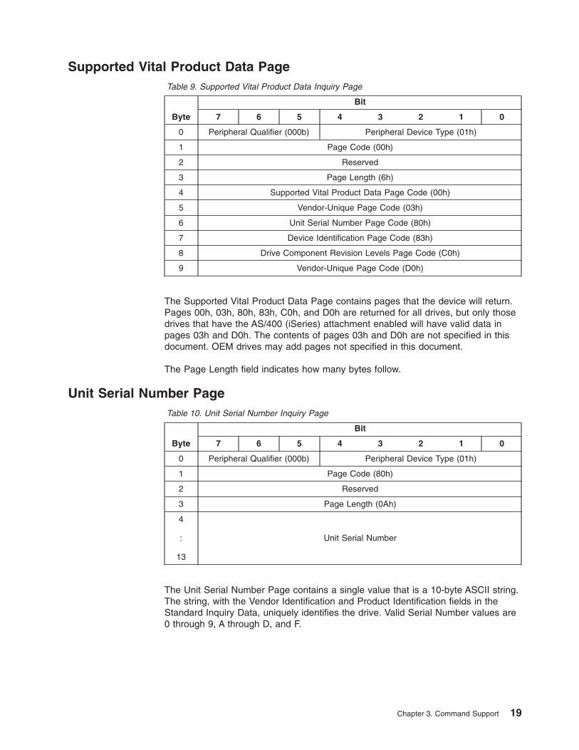
Supported Vital Product Data PageTable 9. Supported Vital Product Data Inquiry Page
Byte
Bit
7 6 5 4 3 2 1 0
0 Peripheral Qualifier (000b) Peripheral Device Type (01h)
1 Page Code (00h)
2 Reserved
3 Page Length (6h)
4 Supported Vital Product Data Page Code (00h)
5 Vendor-Unique Page Code (03h)
6 Unit Serial Number Page Code (80h)
7 Device Identification Page Code (83h)
8 Drive Component Revision Levels Page Code (C0h)
9 Vendor-Unique Page Code (D0h)
The Supported Vital Product Data Page contains pages that the device will return.Pages 00h, 03h, 80h, 83h, C0h, and D0h are returned for all drives, but only thosedrives that have the AS/400 (iSeries) attachment enabled will have valid data inpages 03h and D0h. The contents of pages 03h and D0h are not specified in thisdocument. OEM drives may add pages not specified in this document.
The Page Length field indicates how many bytes follow.
Unit Serial Number PageTable 10. Unit Serial Number Inquiry Page
Byte
Bit
7 6 5 4 3 2 1 0
0 Peripheral Qualifier (000b) Peripheral Device Type (01h)
1 Page Code (80h)
2 Reserved
3 Page Length (0Ah)
4
:
13
Unit Serial Number
The Unit Serial Number Page contains a single value that is a 10-byte ASCII string.The string, with the Vendor Identification and Product Identification fields in theStandard Inquiry Data, uniquely identifies the drive. Valid Serial Number values are0 through 9, A through D, and F.
Chapter 3. Command Support 19
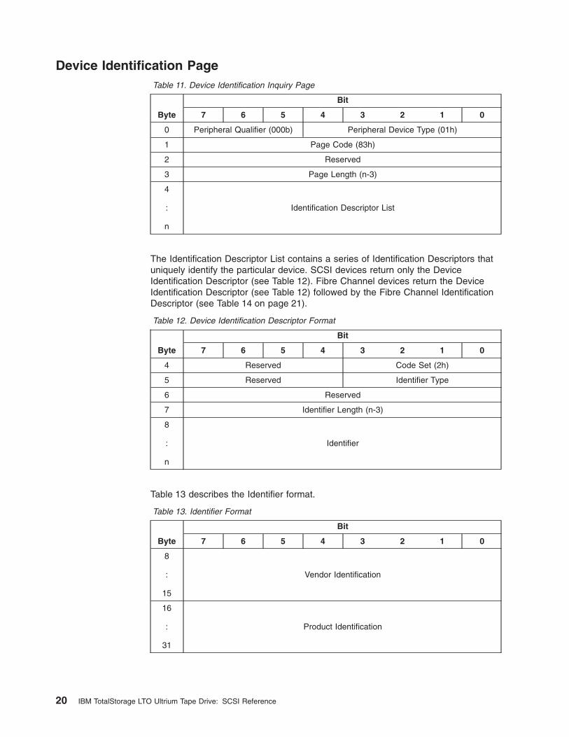
Device Identification PageTable 11. Device Identification Inquiry Page
Byte
Bit
7 6 5 4 3 2 1 0
0 Peripheral Qualifier (000b) Peripheral Device Type (01h)
1 Page Code (83h)
2 Reserved
3 Page Length (n-3)
4
:
n
Identification Descriptor List
The Identification Descriptor List contains a series of Identification Descriptors thatuniquely identify the particular device. SCSI devices return only the DeviceIdentification Descriptor (see Table 12). Fibre Channel devices return the DeviceIdentification Descriptor (see Table 12) followed by the Fibre Channel IdentificationDescriptor (see Table 14 on page 21).
Table 12. Device Identification Descriptor Format
Byte
Bit
7 6 5 4 3 2 1 0
4 Reserved Code Set (2h)
5 Reserved Identifier Type
6 Reserved
7 Identifier Length (n-3)
8
:
n
Identifier
Table 13 describes the Identifier format.
Table 13. Identifier Format
Byte
Bit
7 6 5 4 3 2 1 0
8
:
15
Vendor Identification
16
:
31
Product Identification
20 IBM TotalStorage LTO Ultrium Tape Drive: SCSI Reference
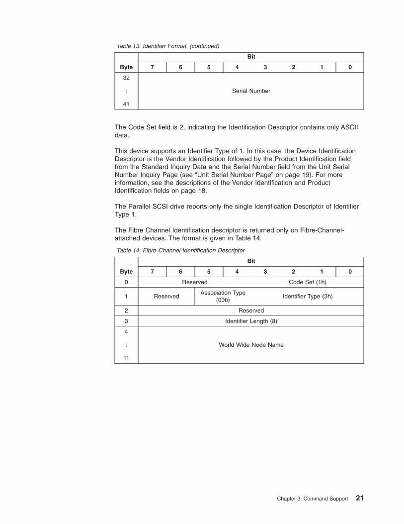
Table 13. Identifier Format (continued)
Byte
Bit
7 6 5 4 3 2 1 0
32
:
41
Serial Number
The Code Set field is 2, indicating the Identification Descriptor contains only ASCIIdata.
This device supports an Identifier Type of 1. In this case, the Device IdentificationDescriptor is the Vendor Identification followed by the Product Identification fieldfrom the Standard Inquiry Data and the Serial Number field from the Unit SerialNumber Inquiry Page (see “Unit Serial Number Page” on page 19). For moreinformation, see the descriptions of the Vendor Identification and ProductIdentification fields on page 18.
The Parallel SCSI drive reports only the single Identification Descriptor of IdentifierType 1.
The Fibre Channel Identification descriptor is returned only on Fibre-Channel-attached devices. The format is given in Table 14.
Table 14. Fibre Channel Identification Descriptor
Byte
Bit
7 6 5 4 3 2 1 0
0 Reserved Code Set (1h)
1 ReservedAssociation Type
(00b)Identifier Type (3h)
2 Reserved
3 Identifier Length (8)
4
:
11
World Wide Node Name
Chapter 3. Command Support 21
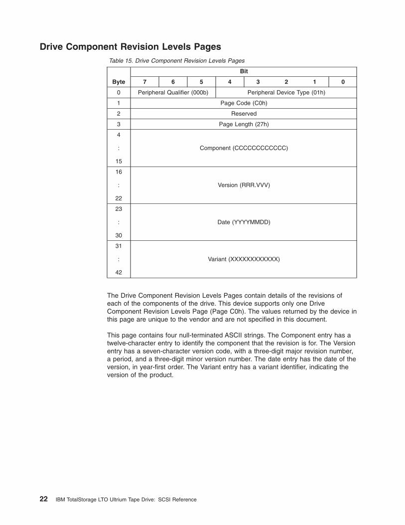
Drive Component Revision Levels PagesTable 15. Drive Component Revision Levels Pages
Byte
Bit
7 6 5 4 3 2 1 0
0 Peripheral Qualifier (000b) Peripheral Device Type (01h)
1 Page Code (C0h)
2 Reserved
3 Page Length (27h)
4
:
15
Component (CCCCCCCCCCCC)
16
:
22
Version (RRR.VVV)
23
:
30
Date (YYYYMMDD)
31
:
42
Variant (XXXXXXXXXXXX)
The Drive Component Revision Levels Pages contain details of the revisions ofeach of the components of the drive. This device supports only one DriveComponent Revision Levels Page (Page C0h). The values returned by the device inthis page are unique to the vendor and are not specified in this document.
This page contains four null-terminated ASCII strings. The Component entry has atwelve-character entry to identify the component that the revision is for. The Versionentry has a seven-character version code, with a three-digit major revision number,a period, and a three-digit minor version number. The date entry has the date of theversion, in year-first order. The Variant entry has a variant identifier, indicating theversion of the product.
22 IBM TotalStorage LTO Ultrium Tape Drive: SCSI Reference
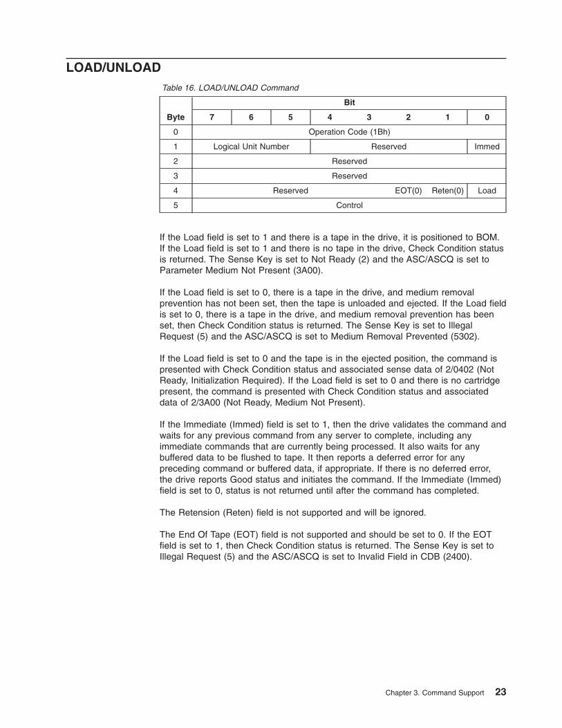
LOAD/UNLOADTable 16. LOAD/UNLOAD Command
Byte
Bit
7 6 5 4 3 2 1 0
0 Operation Code (1Bh)
1 Logical Unit Number Reserved Immed
2 Reserved
3 Reserved
4 Reserved EOT(0) Reten(0) Load
5 Control
If the Load field is set to 1 and there is a tape in the drive, it is positioned to BOM.If the Load field is set to 1 and there is no tape in the drive, Check Condition statusis returned. The Sense Key is set to Not Ready (2) and the ASC/ASCQ is set toParameter Medium Not Present (3A00).
If the Load field is set to 0, there is a tape in the drive, and medium removalprevention has not been set, then the tape is unloaded and ejected. If the Load fieldis set to 0, there is a tape in the drive, and medium removal prevention has beenset, then Check Condition status is returned. The Sense Key is set to IllegalRequest (5) and the ASC/ASCQ is set to Medium Removal Prevented (5302).
If the Load field is set to 0 and the tape is in the ejected position, the command ispresented with Check Condition status and associated sense data of 2/0402 (NotReady, Initialization Required). If the Load field is set to 0 and there is no cartridgepresent, the command is presented with Check Condition status and associateddata of 2/3A00 (Not Ready, Medium Not Present).
If the Immediate (Immed) field is set to 1, then the drive validates the command andwaits for any previous command from any server to complete, including anyimmediate commands that are currently being processed. It also waits for anybuffered data to be flushed to tape. It then reports a deferred error for anypreceding command or buffered data, if appropriate. If there is no deferred error,the drive reports Good status and initiates the command. If the Immediate (Immed)field is set to 0, status is not returned until after the command has completed.
The Retension (Reten) field is not supported and will be ignored.
The End Of Tape (EOT) field is not supported and should be set to 0. If the EOTfield is set to 1, then Check Condition status is returned. The Sense Key is set toIllegal Request (5) and the ASC/ASCQ is set to Invalid Field in CDB (2400).
Chapter 3. Command Support 23
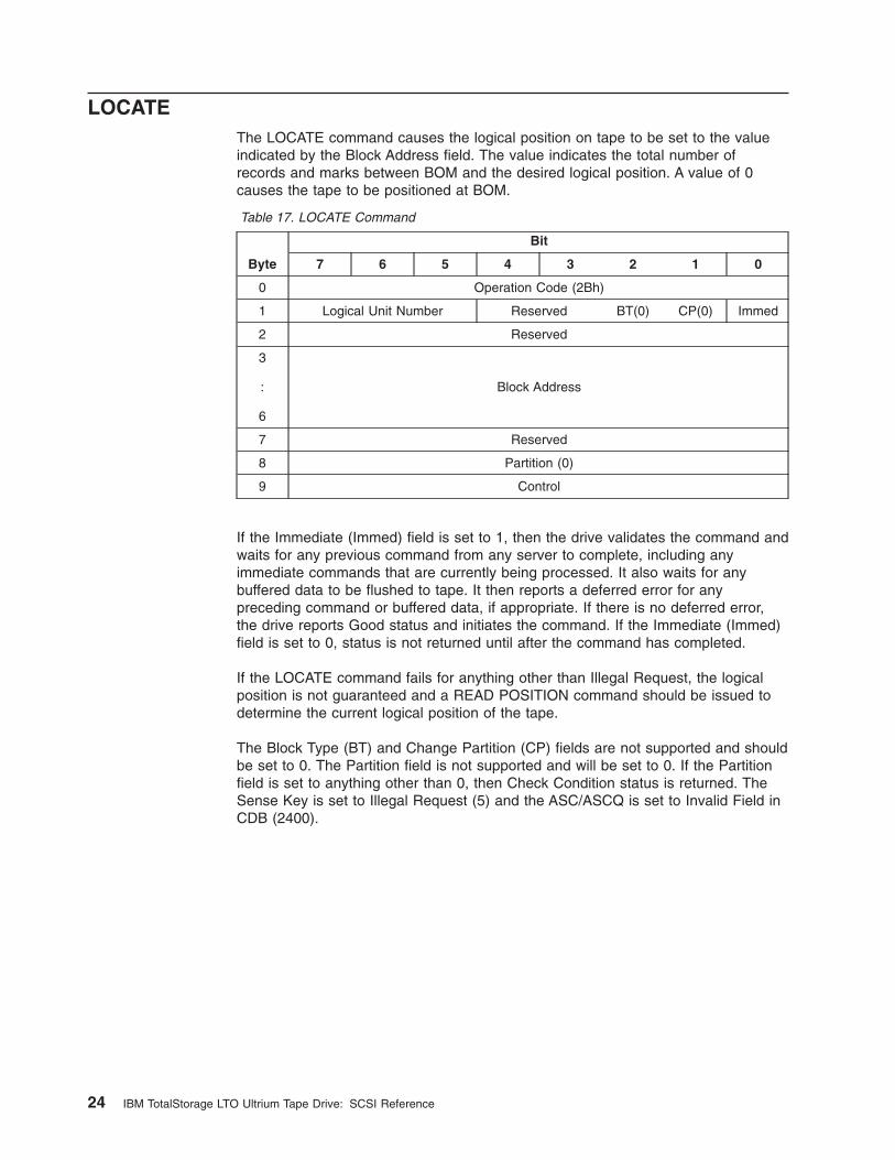
LOCATEThe LOCATE command causes the logical position on tape to be set to the valueindicated by the Block Address field. The value indicates the total number ofrecords and marks between BOM and the desired logical position. A value of 0causes the tape to be positioned at BOM.
Table 17. LOCATE Command
Byte
Bit
7 6 5 4 3 2 1 0
0 Operation Code (2Bh)
1 Logical Unit Number Reserved BT(0) CP(0) Immed
2 Reserved
3
:
6
Block Address
7 Reserved
8 Partition (0)
9 Control
If the Immediate (Immed) field is set to 1, then the drive validates the command andwaits for any previous command from any server to complete, including anyimmediate commands that are currently being processed. It also waits for anybuffered data to be flushed to tape. It then reports a deferred error for anypreceding command or buffered data, if appropriate. If there is no deferred error,the drive reports Good status and initiates the command. If the Immediate (Immed)field is set to 0, status is not returned until after the command has completed.
If the LOCATE command fails for anything other than Illegal Request, the logicalposition is not guaranteed and a READ POSITION command should be issued todetermine the current logical position of the tape.
The Block Type (BT) and Change Partition (CP) fields are not supported and shouldbe set to 0. The Partition field is not supported and will be set to 0. If the Partitionfield is set to anything other than 0, then Check Condition status is returned. TheSense Key is set to Illegal Request (5) and the ASC/ASCQ is set to Invalid Field inCDB (2400).
24 IBM TotalStorage LTO Ultrium Tape Drive: SCSI Reference
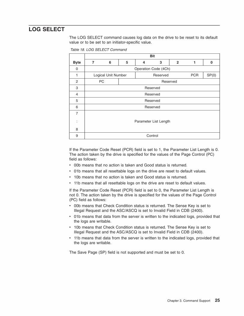
LOG SELECTThe LOG SELECT command causes log data on the drive to be reset to its defaultvalue or to be set to an initiator-specific value.
Table 18. LOG SELECT Command
Byte
Bit
7 6 5 4 3 2 1 0
0 Operation Code (4Ch)
1 Logical Unit Number Reserved PCR SP(0)
2 PC Reserved
3 Reserved
4 Reserved
5 Reserved
6 Reserved
7
:
8
Parameter List Length
9 Control
If the Parameter Code Reset (PCR) field is set to 1, the Parameter List Length is 0.The action taken by the drive is specified for the values of the Page Control (PC)field as follows:
v 00b means that no action is taken and Good status is returned.
v 01b means that all resettable logs on the drive are reset to default values.
v 10b means that no action is taken and Good status is returned.
v 11b means that all resettable logs on the drive are reset to default values.
If the Parameter Code Reset (PCR) field is set to 0, the Parameter List Length isnot 0. The action taken by the drive is specified for the values of the Page Control(PC) field as follows:
v 00b means that Check Condition status is returned. The Sense Key is set toIllegal Request and the ASC/ASCQ is set to Invalid Field in CDB (2400).
v 01b means that data from the server is written to the indicated logs, provided thatthe logs are writable.
v 10b means that Check Condition status is returned. The Sense Key is set toIllegal Request and the ASC/ASCQ is set to Invalid Field in CDB (2400).
v 11b means that data from the server is written to the indicated logs, provided thatthe logs are writable.
The Save Page (SP) field is not supported and must be set to 0.
Chapter 3. Command Support 25
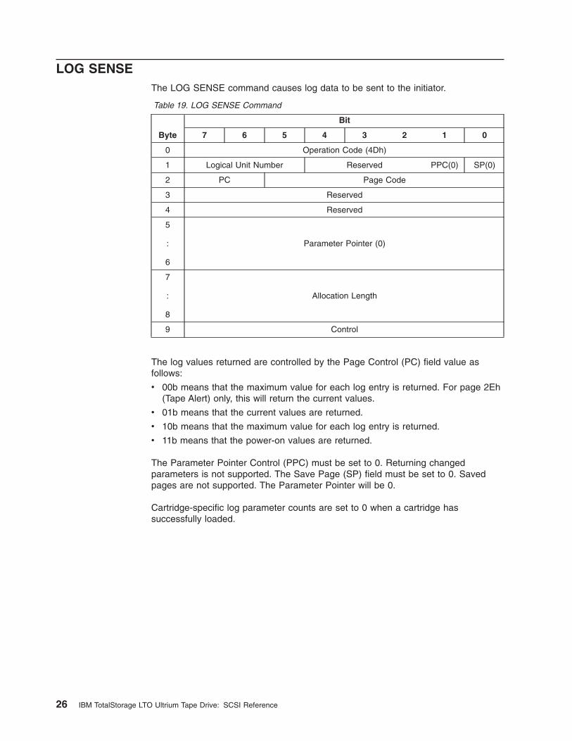
LOG SENSEThe LOG SENSE command causes log data to be sent to the initiator.
Table 19. LOG SENSE Command
Byte
Bit
7 6 5 4 3 2 1 0
0 Operation Code (4Dh)
1 Logical Unit Number Reserved PPC(0) SP(0)
2 PC Page Code
3 Reserved
4 Reserved
5
:
6
Parameter Pointer (0)
7
:
8
Allocation Length
9 Control
The log values returned are controlled by the Page Control (PC) field value asfollows:
v 00b means that the maximum value for each log entry is returned. For page 2Eh(Tape Alert) only, this will return the current values.
v 01b means that the current values are returned.
v 10b means that the maximum value for each log entry is returned.
v 11b means that the power-on values are returned.
The Parameter Pointer Control (PPC) must be set to 0. Returning changedparameters is not supported. The Save Page (SP) field must be set to 0. Savedpages are not supported. The Parameter Pointer will be 0.
Cartridge-specific log parameter counts are set to 0 when a cartridge hassuccessfully loaded.
26 IBM TotalStorage LTO Ultrium Tape Drive: SCSI Reference
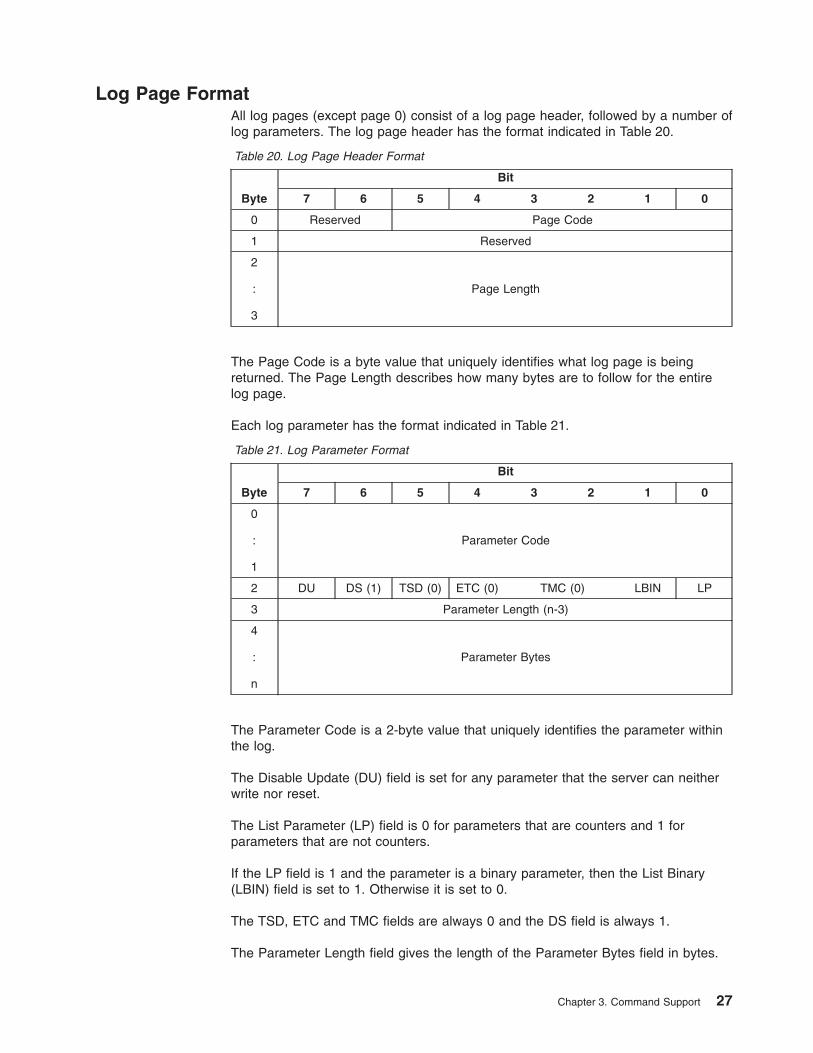
Log Page FormatAll log pages (except page 0) consist of a log page header, followed by a number oflog parameters. The log page header has the format indicated in Table 20.
Table 20. Log Page Header Format
Byte
Bit
7 6 5 4 3 2 1 0
0 Reserved Page Code
1 Reserved
2
:
3
Page Length
The Page Code is a byte value that uniquely identifies what log page is beingreturned. The Page Length describes how many bytes are to follow for the entirelog page.
Each log parameter has the format indicated in Table 21.
Table 21. Log Parameter Format
Byte
Bit
7 6 5 4 3 2 1 0
0
:
1
Parameter Code
2 DU DS (1) TSD (0) ETC (0) TMC (0) LBIN LP
3 Parameter Length (n-3)
4
:
n
Parameter Bytes
The Parameter Code is a 2-byte value that uniquely identifies the parameter withinthe log.
The Disable Update (DU) field is set for any parameter that the server can neitherwrite nor reset.
The List Parameter (LP) field is 0 for parameters that are counters and 1 forparameters that are not counters.
If the LP field is 1 and the parameter is a binary parameter, then the List Binary(LBIN) field is set to 1. Otherwise it is set to 0.
The TSD, ETC and TMC fields are always 0 and the DS field is always 1.
The Parameter Length field gives the length of the Parameter Bytes field in bytes.
Chapter 3. Command Support 27
The Parameter Bytes field contains the actual parameter data.
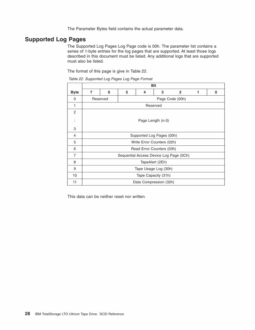
Supported Log PagesThe Supported Log Pages Log Page code is 00h. The parameter list contains aseries of 1-byte entries for the log pages that are supported. At least those logsdescribed in this document must be listed. Any additional logs that are supportedmust also be listed.
The format of this page is give in Table 22.
Table 22. Supported Log Pages Log Page Format
Byte
Bit
7 6 5 4 3 2 1 0
0 Reserved Page Code (00h)
1 Reserved
2
:
3
Page Length (n-3)
4 Supported Log Pages (00h)
5 Write Error Counters (02h)
6 Read Error Counters (03h)
7 Sequential Access Device Log Page (0Ch)
8 TapeAlert (2Eh)
9 Tape Usage Log (30h)
10 Tape Capacity (31h)
11 Data Compression (32h)
This data can be neither reset nor written.
28 IBM TotalStorage LTO Ultrium Tape Drive: SCSI Reference
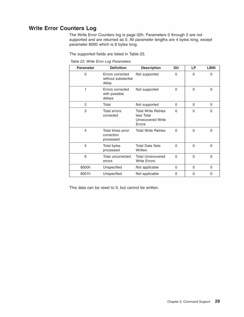
Write Error Counters LogThe Write Error Counters log is page 02h. Parameters 0 through 2 are notsupported and are returned as 0. All parameter lengths are 4 bytes long, exceptparameter 8000 which is 8 bytes long.
The supported fields are listed in Table 23.
Table 23. Write Error Log Parameters
Parameter Definition Description DU LP LBIN
0 Errors correctedwithout substantialdelay
Not supported 0 0 0
1 Errors correctedwith possibledelays
Not supported 0 0 0
2 Total Not supported 0 0 0
3 Total errorscorrected
Total Write Retriesless TotalUnrecovered WriteErrors
0 0 0
4 Total times errorcorrectionprocessed
Total Write Retries 0 0 0
5 Total bytesprocessed
Total Data SetsWritten
0 0 0
6 Total uncorrectederrors
Total UnrecoveredWrite Errors
0 0 0
8000h Unspecified Not applicable 0 0 0
8001h Unspecified Not applicable 0 0 0
This data can be reset to 0, but cannot be written.
Chapter 3. Command Support 29
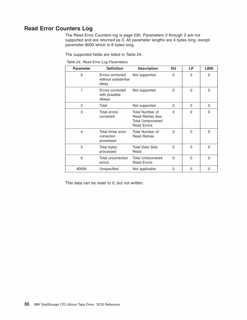
Read Error Counters LogThe Read Error Counters log is page 03h. Parameters 0 through 2 are notsupported and are returned as 0. All parameter lengths are 4 bytes long, exceptparameter 8000 which is 8 bytes long.
The supported fields are listed in Table 24.
Table 24. Read Error Log Parameters
Parameter Definition Description DU LP LBIN
0 Errors correctedwithout substantialdelay
Not supported 0 0 0
1 Errors correctedwith possibledelays
Not supported 0 0 0
2 Total Not supported 0 0 0
3 Total errorscorrected
Total Number ofRead Retries lessTotal UnrecoveredRead Errors
0 0 0
4 Total times errorcorrectionprocessed
Total Number ofRead Retries
0 0 0
5 Total bytesprocessed
Total Data SetsRead
0 0 0
6 Total uncorrectederrors
Total UnrecoveredRead Errors
0 0 0
8000h Unspecified Not applicable 0 0 0
This data can be reset to 0, but not written.
30 IBM TotalStorage LTO Ultrium Tape Drive: SCSI Reference
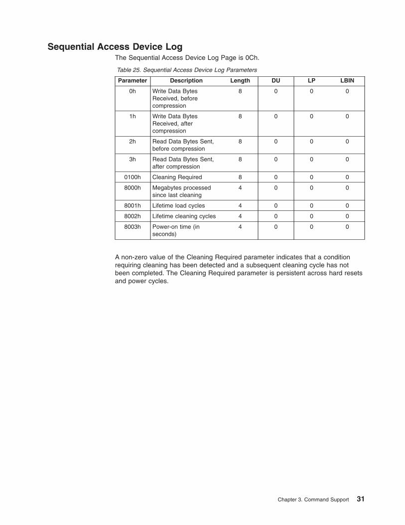
Sequential Access Device LogThe Sequential Access Device Log Page is 0Ch.
Table 25. Sequential Access Device Log Parameters
Parameter Description Length DU LP LBIN
0h Write Data BytesReceived, beforecompression
8 0 0 0
1h Write Data BytesReceived, aftercompression
8 0 0 0
2h Read Data Bytes Sent,before compression
8 0 0 0
3h Read Data Bytes Sent,after compression
8 0 0 0
0100h Cleaning Required 8 0 0 0
8000h Megabytes processedsince last cleaning
4 0 0 0
8001h Lifetime load cycles 4 0 0 0
8002h Lifetime cleaning cycles 4 0 0 0
8003h Power-on time (inseconds)
4 0 0 0
A non-zero value of the Cleaning Required parameter indicates that a conditionrequiring cleaning has been detected and a subsequent cleaning cycle has notbeen completed. The Cleaning Required parameter is persistent across hard resetsand power cycles.
Chapter 3. Command Support 31
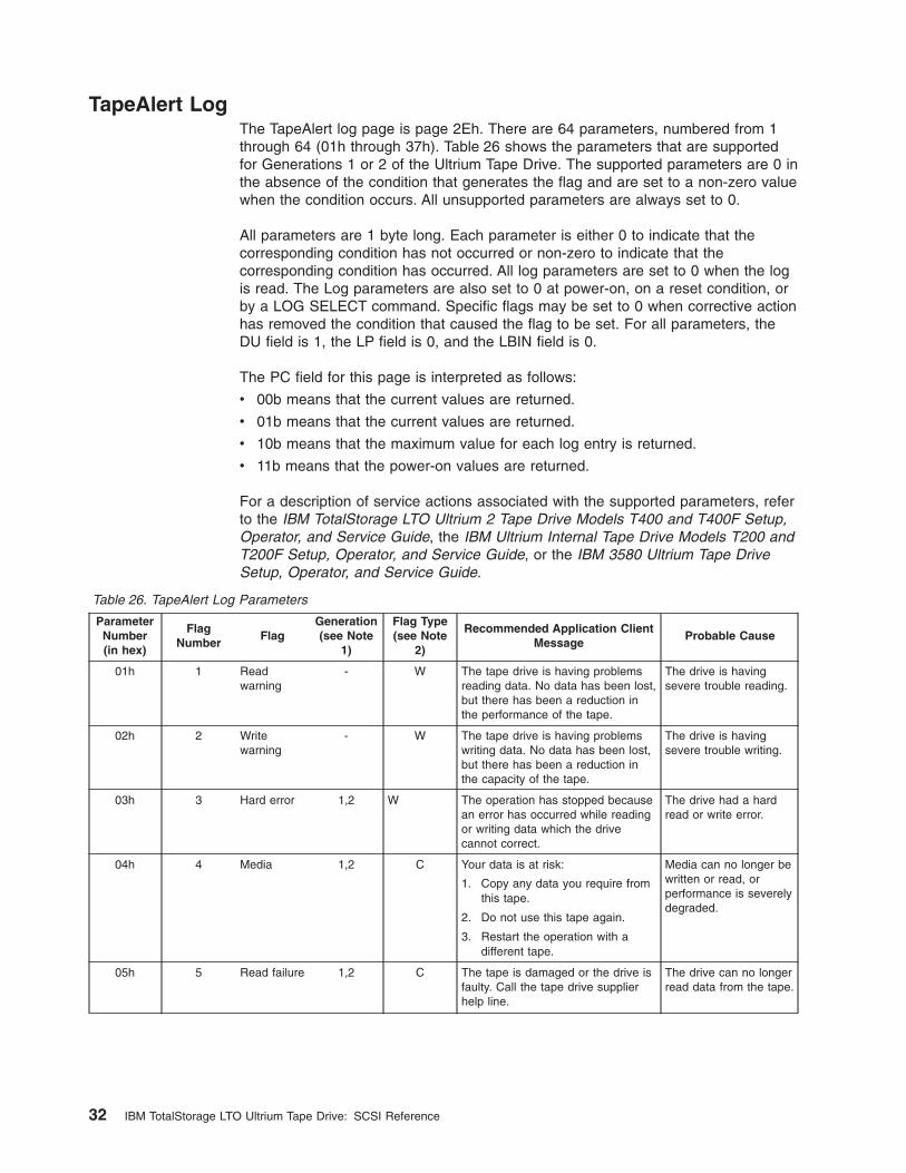
TapeAlert LogThe TapeAlert log page is page 2Eh. There are 64 parameters, numbered from 1through 64 (01h through 37h). Table 26 shows the parameters that are supportedfor Generations 1 or 2 of the Ultrium Tape Drive. The supported parameters are 0 inthe absence of the condition that generates the flag and are set to a non-zero valuewhen the condition occurs. All unsupported parameters are always set to 0.
All parameters are 1 byte long. Each parameter is either 0 to indicate that thecorresponding condition has not occurred or non-zero to indicate that thecorresponding condition has occurred. All log parameters are set to 0 when the logis read. The Log parameters are also set to 0 at power-on, on a reset condition, orby a LOG SELECT command. Specific flags may be set to 0 when corrective actionhas removed the condition that caused the flag to be set. For all parameters, theDU field is 1, the LP field is 0, and the LBIN field is 0.
The PC field for this page is interpreted as follows:
v 00b means that the current values are returned.
v 01b means that the current values are returned.
v 10b means that the maximum value for each log entry is returned.
v 11b means that the power-on values are returned.
For a description of service actions associated with the supported parameters, referto the IBM TotalStorage LTO Ultrium 2 Tape Drive Models T400 and T400F Setup,Operator, and Service Guide, the IBM Ultrium Internal Tape Drive Models T200 andT200F Setup, Operator, and Service Guide, or the IBM 3580 Ultrium Tape DriveSetup, Operator, and Service Guide.
Table 26. TapeAlert Log Parameters
ParameterNumber(in hex)
FlagNumber
FlagGeneration(see Note
1)
Flag Type(see Note
2)
Recommended Application ClientMessage
Probable Cause
01h 1 Readwarning
- W The tape drive is having problemsreading data. No data has been lost,but there has been a reduction inthe performance of the tape.
The drive is havingsevere trouble reading.
02h 2 Writewarning
- W The tape drive is having problemswriting data. No data has been lost,but there has been a reduction inthe capacity of the tape.
The drive is havingsevere trouble writing.
03h 3 Hard error 1,2 W The operation has stopped becausean error has occurred while readingor writing data which the drivecannot correct.
The drive had a hardread or write error.
04h 4 Media 1,2 C Your data is at risk:
1. Copy any data you require fromthis tape.
2. Do not use this tape again.
3. Restart the operation with adifferent tape.
Media can no longer bewritten or read, orperformance is severelydegraded.
05h 5 Read failure 1,2 C The tape is damaged or the drive isfaulty. Call the tape drive supplierhelp line.
The drive can no longerread data from the tape.
32 IBM TotalStorage LTO Ultrium Tape Drive: SCSI Reference
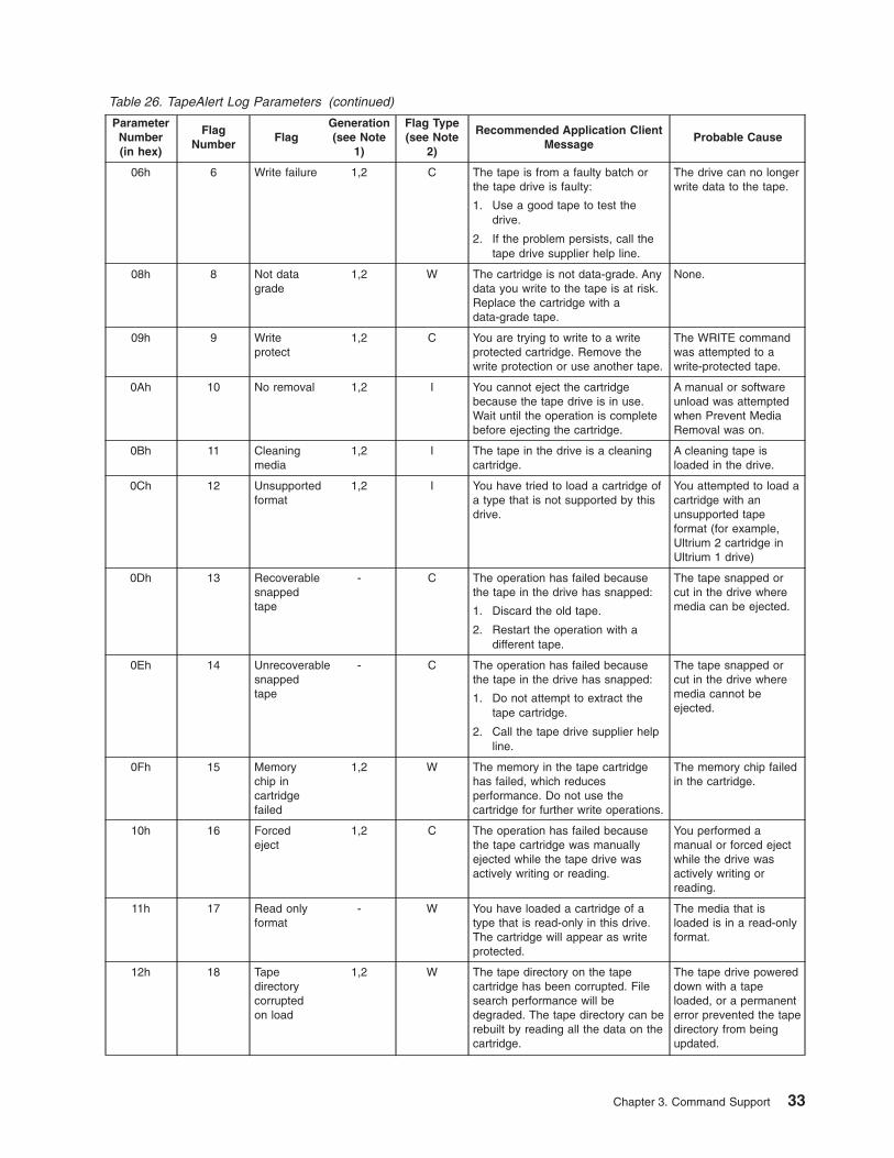
Table 26. TapeAlert Log Parameters (continued)
ParameterNumber(in hex)
FlagNumber
FlagGeneration(see Note
1)
Flag Type(see Note
2)
Recommended Application ClientMessage
Probable Cause
06h 6 Write failure 1,2 C The tape is from a faulty batch orthe tape drive is faulty:
1. Use a good tape to test thedrive.
2. If the problem persists, call thetape drive supplier help line.
The drive can no longerwrite data to the tape.
08h 8 Not datagrade
1,2 W The cartridge is not data-grade. Anydata you write to the tape is at risk.Replace the cartridge with adata-grade tape.
None.
09h 9 Writeprotect
1,2 C You are trying to write to a writeprotected cartridge. Remove thewrite protection or use another tape.
The WRITE commandwas attempted to awrite-protected tape.
0Ah 10 No removal 1,2 I You cannot eject the cartridgebecause the tape drive is in use.Wait until the operation is completebefore ejecting the cartridge.
A manual or softwareunload was attemptedwhen Prevent MediaRemoval was on.
0Bh 11 Cleaningmedia
1,2 I The tape in the drive is a cleaningcartridge.
A cleaning tape isloaded in the drive.
0Ch 12 Unsupportedformat
1,2 I You have tried to load a cartridge ofa type that is not supported by thisdrive.
You attempted to load acartridge with anunsupported tapeformat (for example,Ultrium 2 cartridge inUltrium 1 drive)
0Dh 13 Recoverablesnappedtape
- C The operation has failed becausethe tape in the drive has snapped:
1. Discard the old tape.
2. Restart the operation with adifferent tape.
The tape snapped orcut in the drive wheremedia can be ejected.
0Eh 14 Unrecoverablesnappedtape
- C The operation has failed becausethe tape in the drive has snapped:
1. Do not attempt to extract thetape cartridge.
2. Call the tape drive supplier helpline.
The tape snapped orcut in the drive wheremedia cannot beejected.
0Fh 15 Memorychip incartridgefailed
1,2 W The memory in the tape cartridgehas failed, which reducesperformance. Do not use thecartridge for further write operations.
The memory chip failedin the cartridge.
10h 16 Forcedeject
1,2 C The operation has failed becausethe tape cartridge was manuallyejected while the tape drive wasactively writing or reading.
You performed amanual or forced ejectwhile the drive wasactively writing orreading.
11h 17 Read onlyformat
- W You have loaded a cartridge of atype that is read-only in this drive.The cartridge will appear as writeprotected.
The media that isloaded is in a read-onlyformat.
12h 18 Tapedirectorycorruptedon load
1,2 W The tape directory on the tapecartridge has been corrupted. Filesearch performance will bedegraded. The tape directory can berebuilt by reading all the data on thecartridge.
The tape drive powereddown with a tapeloaded, or a permanenterror prevented the tapedirectory from beingupdated.
Chapter 3. Command Support 33
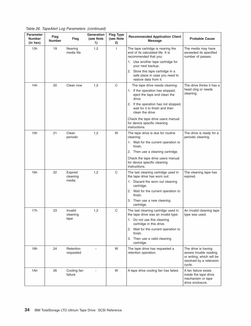
Table 26. TapeAlert Log Parameters (continued)
ParameterNumber(in hex)
FlagNumber
FlagGeneration(see Note
1)
Flag Type(see Note
2)
Recommended Application ClientMessage
Probable Cause
13h 19 Nearingmedia life
1,2 I The tape cartridge is nearing theend of its calculated life. It isrecommended that you:
1. Use another tape cartridge foryour next backup.
2. Store this tape cartridge in asafe place in case you need torestore data from it.
The media may haveexceeded its specifiednumber of passes.
14h 20 Clean now 1,2 C The tape drive needs cleaning:
1. If the operation has stopped,eject the tape and clean thedrive.
2. If the operation has not stopped,wait for it to finish and thenclean the drive.
Check the tape drive users manualfor device specific cleaninginstructions.
The drive thinks it has ahead clog or needscleaning.
15h 21 Cleanperiodic
1,2 W The tape drive is due for routinecleaning:
1. Wait for the current operation tofinish.
2. Then use a cleaning cartridge.
Check the tape drive users manualfor device specific cleaninginstructions.
The drive is ready for aperiodic cleaning.
16h 22 Expiredcleaningmedia
1,2 C The last cleaning cartridge used inthe tape drive has worn out:
1. Discard the worn out cleaningcartridge.
2. Wait for the current operation tofinish.
3. Then use a new cleaningcartridge.
The cleaning tape hasexpired.
17h 23 Invalidcleaningtape
1,2 C The last cleaning cartridge used inthe tape drive was an invalid type:
1. Do not use this cleaningcartridge in this drive.
2. Wait for the current operation tofinish.
3. Then use a valid cleaningcartridge.
An invalid cleaning tapetype was used.
18h 24 Retentionrequested
- W The tape drive has requested aretention operation.
The drive is havingsevere trouble readingor writing, which will beresolved by a retensioncycle.
1Ah 26 Cooling fanfailure
- W A tape drive cooling fan has failed. A fan failure existsinside the tape drivemechanism or tapedrive enclosure.
34 IBM TotalStorage LTO Ultrium Tape Drive: SCSI Reference
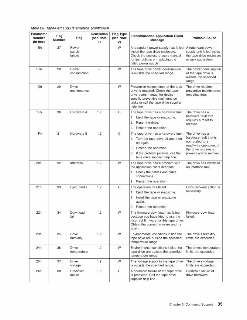
Table 26. TapeAlert Log Parameters (continued)
ParameterNumber(in hex)
FlagNumber
FlagGeneration(see Note
1)
Flag Type(see Note
2)
Recommended Application ClientMessage
Probable Cause
1Bh 27 Powersupplyfailure
- W A redundant power supply has failedinside the tape drive enclosure.Check the enclosure users manualfor instructions on replacing thefailed power supply.
A redundant powersupply unit failed insidethe tape drive enclosureor rack subsystem.
1Ch 28 Powerconsumption
- W The tape drive power consumptionis outside the specified range.
The power consumptionof the tape drive isoutside the specifiedrange.
1Dh 29 Drivemaintenance
- W Preventive maintenance of the tapedrive is required. Check the tapedrive users manual for devicespecific preventive maintenancetasks or call the tape drive supplierhelp line.
The drive requirespreventive maintenance(not cleaning).
1Eh 30 Hardware A 1,2 C The tape drive has a hardware fault:
1. Eject the tape or magazine.
2. Reset the drive.
3. Restart the operation.
The drive has ahardware fault thatrequires a reset torecover.
1Fh 31 Hardware B 1,2 C The tape drive has a hardware fault:
1. Turn the tape drive off and thenon again.
2. Restart the operation.
3. If the problem persists, call thetape drive supplier help line.
The drive has ahardware fault that isnot related to aread/write operation, orthe drive requires apower cycle to recover.
20h 32 Interface 1,2 W The tape drive has a problem withthe application client interface:
1. Check the cables and cableconnections.
2. Restart the operation.
The drive has identifiedan interface fault.
21h 33 Eject media 1,2 C The operation has failed:
1. Eject the tape or magazine.
2. Insert the tape or magazineagain.
3. Restart the operation.
Error recovery action isnecessary.
22h 34 Downloadfail
1,2 W The firmware download has failedbecause you have tried to use theincorrect firmware for this tape drive.Obtain the correct firmware and tryagain.
Firmware downloadfailed.
23h 35 Drivehumidity
1,2 W Environmental conditions inside thetape drive are outside the specifiedtemperature range.
The drive’s humiditylimits are exceeded.
24h 36 Drivetemperature
1,2 W Environmental conditions inside thetape drive are outside the specifiedtemperature range.
The drive’s temperaturelimits are exceeded.
25h 37 Drivevoltage
1,2 W The voltage supply to the tape driveis outside the specified range.
The drive’s voltagelimits are exceeded.
26h 38 Predictivefailure
1,2 C A hardware failure of the tape driveis predicted. Call the tape drivesupplier help line.
Predictive failure ofdrive hardware.
Chapter 3. Command Support 35
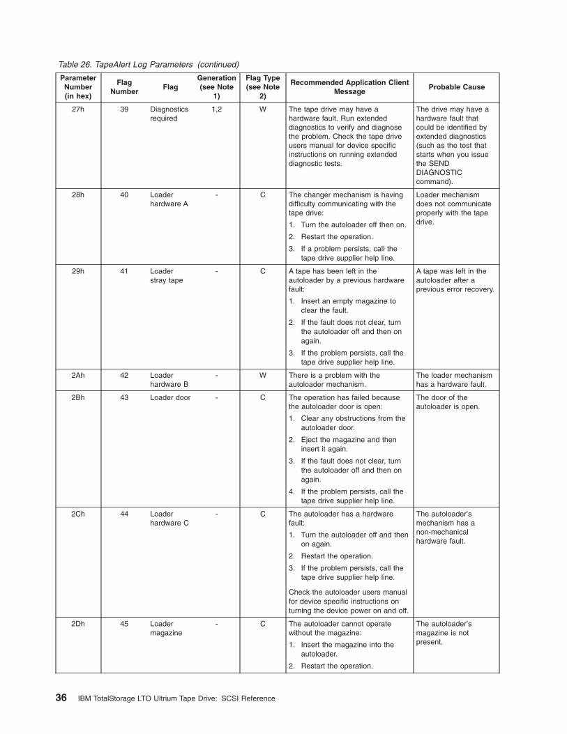
Table 26. TapeAlert Log Parameters (continued)
ParameterNumber(in hex)
FlagNumber
FlagGeneration(see Note
1)
Flag Type(see Note
2)
Recommended Application ClientMessage
Probable Cause
27h 39 Diagnosticsrequired
1,2 W The tape drive may have ahardware fault. Run extendeddiagnostics to verify and diagnosethe problem. Check the tape driveusers manual for device specificinstructions on running extendeddiagnostic tests.
The drive may have ahardware fault thatcould be identified byextended diagnostics(such as the test thatstarts when you issuethe SENDDIAGNOSTICcommand).
28h 40 Loaderhardware A
- C The changer mechanism is havingdifficulty communicating with thetape drive:
1. Turn the autoloader off then on.
2. Restart the operation.
3. If a problem persists, call thetape drive supplier help line.
Loader mechanismdoes not communicateproperly with the tapedrive.
29h 41 Loaderstray tape
- C A tape has been left in theautoloader by a previous hardwarefault:
1. Insert an empty magazine toclear the fault.
2. If the fault does not clear, turnthe autoloader off and then onagain.
3. If the problem persists, call thetape drive supplier help line.
A tape was left in theautoloader after aprevious error recovery.
2Ah 42 Loaderhardware B
- W There is a problem with theautoloader mechanism.
The loader mechanismhas a hardware fault.
2Bh 43 Loader door - C The operation has failed becausethe autoloader door is open:
1. Clear any obstructions from theautoloader door.
2. Eject the magazine and theninsert it again.
3. If the fault does not clear, turnthe autoloader off and then onagain.
4. If the problem persists, call thetape drive supplier help line.
The door of theautoloader is open.
2Ch 44 Loaderhardware C
- C The autoloader has a hardwarefault:
1. Turn the autoloader off and thenon again.
2. Restart the operation.
3. If the problem persists, call thetape drive supplier help line.
Check the autoloader users manualfor device specific instructions onturning the device power on and off.
The autoloader’smechanism has anon-mechanicalhardware fault.
2Dh 45 Loadermagazine
- C The autoloader cannot operatewithout the magazine:
1. Insert the magazine into theautoloader.
2. Restart the operation.
The autoloader’smagazine is notpresent.
36 IBM TotalStorage LTO Ultrium Tape Drive: SCSI Reference
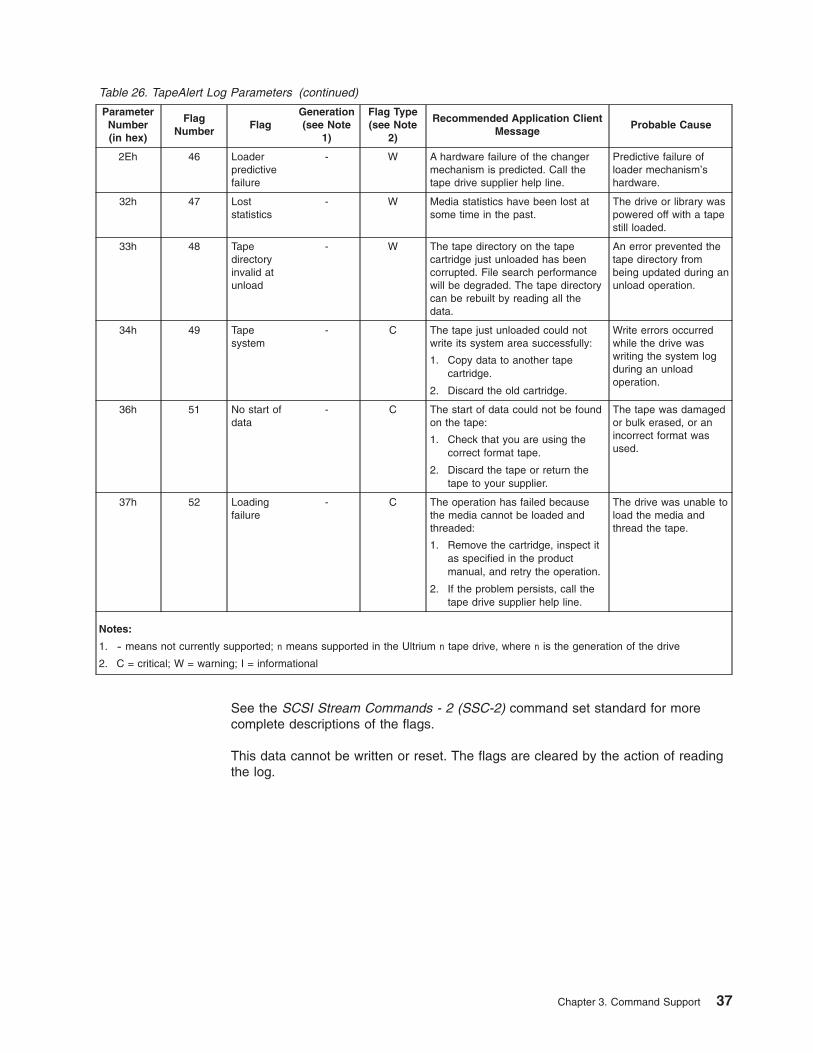
Table 26. TapeAlert Log Parameters (continued)
ParameterNumber(in hex)
FlagNumber
FlagGeneration(see Note
1)
Flag Type(see Note
2)
Recommended Application ClientMessage
Probable Cause
2Eh 46 Loaderpredictivefailure
- W A hardware failure of the changermechanism is predicted. Call thetape drive supplier help line.
Predictive failure ofloader mechanism’shardware.
32h 47 Loststatistics
- W Media statistics have been lost atsome time in the past.
The drive or library waspowered off with a tapestill loaded.
33h 48 Tapedirectoryinvalid atunload
- W The tape directory on the tapecartridge just unloaded has beencorrupted. File search performancewill be degraded. The tape directorycan be rebuilt by reading all thedata.
An error prevented thetape directory frombeing updated during anunload operation.
34h 49 Tapesystem
- C The tape just unloaded could notwrite its system area successfully:
1. Copy data to another tapecartridge.
2. Discard the old cartridge.
Write errors occurredwhile the drive waswriting the system logduring an unloadoperation.
36h 51 No start ofdata
- C The start of data could not be foundon the tape:
1. Check that you are using thecorrect format tape.
2. Discard the tape or return thetape to your supplier.
The tape was damagedor bulk erased, or anincorrect format wasused.
37h 52 Loadingfailure
- C The operation has failed becausethe media cannot be loaded andthreaded:
1. Remove the cartridge, inspect itas specified in the productmanual, and retry the operation.
2. If the problem persists, call thetape drive supplier help line.
The drive was unable toload the media andthread the tape.
Notes:
1. - means not currently supported; n means supported in the Ultrium n tape drive, where n is the generation of the drive
2. C = critical; W = warning; I = informational
See the SCSI Stream Commands - 2 (SSC-2) command set standard for morecomplete descriptions of the flags.
This data cannot be written or reset. The flags are cleared by the action of readingthe log.
Chapter 3. Command Support 37
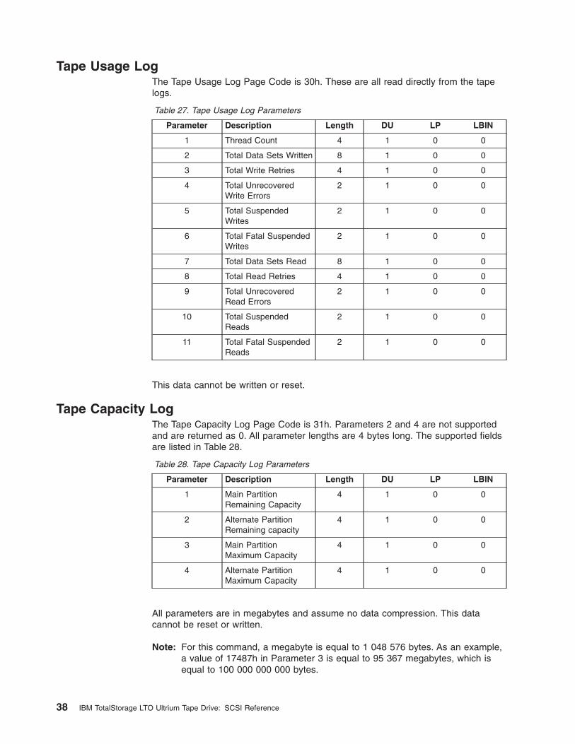
Tape Usage LogThe Tape Usage Log Page Code is 30h. These are all read directly from the tapelogs.
Table 27. Tape Usage Log Parameters
Parameter Description Length DU LP LBIN
1 Thread Count 4 1 0 0
2 Total Data Sets Written 8 1 0 0
3 Total Write Retries 4 1 0 0
4 Total UnrecoveredWrite Errors
2 1 0 0
5 Total SuspendedWrites
2 1 0 0
6 Total Fatal SuspendedWrites
2 1 0 0
7 Total Data Sets Read 8 1 0 0
8 Total Read Retries 4 1 0 0
9 Total UnrecoveredRead Errors
2 1 0 0
10 Total SuspendedReads
2 1 0 0
11 Total Fatal SuspendedReads
2 1 0 0
This data cannot be written or reset.
Tape Capacity LogThe Tape Capacity Log Page Code is 31h. Parameters 2 and 4 are not supportedand are returned as 0. All parameter lengths are 4 bytes long. The supported fieldsare listed in Table 28.
Table 28. Tape Capacity Log Parameters
Parameter Description Length DU LP LBIN
1 Main PartitionRemaining Capacity
4 1 0 0
2 Alternate PartitionRemaining capacity
4 1 0 0
3 Main PartitionMaximum Capacity
4 1 0 0
4 Alternate PartitionMaximum Capacity
4 1 0 0
All parameters are in megabytes and assume no data compression. This datacannot be reset or written.
Note: For this command, a megabyte is equal to 1 048 576 bytes. As an example,a value of 17487h in Parameter 3 is equal to 95 367 megabytes, which isequal to 100 000 000 000 bytes.
38 IBM TotalStorage LTO Ultrium Tape Drive: SCSI Reference
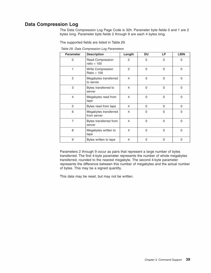
Data Compression LogThe Data Compression Log Page Code is 32h. Parameter byte fields 0 and 1 are 2bytes long. Parameter byte fields 2 through 9 are each 4 bytes long.
The supported fields are listed in Table 29.
Table 29. Data Compression Log Parameters
Parameter Description Length DU LP LBIN
0 Read Compressionratio × 100
2 0 0 0
1 Write CompressionRatio × 100
2 0 0 0
2 Megabytes transferredto server
4 0 0 0
3 Bytes transferred toserver
4 0 0 0
4 Megabytes read fromtape
4 0 0 0
5 Bytes read from tape 4 0 0 0
6 Megabytes transferredfrom server
4 0 0 0
7 Bytes transferred fromserver
4 0 0 0
8 Megabytes written totape
4 0 0 0
9 Bytes written to tape 4 0 0 0
Parameters 2 through 9 occur as pairs that represent a large number of bytestransferred. The first 4-byte parameter represents the number of whole megabytestransferred, rounded to the nearest megabyte. The second 4-byte parameterrepresents the difference between this number of megabytes and the actual numberof bytes. This may be a signed quantity.
This data may be reset, but may not be written.
Chapter 3. Command Support 39
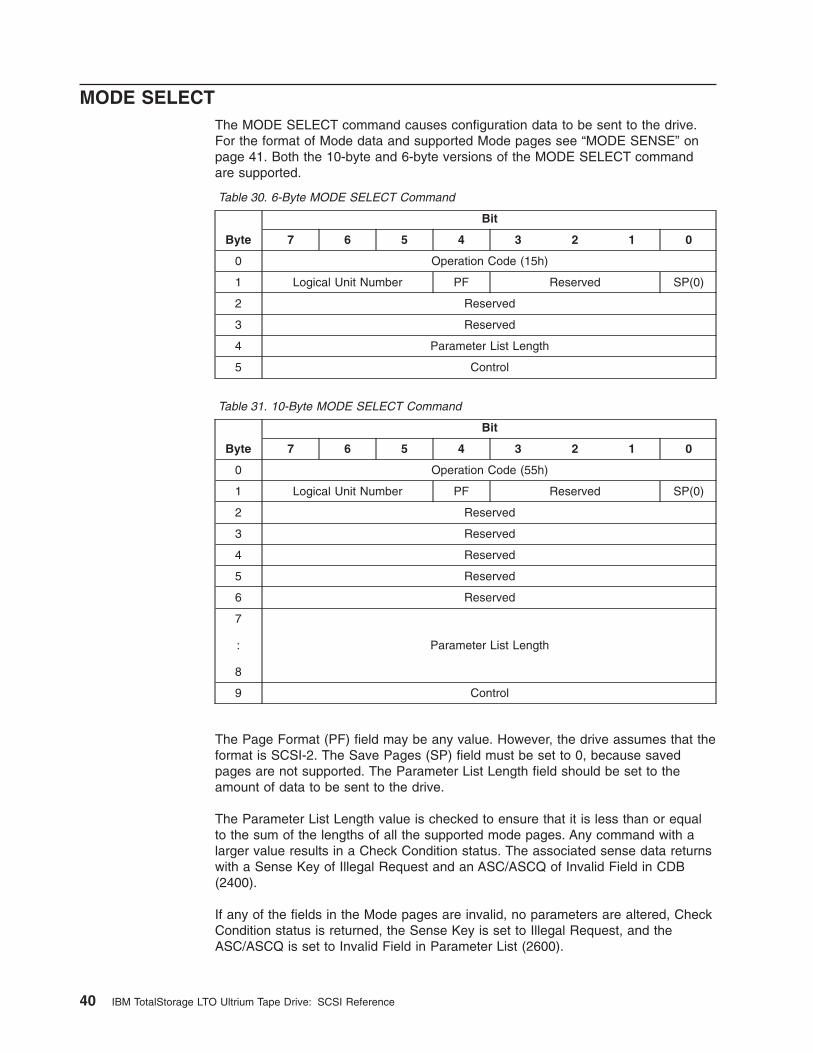
MODE SELECTThe MODE SELECT command causes configuration data to be sent to the drive.For the format of Mode data and supported Mode pages see “MODE SENSE” onpage 41. Both the 10-byte and 6-byte versions of the MODE SELECT commandare supported.
Table 30. 6-Byte MODE SELECT Command
Byte
Bit
7 6 5 4 3 2 1 0
0 Operation Code (15h)
1 Logical Unit Number PF Reserved SP(0)
2 Reserved
3 Reserved
4 Parameter List Length
5 Control
Table 31. 10-Byte MODE SELECT Command
Byte
Bit
7 6 5 4 3 2 1 0
0 Operation Code (55h)
1 Logical Unit Number PF Reserved SP(0)
2 Reserved
3 Reserved
4 Reserved
5 Reserved
6 Reserved
7
:
8
Parameter List Length
9 Control
The Page Format (PF) field may be any value. However, the drive assumes that theformat is SCSI-2. The Save Pages (SP) field must be set to 0, because savedpages are not supported. The Parameter List Length field should be set to theamount of data to be sent to the drive.
The Parameter List Length value is checked to ensure that it is less than or equalto the sum of the lengths of all the supported mode pages. Any command with alarger value results in a Check Condition status. The associated sense data returnswith a Sense Key of Illegal Request and an ASC/ASCQ of Invalid Field in CDB(2400).
If any of the fields in the Mode pages are invalid, no parameters are altered, CheckCondition status is returned, the Sense Key is set to Illegal Request, and theASC/ASCQ is set to Invalid Field in Parameter List (2600).
40 IBM TotalStorage LTO Ultrium Tape Drive: SCSI Reference
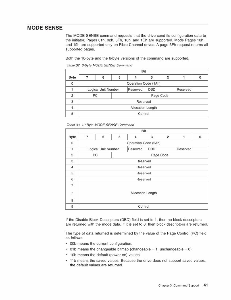
MODE SENSEThe MODE SENSE command requests that the drive send its configuration data tothe initiator. Pages 01h, 02h, 0Fh, 10h, and 1Ch are supported. Mode Pages 18hand 19h are supported only on Fibre Channel drives. A page 3Fh request returns allsupported pages.
Both the 10-byte and the 6-byte versions of the command are supported.
Table 32. 6-Byte MODE SENSE Command
Byte
Bit
7 6 5 4 3 2 1 0
0 Operation Code (1Ah)
1 Logical Unit Number Reserved DBD Reserved
2 PC Page Code
3 Reserved
4 Allocation Length
5 Control
Table 33. 10-Byte MODE SENSE Command
Byte
Bit
7 6 5 4 3 2 1 0
0 Operation Code (5Ah)
1 Logical Unit Number Reserved DBD Reserved
2 PC Page Code
3 Reserved
4 Reserved
5 Reserved
6 Reserved
7
:
8
Allocation Length
9 Control
If the Disable Block Descriptors (DBD) field is set to 1, then no block descriptorsare returned with the mode data. If it is set to 0, then block descriptors are returned.
The type of data returned is determined by the value of the Page Control (PC) fieldas follows:
v 00b means the current configuration.
v 01b means the changeable bitmap (changeable = 1; unchangeable = 0).
v 10b means the default (power-on) values.
v 11b means the saved values. Because the drive does not support saved values,the default values are returned.
Chapter 3. Command Support 41
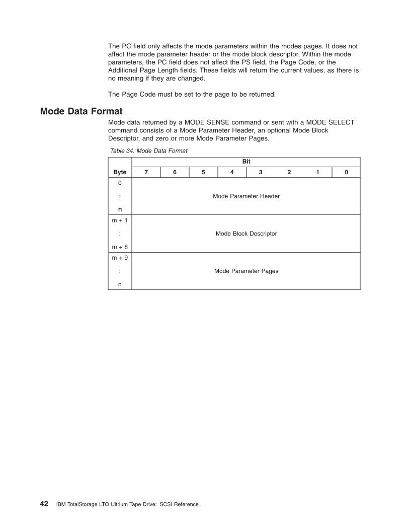
The PC field only affects the mode parameters within the modes pages. It does notaffect the mode parameter header or the mode block descriptor. Within the modeparameters, the PC field does not affect the PS field, the Page Code, or theAdditional Page Length fields. These fields will return the current values, as there isno meaning if they are changed.
The Page Code must be set to the page to be returned.
Mode Data FormatMode data returned by a MODE SENSE command or sent with a MODE SELECTcommand consists of a Mode Parameter Header, an optional Mode BlockDescriptor, and zero or more Mode Parameter Pages.
Table 34. Mode Data Format
Byte
Bit
7 6 5 4 3 2 1 0
0
:
m
Mode Parameter Header
m + 1
:
m + 8
Mode Block Descriptor
m + 9
:
n
Mode Parameter Pages
42 IBM TotalStorage LTO Ultrium Tape Drive: SCSI Reference
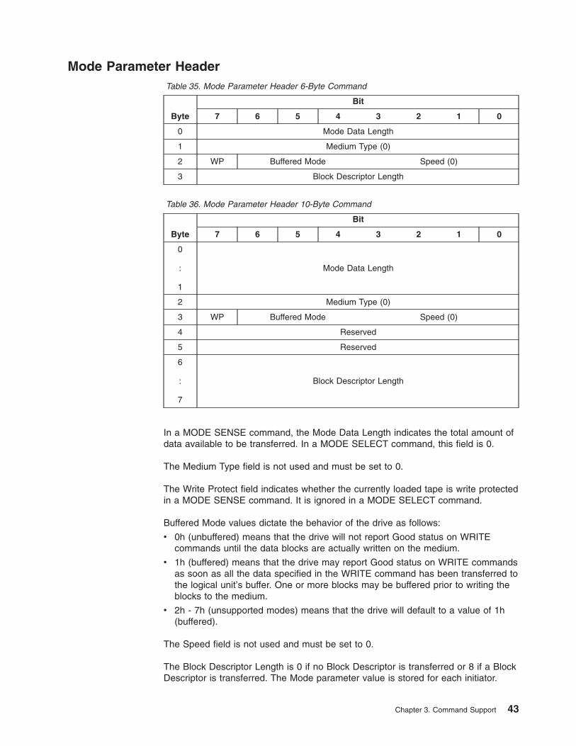
Mode Parameter HeaderTable 35. Mode Parameter Header 6-Byte Command
Byte
Bit
7 6 5 4 3 2 1 0
0 Mode Data Length
1 Medium Type (0)
2 WP Buffered Mode Speed (0)
3 Block Descriptor Length
Table 36. Mode Parameter Header 10-Byte Command
Byte
Bit
7 6 5 4 3 2 1 0
0
:
1
Mode Data Length
2 Medium Type (0)
3 WP Buffered Mode Speed (0)
4 Reserved
5 Reserved
6
:
7
Block Descriptor Length
In a MODE SENSE command, the Mode Data Length indicates the total amount ofdata available to be transferred. In a MODE SELECT command, this field is 0.
The Medium Type field is not used and must be set to 0.
The Write Protect field indicates whether the currently loaded tape is write protectedin a MODE SENSE command. It is ignored in a MODE SELECT command.
Buffered Mode values dictate the behavior of the drive as follows:
v 0h (unbuffered) means that the drive will not report Good status on WRITEcommands until the data blocks are actually written on the medium.
v 1h (buffered) means that the drive may report Good status on WRITE commandsas soon as all the data specified in the WRITE command has been transferred tothe logical unit’s buffer. One or more blocks may be buffered prior to writing theblocks to the medium.
v 2h - 7h (unsupported modes) means that the drive will default to a value of 1h(buffered).
The Speed field is not used and must be set to 0.
The Block Descriptor Length is 0 if no Block Descriptor is transferred or 8 if a BlockDescriptor is transferred. The Mode parameter value is stored for each initiator.
Chapter 3. Command Support 43
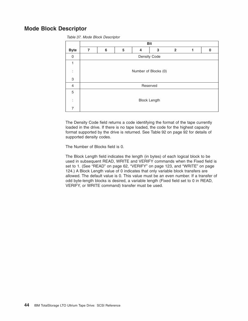
Mode Block DescriptorTable 37. Mode Block Descriptor
Byte
Bit
7 6 5 4 3 2 1 0
0 Density Code
1
:
3
Number of Blocks (0)
4 Reserved
5
:
7
Block Length
The Density Code field returns a code identifying the format of the tape currentlyloaded in the drive. If there is no tape loaded, the code for the highest capacityformat supported by the drive is returned. See Table 92 on page 92 for details ofsupported density codes.
The Number of Blocks field is 0.
The Block Length field indicates the length (in bytes) of each logical block to beused in subsequent READ, WRITE and VERIFY commands when the Fixed field isset to 1. (See “READ” on page 62, “VERIFY” on page 123, and “WRITE” on page124.) A Block Length value of 0 indicates that only variable block transfers areallowed. The default value is 0. This value must be an even number. If a transfer ofodd byte-length blocks is desired, a variable length (Fixed field set to 0 in READ,VERIFY, or WRITE command) transfer must be used.
44 IBM TotalStorage LTO Ultrium Tape Drive: SCSI Reference
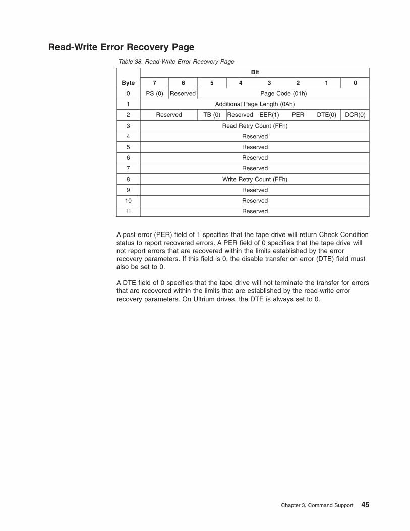
Read-Write Error Recovery PageTable 38. Read-Write Error Recovery Page
Byte
Bit
7 6 5 4 3 2 1 0
0 PS (0) Reserved Page Code (01h)
1 Additional Page Length (0Ah)
2 Reserved TB (0) Reserved EER(1) PER DTE(0) DCR(0)
3 Read Retry Count (FFh)
4 Reserved
5 Reserved
6 Reserved
7 Reserved
8 Write Retry Count (FFh)
9 Reserved
10 Reserved
11 Reserved
A post error (PER) field of 1 specifies that the tape drive will return Check Conditionstatus to report recovered errors. A PER field of 0 specifies that the tape drive willnot report errors that are recovered within the limits established by the errorrecovery parameters. If this field is 0, the disable transfer on error (DTE) field mustalso be set to 0.
A DTE field of 0 specifies that the tape drive will not terminate the transfer for errorsthat are recovered within the limits that are established by the read-write errorrecovery parameters. On Ultrium drives, the DTE is always set to 0.
Chapter 3. Command Support 45
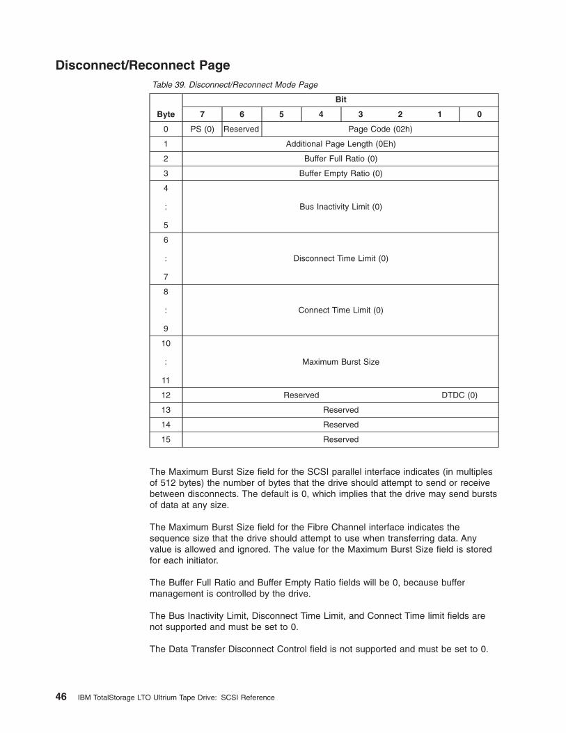
Disconnect/Reconnect PageTable 39. Disconnect/Reconnect Mode Page
Byte
Bit
7 6 5 4 3 2 1 0
0 PS (0) Reserved Page Code (02h)
1 Additional Page Length (0Eh)
2 Buffer Full Ratio (0)
3 Buffer Empty Ratio (0)
4
:
5
Bus Inactivity Limit (0)
6
:
7
Disconnect Time Limit (0)
8
:
9
Connect Time Limit (0)
10
:
11
Maximum Burst Size
12 Reserved DTDC (0)
13 Reserved
14 Reserved
15 Reserved
The Maximum Burst Size field for the SCSI parallel interface indicates (in multiplesof 512 bytes) the number of bytes that the drive should attempt to send or receivebetween disconnects. The default is 0, which implies that the drive may send burstsof data at any size.
The Maximum Burst Size field for the Fibre Channel interface indicates thesequence size that the drive should attempt to use when transferring data. Anyvalue is allowed and ignored. The value for the Maximum Burst Size field is storedfor each initiator.
The Buffer Full Ratio and Buffer Empty Ratio fields will be 0, because buffermanagement is controlled by the drive.
The Bus Inactivity Limit, Disconnect Time Limit, and Connect Time limit fields arenot supported and must be set to 0.
The Data Transfer Disconnect Control field is not supported and must be set to 0.
46 IBM TotalStorage LTO Ultrium Tape Drive: SCSI Reference
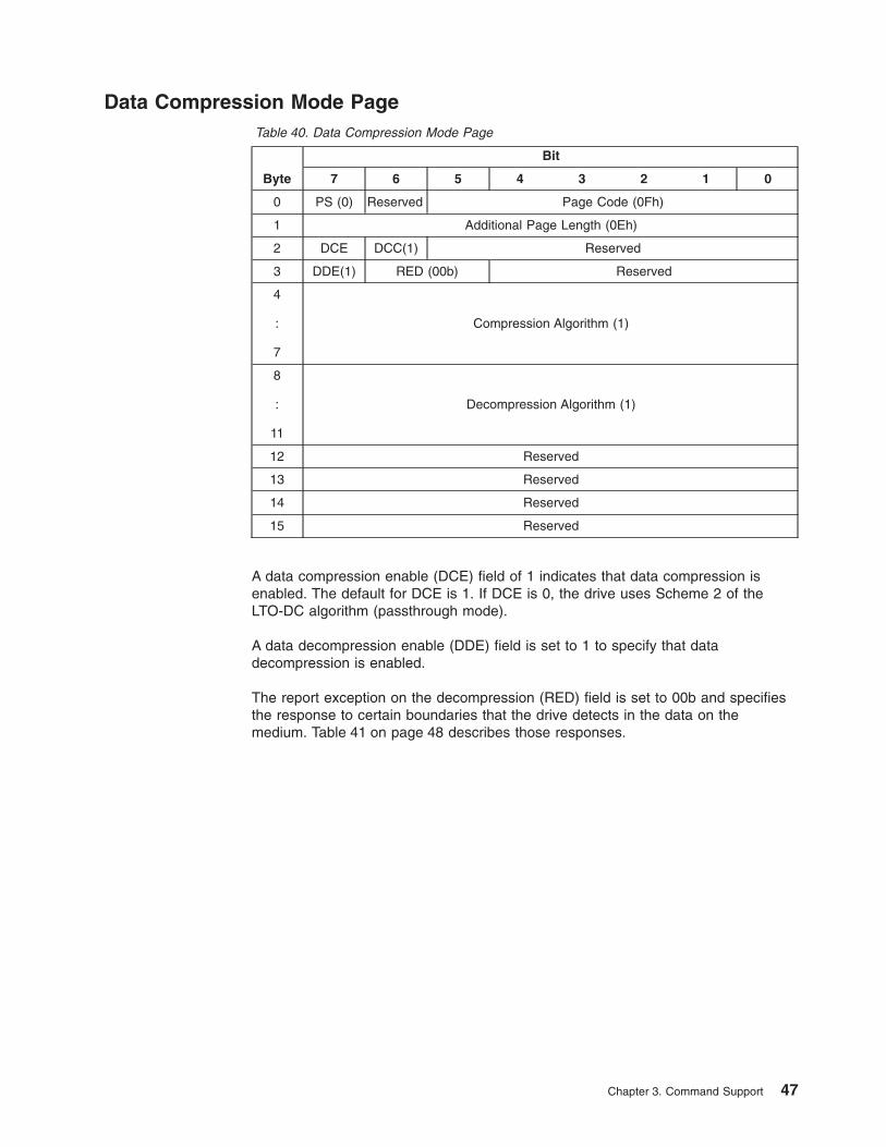
Data Compression Mode PageTable 40. Data Compression Mode Page
Byte
Bit
7 6 5 4 3 2 1 0
0 PS (0) Reserved Page Code (0Fh)
1 Additional Page Length (0Eh)
2 DCE DCC(1) Reserved
3 DDE(1) RED (00b) Reserved
4
:
7
Compression Algorithm (1)
8
:
11
Decompression Algorithm (1)
12 Reserved
13 Reserved
14 Reserved
15 Reserved
A data compression enable (DCE) field of 1 indicates that data compression isenabled. The default for DCE is 1. If DCE is 0, the drive uses Scheme 2 of theLTO-DC algorithm (passthrough mode).
A data decompression enable (DDE) field is set to 1 to specify that datadecompression is enabled.
The report exception on the decompression (RED) field is set to 00b and specifiesthe response to certain boundaries that the drive detects in the data on themedium. Table 41 on page 48 describes those responses.
Chapter 3. Command Support 47
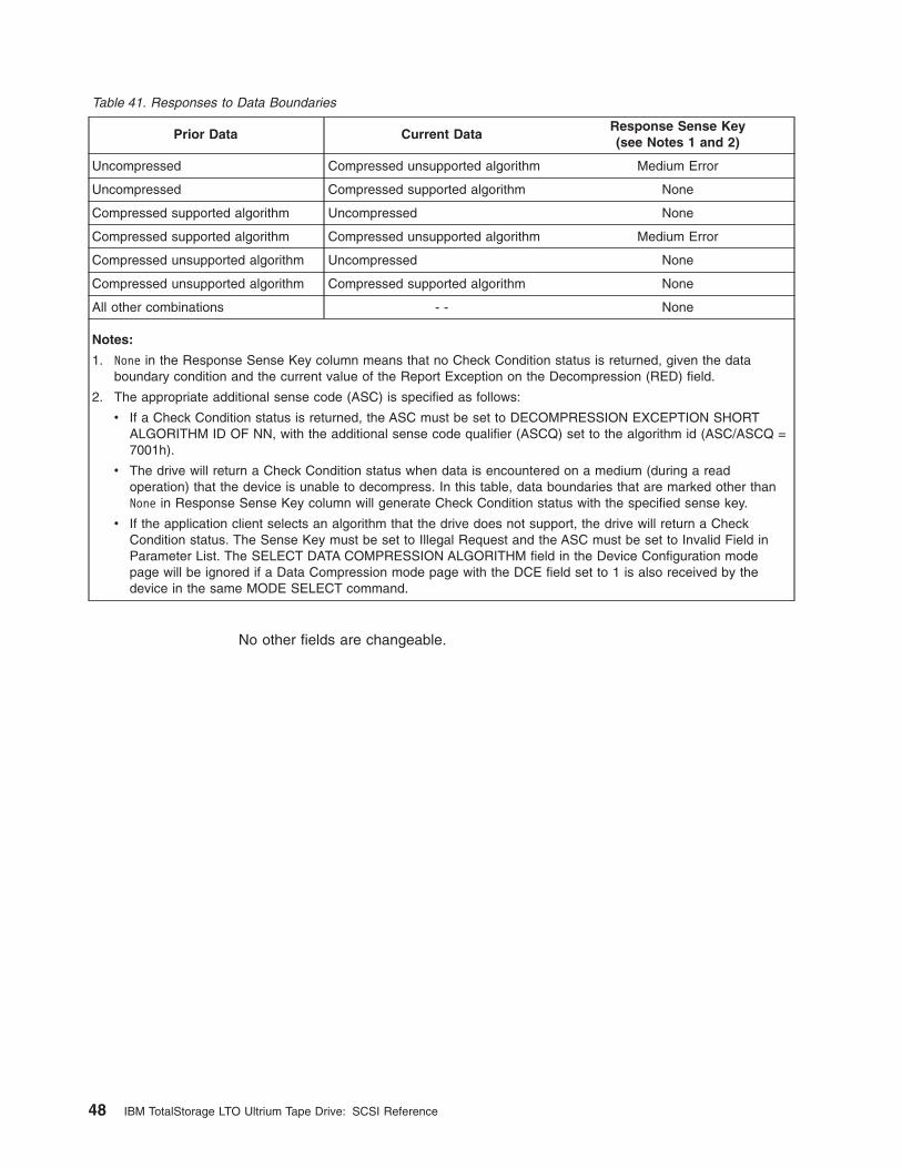
Table 41. Responses to Data Boundaries
Prior Data Current DataResponse Sense Key(see Notes 1 and 2)
Uncompressed Compressed unsupported algorithm Medium Error
Uncompressed Compressed supported algorithm None
Compressed supported algorithm Uncompressed None
Compressed supported algorithm Compressed unsupported algorithm Medium Error
Compressed unsupported algorithm Uncompressed None
Compressed unsupported algorithm Compressed supported algorithm None
All other combinations - - None
Notes:
1. None in the Response Sense Key column means that no Check Condition status is returned, given the databoundary condition and the current value of the Report Exception on the Decompression (RED) field.
2. The appropriate additional sense code (ASC) is specified as follows:
v If a Check Condition status is returned, the ASC must be set to DECOMPRESSION EXCEPTION SHORTALGORITHM ID OF NN, with the additional sense code qualifier (ASCQ) set to the algorithm id (ASC/ASCQ =7001h).
v The drive will return a Check Condition status when data is encountered on a medium (during a readoperation) that the device is unable to decompress. In this table, data boundaries that are marked other thanNone in Response Sense Key column will generate Check Condition status with the specified sense key.
v If the application client selects an algorithm that the drive does not support, the drive will return a CheckCondition status. The Sense Key must be set to Illegal Request and the ASC must be set to Invalid Field inParameter List. The SELECT DATA COMPRESSION ALGORITHM field in the Device Configuration modepage will be ignored if a Data Compression mode page with the DCE field set to 1 is also received by thedevice in the same MODE SELECT command.
No other fields are changeable.
48 IBM TotalStorage LTO Ultrium Tape Drive: SCSI Reference
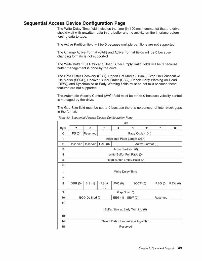
Sequential Access Device Configuration PageThe Write Delay Time field indicates the time (in 100-ms increments) that the driveshould wait with unwritten data in the buffer and no activity on the interface beforeforcing data to tape.
The Active Partition field will be 0 because multiple partitions are not supported.
The Change Active Format (CAF) and Active Format fields will be 0 becausechanging formats is not supported.
The Write Buffer Full Ratio and Read Buffer Empty Ratio fields will be 0 becausebuffer management is done by the drive.
The Data Buffer Recovery (DBR), Report Set Marks (RSmk), Stop On ConsecutiveFile Marks (SOCF), Recover Buffer Order (RBO), Report Early Warning on Read(REW), and Synchronize at Early Warning fields must be set to 0 because thesefeatures are not supported.
The Automatic Velocity Control (AVC) field must be set to 0 because velocity controlis managed by the drive.
The Gap Size field must be set to 0 because there is no concept of inter-block gapsin the format.
Table 42. Sequential Access Device Configuration Page
Byte
Bit
7 6 5 4 3 2 1 0
0 PS (0) Reserved Page Code (10h)
1 Additional Page Length (0Eh)
2 Reserved Reserved CAF (0) Active Format (0)
3 Active Partition (0)
4 Write Buffer Full Ratio (0)
5 Read Buffer Empty Ratio (0)
6
:
7
Write Delay Time
8 DBR (0) BIS (1) RSmk(0)
AVC (0) SOCF (0) RBO (0) REW (0)
9 Gap Size (0)
10 EOD Defined (0) EEG (1) SEW (0) Reserved
11
:
13
Buffer Size at Early Warning (0)
14 Select Data Compression Algorithm
15 Reserved
Chapter 3. Command Support 49
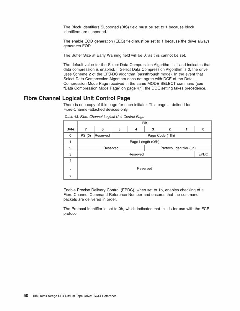
The Block Identifiers Supported (BIS) field must be set to 1 because blockidentifiers are supported.
The enable EOD generation (EEG) field must be set to 1 because the drive alwaysgenerates EOD.
The Buffer Size at Early Warning field will be 0, as this cannot be set.
The default value for the Select Data Compression Algorithm is 1 and indicates thatdata compression is enabled. If Select Data Compression Algorithm is 0, the driveuses Scheme 2 of the LTO-DC algorithm (passthrough mode). In the event thatSelect Data Compression Algorithm does not agree with DCE of the DataCompression Mode Page received in the same MODE SELECT command (see“Data Compression Mode Page” on page 47), the DCE setting takes precedence.
Fibre Channel Logical Unit Control PageThere is one copy of this page for each initiator. This page is defined forFibre-Channel-attached devices only.
Table 43. Fibre Channel Logical Unit Control Page
Byte
Bit
7 6 5 4 3 2 1 0
0 PS (0) Reserved Page Code (18h)
1 Page Length (06h)
2 Reserved Protocol Identifier (0h)
3 Reserved EPDC
4
:
7
Reserved
Enable Precise Delivery Control (EPDC), when set to 1b, enables checking of aFibre Channel Command Reference Number and ensures that the commandpackets are delivered in order.
The Protocol Identifier is set to 0h, which indicates that this is for use with the FCPprotocol.
50 IBM TotalStorage LTO Ultrium Tape Drive: SCSI Reference
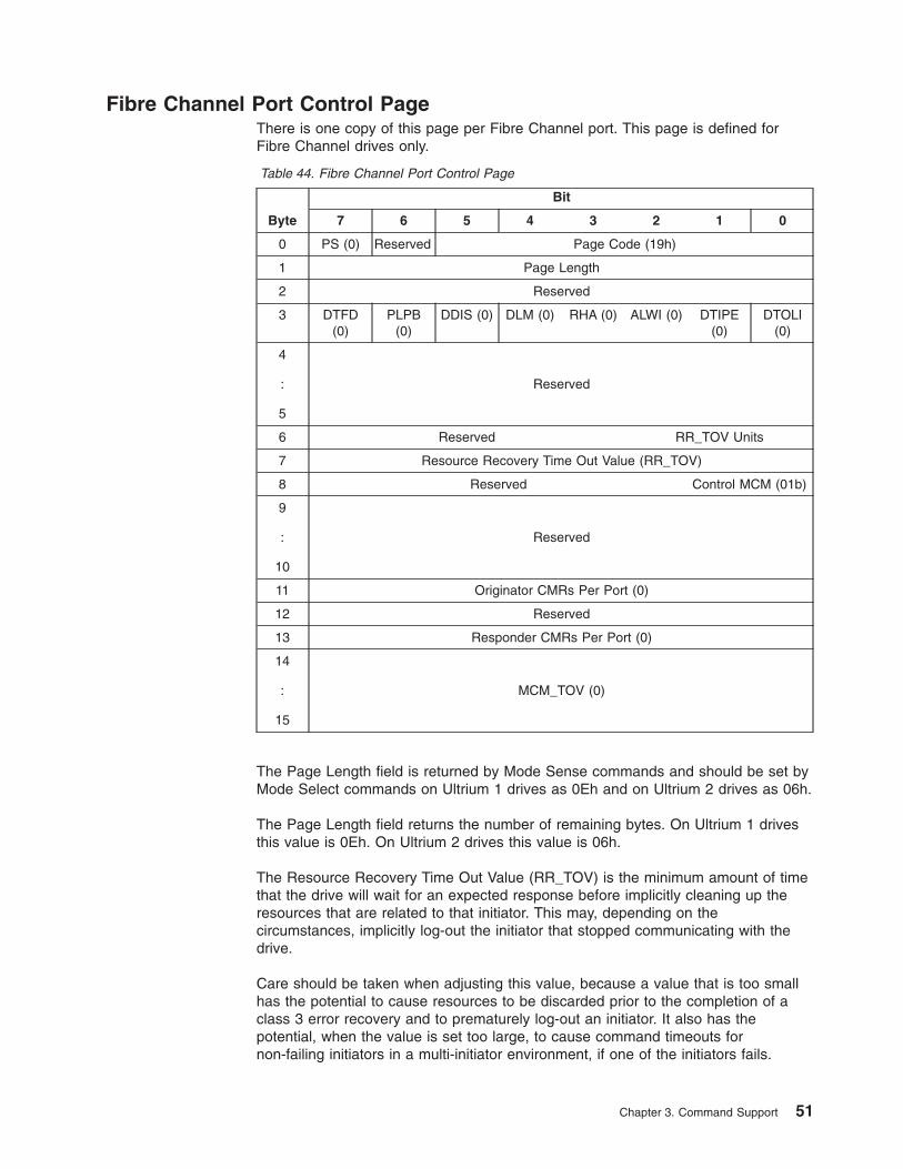
Fibre Channel Port Control PageThere is one copy of this page per Fibre Channel port. This page is defined forFibre Channel drives only.
Table 44. Fibre Channel Port Control Page
Byte
Bit
7 6 5 4 3 2 1 0
0 PS (0) Reserved Page Code (19h)
1 Page Length
2 Reserved
3 DTFD(0)
PLPB(0)
DDIS (0) DLM (0) RHA (0) ALWI (0) DTIPE(0)
DTOLI(0)
4
:
5
Reserved
6 Reserved RR_TOV Units
7 Resource Recovery Time Out Value (RR_TOV)
8 Reserved Control MCM (01b)
9
:
10
Reserved
11 Originator CMRs Per Port (0)
12 Reserved
13 Responder CMRs Per Port (0)
14
:
15
MCM_TOV (0)
The Page Length field is returned by Mode Sense commands and should be set byMode Select commands on Ultrium 1 drives as 0Eh and on Ultrium 2 drives as 06h.
The Page Length field returns the number of remaining bytes. On Ultrium 1 drivesthis value is 0Eh. On Ultrium 2 drives this value is 06h.
The Resource Recovery Time Out Value (RR_TOV) is the minimum amount of timethat the drive will wait for an expected response before implicitly cleaning up theresources that are related to that initiator. This may, depending on thecircumstances, implicitly log-out the initiator that stopped communicating with thedrive.
Care should be taken when adjusting this value, because a value that is too smallhas the potential to cause resources to be discarded prior to the completion of aclass 3 error recovery and to prematurely log-out an initiator. It also has thepotential, when the value is set too large, to cause command timeouts fornon-failing initiators in a multi-initiator environment, if one of the initiators fails.
Chapter 3. Command Support 51
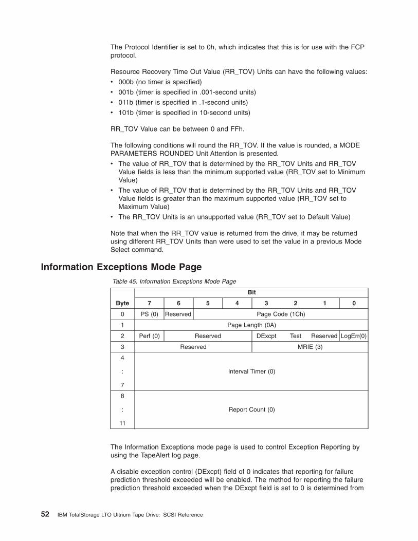
The Protocol Identifier is set to 0h, which indicates that this is for use with the FCPprotocol.
Resource Recovery Time Out Value (RR_TOV) Units can have the following values:
v 000b (no timer is specified)
v 001b (timer is specified in .001-second units)
v 011b (timer is specified in .1-second units)
v 101b (timer is specified in 10-second units)
RR_TOV Value can be between 0 and FFh.
The following conditions will round the RR_TOV. If the value is rounded, a MODEPARAMETERS ROUNDED Unit Attention is presented.
v The value of RR_TOV that is determined by the RR_TOV Units and RR_TOVValue fields is less than the minimum supported value (RR_TOV set to MinimumValue)
v The value of RR_TOV that is determined by the RR_TOV Units and RR_TOVValue fields is greater than the maximum supported value (RR_TOV set toMaximum Value)
v The RR_TOV Units is an unsupported value (RR_TOV set to Default Value)
Note that when the RR_TOV value is returned from the drive, it may be returnedusing different RR_TOV Units than were used to set the value in a previous ModeSelect command.
Information Exceptions Mode PageTable 45. Information Exceptions Mode Page
Byte
Bit
7 6 5 4 3 2 1 0
0 PS (0) Reserved Page Code (1Ch)
1 Page Length (0A)
2 Perf (0) Reserved DExcpt Test Reserved LogErr(0)
3 Reserved MRIE (3)
4
:
7
Interval Timer (0)
8
:
11
Report Count (0)
The Information Exceptions mode page is used to control Exception Reporting byusing the TapeAlert log page.
A disable exception control (DExcpt) field of 0 indicates that reporting for failureprediction threshold exceeded will be enabled. The method for reporting the failureprediction threshold exceeded when the DExcpt field is set to 0 is determined from
52 IBM TotalStorage LTO Ultrium Tape Drive: SCSI Reference
the MRIE field. A DExcpt field of 1 indicates that the target will disable reporting ofthe failure prediction threshold exceeded. The default value for DExcpt is 0.
If the Test field is set to 1, the next command will fail, the Sense Key will be set toUnit Attention, and the ASC/ASCQ will be set to Failure Prediction ThresholdExceeded - False (5DFF). If the Test field is set to 0, the next command isprocessed normally. The default for Test is 0.
The Perf and LogErr fields will be 0. These features are not supported.
The MRIE field must be set to 3 (Conditionally generate recovered error). Thismethod instructs the drive to report informational exception conditions (if thereporting of recovered errors is allowed) by returning a Check Condition status. Ifthe Test field is set to 0, the status may be returned after the informationalexception condition occurs on any command for which Good status would havebeen returned. If the Test field is set to 1, the status will be returned on the nextcommand that is normally capable of returning an informational exception conditionwhen the Test field is set to 0. The Sense Key must be set to Recovered Error andthe Additional Sense Code will indicate the cause of the informational exceptioncondition. This will be Failure Prediction Threshold Exceeded (5D00) if the Test fieldis set to 0 (true error), and Failure Prediction Threshold Exceeded -False (5DFF) ifthe Test field is set to 1 (test).
The command that returns the Check Condition status for the informationalexception will complete without error before any informational exception conditionmay be reported.
The Interval Timer and Report Count must be set to 0. These fields are notsupported.
Chapter 3. Command Support 53
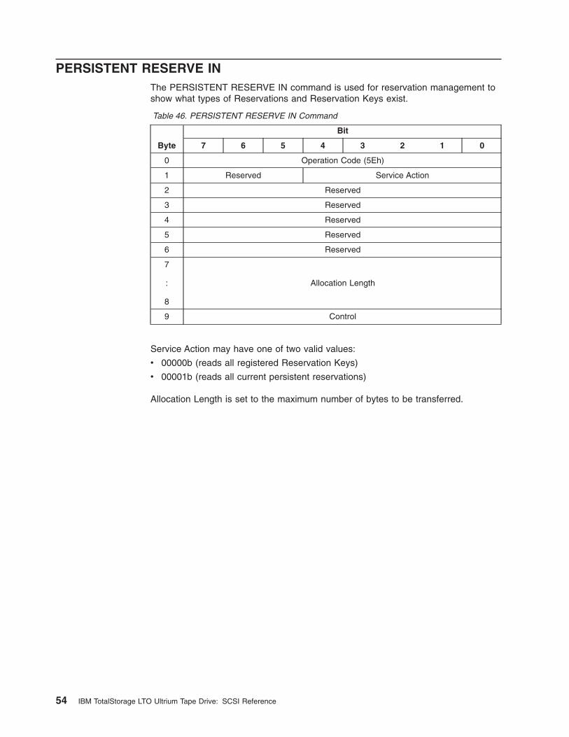
PERSISTENT RESERVE INThe PERSISTENT RESERVE IN command is used for reservation management toshow what types of Reservations and Reservation Keys exist.
Table 46. PERSISTENT RESERVE IN Command
Byte
Bit
7 6 5 4 3 2 1 0
0 Operation Code (5Eh)
1 Reserved Service Action
2 Reserved
3 Reserved
4 Reserved
5 Reserved
6 Reserved
7
:
8
Allocation Length
9 Control
Service Action may have one of two valid values:
v 00000b (reads all registered Reservation Keys)
v 00001b (reads all current persistent reservations)
Allocation Length is set to the maximum number of bytes to be transferred.
54 IBM TotalStorage LTO Ultrium Tape Drive: SCSI Reference
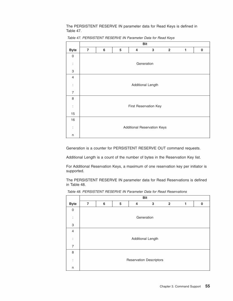
The PERSISTENT RESERVE IN parameter data for Read Keys is defined inTable 47.
Table 47. PERSISTENT RESERVE IN Parameter Data for Read Keys
Byte
Bit
7 6 5 4 3 2 1 0
0
:
3
Generation
4
:
7
Additional Length
8
:
15
First Reservation Key
16
:
n
Additional Reservation Keys
Generation is a counter for PERSISTENT RESERVE OUT command requests.
Additional Length is a count of the number of bytes in the Reservation Key list.
For Additional Reservation Keys, a maximum of one reservation key per initiator issupported.
The PERSISTENT RESERVE IN parameter data for Read Reservations is definedin Table 48.
Table 48. PERSISTENT RESERVE IN Parameter Data for Read Reservations
Byte
Bit
7 6 5 4 3 2 1 0
0
:
3
Generation
4
:
7
Additional Length
8
:
n
Reservation Descriptors
Chapter 3. Command Support 55
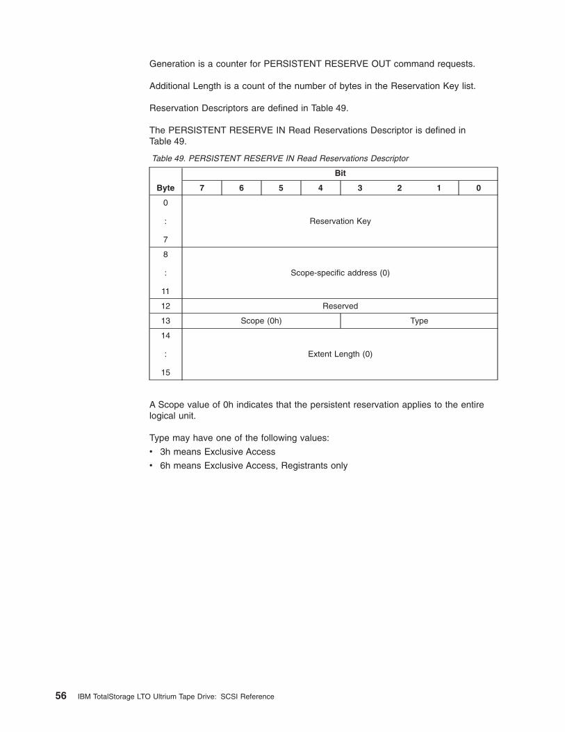
Generation is a counter for PERSISTENT RESERVE OUT command requests.
Additional Length is a count of the number of bytes in the Reservation Key list.
Reservation Descriptors are defined in Table 49.
The PERSISTENT RESERVE IN Read Reservations Descriptor is defined inTable 49.
Table 49. PERSISTENT RESERVE IN Read Reservations Descriptor
Byte
Bit
7 6 5 4 3 2 1 0
0
:
7
Reservation Key
8
:
11
Scope-specific address (0)
12 Reserved
13 Scope (0h) Type
14
:
15
Extent Length (0)
A Scope value of 0h indicates that the persistent reservation applies to the entirelogical unit.
Type may have one of the following values:
v 3h means Exclusive Access
v 6h means Exclusive Access, Registrants only
56 IBM TotalStorage LTO Ultrium Tape Drive: SCSI Reference
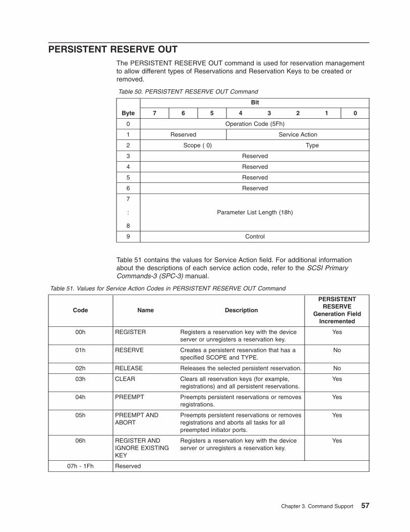
PERSISTENT RESERVE OUTThe PERSISTENT RESERVE OUT command is used for reservation managementto allow different types of Reservations and Reservation Keys to be created orremoved.
Table 50. PERSISTENT RESERVE OUT Command
Byte
Bit
7 6 5 4 3 2 1 0
0 Operation Code (5Fh)
1 Reserved Service Action
2 Scope ( 0) Type
3 Reserved
4 Reserved
5 Reserved
6 Reserved
7
:
8
Parameter List Length (18h)
9 Control
Table 51 contains the values for Service Action field. For additional informationabout the descriptions of each service action code, refer to the SCSI PrimaryCommands-3 (SPC-3) manual.
Table 51. Values for Service Action Codes in PERSISTENT RESERVE OUT Command
Code Name Description
PERSISTENTRESERVE
Generation FieldIncremented
00h REGISTER Registers a reservation key with the deviceserver or unregisters a reservation key.
Yes
01h RESERVE Creates a persistent reservation that has aspecified SCOPE and TYPE.
No
02h RELEASE Releases the selected persistent reservation. No
03h CLEAR Clears all reservation keys (for example,registrations) and all persistent reservations.
Yes
04h PREEMPT Preempts persistent reservations or removesregistrations.
Yes
05h PREEMPT ANDABORT
Preempts persistent reservations or removesregistrations and aborts all tasks for allpreempted initiator ports.
Yes
06h REGISTER ANDIGNORE EXISTINGKEY
Registers a reservation key with the deviceserver or unregisters a reservation key.
Yes
07h - 1Fh Reserved
Chapter 3. Command Support 57
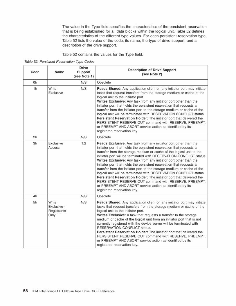
The value in the Type field specifies the characteristics of the persistent reservationthat is being established for all data blocks within the logical unit. Table 52 definesthe characteristics of the different type values. For each persistent reservation type,Table 52 lists the value of the code, its name, the type of drive support, and adescription of the drive support.
Table 52 contains the values for the Type field.
Table 52. Persistent Reservation Type Codes
Code NameDrive
Support(see Note 1)
Description of Drive Support(see Note 2)
0h N/S Obsolete
1h WriteExclusive
N/S Reads Shared: Any application client on any initiator port may initiatetasks that request transfers from the storage medium or cache of thelogical unit to the initiator port.Writes Exclusive: Any task from any initiator port other than theinitiator port that holds the persistent reservation that requests atransfer from the initiator port to the storage medium or cache of thelogical unit will be terminated with RESERVATION CONFLICT status.Persistent Reservation Holder: The initiator port that delivered thePERSISTENT RESERVE OUT command with RESERVE, PREEMPT,or PREEMPT AND ABORT service action as identified by itsregistered reservation key.
2h N/S Obsolete
3h ExclusiveAccess
1,2 Reads Exclusive: Any task from any initiator port other than theinitiator port that holds the persistent reservation that requests atransfer from the storage medium or cache of the logical unit to theinitiator port will be terminated with RESERVATION CONFLICT status.Writes Exclusive: Any task from any initiator port other than theinitiator port that holds the persistent reservation that requests atransfer from the initiator port to the storage medium or cache of thelogical unit will be terminated with RESERVATION CONFLICT status.Persistent Reservation Holder: The initiator port that delivered thePERSISTENT RESERVE OUT command with RESERVE, PREEMPT,or PREEMPT AND ABORT service action as identified by itsregistered reservation key.
4h N/S Obsolete
5h WriteExclusive -RegistrantsOnly
N/S Reads Shared: Any application client on any initiator port may initiatetasks that request transfers from the storage medium or cache of thelogical unit to the initiator port.Writes Exclusive: A task that requests a transfer to the storagemedium or cache of the logical unit from an initiator port that is notcurrently registered with the device server will be terminated withRESERVATION CONFLICT status.Persistent Reservation Holder: The initiator port that delivered thePERSISTENT RESERVE OUT command with RESERVE, PREEMPT,or PREEMPT AND ABORT service action as identified by itsregistered reservation key.
58 IBM TotalStorage LTO Ultrium Tape Drive: SCSI Reference
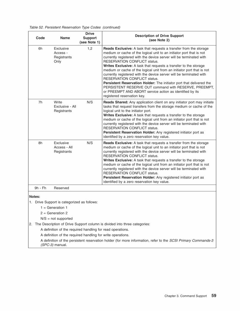
Table 52. Persistent Reservation Type Codes (continued)
Code NameDrive
Support(see Note 1)
Description of Drive Support(see Note 2)
6h ExclusiveAccess -RegistrantsOnly
1,2 Reads Exclusive: A task that requests a transfer from the storagemedium or cache of the logical unit to an initiator port that is notcurrently registered with the device server will be terminated withRESERVATION CONFLICT status.Writes Exclusive: A task that requests a transfer to the storagemedium or cache of the logical unit from an initiator port that is notcurrently registered with the device server will be terminated withRESERVATION CONFLICT status.Persistent Reservation Holder: The initiator port that delivered thePERSISTENT RESERVE OUT command with RESERVE, PREEMPT,or PREEMPT AND ABORT service action as identified by itsregistered reservation key.
7h WriteExclusive - AllRegistrants
N/S Reads Shared: Any application client on any initiator port may initiatetasks that request transfers from the storage medium or cache of thelogical unit to the initiator port.Writes Exclusive: A task that requests a transfer to the storagemedium or cache of the logical unit from an initiator port that is notcurrently registered with the device server will be terminated withRESERVATION CONFLICT status.Persistent Reservation Holder: Any registered initiator port asidentified by a zero reservation key value.
8h ExclusiveAccess - AllRegistrants
N/S Reads Exclusive: A task that requests a transfer from the storagemedium or cache of the logical unit to an initiator port that is notcurrently registered with the device server will be terminated withRESERVATION CONFLICT status.Writes Exclusive: A task that requests a transfer to the storagemedium or cache of the logical unit from an initiator port that is notcurrently registered with the device server will be terminated withRESERVATION CONFLICT status.Persistent Reservation Holder: Any registered initiator port asidentified by a zero reservation key value.
9h - Fh Reserved
Notes:
1. Drive Support is categorized as follows:
1 = Generation 1
2 = Generation 2
N/S = not supported
2. The Description of Drive Support column is divided into three categories:
A definition of the required handling for read operations.
A definition of the required handling for write operations.
A definition of the persistent reservation holder (for more information, refer to the SCSI Primary Commands-3(SPC-3) manual.
Chapter 3. Command Support 59
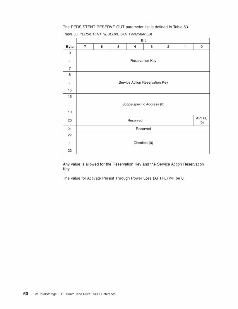
The PERSISTENT RESERVE OUT parameter list is defined in Table 53.
Table 53. PERSISTENT RESERVE OUT Parameter List
Byte
Bit
7 6 5 4 3 2 1 0
0
:
7
Reservation Key
8
:
15
Service Action Reservation Key
16
:
19
Scope-specific Address (0)
20 ReservedAPTPL
(0)
21 Reserved
22
:
23
Obsolete (0)
Any value is allowed for the Reservation Key and the Service Action ReservationKey.
The value for Activate Persist Through Power Loss (APTPL) will be 0.
60 IBM TotalStorage LTO Ultrium Tape Drive: SCSI Reference
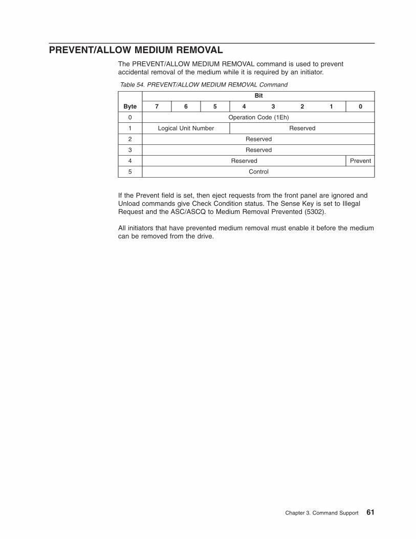
PREVENT/ALLOW MEDIUM REMOVALThe PREVENT/ALLOW MEDIUM REMOVAL command is used to preventaccidental removal of the medium while it is required by an initiator.
Table 54. PREVENT/ALLOW MEDIUM REMOVAL Command
Byte
Bit
7 6 5 4 3 2 1 0
0 Operation Code (1Eh)
1 Logical Unit Number Reserved
2 Reserved
3 Reserved
4 Reserved Prevent
5 Control
If the Prevent field is set, then eject requests from the front panel are ignored andUnload commands give Check Condition status. The Sense Key is set to IllegalRequest and the ASC/ASCQ to Medium Removal Prevented (5302).
All initiators that have prevented medium removal must enable it before the mediumcan be removed from the drive.
Chapter 3. Command Support 61
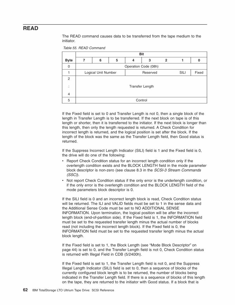
READThe READ command causes data to be transferred from the tape medium to theinitiator.
Table 55. READ Command
Byte
Bit
7 6 5 4 3 2 1 0
0 Operation Code (08h)
1 Logical Unit Number Reserved SILI Fixed
2
:
4
Transfer Length
5 Control
If the Fixed field is set to 0 and Transfer Length is not 0, then a single block of thelength in Transfer Length is to be transferred. If the next block on tape is of thislength or shorter, then it is transferred to the initiator. If the next block is longer thanthis length, then only the length requested is returned. A Check Condition forincorrect length is returned, and the logical position is set after the block. If thelength of the block was the same as the Transfer Length field, then Good status isreturned.
If the Suppress Incorrect Length Indicator (SILI) field is 1 and the Fixed field is 0,the drive will do one of the following:
v Report Check Condition status for an incorrect length condition only if theoverlength condition exists and the BLOCK LENGTH field in the mode parameterblock descriptor is non-zero (see clause 8.3 in the SCSI-3 Stream Commands(SSC)).
v Not report Check Condition status if the only error is the underlength condition, orif the only error is the overlength condition and the BLOCK LENGTH field of themode parameters block descriptor is 0.
If the SILI field is 0 and an incorrect length block is read, Check Condition statuswill be returned. The ILI and VALID fields must be set to 1 in the sense data andthe Additional Sense Code must be set to NO ADDITIONAL SENSEINFORMATION. Upon termination, the logical position will be after the incorrectlength block (end-of-partition side). If the Fixed field is 1, the INFORMATION fieldmust be set to the requested transfer length minus the actual number of blocksread (not including the incorrect length block). If the Fixed field is 0, theINFORMATION field must be set to the requested transfer length minus the actualblock length.
If the Fixed field is set to 1, the Block Length (see “Mode Block Descriptor” onpage 44) is set to 0, and the Transfer Length field is not 0, Check Condition statusis returned with Illegal Field in CDB (5/2400h).
If the Fixed field is set to 1, the Transfer Length field is not 0, and the SuppressIllegal Length Indicator (SILI) field is set to 0, then a sequence of blocks of thecurrently configured block length is to be returned, the number of blocks beingindicated in the Transfer Length field. If there is a sequence of blocks of this lengthon the tape, they are returned to the initiator with Good status. If a block that is
62 IBM TotalStorage LTO Ultrium Tape Drive: SCSI Reference
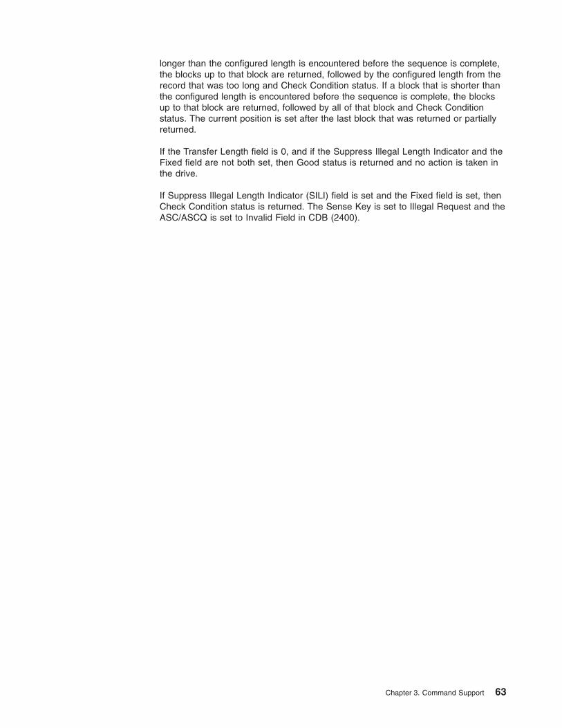
longer than the configured length is encountered before the sequence is complete,the blocks up to that block are returned, followed by the configured length from therecord that was too long and Check Condition status. If a block that is shorter thanthe configured length is encountered before the sequence is complete, the blocksup to that block are returned, followed by all of that block and Check Conditionstatus. The current position is set after the last block that was returned or partiallyreturned.
If the Transfer Length field is 0, and if the Suppress Illegal Length Indicator and theFixed field are not both set, then Good status is returned and no action is taken inthe drive.
If Suppress Illegal Length Indicator (SILI) field is set and the Fixed field is set, thenCheck Condition status is returned. The Sense Key is set to Illegal Request and theASC/ASCQ is set to Invalid Field in CDB (2400).
Chapter 3. Command Support 63
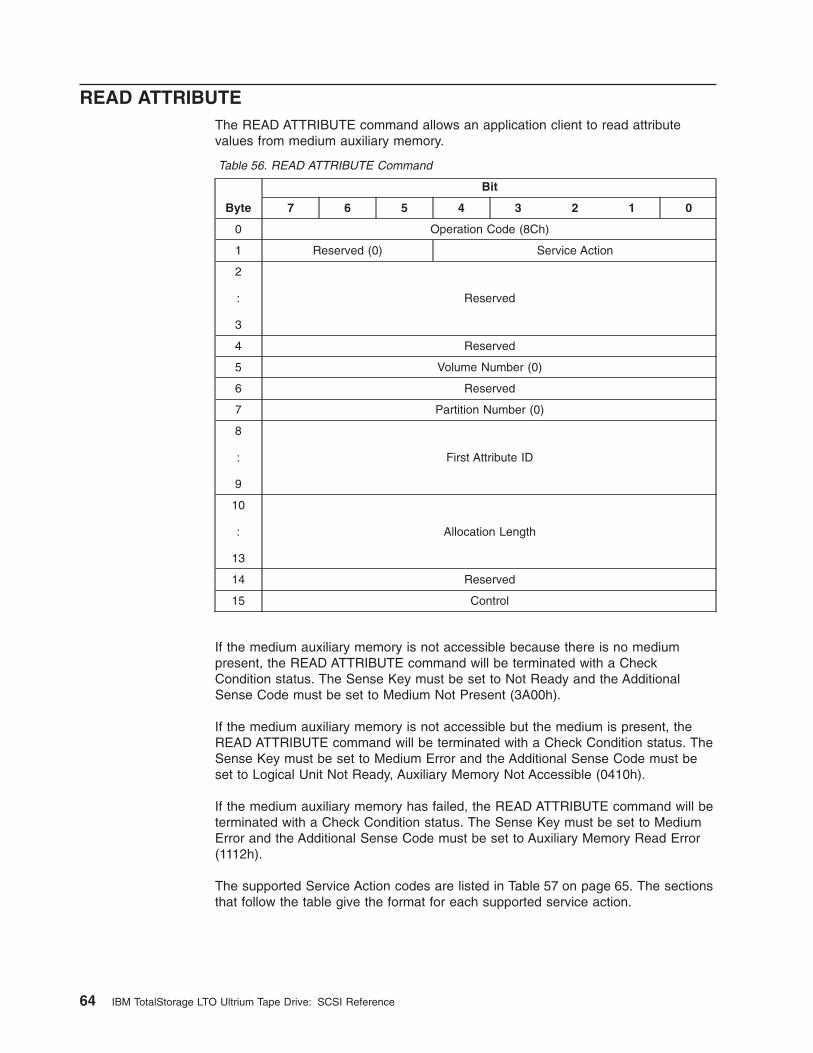
READ ATTRIBUTEThe READ ATTRIBUTE command allows an application client to read attributevalues from medium auxiliary memory.
Table 56. READ ATTRIBUTE Command
Byte
Bit
7 6 5 4 3 2 1 0
0 Operation Code (8Ch)
1 Reserved (0) Service Action
2
:
3
Reserved
4 Reserved
5 Volume Number (0)
6 Reserved
7 Partition Number (0)
8
:
9
First Attribute ID
10
:
13
Allocation Length
14 Reserved
15 Control
If the medium auxiliary memory is not accessible because there is no mediumpresent, the READ ATTRIBUTE command will be terminated with a CheckCondition status. The Sense Key must be set to Not Ready and the AdditionalSense Code must be set to Medium Not Present (3A00h).
If the medium auxiliary memory is not accessible but the medium is present, theREAD ATTRIBUTE command will be terminated with a Check Condition status. TheSense Key must be set to Medium Error and the Additional Sense Code must beset to Logical Unit Not Ready, Auxiliary Memory Not Accessible (0410h).
If the medium auxiliary memory has failed, the READ ATTRIBUTE command will beterminated with a Check Condition status. The Sense Key must be set to MediumError and the Additional Sense Code must be set to Auxiliary Memory Read Error(1112h).
The supported Service Action codes are listed in Table 57 on page 65. The sectionsthat follow the table give the format for each supported service action.
64 IBM TotalStorage LTO Ultrium Tape Drive: SCSI Reference
Table 57. Supported Service Action Codes
Code Name DescriptionFormat of Returned
Data
00h Attribute Values Return attribute values See “Format for theAttribute Values ServiceAction” on page 66
01h Attribute List Returns a list ofavailable attributeidentifiers
See “Format for theAttribute List ServiceAction” on page 67
02h Volume List Returns a list ofavailable VolumeNumbers
See “Format for theVolume List ServiceAction” on page 68
03h Partition List Returns a list ofavailable PartitionNumbers
See “Format for thePartition List ServiceAction” on page 69
04h Restricted Not applicable Not applicable
05h - 1Fh Reserved Not applicable Not applicable
The First Attribute ID field specifies the attribute identifier of the first attribute to bereturned. If the specified attribute identifier is in the unsupported or nonexistentstate, the READ ATTRIBUTE command will be terminated with a Check Conditionstatus (see clause 5.10 in the SCSI Primary Commands-3 (SPC-3)). The SenseKey must be set to Illegal Request and the Additional Sense Code must be set toInvalid Field in CDB.
The Allocation Length field specifies how many bytes have been allocated for thereturned parameter list. If the length is not sufficient to contain the entire parameterlist, the first portion of the list will be returned. This is not considered an error. If theremainder of the list is required, the application client should send a new READATTRIBUTE command with an allocation length large enough to contain the entireparameter list or use the First Attribute ID field to restrict the attributes that arereturned.
The format of parameter data that is returned by the READ ATTRIBUTE commanddepends on the service action that is specified.
Chapter 3. Command Support 65
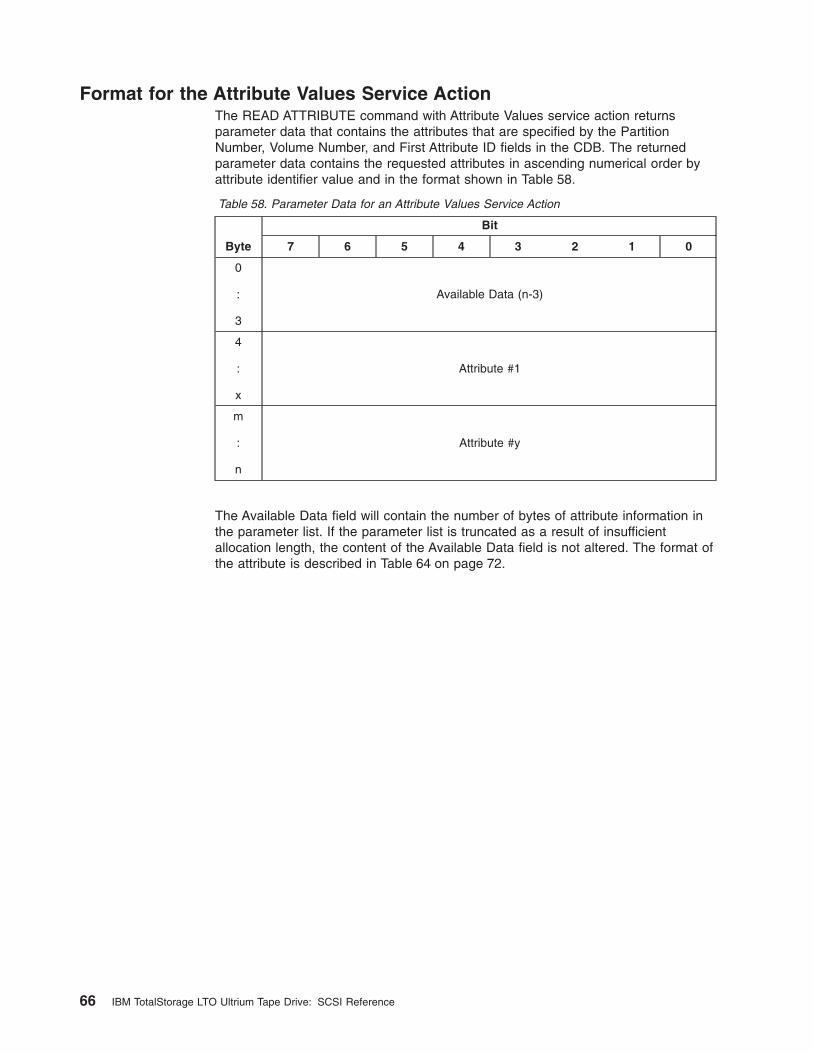
Format for the Attribute Values Service ActionThe READ ATTRIBUTE command with Attribute Values service action returnsparameter data that contains the attributes that are specified by the PartitionNumber, Volume Number, and First Attribute ID fields in the CDB. The returnedparameter data contains the requested attributes in ascending numerical order byattribute identifier value and in the format shown in Table 58.
Table 58. Parameter Data for an Attribute Values Service Action
Byte
Bit
7 6 5 4 3 2 1 0
0
:
3
Available Data (n-3)
4
:
x
Attribute #1
m
:
n
Attribute #y
The Available Data field will contain the number of bytes of attribute information inthe parameter list. If the parameter list is truncated as a result of insufficientallocation length, the content of the Available Data field is not altered. The format ofthe attribute is described in Table 64 on page 72.
66 IBM TotalStorage LTO Ultrium Tape Drive: SCSI Reference
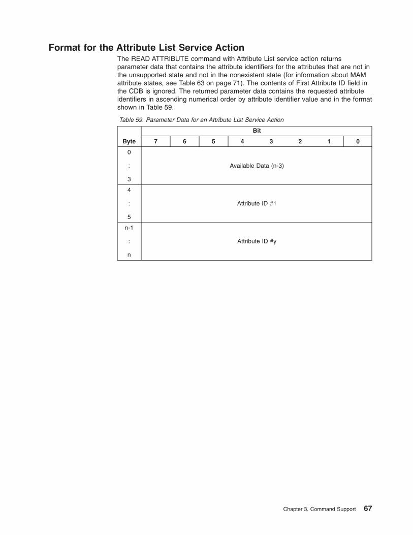
Format for the Attribute List Service ActionThe READ ATTRIBUTE command with Attribute List service action returnsparameter data that contains the attribute identifiers for the attributes that are not inthe unsupported state and not in the nonexistent state (for information about MAMattribute states, see Table 63 on page 71). The contents of First Attribute ID field inthe CDB is ignored. The returned parameter data contains the requested attributeidentifiers in ascending numerical order by attribute identifier value and in the formatshown in Table 59.
Table 59. Parameter Data for an Attribute List Service Action
Byte
Bit
7 6 5 4 3 2 1 0
0
:
3
Available Data (n-3)
4
:
5
Attribute ID #1
n-1
:
n
Attribute ID #y
Chapter 3. Command Support 67

Format for the Volume List Service ActionThe READ ATTRIBUTE command with Volume List service action returnsparameter data that identifies the supported number of volumes (see Table 60). Thecontents of Volume Number, Partition Number, and First Attribute ID fields in theCDB are ignored.
Table 60. Parameter Data for a Volume List Service Action
Byte
Bit
7 6 5 4 3 2 1 0
0
:
1
Available Data (2)
2 First Volume Number (0)
3 Number of Volumes Available (1)
The Available Data field contains two.
The First Volume Number field indicates the first volume that is available and will beset to 0.
The Number of Volumes Available field indicates the number of volumes that areavailable and will be set to 1.
68 IBM TotalStorage LTO Ultrium Tape Drive: SCSI Reference
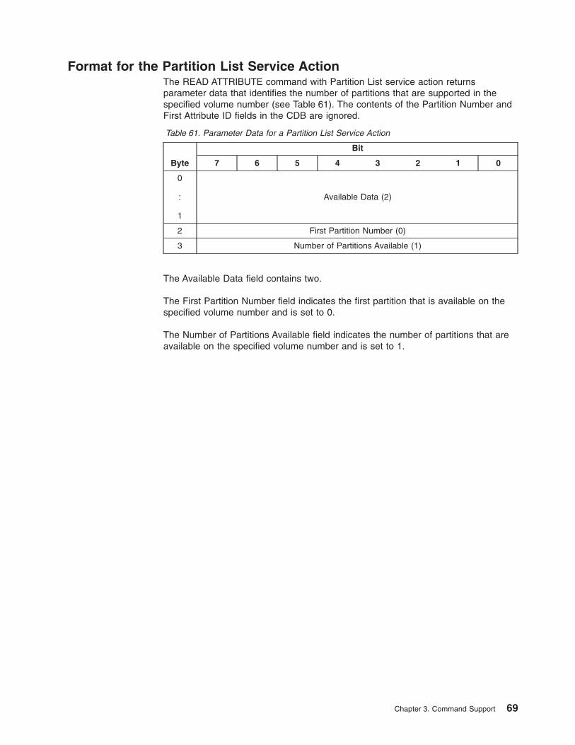
Format for the Partition List Service ActionThe READ ATTRIBUTE command with Partition List service action returnsparameter data that identifies the number of partitions that are supported in thespecified volume number (see Table 61). The contents of the Partition Number andFirst Attribute ID fields in the CDB are ignored.
Table 61. Parameter Data for a Partition List Service Action
Byte
Bit
7 6 5 4 3 2 1 0
0
:
1
Available Data (2)
2 First Partition Number (0)
3 Number of Partitions Available (1)
The Available Data field contains two.
The First Partition Number field indicates the first partition that is available on thespecified volume number and is set to 0.
The Number of Partitions Available field indicates the number of partitions that areavailable on the specified volume number and is set to 1.
Chapter 3. Command Support 69
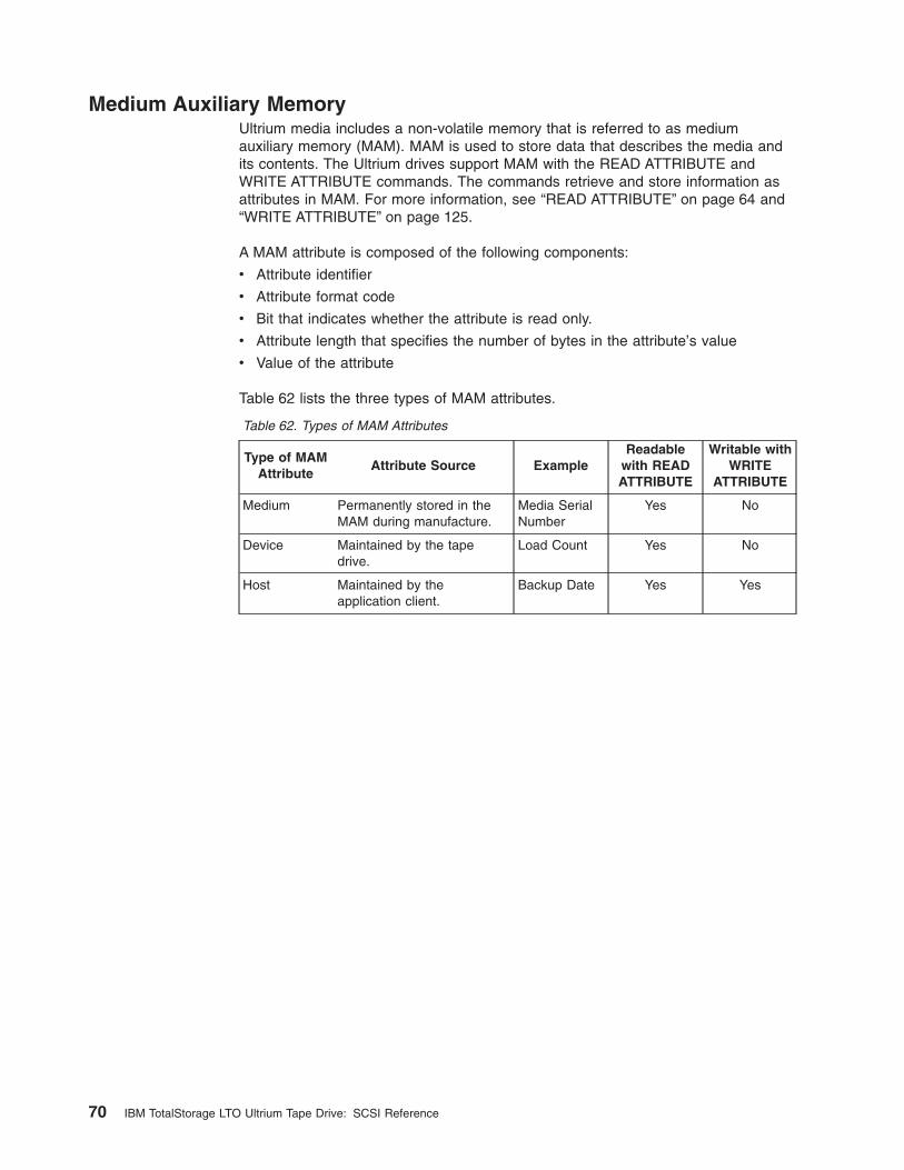
Medium Auxiliary MemoryUltrium media includes a non-volatile memory that is referred to as mediumauxiliary memory (MAM). MAM is used to store data that describes the media andits contents. The Ultrium drives support MAM with the READ ATTRIBUTE andWRITE ATTRIBUTE commands. The commands retrieve and store information asattributes in MAM. For more information, see “READ ATTRIBUTE” on page 64 and“WRITE ATTRIBUTE” on page 125.
A MAM attribute is composed of the following components:
v Attribute identifier
v Attribute format code
v Bit that indicates whether the attribute is read only.
v Attribute length that specifies the number of bytes in the attribute’s value
v Value of the attribute
Table 62 lists the three types of MAM attributes.
Table 62. Types of MAM Attributes
Type of MAMAttribute
Attribute Source ExampleReadable
with READATTRIBUTE
Writable withWRITE
ATTRIBUTE
Medium Permanently stored in theMAM during manufacture.
Media SerialNumber
Yes No
Device Maintained by the tapedrive.
Load Count Yes No
Host Maintained by theapplication client.
Backup Date Yes Yes
70 IBM TotalStorage LTO Ultrium Tape Drive: SCSI Reference
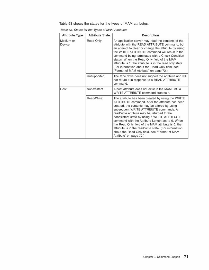
Table 63 shows the states for the types of MAM attributes.
Table 63. States for the Types of MAM Attributes
Attribute Type Attribute State Description
Medium orDevice
Read Only An application server may read the contents of theattribute with the READ ATTRIBUTE command, butan attempt to clear or change the attribute by usingthe WRITE ATTRIBUTE command will result in thecommand being terminated with a Check Conditionstatus. When the Read Only field of the MAMattribute is 1, the attribute is in the read only state.(For information about the Read Only field, see“Format of MAM Attribute” on page 72.)
Unsupported The tape drive does not support the attribute and willnot return it in response to a READ ATTRIBUTEcommand.
Host Nonexistent A host attribute does not exist in the MAM until aWRITE ATTRIBUTE command creates it.
Read/Write The attribute has been created by using the WRITEATTRIBUTE command. After the attribute has beencreated, the contents may be altered by usingsubsequent WRITE ATTRIBUTE commands. Aread/write attribute may be returned to thenonexistent state by using a WRITE ATTRIBUTEcommand with the Attribute Length set to 0. Whenthe Read Only field of the MAM attribute is 0, theattribute is in the read/write state. (For informationabout the Read Only field, see “Format of MAMAttribute” on page 72.)
Chapter 3. Command Support 71
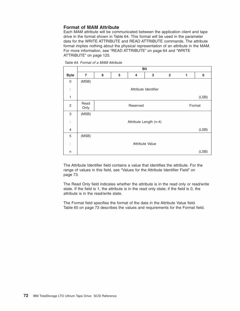
Format of MAM AttributeEach MAM attribute will be communicated between the application client and tapedrive in the format shown in Table 64. This format will be used in the parameterdata for the WRITE ATTRIBUTE and READ ATTRIBUTE commands. The attributeformat implies nothing about the physical representation of an attribute in the MAM.For more information, see “READ ATTRIBUTE” on page 64 and “WRITEATTRIBUTE” on page 125.
Table 64. Format of a MAM Attribute
Byte
Bit
7 6 5 4 3 2 1 0
0
:
1
(MSB)
Attribute Identifier
(LSB)
2ReadOnly
Reserved Format
3
:
4
(MSB)
Attribute Length (n-4)
(LSB)
5
:
n
(MSB)
Attribute Value
(LSB)
The Attribute Identifier field contains a value that identifies the attribute. For therange of values in this field, see “Values for the Attribute Identifier Field” onpage 73.
The Read Only field indicates whether the attribute is in the read only or read/writestate. If the field is 1, the attribute is in the read only state; if the field is 0, theattribute is in the read/write state.
The Format field specifies the format of the data in the Attribute Value field.Table 65 on page 73 describes the values and requirements for the Format field.
72 IBM TotalStorage LTO Ultrium Tape Drive: SCSI Reference
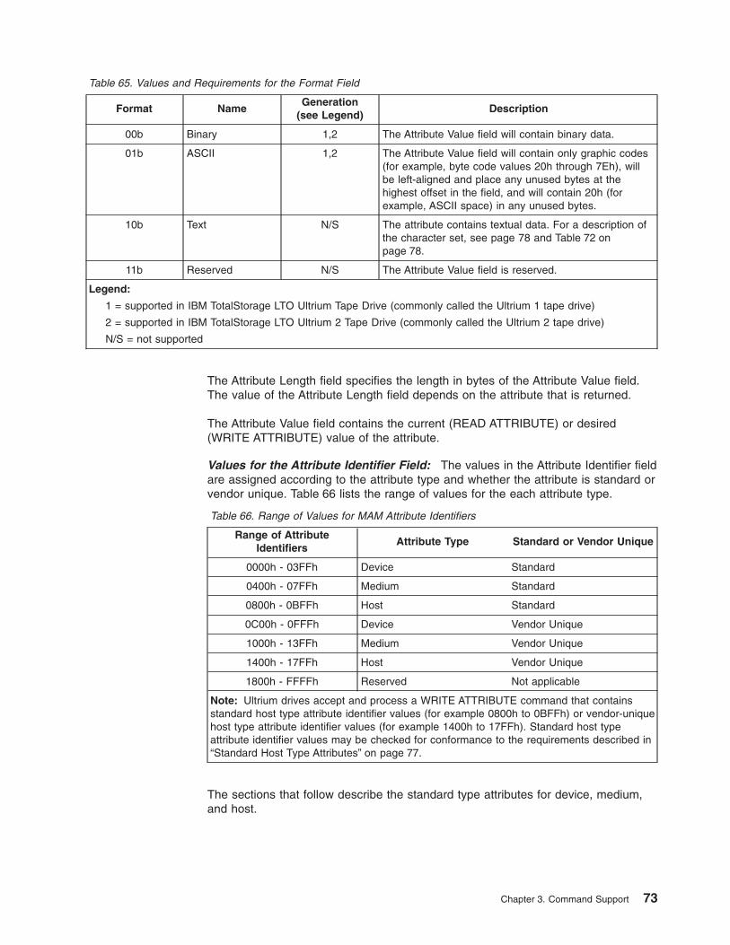
Table 65. Values and Requirements for the Format Field
Format NameGeneration
(see Legend)Description
00b Binary 1,2 The Attribute Value field will contain binary data.
01b ASCII 1,2 The Attribute Value field will contain only graphic codes(for example, byte code values 20h through 7Eh), willbe left-aligned and place any unused bytes at thehighest offset in the field, and will contain 20h (forexample, ASCII space) in any unused bytes.
10b Text N/S The attribute contains textual data. For a description ofthe character set, see page 78 and Table 72 onpage 78.
11b Reserved N/S The Attribute Value field is reserved.
Legend:
1 = supported in IBM TotalStorage LTO Ultrium Tape Drive (commonly called the Ultrium 1 tape drive)
2 = supported in IBM TotalStorage LTO Ultrium 2 Tape Drive (commonly called the Ultrium 2 tape drive)
N/S = not supported
The Attribute Length field specifies the length in bytes of the Attribute Value field.The value of the Attribute Length field depends on the attribute that is returned.
The Attribute Value field contains the current (READ ATTRIBUTE) or desired(WRITE ATTRIBUTE) value of the attribute.
Values for the Attribute Identifier Field: The values in the Attribute Identifier fieldare assigned according to the attribute type and whether the attribute is standard orvendor unique. Table 66 lists the range of values for the each attribute type.
Table 66. Range of Values for MAM Attribute Identifiers
Range of AttributeIdentifiers
Attribute Type Standard or Vendor Unique
0000h - 03FFh Device Standard
0400h - 07FFh Medium Standard
0800h - 0BFFh Host Standard
0C00h - 0FFFh Device Vendor Unique
1000h - 13FFh Medium Vendor Unique
1400h - 17FFh Host Vendor Unique
1800h - FFFFh Reserved Not applicable
Note: Ultrium drives accept and process a WRITE ATTRIBUTE command that containsstandard host type attribute identifier values (for example 0800h to 0BFFh) or vendor-uniquehost type attribute identifier values (for example 1400h to 17FFh). Standard host typeattribute identifier values may be checked for conformance to the requirements described in“Standard Host Type Attributes” on page 77.
The sections that follow describe the standard type attributes for device, medium,and host.
Chapter 3. Command Support 73
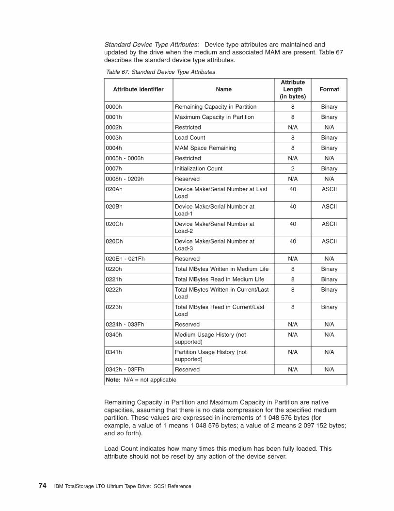
Standard Device Type Attributes: Device type attributes are maintained andupdated by the drive when the medium and associated MAM are present. Table 67describes the standard device type attributes.
Table 67. Standard Device Type Attributes
Attribute Identifier NameAttributeLength
(in bytes)Format
0000h Remaining Capacity in Partition 8 Binary
0001h Maximum Capacity in Partition 8 Binary
0002h Restricted N/A N/A
0003h Load Count 8 Binary
0004h MAM Space Remaining 8 Binary
0005h - 0006h Restricted N/A N/A
0007h Initialization Count 2 Binary
0008h - 0209h Reserved N/A N/A
020Ah Device Make/Serial Number at LastLoad
40 ASCII
020Bh Device Make/Serial Number atLoad-1
40 ASCII
020Ch Device Make/Serial Number atLoad-2
40 ASCII
020Dh Device Make/Serial Number atLoad-3
40 ASCII
020Eh - 021Fh Reserved N/A N/A
0220h Total MBytes Written in Medium Life 8 Binary
0221h Total MBytes Read in Medium Life 8 Binary
0222h Total MBytes Written in Current/LastLoad
8 Binary
0223h Total MBytes Read in Current/LastLoad
8 Binary
0224h - 033Fh Reserved N/A N/A
0340h Medium Usage History (notsupported)
N/A N/A
0341h Partition Usage History (notsupported)
N/A N/A
0342h - 03FFh Reserved N/A N/A
Note: N/A = not applicable
Remaining Capacity in Partition and Maximum Capacity in Partition are nativecapacities, assuming that there is no data compression for the specified mediumpartition. These values are expressed in increments of 1 048 576 bytes (forexample, a value of 1 means 1 048 576 bytes; a value of 2 means 2 097 152 bytes;and so forth).
Load Count indicates how many times this medium has been fully loaded. Thisattribute should not be reset by any action of the device server.
74 IBM TotalStorage LTO Ultrium Tape Drive: SCSI Reference

MAM Space Remaining indicates the space that is currently free in the mediumauxiliary memory. The total MAM capacity is reported in the MAM Capacity attribute.(For a description of the MAM Capacity attribute, see page 76.) Note: It may notalways be possible to use all of the free space that is reported.
Initialization Count indicates the number of times that a device server has logicallyformatted the medium. This figure is cumulative over the life of the medium and willnever be reset.
The Device Vendor Identification/Product Serial Number at Last Load, DeviceVendor Identification/Product Serial Number at Load-1, Device VendorIdentification/Product Serial Number at Load-2, and Device VendorIdentification/Product Serial Number at Load-3 attributes give a rolling history of thelast four device servers in which the medium has been loaded. The format for theattributes is shown in Table 68.
Table 68. Format for Device Vendor Identification/Product Serial Number Attribute, DeviceVendor Identification/Product Serial Number at Load-1 Attribute, Device VendorIdentification/Product Serial Number at Load-2 Attribute, and Device VendorIdentification/Product Serial Number at Load-3 Attribute
Byte
Bit
7 6 5 4 3 2 1 0
0
:
7
(MSB)
Vendor Identification
(LSB)
8
:
39
(MSB)
Product Serial Number
(LSB)
The Vendor Identification field will be the same value that is returned in theStandard Inquiry Data.
The Product Serial Number field contains a vendor-unique serial number. If theproduct serial number is not available, the Product Serial Number field will containASCII spaces (20h).
Total MBytes Written in Medium Life and Total MBytes Read in Medium Life indicatethe number of data bytes that are transferred to or from the medium surface (afterany data compression has been applied) over the entire life of the medium. Thesevalues are cumulative and will never be reset. They are expressed in increments of1 048 576 bytes (for example, a value of 1 means 1 048 576 bytes; a value of 2means 2 097 152 bytes; and so forth).
Total MBytes Written in Current/Last Load and Total MBytes Read in Current/LastLoad indicate the total number of data bytes that are transferred to or from themedium surface (after any data compression has been applied) during the currentload if the medium is currently loaded, or during the last load if the medium iscurrently unloaded. The device server should reset these attributes to 0 when themedium is loaded. These values are expressed in increments of 1 048 576 bytes(for example, a value of 1 means 1 048 576 bytes; a value of 2 means 2 097 152bytes; and so forth).
Chapter 3. Command Support 75
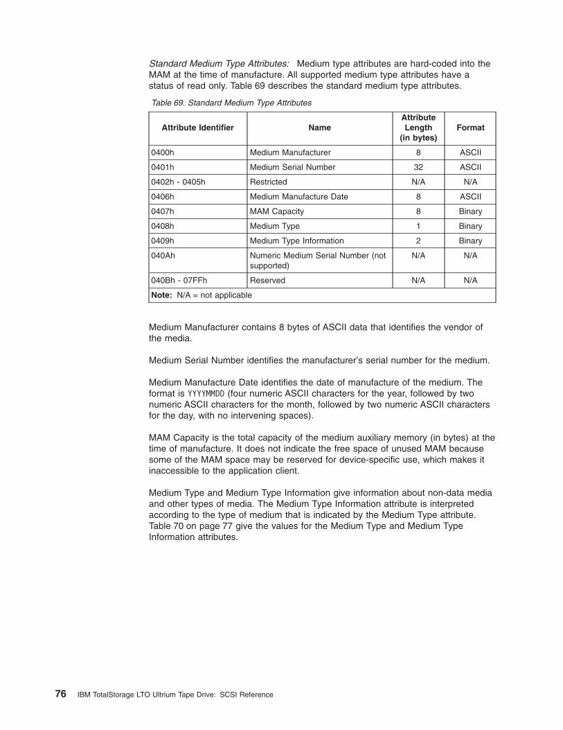
Standard Medium Type Attributes: Medium type attributes are hard-coded into theMAM at the time of manufacture. All supported medium type attributes have astatus of read only. Table 69 describes the standard medium type attributes.
Table 69. Standard Medium Type Attributes
Attribute Identifier NameAttributeLength
(in bytes)Format
0400h Medium Manufacturer 8 ASCII
0401h Medium Serial Number 32 ASCII
0402h - 0405h Restricted N/A N/A
0406h Medium Manufacture Date 8 ASCII
0407h MAM Capacity 8 Binary
0408h Medium Type 1 Binary
0409h Medium Type Information 2 Binary
040Ah Numeric Medium Serial Number (notsupported)
N/A N/A
040Bh - 07FFh Reserved N/A N/A
Note: N/A = not applicable
Medium Manufacturer contains 8 bytes of ASCII data that identifies the vendor ofthe media.
Medium Serial Number identifies the manufacturer’s serial number for the medium.
Medium Manufacture Date identifies the date of manufacture of the medium. Theformat is YYYYMMDD (four numeric ASCII characters for the year, followed by twonumeric ASCII characters for the month, followed by two numeric ASCII charactersfor the day, with no intervening spaces).
MAM Capacity is the total capacity of the medium auxiliary memory (in bytes) at thetime of manufacture. It does not indicate the free space of unused MAM becausesome of the MAM space may be reserved for device-specific use, which makes itinaccessible to the application client.
Medium Type and Medium Type Information give information about non-data mediaand other types of media. The Medium Type Information attribute is interpretedaccording to the type of medium that is indicated by the Medium Type attribute.Table 70 on page 77 give the values for the Medium Type and Medium TypeInformation attributes.
76 IBM TotalStorage LTO Ultrium Tape Drive: SCSI Reference
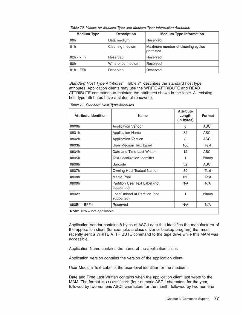
Table 70. Values for Medium Type and Medium Type Information Attributes
Medium Type Description Medium Type Information
00h Data medium Reserved
01h Cleaning medium Maximum number of cleaning cyclespermitted
02h - 7Fh Reserved Reserved
80h Write-once medium Reserved
81h - FFh Reserved Reserved
Standard Host Type Attributes: Table 71 describes the standard host typeattributes. Application clients may use the WRITE ATTRIBUTE and READATTRIBUTE commands to maintain the attributes shown in the table. All existinghost type attributes have a status of read/write.
Table 71. Standard Host Type Attributes
Attribute Identifier NameAttributeLength
(in bytes)Format
0800h Application Vendor 8 ASCII
0801h Application Name 32 ASCII
0802h Application Version 8 ASCII
0803h User Medium Text Label 160 Text
0804h Date and Time Last Written 12 ASCII
0805h Text Localization Identifier 1 Binary
0806h Barcode 32 ASCII
0807h Owning Host Textual Name 80 Text
0808h Media Pool 160 Text
0809h Partition User Text Label (notsupported)
N/A N/A
080Ah Load/Unload at Partition (notsupported)
1 Binary
080Bh - BFFh Reserved N/A N/A
Note: N/A = not applicable
Application Vendor contains 8 bytes of ASCII data that identifies the manufacturer ofthe application client (for example, a class driver or backup program) that mostrecently sent a WRITE ATTRIBUTE command to the tape drive while this MAM wasaccessible.
Application Name contains the name of the application client.
Application Version contains the version of the application client.
User Medium Text Label is the user-level identifier for the medium.
Date and Time Last Written contains when the application client last wrote to theMAM. The format is YYYYMMDDHHMM (four numeric ASCII characters for the year,followed by two numeric ASCII characters for the month, followed by two numeric
Chapter 3. Command Support 77

ASCII characters for the day, followed by two numeric ASCII characters between 00and 24 for the hour, followed by two numeric ASCII characters for the minute, withno intervening spaces).
Text Localization Identifier defines the character set that is used for attributes with aText format. Table 72 gives the values for the Text Localization Identifier attribute.
Table 72. Values for the Text Localization Identifier Attribute
Value Meaning
00h No code specified (ASCII)
01h ISO/IEC 8859-1 (Europe, Latin America)
02h ISO/IEC 8859-2 (Eastern Europe)
03h ISO/IEC 8859-3 (Southeastern Europe, miscellaneous)
04h ISO/IEC 8859-4 (Scandinavia/Baltic)
05h ISO/IEC 8859-5 (Cyrillic)
06h ISO/IEC 8859-6 (Arabic)
07h ISO/IEC 8859-7 (Greek)
08h ISO/IEC 8859-8 (Hebrew)
09h ISO/IEC 8859-9 (Latin 5)
0Ah ISO/IEC 8859-10 (Latin 6)
0Bh - 7Fh Reserved
80h ISO/IEC 10646-1 (UCS-2BE)
81h ISO/IEC 10646-1 (UTF-8)
82h - FFh Reserved
Barcode is the contents of a bar code that is associated with the medium in theMAM.
Owning Host Textual Name indicates the host from which the User Medium Textlabel originates.
Media Pool indicates the media pool to which this medium belongs.
78 IBM TotalStorage LTO Ultrium Tape Drive: SCSI Reference
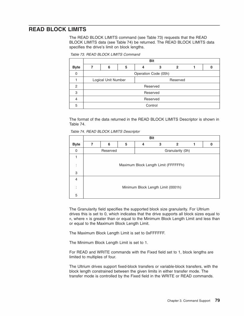
READ BLOCK LIMITSThe READ BLOCK LIMITS command (see Table 73) requests that the READBLOCK LIMITS data (see Table 74) be returned. The READ BLOCK LIMITS dataspecifies the drive’s limit on block lengths.
Table 73. READ BLOCK LIMITS Command
Byte
Bit
7 6 5 4 3 2 1 0
0 Operation Code (05h)
1 Logical Unit Number Reserved
2 Reserved
3 Reserved
4 Reserved
5 Control
The format of the data returned in the READ BLOCK LIMITS Descriptor is shown inTable 74.
Table 74. READ BLOCK LIMITS Descriptor
Byte
Bit
7 6 5 4 3 2 1 0
0 Reserved Granularity (0h)
1
:
3
Maximum Block Length Limit (FFFFFFh)
4
:
5
Minimum Block Length Limit (0001h)
The Granularity field specifies the supported block size granularity. For Ultriumdrives this is set to 0, which indicates that the drive supports all block sizes equal ton, where n is greater than or equal to the Minimum Block Length Limit and less thanor equal to the Maximum Block Length Limit.
The Maximum Block Length Limit is set to 0xFFFFFF.
The Minimum Block Length Limit is set to 1.
For READ and WRITE commands with the Fixed field set to 1, block lengths arelimited to multiples of four.
The Ultrium drives support fixed-block transfers or variable-block transfers, with theblock length constrained between the given limits in either transfer mode. Thetransfer mode is controlled by the Fixed field in the WRITE or READ commands.
Chapter 3. Command Support 79
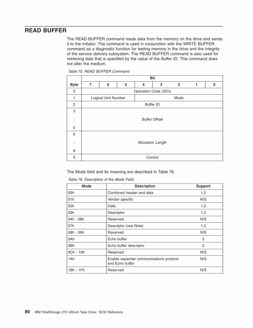
READ BUFFERThe READ BUFFER command reads data from the memory on the drive and sendsit to the initiator. The command is used in conjunction with the WRITE BUFFERcommand as a diagnostic function for testing memory in the drive and the integrityof the service delivery subsystem. The READ BUFFER command is also used forretrieving data that is specified by the value of the Buffer ID. This command doesnot alter the medium.
Table 75. READ BUFFER Command
Byte
Bit
7 6 5 4 3 2 1 0
0 Operation Code (3Ch)
1 Logical Unit Number Mode
2 Buffer ID
3
:
5
Buffer Offset
6
:
8
Allocation Length
9 Control
The Mode field and its meaning are described in Table 76.
Table 76. Description of the Mode Field
Mode Description Support
00h Combined header and data 1,2
01h Vendor specific N/S
02h Data 1,2
03h Descriptor 1,2
04h - 06h Reserved N/S
07h Descriptor (see Note) 1,2
08h - 09h Reserved N/S
0Ah Echo buffer 2
0Bh Echo buffer descriptor 2
0Ch - 19h Reserved N/S
1Ah Enable expander communications protocoland Echo buffer
N/S
1Bh - 1Fh Reserved N/S
80 IBM TotalStorage LTO Ultrium Tape Drive: SCSI Reference
Table 76. Description of the Mode Field (continued)
Mode Description Support
Legend:
1 = supported in IBM TotalStorage LTO Ultrium Tape Drive (commonly called the Ultrium1 tape drive)
2 = supported in IBM TotalStorage LTO Ultrium 2 Tape Drive (commonly called theUltrium 2 tape drive)
N/S = not supported
Note: The descriptor that is returned for Mode 07h has the Buffer Capacity field reported in64-byte increments.
The Buffer ID indicates which buffer is to be read. The Buffer IDs are shown inTable 80 on page 83.
The Buffer Offset field may be set to any address in the buffer.
If the Mode is set to 07h and the Buffer ID is 0, the descriptor that is returned is forthe Main Data buffer, and the Buffer Capacity field is the number of 64-bytesegments that are available.
The format of the 4-byte descriptor is shown in Table 78 on page 82.
Note: The Main Data buffer capacity is larger than can be represented in the BufferOffset field of the CDB and Buffer Capacity field of the header. Tocompensate for this, the Buffer Offset and Buffer Capacity fields for the MainBuffer (buffer ID = 0) are interpreted and expressed in multiples of 64 bytes(for example, a value of 1 equals 64 bytes). This interpretation is for buffermodes 00h, 01h, 02h, 03h, and 07h only.
If the Mode is set to 0Ah, data from the echo buffer is returned.
In this mode, Buffer ID and Buffer Offset fields are ignored. Prior to issuing a READBUFFER command that uses the echo buffer, a WRITE BUFFER command thatuses the echo buffer must have been successfully completed (see “WRITEBUFFER” on page 126). If not, the Read Echo Buffer terminates with a CheckCondition status, the Sense Key is set to Illegal Request, and ASC/ASCQ is set toCommand Sequence Error (2C00h). The Read Echo Buffer returns the samenumber of bytes of data as was received in the prior Write Echo Buffer from thesame initiator.
If the Mode is set to 0Bh, the descriptor information of the echo buffer is returned.The format of the echo buffer descriptor is shown in Table 79 on page 82. The EchoBuffer Overwritten Supported (EBOS) is set to 1 because the drive keeps the echobuffer for each initiator.
Chapter 3. Command Support 81
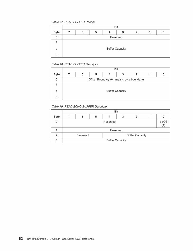
Table 77. READ BUFFER Header
Byte
Bit
7 6 5 4 3 2 1 0
0 Reserved
1
:
3
Buffer Capacity
Table 78. READ BUFFER Descriptor
Byte
Bit
7 6 5 4 3 2 1 0
0 Offset Boundary (0h means byte boundary)
1
:
3
Buffer Capacity
Table 79. READ ECHO BUFFER Descriptor
Byte
Bit
7 6 5 4 3 2 1 0
0 Reserved EBOS(1)
1 Reserved
2 Reserved Buffer Capacity
3 Buffer Capacity
82 IBM TotalStorage LTO Ultrium Tape Drive: SCSI Reference
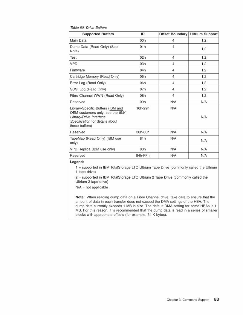
Table 80. Drive Buffers
Supported Buffers ID Offset Boundary Ultrium Support
Main Data 00h 4 1,2
Dump Data (Read Only) (SeeNote)
01h 41,2
Test 02h 4 1,2
VPD 03h 4 1,2
Firmware 04h 4 1,2
Cartridge Memory (Read Only) 05h 4 1,2
Error Log (Read Only) 06h 4 1,2
SCSI Log (Read Only) 07h 4 1,2
Fibre Channel WWN (Read Only) 08h 4 1,2
Reserved 09h N/A N/A
Library-Specific Buffers (IBM andOEM customers only: see the IBMLibrary/Drive InterfaceSpecification for details aboutthese buffers)
10h-29h N/A
N/A
Reserved 30h-80h N/A N/A
TapeMap (Read Only) (IBM useonly)
81h N/AN/A
VPD Replica (IBM use only) 83h N/A N/A
Reserved 84h-FFh N/A N/A
Legend:
1 = supported in IBM TotalStorage LTO Ultrium Tape Drive (commonly called the Ultrium1 tape drive)
2 = supported in IBM TotalStorage LTO Ultrium 2 Tape Drive (commonly called theUltrium 2 tape drive)
N/A = not applicable
Note: When reading dump data on a Fibre Channel drive, take care to ensure that theamount of data in each transfer does not exceed the DMA settings of the HBA. Thedump data currently exceeds 1 MB in size. The default DMA setting for some HBAs is 1MB. For this reason, it is recommended that the dump data is read in a series of smallerblocks with appropriate offsets (for example, 64 K bytes).
Chapter 3. Command Support 83
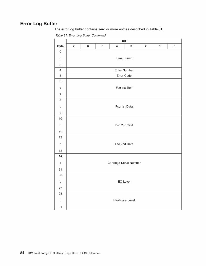
Error Log BufferThe error log buffer contains zero or more entries described in Table 81.
Table 81. Error Log Buffer Command
Byte
Bit
7 6 5 4 3 2 1 0
0
:
3
Time Stamp
4 Entry Number
5 Error Code
6
:
7
Fsc 1st Text
8
:
9
Fsc 1st Data
10
:
11
Fsc 2nd Text
12
:
13
Fsc 2nd Data
14
:
21
Cartridge Serial Number
22
:
27
EC Level
28
:
31
Hardware Level
84 IBM TotalStorage LTO Ultrium Tape Drive: SCSI Reference
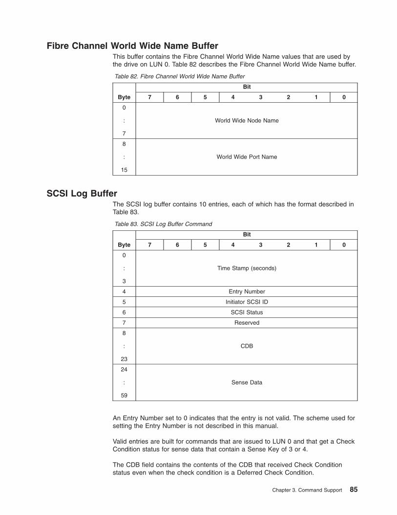
Fibre Channel World Wide Name BufferThis buffer contains the Fibre Channel World Wide Name values that are used bythe drive on LUN 0. Table 82 describes the Fibre Channel World Wide Name buffer.
Table 82. Fibre Channel World Wide Name Buffer
Byte
Bit
7 6 5 4 3 2 1 0
0
:
7
World Wide Node Name
8
:
15
World Wide Port Name
SCSI Log BufferThe SCSI log buffer contains 10 entries, each of which has the format described inTable 83.
Table 83. SCSI Log Buffer Command
Byte
Bit
7 6 5 4 3 2 1 0
0
:
3
Time Stamp (seconds)
4 Entry Number
5 Initiator SCSI ID
6 SCSI Status
7 Reserved
8
:
23
CDB
24
:
59
Sense Data
An Entry Number set to 0 indicates that the entry is not valid. The scheme used forsetting the Entry Number is not described in this manual.
Valid entries are built for commands that are issued to LUN 0 and that get a CheckCondition status for sense data that contain a Sense Key of 3 or 4.
The CDB field contains the contents of the CDB that received Check Conditionstatus even when the check condition is a Deferred Check Condition.
Chapter 3. Command Support 85
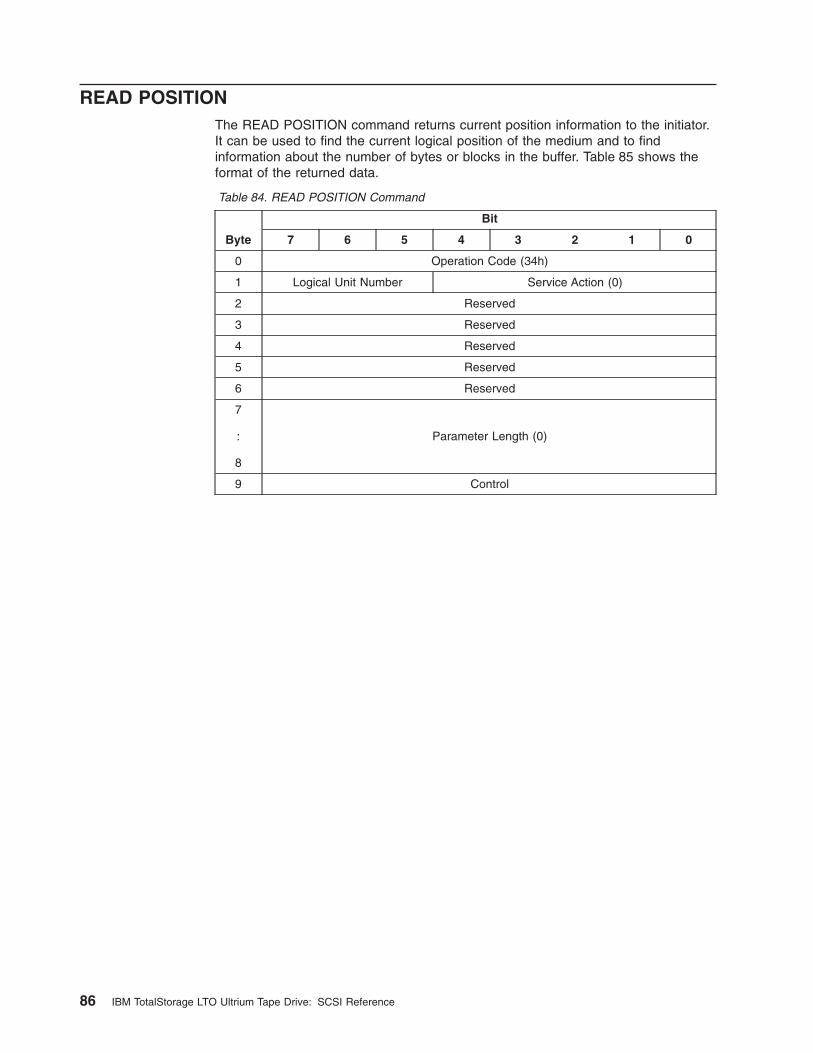
READ POSITIONThe READ POSITION command returns current position information to the initiator.It can be used to find the current logical position of the medium and to findinformation about the number of bytes or blocks in the buffer. Table 85 shows theformat of the returned data.
Table 84. READ POSITION Command
Byte
Bit
7 6 5 4 3 2 1 0
0 Operation Code (34h)
1 Logical Unit Number Service Action (0)
2 Reserved
3 Reserved
4 Reserved
5 Reserved
6 Reserved
7
:
8
Parameter Length (0)
9 Control
86 IBM TotalStorage LTO Ultrium Tape Drive: SCSI Reference
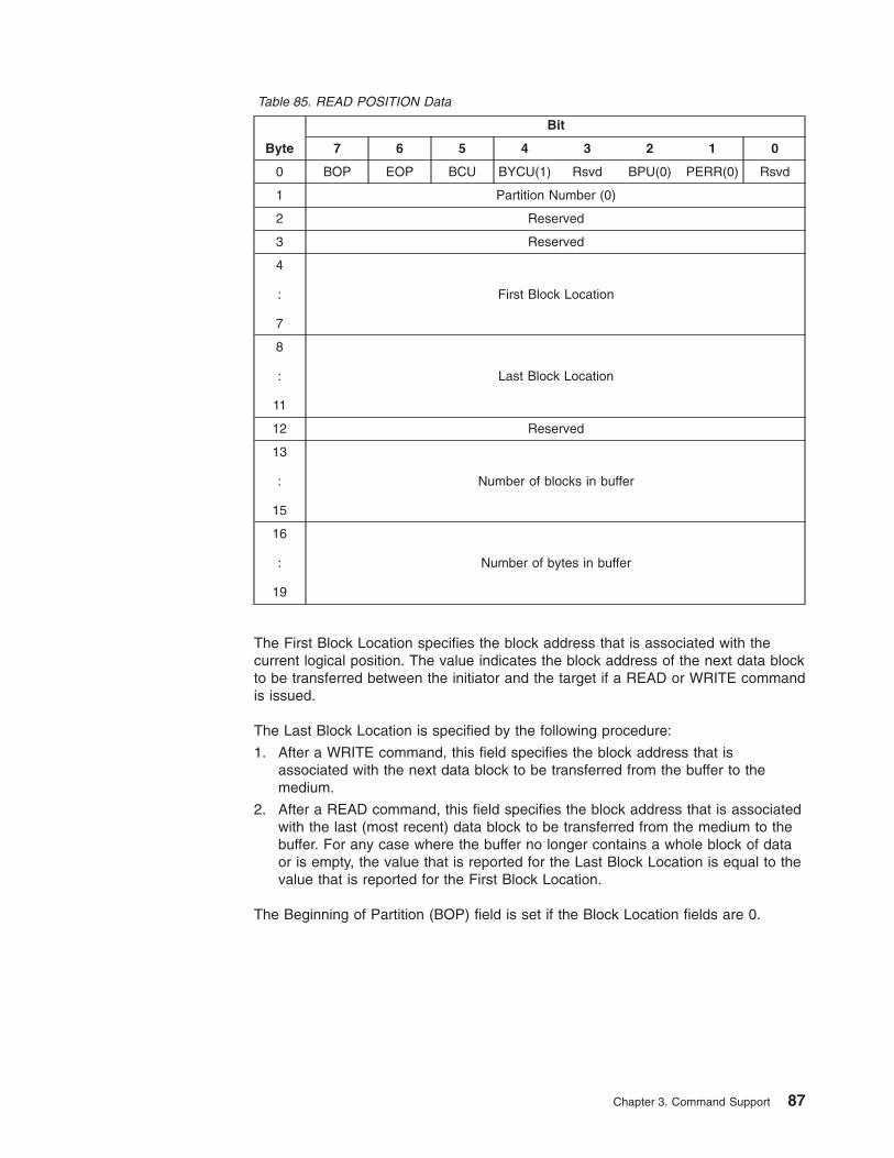
Table 85. READ POSITION Data
Byte
Bit
7 6 5 4 3 2 1 0
0 BOP EOP BCU BYCU(1) Rsvd BPU(0) PERR(0) Rsvd
1 Partition Number (0)
2 Reserved
3 Reserved
4
:
7
First Block Location
8
:
11
Last Block Location
12 Reserved
13
:
15
Number of blocks in buffer
16
:
19
Number of bytes in buffer
The First Block Location specifies the block address that is associated with thecurrent logical position. The value indicates the block address of the next data blockto be transferred between the initiator and the target if a READ or WRITE commandis issued.
The Last Block Location is specified by the following procedure:
1. After a WRITE command, this field specifies the block address that isassociated with the next data block to be transferred from the buffer to themedium.
2. After a READ command, this field specifies the block address that is associatedwith the last (most recent) data block to be transferred from the medium to thebuffer. For any case where the buffer no longer contains a whole block of dataor is empty, the value that is reported for the Last Block Location is equal to thevalue that is reported for the First Block Location.
The Beginning of Partition (BOP) field is set if the Block Location fields are 0.
Chapter 3. Command Support 87
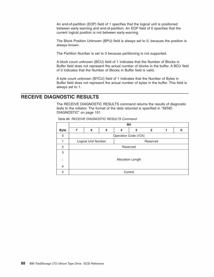
An end-of-partition (EOP) field of 1 specifies that the logical unit is positionedbetween early-warning and end-of-partition. An EOP field of 0 specifies that thecurrent logical position is not between early-warning.
The Block Position Unknown (BPU) field is always set to 0, because the position isalways known.
The Partition Number is set to 0 because partitioning is not supported.
A block count unknown (BCU) field of 1 indicates that the Number of Blocks inBuffer field does not represent the actual number of blocks in the buffer. A BCU fieldof 0 indicates that the Number of Blocks in Buffer field is valid.
A byte count unknown (BYCU) field of 1 indicates that the Number of Bytes inBuffer field does not represent the actual number of bytes in the buffer. This field isalways set to 1.
RECEIVE DIAGNOSTIC RESULTSThe RECEIVE DIAGNOSTIC RESULTS command returns the results of diagnostictests to the initiator. The format of the data returned is specified in “SENDDIAGNOSTIC” on page 101.
Table 86. RECEIVE DIAGNOSTIC RESULTS Command
Byte
Bit
7 6 5 4 3 2 1 0
0 Operation Code (1Ch)
1 Logical Unit Number Reserved
2 Reserved
3
:
4
Allocation Length
5 Control
88 IBM TotalStorage LTO Ultrium Tape Drive: SCSI Reference
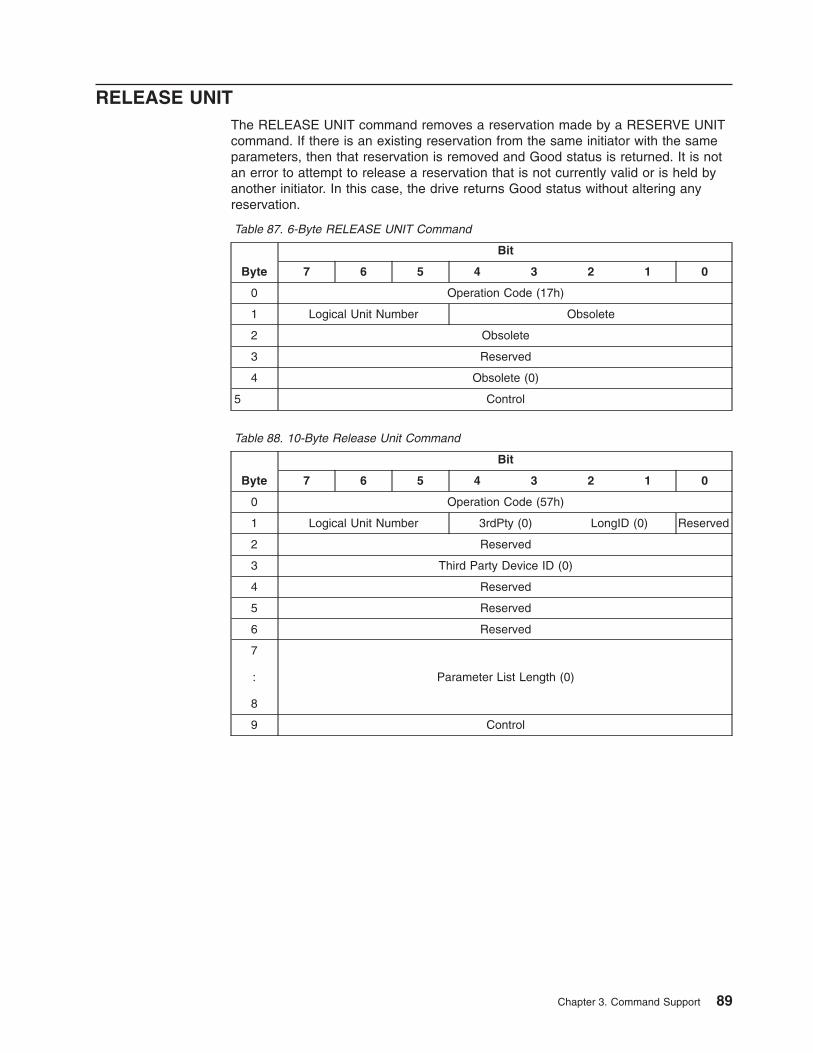
RELEASE UNITThe RELEASE UNIT command removes a reservation made by a RESERVE UNITcommand. If there is an existing reservation from the same initiator with the sameparameters, then that reservation is removed and Good status is returned. It is notan error to attempt to release a reservation that is not currently valid or is held byanother initiator. In this case, the drive returns Good status without altering anyreservation.
Table 87. 6-Byte RELEASE UNIT Command
Byte
Bit
7 6 5 4 3 2 1 0
0 Operation Code (17h)
1 Logical Unit Number Obsolete
2 Obsolete
3 Reserved
4 Obsolete (0)
5 Control
Table 88. 10-Byte Release Unit Command
Byte
Bit
7 6 5 4 3 2 1 0
0 Operation Code (57h)
1 Logical Unit Number 3rdPty (0) LongID (0) Reserved
2 Reserved
3 Third Party Device ID (0)
4 Reserved
5 Reserved
6 Reserved
7
:
8
Parameter List Length (0)
9 Control
Chapter 3. Command Support 89
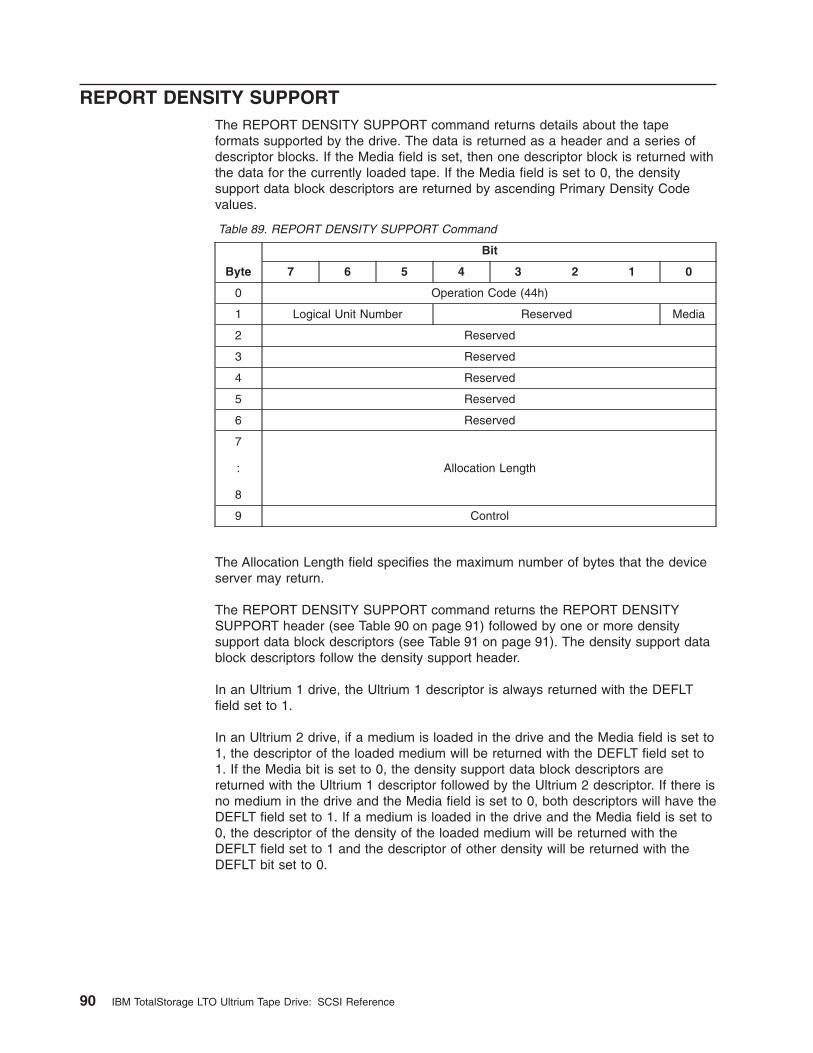
REPORT DENSITY SUPPORTThe REPORT DENSITY SUPPORT command returns details about the tapeformats supported by the drive. The data is returned as a header and a series ofdescriptor blocks. If the Media field is set, then one descriptor block is returned withthe data for the currently loaded tape. If the Media field is set to 0, the densitysupport data block descriptors are returned by ascending Primary Density Codevalues.
Table 89. REPORT DENSITY SUPPORT Command
Byte
Bit
7 6 5 4 3 2 1 0
0 Operation Code (44h)
1 Logical Unit Number Reserved Media
2 Reserved
3 Reserved
4 Reserved
5 Reserved
6 Reserved
7
:
8
Allocation Length
9 Control
The Allocation Length field specifies the maximum number of bytes that the deviceserver may return.
The REPORT DENSITY SUPPORT command returns the REPORT DENSITYSUPPORT header (see Table 90 on page 91) followed by one or more densitysupport data block descriptors (see Table 91 on page 91). The density support datablock descriptors follow the density support header.
In an Ultrium 1 drive, the Ultrium 1 descriptor is always returned with the DEFLTfield set to 1.
In an Ultrium 2 drive, if a medium is loaded in the drive and the Media field is set to1, the descriptor of the loaded medium will be returned with the DEFLT field set to1. If the Media bit is set to 0, the density support data block descriptors arereturned with the Ultrium 1 descriptor followed by the Ultrium 2 descriptor. If there isno medium in the drive and the Media field is set to 0, both descriptors will have theDEFLT field set to 1. If a medium is loaded in the drive and the Media field is set to0, the descriptor of the density of the loaded medium will be returned with theDEFLT field set to 1 and the descriptor of other density will be returned with theDEFLT bit set to 0.
90 IBM TotalStorage LTO Ultrium Tape Drive: SCSI Reference
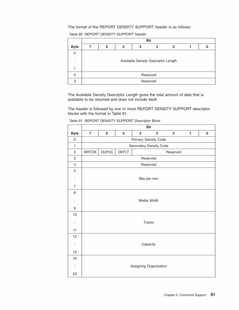
The format of the REPORT DENSITY SUPPORT header is as follows:
Table 90. REPORT DENSITY SUPPORT Header
Byte
Bit
7 6 5 4 3 2 1 0
0
:
1
Available Density Descriptor Length
2 Reserved
3 Reserved
The Available Density Descriptor Length gives the total amount of data that isavailable to be returned and does not include itself.
The header is followed by one or more REPORT DENSITY SUPPORT descriptorblocks with the format in Table 91.
Table 91. REPORT DENSITY SUPPORT Descriptor Block
Byte
Bit
7 6 5 4 3 2 1 0
0 Primary Density Code
1 Secondary Density Code
2 WRTOK DUP(0) DEFLT Reserved
3 Reserved
4 Reserved
5
:
7
Bits per mm
8
:
9
Media Width
10
:
11
Tracks
12
:
15
Capacity
16
:
23
Assigning Organization
Chapter 3. Command Support 91
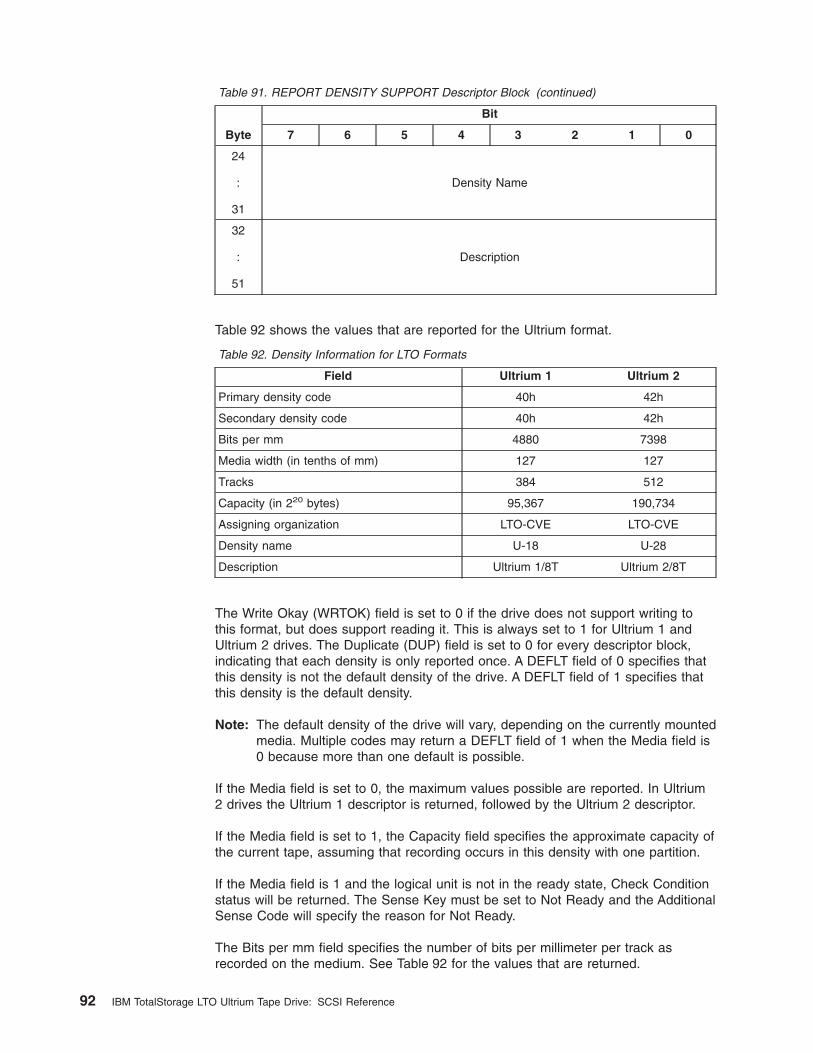
Table 91. REPORT DENSITY SUPPORT Descriptor Block (continued)
Byte
Bit
7 6 5 4 3 2 1 0
24
:
31
Density Name
32
:
51
Description
Table 92 shows the values that are reported for the Ultrium format.
Table 92. Density Information for LTO Formats
Field Ultrium 1 Ultrium 2
Primary density code 40h 42h
Secondary density code 40h 42h
Bits per mm 4880 7398
Media width (in tenths of mm) 127 127
Tracks 384 512
Capacity (in 220 bytes) 95,367 190,734
Assigning organization LTO-CVE LTO-CVE
Density name U-18 U-28
Description Ultrium 1/8T Ultrium 2/8T
The Write Okay (WRTOK) field is set to 0 if the drive does not support writing tothis format, but does support reading it. This is always set to 1 for Ultrium 1 andUltrium 2 drives. The Duplicate (DUP) field is set to 0 for every descriptor block,indicating that each density is only reported once. A DEFLT field of 0 specifies thatthis density is not the default density of the drive. A DEFLT field of 1 specifies thatthis density is the default density.
Note: The default density of the drive will vary, depending on the currently mountedmedia. Multiple codes may return a DEFLT field of 1 when the Media field is0 because more than one default is possible.
If the Media field is set to 0, the maximum values possible are reported. In Ultrium2 drives the Ultrium 1 descriptor is returned, followed by the Ultrium 2 descriptor.
If the Media field is set to 1, the Capacity field specifies the approximate capacity ofthe current tape, assuming that recording occurs in this density with one partition.
If the Media field is 1 and the logical unit is not in the ready state, Check Conditionstatus will be returned. The Sense Key must be set to Not Ready and the AdditionalSense Code will specify the reason for Not Ready.
The Bits per mm field specifies the number of bits per millimeter per track asrecorded on the medium. See Table 92 for the values that are returned.
92 IBM TotalStorage LTO Ultrium Tape Drive: SCSI Reference
The Media Width field specifies the width of the medium that is supported by thisdensity. See Table 92 on page 92 for the values that are returned.
The Tracks field specifies the number of data tracks that are supported on themedium by this density. See Table 92 on page 92 for the values that are returned.
If the Media field is 0, the Capacity field specifies the approximate capacity of thelongest supported medium for this density. If the Media field is 1, the Capacity fieldspecifies the approximate capacity of the current medium for this density. If theapproximate capacity of the current medium is not available for the mountedmedium, the longest supported medium capacity for this density is used. Thecapacity assumes that compression is disabled. The capacity also assumes that themedia is in good condition, and that normal data and block sizes are used. Thisvalue is in units of megabytes (106 bytes). The drive does not guarantee that thisspace is actually available in all cases. See Table 92 on page 92 for the values thatare returned.
The Assigning Organization field contains 8 bytes of ASCII data that identifies theorganization that is responsible for the specifications that define the values in thisdensity support data block descriptor. The data is left-aligned within this field. TheASCII value for a space (20h) is used for padding. See Table 92 on page 92 for thevalues that are returned.
The Density Name field contains 8 bytes of ASCII data that identifies the document(or other identifying name) that is associated with this density support data blockdescriptor. The data is left-aligned within this field. The ASCII value for a space(20h) is used for padding. See Table 92 on page 92 for the values that are returned.
The Description field contains 20 bytes of ASCII data that describe the density. Thedata is left-aligned within this field. The ASCII value for a space (20h) is used forpadding. See Table 92 on page 92 for the values that are returned.
Chapter 3. Command Support 93
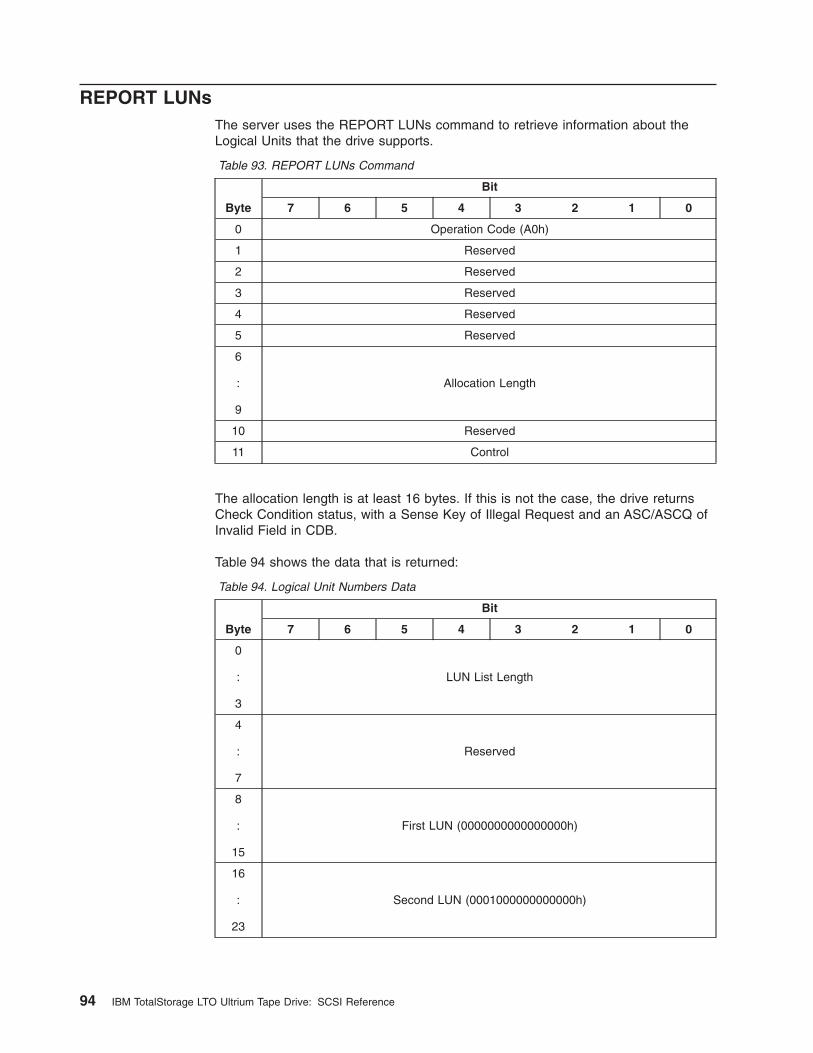
REPORT LUNsThe server uses the REPORT LUNs command to retrieve information about theLogical Units that the drive supports.
Table 93. REPORT LUNs Command
Byte
Bit
7 6 5 4 3 2 1 0
0 Operation Code (A0h)
1 Reserved
2 Reserved
3 Reserved
4 Reserved
5 Reserved
6
:
9
Allocation Length
10 Reserved
11 Control
The allocation length is at least 16 bytes. If this is not the case, the drive returnsCheck Condition status, with a Sense Key of Illegal Request and an ASC/ASCQ ofInvalid Field in CDB.
Table 94 shows the data that is returned:
Table 94. Logical Unit Numbers Data
Byte
Bit
7 6 5 4 3 2 1 0
0
:
3
LUN List Length
4
:
7
Reserved
8
:
15
First LUN (0000000000000000h)
16
:
23
Second LUN (0001000000000000h)
94 IBM TotalStorage LTO Ultrium Tape Drive: SCSI Reference

The LUN List Length field contains the length in bytes of the LUN list that isavailable to be transferred. The LUN list length is the number of logical unitnumbers in the logical unit inventory multiplied by eight. On drives that do not havethe library control path feature enabled this value is 8. On drives that have thelibrary control path feature enabled this value is 16. If the allocation length in theCDB is too small to transfer information about the entire logical unit inventory, theLUN list length value will not be adjusted to reflect the truncation.
The Second LUN field is only returned on drives that have the library control pathfeature enabled.
Chapter 3. Command Support 95
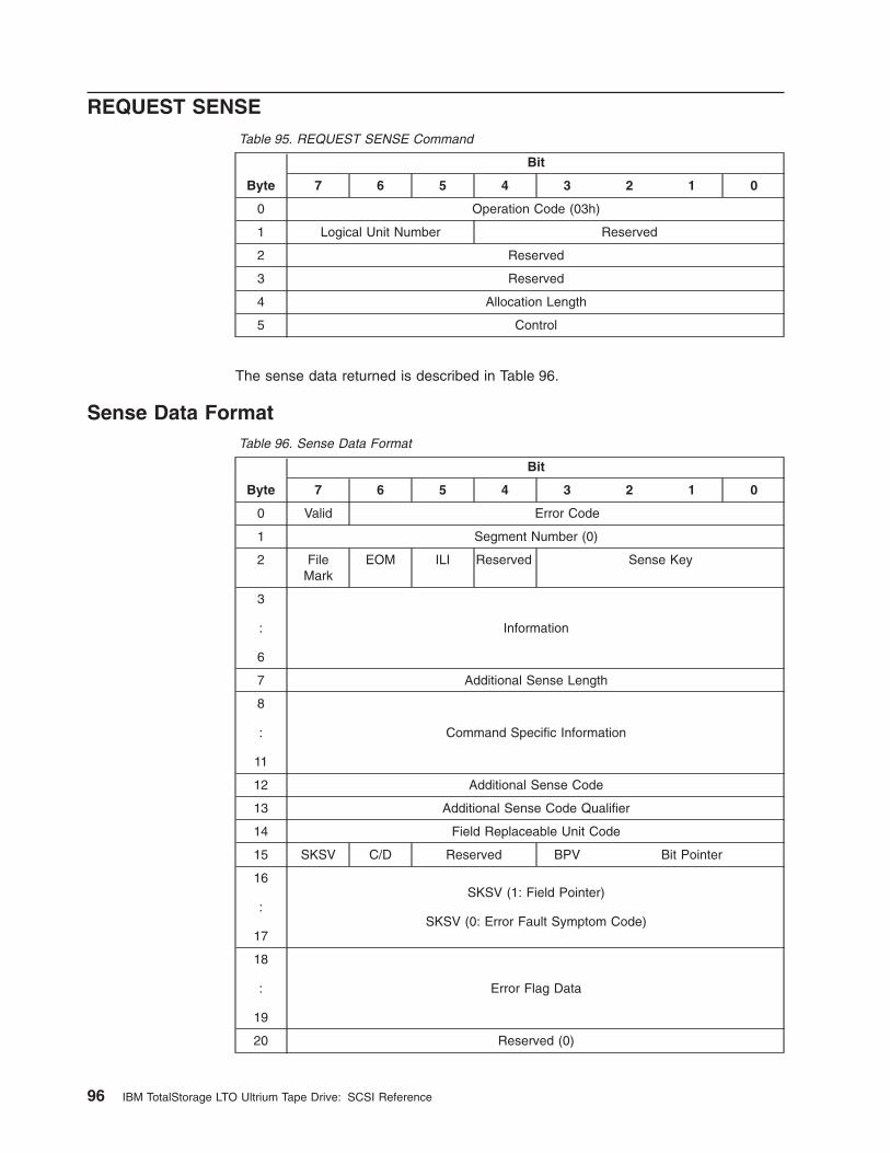
REQUEST SENSETable 95. REQUEST SENSE Command
Byte
Bit
7 6 5 4 3 2 1 0
0 Operation Code (03h)
1 Logical Unit Number Reserved
2 Reserved
3 Reserved
4 Allocation Length
5 Control
The sense data returned is described in Table 96.
Sense Data FormatTable 96. Sense Data Format
Byte
Bit
7 6 5 4 3 2 1 0
0 Valid Error Code
1 Segment Number (0)
2 FileMark
EOM ILI Reserved Sense Key
3
:
6
Information
7 Additional Sense Length
8
:
11
Command Specific Information
12 Additional Sense Code
13 Additional Sense Code Qualifier
14 Field Replaceable Unit Code
15 SKSV C/D Reserved BPV Bit Pointer
16
:
17
SKSV (1: Field Pointer)
SKSV (0: Error Fault Symptom Code)
18
:
19
Error Flag Data
20 Reserved (0)
96 IBM TotalStorage LTO Ultrium Tape Drive: SCSI Reference
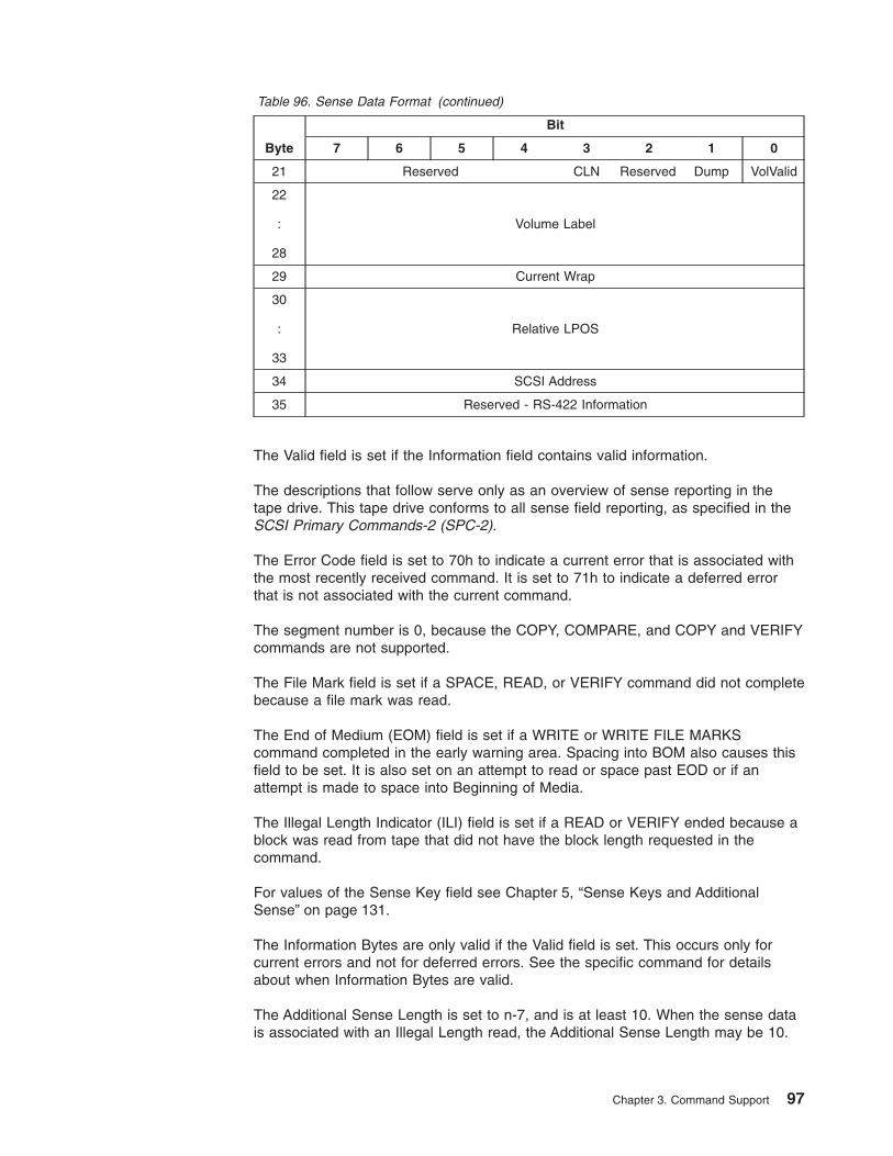
Table 96. Sense Data Format (continued)
Byte
Bit
7 6 5 4 3 2 1 0
21 Reserved CLN Reserved Dump VolValid
22
:
28
Volume Label
29 Current Wrap
30
:
33
Relative LPOS
34 SCSI Address
35 Reserved - RS-422 Information
The Valid field is set if the Information field contains valid information.
The descriptions that follow serve only as an overview of sense reporting in thetape drive. This tape drive conforms to all sense field reporting, as specified in theSCSI Primary Commands-2 (SPC-2).
The Error Code field is set to 70h to indicate a current error that is associated withthe most recently received command. It is set to 71h to indicate a deferred errorthat is not associated with the current command.
The segment number is 0, because the COPY, COMPARE, and COPY and VERIFYcommands are not supported.
The File Mark field is set if a SPACE, READ, or VERIFY command did not completebecause a file mark was read.
The End of Medium (EOM) field is set if a WRITE or WRITE FILE MARKScommand completed in the early warning area. Spacing into BOM also causes thisfield to be set. It is also set on an attempt to read or space past EOD or if anattempt is made to space into Beginning of Media.
The Illegal Length Indicator (ILI) field is set if a READ or VERIFY ended because ablock was read from tape that did not have the block length requested in thecommand.
For values of the Sense Key field see Chapter 5, “Sense Keys and AdditionalSense” on page 131.
The Information Bytes are only valid if the Valid field is set. This occurs only forcurrent errors and not for deferred errors. See the specific command for detailsabout when Information Bytes are valid.
The Additional Sense Length is set to n-7, and is at least 10. When the sense datais associated with an Illegal Length read, the Additional Sense Length may be 10.
Chapter 3. Command Support 97
The Command Specific Information is set to 0, because no supported commandsdefine a use for this field.
For supported Additional Sense Codes and Additional Sense Code Qualifiers, seeChapter 5, “Sense Keys and Additional Sense” on page 131.
The Field Replaceable Unit field is set to 0 or to a non-zero, vendor-specific codethat indicates the part of the drive that is suspected of causing the failure.
The only Sense Key-specific data supported is for Illegal Request (5h). For thissense key, the Sense Key Specific Valid field is set and the following fields are set:
v The Command/Data (C/D) field is set to 1 if the illegal parameter was detected inthe Command Descriptor Block, and is set to 0 if it was detected in the Dataphase.
v If a bit within a byte was invalid, the Bit Pointer Valid (BPV) field is set and theBit Pointer field is set to indicate which bit was in error.
v The Field Pointer is set to indicate which byte was in error.
The Clean (CLN) field is set if the drive needs cleaning, and is otherwise set to 0.
The Dump field indicates that the drive has a Dump available. The field is used toindicate when it is appropriate to read a dump.
The Volume Label Fields Valid (VolValid) field is set if the Volume Label beingreported is valid.
If a cartridge is loaded in the drive and the Volume Label Fields Valid is set, theVolume Label field reports the seven characters from the left of the volume labelfrom the CM Mechanism Related Data page (if one exists), or it reports the sevencharacters from the left of the volume label from the host bar code field in the CM(if it exists), or it reports all spaces (ASCII 20h).
The Current Wrap reports the physical wrap of the tape. The least significant bitreflects the current physical direction. A 0 means the current direction is away fromphysical beginning of tape. A 1 means the current direction is towards physicalbeginning of tape.
Relative LPOS reports the current physical position on tape.
SCSI Address reports the SCSI Bus Address for the drive. Values returned rangefrom 00h to 0Fh.
This Reserved field may contain a value passed across the RS-422 serial interfaceby, for example, a tape library if the library vendor chooses to send such a value.The value passed from across the RS-422 interface is reported persistently until adifferent value is sent, at which time the new value is reported persistently.
98 IBM TotalStorage LTO Ultrium Tape Drive: SCSI Reference
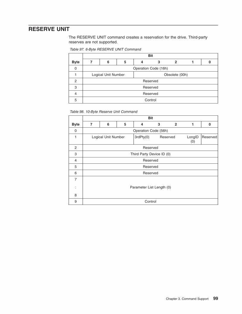
RESERVE UNITThe RESERVE UNIT command creates a reservation for the drive. Third-partyreserves are not supported.
Table 97. 6-Byte RESERVE UNIT Command
Byte
Bit
7 6 5 4 3 2 1 0
0 Operation Code (16h)
1 Logical Unit Number Obsolete (00h)
2 Reserved
3 Reserved
4 Reserved
5 Control
Table 98. 10-Byte Reserve Unit Command
Byte
Bit
7 6 5 4 3 2 1 0
0 Operation Code (56h)
1 Logical Unit Number 3rdPty(0) Reserved LongID(0)
Reserved
2 Reserved
3 Third Party Device ID (0)
4 Reserved
5 Reserved
6 Reserved
7
:
8
Parameter List Length (0)
9 Control
Chapter 3. Command Support 99
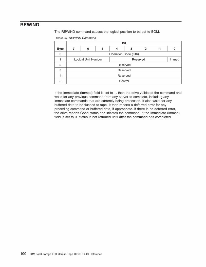
REWINDThe REWIND command causes the logical position to be set to BOM.
Table 99. REWIND Command
Byte
Bit
7 6 5 4 3 2 1 0
0 Operation Code (01h)
1 Logical Unit Number Reserved Immed
2 Reserved
3 Reserved
4 Reserved
5 Control
If the Immediate (Immed) field is set to 1, then the drive validates the command andwaits for any previous command from any server to complete, including anyimmediate commands that are currently being processed. It also waits for anybuffered data to be flushed to tape. It then reports a deferred error for anypreceding command or buffered data, if appropriate. If there is no deferred error,the drive reports Good status and initiates the command. If the Immediate (Immed)field is set to 0, status is not returned until after the command has completed.
100 IBM TotalStorage LTO Ultrium Tape Drive: SCSI Reference
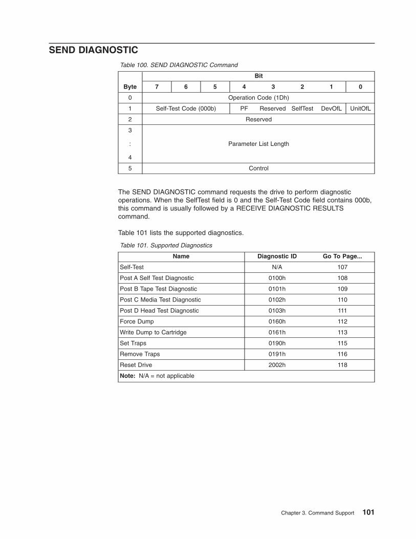
SEND DIAGNOSTICTable 100. SEND DIAGNOSTIC Command
Byte
Bit
7 6 5 4 3 2 1 0
0 Operation Code (1Dh)
1 Self-Test Code (000b) PF Reserved SelfTest DevOfL UnitOfL
2 Reserved
3
:
4
Parameter List Length
5 Control
The SEND DIAGNOSTIC command requests the drive to perform diagnosticoperations. When the SelfTest field is 0 and the Self-Test Code field contains 000b,this command is usually followed by a RECEIVE DIAGNOSTIC RESULTScommand.
Table 101 lists the supported diagnostics.
Table 101. Supported Diagnostics
Name Diagnostic ID Go To Page...
Self-Test N/A 107
Post A Self Test Diagnostic 0100h 108
Post B Tape Test Diagnostic 0101h 109
Post C Media Test Diagnostic 0102h 110
Post D Head Test Diagnostic 0103h 111
Force Dump 0160h 112
Write Dump to Cartridge 0161h 113
Set Traps 0190h 115
Remove Traps 0191h 116
Reset Drive 2002h 118
Note: N/A = not applicable
Chapter 3. Command Support 101
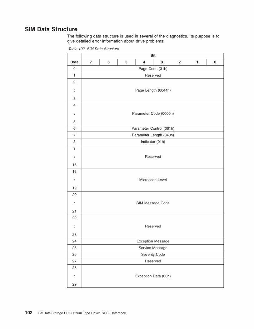
SIM Data StructureThe following data structure is used in several of the diagnostics. Its purpose is togive detailed error information about drive problems:
Table 102. SIM Data Structure
Byte
Bit
7 6 5 4 3 2 1 0
0 Page Code (31h)
1 Reserved
2
:
3
Page Length (0044h)
4
:
5
Parameter Code (0000h)
6 Parameter Control (061h)
7 Parameter Length (040h)
8 Indicator (01h)
9
:
15
Reserved
16
:
19
Microcode Level
20
:
21
SIM Message Code
22
:
23
Reserved
24 Exception Message
25 Service Message
26 Severity Code
27 Reserved
28
:
29
Exception Data (00h)
102 IBM TotalStorage LTO Ultrium Tape Drive: SCSI Reference
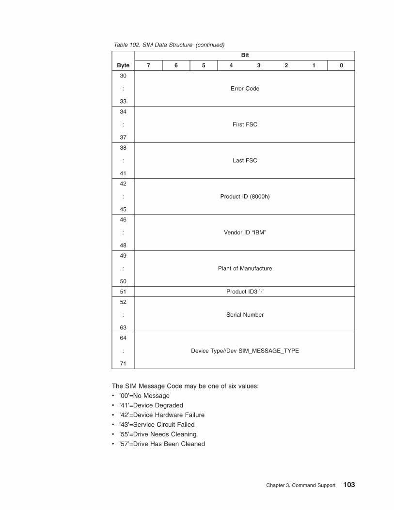
Table 102. SIM Data Structure (continued)
Byte
Bit
7 6 5 4 3 2 1 0
30
:
33
Error Code
34
:
37
First FSC
38
:
41
Last FSC
42
:
45
Product ID (8000h)
46
:
48
Vendor ID “IBM”
49
:
50
Plant of Manufacture
51 Product ID3 ’-’
52
:
63
Serial Number
64
:
71
Device Type//Dev SIM_MESSAGE_TYPE
The SIM Message Code may be one of six values:
v ’00’=No Message
v ’41’=Device Degraded
v ’42’=Device Hardware Failure
v ’43’=Service Circuit Failed
v ’55’=Drive Needs Cleaning
v ’57’=Drive Has Been Cleaned
Chapter 3. Command Support 103
The Exception Message may be one of eight values:
v ’1’=Effect of Failure is Unknown
v ’2’=Device Exception No Performance Impact
v ’3’=Exception on SCSI Interface xx
v ’4’=Device Exception on Operator Panel
v ’5’=Device Exception on Tape Path
v ’6’=Device Exception in Drive
v ’7’=Cleaning Required
v ’8’=Cleaning Done
The Service Message may be one of four values:
v ’1’=Repair Impact is Unknown
v ’7’=Repair will Disable Access to Device Servo
v ’9’=Clean Device
v ’A’=Device Cleaned
The Severity Code may be one of four values:
v ’0’=Service
v ’1’=Moderate
v ’2’=Serious
v ’3’=Acute
104 IBM TotalStorage LTO Ultrium Tape Drive: SCSI Reference
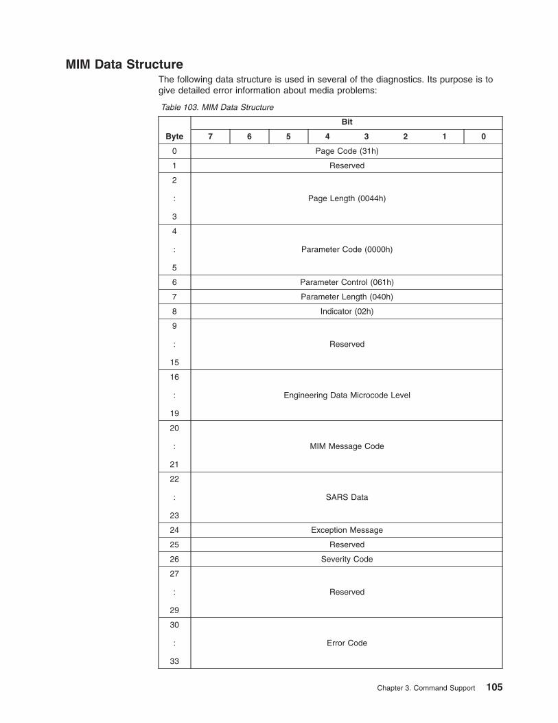
MIM Data StructureThe following data structure is used in several of the diagnostics. Its purpose is togive detailed error information about media problems:
Table 103. MIM Data Structure
Byte
Bit
7 6 5 4 3 2 1 0
0 Page Code (31h)
1 Reserved
2
:
3
Page Length (0044h)
4
:
5
Parameter Code (0000h)
6 Parameter Control (061h)
7 Parameter Length (040h)
8 Indicator (02h)
9
:
15
Reserved
16
:
19
Engineering Data Microcode Level
20
:
21
MIM Message Code
22
:
23
SARS Data
24 Exception Message
25 Reserved
26 Severity Code
27
:
29
Reserved
30
:
33
Error Code
Chapter 3. Command Support 105
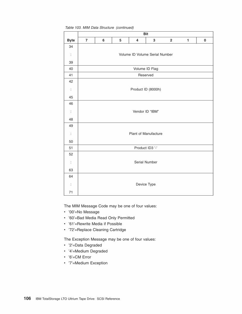
Table 103. MIM Data Structure (continued)
Byte
Bit
7 6 5 4 3 2 1 0
34
:
39
Volume ID Volume Serial Number
40 Volume ID Flag
41 Reserved
42
:
45
Product ID (8000h)
46
:
48
Vendor ID “IBM”
49
:
50
Plant of Manufacture
51 Product ID3 ’-’
52
:
63
Serial Number
64
:
71
Device Type
The MIM Message Code may be one of four values:
v ’00’=No Message
v ’60’=Bad Media Read Only Permitted
v ’61’=Rewrite Media if Possible
v ’72’=Replace Cleaning Cartridge
The Exception Message may be one of four values:
v ’2’=Data Degraded
v ’4’=Medium Degraded
v ’6’=CM Error
v ’7’=Medium Exception
106 IBM TotalStorage LTO Ultrium Tape Drive: SCSI Reference
The Severity Code may be one of four values:
v ’0’=Service
v ’1’=Moderate - Temporary Read/Write Errors
v ’2’=Serious - Permanent Read/Write Errors
v ’3’=Acute - CM Error
The Volume ID Flag may be one of four values:
v ’0’=VOLID not valid
v ’1’=VOLID valid - obtained from tape (CM)
v ’3’=VOLID valid - obtained from cartridge label (server data)
v ’5’=VOLID valid - obtained from cartridge level (library)
Self-TestFor the Self-Test Diagnostic, the CDB values must be set as follows:
v PF - Any value allowed and ignored
v SelfTest - 1
v DevOfl - Any value allowed and ignored
v UnitOfl - Any value allowed and ignored
v Parameter List Length - 0000h
Receive Diagnostics Results: There are no diagnostic results for the Self-Testdiagnostic.
Chapter 3. Command Support 107
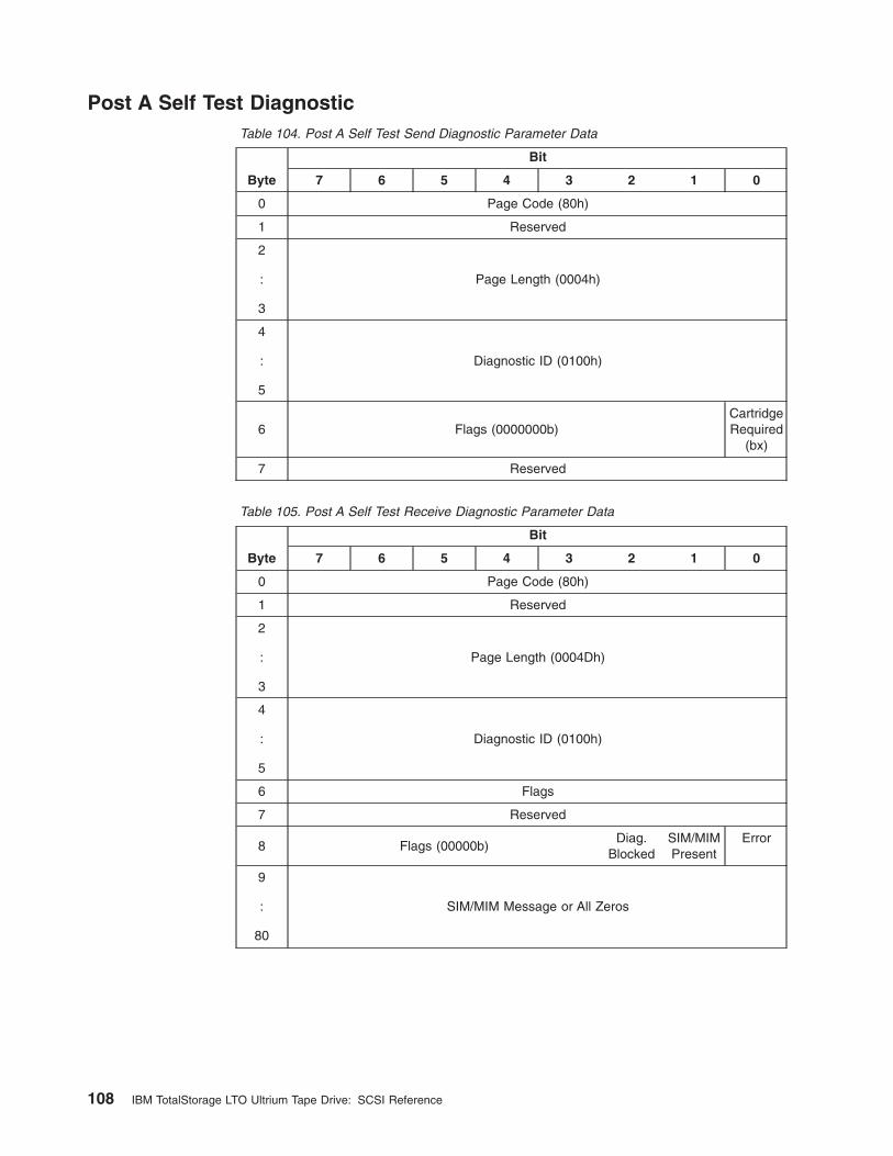
Post A Self Test DiagnosticTable 104. Post A Self Test Send Diagnostic Parameter Data
Byte
Bit
7 6 5 4 3 2 1 0
0 Page Code (80h)
1 Reserved
2
:
3
Page Length (0004h)
4
:
5
Diagnostic ID (0100h)
6 Flags (0000000b)CartridgeRequired
(bx)
7 Reserved
Table 105. Post A Self Test Receive Diagnostic Parameter Data
Byte
Bit
7 6 5 4 3 2 1 0
0 Page Code (80h)
1 Reserved
2
:
3
Page Length (0004Dh)
4
:
5
Diagnostic ID (0100h)
6 Flags
7 Reserved
8 Flags (00000b)Diag.
BlockedSIM/MIMPresent
Error
9
:
80
SIM/MIM Message or All Zeros
108 IBM TotalStorage LTO Ultrium Tape Drive: SCSI Reference
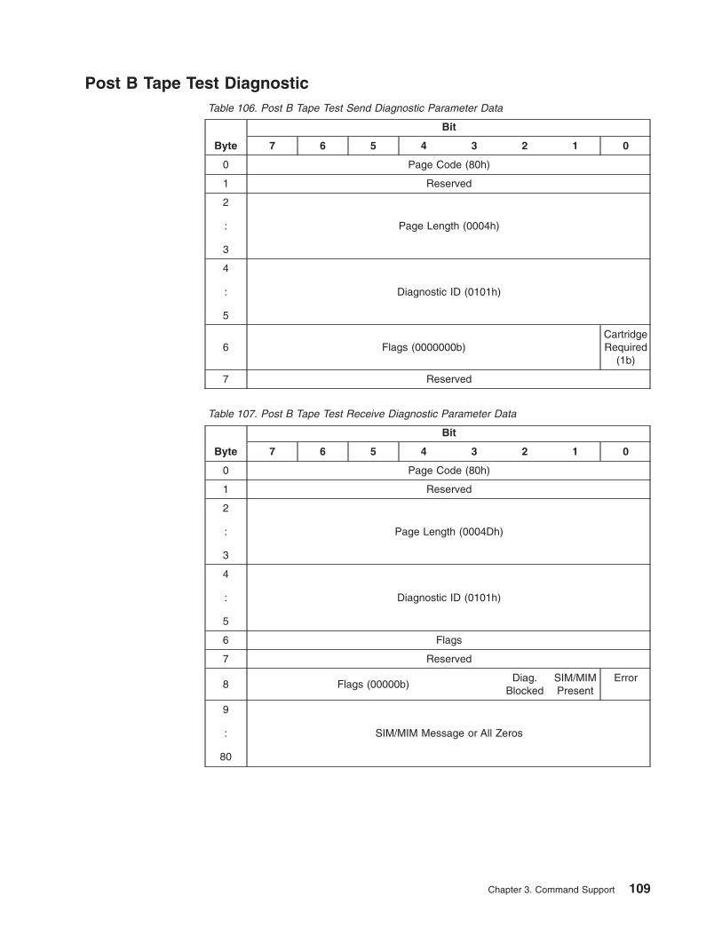
Post B Tape Test DiagnosticTable 106. Post B Tape Test Send Diagnostic Parameter Data
Byte
Bit
7 6 5 4 3 2 1 0
0 Page Code (80h)
1 Reserved
2
:
3
Page Length (0004h)
4
:
5
Diagnostic ID (0101h)
6 Flags (0000000b)CartridgeRequired
(1b)
7 Reserved
Table 107. Post B Tape Test Receive Diagnostic Parameter Data
Byte
Bit
7 6 5 4 3 2 1 0
0 Page Code (80h)
1 Reserved
2
:
3
Page Length (0004Dh)
4
:
5
Diagnostic ID (0101h)
6 Flags
7 Reserved
8 Flags (00000b)Diag.
BlockedSIM/MIMPresent
Error
9
:
80
SIM/MIM Message or All Zeros
Chapter 3. Command Support 109
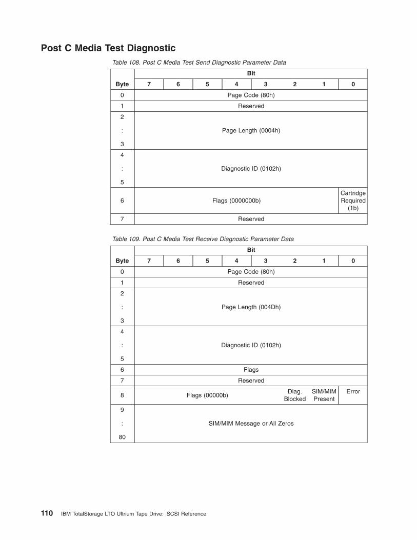
Post C Media Test DiagnosticTable 108. Post C Media Test Send Diagnostic Parameter Data
Byte
Bit
7 6 5 4 3 2 1 0
0 Page Code (80h)
1 Reserved
2
:
3
Page Length (0004h)
4
:
5
Diagnostic ID (0102h)
6 Flags (0000000b)CartridgeRequired
(1b)
7 Reserved
Table 109. Post C Media Test Receive Diagnostic Parameter Data
Byte
Bit
7 6 5 4 3 2 1 0
0 Page Code (80h)
1 Reserved
2
:
3
Page Length (004Dh)
4
:
5
Diagnostic ID (0102h)
6 Flags
7 Reserved
8 Flags (00000b)Diag.
BlockedSIM/MIMPresent
Error
9
:
80
SIM/MIM Message or All Zeros
110 IBM TotalStorage LTO Ultrium Tape Drive: SCSI Reference
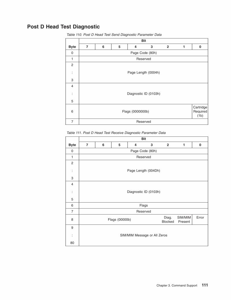
Post D Head Test DiagnosticTable 110. Post D Head Test Send Diagnostic Parameter Data
Byte
Bit
7 6 5 4 3 2 1 0
0 Page Code (80h)
1 Reserved
2
:
3
Page Length (0004h)
4
:
5
Diagnostic ID (0103h)
6 Flags (0000000b)CartridgeRequired
(1b)
7 Reserved
Table 111. Post D Head Test Receive Diagnostic Parameter Data
Byte
Bit
7 6 5 4 3 2 1 0
0 Page Code (80h)
1 Reserved
2
:
3
Page Length (004Dh)
4
:
5
Diagnostic ID (0103h)
6 Flags
7 Reserved
8 Flags (00000b)Diag.
BlockedSIM/MIMPresent
Error
9
:
80
SIM/MIM Message or All Zeros
Chapter 3. Command Support 111

Force DumpThe Force Dump Diagnostic causes the drive to capture into a reserved space inmemory a log of data that is used to assist field and development engineers indetermining the root cause of drive behavior. This log is called a drive dump. Thisdiagnostic copies the dump to memory, but does not save it for later use. The saveoperation must be done by using a READ BUFFER command or a Write Dump ToCartridge Diagnostic.
Note: Because forcing a drive dump will overwrite any previously stored dump,before forcing the dump it may be desirable to check the Dump field of thesense data to determine if a drive dump exists.
For the Force Dump Diagnostic, the CDB values should be set as follows:
v PF - 1
v SelfTest - 0
v DevOfl - Any value allowed and ignored
v UnitOfl - Any value allowed and ignored
v Parameter List Length - 0008h
Table 112 shows the parameter data to be sent with the Force Dump diagnostic.
Table 112. Force Dump Diagnostic Parameter Data
Byte
Bit
7 6 5 4 3 2 1 0
0 Page Code (80h)
1 Reserved
2
:
3
Page Length (0004h)
4
:
5
Diagnostic ID (0160h)
6 Flags (0000000b)CartridgeRequired
(0)
7 Reserved
Receive Diagnostics Results: There are no diagnostic results for the Force Dumpdiagnostic.
112 IBM TotalStorage LTO Ultrium Tape Drive: SCSI Reference
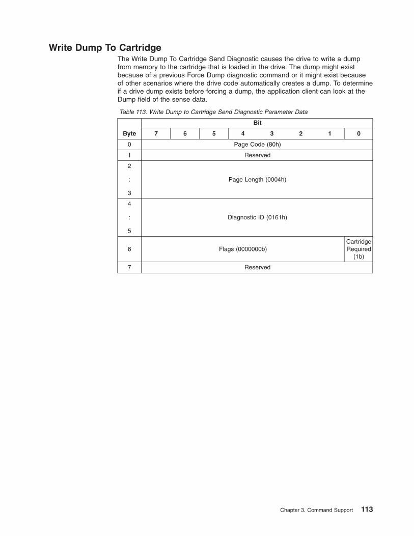
Write Dump To CartridgeThe Write Dump To Cartridge Send Diagnostic causes the drive to write a dumpfrom memory to the cartridge that is loaded in the drive. The dump might existbecause of a previous Force Dump diagnostic command or it might exist becauseof other scenarios where the drive code automatically creates a dump. To determineif a drive dump exists before forcing a dump, the application client can look at theDump field of the sense data.
Table 113. Write Dump to Cartridge Send Diagnostic Parameter Data
Byte
Bit
7 6 5 4 3 2 1 0
0 Page Code (80h)
1 Reserved
2
:
3
Page Length (0004h)
4
:
5
Diagnostic ID (0161h)
6 Flags (0000000b)CartridgeRequired
(1b)
7 Reserved
Chapter 3. Command Support 113
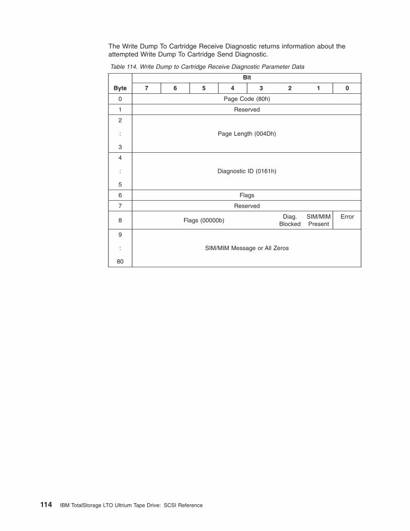
The Write Dump To Cartridge Receive Diagnostic returns information about theattempted Write Dump To Cartridge Send Diagnostic.
Table 114. Write Dump to Cartridge Receive Diagnostic Parameter Data
Byte
Bit
7 6 5 4 3 2 1 0
0 Page Code (80h)
1 Reserved
2
:
3
Page Length (004Dh)
4
:
5
Diagnostic ID (0161h)
6 Flags
7 Reserved
8 Flags (00000b)Diag.
BlockedSIM/MIMPresent
Error
9
:
80
SIM/MIM Message or All Zeros
114 IBM TotalStorage LTO Ultrium Tape Drive: SCSI Reference

Set TrapsThe Set Traps diagnostic is used to cause the drive to force a Panic when thespecified Fault Symptom Code (FSC) is created in the drive. A Panic will cause thedrive to capture a drive dump, then reboot. The drive dump will be available forretrieval after the reboot.
In Ultrium 2 drives a list of traps can be created. When the list is full, the next trapthat is set will automatically clear the least recently set trap. Currently, the maximumnumber of traps that can be set is 10 but may be modified at any time.
In Ultrium 1 drives only one trap is allowed to be set at a time.
For the Set Traps Diagnostic, the CDB values should be set as follows:
v PF - 1
v SelfTest - 0
v DevOfl - Any value allowed and ignored
v UnitOfl - Any value allowed and ignored
v Parameter List Length - 000Ah
Table 115 shows the parameter data to be sent with the Set Traps diagnostic.
Table 115. Set Traps Diagnostic Parameter Data
Byte
Bit
7 6 5 4 3 2 1 0
0 Page Code (80h)
1 Reserved
2
:
3
Page Length (0006h)
4
:
5
Diagnostic ID (0190h)
6 Flags (0000000b)CartridgeRequired
(0)
7 Reserved
8
:
9
Fault Symptom Code
Receive Diagnostics Results: There are no diagnostic results for the Set Trapsdiagnostic.
Chapter 3. Command Support 115
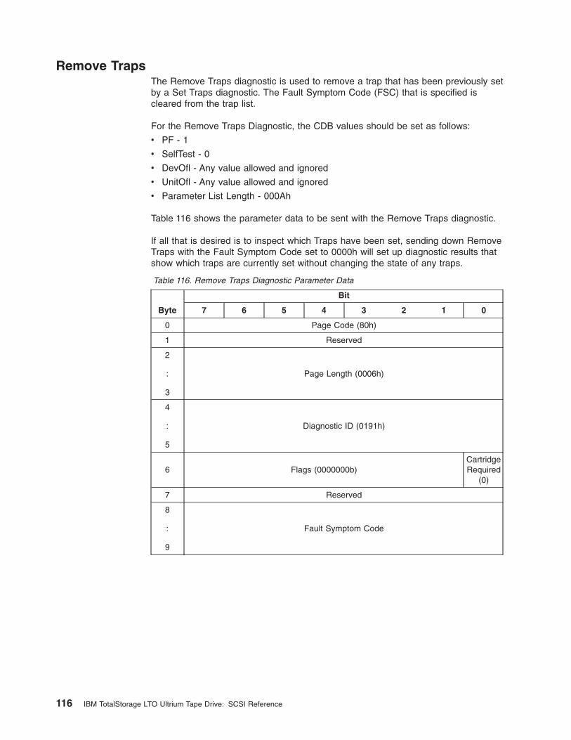
Remove TrapsThe Remove Traps diagnostic is used to remove a trap that has been previously setby a Set Traps diagnostic. The Fault Symptom Code (FSC) that is specified iscleared from the trap list.
For the Remove Traps Diagnostic, the CDB values should be set as follows:
v PF - 1
v SelfTest - 0
v DevOfl - Any value allowed and ignored
v UnitOfl - Any value allowed and ignored
v Parameter List Length - 000Ah
Table 116 shows the parameter data to be sent with the Remove Traps diagnostic.
If all that is desired is to inspect which Traps have been set, sending down RemoveTraps with the Fault Symptom Code set to 0000h will set up diagnostic results thatshow which traps are currently set without changing the state of any traps.
Table 116. Remove Traps Diagnostic Parameter Data
Byte
Bit
7 6 5 4 3 2 1 0
0 Page Code (80h)
1 Reserved
2
:
3
Page Length (0006h)
4
:
5
Diagnostic ID (0191h)
6 Flags (0000000b)CartridgeRequired
(0)
7 Reserved
8
:
9
Fault Symptom Code
116 IBM TotalStorage LTO Ultrium Tape Drive: SCSI Reference
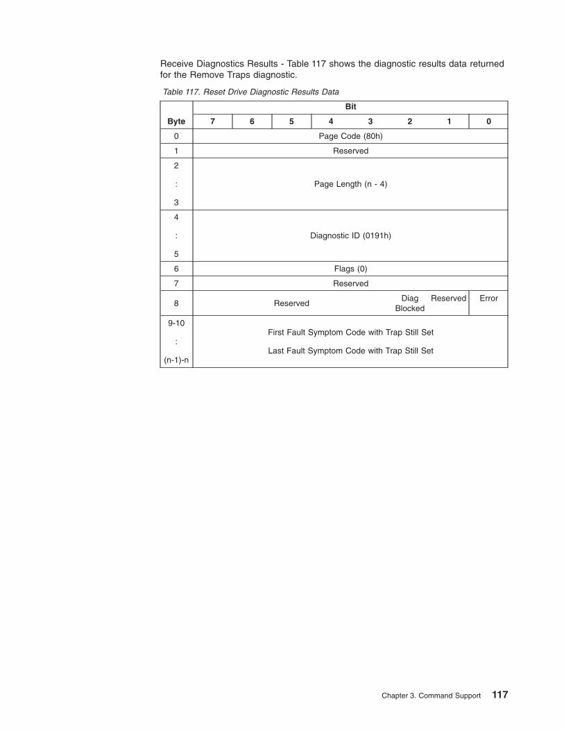
Receive Diagnostics Results - Table 117 shows the diagnostic results data returnedfor the Remove Traps diagnostic.
Table 117. Reset Drive Diagnostic Results Data
Byte
Bit
7 6 5 4 3 2 1 0
0 Page Code (80h)
1 Reserved
2
:
3
Page Length (n - 4)
4
:
5
Diagnostic ID (0191h)
6 Flags (0)
7 Reserved
8 ReservedDiag
BlockedReserved Error
9-10
:
(n-1)-n
First Fault Symptom Code with Trap Still Set
Last Fault Symptom Code with Trap Still Set
Chapter 3. Command Support 117
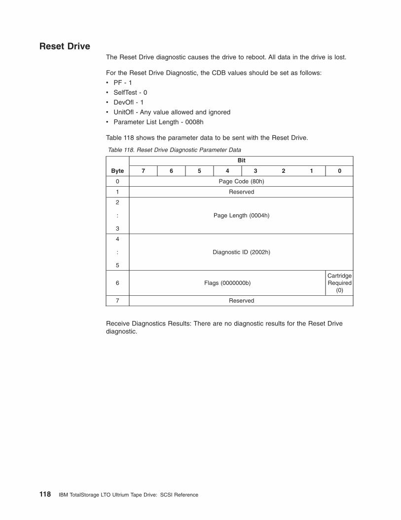
Reset DriveThe Reset Drive diagnostic causes the drive to reboot. All data in the drive is lost.
For the Reset Drive Diagnostic, the CDB values should be set as follows:
v PF - 1
v SelfTest - 0
v DevOfl - 1
v UnitOfl - Any value allowed and ignored
v Parameter List Length - 0008h
Table 118 shows the parameter data to be sent with the Reset Drive.
Table 118. Reset Drive Diagnostic Parameter Data
Byte
Bit
7 6 5 4 3 2 1 0
0 Page Code (80h)
1 Reserved
2
:
3
Page Length (0004h)
4
:
5
Diagnostic ID (2002h)
6 Flags (0000000b)CartridgeRequired
(0)
7 Reserved
Receive Diagnostics Results: There are no diagnostic results for the Reset Drivediagnostic.
118 IBM TotalStorage LTO Ultrium Tape Drive: SCSI Reference
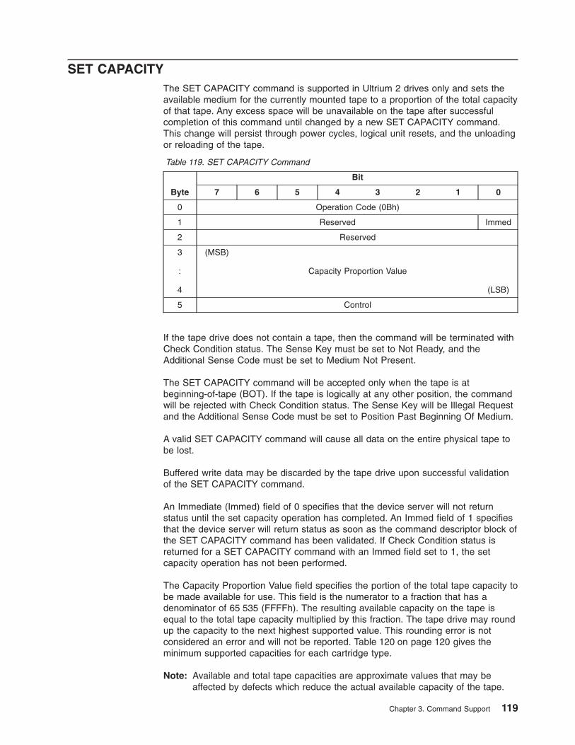
SET CAPACITYThe SET CAPACITY command is supported in Ultrium 2 drives only and sets theavailable medium for the currently mounted tape to a proportion of the total capacityof that tape. Any excess space will be unavailable on the tape after successfulcompletion of this command until changed by a new SET CAPACITY command.This change will persist through power cycles, logical unit resets, and the unloadingor reloading of the tape.
Table 119. SET CAPACITY Command
Byte
Bit
7 6 5 4 3 2 1 0
0 Operation Code (0Bh)
1 Reserved Immed
2 Reserved
3
:
4
(MSB)
Capacity Proportion Value
(LSB)
5 Control
If the tape drive does not contain a tape, then the command will be terminated withCheck Condition status. The Sense Key must be set to Not Ready, and theAdditional Sense Code must be set to Medium Not Present.
The SET CAPACITY command will be accepted only when the tape is atbeginning-of-tape (BOT). If the tape is logically at any other position, the commandwill be rejected with Check Condition status. The Sense Key will be Illegal Requestand the Additional Sense Code must be set to Position Past Beginning Of Medium.
A valid SET CAPACITY command will cause all data on the entire physical tape tobe lost.
Buffered write data may be discarded by the tape drive upon successful validationof the SET CAPACITY command.
An Immediate (Immed) field of 0 specifies that the device server will not returnstatus until the set capacity operation has completed. An Immed field of 1 specifiesthat the device server will return status as soon as the command descriptor block ofthe SET CAPACITY command has been validated. If Check Condition status isreturned for a SET CAPACITY command with an Immed field set to 1, the setcapacity operation has not been performed.
The Capacity Proportion Value field specifies the portion of the total tape capacity tobe made available for use. This field is the numerator to a fraction that has adenominator of 65 535 (FFFFh). The resulting available capacity on the tape isequal to the total tape capacity multiplied by this fraction. The tape drive may roundup the capacity to the next highest supported value. This rounding error is notconsidered an error and will not be reported. Table 120 on page 120 gives theminimum supported capacities for each cartridge type.
Note: Available and total tape capacities are approximate values that may beaffected by defects which reduce the actual available capacity of the tape.
Chapter 3. Command Support 119
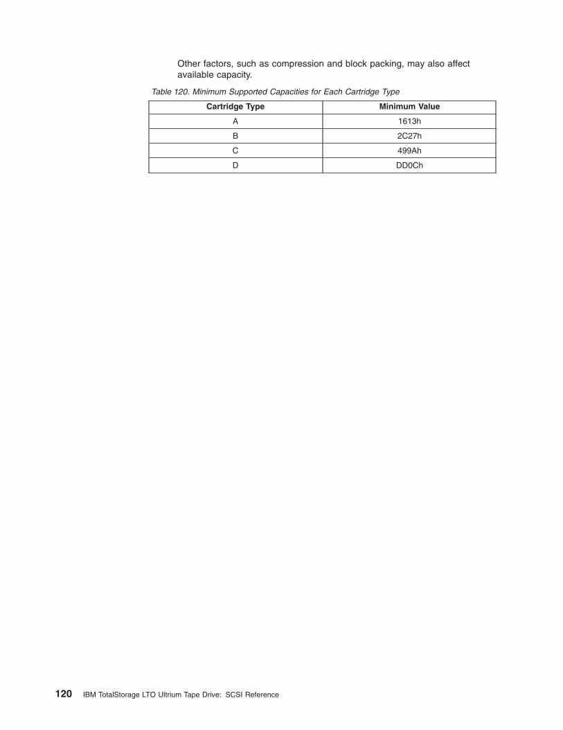
Other factors, such as compression and block packing, may also affectavailable capacity.
Table 120. Minimum Supported Capacities for Each Cartridge Type
Cartridge Type Minimum Value
A 1613h
B 2C27h
C 499Ah
D DD0Ch
120 IBM TotalStorage LTO Ultrium Tape Drive: SCSI Reference
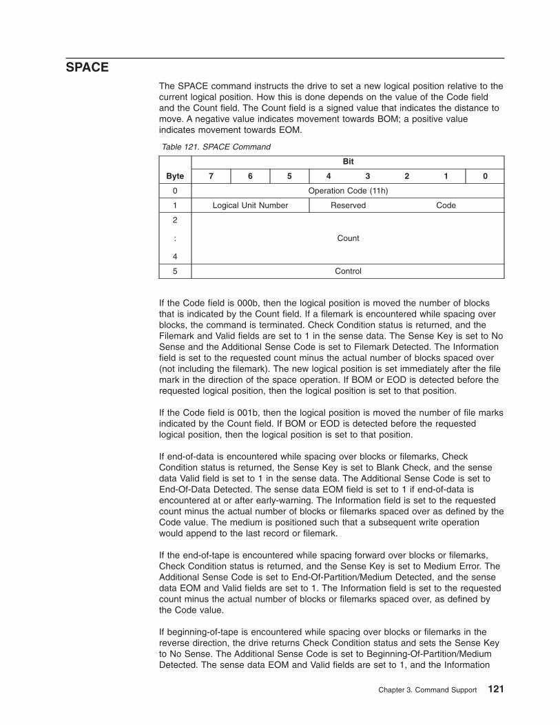
SPACEThe SPACE command instructs the drive to set a new logical position relative to thecurrent logical position. How this is done depends on the value of the Code fieldand the Count field. The Count field is a signed value that indicates the distance tomove. A negative value indicates movement towards BOM; a positive valueindicates movement towards EOM.
Table 121. SPACE Command
Byte
Bit
7 6 5 4 3 2 1 0
0 Operation Code (11h)
1 Logical Unit Number Reserved Code
2
:
4
Count
5 Control
If the Code field is 000b, then the logical position is moved the number of blocksthat is indicated by the Count field. If a filemark is encountered while spacing overblocks, the command is terminated. Check Condition status is returned, and theFilemark and Valid fields are set to 1 in the sense data. The Sense Key is set to NoSense and the Additional Sense Code is set to Filemark Detected. The Informationfield is set to the requested count minus the actual number of blocks spaced over(not including the filemark). The new logical position is set immediately after the filemark in the direction of the space operation. If BOM or EOD is detected before therequested logical position, then the logical position is set to that position.
If the Code field is 001b, then the logical position is moved the number of file marksindicated by the Count field. If BOM or EOD is detected before the requestedlogical position, then the logical position is set to that position.
If end-of-data is encountered while spacing over blocks or filemarks, CheckCondition status is returned, the Sense Key is set to Blank Check, and the sensedata Valid field is set to 1 in the sense data. The Additional Sense Code is set toEnd-Of-Data Detected. The sense data EOM field is set to 1 if end-of-data isencountered at or after early-warning. The Information field is set to the requestedcount minus the actual number of blocks or filemarks spaced over as defined by theCode value. The medium is positioned such that a subsequent write operationwould append to the last record or filemark.
If the end-of-tape is encountered while spacing forward over blocks or filemarks,Check Condition status is returned, and the Sense Key is set to Medium Error. TheAdditional Sense Code is set to End-Of-Partition/Medium Detected, and the sensedata EOM and Valid fields are set to 1. The Information field is set to the requestedcount minus the actual number of blocks or filemarks spaced over, as defined bythe Code value.
If beginning-of-tape is encountered while spacing over blocks or filemarks in thereverse direction, the drive returns Check Condition status and sets the Sense Keyto No Sense. The Additional Sense Code is set to Beginning-Of-Partition/MediumDetected. The sense data EOM and Valid fields are set to 1, and the Information
Chapter 3. Command Support 121
field is set to the total number of blocks or filemarks not spaced over (the requestednumber of blocks or filemarks minus the actual number of blocks or filemarksspaced over). A successfully completed SPACE command does not set EOM to 1 atbeginning-of-tape.
If the Code field is 011b, then the logical position is set to after the last valid blockon tape. In this case the Count field is ignored.
Any other value of the Code field causes Check Condition status to be returned.Spacing to sequential file marks is not supported. Set marks are not supported. TheSense Key is set to Illegal Request and the ASC/ASCQ is set to Invalid Field inCDB (2400).
122 IBM TotalStorage LTO Ultrium Tape Drive: SCSI Reference
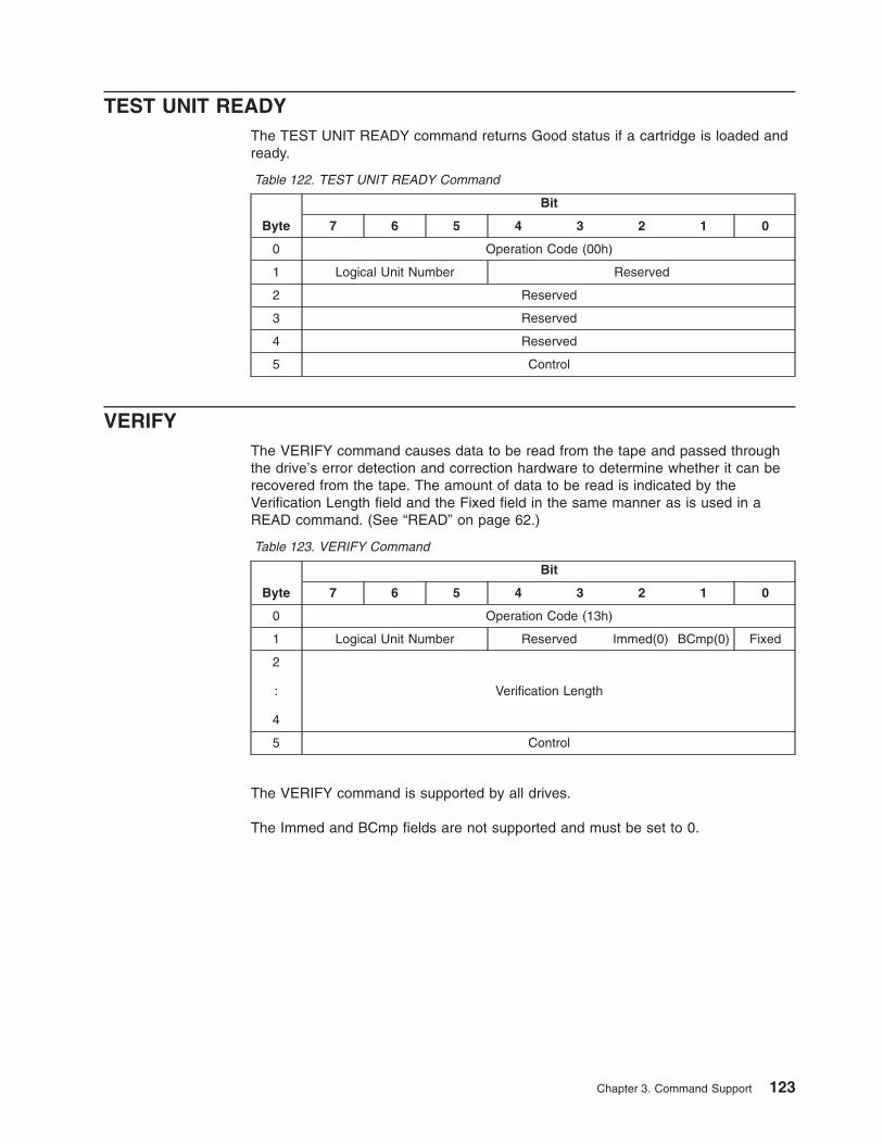
TEST UNIT READYThe TEST UNIT READY command returns Good status if a cartridge is loaded andready.
Table 122. TEST UNIT READY Command
Byte
Bit
7 6 5 4 3 2 1 0
0 Operation Code (00h)
1 Logical Unit Number Reserved
2 Reserved
3 Reserved
4 Reserved
5 Control
VERIFYThe VERIFY command causes data to be read from the tape and passed throughthe drive’s error detection and correction hardware to determine whether it can berecovered from the tape. The amount of data to be read is indicated by theVerification Length field and the Fixed field in the same manner as is used in aREAD command. (See “READ” on page 62.)
Table 123. VERIFY Command
Byte
Bit
7 6 5 4 3 2 1 0
0 Operation Code (13h)
1 Logical Unit Number Reserved Immed(0) BCmp(0) Fixed
2
:
4
Verification Length
5 Control
The VERIFY command is supported by all drives.
The Immed and BCmp fields are not supported and must be set to 0.
Chapter 3. Command Support 123
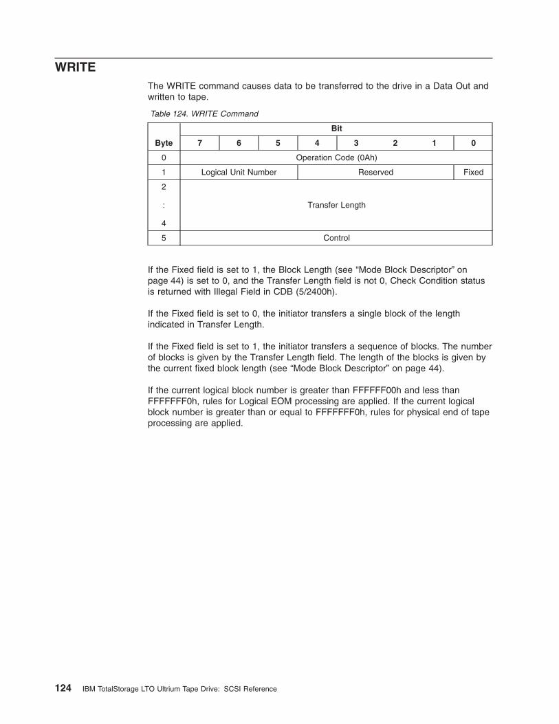
WRITEThe WRITE command causes data to be transferred to the drive in a Data Out andwritten to tape.
Table 124. WRITE Command
Byte
Bit
7 6 5 4 3 2 1 0
0 Operation Code (0Ah)
1 Logical Unit Number Reserved Fixed
2
:
4
Transfer Length
5 Control
If the Fixed field is set to 1, the Block Length (see “Mode Block Descriptor” onpage 44) is set to 0, and the Transfer Length field is not 0, Check Condition statusis returned with Illegal Field in CDB (5/2400h).
If the Fixed field is set to 0, the initiator transfers a single block of the lengthindicated in Transfer Length.
If the Fixed field is set to 1, the initiator transfers a sequence of blocks. The numberof blocks is given by the Transfer Length field. The length of the blocks is given bythe current fixed block length (see “Mode Block Descriptor” on page 44).
If the current logical block number is greater than FFFFFF00h and less thanFFFFFFF0h, rules for Logical EOM processing are applied. If the current logicalblock number is greater than or equal to FFFFFFF0h, rules for physical end of tapeprocessing are applied.
124 IBM TotalStorage LTO Ultrium Tape Drive: SCSI Reference
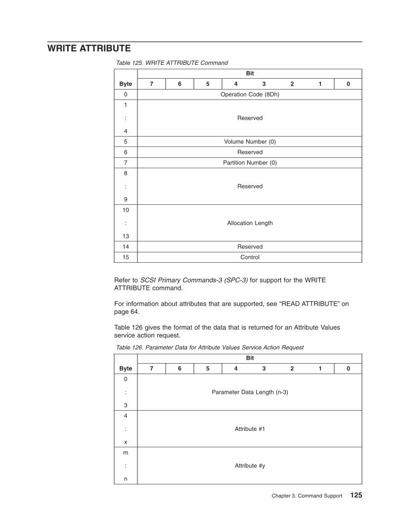
WRITE ATTRIBUTETable 125. WRITE ATTRIBUTE Command
Byte
Bit
7 6 5 4 3 2 1 0
0 Operation Code (8Dh)
1
:
4
Reserved
5 Volume Number (0)
6 Reserved
7 Partition Number (0)
8
:
9
Reserved
10
:
13
Allocation Length
14 Reserved
15 Control
Refer to SCSI Primary Commands-3 (SPC-3) for support for the WRITEATTRIBUTE command.
For information about attributes that are supported, see “READ ATTRIBUTE” onpage 64.
Table 126 gives the format of the data that is returned for an Attribute Valuesservice action request.
Table 126. Parameter Data for Attribute Values Service Action Request
Byte
Bit
7 6 5 4 3 2 1 0
0
:
3
Parameter Data Length (n-3)
4
:
x
Attribute #1
m
:
n
Attribute #y
Chapter 3. Command Support 125
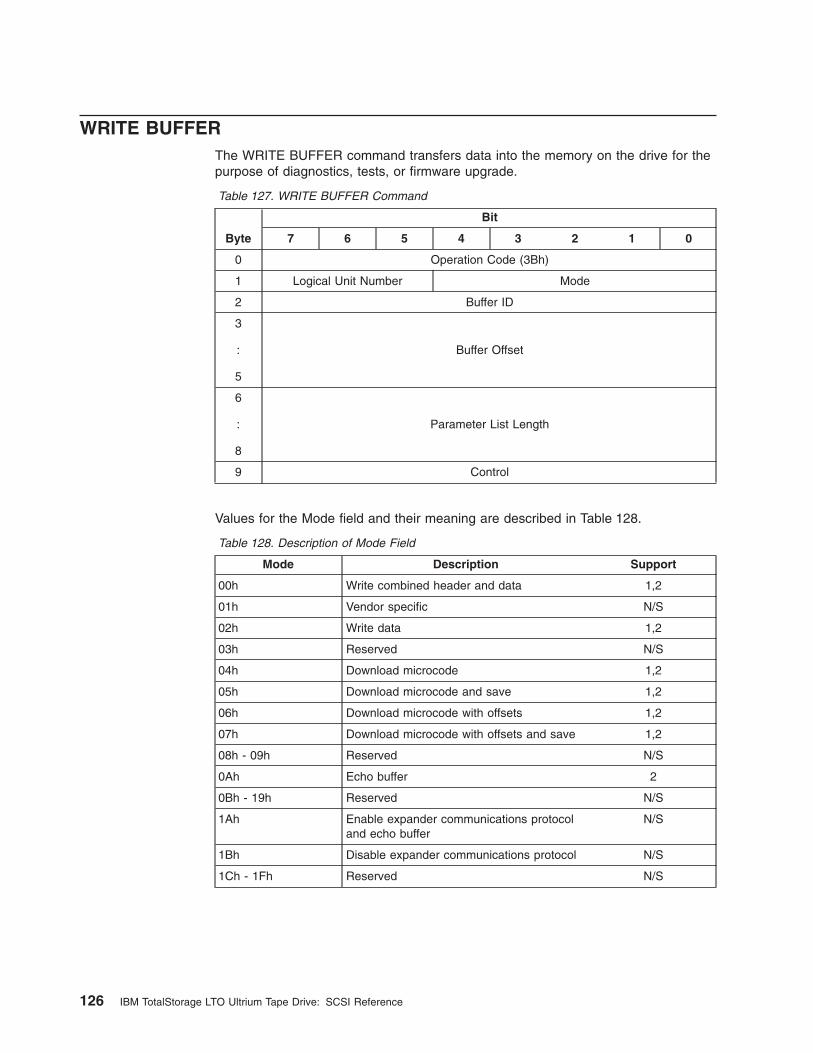
WRITE BUFFERThe WRITE BUFFER command transfers data into the memory on the drive for thepurpose of diagnostics, tests, or firmware upgrade.
Table 127. WRITE BUFFER Command
Byte
Bit
7 6 5 4 3 2 1 0
0 Operation Code (3Bh)
1 Logical Unit Number Mode
2 Buffer ID
3
:
5
Buffer Offset
6
:
8
Parameter List Length
9 Control
Values for the Mode field and their meaning are described in Table 128.
Table 128. Description of Mode Field
Mode Description Support
00h Write combined header and data 1,2
01h Vendor specific N/S
02h Write data 1,2
03h Reserved N/S
04h Download microcode 1,2
05h Download microcode and save 1,2
06h Download microcode with offsets 1,2
07h Download microcode with offsets and save 1,2
08h - 09h Reserved N/S
0Ah Echo buffer 2
0Bh - 19h Reserved N/S
1Ah Enable expander communications protocoland echo buffer
N/S
1Bh Disable expander communications protocol N/S
1Ch - 1Fh Reserved N/S
126 IBM TotalStorage LTO Ultrium Tape Drive: SCSI Reference
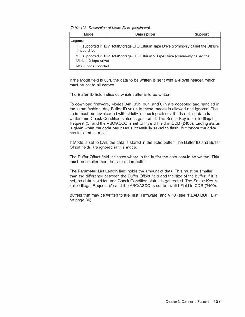
Table 128. Description of Mode Field (continued)
Mode Description Support
Legend:
1 = supported in IBM TotalStorage LTO Ultrium Tape Drive (commonly called the Ultrium1 tape drive)
2 = supported in IBM TotalStorage LTO Ultrium 2 Tape Drive (commonly called theUltrium 2 tape drive)
N/S = not supported
If the Mode field is 00h, the data to be written is sent with a 4-byte header, whichmust be set to all zeroes.
The Buffer ID field indicates which buffer is to be written.
To download firmware, Modes 04h, 05h, 06h, and 07h are accepted and handled inthe same fashion. Any Buffer ID value in these modes is allowed and ignored. Thecode must be downloaded with strictly increasing offsets. If it is not, no data iswritten and Check Condition status is generated. The Sense Key is set to IllegalRequest (5) and the ASC/ASCQ is set to Invalid Field in CDB (2400). Ending statusis given when the code has been successfully saved to flash, but before the drivehas initiated its reset.
If Mode is set to 0Ah, the data is stored in the echo buffer. The Buffer ID and BufferOffset fields are ignored in this mode.
The Buffer Offset field indicates where in the buffer the data should be written. Thismust be smaller than the size of the buffer.
The Parameter List Length field holds the amount of data. This must be smallerthan the difference between the Buffer Offset field and the size of the buffer. If it isnot, no data is written and Check Condition status is generated. The Sense Key isset to Illegal Request (5) and the ASC/ASCQ is set to Invalid Field in CDB (2400).
Buffers that may be written to are Test, Firmware, and VPD (see “READ BUFFER”on page 80).
Chapter 3. Command Support 127
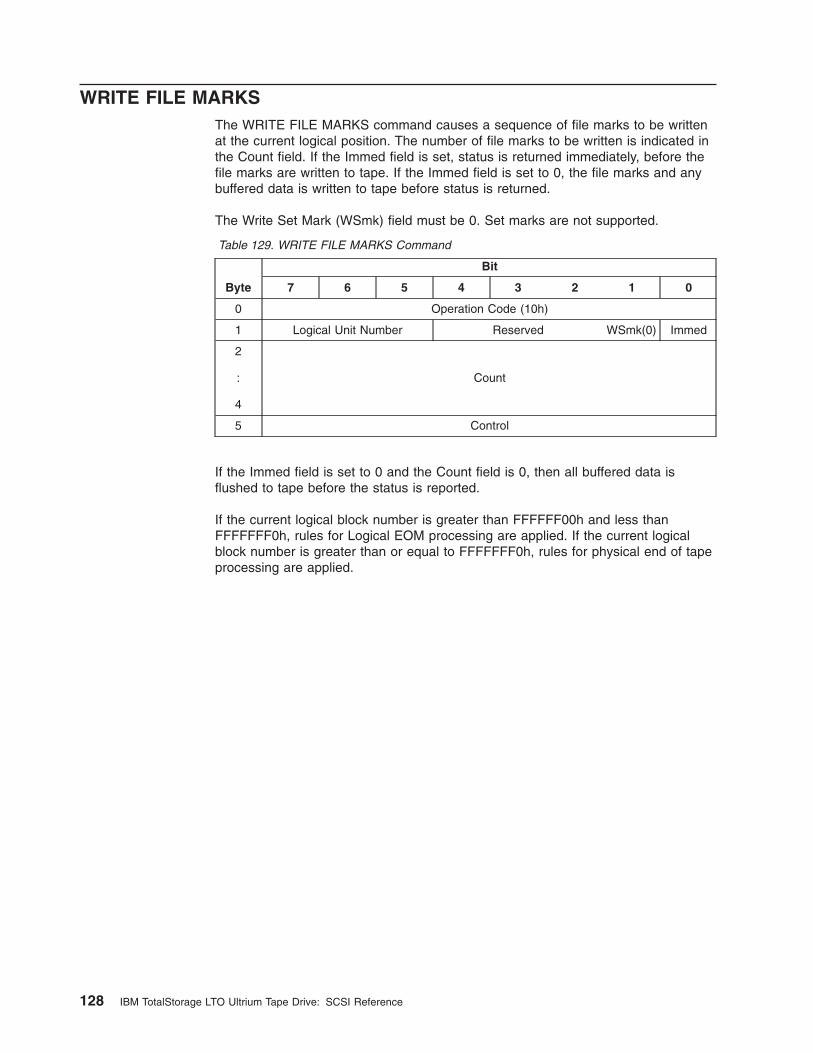
WRITE FILE MARKSThe WRITE FILE MARKS command causes a sequence of file marks to be writtenat the current logical position. The number of file marks to be written is indicated inthe Count field. If the Immed field is set, status is returned immediately, before thefile marks are written to tape. If the Immed field is set to 0, the file marks and anybuffered data is written to tape before status is returned.
The Write Set Mark (WSmk) field must be 0. Set marks are not supported.
Table 129. WRITE FILE MARKS Command
Byte
Bit
7 6 5 4 3 2 1 0
0 Operation Code (10h)
1 Logical Unit Number Reserved WSmk(0) Immed
2
:
4
Count
5 Control
If the Immed field is set to 0 and the Count field is 0, then all buffered data isflushed to tape before the status is reported.
If the current logical block number is greater than FFFFFF00h and less thanFFFFFFF0h, rules for Logical EOM processing are applied. If the current logicalblock number is greater than or equal to FFFFFFF0h, rules for physical end of tapeprocessing are applied.
128 IBM TotalStorage LTO Ultrium Tape Drive: SCSI Reference
Chapter 4. Error Sense Information
Sense DataFor a description of Sense data, see “Sense Data Format” on page 96.
Sense Data ManagementThe drive maintains three types of Sense data:
Current SenseThe Sense data associated with the last command received from theinitiator.
Deferred SenseThe Sense data from a command that has been reported as Good, but hasgenerated sense data after being reported. This may be a command withthe Immediate flag set or may be a buffered write. A command with theImmediate flag set generates sense for the server that sent the command.A buffered write may generate sense for all servers.
Unit Attention SenseThe Sense data generated by a Unit Attention condition. (See “UnitAttention Conditions” on page 129.) This is generated for all servers. Whena Unit Attention condition has been driven by a command (for example,when mode parameters have changed), a Unit Attention is posted for allinitiators except the one that caused the change.
Any command other than a REQUEST SENSE command or an INQUIRY commandgenerates Check Condition status if there is Deferred Sense data or Unit Attentiondata available. All commands generate Check Condition status if the command itselfgenerates sense data. If the next command after the Check Condition status is nota REQUEST SENSE command, then all the sense data for that initiator is cleared.
When a REQUEST SENSE command is received, the Current Sense is returned. Ifthere is no Current Sense, the Deferred Sense is returned. If there is no DeferredSense, the Unit Attention Sense is returned. If there is no Unit Attention Sense,default sense data is returned. Once a particular set of sense data has beenreturned, that sense data is cleared. Any other sense data that is still pending maystill cause Check Condition status for subsequent commands.
Unit Attention ConditionsThe drive generates a Unit Attention condition under the following circumstances:
v Reset condition (for example, power-on, SCSI reset, bus device reset)
v Tape Loaded condition (for example, media inserted, LOAD command fromanother initiator)
v Mode parameters changed by another initiator
v Drive firmware has been upgraded
The drive only maintains one Unit Attention condition at any one time for any oneinitiator. If a subsequent Unit Attention condition is generated, it replaces theexisting one if it is of higher priority. If it is of lower priority, it is ignored. Thepriorities are in the order listed above, with a reset being highest priority and afirmware upgrade being lowest priority.
© Copyright IBM Corp. 2002 129
Persistent ErrorsWhen errors occur that prevent tape operation, they are reported persistently untilthe problem is cleared. For medium-related errors (usually reported with a SenseKey of 3), the error is reported until the cartridge is successfully unloaded. Forhardware-related errors (usually reported with a Sense Key of 4), the error isreported until the drive successfully performs a power-on self test. These persistenterrors are only reported on those commands that are eligible for deferred CheckCondition reporting (see Table 3 on page 7). The error may or may not be reportedas Deferred.
130 IBM TotalStorage LTO Ultrium Tape Drive: SCSI Reference
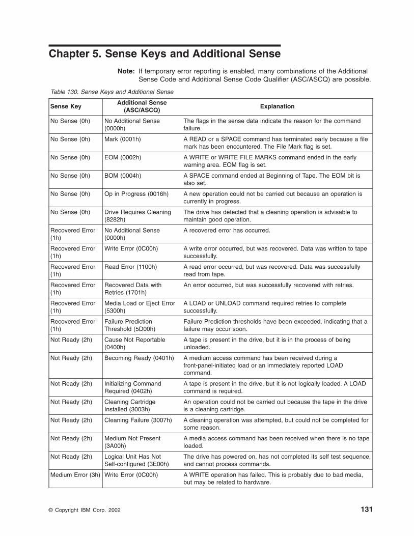
Chapter 5. Sense Keys and Additional Sense
Note: If temporary error reporting is enabled, many combinations of the AdditionalSense Code and Additional Sense Code Qualifier (ASC/ASCQ) are possible.
Table 130. Sense Keys and Additional Sense
Sense KeyAdditional Sense
(ASC/ASCQ)Explanation
No Sense (0h) No Additional Sense(0000h)
The flags in the sense data indicate the reason for the commandfailure.
No Sense (0h) Mark (0001h) A READ or a SPACE command has terminated early because a filemark has been encountered. The File Mark flag is set.
No Sense (0h) EOM (0002h) A WRITE or WRITE FILE MARKS command ended in the earlywarning area. EOM flag is set.
No Sense (0h) BOM (0004h) A SPACE command ended at Beginning of Tape. The EOM bit isalso set.
No Sense (0h) Op in Progress (0016h) A new operation could not be carried out because an operation iscurrently in progress.
No Sense (0h) Drive Requires Cleaning(8282h)
The drive has detected that a cleaning operation is advisable tomaintain good operation.
Recovered Error(1h)
No Additional Sense(0000h)
A recovered error has occurred.
Recovered Error(1h)
Write Error (0C00h) A write error occurred, but was recovered. Data was written to tapesuccessfully.
Recovered Error(1h)
Read Error (1100h) A read error occurred, but was recovered. Data was successfullyread from tape.
Recovered Error(1h)
Recovered Data withRetries (1701h)
An error occurred, but was successfully recovered with retries.
Recovered Error(1h)
Media Load or Eject Error(5300h)
A LOAD or UNLOAD command required retries to completesuccessfully.
Recovered Error(1h)
Failure PredictionThreshold (5D00h)
Failure Prediction thresholds have been exceeded, indicating that afailure may occur soon.
Not Ready (2h) Cause Not Reportable(0400h)
A tape is present in the drive, but it is in the process of beingunloaded.
Not Ready (2h) Becoming Ready (0401h) A medium access command has been received during afront-panel-initiated load or an immediately reported LOADcommand.
Not Ready (2h) Initializing CommandRequired (0402h)
A tape is present in the drive, but it is not logically loaded. A LOADcommand is required.
Not Ready (2h) Cleaning CartridgeInstalled (3003h)
An operation could not be carried out because the tape in the driveis a cleaning cartridge.
Not Ready (2h) Cleaning Failure (3007h) A cleaning operation was attempted, but could not be completed forsome reason.
Not Ready (2h) Medium Not Present(3A00h)
A media access command has been received when there is no tapeloaded.
Not Ready (2h) Logical Unit Has NotSelf-configured (3E00h)
The drive has powered on, has not completed its self test sequence,and cannot process commands.
Medium Error (3h) Write Error (0C00h) A WRITE operation has failed. This is probably due to bad media,but may be related to hardware.
© Copyright IBM Corp. 2002 131
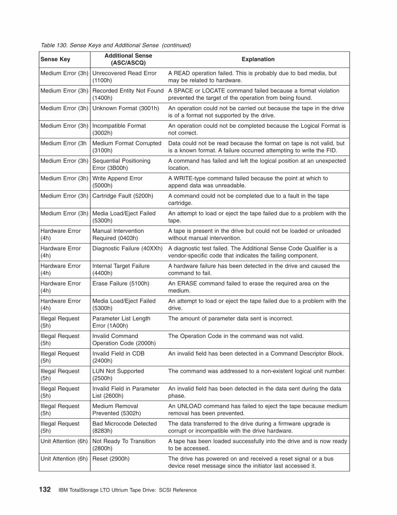
Table 130. Sense Keys and Additional Sense (continued)
Sense KeyAdditional Sense
(ASC/ASCQ)Explanation
Medium Error (3h) Unrecovered Read Error(1100h)
A READ operation failed. This is probably due to bad media, butmay be related to hardware.
Medium Error (3h) Recorded Entity Not Found(1400h)
A SPACE or LOCATE command failed because a format violationprevented the target of the operation from being found.
Medium Error (3h) Unknown Format (3001h) An operation could not be carried out because the tape in the driveis of a format not supported by the drive.
Medium Error (3h) Incompatible Format(3002h)
An operation could not be completed because the Logical Format isnot correct.
Medium Error (3h Medium Format Corrupted(3100h)
Data could not be read because the format on tape is not valid, butis a known format. A failure occurred attempting to write the FID.
Medium Error (3h) Sequential PositioningError (3B00h)
A command has failed and left the logical position at an unexpectedlocation.
Medium Error (3h) Write Append Error(5000h)
A WRITE-type command failed because the point at which toappend data was unreadable.
Medium Error (3h) Cartridge Fault (5200h) A command could not be completed due to a fault in the tapecartridge.
Medium Error (3h) Media Load/Eject Failed(5300h)
An attempt to load or eject the tape failed due to a problem with thetape.
Hardware Error(4h)
Manual InterventionRequired (0403h)
A tape is present in the drive but could not be loaded or unloadedwithout manual intervention.
Hardware Error(4h)
Diagnostic Failure (40XXh) A diagnostic test failed. The Additional Sense Code Qualifier is avendor-specific code that indicates the failing component.
Hardware Error(4h)
Internal Target Failure(4400h)
A hardware failure has been detected in the drive and caused thecommand to fail.
Hardware Error(4h)
Erase Failure (5100h) An ERASE command failed to erase the required area on themedium.
Hardware Error(4h)
Media Load/Eject Failed(5300h)
An attempt to load or eject the tape failed due to a problem with thedrive.
Illegal Request(5h)
Parameter List LengthError (1A00h)
The amount of parameter data sent is incorrect.
Illegal Request(5h)
Invalid CommandOperation Code (2000h)
The Operation Code in the command was not valid.
Illegal Request(5h)
Invalid Field in CDB(2400h)
An invalid field has been detected in a Command Descriptor Block.
Illegal Request(5h)
LUN Not Supported(2500h)
The command was addressed to a non-existent logical unit number.
Illegal Request(5h)
Invalid Field in ParameterList (2600h)
An invalid field has been detected in the data sent during the dataphase.
Illegal Request(5h)
Medium RemovalPrevented (5302h)
An UNLOAD command has failed to eject the tape because mediumremoval has been prevented.
Illegal Request(5h)
Bad Microcode Detected(8283h)
The data transferred to the drive during a firmware upgrade iscorrupt or incompatible with the drive hardware.
Unit Attention (6h) Not Ready To Transition(2800h)
A tape has been loaded successfully into the drive and is now readyto be accessed.
Unit Attention (6h) Reset (2900h) The drive has powered on and received a reset signal or a busdevice reset message since the initiator last accessed it.
132 IBM TotalStorage LTO Ultrium Tape Drive: SCSI Reference
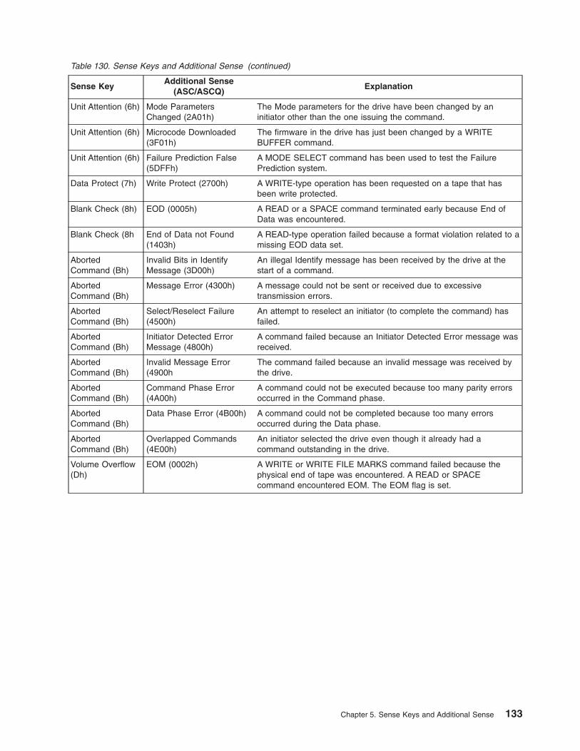
Table 130. Sense Keys and Additional Sense (continued)
Sense KeyAdditional Sense
(ASC/ASCQ)Explanation
Unit Attention (6h) Mode ParametersChanged (2A01h)
The Mode parameters for the drive have been changed by aninitiator other than the one issuing the command.
Unit Attention (6h) Microcode Downloaded(3F01h)
The firmware in the drive has just been changed by a WRITEBUFFER command.
Unit Attention (6h) Failure Prediction False(5DFFh)
A MODE SELECT command has been used to test the FailurePrediction system.
Data Protect (7h) Write Protect (2700h) A WRITE-type operation has been requested on a tape that hasbeen write protected.
Blank Check (8h) EOD (0005h) A READ or a SPACE command terminated early because End ofData was encountered.
Blank Check (8h End of Data not Found(1403h)
A READ-type operation failed because a format violation related to amissing EOD data set.
AbortedCommand (Bh)
Invalid Bits in IdentifyMessage (3D00h)
An illegal Identify message has been received by the drive at thestart of a command.
AbortedCommand (Bh)
Message Error (4300h) A message could not be sent or received due to excessivetransmission errors.
AbortedCommand (Bh)
Select/Reselect Failure(4500h)
An attempt to reselect an initiator (to complete the command) hasfailed.
AbortedCommand (Bh)
Initiator Detected ErrorMessage (4800h)
A command failed because an Initiator Detected Error message wasreceived.
AbortedCommand (Bh)
Invalid Message Error(4900h
The command failed because an invalid message was received bythe drive.
AbortedCommand (Bh)
Command Phase Error(4A00h)
A command could not be executed because too many parity errorsoccurred in the Command phase.
AbortedCommand (Bh)
Data Phase Error (4B00h) A command could not be completed because too many errorsoccurred during the Data phase.
AbortedCommand (Bh)
Overlapped Commands(4E00h)
An initiator selected the drive even though it already had acommand outstanding in the drive.
Volume Overflow(Dh)
EOM (0002h) A WRITE or WRITE FILE MARKS command failed because thephysical end of tape was encountered. A READ or SPACEcommand encountered EOM. The EOM flag is set.
Chapter 5. Sense Keys and Additional Sense 133

134 IBM TotalStorage LTO Ultrium Tape Drive: SCSI Reference
Chapter 6. Attachment Features
Types of Interface AttachmentsThe Ultrium Tape Drive communicates with servers that use SCSI parallel or FibreChannel interfaces. The interfaces share certain tape LUN behaviors, but alsopossess unique features. This chapter describes the common and unique featuresof both types of interfaces.
Common Tape LUN BehaviorsSCSI parallel and Fibre Channel interfaces share the following tape LUN behaviors:
v Power-on procedure
v Reset strategy
v Abort handling
v Multi-initiator support
v Status codes
The sections that follow describe each behavior.
Power-OnThe drive responds to INQUIRY, REPORT LUNs, REQUEST SENSE, and TESTUNIT READY commands within 5 seconds of power-on. The first command (otherthan INQUIRY or REQUEST SENSE) from any initiator gets a Check Conditionstatus with Unit Attention sense data for the power-on. After this, any mediumaccess command is reported with a Sense Key of Not Ready and an ASC/ASCQ ofLUN Has Not Self-Configured Yet (3E00). Once the drive has completed its self testand setup procedures, the drive attempts to load any tape that is present. Mediumaccess commands are reported with an ASC/ASCQ of Drive in Process ofBecoming Ready (0401).
Reset StrategyThe drive supports the hard reset option as is required by SCSI-3. On receiving areset, the following actions are taken:
v The current I/O process is aborted, as in “Abort Handling” on page 136.
v Any queued I/O processes from other initiators are removed.
v All reservations are cleared.
v All mode values are reset to their defaults.
v Synchronous/Wide negotiations are cleared (applies only to SCSI parallel attach).
v A unit attention condition is set.
v A logical position is established that may or may not be the same as the positionprior to the reset. Where possible, the logical position prior to reset is maintained.
For drives that use a Fibre Channel interface, the next command that is eligible forthe Unit Attention Check Condition from each initiator gets a Check Conditionstatus, with Unit Attention sense data for the reset. However, other commands maynot be processed until the internal state of the drive has been reset.
Drives that use a SCSI interface are able to respond to the INQUIRY, REPORTLUNs, REQUEST SENSE, and TEST UNIT READY commands within 250 ms ofthe reset line being released. The next command that is eligible for the Unit
© Copyright IBM Corp. 2002 135
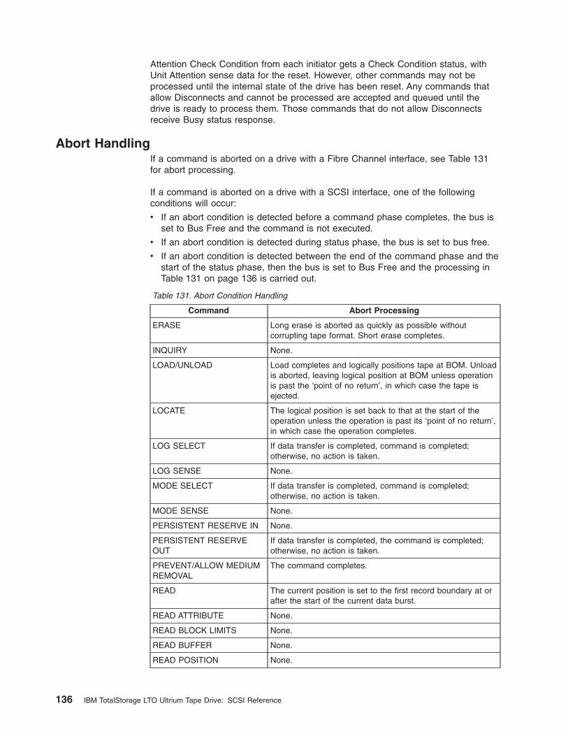
Attention Check Condition from each initiator gets a Check Condition status, withUnit Attention sense data for the reset. However, other commands may not beprocessed until the internal state of the drive has been reset. Any commands thatallow Disconnects and cannot be processed are accepted and queued until thedrive is ready to process them. Those commands that do not allow Disconnectsreceive Busy status response.
Abort HandlingIf a command is aborted on a drive with a Fibre Channel interface, see Table 131for abort processing.
If a command is aborted on a drive with a SCSI interface, one of the followingconditions will occur:
v If an abort condition is detected before a command phase completes, the bus isset to Bus Free and the command is not executed.
v If an abort condition is detected during status phase, the bus is set to bus free.
v If an abort condition is detected between the end of the command phase and thestart of the status phase, then the bus is set to Bus Free and the processing inTable 131 on page 136 is carried out.
Table 131. Abort Condition Handling
Command Abort Processing
ERASE Long erase is aborted as quickly as possible withoutcorrupting tape format. Short erase completes.
INQUIRY None.
LOAD/UNLOAD Load completes and logically positions tape at BOM. Unloadis aborted, leaving logical position at BOM unless operationis past the ‘point of no return’, in which case the tape isejected.
LOCATE The logical position is set back to that at the start of theoperation unless the operation is past its ‘point of no return’,in which case the operation completes.
LOG SELECT If data transfer is completed, command is completed;otherwise, no action is taken.
LOG SENSE None.
MODE SELECT If data transfer is completed, command is completed;otherwise, no action is taken.
MODE SENSE None.
PERSISTENT RESERVE IN None.
PERSISTENT RESERVEOUT
If data transfer is completed, the command is completed;otherwise, no action is taken.
PREVENT/ALLOW MEDIUMREMOVAL
The command completes.
READ The current position is set to the first record boundary at orafter the start of the current data burst.
READ ATTRIBUTE None.
READ BLOCK LIMITS None.
READ BUFFER None.
READ POSITION None.
136 IBM TotalStorage LTO Ultrium Tape Drive: SCSI Reference
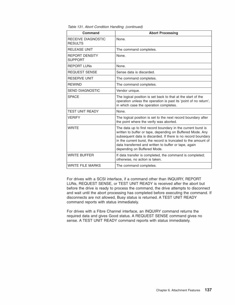
Table 131. Abort Condition Handling (continued)
Command Abort Processing
RECEIVE DIAGNOSTICRESULTS
None.
RELEASE UNIT The command completes.
REPORT DENSITYSUPPORT
None.
REPORT LUNs None.
REQUEST SENSE Sense data is discarded.
RESERVE UNIT The command completes.
REWIND The command completes.
SEND DIAGNOSTIC Vendor unique.
SPACE The logical position is set back to that at the start of theoperation unless the operation is past its ‘point of no return’,in which case the operation completes.
TEST UNIT READY None.
VERIFY The logical position is set to the next record boundary afterthe point where the verify was aborted.
WRITE The data up to first record boundary in the current burst iswritten to buffer or tape, depending on Buffered Mode. Anysubsequent data is discarded. If there is no record boundaryin the current burst, the record is truncated to the amount ofdata transferred and written to buffer or tape, againdepending on Buffered Mode.
WRITE BUFFER If data transfer is completed, the command is completed;otherwise, no action is taken.
WRITE FILE MARKS The command completes.
For drives with a SCSI interface, if a command other than INQUIRY, REPORTLUNs, REQUEST SENSE, or TEST UNIT READY is received after the abort butbefore the drive is ready to process the command, the drive attempts to disconnectand wait until the abort processing has completed before executing the command. Ifdisconnects are not allowed, Busy status is returned. A TEST UNIT READYcommand reports with status immediately.
For drives with a Fibre Channel interface, an INQUIRY command returns therequired data and gives Good status. A REQUEST SENSE command gives nosense. A TEST UNIT READY command reports with status immediately.
Chapter 6. Attachment Features 137
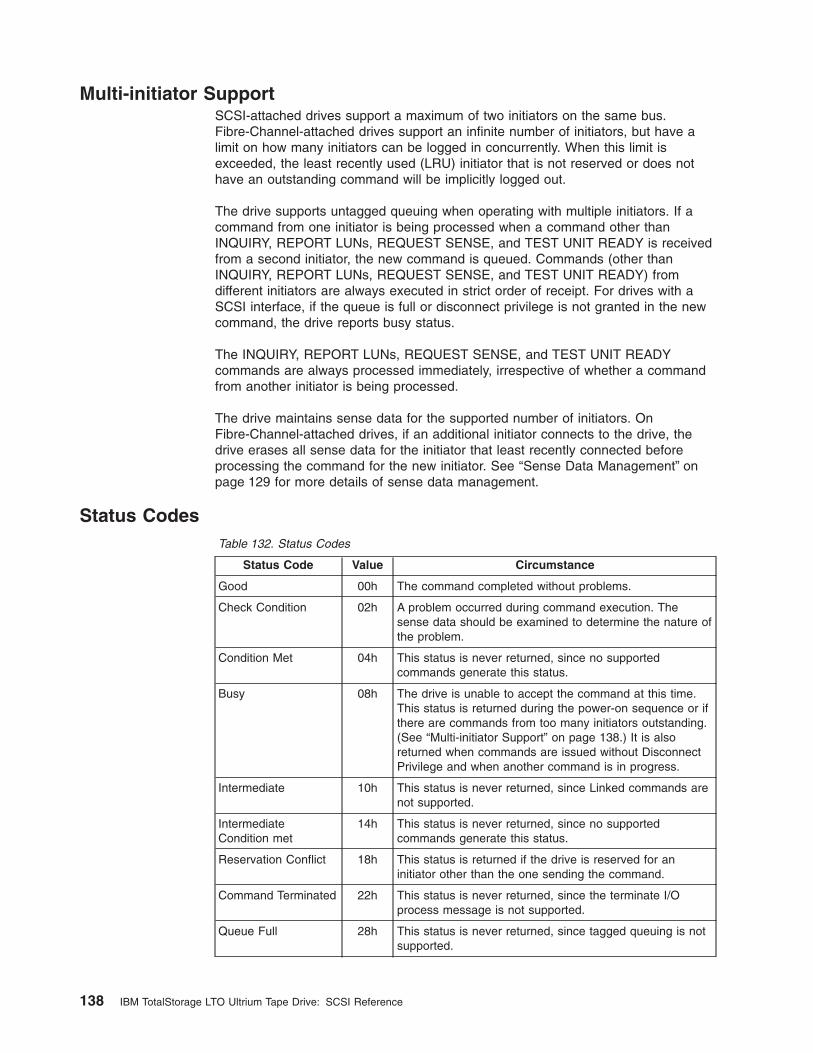
Multi-initiator SupportSCSI-attached drives support a maximum of two initiators on the same bus.Fibre-Channel-attached drives support an infinite number of initiators, but have alimit on how many initiators can be logged in concurrently. When this limit isexceeded, the least recently used (LRU) initiator that is not reserved or does nothave an outstanding command will be implicitly logged out.
The drive supports untagged queuing when operating with multiple initiators. If acommand from one initiator is being processed when a command other thanINQUIRY, REPORT LUNs, REQUEST SENSE, and TEST UNIT READY is receivedfrom a second initiator, the new command is queued. Commands (other thanINQUIRY, REPORT LUNs, REQUEST SENSE, and TEST UNIT READY) fromdifferent initiators are always executed in strict order of receipt. For drives with aSCSI interface, if the queue is full or disconnect privilege is not granted in the newcommand, the drive reports busy status.
The INQUIRY, REPORT LUNs, REQUEST SENSE, and TEST UNIT READYcommands are always processed immediately, irrespective of whether a commandfrom another initiator is being processed.
The drive maintains sense data for the supported number of initiators. OnFibre-Channel-attached drives, if an additional initiator connects to the drive, thedrive erases all sense data for the initiator that least recently connected beforeprocessing the command for the new initiator. See “Sense Data Management” onpage 129 for more details of sense data management.
Status CodesTable 132. Status Codes
Status Code Value Circumstance
Good 00h The command completed without problems.
Check Condition 02h A problem occurred during command execution. Thesense data should be examined to determine the nature ofthe problem.
Condition Met 04h This status is never returned, since no supportedcommands generate this status.
Busy 08h The drive is unable to accept the command at this time.This status is returned during the power-on sequence or ifthere are commands from too many initiators outstanding.(See “Multi-initiator Support” on page 138.) It is alsoreturned when commands are issued without DisconnectPrivilege and when another command is in progress.
Intermediate 10h This status is never returned, since Linked commands arenot supported.
IntermediateCondition met
14h This status is never returned, since no supportedcommands generate this status.
Reservation Conflict 18h This status is returned if the drive is reserved for aninitiator other than the one sending the command.
Command Terminated 22h This status is never returned, since the terminate I/Oprocess message is not supported.
Queue Full 28h This status is never returned, since tagged queuing is notsupported.
138 IBM TotalStorage LTO Ultrium Tape Drive: SCSI Reference
Features of the SCSI InterfaceThe Ultrium Tape Drive’s SCSI parallel interface features the following:
v LUN identification
v Bus parity errors
v Disconnect strategy
v Messages
LUN IdentificationIdentify messages are used to identify the LUN to which an initiator is connectingand to identify which LUN is reconnecting to an initiator. These are required. TheLUN field in SCSI-2 commands is not used.
Bus Parity ErrorsOn detecting a bus parity error during a Command or Data Out phase or receivingan Initiator Detected Error message during a Data In or Status phase, the driveattempts to retry the Bus phase. A Restore Pointers message is sent to the initiatorand the transfer is repeated. Only one retry is attempted for any given burst. If theretry fails or the Restore Pointers message is rejected by an Initiator Detected Error,Message Reject, or Message Parity message, then the drive goes to the Statusphase and attempts to report Check Condition status. If this fails with an InitiatorDetected Error message, the drive goes to Bus Free. The Sense Key is set toAborted Command and the ASC/ASCQ is set to Command Phase Error (4A00) (ifthe error was in the Command phase) or to Data Phase Error (4B00) (if the errorwas in the Data phase). If the error was in the Status phase, the sense dataremains as that from the command.
If an Initiator Detected Error or Message Parity Error message is received duringthe Message In phase, the initiator has detected an error in the message. The drivegoes to Message In and resends the message that was in error. If the subsequentmessage is rejected with an Initiator Detected Error, then the drive goes to theStatus phase and sends Check Condition status. The Sense Key is set to AbortedCommand and the ASC/ASCQ is set to Initiator Detected Error (4800). If thesubsequent message is rejected with a Message Parity Error, then the drive goes tothe Status phase and sends Check Condition status. The Sense Key is set toAborted Command and the ASC/ASCQ is set to Message Error (4300).
On detecting a bus parity error during a Message Out phase, the drive handshakesin all message bytes until ATN is deasserted. It then stays in the Message Outphase to indicate to the initiator that the whole Message Out phase should beresent.
Disconnect StrategyThe disconnect strategy used by the drive is based on the assumption ofmaximizing bus utilization for large sequential data transfers from a large databuffer. The drive disconnects whenever it believes that it can provide better busutilization. This may be between Command and Data phases, between bursts ofdata, or before sending status. However, the drive guarantees that it sends theconfigured maximum burst size or the remaining data in the transfer in any singleData phase burst if the maximum burst size has been set to a value other than 0.
Chapter 6. Attachment Features 139
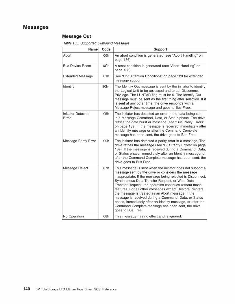
Messages
Message OutTable 133. Supported Outbound Messages
Name Code Support
Abort 06h An abort condition is generated (see “Abort Handling” onpage 136).
Bus Device Reset 0Ch A reset condition is generated (see “Abort Handling” onpage 136).
Extended Message 01h See “Unit Attention Conditions” on page 129 for extendedmessage support.
Identify 80h+ The Identify Out message is sent by the initiator to identifythe Logical Unit to be accessed and to set DisconnectPrivilege. The LUNTAR flag must be 0. The Identify Outmessage must be sent as the first thing after selection. If itis sent at any other time, the drive responds with aMessage Reject message and goes to Bus Free.
Initiator DetectedError
05h The initiator has detected an error in the data being sentin a Message Command, Data, or Status phase. The driveretries the data burst or message (see “Bus Parity Errors”on page 139). If the message is received immediately afteran Identify message or after the Command Completemessage has been sent, the drive goes to Bus Free.
Message Parity Error 09h The initiator has detected a parity error in a message. Thedrive retries the message (see “Bus Parity Errors” on page139). If the message is received during a Command, Data,or Status phase, immediately after an Identify message, orafter the Command Complete message has been sent, thedrive goes to Bus Free.
Message Reject 07h This message is sent when the initiator does not support amessage sent by the drive or considers the messageinappropriate. If the message being rejected is Disconnect,Synchronous Data Transfer Request, or Wide DataTransfer Request, the operation continues without thosefeatures. For all other messages except Restore Pointers,the message is treated as an Abort message. If themessage is received during a Command, Data, or Statusphase, immediately after an Identify message, or after theCommand Complete message has been sent, the drivegoes to Bus Free.
No Operation 08h This message has no effect and is ignored.
140 IBM TotalStorage LTO Ultrium Tape Drive: SCSI Reference
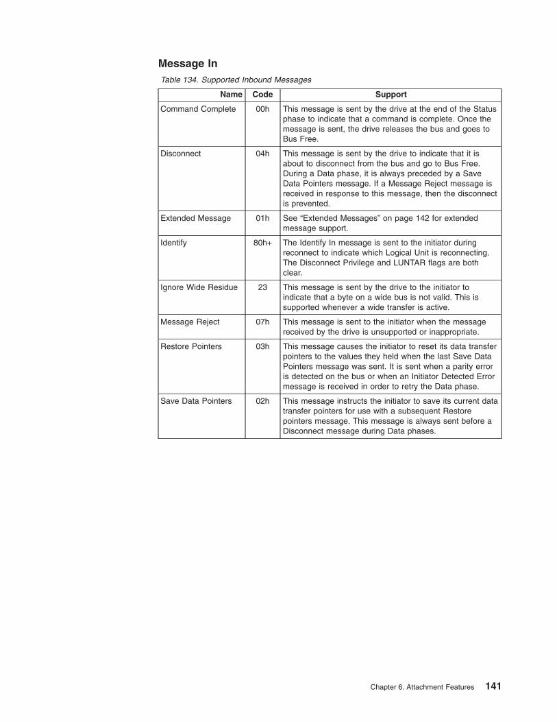
Message InTable 134. Supported Inbound Messages
Name Code Support
Command Complete 00h This message is sent by the drive at the end of the Statusphase to indicate that a command is complete. Once themessage is sent, the drive releases the bus and goes toBus Free.
Disconnect 04h This message is sent by the drive to indicate that it isabout to disconnect from the bus and go to Bus Free.During a Data phase, it is always preceded by a SaveData Pointers message. If a Message Reject message isreceived in response to this message, then the disconnectis prevented.
Extended Message 01h See “Extended Messages” on page 142 for extendedmessage support.
Identify 80h+ The Identify In message is sent to the initiator duringreconnect to indicate which Logical Unit is reconnecting.The Disconnect Privilege and LUNTAR flags are bothclear.
Ignore Wide Residue 23 This message is sent by the drive to the initiator toindicate that a byte on a wide bus is not valid. This issupported whenever a wide transfer is active.
Message Reject 07h This message is sent to the initiator when the messagereceived by the drive is unsupported or inappropriate.
Restore Pointers 03h This message causes the initiator to reset its data transferpointers to the values they held when the last Save DataPointers message was sent. It is sent when a parity erroris detected on the bus or when an Initiator Detected Errormessage is received in order to retry the Data phase.
Save Data Pointers 02h This message instructs the initiator to save its current datatransfer pointers for use with a subsequent Restorepointers message. This message is always sent before aDisconnect message during Data phases.
Chapter 6. Attachment Features 141
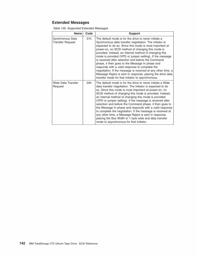
Extended MessagesTable 135. Supported Extended Messages
Name Code Support
Synchronous DataTransfer Request
01h The default mode is for the drive to never initiate aSynchronous data transfer negotiation. The initiator isexpected to do so. Since this mode is most important atpower-on, no SCSI method of changing this mode isprovided. Instead, an internal method of changing thismode is provided (VPD or jumper setting). If the messageis received after selection and before the Commandphase, it then goes to the Message In phase andresponds with a valid response to complete thenegotiation. If the message is received at any other time, aMessage Reject is sent in response, placing the drive datatransfer mode for that initiator to asynchronous.
Wide Data TransferRequest
03h The default mode is for the drive to never initiate a Widedata transfer negotiation. The initiator is expected to doso. Since this mode is most important at power-on, noSCSI method of changing this mode is provided. Instead,an internal method of changing this mode is provided(VPD or jumper setting). If the message is received afterselection and before the Command phase, it then goes tothe Message In phase and responds with a valid responseto complete the negotiation. If the message is received atany other time, a Message Reject is sent in response,placing the Bus Width to 1 byte wide and data transfermode to asynchronous for that initiator.
142 IBM TotalStorage LTO Ultrium Tape Drive: SCSI Reference
Features of the Fibre Channel InterfaceThe Ultrium Internal Tape Drive Model T200F (the Fibre Channel Generation 1drive) is an Arbitrated-Loop-only device (also known as an NL port). The drivesupports Fibre Channel Arbitrated Loop (FC-AL) protocol, and uses Class 3 Serviceframes. The drive also supports both public (switch-attached) and private loops.
Like the Ultrium Internal Tape Drive, the Ultrium 2 Tape Drive Model T400F (theFibre Channel Generation 2 drive) can attach as an FC-AL device. The Generation2 drive can also attach as a point-to-point device (also known as an N Port). Ineither topology, the Ultrium 2 drive can be a public (switch-attached) or privatedevice.
The World Wide Node Name and Port Name that are used by an Ultrium TapeDrive follow the format of the Institute of Electrical and Electronics Engineers(IEEE).
The IBM Ultrium Tape Drive is compliant with the FC-Tape Technical Report of theAccredited Standard Committee NCITS. IBM recommends that your server’s devicedriver and host bus adapter (HBA) use the Class 3 Error Recovery procedures thatare specified in the Fibre Channel Protocol for SCSI, Second Version (FCP-2).
Chapter 6. Attachment Features 143

144 IBM TotalStorage LTO Ultrium Tape Drive: SCSI Reference
Appendix. Notices
TrademarksThe following terms are trademarks of International Business Machines Corporationin the United States or other countries (or regions) or both:
AIX OS/400AS/400 pSerieseserver SPIBM RS/6000iSeries TotalStorage
The following are U. S. trademarks of Hewlett-Packard Company, InternationalBusiness Machines Corporation, and Seagate Technology:
Linear Tape-OpenLTOUltrium
Intel is a registered trademark of Intel Corporation in the United States, or othercountries (or regions), or both.
Microsoft, Windows, Windows NT, and the Windows logo are registered trademarksof Microsoft Corporation in the United States, or other countries (or regions), orboth.
Other company, product, and service names may be trademarks or service marksof others.
© Copyright IBM Corp. 2002 145

146 IBM TotalStorage LTO Ultrium Tape Drive: SCSI Reference

Glossary
This glossary defines the special terms,abbreviations, and acronyms that are used in thispublication.
Numbers and Symbols2:1 compression. The relationship between thequantity of data that can be stored with compression ascompared to the quantity of data that can be storedwithout compression. In 2:1 compression, twice asmuch data can be stored with compression as can bestored without compression.
Aadapter. See adapter card.
adapter card. A circuit board that adds function to acomputer.
AL_PA. See Arbitrated Loop Physical Address.
Arbitrated Loop Physical Address (AL_PA). An 8-bitvalue that identifies a device in an arbitrated loop. AllFibre Channel ports communicate by using AL_PAs.
Bbackups. The short-term retention of records used forrestoring essential business and server files when vitaldata has been lost because of program or server errorsor malfunctions.
bezel. The removable frame that fits over the front ofthe Ultrium Tape Drives.
bit. The smallest unit of data in a computer. A bit(short for binary digit) has a single binary value (either 0or 1). Computers store data and execute instructions inbit multiples called bytes. In most computer systems,there are eight bits in a byte.
bus. See SCSI bus.
byte. A string that consists of a certain number of bits(usually 8) which are treated as a unit and represent acharacter. A byte is a fundamental unit of data.
Ccapacity. The amount of data that can be containedon storage media and expressed in bytes.
cartridge. See tape cartridge.
cartridge memory. See LTO cartridge memory.
circuit board. A thin sheet on which chips and otherelectronic components are placed. Computers consist ofone or more boards, often called cards or adapters.
cleaning cartridge. A tape cartridge that is used toclean the heads of a tape drive. Contrast with datacartridge.
command timeout. Following the issuance of acommand, a period of time during which it is determinedthat there is a bad connection between the server andthe drive.
compression. The process of eliminating gaps, emptyfields, redundancies, and unnecessary data to shortenthe length of records or blocks.
configure. To describe to a server the devices,optional features, and programs installed on the system.
Ddata. Any representations such as characters oranalog quantities to which meaning is, or might be,assigned.
data cartridge. A tape cartridge that is dedicated tostoring data. Contrast with cleaning cartridge.
data compression. See compression.
data transfer rate. The average number of bits,characters, or blocks per unit of time that pass betweencorresponding equipment in a data transmission system.The rate is expressed in bits, characters, or blocks persecond, minute, or hour.
device. Any hardware component or peripheral, suchas a tape drive or tape library, that can receive andsend data.
device driver. A binary file that is installed on a hostsystem and enables the host system to access adevice.
diagnostic. A software program that is designed torecognize, locate, and explain faults in equipment orerrors in programs.
diagnostic cartridge. A tape cartridge that enablesthe detection and isolation of errors in programs andfaults in equipment.
drive. See IBM Ultrium Internal Tape Drive ModelsT200 and T200F or IBM TotalStorage LTO Ultrium 2Tape Drive Models T400 and T400F.
drive dump. The recording, at a particular instant, ofthe contents of all or part of one storage device into
© Copyright IBM Corp. 2002 147
another storage device, usually as a safeguard againstfaults or errors, or in connection with debugging.
drive head. The component that records an electricalsignal onto magnetic tape, or reads a signal from tapeinto an electrical signal.
drive sense data. See SCSI drive sense data.
dump. See drive dump.
duplex. See duplex transmission.
duplex adapter. A mechanism that allows a device tosend and receive communication at the same time.
duplex transmission. Transmission in both directions,either one direction at a time (half-duplex) or bothdirections simultaneously (full-duplex).
Eeject. To remove or force out from within.
electronic mail. Correspondence in the form ofmessages transmitted between user terminals over acomputer network.
e-mail. See electronic mail.
enclosure. A device, such as a desktop unit, tapecartridge autoloader, or tape library, into which you caninstall an Ultrium Tape Drive.
error log. Maintained by an Ultrium Tape Drive, a listthat contains the ten most recent error codes. Thecodes identify errors that pertain to the drive.
FFibre Channel. A 100-MB-per-second, full-duplex,serial communications technology that is capable ofinterconnecting Ultrium Tape Drives and servers whichare separated by as much as 11 kilometers (7 miles).Fibre Channel technology combines features of theinput/output (I/O) and networking interfaces.
Fibre Channel cable. The cable that connects a FibreChannel tape drive to another device. The conductiveelement within the cable is constructed of either copperwires or optical fibers. Generally, copper wires are usedfor short distances (up to 30 meters or 98 feet); opticalfibers are used for longer distances. Fiber-optic cablingis referred to by mode or the frequencies of light wavesthat are carried by a particular cable type. Multimodefiber cables are generally used for distances up to 500meters (1640 feet) and with short-wave (780nanometer) laser light. Single-mode fiber cables areused for distances greater than 500 m (1640 feet) andwith long-wave (1300 nanometer) laser light.
file. A named set of records that are stored orprocessed as a unit.
filemark. Located on the magnetic tape within a tapecartridge, a recorded element that typically marks theorganizational boundaries in a serial file structure (suchas directory boundaries) and that is requested to bewritten or read by the server.
firmware. Proprietary code that is usually delivered aspart of an operating system. Firmware is more efficientthan software that is loaded from an alterable medium,and is more adaptable to change than pure hardwarecircuitry. An example of firmware is the BasicInput/Output System (BIOS) in read-only memory(ROM) on a PC motherboard.
GGb. See gigabit.
GB. See gigabyte.
gigabit (Gb). 1 000 000 000 bits.
gigabyte (GB). 1 000 000 000 bytes.
Hhard addressing. Pertaining to the Fibre Channeldrives (Models T200F and T400F), a method thatidentifies the drive’s LID and, consequently, its AL_PA(the AL_PA enables the drive to communicate with otherdevices).
hardware. The physical equipment or devices thatform a computer.
head. See drive head.
host. The controlling or highest-level system in a datacommunication configuration. Synonymous with server.
IIBM Ultrium Internal Tape Drive Models T200 andT200F. A data-storage device that controls themovement of the magnetic tape in an IBM LTO UltriumTape Cartridge. The drive houses the mechanism (drivehead) that reads and writes data to the tape. Its nativedata capacity is 100 GB per cartridge and up to 200 GBat 2:1 compression. Its native data transfer rate is 15MB per second and 30 MB per second at 2:1compression.
IBM TotalStorage LTO Ultrium 2 Tape Drive ModelsT400 and T400F. A data-storage device that controlsthe movement of the magnetic tape in an IBM LTOUltrium Tape Cartridge. The drive houses themechanism (drive head) that reads and writes data tothe tape. Its native data capacity is 200 GB per
148 IBM TotalStorage LTO Ultrium Tape Drive: SCSI Reference
cartridge and up to 400 GB at 2:1 compression. Itsnative data transfer rate is 35 MB per second and 70MB per second at 2:1 compression.
ID. Identifier.
initiator. In SCSI terms, a SCSI device that requestsan I/O process to be performed by another SCSI device(a target). In many cases, an initiator can also be atarget.
input/output (I/O). Data that is provided to a computeror data that results from computer processing.
install. (1) To set up for use or service. (2) The act ofadding a product, feature, or function to a server ordevice either by a singular change or by the addition ofmultiple components or devices.
Internet. The worldwide collection of interconnectednetworks that use the Internet suite of protocols andpermit public access.
I/O. See input/output.
Jjumper. (1) A tiny connector that fits over a pair ofprotruding pins in a connector. A jumper can be movedto change electrical connectors. When in place, thejumper connects the pins electrically. (2) To place ajumper on a connector pin.
LLinear Tape-Open (LTO). A type of tape storagetechnology developed by the IBM Corporation,Hewlett-Packard, and Seagate. LTO technology is an“open format” technology, which means that its usershave multiple sources of product and media. The “open”nature of LTO technology enables compatibility betweendifferent vendors’ offerings by ensuring that vendorscomply with verification standards.
load. Following the insertion of a tape cartridge intothe tape load compartment, the act of positioning thetape (performed by the tape drive) for reading or writingby the drive’s head.
load and unload cycle. The act of inserting acartridge into a tape drive, loading the tape to loadpoint, rewinding the tape into the cartridge, and ejectingthe cartridge from the drive.
log sense data. See SCSI log sense data.
Low Voltage Differential (LVD). A low-noise,low-power, and low-amplitude electrical signaling systemthat enables data communication between a supportedserver and the Ultrium Tape Drive. LVD signaling usestwo wires to drive one signal over copper wire. The useof wire pairs reduces electrical noise and crosstalk.
LTO. See Linear Tape-Open.
LTO cartridge memory (LTO-CM). Within each LTOUltrium Data Cartridge, an embedded electronics andinterface module that can store and retrieve acartridge’s historical usage and other information.
LTO-CM. See LTO cartridge memory.
LTO-DC. See LTO Data Compression.
LTO Data Compression (LTO-DC). A method thatcompresses a server’s data before the drive writes it totape. LTO-DC detects but does not recompress or testrecord boundaries and file markers (which are encodedas control symbols). It also allows switching betweencompression and no compression within the datastream, which prevents data from expanding when thedrive compresses random or encrypted data.
LVD. See Low Voltage Differential.
Mmagnetic tape. A tape with a magnetizable surfacelayer on which data can be stored by magneticrecording.
MB. See megabyte.
media. The plural of medium.
media capacity. See capacity.
medium. A physical material in or on which data maybe represented, such as magnetic tape.
megabyte (MB). 1 000 000 bytes.
micrometer. One millionth of a meter (.000001 m).Synonymous with micron. Abbreviated as µm.
micron. One millionth of a meter (.000001 m).Synonymous with micrometer. Abbreviated as µm.
microsecond. One millionth of a second (.000001 s).Abbreviated as µs.
millimeter (mm). One thousandth of a meter (.001 m).
millisecond (ms). One thousandth of a second (.001s).
mm. See millimeter.
ms. See millisecond.
Model T200. The version of the IBM Ultrium InternalTape Drive that uses the SCSI interface, has a nativestorage capacity of 100 GB, and a native data transferrate of 15 MB per second.
Model T200F. The version of the IBM Ultrium InternalTape Drive that uses the Fibre Channel interface, has a
Glossary 149
native storage capacity of 100 GB, and a native datatransfer rate of 15 MB per second.
Model T400. The version of the IBM TotalStorage LTOUltrium 2 Tape Drive that uses the SCSI interface, has anative storage capacity of 200 GB, and a native datatransfer rate of 35 MB per second.
Model T400F. The version of the IBM TotalStorageLTO Ultrium 2 Tape Drive that uses the Fibre Channelinterface, has a native storage capacity of 200 GB, anda native data transfer rate of 35 MB per second.
NN/A. Not applicable.
native storage capacity. The amount of data that canbe stored without compression on a tape cartridge.
native sustained data transfer rate. See datatransfer rate.
network. A configuration of data processing devicesand software that is connected for informationinterchange.
network server. In a local area network, a personalcomputer that provides access to files for all of theworkstations in the network.
node. In Fibre Channel technology, a communicatingdevice.
ntutil. Created by IBM, a utility program for LTOdevices that connect to Windows NT and Windows2000. ntutil provides problem determination forhardware or connections, assists with device andmedium changer recognition, forces dumps, loads newfirmware, sends and receives SCSI commands to andfrom the hardware, and obtains SCSI sense data to usein resolving errors.
Ooffline. The operating condition that the Ultrium TapeDrives are in when the server’s applications cannotinteract with it.
online. The operating condition that the Ultrium TapeDrives are in when the server’s applications can interactwith it.
Open Systems. Computer systems whose standardsare not proprietary.
operating system. The master computer controlprogram that translates the user’s commands andallows software application programs to interact with thecomputer’s hardware.
Pparity. The state of being even-numbered orodd-numbered. A parity bit is a binary number that isadded to a group of binary numbers to make the sum ofthat group always odd (odd parity) or even (even parity).
parity error. A transmission error that occurs when thereceived data does not have the parity that is expectedby the receiving system. This usually occurs when thesending and receiving systems have different paritysettings.
port. (1) A system or network access point for dataentry or exit. (2) A connector on a device to whichcables for other devices such as display stations andprinters are attached. (3) The representation of aphysical connection to hardware. A port is sometimesreferred to as an adapter; however, there can be morethan one port on an adapter.
power-off. To remove electrical power from a device.
power-on, powered-on. (1) To apply electrical powerto a device. (2) The state of a device when power hasbeen applied to it.
protocol. The meanings of, and the sequencing rulesfor, requests and responses that are used to manage anetwork, transfer data, and synchronize the states ofnetwork components.
Qquiesce. To put a device into a temporarily inactive orinhibited state, but not remove it from the server.
Rread. To acquire or interpret data from a storagedevice, from a data medium, or from another source.
reboot. To reinitialize the execution of a program byrepeating the initial program load (IPL) operation.
record. The smallest distinct set of data bytes that issupplied from a server for processing and recording bya tape drive, and the smallest distinct set of data to beread from tape, reprocessed, and made available to aserver by a tape drive.
record boundaries. The fixed limits of a record.
repeater. A device that regenerates signals to extendthe range of transmission between data stations or tointerconnect two branches. A repeater is a node of alocal area network.
reset. To return a device or circuit to a clear state.
RS-422 connector. Located at the rear of the UltriumTape Drive, the connector to which the internal RS-422
150 IBM TotalStorage LTO Ultrium Tape Drive: SCSI Reference
cable of an enclosure connects. The connection enablesserial devices to communicate with the drive.
RS-422 interface. An electrical interface standard thatis approved by the Electronic Industries Association(EIA) for connecting serial devices. The RS-422standard, which supports higher data rates and greaterimmunity to electrical interference, is an alternative tothe older RS-232 interface, and uses individualdifferential signal pairs for data transmission. Dependingon data transmission rates, RS-422 can be used atdistances up to 1,275 m (4,000 ft). The RS-422interface also supports multi-point connections.
Ss. See second.
SAN. See Storage Area Network.
SAN Data Gateway. A device that provides FibreChannel attachment between Open Systems serversand SCSI disk and tape storage systems.
SC. See subscription channel connector.
SCSI. See Small Computer Systems Interface.
SCSI bus. (1) A collection of wires through which datais transmitted from one part of a computer to another.(2) A generic term that refers to the complete set ofsignals that define the activity of the Small ComputerSystems Interface (SCSI).
SCSI connector. Located at the rear of the UltriumTape Drive, the connector that facilitates commands toand from the server, and to which the internal SCSIcable of an enclosure connects.
SCSI device. Anything that can connect into the SCSIbus and actively participate in bus activity.
SCSI drive sense data. In response to inquiry fromthe server about an error condition, a packet of SCSIsense bytes that contains information about the errorand that is sent back to the server by the drive.
SCSI ID. The unique address (from 1 to 15) that youassign to an Ultrium Tape Drive that uses a SCSIinterface.
SCSI ID connector. Located at the rear of the UltriumTape Drive, the connector that enables the drive’s SCSIaddress to be set. Addresses are determined by theplacement of jumpers on the pins.
SCSI ID switch. Located on an enclosure thatcontains a Ultrium Tape Drive, a mechanism thatconnects to the drive and allows you to change thedrive’s SCSI ID without using jumpers.
SCSI log sense data. In response to inquiry from theserver about the Ultrium Tape Drive’s error logs and
counters, a packet of SCSI sense bytes which containsthat information and which is sent back to the server bythe drive. Log sense data is used to diagnose problems,especially if the problems are intermittent.
second. One sixtieth of a minute.
selection timeout. Following the selection of an option(for example, a data transfer), the period of time duringwhich it is determined that there is a bad connectionbetween the server and the drive.
sense data. Data that describes an I/O error. Sensedata is presented to a server in response to a SenseI/O command.
serial interface. An interface that sequentially orconsecutively executes two or more operations in asingle device, such as an arithmetic and logic operation.
server. A functional unit that provides services to oneor more clients over a network. Examples include a fileserver, a print server, or a mail server. The IBMEserver pSeries, IBM Eserver iSeries, HP, and Sunare servers. Synonymous with host.
short-wave cable. In Fibre Channel technology, alaser cable that uses a wavelength of 780 nanometersand is only compatible with multimode fiber.
Small Computer Systems Interface (SCSI). Astandard used by computer manufacturers for attachingperipheral devices (such as tape drives, hard disks,CD-ROM players, printers, and scanners) to computers(servers). Pronounced ″scuzzy.″ Variations of the SCSIinterface provide for faster data transmission rates thanstandard serial and parallel ports (up to 160 megabytesper second). The variations include:
v Fast/Wide SCSI: Uses a 16-bit bus, and supportsdata rates of up to 20 MBps.
v SCSI-1: Uses an 8-bit bus, and supports data ratesof 4 MBps.
v SCSI-2: Same as SCSI-1, but uses a 50-pinconnector instead of a 25-pin connector, andsupports multiple devices.
v Ultra SCSI: Uses an 8- or 16-bit bus, and supportsdata rates of 20 or 40 MBps.
v Ultra2 SCSI: Uses an 8- or 16-bit bus and supportsdata rates of 40 or 80 MBps.
v Ultra3 SCSI: Uses a 16-bit bus and supports datarates of 80 or 160 MBps.
v Ultra160 SCSI: Uses a 16-bit bus and supports datarates of 160 MBps.
soft addressing. Pertaining to the Fibre Channeldrive, a method that enables the drive to dynamicallyarbitrate its AL_PA with other Fibre Channel devices onthe loop. The AL_PA enables the drive to communicatewith other devices.
Glossary 151
software. Programs, procedures, rules, and anyassociated documentation pertaining to the operation ofa computer system.
Storage Area Network (SAN). A high-speedsubnetwork of shared storage devices. A SAN’sarchitecture makes all storage devices available to allservers on a LAN or WAN. As more storage devices areadded to a SAN, they too will be accessible from anyserver in the larger network. Because stored data doesnot reside directly on any of a network’s servers, serverpower is used for business applications, and networkcapacity is released to the end user.
subscription channel connector (SC). A push-pulltype of optical connector that features high density, lowloss, low backreflection, and low cost.
switch. A network infrastructure component to whichmultiple nodes attach. Unlike hubs, switches typicallyhave the ability to switch node connections from one toanother. A typical switch can facilitate severalsimultaneous bandwidth transmissions between differentpairs of nodes.
TTapeAlert. A patented technology and ANSI standardthat defines conditions and problems that areexperienced by tape drives.
TapeAlert flags. Status and error messages that aregenerated by the TapeAlert utility and display on theserver’s console.
tape cartridge. A removable storage case that housesbelt-driven magnetic tape that is wound on a supply reeland a takeup reel.
tape drive. See IBM Ultrium Internal Tape DriveModels T200 and T200F or IBM TotalStorage LTOUltrium 2 Tape Drive Models T400 and T400F.
tape path. Within a tape drive, the channel in whichthe media moves.
tapeutil. Created by IBM, a utility program for LTOdevices that connect to all supported servers exceptWindows NT and Windows 2000. tapeutil providesservice aids for tape subsystems, offers a menu-driventool for exercising or testing IBM tape and mediumchanger devices, and includes a command-line interfacethat is convenient for use in shell scripts.
terminate. To prevent unwanted electrical signalreflections by applying a device (known as a terminator)that absorbs the energy from the transmission line.
topology. In communications, the physical or logicalarrangement of nodes in a network, especially therelationships among nodes and the links between them.
TotalStorage LTO Ultrium Tape Drive Models T400and T400F. See IBM TotalStorage LTO Ultrium 2 TapeDrive Models T400 and T400F.
transfer rate. See data transfer rate.
UUltrium Tape Drive. See IBM Ultrium Internal TapeDrive Models T200 and T200F or IBM TotalStorage LTOUltrium 2 Tape Drive Models T400 and T400F.
Ultrium 2 Tape Drive. See IBM TotalStorage LTOUltrium 2 Tape Drive.
uniform resource locator (URL). The address of anitem on the World Wide Web. It includes the protocolfollowed by the fully qualified domain name (sometimescalled the host name) and the request. The web servertypically maps the request portion of the URL to a pathand file name. For example, if the URL ishttp://www.networking.ibm.com/nsg/nsgmain.htm, theprotocol is http; the fully qualified domain name iswww.networking.ibm.com; and the request is/nsg/nsgmain.htm.
unload. The act (performed by the drive) ofunthreading tape from the drive’s internal tape path andreturning it (with the leader block) to the tape cartridge.
URL. See uniform resource locator.
utility. See utility program.
utility program. A computer program that supportscomputer processes. For example, a diagnosticprogram, a trace program, or a sort program.
Vvital product data (VPD). Information about a product.Among other details, the VPD may include a modelnumber, serial number, part number, or level offirmware.
Wweb. See World Wide Web.
World Wide Name. A unique, 8-byte identifier that isassigned by IBM Manufacturing to each Ultrium TapeDrive and used to identify a drive.
World Wide Web. A network of servers that containprograms and files. Many of the files contain hypertextlinks to other documents that are available through thenetwork.
write. To make a permanent or transient recording ofdata in a storage device or on a data medium.
152 IBM TotalStorage LTO Ultrium Tape Drive: SCSI Reference

write protected. Applicable to a tape cartridge, thecondition that exists when some logical or physicalmechanism prevents a device from writing on the tapein that cartridge.
Glossary 153

154 IBM TotalStorage LTO Ultrium Tape Drive: SCSI Reference
Index
Aabort condition, handling 136AS/400
device driver support 4requirements for attaching tape drive to 3
attaching tape drive to server 3Attribute List service action, format 67Attribute Values service action, format 66
Bburst data transfer rate 2bus parity errors, handling 139
Ccapacity 2, 5commands, supported SCSI 11compatible tape cartridges 5compressed capacity 2Current Sense data 129
DData Compression Log 39Data Compression Mode Page 47data transfer rate 2Deferred Sense data 129description of tape drives 1device drivers, supported 4Device Identification Page 20disconnect strategy 139Disconnect/Reconnect Page 46Drive Component Revision Level Pages 22
EERASE command 11, 13error log buffer 84error sense information 129errors
bus parity 139persistent 130
extended messages 142
FFibre Channel attachment
abort condition, handling 135, 136features of interface 143LUN behaviors 135multi-initiator support 135, 138power-on procedure 135requirements 3reset strategy 135status codes 135, 138
Fibre Channel interface 1Fibre Channel Logical Unit Control Page 50Fibre Channel Port Control Page 51Fibre Channel World Wide Name buffer 85Force Dump diagnostic 112
HHewlett-Packard
device driver support 4requirements for attaching tape drive to 3
high voltage differential (HVD) SCSI interface 1, 2HP
device driver support 4requirements for attaching tape drive to 3
HVD interface 1, 2
IInformation Exceptions Mode Page 52INQUIRY command 11, 14Intel-compatible servers
device driver support 4requirements for attaching tape drive to 3
interfaceHVD 1, 2LVD 1, 2type of drive 1
interface attachment 135iSeries server
device driver support 4requirements for attaching tape drive to 3
LLC-duplex 2Linux
device driver support 4requirements for attaching tape drive to 3
LOAD/UNLOAD command 11, 23LOCATE command 11, 24Log Page format 27Log Pages, supported 28LOG SELECT command 11, 25LOG SENSE command 11, 26low voltage differential (LVD) SCSI interface 1, 2LUN identification 139LVD interface 1, 2
MMAM
description 70format 72
Medium Auxiliary Memory (MAM)description 70format 72
© Copyright IBM Corp. 2002 155
message in 141message out 140messages 140, 141, 142MIM data structure 105Mode Block Descriptor 44Mode data format 42Mode Parameter Header 43MODE SELECT (10) command 11, 40MODE SELECT (6) command 11, 40MODE SENSE (10) command 11, 41MODE SENSE (6) command 11, 41multi-initiator support 135, 138
Nnative storage capacity 2native sustained data transfer rate 2
Ooperating systems, supported 3
PPartition List service action, format 69persistent errors 130PERSISTENT RESERVE IN command 11, 54PERSISTENT RESERVE OUT command 11, 57Post A self test diagnostic 108Post B tape test diagnostic 109Post C media test diagnostic 110Post D head test diagnostic 111power-on procedure 135PREVENT/ALLOW MEDIUM REMOVAL command 11,
61pSeries server
device driver support 4requirements for attaching tape drive to 3
RREAD ATTRIBUTE command 11, 64READ BLOCK LIMITS command 11, 79READ BUFFER command 11, 80READ command 11, 62Read Error Counters log 30READ POSITION command 11, 86Read-Write Error Recovery Page 45read/write capability 5RECEIVE DIAGNOSTIC RESULTS command 11, 88RELEASE UNIT (10) command 11, 89RELEASE UNIT (6) command 11, 89Remove Traps diagnostic 116REPORT DENSITY SUPPORT command 11, 90REPORT LUNs command 12, 94REQUEST SENSE command 12, 96requirements for attaching tape drive to server 3RESERVE UNIT (10) command 12, 99RESERVE UNIT (6) command 12, 99Reset Drive diagnostic 118
reset strategy 135REWIND command 12, 100RS-422 interface 2RS/6000
device driver support 4requirements for attaching tape drive to 3
RS/6000 SPdevice driver support 4requirements for attaching tape drive to 3
SSAN connection 2SC-duplex 2SCSI attachment
abort condition, handling 135, 136features of interface 139LUN behaviors 135multi-initiator support 135, 138power-on procedure 135requirements 3reset strategy 135status codes 135, 138
SCSI interface 1SCSI log buffer 85Self-Test diagnostic 107SEND DIAGNOSTIC command 12, 101Sense data
description 97types of and management 129
Sense keys and additional Sense 131Sequential Access Device Configuration Page 49Sequential Access Device Log Page 31servers, supported 3SET CAPACITY command 12, 119Set Traps diagnostic 115SIM data structure 102SPACE command 12, 121Standard Inquiry Data Invalid LUN 17Standard Inquiry Data Valid LUN 15status codes 135, 138Storage Area Network (SAN) connection 2storage capacity 2Sun Microsystems
device driver support 4requirements for attaching tape drive to 3
supported device drivers 4supported Log Pages 28supported SAN components 3supported SCSI commands 11supported servers and operating systems 3supported tape cartridges 5Supported Vital Product Data Page 19
TTape Capacity Log 38tape cartridge
capacity 5compatible cartridges 5
156 IBM TotalStorage LTO Ultrium Tape Drive: SCSI Reference
tape drivesdescription 1type of interface 1
Tape Usage Log 38TapeAlert Log 32TEST UNIT READY command 12, 123transfer rate 2Tru64
device driver support 4
UUltra 160 LVD SCSI interface 2Unit Attention Conditions 129Unit Attention Sense data 129Unit Serial Number Page 19
VVERIFY command 12, 123viewing latest supported attachments 4Volume List service action, format 68
WWindows 2000
device driver support 4requirements for attaching tape drive to 3
Windows NTdevice driver support 4requirements for attaching tape drive to 3
WRITE ATTRIBUTE command 12, 125WRITE BUFFER command 12, 126WRITE command 12, 124Write Dump to Cartridge diagnostic 113Write Error Counters log 29WRITE FILE MARKS command 12, 128
Index 157

158 IBM TotalStorage LTO Ultrium Tape Drive: SCSI Reference


����
Printed in U.S.A.
GA32-0450-00