ibm mobile systems s19k-5649-00 thinkpad 240x (2609 ...tim.id.au/laptops/lenovo/thinkpad...
TRANSCRIPT

S19K-5649-00IBM Mobile Systems
ThinkPad 240X (2609) Hardware MaintenanceManual May 2000

Before using this information and the product it supports,be sure to read the general information under “Read ThisFirst” on page 19.
Fourth Edition (May 2000)
The following paragraph does not apply to the UnitedKingdom or any country where such provisions areinconsistent with local law:
INTERNATIONAL BUSINESS MACHINES CORPO-RATION PROVIDES THIS PUBLICATION "AS IS"WITHOUT ANY WARRANTY OF ANY KIND, EITHEREXPRESS OR IMPLIED, INCLUDING, BUT NOT LIMITEDTO, THE LIMITED WARRANTIES OFMERCHANTABILITY OR FITNESS FOR A PARTICULARPURPOSE. Some states do not allow disclaimers orexpress or implied warranties in certain transactions; there-fore, this statement may not apply to you.
This publication could include technical inaccuracies ortypographical errors. Changes are periodically made to theinformation herein; these changes will be incorporated innew editions of the publication. IBM may make improve-ments or changes in the products or the programsdescribed in this publication at any time.
It is possible that this publication may contain referencesto, or information about, IBM products (machines and pro-grams), programming, or services that are not announcedin your country. Such references or information must notbe construed to mean that IBM intends to announce suchIBM products, programming, or services in your country.
Requests for technical information about IBM productsshould be made to your IBM Authorized Dealer or yourIBM Marketing Representative.
Copyright International Business Machines Corpo-ration 1999, 2000. All rights reserved. Note to US Gov-ernment Users — Documentation related to restrictedrights — Use, duplication, or disclosure is subject torestrictions set forth in GSA ADP Schedule Contract withIBM Corp.

About This Manual
This manual contains service and reference information forIBM ThinkPad 570Z (2644) and ThinkPad Ultrabase pro-ducts. Use this manual along with the advanced diag-nostic tests to troubleshoot problems effectively.
The manual is divided into sections as follows:
� The Introduction section provides general information,guidelines, and safety information required to servicecomputers.
� The product-specific section includes service, refer-ence, and product-specific parts information.
Important
This manual is intended for trained servicers who arefamiliar with ThinkPad products. Use this manualalong with the advanced diagnostic tests to trouble-shoot problems effectively.
Before servicing an IBM ThinkPad product, be sure toreview the safety information under “Safety Notices(Multi-lingual Translations)” on page 4 and “SafetyInformation” on page 11.
iii

iv ThinkPad 240X

Contents
Introduction . . . . . . . . . . . . . . . . . . . 1Important Service Information . . . . . . . . . . . 1
How to Use Error Messages . . . . . . . . . . 2How to Read POST Error Messages . . . . . . 2
Drive and Diskette Compatibility Matrix . . . . . . . 3Safety Notices (Multi-lingual Translations) . . . . . 4Safety Information . . . . . . . . . . . . . . . . 11
General Safety . . . . . . . . . . . . . . . . 11Electrical Safety . . . . . . . . . . . . . . . . 12Safety Inspection Guide . . . . . . . . . . . . 13Handling Electrostatic Discharge-Sensitive Devices 15Grounding Requirements . . . . . . . . . . . . 15
Laser compliance statement . . . . . . . . . . . . 16
General Description . . . . . . . . . . . . . . . 19Read This First . . . . . . . . . . . . . . . . . . 19
What to Do First . . . . . . . . . . . . . . . . 20How to Disable the Password . . . . . . . . . 21
Product Overview . . . . . . . . . . . . . . . . . 22Fn Key Combinations . . . . . . . . . . . . . 22Status Indicators . . . . . . . . . . . . . . . . 23
Checkout Guide . . . . . . . . . . . . . . . . . 25Audio Checkout . . . . . . . . . . . . . . . . 25Fan ASM Checkout . . . . . . . . . . . . . . 26Keyboard and Auxiliary Input Device Checkout . 26Memory Checkout . . . . . . . . . . . . . . . 26Modem Board Checkout . . . . . . . . . . . . 27Power System Checkout . . . . . . . . . . . . 27TrackPoint Checkout . . . . . . . . . . . . . . 29I/O Ports Checkout . . . . . . . . . . . . . . 30Power Management Features . . . . . . . . . 30
Symptom-to-FRU Index . . . . . . . . . . . . . . 33Numeric Error Codes . . . . . . . . . . . . . . 33Error Messages . . . . . . . . . . . . . . . . 35No Beep Symptoms . . . . . . . . . . . . . . 35LCD-Related Symptoms . . . . . . . . . . . . 36Keyboard-Related Symptoms . . . . . . . . . . 36Indicator-Related Symptoms . . . . . . . . . . 36Power-Related Symptoms . . . . . . . . . . . 37PC Card (PCMCIA)-Related Symptoms . . . . . 37Speaker-Related Symptoms . . . . . . . . . . 37Power Management-Related Symptoms . . . . . 37Peripheral-Device-Related Symptom . . . . . . 38Intermittent Problems . . . . . . . . . . . . . 38Undetermined Problems . . . . . . . . . . . . 39
CE Utility Program Diskette . . . . . . . . . . . . 40Writing the VPD Data . . . . . . . . . . . . . 40Flash UUID . . . . . . . . . . . . . . . . . . 40
Running the Diagnostics . . . . . . . . . . . . . . 40FRU Removals and Replacements . . . . . . . . . 41
Contents v

FRU Service Procedures . . . . . . . . . . . . 411010 Battery ASM . . . . . . . . . . . . . . . 431020 Hard Disk Drive . . . . . . . . . . . . . 441030 Keyboard . . . . . . . . . . . . . . . . 451040 Modem Card . . . . . . . . . . . . . . . 461050 DIMM Card . . . . . . . . . . . . . . . 471060 LCD Unit ASM . . . . . . . . . . . . . . 481070 Upper Cover ASM . . . . . . . . . . . . 491080 Speaker ASM . . . . . . . . . . . . . . 511085 Select Button ASM . . . . . . . . . . . . 521090 Cable ASM and Cable ASM LED-R . . . . 531100 Fan ASM . . . . . . . . . . . . . . . . 541110 Modem Cable ASM . . . . . . . . . . . . 561120 Water Channel ASM . . . . . . . . . . . 571130 System Board . . . . . . . . . . . . . . 581135 Rear Bracket . . . . . . . . . . . . . . . 601140 PCMCIA Slots . . . . . . . . . . . . . . 611150 LCD Bezel ASM . . . . . . . . . . . . . 621160 LCD Inverter ASM . . . . . . . . . . . . 631170 LCD Panel ASM (LCD Type A and B) . . . 641180 LCD FPC ASM (LCD Type A) . . . . . . . 661185 LCD FPC ASM (LCD Type B) . . . . . . . 671190 Hinge ASM . . . . . . . . . . . . . . . 68
Computer Parts Listing . . . . . . . . . . . . . . 69LCD Unit Parts Listing (LCD Type A) . . . . . . . . 74LCD Unit Parts Listing (LCD Type B) . . . . . . . . 75Service Tools . . . . . . . . . . . . . . . . . . . 75Notices . . . . . . . . . . . . . . . . . . . . . . 77Trademarks . . . . . . . . . . . . . . . . . . . 77
vi ThinkPad 240X

Introduction
Important Service Information Important
Diskette fixes are customer installable. The diskettefixes are posted on the IBM Support sitehttp://www.pc.ibm.com/support
Advise customers to contact the PC CompanyHelpCenter at 800-772-2227 if they need assistance inobtaining or installing any diskette fixes.
FRU Replacement Strategy
Before Replacing Parts
Ensure that all diskette fixes are installed prior toreplacing any FRUs listed in this manual.
Use the following strategy to prevent unnecessary FRUreplacement and service expense:
� If you are instructed to replace a FRU and thatdoes not correct the problem, reinstall the originalFRU before you continue .
� Some computers have both a processor board and asystem board. If you are instructed to replace eitherthe processor board or the system board, and the firstboard that you replaced does not correct the problem,reinstall the original board, then replace the other(processor or system) board.
� If an adapter or device consists of more than oneFRU, an error code may be caused by any of theFRUs. Before replacing the adapter or device,remove the FRUs, one by one, to see if the symp-toms change. Replace only the FRU that changedthe symptoms.
Attention
A customized setup configuration (other than defaultsettings) may exist on the computer you are servicing.Running Automatic Configuration may alter those set-tings. Note the current configuration settings (usingthe View Configuration option) and verify that the set-tings are in place when service is complete.
Hard Disk Drive Replacement Strategy:Always try to run a low-level format before replacing a harddisk drive.
Introduction 1

Attention
The drive startup sequence in the computer you areservicing might have been changed. Be extremelycareful during write operations such as copying,saving, or formatting. Data or programs can be over-written if you select an incorrect drive.
How to Use Error MessagesUse the error codes displayed on the screen to diagnosefailures. If more than one error code is displayed, beginthe diagnosis with the first error code. The cause of thefirst error code can result in false error codes being dis-played. If no error code is displayed, see if the errorsymptom is listed in the Symptom-to-FRU Index for thecomputer you are servicing.
How to Read POST Error MessagesPOST error messages are displayed on the screen asthree, four, five, or eight digits. The error messages thatcan be displayed as shorter POST messages are high-lighted in this index. Some digits will represent differentinformation for SCSI errors versus non-SCSI errors.
The following example shows which digits display theshorter POST error messages and also defines the SCSIinformation in an eight-digit error message.
Shorter POST Messages
┌────┬────┬────┬────┐
│ │ │ │ │
┌────┬────┬────┬────┬────┬────┬────┬────┐
│ ð │ ð │ ð │ ð │ ð │ ð │ ð │ ð │
└────┴────┴────┴────┴────┴────┴────┴────┘
│ │ │ │ │ │ │ │
Reserved │ │ │ │ │ │ Size (SCSI)
└────┴────┘ │ │ Slot Number (SCSI)
Device Code │ Logical Unit Number (SCSI)
ID (SCSI)
All SCSI devices are set to a different SCSI ID.Duplicate SCSI ID settings can generate a false errormessage. Use the SCSI ID to determine whether the errormessage is coming from an internal or an external device.
2 ThinkPad 240X

Drive and Diskette Compatibility MatrixThe following table provides identification information for3.5-inch drives.
DisketteDrive
IdentifyingMark
3.5-Inch - 1.44MB 1.44 on the eject button3.5-Inch - 2.88MB 2.88 on the eject button
The following table provides compatibility information for3.5-inch diskettes and 3.5-inch diskette drives.
The following table provides identification information for5.25-inch diskette drives.
DisketteCapacity
1.44MBDrive
2.88MBDrive
1.0MB Read/Write Read/Write2.0MB Read/Write Read/Write4.0MB Not Compatible Read/Write
DisketteDrive
IdentifyingMark
5.25-Inch - 360KB (External) Asterisk on bezel5.25-Inch - 1.2MB (Internal) 1.2 on the eject button
The following table provides compatibility information for5.25-inch diskettes and 5.25-inch diskette drives.
Note: A 360KB diskette written to or formatted on a1.2MB drive can be read reliably only on a 1.2MBdrive.
DisketteCapacity
360KBDrive
1.2MBDrive
360KB Read/Write Read/Write1.2MB Not Compatible Read/Write
Introduction 3

Safety Notices (Multi-lingualTranslations)In this manual, safety notices appear in English with apage number reference to the appropriate multi-lingual,translated safety notice found in this section.
The following safety notices are provided in English,French, German, Italian, and Spanish languages.
Safety Notice 1
Before the computer is powered-on after FRU replace-ment, make sure all screws, springs, or other smallparts are in place and are not left loose inside thecomputer. Verify this by shaking the computer and lis-tening for rattling sounds. Metallic parts or metalflakes can cause electrical shorts.
Avant de remettre l'ordinateur sous tension aprèsremplacement d'une unité en clientèle, vérifiez quetous les ressorts, vis et autres pièces sont bien enplace et bien fixées. Pour ce faire, secouez l'unité etassurez-vous qu'aucun bruit suspect ne se produit.Des pièces métalliques ou des copeaux de métalpourraient causer un court-circuit.
Bevor nach einem FRU-Austausch der Computerwieder angeschlossen wird, muß sichergestelltwerden, daß keine Schrauben, Federn oder andereKleinteile fehlen oder im Gehäuse vergessen wurden.Der Computer muß geschüttelt und aufKlappergeräusche geprüft werden. Metallteile oder-splitter können Kurzschlüsse erzeugen.
Prima di accendere l'elaboratore dopo che é stataeffettuata la sostituzione di una FRU, accertarsi chetutte le viti, le molle e tutte le altri parti di piccoledimensioni siano nella corretta posizione e non sianosparse all'interno dell'elaboratore. Verificare ciòscuotendo l'elaboratore e prestando attenzione adeventuali rumori; eventuali parti o pezzetti metallicipossono provocare cortocircuiti pericolosi.
Antes de encender el sistema despues de sustituiruna FRU, compruebe que todos los tornillos, muellesy demás piezas pequeñas se encuentran en su sitio yno se encuentran sueltas dentro del sistema.Compruébelo agitando el sistema y escuchando losposibles ruidos que provocarían. Las piezas metálicaspueden causar cortocircuitos eléctricos.
4 ThinkPad 240X

Safety Notice 2
Some standby batteries contain a small amount ofnickel and cadmium. Do not disassemble it, rechargeit, throw it into fire or water, or short-circuit it. Disposeof the battery as required by local ordinances or regu-lations. Use only the battery in the appropriate partslisting. Use of an incorrect battery can result inignition or explosion of the battery.
Certaines batteries de secours contiennent du nickelet du cadmium. Ne les démontez pas, ne lesrechargez pas, ne les exposez ni au feu ni à l'eau.Ne les mettez pas en court-circuit. Pour les mettre aurebut, conformez-vous à la réglementation en vigueur.Lorsque vous remplacez la pile de sauvegarde oucelle de l'horloge temps réel, veillez à n'utiliser que lesmodèles cités dans la liste de pièces détachéesadéquate. Une batterie ou une pile inappropriéerisque de prendre feu ou d'exploser.
Die Bereitschaftsbatterie, die sich unter demDiskettenlaufwerk befindet, kann geringe MengenNickel und Cadmium enthalten. Sie darf nur durch dieVerkaufsstelle oder den IBM Kundendienstausgetauscht werden. Sie darf nicht zerlegt,wiederaufgeladen, kurzgeschlossen, oder Feuer oderWasser ausgesetzt werden. Die Batterie kannschwere Verbrennungen oder Verätzungenverursachen. Bei der Entsorgung die örtlichenBestimmungen für Sondermüll beachten. BeimErsetzen der Bereitschafts- oder Systembatterie nurBatterien des Typs verwenden, der in derErsatzteilliste aufgeführt ist. Der Einsatz falscherBatterien kann zu Entzündung oder Explosion führen.
Alcune batterie di riserva contengono una piccolaquantità di nichel e cadmio. Non smontarle, ricaricarle,gettarle nel fuoco o nell'acqua né cortocircuitarle.Smaltirle secondo la normativa in vigore (DPR 915/82,successive disposizioni e disposizioni locali). Quandosi sostituisce la batteria dell'RTC (real time clock) o labatteria di supporto, utilizzare soltanto i tipi inseritinell'appropriato Catalogo parti. L'impiego di unabatteria non adatta potrebbe determinare l'incendio ol'esplosione della batteria stessa.
Algunas baterías de reserva contienen una pequeñacantidad de níquel y cadmio. No las desmonte, nirecargue, ni las eche al fuego o al agua ni lascortocircuite. Deséchelas tal como dispone lanormativa local. Utilice sólo baterías que seencuentren en la lista de piezas. La utilización de unabatería no apropiada puede provocar la ignición oexplosión de la misma.
Introduction 5

Safety Notice 3
The battery pack contains small amounts of nickel.Do not disassemble it, throw it into fire or water, orshort-circuit it. Dispose of the battery pack asrequired by local ordinances or regulations. Use onlythe battery in the appropriate parts listing whenreplacing the battery pack. Use of an incorrect batterycan result in ignition or explosion of the battery.
La batterie contient du nickel. Ne la démontez pas,ne l'exposez ni au feu ni à l'eau. Ne la mettez pas encourt-circuit. Pour la mettre au rebut, conformez-vousà la réglementation en vigueur. Lorsque vousremplacez la batterie, veillez à n'utiliser que lesmodèles cités dans la liste de pièces détachéesadéquate. En effet, une batterie inappropriée risquede prendre feu ou d'exploser.
Akkus enthalten geringe Mengen von Nickel. Siedürfen nicht zerlegt, wiederaufgeladen,kurzgeschlossen, oder Feuer oder Wasser ausgesetztwerden. Bei der Entsorgung die örtlichenBestimmungen für Sondermüll beachten. BeimErsetzen der Batterie nur Batterien des Typsverwenden, der in der Ersatzteilliste aufgeführt ist.Der Einsatz falscher Batterien kann zu Entzündungoder Explosion führen.
La batteria contiene piccole quantità di nichel. Nonsmontarla, gettarla nel fuoco o nell'acqua nécortocircuitarla. Smaltirla secondo la normativa invigore (DPR 915/82, successive disposizioni edisposizioni locali). Quando si sostituisce la batteria,utilizzare soltanto i tipi inseriti nell'appropriatoCatalogo parti. L'impiego di una batteria non adattapotrebbe determinare l'incendio o l'esplosione dellabatteria stessa.
Las baterías contienen pequeñas cantidades deníquel. No las desmonte, ni recargue, ni las eche alfuego o al agua ni las cortocircuite. Deséchelas talcomo dispone la normativa local. Utilice sólo bateríasque se encuentren en la lista de piezas al sustituir labatería. La utilización de una batería no apropiadapuede provocar la ignición o explosión de la misma.
6 ThinkPad 240X

Safety Notice 4
The lithium battery can cause a fire, explosion, orsevere burn. Do not recharge it, remove its polarizedconnector, disassemble it, heat it above 100°C(212°F), incinerate it, or expose its cell contents towater. Dispose of the battery as required by localordinances or regulations. Use only the battery in theappropriate parts listing. Use of an incorrect batterycan result in ignition or explosion of the battery.
La pile de sauvegarde contient du lithium. Elleprésente des risques d'incendie, d'explosion ou debrûlures graves. Ne la rechargez pas, ne retirez passon connecteur polarisé et ne la démontez pas. Nel'exposez pas à une temperature supérieure à 100°C,ne la faites pas brûler et n'en exposez pas le contenuà l'eau. Mettez la pile au rebut conformément à laréglementation en vigueur. Une pile inappropriéerisque de prendre feu ou d'exploser.
Die Systembatterie ist eine Lithiumbatterie. Sie kannsich entzünden, explodieren oder schwereVerbrennungen hervorrufen. Batterien dieses Typsdürfen nicht aufgeladen, zerlegt, über 100 C erhitztoder verbrannt werden. Auch darf ihr Inhalt nicht mitWasser in Verbindung gebracht oder der zur richtigenPolung angebrachte Verbindungsstecker entferntwerden. Bei der Entsorgung die örtlichenBestimmungen für Sondermüll beachten. BeimErsetzen der Batterie nur Batterien des Typsverwenden, der in der Ersatzteilliste aufgeführt ist.Der Einsatz falscher Batterien kann zu Entzündungoder Explosion führen.
La batteria di supporto e una batteria al litio e puoincendiarsi, esplodere o procurare gravi ustioni.Evitare di ricaricarla, smontarne il connettorepolarizzato, smontarla, riscaldarla ad una temperaturasuperiore ai 100 gradi centigradi, incendiarla o gettarlain acqua. Smaltirla secondo la normativa in vigore(DPR 915/82, successive disposizioni e disposizionilocali). L'impiego di una batteria non adatta potrebbedeterminare l'incendio o l'esplosione della batteriastessa.
La bateria de repuesto es una bateria de litio y puedeprovocar incendios, explosiones o quemadurasgraves. No la recargue, ni quite el conectorpolarizado, ni la desmonte, ni caliente por encima delos 100°C (212°F), ni la incinere ni exponga elcontenido de sus celdas al agua. Deséchela tal comodispone la normativa local.
Introduction 7

Safety Notice 5
If the LCD breaks and the fluid from inside the LCDgets into your eyes or on your hands, immediatelywash the affected areas with water for at least 15minutes. Seek medical care if any symptoms from thefluid are present after washing.
Si le panneau d'affichage à cristaux liquides se briseet que vous recevez dans les yeux ou sur les mainsune partie du fluide, rincez-les abondamment pendantau moins quinze minutes. Consultez un médecin sides symptômes persistent après le lavage.
Die Leuchtstoffröhre im LCD-Bildschirm enthältQuecksilber. Bei der Entsorgung die örtlichenBestimmungen für Sondermüll beachten. DerLCD-Bildschirm besteht aus Glas und kannzerbrechen, wenn er unsachgemäß behandelt wirdoder der Computer auf den Boden fällt. Wenn derBildschirm beschädigt ist und die darin befindlicheFlüssigkeit in Kontakt mit Haut und Augen gerät,sollten die betroffenen Stellen mindestens 15 Minutenmit Wasser abgespült und bei Beschwerdenanschließend ein Arzt aufgesucht werden.
Nel caso che caso l'LCD si dovesse rompere ed illiquido in esso contenuto entrasse in contatto con gliocchi o le mani, lavare immediatamente le partiinteressate con acqua corrente per almeno 15 minuti;poi consultare un medico se i sintomi dovesseropermanere.
Si la LCD se rompe y el fluido de su interior entra encontacto con sus ojos o sus manos, laveinmediatamente las áreas afectadas con agua durante15 minutos como mínimo. Obtenga atención medicasi se presenta algún síntoma del fluido despues delavarse.
8 ThinkPad 240X

Safety Notice 6
To avoid shock, do not remove the plastic cover thatsurrounds the lower portion of the inverter card.
Afin d'éviter tout risque de choc électrique, ne retirezpas le cache en plastique protégeant la partieinférieure de la carte d'alimentation.
Aus Sicherheitsgründen die Kunststoffabdeckung, dieden unteren Teil der Spannungswandlerplatine umgibt,nicht entfernen.
Per evitare scosse elettriche, non rimuovere lacopertura in plastica che avvolge la parte inferioredella scheda invertitore.
Para evitar descargas, no quite la cubierta de plásticoque rodea la parte baja de la tarjeta invertida.
Safety Notice 7
Though main batteries have low voltage, a shorted orgrounded battery can produce enough current to burncombustible materials or personnel.
Bien que le voltage des batteries principales soit peuélevé, le court-circuit ou la mise à la masse d'unebatterie peut produire suffisamment de courant pourbrûler des matériaux combustibles ou causer desbrûlures corporelles graves.
Obwohl Hauptbatterien eine niedrige Spannunghaben, können sie doch bei Kurzschluß oder Erdunggenug Strom abgeben, um brennbare Materialien zuentzünden oder Verletzungen bei Personenhervorzurufen.
Sebbene le batterie di alimentazione siano a bassovoltaggio, una batteria in corto circuito o a massa puòfornire corrente sufficiente da bruciare materialicombustibili o provocare ustioni ai tecnici dimanutenzione.
Aunque las baterías principales tienen un voltaje bajo,una batería cortocircuitada o con contacto a tierrapuede producir la corriente suficiente como paraquemar material combustible o provocar quemadurasen el personal.
Introduction 9

Safety Notice 8
Before removing any FRU, power-off the computer,unplug all power cords from electrical outlets, removethe battery pack, then disconnect any interconnectingcables.
Avant de retirer une unité remplaçable en clientèle,mettez le système hors tension, débranchez tous lescordons d'alimentation des socles de prise de courant,retirez la batterie et déconnectez tous les cordonsd'interface.
Die Stromzufuhr muß abgeschaltet, alle Stromkabelaus der Steckdose gezogen, der Akku entfernt undalle Verbindungskabel abgenommen sein, bevor eineFRU entfernt wird.
Prima di rimuovere qualsiasi FRU, spegnere ilsistema, scollegare dalle prese elettriche tutti i cavi dialimentazione, rimuovere la batteria e poi scollegare icavi di interconnessione.
Antes de quitar una FRU, apague el sistema,desenchufe todos los cables de las tomas de corrienteeléctrica, quite la batería y, a continuación,desconecte cualquier cable de conexión entredispositivos.
10 ThinkPad 240X

Safety InformationThe following section contains the safety information thatyou need to be familiar with before servicing an IBMmobile computer.
General SafetyFollow these rules to ensure general safety:
� Observe good housekeeping in the area of themachines during and after maintenance.
� When lifting any heavy object:1. Ensure you can stand safely without slipping.2. Distribute the weight of the object equally
between your feet.3. Use a slow lifting force. Never move suddenly
or twist when you attempt to lift.4. Lift by standing or by pushing up with your leg
muscles; this action removes the strain from themuscles in your back. Do not attempt to lift anyobjects that weigh more than 16 kg (35 lb) orobjects that you think are too heavy for you.
� Do not perform any action that causes hazards to thecustomer, or that makes the equipment unsafe.
� Before you start the machine, ensure that otherservice representatives and the customer's personnelare not in a hazardous position.
� Place removed covers and other parts in a safeplace, away from all personnel, while you are ser-vicing the machine.
� Keep your tool case away from walk areas so thatother people will not trip over it.
� Do not wear loose clothing that can be trapped in themoving parts of a machine. Ensure that your sleevesare fastened or rolled up above your elbows. If yourhair is long, fasten it.
� Insert the ends of your necktie or scarf inside clothingor fasten it with a nonconductive clip, approximately 8centimeters (3 inches) from the end.
� Do not wear jewelry, chains, metal-frame eyeglasses,or metal fasteners for your clothing.
Attention: Metal objects are good electrical conduc-tors.
� Wear safety glasses when you are: hammering,drilling soldering, cutting wire, attaching springs, usingsolvents, or working in any other conditions that mightbe hazardous to your eyes.
� After service, reinstall all safety shields, guards,labels, and ground wires. Replace any safety devicethat is worn or defective.
� Reinstall all covers correctly before returning themachine to the customer.
Introduction 11

Electrical SafetyObserve the following rules when working on electricalequipment.
Important
Use only approved tools and test equipment. Somehand tools have handles covered with a soft materialthat does not insulate you when working with live elec-trical currents.
Many customers have, near their equipment, rubberfloor mats that contain small conductive fibers todecrease electrostatic discharges. Do not use thistype of mat to protect yourself from electrical shock.
� Find the room emergency power-off (EPO) switch,disconnecting switch, or electrical outlet. If an elec-trical accident occurs, you can then operate theswitch or unplug the power cord quickly.
� Do not work alone under hazardous conditions ornear equipment that has hazardous voltages.
� Disconnect all power before:– Performing a mechanical inspection– Working near power supplies– Removing or installing main units
� Before you start to work on the machine, unplug thepower cord. If you cannot unplug it, ask the customerto power-off the wall box that supplies power to themachine and to lock the wall box in the off position.
� If you need to work on a machine that has exposedelectrical circuits, observe the following precautions:
– Ensure that another person, familiar with thepower-off controls, is near you.
Attention: Another person must be there toswitch off the power, if necessary.
– Use only one hand when working withpowered-on electrical equipment; keep the otherhand in your pocket or behind your back.
Attention: There must be a complete circuit tocause electrical shock. By observing the aboverule, you may prevent a current from passingthrough your body.
– When using testers, set the controls correctlyand use the approved probe leads and accesso-ries for that tester.
– Stand on suitable rubber mats (obtained locally,if necessary) to insulate you from grounds suchas metal floor strips and machine frames.
Observe the special safety precautions when youwork with very high voltages; these instructions are inthe safety sections of maintenance information. Useextreme care when measuring high voltages.
12 ThinkPad 240X

� Regularly inspect and maintain your electrical handtools for safe operational condition.
� Do not use worn or broken tools and testers.� Never assume that power has been disconnected
from a circuit. First, check that it has beenpowered-off.
� Always look carefully for possible hazards in yourwork area. Examples of these hazards are moistfloors, nongrounded power extension cables, powersurges, and missing safety grounds.
� Do not touch live electrical circuits with the reflectivesurface of a plastic dental mirror. The surface isconductive; such touching can cause personal injuryand machine damage.
� Do not service the following parts with the power onwhen they are removed from their normal operatingplaces in a machine:
– Power supply units – Pumps
– Blowers and fans – Motor generators
and similar units. (This practice ensures correctgrounding of the units.)
� If an electrical accident occurs:– Use caution; do not become a victim your-
self.– Switch off power.– Send another person to get medical aid.
Safety Inspection GuideThe intent of this inspection guide is to assist you in identi-fying potentially unsafe conditions on these products.Each machine, as it was designed and built, had requiredsafety items installed to protect users and service per-sonnel from injury. This guide addresses only those items.However, good judgment should be used to identify poten-tial safety hazards due to attachment of non-IBM featuresor options not covered by this inspection guide.
If any unsafe conditions are present, you must determinehow serious the apparent hazard could be and whetheryou can continue without first correcting the problem.
Consider these conditions and the safety hazards theypresent:
� Electrical hazards, especially primary power (primaryvoltage on the frame can cause serious or fatal elec-trical shock).
� Explosive hazards, such as a damaged CRT face orbulging capacitor
� Mechanical hazards, such as loose or missing hard-ware
Introduction 13

The guide consists of a series of steps presented in achecklist. Begin the checks with the power off, and thepower cord disconnected.
Checklist:
1. Check exterior covers for damage (loose, broken, orsharp edges).
2. Power-off the computer. Disconnect the power cord.3. Check the power cord for:
a. A third-wire ground connector in good condition.Use a meter to measure third-wire ground conti-nuity for 0.1 ohm or less between the externalground pin and frame ground.
b. The power cord should be the appropriate typeas specified in the parts listings.
c. Insulation must not be frayed or worn.4. Remove the cover.5. Check for any obvious non-IBM alterations. Use
good judgment as to the safety of any non-IBM alter-ations.
6. Check inside the unit for any obvious unsafe condi-tions, such as metal filings, contamination, water orother liquids, or signs of fire or smoke damage.
7. Check for worn, frayed, or pinched cables.8. Check that the power-supply cover fasteners (screws
or rivets) have not been removed or tampered with.
14 ThinkPad 240X

Handling ElectrostaticDischarge-Sensitive DevicesAny computer part containing transistors or integrated cir-cuits (ICs) should be considered sensitive to electrostaticdischarge (ESD). ESD damage can occur when there is adifference in charge between objects. Protect against ESDdamage by equalizing the charge so that the machine, thepart, the work mat, and the person handling the part are allat the same charge.
Notes
1. Use product-specific ESD procedures when theyexceed the requirements noted here.
2. Make sure that the ESD protective devices youuse have been certified (ISO 9000) as fully effec-tive.
When handling ESD-sensitive parts:
� Keep the parts in protective packages until they areinserted into the product.
� Avoid contact with other people.� Wear a grounded wrist strap against your skin to
eliminate static on your body.� Prevent the part from touching your clothing. Most
clothing is insulative and retains a charge even whenyou are wearing a wrist strap.
� Use the black side of a grounded work mat to providea static-free work surface. The mat is especiallyuseful when handling ESD-sensitive devices.
� Select a grounding system, such as those listedbelow, to provide protection that meets the specificservice requirement.
Note
The use of a grounding system is desirable butnot required to protect against ESD damage.
– Attach the ESD ground clip to any frame ground,ground braid, or green-wire ground.
– Use an ESD common ground or reference pointwhen working on a double-insulated or battery-operated system. You can use coax orconnector-outside shells on these systems.
– Use the round ground-prong of the AC plug onAC-operated computers.
Grounding RequirementsElectrical grounding of the computer is required for oper-ator safety and correct system function. Proper groundingof the electrical outlet can be verified by a certifiedelectrician.
Introduction 15

Laser compliance statementSome IBM Personal Computer models are equipped fromthe factory with a CD-ROM drive. CD-ROM drives arealso sold separately as options. The CD-ROM drive is alaser product. The CD-ROM drive is certified in the U.S. toconform to the requirements of the Department of Healthand Human Services 21 Code of Federal Regulations(DHHS 21 CFR) Subchapter J for Class 1 laser products.Elsewhere, the drive is certified to conform to the require-ments of the International Electrotechnical Commission(IEC) 825 and CENELEC EN 60 825 for Class 1 laser pro-ducts.
When a CD-ROM drive is installed, note the following.
CAUTION:
Use of controls or adjustments or performance of pro-cedures other than those specified herein might resultin hazardous radiation exposure.
O uso de controles, ajustes ou desempenho deprocedimentos diferentes daqueles aqui especificadospode resultar em perigosa exposição à radiação.
Pour éviter tout risque d'exposition au rayon laser,respectez les consignes de réglage et d'utilisation descommandes, ainsi que les procédures décrites.
Werden Steuer- und Einstellelemente anders als hierfestgesetzt verwendet, kann gefährlicheLaserstrahlung auftreten.
L'utilizzo di controlli, regolazioni o l'esecuzione di pro-cedure diverse da quelle specificate possonoprovocare l'esposizione a
16 ThinkPad 240X

El uso de controles o ajustes o la ejecución deprocedimientos distintos de los aquí especificadospuede provocar la exposición a radiacionespeligrosas.
Opening the CD-ROM drive could result in exposure tohazardous laser radiation. There are no serviceable partsinside the CD-ROM drive. Do not open.
Some CD-ROM drives contain an embedded Class 3A orClass 3B laser diode. Note the following.
DANGER:
Laser radiation when open. Do not stare into thebeam, do not view directly with optical instruments,and avoid direct exposure to the beam.
Radiação por raio laser ao abrir. Não olhe fixo no feixede luz, não olhe diretamente por meio de instrumentosóticos e evite exposição direta com o feixe de luz.
Rayonnement laser si carter ouvert. Évitez de fixer lefaisceau, de le regarder directement avec des instru-ments optiques, ou de vous exposer au rayon.
Laserstrahlung bei geöffnetem Gerät. Nicht direkt oderüber optische Instrumente in den Laserstrahl sehenund den Strahlungsbereich meiden.
Kinyitáskor lézersugár ! Ne nézzen bele se szabadszemmel, se optikai eszközökkel. Kerülje asugárnyalábbal való érintkezést !
Aprendo l'unità vengono emesse radiazioni laser. Nonfissare il fascio, non guardarlo direttamente construmenti ottici e evitare l'esposizione diretta al fascio.
Radiación láser al abrir. No mire fijamente ni examinecon instrumental óptico el haz de luz. Evite laexposición directa al haz.
Introduction 17

18 ThinkPad 240X

General Description
There are two models of LCD panel used with theThinkPad 240X: LCD Type A and LCD Type B. Check thelast five letters of the unit's serial number you are servicingto determine the model.
LCD Type A:
All ThinkPad 240X computers that have serial numberswhose last five alphanumeric characters are "B0586" to"YZZZZ" are fitted with Type A panels.
LCD Type B:
All ThinkPad 240X computers that have serial numberswhose last five letters are "ZAAAA" to "ZZZZZ" are fittedwith Type B panels.
The servicer need only check the fifth letter from the end.If the fifth letter from the end is "B — Y" (inclusive), thenthe LCD panel is Type A. If the fifth letter from the end is"Z", then the LCD panel is Type B.
Read This FirstBefore you go to the checkout guide, be sure to read thissection.
Important Notes
� Only certified trained personnel should servicethe computer.
� Read the entire FRU service procedures beforereplacing any FRUs.
� Use new nylon-coated screws when you replaceFRUs.
� Be extremely careful during write operations suchas copying, saving, or formatting. Drives in thecomputer that you are servicing might have beenrearranged or the drive startup sequence might havebeen altered. If you select an incorrect drive, data orprograms might be overwritten.
� Replace FRUs only for the correct model. Whenyou replace a FRU, make sure the model of the com-puter and FRU part number are correct by referring tothe FRU parts list.
� A FRU should not be replaced because of asingle, unreproducible failure. Single failures canoccur for a variety of reasons that have nothing to dowith a hardware defect, such as: cosmic radiation,electrostatic discharge, or software errors. FRUreplacement should be considered only when a recur-ring problem exists. If this is suspected, clear the
General Description 19

error log and run the test again. Do not replace anyFRUs if log errors do not reappear.
Be careful not to replace a non-defective FRU.
What to Do FirstThe servicer must include the following in the partsexchange form or parts return form that is attached to thereturned FRU:
1. Name and phone number of servicer
2. Date of service
3. Date when part failed
4. Date of purchase
5. Failure symptoms, error codes appearing on thedisplay, and beep symptoms
6. Procedure index and page number in which the failingFRU was detected
7. Failing FRU name and part number
8. Computer type, model number and serial number
9. Customer's name and address
Before checking problems with the computer, determinewhether or not the damage applies to the warranty byreferring to the following:
Note for Warranty: During the warranty period, the cus-tomer may be responsible for repair costs if the computerdamage was caused by misuse, accident, modification,unsuitable physical or operating environment, or impropermaintenance by the customer. The following list providessome common items that are not covered under warrantyand some symptoms that may indicate that the systemwas subjected to stresses beyond normal use:
The following is not covered under warranty:
� LCD panel cracked by applying excessive force orfrom being dropped
� Scratched (cosmetic) parts
� Cracked or broken plastic parts, broken latches,broken pins, or broken connectors caused by exces-sive force
� Damage caused by liquid spilled into the system
� Damage caused by the improper insertion of a PCCard or the installation of an incompatible card
� Damaged or bent PC Card eject button
� Fuses blown by attachment of a non-supporteddevice
� Forgotten computer password (making the computerunusable)
� Sticky keys caused by spilling liquid onto the key-board
20 ThinkPad 240X

The following symptoms might indicate damage caused bynon-warranted activities:
� Missing parts might be a symptom of unauthorizedservice or modification.
� Hard disk drive spindles can become noisy frombeing subjected to excessive force or from beingdropped.
How to Disable the PasswordThere are three passwords used at a typical customer site:the Supervisor Password, the hard disk drive password,and the Power On password.
� Power On password:
1. Power off the computer.
2. Remove the battery pack and AC Adapter.
3. Open the keyboard and disconnect the keyboardconnector from the system board, see “1030Keyboard” on page 45.
4. Short the jumper JP1. See the following figure:
5. Close the keyboard.
6. Power on the computer and wait until POSTends.
7. Verify that the password prompt does notappear.
� Supervisor and hard disk drive passwords:
The Supervisor Password and hard disk drive pass-word are security features that are used to protect thesystem and the hard disk drive data from unauthor-ized access. No overriding capability is provided, so itcannot be replaced if they are forgotten. If the cus-tomer forgets the Supervisor Password, the systemboard must be replaced. If the customer forgets thehard disk drive password, the hard disk drive must bereplaced.
General Description 21

Product OverviewThe following shows an overview of the system features ofthe ThinkPad 240X computer.
Feature Description
Processor Intel Mobile Pentium III 500 MHzor Celeron 450 MHz, 128 KB L2cache
Bus architecture PCI Bus
Memory 64 MB SDRAM onboard
32 MB, 64 MB or 128 MB DIMMcard (max. 192 MB)
BIOS ROM up to 512 Kbytes
Video � 10.4–inch, 16M colors,800x600 pixel TFT color LCD
Audio � 20–bit stereo D/A and 18–bitstereo A/D audio
� Internal speaker
� Internal microphone
Hard disk drive � 6/12 GB, 2.5–inch, IDE inter-face
I/O ports � External monitor
� Headphone/line-out
� Line-in
� Microphone-in
� Mouse/keyboard
� Parallel
� Serial
� USB
� RJ-11
� External diskette drive
Infrared transfer IrDA 1.1
Internal modem 56Kbps (depends on the model)
PC Card (PCMCIA) One Type II
CardBus support
AC Adapter 72–Watt type
Fn Key CombinationsThe following table shows the Fn key and function keycombinations and their corresponding functions.
The Fn key works independently of the operating system.The operating system obtains the status through thesystem management interface to control the system.
Fn + Result
F3 Standby mode
F4 Suspend mode
22 ThinkPad 240X

Fn + Result
F5 Decrease brightness
F6 Increase brightness
F7 Switch between the LCD, the external monitor,and both the LCD and external monitor.
F8 Switch power mode
F9 Hibernation mode
F10 Print screen
F11 Scroll lock
F12 Pause
0 (zero) Activates the system request function
-(minus)
Enables the numeric keypad
= Signals a break
Uparrow
Page up
Downarrow
Page down
Leftarrow
Home
Rightarrow
End
Insert Decreases the internal speaker volume
Delete Increases the internal speaker volume
Back-space
Mutes the internal speaker
Status IndicatorsThe system status LED indicators show the current com-puter status. The following shows the location of each indi-cator symbol and the meaning of each indicator.
ThinkPad
General Description 23

Symbol Color Meaning
(1) Battery status Green Enough battery powerremains for operation.
Blinkingorange
The battery pack needsto be charged.
Orange The battery pack is beingcharged.
(2) Suspendmode
Green The computer is insuspend mode.
Blinkinggreen
The computer is enteringsuspend mode.
(3) Drive in use Orange Data is being read fromor written to the harddisk drive. Do not enterhibernation mode orpower off the computerwhen this indicator is on.
(4) Numeric lock Green The numeric keypad onthe keyboard is enabled.You enable or disablethe keypad by pressingand holding the Fn key,and pressing the NumLkkey. For details, see theUser's Reference.
(5) Caps lock Green Caps Lock mode isenabled. All alphabeticcharacters (A-Z) areentered in capital letterswithout the Shift keybeing pressed. Youenable or disable theCaps Lock mode bypressing and holding theFn key, and pressing theCaps Lock key.
(6) Scroll lock Green Scroll Lock mode isenabled. The Arrowkeys can be used asscreen-scroll functionkeys. The cursor cannotbe moved with theArrow keys. Not allapplication programssupport this function.You enable or disableScroll Lock mode bypressing and holding theFn key, and pressing theScrLk key.
(7) Power on Green The computer is opera-tional. This indicator isalways on when thecomputer is on and notin suspend mode.
24 ThinkPad 240X

Checkout GuideUse the following procedure as a guide for computer prob-lems.
Note: The diagnostic tests are intended to test only IBMproducts. Non-IBM products, prototype cards, ormodified options can give false errors and invalidsystem responses.
1. Obtain the failing symptoms in as much detail as pos-sible.
2. Verify the symptoms by attempting to recreate thefailure by running the diagnostic test or by repeatingthe same operation.
Note: To run the diagnostics, refer to “Running theDiagnostics” on page 40
3. Use the following table with the verified symptom todetermine which page to go to. Search the symptomscolumn and find the description that best matchesyour symptom; then go to the page shown in the "Goto" column.
Symptoms (Verified) Go to
Power failure. (Thepower-on indicator does notgo on or stay on.)
“Power System Checkout”on page 27, then use tablein “Power-RelatedSymptoms” on page 37.
POST does not complete.No beeps or errorcodes/messages are indi-cated.
“Symptom-to-FRU Index” onpage 33, then use table in“No Beep Symptoms” onpage 35.
POST beeps, but no errorcodes are displayed.
“Symptom-to-FRU Index” onpage 33.
POST detected an error anddisplayed numeric errorcodes.
“Symptom-to-FRU Index” onpage 33, then use table in“Numeric Error Codes” onpage 33.
The diagnostic test detectedan error and displayed aFRU code.
“Running the Diagnostics”on page 40.
Other symptoms (such asLCD display problems).
“Symptom-to-FRU Index” onpage 33.
Symptoms cannot be recre-ated (intermittent problems).
Use the customer-reportedsymptoms, and go to“Symptom-to-FRU Index” onpage 33.
Audio CheckoutDo as follows:
1. Boot from the diagnostics diskette and start theprogram.
2. Go to Interactive Tests on the main menu and selectthe Internal Speaker test.
General Description 25

3. If no sound is heard, replace the speaker.
Fan ASM CheckoutTo check the fan ASM, do the following:
1. Boot from the diagnostics diskette and start theprogram.
2. Go to Diagnostics on the main menu and selectOther Devices .
3. Follow the description in the window. If the testdetects a fan ASM problem, replace the fan.
Keyboard and Auxiliary Input DeviceCheckoutNote: Remove the external keyboard if the internal key-
board is to be tested.
If the internal keyboard does not work or an unexpectedcharacter appears, make sure that the flexible cableextending from the keyboard is correctly seated on theconnector.
If the keyboard cable connection is correct, run the Key-board Test. See “Running the Diagnostics” on page 40 fordetails.
If the test detects a keyboard problem, do the followingone at a time to correct the problem. Do not replace a non-defective FRU.
1. Replace the keyboard.
2. Replace the system board.
The following auxiliary input devices are supported for thiscomputer:
� Numeric keypad
� Mouse (PS/2 compatible)
� External keyboard (with keyboard/mouse cable)
If any of these devices do not work, reseat the cable con-nector and repeat the failing operation.
If the problem does not reoccur, replace the device andthen the system board.
Memory CheckoutDIMM are available for increasing memory capacity.
Onboard (MB) Slot (MB) Total Memory(MB)
64 0 64
64 32 96
64 64 128
64 128 192
26 ThinkPad 240X

Memory errors might stop system operation, show errormessages on the screen, or hang the system.
Use the following procedure to isolate memory problems:
1. Turn off the computer and remove any installed DIMMfrom its slot.
2. Boot from the diagnostics diskette and start theprogram.
3. Go to Diagnostics on the main menu and selectMemory Test. If an error appears, replace the systemboard.
4. Turn off the computer and reinstall the DIMM; thenturn on the computer. Verify the memory size; thentest the memory. If an error appears, replace theDIMM.
Note: Make sure that the DIMM is properly installed intothe connector. A loose connection can cause anerror.
Modem Board CheckoutDo the following to isolate the problem to the systeminternal modem:
1. Boot from the diagnostics diskette and start theprogram.
2. Go to Diagnostics on the main menu and selectOther Devices .
3. Follow the description in the window.
4. If the test detects a modem problem, replace themodem card.
Power System CheckoutTo verify the symptom of the problem power on the com-puter using each of the following power sources:
1. Remove the battery ASM.
2. Connect the AC Adapter and check that power is sup-plied.
3. Disconnect the AC Adapter and install the chargedbattery ASM; then check that power is supplied by thebattery ASM.
If you suspect a power problem, refer to the appropriatepower supply check listed below:
� “Checking the AC Adapter” on page 28
� “Checking the Operational Charging” on page 28
� “Checking the Battery ASM” on page 28
General Description 27

Checking the AC Adapter: You are herebecause the computer fails only when the AC Adapter isused:
� If the power-on indicator does not turn on, check thepower cord of the AC Adapter for correct continuityand installation.
� If the operational charge does not work, go to“Checking the Operational Charging.”
Unplug the AC Adapter cable from the computer andmeasure the output voltage at the plug of the AC Adaptercable. See the following figure.
If the voltage is not correct, replace the AC Adapter.
If the voltage is within the range, do the following:
� Replace the system board.
� If the problem is not corrected, go to “UndeterminedProblems” on page 39
Note: An audible noise from the AC Adapter does notalways indicate a defective adapter.
Checking the Operational Charging: Tocheck operational charging, use a discharged battery pack(battery ASM) or a battery ASM that has less than 50% ofthe total power remaining when installed in the computer.
Perform operational charging. If the battery status indicatordoes not turn on, remove the battery ASM and let it returnto room temperature. Reinstall the battery ASM.
If the charge indicator still does not turn on, replace thebattery ASM. If the charge indicator still does not turn on,replace the system board. Then reinstall the battery ASM.If the reinstalled battery ASM is not charged, go to the nextsection.
Checking the Battery ASM: Do the following:
1. Power off the computer.
2. Remove the battery ASM and measure the voltagebetween battery terminals 1 (+) and 5 (-). See the fol-lowing figure:
Pin Voltage (V dc)
1 +15.5 to +17.0
2 Ground
28 ThinkPad 240X

Note: Signal lines, not used in these steps, are usedfor communications between the system andthe battery.
3. If the voltage is less than 10.6V, the battery ASM hasbeen discharged, recharge the battery ASM. If thevoltage is still less than 10.6V, replace the battery.
TrackPoint CheckoutIf the external mouse is connected, the TrackPoint doesnot work. In this case, please detach the external mouse tocheck the TrackPoint.
If this does not correct the TrackPoint problem, continuewith the following:
After you use the TrackPoint, the pointer drifts on thescreen for a short time. This self-acting pointer movementcan occur when a slight, steady pressure is applied to theTrackPoint pointer. This symptom is not a hardwareproblem. No service actions are necessary if the pointermovement stops in a short period of time.
If a click button problem or pointing stick problem occurs,do the following:
1. Boot from the diagnostics diskette and start theprogram.
2. Go to Interactive Tests on the main menu and selectMouse .
3. Follow the instructions in the message window.
If either the pointing stick or the click button does not work,do the following actions one at a time to correct theproblem. Do not replace a non-defective FRU.
1. Reseat the keyboard Touchbutton cables.
2. Replace the keyboard.
3. Replace the system board.
General Description 29

I/O Ports CheckoutNote: Be sure to enable the serial and parallel ports in
the BIOS setup utility before performing diagnosticstests on the I/O ports.
Also, be sure to write down the I/O address for theserial port to identify the port in the diagnostic test.
Do perform a diagnostics checkout on the I/O ports:
1. Boot from the diagnostics diskette and start theprogram.
2. Go to Diagnostics on the main menu and selectSerial Ports or Parallel Ports .
Note: If you want to do a check on the infrared port,select Serial Ports .
3. In the Serial Port Test Category, you can check fouritems:
� Registers and Interrupts
� Internal Loopback
� External Loopback
� FIFO Buffers (16550A)
Move the cursor to the item you want to check, andpress Enter. Then follow the instructions on thescreen.
Note: To do an External Loopback test, you musthave a Loopback plug.
4. In the Parallel Port Test Category, you can check twoitems:
� Command And Data Port
� External Loopback And IRQ
Move the cursor to the item you want to check, andpress Enter. Then follow the instructions on thescreen.
Note: To do an External Loopback And IRQ test,you must have a Loopback plug.
Power Management FeaturesThree power management modes are available in the com-puter system to reduce power consumption and to prolongbattery life.
Standby Mode: In standby mode, the followingoccurs:
� The LCD backlight turns off.
� The hard disk drive motor stops.
Events that cause the computer to enter standby mode:
� Standby mode requested by the Fn key (Fn+F3).
The computer exits standby and resumes operation whenany key is pressed.
30 ThinkPad 240X

Suspend Mode: In suspend mode, the followingoccurs:
� The LCD is powered off.
� The hard disk drive is powered off.
� The CPU stops.
Events that cause the computer to enter suspend mode:
� Suspend mode requested by the Fn key (Fn+F4).
� The Lid is closed.
� The specified time has elapsed.
� Battery low occurs and hibernation conditions areinsufficient.
Note: When battery is low, the battery status indi-cator blinks orange.
Note: In the IBM BIOS Setup Utility, the computer can beset to suspend when the lid is closed.
The following events cause the computer to resume opera-tion from suspend mode:
� The Lid is opened.
� The real time clock alarm is signaled.
� The ring indicator (RI) is signaled by a PC Carddevice or the internal modem.
� The Fn key is pressed.
� Power switch is pressed.
The computer also exits suspend mode when the battery iscritically low or timer conditions are satisfied for enteringhibernation mode.
Hibernation Mode: For Windows NT user:
A Windows NT user cannot create a hibernation file in aWindows NT system that uses the NTFS format system. Ifyou want to use hibernation mode, you should reinstallWindows NT with a FAT format system. Also, if bootmanager is installed, the computer cannot enterhibernation mode.
Note: Before using hibernation mode, you need ahibernation file.
In hibernation mode, the following occurs:
� The system status, RAM, VRAM, and setup data arestored on the hard disk.
� The system is powered off.
Events that cause the computer to enter hibernation mode:
� Hibernation mode requested by function key (Fn+F9).
� Timer conditions are satisfied in suspend mode whenhibernate by timer is enabled.
� A critically low battery condition occurs.
General Description 31

� The power switch is pressed. (BIOS Setup)
The computer exits hibernation mode and resumes opera-tion when the power-on switch is pressed. When power isturned on, the hibernation file in the boot record on thehard disk drive is read and the system status is restoredfrom the hard disk drive.
The power switch must be pressed to cause the computerto resume operation from hibernation mode.
How to Create the Hibernation Function: Do asfollows:
� Turn off the computer.
� Insert the hibernation utility diskette into the diskettedrive (you can create the diskette using the DisketteFactory).
� Turn on the computer.
� Follow the instructions on the screen.
Note: If you change the memory size, you need torecreate the hibernation file or partition. Forpartition-based hibernation, use the hibernationutility to delete the partition first before creating anew one.
32 ThinkPad 240X

Symptom-to-FRU IndexThe Symptom-to-FRU Index lists the symptoms and errorsand the possible causes. The most likely cause is listedfirst.
Note: Perform the FRU replacement or actions in thesequence shown in the FRU/Action columns. If aFRU replacement does not solve the problem, putthe original part back in the computer. Do notreplace a non-defective FRU.
This index can also be used to help you decide the nextpossible FRUs to be replaced when servicing a computer.
Numeric error codes show the errors detected in POST orsystem operation (runtime). In the following error codes, Xcan be any number. If no codes are available, use narra-tive symptoms.
If the symptom is not listed, go to “UndeterminedProblems” on page 39.
Note: For IBM devices not supported by diagnostic codesin this ThinkPad computer, see the manual for thatdevice.
Numeric Error CodesThe following is a list of the message that the BIOS candisplay. Most of them occur during POST. Some of themdisplay information about a hardware device, e.g., theamount of memory installed. Others may indicate aproblem with a device, such as the way it has been config-ured. Following the list are explanations of the messagesand remedies for reported problems.
If the system fails after you make changes in the Setupmenus, reset the computer, enter Setup and install Setupdefaults or correct the error.
Symptom/Error FRU/Action in Sequence
0200
Failure FixedDisk
1. Reseat hard disk drive.
2. Load Setup Defaults in BIOS SetupUtility.
3. Hard disk drive
4. System board
0211
Stuck Key
Go to “Keyboard and Auxiliary InputDevice Checkout” on page 26.
0210
Keyboarderror
Go to “Keyboard and Auxiliary InputDevice Checkout” on page 26.
0212
KeyboardControllerFailed
Go to “Keyboard and Auxiliary InputDevice Checkout” on page 26.
General Description 33

Symptom/Error FRU/Action in Sequence
0213
Keyboardlocked —Unlock keyswitch
Unlock external keyboard.
0220
Monitor typedoes notmatch CMOS— Run Setup
Load Setup Defaults in BIOS Setup Utility.
0230
Shadow RAMFailed atoffset:nnnn
System board
0231
System RAMFailed atoffset:nnnn
1. DIMM
2. System board
0232
ExtendedRAM Failedat offset:nnnn
1. DIMM
2. System board
0250
Systembattery isdead
System board
0251
SystemCMOSchecksumbad —Default con-figurationused
System board
0260
System timererror
1. Run BIOS Setup Utility to reconfigurethe system, then reboot the system.
2. System board
0270
Real timeclock error
1. Run BIOS Setup Utility to reconfigurethe system, then reboot the system.
2. System board
0280
Previous bootincomplete —Default con-figurationused
1. Load Setup Defaults in the BIOSSetup Utility.
2. System board
0281
Memory sizefound byPOST dif-fered fromCMOS
1. Load Setup Defaults in the BIOSSetup Utility.
2. DIMM
3. System board
34 ThinkPad 240X

Symptom/Error FRU/Action in Sequence
02D0
Systemcache error— Cache dis-abled
System board
02F0
CPU ID:
System board
02F5
DMA TestFailed
1. DIMM
2. System board
02F6
Software NMIFailed
1. DIMM
2. System board
02F7
Fail-SafeTimer NMIFailed
1. DIMM
2. System board
Error MessagesSymptom/Error FRU/Action in Sequence
DeviceAddress Con-flict
1. Load Setup Defaults in BIOS SetupUtility.
2. System board
AllocationError for:device
1. Load Setup Defaults in BIOS SetupUtility.
2. System board
Failing Bits:nnnn
1. DIMM
2. System board
InvalidSystem Con-figurationData
System board
I/O deviceIRQ conflict
1. Load Setup Defaults in BIOS SetupUtility.
2. System board
Operatingsystem notfound
1. Check that the operating system hasno failure and is installed correctly.
2. Enter IBM BIOS Setup Utility and seewhether the hard disk drive and thediskette drive are properly installed.
3. Diskette drive
4. Hard disk drive
5. System board
No Beep Symptoms
General Description 35

Symptom/Error FRU/Action in Sequence
No beep, power-onindicator on, LCDblank, no POST
� Ensure every connector isconnected tightly and cor-rectly.
� DIMM
� System board
No beep, power-onindicator off, LCDblank during POST
� Battery ASM
� AC Adapter
� System board
No beep, power-onindicator on, LCDblank during POST
� Reseat DIMM.
� System board
No beep duringPOST but systemruns correctly.
Speaker
LCD-Related SymptomsSymptom/Error FRU/Action in Sequence
LCD backlight notworking
LCD too dark
LCD brightnesscannot be adjusted
1. Reseat the LCD connector.
2. LCD FPC ASM
3. LCD inverter
4. LCD
5. System board
LCD screen unread-able
Character missingpels
Screen abnormal
Wrong color dis-played
1. Reseat the LCD connector.
2. LCD FPC ASM
3. LCD inverter
4. LCD
5. System board
LCD has extra hori-zontal or vertical linesdisplayed.
1. LCD FPC ASM
2. LCD inverter
3. LCD
4. System board
Keyboard-Related SymptomsSymptom/Error FRU/Action in Sequence
Keyboard (one ormore keys) doesn'twork.
1. Reseat the keyboard cable.
2. Keyboard
3. System board
Indicator-Related SymptomsSymptom/Error FRU/Action in Sequence
Indicator incorrectlyremains off or on, butsystem runs cor-rectly.
1. Reseat the LED cable.
2. LED cable
3. System board
36 ThinkPad 240X

Power-Related SymptomsSymptom/Error FRU/Action in Sequence
Power shuts downduring operation.
1. Battery
2. AC Adapter
3. System board
The system will notpower on.
1. Battery ASM
2. AC Adapter
3. System board
The system will notpower off.
1. System board
Battery can't becharged.
� Battery
� System board
PC Card (PCMCIA)-Related SymptomsSymptom/Error FRU/Action in Sequence
System cannot detectthe PC Card(PCMCIA)
1. PC Card (PCMCIA) slotsassembly
2. System board
Speaker-Related SymptomsSymptom/Error FRU/Action in Sequence
Speakers make noiseor no sound comesfrom system.
1. Speaker
2. System board
In DOS or Windowsmultimedia programs,no sound comes fromthe computer.
1. Speaker
2. System board
Power Management-Related SymptomsSymptom/Error FRU/Action in Sequence
The system will notenter hibernationmode.
1. Keyboard (if control is fromthe keyboard)
2. Hard disk drive
3. System board
The system will notwake up fromhibernation mode.
1. Keyboard (if control is fromthe keyboard)
2. Hard disk drive
3. System board
The system will notenter suspend modeafter closing the LCD.
1. LED Card ASM (R)
2. System board
General Description 37

Symptom/Error FRU/Action in Sequence
Battery fuel-gaugedoes not go higherthan 90%.
1. Remove battery ASM and letit cool for 2 hours.
2. Refresh battery (continueusing battery in BIOS Setupmode until power off, thencharge battery).
3. Battery
4. System board
System configurationdoes not match theinstalled devices.
1. Load Setup Defaults andreboot the system.
System hangsintermittently.
1. Fan ASM
2. System board
Peripheral-Device-Related Symptom
Note: If you cannot find a symptom or an error in this listand the problem remains, see “UndeterminedProblems” on page 39.
Symptom/Error FRU/Action in Sequence
External display doesnot work correctly.
System board
USB does not workcorrectly.
System board
Print problems � Run printer self-test.
� Printer driver
� Printer cable
� System board
Serial or parallel portdevice problems
� Device driver
� Device cable
� Device
� System board
Intermittent ProblemsIntermittent system hang problems can be caused by avariety of reasons that have nothing to do with a hardwaredefect, such as cosmic radiation, electronic discharge, orsoftware errors. FRU replacement should be consideredonly when a recurring problem exists.
When analyzing an intermittent problem, do the following:
1. Run the diagnostic test for the system board in loopmode at least 10 times.
2. If no error is detected, do not replace any FRUs.
3. If any error is detected, replace the FRU shown bythe FRU code. Rerun the test to verify that no moreerrors exist.
38 ThinkPad 240X

Undetermined ProblemsYou are here because the diagnostic tests did not identifywhich adapter or device failed, which installed devices areincorrect, whether a short circuit is suspected, or whetherthe system is inoperative. Follow these procedures toisolate the failing FRU (do not isolate non-defective FRUs).
Verify that the power supply being used at the time of thefailure is operating correctly. (See “Power SystemCheckout” on page 27.)
1. Power off the computer.
2. Visually check for damage. If any problems are found,replace the FRU.
3. Remove or disconnect all of the following devices:
a. Non-IBM devices
b. Printer, mouse, and other external devices
c. Battery ASM
d. Hard disk drive
e. DIMM
f. PC Cards (PCMCIA)
4. Power on the computer.
5. Determine if the problem has changed.
6. If the problem does not recur, reconnect the removeddevices one at a time until you find the failing FRU.
7. If the problem remains, replace the following FRUsone at a time. Do not replace a non-defective FRU.
a. System board
b. LCD panel ASM
General Description 39

CE Utility Program Diskette
Writing the VPD DataThe EEPROM on the system board contains the VitalProduct Data (VPD) — that is, a computer serial numberand a system board serial number. When you replace thesystem board, restore the computer serial number usingthe VPD Data Utility in the ThinkPad CE Utility Diskette.The serial number label is attached to the computer.
Flash UUIDThe EEPROM on the system board contains the UniversalUnique ID (UUID) — that is, for Microsoft or Internet use.When you replace the system board using the Flash UUIDUtility in the ThinkPad CE Utility Diskette. The UUID utilitywill automatically assign the UUID via Windows.
Running the DiagnosticsUse either the TrackPoint or the cursor move keys tointeract with the tests.
1. Connect the external floppy disk drive to the com-puter.
2. Insert the PC Doctor startup disk into the diskettedrive.
3. Power-on the computer.
4. From the PC DOS 7.0 Startup Menu, select 1.ThinkPad 240X and press Enter.
The PC-Doctor diagnostic program will load.
5. At the main menu, select the test to run.
6. Press Enter to run the test selected.
7. After starting a test, do not press any key untilprompted, then follow the instructions on the screen.
8. When the test is completed, press Esc to return tothe main menu.
9. Select Quit/Exit Diags to exit the diagnostics utility.
40 ThinkPad 240X

FRU Removals and ReplacementsThis section contains information about removals andreplacements.
� Do not damage any parts. Only certified and trainedpersonnel should service the computer.
� The arrows in this section show the direction of move-ment to remove a FRU, or to turn a screw to releasethe FRU. The arrows are marked in numeric order, insquare callouts, to show the correct sequence ofremoval.
� When other FRUs must be removed before the failingFRU is removed, they are listed at the top of thepage.
� To replace a FRU, reverse the removal procedureand follow any notes that pertain to replacement.
� When replacing a FRU, use the correct screw size, asshown in the procedures.
Safety Notice 1:
Before the computer is powered on after FRU replace-ment, make sure all screws, springs, or other small parts,are in place and are not left loose inside the computer.Verify this by shaking the computer and listening for rat-tling sounds. Metallic parts or metal flakes can cause anelectrical short circuit.
Safety Notice 4:
The battery can cause a fire, explosion, or severe burn. Donot recharge it, remove its polarized connector, disas-semble it, heat it above 100°C (212 °F), incinerate it, orexpose its cell contents to water. Dispose of the battery asrequired by local ordinances or regulations. Use only thebattery in the appropriate parts listing. Use of an incorrectbattery can result in ignition or explosion of the battery.
Safety Notice 8:
Before removing any FRU, power-off the computer, unplugall power cords from electrical outlets, remove the batteryASM, and then disconnect any interconnecting cables.
An electrostatic discharge (ESD) strap (P/N 6405959) mustbe used to establish personal grounding.
FRU Service ProceduresReview the following procedures before replacing anyFRU.
LCD FRU Replacement Notice: The TFT LCD(SVGA 10.4–inch) for the computer contains many thin-filmtransistors (TFTs). A small number of missing, discolored,or lighted dots (on all the time) is characteristic of TFTLCD technology, but excessive pixel problems can cause
General Description 41

viewing concerns. The LCD should be replaced if thenumber of missing, discolored, or lighted dots in any back-ground is: 5 or more bright dots, 5 or more dark dots, or atotal of 9 or more bright and dark dots.
Replacing the System Board: When youreplace the system board, restore the computer serialnumber using the VPD Data Utility and reassign the UUIDusing the Flash UUID Utility in the ThinkPad 240XThinkPad Hardware Maintenance Diskette.
Note: Do not power off the computer while restoring theVPD.
Important Notice
This computer uses special nylon-coated screws withthe following characteristics:
� They maintain tight connections.
� They do not easily come loose, even with shockor vibration.
� They need additional force to tighten.
� They should be used only once.
Do the following when you service this computer:
� Have a screw kit (10L1956) available.
� Always use new screws if you are instructed.
� Use a torque screwdriver (U.S. only) if you haveone.
42 ThinkPad 240X

1010 Battery ASMTo remove the battery ASM:
1. Slide the release lock as shown.
2
1
2
1
2. Slide the release latch as shown.
3. Remove the battery ASM.
Reverse the steps described above when installing a newbattery pack.
General Description 43

1020 Hard Disk DriveWarning
� Do not drop or apply any shock to the hard disk drive.The hard disk drive is sensitive to physical shock.Incorrect handling can cause damage and permanentloss of data on the drive.
� Before removing the drive, have the user make abackup copy of all the information on the drive if pos-sible.
� Never remove the drive while the system is operatingor is in suspend mode.
To remove the hard disk drive:
1. Remove the two screws from the hard disk cover.
2. Slide the hard disk drive module as shown.
3. Lift as shown to remove the hard disk drive module.
StepSize (Quan-tity)
Head &Color Torque
1 M2.5 x 7L (2) Flat head,black
2.5 kgf-cm
Note: Make sure you use the correct screw for replacement.
44 ThinkPad 240X

1030 Keyboard� 1010 Battery ASM
To remove the keyboard:
1. Remove the three screws securing the keyboard.
2
1
2. Turn the notebook over; then lift the keyboard asshown.
Thi
nkP
adThi
nkP
ad
3. Disconnect the keyboard connector from the systemboard. Remove the keyboard from the lower case.
Thi
nkP
adThi
nkP
ad
StepSize (Quan-tity)
Head &Color Torque
1 M2.0 x 9L (3) Flat head,black
2.5 kgf-cm
Note: Make sure you use the correct screw for replacement.
General Description 45

1040 Modem Card� 1010 Battery ASM
� 1030 Keyboard
To remove the modem card:
1. Carefully release the latches on both sides of themodem card.
Thi
nkP
adThi
nkP
ad
2. Disconnect the modem cable from the connector.
3. Gently remove the modem card.
46 ThinkPad 240X

1050 DIMM Card� 1010 Battery ASM
� 1030 Keyboard
To remove the memory card:
1. Carefully release the latches on both sides of thememory card.
Thi
nkP
adThi
nkP
ad
2. Gently remove the memory card.
General Description 47
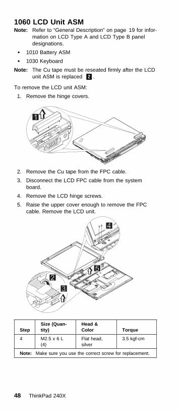
1060 LCD Unit ASMNote: Refer to “General Description” on page 19 for infor-
mation on LCD Type A and LCD Type B paneldesignations.
� 1010 Battery ASM
� 1030 Keyboard
Note: The Cu tape must be reseated firmly after the LCDunit ASM is replaced .2/.
To remove the LCD unit ASM:
1. Remove the hinge covers.
2. Remove the Cu tape from the FPC cable.
3. Disconnect the LCD FPC cable from the systemboard.
4. Remove the LCD hinge screws.
5. Raise the upper cover enough to remove the FPCcable. Remove the LCD unit.
StepSize (Quan-tity)
Head &Color Torque
4 M2.5 x 6 L(4)
Flat head,silver
3.5 kgf-cm
Note: Make sure you use the correct screw for replacement.
48 ThinkPad 240X

1070 Upper Cover ASM� 1010 Battery ASM
� 1020 Hard Disk Drive
� 1030 Keyboard
� 1060 LCD Unit ASM
To remove the upper cover ASM:
1. Remove the screw cover.
2. Remove the screw.
3. Remove the other screw as shown.
4. Remove the two screws from the hard disk drive bay.
5. Turn the notebook over; then remove the two screws.
StepSize (Quan-tity)
Head &Color Torque
2 M2.0 x 4L (1) Flat head,black
2.5 kgf-cm
3 M2.5 x 7L (1) Flat head,black
2.5 kgf-cm
4 M2.0 x 4L (2) Flat head,black
2.5 kgf-cm
5 M2.0 x 4L Flat head,black
2.0 kgf-cm
Note: Make sure you use the correct screw for replacement.
General Description 49

6. Disconnect the Touchbutton cable from the systemboard.
7. Carefully lift the upper cover to expose the speakerconnector as shown.
8. Disconnect the speaker cable from the main unit.Now you can remove the upper cover ASM from thebase cover ASM.
50 ThinkPad 240X

1080 Speaker ASM� 1010 Battery ASM
� 1020 Hard Disk Drive
� 1030 Keyboard
� 1060 LCD Unit ASM
� 1070 Upper Cover ASM
To remove the speaker:
1. Remove the three screws securing the speaker.
2. Remove the Cu tape and the securing tape from thecable.
3. Gently lift the speaker away from the upper cover.
StepSize (Quan-tity)
Head &Color Torque
1 M2.0 x 3L (3) Flat head,silver
2.5 kgf-cm
Note: Make sure you use the correct screw for replacement.
General Description 51

1085 Select Button ASM� 1010 Battery ASM
� 1020 Hard Disk Drive
� 1030 Keyboard
� 1060 LCD Unit ASM
� 1070 Upper Cover ASM
To remove the select button ASM:
1. Remove the three screws as shown.
2. Remove the select button ASM from the top coverASM.
StepSize (Quan-tity)
Head &Color Torque
1 M2.5 x 2.5L(3)
Flat head,silver
2.0 kgf-cm
Note: Make sure you use the correct screw for replacement.
52 ThinkPad 240X

1090 Cable ASM and Cable ASM LED-R� 1010 Battery ASM
� 1020 Hard Disk Drive
� 1030 Keyboard
� 1060 LCD Unit ASM
� 1070 Upper Cover ASM
To remove the hinge LED cable:
1. Disconnect the LED cable, then lift it as shown. (Thecable is fixed with double-sided tape.)
To remove the cable ASM LED-R:
1. Remove the screw.
2. Disconnect the LED board, then lift it as shown.
StepSize (Quan-tity)
Head &Color Torque
1 M2.0 x 7L (1) Flat head,silver
2.0 kgf-cm
Note: Make sure you use the correct screw for replacement.
General Description 53

1100 Fan ASM� 1010 Battery ASM
� 1020 Hard Disk Drive
� 1030 Keyboard
� 1060 LCD Unit ASM
� 1070 Upper Cover ASM
� 1090 Cable ASM and Cable ASM LED-R
Warning
Do not apply pressure on the fan blades or hub assembly;doing so can damage the fan bearings.
To remove the fan ASM:
1. Remove the two screws securing the fan ASM.
2. Carefully lift the fan ASM.
3. Disconnect the cable from the system board.
Warning
The fan ASM FRU includes a small pad of thermal rubber.The thermal rubber has adhesive and protective paper onboth sides and must be fixed onto the fan ASM beforereassembly.
To fix the thermal rubber on the fan ASM:
1. Remove the protective paper from one side of thethermal rubber.
2. Press the thermal rubber firmly in place on the fanASM.
3. Remove the protective paper from the other side ofthe thermal rubber.
54 ThinkPad 240X

Thermal rubber
Protective paper
Warning
When reassembling the fan, ensure that you insert thescrews in the order shown in the following illustration:
StepSize (Quan-tity)
Head &Color Torque
1 M2.0 x 7L (2) Flat head,silver
2.0 kgf-cm
Note: Make sure you use the correct screw for replacement.
General Description 55

1110 Modem Cable ASM� 1010 Battery ASM
� 1020 Hard Disk Drive
� 1030 Keyboard
� 1060 LCD Unit ASM
� 1070 Upper Cover ASM
To remove the modem cable ASM:
� Disconnect the modem cable from the system board.Remove the cable as shown.
56 ThinkPad 240X

1120 Water Channel ASM� 1010 Battery ASM
� 1020 Hard Disk Drive
� 1030 Keyboard
� 1060 LCD Unit ASM
� 1070 Upper Cover ASM
To remove the water channel ASM:
� Remove the water channel ASM as shown.
General Description 57

1130 System Board� 1010 Battery ASM
� 1020 Hard Disk Drive
� 1030 Keyboard
� 1060 LCD Unit ASM
� 1070 Upper Cover ASM
� 1090 Cable ASM and Cable ASM LED-R
� 1100 Fan ASM
� 1120 Water Channel ASM
Note: See “Replacing the System Board” on page 42before proceeding.
1. Remove the screws as shown.
2. Turn the notebook over; remove the two screws fromthe diskette drive connector.
3. Remove the screw from the PCMCIA slot.
4. Remove the battery terminal screw.
5. Gripping firmly as shown, separate the base coveraround the sides from the system board.
58 ThinkPad 240X

6. Remove the system board from the base cover ASM.
StepSize (Quan-tity)
Head &Color Torque
1 M2.0 x 4L (5) Flat head,black
2.5 kgf-cm
2 M2.0 x 6L (2) Flat head,black
2.0 kgf-cm
3 M2.0 x 4L (1) Flat head,black
2.0 kgf-cm
4 M2.0 x 8L (1) Flat head,black
2.0 kgf-cm
Note: Make sure you use the correct screw for replacement.
General Description 59

1135 Rear Bracket� 1010 Battery ASM
� 1020 Hard Disk Drive
� 1030 Keyboard
� 1060 LCD Unit ASM
� 1070 Upper Cover ASM
� 1090 Cable ASM and Cable ASM LED-R
� 1100 Fan ASM
� 1120 Water Channel ASM
� 1130 System Board
Note: See “Replacing the System Board” on page 42before proceeding.
1. Remove the six hexagonal studs as shown.
2. Remove the microphone.
3. Remove the rear bracket.
StepSize (Quan-tity)
Head &Color Torque
1 M2.5 x 4.5L(6)
Hex head,silver
4.0 kgf-cm
Note: Make sure you use the correct screw for replacement.
60 ThinkPad 240X

1140 PCMCIA Slots� 1010 Battery ASM
� 1020 Hard Disk Drive
� 1030 Keyboard
� 1060 LCD Unit ASM
� 1070 Upper Cover ASM
� 1090 Cable ASM and Cable ASM LED-R
� 1100 Fan ASM
� 1120 Water Channel ASM
� 1130 System Board
Warning
Special care must be taken when disconnecting thePCMCIA card not to cause a short or damage the con-nector.
To remove the PCMCIA slots:
1. Remove the screw securing the PCMCIA slot board.
2. Use a flat-bladed screwdriver to disconnect thePCMCIA card from the connector.
3. Carefully remove the PCMCIA card.
StepSize (Quan-tity)
Head &Color Torque
1 M2.0 x 7L (1) Flat head,silver
2.0 kgf-cm
Note: Make sure you use the correct screw for replacement.
General Description 61

1150 LCD Bezel ASM� 1010 Battery ASM
1. Remove the screw cap covers.
2. Remove the screws as shown.
Thi
nkP
adThi
nkP
ad
A
3. Gripping as shown, remove the LCD bezel.
4. The LCD latches must be opened as shown toremove the bezel.
Thi
nkP
adThi
nkP
ad
5. Remove the bezel from the LCD unit.
StepSize (Quan-tity)
Head &Color Torque
2 M2.5 x 5L (2) Flat head,black
2.5 kgf-cm
2A M2.5 x 5L (2) Flat head,black
1.5 kgf-cm
Note: Make sure you use the correct screw for replacement.
62 ThinkPad 240X

1160 LCD Inverter ASM� 1010 Battery ASM
� 1150 LCD Bezel ASM
To remove the LCD inverter ASM:
1. Disconnect the flex cable from the inverter card.
2. Disconnect the FPC cable from the inverter card.Thi
nkP
ad
3. Remove the inverter card. (The inverter card is fixedto the rear cover with double-sided tape.)
General Description 63

1170 LCD Panel ASM (LCD Type A andB)Note: Refer to “General Description” on page 19 for infor-
mation on LCD Type A and LCD Type B paneldesignations.
� 1010 Battery ASM
� 1030 Keyboard
� 1150 LCD Bezel ASM
� 1160 LCD Inverter ASM
To remove the LCD Panel:
1. Remove the Cu tape and disconnect the FPC cable.
2. Remove the four screws securing the LCD Panel.
3. Lift the top cover enough to pass the FPC connectorthrough.
64 ThinkPad 240X

4. Remove the LCD panel.
StepSize (Quan-tity)
Head &Color Torque
2(LCDTypeA)
M2.5 x 4L (4) Flat head,silver
3.0 kgf–cm
2(LCDTypeB)
M2.0 x 4L (4) Flat head,silver
3.0 kgf–cm
Note: Make sure you use the correct screw for replacement.
General Description 65

1180 LCD FPC ASM (LCD Type A)Note: Refer to “General Description” on page 19 for infor-
mation on LCD Type A and LCD Type B paneldesignations.
� 1010 Battery ASM
� 1030 Keyboard
� 1150 LCD Bezel ASM
� 1160 LCD Inverter ASM
� 1170 LCD Panel ASM (LCD Type A and B)
Note: When replacing the flex cable in the following pro-cedure, the labelled face of the cable must faceaway from the LCD panel.
1. Remove the tape from the FPC cable.
2. Disconnect the FPC connector from the LCD panel.
Bs1 FPC 1A P/N DEPC1222AA
Career B through Bs1 FPC 1A P/N DEPC1222AA
3. Disconnect the flex cable from the LCD panel.
66 ThinkPad 240X

1185 LCD FPC ASM (LCD Type B)Note: Refer to “General Description” on page 19 for infor-
mation on LCD Type A and LCD Type B paneldesignations.
� 1010 Battery ASM
� 1030 Keyboard
� 1150 LCD Bezel ASM
� 1160 LCD Inverter ASM
� 1170 LCD Panel ASM (LCD Type A and B)
1. Remove the tape from the FPC cable.
2. Open the fasteners on the FPC cable holder.
3. Disconnect the FPC connector from the LCD panel.
General Description 67

1190 Hinge ASM� 1010 Battery ASM
� 1030 Keyboard
� 1060 LCD Unit ASM
� 1150 LCD Bezel ASM
1. Remove the screws as shown.
2. Remove the hinge ASM.
StepSize (Quan-tity)
Head &Color Torque
1 M2.5 x 4L (2) Flat head,silver
3.5 kgf–cm
Note: Make sure you use the correct screw for replacement.
68 ThinkPad 240X

Computer Parts Listing
d
a
b
c
a
b
c
Index Description FRUNumber
a—d See MISC PARTS list 04P3067
1 HINGE CAP L/R 10L1954
HINGE CAP L/R (i-1124) 04P3066
2 UPPER COVER ASM 04P3059
UPPER COVER ASM (i-1124) 04P3060
3 REAR BRACKET 10L1952
4 LED CARD ASM (L) 10L1303
5 SERIAL/VGA CAP 10L1951
6 STANDARD BATTERY 02K6687
7 PCMCIA SLOT 04P3061
8 DISKETTE DRIVE CONNECTORLID
10L1953
9 TRACKPOINT CAP 84G6536
10 See Keyboard list
General Description 69

Index Description FRUNumber
11 SELECT BUTTON ASM 10L1958
12 FAN ASM 08K5926
13 SPEAKER ASM 02K6307
14 LED CARD ASM (R) 27L0579
15 SYSTEM BOARD ASM CELERON450
08K3206
SYSTEM BOARD ASM PIII 500 08K3208
16 MODEM CARD ASM 10L1305
17 BASE COVER ASM M/T 2609 04P3062
BASE COVER ASM M/T 2612 04P3077
BASE COVER ASM PRC M/T 2609 04P3063
BASE COVER ASM PRC M/T 2612 04P3078
BASE COVER ASM Korea M/T 2609 04P3064
BASE COVER ASM Korea M/T 2612 04P3079
18 HARD DISK DRIVE ASM 6 GB 27L3433
HARD DISK DRIVE ASM 12 GB 27L3434
HARD DISK DRIVE DOOR 04P3065
Description FRUNumber
AC ADAPTER
AC Adapter 72W (2 PIN) 02K6669
AC Adapter 72W (2 PIN) 02K6673
AC Adapter 72W (3 PIN) 02K6666
AC Adapter 72W (3 PIN) 02K6670
KEYBOARD
KBD ASM US English 02K5330
KBD ASM Japanese 02K5331
KBD ASM Japanese i-Series 02K5332
KBD ASM Traditional Chinese 02K5333
KBD ASM Korean 02K5334
KBD ASM Canadian French 02K5335
KBD ASM UK English 02K5336
KBD ASM German 02K5337
KBD ASM French 02K5338
KBD LA Spanish 02K5339
KBD ASM Danish 02K5340
KBD ASM Dutch 02K5341
KBD ASM Swedish/Finnish 02K5342
KBD ASM Italian 02K5343
KBD ASM Norwegian 02K5344
70 ThinkPad 240X

Description FRUNumber
KBD ASM Portuguese 02K5345
KBD ASM Spanish 02K5346
KBD ASM Swiss 02K5347
KBD ASM Belgium 02K5348
KBD ASM Hebrew 02K5349
KBD ASM Arabic 02K5350
KBD ASM Turkish 02K5351
KBD ASM Hungarian 02K5352
KBD ASM Russian 02K5353
KBD ASM Greek 02K5354
KBD ASM Czech 02K5355
KBD ASM Slovenian 02K5356
KBD ASM Slovakian 02K5357
Miscellaneous
Screw Kit 10L1956
MODEM CABLE ASM INTERNAL 27L0580
TELEPHONE CABLE US 27L0478
TELEPHONE CABLE Australia 27L0533
TELEPHONE CABLE UK 27L0480
TELEPHONE CABLE Germany 27L0481
TELEPHONE CABLE France 27L0482
TELEPHONE CABLE Austria 27L0580
TELEPHONE CABLE Belgium 27L0512
TELEPHONE CABLE Denmark/Portugal 27L0513
TELEPHONE CABLE Netherlands 27L0514
TELEPHONE CABLE Norway/Finland 27L0515
TELEPHONE CABLE Italy 27L0516
TELEPHONE CABLE Sweden 27L0517
TELEPHONE CABLE Switzerland 27L0518
TELEPHONE CABLE Spanish/Irish 27L0545
32 MB DIMM 20L0263
64 MB DIMM 20L0264
128 MB DIMM 20L0265
EXTERNAL DISKETTE DRIVE CABLE 12J1711
EXTERNAL DISKETTE DRIVE ASM 05K898905K8990
MICROPHONE HEADSET (i-1124) 02K4941
LARGE BATTERY 02K6690
General Description 71

Description FRUNumber
MISC PARTS
(a) MODEM DOOR
(b) SHUTTER (PCMCIA)
(c) SPRING SHUTTER
(d) WATER CHANNEL
(e) FPC HOLDER (upper)
FPC HOLDER (upper) i-Series
(f) FPC HOLDER (lower)
FPC HOLDER (lower) i-Series
(g) HOOK KNOB - R
HOOK KNOB - R i-Series
(h) SPRING HOOK - R
(i) HOOK KNOB - L
HOOK KNOB - L i-Series
(j) SPRING-HOOK - L
04P3067
Others
Power cord (Japan 2 PIN) 13H5273
Power cord (Australia, Papua New Guinea,New Zealand, Paraguay, Uruguay)
76H3514
Power cord (Bahamas, Barbados, Bermuda,Bolivia, Cayman Islands, Colombia, CostaRica, Dominican Republic, Ecuador, ElSalvador, Guatemala, Guyana, Haiti,Honduras, Jamaica, Korea (South), Mexico,Netherlands, Antilles, Nicaragua, Panama,Peru, Philippines, Saudi Arabia, Suriname,Taiwan, Trinidad (West Indies), Venezuela)
76H3516
Power cord (Austria, Belgium, Bulgaria,Czech Republic, Egypt, Finland, France,Germany, Greece, Hungary, Iceland,Indonesia, Netherlands, Norway, Poland,Portugal, Romania, Slovakia, Spain, Sweden,Turkey, former Yugoslavia)
76H3518
Power cord (Denmark) 76H3520
Power cord (Bangladesh, Pakistan, SouthAfrica, Sri Lanka)
76H3522
Power cord (Abu Dhabi, Albania, Antigua,Bahrain, Brunei, Dubai, Fiji, Hong Kong,India, Ireland, Kenya, Kuwait, Macao,Malaysia, Nigeria, Oman, People's Republicof China, Qatar, Singapore, United Kingdom)
76H3524
Power cord (Switzerland) 76H3528
Power cord (Israel) 76H3532
Power cord (Chile, Italy) 76H3530
Power cord (Korea) 76H3535
Power cord (PRC) 02K0539
Power cord (Canada, U.S.A. 2 PIN) 13H5264
72 ThinkPad 240X

Description FRUNumber
Power cord (Argentina 2 PIN) 36L8870
General Description 73

LCD Unit Parts Listing (LCD Type A)
e
fg
h
i
j
Note: Refer to “General Description” on page 19 for infor-mation on LCD Type A and LCD Type B paneldesignations.
Index Computer FRUNumber
e — j See MISC PARTS list 04P3067
1 LCD BEZEL ASM 04P3056
LCD BEZEL ASM (i-1124) 04P3057
LCD BEZEL ASM Korea 04P3058
2 LCD UNIT-TFT 10.4-inch 05K9653
3 LCD CABLE ASM 10L2164
4 HINGE ASM L/R 10L1943
5 LCD REAR COVER ASM 04P3052
LCD REAR COVER ASM (i-1124) 04P3053
LCD REAR COVER ASM Korea 04P3055
6 INVERTER CARD ASM 10L1530
SCREW CAP (i-1124) 04P3068
74 ThinkPad 240X

LCD Unit Parts Listing (LCD Type B)
e
fg
h
i
j
Note: Refer to “General Description” on page 19 for infor-mation on LCD Type A and LCD Type B paneldesignations.
Index Computer FRUNumber
e—j See MISC PARTS list 04P3067
1 LCD BEZEL ASM 04P3056
LCD BEZEL ASM (i-1124) 04P3057
LCD BEZEL ASM Korea 04P3058
2 LCD UNIT-TFT 10.4-inch 05K9651
3 LCD CABLE ASM 27L0489
4 HINGE ASM L/R 10L1943
5 LCD REAR COVER ASM 08K5820
LCD REAR COVER ASM (i-1124) 04P3054
LCD REAR COVER ASM Korea 08K5925
6 INVERTER CARD ASM 10L1431
Service Tools
Description FRU No.
Diagnostic Diskette N/A
CE Utility Diskette N/A
General Description 75

Description FRU No.
Tri-Connector Wrap Plug 72X8546
PC Test Card 35G4703
Audio Wrap Cable 66G5180
Screwdriver Kit 95F3598
USB Parallel Test Cable 05K2580
Torque Screwdriver (U.S. only) 05K4695
5 mm Socket Wrench 05K4694
Screwdriver 27L8126
76 ThinkPad 240X

NoticesReferences in this publication to IBM products, programs,or services do not imply that IBM intends to make theseavailable in all countries in which IBM operates. Any refer-ence to an IBM product, program, or service is notintended to state or imply that only IBM product, program,or service may be used. Subject to IBM's valid intellectualproperty or other legally protectable rights, any functionallyequivalent product program, or service may be usedinstead of the IBM product, program, or service. The evalu-ation and verification of operation in conjunction with otherproducts, except those expressly designated by IBM, arethe responsibility of the user.
IBM may have patents or pending patent applications cov-ering subject matter in this document. The furnishing ofthis document does not give you any license to thesepatents. You can send license inquiries, in writing, to:
IBM Director of LicensingIBM Corporation500 Columbus AvenueThornwood, NY 10594U.S.A.
TrademarksThe following terms are trademarks or service marks ofIBM Corporation in the United States and other countries:
IBMPS/2ThinkPadTrackPointTrackPoint IV
The following terms are trademarks or service marks ofother companies as follows:
Intel Intel CorporationMylar E.I. Du Pont de Nemours and CompanyPCMCIA Personal Computer Memory Card Interface
AssociationPentium Intel Corporation
General Description 77

IBM
Part Number: 19K5649
Printed in U.S.A.
S19K-5649-ðð