ibm magstar 3590 tape subsystem -...
TRANSCRIPT
IBM Magstar 3590 Tape Subsystem
Hardware Reference
GA32-0331-03
���


IBM Magstar 3590 Tape Subsystem
Hardware Reference
GA32-0331-03
���
Fourth Edition (September, 2000)
This edition of the IBM 3590 High Performance Tape Subsystem Hardware Reference, GA32-0331-03, obsoletes andreplaces GA32-0331-02. Changes or additions are indicated by a vertical line in the left margin.
The following paragraph does not apply to any country where such provisions are inconsistent with local law.
INTERNATIONAL BUSINESS MACHINES CORPORATION PROVIDES THIS PUBLICATION “AS IS” WITHOUTWARRANTY OF ANY KIND, EITHER EXPRESS OR IMPLIED, INCLUDING, BUT NOT LIMITED TO, THE IMPLIEDWARRANTIES OF MERCHANTABILITY OR FITNESS FOR A PARTICULAR PURPOSE. Some states do not allowdisclaimer of express or implied warranties in certain transactions; therefore, this statement may not apply to you.
Order publications through your IBM representative or the IBM branch office serving your locality.
If you have comments or suggestions to improve this book see “Do You Have Comments or Suggestions?” onpage 245.
When you send information to IBM, you grant IBM a non-exclusive right to use or distribute the information in anyway it believes appropriate without incurring any obligation to you.
© Copyright International Business Machines Corporation 1996, 2000. All rights reserved.US Government Users Restricted Rights – Use, duplication or disclosure restricted by GSA ADP Schedule Contractwith IBM Corp.
NoteBefore using this information and the product it supports, be sure to read thegeneral information under “Notices” on page 245.
||

Contents
Figures . . . . . . . . . . . . . . . . . . . . . . . . . . . vii
Preface . . . . . . . . . . . . . . . . . . . . . . . . . . . . ixOrganization . . . . . . . . . . . . . . . . . . . . . . . . . . ixRelated Information . . . . . . . . . . . . . . . . . . . . . . . ix
IBM 3590 Publications . . . . . . . . . . . . . . . . . . . . . ixIBM 3494 Tape Library Dataserver Publications . . . . . . . . . . . . ixIBM 3495 Tape Library Dataserver Publications . . . . . . . . . . . . ixRS/6000 Publications . . . . . . . . . . . . . . . . . . . . . . xAS/400 Publications . . . . . . . . . . . . . . . . . . . . . . x
Related Software Information . . . . . . . . . . . . . . . . . . . . x
Summary of Change . . . . . . . . . . . . . . . . . . . . . . xiiiFourth Edition . . . . . . . . . . . . . . . . . . . . . . . . . xiiiThird Edition . . . . . . . . . . . . . . . . . . . . . . . . . . xiiiSecond Edition . . . . . . . . . . . . . . . . . . . . . . . . . xiii
Chapter 1. Introduction . . . . . . . . . . . . . . . . . . . . . . 1Highlights . . . . . . . . . . . . . . . . . . . . . . . . . . . 1
Exceptional Performance . . . . . . . . . . . . . . . . . . . . 1Improved Reliability and Integrity . . . . . . . . . . . . . . . . . . 2Wide Platform Connectivity . . . . . . . . . . . . . . . . . . . . 2High Capacity . . . . . . . . . . . . . . . . . . . . . . . . . 2Cost Effectiveness . . . . . . . . . . . . . . . . . . . . . . . 2Ease of Use . . . . . . . . . . . . . . . . . . . . . . . . . 3Service . . . . . . . . . . . . . . . . . . . . . . . . . . . 33590 Models . . . . . . . . . . . . . . . . . . . . . . . . . 3Storage Management Software . . . . . . . . . . . . . . . . . . 3
Chapter 2. Drive SCSI Commands . . . . . . . . . . . . . . . . . 5Drive SCSI Commands Listed Alphabetically . . . . . . . . . . . . . . 7Control Byte Definition . . . . . . . . . . . . . . . . . . . . . . 9Change Definition -X‘40’ . . . . . . . . . . . . . . . . . . . . . 10Display Message -X‘C0’ . . . . . . . . . . . . . . . . . . . . . 12Erase -X‘19’ . . . . . . . . . . . . . . . . . . . . . . . . . . 15Inquiry -X‘12’ . . . . . . . . . . . . . . . . . . . . . . . . . 16
Inquiry Standard Data: Valid LUN (Logical Unit Number) . . . . . . . . 16Inquiry Standard Data: Invalid LUN . . . . . . . . . . . . . . . . 19Inquiry Page X‘00’. . . . . . . . . . . . . . . . . . . . . . . 21Inquiry Page X‘03’: ASCII Information . . . . . . . . . . . . . . . 22
Inquiry Page X‘80’: Unit Serial Number . . . . . . . . . . . . . . . . 23Inquiry Page X‘83’: Device Identification. . . . . . . . . . . . . . . . 24Load Unload -X‘1B’ . . . . . . . . . . . . . . . . . . . . . . . 26Locate -X‘2B’ . . . . . . . . . . . . . . . . . . . . . . . . . 28Log Select -X‘4C’ . . . . . . . . . . . . . . . . . . . . . . . . 30Log Sense -X‘4D’ . . . . . . . . . . . . . . . . . . . . . . . . 32
Log Page Format . . . . . . . . . . . . . . . . . . . . . . . 32Log Parameter Format . . . . . . . . . . . . . . . . . . . . . 33Log Page X‘00’: Supported Log Pages . . . . . . . . . . . . . . . 35Log Page X‘02’: Write Error Counters . . . . . . . . . . . . . . . 36Log Page X‘03’: Read Error Counters . . . . . . . . . . . . . . . 38Log Page X‘06’: Non-Medium Errors . . . . . . . . . . . . . . . . 40Log Page X‘0C’: Sequential-access device. . . . . . . . . . . . . . 41
© Copyright IBM Corp. 1996, 2000 iii
||

Log Page X‘31’: SIM/MIM . . . . . . . . . . . . . . . . . . . . 43Log Page X‘32’: Write Errors . . . . . . . . . . . . . . . . . . . 47Log Page X‘34’: Read Forward Errors . . . . . . . . . . . . . . . 51Log Page X‘36’: Read Reverse Errors . . . . . . . . . . . . . . . 58Log Page X‘38’: Blocks/Bytes Transferred . . . . . . . . . . . . . . 59Log Page X‘39’: SCSI Port 0 Interface Errors. . . . . . . . . . . . . 63Log Page X‘3A’: SCSI Port 1 Interface Errors. . . . . . . . . . . . . 65Log Page X‘3B’: Equipment Check Errors . . . . . . . . . . . . . . 66Log Page X‘3D’: Subsystem Statistics . . . . . . . . . . . . . . . 69
Mode Select (6) - X‘15’ . . . . . . . . . . . . . . . . . . . . . . 74Mode Parameter List for Mode Select (6) . . . . . . . . . . . . . . 76Mode Parameter Header for Mode Select (6) . . . . . . . . . . . . . 77Block Descriptor for Mode Select (6) or Mode Select (10) . . . . . . . . 78
Mode Select (10) - X‘55’ . . . . . . . . . . . . . . . . . . . . . 79Mode Parameter List for Mode Select (10) . . . . . . . . . . . . . . 81Mode Parameter Header for Mode Select (10) . . . . . . . . . . . . 82
Mode Sense (6) - X‘1A’ . . . . . . . . . . . . . . . . . . . . . . 83Mode Parameter List for Mode Sense (6) . . . . . . . . . . . . . . 84Mode Parameter Header for Mode Sense (6). . . . . . . . . . . . . 85Block Descriptor for Mode Sense (6) or Mode Sense (10) . . . . . . . . 86
Mode Sense (10) - X‘5A’ . . . . . . . . . . . . . . . . . . . . . 88Mode Parameter List for Mode Sense (10). . . . . . . . . . . . . . 89Mode Parameter Header for Mode Sense (10) . . . . . . . . . . . . 90Mode Page Format . . . . . . . . . . . . . . . . . . . . . . 92
Move Medium -X‘A5’ . . . . . . . . . . . . . . . . . . . . . . 126Persistent Reserve In - X‘5E’ . . . . . . . . . . . . . . . . . . . 127Persistent Reserve Out - X‘5F’ . . . . . . . . . . . . . . . . . . 129Prevent Allow Medium Removal - X‘1E’ . . . . . . . . . . . . . . . 130Read - X‘08’ . . . . . . . . . . . . . . . . . . . . . . . . . 131Read Block Limits - X‘05’ . . . . . . . . . . . . . . . . . . . . 133Read Buffer - X‘3C’ . . . . . . . . . . . . . . . . . . . . . . . 134
Magstar Drive Buffers . . . . . . . . . . . . . . . . . . . . . 135Read Element Status - X‘B8’ . . . . . . . . . . . . . . . . . . . 137Read Position - X‘34’ . . . . . . . . . . . . . . . . . . . . . . 138Read Reverse - X‘0F’ . . . . . . . . . . . . . . . . . . . . . . 141Receive Diagnostic Results - X‘1C’ . . . . . . . . . . . . . . . . . 143
Diagnostic Results Page Formats . . . . . . . . . . . . . . . . 143Recover Buffered Data - X‘14’ . . . . . . . . . . . . . . . . . . . 145Release Unit - X‘17’ . . . . . . . . . . . . . . . . . . . . . . 146Report Density Support- X‘44’ . . . . . . . . . . . . . . . . . . . 147Report LUNs - X‘A0’ . . . . . . . . . . . . . . . . . . . . . . 150Request Sense - X‘03’ . . . . . . . . . . . . . . . . . . . . . 151Reserve Unit - X‘16’ . . . . . . . . . . . . . . . . . . . . . . 158Rewind - X‘01’ . . . . . . . . . . . . . . . . . . . . . . . . 159Send Diagnostic - X‘1D’ . . . . . . . . . . . . . . . . . . . . . 160
PF (Page Format) . . . . . . . . . . . . . . . . . . . . . . 160SelfTest . . . . . . . . . . . . . . . . . . . . . . . . . . 160DevOfL (Device Off Line). . . . . . . . . . . . . . . . . . . . 160UnitOfL (Unit Off Line). . . . . . . . . . . . . . . . . . . . . 161Parameter List Length . . . . . . . . . . . . . . . . . . . . . 161Flag and Link . . . . . . . . . . . . . . . . . . . . . . . . 161Diagnostic Page Formats . . . . . . . . . . . . . . . . . . . 162
Magstar-Supported Diagnostics . . . . . . . . . . . . . . . . . . 162Self-Test . . . . . . . . . . . . . . . . . . . . . . . . . . 164Change SCSI ID Diagnostic. . . . . . . . . . . . . . . . . . . 165POST A Diagnostic . . . . . . . . . . . . . . . . . . . . . . 167
iv Magstar 3590 Hardware Reference
||||
||

POST B Diagnostic . . . . . . . . . . . . . . . . . . . . . . 169ACF Diagnostic . . . . . . . . . . . . . . . . . . . . . . . 171Force Dump Diagnostic . . . . . . . . . . . . . . . . . . . . 173Write Dump to Cartridge Diagnostic . . . . . . . . . . . . . . . . 174Create FMR Cartridge Diagnostic . . . . . . . . . . . . . . . . 176Set Traps Diagnostic . . . . . . . . . . . . . . . . . . . . . 178Remove Traps Diagnostic . . . . . . . . . . . . . . . . . . . 179Set Drive Parameters Diagnostic . . . . . . . . . . . . . . . . . 180Reset VSARS Diagnostic . . . . . . . . . . . . . . . . . . . 181Reset Drive Diagnostic . . . . . . . . . . . . . . . . . . . . 182
Space - X‘11’ . . . . . . . . . . . . . . . . . . . . . . . . . 183Test Unit Ready - X‘00’ . . . . . . . . . . . . . . . . . . . . . 184Write - X‘0A’ . . . . . . . . . . . . . . . . . . . . . . . . . 185Write Buffer - X‘3B’ . . . . . . . . . . . . . . . . . . . . . . . 186Write Filemarks - X‘10’ . . . . . . . . . . . . . . . . . . . . . 187
Chapter 3. ACF SCSI Commands . . . . . . . . . . . . . . . . . 189ACF SCSI Commands Listed Alphabetically . . . . . . . . . . . . . . 190Initialize Element Status - X‘07’ . . . . . . . . . . . . . . . . . . 192Inquiry - X‘12’ . . . . . . . . . . . . . . . . . . . . . . . . . 193
Inquiry Page X‘00’ . . . . . . . . . . . . . . . . . . . . . . 193Inquiry Page X‘80’: Unit Serial Number . . . . . . . . . . . . . . 194Inquiry Page X‘83’: Device Identification . . . . . . . . . . . . . . 194
Log Sense - X‘4D’ . . . . . . . . . . . . . . . . . . . . . . . 196Log Page ‘00’: Supported Log Pages . . . . . . . . . . . . . . . 196
Mode Select (6) - X‘15’ . . . . . . . . . . . . . . . . . . . . . 197Mode Parameter Header for Mode Select (6) . . . . . . . . . . . . 197
Mode Select (10) - X‘55’ . . . . . . . . . . . . . . . . . . . . . 198Mode Parameter Header for Mode Select (10) . . . . . . . . . . . . 198
Mode Sense (6) - X‘1A’ . . . . . . . . . . . . . . . . . . . . . 199Mode Parameter Header for Mode Sense (6) . . . . . . . . . . . . 199
Mode Sense (10) - X‘5A’ . . . . . . . . . . . . . . . . . . . . . 200Mode Parameter Header for Mode Sense (10) . . . . . . . . . . . . 200
Mode Page Format . . . . . . . . . . . . . . . . . . . . . . . 201Move Medium -X‘A5’ . . . . . . . . . . . . . . . . . . . . . . 202Position to Element - X‘2B’ . . . . . . . . . . . . . . . . . . . . 203Read Element Status - X‘B8’ . . . . . . . . . . . . . . . . . . . 204
Element Status Data . . . . . . . . . . . . . . . . . . . . . 205Element Descriptors . . . . . . . . . . . . . . . . . . . . . 207
Receive Diagnostic Results - X‘1C’ . . . . . . . . . . . . . . . . . 213Release Element (6) - X‘17’. . . . . . . . . . . . . . . . . . . . 214Request Sense - X‘03’ . . . . . . . . . . . . . . . . . . . . . 215Reserve Element (6)- X‘16’ . . . . . . . . . . . . . . . . . . . . 216
Data Format of Element List Descriptors . . . . . . . . . . . . . . 216Send Diagnostic - X‘1D’ . . . . . . . . . . . . . . . . . . . . . 217Test Unit Ready - X‘00’ . . . . . . . . . . . . . . . . . . . . . 218
Chapter 4. ACF Modes of Operation . . . . . . . . . . . . . . . . 219ACF Notes . . . . . . . . . . . . . . . . . . . . . . . . . . 219Initiator Control of the ACF . . . . . . . . . . . . . . . . . . . . 220Manual Mode . . . . . . . . . . . . . . . . . . . . . . . . . 221Accumulate Mode . . . . . . . . . . . . . . . . . . . . . . . 222Automatic Mode . . . . . . . . . . . . . . . . . . . . . . . . 223System Mode . . . . . . . . . . . . . . . . . . . . . . . . . 225Random Mode . . . . . . . . . . . . . . . . . . . . . . . . 226Random 2-LUN Mode (B-Series Models Only) . . . . . . . . . . . . . 228
Contents v
Cell Status Indicators . . . . . . . . . . . . . . . . . . . . . . 229Cell Status: Flashing Yellow is an Attention Indicator . . . . . . . . . 229Cell Status: Steady Yellow Indicates Alert Conditions . . . . . . . . . 229Cell Status: Steady Green is an In-Use Indicator . . . . . . . . . . . 229
Appendix A. SCSI Protocol Implementation Notes for the Magstar . . . . 231Device Messages . . . . . . . . . . . . . . . . . . . . . . . 231Supported SCSI Status Codes. . . . . . . . . . . . . . . . . . . 232
Appendix B. Error Sense Information . . . . . . . . . . . . . . . 233Sense Key 0 (No Sense). . . . . . . . . . . . . . . . . . . . . 233Sense Key 1 (Recovered Error) . . . . . . . . . . . . . . . . . . 233Sense Key 2 (Not Ready) . . . . . . . . . . . . . . . . . . . . 233Sense Key 3 (Medium Error) . . . . . . . . . . . . . . . . . . . 234Sense Key 4 (Hardware Error). . . . . . . . . . . . . . . . . . . 234Sense Key 5 (Illegal Request) . . . . . . . . . . . . . . . . . . . 235Sense Key 6 (Unit Attention) . . . . . . . . . . . . . . . . . . . 235Sense Key 7 (Data Protect) . . . . . . . . . . . . . . . . . . . . 236Sense Key 8 (Blank Check). . . . . . . . . . . . . . . . . . . . 236Sense Key B (Aborted Command) . . . . . . . . . . . . . . . . . 236Sense Key D (Volume Overflow) . . . . . . . . . . . . . . . . . . 237
Appendix C. Implementation Considerations . . . . . . . . . . . . 239Scaled Log Page Counters . . . . . . . . . . . . . . . . . . . . 239SCSI-ID and LUN Assignments . . . . . . . . . . . . . . . . . . 239Multiple Port Behavior . . . . . . . . . . . . . . . . . . . . . . 239
Behavior with Auto-Share Disabled . . . . . . . . . . . . . . . . 240Behavior with Auto-Share Enabled . . . . . . . . . . . . . . . . 240
Data Transfer, Block Limits, and Fixed Block Option . . . . . . . . . . . 241Cleaning the Drive in the 3494 Library . . . . . . . . . . . . . . . . 241Drive Cleaning Indicators. . . . . . . . . . . . . . . . . . . . . 242
Operator Panel Cleaning Indication . . . . . . . . . . . . . . . . 242SCSI Interface — Dynamic Cleaning Indicators . . . . . . . . . . . 242SCSI Interface — Static Cleaning Indicator (Sense Data Byte 70). . . . . 243
Notices . . . . . . . . . . . . . . . . . . . . . . . . . . . 245Do You Have Comments or Suggestions? . . . . . . . . . . . . . . 245Terms . . . . . . . . . . . . . . . . . . . . . . . . . . . . 246Trademarks. . . . . . . . . . . . . . . . . . . . . . . . . . 246IBM Agreement for Licensed Internal Code . . . . . . . . . . . . . . 247
Actions You May Not Take . . . . . . . . . . . . . . . . . . . 247AIX License Information Additional Terms and Conditions . . . . . . . . . 248Communication Statements . . . . . . . . . . . . . . . . . . . . 249
Glossary . . . . . . . . . . . . . . . . . . . . . . . . . . 251
Index . . . . . . . . . . . . . . . . . . . . . . . . . . . . 255
vi Magstar 3590 Hardware Reference

Figures
1. IBM 3590 Model B11 Rack-Mounted Tape Subsystem . . . . . . . . . . . . . . . . . 1
© Copyright IBM Corp. 1996, 2000 vii

viii Magstar 3590 Hardware Reference

Preface
OrganizationThe information in this book is presented as follows:
v Chapter 1. Introduction, describes the subsystem.
v Chapter 2. Drive SCSI Commands, describes the SCSI commands supported forthe Magstar drive (LUN 0). These commands include support for the MagstarACF when addressed as an Attached Medium Changer device at LUN 0 (1-LUNaddressing).
v Chapter 3. ACF SCSI Commands, describes the SCSI commands supported forthe Magstar ACF when addressed as an Independent Medium Changer device atLUN 1 (2-LUN addressing).
v Chapter 4. ACF Modes of Operation, describes the seven ACF modes ofoperation.
v Appendix A. SCSI Protocol Implementation Notes for the Magstar, describes theSCSI protocol implementation choices.
v Appendix B. Error Sense Information, provides all error sense informationreported by the Magstar devices.
v Appendix C. Implementation Considerations, describes the SCSI implementationconsiderations.
v The “Glossary” on page 251 describes words and terms used in this book.
v The “Index” on page 255 includes keywords and terms to help retrieveinformation in this book.
Related Information
IBM 3590 PublicationsFor additional information about the 3590 subsystem, refer to:
v IBM Magstar 3590 Tape Subsystem Operator Guide, GA32-0330
v IBM 3591 Tape Control Unit Model A01 Introduction, Planning, and User’s Guide,GA32-0358
v IBM Magstar 3590 Tape Subsystem Introduction and Planning Guide, GA32-0329
v Magstar 3590 Tape Subsystem Silo-Compatible Frame Models C12 and C14Introduction, Planning, and User Guide, GA32-0366
v IBM General Information Installation Manual—Physical Planning, GC22-7072
IBM 3494 Tape Library Dataserver PublicationsFor additional information about the 3494 Tape Library Dataserver, refer to:
v IBM 3494 Introduction and Planning Guide, GA32-0279
v IBM 3494 Operator’s Guide, GA32-0280
v IBM 3494 Physical Planning Template, GX35-5049
v IBM 3494 User’s Guide: Media Library Device Driver for AS/400, GC35-0153
IBM 3495 Tape Library Dataserver PublicationsFor additional information about the 3495 Tape Library Dataserver, refer to:
v IBM 3495 Tape Library Dataserver Introduction and Planning Guide, GA32-0234
© Copyright IBM Corp. 1996, 2000 ix

v IBM 3495 Tape Library Dataserver Models L20, L30, L40, and L50 Operator’sGuide, GA32-0235
RS/6000 PublicationsFor additional information about RS/6000® systems, see:
v RISC System/6000 Getting Started: Using RISC System/6000, GC23-2521
v RISC System/6000 Getting Started: Managing RISC System/6000, GC23-2378
v RISC System/6000 Problem Solving Guide, SC23-2204
v RISC System/6000 V4 Problem Solving Guide, SC23-2606
v RISC System/6000 V4 Message Guide & Reference, SC23-2641
v RISC System/6000 Planning for System Installation, SA38-0508
v RS/6000 7017 Rack Installation and Service Guide, SA48-0548
AS/400 PublicationsFor additional information about AS/400® systems, see:
v AS/400 Physical Planning Guide and Reference, GA41-9571
v AS/400 Control Language Reference, SC41-0030
v AS/400 Service: Service Functions, SY44-3902
v AS/400 System Operation, SC41-3203
v AS/400 Physical Planning Reference, SA41-3109
v AS/400 Physical Planning Summary, SX41-3108
v AS/400 Control Language Reference, SC41-0030
v AS/400 Security Concepts and Planning, SC41-8083
v AS/400 System/370™ Connectivity, GG24-3336
v Automated Tape Library Planning and Management Guide, SC41-3309
Related Software InformationFor information regarding software related to the IBM 3590 Tape Subsystem, referto:
v AIX/ESA Diagnosis Guide, SC23-3079
v AIX/ESA Device Driver Developer’s Guide, SC23-3085
v AIX Parallel and ESCON Channel Tape Attachment/6000 Installation and User’sGuide, GA32-0311
v Basic Tape Library Support User’s Guide and Reference, SC26-7016
v Environmental Record Editing and Printing (EREP) Program User’s Guide andReference, GC28-1378
v DFSMS/MVS Version 1 Release 1: General Information, GC26-4900
v DFSMS/MVS Version 1 Release 1: Object Access Method Planning, Installation,and Storage Administration Guide for Tape Libraries, SC26-3051
v DFSMS/MVS Version 1 Release 1: Object Access Method ApplicationProgrammer’s Reference, SC26-4917
v DFSMS/MVS Version 1 Release 1: Guide and Master Index, GC26-4904
v Multiple Virtual Storage/Enterprise System Architecture Library Guide for SystemProduct, GC28-1601
v MVS/ESA Storage Management Library: Storage Management Reader’s Guide,GC26-3122
x Magstar 3590 Hardware Reference

v Virtual Machine/Enterprise System Architecture Library Guide and Master Index,GC24-5518
v Virtual Machine/Enterprise System Architecture Library Guide and Master Indexfor System/370, GC24-5436
v Virtual Machine/Enterprise System Architecture General Information, GC24-5550
v IBM SCSI Tape Drive and Library Device Drivers Installation and User’s Guide,GC35-0154
Preface xi

xii Magstar 3590 Hardware Reference
Summary of Change
This summary of changes includes specific release updates to this book.
Fourth EditionThis release includes information on the 3590 Extended High PerformanceCartridge Tape and Fibre Channel Attachment. Extended High PerformanceCartridge Tape increases both the IBM Magstar 3590 E Model 256-track serpentineformat capacity to 40GB and the IBM Magstar 3590 B Model 128-track serpentineformat capacity to 20GB. This release includes information on Fibre ChannelAttachment features. With Fibre Channel Attachment, 3590 Model E is now capableof delivering a data rate of 40 MB/sec maximum sustained data rate (with 3:1 datacompression) and up to 100 MB/sec maximum instantaneous data rate. FibreChannel Attachment has increased the maximum distance to 500 meters. It ispossible to extend the maximum distance to 10 kilometers using fibre components.
Third EditionThis release includes information on two new Magstar 3590 tape drives, ModelsE1A and E11. With these models, the native data transfer rate is improved by morethan 50% and cartridge capacity is doubled to a 256-track serpentine format.Models E1A and E11 can read and write data in the 256-track serpentine format,and both Exx and Bxx models read data in the 128-track serpentine format. ModelBxx tape drives write in the 128-track serpentine format.
Second EditionThis release includes information on the Magstar Ultra and hardware featureadditions.
© Copyright IBM Corp. 1996, 2000 xiii
|
||||||||||

xiv Magstar 3590 Hardware Reference

Chapter 1. Introduction
The IBM Magstar 3590 High Performance Tape Subsystem provides new levels offunction, performance, reliability, and cartridge capacity.
Figure 1 shows a 3590 tape subsystem.
Highlightsv Magstar 3590 attaches to selected systems, including Hewlett-Packard, Sun
Microsystems, HP/Convex, CRAY Research, Inc., Silicon Graphics, Intel-basedsystems running Windows NT and Windows 2000, as well as to IBM AS/400,RS/6000, and S/390 systems.
v The Magstar 3590’s 13.5 MB/sec native data rate (33MB/sec with maximumcompression) dramatically reduces backup and recovery times.
v With random access to 1200 GB of data (3:1 compressed), the Magstar 359010-cartridge Automatic Cartridge Facility (ACF) functions as a low-costmini-library.
v Magstar 3590’s 5 meters/sec high-speed search provides rapid access to storeddata.
v Magstar 3590 cartridges can contain 120 GB with 3:1 data compression.
v The Magstar 3590 tape drive is designed for up to a 100-fold increase in dataintegrity over the 3480.
v The Magstar 3590 E-series models also offer a dual 100 MB/sec Fibre ChannelPort option for increased performance and connectivity.
v Dual Ultra/Wide differential SCSI ports provide enhanced sharing capabilities
Exceptional PerformanceThe Magstar 3590 models have leading-edge streaming and start/stop performance.This is important since most applications operate in start/stop mode. The 3590E-series streaming performance is more than four times that of the 3490E, with anative data transfer rate of 13.5 MB/sec (40 MB/sec with 3:1 compression ). Themaximum instantaneous data rate is 40 MB/sec on an Ultra/Wide SCSI Interface.
14
00
06
8
Figure 1. IBM 3590 Model B11 Rack-Mounted Tape Subsystem
© Copyright IBM Corp. 1996, 2000 1
|
|
||
|

The Magstar 3590 E-series models have a maximum instantaneous data rate of100 MB/sec with the Fibre Channel Attachment option.
Improved Reliability and IntegrityThe advanced Magstar 3590 tape drive is designed for up to a 100-fold increase indata integrity over the 3480. Magstar 3590 uses a bidirectional serpentine recordingtechnique and a second-generation magnetoresistive head that writes 16 datatracks at a time. Improved Error Correction Code (ECC) and servo tracks written ontape help ensure data integrity. Resident diagnostics monitor operations to detectpotential problems and aid in fast resolution.
Wide Platform ConnectivityThe Magstar 3590 has two Ultra/Wide differential SCSI ports, allowing the drive tobe shared in a multi-platform open systems environment.
Data can be interchanged across a wide range of platforms with the Magstar 3590Tape Subsystem. The Magstar 3590 attaches to selected systems fromHewlett-Packard, Sun Microsystems, HP/Convex, CRAY, Silicon Graphics, Sequent,and Intel-based systems that support Windows NT and Windows 2000, as well asto IBM AS/400, RS/6000, and S/390 systems.
The Magstar 3590 E-series Models have a Fibre Channel Attachment option,allowing Fibre Channel Attachment to selected RS/6000, Intel-Based systems thatsupport Windows NT and Windows 2000, Sun, and NUMA-Q systems.
High CapacityMagstar 3590 Extended High Performance Cartridge Tapes have a capacity of:
v E-Series:
– 40 GB (native compression)
– 120 GB (3:1 LZI compression)
v B-Series:
– 20 GB (native compression)
– 60 GB (3:1 LZI compression)
Prior generation High Performance Cartridge Tapes provide half the capacity ofthe Extended High Performance Cartridge Tapes.
Magstar 3590 metal particle tape media is housed in a cartridge with the samephysical size as 3480 cartridges, enabling coexistence in an IBM Magstar 3494tape library together with current media. The Magstar 3494 tape library withMagstar 3590 drives provides access to as much as 748 TB (using Extended HighPerformance Cartridge Tapes with 3:1 LZI compression).
Cost EffectivenessHigh capacity means that less equipment, fewer cartridges, and fewer tape mountsare required. High performance can reduce the number of drives required. Thistranslates into less floorspace for tape cartridge storage, tape drives, and tapelibraries. Maintenance costs are also lower than those for high-performance helicaland 3480/3490 drives.
2 Magstar 3590 Hardware Reference
||
|
|||
|
|
|
|
||
|
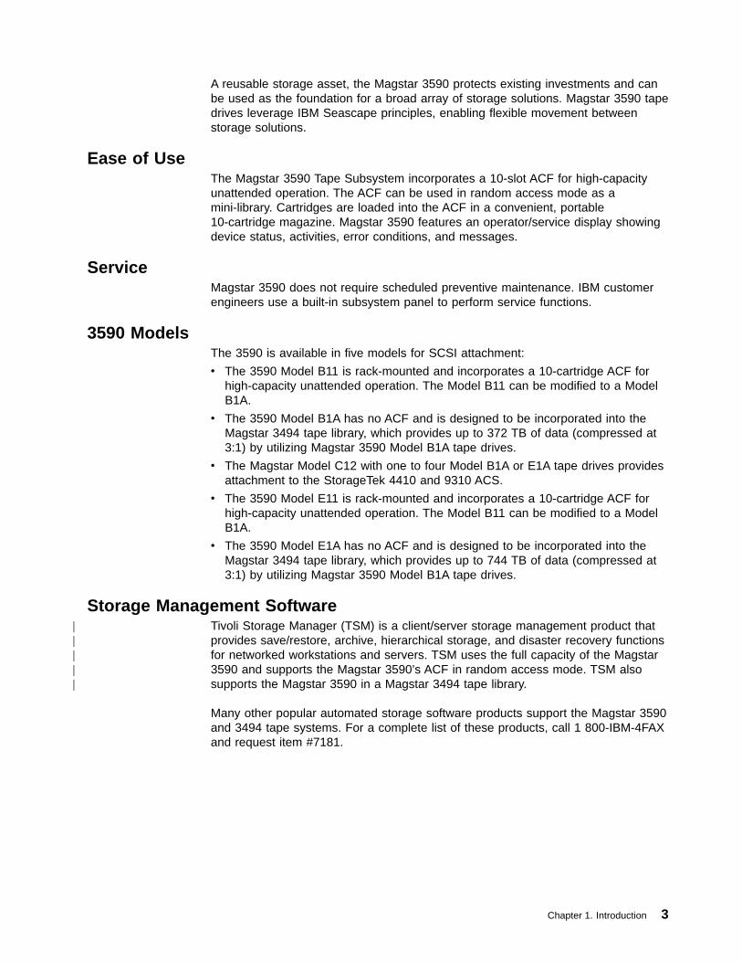
A reusable storage asset, the Magstar 3590 protects existing investments and canbe used as the foundation for a broad array of storage solutions. Magstar 3590 tapedrives leverage IBM Seascape principles, enabling flexible movement betweenstorage solutions.
Ease of UseThe Magstar 3590 Tape Subsystem incorporates a 10-slot ACF for high-capacityunattended operation. The ACF can be used in random access mode as amini-library. Cartridges are loaded into the ACF in a convenient, portable10-cartridge magazine. Magstar 3590 features an operator/service display showingdevice status, activities, error conditions, and messages.
ServiceMagstar 3590 does not require scheduled preventive maintenance. IBM customerengineers use a built-in subsystem panel to perform service functions.
3590 ModelsThe 3590 is available in five models for SCSI attachment:
v The 3590 Model B11 is rack-mounted and incorporates a 10-cartridge ACF forhigh-capacity unattended operation. The Model B11 can be modified to a ModelB1A.
v The 3590 Model B1A has no ACF and is designed to be incorporated into theMagstar 3494 tape library, which provides up to 372 TB of data (compressed at3:1) by utilizing Magstar 3590 Model B1A tape drives.
v The Magstar Model C12 with one to four Model B1A or E1A tape drives providesattachment to the StorageTek 4410 and 9310 ACS.
v The 3590 Model E11 is rack-mounted and incorporates a 10-cartridge ACF forhigh-capacity unattended operation. The Model B11 can be modified to a ModelB1A.
v The 3590 Model E1A has no ACF and is designed to be incorporated into theMagstar 3494 tape library, which provides up to 744 TB of data (compressed at3:1) by utilizing Magstar 3590 Model B1A tape drives.
Storage Management SoftwareTivoli Storage Manager (TSM) is a client/server storage management product thatprovides save/restore, archive, hierarchical storage, and disaster recovery functionsfor networked workstations and servers. TSM uses the full capacity of the Magstar3590 and supports the Magstar 3590’s ACF in random access mode. TSM alsosupports the Magstar 3590 in a Magstar 3494 tape library.
Many other popular automated storage software products support the Magstar 3590and 3494 tape systems. For a complete list of these products, call 1 800-IBM-4FAXand request item #7181.
Chapter 1. Introduction 3
|||||

4 Magstar 3590 Hardware Reference

Chapter 2. Drive SCSI Commands
This chapter describes the SCSI commands supported for the 3590 drive (LUN 0).These commands include support for the 3590 ACF when addressed as anAttached Medium Changer device at LUN 0 (this 1–LUN addressing mode is notsupported on the E-Series models).
“Chapter 3. ACF SCSI Commands” on page 189 describes the SCSI commandssupported for the 3590 ACF when addressed as an Independent Medium Changerdevice at LUN 1 (2-LUN addressing).
Note: For B-Series Models, Attached Medium Changer (1-LUN addressing) is thedefault operating definition for all ACF modes of operation except Random2-LUN (see “Change Definition -X‘40’” on page 10).
The following SCSI command descriptions have a table describing the fields in theCommand Descriptor Block (CDB), similar to the style used in the AmericanNational Standard of the National Committee for Information Technology Standards(NCITS) documents:
v SCSI—3 Media Changer Commands [t10–999D] (hereafter referred to as the“NCITS SMC document”)
v SCSI Primary Commands [X3–301–1997] (hereafter referred to as the “NCITSSPC document”)
v SCSI—3 Stream Commands [t10–997D] (hereafter referred to as the “NCITSSSC document”)
Any parameters or data required by each command follow these descriptions andare described in a “term-definition” format. In this format, the bits or bytes to bedescribed are highlighted and listed on the left. The definition for the bits or bytes isto the right (not highlighted).
Bit Numbering Conventions:
Bit numbering follows ANSI standards as follows:
v Bit 0 is the least significant bit (LSB) occupying the rightmost bit position in thediagrams
v Bits 1–6 continue from right to left in ascending order
v Bit 7 is the most significant bit (MSB) occupying the leftmost bit position in thediagrams
Commands Not Supported:
Certain commands or features of some commands are not currently supported butmay be in the future. All such cases are noted in the command description or inTable 1 on page 7. The following features or commands are not currently supportedbut may be later: Format Medium, and Volume Partitioning. The Copy, Verify,Compare, Copy/Verify, and Send commands are also not supported.
The Write Buffer command is supported but not all buffers are described in thisdocument because most buffers are intended only to be written by the ServiceRepresentative or by Manufacturing. OEM customers who intend to support hostmicrocode download on a new platform should contact IBM for a completedescription of the Write Buffer command for this purpose. Note that new microcode
© Copyright IBM Corp. 1996, 2000 5

may also be loaded without requiring the use of the SCSI Write Buffer command, byusing the Field Microcode Replacement (FMR tape) process described in themaintenance information manual for this product.
6 Magstar 3590 Hardware Reference

Drive SCSI Commands Listed AlphabeticallyTable 1 provides a list of all commands defined by the referenced SCSI-3 standardor by this product as vendor-unique for sequential access devices. For eachcommand, the operation code, reference page for this specification, applicableSCSI-3 standard section, type of support required for the command as defined bythe SCSI-3 standard, and applicability of certain conditions to the command areshown.
Table 1. 3590 Drive Commands (LUN 0)
Command Name OperationCode
See Page SCSIDocument
Applicable Conditions:
RVC¹UAT NRD WRP MFC DCC
Change Definition X'40' 10 SPC Y Y - - - -
Compare (Not Supported) X'39' NS SPC Y Y - - - Y
Copy (Not Supported) X'18' NS SPC Y Y - - - Y
Copy and Verify (Not Supported) X'3A' NS SPC Y Y - - - Y
Display Message X'C0' 12 VU Y Y - - - -
Erase X'19' 15 SSC Y Y Y Y Y Y
Format Medium (Not currently supported) X'04' NS VU Y Y Y Y Y⁷ Y
Inquiry X'12' 16 SPC - - - - - -
Load Unload X'1B' 26 SSC Y Y Y⁴ - Y⁵ Y
Locate X'2B' 28 SSC Y Y Y - Y Y
Log Select X'4C' 30 SPC Y Y - - - -
Log Sense X'4D' 32 SPC Y - - - - -
Mode Select (6) X'15' 74 SPC Y Y - - - Y⁸
Mode Select (10) X'55' 79 SPC Y Y - - - Y⁸
Mode Sense (6) X'1A' 83 SPC - Y - - - -
Mode Sense (10) X'5A' 88 SPC - Y - - - -
Move Medium X'A5' 126 SMC Y Y Y - - Y¹¹
Persistent Reserve In X'5E' 127 SPC - Y - - - -
Persistent Reserve Out X'5F' 129 SPC 12 Y - - - -
Prevent Allow Medium Removal X'1E' 130 SPC Y Y - - - -
Read X'08' 131 SSC Y Y Y - Y Y
Read Block Limits X'05' 133 SSC Y Y - - - -
Read Buffer X'3C' 134 SPC Y - - - - -
Read Element Status X'B8' 137 SMC - Y Y - - Y¹¹
Read Position X'34' 138 SSC Y Y Y - - -
Read Reverse X'0F' 141 SSC Y Y Y - Y Y
Receive Diagnostic Results X'1C' 143 SPC Y Y - - - -
Recover Buffered Data X'14' 145 SSC Y Y Y - - Y
Release Unit X'17' 146 SPC -² Y - - - -
Chapter 2. Drive SCSI Commands 7
|||||
|||||

Table 1. 3590 Drive Commands (LUN 0) (continued)
Command Name OperationCode
See Page SCSIDocument
Applicable Conditions:
RVC¹UAT NRD WRP MFC DCC
Report Density Support Command X'44' 146 SSC Y Y - - - -
Report LUNs X'A0' 150 SPC - - - - - -
Request Sense X'03' 151 SPC - - - - - -
Reserve Unit X'16' 158 SPC Y³ Y - - - -
Rewind X'01' 159 SSC Y Y Y - Y⁵ Y
Send (Not Supported) X'0A' NS SPC - - - - - -
Send Diagnostic X'1D' 160 SPC Y Y Y⁹ - Y⁶ -
Space X'11' 183 SSC Y Y Y - Y Y
Test Unit Ready X'00' 184 SPC Y Y Y - - Y¹⁰
Verify (Not Supported) X'13' NS SPC Y Y Y - Y Y
Write X'0A' 185 SSC Y Y Y Y Y Y
Write Buffer X'3B' 186 SPC Y Y - - - -
Write Filemarks X'10' 187 SSC Y Y Y Y Y Y
Legend:
M Mandatory RVC Reservation Conflict statusO Optional UAT CHECK CONDITION status for Unit AttentionVU Vendor-Unique NRD CHECK CONDITION status for Not Ready- Not Applicable WRP CHECK CONDITION status for Write ProtectedNS Not Supported MFC CHECK CONDITION status for Medium Format Corrupted
DCC Deferred CHECK CONDITIONY Yes (Condition applies)Yn Yes (Condition applies per note n below)
Notes:
1. If an I/O process consists of linked commands and begins with a command that is not subject to the RVC condition,subsequent commands in the I/O process may be subject to Reservation Conflict status, if a linked command is subject to theRVC condition and a reservation conflict exists.
2. Performs no operation if the logical unit is reserved to another initiator.
3. Condition applies if the logical unit is reserved to another initiator.
4. CHECK CONDITION status for a not ready device is not presented to a Load Unload command that requests the loadfunction. CHECK CONDITION status for a not ready device is presented to a Load Unload command that requests the unloadfunction.
5. The command is not subject to the condition unless the medium format corrupted condition has not yet been reported to theinitiator on some prior command.
6. This CHECK CONDITION is diagnostic dependent. Refer to the specific diagnostic in question.
7. The medium must be completely blank and degaussed with a strong degausser before it is possible to reformat it with theFormat Medium command.
8. The deferred CHECK CONDITION only applies to mode page 23.
9. Currently Set SCSI ID and ACF Diagnostics return CHECK CONDITION status unless the device is NOT READY (no loadedcartridge). All others require the device to be READY.
10. Reporting of deferred CHECK CONDITION status for the Test Unit Ready command is optional based on a vendor-unique fieldin the CDB.
11. These commands are not supported by the Drive (LUN 0) for E-Series Models.
12. Reservation Conflict is reported as appropriate for the type of Service Action and Reservation Type requested, and the currentreservation state of the drive.
8 Magstar 3590 Hardware Reference
|||||
||

Control Byte DefinitionThis description of the control byte fields is to be used for all of the 3590commands.
The control byte occurs in the last byte of a command, that is, byte 5 (6-bytecommands), byte 9 (10-byte commands), or byte 11 (12-byte commands). Table 2shows the bit significance of the control byte.
Table 2. Control Byte Definition
BitByte
7MSB
6 5 4 3 2 1 0LSB
5, 9, or 11 Vendor Specific B'00' Reserved B'0000' Flag Link
Note:
The Flag bit specifies which message the target returns to the initiator after transferring status if the Link bit is 1 andthe command completes without an error (that is, for INTERMEDIATE status).
The Link bit is used to continue an I/O process from one command to an additional command. When the Link bit = 1,the initiator requests that the I/O process be continued and that the target enter the command phase upon successfulcompletion of the current command. If the command completes successfully, the target reports INTERMEDIATEstatus and sends one of two messages as defined by the Flag bit.
The Flag and Link bits interact as follows:
v If the Link bit is 0, the Flag bit must also be zero.
v If the Link bit is 0 and the Flag bit is 1, the target returns a CHECK CONDITION status with sense key set toILLEGAL REQUEST.
v If the Flag bit is 0 and the Link bit is 1, and if the command completes successfully, the target sends the LINKEDCOMMAND COMPLETE message.
v If the Flag bit is 1 and the Link bit is 1, and if the command completes successfully, the target sends the LINKEDCOMMAND COMPLETE (WITH FLAG) message.
Chapter 2. Drive SCSI Commands 9

Change Definition -X‘40’The Change Definition command is supported by the 3590 drive. Table 3 shows thecommand format.
Table 3. Change Definition Command
BitByte
7MSB
6 5 4 3 2 1 0LSB
0 Operation code (X'40')
1 Logical Unit Number Reserved
2 Reserved Save
3 Reserved Definition Parameter
4 Reserved
5 Reserved
6 Reserved
7 Reserved
8 Parameter Data Length
9 Vendor Specific (B'00') Reserved (B'0000') Flag Link
The following 3590-specific parameters apply:
v Save: B'0'
v Definition Parameter:
An initiator can request one of several operating definitions to be established. Ifthe command is accepted, the new operating definition applies to all initiators.
After a power on condition, the drive sets its operating definition to its defaultvalue as determined by the ACF mode of operation. Any other hard resetcondition does not affect the current operating definition.
Definition Parameter description:
X'00' Use Current Operating Definition
X'03' SCSI-2 (including Attached Medium Changer)
This will cause the ACF model to enable 1-LUN addressing (AttachedMedium Changer) with a limited set of Medium Changer commandsavailable through LUN 0 only. If LUN 0 receives this option and any unitor element has been reserved by another initiator, the drive returnsRESERVATION CONFLICT status.
SCSI-2 is the default operating definition for this device when the ACF isnot attached or is in Manual, System, Automatic, Accumulate, or Randommode.
Note: Definition Parameter value X'03' is allowed and ignored byE-Series models.
X'52' Independent Medium Changer
This will cause the ACF model to enable 2-LUN addressing (IndependentMedium Changer) with Medium Changer commands available throughLUN 1 only. This option is only meaningful to an ACF model operating inRandom mode. The ACF mode of operation is changed to Random2-LUN. This option is ignored on models without an ACF or when not inRandom mode.
10 Magstar 3590 Hardware Reference

Independent Medium Changer is the default operating definition for thisdevice when the ACF is attached and is in Random 2-LUN mode.
v Parameter Data Length: X'00'
v See “Control Byte Definition” on page 9 for Flag and Link bit descriptions.
Chapter 2. Drive SCSI Commands 11
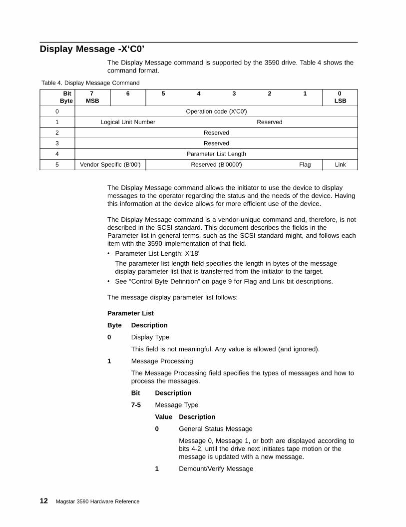
Display Message -X‘C0’The Display Message command is supported by the 3590 drive. Table 4 shows thecommand format.
Table 4. Display Message Command
BitByte
7MSB
6 5 4 3 2 1 0LSB
0 Operation code (X'C0')
1 Logical Unit Number Reserved
2 Reserved
3 Reserved
4 Parameter List Length
5 Vendor Specific (B'00') Reserved (B'0000') Flag Link
The Display Message command allows the initiator to use the device to displaymessages to the operator regarding the status and the needs of the device. Havingthis information at the device allows for more efficient use of the device.
The Display Message command is a vendor-unique command and, therefore, is notdescribed in the SCSI standard. This document describes the fields in theParameter list in general terms, such as the SCSI standard might, and follows eachitem with the 3590 implementation of that field.
v Parameter List Length: X'18'
The parameter list length field specifies the length in bytes of the messagedisplay parameter list that is transferred from the initiator to the target.
v See “Control Byte Definition” on page 9 for Flag and Link bit descriptions.
The message display parameter list follows:
Parameter List
Byte Description
0 Display Type
This field is not meaningful. Any value is allowed (and ignored).
1 Message Processing
The Message Processing field specifies the types of messages and how toprocess the messages.
Bit Description
7-5 Message Type
Value Description
0 General Status Message
Message 0, Message 1, or both are displayed according tobits 4-2, until the drive next initiates tape motion or themessage is updated with a new message.
1 Demount/Verify Message
12 Magstar 3590 Hardware Reference

Message 0, Message 1, or both are displayed according tobits 4-2, until the current volume is unloaded. If the volumeis currently unloaded, the message display is not changedand the command performs no operation.
2 Mount with Immediate Action Indicator
Message 0, Message 1, or both are displayed according tobits 4-2, until the volume is loaded. An attention indicator isactivated. If the volume is currently loaded, the messagedisplay is not changed and the command performs nooperation.
3-6 Reserved (invalid)
7 Demount/Mount with Immediate Action Indicator
When Message Control bits 4-2 are set to a value of 4(B'100'), Message 0 and Message 1 are displayedalternately until the currently mounted volume, if any, isunloaded. When Message Control bits 4-2 are set to anyother value, Message 0 is displayed until the currentlymounted volume, if any, is unloaded. Message 1 isdisplayed from the time the volume is unloaded (orimmediately, if the volume is already unloaded) until anothervolume is loaded. An attention indicator is activated.
4-2 Message Control
Value Description0 Display Message 01 Display Message 12 Flash Message 03 Flash Message 14 Alternate Message 0 and Message 15-7 Reserved (Invalid)
The life and sequences of each message must interact with therequirements of other messages, both sent or internally generatedby the device.
1-0 Reserved
2-5 Reserved
6-7 Message Length
The Message Length field specifies the length of the Message field.
For the 3590 drive, the Message Length field is always X'0010'.
8-15 Message 0
Eight-character ASCII message. If both Message 0 and Message 1 consistentirely of blanks, all messages are cleared, except for ATTN, FID, andCLEAN messages.
The Message 0 field contains the data to be displayed. Characters in themessage are limited to uppercase alphabetic, numeric, blank, and thefollowing special characters:
@ $ # , . / ’ ( ) * & + - = % : _ < > ? ; ¢ ¬ |
Chapter 2. Drive SCSI Commands 13

All lowercase alphabetic characters are converted to uppercase. All othercharacters not listed above, including nulls (X'00'), are displayed as if theyhad been blanks. Real blanks (X'20') must be used to force the messageclearing function described above.
16-23 Message 1
Eight-character ASCII message. If both Message 0 and Message 1 consistentirely of blanks, all messages are cleared, except for ATTN, FID, andCLEAN messages.
The Message 1 field contains the data to be displayed. Characters in themessage are limited to uppercase alphabetic, numeric, blank, and thefollowing special characters:
@ $ # , . / ’ ( ) * & + - = % : _ < > ? ; ¢ ¬ |
All lowercase alphabetic characters are converted to uppercase. All othercharacters not listed above, including nulls (X'00'), are displayed as if theyhad been blanks. Real blanks (X'20') must be used to force the messageclearing function described above.
14 Magstar 3590 Hardware Reference

Erase -X‘19’The Erase command is supported by the 3590 drive.
Table 5 shows the command format.
Table 5. Erase Command
BitByte
7MSB
6 5 4 3 2 1 0LSB
0 Operation code (X'19')
1 Logical Unit Number Reserved Immed Long
2 Reserved
3 Reserved
4 Reserved
5 Vendor Specific (B'00') Reserved (B'0000') Flag Link
The following 3590-specific parameters apply:
v Immed (Immediate)– B'0': return status when the erase operation has completed.– B'1': return status when the CDB has been validated.
v Long: B'1'
All remaining medium in the current partition is erased beginning at the currentlogical position.
v See “Control Byte Definition” on page 9 for Flag and Link bit descriptions.
The Erase command performs a physical medium erase from the current position tothe end of the current or only partition.
Note: A tape may only be one format at a time. 3590 B-Series models erase usingB-Format (density code X'29') and E-Series models erase using E-Format(density code X'2A'). At Beginning Of Tape, any tape written in one formatcan be changed to another format when an Erase command is issued. If anattempt is made by an E-series model to erase a B-Format tape at any otherlocation away from Beginning of Tape, CHECK CONDITION status isreturned with associated sense data of 5/3004 (Illegal Request, Cannot WriteMedium — Incompatible Format). Since a B-Series model cannot read anE-Format tape, this condition cannot happen on a B-Series model.
Chapter 2. Drive SCSI Commands 15

Inquiry -X‘12’Table 6. Inquiry Command
BitByte
7MSB
6 5 4 3 2 1 0LSB
0 Operation code (X'12')
1 Logical Unit Number Reserved CmdDt EVPD
2 Page Code
3 Reserved
4 Allocation Length
5 Vendor Specific (B'00') Reserved (B'0000') Flag Link
There are several forms of Inquiry data. The following are supported and describedin more detail as follows:
v B-Series and E-Series Models:
– “Inquiry Standard Data: Valid LUN (Logical Unit Number)”
– “Inquiry Standard Data: Invalid LUN” on page 19
– “Inquiry Page X‘00’” on page 21
– “Inquiry Page X‘03’: ASCII Information” on page 22
– “Inquiry Page X‘80’: Unit Serial Number” on page 23
– “Inquiry Page X‘83’: Device Identification” on page 24
v E-Series Models Only:
– “Inquiry Page X'D0'” (the contents of this page are not specified in thisdocument)
– “Inquiry Page X'D1'” (the contents of this page are not specified in thisdocument)
Inquiry Standard Data: Valid LUN (Logical Unit Number)The following 3590-specific parameters apply to this request:
v EVPD (Enable Vital Product Data): B'0'
v Page Code: X'00'
v Allocation Length: X'38' (56) bytes available
v See “Control Byte Definition” on page 9 for Flag and Link bit descriptions.
v CmdDt:B'0'
For a logical unit number (LUN) that is associated with an installed device (see“SCSI-ID and LUN Assignments” on page 239), the following standard inquiry datais returned (character fields are in ASCII):
Byte Description
0
Bit Description7-5 Peripheral Qualifier: B'000'4-0 Peripheral Device Type: X'01' or X'08'
v If the Inquiry command is issued to LUN 0, the SequentialAccess Device (tape drive) or Attached Medium Changer deviceLUN, then this field will be X'01'. (An Attached Medium Changerdevice is a limited function extension to an associated Sequential
16 Magstar 3590 Hardware Reference

Access device. Together, they share the same target addressand LUN. The reported Peripheral Device Type is that of theSequential Access device, but a few commands normallyassociated with a Medium Changer device type are supported.This is also called 1-LUN addressing.)
v If the Inquiry command is issued to a Medium Changer devicethat is assigned its own LUN (an Independent Medium Changer),then this field will be X'08'. (An Independent Medium Changermay have its own target/LUN address, or if it shares a targetaddress with other logical units, then it has its own LUN withinthat target. The latter is also called 2-LUN addressing.)
Note: For B-Series models, Attached Medium Changer (1-LUNaddressing) is the default operating definition for all ACFmodes of operation except Random 2-LUN (see “ChangeDefinition -X‘40’” on page 10).
1
Bit Description7 RMB (Removable Medium Bit): B'1'6-0 Reserved
2
Bit Description7-6 ISO/IEC Version: B'00'5-3 ECMA Version: B'000'2-0 ANSI Approved Version: B'011'
3
Bit Description7 AERC (Asynchronous Event Reporting Capability): B'0'6 Obsolete: B'0'5 NormACA (Normal ACA Supported): B'0'4 HiSupport (Hierarchical Support): B'0'3-0 Response Data Format: B'0010'
4 Additional Length (n-4): X'33'
5
Bit Description7 SCCS (An SCC Supported): B'0'6-0 Reserved
6 This byte supports SCSI-3 changes. In SCSI-2, this byte was reserved.
Bit Description7 BQue (Basic Queueing): B'0'6 EncServ (Enclosure Service): B'0'5 BarC: B'0'4 MultiP (Multi-Port): B'0'3 Mchngr (Medium Changer):
For E-Series models, this field is always set to B'0'.
For B-Series models, the value of this field depends on the mode ofthe ACF. If the ACF is in Random mode, this field is set to B'1'. Ifthe ACF mode is Manual, System, Automatic, Accumulate, Random2-LUN, or no automation, this field is set to B'0'. (This bit may
Chapter 2. Drive SCSI Commands 17

change because the Change Definition command is sent or theoperator selects a different mode.) If this bit changes, an unitattention condition is created for all initiators with associated sensedata of 6/3F03 (Unit Attention, Inquiry Data Changed). See “ModePage X‘20’: ACF (Loader) Control” on page 110 for the currentlibrary mode.
2 AckReqQ: B'0'1 Addr32: B'0'0 Addr16: B'1'
7
Bit Description7 RelAdr (Relative Addressing): B'0'6 WBus32 (Wide Bus 32): B'0'5 WBus16 (Wide Bus 16): B'1' (2-byte wide attachment only)4 Sync (Synchronous Transfer): B'1'3 Linked: B'1'2 TranDis (Transfer Disable): B'0'1 CmdQue (Command Queuing): B'0'0 SftRe (Soft Reset): B'0'
8-15 Manufacturer: ‘IBM ’ (in ASCII)
16-31 Device Type and Model Number: ‘03590xxx ’ (in ASCII)
The device type is ‘03590’ and the model number is ‘xxx’; ‘xxx’ can be‘B1A’, or ‘B11’, or ‘E1A’, or ‘E11’.
32-35 Product Revision Level (3590 Microcode Revision Level in ASCII)
36-37 IBM Plant of Manufacture Code.
38-49 Serial Number of device, right justified with leading zeroes, in ASCII.
50-51 For Port 0: ‘ 0’ (in ASCII); For Port 1: ‘ 1’ (in ASCII)
52 Equipment Flags
Bit Description7-5 Reserved4 Auto-Share Feature Installed (see “Multiple Port Behavior” on
page 239)v B'0': Indicates Auto-Share feature is not installedv B'1': Indicates Auto-Share feature is installed
3 Independent Medium Changer Installed (see byte 0, bits 4-0)v B'0': Indicates a Medium Changer is not addressable at this SCSI
ID.v B'1': Indicates a Medium Changer is addressable at LUN 1 of this
SCSI ID.2 Library Attached
v B'0': the device is not attached to a library facility (3494 or 3495)v B'1': the device is attached to a library facility (3494 or 3495)
1 ACF Attachedv B'0': the device does not have an ACF attached.v B'1': the device has an ACF attached
0 Message Display: B'1'
The device is equipped with a message display.
53 SCSI Customization byte: X'00'
54 Reserved
18 Magstar 3590 Hardware Reference
||||||||

55 Message Display Type : X'81'
Inquiry Standard Data: Invalid LUNThe following 3590-specific parameters apply to this request:
v EVPD (Enable Vital Product Data): B'0'
v Page Code: X'00'
v Allocation Length: The maximum number of bytes to be transferred. For E-SeriesModels, there are two densities supported by the device. The number of bytesreturned will be 108 bytes. For B-Series Models, there is one density supportedby the device. The number of bytes returned will be 56 bytes.
v See “Control Byte Definition” on page 9 for Flag and Link bit descriptions.
For a LUN that is not associated with an installed device (see “SCSI-ID and LUNAssignments” on page 239), the following standard inquiry data is returned(character fields are in ASCII):
Byte Description
0
Bit Description7-5 Peripheral Qualifier: B'011'4-0 Peripheral Device Type: X'1F'
1
Bit Description7 RMB (Removable Medium Bit): B'0'6-0 Reserved
2
Bit Description7-6 ISO/IEC Version: B'00'5-3 ECMA Version: B'000'2-0 ANSI Approved Version: B'011'
3
Bit Description7 AERC (Asynchronous Event Reporting Capability): B'0'6 Obsolete: B'0'5 NormACA (Normal ACA Supported): B'0'4 HiSupport (Hierarchical Support): B'0'3-0 Response Data Format: B'0010'
4 Additional Length (n-4): X'1F' (31 bytes)
5
Bit Description7 SCCS (An SCC Supported): B'0'6-0 Reserved
7
Bit Description7 RelAdr (Relative Addressing): B'0'6 WBus32 (Wide Bus 32): B'0'5 WBus16 (Wide Bus 16): B'1' (2-byte wide attachment only)4 Sync (Synchronous transfer): B'1'3 Linked: B'1'
Chapter 2. Drive SCSI Commands 19

2 TranDis (Transfer Disable): B'0'1 ComQue (Command Queuing): B'0'0 SftRe (Soft Reset): B'0'
8-15 Manufacturer: ‘IBM ’ (in ASCII code)
16-31 Device Type and Model Number: ASCII blanks are returned
32-35 Product Revision Level: ASCII blanks are returned
20 Magstar 3590 Hardware Reference
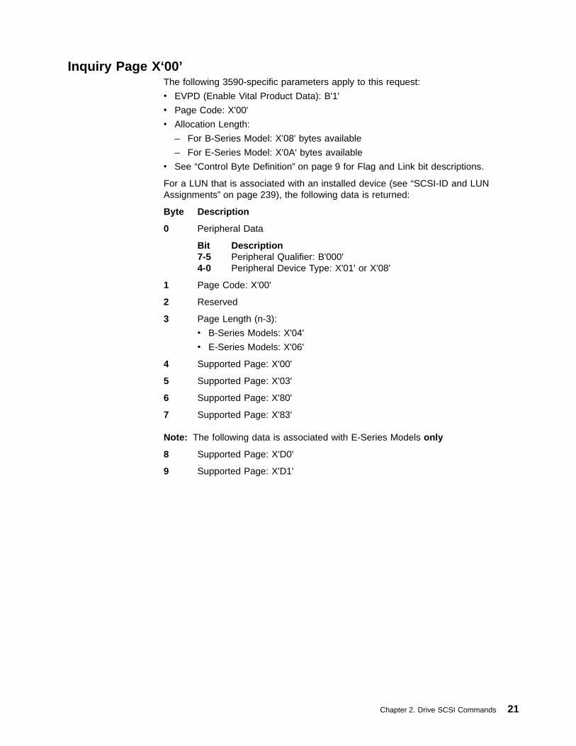
Inquiry Page X‘00’The following 3590-specific parameters apply to this request:
v EVPD (Enable Vital Product Data): B'1'
v Page Code: X'00'
v Allocation Length:
– For B-Series Model: X'08' bytes available
– For E-Series Model: X'0A' bytes available
v See “Control Byte Definition” on page 9 for Flag and Link bit descriptions.
For a LUN that is associated with an installed device (see “SCSI-ID and LUNAssignments” on page 239), the following data is returned:
Byte Description
0 Peripheral Data
Bit Description7-5 Peripheral Qualifier: B'000'4-0 Peripheral Device Type: X'01' or X'08'
1 Page Code: X'00'
2 Reserved
3 Page Length (n-3):
v B-Series Models: X'04'
v E-Series Models: X'06'
4 Supported Page: X'00'
5 Supported Page: X'03'
6 Supported Page: X'80'
7 Supported Page: X'83'
Note: The following data is associated with E-Series Models only
8 Supported Page: X'D0'
9 Supported Page: X'D1'
Chapter 2. Drive SCSI Commands 21
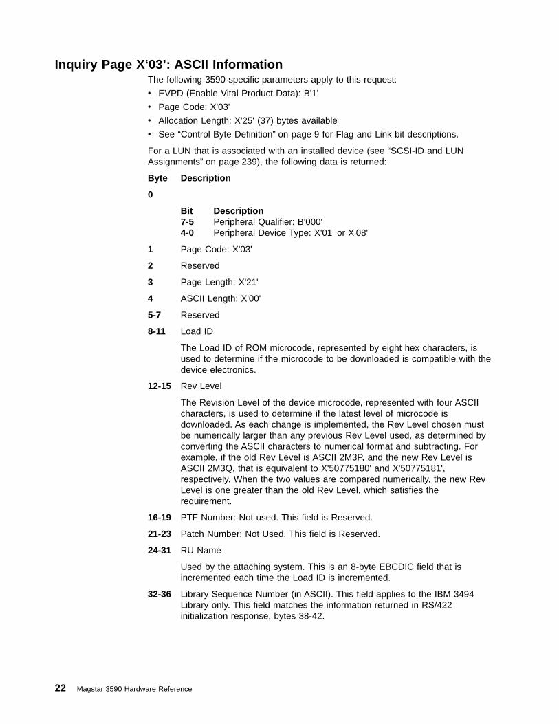
Inquiry Page X‘03’: ASCII InformationThe following 3590-specific parameters apply to this request:
v EVPD (Enable Vital Product Data): B'1'
v Page Code: X'03'
v Allocation Length: X'25' (37) bytes available
v See “Control Byte Definition” on page 9 for Flag and Link bit descriptions.
For a LUN that is associated with an installed device (see “SCSI-ID and LUNAssignments” on page 239), the following data is returned:
Byte Description
0
Bit Description7-5 Peripheral Qualifier: B'000'4-0 Peripheral Device Type: X'01' or X'08'
1 Page Code: X'03'
2 Reserved
3 Page Length: X'21'
4 ASCII Length: X'00'
5-7 Reserved
8-11 Load ID
The Load ID of ROM microcode, represented by eight hex characters, isused to determine if the microcode to be downloaded is compatible with thedevice electronics.
12-15 Rev Level
The Revision Level of the device microcode, represented with four ASCIIcharacters, is used to determine if the latest level of microcode isdownloaded. As each change is implemented, the Rev Level chosen mustbe numerically larger than any previous Rev Level used, as determined byconverting the ASCII characters to numerical format and subtracting. Forexample, if the old Rev Level is ASCII 2M3P, and the new Rev Level isASCII 2M3Q, that is equivalent to X'50775180' and X'50775181',respectively. When the two values are compared numerically, the new RevLevel is one greater than the old Rev Level, which satisfies therequirement.
16-19 PTF Number: Not used. This field is Reserved.
21-23 Patch Number: Not Used. This field is Reserved.
24-31 RU Name
Used by the attaching system. This is an 8-byte EBCDIC field that isincremented each time the Load ID is incremented.
32-36 Library Sequence Number (in ASCII). This field applies to the IBM 3494Library only. This field matches the information returned in RS/422initialization response, bytes 38-42.
22 Magstar 3590 Hardware Reference

Inquiry Page X‘80’: Unit Serial NumberThe following 3590-specific parameters apply to this request:
v EVPD (Enable Vital Product Data): B'1'
v Page Code: X'80'
v Allocation Length: X'10' (16) bytes available
For a LUN that is associated with an installed device (see “SCSI-ID and LUNAssignments” on page 239), the following data is returned:
Byte Description
0 Peripheral Data
Bit Description7-5 Peripheral Qualifier: B'000'4-0 Peripheral Device Type: X'01' or X'08'
1 Page Code: X'80'
2 Reserved
3 Page Length: X'0C'
4-15 Serial Number of device, right-justified with leading zeroes, in ASCII (sameas Inquiry Standard Data bytes 38-49)
Chapter 2. Drive SCSI Commands 23
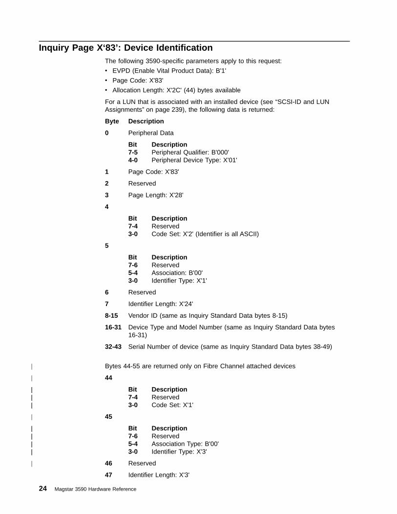
Inquiry Page X‘83’: Device IdentificationThe following 3590-specific parameters apply to this request:
v EVPD (Enable Vital Product Data): B'1'
v Page Code: X'83'
v Allocation Length: X'2C' (44) bytes available
For a LUN that is associated with an installed device (see “SCSI-ID and LUNAssignments” on page 239), the following data is returned:
Byte Description
0 Peripheral Data
Bit Description7-5 Peripheral Qualifier: B'000'4-0 Peripheral Device Type: X'01'
1 Page Code: X'83'
2 Reserved
3 Page Length: X'28'
4
Bit Description7-4 Reserved3-0 Code Set: X'2' (Identifier is all ASCII)
5
Bit Description7-6 Reserved5-4 Association: B'00'3-0 Identifier Type: X'1'
6 Reserved
7 Identifier Length: X'24'
8-15 Vendor ID (same as Inquiry Standard Data bytes 8-15)
16-31 Device Type and Model Number (same as Inquiry Standard Data bytes16-31)
32-43 Serial Number of device (same as Inquiry Standard Data bytes 38-49)
Bytes 44-55 are returned only on Fibre Channel attached devices
44
Bit Description7-4 Reserved3-0 Code Set: X'1'
45
Bit Description7-6 Reserved5-4 Association Type: B'00'3-0 Identifier Type: X'3'
46 Reserved
47 Identifier Length: X'3'
24 Magstar 3590 Hardware Reference
|
|
||||||
|
||||||||
|
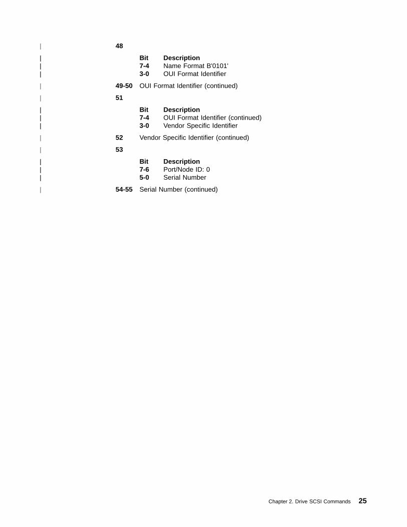
48
Bit Description7-4 Name Format B'0101'3-0 OUI Format Identifier
49-50 OUI Format Identifier (continued)
51
Bit Description7-4 OUI Format Identifier (continued)3-0 Vendor Specific Identifier
52 Vendor Specific Identifier (continued)
53
Bit Description7-6 Port/Node ID: 05-0 Serial Number
54-55 Serial Number (continued)
Chapter 2. Drive SCSI Commands 25
|
||||||
|
|
||||||
|
|
||||||
|

Load Unload -X‘1B’The Load Unload command is supported by the 3590 drive. Table 7 shows thecommand format.
Table 7. Load Unload Command
BitByte
7MSB
6 5 4 3 2 1 0LSB
0 Operation code (X'1B')
1 Logical Unit Number Reserved Immed
2 Reserved
3 Reserved
4 Reserved EOT Re-Ten Load
5 Vendor Specific (B'00') Reserved (B'0000') Flag Link
The following 3590-specific parameters apply:
v Immed (Immediate)– B'0': Indicates the drive is to present status when the command is completed.– B'1': Indicates the drive is to present status as soon as all buffered commands
have completed execution and the CDB of the Load Unload command hasbeen validated. With the exception of Inquiry, Request Sense, and Test UnitReady, subsequent commands are queued until the load/unload operation iscomplete. The completion status of the load/unload operation may be polledby sending a Request Sense command until the sense data returned is nolonger 2/0407 (Not Ready, Logical Unit Not Ready, Operation in Progress).
v EOT (End of Tape): B'0'
v Re-Ten (Retention): B'0'
v Load:
– B'0': In all models, causes an eject of the cartridge from the drive. If thiscommand is received and there is no cartridge present in the drive, thecommand is presented with CHECK CONDITION status and associated sensedata of 2/3A00 (Not Ready, Medium Not Present).
Note: The Load Unload command with the Load bit set to B'0' is sometimescalled an ‘unload command’. The subsequent action of the ACF inresponse to the unload event is ACF mode-dependent:
- For Manual, Accumulate, Automatic, and System modes, the ACFautomatically, without further initiator commands, takes the ejected cartridgefrom the device and places it in the appropriate cell of the ACF.
- For Random and Random 2-LUN modes, the ACF does not respondautomatically, but moves the cartridge to its destination only when orderedby a Move Medium command from an initiator.
– B'1': supported by the 3590 drive only if an ACF is present and the ACF is inSystem mode, or if no ACF is present and a cartridge was unloaded, but notremoved from the drive. In this case, the command performs a reload functionthat may be useful during certain error recovery processes. If this command isreceived and Load set to B'1' is not supported, the command is presentedwith CHECK CONDITION status and associated sense data of 2/3A00 (NotReady, Medium Not Present). If this command is received and Load set toB'1' is supported but there is already a cartridge present in the device, the
26 Magstar 3590 Hardware Reference

command is presented with CHECK CONDITION status and associated sensedata of 2/0403 (Not Ready, Logical Unit Not Ready - Manual InterventionRequired).
v See “Control Byte Definition” on page 9 for Flag and Link bit descriptions.
Chapter 2. Drive SCSI Commands 27

Locate -X‘2B’Table 8 shows the command format.
Table 8. Locate Command
BitByte
7MSB
6 5 4 3 2 1 0LSB
0 Operation code (X'2B')
1 Logical Unit Number Reserved BT CP Immed
2 Reserved
3
Block Address4
5
6
7 Reserved
8 Partition
9 Vendor Specific (B'00') Reserved (B'0000') Flag Link
The following 3590-specific parameters apply:
v BT (Block address Type): B'0'.
v CP (Change Partition):
Note: Partitioning of a volume is not currently supported, but may be in thefuture.
– B'0': no partition change is to be made; locate to the specified block addresswithin the current partition. The Partition field is to be ignored.
– B'1': change to the partition specified by the Partition field prior to locating tothe specified Block Address within the partition.
v Immed (Immediate):– B'0': present status when command is completed.– B'1': present status when all buffered commands have completed execution
and the CDB of the Locate command is validated.
v Block Address:
The destination of the locate operation. This field is a value from X'0000 0000' toX'FFFF FFFF'.
v Partition:
Note: Partitioning of a volume is not currently supported, but may be in thefuture.
The partition field specifies the partition to select, when the CP field is B'1'.
v See “Control Byte Definition” on page 9 for Flag and Link bit descriptions.
If the drive encounters End-of-Data (EOD) while executing this command, thecommand is terminated at the EOD position and CHECK CONDITION status isreturned with associated sense data of 8/0005 (Blank Check, End-of-DataDetected). If the next motion command is another request to move forward (beyondEOD), the drive accepts the command and attempts to position beyond EOD inorder to allow recovery of old data
28 Magstar 3590 Hardware Reference

B-Series Models cannot read or locate on an E-Format tape. If such an attempt ismade, CHECK CONDITION status is returned and Associated sense data is set to3/3002 (Medium Error, Cannot Read Medium — Incompatible Format).
Chapter 2. Drive SCSI Commands 29

Log Select -X‘4C’Table 9. Log Select Command
BitByte
7MSB
6 5 4 3 2 1 0LSB
0 Operation code (X'4C')
1 Logical Unit Number Reserved PCR SP
2 PC Reserved
3 Reserved
4 Reserved
5 Reserved
6 Reserved
7Parameter List Length
8
9 Vendor Specific (B'00') Reserved (B'0000') Flag Link
The following 3590-specific parameters apply:
v PCR (Parameter Code Reset):– B'0': Indicates that the log parameters will not be reset.– B'1': If the parameter list length is zero, all cumulative and threshold log
counter values will be reset to their default values except Page X'3D' (ACFStatistics). If the parameter list length is not zero, the command is terminatedwith CHECK CONDITION status and associated sense data of 5/2400 (IllegalRequest, Invalid Field in CDB).
v SP (Save Parameters): B'0' (Saving of the Log Select parameters is notsupported)
v PC (Page Control):– B'00' (Threshold Values): Supported for all log pages with log counters (LP
field set to B'0' in the Log Parameter Control Byte) except for Page X'3D'(ACF Statistics).
Threshold Notes:
1. The 3590 drive treats each threshold value as a maximum value for thelog counter field. Generally, when a threshold/maximum is reached, all logcounters in that specific log page are locked (no longer updated) until asubsequent reset via a Log Select command.
2. Only the overflowed log counter is locked for Page X'38' (Blocks/BytesTransferred) - all other log counters continue incrementing for this logpage.
3. Log counters for Page X'3D' (ACF Statistics) will lock at maximum valuesand cannot be reset.
4. If the RLEC bit is set to B'1' in Mode Page X'0A' (Control Mode) and a logcounter reaches its threshold/maximum, the drive will report a deferredCHECK CONDITION status with associated sense data of 1/5B02(Recovered Error, Log Counter at Maximum) on the next command eligiblefor a deferred check condition (see Table 1 on page 7). The drive does notreport error sense associated with the threshold condition being met.
– B'01' (Cumulative Values): Supported for all log pages with log counters (LPfield set to B'0' in the Log Parameter Control Byte) except for Page X'3D'.
30 Magstar 3590 Hardware Reference
– B'10' (Default Threshold Values): Not supported. The default threshold valuefor all two-byte log counter fields is X'FFFF'. The default threshold value for allfour-byte log counter fields is X'FFFF FFFF'.
– B'11' (Default Cumulative Values): Not supported. The default cumulativevalue for all two-byte log counter fields is X'0000'. The default cumulativevalue for all four-byte log counter fields is X'0000 0000'.
If the PCR field is set to B'1', the PC field is ignored.
v Parameter List Length:
This field specifies the length in bytes of the parameter list that is to betransferred to the drive. A parameter list length of zero indicates that no pagesare to be transferred. If the parameter list length is zero and the PC field is set toB'00' (Current Threshold Values), the current threshold parameters are set to thedefault threshold values. If the parameter list length is zero and the PC field isset to B'01' (Current Cumulative Values), the current cumulative parameters areset to the default cumulative values (zero).
Note: If the PCR field is set to B'1', this field must be set to zero.
If the parameter list length results in the truncation of any log parameter, thecommand is terminated with CHECK CONDITION status and associated sensedata of 5/2400 (Illegal Request, Invalid Field in CDB).
v See “Control Byte Definition” on page 9 for Flag and Link bit descriptions.
Only one log page is accepted for each Log Select command. For each log page,any combination of the supported log parameters may be sent. If multiple logparameters are sent, they must be sent in ascending order by parameter codevalue. Only the Parameter Value field may be changed from the log parameters thatare returned from Log Sense (see “Log Parameter Format” on page 33). Changesto the Log Parameter Control Byte are not supported.
Note: Initiators should issue a Log Sense command prior to issuing a Log Selectcommand to determine supported log parameter fields.
If a parameter list is received with an unsupported log page, a log parameter codeout of order, or a change to a log parameter field other than the Parameter Value,the command is terminated with CHECK CONDITION status and associated sensedata of 5/2600 (Illegal Request, Invalid Field in Parameter List).
The following log pages are supported for the Log Select command:
v “Log Page X‘02’: Write Error Counters” on page 36
v “Log Page X‘03’: Read Error Counters” on page 38
v “Log Page X‘06’: Non-Medium Errors” on page 40
v “Log Page X‘0C’: Sequential-access device” on page 41
v “Log Page X‘32’: Write Errors” on page 47
v “Log Page X‘34’: Read Forward Errors” on page 51
v “Log Page X‘36’: Read Reverse Errors” on page 58
v “Log Page X‘38’: Blocks/Bytes Transferred” on page 59
v “Log Page X‘39’: SCSI Port 0 Interface Errors” on page 63
v “Log Page X‘3A’: SCSI Port 1 Interface Errors” on page 65
v “Log Page X‘3B’: Equipment Check Errors” on page 66
Chapter 2. Drive SCSI Commands 31
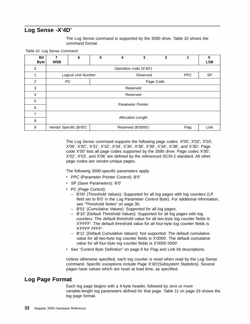
Log Sense -X‘4D’The Log Sense command is supported by the 3590 drive. Table 10 shows thecommand format.
Table 10. Log Sense Command
BitByte
7MSB
6 5 4 3 2 1 0LSB
0 Operation code (X'4D')
1 Logical Unit Number Reserved PPC SP
2 PC Page Code
3 Reserved
4 Reserved
5Parameter Pointer
6
7Allocation Length
8
9 Vendor Specific (B'00') Reserved (B'0000') Flag Link
The Log Sense command supports the following page codes: X'00', X'02', X'03',X'06', X'0C', X'31', X'32', X'34', X'36', X'38', X'39', X'3A', X'3B', and X'3D'. Pagecode X'00' lists all page codes supported by the 3590 drive. Page codes X'00',X'02', X'03', and X'06' are defined by the referenced SCSI-2 standard. All otherpage codes are vendor-unique pages.
The following 3590-specific parameters apply:
v PPC (Parameter Pointer Control): B'0'
v SP (Save Parameters): B'0'
v PC (Page Control):– B'00' (Threshold Values): Supported for all log pages with log counters (LP
field set to B'0' in the Log Parameter Control Byte). For additional information,see “Threshold Notes” on page 30.
– B'01' (Cumulative Values): Supported for all log pages.– B'10' (Default Threshold Values): Supported for all log pages with log
counters. The default threshold value for all two-byte log counter fields isX'FFFF'. The default threshold value for all four-byte log counter fields isX'FFFF FFFF'.
– B'11' (Default Cumulative Values): Not supported. The default cumulativevalue for all two-byte log counter fields is X'0000'. The default cumulativevalue for all four-byte log counter fields is X'0000 0000'.
v See “Control Byte Definition” on page 9 for Flag and Link bit descriptions.
Unless otherwise specified, each log counter is reset when read by the Log Sensecommand. Specific exceptions include Page X'3D'(Subsystem Statistics). Severalpages have values which are reset at load time, as specified.
Log Page FormatEach log page begins with a 4-byte header, followed by zero or morevariable-length log parameters defined for that page. Table 11 on page 33 shows thelog page format.
32 Magstar 3590 Hardware Reference
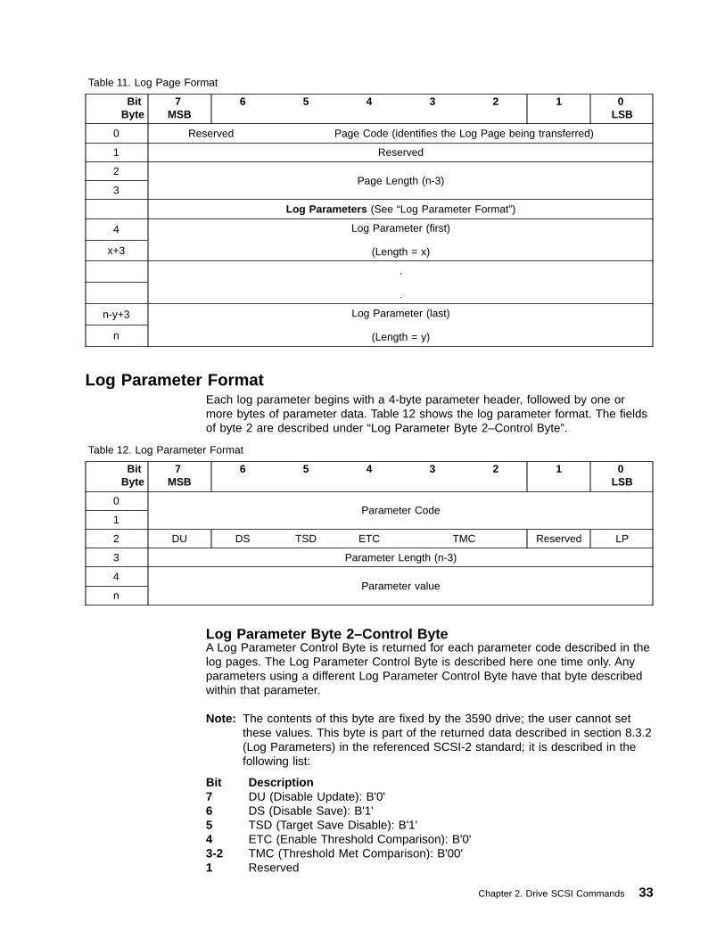
Table 11. Log Page Format
BitByte
7MSB
6 5 4 3 2 1 0LSB
0 Reserved Page Code (identifies the Log Page being transferred)
1 Reserved
2Page Length (n-3)
3
Log Parameters (See “Log Parameter Format”)
4 Log Parameter (first)
(Length = x)x+3
.
.
n-y+3 Log Parameter (last)
(Length = y)n
Log Parameter FormatEach log parameter begins with a 4-byte parameter header, followed by one ormore bytes of parameter data. Table 12 shows the log parameter format. The fieldsof byte 2 are described under “Log Parameter Byte 2–Control Byte”.
Table 12. Log Parameter Format
BitByte
7MSB
6 5 4 3 2 1 0LSB
0Parameter Code
1
2 DU DS TSD ETC TMC Reserved LP
3 Parameter Length (n-3)
4Parameter value
n
Log Parameter Byte 2–Control ByteA Log Parameter Control Byte is returned for each parameter code described in thelog pages. The Log Parameter Control Byte is described here one time only. Anyparameters using a different Log Parameter Control Byte have that byte describedwithin that parameter.
Note: The contents of this byte are fixed by the 3590 drive; the user cannot setthese values. This byte is part of the returned data described in section 8.3.2(Log Parameters) in the referenced SCSI-2 standard; it is described in thefollowing list:
Bit Description7 DU (Disable Update): B'0'6 DS (Disable Save): B'1'5 TSD (Target Save Disable): B'1'4 ETC (Enable Threshold Comparison): B'0'3-2 TMC (Threshold Met Comparison): B'00'1 Reserved
Chapter 2. Drive SCSI Commands 33

0 LP (List Parameter): B'0' (indicates this is a log counter)
34 Magstar 3590 Hardware Reference

Log Page X‘00’: Supported Log PagesThis log page returns the list of log pages supported by the 3590 drive. This pagedoes not contain any log parameters.
Byte Description
0
Bit Description7-6 Reserved5-0 Page Code (B'000000')
1 Reserved
2-3 Page Length (X'000E')
4 Supported Log Pages (X'00')
5 Write Error Counters page (X'02')
6 Read Error Counters page (X'03')
7 Non-Medium Errors page (X'06')
8 Sequential-access device (X'0C')
9 SIM/MIM page (X'31')
10 Write Errors page (X'32')
11 Read Forward Errors page (X'34')
12 Read Reverse Errors page (X'36')
13 Blocks/Bytes Transferred page (X'38')
14 SCSI Port 0 Interface Errors page (X'39')
15 SCSI Port 1 Interface Errors page (X'3A')
16 Equipment Check Errors page (X'3B')
17 Subsystem Statistics page (X'3D')
Chapter 2. Drive SCSI Commands 35

Log Page X‘02’: Write Error CountersThis page is one of the defined error counter pages in the referenced SCSI-2standard. This page is for Write Errors. It is reset when the cartridge is loaded.
Byte Description
0
Bit Description7-6 Reserved5-0 Page Code: X'02'
1 Reserved
2-3 Page length: The page length is determined by the parameters and thenumber of parameters selected for transmission to the initiator.
The following parameter codes are supported for the Write Error Counter page(page code X'02'):
X'0002'Total Write Errors
The sum of the total corrected Write Errors and total Uncorrected WriteErrors.
Byte Description0-1 Parameter Code: X'0002'2 Parameter control byte (see Page 33)3 Parameter length: X'02'4-5 Total Write error count (2-byte binary format)
X'0003'Total Corrected Write Errors
The total of the Corrected Write errors. These errors are corrected by ECC“on the fly” and do not require error recovery procedures (ERPs). Eachcount represents one block in error that was corrected and written.
Byte Description0-1 Parameter Code: X'0003'2 Parameter control byte (see Page 33)3 Parameter length: X'02'4-5 Corrected write error count (2-byte binary format)
X'0005'Total Write Kilobytes Processed
Each count represents a kilobyte (1024 bytes) of data processed across theSCSI interface during write-type commands. The count does not includeERP retries. This field is identical to the SCSI Write Kilobytes Processedfield of Page Code X'38', parameter code X'0001'.
Byte Description0-1 Parameter Code: X'0005'2 Parameter control byte (see Page 33)3 Parameter length: X'04'4-7 Total kilobytes processed count (4-byte binary format)
Refer to “Scaled Log Page Counters” on page 239 for a descriptionof this scaled counter.
36 Magstar 3590 Hardware Reference

X'0006'Total Uncorrected Write Errors
The total number of write errors that could not be corrected by ECC “on thefly,” no servo error was reported, and the error was not a transient error.Each count represents one block in error that was not corrected “on the fly”but was recovered by ERPs and successfully written.
Byte Description0-1 Parameter Code: X'0006'2 Parameter control byte (see Page 33)3 Parameter length: X'02'4-5 Uncorrected write error count (2-byte binary format)
Chapter 2. Drive SCSI Commands 37
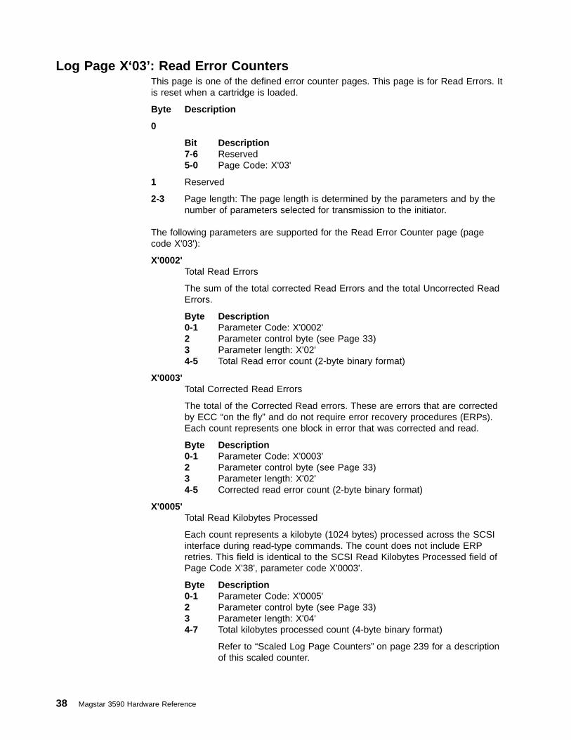
Log Page X‘03’: Read Error CountersThis page is one of the defined error counter pages. This page is for Read Errors. Itis reset when a cartridge is loaded.
Byte Description
0
Bit Description7-6 Reserved5-0 Page Code: X'03'
1 Reserved
2-3 Page length: The page length is determined by the parameters and by thenumber of parameters selected for transmission to the initiator.
The following parameters are supported for the Read Error Counter page (pagecode X'03'):
X'0002'Total Read Errors
The sum of the total corrected Read Errors and the total Uncorrected ReadErrors.
Byte Description0-1 Parameter Code: X'0002'2 Parameter control byte (see Page 33)3 Parameter length: X'02'4-5 Total Read error count (2-byte binary format)
X'0003'Total Corrected Read Errors
The total of the Corrected Read errors. These are errors that are correctedby ECC “on the fly” and do not require error recovery procedures (ERPs).Each count represents one block in error that was corrected and read.
Byte Description0-1 Parameter Code: X'0003'2 Parameter control byte (see Page 33)3 Parameter length: X'02'4-5 Corrected read error count (2-byte binary format)
X'0005'Total Read Kilobytes Processed
Each count represents a kilobyte (1024 bytes) processed across the SCSIinterface during read-type commands. The count does not include ERPretries. This field is identical to the SCSI Read Kilobytes Processed field ofPage Code X'38', parameter code X'0003'.
Byte Description0-1 Parameter Code: X'0005'2 Parameter control byte (see Page 33)3 Parameter length: X'04'4-7 Total kilobytes processed count (4-byte binary format)
Refer to “Scaled Log Page Counters” on page 239 for a descriptionof this scaled counter.
38 Magstar 3590 Hardware Reference

X'0006'Total Uncorrected Read Errors
The total number of read errors that could not be corrected by ECC “on thefly,” no servo error was reported, and the error was not a transient error.Each count represents one block in error that was not corrected “on the fly,”but was recovered by ERPs and successfully read.
Byte Description0-1 Parameter Code: X'0006'2 Parameter control byte (see Page 33)3 Parameter length: X'02'4-5 Uncorrected read error count (2-byte binary format)
Chapter 2. Drive SCSI Commands 39
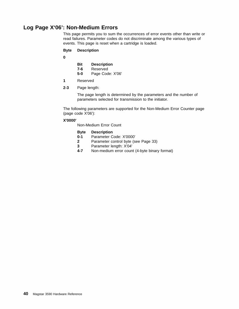
Log Page X‘06’: Non-Medium ErrorsThis page permits you to sum the occurrences of error events other than write orread failures. Parameter codes do not discriminate among the various types ofevents. This page is reset when a cartridge is loaded.
Byte Description
0
Bit Description7-6 Reserved5-0 Page Code: X'06'
1 Reserved
2-3 Page length:
The page length is determined by the parameters and the number ofparameters selected for transmission to the initiator.
The following parameters are supported for the Non-Medium Error Counter page(page code X'06'):
X'0000'Non-Medium Error Count
Byte Description0-1 Parameter Code: X'0000'2 Parameter control byte (see Page 33)3 Parameter length: X'04'4-7 Non-medium error count (4-byte binary format)
40 Magstar 3590 Hardware Reference
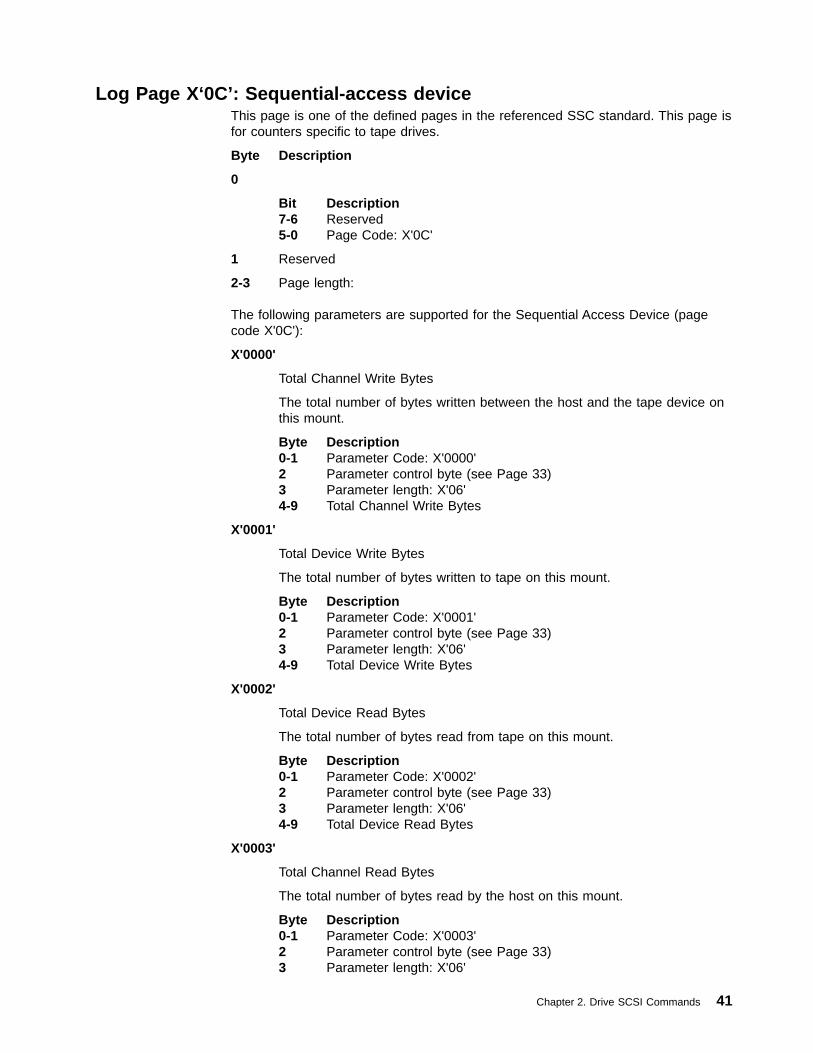
Log Page X‘0C’: Sequential-access deviceThis page is one of the defined pages in the referenced SSC standard. This page isfor counters specific to tape drives.
Byte Description
0
Bit Description7-6 Reserved5-0 Page Code: X'0C'
1 Reserved
2-3 Page length:
The following parameters are supported for the Sequential Access Device (pagecode X'0C'):
X'0000'
Total Channel Write Bytes
The total number of bytes written between the host and the tape device onthis mount.
Byte Description0-1 Parameter Code: X'0000'2 Parameter control byte (see Page 33)3 Parameter length: X'06'4-9 Total Channel Write Bytes
X'0001'
Total Device Write Bytes
The total number of bytes written to tape on this mount.
Byte Description0-1 Parameter Code: X'0001'2 Parameter control byte (see Page 33)3 Parameter length: X'06'4-9 Total Device Write Bytes
X'0002'
Total Device Read Bytes
The total number of bytes read from tape on this mount.
Byte Description0-1 Parameter Code: X'0002'2 Parameter control byte (see Page 33)3 Parameter length: X'06'4-9 Total Device Read Bytes
X'0003'
Total Channel Read Bytes
The total number of bytes read by the host on this mount.
Byte Description0-1 Parameter Code: X'0003'2 Parameter control byte (see Page 33)3 Parameter length: X'06'
Chapter 2. Drive SCSI Commands 41

4-9 Total Channel Read Bytes
X'0100'
Cleaning Required
A non-zero value indicates cleaning required.
Byte Description0-1 Parameter Code: X'0100'2 Parameter control byte (see Page 33)3 Parameter length: X'01'4-9 Cleaning Required
42 Magstar 3590 Hardware Reference

Log Page X‘31’: SIM/MIMPage Code 31 is designed to support SIMs (Service Information Messages), andMIMs (Medium Information Messages). SIMs and MIMs provide the initiator andoperator details on service problems encountered by the device.
This page is not reset when a cartridge is loaded. When read with a Log Sensecommand, only the returned SIM or MIM is no longer available for subsequentretrieval. SIMs and MIMs are stored in and retrieved from a first-in first-out (FIFO)queue. Only 1 SIM or MIM is returned for each Log Sense command that requestsPage Code X'31'. The first 9 bytes are common to both the SIMs and the MIMs.
SIM/MIM Header DataByte Description
0 Page Code
Bit Description7-6 Reserved5-0 Page Code: X'31'
1 Reserved
2-3 Page Length: X'0044'
4-5 Parameter Code: X'0000'
6 Parameter control byte
Bit Description7 DU (Disable Update): B'0'6 DS (Disable Save): B'1'5 TSD (Target Save Disable): B'1'4 ETC (Enable Threshold Comparison): B'0'3-2 TMC (Threshold Met Comparison): B'00'1 Reserved0 LP (List Parameter): B'1'
7 Parameter length: X'40'
8 SIM/MIM Indicator
Value DescriptionX'00' Bytes 9 through 71 are invalid.X'01' Bytes 9 through 71 are a SIM message. See “SIM Messages”.X'02' Bytes 9 through 71 are a MIM message. See “MIM Messages” on
page 45.X'03-FF'
Bytes 9 through 71 are invalid.
SIM MessagesThe following data are the parameters for the hardware SIM message:
Byte Description
9-15 Reserved
16-19 Engineering Data
20-21 SIM Message Code
Value (ASCII) Description‘00’ No Message‘41’ Device Degraded. Call for Service
Chapter 2. Drive SCSI Commands 43
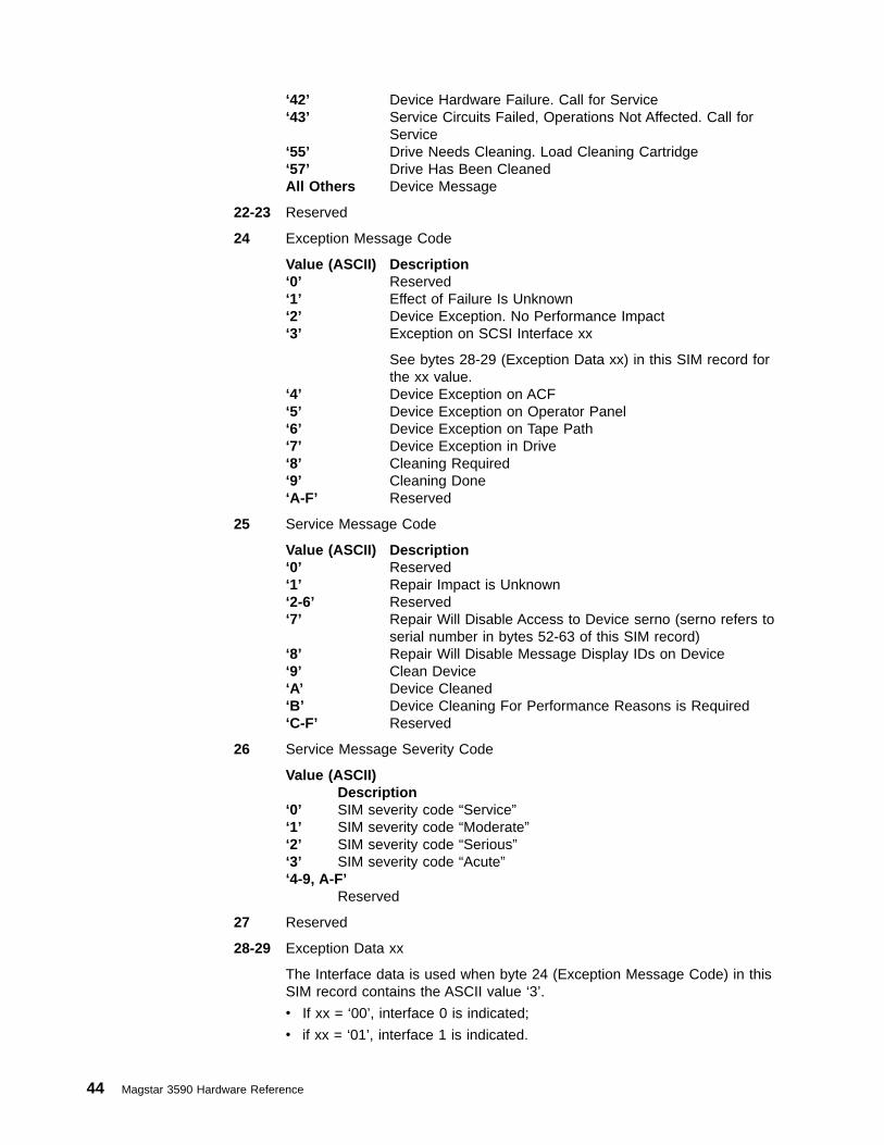
‘42’ Device Hardware Failure. Call for Service‘43’ Service Circuits Failed, Operations Not Affected. Call for
Service‘55’ Drive Needs Cleaning. Load Cleaning Cartridge‘57’ Drive Has Been CleanedAll Others Device Message
22-23 Reserved
24 Exception Message Code
Value (ASCII) Description‘0’ Reserved‘1’ Effect of Failure Is Unknown‘2’ Device Exception. No Performance Impact‘3’ Exception on SCSI Interface xx
See bytes 28-29 (Exception Data xx) in this SIM record forthe xx value.
‘4’ Device Exception on ACF‘5’ Device Exception on Operator Panel‘6’ Device Exception on Tape Path‘7’ Device Exception in Drive‘8’ Cleaning Required‘9’ Cleaning Done‘A-F’ Reserved
25 Service Message Code
Value (ASCII) Description‘0’ Reserved‘1’ Repair Impact is Unknown‘2-6’ Reserved‘7’ Repair Will Disable Access to Device serno (serno refers to
serial number in bytes 52-63 of this SIM record)‘8’ Repair Will Disable Message Display IDs on Device‘9’ Clean Device‘A’ Device Cleaned‘B’ Device Cleaning For Performance Reasons is Required‘C-F’ Reserved
26 Service Message Severity Code
Value (ASCII)Description
‘0’ SIM severity code “Service”‘1’ SIM severity code “Moderate”‘2’ SIM severity code “Serious”‘3’ SIM severity code “Acute”‘4-9, A-F’
Reserved
27 Reserved
28-29 Exception Data xx
The Interface data is used when byte 24 (Exception Message Code) in thisSIM record contains the ASCII value ‘3’.
v If xx = ‘00’, interface 0 is indicated;
v if xx = ‘01’, interface 1 is indicated.
44 Magstar 3590 Hardware Reference
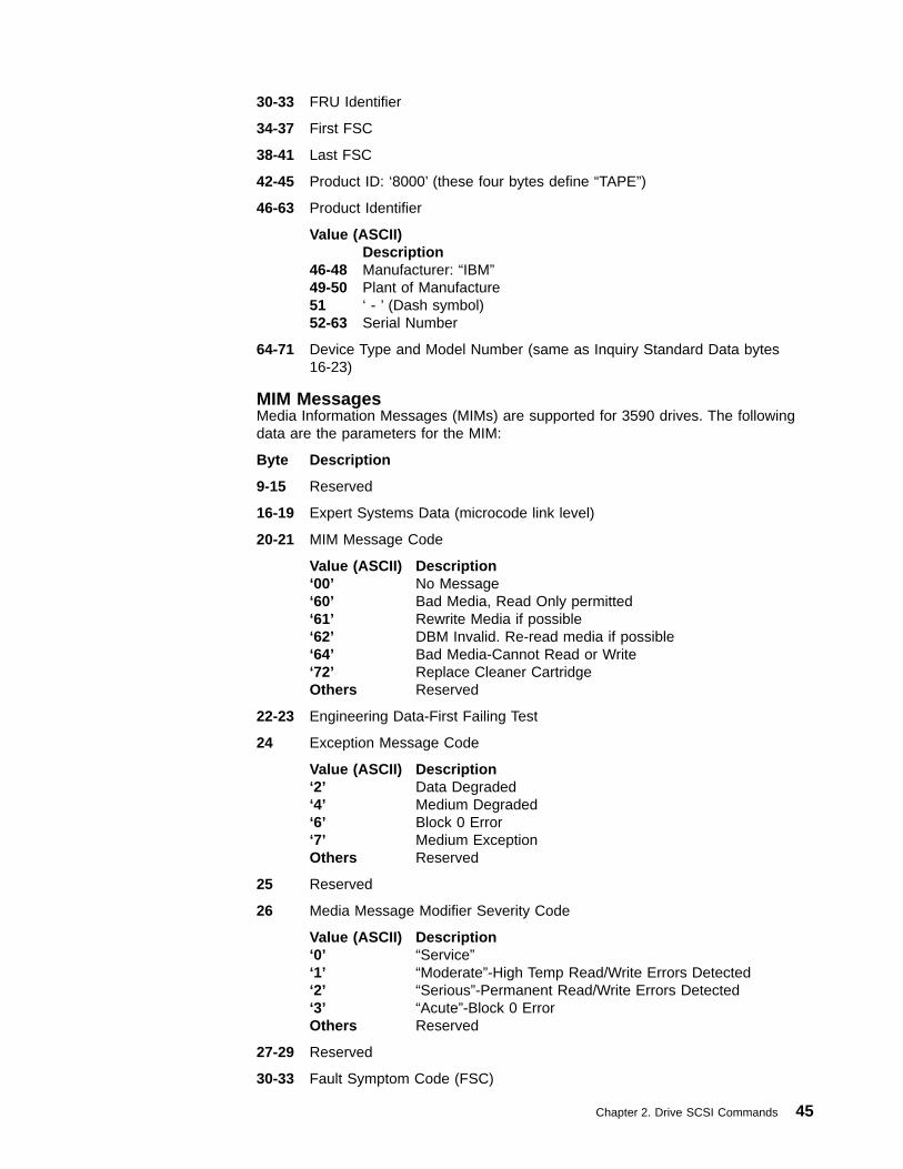
30-33 FRU Identifier
34-37 First FSC
38-41 Last FSC
42-45 Product ID: ‘8000’ (these four bytes define “TAPE”)
46-63 Product Identifier
Value (ASCII)Description
46-48 Manufacturer: “IBM”49-50 Plant of Manufacture51 ‘ - ’ (Dash symbol)52-63 Serial Number
64-71 Device Type and Model Number (same as Inquiry Standard Data bytes16-23)
MIM MessagesMedia Information Messages (MIMs) are supported for 3590 drives. The followingdata are the parameters for the MIM:
Byte Description
9-15 Reserved
16-19 Expert Systems Data (microcode link level)
20-21 MIM Message Code
Value (ASCII) Description‘00’ No Message‘60’ Bad Media, Read Only permitted‘61’ Rewrite Media if possible‘62’ DBM Invalid. Re-read media if possible‘64’ Bad Media-Cannot Read or Write‘72’ Replace Cleaner CartridgeOthers Reserved
22-23 Engineering Data-First Failing Test
24 Exception Message Code
Value (ASCII) Description‘2’ Data Degraded‘4’ Medium Degraded‘6’ Block 0 Error‘7’ Medium ExceptionOthers Reserved
25 Reserved
26 Media Message Modifier Severity Code
Value (ASCII) Description‘0’ “Service”‘1’ “Moderate”-High Temp Read/Write Errors Detected‘2’ “Serious”-Permanent Read/Write Errors Detected‘3’ “Acute”-Block 0 ErrorOthers Reserved
27-29 Reserved
30-33 Fault Symptom Code (FSC)
Chapter 2. Drive SCSI Commands 45

34-39 VOLID (in ASCII). Only valid if indicated by VOLID Valid Flag (byte 40)
40 VOLID Valid Flag
Value (ASCII) Description‘0’ VOLID (bytes 34-39) not valid‘1’ VOLID valid, obtained from tape‘3’ VOLID valid, obtained from cartridge label‘5’ VOLID valid, obtained from cartridge labelOthers Reserved for future use (odd number will always indicate
VOLID valid)
41 Reserved
42-45 Product ID: ‘8000’ (these four bytes define “TAPE”)
46-63 Product Identifier
Value (ASCII) Description46-48 Manufacturer: “IBM”49-50 Plant of Manufacture51 ‘ - ’ (Dash symbol)52-63 Serial Number
64-71 Device Type and Model Number (same as Inquiry Standard Data bytes16-23)
46 Magstar 3590 Hardware Reference

Log Page X‘32’: Write ErrorsPage code 32 contains detailed counters related to write operations. This page isreset when a cartridge is loaded.
Byte Description
0
Bit Description7-6 Reserved5-0 Page Code: X'32'
1 Reserved
2-3 Page length:
The page length is determined by the parameters and the number ofparameters selected for transmission to the initiator.
The following parameters are supported for the Write Error page (page code X'32'):
X'0000'Blocks Corrected
ECC is done “on the fly” by hardware. Each count represents one block inerror that was successfully corrected and written. When multiple errorsoccur on a block, the counter that is updated is based on the first errordetected.
Byte Description0-1 Parameter Code: X'0000'2 Parameter control byte (see Page 33)3 Parameter length: X'02'4-5 Blocks corrected count (2-byte binary format)
X'0001'Servo Transient Condition
ERP action was required because of a servo detected error and the firstretry was successfully in place. Each count represents one block in errorthat was successfully recovered and written. When multiple errors occur ona block, the counter that is updated is based on the first error detected.
Byte Description0-1 Parameter Code: X'0001'2 Parameter control byte (see Page 33)3 Parameter length: X'02'4-5 Servo transient condition count (2-byte binary format)
X'0002'RDF/ECC Transient Conditions
ERP action was required because of a RDF (Read Data Flow) or ECCdetected error and the first retry was successfully in place. Each countrepresents one block in error that was successfully recovered and written.When multiple errors occur on a block, the counter that is updated is basedon the first error detected.
Byte Description0-1 Parameter Code: X'0002'2 Parameter control byte (see Page 33)3 Parameter length: X'02'4-5 RDF/ECC transient condition count (2-byte binary format)
Chapter 2. Drive SCSI Commands 47

X'0003'Write Velocity Errors
The count of detected write velocity errors. Each count represents oneoccurrence, not just the count of affected blocks. Counts may includeoccurrences from both temporary and permanent errors.
Byte Description0-1 Parameter Code: X'0003'2 Parameter control byte (see Page 33)3 Parameter length: X'02'4-5 Write Velocity Error Count (2-byte binary format)
X'0004'Servo Data Acquisition Errors
A servo error (servo dropout or off-track shutdown) was detected whiletrying to acquire an IBG or block at the beginning of a write appendsequence; ERP action was required, and servo transient condition criteriawere not met. Each count represents one block in error that wassuccessfully recovered and written. When multiple errors occur on a block,the counter that is updated is based on the first error detected.
Byte Description0-1 Parameter Code: X'0004'2 Parameter control byte (see Page 33)3 Parameter length: X'02'4-5 Servo data acquisition error count (2-byte binary format)
X'0005'RDF Data Acquisition Errors
During read-back check, the Read Data Flow (RDF) failed to acquire anIBG or block at the beginning of a write append sequence and no servoerror was reported, ERP action was required, and RDF/ECC transientcondition criteria were not met. Each count represents one block in errorthat was successfully recovered and written. When multiple errors occur ona block, the counter that is updated is based on the first error detected.
Byte Description0-1 Parameter Code: X'0005'2 Parameter control byte (see Page 33)3 Parameter length: X'02'4-5 RDF data acquisition error count (2-byte binary format)
X'0006'Servo Data Errors
A servo error (servo dropout or off-track shutdown) was detected whilewriting data, ERP action was required, and servo transient condition criteriawere not met. Each count represents one block in error that wassuccessfully recovered and written. When multiple errors occur on a block,the counter that is updated is based on the first error detected.
Byte Description0-1 Parameter Code: X'0006'2 Parameter control byte (see Page 33)3 Parameter length: X'02'4-5 Servo data error count (2-byte binary format)
X'0007'ECC Data Errors
48 Magstar 3590 Hardware Reference
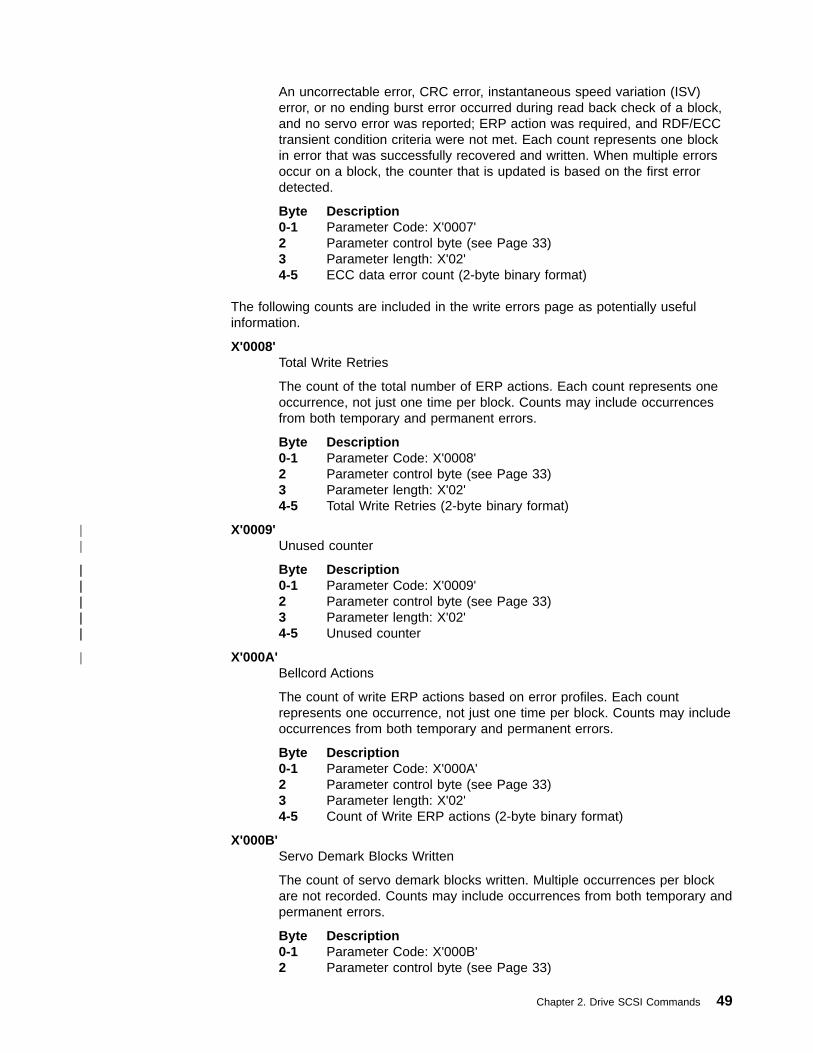
An uncorrectable error, CRC error, instantaneous speed variation (ISV)error, or no ending burst error occurred during read back check of a block,and no servo error was reported; ERP action was required, and RDF/ECCtransient condition criteria were not met. Each count represents one blockin error that was successfully recovered and written. When multiple errorsoccur on a block, the counter that is updated is based on the first errordetected.
Byte Description0-1 Parameter Code: X'0007'2 Parameter control byte (see Page 33)3 Parameter length: X'02'4-5 ECC data error count (2-byte binary format)
The following counts are included in the write errors page as potentially usefulinformation.
X'0008'Total Write Retries
The count of the total number of ERP actions. Each count represents oneoccurrence, not just one time per block. Counts may include occurrencesfrom both temporary and permanent errors.
Byte Description0-1 Parameter Code: X'0008'2 Parameter control byte (see Page 33)3 Parameter length: X'02'4-5 Total Write Retries (2-byte binary format)
X'0009'Unused counter
Byte Description0-1 Parameter Code: X'0009'2 Parameter control byte (see Page 33)3 Parameter length: X'02'4-5 Unused counter
X'000A'Bellcord Actions
The count of write ERP actions based on error profiles. Each countrepresents one occurrence, not just one time per block. Counts may includeoccurrences from both temporary and permanent errors.
Byte Description0-1 Parameter Code: X'000A'2 Parameter control byte (see Page 33)3 Parameter length: X'02'4-5 Count of Write ERP actions (2-byte binary format)
X'000B'Servo Demark Blocks Written
The count of servo demark blocks written. Multiple occurrences per blockare not recorded. Counts may include occurrences from both temporary andpermanent errors.
Byte Description0-1 Parameter Code: X'000B'2 Parameter control byte (see Page 33)
Chapter 2. Drive SCSI Commands 49
||
||||||||||
|

3 Parameter length: X'02'4-5 Count of servo demark blocks written (2-byte binary format)
X'000C'VCR Write Errors
The count of write errors in the Volume Control Region. Each countrepresents one occurrence, not just one time per block. Counts may includeoccurrences from both temporary and permanent errors.
Byte Description0-1 Parameter Code: X'000C'2 Parameter control byte (see Page 33)3 Parameter length: X'02'4-5 VCR Write Error count (2-byte binary format)
X'000D'Unused counter
Byte Description0-1 Parameter Code: X'000D'2 Parameter control byte (see Page 33)3 Parameter length: X'02'4-5 Unused counter
X'000E'Blocks Lifted
The total number of times the device had to lift and move a block. Eachcount represents one occurrence, not just one time per block. Counts mayinclude occurrences from both temporary and permanent errors.
Byte Description0-1 Parameter Code: X'000E'2 Parameter control byte (see Page 33)3 Parameter length: X'02'4-5 Blocks Lifted Error count (2-byte binary format)
X'000F'Write Gap Misses
The number of times that the drive overran the buffer and had to stop andrestart during a write. Each count represents one occurrence, not just onetime per write.
Byte Description0-1 Parameter Code: X'000F'2 Parameter control byte (see Page 33)3 Parameter length: X'02'4-5 Write Gap Miss count (2-byte binary format)
X'0010'Unused counter
Byte Description0-1 Parameter Code: X'0010'2 Parameter control byte (see Page 33)3 Parameter length: X'02'4-5 Unused counter
50 Magstar 3590 Hardware Reference
||
||||||||||
|
||
||||||||||
|

Log Page X‘34’: Read Forward ErrorsPage code 34 contains detailed counters related to read operations. This page isreset when a cartridge is loaded.
Byte Description
0
Bit Description7-6 Reserved5-0 Page Code: X'34'
1 Reserved
2-3 Page length:
The page length is determined by the parameters and the number ofparameters selected for transmission to the initiator.
The following parameters are supported for the Read Forward Error page (pagecode X'34'):
Read errors are broken into nine main counters that are mutually exclusive.
X'0000'Blocks Corrected
ECC is done “on the fly” by hardware. Each count represents one block inerror that was successfully corrected and read. When multiple errors occuron a block, the counter that is updated is based on the first error detected.
Byte Description0-1 Parameter Code: X'0000'2 Parameter control byte (see Page 33)3 Parameter length: X'02'4-5 Blocks corrected count (2-byte binary format)
X'0001'Servo Transient Condition
ERP action was required because of a servo detected error and the firstretry was successfully in place. Each count represents one block in errorthat was successfully recovered and read. When multiple errors occur on ablock, the counter that is updated is based on the first error detected.
Byte Description0-1 Parameter Code: X'0001'2 Parameter control byte (see Page 33)3 Parameter length: X'02'4-5 Servo transient condition count (2-byte binary format)
X'0002'RDF/ECC Transient Conditions
ERP action was required because of a RDF (Read Data Flow) or ECCdetected error and the first retry was successfully in place. Each countrepresents one block in error that was successfully recovered and read.When multiple errors occur on a block, the counter that is updated is basedon the first error detected.
Byte Description0-1 Parameter Code: X'0002'2 Parameter control byte (see Page 33)
Chapter 2. Drive SCSI Commands 51

3 Parameter length: X'02'4-5 RDF/ECC transient condition count (2-byte binary format)
X'0003'Read Velocity Errors
The count of detected read velocity errors. Each count represents oneoccurrence, not just the count of affected blocks. Counts may includeoccurrences from both temporary and permanent errors.
Byte Description0-1 Parameter Code: X'0003'2 Parameter control byte (see Page 33)3 Parameter length: X'02'4-5 Read Velocity Error Count (2-byte binary format)
X'0004'Servo Data Acquisition Errors
A servo error (servo dropout or off track shutdown) was detected whiletrying to acquire an IBG or block, ERP action was required, and servotransient condition criteria were not met. Each count represents one blockin error that was successfully recovered and read. When multiple errorsoccur on a block, the counter that is updated is based on the first errordetected.
Byte Description0-1 Parameter Code: X'0004'2 Parameter control byte (see Page 33)3 Parameter length: X'02'4-5 Servo data acquisition error count (2-byte binary format)
X'0005'RDF Data Acquisition Errors
The RDF (Read Data Flow) failed to acquire an IBG or block, and no servoerror was reported; ERP action was required, and RDF/ECC transientcondition criteria were not met. Each count represents one block in errorthat was successfully recovered and read. When multiple errors occur on ablock, the counter that is updated is based on the first error detected.
Byte Description0-1 Parameter Code: X'0005'2 Parameter control byte (see Page 33)3 Parameter length: X'02'4-5 RDF data acquisition error count (2-byte binary format)
X'0006'Servo Data Errors
A servo error (servo drop out) was detected while reading a block; ERPaction was required, and servo transient condition criteria were not met.Each count represents one block in error that was successfully recoveredand read. When multiple errors occur on a block, the counter that isupdated is based on the first error detected.
Byte Description0-1 Parameter Code: X'0006'2 Parameter control byte (see Page 33)3 Parameter length: X'02'4-5 Servo data error count (2-byte binary format)
52 Magstar 3590 Hardware Reference
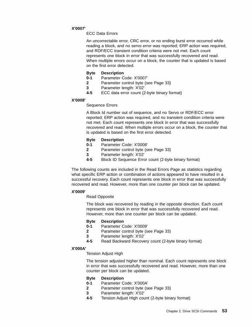
X'0007'ECC Data Errors
An uncorrectable error, CRC error, or no ending burst error occurred whilereading a block, and no servo error was reported; ERP action was required,and RDF/ECC transient condition criteria were not met. Each countrepresents one block in error that was successfully recovered and read.When multiple errors occur on a block, the counter that is updated is basedon the first error detected.
Byte Description0-1 Parameter Code: X'0007'2 Parameter control byte (see Page 33)3 Parameter length: X'02'4-5 ECC data error count (2-byte binary format)
X'0008'Sequence Errors
A Block Id number out of sequence, and no Servo or RDF/ECC errorreported; ERP action was required, and no transient condition criteria werenot met. Each count represents one block in error that was successfullyrecovered and read. When multiple errors occur on a block, the counter thatis updated is based on the first error detected.
Byte Description0-1 Parameter Code: X'0008'2 Parameter control byte (see Page 33)3 Parameter length: X'02'4-5 Block ID Sequence Error count (2-byte binary format)
The following counts are included in the Read Errors Page as statistics regardingwhat specific ERP action or combination of actions appeared to have resulted in asuccessful recovery. Each count represents one block in error that was successfullyrecovered and read. However, more than one counter per block can be updated.
X'0009'Read Opposite
The block was recovered by reading in the opposite direction. Each countrepresents one block in error that was successfully recovered and read.However, more than one counter per block can be updated.
Byte Description0-1 Parameter Code: X'0009'2 Parameter control byte (see Page 33)3 Parameter length: X'02'4-5 Read Backward Recovery count (2-byte binary format)
X'000A'Tension Adjust High
The tension adjusted higher than nominal. Each count represents one blockin error that was successfully recovered and read. However, more than onecounter per block can be updated.
Byte Description0-1 Parameter Code: X'000A'2 Parameter control byte (see Page 33)3 Parameter length: X'02'4-5 Tension Adjust High count (2-byte binary format)
Chapter 2. Drive SCSI Commands 53
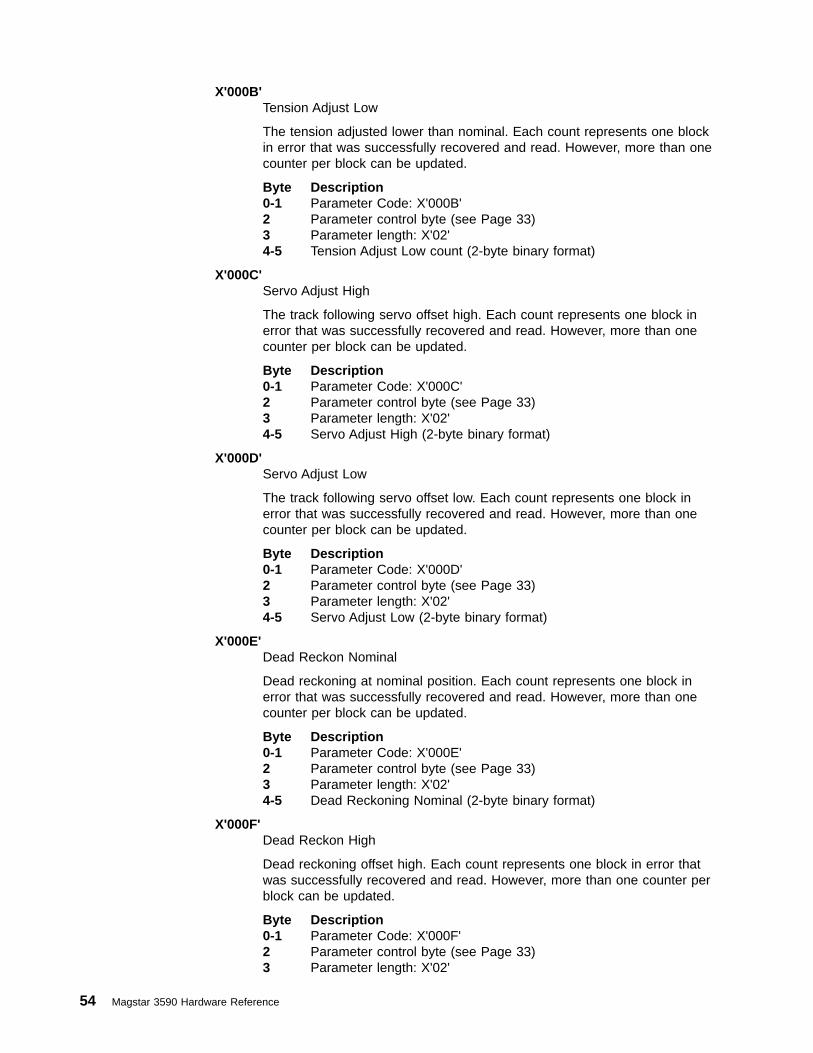
X'000B'Tension Adjust Low
The tension adjusted lower than nominal. Each count represents one blockin error that was successfully recovered and read. However, more than onecounter per block can be updated.
Byte Description0-1 Parameter Code: X'000B'2 Parameter control byte (see Page 33)3 Parameter length: X'02'4-5 Tension Adjust Low count (2-byte binary format)
X'000C'Servo Adjust High
The track following servo offset high. Each count represents one block inerror that was successfully recovered and read. However, more than onecounter per block can be updated.
Byte Description0-1 Parameter Code: X'000C'2 Parameter control byte (see Page 33)3 Parameter length: X'02'4-5 Servo Adjust High (2-byte binary format)
X'000D'Servo Adjust Low
The track following servo offset low. Each count represents one block inerror that was successfully recovered and read. However, more than onecounter per block can be updated.
Byte Description0-1 Parameter Code: X'000D'2 Parameter control byte (see Page 33)3 Parameter length: X'02'4-5 Servo Adjust Low (2-byte binary format)
X'000E'Dead Reckon Nominal
Dead reckoning at nominal position. Each count represents one block inerror that was successfully recovered and read. However, more than onecounter per block can be updated.
Byte Description0-1 Parameter Code: X'000E'2 Parameter control byte (see Page 33)3 Parameter length: X'02'4-5 Dead Reckoning Nominal (2-byte binary format)
X'000F'Dead Reckon High
Dead reckoning offset high. Each count represents one block in error thatwas successfully recovered and read. However, more than one counter perblock can be updated.
Byte Description0-1 Parameter Code: X'000F'2 Parameter control byte (see Page 33)3 Parameter length: X'02'
54 Magstar 3590 Hardware Reference
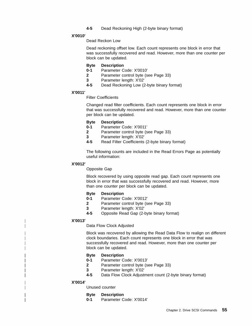
4-5 Dead Reckoning High (2-byte binary format)
X'0010'Dead Reckon Low
Dead reckoning offset low. Each count represents one block in error thatwas successfully recovered and read. However, more than one counter perblock can be updated.
Byte Description0-1 Parameter Code: X'0010'2 Parameter control byte (see Page 33)3 Parameter length: X'02'4-5 Dead Reckoning Low (2-byte binary format)
X'0011'Filter Coefficients
Changed read filter coefficients. Each count represents one block in errorthat was successfully recovered and read. However, more than one counterper block can be updated.
Byte Description0-1 Parameter Code: X'0011'2 Parameter control byte (see Page 33)3 Parameter length: X'02'4-5 Read Filter Coefficients (2-byte binary format)
The following counts are included in the Read Errors Page as potentiallyuseful information:
X'0012'Opposite Gap
Block recovered by using opposite read gap. Each count represents oneblock in error that was successfully recovered and read. However, morethan one counter per block can be updated.
Byte Description0-1 Parameter Code: X'0012'2 Parameter control byte (see Page 33)3 Parameter length: X'02'4-5 Opposite Read Gap (2-byte binary format)
X'0013'Data Flow Clock Adjusted
Block was recovered by allowing the Read Data Flow to realign on differentclock boundaries. Each count represents one block in error that wassuccessfully recovered and read. However, more than one counter perblock can be updated.
Byte Description0-1 Parameter Code: X'0013'2 Parameter control byte (see Page 33)3 Parameter length: X'02'4-5 Data Flow Clock Adjustment count (2-byte binary format)
X'0014'Unused counter
Byte Description0-1 Parameter Code: X'0014'
Chapter 2. Drive SCSI Commands 55
||
||||
||||||||||
||
||||
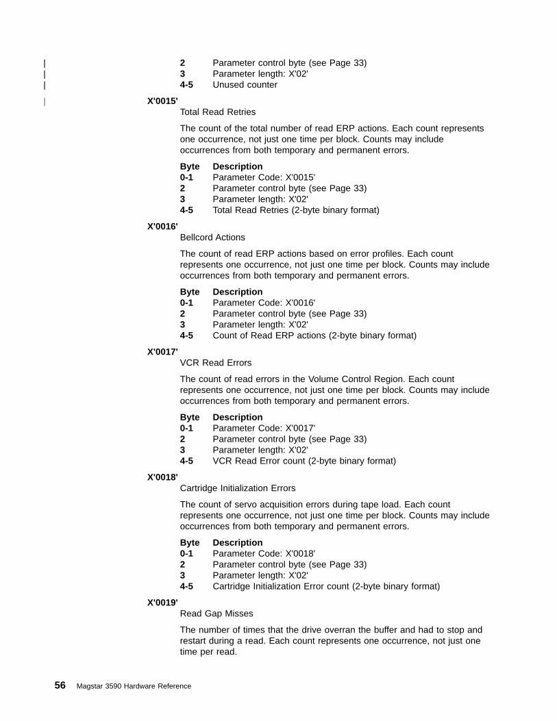
2 Parameter control byte (see Page 33)3 Parameter length: X'02'4-5 Unused counter
X'0015'Total Read Retries
The count of the total number of read ERP actions. Each count representsone occurrence, not just one time per block. Counts may includeoccurrences from both temporary and permanent errors.
Byte Description0-1 Parameter Code: X'0015'2 Parameter control byte (see Page 33)3 Parameter length: X'02'4-5 Total Read Retries (2-byte binary format)
X'0016'Bellcord Actions
The count of read ERP actions based on error profiles. Each countrepresents one occurrence, not just one time per block. Counts may includeoccurrences from both temporary and permanent errors.
Byte Description0-1 Parameter Code: X'0016'2 Parameter control byte (see Page 33)3 Parameter length: X'02'4-5 Count of Read ERP actions (2-byte binary format)
X'0017'VCR Read Errors
The count of read errors in the Volume Control Region. Each countrepresents one occurrence, not just one time per block. Counts may includeoccurrences from both temporary and permanent errors.
Byte Description0-1 Parameter Code: X'0017'2 Parameter control byte (see Page 33)3 Parameter length: X'02'4-5 VCR Read Error count (2-byte binary format)
X'0018'Cartridge Initialization Errors
The count of servo acquisition errors during tape load. Each countrepresents one occurrence, not just one time per block. Counts may includeoccurrences from both temporary and permanent errors.
Byte Description0-1 Parameter Code: X'0018'2 Parameter control byte (see Page 33)3 Parameter length: X'02'4-5 Cartridge Initialization Error count (2-byte binary format)
X'0019'Read Gap Misses
The number of times that the drive overran the buffer and had to stop andrestart during a read. Each count represents one occurrence, not just onetime per read.
56 Magstar 3590 Hardware Reference
||||||
|
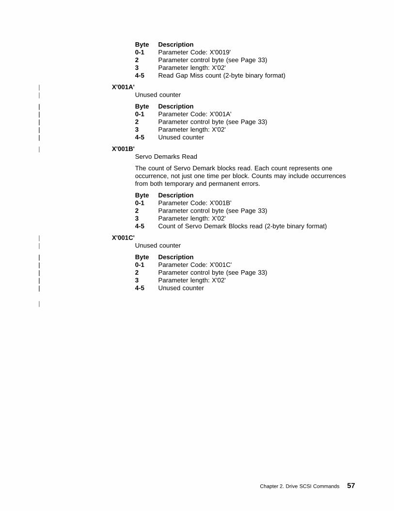
Byte Description0-1 Parameter Code: X'0019'2 Parameter control byte (see Page 33)3 Parameter length: X'02'4-5 Read Gap Miss count (2-byte binary format)
X'001A'Unused counter
Byte Description0-1 Parameter Code: X'001A'2 Parameter control byte (see Page 33)3 Parameter length: X'02'4-5 Unused counter
X'001B'Servo Demarks Read
The count of Servo Demark blocks read. Each count represents oneoccurrence, not just one time per block. Counts may include occurrencesfrom both temporary and permanent errors.
Byte Description0-1 Parameter Code: X'001B'2 Parameter control byte (see Page 33)3 Parameter length: X'02'4-5 Count of Servo Demark Blocks read (2-byte binary format)
X'001C'Unused counter
Byte Description0-1 Parameter Code: X'001C'2 Parameter control byte (see Page 33)3 Parameter length: X'02'4-5 Unused counter
Chapter 2. Drive SCSI Commands 57
||
||||||||||
|
||
||||||||||
|
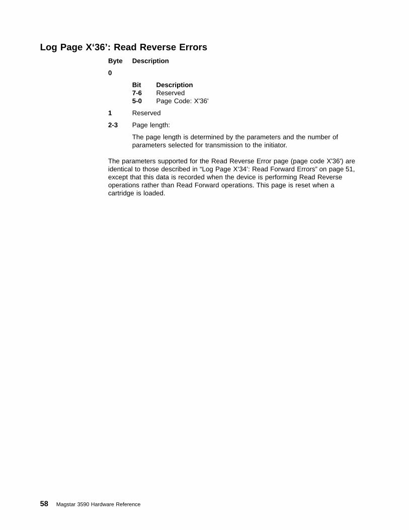
Log Page X‘36’: Read Reverse ErrorsByte Description
0
Bit Description7-6 Reserved5-0 Page Code: X'36'
1 Reserved
2-3 Page length:
The page length is determined by the parameters and the number ofparameters selected for transmission to the initiator.
The parameters supported for the Read Reverse Error page (page code X'36') areidentical to those described in “Log Page X‘34’: Read Forward Errors” on page 51,except that this data is recorded when the device is performing Read Reverseoperations rather than Read Forward operations. This page is reset when acartridge is loaded.
58 Magstar 3590 Hardware Reference

Log Page X‘38’: Blocks/Bytes TransferredThis page is reset when a cartridge is loaded.
Byte Description
0
Bit Description7-6 Reserved5-0 Page Code: X'38'
1 Reserved
2-3 Page length:
The page length is determined by the parameters and the number ofparameters selected for transmission to the initiator.
The following parameters are supported for the Blocks/Bytes Transferred page(page code X'38'):
X'0000'SCSI Write Blocks Processed
Each count represents a block processed across the SCSI interface duringa Write. The count does not include ERP retries.
Byte Description0-1 Parameter Code: X'0000'2 Parameter control byte (see Page 33)3 Parameter length: X'04'4-7 SCSI write blocks processed (4-byte binary format)
X'0001'SCSI Write Kilobytes Processed
Each count represents a kilobyte (1024 bytes) processed across the SCSIinterface during a Write. The count does not include ERP retries. You candivide this count by Device Write Kilobytes Processed, X'0005', to calculatean approximate write compression ratio.
Byte Description0-1 Parameter Code: X'0001'2 Parameter control byte (see Page 33)3 Parameter length: X'04'4-7 SCSI write kilobytes processed (4-byte binary format)
Refer to “Scaled Log Page Counters” on page 239 for a descriptionof this scaled counter.
X'0002'SCSI Read Blocks Processed
Each count represents a block processed across the SCSI interface duringa Read. The count does not include ERP retries.
Byte Description0-1 Parameter Code: X'0001'2 Parameter control byte (see Page 33)3 Parameter length: X'04'4-7 SCSI read blocks processed (4-byte binary format)
X'0003'SCSI Read Kilobytes Processed
Chapter 2. Drive SCSI Commands 59
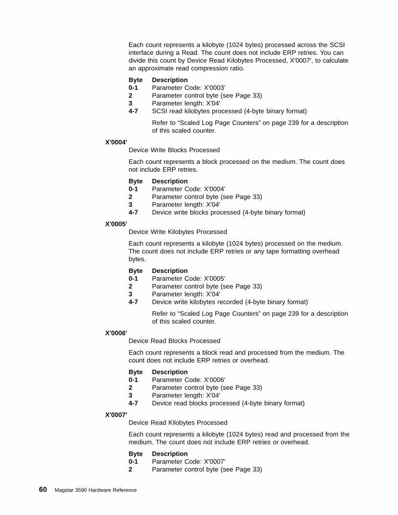
Each count represents a kilobyte (1024 bytes) processed across the SCSIinterface during a Read. The count does not include ERP retries. You candivide this count by Device Read Kilobytes Processed, X'0007', to calculatean approximate read compression ratio.
Byte Description0-1 Parameter Code: X'0003'2 Parameter control byte (see Page 33)3 Parameter length: X'04'4-7 SCSI read kilobytes processed (4-byte binary format)
Refer to “Scaled Log Page Counters” on page 239 for a descriptionof this scaled counter.
X'0004'Device Write Blocks Processed
Each count represents a block processed on the medium. The count doesnot include ERP retries.
Byte Description0-1 Parameter Code: X'0004'2 Parameter control byte (see Page 33)3 Parameter length: X'04'4-7 Device write blocks processed (4-byte binary format)
X'0005'Device Write Kilobytes Processed
Each count represents a kilobyte (1024 bytes) processed on the medium.The count does not include ERP retries or any tape formatting overheadbytes.
Byte Description0-1 Parameter Code: X'0005'2 Parameter control byte (see Page 33)3 Parameter length: X'04'4-7 Device write kilobytes recorded (4-byte binary format)
Refer to “Scaled Log Page Counters” on page 239 for a descriptionof this scaled counter.
X'0006'Device Read Blocks Processed
Each count represents a block read and processed from the medium. Thecount does not include ERP retries or overhead.
Byte Description0-1 Parameter Code: X'0006'2 Parameter control byte (see Page 33)3 Parameter length: X'04'4-7 Device read blocks processed (4-byte binary format)
X'0007'Device Read Kilobytes Processed
Each count represents a kilobyte (1024 bytes) read and processed from themedium. The count does not include ERP retries or overhead.
Byte Description0-1 Parameter Code: X'0007'2 Parameter control byte (see Page 33)
60 Magstar 3590 Hardware Reference
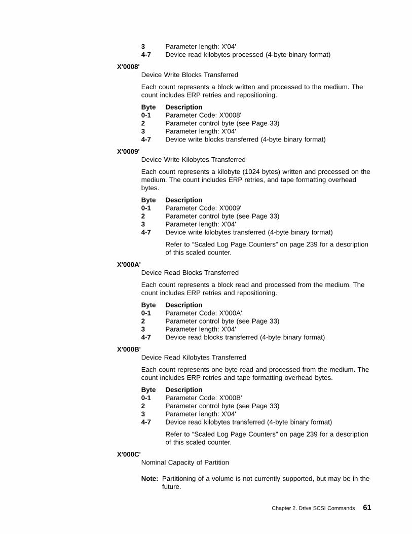
3 Parameter length: X'04'4-7 Device read kilobytes processed (4-byte binary format)
X'0008'Device Write Blocks Transferred
Each count represents a block written and processed to the medium. Thecount includes ERP retries and repositioning.
Byte Description0-1 Parameter Code: X'0008'2 Parameter control byte (see Page 33)3 Parameter length: X'04'4-7 Device write blocks transferred (4-byte binary format)
X'0009'Device Write Kilobytes Transferred
Each count represents a kilobyte (1024 bytes) written and processed on themedium. The count includes ERP retries, and tape formatting overheadbytes.
Byte Description0-1 Parameter Code: X'0009'2 Parameter control byte (see Page 33)3 Parameter length: X'04'4-7 Device write kilobytes transferred (4-byte binary format)
Refer to “Scaled Log Page Counters” on page 239 for a descriptionof this scaled counter.
X'000A'Device Read Blocks Transferred
Each count represents a block read and processed from the medium. Thecount includes ERP retries and repositioning.
Byte Description0-1 Parameter Code: X'000A'2 Parameter control byte (see Page 33)3 Parameter length: X'04'4-7 Device read blocks transferred (4-byte binary format)
X'000B'Device Read Kilobytes Transferred
Each count represents one byte read and processed from the medium. Thecount includes ERP retries and tape formatting overhead bytes.
Byte Description0-1 Parameter Code: X'000B'2 Parameter control byte (see Page 33)3 Parameter length: X'04'4-7 Device read kilobytes transferred (4-byte binary format)
Refer to “Scaled Log Page Counters” on page 239 for a descriptionof this scaled counter.
X'000C'Nominal Capacity of Partition
Note: Partitioning of a volume is not currently supported, but may be in thefuture.
Chapter 2. Drive SCSI Commands 61

The nominal capacity of the current partition (in kilobytes).
Byte Description0-1 Parameter Code: X'000C'2 Parameter control byte (see Page 33)3 Parameter length: X'04'4-7 Nominal capacity of partition in kilobytes (4-byte binary format)
Note: Partitioning of a volume is not currently supported, but maybe in the future.
Refer to “Scaled Log Page Counters” on page 239 for a descriptionof this scaled counter.
X'000D'Fractional Part of Partition Currently Traversed
Note: Partitioning of a volume is not currently supported, but may be in thefuture.
The fractional part of the partition traversed (N/255).
Byte Description0-1 Parameter Code: X'000D'2 Parameter control byte (see Page 33)3 Parameter length: X'01'4 Fraction of partition currently traversed (X'00 to FF')
X'000E'Nominal Capacity of the Volume
The nominal capacity of the volume (in kilobytes)
Byte Description0-1 Parameter Code: X'000E'2 Parameter control byte (see Page 33)3 Parameter length: X'04'4-7 Nominal capacity of volume in kilobytes (4-byte binary format)
Refer to “Scaled Log Page Counters” on page 239 for a descriptionof this scaled counter.
X'000F'Fractional Part of Volume Currently Traversed
The fractional part of the volume traversed (N/255).
Byte Description0-1 Parameter Code: X'000F'2 Parameter control byte (see Page 33)3 Parameter length: X'01'4 Fraction of volume currently traversed (X'00 to FF')
62 Magstar 3590 Hardware Reference
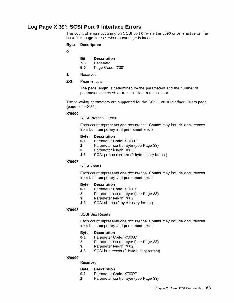
Log Page X‘39’: SCSI Port 0 Interface ErrorsThe count of errors occurring on SCSI port 0 (while the 3590 drive is active on thebus). This page is reset when a cartridge is loaded.
Byte Description
0
Bit Description7-6 Reserved5-0 Page Code: X'39'
1 Reserved
2-3 Page length:
The page length is determined by the parameters and the number ofparameters selected for transmission to the initiator.
The following parameters are supported for the SCSI Port 0 Interface Errors page(page code X'39'):
X'0000'SCSI Protocol Errors
Each count represents one occurrence. Counts may include occurrencesfrom both temporary and permanent errors.
Byte Description0-1 Parameter Code: X'0000'2 Parameter control byte (see Page 33)3 Parameter length: X'02'4-5 SCSI protocol errors (2-byte binary format)
X'0007'SCSI Aborts
Each count represents one occurrence. Counts may include occurrencesfrom both temporary and permanent errors.
Byte Description0-1 Parameter Code: X'0007'2 Parameter control byte (see Page 33)3 Parameter length: X'02'4-5 SCSI aborts (2-byte binary format)
X'0008'SCSI Bus Resets
Each count represents one occurrence. Counts may include occurrencesfrom both temporary and permanent errors.
Byte Description0-1 Parameter Code: X'0008'2 Parameter control byte (see Page 33)3 Parameter length: X'02'4-5 SCSI bus resets (2-byte binary format)
X'0009'Reserved
Byte Description0-1 Parameter Code: X'0009'2 Parameter control byte (see Page 33)
Chapter 2. Drive SCSI Commands 63
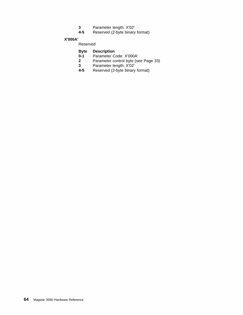
3 Parameter length: X'02'4-5 Reserved (2-byte binary format)
X'000A'Reserved
Byte Description0-1 Parameter Code: X'000A'2 Parameter control byte (see Page 33)3 Parameter length: X'02'4-5 Reserved (2-byte binary format)
64 Magstar 3590 Hardware Reference

Log Page X‘3A’: SCSI Port 1 Interface ErrorsThe count of errors occurring on SCSI port 1 (while the 3590 drive is active on thebus). This page is reset when a cartridge is loaded.
Byte Description
0
Bit Description7-6 Reserved5-0 Page Code: X'3A'
1 Reserved
2-3 Page length:
The page length is determined by the parameters and the number ofparameters selected for transmission to the initiator.
The following parameters are supported for the SCSI Port 1 Interface Errors page(page code X'3A'):
Note: The parameters are identical to those found in “Log Page X‘39’: SCSI Port 0Interface Errors” on page 63, except this data is recorded when the device isusing interface 1.
Chapter 2. Drive SCSI Commands 65

Log Page X‘3B’: Equipment Check ErrorsThe following counters all deal with errors where a logic problem in the drivehardware is suspected (as opposed to errors with write or read data to or from thetape or the SCSI bus). This page is reset when a cartridge is loaded.
Byte Description
0
Bit Description7-6 Reserved5-0 Page Code: X'3B'
1 Reserved
2-3 Page length:
The page length is determined by the parameters and the number ofparameters selected for transmission to the initiator.
The following parameters are supported for the Equipment Check Errors page(page code X'3B'):
X'0001'Operator Panel Errors
Each count represents one occurrence. Counts may include occurrencesfrom both temporary and permanent errors.
Byte Description0-1 Parameter Code: X'0001'2 Parameter control byte (see Page 33)3 Parameter length: X'02'4-5 Operator panel errors (2-byte binary format)
X'0002'SCSI Protocol Chip Errors
Each count represents one occurrence. Counts may include occurrencesfrom both temporary and permanent errors.
Byte Description0-1 Parameter Code: X'0002'2 Parameter control byte (see Page 33)3 Parameter length: X'02'4-5 SCSI protocol chip errors (2-byte binary format)
X'0003'SCSI Buffer Errors
Each count represents one occurrence. Counts may include occurrencesfrom both temporary and permanent errors.
Byte Description0-1 Parameter Code: X'0003'2 Parameter control byte (see Page 33)3 Parameter length: X'02'4-5 SCSI buffer errors (2-byte binary format)
X'0004'Compactor Errors
Each count represents one occurrence. Counts may include occurrencesfrom both temporary and permanent errors.
66 Magstar 3590 Hardware Reference

Byte Description0-1 Parameter Code: X'0004'2 Parameter control byte (see Page 33)3 Parameter length: X'02'4-5 Compactor errors (2-byte binary format)
X'0005'Format Buffer Errors
Each count represents one occurrence. Counts may include occurrencesfrom both temporary and permanent errors.
Byte Description0-1 Parameter Code: X'0005'2 Parameter control byte (see Page 33)3 Parameter length: X'02'4-5 Format buffer errors (2-byte binary format)
X'0006'Data Flow Hardware Errors
Each count represents one occurrence. Counts may include occurrencesfrom both temporary and permanent errors.
Byte Description0-1 Parameter Code: X'0006'2 Parameter control byte (see Page 33)3 Parameter length: X'02'4-5 Data flow hardware errors (2-byte binary format)
X'0007'ECC Hardware Errors
Each count represents one occurrence. Counts may include occurrencesfrom both temporary and permanent errors.
Byte Description0-1 Parameter Code: X'0007'2 Parameter control byte (see Page 33)3 Parameter length: X'02'4-5 ECC hardware errors (2-byte binary format)
X'0008'Analog Card Hardware Errors
Each count represents one occurrence. Counts may include occurrencesfrom both temporary and permanent errors.
Byte Description0-1 Parameter Code: X'0008'2 Parameter control byte (see Page 33)3 Parameter length: X'02'4-5 Analog card hardware errors (2-byte binary format)
X'0009'Mailbox Interface Errors
Each count represents one occurrence. Counts may include occurrencesfrom both temporary and permanent errors.
Byte Description0-1 Parameter Code: X'0009'2 Parameter control byte (see Page 33)
Chapter 2. Drive SCSI Commands 67

3 Parameter length: X'02'4-5 Mailbox interface errors (2-byte binary format)
68 Magstar 3590 Hardware Reference

Log Page X‘3D’: Subsystem StatisticsThe following counters all deal with Subsystem statistics and errors. This page isnever reset. The counters are maintained in VPD and persist across Log Selects,Log Sense, Power On Resets, and even microcode download. Current values arewritten to VPD every eight operating hours when the drive is in a not ready state.The user may also save these counters to VPD at other times (such as just prior topowering off) by selecting the Save option from the operator panel Statistics menu.The counters lock at maximum values.
Note: The page is currently returned; however, more fields may be supported inthe future.
Byte Description
0
Bit Description7-6 Reserved5-0 Page Code: X'3D'
1 Reserved
2-3 Page length:
The page length is determined by the parameters and the number ofparameters selected for transmission to the initiator.
The following parameters are supported for the Subsystems Statistics Page (pagecode X'3D'):
X'0000'ACF Errors
Each count represents one occurrence. Counts may include occurrencesfrom both temporary and permanent errors.
Byte Description0-1 Parameter Code: X'0000'2 Parameter control byte (see Page 33)3 Parameter length: X'02'4-5 ACF errors (2-byte binary format)
X'0001'ACF Failures of Put to Drive Actions
Each count represents one occurrence where a ACF attempt to move acartridge to the drive failed.
Byte Description0-1 Parameter Code: X'0001'2 Parameter control byte (see Page 33)3 Parameter length: X'02'4-5 ACF put to drive failures (2-byte binary format)
X'0002'ACF Failures of Get from Drive Actions
Each count represents one occurrence where a ACF attempt to remove acartridge from the drive failed.
Byte Description0-1 Parameter Code: X'0002'2 Parameter control byte (see Page 33)
Chapter 2. Drive SCSI Commands 69
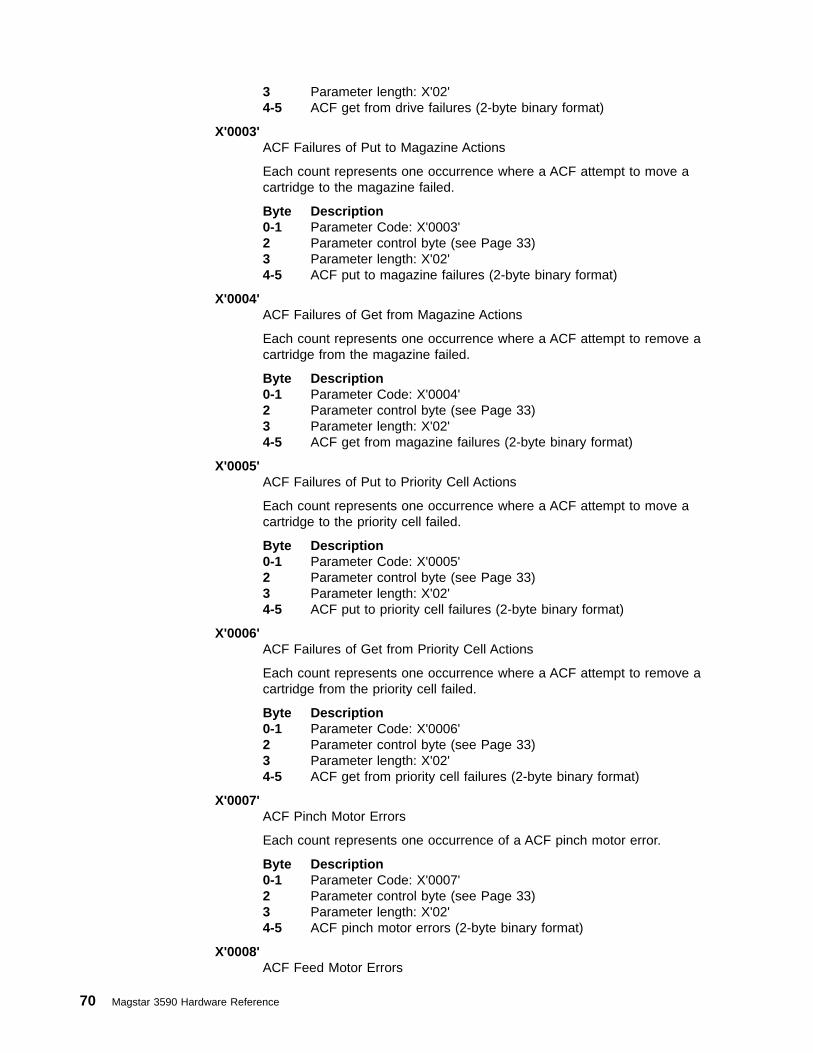
3 Parameter length: X'02'4-5 ACF get from drive failures (2-byte binary format)
X'0003'ACF Failures of Put to Magazine Actions
Each count represents one occurrence where a ACF attempt to move acartridge to the magazine failed.
Byte Description0-1 Parameter Code: X'0003'2 Parameter control byte (see Page 33)3 Parameter length: X'02'4-5 ACF put to magazine failures (2-byte binary format)
X'0004'ACF Failures of Get from Magazine Actions
Each count represents one occurrence where a ACF attempt to remove acartridge from the magazine failed.
Byte Description0-1 Parameter Code: X'0004'2 Parameter control byte (see Page 33)3 Parameter length: X'02'4-5 ACF get from magazine failures (2-byte binary format)
X'0005'ACF Failures of Put to Priority Cell Actions
Each count represents one occurrence where a ACF attempt to move acartridge to the priority cell failed.
Byte Description0-1 Parameter Code: X'0005'2 Parameter control byte (see Page 33)3 Parameter length: X'02'4-5 ACF put to priority cell failures (2-byte binary format)
X'0006'ACF Failures of Get from Priority Cell Actions
Each count represents one occurrence where a ACF attempt to remove acartridge from the priority cell failed.
Byte Description0-1 Parameter Code: X'0006'2 Parameter control byte (see Page 33)3 Parameter length: X'02'4-5 ACF get from priority cell failures (2-byte binary format)
X'0007'ACF Pinch Motor Errors
Each count represents one occurrence of a ACF pinch motor error.
Byte Description0-1 Parameter Code: X'0007'2 Parameter control byte (see Page 33)3 Parameter length: X'02'4-5 ACF pinch motor errors (2-byte binary format)
X'0008'ACF Feed Motor Errors
70 Magstar 3590 Hardware Reference
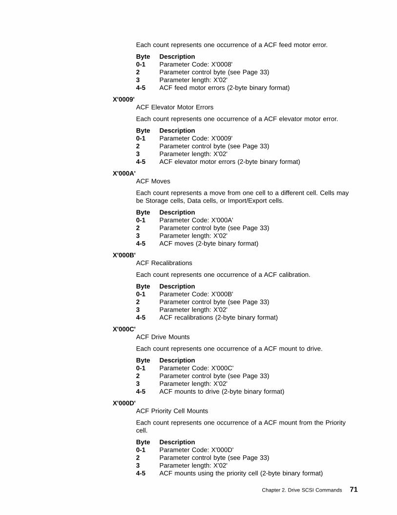
Each count represents one occurrence of a ACF feed motor error.
Byte Description0-1 Parameter Code: X'0008'2 Parameter control byte (see Page 33)3 Parameter length: X'02'4-5 ACF feed motor errors (2-byte binary format)
X'0009'ACF Elevator Motor Errors
Each count represents one occurrence of a ACF elevator motor error.
Byte Description0-1 Parameter Code: X'0009'2 Parameter control byte (see Page 33)3 Parameter length: X'02'4-5 ACF elevator motor errors (2-byte binary format)
X'000A'ACF Moves
Each count represents a move from one cell to a different cell. Cells maybe Storage cells, Data cells, or Import/Export cells.
Byte Description0-1 Parameter Code: X'000A'2 Parameter control byte (see Page 33)3 Parameter length: X'02'4-5 ACF moves (2-byte binary format)
X'000B'ACF Recalibrations
Each count represents one occurrence of a ACF calibration.
Byte Description0-1 Parameter Code: X'000B'2 Parameter control byte (see Page 33)3 Parameter length: X'02'4-5 ACF recalibrations (2-byte binary format)
X'000C'ACF Drive Mounts
Each count represents one occurrence of a ACF mount to drive.
Byte Description0-1 Parameter Code: X'000C'2 Parameter control byte (see Page 33)3 Parameter length: X'02'4-5 ACF mounts to drive (2-byte binary format)
X'000D'ACF Priority Cell Mounts
Each count represents one occurrence of a ACF mount from the Prioritycell.
Byte Description0-1 Parameter Code: X'000D'2 Parameter control byte (see Page 33)3 Parameter length: X'02'4-5 ACF mounts using the priority cell (2-byte binary format)
Chapter 2. Drive SCSI Commands 71

X'000E'ACF Magazine Cell Mounts
Each count represents one occurrence of a ACF mount from a magazinecell.
Byte Description0-1 Parameter Code: X'000E'2 Parameter control byte (see Page 33)3 Parameter length: X'02'4-5 ACF mounts using the magazine cell (2-byte binary format)
X'000F'ACF Cleaning Mounts to Device
Each count represents one mount of the cleaning cartridge into the device.All cleaning mounts are counted regardless of whether a ACF wasconfigured with the drive or not. In particular cleaning mounts in a 3494library are counted.
Byte Description0-1 Parameter Code: X'000F'2 Parameter control byte (see Page 33)3 Parameter length: X'02'4-5 ACF cleaning cartridge mounts (2-byte binary format)
X'0020'Volume Lifetime Mounts
The count represents the total number of successful cartridge unloadsperformed during the lifetime of a cartridge. This field is not updated forthose mounts that occur with the volume physically write-protected.
Byte Description0-1 Parameter Code: X'0020'2 Parameter control byte (see Page 33)3 Parameter length: X'04'4-7 Volume lifetime mounts
X'0021'Volume Lifetime Megabytes Written
The count represents the total number of bytes in Megabytes written duringthe lifetime of the cartridge. On each unload, an approximate value iscalculated and stored by rounding up to the nearest Megabyte. These bytesare counted as they are processed to the medium (compressed bytes), notat the SCSI interface. This field is not updated during those mounts thatoccur with the volume physically write-protected.
Byte Description0-1 Parameter Code: X'0021'2 Parameter control byte (see Page 33)3 Parameter length: X'04'4-7 Volume lifetime Megabytes written
X'0022'Volume Lifetime Megabytes Read
The count represents the total number of bytes in Megabytes read duringthe lifetime of the cartridge. On each unload, an approximate value iscalculated and stored by rounding up to the nearest Megabyte. These bytesare counted as they are processed to the medium (compressed bytes), not
72 Magstar 3590 Hardware Reference

at the SCSI interface. This field is not updated during those mounts thatoccur with the volume physically write-protected.
Byte Description0-1 Parameter Code: X'0022'2 Parameter control byte (see Page 33)3 Parameter length: X'04'4-7 Volume lifetime Megabytes read
X'0040'Drive Lifetime Mounts
Each count represents the total number of successful cartridge unloadsperformed during the lifetime of the drive.
Byte Description0-1 Parameter Code: X'0040'2 Parameter control byte (see Page 33)3 Parameter length: X'04'4-7 Volume lifetime mounts
X'0041'Drive Lifetime Megabytes Written
The count represents the total number of bytes in Megabytes written duringthe lifetime of the drive. On each unload, an approximate value iscalculated and stored by rounding up to the nearest Megabyte. These bytesare counted as they are processed to the medium (compressed bytes), notat the SCSI interface.
Byte Description0-1 Parameter Code: X'0041'2 Parameter control byte (see Page 33)3 Parameter length: X'04'4-7 Drive lifetime Megabytes written
X'0042'Drive Lifetime Megabytes Read
The count represents the total number of bytes in Megabytes read duringthe lifetime of the drive. On each unload, an approximate value iscalculated and stored by rounding up to the nearest Megabyte. These bytesare counted as they are processed to the medium (compressed bytes), notat the SCSI interface.
Byte Description0-1 Parameter Code: X'0042'2 Parameter control byte (see Page 33)3 Parameter length: X'04'4-7 Drive lifetime Megabytes read
Chapter 2. Drive SCSI Commands 73
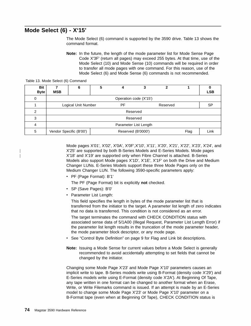
Mode Select (6) - X‘15’The Mode Select (6) command is supported by the 3590 drive. Table 13 shows thecommand format.
Note: In the future, the length of the mode parameter list for Mode Sense PageCode X'3F' (return all pages) may exceed 255 bytes. At that time, use of theMode Select (10) and Mode Sense (10) commands will be required in orderto transfer all mode pages with one command. For this reason, use of theMode Select (6) and Mode Sense (6) commands is not recommended.
Table 13. Mode Select (6) Command
BitByte
7MSB
6 5 4 3 2 1 0LSB
0 Operation code (X'15')
1 Logical Unit Number PF Reserved SP
2 Reserved
3 Reserved
4 Parameter List Length
5 Vendor Specific (B'00') Reserved (B'0000') Flag Link
Mode pages X'01', X'02', X'0A', X'0F',X'10', X'11', X'20', X'21', X'22', X'23', X'24', andX'25' are supported by both B-Series Models and E-Series Models. Mode pagesX'18' and X'19' are supported only when Fibre Channel is attached. B-SeriesModels also support Mode pages X'1D', X'1E', X'1F' on both the Drive and MediumChanger LUNs. E-Series Models support these three Mode Pages only on theMedium Changer LUN. The following 3590-specific parameters apply:
v PF (Page Format): B'1'
The PF (Page Format) bit is explicitly not checked.
v SP (Save Pages): B'0'
v Parameter List Length:
This field specifies the length in bytes of the mode parameter list that istransferred from the initiator to the target. A parameter list length of zero indicatesthat no data is transferred. This condition is not considered as an error.
The target terminates the command with CHECK CONDITION status withassociated sense data of 5/1A00 (Illegal Request, Parameter List Length Error) ifthe parameter list length results in the truncation of the mode parameter header,the mode parameter block descriptor, or any mode page.
v See “Control Byte Definition” on page 9 for Flag and Link bit descriptions.
Note: Issuing a Mode Sense for current values before a Mode Select is generallyrecommended to avoid accidentally attempting to set fields that cannot bechanged by the initiator.
Changing some Mode Page X'23' and Mode Page X'10' parameters causes animplicit write to tape. B-Series models write using B-Format (density code X'29') andE-Series models write using E-Format (density code X'2A'). At Beginning Of Tape,any tape written in one format can be changed to another format when an Erase,Write, or Write Filemarks command is issued. If an attempt is made by an E-Seriesmodel to change some Mode Page X'23' or Mode Page X'10' parameter on aB-Format tape (even when at Beginning Of Tape), CHECK CONDITION status is
74 Magstar 3590 Hardware Reference
||

returned with associated sense data of 5/3005 (Illegal Request, Cannot WriteMedium — Incompatible Format). Since a B-Series model cannot read an E-Formattape, this condition cannot happen on a B-Series model.
Listed below are the Mode Parameters that cause implicit writes:
v Mode Page 10, Byte 15, Bit 1 PERSWP
v Mode Page 10, Byte 15, Bit 0 PRMWP
v Mode Page 23, Byte 10, Bit 4 Persistent Write Protect
v Mode Page 23, Byte 10, Bit 3 Reset Persistent Write Protect
v Mode Page 23, Byte 10, Bit 0 Permanent Write Protect
v Mode Page 23, Byte 11, Bit 0 CapScalV
v Mode Page 23, Byte 20, Bit 0 Edge Track
Note: For Reserved-Vendor-Unique fields, appropriate values to issue on a ModeSelect may be non-zero. Mode Selects to pages with these fields should usea value obtained by issuing a Mode Sense just prior to the Mode Select.
Chapter 2. Drive SCSI Commands 75
||||
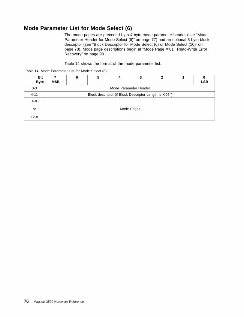
Mode Parameter List for Mode Select (6)The mode pages are preceded by a 4-byte mode parameter header (see “ModeParameter Header for Mode Select (6)” on page 77) and an optional 8-byte blockdescriptor (see “Block Descriptor for Mode Select (6) or Mode Select (10)” onpage 78). Mode page descriptions begin at “Mode Page X‘01’: Read-Write ErrorRecovery” on page 93
Table 14 shows the format of the mode parameter list.
Table 14. Mode Parameter List for Mode Select (6)
BitByte
7MSB
6 5 4 3 2 1 0LSB
0-3 Mode Parameter Header
4-11 Block descriptor (if Block Descriptor Length is X'08.')
4-n
or
12-n
Mode Pages
76 Magstar 3590 Hardware Reference

Mode Parameter Header for Mode Select (6)There is one copy of the mode parameter header for each initiator. Table 15 showsthe format of the mode parameter header for Mode Select (6).
Table 15. Mode Parameter Header for Mode Select (6)
BitByte
7MSB
6 5 4 3 2 1 0LSB
0 Mode Data Length (Reserved for Mode Select)
1 Medium Type
2 Device-Specific Parameter
3 Block Descriptor Length
Mode parameter header field descriptions follow:
Byte Description
0 Reserved
1 Medium Type: Any value is allowed and ignored.
2 Device-Specific Parameter - Sequential Access Devices
Bit Description7 Undefined (field is ignored)6-4 Buffered Mode
Value Description0 Good status is reported when data is on medium1 Good status is reported when data is in the buffer2 Good status is reported when data is in the buffer and data
from other initiators is written on medium3-7 Reserved
This field is changeable. The default value for this field is 1.3-0 Speed: X'0' (use default speed)
3 Block Descriptor Length:v Set to X'00' if no block descriptor follows.v Set to X'08' if a single block descriptor follows.
This is a changeable field.
Chapter 2. Drive SCSI Commands 77

Block Descriptor for Mode Select (6) or Mode Select (10)The presence of the block descriptor in the Mode Select command depends on thevalue of the Block Descriptor Length in the mode parameter header. There is onecopy of the block descriptor for each initiator. Table 16 shows the format of theblock descriptor.
Table 16. Block Descriptor for Mode Select (6) or Mode Select (10)
BitByte
7MSB
6 5 4 3 2 1 0LSB
0 Density Code
1-3 Number of Blocks
4 Reserved
5-7 Block Length
The block descriptor field definitions follow:
Byte Description
0 Density Code:
Value DescriptionX'00' Use default density codeX'29' Use 3590 B-Format density codeX'2A' Use 3590 E-Format density code (E-Series Models only)X'7F' No change from previous density - NOP
A Change to this field is allowed and ignored.
1-3 Number of Blocks: X'000000'
4 Reserved
5-7 Block Length:
Block length is a changeable field. Any value of block length can bespecified between the minimum and the maximum block lengths, inclusive,specified in the Read Block Limits command. A Block Length value ofX'000000' indicates that the logical block size to be written to or read fromthe medium is specified by the Transfer Length field in the CDB (see “Read- X‘08’” on page 131 and “Write - X‘0A’” on page 185).
78 Magstar 3590 Hardware Reference
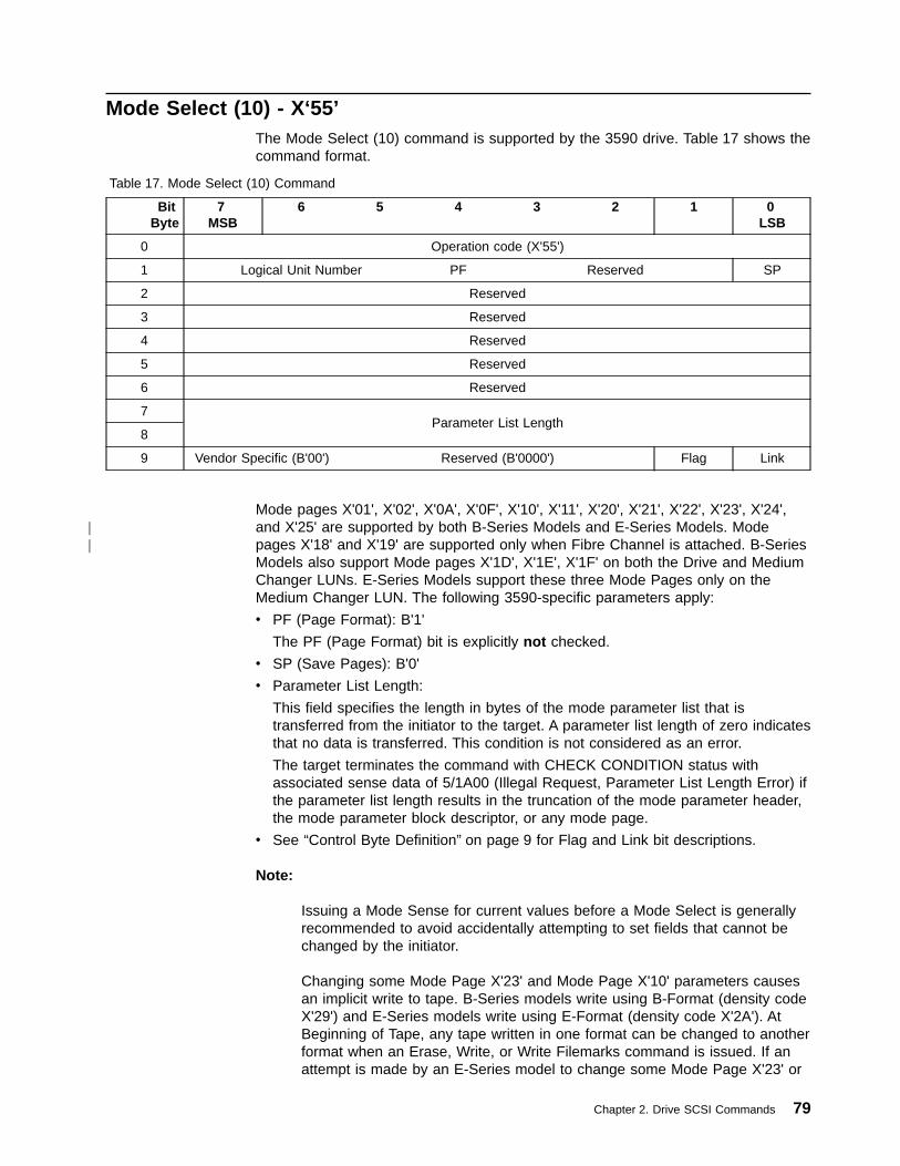
Mode Select (10) - X‘55’The Mode Select (10) command is supported by the 3590 drive. Table 17 shows thecommand format.
Table 17. Mode Select (10) Command
BitByte
7MSB
6 5 4 3 2 1 0LSB
0 Operation code (X'55')
1 Logical Unit Number PF Reserved SP
2 Reserved
3 Reserved
4 Reserved
5 Reserved
6 Reserved
7Parameter List Length
8
9 Vendor Specific (B'00') Reserved (B'0000') Flag Link
Mode pages X'01', X'02', X'0A', X'0F', X'10', X'11', X'20', X'21', X'22', X'23', X'24',and X'25' are supported by both B-Series Models and E-Series Models. Modepages X'18' and X'19' are supported only when Fibre Channel is attached. B-SeriesModels also support Mode pages X'1D', X'1E', X'1F' on both the Drive and MediumChanger LUNs. E-Series Models support these three Mode Pages only on theMedium Changer LUN. The following 3590-specific parameters apply:
v PF (Page Format): B'1'
The PF (Page Format) bit is explicitly not checked.
v SP (Save Pages): B'0'
v Parameter List Length:
This field specifies the length in bytes of the mode parameter list that istransferred from the initiator to the target. A parameter list length of zero indicatesthat no data is transferred. This condition is not considered as an error.
The target terminates the command with CHECK CONDITION status withassociated sense data of 5/1A00 (Illegal Request, Parameter List Length Error) ifthe parameter list length results in the truncation of the mode parameter header,the mode parameter block descriptor, or any mode page.
v See “Control Byte Definition” on page 9 for Flag and Link bit descriptions.
Note:
Issuing a Mode Sense for current values before a Mode Select is generallyrecommended to avoid accidentally attempting to set fields that cannot bechanged by the initiator.
Changing some Mode Page X'23' and Mode Page X'10' parameters causesan implicit write to tape. B-Series models write using B-Format (density codeX'29') and E-Series models write using E-Format (density code X'2A'). AtBeginning of Tape, any tape written in one format can be changed to anotherformat when an Erase, Write, or Write Filemarks command is issued. If anattempt is made by an E-Series model to change some Mode Page X'23' or
Chapter 2. Drive SCSI Commands 79
||

Mode Page X'10' parameter on a B-Format tape (even when at Beginning OfTape), CHECK CONDITION status is returned with associated sense data of5/3005 (Illegal Request, Cannot Write Medium — Incompatible Format).Since a B-Series model cannot read an E-Format tape, this condition cannothappen on a B-Series model.
Listed below are the Mode Parameters that cause implicit writes:
v Mode Page 10, Byte 15, Bit 1 PERSWP
v Mode Page 10, Byte 15, Bit 0 PRMWP
v Mode Page 23, Byte 10, Bit 4 Persistent Write Protect
v Mode Page 23, Byte 10, Bit 3 Reset Persistent Write Protect
v Mode Page 23, Byte 10, Bit 0 Permanent Write Protect
v Mode Page 23, Byte 11, Bit 0 CapScalV
v Mode Page 23, Byte 20, Bit 0 Edge Track
Note: For Reserved-Vendor-Unique fields, appropriate values to issue on a ModeSelect may be non-zero. Mode Selects to pages with these fields should usea value obtained by issuing a Mode Sense just prior to the Mode Select.
80 Magstar 3590 Hardware Reference
||||

Mode Parameter List for Mode Select (10)The mode pages are preceded by a 8-byte mode parameter header (see “ModeParameter Header for Mode Select (10)” on page 82) and an optional 8-byte blockdescriptor (see “Block Descriptor for Mode Select (6) or Mode Select (10)” onpage 78). Mode page descriptions begin at “Mode Page X‘01’: Read-Write ErrorRecovery” on page 93.
Table 18 shows the format of the mode parameter list.
Table 18. Mode Parameter List for Mode Select (10)
BitByte
7MSB
6 5 4 3 2 1 0LSB
0-7 Mode Parameter Header
8-15 Block descriptor (if Block Descriptor Length is X'08.')
8-n
or
16-n
Mode Pages
Chapter 2. Drive SCSI Commands 81

Mode Parameter Header for Mode Select (10)There is one copy of the mode parameter header for each initiator. Table 19 showsthe format of the mode parameter header for Mode Select (10).
Table 19. Mode Parameter Header for Mode Select (10)
BitByte
7MSB
6 5 4 3 2 1 0LSB
0Mode Data Length (Reserved for Mode Select)
1
2 Medium Type
3 Device-Specific Parameter
4 Reserved
5 Reserved
6Block Descriptor Length
7
Mode parameter header field descriptions follow:
Byte Description
0-1 Reserved
2 Medium Type: Any value is allowed and ignored.
3 Device-Specific Parameter - Sequential Access Devices
Bit Description7 Undefined (field is ignored)6-4 Buffered Mode
Value Description0 Good status is reported when data on medium1 Good status is reported when data is in buffer2 Good status is reported when data in buffer and data from
other initiators is written on medium3-7 Reserved
This field is changeable. The default value for this field is 1.3-0 Speed: X'0' (use default speed)
4-5 Reserved
6-7 Block Descriptor Length:v Set to X'0000' if no block descriptor follows.v Set to X'0008' if a single block descriptor follows.
This is a changeable field.
82 Magstar 3590 Hardware Reference
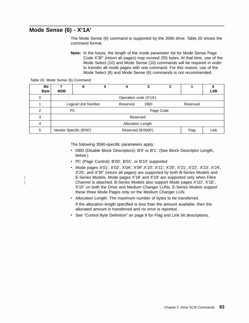
Mode Sense (6) - X‘1A’The Mode Sense (6) command is supported by the 3590 drive. Table 20 shows thecommand format.
Note: In the future, the length of the mode parameter list for Mode Sense PageCode X'3F' (return all pages) may exceed 255 bytes. At that time, use of theMode Select (10) and Mode Sense (10) commands will be required in orderto transfer all mode pages with one command. For this reason, use of theMode Select (6) and Mode Sense (6) commands is not recommended.
Table 20. Mode Sense (6) Command
BitByte
7MSB
6 5 4 3 2 1 0LSB
0 Operation code (X'1A')
1 Logical Unit Number Reserved DBD Reserved
2 PC Page Code
3 Reserved
4 Allocation Length
5 Vendor Specific (B'00') Reserved (B'0000') Flag Link
The following 3590-specific parameters apply:
v DBD (Disable Block Descriptors): B'0' or B'1'. (See Block Descriptor Length,below.)
v PC (Page Control): B'00', B'01', or B'10' supported
v Mode pages X'01', X'02', X'0A', X'0F',X'10', X'11', X'20', X'21', X'22', X'23', X'24',X'25', and X'3F' (return all pages) are supported by both B-Series Models andE-Series Models. Mode pages X'18' and X'19' are supported only when FibreChannel is attached. B-Series Models also support Mode pages X'1D', X'1E',X'1F' on both the Drive and Medium Changer LUNs. E-Series Models supportthese three Mode Pages only on the Medium Changer LUN.
v Allocation Length: The maximum number of bytes to be transferred.
If the allocation length specified is less than the amount available, then theallocated amount is transferred and no error is reported.
v See “Control Byte Definition” on page 9 for Flag and Link bit descriptions.
Chapter 2. Drive SCSI Commands 83
||

Mode Parameter List for Mode Sense (6)The mode pages are preceded by a 4-byte mode parameter header (see “ModeParameter Header for Mode Sense (6)” on page 85) and an optional blockdescriptor. If the DBD field is B'0', an 8-byte block descriptor follows the modeparameter header (see “Block Descriptor for Mode Sense (6) or Mode Sense (10)”on page 86). If the DBD field is B'1', the block descriptor is not present and the firstmode page follows the mode parameter header. Mode page descriptions begin at“Mode Page X‘01’: Read-Write Error Recovery” on page 93.
Table 21 shows the format of the mode parameter list.
Table 21. Mode Parameter List for Mode Sense (6)
BitByte
7MSB
6 5 4 3 2 1 0LSB
0-3 Mode Parameter Header
4-11 Block descriptor (if DBD is set to B'0')
4-nor
12-nMode Pages
84 Magstar 3590 Hardware Reference

Mode Parameter Header for Mode Sense (6)There is one copy of the mode parameter header for each initiator. Table 22 showsthe format of the mode parameter header for Mode Sense (6).
Table 22. Mode Parameter Header for Mode Sense (6)
BitByte
7MSB
6 5 4 3 2 1 0LSB
0 Mode Data Length
1 Medium Type
2 Device-Specific Parameter
3 Block Descriptor Length
Mode parameter header field descriptions follow:
Byte Description
0 Mode data length
The length in bytes of the following data that is available to be transferred.(The mode data length does not include itself; that is, the length value is 1less than the total length of the data available for transfer.)
1 Medium Type:
Value DescriptionX'00' No medium present or the drive does not support Extended High
Performance Cartridge TapeX'81' Medium present is High Performance Cartridge TapeX'82' Medium present is Extended High Performance Cartridge Tape
2 Device-Specific Parameter - Sequential Access Devices
Bit Description7 WP (Write Protect):
v B'0': indicates that the medium is not write protectedv B'1': indicates that the medium is write protected
Note: For the Mode Select commands, this field is ignored.6-4 Buffered Mode
Value Description0 Good status is reported after data is on the medium1 Good status is reported after data is in the buffer2 Good status is reported after data is in the buffer and data
from other initiators is written on the medium3-7 Reserved
This field is changeable. The default value for this field is 1.3-0 Speed: X'0' (use default speed)
3 Block Descriptor Length:v If DBD = B'0', the Block Descriptor Length field is set to X'08' and a block
descriptor follows.v If DBD = B'1', the Block Descriptor Length field is set to X'00' and no
block descriptor follows.
Chapter 2. Drive SCSI Commands 85
||
||
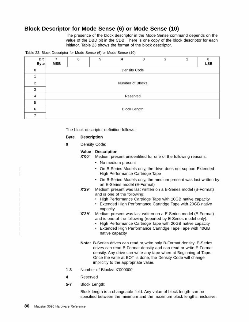
Block Descriptor for Mode Sense (6) or Mode Sense (10)The presence of the block descriptor in the Mode Sense command depends on thevalue of the DBD bit in the CDB. There is one copy of the block descriptor for eachinitiator. Table 23 shows the format of the block descriptor.
Table 23. Block Descriptor for Mode Sense (6) or Mode Sense (10)
BitByte
7MSB
6 5 4 3 2 1 0LSB
0 Density Code
1
Number of Blocks2
3
4 Reserved
5
Block Length6
7
The block descriptor definition follows:
Byte Description
0 Density Code:
Value DescriptionX'00' Medium present unidentified for one of the following reasons:
v No medium present
v On B-Series Models only, the drive does not support ExtendedHigh Performance Cartridge Tape
v On B-Series Models only, the medium present was last written byan E-Series model (E-Format)
X'29' Medium present was last written on a B-Series model (B-Format)and is one of the following:v High Performance Cartridge Tape with 10GB native capacityv Extended High Performance Cartridge Tape with 20GB native
capacityX'2A' Medium present was last written on a E-Series model (E-Format)
and is one of the following (reported by E-Series model only):v High Performance Cartridge Tape with 20GB native capacityv Extended High Performance Cartridge Tape Tape with 40GB
native capacity
Note: B-Series drives can read or write only B-Format density. E-Seriesdrives can read B-Format density and can read or write E-Formatdensity. Any drive can write any tape when at Beginning of Tape.Once the write at BOT is done, the Density Code will changeimplicitly to the appropriate value.
1-3 Number of Blocks: X'000000'
4 Reserved
5-7 Block Length:
Block length is a changeable field. Any value of block length can bespecified between the minimum and the maximum block lengths, inclusive,
86 Magstar 3590 Hardware Reference
||
||||||||||

specified in the Read Block Limits command. A Block Length value ofX'000000' indicates that the logical block size to be written to or read fromthe medium is specified by the Transfer Length field in the CDB (see “Read- X‘08’” on page 131 and “Write - X‘0A’” on page 185).
Chapter 2. Drive SCSI Commands 87

Mode Sense (10) - X‘5A’The Mode Sense (10) command is supported by the 3590 drive. Table 24 showsthe command format.
Table 24. Mode Sense (10) Command
BitByte
7MSB
6 5 4 3 2 1 0LSB
0 Operation code (X'5A')
1 Logical Unit Number Reserved DBD Reserved
2 PC Page Code
3 Reserved
4 Reserved
5 Reserved
6 Reserved
7Allocation Length
8
9 Vendor Specific (B'00')
Reserved (B'0000') Flag Link
The following 3590-specific parameters apply:
v DBD (Disable Block Descriptors): B'0' or B'1'. (See Block Descriptor Length,below.)
v PC (Page Control): B'00', B'01'; or B'10' supported
v Mode pages X'01', X'02', X'0A', X'0F',X'10', X'11', X'20', X'21', X'22', X'23', X'24',X'25', and X'3F' (return all pages) are supported by both B-Series Models andE-Series Models. Mode pages X'18' and X'19' are supported only when FibreChannel is attached. B-Series Models also support Mode pages X'1D', X'1E', andX'1F' on both the Drive and Medium Changer LUNs. E-Series Models supportthese three Mode Pages only on the Medium Changer LUN.
v Allocation Length: The maximum number of bytes to be transferred.
If the allocation length specified is less than the amount available, then theallocated amount is transferred and no error is reported.
v See “Control Byte Definition” on page 9 for Flag and Link bit descriptions.
88 Magstar 3590 Hardware Reference
||

Mode Parameter List for Mode Sense (10)The mode pages are preceded by an 8-byte mode parameter header (see “ModeParameter Header for Mode Sense (10)” on page 90) and an optional blockdescriptor. If the DBD field is B'0', an 8-byte block descriptor follows the modeparameter header (see “Block Descriptor for Mode Sense (6) or Mode Sense (10)”on page 86). If the DBD field is B'1', the block descriptor is not present and the firstmode page follows the mode parameter header. Mode page descriptions begin at“Mode Page X‘01’: Read-Write Error Recovery” on page 93.
Table 25 shows the format of the mode parameter list.
Table 25. Mode Parameter List for Mode Sense (10)
BitByte
7MSB
6 5 4 3 2 1 0LSB
0-7 Mode Parameter Header
8-16 Block descriptor (if DBD is set to B'0')
8-nor
16-nMode Pages
Chapter 2. Drive SCSI Commands 89

Mode Parameter Header for Mode Sense (10)There is one copy of the mode parameter header for each initiator. Table 26 showsthe format of the mode parameter header for Mode Sense (10).
Table 26. Mode Parameter Header for Mode Sense (10)
BitByte
7MSB
6 5 4 3 2 1 0LSB
0Mode Data Length
1
2 Medium Type
3 Device-Specific Parameter
4 Reserved
5 Reserved
6Block Descriptor Length
7
Mode parameter header field descriptions follow:
Byte Description
0-1 Mode data length
The length in bytes of the following data that is available to be transferred.(The mode data length does not include itself; that is, the length value is 1less than the total length of the data available for transfer.)
2 Medium Type:
Value DescriptionX'00' No medium present or the drive does not support Extended High
Performance Cartridge TapeX'81' Medium present is High Performance Cartridge TapeX'82' Medium present is Extended High Performance Cartridge Tape
3 Device-Specific Parameter - Sequential Access Devices
Bit Description7 WP (Write Protect):
v B'0': indicates that the medium is not write protectedv B'1': indicates that the medium is write protected
Note: For the Mode Select commands, this field is ignored.6-4 Buffered Mode
Value Description0 Good status is reported after data is on the medium1 Good status is reported after data is in the buffer2 Good status is reported after data is in the buffer and data
from other initiators is written on the medium3-7 Reserved
This field is changeable. The default value for this field is 1.3-0 Speed: X'0' (use default speed)
4-5 Reserved
6-7 Block Descriptor Length:
90 Magstar 3590 Hardware Reference
||
||

v If DBD = B'0', the Block Descriptor Length field is set to X'0008' and ablock descriptor follows.
v If DBD = B'1', the Block Descriptor Length field is set to X'0000' and noblock descriptor follows.
Chapter 2. Drive SCSI Commands 91
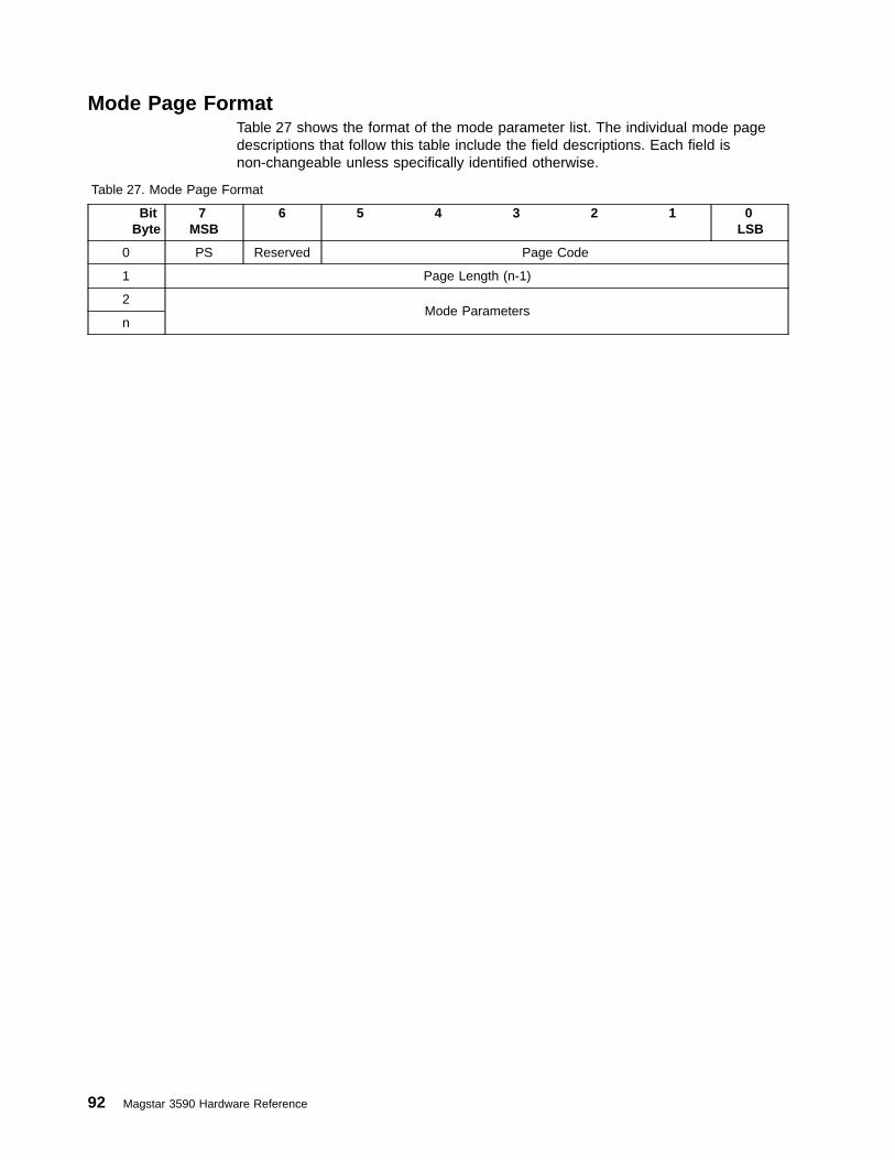
Mode Page FormatTable 27 shows the format of the mode parameter list. The individual mode pagedescriptions that follow this table include the field descriptions. Each field isnon-changeable unless specifically identified otherwise.
Table 27. Mode Page Format
BitByte
7MSB
6 5 4 3 2 1 0LSB
0 PS Reserved Page Code
1 Page Length (n-1)
2Mode Parameters
n
92 Magstar 3590 Hardware Reference
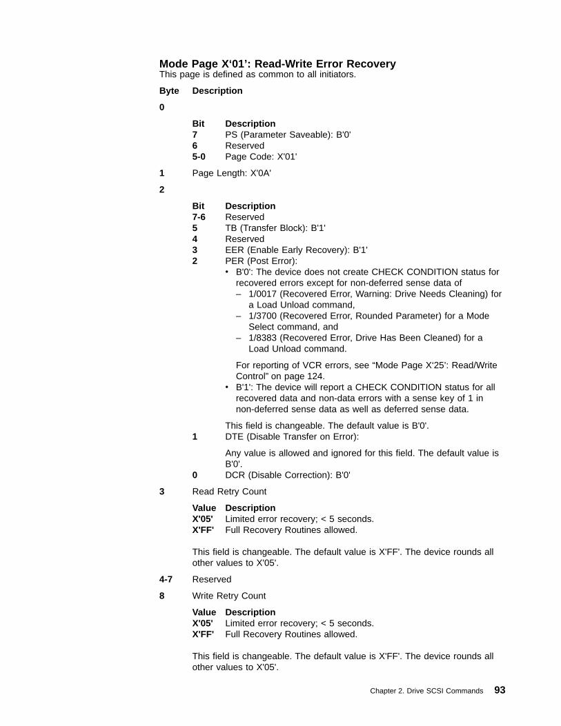
Mode Page X‘01’: Read-Write Error RecoveryThis page is defined as common to all initiators.
Byte Description
0
Bit Description7 PS (Parameter Saveable): B'0'6 Reserved5-0 Page Code: X'01'
1 Page Length: X'0A'
2
Bit Description7-6 Reserved5 TB (Transfer Block): B'1'4 Reserved3 EER (Enable Early Recovery): B'1'2 PER (Post Error):
v B'0': The device does not create CHECK CONDITION status forrecovered errors except for non-deferred sense data of– 1/0017 (Recovered Error, Warning: Drive Needs Cleaning) for
a Load Unload command,– 1/3700 (Recovered Error, Rounded Parameter) for a Mode
Select command, and– 1/8383 (Recovered Error, Drive Has Been Cleaned) for a
Load Unload command.
For reporting of VCR errors, see “Mode Page X‘25’: Read/WriteControl” on page 124.
v B'1': The device will report a CHECK CONDITION status for allrecovered data and non-data errors with a sense key of 1 innon-deferred sense data as well as deferred sense data.
This field is changeable. The default value is B'0'.1 DTE (Disable Transfer on Error):
Any value is allowed and ignored for this field. The default value isB'0'.
0 DCR (Disable Correction): B'0'
3 Read Retry Count
Value DescriptionX'05' Limited error recovery; < 5 seconds.X'FF' Full Recovery Routines allowed.
This field is changeable. The default value is X'FF'. The device rounds allother values to X'05'.
4-7 Reserved
8 Write Retry Count
Value DescriptionX'05' Limited error recovery; < 5 seconds.X'FF' Full Recovery Routines allowed.
This field is changeable. The default value is X'FF'. The device rounds allother values to X'05'.
Chapter 2. Drive SCSI Commands 93

9-11 Reserved
94 Magstar 3590 Hardware Reference

Mode Page X‘02’: Disconnect-ReconnectThere is one copy of this page for each initiator.
Byte Description
0
Bit Description7 PS: B'0'6 Reserved5-0 Page Code: X'02'
1 Page Length: X'0E'
2 Buffer Full Ratio: X'00'
3 Buffer Empty Ratio: X'00'
4-5 Bus Inactivity Limit: X'0000' (no limit)
6-7 Disconnect Time Limit: X'0000' (no limit)
8-9 Connect Time Limit: X'0000' (no limit)
10-11 Maximum Burst Size: SCSI - X'0000' (no limit)
Any value is allowed and ignored for this field. X'0000' is the default value.
Fibre Channel - Any value is allowed.
12
Bit Description7 EMDP (Enable Modify Data Pointers): B'0'6 FARd (Fair Arbitration Read): B'0'5 FAWrt (Fair Arbitration Write): B'0'4 FAStat (Fair Arbitration Status): B'0'3 Dimm (Disconnect Immediate): B'0'2-0 DTDC (Data Transfer Disconnect Word): B'000'
13 Reserved
14-15 First Burst Size: X'0000'
Chapter 2. Drive SCSI Commands 95
||
|
|

Mode Page X‘0A’: Control ModeThere is one copy of this page for each initiator.
Byte Description
0
Bit Description7 PS: B'0'6 Reserved5-0 Page Code: X'0A'
1 Page Length: X'0A'
2
Bit Description7-5 TST (Task Set Type): B'000'4-2 Reserved1 GLTSD (Global Logging Target Save Disable): B'0'
3
Bit Description7-4 Queue Algorithm Modifier: B'0000'3-2 Reserved1 QErr (Queue Error): B'0'0 DQue (Disable Queuing): B'1'
Note: The 3590 drive does not support tagged queuing.
4
Bit Description7 Reserved6 RAC (Report A Check): B'0'5-3 Reserved2 RAERP (Ready Asynchronous Event Reporting): B'0'1 UAAERP (Unit Attention Asynchronous Event Reporting): B'0'0 EAERP (Error Asynchronous Event Reporting): B'0'
5 Reserved
6-7 Ready AEN Holdoff Period: X'0000'
If AEN is disabled (Byte 4 bit 2 = 0), this field is not meaningful.
8-9 Busy timeout period: X'FFFF'
10 Reserved
11 Reserved
96 Magstar 3590 Hardware Reference
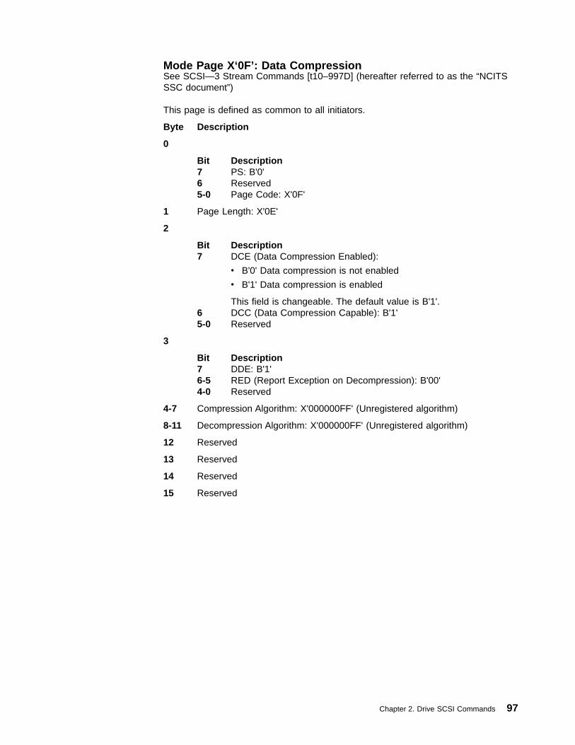
Mode Page X‘0F’: Data CompressionSee SCSI—3 Stream Commands [t10–997D] (hereafter referred to as the “NCITSSSC document”)
This page is defined as common to all initiators.
Byte Description
0
Bit Description7 PS: B'0'6 Reserved5-0 Page Code: X'0F'
1 Page Length: X'0E'
2
Bit Description7 DCE (Data Compression Enabled):
v B'0' Data compression is not enabled
v B'1' Data compression is enabled
This field is changeable. The default value is B'1'.6 DCC (Data Compression Capable): B'1'5-0 Reserved
3
Bit Description7 DDE: B'1'6-5 RED (Report Exception on Decompression): B'00'4-0 Reserved
4-7 Compression Algorithm: X'000000FF' (Unregistered algorithm)
8-11 Decompression Algorithm: X'000000FF' (Unregistered algorithm)
12 Reserved
13 Reserved
14 Reserved
15 Reserved
Chapter 2. Drive SCSI Commands 97

Mode Page X‘10’: Device ConfigurationThis page is defined as common to all initiators.
Byte Description
0
Bit Description7 PS: B'0'6 Reserved5-0 Page Code: X'10'
1 Page Length: X'0E'
2
Bit Description7 Reserved6 CAP (Change Active Partition):
v B'0': No partition change is specified.v B'1': Logical partition is to be changed to the partition specified in
the Active Partition field.
Note: Partitioning of a volume is not currently supported, but maybe in the future.
This is a changeable field. The default value is B'0'.5 CAF (Change Active Format): B'0'4-0 Active Format: B'00000'
3 Active Partition:
Note: Partitioning of a volume is not currently supported, but may be in thefuture.
For Mode Select, this is the logical partition to be changed to, if the CAP bitis on.
For Mode Sense, this is the current logical partition.
4 Write Buffer Full Ratio: X'00' (value not specified)
5 Read Buffer Empty Ratio: X'00' (value not specified)
6-7 Write Delay Time: X'0014' (about 2 sec)
8
Bit Description7 DBR (Data Buffer Recovery): B'1'6 BIS (Block Identifier Supported): B'1'5 RSmk (Report Setmarks): B'0'4 AVC (Automatic Velocity Control): B'0'3-2 SOCF (Stop on Consecutive Filemarks): This is not a changeable
field.v B'00' (read ahead to fill buffer, without regard for filemarks)
1 RBO (Recover Buffer Order):v B'0' (FIFO)v B'1' (LIFO)
This field is changeable. The default value is B'0' (FIFO).0 REW (Report Early Warning): B'0'
98 Magstar 3590 Hardware Reference

9 Gap Size: X'00'
10
Bit Description7-5 EOD Defined (End Of Data Defined): B'000'4 EEG (Enable EOD Generation): B'1'3 SEW (Synchronize at Early-Warning): B'1'2 SWP (Soft Write Protect): B''1-0 Reserved
11-13 Buffer Size at Early Warning: X'000000'
14 Select Data Compression Algorithm:
Value DescriptionX'00' No compression usedX'01' Use default compression algorithm (LZ1)X'02-FF'
Reserved
This field is changeable. The default value is X'01'.
Note: On a Mode Sense, the value of byte 14 will always match up withwhat is found on Mode Page X'0F', Byte 2, Bit 7. If this byte alone isupdated on a Mode Select, and Mode Page X'0F' is not sent, thenMode Page X'0F', Byte 2, Bit 7 is updated to match what was set inthis field. If both Page X'10' and Page X'0F' are sent, then what is inPage X'0F' is used to update both fields and any legal value in byte14 is ignored.
15
Bit Description7-3 Reserved2 ASOCWP (Associated Write Protect)
v B'0': No soft write protect is in effect
v B'1': No write type commands will be allowed for the currentmount
This field is changeable. The default value is B'0'.1 PERSWP (Persistent Write Protect)
v B'0': Persistent Write Protect not in effect
v B'1': No write type commands will be allowed on this tape.
This field is changeable. The default value is B'0'.0 PRMWP (Permanent Write Protect)
v B'0': No soft write protect is in effect
v B'1': No write type commands will ever be allowed for themounted tape
This field is changeable (but cannot be reset). The default value isB'0'.
These write protect bits are new to SCSI-3. The identical functionsare provided by the write protect bits in vendor unique Mode Page23. On a Mode Sense, the values in byte 15 will always match upwith what is found on vendor unique Mode Page X'23', Byte 10. Ifthis byte alone is updated on a Mode Select, and Mode Page X'23'
Chapter 2. Drive SCSI Commands 99

is not sent, then Mode Page X'23', Byte 10 is updated to matchwhat was set in this field. If both Page X'10' and Page X'23' aresent, then what is in Page X'10', byte 15 is used to update bothfields and any legal value in Mode Page X'23', Byte 10 is ignored.
100 Magstar 3590 Hardware Reference
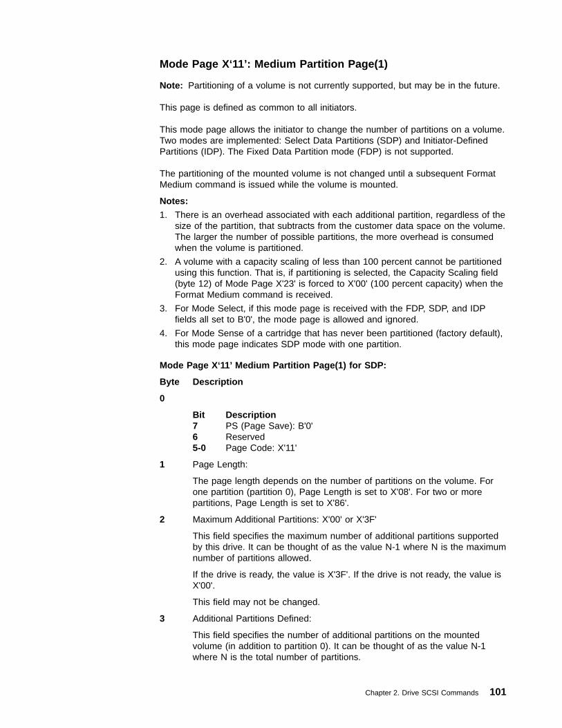
Mode Page X‘11’: Medium Partition Page(1)
Note: Partitioning of a volume is not currently supported, but may be in the future.
This page is defined as common to all initiators.
This mode page allows the initiator to change the number of partitions on a volume.Two modes are implemented: Select Data Partitions (SDP) and Initiator-DefinedPartitions (IDP). The Fixed Data Partition mode (FDP) is not supported.
The partitioning of the mounted volume is not changed until a subsequent FormatMedium command is issued while the volume is mounted.
Notes:
1. There is an overhead associated with each additional partition, regardless of thesize of the partition, that subtracts from the customer data space on the volume.The larger the number of possible partitions, the more overhead is consumedwhen the volume is partitioned.
2. A volume with a capacity scaling of less than 100 percent cannot be partitionedusing this function. That is, if partitioning is selected, the Capacity Scaling field(byte 12) of Mode Page X'23' is forced to X'00' (100 percent capacity) when theFormat Medium command is received.
3. For Mode Select, if this mode page is received with the FDP, SDP, and IDPfields all set to B'0', the mode page is allowed and ignored.
4. For Mode Sense of a cartridge that has never been partitioned (factory default),this mode page indicates SDP mode with one partition.
Mode Page X‘11’ Medium Partition Page(1) for SDP:
Byte Description
0
Bit Description7 PS (Page Save): B'0'6 Reserved5-0 Page Code: X'11'
1 Page Length:
The page length depends on the number of partitions on the volume. Forone partition (partition 0), Page Length is set to X'08'. For two or morepartitions, Page Length is set to X'86'.
2 Maximum Additional Partitions: X'00' or X'3F'
This field specifies the maximum number of additional partitions supportedby this drive. It can be thought of as the value N-1 where N is the maximumnumber of partitions allowed.
If the drive is ready, the value is X'3F'. If the drive is not ready, the value isX'00'.
This field may not be changed.
3 Additional Partitions Defined:
This field specifies the number of additional partitions on the mountedvolume (in addition to partition 0). It can be thought of as the value N-1where N is the total number of partitions.
Chapter 2. Drive SCSI Commands 101
The values for this field may be X'00, 01, 03, 07, 0F, 17, 1F, 27, 2F, 37, or3F' for SDP. If the drive is not ready, the value is X'00'.
This is a changeable field and subject to rounding (values are rounded up).This field may not be changed when the drive is not ready.
The partitioning of the mounted volume is not changed until a subsequentFormat Medium command is issued while the volume is mounted.
4
Bit Description
7 FDP (Fixed Data Partitions): B'0'
6 SDP (Select Data Partitions):
For Mode Sense, this bit is set to B'1'.
For Mode Select,v B'0': All values of this mode page are ignored.v B'1': The drive is to partition according to the Additional Partitions
Defined field.
5 IDP (Initiator Defined Partitions): B'0'
4-3 PSUM (Partition Size Unit of Measure): B'10' (Unit of measure isMB)
2 POFM (Partition on Format Medium): B'1'
This bit indicates that the Mode Select command will not causechanges to the partition sizes or user data, either recorded orbuffered. Actual media partitioning occurs with a subsequent FormatMedium command using the mode data for Medium Partition Page(1). Field values specified by a Mode Select command for MediumPartition Page (1) will not be changed by the drive before the mediais unloaded or the drive is reset.
1 CLEAR (Partition clearing): B'0'
0 ADDP (Adding Partitions): B'0'
5 Medium Format Recognition: X'03' (Capable of format and partitionrecognition)
6
Bit Description7-4 Reserved3-0 Partition Units: X'0'
7 Reserved
8-9 or Partition Size Descriptors (2 bytes each):
8-135
Each 2 byte field specifies the size of a partition (in MB) whose partitionnumber is in the range of 0..63, beginning with partition 0. Summing thepartition sizes provides a mechanism for an initiator to calculate the volumecapacity with Mode Sense in a standard way as opposed to 3590 vendorunique Mode Page X'23'.
For Mode Select, any values for these fields are allowed and ignored forSDP. These fields are updated by the drive when an initiator specifies anew number of partitions.
102 Magstar 3590 Hardware Reference

Note: When more than one partition is defined, the sum of the partitionsizes may be less than when only a single partition is defined. Eachpartition requires a certain amount of overhead space on a volume,which reduces the usable customer data space.
Chapter 2. Drive SCSI Commands 103

Mode Page X‘18’: Fibre Channel Logical Unit ControlThere is one copy of this page for each initiator. This page is defined for FibreChannel attached devices only.
Byte Description
0
Bit Description7 PS: 06 Reserved5-0 Page Code: X'18'
1 Page Length: X'06'
2 Reserved
3
Bit Description7-1 Reserved0 EPDC (Enable Precise Delivery Control)
4-7 Reserved
Mode pages X'01', X'02', X'0A', X'0F',X'10', X'11', X'20', X'21', X'22', X'23', X'24',X'25', and X'3F' (return all pages) are supported by both B-Series Models andE-Series Models. Mode pages X'18' and X'19' are supported only when FibreChannel is attached. B-Series Models also support Mode pages X'1D', X'1E', andX'1F' on both the Drive and Medium Changer LUNs. E-Series Models support thesethree Mode Pages only on the Medium Changer LUN.
104 Magstar 3590 Hardware Reference
|||
||
|
||||||||
||
||
|
||||||
||
||||||

Mode Page X‘19’: Fibre Channel Port ControlThere is one copy of this page per Fibre Channel port. This page is defined forFibre Channel attached devices only.
Byte Description
0
Bit Description7 PS: 06 Reserved5-0 Page Code: X'19'
1 Page Length: X'0E'
2 Reserved
3
Bit Description7 DTFD (Disable Target Fabric Discovery): 06 PLPB (Prevent Loop Port Bypass): 05 DDIS (Disable Discovery): 04 DLM (Disable Loop Master): 03 RHA (Require Hard Address): 02 ALWI (Allow Login without Loop Initialization): 01 DTIPE (Disable Target Initiated Port Enable): 00 DTOLI (Disable Target Originated Loop Initialization): 0
4-5 Reserved
6
Bit Description7-3 Reserved2-0 RR_TOV
B'000' - No timer is specifiedB'001' - Timer is specified in .001 second unitsB'011' - Timer is specified in .1 second unitsB'101' - Timer is specified in 10 second units
7 RR_TOV (Resource Recovery Time Out Value)
8
Bit Description7-2 Reserved1-0 Control MCM (Multiple Circuit Mode): B'01'
9-10 Reserved
11 Originator CMRs Per Port: 0
12 Reserved
13 Responder CMRs Per Port: 0
14-15 MCM_TOV (MCM Time Out Value): 0
Mode pages X'01', X'02', X'0A', X'0F',X'10', X'11', X'20', X'21', X'22', X'23', X'24',X'25', and X'3F' (return all pages) are supported by both B-Series Models andE-Series Models. Mode pages X'18' and X'19' are supported only when FibreChannel is attached. B-Series Models also support Mode pages X'1D', X'1E', andX'1F' on both the Drive and Medium Changer LUNs. E-Series Models support thesethree Mode Pages only on the Medium Changer LUN.
Chapter 2. Drive SCSI Commands 105
|||
||
|
||||||||
||
||
|
||||||||||||||||||
||
|
||||||||||||||
||
|
||||||
||
||
||
||
||
||||||

Mode Page X‘1D’: Element Address AssignmentThis page is defined as common for all initiators. This page is a static page,independent of the presence of the 3590 ACF, the current operating definition, orthe current ACF mode of operation. Addresses defined here are those which shouldbe used by the Move Medium command.
Byte Description
0
Bit Description7 PS: B'0'.6 Reserved5-0 Page Code: X'1D'
1 Parameter Length: X'12'
2-3 Medium Transport Element Address: X'0000'
4-5 Number of Medium Transport Elements: X'0001'
6-7 First Storage Element Address (magazine cell address): X'0020'
8-9 Number of Storage Elements: X'000A'
10-11 First Import/Export Element Address (the import/export element is oftenreferred to as the “priority cell” or “priority slot”): X'001F'
12-13 Number of Import/Export Elements: X'0001'
14-15 First Data Transfer Element Address (the data transfer element is morecommonly known as the drive, the unit with the read/write head): X'0010'
16-17 Number of Data Transfer Elements: X'0001'
18-19 Reserved
Note: The fields in Mode Page X'1D' are not changeable. If a Mode Selectcommand is issued with values other than those returned by a Mode Sensecommand, the device returns CHECK CONDITION status with associatedsense data of 5/2600 (Illegal Request, Invalid Field in Parameter List).
106 Magstar 3590 Hardware Reference
Mode Page X‘1E’: Transport Geometry ParametersThe transport geometry parameters page defines whether each medium transportelement is a member of a set of elements that share a common robotics subsystemand whether the element is capable of medium rotation. One transport geometrydescriptor is returned for each medium transport element. Because the 3590 ACFhas only one medium transport element, only one descriptor is returned.
This page is defined as common to all initiators. This page is a static page,independent of the presence of the 3590 ACF, the current operating definition, orthe current ACF mode of operation.
There are no changeable parameters in this mode page.
Byte Description
0
Bit Description7 PS: B'0'6 Reserved5-0 Page Code: X'1E'
1 Page Length: X'02'
2
Bit Description7-1 Reserved0 Rotate: B'0'
3590 ACF does not support media rotation.
3 Member Number in Transport Element Set: X'00'
Because the 3590 ACF has only one transport element, this byte is set to 0.
Chapter 2. Drive SCSI Commands 107
Mode Page X‘1F’: Device CapabilitiesThis page is defined as common for all initiators. This page is a static page,independent of the presence of the 3590 ACF, the current operating definition, orthe current ACF mode of operation.
Byte Description
0
Bit Description
7 PS: B'0'
6 Reserved
5-0 Page Code: X'1F'
1 Parameter Length: X'0E'
2 Store XX Field
Bit Description7-4 Reserved3 StorDT (Store in Data Transfer): B'1'2 StorI/E (Store in Import/Export): B'1'1 StorST (Store in Storage Element): B'1'0 StorMT (Store in Medium Transport): B'0'
3 Reserved
4 Medium Transport Capabilities
Bit Description7-4 Reserved3 MT->DT (Can move from an MT element to a DT element): B'0'2 MT->I/E (Can move from an MT element to an I/E element): B'0'1 MT->ST (Can move from an MT element to a ST element): B'0'0 MT->MT (Can move from an MT element to a MT element): B'0'
5 Storage Element Capabilities
Bit Description7-4 Reserved3 ST->DT (Can move from a ST element to a DT element): B'1'2 ST->I/E (Can move from an ST element to an I/E element): B'1'1 ST->ST (Can move from a ST element to a ST element): B'1'0 ST->MT (Can move from an ST element to an MT element): B'0'
6 Import/Export Element Capabilities
Bit Description7-4 Reserved3 I/E->DT (Can move from an I/E element to a DT element): B'1'2 I/E->I/E (Can move from an I/E element to an I/E element): B'0'1 I/E->ST (Can move from an I/E element to an ST element): B'1'0 I/E->MT (Can move from an I/E element to an MT element): B'0'
7 Data Transfer Element Capabilities
Bit Description7-4 Reserved3 DT->DT (Can move from a DT element to a DT element): B'1'2 DT->I/E (Can move from an DT element to an I/E element): B'1'1 DT->ST (Can move from a DT element to a ST element): B'1'0 DT->MT (Can move from a DT element to an MT element): B'0'
108 Magstar 3590 Hardware Reference

8-11 Reserved
12 Medium Transport Element Exchange Capabilities
Bit Description7-4 Reserved3 MT<>DT: B'0'2 MT<>I/E: B'0'1 MT<>ST: B'0'0 MT<>MT: B'0'
13 Storage Element Exchange Capabilities
Bit Description7-4 Reserved3 ST<>DT: B'0'2 ST<>I/E: B'0'1 ST<>ST: B'0'0 ST<>MT: B'0'
14 Import/Export Element Exchange Capabilities
Bit Description7-4 Reserved3 I/E<>DT: B'0'2 I/E<>I/E: B'0'1 I/E<>ST: B'0'0 I/E<>MT: B'0'
15 Data Transport Element Exchange Capabilities
Bit Description7-4 Reserved3 DT<>DT: B'0'2 DT<>I/E: B'0'1 DT<>ST: B'0'0 DT<>MT: B'0'
Note: The fields in Mode Page X'1F' are not changeable. If a Mode Selectcommand is issued with values other than those returned by a Mode Sensecommand, the device returns CHECK CONDITION status with associatedsense data of 5/2600 (Illegal Request, Invalid Field in Parameter List).
Chapter 2. Drive SCSI Commands 109

Mode Page X‘20’: ACF (Loader) ControlThis page is defined as common to all initiators. This page is reported by LUN 0regardless of the current operating definition.
Page Code 20 is designed to support the ACF.
Byte Description
0
Bit Description7 PS (Page Save): B'0'6 Reserved5-0 Page Code: X'20'
1 Page Length: X'0A'
2 Loader Mode:
Value DescriptionX'00' No Loader or undefined type of loader
Note: This is the setting for non-ACF models.X'01' System Mode
Only the operator can cause the ACF to enter System mode.System mode can be selected from the operator panel Set ACFMode menu.
See “System Mode” on page 225 for a full description of Systemmode.
X'02' Random or Random 2-LUN Mode (SCSI Medium Changer mode)
Only the operator can cause the ACF to enter Random or Random2-LUN mode. Random or Random 2-LUN mode can be selectedfrom the operator panel Set ACF Mode menu. The magazine mustbe present and in a locked condition before the command isaccepted.
Refer to “Random Mode” on page 226 for a full description ofRandom mode.
Refer to “Random 2-LUN Mode (B-Series Models Only)” onpage 228 for a full description of Random 2-LUN mode.
Note: For E-Series Models, only the Random option is available.X'03' Manual Mode
Only the operator can cause the ACF to enter Manual mode.Manual mode can be selected from the operator panel Set ACFMode menu.
Refer to “Manual Mode” on page 221 for a full description of Manualmode.
X'04' Accumulate Mode
Only the operator can cause the ACF to enter Accumulate mode. Itcan be selected from the operator panel Set ACF Mode menu.
Refer to “Accumulate Mode” on page 222 for a full description ofAccumulate mode.
X'05' Automatic (Sequential) Mode
110 Magstar 3590 Hardware Reference

Only the operator can cause the ACF to enter Automatic mode. Itcan be selected from the operator panel Set ACF Mode menu.
Refer to “Automatic Mode” on page 223 for a complete descriptionof Automatic mode.
The Loader Mode field is not changeable from the SCSI interface. If themode is changed from the operator panel, all initiators receive a UnitAttention. Any mode set through the operator panel becomes effectiveimmediately and is stored in nonvolatile memory as the default mode forsubsequent power-on cycles.
3 Reserved
4 Loader Qualifier
The loader qualifier field allows for variations of operation within a givenmode.
Bit Description7 Multiple Access: B'0'6 Priority Cell Enabled: B'1'5-0 Reserved
5-11 Reserved
Note: The fields in Mode Page X'20' are not changeable from the SCSI interface. Ifa Mode Select command is issued with values other than those returned bya Mode Sense command, the device returns CHECK CONDITION statuswith associated sense data of 5/2600 (Illegal Request, Invalid Field inParameter List).
Chapter 2. Drive SCSI Commands 111

Mode Page X‘21’: TOD ControlThe TOD (Time-of-Day) control is used to provide the device with an estimate of thecorrect time. The device adds the current TOD clock to every block transferred tomedia. These time traces can then be used by engineering for analysis of mediumat a later time.
The Time-of-Day clock is a binary counter with a 64-bit format: bit 63 being thehighest value; bit 0 being the lowest. Bit 12 represents a 1 microsecond clock; thatis, the TOD is incremented by 1 in bit position 12, once every microsecond. Thisgives the TOD clock a cycle time of approximately 143 years. Setting the high orderbyte to any number greater than X'F0' will result in parameter rounding down toX'F0' with CHECK CONDITION status and associated sense data of 1/3700(Recovered Error, Rounded Parameter).
The time of day may be set only when the device is in the Not Ready state. If aninitiator attempts to set the TOD when the device is Ready, the command isterminated with CHECK CONDITION status and associated sense data of 1/3700(Recovered Error, Rounded Parameter). Note that this choice is made to avoidfailing applications for incorrect attempts at setting the TOD clock. Rounding in thiscase results in no change.
This page is defined as common to all initiators.
Page Code 21 is designed to provide the time-of-day clock setting to the device for3590 format data.
Byte Description
0
Bit Description7 PS (Page Save): B'0'6 Reserved5-0 Page Code: X'21'
1 Page Length: X'0A'
2-9 Time of Day
This is a changeable field.
The default time setting at power on is X'0000 0000 0000 0000'. The Timeof Day (TOD) clock begins counting relative time from that point.
The TOD clock can be set by any initiator at any time the device is in theNot Ready state. When sensed, the TOD field returns the time of day lastset into the device by an initiator. If the TOD field has never been set by aninitiator, the TOD field contains X'0000 0000 0000 0000'. A clock value ofX'0000 0000 0000 0000' corresponds to a time of January 1, 1900, 0:00AM, Greenwich Mean Time.
10 Time-of-Day Flags
Bit Description7-3 Reserved2 TOD Reset Valid
v B'0': The TOD clock will not be reset. Default value on ModeSense
v B'1': The TOD clock will be reset (valid only on Mode Select)1 SysSet TOD
v B'0': The TOD was not set by an initiator
112 Magstar 3590 Hardware Reference

v B'1': The TOD was set by an initiator
This field is not a changeable field. It describes the state of theTOD counter.
0 Relative TODv B'0': The TOD was not set by the devicev B'1': The TOD was set by the device
This field is not a changeable field. It describes the state of theTOD counter.
11 Reserved
Chapter 2. Drive SCSI Commands 113
Mode Page X‘22’: LanguageThe Language page is used to provide the initiator with the ability to request achange of the language displayed on the operator panel.
This page is defined as common to all initiators.
Page Code 22 is designed to report or request a change to the language displayedon the operator panel. This page is supported for all models, even for models withno operator panel.
Byte Description
0
Bit Description7 PS (Page Save): B'0'6 Reserved5-0 Page Code: X'22'
1 Page Length: X'02'
2 Present Language
When sensed, this field indicates the current language. The followinglanguages are supported:
Code LanguageX'00' U.S. EnglishX'01' SpanishX'02' GermanX'(03-FF)'
Reserved
The default setting at power on is the current value in VPD. This field is notdirectly changeable, although it may be indirectly changed by updating the“Requested Language” field of this mode page or by selecting a differentlanguage at the operator panel.
3 Requested Language
The codes described for “Present Language” above apply to the selectionof a requested language. This field is changeable. When sensed, this fieldhas the same value as the “Present Language” field. When selected, thisfield will result in an update to the “Present Language” field.
114 Magstar 3590 Hardware Reference

Mode Page X‘23’: Medium SenseThe Medium Sense page provides information about the state of the mediumcurrently associated with the device, if any.
This page is defined as common to all initiators.
Note: Issuing a Mode Sense for current values before a Mode Select is generallyrecommended to avoid accidentally attempting to set fields that cannot bechanged by the initiator. Not all fields in this page can be set by users.All fields other than those explicitly indicated that can be set by usersare read-only.
Byte Description
0
Bit Description7 PS (Page Save): B'0'6 Reserved5-0 Page Code: X'23'
1 Page Length: X'22'
2-3 Reserved
4-5 Medium Identifier:
When there is an associated medium, this field contains the mediumidentifier of the associated medium.
Value DescriptionX'0000'
No medium presentX'0130'
Medium present is High Performance Cartridge TapeX'0131'
Medium present is Extended High Performance Cartridge Tape
6 Format Identifier:
When there is an associated medium, this field contains the format identifierof the associated medium.
Value DescriptionX'00' No medium presentX'23' Medium present was last written on a B-Series model (B-Format)
and is one of the following:v High Performance Cartridge Tape with 10GB native capacityv Extended High Performance Cartridge Tape with 20GB native
capacityX'24' Medium present was last written on a E-Series model (E-Format)
and is one of the following:v High Performance Cartridge Tape with 20GB native capacityv Extended High Performance Cartridge Tape with 40GB native
capacity
Note: B-Series drives can read or write only B-Format density.E-Series drives can read B-Format density and can read orwrite E-Format density. Any drive can write any tape when atBeginning of Tape. Once the write at BOT is done, theDensity Code will change implicitly to the appropriate value.
Chapter 2. Drive SCSI Commands 115
||
||||||||||
7-9 Reserved
10 Write Protect Flags
There are two forms of write protect: logical and physical, and three typesof logical write protect. Each performs essentially the same function: eachprotects the customers data from change. Each write protect methodperforms that function; the only difference is the permanence of the effect(but note the differences with respect to VCR validity for Associated WriteProtection).
Bits Description
7 Physical Write Protect
This field is also found in “Request Sense - X‘03’” on page 151(byte 24, bit 1).
This field indicates the state of the physical Write Protect switchlocated on the cartridge. This switch is controlled by the user. Whenthe switch is set to 1, the entire physical volume is set to the writeprotected state; when the switch is set to 0, the volume is physicallywrite enabled.v B'0': The cartridge write protect switch is set to write enabled.v B'1': The cartridge write protect switch is set to write protected
state.
This field is not changeable.
This field may be changed only by physically changing the state ofthe switch on the cartridge. After the cartridge is loaded into thedevice, the write protect switch is not available to the user, and,therefore, does not change states while mounted.
6 Associated Write Protect
An OR condition of the three forms of logical write protect may befound in “Request Sense - X‘03’” on page 151 (byte 24, bit 0).
This field allows an initiator to set the logical volume to theAssociated Write Protected state. Associated Write Protect protectsa volume only while the logical volume is associated with (mountedon) the device.
For a Mode Select command, this field has the following meaning:v B'0': Do not change the Associated Write Protect state.v B'1': Set this logical volume to the Associated Write Protect state.
For a Mode Sense command, this field responds with a B'1' only ifthe logical volume is set to Associated Write Protect, or it respondswith a B'0'.
The logical volume can be set to Associated Write Protect at anytime. The medium need not be positioned to Beginning of Partition(BOP).
When the initiator accepts the GOOD status from the Mode Selectcommand, the logical volume is write protected. Buffered write datais not necessarily transferred to the medium prior to the completionof the Mode Select command. It is transferred at such time as itwould have been had no further writes been issued (in any caseprior to cartridge unload).
116 Magstar 3590 Hardware Reference
The Associated Write Protect state remains only as long as themedium is associated with (mounted on) the device. Both Unloadand Power Off return the logical volume to the default state of writeenabled. The initiator can also write enable the logical volume byissuing the Mode Select command with the Reset Associated WriteProtect field set to B'1'.
While in the Associated Write Protect state, any attempt torepartition, reformat, or write results in CHECK CONDITION statuswith associated sense data of 7/2700 (Data Protect, WriteProtected).
Note: For models with an operator panel, the write protect icon willappear on the status screen when the medium is physicallyor logically write protected. Except for the time span coveredby cartridge loading and cartridge unloading, the icon willremain on until the initiator requests the write protectionstatus to change or unload or power-off occurs, which resetthe status by default. During load and unload the icon willrevert to the unprotected indicator. This is due to updates tothe tape VCR region, which requires writing. Unlike PhysicalWrite Protection, Persistent Write Protection, or PermanentWrite Protection, the VCR is subject to change when underAssociated Write Protection. This means that unexpectedpower-offs during the load or unload process whileAssociated Write Protection is set may result in the VCRbeing in an invalid state, just as is possible when no writeprotection is active. Subsequent locate and space operationsto the volume will operate at low speed until new records arewritten and the VCR is rebuilt.
5 Reset Associated Write Protect
A 1 in this field causes the Associated Write Protect state to bereset; that is, to change the state of the logical volume from writeprotected to write enabled. After being reset, the logical volumeagain accepts write commands.
For a Mode Select command, this field has the following meaning:v B'0': Do not change the Associated Write Protect state.v B'1': Reset the Associated Write Protect state for this logical
volume.
For a Mode Sense command, this field is B'0'.
When the device successfully executes a Reset Associated WriteProtect, the device immediately resets the write protected state tothe write enabled state and allows write commands from that point.
4 Persistent Write Protect
An OR condition of the three forms of logical write protect may befound in “Request Sense - X‘03’” on page 151 (byte 24, bit 0).
This field allows an initiator to set the logical volume to the writeprotected state. Unlike the Associated Write Protect, PersistentWrite Protect ‘persists’ across mount cycles because the state iswritten in the VCR of the volume.
For a Mode Select command, this field has the following meaning:
Chapter 2. Drive SCSI Commands 117

v B'0': Do not change the Persistent Write Protect state.v B'1': Set this logical volume to the Persistent Write Protect state.
For a Mode Sense command, this field responds with a B'1' only ifthe logical volume is set to Persistent Write Protect; otherwise, itresponds with a B'0'.
The volume can be set to Persistent Write Protect only when themedium is positioned to Beginning of Partition 0 (BOP 0). Thedevice writes the Persistent Write Protect field in the VCR andpresents status to the initiator. If the command fails, persistent writeprotection cannot be guaranteed.
Unlike Permanent Write Protect (see below), the volume may bewrite enabled by issuing a Mode Select with the Reset PersistentWrite Protect field set to B'1'. Similar to Permanent Write Protect, ifa partition is set to Persistent Write Protect, the physical volumemay not be repartitioned unless all partitions on the volume arewrite enabled. Any attempt to repartition, reformat, or write results inCHECK CONDITION status with associated sense data of 7/2700(Data Protect, Write Protected).
3 Reset Persistent Write Protect:
A 1 in this field causes the Persistent Write Protect field to be reset;that is, to change the state of the logical volume from writeprotected to write enabled. After being reset, the logical volumeagain accepts write commands.
For a Mode Select command, this field has the following meaning:v B'0': Do not change the Persistent Write Protect state.v B'1': Reset the Persistent Write Protect state for this logical
volume.
For a Mode Sense command, this field is B'0'.
The device must be at BOP 0 to accept Reset Persistent WriteProtect.
2-1 Reserved
0 Permanent Write Protect
An OR condition of the three forms of logical write protect may befound in “Request Sense - X‘03’” on page 151 (byte 24, bit 0).
This field allows an initiator to set the logical volume to apermanently write protected state. Similar to the Persistent WriteProtect, Permanent Write Protect ‘persists’ across mount cyclebecause the state is written in the VCR of the physical volume.Unlike Persistent Write Protect, Permanent Write Protect can neverbe reset except by degaussing.
For a Mode Select command, this field has the following meaning:v B'0': Do not change the Permanent Write Protect state.v B'1': Set this logical volume to the Permanent Write Protect state.
After being set, THIS LOGICAL VOLUME CAN NEVER BEWRITTEN ON AGAIN!
118 Magstar 3590 Hardware Reference

Notes:
1. Only if the physical medium is completely degaussed andreformatted can the writing again be done.
2. The Format Medium command is not currently supported butmay be in the future.
For a Mode Sense command, this field responds with a B'1' only ifthe logical volume is set to the Permanent Write Protect state;otherwise, it responds with a B'0'.
The volume can be set to the Permanent Write Protect state onlywhen the medium is positioned to Beginning of Partition 0 (BOP 0).The device writes the Permanent Write Protect field in the VCR andpresents status to the initiator. Any attempt to repartition, reformat,or write results in CHECK CONDITION status with associatedsense data of 7/2700 (Data Protect, Write Protected).
11 Capacity Scaling Control
Bits Description7-1 Reserved0 CapScalV (Capacity Scaling Valid)
v B'0': Indicates that the device should not scale the medium inaccordance with the value in the Capacity Scaling field.
v B'1': Indicates that the device should scale the medium inaccordance with the value in the Capacity Scaling field.
This field is changeable. The default value is B'0'. For ModeSense commands, this field is B'0'.
Scaling of the capacity is accepted only at Beginning of Partition 0 (BOP 0).A valid Capacity Scaling request causes all data on the entire physicalvolume to be lost. If this command is received at other than BOP 0, thecommand is presented CHECK CONDITION status with associated sensedata of 5/2600 (Illegal Request, Invalid Field in Parameter List).
12 Capacity Scaling
This field allows an initiator to logically change the size of partition 0. Oneeffect is faster access to data at the expense of data capacity. This byteindicates or sets the currently formatted medium capacity in relationship tothe maximum medium capacity. Formatted medium capacity in this contextrefers to the amount of data that can be potentially written on the medium,independently of the amount that is currently written. The capacity isreduced to a value of n/256*100 percent of this maximum capacity where nis the value in the Capacity Scaling field and ranges between 1 and 256(X'01 - FF, 00'). (The value X'00' represents 256, or 100% of capacity.) Forexample, a Capacity Scaling value of 128 (X'80') reduces the capacity of asingle partition volume to 50% of its maximum value, but also reduces theaverage access time to any given data.
This field is changeable. The default value is X'00'. This medium is changedto the percent indicated in this field only if the CapScalV bit is also set toB'1'.
Only certain values are supported: X'00', X'C0', X'80', and X'40', all othervalues are rounded up to the next highest value, with all values betweenX'C1-FF' being rounded ‘up’ to X'00', which represents 100%. If a value isrounded, the device responds to the Mode Select command with CHECK
Chapter 2. Drive SCSI Commands 119
CONDITION status and associated sense data of 1/3700 (Recovered Error,Rounded Parameter). The device responds to the values in the CapacityScaling field as follows:v X'C1-FF,00': 100% Capacityv X'81-C0': 75% Capacityv X'41-80': 50% Capacityv X'01-40': 25% Capacity
This command is accepted only at Beginning of Partition 0 (BOP 0). A validCapacity Scaling command causes all data on the entire physicalvolume to be lost and only partition 0 to remain at some size. If thiscommand is received at other than BOP 0, the command is presentedCHECK CONDITION status with associated sense data of 5/2600 (IllegalRequest, Invalid Field in Parameter List).
Mode Sense values returned are X'00', X'C0', X'80', or X'40', correspondingto 100% of maximum capacity, 75% of maximum capacity, 50% ofmaximum capacity, or 25% of maximum capacity, respectively.
13-16 Medium Capacity
This field specifies the nominal capacity, in kilobytes, of the programaccessible portion of the medium indicated by the Medium Identifier in bytes4-5. If capacity scaling is in effect, this field reflects the capacity afterscaling. If the medium is currently partitioned, the nominal capacity of themedium is the sum of the nominal capacity of all partitions. The value in thefield multiplied by 1024 yields the approximate capacity in bytes. The field isset to 0 if the capacity is unknown. This field is not changeable. It is forreporting only.
17 Partition Number
Note: Partitioning of a volume is not currently supported, but may be in thefuture.
This field specifies the partition number of the currently active partition. Thefield is set to X'00' if there is only one partition on the medium or if thepartition number is unknown. This field cannot be set by a user but reflectschanges effected by “Mode Page X‘10’: Device Configuration” on page 98.
See also “Locate -X‘2B’” on page 28 for changing the active partition and“Mode Page X‘10’: Device Configuration” on page 98 for creating partitions.
18-19 Reserved
20 Test Flags
Bit Description
7-1 Reserved-Vendor-Unique
0 Edge Trackv B'0': Disable edge track write mode.v B'1': Activate edge track write mode.
This field invokes a mode used for Edge Track testing when thedevice is being used as a medium tester. This field can only beused when the device is being used as a medium tester.
If the initiator sets Edge Track and the device is in Tester Mode andthe medium is at BOP 0, the device writes on one outside track
120 Magstar 3590 Hardware Reference
||

while the medium is moving towards EOT, and writes on the otheroutside track while the medium is moving toward BOP 0.
This field is changeable. The default value is B'0', but this fieldmay only be set to B'1' when (1) the device is previously placed inTester Mode (a mode that can be set at installation time only) and(2) the medium is at BOP 0.
If the device is not in Tester Mode and an initiator attempts to writethis field, CHECK CONDITION status is presented with associatedsense data of 5/2600 (Illegal Request, Invalid Field in ParameterList).
If an initiator attempts to write this field at other than BOP 0, thecommand is presented CHECK CONDITION status with associatedsense data of 5/2600 (Illegal Request, Invalid Field in ParameterList).
21 Internal-VOLID Flags
Bits Description7 Internal-VOLID Valid
v B'0': Indicates that the fields are not valid.v B'1': Indicates that the internal volume-identifier field and the
remainder of the internal-VOLID flags field are valid.6 DBM Valid
v B'0': Indicates that the Device Block Map is not valid.v B'1': Indicates that the Device Block Map is valid.
5-3 Reserved2-0 Internal-VOLID Information Source
Value Description0 Internal-VOLID from external source, that is, a library
manager.1 Internal VOLID from medium, namely the VOL1 record.2-7 Reserved
22-27 Internal-Volume Identifier
If available, this field contains the volume identifier, which is recorded onthe medium. The field is left-justified and padded with X'20' (ASCII blanks).If the Volume Identifier is not valid, it is set to X'0000 0000 0000'.
28-31 Partition Capacity
Note: Partitioning of a volume is not currently supported, but may be in thefuture.
This field specifies the nominal capacity, in kilobytes, of the programaccessible portion of the currently active partition. The value in the fieldmultiplied by 1024 yields the number of bytes in the partition. The field isset to 0 if the capacity is unknown. This field is not changeable but doesreflect changes by other activity. It is for reporting only.
32-35 Kilobytes Traversed
This field specifies the current position on the tape measured in kilobytes(1024 bytes) traversed (user data only). The value at the logical end of tapeshould equal the nominal capacity of the tape. All values are rounded downto the nearest kilobyte.
Chapter 2. Drive SCSI Commands 121

Mode Page X‘24’: Initiator-Specific ExtensionsThe Initiator-Specific Extensions page provides controls that allow selective use ofCRC protection and permit program control of key synchronous data transferparameters.
There is one copy of this page for each initiator.
Byte Description
0
Bit Description7 PS (Page Save): B'0'6 Reserved5-0 Page Code: X'24'
1 Page Length: X'16'
2 CRC Target Support
This field cannot be changed by the initiator.
Bits Description7
v B'0': IEEE CRC checking across interface is not supportedv B'1': IEEE CRC checking across interface is supported
6v B'0': 3590-specific CRC checking across interface is not
supportedv B'1': 3590-specific CRC checking across interface is supported
5-0 Reserved
3 CRC Target Enablement
This field can be changed by the initiator.
Value DescriptionX'00' CRC checking across interface disabled (default setting)X'01' IEEE CRC checking enabled across interface (not supported
currently)X'02' 3590 CRC checking enabled across interface
4 CRC (1) Placement and Length
This field can be changed by the initiator. Only 4 byte appended CRC iscurrently supported.
Bits Description7-6 CRC Placement
Value DescriptionB'00' CRC appended to dataB'01' CRC prefixed to data
5-0 CRC Length (0-64 bytes)
5 CRC (1) Scope
Bits Description7 Read data checked: B'1'6 Write data checked: B'1'5 Parameter read data checked: B'0'4 Parameter write data checked: B'0'3 CDB checked: B'0'2 Reserved-Vendor-Unique
122 Magstar 3590 Hardware Reference
||

1-0 Reserved
6 Other CRC (1) Characteristics
Bits Description7 CDB transfer length includes CRC length if B'1' (not changeable).6 Big Endian if B'1'. Little Endian if B'0' (not changeable).5
v B'0': Check One on Read CRC Miscomparev B'1': Check Condition on Read CRC Miscompare
This is a changeable field. The default value is B'1'.4
v B'0': Check One on Write CRC Miscomparev B'1': Check Condition on Write CRC Miscompare
This is a changeable field. The default value is B'1'.3
v B'0': Deferred Check Condition or Check One on Write CRCMiscompare
v B'1': Immediate Check Condition on Write CRC Miscompare
This is a changeable field. The default value is B'1'.2-0 Reserved
7-12 Reserved
13 Transfer Period for SDTR Message expressed as a multiple of 4ns. Set toX'FF' for target default behavior (will try to match initiator). Half speedoperation is at 200ns (field=50). Does not persist across resets.
14 REQ/ACK Offset for SDTR Message. Set to X'FF' for target default behavior(will try to match initiator). Does not persist across resets.
15 Buffer Association Enablement (DDR Support). This is persistent acrossSCSI bus resets and bus device resets.
Bits Description7
v B'0': Manual Unload Association Disabledv B'1': Manual Unload Association Enabled
6v B'0': Manual Rewind Association Disabledv B'1': Manual Rewind Association Enabled
5v B'0': Association on Unload With Write Error Disabledv B'1': Association on Unload With Write Error Enabled
4-0 Reserved
16-23 Reserved
Chapter 2. Drive SCSI Commands 123
||
Mode Page X‘25’: Read/Write ControlThis page is defined as common to all initiators.
Byte Description
0
Bit Description7 PS (Page Save): B'0'6 Reserved5-0 Page Code: X'25'
1 Page Length: X'1E'
2
Bit Description7-3 Reserved2 Ignore Sequence Checks on Locate command
v B'0': Do not ignore sequence checksv B'1': Ignore sequence checks
This is a changeable field. The default value is B'0'.1 Ignore Sequence Checks on Space command for blocks
v B'0': Do not ignore sequence checksv B'1': Ignore sequence checks
This is a changeable field. The default value is B'0'.0 Ignore Sequence Checks on Space command for filemarks
v B'0': Do not ignore sequence checksv B'1': Ignore sequence checks
This is a changeable field. The default value is B'0'.
3
Bit Description7-5 Reserved4-3 Reserved Vendor-Unique2 Ignore Data Checks on Locate command
v B'0': Do not ignore data checksv B'1': Ignore data checks
This is a changeable field. The default value is B'1'.1 Ignore Data Checks on Space command for blocks
v B'0': Do not ignore data checksv B'1': Ignore data checks
This is a changeable field. The default value is B'1'.0 Ignore Data Checks on Space command for filemarks
v B'0': Do not ignore data checksv B'1': Ignore data checks
This is a changeable field. The default value is B'1'.
4-5 Reserved
6-7 Logical End of Partition — Early Warning (LEOP-EW)
This field provides a vehicle for the initiator to enable an early warningindication of the approach of the Logical End of Partition (LEOP). Thiswarning may be used by the initiator to ensure it has sufficient remainingspace on the current tape partition to commit all of its internal write buffers.The early warning is provided in the form of a deferred CHECK
124 Magstar 3590 Hardware Reference

CONDITION status with associated sense data of 6/0002 (Unit Attention,End-of-Partition/Medium Detected). This CHECK CONDITION status isreturned when the first device block is committed to the medium whichcomes within the specified number of megabytes of the LEOP. The normalinitiator response may be to stop further writes and flush all initiator buffereddata to the drive.
This field is changeable and is specified in megabytes. The default value isX'0000'. A value of X'0000' results in no warning being given. Any valuefrom X'0001' to X'000B' results in a warning 11 megabytes prior to theLEOP. Any other value specifies the number of megabytes prior to theLEOP that the warning will occur. The device makes a worst casecompression assumption.
8
Bit Description7-1 Reserved0 Report VCR Errors
v B'0': If the Mode Page X'01' PER bit is set to B'0', do not reportVCR errors.
v B'1': Report CHECK CONDITION status and deferred sense dataof 1/0000 (Recovered Error, No Additional Sense Information) forpermanent read/write VCR errors including Device Block Map(DBM) invalid.
This field is changeable. The default value is B'0'.
9-31 Reserved
Chapter 2. Drive SCSI Commands 125

Move Medium -X‘A5’The Move Medium Command is supported by LUN 0 of the drive only on B-Seriesmodels and then only when operating as an Attached Medium Changer.
The Move Medium command supported by the drive (LUN 0) is the same as theMove Medium command supported by the ACF (LUN1). “Move Medium -X‘A5’” onpage 202 for a description of the Move Medium Command.
126 Magstar 3590 Hardware Reference
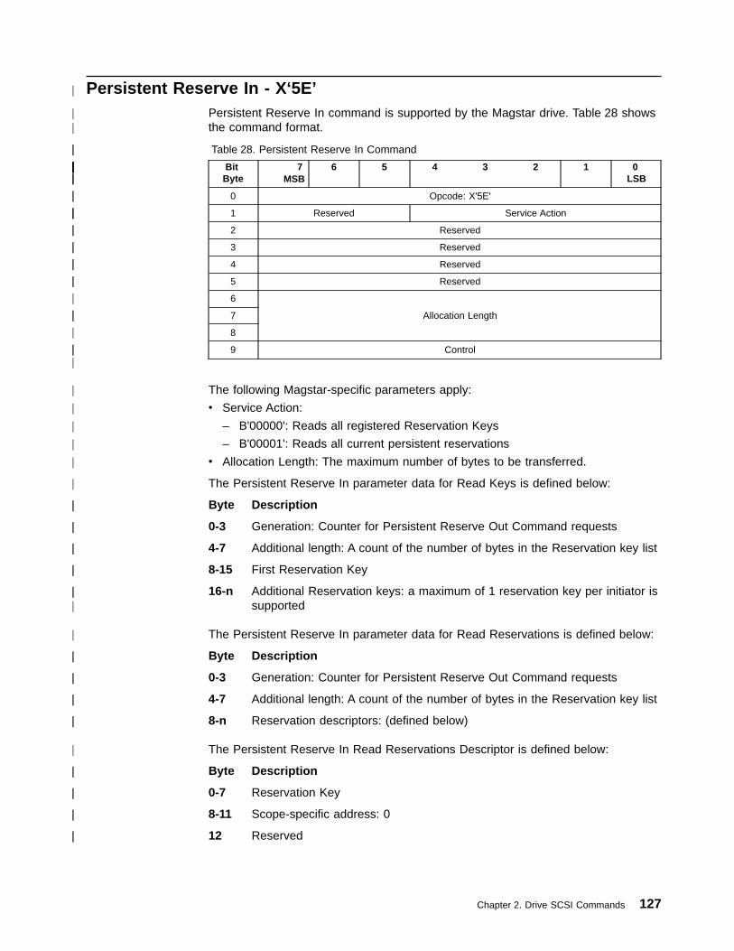
Persistent Reserve In - X‘5E’Persistent Reserve In command is supported by the Magstar drive. Table 28 showsthe command format.
Table 28. Persistent Reserve In Command
BitByte
7MSB
6 5 4 3 2 1 0LSB
0 Opcode: X'5E'
1 Reserved Service Action
2 Reserved
3 Reserved
4 Reserved
5 Reserved
6
Allocation Length7
8
9 Control
The following Magstar-specific parameters apply:
v Service Action:
– B'00000': Reads all registered Reservation Keys
– B'00001': Reads all current persistent reservations
v Allocation Length: The maximum number of bytes to be transferred.
The Persistent Reserve In parameter data for Read Keys is defined below:
Byte Description
0-3 Generation: Counter for Persistent Reserve Out Command requests
4-7 Additional length: A count of the number of bytes in the Reservation key list
8-15 First Reservation Key
16-n Additional Reservation keys: a maximum of 1 reservation key per initiator issupported
The Persistent Reserve In parameter data for Read Reservations is defined below:
Byte Description
0-3 Generation: Counter for Persistent Reserve Out Command requests
4-7 Additional length: A count of the number of bytes in the Reservation key list
8-n Reservation descriptors: (defined below)
The Persistent Reserve In Read Reservations Descriptor is defined below:
Byte Description
0-7 Reservation Key
8-11 Scope-specific address: 0
12 Reserved
Chapter 2. Drive SCSI Commands 127
|
||
||
||||||||||||
||
|||
||
||
||
||
|
||
|
|||
|
|
|
|
|
|
||
||
||
||
|||
|
||
||
||
||
|
||
||
||
||
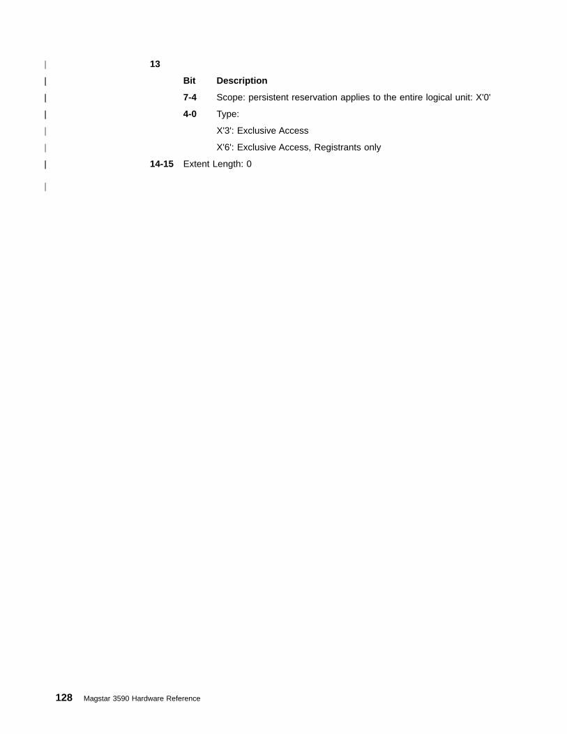
13
Bit Description
7-4 Scope: persistent reservation applies to the entire logical unit: X'0'
4-0 Type:
X'3': Exclusive Access
X'6': Exclusive Access, Registrants only
14-15 Extent Length: 0
128 Magstar 3590 Hardware Reference
|
||
||
||
|
|
||
|

Persistent Reserve Out - X‘5F’Persistent Reserve Out command is supported by the Magstar drive. Table 29shows the command format.
Table 29. Persistent Reserve Out Command
BitByte
7MSB
6 5 4 3 2 1 0LSB
0 Opcode: X'5F'
1 Reserved Service Action
2 Scope Type
3 Reserved
4 Reserved
5 Reserved
6 Reserved
7Parameter list length
8
9 Control
The following Magstar-specific parameters apply:
v Service Action:
– B'00000': Register a reservation key with the device server
– B'00001': Create a persistent reservation using a reservation key
– B'00002': Release a persistent reservation
– B'00003': Clear all reservation keys and all persistent reservations
– B'00004': Preempt persistent reservations from another initiator
– B'00005': Preempt persistent reservations from another Initiator and clear thetask set for the preempted initiator
v Scope: 0Type:
X'3': Exclusive Access
X'6': Exclusive Access, Registrants only
v Parameter list length: x0018
The Persistent Reserve Out parameter list is defined below:
Byte Description
0-7 Reservation key
8-15 Service action Reservation key
16-19 Scope-specific address: 0
20
Byte Description
7-1 Reserved
0 APTPL: Activat Persist Through Power Loss: 0
21 Reserved
22-23 Obselete: 0
Chapter 2. Drive SCSI Commands 129
|
||
||
||||||||||||
||
|||
|||
||
||
||
||
|||
|||
|
|
|
|
|
|
|
||
||
|
|
|
|
||
||
||
||
|
||
||
||
||
||
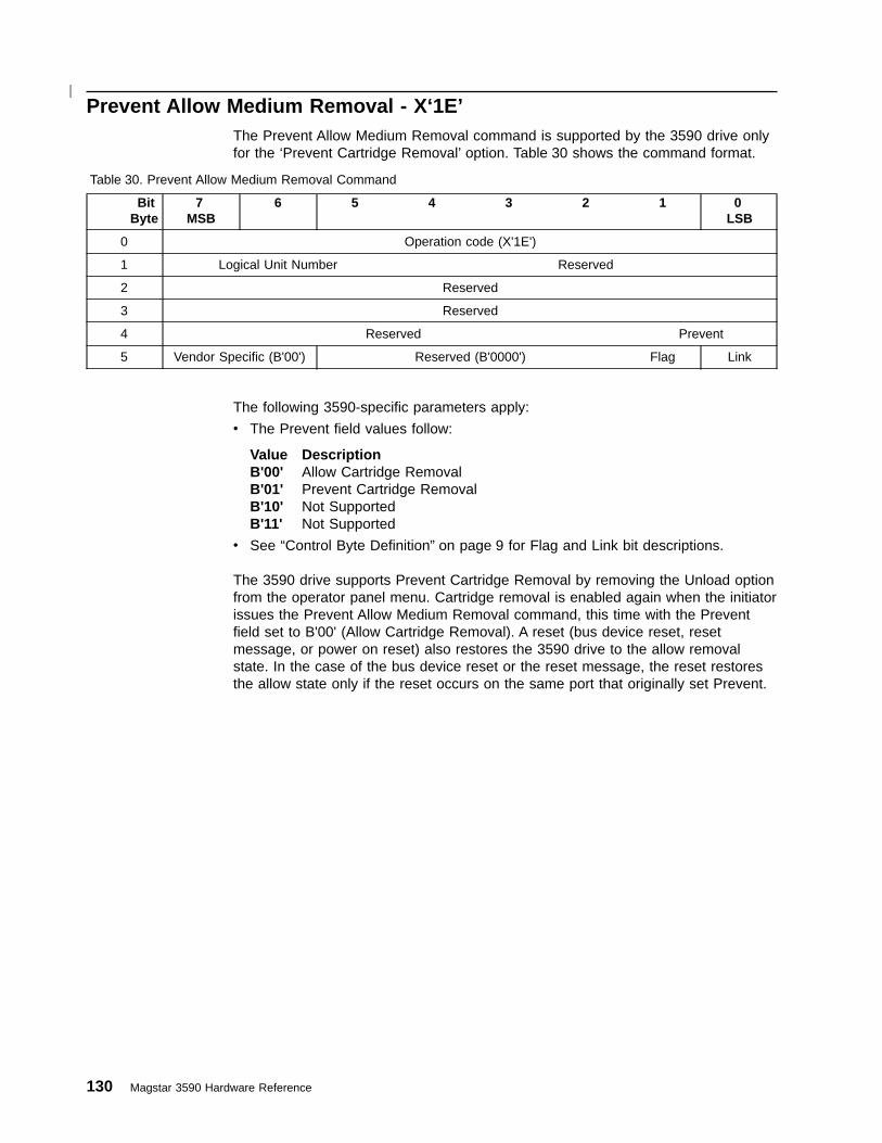
Prevent Allow Medium Removal - X‘1E’The Prevent Allow Medium Removal command is supported by the 3590 drive onlyfor the ‘Prevent Cartridge Removal’ option. Table 30 shows the command format.
Table 30. Prevent Allow Medium Removal Command
BitByte
7MSB
6 5 4 3 2 1 0LSB
0 Operation code (X'1E')
1 Logical Unit Number Reserved
2 Reserved
3 Reserved
4 Reserved Prevent
5 Vendor Specific (B'00') Reserved (B'0000') Flag Link
The following 3590-specific parameters apply:
v The Prevent field values follow:
Value DescriptionB'00' Allow Cartridge RemovalB'01' Prevent Cartridge RemovalB'10' Not SupportedB'11' Not Supported
v See “Control Byte Definition” on page 9 for Flag and Link bit descriptions.
The 3590 drive supports Prevent Cartridge Removal by removing the Unload optionfrom the operator panel menu. Cartridge removal is enabled again when the initiatorissues the Prevent Allow Medium Removal command, this time with the Preventfield set to B'00' (Allow Cartridge Removal). A reset (bus device reset, resetmessage, or power on reset) also restores the 3590 drive to the allow removalstate. In the case of the bus device reset or the reset message, the reset restoresthe allow state only if the reset occurs on the same port that originally set Prevent.
130 Magstar 3590 Hardware Reference
|

Read - X‘08’The Read command is supported by the 3590 drive. Table 31 shows the commandformat.
Table 31. Read Command
BitByte
7MSB
6 5 4 3 2 1 0LSB
0 Operation code (X'08')
1 Logical Unit Number Reserved SILI Fixed
2
Transfer Length3
4
5 Vendor Specific (B'00') Reserved (B'0000') Flag Link
The following 3590-specific parameters apply:
v SILI (Suppress Incorrect Length Indicator) (per SCSI-2 standard).
v Fixed:– B'0': Variable length blocks are supported– B'1': Fixed length blocks are supported
v Transfer Length: value from X'000000' to X'FFFFFF'. Although the maximumblock size for this tape drive is X'200000' (2,097,152 bytes), any transfer length isaccepted and the underlength condition rules are applied for transfer requestsbigger than the actual block size. A transfer Length of X'000000' indicates that nobytes/blocks are transferred. This condition is not considered an error and thelogical position is not changed.
v See “Control Byte Definition” on page 9 for Flag and Link bit descriptions.
For further explanation, see “Data Transfer, Block Limits, and Fixed Block Option”on page 241.
A successful Read command with a Fixed bit of 1 transfers the requested TransferLength, times the current block length in bytes to the initiator. A successful Readcommand with a Fixed bit of 0 transfers the requested Transfer Length in bytes tothe initiator. Upon completion, the logical position is after the last block transferred(end-of-partition side).
If SILI bit is B'1' and the Fixed bit is B'0', the target performs one of the followingactions:
1. Reports CHECK CONDITION status for an incorrect block length condition onlyif the overlength condition exists (see SCSI section 10.4) and the Block Lengthfield in the mode parameter block descriptor is nonzero (see SCSI section8.3.3). The associated sense data is 0/0000 (Incorrect Length, No Sense Data).
2. Does not report CHECK CONDITION status if the only error is the underlengthcondition (see SCSI-2 section 10.4), or if the only error is the overlengthcondition and Block Length field of the mode parameters block descriptor is B'0'.(See note 1 on page 132.)
If the SILI bit is B'1' and the Fixed bit is B'1', the target terminates the commandwith CHECK CONDITION status with associated sense data of 5/2400 (IllegalRequest, Invalid Field in CDB).
Chapter 2. Drive SCSI Commands 131

If the SILI bit is B'0' and an incorrect length block is read, CHECK CONDITIONstatus is returned and the ILI and valid bits are set to B'1' in the sense data. Upontermination, the logical position is after the incorrect length block (end-of-partitionside). If the Fixed bit is 1, the information field is set to the requested TransferLength, minus the actual number of blocks read (not including the incorrect lengthblock).
If the Fixed bit is B'0', the information field is set to the requested Transfer Length,minus the actual block length in two’s complement format.
If the logical unit encounters a filemark during a Read command, CHECKCONDITION status is returned and the filemark and valid bits are set to B'1' in thesense data. The associated sense data is set to 0/0001 (No Sense, FilemarkDetected). Upon termination, the logical position is after the filemark(end-of-partition side). If the Fixed bit is B'1', the information field is set to therequested Transfer Length, minus the actual number of blocks read (not includingthe filemark). If the Fixed bit is B'0', the information field is set to the requestedTransfer Length.
If the logical unit encounters end-of-medium during a Read command, CHECKCONDITION status is returned and the EOM and valid bits are set to B'1' in thesense data. Associated sense data is set to 3/0002 (Medium Error, End of Medium).
If the logical unit encounters early warning and the REW bit is set to 1 in the deviceconfiguration page, CHECK CONDITION status is returned and the EOM and validbits are set to B'1' in the sense data. Associated sense data is set to D/0002(Overflow, End-of-Partition/Medium Detected). If the Fixed bit is B'1', the informationfield is set to the requested Transfer Length, minus the actual number of blockstransferred. If the Fixed bit is B'0', the information field is set to the requestedTransfer Length.
If the drive encounters End-of-Data (EOD) while executing this command, thecommand is terminated at the EOD position and CHECK CONDITION status isreturned with associated sense data of 8/0005 (Blank Check, End-of-DataDetected). If the next motion command is another request to move forward (beyondEOD), the drive accepts the command and attempts to position beyond EOD inorder to allow recovery of old data.
B-Series models cannot read an E-Format tape. If such an attempt is made,CHECK CONDITION status is returned and Associated sense data is set to 3/3002(Medium Error, Cannot Read Medium - Incompatible Format).
Notes:
1. Because the residue information normally provided in the information field of thesense data may not be available when the SILI bit is set, use other methods todetermine the actual block length (for example, including length information inthe data block).
2. In the case of the Fixed bit of 1 with an overlength condition, only the position ofthe incorrect-length logical block can be determined from the sense data. Theactual length of the incorrect block is not reported. Other means may be used todetermine the actual length (for example, backspace and read it again withFixed bit set to B'0').
132 Magstar 3590 Hardware Reference

Read Block Limits - X‘05’The Read Block Limits command is supported by the 3590 drive. Table 32 showsthe command format.
Table 32. Read Block Limits Command
BitByte
7MSB
6 5 4 3 2 1 0LSB
0 Operation code (X'05')
1 Logical Unit Number Reserved
2 Reserved
3 Reserved
4 Reserved
5 Vendor Specific (B'00') Reserved (B'0000') Flag Link
The following 3590-specific parameters apply to the Read Block Limits data:
Byte Description
0 Reserved
1-3 Maximum Block Length Limit: X'200000' (2,097,152 bytes)
4-5 Minimum Block Length Limit: X'0001' (1 byte)
See “Control Byte Definition” on page 9 for Flag and Link bit descriptions.
Any block length in the range of 1 to 2,097,152 is supported.
For further explanation, see “Data Transfer, Block Limits, and Fixed Block Option”on page 241.
Chapter 2. Drive SCSI Commands 133

Read Buffer - X‘3C’The Read Buffer command is supported by the 3590 drive. Table 33 shows thecommand format.
Table 33. Read Buffer Command
BitByte
7MSB
6 5 4 3 2 1 0LSB
0 Operation code (X'3C')
1 Logical Unit Number Reserved Mode
2 Buffer ID
3
Buffer Offset4
5
6
Allocation Length7
8
9 Vendor Specific (B'00') Reserved (B'0000') Flag Link
The following 3590-specific parameters apply:
v Mode: B'001' or B'011'– B'001': Vendor Specific mode (returns data contained in the buffer specified
by Buffer ID)– B'011': Descriptor mode (returns the offset boundary and buffer size in bytes,
for the buffer specified in Buffer ID)
v Buffer ID: The buffers supported in the 3590 drive are described in Table 34 onpage 135.
v Buffer Offset: In mode B'001', the starting address in the buffer to be read. Formode B'011', this field must be X'000000'.
v Allocation Length: The maximum number of bytes to be transferred.
The device transfers the number of bytes specified in the Allocation Length fieldor the number of bytes in the header and buffer being read, whichever is less.This is not an error.
v See “Control Byte Definition” on page 9 for Flag and Link bit descriptions.
Each buffer image has its own unique format, describing where certain key datamay be found. Certain buffers contain embedded data in the buffer imagedescribing the length of the total buffer image, and a CRC field that checks the totalbuffer image. Uploading the microcode buffer is one such example.
“Magstar Drive Buffers” on page 135 lists the accessible buffers.
134 Magstar 3590 Hardware Reference

Magstar Drive BuffersTable 34 lists the Magstar drive buffers and their IDs:
Table 34. Magstar Drive Buffers
Buffer ID Offset Boundary
Dump and Error Data (Read Only) X'00' 4
Microcode (Write Only) X'00'or X'01' 4
Vital Product Data (DRAM) X'07' 4
Vital Product Data (EEProm) X'08' 4
Dump Data 2 X'09' 4
Test Buffer X'0A' 4
Drive Serial Number X'0F' 4
Each buffer is described in the following list, ordered by buffer ID.
Buffer IDBuffer
X'00' Dump and Error Data (Read Only)
This buffer is read-only and supports Read Buffer modes 1 and 3. In thesemodes, the Buffer Offset field provides an offset into the buffer. TheAllocation Length specifies the maximum number of bytes to be read fromthe buffer, starting at the offset specified by the Buffer Offset field. For thisbuffer, the Buffer Offset must be on a 16-byte boundary. If the Buffer Offsetis not on a 16-byte boundary, the device returns CHECK CONDITIONstatus with associated sense data of 5/2400 (Illegal Request, Invalid Field inCDB).
If an initiator attempts to issue a Write Buffer command to this buffer, thedevice returns CHECK CONDITION status with associated sense data of5/2400 (Illegal Request, Invalid Field in CDB).
X'07' Vital Product Data (DRAM)
This buffer is read-only and supports Read Buffer modes 1 and 3.
In Read Buffer mode 1, the Buffer Offset field provides an offset into thebuffer, and must be on a 16-byte boundary. If the Buffer Offset exceeds thesize of the buffer or is otherwise incorrect, the device returns CHECKCONDITION status with associated sense data of 5/2400 (Illegal Request,Invalid Field in CDB).
The Allocation Length field specifies the maximum number of bytes to beread from the buffer, starting at the offset specified by the Buffer Offsetfield.
X'08' Vital Product Data (EEPROM)
This buffer is read only and supports Read Buffer modes 1 and 3. In ReadBuffer mode 1, the Buffer Offset field provides an offset into the buffer. TheAllocation Length specifies the maximum number of bytes to be read fromthe buffer, starting at the offset specified by the Buffer Offset field. For thisbuffer, the Buffer Offset must be on a 16-byte boundary. If the Buffer Offsetis not on a 16-byte boundary, the device returns CHECK CONDITIONstatus with associated sense data of 5/2400 (Illegal Request, Invalid Field inCDB).
Chapter 2. Drive SCSI Commands 135
If an initiator attempts to issue a Write Buffer command to this buffer, thedevice returns CHECK CONDITION status with associated sense data of5/2400 (Illegal Request, Invalid Field in CDB).
X'09' Dump Data 2
This buffer is read only and supports Read Buffer modes 1 and 3. In ReadBuffer mode 1, the Buffer Offset field provides an offset into the buffer. TheAllocation Length specifies the maximum number of bytes to be read fromthe buffer, starting at the offset specified by the Buffer Offset field. For thisbuffer, the Buffer Offset must be on a 16-byte boundary. If the Buffer Offsetis not on a 16-byte boundary, the device returns CHECK CONDITIONstatus with associated sense data of 5/2400 (Illegal Request, Invalid Field inCDB).
If an initiator attempts to issue a Write Buffer command to this buffer, thedevice returns CHECK CONDITION status with associated sense data of5/2400 (Illegal Request, Invalid Field in CDB).
X'0A' Test Buffer
This buffer may be written and supports Read Buffer modes 1 and 3. InRead Buffer mode 1, the Buffer Offset field provides an offset into thebuffer. The Allocation/Parameter List Length specifies the maximum numberof bytes to be read from/written to the buffer, starting at the offset specifiedby the Buffer Offset field. For this buffer, the Buffer Offset must be on a16-byte boundary. If the Buffer Offset is not on a 16-byte boundary, thedevice returns CHECK CONDITION status with associated sense data of5/2400 (Illegal Request, Invalid Field in CDB).
X'0F' Drive Serial Number with Checksum
This buffer is write only and supports Write Buffer Mode 1 with a BufferOffset of 0 only. The Parameter List Length field must be set to 13. The first12 bytes of parameter data are the new serial number and the last byte is achecksum of the first 12 bytes. The drive serial number may be read atbytes 38-49 of standard Inquiry data.
If an initiator attempts to issue a Read Buffer command to this buffer, thedevice returns CHECK CONDITION status with associated sense data of5/2400 (Illegal Request, Invalid Field in CDB).
136 Magstar 3590 Hardware Reference
Read Element Status - X‘B8’The Read Element Status Command is supported by LUN 0 of the drive only onB-Series models and then only when operating as an Attached Medium Changer.
The Read Element Status command supported by the drive (LUN 0) is the same asthe Read Element Status command supported by the ACF (LUN1).
“Read Element Status - X‘B8’” on page 204 for a description of the Read ElementStatus Command.
Chapter 2. Drive SCSI Commands 137
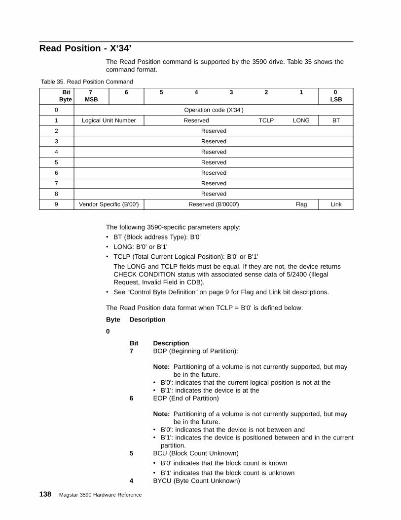
Read Position - X‘34’The Read Position command is supported by the 3590 drive. Table 35 shows thecommand format.
Table 35. Read Position Command
BitByte
7MSB
6 5 4 3 2 1 0LSB
0 Operation code (X'34')
1 Logical Unit Number Reserved TCLP LONG BT
2 Reserved
3 Reserved
4 Reserved
5 Reserved
6 Reserved
7 Reserved
8 Reserved
9 Vendor Specific (B'00') Reserved (B'0000') Flag Link
The following 3590-specific parameters apply:
v BT (Block address Type): B'0'
v LONG: B'0' or B'1'
v TCLP (Total Current Logical Position): B'0' or B'1'
The LONG and TCLP fields must be equal. If they are not, the device returnsCHECK CONDITION status with associated sense data of 5/2400 (IllegalRequest, Invalid Field in CDB).
v See “Control Byte Definition” on page 9 for Flag and Link bit descriptions.
The Read Position data format when TCLP = B'0' is defined below:
Byte Description
0
Bit Description7 BOP (Beginning of Partition):
Note: Partitioning of a volume is not currently supported, but maybe in the future.
v B'0': indicates that the current logical position is not at thev B'1': indicates the device is at the
6 EOP (End of Partition)
Note: Partitioning of a volume is not currently supported, but maybe in the future.
v B'0': indicates that the device is not between andv B'1': indicates the device is positioned between and in the current
partition.5 BCU (Block Count Unknown)
v B'0' indicates that the block count is known
v B'1' indicates that the block count is unknown4 BYCU (Byte Count Unknown)
138 Magstar 3590 Hardware Reference

v B'0' indicates that the block count is known
v B'1' indicates that the block count is unknown3 Reserved2 BPU (Block Position Unknown)
v B'0' indicates that the block position is known
v B'1' indicates that the block position is unknown1 PERR (Position Error): B'0'0 Reserved
1 Partition Number:
Note: Partitioning of a volume is not currently supported, but may be in thefuture.
Reports the partition number for the current logical position. When themedium has only one partition, this field is set to 0.
2-3 Reserved
4-7 First Block Location:
Specifies the block address associated with the current logical position. Thevalue indicates the block address of the next data block to be transferredbetween the initiator and the target if a Read or Write command is issued,in the range X'0000 0000' to X'FFFF FFFF'.
8-11 Last Block Location:
After a write command, this field specifies the block address associatedwith the next data block to be transferred from the buffer to the medium.After a read command, this field specifies the block address associated withthe last (most recent) data block to be transferred from the medium to thebuffer. For any case where the buffer no longer contains a whole block ofdata or is empty, the value reported for the Last Block Location is equal tothe value reported for the First Block Location, in the range X'0000 0000' toX'FFFF FFFF'.
12 Reserved
13-15 Number of Write Blocks in Buffer:
The number of data blocks in the buffer that have not been written to themedium. (This value is zero if the device is reading rather than writing.)
16-19 Number of Write Bytes in Buffer
The total number of data bytes (before compaction) in the buffer that havenot been written to the medium.
The Read Position data format when TCLP = B'1' is defined below:
Byte Description
0
Bit Description7 BOP (Beginning of Partition):
Note: Partitioning of a volume is not currently supported, but maybe in the future.
v B'0': indicates that the current logical position is not at thev B'1': indicates the device is at the
Chapter 2. Drive SCSI Commands 139

6 EOP (End of Partition)
Note: Partitioning of a volume is not currently supported, but maybe in the future.
v B'0': indicates that the device is not between andv B'1': indicates the device is positioned between and in the current
partition.5-4 Reserved3 MPU (Mark Position Unknown)
v B'0' indicates that the current logical block position is known
v B'1' indicates that the current logical block position is unknown2 BPU (Block Position Unknown)
v B'0' indicates that the block position is known
v B'1' indicates that the block position is unknown1 Reserved
1 Reserved
2 Reserved
3 Reserved
4-7 Partition Number:
Note: Partitioning of a volume is not currently supported, but may be in thefuture.
Reports the partition number for the current logical position. When themedium has only one partition, this field is set to 0.
8-15 First Block Location:
Specifies the block address associated with the current logical position. Thevalue indicates the block address of the next data block to be transferredbetween the initiator and the target if a Read or Write command is issued,in the range X'0000 0000' to X'FFFF FFFF'.
16-23 File Number
Specifies the number of filemarks between Beginning of Partition and thecurrent logical position.
Note: There are many non-error situations where the file number isunknown. Because of this, the Mark Position Unknown often is set toTRUE and the File Number field is zero.
24-31 Set Number
Current Set Number: B'0'
140 Magstar 3590 Hardware Reference
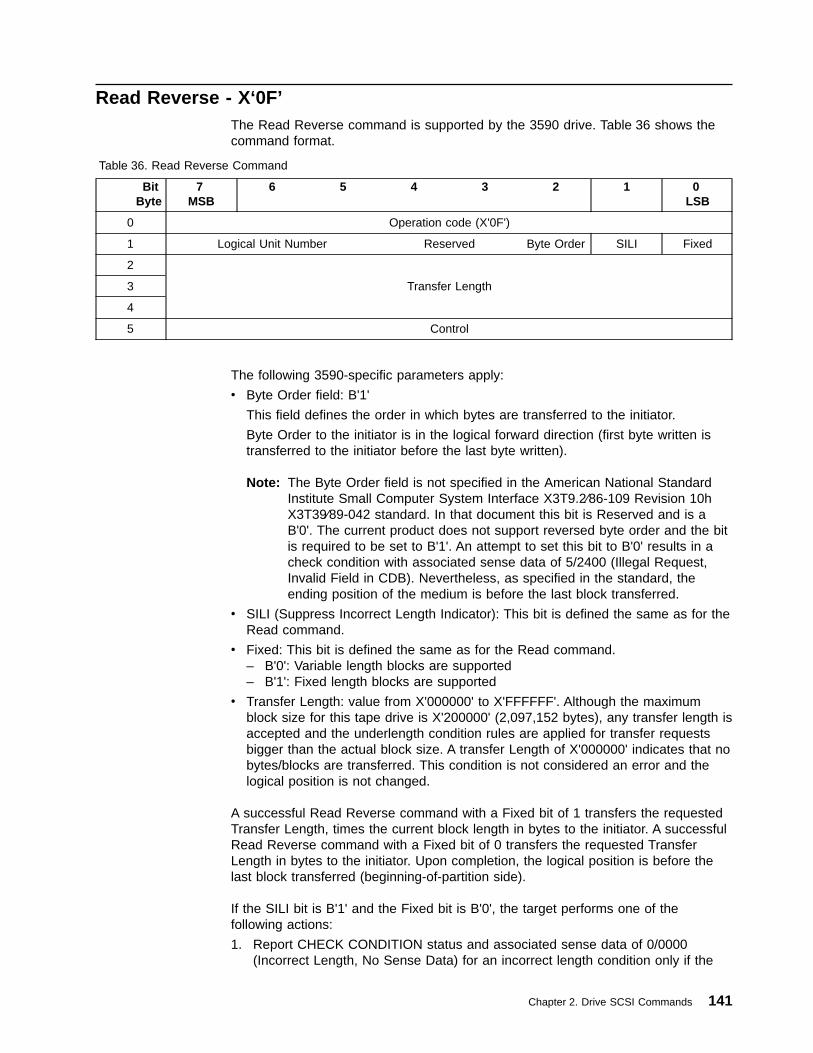
Read Reverse - X‘0F’The Read Reverse command is supported by the 3590 drive. Table 36 shows thecommand format.
Table 36. Read Reverse Command
BitByte
7MSB
6 5 4 3 2 1 0LSB
0 Operation code (X'0F')
1 Logical Unit Number Reserved Byte Order SILI Fixed
2
Transfer Length3
4
5 Control
The following 3590-specific parameters apply:
v Byte Order field: B'1'
This field defines the order in which bytes are transferred to the initiator.
Byte Order to the initiator is in the logical forward direction (first byte written istransferred to the initiator before the last byte written).
Note: The Byte Order field is not specified in the American National StandardInstitute Small Computer System Interface X3T9.2⁄86-109 Revision 10hX3T39⁄89-042 standard. In that document this bit is Reserved and is aB'0'. The current product does not support reversed byte order and the bitis required to be set to B'1'. An attempt to set this bit to B'0' results in acheck condition with associated sense data of 5/2400 (Illegal Request,Invalid Field in CDB). Nevertheless, as specified in the standard, theending position of the medium is before the last block transferred.
v SILI (Suppress Incorrect Length Indicator): This bit is defined the same as for theRead command.
v Fixed: This bit is defined the same as for the Read command.– B'0': Variable length blocks are supported– B'1': Fixed length blocks are supported
v Transfer Length: value from X'000000' to X'FFFFFF'. Although the maximumblock size for this tape drive is X'200000' (2,097,152 bytes), any transfer length isaccepted and the underlength condition rules are applied for transfer requestsbigger than the actual block size. A transfer Length of X'000000' indicates that nobytes/blocks are transferred. This condition is not considered an error and thelogical position is not changed.
A successful Read Reverse command with a Fixed bit of 1 transfers the requestedTransfer Length, times the current block length in bytes to the initiator. A successfulRead Reverse command with a Fixed bit of 0 transfers the requested TransferLength in bytes to the initiator. Upon completion, the logical position is before thelast block transferred (beginning-of-partition side).
If the SILI bit is B'1' and the Fixed bit is B'0', the target performs one of thefollowing actions:
1. Report CHECK CONDITION status and associated sense data of 0/0000(Incorrect Length, No Sense Data) for an incorrect length condition only if the
Chapter 2. Drive SCSI Commands 141

overlength condition exists (see SCSI section 10.4), and the Block Length fieldin the mode parameter block descriptor is nonzero (see SCSI section 8.3.3).
2. Not report CHECK CONDITION status if the only error is the underlengthcondition (see SCSI section 10.4), or if the only error is the overlength conditionand Block Length field of the mode parameters block descriptor is B'0'. (Seenote 1.)
If the SILI bit is B'1' and the Fixed bit is B'1', the target terminates the commandwith CHECK CONDITION status with associated sense data of 5/2400 (IllegalRequest, Invalid Field in CDB).
If the SILI bit is B'0' and an incorrect length block is read, CHECK CONDITIONstatus is returned and the ILI and valid bits are set to B'1' in the sense data. Upontermination, the logical position is before the incorrect length block(beginning-of-partition side).
If the Fixed bit is B'1', the information field is set to the requested Transfer Length,minus the actual number of blocks read (not including the incorrect length block).
If the Fixed bit is B'0', the information field is set to the requested Transfer Length,minus the actual block length. Targets that do not support negative values set theinformation field to zero if the overlength condition exists (see SCSI section 10.4).
If the logical unit encounters a filemark during a Read Reverse command, CHECKCONDITION status is returned and the filemark and valid bits are set to B'1' in thesense data. The associated sense data is set to 0/0001 (No Sense, FilemarkDetected). Upon termination, the logical position is before the filemark(beginning-of-partition side).
If the Fixed bit is B'1', the information field is set to the requested Transfer Length,minus the actual number of blocks read (not including the filemark). If the Fixed bitis B'0', the information field is set to the requested Transfer Length.
If the logical unit encounters beginning-of-medium during a Read Reversecommand, CHECK CONDITION status is returned and the EOM and valid bits areset to B'1' in the sense data. Associated sense data is set to 0/0004 (No Sense,Beginning of Medium).
If the Fixed bit is B'1', the information field is set to the requested Transfer Length,minus the actual number of blocks transferred.
If the Fixed bit is B'0', the information field is set to the requested Transfer Length.
If the logical unit encounters End of Data (EOD) while reading, a sequence error isgenerated 3/1404 (Medium Error, Block Sequence Error).
Notes:
1. Because the residue information normally provided in the information field of thesense data may not be available when the SILI bit is set, use other methods fordetermining the actual block length (For example, including length information inthe data block).
2. In the case of the Fixed bit of 1 with an overlength condition, only the position ofthe incorrect-length logical block can be determined from the sense data. Theactual length of the incorrect block is not reported. Other means may be used todetermine the actual length (for example, read it again with Fixed bit set to B'0').
142 Magstar 3590 Hardware Reference

Receive Diagnostic Results - X‘1C’The Receive Diagnostic Results command is supported by the 3590 drive. After aSend Diagnostic command completes, use the Receive Diagnostic Resultscommand to receive the results.
Note: For diagnostics that produce diagnostic results, the Receive DiagnosticResult command should be linked to the Send Diagnostic command, or theLUN should be reserved. See the American National Standard Institute SmallComputer System Interface X3T9.2⁄86-109 Revision 10h X3T39⁄89-042standard for details.
Table 37 shows the command format.
Table 37. Receive Diagnostic Results Command
BitByte
7MSB
6 5 4 3 2 1 0LSB
0 Operation code (X'1C')
1 Logical Unit Number Reserved
2 Reserved
3Allocation Length
4
5 Vendor Specific (B'00') Reserved (B'0000') Flag Link
The following 3590-specific parameters apply:
v Allocation Length is the maximum number of bytes to be returned in the page ofdata following the command (if any).
v See “Control Byte Definition” on page 9 for Flag and Link bit descriptions.
Diagnostic Results Page FormatsThe 3590 drive supports two diagnostic pages: Page Code X'00' and Page CodeX'80'.
Page Code X'00'The format for the Receive Diagnostic Results command follows:
Byte Description
0 Page Code: X'00'
1 Reserved
2-3 Page Length: X'0002'
4 Page Code Supported: X'00'
5 Page Code Supported: X'80'
Page Code X'80'Is a general purpose page for returning diagnostic data to the initiator. The formatfor the Receive Diagnostic Results command follows:
Byte Description
0 Page Code: X'80'
1 Reserved
2-3 Page Length (n-3)
Chapter 2. Drive SCSI Commands 143
4-5 Diagnostic ID
This field contains the same value as that sent with the Send Diagnosticcommand for which this response is associated.
6 Flags
Set to X'00' for the Receive Diagnostic Results command
7 Reserved
8-n Diagnostic Results
The Diagnostic Results field contains the results from the diagnostic. Seethe individual Send Diagnostic parameter descriptions for the field contents.
Refer to “Magstar-Supported Diagnostics” on page 162 for a list of diagnosticparameters supported by the 3590 drive.
144 Magstar 3590 Hardware Reference
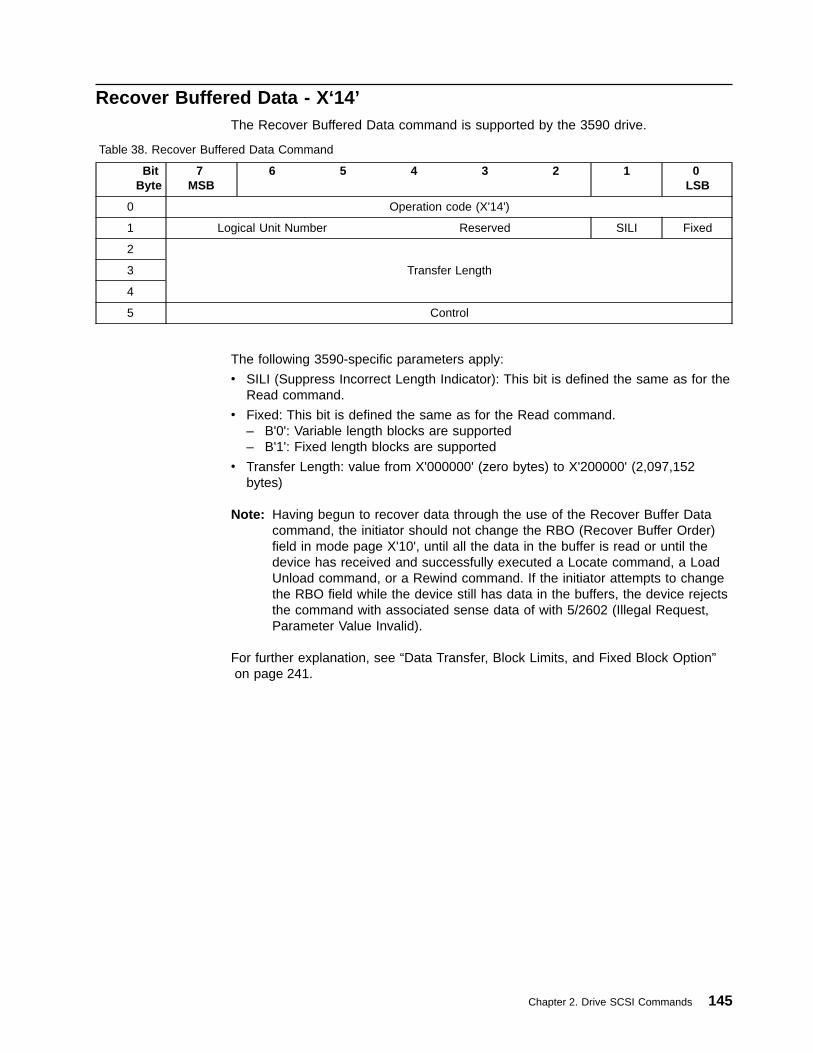
Recover Buffered Data - X‘14’The Recover Buffered Data command is supported by the 3590 drive.
Table 38. Recover Buffered Data Command
BitByte
7MSB
6 5 4 3 2 1 0LSB
0 Operation code (X'14')
1 Logical Unit Number Reserved SILI Fixed
2
Transfer Length3
4
5 Control
The following 3590-specific parameters apply:
v SILI (Suppress Incorrect Length Indicator): This bit is defined the same as for theRead command.
v Fixed: This bit is defined the same as for the Read command.– B'0': Variable length blocks are supported– B'1': Fixed length blocks are supported
v Transfer Length: value from X'000000' (zero bytes) to X'200000' (2,097,152bytes)
Note: Having begun to recover data through the use of the Recover Buffer Datacommand, the initiator should not change the RBO (Recover Buffer Order)field in mode page X'10', until all the data in the buffer is read or until thedevice has received and successfully executed a Locate command, a LoadUnload command, or a Rewind command. If the initiator attempts to changethe RBO field while the device still has data in the buffers, the device rejectsthe command with associated sense data of with 5/2602 (Illegal Request,Parameter Value Invalid).
For further explanation, see “Data Transfer, Block Limits, and Fixed Block Option”on page 241.
Chapter 2. Drive SCSI Commands 145

Release Unit - X‘17’The Release Unit command is supported by the 3590 drive. Table 39 shows thecommand format.
Table 39. Release Unit Command
BitByte
7MSB
6 5 4 3 2 1 0LSB
0 Operation code (X'17')
1 Logical Unit Number 3rdPty Third Party Device ID Reserved
2 Reserved
3 Reserved
4 Reserved
5 Vendor Specific (B'00') Reserved (B'0000') Flag Link
The following 3590-specific parameters apply:
v 3rdPty (Third Party): B'0'
v Third Party Device ID: B'000'
v See “Control Byte Definition” on page 9 for Flag and Link bit descriptions.
146 Magstar 3590 Hardware Reference

Report Density Support- X‘44’The Report Density Support command is supported by the 3590 drive.
Table 40. Report Density Support
BitByte
7MSB
6 5 4 3 2 1 0LSB
0 Operation code (X'44')
1 Reserved Media
2 Reserved
3 Reserved
4 Reserved
5 Reserved
6 Reserved
7 Allocation Length
9 Control Byte
The following 3590-specific parameters apply:
v Media:
– B'0' report all supported densities for all supported medium types
– B'1' report all supported densities for the current medium in the drive
v Allocation Length is the maximum number of bytes to be transferred.
– For E-Series Models, there are two densities supported by the device. Thenumber of bytes returned will be 108 bytes.
– For B-Series Models, there is one density supported by the device. Thenumber of bytes returned will be 56 bytes.
v See “Control Byte Definition” on page 9 for Flag and Link bit descriptions.
If Media = B'1' and the device is not ready, the drive will return 2/0400 (Not Ready,Not Ready Cause Not Reportable).
The Report Density Support data format returned is defined below:
Byte Description
0-1 Available Density Support Length
2 Reserved
3 Reserved
4-n Density Support Data Block Descriptors
The Report Density Block descriptor for High Performance Cartridge Tape andExtended High Performance Cartridge Tape is defined below. Note that his formatapplies to both the High Performance Cartridge Tape and Extended HighPerformance Cartridge Tape. The B-Series models return this format only.
Byte Description
0 Primary Density Code: X'29'
1 Secondary Density Code:
v E-Series models: X'29'
Chapter 2. Drive SCSI Commands 147

v B-Series models: X'00'
2
Bit Description7 WRTOK:
v E-Series models: B'0' (The device cannot write this format)
v B-Series models: B'1' (The device can write this format)6 DUP: Only one data block for this density code. B'0'5 DEFLT:
v E-Series models: B'0' (This format is not the default format)
v B-Series models: B'1' (This format is the default format)4-0 Reserved
3 Reserved
4 Reserved
5-7 Bits Per MM: X'000D48'
8-9 Media Width (in millimeters): X'000D'
10-11 Tracks: X'0080'
12-15 Capacity (in Megabytes):
v Media Bit = B'0': X'00004E20'
v Media Bit = B'1':
– High Performance Cartridge Tape is loaded: X'00002710'
– Extended High Performance Cartridge Tape is loaded: X'00004E20'
16-23 Assigning Organization:'IBM '
(in ASCII)
24-31 Density Name'3590 '
(in ASCII)
32-51 Description' '
(in ASCII)
Supported on E-Series models only, the Density Support data block descriptor forE-Format Density is defined below. Note that this format applies to both the HighPerformance Cartridge Tape and Extended High Performance Cartridge Tape.
Byte Description
0 Primary Density Code: X'2A'
1 Secondary Density Code: 0
2
Bit Description7 WRTOK: The device can write this format. B'1'6 DUP: Only one data block for this density code. B'0'5 DEFLT: This format is the default format: B'1'
148 Magstar 3590 Hardware Reference
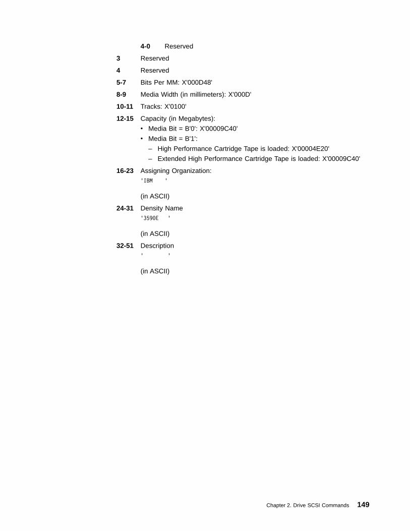
4-0 Reserved
3 Reserved
4 Reserved
5-7 Bits Per MM: X'000D48'
8-9 Media Width (in millimeters): X'000D'
10-11 Tracks: X'0100'
12-15 Capacity (in Megabytes):
v Media Bit = B'0': X'00009C40'
v Media Bit = B'1':
– High Performance Cartridge Tape is loaded: X'00004E20'
– Extended High Performance Cartridge Tape is loaded: X'00009C40'
16-23 Assigning Organization:'IBM '
(in ASCII)
24-31 Density Name'3590E '
(in ASCII)
32-51 Description' '
(in ASCII)
Chapter 2. Drive SCSI Commands 149
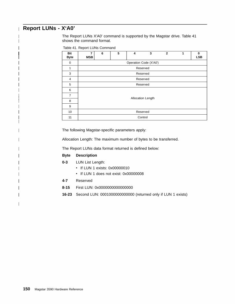
Report LUNs - X‘A0’The Report LUNs X'A0' command is supported by the Magstar drive. Table 41shows the command format.
Table 41. Report LUNs Command
BitByte
7MSB
6 5 4 3 2 1 0LSB
0 Operation Code (X'A0')
1 Reserved
3 Reserved
4 Reserved
5 Reserved
6
Allocation Length7
8
9
10 Reserved
11 Control
The following Magstar-specific parameters apply:
Allocation Length: The maximum number of bytes to be transferred.
The Report LUNs data format returned is defined below:
Byte Description
0-3 LUN List Length:
v If LUN 1 exists: 0x00000010
v If LUN 1 does not exist: 0x00000008
4-7 Reserved
8-15 First LUN: 0x0000000000000000
16-23 Second LUN: 0001000000000000 (returned only if LUN 1 exists)
150 Magstar 3590 Hardware Reference
|
||
||
||||||||||||
||
||
||
||
||
|
||
|
|
||
|||
|
|
|
||
||
|
|
||
||
||
|

Request Sense - X‘03’The Request Sense command is supported by the 3590 drive. Table 42 shows thecommand format.
Table 42. Request Sense Command
BitByte
7MSB
6 5 4 3 2 1 0LSB
0 Operation code (X'03')
1 Logical Unit Number Reserved
2 Reserved
3 Reserved
4 Allocation Length
5 Vendor Specific (B'00') Reserved (B'0000') Flag Link
The following 3590-specific parameters apply:
v Allocation Length: The maximum number of bytes to be transferred.
This device has 96 bytes of sense data. If the allocation length specified is less,then the allocated amount is transferred, the remaining sense data is lost, and noerror is reported. If the allocated length specified is greater, then only 96 bytes ofsense data are transferred and no error is reported.
v See “Control Byte Definition” on page 9 for Flag and Link bit descriptions.
When acting as an Attached Medium Changer, the device returns sense datarelated to the drive as well as the library. When acting as an Independent MediumChanger, the device only returns sense data related to the LUN which has beenspecified.
The format of the sense data follows:
Byte Description
0
Bit Description7 Valid:
v B'0' indicates that information bytes 3-6 are not valid.
v B'1' indicates that information bytes 3-6 are valid.6-0 Error Code (X'70' or X'71')
1 Segment Number: X'00'
2
Bit Description7 Filemark:
v B'0' indicates that the current read command has notencountered a filemark.
v B'1' indicates that the current read command has encountered afilemark.
This device does not report Setmarks, per Mode Page 10, Byte8(5).
6 EOM (End-Of-Medium):
v B'0' indicates that the device is not at the end of medium.
Chapter 2. Drive SCSI Commands 151

v B'1' indicates that the device is at the end of medium.5 ILI (Incorrect Length Indicator): This bit is set to B'1' if a Read
command reads a block of incorrect length and the SILI field in theRead Command was set to B'0'.
4 Reserved3-0 Sense Key: See “Appendix B. Error Sense Information” on
page 233.
3-6 Information: The content of this field varies depending on the failingcommand and error. This field is only valid when the Valid bit (byte 0, bit 7)is set to B'1'.v Non-Deferred Errors with Fixed bit = B'0':
The Information field reflects the number of bytes (uncompacted) in thebuffer.
v Non-Deferred Errors with Fixed bit = B'1':
The Information field reflects the number of blocks in the buffer(regardless of block size).
v Deferred Errors and non-deferred errors for all other command types:
– If the Block Length field in the block descriptor area of the ModeSelect command is X'000000':
The Information field reflects the number of bytes (uncompacted) inthe buffer.
– If the Block Length field in the block descriptor area of the ModeSelect command is any value other than X'000000':
The Information field reflects the number of blocks in the buffer.
7 Additional Sense Length (n-7): X'0A' or X'58'v The 3590 drive supports a total of 96 bytes of sense data (a value of
X'58' in the Additional Sense Length field). The first 18 bytes arestandard.
v Only the first 18 bytes of sense data are returned (a value of X'0A' in theAdditional Sense Length field) in association with an underlengthcondition for a read command with SILI bit of B'0' and a Fixed bit of B'0'.
8-11 Command-Specific Information: X'0000 0000'
The 3590 drive does not support the commands associated with this field.
12 Additional Sense Code: See “Appendix B. Error Sense Information” onpage 233.
13 Additional Sense Code Qualifier: See “Appendix B. Error Sense Information”on page 233.
14 Field Replaceable Unit Code
Used to specify a failed FRU or FRU group. A non-zero value does notnecessarily mean a FRU has been identified.
15-17 Sense Key Specific
When the sense key field value is Illegal Request, the SKSV bit is B'1' andbytes 15-17 are interpreted as follows:
Byte Description15 Sense Key Specific
Bit Description7 SKSV (Sense Key Specific Valid): B'1'6 C/D (Control/Data):
152 Magstar 3590 Hardware Reference
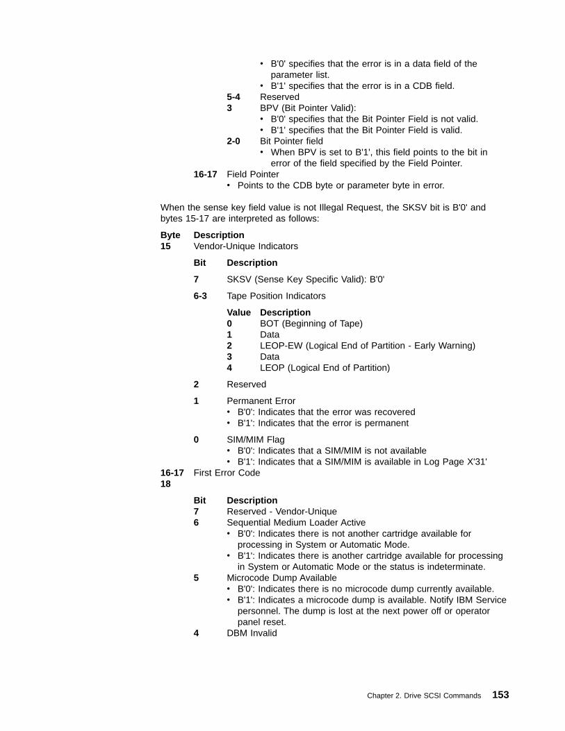
v B'0' specifies that the error is in a data field of theparameter list.
v B'1' specifies that the error is in a CDB field.5-4 Reserved3 BPV (Bit Pointer Valid):
v B'0' specifies that the Bit Pointer Field is not valid.v B'1' specifies that the Bit Pointer Field is valid.
2-0 Bit Pointer fieldv When BPV is set to B'1', this field points to the bit in
error of the field specified by the Field Pointer.16-17 Field Pointer
v Points to the CDB byte or parameter byte in error.
When the sense key field value is not Illegal Request, the SKSV bit is B'0' andbytes 15-17 are interpreted as follows:
Byte Description15 Vendor-Unique Indicators
Bit Description
7 SKSV (Sense Key Specific Valid): B'0'
6-3 Tape Position Indicators
Value Description0 BOT (Beginning of Tape)1 Data2 LEOP-EW (Logical End of Partition - Early Warning)3 Data4 LEOP (Logical End of Partition)
2 Reserved
1 Permanent Errorv B'0': Indicates that the error was recoveredv B'1': Indicates that the error is permanent
0 SIM/MIM Flagv B'0': Indicates that a SIM/MIM is not availablev B'1': Indicates that a SIM/MIM is available in Log Page X'31'
16-17 First Error Code18
Bit Description7 Reserved - Vendor-Unique6 Sequential Medium Loader Active
v B'0': Indicates there is not another cartridge available forprocessing in System or Automatic Mode.
v B'1': Indicates there is another cartridge available for processingin System or Automatic Mode or the status is indeterminate.
5 Microcode Dump Availablev B'0': Indicates there is no microcode dump currently available.v B'1': Indicates a microcode dump is available. Notify IBM Service
personnel. The dump is lost at the next power off or operatorpanel reset.
4 DBM Invalid
Chapter 2. Drive SCSI Commands 153

Note: This field is not valid if the drive is not ready or when thesense data is associated with a prior CHECK CONDITIONstatus (contingent allegiance condition).
v B'0': Indicates the Device Block Map is validv B'1': Indicates the Device Block Map is invalid
3-1 Reserved0 Port Reporting Sense
v B'0': Indicates this sense reported on port 0v B'1': Indicates this sense reported on port 1
19 SCSI IDs
Bit Description7-4 ID for Port 03-0 ID for Port 1
These fields contain the SCSI IDs of the two ports. These IDs canbe changed from the operator’s panel. When changed from theoperator’s panel, the permanent addresses stored in the VPD arealso changed. The change to the IDs does not take effect until thenext or Reset (issued from the Operator’s panel).
The SCSI IDs can be temporarily changed using the Change SCSIID diagnostic routine. Although a port ID may be temporarilychanged by this routine, the default value of the port ID is given inthis sense command, not the temporary value assigned.
20 ACF Status
Bit Description7-4 Reserved3 Magazine Lock
v B'0': The cartridges may be removed from the magazine.v B'1': The cartridges are locked in the magazine.
2 Reserved1 Magazine Available
v B'0': The magazine is not mounted in the ACF.v B'1': The magazine is mounted in the ACF.
A magazine removed from the ACF causes CHECK CONDITIONstatus to be prepared with associated sense data of 6/3B12 (UnitAttention, Medium Magazine Removed).
0 Reserved21-22 Reserved - Vendor-Unique23
Bit Description
7-4 Medium Access Field
Value Description0 Position unknown (during power-on initialization or unusual
conditions)1 Load error (cartridge loaded, but drive not ready)4 Cartridge unloaded or removed5 Cartridge is currently loading6 Cartridge is currently unloading9 Cartridge is loaded
Note: other values are possible, but undefined.
3-0 Reserved
154 Magstar 3590 Hardware Reference
|
|
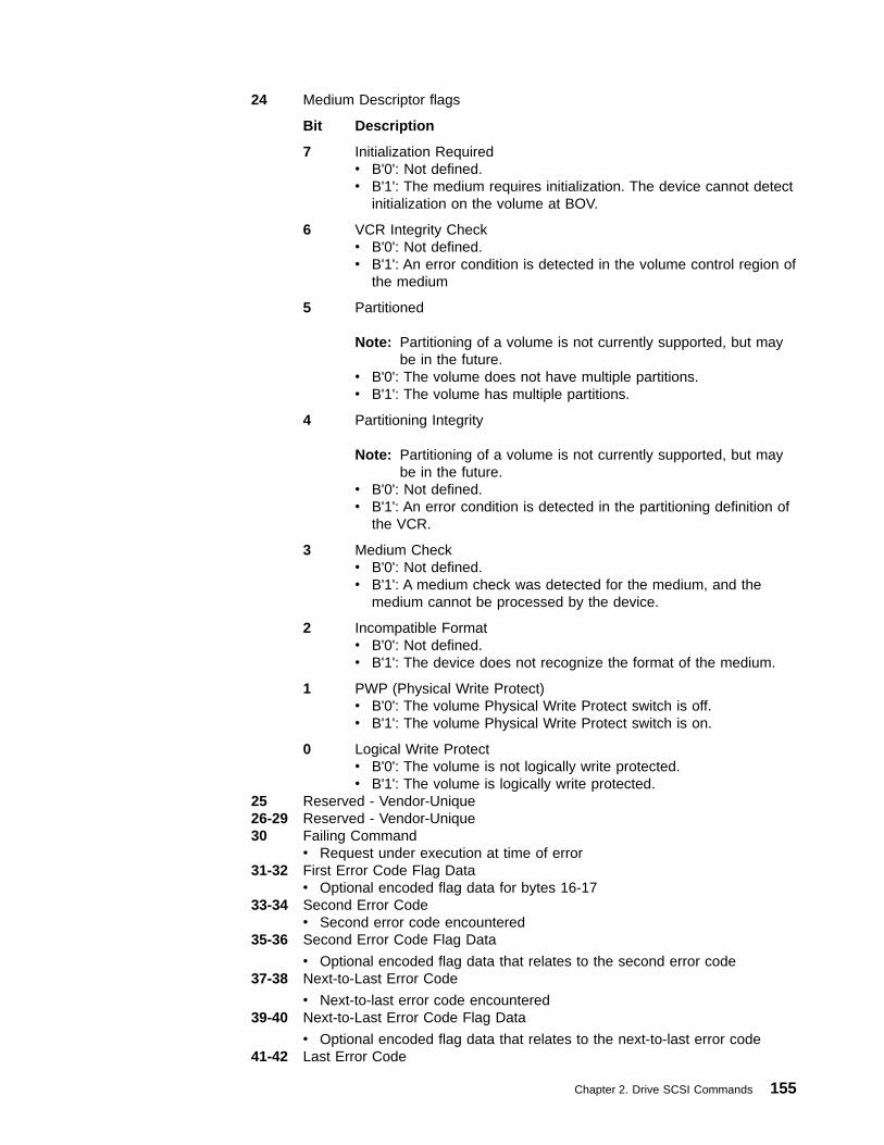
24 Medium Descriptor flags
Bit Description
7 Initialization Requiredv B'0': Not defined.v B'1': The medium requires initialization. The device cannot detect
initialization on the volume at BOV.
6 VCR Integrity Checkv B'0': Not defined.v B'1': An error condition is detected in the volume control region of
the medium
5 Partitioned
Note: Partitioning of a volume is not currently supported, but maybe in the future.
v B'0': The volume does not have multiple partitions.v B'1': The volume has multiple partitions.
4 Partitioning Integrity
Note: Partitioning of a volume is not currently supported, but maybe in the future.
v B'0': Not defined.v B'1': An error condition is detected in the partitioning definition of
the VCR.
3 Medium Checkv B'0': Not defined.v B'1': A medium check was detected for the medium, and the
medium cannot be processed by the device.
2 Incompatible Formatv B'0': Not defined.v B'1': The device does not recognize the format of the medium.
1 PWP (Physical Write Protect)v B'0': The volume Physical Write Protect switch is off.v B'1': The volume Physical Write Protect switch is on.
0 Logical Write Protectv B'0': The volume is not logically write protected.v B'1': The volume is logically write protected.
25 Reserved - Vendor-Unique26-29 Reserved - Vendor-Unique30 Failing Command
v Request under execution at time of error31-32 First Error Code Flag Data
v Optional encoded flag data for bytes 16-1733-34 Second Error Code
v Second error code encountered35-36 Second Error Code Flag Data
v Optional encoded flag data that relates to the second error code37-38 Next-to-Last Error Code
v Next-to-last error code encountered39-40 Next-to-Last Error Code Flag Data
v Optional encoded flag data that relates to the next-to-last error code41-42 Last Error Code
Chapter 2. Drive SCSI Commands 155
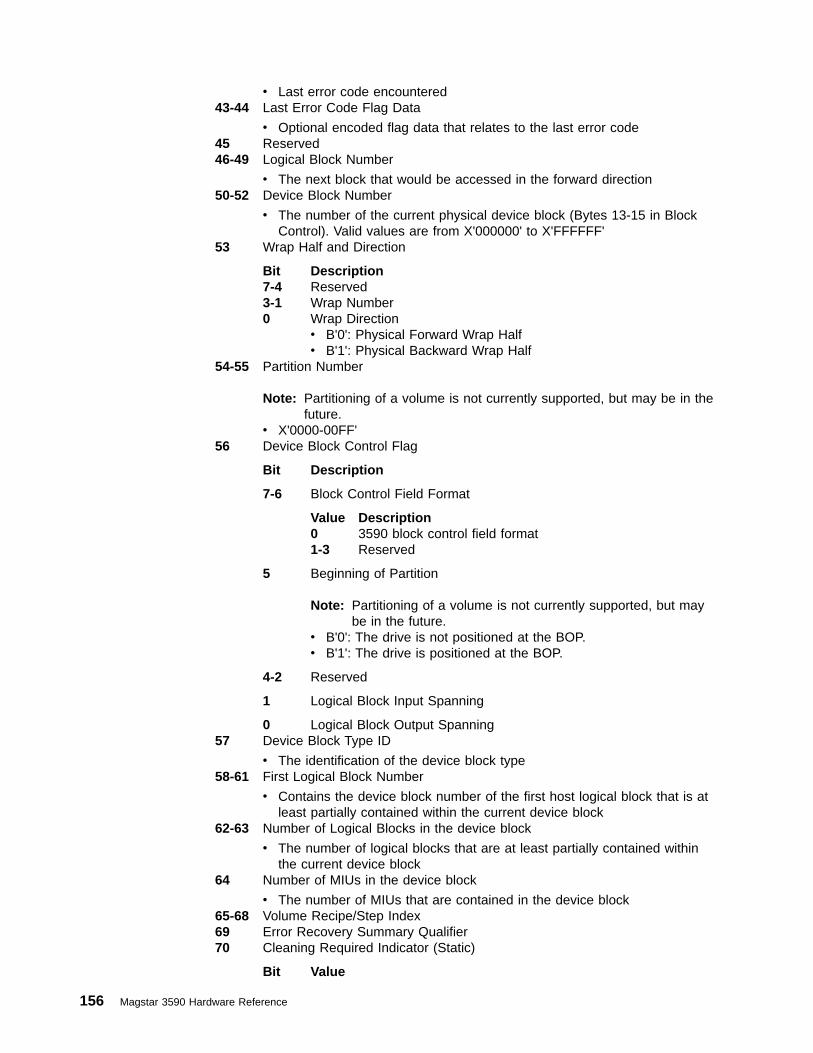
v Last error code encountered43-44 Last Error Code Flag Data
v Optional encoded flag data that relates to the last error code45 Reserved46-49 Logical Block Number
v The next block that would be accessed in the forward direction50-52 Device Block Number
v The number of the current physical device block (Bytes 13-15 in BlockControl). Valid values are from X'000000' to X'FFFFFF'
53 Wrap Half and Direction
Bit Description7-4 Reserved3-1 Wrap Number0 Wrap Direction
v B'0': Physical Forward Wrap Halfv B'1': Physical Backward Wrap Half
54-55 Partition Number
Note: Partitioning of a volume is not currently supported, but may be in thefuture.
v X'0000-00FF'56 Device Block Control Flag
Bit Description
7-6 Block Control Field Format
Value Description0 3590 block control field format1-3 Reserved
5 Beginning of Partition
Note: Partitioning of a volume is not currently supported, but maybe in the future.
v B'0': The drive is not positioned at the BOP.v B'1': The drive is positioned at the BOP.
4-2 Reserved
1 Logical Block Input Spanning
0 Logical Block Output Spanning57 Device Block Type ID
v The identification of the device block type58-61 First Logical Block Number
v Contains the device block number of the first host logical block that is atleast partially contained within the current device block
62-63 Number of Logical Blocks in the device block
v The number of logical blocks that are at least partially contained withinthe current device block
64 Number of MIUs in the device block
v The number of MIUs that are contained in the device block65-68 Volume Recipe/Step Index69 Error Recovery Summary Qualifier70 Cleaning Required Indicator (Static)
Bit Value
156 Magstar 3590 Hardware Reference
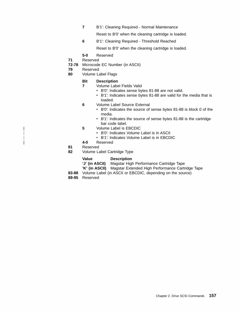
7 B'1': Cleaning Required - Normal Maintenance
Reset to B'0' when the cleaning cartridge is loaded.
6 B'1': Cleaning Required - Threshold Reached
Reset to B'0' when the cleaning cartridge is loaded.
5-0 Reserved71 Reserved72-78 Microcode EC Number (in ASCII)79 Reserved80 Volume Label Flags
Bit Description7 Volume Label Fields Valid
v B'0': Indicates sense bytes 81-88 are not valid.v B'1': Indicates sense bytes 81-88 are valid for the media that is
loaded.6 Volume Label Source External
v B'0': Indicates the source of sense bytes 81-88 is block 0 of themedia.
v B'1': Indicates the source of sense bytes 81-88 is the cartridgebar code label.
5 Volume Label is EBCDICv B'0': Indicates Volume Label is in ASCIIv B'1': Indicates Volume Label is in EBCDIC
4-0 Reserved81 Reserved82 Volume Label Cartridge Type
Value Description’J’ (in ASCII) Magstar High Performance Cartridge Tape’K’ (in ASCII) Magstar Extended High Performance Cartridge Tape
83-88 Volume Label (in ASCII or EBCDIC, depending on the source)89-95 Reserved
Chapter 2. Drive SCSI Commands 157
||||||

Reserve Unit - X‘16’The Reserve Unit command is supported by the 3590 drive. Table 43 shows thecommand format.
Table 43. Reserve Unit Command
BitByte
7MSB
6 5 4 3 2 1 0LSB
0 Operation code (X'16')
1 Logical Unit Number 3rdPty Third Party Device ID Reserved
2 Reserved
3 Reserved
4 Reserved
5 Vendor Specific (B'00') Reserved (B'0000') Flag Link
The following 3590-specific parameters apply:
v 3rdPty (Third Party): B'0'
v Third Party Device ID: B'000'
v See “Control Byte Definition” on page 9 for Flag and Link bit descriptions.
Note: Reserves are honored across initiator as well as port boundaries. Foradditional information, see “Multiple Port Behavior” on page 239.
158 Magstar 3590 Hardware Reference
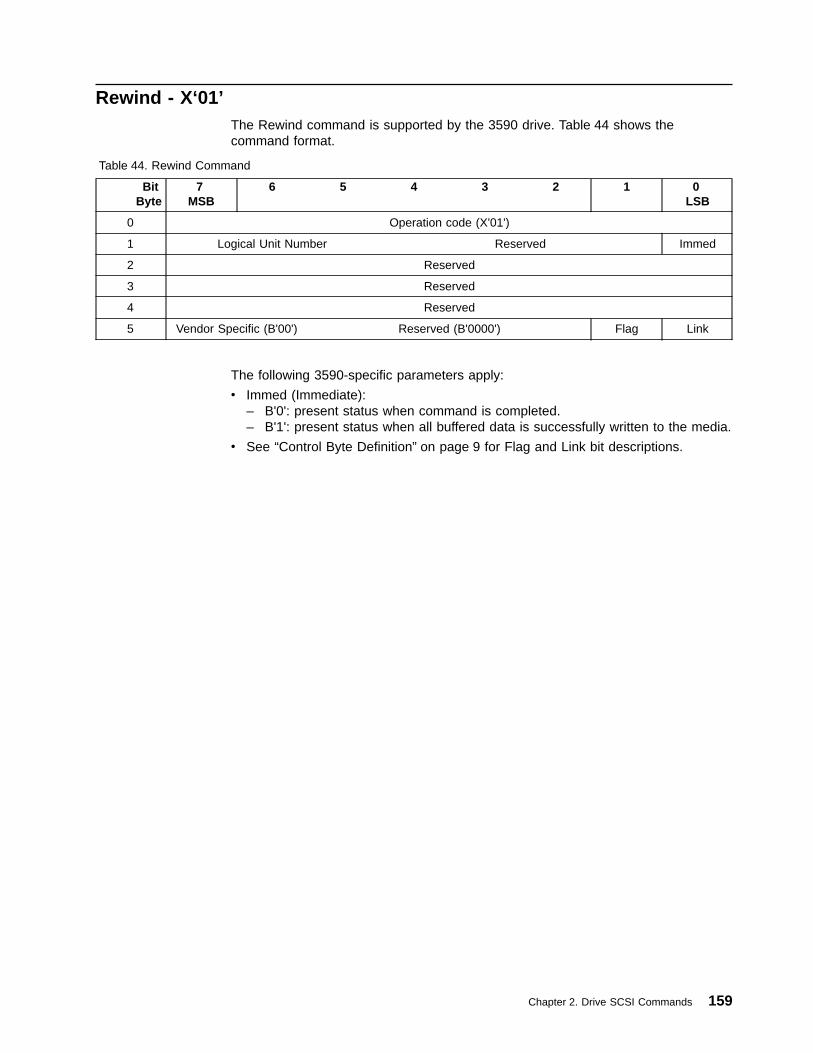
Rewind - X‘01’The Rewind command is supported by the 3590 drive. Table 44 shows thecommand format.
Table 44. Rewind Command
BitByte
7MSB
6 5 4 3 2 1 0LSB
0 Operation code (X'01')
1 Logical Unit Number Reserved Immed
2 Reserved
3 Reserved
4 Reserved
5 Vendor Specific (B'00') Reserved (B'0000') Flag Link
The following 3590-specific parameters apply:
v Immed (Immediate):– B'0': present status when command is completed.– B'1': present status when all buffered data is successfully written to the media.
v See “Control Byte Definition” on page 9 for Flag and Link bit descriptions.
Chapter 2. Drive SCSI Commands 159

Send Diagnostic - X‘1D’The Send Diagnostic command is supported by the 3590 drive. Send Diagnostic isused to execute the 3590 diagnostics and to perform special functions that wouldnormally only be available from the operator panel.
Note: For diagnostics that produce diagnostic results, the Receive DiagnosticResult command should be Linked to the Send Diagnostic command, or theLUN should be reserved. See the referenced SCSI-2 specification for details.
Table 45 shows the command format.
Table 45. Send Diagnostic Command
BitByte
7MSB
6 5 4 3 2 1 0LSB
0 Operation code (X'1D')
1 Logical Unit Number PF Reserved SelfTest DevOfl UnitOfl
2 Reserved
3Parameter List Length
4
5 Vendor Specific (B'00') Reserved (B'0000') Flag Link
The following 3590-specific parameters apply:
PF (Page Format)Set to B'1'.
SelfTestThe values can be the following:v B'0': perform the diagnostic operation specified in the parameter list.v B'1': perform self-test. See “Self-Test” on page 164 for details of this diagnostic.
Note: When Self-Test is requested, no other diagnostics may be simultaneouslyrequested.
DevOfL (Device Off Line)The values can be the following:v B'0' is supported and prohibits any diagnostic operations that may be detected by
subsequent I/O processes.v B'1' is supported and grants permission to the target to perform diagnostic
operations that may affect all the logical units on a target; that is, alteration ofreservations, log parameters, or sense data.
v B'x' in the diagnostic description indicates that either B'0' or B'1' may be usedwith identical effects.
Note: DevOfl and UnitOfl are set by the system. These bits grant permission to thetarget to perform vendor-specific diagnostic operations on the target that maybe visible to attached initiators. Thus, by preventing operations that are notenabled by these bits, the target assists the operating system in protectingits resources.
160 Magstar 3590 Hardware Reference

UnitOfL (Unit Off Line)The values can be the following:v B'0' is supported and prohibits any diagnostic operations that may be detected by
subsequent I/O processes.v B'1' is supported and grants permission to the target to perform diagnostic
operations that may affect the user medium on the logical unit; for example, writeoperations to the user-accessible medium, or operations that reposition themedium on sequential access devices.
v B'x' in the diagnostic description indicates that either B'0' or B'1' may be usedwith identical effects.
Parameter List LengthThis field specifies the length in bytes of the parameter list that is transferred fromthe initiator to the target.
A parameter list length value of zero specifies that no data is transferred. Thiscondition is not considered an error. If the specified parameter list length results intruncation of one or more pages (PF bit set to 1), the target returns CHECKCONDITION status with associated sense data of 5/2400 (Illegal Request, InvalidField in CDB).
Flag and LinkSee “Control Byte Definition” on page 9 for Flag and Link bit descriptions.
Chapter 2. Drive SCSI Commands 161
Diagnostic Page FormatsThe 3590 drive supports two diagnostic page formats: Page Code X'00' and PageCode X'80'.
Page Code X'00'The format for the Send Diagnostic command follows:
Byte Description
0 Page Code: X'00'
1 Reserved (X'00')
2-3 Page Length: X'0000'
Page Code X'80'Is a general purpose page for sending flags and diagnostic parameters to thetarget. The format for the Send Diagnostic command follows:
Byte Description
0 Page Code: X'80'
1 Reserved
2-3 Page Length (n-3)
4-5 Diagnostic ID
This field specifies the diagnostic that is to be run
6 Flags (Send Diagnostic command)
Bits Description7-1 Reserved0 Cartridge Required
Set to 1 when a cartridge is required for a diagnostic. When 1, acartridge must be loaded and ready for the Send Diagnosticcommand to be accepted. See specific diagnostic descriptions forcartridge use: some diagnostics require this bit to be set to 1, somerequire it to be set to 0, and some do not require a specific bitsetting.v B'0': No cartridge requiredv B'1': Cartridge required
7 Reserved
8-n Diagnostic Parameters
The Diagnostic Parameters field contains the parameters required to runthe diagnostic.
See “Magstar-Supported Diagnostics” for a list of diagnostic routines supported bythe 3590 drive.
Magstar-Supported DiagnosticsTable 46 on page 163 shows the diagnostic routines supported by the Magstardrive. These diagnostics reside in the device. (See “Send Diagnostic - X‘1D’” onpage 160 and “Receive Diagnostic Results - X‘1C’” on page 143 for additionalinformation on the commands.) Individual diagnostic descriptions follow Table 46 onpage 163.
162 Magstar 3590 Hardware Reference

Table 46. Supported Diagnostic Routines
Diagnostic Name Diagnostic ID See Page
Self-Test None 164
Change SCSI ID X'0001' 165
POST A Diagnostic X'0100' 167
POST B Diagnostic X'0101' 169
ACF Diagnostic X'0102' 171
Force Dump X'0160' 173
Write Dump to Cartridge X'0161' 174
Create FMR Cartridge X'0170' 176
Set Traps X'0190' 178
Remove Traps X'0191' 179
Set Drive Parameters X'2000' 180
Reset VSARS X'2001' 181
Reset Drive X'2002' 182
The Change SCSI ID and the ACF Diagnostics require the drive to have nocartridge loaded.
Chapter 2. Drive SCSI Commands 163
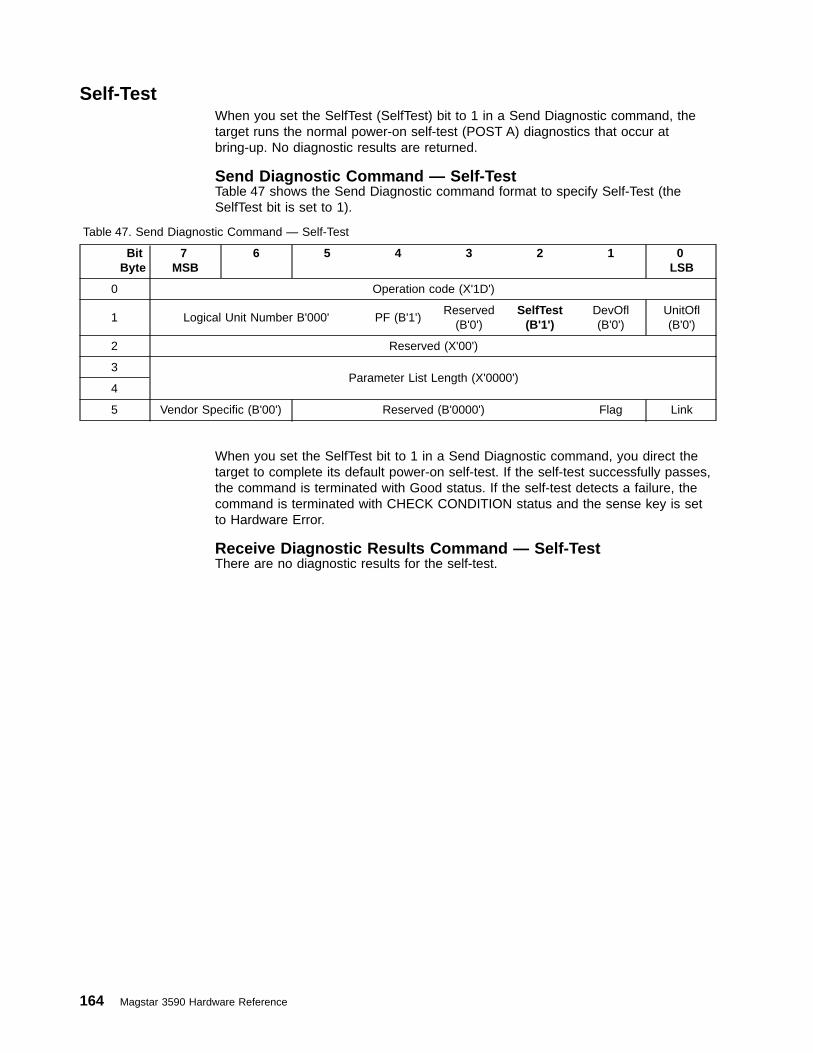
Self-TestWhen you set the SelfTest (SelfTest) bit to 1 in a Send Diagnostic command, thetarget runs the normal power-on self-test (POST A) diagnostics that occur atbring-up. No diagnostic results are returned.
Send Diagnostic Command — Self-TestTable 47 shows the Send Diagnostic command format to specify Self-Test (theSelfTest bit is set to 1).
Table 47. Send Diagnostic Command — Self-Test
BitByte
7MSB
6 5 4 3 2 1 0LSB
0 Operation code (X'1D')
1 Logical Unit Number B'000' PF (B'1')Reserved
(B'0')SelfTest
(B'1')DevOfl(B'0')
UnitOfl(B'0')
2 Reserved (X'00')
3Parameter List Length (X'0000')
4
5 Vendor Specific (B'00') Reserved (B'0000') Flag Link
When you set the SelfTest bit to 1 in a Send Diagnostic command, you direct thetarget to complete its default power-on self-test. If the self-test successfully passes,the command is terminated with Good status. If the self-test detects a failure, thecommand is terminated with CHECK CONDITION status and the sense key is setto Hardware Error.
Receive Diagnostic Results Command — Self-TestThere are no diagnostic results for the self-test.
164 Magstar 3590 Hardware Reference
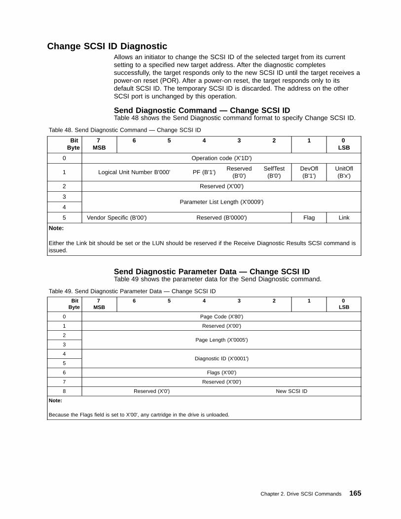
Change SCSI ID DiagnosticAllows an initiator to change the SCSI ID of the selected target from its currentsetting to a specified new target address. After the diagnostic completessuccessfully, the target responds only to the new SCSI ID until the target receives apower-on reset (POR). After a power-on reset, the target responds only to itsdefault SCSI ID. The temporary SCSI ID is discarded. The address on the otherSCSI port is unchanged by this operation.
Send Diagnostic Command — Change SCSI IDTable 48 shows the Send Diagnostic command format to specify Change SCSI ID.
Table 48. Send Diagnostic Command — Change SCSI ID
BitByte
7MSB
6 5 4 3 2 1 0LSB
0 Operation code (X'1D')
1 Logical Unit Number B'000' PF (B'1')Reserved
(B'0')SelfTest
(B'0')DevOfl(B'1')
UnitOfl(B'x')
2 Reserved (X'00')
3Parameter List Length (X'0009')
4
5 Vendor Specific (B'00') Reserved (B'0000') Flag Link
Note:
Either the Link bit should be set or the LUN should be reserved if the Receive Diagnostic Results SCSI command isissued.
Send Diagnostic Parameter Data — Change SCSI IDTable 49 shows the parameter data for the Send Diagnostic command.
Table 49. Send Diagnostic Parameter Data — Change SCSI ID
BitByte
7MSB
6 5 4 3 2 1 0LSB
0 Page Code (X'80')
1 Reserved (X'00')
2Page Length (X'0005')
3
4Diagnostic ID (X'0001')
5
6 Flags (X'00')
7 Reserved (X'00')
8 Reserved (X'0') New SCSI ID
Note:
Because the Flags field is set to X'00', any cartridge in the drive is unloaded.
Chapter 2. Drive SCSI Commands 165

Receive Diagnostic Results Command — Change SCSI IDThe initiator issues a Receive Diagnostic Results to the old SCSI ID, which returnsPage Code X'80' with the default SCSI ID, the new SCSI ID, and the Diagnostic ID.
The target SCSI ID is modified after the Receive Diagnostic Results command issuccessfully received. The default SCSI ID is unchanged by this process. Thechange of SCSI ID is only applicable to the SCSI port on which the diagnostic isperformed. Any reservations for all LUNs under the target are reset when the ID ischanged.
The target maintains the new SCSI ID until either a POR is received (at which timeit reverts to the default SCSI ID stored), or until it receives another Change SCSI IDdiagnostic command.
Table 50 shows the Receive Diagnostic Results command format for the ChangeSCSI ID diagnostic.
Table 50. Receive Diagnostic Results Command — Change SCSI ID
BitByte
7MSB
6 5 4 3 2 1 0LSB
0 Operation code (X'1C')
1 Logical Unit Number B'000' Reserved (B'00000')
2 Reserved (X'00')
3Allocation Length
4
5 Vendor Specific (B'00') Reserved (B'0000') Flag Link
Receive Diagnostic Results Data — Change SCSI IDTable 51 shows the diagnostic results data received from the Change SCSI IDdiagnostic.
Table 51. Receive Diagnostic Results Data — Change SCSI ID
BitByte
7MSB
6 5 4 3 2 1 0LSB
0 Page Code (X'80')
1 Reserved (X'00')
2Page Length (X'0006')
3
4Diagnostic ID (X'0001')
5
6 Flags (X'00')
7 Reserved (X'00')
8 Reserved (X'0') New SCSI ID
9 Reserved (X'0') Default SCSI ID
166 Magstar 3590 Hardware Reference
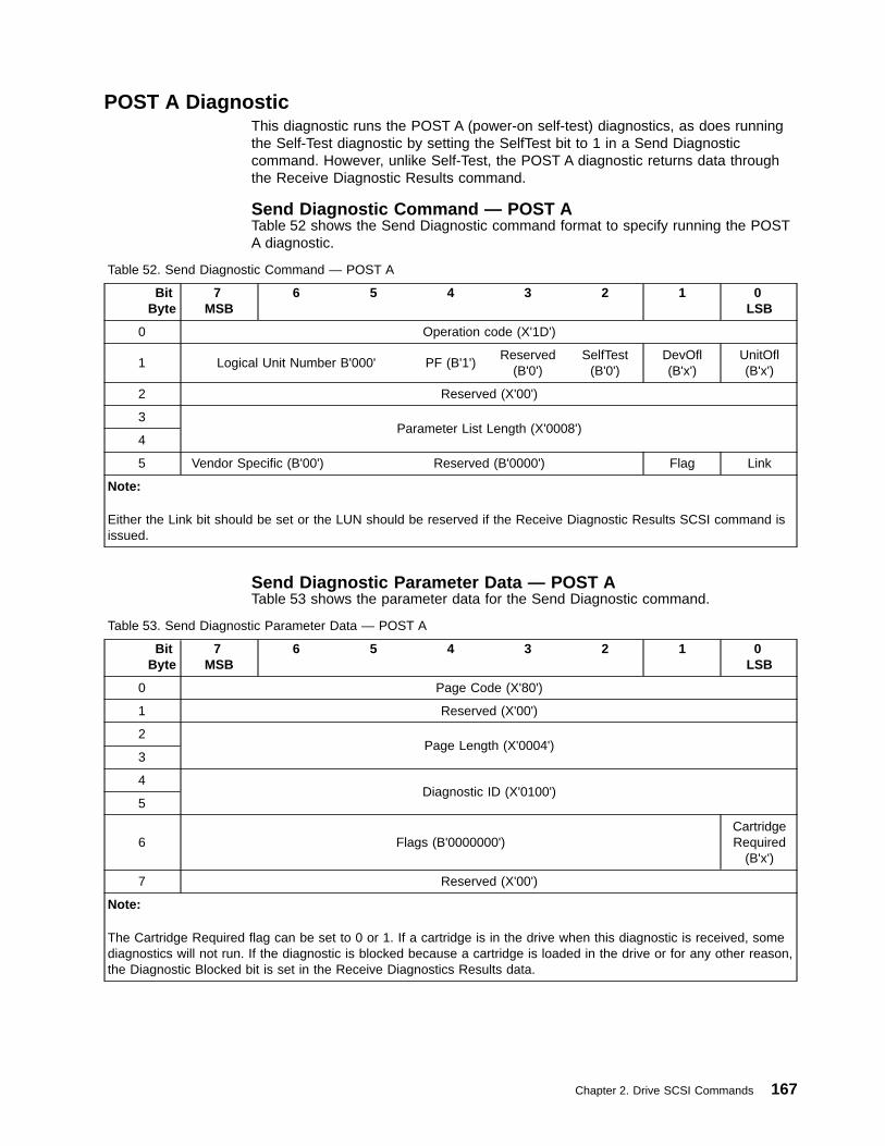
POST A DiagnosticThis diagnostic runs the POST A (power-on self-test) diagnostics, as does runningthe Self-Test diagnostic by setting the SelfTest bit to 1 in a Send Diagnosticcommand. However, unlike Self-Test, the POST A diagnostic returns data throughthe Receive Diagnostic Results command.
Send Diagnostic Command — POST ATable 52 shows the Send Diagnostic command format to specify running the POSTA diagnostic.
Table 52. Send Diagnostic Command — POST A
BitByte
7MSB
6 5 4 3 2 1 0LSB
0 Operation code (X'1D')
1 Logical Unit Number B'000' PF (B'1')Reserved
(B'0')SelfTest
(B'0')DevOfl(B'x')
UnitOfl(B'x')
2 Reserved (X'00')
3Parameter List Length (X'0008')
4
5 Vendor Specific (B'00') Reserved (B'0000') Flag Link
Note:
Either the Link bit should be set or the LUN should be reserved if the Receive Diagnostic Results SCSI command isissued.
Send Diagnostic Parameter Data — POST ATable 53 shows the parameter data for the Send Diagnostic command.
Table 53. Send Diagnostic Parameter Data — POST A
BitByte
7MSB
6 5 4 3 2 1 0LSB
0 Page Code (X'80')
1 Reserved (X'00')
2Page Length (X'0004')
3
4Diagnostic ID (X'0100')
5
6 Flags (B'0000000')CartridgeRequired
(B'x')
7 Reserved (X'00')
Note:
The Cartridge Required flag can be set to 0 or 1. If a cartridge is in the drive when this diagnostic is received, somediagnostics will not run. If the diagnostic is blocked because a cartridge is loaded in the drive or for any other reason,the Diagnostic Blocked bit is set in the Receive Diagnostics Results data.
Chapter 2. Drive SCSI Commands 167
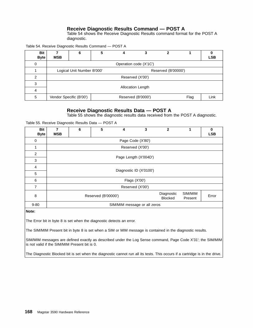
Receive Diagnostic Results Command — POST ATable 54 shows the Receive Diagnostic Results command format for the POST Adiagnostic.
Table 54. Receive Diagnostic Results Command — POST A
BitByte
7MSB
6 5 4 3 2 1 0LSB
0 Operation code (X'1C')
1 Logical Unit Number B'000' Reserved (B'00000')
2 Reserved (X'00')
3Allocation Length
4
5 Vendor Specific (B'00') Reserved (B'0000') Flag Link
Receive Diagnostic Results Data — POST ATable 55 shows the diagnostic results data received from the POST A diagnostic.
Table 55. Receive Diagnostic Results Data — POST A
BitByte
7MSB
6 5 4 3 2 1 0LSB
0 Page Code (X'80')
1 Reserved (X'00')
2Page Length (X'004D')
3
4Diagnostic ID (X'0100')
5
6 Flags (X'00')
7 Reserved (X'00')
8 Reserved (B'00000')DiagnosticBlocked
SIM/MIMPresent
Error
9-80 SIM/MIM message or all zeros
Note:
The Error bit in byte 8 is set when the diagnostic detects an error.
The SIM/MIM Present bit in byte 8 is set when a SIM or MIM message is contained in the diagnostic results.
SIM/MIM messages are defined exactly as described under the Log Sense command, Page Code X'31'; the SIM/MIMis not valid if the SIM/MIM Present bit is 0.
The Diagnostic Blocked bit is set when the diagnostic cannot run all its tests. This occurs if a cartridge is in the drive.
168 Magstar 3590 Hardware Reference

POST B DiagnosticThis diagnostic causes all of the 3590 drive read, write, and motion test diagnosticsto be executed. Thus, a cartridge is required to be loaded to run the diagnostic.
Send Diagnostic Command — POST BTable 56 shows the Send Diagnostic command format to specify running the POSTB diagnostic.
Table 56. Send Diagnostic Command — POST B
BitByte
7MSB
6 5 4 3 2 1 0LSB
0 Operation code (X'1D')
1 Logical Unit Number B'000' PF (B'1')Reserved
(B'0')SelfTest
(B'0')DevOfl(B'x')
UnitOfl(B'1')
2 Reserved (X'00')
3Parameter List Length (X'0008')
4
5 Vendor Specific (B'00') Reserved (B'0000') Flag Link
Note:
Either the Link bit should be set or the LUN should be reserved if the Receive Diagnostic Results SCSI command isissued.
Send Diagnostic Parameter Data — POST BTable 57 shows the parameter data for the Send Diagnostic command.
Table 57. Send Diagnostic Parameter Data — POST B
BitByte
7MSB
6 5 4 3 2 1 0LSB
0 Page Code (X'80')
1 Reserved (X'00')
2Page Length (X'0004')
3
4Diagnostic ID (X'0101')
5
6 Flags (B'0000000')CartridgeRequired
(B'1')
7 Reserved (X'00')
Note:
Because the Cartridge Required flag is set to 1, a cartridge must be loaded and ready before the diagnostic is run.
Chapter 2. Drive SCSI Commands 169
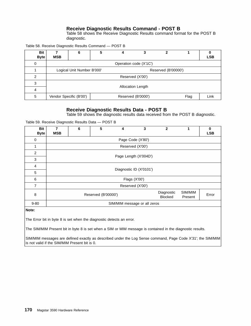
Receive Diagnostic Results Command - POST BTable 58 shows the Receive Diagnostic Results command format for the POST Bdiagnostic.
Table 58. Receive Diagnostic Results Command — POST B
BitByte
7MSB
6 5 4 3 2 1 0LSB
0 Operation code (X'1C')
1 Logical Unit Number B'000' Reserved (B'00000')
2 Reserved (X'00')
3Allocation Length
4
5 Vendor Specific (B'00') Reserved (B'0000') Flag Link
Receive Diagnostic Results Data - POST BTable 59 shows the diagnostic results data received from the POST B diagnostic.
Table 59. Receive Diagnostic Results Data — POST B
BitByte
7MSB
6 5 4 3 2 1 0LSB
0 Page Code (X'80')
1 Reserved (X'00')
2Page Length (X'004D')
3
4Diagnostic ID (X'0101')
5
6 Flags (X'00')
7 Reserved (X'00')
8 Reserved (B'00000')DiagnosticBlocked
SIM/MIMPresent
Error
9-80 SIM/MIM message or all zeros
Note:
The Error bit in byte 8 is set when the diagnostic detects an error.
The SIM/MIM Present bit in byte 8 is set when a SIM or MIM message is contained in the diagnostic results.
SIM/MIM messages are defined exactly as described under the Log Sense command, Page Code X'31'; the SIM/MIMis not valid if the SIM/MIM Present bit is 0.
170 Magstar 3590 Hardware Reference

ACF DiagnosticThis command causes all the ACF functions to be executed on ACF models,including the ACF/drive interface.
Send Diagnostic Command - ACFTable 60 shows the Send Diagnostic command format to specify running the ACFDiagnostic.
Table 60. Send Diagnostic Command — ACF
BitByte
7MSB
6 5 4 3 2 1 0LSB
0 Operation code (X'1D')
1 Logical Unit Number B'000' PF (B'1')Reserved
(B'0')SelfTest
(B'0')DevOfl(B'x')
UnitOfl(B'x')
2 Reserved (X'00')
3Parameter List Length (X'0008')
4
5 Vendor Specific (B'00') Reserved (B'0000') Flag Link
Note:
Either the Link bit should be set or the LUN should be reserved if the Receive Diagnostic Results SCSI command isissued.
Send Diagnostic Parameter Data - ACFTable 61 shows the parameter data for the Send Diagnostic command.
Table 61. Send Diagnostic Parameter Data — ACF
BitByte
7MSB
6 5 4 3 2 1 0LSB
0 Page Code (X'80')
1 Reserved (X'00')
2Page Length (X'0004')
3
4Diagnostic ID (X'0102')
5
6 Flags (B'0000000')CartridgeRequired
(B'0')
7 Reserved (X'00')
Note:
The Cartridge Required flag must be set to 0.
Chapter 2. Drive SCSI Commands 171

Receive Diagnostic Results Command - ACFTable 62 shows the Receive Diagnostic Results command format for the ACFDiagnostic.
Table 62. Receive Diagnostic Results Command — ACF
BitByte
7MSB
6 5 4 3 2 1 0LSB
0 Operation code (X'1C')
1 Logical Unit Number B'000' Reserved (B'00000')
2 Reserved (X'00')
3Allocation Length
4
5 Vendor Specific (B'00') Reserved (B'0000') Flag Link
Receive Diagnostic Results Data - ACFTable 63 shows the diagnostic results data received from the ACF Diagnostic.
Table 63. Receive Diagnostic Results Data - ACF
BitByte
7MSB
6 5 4 3 2 1 0LSB
0 Page Code (X'80')
1 Reserved (X'00')
2Page Length (X'004D')
3
4Diagnostic ID (X'0102')
5
6 Flags (X'00')
7 Reserved (X'00')
8 Reserved (B'000000')DiagnosticBlocked
SIM/MIMPresent
Error
9-80 SIM/MIM message or all zeros
Note:
The Error bit in byte 8 is set when the diagnostic detects an error.
The SIM/MIM Present bit in byte 8 is set when a SIM or MIM message is contained in the diagnostic results.
SIM/MIM messages are defined exactly as described under the Log Sense command, Page Code X'31'; the SIM/MIMis not valid if the SIM/MIM Present bit is 0.
172 Magstar 3590 Hardware Reference

Force Dump DiagnosticThis diagnostic forces a dump. The dump data is stored in 3590 drive controlstorage and can be read by the Read Buffer command (Buffer ID of X'00'). See“Read Buffer - X‘3C’” on page 134.
When a higher priority dump has been generated automatically by the drive but hasnot yet been read, the drive will ignore this Send Diagnostic command and returnGOOD status.
Send Diagnostic Command — Force DumpTable 64 shows the Send Diagnostic command format to specify Force Dump.
Table 64. Send Diagnostic Command — Force Dump
BitByte
7MSB
6 5 4 3 2 1 0LSB
0 Operation code (X'1D')
1 Logical Unit Number B'000' PF (B'1')Reserved
(B'0')SelfTest
(B'0')DevOfl(B'x')
UnitOfl(B'x')
2 Reserved (X'00')
3Parameter List Length (X'0008')
4
5 Vendor Specific (B'00') Reserved (B'0000') Flag Link
Send Diagnostic Parameter Data — Force DumpTable 65 shows the parameter data for the Send Diagnostic command.
Table 65. Send Diagnostic Parameter Data — Force Dump
BitByte
7MSB
6 5 4 3 2 1 0LSB
0 Page Code (X'80')
1 Reserved (X'00')
2Page Length (X'0004')
3
4Diagnostic ID (X'0160')
5
6 Flags (B'0000000')CartridgeRequired
(B'x')
7 Reserved (X'00')
Note:
The Cartridge Required flag can be set to 0 or 1.
Receive Diagnostic Results Command — Force DumpThere are no diagnostic results for this function.
Chapter 2. Drive SCSI Commands 173
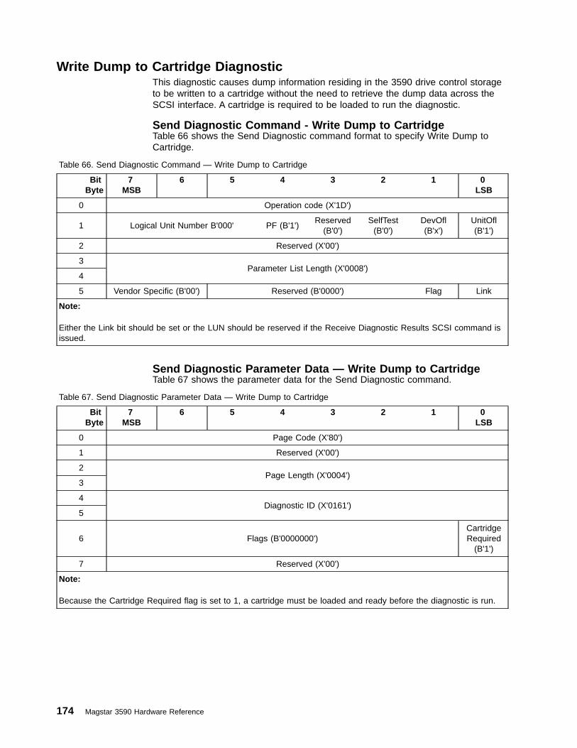
Write Dump to Cartridge DiagnosticThis diagnostic causes dump information residing in the 3590 drive control storageto be written to a cartridge without the need to retrieve the dump data across theSCSI interface. A cartridge is required to be loaded to run the diagnostic.
Send Diagnostic Command - Write Dump to CartridgeTable 66 shows the Send Diagnostic command format to specify Write Dump toCartridge.
Table 66. Send Diagnostic Command — Write Dump to Cartridge
BitByte
7MSB
6 5 4 3 2 1 0LSB
0 Operation code (X'1D')
1 Logical Unit Number B'000' PF (B'1')Reserved
(B'0')SelfTest
(B'0')DevOfl(B'x')
UnitOfl(B'1')
2 Reserved (X'00')
3Parameter List Length (X'0008')
4
5 Vendor Specific (B'00') Reserved (B'0000') Flag Link
Note:
Either the Link bit should be set or the LUN should be reserved if the Receive Diagnostic Results SCSI command isissued.
Send Diagnostic Parameter Data — Write Dump to CartridgeTable 67 shows the parameter data for the Send Diagnostic command.
Table 67. Send Diagnostic Parameter Data — Write Dump to Cartridge
BitByte
7MSB
6 5 4 3 2 1 0LSB
0 Page Code (X'80')
1 Reserved (X'00')
2Page Length (X'0004')
3
4Diagnostic ID (X'0161')
5
6 Flags (B'0000000')CartridgeRequired
(B'1')
7 Reserved (X'00')
Note:
Because the Cartridge Required flag is set to 1, a cartridge must be loaded and ready before the diagnostic is run.
174 Magstar 3590 Hardware Reference

Receive Diagnostic Results Command - Write Dump to CartridgeTable 68 shows the Receive Diagnostic Results command format for the WriteDump to Cartridge diagnostic.
Table 68. Receive Diagnostic Results Command — Write Dump to Cartridge
BitByte
7MSB
6 5 4 3 2 1 0LSB
0 Operation code (X'1C')
1 Logical Unit Number B'000' Reserved (B'00000')
2 Reserved (X'00')
3Allocation Length
4
5 Vendor Specific (B'00') Reserved (B'0000') Flag Link
Receive Diagnostic Results Data — Write Dump to CartridgeTable 69 shows the diagnostic results data received from the Write Dump toCartridge diagnostic.
Table 69. Receive Diagnostic Results Data — Write Dump to Cartridge
BitByte
7MSB
6 5 4 3 2 1 0LSB
0 Page Code (X'80')
1 Reserved (X'00')
2Page Length (X'004D')
3
4Diagnostic ID (X'0161')
5
6 Flags (X'00')
7 Reserved (X'00')
8 Reserved (B'00000')DiagnosticBlocked
SIM/MIMPresent
Error
9-80 SIM/MIM message or all zeros
Note:
The Error bit in byte 8 is set if an error occurs while writing the tape.
The SIM/MIM Present bit in byte 8 is set when a SIM or MIM message is contained in the diagnostic results.
SIM/MIM messages are defined exactly as described under the Log Sense command, Page Code X'31'; the SIM/MIMis not valid if the SIM/MIM Present bit is 0.
Chapter 2. Drive SCSI Commands 175
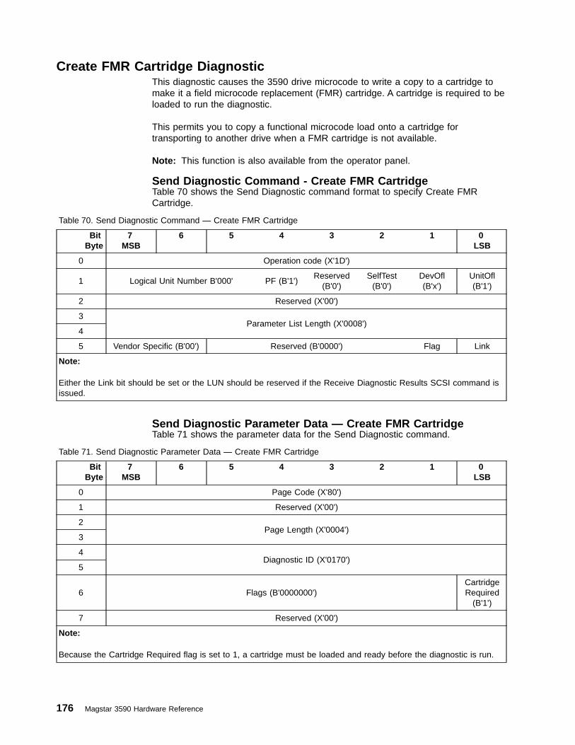
Create FMR Cartridge DiagnosticThis diagnostic causes the 3590 drive microcode to write a copy to a cartridge tomake it a field microcode replacement (FMR) cartridge. A cartridge is required to beloaded to run the diagnostic.
This permits you to copy a functional microcode load onto a cartridge fortransporting to another drive when a FMR cartridge is not available.
Note: This function is also available from the operator panel.
Send Diagnostic Command - Create FMR CartridgeTable 70 shows the Send Diagnostic command format to specify Create FMRCartridge.
Table 70. Send Diagnostic Command — Create FMR Cartridge
BitByte
7MSB
6 5 4 3 2 1 0LSB
0 Operation code (X'1D')
1 Logical Unit Number B'000' PF (B'1')Reserved
(B'0')SelfTest
(B'0')DevOfl(B'x')
UnitOfl(B'1')
2 Reserved (X'00')
3Parameter List Length (X'0008')
4
5 Vendor Specific (B'00') Reserved (B'0000') Flag Link
Note:
Either the Link bit should be set or the LUN should be reserved if the Receive Diagnostic Results SCSI command isissued.
Send Diagnostic Parameter Data — Create FMR CartridgeTable 71 shows the parameter data for the Send Diagnostic command.
Table 71. Send Diagnostic Parameter Data — Create FMR Cartridge
BitByte
7MSB
6 5 4 3 2 1 0LSB
0 Page Code (X'80')
1 Reserved (X'00')
2Page Length (X'0004')
3
4Diagnostic ID (X'0170')
5
6 Flags (B'0000000')CartridgeRequired
(B'1')
7 Reserved (X'00')
Note:
Because the Cartridge Required flag is set to 1, a cartridge must be loaded and ready before the diagnostic is run.
176 Magstar 3590 Hardware Reference

Receive Diagnostic Results Command - Create FMR CartridgeTable 72 shows the Receive Diagnostic Results command format for the CreateFMR Cartridge diagnostic.
Table 72. Receive Diagnostic Results Command — Create FMR Cartridge
BitByte
7MSB
6 5 4 3 2 1 0LSB
0 Operation code (X'1C')
1 Logical Unit Number B'000' Reserved (B'00000')
2 Reserved (X'00')
3Allocation Length
4
5 Vendor Specific (B'00') Reserved (B'0000') Flag Link
Receive Diagnostic Results Data - Create FMR CartridgeTable 73 shows the diagnostic results data received from the Create FMR Cartridgediagnostic.
Table 73. Receive Diagnostic Results Data — Create FMR Cartridge
BitByte
7MSB
6 5 4 3 2 1 0LSB
0 Page Code (X'80')
1 Reserved (X'00')
2Page Length (X'004D')
3
4Diagnostic ID (X'0170')
5
6 Flags (X'00')
7 Reserved (X'00')
8 Reserved (B'000000')DiagnosticBlocked
SIM/MIMPresent
Error
9-80 SIM/MIM message or all zeros
Note:
The Error bit in byte 8 is set if an error occurs while creating the FMR cartridge.
The SIM/MIM Present bit in byte 8 is set when a SIM or MIM message is contained in the diagnostic results.
SIM/MIM messages are defined exactly as described under the Log Sense command, Page Code X'31'; the SIM/MIMis not valid if the SIM/MIM Present bit is 0.
Chapter 2. Drive SCSI Commands 177
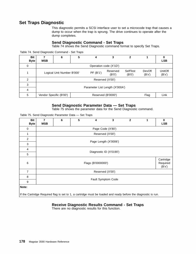
Set Traps DiagnosticThis diagnostic permits a SCSI interface user to set a microcode trap that causes adump to occur when the trap is sprung. The drive continues to operate after thedump completes.
Send Diagnostic Command - Set TrapsTable 74 shows the Send Diagnostic command format to specify Set Traps.
Table 74. Send Diagnostic Command - Set Traps
BitByte
7MSB
6 5 4 3 2 1 0LSB
0 Operation code (X'1D')
1 Logical Unit Number B'000' PF (B'1')Reserved
(B'0')SelfTest
(B'0')DevOfl(B'x')
UnitOfl(B'x')
2 Reserved (X'00')
3Parameter List Length (X'000A')
4
5 Vendor Specific (B'00') Reserved (B'0000') Flag Link
Send Diagnostic Parameter Data — Set TrapsTable 75 shows the parameter data for the Send Diagnostic command.
Table 75. Send Diagnostic Parameter Data — Set Traps
BitByte
7MSB
6 5 4 3 2 1 0LSB
0 Page Code (X'80')
1 Reserved (X'00')
2Page Length (X'0006')
3
4Diagnostic ID (X'0190')
5
6 Flags (B'0000000')CartridgeRequired
(B'x')
7 Reserved (X'00')
8Fault Symptom Code
9
Note:
If the Cartridge Required flag is set to 1, a cartridge must be loaded and ready before the diagnostic is run.
Receive Diagnostic Results Command - Set TrapsThere are no diagnostic results for this function.
178 Magstar 3590 Hardware Reference

Remove Traps DiagnosticThis diagnostic permits a SCSI interface user to remove a microcode trap that wasset either via the operator panel or the SCSI Set Traps Diagnostic.
Send Diagnostic Command - Remove TrapsTable 76 shows the Send Diagnostic command format to specify Remove Traps.
Table 76. Send Diagnostic Command - Remove Traps
BitByte
7MSB
6 5 4 3 2 1 0LSB
0 Operation code (X'1D')
1 Logical Unit Number B'000' PF (B'1')Reserved
(B'0')SelfTest
(B'0')DevOfl(B'x')
UnitOfl(B'x')
2 Reserved (X'00')
3Parameter List Length (X'000A')
4
5 Vendor Specific (B'00') Reserved (B'0000') Flag Link
Send Diagnostic Parameter Data Remove TrapsTable 77 shows the parameter data for the Send Diagnostic command.
Table 77. Send Diagnostic Parameter Data — Remove Traps
BitByte
7MSB
6 5 4 3 2 1 0LSB
0 Page Code (X'80')
1 Reserved (X'00')
2Page Length (X'0006')
3
4Diagnostic ID (X'0191')
5
6 Flags (B'0000000')CartridgeRequired
(B'x')
7 Reserved (X'00')
8Fault Symptom Code
9
Note:
If the Cartridge Required flag is set to 1, a cartridge must be loaded and ready before the diagnostic is run.
Receive Diagnostic Results Command - Remove TrapsThere are no diagnostic results for this function.
Chapter 2. Drive SCSI Commands 179
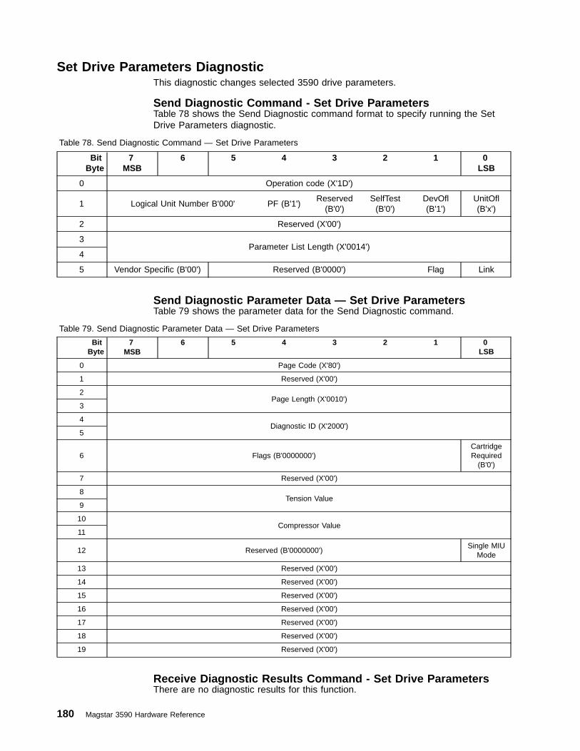
Set Drive Parameters DiagnosticThis diagnostic changes selected 3590 drive parameters.
Send Diagnostic Command - Set Drive ParametersTable 78 shows the Send Diagnostic command format to specify running the SetDrive Parameters diagnostic.
Table 78. Send Diagnostic Command — Set Drive Parameters
BitByte
7MSB
6 5 4 3 2 1 0LSB
0 Operation code (X'1D')
1 Logical Unit Number B'000' PF (B'1')Reserved
(B'0')SelfTest
(B'0')DevOfl(B'1')
UnitOfl(B'x')
2 Reserved (X'00')
3Parameter List Length (X'0014')
4
5 Vendor Specific (B'00') Reserved (B'0000') Flag Link
Send Diagnostic Parameter Data — Set Drive ParametersTable 79 shows the parameter data for the Send Diagnostic command.
Table 79. Send Diagnostic Parameter Data — Set Drive Parameters
BitByte
7MSB
6 5 4 3 2 1 0LSB
0 Page Code (X'80')
1 Reserved (X'00')
2Page Length (X'0010')
3
4Diagnostic ID (X'2000')
5
6 Flags (B'0000000')CartridgeRequired
(B'0')
7 Reserved (X'00')
8Tension Value
9
10Compressor Value
11
12 Reserved (B'0000000')Single MIU
Mode
13 Reserved (X'00')
14 Reserved (X'00')
15 Reserved (X'00')
16 Reserved (X'00')
17 Reserved (X'00')
18 Reserved (X'00')
19 Reserved (X'00')
Receive Diagnostic Results Command - Set Drive ParametersThere are no diagnostic results for this function.
180 Magstar 3590 Hardware Reference
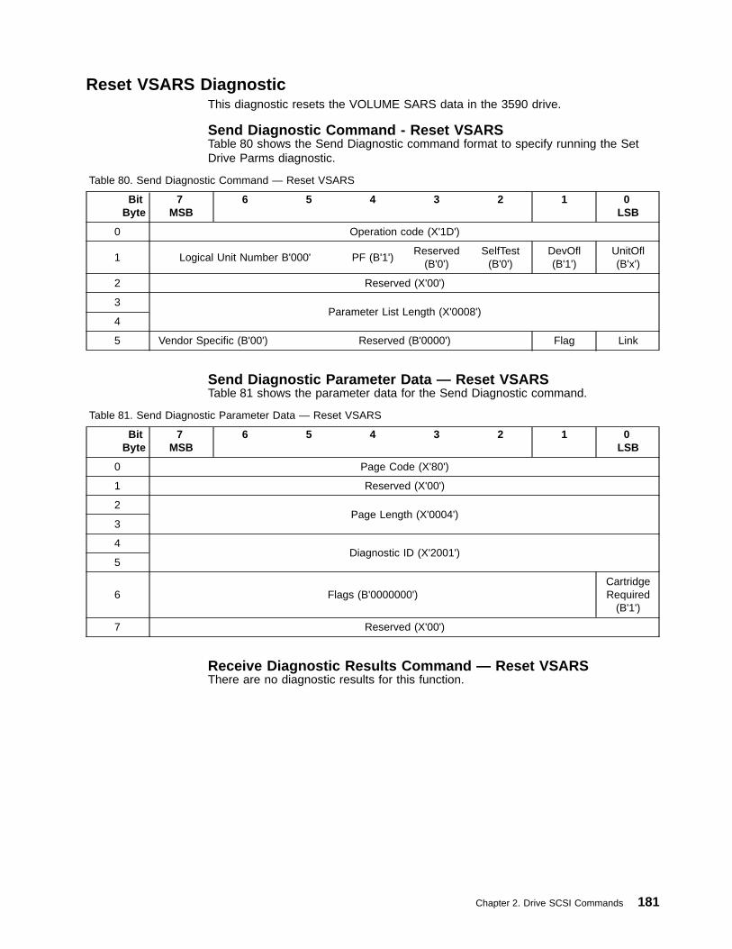
Reset VSARS DiagnosticThis diagnostic resets the VOLUME SARS data in the 3590 drive.
Send Diagnostic Command - Reset VSARSTable 80 shows the Send Diagnostic command format to specify running the SetDrive Parms diagnostic.
Table 80. Send Diagnostic Command — Reset VSARS
BitByte
7MSB
6 5 4 3 2 1 0LSB
0 Operation code (X'1D')
1 Logical Unit Number B'000' PF (B'1')Reserved
(B'0')SelfTest
(B'0')DevOfl(B'1')
UnitOfl(B'x')
2 Reserved (X'00')
3Parameter List Length (X'0008')
4
5 Vendor Specific (B'00') Reserved (B'0000') Flag Link
Send Diagnostic Parameter Data — Reset VSARSTable 81 shows the parameter data for the Send Diagnostic command.
Table 81. Send Diagnostic Parameter Data — Reset VSARS
BitByte
7MSB
6 5 4 3 2 1 0LSB
0 Page Code (X'80')
1 Reserved (X'00')
2Page Length (X'0004')
3
4Diagnostic ID (X'2001')
5
6 Flags (B'0000000')CartridgeRequired
(B'1')
7 Reserved (X'00')
Receive Diagnostic Results Command — Reset VSARSThere are no diagnostic results for this function.
Chapter 2. Drive SCSI Commands 181
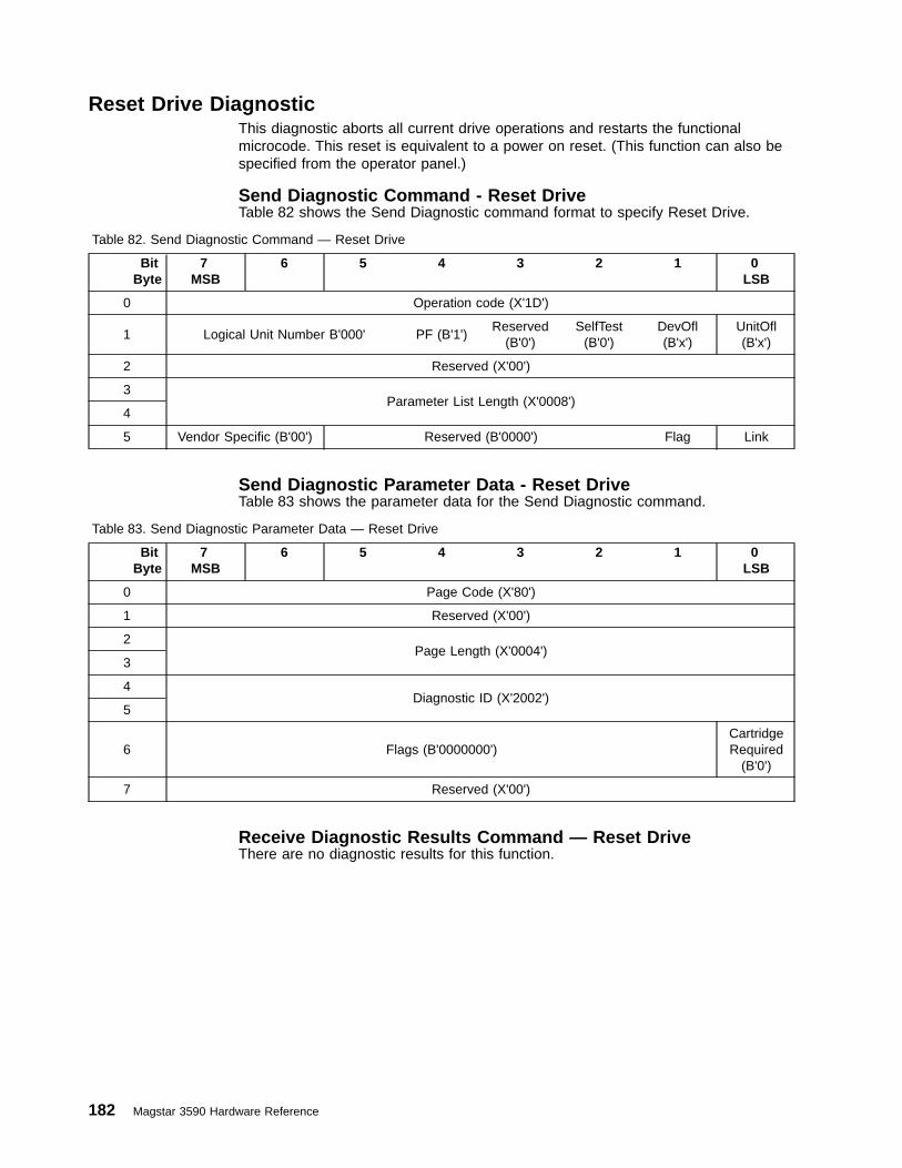
Reset Drive DiagnosticThis diagnostic aborts all current drive operations and restarts the functionalmicrocode. This reset is equivalent to a power on reset. (This function can also bespecified from the operator panel.)
Send Diagnostic Command - Reset DriveTable 82 shows the Send Diagnostic command format to specify Reset Drive.
Table 82. Send Diagnostic Command — Reset Drive
BitByte
7MSB
6 5 4 3 2 1 0LSB
0 Operation code (X'1D')
1 Logical Unit Number B'000' PF (B'1')Reserved
(B'0')SelfTest
(B'0')DevOfl(B'x')
UnitOfl(B'x')
2 Reserved (X'00')
3Parameter List Length (X'0008')
4
5 Vendor Specific (B'00') Reserved (B'0000') Flag Link
Send Diagnostic Parameter Data - Reset DriveTable 83 shows the parameter data for the Send Diagnostic command.
Table 83. Send Diagnostic Parameter Data — Reset Drive
BitByte
7MSB
6 5 4 3 2 1 0LSB
0 Page Code (X'80')
1 Reserved (X'00')
2Page Length (X'0004')
3
4Diagnostic ID (X'2002')
5
6 Flags (B'0000000')CartridgeRequired
(B'0')
7 Reserved (X'00')
Receive Diagnostic Results Command — Reset DriveThere are no diagnostic results for this function.
182 Magstar 3590 Hardware Reference

Space - X‘11’The Space command is supported by the 3590 drive. With the 3590 mediumformat, this command is implemented similar to the Locate command, causing thetape to move at high speed when appropriate (5 m/s). Table 84 shows thecommand format.
Table 84. Space Command
BitByte
7MSB
6 5 4 3 2 1 0LSB
0 Operation code (X'11')
1 Logical Unit Number Reserved Code
2
Count3
4
5 Vendor Specific (B'00') Reserved (B'0000') Flag Link
The following 3590-specific parameters apply:
v Code
The following codes are supported:– B'000' Blocks– B'001' Filemarks– B'010' Sequential Filemarks– B'011' End of Data
v Count
When spacing over blocks or filemarks, the count field specifies the number ofblocks or filemarks to be spaced over in the current partition. A positive value Nin the count field causes forward positioning (toward End of Partition) over Nblocks or filemarks ending on the End of Partition side of the last block orfilemark. A zero value in the count field causes no change of logical position. Anegative value -N (two’s complement notation) in the count field causes reversepositioning (toward Beginning Of Partition) over N blocks or filemarks ending onthe Beginning of Partition side of the last block or filemark.
v See “Control Byte Definition” on page 9 for Flag and Link bit descriptions.
If the drive encounters End-of-Data (EOD) while executing this command, thecommand is terminated at the EOD position and CHECK CONDITION status isreturned with associated sense data of 8/0005 (Blank Check, End-of-DataDetected). If the next motion command is another request to move forward (beyondEOD), the drive accepts the command and attempts to position beyond EOD inorder to allow recovery of old data.
B-Series models cannot read or space on an E-Format tape. If such an attempt ismade, CHECK CONDITION status is returned and Associated sense data is set to3/3002 (Medium Error, Cannot Read Medium - Incompatible Format).
Chapter 2. Drive SCSI Commands 183

Test Unit Ready - X‘00’The Test Unit Ready command is supported by the 3590 drive. Table 85 shows thecommand format.
Table 85. Test Unit Ready Command
BitByte
7MSB
6 5 4 3 2 1 0LSB
0 Operation code (X'00')
1 Logical Unit Number Reserved
2 Reserved EDCC
3 Reserved
4 Reserved
5 Vendor Specific (B'00') Reserved (B'0000') Flag Link
The following 3590-specific parameters apply:
v EDCC (Enable Deferred CHECK CONDITION):– B'0': Deferred CHECK CONDITION status is not to be reported for this
command.– B'1': Deferred CHECK CONDITION status may be reported for this command.
v See “Control Byte Definition” on page 9 for Flag and Link bit descriptions.
184 Magstar 3590 Hardware Reference

Write - X‘0A’The Write command is supported by the 3590 drive. Table 86 shows the commandformat.
Table 86. Write Command
BitByte
7MSB
6 5 4 3 2 1 0LSB
0 Operation code (X'0A')
1 Logical Unit Number Reserved Fixed
2
Transfer Length3
4
5 Vendor Specific (B'00') Reserved (B'0000') Flag Link
The following 3590-specific parameters apply:
v The Fixed option of the Write command is supported. See also “Data Transfer,Block Limits, and Fixed Block Option” on page 241.
v Transfer Length: value from X'000000' (zero bytes) to X'200000' (2,097,152bytes). A Transfer Length of X'000000' indicates that no data is transferred. Thiscondition is not considered an error and the logical position is not changed.
v See “Control Byte Definition” on page 9 for Flag and Link bit descriptions.
Note: A tape may only be one format at a time. 3590 B-Series models write usingB-Format (density code X'29') and E-Series models write using E-Format(density code X'2A'). At Beginning Of Tape, any tape previously written inone format can be changed to another format when a Write command isissued. If an attempt is made by an E-series model to write a B-Format tapeat any other location away from Beginning of Tape. CHECK CONDITIONstatus is returned with associated sense data of 5/3005 (Illegal Request,Cannot Write Medium - Incompatible Format). Since a B-Series modelcannot read an E-Format tape, this condition cannot happen on a B-Seriesmodel.
Chapter 2. Drive SCSI Commands 185

Write Buffer - X‘3B’The Write Buffer command is supported, but not all buffers are described in thisdocument because most buffers are intended only to be written by the servicerepresentative or by manufacturing. OEM customers who intend to support hostmicrocode download on a new platform should contact IBM for a completedescription of the Write Buffer command for this purpose. Note that new microcodemay also be loaded without requiring the use of the SCSI Write Buffer command, byusing the Field Microcode Replacement (FMR tape) process described in themaintenance information manual for this product. See “Magstar Drive Buffers” onpage 135 for a list of the buffers supported by the drive. Table 87 shows thecommand format.
Table 87. Write Buffer Command
BitByte
7MSB
6 5 4 3 2 1 0LSB
0 Operation code (X'3B')
1 Logical Unit Number Reserved Mode
2 Buffer ID
3
Buffer Offset4
5
6
Parameter List Length7
8
9 Vendor Specific (B'00') Reserved (B'0000') Flag Link
The following 3590-specific parameters apply:
v Modes:
– Mode 1 (Vendor Unique) is supported.
– Mode 5 (Download Microcode and Save) is supported.
– Mode 6 (Download Microcode With Offsets) is supported
– Mode 7 (Download Microcode With Offsets and Save) is supported.
v Buffer ID: The buffers supported in the 3590 drive are described in Table 34 onpage 135.
v Buffer Offset: The 3590 drive defines the buffer offset field to be the address ofthe first location to be written by the current Write Buffer command, for bothmode 1 and mode 5 of this command.
v Parameter List Length field: The number of bytes to be transferred for both mode1 and mode 5.
v See “Control Byte Definition” on page 9 for Flag and Link bit descriptions.
186 Magstar 3590 Hardware Reference

Write Filemarks - X‘10’The Write Filemarks command is supported by the 3590 drive. Table 88 shows thecommand format.
Table 88. Write Filemarks Command
BitByte
7MSB
6 5 4 3 2 1 0LSB
0 Operation code (X'10')
1 Logical Unit Number Reserved WSmk Immed
2
Transfer Length3
4
5 Vendor Specific (B'00') Reserved (B'0000') Flag Link
The following 3590-specific parameters apply:
v The WSmk (Write Setmark): B'0'
v Immed (Immediate):– B'0': present status when command is completed.– B'1': present status when command is verified.
v Transfer Length:
Because the WSmk is set to B'0', the field indicates the number of filemarks tobe written.
v See “Control Byte Definition” on page 9 for Flag and Link bit descriptions.
After any buffered write operation completes, the initiator can issue a WriteFilemarks command with the Immed bit set to B'0' and the Transfer Length set toX'000000' to ensure that all buffered data and filemarks are successfully written tothe medium (synchronized).
Note: A tape may only be one format at a time. 3590 B-Series models write usingB-Format (density code X'29') and E-Series models write using E-Format(density code X'2A'). At Beginning Of Tape, any tape written in one formatcan be changed to another format when a Write Filemarks command isissued. If an attempt is made by an E-series model to write a B-Format tapeat any other location away from Beginning of Tape. CHECK CONDITIONstatus is returned with associated sense data of 5/3005 (Illegal Request,Cannot Write Medium — Incompatible Format). Since a B-Series modelcannot read an E-Format tape, this condition cannot happen on a B-Seriesmodel.
Chapter 2. Drive SCSI Commands 187

188 Magstar 3590 Hardware Reference
Chapter 3. ACF SCSI Commands
This chapter describes the SCSI commands supported for the 3590 ACF whenaddressed as an Independent Medium Changer device at LUN 1 (2-LUNaddressing).
“Chapter 2. Drive SCSI Commands” on page 5 describes the SCSI commandssupported for the 3590 drive (LUN 0). Those commands include support for the3590 ACF when addressed as an Attached Medium Changer device at LUN 0(1-LUN addressing).
Note: Attached Medium Changer (1-LUN addressing) is the default operatingdefinition for all ACF modes of operation except Random 2-LUN (see“Change Definition -X‘40’” on page 10).
The following SCSI command descriptions have a table describing the fields in theCommand Descriptor Block (CDB), similar to the style used in the ANSI SmallComputer System Interface-2 standard. The descriptions following each CDBspecify the options, values, and ranges for the fields described in the CDB assupported by the 3590 ACF. See section 7.2 in the American National StandardInstitute Small Computer System Interface X3T9.2⁄86-109 Revision 10hX3T39⁄89-042 standard for a description of the CDB and its fields.
© Copyright IBM Corp. 1996, 2000 189

ACF SCSI Commands Listed AlphabeticallyTable 89 provides a list of all commands defined by the referenced SCSI-2 standardfor medium changer devices. For each command, the operation code, referencepage for this specification, applicable SCSI-2 standard section, type of supportrequired for the command as defined by the SCSI standard, and applicability ofcertain conditions to the command are shown.
Table 89. 3590 ACF Commands (LUN 1)
Command Name Operation Code See Page SCSIDocument
Applicable Conditions:
RVC¹UAT NRD WRP MFC DCC
Change Definition X'40' NS SPC Y Y - - - -
Exchange Medium X'A6' NS SMC Y Y Y - - Y
Initialize Element Status X'07' 192 SPC Y Y Y - - Y
Inquiry X'12' 193 SPC - - - - - -
Log Select X'4C' NS SPC Y Y - - - -
Log Sense X'4D' 196 SPC Y - - - - -
Mode Select (6) X'15' 197 SPC Y Y - - - -
Mode Select (10) X'55' 198 SPC Y Y - - - -
Mode Sense (6) X'1A' 199 SPC - Y - - - -
Mode Sense (10) X'5A' 200 SPC - Y - - - -
Move Medium X'A5' 126 SMC Y Y Y - - Y
Position to Element X'2B' 203 SMC Y Y Y - - Y
Prevent Allow Medium Removal X'1E' NS SPC Y Y - - - -
Read Buffer X'3C' NS SPC Y - - - - -
Read Element Status X'B8' 137 SMC - Y Y - - -
Receive Diagnostic Results X'1C' 213 SPC Y Y - - - -
Release Element (6) X'17' 214 SMC -² Y - - - -
Request Sense X'03' 151 SPC - - - - - -
Request Volume Element Address X'B5' NS SMC Y Y - - - Y
Reserve Element (6) X'16' 216 SMC Y³ Y - - - -
Rezero Unit X'01' NS SMC Y Y - - - -
Send Diagnostic X'1D' 217 SPC Y Y - - - -
Send Volume Tag X'B6' NS SMC Y Y - - - Y
Test Unit Ready X'00' 184 SPC Y Y Y - - Y⁴
Write Buffer X'3B' NS SPC Y Y - - - -
190 Magstar 3590 Hardware Reference

Table 89. 3590 ACF Commands (LUN 1) (continued)
Command Name Operation Code See Page SCSIDocument
Applicable Conditions:
RVC¹UAT NRD WRP MFC DCC
Legend:
M Mandatory RVC Reservation Conflict statusO Optional UAT CHECK CONDITION status for Unit Attention- Not Applicable NRD CHECK CONDITION status for Not ReadyNS Not Supported WRP CHECK CONDITION status for Write Protected
MFC CHECK CONDITION status for Medium Format CorruptedDCC Deferred CHECK CONDITIONY Yes (Condition Applies)Yn Yes (Condition applies per note n below)
Notes:
1. If an I/O process consists of linked commands and begins with a command which is not subject to the RVC condition,subsequent commands in the I/O process are subject to Reservation Conflict status if the command is subject to the RVCcondition and a reservation conflict exists.
2. Performs no operation if logical unit is reserved to another initiator.
3. Condition applies if logical unit is reserved to another initiator.
4. Reporting of deferred CHECK CONDITION status for the Test Unit Ready command is optional based on a vendor-unique fieldin the CDB.
Chapter 3. ACF SCSI Commands 191

Initialize Element Status - X‘07’Table 90. Initialize Element Status Command
BitByte
7MSB
6 5 4 3 2 1 0LSB
0 Operation code (X'07')
1 Logical Unit Number Reserved
2 Reserved
3 Reserved
4 Reserved
5 Control
The Initialize Element Status command is allowed and ignored for the 3590 ACF.The Read Element Status command will always cause the ACF to check allelements for media present and for any other status relevant to that element.
192 Magstar 3590 Hardware Reference

Inquiry - X‘12’The Inquiry command supported by the ACF (LUN 1) is the same as the Inquirycommand supported by the drive (LUN 0).
The Inquiry data returned by the ACF is different from the drive. There are severalforms of Inquiry data. The following are supported and described in more detail asfollows: There are several forms of Inquiry data. The following are supported anddescribed in more detail as follows:
v B-Series and E-Series Models:
– “Inquiry Standard Data: Valid LUN (Logical Unit Number)” on page 16
– “Inquiry Standard Data: Invalid LUN” on page 19
– “Inquiry Page X‘00’”
– “Inquiry Page X‘03’: ASCII Information” on page 22
– “Inquiry Page X‘80’: Unit Serial Number” on page 194
– “Inquiry Page X‘83’: Device Identification” on page 194
v E-Series Models Only:
– “Inquiry Page X'D0'” (the contents of this page are not specified in thisdocument)
Refer to “Inquiry -X‘12’” on page 16 for a description of the Inquiry command.
Inquiry Page X‘00’The following 3590-specific parameters apply to this request:
v EVPD (Enable Vital Product Data): B'1'
v Page Code: X'00'
v Allocation Length: X'09' bytes available
v See “Control Byte Definition” on page 9 for Flag and Link bit descriptions.
For a LUN that is associated with an installed device (see “SCSI-ID and LUNAssignments” on page 239), the following data is returned:
Byte Description
0 Peripheral Data
Bit Description7-5 Peripheral Qualifier: B'000'4-0 Peripheral Device Type: X'08'
1 Page Code: X'00'
2 Reserved
3 Page Length (n-3): X'05'
4 Supported Page: X'00'
5 Supported Page: X'03'
6 Supported Page: X'80'
7 Supported Page: X'83'
8 Supported Page: X'D0'
Chapter 3. ACF SCSI Commands 193
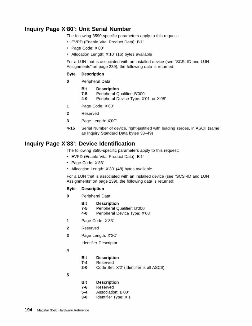
Inquiry Page X‘80’: Unit Serial NumberThe following 3590-specific parameters apply to this request:
v EVPD (Enable Vital Product Data): B'1'
v Page Code: X'80'
v Allocation Length: X'10' (16) bytes available
For a LUN that is associated with an installed device (see “SCSI-ID and LUNAssignments” on page 239), the following data is returned:
Byte Description
0 Peripheral Data
Bit Description7-5 Peripheral Qualifier: B'000'4-0 Peripheral Device Type: X'01' or X'08'
1 Page Code: X'80'
2 Reserved
3 Page Length: X'0C'
4-15 Serial Number of device, right-justified with leading zeroes, in ASCII (sameas Inquiry Standard Data bytes 38–49)
Inquiry Page X‘83’: Device IdentificationThe following 3590-specific parameters apply to this request:
v EVPD (Enable Vital Product Data): B'1'
v Page Code: X'83'
v Allocation Length: X'30' (48) bytes available
For a LUN that is associated with an installed device (see “SCSI-ID and LUNAssignments” on page 239), the following data is returned:
Byte Description
0 Peripheral Data
Bit Description7-5 Peripheral Qualifier: B'000'4-0 Peripheral Device Type: X'08'
1 Page Code: X'83'
2 Reserved
3 Page Length: X'2C'
Identifier Descriptor
4
Bit Description7-4 Reserved3-0 Code Set: X'2' (Identifier is all ASCII)
5
Bit Description7-6 Reserved5-4 Association: B'00'3-0 Identifier Type: X'1'
194 Magstar 3590 Hardware Reference

6 Reserved
7 Identifier Length: X'28'
8-15 Vendor ID (same as Inquiry Standard Data bytes 8–15)
16-31 Device Type and Model Number (same as Inquiry Standard Data bytes16–31)
32-43 Serial Number of device, right justified with leading zeroes, in ASCII (sameas Inquiry Standard Data bytes 38–49)
44-47 First Storage Element Address (ASCII representation of 4 hexidecimal digitsfrom Mode Page X'ID' bytes 6–7)
Bytes 48-59 are returned only on Fibre Channel attached devices.
48
Bit Description
7-4 Reserved
3-0 Code Set: X'1'
49
Bit Description
7-6 Reserved
5-4 Association Type: B'00'
3-0 Identifier Type: X'3'
50 Reserved
51 Identifier Length: X'08'
52
Bit Description
7-4 Name Format: B'0101'
3-0 OUI Format Identifier
53-54 OUI Format Identifier (continued)
55
Bit Description
7-4 OUI Format Identifier (continued)
3-0 Vendor Specified Identifier
56 Vendor Specified Identifier (continued)
57
Bit Description
7-6 Port/Node ID: B'11'
5-0 Serial Number
58-59 Serial Number (continued)
Chapter 3. ACF SCSI Commands 195
|
|
||
||
||
|
||
||
||
||
||
||
|
||
||
||
||
|
||
||
||
||
|
||
||
||
||
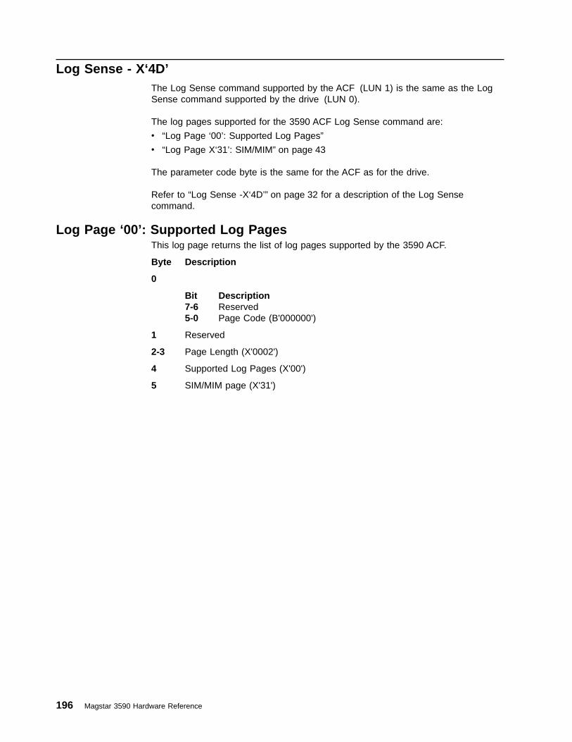
Log Sense - X‘4D’The Log Sense command supported by the ACF (LUN 1) is the same as the LogSense command supported by the drive (LUN 0).
The log pages supported for the 3590 ACF Log Sense command are:
v “Log Page ‘00’: Supported Log Pages”
v “Log Page X‘31’: SIM/MIM” on page 43
The parameter code byte is the same for the ACF as for the drive.
Refer to “Log Sense -X‘4D’” on page 32 for a description of the Log Sensecommand.
Log Page ‘00’: Supported Log PagesThis log page returns the list of log pages supported by the 3590 ACF.
Byte Description
0
Bit Description7-6 Reserved5-0 Page Code (B'000000')
1 Reserved
2-3 Page Length (X'0002')
4 Supported Log Pages (X'00')
5 SIM/MIM page (X'31')
196 Magstar 3590 Hardware Reference

Mode Select (6) - X‘15’The Mode Select (6) command supported by the ACF (LUN 1) is the same as theMode Select (6) command supported by the drive (LUN 0).
The mode pages supported by the 3590 ACF are:
v “Mode Page X‘0A’: Control Mode” on page 96
v “Mode Page X‘1D’: Element Address Assignment” on page 106
v “Mode Page X‘1E’: Transport Geometry Parameters” on page 107
v “Mode Page X‘1F’: Device Capabilities” on page 108
v “Mode Page X‘20’: ACF (Loader) Control” on page 110
Refer to “Mode Select (6) - X‘15’” on page 74 for a description of the Mode Select(6) command.
Mode Parameter Header for Mode Select (6)The Mode Pages for the Mode Select (6) command are preceded by a four byteMode Parameter Header.
There is one copy of this header for each initiator.
Byte Description
0 Mode Data Length: X'00'
This field is reserved when used with the Mode Select (6) command. (Whenused with the Mode Sense commands, this field specifies the length inbytes of the following data that is available to be transferred. The lengthfield does not include itself.)
1 Medium Type: X'00'
This field is reserved on Medium Changer Devices.
2 Device-Specific Parameter: X'00'
This field is reserved on Medium Changer Devices.
3 Block Descriptor Length: X'00'
Block descriptors are not used on the 3590 ACF.
Chapter 3. ACF SCSI Commands 197

Mode Select (10) - X‘55’The Mode Select (10) command supported by the ACF (LUN 1) is the same as theMode Select (10) command supported by the drive (LUN 0).
The mode pages supported by the 3590 ACF are:
v “Mode Page X‘0A’: Control Mode” on page 96
v “Mode Page X‘1D’: Element Address Assignment” on page 106
v “Mode Page X‘1E’: Transport Geometry Parameters” on page 107
v “Mode Page X‘1F’: Device Capabilities” on page 108
v “Mode Page X‘20’: ACF (Loader) Control” on page 110
Refer to “Mode Select (10) - X‘55’” on page 79 for a description of the Mode Select(10) command.
Mode Parameter Header for Mode Select (10)The Mode Pages for the Mode Select (10) command are preceded by an eight-byteMode Parameter Header.
There is one copy of this header for each initiator.
Byte Description
0-1 Mode Data Length: X'0000'
This field is reserved when used with the Mode Select (10) command.(When used with the Mode Sense commands, this field specifies the lengthin bytes of the following data that is available to be transferred. The lengthfield does not include itself.)
2 Medium Type: X'00'
This field is reserved on Medium Changer Devices.
3 Device-Specific Parameter: X'00'
This field is reserved on Medium Changer Devices.
4-5 Reserved
6-7 Block Descriptor Length: X'0000'
Block descriptors are not used on the 3590 ACF.
198 Magstar 3590 Hardware Reference

Mode Sense (6) - X‘1A’The Mode Sense (6) command supported by the ACF (LUN 1) is the same as theMode Sense (6) command supported by the drive (LUN 0).
The mode pages supported by the 3590 ACF are:
v “Mode Page X‘0A’: Control Mode” on page 96
v “Mode Page X‘1D’: Element Address Assignment” on page 106
v “Mode Page X‘1E’: Transport Geometry Parameters” on page 107
v “Mode Page X‘1F’: Device Capabilities” on page 108
v “Mode Page X‘20’: ACF (Loader) Control” on page 110
Refer to “Mode Sense (6) - X‘1A’” on page 83 for a description of the Mode Select(6) command.
Mode Parameter Header for Mode Sense (6)The Mode Pages for the Mode Sense (6) command are preceded by a four byteMode Parameter Header.
There is one copy of this header for each initiator.
Byte Description
0 Mode Data Length:
When used with the Mode Sense commands, this field specifies the lengthin bytes of the following data that is available to be transferred. The lengthfield does not include itself. (This field is reserved when used with the ModeSelect (6) command.)
1 Medium Type: X'00'
This field is reserved on Medium Changer Devices.
2 Device-Specific Parameter: X'00'
This field is reserved on Medium Changer Devices.
3 Block Descriptor Length: X'00'
Block descriptors are not used on the 3590 ACF.
Chapter 3. ACF SCSI Commands 199
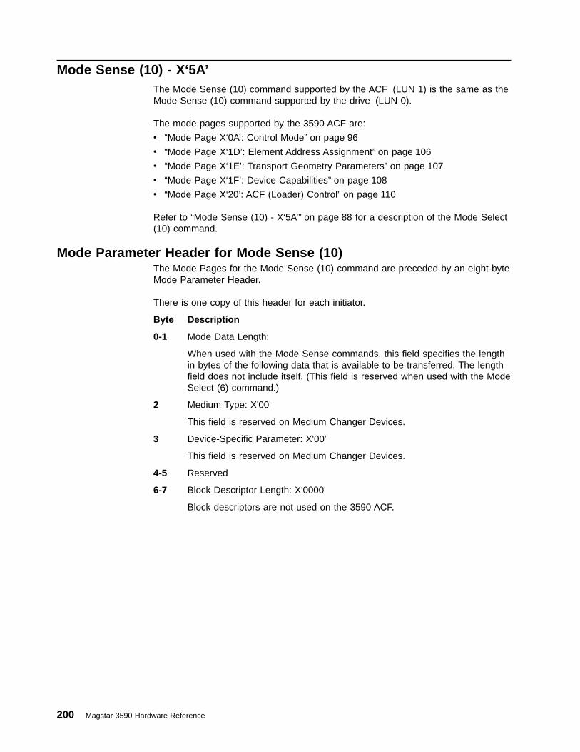
Mode Sense (10) - X‘5A’The Mode Sense (10) command supported by the ACF (LUN 1) is the same as theMode Sense (10) command supported by the drive (LUN 0).
The mode pages supported by the 3590 ACF are:
v “Mode Page X‘0A’: Control Mode” on page 96
v “Mode Page X‘1D’: Element Address Assignment” on page 106
v “Mode Page X‘1E’: Transport Geometry Parameters” on page 107
v “Mode Page X‘1F’: Device Capabilities” on page 108
v “Mode Page X‘20’: ACF (Loader) Control” on page 110
Refer to “Mode Sense (10) - X‘5A’” on page 88 for a description of the Mode Select(10) command.
Mode Parameter Header for Mode Sense (10)The Mode Pages for the Mode Sense (10) command are preceded by an eight-byteMode Parameter Header.
There is one copy of this header for each initiator.
Byte Description
0-1 Mode Data Length:
When used with the Mode Sense commands, this field specifies the lengthin bytes of the following data that is available to be transferred. The lengthfield does not include itself. (This field is reserved when used with the ModeSelect (6) command.)
2 Medium Type: X'00'
This field is reserved on Medium Changer Devices.
3 Device-Specific Parameter: X'00'
This field is reserved on Medium Changer Devices.
4-5 Reserved
6-7 Block Descriptor Length: X'0000'
Block descriptors are not used on the 3590 ACF.
200 Magstar 3590 Hardware Reference

Mode Page Format“Mode Page Format” on page 92 shows the format of the mode parameter list. Theindividual mode page descriptions that follow this table include the fielddescriptions.
Chapter 3. ACF SCSI Commands 201

Move Medium -X‘A5’The Move Medium Command is supported by LUN 0 of the drive only on B-Seriesmodels and then only when operating as an Attached Medium Changer.
The Move Medium command supported by the drive (LUN 0) is the same as theMove Medium command supported by the ACF (LUN 1).
Table 91 shows the command format.
Table 91. Move Medium Command
BitByte
7MSB
6 5 4 3 2 1 0LSB
0 Operation code (X'A5')
1 Logical Unit Number Reserved
2Transport Element Address
3
4Source Address
5
6Destination Address
7
8 Reserved
9 Reserved
10 Reserved Invert
11 Vendor Specific (B'00') Reserved (B'0000') Flag Link
The following 3590-specific parameters apply:
v Transport Element Address: X'0000' (Or X'0001', which instructs the ACF tochoose the Medium Transport. Because there is only one, either address getsthe same results.)
v Source Addresses:– Data Transfer Element (device) — X'0010'– Import Export Element (Priority Cell) — X'001F'– Storage Elements (Magazine cells — top to bottom) - X'(0020-0029)'
v Destination Addresses:– Data Transfer Element (device) — X'0010'– Import Export Element (Priority Cell) — X'001F'– Storage Elements (Magazine cells — top to bottom) - X'(0020-0029)'
Note: The Medium Transport Element (element address X'0000') is not capableof storing a media element. If this element address is specified as aSource or Destination Address in a Move Medium command, thecommand is presented CHECK CONDITION status with associated sensedata of 5/2101 (Illegal Request, Invalid Element Address).
v Invert: B'0'
v See “Control Byte Definition” on page 9 for Flag and Link bit descriptions.
For additional information on element addresses and descriptions, see “Mode PageX‘1D’: Element Address Assignment” on page 106, “Mode Page X‘1F’: DeviceCapabilities” on page 108, and “Read Element Status - X‘B8’” on page 137.
202 Magstar 3590 Hardware Reference
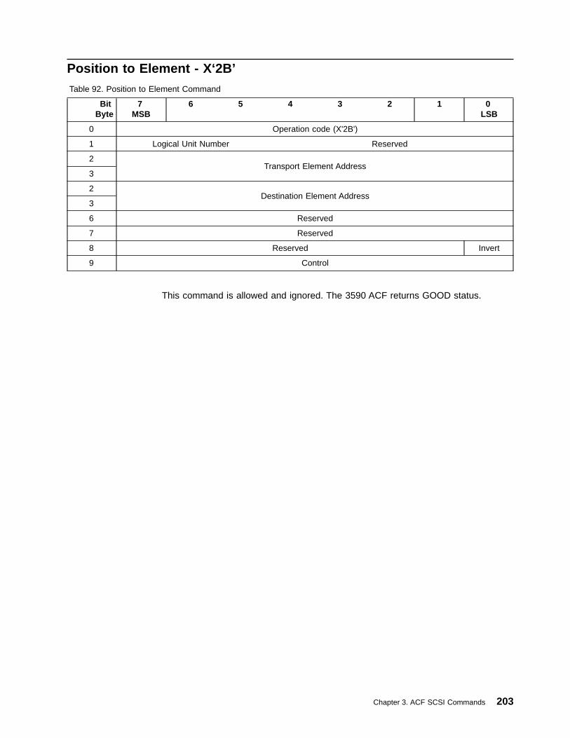
Position to Element - X‘2B’Table 92. Position to Element Command
BitByte
7MSB
6 5 4 3 2 1 0LSB
0 Operation code (X'2B')
1 Logical Unit Number Reserved
2Transport Element Address
3
2Destination Element Address
3
6 Reserved
7 Reserved
8 Reserved Invert
9 Control
This command is allowed and ignored. The 3590 ACF returns GOOD status.
Chapter 3. ACF SCSI Commands 203

Read Element Status - X‘B8’The Read Element Status Command is supported by LUN 0 of the drive only onB-Series models and then only when operating as an Attached Medium Changer.
The Read Element Status command supported by the drive (LUN 0) is the same asthe Read Element Status command supported by the ACF (LUN 1).
The Read Element Status command is supported by LUN 0 of the 3590 drive whenoperating as an Attached Medium Changer.
This command is only accepted by 3590 ACF models when the ACF is in Randomor Random 2-LUN mode. If this command is received while the ACF is not inRandom or Random 2-LUN mode, the device will return CHECK CONDITIONstatus with the associated sense data of 2/0403 (Not Ready, Logical Unit NotReady - Manual Intervention Required). Table 93 shows the command format.
Table 93. Read Element Status Command
BitByte
7MSB
6 5 4 3 2 1 0LSB
0 Operation code (X'B8')
1 Logical Unit Number VolTag Element Type Code
2Starting Element Address
3
4Number of Elements
5
6 Reserved CURDATA DVCID
7
Allocation Length8
9
10 Reserved
11 Vendor Specific (B'00') Reserved (B'0000') Flag Link
The following 3590-specific parameters apply:
v VolTag (Volume Tags): B'0'
The VolTag field is not supported by the 3590 device.
v DVCID
– B'0': Requests the library to report status for the element(s) indicated in theElement Type Code field.
– B'1': Requests the library to report device identifiers, if available, for the DataTransfer Elements.
v CURDATA
– B'0': Motion is allowed as needed in order to return a maximum set of validelement status data.
– B'1': Motion is not allowed — a minimum set of valid data may be returned.This field is supported for SCSI-3 compliance, but it is not required to be setto B'1' in order to obtain the Device IDs for the Data Transfer Elements. Allother data will be returned as invalid with an ASC/ASCQ in each elementdescriptor set to 81/00 (Status is Questionable).
204 Magstar 3590 Hardware Reference

v Element Type Code:
Value DescriptionX'0' Report all element typesX'1' Report Medium Transport Elements onlyX'2' Report Storage Elements onlyX'3' Report Import/Export Elements onlyX'4' Report Data Transfer Elements only
v Starting Element Address is the minimum element address to report.
v Number of Elements is the maximum number of elements to be included in thisreport.
v Allocation Length is the maximum number of bytes of data to be returned for thisreport.
v See “Control Byte Definition” on page 9 for Flag and Link bit descriptions.
Element Status DataThis data is a header that precedes the specific element type information, if any.Following this data are zero or more Element Status Pages, up to one for each ofthe four Element Types supported, if the command permits. Following each ElementStatus Page are zero or more Element Descriptors, up to one Element Descriptorfor each element cell of that element type in the ACF, again if the data in the CDBpermits.
Byte Description
0-1 First Element Address Reported:
The smallest element address found to meet the CDB request. For the3590 ACF, the lowest value is X'0000' and the highest value is X'0029'.
2-3 Number of Elements
The number of elements meeting the request in the CDB. For the 3590ACF, the lowest value is X'0000' and the highest value is X'000D'.
4 Reserved
5-7 Byte Count of Report Available
Element Status PageThere is one status page for each of the element types to be reported.
Byte Description
0 Element Type Code
Indicates the element type reported by this page. (The Element Type Codesallowed for the Element Status Page are 1, 2, 3, and 4; 0 is allowed for theCDB only.)
1 Tag Byte
Bit Description7 PVolTag (Primary Volume Tag): B'0'
The 3590 device does not support PVolTag.6 AVolTag (Alternate Volume Tag): B'0'
The 3590 device does not support AVolTag.5-0 Reserved
2-3 Element Descriptor Length: X'000C'
Chapter 3. ACF SCSI Commands 205

The length of each type of Element Descriptors. For the 3590 device, theElement Descriptor Length is the same for all four element types.
4 Reserved
5-7 Byte Count of Descriptor Data Available
The number of bytes of element descriptor data available for elements ofthis element type meeting the request in the CDB.
206 Magstar 3590 Hardware Reference
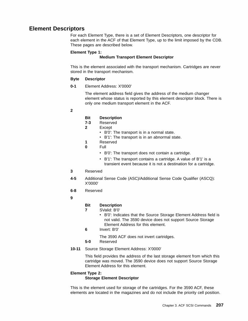
Element DescriptorsFor each Element Type, there is a set of Element Descriptors, one descriptor foreach element in the ACF of that Element Type, up to the limit imposed by the CDB.These pages are described below.
Element Type 1:Medium Transport Element Descriptor
This is the element associated with the transport mechanism. Cartridges are neverstored in the transport mechanism.
Byte Descriptor
0-1 Element Address: X'0000'
The element address field gives the address of the medium changerelement whose status is reported by this element descriptor block. There isonly one medium transport element in the ACF.
2
Bit Description7-3 Reserved2 Except
v B'0': The transport is in a normal state.v B'1': The transport is in an abnormal state.
1 Reserved0 Full
v B'0': The transport does not contain a cartridge.
v B'1': The transport contains a cartridge. A value of B'1' is atransient event because it is not a destination for a cartridge.
3 Reserved
4-5 Additional Sense Code (ASC)/Additional Sense Code Qualifier (ASCQ):X'0000'
6-8 Reserved
9
Bit Description7 SValid: B'0'
v B'0': Indicates that the Source Storage Element Address field isnot valid. The 3590 device does not support Source StorageElement Address for this element.
6 Invert: B'0'
The 3590 ACF does not invert cartridges.5-0 Reserved
10-11 Source Storage Element Address: X'0000'
This field provides the address of the last storage element from which thiscartridge was moved. The 3590 device does not support Source StorageElement Address for this element.
Element Type 2:Storage Element Descriptor
This is the element used for storage of the cartridges. For the 3590 ACF, theseelements are located in the magazines and do not include the priority cell position.
Chapter 3. ACF SCSI Commands 207
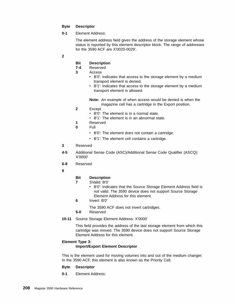
Byte Descriptor
0-1 Element Address:
The element address field gives the address of the storage element whosestatus is reported by this element descriptor block. The range of addressesfor the 3590 ACF are X'0020-0029'.
2
Bit Description7-4 Reserved3 Access
v B'0': Indicates that access to the storage element by a mediumtransport element is denied.
v B'1': Indicates that access to the storage element by a mediumtransport element is allowed.
Note: An example of when access would be denied is when themagazine cell has a cartridge in the Export position.
2 Exceptv B'0': The element is in a normal state.v B'1': The element is in an abnormal state.
1 Reserved0 Full
v B'0': The element does not contain a cartridge.
v B'1': The element cell contains a cartridge.
3 Reserved
4-5 Additional Sense Code (ASC)/Additional Sense Code Qualifier (ASCQ):X'0000'
6-8 Reserved
9
Bit Description7 SValid: B'0'
v B'0': Indicates that the Source Storage Element Address field isnot valid. The 3590 device does not support Source StorageElement Address for this element.
6 Invert: B'0'
The 3590 ACF does not invert cartridges.5-0 Reserved
10-11 Source Storage Element Address: X'0000'
This field provides the address of the last storage element from which thiscartridge was moved. The 3590 device does not support Source StorageElement Address for this element.
Element Type 3:Import/Export Element Descriptor
This is the element used for moving volumes into and out of the medium changer.In the 3590 ACF, this element is also known as the Priority Cell.
Byte Descriptor
0-1 Element Address:
208 Magstar 3590 Hardware Reference
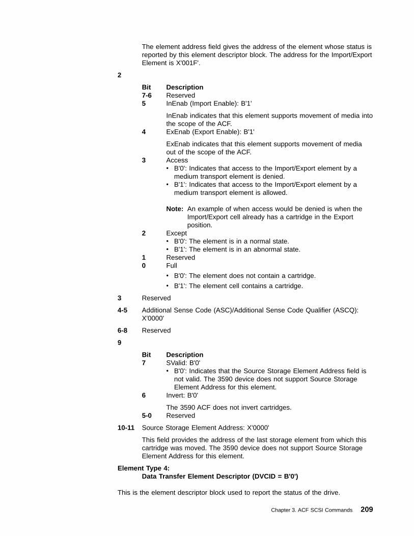
The element address field gives the address of the element whose status isreported by this element descriptor block. The address for the Import/ExportElement is X'001F'.
2
Bit Description7-6 Reserved5 InEnab (Import Enable): B'1'
InEnab indicates that this element supports movement of media intothe scope of the ACF.
4 ExEnab (Export Enable): B'1'
ExEnab indicates that this element supports movement of mediaout of the scope of the ACF.
3 Accessv B'0': Indicates that access to the Import/Export element by a
medium transport element is denied.v B'1': Indicates that access to the Import/Export element by a
medium transport element is allowed.
Note: An example of when access would be denied is when theImport/Export cell already has a cartridge in the Exportposition.
2 Exceptv B'0': The element is in a normal state.v B'1': The element is in an abnormal state.
1 Reserved0 Full
v B'0': The element does not contain a cartridge.
v B'1': The element cell contains a cartridge.
3 Reserved
4-5 Additional Sense Code (ASC)/Additional Sense Code Qualifier (ASCQ):X'0000'
6-8 Reserved
9
Bit Description7 SValid: B'0'
v B'0': Indicates that the Source Storage Element Address field isnot valid. The 3590 device does not support Source StorageElement Address for this element.
6 Invert: B'0'
The 3590 ACF does not invert cartridges.5-0 Reserved
10-11 Source Storage Element Address: X'0000'
This field provides the address of the last storage element from which thiscartridge was moved. The 3590 device does not support Source StorageElement Address for this element.
Element Type 4:Data Transfer Element Descriptor (DVCID = B'0')
This is the element descriptor block used to report the status of the drive.
Chapter 3. ACF SCSI Commands 209

Byte Descriptor
0-1 Element Address:
The element address field gives the address of the element whose status isreported by this element descriptor block. The address for the Data TransferElement is X'0010'.
2
Bit Description7-4 Reserved3 Access
v B'0': Indicates that access to the Data Transfer element by amedium transport element is denied.
v B'1': Indicates that access to the Data Transfer element by amedium transport element is allowed.
2 Exceptv B'0': The element is in a normal state.v B'1': The element is in an abnormal state.
1 Reserved0 Full
v B'0': The element does not contain a cartridge.
v B'1': The element contains a cartridge in a loaded or ejectedposition.
Note: A cartridge in the loaded position is indicated by the Full bitset to B'1' and the Access bit set to B'0'. A cartridge in theejected position is indicated by the Full bit set to B'1' and theAccess bit set to B'1'.
3 Reserved
4-5 Additional Sense Code (ASC)/Additional Sense Code Qualifier (ASCQ):X'0000'
6
Bit Description7 Not Bus (Not this Bus): B'0'
Indicates that the SCSI address and LU values are on the samebus as the medium changer device.
6 Reserved5 ID Valid: B'1'
ID Valid indicates that the SCSI bus address field contains validinformation.
4 LU Valid: B'1'
Logical Unit Valid indicates that the Logical Unit Number fieldcontains valid information.
3 Reserved2-0 Logical Unit Number: B'000'
The LUN is always zero.
7 SCSI bus address
Set to the SCSI ID of the drive.
8 Reserved
210 Magstar 3590 Hardware Reference
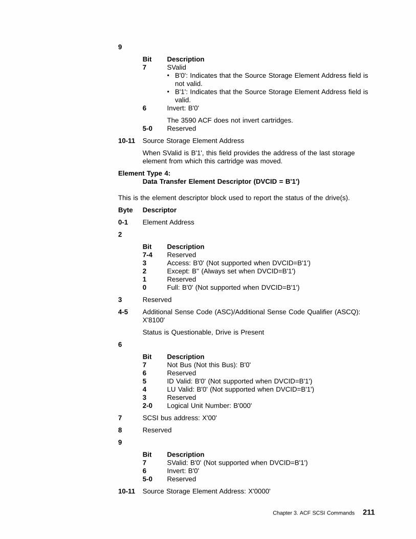
9
Bit Description7 SValid
v B'0': Indicates that the Source Storage Element Address field isnot valid.
v B'1': Indicates that the Source Storage Element Address field isvalid.
6 Invert: B'0'
The 3590 ACF does not invert cartridges.5-0 Reserved
10-11 Source Storage Element Address
When SValid is B'1', this field provides the address of the last storageelement from which this cartridge was moved.
Element Type 4:Data Transfer Element Descriptor (DVCID = B'1')
This is the element descriptor block used to report the status of the drive(s).
Byte Descriptor
0-1 Element Address
2
Bit Description7-4 Reserved3 Access: B'0' (Not supported when DVCID=B'1')2 Except: B'' (Always set when DVCID=B'1')1 Reserved0 Full: B'0' (Not supported when DVCID=B'1')
3 Reserved
4-5 Additional Sense Code (ASC)/Additional Sense Code Qualifier (ASCQ):X'8100'
Status is Questionable, Drive is Present
6
Bit Description7 Not Bus (Not this Bus): B'0'6 Reserved5 ID Valid: B'0' (Not supported when DVCID=B'1')4 LU Valid: B'0' (Not supported when DVCID=B'1')3 Reserved2-0 Logical Unit Number: B'000'
7 SCSI bus address: X'00'
8 Reserved
9
Bit Description7 SValid: B'0' (Not supported when DVCID=B'1')6 Invert: B'0'5-0 Reserved
10-11 Source Storage Element Address: X'0000'
Chapter 3. ACF SCSI Commands 211

Identification Descriptor (same as Drive Inquiry Page X'83', bytes 4–43)
12
Bit Description7-4 Reserved3-0 Code Set: X'2' (Identifier is all ASCII)
13
Bit Description7-6 Reserved5-4 Association: B'00'3-0 Identifier Type: X'1'
14 Reserved
15 Length of Device Identifier: X'24'
16-23 Vendor ID
24-39 Device Type and Model Number
40-51 Serial Number of device, right justified with leading zeroes, in ASCII
212 Magstar 3590 Hardware Reference
Receive Diagnostic Results - X‘1C’The Receive Diagnostic Results command supported by the ACF (LUN 1) is thesame as the Receive Diagnostic Results command supported by the drive (LUN 0).
The only Diagnostic ID supported by the 3590 ACF is X'0102', ACF Diagnostic (see“Magstar-Supported Diagnostics” on page 162).
Refer to “Receive Diagnostic Results - X‘1C’” on page 143 for a description of theReceive Diagnostic Results command.
Chapter 3. ACF SCSI Commands 213
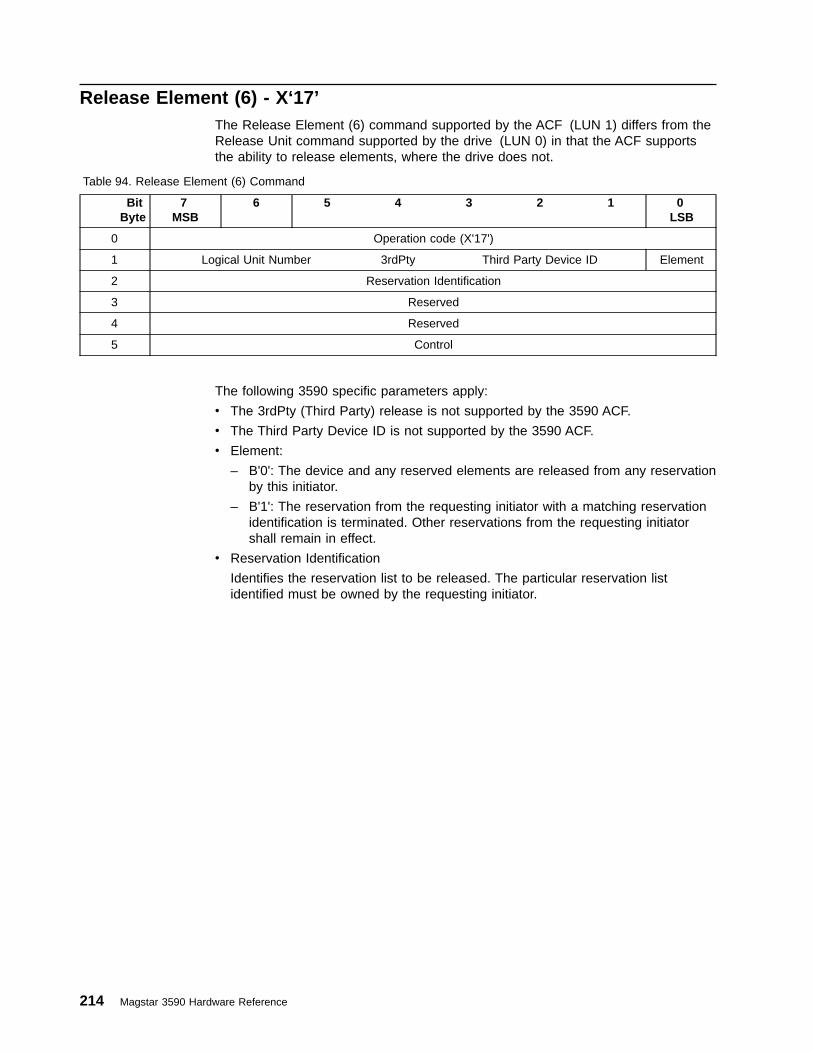
Release Element (6) - X‘17’The Release Element (6) command supported by the ACF (LUN 1) differs from theRelease Unit command supported by the drive (LUN 0) in that the ACF supportsthe ability to release elements, where the drive does not.
Table 94. Release Element (6) Command
BitByte
7MSB
6 5 4 3 2 1 0LSB
0 Operation code (X'17')
1 Logical Unit Number 3rdPty Third Party Device ID Element
2 Reservation Identification
3 Reserved
4 Reserved
5 Control
The following 3590 specific parameters apply:
v The 3rdPty (Third Party) release is not supported by the 3590 ACF.
v The Third Party Device ID is not supported by the 3590 ACF.
v Element:
– B'0': The device and any reserved elements are released from any reservationby this initiator.
– B'1': The reservation from the requesting initiator with a matching reservationidentification is terminated. Other reservations from the requesting initiatorshall remain in effect.
v Reservation Identification
Identifies the reservation list to be released. The particular reservation listidentified must be owned by the requesting initiator.
214 Magstar 3590 Hardware Reference
Request Sense - X‘03’The Request Sense command supported by the ACF (LUN 1) is the same as theRequest Sense command supported by the drive (LUN 0).
When acting as an Independent Medium Changer, the device only returns sensedata related to the LUN which has been specified.
Refer to “Request Sense - X‘03’” on page 151 for a description of the RequestSense command.
Chapter 3. ACF SCSI Commands 215
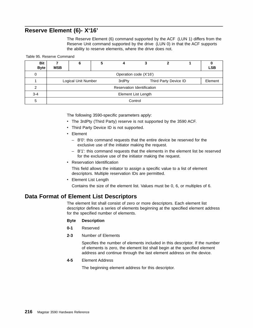
Reserve Element (6)- X‘16’The Reserve Element (6) command supported by the ACF (LUN 1) differs from theReserve Unit command supported by the drive (LUN 0) in that the ACF supportsthe ability to reserve elements, where the drive does not.
Table 95. Reserve Command
BitByte
7MSB
6 5 4 3 2 1 0LSB
0 Operation code (X'16')
1 Logical Unit Number 3rdPty Third Party Device ID Element
2 Reservation Identification
3-4 Element List Length
5 Control
The following 3590-specific parameters apply:
v The 3rdPty (Third Party) reserve is not supported by the 3590 ACF.
v Third Party Device ID is not supported.
v Element
– B'0': this command requests that the entire device be reserved for theexclusive use of the initiator making the request.
– B'1': this command requests that the elements in the element list be reservedfor the exclusive use of the initiator making the request.
v Reservation Identification
This field allows the initiator to assign a specific value to a list of elementdescriptors. Multiple reservation IDs are permitted.
v Element List Length
Contains the size of the element list. Values must be 0, 6, or multiples of 6.
Data Format of Element List DescriptorsThe element list shall consist of zero or more descriptors. Each element listdescriptor defines a series of elements beginning at the specified element addressfor the specified number of elements.
Byte Description
0-1 Reserved
2-3 Number of Elements
Specifies the number of elements included in this descriptor. If the numberof elements is zero, the element list shall begin at the specified elementaddress and continue through the last element address on the device.
4-5 Element Address
The beginning element address for this descriptor.
216 Magstar 3590 Hardware Reference

Send Diagnostic - X‘1D’The Send Diagnostic command supported by the ACF (LUN 1) is the same as theSend Diagnostic command supported by the drive (LUN 0).
The only Diagnostic ID supported by the 3590 ACF is X'0102', ACF Diagnostic (see“Magstar-Supported Diagnostics” on page 162).
Refer to “Send Diagnostic - X‘1D’” on page 160 for a description of the SendDiagnostic command.
Chapter 3. ACF SCSI Commands 217

Test Unit Ready - X‘00’The Test Unit Ready command supported by the ACF (LUN 1) is the same as theTest Unit Ready command supported by the drive (LUN 0).
Refer to “Test Unit Ready - X‘00’” on page 184 for a description of the Test UnitReady command.
218 Magstar 3590 Hardware Reference

Chapter 4. ACF Modes of Operation
The ACF has 7 modes of operation: Manual, Automatic, System, Accumulate,Random, and Random 2-LUN. The operator can choose all the modes.
Each mode and their operations are described in the following list:
ManualCartridge is fed to the drive loader individually each time.
AccumulateCartridge is put in the priority cell and output into the magazine.
AutomaticCartridges that are put into the magazine are automatically fed into thedrive loader one after another until the entire magazine is processed.
SystemCartridges that are put into the magazine are fed to the drive loader oneafter another under the attaching system’s command until the entiremagazine is processed. Note that not all attaching hosts support Systemmode.
RandomOperates as a small library. All cartridge moves are made under theattaching system’s commands. Cartridges may be accessed andre-accessed in any order. For E-Series Models, Random Mode operates asa SCSI Independent Media Changer.
Random 2-LUNSame as Random Mode, except operates as a SCSI Independent MediumChanger (2-LUN addressing) rather than a SCSI Attached Medium Changer(1-LUN addressing). This Mode is not available on E-Series Modles sinceRandom Mode operates as an Independent Media Changer already inRandom Mode.
ACF NotesThese items are general in nature and cover many or all modes. Rather thanrepeating these notes in each mode description, the notes are shown here andreferenced from the mode descriptions.
1. When the magazine is removed from the ACF, it is automatically locked.
When the magazine is placed in the ACF, it is automatically unlocked. If ACFRandom or Random 2-LUN mode is to be used, the operator must press themagazine lock button.
2. In Random or Random 2-LUN mode, a cartridge that is returned to themagazine is placed in the import position, to be available for reuse by theattaching host.
3. In Manual, Automatic, Accumulate, and System mode, a cartridge returned tothe magazine is placed in the export position.
4. To reuse a cartridge exported in the priority cell (in all modes), either removeand re-insert the cartridge or push the cartridge back to the import position andselect Start on the Operator Panel.
5. The feed mechanism for the ACF can access cartridges only in the importposition.
© Copyright IBM Corp. 1996, 2000 219
6. If the ACF is disabled, the operator presses Start on the operator panel, andthere is no magazine in the ACF or there is no cartridge in the import position ineither the magazine or in the priority cell, the ACF returns to the disabled statewithout changing the position of any cartridge. This does not constitute an errorand no error status is returned.
7. If while unloading a cartridge to the magazine, the destination cell is occupied,the ACF tries to unload the cartridge to the priority cell (also see Note 9).
8. If the ACF is instructed to unload a cartridge to the magazine and the magazineis not installed, the ACF tries to unload the cartridge to the priority cell (also seeNote 9). The cell-status indicator is set to alert (solid yellow) for the priority cell.
9. If the ACF tries to unload the cartridge to the priority cell (in any mode otherthan Random or Random 2-LUN) and the priority cell is occupied, the ACF setsthe cell status indicator to attention (flashing yellow) on all cells and disables theACF (extra cartridge condition). The ACF causes CHECK-CONDITION status tobe returned with associated sense data of 5/3B0D (Illegal Request, MediumDestination Element Full). In Random or Random 2-LUN mode, a Move Mediumcommand specifying the priority cell as a target will cause CHECK CONDITIONstatus to be returned with associated sense data of 5/3B0D (Illegal Request,Medium Destination Element Full) if the priority cell is already occupied.
For any mode other than Random or Random 2-LUN, when the cartridgeoccupying the priority cell is removed (by the operator in most modes), the ACFwill automatically transfer the previously blocked cartridge to the priority cell inexport position without further operator intervention. The associated cell statusinformation is reset.
Initiator Control of the ACFWhen the ACF operates in Manual, Accumulate, or Automatic mode, the initiatorcontrols only the unload of the cartridge from the device; it does not issue anycommand that causes the ACF to load a cartridge. A Load Unload command thatrequests an unload operation causes a cartridge to be unloaded. See also “ACFNotes” on page 219.
If a Load/Unload command with the ‘load’ bit set is received while the ACF isenabled in System mode, the ACF loads a cartridge. If a Load Unload commandwith the ‘load’ bit set is received in any mode other than System mode, thecommand is presented CHECK-CONDITION status with associated sense data of2/0400 (Not Ready, Logical Unit Not Ready, Cause Not Reportable). Receiving twoLoad Unload commands with the ‘load’ bit set and without an intervening unloadalso causes the same check condition. If no ACF is present and a cartridge wasunloaded but not removed, the Load Unload command is accepted with the Load bitset to 1.
When the ACF operates in System mode, the program has indirect control over theACF. The program specifies that a cartridge is to be loaded if possible, but cannotspecify from which cell the cartridge is to be obtained. If no magazine is found andthe priority cell is empty, the command is presented CHECK CONDITION statuswith associated sense data of 2/3A00 (Not Ready, No Medium Present). If amagazine is present, but contains no cartridges that can be loaded and the prioritycell is also empty, the command is presented CHECK CONDITION status withassociated sense data of 5/3B0E (Illegal Request, Medium Source Element Empty).
220 Magstar 3590 Hardware Reference
When the ACF operates in Random or Random 2-LUN mode, the program cancontrol the ACF through the Prevent Allow Medium Removal, Read Element Status,and Move Medium commands. These commands allow the ACF to accesscartridges from cells that are located nonsequentially, to assist the initiator ingenerating and maintaining an inventory of the cartridges in the magazine, and toindicate to the operator that these cartridges can be removed.
The physical implementation for most modes can be viewed as a medium changerwith 11 import and export ports, no storage elements, a single data transferelement, and a single medium transport element that cannot be used topermanently store a piece of medium. Random and Random 2-LUN modes have adifferent configuration.
For Random or Random 2-LUN mode, the ACF contains one import and exportport, 10 storage elements, a single data-transfer element and a singlemedium-transport element. The program should issue the Read Element Statuscommand when changing ACF modes to assure the correct configuration.
In Random and Random 2-LUN modes, an exported medium can be importedagain from the magazine.
Manual ModeManual mode allows the operator to load a cartridge by operator action. Each timethe operator presses Start, the ACF selects a cartridge from the appropriate celland mounts it in the device. Only one cartridge is loaded for each operator action.
Terminology Note: Initial Conditions refers to actions the operator or attachinghost must take prior to attempting to initiate ACF activity.Enabling Conditions refers to the actions that begin ACFmotion. Similarly Disabling Conditions refers to the actions thatstop ACF activity.
When the ACF is operating in Manual mode, the following applies (see also “ACFNotes” on page 219):
v Initial condition:
– Manual mode must be selected from the Select ACF Mode menu at theoperator panel.
Note: When the ACF enters Manual mode from any other mode, the mediumchanger (‘mchngr’) bit in Inquiry data is set to 0 and the ACF mode inMode Page X'20' is set to Manual.
v Enabling conditions: Two way to enable Manual mode
– Insert a cartridge into the import position of the priority cell
– Press Start if there is a loadable cartridge in the magazine.
v Disabling conditions: The ACF becomes disabled in Manual mode when:
– The magazine cartridge was processed and returned to its original cell andthere is no cartridge in the import position of the priority cell.
– The ACF is enabled from the operator choosing Start, but the ACF cannotdetect a cartridge in the import position in the magazine.
– An attention condition is detected in the ACF; for example, an extra cartridgecondition.
Chapter 4. ACF Modes of Operation 221

– The magazine is not installed, choosing Start causes the ACF to return to thedisabled state.
v Operation
1. If the ACF is disabled and in Manual mode, and the operator chooses Starton the operator panel, the ACF becomes enabled and then verifies that atleast one cartridge is in the import position of the magazine. If so, the ACFindexes down the magazine until it finds the first cell with a cartridge in theimport position. The ACF sets the cell-status indicator for that cell to in-use(steady green) and moves the cartridge from the cell to the device.
2. If the ACF is disabled and in Manual mode, and a cartridge is placed in theimport position of the priority cell, the ACF loads the cartridge in the deviceand sets the cell-status indicator to in-use (steady green) for the priority cell.
3. If a cartridge is placed in the priority cell while the ACF is enabled and inManual mode, the ACF sets the cell-status indicator of the priority cell toin-use (steady green). When the ACF completes its current operation, theACF automatically loads the priority cell as described in step 2.
4. When a cartridge that was loaded while in Manual mode is unloaded, it isreturned to its original cell if possible, and the in-use indication is turned off. Ifthe original cell is occupied, the ACF turns off the in-use indicator and putsthe cartridge in the priority cell, if possible, and sets the priority cell statusindicator to alert (steady yellow). If the priority cell is occupied, the ACF isdisabled and it presents check status (see step 9 on page 220). Thecell-status indicators for all cells are set to attention (flashing yellow). Anintervention message is posted on the operator panel.
v Cleaning the drive in Manual mode:
To clean the drive when the ACF is in Manual mode, place a cleaning cartridge inthe priority cell. The cleaning cartridge is automatically loaded, completes itscleaning, and is unloaded into the priority cell again. To determine when cleaningis required, see “Drive Cleaning Indicators” on page 242.
Accumulate ModeSome customers organize their operations so that certain ßs focus on specificcartridge mounts; that is, the entire device is dedicated to responding to servicingspecific volumes requested by the initiator. For this type of operation, the customerneeds the ability to easily insert specific cartridges and the ability to allowprocessed specific mount to accumulate in a hopper until it is convenient for theoperator to retrieve a group of cartridges.
In Manual, Automatic, and System mode, cartridges are always exported to thesame ACF cell from which they were imported, if possible. This makes themconvenient for processing scratch volumes. Accumulate mode differs in thatcartridges are always imported from the priority cell, and exported to a magazinecell. This allows the operator to insert specific cartridges into the priority cell, and toaccumulate processed cartridges into the magazine for pickup by the operator.
When the ACF is in Accumulate mode, the following applies (see also “ACF Notes”on page 219):
v Initial conditions
– Accumulate mode must be selected from the Select ACF Mode menu at theoperator panel.
222 Magstar 3590 Hardware Reference

Note: When the ACF enters Accumulate mode from any other mode, themedium changer (mchngr) bit in Inquiry data is set to zero and the ACFmode in Mode Page X'20' is set to Accumulate.
– While not a required condition, we recommend that initially the magazine beempty.
– To indicate to the operator that they should not place cartridges in themagazine (only remove cartridges), all magazine cells have the cell-statusindicators set to in-use (steady green). This is to remind the operator that theentire magazine is reserved as the accumulate hopper.
v Enabling condition: To enable Accumulate mode
– Insert a cartridge into the import position of the priority cell.
v Disabling conditions: The ACF becomes disabled in Accumulate mode as follows:
– The magazine is full and the last imported cartridge is returned to the prioritycell.
– An attention condition is detected in the ACF; for example, an extra cartridgecondition.
v Operation:
1. If the ACF is disabled and in Accumulate mode, the ACF becomes enabledwhen a cartridge is inserted in the import position of the priority cell.
2. When a cartridge is inserted into the priority cell, the cartridge sets thecell-status indicator to in-use (steady green) for the priority cell and waits forthe device to become available.
3. When the device is available, the cartridge is loaded in the device and thepriority cell indicator is turned off.
4. When a cartridge is unloaded from the drive, it is moved to the magazine.The ACF places the cartridge in the top cell of the magazine unless that cellis occupied. If the top cell is occupied, the ACF searches down the magazinefor the next available cell. Each cartridge is placed in the export position.
5. When the last available cell in the magazine is filled, the ACF warns theoperator by activating all magazine cell-status indicators to alert (steadyyellow). If another cartridge is unloaded, it is placed into the priority cellagain, if possible, and the priority cell indicator is set to alert (steady yellow).See step 9 on page 220 if the priority cell is also full.
v Cleaning the drive in Accumulate mode:
To clean the drive when the ACF is in Accumulate mode, place a cleaningcartridge in the priority cell. The cleaning cartridge is automatically loaded,completes its cleaning, and is unloaded into the next available magazine cell. Ifno magazine cell is available, the cartridge is returned to the priority cell. Todetermine when cleaning is required, see “Drive Cleaning Indicators” onpage 242.
Automatic ModeAutomatic mode provides the operator a mechanism to keep the drive continuallyfed with cartridges from the magazine. After enabling the ACF, is automaticallyfeeds cartridges to the device until all the cartridges in the magazine are processed.The operator can supply specific cartridges to an application by inserting thecartridge into the priority cell. The priority cell cartridge is automatically the nextcartridge to be loaded into the device, provided a load operation is not currently inprogress. When the specific cartridge is completed, the ACF automatically resumesprocessing cartridges from the magazine.
Chapter 4. ACF Modes of Operation 223
Processed cartridges can be removed from the magazine and unprocessedcartridges can be added, without disturbing the ACF. The ACF locates eachunprocessed cartridge.
When the ACF is in Automatic mode, the following applies (see also “ACF Notes”on page 219):
v Initial conditions:
– Automatic mode must be selected from the Select ACF Mode menu at theoperator panel.
Note: When the ACF enters Automatic mode from any other mode, themedium changer (mchngr) bit in Inquiry data is set to 0 and the ACFmode in Mode Page X'20' is set to Automatic.
– The ACF is initialized so the top of the magazine is considered the currentcell.
v Enabling Conditions: Two ways to enable Automatic mode follow:
– Choosing Start on the operator panel, if there is loadable cartridge in themagazine
– Inserting a cartridge in the import position of the priority cell.
v Disabling conditions: The ACF is disabled in Automatic mode as follows:
– A magazine or priority cartridge is processed and returned to its original cell,and there is no cartridge in the import position of the magazine or priority cell.
– The ACF is enabled from the operator choosing Start, but the ACF cannotdetect a cartridge in the import position in either the magazine or the prioritycell.
– An attention condition is detected in the ACF; for example, an extra cartridgecondition.
v Operation
1. If the ACF is disabled and in Automatic mode, and the operator chooses Starton the operator panel, the ACF becomes enabled and verifies that there is atleast one cartridge in the import position of the magazine. If so, the ACFindexes down the magazine until it finds the first cell with a cartridge in theimport position. The ACF sets the cell-status indicator for that cell to in-use(steady green) and moves the cartridge from the cell to the device.
2. If the ACF is disabled and in Automatic mode and a cartridge is placed in theimport position of the priority cell, the ACF is enabled, it loads the cartridge inthe device, and it sets the cell-status indicator to in-use (steady green) for thepriority cell.
3. If a cartridge is placed in the priority cell while the ACF is enabled and inAutomatic mode, the ACF sets the cell-status indicator of the priority cell toin-use (steady green). When the ACF completes its current operation, itautomatically loads the priority cell as described in step 2.
4. When a cartridge that was loaded while in Automatic mode is unloaded, it isreturned to its original cell, if possible, and the in-use indicator for that cell isturned off. The ACF then searches the magazine for the next cell in theimport position and loads it in the device. This process repeats until the ACFcannot find another cartridge to load.
v Cleaning the drive in Automatic mode:
To clean the drive when the ACF is in Automatic mode, place a cleaning cartridgein the priority cell. The cleaning cartridge is automatically loaded, completes itscleaning, and is unloaded into the priority cell again. To determine when cleaningis required, see “Drive Cleaning Indicators” on page 242.
224 Magstar 3590 Hardware Reference
System ModeSystem mode provides the operator an additional mechanism to keep the drivecontinually loaded with cartridges from the magazine. When the ACF is enabled andthe first cartridge loaded, subsequent load commands are under the control of theinitiator. The ACF loads one cartridge in response to each of these systemcommands until all the cartridges in the magazine are processed.
System mode does not preclude specific mount requests from the initiator. Theoperator can supply specific cartridges to an application by inserting the cartridge inthe priority cell. The priority cell cartridge is automatically the next cartridge to beloaded in the device, provided a load operation is not currently in progress. Whenthe specific cartridge is complete, the ACF automatically resumes processingcartridges from the magazine under system control.
Processed cartridges can be removed from the magazine and unprocessedcartridges can be added, without disturbing the ACF. The ACF locates eachunprocessed cartridge.
When the ACF is in System mode, the following applies (see also “ACF Notes” onpage 219):
v Initial conditions
– System mode must be selected from the Select ACF Mode menu at theoperator panel.
Note: When the ACF enters System mode from any other mode, the mediumchanger (mchngr) bit in Inquiry data is set to 0 and the ACF mode inMode Page X'20' is set to System.
– The ACF is initialized so the top cell of the magazine is considered the currentcell location.
v Enabling conditions: Two ways to enable System mode follow:
– Select Start ACF on the operator panel if there is a loadable cartridge in themagazine.
– Insert a cartridge in the import position of the priority cell.
v Disabling conditions: The ACF becomes disabled in System mode as follows:
– A magazine or priority cartridge is processed and returned to its original cell,and there is no cartridge in the import position of the magazine or priority cell.
– The ACF is enabled from the operator choosing Start, but the ACF cannotdetect a cartridge in the import position in either the magazine or the prioritycell.
– An attention condition is detected in the ACF; for example, extra cartridgecondition.
v Operation:
1. If the ACF is disabled and in System mode, and the operator chooses Starton the operator panel, the ACF becomes enabled and verifies that there is atleast one cartridge in the import position of the magazine. If so, the ACFindexes down the magazine until it finds the first cell with a cartridge in theimport position. The ACF sets the cell-status indicator for that cell to in-use(steady green) and moves the cartridge from the cell to the device.
2. If the ACF is disabled and in System mode, and a cartridge is placed in theimport position of the priority cell, the ACF loads the cartridge in the deviceand sets the cell-status indicator to in-use (steady green) for the priority cell.
Chapter 4. ACF Modes of Operation 225
3. If a cartridge is placed in the priority cell while the ACF is enabled and inSystem mode, the ACF sets the cell-status indicator of the priority cell toin-use (steady green). When the ACF completes its current operation, itautomatically loads the priority cell as described in step 2 on page 225.
4. When the system completes processing a cartridge, it issues a Loadcommand with the load bit set to B'0'. The ACF unloads the old cartridge andreturns it to its original cell, if possible, and turns off the in-use indicator forthat cell. The ACF waits in enabled state until it receives a Load Unloadcommand with the load bit set to B'1', or until a cartridge is inserted in thepriority cell. In the case of the Load Unload command, the ACF searches themagazine for the next cell in the import position and loads it to the device.This process repeats until the ACF cannot find another cartridge to load.
v Cleaning the drive in System mode:
To clean the drive when the ACF is in System mode, place a cleaning cartridgein the priority cell. The cleaning cartridge is automatically loaded, completes itscleaning, and is unloaded into the priority cell again. To determine when cleaningis required, see “Drive Cleaning Indicators” on page 242.
Random ModeIn E-Series Models, the Random Mode functions as if it was a virtual Random2-LUN Mode. For a description of this E-Series characteristic, see “Random 2-LUNMode (B-Series Models Only)” on page 228. This change in functionality withinRandom Mode is exclusive to the E-Series Models a feature of their improveddesign.
Random mode is designed to act as a small, self-contained library of up to 10cartridges, controlled by the initiator. The initiator uses the SCSI Medium Movercommands to select a cartridge from a given cell and move it to its destination cell.Control of the source and destination cells are left entirely to the initiator.
Being in Random mode does not preclude initiator requests for specific mounts.Requests for specific cartridges to be mounted can be satisfied by inserting thespecific cartridge in the priority cell. In Random mode, the priority cell is simplyanother addressable cell. The ACF notifies the initiator of the presence of acartridge in the priority cell, but the initiator must specifically address that cell toaccess the cartridge.
To ensure the integrity of the library, the magazine has a lock on the magazine. Themagazine lock prevents the addition or removal of cartridges from the magazineafter the magazine is installed in the ACF and locked. The ACF senses the state ofthe magazine lock and does not permit Random mode to be enabled unless themagazine lock is set to the locked position. A sensor on the ACF allows the unit todetermine that the magazine is not installed or was removed. This disables Randommode.
Because the magazine must be locked in Random mode, the priority cell is used asan I/O port to the library, to add or remove cartridges from the magazine withouthaving to violate the integrity of the locked magazine. The initiator can movecartridges from the priority cell to any empty magazine cell (or the device), or froma magazine cell (or the device) to the priority cell. Library inventory and the controlof the inventory is entirely the responsibility of the initiator.
If a Move Medium or Read Element Status command is issued with no magazinepresent, or with the magazine unlocked, the command fails with a permanent error.
226 Magstar 3590 Hardware Reference

When the ACF is in Random mode, the following applies (see also “ACF Notes” onpage 219 ):
v Initial conditions
– Random mode must be selected from the Select ACF Mode menu at theoperator panel.
Note: When the ACF enters Random mode from any other mode, themedium changer (mchngr) bit in Inquiry data is set to 1 and the ACFmode in Mode Page X'20' is set to Random.
– Only when the medium changer (mchngr) bit in Inquiry data is set to 1 doesthe device accept the Medium Move, Read Element Status, and Prevent AllowMedium Removal commands. These commands control the ACF as describedin “Initiator Control of the ACF” on page 220.
– The ACF is set to enabled and waits for the initiator command to move themedia.
v Enabling conditions: Random mode is enabled if all the following conditions aremet:
– The magazine is installed in the ACF.
– The magazine lock is in the locked state.
– A valid Move Medium command is received.
v Disabling conditions: The ACF is disabled in Random mode if one of thefollowing conditions are met:
– The magazine is removed from the ACF.
– The magazine is unlocked.
– An attention condition is detected in the ACF; for example, extra cartridgecondition.
v Operation:
1. When first enabled in Random mode, the ACF waits for initiator commands.
2. All magazine cell-status indicators are set to in-use (steady green). Thein-use indicators remain on unless Random mode is disabled. The priority cellcell-status indicator is activated as it is used.
3. All cartridge movement is under control of the initiator using the MediumMover commands.
4. The ACF honors the Prevent Allow Media Removal command by not allowingoperator-initiated export of cartridges any time the command has specifiedPrevent Media Removal.
5. The priority cell has an assigned element address and can be accessed bythe accessor under initiator control. If an operator inserts a cartridge in thepriority cell, the ACF notifies the initiator with CHECK CONDITION status andsense data of 6/2801 (Unit Attention, Import or Export Element Accessed).The ACF will not access the cartridge in the priority cell unless commandedby the initiator.
6. If a cartridge that was loaded while in Random mode is unloaded, it may notalways be returned to the same cell where it was previously located. Theinitiator controls the cartridge location. When the cartridge is placed in amagazine cell, it is placed in the import position.
v Cleaning the drive in Random mode (to determine when cleaning is required, see“Drive Cleaning Indicators” on page 242):
To clean the drive when the ACF is in Random mode, use one of the followingalternatives:
Chapter 4. ACF Modes of Operation 227

– Place a cleaning cartridge in the priority cell of the ACF and issue a MoveMedium command with source address set to the Import Export Element(X'001F') and destination address set to the Data Transfer Element (X'0010').This must be done when no other cartridge is loaded in the drive.
When cleaning is complete, either the application must issue the MoveMedium directly, or it must permit an operator to issue the command via autility program. This method will not require another inventory of cartridges.
Note: The “tapeutil” routine provided with the AIX 3590 driver provides theoperator with the means to issue the Move Medium command.
AS/400 users can run the WRK TAP CTG command and specify the CheckTape Cartridge option on:
- Volume serial CLNxxx (if the cleaning cartridge is already in the inventory)
- Volume serial IMPxxx (if the cleaning cartridge was just placed in thepriority cell).
v Place a cleaning cartridge in a fixed position in the magazine before loading theACF and inform the controlling application of that position. The application shouldperiodically load the cleaning cartridge (current recommendation: every 150 GBof tape data (15 full passes of cartridges).
v At a time that is appropriate for the application (and when no cartridges areloaded in the drive), change the ACF mode from Random mode to Manual modeusing the operator panel (Manual mode operations from the priority cell do notrequire that the magazine be unlocked). Insert the cleaning cartridge into thepriority cell.
When the cleaning is complete, the cleaning cartridge is automatically exportedto the priority cell. At that time, change the ACF mode back to Random mode.The operator may choose to vary the drive offline during the cleaning period. Theapplication may inventory the ACF again at this time using the Read ElementStatus command. Optionally, the application may also re-verify the cartridge’sinternal labels.
Random 2-LUN Mode (B-Series Models Only)Random 2-LUN mode is the same as Random mode except for the method bywhich the SCSI Medium Changer commands are addressed to the SCSI ID of thedrive. In Random mode, the 3590 ACF acts as an Attached Medium Changer andsupports a limited set of Medium Changer commands at LUN 0 only (1-LUNaddressing). In Random 2-LUN mode, the 3590 ACF acts as an IndependentMedium Changer and supports Medium Changer commands at LUN 1 only (2-LUNaddressing).
This mode should only be selected when specified by the instructions or thecertified device lists for all of the software applications to be accessing the 3590ACF. Many software applications support either 1-LUN addressing or 2-LUNaddressing BUT NOT BOTH. Selection of an incorrect mode or incompatibleapplications in a multi-application environment may result in errors while attemptingto access the ACF.
228 Magstar 3590 Hardware Reference

Cell Status IndicatorsThis section describes the operation of the cell status indicators for the ACF and thepriority cell, and the conditions identified by the indicators. The indicators are lightemitting diodes (LEDs) that are either off, emitting green light, or emitting yellowlight. The indicator operations are described under the following headings:
v “Cell Status: Flashing Yellow is an Attention Indicator”
v “Cell Status: Steady Yellow Indicates Alert Conditions”
v “Cell Status: Steady Green is an In-Use Indicator”
Cell Status: Flashing Yellow is an Attention IndicatorThe device requires operator assistance. Table 96 describes the Attention condition.There will be a corresponding operator panel ATTN ACF message in the casewhere the LEDs indicate attention.
Table 96. Cell Status Indicators Flashing Yellow–Attention Indicator
Indicator State Description of the Condition
All 11 LEDs -- magazinelights and the priority celllight -- are flashing yellow(Accumulate, Automatic,Manual, and System modes)or all 10 magazine LEDs areflashing yellow (Randommode).
Further activity is stopped. Requires operator attention such as installing themagazine, locking or unlocking the magazine, clearing a cartridge jam, and so on.Once the condition is cleared the LEDs return to normal after Start is selected. Typicalsupplemental messages to ATTN ACF include extra cartridge, picker error, and exporterror.
Cell Status: Steady Yellow Indicates Alert ConditionsDoes not immediately preclude machine operation, but may, unless the condition iscleared soon. Table 97 describes the Alert condition:
Table 97. Cell Status Indicators Steady Yellow–Alert Conditions
Indicator State Description of the Condition
All 10 magazine LEDs aresteady yellow
Accumulate, Automatic, Manual, or System modes only–Magazine Not Installed or islocked. LEDs return to normal when condition is cleared.
Automatic, or System modes only–Magazine Processed - no cartridges are in theimport position in the magazine or the priority cell. LEDs return to normal whencondition is cleared.
Accumulate mode only–Magazine Full - Warns the operator to remove the fullmagazine and replace it with one that is not full. LEDs return to normal when Start isselected.
Priority cell light is steadyyellow
Priority Cell Demount - Instructs the operator to remove the cartridge in the prioritycell.
Cell Status: Steady Green is an In-Use IndicatorThe indicated cells are in use by the ACF or the program. Table 98 on page 230describes the in-use condition:
Chapter 4. ACF Modes of Operation 229
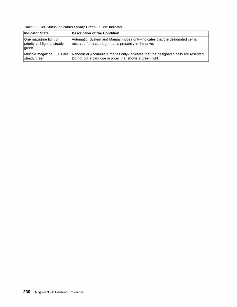
Table 98. Cell Status Indicators Steady Green–In-Use Indicator
Indicator State Description of the Condition
One magazine light orpriority cell light is steadygreen
Automatic, System and Manual modes only–Indicates that the designated cell isreserved for a cartridge that is presently in the drive.
Multiple magazine LEDs aresteady green
Random or Accumulate modes only–Indicates that the designated cells are reserved.Do not put a cartridge in a cell that shows a green light.
230 Magstar 3590 Hardware Reference
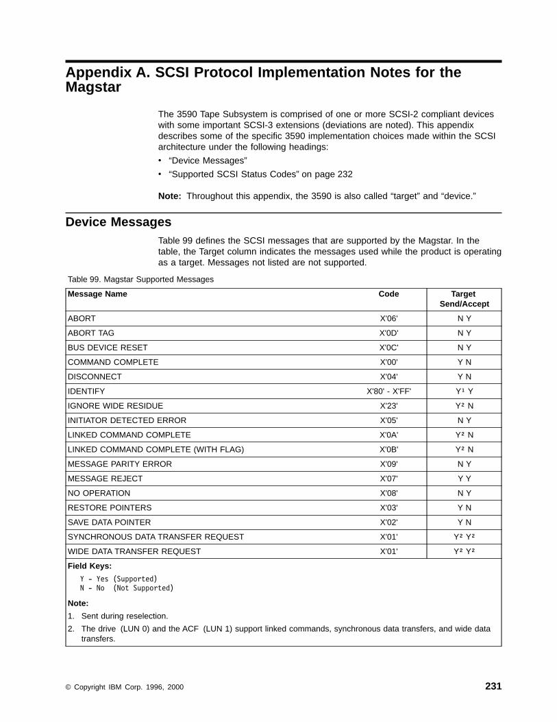
Appendix A. SCSI Protocol Implementation Notes for theMagstar
The 3590 Tape Subsystem is comprised of one or more SCSI-2 compliant deviceswith some important SCSI-3 extensions (deviations are noted). This appendixdescribes some of the specific 3590 implementation choices made within the SCSIarchitecture under the following headings:
v “Device Messages”
v “Supported SCSI Status Codes” on page 232
Note: Throughout this appendix, the 3590 is also called “target” and “device.”
Device MessagesTable 99 defines the SCSI messages that are supported by the Magstar. In thetable, the Target column indicates the messages used while the product is operatingas a target. Messages not listed are not supported.
Table 99. Magstar Supported Messages
Message Name Code TargetSend/Accept
ABORT X'06' N Y
ABORT TAG X'0D' N Y
BUS DEVICE RESET X'0C' N Y
COMMAND COMPLETE X'00' Y N
DISCONNECT X'04' Y N
IDENTIFY X'80' - X'FF' Y¹ Y
IGNORE WIDE RESIDUE X'23' Y² N
INITIATOR DETECTED ERROR X'05' N Y
LINKED COMMAND COMPLETE X'0A' Y² N
LINKED COMMAND COMPLETE (WITH FLAG) X'0B' Y² N
MESSAGE PARITY ERROR X'09' N Y
MESSAGE REJECT X'07' Y Y
NO OPERATION X'08' N Y
RESTORE POINTERS X'03' Y N
SAVE DATA POINTER X'02' Y N
SYNCHRONOUS DATA TRANSFER REQUEST X'01' Y² Y²
WIDE DATA TRANSFER REQUEST X'01' Y² Y²
Field Keys:
Y - Yes (Supported)N - No (Not Supported)
Note:
1. Sent during reselection.
2. The drive (LUN 0) and the ACF (LUN 1) support linked commands, synchronous data transfers, and wide datatransfers.
© Copyright IBM Corp. 1996, 2000 231
Programmer Note: For the Identify Message, we strongly recommend that theDisconnect Privilege bit be set, if you desire error recovery onData phase.
Supported SCSI Status CodesThe SCSI status codes are defined in the SCSI-2 standard. The Magstar does notuse all these status codes. However, the 3590 complies with the SCSI standard forall status codes that it supports. The list of status codes and their use in theMagstar follows:
Status Description
GOODUsed on the last command of any nexus when the last command finishescorrectly. There may be one or more commands per nexus, depending onwhether linking has been used.
CHECK CONDITIONUsed to report any error condition that generates a contingent allegiance forthe command. Unexpected disconnect may be used when the devicecannot report by other means. This is an allowable SCSI-2 option. Thedevice prepares sense data for the event that may be retrieved with aRequest Sense command. If CHECK CONDITION status is presented, acontingent allegiance does exist. If Unexpected Disconnect is used, sensedata is prepared but no contingent allegiance exists (per the SCSI-2standard).
RESERVATION CONFLICTUsed when an initiator not holding a current reservation attempts to executean unauthorized command while a reservation is in effect.
INTERMEDIATEUsed as required by SCSI-2. This status code means the equivalent ofGOOD status for linked commands (1..n-1).
BUSY Used when required by SCSI-2 (for example, contingent allegiance). Thedual port nature of Magstar makes the SCSI-3 behavior extend the BUSYstatus to a second port. No unnecessary BUSY status is presented.However, some BUSY status reports are required and are presented. BUSYstatus is presented during the power-up sequence until the diagnostics arecomplete. Under ordinary circumstances, this is the most common reasonfor encountering BUSY status.
CONDITION METNot Used
INTERMEDIATE-CONDITION METNot Used
COMMAND TERMINATEDNot Used
QUEUE FULLNot Used
232 Magstar 3590 Hardware Reference

Appendix B. Error Sense Information
This appendix lists all possible combinations of Sense Keys, Additional SenseCodes (ASC), and Additional Sense Code Qualifiers (ASCQ) that are reported bythe 3590 devices.
Sense Key 0 (No Sense)Table 100. ASC, and ASCQ Summary for Sense Key 0 (No Sense)
ASC ASCQ Description Drive ACF
00 00 No Additional Sense Information - EOM X
00 00 No Additional Sense Information - ILI X
00 00 No Additional Sense Information - FM X
00 01 Filemark Detected X
00 04 Beginning-of-Partition or Medium Detected X
Sense Key 1 (Recovered Error)Table 101. ASC, and ASCQ Summary for Sense Key 1 (Recovered Error)
ASC ASCQ Description Drive ACF
00 00 No Additional Sense Information X X
00 17 Drive Needs Cleaning X
17 01 Recovered Data with Retries X
18 00 Recovered Data with Error Correction Applied X
37 00 Rounded Parameter X
5B 02 Log Counter at Maximum X
83 83 Drive Has Been Cleaned (newer versions of microcode) X
Note: Many additional ASC ASCQ combinations are possible if recovered errorreporting is enabled via Mode Select. Recovered Error Reporting Enabled isthe default option with some of the 3590 device drivers.
Sense Key 2 (Not Ready)Table 102. ASC, and ASCQ Summary for Sense Key 2 (Not Ready)
ASC ASCQ Description Drive ACF
04 00 Logical Unit Not Ready, Cause Not Reportable X X
04 01 Logical Unit Is in Process of Becoming Ready X X
04 03 Logical Unit Not Ready, Manual Intervention Required X X
04 04 Logical Unit Not Ready, Format in Progress X
04 07 Logical Unit Not Ready, Operation in Progress X
15 01 Mechanical Positioning Error, Manual Intervention Required X
30 03 Cleaning in Progress X
3A 00 Medium Not Present X
© Copyright IBM Corp. 1996, 2000 233
|||
|

Table 102. ASC, and ASCQ Summary for Sense Key 2 (Not Ready) (continued)
ASC ASCQ Description Drive ACF
3B 12 Medium Magazine Removed X
53 00 Media Load or Eject Failed X
Sense Key 3 (Medium Error)Table 103. ASC, and ASCQ Summary for Sense Key 3 (Medium Error)
ASC ASCQ Description Drive ACF
03 02 Excessive Write Errors X
09 00 Track Following Error X
0C 00 Write Error X
11 00 Unrecovered Read Error X
11 01 Read Retries Exhausted X
11 08 Incomplete Block Read X
14 00 Recorded Entity Not Found X
14 01 Record Not Found X
14 02 Filemark or Setmark Not Found X
14 03 End-of-Data Not Found X
14 04 Block Sequence Error X
30 00 Incompatible Medium Installed X
30 01 Cannot Read Medium, Unknown Format X
30 02 Cannot Read Medium, Incompatible Format X
31 00 Medium Format Corrupted X
31 01 Format Command Failed X
33 00 Tape Length Error X
51 00 Erase Failure X
85 00 Write Protected Because of Tape or Drive Failure X
85 01 Write Protected Because of Tape Failure X
85 02 Write Protected Because of Drive Failure X
Sense Key 4 (Hardware Error)Table 104. ASC, and ASCQ Summary for Sense Key 4 (Hardware Error)
ASC ASCQ Description Drive ACF
09 00 Track Following Error X
15 01 Mechanical Positioning Error X
3B 00 Sequential Positioning Error X
3B 08 Reposition Error X
40 00 Diagnostic Failure X
44 00 Internal Target FailureDrive Needs Cleaning, Warning Threshold Exceeded
XX
X
234 Magstar 3590 Hardware Reference

Table 104. ASC, and ASCQ Summary for Sense Key 4 (Hardware Error) (continued)
ASC ASCQ Description Drive ACF
47 80 Read Internal CRC Error X
47 81 Write Internal CRC Error X
4C 00 Logical Unit Failed Self-Configuration X
52 00 Cartridge Fault X
53 00 Media Load or Eject Failed X
53 01 Unload Tape Failure X
Sense Key 5 (Illegal Request)Table 105. ASC, and ASCQ Summary for Sense Key 5 (Illegal Request)
ASC ASCQ Description Drive ACF
1A 00 Parameter List Length Error X X
20 00 Invalid Command Operation Code X X
21 01 Invalid Element Address X
24 00 Invalid Field in CDB X X
25 00 Logical Unit Not Supported X X
26 00 Invalid Field in Parameter List X X
26 01 Parameter Not Supported X
26 02 Parameter Value Invalid X
26 03 Threshold Parameters Not Supported X
2C 00 Command Sequence Error X
30 05 Cannot Write Medium — Incompatible Format X
39 00 Saving Parameters Not Supported X
3B 0D Medium Destination Element Full X
3B 0E Medium Source Element Empty X
3B 11 Medium Magazine Not Accessible X
3B 80 Medium Transport Element Full X
3D 00 Invalid Bits in Identify Message X X
53 02 Medium Removal Prevented X
5B 03 Log List Codes Exhausted X
80 00 CU Mode, Vendor-Unique X X
85 03 Write Protected Because of Current Tape Position X
Sense Key 6 (Unit Attention)Table 106. ASC, and ASCQ Summary for Sense Key 6 (Unit Attention)
ASC ASCQ Description Drive ACF
00 02 End-of-Partition/Medium Detected, Early Warning X
28 00 Not Ready to Ready Transition, Medium May Have Changed X X
28 01 Import or Export Element Accessed X
Appendix B. Error Sense Information 235
||||
||||

Table 106. ASC, and ASCQ Summary for Sense Key 6 (Unit Attention) (continued)
ASC ASCQ Description Drive ACF
28 80 Not Ready to Ready Transition, Medium Changer X
29 00 Power On, Reset, or Bus Device Reset Occurred X X
2A 01 Mode Parameters Changed X X
2A 02 Log Parameters Changed X
2F 00 Commands Cleared by Another Initiator X
30 00 Incompatible Medium Installed X
3B 12 Medium Magazine Removed X
3B 13 Medium Magazine Inserted X
3B 14 Medium Magazine Locked X
3B 15 Medium Magazine Unlocked X
3F 01 Microcode Has Been Changed X X
3F 02 Changed Operating Definition X X
3F 03 Inquiry Data Has Changed X X
5A 01 Operator Medium Removal Request X
82 83 Drive Has Been Cleaned (older versions of microcode) X
Sense Key 7 (Data Protect)Table 107. ASC, and ASCQ Summary for Sense Key 7 (Data Protect)
ASC ASCQ Description Drive ACF
27 00 Write Protected X
Sense Key 8 (Blank Check)Table 108. ASC, and ASCQ Summary for Sense Key 8 (Blank Check)
ASC ASCQ Description Drive ACF
00 05 End-of-Data Detected X
14 01 Record Not Found, Void Tape X
Sense Key B (Aborted Command)Table 109. ASC, and ASCQ Summary for Sense Key B (Aborted Command)
ASC ASCQ Description Drive ACF
14 00 Recorded Entity Not Found X
14 01 Record Not Found X
14 02 Filemark or Setmark Not Found X
1B 00 Synchronous Data Transfer Error X X
43 00 Message Error X X
44 00 Internal Target Failure X X
45 00 Select or Reselect Failure X X
236 Magstar 3590 Hardware Reference

Table 109. ASC, and ASCQ Summary for Sense Key B (Aborted Command) (continued)
ASC ASCQ Description Drive ACF
47 00 SCSI Parity Error X X
48 00 Initiator Detected Error Message Received X X
49 00 Invalid Message Error X X
4A 00 Command Phase Error X X
4B 00 Data Phase Error X X
4E 00 Overlapped Commands Attempted X X
Sense Key D (Volume Overflow)Table 110. ASC, and ASCQ Summary for Sense Key D (Volume Overflow)
ASC ASCQ Description Drive ACF
00 02 End-of-Partition/Medium Detected X
Appendix B. Error Sense Information 237

238 Magstar 3590 Hardware Reference

Appendix C. Implementation Considerations
Scaled Log Page CountersFor log page counters that add by 1K units (K=1024), the following scalingalgorithm applies:
If 0 <= x < 2K items, x = 1 count; if 2K <= x < 3K, x = 2; if 3K <= x < 4K, x = 3; andso on. Drive implementation algorithm: Shift unscaled counter register right 10 bits(divide by 1K), test the remaining contents for zero. If zero, add 1 to scaled logpage counter; if greater than zero, add the remaining contents of the unscaledcounter to the scaled log page counter. Zero unscaled counter register and restart.
SCSI-ID and LUN AssignmentsEvery Magstar SCSI interface can be assigned a single SCSI-ID in the range of 0to 15, but must be the only device on that bus with that ID.
Magstar drives can operate in one of two ways: as a 1-LUN device which combinesfull Sequential Access support with limited (Attached) Medium Changer support(SCSI-3 option); or as a 2-LUN device that has a separately addressable SequentialAccess device and a separately addressable (Independent) Medium Changerdevice (SCSI-2 or SCSI-3 compatible).
In the 1-LUN case, LUN 0 is the only LUN which is associated with an installeddevice. All other LUNs are invalid unit addresses as defined in section 7.5.3,Selection of an Invalid Logical Unit in the SCSI-2 standard.
In the 2-LUN case, the Sequential Access device is always LUN 0 and the MediumChanger device is always LUN 1. Note that both device types use the same targetaddress on a port.
Notes:
1. Attached Medium Changer (1-LUN addressing) is the default operating definitionfor all ACF modes of operation except Random 2-LUN (see “Change Definition-X‘40’” on page 10).
2. The SCSI-ID is factory set to X'03' but may be changed using the operatorpanel menus.
3. The Magstar SCSI-ID may be assigned any value from 0 to 15, but must be theonly device on the bus with that ID.
4. A diagnostic, Change SCSI ID, allows the SCSI-ID to be temporarily set to avalue other than its default to allow factory tests at different SCSI-IDs, withoutphysically changing the address.
Multiple Port BehaviorThe two SCSI ports of a 3590 provide alternate paths through which the logicalunit(s) of a 3590 may be reached. The ports are referred to as Port 0 and Port 1.Each port has it’s own unique SCSI ID. When operating as an Independent MediumChanger (2-LUN addressing), both LUN 0 and LUN 1 are available through bothports.
Using the operator panel, the operator may manually set each port in an online oroffline state. Additionally, the operator may select to enable an Auto-Share function
© Copyright IBM Corp. 1996, 2000 239
which will dynamically set one port offline when the drive or ACF logical unit hasbeen reserved via a SCSI command and, conversely, will set the port online whenthe logical unit has been released via a SCSI command.
Note: If a port is not connected, the operator must set the port “Offline” at theoperator panel to avoid a false detection of an active SCSI reset signal.
Behavior with Auto-Share DisabledUsage of the 3590 with both ports online and with Auto-Share disabled is notrecommended. Generally, the drive behavior with Auto-Share disabled is such thatall initiators, regardless of port, are treated the same as multiple initiators on thesame port. The exception to this is the handling of mode pages and reservations(both unit and element) when a hard reset condition occurs. The following rules aredescribed with respect to a local bus (the SCSI bus on which the hard resetcondition occurred) and a remote bus (the other SCSI bus to which the 3590 isattached). When operating as an Independent Medium Changer, the rules applyseparately for each logical unit (in other words, one rule will apply for LUN 0 while adifferent rule might apply for LUN 1).
1. If there are no reservations when a hard reset condition occurs, all mode pagesare reset. All initiators on the local bus receive a Unit Attention condition forPower On, Reset, or Bus Device Reset Occurred. All initiators on the remotebus receive a Unit Attention condition for Mode Parameters Changed.
2. If there are one or more reservations when a hard reset condition occurs and allreservations were granted to initiators on the local bus, all mode pages arereset and all reservations are reset. All initiators on the local bus receive a UnitAttention condition for Power On, Reset, or Bus Device Reset Occurred. Allinitiators on the remote bus receive a Unit Attention condition for ModeParameters Changed.
3. If there are one or more reservations when a hard reset condition occurs andone or more of the reservations were granted to an initiator on the remote bus,only those mode pages and reservations unique to each initiator on the localbus are reset. Mode pages and reservations unique to each initiator on theremote bus are not reset. Mode pages which are defined as common to allinitiators are not reset. All initiators on the local bus receive a Unit Attentioncondition for Power On, Reset, or Bus Device Reset Occurred. All initiators onthe remote bus see no effects of the hard reset condition on the other bus.
Behavior with Auto-Share EnabledWhen Auto-Share is enabled, the drive treats a SCSI reservation of a logical unit asa trigger to set the remote port offline. Consequently, the drive treats a SCSIrelease of a logical unit as a trigger to set the remote port online. The offline stateof the remote port in this scenario is referred to as ‘auto-offline’. In order toeliminate the exposure of a host on the remote port accessing the media belongingto the reserving host , the auto-offline state of the remote port is not reset by a hardreset condition on the online local port, even though the logical unit reservations arecleared. The auto-offline port may only be set online by one of the following events:
v Processing of a valid SCSI Release command which completes with noreservations existing for a logical unit
v Power-on-reset of the drive
v Operator selection of the menu option to set the port online
When the auto-offline port is set online, all initiators on that port receive a UnitAttention condition.
240 Magstar 3590 Hardware Reference
The handling of mode pages and reservations when a hard reset condition occurswith Auto-Share enabled is the same as with Auto-Share disabled (see Behaviorwith Auto-Share Disabled) except that there are no Unit Attention conditions forinitiators on a remote bus if the remote port is in an auto-offline state.
Data Transfer, Block Limits, and Fixed Block OptionThe Magstar drive is designed to buffer multiple records. Logical blocks may beprefetched to the buffer before they are requested by a Read command or held inthe buffer after they are written by a Write command. For successivesequential-motion operations, the presence of the buffering in the device does notadversely affect the performance of the subsystem. Non-sequential motion does notresult in errors, but may result in delays because of requirements to synchronizebuffers or discard read ahead data. Buffer management in the device determineswhen to read additional data from the medium into the buffer, or when to write datafrom the buffer to the medium. A logical block is not written to tape until the block isentirely received into the buffer.
When the Fixed bit of the Read or Write command is set to B'1', each Read orWrite command transfers zero or more logical blocks. The subsystem takesappropriate action to assemble or disassemble the logical blocks being transferredover the interface so that they remain independent blocks on the medium. There isno guarantee that the group of blocks transferred by the Write command isrequested as a group by a subsequent Read command, so the device must beprepared to assemble and disassemble on a block boundary. This is managed bytreating all blocks and filemarks as independent from one another, both for datacompaction and for recording. The use of the Save Data Pointers message atlogical block boundaries during the transfer assists in recovery actions in the middleof the transfer (that is, only the last logical block needs to be retransferred).Disconnection between logical blocks may also occur if the subsystem requiresadditional time to process logical blocks being transferred.
When the Fixed bit of the Read or Write command is set to B'0', each Read orWrite command transfers a single logical block.
After EOT is reached on any Write command, only a single block is transferredbefore terminating the command with check condition status 0/0000 (No Sense, NoAdditional Sense Information) and EOM set to B'1'. The same is true for WriteFilemark commands.
The device supports a minimum logical block length of 1 and a maximum logicalblock length is 2,097,152 bytes (X'200000'). Any block length between the limits isalso supported. Refer also to “Read Block Limits - X‘05’” on page 133 for furtherinformation on block sizes and limitations.
Note: Odd-byte transfer (fixed or variable) width can only be one byte. For thesetransfers, the maximum burst data rate is 10MB per second (one-half thenormal Magstar drive burst data rate). The drive negotiates narrow beforethe data phase.
Cleaning the Drive in the 3494 LibraryIn the 3494 no ACF exists; thus no notion of ACF Library mode exists. However, thedrive is automatically cleaned in the 3494 library as it is in the 3495 library.
Appendix C. Implementation Considerations 241

When the drive determines that either maintenance cleaning is required, or that theSARS thresholds have been reached, a message is sent to the library (via theRS-422 interface) to request cleaning. This occurs when the Cleaning message isnormally sent to the drive operator panel. The 3494 Library Manager schedules themounting of the cleaning cartridge. Thus, the host operating system and applicationare freed of any responsibility to facilitate the cleaning.
For information on cleaning drives that are not installed in a library, see the ACFmode descriptions beginning with “Manual Mode” on page 221.
Drive Cleaning IndicatorsFor stand-alone drive models, automatic cleaning of the drive is not possible. Forlibrary models, automatic cleaning of the drives by the library may be disabled(although it is not recommended). For either case, cleaning of the drives must bemanaged by the host application or manually, by the operator.
Note: Failure to clean a drive may result in data loss.
This section describes how cleaning indicators are presented from the drive. Thecleaning indicators may be presented even with automatic cleaning enabled in alibrary environment. The cleaning indicators can be presented through the following:
v “Operator Panel Cleaning Indication”
v “SCSI Interface — Dynamic Cleaning Indicators”
v “SCSI Interface — Static Cleaning Indicator (Sense Data Byte 70)” on page 243
Operator Panel Cleaning IndicationFor Magstar ACF models, a CLEAN message is displayed on the operator paneldisplay when cleaning with a cleaning cartridge is required. For additional details,see the Operator Guide for this product.
SCSI Interface — Dynamic Cleaning IndicatorsDynamic cleaning indicators that are sent across the SCSI interface include:
v ASC/ASCQ codes related to cleaning in Table 111.
Table 111. ASC/ASCQ Codes Related to Cleaning
Code Description Sense Key ASC/ASCQ
Drive Needs Cleaning 1 00/17
Drive Has Been Cleaned (newer versions of microcode) 1 83/83
Cleaning in Progress (cleaner cartridge installed) 2 30/03
Drive Needs Cleaning, Warning Threshold Exceeded 4 44/00
Drive Has Been Cleaned (earlier versions of microcode) 6 82/83
v Service Information Message (SIM) bytes 20-21 of Log Page X'31' (SIMavailability is shown in sense data):
Value (ASCII) Description
’55’ Drive Needs Cleaning. Load Cleaning Cartridge
’57’ Drive Has Been Cleaned
Note: If the device driver shields the application from dynamic notifications, theinformation is usually available from the system error log.
242 Magstar 3590 Hardware Reference
|
|
|
|

SCSI Interface — Static Cleaning Indicator (Sense Data Byte 70)The bit significance of sense data byte 70 follows:
Bit Description
7 Set to B'1' “Cleaning Required: Normal Maintenance” when cleaning isrequired because of the normal preventive maintenance guideline (that is,every 150GB). This bit is set when the Cleaning message is generated fordisplay (for this case).
Reset to B'0' when the cleaning cartridge is loaded.
6 Set to B'1' “Cleaning Required: Threshold Reached” when cleaning isrequired based on other internal threshold criteria. This bit is set when theCleaning message is generated for display (for this case).
Reset to B'0' when the cleaning cartridge is loaded.
5-0 Set to B'000000' “Reserved.” These bits will be used for future cleaningcriteria, including the following:
v Performance-driven cleaning
v Wet cleaning
v Dry brush cleaning
Appendix C. Implementation Considerations 243

244 Magstar 3590 Hardware Reference

Notices
References in this publication to IBM programs or services do not imply that IBMintends to make these available in all countries in which IBM operates. Anyreference to an IBM product, program, or service is not intended to state or implythat only IBM’s product, program, or service may be used. Any functionallyequivalent product, program, or service that does not infringe any of IBM’sintellectual property rights may be used instead of the IBM product, program, orservice. Evaluation and verification of operation in conjunction with other products,except those expressly designed by IBM, are the user’s responsibility.
IBM may have patents or pending patent applications covering subject matter in thisdocument. The furnishing of this document does not give you any license to thesepatents. You can send license inquiries, in writing, to the IBM Director of Licensing,IBM Corporation, 500 Columbus Avenue, Thornwood, NY 10594, U.S.A.
Do You Have Comments or Suggestions?Your feedback is important in helping to provide the most accurate and high-qualityinformation. If you have comments or suggestions for improving this publication, youcan send us comments electronically by using these addresses:
v Internet: [email protected] (or starpubs at vnet.ibm.com)
v IBMLink from U.S.A.: STARPUBS at SJEVM5
v IBMLink from Canada: STARPUBS at TORIBM
v IBM Mail Exchange: USIB3VVD at IBMMAIL
v Fax from U.S.A. and Canada: 520 799-2906
v Fax from other countries: 520 799-2906
You can also mail your comments by using the Reader Comment Form in the backof this manual or direct your mail to:
IBM CorporationInformation Development, Department 61C9000 South Rita RoadTucson, AZ 85744-0001, U.S.A.
When you send information to IBM, you grant IBM a nonexclusive right to use ordistribute the information in any way it believes appropriate without incurring anyobligation to you.
© Copyright IBM Corp. 1996, 2000 245

TermsFor definitions of terms, abbreviations, and acronyms, refer to the “Glossary” onpage 251. This comprehensive reference contains terms used in this publications.
TrademarksThe following terms are trademarks of the IBM Corporation in the United States orother countries or both:
ADSTAR Application System/400AIX AS/400ESA/390 ESCONES/3090 ES/9000IBM RS/6000 SPRS/6000 S/390 Parallel Transaction and Enterprise ServersS/390 RS/6000 SPSP2 System/370System/390
The following terms are trademarks of other companies:
Adaptec Hewlett-PackardSun Sun Microsystems, Inc.StorageTek Storage Technology CorporationWindows NT
Microsoft, Windows, and Windows NT are registered trademarks of MicrosoftCorporation.
246 Magstar 3590 Hardware Reference

IBM Agreement for Licensed Internal CodeYou accept the terms of this Agreement by your initial use of a machine thatcontains IBM Licensed Internal Code (called “Code”).
These terms apply to Code used by certain machines IBM or your reseller specifies(called “Specific Machines”). International Business Machines Corporation or one ofits subsidiaries (“IBM”) owns copyrights in Code or has the right to license Code.IBM or a third party owns all copies of Code, including all copies made from them.
If you are the rightful possessor of a Specific Machine, IBM grants you a license touse the Code (or any replacement IBM provides) on, or in conjunction with, only theSpecific Machine for which the Code is provided. IBM licenses the Code to only onerightful possessor at a time.
Under each license, IBM authorizes you to do only the following:
1. Execute the Code to enable the Specific Machine to function according to itsOfficial Published Specifications (called “Specifications”);
2. Make a backup or archival copy of the Code (unless IBM makes one availablefor your use), provided you reproduce the copyright notice and any other legendof ownership on the copy. You may use the copy only to replace the original,when necessary; and
3. Execute and display the Code as necessary to maintain the Specific Machine.
You agree to acquire any replacement for, or additional copy of, Code directly fromIBM in accordance with IBM’s standard policies and practices. You also agree touse that Code under these terms.
You may transfer possession of the Code to another party only with the transfer ofthe Specific Machine. If you do so, you must 1) destroy all your copies of the Codethat were not provided by IBM, 2) either give the other party all your IBM-providedcopies of the Code or destroy them, and 3) notify the other party of these terms.IBM licenses the other party when it accepts these terms. These terms apply to allCode you acquire from any source.
Your license terminates when you no longer rightfully possess the Specific Machine.
Actions You May Not TakeYou agree to use the Code only as authorized above. You may not do, for example,any of the following:
1. Otherwise copy, display, transfer, adapt, modify, or distribute the Code(electronically or otherwise), except as IBM may authorize in the SpecificMachine’s Specifications or in writing to you;
2. Reverse assemble, reverse compile, or otherwise translate the Code unlessexpressly permitted by applicable law without the possibility of contractualwaiver;
3. Sublicense or assign the license for the Code; or
4. Lease the Code or any copy of it.
Notices 247
AIX License Information Additional Terms and ConditionsAs pertaining to AIX code within the 3590 Model A00 and A50, the following applies.
This software and documentation is based in part on the Fourth Berkeley SoftwareDistribution under license from the Regents of the University of California. Weacknowledge the following institutions for their role in its development: the ElectricalEngineering and Computer Sciences Department at the Berkeley campus.
The Fourth Berkeley Software Distribution is provided by the Regents of theUniversity of California and other contributors on an “AS-IS” basis. NEITHER THEREGENTS OF THE UNIVERSITY OF CALIFORNIA NOR THE OTHERCONTRIBUTORS MAKE ANY WARRANTIES, EITHER EXPRESS OR IMPLIED,AS TO ANY MATTER WHATSOEVER, INCLUDING WITHOUT LIMITATION, THECONDITION OF THE FOURTH BERKELEY SOFTWARE DISTRIBUTION, ITSMERCHANTABILITY OR ITS FITNESS FOR ANY PARTICULAR PURPOSE.
The Regents of the University of California and other contributors are under noobligation to provide either maintenance services, update services, notices of latentdefects, or correction of defects for the Fourth Berkeley Software Distribution.
248 Magstar 3590 Hardware Reference
Communication StatementsFederal Communications Commission (FCC) Statement
This equipment has been tested and found to comply with the limits of a Class Adigital device, pursuant to Part 15 of the FCC Rules. These limits are designed toprovide reasonable protection against harmful interference when the equipment isoperated in a commercial environment. This equipment generates, uses, and canradiate radio frequency energy and, if not installed and used in accordance with theinstruction manual, may cause harmful interference to radio communications.Operation of this equipment in a residential area is likely to cause harmfulinterference, in which case the user will be required to correct the interference athis own expense.
Properly shielded and grounded cables and connectors must be used in order tomeet FCC emission limits. IBM is not responsible for any radio or televisioninterference caused by using other than recommended cables and connectors or byunauthorized changes or modifications to this equipment. Unauthorized changes ormodifications could void the user’s authority to operate the equipment.
This device complies with Part 15 of the FCC Rules. Operation is subject to thefollowing two conditions: (1) this device may not cause harmful interference, and (2)this device must accept any interference received, including interference that mycause undesired operation.
Canadian Department of Communications Compliance Statement
This equipment does not exceed Class A limits per radio noise emissions for digitalapparatus, set out in the Radio Interference Regulation of the Canadian Departmentof Communications.
Avis de conformité aux normes du ministère des Communications du Canada
Cet équipement ne dépasse pas les limites de Classe A d’émission de bruitsradioélectriques pour les appareils numériques, telles que prescrites par leRèglement sur le brouillage radioélectrique établi par le ministère desCommunications du Canada.
European Union (EU) Electromagnetic Compatibility Directive
This product is in conformity with the protection requirements of EU CouncilDirective 89/336/EEC on the approximation of the laws of the Member Statesrelating to electromagnetic compatibility. IBM cannot accept responsibility for anyfailure to satisfy the protection requirements resulting from a non-recommendedmodification of the product, including the fitting of non-IBM option cards.
This product has been tested and found to comply with the limits for Class AInformation Technology Equipment according to CISPR 22/European StandardEN 55022. The limits for Class A equipment were derived for commercial andindustrial environments to provide reasonable protection against interference withlicensed communication equipment.
Attention: This is a Class A product. In a domestic environment, this product maycause radio interference, in which case, the user may be required to take adequatemeasures.
Notices 249
Germany Electromagnetic Compatibility Directive
Dieses Gerät ist berechtigt in Übereinstimmung mit dem deutschen EMVGvom 9.Nov.92 das EG-Konformitätszeichen zu führen. Der Auβteller derKonformitätserklärung ist die IBM.
Dieses Gerät erfüllt die Bedingungen der EN 55022 Klasse A. Für diese Klasse vonGeräten gilt folgende Bestimmung nach dem EMVG: Geräte dürfen an Orten, fürdie sie nicht ausreichend entstört sind, nur mit besonderer Genehmigung desBundesminesters für Post und Telekommunikation oder des Bundesamtes für Postund Telekommunikation betrieben werden. Die Genehmigung wird erteilt, wennkeine elektromagnetischen Störungen zu erwarten sind. (Auszug aus dem EMVGvom 9.Nov.92, Para.3, Abs.4)
Hinweis:
Dieses Genehmigungsverfahren ist von der Deutschen Bundepost noch nichtveroöffentlicht worden.
New Zealand Compliance Statement
Attention: This is a Class A product. In a domestic environment this product maycause radio interference in which case the user may be required to take adequatemeasures.
Taiwan Class A Statement
Japan Voluntary Control Council for Interference Statement
250 Magstar 3590 Hardware Reference

Glossary
This glossary defines the special terms,abbreviations, and acronyms that are used in thispublication. If you do not find the term you arelooking for, refer to the index or to IBM Dictionaryof Computing, New York: McGraw-Hill, 1994.
AABEND. Abnormal end of task.
access method. A technique for moving data betweenprocessor storage and input/output devices.
ADSM. ADSTAR Distributed Storage Manager.
ANSI. American National Standards Institute.
archiving. The storage of backup files and associatedjournals, usually for a given period of time.
archiving application. The retention of records, inmachine-readable form, for historical purposes.
argument. Any value of an independent variable.
ASC. Additional Sense Code.
ASCQ. Additional Sense Code Qualifier.
automatic mode. A mode of operation that can beselected on the cartridge loader. This mode allows theautomatic feeding and loading of premounted tapecartridges requiring no operator action.
Bbeginning of tape (BOT). The location on a magnetictape that indicates the beginning of the permissiblerecording area.
block. A collection of contiguous records recorded asa unit. Blocks are separated by interblock gaps, andeach block may contain one or more records.
BOT. Beginning of tape.
bpi. Bits per inch.
BPI. Bytes per inch.
buffer. A routine or storage used to compensate for adifference in rate of flow of data, or time of occurrenceof events, when transferring data from one device toanother.
buffered mode. The buffered mode allows a numberof logical blocks to accumulate in the control unit bufferbefore the data is transferred to the device or channel.
This mode is suppressed automatically, if the recordexceeds the maximum buffered capacity.
Ccapacity. See media capacity.
cartridge loader. A standard function for the tapedrive that allows the manual loading of single tapecartridges.
CDB. Command description block.
command. A control signal that initiates an action orthe beginning of a sequence of actions. See alsochannel command.
contingent allegiance. (1) A condition in which a driveowes a response to a specific channel path because ofa unit check. (2) A condition generated by a checkcondition status during which a target preserves sensedata.
conversion. The process of changing from onemethod of data processing to another or from onedata-processing system to another.
DDASD. Direct-access storage device.
data. Any representations such as characters oranalog quantities to which meaning is, or might be,assigned.
data base. A set of data, consisting of at least one file,that is sufficient for a given purpose or for a givendata-processing system.
data compression. An algorithmic data-reductiontechnique that encodes data from the host and stores itin less space than unencoded data. The original data isrecovered by an inverse process called decompression.
data-compression ratio. The number of host databytes divided by the number of encoded bytes. It isvariable depending on the characteristics of the databeing processed. The more random the data stream,the lower the opportunity to achieve compression.
dataset. The major unit of data storage and retrieval,consisting of a collection of data in one of severalprescribed arrangements and described by controlinformation to which the system has access.
deferred unit check. A condition in which a drivereturns a unit check indication for an event that
© Copyright IBM Corp. 1996, 2000 251

occurred asynchronously with the channel commands.The deferred unit check may not refer to the commandthat receives the indication.
drive loaded. A condition of a tape drive in which atape cartridge has been inserted in the drive, and thetape has been threaded to the beginning-of-tapeposition.
dump. To write the contents of storage, or of a part ofstorage, usually from an internal storage to a externalmedium, for a specific purpose such as to allow otheruse of storage, as a safeguard against faults or errors,or in connection with debugging.
Eeffective data rate. The average number of bits,bytes, characters, or blocks per unit time transferredfrom a data source to a data sink and accepted asvalid. The rate is expressed in bits, bytes, characters, orblocks per second, minute, or hour.
effective recording density. The number of userbytes per unit of length of the recording medium.
enable. To provide the means or opportunity. Themodification of system, control unit, or device actionthrough the change of a software module or a hardwareswitch (circuit jumper) position.
ERA. Error-recovery action performed by the host.
ERP. See error-recovery procedures.
error-recovery procedures (ERP). (1) Proceduresdesigned to help isolate and, where possible, to recoverfrom errors in equipment. The procedures are oftenused in conjunction with programs that record thestatistics of machine malfunctions. (2) Error-recoveryprocedures performed by the subsystem.
explicitly activated. A process in which the attributesof an identifier are specified. Contrast with implicitlyactivated.
extended contingent allegiance. (1) A conditioncaused by a permanent buffered-write error in which thedrive responds only to the channel path group fromwhich the write command was received. The extendedcontingent allegiance continues until a controllingcomputer in the channel path group retrieves theunwritten data from the buffer or issues a tape motioncommand. (2) A condition generated by an initiaterecovery message to assist in extended error recoveryprocedures in multi-initiator systems.
Ffield replaceable unit (FRU). An assembly that isreplaced in its entirety when any one of its componentsfails. In some cases a field replaceable unit may contain
other field replaceable units; for example, a brush and abrush block that can be replaced individually or as asingle unit.
file. A set of related records, treated as a unit; forexample, in stock control, a file could consist of a set ofinvoices.
file protected. Pertaining to a tape volume from whichdata can be read only. Data cannot be written on orerased from the tape.
format. The arrangement or layout of data on a datamedium.
FRU. Field replaceable unit.
GGB. Gigabyte; 1 000 000 000 bytes of storage.
Hhost system. A data-processing system that is used toprepare programs and the operating environments foruse on another computer or controller.
Iimplicitly activated. A process in which the attributesof an identifier are determined by default. Contrast withexplicitly activated.
initiator. A SCSI device that requests an I/O processto be performed by another SCSI device (a target). Inmany cases, an initiator can also be a target.
install. To set up for use or service. The act of addinga product, feature, or function to a system or deviceeither by a singular change or by the addition of multiplecomponents or devices.
interchange application. The preparation of tapes foruse on other systems or devices, either local or remote,or the use of tape data prepared by another system.
interposer. An interposer is a part used to convert a68-pin connector to a 50-pin D-shell connector.
invoke. To petition for help or support. The request fora feature or function to be utilized in future processingactivities through the use of software or hardwarecommands.
Jjournaling. Recording transactions against a datasetso that the dataset can be reconstructed by applyingtransactions in the journal against a previous version ofthe dataset.
252 Magstar 3590 Hardware Reference
KKB. Kilobyte; 1 024 bytes of storage.
Lloader. See cartridge loader.
load point. The beginning of the recording area onmagnetic tape.
logical end of tape. A point on the tape where writtendata normally ends.
LSB. Least significant bit.
LUN. Logical unit number.
MMB. Megabyte; 1 000 000 bytes of storage.
magnetic recording. A technique of storing data byselectively magnetizing portions of a magnetizablematerial.
magnetic tape. A tape with a magnetizable surfacelayer on which data can be stored by magneticrecording.
magnetic tape drive. A mechanism for movingmagnetic tape and controlling its movement.
manual mode. A mode of operation that can beselected on the cartridge loader. This mode allows asingle tape cartridge feed, performed by the operator.
media capacity. The amount of data that can becontained on storage media and expressed in bytes ofdata.
microprocessor. An integrated circuit that acceptscoded instructions for execution; the instructions may beentered, integrated, or stored internally.
microprogram. (1) A sequence of elementaryinstructions that correspond to a specific computeroperation which is maintained in special storage; andwhose execution is initiated by the introduction of acomputer instruction into the instruction register of acomputer. (2) A group of micro instructions that whenexecuted perform a preplanned function.
migration. See conversion.
MSB. Most significant bit.
OOEM. Original equipment manufacturer.
Pphysical end of tape. A point on the tape beyondwhich the tape is not permitted to move.
POR. Power-on reset.
primed. Pertaining to a condition of a tape drive whenthe controlling computer addresses the drive but thedrive is not in a ready state.
processing application. The execution of asystematic sequence of operations performed on data toaccomplish a specific purpose.
Program Temporary Fix. PTF
PTF. Program Temporary Fix
Qquiesce. To bring a device or system to a halt by arejection of new requests for work.
Rread-type commands. Any commands that causedata to be read from tape.
record. A collection of related data or words, treatedas a unit; for example, in stock control, each invoicecould constitute one record.
recording density. The number of bits in a singlelinear track measured per unit of length of the recordingmedium.
retension (or refresh). The process or function oftightening the tape onto the cartridge, if it is sensed thatthe tape has a loose wrap on the cartridge.
SSCSI. Small Computer System Interface.
SCSI address. The octal representation of the uniqueaddress (0–F) assigned to a SCSI device. This addresswould normally be assigned and set in the SCSI deviceduring system installation.
SCSI device. A host adapter or a target controller thatcan be attached to the SCSI bus.
SCSI ID. The bit-significant representation of the SCSIaddress referring to one of the signal lines DB (F–0).
special feature. A specific design addition to an IBMproduct that is quoted in the IBM Sales Manual andordered separately.
Glossary 253

standard function. The significant design elements ofan IBM product that are included as part of the basicstandard product.
synchronization. The process of coordinating theactivities of the controlling computer and the magnetictape subsystem to obtain the condition in which thebuffer is empty and the tape is in the correct position forthe next operation.
system mode. A mode of operation that can beselected on the cartridge loader. This mode allows theautomatic feeding and loading of premounted blank orscratch tape cartridges in response to non-specificvolume requests, while specific volume requests requireoperator insertion of the requested tape cartridge.
Ttape cartridge. A container holding magnetic tape thatcan be processed without separating it from thecontainer.
tape drive. A device that is used for moving magnetictape and includes the mechanisms for writing andreading data to and from the tape.
tape synchronous mode. The tape synchronousmode transfers records whose length is greater than thelimits defined for buffered records. The device operatesin the tape synchronous mode, if the format beingprocessed is supported.
tape unit. A device that contains tape drives and theirassociated power supplies and electronics.
target. A SCSI device that performs an operationrequested by the initiator. In many cases, a target canalso be an initiator.
target routine. A target routine is an I/O processdirected to a target, and not to a logical unit.
terminator. A part used to end a channel orconnection on a computer system.
Vvolume. (1) A certain portion of data, together with itsdata carrier, that can be handled conveniently as a unit.(2) A data carrier that is mounted and demounted as aunit, for example, a reel of magnetic tape, a disk pack.
volume control region (VCR). A region on themedium that contains volume control information.
Wwrite-type commands. Any commands that causedata to be written on tape or affect buffered write data.
254 Magstar 3590 Hardware Reference

Index
Numerics3494
publications ix3494 library, cleaning drives in 2413590
introduction to 1publications ix
3590 SCSI commandschange definition 7, 10, 190compare 7copy 7copy and verify 7display message 7, 12erase 7, 15exchange medium 190format medium 7initialize element status 192inquiry 7, 16, 190, 193load unload 7, 26locate 7, 28log select 7, 30, 190log sense 7, 32, 190, 196mode select (10) 7, 79Mode Select (10) 190, 198mode select (6) 7, 74Mode Select (6) 190, 197mode sense (10) 7, 88Mode Sense (10) 190, 200mode sense (6) 7, 83Mode Sense (6) 190, 199move medium 7, 126, 190, 202Persistent Reserve In 7Persistent Reserve In - X‘5E’ 127Persistent Reserve Out 7Persistent Reserve Out - X‘5F’ 129position to element 190, 203prevent allow medium removal 130, 190read 131read block limits 7, 133read buffer 7, 134, 190read command 7read element status 7, 137, 190, 204read position 7, 138read reverse 7, 141receive diagnostic results 7, 143, 190, 213recover buffered data 7, 145release 214release element (6) 190release unit 7, 8, 146Report Density Support 147Report LUNs 8Report LUNs - X‘A0’ 150request sense 8, 151, 190, 215request volume element address 190reserve 190, 216reserve unit 8, 158rewind 8, 159
3590 SCSI commands (continued)rezero unit 190send 8send diagnostic 8, 160, 190, 217send volume tag 190space 8, 183test unit ready 8, 184, 190, 218unsupported 5verify 8write 8, 185write buffer 6, 8, 186, 190write filemarks 8, 187
Aabort
message 231tag message 231
Access 208, 209, 210, 211accumulate mode, ACF 222accumulate mode, cleaning the drive 223AckReqQ 18active format 98active partition 98additional
partitions defined 101sense code (ASC) 152sense code qualifier (ASCQ) 152sense length 152
additional publications xAddr16 18Addr32 18AERC 17analog card hardware errors 67ANSI approved version 17, 19architectural issues
block length constraints 241microcode revision level 18plant of manufacture association 18product revision level 18, 20read (fixed bit) 241Read Block Limits 241serial number 18serial number association 18soft-reset alternative 18, 20supported commands 231supported messages 231write (fixed bit) 241
ASC 152, 207, 208, 209, 210, 211, 233ASC/ASCQ codes
1/3700 (Recovered Error, Rounded Parameter) 1122/0403 (Not Ready, Logical Unit Not Ready - Manual
Intervention Required). 204ASC/ASCQ codes related to cleaning 242ASCQ 152, 207, 208, 209, 210, 211, 233ASOCWP 99associated write protect 116Association 24, 194
© Copyright IBM Corp. 1996, 2000 255

automatic mode, cleaning the drive 224automatic velocity control (AVC) 98AVolTag 205
BBarC 17beginning of partition 156bellcord actions 49, 56BIS 98bit pointer field 153block
address format 28control field format 156descriptor 77, 82descriptor (mode sense) 86descriptor length (mode select command) 82descriptor length (mode sense command) 85, 90id sequence errors 53length 86length constraints 241length limits 133
blockscorrected count 47, 51lifted 50or bytes transferred page 59
BOP 138, 139BPV 153BQue 17BT 28, 138buffer
empty ratio 95full ratio 95size at early warning 99
buffered mode 82, 85, 90bus device reset message 231bus inactivity limit 95byte order field 141
CC/D 152CAF 98CAP 98capacity of partition, nominal 62capacity scaling 119capacity scaling valid 119CapScalV 119cartridge initialization errors 56change definition command 7, 10, 190change partition 98changes, summary of xiiicleaning the drive
ASC/ASCQ codes related to cleaning 242dynamic indicators, SCSI 242in accumulate mode 223in automatic mode 224in manual mode 222in random mode 227in system mode 226in the 3494 library 241indicators 242
cleaning the drive (continued)operator panel indication 242static indicators 243
CmdQue 18Code Set 24, 194command
-specific information 152complete message 231
commands, SCSIchange definition 7, 10, 190compare 7copy 7copy and verify 7display message 7, 12erase 7, 15format medium 7inquiry 7, 8, 16, 193load/unload 7, 26locate 7, 28log select 7, 30log sense 7, 32mode select (10) 7, 79mode select (6) 7, 74mode sense (10) 7, 88mode sense (6) 7, 83move medium 7, 126, 202prevent allow medium removal 7, 130read 7, 131read block limits 7, 133read buffer 7, 134read element status 7, 137, 204read position 138read reverse 7, 141receive diagnostic results 7, 143recover buffered data 7, 127, 129, 145, 150release unit 7, 8, 146request sense 8, 151reserve unit 8, 158rewind 8, 159send diagnostic 8, 160space 8, 183test unit ready 8, 184verify 8write 8, 185write buffer 6, 8, 186write filemarks 8, 187
communication statements 249compactor errors 67compare command 7Compression Algorithm 97ComQue 20connect time limit 95control mode page 96copy and verify command 7copy command 7CP 28
Ddata
flow hardware errors 67transfer element address 202
256 Magstar 3590 Hardware Reference

Data Compression 97Data Compression Capable 97Data Compression Enabled 97data flow clock adjusted 55Data Transfer Disconnect Word 95data transfer element address 106DBD 83, 85, 88, 91DBR 98DCC 97DCE 97DCR 93DDE 97dead reckoning
high 54low 55nominal 54
Decompression Algorithm 97definition parameter 10density code
mode select command 78mode sense command 86
device-specific parameters 82, 85, 90block control flags 156block number 156block type id 156capabilities page 108message 44read blocks processed 60read blocks transferred 61read bytes processed 60read bytes transferred 61type modifier 19write blocks recorded 60write blocks transferred 61write bytes recorded 60write bytes transferred 61
device type and model number 18DevOfL 160disconnect
message 231time limit 95
display message command 7, 12DQue 96drive serial number 18DS 43DS field 33DT 108DTDC 95DTE 93DU 43DU field 33dual port busy status 232dump and error data buffer 135dump available 153DUP 148
EEAERP 96ECC data errors 53ECC hardware errors 67
ECMA version 17, 19edge track 120EEG 99EER 93element
address assignment 106descriptor length 205status data 205type code 205
EMDP 95Enable Modify Data Pointers 95EncServ 17EOD defined 99EOM 152EOP 138, 140EOT 26equipment check errors page 66equipment flags 18erase command 7, 15Error Asynchronous Event Reporting 96error code 151ETC field 33, 43EVPD 16, 19, 21, 22, 23, 24, 193, 194Except 207, 208, 209, 210, 211exception data 44exception message code 44, 45exchange medium 190ExEnab 209
Ffailing command 155Fair Arbitration Write 95FARd 95FAStat 95FAStat (Fair Arbitration Status) 95FAWrt 95FDP 102Fibre Channel Logical Unit Control page 104Fibre Channel Port Control page 105field microcode replacement (FMR) 6, 186field pointer 153field replaceable unit code 152filemarks 98, 151, 183, 187first
block location 139, 140element address reported 205error code 153error code flags 155FSC 45logical block number 156
First Burst Size 95fixed
bit in Write/Read 241read command 131read reverse command 141recover buffered data command 145write command 185
FMR cartridge 6, 186format
buffer errors 67identifier 115
Index 257

format (continued)incompatible 155medium command 7
fraction of partition currently traversed 62fraction of volume currently traversed 62FRU code 152FRU identifier field 45FSE, first 45FSE, last 45Full 207, 208, 209, 210, 211
Ggap size 99Global Logging Target Save Disable 96GLTSD 96
Hhardware SIM 43Hierarchical Support 17HiSupport 19
II/E 108ID Valid 210, 211Identifier Type 24, 194identify message 231IDP 102ignore data checks on locate command 124ignore data checks on space blocks 124ignore data checks on space filemarks 124ignore sequence checks on locate command 124ignore sequence checks on space blocks 124ignore sequence checks on space filemarks 124ignore wide residue message 231ILI 148, 152Immed 15, 26, 28, 159, 187import/export element address 106, 202indicators, cleaning 242InEnab 209information 152initialize element status command 192initiator detected error message 231inquiry command 7, 16, 190, 193integrity check, partitioning 155internal-VOLID 121introduction to 3590 1invert 202Invert 207, 208, 209, 211ISO version 17, 19
Llanguage 114last
block location 139error code 155error code flags 156FSC 45
libraryattached 18sequence number 22
linked bit 18, 19linked command complete
(with flag) message 231message 231
load command 27load unload command 7, 26loader modes 110locate command 7, 28log parameter control byte 33log select command 7, 30, 190log sense command 7, 32, 190, 196logical
block input spanning 156block number 156block output spanning 156write protect 155
long 15LP 43LP field 34LU Valid 210, 211LZ1 99
Mmagazine available sense bit 154magazine cell address 106magazine lock sense bit 154mailbox interface errors 67manual mode, ACF 221manual mode, cleaning the drive 222manufacturer device type 18manufacturer identification 20maximum
additional partitions 101block length limit 133burst size 95
Mchngr 17media transport element 202medium
capacity 120check 155identifier 115partition page 1 101sense 115type 82, 85, 90
medium transport address 106message
abort 231abort tag 231bus device reset 231codes, MIMs 45codes, SIMs 43command complete 231disconnect 231display 18display type 19identify 231ignore wide residue 231initiator detected error 231
258 Magstar 3590 Hardware Reference

message (continued)linked command complete 231linked command complete (with flag) 231message parity error 231message reject 231no operation 231parity error message 231reject message 231restore pointers 231save data pointer 231synchronous data transfer 231wide data transfer request 231
microcodedump available 153revision level 18
microcode download 6, 186minimum block length limit 133mode
ACF, operation 219pages
X'01' 93X'02' 95X'0A' 96X'0F' 97X'10' 98X'11' 101X'18' 104X'19' 105X'1D' 106X'1E' 107X'1F' 108X'24' 122X'25' 124
parameter header 82, 85, 90, 197, 198, 199, 200mode select (10) command 7, 79Mode Select (10) command 198mode select (6) command 7, 74Mode Select (6) command 190, 197mode sense (10) command 7, 88Mode Sense (10) command 190, 200mode sense (6) command 7, 83Mode Sense (6) command 190, 199model number and device type 18Move Medium address for drive 106move medium command 7, 126, 190, 202MT 108MultiP 17
Nnext-to-last error code 155next-to-last-error code flags 155no operation message 231nominal volume capacity 62non-medium error count 40NormACA 17Not Bus 210, 211notices 245number of
blocks 86blocks in buffer 139bytes in buffer 139
number of (continued)elements 205logical blocks in device block 156MIUs in device block 156
OObsolete 19operation modes, ACF 219operator panel errors 66opposite read gap 55organization ix
Ppage code
0 35, 19602 36, 9503 3806 400A 960C 410F 9710 9811 1011D 1061F 10820 11021 11222 11423 11524 12225 12431 4332 4734 5136 5838 5939 633A 653B 663D 69list 35, 196
page control 83parameter control byte, log 33partition
capacity 121change command 98currently traversed, fraction of 62direction 156field 28number 120, 139, 140, 156size descriptor 103volume 155
partitioning integrity check 155PC 88PC (log select command) 30PC (log sense command) 32PC (page control) 83PER 93percent capacity 119peripheral device type 17, 19, 21, 22, 23, 24, 193, 194
Index 259
peripheral qualifier 16, 19, 21, 22, 23, 24, 193, 194permanent error 153permanent write protect 118Permanent Write Protect 100Persistent Reserve In - X‘5E’ 127Persistent Reserve In command 7Persistent Reserve Out - X‘5F’ 129Persistent Reserve Out command 7persistent write protect 117PERSWP 99PF 160PF (mode select 6 command) 74, 79physical write protect 155plant of manufacture 18port behavior with Reserve Unit 158port busy status 232position to element 190position to element command 203PPC field (log sense command) 32preface ixprevent allow medium removal command 7, 130, 190prevent cartridge 130priority cell address 106priority cell element address 202priority slot address 106PRMWP 100product
and model number 18id field 45, 46identification 18identifier 45, 46revision level 20
PS (mode page 01) 93PS (mode page 02) 95publications
3494 ix3495 ix3590 ixadditional xrelated ix
PVolTag 205PWP 155
QQErr 96queue algorithm modifier 96
RRAC 96RAERP 96random mode, ACF 226random mode, cleaning the drive 227RBO 98RDF data acquisition errors 48, 52RDF/ECC transient condition count 47, 51Re-Ten 26read
backward recovery 53buffer empty ratio 98error counter page 38
read (continued)filter coefficients 55forward error page 51gap misses 57retry count 93reverse error counter page 40reverse error page 58Sequential-access drive 41velocity errors 52
read block limits command 7, 133read buffer command 7, 134, 190read command 7, 131read element status command 7, 137, 190, 204read position command 7, 138read reverse command 7, 141reader comments 245ready AEN holdoff period 96Ready Asynchronous Event Reporting 96receive diagnostic results command 7, 143, 190, 213recover buffered data command 7, 145RED 97RelAdr 18, 19related publications ixrelative TOD 113release command 190, 214release unit command 7, 8, 146Report A Check 96Report Density Support command 147Report Exception on Decompression 97Report LUNs - X‘A0’ 150Report LUNs command 8request sense command 8, 151, 190, 215request volume element address 190reserve behavior for multiple ports 158reserve command 190, 216reserve unit command 8, 158reset
associated write protect 117persistent write protect 118
response data format 17, 19restore pointers message 231REW 98rewind command 8, 159rezero unit 190RMB 17, 19RSmk 98
Ssave data pointer message 231SCCS 17, 19SCSI commands
change definition 7, 10, 190compare 7copy 7copy and verify 7display message 7, 12erase 7, 15format medium 7inquiry 7, 8, 16, 193load/unload 7, 26locate 7, 28
260 Magstar 3590 Hardware Reference
SCSI commands (continued)log select 7, 30log sense 7, 32mode select (10) 7, 79mode select (6) 7, 74mode sense (10) 7, 88mode sense (6) 7, 83move medium 7, 126, 202prevent allow medium removal 7, 130read 7, 131read block limits 7, 133read buffer 7, 134read element status 7, 137, 204read position 138read reverse 7, 141receive diagnostic results 7, 143recover buffered data 7, 127, 129, 145, 150release unit 7, 8, 146request sense 8, 151reserve unit 8, 158rewind 8, 159send diagnostic 8, 160space 8, 183test unit ready 8, 184verify 8write 8, 185write buffer 6, 8, 186write filemarks 8, 187
SCSI protocol chip errors 66SDP 102second error code 155second error code flags 155segment number 151select (10) command 190select (10) command, mode 7select data compression algorithm 99SelfTest 160send command 8send diagnostic command 8, 160, 190, 217send volume tag 190sense
key specific 152mode, command 83, 88mode, commands 7
sequential-access device 41, 42sequential-device access 41serial number, drive 18service message code 44service message severity code 44, 45servo
adjust high 54adjust low 54data acquisition errors 48, 52data errors 48, 49, 52demark blocks read 57demark blocks written 49transient condition count 47, 51
setmarks 98, 151SEW 99SftRe 18, 20SILI 131, 141, 145
SIMand MIM pages 43flag 153message codes 43
SKSV 152, 153small computer system interface (SCSI)
aborts 63buffer errors 66bus resets 63dynamic cleaning indicators 242port 0 interface errors page 63port 1 interface errors page 65protocol errors 63section 10.4 131, 142section 8.3.3 131, 142static cleaning indicators 243write blocks processed 59write bytes transferred 59, 60
SOCF 98Soft Write Protect 99source addresses 202source storage element address 207, 208, 209, 211SP (log select command) 30SP (mode select command) 74, 79SP field (log sense command) 32space command 8, 183speed 77, 82, 85, 90ST 108starting element address 205storage element address 106, 202StorXX 108summary of changes xiiiSValid 207, 208, 209, 211SWP 99Sync 18, 19synchronize to medium 187synchronous data transfer message 231SysSet TOD 112system mode, ACF 225system mode, cleaning the drive 226
Ttape position indicators 153Task Set Type 96TB 93tension adjust high 53tension adjust low 54terminology 246test unit ready command 8, 184, 190, 218third party 214third party device id 214time-of-day 112time-of-day flags 112TMC 43TMC field 33TOD 112TOD flags 112TOD Reset Valid 112total
bytes processed 36, 38corrected read errors 38
Index 261
total (continued)corrected write errors 36read errors 38read retries 56uncorrected read errors 39uncorrected write errors 37unused counter 49, 50write errors 36write retries 49
trademarks 246TranDis 18, 20transfer length
read command 131read reverse command 141recover buffered data command 145write command 185write filemarks command 187
transport element addresselement addresses 202
transport geometry parameters page 107TrmIOP 17TSD 43TSD field 33TST 96
UUAAERP 96Unit Attention Asynchronous Event Reporting 96UnitOfL 161unsupported commands 5unused counter 55, 57
Vvalid 151vendor identification 18, 20verify command 8VolTag 204volume
capacity 62control region (VCR)
integrity check 155read errors 56write errors 50
currently traversed, fraction of 62
WWBus16 18, 19WBus32 18, 19wide data transfer request message 231WP 85, 90wrap half and direction 156write
buffer full ratio 98delay time 98error counter page 36error page 47gap misses 50protect 85, 90, 116, 117, 118
write (continued)protect, logical 155protect, physical 155retry count 93velocity errors 48
write buffer command 6, 8, 186, 190write command 8, 185write filemarks command 8, 187write protect
associated 116permanent 118persistent 117
WRTOK 148WSmk 187
262 Magstar 3590 Hardware Reference

Readers’ Comments — We’d Like to Hear from You
IBM Magstar 3590 Tape SubsystemHardware Reference
Publication No. GA32-0331-03
Overall, how satisfied are you with the information in this book?
Very Satisfied Satisfied Neutral Dissatisfied Very DissatisfiedOverall satisfaction h h h h h
How satisfied are you that the information in this book is:
Very Satisfied Satisfied Neutral Dissatisfied Very DissatisfiedAccurate h h h h h
Complete h h h h h
Easy to find h h h h h
Easy to understand h h h h h
Well organized h h h h h
Applicable to your tasks h h h h h
Please tell us how we can improve this book:
Thank you for your responses. May we contact you? h Yes h No
When you send comments to IBM, you grant IBM a nonexclusive right to use or distribute your comments in anyway it believes appropriate without incurring any obligation to you.
Name Address
Company or Organization
Phone No.

Readers’ Comments — We’d Like to Hear from YouGA32-0331-03
GA32-0331-03
����Cut or FoldAlong Line
Cut or FoldAlong Line
Fold and Tape Please do not staple Fold and Tape
Fold and Tape Please do not staple Fold and Tape
NO POSTAGENECESSARYIF MAILED IN THEUNITED STATES
BUSINESS REPLY MAILFIRST-CLASS MAIL PERMIT NO. 40 ARMONK, NEW YORK
POSTAGE WILL BE PAID BY ADDRESSEE
International Business Machine CorporationDepartment 61C 9000 South Rita RoadTucson, AZ , U.S.A. 85741-0001
_ _ _ _ _ _ _ _ _ _ _ _ _ _ _ _ _ _ _ _ _ _ _ _ _ _ _ _ _ _ _ _ _ _ _ _ _ _ _ _ _ _ _ _ _ _ _ _ _ _ _ _ _ _ _ _ _ _ _ _ _ _ _ _ _ _ _ _ _ _ _ _ _ _ _ _ _ _ _ _ _ _ _ _ _ _ _ _ _
_ _ _ _ _ _ _ _ _ _ _ _ _ _ _ _ _ _ _ _ _ _ _ _ _ _ _ _ _ _ _ _ _ _ _ _ _ _ _ _ _ _ _ _ _ _ _ _ _ _ _ _ _ _ _ _ _ _ _ _ _ _ _ _ _ _ _ _ _ _ _ _ _ _ _ _ _ _ _ _ _ _ _ _ _ _ _ _ _
__
__
__
__
__
__
__
__
__
__
__
__
__
__
__
__
__
__
__
__
__
__
__
__
__
__
__
__
__
__
__
__
__
__
__
__
__
__
__
__
__
__
__
__
__
__
__
__
__
_


����
Printed in the United States of Americaon recycled paper containing 10%recovered post-consumer fiber.
GA32-0331-03
Spine information:
��� IBM Magstar 3590 Tape Subsystem Magstar 3590 Hardware Reference