ibm ds8000 cli
DESCRIPTION
Complete CLI REference of DS8000 ArraysTRANSCRIPT

IBM System Storage DSVersion 7 Release 0
Command-Line Interface User's Guidefor DS8000 series
GC27-4212-00
���


IBM System Storage DSVersion 7 Release 0
Command-Line Interface User's Guidefor DS8000 series
GC27-4212-00
���

Note:Before using this information and the product it supports, read the information in Notices.
This edition replaces GC53-1127-07 and all previous versions of SC26-7916.
© Copyright IBM Corporation 2006, 2012.US Government Users Restricted Rights – Use, duplication or disclosure restricted by GSA ADP Schedule Contractwith IBM Corp.

Contents
Safety and Environmental notices . . . viiSafety notices . . . . . . . . . . . . . viiEnvironmental notices . . . . . . . . . . viii
Summary of changes. . . . . . . . . ix
Chapter 1. Introduction to the DS8000series. . . . . . . . . . . . . . . . 1Overview of the DS8000 series . . . . . . . . 1
Chapter 2. Installing, upgrading, andremoving the DS CLI . . . . . . . . . 3Operating systems that support the DS CLI . . . . 3Installing the DS CLI . . . . . . . . . . . 3
DS CLI preinstallation information . . . . . . 4Mounting the DS CLI installation CD . . . . . 6Installing the DS CLI using the graphical mode. . 7Installing the DS CLI using the console mode . . 10Installing the DS CLI using the unattended(silent) mode . . . . . . . . . . . . . 13Correcting the Java Virtual Machine Not FoundError . . . . . . . . . . . . . . . 15
Upgrading the DS CLI on your system . . . . . 16Removing the DS CLI . . . . . . . . . . . 17
Removing the DS CLI from your system usinggraphical mode . . . . . . . . . . . . 17Removing the DS CLI using unattended (silent)mode . . . . . . . . . . . . . . . 18Removing the DS CLI using the console mode. . 19Removing the DS CLI from a System i model . . 19
OpenVMS system integration . . . . . . . . 21Enhancing the command console LUN for DSCLI use. . . . . . . . . . . . . . . 21Enhancing the OpenVMS system messages . . . 22Enabling OpenVMS to use the DS CLI help . . 22Java Runtime Environment considerations for DSCLI . . . . . . . . . . . . . . . . 23Quota considerations for DS CLI . . . . . . 23
DS CLI post-installation tasks . . . . . . . . 24Creating a default CLI profile . . . . . . . 24Setting up user accounts using the DS CLI . . . 30Activating your machine and feature licensesusing the DS CLI . . . . . . . . . . . 34
Chapter 3. Running the DS CLI . . . . 37Logging into the DS CLI . . . . . . . . . . 37Using the DS CLI single-shot command mode . . . 38Using the DS CLI script command mode . . . . 39Using the DS CLI interactive command mode(history and reports) . . . . . . . . . . . 40Obtaining the serial (storage image ID) numberusing the DS CLI . . . . . . . . . . . . 41DS CLI command help . . . . . . . . . . 41Obtaining and interpreting DS CLI exit codes . . . 42
DS CLI operational limitations . . . . . . . . 44Messages in the CLI and management consoleserver . . . . . . . . . . . . . . . . 45
Chapter 4. CLI commands . . . . . . 47About CLI commands . . . . . . . . . . . 47Understanding the syntax diagrams . . . . . . 48Common command flags . . . . . . . . . . 49Framework commands . . . . . . . . . . 50
dscli . . . . . . . . . . . . . . . . 51echo . . . . . . . . . . . . . . . . 52exit . . . . . . . . . . . . . . . . 53help . . . . . . . . . . . . . . . . 53helpmsg . . . . . . . . . . . . . . 54quit . . . . . . . . . . . . . . . . 54setenv . . . . . . . . . . . . . . . 55showenv . . . . . . . . . . . . . . 57ver . . . . . . . . . . . . . . . . 58
User account and security commands . . . . . 59chauthpol . . . . . . . . . . . . . . 61chpass . . . . . . . . . . . . . . . 62chuser . . . . . . . . . . . . . . . 63cpauthpol . . . . . . . . . . . . . . 65lsauthpol . . . . . . . . . . . . . . 65lsuser . . . . . . . . . . . . . . . 67managepwfile . . . . . . . . . . . . 68mkauthpol. . . . . . . . . . . . . . 70mkuser . . . . . . . . . . . . . . . 70rmauthpol . . . . . . . . . . . . . . 72rmuser . . . . . . . . . . . . . . . 72setauthpol . . . . . . . . . . . . . . 73setrmpw . . . . . . . . . . . . . . 81showauthpol . . . . . . . . . . . . . 82showpass . . . . . . . . . . . . . . 86showuser . . . . . . . . . . . . . . 87testauthpol . . . . . . . . . . . . . 88who . . . . . . . . . . . . . . . . 89whoami . . . . . . . . . . . . . . 91
Private network security commands . . . . . . 92chaccess . . . . . . . . . . . . . . 92lsaccess . . . . . . . . . . . . . . . 93
Application key commands . . . . . . . . . 94applykey . . . . . . . . . . . . . . 94lskey . . . . . . . . . . . . . . . 94
Data encryption and security commands . . . . 96chkeymgr . . . . . . . . . . . . . . 97lskeygrp . . . . . . . . . . . . . . 97lskeymgr . . . . . . . . . . . . . . 100managekeygrp . . . . . . . . . . . . 101managereckey . . . . . . . . . . . . 102mkkeygrp . . . . . . . . . . . . . 104mkkeymgr . . . . . . . . . . . . . 104mkreckey. . . . . . . . . . . . . . 105rmkeygrp . . . . . . . . . . . . . 106rmkeymgr . . . . . . . . . . . . . 106
© Copyright IBM Corp. 2006, 2012 iii

rmreckey . . . . . . . . . . . . . . 107showkeygrp . . . . . . . . . . . . . 108
Physical resource information commands . . . . 109lsda . . . . . . . . . . . . . . . 110lsframe . . . . . . . . . . . . . . 112lsstgencl . . . . . . . . . . . . . . 113lshba . . . . . . . . . . . . . . . 117lsddm . . . . . . . . . . . . . . . 118
Storage complex configuration commands . . . . 122chsp . . . . . . . . . . . . . . . 122setvpn. . . . . . . . . . . . . . . 124lsvpn . . . . . . . . . . . . . . . 125showsp . . . . . . . . . . . . . . 126
Storage unit configuration commands . . . . . 128chsu . . . . . . . . . . . . . . . 128lssu. . . . . . . . . . . . . . . . 129showsu . . . . . . . . . . . . . . 131
Storage image configuration commands . . . . 133chsi. . . . . . . . . . . . . . . . 134diagsi . . . . . . . . . . . . . . . 135lsserver . . . . . . . . . . . . . . 136lssi . . . . . . . . . . . . . . . . 138showsi . . . . . . . . . . . . . . 140
I/O port and host connection configurationcommands . . . . . . . . . . . . . . 143
Storage image I/O port commands . . . . . 143Host connection commands . . . . . . . 156
Storage configuration commands . . . . . . . 176Array site specific commands . . . . . . . 176Array specific commands . . . . . . . . 181Rank specific commands . . . . . . . . 189Extent pool specific commands . . . . . . 201Address group specific commands . . . . . 214Logical control unit specific commands. . . . 216CKD logical volume specific commands . . . 225Logical subsystem specific commands . . . . 254Fixed block logical volume specific commands 258Volume group specific commands . . . . . 288Advanced operation commands . . . . . . 298Space-efficient storage commands . . . . . 301
I/O Priority Management commands . . . . . 317lsperfgrp . . . . . . . . . . . . . . 318lsperfgrprpt . . . . . . . . . . . . . 319lsperfrescrpt . . . . . . . . . . . . . 322
Resource Group commands . . . . . . . . 323chresgrp . . . . . . . . . . . . . . 324lsresgrp . . . . . . . . . . . . . . 324manageresgrp . . . . . . . . . . . . 326mkresgrp . . . . . . . . . . . . . . 329rmresgrp . . . . . . . . . . . . . . 330showresgrp . . . . . . . . . . . . . 331
Copy Services commands . . . . . . . . . 332FlashCopy commands . . . . . . . . . 333Remote FlashCopy commands. . . . . . . 354Remote Mirror and Copy path commands. . . 373Remote Mirror and Copy pair commands . . . 385Global Mirror commands . . . . . . . . 413Global Mirror session commands . . . . . . 430
Offload file commands . . . . . . . . . . 437offloadauditlog . . . . . . . . . . . . 438offloadfile . . . . . . . . . . . . . 441
Chapter 5. Configuring and managinglogical storage . . . . . . . . . . . 443Configuring new fixed block storage using the DSCLI. . . . . . . . . . . . . . . . . 443
Creating extent pools for fixed block volumesusing the DS CLI . . . . . . . . . . . 443Creating arrays for fixed block volumes usingthe DS CLI . . . . . . . . . . . . . 445Creating a rank using the DS CLI . . . . . 446Creating fixed block volumes using the DS CLI 447Creating LUN volumes for System i models . . 449Correcting a fixed block configuration error . . 451Creating fixed block volume groups using theDS CLI . . . . . . . . . . . . . . 451Creating a volume group for System i models 453Configuring Fibre Channel I/O ports using theDS CLI . . . . . . . . . . . . . . 454Creating SCSI host port connections using DSCLI. . . . . . . . . . . . . . . . 455
Configuring new count key data storage using DSCLI. . . . . . . . . . . . . . . . . 457
Creating count key data extent pools using theDS CLI . . . . . . . . . . . . . . 458Creating arrays for CKD volumes using the DSCLI. . . . . . . . . . . . . . . . 459Creating a rank for CKD volumes using the DSCLI. . . . . . . . . . . . . . . . 460Creating logical control units for CKD volumesusing DS CLI . . . . . . . . . . . . 461Creating count key data volumes using the DSCLI. . . . . . . . . . . . . . . . 462Correcting a CKD volume configuration error 464Configuring Fibre Channel I/O ports using theDS CLI . . . . . . . . . . . . . . 465
Managing your logical storage configuration . . . 466Using DS CLI commands on i5/OS . . . . . 466Modifying an extent pool . . . . . . . . 468Viewing extent pool status . . . . . . . . 469Viewing extent pool properties and performancemetrics . . . . . . . . . . . . . . 469Deleting extent pools from a storageconfiguration . . . . . . . . . . . . 470Viewing the array disk drive module status . . 470Viewing array status . . . . . . . . . . 471Viewing properties for one array . . . . . . 472Removing arrays from a storage configurationor a rank assignment . . . . . . . . . . 473Adding a rank to an extent pool . . . . . . 474Modifying a rank . . . . . . . . . . . 475Viewing rank status . . . . . . . . . . 476Viewing properties for one rank . . . . . . 476Correcting a rank-related configuration error 477Removing ranks from a storage configuration 478Modifying a logical control unit . . . . . . 478Viewing logical control unit status . . . . . 479Viewing properties for one logical control unit 480Removing logical control units from a CKDstorage configuration . . . . . . . . . . 481
Chapter 6. Copy Services functions 483
iv CLI User's Guide

FlashCopy functions . . . . . . . . . . . 483Creating a FlashCopy relationship . . . . . 483Creating a persistent FlashCopy relationship 484Viewing information about FlashCopyrelationships. . . . . . . . . . . . . 484Deleting FlashCopy relationships . . . . . . 485Creating remote FlashCopy transactions . . . 486Resynchronizing FlashCopy relationships . . . 488Reversing a FlashCopy relationship . . . . . 488Applying the FlashCopy revertible option toexisting FlashCopy relationships . . . . . . 489Starting a background copy of a FlashCopyrelationship . . . . . . . . . . . . . 490Preventing write operations on FlashCopy targetvolumes . . . . . . . . . . . . . . 491Creating a FlashCopy target volume on anexisting Metro Mirror source volume . . . . 492Discarding changes to FlashCopy targetvolumes . . . . . . . . . . . . . . 493Committing data to FlashCopy target volumes 494
Metro Mirror functions . . . . . . . . . . 495Displaying the status of established paths . . . 495Displaying the WWNN of a storage unit . . . 495Creating remote mirror and copy paths. . . . 496Correcting a path-related configuration error 497Removing paths . . . . . . . . . . . 498Creating a Metro Mirror relationship . . . . 499Creating a Metro Mirror consistency group . . 500Resuming a Metro Mirror relationship . . . . 501Pausing a Metro Mirror relationship . . . . . 502Creating a Global Copy relationship . . . . . 502Deleting a Metro Mirror relationship . . . . 503Modifying logical subsystem timeout values . . 504Defining a path that has the consistency optionenabled . . . . . . . . . . . . . . 507Monitoring Remote Mirror and Copy paths . . 508Performing a failback recovery operation . . . 508Performing a failover recovery operation . . . 509Viewing information about Metro Mirrorrelationships. . . . . . . . . . . . . 510Converting Global Copy volume pairs tosynchronous. . . . . . . . . . . . . 510Determining which I/O ports are available forpaths . . . . . . . . . . . . . . . 511Deleting a single volume Metro Mirrorrelationship . . . . . . . . . . . . . 512Copy Services functions across a 2105 andDS8000 or DS6000 model . . . . . . . . 513Creating a Metro Mirror volume pair between aDS8000 model or a DS6000 model and a 2105 . 513
Global Mirror functions . . . . . . . . . . 516Adding volumes to a session (Global Mirror) 516Modifying the tuning parameters of a GlobalMirror session . . . . . . . . . . . . 517Modifying the topology of a Global Mirrorsession . . . . . . . . . . . . . . 518Viewing a Global Mirror session . . . . . . 520Querying Global Mirror processing . . . . . 520Pausing Global Mirror processing . . . . . 521Resuming Global Mirror processing . . . . . 521Starting Global Mirror processing . . . . . 522
Ending Global Mirror processing (script mode) 523Ending Global Mirror processing (no script) . . 523Setting up the Global Mirror Environment. . . 524Removing a Global Mirror environment . . . 529
Chapter 7. Recovering from a disasterusing Global Mirror . . . . . . . . . 537Ending Global Mirror processing when a disasteroccurs . . . . . . . . . . . . . . . . 538Checking Global Mirror transaction status in adisaster situation . . . . . . . . . . . . 539Initiating failover processing for B volumes to Avolumes . . . . . . . . . . . . . . . 540Analyzing and validating the consistency groupstate . . . . . . . . . . . . . . . . 541Using the revertflash command to correctFlashCopy relationships . . . . . . . . . . 542Using the commitflash command to correctFlashCopy relationships . . . . . . . . . . 543Using fast reverse restore processing to createconsistency . . . . . . . . . . . . . . 545Waiting for the background copy to complete . . 546Reestablishing the FlashCopy relationshipsbetween B volumes and C volumes . . . . . . 547Preparing to reinstate production at the local site 548Resynchronizing the volumes . . . . . . . . 549Querying, quiescing, and re-querying . . . . . 550Reestablishing remote mirror and copy paths (siteA to site B) . . . . . . . . . . . . . . 551Performing Global Copy failover processing to theA volumes . . . . . . . . . . . . . . 552Performing Global Copy failback processing for theA volumes . . . . . . . . . . . . . . 553Resuming Global Mirror processing at site A . . . 554
Chapter 8. Recovery scenarios forplanned and unplanned outages usingMetro/Global Mirror . . . . . . . . . 557Setting up a Metro/Global Mirror environment . . 557Failover and restore operations to the intermediatesite during a planned outage . . . . . . . . 561Failover and restore operations to the intermediatesite during an unplanned outage . . . . . . . 567Failover and restore operations at the remote siteduring a planned outage . . . . . . . . . 571Failover and restore operations at the remote siteduring an unplanned outage . . . . . . . . 578Using forced failover and failback during aplanned Metro/Global Mirror outage . . . . . 589Using forced failover and failback during anunplanned Metro/Global Mirror outage . . . . 599Discarding changes or committing changes toconsistency groups . . . . . . . . . . . 610
Recovery scenario using incrementalresynchronization in a Metro/Global Mirrorconfiguration . . . . . . . . . . . . 611
Chapter 9. Command-line interfacescenarios . . . . . . . . . . . . . 621
Contents v

Modifying fixed block volume groups . . . . . 621Deleting data storage configurations. . . . . . 622
Deleting a fixed block data storageconfiguration . . . . . . . . . . . . 622Deleting a count key data storage configuration 625
Processing remote FlashCopy (inband) transactions 628Metro Mirror test scenario: failback operation fromlocal to remote site . . . . . . . . . . . 630Allowed remote mirror and copy volume pairconversions . . . . . . . . . . . . . . 631Resource Groups . . . . . . . . . . . . 632
Using Resource Groups . . . . . . . . . 634
Appendix A. Accessibility . . . . . . 637
Appendix B. Archived CLI Information 639
Notices . . . . . . . . . . . . . . 641Trademarks . . . . . . . . . . . . . . 642
Electronic emission notices . . . . . . . . . 642Federal Communications Commission statement 642Industry Canada compliance statement . . . . 643European Union Electromagnetic CompatibilityDirective . . . . . . . . . . . . . . 643Japanese Voluntary Control Council forInterference (VCCI) class A statement . . . . 644Japanese Electronics and InformationTechnology Industries Association (JEITA)statement. . . . . . . . . . . . . . 644Korea Communications Commission (KCC)Electromagnetic Interference (EMI) Statement. . 645Russia Electromagnetic Interference (EMI) ClassA Statement . . . . . . . . . . . . . 645Taiwan Class A compliance statement . . . . 645
Taiwan contact information. . . . . . . . . 645
Index . . . . . . . . . . . . . . . 647
vi CLI User's Guide

Safety and Environmental notices
This section contains information about safety notices that are used in this guide and environmentalnotices for this product.
Safety noticesObserve the safety notices when using this product. These safety notices contain danger and cautionnotices. These notices are sometimes accompanied by symbols that represent the severity of the safetycondition.
Most danger or caution notices contain a reference number (Dxxx or Cxxx). Use the reference number tocheck the translation in the IBM System Storage DS8000 Safety Notices, P/N 98Y1543.
The sections that follow define each type of safety notice and give examples.
Danger notice
A danger notice calls attention to a situation that is potentially lethal or extremely hazardous to people. Alightning bolt symbol always accompanies a danger notice to represent a dangerous electrical condition.A sample danger notice follows:
DANGER: An electrical outlet that is not correctly wired could place hazardous voltageon metal parts of the system or the devices that attach to the system. It is theresponsibility of the customer to ensure that the outlet is correctly wired and grounded toprevent an electrical shock. (D004)
Caution notice
A caution notice calls attention to a situation that is potentially hazardous to people because of someexisting condition, or to a potentially dangerous situation that might develop because of some unsafepractice. A caution notice can be accompanied by one of several symbols:
If the symbol is... It means...
A generally hazardous condition not represented by other safety symbols.
This product contains a Class II laser. Do not stare into the beam. (C029)Laser symbols are always accompanied by the classification of the laser asdefined by the U. S. Department of Health and Human Services (forexample, Class I, Class II, and so forth).
A hazardous condition due to mechanical movement in or around theproduct.
© Copyright IBM Corp. 2006, 2012 vii

If the symbol is... It means...
This part or unit is heavy but has a weight smaller than 18 kg (39.7 lb). Usecare when lifting, removing, or installing this part or unit. (C008)
Sample caution notices follow:
CautionThe battery is a lithium ion battery. To avoid possible explosion, do not burn. Exchange only withthe IBM-approved part. Recycle or discard the battery as instructed by local regulations. In theUnited States, IBM® has a process for the collection of this battery. For information, call1-800-426-4333. Have the IBM part number for the battery unit available when you call. (C007)
CautionThe system contains circuit cards, assemblies, or both that contain lead solder. To avoid therelease of lead (Pb) into the environment, do not burn. Discard the circuit card as instructed bylocal regulations. (C014)
CautionWhen removing the Modular Refrigeration Unit (MRU), immediately remove any oil residuefrom the MRU support shelf, floor, and any other area to prevent injuries because of slips or falls.Do not use refrigerant lines or connectors to lift, move, or remove the MRU. Use handholds asinstructed by service procedures. (C016)
CautionDo not connect an IBM control unit directly to a public optical network. The customer must usean additional connectivity device between an IBM control unit optical adapter (that is, fibre,ESCON®, FICON®) and an external public network . Use a device such as a patch panel, a router,or a switch. You do not need an additional connectivity device for optical fibre connectivity thatdoes not pass through a public network.
Environmental noticesThe environmental notices that apply to this product are provided in the Environmental Notices and UserGuide, Z125-5823-xx manual. A copy of this manual is located on the publications CD.
viii CLI User's Guide

Summary of changes
This document contains terminology, maintenance, and editorial changes for version GC27-4212-00 of theIBM System Storage® DS Command-Line Interface User's Guide. Technical changes or additions to thetext and illustrations are indicated by a vertical line to the left of the change.
Changed informationv Documentation of Easy Tier® default settings in the DS Storage Manager was updated.v The default setting for I/O Priority Manager is now Disabled.v The following commands have been updated for this release:
– mkfbvol command - Added new parameter (-t10dif) to the syntax.– mkuser command - Character limit enforced on username. Additional note added pertaining to
enclosing password in quotes.– lsflash command - Added new parameter (-dataset) to the syntax.– pausegmir command - Added new parameter (-withsecondary) to the syntax.– showgmir command - Two new copy states added Paused with Secondary Consistency and Paused
because Resume Failed.– reverseflash command - Modified the default copy behavior when used with both the -tgtse and
-fast parameters.– lspprc command - Added new Suspended state reason codes to the report definitions.
Deleted Information
The following information has been removed for this release:v Removed the Java 1.4.2 packages from the installation CD. These packages were previously included,
although never required. You may acquire these packages from older DS CLI installation CDs at:ftp://ftp.software.ibm.com/storage/ds8000/updates/DS8K_Customer_Download_Files/CLI/The DS CLI installation CD previously contained the following Java packages:\IMAGES\HMC\IBMJava2-JRE-1.4.2-0.0.i386.rpm\IMAGES\HMC\ibm-java2-jre-142.exe\IMAGES\HMC\jre14-20040626.tar.gz
v Removed the following deprecated commands and older reference information from this publication.This information is now available in the Archived CLI Information section of the IBM System StorageDS8000® Information Center.– DS6000 remote support and notification commands (setplex, showplex, setdialhome, setsmtp,
setsnmp, setsim, setcontactinfo, showcontactinfo, and testcallhome)– DS6000 PE package commands (offloadss, mkpe, sendss, sendpe, lsss, and lspe)– DS6000 problem log commands (closeproblem, and lsproblem)– setoutput command– The Command equivalents topic.– The Output field descriptions topic.– The Configuring the DS8000 (using DS CLI) for use with the Tivoli Storage Productivity Center Replication
Manager topic.– Instructions for installing the DS CLI on an OpenVMS system.
© Copyright IBM Corp. 2006, 2012 ix
|
|
|
|
||
|
|
||
||
|
|
|
|
|

x CLI User's Guide

Chapter 1. Introduction to the DS8000 series
The IBM System Storage DS8000 series is a high-performance, high-availability, and high-capacity seriesof disk storage that support continuous operations. The DS8000 series is built on IBM POWERmicroprocessors in dual two-way or dual four-way shared processor complexes.
Note:
The DS8000 version of the DS CLI works for the DS6000™ series. All DS6000 series specificcommands also work correctly, but are documented only in the Archived CLI Information sectionof the IBM System Storage DS8000 Information Center, and in versions of the DS CLI User’s Guideearlier than version GC27-4212-00.
Overview of the DS8000 seriesThe DS8000 series offers various choices of base and expansion models so you can configure storage unitsthat meet your performance and configuration needs:
DS8100The DS8100 features a dual two-way processor complex and support for one expansion model.
DS8300The DS8300 features a dual four-way processor complex and support for up to four expansionmodels.
DS8700The DS8700 provides the option of a dual two-way processor complex or dual-four way processorcomplex. A dual four-way processor complex provides support for up to four expansion models.(Dual LPAR support is not available for the DS8700.)
DS8800The DS8800 is the latest and most advanced disk enterprise storage system in the DS8000 series.The DS8800 provides the option of a dual two-way processor complex or dual-four way processorcomplex. A dual four-way processor complex provides support for up to three expansion models.
All DS8000 series models consist of a storage unit and one or two management consoles, two being therecommended configuration.
The DS8000 series offers a range of features including automated storage tier optimization, point-in-timecopy functions with IBM FlashCopy®, Remote Mirror and Copy functions with Metro Mirror, GlobalCopy, Global Mirror, Metro/Global Mirror, IBM z/OS® Global Mirror, and z/OS Metro/Global Mirror.
In addition to the DS Command-Line Interface (CLI), the following management capabilities help youmanage your DS8000 functions:v IBM System Storage DS Storage Manager (GUI). The updated DS Storage Manager GUI enables easier,
more effective management of logical configurations and Copy Services functions for the DS8000.v IBM System Storage DS Open application programming interface (API). The DS Open API can be used
to automate configuration management through customer-written applications. The DS Open APIpresents another option for managing storage units by complementing the use of the DS StorageManager and the DS command-line interface.
v IBM Tivoli® Storage Productivity Center. The IBM Tivoli Storage Productivity Center complements theDS Storage Manager by providing advanced capabilities that can help you centralize the managementof your storage environment. With the Tivoli Storage Productivity Center, it is possible to manage andfully configure multiple DS8000 storage systems from a single point of control.
© Copyright IBM Corp. 2006, 2012 1
||||

v IBM Tivoli Storage Productivity for Replication Manager. The Tivoli Storage Productivity forReplication Manager facilitates the use and management of Copy Services functions such as the remotemirror and copy functions (Metro Mirror and Global Mirror) and the point-in-time function(FlashCopy).
Note: For DS8000, you can have a maximum of 256 clients connected to a single storage unit server atthe same time. Clients include all DS Storage Managers, DS command-line interfaces, DS openapplication interfaces, and IBM Tivoli Storage Productivity Center for Replication sessions.However, you must not simultaneously start more than 100 client sessions including DS CLIsessions. Starting more than 100 sessions simultaneously can result in connection problems.
To learn additional information about the DS8000 series:v See the IBM System Storage DS8000 Introduction and Planning Guide.v View the DS8000 Information Center, which is an information database that provides you with the
opportunity to quickly familiarize yourself with the major aspects of the DS8000 series and to easilyrecognize the topics for which you might require more information. Because the information is all inone place rather than across multiple publications, you can access the information that you need moreefficiently and effectively. For the latest version of the online Information Center, go to the IBM SystemStorage DS8000 Information Center.
v View the e-Learning modules that are available from the DS Storage Manager Welcome page or theDS8000 Information Center. The e-Learning modules provide animated presentations that describe theinstallation, configuration, management, and servicing of the DS8000 series.
2 CLI User's Guide

Chapter 2. Installing, upgrading, and removing the DS CLI
Before you decide to install the DS CLI on your system, familiarize yourself with the operating systemsthat support this application, the tasks that are involved in upgrading your system (particularly if yournetwork includes IBM TotalStorage Enterprise Storage Servers machine type 2105), and the operationallimitations that are associated with the DS CLI.
While the DS CLI installation CD comes with the release bundle documentation for the DS8000, theinstallation CD ISO image files are also available online. Each entry in the following table will take you toa listing of release bundles and their corresponding DS CLI version numbers. At the bottom of eachlisting is a link to the FTP site where you can download the installation CD ISO image files. You can alsogo directly to the FTP site at ftp://ftp.software.ibm.com/storage/ds8000/updates/DS8K_Customer_Download_Files/CLI/.
DS8000 Series DS8000 Bundle Listing
DS8100/DS8300 http://www-01.ibm.com/support/docview.wss?uid=ssg1S4000641
DS8700 http://www-01.ibm.com/support/docview.wss?uid=ssg1S4000853
DS8800 http://www-01.ibm.com/support/docview.wss?uid=ssg1S4000983
Operating systems that support the DS CLIYou can install the DS CLI on machines that use one of the following operating systems:v AIX® 5.1, 5.2, 5.3, 6.1v HP-UX 11.0, 11i, v1, v2, v3. (The DS CLI supports HP-UX 11iv3 only when the Legacy mode is
enabled).v HP Tru64 UNIX version 5.1, 5.1Av Linux (RedHat 3.0 Advanced Server [AS] and Enterprise Server [ES], Red Hat Enterprise Linux [RHEL]
4, RHEL 5)v SUSE 8, SUSE 9, SUSE Linux Enterprise Server (SLES) 8, SLES 9, SLES 10v VMware ESX v3.0.1 Consolev Novell NetWare 6.5v IBM System i® i5/OS® 5.3v OpenVMS 7.3-1 (or newer)v Sun Solaris 7, 8, 9v Microsoft Windows 2000, Windows Datacenter, Windows 2003, Windows Vista, Windows Server 2008,
Windows XP, and Windows 7.
Installing the DS CLIOn most systems you can install the DS CLI using a silent mode, console mode, or by using a GUIapplication mode.
© Copyright IBM Corp. 2006, 2012 3
||||||
|||
|||
|||
||||

DS CLI preinstallation informationThe IBM System Storage DS CLI can be used by open systems hosts to start and manage FlashCopy andMetro and Global Mirror functions through batch processes and scripts. This information provides keyconsiderations when you initiate a DS CLI installation on the various supported operating systems.
Specific preinstallation concerns
Consider the following specific concerns as you prepare to install the DS CLI.
DS6000 preinstallation specifics
After installation and before you can use the DS CLI commands on a DS6000 machine type, be aware ofthe following requirements:v Your management console must be equipped with the DS Storage Manager graphical user interface
(GUI).v The GUI must have been installed as a full management console installation.v Your storage unit must be configured. You must use the DS Storage Manager for this initial
configuration. The configuration process includes the following tasks:– Selecting your storage complex– Assigning your storage unit to the storage complex– Designating network information for the storage unit
DS8000 preinstallation specifics
There are no preinstallation concerns for the DS8000.
General preinstallation specifics for supported operating systems
The following list provides information that helps you prepare for the installation of the DS CLI on oneof the supported operating systems. This information includes the location of the installers that you mustuse with each supported operating system. The installers are located in the IMAGES\HMC\Disk1\InstData directory, and sorted into folders by operating system.v The following table provides the installation file location, by operating system.
Supported host systems Installation file location
IBM AIX (5.1, 5.2, 5.3, 6.1) IMAGES\HMC\Disk1\InstData\AIX\NoVM\dsclisetup.bin
Hewlett-Packard-UX (11.0, 11i, v1, v2) IMAGES\HMC\Disk1\InstData\HPUX\NoVM\dsclisetup.bin
Linux (Red Hat 3.0 Advanced Server [AS] and EnterpriseServer [ES]), RHEL 4, RHEL 5Note: See the additional instructions following this table.
IMAGES\HMC\Disk1\InstData\Linux\NoVM\dsclisetup.bin
SUSE Linux SLES 8, SLES 9, SUSE 8, SUSE 9, SLES10Note: See the additional instructions following this table.
IMAGES\HMC\Disk1\InstData\Linux\NoVM\dsclisetup.bin
Sun Solaris (7, 8, 9) IMAGES\HMC\Disk1\InstData\Solaris\NoVM\dsclisetup.bin
HP Tru64 (5.1, 5.1A) IMAGES\HMC\Disk1\InstData\HPUX\NoVM\dsclisetup.bin
Novell NetWare 6.5 IMAGES\HMC\Disk1\InstData\Windows\NoVM\dsclisetup.exe
System i i5/OS 5.3 IMAGES\HMC\Disk1\InstData\Windows\NoVM\dsclisetup.exe
4 CLI User's Guide

Supported host systems Installation file location
OpenVMS 7.3-1 (or newer, Alpha processor only) See the Archived CLI Information section of the IBMSystem Storage DS8000 Information Center forinformation on how to install, use, and remove the DScommand-line interface in an OpenVMS environment.
VMware ESX v3.0.1 Console IMAGES\HMC\Disk1\InstData\Linux\NoVM\dsclisetup.bin
Windows 2000, Windows Datacenter, Windows 2003,Windows Vista, Windows Server 2008, Windows XP, andWindows 7.
IMAGES\HMC\Disk1\InstData\Windows\NoVM\dsclisetup.exe
v You must have installed Java™ 1.4.1 or later on your system. The installation program checks for thisrequirement during installation and does not install the DS CLI if you do not have Java 1.4.1 or later.
v For an AIX installation:– The LIBPATH environment variable can interfere with the installation of the DS CLI and can result
in the display of the Java Virtual Machine Not Found Error. To avoid this interference, you mustdisable the LIBPATH environment variable before you install the DS CLI. After the installation of theDS CLI, you must enable the LIBPATH environment variable so that it can be used with otherapplications.
– Run the following commands to sequentially disable the LIBPATH environment variable, install theDS CLI, and restore the LIBPATH environment variable:export LIBSAVE=$LIBPATH
unset LIBPATHAIX/NoVM/dsclisetup.bin LAX_VM /opt/ibm-Java-whatever/java/bin/javaexport LIBPATH=$LIBSAVEunset LIBSAVE
v For a System i model installation:
Note: The installation of DS CLI on a System i model is done remotely from a Windows platform. Youcannot run the DS CLI installer directly on a System i model.
The System i model and i5/OS must meet the following requirements before the DS CLI can beinstalled:– Prerequisites:
- The latest Java group program temporary fixes (PTF)- i5/OS 5722-SS1 option 34 - Digital certificate manager- Licensed product 5722-AC3 option *base - Crypto Access Provider 128 bit- Licensed product i5/OS 5722-DG1option *base - IBM HTTP Server- Licensed product 5722-JV1 options 6 - Java Developer Kit 1.4- The latest cumulative PTF package that is installed on the i5/OS
– If you are installing onto a System i model, ensure that the workstation that you are installing fromis network-attached to the iSeries® server.
– During the installation of the DS CLI onto a System i model, you must provide the followinginformation:- The name of the iSeries server to which you are installing the DS CLI.- The user name and password that is used to access the designated iSeries server.
– When you install onto a System i model, a _uninst folder is created on the Windows desktop. Savethis folder for uninstallation in the future.
v The installation process installs the DS CLI in the following default directories:
AIX /opt/ibm/dscli
HPUX /opt/ibm/dscli
Chapter 2. Installing, upgrading, and removing the DS CLI 5
||||
||

Linux /opt/ibm/dscli
Sun Solaris/opt/ibm/dscli
WindowsC:\Program Files\IBM\dscli
HP Tru64 UNIX/opt/ibm/dscli
iSeries/ibm/dscli
VMware/opt/ibm/dscli
Novell NetWareSYS:\IBM\dscli
v Regardless of the operating system and DS series that you use, you must activate your licenseactivation codes (part of the DS Storage Manager post-installation instructions) before you can use theCLI commands that are associated with Copy Services functions.
Mounting the DS CLI installation CDBefore you can initiate the DS CLI installation, most systems require that you mount the DS CLIinstallation CD. These instructions describe how to mount the installation CD on each of the supportedoperating systems. The Windows operating system does not require that you mount the CD. Because theOpenVMS system has additional installation requirements, the installation instructions for the OpenVMSsystem are explained in a separate topic.
About this task
Perform the following steps to mount the DS CLI installation CD in preparation for the DS CLIinstallation:1. Log on to your host system as a root user or administrator.2. Insert the DS CLI product CD into the CD drive. If a window opens for the CD drive, close the
window.3. Mount the CD drive using the mount command according to your system. You can mount your CD
drive using the following examples:
AIX Create a directory for the CD-ROM by issuing the following command:mkdir /cdrom -p
Create a file system for the CD-ROM by issuing the following command:crfs -v cdrfs -p ro -d cd0 -m /cdrom
where cd0 represents the CD-ROM drive.
Mount the CD-ROM file system by issuing the following command:mount /cdrom
HPUX Mount the CD-ROM file system using the path name for your environment by issuing thefollowing commands:ioscan -funC disk | moremount /dev/dsk/c?t?d? /<cdrom>
Linux Issue the following command on Red Hat systems:mount /dev/cdrom
6 CLI User's Guide

Sun SolarisIssue the following command:mkdir /mntmount -F hsfs -r /dev/dsk/c0t6d0s2 /mnt
Note: The device name /dev/dsk/c0t6d0s2 is the default name for Sun Solaris. The devicename might be different on your system depending on your hardware configuration.
WindowsYou are not required to mount the CD if you are using this operating system.
HP Tru64 UNIXIssue the following command:mount -t cdfs -o noversion /dev/rznn /mnt
where nn represents the number of CD-ROM drives.
Novell NetWareYou are not required to mount the CD if you are using this operating system.
4. Navigate to your CD drive and proceed with either the unattended (silent), console, or graphicinstallation.
Installing the DS CLI using the graphical modeComplete this task to install the DS CLI on your system using the graphical installation mode. Users ofWindows, Novell NetWare, UNIX, Linux, and System i systems can install the DS CLI using the graphicalmode.
Before you begin
Consider the following requirements before you perform the installation of the DS CLI:v You must have a version of Java 1.4.1 or higher that is installed on your system in a standard directory.
The DS CLI installer checks the standard directories to determine if a version of Java 1.4.1 or higherexists on your system. If this version is not found in the standard directories, the installation fails.
Note: Ensure that you use Java version 1.4.2.v If the DS CLI has been previously installed on your client or host system, you must end any active
sessions of the DS CLI before you run the DS CLI installation CD.v If you are installing onto a Novell NetWare system, you are directed to provide the following
information:– The directory where your Windows drive is mapped– The location of the JAVA_HOME environment variable. The JAVA_HOME environment variable is
where the Java runtime environment file is installed. During the DS CLI installation process, youmust specify the location of the Java Runtime Environment (JRE) file.
v System i and i5/OS installations have the following requirements:– The latest Java group program temporary fixes (PTF)– The i5/OS 5722-SS1 option 34 - Digital certificate manager– Licensed product 5722-AC3 option *base - Crypto Access Provider 128 bit– Licensed product 5722-DG1option *base - IBM HTTP Server for iSeries– Licensed product 5722-JV1 options 6 - Java Developer Kit 1.4– The latest cumulative PTF package installed on the i5/OS– The workstation that you are installing from must be connected to the i5/OS through an IP
connection.
Chapter 2. Installing, upgrading, and removing the DS CLI 7
|

About this task
Notes:
1. From the command line, you can use the -i parameter to specify any user interface modewhen installing the DS CLI: -i [swing | console | silent]. The default mode for installingWindows is swing. The default for UNIX and Linux is console mode. You do not have tospecify the mode in the command unless you want to use something other than the defaultmode.
2. While in console mode, you can type back to return to the previous screen, or quit to exit theinstallation.
You can install the DS CLI using the graphical mode with the help of an installation wizard. Before youcan use the DS CLI, some operating systems require that you restart your system after the installation iscomplete. You might also be required to open a new command prompt window to start a DS CLI session.
Note: After you install the new version of the DS CLI, your old DS CLI sessions might be unusable.
Perform the following steps to install the DS CLI using the graphical mode:
Procedure1. Start the setup file that is appropriate for your operating system. You can find the setup file on the
installation CD by navigating to IMAGES\HMC\Disk1\InstData, and then selecting your platform tofind the appropriate setup file. For example, in Windows the path would be IMAGES\HMC\Disk1\InstData\Windows\NoVM\dsclisetup.exe.The Introduction window is displayed.Initially (for all types of installation), the DS CLI installer checks your standard directories for thecorrect version of Java. If the correct version of Java is not found, you receive one of the followingmessages:v If you are using Windows, the following message is displayed:
LaunchAnywhere Error: Could not find a valid Java virtual machine to load.
You may need to reinstall a supported Java virtual machine.
v If you are using Unix or Linux, the following message is displayed:No Java virtual machine could be found from your PATHenvironment variable. You must install a VM prior torunning this program.
The manner in which you respond to this message depends on your operating system and yourinstallation environment settings. If the installation fails because the correct version of Java is notfound, see “Correcting the Java Virtual Machine Not Found Error” on page 15.
2. Click Next on the Introduction window to continue or Cancel to exit the installation. When you clickNext the License Agreement window is displayed.
3. Select I accept the terms of the License Agreement and click Next to continue. Select I do notaccept the terms of the License Agreement and Cancel to exit the installation.In Windows, when you accept the agreement and click Next, the Select Target System window isdisplayed (See Step 4. Otherwise proceed to step 5 on page 9.
4. (Windows, Novell NetWare, or OS/400® installation) Select the target system (Windows, NovellNetWare, or OS/400) where you want the DS CLI installed, and then click Next to continue orCancel to exit the installation.a. Select Windows as your target system for all systems except Novell NetWare and OS/400. When
you select Windows and click Next, the Choose Install Folder window is displayed.b. When you select Novell NetWare and click Next, the Novell Location window is displayed. Go to
Step 6 on page 9 to continue the installation.
8 CLI User's Guide

c. When you select OS/400 and click Next, the OS/400 System Information window is displayed.Go to Step 7 to continue the installation process.
5. Verify that the directory name that is shown in the Choose Install Folder window is the directorywhere you want to install the DS CLI. If it is not the correct directory, enter the directory path in theinput field. Click Next to continue the installation. Click Cancel to exit the installation.When you click Next to continue the installation, the Pre-Installation Summary window is displayed.Go to Step 8 to continue the installation process.
Note: If you are installing onto a System i system, a window that asks for the directory where Javais installed on the i5/OS is displayed when you click Next. Go to Step 7 to continue theinstallation process.
6. (Novell NetWare installation) When you select Novell NetWare and click Next, the Choose InstallFolder window is displayed. Click Next to continue. Complete the information on the Set NovellNetWare Configuration window. You are asked to supply the location where the Windows drive ismapped and where the Java home directory that contains the version of Java you want to use islocated. Click Next to continue the installation. Click Cancel if you want to exit the installation.When you click Next to continue the installation, the Pre-Installation Summary window is displayed.Go to Step 8 to continue the installation process.
7. (OS400 installation) On the OS/400 System Information window, confirm that any previous versionsof the CLI have been uninstalled and then click Next. On the Enter Sign On Credentials window,enter the iSeries system name, user name, and password. Click Next to continue. ThePre-Installation Summary window is displayed. Go to Step 8 to continue the installation process.
8. (Pre-Installation Summary window) Verify that the displayed information is accurate. This windowprovides the location where the command-line interface will be installed and specifies how muchspace it will occupy on your drive. Click Install to continue or Cancel to exit the installation. Youcan change the installation directory by clicking the Previous button.When you click Install to continue the installation process, the Installation progress window isdisplayed.
9. (Installation progress window) This window provides the progress bar that reflects the progress ofthe installation as the files are installed. After the installation is complete, click Next to continue orCancel to exit the installation.When you click Next to continue the installation process, the Important Information window isdisplayed.
10. (Important Information window) This window provides you with the opportunity to read theREADME file. Click Done to complete the installation.
What to do next
Notes:
1. The DS CLI is installed in the following two places in i5/OS:v IFS directory IBM/DS_CLI. This directory contains the profiles, .EXE files, Java .JAR files,
readme files, and so on.v The QDSCLI library. This library contains executable code.
Note: Beginning in Version 6 Release 1, the QDSCLI library output is stored in the outputfile that you specified in the DS CLI. Errors will be stored in a file of the same namewith .error appended to it. If you have programmed anything using the output, youshould update your programs to look in both the specified file and the .error file toget a complete view of the results.
2. Before you can start the DS CLI from the i5/OS, you must add the QDSCLI library to thei5/OS library list.
Chapter 2. Installing, upgrading, and removing the DS CLI 9

3. You can check the following directories to verify that the DS CLI has been installed for youroperating system:
AIX /opt/ibm/dscli
HPUX /opt/ibm/dscli
Linux /opt/ibm/dscli
Sun Solaris/opt/ibm/dscli
WindowsC:\Program Files\IBM\dscli
HP Tru64 UNIX/opt/ibm/dscli
iSeries/ibm/dscli
Novell NetWareSYS:\IBM\dscli
Installing the DS CLI using the console modeComplete this task to install the DS CLI on your system using the console mode. The console mode isprimarily used for installations on a Linux operating system or on a UNIX operating system without anX display. You can run the installer from a command prompt on a Windows operating system.
Before you begin
Consider the following before you perform the installation of the DS CLI:v You must have a version of Java 1.4.1 or higher that is installed on your system in a standard directory.
The DS CLI installer checks the standard directories to determine if a version of Java 1.4.1 or higherexists on your system. If this version is not found in the standard directories, the installation fails. Ifthe installation fails because the correct version of Java is not found, see “Correcting the Java VirtualMachine Not Found Error” on page 15.
v If the DS CLI was installed on your client or host system in the past, you must end any active sessionsof the DS CLI before you run the DS CLI installation CD.
v If you are installing onto a Novell NetWare system, you are directed to provide the followinginformation:– The directory where your Windows drive is mapped– The directory where the JAVA HOME is located
About this task
Before you can use the DS CLI, some operating systems require that you restart your system after theinstallation is complete. You might also be required to open a new command prompt window to start aDS CLI session.
Perform the following steps to install the DS CLI using the console mode:
Procedure1. Insert the DS CLI Installation CD into the CD drive.2. Open a command prompt and navigate to the location of the dsclisetup file on the DS CLI CD. You
can find the setup file by navigating to IMAGES\HMC\Disk1\InstData, and then selecting yourplatform to find the appropriate setup file. For example, in Windows the path would beIMAGES\HMC\Disk1\InstData\Windows\NoVM\dsclisetup.exe.
10 CLI User's Guide
|||||

3. Type the following command on the command line: dsclisetup<.exe | .bin> -i console. Forexample, for Windows, type: dsclisetup.exe -i console or, for Linux, type: dsclisetup.bin -iconsole. For an installation onto an OS/400 system from a Windows operating system, type:setupwin32console.exe -os400. The Introduction screen is displayed.
Notes:
a. You can use the -i parameter to specify any user interface mode when installing the DSCLI: -i [swing | console | silent]. The default mode for installing Windows is swing.The default for UNIX and Linux is console mode. You do not have to specify the mode inthe command unless you want to use something other than the default mode.
b. While in console mode, you can type back to return to the previous screen, or quit to exitthe installation.
4. Press Enter to continue. The License agreement screen is displayed.
5. Type Y and press Enter to accept the terms of the license agreement. If you are running the installeron Windows, the Select Target System screen is displayed.
Preparing CONSOLE Mode Installation...==========================================================
IBM System Storage DS Command Line Interface(created with InstallAnywhere by Macrovision)------------------------------------------------------------
===========================================================Introduction------------InstallAnywhere will guide you through the installation of IBM System Storage DS CommandLine Interface. It is strongly recommended that you quit all programs before continuingwith this installation. Respond to each prompt to proceed to the next step in theinstallation. If you want to change something on a previous step, type ’back’.You may cancel this installation at any time by typing ’quit’.PRESS <ENTER> TO CONTINUE:
===============================================================================License Agreement-----------------
Installation and Use of IBM System Storage DS Command Line Interface RequiresAcceptance of the Following License Agreement:
Use of the IBM System Storage DS Command Line Interface (CLI) is governed bythe IBM Agreement for Licensed Internal Code, a copy of which has been providedwith your DS Machine.
Copyright 2008 International Business MachinesCorporation All rights reserved.
DO YOU ACCEPT THE TERMS OF THIS LICENSE AGREEMENT? (Y/N):
Chapter 2. Installing, upgrading, and removing the DS CLI 11

6. If you are installing on a Windows operating system, type 1. If you are installing on a NovellNetWare operating system, type 2. Press Enter if you want to select the default operating system, orpress Enter after you have typed in your selection. The Choose Install Folder screen is displayed.
Choose Install Folder---------------------
Where would you like to install?
Default Install Folder: C:\Program Files\IBM\dscli
ENTER AN ABSOLUTE PATH, OR PRESS ENTER TO ACCEPT THE DEFAULT:
7. Enter the path where you would like to install the DS CLI, or press Enter to accept the defaultlocation. The confirmation message below is displayed.
INSTALL FOLDER IS: C:\Program Files\IBM\dscliIS THIS CORRECT? (Y/N):
8. Type Y and press Enter to continue installing the DS CLI in the specified location. Type N and pressEnter to change the location. Type Y to confirm that the location is correct, and press Enter.a. If you are installing on Windows, the Pre-Installation Summary window is displayed.
Pre-Installation Summary------------------------
Please Review the Following Before Continuing:
Product Name:IBM System Storage DS Command Line Interface
Install Folder:C:\Program Files\IBM\dscli
Disk Space Information (for Installation Target):Required: 28,988,352 bytesAvailable: 80,796,971,008 bytes
PRESS ENTER TO CONTINUE:
b. If you are installing the CLI on a Novell NetWare system, the Set Novell NetWare Configurationwindow is displayed. Enter the Novell location where the Windows drive is installed and pressEnter. The Set Novell NetWare Configuration screen is displayed. Enter the location of the JAVAdirectory that you would like to use and press Enter. The Pre-Installation Summary screen isdisplayed.
Select Target System--------------------
Please select the appropriate target system:
->1- Windows2- Novell NetWare
ENTER THE NUMBER FOR YOUR CHOICE, OR PRESS ENTER TO ACCEPT THE DEFAULT:
12 CLI User's Guide

====================================================Set Novell NetWare Configuration--------------------------------
Please indicate the Novell location:
Novell location(volume:directory) (DEFAULT: SYS:):
9. Press Enter to begin the installation process.
Installing...-------------
[==================|==================|==================|==================][-----Calling Refresh Environment...-------------|------------------|---------
--------|------------------]
===============================================================================Installation Result-------------------
Congratulations. IBM System Storage DS Command Line Interface has beensuccessfully installed to:
C:\Program Files\IBM\dscli
PRESS <ENTER> TO CONTINUE:
10. Press Enter to continue. Important information about the README file is displayed.
Important Information---------------------
Please read the information below.
IBM(R) System Storage(R) DS Command Line Interfacefor Microsoft(R) Windows 2000(R), Windows 2003(R)Host Systems
README---------------------------------------------------------Contents
1.0 About this README file1.1 Who should read this README file1.2 Help contacts2.0 Where to find more information3.0 Contents of Windows CLI package4.0 Notices5.0 Trademarks and service marks
---------------------------------------------------------1.0 About this README file
This README file tells you where to find userinformation about the IBM System Storage DSCommand Line Interface (CLI) User’s Guide and lists
PRESS <ENTER> TO CONTINUE:
11. Press Enter to continue reading until you reach the end of the important information. When youfinish reading the important information, the CLI installation is complete.
Installing the DS CLI using the unattended (silent) modeComplete this task to install the DS CLI using the unattended (silent) mode.
Chapter 2. Installing, upgrading, and removing the DS CLI 13

Before you begin
Consider the following before you perform the installation of the DS CLI:v You must have installed a version of Java 1.4.1 or higher on your system in a standard directory. The
DS CLI installer checks the standard directories to determine whether a version of Java 1.4.1 or higherexists on your system. If this version is not found in the standard directories, the installation fails. Ifthe installation fails because the correct version of Java is not found, see “Correcting the Java VirtualMachine Not Found Error” on page 15.
v If the DS CLI was installed on your host machine in the past, ensure that you end any active sessionsof the DS CLI before you run the DS CLI installation CD.
v Silent mode installation on OS/400 and Novell NetWare systems is not supported.
About this task
Using the unattended (silent) mode of installation, you can perform the installation from the commandline using default selections without prompts or feedback. You can create a configuration file and use atext editor to change the default installation selections.
Before you can use the DS CLI, some operating systems require that you restart your system after theinstallation is complete. Or, you might be required to open a new command prompt window to start aDS CLI session.
Note: After you install the new version of the DS CLI, your old DS CLI sessions might be unusable.
Perform the following steps to install the DS CLI using the unattended (silent) mode:
Procedure1. Log on to your system as an administrator.2. Insert the DS CLI installation CD into the CD drive.3. Open a command prompt and navigate to the location of the dsclisetup file on the DS CLI CD. You
can find the setup file by navigating to IMAGES\HMC\Disk1\InstData, and then selecting yourplatform to find the appropriate setup file. For example, in Windows the path would beIMAGES\HMC\Disk1\InstData\Windows\NoVM\dsclisetup.exe.
4. Type the following command at the command prompt: dsclisetup.exe -i silent. Press the Enterkey on your keyboard to start the installation process in unattended (silent) mode.The silent installation process applies all the default options to your installation. If you want tomodify the default options, go to the next step.
Note: Initially the DS CLI installer checks your standard directories for the correct version of Java. Ifthe correct version of Java is not found, you receive the following message:v If you are using Windows, the following message is displayed:
LaunchAnywhere Error: Could not find a valid Java virtualmachine to load.
You may need to reinstall a supported Java virtual machine.
v If you are using UNIX or Linux, the following message is displayed:No Java virtual machine could be found from your PATHenvironment variable. You must install a VM prior torunning this program.
If you receive this message, see “Correcting the Java Virtual Machine Not Found Error” onpage 15.
5. Optionally, you can generate a configuration file in a non-silent mode, then use this file in subsequentsilent installs. For example:
14 CLI User's Guide
|||||

a. Execute the following command to install a sample instance of dscli. dsclisetup.exe -r"c:\install.properties" The resulting file, install.properties, will contain all of the install settings.
b. Modify the settings in install.properties if needed.c. You can use this generated configuration file in silent installs with the following command:
dsclisetup.exe -i silent -f "c:\install.properties"
Correcting the Java Virtual Machine Not Found ErrorComplete this task to correct the Java Virtual Machine Not Found Error.
About this task
The Java Virtual Machine Not Found error occurs when the DS CLI installer cannot find the correctversion of Java in the standard directories of your system. You must have Java 1.4.1 or higher on yoursystem for the DS CLI to work.
Notes:
1. This error might also occur if you are installing the DS CLI on an AIX system. The LIBPATHenvironment variable can interfere with the installation of the DS CLI and can result in thedisplay of the Java Virtual Machine Not Found error. To prevent this error, disable theLIBPATH environment variable before you install the DS CLI. After the installation of the DSCLI, enable the LIBPATH environment variable so that it can be used with other applications.
2. If you have already installed the DS Storage Manager, you have installed Java 1.5 on yoursystem. However, because it was not installed in one of your standard directories, the DS CLIinstaller did not find it during its initial check.
If Java 1.4.1 or higher is not found during the initial check, the following message is displayed:v If you are using Windows, the following message is displayed:
LaunchAnywhere Error: Could not find a valid Java virtual machine to load.
You may need to reinstall a supported Java virtual machine.
v If you are using UNIX or Linux, the following message is displayed:No Java virtual machine could be found from your PATHenvironment variable. You must install a VM prior torunning this program.
After ensuring that Java 1.4.1 or higher is installed, perform one of the following actions to correct theJava Virtual Machine Not Found error:v Run the DS CLI installer again from the console, and provide the path to the JVM using the LAX_VM
option. The following examples represent paths to the correct version of Java:– For a Windows system, specify the following path:
dsclisetup.exe LAX_VM "C:\Program Files\java-whatever\jre\bin\java.exe"
Note: Because there is a space in the Program Files directory name, you are required to add quotesaround the file name.
– For a UNIX or Linux system, specify the following path:dsclisetup.bin LAX_VM /opt/ibm-Java-whatever/java/bin/java
Note: If you use this argument, the installer attempts to use whatever JVM that you specify. Youmust use a supported version.
– Continue with the installation of the DS CLI.v (For UNIX or Linux) Add the Java virtual machine location to your PATH environment variable by
running the following command:export PATH=$PATH:/opt/ibm-Java-whatever/java/bin
Chapter 2. Installing, upgrading, and removing the DS CLI 15

Then, run the dsclisetup.bin program to install the DS CLI.v (AIX only) Run the following commands to sequentially disable the LIBPATH environment variable,
install the DS CLI, and restore the LIBPATH environment variable:export LIBSAVE=$LIBPATH
unset LIBPATHdsclisetup.bin LAX_VM/opt/ibm-Java-whatever/java/bin/java
export LIBPATH=$LIBSAVEunset LIBSAVE
Upgrading the DS CLI on your systemYou can upgrade the DS CLI on your system by following the removal and installation procedures.However, there are considerations that you must evaluate before you make this upgrade.
Upgrading the DS CLI
Notes:
1. Beginning with Release 4.2, the DS CLI installation program changed from the InstallShieldMultiPlatform installer to the InstallAnywhere installer, which reduced many restrictions.
2. Installations of multiple DS CLIs using the InstallShield MultiPlatform installer are notsupported.
3. Installations of multiple DS CLIs using the InstallAnywhere installer (with up to one DS CLIusing the ISMP installer or one ESS CLI) are supported.
4. As a result of supporting multiple DS CLI installations, the DS CLI location is no longeradded to the Windows PATH environment variable. This may cause any existing shell scriptsto fail if they rely on the DS CLI program location being in the PATH variable. To fix thisproblem, you can choose from one of the following solutions:v You can set the default DS CLI location by manually adding it to the PATH environment
variable.v You can use the full DS CLI path name in all of the DS CLI scripts that you use.v You can write a script to change to a specific DS CLI location, then execute the rest of your
scripts using that DS CLI location.v You can change the PATH environment variable so it is using the correct DS CLI location
before calling each script.
As part of your upgrade preparation, consider the following items:v If the DS CLI was previously installed with the InstallShield MultiPlatform installer, an upgrade
requires that you remove the existing DS CLI and that you install the upgraded DS CLI. This methodis the most certain way to ensure that you receive an error-free installation. However, this removal andinstallation process can be a concern where you have customized the system profile file. Areinstallation can most likely overwrite your current system profile file. If you want to keep yourcurrent system profile file, perform the following actions:1. Make a copy of your current system profile file and save it in a convenient place.2. Merge the saved system profile file into the new system profile file in the DS CLI installation
directory after the installation has completed. You can therefore keep any customized variables, andretain any new variables in the system profile file that was installed with the upgraded DS CLI.
Note: Personal profiles that are not saved under the DS CLI installation directory are not affectedby the upgrade process.
Replacing the Copy Services CLI with the DS CLI
16 CLI User's Guide

The Copy Services CLI that came with the ESS 2105 can be replaced with the DS CLI with changes. TheDS CLI is designed to support the following features that exist on the IBM TotalStorage EnterpriseStorage Server Models 750 and 800:v A Copy Services domain that is configured as part of the IBM TotalStorage Enterprise Storage Server®
Models 750 and 800v All available Copy Services functions on the ESS 2105, including FlashCopy Version 2 and PPRC
Version 2 licenses
However, the DS CLI is not designed to support the Copy Services CLI scripts that you have written forthe ESS 2105. You must modify these scripts or write new ones to accommodate the upgrade. Keep thefollowing considerations in mind:v Individual Copy Services tasks in the Copy Services CLI are replaced by individual DS CLI commands.
Saving a DS CLI command to a shell script is the equivalent of saving a 2105 Copy Services task.v Grouped Copy Services tasks can be replaced by built-in DS CLI scripts that use the -script parameter.
This works even in environments that do not have command-line shells. The grouped tasks can also bereplaced by shell scripts in environments that support command-line shells.
v Shell scripts that are used to invoke saved 2105 Copy Services tasks must be rewritten to start theequivalent DS CLI commands and scripts.
v In a mixed ESS 2105 and DS8000 environment, only the DS CLI can perform Copy Services functionsbetween the ESS and the DS models.
Replacing the ESS CLI with the DS CLI
The ESS CLI that came with the ESS 2105 cannot be replaced with the DS CLI. Logical configurationcommands for the 2105 are not supported in the DS CLI and you must use the existing 2105 ESS CLI forthis purpose.
Removing the DS CLIYou can remove the DS CLI using the same modes that are allowed by the operating systems during theinstallation process. For example, you can use the graphical (swing) mode, unattended (silent) mode, orconsole mode to install this interface. Conversely, you can remove this interface using the graphical(swing) mode, unattended (silent) mode, or console mode.
The following topics describe the steps required to successfully remove the DS command-line interface.
Removing the DS CLI from your system using graphical modeComplete this task to remove the DS CLI from your system when the DS CLI is installed on a Windows,Novell NetWare, or UNIX system.
About this task
Notes:
1. The following procedure applies to the removal of only the DS CLI. This procedure cannot beused to remove other versions of the CLI.
2. If you do not want to create a new profile when you reinstall the CLI, select to not delete theDS CLI profile as you complete this task, or copy the profile file to a safe place beforeremoving the CLI.
Procedure1. Run the uninstaller to remove the DS CLI from your system.
Note: Refer to the User's Guide that is installed with your current DS CLI for removal instructions.
Chapter 2. Installing, upgrading, and removing the DS CLI 17

a. Navigate to the location where the DS CLI was installed. For example, on Windows the pathmight be C:\Program Files\IBM\dscli. On UNIX or Linux systems, the location might be/opt/ibm/dscli.
b. Open the _uninst directory (On Windows, C:\Program Files\IBM\dscli\_uninst\uninstaller.exe.On UNIX or Linux systems, /opt/ibm/dscli/_uninst/uninstaller.
c. You can use the -i parameter to specify any user interface mode when uninstalling the DS CLI: -i[swing | console | silent]. The default mode for uninstalling Windows is swing. The default forUNIX and Linux is console mode. You do not have to specify the mode in the command unless youwant to use something other than the default mode.
Note: While in console mode, you can type back to return to the previous screen, or quit to exitthe installation.
d. From the command prompt, specify the -i swing parameter to open the uninstaller in graphicalmode. The Uninstall IBM System Storage DS® Command Line Interface window is displayed.Click the Uninstall button to complete the uninstallation process, or Cancel to cancel theuninstallation.
e. The Uninstall Complete window is displayed after the uninstallation process has completed. ClickOK to close the window.
2. Alternately, you can use the Add/Remove Programs facility of the Windows operating system toremove the DS CLI from your system. When you have processed the uninstall steps, restart yoursystem to complete the uninstall. Perform the following steps to remove the DS CLI using thegraphical mode.a. Navigate to the Windows Control Panel and open the Add/Remove program facility.b. Scroll the list of currently installed programs and click the listing for IBM System Storage DS
Command-Line Interface.c. Click the Change/Remove button and the Welcome window for the Uninstaller is displayed.d. Click Next to continue or click Cancel to exit the removal process. When you click Next, the
Confirmation window is displayed that shows the directory from which the DS CLI program isremoved.
e. Click Remove to continue or Cancel to stop the removal and exit the uninstall process. Click Backto return to the previous window. When you click Remove, the Uninstallation Progress window isdisplayed. When the uninstall process is finished, the Finish window is displayed, which containsa statement about the success or failure of the uninstall process. Click Finish to close.If the uninstall program does not remove some information from your system, the Restart windowis displayed. You must restart so that previously locked files are released and automaticallydeleted.
f. Close the Add/Remove Programs window.g. Restart your system, if required (now or later), to complete the removal process.
Removing the DS CLI using unattended (silent) modeUse the unattended (silent) mode to remove the DS CLI through the command line if the DS CLI isinstalled on any system other than OpenVMS, Novell NetWare, or System i i5/OS.
About this task
Perform the following steps to successfully uninstall the DS CLI.
Notes:
1. If you are using Windows or Novell, you will use the Add/Remove Programs feature touninstall the DS CLI.
2. This uninstall process only works with DS CLI. No other versions of CLI can be removed withthis process.
18 CLI User's Guide

Procedure1. Locate the uninstaller file in the /_uninst folder. If you selected the default directory, you can find
the _uninst folder using the /opt/ibm/dscli path. The uninstaller file name is uninstaller.exe forWindows, or uninstaller for other platforms.
2. Type the following command at the command prompt: <install directory>/_uninst/uninstaller -isilent
3. Press the Enter key. All the associated CLI files are uninstalled.
Note: On Windows, you might need to restart your computer to complete the removal of files thatwere locked during the uninstallation process.
Removing the DS CLI using the console modeUse the console mode to remove the DS CLI when the DS CLI is installed on a UNIX system that doesnot have use of an X display.
About this task
Perform the following steps to remove the DS CLI using the console mode:
Procedure1. Type the following command at a command prompt: <install directory>/_uninst/uninstaller -i
console
2. The Uninstall IBM System Storage DS Command Line Interface page is displayed.
Preparing CONSOLE Mode Installation...
===================================================================IBM System Storage DS Command Line Interface (created withInstallAnywhere by Macrovision)-------------------------------------------------------------------
===================================================================Uninstall IBM System Storage DS Command Line Interface------------------------------------------------------
About to uninstall...
IBM System Storage DS Command Line Interface
This will remove features installed by InstallAnywhere. It will notremove files and folders created after the installation.
Hit "Enter" to uninstall.
PRESS Enter TO CONTINUE:
3. Press Enter to continue. The DS CLI is now uninstalled from your system. You might have to restartto complete the removal of files that were locked during the uninstallation process.
Removing the DS CLI from a System i modelThis section contains information to help you uninstall the DS CLI from a System i model.
Because the DS CLI is installed on a System i model from a remote system, it is not possible to use theconventional DS CLI removal methods that you use with other systems.
When the DS CLI was installed onto your System i model, you used a remote system to perform theinstallation (for example, Windows, UNIX or AIX). Part of the installation process is the creation of an
Chapter 2. Installing, upgrading, and removing the DS CLI 19

uninstaller. However, because you were using another system to do your installation, the uninstaller thatwas created was for the system that you installed from and not for the System i model. This uninstallercannot be used to uninstall the DS CLI.
When you want to uninstall the DS CLI, you can use one of the following two methods:v Uninstall directly from your i5/OS System i model by performing the following steps:
1. Delete the library using DLTLIB QDSCLI.2. Run the command, EDTF 'DSCLI_INSTALL_PARENT', where ''DSCLI_INSTALL_PARENT' is the
parent directory of the DS CLI installation. The default parent directory is /ibm.3. Insert a 9 (recursive delete) beside the DS CLI directory to remove all DS CLI java code.You might use this method if you are not planning to upgrade the DS CLI and you want to totallyremove the DS CLI from your System i model.
v Uninstall using a remote system.You might use this method when you are upgrading the DS CLI, because after the removal, you canuse this remote system to install the upgraded DS CLI.
Removing the DS CLI using your System i model directlyComplete this task to remove the DS CLI through the direct use of your System i model.
Before you begin
You cannot use the conventional DS CLI removal methods that are used on other systems because theinstallation of the DS CLI on your System i model was done from a remote system. The remoteinstallation does not allow the creation of an uninstaller that can be used directly by your System i modelfor the removal process. However, it is possible to use your System i model directly (bypassing theuninstaller) to remove the DS CLI.
You cannot use the uninstaller that was created for the DS CLI when you originally installed the DS CLIbecause it was created for the remote system that you used for the installation and not for the System imodel.
About this task
You can perform this procedure at any time. However, it is common to perform this procedure when youwant to remove the DS CLI from your system, but you do not intend to perform an associated upgradeof the DS CLI.
Note: The i5/OS direct removal method requires that you use the i5/OS console mode and that youissue an i5/OS command. The following steps presume that you are logged in to the i5/OS andhave the authority to issue a removal command.
Perform the following steps to remove the DS CLI through the direct use of your System i model:
Procedure1. Issue the following command from your i5/OS application:
RUNJVA CLASS(run) PARM(’-console’)CLASSPATH(’/QIBM/ProdData/Java400/jt400ntv.jar:/yourdir/_uninst/uninstall.jar’)
Substitute your uninstall directory for yourdir.2. Wait until the uninstall process is complete before you continue with your next process.
Removing the DS CLI from your System i model using the remote methodComplete this task to remove the DS CLI from your System i model using the remote method.
20 CLI User's Guide

Before you begin
You cannot use the conventional DS CLI removal methods that are used on other systems because theinstallation of the DS CLI on your System i model has been done from a remote system. The remoteinstallation does not allow the creation of an uninstaller that can be used directly by your System i modelfor the removal process. However, it is possible to use the remote removal method on your System imodel to remove the DS CLI.
Ensure that the remote system that you use to uninstall the DS CLI is network-attached to the System imodel and is a supported platform for DS CLI.
About this task
You can use the following remote method to remove the DS CLI from a System i model. You can performthis procedure at any time. However, it is common to perform this procedure when you want to upgradethe DS CLI, because the remote system that you are using to remove the DS CLI is typically the samesystem that you use for the upgrade.
To remove the DS CLI from your System i model using the remote method, perform the following steps:
Procedure1. Navigate to the _uninst folder on the Windows desktop. The _uninst folder was created when the DS
CLI installer was initially run on the remote Windows machine.2. Run the uninstaller.exe file to uninstall the DS CLI on the remote System i system. Enter the system
name, user name, and password to complete the uninstallation.
OpenVMS system integrationYou can adjust your OpenVMS system to obtain greater benefits from the use of the DS CLI. The hintsand tips that are provided in this section show how to obtain these benefits through the optimalintegration of the DS CLI into your OpenVMS system.
The following list provides the areas that you might consider for optimizing the use of the DS CLI inyour OpenVMS system:v Command Console LUN (CCL)v OpenVMS system messagesv Message helpv Java Run Time Environment (JRE)v Quota recommendations
Enhancing the command console LUN for DS CLI useThe OpenVMS operating system considers a Fibre Channel device with LUN ID 0 as Command ConsoleLUN (CCL). These devices do not normally display when you issue the DS CLI lshostvol command.However, with adjustments, these devices can be displayed when you issue the lshostvol command. Thefollowing description provides the information that you need to make this enhancement work on yourOpenVMS system.
Fibre Channel CCL devices have the OpenVMS device type GG, which result in OpenVMS device namesin the form $1$GGAn. In contrast, Fibre Channel disk devices have the OpenVMS device type DG, whichresult in device names in the form $1$DGAn. Therefore, LUN 0 devices on OpenVMS are a special devicetype, different from disk devices.
The DS CLI lshostvol command displays the mapping of host device names or volume names to machinetype 2105, 2107/242x, and 1750 volume IDs. That implies that all host devices belonging to
Chapter 2. Installing, upgrading, and removing the DS CLI 21

2105/2107/242x/1750 volumes are displayed. Therefore, CCL devices $1$GGAn are included in thelshostvol output for multiplatform consistency and to match the output of other DS CLI commands.
However, the inclusion of CCL devices can be confusing for users who expect that the lshostvolcommand displays only the disk devices. You can use the OpenVMS logical nameIBMDSCLI$SHOW_GG_DEVICES to modify the DS CLI behavior: If this logical name translates to anexpression which evaluates as True in OpenVMS conventions (1, Y, YES, T, or TRUE), then the $1$GGAnCCL devices are shown in the command output. Otherwise, the $1$GGAn CCL devices are not shown.
The startup procedure IBMDSCLI$STARTUP.COM defines the logical nameIBMDSCLI$SHOW_GG_DEVICES as Y. If you want to suppress $1$GGAn CCL devices in the lshostvolcommand output, you can redefine the logical name after the startup procedure has been processed.
Enhancing the OpenVMS system messagesWhen you use the DS CLI, the application provides messages regarding the application processes, status,and errors. You also receive the OpenVMS system messages but they are displayed in a different format.You can make this situation less confusing by making the following adjustments.
The DS CLI messages are presented in an operating-system independent format. In contrast, nativeOpenVMS programs provide messages using the system message facility as displayed in the followingformat: %facility-level-identification, text.
To ensure that the OpenVMS command SET MESSAGE and customer-written tools that scan for suchmessages work correctly, the DS CLI provides each message using OpenVMS system services in additionto the operating system independent output. After displaying the OpenVMS message, the normal DS CLImessage is provided unchanged. This ensures that the DS CLI messages are identical across platformsand that you can work with the DS CLI documentation.
However, these redundant messages can be confusing for users who are not familiar with OpenVMS. Youcan use the OpenVMS logical name IBMDSCLI$OPENVMS_MESSAGES to modify the DS CLIbehavior: If this logical name translates to an expression which evaluates as True in OpenVMSconventions (1, Y, YES, T, or TRUE), then the additional OpenVMS-formatted messages are presented.Otherwise, only the operating system independent DS CLI messages are shown.
The startup procedure IBMDSCLI$STARTUP.COM defines the logical nameIBMDSCLI$OPENVMS_MESSAGES as Y. If you want to suppress the OpenVMS-formatted messages,you can redefine the logical name after the startup procedure has been processed.
Enabling OpenVMS to use the DS CLI helpThe DS CLI installation process offers the option to add modules to the system help library. If you enableOpenVMS with this option, you can use the DS CLI help.
The DS CLI installation process offers the option to add modules to the system help librarySYS$COMMON:[SYSHLP]HELPLIB.HLB and the system messages databaseSYS$COMMON:[SYSHLP]MSGHLP$LIBRARY.MSGHLP$DATA. If you choose this option, the module IBMDSCLI isadded as the top-level key to the help library, and the DS CLI status messages can be accessed using theHELP/MESSAGE/FACILITY=IBMDSCLI command. Additionally, the login procedureIBMDSCLI$MANAGER:IBMDSCLI$LOGIN.COM activates the message section fileIBMDSCLI$SYSTEM:IBMDSCLI_Messages_Shr.exe for the current process.
In every case, the installation process provides the following files in the directory which is referred by thelogical name IBMDSCLI$HELP:
IBMDSCLI_Ovr.hlpA help library containing one module with the top-level key IBMDSCLI. You can add this library
22 CLI User's Guide

to the search list for help libraries in your OpenVMS system by defining appropriate logicalnames HLP$LIBRARY, HLP$LIBRARY_1, HLP$LIBRARY_2, and so on.
IBMDSCLI_Messages.msghlp$dataA message help data file with messages for facility IBMDSCLI. You can add this data file to thesearchlist for message help files in your OpenVMS system by defining the logical nameMSGHLP$LIBRARY accordingly.
If you do not want the installation process to modify the OpenVMS system libraries, you can use theseOpenVMS default logical names to integrate the DS CLI help information manually.
Java Runtime Environment considerations for DS CLIThe DS CLI login procedure IBMDSCLI$MANAGER:IBMDSCLI$LOGIN.COM definesJAVA$CLASSPATH in the OpenVMS process logical name table and it overrides any existing Javaclasspath definition. If you want to use other Java-based software in the same process, you must redefineJAVA$CLASSPATH so that it provides the classpath as a JAVA command parameter.
The following information provides an overview of how the installation of the DS CLI affects the Javaenvironment of your OpenVMS system.
Because the DS CLI relies on Java Run Time Environment (JRE) V1.4.2, mandatory JRE files are installedin the directory tree that is referenced by the logical name IBMDSCLI$JRE. This setup is according to HPguidelines. The login procedure IBMDSCLI$MANAGER:IBMDSCLI$LOGIN.COM calls the JRE setupprocedure which defines several logical names and DCL symbols for usage by the Fast Virtual Machine.
If your OpenVMS host system uses other software that requires JRE but cannot run with the same JREversion as the DS CLI, users of that software can switch between different Java versions. To use differentJRE versions, you must run a command procedure to set up the Java environment definitions for theversion that you want to use in the given process. See the OpenVMS Java documentation at:
http://h18012.www1.hp.com/java/documentation/1.4.2/ovms/docs/user_guide.html
The DS CLI application-specific Java classes are bundled in Java Archive (.JAR) files in the directoryreferenced by logical name IBMDSCLI$LIBRARY. These files must be included in the Java classpath. OnOpenVMS, two logical names define the classpath:
CLASSPATHFor UNIX-style names. You can use a string inside single quotation marks that consists ofcolon-separated path names.
JAVA$CLASSPATHFor OpenVMS specification syntax. You can specify multiple paths with a comma-separatedexpression (not enclosed in single quotation marks) as OpenVMS logical name search list.JAVA$CLASSPATH overrides CLASSPATH, if JAVA$CLASSPATH is defined.
Because of this override process, you might have to redefine the JAVA$CLASSPATH to provide the classpath as a JAVA command parameter. However, this JAVA command parameter is only required if youwant to use other Java-based software in the same process.
Quota considerations for DS CLIThe JRE was designed to perform optimally on UNIX systems, where each process is given large quotasby default. On OpenVMS, the default behavior gives each process lower quotas so that many processescan co-exist on a system.
Chapter 2. Installing, upgrading, and removing the DS CLI 23

To get the best Java performance on OpenVMS, HP recommends that you set process quotas to match atypical UNIX system. HP also recommends these as minimum quota settings (except where noted). Seethese recommendations at:
http://h18012.www1.hp.com/java/documentation/1.4.2/ovms/docs/user_guide.html
To check whether your current process quotas fulfill the recommendations, you can run the followingprocess: IBMDSCLI$JRE:[LIB]Java$Check_Environment.com.
DS CLI post-installation tasksComplete these tasks to set up the DS CLI so that you can use the DS CLI to configure your DS8000 orDS6000.
Before you begin
You must install the DS CLI before you complete these post-installation tasks. See Chapter 3, “Runningthe DS CLI,” on page 37 for information about running the DS CLI, obtaining help, and interpreting exitcodes.
About this task
Note: Before you can use the DS CLI with the i5/OS, if you are using external load source, you must setup the initial configuration of your DS8000 or DS6000 models. After the initial configuration, youcan do a D-mode IPL and begin using the DS CLI directly from the i5/OS. In the meantime, youcan follow the list below as a guide for your initial configuration.
Complete these tasks to complete the installation of the DS CLI:
Procedure1. Set your DS CLI default configuration settings. If this is a new DS8000 installation, complete the rest
of this procedure.2. Initiate® the DS CLI to begin using it in either single-shot, script, or interactive command mode.3. Set up your required user accounts and passwords.4. Activate your licensed functions. This includes obtaining your feature activation codes and applying
the feature activation codes to your storage unit.5. Enable the remote support and call home functions for your DS6000 model. You must provide
customer contact and network information to enable these functions.6. Use the DS CLI to enable SNMP traps for Copy Services events and storage complex events on your
storage unit.7. Register for the My Support service for your DS6000 model.8. Optionally, configure encryption on your encryption-capable DS8000 storage unit.9. Configure new fixed block or CKD storage. Use the DS CLI to create and modify fixed block extent
pools, arrays, ranks, volumes, and volume groups. You can also configure host ports and connections.
Creating a default CLI profileYou can create default settings for the CLI by defining one or more profiles on the system. For example,you can specify the output format for list commands, the number of rows per page in the output, thebanner that is included with the output, and the management console (MC) for the DS8000. For theDS6000, you can specify the storage management console (SMC) for the session.
If a user enters a value with a command that is different from a value in the profile, the commandoverrides the profile.
24 CLI User's Guide
||

The following options are available for profile files:v You can modify the default profile. The default profile, dscli.profile, is installed in the profile directory
with the software. For example, C:\Program Files\IBM\DSCLI\profile\dscli.profile is the directorypath for the Windows XP platform and /opt/ibm/dscli/profile/dscli.profile is the directory pathfor UNIX and Linux platforms.
v You can create a personal default profile by making a copy of the system default profile as<user_home>/dscli/profile/dscli.profile.
v You can create a profile for the storage unit operations. Save the profile in the user profile directory.For example:
<user_home>\dscli\profile\operation_name1<user_home>\dscli\profile\operation_name2
These profile files can be specified using the DS CLI command parameter -cfg <profile_name>. If the-cfg profile file is not specified, the user's default profile file is used. If a user's profile file does notexist, the system default profile file is used.
The home directory <user_home> is defined by the Java system property named "user.home". The locationof your home directory is determined by your operating system. The following examples are homedirectories in different operating systems:
Windows XP operating systemFor a Windows XP operating system, the property value defaults to the environment variable%USERPROFILE%. As a result, your personal profile is C:\Documents and Settings\username\dscli\profiles\dscli.profile.
UNIX or Linux operating systemFor a UNIX or Linux operating system, the property value defaults to the environment variable$HOME. As a result, your personal profile is ~/dscli/profile/dscli.profile.
OpenVMS systemFor an OpenVMS operating system, the property value defaults to the logical name SYS$LOGIN. Asa result, your personal profile is [.dscli.profile]dscli.profile.
When you install the DS CLI, the default profile is installed in the profile directory with the software. Thefile name is dscli.profile; for example. c:\Program Files\IBM\DSCLI\profile\dscli.profile.
The following steps provide an example of the process you can use to modify key items in the profilefile:1. Click the DSCLI icon on your desktop. A command prompt window is displayed.2. Enter edit dscli.profile at the command prompt. The profile configuration file is displayed.3. Scroll down to the number (#) sign in front of HMC1: and remove the # sign.4. Enter the correct IP address of your management console.5. Scroll down to the # sign in front of DEVID and remove the # sign.6. Enter the serial number of your machine type (include the values for manufacture, machine type, and
serial number).7. Save the file.8. Enter cd.. at your command prompt.9. Enter DSCLI at your command prompt and the DS CLI starts. You are asked to provide only your user
ID and password and not the address of your management consoles.
Table 1 on page 26 provides the list of profile variables that you can use to create the profile.
Chapter 2. Installing, upgrading, and removing the DS CLI 25

Table 1. Profile variables
Variable Description
banner: on|off Enables or disables the banner that appears before the command output. Thisvariable is equivalent to the command option -bnr. The command option -bnroverrides this default value.
delim Specifies a delimiter character for the format: delim variable. The default characteris a comma. This variable is equivalent to the command option -delim. Thecommand option -delim overrides this default value.
devid Specifies the storage image ID that is the target for the command. This value isequivalent to the command option -dev. The command option -dev overrides thisdefault value.
echo Specifies whether the command is printed before it is executed.
Specify one of the following formats:
v on: Specifies that the command is printed before it is executed.
v off: Specifies that the command is not printed before it is executed.
echoprefix Specifies the command prefix to print before a command is executed.
v echoprefix: Specifies the prefix to print before a command is executed. If echo ison and echoprefix is specified, then its value is to be printed on the line beforethe echoed command.
v none: Specifies that no prefix is to be printed before an echoed command.
format Specifies the output format for list commands.
Specify one of the following formats:
v default: Specifies default output.
v xml: Specifies XML format.
v delim: Specifies columnar format. Columns are delimited with the character thatyou must specify with the delim variable.
v stanza: Specifies a vertical table.
This variable is equivalent to the command option -fmt. The command option -fmtoverrides this default value.
fullid Specifies that IDs display in fully qualified format, which includes the storageimage ID.
header: on|off Enables or disables the headers that display with the columns of data in the listcommands. This variable is equivalent to the command option -hdr. The commandoption -hdr overrides this default value.
hmc1 Specifies the primary Storage Manager IP address. This variable is equivalent tothe command option -hmc1. The command option -hmc1 overrides this defaultvalue.
hmc2 Specifies the secondary Storage Manager IP address. This variable is equivalent tothe command option -hmc2. The command option -hmc2 overrides this defaultvalue.
26 CLI User's Guide

Table 1. Profile variables (continued)
Variable Description
locale Specifies the language for the output on the local computer.v ar: Arabicv be: Byelorussianv bg: Bulgarianv ca: Catalanv cs: Czechv da: Danishv de: Germanv el: Greekv en: Englishv es: Spanishv et: Estonianv fi: Finnishv fr: Frenchv gu: Gujarativ hi: Hindiv hr: Croatianv hu: Hungarianv in: Indonesianv is: Icelandicv it: Italianv iw: Hebrewv ja: Japanesev kk: Kazakhv kn: Kannadav ko: Koreanv lt: Lithuanianv lv: Latvian (Lettish)v mk: Macedonianv mr: Marathiv ms: Malay
Chapter 2. Installing, upgrading, and removing the DS CLI 27
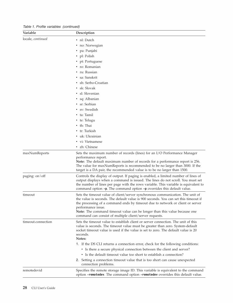
Table 1. Profile variables (continued)
Variable Description
locale, continued v nl: Dutch
v no: Norwegian
v pa: Punjabi
v pl: Polish
v pt: Portuguese
v ro: Romanian
v ru: Russian
v sa: Sanskrit
v sh: Serbo-Croatian
v sk: Slovak
v sl: Slovenian
v sq: Albanian
v sr: Serbian
v sv: Swedish
v ta: Tamil
v te: Telugu
v th: Thai
v tr: Turkish
v uk: Ukrainian
v vi: Vietnamese
v zh: Chinese
maxNumReports Sets the maximum number of records (lines) for an I/O Performance Managerperformance report.Note: The default maximum number of records for a performance report is 256.The value for maxNumReports is recommended to be no larger than 3000. If thetarget is a DA pair, the recommended value is to be no larger than 1500.
paging: on|off Controls the display of output. If paging is enabled, a limited number of lines ofoutput displays when a command is issued. The lines do not scroll. You must setthe number of lines per page with the rows variable. This variable is equivalent tocommand option -p. The command option -p overrides this default value.
timeout Sets the timeout value of client/server synchronous communication. The unit ofthe value is seconds. The default value is 900 seconds. You can set this timeout ifthe processing of a command ends by timeout due to network or client or serverperformance issue.Note: The command timeout value can be longer than this value because onecommand can consist of multiple client/server requests.
timeout.connection Sets the timeout value to establish client or server connection. The unit of thisvalue is seconds. The timeout value must be greater than zero. System-defaultsocket timeout value is used if the value is set to zero. The default value is 20seconds.Notes:
1. If the DS CLI returns a connection error, check for the following conditions:
v Is there a secure physical connection between the client and server?
v Is the default timeout value too short to establish a connection?
2. Setting a connection timeout value that is too short can cause unexpectedconnection problems.
remotedevid Specifies the remote storage image ID. This variable is equivalent to the commandoption -remotedev. The command option -remotedev overrides this default value.
28 CLI User's Guide

Table 1. Profile variables (continued)
Variable Description
rows Specifies the number of rows per page of output if the paging variable is enabled.This variable is equivalent to command option -r. The command option -roverrides this default value.
verbose: on|off Enables or disables verbose output. This variable is equivalent to the commandoption -v. The command option -v overrides this default value.
Example## DS CLI Profile#
## Management Console/Node IP Address(es)# hmc1 and hmc2 are equivalent to -hmc1 and -hmc2 command options.#hmc1: 127.0.0.1#hmc2: 127.0.0.1
## Default target Storage Image ID# "devid" and "remotedevid" are equivalent to# "-dev storage_image_ID" and "-remotedev storage_image_ID" command options,# respectively.#devid: IBM.2107-AZ12341#remotedevid: IBM.2107-AZ12341
## locale# Default locale is based on user environment.#locale: en
# Timeout value of client/server synchronous communication in second.# DSCLI command timeout value may be longer than client/server communication# timeout value since multiple requests may be made by one DSCLI command# The number of the requests made to server depends on DSCLI commands.# The default timeout value is 900 seconds.#timeout: 900
# Socket connection timeout value in seconds.# The timeout value must be greater than zero.# System default socket timeout value is used if timeout value is set to zero.# The default connection timeout value is 20 seconds.#timeout.connection: 20
# Output settings## ID format of objects:# on: fully qualified format# off: short formatfullid: off
# Paging and Rows per page.# paging enables/disables paging the output per line numbers specified by "rows".# "paging" is equivalent to "-p on|off" option.# on : Stop scrolling per output lines defined by "rows".# off : No paging. (default)# "rows" is equivalent to "-r #" option.paging: off#rows: 24
# Output format type for ls commands, which can take one of the following values:# default: Default output
Chapter 2. Installing, upgrading, and removing the DS CLI 29

# xml : XML format# delim : delimit columns using a character specified by "delim"# stanza : Horizontal table format# "format" is equivalent to option "-fmt default|xml|delim|stanza".#format: default
# delimiter character for ls commands.#delim: |# Display banner message. "banner" is equivalent to option "-bnr on|off".# on : Banner messages are displayed. (default)# off : No Banner messages are displayed.banner: on
## Display table header for ls commands. "header" is equivalent# to option "-hdr on|off".# on : Table headers are displayed. (default)# off : No table headers are displayed.header: on
## Display verbose information. "verbose" is equivalent to option "-v on|off".# on : Display verbose information.# off : No verbose information.verbose: off
# Echo each dscli command.# on : Echo commands to standard out prior to execution. Passwords withincommand line arguments will be hidden.# off : No command echo. (default)#echo:on
# If echo is on and echoprefix is specified, its value will be printed on theline before the echoed command.#echoprefix:dscli>
# The max number of records for performance report.# The default max number of records for performance report is 256. The value for it is suggested to be# not larger than 3000. If the target is dapair, the value is suggested to be not larger than 1500.#maxNumReports: 256
# End of Profile
Setting up user accounts using the DS CLIThis task describes how to set up a user account. You must have administrator authority to enable thisfunction.
Before you begin
The default administrator and security administrator accounts are set up automatically at the time ofinstallation. To access the storage administrator account, use the user name admin and the defaultpassword admin. To access the security administrator account, use the user name secadmin and the defaultpassword secadmin. These passwords are temporary and expire after their initial use. You must change thepassword before you can use any of the other functions. The storage administrator can assign a user toone or more user roles, except for the security administrator role. Only the security administrator canassign a user to the security administrator role. The user roles and the associated functions allowed bythe assignment are as follows:
admin (Administrator)All users that you assign to the storage administrator user role have access to all DS6000 storagemanagement console-server service methods, and all DS8000 storage image resources except thosethat are reserved for security administrator users.
30 CLI User's Guide

secadmin (Security Administrator)All users that you assign to the security administrator user role may initiate recovery key operations,and add other users to this role. Users in this role may not be assigned to any other user role, andusers in any other user role may not be assigned to this role.
op_volume (Logical Operator)The logical operator user role allows access to service methods and resources that relate to logicalvolumes, hosts, host ports, logical subsystems, logical volumes, and volume groups, excludingsecurity methods. In addition, this user role inherits all authority of the monitor user role.
op_storage (Physical Operator)The physical operator user role allows access to physical configuration service methods andresources, including storage complex, storage image, array, rank, and extent pool objects. This userrole inherits all the authority of the Copy Services operator and logical operator user roles, excludingsecurity methods.
op_copy_services (Copy Services Operator)The Copy Services operator user role allows access to all Copy Services service methods andresources, excluding security methods. In addition, this user role inherits all authority of the monitoruser role.
service (Service Operator)The service operator user role includes monitor authority, plus access to all managementconsole-server service methods and resources, such as performing code loads and retrieving problemlogs.
monitor (Monitor)The monitor user role allows access to list and show commands. It provides access to all read-only,nonsecurity management console-server service methods and resources.
no_access (No Access)The no_access user role does not allow access to any service methods or storage image resources. Bydefault, this user role is assigned to any user account in the security repository that is not associatedwith any other user role.
Table 2. User role capabilities
Capability AdministratorSecurityAdministrator
PhysicalOperator
LogicalOperator
CopyServicesOperator Monitor
ServiceOperator(DS6000only)
NoAccess
Security useraccountmanagement
X
Recoverykeymanagement
X
User accountmanagement
X
Access auditlog
X
Updatestoragecomplex
X X
Poweron/offstorageimage
X X
Chapter 2. Installing, upgrading, and removing the DS CLI 31

Table 2. User role capabilities (continued)
Capability AdministratorSecurityAdministrator
PhysicalOperator
LogicalOperator
CopyServicesOperator Monitor
ServiceOperator(DS6000only)
NoAccess
Updatestorage unit
X X
Updatestorageimage
X X
Warmstartstorageimage
X X
Managearrays,ranks, extentpools
X X
I/O portconfiguration
X X
Configurationrecoveryservices(unfencevolumes,discardpinnedtracks, repairranks,...)
X X
Hostconfiguration
X X X
Logicalsubsystemconfiguration
X X X
Volumeconfiguration
X X X
Add orremovevolumegroup
X X X
Assign orunassignvolumegroup tohostconnection
X X X
Add orremovevolumes tovolumegroup
X X X
32 CLI User's Guide

Table 2. User role capabilities (continued)
Capability AdministratorSecurityAdministrator
PhysicalOperator
LogicalOperator
CopyServicesOperator Monitor
ServiceOperator(DS6000only)
NoAccess
ManageCopyServices(FlashCopy,PPRC,GlobalMirror)
X X X
Set CopyServicestimeoutvalues
X X X
Update useraccountpassword
X X X X X X
Query FRUsandenclosures
X X X X X X
Queryconfiguration
X X X X X X
Query CopyServices
X X X X X X
FRUmanagement
X X X
Problemmanagement
X X X
Validatecommunicationpaths
X X X
Activatecode load
X X X
Create a newPE package
X X X
Managestorage unitIP addresses
X
In addition to assigning users to one or more user roles, you also must assign a default password to eachuser. When you notify users of their role assignment and default password, indicate that the defaultpassword is only good for the initial log on. Users must change the password at the time of their initiallog on. Also, remind all users to record their password in a safe place, because there is no way that theadministrator or the application can retrieve a password.
Note: You must change the default password for an account, including the administrator account, to beable to use any CLI command other than the one to change the password. See the chusercommand for more information.
Chapter 2. Installing, upgrading, and removing the DS CLI 33

About this task
Use the mkuser DS CLI command to create new user accounts with specific roles (user role or roles) andan initial password. If you assign multiple roles to an account, ensure that you separate the different roleswith a comma. For example, op_volume, op_storage. See the mkuser command description for moredetails.
Procedure1. Log in to the DS CLI in interactive command mode.2. Issue the following command from the dscli command prompt to assign a user to an account with a
default password: dscli> mkuser -pw AB9cdefg -group service,op_copy_services –pol my_policy1testuser
3. Press Enter and observe the processing result. A successful process returns the following display:User Name testuser with my_policy1 successfully created.
Activating your machine and feature licenses using the DS CLIUse the steps described in this task to activate your license activation codes. These codes must beactivated before any configuration can be applied to your DS8000 or DS6000 network.
Before you begin
Some license activation codes include:v Operating environment license for each storage unit that you own. (This license must be activated.)v Copy Services, which can consist of the following features:
– FlashCopy– Remote mirror and copy
v Parallel access volumes (PAV)v IBM HyperPAV (DS8000 only)v IBM FlashCopy SE (DS8000 only)
There are multiple codes that are associated with these features. For a complete list of activation codes,please see the IBM Disk Storage Feature Activation (DSFA) website at:
www.ibm.com/storage/dsfa/
On the website, enter your machine type, serial number, and machine signature. If you need to acquirethe information to complete these fields, issue the DS CLI showsu command to show the machine typeand serial number, and the showsi command to show the machine signature.
Download your codes in XML format onto a CD or USB flash drive. You can then import the codes fromthe XML file when you process the DS CLI applykey command.
Notes:
1. For DS8000, in most situations, the DSFA application can locate your 2244 licenseauthorization record when you enter the DS8000 (2107) serial number and signature. However,if the 2244 license authorization record is not attached to the 2107 record, you must assign it tothe 2107 record in the DSFA application. In this situation, you must have the 2244 serialnumber (which you can find on the License Function Authorization document).
2. For DS6000, in most situations, the DSFA application can locate your order confirmation code(OCC) when you enter the DS6000 (1750) serial number and signature. However, if the OCC is
34 CLI User's Guide
|
||
|||

not attached to the 1750 record, you must assign it to the 1750 record in the DSFA application.In this situation, you must have the OCC (which you can find on the License FunctionAuthorization document).
About this task
The DS CLI applykey command activates the licenses for your storage unit. The DS CLI lskey commandverifies which type of licensed features are activated for your storage unit.
Perform the following steps to activate your license activation codes:
Procedure1. Log in to the DS CLI in interactive command mode.2. Issue the DS CLI applykey command at the dscli command prompt as follows. (This example
presumes that your XML file is named "keys.xml" and it resides on a CD or USB flash drive): dscli>applykey -file a:\keys.xml -dev IBM.2107-75FA120
3. Press Enter. When the process has completed, the following message is displayed:Licensed Machine Code key xxxx, key xxxx successfully applied.
4. Verify that the keys have been activated for your storage unit by issuing the DS CLI lskey commandas follows: lskey -dev IBM.2107-75FA120
5. Press Enter and the following type of report is displayed:
Activation key Authorization level (TB) Scope
Operating environment (OEL) 45 All
Remote mirror and copy (RMC) 25 All
Metro mirror (MM) 25 All
Global mirror (GM) 25 All
Metro/global mirror(MGM)
25 All
Remote mirror for z/OS (RMZ) 25 CKD
Point in time copy (PTC) 25 All
Parallel access volumes (PAV) 100 CKD
IBM HyperPAV On CKD
IBM FlashCopy SE 105 All
Chapter 2. Installing, upgrading, and removing the DS CLI 35

36 CLI User's Guide

Chapter 3. Running the DS CLI
You can use the DS CLI in three different command modes.
Note: For the DS6000 model, you must ensure that you have installed the DS Storage Manager using thefull-management console installation and that you have configured your domain. Without thisdomain configuration (which is a one-time process), you cannot use the DS CLI.
The following command modes are available:v Single-shotv Interactivev Script
Note: DS CLI logs are created on the system running the DS CLI. The location of the logs is under theuser home directory at dscli/log/. This location cannot be changed. For example, on Windows XPthe logs for the administrator user are created under the directory C:\Documents andSettings\Administrator\dscli\log. On UNIX, the logs are created under the directory~/dscli/log.
Logging into the DS CLIYou must log in to the DS CLI to use any of the command modes.
Before you begin
You must ensure that you are in the directory where you installed the DS CLI, or use the full path nameof the DS CLI. The following list provides the location of the default directory for each operating system:
AIX /opt/ibm/dscli
HPUX /opt/ibm/dscli
Linux /opt/ibm/dscli
Sun Solaris/opt/ibm/dscli
WindowsC:\Program Files\IBM\dscli
HP Tru64 UNIX/opt/ibm/dscli
iSeries/ibm/dscli
Novell NetWareSYS:\IBM\dscli
About this task
To log in to the DS CLI, open a command prompt and enter dscli with the following information:
HMC1Specify the primary management console.
© Copyright IBM Corp. 2006, 2012 37

Note: If you are using a 2105 machine type as part of your network and are going to use theCopy Services functions, you must specify the IP address of the domain control serverwhere you have installed the DS CLI.
User NameSpecify the name of the user account. The default user names for the first logins are admin andsecadmin.
PasswordSpecify the user password. The default password for the administrator account is admin and thedefault password for the security administrator account is secadmin. However, these passwordsare only good for the first login.
Note: Because the passwords for the administrator and security administrator accounts expireafter you log in for the first time, you must change the password before you can performany other DS CLI command function. Use the chuser command to change your password.
Each time you log in to the DS CLI, either in the directory where you installed the DS CLI or using thefull path name for the DS CLI, you can specify this information using either of the following threemethods:v You may log in to the DS CLI without specifying any of this information on the command line and the
application will prompt you to enter the information interactively. For example: /opt/ibm/dscli/dscli.v You may log in to the DS CLI by specifying this information on the command line. For example: dscli
-hmc1 mtc032h.storage.tucson.ibm.com -user admin -passwd topn0t.v You may log in to the DS CLI by specifying this information on the command line, except for the
password, by using the -pwfile parameter instead of the -passwd parameter. For example: dscli -hmc19.1.12.123 -user admin -pwfile /home/ming/dscli/security.dat, where "ming" is the user ID used tolog into the operating system. The security.dat file was created by using the DS CLI commandmanagepwfile. See the DS CLI command managepwfile for more details.
Notes:
1. Entering a DS CLI command at the dscli command prompt requires that you continueentering all the parameters and values until the command is complete. This can result in anautomatic line wrap if your command has many parameters and values.
2. You cannot force a line break or wrap by pressing the Enter key and then typing the rest ofthe command on a second line. The DS CLI interprets the use of the Enter key as an end tothe function and begins to process whatever is contained on the line, ignoring the second line.
3. The DS CLI command examples that are provided in this guide are often shown with linewraps that would not occur during your input. These examples are displayed for clarity andother formatting considerations.
Using the DS CLI single-shot command modeUse the DS CLI single-shot command mode if you want to issue an occasional command but do not wantto keep a history of the commands that you have issued.
About this task
You must supply the login information and issue the command that you want to process at the sametime. Perform the following steps to use the single-shot mode:
Procedure1. Use the following command format to start a DS CLI session (Windows operating system):
dscli -hmc1 9.1.23.456 -user admin -passwd my_passwordlssi -s -fullid -hdr off
38 CLI User's Guide

Here is an example of this same command in i5/OS without the report delimiters:DSCLI SCRIPT(*NONE) HMC1(’9.1.23.456’) USER(admin) PASSWORD(my_password)DSCLI(lssi)
This command demonstrates the use of the lssi command with the -s parameter. Use this commandto view the storage image IDs for your storage complex. The storage image ID consists of themanufacturer name (IBM), the machine type (2107 or 1750), and the serial number.
Notes:
a. The command example uses the -fullid DS CLI command parameter. The -fullidcommand parameter generates fully qualified IDs, which include the storage image ID, forevery ID that is displayed in the command output.
b. The command example also uses the -hdr off command parameter, which turns off theheader that is associated with the report generated from the lssi command.
c. Almost every DS CLI command requires the use of the storage image ID. You can set it asan environment variable by setting devid in the profile file, or by setting devid using thesetenv command. If you choose not to set it, the dscli will set a default devid on systemswhere the management console is aware of only one storage image. If you provide the-dev (storage_image_ID) parameter in commands, the value that you type takes priorityover the devid environment variable. If you specify a full ID that contains the storage imageID, the storage image ID that you specify takes priority over the value from the -dev(storage_image_ID) parameter and over the devid environment variable.
2. Wait for the command to process. The following type of report is generated to list the storage imageIDs that are associated with the storage complex.v IBM.2107-75FA111v IBM.2107-75FA112v IBM.2107-75FA120
Using the DS CLI script command modeUse the DS CLI script command mode if you want to issue a sequence of DS CLI commands.Administrators can use this mode to create automated processes. For example, this mode can be used toestablish remote mirror and copy relationships for volume pairs.
Before you begin
Consider the following requirements when using the DS CLI script command mode:v The DS CLI script can contain only DS CLI commands. Use of shell commands results in a process
failure.v You can add comments to the scripts. Comments must be prefixed by the number sign (#). For
example, # This script contains PPRC Path establish procedures.v You can set the echo environment variable using the dscli profile file or you can use the setenv
command to specify that the dscli command name is displayed before the command output.
Note: It is not the intent of this instruction to tell you how to write a script. An example script isdisplayed for your use as a guide.
About this task
You can issue the DS CLI script from the command prompt at the same time that you provide your logininformation.
Procedure1. Enter the script name at the command prompt using the following format:
Chapter 3. Running the DS CLI 39
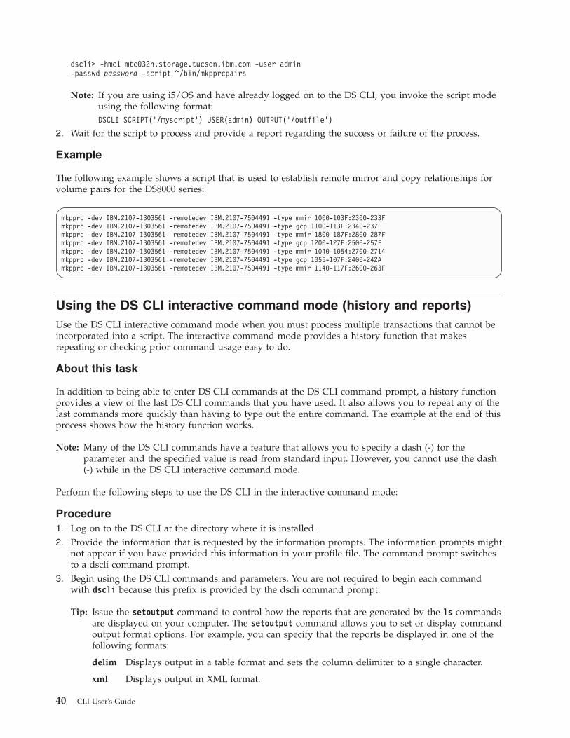
dscli> -hmc1 mtc032h.storage.tucson.ibm.com -user admin-passwd password -script ~/bin/mkpprcpairs
Note: If you are using i5/OS and have already logged on to the DS CLI, you invoke the script modeusing the following format:DSCLI SCRIPT(’/myscript’) USER(admin) OUTPUT(’/outfile’)
2. Wait for the script to process and provide a report regarding the success or failure of the process.
Example
The following example shows a script that is used to establish remote mirror and copy relationships forvolume pairs for the DS8000 series:
Using the DS CLI interactive command mode (history and reports)Use the DS CLI interactive command mode when you must process multiple transactions that cannot beincorporated into a script. The interactive command mode provides a history function that makesrepeating or checking prior command usage easy to do.
About this task
In addition to being able to enter DS CLI commands at the DS CLI command prompt, a history functionprovides a view of the last DS CLI commands that you have used. It also allows you to repeat any of thelast commands more quickly than having to type out the entire command. The example at the end of thisprocess shows how the history function works.
Note: Many of the DS CLI commands have a feature that allows you to specify a dash (-) for theparameter and the specified value is read from standard input. However, you cannot use the dash(-) while in the DS CLI interactive command mode.
Perform the following steps to use the DS CLI in the interactive command mode:
Procedure1. Log on to the DS CLI at the directory where it is installed.2. Provide the information that is requested by the information prompts. The information prompts might
not appear if you have provided this information in your profile file. The command prompt switchesto a dscli command prompt.
3. Begin using the DS CLI commands and parameters. You are not required to begin each commandwith dscli because this prefix is provided by the dscli command prompt.
Tip: Issue the setoutput command to control how the reports that are generated by the ls commandsare displayed on your computer. The setoutput command allows you to set or display commandoutput format options. For example, you can specify that the reports be displayed in one of thefollowing formats:
delim Displays output in a table format and sets the column delimiter to a single character.
xml Displays output in XML format.
mkpprc -dev IBM.2107-1303561 -remotedev IBM.2107-7504491 -type mmir 1000-103F:2300-233Fmkpprc -dev IBM.2107-1303561 -remotedev IBM.2107-7504491 -type gcp 1100-113F:2340-237Fmkpprc -dev IBM.2107-1303561 -remotedev IBM.2107-7504491 -type mmir 1800-187F:2800-287Fmkpprc -dev IBM.2107-1303561 -remotedev IBM.2107-7504491 -type gcp 1200-127F:2500-257Fmkpprc -dev IBM.2107-1303561 -remotedev IBM.2107-7504491 -type mmir 1040-1054:2700-2714mkpprc -dev IBM.2107-1303561 -remotedev IBM.2107-7504491 -type gcp 1055-107F:2400-242Amkpprc -dev IBM.2107-1303561 -remotedev IBM.2107-7504491 -type mmir 1140-117F:2600-263F
40 CLI User's Guide

stanza Displays output in stanza (vertical table) format.
See the setoutput command for more details.
Example
To use the DS CLI history function that is associated with the interactive command mode, perform thefollowing steps:1. Issue an exclamation mark (!) to display CLI commands that you have used in the current session.
For example: dscli> ! results in a list of commands such as the following example:[4] lsarraysite -dev IBM.2107-1300771[3] lsarray -dev IBM.2107-1300771[2] lsextpool -dev IBM.2107-1300771[1] lsextpool -dev IBM.2107-1300771
2. Issue dscli> !1 to retry the last command. Or, issue dscli> !3 to retry command [3].
Obtaining the serial (storage image ID) number using the DS CLIAlmost every DS CLI command requires the use of the storage image ID. If you add your target storageimage ID into your profile file under the devid designation, you are not required to provide the storageimage ID when you issue each command.
About this task
Use the lssi DS CLI command to list the storage image IDs that are associated with your storagecomplex. The storage image ID consists of the manufacture name (IBM), the machine type (2107 or 1750),and the serial number. You can record the target storage image ID in your profile file. This can save youinput time when you have to process many transactions that cannot be part of a script.
To obtain a list of the storage image ID numbers, perform the following steps:
Procedure1. Log in to the DS CLI in interactive command mode.2. Enter the following command format at the dscli command prompt to obtain the storage image IDs:
dscli> lssi -s
3. Wait for the command to process. The following type of report is generated, which lists the storageimage IDs that are associated with the storage complex.v IBM.2107-75FA111v IBM.2107-75FA112v IBM.2107-75FA120
DS CLI command helpYou can view online help for each CLI command. To view the help, type the word help and thecommand name at the dscli command prompt.
The help command contains parameters that influence the type of help information that you can receive:
Table 3. Parameters for the help command
Command Description
help Displays a list of all the DS CLI commands that areavailable for use.
help -s Displays a list of commands with brief descriptions.
Chapter 3. Running the DS CLI 41

Table 3. Parameters for the help command (continued)
Command Description
help -l Displays a list of commands with their associated syntax.
help -match <string> Displays a list of commands that contain the specifiedstring. This parameter cannot be used with any otherparameters.
command_name -hcommand_name -helpcommand_name -?help command_name
Displays the reference page (man page) for the commandname.
help -s command_name Displays the brief description for the command name.
help -l command_name Displays the usage statement for the command name.
Notes:
v You cannot use the -s and -l parameters with the following help command parameters: -h,-help, and -?.
v Much of the information that is associated with the help command is displayed in list format.You can include the page (-p on) and row (-r number) controls; for example, dscli> help -p on-r 20. This command pauses your page listing after 20 entries and prompts you to press anykey to continue.
Exampledscli> help -match flash
The resulting outputreverseflashcommitflashrmflashlsremoteflashresyncremoteflashresyncflashmkremoteflashsetflashrevertiblerevertflashunfreezeflashrevertremoteflashrmremoteflashcommitremoteflashmkflashlsflashsetremoteflashrevertible
Obtaining and interpreting DS CLI exit codesComplete this task to obtain and interpret DS CLI exit codes.
About this task
Whenever you complete a transaction using the DS CLI single-shot mode or the script mode, an exit codeis generated. However, no exit codes are generated when you use the DS CLI interactive mode, becauseyou never leave the DS CLI session.
When you use the single-shot mode, an exit code is generated after each DS CLI command is fullyprocessed. When you use the script mode, exit codes are only generated when the script exits the session.In script mode, you must interpret output for the status.
42 CLI User's Guide

DS CLI exit codes provide more general reasons (than the error messages provide) why a CLI commandtransaction has failed. The following table lists the exit codes and their meanings.
Note: The operating system might generate other exit codes not listed in Table 4 if the DS CLI is stoppedby another process. For example, code 143 for the Windows operating system.
Table 4. DS CLI exit codes
Code Category Description
0 Success Specifies that the command issuccessfully processed.
2 Syntax error Specifies that there is an error in theway that the command is presented(misaligned or wrong parameters) forprocessing.
3 Connection error Specifies that there is a connectivityor protocol error.
4 Server error Specifies that an error occurs duringa function call to the applicationserver.
5 Authentication error Specifies that an error occurs duringthe authentication process.
6 Application error Specifies that an error occurs due to aMetaProvider client applicationspecific process.
63 Configuration error Specifies that the CLI.CFG file is notfound or accessible.
64 Configuration error Specifies that the javaInstall variablewas not provided in CLI.cfg.
65 Configuration error Specifies that the javaClasspathvariable was not provided in CLI.cfg.
66 Configuration error Specifies that the format of theconfiguration file is not correct.
Perform the following steps to view, interpret, and use the DS CLI exit codes.
Procedure1. (Script mode) Retrieve the most recent exit code. For a Windows operating system, use %ERRORLEVEL%
to retrieve the most recent exit code. For a UNIX or Linux operating system, use $? to retrieve themost recent exit code.The following examples demonstrate the retrieval commands. The first part of the example shows thecommand that failed and the second part of the example shows the code to obtain the DS CLI exitcode.Windows operating systemC:\Program Files\ess\cli>dscli testCMMCI9013E Command: test was not found.Tip: Enter “help” for a list of available commands.
C:\Program Files\ess\cli>echo %ERRORLEVEL%2
UNIX or Linux operating systemaix23 ->dscli testCMMCI9013E Command: test was not found.Tip: Enter “help” for a list of available commands.
Chapter 3. Running the DS CLI 43

echo $?2
2. Use the previous table to interpret the value that is associated with the code and correct the commandaccording to the exit code description.
Results
Processing that determines your next course of action
Based on the interpretation of the exit code value and the following processing description that isassociated with a failed DS CLI transaction, you can determine your next course of action.
Single-shot modeThe following processing is associated with a single-shot mode transaction:v All operations of the DS CLI transaction that can be processed are processed even though an error
has occurred with one or more of the processed parameters that are associated with the transaction.v A report on all successful completions is generated.v A report on all failures is generated.
Script modeThe following processing is associated with a script mode transaction:1. A DS CLI failure exit code is issued.2. The script mode is automatically exited with no additional processing.
DS CLI operational limitationsThere are operational limitations that are associated with the use of the DS CLI.
These limitations are described as follows:v Volumes in the same volume space, logical subsystem (LSS), logical control unit (LCU), or address
group cannot be of mixed type. They are either fixed block or count key data (CKD).
Note: The volume space is called an extent pool. An extent pool contains one or more ranks of acommon storage type (fixed block or CKD).
v Logical subsystems cannot be created using the DS CLI. A fixed block LSS is automatically createdwhen your first fixed block volume is assigned to the LSS address space. A fixed block LSS isautomatically deleted when the last fixed block volume is removed from an LSS address space.
Note: You can use DS CLI commands to create, modify, and delete LCUs, which are the CKD volumeequivalent of a fixed block LSS.
v You must not start more than 100 DS CLI sessions simultaneously. Starting more than 100 DS CLIsessions simultaneously can result in connection problems.
v The maximum number of simultaneous DS CLI sessions is dependent on several executionenvironment factors such as the host hardware configuration, the vendor and version of the host OS,the vendor and version of the Java used by the DS CLI, the type and mix of DS CLI commands, LANcongestion, and the capacity, configuration, and current workload of the DS8000. It is unlikely that youwill experience problems using multiple DS CLI sessions, but under high stress conditions, you mightbe required to reduce the number of simultaneous DS CLI sessions on each host and the total numberof DS CLI sessions to the DS8000.
v Beginning with Version 6 Release 1, the DS CLI is available from the HMC console with the followingrestrictions:– The DS CLI is only available in interactive mode from the fluxbox menu.– You cannot upgrade the DS CLI on the HMC except though newer releases of HMC software.– You cannot edit the existing DS CLI profile, or specify a different profile.
44 CLI User's Guide

– You cannot use commands that upload or download files, for example:- offloadauditlog
- offloadfile
- applykey cannot be used with the -file parameter- setauthpol cannot be used with the -action value of settruststore
Messages in the CLI and management console serverWhen you use the command-line interface and the management console, the applications providemessages regarding the application processes, status, and errors. This section also provides informationabout how the DS CLI manages OpenVMS messages.
The user interfaces and the supporting software issue three types of messages. When you need to see thedetails about a DS CLI message, use the helpmsg command.
Informational messagesThese messages are identified by the letter "I" at the end of the message identifier. They provideinformation about system activities as they take place. For example, an informational message mightreport that a volume was successfully created. No user action is necessary.
Warning messagesThese messages are identified by the letter "W" at the end of the message identifier. They warn thatuser activated activities might have consequences that you do not anticipate. Warning messagesnormally provide the opportunity to continue an activity or to cancel it.
Error messagesThese messages are identified by the letter "E" at the end of the message identifier. They indicate thatan error has occurred. Refer to the explanations and recommended actions in this document toresolve the problem.
Chapter 3. Running the DS CLI 45

46 CLI User's Guide

Chapter 4. CLI commands
This section describes the command-line interface (CLI) commands that you can use to performconfiguration and storage management tasks.
About CLI commandsThis topic provides a description of the components and structure of a command-line interface command.
A command-line interface command consists of the following types of components, arranged in thefollowing order:1. The command name.2. The command flags and flag parameters.
3. One or more command parameters, each followed by any sub parameters it might require.
The command name specifies the task that the command-line interface is to perform. For example,lsarraysite tells the command-line interface to list array sites, and mklcu tells the command-line interfaceto create a logical control unit.
Flags modify the command. They provide additional information that directs the command-line interfaceto perform the command task in a specific way. For example, the -h flag tells the command-line interfaceto display the reference page for the command. Some flags can be used with every command-lineinterface command. Others are specific to a command and are invalid when used with other commands.Flags are preceded by a hyphen (-), and can be followed immediately by a space and a flag parameter.
Flag parameters provide information that is required to implement the command modification that isspecified by a flag. For example, the -user flag requires a user_name parameter, and the -passwd flagrequires a password parameter. Flag parameters are variables. This means that their value changes to meetyour needs. Every user has a different user name and password. Not all flags require parameters. In thiscase, the flag itself provides all the information that is necessary. Some flag parameters are optional andmight allow the use of multiple values. These values must be separated with a comma and no whitespace between the values. If you do not provide a parameter, then a default value is assumed. Forexample, you can specify -v on, or -v off to turn verbose mode on or off; but specifying -v only, results inan error.
The command parameter provides basic information that is necessary to perform the command task.When a command parameter is required, it is always the last component of the command; and it is notpreceded by a flag. Some commands permit multiple command parameters with each parameterseparated by a white space and not a comma (unlike flag parameters that allow multiple values). Somecommands, like lsuser, do not require a command parameter, because a default value of all is alwaysassumed. For some commands, like lsarraysite, the command parameter is optional. If no value isprovided, then a default value of all is assumed. If a value is provided, then the command-line interfacelists information only about the array site or sites provided in the command parameter string.
In the following example, lsrank is the command name. -dev and -l are command parameters.IBM.2107–75FA120 is the sub parameter for the -dev parameter, and R1, R2, and R3 are a list of commandparameters. Note that the banner is not listed for all examples provided in this publication.
dscli> lsrank -dev IBM.2107-75FA120 -l R1 R2 R3
© Copyright IBM Corp. 2006, 2012 47

Understanding the syntax diagramsA syntax diagram uses symbols to represent the elements of a command and to specify the rules forusing these elements.
Syntax diagrams
Main path line
�� ��
Begins on the left with double arrowheads (>>) and ends on the right with two arrowheadsfacing each other (><). If a diagram is longer than one line, each line to be continued ends with asingle arrowhead (>) and the next line begins with a single arrowhead. Read the diagrams fromleft-to-right, top-to-bottom, following the main path line.
Keyword
�� dscli ��
Represents the name of a command, parameter, or argument. A keyword is not in italics. Spell akeyword exactly as it is shown in the syntax diagram.
Required keywords
�� mkuser -pw password -group group_name [ . . . ]-pol pol_name
�
�-scope user_resource_scope
User Name" - "
��
Indicates the parameters or arguments you must specify for the command. Required keywordsappear on the main path line. Mutually exclusive required keywords are stacked vertically.
Optional keywords
��-h -help -?
��
Indicates the parameters or arguments you can choose to specify for the command. Optionalkeywords appear below the main path line. Mutually exclusive optional keywords are stackedvertically.
Variable
�� variable ��
Represents the value you need to supply for a parameter or argument, such as a file name, username, or password. Variables are in italics.
Special characters
- (minus) or / (slash) signParameters are prefixed with a - (minus) sign. Parameters define the action of a command ormodify the operation of a command. You can use multiple parameters, followed by variables,when you issue a command.
48 CLI User's Guide

[ ] square bracketsOptional values are enclosed in square brackets.
{ } bracesRequired or expected values are enclosed in braces.
| vertical barA vertical bar indicates that you have a choice between two or more options or arguments.
For example, [ a | b ] indicates that you can choose a, b, or nothing. Similarly, { a | b } indicatesthat you must choose either a or b.
... ellipsisAn ellipsis signifies the values that can be repeated on the command line or multiple values orarguments.
– dash A dash indicates that, as an alternative to entering the parameter, a value or values are suppliedfrom stdin. stdin varies depending on your settings and is available when you are usingsingle-shot or script mode. This option is not available when using interactive mode.
Common command flagsYou can use these flags with any command-line interface command.
Parameters Description
-p on | off Turns paging on or off. Displays 24 rows at a time unless used withthe -r flag. The default is off in single-shot mode and on ininteractive mode. You can page up or down by pressing any key. Youcan specify -p on or -p off to turn the paging on or off; but if youspecify only -p, you get an error.Note: You can only use this flag with the ls type (for example, lsuser,lskey, lsserver) commands and the help (setoutput) command.
-r number Specifies the number of rows (1 - 100) per page. This flag is validonly when the -p flag is set to on. The default value is 24 rows.Note: You can only use this flag with the ls type (for example, lsuser,lskey, lsserver) commands and the help (setoutput) command.
-fmt xml | stanza | delim | defaultxml Sets the output format to XML.
Note: You can use this option only with list (for example,lsuser, lskey, lsserver) commands
stanza Sets the output format to stanza.Note: You can use this option only with list (for example,lsuser, lskey, lsserver) commands
delim Sets the output format to a table. You must set the columndelimiter to a single character with the -delim flag.Note: You can use this option only with list (for example,lsuser, lskey, lsserver) commands
default Sets the output to a space-separated plain text table.Note: You can use this option only with list (for example,lsuser, lskey, lsserver) commands
-delim char Sets the output to delimited output and the delimiter to the singlecharacter char. You must enclose char in single or double quotationmarks if the character is a shell metacharacter (such as * or \t). Ifchar is not specified, the CLI program returns a syntax error. A blankspace, even when it is enclosed within quotation marks, is not a validcharacter as a delimiter.Note: You can use this option only with list (for example, lsuser,lskey, lsserver) commands
Chapter 4. CLI commands 49

Parameters Description
-hdr on | off Turns the header on or off. The default is on. You can specify -hdr onor -hdr off to turn the header on or off; but if you specify only -hdr,you get an error.
-bnr on | off Turns the banner on or off. The default is on. You can specify -bnr onor -bnr off to turn the banner on or off; but if you specify only-bnr,you get an error.
-v on | off Turns verbose mode on or off. The default is off. You can specify -von or -v off to turn verbose mode on or off; but if you specify only-v,you get an error.
-fullid on | off Provides fully qualified IDs, which include the storage image ID, forevery ID that is displayed in the command output. The default valueis off. You can specify -fullid on or -fullid off; but if you specifyonly-fullid, you get an error.Note: You can only use this command flag with list (for example,lsioport, lskey) and show (for example, showsu, showlss) commands.
-help | -h | -? Displays a detailed description of the specified command, includingsyntax, parameter descriptions, and examples. If you specify a helpoption, all other command options are ignored.
-s Displays the short output for the command, which is usually a singlecolumn of the resource IDs of the objects specified by the command.For detailed information, see the -s parameter for that command.Notes:
1. You can only use this flag with the help (setoutput) commandand the ls type (for example, lsuser, lsserver) commands, exceptfor lskey.
2. You cannot use the -s and -l parameters together.
-l Displays the long output for the command, which is the defaultoutput plus additional columns of data to the right of the defaultcolumns. For detailed information for a specific command, see the -lparameter for that command.Notes:
1. You can only use this flag with the help (setoutput) commandand the ls type (for example, lsuser, lsserver) commands, exceptfor lskey.
2. You cannot use the -s and -l parameters together.
Framework commandsThis section contains the user interface framework commands for the DS command-line interface.
The following framework commands are available:
dscli Starts the DS CLI. Use this command to perform storage management tasks from thecommand-line.
echo Allows you to specify whether the dscli will echo each specified command, or to display auser-specified string. If echo is turned on, each command will be printed before it is executed.The echo can also be turned on or off using the dscli profile file or the setenv command.
exit Ends an interactive command-line interface session.
help Displays a list of commands available in a command-line interface and optionally displays thesyntax or brief description of each command. If you specify this command with no parameters,this command displays only a list of available commands.
50 CLI User's Guide

helpmsgUsed to obtain details about information, warning, and error messages.
quit Ends an interactive command-line interface session.
setenv Allows you to set DS CLI environment variables that are located in the DS CLI profile.
showenvDisplays the DS CLI environment variables.
ver Displays the versions of the command-line interface, storage management console (HMC orSMC), and licensed machine code. It does not display the version number of the graphical userinterface (GUI).
dscliThe dscli command starts the DS CLI. Use this command to run DS CLI commands in the interactive,single-shot, or script mode.
�� dscli-h-help-?
-ver-overview
-cfg profile -hmc1 hmc1 -hmc2 hmc2�
�-user user_name -passwd password
-pwfile passwordfilecommand-script file_name
��
Parameters
-help | -h | -?(Optional) Displays a help screen about how to use the DS CLI program.
-ver(Optional) Displays the DS CLI version.
-overview(Optional) Provides overview information about the DS CLI.
-cfg profileSpecifies a profile file. This parameter is not required if you are using default profiles. The defaultprofile file name is dscli.profile, and it is provided as part of the DS CLI package under the profiledirectory. See “Creating a default CLI profile” on page 24 for more information.
-hmc1 hmc1(Optional) Specifies the primary management console IP address or the DNS name.
Note: You can connect the DS CLI to the HMC using an IPV6 IP address if your Java virtual machinelevel supports IPV6.
This parameter is not required if you have established this information as a profile variable.
-hmc2 hmc2(Optional) Specifies the secondary management console IP address or the DNS name. This parameteris not required if you have established this information as a profile variable.
-user user_name(Optional) Specifies your user name for issuing DS CLI commands on the command-line.
-passwd password(Optional and not recommended) Specifies the password you want to use to authenticate when you
Chapter 4. CLI commands 51

start the CLI session.This parameter is not required or recommended. If you use this method todesignate your password, the password is displayed on the screen. Another option is to specify apassword file (see the next parameter) that is used when you start the DS CLI.
-pwfile passwordfile(Optional) Specifies a password file containing your password as an alternative to the –passwdparameter.
Note: You cannot specify both the -pwfile and the -passwd parameter when you start the DS CLI,otherwise an error message is given.
command(Optional) Specifies the single command that you want to run.
Note: You cannot specify both the command and -script file_name parameters. Use -script for scriptmode, command for single-shot mode, and use neither for interactive mode.
-script file_name(Optional) Initiates the script mode so that multiple dscli program commands can be issuedconsecutively using a saved file. Format options that are specified using the framework setoutputcommand apply to all commands in the file. Output from successful commands routes to stdout, andoutput from failed commands routes to stderr. If an error occurs during the processing of one of thecommands in the file, the script exits at the point of failure and returns to the system prompt.
echoThe echo command allows you to specify whether the dscli will echo each specified command, or todisplay a user-specified string.
If echo is turned on, each command will be printed before it is executed. The echo can also be turned onor off using the dscli profile file or the setenv command.
�� echoonoffmessage
��
Parameters
on | off | message(Optional) Specifies whether the echo is turned on or off, or if a message is displayed. If it is turnedon, each command will be displayed before it is executed. If it is turned off, the dscli will not displayanything before executing a command. You can also choose to echo a string of your choice. Forexample, if you enter echo something else, the string "something else" will be displayed. Issuing theecho command without any parameters will display whether echo is on or off.
Note: If the echoprefix variable is set, its value will be printed on the same line preceding thecommands that are echoed.
Example
Issuing the echo command:dscli> echo on
The resulting outputdscli> echo on
52 CLI User's Guide

CMUC00212I echo: completed successfully.
exitThe exit command ends an interactive command-line interface session.
�� exit ��
helpThe help command displays a list of commands available in a command-line interface and optionallydisplays the syntax or brief description of each command. If you specify this command with noparameters, this command displays only a list of available commands.
�� help-?-h-help
-l-s
off-p on
-r number command_name�
�-match string
��
Parameters
-? | -h | -helpDisplays a detailed description of this command, including syntax, parameter descriptions, andexamples. If you specify a help option, all other command options are ignored.
-lDisplays a list of available commands with the syntax diagrams for each. If you specify a commandname with this parameter, this command displays the syntax for only the specified command.
-sDisplays a list of available commands with a brief description of each. If you specify a commandname with this parameter, this command displays a brief description for only the specified command.
-p off | onSpecifies whether to display one page of text at a time or all text at once.
off Displays all text at one time. This value is the default.
on Displays one page of text at a time. Pressing any key displays the next page.
-r numberSpecifies the number of rows per page to display when the -p parameter is on. The default is 24rows. You can specify a value from 1 to 100.
command_nameDisplays help information for the specified command, including the syntax diagram, parameterdescriptions, return codes and errors, descriptions, examples, and miscellaneous remarks.
-match stringDisplays a list of commands that contain the specified string. This parameter cannot be used withany other parameters.
Example
Invoke help#dscli> help -s exit
Chapter 4. CLI commands 53

The resulting outputEnds a command-line interface session.
helpmsgThe helpmsg command is used to obtain details about information, warning, and error messages.
�� helpmsg message_ID ��
Parameters
Notes:
1. The message information revealed by this command is a snapshot of what is available in yourcurrent code version.
2. This command does not work for GUI messages.3. For the most up-to-date information, see the list of individual messages in the IBM System
Storage DS8000 Information Center.
message_ID(Required) Specifies the message number that you are querying. You must enter the entire messagenumber (for example, CMUC00246I, CMUC00244W, CMUC00247E). You do not have to enter all caps.Substitute keys are not allowed and cause an error if used.
Example
Invoking the helpmsg commanddscli> helpmsg cmuc00247e
The resulting outputCMUC00247E COMMAND_INFO You are attempting to create volumes for a logicalsubsystem that does not match the rank group of the extent pool that youspecified.
ExplanationYou create a logical volume from an extent pool in a rank group. The logicalvolume is also a member of a logical subsystem group. The logical subsystemgroup identifier and the rank group identifier of the extent pool that youspecify must be identical. Even-numbered logical subsystem identifiers areassociated with rank group identifier 0, and odd-numbered logical subsystemidentifiers are associated with rank group identifier 1.
ActionRetry the create volume task and specify an extent pool and a logicalsubsystem group that are in the same rank group.
quitThe quit command ends an interactive command-line interface session.
�� quit-?-h-help
��
54 CLI User's Guide

Parameters
-? | -h | -helpDisplays a detailed description of this command, including syntax, parameter descriptions, andexamples. If you specify a help option, all other command options are ignored.
setenvThe setenv command allows you to override the default values of the DS CLI environment variables. Thedefault values are found in the DS CLI profile, and the new values are valid for the current interactivesession only and not permanently saved back into the DS CLI profile.
�� setenv-paging on
off-rows # -format default
xmldelimstanza
-delim char�
�-header on
off-verbose on
off-banner on
off
�
�-devid storage_image_ID -remotedevid storage_image_ID -echo on
off
�
�-echoprefix echo_prefix
none-locale user_locale -timeout timeout_in_sec
�
�-fullid on
off-maxnumreports max_reports
��
Parameters
-paging on | off(Optional) Specifies whether to display one page of text at a time or all of the text at once.
offDisplays all of the text at one time. This value is the default.
on Displays one page of text at a time. Pressing any key displays the next page.
-rows #(Optional) Specifies the number of rows per page to display when -paging is set to on. The default is24 rows. You can specify a value from 1 to 100.
-format default | xml | delim | stanza(Optional) Specifies the format of the output. You can specify one of the following values:
defaultSpecifies that the output is to be displayed in a tabular format using a space as the delimiterbetween the columns. This value is the default.
delimSpecifies that the output format is to be set to a table and sets the column delimiter to a singlecharacter that is specified by the -delim char parameter.
xmlSpecifies that the output is to be displayed in XML format.
Chapter 4. CLI commands 55

stanzaSpecifies that the output is to be displayed in a stanza (vertical table) format.
-delim char(Optional) Specifies the delimiter character (such as a comma) used in the report.
-header on | off(Optional) Specifies whether to display the table header.
on Displays the table header. This value is the default.
offDoes not display the table header.
-verbose on | off(Optional) Specifies whether to enable verbose mode.
offDisables verbose mode. The value that you specify takes the place of the value that you specifiedin the profile.
on Enables verbose mode.
-banner on | off(Optional) Specifies whether the banner (command header) message is enabled.
offTurns off the header mode so that the command header does not display.
on Turns on the header mode so that the command header is displayed.
-devid storage_image_ID(Optional) Specifies the default devid.
-remotedevid storage_image_ID(Optional) Specifies the default remote devid.
-echo on | off(Optional) Specifies whether the echo is turned on or off. If it is turned on, each command will beprinted before it is executed.
-echoprefix echo_prefix | none(Optional) Specifies a prefix to display before each echoed command. -echoprefix none indicates thatno prefix should be displayed.
-locale user_locale(Optional) Specifies the output language on the local computer. The default locale is based on theuser environment settings. Example: en
-timeout timeout_in_sec(Optional) Specifies the timeout value of client/server synchronous communication. The timeoutvalue is displayed in seconds.
-fullid on | off(Optional) Specifies that IDs are displayed in the fully qualified format, which includes the storageimage ID. The default value is off.
-maxnumreports max_reports(Optional) Specifies the maximum number of records for the performance report. The default value is256.
56 CLI User's Guide

Example
You can issue the setenv command for a DS8000 model.
Invoking the setenv commanddscli> setenv -echo on
The resulting output
CMUC00043I setenv: Environment variable successfully set.
showenvThe showenv command displays the DS CLI environment variables.
�� showenv ��
Example
You can issue the showenv command for a DS8000 model.
Invoking the showenv commanddscli> showenv
The resulting outputpaging offrows 24format defaultdelim ,header onverbose offbanner ondevid IBM.2107-1301441remotedevid IBM.2107-1301441echo offechoprefix -locale zhtimeout -fullid offmaxNumReports 256
Report field definitions
pagingSpecifies whether paging is turned on or off.
rows Specifies the number of rows per page that are displayed.
formatSpecifies the output format.
delim Specifies the delimiter character that is used in the delim output format.
headerSpecifies whether the header should be turned on or off.
verboseSpecifies whether verbose mode is turned on or off.
bannerSpecifies whether the banner is turned on or off.
Chapter 4. CLI commands 57

devid Specifies the default devid.
remotedevidSpecifies the default remote devid.
echo Specifies whether the echo is turned on or off. If it is turned on, each command will be printedbefore it is executed.
echoprefixSpecifies that a prefix is displayed before each echoed command. A dash "-" is shown and noprefix is displayed if echoprefix is not specified.
locale Specifies the output language on the local computer.
timeoutSpecifies the timeout value of client/server synchronous communication. The timeout value isdisplayed in seconds.
fullid Specifies that IDs are displayed in the fully qualified format, which includes the storage imageID.
maxnumreportsSpecifies the maximum number of records for the performance report.
verThe ver command displays the versions of the command-line interface, storage management console(HMC or SMC), and licensed machine code. It does not display the version number of the Graphical UserInterface (GUI).
�� ver-s-l
-cli -stgmgr -lmc��
Parameters
-s(Optional) Specifies that the system displays the version of the command-line interface program. Youcannot use the -s and -l parameters together.
-l(Optional) Specifies that the system displays the following version information:v The version of the DS command-line interfacev The version of the DS Storage Manager (SMC or HMC)v The version of the licensed machine code
You cannot use the -s and -l parameters together.
-cli(Optional) Displays the version of the DS Command-line interface program. Version numbers are inthe format version.release.modification.fixlevel.
-stgmgr(Optional) Displays the HMC code version number. This value is not the version number of theGraphical User Interface (GUI).
-lmc(Optional) Displays the version of the DS licensed machine code.
58 CLI User's Guide

Example
Invoking the ver commanddscli> ver –l
The resulting outputDS CLI 7.6.20.138StorageManager 7.7.2.0.20110422.1====Version================Storage Image LMC===========================IBM.2107-75LH321 6.6.10.166
User account and security commandsThis section contains commands that are used to maintain user accounts and security.
The DS8000 comes with an internal authentication and authorization service, called the Basicauthentication service. This service also provides user management and is identical to the serviceprovided in previous DS6000/DS8000 models. The DS8000 allows you to use an external authenticationservice, such as a LDAP server, but still uses the internal authorization service to grant access toresources as defined by the DS8000 user group roles of administrator, storage operator, volume operator,Copy Services operator, service operator, and monitor.
An authentication policy defines the authentication service to be used, any parameters that are requiredto connect to and utilize that authentication service, and any mappings from that service's user groups tothe DS8000 user group roles. It is assumed that any external authentication service will provide tools foruser account management, therefore the DS8000 will only manage user accounts defined in the Basicauthentication service. Currently, the DS8000 defines two policy types, Basic and SAS (StorageAuthentication Service). The Basic policy type uses the DS8000 Basic authentication service, and the SASpolicy type uses the authentication service provided by an IBM SSPC (IBM System Storage ProductivityCenter).
With the introduction of the encryption recovery key, a "dual control" security process is required toprotect the authorized usage of the recovery key. This dual control process requires two separate useraccounts to process most recovery commands. If these accounts are owned by two different people, thenthe recovery key cannot be used by any one person to gain access to encrypted data. The first user role isthe same 'admin' user role that has existed in previous versions of the DS8000, but it is now referred to asa storage administrator. The second user role, 'secadmin', is referred to as a security administrator. In thedual control process, the security administrator initiates a recovery key operation, and the storageadministrator authorizes the operation that completes, or activates, the operation. The storageadministrator cannot initiate any recovery key operation and a security administrator cannot authorizeany recovery key operation.
Any user that has security administrator authority cannot have the authority of any other user role, and auser with any other user role cannot have the security administrator authority at the same time. Thisisolation of the security administrator authority is extended into the creation of a SAS policy byrestricting who can specify mapping of external users and groups to the security administrator role toonly those users with security administrator authority. This last restriction can create problems if theactive SAS policy does not have any valid users or groups mapped to the security administrator rolebecause no user could initiate any of the recovery key operations. To avoid these problems, the followingSAS creation procedure is recommended:1. Either the storage administrator or security administrator creates a new, or copies an existing SAS
policy.2. The security administrator specifies the mappings to the security administrator role.3. The storage administrator specifies all other attributes and mappings of the SAS policy.
Chapter 4. CLI commands 59

4. Either the storage administrator or security administrator tests the new policy.5. The storage administrator activates the new policy.
The following user account and security commands are available:
chauthpolChanges the general attributes of an authentication policy, such as the policy name and theactivation state. General attributes are attributes that apply to every policy type.
chpass Changes the password expiration time, number of login attempts, minimum password age,minimum password length, and password history for a storage complex.
chuser Modifies and locks or unlocks a user account. Users who do not have administrator authority, usethis command to change an expired password and create a password that is not known to theadministrator who created their account.
cpauthpolCopies an existing authentication policy to a new policy. You can only copy a policy within thesame storage complex. Copying between different storage complexes is not supported.
lsauthpolDisplays a list of all the authentication policies on the storage complex.
lsuser Generates a report that lists the user names and access authority levels of the storage image useraccount.
managepwfileCreates a password file for an existing ESS or DS user account. This command processes thepassword requirements for 2105, 2107/242x, and 1750 systems.
mkauthpolAllows you to create an empty authentication policy. Use the setauthpol command to set specificpolicy attributes.
mkuser Creates a DS CLI or a DS Storage Manager Basic authentication policy user account.
rmauthpolAllows you to remove an authentication policy.
rmuser Removes a storage image user account. CLI users with administrative authority use thiscommand to delete a user account file.
setauthpolModifies policy attributes that apply to a specific type of authentication policy, changing thecontents of the policy.
setrmpwChanges the IBM Tivoli Storage Productivity Center Replication Manager password. Only aperson who has administrator authority can invoke this command (DS8000 only).
showauthpolDisplays detailed properties of a specified authentication policy.
showpassGenerates a report that lists the number of days until the password expires, number of failedlogin attempts, password age, minimum password length, and password history that areassociated with a password.
showuserGenerates a report that displays the details for an individual storage image user account.
testauthpolAllows you to test a specified authentication policy.
who Displays authentication information for the users who are currently logged in (DS8000 only).
60 CLI User's Guide

whoami Displays authentication information for the current user (DS8000 only).
chauthpolThe chauthpol command changes the general attributes of an authentication policy, such as the policyname and the activation state.
General attributes are attributes that apply to every policy type. To change specific attributes that onlyapply to some policy types, use the setauthpol command. This command is not supported on DS6000models.
�� chauthpol-name new_pol_name -activate -username user_name
�
�-pw password -quiet
pol_name | - ��
Parameters
-name new_pol_name(Optional) Specifies the new name for the authentication policy. This parameter cannot be used withthe -activate parameter.
-activate(Optional) Activates the specified authentication policy. This parameter requires the -username and-pw parameters, and optionally the -quiet parameter. This parameter cannot be used with the -nameparameter. To use this parameter, you must be logged in with the currently active authenticationpolicy with storage administrator authority, and the name specified by the -username parameter musthave storage administrator authority in the specified authentication policy to be activated.
-username user_name(Optional) Specifies a valid user name in the policy being activated.
Note: You must have administrator privileges in the current policy to modify the user name in thenew policy.
This parameter is required when the -activate parameter is specified.
-pw password(Optional) Specifies the password of the user name that is specified in the -username parameter.
Note: You must have administrator privileges in the current policy to modify the password in thenew policy.
This parameter is required when the -activate parameter is specified.
-quiet(Optional) Turns off the modification confirmation prompt for this command.
pol_name | –(Required) Specifies the name of the authentication policy. If you use the dash (-), the specified valueis read from standard input. You cannot use the dash (-) while you are in the DS CLI interactivecommand mode.
Example 1
Invoking the chauthpol command to change the attributes of an authentication policy.dscli> chauthpol –quiet –name my_policy1 my_policy_01
The resulting output
Chapter 4. CLI commands 61

Authentication policy my_policy_01 successfully modified.
Example 2
Invoking the chauthpol command to change the attributes of an authentication policy.dscli> chauthpol –quiet –activate –username admin –pw test2ibm my_policy2
The resulting outputAuthentication policy my_policy_2 successfully modified.
chpassThe chpass command changes the password expiration time, minimum password age, minimumpassword length, password history, and the number of login attempts for a basic user account.
�� chpass-expire number -fail number -age number -length number
�
�-history number -reset -pol pol_name
��
Parameters
-expire number(Optional) Specifies the number of days a user account password is valid before it expires and needsto be changed by the user. The default number of days is 90. If you do not want the password toexpire, enter a value of zero. After the password expires, the user is not allowed to log in unless thepassword is changed.
Note: Though the expiration range is 0 - 9999, a nonzero must also be greater than or equal to theminimum age value. So, to avoid a possible password problem, do not allow the password toexpire before you change the value. For example, assuming an age value of 7 (meaning youcannot change the password more than once a week), but the expiration is set to 5 days, therewould be two days in which you could not use the account.
-fail number(Optional) Specifies the number of login attempts allowed on any given user account. The number oflogin attempts can be zero to twenty-five. The default number of login attempts is 5. If you do notwant a limit on the number of login attempts, enter zero. After the number of login attempts isexceeded, the user account is locked.
-age number(Optional) Specifies the number of days that a user must wait before changing a password. A zerodisables the age requirement of the password, and the default age is 1.
Note: The range is 0 - expiration value, inclusive. The real check is that the age value should notexceed the password expiration value, for the reason explained under the -expire parameter.
-length number(Optional) Specifies the minimum length (from 6 to 16 characters) for passwords. The default is 8.
-history number(Optional) Specifies the number of unique passwords (from 1 to 16) that a user must go throughbefore reusing a password. The default is 8.
-reset(Optional) Resets all of the password rule values to their default values.
62 CLI User's Guide

Note: The -reset parameter can only be specified by itself and not with any other parameters.
-pol pol_name(Optional - DS8000 only) Specifies the name of the basic authentication policy. This parameter isoptional if you have authenticated with a 'basic' authentication policy type, but it is required if youare authenticated with another type of authentication policy.
Example
Invoking the chpass commanddscli> chpass –pol my_policy1 -expire 20 -fail 0 -age 0 -length 8 -history 10
The resulting outputPassword parameters with my_policy1 successfully changed.
chuserThe chuser command modifies and locks or unlocks a DS CLI or a DS Storage Manager basic useraccount.
All users can use this command to change their own password, but users with administrator authoritycan also use this command to update any user's account password, to modify user group authority, or tolock or unlock a user account. Users with security administrator authority can only modify the attributesof a user ID in the security administrator group role, while users with administrator authority can modifythe attributes of a user ID in any user role except security administrator.
Note: When a person with administrator authority designates the password, the password is set to expireupon its initial use. The user of the password must use the chuser command to establish a newpassword before access to the rest of the DS CLI can be granted.
�� chuser-pw new_password -lock -unlock -group group_name [ . . . ]
�
�-pol pol_name -scope user_resource_scope
User_Name" - "
��
Parameters
-pw new_password(Optional) Specifies that the new designated password is to be assigned to the user.
Notes:
1. When a person with administrator authority uses this parameter in association with the-unlock parameter, the new password is temporary and expires upon the initial use.
2. When a person without administrator authority uses this parameter, the new passwordbecomes the valid password and replaces the prior password.
new_passwordIndicates the new password.
The new password must meet the following criteria:v Must be at least the minimum length as set by an administrator and no longer than 16
characters.v Must contain at least two types of characters from the three groups: alphabetic, numeric,
and symbols.– Allowable characters are: a-z, A-Z, 0-9, and the symbols !@#$%&*().
Chapter 4. CLI commands 63

v Cannot contain the user ID of the user.
Note: If symbols are contained in your password, you might be required to enclose thepassword in quotation marks to prevent any special interpretations or expansions bythe operating system shell program.
Note: Even with a valid password, a user cannot interactively login when all of the followingconditions are present:v The version of DS CLI used is pre-R6.1v Entering the password without either the -passwd or -pwfile parametersv The DS CLI is operating in the Windows (all versions), Netware, or OpenVMS
environmentsv The password contains anything other than alphabetic or numeric characters (that is,
symbols)
But if any of these conditions is not present, then the user should not encounter anyproblems in logging in with a valid password.
-lock(Optional) Specifies that a user account is to be locked.
A person with administrator authority can use this parameter to lock a user account. The lockingaction occurs when the user authenticates the account. If a user is already active (authenticated) andis using the DS CLI, the lock does not occur until logout.
-unlock(Optional) Specifies that a user account is to be unlocked.
A person with administrator authority can use this parameter to unlock a user account when the usercan no longer log in to the DS CLI. A person might not be able to log in to the DS CLI for thefollowing reasons:v The user forgot the password and in an attempt to log in went beyond the set number of allowable
attempts. Going beyond the set limit locks the user account.
Note: When unlocking a user account for this scenario, the administrator must also assign a newpassword to the user using the -pw parameter. The new password is temporary andimmediately expires after its initial use. The administrator must notify the user of this newpassword.
v Someone with administrator authority has locked the user account.
-group group_name [. . . ](Optional) Specifies a user's access authority group or groups. A user can be assigned to many of thefollowing user groups:v admin (Administrator)v op_storage (Physical Operator)v op_volume (Logical Operator)v op_copy_services (Copy Services Operator)v secadmin (Security Administrator)v service (Service Operator)v monitor (Monitor)v no_access (No Access)
-pol pol_name(Optional - DS8000 only) Specifies the name of the basic authentication policy. This parameter isoptional if you have authenticated with a 'basic' authentication policy type, but it is required if youare authenticated with another type of authentication policy.
64 CLI User's Guide
|||
||
|
|
||
||
||

-scope user_resource_scope(Optional) Specifies the user resource scope, which must meet the following criteria:v Must be 1 to 32 characters longv The characters are limited to upper and lower case alphabetic, numeric, and the special characters,
dash ( - ), underscore ( _ ), and period ( . ). You can also define the scope as a single asterisk ( * ).
Example: Product_A
User_Name | –(Required) Specifies the name of the user account.
Notes:
1. The administrator inserts the name of the user account that is affected by the changes (thatis, group name, lock, or unlocking).
2. Users who are changing their passwords can insert their user names.
If you use the dash (-), the specified value is read from standard input. You cannot use the dash (-)while you are in the DS CLI interactive command mode.
Example
Invoking the chuser commanddscli> chuser -pw xy0abcde testuser
The resulting outputUser tester successfully modified.
cpauthpolThe cpauthpol command copies an existing authentication policy to a new policy. You can only copy apolicy within the same storage complex. Copying between different storage complexes is not supported.This command is not supported on DS6000 models.
�� cpauthpol -name new_pol_name pol_name | - ��
Parameters
-name new_pol_name(Required) Specifies the new name for the (copied) authentication policy.
pol_name | -(Required) Specifies the name of the existing authentication policy that is being copied. If you use thedash (-), the specified value is read from standard input. You cannot use the dash (-) while you are inthe DS CLI interactive command mode.
Example
Invoking the cpauthpol command to copy an existing authentication policy to a new policy.dscli> cpauthpol –name my_policy4 my_policy2
The resulting outputNew authentication policy my_policy4 successfully copied.
lsauthpolThe lsauthpol command displays a list of all the authentication policies on the storage complex. Thiscommand is not supported on DS6000 models.
Chapter 4. CLI commands 65

�� lsauthpol-s-l
-type pol_type pol_name
. . .-
��
Parameters
-s(Optional) Displays only the policy name. You cannot use the -s and the -l parameters together.
-l(Optional) Displays the default output and location. You cannot use the -s and the -l parameterstogether.
-type pol_type(Optional) Specifies the type of authentication policy that you want to list. For example, SAS.
SAS The storage authentication service (SAS) authentication type uses the authentication serviceprovided by the IBM System Storage Productivity Center.
Basic The Basic authentication type uses the DS8000 Basic authentication service.
pol_name . . . | –(Optional) Specifies the name of the authentication policy that you want to list. If you use the dash(-), the specified value is read from standard input. You cannot use the dash (-) while you are in theDS CLI interactive command mode.
Example
Invoking the lsauthpol command to display a list of all the authentication policies on the storagecomplex.dscli> lsauthpol -l
The resulting outputname type state locationPol1 SAS inactive http://yoursite.comPol2 SAS active http://yoursite.commy_policy1 Basic inactive 9.12.133.155
Report field definitions
Name*
Specifies the name of the authentication policy.
TypeSpecifies the authentication policy type. (For example, SAS.)
StateSpecifies the state of the authentication policy, either active or inactive.
Location+
Specifies the URL or the IP address for the authentication server. Multiple locations are separated bycommas without spaces.
Key:
* Displayed when the -s parameter is specified.
+ Displayed only when the -l parameter is specified.
66 CLI User's Guide
|
||
|
|
|
||
||

lsuserThe lsuser command returns a list of basic user account names and access authority levels.
�� lsuser-s-l
-pol pol_name -scope user_resource_scope User_Name [. . .]" - "
��
Parameters
-s(Optional) Displays only the user names. You cannot use the -l and the -s parameters together.
-l(Optional) Displays the default output. You cannot use the -l and the -s parameters together.
-pol pol_name(Optional - DS8000 only) Specifies the name of the basic authentication policy. This parameter isoptional if you have authenticated with a 'basic' authentication policy type, but it is required if youare authenticated with another type of authentication policy.
-scope user_resource_scope(Optional) Displays only the user accounts that have the specified user resource scope. If you do notspecify the scope, users with any user resource scope might be displayed.
User_Name [. . .] | " - "(Optional) Displays the user accounts with the specified user names. Separate multiple user nameswith a blank space between each name.
Example
Note: For this command and all other DS CLI list commands, the results are shown in table format toprovide clarity. The actual reports do not display as tables.
Invoking the lsuser commanddscli> lsuser -l –pol my_policy1
The resulting output
Name Group State Scope
Testuser service,op_copy_services active Product_A
Biguser admin active *
Smalluser op_storage locked Product_A
Report field definitions
Name*
Specifies the user name that is assigned to the user account.
GroupSpecifies the access authority group of the user. One or more of the following group designations isdisplayed:v admin (Administrator)v secadmin (Security Administrator)v op_storage (Physical Operator)v op_volume (Logical Operator)
Chapter 4. CLI commands 67
|
|
|

v op_copy_services (Copy Services Operator)v service (Service Operator)v monitor (Monitor)v no_access (No Access)
StateSpecifies the status of the user account for the designated user group, either active or locked.
Scope+
Specifies the user resource scope. A dash (-) is displayed if the storage unit does not support resourcegroups.
Key:
* Displayed when the -s parameter is specified.
+ Displayed only when the -l parameter is specified.
managepwfileThe managepwfile command creates a password file for an existing ESS or DS user account. Thiscommand processes the password requirements for the 2105, 2107, and 1750 systems.
�� managepwfile -action addremovechange
-pwfile file_name -mc1 hmc1�
�-mc2 hmc2 -name username -pw password
��
Parameters
-action(Required) Specifies that a process that is designated by the sub-parameter be enacted on thepassword file.
add Specifies that an entry for the user and the specified primary HMC be created in thepassword file. If the password file does not exist, it will be created.
removeSpecifies that the password file entry be removed for the designated user.
changeSpecifies that the password file entry be changed for the designated user.
-pwfile file_name(Optional) Specifies the name that you want to use for the password file. You can specify thepassword file as an absolute path or a relative path. The relative path is obtained from the currentworking directory.
-mc1 hmc1(Optional) Specifies the DNS name or the IP address. “hmc1” designates the Model 2107 primaryHMC, Model 1750 primary SMC, Model 2105 primary Copy Services server DNS or IP address.
Note: If you do not specify this parameter, the DS CLI will use the value that was specified for -hmc1in the current CLI session connection, or the default value, if specified, for HMC1 in yourprofile file. This value, as entered and converted to lower case, along with the value of the-name parameter is used as a key in the password file. If the values for -mc1 and -mc2 areequivalent, then only one key is generated.
68 CLI User's Guide
|
|
||
||
|

-mc2 hmc2(Optional) Specifies the DNS name or the IP address of the secondary HMC.
Note: If you do not specify this parameter, the DS CLI will use the value that was specified for -hmc2in the current CLI session connection, or the default value, if specified, for HMC2 in yourprofile file. This value, as entered and converted to lower case, along with the value of the-name parameter is used as a key in the password file. If the values for -mc1 and -mc2 areequivalent, then only one key is generated.
-name username(Optional) Specifies the name that you use to access the DS CLI. This information, along with the-mc1 and -mc2 parameter information, is used as keys in the password file.
-pw password(Optional) Specifies a user-assigned password. The password is case-sensitive.
Notes:
1. A password file is created with a user's default protection mask. The user can update theprotection mask to allow access only to the owner of the file. Also, you must write down thedirectory name where the password file is contained in case you need to use it later.
2. The password file has a default value of <user_home>/dscli/security.dat.The home directory <user_home> is defined by the Java system property named "user.home"The location of your password file is determined by your operating system. The followingexamples are home directories in different operating systems:
Windows XP operating systemFor a Windows XP operating system, the property value defaults to the environmentvariable %USERPROFILE%. As a result, your personal profile is C:\Documents andSettings\<username>\dscli\security.dat.
UNIX or Linux operating systemFor an UNIX or Linux operating system, the property value defaults to the environmentvariable $HOME. As a result, your personal profile is ~/dscli/security.dat.
i5/OSFor the i5/OS, your personal profile is /home/<username>/dscli/security.dat.
OpenVMS systemFor an OpenVMS operating system, the property value defaults to the logical nameSYS$LOGIN. As a result, your personal profile is [.dscli.profile]security.dat.
Note: The values of the Java system properties can be redefined by JRE options. If you arehaving problems, check to see whether you have an environment setting like thefollowing on your local system:_JAVA_OPTIONS=-Duser.home=...
3. In some circumstances, this command might return more than one error/informationalmessage.
Example
Invoking the managepwfile commanddscli> managepwfile -action add -mc1 myess.ibm.com -mc2 myess2.ibm.com-name testuser –pw AB9cdefg
The resulting output
Chapter 4. CLI commands 69

Record myess.ibm.com/testuser successfully added to password filec:\Documents and Settings\testuser\dscli\security.datRecord myess2.ibm.com/testuser successfully added to password filec:\Documents and Settings\testuser\dscli\security.dat
mkauthpolThe mkauthpol command allows you to create an empty authentication policy. This command is notsupported on DS6000 models.
After you create an authentication policy, use the manageauthpol command to configure it, and thechauthpol command to enable it.
�� mkauthpol -type sas pol_name-
��
Parameters
-type sas(Required) Specifies the authentication policy type. Currently, SAS (Storage Authentication Service) isthe only valid value for this parameter and it is required.
pol_name | -(Required) Specifies the name of the authentication policy. If you use the dash (-), the specified valueis read from standard input. You cannot use the dash (-) while you are in the DS CLI interactivecommand mode.
Example
Invoking the mkauthpol command to an empty authentication policy.dscli> mkauthpol -type sas my_policyname
The resulting outputAuthentication policy my_policyname successfully created.
mkuserThe mkuser command creates a DS CLI or a DS Storage Manager Basic authentication policy user accountwith a password and user group authority. Only users with security administrator authority can createuser IDs in the security administrator role and cannot create an ID in any other group role. A user withadministrator authority can create user IDs in any group role except security administrator.
�� mkuser -pw password -group group_name [ . . . ]-pol pol_name
�
�-scope user_resource_scope
User_Name"-"
��
Parameters
-pw password(Required) Specifies the password that is assigned to the user that allows their use of the DS CLIcommand-line function. This password is temporary and expires after the initial use. The user mustassign themselves a new password using the chuser command before they can use any othercommands in the DS CLI.
70 CLI User's Guide

passwordThe password that is assigned by the administrator to a user.
The password must meet the following criteria:v Must be at least the minimum length as set by an administrator and no longer than 16
characters.v Must contain at least two types of characters from the three groups: alphabetic, numeric,
and symbols.v Allowable characters are: a-z, A-Z, 0-9, and the symbols !@#$%&*().v Cannot contain the user ID of the user.
Note: If symbols are contained in your password, you might be required to enclose thepassword in quotation marks to prevent any special interpretations or expansions bythe operating system shell program.
Note: Even with a valid password, a user cannot interactively login when all of the followingconditions are present:v The version of DS CLI used is pre-R6.1v Entering the password without either the -passwd or -pwfile parametersv The DS CLI is operating in the Windows (all versions), Netware, or OpenVMS
environmentsv The password contains anything other than alphabetic or numeric characters (that is,
symbols)
But if any of these conditions is not present, then the user should not encounter anyproblems in logging in with a valid password.
-group group_name [...](Required) Specifies the user's access authority group.v admin (Administrator)v op_storage (Physical Operator)v op_volume (Logical Operator)v op_copy_services (Copy Services Operator)v secadmin (Security Administrator)v service (Service Operator)v monitor (Monitor)v no_access (No Access)
-pol pol_name(Optional) Specifies the name of the basic authentication policy. This parameter is optional if youhave authenticated with a 'basic' authentication policy type, but it is required if you are authenticatedwith another type of authentication policy. This parameter is not supported on DS6000 models.
-scope user_resource_scope(Optional) Specifies the user resource scope, which must meet the following criteria:v Must be 1 to 32 characters longv The characters are limited to upper and lower case alphabetic, numeric, and the special characters,
dash ( - ), underscore ( _ ), and period ( . ). You can also define the scope as a single asterisk ( * ).
The default scope is * for users in both the administrator and the security administrator groups, andPUBLIC for users in all other authority groups.
Example: Product_A
Chapter 4. CLI commands 71
|||
||
|
|
||
||
||

Note: The user resource scope is matched to one or more resource group IDs that are assigned toresource groups. If the resource group ID of a resource group matches the user resource scope,the user is authorized to issue Copy Services requests to a logical volume, LSS, or LCU that isassigned to the resource group. To issue a Copy Services request to establish a volume pairing,an LSS-pairing, or LCU-pairing, the user must be authorized to access the source volume,source LSS, or source LCU, respectively. To issue a Copy Services request that operates on anLSS or LCU or has a session parameter, the user must be authorized to access that LSS or LCU.
User_Name | –(Required) The user name of the new user that you are creating.
An account name must be between 1 and 64 characters in length and can include the alphanumericcharacters (a-z, A-Z, 0-9), the period(.), the hyphen (-), the underscore (_), and letters from any otherlanguages. If you use the dash (-), the specified value is read from standard input. You cannot use thedash (-) while you are in the DS CLI interactive command mode.
Example
Invoking the mkuser commanddscli> mkuser -pw AB9cdefg -group service,op_copy_services –pol my_policy1 testuser
The resulting outputCMUC00133I mkuser: User testuser with my_policy1 successfully created.
rmauthpolThe rmauthpol command allows you to remove an authentication policy. This command is not supportedon DS6000 models.
�� rmauthpol-quiet
pol_name. . .
-
��
Parameters
-quiet(Optional) Turns off the removal confirmation prompt for this command.
pol_name . . . | -(Required) Specifies the name of the authentication policy that you want to remove. If you use thedash (-), the specified value is read from standard input. You cannot use the dash (-) while you are inthe DS CLI interactive command mode.
Example
Invoking the rmauthpol command to remove an authentication policy.dscli> rmauthpol my_policy3
The resulting outputAre you sure you want to delete Authentication policy my_policy3? y/n y
Authentication policy my_policy3 successfully removed.
rmuserThe rmuser command removes a basic user account.
72 CLI User's Guide
|||

Only users with administrator authority can use this command to delete a user ID. Users with securityadministrator authority can only delete a user ID in the security administrator group role, while userswith administrator authority can delete a user ID in any group role except security administrator .
�� rmuser-quiet -pol pol_name
User_Name" - "
��
Parameters
-quiet(Optional) Turns off the removal confirmation prompt for this command.
-pol pol_name(Optional - DS8000 only) Specifies the name of the basic authentication policy. This parameter isoptional if you have authenticated with a 'basic' authentication policy type, but it is required if youare authenticated with another type of authentication policy.
User_Name | –(Required) Specifies the user name of the user account to be removed.
If you use the dash (-), the specified value is read from standard input. You cannot use the dash (-)while you are in the DS CLI interactive command mode.
Example
Invoking the rmuser commanddscli> rmuser –pol my_policy1 testuser
The resulting outputAre you sure you want to delete User_Name testuser? y/nYUser_Name testuser within my_policy1 successfully deleted.
setauthpolThe setauthpol command modifies policy attributes that apply to a specific type of authentication policy,changing the contents of the policy. This command is not supported on DS6000 models.
To change attributes that are independent of the policy type, use the chauthpol command. Only userswith security administrator authority can map a user ID or group to the security administrator grouprole. Users with security administrator authority cannot map a user ID or group to any other group role.A user with administrator authority can map a user ID, or group, to any group role except securityadministrator.
Depending on the policy type and the action that is selected, all of the other parameters can vary inmeaning. For this reason, the syntax diagrams and the parameter descriptions are separated by policytypes and actions. If a parameter is not found under a specific policy type, then it does not apply to thatpolicy type.
Using setauthpol, you can map external users and groups to one or more authority groups and to a userresource scope.
Notes:
v You must have administrator authority and a user resource scope of '*' in the current policy touse this command.
Chapter 4. CLI commands 73

v If an external user belongs to several external groups that map to more than one user resourcescope, other than DEFAULT, then the user cannot logon unless there is also a mapping betweenthe external user and one specific user resource scope.
v The previous parameters -groupmap and -usermap, used with the addmap, rmmap, andsetmap actions, are now deprecated but are still valid for use in commands. The newparameters -extgroup, -extuser, and -dsgroup replace the deprecated parameters, and cannot beused in the same command line with them.
�� setauthpol -action setauthserveraddmaprmmaprmallmapsetmapsetsasusersettruststore
��
Each of the following sections shows the options for one of the listed -action parameters:
-action setauthserver
�� setauthpol -action setauthserver pol_name-loc loc1 [,loc2...] -
��
-action addmap
�� setauthpol -action addmap-extgroup extgrp[,extgrp...]
�
�-extuser extuser[,extuser...] -dsgroup dsgrp[,dsgrp...]
�
�-scope user_resource_scope
pol_name-
��
-action rmmap
�� setauthpol -action rmmap-extgroup extgrp[,extgrp...]
�
�-extuser extuser[,extuser...] -dsgroup dsgrp[,dsgrp...]
�
�-scope user_resource_scope
pol_name-
��
-action rmallmap
�� setauthpol -action rmallmap-extgroup extgrp[,extgrp...]
�
74 CLI User's Guide

�-extuser extuser[,extuser...] -dsgroup dsgrp[,dsgrp...]
�
�-scope user_resource_scope
pol_name-
��
-action setmap
�� setauthpol -action setmap-extgroup extgrp[,extgrp...]
�
�-extuser extuser[,extuser...] -dsgroup dsgrp[,dsgrp...]
�
�-scope user_resource_scope
pol_name ��
-action setsasuser
�� setauthpol -action setsasuser-username name -pw password
pol_name-
��
-action settruststore
�� setauthpol -action settruststore-pw password -loc loc1
pol_name-
��
Action parameters
-action setauthserver(Required) Specifies the authentication server used in the policy.
-action addmap(Required) Allows you to add to the mappings of external users or groups in the DS8000 authoritygroup roles.
Note: Either the -extgroup or -extuser (or both) parameters can be used in conjunction with eitherthe -dsgroup or -scope (or both) parameters to add a mapping between the specified mappingpairs.
-action rmmap(Required) Allows you to remove either all or specific mappings of external users or groups from theDS8000 authority group roles.
Note: Either the -extgroup or -extuser (or both) parameters can be used in conjunction with eitherthe -dsgroup or -scope (or both) parameters to remove the mapping between the specifiedmapping pairs. Any existing mappings that are not part of the specified parameters are notremoved.
-action rmallmap(Required) Allows you to remove multiple mappings of DS8000 authority group roles and/or userresource scope to external users or groups.
-action setmap(Required) Allows you to map external users or groups to DS8000 authority group roles. If previous
Chapter 4. CLI commands 75

mappings are defined, the setmap action replaces them. Use the addmap action to add new mappingswithout replacing previous versions. All unspecified roles are unchanged.
Note: Either the -extgroup or -extuser (or both) parameters can be used in conjunction with eitherthe -dsgroup or -scope (or both) parameters to set the mapping between the specified mappingpairs. Any existing mappings for the specified keyword pairs are replaced by the specifiedmapping.
-action setsasuser(Required) Specifies the storage authentication service (SAS) user.
-action settruststore(Required) Specifies the location of the truststore file. You must specify the password to check theintegrity of the keystore data, and to set the truststore.
The table below includes all of the valid combinations of actions and parameters and their effects on theDS8000:
Table 5. setauthpol action and parameter combinations
Action Parameter Group 1 Parameter Group 2 Effects
addmap -extgroup extgrp[,extgrp]-extuser extuser[,extuser]
-dsgroup dsgrp[,dsgrp] Add mapping to existing maps
rmmap -extgroup extgrp[,extgrp]-extuser extuser[,extuser]
-dsgroup dsgrp[,dsgrp]-scope urs
Remove mapping fromexisting maps
rmallmap -extgroup extgrp[,extgrp]-extuser extuser[,extuser]-dsgroup dsgrp[,dsgrp]-scope urs
Remove specified values fromall existing maps
setauthserver -loc url1[,url2] Set location of authenticationserver
setmap -extgroup extgrp[,extgrp]-extuser extuser[,extuser]
-dsgroup dsgrp[,dsgrp]-scope urs
Specify mapping to replaceexisting maps
setsasuser -username name -pw password Set SAS user name andpassword
settruststore -loc filepath -pw password Set location and password oftrust store file
Parameter Definitions
url1, url2An IPv4, IPv6, or DNS-named IP address.
filepathThe full path name to the trust store file on the local system.
urs The User Resource Scope.
Parameters for a basic policy type, sorted by the selected action
There are no attributes that can be set for this policy type.
Parameters for a SAS policy type, sorted by the selected action
Parameters for -action setauthserver:
-loc loc1 [,loc2...](Optional) Specifies the URL location of the authentication servers. Multiple locations are separatedby commas without spaces.
76 CLI User's Guide

pol_name | -(Required) Specifies the name of the authentication policy. If you use the dash (-), the specified valueis read from standard input. You cannot use the dash (-) while you are in the DS CLI interactivecommand mode.
Parameters for -action setmap:
-extgroup extgrp[,extgrp...](Optional) This action maps DS8000 authentication group roles (-dsgroup) and/or a user resourcescope (-scope) to a specified list of external authentication group names (extgrp). Multiple groupnames are separated with commas without spaces. All unspecified external groups are unchanged.
Example: ESS_ds1,ESS_ds2
-extuser extuser[,extuser...](Optional) This action maps DS8000 authentication group roles (-dsgroup) and/or a user resourcescope (-scope) to the specified list of external authentication user names (-extuser). Multiple usernames are separated with commas without spaces. All unspecified external users are unchanged.
Example: fred,sally
-dsgroup dsgrp[,dsgrp...](Optional) This action lists DS8000 authentication group roles (dsgrp) that consist of one or more ofthe following role names: "admin", "secadmin", "op_storage", "op_volume", "op_copy_services","service", "monitor", and "no_access". Multiple role names are separated with commas without spaces.
Example: op_volume,op_copy_services
-scope user_resource_scope(Optional) Specifies the user resource scope, which must meet the following criteria:v Must be 1 to 32 characters longv The characters are limited to upper and lower case alphabetic, numeric, and the special characters,
dash ( - ), underscore ( _ ), and period ( . ). You can also define the scope as a single asterisk ( * ).
The default scope is * for users in the administrator and security administrator authority groups, andPUBLIC for users in all other authority groups.
Example: Product_A
Note: The user resource scope is matched to one or more resource group IDs that are assigned toresource groups. If the resource group ID of a resource group matches the user resource scope,the user is authorized to issue Copy Services requests to a logical volume, LSS, or LCU that isassigned to the resource group. To issue a Copy Services request to establish a volume pairing,an LSS-pairing, or LCU-pairing, the user must be authorized to access the source volume,source LSS, or source LCU, respectively. To issue a Copy Services request that operates on anLSS or LCU or has a session parameter, the user must be authorized to access that LSS or LCU.
pol_name | -(Required) Specifies the name of the authentication policy. If you use the dash (-), the specified valueis read from standard input. You cannot use the dash (-) while you are in the DS CLI interactivecommand mode.
Parameters for -action addmap:
-extgroup extgrp[,extgrp...](Optional) This action maps DS8000 authentication group roles (-dsgroup) and user resource scope(-scope) to a specified list of external authentication group names (extgrp). Multiple group names areseparated with commas without spaces. All unspecified external groups are unchanged.
Example: ESS_ds1,ESS_ds2
Chapter 4. CLI commands 77

-extuser extuser[,extuser...](Optional) This action maps DS8000 authentication group roles (-dsgroup) and user resource scope(-scope) to the specified list of external user (-extuser). Multiple user names are separated withcommas without spaces. All unspecified external users are unchanged.
Note: Use of this parameter is not recommended for maintenance reasons.
Example: fred,sally
-dsgroup dsgrp[,dsgrp...](Optional) This action lists DS8000 authentication group roles (dsgrp) that consist of one or more ofthe following role names: "admin", "secadmin", "op_storage", "op_volume", "op_copy_services","service", "monitor", and "no_access". Multiple role names are separated with commas without spaces.
Example: op_volume,op_copy_services
-scope user_resource_scope(Optional) Specifies the user resource scope, which must meet the following criteria:v Must be 1 to 32 characters longv The characters are limited to upper and lower case alphabetic, numeric, and the special characters,
dash ( - ), underscore ( _ ), and period ( . ). You can also define the scope as a single asterisk ( * ).
The default scope is * for users in the administrator authority group, and PUBLIC for users in allother authority groups.
Example: Product_A
Note: The user resource scope is matched to one or more resource group IDs that are assigned toresource groups. If the resource group ID of a resource group matches the user resource scope,the user is authorized to issue Copy Services requests to a logical volume, LSS, or LCU that isassigned to the resource group. To issue a Copy Services request to establish a volume pairing,an LSS-pairing, or LCU-pairing, the user must be authorized to access the source volume,source LSS, or source LCU, respectively. To issue a Copy Services request that operates on anLSS or LCU or has a session parameter, the user must be authorized to access that LSS or LCU.
pol_name | -(Required) Specifies the name of the authentication policy. If you use the dash (-), the specified valueis read from standard input. You cannot use the dash (-) while you are in the DS CLI interactivecommand mode.
Parameters for -action rmmap:
-extgroup extgrp[,extgrp...](Optional) This action unmaps DS8000 authentication group roles (-dsgroup) and user resource scope(-scope) to a specified list of external authentication group names (extgrp). Multiple group names areseparated with commas without spaces. All unspecified external groups are unchanged.
Example: ESS_ds1,ESS_ds2
-extuser extuser[,extuser...](Optional) This action unmaps DS8000 authentication group roles (-dsgroup) and user resource scope(-scope) to the specified list of external users (-extuser). Multiple user names are separated withcommas without spaces. All unspecified external users are unchanged.
Note: Use of this parameter is not recommended for maintenance reasons.
Example: fred,sally
-dsgroup dsgrp[,dsgrp...](Optional) This action lists DS8000 authentication group roles (dsgrp) that consist of one or more of
78 CLI User's Guide

the following role names: "admin", "secadmin", "op_storage", "op_volume", "op_copy_services","service", "monitor", and "no_access". Multiple role names are separated with commas without spaces.
Example: op_volume,op_copy_services
-scope user_resource_scope(Optional) Specifies the user resource scope, which must meet the following criteria:v Must be 1 to 32 characters longv The characters are limited to upper and lower case alphabetic, numeric, and the special characters,
dash ( - ), underscore ( _ ), and period ( . ). You can also define the scope as a single asterisk ( * ).
The default scope is * for users in the administrator authority group, and PUBLIC for users in allother authority groups.
Example: Product_A
Notes:
1. The user resource scope is matched to one or more resource group IDs that are assigned toresource groups. If the resource group ID of a resource group matches the user resourcescope, the user is authorized to issue Copy Services requests to a logical volume, LSS, orLCU that is assigned to the resource group. To issue a Copy Services request to establish avolume pairing, an LSS-pairing, or LCU-pairing, the user must be authorized to access thesource volume, source LSS, or source LCU, respectively. To issue a Copy Services requestthat operates on an LSS or LCU or has a session parameter, the user must be authorized toaccess that LSS or LCU.
2. When a scope mapping is removed from a -extuser or -extgroup, the default scope willstill apply.
pol_name | -(Required) Specifies the name of the authentication policy. If you use the dash (-), the specified valueis read from standard input. You cannot use the dash (-) while you are in the DS CLI interactivecommand mode.
Parameters for -action rmallmap:
-extgroup extgrp[,extgrp...](Optional) Specifies that all maps with the external groups specified by this parameter are removed.Multiple group names are separated with commas without spaces. All unspecified external groupsare unchanged.
Example: ESS_ds1,ESS_ds2
-extuser extuser[,extuser...](Optional) Specifies that all maps with the external users specified by this parameter are removed.Multiple user names are separated with commas without spaces. All unspecified external users areunchanged.
Note: Use of this parameter is not recommended for maintenance reasons.
Example: fred,sally
-dsgroup dsgrp[,dsgrp...](Optional) Specifies that all maps with the DS8000 groups specified by this parameter are removed.DS8000 authentication group roles (dsgrp) consist of one or more of the following role names:"admin", "secadmin", "op_storage", "op_volume", "op_copy_services", "service", "monitor", and"no_access". Multiple role names are separated with commas without spaces.
Example: op_volume,op_copy_services
Chapter 4. CLI commands 79

-scope user_resource_scope(Optional) Specifies that all maps with the scope specified by this parameter are removed. The userresource scope must meet the following criteria:v Must be 1 to 32 characters longv The characters are limited to upper and lower case alphabetic, numeric, and the special characters,
dash ( - ), underscore ( _ ), and period ( . ). You can also define the scope as a single asterisk ( * ).
The default scope is * for users in the administrator authority group, and PUBLIC for users in allother authority groups.
Example: Product_A
Notes:
1. The user resource scope is matched to one or more resource group IDs that are assigned toresource groups. If the resource group ID of a resource group matches the user resourcescope, the user is authorized to issue Copy Services requests to a logical volume, LSS, orLCU that is assigned to the resource group. To issue a Copy Services request to establish avolume pairing, an LSS-pairing, or LCU-pairing, the user must be authorized to access thesource volume, source LSS, or source LCU, respectively. To issue a Copy Services requestthat operates on an LSS or LCU or has a session parameter, the user must be authorized toaccess that LSS or LCU.
2. When a scope mapping is removed from a -extuser or -extgroup, the default scope willstill apply.
pol_name | -(Required) Specifies the name of the authentication policy. If you use the dash (-), the specified valueis read from standard input. You cannot use the dash (-) while you are in the DS CLI interactivecommand mode.
Parameters for -action settruststore:
-pw password(Optional) Specifies the truststore password.
-loc loc1(Optional) Specifies the local truststore file location. Only one truststore location can be specified.
Example: c:\mystore\trust.dat
pol_name | -(Required) Specifies the name of the authentication policy. If you use the dash (-), the specified valueis read from standard input. You cannot use the dash (-) while you are in the DS CLI interactivecommand mode.
Parameters for -action setsasuser:
-username name(Optional) Specifies the user name that is used internally by SAS (Storage Authentication Service).Only one user name can be specified.
-pw password(Optional) Specifies the user name password used internally by SAS.
pol_name | -(Required) Specifies the name of the authentication policy. If you use the dash (-), the specified valueis read from standard input. You cannot use the dash (-) while you are in the DS CLI interactivecommand mode.
80 CLI User's Guide

Example
The difference between the previous and new syntax for specifying users and groups
v Previous syntaxdscli> setauthpol –action addmap –groupmap admin:Admins/monitor:Admins,Users
v New syntaxdscli> setauthpol –action addmap –extgroup Admins –dsgroup admin
dscli> setauthpol –action addmap –extgroup Admins,Users –dsgroup monitor
Remove all mappings between the external group 'Dept54' and all internal DS0000 groups and/orscopedscli> setauthpol –action rmallmap –extgroup Dept54
Invoking the setauthpol command to modify the contents of the policydscli> setauthpol –setsasuser –username was_user –pw test2ibm my_policy1
The resulting outputAuthentication policy my_policy1 successfully modified.
setrmpwThe setrmpw command (DS8000 only) changes the IBM Tivoli Storage Productivity Center ReplicationManager password. Only a person who has administrator authority can invoke this command.
�� setrmpw -dev storage_image_ID-server 0
1both
-rmpw RM_password��
Parameters
-dev storage_image_ID(Required) Specifies the storage image ID, which consists of the values for manufacturer, machinetype, and serial number. The storage image ID is required if you do not set the devid variable in yourprofile or through the setenv command, and the HMC is aware of more than one storage image.
-server 0 | 1| both(Optional) Specifies the server where the password is changed. The default is both.
-rmpw RM_password(Required) Specifies the new Replication Manager password. The password must meet the followingcriteria:v The password must contain a minimum of 5 alphabetic characters and 1 numeric character.v The password must begin and end with an alphabetic character.v The alphabetic characters must be entered in uppercase and the password is case sensitive.v The password cannot contain the user name of the account that it is for.v Allowable characters are: a-z, A-Z, 0-9, and the symbols !@#$%&*().
Example
Note: If you do not specify the -rmpw parameter on your command line, you are asked twice to supplythe Replication Manager password after you have entered the setrmpw command.
Invoking the setrmpw command
Chapter 4. CLI commands 81

dscli> setrmpw -dev IBM.2107-75ALA2P-server 0 -rmpw CLI1TIME
The resulting outputRM password was successfully updated.
showauthpolThe showauthpol command displays detailed properties of a specified authentication policy. Thiscommand is not supported on DS6000 models.
�� showauthpol-map -revmap
pol_name | - ��
Parameters
-map(Optional) Displays tables with mappings of Basic authorization group roles and user resource scopesto external groups and users in the specified policy. No table is displayed if there are no mappingrelationships in the specified policy.
Note: The -map and -revmap parameters cannot be used together.
-revmap(Optional) Displays tables with mappings of external groups and users to Basic authorization grouproles and user resource scopes in the specified policy. No table is displayed if there are no mappingrelationships in the specified policy.
Note: The -map and -revmap parameters cannot be used together.
pol_name | -(Required) Specifies the name of the authentication policy that you would like to view. If you use thedash (-), the specified value is read from standard input. You cannot use the dash (-) while you are inthe DS CLI interactive command mode.
Example 1
Invoking the showauthpol command to view the detailed properties of a specified authenticationpolicy.dscli> showauthpol my_policy2
The resulting output
Table 6. .
name my_policy2
type SAS
state inactive
location 9.11.xxx.xxx
truststore my_policy2_trustStore.jks
sasuser -
82 CLI User's Guide
|
||
|
|
||
|
||
||
||
||
||
|||

Example 2
Invoking the showauthpol command to view the detailed properties of a specified authenticationpolicy using the -map parameter.dscli> showauthpol -map my_policy2
The resulting output
name my_policy2
type SAS
state inactive
location 9.11.xxx.xxx
truststore my_policy2_trustStore.jks
sasuser -
============================Role Group Maps ===========================
DS_group Ext_group
op_volume grpa,grpb
op_copy_services grpa,grpb
============================Role User Maps===========================
DS_group Ext_user
admin joe,bob
no_access bob
============================Scope Group Maps===========================
Scope Ext_group
Accounting grpa
Purchasing grpb
============================Scope User Maps===========================
Scope Ext_user
* bob
Accounting joe
Example 3
Invoking the showauthpol command to view the detailed properties of a specified authenticationpolicy using the -revmap parameter.dscli> showauthpol -revmap my_policy2
The resulting output
name my_policy2
type SAS
state inactive
Chapter 4. CLI commands 83
|
|
|
|
|
|

location 9.11.xxx.xxx
truststore my_policy2_trustStore.jks
sasuser -
============================Role Group Maps===========================
Ext_group DS_group
grpb op_volume,op_copy_services
grpa op_volume,op_copy_services
============================Role User Maps===========================
Ext_user DS_group
bob admin,no_access
joe admin
============================Scope Group Maps===========================
Ext_group Scope
grpb Purchasing
grpa Accounting
============================Scope User Maps===========================
Ext_user Scope
bob *
joe Accounting
Report field definitions
For a basic policy type, the following properties are displayed:
NameSpecifies the name of the authentication policy.
TypeSpecifies the authentication policy type.
StateSpecifies the state of the authentication policy (active or inactive).
LocationSpecifies the names or IP addresses of the Hardware Management Consoles that were used whenusers logged in. If users logged in from more than one location, a list of locations is displayed,separated by commas.
ExpireSpecifies the number of days a user account password is valid before it expires.
AgeSpecifies the minimum days a user must wait before changing a password.
FailSpecifies the number of login attempts allowed on any given user account.
84 CLI User's Guide
|
|
|
|

LengthSpecifies the minimum length of a password.
HistorySpecifies the number of unique passwords that a user must go through before reusing a password.
For a SAS type policy, the following properties are displayed:
NameSpecifies the name of the authentication policy.
TypeSpecifies the authentication policy type.
StateSpecifies the state of the authentication policy (active or inactive).
LocationSpecifies the URL for the authentication server. Multiple locations are separated by commas.
truststoreSpecifies the truststore file name.
sasuserSpecifies the user name used internally by SAS (Storage Authentication Service).
The -map and -revmap are mutually exclusive, but both display the mapping from external users andgroups to DS8000 user role groups and user resource scopes. The-map parameter displays this informationfrom the DS8000 point of view and is useful for answering questions like, “Which external users andgroups map to the DS8000 role group administrator?” The -revmap parameter displays the sameinformation, but from the external point of view and is useful answering questions like, “Which DS8000user role groups and user resource scope map to the external group Human_Resources?”
The following additional properties are displayed when the -map parameter is specified:
Role Group Maps
DS_groupDisplays the name of the DS8000 authority group. The user authority group can consist of one ormore of one of the following roles: admin, secadmin, op_storage, op_volume, op_copy_services,service, monitor, or no_access.
Ext_groupDisplays the external groups that are mapped to each selected DS8000 authority group. Multipleexternal group names are separated by commas.
Role User Maps
DS_groupDisplays the name of the DS8000 authority group. The user authority group can consist of one ormore of the following roles: admin, op_storage, op_volume, op_copy_services, service, monitor, orno_access.
Ext_userDisplays the external users that are mapped to each selected DS8000 authority group. Multipleexternal user names are separated by commas.
Scope Group Maps
ScopeDisplays the user resource scope.
Chapter 4. CLI commands 85

Ext_groupDisplays the external group names that are mapped to each user resource scope. Multiple externalgroup names are separated by commas.
Scope User Maps
ScopeDisplays the user resource scope.
Ext_userDisplays the external users that are mapped to each user resource scope. Multiple external usernames are separated by commas.
The following additional properties are displayed when the -revmap parameter is specified:
Role Group Maps
Ext_groupDisplay one or more external group names.
DS_groupDisplay the DS8000 authority group names that are mapped to each external group name. Multipleexternal group names are separated by commas.
Role User Maps
Ext_userDisplays one or more external users.
DS_groupDisplays the DS8000 authority group names that are mapped to each external group name. Multipleexternal group names are separated by commas.
Scope Group Maps
Ext_groupSpecifies the name of the DS8000 authority group. The user authority group can consist of one ormore of the following roles: admin, op_storage, op_volume, op_copy_services, service, monitor, orno_access.
ScopeDisplays the user resource scope that is mapped to each external group name.
Scope User Maps
Ext_groupSpecifies the name of the DS8000 authority group. The user authority group can consist of one ormore of the following roles: admin, op_storage, op_volume, op_copy_services, service, monitor, orno_access.
ScopeDisplays the user resource scope that is mapped to each external group name.
showpassThe showpass command lists the properties of passwords.
�� showpass-pol pol_name
��
86 CLI User's Guide

Parameters
-pol pol_name(Optional) Specifies the name of the basic authentication policy. This parameter is optional if youhave authenticated with a 'basic' authentication policy type, but it is required if you are authenticatedwith another type of authentication policy.
Example
Invoking the showpass commanddscli> showpass –pol my_policy1
The resulting outputdscli> showpassPassword Expiration 90 daysFailed Logins Allowed 5Password Age 1 daysMinimum Length 8Password History 8
Report field definitions
Password ExpirationThe number of days all user account passwords are valid before they expire.
Note: In the showuser command, the DaysToExpire field displays the number of days a particularuser account password will be valid before it expires.
Failed Logins AllowedThe number of login attempts allowed on any given user account.
Password AgeThe minimum days a user must wait before changing a password.
Minimum LengthThe minimum length of a password
Password HistoryThe number of unique passwords that a user must go through before reusing a password.
showuserThe showuser command displays details for basic user accounts.
A CLI user with administrative authority uses this command to display the properties (group assignment,user account status and number of failed logins) that are associated with a current user account.
�� showuser-pol pol_name
User_Name" - "
��
Parameters
-pol pol_name(Optional - DS8000 only) Specifies the name of the basic authentication policy. This parameter isoptional if you have authenticated with a 'basic' authentication policy type, but it is required if youare authenticated with another type of authentication policy.
User_Name | –(Required) Specifies the name of the user account .
Chapter 4. CLI commands 87

If you use the dash (-), the specified value is read from standard input. You cannot use the dash (-)while you are in the DS CLI interactive command mode.
Example
For this command and all other DS CLI show commands, the results are shown in table format for clarity.The actual reports do not display as tables.
The following table represents the headers that are displayed on the output reports that are associatedwith the showuser command.
Invoking the showuser commanddscli> showuser –pol my_policy1 testuser
The resulting output
Column Header Description
Name Name of the user that you have queried.
Group The user's access authority group. One or more of thefollowing group designations is displayed:
v admin (Administrator)
v secadmin (Security Administrator)
v op_storage (Physical Operator)
v op_volume (Logical Operator)
v op_copy_services (Copy Services Operator)
v service (Service Operator)
v monitor (Monitor)
v no_access (No Access)
State The status of the user account for the specified usergroup, either active or locked.
FailedLogin Count of login failures since the last successful login forthis user. This number resets to 0 with each successfullogin.
DaysToExpire The number of days a user account password is validbefore it expires.Note: A dash ( - ) means the field is unsupported onthe server. 9999 means the password expiration functionis disabled.
Scope The user resource scope. A dash (-) is displayed if thestorage unit does not support resource groups.
testauthpolThe testauthpol command allows you to test the specified authentication policy. This command is notsupported on DS6000 models.
�� testauthpol -username user_name -pw password pol_name | - �
�-scope resource_scope -group dsgroup1[,dsgroup2,...]
��
88 CLI User's Guide

Parameters
-username user_name(Required) Specifies the user name for the authentication policy that is being tested. For example, ifthe current policy is Policy1 and you want to test Policy2, then you must be logged in with anadministrator user account in Policy1, and provide a valid user name and password for Policy2.
-pw password(Required) Specifies the password for the user name in the policy being tested.
pol_name | –(Required) Specifies the authentication policy that you want to test. If you use the dash (-), thespecified value is read from standard input. You cannot use the dash (-) while you are in the DS CLIinteractive command mode.
-scope resource_scope(Optional) Specifies the expected scope that the user is associated with. The test will succeed if theuser is associated with the scope. The scope mappings can be set and changed using the setauthpolcommand.
-group dsgroup1[,dsgroup2,...](Optional) Specifies the expected groups that the user belongs to. The test will succeed if the user ispart of each of the specified groups. The group mappings can be set and changed using thesetauthpol command.
Example
Invoking the testauthpol command to test a specified authentication policy.dscli> testauthpol –username admin –pw test2ibm my_policy2
The resulting outputAuthentication policy my_policy2 successfully verified.
whoThe who command displays authentication information for the users who are currently logged in.
�� who-s-l
-group group_name -pol pol_name -type client_type�
�-address client_address user_name
"-"
��
Parameters
-s(Optional) Displays the user names for the users who are currently logged on. The -l and -sparameters cannot be used together.
-l(Optional) Displays details about the users who are currently logged on, including user name andauthority groups that the user belongs to. The -l and -s parameters cannot be used together.
-group group_name(Optional) Displays the list of users who are currently logged in and who are part of the specifiedaccess authority group. If the user has multiple group roles, the user will be displayed if any of thoseroles match the specified group.
Chapter 4. CLI commands 89

group_name [...]The following list provides the list choices that can be assigned to a user. The group_namecan be one of the following roles:v admin (Administrator)v op_storage (Physical Operator)v op_volume (Logical Operator)v op_copy_services (Copy Services Operator)v secadmin (Security Administrator)v service (Service Operator)v monitor (Monitor)v no_access (No Access)
-pol pol_name(Optional) Displays the list of users who are currently logged in under the specified client type.
-type client_type(Optional) Displays the list of users who are currently logged in and who have the specified clienttype. One of the following client types are displayed:
DSCIMDS open application programming interface
DSCLIDS Command Line Interface
DSGUIDS Storage Manager Interface
TPC IBM TotalStorage Productivity Center for Disk
TPC-RIBM TotalStorage Productivity Center for Replication
UnknownUnknown might be displayed for older versions of any of the client types listed above.
-address client_address(Optional) Displays the users who are currently logged in with the specified client address.
user_name | -(Optional) Displays only the users names for the specified user account.
If you use the dash (-), the specified value is read from standard input. You cannot use the dash (-)while you are in the DS CLI interactive command mode.
Example
Invoking the who command to view authentication information for the users who are currently loggedin.dscli> who
The resulting output
Name Group Policy Scope Type Version Address
Testuser service,op_copy_services
localPolicy * DSCLI 7.6.10.204 9.101.234.3
Biguser admin localPolicy PUBLIC DSCLI 7.6.10.204 9.101.234.3
90 CLI User's Guide

Report field definitions
Name Specifies the user names for the users who are currently logged on.
Group Specifies the authority groups that the current users are assigned to.
Policy Specifies the name of the authentication policy that was active when each of the current usersauthenticated. The currently active policy can differ.
Scope Specifies the user resource scope.
Type Specifies the client type. The value is Unknown when the DS CLI is pre-R6.1.
VersionSpecifies the client version. The value is Unknown when the DS CLI is pre-R6.1.
AddressSpecifies the client address.
whoamiThe whoami command displays authentication information for the current user. This command is notsupported on DS6000 models.
�� whoami-s-l
��
Parameters
-s(Optional) Provides the user name of the current user. The -l and -s parameters cannot be usedtogether.
-l(Optional) Provides details about the current user, including user name and authority groups that theuser belongs to. The -l and -s parameters cannot be used together.
Example
Invoking the whoami command to view authentication information for the current user.dscli> whoami
The resulting output
Name Group Policy Scope
admin admin localPolicy *
Report field definitions
Name Specifies the user name for the current user.
Group Specifies the authority groups that the current user is assigned to.
Policy Specifies the name of the authentication policy that was active when the current userauthenticated. The currently active policy can differ.
Scope Specifies the user resource scope.
Chapter 4. CLI commands 91

Private network security commandsThis section contains commands that are used to manage network security on the DS8000 using the DSCLI.
The following private network security commands are available:v chaccess - The chaccess command allows you to change one or more access settings of a hardware
management console.v lsaccess - The lsaccess command displays the access settings of a hardware management console.
chaccessThe chaccess command allows you to change one or more access settings of a hardware managementconsole (HMC). Only users with administrator authority can access this command.
�� chaccess-cmdline enable
disable-wui enable
disable-modem enable
disable
�
�-hmc 1
2all
��
Parameters
-cmdline enable | disable(Optional) Specifies whether you want to enable or disable the command line shell access to theHMC via the Internet or a VPN connection. This command affects service access only and does notchange access to the machine via the DS Command Line Interface.
-wui enable | disable(Optional) Specifies whether you want to enable or disable the Web User Interface (WUI) access onthe HMC via the Internet or a VPN connection. This command affects service access only and doesnot change access to the machine via the DS Storage Manager.
-modem enable | disable(Optional) Specifies whether you want to enable or disable the modem dial-in and VPN initiation tothe HMC.
-hmc 1 | 2 | all(Optional) Specifies to which HMC you want the access settings to apply. “hmc 1” specifies theprimary HMC, and “hmc 2” specifies the secondary HMC. The default value (“all”) specifies theprimary HMC on a single HMC system, and both the primary and secondary HMCs on a dual HMCsystem.
Example
Invoking the chaccess commanddscli> chaccess –cmdline enable –wui enable -hmc 1
The resulting outputhmc1 successfully modified.
92 CLI User's Guide

lsaccessThe lsaccess command displays the access settings of a hardware management console (HMC).
�� lsaccess-hmc 1
2all
��
Parameters
-hmc 1 | 2 | all(Optional) Specifies for which HMC you want the access settings to be displayed. “hmc 1” specifiesthe primary HMC, and “hmc 2” specifies the secondary HMC. The default value (“all”) specifies theprimary HMC on a single HMC system, and both the primary and secondary HMCs on a dual HMCsystem.
Example
For this command and all other DS CLI list commands, the results are shown in table format to provideclarity. The actual reports do not display as tables.
The following table represents the headers that are displayed on the output report that is associated withthe lsaccess command using the -hmc parameter.Invoking the lsaccess command to display a list of the HMC access settings.dscli> lsaccess -hmc all
The resulting output
hmc cmdline wui modem
hmc1 enabled enabled enabled
hmc2 enabled enabled enabled
Report field definitions
hmcDisplays the HMC identifier.
cmdlineIndicates whether the command line interface is enabled or disabled for service access through anInternet or VPN connection. If the client is not connected to an HMC, a dash indicates that theinformation is unavailable.
wuiIndicates whether the Web user interface (WUI) is enabled or disabled for service access through anInternet or VPN connection. If the client is not connected to an HMC, a dash indicates that theinformation is unavailabl
modemIndicates whether the modem is enabled or disabled for access through an Internet or VPNconnection. If the client is not connected to an HMC, a dash indicates that the information isunavailable.
Chapter 4. CLI commands 93
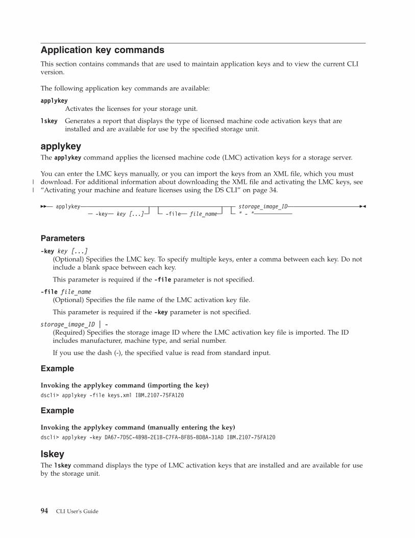
Application key commandsThis section contains commands that are used to maintain application keys and to view the current CLIversion.
The following application key commands are available:
applykeyActivates the licenses for your storage unit.
lskey Generates a report that displays the type of licensed machine code activation keys that areinstalled and are available for use by the specified storage unit.
applykeyThe applykey command applies the licensed machine code (LMC) activation keys for a storage server.
You can enter the LMC keys manually, or you can import the keys from an XML file, which you mustdownload. For additional information about downloading the XML file and activating the LMC keys, see“Activating your machine and feature licenses using the DS CLI” on page 34.
�� applykey-key key [...] -file file_name
storage_image_ID" - "
��
Parameters
-key key [...](Optional) Specifies the LMC key. To specify multiple keys, enter a comma between each key. Do notinclude a blank space between each key.
This parameter is required if the -file parameter is not specified.
-file file_name(Optional) Specifies the file name of the LMC activation key file.
This parameter is required if the -key parameter is not specified.
storage_image_ID | -(Required) Specifies the storage image ID where the LMC activation key file is imported. The IDincludes manufacturer, machine type, and serial number.
If you use the dash (-), the specified value is read from standard input.
Example
Invoking the applykey command (importing the key)dscli> applykey -file keys.xml IBM.2107-75FA120
Example
Invoking the applykey command (manually entering the key)dscli> applykey -key DA67-7D5C-4B98-2E1B-C7FA-8F85-BD8A-31AD IBM.2107-75FA120
lskeyThe lskey command displays the type of LMC activation keys that are installed and are available for useby the storage unit.
94 CLI User's Guide
||

The lskey command only displays the keys that are installed. Refer to the IBM System Storage DS8000Introduction and Planning Guide for more information on how to choose which keys are needed and howto acquire them.
�� lskey storage_image_ID" – "
��
Parameters
storage_image_ID | –(Required) Specifies the storage image ID for which to view a list of activated features. The IDincludes manufacturer, type, and serial number.
If you use the dash (-), the specified value is read from standard input. However, you cannot use thedash (-) if you are using the DS CLI interactive command mode.
Example
For this command and all other DS CLI list commands, the results are shown in table format for clarity.The actual reports do not display as tables.
The following table shows example activation keys. Some activation keys are not listed in the example.The lskey command displays only the keys that are installed.
Invoking the lskey command to display a list of the installed LMC activation keys.dscli> lskey IBM.2107-75FA120
The resulting output
Activation key Authorization level (TB) Scope
Parallel access volumes (PAV) On CKD
Point in time copy (PTC) On All
Global Mirror (GM), (not availablefor DS6000 models)
25 All
HyperPAV (not available for DS6000models)
On CKD
Metro/Global Mirror (MGM), 25 All
Metro Mirror (MM), (not available forDS6000 models)
25 All
Remote mirror and copy (RMC) 25 All
Remote mirror for z/OS (RMZ) 25.1 CKD
DS8000 I/O Priority Manager 25 All
Operating Environment (OEL) 45 All
IBM System Storage Easy Tier On All
IBM FlashCopy SE (not available forDS6000 models)
25 All
High Performance FICON for Systemz (zHPF) (not available for DS6000models)
On CKD
RMZ Resync (not available forDS6000 models)
25 CKD
Chapter 4. CLI commands 95
|

Report field definitions
Activation keySpecifies the type of LMC activation key that is activated for the storage image.
Authorization Level (TB)Specifies the capacity of the specified license feature. The quantity is displayed in terabytes (TB). Oneof the following values is displayed:v Value in terabytesv On if the license is for the maximum capacity, or Off if the license is for zero capacity
ScopeSpecifies the storage type for the designated license: fixed block (FB), count key data (CKD), or All.Parallel access volumes, Remote Mirror for z/OS, and HyperPAV display only the values CKD or All.
Data encryption and security commandsThis section contains commands that are used to configure for disk encryption.
For security purposes, encryption keys are stored on external key servers, not on the DS8000. Themkkeymgr, chkeymgr, rmkeymgr, and lskeymgr commands are used to specify the location of the externalkey servers and which servers are to be utilized by the DS8000. If multiple servers are specified, it isassumed that the servers themselves manage the process to ensure that the stored keys are synchronized.Since multiple manufacturers' products might be using the same key servers, the mkkeygrp, rmkeygrp,lskeygrp, and showkeygrp commands are used to specify a label for any specific encryption key.
In some environments, there might be two disjoint groups of external key servers that are defined andthat cannot synchronize their stored keys securely. In this case, the DS8000 allows you to specify a secondlabel, one label for each group of servers. Under certain unusual circumstances, it might be possible tolose access to the encrypted data on the DS8000. This could occur if all of the external keys servers godown, or if all physical connections are lost between the DS8000 and the external key servers. To preventany of these possibilities from becoming a permanent loss of data access, you are required to create anencryption data access recovery key that is managed with a dual control process described in the "Useraccount and security commands" section. The encryption recovery key itself is manually managed withthe managereckey, mkreckey, and rmreckey commands.
The following data encryption and security commands are available:
chkeymgrUpdates the attributes of the key server entry on the storage complex.
lskeygrpDisplays a list of the key server encryption key group entries on the specified storage image.
lskeymgrDisplays a list of the key server entries that are on the storage complex.
managekeygrpAllows you to manage an encryption key group.
managereckeyAllows you to manage an existing encryption recovery key.
mkkeygrpCreates an entry for the key server encryption key group on the storage image.
mkkeymgrCreates an entry for the key server on the storage complex.
mkreckeyAllows you to create an encryption recovery key.
96 CLI User's Guide

rmkeygrpRemoves an entry for the key server encryption key group on a specified storage image.
rmkeymgrRemoves a key server entry on the storage complex.
rmreckeyAllows you to remove an encryption recovery key.
showkeygrpDisplays detailed information for a specified key server encryption key group entry on thestorage image.
chkeymgrThe chkeymgr command updates the attributes of the key server entry on the storage complex. Thiscommand is not supported on DS6000 models.
�� chkeymgr-state active
inactive
key_server_ID" - "
��
Parameters
-state active | inactive(Optional) Updates the state of the key server.
key_server_ID | -(Required) Specifies the key server ID. If you use the dash (-), the specified value is read fromstandard input. You cannot use the dash (-) while you are in the DS CLI interactive command mode.
Example
An invocation example
dscli> chkeymgr -state inactive 1
The resulting outputThe key server 1 configuration has been changed.
lskeygrpThe lskeygrp command displays a list of the key server encryption key group entries on the specifiedstorage image. This command is not supported on DS6000 models.
�� lskeygrp-dev storage_image_ID -s
-l-state accessible
inaccessibleunconfiguredrekeying
�
Chapter 4. CLI commands 97

�-reckeystate configured
newkeyveripendnewkeyauthpendrekeyveripendrekeyauthpendrecovauthpenddeconfauthpenddisabledenableauthpenddisableauthpend
Encryption_Group_ID. . .
"-"
��
Parameters
-dev storage_image_ID(Optional) Displays key group entries for the specified storage image ID, which includesmanufacturer, machine type, and serial number. For example, IBM.2107-75FA120. The storage imageID is required if you do not specify a fully qualified encryption group ID, do not set the devidvariable in your profile or through the setenv command, and the HMC is aware of more than onestorage image. Using the -dev parameter will temporarily override any defined value for devid for thecurrent command.
-s(Optional). Displays only the attributes that are identified as short output. You cannot use the -s andthe -l parameters together.
-l(Optional). Displays the default output and additional attributes that are identified as long output.You cannot use the -l and the -s parameters together.
-state accessible | inaccessible | rekeying(Optional) Specifies the state of the encryption group.
-reckeystate accessible | newkeyveripend | newkeyauthpend | rekeyveripend | rekeyauthpend |recovauthpend | deconfauthpend | disabled | enableauthpend | disableauthpend
(Optional) Specifies encryption groups with the specified recovery key state.
Encryption_Group_ID. . . |" - "(Optional) Specifies the ID for the encryption group that you want to view. If you use the dash (-),the specified value is read from standard input. You cannot use the dash (-) while you are in the DSCLI interactive command mode.
Example
Invoking the lskeygrp command to display a list of the key server encryption key groups.
dscli> lskeygrp -dev IBM.2107-75FA120 -l 1
The resulting output
ID state reckeystate reckeydate datakeydate label label2
1 accessible configured 03/31/2009 03/31/2009 MyCompany MyCompany2
Report field definitions
ID Specifies the encryption group ID.
numpoolsSpecifies the number of extent pools that are configured in the specified encryption group.
98 CLI User's Guide
|

stateSpecifies one of the following states of the encryption group:
accessibleThe encryption group is accessible if it has been configured and the storage image has obtainedthe encryption key from the key server for the encryption group.
inaccessibleThe encryption group is inaccessible if the storage image was unable to obtain the encryption keyfrom the key server.
unconfiguredThe encryption group is unconfigured if it has not been configured.
rekeyingThe encryption group is accessible and rekeying if it has been configured and the storage imagehas obtained the encryption key from the key server for the encryption group and is currently inthe middle of rekeying.
reckeystateSpecifies one of the following states of the recovery key:
configuredA new recovery key has been requested, verified, and authorized.
unconfiguredA recovery key has not been created.
newkeyveripendA new recovery key has been requested but not verified.
newkeyauthpendA new recovery key has been requested and verified, but not authorized.
rekeyveripendA new recovery key action has been requested but not verified.
rekeyauthpendA new recovery key action has been requested and verified, but not authorized.
recovauthpendA recover action has been requested, but not authorized.
deconfauthpendA deconfigure action has been requested, but not authorized.
disabledA recovery key has been disabled, and the encryption group will be used without a recovery key.
enableauthpendAn enable action has been requested, but not authorized.
disableauthpendA disable action has been requested, but not authorized.
reckeydateThe date of the last recovery key creation.
datakeydateThe date of the last data key creation. If the encryption group is unconfigured, then any displayeddate is to be considered erroneous data.
Chapter 4. CLI commands 99

labelSpecifies the label for the key server encryption key group. Due to the possible length of the labelvalue, this column will always be the second to last column even as new columns are added to theoutput in the future. Example: MyCompany
label2Specifies the second label for the key server encryption key group. Due to the possible length of thelabel2 value, this column will always be the last column even as new columns are added to theoutput in the future. Example: MyCompany2
lskeymgrThe lskeymgr command displays a list of the key server entries that are on the storage complex. Thiscommand is not supported on DS6000 models.
�� lskeymgr-s-l
-port port_ID -state activeinactive
�
�-status normal
hmc1_degradedhmc2_degradedfailed
-addr IP_address key_server_ID . . ." - "
��
Parameters
-s (Optional) Displays the key server IDs.
-l (Optional) Displays the default output.
-port port_ID(Optional) Displays the key servers that use the port ID that you specify. The key server port ID isfour or five decimal characters. For example, 8100 is a valid port ID.
-state active | inactive(Optional) Displays the key servers that are in the state that you specify.
-status normal | hmc1_degraded | hmc2_degraded | failed(Optional) Displays the status of the key server path.
-addr IP_address(Optional) Displays the key server that uses the IP address you specify. The IP address can be an IPv4address, an IPv6 address, or a DNS name.
key_server_ID . . . | -(Optional) Displays the key servers that use the ID or IDs you specify. To include multiple IDs,separate each ID with a blank space. For example, 1 2 3 4. If you use the ( - ) dash option, this valuecan be read from standard input.
Example
Invoking the lskeymgr command to display a list of the key servers.
dscli> lskeymgr 1 2
The resulting outputID state status addr port1 active normal my_address1 38012 active normal my_address2 3801
100 CLI User's Guide
|
|
|

Report field definitions
ID*
The key server identification number. For example, 4.
stateThe state of the key server. The state can be either active or inactive.
statusThe status of the key server path.
addrThe IP address of the key server.
portThe key server port ID.
Key:
* Displayed when the -s parameter is specified.
+ Displayed only when the -l parameter is specified.
managekeygrpThe managekeygrp command allows you to manage an encryption key group. This command is notsupported on DS6000 models.
�� managekeygrp-dev storage_image_ID
-action rekey-key data
�
�-label key_label
-label2 second_key_label
encryption_group_ID-
��
Parameters
-dev storage_image_ID(Optional) Displays the properties for the specified storage image ID, which includes manufacturer,machine type, and serial number. For example, IBM.2107-75FA120. The storage image ID is required ifyou do not specify a fully qualified encryption group ID, do not set the devid variable in your profileor through the setenv command, and the HMC is aware of more than one storage image. Using the-dev parameter will temporarily override any defined value for devid for the current command.
-action rekey(Required) Use this parameter to rewrap the encryption group key specified by the -key parameter.
-key data(Optional) Use this parameter to specify that the encryption key group data key will be rewrappedwith the rekey action. The key can be rewrapped with either new or existing key labels. Thisparameter is required when using the rekey action.
-label key_label(Optional) Use this parameter to specify the label for the encryption key group data key. Thisparameter is required when using the -label2 parameter. You can enter a maximum of 64 ASCIIcharacters for the label.
-label2 second_key_label(Optional) Use this parameter to specify the second label for the encryption key group data key. Youcan enter a maximum of 64 ASCII characters for the label.
Chapter 4. CLI commands 101
|
|
||
||
|

encryption_group_ID | " - "(Required) Specifies the ID for the encryption group. The encryption group ID is a decimal numberthat ranges from 1 to N, where N is the maximum number of encryption groups supported by theDS8000. If you use the dash (-), the specified value is read from standard input. You cannot use thedash (-) while you are in the DS CLI interactive command mode.
Example
An invocation example
dscli> managekeygrp –dev IBM.2107-75FA120 -action rekey -key data -label companyABC -label2companyXYZ 1
The resulting outputCMUCFFFFFI managekeygrp: The rekey action has been performed forkey server encryption group 1.
managereckeyThe managereckey command allows you to manage an existing encryption recovery key. This command isnot supported on DS6000 models.
�� managereckey-dev storage_image_ID
-action verifyrekeyrecovercancelvalidateauthorizeenabledisable
-key the_key�
� encryption_group_ID"-"
��
Parameters
-dev storage_image_ID(Optional) Specifies the storage image ID, which includes manufacturer, machine type, and serialnumber. For example, IBM.2107-75FA120. The storage image ID is required if you do not specify afully qualified encryption group ID, do not set the devid variable in your profile or through thesetenv command, and the HMC is aware of more than one storage image. Using the -dev parameterwill temporarily override any defined value for devid for the current command.
-action verify | rekey | recover | cancel | validate | authorize | enable | disable(Required) Specifies the action to perform on the encryption recovery key.
VerifyThe verify option is for users with security administrator authority, and is the second step increating an Encryption Recovery Key or re-creating an existing Encryption Recovery Key. Verifythat you have received the new Recovery Key from the first step (mkreckey, or managereckeywith the -rekey option), by specifying that new key with the -key parameter. The next steprequires the storage administrator to authorize the pending operation.
RekeyThe rekey option is for users with security administrator authority, and is the first step toreconfigure an existing Encryption Recovery Key. The existing Encryption Recovery Key is notrequired to start the rekey operation. The next step requires the security administrator to verifythe new recovery key.
102 CLI User's Guide

RecoverThe recover option is for users with security administrator authority, and is the first step toutilizing the Encryption Recovery Key to recover access to the encrypted data on the DS8000. Theuser specifies the Encryption Recovery Key with the -key parameter. The next step requires thestorage administrator to authorize the recover operation.
CancelThe cancel option is for users with either security administrator or storage administrator authorityto cancel any verification or authorization pending steps. The existing Encryption Recovery Keyis not required and no further steps are required.
ValidateThe validate option is for users with security administrator authority, and is used to ensure thatthe existing Encryption Recovery Key is identical to the recovery key that is in the user'spossession. The user specifies the Encryption Recovery Key in their possession with the -keyparameter, but no further steps are required.
AuthorizeThe authorize option is for users with storage administrator authority, and is the final step of mostrecovery key operations. Once authorized, the pending recovery key operation is completed andany resulting changes to the DS8000 are started. The existing Encryption Recovery Key is notrequired and no further steps are required.
EnableThe enable option is for users with security administrator authority, and is the first step to enablethe Encryption Recovery Key for the given encryption group. The Recovery Key only needs to beenabled if it has been previously disabled. The existing Encryption Recovery Key is not required.The next step requires the storage administrator to authorize the pending operation.
DisableThe disable option is for users with security administrator authority, and is the first step to disablethe Encryption Recovery Key for the given encryption group. The existing Encryption RecoveryKey is not required. The next step requires the storage administrator to authorize the pendingoperation. After that, the group will operate without an Encryption Recovery Key, and will not berecoverable with a Recovery Key.
-key the_key(Optional) Specifies the encryption recovery key. The encryption recovery key is a string of 64hexadecimal characters. For example, 01F3-45A7-8D12-B586-0123-4C67-891E-3586-01A3-45E7-8D12-3586-0123-45C7-8912-3B86.
encryption_group_ID | -(Required) Specifies the encryption group ID for the encryption recovery key that you want tomanage. The encryption group ID is a decimal number that ranges from 1 to N, where N is themaximum number of encryption groups supported by the DS8000. Use the showsi command todetermine this maximum number. If you use the dash (-), the specified value is read from standardinput. You cannot use the dash (-) while you are in the DS CLI interactive command mode.
Example
An invocation example
dscli> managereckey -dev IBM.2107-75FA120 -action verify -key 0123-4567-8912-3586-0123-4567-8912-3586-0123-4567-8912-3586-0123-4567-8912-3586 1
The resulting outputThe Recovery Key for encryption group 1 has been verified, authorization pending.
Chapter 4. CLI commands 103

mkkeygrpThe mkkeygrp command creates an entry for the key server encryption key group on the storage image.This command is not supported on DS6000 models.
�� mkkeygrp-dev storage_image_ID
-label key_label-label2 second_key_label
�
� Encryption_Group_ID"-"
��
Parameters
-dev storage_image_ID(Optional) Specifies the storage image ID, which includes manufacturer, machine type, and serialnumber. For example, IBM.2107-75FA120. The storage image ID is required if you do not specify afully qualified encryption group ID, do not set the devid variable in your profile or through thesetenv command, and the HMC is aware of more than one storage image. Using the -dev parameterwill temporarily override any defined value for devid for the current command.
-label key_label(Required) Specifies the label for the encryption key group data key. You can enter a maximum of 64ASCII characters for the label.
-label2 second_key_label(Optional) Specifies the second label for the encryption key group data key. You can enter amaximum of 64 ASCII characters for the label.
Encryption_Group_ID | -(Required) Specifies the ID for the encryption group. The encryption group ID is a decimal numberthat ranges from 1 to N, where N is the maximum number of encryption groups supported by theDS8000. Use the showsi command to determine this maximum number. If you use the dash (-), thespecified value is read from standard input. You cannot use the dash (-) while you are in the DS CLIinteractive command mode.
Example
An invocation example
dscli> mkkeygrp -dev IBM.2107-75FA120 -label MyCompany -label2 MyCompany2 1
The resulting outputThe key server encryption key group 1 has been created.
mkkeymgrThe mkkeymgr command creates an entry for the key server on the storage complex. This command is notsupported on DS6000 models.
�� mkkeymgr-port port_ID -state active
inactive
-addr IP_address �
� key_server_ID"-"
��
104 CLI User's Guide
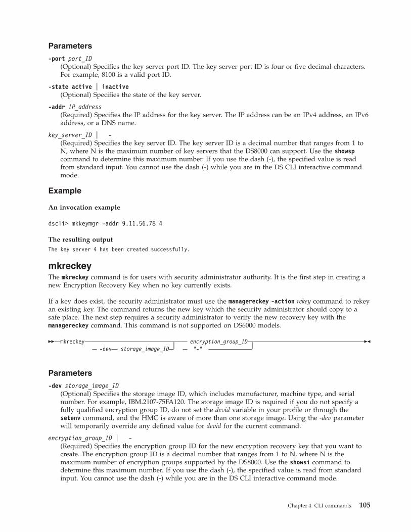
Parameters
-port port_ID(Optional) Specifies the key server port ID. The key server port ID is four or five decimal characters.For example, 8100 is a valid port ID.
-state active | inactive(Optional) Specifies the state of the key server.
-addr IP_address(Required) Specifies the IP address for the key server. The IP address can be an IPv4 address, an IPv6address, or a DNS name.
key_server_ID | -(Required) Specifies the key server ID. The key server ID is a decimal number that ranges from 1 toN, where N is the maximum number of key servers that the DS8000 can support. Use the showspcommand to determine this maximum number. If you use the dash (-), the specified value is readfrom standard input. You cannot use the dash (-) while you are in the DS CLI interactive commandmode.
Example
An invocation example
dscli> mkkeymgr -addr 9.11.56.78 4
The resulting outputThe key server 4 has been created successfully.
mkreckeyThe mkreckey command is for users with security administrator authority. It is the first step in creating anew Encryption Recovery Key when no key currently exists.
If a key does exist, the security administrator must use the managereckey -action rekey command to rekeyan existing key. The command returns the new key which the security administrator should copy to asafe place. The next step requires a security administrator to verify the new recovery key with themanagereckey command. This command is not supported on DS6000 models.
�� mkreckey-dev storage_image_ID
encryption_group_ID"-"
��
Parameters
-dev storage_image_ID(Optional) Specifies the storage image ID, which includes manufacturer, machine type, and serialnumber. For example, IBM.2107-75FA120. The storage image ID is required if you do not specify afully qualified encryption group ID, do not set the devid variable in your profile or through thesetenv command, and the HMC is aware of more than one storage image. Using the -dev parameterwill temporarily override any defined value for devid for the current command.
encryption_group_ID | -(Required) Specifies the encryption group ID for the new encryption recovery key that you want tocreate. The encryption group ID is a decimal number that ranges from 1 to N, where N is themaximum number of encryption groups supported by the DS8000. Use the showsi command todetermine this maximum number. If you use the dash (-), the specified value is read from standardinput. You cannot use the dash (-) while you are in the DS CLI interactive command mode.
Chapter 4. CLI commands 105

Example
An invocation example
dscli> mkreckey -dev IBM.2107-75FA120 1
The resulting outputThe Recovery Key 0123-4567-8912-3586-0123-4567-8912-3586-0123-4567-8912-3586-0123-4567-8912-3586 for encryption group 1has been created, verification pending.
rmkeygrpThe rmkeygrp command removes an entry for the key server encryption key group on a specified storageimage. This command is not supported on DS6000 models.
�� rmkeygrp-dev storage_image_ID -quiet
encryption_group_ID. . .
" - "
��
Parameters
-dev storage_image_ID(Optional) Specifies the storage image ID, which includes manufacturer, machine type, and serialnumber. For example, IBM.2107-75FA120. The storage image ID is required if you do not specify afully qualified encryption group ID, do not set the devid variable in your profile or through thesetenv command, and the HMC is aware of more than one storage image. Using the -dev parameterwill temporarily override any defined value for devid for the current command.
-quiet(Optional) Turns off the removal confirmation prompt for this command.
encryption_group_ID(Required) Specifies the ID for the encryption group. If you use the dash (-), the specified value isread from standard input. You cannot use the dash (-) while you are in the DS CLI interactivecommand mode.
Example
An invocation example
dscli> rmkeygrp -dev IBM.2107-75FA120 1
The resulting outputAre you sure you want to delete the key server encryption group 1? y/n yThe key server encryption group 1 has been deleted.
rmkeymgrThe rmkeymgr command removes a key server entry on the storage complex. This command is notsupported on DS6000 models.
�� rmkeymgr-quiet
key_server_ID . . ." - "
��
106 CLI User's Guide

Parameters
-quiet(Optional) Turns off the removal confirmation prompt for this command.
key_server_ID . . . | -(Required) Deletes the key servers with the specified key server ID. You must separate multiple IDsor ID ranges with a space between each value. If you use the dash (-), the specified value is readfrom standard input. You cannot use the dash (-) while you are in the DS CLI interactive commandmode.
Example
An invocation example
dscli> rmkeymgr 1
The resulting outputAre you sure you want to delete key server entry 1? y/nyThe key server 1 has been deleted.
rmreckeyThe rmreckey command allows you to remove an encryption recovery key. This command is notsupported on DS6000 models.
�� rmreckey-dev storage_image_ID
encryption_group_ID"-"
��
Parameters
-dev storage_image_ID(Optional) Specifies the storage image ID, which includes manufacturer, machine type, and serialnumber. For example, IBM.2107-75FA120. The storage image ID is required if you do not specify afully qualified encryption group ID, do not set the devid variable in your profile or through thesetenv command, and the HMC is aware of more than one storage image. Using the -dev parameterwill temporarily override any defined value for devid for the current command.
encryption_group_ID | -(Required) Specifies the encryption group ID for the encryption recovery key that you want todeconfigure. The encryption group ID is a decimal number that ranges from 1 to N, where N is themaximum number of encryption groups supported by the DS8000. Use the showsi command todetermine this maximum number. If you use the dash (-), the specified value is read from standardinput. You cannot use the dash (-) while you are in the DS CLI interactive command mode.
Example
An invocation example
dscli> rmreckey -dev IBM.2107-75FA120 -1300861 1
The resulting outputThe Recovery Key for encryption group 1 will be de-configured after authorization.
Chapter 4. CLI commands 107

showkeygrpThe showkeygrp command displays detailed information for a specified key server encryption key groupentry on the storage image. This command is not supported on DS6000 models.
�� showkeygrp-dev storage_image_ID
Encryption_Group_ID"-"
��
Parameters
-dev storage_image_ID(Optional) Displays the properties for the specified storage image ID, which includes manufacturer,machine type, and serial number. For example, IBM.2107-75FA120. The storage image ID is required ifyou do not specify a fully qualified encryption group ID, do not set the devid variable in your profileor through the setenv command, and the HMC is aware of more than one storage image. Using the-dev parameter will temporarily override any defined value for devid for the current command.
Encryption_Group_ID(Required) Specifies the ID for the encryption group.
Example
An invocation example
dscli> showkeygrp -dev IBM.2107-75FA120 1
The resulting output
ID 1
numranks 1
numpools 1
state accessible
reckeystate unconfigured
reckeydate 05/15/2009 16:37:46 CST
datakeydate 03/31/2009 16:57:13 CST
label MyCompany
label2 MyCompany2
Report field definitions
encryption group IDSpecifies the encryption group ID.
numranksSpecifies the number of ranks that are configured in the specified encryption group.
numpoolsSpecifies the number of extent pools that are configured in the specified encryption group.
state Specifies one of the following states of the encryption group:
accessibleThe encryption group is accessible if it has been configured and the storage image hasobtained the encryption key from the key server for the encryption group.
108 CLI User's Guide

inaccessibleThe encryption group is inaccessible if the storage image was unable to obtain theencryption key from the key server.
unconfiguredThe encryption group is unconfigured if it has not been configured.
rekeyingThe encryption group is accessible and rekeying if it has been configured and the storageimage has obtained the encryption key from the key server for the encryption group andis currently in the middle of rekeying.
reckeystate
configuredA new recovery key has been requested, verified, and authorized.
unconfiguredA recovery key has not been created.
newkeyveripendA new recovery key has been requested but not verified.
newkeyauthpendA new recovery key has been requested and verified, but not authorized.
rekeyveripendA new recovery key action has been requested but not verified.
rekeyauthpendA new recovery key action has been requested and verified, but not authorized.
recovauthpendA recover action has been requested, but not authorized.
deconfauthpendA deconfigure action has been requested, but not authorized.
disabledA recovery key has been disabled, and the encryption group will be used without arecovery key.
enableauthpendAn enable action has been requested, but not authorized.
disableauthpendA disable action has been requested, but not authorized.
reckeydateThe date and time of the last recovery key creation.
datakeydateThe date and time of the last data key creation. If the encryption group is unconfigured, then anydisplayed date is to be considered erroneous data.
label Specifies the label for the key server encryption key group. Example: MyCompany
label2 Specifies the second label for the key server encryption key group. Example: MyCompany2
Physical resource information commandsThis section contains commands that are used to view information about the physical resources in yourstorage complex.
The following physical resource information commands are available:
Chapter 4. CLI commands 109

lsda Displays a report that lists the device adapters (DA) for each storage image and the status of eachdevice adapter in the list. This command is not supported on DS6000 models.
lsddm Displays a report that lists the disk drive modules and status information for each disk drivemodule in the list.
lsframeGenerates a report that displays a list of the frame enclosures for a storage image. This commandis not supported on DS6000 models.
lshba Displays a report that lists the storage image host adapters and status information for each hostadapter in the list. This command is not supported on DS6000 models.
lsstgenclGenerates a report that displays a list of the storage enclosures and status information for eachenclosure in the list.
lsdaThe lsda command displays a list of device adapters (DA) for each storage image. You can use thiscommand to look at the status of each device adapter in the list. This command is not supported onDS6000 models.
�� lsda-s -encl enclosure_ID-l
-server server_ID -dapair dapair_ID�
�-state online
offlinefailedloopx
storage_image_ID. . .
" - "
��
Parameters
-s(Optional) Displays only device adapter IDs. You cannot use the -l and the -s parameters together.
-l(Optional) Displays the default output, plus the I/O enclosure and device adapter locations, featurecodes, and interface IDs. You cannot use the -l and the -s parameters together.
-encl enclosure_ID(Optional) Displays the device adapters that are associated with the specified processor complex orI/O enclosure.
-server server_ID(Optional) Displays only device adapters that are associated with the specified server.
-dapair dapair_ID(Optional) Displays only device adapters that are associated with the specified device adapter pair.
-state online | offline | failed | loopx(Optional) Displays only device drivers in the specified state.
storage_image_ID . . . | -(Required) Displays device adapters for the specified storage images. A storage image ID includes avalue for the manufacturer, machine type, and serial number. You must separate multiple IDs withspaces.
Note: You cannot specify ID ranges.
110 CLI User's Guide
||

If you use the dash (-), the specified value is read from standard input. You cannot use the dash (-)while you are in the DS CLI interactive command mode.
Example
For this command and all other DS CLI list commands, the results are shown in table format to provideclarity. The actual reports do not display as tables.
The following table represents the headers that are displayed on the output report that is associated withthe lsda command.
Invoking the lsda commanddscli> lsda -l IBM.2107-75FA120
The resulting output
ID State Loc
IBM.2107-75FA120/R1-11-P1-C1
Online U2107-75FA120-11/P1-C1
IBM.2107-75FA120/R1-11-P1-C6
Online U2107-75FA120-11/P1-C6
IBM.2107-75FA120/R1-12-P1-C1
Online U2107-75FA120-12/P1-C1
IBM.2107-75FA120/R1-12-P1-C6
Online U2107-75FA120/R1-12-P1-C6
FC Server DA pair Interfs
1234 00 IBM.2107-75FA120/11
111,0112,0113,0114
1234 01 IBM.2107-75FA120/12
111,0112,0113,0114
1234 00 IBM.2107-75FA120/11
111,0112,0113,0114
1234 01 IBM.2107-75FA120/12
111,0112,0113,0114
Report field definitions
ID*
Specifies the unique identifier of the device adapter.
StateSpecifies the current availability state of the specified device adapter. One of the following values isdisplayed:v Onlinev Offlinev Coming onlinev Going offlinev Failedv Offline Loop 1v Offline Loop 2
Chapter 4. CLI commands 111
|

v Offline Loop 3v Offline Loop 4v Offline Loop 1/2v Offline Loop 3/4v Taking down Loop 1v Taking down Loop 2v Taking down Loop 3v Taking down Loop 4v Taking down Loop 1/2v Taking down Loop 3/4v Bring up all loops
Loc+
Specifies the I/O enclosure and the device adapter location.
The I/O enclosure location format is Uttt.mmm.ppsssss.
The device adapter location format is Pn-Cn where Pn indicates the Planner number (1) and Cnindicates the card number (1 - 6).
FC+
Specifies the feature code that is used to order the specified device adapter.
ServerSpecifies the server or device adapter group to which the device adapter is assigned.
DA pairSpecifies the storage unit ID that is followed by the device adapter pair ID that is associated with thespecified device adapter. The device adapter pair identifier is a two-digit decimal number, with noleading zeros. Device adapter pairs are located in I/O enclosure pairs. Device adapter pair ID impliesI/O enclosure location.
An even numbered device adapter pair ID indicates the first device adapter pair in an I/O enclosurepair. An odd numbered device adapter pair ID indicates the second device adapter pair in an IOenclosure pair.
Interfs+
Specifies the four interface IDs that are associated with the FC-AL ports.
Key:
* Displayed when the -s parameter is specified.
+ Displayed only when the -l parameter is specified.
lsframeThe lsframe command displays a list of frame enclosures for a storage image. This command is notsupported on DS6000 models.
�� lsframe storage_image_ID-s . . .-l " - "
��
Parameters
-s Displays the rack enclosure ID. You cannot use the -l and the -s parameters together.
112 CLI User's Guide
|
|
|
||
||
|

-l Displays default output plus the frame ID and location of the frame enclosure. You cannot use the -land the -s parameters together.
storage_image_ID . . . | -Displays frame enclosure information for the specified storage image IDs. A storage image IDincludes manufacturer, type, and serial number. You must separate multiple IDs with spaces.
Note: ID ranges cannot be specified.
If you use the dash (-), the specified value is read from standard input. You cannot use the dash (-)while you are in the DS CLI interactive command mode.
Example
For this command and all other DS CLI list commands, the results are shown in table format to provideclarity. The actual reports do not display as tables.
The following table represents the headers that are displayed on the output report that is associated withthe lsframe command.
Invoking the lsframe commanddscli> lsframe -l IBM.2107-75FA120
The resulting output
ID frm# Frame loc
IBM.2107-75FA120/R1
R1 1 U2107-75FA120
IBM.2107-75FA120/R2
R2 2 U2107-75FA120
Report field definitions
ID*
Identifies the unique identifier of the frame enclosure.
frm#Identifies the frame number within a storage unit that contains the specified frame enclosure.
Frame+
Identifies the unique identifier of the storage unit equipment frame that contains the specified frameenclosure.
Loc+
Identifies the frame enclosure location.
The location format is Uttt.mmm.ppsssss.
Key:
* Displayed when the -s parameter is specified.
+ Displayed only when the -l parameter is specified.
lsstgenclThe lsstgencl command displays a list of storage enclosures and status information for each enclosure inthe list.
Chapter 4. CLI commands 113
||
|
||
||
|

�� lsstgencl-s-l
-state normalnot_normal
storage_image_ID . . ." - "
��
Parameters
-s (Optional) Displays the storage enclosure ID. You cannot use the -l and the -s parameters together.
-l (Optional) Displays default output, plus the frame number, ID, location, feature code, number ofstorage slots, and state of the storage enclosure. You cannot use the -l and the -s parameterstogether.
-state normal| not_normal(Optional) Displays all the storage enclosures that are associated with the specified storage unit thatcontain a condition of normal or a condition that falls under the category of not normal.
storage_image_ID . . . | -(Required) Displays storage enclosure information for the specified storage image IDs. A storageimage ID consists of manufacturer, machine type, and serial number. You must separate multiple IDswith a space between each ID.
Note: You cannot specify an ID range.
If you use the dash (-), the specified value is read from standard input. You cannot use the dash (-)while you are in the DS CLI interactive command mode.
Example
For this command and all other DS CLI list commands, the results are shown in table format to provideclarity. The actual reports do not display as tables.
The following tables represent the headers that are displayed on the output report that is associated withthe lsstgencl command using the -l parameter.
Invoking the lsstgencl commanddscli> lsstgencl -l IBM.2107-75FA120
The resulting output
ID Frame Enclnum Loc FC Interfaces
IBM.2107-D21.75FA120/R1-S11
R1 S11 U2107.921.75FA120
3221 0111, 0112,0113, 0114
IBM.2107-D21.75FA120/R1-S12
R1 S12 U2107.921.75FA120
3221 0121, 0122,0123, 0124
IBM.1750-EX1.68FA120/S00
- S01 U1750.511.685FA120
- 0080, 0081,0180, 0181(Not inter-face values.See thefielddefinitions)
114 CLI User's Guide
|||

ID Frame Enclnum Loc FC Interfaces
IBM.1750-EX1.68FA120/S01
- S02 U1750.511.685FA120
- 0082, 0083,0182, 0183(Not inter-face values.See thefielddefinitions)
Interadd Storslot Stordev Cap (GB) RPM State
0 x 0 (DS8000only)
16 16 145 10000 normal
0 x 1 (DS8000only)
16 16 145 10000 normal
0 x 0 (DS6000only)
16 16 145 10000 normal
0 x 1 (DS6000only)
16 16 145 10000 normal
Report field definitions
ID*
Specifies the enclosure ID and enclosure number.
Note: This is the only information that is displayed if you use the -s parameter. None of the othervalues are displayed.
Frame+
Specifies the frame number within the designated storage unit that contains this storage enclosure.
A " - " value is displayed for a DS6000 model.
Enclnum+
Specifies the identity of a storage enclosure within a storage unit frame.
Loc+
Specifies the storage enclosure location by identifying the storage unit frame that contains the storageenclosure. The location format is Utttt.mmm.ppsssss.
FC+
Specifies the feature code that was used to order this storage enclosure.
InterfacesSpecifies a list of four interface identifiers, one for each DA I/O port.
A DA interface ID consists of four hexadecimal characters with the following format: t00 eeeee aaaapppp, (value is separated for readability), wherev t = port type (0 = I/O port, DA ports are always I/O ports)v 00 = reservedv eeeee = enclosure numberv aaaa = adapter numberv pppp = port number
Notes:
1. For dual loop 0 enclosures, the DA I/O port values are displayed as 0080, 0081, 0180, 0181.2. For dual loop 1 enclosures the DA I/O port values are displayed as 0082, 0083, 0182, 0183.
Chapter 4. CLI commands 115

InteraddSpecifies the FC-AL interface base address assigned to this storage enclosure for DDM access.
Storslot+
Specifies the number of slots for storage devices in this storage enclosure.
StordevSpecifies the number of storage devices that are installed in this storage enclosure.
Cap (GB)Specifies the capacity of DDMs in the storage enclosure.
Note: This field can contain multiple capacity values separated by a comma when the DDMs withdifferent capacity are installed in the storage enclosure.
RPMSpecifies the rpm of the DDMs in the storage enclosure.
Note: This field can contain multiple RPM values separated by a comma when the DDMs withdifferent capacity are installed in the storage enclosure.
State+
Specifies the condition of the storage enclosure. The condition of the enclosure is either normal orone of the conditions that falls under the category not_normal. The following values can bedisplayed:
normalIndicates that the storage enclosure is not in any failure or transient condition.
offline(DS8000 only) Indicates that the storage enclosure is not capable of processing any functions.
failedIndicates that the storage enclosure is broken and ready to be removed without impacting thesystem.
Note: For a DS6000 model, this condition changes to inter failed if the storage enclosure is foundto be in good condition again.
new(DS6000 only) This condition only displays when a storage enclosure is first discovered.
removed(DS6000 only) Indicates that the storage enclosure was removed from the system.
inappropriate(DS6000 only) Indicates that the hardware resource cannot be integrated in the system.
inter failed(DS6000 only) Indicates that the hardware resource is faulty but still working.
PFSed (Prepared for Service)(DS6000 only) Indicates that the storage enclosure is ready to be removed without impacting thesystem.
attention(DS6000 only) Indicates that there is a problem with the storage enclosure; however, it is notknown whether it is faulty or not. This condition reverts to normal if the problem is closed.
resuming(DS8000 only) Indicates that the storage enclosure is in the process of coming online.
quiescing(DS8000 only) Indicates that the storage enclosure is in the process of going offline.
116 CLI User's Guide
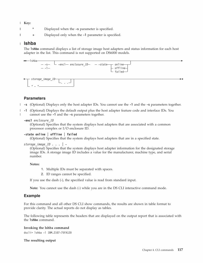
Key:
* Displayed when the -s parameter is specified.
+ Displayed only when the -l parameter is specified.
lshbaThe lshba command displays a list of storage image host adapters and status information for each hostadapter in the list. This command is not supported on DS6000 models.
�� lshba-s -encl enclosure_ID-l
-state onlineofflinefailed
�
� storage_image_ID. . .
" - "
��
Parameters
-s (Optional) Displays only the host adapter IDs. You cannot use the -l and the -s parameters together.
-l (Optional) Displays the default output plus the host adapter feature code and interface IDs. Youcannot use the -l and the -s parameters together.
-encl enclosure_ID(Optional) Specifies that the system displays host adapters that are associated with a commonprocessor complex or I/O enclosure ID.
-state online | offline | failed(Optional) Specifies that the system displays host adapters that are in a specified state.
storage_image_ID . . . | -(Optional) Specifies that the system displays host adapter information for the designated storageimage IDs. A storage image ID includes a value for the manufacturer, machine type, and serialnumber.
Notes:
1. Multiple IDs must be separated with spaces.2. ID ranges cannot be specified.
If you use the dash (-), the specified value is read from standard input.
Note: You cannot use the dash (-) while you are in the DS CLI interactive command mode.
Example
For this command and all other DS CLI show commands, the results are shown in table format toprovide clarity. The actual reports do not display as tables.
The following table represents the headers that are displayed on the output report that is associated withthe lshba command.
Invoking the lshba commanddscli> lshba -l IBM.2107-75FA120
The resulting output
Chapter 4. CLI commands 117
|
||
||
|
|
||

ID State Loc
IBM.2107-75FA120/R1-11-P1-C2
Online U2107-75FA120-11/P1-C2
IBM.2107-75FA120/R1-11-P1-C3
Online U2107-75FA120-11/P1-C3
IBM.2107-75FA120/R1-12-P1-C2
Online U2107-75FA120-/R1-12-P1-C2
IBM.2107-75FA120/R1-12-P1-C3
Online U2107-75FA120/R1-12-P1-C3
FC interfID
1234 0x0121,0x0121,0x0123,0x0124
1234 0x0131,0x0131,0x0133,0x0134
1234 0x0221,0x0221,0x0223,0x0224
1234 0x0231,0x0231,0x0233,0x0234
Report field definitions
ID Specifies the unique identifier of the host adapter.
StateSpecifies the current availability state of the specified host adapter.
LocSpecifies the I/O enclosure and the host adapter location.
The I/O enclosure location format is Uttt.mmm.ppsssss.
The host adapter location format is Pn-Cn where Pn indicates the Planner number (1) and Cnindicates the card number (1 - 6).
FC Specifies the feature code that is used to order the specified host adapter.
interfIDSpecifies the four interface IDs that are associated with the I/O ports on the host adapter.
lsddmThe lsddm command displays a list of disk drive modules (DDMs) and status information for each DDMin the list.
�� lsddm-s -enclosure enclosure_ID-l
-dapair dapair_ID�
�-arsite arraysite_ID -usage unassigned
unconfiguredsparenot_sparearray_member
-state normalnot_normal
�
�-dualloop 1
2-encrypt supported
unsupported
-diskclass entnlssd
�
118 CLI User's Guide

� storage_image_ID. . .
" - "
��
Parameters
-s (Optional) Displays only the DDM IDs. You cannot use the -s and -l parameters together.
-l (Optional) Displays the default output. You cannot use the -s and -l parameters together.
-enclosure enclosure_ID(Optional) Specifies that the system displays DDMs that are associated with a common storageenclosure ID. This parameter accepts a fully qualified enclosure ID, which includes either the storageimage ID or a shortened version without the storage image ID. The shortened version is ahexadecimal number within the range (00 - 3F).
-dapair dapair_ID(Optional) Specifies that the system displays DDMs that are associated with a common deviceadapter (DA) pair ID. This parameter accepts a fully qualified DA pair ID, which includes either thestorage image ID or a shortened version without the storage image ID. The shortened version is atwo-digit decimal number with no leading zeros.
-arsite arraysite_ID(Optional) Specifies that the system displays DDMs that are associated with a common array site ID.This parameter accepts a fully qualified array site ID, which includes either the storage image ID or ashortened version without the storage image ID. The shortened version is a four-digit decimalnumber with no leading zeros, prefixed with the letter S.
-usage unassigned | unconfigured | spare | not_spare | array_member(Optional) Specifies that the system displays DDMs that are associated with a specified usage.
-state normal | not_normal(Optional) Specifies that the system displays DDMs that are associated with a specified state.
-dualloop 1 | 2(Optional) Specifies that the system displays DDMs that are associated with the designated dual loop.
-encrypt supported | unsupported(Optional) Specifies that the system displays only the DDMs that have the specified encryptioncapability.
-diskclass ent | nl | ssd(Optional) Displays the DDMs that are associated with the specified disk class.
storage_image_ID . . . | -(Required) Specifies that the system displays DDM information for the designated storage image IDs.A storage image ID includes a value for the manufacturer, machine type, and serial number. You canspecify multiple IDs and they must be separated with a space between each ID.
Note: You cannot specify ID ranges.
If you use the dash (-), the specified value is read from standard input.
Note: You cannot use the dash (-) while you are in the DS CLI interactive command mode.
Example
For this command and all other DS CLI list commands, the results are shown in table format to provideclarity. The actual reports do not display as tables.
Chapter 4. CLI commands 119
|

The following tables represent the headers that are displayed on the output report that is associated withthe lsddm command using the -l parameter.
Invoking the lsddm commanddscli> lsddm -l IBM.2107-75FA120
The resulting output
ID Model locfirmwarelevel DA pair DualLoop dkcap (10^9B)
IBM.2107-D21-75FA120/R1-S11-P1-D1
S0BE146 U2107.921.75FA120
3603 11 1 145
IBM.2107-D21-75FA120/R1-S11-P1-D2
S0BE146 U2107.921.75FA120
3603 11 1 145
diskrpm dkinfdkrate(Gb/sec) dkuse arsite Position State diskclass encrypt
1000 FCAL 2 arraymember
S123 1 normal ENT supported
1000 FCAL 2 arraymember
S123 2 normal SATA supported
Report field definitions
ID*
Specifies the system-assigned unique identifier for the DDM.
ModelSpecifies the DDM model. The model name is a string of the form VRFCGGG, where VRFC is thetype of disk family and GGG is the disk capacity in decimal gigabytes (GB).
locSpecifies the storage enclosure and the DDM location. The DDM location format is Pn-Dn, where Pnis the Planer number (1), and Dn is the DDM number (1 - 16).
FirmwarelevelSpecifies the level of firmware that is installed on the specified DDM.
DA pairSpecifies the device adapter pair ID. DA pairs are located in I/O enclosure pairs.
Note: An even-numbered DA pair ID indicates the first DA pair in an I/O enclosure pair. Anodd-numbered DA pair ID indicates the second DA pair in an I/O enclosure pair.
DualloopSpecifies the dual loop that the specified DDM resides on. The value is either 1 or 2.
Dkcap (10^9B)Specifies the DDM raw capacity in decimal gigabytes (GB).
diskrpmSpecifies the DDM rpm. One of the following values is displayed:
120 CLI User's Guide
||
|

v 10000v 15000
dkinfSpecifies the DDM interface type. One of the following values are displayed:v FC-ALv SAS (Serial Attached SCSI)
Dkrate (Gb/sec)Specifies the DDM interface rate.
dkuseSpecifies the DDM usage in an array site. One of the following values are displayed:v unassignedv unconfiguredv spare requiredv spare not requiredv array member
arsiteSpecifies the array site ID.
PositionSpecifies the DDM position in an array site configuration of DDMs.
StateSpecifies the current DDM state. One of the following values are displayed:
NormalThe storage device is operational and functional in its current disk usage.
NewIndicates the initial state when a DDM is inserted or first discovered.
InstallingA new storage device has been identified.
VerifyingThe storage device is made accessible to the device adapter, its characteristics are determined,cabling is checked, and diagnostics are run.
FormattingA verified storage device requires low-level formatting and the formatting operation is inprogress.
InitializingThe storage device is being initialized with all zero sectors.
CertifyingThe storage device is read-accessed to determine that all sectors can be read.
RebuildingThe storage device is being rebuilt with data from the array that it is associated with.
Migration TargetDDM migration is migrating another array member storage device to this spare storage device.
Migration SourceDDM migration is migrating this array member storage device to another spare storage device.
FailedThe storage device has failed and an immediate repair action is required.
Chapter 4. CLI commands 121

Failed - Deferred ServiceThe storage device has failed and a repair action is not immediately required.
RemovedThe storage device is removed from the system and removal has been processed by the system.
InappropriateThe storage device is incompatible with the system; for example, a storage device that has thewrong capacity or rpm. The DDM is not failed, because it can be valid for other systems andlocations.
Inter failedIndicates that the DDM is faulty but still working.
PFSedIndicates that the DDM is prepared for service, and ready to be removed without impacting thesystem.
DiskclassSpecifies the disk class as either high speed Fibre Channel disk drives or near-line disk drives. One ofthe following values can be displayed:v ENT = Specifies enterprise and represents high speed Fibre Channel disk drivesv NL = Specifies near-line and represents ATA (FATA) disk drivesv SATA = Specifies high capacity SATA disk drives.
EncryptSpecifies the encryption support capability. One of the following values can be displayed:
supportedThe disk drive modules in this rank are capable of encryption.
unsupportedThe disk drive modules in this rank are not capable of encryption.
Key:
* Displayed when the -s parameter is specified.
+ Displayed only when the -l parameter is specified.
Storage complex configuration commandsThis section contains commands that are used to configure a storage complex for DS8000 models only.
The following storage complex configuration commands are available:
chsp Modifies a storage complex for items such as notification of the Simple Network ManagementProtocol (SNMP) traps and email problem notification lists in a storage complex.
lsvpn Displays a report that lists the outbound VPN information such as management consoles andconnection status. This command is not supported on DS6000 models.
setvpn Used when remote access is required by IBM Support personnel and there is no local on-siteaccess to the machine.
showsp Generates a report that displays detailed properties of a storage complex.
chspThe chsp command modifies a storage complex for items such as notification of the Simple NetworkManagement Protocol (SNMP) traps and email problem notification lists in a storage complex. Thiscommand is not supported on DS6000 models.
122 CLI User's Guide
|
||
||
|

Notes:
v The Storage Manager server domain is a single storage complex. The storage complex objectcan only be created or deleted by service personnel.
v The SNMP settings only apply to some types of snmp notifications (Example: Copy Services).
�� chsp-snmp on
off-snmpaddr new_ip_list -emailnotify on
off
�
�-emailaddr new_email_list -emailrelay on
off
�
�-emailrelayaddr new_relay_ip_list -emailrelayhost new_relay_host_name
�
�-desc new_sp_description -name new_sp_name
��
Parameters
-snmp on | off(Optional) Specifies whether the Simple Network Management Protocol (SNMP) trap notificationfunction sends notifications when a problem occurs on a storage complex. SNMP traps that aregenerated by the storage complex are sent to the IP address that is specified by the -snmpaddrparameter.
-snmpaddr new_ip_list(Optional) Specifies a new SNMP trap destination list. This list consists of one or two IP addressesthat receive SNMP traps that are generated by the storage complex if SNMP is enabled.
Note: Multiple IP addresses must be separated with a comma with no space before or after eachcomma.
-emailnotify on | off(Optional) This parameter is not currently supported.
-emailaddr new_email_list(Optional) This parameter is not currently supported.
-emailrelay on | off(Optional) This parameter is not currently supported.
-emailrelayaddr new_relay_ip_list(Optional) This parameter is not currently supported.
-emailrelayhost new_relay_host_name(Optional) This parameter is not currently supported.
-desc new_sp_description(Optional) Specifies your description of the storage complex. This description is limited to 256 byte or128 double-byte characters.
-name new_sp_name(Optional) Specifies the name that you designate for the storage complex. This name is limited to 32byte or 16 double-byte characters.
Chapter 4. CLI commands 123

Example
Invoking the chsp commanddscli> chsp -desc "my storage complex"
The resulting outputStorage-complex IBM.2107-75FA120successfully modified.
setvpnThe setvpn command starts or ends an outbound virtual private network connection (VPN). Thiscommand is not supported on DS6000 models.
During the installation of the DS8000 product, the hardware management console (HMC) sends acertificate (signed public key) to IBM for server authentication and for SSL encryption of applicationsusing VPN (Internet and modem) connections.
You can use the setvpn command to start or stop the session and to create a secure connection. Inaddition, the IBM VPN server does additional authentication to allow traffic to certain IBM servers only,for the call home feature and remote service.
Notes:
1. Only IBM support personnel with special access rights can use the VPN connection.2. The setvpn command is used when remote access is required by IBM Support personnel and
there is no local on-site access to the machine.3. It can take from 2 to 10 minutes for the secure connection to be established and recognized by
the RS3/RS4 server.4. The secure connection ends automatically when the terminal emulation session ends.
However, you also have the ability to end the session earlier by issuing the setvpn -actiondisconnect command.
5. The -vpnaddr parameter requires that you specify a value for either smc1 or smc2. If you donot specify the -vpnaddr parameter, the storage management console (SMC) for the currentconnection is used. The SMC address is taken from the profile file or the SMC address thatyou specify on the DS CLI command line.
�� setvpn-vpnaddr smc1
smc2
-action connectdisconnect
��
Parameters
-vpnaddr smc1 | smc2(Optional) Specifies the VPN server machine. In addition, you can specify where you want theoutbound VPN to start from by designating the following values:
smc1 Identifies the management console (SMC) where you want the outbound VPN to start from.The console that you have specified in your profile for hmc1 starts your DS CLI session,unless you specify a console that is not designated in your profile. In this case, the consolethat you specify to start your session is the one where the connection is made.
smc2 Identifies the management console where you want the outbound VPN to start from. Theconsole that you have specified in your profile for hmc2 starts your DS CLI session, unlessyou specify a console that is not designated in your profile. In this case, the console that youspecify to start your session is the one where the connection is made.
124 CLI User's Guide

-action connect | disconnect(Required) Specifies that the secure VPN connection be started or disconnected.
Example
Invoking the setvpn commanddscli> setvpn –vpnaddr smc1 –action connect
The resulting outputSecure connection started.
lsvpnThe lsvpn command displays a report that lists the outbound VPN information such as managementconsoles and connection status. This command is not supported on DS6000 models.
�� lsvpn-s-l
-vpnaddr smc1smc2
-vpnstatus connecteddisconnected
��
Parameters
-s(Optional) Displays the management console (SMC) and connection status. You cannot use the -l and-s parameters together.
-l(Optional) Displays the management console (SMC) and connection status. You cannot use the -l and-s parameters together.
-vpnaddr smc1 | smc2(Optional) Specifies the VPN server machine. In addition, you can specify where the outbound VPNwas started from by designating the following values:
smc1 Identifies the management console (SMC) where the outbound VPN was started from. Theconsole that you have specified in your profile for hmc1 starts your DS CLI session, unlessyou specify a console that is not designated in your profile. In this case, the console that youspecified to start your session is the one that is listed in the report as being where theconnection was made.
smc2 Identifies the management console where the outbound VPN was started from if you did notstart it from the management console identified by smc1. The console that you have specifiedin your profile for hmc2 starts your DS CLI session, unless you specified a console that is notdesignated in your profile. In this case, the console that you specified to start your session isthe one that is listed in the report as being where the connection was made.
Note: The default value is to display the address for smc1 and smc2. If you do not specify the-vpnaddr parameter, the generated report displays both the smc1 and smc2 addresses as theyare recorded in your profile.
-vpnstatus connected | disconnected(Optional) Specifies that you receive a report that displays only the SMC for the connection statusspecified.
Note: The default value is to display the connection status for all SMCs. The generated reportdisplays all connected and disconnected SMCs.
Chapter 4. CLI commands 125
||
||

Example
For this command and all other DS CLI list commands, the results are shown in table format for clarity.The actual reports do not display as tables.
The following table represents the headers that are displayed on the output report that is associated withthe lsvpn command.
Invoking the lsvpn commanddscli> lsvpn -l
The resulting output
VPN Address VPN Status
smc1 Connected
smc2 Disconnected
showspThe showsp command displays a properties report for a storage complex. This command is not supportedon DS6000 models.
The report included the properties values for the names, descriptions, and customer account names of thestorage complex.
�� showsp ��
Parameters
There are no parameters for this command.
Notes:
1. The snmp settings only apply to some types of snmp notifications (Example: Copy Services).2. The email parameters are not currently supported.
Example
The following table represents the headers that are displayed on the output report that is associated withthe showsp command.
Invoking the showsp commanddscli> showsp
The resulting output
Name Desc Acct SNMP SNMPadd
My_storage-complex
Productionstorage-complex
ABC Company Enabled 9.xxx.14.245
126 CLI User's Guide

eMailnotify eMailaddr eMailrelayeMailrelay-addr
eMailrelay-host
numkssupported
Enabled [email protected],[email protected]
Disabled 9.xxx.14.45 relay_host 1
Report field definitions
Name Specifies the name of the storage complex.
Desc Specifies the description of the storage complex.
Acct Specifies the customer account name for the storage complex.
SNMPSpecifies whether SNMP traps that are generated by the storage complex for software events aresent to the IP address that is specified by the chsp command. Other types of SNMP traps areenabled and disabled using the user interface on the HMC. This column displays the values:Enabled or Disabled.
SNMPaddSpecifies one or two IP addresses if SNMP is enabled. These addresses indicate where SNMPtraps that are generated by the storage complex are sent. Multiple IP addresses are separatedwith commas with no blank space before and after each; for example: 9.111.14.254,9.113.22.236
eMailnotifySpecifies whether email notifications are enabled or disabled.
When the chsp command enables the -emailnotify and -emailrelay parameters, the emailnotification is directed to the IP address that is associated with the -emailrelayhost hostnameparameter. However, if the email relay host name is not specified, the email notification isdirected to the email relay address.
When email notify is enabled and email relay is disabled, the email notification is sent directly tothe specified email address.
eMailaddrSpecifies one or more email addresses to which notification is sent if service is required whenemail is enabled. A " - " is displayed if email is not enabled or if an email address is not available.
eMailrelaySpecifies whether -emailrelay is enabled or disabled.
When -email and -emailrelay parameters are enabled, the email notification is directed to the IPaddress that is associated with the -emailrelayhost hostname parameter. However, if the emailrelay host name is not specified, the email notification is directed to the email relay address.
When -email is enabled and -emailrelay is disabled, the email is sent directly to the specifiedemail address.
eMailrelayaddrSpecifies one or more email relay IP addresses. These IP addresses represent the addressesthrough which notification is relayed if service is required when email is enabled.
eMailrelayhostSpecifies the email relay host system name.
numkssupportedThe number of key servers that are supported.
Chapter 4. CLI commands 127

Storage unit configuration commandsThis section contains commands that are used to configure a storage unit.
A storage unit is a single, physical storage subsystem. A storage complex is a configuration of one ormore storage units that is managed by a management console. If you have one DS8000 machine, then youhave a single storage complex containing a single storage unit.
A storage image is a partitioning of a storage unit that provides emulation of a virtual storage server. Youcan configure more than one storage image on a storage unit (DS8000 series only).
The following storage unit configuration commands are available:
chsu Changes the description and name you have associated with a specified storage unit. For DS8000,you can also change the remote power control mode on the storage unit.
lssu Generates reports that allow you to view details about your storage units.
showsu Generates reports that allow you to view details about your storage units.
chsuThe chsu command modifies a storage unit. You can also use this command to power-on and power-off aDS8000 storage unit.
�� chsu-pwrmode manual
autozseries
-pwron -pwroff -quiet�
�-desc new_su_description -name new_su_name
storage_unit_ID" - "
��
Parameters
-pwrmode manual | auto | zseries(Optional) (DS8000 only) Sets a requested remote power control mode on the storage unit.
manualSpecifies that the storage facility power-on and power-off sequences are performed based on themanual power on and off controls.
autoA storage facility power-on sequence is performed when external power first becomes availableto the first rack of a storage facility (for example, when standby power is first activated to theremote power control cards).
zseriesSpecifies that the power control mode is set to zSeries remote power control.
Note: Changing the power mode can take several minutes. Initiating a power-on or power-offrequest in manual mode can take up to 25 minutes. During a power-on or power-off request,access requests to the storage unit might be queued. This queuing can result in a loss ofresponse on other functions that access the storage unit when accessed by the CLI.
-pwron(Optional) (DS8000 only) Turns on power to the storage unit. For DS8000, this parameter is valid ifthe control mode is set to manual and the switch is set to remote.
128 CLI User's Guide

-pwroff(Optional) Turns off power to the storage unit. For DS8000, this parameter is valid if the control modeis set to manual and the switch is set to remote.
-quiet(Optional) Turns off the modification confirmation prompt for this command.
-desc new_su_description(Optional) Allows you to specify a description for the storage unit. The description is limited to 256byte or 128 double-byte characters.
-name new_su_name(Optional) Allows you to specify a user-defined name for the storage unit. This name is limited to 32bytes or 16 double-byte characters.
storage_unit_ID | -(Required) Accepts the fully qualified storage unit ID. The storage unit ID consists of manufacturer,machine type, and serial number. For example, IBM.2107-75FA120.
If you use the dash (-), the specified value is read from standard input. You cannot use the dash (-)while you are in the DS CLI interactive command mode.
Example
Invoking the chsu commanddscli> chsu -pwrmode manual IBM.2107-75FA120
The resulting outputStorage unit IBM.2107-75FA120 successfully modified.
lssuThe lssu command displays a list of storage units in a storage complex. You can use this command tolook at the status and other properties of each storage unit in the list.
�� lssu-s-l
-power onoff
storage_unit_ID. . .
" - "
��
Parameters
-s (Optional) Displays only the storage unit ID. You cannot use the -l and the -s parameters together.
-l (Optional) Displays default output plus the power mode and storage unit description. You cannot usethe -l and the -s parameters together.
-power on | off(Optional) Displays only the storage units in the specified power state.
storage_unit_ID . . . | -(Optional) Displays storage units with the specified storage unit IDs. A storage unit ID includesmanufacturer, machine type, and serial number. You must separate multiple IDs with a spacebetween each ID.
Note: You cannot specify ID ranges.
If you use the dash (-), the specified value is read from standard input. You cannot use the dash (-)while you are in the DS CLI interactive command mode.
Chapter 4. CLI commands 129
|
||

Example
For this command and all other DS CLI list commands, the results are shown in table format to provideclarity. The actual reports do not display as tables.
The following table represents the headers that are displayed on the output report that is associated withthe lssu command using the -l parameter.
Invoking the lssu commanddscli> lssu -l
The resulting output
Name ID Model WWNNPwState
PwMode Desc
SU 1 IBM.2107-75FA110
921 3007ACF3012399E0
On Local Test
SU 2 IBM.2107-75FA120
921 3007ACF3045699E0
On Local Produc-tion
SU 3 IBM.2107-75FA130
921 3007ACF3078999E0
On Local Backup
Report field definitions
NameSpecifies the user-defined name for each storage unit found within the storage complex. This value is" - " if you have not assigned a name to a storage unit.
ID Specifies the storage unit ID which consists of the manufacture name, machine type, and serialnumber. When the -s parameter is used, this is the only information that is displayed for the lssucommand.
ModelIdentifies the model number of the storage unit.
WWNNSpecifies the World Wide Node Name for the listed storage unit. This value is " - " if the WWNN isnot known
Pw StateIndicates the power status of the listed storage unit. One of the following values is displayed:
On Indicates the storage unit power is on.
OffIndicates the storage unit power is off.
Turning OnIndicates the storage unit power is in the process of turning on.
Turning OffIndicates the storage unit power is in the process of turning off.
Power ExceptionIndicates that storage unit power is on, but online operation is not possible due to a power faultin one of the storage unit frames.
130 CLI User's Guide

Pw ModeIndicates the power control mode in effect for the listed storage unit. One of the following values isdisplayed:
LocalIndicates that the SMC local/remote switch is set to the local power control mode.
Remote SMC ManualIndicates that the SMC local/remote switch is set to remote and that the power control mode isset to manual power control.
Remote SMC AutoIndicates that the SMC local/remote switch is set to remote and that the power control mode isset to auto-power control.
Remote zSeries Power ControlIndicates that the SMC local/remote switch is set to remote and that the power control mode isset to zSeries remote power control.
DescSpecifies the description that you assigned the storage unit. This value is displayed as a " - " if nodescription has been assigned.
showsuThe showsu command displays detailed properties of an individual storage unit.
�� showsu storage_unit_ID" - "
��
Parameters
storage_unit_ID(Required) Specifies the storage unit ID. A storage unit ID consists of manufacturer, machine type,and serial number.
If you use the dash (-), the specified value is read from standard input. You cannot use the dash (-)while you are in the DS CLI interactive command mode.
Example
For this command and all other DS CLI show commands, the results are shown in table format toprovide clarity. The actual reports do not display as tables.
The following table represents the headers that are displayed on the output report that is associated withthe showsu command.
Invoking the showsu commanddscli> showsu IBM.2107–75FA120
The resulting output
Name Desc ID Model WWNN Config
MyStor-ageUnit
Thisis myDS Stor-age Unit
IBM.2107-75FA120
921 3007ACF3012399E0
4-way,single SFI
Chapter 4. CLI commands 131

Pw State Pw Mode Reqpm Processor Memory MTS
On Local RemoteSMCmanual
1 GB IBM.2424-75FA120
Report field definitions
NameSpecifies the name that you assigned for the designated storage unit. This value is " - " if you havenot assigned a name to a storage unit.
DescSpecifies the description that you assigned for the designated storage unit. This value is displayed asa " - " if no description has been assigned.
ID Specifies the storage unit ID which consists of the manufacture name, machine type, and serialnumber.
ModelIdentifies the model number of the designated storage unit.
WWNNSpecifies the World Wide Node Name for the listed storage unit. This value is " - " if the WWNN isnot known.
ConfigSpecifies the internal I/O interface configuration for the storage unit. One of the following values isdisplayed:
UndefinedIndicates that the configuration is undefined. The value indicates that either this information isnot supported for this storage unit model, or a configuration upgrade is in progress that cancause the configuration option to change.
2-way, single SFIIndicates that there are two processors and a single storage facility image.
4-way, single SFIIndicates that there are four processors and a single storage facility image.
4-way, dual SFIIndicates that there are four processors and dual storage facility images.
8-way, single SFIIndicates that there are eight processors and a single storage facility image.
8-way, dual SFIIndicates that there are eight processors and dual storage facility images.
Pw StateIndicates the power status of the listed storage unit. One of the following values is displayed:
On Indicates the storage unit power is on.
OffIndicates the storage unit power is off.
Turning OnIndicates the storage unit power is in the process of turning on.
Turning OffIndicates the storage unit power is in the process of turning off.
132 CLI User's Guide

Power ExceptionIndicates that storage unit power is on, but online operation is not possible due to a power faultin one of the storage unit frames.
Pw ModeIndicates the power control mode in effect for the listed storage unit. One of the following values isdisplayed:
LocalIndicates that the SMC local/remote switch is set to the local power control mode.
Remote SMC ManualIndicates that the SMC local/remote switch is set to remote and that the power control mode isset to manual power control.
Remote SMC AutoIndicates that the SMC local/remote switch is set to remote and that the power control mode isset to auto-power control.
Remote zSeries Power ControlIndicates that the SMC local/remote switch is set to remote and that the power control mode isset to zSeries remote power control.
ReqpmIndicates the power control mode to apply when the local/remote switch is set to remote powercontrol mode. One of the following values is displayed:v Remote SMC Manualv Remote SMC Autov Remote zSeries Power Control
Note: The default value is remote SMC Manual mode.
Processor MemorySpecifies the amount in decimal gigabytes (GB) of processor memory configured on the storage unit.
MTS(DS8000 models) Specifies the order type of the storage unit. The order type and the machine type ofthe storage unit is the same on all storage units ordered before release 2.4. After release 2.4, the ordertype varies according to the warranty periods associated with the storage unit.
(DS6000 models) No value is specified for a DS6000 model.
Storage image configuration commandsThis section contains commands that are used to configure a storage image.
The following storage image configuration commands are available:
chsi Primarily enables or disables the ESSNet user interface that issues Copy Services operations forthe storage image, changes the description and name that you have assigned to the storageimage, or changes a System i serial number.
diagsi An administrative utility command that a user with administrator or service operator authoritycan use for non-routine diagnostic actions.
lsserverDisplays all the servers in a storage complex or a list of specified servers. The displayed list alsoprovides the status information for each server including the LIC version number, operatingsystem version number, and bundle version.
Chapter 4. CLI commands 133
|
|

lssi Displays a list of storage images in a storage complex. These commands requires that you use thestorage image WWNN, which is displayed for each storage image when you use the lssicommand.
showsi Displays the detailed properties of a storage image. In addition, the storage image WWNN isdisplayed for the specified storage image. The storage image WWNN is needed when you usethe lsavailpprcport and mkpprcpath commands.
chsiThe chsi command modifies a storage image. You can use it to set characteristics such as online or offlinestate, name, and description.
�� chsi-essnetcs y
n-volgrp volume_group_ID -desc new_si_description
�
�-name new_si_name -os400sn iSeries_Serial_Number -etautomode all
tierednone
�
�-etmonitor all
automodenone
-iopmmode disablemonitormonitorsnmpmanagemanagesnmp
storage_image_ID" - "
��
Parameters
-essnetcs y | n(Optional) Enables or disables the storage complex ESSNet user interface to invoke Copy Servicesoperations for the storage image. y (yes) is the default.
-volgrp volume_group_ID(Optional) Specifies the ESSNet Copy Services type volume group that contains the logical volumesthat are eligible for control by Copy Services operations, when the -essnetcs y parameter is used. Alllogical volumes are eligible for control by Copy Services operations if the -essnetcs y parameter andthe volume group ID are not specified.
The -volgrp parameter accepts a fully qualified volume group ID including the storage image ID or ashortened version. The shortened version is a four-digit decimal number with no leading zeros,prefixed with the letter V.
-desc new_si_description(Optional) Specifies the description that you assign to the storage image. The description is limited to256 bytes or 128 double-byte characters.
-name new_si_name(Optional) Specifies the name that you assign to the storage image. The storage image name islimited to 32-byte or 16 double-byte characters.
-os400sn iSeries_Serial_NumberSpecifies the new iSeries serial number.
The serial number consists of 3 hexadecimal characters. It uniquely identifies LUNs within acustomer storage complex. It is appended to the unit serial number that is returned by a SCSI inquirycommand that is directed to each LUN.
Notes:
134 CLI User's Guide

1. You must restart your computer after you process this DS CLI command to assign a newserial number.
2. The iSeries serial number is only required when you have multiple DS**** machines withthe last 3-digits of the machine serial number that overlap.
-etautomode all | tiered | none(Optional) Specifies whether the IBM System Storage Easy Tier LIC feature is active and controllingthe automated portion of this feature. If the value is set to “all”, the Easy Tier automatic mode isactive on all pools, and the manual mode is also active. If the value is set to “tiered”, the automaticmode is active on pools with multiple tiers, and the manual mode is also active. If the value is set to“none”, the manual mode is active, but the automatic mode is inactive.
-etmonitor all | automode | none(Optional) Specifies whether volumes are monitored for potential benefits by IBM System StorageEasy Tier. If the value is set to "all", then all of the volumes on the DS8000 are monitored regardlessof the Easy Tier LIC feature. If the value is set to “automode” and Easy Tier is active, then only thosevolumes that are managed by the Automatic Mode of Easy Tier are monitored. If the value is set to“automode” and Easy Tier is inactive, then no volumes are monitored. If the value is set to “none”,then no volumes are monitored.
-iopmmode disable | monitor | monitorsnmp | manage | managesnmp(Optional) Specifies the I/O priority management mode, which could be one of the following values:
disableSpecifies that the I/O priority manager function is disabled.
monitorSpecifies that resources associated with performance groups that specify I/O management aremonitored, but not managed.
monitorsnmpSpecifies the same condition as monitor, but with added SNMP trap support.
manageSpecifies that resources associated with performance groups that specify I/O management aremanaged.
managesnmpSpecifies the same condition as manage, but with added SNMP trap support.
Note: The default I/O priority management mode is managed mode.
storage_image_ID | -(Required) Specifies the storage image ID, which consists of the values for manufacturer, machinetype, and serial number.
If you use the dash (-), the specified value is read from standard input. You cannot use the dash (-)while you are in the DS CLI interactive command mode.
Examples
Invoking the chsi commanddscli> chsi -essnetcs n IBM.2107–75FA120
The resulting outputStorage image IBM.2107–75FA120 successfully modified.
diagsiThe diagsi command is an administrative utility command that a user with administrator or serviceoperator authority can use for nonroutine diagnostic actions.
Chapter 4. CLI commands 135
|

�� diagsi -action warmstart-quiet saveuilogs
storage_image_ID"-"
��
Parameters
Note: Only users with administrator or service authority are authorized to use this command.
-action warmstart | saveuilogs(Required) Specifies the administrative action to be performed.
warmstartThe -action warmstart parameter initiates a warmstart on the storage image, which causes thestorage image to collect microcode data that is useful in diagnosing problems. This action isrestricted to the following usage rules:v This action must only be used under the direction of IBM Service.v You must be in interactive mode to issue this action. You cannot issue this action while in
single shot mode or from a script.v Five minutes must pass before you can reissue the -action warmstart parameter.v If you issue the -action warmstart parameter more than 10 times during a 24-hour period, the
warmstart will not collect the microcode diagnostic data.
saveuilogsThe -action saveuilogs parameter offloads DS CLI logs to the IBM System Storage ManagementConsole and saves DS Network Interface, DS CLI, DS Storage Manager, and CIM logs. All of theuser interface log files can then be retrieved with a PE package.
-quiet(Optional) Turns off the diagnostic control confirmation prompt for this command.
storage_image_ID | -(Required) Specifies the fully qualified storage image ID. The storage image ID consists ofmanufacturer, machine type, and serial number.
If you use the dash (-), the specified value is read from standard input. However, you cannot use thedash (-) if you are using the DS CLI interactive mode.
Example
Invoking the diagsi commanddscli> diagsi -action saveuilogs IBM.2107–68FA121
The resulting outputAre you sure you want to perform diagnostic control saveuilogs? [y/n]:yDiagnostic control saveuilogs is successfully submitted. It will take some time for the system to complete the request.
lsserverThe lsserver command displays all servers in a storage complex or a list of specified servers and it alsodisplays the status information for each server in the list.
�� lsserver-s-l
Server_ID. . .
" - "
��
136 CLI User's Guide

Parameters
-s (Optional) Displays only the server ID. You cannot use the -l and the -s parameters together.
-l (Optional) Displays the default output and the state of the servers. You cannot use the -l and the -sparameters together.
Server_ID . . . | -(Optional) Displays the server information for the specified server IDs. This parameter accepts a fullyqualified server ID, which includes the storage image ID or a shortened version without the storageimage ID. The shortened version is a two-digit decimal number with no leading zeros.
For DS8000,v Example: IBM.2107-13AAV3A/0v Example: IBM.2107-13AAV3A/1
To specify a range of server IDs, separate the server IDs with a hyphen.
You must separate multiple server IDs or ranges of server IDs with a blank space between each ID orrange of IDs.
If you use the dash (-), the specified value is read from standard input. You cannot use the dash (-)while you are in the DS CLI interactive command mode.
Example
For this command and all other DS CLI list commands, the results are shown in table format to provideclarity. The actual reports do not display as tables.
The following table represents the headers that are displayed on the output report that is associated withthe lsserver command using the -l parameter.
Invoking the lsserver commanddscli> lsserver -l
The resulting output
ID Image ID Image NamePowerControl SFI State LIC Version OS Version
BundleVersion
IBM.2107–75FA120/00
1 SF1300320ESS01
0 Online 5.3.0.832 - -
IBM.2107–75FA120/01
1 SF1300320ESS11
0 Online 5.3.0.832 - -
Report field definitions
ID*
Specifies the unique identifier of the server. This value includes the storage image ID and the serverID.
Image IDSpecifies the image ID for the designated storage server. For a DS6000, this field always reports adash.
Image NameSpecifies the image name for the designated storage server. For a DS6000, this field always reports adash.
Chapter 4. CLI commands 137

Power Control SFISpecifies the storage server power control SFI.
State+
Specifies the current state of the designated server.
LIC VersionSpecifies the LIC version for the designated storage server.
OS VersionSpecifies the operating system version for the designated server. For a DS8000, this field alwaysreports a dash.
Bundle VersionSpecifies the bundle version for the designated storage server. For a DS8000, this field always reportsa dash.
Key:
* Displayed when the -s parameter is specified.
+ Displayed only when the -l parameter is specified.
lssiThe lssi command displays a list of storage images in a storage complex.
You can use this command to look at the status of each storage image in the list. The storage imageworldwide node name (WWNN) is displayed when this command is used. You must use the storageimage WWNN with the lsavailpprcport and mkpprcpath commands.
�� lssi-s-l
-state onlineofflinefenced
-su_id storage_unit_ID�
�storage_image_ID
. . ." - "
��
Parameters
-s(Optional) Displays only the storage image IDs. You cannot use the -l and the -s parameterstogether.
-l(Optional) Displays the default output, ESSNet, volume group, and storage image description. Youcannot use the -l and the -s parameters together.
-state online | offline | fenced(Optional) Displays only the storage images in the specified state.
-su_id storage_unit_ID . . .(Optional) Displays the storage images that are associated with the specified storage unit. A storageunit ID consists of manufacturer, machine type, and serial number.
storage_image_ID . . . | -(Optional) Accepts fully qualified storage image IDs. A storage image ID consists of manufacturer,machine type, and serial number. You must separate multiple IDs with a space between each ID.
138 CLI User's Guide
|
||
||
|

Note: You cannot specify ID ranges.
If you use the dash (-), the specified value is read from standard input. You cannot use the dash (-)while you are in the DS CLI interactive command mode.
Example
For this command and all other DS CLI list commands, the results are shown in table format to provideclarity. The actual reports do not display as tables.
The following tables represent the headers that are displayed on the output report that is associated withthe lssi command using the -l parameter. There is a difference in the input values when you use thesu_ID and storage_image_ID parameters.
Invoking the lssi commanddscli> lssi -l
The resulting output
Name ID Storage Unit Model WWNN
DS 1 IBM.2107-75FA120 IBM.2107-75FA120 921 3007ACF3012399E0
State ESSNet Volume Group Desc
Online Enabled - This is my DS storageImage
Report field definitions
NameSpecifies the name that you assigned to the storage unit.
ID*
Specifies the storage image ID that consists of the manufacture, machine type, and serial number.
Storage UnitSpecifies the storage unit ID that consists of the manufacture, machine type, and serial number.
ModelSpecifies the model number that is associated with the storage unit.
WWNNSpecifies the worldwide node name that is assigned to the storage unit.
StateSpecifies the status of the storage unit. One of the following values are displayed:
OnlineIndicates that the storage unit is capable of processing all functions.
OfflineIndicates that the storage unit is offline and not capable of processing any functions.
ResumingIndicates that the storage unit is in the process of coming online.
QuiescingIndicates that the storage unit is in the process of going offline.
Chapter 4. CLI commands 139

Quiesce ExceptionIndicates that the storage unit is in the quiesce exception state.
Forced QuiescingIndicates that the storage unit is in the process of performing a force offline operation.
FencedIndicates that the storage unit has failed and is offline.
Discovery(DS6000 only) Indicates that the storage unit is determining which physical configurations areavailable and updates itself when it discovers new hardware.
ESSNet+
Specifies that the storage-complex ESSNet user interface can invoke Copy Services operations to thisstorage image. Enabled or Disabled are the values that are displayed in this field.
Volume Group+
Specifies the ESSNet Copy Services Volume Group ID or displays a " - " in this field.
If ESSNet Copy Services operations are enabled, the value that is displayed in this field specifies theESSNet Copy Services type volume group. This volume group contains the logical volumes that canbe controlled by Copy Services operations that are initiated through the ESSNet.
If ESSNet Copy Services operations are enabled and the ESSNet Copy Services Volume Group ID isnot specified (represented by the " - " value in this field), all logical volumes are eligible to becontrolled by Copy Services operations that are initiated through the ESSNet.
Desc+
Specifies the value that you have assigned as a description for the storage unit.
Key:
* Displayed when the -s parameter is specified.
+ Displayed only when the -l parameter is specified.
showsiThe showsi command displays detailed properties of a storage image.
The storage image worldwide node name (WWNN) is displayed when this command is used. You mustuse the storage image WWNN with the lsavailpprcport and mkpprcpath commands.
�� showsi storage_image_ID" - "
��
Parameters
storage_image_ID | -(Required) Specifies the storage image ID. A storage image ID consists of a manufacturer, machinetype, and serial number.
If you use the dash (-), the specified value is read from standard input. However, you cannot use thedash (-) while you are in the DS CLI interactive command mode.
Example
For this command and all other DS CLI show commands, the results are shown in table format toprovide clarity. The actual reports do not display as tables.
140 CLI User's Guide
|
||
||
|

The following tables represents the headers that are displayed on the output report that is associated withthe showsi command.
Invoking the showsi commanddscli> showsi IBM.2107–75FA120
The resulting output
Name Desc ID Storage Unit Model WWNN Signature
My StorageImage
This is my DSstorage Image
IBM.2107-75FA120
IBM.2107-75FA120
921 3007ACF3012399E0
0123-4500-0000
State ESSNetVolumeGroup
Os400Serial NVS Memory Cache Memory Processor Memory
Online Enabled - - 8 GB 128 GB 1 GB
MTSnumegsupported ETAutoMode ETMonitor IOPMmode
IBM.2421-75FA120
1 tiered all Monitored
Report field definitions
NameSpecifies the name that you assigned to the storage unit.
DescSpecifies the value that you have assigned as a description for the storage unit.
ID Specifies the storage image ID that consists of the manufacture, machine type, and serial number.
Storage UnitSpecifies the storage unit ID that consists of the manufacture, machine type, and serial number.
ModelSpecifies the model number that is associated with the storage unit.
WWNNSpecifies the worldwide node name that is assigned to the storage unit.
SignatureSpecifies the machine signature that is represented by 12 hexadecimal digits in the formatxxxx-xxxx-xxxx.
StateSpecifies the status of the storage unit. One of the following values are displayed:
OnlineIndicates that the storage unit is capable of processing all functions.
OfflineIndicates that the storage unit is not capable of processing any functions.
ResumingIndicates that the storage unit is in the process of coming online.
QuiescingIndicates that the storage unit is in the process of going offline.
Chapter 4. CLI commands 141

Quiesce ExceptionIndicates that the storage unit is in the quiesce exception state.
Forced QuiescingIndicates that the storage unit is in the process of performing a force offline operation.
FencedIndicates that the storage unit has failed and is offline.
DiscoveryIndicates that the storage unit is determining which physical configurations are available andupdates itself when it discovers new hardware (DS6000 only).
accessibleThe encryption group is accessible if it has been configured and the storage image has obtainedthe encryption key from the key server for the encryption group.
inaccessibleThe encryption group is inaccessible, the storage image was unable to obtain the encryption keyfrom the key server.
unconfiguredThe encryption group is unconfigured if it has not been configured.
ESSNetSpecifies that the storage-complex ESSNet user interface can invoke Copy Services operations to thisstorage image. Enabled or Disabled are the values that are displayed in this field.
Volume GroupSpecifies the ESSNet Copy Services Volume Group ID or displays a " - " in this field.
If ESSNet Copy Services operations are enabled, the value that is displayed in this field specifies theESSNet Copy Services type volume group. This volume group contains the logical volumes that canbe controlled by Copy Services operations that are initiated through the ESSNet.
If ESSNet Copy Services operations are enabled and the ESSNet Copy Services Volume Group ID isnot specified (represented by the " - " value in this field), all logical volumes are eligible to becontrolled by Copy Services operations that are initiated through the ESSNet.
OS400Serial (DS6000 only)Specifies " - " for a DS8000 model and the iSeries serial number for a DS6000 model.
The serial number consists of 3 hexadecimal characters. It is used to uniquely identify LUNs within acustomer's storage complex. It is appended to the unitSerialNumber that is returned by a SCSIinquiry command directed to each LUN.
NVS MemorySpecifies the amount in decimal gigabytes (GB) of nonvolatile storage (NVS) memory configured onthe storage unit. Example: 4.0 GB
Cache MemorySpecifies the amount in decimal gigabytes (GB) of cache memory configured on the storage unit. Thismemory equals the processor memory less the memory required for the operating system (varies withmicrocode level), NVS, and the tables that are required to manage the cache memory.
Processor MemorySpecifies the amount in decimal gigabytes (GB) of processor memory configured on the storage unit.This memory equals the installed memory less the reserved memory requirements, includingfirmware memory, and varies with the DS8000 model, the DS8000 configuration, and the microcodelevel.
MTSSpecifies the order type of the storage unit. The order type and the machine type of the storage unit
142 CLI User's Guide
||
|||
||||

is the same on all storage units that are ordered before release 2.4. After release 2.4, the order typevaries according the warranty periods that are associated with the storage unit.
Note: This value is not reported for a DS6000 model. A " - " value is displayed.
numegsupportedSpecifies the number of encryption groups that are supported.
ETAutoModeSpecifies whether the IBM System Storage Easy Tier LIC feature is active and controlling theautomated portion of this feature. If the value is set to “all”, the Easy Tier automatic mode is activeon all pools, and the manual mode is also active. If the value is set to “tiered”, the automatic mode isactive only on pools with multiple tiers, and the manual mode is also active. If the value is set to“none”, the manual mode is active, but the automatic mode is inactive.
ETMonitorSpecifies whether volumes are monitored for potential benefits by IBM System Storage Easy Tier. Ifthe value is set to "all", then all of the volumes on the DS8000 are monitored regardless of the EasyTier LIC feature. If the value is set to "AutoMode" and Easy Tier is active, then only those volumesthat are managed by the Automatic Mode of Easy Tier are monitored. If the value is set to"AutoMode" and Easy Tier is inactive, then no volumes are monitored. If the value is set to "none",then no volumes are monitored. If the value is set to "-" (dash), then the storage system does notsupport the Easy Tier feature.
IOPMmodeSpecifies the I/O priority management mode, which could be one of the following values:
DisabledSpecifies that the I/O priority manager function is disabled.
MonitoredSpecifies that resources associated with performance groups that specify I/O management aremonitored, but not managed.
MonitoredSNMPSpecifies the same condition as Monitored, but with added SNMP trap support.
ManagedSpecifies that resources associated with performance groups that specify I/O management aremanaged.
ManagedSNMPSpecifies the same condition as Managed, but with added SNMP trap support.
Note: The default I/O priority management mode is managed mode.
I/O port and host connection configuration commandsThis section contains storage image I/O port and host connection configuration commands.
Storage image I/O port commandsThis section contains commands that are used to configure storage image I/O port information and todisplay storage image I/O port information.
The following storage image I/O port commands are available:
lsioportDisplays a list of I/O ports on a specified storage image and optionally provides performancemetrics for each I/O port that is listed.
Chapter 4. CLI commands 143

setioportConfigures one or more I/O ports for open systems or System z® host system connections.
showioportDisplays the properties of a specified I/O port. It optionally displays the performance metrics forthe I/O port.
lsioportThe lsioport command displays a list of all the I/O ports that are installed on the specified storageimage and optionally provides performance metrics for each I/O port that is listed.
�� lsioport-dev storage_image_ID -s
-l-type fc
escon
�
�-topology fc-al
scsi-fcpficon
-state onlineofflinefenceddeconfigured
-metrics�
�port_ID
. . ." - "
��
Parameters
-dev storage_image_ID(Optional) Specifies the storage image ID, which consists of manufacturer, machine type, and serialnumber. The storage image ID is required if you do not specify a fully qualified port ID, do not setthe devid variable in your profile or through the setenv command, and the HMC is aware of morethan one storage image. Using the -dev parameter temporarily overrides any defined value for devidfor the current command.
-s(Optional) Displays fully qualified port IDs. You cannot use the -l and -s parameters together.
-l(Optional) Displays default output plus the I/O port interface speed.
-type fc | escon(Optional) Displays I/O ports of the specified port type. Escon can be specified as the port type forDS8000 models only.
-topology fc-al | scsi-fcp | ficon(Optional) Displays Fibre Channel I/O ports with the specified topology.
-state online | offline | fenced | deconfigured(Optional) Displays I/O ports of the specified state.
-metrics(Optional) Displays port ID and performance metrics for each port that is specified.
Note: All performance counts are an accumulation since the most recent counter wrap or counterreset operation. I/O port performance counters are reset with a storage unit power-onsequence.
144 CLI User's Guide
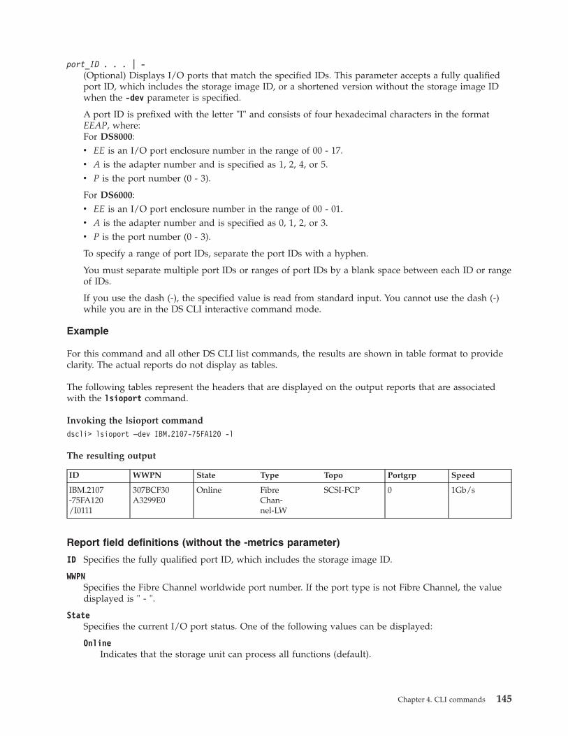
port_ID . . . | -(Optional) Displays I/O ports that match the specified IDs. This parameter accepts a fully qualifiedport ID, which includes the storage image ID, or a shortened version without the storage image IDwhen the -dev parameter is specified.
A port ID is prefixed with the letter "I" and consists of four hexadecimal characters in the formatEEAP, where:For DS8000:v EE is an I/O port enclosure number in the range of 00 - 17.v A is the adapter number and is specified as 1, 2, 4, or 5.v P is the port number (0 - 3).
For DS6000:v EE is an I/O port enclosure number in the range of 00 - 01.v A is the adapter number and is specified as 0, 1, 2, or 3.v P is the port number (0 - 3).
To specify a range of port IDs, separate the port IDs with a hyphen.
You must separate multiple port IDs or ranges of port IDs by a blank space between each ID or rangeof IDs.
If you use the dash (-), the specified value is read from standard input. You cannot use the dash (-)while you are in the DS CLI interactive command mode.
Example
For this command and all other DS CLI list commands, the results are shown in table format to provideclarity. The actual reports do not display as tables.
The following tables represent the headers that are displayed on the output reports that are associatedwith the lsioport command.
Invoking the lsioport commanddscli> lsioport –dev IBM.2107-75FA120 -l
The resulting output
ID WWPN State Type Topo Portgrp Speed
IBM.2107-75FA120/I0111
307BCF30A3299E0
Online FibreChan-nel-LW
SCSI-FCP 0 1Gb/s
Report field definitions (without the -metrics parameter)
ID Specifies the fully qualified port ID, which includes the storage image ID.
WWPNSpecifies the Fibre Channel worldwide port number. If the port type is not Fibre Channel, the valuedisplayed is " - ".
StateSpecifies the current I/O port status. One of the following values can be displayed:
OnlineIndicates that the storage unit can process all functions (default).
Chapter 4. CLI commands 145

OfflineIndicates that the storage unit is not capable of processing any functions.
ResumingIndicates that the storage unit is in the process of coming online.
QuiescingIndicates that the storage unit is in the process of going offline.
FencedIndicates that the storage unit has failed and is offline.
DeconfiguredIndicates that the I/O port is in the process of being deleted.
TypeSpecifies the port type. The following values can be displayed:v Fibre Channel-SW - (SW stands for short wave)v Fibre Channel-LW - (LW stands for long wave, 10 KM)v Fibre Channel-LW 4 KM - (LW stands for long wave, 4 KM) (DS8000 only)v ESCON (DS8000 only)
TopoSpecifies the I/O port topology. The following values can be displayed:v FC-ALv SCSI-FCPv FICONv " - " This value is displayed when the port type is not Fibre Channel.
PortgrpSpecifies the identifier that associates a subset of the I/O ports that are operating in anonymousaccess mode. Default value is 0 when these subsets are not specified.
SpeedSpecifies the I/O port interface speed. The following values can be displayed:v ESCON ports = 200 Mb/s (DS8000 only)v FCP ports = 1 Gb/s, 2 Gb/s, 4 Gb/s, 8 Gb/sv FICON ports = 1 Gb/s, 2 Gb/s, 4 Gb/s, 8 Gb/sv Unknown
Report field definitions (with -metrics parameter)
When you use the -metrics parameter and do not specify a port type, two reports are displayed.
For DS8000 models, one report is for the FICON/ESCON I/O port type and the other report is for theSCSI-FCP I/O port type. A banner is displayed (for example: ===FICON/ESCON-Enabled I/O Ports===)before each report.
For DS6000 models, one report is for the FICON I/O port type and the other report is for the SCSI-FCPI/O port type. A banner is displayed (for example: ===FICON-Enabled I/O Ports===) before each report.
For DS8000 and DS6000 models, a report is not displayed for a port type that has no ports that areenabled.
FICON ports (for DS6000 models only) and FICON/ESCON ports (for DS8000 models only): Each of thefollowing headers and value types are displayed:
146 CLI User's Guide

ID Specifies the fully qualified port ID.
DateSpecifies the current time stamp for the I/O port performance counters. For example, 08/11/0502:23:49 is the format that is used to report this value.
bytereadSpecifies the number of bytes that are read in 128 KB increments.
bytewritSpecifies the number of bytes that are written in 128 KB increments.
ReadsSpecifies a value that is based on extended count-key-data (ECKD™) data received operations.
WritesSpecifies a value that is based on ECKD data transferred operations.
TimereadSpecifies a value that is based on the ECKD data that is received (read-accumulated time) on achannel. The displayed value is based on increments of 16 milliseconds.
TimewriteSpecifies a value that is based on the ECKD data that is transferred (write-accumulated time) on achannel. The displayed value is based on increments of 16 milliseconds.
SCSI-FCP ports: Each of the following headers and value types are displayed:
ID Specifies the fully qualified port ID.
DateSpecifies the current time stamp for the I/O port performance counters. For example, 08/11/0502:23:49 is the format used to report this value.
BytewritSpecifies a value for the remote mirror and copy data transferred operations in increments of 128 KB.
BytereadSpecifies a value for the remote mirror and copy data received operations in increments of 128 KB.
WritesSpecifies a value for the remote mirror and copy data transferred operations.
ReadsSpecifies a value for the remote mirror and copy data received operations.
TimewriteSpecifies a value that is based on the remote mirror and copy data transferred (write-accumulated)time on a channel. The displayed value is based on increments of 16 milliseconds.
TimereadSpecifies a value for the remote mirror and copy data received (read-accumulated) time on a channel.The displayed value is based on increments of 16 milliseconds.
BytereadSpecifies a value that is based on the SCSI data received operations. The displayed value is based onincrements of 128 KB.
ReadsSpecifies a value that is based on the SCSI data transferred operations.
WritesSpecifies a value that is based on the SCSI data transferred operations.
Chapter 4. CLI commands 147
TimereadSpecifies a value that is based on the SCSI data received (read-accumulated) time on a channel. Thedisplayed value is based on increments of 16 milliseconds.
TimewriteSpecifies a value that is based on the SCSI data transferred (write-accumulated) time on a channel.The displayed value is based on increments of 16 milliseconds.
Report field definitions (with -metrics and –l parameters)
LinkFailErrSpecifies the total number of miscellaneous Fibre Channel link errors.
LossSyncErrSpecifies the number of loss of synchronization errors. These errors occur when there is a confirmedand a persistent synchronization loss on the Fibre Channel link.
LossSigErrSpecifies the number of times that a loss of signal was detected on the Fibre Channel link when asignal was previously detected.
PrimSeqErrSpecifies the number of primitive sequence protocol error counts where an unexpected primitivesequence was received.
InvTxWordErrSpecifies the number of times a "bit" error was detected. Examples of a "bit" errors are a codeviolation, an invalid special code alignment, or a disparity error.
CRCErrSpecifies the number of times the CRC of a received frame is in error.
LRSentSpecifies the number of times the port has changed from an active (AC) state to a Link Recovery(LR1) state.
LRRecThis count is the number of times the port has changed from an active (AC) state to a Link Recovery(LR2) state.
IllegalFrameSpecifies the number of frames that violated the Fibre Channel protocol. One example of a violationis an invalid frame header, which occurs when the first frame of a data sequence is missing and asubsequent data frame is detected as illegal.
OutOrdDataSpecifies the number of times that an out-of-order frame is detected. The frame is either missing froma data sequence or it is received beyond the sequence reassembly threshold of the port.
OutOrdACKSpecifies the number of times that an out-of-order ACK (ACKnowledgment field of the TCP protocol)frame is detected. The frame is either missing from a data sequence or it is received beyond thesequence reassembly threshold of the port.
DupFrameSpecifies the number of times a frame was received that has been detected as previously processed.
InvRelOffsetSpecifies the number of times that a frame was received with bad relative offset in the frame header.
SeqTimeoutSpecifies the number of times the port has detected a timeout condition after receiving a sequenceinitiative for a Fibre Channel exchange.
148 CLI User's Guide

BitErrRateSpecifies the number of the bit error (invalid transmission word) bursts for the previous 5 minutecounting window. This number is reset every 5 minutes.
setioportThe setioport command configures one or more I/O ports for open systems or System z host systemconnections. This command cannot be used for ESCON ports.
�� setioport-dev storage_image_ID -topology fc-al
scsi-fcpficon
�
� port_ID. . .
" - "
��
Parameters
-dev storage_image_ID(Optional) Specifies the storage image ID, which includes manufacturer, machine type, and serialnumber. The storage image ID consists of manufacturer, machine type, and serial number. Thestorage image ID is required if you do not specify a fully qualified port ID, do not set the devidvariable in your profile or through the setenv command, and the HMC is aware of more than onestorage image. Using the -dev parameter will temporarily override any defined value for devid for thecurrent command.
-topology fc-al | scsi-fcp | ficon(Optional) Sets the topology for an I/O port, either Fibre Channel Arbitrated Loop, SCSI-FCP, orFICON.
fibre channel arbitrated loop (code fc-al)The fc-al topology setting enables the SCSI ULP with a FC-AL topology. The FC-AL topologydoes not support PPRC path I/O operations.
SCSI-FCPThe SCSI-FCP topology setting enables the SCSI ULP with a point-to-point or switched fabrictopology. PPRC path I/O operations are enabled for this setting.
ficonThe ficon topology setting enables the FICON ULP with a point-to-point or switched fabrictopology. PPRC path I/O operations are not supported for FICON ULP.
port_ID . . . | -(Required) Specifies the I/O port ID. Accepts a fully qualified port ID, which includes the storageimage ID, or a shortened version without the storage image ID when the -dev parameter is specified.
A port ID is prefixed with the letter I and consists of four hexadecimal characters in the format EEAP,where:For DS8000:v EE is an I/O port enclosure number in the range of 00 - 17.v A is the adapter number and is specified as 0, 1, 3, or 4.v P is the port number (0 - 3).
For DS6000:v EE is an I/O port enclosure number in the range of 00 - 01.v A is the adapter number and is specified as 0, 1, 2, or 3.v P is the port number (0 - 3).
Chapter 4. CLI commands 149

To specify a range of port IDs, separate the port IDs with a hyphen.
You must separate multiple port IDs or ranges of port IDs by a blank space between each ID or rangeof IDs.
If you use the dash (-), the specified value is read from standard input. You cannot use the dash (-)while you are in the DS CLI interactive command mode.
Example
Invoking the setioport command
This example configures four I/O ports for FICON topology.dscli> setioport -dev IBM.2107–75FA120 -topology ficon I0111 I0121 I0211 I0221
The resulting outputI/O Port I0111 successfully configured.I/O Port I0121 successfully configured.I/O Port I0211 successfully configured.I/O Port I0221 successfully configured.
showioportThe showioport command displays properties of an I/O port. It optionally displays the performancemetrics for a specific I/O port.
�� showioport-dev storage_image_ID -metrics
port_ID" - "
��
Parameters
-dev storage_image_ID(Optional) Specifies the storage image ID, which consists of manufacturer, machine type, and serialnumber. The storage image ID is required if you do not specify a fully qualified port ID, do not setthe devid variable in your profile or through the setenv command, and the HMC is aware of morethan one storage image. Using the -dev parameter temporarily overrides any defined value for devidfor the current command.
-metrics(Optional) Specifies that the port ID and the performance metrics for the specified I/O port bedisplayed.
Note: All performance counts are an accumulation since the most recent counter wrap or counterreset operation. I/O port performance counters are reset with a storage unit power-onsequence.
port_ID | -(Required) Displays the property level details for the specified port IDs. This parameter accepts afully qualified unique port ID, that is represented in the following format: manufacturer.machinetype-serial number/portID.
For example, for DS8000, IBM.2107–75FA120/I0110
A port ID is prefixed with the letter I and consists of four hexadecimal characters in the format EEAP,where:For DS8000:v EE is an I/O port enclosure number in the range of 00 - 17.v A is the adapter number and is specified as 1, 2, 4, or 5.v P is the port number (0 - 3).
150 CLI User's Guide

For DS6000:v EE is an I/O port enclosure number in the range of 00 - 01.v A is the adapter number and is specified as 0, 1, 2, or 3.v P is the port number (0 - 3).
If you use the dash (-), the specified value is read from standard input. You cannot use the dash (-)while you are in the DS CLI interactive command mode.
Example 1
For this command and all other DS CLI show commands, the results are shown in table format toprovide clarity. The actual reports do not display as tables.
The following tables represent the headers that are displayed on the output reports that are associatedwith the showioport command.
Invoking the showioport command to show port propertiesdscli> showioport -dev IBM.1400-1B1 I0000
The resulting output
ID WWPN State Loc Type
IBM.1400-1B1/I0000
500500763080005AE
Online U1400.1B1.1300025-P1-C1-T0
FibreChannel-SW
Speed Topo Portgrp unkSCSIlog physloc
8 Gb/s SCSI-FCP 0 - R1-I1-C1-T0
Report field definitions (with the -dev parameter)
ID Specifies the fully qualified unique port ID.
WWPNSpecifies the Fibre Channel I/O port worldwide port number (WWPN). If the port type is not FibreChannel, this value is specified as a " - ".
StateSpecifies the current state of the I/O port. One of the following values is displayed:
OnlineIndicates that the storage unit can process all functions (default).
OfflineIndicates that the storage unit is not capable of processing any functions.
ResumingIndicates that the storage unit is in the process of coming online.
QuiescingIndicates that the storage unit is in the process of going offline.
FencedIndicates that the storage unit has failed and is offline.
DeconfiguredIndicates that the I/O port is in the process of being deleted.
Chapter 4. CLI commands 151
|
|
|
||||||
|||
||||||
||
|
||||||
||||||

LocSpecifies the storage enclosure location by identifying the storage unit frame that contains the storageenclosure. The location format is Utttt.mmm.ppsssss.
TypeSpecifies the port type. The following values can be displayed:v Fibre Channel-SW - (SW stands for short wave)v Fibre Channel-LW - (LW stands for long wave, 10 KM)v Fibre Channel-LW 4 KM - (LW stands for long wave, 4 KM) (DS8000 only)v ESCON (DS8000 only)
SpeedSpecifies the I/O port interface speed. The following values can be displayed:v ESCON ports = 200 Mb/s (DS8000 only)v FCP ports = 1 Gb/s, 2 Gb/s, 4 Gb/s, 8 Gb/sv FICON ports = 1 Gb/s, 2 Gb/s, 4 Gb/s, 8 Gb/sv Unknown
TopoSpecifies the port topology. If the port type is not Fibre Channel, then the displayed value is " - ".One of the following values is displayed:v FC-ALv SCSI-FCPv FICONv SCSI-FCP/FICONv " - " (if not Fibre Channel)
PortgrpSpecifies an identifier that associates a subset of the I/O port objects that are operating in anonymousaccess mode.
unkSCSIlogSpecifies a list of unknown SCSI N-port WWPN identifiers that have attempted to login into this I/Oport.
physlocSpecifies the physical location of the I/O port. The I/O port location code is a combination of therack, I/O enclosure, card, and port that provides the physical link. The value of the location uses thefollowing format: R(1-2)-I(1-8)-C(1-6)-P(1-4).v R is the rack locationv I is the I/O enclosurev C is the cardv P is the port of the adapter
This information is not supported for the DS6000.
Note: R1-I3-C2-P1 is an example of this format.
Example 2
For this command and all other DS CLI show commands, the results are shown in table format toprovide clarity. The actual reports do not display as tables.
The following tables represent the headers that are displayed on the output reports that are associatedwith the showioport command, with the -metrics parameter.
152 CLI User's Guide
|
|
|
||
||

Invoking the showioport command to show port performance metricsdscli> showioport -dev IBM.1400-1B1 -metrics I0000
The resulting output
ID Datebyteread(FICON/ESCON)
bytewrit(FICON/ESCON)
Reads(FICON/ESCON)
IBM.1400-1B1/I0000
04/17/2012 11:02:45 MST0 0 0
Writes(FICON/ESCON)
timeread(FICON/ESCON)
timewrite(FICON/ESCON) bytewrit (PPRC) byteread (PPRC)
0 0 0 0 0
Writes (PPRC) Reads (PPRC) timewrite (PPRC) timeread (PPRC) byteread (SCSI)
0 0 0 0 1271326535
bytewrit (SCSI) Reads (SCSI) Writes (SCSI) timeread (SCSI) timewrite (SCSI)
65721755 2479310687 1170136080 81426674 407813158
LinkFailErr (FC) LossSyncErr (FC) LossSigErr (FC) PrimSeqErr (FC) InvTxWordErr (FC)
8 45 0 0 125
CRCErr (FC) LRSent (FC) LRRec (FC) IllegalFrame (FC) OutOrdData (FC)
0 0 0 0 0
OutOrdACK (FC) DupFrame (FC) InvRelOffset (FC) SeqTimeout (FC) BitErrRate (FC)
0 0 0 0 0
RcvBufZero (FC) SndBufZero (FC) RetQFullBusy (FC) ExchOverrun (FC) ExchCntHigh (FC)
0 0 0 0 0
ExchRemAbort (FC) CurrentSpeed (FC) %UtilizeCPU (FC)
0 0 0
Report field definitions (with the -metrics parameter)
ID Specifies the fully qualified port ID.
DateSpecifies the current time stamp for the I/O port performance counters. For example, 08/11/0502:23:49 is the way that this value is reported.
byteread (FICON/ESCON)Specifies the number of bytes that are read in increments of 128 KB.
bytewrit (FICON/ESCON)Specifies the number of bytes that are written in increments of 128 KB.
Chapter 4. CLI commands 153
|
|
|
|||||||||
|||
||||
|
|||||||||
||||||
||||||
||||||
||||||
||||||
||||||
||||||
||||||
||||||
||||||
||||||
||||||
||||||
||||
||||
|

Reads (FICON/ESCON)Specifies a value that is based on the extended count-key-data (ECKD) architecture data receivedoperations.
Writes (FICON/ESCON)Specifies a value that is based on the ECKD architecture data transferred operations.
Timeread (FICON/ESCON)Specifies a value that is based on the ECKD data received (read-accumulated time) on a channel. Thedisplayed value is based on increments of 16 milliseconds.
Timewrite (FICON/ESCON)Specifies a value that is based on the ECKD data transferred (write-accumulated time) on a channel.The displayed value is based on increments of 16 milliseconds.
Bytewrit (PPRC)Specifies a value for the remote mirror and copy data transferred operation in increments of 128 KB.
Byteread (PPRC)Specifies a value for the remote mirror and copy data received operations in increments of 128 KB.
Writes (PPRC)Specifies a value for the remote mirror and copy data transferred operations.
Reads (PPRC)Specifies a value for the remote mirror and copy data received operations.
Timewrite (PPRC)Specifies a value based on the remote mirror and copy data transferred (write-accumulated) time on achannel. The displayed value is based on increments of 16 milliseconds.
Timeread (PPRC)eSpecifies a value for the remote mirror and copy data received (read-accumulated) time on a channel.The displayed value is based on increments of 16 milliseconds.
Byteread (SCSI)Specifies a value that is based on the SCSI data received operations. The displayed value is based onincrements of 128 KB.
Bytewrit (SCSI)Specifies a value that is based on the SCSI data transferred operations. The displayed value is basedon increments of 128 KB.
Reads (SCSI)Specifies a value that is based on the SCSI data received operations.
Writes (SCSI)Specifies a value that is based on the SCSI data transferred operations.
Timeread (SCSI)Specifies a value that is based on the SCSI data received (read-accumulated) time on a channel. Thedisplayed value is based on increments of 16 milliseconds.
Timewrite (SCSI)Specifies a value that is based on the SCSI data transferred (write-accumulated) time on a channel.The displayed value is based on increments of 16 milliseconds.
LinkFailErr (FC)Specifies the total number of miscellaneous Fibre Channel link errors.
LossSyncErr (FC)Specifies the number of loss of synchronization errors. These errors occur when there is a confirmedand a persistent synchronization loss on the Fibre Channel link.
154 CLI User's Guide

LossSigErr (FC)Specifies the number of times that a loss of signal was detected on the Fibre Channel link when asignal was previously detected.
PrimSeqErr (FC)Specifies the number of primitive sequence protocol error counts where an unexpected primitivesequence was received.
InvTxWordErr (FC)Specifies the number of times a bit error was detected. Examples of bit errors are a code violation, aninvalid special code alignment, or a disparity error.
CRCErr (FC)Specifies the number of times the CRC of a received frame is in error.
LRSent (FC)Specifies the number of times the port has changed from an active (AC) state to a Link Recovery(LR1) state.
LRRec (FC)This count is the number of times the port has changed from an active (AC) state to a Link Recovery(LR2) state.
IllegalFrame (FC)Specifies the number of frames that violated the Fibre Channel protocol. One example of a violationis an invalid frame header, which occurs when the first frame of a data sequence is missing and asubsequent data frame is detected as illegal.
OutOrdData (FC)Specifies the number of times that an out-of-order frame is detected. The frame is either missing froma data sequence or it is received beyond the sequence reassembly threshold of the port.
OutOrdACK (FC)Specifies the number of times that an out-of-order ACK (ACKnowledgment field of the TCP protocol)frame is detected. The frame is either missing from a data sequence or it is received beyond thesequence reassembly threshold of the port.
DupFrame (FC)Specifies the number of times a frame was received that has been detected as previously processed.
InvRelOffset (FC)Specifies the number of times that a frame was received with bad relative offset in the frame header.
SeqTimeout (FC)Specifies the number of times the port has detected a timeout condition after receiving a sequenceinitiative for a Fibre Channel exchange.
BitErrRate (FC)Specifies the number of bit error (transmission words that are not valid) bursts for the previous 5minute counting window. This number is reset every 5 minutes.
RcvBufZero (FC)Specifies the number of one second intervals that the receive buffer credit was zero.
SndBufZero (FC)Specifies the number of one second intervals that the send buffer credit was zero.
RetQFullBusy (FC)Specifies the number of times that the FCP port returned “queue full” or “busy” status.
ExchOverrun (FC)Specifies the number of Fibre Channel exchanges that were lost due to overdriving the host adapterport.
Chapter 4. CLI commands 155
||
||
||
|||

ExchCntHigh (FC)Specifies the number of times that the Fibre Channel exchange count crossed the High Threshold.
ExchRemAbort (FC)Specifies the number of times that a port received an abort.
CurrentSpeed (FC)Specifies the current operating link speed.
%UtilizeCPU (FC)Specifies the percentage of the CPU that is being utilized. The percentage is followed by a space andeither “Average” or “Dedicated”. “Average” means that the Host Adapter CPUs are being used as ashared resource for the Host Adapter ports. “Dedicated” means that the Host Adapter CPUs are adedicated resource for each Host Adapter port.
Host connection commandsThis section contains commands that are used to configure host connections and to display hostconnection information.
The following host connection commands are available:
chhostconnectModifies a SCSI host port configuration. You must ensure that the host port is offline to the hostsystem before you process the chhostconnect command.
lshostconnectDisplays a list of host connections for a storage image and the status information for each hostconnection in the list.
lshostvolDisplays the mapping of host device names or volume names to machine type 2105, 2107/242x,and 1750 volume IDs.
lsportprofDisplays a list of port profiles that are supported on a storage unit and their recommendedaddress discovery and logical block size values. This command is helpful to obtain therecommended values for the mkhostconnect command.
managehostconnectModifies the volume group assignment for a SCSI host port. Ensure that the host port is offline tothe host system before you process the managehostconnect command.
mkhostconnectConfigures the open systems hosts port attachments to Fibre Channel ports that are configuredfor FC-AL or SCSI-FCP topology.
rmhostconnectRemoves a SCSI host port connection from a storage image.
showhostconnectDisplays the detailed properties of a specified storage image host connection.
lshosttypeDisplays a list of known hosts, their associated port profiles, address discovery, and logical blocksize values.
chhostconnectThe chhostconnect command modifies a SCSI host port configuration.
�� chhostconnect-dev storage_image_ID -lbs 512
520
�
156 CLI User's Guide
||
||
||
|||||

�-addrdiscovery reportlun
lunpolling-profile port_profile_name
�
�-hosttype host_type -portgrp port_grp_number -volgrp volume_group_ID
none
�
�-ioport port_ID
port_ID_listallnone
-desc description -name new_host_name�
� host_connection_ID" - "
��
Parameters
Notes:
1. The chhostconnect command can be disruptive to host system I/O operations if the affectedhost port is logged in to the target storage unit. You must ensure that the host port is offline tothe host system before you process the chhostconnect command.
2. Using the -hosttype parameter when you issue this command allows you to save input andprocessing time. The -hosttype parameter supplies the same information as if you had usedthe following three parameters:v -profile
v -addrdiscovery
v -lbs
3. If you are using the HP-UX operating system, see the volume restriction that is describedunder the -addrdiscovery parameter.
-dev storage_image_ID(Optional) Specifies the storage image ID, which consists of manufacturer, machine type, and serialnumber. The storage image ID is required if you do not specify a fully qualified host connection ID,do not set the devid variable in your profile or through the setenv command, and the HMC is awareof more than one storage image. Using the -dev parameter temporarily overrides any defined valuefor devid for the current command.
For DS8000, example of a fully qualified storage image ID: IBM.2107-75FA120
-lbs 512 | 520(Optional) Specifies the logical block size that is used by the host system. The block size must becompatible with the volume group type and the volume type configurations that apply to the hostport connection. The 520 logical block size is typically used by the IBM System i models (OS/400).
Notes:
1. You cannot use the -lbs parameter and -hosttype parameter together, but you can useeach one separately.
2. If you do not use the -hosttype parameter, use the lsportprof command to determine theblock size that you need to specify for the -lbs parameter.
-addrdiscovery reportlun | lunpolling(Optional) Specifies the method for identifying logical unit number (LUN) addresses.v The reportlun method specifies that the host system can access up to 64 000 LUNs.v The lunpolling method specifies that the host system can access up to 256 LUNs.
Chapter 4. CLI commands 157

Notes:
1. You cannot use the -addrdiscovery parameter and -hosttype parameter together, but youcan use each one separately.
2. For HP-UX operating systems, the number of volumes in the volume group must notexceed seven volumes. This restriction only applies when the -addrdiscovery parameter isset to reportlun and the associated volume group is of type scsimap256.
-profile port_profile_name(Optional) Specifies the name of the host connection behavior profile. If the name includes a blankspace, enclose the name with double quotation marks. For example, -profile “IBM pSeries – Sun”.
Notes:
1. You cannot use the -profile parameter and the -hosttype parameter together, but you canuse each one separately.
2. If you do not use the -hosttype parameter, use the lsportprof command to obtain a list ofavailable profiles.
-hosttype host_type(Optional) Specifies information about the following three parameters:v -profile
v -addrdiscovery
v -lbs
Notes:
1. You cannot use the -hosttype parameter with the -profile, addrdiscovery, or -lbsparameters.
2. Use the lshosttype command to obtain a list of known host types.
-portgrp port_grp_number(Optional) Specifies a user-assigned number that associates two or more host ports with access to acommon volume group. Port group zero is reserved for ports that have not been associated with aport group.
-volgrp volume_group_ID | none(Optional) Specifies an available volume group or no volume group if the none subparameter is used.This command accepts a fully qualified volume group ID including the storage image ID or ashortened version if the -dev parameter is specified. The shortened version is a four-digit decimalnumber with no leading zeros, prefixed with the letter V.
A host connection can use only one volume group per storage image. (A single WWPN can accessonly one volume group per storage image.) Host operations cannot be initiated until a volume groupID is assigned.
If none is specified, the volume group ID assignment is removed from a SCSI host port object.
-ioport port_ID port_ID_list |all|none(Optional) Specifies all, none, or, one or more I/O port IDs that allow host connection access tovolumes. This command accepts a fully qualified port ID including the storage image ID or ashortened version if the -dev parameter is specified.
port_ID port_ID_listSpecifies that you can designate up to 128 ports for an open systems host attachmentassignment. You can list one or more port IDs separated by commas with no spaces. If youenter a list of I/O port IDs, access from the specified host connection to the specified volumegroup is allowed using only the designated list of port IDs.
all Specifies that you want to add all I/O port IDs. This setting allows the specified hostconnection access to the designated volume group through all the associated I/O port IDs.
158 CLI User's Guide

none Specifies that you do not want to add any I/O ports. If you do not specify I/O ports, thestorage unit is configured to allow host connection access to the specified volume groupusing any I/O port that is configured for FC-AL or SCSI-FCP topology.
Examples of -dev parameter use
If you specify the -dev parameter, you can use the shortened version of the -ioport parameter asfollows:v For DS8000,
dscli> chhostconnect -dev IBM.2107-75FA120 -ioport I0222 1
where 1 represents the required parameter, host_connection_ID.
If you do not specify the -dev parameter and you specify the -ioport parameter, you must use thefully qualified version of the port ID with the -ioport parameter specified as follows:v For DS8000:
dscli> chhostconnect -ioport IBM.2107-75FA120/I0222 IBM.2107-75FA120/1
where IBM.1750-68FA120/1 or IBM.2107-75FA120/1 represents the required parameter,host_connection_ID
A port ID is prefixed with the letter I and consists of four hexadecimal characters in the format EEAP,where:For DS8000:v EE is an I/O port enclosure number in the range of 00 - 17.v A is the adapter number and is specified as 1, 2, 4, or 5.v P is the port number (0 - 3).
For DS6000:v EE is an I/O port enclosure number in the range of 00 - 01.v A is the adapter number and is specified as 0, 1, 2, or 3.v P is the port number (0 - 3).
To specify a range of port IDs, separate the port IDs with a hyphen.
Separate multiple port IDs or ranges of port IDs with a comma between each ID or range of IDs.
Note: Changing the I/O port values can result in a disruption of current logins by the host systems.
-desc description(Optional) Specifies the description that you defined for the SCSI host port. The description is limitedto 256-byte or 128 double-byte characters.
-name new_host_name(Optional) Specifies the user-assigned host system or port name. The name is limited to 32-byte or 16double-byte characters.
host_connection_ID | -(Required) Specifies the host connection ID, which is a unique identifier that uses any number from 0- FFFE within the scope of a storage image. This parameter accepts a fully qualified ID or a shortenedversion if the -dev parameter is specified.
If you do not specify the -dev parameter and you specify the host_connection_ID parameter, youmust use the fully qualified version of the host connection ID as follows:v For DS8000:
dscli> chhostconnect -desc newdescription IBM.2107-75FA120/1
v For DS6000:dscli> chhostconnect -desc newdescription IBM.1750-68FA120/1
Chapter 4. CLI commands 159

If you use the dash (-), the specified value is read from standard input. You cannot use the dash (-)while you are in the DS CLI interactive command mode.
Attention: Use caution when you work with connection IDs to ensure that you have specified thecorrect connection that you want to change. For example, if you intend to change connection ID 0005and type 000, the system changes connection ID 0. Or, if you want to change connection ID 0020 andtype 002, the system changes connection ID 2. The system does not recognize the leading zeros, and000 is interpreted as connection ID 0 and 002 is interpreted as connection ID 2.
Example
Invoking the chhostconnect commanddscli> chhostconnect-dev IBM.2107–75FA120-name host_1_port_2 1
The resulting outputHost connection 1 successfully modified.
lshostconnectThe lshostconnect command displays a list of host connections for a storage image and the statusinformation for each host connection in the list.
You can also use this command to obtain a list of worldwide port numbers (WWPNs) from asystem-detected-unknown host port. You can use these WWPNs to create a host connection using themkhostconnect command.
�� lshostconnect-dev storage_image_ID -s
-l-portgrp port_grp_number
�
�-volgrp volume_group_ID -unknown -login -wwpn wwpn
�
�host_connection_ID
. . ." - "
��
Parameters
-dev storage_image_ID(Optional) Displays the host connections for the specified storage image. A storage image ID consistsof manufacturer, machine type, and serial number. The storage image ID is required if you do notspecify a fully qualified host connection ID, do not set the devid variable in your profile or throughthe setenv command, and the HMC is aware of more than one storage image. Using the -devparameter temporarily overrides any defined value for devid for the current command.
For DS8000, example of a fully qualified storage image ID: IBM.2107-75FA120
-s(Optional) Specifies the host connection IDs. You cannot use the -l and the -s parameters together.
-l(Optional) Specifies the default output and your description for each host connection in the list. Youcannot use the -l and the -s parameters together.
160 CLI User's Guide

-portgrp port_grp_number(Optional) Specifies the host connections that have an associated group number.
Note: You cannot use the -portgrp parameter with the -unknown or -login parameters.
-volgrp volume_group_ID(Optional) Specifies that only the host connections with the specified volume group ID are to bedisplayed. The volume group ID is a four-digit decimal number with no leading zeros, prefixed withthe letter V.
Note: You cannot use the -volgrp parameter with the -unknown or -login parameters.
-unknown(Optional) Specifies that a list of logged in host ports (WWPNs), that are not recognized as beingassociated with the designated storage unit, be displayed.
Note: The list of logged in host posts includes all of the host ports that the storage unit detects, andit does not take into account changes that the storage unit could not detect. For example, thestorage unit cannot detect that a cable has been disconnected from the port of the host deviceor that a fabric zoning change has occurred. In these cases, the host might not be able tocommunicate with the storage device anymore; however, the storage device might not detectthis condition and still views the host as logged in.
This parameter generates a list report that contains the following three information fields:v WWNNv WWPNv ESSIOport
Note: You cannot use the -unknown parameter with the -portgrp, -volgrp, -login orhost_connection_ID parameters.
-login(Optional) Specifies that a list is to be displayed of host port (WWPNs) that are logged in and sortedby the ESS I/O port IDs for known connections. The report displays one line of information perconnection. However, no information is displayed for a FICON connection.
Notes:
1. Known logins are logins for which you have created for host connection, as well asRemote Mirror and Copy paths and anonymous connections.
2. You cannot use the -login parameter with the -unknown, -portgrp, -volgrp, orhost_connection_ID parameters.
-wwpn wwpn(Optional) Specifies that only the host connect objects for the specified WWPN is displayed.
host_connection_ID . . . | -(Optional) Specifies that host connection information for the specified host connection IDs bedisplayed. This parameter accepts a fully qualified ID (includes manufacture. machine type, serialnumber/hostconnectID) or a shortened version if the -dev parameter is specified.
Note: You cannot use the host_connection_ID parameter with the -login or -unknown parameters.
If you use the dash (-), the specified value is read from standard input. You cannot use the dash (-)while you are in the DS CLI interactive command mode.
For DS8000, example of a fully qualified host connection ID: IBM.2107-75FA120/2
Example of a shortened version host connection ID: 0002
Chapter 4. CLI commands 161

Example
Note: You can receive different reports when you use the lshostconnect command, one for the -unknownparameter, one for the -login parameter, one for the -l parameter, and one for the -s parameter.The reports that are associated with the -unknown, -login, and -l parameters are provided in thisdescription.
For this command and all other DS CLI list commands, the results are shown in table format toprovide clarity. The actual reports do not display as tables.
The following tables represent the headers that are displayed on the output reports that areassociated with the lshostconnect command.
Invoking the lshostconnect command without the -unknown parameterdscli> lshostconnect-dev IBM.2107–75FA120 -l
The resulting output The following table displays four ports, which is possible when you query aDS8000 model. If you query a DS6000 model, only two ports are displayed.
Name ID WWPN HostType LBSAddrdiscovery
My host port 1 IBM.2107-75FA120/1
3007ACF30A2399E0
Unknown 512 reportLUN
My host port 2 IBM.2107-75FA120/2
3007ACF30A2399E1
Unknown 512 reportLUN
My host port 3 IBM.2107-75FA120/3
3007ACF30A2399E2
Unknown 512 reportLUN
My host port 4 IBM.2107-75FA120/4
3007ACF30A2399E3
Unknown 512 reportLUN
Profile portgrp volgrpID atchtopo ESSIOport Speed Desc
IBMpSeries
- AIX
0 V100 - I0111,I0121I0211,I0221
Unknown SCSI1
IBMpSeries
- AIX
0 V100 - All Unknown SCSI2
IBMpSeries
– pLinux
0 V100 - I0111,I0121I0211,I0221
Unknown SCSI3
IBMpSeries
- pLinux
0 V100 - - Unknown SCSI4
Example of lshostconnect using the -unknown parameter
Invoking the lshostconnect command with the -unknown parameterdscli> lshostconnect-dev IBM.2107–75FA120 -unknown
The resulting output
162 CLI User's Guide

WWNN WWPN ESSIOport
3007ACF30A239900 3007ACF30A2399E0 I0111, I0121, I0211, I0221
3007ACF30A239900 3007ACF30A2399E1 I0121
3007ACF30A239900 3007ACF30A2399E2 I0111, I0121, I0211, I0221
3007ACF30A239900 3007ACF30A2399E3 I0111
Example of lshostconnect using the -login parameter
Invoking the lshostconnect command with the -login parameterdscli> lshostconnect-dev IBM.2107–75FA120 -login
The resulting output
WWNN WWPN ESSIOport LoginType Name ID
3007ACF30A239900
3007ACF30A2399E0
I0111 SCSI MyHostA 1
3007ACF30A239900
3007ACF30A2399E1
I0111 SCSI MyHostB 1
3007ACF30A239900
3007ACF30A2399E2
I0221 SCSI - -
Report field definitions when the -unknown or -login parameter is not used
NameHost connection/SCSI port nickname.
The name is limited to 32-byte or 16 double-byte characters.
ID A fully qualified host connection ID: manufacturer.type-serial number/hostconnectID
The host connection ID component is a unique identifier (0 - FFFE) within the scope of a storage unit.
WWPNSpecifies the worldwide port name (WWPN) for this host system port.
HostTypeSpecifies the name of the host type.
Unknown is displayed when the information is not available and indicates that the host type was notspecified when the host connection was created or modified.
LBSSpecifies the logical block size that is used by the designated host system and host system port.
The logical block setting must be compatible with the volume group type that is configured forvolume access. The 520 block size is typically used for IBM System i host system attachments.
AddrdiscoverySpecifies the LUN address discovery method used by the designated host system and host systemport.
The LUN Discovery method must be compatible with the volume group type that is configured forvolume access.
The Poll LUNs method enables access to a maximum of 256 LUNs. The Report LUNs method enablesaccess to a maximum of 64 000 LUNs.
Chapter 4. CLI commands 163

ProfileSpecifies the name of the host connection behavior profile.
PortgrpSpecifies the host port group ID. This ID ties together a group of SCSI host port objects that areaccessing a common volume group. If the port group value is set to zero, the host port is notassociated with any port group.
VolgrpIDSpecifies the volume group ID. This ID is a unique identifier within the DS8000 for the SCSI volumegroup that the specified SCSI host port is assigned to.
Specifies the volume group ID. This ID is a unique identifier within the DS6000 for the SCSI volumegroup that the specified SCSI host port is assigned to.
AtchtopoThe atchtopo is an attribute of the I/O port and, under certain conditions, might display a value thatis inconsistent with the value reported by the lsioport command. Because this inconsistency cannotbe corrected in all cases, the atchtopo attribute always displays as a " - " value. To obtain the I/O porttopology, use the lsioport or showioport commands.
ESSIOportSpecifies the array of port IDs that the designated host port is logged in to.
A port ID is prefixed with the letter "I" and consists of four hexadecimal characters in the formatEEAP, where:For DS8000:v EE is an I/O port enclosure number in the range of 00 - 17.v A is the adapter number and is specified as 1, 2, 4, or 5.v P is the port number (0 - 3).
For DS6000:v EE is an I/O port enclosure number in the range of 00 - 01.v A is the adapter number and is specified as 0, 1, 2, or 3.v P is the port number (0 - 3).
SpeedSpeed is an attribute of the I/O port and, under certain conditions, might display a value that isinconsistent with the value reported by the lsioport command. Because this inconsistency cannot becorrected in all cases, the speed attribute always displays a value of "Unknown". To query the speedof an I/O port use the lsioport or showioport commands.
DescSpecifies the description that you defined for the SCSI host port. The description is limited to 256byte or 128 double-byte characters.
Report field definitions when the -unknown parameter is used
WWNNSpecifies the worldwide node name for the designated host system.
WWPNSpecifies the worldwide port name for the designated host system port.
ESSIOportSpecifies the array of port IDs that the designated host port is logged in to.
A port ID is prefixed with the letter "I" and consists of four hexadecimal characters in the formatEEAP, where:For DS8000:v EE is an I/O port enclosure number in the range of 00 - 17.
164 CLI User's Guide

v A is the adapter number and is specified as 1, 2, 4, or 5.v P is the port number (0 - 3).
For DS6000:v EE is an I/O port enclosure number in the range of 00 - 01.v A is the adapter number and is specified as 0, 1, 2, or 3.v P is the port number (0 - 3).
Report field definitions when the -login parameter is used
WWNNSpecifies the worldwide node name (WWNN) for this host system.
WWPNSpecifies the worldwide port name (WWPN) for this host system port.
ESSIOportSpecifies the port ID that the designated host port is logged in to.
A port ID is prefixed with the letter "I" and consists of four hexadecimal characters in the formatEEAP, where:For DS8000:v EE is an I/O port enclosure number in the range of 00 - 17.v A is the adapter number and is specified as 1, 2, 4, or 5.v P is the port number (0 - 3).
For DS6000:v EE is an I/O port enclosure number in the range of 00 - 01.v A is the adapter number and is specified as 0, 1, 2, or 3.v P is the port number (0 - 3).
LoginTypeSpecifies the type of login such as SCSI.
NameSpecifies the name that you assigned to the host. If a name is not assigned, a " - " value is displayed.
ID A fully qualified host connection ID: manufacturer, machine type, serial number/hostconnectID
The host connection ID component is a unique identifier (0 - FFFE) within the scope of a storage unit.
lshostvolThe lshostvol command displays the mapping of host device names or volume names to machine type2105, 2107, and 1750 volume IDs. (This command is not supported on the i5/OS.)
�� lshostvol ��
Parameters
There are no parameters for this command.
Notes:
1. The lshostvol command displays only volumes that are accessed using a direct Fibre Channelpath when you use the command on an OpenVMS host system that is a member of anOpenVMS cluster. The command output does not display information about the followingOpenVMS cluster devices:v Volumes to which the host system only has MSCP paths.
Chapter 4. CLI commands 165

v Volumes to which the host system uses only MSCP paths at this time even though it hasboth MSCP and direct paths.
2. If you do not have installed the IBM Multipath Subsystem Device Driver (SDD), the virtualpath (vPath) name is not displayed.
3. On a Red Hat Enterprise Linux system, attached devices might be detected by the HBA driver,but they are not registered with the operating system. Normally, the operating system is set upto automatically detect all LUNS. However, if this does not occur automatically, you mustissue the following for every volume (LUN):echoscsi add-single-device host# channel# lun# >/proc/scsi/scsi
If SDD is installed on your system, you can run the scsiscan script to detect all the LUNs.4. If the user that is running the DS CLI on the host does not have permissions to view the host
volumes, the lshostvol command will return no host volumes found.
Example
The information that is displayed on the report that is generated from the lshostvol command isdifferent depending on whether you have SDD installed. The following example tables indicate thedifferences.
For this command and all other DS CLI list commands, the results are shown in table format to provideclarity. The actual reports do not display as tables.
The following tables represent the headers that are displayed on the output reports that are associatedwith the lshostvol command.
Invoking the lshostvol commanddscli> lshostvol
The resulting output with SDD installed
Disk Name Volume ID Vpath Name
my_vol_01,my_vol_04 IBM.2107-75DA110/175D vpath01
my_vol_02,my_vol_05 IBM.2107-75EA120/175E vpath02
my_vol_03,my_vol_06 IBM.2107-75FA130/175F vpath03
my_vol_07,my_vol_09 IBM.2105-29239/119E Vpath04
my_vol_08,my_vol_10 IBM.2105-29239/119F Vpath05
The resulting output without SDD installed
Device/Volume Name Volume ID Vpath Name
Hdisk01 IBM.2107-75DA110/175D -
Hdisk02 IBM.2107-75EA120/175E -
Hdisk03 IBM.2107-75FA130/175F -
Hdisk07 IBM.2105-29239/119E -
Hdisk08 IBM.2105-29239/119F -
166 CLI User's Guide

Report column definitions
Device/Volume nameSpecifies the nickname you assigned to the device or volume. When SDD is installed, this columnreports the volume name instead of the device name.
Volume IDSpecifies the ID of the storage unit.
Vpath nameSpecifies the virtual path name. When SDD is not installed, this value is reported as " - ".
lsportprofThe lsportprof command displays a list of port profiles that are supported on a storage unit and theirrecommended address discovery and logical block size values.
You can use this command to view known values for the block size (lbs) and address discovery(addrdiscovery) parameters in the mkhostconnect command.
Note: Use this command to get the recommended values for the mkhostconnect command.
�� lsportprof storage_image_ID" - "
��
Parameters
storage_image_ID | -(Required) Displays a list of port profiles for the specified storage image IDs. A storage image IDconsists of manufacturer, type, and serial number.
If you use the dash (-), the specified value is read from standard input. You cannot use the dash (-)while you are in the DS CLI interactive command mode.
For DS8000, example: IBM.2107-75FA120
Example
For this command and all other DS CLI list commands, the results are shown in table format to provideclarity. The actual reports do not display as tables.
The following table represents the headers that are displayed on the output report that is associated withthe lsportprof command.
Invoking the lsportprof commanddscli> lsportprof IBM.2107-75FA120
The resulting output
Name AddrDiscovery LBS
IBM pSeries – AIX ReportLUN 512
IBM pSeries – pLinux LUNPolling 512
Report column definitions
Name Specifies the name of the host connection behavior profile. The port profile specifies a given hostor operating system type.
Chapter 4. CLI commands 167

AddrDiscoverySpecifies the address discovery method. One of the following values is displayed:
LUN PollingSpecifies that host system LUN access is limited to a maximum of 256 LUNs.
Report LUNSpecifies that host system LUN access is limited to a maximum of 64000 LUNs
LBS Specifies the logical block size. One of the following values is displayed:v 512 - This value is displayed for all hosts except OS400.v 520 - This value is displayed for an OS400 host.
managehostconnectThe managehostconnect command modifies the volume group assignment for a SCSI host port.
�� managehostconnect-dev storage_image_ID
-volgrp volume_group_IDnone
�
� port_grp_number" - "
��
Parameters
Notes:
1. The managehostconnect command can be disruptive to host system I/O operations if theaffected host port is logged onto the target storage unit. Ensure that the host port is offline tothe host system before you process the managehostconnect command.
2. This command is used more effectively after you have issued the lshostconnect orshowhostconnect commands and have analyzed the reports that are generated by thesecommands. The information that is reported by these commands can help you ensure that youspecify the correct port group number when you issue the managehostconnect command.
-dev storage_image_ID(Optional) Specifies the storage image ID, which consists of manufacturer, machine type, and serialnumber. The storage image ID is required if you do not specify a fully qualified volume group ID, donot set the devid variable in your profile or through the setenv command, and the HMC is aware ofmore than one storage image. Using the -dev parameter will temporarily override any defined valuefor devid for the current command.
-volgrp volume_group_ID | none(Required) Specifies that the SCSI host port connections that are associated with the specified portgroup number will be modified to access this volume group ID. A volume group ID is a four-digitdecimal number with no leading zeroes, prefixed with the letter V.
If none is specified, the volume group ID assignment is removed from all SCSI host port objects thatare associated with a common port group number.
Example: -volgrp none
port_grp_number | -(Required) Specifies the SCSI host port group number that associates two or more host ports ashaving access to a common volume group.
If you use the dash (-), the specified value is read from standard input. However, you cannot use thedash (-) while you are in the DS CLI interactive command mode.
168 CLI User's Guide

Example
Invoking the managehostconnect commanddscli> managehostconnect -dev IBM.2107-75FA120 -volgrp 11 1
The resulting outputPort group number 1 successfully modified.
mkhostconnectThe mkhostconnect command configures open systems hosts port attachments to Fibre Channel ports thatare configured for FC-AL or SCSI-FCP topology.
�� mkhostconnect -wwpn wwpn-dev storage_image_ID -lbs 512
520
�
�-addrdiscovery reportlun
lunpolling-profile port_profile_name
�
�-hosttype host_type -portgrp port_grp_number -volgrp volume_group_ID
�
�-ioport port_ID
port_ID_listallnone
-desc descriptionhost_name" - "
��
Parameters
Open systems hosts port attachments to Fibre Channel ports are configured for identified access modeand SCSI protocol.
Notes:
1. Ensure that you use the -hosttype parameter when you issue this command, because doing sosaves input and processing time. The -hosttype parameter supplies the same information as ifyou had used the following three parameters:v -profile
v -addrdiscovery
v -lbs
2. If you are using the HP-UX operating system, see the volume restriction that is describedunder the -addrdiscovery parameter.
-dev storage_image_ID(Optional) Specifies the storage image ID, which consists of manufacturer, machine type, and serialnumber. The storage image ID is required if you do not specify a fully qualified WWPN, do not setthe devid variable in your profile or through the setenv command, and the HMC is aware of morethan one storage image. Using the -dev parameter will temporarily override any defined value fordevid for the current command.
-wwpn wwpn(Required) Specifies the worldwide port name (WWPN). The WWPN is a 16-character hexadecimalID. The names are host attachment specific; for example, 12341234000A000F.
Chapter 4. CLI commands 169

Note: You should not create more than one hostconnect per WWPN, except for SUN hosts. Creatingmore than one hostconnect per WWPN (each with a different volume group) is only supportedfor SUN.
-lbs 512 | 520(Optional) Specifies the logical block size that is used by the specified host system, in bytes. Theblock size must be compatible with the volume group type and the volume type configurations thatapply to the specified host port connection. The 520-byte size is typically used by IBM System imodels (OS/400).
Notes:
1. Do not use the -lbs parameter if you specify the -hosttype parameter.2. If you do not use the -hosttype parameter, use the lsportprof command to determine the
block size that you need to specify.
-addrdiscovery reportlun | lunpolling(Optional) Specifies the method for discovering logical unit number (LUN) addresses.v The reportlun method specifies that the host system can access up to 64 000 LUNs.
Note: Use the reportlun method only with volume groups that are designated as mask type. (Thisdesignation is assigned when you use the mkvolgrp command to create the volume group.)However, you can use the reportlun method for a map type, but there are additionalconsiderations if you are using an HP-UX operating system.
For HP-UX operating systems, the number of volumes in the volume group must not exceedseven volumes. This restriction only applies when the -addrdiscovery parameter is set toreportlun and the associated volume group is of type scsimap256.
v The lunpolling method specifies that the host system can access up to 256 LUNs. For Sun, Linux,and Windows operating systems, the lunpolling method is typically selected.
Notes:
1. Use the lunpolling method only with volume groups that are designated as map type.(This designation is assigned when you use the mkvolgrp command to create the volumegroup.)
2. Do not use the -addrdiscovery parameter if you specify the -hosttype parameter.
-profile port_profile_name(Optional. If you specify the -hosttype parameter, this parameter is not used.) Specifies the name ofthe host connection behavior profile. If the name includes a blank space, enclose the name withdouble quotation marks. For example, -profile “IBM pSeries – AIX”.
Notes:
1. Do not use the -profile parameter if you specify the -hosttype parameter.2. If you do not use the -hosttype parameter, use the lsportprof command to obtain a list
of available profiles.
-hosttype host_type(Optional) Specifies information about the following three parameters:v -profile
v -addrdiscovery
v -lbs
Notes:
1. When the -hosttype parameter is specified, do not use the -profile, -addrdiscovery, or-lbs parameters.
170 CLI User's Guide

2. Use the lshosttype command to obtain a list of known host types.
-portgrp port_grp_number(Optional) Specifies the identifier that associates two or more host ports with access to a commonvolume group. Port group zero is reserved for ports that have not been associated with a port group.
-volgrp volume_group_ID(Optional) Specifies an available volume group. This parameter accepts a fully qualified volumegroup ID including the storage image ID or a shortened version. The shortened version is a four-digitdecimal number with no leading zeroes, prefixed with the letter V.
A host connection uses only one volume group per storage image; that is, a single WWPN can accessonly one volume group per storage image.
Note: If you do not specify a volume group when a host connection is created, the value for volumegroup is displayed as a " - " when you issue a lshostconnect or showhostconnect command.
-ioport port_ID port_ID_list |all|none(Optional) Specifies all, none, one, or more I/O port IDs that allow host connection access tovolumes. I/O ports cannot share the same WWPN. Ensure that there are no conflicts with the I/Oports of existing SCSI host connections.
port_ID port_ID_listSpecifies that you can designate up to 128 ports for an open systems host attachmentassignment. You can list one or more port IDs separated by commas with no spaces. If youenter a list of I/O port IDs, access from the specified host connection to the specified volumegroup is allowed using only the designated list of port IDs.
all Specifies that you want to add all I/O port IDs. This allows the specified host connectionaccess to the designated volume group through all the associated I/O port IDs.
none Specifies that you do not want to add any I/O ports. If you do not specify I/O ports, thestorage unit is configured to allow host connection access to the specified volume groupusing any I/O port that is configured for FC-AL or SCSI-FCP topology.
A port ID is four hexadecimal characters in the format EEAP, where:For DS8000:v EE is an I/O port enclosure number in the range of 00 - 17.v A is the adapter number and is specified as 1, 2, 4, or 5.v "P" is the port number (0 - 3).
For DS6000:v EE is an I/O port enclosure number in the range of 00 - 01.v A is the adapter number and is specified as 0, 1, 2, or 3.v "P" is the port number (0 - 3).
This number is prefixed with the letter I.
To specify a range of port IDs, separate the port IDs with a hyphen.
You must separate multiple port IDs or ranges of port IDs with a comma between each ID or rangeof IDs.
-desc description(Optional) Specifies the description that you defined for the SCSI host port. The description is limitedto 256 byte or 128 double-byte characters.
host_name | -(Required) Specifies your host system or port name, limited to 16 characters.
If you use the dash (-), the specified value is read from standard input. You cannot use the dash (-)while you are in the DS CLI interactive command mode.
Chapter 4. CLI commands 171

Example
Invoking the mkhostconnect commanddscli> mkhostconnect -dev IBM.2107-75FA120 –wwname 12341234000A000F–profile “IBM pSeries – AIX” host_1_port_1
The resulting outputHost connection 0 successfully created.
rmhostconnectThe rmhostconnect command removes a SCSI host port connection from a storage image.
�� rmhostconnect-dev storage_image_ID -quiet
host_connection_ID" - "
��
Parameters
-dev storage_image_ID(Optional) Specifies the storage image ID, which consists of manufacturer, machine type, and serialnumber. The storage image ID is required if you do not specify a fully qualified ID for all hostconnections, do not set the devid variable in your profile or through the setenv command, and theHMC is aware of more than one storage image. Using the -dev parameter will temporarily overrideany defined value for devid for the current command.
-quiet(Optional) Turns off the removal confirmation prompt.
host_connection_ID | -(Required) Specifies the host connect ID, which is a unique identifier that uses any number from 0 -FFFE within the scope of a storage image. This parameter accepts a fully qualified ID (includesmanufacturer.machine type-serial number/hostconnectID) or a shortened version if the -dev parameter isspecified.
For DS8000, example of a fully qualified host connection ID: IBM.2107-75FA120/1
For DS6000, example of a fully qualified host connection ID: IBM.1750-68FA120/2
If you use the dash (-), the specified value is read from standard input. You cannot use the dash (-)while you are in the DS CLI interactive command mode.
Attention: Use caution when you work with connection IDs to ensure that you have specified theconnection that you want to delete. For example, if you intend to delete connection ID 0005 and type000, the system deletes connection ID 0. Or, if you want to delete connection ID 0020 and type 002,the system deletes connection ID 2. The system does not consider the leading zeros, and 000 isinterpreted as connection ID 0 and 002 is interpreted as connection ID 2.
Example
Invoking the rmhostconnect commanddscli> rmhostconnect -dev IBM.2107-75FA120 1
The resulting outputAre you sure you want to delete Host Connection IBM.2107-75FA120/1? y/n YHost Connection IBM.2107-75FA120/1 successfully deleted.
172 CLI User's Guide

showhostconnectThe showhostconnect command displays detailed properties of a storage image host connection.
�� showhostconnect-dev storage_image_ID
host_connection_ID" - "
��
Parameters
-dev storage_image_ID(Optional) Specifies the storage image ID, which consists of manufacturer, machine type, and serialnumber. The storage image ID is required if you do not specify a fully qualified ID for the hostconnection, do not set the devid variable in your profile or through the setenv command, and theHMC is aware of more than one storage image. Using the -dev parameter will temporarily overrideany defined value for devid for the current command.
host_connection_ID | -(Required) Specifies a fully qualified host connection ID, which includes the manufacturer, machinetype, and serial number if the -dev parameter is not used. The host connection ID is a uniqueidentifier (0 - FFFE) within the scope of a storage image.
If you use the dash (-), the specified value is read from standard input. You cannot use the dash (-)while you are in the DS CLI interactive command mode.
Example
For this command and all other DS CLI show commands, the results are shown in table format toprovide clarity. The actual reports do not display as tables.
The following tables represent the headers that are displayed on the output report that is associated withthe showhostconnect command.
Invoking the showhostconnect commanddscli> showhostconnect -dev IBM.2107–75FA120 1
The resulting output
Name ID WWPN HostType LBSAddrdiscovery
My host port 1 IBM.2107-75FA120/1
3007ACF30A2399E0
Unknown 512 reportLUN
Profile Portgrp VolgrpID Atchtopo ESSIOport Speed Desc
IBMpSeries
- AIX
0 100 - I0111,I0121I0211,I0221
Unknown SCSI1
Report field definitions
NameSpecifies the host connection SCSI port nickname.
The name is limited to 32 byte or 16 double-byte characters.
ID Specifies a fully qualified host connection ID.
Chapter 4. CLI commands 173

The value that is represented by the host_connection_ID parameter is a unique identifier (0 - FFFE)within the scope of a storage unit.
WWPNSpecifies the worldwide port name (WWPN) for the designated host system port.
HostTypeSpecifies the name of the host type.
"Unknown" is displayed when the information is not available. This indicates that the host type wasnot specified when the host connection was created or modified.
LBSSpecifies the logical block size that is used by this host system and the host system port.
The logical block setting must be compatible with the volume group type that is configured forvolume access. The 520 block size is typically used for IBM System i host system attachments.
AddrdiscoverySpecifies the LUN address discovery method that is used by this host system and the host systemport.
The LUN Discovery method must be compatible with the volume group type that is configured forvolume access.
The Poll LUNs method enables access to a maximum of 256 LUNs. The Report LUNs method enablesaccess to a maximum of 64 000 LUNs.
ProfileSpecifies the name of the host connection behavior profile.
PortgrpSpecifies the host port group ID. The ID ties together a group of SCSI host port objects that areaccessing a common volume group. If the port group value is set to zero, the host port is notassociated with any port group.
VolgrpIDSpecifies the volume group ID. This ID is a unique identifier within the DS8000 for the SCSI volumegroup that the specified SCSI host port is assigned to.
Specifies the volume group ID. This ID is a unique identifier within the DS6000 for the SCSI volumegroup that the specified SCSI host port is assigned to.
AtchtopoThe atchtopo is an attribute of the I/O port and, under certain conditions, might display a value thatis inconsistent with the value reported by the lsioport command. Because this inconsistency cannotbe corrected in all cases, the atchtopo attribute always displays as a " - " value. To obtain the I/O porttopology, use the lsioport or showioport commands.
ESSIOportSpecifies the array of port IDs that the designated host port is logged into.
A port ID is prefixed with the letter "I" and consists of four hexadecimal characters in the formatEEAP, where:For DS8000:v EE is an I/O port enclosure number in the range of 00 - 17.v A is the adapter number and is specified as 1, 2, 4, or 5.v P is the port number (0 - 3).
For DS6000:v EE is an I/O port enclosure number in the range of 00 - 01.v A is the adapter number and is specified as 0, 1, 2, or 3.
174 CLI User's Guide

v P is the port number (0 - 3).
SpeedSpeed is an attribute of the I/O port and, under certain conditions, might display a value that isinconsistent with the value reported by the lsioport command. Because this inconsistency cannot becorrected in all cases, the speed attribute always displays a value of "Unknown". To query the speedof an I/O port use the lsioport or showioport commands.
DescSpecifies the description you defined for the SCSI host port. The description is limited to 256 byte or128 double-byte characters.
lshosttypeThe lshosttype command displays a list of known hosts, their associated port profiles, address discovery,and logical block size values. Use this command to get the available host types for the mkhostconnectcommand.
�� lshosttype-s-l
-type volumeGroup_type ��
Parameters
-s(Optional) Displays the host types only. You cannot use the -l and -s parameters together.
-l(Optional) Displays the default output for the specified host type. You cannot use the -l and -sparameters together.
-type volumeGroup_type(Required) Displays only those host types that are associated with the specified volume group type.
volumeGroup_typeOnly one type can be queried at a time. The following list provides the choices that can bespecified.v ficonallv scsiallv scsimaskv scsimap256v os400allv os400mask
Example
For this command and all other DS CLI list commands, the results are shown in table format to provideclarity. The actual reports do not display as tables.
The following table represents the headers that are displayed on the output report that is associated withthe lshosttype command.
Invoking the lshosttype commanddscli> lshosttype -l -typescsiall
The resulting output
Chapter 4. CLI commands 175

Host Type Profile AddrDiscovery LBS Description
pSeries IBM pSeries - AIX reportlun 512 IBM pSeries, RS/6000and RS/6000 SPServers (AIX)
zLinux IBM zSeries - zLinux lunpolling 512 IBM zSeries Servers(Linux)
Report column definitions
Host Type*
Specifies the name of the specific host type.
ProfileSpecifies the name of the host connection behavior profile. The port profile specifies a given host oroperating system type.
AddrDiscoverySpecifies the address discovery method. One of the following values is displayed:
LUN PollingSpecifies that host system LUN access is limited to a maximum of 256 LUNs.
Report LUNSpecifies that host system LUN access is limited to a maximum of 64K LUNs
LBSSpecifies the logical block size. One of the following values is displayed:v 512 - This value is displayed for all hosts except OS400.v 520 - This value is displayed for an OS400 host.
DescriptionSpecifies additional host type details.
Key:
* Displayed when the -s parameter is specified.
+ Displayed only when the -l parameter is specified.
Storage configuration commandsThis section contains storage configuration commands.
The commands below allow you to configure storage for System z and open system hosts.
Array site specific commandsThis section contains commands that are used to display array site information.
The following array site specific commands are available:
lsarraysiteGenerates a report that lists the array sites and status information for each array site in the list.
showarraysiteGenerates a report that displays the detailed properties of a specific storage image array site.
lsarraysiteThe lsarraysite command displays a list of array sites and status information for each array site in thelist.
176 CLI User's Guide
|
||
||
|

�� lsarraysite-dev storage_image_ID -s
-l-dapair dapair_ID
�
�-cap capacity -array array_ID -state assigned
unassignedunavailableinitializing
�
�-encrypt supported
unsupportedsite_ID
. . ." - "
��
Parameters
-dev storage_image_ID(Optional) Specifies the storage image ID, which consists of manufacturer, machine type, and serialnumber. The storage image ID is required if you do not specify a fully qualified site ID, do not setthe devid variable in your profile or through the setenv command, and the HMC is aware of morethan one storage image. Using the -dev parameter will temporarily override any defined value fordevid for the current command.
-s(Optional) Displays the array ID. You cannot use the -l and the -s parameters together.
-l(Optional) Displays the default output plus the disk drive module rpm (revolutions per minute), diskclass, and encryption support capability. You cannot use the -l and the -s parameters together.
-dapair dapair_ID(Optional) Displays array sites that are associated with a common device adapter pair ID. A deviceadapter pair ID is a two-digit decimal number with no leading zeros.
-cap capacity(Optional) Displays in decimal gigabytes (GB) the array sites that have the specified capacity of thedisk drive module.
-array array_ID(Optional) Displays the array site that is associated with the specified array ID. An array ID is afour-digit decimal number with no leading zeros, prefixed with the letter A.
-state assigned | unassigned | unavailable | initializing(Optional) Displays array sites that are in the specified state. One of the following values isdisplayed:
assignedSpecifies that the designated array site is defined as an array.
unassignedSpecifies that the array site is available to be defined as an array.
unavailableSpecifies that the designated array site is unassigned and at least one disk is not in thenormal state. Also, the array site is not in the initializing state.
initializingSpecifies that the array site is unassigned and all disks are either in the normal or initializingstate. Also, at least one disk is in the initializing state.
Chapter 4. CLI commands 177
||
||

-encrypt supported|unsupported(Optional) Displays only the array that has the specified encryption capability.
site_ID . . . | -(Optional) Displays array sites that have the specified IDs. An array site identifier is a four-digitdecimal number with no leading zeros, prefixed with the letter S.
To specify a range of array site IDs, separate the array site IDs with a hyphen.
You must separate multiple array site IDs or ranges of array site IDs with a blank space between eachID or range of IDs.
If you use the dash (-), the specified value is read from standard input. You cannot use the dash (-)while you are in the DS CLI interactive command mode.
Example
For this command and all other DS CLI list commands, the results are shown in table format to provideclarity. The actual reports do not display as tables.
The following tables represent the headers that are displayed on the output report that is associated withthe lsarraysite command using the -l parameter.
Invoking the lsarraysite commanddscli> lsarraysite -l
The resulting output
Arsite DA pairDkcap
(10^9B) Diskrpm State Array Diskclass Encrypt
S1 2 146.0 10000 Assigned A1 ENT supported
S2 2 146.0 10000 Assigned A0 ENT supported
S3 2 146.0 10000 Assigned A3 NL unsupported
S4 2 146.0 10000 Assigned A2 SATA unsupported
Report field definitions
Arsite*
Specifies the array site ID. The array site ID is a four-digit decimal number, with no leading zeros,prefixed with the letter S.
Note: The array site ID does not point to a physical location.
DA pairIdentifies the DA pair ID. DA pairs are located in I/O enclosure pairs. The DA pair ID indicates theI/O enclosure location.
Note: An even-numbered DA pair ID indicates the first DA pair in an I/O enclosure pair. Anodd-numbered DA pair ID indicates the second DA pair in an I/O enclosure pair.
Dkcap (10^9B)Specifies the minimum disk capacity of the disks in the designated array site in decimal gigabytes(GB).
Diskrpm+
Specifies the minimum disk rpm of the disks in the designated array site.
178 CLI User's Guide
||

StateSpecifies the array site state. One of the following values can be displayed in this field:
AssignedSpecifies that the designated array site is defined as an array.
UnassignedSpecifies that the array site is available to be defined as an array.
UnavailableSpecifies that the designated array site is unassigned and at least one disk is not in the normalstate. Also, the array site is not in the initializing state.
InitializingSpecifies that the array site is unassigned and all disks are either in the normal or initializingstate. Also, at least one disk is in the initializing state.
ArraySpecifies the array ID that this assigned array site is assigned to. The ID is prefixed by the letter A.
Diskclass+
Specifies the disk class as either high speed Fibre Channel disk drives or near-line disk drives. One ofthe following values can be displayed:
ENTSpecifies enterprise and represents high-speed Fibre Channel disk drives.
NL Specifies near-line and represents ATA (FATA) disk drives
SATASpecifies high capacity SATA disk drives.
encrypt+
Specifies the encryption support capability. One of the following values can be displayed:
supportedThe disk drive modules in this arraysite are capable of encryption.
unsupportedThe disk drive modules in this arraysite are not capable of encryption.
Key:
* Displayed when the -s parameter is specified.
+ Displayed only when the -l parameter is specified.
showarraysiteThe showarraysite command displays detailed properties of a specific storage image array site.
�� showarraysite-dev storage_image_ID
site_ID" - "
��
Parameters
-dev storage_image_ID(Optional) Specifies the storage image ID, which consists of manufacturer, machine type, and serialnumber. The storage image ID is required if you do not specify a fully qualified site ID, do not setthe devid variable in your profile or through the setenv command, and the HMC is aware of morethan one storage image. Using the -dev parameter will temporarily override any defined value fordevid for the current command.
Chapter 4. CLI commands 179
|
||
||
|

site_ID | -(Required) Specifies that information be displayed for the designated array site ID. This parameteralso accepts a fully qualified site ID, which consists of the storage image ID or a shortened versionwithout the storage image ID, if the -dev parameter is specified. The shortened version is a four-digitdecimal number with no leading zeros, prefixed by the letter S. The array site ID does not imply aphysical location.
If you use the dash (-), the specified value is read from standard input. You cannot use the dash (-)while you are in the DS CLI interactive command mode.
Example
For this command and all other DS CLI show commands, the results are shown in table format toprovide clarity. The actual reports do not display as tables.
The following tables represent the headers that are displayed on the output report that is associated withthe showarraysite command.
Invoking the showarraysite commanddscli> showarraysite-dev IBM.2107–75FA120 S11
The resulting output
arsite DA pairDkcap(10^9B) Diskrpm State
IBM.2107-75FA120/S11
IBM.2107-75FA120/0
146 15000 Assigned
Array DkinfDkrate(GB/sec) DDMSN Spares dataDDM Diskclass Encrypt
IBM.2107-75FA120/A44
FCAL 2 0123456789ABCDEF
0 8 SATA unsupported
Report field definitions
Arsite Specifies the array site ID. The array site ID is a four-digit decimal number, no leading zeros,prefixed by the letter S.
Notes:
1. IBM DS6000 array sites consist of four DDMs. IBM DS8000 array sites consist of eightDDMs.
2. The array site ID does not imply a physical location.
DA pairSpecifies the DA pair ID. DA pairs are located in I/O enclosure pairs. DA pair ID implies the I/Oenclosure location.
Note: (DS8000 only) DA Adapters are installed in slot 3 in one enclosure and slot 6 in the peerenclosure. The DA pair ID identifies the enclosure that contains the DA Adapter in slot 3.For example, a DA adapter is installed in slot of 3 of enclosure 2. Its peer is installed inslot 6 of enclosure 3. In this case, the DA Pair ID is 2.
180 CLI User's Guide

Dkcap (10^9B)Specifies the minimum disk capacity of the disks in the designated array site.
DiskrpmSpecifies the minimum disk rpm of the disks in the designated array site.
State Specifies the array site state. The values that can be displayed in this field are as follows:
assignedSpecifies that the designated array site is defined as an array.
unassignedSpecifies that the array site is available to be defined as an array.
Array Specifies the array ID that the designated array site is assigned to. The ID is prefixed by the letterA.
Dkinf Specifies the DDM interface type for the disks in this array site. One of the following values aredisplayed:v FC-AL (Fibre Channel arbitrated loop)v SAS (Serial Attached SCSI)
DkrateSpecifies the minimum disk interface rate of the disks in the designated array site.
DDMSNSpecifies the list of DDM serial numbers (SN) that are associated with the designated array site.Each DDM SN is a 16-character string. Each serial number is separated by a comma.
SparesSpecifies the number of spare DDMs that are allocated from the array site.
DataDDMSpecifies the number of data DDMs. This value is based on the number of DDMs minus thenumber of spares.
DiskclassSpecifies the disk class as either high speed Fibre Channel disk drives or near-line disk drives.One of the following values are displayed:
ENT Specifies enterprise and designates a high-speed Fibre Channel disk drive.
NL Specifies near-line and represents ATA (FATA) disk drives.
SATA Specifies high capacity SATA disk drives.
encryptSpecifies the encryption support capability. One of the following values are displayed:
supportedThe disk drive modules in this array site are capable of encryption.
unsupportedThe disk drive modules in this array site are not capable of encryption.
Array specific commandsThis section contains commands that are used to create and delete arrays and to display arrayinformation.
The following array specific commands are available:
lsarrayGenerates a report that displays a list of arrays in a storage image and the status information foreach array in the list.
Chapter 4. CLI commands 181

mkarrayCreates one array per command.
rmarrayRemoves the specified array or arrays from the storage unit.
showarrayGenerates a report that displays the detailed properties of a specific array.
lsarrayThe lsarray command displays a list of arrays in a storage image and status information for each arrayin the list.
�� lsarray-dev storage_image_ID -s
-l-state assigned
unassignedunavailable
�
�-data normal
degradedreadonlyfailedrepairinginaccessible
-raidtype 5610
-dapair dapair_ID�
�-cap capacity -rank rank_ID -encrypt supported
unsupported
�
�array_ID
. . ." - "
��
Parameters
-dev storage_image_ID(Optional) Specifies the storage image ID, which includes the manufacturer, machine type, and serialnumber. The storage image ID is required if you do not specify a fully qualified array ID, do not setthe devid variable in your profile or through the setenv command, and the HMC is aware of morethan one storage image. Using the -dev parameter temporarily overrides any defined value for devidfor the current command.
-s(Optional) Displays only the array ID. You cannot use the -l and the -s parameters together.
-l(Optional) Displays default output plus the disk class and encryption capability of the arrays. Youcannot use the -l and the -s parameters together.
-state assigned | unassigned | unavailable(Optional) Specifies that information about those arrays in the designated state are to be displayed onthe generated report.
-data normal | degraded | readonly | failed | repairing | inaccessible(Optional) Specifies that information about those arrays in the designated data state are to bedisplayed on the generated report.
-raidtype 5 | 6 | 10(Optional - DS8000 only) Displays only those arrays with the specified RAID type, 5, 6, or 10.
182 CLI User's Guide
|
||

-dapair dapair_ID(Optional) Displays only the array that is specified by the device adapter pair ID. A device adapterpair ID is a two-digit decimal number with no leading zeros.
-cap capacity(Optional) Displays in decimal gigabytes (GB) only the array with the specified DDM capacity. Youcan specify up to three digits after the decimal point, for example -cap 144.7.
-rank rank_ID(Optional) Displays only the array that is assigned to the specified rank ID. A rank ID is a four-digitdecimal number with no leading zeros, prefixed with the letter R.
-encrypt supported | unsupported(Optional) Displays only the array sites that have the specified encryption capability.
array_ID . . . | -(Optional) Displays array information for the specified arrays. An array ID is a four-digit decimalnumber with no leading zeros, prefixed with the letter A.
To specify a range of array IDs, separate the array IDs with a hyphen. For example: A10-A12 (equatesto A10 A11 A12)
You must separate multiple array IDs or ranges of array IDs with a blank space between each ID orrange of IDs. For example: A11 A12 A14-A16. Your command in this case could look like:For DS8000,dscli> lsarray IBM.2107–75FA120 -l A11 A12 A14-A16
If you use the dash (-), the specified value is read from standard input. You cannot use the dash (-)while you are in the DS CLI interactive command mode.
Example
For this command and all other DS CLI list commands, the results are shown in table format to provideclarity. The actual reports do not display as tables.
The following tables represent the headers that are displayed on the output report that is associated withthe lsarray command using the -l parameter.
Invoking the lsarray commanddscli> lsarray -dev IBM.2107–75FA120 -l
The resulting output
Array State Data RaidType
A10 Assigned Normal 5(6+p)
A11 Assigned Normal 5(7+p)
A12 Assigned Normal 5(6+p)
A13 Unassigned Normal 5(7+p)
Arsite Rank DA Pair DDMcap (10^9B) Diskclass Encrypt
S20 R11 10 145 ENT supported
S21 R12 11 145 ENT supported
S30 R13 20 300 NL unsupported
S31 - 21 300 SATA unsupported
Chapter 4. CLI commands 183
||

Report field descriptions
Array*
Specifies the array number. The array number starts with the prefix A, followed by a four-digitdecimal number with no leading zeros (for example, A44).
StateSpecifies the relationship between the array and a rank. One of the following values is displayed:
AssignedThe array is assigned to a rank.
UnassignedThe array is not assigned to a rank and all of the storage devices that are indicated by the diskserial numbers attribute are in the normal state.
UnavailableThe array is not assigned to a rank and one or more of the disk drive modules (DDMs) that areindicated by the disk serial numbers attribute are not in the normal state.
DataThis value reflects the current data status. One of the following values is displayed:
NormalThe array is in the Normal data state if none of the other data states applies. This status applies ifthe array is unassigned.
DegradedThe array is in the Degraded data state if both of the following conditions exist:v The Read-only, Failed, Repairing, or Inaccessible data states do not apply.v One or more redundancy groups are rebuilding (that is, there is a DDM with a rebuilding state
in the array).
Read OnlyThe array is in the Read-only data state if all of the following conditions exist:v The Failed, Repairing, and Inaccessible data states do not apply.v One or more DDMs have failed.v There are insufficient spares to support all rebuild operations.v Continued write operation without redundancy could result in data loss.
FailedThe array is in the Failed data state if all of the following conditions exist:v The Repairing and Inaccessible data states do not apply.v Two or more DDMs in the array have failed.v There are insufficient DDMs left in the array to rebuild the data that was lost on the failing
storage devices.
RepairingThe array is in the Repairing data state if all of the following conditions exist:v The Inaccessible data status does not apply.v The array has previously entered the failed state.v The repair array function has been accepted.v The repair array function has not completed.
InaccessibleThe array is in the Inaccessible data state if the storage unit cannot access a set of storage devicesthat are sufficient to access all the data on the array.
184 CLI User's Guide

RaidTypeIndicates the type of RAID array (5, 6, or 10) and the array configuration (for example, 6+P).
Note: The RAID type 6 is displayed in DS8000 models only.
arsiteIndicates the array sites that are associated with the array.
RankSpecifies the rank the array is assigned to. The value is displayed as a combination of a StorageImage ID and a rank number. The rank number is the prefix R, followed by a four-digit decimalnumber, with no leading zeros (for example, R26).
DA pairIdentifies the DA pair ID. DA pairs are located in I/O enclosure pairs. DA pair ID indicates the I/Oenclosure location.
Note: An even-numbered DA pair ID indicates the first DA pair in an I/O enclosure pair. Anodd-numbered DA pair ID indicates the second DA pair in an I/O enclosure pair.
DDMcap (10^9B)Indicates the minimum disk capacity in decimal gigabytes (GB) of the storage devices (DDMs) in thespecified array.
Diskclass+
Specifies the disk class as either high speed Fibre Channel disk drives or near-line disk drives. One ofthe following values is displayed:
ENT Specifies enterprise and represents high speed Fibre Channel disk drives
NL Specifies near-line and represents ATA (FATA) disk drives
SATA Specifies high capacity SATA disk drives.
encryptSpecifies the encryption support capability. One of the following values is displayed:
supportedThe disk drive modules in this array are encryption capable.
unsupportedThe disk drive modules in this array are not encryption capable.
Key:
* Displayed when the -s parameter is specified.
+ Displayed only when the -l parameter is specified.
mkarrayThe mkarray command creates one array per command. You can specify two array sites if you areworking with a DS6000 machine type, but you can specify only one array site for a DS8000 machine type.
�� mkarray-dev storage_image_ID
-raidtype 5610
-arsite array_site ��
Parameters
-dev storage_image_ID(Optional) Specifies the storage image ID, which includes manufacturer, machine type, and serialnumber. The storage image ID is required if you do not specify a fully qualified array site, do not set
Chapter 4. CLI commands 185
||
|
||
||
|

the devid variable in your profile or through the setenv command, and the HMC is aware of morethan one storage image. Using the -dev parameter will temporarily override any defined value fordevid for the current command.
-raidtype 5 | 6 | 10(Required) Specifies a RAID type for the array.
Note: The -raidtype 6 parameter can be specified for DS8000 models only.
-arsite array_site(Required for a DS8000 machine type) Specifies the array site for the array. An array site number is afour-digit decimal number with no leading zeros, prefixed with the letter S.
Example of fully qualified array site: IBM.2107–75FA120/S11
(Required for a DS6000 machine type) Specify one or two array sites for IBM 1750 RAID types 5 and10. If there are two array sites, both must be associated with a common DA pair ID. An array sitenumber is a four-digit decimal number with no leading zeros, prefixed with the letter S. Separate thetwo array sites by a comma with no blank space in between. Example: S10,S11.
Example
Invoking the mkarray commanddscli> mkarray -dev IBM.2107–75FA120 -raidtype 10 -arsite S08
The resulting outputArray A10 successfully created.
rmarrayThe rmarray command deletes arrays.
�� rmarray-dev storage_image_ID -quiet
array_ID. . .
" - "
��
Parameters
-dev storage_image_ID(Optional) Specifies the storage image ID, which consists of manufacturer, machine type, and serialnumber. The storage image ID is required if you do not specify a fully qualified ID for all array IDs,do not set the devid variable in your profile or through the setenv command, and the HMC is awareof more than one storage image. Using the -dev parameter will temporarily override any definedvalue for devid for the current command.
-quiet(Optional) Turns off the array removal confirmation prompt for this command.
array_ID . . . | -(Required) Specifies the array IDs that are to be deleted. Accepts a fully qualified array ID, whichincludes the storage image ID, or a shortened version without the storage image ID if the -devparameter is specified. The shortened version is a four digit decimal number with no leading zeros,prefixed by the letter "A".
To specify a range of array IDs, separate the array IDs with a hyphen.
You must separate multiple array IDs or ranges of array IDs with a blank space between each ID orrange of IDs.
If you use the dash (-), the specified value is read from standard input.
186 CLI User's Guide

Note: You cannot use the dash (-) while you are in the DS CLI interactive command mode.
Example
Invoking the rmarray commanddscli> rmarray -dev IBM.2107–75FA120 A44
The resulting outputAre you sure you want to delete array IBM.2107–75FA120/A44? [y/n]: Y
Array Storage Image ID/A44 successfully deleted.
showarrayThe showarray command displays detailed properties of a specific array.
�� showarray-dev storage_image_ID
array_ID" - "
��
Parameters
-dev storage_image_ID(Optional) Specifies the storage image ID, which consists of manufacturer, machine type, and serialnumber. The storage image ID is required if you do not specify a fully qualified array ID, do not setthe devid variable in your profile or through the setenv command, and the HMC is aware of morethan one storage image. Using the -dev parameter will temporarily override any defined value fordevid for the current command.
array_ID | -(Required) Specifies the array ID that you want to view. This parameter accepts a fully qualifiedarray ID, which consists of the storage image ID, or a shortened version without the storage image IDif the -dev parameter is specified. The shortened version is a four-digit decimal number with noleading zeros, prefixed by the letter A.
If you use the dash (-), the specified value is read from standard input. You cannot use the dash (-)while you are in the DS CLI interactive command mode.
Example
For this command and all other DS CLI show commands, the results are shown in table format toprovide clarity. The actual reports do not display as tables.
The following tables represent the headers that are displayed on the output report that is associated withthe showarray command.
Invoking the showarray commanddscli> showarray -dev IBM.2107–75FA120 A44
The resulting output
Array SN State Datastate RaidType Arsite
IBM.2107-75FA120/A44
AZ123AQ Assigned Normal 5 (6+P) S21
Chapter 4. CLI commands 187

Rank DA PairDDMcap
(10^9B) DDMRPMInterfaceType
Interrate(GB/secs) Diskclass Encrypt
2107-75FA123/R26
2107-75FA123/11
145 15000 FCAL 2 SATA unsupported
Report field definitions
Array Specifies the array ID number. The array ID number starts with the prefix A, followed by afour-digit decimal number with, no leading zeros (for example, A44).
SN Specifies the unique internal identifier for the data space of the designated array (for example,AZ123AQ).
State Specifies the array state. One of the following values is displayed:
AssignedThe array is assigned to a rank.
UnassignedThe array is not assigned to a rank and all of the storage devices that are indicated by thedisk serial numbers attribute are in the normal state.
UnavailableThe array is not assigned to a rank and one or more of the disk drive modules (DDMs) thatare indicated by the disk serial numbers attribute are not in the normal state.
DatastateSpecifies the current data state. One of the following values is displayed:
NormalThe array is in the Normal data state if none of the other data states applies. This statusapplies if the array is unassigned.
DegradedThe array is in the Degraded data state if both of the following conditions exist:v The Read-only, Failed, Repairing, or Inaccessible data states do not apply.v One or more redundancy groups are rebuilding (that is, there is a DDM with a rebuilding
state in the array).
Read OnlyThe array is in the Read-only data state if all of the following conditions exist:v The Failed, Repairing, and Inaccessible data states do not apply.v One or more DDMs have failed.v There are insufficient spares to support all rebuild operations.v Continued write operation without redundancy could result in data loss.
FailedThe array is in the Failed data state if all of the following conditions exist:v The Repairing and Inaccessible data states do not apply.v Two or more DDMs in the array have failed.v There are insufficient DDMs left in the array to rebuild the data that was lost on the failing
storage devices.
RepairingThe array is in the Repairing data state if all of the following conditions exist:v The Inaccessible data state does not apply.v The array has previously entered the failed state.v The repair array function has been accepted.
188 CLI User's Guide

v The repair array function has not completed.
InaccessibleThe array is in the Inaccessible data state if the storage unit cannot access a set of storagedevices that are sufficient to access all the data on the array.
RaidTypeSpecifies the type of RAID array (5, 6, or 10) and the array configuration (for example, 6+P).
Note: The RAID type 6 is displayed in DS8000 models only.
Arsite Specifies the array sites that are associated with the array.
Rank Specifies the rank that the array is assigned to. The value is displayed as a combination of astorage image ID and a rank number. The rank number is the prefix R, followed by a four-digitdecimal number, with no leading zeros (for example, R26).
Note: If the array is unassigned, the field is " – "
DA pairSpecifies the DA pair ID. DA pairs are located in I/O enclosure pairs. The DA pair ID indicatesthe location of the I/O enclosure.
Note: DA adapters are installed in slot 3 an enclosure and slot 6 in the peer enclosure. The DApair ID identifies the enclosure that contains the DA adapter in slot 3. For example, a DAadapter is installed in slot of 3 of enclosure 2. Its peer is installed in slot 6 of enclosure 3.In this case, the DA Pair ID is 2.
DDMcap (10^9B)Specifies the minimum disk capacity (10^9B) of the storage devices (DDMs) in the designatedarray.
DDMRPMSpecifies the minimum disk rpm of the DDMs in the designated array.
Interface TypeSpecifies the disk interface type of the DDMs in the designated array
InterrateSpecifies the minimum disk interface rate of the disks in the designated array.
DiskclassSpecifies the disk class as either high speed Fibre Channel disk drives or near-line disk drives.One of the following values can be displayed:
ENT Specifies enterprise and represents high speed Fibre Channel disk drives
NL Specifies near-line and represents ATA (FATA) disk drives
SATA Specifies high capacity SATA disk drives.
encryptSpecifies the encryption support capability. One of the following values can be displayed:
supportedThe disk drive modules in this array are capable of encryption.
unsupportedThe disk drive modules in this array are not capable of encryption.
Rank specific commandsThis section contains commands that are used to create, modify, and delete ranks and to display rankinformation.
Chapter 4. CLI commands 189

The following rank specific commands are available:
chrank Assigns an unassigned rank to an extent pool or removes an assigned rank from a extent pool.This command can also be used to change an assigned rank to an unassigned rank.
lsrank Generates a report that displays a list of defined ranks in a storage unit and the statusinformation for each rank in the list.
mkrank Creates one fixed block or count key data (CKD) rank from one array.
rmrank Deletes the specified ranks from a storage unit.
showrankGenerates two types of reports. One report displays the detailed properties of a specified rank.The other report displays the performance metrics of a specified rank.
chrankThe chrank command assigns an unassigned rank to an extent pool, or removes an assigned rank from aextent pool. This command can also be used to change an assigned rank to an unassigned rank.
�� chrank-dev storage_image_ID -reserve -release -unassign
�
�-extpool extentpool_ID -quiet
rank_ID. . .
" - "
��
Parameters
-dev storage_image_ID(Optional) Specifies the storage image ID, which consists of manufacturer, machine type, and serialnumber. The storage image ID is required if you do not specify fully qualified IDs, do not set thedevid variable in your profile or through the setenv command, and the HMC is aware of more thanone storage image. Using the -dev parameter temporarily overrides any defined value for devid for thecurrent command.
-reserve(Optional) Changes the rank configuration state to Reserved if the rank is assigned to an extent pool,or changes the state to Unassigned Reserved if the rank is not assigned to an extent pool. If the rankis in the depopulating state, changing the configuration state to Reserved with the -reserve parameterwill also stop the rank depopulation.
Note: Versions of the DS CLI prior to Release 6.1 will fail if they use the -reserve parameter onRelease 6.1 or later DS8000 machines when the rank is in the unassigned state. These DS CLIversions cannot handle the Unassigned Reserved state.
-release(Optional) Changes the rank configuration state from Unassigned Reserved to Unassigned, or fromReserved, Normal or Depopulation Error to Normal.
-unassign(Optional) Changes the rank configuration state to Unassigned by removing the rank from the extentpool. If there are any extents on this rank that are used to provision a volume, the unassign willnormally fail. If the Easy Tier LIC feature is active, then the rank configuration state is set toDepopulating while the extents are migrated to other ranks in the same extent pool. If thedepopulation is successful, the rank configuration state is set to Unassigned. If it is not successful, thestate is set to Depopulation Error.
Notes:
190 CLI User's Guide

1. If the rank enters the Depopulating configuration state, the time required to depopulate therank depends on the number of allocated extents; it might take a long time before the rankenters the Unassigned state. When this situation occurs, a confirmation prompt will begiven, but may be suppressed with the -quiet parameter.
2. Versions of the DS CLI prior to Release 6.1 will fail if they use the -unassign parameter onRelease 6.1 or later DS8000 machines with allocated extents. These previous versions of theDS CLI must manually delete or migrate any volumes using these ranks before using the-unassign parameter.
3. The -extpool and -unassign parameters cannot be used together.
-extpool extentpool_ID(Optional) Assigns the rank to an extent pool. Accepts either a fully qualified extent pool IDincluding storage image ID or a shortened version if the -dev parameter is used. The shortenedversion is a four-digit decimal number with no leading zeroes, prefixed with the letter P.
Note: The -extpool and -unassign parameters cannot be used together.
-quiet(Optional) Turns off the rank modification confirmation prompt for this command.
rank_ID . . . | -(Required) Specifies one or more ranks to be modified. Accepts either a fully qualified rank ID, or arank number if the -dev parameter is used. A rank number is a four-digit decimal number with noleading zeroes, prefixed by the letter R.
To specify a range of rank IDs, separate the rank IDs with a hyphen.
You must separate multiple rank IDs or ranges of rank IDs with a blank space between each ID orrange of IDs.
If you use the dash (-), the specified value is read from standard input. You cannot use the dash (-)while you are in the DS CLI interactive command mode.
Example
Invoking the chrank commanddscli> chrank -dev IBM.2107-75FA120 -extpool P101 -quiet R2
The resulting outputRank IBM.2107-75FA120/R2 successfully modified.
lsrankThe lsrank command displays a list of defined ranks in a storage image and status information for eachrank.
�� lsrank-dev storage_image_ID -s
-l-grp 0
1
�
Chapter 4. CLI commands 191

�-state normal
unassignedreserveddepopulatingconfiguringunassignedreserveddepopulationerrconfigerrdeconfiguringdeconfigerrconfigpendingconfigpendingerrconfigoutofsyncerr
-data normaldegradedreadonlyfailedrepairinginaccessible
-type 5610
�
�-extpool extentpool_ID -stgtype fb
ckd-encryptgrp encryption_group_ID
�
�rank_ID
. . ." - "
��
Parameters
-dev storage_image_ID(Optional) Specifies the storage image ID, which consists of manufacturer, machine type, and serialnumber. The storage image ID is required if you do not specify fully qualified IDs, do not set thedevid variable in your profile or through the setenv command, and the HMC is aware of more thanone storage image. Using the -dev parameter will temporarily override any defined value for devidfor the current command.
For DS8000, example: IBM.2107-75FA120
-s(Optional) Displays only the rank ID. You cannot use the -l and the -s parameters together.
-l(Optional) Displays the default output plus the extent pool name, number of extents, extents that areused, and encryption group for each rank. You cannot use the -l and the -s parameters together.
-grp 0 | 1(Optional) Displays only the ranks that belong to the specified rank group. A rank in the unassignedstate is not associated with a rank group.
-state normal | unassigned | reserved | depopulating | configuring | unassignedreserved |depopulationerr | configerr | deconfiguring | deconfigerr | configpending | configpendingerr |configoutofsyncerr
(Optional) Displays only ranks in the specified state.
-data normal | degraded | readonly | failed | repairing | inaccessible(Optional) Displays only ranks in the specified data state.
-type 5 | 6 | 10(Optional) Displays only ranks of the specified RAID type.
Note: The -raidtype 6 parameter can be specified for DS8000 models only.
192 CLI User's Guide
||

-extpool extentpool_ID(Optional) Displays only ranks in the specified extent pool. An extent pool ID is a four-digit decimalnumber with no leading zeroes, prefixed with the letter P.
-stgtype fb | ckd(Optional) Displays only ranks that are configured for the specified storage type.
-encryptgrp encryption_group_ID(Optional) Displays the encryption group that this rank uses.
rank_ID . . . | –(Optional) Displays rank information for specified rank IDs. An ID range is defined by two IDs thatare separated by a hyphen.
You must separate multiple rank IDs or ranges of rank IDs with a blank space between each ID orrange of IDs.
If you use the dash (-), the specified value is read from standard input. You cannot use the dash (-)while you are in the DS CLI interactive command mode.
Example
For this command and all other DS CLI list commands, the results are shown in table format to provideclarity. The actual reports do not display as tables.
The following tables represent the headers that are displayed on the output report that is associated withthe lsrank command using the -l parameter.
Invoking the lsrank commanddscli> lsrank -dev IBM.2107-75FA120 -l
The resulting output
ID Group State Datastate Array RAIDtype
IBM.2107-75FA120/R1
0 Normal Normal A1 5
IBM.2107-75FA120/R2
0 Normal Normal A2 5
IBM.2107-75FA120/R3
0 Normal Normal A3 5
IBM.2107-75FA120/R4
0 Normal Normal A4 5
ExtpoolID Extpoolnam Stgtype Exts Usedexts Encryptgrp
P1 poolA fb 1,000 500 1
P1 poolA fb 1,000 500 1
P1 poolA fb 1,000 500 1
P1 poolA fb 1,000 500 1
Report field definitions
ID Specifies the unique identifier assigned to the rank.
GroupSpecifies the rank group that the rank is assigned to. A value of 0, 1, or " - " is displayed. If a rank isunassigned, the value displayed is " - ".
Chapter 4. CLI commands 193

StateSpecifies the current configuration state of this rank ID. One of the following values is displayed:
NormalSpecifies that rank is assigned to an extent pool ID and none of the other state conditions apply.
UnassignedSpecifies that the rank is not assigned to a extent pool ID.
ReservedSpecifies that the rank extents are not eligible for volume assignment.
DepopulatingSpecifies that the extents on a rank are not eligible for allocation and the existing allocations areto be moved to another rank in the extent pool using dynamic extent relocation.
ConfiguringSpecifies that the rank is in the process of being initially configured.
Unassigned ReservedSpecifies that a rank is not assigned to any extent pools, and it is also reserved. A rank with thisstate will change to Reserved state after it is assigned to an extent pool or changed to theUnassigned state after it is released.
Depopulation ErrorSpecifies that the depopulation of a rank has failed and efforts to depopulate the rank havestopped. A rank with this state will change to Reserved state if it is reserved, or change toNormal state if it is released.
Configuration ErrorSpecifies that a rank configuration process failed to complete successfully. This state reflects aninternal error condition and not an error in the user's request to create the rank. To correct thisstate, you must delete the designated rank configuration.
DeconfiguringSpecifies that the rank is in the process of being deleted.
Deconfiguration ErrorSpecifies that a rank removal process has failed to complete successfully. This state reflects aninternal error condition and not an error in the request to remove the rank. To correct this state,you must reissue the rmrank command for the designated rank configuration.
Datastate
Note: A rank is not considered for new extent allocations if it is not in the normal or degraded datastate (even if the configuration state is normal).
Datastate specifies the current state of the data extents contained by the designated rank ID. One ofthe following values is displayed:
NormalA rank is in the normal data state during one of the following configuration states: unassigned,configuring, or configuration error.
DegradedA rank is in the degraded data state if one or more arrays in the rank are in the degraded datastate and none are in the read only, failed, repairing, or inaccessible data states.
Read onlyA rank is in the read only data state if one or more arrays in the rank are in the read only datastate and none are in the failed, repairing, or inaccessible data states.
FailedThe rank is in the failed data state if one or more arrays in the rank are in the failed data state.
194 CLI User's Guide
||||

RepairingA rank is in the repairing data state if one or more arrays in the rank are in the repairing datastate and none are in the failed data state.
InaccessibleA rank is in the inaccessible data state if one or more arrays in the rank are in the inaccessibledata state and none are in the failed or repairing data states.
ArraySpecifies the array ID that is assigned to the designated rank.
RAIDtypeSpecifies the RAID type of the array associated with this rank. The value displayed is either 5, 6, or10.
Note: The RAID type 6 is displayed in DS8000 models only.
ExtpoolIDSpecifies the extent pool to which the rank is assigned.
ExtpoolnamSpecifies the name that is assigned to the extent pool to which the rank is assigned.
StgtypeSpecifies the storage type of the extent pool to which the rank is assigned. The value displayed iseither fb (fixed block) or ckd (count key data)
ExtsSpecifies the number of extents that are contained in the designated rank. The value displayed is anumber in the range of 1 - 4000.
UsedextsSpecifies the number of extents that are allocated to volumes from the designated rank. The valuedisplayed is a number in the range of 1 - 4000.
encryptgrpSpecifies the encryption group number. A dash ( - ) means that either encryption is supported but notused, or encryption is not supported.
mkrankThe mkrank command creates one fixed block or count key data (CKD) rank from one array.
�� mkrank -array array_ID-dev storage_image_ID
-stgtype fbckd
�
�-encryptgrp encryption_group_ID -wait -extpool extentpool_ID
��
Parameters
Note: Ensure that you specify either the -wait or the -extpool parameter when using the mkrankcommand. Using either of these parameters allows you to be notified if the rank configuration hasfailed for any reason.
-dev storage_image_ID(Optional) Specifies the storage image ID, which includes manufacturer, type, and serial number. Thestorage image ID is required if you do not specify fully qualified IDs for the extent pool, do not setthe devid variable in your profile or through the setenv command, and the HMC is aware of morethan one storage image. Using the -dev parameter will temporarily override any defined value fordevid for the current command.
Chapter 4. CLI commands 195

-array array_ID(Required) Specifies the ID of the array from which the rank is to be created. An array ID is a fourdigit decimal number with no leading zeroes, prefixed with the letter A.
-stgtype fb | ckd(Required) Specifies the type of extent for which the rank will be configured, either fixed block orcount key data.
-encryptgrp encryption_group_ID(Optional - DS8000 only) Specifies the encryption group that this rank should use. The default iszero, which means that no encryption group is assigned to the rank.
-wait(Optional) Delays the command response until the rank configuration process completes.
-extpool extentpool_ID(Optional) Specifies the extent pool that contains the created rank extents. If an extent pool isspecified, then the rank will be assigned to the extent pool. Otherwise, the rank state is unassigned. Ifspecified, the extent pool must exist and must be compatible with the specified -stgtype parameteroption. An extent pool ID is a four-digit decimal number with no leading zeroes, prefixed with theletter P.
Note: You must use the chrank command if you choose to specify the extent pool ID at a later time.
Example
Invoking the mkrank commanddscli> mkrank -dev IBM.2107-75FA120 -array A44 -stgtype fb -wait -encryptgrp 1
The resulting outputSun Aug 11 02:23:49 PST 2004 IBM DS CLI Device: IBM.2107-75FA120
Rank IBM.2107-75FA120/R44 successfully created.
rmrankThe rmrank command deletes ranks from a storage image. This command is rejected if any volumeextents in the rank are being used. In addition, this command formats the drives (DDMs). Until theformatting is done, the associated array cannot be removed.
�� rmrank-dev storage_image_ID -quiet
rank_ID. . .
" - "
��
Parameters
Note: The processing time that is associated with this command can be lengthy and might inhibit youruse of the array on which this command is being processed.
When the rmrank command is issued, the following processing occurs:v The rank is unassigned from the array.v The rank is removed. When this is successful a message is displayed. This piece of the process does not
take long; however, the processing that is associated with this command is not complete even thoughyou have received a message that the rank was removed.
v The array is formatted. This processing can take some time. During this processing the array cannot beremoved or assigned to another rank. Also, until this process is fully completed, the array is listed asassigned to the rank from which it is has been removed.
196 CLI User's Guide

v You can check the progress of the rmrank command by logging onto another session of DS CLI. Issuethe lsarray command against the storage image (for DS8000) or storage unit (for DS6000) where therank or ranks are being deleted. When you no longer see the array that is assigned to the rank fromwhich you removed it, the remove rank process is complete.
The following list defines the parameters that are associated with the rmrank command:
-dev storage_image_ID(Optional) Specifies the storage image ID, which includes manufacturer, machine type, and serialnumber. The storage image ID is required if you do not specify a fully qualified ID for all ranks, donot set the devid variable in your profile or through the setenv command, and the HMC is aware ofmore than one storage image. Using the -dev parameter will temporarily override any defined valuefor devid for the current command.
-quiet(Optional) Turns off the rank removal confirmation prompt for this command.
rank_ID . . . | -(Required) Specifies an array of one or more ranks to be deleted. This parameter accepts a fullyqualified rank ID, which includes the storage image ID, or a shortened version without the storageimage ID if the -dev parameter is specified. The shortened version is a four-digit decimal numberwith no leading zeroes, prefixed with the letter R.
To specify a range of rank IDs, separate the rank IDs with a hyphen.
You must separate multiple rank IDs or ranges of rank IDs with a space between each ID or range ofIDs.
If you use the dash (-), the specified value is read from standard input. You cannot use the dash (-)while you are in the DS CLI interactive command mode.
Example
Invoking the rmrank commanddscli> rmrank -dev IBM.2107-75FA120 R23
The resulting outputAre you sure you want to delete rank R23? [y/n]: Y
Rank R23 successfully deleted.
showrankThe showrank command displays detailed properties or performance metrics of a rank.
�� showrank rank_ID-dev storage_image_ID -metrics
��
Parameters
-dev storage_image_ID(Optional) Specifies the storage image ID, which consists of manufacturer, machine type, and serialnumber. The storage image ID is required if you do not specify a fully qualified rank ID, do not setthe devid variable in your profile or through the setenv command, and the HMC is aware of morethan one storage image. Using the -dev parameter temporarily overrides any defined value for devidfor the current command.
-metrics(Optional) Displays the rank ID and performance statistics for the specified rank.
Chapter 4. CLI commands 197

Note: All performance statistics are an accumulation since the most recent counter wrap or counterreset. Rank performance counters are reset on a power up sequence or by a server failover andfailback sequence.
rank_ID(Required) Specifies the properties for the specified rank. This parameter accepts a fully qualifiedrank ID, which consists of the storage image ID, or a shortened version without the storage image IDif the -dev parameter is specified. The shortened version is a four-digit decimal number with noleading zeros, prefixed by the letter R.
Example 1
For this command and all other DS CLI show commands, the results are shown in table format toprovide clarity. The actual reports do not display as tables.
The following tables represent the headers that are displayed on the output reports that are associatedwith the showrank command.
Invoking the showrank command to show rank propertiesdscli> showrank -dev IBM.2107-75FA120 R34
The resulting output
ID SN Group State Datastate Array RAIDtype
2107-75FA120/R34
A23567 0 Normal Normal IBM.2107-75FA120/A44
10
ExtpoolID Extpoolnam Volumes Stgtype Exts Usedexts
IBM.2107-75FA120/P48
host_4_extpool
IBM.2107-75FA120/R7
FB 1,000 500
Widearrays Nararrays Trksize Strpsize Strpesize Extsize Encryptgrp
1 0 128 4 4 16,384 -
migrating(in) migrating(out)
0 10
Report field definitions (-metrics parameter not specified)
ID Specifies the unique ID that is assigned by the system to the rank. The ID includes the storageimage ID and the rank ID.
SN Specifies the unique serial number that is assigned to the designated rank ID.
Group Specifies the rank group that the rank is assigned to. One of the following values is displayed: 0,1, " - ".
Note: " - " is displayed if the rank has not been assigned to an extent pool.
State Specifies the configuration state that is associated with the rank at the time that the report isgenerated. The following values can be displayed for the rank:
198 CLI User's Guide
|

NormalSpecifies that a rank is assigned to an extent pool ID and none of the other stateconditions apply.
UnassignedSpecifies that a rank is not assigned to an extent pool ID.
ReservedSpecifies that rank extents are not eligible for volume allocation.
DepopulatingSpecifies that the extents on a rank are not eligible for allocation and the existingallocations are to be moved to another rank in the extent pool using dynamic extentrelocation.
ConfiguringSpecifies that a rank is in the process of being initially configured. This state indicatesthat the associated rank transaction has not completed.
Unassigned ReservedSpecifies that a rank is not assigned to any extent pools, and it is also reserved. A rankwith this state will change to Reserved state after it is assigned to an extent pool orchanged to the Unassigned state after it is released.
Depopulation ErrorSpecifies that the depopulation of a rank has failed and efforts to depopulate the rankhave stopped. A rank with this state will change to Reserved state if it is reserved, orchange to Normal state if it is released.
Configuration ErrorSpecifies that a rank configuration process did not complete successfully. This stateindicates that there is an internal error condition and it is not an indication that there wasa user input error.
DeconfiguringSpecifies that a rank is in the process of being deleted.
Deconfiguration ErrorSpecifies that a rank removal process did not complete successfully. This state indicatesthat there is an internal error condition and it is not an indication that there was a userinput error. This configuration state is corrected by reissuing the rmrank command.
DatastateSpecifies the current state of the data extents that are contained by this rank ID. The followingvalues can be displayed for the rank:
NormalSpecifies that none of the other data states apply.
DegradedSpecifies that one or more arrays in the rank are in the degraded state.
Read OnlySpecifies that one or more arrays in the rank are in the Read Only state.
Failed Specifies that one or more arrays in the rank are in the Failed state.
RepairingSpecifies that one or more arrays in the rank are in the Repairing state.
InaccessibleSpecifies that one or more arrays in the rank are in the Inaccessible state.
Array Specifies the array ID that is assigned to the designated rank.
Chapter 4. CLI commands 199

RAIDtypeSpecifies the RAID type (5, 6, or 10) of the array that is associated with the designated rank.
Note: The RAID type 6 is displayed in DS8000 models only.
ExtpoolIDSpecifies the extent pool to which the designated rank is assigned.
ExtpoolnamSpecifies the extent pool to which the designated rank is assigned.
VolumesSpecifies the volume IDs that have an extent pool value that is allocated on the designated rank.
StgtypeSpecifies the storage type of the extent pool the designated rank is assigned to. Valid values arefixed block and count key data (CKD).
Exts Specifies the number of extents that are contained in the designated rank. 1 - 4000 are validvalues.
UsedextsSpecifies the number of extents that are allocated to volumes from the designated rank.
WidearraysSpecifies the number of wide arrays that are contained by the designated rank. 0 or 1 are validvalues.
NararraysSpecifies the number of narrow arrays that are contained by the designated rank.
TrksizeSpecifies the track size.
Notes:
1. The track size is displayed as a 1 if it is associated with a CKD storage type.2. The track size is displayed as 128 if it is associated with a fixed block storage type.
StrpsizeSpecifies the number of logical tracks in a strip on the designated rank.
StrpesizeSpecifies the number of logical tracks in a stripe on the designated rank.
ExtsizeSpecifies the number of logical tracks in a extent on the designated rank.
Notes:
1. A CKD 1 GB extent contains 16 696 tracks.2. A fixed block 1 GB extent contains 16 384 tracks.
encryptgrpSpecifies the encryption group number. A dash ( - ) means that either encryption is supported butnot used, or encryption is not supported.
migrating(in)Specifies the number of extents migrating into the rank. In other words, this value is the numberof migrating extents in the rank that have specified this rank as the target of the migration.
200 CLI User's Guide

migrating(out)Specifies the number of extents migrating out of the rank. In other words, this value is thenumber of migrating extents in the rank that have specified this rank as the source of themigration.
Example 2
Invoking the showrank command to show performance metricsdscli> showrank -dev IBM.2107-75FA120 -metrics R34
The resulting output
ID Date Byteread Bytewrit Reads
2107-75FA120/R34
10/11/0402:23:47
10000 10000 10000
Writes Timeread Timewrite dataencrypted
10000 10000 10000 yes
Report field definitions (with the -metrics parameter specified)
ID Specifies the unique ID that is assigned by the system to the rank. The ID includes the storageimage ID and the rank ID.
Date Specifies the time stamp for the rank performance counters.
BytereadSpecifies the number of rank bytes that are read in 128 KB increments.
BytewritSpecifies the number of rank bytes that are written in 128 KB increments.
Reads Specifies the rank read operations.
Writes Specifies the rank write operations.
TimereadSpecifies the rank read response time in 16 millisecond increments.
TimewriteSpecifies the rank write response time in 16 millisecond increments.
dataencryptedSpecifies whether the data stored on the physical media is encrypted.
Extent pool specific commandsThis section contains commands that are used to create, modify, and delete extent pools and to displayextent pool information.
The following extent pool specific commands are available:
chextpoolModifies an extent pool.
lsextpoolGenerates a report that displays a list of the extent pools in a storage unit and the statusinformation on each extent pool in the list.
Chapter 4. CLI commands 201
|

mkextpoolCreates a fixed block or count key data (CKD) storage type extent pool.
rmextpoolDeletes one or more specified extent pools from a storage unit.
showextpoolGenerates two types of reports. One of the reports displays the detailed properties of a specifiedextent pool. The other report displays the performance metrics for the specified extent pool.
chextpoolThe chextpool command modifies attributes that are associated with an extent pool and allows you tomerge two extent pools.
�� chextpool-dev storage_image_ID -name new_extent_pool_name
�
�-extentlimit enable
disable-limit extent_limit_percentage
�
�-threshold extent_threshold_percentage -virextentlimit enable
disable
�
�-virlimit virtual_extent_limit_percentage
�
�-virthreshold virtual_extent_threshold_percentage -merge from_extentpool_ID
�
�-quiet
extentpool_ID" - "
��
Parameters
Note: The -virextentlimit, -virlimit, and -virthreshold parameters are used only on DS8000 models.
-dev storage_image_ID(Optional) Specifies the storage image ID, which consists of a value for manufacturer, machine type,and serial number. The storage image ID is required if you do not specify a fully qualified ID for theextent pool, do not set the devid variable in your profile or through the setenv command, and theHMC is aware of more than one storage image. Using the -dev parameter temporarily overrides anydefined value for devid for the current command.
-name new_extent_pool_name(Optional) Specifies a new name for the extent pool.
-extentlimit enable | disable(Optional) Specifies that the extent limit function is to be enabled or disabled.
-limit extent_limit_percentage(Optional) Specifies the maximum value of the percentage of allocated real extents that are allowed inthis extent pool.
-threshold extent_threshold_percentage(Optional) Specifies threshold as a percentage of the available real extents that is compared to theactual percentage of available real extents. The system issues a warning when this percentage isexceeded.
202 CLI User's Guide

Note: A warning is issued when this percentage is exceeded by capacity allocation to Extent SpaceEfficient (ESE) volumes.
-virextentlimit enable | disable(Optional - DS8000 only) Specifies that the virtual extent limit function is enabled or disabled.
-virlimit virtual_extent_limit_percentage(Optional - DS8000 only) Specifies the maximum value of the percentage of allocated virtual extentsthat are allowed in this extent pool.
-virthreshold virtual_extent_threshold_percentage(Optional - DS8000 only) Specifies the minimum threshold percentage of the virtual extents available.When the percentage of the currently available virtual extents is less than this minimum percentage,notifications are sent and the virtual extent status is reported as exceeded.
-merge from_extentpool_ID(Optional) Specifies an existing extent pool to be merged into the extent pool specified by theextentpool_ID parameter. When the merge is complete, the ranks assigned to from_extentpool_ID arereassigned to extentpool_ID, and the extent pool specified by from_extentpool_ID are removed. Thisparameter cannot be used with any other parameters except the -quiet and -dev parameters.
-quiet(Optional) Turns off the confirmation prompt for the –merge parameter.
extentpool_ID | –(Required) Specifies the ID of the extent pool to be changed. This parameter accepts either a fullyqualified extent pool ID or a shortened version if the -dev parameter is used. The shortened versionis a four-digit decimal number with no leading zeros, prefixed with the letter P.
If you use the dash (-), the specified value is read from standard input.
Note: You cannot use the dash (-) while you are in the DS CLI interactive command mode.
Example
Invoking the chextpool commanddscli> chextpool -name host_4_extpool IBM.2107-75FA120/P21
The resulting outputExtent Pool IBM.2107-75FA120/P21 successfully modified.
Invoking the chextpool command using the virtual extent parametersdscli> chextpool -dev IBM.2107-75FA120 –virextentlimit enable –virlimit 50–virthreshold 0 my_extpool
The resulting outputExtent Pool IBM.2107-75FA120/P21 successfully modified.
lsextpoolThe lsextpool command displays a list of extent pools in a storage unit and status information on eachextent pool in the list.
�� lsextpool-dev storage_image_ID -s
-l-stgtype fb
ckd-rankgrp 0
1
�
Chapter 4. CLI commands 203

�-encryptgrp encryption_group_ID extentpool_ID
. . ." - "
��
Parameters
-dev storage_image_ID(Optional) Specifies the storage image ID, which consists of manufacturer, machine type, and serialnumber. The storage image ID is required if you do not specify fully qualified IDs, do not set thedevid variable in your profile or through the setenv command, and the HMC is aware of more thanone storage image. Using the -dev parameter will temporarily override any defined value for devidfor the current command.
-s(Optional) Displays only extent pool IDs. You cannot use the -l and the -s parameters together.
-l(Optional) Displays default output plus the number of ranks and tiers, encryption group ID, andmanagement status of the extent pools. You cannot use the -l and the -s parameters together.
-stgtype fb | ckd(Optional) Displays only extent pools with the specified storage type.
-rankgrp 0 | 1(Optional) Displays only extent pools in the specified rank group.
-encryptgrp encryption_group_ID(Optional) Displays only extent pool of the specified encryption group.
extentpool_ID . . . | –(Optional) Displays only the extent pools with the specified IDs. An extent pool ID is a four-digitdecimal number with no leading zeroes, prefixed by the letter P.
To specify a range of extent pool IDs, separate the extent pool IDs with a hyphen.
You must separate multiple extent pool IDs or ranges of extent pool IDs with a space between eachID or range of IDs.
If you use the dash (-), the specified value is read from standard input. You cannot use the dash (-)while you are in the DS CLI interactive command mode.
Example
For this command and all other DS CLI list commands, the results are shown in table format to provideclarity. The actual reports do not display as tables.
The following tables represent the headers that are displayed on the output report that is associated withthe lsextpool command using the -l parameter.
Invoking the lsextpool commanddscli> lsextpool -dev IBM.2107-75FA120 -l
The resulting output
204 CLI User's Guide
||

Name ID Stgtype Rankgrp Status
Avail-stor(2^30B)
ckd_c0_ext_pool00
IBM.2107-1300321/P0
ckd 0 below 600
ckd_c1_ext_pool01
IBM.2107-1300321/P1
ckd 1 below 600
fb_c0_ext_pool02
IBM.2107-1300321/P2
fb 0 below 715
fb_c1_ext_pool03
IBM.2107-1300321/P3
fb 1 below 715
%allo-cated
Avail-able
Reser-ved
Num-vols
Num-ranks
encryptgrp
21 681 0 64 1 1
21 681 0 64 1 1
8 715 0 64 1 -
8 715 0 64 1 -
numtiers etmanaged
1 no
Report field definitions
NameIdentifies the name you assigned to the extent pool.
ID*
Specifies the system assigned unique identifier for the extent pool object.
StgtypeIdentifies the storage type associated with the extent pool. One of the following is displayed:v fbv ckd
RankgrpSpecifies the rank group in which the designated extent pool is configured.
StatusSpecifies the extent status. One of the following values is displayed:
exceededSpecifies that the percent of real extents available is less than the real extent threshold.
belowSpecifies that the percent of real extents available is greater than the real extent threshold.
fullSpecifies that the %Extents Available is 0.
Chapter 4. CLI commands 205

Availstor (2^30B)Specifies the available storage for the designated extent pool, in gibibytes (GiB).
%allocatedSpecifies the percentage of real extents allocated.
AvailableSpecifies the maximum number of real extents available for allocation in the designated extent pool.
ReservedSpecifies the real extents reserved in the designated extent pool.
NumvolsIdentifies the number of logical volumes that have been configured from the designated extent pool.
Numranks+
Identifies the number of ranks that have been configured in the designated extent pool.
Encryptgrp+
The encryption group number that the extent pool is related to. A dash ( - ) means that eitherencryption is supported but not used, or encryption is not supported.
Numtiers+
Specifies the number of tiers in this extent pool.
Etmanaged+
Specifies whether or not the extent pool is managed.
Key:
* Displayed when the -s parameter is specified.
+ Displayed only when the -l parameter is specified.
mkextpoolThe mkextpool command creates a fixed block or count key data (CKD) storage type extent pool.
�� mkextpool-dev storage_image_ID
-rankgrp 01
-stgtype fbckd
�
�-extentlimit enable
disable-limit extent_limit_percentage
�
�-threshold extent_threshold_percentage -virextentlimit enable
disable
�
�-virlimit virtual_extent_limit_percentage
�
�-virthreshold virtual_extent_threshold_percentage -encryptgrp encryption_group_ID
�
� extent_pool_name "-" ��
Parameters
Notes:
1. The -virextentlimit, -virlimit, and -virthreshold parameters are used only on DS8000models.
206 CLI User's Guide
|
|
||
||
|

2. An extent pool object is assigned to either rank group 0 or 1, which allows the extent pool tobe managed by storage unit server 0 or 1 respectively.
3. Create extent pool objects before creating array and rank objects.4. Create extent pools of a given type for both rank groups 0 and 1 so that volumes that are
assigned to a volume group can be spread across both rank groups 0 and 1.
-dev storage_image_ID(Optional) Specifies the storage image ID, which consists of manufacturer, machine type, and serialnumber. The storage image ID is required if you do not specify a fully qualified encryption group ID,do not set the devid variable in your profile or through the setenv command, and the HMC is awareof more than one storage image. Using the -dev parameter will temporarily override any definedvalue for devid for the current command.
-rankgrp 0 | 1(Required) Assigns the extent pool to either rank group 0 or 1. Rank group 0 is managed by server 0,and rank group 1 is managed by server 1.
Note: If an extent pool does not exist, you can issue the chrank command after an extent pool iscreated to assign the rank to the extent pool. In addition, you can create extent pools of a giventype for both rank groups 0 and 1 so that volumes that are assigned to a volume group mightbe spread across both rank groups 0 and 1.
-stgtype fb | ckd(Required) Specifies the volume storage type that is contained by this extent pool.
-extentlimit enable | disable(Optional) Specifies that the extent limit function is enabled or disabled. The default is disable.
-limit extent_limit_percentage(Optional) Specifies the maximum value of the percentage of allocated real extents that are allowed inthis extent pool. This value defaults to 100 if not specified.
-threshold extent_threshold_percentage(Optional) Specifies the minimum threshold percentage of the real extents available. When thepercentage of the currently available real extents is less than this minimum percentage, notificationsare sent and the real extent status is reported as exceeded.
-virextentlimit enable | disable(Optional - DS8000 only) Specifies that the virtual extent limit function be enabled or disabled. Thedefault is disable.
-virlimit virtual_extent_limit_percentage(Optional - DS8000 only) Specifies the maximum value of the percentage of allocated virtual extentsthat are allowed in this extent pool.
-virthreshold virtual_extent_threshold_percentage(Optional - DS8000 only) Specifies the minimum threshold percentage of the virtual extents available.When the percentage of the currently available virtual extents is less than this minimum percentage,notifications are sent and the virtual extent status is reported as exceeded.
-encryptgrp encryption_group_ID(Optional - DS8000 only) Specifies the encryption group that this extent pool should use. The defaultis zero, which means that no encryption group is assigned to the extent pool.
extent_pool_name | –(Required) Specifies your extent pool name, which is limited to 16 characters.
If you use the dash (-), the specified value is read from standard input.
Note: You cannot use the dash (-) while you are in the DS CLI interactive command mode.
Chapter 4. CLI commands 207

Example
Invoking the mkextpool commanddscli> mkextpool -dev IBM.2107-75FA120-rankgrp 0 -stgtype fb my_extpool
The resulting outputExtent pool P2 successfully created.
Invoking the mkextpool command using the virtual extent parametersdscli> mkextpool -dev IBM.2107-75FA120-rankgrp 0 -stgtype fb –virextentlimit enable –virlimit 30 –virthreshold 10my_extpool -encryptgrp 1
The resulting outputExtent pool P2 successfully created.
rmextpoolThe rmextpool command deletes extent pools from a storage image.
�� rmextpool-dev storage_image_ID -quiet
extentpool_ID. . .
" - "
��
Parameters
-dev storage_image_ID(Optional) Specifies the storage image ID, which consists of manufacturer, machine type, and serialnumber. The storage image ID is required if you do not specify a fully qualified ID for all extentpools, do not set the devid variable in your profile or through the setenv command, and the HMC isaware of more than one storage image. Using the -dev parameter will temporarily override anydefined value for devid for the current command.
-quiet(Optional) Turns off the extent pool removal confirmation prompt for this command.
extentpool_ID . . . | –(Required) Specifies the IDs of one or more extent pools to be deleted. A fully qualified extent poolID is accepted, which consists of the storage image ID, or a shortened version without the storageimage ID if the-dev parameter is specified. The shortened version is a four-decimal digit number withno leading zeroes, prefixed with the letter P.
Note: All rank assignments must be removed before extent pool can be deleted.
To specify a range of extent pool IDs, separate the extent pool IDs with a hyphen.
You must separate multiple extent pool IDs or ranges of extent pool IDs with a blank space betweeneach ID or range of IDs.
If you use the dash (-), the specified value is read from standard input. You cannot use the dash (-)while you are in the DS CLI interactive command mode.
Example
Invoking the rmextpool commanddscli> rmextpool IBM.2107-75FA120/P101
The resulting output
208 CLI User's Guide

Are you sure you want to delete extent pool IBM.2107.75FA120/P101? [y/n]: Y
Extent pool IBM.2107-75FA120/P101 successfully deleted.
showextpoolThe showextpool command displays detailed properties or performance metrics of an extent pool.
�� showextpool-dev storage_image_ID -metrics
extentpool_ID" - "
��
Parameters
-dev storage_image_ID(Optional) Specifies the storage image ID, which consists of a value for manufacturer, machine type,and serial number. The storage image ID is required if you do not specify a fully qualified extentpool ID, do not set the devid variable in your profile or through the setenv command, and the HMCis aware of more than one storage image. Using the -dev parameter temporarily overrides anydefined value for devid for the current command.
-metrics(Optional) Displays the extent pool ID and performance metrics for the specified extent pool.
Note: All performance metrics are an accumulation starting from the most recent counter wrap orcounter reset. The extent pool performance counters are reset on the following occurrences:v The storage unit is powered-up.v A server has failed and the failover and failback sequence is performed.
extentpool_ID | -(Required) Specifies the extent pool to be displayed. This parameter accepts a fully qualified extentpool ID, which consists of the storage image ID or an extent pool number without the storage imageID, if the -dev parameter is specified. The extent pool number is a four-digit decimal number with noleading zeroes, prefixed with the letter P. Even numbered extent pools are associated with rank group0. Odd numbered extent pools are associated with rank group 1.
If you use the dash (-), the specified value is read from standard input.
Note: You cannot use the dash (-) while you are in the DS CLI interactive command mode.
Example 1
For this command and all other DS CLI show commands, the results are shown in table format toprovide clarity. The actual reports do not display as tables.
The following tables represent the headers that are displayed on the output reports that are associatedwith the showextpool command.
Invoking the showextpool command to show extent pool propertiesdscli> showextpool -dev IBM.2107-75FA120 P21
The resulting output
Name ID stgtypetotlstor(2^30B)
availstor(2^30B)
resvdstor(2^30B) rankgrp
host_4_extpool
IBM.2107-75FA120/P21
fb 1000 800 0 1
Chapter 4. CLI commands 209
|

numranks numvols status
%allo-cated
%avail-able
config-ured allowed
avail-able
4 3 exceeded 20 80 1000 600 800
allocated reserved %limit%thres-hold
200 0 80 30
virextstatus %virallocated %viravailable virconfigured virallowed
below 10 90 1000 800
viravailable virallocated virreserved %virextlimit%virext-threshold
encryptgrp
720 80 0 70 35 1
%allocated(ese)
%allocated(rep)
%allocated(std)
%allocated(over)
0 0 0 0
%virallocated(ese)
%virallocated(tse)
%virallocated(init)
3 3 0
%migrating(in) %migrating(out)
0 10
numtiers etmanaged
1 no
Report field definitions
NameIdentifies the name you assigned to the extent pool.
ID Specifies the system assigned unique identifier for the extent pool object.
stgtypeIdentifies the storage type associated with the extent pool. One of the following is displayed:v fbv ckd
totlstor (2^30 Bytes)Specifies the amount of storage associated with the extent pool in gibibytes (GiB).
availstor (2^30 Bytes)Specifies the available storage for the designated extent pool in gibibytes (GiB).
resvdstor (2^30 Bytes)Specifies the amount of reserved storage for the designated extent pool in gigabytes (GB).
210 CLI User's Guide

rankgrpSpecifies the rank group in which the designated extent pool is configured.
numranksSpecifies the number of ranks configured in the designated extent pool.
numvolsIdentifies the number of logical volumes that have been configured from the designated extent pool.
statusSpecifies the extent status. One of the following values is displayed:
exceededSpecifies that the percent of real extents available is less than the real extent threshold
belowSpecifies that the percent of real extents available is greater than the real extent threshold.
fullSpecifies that the %Extents available is zero.
%allocatedSpecifies the percentage of real extents allocated. A value of 1 - 100 is displayed.
%availableSpecifies the percentage of real extents that are available. A value of 1 - 100 is displayed.
configuredSpecifies the number of real extents that are contained in the extent pool.
allowedSpecifies the number of real extents that are below the applicable extent limit.
availableThe number of real extents of a given type that are available for allocation to a logical volume.
allocatedSpecifies the number of real extents of a given type in the extent pool that are allocated to logicalvolumes or auxiliary volumes.
reservedSpecifies the number of unallocated real extents in the extent pool that are on ranks of the sameextent type in the reserved state. In addition, this value is the number of unallocated extents abovethe applicable extent limit on ranks of the same extent type that are not in the reserved state.
%limitSpecifies the maximum percentage of allocated real extents that are allowed in this extent pool.
%thresholdSpecifies the minimum threshold percentage of the real extents available. When the percentage of thecurrently available real extents is less than this minimum percentage, notifications are sent and theextent status is reported as exceeded.
Note: A warning is issued when this percentage is exceeded by capacity allocation to Extent SpaceEfficient (ESE) volumes.
Virextstatus(DS8000) Specifies the virtual extent status. One of the following values is displayed:
exceededIndicates that the virtual extents available percentage is less than the virtual extent threshold.
belowIndicates that the virtual extents available (viravailable) as a percentage of the total extents(virallowed) is greater than the virtual extent threshold (virextthreshold).
Chapter 4. CLI commands 211

fullIndicates that the available virtual extents is zero.
(DS6000) No value displayed.
%virallocated(DS8000) Specifies the percentage of virtual extents that are allocated compared to the total virtualextents that are allowed. Valid values are 0 - 100.
(DS6000) No value displayed.
%viravailable(DS8000) Specifies the percentage of virtual extents that are available compared to the total virtualextents that are allowed. Valid values are 0 - 100.
(DS6000) No value displayed.
Virconfigured(DS8000) Specifies the number of virtual extents that are configured in the extent pool.
Virallowed(DS8000) Specifies the number of virtual extents that are below the applicable virtual extent limit.
(DS6000) No value displayed.
Viravailable(DS8000) Specifies the number of virtual extents that are available for allocation to space-efficientvolumes.
(DS6000) No value displayed.
Virallocated(DS8000) Specifies the number of virtual extents in the extent pool that are allocated to space-efficientvolumes.
(DS6000) No value displayed.
Virreserved(DS8000) Specifies the number of unallocated virtual extents in the extent pool that are on ranks ofthe same extent type that are in the reserved state. In addition, this value specifies the number ofunallocated extents above the applicable extent limit on ranks of the same extent type that are not inthe reserved state.
(DS6000) No value displayed.
%virextlimit(DS8000) Specifies the maximum value of the percentage of allocated virtual extents that can beallowed in this extent pool.
Note: If the virtual extent limit is not enabled, a " - " value is displayed.
(DS6000) No value displayed.
%virextthreshold(DS8000) Specifies the minimum threshold percentage of the virtual extents available. When thepercentage of the currently available virtual extents is less than this minimum percentage and thevirtual extent status is reported as exceeded.
Note: If the virtual extent limit is not enabled, a " - " value is displayed.
(DS6000) No value displayed.
encryptgrpThe encryption group number that the extent pool is related to. A dash ( - ) means that eitherencryption is supported but not used, or encryption is not supported.
212 CLI User's Guide

%allocated(ese)Specifies the percentage of allocated real extents on ESE (Extent Space Efficient) volumes compared tothe real capacity of the Extent Pool.
%allocated(rep)Specifies the percentage of allocated real extents on space efficient repository compared to the realcapacity of the Extent Pool.
%allocated(std)Specifies the percentage of allocated real extents on standard volumes compared to the real capacityof the Extent Pool.
%allocated(over)Specifies the percentage of allocated real extents used for overhead, such as to support space efficientstorage, compared to the real capacity of the Extent Pool.
%virallocated(ese)Specifies the percentage of allocated virtual extents on ESE (Extent Space Efficient) volumescompared to the virtual capacity of the Extent Pool.
%virallocated(tse)Specifies the percentage of allocated virtual extents on TSE (Track Space Efficient) volumes comparedto the virtual capacity of the Extent Pool.
%virallocated(init)Specifies the percentage of allocated virtual extents being initialized compared to the virtual capacityof the Extent Pool.
%migrating(in)The percentage of extents migrating into the extent pool compared to the real capacity of the extentpool. (This value is the percentage of migrating extents in the extent pool that have specified thisextent pool as the target of the migration.)
%migrating(out)The percentage of extents migrating out of the extent pool compared to the real capacity of the extentpool. (This value is the percentage of migrating extents in the extent pool that have specified thisextent pool as the source of the migration.)
numtiersSpecifies the number of tiers in this extent pool.
etmanagedSpecifies whether or not the extent pool is managed.
Example 2
Invoking the showextpool command to show performance metricsdscli> showextpool-metrics IBM.2107-75FA120/P101
The resulting output
ID Daterealextcap realext
realallocext
realextconv
IBM.2107-75FA120/P101
10/11/0402:23:47
10000 10000 10000 10000
Chapter 4. CLI commands 213
|

dyrelocsource
dyreloctarget
10000 10000
virextcap virext dataencrypted
10000 100000 yes
Report field definitions
ID Specifies the system assigned unique identifier for the extent pool object.
DateIdentifies the current time stamp for the extent pool performance counters.
realextcapSpecifies the real extent pool capacity in gibibytes (GiB).
realextSpecifies the number of real extents in the extent pool.
realallocextSpecifies the number of real allocated extents in the extent pool.
realextconvSpecifies real extent conversions.
dyrelocsourceSpecifies the number of extents that were sources of a dynamic extent relocation.
dyreloctargetSpecifies the number of extents that were targets of a dynamic extent relocation.
virextcap(DS8000) Specifies the virtual extent pool capacity in gibibytes (GiB).
(DS6000) No value displayed.
virext(DS8000) Specifies the number of virtual extents in the extent pool.
(DS6000) No value displayed.
dataencryptedSpecifies whether the data stored on the physical media is encrypted.
Address group specific commandsThis section contains commands that are used to display address group information.
The following address group specific commands are available:
lsaddressgrpDisplays address group information.
lsaddressgrpGenerates a report that displays a list of address groups for a storage unit and the statusinformation for each address group in the list.
lsaddressgrpThe lsaddressgrp command displays a list of address groups for a storage image and the statusinformation for each address group in the list.
214 CLI User's Guide
|
|
|

�� lsaddressgrp-dev storage_image_ID -s
-l-stgtype fb
ckd
��
Parameters
-dev storage_image_ID(Optional). Specifies the storage image ID, which consists of manufacturer, machine type, and serialnumber. Displays only the objects for the storage unit specified. The storage image ID is required ifyou do not set the devid variable in your profile or through the setenv command, and the HMC isaware of more than one storage image. Using the -dev parameter will temporarily override anydefined value for devid for the current command.
For DS8000, example: IBM.2107-75FA120
For DS6000, example: IBM.1750-68FA120
-s (Optional). Displays the address group IDs only. You cannot use the -l and the -s parameterstogether.
-l (Optional). Displays the default output. You cannot use the -l and the -s parameters together.
-stgtype fb | ckd(Optional). Displays only the address groups that are associated with the specified storage type.
Example
For this command and all other DS CLI list commands, the results are shown in table format to provideclarity. The actual reports do not display as tables.
The following table represents the headers that are displayed on the output report that is associated withthe lsaddressgrp command using the -l parameter.
Invoking the lsaddressgrp commanddscli> lsaddressgrp -dev IBM.2107-75FA120 -l
The resulting output
ID Stgtype Basevolnum Vols LSSs Confgvols
IBM.2107-75FA120/0
fb 0000 4096 16 164096
IBM.2107-75FA120/1
fb 0100 4096 16 164096
IBM.2107-75FA120/2
ckd 0200 4096 16 164096
IBM.2107-75FA120/3
ckd 0300 4096 16 164096
Report field descriptions
ID*
Specifies the storage image address group unique identifier. The address number is a singlehexadecimal character (0 - 9 or uppercase A - F).
Chapter 4. CLI commands 215

StgtypeSpecifies the type of logical devices that are configured for the specified address group: fb - fixedblock and ckd - count key data.
BasevolnumSpecifies the lowest logical volume number in the address group.
VolsSpecifies the number of logical volume numbers that are associated with the address group.
LSSsSpecifies the number of logical subsystems (LSSs) that are configured on the address group.
ConfgvolsSpecifies the number of logical volumes that are configured on the address group.
Key:
* Displayed when the -s parameter is specified.
+ Displayed only when the -l parameter is specified.
Logical control unit specific commandsThis section contains commands that are used to create, modify, and delete logical control units forSystem z models and to display logical control unit information.
Use the following logical control unit specific commands:
chlcu Modifies a logical control unit.
lslcu Generates a report that displays a list of logical control units for a storage unit and the statusinformation for each logical control unit in the list.
mklcu Creates a logical control unit in a storage unit. A logical control unit is configured to represent agrouping of logical CKD volumes.
rmlcu Deletes one or more specified logical control units.
showlcuGenerates a report that displays the detailed properties for the specified logical control unit.
chlcuThe chlcu command modifies a logical control unit.
�� chlcu-dev storage_image_ID -ss new_ss_ID -lcutype 3990-3
3990-tpf3990-6bs2000
�
�-critmode enable
disable-pprcconsistgrp enable
disable-extlongbusy timeout
�
�-ccsess timeout -xrcsess timeout -resgrp resource_group_ID
�
� LCU_ID. . .
" - "
��
216 CLI User's Guide
|
||
||
|

Parameters
-dev storage_image_ID(Optional). Specifies the storage image ID, which consists of manufacturer, machine type, and serialnumber. The storage image ID is required if you do not specify a fully qualified LCU subsystem ID,do not set the devid variable in your profile or through the setenv command, and the HMC is awareof more than one storage image. Using the -dev parameter will temporarily override any definedvalue for devid for the current command.
-ss new_ss_ID(Optional). Specifies your new LCU subsystem ID value (valid range is hexadecimal 0x0001 -0xFFFF). If this parameter is specified, multiple LCUs are not allowed. The new SSID that you specifyreplaces the existing SSID value in the initial target LCU ID.
Example: F010
-lcutype 3990-3 | 3990-tpf | 3990-6 | bs2000(Optional). Changes the target LCUs to the new LCU type:
3990-3 TYPE_3990_MODEL_3
3990-tpfTYPE_3990_MODEL_3_for_TPF
3990-6 TYPE_3990_MODEL_6
BS2000TYPE_BS_2000
-critmode enable | disable(Restricted). Specifies that the critical heavy mode setting in the target LCUs be enabled or disabled.Critical heavy mode controls the behavior of the remote mirror and copy (formerly PPRC) pairs thathave a primary logical volume on this LCU and are in an LCU consistency group. See the mkpprccommand for additional information.
You must have administrator privileges to specify this option.
-pprcconsistgrp enable | disable(Optional). Specifies that the remote mirror and copy consistency group state setting be enabled ordisabled. Any volume that becomes suspended that is associated with the subsystem LSS passes intoan extended Long Busy state unless a created consistency group has been received. Otherwise, thevolume does not become long busy.
-extlongbusy timeout(Optional). Specifies the time in seconds that an LCU consistency group volume stays long busy afterreporting an error that causes a remote mirror and copy (formerly PPRC) suspension if a consistencygroup has not been created.
-ccsess timeout(Optional). Specifies the concurrent copy session timeout in seconds setting. This value indicates howlong (in seconds) any LCU volume in a concurrent copy session stays long busy before the concurrentcopy session is suspended.
Example: 500
-xrcsess timeout(Optional - DS8000 only). Specifies the XRC session timeout value in seconds. This value indicates thetime in seconds that any LCU volume in an XRC session stays long busy before the XRC session issuspended. The valid timeout range is 1 - 9999 seconds.
Example: 500
Chapter 4. CLI commands 217

-resgrp resource_group_ID(Optional) Specifies the resource group that the LCUs are assigned to. The resource group ID beginswith the letters RG and ends with a decimal number.
LCU_ID . . . | -(Required). Specifies one or more LCUs that are to be modified by this command. A LCU ID is twohexadecimal characters 00 - FE for DS8000 and 00 - 1F for DS6000.
You must separate multiple IDs and multiple ID ranges with a space. This parameter accepts a fullyqualified LCU ID (which includes the manufacture.machinetype-serial number/ID) or a shortenedversion if the -dev parameter is specified.
To specify a range of LCU IDs, separate the IDs with a hyphen (-).
If you have specified a new subsystem ID value with the -ss parameter, only one LCU ID can bespecified.
If you use the dash (-), the specified value is read from standard input. You cannot use the dash (-)while you are in the DS CLI interactive command mode.
Example: 00-03 08
Example
Invoking the chlcu commanddscli> chlcu -dev IBM.2107-75FA120 -critmode enable 00-0F
The resulting outputLCU 00 successfully modified.LCU 01 successfully modified....LCU 0F successfully modified.
lslcuThe lslcu command displays a list of logical control units (LCUs) for a storage image and statusinformation for each logical control unit in the list.
�� lslcu-dev storage_image_ID -s
-l-addrgrp address_group
�
�-resgrp resource_group_ID LCU_ID
. . ." - "
��
Parameters
-dev storage_image_ID(Optional). Specifies the storage image ID, which consists of manufacturer, machine type, and serialnumber. Displays only the objects for the storage unit that is specified. The storage image ID isrequired if you do not specify a fully qualified LCU ID, do not set the devid variable in your profileor through the setenv command, and the HMC is aware of more than one storage image. Using the-dev parameter will temporarily override any defined value for devid for the current command.
For DS8000, example: IBM.2107-75FA120
-s(Optional). Displays LCU IDs only. You cannot use the -l and the -s parameters together.
218 CLI User's Guide
|

-l(Optional). Use this parameter to display the default output plus resource groups. You cannot use the-l and the -s parameters together.
-addrgrp address_group(Optional). Specifies an address group. Only the LCUs that belong to the specified address group aredisplayed. An address group is a single character in the range of 0 - 9 or A - F.
-resgrp resource_group_ID(Optional) Displays only the LCUs that are assigned to the specified resource group ID. The resourcegroup ID begins with the letters RG and ends with a decimal number.
LCU_ID . . . | -(Optional). Specifies the ID associated with an LCU. A LCU ID is two hexadecimal characters 00 - FEfor DS8000 and 00 - 1F for DS6000.
To specify a range of LCU IDs, separate the LCU IDs with a hyphen (-).
You must separate multiple LCU IDs or ranges of LCU IDs with a blank space between each ID orrange of IDs.
If you use the dash (-), the specified value is read from standard input. You cannot use the dash (-)while you are in the DS CLI interactive command mode.
Example: 00-03 08
Example
For this command and all other DS CLI list commands, the results are shown in table format to provideclarity. The actual reports do not display as tables.
The following table represents the headers that are displayed on the output report that is associated withthe lslcu command using the -l parameter.
Invoking the lslcu commanddscli> lslcu -dev IBM.2107-75FA120 -l
The resulting output
ID Groupaddr-grp
confg-vols subsys
con-base-type resgrp
IBM.2107-75FA120/10
0 0 256 8010 3990-6 RG0
IBM.2107-75FA120/11
1 0 256 8011 3990-6 RG0
IBM.2107-75FA120/12
0 0 256 8012 3990-6 RG0
IBM.2107-75FA120/13
1 0 256 8013 3990-6 RG0
Report field definitions
ID*
Specifies the LCU ID.
Chapter 4. CLI commands 219
||

This is a unique identifier that is assigned to this logical control unit object. The ID includes thestorage image ID and the 2-digit LCU ID.
GroupSpecifies the server that is managing the logical control unit group. The server is identified as either 0or 1.
AddrgrpSpecifies the address group object of which the logical control unit is a member.
ConfgvolsSpecifies the number of volumes, or logical devices assigned to the LCU ID. This number includesbase CKD volumes and alias CKD volumes.
SubsysSpecifies the value you assigned, or the default SSID value.
ConbasetypeSpecifies the LCU type. The allowable values include the following LCU types:v 3390-3v 3390-tpfv 3390-6 (this value is the default if no value is assigned)v bs2000
resgrp+
Specifies the resource group ID that the LCU is assigned to. The resource group ID begins with theletters RG and ends with a decimal number.
Key:
* Displayed when the -s parameter is specified.
+ Displayed only when the -l parameter is specified.
mklcuThe mklcu command creates a logical control unit (LCU) in a storage image.
�� mklcu-dev storage_image_ID
-qty quantity -id lcu_ID -ss ss_ID �
�-lcutype 3990-3
3990-tpf3990-6bs2000
-critmode -pprcconsistgrp -extlongbusy timeout�
�-ccsess timeout -xrcsess timeout -resgrp resource_group_ID
��
Parameters
Notes:
1. A logical control unit is configured to represent a grouping of logical CKD volumes.2. Multiple sequential LCU IDs can be created with a single request, but all logical control units
must be of the same type and specify the same options.
220 CLI User's Guide
|
||
||
|

3. The DS8000 has a 64 KB 256 volume address space that is partitioned into 255 logicalsubsystem (LSS) units, where each LSS contains 256 logical volume numbers. The 255 LSSunits are assigned to one of 16 address groups, where each address group contains 16 LSSs, or4 KB volume addresses.
4. The DS6000 has a 16 384 volume address space that is partitioned into 64 logical subsystem(LSS) units, where each LSS contains 256 logical volume numbers . The 64 LSS units areassigned to one of 4 address groups, where each address group contains 16 LSSs, or 4096volume addresses. All of the LSSs in one address group must be of the same type (CKD orfixed block).
5. LCUs are typically created in groups of 16, beginning at LSS address X'x0'.
-dev storage_image_ID(Optional). Specifies the storage image ID, which consists of manufacturer, machine type, and serialnumber. The storage image ID is required if you do not specify a fully qualified LCU ID, do not setthe devid variable in your profile or through the setenv command, and the HMC is aware of morethan one storage image. Using the -dev parameter will temporarily override any defined value fordevid for the current command.
For DS8000, example: IBM.2107-75FA120
-qty quantity(Required). Specifies the number of LCU IDs to be created. You can specify a quantity value from 1 -255 for the DS8000 model. You can specify a quantity value from 1 - 64 for the DS6000 model.
This command is rejected if any of the LCU IDs which are based on the initial LCU ID and thequantity, are currently defined or are outside the range of supported LCU IDs. The valid LCU IDrange for DS8000 is 00 - FE and for DS6000 it is 00 - 1F.
Example: 16
-id lcu_ID(Required). Specifies the LCU ID to be created, or the first LCU ID in a sequence of LCU IDs to becreated. A LCU ID is two hexadecimal characters 00 - FE for DS8000 and 00 - 1F for DS6000.
Example: 00
-ss ss_ID(Required). Specifies the subsystem ID that you have assigned. A subsystem ID is four hexadecimalcharacters 0x0001 - 0xFFFF. If multiple LCU IDs are being created, then the SSID value increments foreach additional LCU ID that is created.
If 16 LCUs are created, starting with SSID 0x10, then the SSID values are 0x0010 – 0x001F.
Example: 0010
-lcutype 3990-3 | 3990-tpf | 3990-6 | bs2000(Optional). Specifies that one of the following types of LCU be created:
3990-3 type 3990 model 3
3990-tpftype 3990 model 3 for tpf
3990-6 type 3990 model 6
bs2000type bs 2000
-critmode(Restricted). Specifies that critical heavy mode be enabled. Critical Heavy mode controls the behaviorof the remote copy and mirror pairs that have a primary logical volume on this LCU. The defaultvalue is disable.
Chapter 4. CLI commands 221

You must have administrator privileges to specify this option. See the mkpprc command for additionalnotes about the use of this parameter.
Note: If an attempt is made to create the LCU and enable the critical heavy mode but the user doesnot have the authority to enable the -critmode parameter, two messages are displayed whenthe command is processed:v One message states that the LCU has been successfully created.v A second message states "Your user ID does not have the authority to perform this
operation".
So, the LCU is created but the critical heavy mode is not enabled.
-pprcconsistgrp(Optional). Specifies a remote mirror and copy consistency group state setting. Any volume thatbecomes suspended that is associated with the subsystem LSS passes into an extended Long Busystate unless the consistency group that was created previously has been received. Otherwise, thevolume does not become long busy.
-extlongbusy timeout(Optional). Specifies the time in seconds that an LCU consistency group volume stays long busy afterreporting an error that causes a remote mirror and copy suspension if a consistency group has notbeen created. The default value is 120 seconds.
-ccsess timeout(Optional). Specifies the concurrent copy session timeout parameter as the time in seconds that anyLCU volume in a concurrent copy session stays long busy before suspending a concurrent copysession. The valid timeout range is 1 - 9999 seconds. The default value is 300 seconds.
Example: 500
-xrcsess timeout(Optional - DS8000 only). Specifies the XRC session timeout parameter as the time in seconds thatany LCU volume in an XRC session stays long busy before suspending the XRC session. The validtimeout range is 1 - 9999 seconds. The default value is 300 seconds.
Example: 500
-resgrp resource_group_ID(Optional) Specifies the resource group that the LCUs are assigned to. The resource group ID beginswith the letters RG and ends with a decimal number. The default is RG0.
Example
Invoking the mklcu commanddscli> mklcu -dev IBM.2107-75FA120 -qty 16 -id 80 -ss 2300
The resulting outputLCU 80 successfully created.LCU 81 successfully created....LCU 8F successfully created.
rmlcuThe rmlcu command deletes existing logical control units.
�� rmlcu-dev storage_image_ID -quiet
LCU_ID. . .
" - "
��
222 CLI User's Guide

Parameters
-dev storage_image_ID(Optional) Specifies the storage image ID, which consists of manufacturer, machine type, and serialnumber. The storage image ID is required if you do not specify a fully qualified ID for all logicalcontrol units, do not set the devid variable in your profile or through the setenv command, and theHMC is aware of more than one storage image. Using the -dev parameter will temporarily overrideany defined value for devid for the current command.
For DS8000, example: IBM.2107-75FA120
-quiet(Optional) Turns off the LCU removal confirmation prompt for this command.
LCU_ID . . . | -(Required) An array of one or more LCUs to be removed. This parameter accepts a fully qualifiedLCU ID or a shortened version, if the -dev parameter is specified. A LCU ID is two hexadecimalcharacters in the range 00 - FE for the DS8000 and 00 - 1F for the DS6000.
To specify a range of LCU IDs, separate the LCU IDs with a hyphen (-).
You must separate multiple LCU IDs or ranges of LCU IDs with a blank space between each ID orrange of IDs.
Example: 00-03 08
If you use the dash (-), the specified value is read from standard input.
Note: You cannot use the dash (-) while you are in the DS CLI interactive command mode.
Example
Invoking the rmlcu commanddscli> rmlcu -dev IBM.2107-75FA120 00-0F
The resulting outputAre you sure you want to delete LCU 00-0F ? y/n YLCU 00 successfully deleted.Are you sure you want to delete LCU 01 ? y/n YLCU 01 successfully deleted....Are you sure you want to delete LCU 0F ? y/n YLCU 0F successfully deleted.
showlcuThe showlcu command displays the detailed properties of an individual logical control unit (LCU).
�� showlcu-dev storage_image_ID
LCU_ID" - "
��
Parameters
-dev storage_image_ID(Optional). Specifies the storage image ID, which consists of manufacturer, machine type, and serialnumber. The storage image ID is required if you do not specify a fully qualified ID for the logicalcontrol unit, do not set the devid variable in your profile or through the setenv command, and theHMC is aware of more than one storage image. Using the -dev parameter will temporarily overrideany defined value for devid for the current command.
For DS8000, example: IBM.2107-75FA120
Chapter 4. CLI commands 223

LCU_ID | -(Required). Displays the properties for the specified logical control unit. The LCU ID is a 2-digithexadecimal number in the range of 00 - FE for the DS8000 and 00 - 1F for the DS6000.
Accepts a fully qualified LCU ID, which consists of the storage image ID or a shortened versionwithout the storage image ID, if the -dev parameter is specified.
If you use the dash (-), the specified value is read from standard input. You cannot use the dash (-)while you are in the DS CLI interactive command mode.
For DS6000, example: IBM.1750-68FA120/10
Example
For this command and all other DS CLI show commands, the results are shown in table format toprovide clarity. The actual reports do not display as tables.
The following tables represent the headers that are displayed on the output report that is associated withthe showlcu command.
Invoking the showlcu commanddscli> showlcu -dev IBM.2107-75FA120 10
The resulting output
ID GroupAddr-grp
Confg-vols Subsys
Con-base-type
IBM.2107-75FA120/10
0 1 256 0010 3990-6
Pprc-consist-grp
Xtndlbz-timeout
Ccsess-timout
Xrc-sess-timout
Crit-hvmode resgrp
Disabled 120 secs 300 secs 300 secs Disabled RG0
Report field definitions
ID Specifies the unique identifier that is assigned to this logical control unit object. It includes thestorage image ID and the 2-digit LCU ID: 00 - FE (DS8000 only); 00 - 1F (DS6000 only).
Group Specifies the server that manages the logical control unit group. The displayed values are 0 or 1.
AddrgrpSpecifies the address group object that the logical control unit is a member of.
ConfgvolsSpecifies the number of volumes or the logical devices that are assigned to this LCU ID. Thisnumber includes base count key data (ckd) volumes and alias ckd volumes.
SubsysSpecifies the subsystem ID that you assigned to this logical control unit. The range of values thatyou selected from is 0001 - FFFF.
ConbasetypeSpecifies the LCU type that you designated for the logical control unit. If you did not designate atype, the default value of 3990-6 is assigned and displayed.
224 CLI User's Guide

PprcconsistgrpSpecifies the assigned PPRC consistency group state setting. If you do not designate enabled, thedefault value of disabled is assigned.
XtndlbztimoutSpecifies the assigned extended long busy timeout value. If you do not designate a value, thedefault value of 120 seconds is assigned and displayed.
CcsesstimoutSpecifies the assigned concurrent copy session timeout value. If you do not designate a value, thedefault value of 300 seconds is assigned and displayed.
Xrcsesstimout(DS8000 only) Specifies the assigned XRC session timeout value. If you do not designate a value,the default value of 300 seconds is assigned and displayed.
CrithvmodeSpecifies whether the critical heavy mode for Remote Mirror and Copy operations is in effect. Ifyou do not designate a value, the default value of Disabled is assigned and displayed.
resgrp Specifies the resource group ID that the LCU is assigned to. The resource group ID begins withthe letters RG and ends with a decimal number.
CKD logical volume specific commandsThis section contains commands that are used to create, modify, and delete count key data (CKD) logicalvolumes for System z models and to display logical volume information.
The following CKD logical volume specific commands are available:
chckdvolModifies the nickname that you assigned to the count key data (CKD) base volume.
initckdvolReleases extents from a space-efficient logical volume, and removes (erases) data from standardvolumes.
lsckdvolGenerates a report that displays a list of count key data (CKD) base and alias volumes in astorage unit and the status information for each volume in the list.
manageckdvolInitiates a change on count key data (CKD) volumes by executing a process.
mkaliasvolCreates System z CKD alias volumes (referred to as parallel access volumes or PAVs) in a storageunit.
mkckdvolCreates System z count key data (CKD) base CKD volumes in a storage image.
rmckdvolDeletes one or more specified count key data (CKD) base or alias volumes from a storage unit.
showckdvolGenerates two reports. One report displays the detailed properties of a specified count key datavolume. The other report displays the performance metrics for specified count key data volume.
chckdvolThe chckdvol command modifies the attributes that are associated with a count key data (CKD) basevolume.
Chapter 4. CLI commands 225

�� chckdvol-dev storage_image_ID -name new_volume_name
�
�-cap new_capacity -captype cyl
mod1-datatype 3380
33903390-A
-quiet�
�-perfgrp performance_group_ID -resgrp resource_group_ID
�
� volume_ID. . .
" - "
��
Parameters
-dev storage_image_ID(Optional) Specifies the storage image ID, which consists of manufacturer, machine type, and serialnumber. The storage image ID is required if you do not specify a fully qualified volume ID, do notset the devid variable in your profile or through the setenv command, and the HMC is aware of morethan one storage image. Using the -dev parameter will temporarily override any defined value fordevid for the current command.
-name new_volume_name(Optional) User specified nickname for this CKD base volume. This nickname should not exceed 16characters. It can contain one of the following wild cards:v (#d) - insert volume_ID (decimal format)v (#h) - insert volume_ID (hexadecimal format)
-datatype 3380|3390|3390-A(Optional) Specifies the volume data type.
For Extended Addressing Volumes (EAV), which have a capacity greater than 65520 cylinders, thedata type 3390-A must be specified. You can also specify the data type 3390-A for volumes smallerthan 65520 cylinders.
Notes:
1. You can specify the data type 3390–A for DS8000 models only.2. You must ensure that the volume data type is compatible with the host systems that access
this volume.3. You cannot use the -datatype parameter and the -cap parameter in the same command.
-cap new_capacity(Optional) (DS8000 only) Specifies the quantity of CKD cylinders that you want to allocate to thespecified volume. You can also use the -captype parameter to change the unit type of the capacity tomod1 units.
3380 volumes cannot be expanded.
For 3390–A volumes (DS8000 only), the -cap parameter value can be in the range of 1 to 65,520(increments of 1) or 65,667– 1,182,006 (increments of 1113).
For 3390 volumes, the -cap parameter value can be in the range of 1 to 65,520 (849KB to 55.68 GiB).
Notes:
1. Check your operating system documentation to ensure that volume expansion issupported before proceeding with the expansion.
226 CLI User's Guide

2. If you expand a 3390 volume to an Extended Addressing Volume (EAV), the data type ischanged to 3390-A.
3. Attempting to reduce the size returns an error and causes the transaction to fail.4. You cannot use the -datatype parameter and the -cap parameter in the same command.
-captype cyl | mod1(Optional) Specifies the unit type of the capacity given by using the -cap parameter. The default iscyl. A mod1 unit is equivalent to 1113 cylinders, and 1263.28 cylinders is equivalent to 1 GiB. Youmust specify the -cap parameter to specify the -captype.
-quiet(Optional) Turns off the CKD volume modification confirmation prompt for this command.
-perfgrp performance_group_ID(Optional) Specifies the performance group ID that the volumes are assigned to. The performancegroup ID begins with the letters PG, and valid performance groups numbers are 0, and 16-31. Thedefault is PG0.
-resgrp resource_group_ID(Optional) Specifies the resource group that the volumes are assigned to. The resource group IDbegins with the letters RG and ends with a decimal number.
volume_ID . . . | -(Required) An array of one or more CKD base volume IDs or volume ID ranges to modify.
A volume ID range is defined by two volume IDs that are separated by a dash. Multiple volume IDsor volume ID ranges must be separated with a blank space between each ID.
Example: 0100-010F 0180-018F 0120
The volume ID format is four hexadecimal characters LLVV that represent the following values:
LL (for a DS8000 model)Specifies the logical control unit number, 00 - FE
LL (for a DS6000 model)Specifies the logical control unit number, 00 - 1F
VV (for DS6000 and DS8000 models)Specifies the volume number, 00 - FF
You must fully qualify the volume ID with manufacturer, machine type, and serial number if you donot use the -dev parameter.
If you use the dash (-), the specified value is read from standard input. You cannot use the dash (-) ifyou are in the DS CLI interactive mode.
Example
Invoking the chckdvol commanddscli> chckdvol -dev IBM.2107-75FA120 -perfgrp PG18 0100
The resulting outputCKD volume 0100 successfully modified.
initckdvolThe initckdvol command initializes a logical volume and releases extents from a space-efficient logicalvolume.
Chapter 4. CLI commands 227

For space efficient logical volumes, this command is used to release space. For TSE volumes, it releasestracks in the repository, reducing the repository allocated space. For ESE volumes, it releases extents inthe extent pool being used, reducing the allocated extents.
For example, if a space-efficient logical volume has data that is stored on it that is no longer needed, usethe initfbvol command to free the extents/tracks that were assigned to this logical volume. This allowsthe extents/tracks to be reused by other space-efficient logical volumes. This command is not supportedon DS6000 models.
�� initckdvol-dev storage_image_ID -action releasespace -quiet
�
� volume_ID. . .
" - "
��
For example, if a space-efficient logical volume is used as a FlashCopy target volume and the data that isstored on these tracks are no longer needed, use the initckdvol command to free the extents that wereassigned to this logical volume. This allows the extents to be reused by other space-efficient logicalvolumes. This command is not supported on DS6000 models.
Parameters
-dev storage_image_ID(Optional) Specifies the storage image ID, which consists of a value for manufacturer, machine type,and serial number. The storage image ID is required if you do not specify a fully qualified volumeID, do not set the devid variable in your profile or through the setenv command, and the HMC isaware of more than one storage image. Using the -dev parameter will temporarily override anydefined value for devid for the current command.
-action releasespace(Optional) Specifies that you want the system to release the repository space held by the designatedspace-efficient volume back to the repository. (The repository is the physical extents that provision thevirtual extents for virtual space volumes.) The -action releasespace command cannot be used on astandard volume.
-quiet(Optional) Turns off the confirmation prompt for the -action parameter.
volume_ID . . .|-(Required) The volume ID format is four hexadecimal characters LLVV, that represent the followingvalues:
LL Specifies the logical control unit number, 00 - FE.
VV Specifies the volume number, 00 - FF.
You must fully qualify the volume ID with manufacturer, machine type, and serial number if you donot use the -dev parameter.
To specify a range of volume IDs, separate the volume IDs with a dash.
You must separate multiple volume IDs or ranges of volume IDs with a blank space between each IDor range of IDs.
If you use the dash (-), the specified value is read from standard input. However, you cannot use thedash (-) if you are using the DS CLI interactive command mode.
228 CLI User's Guide

Example
Invoking the initckdvol commanddscli> initckdvol -dev IBM.2107-75FA120–action releasespace 0101
The resulting outputCMUC00338W initckdvol: Are you sure that you want to submit the commandreleasespace for the CKD volume 0101?[Y/N]:yCMUC00341I initckdvol:: 0101: The command releasespace hascompleted successfully.
lsckdvolThe lsckdvol command displays a list of count key data (CKD) base and alias volumes in a storageimage and status information for each volume in the list.
�� lsckdvol-dev storage_image_ID -s
-l-datatype 3380
33903390-A
�
�-extpool extentpool_ID -access online
fenced-data normal
not_normal
�
�-config normal
not_normal-lcu lcu_ID -voltype base
alias
�
�-sam standard
tseese
-eam legacyrotatevolsrotateextsmanaged
-perfgrp performance_group_ID�
�-resgrp resource_group_ID volume_ID
. . ." - "
��
Parameters
-dev storage_image_ID(Optional) Specifies the storage image ID, which includes manufacturer, machine type, and serialnumber. The storage image ID is required if you do not specify fully qualified IDs, do not set thedevid variable in your profile or through the setenv command, and the HMC is aware of more thanone storage image. Using the -dev parameter will temporarily override any defined value for devidfor the current command.
-s(Optional) Displays only volume IDs associated with the storage image ID. You cannot use the -s andthe -l parameters together.
-l(Optional) Displays the default output plus additional attributes that are identified as long output inthe Report field definitions list. You cannot use the -s and the -l parameters together.
Chapter 4. CLI commands 229
||
||

-datatype 3380 | 3390 | 3390-A(Optional) Specifies that you want the system to display only volumes that meet the designatedvolume data type.
Note: The data type 3390–A can be displayed for DS8000 models only.
-extpool extentpool_ID(Optional) Specifies that you want the system to display only volumes that are associated with thedesignated extent pool.
-access online | fenced(Optional) Specifies that you want the system to display only volumes with the specified access state.
-data normal | not_normal(Optional) Specifies that you want the system to display only the volumes that meet the criteria ofthe designated data state.
-config normal | not_normal(Optional) Specifies that you want the system to display only the volumes that meet the criteria ofthe designated configuration state.
-lcu lcu_ID(Optional) Specifies that you want the system to display only volumes with IDs that contain thespecified logical control unit ID. Each logical control unit can contain up to 256 volumes. The LCU IDis a 2-digit hexadecimal number in the range of 00 - FE for the DS8000 and 00 - 1F for the DS6000.
Note: Including the -lcu parameter can significantly reduce response time because the entire storageunit does not have to be queried.
-voltype base | aliasSpecifies the type of CKD volumes that you want the system to display.
-sam standard | tse | ese(Optional - DS8000 only) Specifies that you want the system to display only volumes that meet thecriteria of the storage allocation method as follows:
standardVolumes that are fully allocated with real extents.
tse Track space-efficient logical volumes that contain a set of virtual extents that are associatedwith the space-efficient storage in the same extent pool.
ese Extent space efficient logical volumes that are provisioned with a set of virtual extents thatare associated with the space efficient storage in the same extent pool.
-eam legacy | rotatevols | rotateexts | managed(Optional - DS8000 only) Specifies that you want the system to display only volumes that meet thecriteria of the extent allocation method as follows:
legacy Specifies that the volume was created before the use of the current algorithm. Legacy isalways the reported value for a DS6000 model.
rotateextsSpecifies that volumes were created using storage-pool striping.
rotatevolsSpecifies that each successive logical volume that is created is allocated on the next availablerank in the extent pool.
managedSpecifies that the volume is in an extent pool managed by Easy Tier.
230 CLI User's Guide

-perfgrp performance_group_ID(Optional) Specifies the performance group ID that the volumes are assigned to. The performancegroup ID begins with the letters PG, and valid performance groups numbers are 0, and 16-31. Thedefault is PG0.
-resgrp resource_group_ID(Optional) Displays only the volumes that are assigned to the specified resource group ID. Theresource group ID begins with the letters RG and ends with a decimal number.
volume_ID . . . | -(Optional) Displays volumes with the specified IDs. The volume ID format is four hexadecimalcharacters LLVV that represent the following values:
LL (for DS8000)Specifies the logical control unit number, 00 - FE
LL (for DS6000)Specifies the logical control unit number, 00 - 1F
VV (for both the DS8000 and DS6000)Specifies the volume number, 00 - FF
To specify a range of volume IDs, separate the volume IDs with a dash (-).
You must separate multiple volume IDs or ranges of volume IDs with a blank space between each IDor range of IDs.
Example: 0100-010F 0180-018F 0120
If you use the dash (-), the specified value is read from standard input. However, you cannot use thedash (-) while you are in the DS CLI interactive command mode.
Example
For this command and all other DS CLI show commands, the results are shown in table format for clarity.The actual reports do not display as tables.
The following tables represent the headers that are displayed on the output report that is associated withthe lsckdvol command using the -l parameter.
Note: If a column heading applies to the DS8000 only, a " - " value is displayed when the report isgenerated for a DS6000 model.
The following example is based on the output results for a volume with 3340 cylinders.
Invoking the lsckdvol commanddscli> lsckdvol-dev IBM.2107-1300861 -l 1410
The resulting output
Name IDaccstate
datastate
configstate
deviceMTM volser
datatype
My_volume_1410
1410 Online Normal Normal 3390-9 A03976 3390
Chapter 4. CLI commands 231

voltype orgbvols extpool sam cap (cyl)cap(2^30B)
cap(10^9B)
CKD base - P2 standard 3340 2.6 2.8
reqcap (cyl) eam perfgrp resgrp
3339 legacy PG18 RG0
Report field definitions
NameIdentifies the nickname that you assigned to the designated volume object.
ID Identifies the unique identifier that is assigned to the designated volume object
Accstate (access state)One of the following designations can be displayed:
OnlineSpecifies that the logical volume is accessible to a host.
FencedSpecifies that the logical volume is in the volume fenced state and is not accessible to the host.
" - "Specifies that the logical volume is designated as a CKD alias volume.
DatastateOne of the following designations can be displayed:
NormalSpecifies that none of the other data states apply. The access state is Online.
PinnedSpecifies that none of the other data states apply and the logical volume has one or more pinnednon-retryable tracks. The access state is Online.
Read onlySpecifies that the logical volume is read only because one or more extents on the logical volumeare on a rank in the read only data state. The access state is Online.
InaccessibleSpecifies that one or more extents that are associated with the logical volume are on a rank that isin the inaccessible data state. The access state is Fenced.
Indeterminate data lossSpecifies that the following data states do not apply and that one of the following conditions hasoccurred:
Data states that do not apply:v Rank failedv Rank repairingv Rank repairedv Global inaccessiblev Global lost data
Conditions - one of the following occurred:v Committed write data was lost before it was destaged and the track identifiers that are
associated with the data are unknown.v Data was lost that indicated extents on the logical volume were active FlashCopy targets.
232 CLI User's Guide

The access state is fenced.
Rank failedSpecifies that one or more extents that are associated with the logical volume are on a rank that isin the failed data state. The access state is Fenced.
Rank repairingSpecifies that one or more extents that are associated with the logical volume are on ranks thatare in the repairing data state. The access state is Fenced.
Rank repairedSpecifies that one or more extents that are associated with the logical volume are on ranks thatwere in the repairing state, but are not in the repairing state now. The access state is Fenced.
Global inaccessibleSpecifies that the global metadata that is associated with the logical volume configuration isinaccessible. Some of the data that is associated with the logical volume might be inaccurate. Theaccess state is Fenced.
Global lostSpecifies that global metadata that is associated with the logical volume configuration has beenlost. As a result, some of the data that is associated with the logical volume might be inaccurate.The access state is fenced.
NVS data inaccessibleSpecifies that active NVS data is inaccessible for one or more logical volumes of an LSS group.The logical volumes in the LSS group cannot be made accessible. The access state is Fenced.
" - "Specifies that the logical volume is designated as a CKD alias.
ConfigstateOne of the following configuration states are displayed:
NormalIndicates that there are no logical volume configuration operations in progress, and the volume isnot being deconfigured, merged, or migrated.
ConfiguringIndicates that the logical volume is in the process of being configured for the first time.
ReconfiguringIndicates that the logical volume is in the process of allocating or deallocating extents due to amodification of the requested capacity attribute after initial creation.
DeconfiguringIndicates that the logical volume is in the process of being deleted.
Configuration errorIndicates that the initial configuration did not complete successfully. This state reflects an internalerror condition and not an error in the request to create the volume. If you have a volume in thisstate, use the rmfbvol command to delete each volume listed with the configuration state of"configuration error".
MergingIndicates that the volume is in the process of merging. For example, merging from one extentpool to a different extent pool.
MigratingIndicates that the volume is in the process of migrating, or waiting to be migrated.
Migration CancelledIndicates that the volume was in the process of migrating and then the ‘migcancel' action of themanageckdvol command was issued, leaving some of the extents waiting to be migrated in the
Chapter 4. CLI commands 233

source pool while other extents have already migrated to the target pool. Migration has stopped,and cannot be resumed. If you have a volume in this state, try to migrate it again to the originalsource or target extent pool.
Migration PausedIndicates that the volume was in the process of migrating and then the ‘migpause' action of themanageckdvol command was issued. Migration has stopped, but can be resumed.
Migration ErrorIndicates that the volume migration process failed to complete successfully. This state reflects aninternal error condition and not an error in the request of the user to migrate a volume. If youhave a volume in this state, try to migrate it again to the original source or target extent pool.
Reconfiguration errorIndicates that the reconfiguration request did not complete successfully.
Deconfiguration errorIndicates that a request to delete a volume did not complete successfully. This state reflects aninternal error condition and not an error in the request to remove the volume. To correct thisstate, you must reissue the rmfbvol command for the designated volume.
Transposition ErrorIndicates that the volume is in an extent pool that was unsuccessfully merged. This state reflectsan internal error condition. Corrective action: Use the chextpool command with the -mergeparameter again to redrive the merge extent pool and to correct this state.
deviceMTMOne of the following is displayed:v 3380-2v 3380-3v 3390-3v 3390-9v 3390-A
Device MTM is determined by the CKD base volume data type and volume capacity (in cylinders).
Note: The deviceMTM 3390–A can be displayed for DS8000 models only.
VolserSpecifies the base CKD volume serial number written by the user at track address 0x0000, record 3.
DatatypeIdentifies the volume data type setting.
VoltypeSpecifies that the logical volume is one of the following types:v CKD basev CKD alias
Orgbvols (original base vol)One of the following is specified:v Identifies the original base CKD volume ID to which this CKD alias volume is assigned.v " - " is displayed for a CKD base volume type.
Note: For a CKD Alias type volume, the base and alias volume IDs are of a common LCU ID.
ExtpoolIdentifies the extent pool ID. Volume extents are allocated from this extent pool ID.
234 CLI User's Guide

Note: Volumes that belong to an encrypted extent pool are encrypted. You can see the encryptiongroup of an extent pool by using the lsextpool -l, or showextpool commands.
SAMSpecifies the storage allocation method. The following values are displayed:
standardDesignates that the system fully allocated the volume with real extents at volume creation time.An inquiry on a DS6000 model always reports this value.
tseDesignates that a track space-efficient logical volume contains a set of virtual extents that areassociated with the space-efficient storage in the same extent pool. Physical space for a givenlogical track on a track space-efficient logical volume is dynamically allocated and deallocatedfrom the repository in the space-efficient storage.
eseDesignates that an extent space efficient logical volume is provisioned with a set of virtual extentsthat are associated with the space efficient storage in the same extent pool. Physical space for anextent space efficient logical volume is dynamically allocated and de-allocated from the extentpool.
Cap (cyl)Specifies the quantity of volume CKD cylinders that are available for host system access.
Cap (2^30B)Specifies the size of volume that is available for host system access in gibibytes (GiB).
Cap (10^9B)Specifies the size of volume that is available for host system access in decimal gigabytes (GB).
Reqcap (cyl)Specifies the requested quantity of volume CKD cylinders (for example, 3339).
Note: A value of 0 is displayed for the DS6000.
EAMSpecifies the extent allocation method that will be used if the volume is migrated or expanded.
legacySpecifies that the volume was created before the use of the current algorithm. Legacy is alwaysthe reported value for a DS6000 model.
rotateextsSpecifies that the extents for each new logical volume are allocated across all available ranks, andis also known as storage-pool striping. This value is the default.
rotatevolsSpecifies that the extents for each new logical volume are allocated from each successive rank.This means that the extents for a particular volume will be allocated from one rank, while theextents for the next volume will be allocated from the next successive rank, and so on.
managedSpecifies that the extents are currently managed by Easy Tier, and the extents for any newvolumes are initially allocated across all available ranks in the lowest tier of storage.
" - "A dash (-) value is displayed if the extent allocation method does not apply , for example if thevolume is a track space efficient (TSE) volume.
perfgrpSpecifies the performance group ID that the volume is assigned to. The performance group ID beginswith the letters PG and ends with a decimal number.
Chapter 4. CLI commands 235
|
|

resgrpSpecifies the resource group ID that the volume is assigned to. The resource group ID begins with theletters RG and ends with a decimal number.
manageckdvolThe manageckdvol command initiates a change on count key data (CKD) volumes by executing a process.This command is not supported on DS6000 models.
�� manageckdvol-dev storage_image_ID
-action migstartmigcancelmigpausemigresume
�
�-eam rotatevols
rotateexts-extpool extent_pool_ID
Volume_ID. . .
" - "
��
Parameters
-dev storage_image_ID(Optional) Specifies the storage image ID, which consists of manufacturer, machine type, and serialnumber. The storage image ID is required if you do not specify a fully qualified volume ID, do notset the devid variable in your profile or through the setenv command, and the HMC is aware of morethan one storage image. Using the -dev parameter temporarily overrides any defined value for devidfor the current command.
-action migstart|migcancel|migpause|migresume(Required) Specifies that one of the following actions is to be performed:
migstartInitiates volume migration on the specified volumes that are in the "normal" or "cancelled"state. Volumes are placed into the migrating state. Volumes that are in the cancelled statemust have the original source or the destination extent pool as the value of the –extpoolparameter.
migcancelCancels volume migration on the specified volumes that are in the migrating state. Volumesthat have not yet started migration are put in the "normal" state, and volumes that are in themiddle of migration are put in the "cancelled" state.
migpausePauses volume migration on the specified volumes that are in the migrating state. Volumesthat have not yet started migration or that are in the middle of migration are put in the"paused" state.
migresumeResumes volume migration on the specified volumes that are in the "paused" state.
-eam(Optional) Specifies the extent allocation method as follows:
rotateextsSpecifies that the extents for each new logical volume are allocated across all available ranks,and is also known as storage-pool striping. This value is the default.
rotatevolsSpecifies that the extents for each new logical volume are allocated from each successive rank.This means that the extents for a particular volume will be allocated from one rank, while theextents for the next volume will be allocated from the next successive rank, and so on.
236 CLI User's Guide

Note: You can only specify the -eam if -action migstart is also specified.
-extpool extent_pool_ID(Optional) Changes the extent pool ID of the volume so that the volume can migrate to the newextent pool. Accepts either a fully qualified extent pool ID including storage image ID or a shortenedversion if the -dev parameter is used. The shortened version is a four-digit decimal number with noleading zeroes, prefixed with the letter P.
Note: When the command returns, the volume migration might still be occurring. It can be availablefor I/O and copy services during migration. Its configstate can indicate that it is migrating.
volume_ID . . . | -(Required) Specifies an array of one or more CKD base volume IDs or volume ID ranges to modify.
A volume ID range is defined by two volume IDs that are separated by a dash. Multiple volume IDsor volume ID ranges must be separated with a blank space between each ID.
Example: 0100-010F 0180-018F 0120
The volume ID format is four hexadecimal characters LLVV that represent the following values:
LL (for a DS8000 model)Specifies the logical control unit number, 00 - FE
LL (for a DS6000 model)Specifies the logical control unit number, 00 - 1F
VV (for DS6000 and DS8000 models)Specifies the volume number, 00 - FF
You must fully qualify the volume ID with manufacturer, machine type, and serial number if you donot use the -dev parameter.
If you use the dash (-), the specified value is read from standard input. You cannot use the dash (-) ifyou are in the DS CLI interactive mode.
Example
Invoking the manageckdvol commanddscli> manageckdvol -dev IBM.2107-75FA120 -action migstart –extpool P2 0100
The resulting outputCMUC00000I manageckdvol: CKD Volume 0100 action migstart executed successfully.
mkaliasvolThe mkaliasvol command creates System z CKD alias volumes (referred to as parallel access volumes orPAVs) in a storage image.
�� mkaliasvol-dev storage_image_ID -base volume_ID (volume_ID_range)
�
�-order increment
decrement-qty quantity -wait
volume_ID" - "
��
Parameters
Note: Volumes are automatically assigned to the FICON/ESCON – ALL volume group ID 10.
Chapter 4. CLI commands 237

-dev storage_image_ID(Optional) Specifies the storage image ID, which consists of manufacturer, machine type, and serialnumber. The storage image ID is required if you do not specify a fully qualified volume ID, do notset the devid variable in your profile or through the setenv command, and the HMC is aware of morethan one storage image. Using the -dev parameter will temporarily override any defined value fordevid for the current command.
-base volume_ID (volume_ID_range)(Required) Specifies an existing base CKD volume ID or a volume ID range.
Note: You cannot use multiple volume IDs separated by commas and multiple ID ranges incombination. This combination is rejected.
Use the -base parameter to create one or more CKD alias volumes that are assigned to the specifiedbase CKD volume ID. The LCU ID component for all volume IDs must be identical.
The alias volume IDs are assigned consecutively in the order specified by the -order parameter. Thefollowing examples show the processing affects of the -order parameter:dscli> mkaliasvol -base 0000 -order increment -qty 2 0080creates two alias volumes 0080 and 0081 for base volume 0000.
dscli> mkaliasvol -base 0000-003F -order increment -qty 2 0080creates two alias volumes for each base volume as follows:0080,0081 for base volume 00000082,0083 for base volume 0001...00FE,00FF for base volume 003F
-order increment | decrement(Optional) Specifies the order in which alias volume IDs are assigned. For example:dscli> mkaliasvol -base 0000-003F -order decrement -qty 2 00FFcreates two alias volumes for each base volume as follows:00FF,00FE for base volume 000000FD,00FC for base volume 0001...0081,0080 for base volume 003F
Note: If the -order parameter is not specified the default value is decrement.
-qty quantity(Optional) Specifies the number of alias volumes that are assigned to each specified CKD basevolume.
If you do not specify the -qty parameter, then one alias volume is created for each base volumespecified.
If you specify the -qty parameter, you have to indicate the number of alias volumes that you want toassign to each specified CKD base volume.
Note: The total number of base volumes plus the number of alias volumes must be less than or equalto 256.
-wait(Optional) Delays the command response until the volume configuration processes complete.
volume_ID -(Required) Identifies the starting alias volume ID in a sequence of volume IDs to be created
The volume ID format is four hexadecimal characters LLVV that represent the following values:
LL (for a DS8000 model)Specifies the logical control unit number, 00 - FE
238 CLI User's Guide

LL (for a DS6000 model)Specifies the logical control unit number, 00 - 1F
VV (for DS6000 and DS8000 models)Specifies the volume number, 00 - FF
If you use the dash (-), the specified value is read from standard input. You cannot use the dash (-)while you are in the DS CLI interactive command mode.
Example
Invoking the mkaliasvol commanddscli> mkaliasvol –dev IBM.2107-75FA120 –base 0100-010F -orderdecrement -qty 2 01FF
The resulting outputCKD Volume 01FF successfully created.CKD Volume 01FE successfully created....CKD Volume 01E1 successfully created.CKD Volume 01E0 successfully created.
mkckdvolThe mkckdvol command creates System z count key data (CKD) base or CKD alias volumes in a storageimage.
�� mkckdvol-dev storage_image_ID -extpool extentpool_ID -base volume_ID
�
�-3380 -datatype 3380
33903390-A
-cap capacity -captype cylmod1
�
�-name volume_name -wait -sam standard
tseese
-eam rotatevolsrotateexts
�
�-perfgrp performance_group_ID -resgrp resource_group_ID
�
� volume_ID. . .
" - "
��
Parameters
-dev storage_image_ID(Optional) Specifies the storage image ID, which includes manufacturer, machine type, and serialnumber. The storage image ID is required if you do not specify fully qualified IDs, do not set thedevid variable in your profile or through the setenv command, and the HMC is aware of more thanone storage image. Using the -dev parameter will temporarily override any defined value for devidfor the current command.
-extpool extentpool_ID(Optional) Creates the base or alias volumes from data extents that are contained in this extent pool.The extent pool storage type defines the volume storage type. An extent pool ID is a four-digitdecimal number with no leading zeroes, prefixed with the letter P.
Chapter 4. CLI commands 239

Note: This parameter is ignored if the -base parameter is specified.
-base volume_ID(Optional) Specifies an existing base CKD volume ID. The volume ID format is four hexadecimalcharacters LLVV, that represent the following values:
LL (for a DS8000 model)Specifies the logical control unit number, 00 - FE
LL (for a DS6000 model)Specifies the logical control unit number, 00 - 1F
VV (for DS6000 and DS8000 models)Specifies the volume number, 00 - FF
Use the -base parameter to create one or more CKD alias volumes that are assigned to the specifiedbase CKD volume ID. The LCU ID component for all volume IDs must be identical.
Note: Ensure that you use the mkaliasvol command rather than mkckdvol command to create aliasvolumes.
-3380(Optional) This parameter is equivalent to the -datatype 3380 parameter and it is recommended thatyou use the -datatype parameter if you need to specify the data type.
-datatype 3380|3390|3390-A(Optional) Specifies the volume data type.
For Extended Addressing Volumes (EAV), which have a capacity greater than 65520 cylinders, thedata type 3390-A must be specified. You can also specify the data type 3390-A for volumes smallerthan 65520 cylinders.
If neither the -datatype nor the -3380 parameters are specified, then the default data type is 3390-Afor capacities greater than 65520 cylinders, and 3390 for smaller capacities.
Notes:
1. You can specify the data type 3390–A for DS8000 models only.2. You must ensure that the volume data type is compatible with the host systems that access
this volume.3. The -datatype parameter is ignored when the -base parameter is specified.4. You cannot use the -datatype parameter and the -3380 parameter in the same command.
-cap capacity(Optional) Specifies the quantity of CKD cylinders that are allocated to this volume. The capacity canalso be specified in mod1 units using the -captype parameter.
For 3380 volumes, the -cap parameter value can be 2226 (1.59 GiB) or 3339 (2.37 GiB).
For 3390 volumes, the -cap parameter value can be in the range of 1 to 65,520 (849KB to 55.68 GiB).
For 3390–A volumes (DS8000 only), the -cap parameter value can be in the range of 1 to 65,520(increments of 1) or 65,667– 1,182,006 (increments of 1113).
Note: This parameter is ignored if the -base parameter is specified, and this parameter is required ifthe -base parameter is not specified.
-captype cyl | mod1(Optional) Specifies the unit type of the capacity given by using the -cap parameter. The default iscyl. A mod1 unit is equivalent to 1113 cylinders, and 1263.28 cylinders is equivalent to 1 GiB.
240 CLI User's Guide

-name volume_name(Optional) Specifies your nickname for the CKD base volumes that are created by this command.Your volume name cannot exceed 16 characters. It can contain one of the following wild cards:v (#d) insert volume ID (decimal)v (#h) insert volume ID (hexadecimal)
Note: The -name parameter is ignored when the -base parameter is specified.
-wait(Optional) Specifies that the command response be delayed until the volume configuration processescomplete.
-sam standard | tse | ese(Optional - DS8000 only) Specifies the storage allocation method as follows:
standardDesignates that the system fully allocate the volume with real extents at volume creationtime. This value is the default.
tse Designates that a track space-efficient logical volume contains a set of virtual extents that areassociated with the space-efficient storage in the same extent pool. The physical space for agiven logical track on a track space-efficient logical volume is dynamically allocated anddeallocated from the repository in the space-efficient storage.
Note: To use this subparameter, you must have previously created space-efficient storage(using the mksestg command) for the extentpool.
ese Designates that an extent space efficient (ESE) logical volume is provisioned with a set ofvirtual extents that are associated with the space efficient storage in the same extent pool.Physical space for an extent space efficient logical volume is dynamically allocated andde-allocated from the extent pool. ESE volumes are used for IBM System Storage DS8000 ThinProvisioning.
Note: To use this subparameter, you must have previously created space-efficient storage(using the mksestg command) for the extentpool.
-eam rotatevols | rotateexts(Optional - DS8000 only) Specifies the extent allocation method as follows:
rotateextsSpecifies that the extents for each new logical volume are allocated across all available ranks,and is also known as storage-pool striping. This value is the default.
rotatevolsSpecifies that the extents for each new logical volume are allocated from each successive rank.This means that the extents for a particular volume will be allocated from one rank, while theextents for the next volume will be allocated from the next successive rank, and so on.
-perfgrp performance_group_ID(Optional) Specifies the performance group ID that the volumes are assigned to. The performancegroup ID begins with the letters PG. The default is PG0.
-resgrp resource_group_ID(Optional) Specifies the resource group that the volumes are assigned to. The resource group IDbegins with the letters RG and ends with a decimal number. The default is RG0.
volume_ID . . . | -(Required) Specifies an array of one or more CKD base or alias volume IDs or volume ID ranges tobe created. The volume IDs must share a common logical control unit ID.
Note: Volumes are automatically assigned to the FICON/ESCON – ALL volume group ID 10.
Chapter 4. CLI commands 241

The volume ID format is four hexadecimal characters LLVV, that represent the following values:
LL (for a DS8000 model)Specifies the logical control unit number, 00 - FE
LL (for a DS6000 model)Specifies the logical control unit number, 00 - 1F
VV (for DS6000 and DS8000 models)Specifies the volume number, 00 - FF
A volume ID range is defined by two volume IDs that are separated by a dash.
You must separate multiple volume IDs or ranges of volume IDs with a blank space between each IDor range of IDs.
Note: Multiple volumes can be created with a single request, but all volumes must have the samecapacity, extent pool, and data type.
Example: 0100-010F 0180-018F 0120
If you use the dash (-), the specified value is read from standard input. You cannot use the dash (-) ifyou are in the DS CLI interactive mode.
Example
Invoking the mkckdvol commanddscli> mkckdvol -dev IBM.2107-75FA120-extpool P1 -name my_volume_#d -cap 3339 -perfgrp PG17 -sam ese 0100 0101 0102 0103
The resulting outputCKD volume 0100 successfully created.CKD volume 0101 successfully created.CKD volume 0102 successfully created.CKD volume 0103 successfully created.
rmckdvolThe rmckdvol command deletes count key data (CKD) base or alias volumes from a storage image.
�� rmckdvol-dev storage_image_ID -quiet -force
volume_ID. . .
" - "
��
Parameters
A specific use of this command is made when you are confronted with a volume or volumes that are in aconfiguration state of "configuration error." To correct this configuration state, issue the rmckdvolcommand for each affected volume. You can specify a volume range according to the commandspecifications when it is appropriate.
-dev storage_image_ID(Optional) Specifies the storage image ID, which consists of manufacturer, machine type, and serialnumber. The storage image ID is required if you do not specify a fully qualified ID for all logicalvolumes, do not set the devid variable in your profile or through the setenv command, and the HMCis aware of more than one storage image. Using the -dev parameter will temporarily override anydefined value for devid for the current command.
-quiet(Optional) Turns off the volume removal confirmation prompt for this command.
242 CLI User's Guide

-force(Optional) Attempts to delete the volumes without checking to see whether or not the volumes are inuse. If multiple volumes are specified and some are in use and some are not, the ones not in use willbe deleted.
volume_ID . . . | -(Required) An array of one or more CKD base or CKD alias volume IDs or volume ID ranges to beremoved. Accepts a fully qualified volume ID, which includes the storage image ID or a shortenedversion without the storage image ID if the -dev parameter is specified. The shortened volume IDformat is four hexadecimal characters LLVV, that represent the following values:
LL (for a DS8000 model)Specifies the logical control unit number, 00 - FE
LL (for a DS6000 model)Specifies the logical control unit number, 00 - 1F
VV (for DS6000 and DS8000 models)Specifies the volume number, 00 - FF that is contained by a logical control unit (logicalsubsystem).
Note: A CKD base volume cannot be removed if an alias volume is associated with it.
A volume ID range is defined by two volume IDs that are separated by a dash.
You must separate multiple volume IDs or ranges of volume IDs with a blank space between each IDor range of IDs.
For DS8000, example: 0100-010F 0180-FEFF 0120
If you use the dash (-), the specified value is read from standard input. However, you cannot use thedash (-) while you are in the DS CLI interactive command mode.
Example
Invoking the rmckdvol commanddscli> rmckdvol -dev IBM.2107-75FA120 0000 0001
The resulting outputAre you sure you want to delete Volume 0000? y/n YVolume 0000 successfully deleted.Are you sure you want to delete Volume 0001? y/n YVolume 0001 successfully deleted.
showckdvolThe showckdvol command displays detailed properties of an individual count key data volume. Thiscommand can also be used to display the performance metrics for an individual volume ID.
�� showckdvol-dev storage_image_ID -rank
�
�-metrics -volgrp volume_group_ID
volume_ID" - "
��
Parameters
Note: All performance counts are an accumulation from the most recent counter wrap or counter reset. Areset of the volume performance counters occurs in association with the following events:v The storage unit is turned on.
Chapter 4. CLI commands 243

v There has been a server failure, and the server failover or failback sequence has been initiated.
-dev storage_image_ID(Optional) Specifies the storage image ID, which consists of the manufacturer, machine type, andserial number. The storage image ID is required if you do not specify a fully qualified volume ID, donot set the devid variable in your profile or through the setenv command, and the HMC is aware ofmore than one storage image. Using the -dev parameter temporarily overrides any defined value fordevid for the current command.
-rank(Optional) Specifies that a rank extents table is to be displayed. This table displays the set of ranksthat the logical volume has extents configured on and the number of extents for that logical volume.
Note: This parameter cannot be used with the -metrics or -volgrp parameters.
-metrics(Optional) Displays the volume ID and performance metrics for the specified volume.
Notes:
1. All performance counts are an accumulation since the most recent counter wrap or counterreset. Volume performance counters are reset on a power-up sequence. Volumeperformance counters are reset by a server failover and failback sequence.
2. Do not use this parameter with the -rank or -volgrp parameters.
-volgrp volume_group_ID(Required if you do not specify the volume_ID parameter.) Specifies that the CKD volumes that areassociated with the designated volume group ID is to be displayed. There is only one volume groupfor CKD volumes and it contains all volumes.
Notes:
v The -volgrp parameter can only be used when you are doing a query for performancemetrics.
v Do not use the -volgrp parameter with the volume_ID parameter.v Do not use the -volgrp parameter with the -rank or -metrics parameters.
volume_ID -(Optional) Specifies that you want the system to display detail information about the designatedvolume. The volume ID format is four hexadecimal characters LLVV that represent the followingvalues:
LL (for a DS8000 model)Specifies the logical control unit number, 00 - FE
LL (for DS6000 model)Specifies the logical control unit number, 00 - 1F
VV (for both the DS8000 and DS6000 model)Specifies the volume number, 00 - FF
If you use the dash (-), the specified value is read from standard input. However, you cannot use thedash (-) while you are in the DS CLI interactive command mode.
Example 1
For this command and all other DS CLI show commands, the results are shown in table format toprovide clarity. The actual reports do not display as tables.
244 CLI User's Guide
|

The following tables represent the headers that are displayed on the output reports that are associatedwith the showckdvol command using the -rank parameter. When the rank parameter is specified, a rankextents table is also displayed. It appears at the end of the regular report.
Invoking the showckdvol to show volume properties
Note: The following example is based on the use of the showckdvol command for a 3390 volume with3339 cylinders. When the rank parameter is specified, a rank extents table is displayed at the endof the regular report.
dscli> showckdvol -devIBM.2107-1300861 -rank 1410
The resulting output
Name IDaccstate
datastate
configstate
deviceMTM volser
datatype
My_volume_1410
1410 Online Normal Normal 3390-3 A03967 3390
voltypeorgb-vols addrgrp extpool exts
cap(cyl)
cap(2^30B)
cap(10^9B) Ranks
CKD Base – 1 P2 3 3339 2.6 2.8 2
sam repcapalloc eam reqcap (cyl)cap(Mod1)
TSE 1.7 - 3339 0.0
realextents virtualextents
1 0
migrating migratingfrom
0 -
perfgrp
PG0
resgrp
RG0
============================Rank extents===========================
Rank Extents
R0 1
R2 2
Chapter 4. CLI commands 245
|

Report field definitions ( -metrics parameter not specified)
NameSpecifies the nickname that you assigned for this volume object.
ID Specifies the unique identifier that is assigned to this volume object.
AccstateOne of the following designations can be displayed:
OnlineSpecifies that the logical volume is accessible to a host.
FencedSpecifies that the logical volume is in the volume fenced state and is not accessible to the host.
" - "Specifies that the logical volume is designated as a CKD alias volume.
DatastateOne of the following designations can be displayed:
NormalSpecifies that none of the other data states apply. The access state is Online.
PinnedSpecifies that none of the other data states apply and the logical volume has one or more pinnednon-retryable tracks. The access state is Online.
Read onlySpecifies that the logical volume is read-only because one or more extents on the logical volumeare on a rank in the read-only data state. The access state is Online.
InaccessibleSpecifies that one or more extents that are associated with the logical volume are on a rank that isin the inaccessible data state. The access state is Fenced.
Virtual space faultSpecifies that the logical volume has a space-efficient storage allocation method, and there wasnot enough space available to convert a virtual logical track to a real logical track. The accessstate is Online.
Indeterminate data lossSpecifies that the following data states do not apply and that one of the following conditions hasoccurred:
Data states that do not apply:v Rank failedv Rank repairingv Rank repairedv Global inaccessiblev Global lost data
Conditions: One of the following occurred:v Committed write data was lost before it was destaged and the track identifiers that are
associated with the data are unknown.v Data was lost that indicated extents on the logical volume were active FlashCopy targets.
The access state is Fenced.
Rank failedSpecifies that one or more extents that are associated with the logical volume are on a rank that isin the failed data state. The access state is Fenced.
246 CLI User's Guide

Rank repairingSpecifies that one or more extents that are associated with the logical volume are on ranks thatare in the repairing data state. The access state is Fenced.
Rank repairedSpecifies that one or more extents that are associated with the logical volume are on ranks thatwere in the repairing state, but are not in the repairing state now. The access state is Fenced.
Global inaccessibleSpecifies that the global metadata that is associated with the logical volume configuration isinaccessible. Some of the data that is associated with the logical volume might be inaccurate. Theaccess state is Fenced.
Global lost dataSpecifies that global metadata that is associated with the logical volume configuration has beenlost. As a result, some of the data that is associated with the logical volume might be inaccurate.The access state is Fenced.
NVS data inaccessibleSpecifies that active NVS data is inaccessible for one or more logical volumes of an LSS group.The logical volumes in the LSS group cannot be made accessible. The access state is fenced.
Specifies that the logical volume is designated as a CKD alias.
ConfigstateOne of the following designations can be displayed:
NormalIndicates that there are no logical volume configuration operations in progress, and the volume isnot being deconfigured, merged, or migrated.
ConfiguringIndicates that the logical volume is in the process of being configured for the first time.
ReconfiguringIndicates that the logical volume is in the process of allocating or deallocating extents due to amodification of the requested capacity attribute after initial creation.
DeconfiguringIndicates that the logical volume is in the process of being deleted.
Configuration errorIndicates that the initial configuration did not complete successfully. This state reflects an internalerror condition and not an error in the request to create the volume. If you have a volume in thisstate, use the rmfbvol command to delete each volume listed with the configuration state of"configuration error".
MergingIndicates that the volume is in the process of merging. For example, merging from one extentpool to a different extent pool.
MigratingIndicates that the volume is in the process of migrating, or waiting to be migrated.
Migration CancelledIndicates that the volume was in the process of migrating and then the ‘migcancel' action of themanageckdvol command was issued, leaving some of the extents waiting to be migrated in thesource pool while other extents have already migrated to the target pool. Migration has stopped,and cannot be resumed. If you have a volume in this state, try to migrate it again to the originalsource or target extent pool.
Chapter 4. CLI commands 247

Migration PausedIndicates that the volume was in the process of migrating and then the ‘migpause' action of themanageckdvol command was issued. Migration has stopped, but can be resumed.
Migration ErrorIndicates that the volume migration process failed to complete successfully. This state reflects aninternal error condition and not an error in the user's request to migrate a volume. If you have avolume in this state, try to migrate it again to the original source or target extent pool.
Reconfiguration errorIndicates that the reconfiguration request did not complete successfully.
Deconfiguration errorIndicates that a request to delete a volume did not complete successfully. This state reflects aninternal error condition and not an error in the request to remove the volume. To correct thisstate, you must reissue the rmfbvol command for the designated volume.
Transposition ErrorIndicates that the volume is in an extent pool that was unsuccessfully merged. This state reflectsan internal error condition. Corrective action: Use the chextpool command with the -mergeparameter again to redrive the merge extent pool and to correct this state.
deviceMTMOne of the following can be displayed:v 3380-2v 3380-3v 3390-3v 3390-9
VolserSpecifies the volume serial number. A volume serial number is 6 bytes of data, displayed as sixcharacters.
DatatypeSpecifies the volume data type setting (3380 or 3390).
VoltypeSpecifies that the logical volume is one of the following types:v CKD basev CKD alias
Orgbvols (original base vol)One of the following can be specified:v Identifies the original base CKD volume ID to which this CKD alias volume is assigned.
Note: For a CKD Alias type volume, the base and alias volume IDs share a common LCU ID.v " - " is displayed for a CKD base volume type.
AddrgrpSpecifies the address group that contains this volume object. An address group ID is one hexadecimalcharacter (0 - F).
ExtpoolSpecifies the extent pool ID.
Note: Volumes that belong to an encrypted extent pool are encrypted. You can see the encryptiongroup of an extent pool by using the lsextpool -l, or showextpool commands.
ExtsSpecifies the number of real and virtual extents used by the designated volume ID.
248 CLI User's Guide

Cap (cyl)Specifies the quantity of volume cylinders that are available for host system access.
Cap (2^30B)Specifies the size of volume that is available for host system access in gibibytes (GiB).
Cap (10^9B)Specifies the size of volume that is available for host system access in decimal gigabyte (GB) units.
RanksSpecifies the number of ranks the volume resides on.
SAMSpecifies the storage allocation method. The following values are displayed:
standardDesignates that the system fully allocated the volume with real extents at volume creation time.An inquiry on a DS6000 model always reports this value.
tseDesignates that a track space-efficient logical volume contains a set of virtual extents that areassociated with the space-efficient storage in the same extent pool. Physical space for a givenlogical track on a track space-efficient logical volume is dynamically allocated and deallocatedfrom the repository in the space-efficient storage.
eseDesignates that an extent space efficient logical volume is provisioned with a set of virtual extentsthat are associated with the space efficient storage in the same extent pool. Physical space for anextent space efficient logical volume is dynamically allocated and de-allocated from the extentpool.
RepcapallocSpecifies the allocated physical repository capacity of the track space-efficient storage. This value iscalculated on the available repository capacity as a result of writes to the track space-efficient volume.This value is displayed in the format of X.Y, where X is in whole gibibytes (1 GiB = 2^30 B) and Yrepresents tenths of a GiB, which is limited to a single digit (0 - 9).
Note:
1. A " - " value is displayed in this column if the value displayed in the SAM column isStandard or ESE.
2. A " - " value is displayed for the DS6000.
EAMSpecifies the extent allocation method that is used if the volume is migrated or expanded. One of thefollowing values is displayed:
legacySpecifies that the volume was created before the use of the current algorithm. Legacy is alwaysthe reported value for a DS6000 model.
rotateextsSpecifies that the extents for each new logical volume are allocated across all available ranks, andis also known as storage-pool striping. This value is the default.
rotatevolsSpecifies that the extents for each new logical volume are allocated from each successive rank.This means that the extents for a particular volume will be allocated from one rank, while theextents for the next volume will be allocated from the next successive rank, and so on.
managedSpecifies that the extents are currently managed by Easy Tier, and the extents for any newvolumes are initially allocated across all available ranks in the lowest tier of storage.
Chapter 4. CLI commands 249
|
|
|||
|||||
|||||
||||
|||
|||
||||
|||

" – "A " - " value is displayed if the extent allocation method does not apply, for example, trackspace-efficient logical volumes.
Reqcap (cyl)Specifies the requested quantity of volume CKD cylinders (for example, 3339).
Note: A value of 0 is displayed for the DS6000.
cap (Mod1)Specifies the quantity of Mod1 units (Mod1 = 1113 cylinders).
realextentsSpecifies the number of real extents used by the logical volume.
virtualextentsSpecifies the number of virtual extents used by the logical volume.
migratingThe number of extents for this volume that are currently being migrated.
migratingfromA list of one or more extent pool IDs where the extents are migrating from. If there are no migratingextents, a dash "-" is displayed. Unknown is displayed if information about the extent pool IDs is notavailable.
perfgrpSpecifies the performance group ID that the volume is assigned to. The performance group ID beginswith the letters PG and ends with a decimal number.
resgrpSpecifies the resource group ID that the volume is assigned to. The resource group ID begins with theletters RG and ends with a decimal number.
Report field definitions ( -rank parameter specified)
Rank (Rank Extent table)Specifies the rank ID.
Extents (Rank Extents table)Specifies the number of extents for the volume on the rank.
Example 2
For this command and all other DS CLI show commands, the results are shown in table format toprovide clarity. The actual reports do not display as tables.
The following tables represent the headers that are displayed on the output reports that are associatedwith the showckdvol command using the -metrics parameter.
Invoking the showckdvol to show performance metricsdscli> showckdvol -metricsIBM.2107-75FA120/0101
The resulting output
250 CLI User's Guide
|||
|

ID Datenormrdrqts
normrdhits
normwritereq
normwritehits
seqreadreqs
seqreadhits
seqwritereq
IBM.2107-75FA120/0101
10/11/0402:23:49
10000 10000 10000 10000 10000 10000 10000
seqwrite-hits
cachfwr-reqs
cachfwr-hits
cachfw-reqs
cachfw-hits
inbcach-load
bypass-cach
seqDASDtrans
10000 10000 10000 10000 10000 10000 10000 10000
DASD-trans
cache-trans
NVS-spadel
normwriteops
seqwrite-ops
reccachemis
qwrite-prots
CKDir-trkac
10000 10000 10000 10000 10000 10000 10000 10000
CKDirtrkhits
cachsp-delay
timelow-ifact phread phwrite phwrite
phbyte-read
phbyte-writ
10000 10000 10000 10000 10000 10000 10000 10000
recmo-reads
sfiletrkreads
contam-wrts
PPRC-trks
NVS-spallo
timeph-read
timeph-write
byte-read
10000 10000 10000 10000 10000 10000 10000 10000
bytewrit timeread timewrite zHPFRead zHPFWrite
10000 10000 10000 - -
zHPFPrefetchReq zHPFPrefetchHit
0 0
GMCollisionsSidefileCount GMCollisionsSendSyncCount
0 0
Report field definitions ( -metrics parameter specified)
ID Specifies the unique identifier that is assigned to this volume object.
DateSpecifies the current time stamp for the volume performance counters.
normrdrqtsSpecifies the number of normal read operations that are issued by a host to a volume.
normrdhitsSpecifies the number of normal read operations where data did not move to or from a storage device.
Chapter 4. CLI commands 251

normwritereqSpecifies Write Normal I/O Requests
normwritehitsSpecifies DASD Fast Write I/O Request Hits
seqreadreqsSpecifies Search/Read Sequential I/O Requests
seqreadhitsSpecifies Search/Read Sequential I/O Request Hits
seqwritereqSpecifies Write Sequential I/O Requests
seqwritehitsSpecifies DASD Fast Write Sequential I/O Request Hits
cachfwrreqsSpecifies Search/Read Cache Fast Write I/O Requests
cachfwrhitsSpecifies Search/Read Cache Fast Write I/O Request Hits
cachfwreqsSpecifies Cache Fast Write I/O Requests
cachfwhitsSpecifies Cache Fast Write I/O Requests Hits
inbcachloadSpecifies Inhibit Cache Loading I/O Requests that operate with DASD
bypasscachSpecifies Bypass Cache I/O Requests
seqDASDtransSpecifies Sequential DASD to Cache Transfer Operations
DASDtransSpecifies DASD to Cache Transfer Operation Count
cachetransSpecifies Cache to DASD Transfer Operation Count
NVSspadelSpecifies DASD Fast Write Operations Delayed Due to nonvolatile storage Space Constraints
normwriteopsSpecifies Normal ‘DASD Fast Write' Write Operation Counts
seqwriteopsSpecifies Sequential Access ‘DASD Fast Write' Write Operation Counts
reccachemisSpecifies Number of record cache Read Misses
qwriteprotsSpecifies Quick Write Promotes
CKDirtrkacSpecifies Irregular Track Accesses
CKDirtrkhitsSpecifies Irregular Track Accesses Hits
252 CLI User's Guide

cachspdelaySpecifies Operations Delayed Due To Cache Space Constraints
timelowifactSpecifies Milliseconds of lower interface I/O activity for the indicated device.
phreadSpecifies Physical Storage Read Operations
phwriteSpecifies Physical Storage Write Operations
phbytereadSpecifies Physical Storage Bytes Read in 128 KB increments.
phbytewritSpecifies Physical Storage Bytes Written in 128 KB increments.
recmoreadsSpecifies Record Mode Read Operations
sfiletrkreadsSpecifies the Number of tracks read from the Concurrent Copy or XRC Sidefile.
contamwrtsSpecifies the Number of Contaminating writes for a Concurrent Copy or XRC volume
PPRCtrksSpecifies the Number of tracks or portion of tracks that were transferred to the secondary device of aPPRC pair.
NVSspalloSpecifies the NVS Space Allocations
timephreadSpecifies the physical storage read response time in 16 ms increments.
timephwriteSpecifies the physical storage write response time in 16 ms increments.
bytereadSpecifies the number of bytes that are read in 128 KB increments
bytewritSpecifies the number of bytes that are written in 128 KB increments.
timereadSpecifies the accumulated response time for all read operations.
timewriteSpecifies the accumulated response time for all write operations.
zHPFReadSpecifies the High Performance FICON (HPF) Read I/O Requests for volume performance statistics.
zHPFWriteSpecifies the HPF Write I/O Requests for volume performance statistics.
zHPFPrefetchReqSpecifies the number of HPF Pre-fetch I/O requests.
zHPFPrefetchHitSpecifies the number of HPF Pre-fetch I/O request hits.
GMCollisionsSidefileCountSpecifies the number of Global Mirror Collisions sidefile.
Chapter 4. CLI commands 253

GMCollisionsSendSyncCountSpecifies the number of Global Mirror Collisions Send Synchronous Count.
Logical subsystem specific commandsThis section contains commands that are used to modify logical subsystems for Open Systems and todisplay logical subsystem information.
The following logical subsystem specific commands are available:
chlss Modifies one or more logical subsystems.
lslss Generates a report that displays a list of logical subsystems (LSSs) for a storage unit and thestatus information for each logical subsystem in the list.
showlssGenerates a report that displays the detailed properties of a specified LSS.
chlssThe chlss command modifies a logical subsystem.
�� chlss-dev storage_image_ID -ss ss_ID -pprcconsistgrp enable
disable
�
�-extlongbusy timeout -resgrp resource_group_ID
LSS_ID. . .
" - "
��
Parameters
-dev storage_image_ID(Optional) Specifies the storage image ID, which consists of manufacturer, machine type, and serialnumber. The storage image ID is required if you do not specify a fully qualified ID for all logicalsubsystems, do not set the devid variable in your profile or through the setenv command, and theHMC is aware of more than one storage image. Using the -dev parameter will temporarily overrideany defined value for devid for the current command.
-ss ss_ID(Optional). Specifies the subsystem ID of the logical subsystem. The subsystem ID that you specifyreplaces the existing subsystem ID in the initial target LSS ID.
The ID is in the format 0001 - FFFF.
Example: 013F
-pprcconsistgrp enable | disable(Optional) Enables a volume that is associated with a logical subsystem to become suspended andenter an extended long busy state if it has not received a notification that a consistency group hasbeen created. Otherwise, the volumes associated with the LSS do not go to a long-busy state.
-extlongbusy timeout(Optional) Specifies the time in seconds that an LSS consistency group volume stays long busy afterreporting an error that causes a remote mirror and copy suspension if a consistency group has notbeen created. The default value for new LSSs is 60 seconds (1 minute).
-resgrp resource_group_ID(Optional) Specifies the resource group that the LSSs are assigned to. The resource group ID beginswith the letters RG and ends with a decimal number.
254 CLI User's Guide

LSS_ID . . . | -(Required) Specifies one or more LSSs to be modified by this command. An LSS ID is twohexadecimal characters 00 - FE for the DS8000 and it is 00 - 1F for the DS6000.
To specify a range of LSS IDs, separate the IDs with a hyphen.
You must separate multiple LSS IDs or ranges of LSS IDs with a blank space between each ID orrange of IDs.
If you use the dash (-), the specified value is read from standard input. You cannot use the dash (-)while you are in the DS CLI interactive command mode.
Example: 00-03 08
Example
Invoking the chlss commanddscli> chlss -dev IBM.2017-75FA120 -extlongbusy 120 06 0F
The resulting outputLSS 06 successfully modified.LSS 0F successfully modified.
lslssThe lslss command displays a list of logical subsystems (LSSs) for a storage image and statusinformation for each logical subsystem in the list.
�� lslss-dev storage_image_ID -s
-l-addrgrp address_group
�
�-resgrp resource_group_ID LSS_ID
. . ." - "
��
Parameters
-dev storage_image_ID(Optional) Specifies the storage image ID, which consists of manufacturer, machine type, and serialnumber. The storage image ID is required if you do not specify a fully qualified LSS ID, do not setthe devid variable in your profile or through the setenv command, and the HMC is aware of morethan one storage image. Using the -dev parameter will temporarily override any defined value fordevid for the current command.
-s(Optional) Displays LSS IDs. You cannot use the -l and the -s parameters together.
-l(Optional) Displays the default output plus the SSID and resource group ID. You cannot use the -land the -s parameters together.
-addrgrp address_group(Optional) Displays only LSSs that belong to the specified address group. An address group is asingle hexadecimal character (0 - F).
-resgrp resource_group_ID(Optional) Displays only the LSSs that are assigned to the specified resource group ID. The resourcegroup ID begins with the letters RG and ends with a decimal number.
Chapter 4. CLI commands 255
||

LSS_ID . . . | –(Optional) Specifies the logical subsystem IDs. An LSS ID is two hexadecimal characters 00 - FE forthe DS8000 and 00 - 1F for the DS6000.
To specify a range of logical subsystem IDs, separate the logical subsystem IDs with a hyphen.
You must separate multiple logical subsystem IDs or ranges of logical subsystem IDs with a blankspace between each ID or range of IDs.
Example: 00-03 08
If you use the dash (-), the specified value is read from standard input. You cannot use the dash (-)while you are in the DS CLI interactive command mode.
Example
For this command and all other DS CLI list commands, the results are shown in table format to provideclarity. The actual reports do not display as tables.
The following table represents the headers that are displayed on the output report that is associated withthe lslss command using the -l parameter.
Invoking the lslss commanddscli> lslss -dev IBM.1750-75FA120 -l
The resulting output
ID Group Addrgrp Stgtype Confgvols Subsys resgrp
IBM.2107-75FA120/10
0 1 fb 256 FF10 RG0
IBM.2107-75FA120/11
1 1 fb 256 FF11 RG0
IBM.2107-75FA120/12
0 1 fb 256 FF12 RG0
Report field definitions
ID*
Specifies the unique identifier that is assigned to this logical subsystem object. The identifier includesthe storage image ID and a 2-digit hexadecimal number for the LSS ID. The LSS ID can be in therange of 00 - FE for the DS8000 and 00 - 1F for the DS6000.
GroupSpecifies the server that is managing the logical subsystem group. The server is identified as either 0or 1.
AddrgrpSpecifies the address group object of which the logical subsystem is a member.
StgtypeSpecifies the type of storage volumes that are contained by this logical subsystem. The displayedvalue is either fb (fixed block) or ckd (count key data).
ConfgvolsSpecifies the number of volumes currently assigned to this logical subsystem.
256 CLI User's Guide

Subsys+
Specifies the user assigned, or default SSID value.
resgrp+
Specifies the resource group ID that the LSS is assigned to. The resource group ID begins with theletters RG and ends with a decimal number.
Key:
* Displayed when the -s parameter is specified.
+ Displayed only when the -l parameter is specified.
showlssThe showlss command displays detailed properties of a logical subsystem (LSS).
�� showlss-dev storage_image_ID
LSS_ID" - "
��
Parameters
-dev storage_image_ID(Optional) Specifies the storage image ID, which consists of manufacturer, machine type, and serialnumber. The storage image ID is required if you do not specify a fully qualified LSS ID, do not setthe devid variable in your profile or through the setenv command, and the HMC is aware of morethan one storage image. Using the -dev parameter will temporarily override any defined value fordevid for the current command.
LSS_ID | -(Required) Displays the properties for the specified logical subsystem. This parameter accepts a fullyqualified LSS ID, which consists of the storage image ID, or a shortened version without the storageimage ID if the -dev parameter is specified. The shortened version is two hexadecimal digits in therange 00 - FE for the DS8000 and 00 - 1F for the DS6000.
The following is an example of a fully qualified LSS ID: IBM.2107-75FA120/10
The following is an example of a shortened version of the LSS ID when the -dev parameter isspecified:dscli> showlss -dev IBM.2107-75FA120 10
If you use the dash (-), the specified value is read from standard input. You cannot use the dash (-)while you are in the DS CLI interactive command mode.
Example
For this command and all other DS CLI show commands, the results are shown in table format toprovide clarity. The actual reports do not display as tables.
The following tables represent the headers that are displayed on the output report that is associated withthe showlss command.
Invoking the showlss command to show default informationdscli> showlss IBM.2107-75FA120/10
The resulting output
Chapter 4. CLI commands 257
|
||
||
|
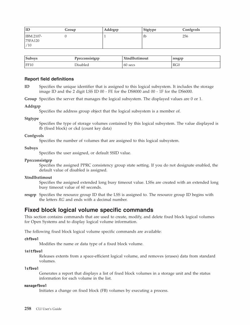
ID Group Addrgrp Stgtype Confgvols
IBM.2107-75FA120/10
0 1 fb 256
Subsys Pprcconsistgrp Xtndlbztimout resgrp
FF10 Disabled 60 secs RG0
Report field definitions
ID Specifies the unique identifier that is assigned to this logical subsystem. It includes the storageimage ID and the 2 digit LSS ID 00 - FE for the DS8000 and 00 - 1F for the DS6000.
Group Specifies the server that manages the logical subsystem. The displayed values are 0 or 1.
AddrgrpSpecifies the address group object that the logical subsystem is a member of.
StgtypeSpecifies the type of storage volumes contained by this logical subsystem. The value displayed isfb (fixed block) or ckd (count key data)
ConfgvolsSpecifies the number of volumes that are assigned to this logical subsystem.
SubsysSpecifies the user assigned, or default SSID value.
PprcconsistgrpSpecifies the assigned PPRC consistency group state setting. If you do not designate enabled, thedefault value of disabled is assigned.
XtndlbztimoutSpecifies the assigned extended long busy timeout value. LSSs are created with an extended longbusy timeout value of 60 seconds.
resgrp Specifies the resource group ID that the LSS is assigned to. The resource group ID begins withthe letters RG and ends with a decimal number.
Fixed block logical volume specific commandsThis section contains commands that are used to create, modify, and delete fixed block logical volumesfor Open Systems and to display logical volume information.
The following fixed block logical volume specific commands are available:
chfbvolModifies the name or data type of a fixed block volume.
initfbvolReleases extents from a space-efficient logical volume, and removes (erases) data from standardvolumes.
lsfbvolGenerates a report that displays a list of fixed block volumes in a storage unit and the statusinformation for each volume in the list.
managefbvolInitiates a change on fixed block (FB) volumes by executing a process.
258 CLI User's Guide

mkfbvolCreates open systems fixed block volumes in a storage unit.
rmfbvolDeletes one or more specified fixed block volumes from a storage unit.
showfbvolGenerates two types of reports. The first report displays the detailed properties for a specifiedfixed block volume. The second report displays the performance metrics for a specified fixedblock volume.
chfbvolThe chfbvol command is used to change the name or capacity of a fixed block volume.
�� chfbvol-dev storage_image_ID -os400 protected
unprotectedA01A81A02A82A04A84A05A85A06A86A07A87
�
�-name new_volume_name -type ess
dsblocks
-cap new_capacity -quiet�
�-perfgrp performance_group_ID -resgrp resource_group_ID
�
� volume_ID. . .
" - "
��
Parameters
-dev storage_image_ID(Optional) Specifies the storage image ID, which consists of the manufacturer, machine type, andserial number. The storage image ID is required if you do not specify a fully qualified volume ID, donot set the devid variable in your profile or through the setenv command, and the HMC is aware ofmore than one storage image. Using the -dev parameter temporarily overrides any defined value fordevid for the current command.
-os400 protected | unprotected | A01 | A81 | A02 | A82 | A04 | A84 | A05 | A85 | A06 | A86 | A07| A87
(Optional - DS8000 only) Specifies options for the OS 400 volume data types and indicates the type ofmodifications that can be performed. Check your operating system documentation to ensure thatvolume expansion is supported before you proceed with the expansion:
Volume data type is os400 protected (FB 520P)You can change the volume data type to os400 unprotected (FB 520U)
Chapter 4. CLI commands 259

Volume data type is os400 unprotected (FB 520U)You can change the volume data type to os400 protected (FB 520P)
Volume data type is 512You cannot change the volume data type.
Current Volume Volume Size Change to Volume Volume Size
A01 protected 8.59 GB A81 unprotected 8.59 GB
A81 unprotected 8.59 GB A01 protected 8.59 GB
A02 protected 17.55 GB A82 unprotected 17.55 GB
A82 unprotected 17.55 GB A02 protected 17.55 GB
A05 protected 35.17 GB A85 unprotected 35.17 GB
A85 unprotected 35.17 GB A05 protected 35.17 GB
A04 protected 70.56 GB A84 unprotected 70.56 GB
A84 unprotected 70.56 GB A04 protected 70.56 GB
A06 protected 141.12 GB A86 unprotected 141.12 GB
A86 unprotected 141.12 GB A06 protected 141.12 GB
A07 protected 282.35 GB A87 unprotected 282.35 GB
A87 unprotected 282.35 GB A07 protected 282.35 GB
Notes:
1. If the volume is unassigned to any System i model or nonconfigured volume, you can usethis parameter to change the designated protection value.
2. If the volume is assigned and is a part of the i5/OS configuration, you cannot use thisparameter to change the protection value. The only way to change the protection value ona volume that is part of the i5/OS configuration is to perform the following steps withextreme caution:a. Remove the volume from the i5/OS application. This step must be done first.b. Remove the volume from the DS systemc. Create a volume and assign the correct protection value.
3. You cannot use the -os400 parameter with the -cap or the -type parameters.
-name new_volume_name(Optional) Specifies the nickname for this volume. A nickname cannot exceed 16 characters.
-type ess | ds | blocks(Optional - DS8000 only) Specifies the unit type of capacity that is specified by the -cap parameter.
ess Specifies that the unit is 10^9 bytes.
ds Specifies that the unit is 2^30 bytes.
blocks Specifies that the unit is 512 blocks.
Notes:
1. If the -type parameter is not specified, the LUN is created as type ds.2. The -type parameter is ignored when the -os400 parameter is specified.
-cap new_capacity(Optional - DS8000 only) Specifies the storage size that you want to allocate to the specified volume.Check your operating system documentation to ensure that volume expansion is supported beforeyou proceed with the expansion.
260 CLI User's Guide

Notes:
1. If you attempt to reduce the volume size, the command fails.2. You cannot use the -cap parameter with the -os400 parameter.
If the -type parameter is omitted or the -type ds parameter is specified:v 1 gibibyte (GiB) = 1,073,741,824 (2^30 bytes)v Supported storage sizes range from 1 to 2048.
If the -type ess parameter is specified:v capacity = X.Y or X
– where X is whole decimal gigabytes, with 1 GB = 1,000,000,000 (10^9 bytes).– where Y represents a fraction of 1 GB. Y is limited to a single digit (0-9) to the right of the
decimal.v Supported storage sizes range from 0.1 - 982.2 (0.1 increment).
If the -type blocks parameter is specified, new_capacity is the number of 512 blocks. Supported storagesizes are from 1 to 4294967296 (2048 x 2^30 bytes).
-quiet(Optional - DS8000 only) Turns off the confirmation prompt for this command.
-perfgrp performance_group_ID(Optional) Specifies the performance group ID that the volumes are assigned to. The performancegroup ID begins with the letters PG. The default is PG0.
-resgrp resource_group_ID(Optional) Specifies the resource group that the volumes are assigned to. The resource group IDbegins with the letters RG and ends with a decimal number.
volume_ID . . . | -(Required) Specifies one or more volume IDs to be modified. The volume ID is a 32-bit number thatcan be represented as four hexadecimal digits in the form of XYZZ where:
X Specifies the address group, 0 - 1.
XY This parameter is not available for DS6000 models. Specifies the logical subsystem number, 00- FE.
XY This parameter is only available for DS6000 models. Specifies the logical subsystem number,00 - 1E.
ZZ Specifies the volume number, 00 - FF.
You must fully qualify the volume ID with manufacturer, machine type, and serial number if you donot use the -dev parameter.
To specify a range of volume IDs, separate the volume IDs with a hyphen.
You must separate multiple volume IDs or ranges of volume IDs with a blank space between each IDor range of IDs.
Example: 0100-010F 0180-018F 0120
If you use the dash (-), the specified value is read from standard input. However, you cannot use thedash (-) if you are using the DS CLI interactive command mode.
Example
Invoking the chfbvol commanddscli> chfbvol -dev IBM.2107-75FA120 -os400 protected 0100 0101
Chapter 4. CLI commands 261
|
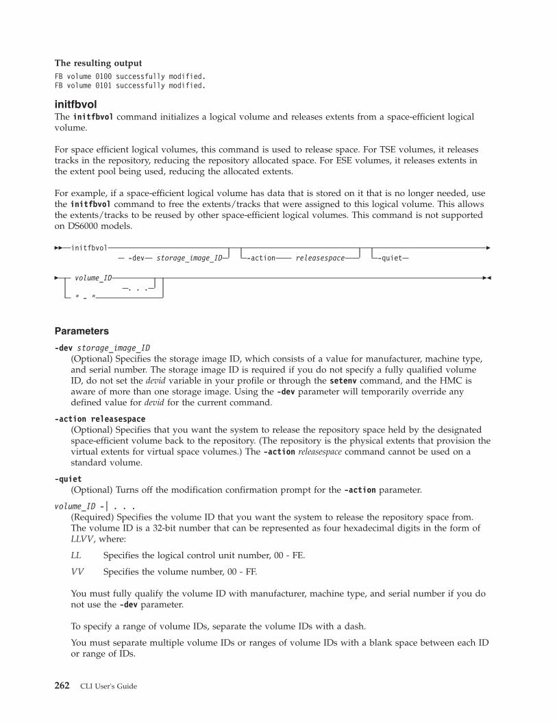
The resulting outputFB volume 0100 successfully modified.FB volume 0101 successfully modified.
initfbvolThe initfbvol command initializes a logical volume and releases extents from a space-efficient logicalvolume.
For space efficient logical volumes, this command is used to release space. For TSE volumes, it releasestracks in the repository, reducing the repository allocated space. For ESE volumes, it releases extents inthe extent pool being used, reducing the allocated extents.
For example, if a space-efficient logical volume has data that is stored on it that is no longer needed, usethe initfbvol command to free the extents/tracks that were assigned to this logical volume. This allowsthe extents/tracks to be reused by other space-efficient logical volumes. This command is not supportedon DS6000 models.
�� initfbvol-dev storage_image_ID -action releasespace -quiet
�
� volume_ID. . .
" - "
��
Parameters
-dev storage_image_ID(Optional) Specifies the storage image ID, which consists of a value for manufacturer, machine type,and serial number. The storage image ID is required if you do not specify a fully qualified volumeID, do not set the devid variable in your profile or through the setenv command, and the HMC isaware of more than one storage image. Using the -dev parameter will temporarily override anydefined value for devid for the current command.
-action releasespace(Optional) Specifies that you want the system to release the repository space held by the designatedspace-efficient volume back to the repository. (The repository is the physical extents that provision thevirtual extents for virtual space volumes.) The -action releasespace command cannot be used on astandard volume.
-quiet(Optional) Turns off the modification confirmation prompt for the -action parameter.
volume_ID -| . . .(Required) Specifies the volume ID that you want the system to release the repository space from.The volume ID is a 32-bit number that can be represented as four hexadecimal digits in the form ofLLVV, where:
LL Specifies the logical control unit number, 00 - FE.
VV Specifies the volume number, 00 - FF.
You must fully qualify the volume ID with manufacturer, machine type, and serial number if you donot use the -dev parameter.
To specify a range of volume IDs, separate the volume IDs with a dash.
You must separate multiple volume IDs or ranges of volume IDs with a blank space between each IDor range of IDs.
262 CLI User's Guide

If you use the dash (-), the specified value is read from standard input. However, you cannot use thedash (-) if you are using the DS CLI interactive command mode.
Example
Invoking the initfbvol commanddscli> initfbvol -dev IBM.2107-75FA120–action releasespace 0101
The resulting outputCMUC00338W initfbvol: Are you sure that you want to submit the commandreleasespace for the FB volume 0101?[Y/N]:yCMUC00341I initfbvol:: 0101: The command releasespace hascompleted successfully.
lsfbvolThe lsfbvol command displays a list of fixed block volumes in a storage image and status informationfor each volume in the list.
�� lsfbvol-dev storage_image_ID -s
-l-datatype 512
512t520p520u
�
�-extpool extentpool_ID -access online
fenced-data normal
not_normal
�
�-config normal
not_normal-lss LSS_ID -volgrp volume_group_ID
�
�-sam standard
tseese
-eam legacyrotatevolsrotateextsmanaged
-perfgrp performance_group_ID�
�-resgrp resource_group_ID volume_ID
. . ." - "
��
Parameters
Note: For a storage unit that is heavily configured, it is recommended that you specify the -lss or the-volgrp parameter as part of your command.
-dev storage_image_ID(Optional) Displays the storage image ID, which consists of manufacturer, machine type, and serialnumber. The storage image ID is required if you do not specify fully qualified IDs, do not set thedevid variable in your profile or through the setenv command, and the HMC is aware of more thanone storage image. Using the -dev parameter will temporarily override any defined value for devid forthe current command.
-s(Optional) Displays only the volume IDs. You cannot use the -l and the -s parameters together.
Chapter 4. CLI commands 263
|
-l(Optional) Displays default output plus additional attributes that are identified as long output in theReport field definitions list. You cannot use the -l and the -s parameters together.
-datatype 512 | 512t | 520p | 520u(Optional) Displays volumes of the specified volume data type. Standard 2107/1750 volume (512),T10-DIF algorithm protection (512t), System i protected (520p), System i unprotected (520u).
-extpool extentpool_ID(Optional) Displays volumes that are sourced from the specified extent pool. An extent pool ID is afour-digit decimal number with no leading zeroes, prefixed with the letter P.
-access online | fenced(Optional) Displays volumes with the specified access state.
-data normal | not_normal(Optional) Displays volumes with the specified data state.
-config normal | not_normal(Optional) Displays volumes with the specified configuration.
-lss LSS_ID(Optional) Displays volumes with IDs that contain the specified logical subsystem ID. Each logicalsubsystem can contain up to 256 volumes. A logical subsystem ID is two hexadecimal characters 00 -FE for the DS8000 and 00 - 1F for the DS6000.
-volgrp volume_group_ID(Optional) Displays volumes that are assigned to the specified volume group ID. A volume group IDis a four-digit decimal number, with no leading zeros, prefixed by the letter V. For example, V123.
-sam standard | tse | ese(Optional - DS8000 only) Specifies the storage allocation method as follows:
standardSpecifies that you want the system to fully allocate the volume with real extents when itcreates the volumes.
tse Specifies that you want the system to create track space-efficient volumes. After creation,these space-efficient volumes contain a set of virtual extents that are associated with thespace-efficient storage in the same extent pool. The physical space for a given logical track ona track space-efficient logical volume is dynamically allocated and deallocated from therepository in the space-efficient storage.
ese Specifies that an extent space efficient logical volume is provisioned with a set of virtualextents that are associated with the space efficient storage in the same extent pool. Physicalspace for an extent space efficient logical volume is dynamically allocated and de-allocatedfrom the extent pool.
-eam legacy | rotatevols | rotateexts | managed(Optional - DS8000 only) Specifies that you want the system to display only volumes that meet thecriteria of the designated extent allocation method as follows:
legacy Specifies that the volumes that were created before the current algorithms were implemented.
rotateextsSpecifies that the extents for each new logical volume are allocated across all available ranks,and is also known as storage-pool striping. This value is the default.
rotatevolsSpecifies that the extents for each new logical volume are allocated from each successive rank.This means that the extents for a particular volume will be allocated from one rank, while theextents for the next volume will be allocated from the next successive rank, and so on.
264 CLI User's Guide
||
|
|

managedSpecifies that the extents are currently managed by Easy Tier, and the extents for any newvolumes are initially allocated across all available ranks in the lowest tier of storage.
-perfgrp performance_group_ID(Optional) Displays only the volumes that belong to the specified performance group. Theperformance group ID begins with the letters PG.
-resgrp resource_group_ID(Optional) Displays only the volumes that are assigned to the specified resource group ID. Theresource group ID begins with the letters RG and ends with a decimal number.
volume_ID . . . | –(Optional) Displays volumes with the specified IDs. The volume ID is a 32 bit number that can berepresented as 4 hexadecimal digits in the form of XYZZ where:
XY (for a DS8000 model)Specifies the logical subsystem number, 00 - FE.
XY (for a DS6000 model)Specifies the logical subsystem number, 00 - 1E.
ZZ (for DS6000 and DS8000 models)Specifies the volume number, 00 - FF.
X (for DS6000 and DS8000 models)Specifies the address group, 0 - 1, for DS6000 and 0–F for DS8000.
To specify a range of volume IDs, separate the volume IDs with a hyphen.
You must separate multiple volume IDs or ranges of volume IDs with a blank space between each IDor range of IDs.
If you use the dash (-), the specified value is read from standard input. You cannot use the dash (-)while you are in the DS CLI interactive command mode.
Example: 0100-010F 0180-018F 0120
Example
For this command and all other DS CLI list commands, the results are shown in table format to provideclarity. The actual reports do not display as tables.
The following tables represent the headers that are displayed on the output report that is associated withthe lsfbvol command using the -l parameter.
Invoking the lsfbvol commanddscli> lsfbvol-dev IBM.2107-75FA120 -l -volgrp V2
The resulting output
Name ID accstate datastateconfigstate
deviceMTM
datatype
My_volume_
0001
0100 Online Normal Normal 2107-900 FB 512
My_volume_
0002
0102 Online Normal Normal 2107-A07 FB 520P
Chapter 4. CLI commands 265

Name ID accstate datastateconfigstate
deviceMTM
datatype
My__volume
0003
0103 Online Normal Normal 2107-900 FB 512
extpool sam captypecap(2^30B)
cap(10^9B)
cap(blocks) Volgrp
P21 standard DS 64.0 - 134217728 V2
P31 standard iSeries 128.0 68.7 268435456 V2
P21 standard ESS - 35.0 68359424 -
eam reqcap (blocks) perfgrp resgrp
legacy 2097152 PG1 RG0
rotateexts 2097152 PG1 RG0
legacy 2097152 PG1 RG0
Report field definitions
NameIdentifies the nickname that you assigned for the specified volume object.
ID Identifies the unique identifier that is assigned to this volume object.
AccstateOne of the following access states are displayed: Online or Fenced.
OnlineThe logical volume is accessible to a host.
FencedThe logical volume is in the volume fenced state and is not accessible to the host.
DatastateOne of the following data states are displayed:
NormalSpecifies that none of the other data states apply. The access state is Online.
Read onlyIndicates that the logical volume is read only because one or more extents on the logical volumeare on a rank in the read only data state. The access state is Online.
InaccessibleIndicates that one or more extents that are associated with the logical volume are on a rank thatis in the inaccessible data state. The access state is fenced.
Virtual space faultSpecifies that the logical volume has a storage allocation method of track space-efficient. Therewas not enough space available to convert a virtual logical track to a real logical track. The accessstate is Online.
Indeterminate data lossSpecifies that the following data states do not apply and that one of the following conditions hasoccurred:
Data states that do not apply:
266 CLI User's Guide

v Rank failedv Rank repairingv Rank repairedv Global inaccessiblev Global lost data
Conditions - one of the following occurred:v Committed write data was lost before it was destaged and the track identifiers that are
associated with the data are unknown.v Data has been lost that indicates that extents on the logical volume were active FlashCopy
targets.
The access state is fenced.
Rank failedIndicates that one or more extents that are associated with the logical volume are on a rank thatis in the Failed data state. The access state is Fenced. This data state transitions to the Rankrepairing state if the rank transitions to the Rank repairing state through use of the repair arrayfunction.
Rank RepairingIndicates that one or more extents that are associated with the logical volume are on ranks in therepairing data state. The access state is fenced.
Rank RepairedIndicates that one or more extents that are associated with the logical volume are on ranks thatwere in the repairing state, but are not in the repairing state now. The access state is fenced.
Global inaccessibleSpecifies that the global metadata that is associated with the logical volume configuration isinaccessible. Some of the data associated with the logical volume might be inaccurate. The accessstate is fenced.
Global lost dataSpecifies that global metadata that is associated with the logical volume configuration has beenlost. As a result, some of the data associated with the logical volume might be inaccurate. Theaccess state is fenced.
NVS data inaccessibleSpecifies that active NVS data is inaccessible for one or more logical volumes of an LSS group.The logical volumes in the LSS group cannot be made accessible. The access state is fenced.
ConfigstateOne of the following configuration states are displayed:
NormalIndicates that there are no logical volume configuration operations in progress, and the volume isnot being deconfigured, merged, or migrated.
ConfiguringIndicates that the logical volume is in the process of being configured for the first time.
ReconfiguringIndicates that the logical volume is in the process of allocating or deallocating extents due to amodification of the requested capacity attribute after initial creation.
DeconfiguringIndicates that the logical volume is in the process of being deleted.
Configuration errorIndicates that the initial configuration did not complete successfully. This state reflects an internal
Chapter 4. CLI commands 267

error condition and not an error in the request to create the volume. If you have a volume in thisstate, use the rmfbvol command to delete each volume listed with the configuration state of"configuration error".
MergingIndicates that the volume is in the process of merging. For example, merging from one extentpool to a different extent pool.
MigratingIndicates that the volume is in the process of migrating, or waiting to be migrated.
Migration CancelledIndicates that the volume was in the process of migrating and then the ‘migcancel' action of themanageckdvol command was issued, leaving some of the extents waiting to be migrated in thesource pool while other extents have already migrated to the target pool. Migration has stopped,and cannot be resumed. If you have a volume in this state, try to migrate it again to the originalsource or target extent pool.
Migration PausedIndicates that the volume was in the process of migrating and then the ‘migpause' action of themanageckdvol command was issued. Migration has stopped, but can be resumed.
Migration ErrorIndicates that the volume migration process failed to complete successfully. This state reflects aninternal error condition and not an error in the request of the user to migrate a volume. If youhave a volume in this state, try to migrate it again to the original source or target extent pool.
Reconfiguration errorIndicates that the reconfiguration request did not complete successfully.
Deconfiguration errorIndicates that a request to delete a volume did not complete successfully. This state reflects aninternal error condition and not an error in the request to remove the volume. To correct thisstate, you must reissue the rmfbvol command for the designated volume.
Transposition ErrorIndicates that the volume is in an extent pool that was unsuccessfully merged. This state reflectsan internal error condition. Corrective action: Use the chextpool command with the -mergeparameter again to redrive the merge extent pool and to correct this state.
deviceMTMIndicates the volume device type and model. The volume MTM (machine type, model) is determinedby the fixed block volume data type and the volume capacity (in GB). The machine type is either2107 or 1750; however, the MTM can be any one of the following depending on your system:
2107-900Indicates a standard 2107 volume.
1750-500Indicates a standard 1750 volume.
xxxx-A0xIndicates that the xxxx is a 2107 or 1750. The A0 indicates a System i protected volume (forexample, 2107-A01 or 1750-A07).
xxxx-A8xIndicates that the xxxx is 2107 or 1750. The A8 indicates a System i unprotected volume (forexample, 2107-A81 or 1750-A87).
DatatypeIndicates the volume data type setting. One of the following values will be displayed:v FB 512
268 CLI User's Guide

v FB 512Tv FB 520Pv FB 520U
ExtpoolIdentifies the extent pool ID. Volume extents are allocated from this extent pool ID.
Note: Volumes that belong to an encrypted extent pool are encrypted. You can see the encryptiongroup of an extent pool by using the lsextpool -l, or showextpool commands.
SAMSpecifies the storage allocation method. The following values are displayed:
standardIndicates that the system fully allocated the volume with real extents at volume creation time. Aninquiry on a DS6000 model always reports a value of standard.
tseIndicates that a track space-efficient logical volume contains a set of virtual extents that areassociated with the space-efficient storage in the same extent pool. Physical space for a givenlogical track on a track space-efficient logical volume is dynamically allocated and deallocatedfrom the repository in the space-efficient storage.
eseIndicates that an extent space efficient logical volume is provisioned with a set of virtual extentsthat are associated with the space efficient storage in the same extent pool. Physical space for anextent space efficient logical volume is dynamically allocated and de-allocated from the extentpool.
CaptypeIndicates the capacity unit type that is used at volume creation. One of the following values isdisplayed:
ESSThe capacity unit is decimal gigabytes (GB).
DS The capacity unit is gibibytes (GiB).
DS/ESSThe capacity unit is gibibytes (GiB) or decimal gigabytes (GB).
BlocksThe capacity unit is 512B.
iSeriesThe capacity unit was not specified at volume creation. This fixed block volume was created onlyfor iSeries.
Cap (2^30B)Specifies the size of the volume that is available for host system access in gibibytes (GiB).
Note: " – " is displayed if the capacity unit type of the volume is ESS (captype=ESS)
Cap (10^9B)Specifies the size of the volume that is available for host system access in decimal gigabyte (GB)units.
Note: " – " is displayed if the capacity unit type of the volume is DS (captype=DS)
Cap (blocks)Indicates the quantity of volume logical blocks that are available for host system access.
Chapter 4. CLI commands 269
|
|
|
|
|
|
||
|

VolgrpSpecifies the volume groups (excluding default volume groups) that a volume belongs to.
Multiple volume groups that are associated with the volume are separated by a comma.
A " – " is displayed if there are no volume groups that are associated with the volume.
Unknown is displayed if information about the volume groups is not available.
EAMSpecifies the extent allocation method that will be used if the volume is migrated or expanded.
legacySpecifies that the volume was created before the use of the current algorithm. Legacy is alwaysthe reported value for a DS6000 model.
rotateextsSpecifies that the extents for each new logical volume are allocated across all available ranks, andis also known as storage-pool striping. This value is the default.
rotatevolsSpecifies that the extents for each new logical volume are allocated from each successive rank.This means that the extents for a particular volume will be allocated from one rank, while theextents for the next volume will be allocated from the next successive rank, and so on.
managedSpecifies that the extents are currently managed by Easy Tier, and the extents for any newvolumes are initially allocated across all available ranks in the lowest tier of storage.
" – "A dash " - " value is displayed if the extent allocation method does not apply , for example if thevolume is a track space efficient (TSE) volume.
Reqcap (blocks)Specifies the requested quantity of volume logical blocks (for example, 3339).
Note: A value of 0 is displayed for the DS6000.
perfgrpSpecifies the performance group ID that the volume is assigned to. The performance group ID beginswith the letters PG and ends with a decimal number.
resgrpSpecifies the resource group ID that the volume is assigned to. The resource group ID begins with theletters RG and ends with a decimal number.
managefbvolThe managefbvol command initiates a change on fixed block (FB) volumes by executing a process. Thiscommand is not supported on DS6000 models.
�� managefbvol-dev storage_image_ID
-action migstartmigcancelmigpausemigresume
�
�-eam rotatevols
rotateexts-extpool extent_pool_ID
Volume_ID. . .
" - "
��
270 CLI User's Guide

Parameters
-dev storage_image_ID(Optional) Specifies the storage image ID, which consists of manufacturer, machine type, and serialnumber. The storage image ID is required if you do not specify a fully qualified volume ID, do notset the devid variable in your profile or through the setenv command, and the HMC is aware of morethan one storage image. Using the -dev parameter temporarily overrides any defined value for devidfor the current command.
-action migstart|migcancel|migpause|migresume(Required) Specifies that one of the following actions are to be performed:
migstartInitiates volume migration on the specified volumes that are in the "normal" or "cancelled"state. Volumes are placed into the migrating state. Volumes that are in the cancelled statemust have the original source or the destination extent pool as the value of the –extpoolparameter.
migcancelCancels volume migration on the specified volumes that are in the migrating state. Volumesthat have not yet started migration are put in the "normal" state, and volumes that are in themiddle of migration are put in the "cancelled" state.
migpausePauses volume migration on the specified volumes that are in the migrating state. Volumesthat have not yet started migration or that are in the middle of migration are put in the"paused" state.
migresumeResumes volume migration on the specified volumes that are in the "paused" state.
-eam(Optional) Specifies the extent allocation method as follows:
rotateextsDesignates that extents that are allocated to a logical volume are successively rotated throughthe ranks within an extent pool.
rotatevolsDesignates that each successive logical volume that is created is allocated on the nextavailable rank in the extent pool. This parameter is the default value.
Note: You can specify the -eam parameter only if -action migstart is also specified.
-extpool extent_pool_ID(Optional) Changes the extent pool ID of the volume so the volume migrates to the new extent pool.Accepts either a fully qualified extent pool ID including storage image ID or a shortened version ifthe -dev parameter is used. The shortened version is a four-digit decimal number with no leadingzeroes, prefixed with the letter P.
Note: When the command returns, the volume migration might still be occurring. It is available forI/O and copy services during migration. Its configstate indicates that it is migrating.
volume_ID . . . | -(Required) Specifies an array of one or more CKD base volume IDs or volume ID ranges to modify.
A volume ID range is defined by two volume IDs that are separated by a dash. Multiple volume IDsor volume ID ranges must be separated with a blank space between each ID.
Example: 0100-010F 0180-018F 0120
The volume ID format is four hexadecimal characters LLVV that represent the following values:
Chapter 4. CLI commands 271

LL (for a DS8000 model)Specifies the logical control unit number, 00 - FE
LL (for a DS6000 model)Specifies the logical control unit number, 00 - 1F
VV (for DS6000 and DS8000 models)Specifies the volume number, 00 - FF
You must fully qualify the volume ID with manufacturer, machine type, and serial number if you donot use the -dev parameter.
If you use the dash (-), the specified value is read from standard input. You cannot use the dash (-) ifyou are in the DS CLI interactive mode.
Example
Invoking the managefbvol commanddscli> managefbvol -dev IBM.2107-75FA120 -action migstart –extpool P2 0100
The resulting outputCMUC00000I manageckdvol: CKD Volume 0100 action migstart executed successfully.
mkfbvolThe mkfbvol command creates open systems fixed block (FB) volumes in a storage image.
�� mkfbvol -extpool extentpool_ID-dev storage_image_ID -os400 A01
A81A02A82A04A84A05A85A06A86A07A87
�
�-type ess
dsblocks
-cap capacity -name volume_name�
�-volgrp volume_group_ID -wait -sam standard
tseese
-eam rotatevolsrotateexts
�
�-perfgrp performance_group_ID -resgrp resource_group_ID -t10dif
�
� volume_ID. . .
" - "
��
272 CLI User's Guide

Parameters
Notes:
1. You can create multiple volumes with one command; however, all volumes must have thesame capacity, extent pool, and data type.
2. If host attachment volume groups have not yet been created, create temporary volume groupsand assign new fixed block volumes to the temporary volume groups according to the volumetype and capacity characteristics.
3. To use the -sam tse parameter you must have previously created space-efficient storage (usingthe mksestg command) for the extent pool.
-dev storage_image_ID(Optional) Specifies the storage image ID, which includes a value for the manufacturer, machine type,and serial number. The storage image ID is required if you do not specify fully qualified IDs, do notset the devid variable in your profile or through the setenv command, and the HMC is aware of morethan one storage image. Using the -dev parameter will temporarily override any defined value fordevid for the current command.
-extpool extentpool_ID(Required) Creates the base or alias volumes from data extents that are contained in this extent pool.The extent pool storage type defines the volume storage type. An extent pool ID is a four-digitdecimal number with no leading zeros, prefixed with the letter P.
-os400 A01 | A81 | A02 | A82 | A04 | A84 | A05 | A85 | A06 | A86 | A07 | A87(Optional) The OS 400 volume options. If this parameter is not specified, the default standard2107/1750 volume is created.
This parameter is required if capacity is not specified.
The storage sizes and the data types for this volume:v A01 - 8.6 GB, protectedv A81 - 8.6 GB, unprotectedv A02 - 17.5 GB, protectedv A82 - 17.5 GB, unprotectedv A04 - 70.5 GB, protectedv A84 - 70.5 GB, unprotectedv A05 - 35.1 GB, protectedv A85 - 35.1 GB, unprotectedv A06 - 141.12 GB, protectedv A86 - 141.12 GB, unprotectedv A07 - 282.25 GB, protectedv A87 - 282.25 GB, unprotected
Decimal gigabyte (GB) is 10^9 bytes.
Note: You must ensure that the volume data type is compatible with the host systems that can accessthis volume.
-type ess | ds | blocks(Optional) Specifies the unit type of capacity that is specified by the -cap parameter.
ess Specifies that the unit is decimal gigabytes (GB) 10^9 bytes.
ds Specifies that the unit is gibibytes (GiB) 2^30 bytes.
blocks Specifies that the unit is 512 blocks.
Chapter 4. CLI commands 273
|
|
|

Notes:
1. If the -type parameter is not specified, the lun is created as type ds.2. The -type parameter is ignored when the -os400 parameter is specified.
-cap capacity(Optional) Specifies the storage size that is allocated to this volume object.
Note: This parameter is required if the -os400 parameter is not specified.
If the -type parameter is omitted or the -type ds parameter is specified:v 1 gibibyte (GiB) = 1,073,741,824 (2^30 bytes)v Supported storage sizes range from 1 to 2048.
If the -type ess parameter is specified:v capacity = X.Y or X
– where X is whole decimal gigabytes, with 1 GB = 1,000,000,000 (10^9 bytes).– where Y represents a fraction of 1 decimal gigabyte (GB). Y is limited to a single digit (0-9) to
the right of the decimal.v Supported storage sizes range from 0.1 - 982.2 (0.1 increment).
If the -type blocks parameter is specified, capacity is the number of 512 blocks. Supported storagesizes are from 1 to 4294967296 (2048 x 2^30 bytes).
-name volume_name(Optional) Your nickname for this volume. The nickname can be 16 characters long, and it cancontain one of the following wildcard characters:v #d decimal volume IDv #h hexadecimal volume ID
-volgrp volume_group_ID(Optional) Specifies to which volume group the volumes are assigned. A volume group ID is afour-digit decimal number with no leading zeros, prefixed with the letter V.
-wait(Optional) Delays the command response until the volume configuration processes complete.
Note: If you specify this parameter, you must wait until your original command processescompletely before you can issue a new command.
-sam standard | tse | ese(Optional - DS8000 only) Specifies the storage allocation method as follows:
standardDesignates that you want the system to fully allocate the volume with real extents when itcreates the volumes. This value is the default.
tse Designates that you want the system to create track space-efficient volumes. After creation,these space-efficient volumes contain a set of virtual extents that are associated with thespace-efficient storage in the same extent pool. The physical space for a given logical track ona track space-efficient logical volume is dynamically allocated and deallocated from therepository in the space-efficient storage.
Note: To use this subparameter, you must have previously created space-efficient storage(using the mksestg command) for the extentpool.
ese Designates that an extent space efficient (ESE) logical volume is provisioned with a set ofvirtual extents that are associated with the space efficient storage in the same extent pool.
274 CLI User's Guide
|

Physical space for an extent space efficient logical volume is dynamically allocated andde-allocated from the extent pool. ESE volumes are used for IBM System Storage DS8000 ThinProvisioning.
Note: To use this subparameter, you must have previously created space-efficient storage(using the mksestg command) for the extentpool.
-eam rotateexts | rotatevols(Optional - DS8000 only) Specifies the extent allocation method as follows:
rotateextsSpecifies that the extents for each new logical volume are allocated across all available ranks,and is also known as storage-pool striping. This value is the default.
rotatevolsSpecifies that the extents for each new logical volume are allocated from each successive rank.This means that the extents for a particular volume will be allocated from one rank, while theextents for the next volume will be allocated from the next successive rank, and so on.
-perfgrp performance_group_ID(Optional) Specifies the performance group ID that the volumes are assigned to. The performancegroup ID begins with the letters PG. The default is PG0.
-resgrp resource_group_ID(Optional) Specifies the resource group that the volumes are assigned to. The resource group IDbegins with the letters RG and ends with a decimal number. The default is RG0.
Note: If you create any fixed block LSSs using this command, the LSSs are assigned to the sameresource group as the logical volumes.
-t10dif(Optional - DS8000 only) Specifies that the DS8000 is using the CRC-16-T10-DIF algorithm to storedata.
Note: The -t10dif and -os400 parameters cannot be used together.
volume_ID . . . | -(Required) An array of one or more fixed block volume IDs to be created. The volumes must share acommon logical subsystem ID.
The volume ID format is four hexadecimal characters XYZZ, that represent the following values:
X (for DS8000 and DS6000)Specifies the address group, 0 -1 for DS6000 and 0–F for DS8000.
XY (DS6000 only)Specifies the logical subsystem number, 00 - 1E.
XY (DS8000 only)Specifies the logical subsystem number, 00 - FE.
ZZ (for DS8000 and DS6000)Specifies the volume number, 00 - FF.
To specify a range of volume IDs, separate the volume IDs with a dash (-).
You must separate multiple volume IDs or ranges of volume IDs with a blank space between each IDor range of IDs.
Example: 0100-010F 0180-018F 0120
If you use the dash (-), the specified value is read from standard input. However, you cannot use thedash (-) while you are in the DS CLI interactive command mode.
Chapter 4. CLI commands 275

Example
Invoking the mkfbvol commanddscli> mkfbvol -dev IBM.2107-75FA120-extpool P1 -name my_vol_#d -type ess
-cap 8.6 -sam ese 0100 0101 0102 0103
The resulting outputFB volume 0100 successfully created.FB volume 0101 successfully created.FB volume 0102 successfully created.FB volume 0103 successfully created.
rmfbvolThe rmfbvol command deletes fixed block volumes from a storage image.
�� rmfbvol-dev storage_image_ID -quiet -safe
-force
Volume_ID. . .
" - "
��
Parameters
Note: You can use this command when there are volumes that are in the configuration error state. Tocorrect this configuration state, issue the rmfbvol command for each affected volume. You canspecify a volume range according to the command specifications when it is appropriate.
-dev storage_image_ID(Optional) Specifies the storage image ID, which includes manufacturer, machine type, and serialnumber. The storage image ID is required if you do not specify a fully qualified volume ID for alllogical volumes, do not set the devid variable in your profile or through the setenv command, and theHMC is aware of more than one storage image. Using the -dev parameter temporarily overrides anydefined value for devid for the current command.
-quiet(Optional) Turns off the volume removal confirmation prompt for this command.
-safe(Optional) The -safe parameter specifies that the system perform a check to see whether the specifiedvolumes are assigned to any non-default volume groups. If any volumes are still assigned to auser-defined volume group, the rmfbvol command fails without deleting any volumes. During thisoccurrence, messages are provided which list the volumes that are still assigned to a user-definedvolume group.
Notes:
v If there is any reason that the system cannot perform the check, the rmfbvol command failsand no volumes are deleted.
v The -safe and -force parameters cannot be specified at the same time.
-force(Optional) The -force parameter attempts to delete the volumes without checking to see whether thevolumes are in use. If multiple volumes are specified and some are in use and some are not, the onesnot in use can be deleted.
Note: The -safe and -force parameters cannot be specified at the same time.
Volume_ID . . . | -(Required) Specifies an array of one or more fixed block volume IDs to be removed. This parameter
276 CLI User's Guide

also accepts a fully qualified volume ID, which includes the storage image ID, or a shortened versionwithout the storage image ID if the -dev parameter is specified.
Example of -dev parameter use
If you specify the -dev parameter, you can use the shortened version of the Volume_ID parameter asfollows:
For DS8000:dscli> rmfbvol -dev IBM.2107-75FA120 0100-010F 0180-018F 0120
For DS6000:dscli> rmfbvol -dev IBM.1750-13ABR4A 0005-00FF
If you do not specify the -dev parameter and you specify the Volume_ID variable, you must use thefully qualified version of the volume ID as follows:
For DS8000:dscli> rmfbvol IBM.2107-75FA120/0100-010F 0180-018F 0120
For DS6000:dscli> rmfbvol IBM.1750-13ABR4A/0005-00FF
The volume ID is a 32 bit number that can be represented as four hexadecimal digits in the form ofXYZZ where:
X (for DS6000 and DS8000 models)Specifies the address group, 0 -1 for DS6000 and 0–F for DS8000.
XY (for a DS8000 model)Specifies the logical subsystem number, 00 - FE.
XY (for a DS6000 model)Specifies the logical subsystem number, 00 - 1E.
ZZ (for DS6000 and DS8000 models)Specifies the volume number, 00 - FF.
To specify a range of volume IDs, separate the volume IDs with a hyphen.
You must separate multiple volume IDs or ranges of volume IDs with a blank space between each IDor range of IDs.
If you use the dash (-), the specified value is read from standard input. You cannot use the dash (-)while you are in the DS CLI interactive command mode.
Example
Invoking the rmfbvol commanddscli> rmfbvol -dev IBM.2107-75FA120 0100 0101
The resulting outputAre you sure you want to delete 0100? y/n YVolume 0100 successfully deleted.Are you sure you want to delete 0101? y/n YVolume 0101 successfully deleted.
The following is an example of the output that results when you specify that you want a range ofvolume IDs to be removed.
Invoking the rmfbvol commanddscli> rmfbvol -dev IBM.2107-75FA120 0005-0024
Chapter 4. CLI commands 277

CMUC00027W rmfbvol: Are you sure you want to delete FB volume 0005-0024?[y/n]:yCMUC00028I rmfbvol: FB volume 0005 successfully deleted.CMUC00028I rmfbvol: FB volume 0006 successfully deleted.CMUC00028I rmfbvol: FB volume 0007 successfully deleted.CMUC00028I rmfbvol: FB volume 0008 successfully deleted.CMUC00028I rmfbvol: FB volume 0009 successfully deleted.CMUC00028I rmfbvol: FB volume 000A successfully deleted.CMUC00028I rmfbvol: FB volume 000B successfully deleted.CMUC00028I rmfbvol: FB volume 000C successfully deleted.CMUC00028I rmfbvol: FB volume 000D successfully deleted.CMUC00028I rmfbvol: FB volume 000E successfully deleted.CMUC00028I rmfbvol: FB volume 000F successfully deleted.CMUC00028I rmfbvol: FB volume 0010 successfully deleted.CMUC00028I rmfbvol: FB volume 0011 successfully deleted.CMUC00028I rmfbvol: FB volume 0012 successfully deleted.CMUC00028I rmfbvol: FB volume 0013 successfully deleted.CMUC00028I rmfbvol: FB volume 0014 successfully deleted....
showfbvolThe showfbvol command displays detailed properties for an individual volume. This command can alsobe used to display the performance metrics of a fixed block volume.
�� showfbvol-dev storage_image_ID -rank -metrics
�
�-volgrp volume_group_ID
volume_ID" - "
��
Parameters
-dev storage_image_ID(Optional) Specifies the storage image ID, which consists of manufacturer, machine type, and serialnumber. The storage image ID is required if you do not specify a fully qualified volume ID, do notset the devid variable in your profile or through the setenv command, and the HMC is aware of morethan one storage image. Using the -dev parameter temporarily overrides any defined value for devidfor the current command.
-rank(Optional) Specifies that a rank extents table is to be displayed. This table displays the set of ranksthat the logical volume has extents configured on and the number of extents for that logical volume.
Note: This parameter cannot be used with the -metrics or -volgrp parameters.
-metrics(Optional) Displays volume ID and performance metrics for the specified volume.
Notes:
1. All performance counts are an accumulation since the most recent counter wrap or counterreset. Volume performance counters are reset on a power-up sequence. Volumeperformance counters are reset by a server failover and failback sequence.
2. Do not use this parameter with the -rank parameters.
-volgrp volume_group_ID(Required if you do not specify the volume_ID parameter.) Specifies that the fixed block volumes thatare associated with the designated volume group ID are to be displayed.
Notes:
278 CLI User's Guide

1. You can only use the -volgrp parameter when you are doing a query for performancemetrics.
2. Do not use the -volgrp parameter with the volume_ID parameter.3. Do not use the -volgrp parameter with the -rank parameters.
volume_ID | –(Required if you do not specify the -volgrp parameter.) Displays information for the specifiedvolume. This parameter accepts a fully qualified volume ID, which consists of the storage_image_ID ora shortened version without the storage image ID, if you specify the -dev parameter. The volume IDis a 32 bit number that can be represented as four hexadecimal digits in the form of XYZZ where:
X (for DS6000 and DS8000 models)Specifies the address group, 0 - 1 for DS6000 and 0–F for DS8000.
XY (for a DS8000 model)Specifies the logical subsystem number, 00 - FE.
XY (for a DS6000 model)Specifies the logical subsystem number, 00 - 1E.
ZZ (for DS6000 and DS8000 models)Specifies the volume number, 00 - FF.
If you use the dash (-), the specified value is read from standard input. However, you cannot use thedash (-) while you are in the DS CLI interactive command mode.
Note: Do not use the volume_ID parameter with the -volgrp parameter.
Example 1
For this command and all other DS CLI show commands, the results are shown in table format toprovide clarity. The actual reports do not display as tables.
The following tables represent the headers that are displayed on the output reports that are associatedwith the showfbvol command using the -rank parameter. When the rank parameter is specified, a rankextents table is also displayed. It appears at the end of the regular report.
Invoking the showfbvol to show volume properties
Note: The example output is based on using the showfbvol command for a 1.0 gibibyte (GiB)volume.When the rank parameter is specified, a rank extents table is displayed at the end of the regularreport.
dscli> showfbvol-dev IBM.2107-1300861 -rank 6000
The resulting output
Name IDaccstate
datastate
configstate
deviceMTM
datatype addrgrp
My_volume_6000
6000 Online Normal Normal 2107-900 FB 512 6
extpool exts captypecap(2^30B)
cap(10^9B)
cap(blocks) volgrp ranks dbexts
P0 1622 DS 1622.0 - 3401580544 - 2 0
Chapter 4. CLI commands 279
|
|

sam repcapalloc eam reqcap (blocks)
Standard - rotateexts 2097152
realextents virtualextents migrating migratingfrom perfgrp resgrp
1 0 0 - PG0 RG0
============================Rank extents===========================
Rank Extents
R0 1
R2 2
Report field definitions ( -metrics parameter not specified)
NameSpecifies the nickname that you assigned for this volume object.
ID Specifies the unique identifier that is assigned to this volume object.
AccstateOne of the following access states are displayed: Online or Fenced.
OnlineThe logical volume is accessible to a host.
FencedThe logical volume is in the volume fenced state and is not accessible to the host.
DatastateOne of the following data states are displayed:
NormalNone of the other data states apply. The access state is Online.
PinnedSpecifies that none of the other data states apply and the logical volume has one or more pinnednon-retryable tracks. The access state is Online.
Read onlyIndicates that the logical volume can be read but not written to because one or more extents onthe logical volume are on a rank in the read only data state. The access state is Online.
InaccessibleIndicates that one or more extents that are associated with the logical volume are on a rank thatis in the inaccessible data state. The access state is Fenced.
Virtual space faultSpecifies that the logical volume has a storage allocation method of extent space-efficient or trackspace-efficient. There was not enough available space to convert a virtual logical track to a reallogical track. The access state is Online.
Indeterminate data lossSpecifies that the following data states do not apply and that one of the following conditions hasoccurred:
Data states that do not apply:v Rank failedv Rank repairingv Rank repaired
280 CLI User's Guide
|

v Global inaccessiblev Global lost data
Conditions - one of the following conditions has occurred:v Committed write data was lost before it was destaged and the track identifiers that are
associated with the data are unknown.v Data was lost that indicated extents on the logical volume were active FlashCopy targets.
The access state is Fenced.
Rank failedIndicates that one or more extents that are associated with the logical volume are on a rank thatis in the Failed data state. The access state is Fenced. This data state changes to Rank repairing ifthe rank changes to the Rank repairing state through use of the repair array function.
Rank RepairingIndicates that one or more extents that are associated with the logical volume are on ranks in therepairing data state. The access state is Fenced.
Rank RepairedIndicates that one or more extents that are associated with the logical volume are on ranks thatwere in the repairing state, but are not in the repairing state now. The access state is Fenced.
Global inaccessibleSpecifies that the global metadata that is associated with the logical volume configuration isinaccessible. Some of the data that is associated with the logical volume might be inaccurate. Theaccess state is Fenced.
Global lostSpecifies that global metadata that is associated with the logical volume configuration has beenlost. As a result, some of the data that is associated with the logical volume might be inaccurate.The access state is Fenced.
NVS data inaccessibleSpecifies that active nonvolatile storage (NVS) data is inaccessible for one or more logicalvolumes of an LSS group. The logical volumes in the LSS group cannot be made accessible. Theaccess state is Fenced.
ConfigstateOne of the following configuration states are displayed:
NormalIndicates that there are no logical volume configuration operations in progress, and the volume isnot being deconfigured, merged, or migrated.
ConfiguringIndicates that the logical volume is in the process of being configured for the first time.
ReconfiguringIndicates that the logical volume is in the process of allocating or deallocating extents due to amodification of the requested capacity attribute after initial creation.
DeconfiguringIndicates that the logical volume is in the process of being deleted.
Configuration errorIndicates that the initial configuration did not complete successfully. This state reflects an internalerror condition and not an error in the request to create the volume. If you have a volume in thisstate, use the rmfbvol command to delete each volume listed with the configuration state of"configuration error".
Chapter 4. CLI commands 281

MergingIndicates that the volume is in the process of merging. For example, merging from one extentpool to a different extent pool.
MigratingIndicates that the volume is in the process of migrating, or waiting to be migrated.
Migration CancelledIndicates that the volume was in the process of migrating and then the ‘migcancel' action of themanageckdvol command was issued, leaving some of the extents waiting to be migrated in thesource pool while other extents have already migrated to the target pool. Migration has stopped,and cannot be resumed. If you have a volume in this state, try to migrate it again to the originalsource or target extent pool.
Migration PausedIndicates that the volume was in the process of migrating and then the ‘migpause' action of themanageckdvol command was issued. Migration has stopped, but can be resumed.
Migration ErrorIndicates that the volume migration process failed to complete successfully. This state reflects aninternal error condition and not an error in the user's request to migrate a volume. If you have avolume in this state, try to migrate it again to the original source or target extent pool.
Reconfiguration errorIndicates that the reconfiguration request did not complete successfully.
Deconfiguration errorIndicates that a request to delete a volume did not complete successfully. This state reflects aninternal error condition and not an error in the request to remove the volume. To correct thisstate, you must reissue the rmfbvol command for the designated volume.
Transposition ErrorIndicates that the volume is in an extent pool that was unsuccessfully merged. This state reflectsan internal error condition. Corrective action: Use the chextpool command with the -mergeparameter again to redrive the merge extent pool and to correct this state.
deviceMTMIndicates the volume device type and the machine type. The volume MTM is determined by the fixedblock volume data type and the volume capacity (in GB). The machine type is either 2107 or 1750;however, the MTM can be any one of the following depending on your system:
2107-900Indicates a standard 2107 volume.
1750-500Indicates a standard 1750 volume.
xxxx-A0xThe xxxx is 2107 or 1750; the A0 indicates a System i protected volume (for example, 2107-A01 or1750-A07).
xxxx-A8xThe xxxx is 2107 or 1750; the A8 indicates a System i unprotected volume (for example, 2107-A81or 1750-A87).
DatatypeIndicates the volume data type setting. One of the following values is displayed:v FB 512v FB 512Tv FB 520Pv FB 520U
282 CLI User's Guide
|

AddrgrpSpecifies the address group that contains the designated volume object. An address group ID is onehexadecimal character ( 0 - F ).
ExtpoolSpecifies the extent pool ID. Volume extents are allocated from this extent pool ID.
Note: Volumes that belong to an encrypted extent pool are encrypted. You can see the encryptiongroup of an extent pool by using the lsextpool -l, or showextpool commands.
ExtsSpecifies the number of real and virtual extents used by the designated volume ID.
CaptypeIndicates capacity unit type used at volume creation. One of the following values is displayed:
ESSThe capacity unit is decimal gigabytes (GB).
DS The capacity unit is gibibytes (GiB).
DS/ESSThe capacity unit is gibibytes (GiB) or decimal gigabytes (GB).
BlocksThe capacity unit 512 B.
iSeriesThe capacity unit was not specified at volume creation. This fixed block volume was created foriSeries.
Cap (2^30B)Specifies the size of the volume that is available for host system access in gibibytes (GiB).
Note: " – " is displayed if the capacity unit type of the volume is ESS (captype=ESS)
Cap (10^9B)Specifies the size of volume that is available for host system access in decimal gigabytes (GB).
Note: " – " is displayed if the capacity unit type of the volume is DS (captype=DS)
Cap blocksIndicates the quantity of volume logical blocks that are available for host system access.
VolgrpSpecifies the volume groups (excluding default volume groups) that a volume belongs to.
Multiple volume groups that are associated with the volume are separated by a comma.
A " – " is displayed if there are no volume groups that are associated with the volume.
Unknown is displayed if information about the volume groups is not available.
RanksSpecifies the number of ranks that the volume resides on.
SAMSpecifies the storage allocation method. The following values are displayed:
standardDesignates that the system fully allocated the volume with real extents at volume creation time.An inquiry on a DS6000 model always reports this value.
tseDesignates that a track space-efficient logical volume contains a set of virtual extents that are
Chapter 4. CLI commands 283
|
|
|
|
|
|
|
|||
||

associated with the space-efficient storage in the same extent pool. Physical space for a givenlogical track on a track space-efficient logical volume is dynamically allocated and deallocatedfrom the repository in the space-efficient storage.
eseDesignates that an extent space efficient logical volume is provisioned with a set of virtual extentsthat are associated with the space efficient storage in the same extent pool. Physical space for anextent space efficient logical volume is dynamically allocated and deallocated from the extentpool.
Note: IBM Database protection feature supports standard volumes only.
RepcapallocSpecifies the allocated physical repository capacity of the track space-efficient storage. This value iscalculated on the available repository capacity as a result of writes to the track space-efficient volume.This value is displayed in the format of X.Y, where X is in whole gibibytes (GiB) and Y representstenths of a GiB, which is limited to a single digit (0 - 9) .
Note:
1. A " – " value is displayed in this column if the value displayed in the SAM column is notTSE.
2. A " – " value is displayed for the DS6000.
EAMSpecifies the extent allocation method that is to be used if the volume is migrated or expanded. Oneof the following values is displayed:
legacyDesignates that the volume was created before the use of the current algorithm. Legacy is alwaysthe reported value for a DS6000 model.
rotateextsSpecifies that the extents for each new logical volume are allocated across all available ranks, andis also known as storage-pool striping. This value is the default.
rotatevolsSpecifies that the extents for each new logical volume are allocated from each successive rank.This means that the extents for a particular volume will be allocated from one rank, while theextents for the next volume will be allocated from the next successive rank, and so on.
managedSpecifies that the extents are currently managed by Easy Tier, and the extents for any newvolumes are initially allocated across all available ranks in the lowest tier of storage.
" – "A " - " value is displayed if the extent allocation method does not apply, for example, trackspace-efficient logical volumes.
Reqcap (blocks)Specifies the requested quantity of volume logical block (for example, 3339).
Note: A value of 0 is displayed for the DS6000.
realextentsSpecifies the number of real extents used by the logical volume.
virtualextentsSpecifies the number of virtual extents used by the logical volume.
migratingThe number of extents for this volume that are currently being migrated.
284 CLI User's Guide
|||
|||||
||
|||
|||
||||
|||
|||

migratingfromA list of one or more extent pool IDs where the extents are migrating from. If there are no migratingextents, a dash "-" is displayed. Unknown is displayed if information about the extent pool IDs is notavailable.
perfgrpSpecifies the performance group ID that the volume is assigned to. The performance group ID beginswith the letters PG and ends with a decimal number.
resgrpSpecifies the resource group ID that the volume is assigned to. The resource group ID begins with theletters RG and ends with a decimal number.
Report field definitions ( -rank parameter specified)
Rank (Rank Extent table)Specifies the rank ID.
Extents (Rank Extents table)Specifies the number of extents for the volume on the rank.
Example 2
For this command and all other DS CLI show commands, the results are shown in table format toprovide clarity. The actual reports do not display as tables.
The following tables represent the headers that are displayed on the output reports that are associatedwith the showfbvol command using the -metrics parameter.
Invoking the showfbvol to show performance metricsdscli> showfbvol -metrics IBM.2107-75FA120/0101
The resulting output
ID Datenormrdrqts
normrdhits
normwritereq
normwritehits
seqreadreqs
seqreadhits
seqwritereq
IBM.2107-75FA120/0101
10/11/0402:23:49
10000 10000 10000 10000 10000 10000 10000
seqwrite-hits
cachfwr-reqs
cachfwr-hits
cachfw-reqs
cachfw-hits
inbcach-load
bypass-cach
seqDASDtrans
10000 10000 10000 10000 10000 10000 10000 10000
DASD-trans
cache-trans
NVS-spadel
normwriteops
seqwrite-ops
reccachemis
qwrite-prots
CKDir-trkac
10000 10000 10000 10000 10000 10000 10000 0
Chapter 4. CLI commands 285
|

CKDirtrkhits
cachsp-delay
timelow-ifact phread phwrite phwrite
phbyte-read
phbyte-writ
0 10000 10000 10000 10000 10000 10000 10000
recmo-reads
sfiletrkreads
contam-wrts
PPRC-trks
NVS-spallo
time-phread
timeph-write
byte-read
10000 0 0 10000 10000 10000 10000 10000
bytewrit timeread timewrite zHPFRead zHPFWrite
10000 10000 10000 - -
zHPFPrefetchReq zHPFPrefetchHitGMCollisions-SidefileCount
GMCollisions-SendSyncCount
0 0 0 0
Report field definitions ( -metrics parameter specified)
ID Specifies the unique identifier that is assigned to this volume object.
DateSpecifies the current time stamp for the volume performance counters.
normrdrqtsSpecifies Search/Read Normal I/O Requests.
normrdhitsSpecifies Search/Read Normal I/O Requests instances.
normwritereqSpecifies Write Normal I/O Requests.
normwritehitsSpecifies DASD Fast Write I/O Request instances.
seqreadreqsSpecifies Search/Read Sequential I/O Requests.
seqreadhitsSpecifies Search/Read Sequential I/O Request instances.
seqwritereqSpecifies Write Sequential I/O Requests.
seqwritehitsSpecifies DASD Fast Write Sequential I/O Request instances.
cachfwrreqsSpecifies Search/Read Cache Fast Write I/O Requests.
cachfwrhitsSpecifies Search/Read Cache Fast Write I/O Request instances.
cachfwreqsSpecifies Cache Fast Write I/O Requests.
cachfwhitsSpecifies Cache Fast Write I/O Requests instances.
286 CLI User's Guide

inbcachloadSpecifies Inhibit Cache Loading I/O Requests that operate with DASD.
bypasscachSpecifies Bypass Cache I/O Requests.
seqDASDtransSpecifies Sequential DASD to Cache Transfer Operations.
DASDtransSpecifies DASD to Cache Transfer Operation Count.
cachetransSpecifies Cache to DASD Transfer Operation Count.
NVSspadelSpecifies DASD Fast Write Operations Delayed Due to nonvolatile storage Space Constraints.
normwriteopsSpecifies Normal ‘DASD Fast Write' Write Operation Counts.
seqwriteopsSpecifies Sequential Access ‘DASD Fast Write' Write Operation Counts.
reccachemisSpecifies Number of record cache Read Misses.
qwriteprotsSpecifies Quick Write Promotes.
CKDirtrkacSpecifies Irregular Track Accesses. A 0 (zero) value is displayed for a fixed block volume.
CKDirtrkhitsSpecifies Irregular Track Accesses instances. A 0 (zero) value is displayed for a fixed block volume.
cachspdelaySpecifies Operations Delayed Due To Cache Space Constraints.
timelowifactSpecifies Milliseconds of lower interface I/O activity for the indicated device.
phreadSpecifies Physical Storage Read Operations.
phwriteSpecifies Physical Storage Write Operations.
phbytereadSpecifies Physical Storage Bytes Read in 128 KB increments.
phbytewritSpecifies Physical Storage Bytes Written in 128 KB increments.
recmoreadsSpecifies Record Mode Read Operations.
sfiletrkreadsSpecifies the Number of tracks read from the Concurrent Copy or XRC Sidefile. A 0 (zero) value isdisplayed for a fixed block volume.
contamwrtsSpecifies the Number of Contaminating writes for a Concurrent Copy or XRC volume. A 0 (zero)value is displayed for a fixed block volume.
Chapter 4. CLI commands 287

PPRCtrksSpecifies the Number of tracks or portion of tracks that were transferred to the secondary device of aPPRC pair.
NVSspalloSpecifies the NVS Space Allocations.
timephreadSpecifies the Physical Storage Read Response Time in 16 ms increments.
timephwriteSpecifies the Physical Storage Write Response Time in 16 ms increments.
bytereadSpecifies the number of Bytes read in 128 KB increments.
bytewritSpecifies the number of Bytes written in 128 KB increments.
timereadSpecifies the accumulated response time for all read operations.
timewriteSpecifies the accumulated response time for all write operations.
zHPFReadSpecifies the HPF Read I/O Requests for volume performance statistics.
zHPFWriteSpecifies the HPF Write I/O Requests for volume performance statistics.
zHPFPrefetchReqSpecifies the number of HPF Pre-fetch I/O requests.
zHPFPrefetchHitSpecifies the number of HPF Pre-fetch I/O request hits.
GMCollisionsSidefileCountSpecifies the number of Global Mirror Collisions sidefile.
GMCollisionsSendSyncCountSpecifies the number of Global Mirror Collisions Send Synchronous Count.
Volume group specific commandsThis section contains commands that are used to create, modify, and delete volume groups and to displayvolume group information.
The following volume group specific commands are available:
chvolgrpModifies a volume group name and volume members.
lsvolgrpGenerates a report that displays a list of volume groups in a storage unit and the statusinformation for each volume group in the list.
mkvolgrpCreates a volume group in a storage unit.
rmvolgrpDeletes the specified volume group or volume groups from a storage unit.
showvolgrpGenerates a report that displays the detailed properties of a volume group.
288 CLI User's Guide

chvolgrpThe chvolgrp command modifies a volume group name and volume members.
�� chvolgrp-dev storage_image_ID -name new_Volume_Group_name
�
�-action add
removereplace
-volume volume_ID . . . -lun lun_ID�
� Volume_Group_ID" - "
��
Parameters
Note: If you are using an HP-UX operating systems, the number of volumes in the volume group mustnot exceed 7 volumes. This restriction only applies when the hostconnect attribute for the-addrdiscovery parameter is set to reportlun and the associated volume group is of type mapscsi256.
-dev storage_image_ID(Optional). Specifies the storage image ID, which consists of manufacturer, machine type, and serialnumber. The storage image ID is required if you do not specify fully qualified IDs, do not set thedevid variable in your profile or through the setenv command, and the HMC is aware of more thanone storage image. Using the -dev parameter will temporarily override any defined value for devidfor the current command.
For DS8000, example: IBM.2107-75FA120
-name new_Volume_Group_name(Optional). Specifies a new name for the volume group. The name is limited to 16 characters. Thename must be unique across volume groups that are contained by a storage unit.
-action add | remove | replace(Optional, unless the -volume parameter is specified). Specify one of the following values with thisparameter:
add Specifies that the volumes be added to the volume group.
removeSpecifies that the volumes be removed from the volume group.
replaceSpecifies that the existing volumes be replaced by the specified volumes.
Note: The chvolgrp command fails if you have specified the -volume parameter and not included the-action parameter.
-volume volume_ID . . .(Optional unless you are specifying the -action or the -lun parameter, then the -volume parameter isrequired.) Specifies an array of one or more volume IDs or volume ID ranges to be included in thevolume group when the -action parameter is specified.
The volume ID is a 32 bit number that can be represented as 4 hexadecimal digits in the form ofXYZZ where:
X (for DS6000 and DS8000 models)Specifies the address group, 0 - 1 for DS6000 and 0–F for DS8000.
XY (for a DS8000 model)Specifies the logical subsystem number, 00 - FE.
Chapter 4. CLI commands 289

XY (for a DS6000 model)Specifies the logical subsystem number, 00 - 1E.
ZZ (for DS6000 and DS8000 models)Specifies the volume number, 00 - FF.
To specify a range of volume IDs, separate the volume IDs with a dash (-).
You must separate multiple volume IDs or ranges of volume IDs with a comma between each ID orrange of IDs.
Notes:
1. For SCSI MAP 256, the array or ranges cannot exceed 256 volume ID entries. Otherwise,up to 64 384 entries are allowed.
2. The chvolgrp command fails if you specify the -volume parameter and do not specify the-action parameter.
Example: 0100-010F,0180-018F,0120
-lun lun_ID(Optional - SCSI MAP 256 only). Specifies the LUN ID in hexadecimal value (00 - FF), which ismapped to the specified volume ID when the -action add or -action replace parameter is specified. Ifmultiple volume IDs are specified by the -volume parameter, the LUN ID is consecutively assigned inincremental order. If the specified LUN ID is not valid, the command is rejected.
Note: This parameter is only valid when the target volume group type is SCSI MAP 256. Otherwise,this command fails.
If the -action add parameter is specified and the specified LUN ID is already mapped to the othervolume in the specified volume group, the command fails.
If the -action add parameter is specified without the -lun parameter, an unused LUN ID is assignedto the volume ID. In this case, the unused LUN ID is selected from a smaller number.The following example shows how this works:A volume group of "SCSI Map 256" type has Volume 0000 and 0001. TheirLUNs are the members of the following volume group:(showvolgrp displays the current mapping.)0000 : 100001 : 11Because the range of LUN IDs is 00-FF, the unused LUN IDsare 00,01,...,0F,12,13,...,FF.
If you add volume 0002 and 0003 to this volume group without the -lunparameter, the mapping results in the following because 00 and 01 are"smaller" unused LUN IDs:0002 : 000003 : 010000 : 100001 : 11
If the -action replace parameter is specified without specifying the -lun parameter, lun_ID=00 isassumed.
Volume_Group_ID | –(Required). Specifies the ID of the volume group being changed. The volume group ID is made up ofthe storage image ID followed by the volume group ID. This parameter also accepts a fully qualifiedvolume group ID including the storage image ID or a shortened version. The shortened version is afour-digit decimal number with no leading zeroes, prefixed with the letter V.
If you use the dash (-), the specified value is read from standard input. You cannot use the dash (-)while you are in the DS CLI interactive command mode.
290 CLI User's Guide

Example
Invoking the chvolgrp commanddscli> chvolgrp -action add -volume 0000-000F IBM.2107-75FA120/V2341
The resulting outputVolume group V2341 successfully modified.
lsvolgrpThe lsvolgrp command displays a list of volume groups in a storage image and status information foreach volume group in the list.
�� lsvolgrp-dev storage_image_ID -s
-l-type ficonall
scsiallscsimaskscsimap256os400allos400mask
�
�-volume volume_ID Volume_Group_ID
. . ." - "
��
Parameters
-dev storage_image_ID(Optional). Specifies the storage image ID, which includes manufacturer, machine type, and serialnumber. Displays only the objects for the storage unit that is specified. The storage image ID isrequired if you do not specify fully qualified IDs, do not set the devid variable in your profile orthrough the setenv command, and the HMC is aware of more than one storage image. Using the-dev parameter will temporarily override any defined value for devid for the current command.
For DS8000, example: IBM.2107-75FA120
-s(Optional). Displays volume group IDs only. You cannot use the -l and the -s parameters together.
-l(Optional). Displays the default output. You cannot use the -l and the -s parameters together.
-type | ficonall | scsiall | scsimask | scsimap256 | os400all | os400mask(Optional). Displays only volume groups that are configured as the specified volume group type.
-volume volume_ID(Optional). Displays volume groups that contain the specified volume ID. The volume ID is a 32 bitnumber that can be represented as 4 hexadecimal digits in the form of XYZZ where:
X (for DS6000 and DS8000 models)Specifies the address group, 0 - 1 for DS6000 and 0–F for DS8000.
XY (for a DS8000 model)Specifies the logical subsystem number, 00 - FE.
XY (for a DS6000 model)Specifies the logical subsystem number, 00 - 1E.
ZZ (for DS6000 and DS8000 models)Specifies the volume number, 00 - FF.
Chapter 4. CLI commands 291
|

Volume_Group_ID . . . | –(Optional). Displays volume groups with the specified IDs. A volume group ID is a four-digit decimalnumber with no leading zeroes, prefixed with the letter V.
This parameter accepts a fully qualified volume group ID or a shortened version, if the -devparameter is specified.
To specify a range of volume group IDs, separate the volume group IDs with a hyphen. You mustseparate multiple volume group IDs or ranges of volume group IDs with a blank space between eachID or range of IDs.
If you use the dash (-), the specified value is read from standard input. You cannot use the dash (-)while you are in the DS CLI interactive command mode.
Example
For this command and all other DS CLI list commands, the results are shown in table format to provideclarity. The actual reports do not display as tables.
The following table represents the headers that are displayed on the output report that is associated withthe lsvolgrp command using the -l parameter.
Invoking the lsvolgrp commanddscli> lsvolgrp -dev IBM.2107-75FA120 -l
The resulting outputSun Aug 11 02:23:49 PST 2004 IBM DS CLI Device: IBM.2107-75FA120
Name ID Type
Host_xxx_volumes
1011 OS400Mask
Host_yyy_volumes
1111 OS400Map 256
Host_zzz_volumes
1211 SCSIMask
Report field definitions
NameSpecifies the name you assigned for this volume group ID.
ID*
Specifies the storage unit ID followed by the volume group ID. The volume group identifier is afour-digit decimal number, with no leading zeros, prefixed by the letter V.
TypeSpecifies the type of the volume group.
Key:
* Displayed when the -s parameter is specified.
+ Displayed only when the -l parameter is specified.
292 CLI User's Guide
|
||
||

mkvolgrpThe mkvolgrp command creates a volume group in a storage image.
�� mkvolgrp-dev storage_image_ID -hosttype host_type -type scsimask
scsimap256os400mask
�
�-volume volume_ID . . . -lun lun_ID
Volume_Group_Name" - "
��
Parameters
Notes:
1. Ensure that you use the -hosttype parameter when you issue this command.2. When you create DS6000 volume groups for (RedHat) Linux using the mkvolgrp command, the
-type parameter must be set to scsimap256.3. When you create DS6000 volume groups for AIX5L, the -type parameter must be set to
scsimap.
If you are using an HP-UX operating system, the number of volumes in the volume group must notexceed 7 volumes. This restriction only applies when the hostconnect attribute for the -addrdiscoveryparameter is set to reportlun and the associated volume group is of type scsimap256.
-dev storage_image_ID(Optional). Specifies the storage image ID, which includes manufacturer, machine type, and serialnumber. The storage image ID is required if you do not specify a fully qualified volume ID, do notset the devid variable in your profile or through the setenv command, and the HMC is aware of morethan one storage image. Using the -dev parameter will temporarily override any defined value fordevid for the current command.
For DS8000, example: IBM.2107-75FA120
-hosttype host_type(Optional) Use this parameter as an alternative method for specifying the type of Volume Group.
Note: You cannot use this parameter with the -type parameter.
-type | scsimask | scsimap256 | os400mask(Optional). Specifies the type of the volume group.
scsimask (default)Creates a SCSI mask volume group. This option is available if the host adapter supportsfour-byte LUN addresses.
scsimap256Creates a SCSI-MAP 256 volume group.
os400maskCreates an OS400 mask volume group. The IBM IBM i host system typically uses fixed blockvolumes of 520-byte logical block size. This option is available only if the host adaptersupports four-byte LUN addresses.
Note: This volume group is also referred to as SCSI520-MASK. When an error message isdisplayed for the OS400 MASK, SCSI520-MASK is referenced instead.
Note: You cannot use this parameter with the -type parameter.
Chapter 4. CLI commands 293
|

-volume volume_ID | . . .(Optional). Specifies the array of volume IDs to include in the volume group. For the -typescsimap256 parameter, the array cannot exceed 256 volume ID entries. Otherwise, up to 64 384 entriesare allowed.
The volume ID is a 32-bit number that can be represented as 4 hexadecimal digits in the form ofXYZZ where:
X (for DS6000 and DS8000 models)Specifies the address group, 0 - 1 for DS6000 and 0–F for DS8000.
XY (for a DS8000 model)Specifies the logical subsystem number, 00 - FE.
XY (for a DS6000 model)Specifies the logical subsystem number, 00 - 1E.
ZZ (for DS6000 and DS8000 models)Specifies the volume number, 00 - FF.
To specify a range of volume IDs, separate the volume IDs with a dash (–).
You must separate multiple volume IDs or ranges of volume IDs with a comma between each ID orrange of IDs.
Example: 0100-010F,0180-018F,0120
-lun lun_ID(Optional) Specifies the LUN ID in hexadecimal value (00 - FF) which is mapped to the specifiedvolume ID for a SCSI-MAP256 type volume group. If multiple volume IDs are specified by the-volume parameter, LUN IDs are assigned consecutively in incremental order.
Note: This parameter is only valid for a SCSI-MAP 256 type volume group. If this parameter isspecified for any other type of volume group, the command fails.
Volume_Group_Name | -(Required). Specifies the volume group name, not to exceed 16 characters. Ensure that the name isunique within the scope of the storage image. Accepts a fully qualified volume group name or ashortened version, if the -dev parameter is specified.
If you use the dash (-), the specified value is read from standard input. You cannot use the dash (-)while you are in the DS CLI interactive command mode.
Example
Invoking the mkvolgrp commanddscli> mkvolgrp -dev IBM.2107-75FA120-volume 0000-000F host_xyz_volumes
The resulting outputVolume group V0 successfully created.
rmvolgrpThe rmvolgrp command deletes existing volume groups from a storage image.
�� rmvolgrp-dev storage_image_ID -quiet
Volume_Group_ID. . .
" - "
��
294 CLI User's Guide

Parameters
-dev storage_image_ID(Optional). Specifies the storage image ID, which consists of manufacturer, machine type, and serialnumber. The storage image ID is required if you do not specify a fully qualified volume group ID, donot set the devid variable in your profile or through the setenv command, and the HMC is aware ofmore than one storage image. Using the -dev parameter will temporarily override any defined valuefor devid for the current command.
For DS8000, example: IBM.2107-75FA120
-quiet(Optional) Turns off the volume group removal confirmation prompt for this command.
Volume_Group_ID . . . | -(Required). Specifies an array of one or more volume groups IDs to be deleted. All volume groupsspecified must belong to the same storage unit. This parameter also accepts a fully qualified volumegroup ID, which consists of the storage image ID, or a shortened version without the storage imageID if the -dev parameter is specified. The shortened version is a four-digit decimal number with noleading zeroes, prefixed with the letter V.
To specify a range of volume group IDs, separate the volume group IDs with a dash (-).
You must separate multiple volume group IDs or ranges of volume group IDs with a blank spacebetween each ID or range of IDs.
If you use the dash (-), the specified value is read from standard input. However, you cannot use thedash (-) while you are in the DS CLI interactive command mode.
Example of -dev parameter useIf you specify the -dev parameter, you can use the shortened version of the Volume_Group_IDparameter as follows:For DS8000,dscli> rmvolgrp -dev IBM.2107-75FA120 V11
If you do not specify the -dev parameter and you specify the Volume_Group_ID parameter, you mustuse the fully qualified version of the volume group ID as follows:For DS8000,dscli> rmvolgrp IBM.2107-75FA120/V11
Example
Invoking the rmvolgrp commanddscli> rmvolgrp IBM.2107-75FA1243/V123
The resulting outputAre you sure you want to delete Volume Group IBM.2107-75FA1243/V123? y/nYVolume group IBM.2107-75FA1243/V123 successfully deleted.
showvolgrpThe showvolgrp command displays detailed properties of a volume group.
�� showvolgrp Volume_Group_ID-dev storage_image_ID -lunmap " - "
��
Chapter 4. CLI commands 295

Parameters
-dev storage_image_ID(Optional). Specifies the storage image ID, which consists of manufacturer, machine type, and serialnumber. The storage image ID is required if you do not specify a fully qualified volume group ID, donot set the devid variable in your profile or through the setenv command, and the HMC is aware ofmore than one storage image. Using the -dev parameter will temporarily override any defined valuefor devid for the current command.
For DS8000, example: IBM.2107-75FA120
-lunmap(Optional). Specifies that a LUN mapping table be displayed that shows the volume ID and LUN IDrelationship. This parameter is valid for all scsi and os400 type volume groups.
Volume_Group_ID | -(Required). Specifies that the properties be displayed for the specified volume group. This parameteraccepts a fully qualified volume group ID, which consists of the storage image ID, or a shortenedversion without the storage image ID if the -dev parameter is specified. The shortened version is afour-digit decimal number with no leading zeros, prefixed with the letter V.
Examples of -dev parameter use
If you specify the -dev parameter, you can use the shortened version of the Volume_Group_IDparameter as follows:
For DS8000:dscli> showvolgrp -dev IBM.2107-75FA120 V11
where V11 represents value for the volume group ID.
If you do not specify the -dev parameter, and you specify the Volume_Group_ID parameter, you mustspecify the fully qualified version of the Volume_Group_ID parameter as follows:
For DS8000:dscli> showvolgrp IBM.2107-75FA120/V11
If you use the dash (-), the specified value is read from standard input. You cannot use the dash (-)while you are in the DS CLI interactive command mode.
Example 1
For this command and all other DS CLI show commands, the results are shown in table format toprovide clarity. The actual reports do not display as tables.
The following tables represent the headers that are displayed on the output reports that are associatedwith the showvolgrp command.
Note: The volume group type determines the format of the LUN ID that is reported. The followingexamples demonstrate these differences.
Invoking the showvolgrp command where the volume group type is SCSI MAP 256dscli> showvolgrp -lunmap IBM.2107-1300861/V2
The resulting output
296 CLI User's Guide
|

Name ID Type Vols
My_host_system_volumes
V2 SCSI-MAP256
1000 10011002 10031004 10051006 1007
============================LUN Mapping===========================
vol lun
1000 00
1001 01
1002 02
1003 03
1004 04
1005 05
1006 06
1007 07
Example 2
Invoking the showvolgrp command where the volume group type is SCSI Maskdscli> showvolgrp -lunmap IBM.2107-1300861/V18
The resulting output
Name ID Type Vols
myVG1 V18 SCSI-Mask
1000 10011002 10031004 10051006 1007
============================LUN Mapping===========================
vol lun
1000 40104000
1001 40104001
1002 40104002
1003 40104003
1004 40104004
1005 40104005
1006 40104006
1007 40104007
Report field definitions
NameSpecifies the name that you assigned for the designated volume group ID.
ID Specifies the volume group ID. The volume group identifier is a four-digit decimal number having noleading zeros, and prefixed by a V.
Chapter 4. CLI commands 297
|

TypeSpecifies the configured volume group type. Any one of the following volume group types can bequeried: FICON/ESCON All | SCSI all | SCSI Mask | SCSI MAP 256 | os400 all | os400 Mask |ESSNet Copy Services
Note: os400 all and os400 Mask are sometimes referred to as SCSI520 all and SCSI520 Mask.
VolsIdentifies the complement of accessible volume numbers within the designated volume group.
vol (part of LUN mapping table)Specifies the volume ID.
lun (part of LUN mapping table)Specifies the LUN ID that is mapped to the designated volume ID. As noted in the examples, theLUN IDs can be different based on volume group type.
Advanced operation commandsThis section contains commands that are used to further administer and tune storage.
The following advanced operation commands are available:
clearvolClears Copy Services relationships for a base logical volume.
lsvolinitDisplays a list of fixed block volumes, either newly created or resized, that are still initializing inthe ESS image. CKD volumes are not displayed. This command is not supported on DS6000models.
clearvolThe clearvol command clears Copy Services relationships for a base logical volume.
�� clearvol-dev storage_image_ID -pprcsource -pprctarget -fcsource
�
�-fctarget
Volume_ID" - "
��
Parameters
-dev storage_image_ID(Optional). Specifies the storage image ID, which consists of manufacturer, machine type, and serialnumber. The storage image ID is required if you do not specify a fully qualified volume ID, do notset the devid variable in your profile or through the setenv command, and the HMC is aware of morethan one storage image. Using the -dev parameter will temporarily override any defined value fordevid for the current command.
-pprcsource(Optional). This parameter is used with a base logical volume. It removes any remote mirror andcopy relationships on the logical volume where the specified logical volume operates as a remotemirror and copy source.
-pprctarget(Optional). This parameter is used with a base logical volume. It removes any remote mirror andcopy relationships on the logical volume where the specified logical volume operates as a remotemirror and copy target.
298 CLI User's Guide

-fcsource(Optional). This parameter is used with a base logical volume. It removes any FlashCopyrelationships on the logical volume where the specified logical volume operates as a FlashCopysource.
-fctarget(Optional). This parameter is used with a base logical volume. It removes any FlashCopyrelationships on the logical volume where the specified logical volume operates as a FlashCopytarget.
Volume_ID | -(Required). Specifies the volume ID where Copy Services relationships are to be cleared. Thisparameter accepts a fully qualified volume ID, which includes the storage image ID or a shortenedversion, if the -dev parameter is specified. The volume ID is a 32 bit number that can be representedas 4 hexadecimal digits in the form of XYZZ where:
X (for DS6000 and DS8000 models)Specifies the address group, 0 - 1 for DS6000 and 0–F for DS8000.
XY (for a DS8000 model)Specifies the logical subsystem number, 00 - FE.
XY (for a DS6000 model)Specifies the logical subsystem number, 00 - 1E.
ZZ (for DS6000 and DS8000 models)Specifies the volume number, 00 - FF.
If you use the dash (-), the specified value is read from standard input. You cannot use the dash (-)while you are in the DS CLI interactive command mode.
For DS8000, example: IBM.2107-75FA120/0001
Example
Invoking the clearvol commanddscli> clearvol -dev IBM.2107-75FA120 0001
The resulting outputVolume 0001 successfully cleared.
lsvolinitThe lsvolinit command displays volumes that are being initialized using flash init. CKD volumes arenot displayed. This command is not supported on DS6000 models.
�� lsvolinit-dev storage_image_ID -s
-l
volume_ID. . .
" - "
��
Parameters
Note: If trackstoinit reaches zero, the initialization is complete and the volume is no longer listed withthis command
-dev storage_image_ID(Optional). Specifies the storage image ID, which consists of manufacturer, machine type, and serialnumber. Displays only the objects for the storage unit that is specified. The storage image ID isrequired if you do not specify a fully qualified volume ID, do not set the devid variable in your
Chapter 4. CLI commands 299

profile or through the setenv command, and the HMC is aware of more than one storage image.Using the -dev parameter will temporarily override any defined value for devid for the currentcommand.
-s(Optional). Displays only the volume ID. You cannot use the -s and the -l parameters together.
-l(Optional). Displays the default output. You cannot use the -l and the -s parameters together.
volume_ID . . . | -(Required). Specifies the IDs of the volumes that you want to query.
You must separate multiple volume IDs or ranges of volume IDs with a blank space between each IDor range of IDs.
If you use the dash (-), the specified value is read from standard input. You cannot use the dash (-)while you are in the DS CLI interactive command mode.
Example
For this command and all other DS CLI list commands, the results are shown in table format to provideclarity. The actual reports do not display as tables.
The following table represents the headers that are displayed on the output report that is associated withthe lsvolinit command using the -l parameter.
Invoking the lsvolinit commanddscli> lsvolinit-dev IBM.2107-75FA120 -l 0100-0101
The resulting output
ID state trackstoinit
100 Valid 128
101 Valid 1
Report field definitions
ID*
Specifies the volume ID.
StateSpecifies the state of the initialization. One of the following values is displayed:
ValidIndicates that the volume with the initialization in process is in a normal state and was queriedsuccessfully.
Validation RequiredIndicates that the volume cannot be queried due to temporary microcode conditions. Issuing thequery again, after a short interval, should solve the condition.
Volume InaccessibleIndicates that the volume cannot be accessed (usually because it is in a fenced state) and thequery failed.
InvalidIndicates that a general internal error occurred during the processing of the query.
300 CLI User's Guide
|
|

Note: If the state is anything other than Valid, then all other columns, except ID, are reported as " - ".
TracksToInitSpecifies the number of tracks that are not yet initialized. The maximum value that can be displayedis dependent on the volume size.
Key:
* Displayed when the -s parameter is specified.
+ Displayed only when the -l parameter is specified.
Space-efficient storage commandsThis section contains commands that are used only by DS8000 models to create, modify, delete, andreview properties for space-efficient storage commands.
The following space-efficient storage commands are available:
chsestgModifies the space-efficient attributes in an extent pool.
lssestgGenerates a report that displays the space-efficient storage values for the entire storage image.
mksestgCreates space-efficient storage in an extent pool.
rmsestgDeletes space-efficient storage from an extent pool.
showsestgGenerates a report that displays detailed properties of the space-efficient storage for an individualextent pool.
chsestgThe chsestg command changes the space-efficient storage attributes for an extent pool. This command isnot supported on DS6000 models.
�� chsestg-dev storage_image_ID -repcapthreshold repository_threshold_percentage
�
�-captype gb
blockscylmod1
-repcap capacity -reppercent percentage�
�-vircap capacity -quiet -wait
extentpool_ID"-"
��
Parameters
-dev storage_image_ID(Optional) Specifies the storage image ID, which consists of a value for manufacturer, machine type,and serial number. The storage image ID is required if you do not specify a fully qualified ID for theextent pool ID, do not set the devid variable in your profile or through the setenv command, and theHMC is aware of more than one storage image. Using the -dev parameter temporarily overrides anydefined value for devid for the current command.
Chapter 4. CLI commands 301
|
||
||
|

-repcapthreshold repository_threshold_percentage(Optional) Specifies the minimum threshold percentage of the physical repository capacity available.When the percentage of the currently available repository capacity is less than this minimumpercentage, notifications are sent and the repository capacity status is reported as exceeded.
Notes:
1. There are three thresholds for the repository that generate notifications when theirthresholds amounts are attained. Two of the three thresholds are set by the system andcannot be changed. They are set to 0% (full) and 15% (85% full). The third threshold is theuser-defined threshold that is set here, and the repository capacity status is based on thisthreshold. When any of the three thresholds have attained a threshold amount, anotification will be sent for that particular threshold. No further notifications will be sentuntil the repository capacity changes. If the repository capacity changes and remains abovethe threshold, another notification might be sent, but no more than one notification everyfive minutes. You must free capacity in the repository to stop the notifications. If theuser-defined threshold is equal to one of the other two fixed thresholds, only onenotification is sent, at most once every five minutes, for the two equivalent thresholds.
2. To verify that your storage complex is set up to send notifications, use the showspcommand. If it is not set up, use the chsp command to set up notifications.
-captype gb | blocks | cyl | mod1(Optional) Specifies the type of capacity unit that is specified by the -repcap parameter. gb is thedefault for fixed block storage and mod1 is the default for CKD.
Select one of the following capacity unit types:
gb (binary gigabyte)Specifies the capacity unit type as gibibytes (GiB). (1 GiB = 2^30 Bytes = 1,073,741,824 Bytes)
blocks Specifies the capacity unit type as blocks. This capacity unit type can only be selected forfixed block storage. (1 GiB = 2,097,152 blocks)
cyl Specifies the capacity unit type as cylinders. This capacity unit type can only be selected forcount key data (CKD) storage. (1 GiB = 1263.28 cylinders)
modl Specifies the capacity unit type in mod1 units. This capacity unit type can only be selected forcount key data (CKD) storage. (1 modl = 1113 cylinders)
-repcap capacity(Optional) Specifies the amount of physical capacity that you want to provision for the virtualcapacity of the track space-efficient logical volumes. All capacities must be designated as wholenumbers. The capacity units are specified by the -captype parameter. Specifying 0 removes analready existing physical repository.
Note: Extent space efficient volumes do not need repository capacity; their physical space comesdirectly from the extent pool.
The minimum, non-zero value that you can designate for each unit type is as follows:v gb = 16 GiBv blocks = 33, 554, 432 blocks, which is equivalent to 16 GiB.v cyl = 16740 cylinders.v mod1 = 16 mod1 units.
Notes:
1. The -repcap or -reppercent parameters can be used to create or remove a repository.Changing the size of an existing repository is not supported.
2. Extent space efficient volumes do not need repository capacity; their physical space comesdirectly from the extent pool.
302 CLI User's Guide
|

-reppercent percentage(Optional) Specifies the amount of physical capacity that you want to provision for the virtualcapacity of the track space efficient logical volumes, specified as a percentage of the total virtualcapacity. You can specify a percentage from 0 to 100. Specifying 0 removes an already existingphysical repository.
Note: The -repcap or -reppercent parameters can be used to create or remove a repository. Changingthe size of an existing repository is not supported.
-vircap capacity(Optional) Specifies the amount of virtual capacity that can be allocated to space-efficient logicalvolumes. All capacities must be designated as whole numbers. The capacity units are specified by the-captype parameter.
Notes:
1. Some releases of the DS8000 require that the ratio of virtual capacity to repository capacityis to be at least 2:1.
2. Only one of the following parameters can be specified: -repcapthreshold, –repcap,-reppercent, and -vircap.
-quiet(Optional) Turns off the modification confirmation prompt for this command.
-wait(Optional) Specifies that the command will be delayed until after the space efficient storage is created,configured, and in a Normal state. If an error condition is detected while waiting, the commandreturns and reports an error. The -wait parameter can only be specified if either -vircap, -repcap, or-reppercent is also specified.
extentpool_ID | –(Required) Specifies the ID of the space-efficient storage extent pool that you want to change. Thisparameter accepts either a fully qualified extent pool ID or a shortened version if the -dev parameteris used. The shortened version is a four-digit decimal number with no leading zeros, prefixed withthe letter P.
If you use the dash (-), the specified value is read from standard input. You cannot use the dash (-)while you are in the DS CLI interactive command mode.
Example
Invoking the chsestg command to modify space-efficient storage in an extent pool.dscli> chsestg -dev IBM.2107-75FA120–repcapthreshold 75 P2
The resulting outputThe space-efficient storage for the extent pool P2 has been modified successfully.
lssestgThe lssestg command displays a list of the track space-efficient storage in the storage unit. Thiscommand is not supported on DS6000 models.
�� lssestg-dev storage_image_ID -s
-l-percent extentpool_ID
. . ." - "
��
Chapter 4. CLI commands 303

Parameters
-dev storage_image_ID(Optional) Specifies the storage image ID, which consists of a value for manufacturer, machine type,and serial number. The storage image ID is required if you do not specify a fully qualified extentpool ID, do not set the devid variable in your profile or through the setenv command, and the HMCis aware of more than one storage image. Using the -dev parameter temporarily overrides anydefined value for devid for the current command.
-s(Optional) Displays only the extent pool IDs of the extent pools that contain space-efficient storage.You cannot use the -s and the -l parameters together.
-l(Optional) Displays the default output plus the virtual and physical repository capacity allocated fortrack space-efficient storage. You cannot use the -s and the -l parameters together.
-percent(Optional) Specifies that the repcapalloc and vircapalloc values be displayed in percentages ratherthan in gibibyte (GiB) or Mod1 units.
Note: In some versions of the DS CLI, the displayed percentages for the repcapalloc and vircapallocvalues used one decimal place. However, because internal percentage calculations only usewhole numbers, the decimal place has been removed.
extentpool_ID | . . . | –(Optional) Specifies the IDs of one or more extent pools that you want the system to display thespace-efficient storage details for. A fully qualified extent pool ID is accepted, which consists of thestorage image ID, or a shortened version without the storage image ID if the -dev parameter isspecified. The shortened version is a four-decimal digit number with no leading zeros, prefixed withthe letter P.
To specify a range of extent pool IDs, separate the extent pool IDs with a hyphen.
You must separate multiple extent pool IDs or ranges of extent pool IDs with a blank space betweeneach ID or range of IDs.
If you use the dash (-), the specified value is read from standard input. You cannot use the dash (-)while you are in the DS CLI interactive command mode.
Example
For this command and all other DS CLI list commands, the results are shown in table format to provideclarity. The actual reports do not display as tables.
The following table represents the headers that are displayed on the output report that is associated withthe lssestg command using the -l parameter.
Invoking the lssestg command to display track space-efficient storage in a storage unit.dscli> lssestg -dev IBM.2107-75FA120 -l
The resulting output
extpool stgtype datastate configstate repcapstatus
P1 ckd Normal Normal below
P2 fb Normal Normal below
P10 fb Normal Normal below
304 CLI User's Guide
||
|||

repcap(GiB/Mod1) vircap repcapalloc vircapalloc
19.0 38.1 1.0 5.0
20.0 40.0 0.0 0.0
16.0 200.0 0.0 0.0
Report field definitions
ExtpoolIdentifies the extent pool that you are querying.
StgtypeIdentifies the storage type. The value that is displayed is either fb (fixed block) or ckd (count keydata).
DatastateOne of the following data states are displayed:
NormalIndicates that the space-efficient storage state is normal and that none of the other data statesapply.
PinnedIndicates that none of the other data states apply and that there are logical tracks that are presentor at least identified in NVS or cache that cannot be destaged for one reason or another.
Read onlyIndicates that the logical volume is read only because one or more extents on the logical volumeare on a rank in the read only data state.
InaccessibleIndicates that one or more extents that are associated with the logical volume are on a rank thatis in the inaccessible data state.
Indeterminate data lossIndicates that the following data states do not apply and that one of the following conditions hasoccurred:
Data states that do not apply:v Rank failedv Rank repairingv Rank repairedv Global inaccessiblev Global lost data
Conditions - one of the following occurred:v Committed write data was lost before it was destaged and the track identifiers that are
associated with the data are unknown.v Data has been lost that indicates that extents on the logical volume were active FlashCopy
targets.
Rank failedIndicates that one or more extents that are associated with the logical volume are on a rank thatis in the Failed data state. This data state transitions to the Rank repairing state if the ranktransitions to the Rank repairing state through use of the repair array function.
Rank RepairingIndicates that one or more extents that are associated with the logical volume are on ranks in therepairing data state.
Chapter 4. CLI commands 305

Rank RepairedIndicates that one or more extents that are associated with the logical volume are on ranks thatwere in the repairing state, but are not in the repairing state now.
Global inaccessibleIndicates that the global metadata that is associated with the logical volume configuration isinaccessible. Some of the data associated with the logical volume might be inaccurate.
Global lost dataIndicates that global metadata that is associated with the logical volume configuration has beenlost. As a result, some of the data associated with the logical volume might be inaccurate.
NVS data inaccessibleIndicates that active NVS data is inaccessible for one or more logical volumes of an LSS group.The logical volumes in the LSS group cannot be made accessible.
Extent faultIndicates that none of the other states apply and a logical volume needs virtual space convertedto real space, but the space was not available. So the subsequent writes fail until the spacebecomes available.
ConfigstateOne of the following configuration states are displayed:
NormalIndicates that there are no track space-efficient storage configuration operations in progress.
Configuration pendingIndicates that there is an initial configuration for track space-efficient storage is in the queue.
Configuration pending errorIndicates that the request for initial configuration for track space-efficient storage to be in thequeue did not complete successfully.
ConfiguringIndicates that track space-efficient storage is in the process of being configured for the first time.
Configuration errorIndicates that the initial configuration did not complete successfully. This state reflects an internalerror condition and not an error in the request to create the track space-efficient storage.
Corrective action: Use thermsestg command to delete each track in the space-efficient storage thatis listed with the configuration state of "configuration error".
Reconfiguration errorIndicates that the reconfiguration request did not complete successfully.
Migration errorIndicates that the dynamic volume relocation operation was ended during processing.
Configuration out-of-synchIndicates that there are internal inconsistencies for the configuration state of the space-efficientstorage.
DeconfiguringIndicates that the track space-efficient storage is in the process of being deleted.
Deconfiguration errorIndicates that a request to delete track space-efficient storage did not complete successfully. Thisstate reflects an internal error condition and not an error in the request to remove the volume. Tocorrect this state, you must reissue the rmsestg command for the track in the space-efficientstorage that is listed with the configuration state of "deconfiguration error".
306 CLI User's Guide

Degraded - Configuration ErrorIndicates that some of the storage configuration process failed to complete successfully. Some isnormal and it can continue to be used.
Degraded - Configuration Out of SynchIndicates that there are internal inconsistencies for the configuration state of some of the storage.Some is normal and it can continue to be used.
Degraded - Configuration PendingIndicates that the configuration operation for some of the storage is queued. Some is normal andit can continue to be used.
Degraded - ConfiguringIndicates that some of the storage is in the process of configuring. Some is normal and it cancontinue to be used.
Degraded - Deconfiguration ErrorIndicates that some of the deconfiguration process did not complete successfully. Some is normaland it can continue to be used.
Degraded DeconfiguringIndicates that some of the storage is in the process of being deleted. Some is normal and it cancontinue to be used.
Degraded - Migration ErrorIndicates that some of the space efficient storage is in the process of being migrated and some isnormal and it can continue to be used.
Degraded - PendingIndicates that some of the configuration operation is queued. Some is normal and it can continueto be used.
Degraded - Reconfiguration ErrorIndicates that some of the space efficient storage is in the process of being reconfigured and someis normal and can continue to be used.
UnknownIndicates that the configuration state of the space-efficient storage cannot be determined due toan internal error.
Partial - No Physical SpaceIndicates that there is no physical space defined. Defining physical space is not required and thestate might be normal, with only virtual space defined.
Partial - No Virtual SpaceIndicates that the physical space is defined, but the virtual space is not.
ReconfiguringIndicates that the space efficient storage is in the process of being reconfigured.
Degraded -ReconfiguringIndicates that some of the space efficient storage is in the process of being reconfigured and someis normal and that it can continue to be used.
MigratingIndicates that space efficient storage is in the process of being migrated.
Degraded - MigratingIndicates that some of the space efficient storage is in the process of being migrated and some isnormal and that it can continue to be used.
MergingIndicates that the volume is in the process of merging. For example, merging from one extentpool to a different extent pool.
Chapter 4. CLI commands 307

Degraded - MergingIndicates that some of the space efficient storage is in the process of being merged and some isnormal and that it can continue to be used.
Transposition ErrorIndicates that an internal error condition has occurred. This error can happen when a mergeextent pool operation fails. To correct this state, use the chextpool command with the -mergeparameter to redrive the original merge pool operation.
Degraded - Transposition ErrorIndicates that an internal error condition has occurred on some of the space efficient storage andsome is normal and that it can continue to be used.
RepcapstatusIndicates the status of the repository capacity. One of the following three values is displayed:
- A dash (-) is displayed if the status is undefined or not applicable. For example, a dash isdisplayed if the repository does not exist.
belowThe repository capacity available (repcap - repcapalloc), as a percentage of total repositorycapacity (repcap) is greater than the repository capacity threshold.
exceededThe repository capacity available is less than the repository capacity threshold.
fullThe repository capacity available is zero.
Repcap(GiB/Mod1)Indicates the total physical repository capacity in the format of X.Y where, for fixed block volumes, Xis in whole gibibytes (GiB) and Y represents tenths of a GiB, and is limited to a single digit (0 -9). For CKD volumes, the Mod1 capacity (1 Mod1 = 1113 cylinders) is displayed, where X is a wholeMod1, and Y represents tenths of a Mod1.
VircapIndicates the total virtual capacity in the format of X.Y where, for fixed block volumes, X is in wholegibibytes (GiB) and Y represents tenths of a GiB, and is limited to a single digit (0 - 9). For CKDvolumes, the Mod1 capacity (1 Mod1 = 1113 cylinders) is displayed, where X is a whole Mod1, and Yrepresents tenths of a Mod1.
RepcapallocIndicates the allocated physical repository capacity of the track space-efficient storage used from theavailable repository capacity as a result of writes to the space-efficient volume. Displayed in theformat of X.Y where, for fixed block volumes, X is in whole gibibytes (GiB) and Y represents tenths ofa GiB, and is limited to a single digit (0 - 9). For CKD volumes, the Mod1 capacity (1113 cylinders) isdisplayed, where X is a whole Mod1, and Y represents tenths of a Mod1.
If the -percent parameter is specified, the percent of total allocated physical repository is displayedin the format of a whole number with % (for example, 12%).
VircapallocIndicates the allocated virtual capacity of the track space-efficient storage, that is to say, the amountof virtual capacity already defined as space-efficient volumes. Displayed in the format of X.Y where,for fixed block volumes, X is in whole gibibytes (GiB) and Y represents tenths of a GiB, and is limitedto a single digit (0 - 9). For CKD volumes, the Mod1 capacity (1113 cylinders) is displayed, where X isa whole Mod1, and Y represents tenths of a Mod1.
If the -percent parameter is specified, the percent of total virtual capacity that is defined asspace-efficient volumes is displayed in the format of a whole number with % (for example, 12%).
308 CLI User's Guide
||||
||||
|||||
||
|||||
||

mksestgThe mksestg command creates space-efficient storage in an existing extent pool. This command is notsupported on DS6000 models.
�� mksestg-dev storage_image_ID -captype gb
blockscylmod1
-vircap capacity�
�-repcapthreshold repository_threshold_percentage -repcap capacity
-reppercent percentage-wait
�
� extentpool_ID-
��
Parameters
-dev storage_image_ID(Optional) Specifies the storage image ID, which consists of a value for manufacturer, machine type,and serial number. The storage image ID is required if you do not specify a fully qualified extentpool ID, do not set the devid variable in your profile or through the setenv command, and the HMCis aware of more than one storage image. Using the -dev parameter temporarily overrides any definedvalue for devid for the current command.
-captype gb | blocks | cyl | mod1(Optional) Specifies the unit type of the virtual and repository capacities. The following values arespecified for each of these unit types:v gb is used to specify gibibytes (GiB). 1 GiB = 1 073 741 824 bytes. This type is the default for fixed
block storage when the parameter -captype is not specified.v blocks is used only with fixed block storage. 2 097 152 blocks is equivalent to 1 GiB.v cyl is used only with CKD storage. 1263.28 cylinders is equivalent to 1 GiB.v mod1 is used only with CKD storage, and it is the default for CKD extent pools. 1113 cylinders is
equivalent to 1 Mod1.
-vircap capacity(Optional) Specifies the amount of virtual capacity that can be allocated to space-efficient logicalvolumes. All capacities must be designated as whole numbers. The capacity units are specified by the-captype parameter.
Note: Some DS8000 models require the ratio of virtual capacity to repository capacity to be at least2:1.
-repcapthreshold repository_threshold_percentage(Optional) Specifies the minimum threshold percentage of the physical repository capacity that iscurrently available. When the percentage of the currently available repository capacity is less thanthis minimum percentage, notifications are sent and the repository capacity status is reported asexceeded. The default value is zero.
Notes:
1. There are three thresholds for the repository that generate notifications when theirthresholds amounts are attained. Two of the three thresholds are set by the system andcannot be changed. They are set to 0% (full) and 15% (85% full). The third threshold is theuser-defined threshold that is set here, and the repository capacity status is based on thisthreshold. When any of the three thresholds have attained a threshold amount, a
Chapter 4. CLI commands 309
||

notification will be sent for that particular threshold. No further notifications will be sentuntil the repository capacity changes. If the repository capacity changes and remains abovethe threshold, another notification might be sent, but no more than one notification everyfive minutes. You must free capacity in the repository to stop the notifications. If theuser-defined threshold is equal to one of the other two fixed thresholds, only onenotification is sent, at most once every five minutes, for the two equivalent thresholds.
2. To verify that your storage complex is set up to send notifications, use the showspcommand. If it is not set up, use the chsp command to set up notifications.
-repcap capacitySpecifies the amount of real capacity that is needed to allocate virtual capacity for trackspace-efficient logical volumes. All capacities must be designated as whole numbers. The capacityunits are specified by the -captype parameter. The minimum, non-zero value that you can designatefor each unit type is as follows:v gb = 16 GiBv blocks = 33 554 432 blocks, which is equivalent to 16 GiB.v cyl = 16740 cylinders.v mod1 = 16 mod1 units.
You cannot specify the -repcap and -reppercent parameters at the same time.
Note: Extent space efficient volumes do not need repository capacity; their physical space comesdirectly from the extent pool.
-reppercent percentageSpecifies the amount of physical capacity as a percentage of the virtual capacity (the virtual capacityis defined by the -vircap parameter in this command). This value is specified as a percentage ofvirtual capacity in the range of 0 - 100%. You cannot specify the -reppercent and -repcap parameterstogether.
Note: Some DS8000 models require the ratio of virtual capacity to repository capacity to be at least2:1. On systems with this requirement, the effective maximum percentage is 50%. In manycases, a value of 20% of the virtual capacity is a good value, however, under 20% of virtualcapacity might degrade performance significantly.
-wait(Optional) Specifies that the command will be delayed until after the space efficient storage is created,configured, and in a Normal state. If an error condition is detected while waiting, the commandreturns and reports an error.
extentpool_ID | -(Required) Specifies the extent pool that is used to provision the extents used by this space efficientstorage. For example, P111. If you use the dash (-), the specified value is read from standard input.You cannot use the dash (-) while you are in the DS CLI interactive command mode.
Example
Invoking the mksestg command to create space-efficient storage in an extent pool.dscli> mksestg -dev IBM.2107-75FA120-captype gb -vircap 32 -repcap 16 P101
The resulting outputThe space-efficient storage for the extent pool P101 has been created successfully.
rmsestgThe rmsestg command deletes the space-efficient storage in an extent pool. This command is notsupported on DS6000 models.
310 CLI User's Guide

�� rmsestg-dev storage_image_ID -quiet
extentpool_ID. . .
" - "
��
Parameters
-dev storage_image_ID(Optional) Specifies the storage image ID, which consists of a value for manufacturer, machine type,and serial number. The storage image ID is required if you do not specify a fully qualified ID for theextent pool ID, do not set the devid variable in your profile or through the setenv command, and theHMC is aware of more than one storage image. Using the -dev parameter will temporarily overrideany defined value for devid for the current command.
-quiet(Optional) Turns off the space-efficient storage removal confirmation prompt for this command.
extentpool_ID | . . . | –(Required) Specifies the IDs of one or more extent pools that you want to delete the space-efficientstorage from. A fully qualified extent pool ID is accepted, which consists of the storage image ID or ashortened version without the storage image ID if the -dev parameter is specified. The shortenedversion is a four-decimal digit number with no leading zeroes, prefixed with the letter P.
To specify a range of extent pool IDs, separate the extent pool IDs with a hyphen.
You must separate multiple extent pool IDs or ranges of extent pool IDs with a blank space betweeneach ID or range of IDs.
If you use the dash (-), the specified value is read from standard input.
Note: You cannot use the dash (-) while you are in the DS CLI interactive command mode.
Example
Invoking the rmsestg command to create space-efficient storage in an extent pool.dscli> rmsestg -dev IBM.2107-75FA120 P2
The resulting outputAre you sure that you want to delete the space-efficient storage forthe extent pool P2?[Y/N]:The space-efficient storage for the extent pool P2 has beendeleted successfully.
showsestgThe showsestg command displays a detailed properties report of the space-efficient storage of anindividual extent pool. This command is not supported on DS6000 models.
�� showsestg-dev storage_image_ID
extentpool_ID" - "
��
Parameters
-dev storage_image_ID(Optional) Specifies the storage image ID, which consists of a value for manufacturer, machine type,and serial number. The storage image ID is required if you do not specify a fully qualified extentpool ID, do not set the devid variable in your profile or through the setenv command, and the HMCis aware of more than one storage image. Using the -dev parameter temporarily overrides anydefined value for devid for the current command.
Chapter 4. CLI commands 311

extentpool_ID | –(Required) Specifies the ID of the extent pool that you want to query for the space-efficient storagevalues. A fully qualified extent pool ID is accepted, which consists of the storage image ID, or ashortened version without the storage image ID if the -dev parameter is specified. The shortenedversion is a four-decimal digit number with no leading zeros, prefixed with the letter P.
If you use the dash (-), the specified value is read from standard input. You cannot use the dash (-)while you are in the DS CLI interactive command mode.
Example
For this command and all other DS CLI show commands, the results are shown in table format toprovide clarity. The actual reports do not display as tables.
Invoking the showsestg command to show space-efficient storage in an extent pool.dscli> showsestg -dev IBM.2107-75FA120 P1
The resulting output
extpool stgtype datastate configstate repcapstatus
P1 ckd Normal Normal below
%repcap-threshold
repcap-(GiB)
repcap(Mod1)
repcap-(blocks)
repcap-(cyl)
repcap-alloc(GiB/Mod1)
%repcap-alloc
0 16.8 19.0 - 21 200 1.0 5
vircap(GiB)
vircap(Mod1)
vircap-(blocks)
vircap-(cyl)
vircap-alloc(GiB/Mod1)
33.6 38.1 - 42 400 5.0
%vircap-alloc
overhead(GiB/Mod1)
reqrepcap(GiB/Mod1)
reqvircap(GiB/Mod1)
13 3.0 19.0 32.0
Report field definitions
ExtpoolIdentifies the extent pool that you are querying.
StgtypeIdentifies the storage type. The value that is displayed is either fb (fixed block) or ckd (count keydata).
DatastateOne of the following data states are displayed:
NormalIndicates that the space-efficient storage state is normal and that none of the other data statesapply.
PinnedIndicates that none of the other data states apply and that there are logical tracks that are presentor at least identified in NVS or cache that cannot be destaged for one reason or another.
312 CLI User's Guide

Read onlyIndicates that the logical volume is read only because one or more extents on the logical volumeare on a rank in the read only data state.
InaccessibleIndicates that one or more extents that are associated with the logical volume are on a rank thatis in the inaccessible data state.
Indeterminate data lossIndicates that the following data states do not apply and that one of the following conditions hasoccurred:
Data states that do not apply:v Rank failedv Rank repairingv Rank repairedv Global inaccessiblev Global lost data
Conditions: one of the following has occurred:v Committed write data was lost before it was destaged and the track identifiers that are
associated with the data are unknown.v Data has been lost that indicates that extents on the logical volume were active FlashCopy
targets.
Rank failedIndicates that one or more extents that are associated with the logical volume are on a rank thatis in the Failed data state. This data state transitions to the Rank repairing state if the ranktransitions to the Rank repairing state through use of the repair array function.
Rank RepairingIndicates that one or more extents that are associated with the logical volume are on ranks in therepairing data state.
Rank RepairedIndicates that one or more extents that are associated with the logical volume are on ranks thatwere in the repairing state, but are not in the repairing state now.
Global inaccessibleIndicates that the global metadata that is associated with the logical volume configuration isinaccessible. Some of the data that is associated with the logical volume might be inaccurate.
Global lost dataIndicates that global metadata that is associated with the logical volume configuration has beenlost. As a result, some of the data that is associated with the logical volume might be inaccurate.
NVS data inaccessibleIndicates that active NVS data is inaccessible for one or more logical volumes of an LSS group.The logical volumes in the LSS group cannot be made accessible.
Extent faultIndicates that none of the other states apply and a logical volume needs virtual space convertedto real space, but the space was not available. So the subsequent writes fail until the spacebecomes available.
ConfigstateOne of the following configuration states are displayed:
NormalIndicates that there are no track space-efficient storage configuration operations in progress.
Chapter 4. CLI commands 313
Configuration pendingIndicates that there is an initial configuration for track space-efficient storage is in the queue.
Configuration pending errorIndicates that the request for initial configuration for track space-efficient storage to be in thequeue did not complete successfully.
ConfiguringIndicates that track space-efficient storage is in the process of being configured for the first time.
Configuration errorIndicates that the initial configuration did not complete successfully. This state reflects an internalerror condition and not an error in the request to create the track space-efficient storage.
Corrective action: Use the rmsestg command to delete each track in the space-efficient storagethat is listed with the configuration state of "configuration error".
Reconfiguration errorIndicates that the reconfiguration request did not complete successfully.
Migration errorIndicates that the dynamic volume relocation operation was ended during processing.
Configuration out-of-synchIndicates that there are internal inconsistencies for the configuration state of the space-efficientstorage.
DeconfiguringIndicates that the track space-efficient storage is in the process of being deleted.
Deconfiguration errorIndicates that a request to delete track space-efficient storage did not complete successfully. Thisstate reflects an internal error condition and not an error in the request to remove the volume. Tocorrect this state, you must reissue the rmsestg command for the track in the space-efficientstorage that is listed with the configuration state of "deconfiguration error".
Degraded - Configuration ErrorIndicates that part of the storage configuration process failed to complete successfully.
Degraded - Configuration Out of SynchIndicates that there are internal inconsistencies for the configuration state of some of the storage.Some is normal and it can continue to be used.
Degraded - Configuration PendingIndicates that part of the configuration operation is queued. Some is normal and it can continueto be used.
Degraded - ConfiguringIndicates that some of the storage is in the process of configuring. Some is normal and it cancontinue to be used.
Degraded - Deconfiguration ErrorIndicates that part of the deconfiguration process did not complete successfully. Some is normaland it can continue to be used.
Degraded DeconfiguringIndicates that some of the storage is in the process of being deleted. Some is normal and it cancontinue to be used.
Degraded - Migration ErrorIndicates that some of the space efficient storage is in the process of being migrated and some isnormal and it can continue to be used.
314 CLI User's Guide

Degraded - PendingIndicates that the configuration operation is queued.
Degraded - Reconfiguration ErrorIndicates that some of the space efficient storage is in the process of being reconfigured and someis normal and can continue to be used.
UnknownIndicates that the configuration state of the space-efficient storage cannot be determined due toan internal error.
Partial - No Physical SpaceIndicates that there is no physical space defined. Defining physical space is not required and thestate might be normal, with only virtual space defined.
Partial - No Virtual SpaceIndicates that the physical space is defined, but the virtual space is not.
ReconfiguringIndicates that the space efficient storage is in the process of being reconfigured.
Degraded – ReconfiguringIndicates that some of the space efficient storage is in the process of being reconfigured and someis normal and that it can continue to be used.
MigratingIndicates that space efficient storage is in the process of being migrated.
Degraded - MigratingIndicates that some of the space efficient storage is in the process of being migrated and some isnormal and that it can continue to be used.
MergingIndicates that the volume is in the process of merging. For example, merging from one extentpool to a different extent pool.
Degraded - MergingIndicates that some of the space efficient storage is in the process of being merged and some isnormal and that it can continue to be used.
Transposition ErrorIndicates that an internal error condition has occurred. This error can happen when a mergeextent pool operation fails. To correct this state, use the chextpool command with the -mergeparameter to rerun the original merge pool operation.
Degraded - Transposition ErrorIndicates that an internal error condition has occurred on some of the space efficient storage andsome is normal and that it can continue to be used.
RepcapstatusIndicates the status of the repository capacity. One of the following three values is displayed:
- A dash (-) is displayed if the status is undefined or not applicable. For example, a dash isdisplayed if the repository does not exist.
belowThe repository capacity available (repcap - repcapalloc), as a percentage of total repositorycapacity (repcap) is greater than the repository capacity threshold.
exceededThe repository capacity available is less than the repository capacity threshold.
fullIndicates that the repository capacity available is zero.
Chapter 4. CLI commands 315

%repcapthresholdSpecifies the minimum threshold percentage of the physical repository capacity available. When thepercentage of the currently available repository capacity is less than this minimum percentage,notifications are sent and the repository capacity status is reported as exceeded. The default value iszero.
Notes:
1. There are three thresholds for the repository that generate notifications when theirthresholds amounts are attained. Two of the three thresholds are set by the system andcannot be changed. They are set to 0% (full) and 15% (85% full). The third threshold is theuser-defined threshold that is set here, and the repository capacity status is based on thisthreshold. When any of the three thresholds have attained a threshold amount, anotification will be sent for that particular threshold. No further notifications will be sentuntil the repository capacity changes. If the repository capacity changes and remains abovethe threshold, another notification might be sent, but no more than one notification everyfive minutes. You must free capacity in the repository to stop the notifications. If theuser-defined threshold is equal to one of the other two fixed thresholds, only onenotification is sent, at most once every five minutes, for the two equivalent thresholds.
2. To verify that your storage complex is set up to send notifications, use the showspcommand. If it is not set up, use the chsp command to set up notifications.
Repcap (GiB)Indicates the total physical repository capacity in the format of X.Y, where, for fixed block volumes, Xis in whole gibibytes (GiB) and Y represents tenths of a GiB, and is limited to a single digit (0 - 9).
Repcap (Mod1)Indicates the total physical repository capacity for CKD in the format of X.Y, where X is in wholeMod1 units (1113 cylinders) and Y represents tenths of a Mod1 unit, and is limited to a single digit (0- 9). A value is displayed if the storage is for CKD, otherwise, a " - " value is displayed if the storageis for fixed block.
Repcap (blocks)Indicates the total physical repository capacity in blocks. A value is displayed if the storage is forfixed block, otherwise, a " - " value is displayed if the storage is for CKD.
Repcap (cyl)Indicates the total physical repository capacity in cylinders. A value is displayed if the storage is forCKD, otherwise, a " - " value is displayed if the storage is for fixed block.
Repcapalloc (GiB/Mod1)Indicates the allocated physical repository capacity of the track space-efficient storage from theavailable repository capacity as a result of writes to the track space-efficient volumes. This value isdisplayed in the format of X.Y, where, for fixed block volumes, X is in whole gibibytes (GiB) and Yrepresents tenths of a GiB, and is limited to a single digit (0 - 9). For CKD volumes, X is in wholeMod1 units (1113 cylinders) and Y represents tenths of a Mod1 unit, and is limited to a single digit (0- 9).
%repcapallocIndicates the allocated virtual capacity of the track space-efficient storage; that is, the amount ofvirtual capacity that is already defined as a percentage.
Note: In some versions of the DS CLI, the displayed percentage for the repcapalloc value used onedecimal place. However, because internal percentage calculations only use whole numbers, thedecimal place has been removed.
Vircap (GiB)Indicates the total virtual capacity in the format of X.Y, where X is in whole gibibytes (1 GiB) and Yrepresents tenths of a GiB, and is limited to a single digit (0 - 9).
316 CLI User's Guide
||
||||||
||

Vircap (Mod1)Indicates the total virtual capacity in the format of X.Y, where X is in whole Mod1 units (1113cylinders) and Y represents tenths of a Mod1 unit, and is limited to a single digit (0 - 9). A value isdisplayed if the storage is for CKD, otherwise, a " - " value is displayed if the storage is for fixedblock.
Vircap (blocks)Indicates the total virtual capacity in blocks. A value is displayed if the storage is for fixed block,otherwise, a " - " value is displayed if the storage is for CKD.
Vircap (cyl)Indicates the total virtual capacity in cylinders. A value is displayed if the storage is for CKD,otherwise, a " - " value is displayed if the storage is for fixed block.
Vircapalloc (GiB/Mod1)Indicates the allocated virtual capacity of the track space-efficient storage; that is, the amount ofvirtual capacity that is already defined as space-efficient volumes. Displayed in the format of X.Y,where, for fixed block volumes, X is in whole gibibytes (GiB) and Y represents tenths of a GiB, and islimited to a single digit (0 - 9). For CKD volumes, X is in whole Mod1 units (1113 cylinders) and Yrepresents tenths of a Mod1 unit, and is limited to a single digit (0 - 9).
%vircapallocIndicates the space-efficient storage allocated virtual capacity as a percentage.
Note: In some versions of the DS CLI, the displayed percentage for the vircapalloc value used onedecimal place. However, because internal percentage calculations only use whole numbers, thedecimal place has been removed.
Overhead (GiB/Mod1)Indicates the amount of physical space incurred to implement space-efficient storage.
reqrepcap(GiB/Mod1)Indicates the total physical repository capacity that was requested in the format of X.Y, where, forfixed block volumes, X is in whole gibibytes (GiB) and Y represents tenths of a GiB, and is limited toa single digit (0 - 9). For CKD volumes, X is in whole Mod1 units (1113 cylinders) and Y representstenths of a Mod1 unit, and is limited to a single digit (0 - 9).
reqvircap (GiB/Mod1)Indicates the total virtual repository capacity requested in the format of X.Y, where X is in wholegibibytes (GiBs) and Y represents tenths of a GiB, and is limited to a single digit (0 - 9).
I/O Priority Management commandsThe performance group attribute on logical volumes associates those volumes with a performance groupobject. Each performance group has an associated performance policy that determines how the I/Opriority manager processes I/O operations for the logical volume.
The I/O priority manager maintains statistics for the set of logical volumes in each performance groupthat can be queried using the lsperfgrprpt command. If management is performed for the performancepolicy, the I/O priority manages the I/O operations of all managed performance groups to achieve thegoals of the associated performance policies. If not specified, the performance group defaults to 0. Thefollowing performance groups are predefined and have the associated performance policies:
Performance Group Performance Policy
0 0
1-5 1
6-10 2
11-15 3
Chapter 4. CLI commands 317
|||||
||||
||

The performance policies have the following attributes:
Performance Policy Description
0 No Monitoring, No Management
1 Fixed Block, No Monitoring, High Priority Management
2 Fixed Block, Monitoring, Medium Priority Management
3 Fixed Block, Monitoring, Low Priority Management
This section contains commands that are used to manage quality of service for DS8000 models only.
The following I/O Priority Management commands are available:
lsperfgrpDisplays a list of performance groups and information for each performance group in the list.
lsperfgrprptDisplays a list of performance group statistics.
lsperfrescrptDisplays a list of performance resources and information for each performance resource in thelist.
lsperfgrpThe lsperfgrp command displays a list of performance groups and information for each performancegroup in the list.
�� lsperfgrp-dev storage_image_ID -s
-l-pol policy_ID
�
�performance_group_ID
. . .-
��
Parameters
-dev storage_image_ID(Optional) Displays the storage image ID, which consists of manufacturer, machine type, and serialnumber. The storage image ID is required if you do not specify fully qualified IDs, do not set thedevid variable in your profile or through the setenv command, and the HMC is aware of more thanone storage image. Using the -dev parameter will temporarily override any defined value for devidfor the current command.
-s(Optional) Displays only the performance group ID. You cannot use the -s and the -l parameterstogether.
-l(Optional) Displays the default output. You cannot use the -s and the -l parameters together.
-pol policy_ID(Optional) Displays only the performance groups with the specified policy ID.
318 CLI User's Guide
||
|

performance_group_ID . . . | –(Optional) Displays only the performance groups with the performance group IDs specified. MultipleIDs or ID ranges must be separated with a white space between each value. If you use the dash (-),the specified value is read from standard input.
Example
Invoking the lsperfgrp commanddscli> lsperfgrp
The resulting output
ID pol
PG0 1
PG1 2
PG2 2
Report field definitions
ID*
Displays the unique identifier that is assigned to this performance group ID.
polDisplays the policy ID number.
Key:
* Displayed when the -s parameter is specified.
+ Displayed only when the -l parameter is specified.
lsperfgrprptThe lsperfgrprpt command displays a list of performance reports for the given set of performancegroups, or all if none are specified.
�� lsperfgrprpt-dev storage_image_ID -s
-l-dapair dapair_ID-rank rank_ID
�
�-start time -stop time -interval time performance_group_ID
-
��
Parameters
-dev storage_image_ID(Optional) Displays the storage image ID, which consists of manufacturer, machine type, and serialnumber. The storage image ID is required if you do not specify fully qualified IDs, do not set thedevid variable in your profile or through the setenv command, and the HMC is aware of more thanone storage image. Using the -dev parameter will temporarily override any defined value for devidfor the current command.
-s(Optional) Use this parameter to display only the performance group IDs. You cannot use the -s andthe -l parameters together.
Chapter 4. CLI commands 319
|
||
||
|

-l(Optional) Use this parameter to display the default output and additional attributes that areidentified as long output. You cannot use the -s and the -l parameters together.
-dapair dapair_ID(Optional) Displays only the performance groups with the specified DA pair ID. You cannot use the-dapair and the -rank parameters together.
-rank rank_ID(Optional) Displays only the performance groups with the specified rank ID. You cannot use the-dapair and the -rank parameters together.
-start time(Optional) Specifies the start time of the report in the past, relative to the current time. The timeformat is specified in days, hours, minutes; for example: 1d,2h,3m. The default is 1h, which meansone hour before the current time.
-stop time(Optional) Specifies the stop time of the report in the past, relative to the current time. The timeformat is specified in days, hours, minutes. The default is 0m, which means the current time.
-interval time(Optional) Specifies the interval of time between report samples. The time format is specified in days,hours, minutes. The default is 5m, which means a five-minutes interval between samples.
performance_group_ID | –(Optional) Displays only the performance groups with the performance group IDs specified. MultipleIDs or ID ranges must be separated with a white space between each value. If you use the dash (-),the specified value is read from standard input.
Note: Each line of the display is defined as a "report" for that resource at that time. This commandhas a maximum limit of 256 reports, but is configurable in the dscli.profile. If the limit isexceeded, the command displays an error message and the limit number of reports. Thetruncated reports are not always at the end of the displayed reports, but might appear asmissing reports within the range of the displayed reports.
Example
Invoking the lsperfgrprpt commanddscli> lsperfgrprpt
The resulting output
Date/Time grp resrc avIO avMB avresp pri
2009-05-20/15:23:19
PG50 IBM.2107-75FA120
123465 1.234 12.345 12
aveQ tgtQ %hlpT %dlyT %impT mnIO mxIO %idle mnMB mxMB
123 123 100 100 100 123456 123456 100 1.234 1.234
mnresp mxresp %Hutl %VHutl %loQ %hiQ %hlp# %rep %dly# %ceil
123.450 123.450 100 100 100 100 100 100 100 1234
320 CLI User's Guide

Report field definitions
Date/TimeSpecifies the time stamp for the performance group statistics.
grp Specifies the performance group ID.
resrc Specifies the resource ID for the specified resource.
avIO Specifies the average (mean) IO operation per second.
avMB Specifies the average (mean) megabytes per second transferred.
avresp Specifies the average (mean) response time in tenths of a second for track IO operations duringthis interval.
pri Specifies the performance group priority.
avQ Specifies the average (mean) I/O-weighted QoS index during this interval.
tgtQ Specifies the QoS target value for the performance group.
%hlpTSpecifies the percent of intervals in which IOs were helped.
%dlyTSpecifies the percent of time in which IOs were delayed.
%imptSpecifies the percentage of impact on those I/Os delayed.
mnIO Specifies the minimum track IO operation per second.
mxIO Specifies the maximum track IO operation per second.
%idle Specifies the percentage idle.
mnMBSpecifies the minimum megabytes per second transferred.
mxMBSpecifies the maximum megabytes per second transferred.
mnrespSpecifies the minimum response time for track IO operations during this interval.
mxrespSpecifies the maximum response time for track IO operations during this interval.
%Hutl Specifies the percentage of time in which the specified resource had utilization high enough towarrant workload control.
%VHutlSpecifies the percentage of time in which the specified resource had very high utilization.
%loQ Specifies the interval percentage with low QoS.
%hiQ Specifies the time percentage with high QoS.
%hlp# Specifies the percent of IOs which were helped.
%req Specifies the percentage of time in which IO help was requested.
%dly# Specifies the percentage of IOs delayed by throttling.
%ceil Specifies the ceiling for performance group on acceptable impact.
Chapter 4. CLI commands 321

lsperfrescrptThe lsperfrescrpt command displays a list of performance reports for a given resource or set ofresources of a given type.
�� lsperfrescrpt-dev storage_image_ID -s
-l-start time -stop time
�
�-interval time dapair_id
rank_id" - "
��
Parameters
-dev storage_image_ID(Optional) Displays the storage image ID, which consists of manufacturer, machine type, and serialnumber. The storage image ID is required if you do not specify fully qualified IDs, do not set thedevid variable in your profile or through the setenv command, and the HMC is aware of more thanone storage image. Using the -dev parameter will temporarily override any defined value for devidfor the current command.
-s(Optional) Use this parameter to display only the performance group IDs. You cannot use the -s andthe -l parameters together.
-l(Optional) Use this parameter to display the default output and additional attributes that areidentified as long output. You cannot use the -s and the -l parameters together.
-start time(Optional) Specifies the start time of the report in the past, relative to the current time. The timeformat is specified in days, hours, minutes; for example: 1d,2h,3m. The default is 1h, which meansone hour before the current time.
-stop time(Optional) Specifies the stop time of the report in the past, relative to the current time. The timeformat is specified in days, hours, minutes. The default is 0m, which means the current time.
-interval time(Optional) Specifies the interval of time between report samples. The time format is specified in days,hours, minutes. The default is 5m, which means a five-minutes interval between samples.
dapair_id | rank_id | –(Optional) The specified resource for which performance reports should be displayed.
A device adapter pair ID (dapair_id) is a decimal number prefixed by the letters DP. A rank number(rank_id) is a decimal number prefixed by the letter R.
If you use the dash (-), the specified value is read from standard input. You cannot use the dash (-)while you are in the DS CLI interactive command mode. If specifying a resource, only one resourcemay be specified.
Note: Each line of the display is defined as a "report" for that resource at that time. This commandhas a maximum limit of 256 reports, but is configurable in the dscli.profile. If the limit isexceeded, the command displays an error message and the limit number of reports. Thetruncated reports are not always at the end of the displayed reports, but might appear asmissing reports within the range of the displayed reports.
322 CLI User's Guide

Example
Invoking the lsperfrescrpt commanddscli> lsperfrescrpt DP2
The resulting output
Date/Time resrc avIO avMB avresp %Hutl %hlpT %dlyT %impT
2009-05-20/15:23:19
IBM.2107-75FA120
555 2.046 1.477 0 13 0 212
Report field definitions
Date/TimeSpecifies the time stamp for the performance group statistics.
resrc Specifies the resource ID for the specified resource.
avIO Specifies the average (mean) IO operation per second.
avMB Specifies the average (mean) megabytes per second transferred.
avresp Specifies the average (mean) response time in tenths of a second for track IO operations duringthis interval.
%Hutl Specifies the percentage of time in which the specified resource had utilization high enough towarrant workload control.
%hlpTSpecifies the percent of intervals in which IOs were helped.
%dlyTSpecifies the percent of time in which IOs were delayed.
%imptSpecifies the percentage of impact on those I/Os delayed.
Resource Group commandsThis section contains commands that allow you to specify-policy based limitations on who has access toresources and how those resources can be used. In this release, the policy limitations have been definedfor Copy Services relationships.
The following Resource Group commands are available:
chresgrpChanges a resource group object on a storage image.
lsresgrpDisplays a list of resource group objects on the storage image.
manageresgrpManages the contents of a resource group object on a storage image.
mkresgrpCreates a resource group object on a storage image.
rmresgrpRemoves a resource group object on a storage image.
showresgrpDisplays detailed properties for an individual volume.
Chapter 4. CLI commands 323

chresgrpThe chresgrp command is used to change a resource group object on a storage image.
Note: Resource Group 0 (zero) is predefined and cannot be created, deleted, or modified. By default, allresources belong to this group unless otherwise specified.
�� chresgrp-dev storage_image_ID -label resource_group_label
�
�-name resource_group_name
resource_group_ID"-"
��
Parameters
-dev storage_image_ID(Optional) Specifies the storage image ID, which consists of the manufacturer, machine type, andserial number. The storage image ID is required if you do not specify a fully qualified resource groupID, do not set the devid variable in your profile or through the setenv command, and the HMC isaware of more than one storage image. Using the -dev parameter temporarily overrides any definedvalue for devid for the current command.
-label resource_group_label(Optional) Specifies the resource group label. The resource group label is 1 to 32 characters and islimited to upper and lower case alphabetic and numeric characters, and the special characters (-), (_),and (.). Label names must be unique.
-name resource_group_name(Optional) Specifies the user-assigned nickname for this resource group object. The maximum lengthis 64 single-byte or 32 double-byte characters.
resource_group_ID | –(Required) The resource group ID. The resource group ID begins with the letters RG and ends with adecimal number. If you use the dash (-), the specified value is read from standard input.
Example
Invoking the chresgrp commanddscli> chresgrp –dev IBM.2107-75FA120 –name “A_Group” RG1
The resulting outputResource Group RG1 successfully modified.
lsresgrpThe lsresgrp command displays a list of resource group objects on the storage image.
�� lsresgrp-dev storage_image_ID -s
-l-label resource_group_label
�
�-name resource_group_name resource_group_ID
"-"
��
324 CLI User's Guide

Parameters
-dev storage_image_ID(Optional) Specifies the storage image ID, which consists of manufacturer, machine type, and serialnumber. The storage image ID is required if you do not specify fully qualified IDs, do not set thedevid variable in your profile or through the setenv command, and the HMC is aware of more thanone storage image. Using the -dev parameter will temporarily override any defined value for devidfor the current command.
-s(Optional) Displays only the resource group IDs. You cannot use the -l and the -s parameterstogether.
-l(Optional) Displays default output. You cannot use the -l and the -s parameters together.
-label resource_group_label(Required) Displays the specified resource group label. The resource group label is 1 to 32 charactersand is limited to upper and lower case alphabetic and numeric characters, and the special characters(-), (_), and (.).
-name resource_group_name(Optional) Displays the specified user assigned nickname for this resource group object. Themaximum length is 64 single-byte or 32 double-byte characters.
resource_group_ID | –(Optional) The resource group ID. The resource group ID begins with the letters RG and ends with adecimal number. If the resource group ID is not specified, one will be assigned. If you use the dash(-), the specified value is read from standard input.
Example
For this command and all other DS CLI list commands, the results are shown in table format to provideclarity. The actual reports do not display as tables.
The following tables represent the headers that are displayed on the output report that is associated withthe lsresgrp command using the -l parameter.
Note:
Invoking the lsresgrp commanddscli> lsresgrp
The resulting output
ID Name State Label
RG1 ProductA_admins normal Product_A
RG2 ProductA_group1 normal Product_A.grp1
RG3 ProductA_group2 normal Product_A.grp2
Report field definitions
ID*
Identifies the unique identifier that is assigned to this resource group ID.
nameIdentifies the nickname that you assigned for this resource group object.
Chapter 4. CLI commands 325
||
|

stateSpecifies the current configuration state of this resource group. One of the following values isdisplayed:
NormalSpecifies that the resource group is not being configured.
ConfiguringSpecifies that the resource group is being configured.
Configuration ErrorSpecifies that the resource group configuration process failed to complete successfully.
DeconfiguringSpecifies that a resource group is in the process of being deleted.
Deconfiguration ErrorSpecifies that the resource group deletion process failed to complete successfully.
LabelSpecifies the resource group label. The resource group label is 1 to 32 characters and is limited toupper and lower case alphabetic and numeric characters, and the special characters (-), (_), and (.).
Key:
* Displayed when the -s parameter is specified.
+ Displayed only when the -l parameter is specified.
manageresgrpThe manageresgrp command allows you to manage the contents of any resource group object on a storageimage, except resource group 0 (RG0). RG0 is predefined and cannot be created, deleted, or modified. Bydefault, all resources belong to RG0 unless otherwise specified.
�� manageresgrp-dev storage_image_ID
-action setaddremove
-ctrl copyglobalpassglobalgmsessiongmmaster
�
�-scope resource_scope -sessions session_ID[,session_ID...]
allnone
�
� resource_group_ID"-"
��
Parameters
-dev storage_image_ID(Optional) Specifies the storage image ID, which includes manufacturer, machine type, and serialnumber. For example, IBM.2107-75FA120. The storage image ID is required if you do not specify afully qualified encryption group ID, do not set the devid variable in your profile or through thesetenv command, and the HMC is aware of more than one storage image. Using the -dev parameterwill temporarily override any defined value for devid for the current command.
-action set | add | remove(Required) Specifies the action to apply to the specified resource control.
set Explicitly sets the value of a particular control to the specified value. For example, on the
326 CLI User's Guide
|
||
||
|

copyglobal control, it indicates that the Resource Scope specified by the -scope parameterreplaces the existing value for the copyglobal control.
add Adds the specified values to the existing values for a particular control. For example, on thegmmaster control, it indicates that the session IDs specified by the-sessions parameter areadded to the existing list of session IDs that are allowed to be Global Mirror Master sessionsfor this resource.
removeRemoves the specified values from the existing values for a particular control. For example,on the gmmaster control, it indicates that the session IDs specified by the -sessionsparameter are removed from the existing list of session IDs that are allowed to be GlobalMirror Master sessions for this resource.
-ctrl copyglobal | passglobal | gmmaster | gmsession(Required) Specifies the resource group control that is the object of the specified action. These controlscan be physical (for example, a volume), logical (for example, a Global Mirror relationship), or theycan be behavioral (for example, the allowed Copy Services behavior between two resources).
copyglobalSpecifies the Copy Services Global Resource Scope (CS GRS). This resource scope applies tothe Establish PPRC Pair (mkpprc) and Establish FlashCopy Pair (mkflash) operations that areissued from any source (a network user ID or a host system). The primary/source logicalvolume of the volume pair verifies that the secondary/target logical volume is within thescope of the CS GRS in its associated resource group and the secondary/target logical volumeof the volume pair verifies that the primary/source logical volume is within the scope of theCS GRS in its associated resources group. If either check fails, the requested operation isrejected.
passglobalSpecifies the Pass-Through Global Resource Scope (PGRS). Some host-issued commands canbe issued to a given logical volume but operate on a different logical volume or logicalsubsystem that is specified in the command parameters. In this case, the logical volume thatreceives the command is called the pass-through device and the logical volume or the logicalsubsystem that the command operates on is called the destination device (logical volume orlogical subsystem). This resource scope applies to any Copy Services commands from anysource (network user ID or a host system) that result in a pass-through operation. In thiscase, the resource group label of the destination device must be within the scope of thepass-through logical volume PGRS. Pass-through occurs for the following situations:1. A Copy Services request is issued to a CKD logical volume that operates on either a fixed
block logical volume or logical subsystem. In cases where the Copy Services requestestablishes a pair or a path, it is the primary/source logical volume or logical subsystemthat the must be within the scope of the pass-through logical volume.
2. A Copy Service request is issued to a CKD logical volume that is a PPRC primary of aPPRC pair, the request specifies that the request is issued to the PPRC secondary of thePPRC pair, and the request operates on either a fixed block logical volume or logicalsubsystem. In cases where the Copy Services request establishes a pair or a path, it is theprimary/source logical volume or logical subsystem that the must be within the scope ofthe pass-through logical volume.
gmmasterSpecifies the Global Mirror Masters Allowed control, which specifies one or more sessionnumbers whose associated global mirror master is allowed to be managed through an LSS orLCU associated with this resource group. Each global mirror session has one and only onemaster and it may be run on any storage image that has an LSS associated with the session.The Global Mirror Masters Allowed control allows the user to select which storage image theGM master for a given session is allowed to run on by allowing the GM master in a resourcegroups on one or more storage images and disallowing it in the resource groups on one or
Chapter 4. CLI commands 327
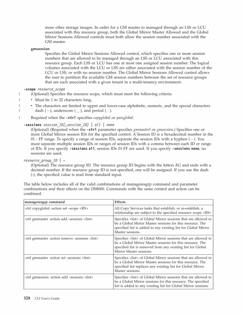
more other storage images. In order for a GM master to managed through an LSS or LCUassociated with this resource group, both the Global Mirror Master Allowed and the GlobalMirror Sessions Allowed controls must both allow the session number associated with theGM master.
gmsessionSpecifies the Global Mirror Sessions Allowed control, which specifies one or more sessionnumbers that are allowed to be managed through an LSS or LCU associated with thisresource group. Each LSS or LCU has one at most one assigned session number. The logicalvolumes associated with the LCU or LSS are either associated with the session number of theLCU or LSS, or with no session number. The Global Mirror Sessions Allowed control allowsthe user to partition the available GM session numbers between the set of resource groupsthat are each associated with a given tenant in a multi-tenancy environment.
-scope resource_scope(Optional) Specifies the resource scope, which must meet the following criteria:v Must be 1 to 32 characters long.v The characters are limited to upper and lower-case alphabetic, numeric, and the special characters
dash ( - ), underscore ( _ ), and period ( . ).
Required when the -ctrl specifies copyglobal or passglobal.
-sessions session_ID[,session_ID] | all | none(Optional) (Required when the -ctrl parameter specifies gmmasterl or gmsession.) Specifies one ormore Global Mirror session IDs for the specified control. A Session ID is a hexadecimal number in the01 - FF range. To specify a range of session IDs, separate the session IDs with a hyphen ( - ). Youmust separate multiple session IDs or ranges of session IDs with a comma between each ID or rangeof IDs. If you specify -sessions all, session IDs 01-FF are used. If you specify -sessions none, nosessions are used.
resource_group_ID | –(Optional) The resource group ID. The resource group ID begins with the letters RG and ends with adecimal number. If the resource group ID is not specified, one will be assigned. If you use the dash(-), the specified value is read from standard input.
The table below includes all of the valid combinations of manageresgrp command and parametercombinations and their effects on the DS8000. Commands with the same control and action can becombined.
manageresgrp command Effects
-ctrl copyglobal -action set -scope <RS> All Copy Services tasks that establish, or re-establish, arelationship are subject to the specified resource scope <RS>
-ctrl gmmaster -action add -sessions <list> Specifies <list> of Global Mirror sessions that are allowed tobe a Global Mirror Master sessions for this resource. Thespecified list is added to any existing list for Global MirrorMaster sessions.
-ctrl gmmaster -action remove -sessions <list> Specifies <list> of Global Mirror sessions that are allowed tobe a Global Mirror Master sessions for this resource. Thespecified list is removed from any existing list for GlobalMirror Master sessions.
-ctrl gmmaster -action set -sessions <list> Specifies <list> of Global Mirror sessions that are allowed tobe a Global Mirror Master sessions for this resource. Thespecified list replaces any existing list for Global MirrorMaster sessions.
-ctrl gmsession -action add -sessions <list> Specifies <list> of Global Mirror sessions that are allowed tobe a Global Mirror sessions for this resource. The specifiedlist is added to any existing list for Global Mirror sessions.
328 CLI User's Guide
|
|
||
|

manageresgrp command Effects
-ctrl gmsession -action remove -sessions <list> Specifies <list> of Global Mirror sessions that are allowed tobe a Global Mirror sessions for this resource. The specifiedlist is removed from any existing list for Global Mirrorsessions.
-ctrl gmsession -action set -sessions <list> Specifies <list> of Global Mirror sessions that are allowed tobe a Global Mirror sessions for this resource. The specifiedlist replaces any existing list for Global Mirror sessions.
-ctrl passglobal -action set -scope <RS> All Copy Services tasks that establish, or re-establish, arelationship through a pass through device are subject to thespecified resource scope <RS>
Notes:
1. When a Copy Services command is rejected as a result of a resource group policy attribute, theindicated error code or error message specifies which resource involved in the operation hascaused the operation to be rejected. As such, the policy that cause the rejection would be inthe resource group that is associated with that resource. For example, an Establish PPRC Pair(mkpprc) operation causes a PPRC to be established between a primary volume A and asecondary volume B. If the request is rejected with an error that indicates that the primaryvolume has rejected the operation because of a target resource scope error, then it is theresource group of volume A that contains the CS_GRS parameter that caused the operation tobe rejected.
2. The combination of the CS_GRS and P_GRS controls allow the user to limit the set ofresources that can be accessed by Copy Services operations issued to a given logical volume.A host (by volume group or other host dependent mechanism) or user ID (by URS) is limitedto a specific set of connection logical volumes. The CS_GRS limits what target/secondaries theconnection volume is allowed to have. The P_GRS limits what destination volumes can beaccessed from either the connection volume or its associated secondary, when the command isissued to the secondary through the primary. For example a FICON host can only issuecommands to volumes defined in the HCD of the host. If it issues a command to logicalvolume A that requests volumes A and B to establish a PPRC pair, the CS GRS in the RGs ofvolumes A and B are checked to see whether the relationship is allowed. If the relationship isestablished and the host then issues a command to the PPRC secondary that request that fixedblock volumes C and D establish a flash copy pair, the PGRS of volume B is checked to seewhether it allows volume B to passthrough to volume C, and then subsequently the CS_GRSin the RGs of volumes C and D are checked to see whether the relationship is allowed.
Example
Invoking the manageresgrp commanddscli> manageresgrp –dev IBM.2107-75FA120 –action set –ctrl copyglobal –scope Product_A RG1
The resulting outputResource Group RG1 successfully modified.
mkresgrpThe mkresgrp command creates a resource group object on a storage image.
�� mkresgrp-dev storage_image_ID
-label resource_group_label �
Chapter 4. CLI commands 329

�-name resource_group_name resource_group_ID
"-"
��
Parameters
-dev storage_image_ID(Optional) Specifies the storage image ID, which includes manufacturer, machine type, and serialnumber. For example, IBM.2107-75FA120. The storage image ID is required if you do not specify afully qualified encryption group ID, do not set the devid variable in your profile or through thesetenv command, and the HMC is aware of more than one storage image. Using the -dev parameterwill temporarily override any defined value for devid for the current command.
-label resource_group_label(Required) Specifies the resource group label. The resource group label is 1 to 32 characters and islimited to upper and lower case alphabetic and numeric characters, and the special characters (-), (_),and (.). Resource group labels must be unique within the domain of the specified device.
-name resource_group_name(Optional) Specifies the user assigned nickname for this resource group object. The maximum lengthis 64 single-byte or 32 double-byte characters.
resource_group_ID | –(Optional) The resource group ID. The resource group ID begins with the letters RG and ends with adecimal number. If the resource group ID is not specified, one will be assigned. If you use the dash(-), the specified value is read from standard input.
Example
Invoking the mkresgrp commanddscli> mkresgrp –dev IBM.2107-75FA120 –label Product_A –name “A_Group” RG1
The resulting outputCMUC00133I mkresgrp: Resource Group RG1 successfully created.
rmresgrpThe rmresgrp command removes a resource group object on a storage image.
Notes:
1. Resource Group 0 (zero) is predefined and cannot be created, deleted, or modified. By default,all resources belong to this group unless otherwise specified.
2. You cannot delete a resource group if there are resources still assigned to that resource group.For example, if a volume or LCU has a resource group ID of RG4, then you cannot delete RG4until you remove those volumes or LCUs from the resource group.
�� rmresgrp-dev storage_image_ID -quiet
resource_group_ID"-"
��
Parameters
-dev storage_image_ID(Optional) Specifies the storage image ID, which includes manufacturer, machine type, and serialnumber. For example, IBM.2107-75FA120. The storage image ID is required if you do not specify afully qualified encryption group ID, do not set the devid variable in your profile or through the
330 CLI User's Guide

setenv command, and the HMC is aware of more than one storage image. Using the -dev parameterwill temporarily override any defined value for devid for the current command.
-quiet(Optional) Turns off the resource group removal confirmation prompt.
resource_group_ID | –(Required) An array of one or more resource group IDs or resource group ID ranges to be removed.A resource group ID range is defined by two resource group IDs that are separated by a hyphen.Multiple resource group IDs or resource group ID ranges must be separated with a blank spacebetween each ID.
The resource group ID begins with the letters RG and ends with a decimal number. If you use thedash (-), the specified value is read from standard input.
Example
Invoking the rmresgrp commanddscli> rmresgrp -quiet –dev IBM.2107-75FA120 RG1
The resulting outputResource Group RG1 successfully deleted.
showresgrpThe showresgrp command displays detailed properties of a resource group.
�� showresgrp-dev storage_image_ID
resource_group_ID"-"
��
Parameters
-dev storage_image_ID(Optional) Specifies the storage image ID, which consists of manufacturer, machine type, and serialnumber. The storage image ID is required if you do not specify a fully qualified volume ID, do notset the devid variable in your profile or through the setenv command, and the HMC is aware of morethan one storage image. Using the -dev parameter temporarily overrides any defined value for devidfor the current command.
resource_group_ID | –(Optional) The resource group ID. The resource group ID begins with the letters RG and ends with adecimal number. If the resource group ID is not specified, one will be assigned. If you use the dash(-), the specified value is read from standard input.
Example
For this command and all other DS CLI show commands, the results are shown in table format toprovide clarity. The actual reports do not display as tables.
Invoking the showresgrp commanddscli> showresgrpRG1
The resulting output
Attribute Value
ID RG1
Chapter 4. CLI commands 331

Attribute Value
Name Product_A.admins
State Normal
Label Product_A
CS_Global _RS Product_A
Passthru_ Global_RS PUBLIC
GM_sessions _allowed 01-FF
GM_masters _allowed 7,20-2F,A0
Report field definitions
ID Identifies the unique identifier that is assigned to this resource group ID.
name Identifies the nickname that you assigned for this resource group object.
state Specifies the current configuration state of this resource group. One of the following values isdisplayed:
NormalSpecifies that the resource group is not being configured.
ConfiguringSpecifies that the resource group is being configured.
Configuration ErrorSpecifies that the resource group configuration process failed to complete successfully.
DeconfiguringSpecifies that a resource group is in the process of being deleted.
Deconfiguration ErrorSpecifies that the resource group deletion process failed to complete successfully.
Label Specifies the resource group label. The resource group label is 1 to 32 characters and is limited toupper and lower case alphabetic and numeric characters, and the special characters (-), (_), and(.).
CS_Global_RSSpecifies all of the Copy Services requests that establish or re-establish a relationship, and aresubject to this resource scope including FlashCopy and PPRC relationships.
Passthru_Global_RSSpecifies all of the Copy Services requests that are issued though a pass-through logical volumeare treated as a relationship between the pass-through logical volume and source logical volumeand are subject to this resource scope.
GM_Sessions_AllowedSpecifies an array of Global Mirror session IDs that are allowed to be used for the volumes in thisresource.
GM_Masters_AllowedSpecifies an array of Global Mirror session IDs that are allowed to be used as a master session forvolumes in this resource.
Copy Services commandsThis section contains Copy Services commands.
You can use the Copy Services commands below to manage Copy Services tasks.
332 CLI User's Guide

FlashCopy commandsThis section contains commands that are used to configure FlashCopy relationships and to displayFlashCopy information.
The following FlashCopy commands are available:
commitflashCompletes a partially formed Global Mirror consistency group. It is used as part of the recoveryfrom a disaster.
resyncflashCreates a point-in-time copy of an existing FlashCopy pair that was established with the -recordand -persist parameters. The resyncflash command only copies the parts of the volume thathave changed since the last point in time copy.
lsflashGenerates a report that displays a list of FlashCopy relationships and the status information foreach FlashCopy relationship in the list.
mkflashInitiates a point-in-time copy from source volumes to target volumes.
reverseflashReverses the FlashCopy relationship.
revertflashRestores the former Global Mirror consistency group from one that is currently forming. It is usedas part of the recovery from a disaster.
rmflashRemoves a relationship between FlashCopy volume pairs.
unfreezeflashResets a FlashCopy consistency group that was previously established with the -freezeparameter when the mkflash or resyncflash commands were issued.
setflashrevertibleModifies a FlashCopy volume pair that is part of a Global Mirror relationship to revertible. Therevertible feature allows data to be committed to the target to form a new consistency group, orrestored back to the last consistency group.
commitflashThe commitflash command is used as part of the recovery from a disaster scenario to complete a partiallyformed Global Mirror consistency group.
�� commitflash-dev storage_image_ID -seqnum flash_sequence_num
�
� source_volume_ID. . .
" - "
��
Parameters
The following transactions must be completed before you can issue the commitflash command:1. Issue the mkflash command with the -record and -persist parameters specified to establish the
FlashCopy volume pair relationship.2. Issue the setflashrevertible command on the FlashCopy volume pair.
Chapter 4. CLI commands 333

-dev storage_image_ID(Optional) Specifies the storage image ID, which includes manufacturer, machine type, and serialnumber. The storage image ID is required if you do not specify a fully qualified ID for all sourcevolumes, do not set the devid variable in your profile or through the setenv command, and the HMCis aware of more than one storage image. Using the -dev parameter will temporarily override anydefined value for devid for the current command.
-seqnum flash_sequence_number(Optional) When a FlashCopy sequence number is specified, the commit operation is performed onlyon those relationships that are associated with the specified number.
This parameter is not supported for machine type 2105.
Example: 0010
source_volume_ID . . . | –(Required) Specifies the source volumes for which FlashCopy relationships are to be committed. Thechosen FlashCopy pair is the one established or modified with the -record parameter. This parameteraccepts fully qualified volume IDs, which includes storage image IDs, or a shortened version withoutstorage image IDs if either the -dev parameter is specified or you specify a value for the devidvariable in your profile file. You must separate multiple source volume IDs with spaces.
The volume ID is a 32-bit number that can be represented as 4 hexadecimal digits in the form ofXYZZ where:
X (for DS6000 and DS8000 models)Specifies the address group, 0 - 1 for DS6000 and 0–F for DS8000.
XY (for a DS8000 model)Specifies the logical subsystem number, 00 - FE.
XY (for a DS6000 model)Specifies the logical subsystem number, 00 - 1E.
ZZ (for DS6000 and DS8000 models)Specifies the volume number, 00 - FF.
If you use the dash (-), the specified value is read from standard input. You cannot use the dash (-)while you are in the DS CLI interactive command mode.
For DS8000, example of a fully qualified volume ID: IBM.2107-75FA120/0001
Example of a shortened version: 0001
Example of multiple IDs: 0001 0003 0008
Example
Invoking the commitflash commanddscli> commitflash -dev IBM.2107-75FA120 0100
The resulting outputFlashCopy volume pair for source 0100 successfully committed.
resyncflashThe resyncflash command is a point-in-time copy of an existing FlashCopy pair that was establishedwith the -record and -persist parameters.
The resyncflash command only copies the parts of the volume that have changed since the lastpoint-in-time copy.
334 CLI User's Guide

�� resyncflash-dev storage_image_ID -tgtpprc -tgtoffline -tgtinhibit
�
�-freeze -record -persist -tgtse -cp
-nocp
�
�-seqnum flash_sequence_num -pmir no
requiredpreferred
�
� source_volume_ID:target_volume_ID. . .
" - "
��
Parameters
When a FlashCopy pair is established with the -record and -persist parameters, the pair initiallysynchronizes and a record of all host write operations to the source is maintained in the source volumes.When the resyncflash command is issued on the FlashCopy pair, the new data that is written to thesource is copied to the target. The parameters you specify in this command replace the parameters youpreviously specified for the existing relationship. To keep the -record and -persist parameters, you mustspecify these parameters in the resyncflash command.
-dev storage_image_ID(Optional) Specifies the storage image ID, which consists of a manufacturer, machine type, and serialnumber. The storage image ID is required if you do not specify a fully ID for the source and targetvolumes, do not set the devid variable in your profile or through the setenv command, and the HMCis aware of more than one storage image. Using the -dev parameter will temporarily override anydefined value for devid for the current command.
-tgtpprc(Optional) Allows the FlashCopy target volume to be a remote mirror and copy source volume.
-tgtoffline(Optional) Rejects the resyncflash command if the target volume is online for host system access.This parameter applies only to count key data (CKD) volumes.
-tgtinhibit(Optional) Prevents host system write operations to the target volume while the FlashCopyrelationship exists.
-freeze(Optional) Starts the queue full condition for the source volume. During the queue full condition, thesource volume reports a status of long busy. All writes to the source volume are queued by the hostand are written after the queue full condition is reset. The queue full condition is reset by an extendedlong busy timeout condition. The timeout condition affects all FlashCopy source volumes that arecontained within a respective logical subsystem and that are established or modified with thisparameter.
Note: Use the chlss and the chlcu commands to modify the extended long busy timeout setting.
-record(Optional) Records the tracks that have changed on both volumes within a FlashCopy pair. Select thisparameter when you establish an initial FlashCopy volume pair that you want to use with theresyncflash command. The -persist parameter is automatically selected when this parameter isselected.
Chapter 4. CLI commands 335

-persist(Optional) Retains the FlashCopy relationship after the background copy completes. The FlashCopyrelationship between the source and the target volumes remains indefinitely until you issue a rmflashcommand. This parameter is automatically selected when the -record parameter is selected. Selectthis parameter along with the -record parameter if you want to use this volume pair with theresyncflash, reverseflash or setflashrevertible commands.
-tgtse(Optional - DS8000 only) Specifies that the target volume that you are designating for a FlashCopyrelationship might be a space-efficient logical volume. An error message is generated if the targetvolume that you are using to create the FlashCopy relationship is a space-efficient volume and youdo not specify this parameter.
-nocp(Optional) Inhibits a background copy. Data is copied from the source volume to the target volumeonly if a track on the source volume is modified. The FlashCopy volume pair relationship remainsindefinitely until it is broken by a rmflash command or until all tracks on the source volume aremodified.
When the -tgtse parameter is specified and neither the -cp nor the -nocp parameters are specified,the no background copy behavior is the default.
Note: You cannot use the -nocp parameter with the -cp parameter in the same command.
-cp(Optional) Starts a background copy. When the -tgtse parameter is not specified and neither the -cpnor the -nocp parameters are specified, the background copy behavior is the default.
Note: You cannot use the -nocp parameter with the -cp parameter in the same command.
-seqnum flash_sequence_num(Optional) This parameter is not supported for machine type 2105. Associates the FlashCopyrelationships that are established with the specified sequence number. You can use this sequencenumber as an identifier for a relationship or group of relationships. An example sequence number is00010.
-pmir no | required | preferred(DS8000 only) Specifies the IBM Remote Pair Copy option that you want to use. The IBM RemotePair Copy option, sometimes called preserve mirror, preserves synchronous Metro Mirror pairs whenthe FlashCopy source and target volumes are both Metro Mirror primary volumes and both MetroMirror secondary volumes on the same storage unit. The FlashCopy operation is performed on boththe local site and the remote site.
no FlashCopy operations are not performed on the remote site. If the target volume is a MetroMirror primary volume, the remote copy might temporarily change to the duplex pendingstate. no is the default if the -pmir parameter is not specified.
requiredFlashCopy operations do not change the state of the Metro Mirror primary volume pair toduplex pending. Both the source Metro Mirror volume pair and the target Metro Mirrorvolume pair must be in the full duplex state.
preferredUses the IBM Remote Pair Copy option for FlashCopy operations when possible. The IBMRemote Pair Copy option cannot be used if the configuration is not correct or the state of thevolume is not supported with this function.
source_volume_ID:target_volume_ID . . . | -(Required) Increments a FlashCopy relationship for the source and target volume pairs with thespecified IDs . This parameter accepts fully qualified volume IDs, which includes storage image IDs,
336 CLI User's Guide

or a shortened version without storage image IDs if the -dev parameter is specified or you specify avalue for the devid variable in your profile file. You must separate multiple FlashCopy pair IDs withspaces.
A FlashCopy pair ID consists of two volume IDs, one designated as the source and the other as thetarget volume for a FlashCopy relationship. You must separate the two volume IDs of a FlashCopypair ID with a colon and no space. The first volume ID is the source volume. The second volume IDis the target volume.
The volume ID is a 32-bit number that can be represented as 4 hexadecimal digits in the form ofXYZZ, where:
X (for DS6000 and DS8000 models)Specifies the address group, 0 - 1 for DS6000 and 0–F for DS8000.
XY (for a DS8000 model)Specifies the logical subsystem number, 00 - FE.
XY (for a DS6000 model)Specifies the logical subsystem number, 00 - 1E.
ZZ (for DS6000 and DS8000 models)Specifies the volume number, 00 - FF.
If you use the dash (-), the specified value is read from standard input. You cannot use the dash (-)while you are in the DS CLI interactive command mode.
For DS8000, an example of a fully qualified FlashCopy pair ID is IBM.2107-75FA120/0001:IBM.2107-75FA120/0004
An example of a shortened version is 0001:0004
An example of multiple pairs is 0001:0004 0003:00FF 0008:000C
Example
An invocation exampledscli> resyncflash –dev IBM.2107-75FA120 -freeze 0100:0200
The resulting outputRemote FlashCopy volume pair 0100:0200 successfully resynchronized.
lsflashThe lsflash command displays a list of FlashCopy relationships and status information for eachFlashCopy relationship in the list.
�� lsflash-dev storage_image_ID -s
-l-activecp -dataset -record
�
�-persist -revertible -cp -tgtse -state valid
invalidvalidation-requiredvolume-inaccessibletgt-failednot-valid
�
�-seqnum flash_sequence_num -retry count[,interval]
�
Chapter 4. CLI commands 337
|

� source_volume_ID:target_volume_IDvolume_ID . . .
" - "
��
Parameters
-dev storage_image_ID(Optional) Specifies the storage image ID, which includes manufacturer, machine type, and serialnumber. The storage image ID is required if you do not specify a fully qualified ID for the source andtarget volumes, do not set the devid variable in your profile or through the setenv command, and theHMC is aware of more than one storage image. Using the -dev parameter temporarily overrides anydefined value for devid for the current command.
-s(Optional) Displays FlashCopy pair IDs. You cannot use the -s and the -l parameters together.
-l(Optional) Displays the default output plus additional attributes that are identified as long output.You cannot use the -s and the -l parameters together.
-activecp(Optional) Displays the FlashCopy relationships where their background copy process is active.
Note: The background copy process might be inactive for a while before it starts.
-dataset(Optional) Displays the volumes that are participating in the Dataset FlashCopy relationships.
-record(Optional) Displays the FlashCopy relationships that were established with the -record parameter.
-persist(Optional) Displays the FlashCopy relationships that were established with the -persist parameter.
-revertible(Optional) Displays the FlashCopy relationships that were established with the -revertibleparameter.
-cp(Optional) Displays the FlashCopy relationships that were established with the -cp parameter.
-tgtse(Optional - DS8000 only) Displays the FlashCopy relationships that have a space-efficient target.
-state valid | invalid | validation-required |volume-inaccessible | tgt-failed | not-valid(Optional) Displays the FlashCopy relationships that are identified by the specific state.
Note: When you specify not-valid, all FlashCopy relationships that do not meet the requirements forthe valid state are displayed.
-seqnum flash_sequence_number(Optional) Displays the FlashCopy relationships that are associated with the specified sequencenumber. The default is 0000.
Note: This parameter is not supported for machine type 2105.
-retry count[,interval](Optional) Specifies how you want the system to handle a validation-required state.
The system currently handles a validation-required state as follows:
338 CLI User's Guide
||

v If there are one or more FlashCopy relationships, an immediate retry is initiated. In most cases, thereasons for the validation-required state are cleared by the time that the retry is processed andnormal processing continues.
v If the validation-required state still exists after the first retry, the system initiates five wait and retrycycles with a delay of 5 seconds between each cycle. At any time during these cycles, if the reasonsfor the validation-required state are cleared, normal processing continues.
You can change how the system handles a validation-required state as follows:v Set the number of retries (count) to 0. When you set the number of retries to 0, it prevents the
system from attempting any retries.v Set the number of retries to 1. The system performs an immediate retry if there are one or more
FlashCopy relationships in the validation-required state. The 5-second delay is not initiated.v Set the number of retries to N, with N greater than 1. The system performs an immediate retry if
there are one or more FlashCopy relationships in the validation-required state, followed by at leastone wait and retry loop. The default for N is 6. You can change the length of the 5-second defaultwait delay using the optional interval value.
source_volume_ID:target_volume_ID | volume_ID . . . | -(Required) Displays the FlashCopy relationships for the source and target volume pairs with thespecified IDs, or displays the FlashCopy relationships for a single volume ID if the volume ID isspecified.
This parameter accepts fully qualified volume IDs, which includes the storage image IDs, or ashortened version without storage image IDs, if the -dev parameter is specified or you can specify avalue for the devid variable in your profile file.
A FlashCopy pair ID consists of two volume IDs, one designated as the source and the other as thetarget volume for a FlashCopy relationship. You must separate the two volume IDs of a FlashCopypair ID with a colon and no space. The first volume ID is the source volume. The second volume IDis the target volume.
The volume ID is a 32-bit number that can be represented as four hexadecimal digits in the form ofXYZZ, where:
X (for DS6000 and DS8000 models)Specifies the address group, 0 - 1 for DS6000 and 0–F for DS8000.
XY (for a DS8000 model)Specifies the logical subsystem number, 00 - FE.
XY (for a DS6000 model)Specifies the logical subsystem number, 00 - 1E.
ZZ (for DS6000 and DS8000 models)Specifies the volume number, 00 - FF.
You must separate multiple IDs with spaces. You can specify FlashCopy pair IDs and a range ofFlashCopy pair IDs, or you can specify volume IDs and a range of volume IDs. You cannot specify acombination of FlashCopy pair IDs and volumes IDs.
If you use the dash (-), the specified value is read from standard input. You cannot use the dash (-)while you are in the DS CLI interactive command mode.
Example
For this command and all other DS CLI list commands, the results are shown in table format to provideclarity. The actual reports do not display as tables.
The following tables represent the headers that are displayed on the output report that is associated withthe lsflash command using the -l parameter.
Chapter 4. CLI commands 339

Invoking the lsflash commanddscli> lsflash -dev IBM.2107-75FA120 -l 0100:0200 0101:0201 0102:0202 0103:0203
The resulting output
ID SrcLSSSequen-ceNum
Time-out
ActiveCopy
Record-ing
Persis-tent
Revert-ible
0100:0200 01 10 60 Disabled Disabled Disabled Disabled
0101:0201 01 10 60 Disabled Disabled Disabled Disabled
0102:0202 01 11 60 Disabled Disabled Disabled Disabled
0103:0203 01 11 60 Disabled Disabled Disabled Disabled
Source-Write-Enabled
Target-Write-Enabled
Back-ground-Copy
OutOf-Sync-Tracks
Date-Created
Date-Synced State
is-TgtSE Pmir
Enabled Disabled Disabled 0 10/01/200702:20:00
10/01/200702:23:47
Valid TSE No
Enabled Disabled Disabled 0 10/01/200702:20:00
10/01/2007
02:23:47
Valid TSE No
Enabled Disabled Disabled 0 10/01/200702:20:00
10/01/200702:23:47
Valid ESE No
Enabled Disabled Disabled 0 10/01/200702:20:00
10/01/200702:23:47
Valid ESE No
Report field definitions
ID Specifies the FlashCopy pair ID. This ID consists of two volume IDs, one designated as the sourceand the other as the target volume for a FlashCopy relationship. For dataset FlashCopyrelationships, the source volume ID is the same as the target volume ID, which indicates that thisvolume is participating as a source or a target in a dataset FlashCopy relationship.
SrcLSSSpecifies the Consistency Group LSS ID that is associated with the source volume of thisFlashCopy relationship.
SequenceNumSpecifies the sequence number that is associated with the FlashCopy relationship.
Note: This item is not supported on the 2105.
TimeoutSpecifies the consistency group Long Busy Timeout setting for the LSS ID that is associated withthe source volume of this FlashCopy relationship. This value can be modified using the chlss(FB) or the chlcu (CKD) command.
ActiveCopySpecifies whether the background copy process is active for this FlashCopy relationship.
RecordingSpecifies whether this FlashCopy relationship was established with the record changes option.
340 CLI User's Guide
|||

PersistentSpecifies whether this FlashCopy relationship was established with the persistent option.
RevertibleSpecifies whether this FlashCopy relationship was established with the revertible option.
SourceWriteEnabledSpecifies whether this FlashCopy relationship was established with the allow source writesoption. No value is displayed in the DS6000 models.
TargetWriteEnabledSpecifies whether this FlashCopy relationship was established with the allow target writes option.No value is displayed in the DS6000 models.
BackgroundCopySpecifies whether this FlashCopy relationship was established with the run background copyoption. No value is displayed in the DS6000 models.
OutOfSyncTracksSpecifies the number of tracks that are not synchronized for this FlashCopy relationship. Themaximum value that can be displayed is dependent on the source volume size. A dash (-) isdisplayed when the track counter is not available. No value is displayed in the DS6000 models.
DateCreatedSpecifies the date and the time that the FlashCopy relationship was established. No value isdisplayed in the DS6000 models.
DateSyncedSpecifies the date and time that FlashCopy relationship was synchronized, or specifies " - " if therelationship is not synchronized. No value is displayed in the DS6000 models.
State Specifies the state of the FlashCopy relationships. One of the following values is displayed foreach FlashCopy relationship:
Note: When a query indicates any state other than valid, the only information that is displayedon the report is the FlashCopy pair ID and the state condition. The rest of the informationcolumns are displayed with a " - " value.
Valid Indicates that the FlashCopy relationship is in a normal state, and that it has beenqueried successfully.
Validation RequiredIndicates that the FlashCopy relationship cannot be queried. The reason that the query isblocked is only temporary. If you issue a new query within several seconds, the problemno longer exists.
Tgt FailedIndicates that the FlashCopy relationship is in an error state. The point-in-time copy islost, and the FlashCopy relationship must be withdrawn. You must issue the rmflashcommand to remove the FlashCopy relationship.
Volume InaccessibleIndicates that the volume cannot be accessed and that the query has failed. When thisstate is displayed, it generally means that the volume is in a fenced condition.
InvalidIndicates that a general internal error occurred when the query was processed.
DatasetIndicates that the source volume is participating as a source or a target in a dataset, orextent level, FlashCopy relationship.
Chapter 4. CLI commands 341
|||

Note: For dataset FlashCopy relationships, a dash (-) will be listed for all of the fields except theID and the State.
isTgtSEIndicates whether this FlashCopy relationship has a space-efficient target.
No Indicates that the target is not space-efficient.
TSE Indicates that the target is a track space-efficient volume.
ESE Indicates that the target is an extent space-efficient (ESE) volume. ESE volumes are usedfor IBM System Storage DS8000 Thin Provisioning.
UnknownIndicates that the space allocation method of the target is not known.
Pmir (DS8000 only) The IBM Remote Pair Copy option preserves synchronous Metro Mirror pairswhen the FlashCopy source volume and target volume are Metro Mirror primary volumes andthe Metro Mirror secondary volumes are on the same storage unit. The FlashCopy operation isperformed on both the local site and the remote site.
No Indicates that the IBM Remote Pair Copy option was not specified.
PreferredIndicates that the IBM Remote Pair Copy option was specified. If the target is a MetroMirror primary, then the FlashCopy function can preserve the Full Duplex mode of thetarget Metro Mirror relationship, if it is possible. If the IBM Remote Pair Copy function isnot possible, you can use processing defined for the IBM Remote Pair Copy option of"No".
RequiredIndicates that the IBM Remote Pair Copy option was specified. If the target is a MetroMirror primary, then the FlashCopy function is required to preserve the Full Duplexmode of the target Metro Mirror relationship. Processing can fail if the IBM Remote PairCopy function is not possible.
RemoteIndicates a remote FlashCopy relationship that was initiated by another FlashCopyestablished at the Metro Mirror primary site with an IBM Remote Pair Copy option of‘preferred' or ‘required'.
UnknownThe IBM Remote Pair Copy relationship type cannot be determined. The source andtarget were created with IBM Remote Pair Copy, but they are no longer both MetroMirror primaries or both Metro Mirror secondaries.
mkflashThe mkflash command starts a point-in-time copy from source volumes to target volumes.
�� mkflash-dev storage_image_ID -tgtpprc -tgtoffline -tgtinhibit
�
�-freeze -record -persist -tgtse -cp
-nocp-wait
�
�-seqnum flash_sequence_num -pmir no
requiredpreferred
�
342 CLI User's Guide
||

� source_volume_ID:target_volume_ID. . .
" - "
��
Parameters
-dev storage_image_ID(Optional) Specifies the storage image ID, which consists of a manufacturer, machine type, and serialnumber. The storage image ID is required if you do not specify a fully qualified ID for the source andtarget volumes, do not set the devid variable in your profile or through the setenv command, and theHMC is aware of more than one storage image. Using the -dev parameter will temporarily overrideany defined value for devid for the current command. For example, DS8000 models useIBM.2107-75FA120
-tgtpprc(Optional) Allows the FlashCopy target volume to be a remote mirror and copy source volume.
-tgtoffline(Optional) Rejects the mkflash command if the target volume is online for host system access. Thisparameter applies only to count key data (CKD) volumes.
-tgtinhibit(Optional) Prevents host system write operations to the target volume while the FlashCopyrelationship exists.
-freeze(Optional) Starts the queue full condition for the source volume. During the queue full condition, thesource volume reports a status of long busy. All writes to the source volume are queued by the hostand are written after the queue full condition is reset. The queue full condition is reset by an extendedlong busy timeout condition. The timeout condition affects all FlashCopy source volumes that arecontained within a respective logical subsystem and that are established or modified with thisparameter.
Note: Use the chlss and the chlcu commands to modify the extended long busy timeout setting.
-record(Optional) Records the tracks that have changed on both volumes within a FlashCopy pair. Select thisparameter when you establish an initial FlashCopy volume pair that you want to use with theresyncflash command. The -persist parameter is automatically selected when this parameter isselected.
-persist(Optional) Retains the FlashCopy relationship after the background copy completes. The FlashCopyrelationship between the source and the target volumes remains indefinitely until you issue a rmflashcommand. This parameter is automatically selected when the -record parameter is selected. Selectthis parameter along with the -record parameter if you want to use this volume pair with theresyncflash, reverseflash or setflashrevertible commands.
-tgtse(Optional - DS8000 only) Specifies that the target volume that you are designating for a FlashCopyrelationship might be a space-efficient logical volume. An error message is generated if the targetvolume that you are using to create the FlashCopy relationship is a space-efficient volume and youdo not specify this parameter.
-nocp(Optional) Inhibits a background copy. Data is copied from the source volume to the target volumeonly if a track on the source volume is modified. The FlashCopy volume pair relationship remainsindefinitely until it is broken by a rmflash command or until all tracks on the source volume aremodified.
Chapter 4. CLI commands 343

When the -tgtse parameter is specified and neither the -cp nor the -nocp parameters are specified,the no background copy behavior is the default.
Note: You cannot use the -nocp parameter with the -cp parameter in the same command.
-cp(Optional) Starts a background copy. When the -tgtse parameter is not specified and neither the -cpnor the -nocp parameters are specified, the background copy behavior is the default.
Note: You cannot use the -nocp parameter with the -cp parameter in the same command.
-wait(Optional - DS8000 only) Delays the command response until the background copy process iscomplete.
Notes:
1. You cannot use the -wait parameter with either the -persist or the -nocp parameters.2. You cannot use the -wait parameter when -tgtse is specified and neither the -cp nor the
-nocp parameters are specified. No background copy behavior is the default.
-seqnum flash_sequence_num(Optional) This parameter is not supported for machine type 2105. Associates the FlashCopyrelationships that are established with the specified sequence number. You can use this sequencenumber as an identifier for a relationship or group of relationships. An example sequence number is00010.
-pmir no | required | preferred(DS8000 only) Specifies the IBM Remote Pair Copy option that you want to use. The IBM RemotePair Copy option, sometimes called preserve mirror, preserves synchronous Metro Mirror pairs whenthe FlashCopy source volume and target volume are Metro Mirror primary volumes and the MetroMirror secondary volumes are on the same storage unit. The FlashCopy operation is performed onboth the local site and the remote site.
no FlashCopy operations are not performed on the remote site. If the target volume is a MetroMirror primary volume, the remote copy might temporarily change to the duplex pendingstate. The default is no if the -pmir parameter is not specified.
requiredFlashCopy operations do not change the state of the Metro Mirror primary volume pair toduplex pending. Both the source Metro Mirror volume pair and the target Metro Mirrorvolume pair must be in the full duplex state.
preferredUses the IBM Remote Pair Copy option for FlashCopy operations when possible. The IBMRemote Pair Copy option cannot be used if the configuration is not correct or the state of thevolume is not supported with this function.
source_volume_ID:target_volume_ID . . . | -(Required) Establishes a FlashCopy relationship for the source and target volume pairs with thespecified IDs. This parameter accepts fully qualified volume IDs, which consist of storage image IDsor a shortened version without storage image IDs, if the -dev parameter is specified. You can alsospecify a value for the devid variable in your profile file. You must separate multiple FlashCopy pairIDs with spaces.
A FlashCopy pair ID consists of two volume IDs: one designated as the source and the other as thetarget volume for a FlashCopy relationship. You must separate the two volume IDs of a FlashCopypair ID with a colon and no space. The first volume ID is the source volume. The second volume IDis the target volume.
344 CLI User's Guide

Note: You might receive an error message that indicates the number of relationships has beenexceeded or that an initial volume format is in progress. This means that the FlashCopyrelationship cannot be established because the maximum number of relationships have alreadybeen established. Or, the volume was recently created and is still being initialized to supportFlashCopy processing. You can issue the mkflash command to establish the FlashCopyrelationship after the initial volume format process is complete.
The volume ID is a 32-bit number that can be represented as 4 hexadecimal digits in the form ofXYZZ, where:
X (for DS6000 and DS8000 models)Specifies the address group, 0 - 1 for DS6000 and 0 - F for DS8000.
XY (for a DS8000 model)Specifies the logical subsystem number, 00 - FE.
XY (for a DS6000 model)Specifies the logical subsystem number, 00 - 1E.
ZZ (for DS6000 and DS8000 models)Specifies the volume number, 00 - FF.
If you use the dash (-), the specified value is read from standard input. You cannot use the dash (-)while you are in the DS CLI interactive command mode.
For DS8000, an example of a fully qualified FlashCopy pair ID is IBM.2107-75FA120/0001:IBM.2107-75FA120/0004
An example of a shortened version is 0001:0004
An example of multiple pairs is 0001:0004 0003:00FF 0008:000C
Example
An invocation exampledscli> mkflash -dev IBM.2107-75FA120 -freeze 0100:0200
The resulting outputFlashCopy pair 0100:0200 successfully created.
reverseflashThe reverseflash command reverses the FlashCopy relationship.
�� reverseflash-dev storage_image_ID -record -persist -fast
�
�-tgtpprc -tgtoffline -tgtinhibit -tgtse -cp
-nocp
�
�-seqnum flash_sequence_num -pmir no
requiredpreferred
�
� source_volume_ID:target_volume_ID. . .
" - "
��
Chapter 4. CLI commands 345

Parameters
You can reverse the direction of a FlashCopy relationship, where the volume that was previously definedas the target becomes the source for the volume that was previously defined as the source. The data thathas changed is copied to the volume that was previously defined as the source. For example, you create aFlashCopy relationship between source volume A and target volume B. Data loss occurs on sourcevolume A. To keep applications running, you can reverse the FlashCopy relationship so that volume B iscopied to volume A.
After the reversal takes place, ensure that you designate this new relationship when you issue any futurecommands. Failure to designate this reversed relationship can produce unexpected results. For example,you use the reverseflash command to reverse the relationship of source volume 1600 and target volume1800. The source volume then becomes 1800 and the target volume becomes 1600. All queries and futureprocessing on this relationship must show volume 1800 as the source and volume 1600 as the target.
The following list defines the parameters that are associated with the reverseflash command:
-dev storage_image_ID(Optional) Specifies the storage image ID, which consists of a manufacturer, machine type, and serialnumber. The storage image ID is required if you do not specify a fully qualified ID for the source andtarget volumes, do not set the devid variable in your profile or through the setenv command, and theHMC is aware of more than one storage image. Using the -dev parameter will temporarily overrideany defined value for devid for the current command. For example, DS8000 models useIBM.2107-75FA120
-record(Optional) Records the tracks that have changed on both volumes within a FlashCopy pair. Select thisparameter when you establish an initial FlashCopy volume pair that you want to use with theresyncflash command. The -persist parameter is automatically selected when this parameter isselected.
-persist(Optional) Retains the FlashCopy relationship after the background copy completes. The FlashCopyrelationship between the source and the target volumes remains indefinitely until you issue a rmflashcommand. This parameter is automatically selected when the -record parameter is selected. Selectthis parameter along with the -record parameter if you want to use this volume pair with theresyncflash, reverseflash or setflashrevertible commands.
-fast(Optional) Specify this parameter when you want to issue the reverseflash command before thebackground copy completes.
Note: To use the fast reverse function, the relationship must be set to Target write inhibit. The fastreverse processing function is intended for use as part of Global Mirror recovery process.
At the end of this operation, the original FlashCopy target volume is not usable. Normally,after this command completes the background copy, the new FlashCopy target volume is usedas the FlashCopy source volume to restore the original FlashCopy target volume.
-tgtpprc(Optional) Allows the FlashCopy target volume to be a Remote Mirror and Copy source volume.
-tgtoffline(Optional) Rejects the reverseflash command if the target volume is online for host system access.This parameter applies only to count key data (CKD) volumes.
-tgtinhibit(Optional) Prevents host system write operations to the target while the FlashCopy relationship exists.
346 CLI User's Guide

-tgtse(Optional - DS8000 only) Specifies that the target volume that you are designating for a FlashCopyrelationship might be a space-efficient logical volume. An error message is generated if the targetvolume that you are using to create the FlashCopy relationship is a space-efficient volume and youdo not specify this parameter.
-nocp(Optional) Inhibits a background copy. Data is copied from the source volume to the target volumeonly if a track on the source volume is modified. The FlashCopy volume pair relationship remainsindefinitely until it is broken by a rmflash command or until all tracks on the source volume aremodified.
If neither the -cp nor the -nocp parameter are specified, then the default background copy behavior isdetermined by the -tgtse and -fast parameters. If the -tgtse parameter is specified, and the -fastparameter is not specified, then the default behavior is to not perform a background copy. Otherwise,the default behavior is to perform a background copy.
Note: You cannot use the -nocp parameter with the -cp parameter in the same command.
-cp(Optional) Starts a background copy. Data is copied from the source volume to the target volume as abackground task and does not require any source volume modifications to trigger the copy.
If neither the -cp nor the -nocp parameter are specified, then the default background copy behavior isdetermined by the -tgtse and -fast parameters. If the -tgtse parameter is specified, and the -fastparameter is not specified, then the default behavior is to not perform a background copy. Otherwise,the default behavior is to perform a background copy.
Note: You cannot use the -nocp parameter with the -cp parameter in the same command.
-seqnum flash_sequence_num(Optional) This parameter is not supported for machine type 2105. Associates the FlashCopyrelationships that are established with the specified sequence number. You can use this sequencenumber as an identifier for a relationship or group of relationships. An example sequence number is00010.
-pmir no | required | preferred(DS8000 only) Specifies the IBM Remote Pair Copy option that you want to use. The IBM RemotePair Copy option, sometimes called preserve mirror, preserves synchronous Metro Mirror pairs whenthe FlashCopy source volume and target volume are Metro Mirror primary volumes and the MetroMirror secondary volumes are on the same storage unit. The FlashCopy operation is performed onboth the local site and the remote site.
no FlashCopy operations are not performed on the remote site. If the target volume is a MetroMirror primary volume, the remote copy might temporarily change to the duplex pendingstate. The default is no if the -pmir parameter is not specified.
requiredFlashCopy operations do not change the state of the Metro Mirror primary volume pair toduplex pending. Both the source Metro Mirror volume pair and the target Metro Mirrorvolume pair must be in the full duplex state.
preferredUses the IBM Remote Pair Copy option for FlashCopy operations when possible. The IBMRemote Pair Copy option cannot be used if the configuration is not correct or the state of thevolume is not supported with this function.
source_volume_ID:target_volume_ID . . . | -(Required) Establishes a FlashCopy relationship for the source and target volume pairs with thespecified IDs. This parameter accepts fully qualified volume IDs, which consist of storage image IDs
Chapter 4. CLI commands 347

or a shortened version without storage image IDs, if the -dev parameter is specified. You can alsospecify a value for the devid variable in your profile file. You must separate multiple FlashCopy pairIDs with spaces.
A FlashCopy pair ID consists of two volume IDs: one designated as the source and the other as thetarget volume for a FlashCopy relationship. You must separate the two volume IDs of a FlashCopypair ID with a colon and no space. The first volume ID is the source volume. The second volume IDis the target volume.
The volume ID is a 32-bit number that can be represented as 4 hexadecimal digits in the form ofXYZZ, where:
X (for DS6000 and DS8000 models)Specifies the address group, 0 - 1 for DS6000 and 0 - F for DS8000.
XY (for a DS8000 model)Specifies the logical subsystem number, 00 - FE.
XY (for a DS6000 model)Specifies the logical subsystem number, 00 - 1E.
ZZ (for DS6000 and DS8000 models)Specifies the volume number, 00 - FF.
If you use the dash (-), the specified value is read from standard input. You cannot use the dash (-)while you are in the DS CLI interactive command mode.
For DS8000, an example of a fully qualified FlashCopy pair ID is IBM.2107-75FA120/0001:IBM.2107-75FA120/0004
An example of a shortened version is 0001:0004
An example of multiple pairs is 0001:0004 0003:00FF 0008:000C
Example
An invocation exampledscli> reverseflash -dev IBM.2107-75FA120 0100:0200
The resulting outputFlashCopyvolume pair 0100:0200 successfully reversed.
revertflashThe revertflash command is used as part of the recovery from a disaster scenario to rollback a GlobalMirror consistency group that is in the process of forming. The former Global Mirror consistency group isrestored.
�� revertflash-dev storage_image_ID -seqnum flash_sequence_num
�
� SourceVolume_ID. . .
" - "
��
Parameters
-dev storage_image_ID(Optional) Specifies the storage image ID, which includes manufacturer, machine type, and serialnumber. The storage image ID is required if you do not specify a fully qualified ID for the source
348 CLI User's Guide

volume, do not set the devid variable in your profile or through the setenv command, and the HMCis aware of more than one storage image. Using the -dev parameter will temporarily override anydefined value for devid for the current command.
DS8000 example: IBM.2107-75FA120
DS6000 example: IBM.1750-685FA120
-seqnum flash_sequence_num(Optional) Specifies the FlashCopy sequence number. When this number is specified, the revertflashoperation is performed only on those relations associated with the specified number.
This parameter is not supported for machine type 2105.
Example: 0010
SourceVolumeID . . . | -(Required) Specifies the source volume ID for which the FlashCopy relationship is to be reverted. Thechosen FlashCopy pair is the one established or modified with the -record parameter. This parameteraccepts fully qualified volume IDs, which includes storage image IDs, or a shortened version withoutstorage image IDs if the -dev parameter is specified or you specify a value for the devid variable inyour profile file. You must separate multiple source volume IDs with spaces.
The volume ID is a 32-bit number that can be represented as 4 hexadecimal digits in the form ofXYZZ, where:
X (for DS6000 and DS8000 models)Specifies the address group, 0 - 1 for DS6000 and 0 - F for DS8000.
XY (for a DS8000 model)Specifies the logical subsystem number, 00 - FE.
XY (for a DS6000 model)Specifies the logical subsystem number, 00 - 1E.
ZZ (for DS6000 and DS8000 models)Specifies the volume number, 00 - FF.
If you use the dash (-), the specified value is read from standard input. You cannot use the dash (-)while you are in the DS CLI interactive command mode.
Example of a fully qualified volume ID: IBM.2107-75FA120/0001
Example of a shortened version: 0001
Example of multiple IDs: 0001 0003 0008
Example
Invoking the revertflash commanddscli> revertflash -dev IBM.2107-75FA120 0100
The resulting outputFlashCopy pair 0100:0200 successfully reverted.
rmflashThe rmflash command removes a relationship between FlashCopy volume pairs.
�� rmflash-dev storage_image_ID -quiet -tgtonly -tgtreleasespace
�
Chapter 4. CLI commands 349

�-cp -cprm -resettgtinhibit -wait -seqnum flash_sequence_number
�
� SourceVolumeID:TargetVolumeID. . .
" - "
��
Parameters
Notes:
1. Invoking this command with the -cp parameter on a FlashCopy relationship that waspreviously marked with the -persist parameter does not remove the relationship. Instead, thesource data is copied to the target.
2. Invoking this command with the -resettgtinhibit parameter does not withdraw therelationship, but resets the -tgtinhibit parameter if it was previously set.
3. All settings apply to all specified FlashCopy pairs.4. Do not use the -wait parameter on persistent relations.5. The -seqnum parameter is not supported for a 2105 machine type.
-dev storage_image_ID(Optional) Specifies the storage image ID, which includes manufacturer, machine type, and serialnumber. The storage image ID is required if you do not specify a fully qualified ID for the source andtarget volumes, do not set the devid variable in your profile or through the setenv command, and theHMC is aware of more than one storage image. Using the -dev parameter temporarily overrides anydefined value for devid for the current command.
DS8000 example: IBM.2107-75FA120
DS6000 example: IBM.1750-68FA120
-quiet(Optional) Turns off the FlashCopy pair removal confirmation prompt.
-tgtonly(Optional) Specifies the target volume of the FlashCopy pair to remove the relationship. In addition,the Copy Indicator for the target volume is reset.
Note: If you use the -tgtonly parameter on CKD volumes, any data set level relationships created bya S/390 host are removed from the specified target volume.
-tgtreleasespace(Optional - DS8000 only) Specifies that you want the system to release the space that has beenallocated to a space-efficient logical target volume.
-cp(Optional) Specifies that the FlashCopy relationship is to be changed from No Copy to Copy and thatthe remaining source volume tracks be copied to the target volume. The relationship is removedwhen all the data is copied unless the relationship is persistent. When this parameter is specified, thecopy takes place for all volume pairs where the source volume ID is identical to the source volumethat is specified in the command.
-cprm(Optional) Specifies a change to a FlashCopy relationship from No Copy to Copy, and copies theremaining source volume tracks to the target volume. The relationship is removed after all of the datais copied. If the FlashCopy relationship is a remote relationship established automatically by anotherestablish FlashCopy with the preserve mirror option set to "preferred" or "required", then the rmflashcommand fails if you do not use the -cprm option.
350 CLI User's Guide

For non-persistent relationships, a Background Copy is initiated for all of the existing relationshipswithin the specified source and target volumes. The relationships are terminated after the backgroundcopy is completed. For persistent relationships, all of the existing relationships within the specifiedsource and target volumes change to non-persistent relationships, and then a Background Copy isinitiated. The relationships are terminated after the background copy is completed.
-resettgtinhibit(Optional) Specifies that the parameter that does not allow host system write operations to the targetID while the FlashCopy relationship exists is to be reset, in case it was previously set.
Note: Specifying this parameter in itself does not cause the FlashCopy relationship to be withdrawn.
-wait(Optional) Specifies that the command response is to be delayed until the background copy processcompletes.
Notes:
1. Only pairs of source and target volume IDs are allowed when you use the -waitparameter.
2. The -cp parameter must be used with the -wait parameter.3. Do not use the -wait parameter on relationships that are marked -persist, an error results
from this usage.
-seqnum flash_sequence_num(Optional) Specifies the FlashCopy sequence number. When this number is specified, the rmflashoperation is performed only on those relationships associated with the specified number.
Example: 0010
Note: This parameter is not supported for a 2105 machine type.
SourceVolumeID:TargetVolumeID . . . | -(Required) Specifies the source and target volume pairs for which the FlashCopy relationships areremoved. This parameter accepts a fully qualified volume ID, which includes storage image IDs, or ashortened version without storage image IDs if the -dev parameter is specified or you specify a valuefor the devid variable in your profile file. You must separate multiple FlashCopy pair IDs with spaces.
A FlashCopy pair ID consists of two volume IDs, one designated as the source and the other as thetarget volume for a FlashCopy relationship. You must separate the two volume IDs of a FlashCopypair ID with a colon and no space. The first volume ID is the source volume. The second volume IDis the target volume.
When the -tgtonly parameter is specified, you must enter volume IDs. Volume pair IDs are not validwith the -tgtonly parameter.
The volume ID is a 32 bit number that can be represented as four hexadecimal digits in the form ofXYZZ, where:
XY (for a DS8000 model)Specifies the logical subsystem number, 00 - FE.
XY (for a DS6000 model)Specifies the logical subsystem number, 00 - 1E.
ZZ (for DS6000 and DS8000 models)Specifies the volume number, 00 - FF.
X (for DS6000 and DS8000 models)Specifies the address group, 0 - 1.
If you use the dash (-), the specified value is read from standard input. However, you cannot use thisfeature if you are using the DS CLI interactive command mode.
Chapter 4. CLI commands 351

Example of a fully qualified FlashCopy pair ID (for DS8000): IBM.2107-75FA120/0001:IBM.2107-75FA120/0004
Example of a shortened version: 0001:0004
Example of multiple pairs: 0001:0004 0003:00FF 0008:000C
Example
Invoking the rmflash commanddscli> rmflash-dev IBM.2107-75FA120 -tgtreleasespace 0100:0200
The resulting outputAre you sure you want to remove the FlashCopy pair 0001:0002? [y/n]: Y
FlashCopy pair 0100:0200 successfully removed.
unfreezeflashThe unfreezeflash command resets a FlashCopy consistency group that was previously established withthe -freeze parameter when the mkflash or resyncflash commands were issued.
�� unfreezeflash-dev storage_image_ID
source_LSS_ID. . .
" - "
��
Parameters
-dev storage_image_ID(Optional) Specifies the source storage image ID, which includes manufacturer, machine type, andserial number. The storage image ID is required if you do not specify a fully qualified LSS ID, do notset the devid variable in your profile or through the setenv command, and the HMC is aware of morethan one storage image. Using the -dev parameter will temporarily override any defined value fordevid for the current command.
source_LSS_ID . . . | -(Required) Specifies that the FlashCopy consistency group be reset for the designated source LSS IDs.The parameter also accepts fully qualified LSS IDs, which includes the storage image ID, or ashortened version without the storage image ID if the -dev parameter is specified or you specify avalue for the devid variable in your profile file.
The fully qualified LSS ID format is storage_image_ID/XX. The DS8000 value for the XX is 00 - FEand the DS6000 value is 00 - 1F.
If you use the dash (-), the specified value is read from standard input.
Note: You cannot use the dash (-) while you are in the DS CLI interactive command mode.
DS8000 example of a fully qualified LSS ID: IBM.2107-75FA120/00
DS6000 example of a fully qualified LSS ID: IBM.1750-68FA120/00
Example of a shortened version: 00
Example of multiple IDs: 10 20 30
Example
Invoking the unfreezeflash commanddscli> unfreezeflash -dev IBM.2107-75FA120 01
352 CLI User's Guide

The resulting outputFlashCopy consistency group for logical subsystem 01successfully reset.
setflashrevertibleThe setflashrevertible command modifies a FlashCopy volume pair that is part of a FlashCopyrelationship to revertible.
The revertible feature allows data to be committed to the target to form a new consistency group or torevert to the last consistency group. This command must be run before the FlashCopy pair can becommitted or reverted.
�� setflashrevertible-dev storage_image_ID -tgtoffline -tgtse
�
�-seqnum flash_sequence_num
source_volume_ID:target_volume_ID. . .
" - "
��
Parameters
Note: The -nocp, -record, -persist, and -tgtinhibit (target inhibit) parameters are includedautomatically when this command processes.
-dev storage_image_ID(Optional) Specifies the storage image ID, which includes manufacturer, machine type, and serialnumber. The storage image ID is required if you do not specify a fully qualified ID for all source andtarget volumes, do not set the devid variable in your profile or through the setenv command, and theHMC is aware of more than one storage image. Using the -dev parameter will temporarily overrideany defined value for devid for the current command.
For DS8000, example: IBM.2107-75FA120
For DS6000, example: IBM.1750-68FA120
-tgtoffline(Optional) Causes an establish FlashCopy volume pair command to be rejected if the target volume isonline for host system access. This parameter applies only to CKD volumes.
-tgtse(Optional - DS8000 only) Specifies that the target volume that is part of the FlashCopy relationshipthat you are modifying to be designated as revertible might be a space-efficient logical volume. Anerror message is generated if the target volume is a space-efficient volume and you do not specifythis parameter.
-seqnum flash_sequence_num(Optional) Associates the FlashCopy relationships that are changed with the specified sequencenumber. Only the relationships that are successfully modified by the command are assigned thespecified sequence number, leaving the ones that fail with the previous number (if previouslyspecified).
This parameter is not supported for machine type 2105.
Example: 0010
source_volume_ID:target_volume_ID . . . | -(Required) Modifies FlashCopy relationships for the source and target volume pairs with the IDsspecified. This parameter accepts fully qualified volume IDs, which includes storage image IDs, or a
Chapter 4. CLI commands 353

shortened version without storage image IDs, if the -dev parameter is specified. Or, you can specify avalue for the devid variable that resides in your profile file. You must separate multiple FlashCopypair IDs with spaces.
A FlashCopy pair ID consists of two volume IDs, one designated as the source and the other as thetarget volume for a FlashCopy relationship. You must separate the two volume IDs of a FlashCopypair ID with a colon and no space. The first volume ID is the source volume. The second volume IDis the target volume.
The volume ID is a 32 bit number that can be represented as 4 hexadecimal digits in the form ofXYZZ, where:
XY (for a DS8000 model)Specifies the logical subsystem number, 00 - FE.
XY (for a DS6000 model)Specifies the logical subsystem number, 00 - 1E.
ZZ (for DS6000 and DS8000 models)Specifies the volume number, 00 - FF.
X (for DS6000 and DS8000 models)Specifies the address group, 0 - 1.
If you use the dash (-), the specified value is read from standard input. You cannot use the dash (-)while you are in the DS CLI interactive command mode.
Example of a fully qualified FlashCopy pair ID: IBM.2107-75FA120/0001:IBM.2107-75FA120/0004
Example of a shortened version: 0001:0004
Example of multiple pairs: 0001:0004 0003:00FF 0008:000C
Example
Invoking the setflashrevertible commanddscli> setflashrevertible-dev IBM.2107-75FA120 -tgtse 0100:0200
The resulting outputFlashCopy volume pair 0100:0200 successfullymade revertible.
Remote FlashCopy commandsThis section contains commands that are used to configure Remote FlashCopy relationships and todisplay Remote FlashCopy information. Remote FlashCopy commands are used to process what wasformerly known as inband FlashCopy transactions. These types of transactions cannot be handledthrough the GUI.
A remote flash is a FlashCopy relationship on a machine at a remote site from the local site machine thatyou are connected to.
The following Remote FlashCopy commands are available:
commitremoteflashSends data to a target volume to form a consistency between the remote source and targetFlashCopy pair.
resyncremoteflashIncrements an existing remote FlashCopy pair that has been established with the -record and-persist parameters.
354 CLI User's Guide

lsremoteflashGenerates a report that displays a list of FlashCopy relationships and the status information foreach FlashCopy relationship in the list.
mkremoteflashInitiates a remote point-in-time copy from source volumes to target volumes through a remotemirror and copy relationship.
revertremoteflashRestores data on the source volume to its most recent consistency formation.
rmremoteflashRemoves a relationship between remote FlashCopy volume pairs.
setremoteflashrevertibleModifies the specified remote FlashCopy volume pair that is part of a Global Mirror relationshipto a revertible state. This command must be run before the FlashCopy pair can be committed orreverted.
commitremoteflashThe commitremoteflash command sends data to a target volume to form a consistency between theremote source and target FlashCopy pair.
�� commitremoteflash-dev storage_image_ID
-conduit LSS_ID �
�-seqnum flash_sequence_num -srcss SS_ID
SourceVolumeID. . .
" - "
��
Parameters
Notes:
1. Establish the pair by issuing either the mkflash or mkremoteflash command with the -recordand -persist parameters.
2. Issue either the setflashrevertible or setremoteflashrevertible command against the pair.
Only after you have taken these two steps can you issue the commitremoteflash command.
-dev storage_image_ID(Optional) Specifies the storage image ID, which includes manufacturer, machine type, and serialnumber. The storage image ID is required if you do not specify fully qualified IDs, do not set thedevid variable in your profile or through the setenv command, and the HMC is aware of more thanone storage image. Using the -dev parameter will temporarily override any defined value for devidfor the current command.
For DS8000, example: IBM.2107-75FA120
-conduit LSS_ID(Required) Specifies the source logical subsystem (LSS) of an existing remote mirror and copyrelationship that is to be used as a means for communicating with the remote storage image. Thesource volume IDs that are specified in the SourceVolumeID parameter must serve as secondaryvolumes in a remote mirror and copy relationship in which one of the conduit LSS volumes serves asa primary volume.
When this parameter is used, you must specify a fully qualified LSS ID. The fully qualified LSS IDformat is storage_image_ID/XX. The DS8000 value for the XX is 00 - FE and the DS6000 value is 00 -1F.
Chapter 4. CLI commands 355

-seqnum flash_sequence_number(Optional) Specifies that the commit operation is performed only on those source volumes that areassociated with the specified sequence number.
This parameter is not supported for machine type 2105.
Example: 0010
-srcss SS_ID(Optional) Specifies the subsystem ID of the source logical subsystem at the remote site. When thisparameter is used, all source volumes must be within the same logical subsystem.
This parameter is required only for IBM System Storage Enterprise Storage Server versions 2.4.0 and2.4.1.
Example: FF10
SourceVolumeID . . . | -(Required) Commits remote FlashCopy relationships for the source volumes with the specified IDs.The chosen pair is the one with the enabled -record parameter. You must separate multiple sourcevolume IDs with spaces.
This parameter accepts fully qualified volume IDs, which includes the storage image ID, or ashortened version without the storage image ID if either the -dev parameter is specified, or you canspecify a value for the devid variable in your profile file.
The volume ID is a 32 bit number that can be represented as 4 hexadecimal digits in the form ofXYZZ, where:
XY (for a DS8000 model)Specifies the logical subsystem number, 00 - FE.
XY (for a DS6000 model)Specifies the logical subsystem number, 00 - 1E.
ZZ (for DS6000 and DS8000 models)Specifies the volume number, 00 - FF.
X (for DS6000 and DS8000 models)Specifies the address group, 0 - 1.
If you use the dash (-), the specified value is read from standard input. You cannot use the dash (-)while you are in the DS CLI interactive command mode.
For DS8000, example of a fully qualified volume ID: IBM.2107-75FA120/0001
Example of a shortened version: 0001
Example of IDs: 0001 0003 0008
Example
Invoking the commitremoteflash commanddscli> commitremoteflash -dev IBM.2107-75FA120 -conduit IBM.2107-75FA150/10 0100
The resulting outputFlashCopy pair 0100:0200 successfully committed.
resyncremoteflashThe resyncremoteflash command (formerly called the incremoteflash command and associated with theincremental FlashCopy process) increments an existing remote FlashCopy pair that has been establishedwith the -record and -persist parameters.
356 CLI User's Guide

�� resyncremoteflash-dev storage_image_ID
-conduit LSS_ID-record
�
�-persist -freeze -tgtpprc -tgtoffline -tgtinhibit -tgtse
�
�-cp-nocp
-seqnum flash_sequence_num -srcss SS_ID�
� SourceVolumeID:TargetVolumeID. . .
" - "
��
Parameters
Note: When a pair is established with the -record and -persist parameters, the pair initiallysynchronizes and then a record of all data that is written from the host to the source is maintainedin the source volumes. When the resyncremoteflash command is issued on the pair, the new datathat is written to the source is copied to the target. The specified parameters in this commandreplace the parameters in the existing relationship. To keep the initial -record and -persistparameter values, the -record and -persist parameters must be specified using theresyncremoteflash command.
-dev storage_image_ID(Optional) Specifies the storage image ID, which includes manufacturer, machine type, and serialnumber. The storage image ID is required if you do not specify fully qualified IDs, do not set thedevid variable in your profile or through the setenv command, and the HMC is aware of more thanone storage image. Using the -dev parameter temporarily overrides any defined value for devid forthe current command.
For DS8000, example: IBM.2107-75FA120
-conduit LSS_ID(Required) Specifies the source logical subsystem (LSS) of an existing remote mirror and copyrelationship that is to be used as a means for communicating with the remote storage image. Thesource volume IDs that are specified in the SourceVolumeID:TargetVolumeID parameter, must serveas secondary volumes in a remote mirror and copy relationship in which one of the conduit LSSvolumes serves as a primary volume.
When you use this parameter, you must specify a fully qualified LSS ID. The fully qualified LSS IDformat is storage_image_ID/XX, where XX is a hexadecimal number in the range 00 - FE, for theDS8000, and 00 - 1F, for the DS6000.
For DS8000, example: IBM.2107-75FA120/00
-record(Optional) Specifies that the changed tracks on both volumes within a FlashCopy pair are to berecorded. Select this parameter if you intend to use the resyncremoteflash command again with thispair. The -persist parameter is automatically set in the code when the -record parameter isspecified.
-persist(Optional) Specifies that the FlashCopy relationship is to be retained after the background copycompletes. The FlashCopy relationship between the source and the target volumes remainsindefinitely until you issue a rmremoteflash command. This parameter is automatically set in thecode when the -record parameter is specified.
Specify this parameter along with the -record parameter if you intend to use this volume pair withthe resyncremoteflash, reverseremoteflash, or setremoteflashrevertible commands.
Chapter 4. CLI commands 357

-freeze(Optional) Specifies the Freeze Consistency Group condition. This option causes the source volume tobe busy (Queue Full status on Open Systems) to all host I/O operations until a FlashCopyConsistency Group Created command is received. All writes to the source volume are queued by thehost and are written after the Consistency Group Created command is complete.
During the busy condition, the source volume reports Queue Full for fixed block volumes and busystatus for CKD volumes.
The busy condition can also be reset by an extended long busy timeout (default 120 seconds). Thetimeout condition affects all FlashCopy source volumes that are contained within a respective logicalsubsystem and that are established or modified with the -freeze parameter.
Note: This parameter is used with other processing steps for purposes such as backups, testing, orrecovery solutions. The use of this parameter ensures that volumes on the target LSSs areconsistent with the source LSSs volumes.
-tgtpprc(Optional) Allows the FlashCopy target volume to be a remote mirror and copy source volume.
-tgtoffline(Optional) Causes the resyncremoteflash command to be rejected if the target volume is online forhost system access.
Note: This parameter applies only to count key data volumes.
-tgtinhibit(Optional) Prevents host system write operations to the target while the FlashCopy relationship exists.
-tgtse(Optional - DS8000 only) Specifies that the target volume might be a space-efficient logical volume.An error message is generated if the target volume is a space-efficient volume and you do not specifythis parameter.
-nocp(Optional - DS8000 only) Inhibits background copy. Data is copied from the source volume to thetarget volume only if a track on the source volume is modified. The FlashCopy volume pairrelationship remains indefinitely until it is broken by a rmflash command, or until all tracks on thesource volume are modified.
When -tgtse is specified and the -cp and -nocp parameters are not specified, the no backgroundcopy behavior is the default.
You cannot use the -nocp parameter with the -cp parameter in the same command.
-cp(Optional - DS8000 only) Specifies that a background copy is to be initiated. When -tgtse is notspecified and the -cp and -nocp parameters are not specified, the background copy behavior is thedefault.
You cannot use the -cp parameter with the -nocp parameter in the same command.
-seqnum flash_sequence_num(Optional) Associates the FlashCopy relationships that are established with the specified sequencenumber. You can use this sequence number as an identifier for a relationship or group ofrelationships. Only the relationships that are modified successfully by the resyncremoteflashcommand are assigned the specified sequence number, leaving the ones that fail with the previousone (if they were previously specified).
This parameter is not supported for machine type 2105.
Example: 0010
358 CLI User's Guide

-srcss SS_ID(Optional) Specifies the subsystem ID of the source logical subsystem at the remote site. Thesubsystem ID is a four-digit hexadecimal number in the range (0001 - FFFF). When this parameter isused, all source volumes must be designated within the same logical subsystem.
This parameter is required for IBM System Storage Enterprise Storage Server versions 2.4.0 and 2.4.1.
Example: FF10
SourceVolumeID:TargetVolumeID . . . | -(Required) Specifies that a remote FlashCopy relationship for the source and target volume pairs beincremented with the designated IDs. This parameter accepts fully qualified volume IDs, whichincludes storage image IDs or a shortened version without storage image IDs, if the -dev parameter isspecified,
A FlashCopy pair ID consists of two volume IDs: one designated as the source and the other as thetarget volume for a FlashCopy relationship. You must separate the two volume IDs of a FlashCopypair ID with a colon and no space. The first volume ID is the source volume. The second volume IDis the target volume.
The volume ID is a 32-bit number that can be represented as four hexadecimal digits in the form ofXYZZ, where:
XY (for a DS8000 model)Specifies the logical subsystem number, 00 - FE.
XY (for a DS6000 model)Specifies the logical subsystem number, 00 - 1E.
ZZ (for DS6000 and DS8000 models)Specifies the volume number, 00 - FF.
X (for DS6000 and DS8000 models)Specifies the address group, 0 - 1.
If you use the dash (-), the specified value is read from standard input. You cannot use the dash (-)while you are in the DS CLI interactive command mode.
For DS8000, example of a fully qualified FlashCopy pair ID: IBM.2107-75FA120/0001:IBM.2107-75FA120/0004
Example of a shortened version: 0001:0004
Example of multiple pairs: 0001:0004 0003:00FF 0008:000C
Example
Invoking the resyncremoteflash commanddscli> resyncremoteflash -dev IBM.2107-75FA120-conduit IBM.2107-75FA150/10 0100:0200
The resulting outputRemote FlashCopy volume pair 0100:0200 successfully resynchronized.Use the lsremoteflash command to determine copy completion.
Note: This message is returned before the copy completes.
lsremoteflashThe lsremoteflash command displays a list of remote FlashCopy relationships and status information foreach FlashCopy relationship in the list. Remote FlashCopy relationships exist on a remote site, and can bequeried (issue lsremoteflash command) from your local site.
Chapter 4. CLI commands 359

�� lsremoteflash -conduit LSS_ID-dev storage_image_ID -s
-l-activecp
�
�-record -persist -revertible -cp -tgtse
�
�-state valid
invalidvalidation-requiredvolume-inaccessibletgt-failedpath-unavailablenot-valid
-seqnum flash_sequence_num�
�-srcss Source_LSS_SSID
SourceVolumeID:TargetVolumeID. . .
" - "
��
Parameters
Note: All settings apply to all FlashCopy pairs that are specified.
-dev storage_image_ID(Optional) Specifies the remote site storage image ID, which consists of manufacturer, machine type,and serial number. The remote site storage image ID is required if you do not specify fully qualifiedIDs, do not set the devid variable in your profile or through the setenv command, and the HMC isaware of more than one storage image. Using the -dev parameter temporarily overrides any definedvalue for devid for the current command.
-conduit LSS_ID(Required) Specifies the source logical subsystem (LSS) of an existing Remote Mirror and Copyrelationship that is used as a means for communicating with the remote storage image.
The source volume IDs that are specified in the SourceVolumeID:TargetVolumeID parameter must serveas secondary volumes in a Remote Mirror and Copy relationship in which one of the conduit LSSvolumes serves as a primary volume.
This parameter accepts a fully qualified LSS ID, which includes the storage image ID. The fullyqualified LSS ID format is storage_image_ID/XX, where:
XY (for a DS8000 model)Specifies the logical subsystem number, 00 - FE.
XY (for a DS6000 model)Specifies the logical subsystem number, 00 - 1E.
ZZ (for DS6000 and DS8000 models)Specifies the volume number, 00 - FF.
X (for DS6000 and DS8000 models)Specifies the address group, 0 - 1.
-s(Optional) Displays only FlashCopy pair IDs. You cannot use the -l and the -s parameters together.
-l(Optional) Displays the default output plus out-of-sync tracks and date that the FlashCopyrelationship was created. You cannot use the -l and the -s parameters together.
360 CLI User's Guide
|
||

-activecp(Optional) Specifies that FlashCopy relationships with an active background copy process are to bedisplayed.
-record(Optional) Specifies that the FlashCopy relationships that were established with the -recordparameter are to be displayed.
-persist(Optional) Specifies that the FlashCopy relationships that were established with the -persistparameter are to be displayed.
-revertible(Optional) Specifies that the FlashCopy relationships that were established with the -revertibleparameter are to be displayed.
-cp(Optional) Specifies that the FlashCopy relationships that were established with the run backgroundcopy (-cp) parameter are to be displayed.
-tgtse(Optional) Displays the FlashCopy relationships that have a space-efficient target. This parameter isnot supported on DS6000 models.
-state valid | invalid | validation-required |volume-inaccessible | tgt-failed |path-unavailable | not-valid
(Optional) Displays the FlashCopy relationships that are identified by the specific state.
Note: When you specify not-valid, all FlashCopy relationships that do not meet the requirements forthe valid state are displayed.
-seqnum flash_sequence_number(Optional) Specifies that the FlashCopy relationships that are associated with the specified sequencenumber are to be displayed.
This parameter is not supported for machine type 2105.
-srcss Source_LSS_SSID(Optional) Specifies the subsystem ID of the source logical subsystem at the remote site. The ID is inthe format 0x0001 - 0xFFFF.
This value is required for the IBM System Storage Enterprise Storage Server versions 2.4.0 and 2.4.1.When you specify SS_IDs, the source volumes are restricted to one LSS.
Example: FF10
SourceVolumeID:TargetVolumeID . . . | -(Required) Specifies that the FlashCopy relationships for the remote site source and target volumepairs with the specified IDs be displayed.
This parameter accepts fully qualified volume IDs, which includes storage image IDs, or a shortenedversion without storage image IDs if the -dev parameter is specified.
A FlashCopy pair ID consists of two volume IDs, one designated as the source and the other as thetarget volume for a FlashCopy relationship. You must separate the two volume IDs of a FlashCopypair ID with a colon and no space. The first volume ID is the source volume. The second volume IDis the target volume.
You must separate multiple IDs with spaces. You can specify FlashCopy pair IDs and a range ofFlashCopy pair IDs, or you can specify volume IDs and a range of volume IDs. You cannot specify acombination of FlashCopy pair IDs and volumes IDs.
The volume ID is a 32-bit number that can be represented as four hexadecimal digits in the form ofXYZZ, where:
Chapter 4. CLI commands 361

XY (for a DS8000 model)Specifies the logical subsystem number, 00 - FE.
XY (for a DS6000 model)Specifies the logical subsystem number, 00 - 1E.
ZZ (for DS6000 and DS8000 models)Specifies the volume number, 00 - FF.
X (for DS6000 and DS8000 models)Specifies the address group, 0 - 1.
If you use the dash (-), the specified value is read from standard input. You cannot use the dash (-)while you are in the DS CLI interactive command mode.
Example of a fully qualified volume ID pair: IBM.2107-75FA120/0001:IBM.2107-68FA120/0004
Example of a shortened version: 0001:0004
Example of multiple pairs: 0001:0004 0003:00FF 0008:000C
Example
For this command and all other DS CLI list commands, the results are shown in table format to provideclarity. The actual reports do not display as tables.
The following tables represent the headers that are displayed on the output report that is associated withthe lsremoteflash command using the -l parameter.
Invoking the lsremoteflash commanddscli> lsremoteflash -l -dev IBM.2107-75FA120-conduit IBM.2107-75FA150/10 IBM.2107-75FA120/0100:IBM.2107-75FA120/0200
The resulting output
ID SrcLSSSequenceNum Active Copy Recording Persistent Revertible
0100:0200 01 10 Disabled Disabled Disabled Disabled
Source-Write-Enabled
Target-Write-Enabled
Back-ground-Copy
Copy-Indic-ator
OutOf-Sync-Tracks
Date-Created
Date-Synced State
is-TgtSE Pmir
Enabled Disabled Disabled Yes 0 10/01/200702:20:00
10/01/200702:23:47
Valid TSE No
Report field definitions
ID*
Specifies the FlashCopy pair ID. The FlashCopy pair ID consists of two volume IDs. One isdesignated as the source and the other is the target volume for a FlashCopy relationship.
SrcLSSSpecifies the logical subsystem ID.
SequenceNumSpecifies the sequence number that is associated with the FlashCopy relationship.
362 CLI User's Guide

ActiveCopySpecifies (enabled or disabled) whether the background copy is active on the specified FlashCopypair.
RecordingSpecifies (enabled or disabled) whether the designated FlashCopy pair is established with recordingactivated.
PersistentSpecifies (enabled or disabled) whether the designated FlashCopy pair is established with persistentactivated.
RevertibleSpecifies (enabled or disabled) whether the designated FlashCopy pair is established with therevertible option activated.
SourceWriteEnabledSpecifies (enabled or disabled) whether this FlashCopy relationship was established with the AllowSource Writes option. No value is displayed for the DS6000.
TargetWriteEnabledSpecifies (enabled or disabled) whether this FlashCopy relationship was established with the AllowTarget Writes option. No value is displayed for the DS6000.
BackgroundCopySpecifies (enabled or disabled) whether this FlashCopy relationship was established with the RunBackground Copy option. No value is displayed for the DS6000.
OutofSyncTracks+
Specifies the number of tracks that are not synchronized for this FlashCopy relationship. No value isdisplayed for the DS6000. A dash (-) is displayed when the track counter is not available.
DateCreated+
Specifies the date and the time that the FlashCopy relationship was established. No value isdisplayed for the DS6000.
DateSyncedSpecifies the date and the time that this FlashCopy relationship was synchronized, or " - " if therelationship is not synchronized. No value is displayed for the DS6000.
StateSpecifies the state of the FlashCopy relationships. One of the following values is displayed for eachFlashCopy relationship:
Note: When a query indicates any state other than valid, the only information that is displayed onthe report is the FlashCopy pair ID and the state condition. The rest of the informationcolumns are displayed with a " - " value.
ValidIndicates that the FlashCopy relationship is in a normal state, and that it has been queriedsuccessfully.
Validation RequiredIndicates that the FlashCopy relationship cannot be queried. The reason that the query is blockedis only temporary. If you issue a new query within several seconds, the problem no longer exists.
Tgt FailedIndicates that the FlashCopy relationship is in an error state. The point-in-time copy is lost, andthe FlashCopy relationship must be withdrawn. You must issue the rmflash command to removethe FlashCopy relationship.
Chapter 4. CLI commands 363

Volume InaccessibleIndicates that the volume cannot be accessed and that the query has failed. When this state isdisplayed, it generally means that the volume is in a fenced condition.
InvalidIndicates that a general internal error has occurred when the query is processed.
Path UnavailableThe specified inband path does not exist. The user must verify that the Remote Mirror and Copypath exists.
Note: No value is displayed for the DS6000.
isTgtSEIndicates whether this FlashCopy relationship has a space-efficient target.
No Indicates that the target is not space-efficient.
TSEIndicates that the target is a track space-efficient volume.
ESEIndicates that the target is an extent space-efficient (ESE) volume. ESE volumes are used for IBMSystem Storage DS8000 Thin Provisioning.
UnknownIndicates that the space allocation method of the target is not known.
Pmir(DS8000 only) The IBM Remote Pair Copy option preserves synchronous Metro Mirror pairs whenthe FlashCopy source volume and target volume are Metro Mirror primary volumes and the MetroMirror secondary volumes are on the same storage unit. The FlashCopy operation is performed onboth the local site and the remote site.
No Indicates that the IBM Remote Pair Copy option was not specified.
PreferredIndicates that the IBM Remote Pair Copy option was specified. If the target is a Metro Mirrorprimary, then the FlashCopy function must preserve the Full Duplex mode of the target MetroMirror relationship, if it is possible. If the IBM Remote Pair Copy function is not possible, youcan use processing defined for the IBM Remote Pair Copy option of "No".
RequiredIndicates that the IBM Remote Pair Copy option was specified. If the target is a Metro Mirrorprimary, then the FlashCopy function is required to preserve the Full Duplex mode of the targetMetro Mirror relationship. Processing fails if the IBM Remote Pair Copy function is not possible.
RemoteIndicates that this remote FlashCopy relationship was initiated by another FlashCopy establishedat the Metro Mirror primary site with an IBM Remote Pair Copy option of ‘preferred' or‘required'.
UnknownThe IBM Remote Pair Copy relationship type cannot be determined. The source and target werecreated with IBM Remote Pair Copy, but they are no longer both Metro Mirror primaries or bothMetro Mirror secondaries.
Key:
* Displayed when the -s parameter is specified.
+ Displayed only when the -l parameter is specified.
364 CLI User's Guide
|
||
||

mkremoteflashThe mkremoteflash command initiates a remote point-in-time copy from source volumes to targetvolumes through a Remote Mirror and Copy relationship.
�� mkremoteflash-dev storage_image_ID
-conduit LSS_ID-tgtpprc
�
�-tgtoffline -tgtinhibit -freeze -record -persist -tgtse
�
�-cp-nocp
-seqnum flash_sequence_num -srcss SS_ID�
� source_volume_ID:target_volume_ID. . .
" - "
��
Parameters
-dev storage_image_ID(Optional) Specifies the storage image ID, which includes manufacturer, machine type, and serialnumber. The storage image ID is required if you do not specify fully qualified IDs, do not set thedevid variable in your profile or through the setenv command, and the HMC is aware of more thanone storage image. Using the -dev parameter will temporarily override any defined value for devidfor the current command.
-conduit LSS_ID(Required) Specifies the source logical subsystem (LSS) of an existing remote mirror and copyrelationship that is to be used as a conduit for communicating with the remote storage image. Thesource volume IDs that are specified in the SourceVolumeID:TargetVolumeID parameter, must serve assecondary volumes in a remote mirror and copy relationship in which one of the conduit LSSvolumes serves as a primary volume.
When you use this parameter, you must specify a fully qualified LSS ID. The fully qualified LSS IDformat is storage_image_ID/XX. The DS8000 value for the XX is 00 - FE and the DS6000 value is 00 -1F.
For DS8000, example: IBM.2107-75FA120/00
-tgtpprc(Optional) Allows the FlashCopy target volume to be a remote mirror and copy source volume.
-tgtoffline(Optional) Causes the mkremoteflash command to be rejected if the target volume is online for hostsystem access. This parameter applies only to CKD volumes.
-tgtinhibit(Optional) Prevents host system write operations to the target while the FlashCopy relationship exists.
-freeze(Optional) Specifies the Freeze Consistency Group condition. The use of this parameter triggers thequeue full condition for the source volume. All writes to the source volume are queued by the hostand are written after the queue full condition is reset.
During the queue full condition, the source volume reports long busy status.
The queue full condition is reset by an extended long busy timeout condition. The timeout conditionaffects all FlashCopy source volumes that are contained within a respective logical subsystem andthat are established or modified with the -freeze parameter.
Chapter 4. CLI commands 365
|

Note: This parameter is used with other processing steps for purposes such as backups, testing, orrecovery solutions. The use of this parameter ensures that volumes on the target LSSs areconsistent with the source LSSs volumes.
-record(Optional) Specifies that the changed tracks on both volumes within a FlashCopy pair be recorded.Select this parameter if you intend to use the resyncremoteflash command again with this pair. The-persist parameter is automatically selected when the -record parameter is specified.
-persist(Optional) Specifies that you want to retain the FlashCopy relationship after the background copycompletes. The FlashCopy relationship between the source and the target volumes remainsindefinitely until you issue a rmremoteflash command. This parameter is automatically selected whenthe -record parameter is specified.
Specify this parameter along with the -record parameter if you intend to use this volume pair withthe resyncremoteflash, reverseremoteflash, or setremoteflashrevertible commands.
-tgtse(Optional - DS8000 only) Specifies that the target volume might be a space-efficient logical volume.An error message is generated if the target volume that you have specified is a space-efficient volumeand you do not specify the -tgtse parameter.
-nocp(Optional) Inhibits background copy. Data will be copied from the source volume to the targetvolume only if a track on the source volume is modified. The FlashCopy volume pair relationshipremains indefinitely until it is broken by a rmremoteflash command, or until all tracks on the sourcevolume are modified.
When -tgtse is specified and the -nocp parameter is not specified, the no background copy behavioris the default. You cannot use the -nocp parameter with the -cp parameter in the same command.
-cp(Optional - DS8000 only) Specifies that a background copy be initiated. When (-tgtse is not specified)and neither the -cp nor the -nocp parameters are specified, the background copy behavior is thedefault.
You cannot use the -cp parameter with the -nocp parameter in the same command.
-seqnum flash_sequence_num(Optional) Associates the FlashCopy relationships that are established with the specified sequencenumber. This sequence number can be used as an identifier for a relationship or group ofrelationships.
Example: 0010
This parameter is not supported for machine type 2105.
-srcss SS_ID(Optional) Specifies the subsystem ID of the source logical subsystem at the remote site. The ID is inthe format 0x0001 - 0xFFFF.
This value is required for the IBM System Storage Enterprise Storage Server versions 2.4.0 and 2.4.1.When you specify SS_IDs, the source volumes are restricted to one LSS.
Example: FF10
SourceVolumeID:TargetVolumeID . . . | -(Required) Specifies that a remote FlashCopy relationship for the source and target volume pairs beincremented with the designated IDs. This parameter accepts fully qualified volume IDs, whichincludes the storage image IDs or a shortened version without storage image IDs, if the -devparameter is specified.
366 CLI User's Guide

A FlashCopy pair ID consists of two volume IDs: one designated as the source and the other as thetarget volume for a FlashCopy relationship. You must separate the two volume IDs of a FlashCopypair ID with a colon and no space. The first volume ID is the source volume. The second volume IDis the target volume.
The volume ID is a 32-bit number that can be represented as 4 hexadecimal digits in the form ofXYZZ, where:
XY (for a DS8000 model)Specifies the logical subsystem number, 00 - FE.
XY (for a DS6000 model)Specifies the logical subsystem number, 00 - 1E.
ZZ (for DS6000 and DS8000 models)Specifies the volume number, 00 - FF.
X (for DS6000 and DS8000 models)Specifies the address group, 0 - 1.
If you use the dash (-), the specified value is read from standard input. You cannot use the dash (-)while you are in the DS CLI interactive command mode.
For the DS8000, example of a fully qualified FlashCopy pair ID: IBM.2107-75FA120/0001:IBM.2107-75FA120/0004
Example of a shortened version: 0001:0004
Example of multiple pairs: 0001:0004 0003:00FF 0008:000C
Example
Invoking the mkremoteflash commanddscli> mkremoteflash -dev IBM.2107-75FA120-conduit IBM.2107-75FA150/10 0100:0200
The resulting outputFlashCopy volume Pair 0100:0200 successfully created.Use the lsremoteflash command to determine copy completion.
revertremoteflashThe revertremoteflash command is used to restore data on the source volume to its most recentconsistency formation. All new write operations to the source since the most recent consistency formationare overwritten with the previous consistency.
�� revertremoteflash-dev storage_image_ID
-conduit LSS_ID �
�-seqnum flash_sequence_num -srcss SS_ID
SourceVolumeID. . .
" - "
��
Parameters
You must take the following actions before you can use the revertremoteflash command:
Notes:
1. Issue the mkflash or mkremoteflash command with the -persist and -record parameters toestablish the FlashCopy pair.
Chapter 4. CLI commands 367

2. Issue the setflashrevertible or setremoteflashrevertible command against the FlashCopypair.
-dev storage_image_ID(Optional) Specifies the storage image ID, which includes manufacturer, machine type, and serialnumber. The storage image ID is required if you do not specify fully qualified IDs, do not set thedevid variable in your profile or through the setenv command, and the HMC is aware of more thanone storage image. Using the -dev parameter will temporarily override any defined value for devidfor the current command.
-conduit LSS_ID(Required) Specifies the source logical subsystem (LSS) of an existing remote mirror and copy(formerly PPRC) relationship that is used as a means for communicating with the remote storageimage. The source volume IDs that are specified in SourceVolumeID:TargetVolumeID must serve assecondary volumes in a remote mirror and copy relationship in which one of the conduit LSSvolumes serves as a primary volume.
When you use this parameter, you must specify a full qualified LSS ID. The fully qualified LSS IDformat is storage_image_ID/XX. The DS8000 value for the XX is 00 - FE and the DS6000 value is 00 -1F.
For DS8000, example: IBM.2107-75FA120/00
-seqnum flash_sequence_num(Optional) When a FlashCopy sequence number is specified, the revertremoteflash operation isperformed only on those relationships that are associated with the specified number.
Example: 0010
This parameter is not supported for machine type 2105.
-srcss SS_ID(Optional) Specifies the subsystem ID of the source logical subsystem at the remote site. The ID is inthe format 0x0001 - 0xFFFF.
This value is required for the IBM System Storage Enterprise Storage Server versions 2.4.0 and 2.4.1.3. When you specify SS_IDs, the source volumes are restricted to one logical subsystem.
Example: FF10
SourceVolumeID . . . | -(Required) Specifies the remote FlashCopy relationship for the source volume with the specified IDthat is to be reverted. The chosen FlashCopy pair is the one that is established or modified with the-record parameter.
This parameter accepts fully qualified volume IDs, which includes storage image IDs, or a shortenedversion without storage image IDs if the -dev parameter is specified. You must separate multiplesource volume IDs with spaces.
The volume ID is a 32-bit number that can be represented as 4 hexadecimal digits in the form ofXYZZ, where:
XY (for a DS8000 model)Specifies the logical subsystem number, 00 - FE.
XY (for a DS6000 model)Specifies the logical subsystem number, 00 - 1E.
ZZ (for DS6000 and DS8000 models)Specifies the volume number, 00 - FF.
X (for DS6000 and DS8000 models)Specifies the address group, 0 - 1.
368 CLI User's Guide

If you use the dash (-), the specified value is read from standard input. You cannot use the dash (-)while you are in the DS CLI interactive command mode.
Example of a shortened version: 0001
Example of multiple IDs: 0001 0003 0008
Example
Invoking the revertremoteflash commanddscli> revertremoteflash -dev IBM.2107-75FA120-conduit IBM.2107-75FA150/10 0100
The resulting outputRemote FlashCopy volume pair 0100:0200 successfully reverted.
rmremoteflashThe rmremoteflash command removes a relationship between remote FlashCopy volume pairs.
�� rmremoteflash -conduit LSS_ID-dev storage_image_ID -quiet
�
�-tgtreleasespace -cp -seqnum flash_sequence_number -srcss SS_ID
�
� SourceVolumeID:TargetVolumeID. . .
" - "
��
Parameters
Notes:
1. Invoking this command and using the -cp parameter on a FlashCopy relationship that waspreviously marked with the -persist parameter does not remove the relationship. Instead, thesource volume is copied to the target volume.
2. Invoking this command resets the -tgtinhibit parameter option if it was previously set.3. All settings apply to all specified FlashCopy pairs.4. The -seqnum parameter is not supported for model 2105.5. When SS_IDs are specified, the source volumes are restricted to 1 LSS.
-dev storage_image_ID(Optional) Specifies the storage image ID, which includes manufacturer, machine type, and serialnumber. The storage image ID is required if you do not specify fully qualified IDs, do not set thedevid variable in your profile or through the setenv command, and the HMC is aware of more thanone storage image. Using the -dev parameter will temporarily override any defined value for devidfor the current command.
-conduit LSS_ID(Required) Specifies the source logical subsystem (LSS) of an existing remote mirror and copy(formerly PPRC) relationship that is to be used as a means for communicating with the remotestorage image. The source volume IDs that are specified in SourceVolumeID:TargetVolumeID must serveas secondary volumes in a remote mirror and copy relationship in which one of the conduit LSSvolumes serves as a primary volume.
This parameter allows the use of a fully qualified LSS ID, which includes the storage image ID. Thefully qualified LSS ID format is storage_image_ID/XX. The DS8000 value for the XX is 00 - FE andthe DS6000 value is 00 - 1F.
Chapter 4. CLI commands 369

-quiet(Optional) Turns off the FlashCopy pair removal confirmation prompt for this command.
-tgtreleasespace(Optional - DS8000 only) Specifies that you want the system to release the space that has beenallocated to the space-efficient target logical volumes back to the repository. This release must occurat the same time that the FlashCopy pair is removed if the only access to the space-efficient volumesis through the conduit LSS ID.
-cp(Optional) Specifies that the FlashCopy relationship be changed from the No Copy to the Copy mode.Additionally the remaining source volume tracks are copied to the target volume. The relationship isremoved when all the data is copied unless the relationship is persistent. When the -cp parameter isspecified, the copy is processed for all volume pairs where the source volume ID is identical to thesource volume that is specified in the command.
-seqnum flash_sequence_num(Optional) When a FlashCopy sequence number is specified, the rmremoteflash operation isperformed only on those relations that are associated with the specified number.
Example: 0010
This parameter is not supported for machine type 2105.
-srcss SS_ID(Optional) Specifies the subsystem ID of the source logical subsystem at the remote site. The ID is inthe format 0x0001 - 0xFFFF.
This value is required for the IBM System Storage Enterprise Storage Server versions 2.4.0 and 2.4.1.4. When you specify SS_IDs, the source volumes are restricted to one logical subsystem.
Example: FF10
SourceVolumeID:TargetVolumeID . . . | -(Required) Specifies the remote FlashCopy relationships for the source and target volume pairs withthe specified IDs that are to be removed.
This parameter accepts fully qualified volume IDs, which includes storage image IDs, or a shortenedversion without storage image IDs if the -dev parameter is specified. You must separate multipleFlashCopy pair IDs with spaces.
A FlashCopy pair ID consists of two volume IDs, one designated as the source and the other as thetarget volume for a FlashCopy relationship. You must separate the two volume IDs of a FlashCopypair ID with a colon and no space. The first volume ID is the source volume. The second volume IDis the target volume.
The volume ID is a 32-bit number that can be represented as 4 hexadecimal digits in the form ofXYZZ, where:
XY (for a DS8000 model)Specifies the logical subsystem number, 00 - FE.
XY (for a DS6000 model)Specifies the logical subsystem number, 00 - 1E.
ZZ (for DS6000 and DS8000 models)Specifies the volume number, 00 - FF.
X (for DS6000 and DS8000 models)Specifies the address group, 0 - 1.
If you use the dash (-), the specified value is read from standard input. You cannot use the dash (-)while you are in the DS CLI interactive command mode.
Example of a fully qualified FlashCopy pair ID: IBM.2107-75FA120/0001:IBM.2107-68FA120/0004
370 CLI User's Guide

Example of a shortened version: 0001:0004
Example of multiple pairs: 0001:0004 0003:00FF 0008:000C
Example
Invoking the rmremoteflash commanddscli> rmremoteflash -dev IBM.2107-75FA120-conduit IBM.2107-75FA150/10 0100:0200
The resulting outputAre you sure you want to remove the FlashCopy pair 0100:0200? [y/n]: Y
Removal of the remote FlashCopy volume pair 0100:0200 has been initiatedsuccessfully. Use the lsremoteflash command to determine when therelationship is deleted.
setremoteflashrevertibleThe setremoteflashrevertible command modifies a remote FlashCopy volume pair that is part of aFlashCopy relationship to revertible.
When a pair is revertible, the data can be committed to the target to form a new consistency group, or itcan be reverted back to the last consistency group. This command must be run before the FlashCopy paircan be committed or reverted.
�� setremoteflashrevertible -conduit LSS_ID-dev storage_image_ID -tgtoffline
�
�-tgtse -seqnum flash_sequence_num -srcss SS_ID
�
� SourceVolumeID:TargetVolumeID. . .
" - "
��
Parameters
Note: The -nocp, -record, -persist, and -tgtinhibit (target inhibit) parameters that were specifiedwhen the FlashCopy pair was made (mkremoteflash command) are included automatically whenthe setremoteflashrevertible command processes.
-dev storage_image_ID(Optional) Specifies the storage image ID, which includes manufacturer, machine type, and serialnumber. The storage image ID is required if you do not specify fully qualified IDs, do not set thedevid variable in your profile or through the setenv command, and the HMC is aware of more thanone storage image. Using the -dev parameter will temporarily override any defined value for devidfor the current command.
-conduit LSS_ID(Required) Specifies the source logical subsystem (LSS) of an existing remote mirror and copyrelationship that is to be used as a passage for communicating with the remote storage image. Thesource volume IDs that are specified in SourceVolumeID:TargetVolumeID must serve as secondaryvolumes in a remote mirror and copy relationship in which one of the passage LSS volumes serves asa primary volume.
When you use this parameter, you must specify a fully qualified LSS ID. The fully qualified LSS IDformat is storage_image_ID/XX, where XX is a hexadecimal number in the range 00 - FE for theDS8000. The DS6000 value is 00 - 1F.
Chapter 4. CLI commands 371

-tgtoffline(Optional) Causes an establish FlashCopy volume pair command to be rejected if the target volumeID is online for host system access.
This parameter applies only to CKD volumes.
-tgtse(Optional - DS8000 only) Specifies that the target volume that is part of the FlashCopy relationshipthat you are modifying to be designated as revertible might be a space-efficient logical volume. Anerror message is generated if the target volume is a space-efficient volume and you do not specifythis parameter.
-seqnum flash_sequence_num(Optional) Associates the remote FlashCopy relationships that are changed with the specifiedsequence number. Only the relationships that are successfully modified by the command get thespecified sequence number, leaving the ones that failed with the previous number (if previouslyspecified).
Example: 0010
This parameter is not supported for machine type 2105.
-srcss SS_ID(Optional) Specifies the subsystem ID of the source logical subsystem at the remote site. The ID is inthe format 0x0001 - 0xFFFF.
This value is required for the IBM System Storage Enterprise Storage Server versions 2.4.0 and 2.4.1.
Example: FF10
SourceVolumeID:TargetVolumeID . . . | -(Required) Specifies that the remote FlashCopy relationships for the designated source and targetvolume pairs be modified.
This parameter accepts fully qualified volume IDs, which includes storage image IDs, or a shortenedversion without storage image IDs if the -dev parameter is specified. You must separate multipleFlashCopy pair IDs with spaces.
A FlashCopy pair ID consists of two volume IDs, one designated as the source and the other as thetarget volume for a FlashCopy relationship. You must separate the two volume IDs of a FlashCopypair ID with a colon and no space. The first volume ID is the source volume. The second volume IDis the target volume.
The volume ID is a 32-bit number that can be represented as 4 hexadecimal digits in the form ofXYZZ, where:
XY (for a DS8000 model)Specifies the logical subsystem number, 00 - FE.
XY (for a DS6000 model)Specifies the logical subsystem number, 00 - 1E.
ZZ (for DS6000 and DS8000 models)Specifies the volume number, 00 - FF.
X (for DS6000 and DS8000 models)Specifies the address group, 0 - 1.
If you use the dash (-), the specified value is read from standard input. You cannot use the dash (-)while you are in the DS CLI interactive command mode.
Example of a fully qualified FlashCopy pair ID: IBM.2107-75FA120/0001:IBM.2107-75FA120/0004
Example of a shortened version: 0001:0004
Example of multiple pairs: 0001:0004 0003:00FF 0008:000C
372 CLI User's Guide

Example
Invoking the setremoteflashrevertible commanddscli> setremoteflashrevertible -dev IBM.2107-75FA120 0100:
The resulting outputRemote FlashCopy pair 0100:0200 successfully made revertible.
Remote Mirror and Copy path commandsThis section contains commands that create and delete Remote Mirror and Copy (formerly PPRC) pathsand display Remote Mirror and Copy path information.
The following Remote Mirror and Copy path commands are available:
lsavailpprcportGenerates a report that displays a list of ESCON or Fibre Channel I/O ports that can be definedas Remote Mirror and Copy paths.
lspprcpathGenerates a report that displays a list of existing Remote Mirror and Copy path definitions.
mkesconpprcpathCreates a Remote Mirror and Copy path between source and target logical subsystems over anESCON connection.
mkpprcpathEstablishes or replaces a Remote Mirror and Copy path between source and target logicalsubsystems (LSSs) over a Fibre Channel connection.
rmpprcpathDeletes one or more specified Remote Mirror and Copy paths.
lsavailpprcportThe lsavailpprcport command displays a list of ESCON or Fibre Channel I/O ports that can be definedas remote mirror and copy (formerly PPRC) paths.
The DS8000 models and DS6000 models support only Fibre Channel ports. The Enterprise Storage Server(2105 machine type) supports ESCON ports.
Secondary ports listed for PPRC are only available when configured as FCP. Secondary FICON ports,while displayed in the list, are not supported, and the DS CLI command mkpprcpath issued to asecondary FICON port will fail.
Note: If you are creating paths between an older release of the DS8000 (Release 5.1 or earlier), whichsupports only 4-port host adaptors, and a newer release of the DS8000 (Release 6.0 or later), whichsupports 8-port host adaptors, the paths should connect only to the lower four ports on the newerstorage unit.
�� lsavailpprcport-dev storage_image_ID
-remotewwnn wwnn-s-l
�
�-remotedev storage_image_ID
Source_LSS_ID:Target_LSS_ID" - "
��
Chapter 4. CLI commands 373

Parameters
-dev storage_image_ID(Optional). Specifies the source volume storage image ID, which consists of manufacturer, machinetype, and serial number. The storage image ID is required if you do not specify a fully qualified LSSID, do not set the devid variable in your profile or through the setenv command, and the HMC isaware of more than one storage image. Using the -dev parameter will temporarily override anydefined value for devid for the current command.
-remotewwnn wwnn(Required). Specifies the worldwide node name (WWNN). The format is a 16-hexadecimal ID.
Note: You want to use the WWNN that is associated with the remote storage image. Run the lssi orshowsi command to obtain this number. If you use the WWNN that is associated with theprimary storage unit, this command fails.
WWNN example: 12341234000A000F
-s(Optional). Displays the local port ID. You cannot use the -l and the -s parameters together.
-l(Optional). Displays all fields. You cannot use the -l and the -s parameters together.
-remotedev storage_image_ID(Required or Optional). Specifies the remote storage unit that contains the I/O ports that are queriedby the Source_LSS_ID:Target_LSS_ID parameter. The remotedev ID consists of the value for themanufacturer, machine type, and serial number.
Required - This parameter is required when querying ESCON I/O ports unless a fully qualifiedtarget logical subsystem ID is specified.
Optional - This parameter is optional if you are querying fibre channel I/O ports.
Note: If specified the format of this entry might be checked for correctness even though the value isnot used.
For DS8000, example: IBM.2107-75FA120
Source_LSS_ID:Target_LSS_ID | -(Required) Queries I/O ports that are available for a remote mirror and copy path relationship for thesource and target LSSs. This parameter accepts fully qualified LSS IDs, which includes the storageimage ID or shortened version without the storage image ID, if the -dev parameter is specified.
A remote mirror and copy path LSS pair ID consists of two LSS IDs, one designated as the sourceLSS and the other as the target LSS for a remote mirror and copy path relationship. The two LSS IDsmust be separated with a colon and no spaces. The first LSS ID is the source LSS. The second LSS IDis the target LSS.
The fully qualified LSS ID format is storage_image_ID/XX, where XX is a hexadecimal number in therange 00 - FE for a DS8000 model and 00 - 1F for a DS6000 model.If you do not use the -dev and -remotedev parameters, the fully qualifiedsource_LSS_ID:target_LSS_ID value must be placed after the -remotewwnn value in your command line.Your command line can look like the following example:dscli> lsavailpprcport –l –remotewwnn 12341234000A000FIBM.2107-75FA120/01:IBM.2107-75FA150/01
If you use the dash (-), the specified value is read from standard input. You cannot use the dash (-)while you are in the DS CLI interactive command mode.
Example pair: 00:00
Example of multiple pairs: 00:00 01:01 02:02
374 CLI User's Guide

Example
For this command and all other DS CLI list commands, the results are shown in table format to provideclarity. The actual reports do not display as tables.
The following tables represent the headers that are displayed on the output report that is associated withthe lsavailpprcport command using the -l parameter.
Invoking the lsavailpprcport commanddscli> lsavailpprcport –l –dev IBM.2107-75FA120–remotewwnn 12341234000A000F 01:01
The resulting output
ESCON port information displays for the 2105 machine type.
Local port Attached port Type Switch ID Switch port
I0100 I0200 FCP N/A N/A
I0150 I0620 ESCON N/A N/A
I0200 N/A ESCON Switch IBM.111.2222.75113AB
I10
I0250 N/A ESCON Switch IBM.111.2222.75113AB
I20
Report field descriptions
Local portSpecifies the fully qualified unique Port ID on the local storage unit. FCP and ESCON port IDsare displayed as follows:
FCP port IDFour hexadecimal characters in the format 0xEEAP, where ‘EE’ is a port enclosure number (00- 3F), ‘A’ is the adapter number (0 - F), and ‘P’ is the port number (0 - F). The FCP port IDnumber is prefixed with the letter I.
ESCON port IDFour hexadecimal characters in the format 0xEEAP, where ‘EE’ is a port enclosure number (04- 07), ‘A’ is the adapter number (0 - 3), and ‘P’ is the port number (0 - 1). The ESCON port IDnumber is prefixed with the letter I.
Note: When you specify the -s parameter, the local port information is the only informationdisplayed on the report.
Attached portSpecifies the fully qualified unique Port ID on the attached storage unit. FCP and ESCON port IDnumbers are displayed in the format that is described for Local port. However, if there is anESCON Switch value, the value displayed in this column is N/A (not applicable).
Type Specifies the connection type. FCP is the only applicable value for a 2107 or 1750 machine type.For a 2105 machine type, you can have a value of ESCON or ESCON Switch.
Switch IDSpecifies the Switch ID for ESCON Switch connections.
Note: For FCP and direct ESCON, the displayed value in this field is N/A (not applicable).
Chapter 4. CLI commands 375

Switch portSpecifies the Port ID on the Switch device that is connected to the attached ESS. The Switch portID component is two hexadecimal characters in the format 0xPP, where ‘PP’ is a port number (00- ff). The number is prefixed with the letter I.
Note: For FCP and direct ESCON, the value of this field is N/A (not applicable).
lspprcpathThe lspprcpath command displays a list of existing remote mirror and copy path definitions.
�� lspprcpath-dev storage_image_ID -s
-l
Source_LSS_ID. . .
" - "
��
Parameters
-dev storage_image_ID(Optional) Specifies the storage image ID, which consists of values for the manufacturer, machinetype, and serial number. The storage image ID is required if you do not specify a fully qualified IDfor the source LSS, do not set the devid variable in your profile or through the setenv command, andthe HMC is aware of more than one storage image. Using the -dev parameter will temporarilyoverride any defined value for devid for the current command.
-s(Optional) Displays the default output of the report but does not include the Failed Reason column.You cannot use the -l and the -s parameters together.
-l(Optional) Displays the default output and the Failed Reason and PPRC CG descriptions. You cannotuse the -l and the -s parameters together.
Source_LSS_ID . . . | -(Required) Specifies that the Remote Mirror and Copy paths that are defined for the specified sourceLSS IDs be displayed.
This parameter accepts ranges and individual LSS IDs. You might specify fully qualified LSS IDs,including the storage image ID, or a shortened version if the -dev parameter is specified. The fullyqualified LSS ID format is storage_image_ID/XX, where XX is a hexadecimal number in the range 00 -FE for the DS8000. The DS6000 value is in the range 00 - 1F.
You must separate multiple LSS IDs with spaces.
If you use the dash (-), the specified value is read from standard input. You cannot use the dash (-)while you are in the DS CLI interactive command mode.
Example: 00
Example of multiple source LSS IDs: 00 01 02
Example
For this command and all other DS CLI list commands, the results are shown in table format to provideclarity. The actual reports do not display as tables.
The following tables represent the headers that are displayed on the output report when the -l parameteris used with the lspprcpath command.
Invoking the lspprcpath commanddscli> lspprcpath -dev IBM.2107-75FA120 -l 10
376 CLI User's Guide

The resulting output
Src Tgt State SS
IBM.2107-75FA120/10
IBM.2107-75FA150/10
Failed 0010
IBM.2107-75FA120/10
IBM.2107-75FA150/11
Success 0011
IBM.2107-75FA120/10
IBM.2107-75FA150/12
Degraded 0012
IBM.2107-75FA120/10
IBM.2107-75FA150/13
Invalid 0013
PortAttachedPort
TgtWWNN
FailedReason PPRC CG
IBM.2107-75FA120/I0100
IBM.2107-75FA150/I0100
3007ACF3012399E0
ConfigurationError
Disabled
IBM.2107-75FA120/I0100
IBM.2107-75FA150/I0100
3007ACF-3012399E0
- Enabled
IBM.2107-75FA120/I0100
IBM.2107-75FA150/I0100
3007ACF-3012399E0
Path DegradedDue toHigh FailureRate
Disabled
IBM.2107-75FA120/I0100
IBM.2107-75FA150/I0100
3007ACF-3012399E0
- Enabled
Report field definitions
Src Specifies the fully qualified logical subsystem ID. Use the -fullid parameter to display fullyqualified IDs, which include the storage image ID.
Tgt Specifies the fully qualified remote mirror and copy ID for the path target LSS. Use the -fullidparameter to display fully qualified IDs, which include the storage image ID.
State Displays the current remote mirror and copy path state. One of the following values can bedisplayed:
Failed The path is not established and has failed. When this is the state value, see the FailedReason column for an explanation.
SuccessThe path is established and it is operating normally. When this is the state value, theFailed Reason column displays a " - " value.
InvalidThe path is in an unknown state. When this is the state value, the Failed Reason codedisplays a " - " value.
DegradedThe path is established, but with degraded performance. When this is the state value, seethe Failed Reason column for an explanation.
Chapter 4. CLI commands 377
||
||
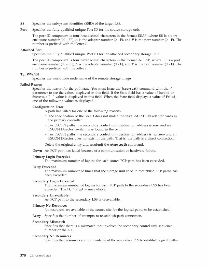
SS Specifies the subsystem identifier (SSID) of the target LSS.
Port Specifies the fully qualified unique Port ID for the source storage unit.
The port ID component is four hexadecimal characters in the format EEAP, where EE is a portenclosure number (00 - 3F), A is the adapter number (0 - F), and P is the port number (0 - F). Thenumber is prefixed with the letter I.
Attached PortSpecifies the fully qualified unique Port ID for the attached secondary storage unit.
The port ID component is four hexadecimal characters in the format 0xEEAP, where EE is a portenclosure number (00 - 3F), A is the adapter number (0 - F), and P is the port number (0 - F). Thenumber is prefixed with the letter I.
Tgt WWNNSpecifies the worldwide node name of the remote storage image.
Failed ReasonSpecifies the reason for the path state. You must issue the lspprcpath command with the -lparameter to see the values displayed in this field. If the State field has a value of Invalid orSuccess, a " - " value is displayed in this field. When the State field displays a value of Failed,one of the following values is displayed:
Configuration ErrorA path has failed for one of the following reasons:v The specification of the SA ID does not match the installed ESCON adapter cards in
the primary controller.v For ESCON paths, the secondary control unit destination address is zero and an
ESCON Director (switch) was found in the path.v For ESCON paths, the secondary control unit destination address is nonzero and an
ESCON Director does not exist in the path. That is, the path is a direct connection.
Delete the original entry and resubmit the mkpprcpath command.
Down An FCP path has failed because of a communication or hardware failure.
Primary Login ExceededThe maximum number of log ins for each source FCP path has been exceeded.
Retry ExceededThe maximum number of times that the storage unit tried to reestablish FCP paths hasbeen exceeded.
Secondary Login ExceededThe maximum number of log ins for each FCP path to the secondary LSS has beenexceeded. The FCP target is unavailable.
Secondary UnavailableAn FCP path to the secondary LSS is unavailable.
Primary No ResourcesNo resources are available at the source site for the logical paths to be established.
Retry Specifies the number of attempts to reestablish path connection.
Secondary MismatchSpecifies that there is a mismatch that involves the secondary control unit sequencenumber or the LSS.
Secondary No ResourcesSpecifies that resources are not available at the secondary LSS to establish logical paths.
378 CLI User's Guide

Secondary LSS MismatchSpecifies that there is a mismatch of the secondary control unit LSS ID or a failure of theI/O that collects secondary information for validation.
TimeoutSpecifies that a timeout has occurred. No reason is available.
Not Properly ConfiguredSpecifies that the primary Fibre Channel adapter is not configured properly, or it is notloaded with the correct version of microcode.
Secondary Not PPRC CapableSpecifies that the Fibre Channel path from secondary adapter is not capable of processinga remote mirror and copy path. This can occur from one of the following reasons:v The secondary adapter is not configured properly, or it is not loaded with the correct
version of microcode.v The secondary adapter is already a target of 32 different storage units.
ESCON Channel DirectionSpecifies that the primary control unit port or link cannot be converted to channel modebecause a logical path is already established on the port or link. The establish pathoperations are not automatically retried within the control unit.
ESCON Initialization FailedSpecifies that initialization for the ESCON protocol has failed.
ESCON Link OfflineSpecifies that the ESCON link is offline. This is caused by the lack of light detectioncoming from a host, peer, or switch.
Path Degraded Due to High Failure RateIndicates that a Fibre Channel path is established; however, because of the high failurerate, the path is degraded.
Path Removed Due to High Failure RateIndicates that the Fibre Channel path link has been removed because the path hasexperienced a high failure rate.
System Reserved PathIndicates that the system has reserved resources for a remote mirror and copy path, forexample, after a failoverpprc or a freezepprc command is used. The resources can beused later, such as for the failbackpprc command. In most cases, no action is required. Ifit is known that a system reserved path is not required, it can be removed with thermpprcpath command only after there are no remote mirror and copy pairs remainingbetween the LSSs.
PPRC CGDisplays the status of the PPRC consistency group. You must issue the lspprcpath commandwith the -l parameter to see the values displayed in this field. One of the following values can bedisplayed:
EnabledIndicates that the remote mirror and copy consistency group is enabled.
DisabledIndicates that the remote mirror and copy consistency group is disabled.
mkesconpprcpathThe mkesconpprcpath command creates a remote mirror and copy (formerly PPRC) path between sourceand target logical subsystems over an ESCON connection.
Chapter 4. CLI commands 379

The command allows you to specify ESCON direct and ESCON switch connections. Use this commandonly with IBM System Storage Enterprise Storage Servers (2105, Model 800 and Model 750).
�� mkesconpprcpath-dev storage_image_ID -remotedev storage_image_ID
�
�-remotewwnn WWNN
-srclss Source_LSS_ID-srcss ss_ID
-tgtlss Target_LSS_ID �
�-tgtss ss_ID -consistgrp -force
�
� Source_Port_ID:Target_Port_ID. . .
" - "
��
Parameters
Notes:
1. The mkesconpprcpath command is applicable only for the IBM System Storage EnterpriseStorage Server (2105, Model 800 and Model 750). DS8000 models and DS6000 models supportonly Fibre Channel connections.
2. When you specify a switch port ID as the target port, specify the outgoing port that isconnected to the remote ESS and not to the incoming port that is connected to the local ESS.
-dev storage_image_ID(Optional). Specifies the storage image ID, which consists of manufacturer, machine type, and serialnumber. The storage image ID is required if you do not specify a fully qualified source LSS ID, donot set the devid variable in your profile or through the setenv command, and the HMC is aware ofmore than one storage image. Using the -dev parameter will temporarily override any defined valuefor devid for the current command.
Example: IBM.2105-FA120
-remotedev storage_image_ID(Optional). Specifies the remote storage image ID, which consists of manufacturer, machine type, andserial number. This parameter is required if you do not fully qualify the target LSS ID.
Example: IBM.2105-FA150
-srclss Source_LSS_ID(Required). Specifies the source logical subsystem (LSS) ID. Accepts a fully qualified LSS ID, whichincludes the storage image ID or a shortened version without the storage image ID, if the -devparameter is used. The fully qualified LSS ID format is storage_image_ID/xx, where 'xx' is ahexadecimal number in the range '00 - FE'.
-srcss ss_ID(Optional). Specifies the subsystem ID of the primary logical subsystem in the format '0x0001 -0xFFFF'.
This value is required for the IBM Enterprise Storage Server versions 2.4.0 and 2.4.1.
Example: 0010
-tgtlss Target_LSS_ID(Required). Specifies the target logical subsystem (LSS) ID. Accepts a fully qualified LSS ID, whichincludes the storage image ID, or a shortened version without the storage image ID, if the -remotedevparameter is used. The fully qualified LSS ID format is storage_image_ID/xx, where 'xx' is ahexadecimal number in the range '00 - FE'.
380 CLI User's Guide

-remotewwnn WWNN(Optional). Specifies the worldwide node name. The format is a 16-hexadecimal ID.
Note: If you use this parameter, the format is checked even though there might be times that thevalue is not used.
Example: 12341234000A000F
-tgtss ss_ID(Optional). Specifies the subsystem ID of the secondary logical subsystem in the format '0x0001 -0xFFFF'.
This value is required for the IBM Enterprise Storage Server versions 2.4.0 and 2.4.1.
Example: 0010
-consistgrp(Optional). Creates a consistency group for the remote mirror and copy volume pairs that areassociated with the PPRC paths that are established by this command. A remote mirror and copyconsistency group is a set of remote mirror and copy volume pairs that have the same source andtarget LSS.
Normally, when an error occurs in a member of a remote mirror and copy volume pair, the volume isput in a suspended state. However, if the volume is participating in a consistency group, it is placed ina long busy state.
-force(Optional). Creates a new remote mirror and copy path even if the specified remote mirror and copypath already exists.
Source_Port_ID:Target_Port_ID . . . | -(Required). Establishes a remote mirror and copy path between the source and target ports for thespecified source and target logical subsystems. The source port must be an ESCON I/O port that isconfigured for point-to-point or switch topology. The source port is enabled automatically for remotemirror and copy primary I/O operations. The target port must be a switch I/O port that isconfigured for point-to-point or switch topology. The target port is enabled automatically for remotemirror and copy primary I/O operations.
Note: Do not specify a target port ID when you specify an ESCON direct connection. Instead, specifyonly the source port ID.
This parameter accepts only non-fully qualified port IDs, which does not include the storage imageID. A remote mirror and copy path port pair ID consists of two port IDs. The first is designated asthe source port and the second as the target port for the remote mirror and copy path. You mustseparate the two port IDs with a colon and no spaces. A direct ESCON I/O port ID is fourhexadecimal characters in the format EEAP, where EE is a port enclosure number '00 - 3F', A is theadapter number '0 - F', and P is the port number '0 - F'. This number is prefixed with the letter I. Aswitch ESCON I/O port ID is two hexadecimal characters in the range '00 - FF'. This number isprefixed with the letter I.
This parameter accepts up to eight remote mirror and copy path port pair IDs. You must separatemultiple port pair IDs with spaces.
If you use the dash (-), the specified value is read from standard input. You cannot use the dash (-)while you are in the DS CLI interactive command mode.
Example pair: I1A10:I20
Example of a source ESCON port and target switch port pair: I1A10:I20
Example of multiple pairs: I1A10:I20 I1A11:I21 I1A12 (the last object identifies an ESCON connection)
Chapter 4. CLI commands 381

Example (2105 use only)
Invoking the mkesconpprcpath commanddscli> mkesconpprcpath -dev IBM.2105-FA120 -remotedev IBM.2105-FA150-srclss 01 -tgtlss 01 I0100:I20 I0110:I21
The resulting outputRemote Mirror and Copy pathIBM.2105-FA120/01:IBM.2105-FA150/01 successfully created.
mkpprcpathThe mkpprcpath command establishes or replaces a remote mirror and copy (formerly PPRC) pathbetween source and target logical subsystems (LSSs) over a Fibre Channel connection.
This is the only supported connectivity for machine types 2107 and 1750. Paths can be establishedbetween the following machine types: 2105:2105, 2107:2107, 2107:1750, 2107:2105, 1750:1750, 1750:2105.
Note: Secondary ports listed for PPRC, after issuing the lsavailpprcport command, are only availablewhen configured as FCP. Secondary FICON ports, while displayed in the list, are not supported,and the DS CLI command mkpprcpath issued to a secondary FICON port will fail.
�� mkpprcpath-dev storage_image_ID -remotedev storage_image_ID
�
� -remotewwnn WWNN -srclss source_LSS_ID-srcss SS_ID
-tgtlss target_LSS_ID �
�-tgtss SS_ID -consistgrp
source_port_ID:target_port_ID. . .
" - "
��
Parameters
-dev storage_image_ID(Optional) Specifies the source storage image ID, which includes manufacturer, machine type, andserial number. The storage image ID is required if you do not specify fully qualified IDs, do not setthe devid variable in your profile or through the setenv command, and the HMC is aware of morethan one storage image. Using the -dev parameter will temporarily override any defined value fordevid for the current command.
-remotedev storage_image_ID(Optional) Specifies the ID of the secondary storage image, which includes manufacturer, machinetype, and serial number. If specified, the format of this entry might be checked for correctnessalthough the value is not used.
For DS8000, example: IBM.2107-75FA150
-remotewwnn WWNN(Required) Specifies the worldwide node name of the secondary storage image. The format is a16-hexadecimal ID.
Note: Ensure that you use the worldwide node name that is associated with the secondary storageunit. Run the lssi or showsi command to obtain this number.
Example: 12341234000A000F
-srclss source_LSS_ID(Required) Specifies the source logical subsystem ID. Use a fully qualified LSS ID, which includes thestorage image ID, or use a shortened version without the storage image ID, if the -dev parameter is
382 CLI User's Guide

used. The fully qualified LSS ID format is storage_image_ID/XX, where XX is a hexadecimal numberin the range 00 - FE for the DS8000. The DS6000 value is in the range 00 - 1F.
Example of a shortened version: 00
-srcss SS_ID(Optional) Specifies the subsystem ID of the primary logical subsystem in the format 0x0001 - 0xFFFF.
This value is required for the IBM TotalStorage Enterprise Storage Server versions 2.4.0 and 2.4.1.
Example: 0010
-tgtlss target_LSS_ID(Required) Specifies the logical subsystem ID associated with the secondary storage unit as the target.Use a fully qualified LSS ID, which includes the storage image ID. The fully qualified LSS ID formatis storage_image_ID/XX, where XX is a hexadecimal number in the range 00 - FE for the DS8000. TheDS6000 value is in the range 00 - 1F.
Example of a shortened version: 01
-tgtss SS_ID(Optional) Specifies the subsystem ID of the secondary logical subsystem in the format 0x0001 -0xFFFF.
This value is required for the IBM TotalStorage Enterprise Storage Server versions 2.4.0 and 2.4.1.
Example: 0010
-consistgrp(Optional) Creates a consistency group for the remote mirror and copy volume pairs. A remote mirrorand copy consistency group is a set of remote mirror and copy volume pairs that have the samesource and target LSS.
Normally, when an error occurs in a member of a remote mirror and copy volume pair, the storageunit places the volume in a suspended state. However, if the volume participates in a consistencygroup, it is placed in a long busy state.
source_port_ID:target_port_ID . . . | -(Required) Establishes a remote mirror and copy path between the source and target ports for thespecified source and target logical subsystems. The source and target ports must be Fibre ChannelI/O ports that are configured for point-to-point or switched fabric topology. They are enabledautomatically for remote mirror and copy secondary I/O operations. They are not enabled for FICONI/O operations.
Use fully qualified port IDs, which includes the storage image ID, or use a shortened version withoutthe storage image ID if the -dev parameter is specified. A remote mirror and copy path port pair IDconsists of two port IDs. Designate the first as the source port and the second as the target port forthe remote mirror and copy path. You must separate the two port IDs with a colon and no spaces. Aport ID is four hexadecimal characters in the format EEAP, where EE is a port enclosure number (00 -3F), A is the adapter number (0 - F), and P is the port number (0 - F). This number is prefixed withthe letter I.
This parameter accepts up to eight remote mirror and copy path port pair IDs. You must separatemultiple port pair IDs with spaces.
If you use the dash (-), the specified value is read from standard input. You cannot use the dash (-)while you are in the DS CLI interactive command mode.
Example of the shortened version: I1A10:I2A20
Example of multiple pairs: I1A10:I2A20 I1A11:I2A21 I1A12:I2A22
Chapter 4. CLI commands 383

Example
Invoking the mkpprcpath commanddscli> mkpprcpath -dev IBM.2107-75FA120-srclss 01 -tgtlss 01 –remotewwnn 12341234000A000F I0100:I0100
The resulting outputRemote Mirror and Copy path 01:01 successfully established.
rmpprcpathThe rmpprcpath command deletes a Remote Mirror and Copy path.
�� rmpprcpath-dev storage_image_ID -remotedev storage_image_ID
�
�-remotewwnn WWNN -type fcp
escon-quiet -force
�
� source_LSS_ID:target_LSS_ID. . .
"- "
��
Parameters
-dev storage_image_ID(Optional) Specifies the source storage image ID, which includes manufacturer, machine type, andserial number. The storage image ID is required if you do not specify a fully qualified source LSS ID,do not set the devid variable in your profile or through the setenv command, and the HMC is awareof more than one storage image. Using the -dev parameter will temporarily override any definedvalue for devid for the current command.
-remotedev storage_image_ID(Optional) Specifies the target storage image ID, which includes manufacturer, machine type, andserial number. This parameter is required if you do not specify a fully qualified target LSS ID or ifthe -dev parameter is used.
-remotewwnn WWNN(Optional) Specifies the secondary worldwide node name.
Note: The following considerations can help you decide whether to use this parameter:v If you do not specify this parameter, DS CLI processing requires a query for this information
from the remote device. In some cases, due to the path-specific state, the query might fail tolocate the remote WWNN. If the remote WWNN cannot be located, the rmpprcpathcommand fails. Process the lspprcpath command to obtain the remote WWNN informationand then process the rmpprcpath command with the remote WWNN information included.
v Use the lspprcpath command to obtain the remote WWNN information.
-type fcp | escon(Optional) The type of the connection over which the path was created.
fcp Fibre-channel protocol
escon (DS8000 only) Enterprise Systems Connection (IBM S/390 and System z)
-quiet(Optional) Turns off the Remote Mirror and Copy path removal confirmation prompt for thiscommand.
384 CLI User's Guide

-force(Optional) Specifies that you want to remove Remote Mirror and Copy paths even if Remote Mirrorand Copy volume pairs exist. Otherwise, specified paths that are associated with existing RemoteMirror and Copy volume pairs are not be removed.
source_LSS_ID:target_LSS_ID . . . | -(Required) Specifies the Remote Mirror and Copy path relationships for the source and target LSSsthat are to be removed. The LSS pair ID consists of two LSS IDs, one designated as the source LSSand the other as the target LSS for a Remote Mirror and Copy path relationship. The two LSS IDsmust be separated with a colon and no spaces. The first LSS ID is the source LSS. The second LSS IDis the target LSS.
This parameter accepts fully qualified LSS IDs, which includes the storage image ID, or a shortenedversion without the storage image ID if the -dev parameter is specified.
The fully qualified LSS ID format is storage_image_ID/XX, where XX is a hexadecimal number in therange 00 - FE for the DS8000. The DS6000 value is in the range 00 - 1F.
If you use the dash (-), the specified value is read from standard input. You cannot use the dash (-)while you are in the DS CLI interactive command mode.
For DS8000, example of a fully qualified pair: IBM.2107-75FA120/00:IBM.2107-75FA150/00
Example of a shortened version: 00:00
Example of multiple pairs: 00:00 01:01 02:02
Example
Invoking the rmpprcpath commanddscli> rmpprcpath -dev IBM.2107-75FA120 -remotedev IBM.2107-75FA150-remotewwnn 12341234000A000F 01:01
The resulting outputAre you sure want to remove the Remote Mirror and Copy path 01:01? [y/n]: YRemote Mirror and Copy path 01:01 successfully removed.
Remote Mirror and Copy pair commandsThis section contains commands that create, manage, and delete Remote Mirror and Copy (formerlyPPRC) pairs and display Remote Mirror and Copy pair information.
The following Remote Mirror and Copy pair commands are available:
failbackpprcCopies the required data from the source volume to the target volume to resume mirroring. Youcan use this command after a failoverpprc command has been issued to restart mirroring fromsite A (local site) to site B (remote site).
failoverpprc
Generates Global Mirror and Metro Mirror disaster recovery processes with the following results:v In a Global Mirror failover recovery process, the failoverpprc command initiates failover
processing of B volumes to A volumes.v In a Global Mirror failback recovery process (production is returned to the local site), the
failoverpprc command initiates failover processing from A volumes to B volumes.v In a Metro Mirror disaster recovery process, failover processing to the Global Copy secondary
volume causes the secondary volumes to become primary volumes and immediately suspendsthese volumes. The failoverpprc command changes a secondary device into a primarysuspended device while leaving the primary device in its current state.
Chapter 4. CLI commands 385

lspprc Generates a report that displays a list of remote mirror and copy volume relationships for astorage image and the status information for each remote mirror and copy volume relationship inthe list.
mkpprc Establishes a remote mirror and copy relationship for a volume pair.
freezepprcCreates a new remote mirror and copy consistency group. It places the source logical subsystem(LSS) in the long busy state so that no I/O can be directed to it. It also removes remote mirrorand copy paths between the source LSS and target LSS and sets the queue-full condition for theprimary volume.
pausepprcPauses an existing remote mirror and copy volume pair relationship or pauses a single volumeID.
resumepprcResumes a remote mirror and copy relationship for a volume pair.
rmpprc Removes one or more specified remote mirror and copy volume pair relationships, or it removesa single volume ID (which might be useful when a disaster occurs and you want to specify onlythe available volume and not both the primary and secondary volumes).
unfreezepprcResumes I/O activity on a storage unit where the freezepprc command has been issued. Theunfreezepprc command resets the queue full condition for the primary volume.
failbackpprcThe failbackpprc command copies the required data from the source volume to the target volume toresume mirroring.
This command is used in the disaster recovery processes that are associated with sites using MetroMirror, Global Mirror, or Metro/Global Mirror processing.
�� failbackpprc-dev storage_image_ID -remotedev storage_image_ID
�
� -type mmirgcp -cascade -tgtse -suspend -tgtonline -resetreserve
�
�-force -tgtread -disableautoresync
�
� SourceVolumeID:TargetVolumeID. . .
" - "
��
Parameters
Notes:
1. You can issue the failbackpprc command against any remote mirror and copy volume that isin a primary suspended state. The failback processing copies the required data from the sourcevolume to the target volume to resume mirroring.
2. A metro mirror (synchronous) pair must be suspended before it can be reestablished as aGlobal Copy (extended distance) pair and vice versa.
3. When you specify subsystem IDs (SSIDs), the source and target volumes are restricted to 1LSS for the source and 1 LSS for the target.
386 CLI User's Guide

-dev storage_image_ID(Optional) Specifies the source storage image ID, which includes manufacturer, machine type, andserial number. The storage image ID is required if you do not specify a fully qualified source volumeID (which includes the storage image ID, for the source volume IDs that are defined by theSource_Volume_ID:Target_Volume_ID parameter), do not set the devid variable in your profile orthrough the setenv command, and the HMC is aware of more than one storage image. Using the-dev parameter temporarily overrides any defined value for devid for the current command.
Note: The use of the failbackpprc command requires a role reversal for this parameter. The value forthis parameter must be the original primary site which has been repaired and is ready to onceagain become your primary production site. For example:v Original primary site (Site A) has a value of IBM.2107-75FA120 with volumes 0100, 0101,
0102, 0103.v Original secondary site (Site B) has a value of IBM.2107-75FA150 with volumes 0200, 0201,
0202, 0203.v The following failbackpprc command is correct:
dscli> failbackpprc -dev IBM.2107-75FA120-remotedev IBM.2107-75FA1500100:0200 0101:0201 0102:0202 0103:0203
-remotedev storage_image_ID(Optional) Specifies the target storage image ID, which includes manufacturer, type, and serialnumber. The -remotedev parameter identifies the remote storage unit that contains the target volumeIDs that are defined by the SourceVolumeID:TargetVolumeID parameter. The -remotedev parameter isrequired if you do not specify a fully qualified target volume ID or if you use the -dev parameter.
Note: The use of the failbackpprc command requires a role reversal for this parameter. The value forthis parameter must be the original secondary site. For example:v Original primary site (Site A) has a value of IBM.2107-75FA120 with volumes 0100, 0101,
0102, 0103.v Original secondary site (Site B) has a value of IBM.2107-75FA150 with volumes 0200, 0201,
0202, 0203.v The following failbackpprc command is correct:
dscli> failbackpprc -dev IBM.2107-75FA120-remotedev IBM.2107-75FA1500100:0200 0101:0201 0102:0202 0103:0203
-type mmir | gcp(Required) Modify one or more existing remote mirror and copy volume relationships as either MetroMirror (Synchronous) or Global Copy (Extended Distance) relationships.
mmir Metro Mirror maintains the remote mirror and copy relationship in a consistent manner byreturning the I/O write completion status to the application when the updates are committedto the target. This process becomes slower as the physical distance between source and targetincreases.
gcp Global Copy maintains the remote mirror and copy relationship in a nonsynchronous manner.I/O write completion status is returned to the application when the updates are committed tothe source. Updates to the target volume are performed at a later time. The original order ofupdates is not strictly maintained.
-cascade(Optional) Specifies that the remote mirror and copy target volume can also be a remote mirror andcopy source volume of a different remote mirror and copy volume relationship.
Chapter 4. CLI commands 387

-tgtse(Optional) Specifies that the PPRC secondary volume is a space efficient volume.
-suspend(Optional) Specifies that the remote mirror and copy relationship is to be suspended when the taskcompletes.
Notes:
1. This parameter is not valid for a Global Copy (Extended Distance) remote mirror and copyvolume relationship.
2. This parameter is not valid for a Metro Mirror (Synchronous) remote mirror and copyvolume relationship that is established with the No Copy option activated.
-tgtonline(Optional) Specifies that a remote mirror and copy volume relationship is to be established, includingwhen the target volume is online to host systems.
Note: This parameter applies only to S/390 or System z volumes. It does not apply to Open Systemsvolumes.
-resetreserve(Optional) Specifies that a remote mirror and copy relationship is to be established when the volumeon the secondary logical subsystem is reserved by another host. If this parameter is not specified andthe volume on the secondary logical subsystem is reserved, the command fails.
Note: This parameter applies only to fixed block volumes.
-force(Optional - DS8000 only) Specifies whether validation of the volumes involved in the establishrequest occurs or is bypassed. This parameter allows you to create a FlashCopy pair between twovolumes who had no previous relationship and ONLY copy changed tracks.
Notes:
1. This parameter can only be used as part of a Metro/Global Mirror (3-site) disasterrecovery process.
2. Only use this parameter if you are fully aware of the affect this parameter has on yourtransactions. A couple of scenarios are provided in this guide that describe a set ofcircumstances that allow you to safely use this parameter. If your circumstances do notmatch the scenarios, you are cautioned not to use this parameter unless advised to do soby IBM Technical Support.
-tgtread(Optional) Specifies that host servers be allowed to read from the remote mirror and copy targetvolume. For a host server to read the volume, the remote mirror and copy pair must be in afull-duplex state.
Note: This parameter applies only to Open System volumes.
-disableautoresync(Optional - DS8000 only) Allows you to disable the mechanism that automatically resumes asuspended Global Copy relationship. The default is not disabled. The -disableautoresync parameteris available only in Version 5 Release 3 or later.
SourceVolumeID:TargetVolumeID . . . | -(Required) Specifies the remote mirror and copy volume pair IDs for the source and target volumepairs that are to undergo failback processing. The original values (before the disaster) return with thesource volume IDs equal to the A volumes and the target volume IDs equal to the B volumes.
388 CLI User's Guide

This parameter accepts fully qualified volume IDs, which includes storage image IDs or a shortenedversion without storage image IDs if the -dev parameter is specified. You must separate multipleremote mirror and copy pair IDs with spaces.
A remote mirror and copy volume pair ID consists of two volume IDs, one designated as the sourceand the other as the target volume for a remote mirror and copy relationship. You must separate thetwo volume IDs of a remote mirror and copy pair ID with a colon and no space. The first volume IDis the source volume. The second volume ID is the target volume.
The volume ID is a 32 bit number that can be represented as 4 hexadecimal digits in the form ofXYZZ, where:
X (for DS6000 and DS8000 models)Specifies the address group, 0 - 1 for DS6000 and 0 - F for DS8000.
XY (for a DS8000 model)Specifies the logical subsystem number, 00 - FE.
XY (for a DS6000 model)Specifies the logical subsystem number, 00 - 1E.
ZZ (for DS6000 and DS8000 models)Specifies the volume number, 00 - FF.
If you use the dash (-), the specified value is read from standard input. You cannot use the dash (-)while you are in the DS CLI interactive command mode.
For DS8000, example of a fully qualified pair: IBM.2107-75FA120/0100:IBM.2107-75FA150/0100
Example of multiple pairs: 0101:0101 0102:0102 0103:0103
Example
Invoking the failbackpprc commanddscli> failbackpprc -dev IBM.2107-75FA120 -remotedev IBM.2107-75FA1500100:0100 0101:0101 0102:0102 0103:0103
The resulting outputRemote Mirror and Copy pair IBM.2107-75FA120/0100:IBM.2107-75FA150/0100successfully failed back.Remote Mirror and Copy pair IBM.2107-75FA120/0101:IBM.2107-75FA150/0101successfully failed back.Remote Mirror and Copy pair IBM.2107-75FA120/0102:IBM.2107-75FA150/0102successfully failed back.Remote Mirror and Copy pair IBM.2107-75FA120/0103:IBM.2107-75FA150/0103successfully failed back.
failoverpprcThe failoverpprc command is used only with disaster recovery processing.
This command is used in the disaster recovery processes associated with sites using Metro Mirror, GlobalMirror, or Metro/Global Mirror processing. The failoverpprc command succeeds even if the paths aredown and the volume at the production site is unavailable or nonexistent.
�� failoverpprc-dev storage_image_ID -remotedev storage_image_ID
�
� -type mmirgcp -tgtonline -cascade -force -disableautoresync
�
Chapter 4. CLI commands 389
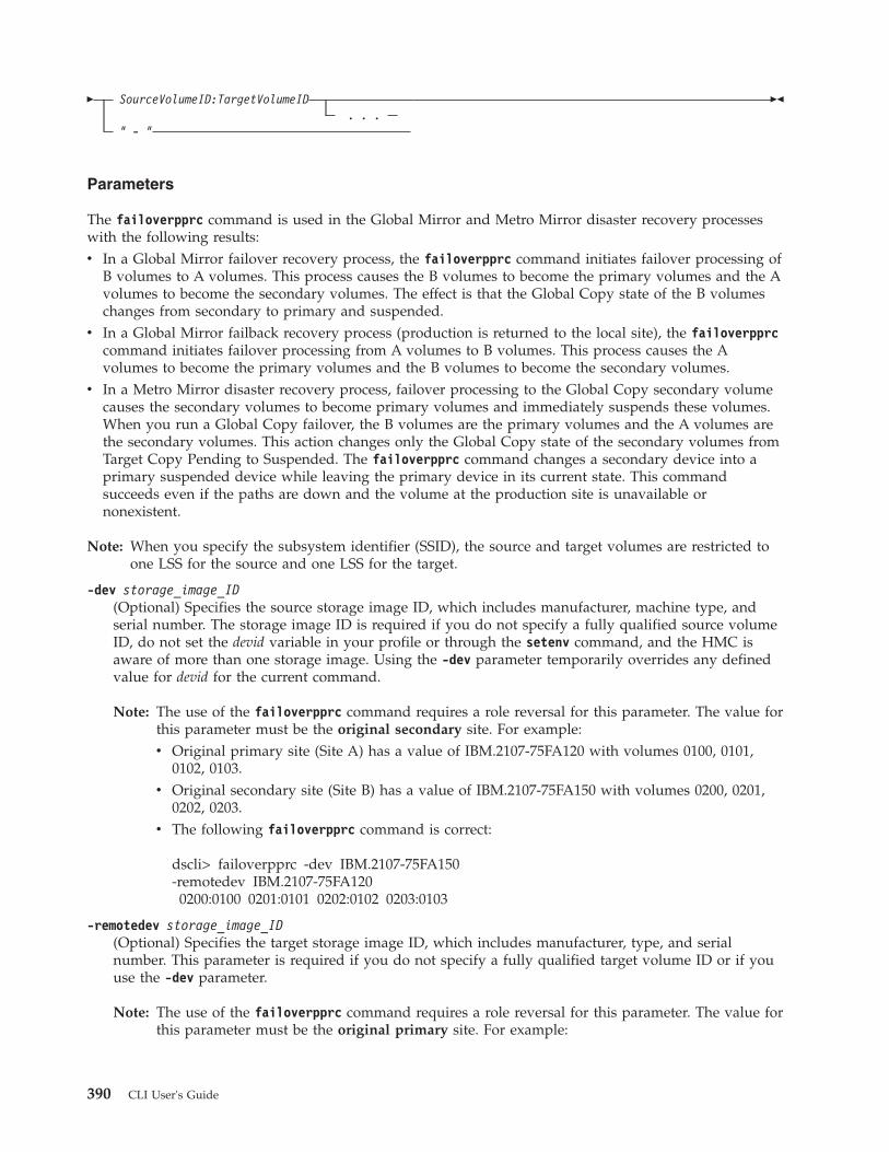
� SourceVolumeID:TargetVolumeID. . .
" - "
��
Parameters
The failoverpprc command is used in the Global Mirror and Metro Mirror disaster recovery processeswith the following results:v In a Global Mirror failover recovery process, the failoverpprc command initiates failover processing of
B volumes to A volumes. This process causes the B volumes to become the primary volumes and the Avolumes to become the secondary volumes. The effect is that the Global Copy state of the B volumeschanges from secondary to primary and suspended.
v In a Global Mirror failback recovery process (production is returned to the local site), the failoverpprccommand initiates failover processing from A volumes to B volumes. This process causes the Avolumes to become the primary volumes and the B volumes to become the secondary volumes.
v In a Metro Mirror disaster recovery process, failover processing to the Global Copy secondary volumecauses the secondary volumes to become primary volumes and immediately suspends these volumes.When you run a Global Copy failover, the B volumes are the primary volumes and the A volumes arethe secondary volumes. This action changes only the Global Copy state of the secondary volumes fromTarget Copy Pending to Suspended. The failoverpprc command changes a secondary device into aprimary suspended device while leaving the primary device in its current state. This commandsucceeds even if the paths are down and the volume at the production site is unavailable ornonexistent.
Note: When you specify the subsystem identifier (SSID), the source and target volumes are restricted toone LSS for the source and one LSS for the target.
-dev storage_image_ID(Optional) Specifies the source storage image ID, which includes manufacturer, machine type, andserial number. The storage image ID is required if you do not specify a fully qualified source volumeID, do not set the devid variable in your profile or through the setenv command, and the HMC isaware of more than one storage image. Using the -dev parameter temporarily overrides any definedvalue for devid for the current command.
Note: The use of the failoverpprc command requires a role reversal for this parameter. The value forthis parameter must be the original secondary site. For example:v Original primary site (Site A) has a value of IBM.2107-75FA120 with volumes 0100, 0101,
0102, 0103.v Original secondary site (Site B) has a value of IBM.2107-75FA150 with volumes 0200, 0201,
0202, 0203.v The following failoverpprc command is correct:
dscli> failoverpprc -dev IBM.2107-75FA150-remotedev IBM.2107-75FA1200200:0100 0201:0101 0202:0102 0203:0103
-remotedev storage_image_ID(Optional) Specifies the target storage image ID, which includes manufacturer, type, and serialnumber. This parameter is required if you do not specify a fully qualified target volume ID or if youuse the -dev parameter.
Note: The use of the failoverpprc command requires a role reversal for this parameter. The value forthis parameter must be the original primary site. For example:
390 CLI User's Guide

v Original primary site (Site A) has a value of IBM.2107-75FA120 with volumes 0100, 0101,0102, 0103.
v Original secondary site (Site B) has a value of IBM.2107-75FA150 with volumes 0200, 0201,0202,0203.
v The following failoverpprc command is correct:
dscli> failoverpprc -dev IBM.2107-75FA150-remotedev IBM.2107-75FA1200200:0100 0201:0101 0202:0102
-type mmir | gcp(Required) Modifies one or more existing remote mirror and copy volume relationships as eitherMetro Mirror or Global Copy relationships.
mmir Metro Mirror maintains the remote mirror and copy relationship in a consistent synchronousmanner when the updates are committed to the target. This process becomes slower as thephysical distance between source and target increases.
gcp Global Copy maintains the remote mirror and copy relationship in a nonsynchronous mannerwhen the updates are committed to the source. Updates to the target volume are performedat a later time. The original order of updates is not strictly maintained.
-tgtonline(Optional) Establishes a remote mirror and copy volume relationship, including when the targetvolume is online to host systems.
This parameter applies to S/390 or System z volumes. It does not apply to Open Systems volumes.
-cascade(Optional) Specifies that the PPRC target volume can also be a PPRC source volume of a differentPPRC volume relationship.
-force(Optional - DS8000 only) Specifies whether validation of the volumes that are involved in theestablish request occurs or is bypassed. This parameter allows you to create a FlashCopy pairbetween two volumes that had no previous relationship and only copy changed tracks.
Notes:
1. This parameter can only be used as part of a Metro/Global Mirror (3-site) disasterrecovery process.
2. Use the -force parameter if you are fully aware of the affect that this parameter has onyour transactions. A couple of tasks are provided in this guide that describe a set ofcircumstances that allow you to safely use this parameter. If your circumstances do notmatch the scenarios, you are cautioned not to use this parameter unless advised to do soby IBM Technical Support.
-disableautoresync(Optional - DS8000 only) Allows you to disable the mechanism that automatically resumes asuspended Global Copy relationship. The default is not disabled. The -disableautoresync parameteris available only in Version 5 Release 3 or later.
SourceVolumeID:TargetVolumeID . . . | –(Required) Specifies the remote mirror and copy volume pair IDs of the source and target volumesthat must have their relationships changed so that the target volumes (B volumes) become the sourcevolumes and the original source volumes (A volumes) become the target volumes. This results in thefollowing conditions:v The source volumes (B volumes) show as a suspended host.v The target volumes (A volumes) show as a suspended target and they are accessible for mounting.
Chapter 4. CLI commands 391

This parameter also accepts fully qualified volume IDs, which includes storage image IDs or ashortened version without storage image IDs, if the -dev parameter is specified. You must separatemultiple remote mirror and copy pair IDs with spaces.
A remote mirror and copy pair ID consists of two volume IDs: one designated as the source and theother as the target volume for a remote mirror and copy relationship. You must separate the twovolume IDs of a remote mirror and copy pair ID with a colon and no space. The first volume ID isthe source volume. The second volume ID is the target volume.
The volume ID is a 32 bit number that can be represented as four hexadecimal digits in the form ofXYZZ, where:
X (for DS6000 and DS8000 models)Specifies the address group, 0 - 1 for DS6000 and 0 - F for DS8000.
XY (for a DS8000 model)Specifies the logical subsystem number, 00 - FE.
XY (for a DS6000 model)Specifies the logical subsystem number, 00 - 1E.
ZZ (for DS6000 and DS8000 models)Specifies the volume number, 00 - FF.
If you use the dash (-), the specified value is read from standard input. You cannot use the dash (-)while you are in the DS CLI interactive command mode.
For DS8000, example of a fully qualified pair: IBM.2107-75FA150/0100:IBM.2107-75FA120/0100
Example of a shortened version: 0100:0100
Example of multiple pairs: 0101:0101 0102:0102 0103:0103
Example
Invoking the failoverpprc commanddscli> failoverpprc -dev IBM.2107-75FA150 -remotedev IBM.2107-75FA1200200:0100 0201:0101 0202:0102
The resulting output
A confirmation message is presented for each remote mirror and copy pair that is successfully suspended.
lspprcThe lspprc command displays a list of remote mirror and copy (formerly PPRC) volume relationships fora storage image, and status information for each remote mirror and copy volume relationship in the list.
�� lspprc-dev storage_image_ID -remotedev storage_image_ID
�
�-state copy-pending
full-duplexsuspendedtarget-copy-pendingtarget-full-duplextarget-suspendedinvalid-statevalidation-requiredvolume-inaccessible
-s-l
�
392 CLI User's Guide
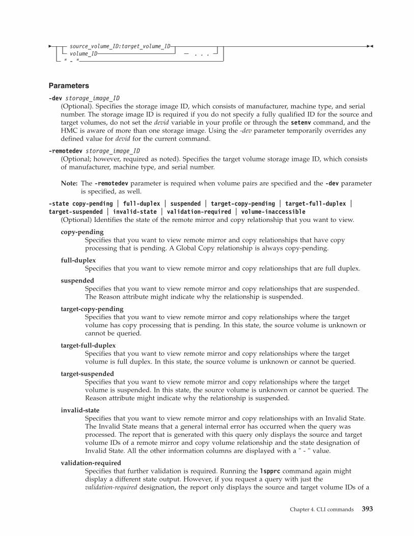
� source_volume_ID:target_volume_IDvolume_ID . . .
" - "
��
Parameters
-dev storage_image_ID(Optional). Specifies the storage image ID, which consists of manufacturer, machine type, and serialnumber. The storage image ID is required if you do not specify a fully qualified ID for the source andtarget volumes, do not set the devid variable in your profile or through the setenv command, and theHMC is aware of more than one storage image. Using the -dev parameter temporarily overrides anydefined value for devid for the current command.
-remotedev storage_image_ID(Optional; however, required as noted). Specifies the target volume storage image ID, which consistsof manufacturer, machine type, and serial number.
Note: The -remotedev parameter is required when volume pairs are specified and the -dev parameteris specified, as well.
-state copy-pending | full-duplex | suspended | target-copy-pending | target-full-duplex |target-suspended | invalid-state | validation-required | volume-inaccessible
(Optional) Identifies the state of the remote mirror and copy relationship that you want to view.
copy-pendingSpecifies that you want to view remote mirror and copy relationships that have copyprocessing that is pending. A Global Copy relationship is always copy-pending.
full-duplexSpecifies that you want to view remote mirror and copy relationships that are full duplex.
suspendedSpecifies that you want to view remote mirror and copy relationships that are suspended.The Reason attribute might indicate why the relationship is suspended.
target-copy-pendingSpecifies that you want to view remote mirror and copy relationships where the targetvolume has copy processing that is pending. In this state, the source volume is unknown orcannot be queried.
target-full-duplexSpecifies that you want to view remote mirror and copy relationships where the targetvolume is full duplex. In this state, the source volume is unknown or cannot be queried.
target-suspendedSpecifies that you want to view remote mirror and copy relationships where the targetvolume is suspended. In this state, the source volume is unknown or cannot be queried. TheReason attribute might indicate why the relationship is suspended.
invalid-stateSpecifies that you want to view remote mirror and copy relationships with an Invalid State.The Invalid State means that a general internal error has occurred when the query wasprocessed. The report that is generated with this query only displays the source and targetvolume IDs of a remote mirror and copy volume relationship and the state designation ofInvalid State. All the other information columns are displayed with a " - " value.
validation-requiredSpecifies that further validation is required. Running the lspprc command again mightdisplay a different state output. However, if you request a query with just thevalidation-required designation, the report only displays the source and target volume IDs of a
Chapter 4. CLI commands 393

remote mirror and copy volume relationship that have a designation of validation-required.All the other information columns are displayed with a " - " value.
volume-inaccessibleSpecifies that you want to view remote mirror and copy relationships where the volumecannot be viewed, this means that the volume is fenced. The report that is generated withthis query only displays the source and target volume IDs of a remote mirror and copyvolume relationship and the state designation of volume-inaccessible. All the other informationcolumns are displayed with a " - " value.
-s(Optional). Displays the remote mirror and copy volume pair IDs. You cannot use the -s and the -lparameters together.
-l(Optional). Displays the default output plus additional attributes that are identified as long output.You cannot use the -s and the -l parameters together.
SourceVolumeID:TargetVolumeID | Volume_ID . . . | –(Required) Displays the remote mirror and copy relationships for the source and target volume pairs,or for volumes with the specified IDs.
This parameter accepts fully qualified volume IDs, which includes storage image IDs or a shortenedversion without storage image IDs, if the -dev parameter is specified. You must separate multipleremote mirror and copy pair IDs with spaces.
A remote mirror and copy pair ID consists of two volume IDs: one designated as the source and theother as the target volume for a remote mirror and copy relationship. You must separate the twovolume IDs of a remote mirror and copy pair ID with a colon and no spaces. The first volume ID isthe source volume. The second volume ID is the target volume.
You can enter remote mirror and copy pair IDs, a range of remote mirror and copy pair IDs, singlevolume IDs, or a range of volume IDs. You cannot enter a combination of remote mirror and copypair IDs and volume IDs.
The volume ID is a 32 bit number that can be represented as four hexadecimal digits in the form ofXYZZ, where:
XY (for a DS8000 model)Specifies the logical subsystem number, 00 - FE.
XY (for a DS6000 model)Specifies the logical subsystem number, 00 - 1E.
ZZ (for DS6000 and DS8000 models)Specifies the volume number, 00 - FF.
X (for DS6000 and DS8000 models)Specifies the address group, 0 - 1.
If you use the dash (-), the specified value is read from standard input. You cannot use the dash (-)while you are in the DS CLI interactive command mode.
Example of a shortened version pair: 0100:0100
Example of multiple pair IDs: 0100:0100 0200:0200 0300:0300
Example of a range of pair IDs: 0100-010F:0100-010F
Example of a source or target volume ID: 0100
Example of a range of source or target volume IDs: 0100-010F
Note: A query of target volume IDs is directed to the storage image that is identified by the -devparameter or embedded in the fully qualified single volume IDs.
394 CLI User's Guide

Example
For this command and all other DS CLI list commands, the results are shown in table format to provideclarity. The actual reports do not display as tables.
The following tables represent the headers that are displayed on the output report that is associated withthe lspprc command using the -l parameter.
Invoking the lspprc commanddscli>lspprc -dev IBM.2107-75FA120 -remotedev IBM.2107-75FA150 -l 0100:01000101:0101
The resulting output
ID State Reason Type
OutOfSyncTracks
TgtRead
SrcCascade
IBM.2107-75FA120/0100:IBM.2107-75FA150/0100
Full-Duplex
- MetroMirror
0 Enabled Disabled
IBM.2107-75FA120/0101:IBM.2107-75FA150/0101
Full-Duplex
- MetroMirror
0 Enabled Disabled
TgtCascade
DateSus-pended
SourceLSS
Timeout(secs)
CriticalMode
FirstPassStatus
Incre-mentalResync
TgtWrite
Enabled - 01 120 Disabled False Enabled Enabled
Enabled - 02 120 Disabled False Enabled Enabled
GMIR CG PPRC CG isTgtSE DisableAutoResync
Disabled Disabled Unknown -
Disabled Disabled Unknown -
Report field descriptions
ID Specifies the source and target volume IDs of a remote mirror and copy volume relationship. Usethe -fullid parameter to display fully qualified IDs, which include the storage image ID.
State Displays the current remote mirror and copy volume relationship state. One of the followingvalues is displayed:
Copy PendingIndicates that the relationship is copy pending. A Global Copy (extended distance)relationship is always copy pending.
Full DuplexIndicates that the relationship is full duplex.
Chapter 4. CLI commands 395
||

SuspendedIndicates that the relationship is suspended. The Reason attribute might indicate why therelationship is suspended.
Target Copy PendingIndicates that the source volume is unknown or cannot be queried and the target state iscopy pending.
Target Full DuplexIndicates that the source volume is unknown or cannot be queried and the target state is fullduplex.
Target SuspendedIndicates that the source volume is unknown or cannot be queried and the target state issuspended.
Invalid StateIndicates that a general internal error occurred when the query was processed.
Note: The report that is generated with the Invalid State designation only displays the sourceand target volume IDs of a remote mirror and copy volume relationship and the statedesignation of Invalid State. All the other information columns are displayed with a " -" value.
Validation RequiredIndicates that the status of the volume cannot be determined at this time. Further validationis required. Sometimes, running the same lspprc command again later has different stateoutput.
Note: The report that is generated with the validation-required designation only displays thesource and target volume IDs of a remote mirror and copy volume relationship and thestate designation of validation-required. All the other information columns aredisplayed with a " - " value.
Volume InaccessibleIndicates that the volume could not be queried. This information means that the volume isfenced.
Note: The report that is generated with the Volume Inaccessible designation only displays thesource and target volume IDs of a remote mirror and copy volume relationship and thestate designation of Volume Inaccessible. All the other information columns aredisplayed with a " - " value.
ReasonIndicates why the remote mirror and copy volume relationship is suspended. The followingvalues can be displayed:
- Indicates that the volume is suspended but the reason for the suspension is not definedwithin the system
Not in PPRC RelationshipIndicates that the designated volume is not part of a remote mirror and copy pair.
Host SourceIndicates that the remote mirror and copy processing on the volume was suspended bythe primary host. The host command might have specified an immediate suspension orthat the volume is to be suspended when it entered a full duplex state.
Host TargetIndicates that remote mirror and copy processing was suspended on the secondaryvolume. Updates to primary volumes and out-of-sync tracks are still being processed.
396 CLI User's Guide

Update TargetIndicates that remote mirror and copy processing was suspended on a secondary volumeby the primary control unit update secondary device status command.
Internal Conditions BothIndicates that remote mirror and copy processing was suspended on a volume by eitherthe primary control unit or the secondary control unit because of internal conditions.
Simplex TargetSpecifies that remote mirror and copy processing was suspended on a volume when thesecondary control unit sent a state change Indicates to the primary control unit indicatinga transition to a simplex state.
Internal Conditions TargetIndicates that remote mirror and copy processing was suspended on a secondary volumewhen the primary control unit was notified that the secondary volume became suspendeddue to internal conditions.
Power®
Indicates that remote mirror and copy processing was suspended on a volume when theprimary or secondary control unit was shut down or restarted.
Notes:
1. The paths to the secondary controller might not be available if the power tothe primary controller was shut down. If only the secondary control unit wasshut down, it might be possible for the paths to be restored depending on thepath status. Use the following process to determine whether your remotemirror and copy processing can be restored on the affected volumes:a. Issue the lspprc command and use the generated report to determine the
path status.b. Issue the mkpprc command if the paths are still in tact. This process
resynchronizes the volume pairs.c. Continue with your processing.
2. If the previous process cannot be performed, you must remove the pairrelationships on the affected volumes and start your remote mirror and copyprocessing from the beginning on the affected volumes.
Freeze Indicates that remote mirror and copy processing was suspended on a volume pairbecause the host issued a Freeze PPRC Group order.
Volume Not ConfiguredIndicates that remote mirror and copy processing was suspended on a volume becausethe volume is not part of a copy pair relationship.
Remote Copy PendingIndicates that the volume transitioned to the pending state as a result of establishing aFlashCopy relationship. Before the attempt was made to establish the FlashCopyrelationship, the volume was in Full Duplex mode.
Release Space FailureIndicates that the pair is suspended due to the failure to release unused space-efficientstorage on the Remote Mirror and Copy secondary volume.
With Secondary ConsistencyIndicates that the Remote Mirror and Copy secondary volumes form a consistent data set.
Type Indicates that the remote copy and mirror volume relationship is a Metro Mirror (synchronous)relationship, a Global Copy (extended distance) relationship, or the relationship type is unknown.
Chapter 4. CLI commands 397
||

Out Of Sync TracksIndicates the number of tracks that are not synchronized for this FlashCopy relationship. Themaximum value is dependent on the source volume size.
Notes:
1. If you issue the lspprc command to view the out-of-sync value for a volume pair (forexample, 0000:0001) on a 2105, there is no observable decrease in the value from whenyou issue the query to the end of the process.
2. If you issue the lspprc command to view the out-of-sync value for a single volume(for example, 0000) on a 2105, there is an observable decrease in the value but only at10 second intervals. If you issue the lspprc command and reissue it again before the10 seconds has expired, there is no observable change in the value.
3. If you issue the lspprc command to view the out-of-sync value for a volume pair or asingle volume on a DS8000 or a DS6000, there is an observable decrease in the valuebut only at 10 second intervals.
Tgt ReadIndicates that Read I/O operations to the target volume are allowed.
Src CascadeIndicates that the source volume of this relationship is enabled to also be a target volume of adifferent relationship.
Tgt CascadeIndicates that the target volume of this relationship is enabled so that it is also a source volumefor a different relationship. No value is displayed for a DS6000 model.
Date SuspendedIndicates the date when this relationship was last suspended. The value can be displayed as a " -". No value is displayed for a DS6000 model.
SourceLSSIndicates the consistency group LSS ID that is associated with the source volume of this PPRCvolume relationship. No value is displayed for a DS6000 model.
Timeout (secs)Indicates the consistency group Long Busy Timeout setting for the LSS ID that is associated withthe source volume of this PPRC volume relationship. This value can be modified using the chlss(FB) or the chlcu (CKD) command. No value is displayed for a DS6000 model.
Critical ModeIndicates whether the remote copy and mirror primary volume represents a critical volume. Novalue is displayed for a DS6000 model.
First Pass StatusIndicates whether the first pass of Global Copy is complete. When you query the primary volumeof a Global Copy pair, True is displayed when the first pass is complete, False is displayed whenthe first pass is not yet complete, and Invalid is displayed if the pair is not Global Copy or if thesecondary was queried.
Incremental ResyncIndicates if incremental resynchronization is running. No value is displayed for a DS6000 model.
Tgt WriteIndicates whether input is allowed to the remote mirror and copy secondary volume. No value isdisplayed for a DS6000 model.
GMIR CGThe value for this field is fixed to display N/A (not available). Use the lssession command tomonitor the status of Global Mirror relationships.
398 CLI User's Guide

PPRC CGIndicates if the remote mirror and copy consistency group is enabled, disabled or not available.
Notes:
1. This value is displayed when you designate the use of the -l parameter, and when theprimary volume is being queried. If the secondary volume is being queried, the valuedisplayed for this field is N/A (not available).
2. This value is not reported for model 2105. If a model 2105 is being queried, the valuedisplayed for this field is N/A (not available).
isTgtSEIndicates whether this remote mirror and copy relationship has a space-efficient secondary.
UnknownIndicates that the space allocation method of the target is not known.
DisableAutoResyncIndicates whether the mechanism that automatically resumes a suspended Global Copyrelationship is active. No value is displayed for a DS6000 model.
mkpprcThe mkpprc command establishes a remote mirror and copy (formerly PPRC) relationship for a volumepair.
�� mkpprc-dev storage_image_ID -remotedev storage_image_ID
-type mmirgcp
�
�-mode full
nocp-cascade -tgtonline -tgtread -critmode
�
�-suspend -resetreserve -incrementalresync enable
enablenoinitdisablerecoveroverride
-tgtse�
�-disableautoresync -wait
SourceVolumeID:TargetVolumeID. . .
" - "
��
Parameters
Notes:
1. When you specify subsystem IDs, the source and target volumes are restricted to one LSS forthe source and one LSS for the target.
2. If you are using the Cisco MDS 9216 Multilayer Fabric Switch, you must not enable the writeacceleration feature. The mkpprc command might fail if the write acceleration feature isenabled.
-dev storage_image_ID(Optional) Specifies the source storage image ID, which includes manufacturer, machine type, andserial number. The storage image ID is required if you do not specify a fully qualified source volumeID, do not set the devid variable in your profile or through the setenv command, and the HMC isaware of more than one storage image. Using the -dev parameter will temporarily override anydefined value for devid for the current command.
Chapter 4. CLI commands 399

For DS8000, example: IBM.2107-75FA120
-remotedev storage_image_ID(Optional) Specifies the target storage image ID, which includes manufacturer, machine type, andserial number. This parameter is required if you do not specify a fully qualified target volume ID, orif the -dev parameter is selected.
For DS6000, example: IBM.1750-75FA120
-type mmir | gcp(Required) Establishes one or more remote mirror and copy volume relationships as either MetroMirror (synchronous) or Global Copy (extended distance) relationships.
mmir Metro Mirror maintains the remote mirror and copy relationship in a consistent(synchronous) manner by returning I/O write completion status to the application when theupdates are committed to the target. This process becomes slower as the physical distancebetween source and target increases.
gcp Global Copy maintains the remote mirror and copy relationship in a nonsynchronous manner.I/O write completion status is returned to the application when the updates are committed tothe source. Updates to the target volume are performed at a later time. The original order ofupdates is not strictly maintained.
-mode full | nocp(Optional) Specifies the following initial data copy mode for the remote mirror and copy volumerelationships:
full Full mode copies the entire source volume to the target volume. This value is the defaultwhen you do not specify the no copy mode.
nocp No Copy mode does not copy data from source to target volumes. This option presumes thatthe volumes are already synchronized.
-cascade(Optional) Enables a remote mirror and copy target volume to be a remote mirror and copy sourcevolume for a different remote mirror and copy volume relationship. The default value for thisparameter is disabled.
-tgtonline(Optional) Establishes a remote mirror and copy volume relationship, including when the targetvolume is online to host systems. This parameter applies to S/390 or System z volumes and does notapply to Open Systems volumes. The default value for this parameter is disabled.
-tgtread(Optional) Allows host servers to read from the remote mirror and copy target volume. For a hostserver to read the volume, the remote mirror and copy pair must be in a full-duplex state. Thisparameter applies to open systems volumes and does not apply to IBM S/390 or System z volumes.The default value for this parameter is disabled.
-critmode(Optional) Protects the source volume from receiving new data. If the last path fails between the pairsand results in the inability to send information to the target, the source is protected. Current updatesand subsequent attempts to update the source fail with a unit check on S/390. The default value forthis parameter is disabled.
Note: This parameter applies only to S/390 or System z volumes.
Critical mode operates in one of three ways depending on the setting of the LCU critical mode andthe setting of the -critmode parameter in this command. The following table presents an overview ofhow the critical volume mode works.
400 CLI User's Guide

Critical Mode LCU, Critical Heavy Mkpprc critmode Description
Normal Disabled or Enabled Disabled v Suspends the primaryvolume.
v Allows write operationsto the primary volume.
Critical Volume Disabled Enabled v Suspends the primaryvolume when the lastpath to the secondaryvolume has failed.
v Inhibits write operationsto the primary volume.
Critical Heavy Enabled Enabled v Suspends the primaryvolume when thesecondary volume cannotbe updated for anyreason.
v Inhibits write operationsto the primary volume.
Notes:
1. Use the -critmode parameter only for log devices, not for devices that the system requires.In extreme cases, the host system might require you to load the initial program to recovera device that is write inhibited. Whenever possible, use the freezepprc command as analternative to using the -critmode parameter.
2. The -critmode parameter cannot be used with Global Copy or remote copy and mirrorcascading volumes.
3. To reset a volume that is write inhibited because of critical mode, you can issue themkpprc, pausepprc, or rmpprc command to this volume.
4. Use automation software as part of any solution that includes critical mode. Automationsoftware is not a part of the software that is provided with the storage unit; you mustsupply it. However, IBM has offerings to assist with this automation. For moreinformation, contact your IBM storage representative.
-suspend(Optional - DS8000 only) Suspends the remote mirror and copy relationship when the task completes.This parameter is not valid for a Global Copy (extended distance) remote mirror and copy volumerelationship. This parameter is not valid for a Metro Mirror (synchronous) remote mirror and copyvolume relationship that is established with the No Copy option. The default value for this parameteris disabled.
-resetreserve(Optional - open system volumes only) Allows the establishment of a remote mirror and copyrelationship when the volume on the secondary logical subsystem is reserved by another host. Thisparameter can only be used with open system volumes. If this option is not specified and the volumeon the secondary logical subsystem is reserved, the command fails.
-incrementalresync enable | enablenoinit | disable | recover | override(Required for three-site Metro/Global Mirror recovery - DS8000 only) Specifies the resynchronizationmethod used in a three-site Metro/Global Mirror disaster recovery configuration. A three-siteMetro/Global Mirror configuration usually involves: Site A (local site), which contains the productionvolumes (or the A volumes); Site B (intermediate site), which contains the B volumes and a local,synchronous copy; and Site C (remote site), which contains the C volumes and an asynchronous copythat is located remotely from sites A and B.
Chapter 4. CLI commands 401

You can specify the following options when you first establish volume pairs using the mkpprccommand or on established volume pairs using this command.
enableSpecifies that change recording features be created on each of the primary Metro Mirrorvolumes to enable the microcode to monitor and track data in a Metro/Global Mirrorconfiguration. This is data that has been written to the primary volumes but has not beensecured on the remote site volumes.
enablenoinitSpecifies that the change recording features are not created or started on the primary MetroMirror volumes in a Metro/Global Mirror configuration. Only use this option in specificrecovery scenarios.
disableSpecifies that the current incremental resynchronization function be stopped on the primaryvolumes of the Metro Mirror volume pairs.
recoverSpecifies that a new Global Mirror volume pair be established using an existing primaryMetro Mirror (A) volume at the local site and a secondary Global Copy (C) volume at theremote site. When this command processes, only changes to the local Metro Mirror volumesare copied to the volumes at the remote site.
Note: When you specify this option, the system verifies that the failed secondary volumes forthe volumes in a Metro Mirror relationship are the primary volumes for the volumes ina Global Copy relationship and that the specified volumes have the intermediatevolumes in common. That is, the primary specified volumes are the A volumes and thesecondary specified volumes are the C volumes in a Metro/Global Mirrorconfiguration.
overrideSpecifies that a new Global Mirror volume pair be established using an existing primaryMetro Mirror (A) volume at the local site and a secondary Global Copy (C) volume at theremote site. When this command processes, only changes to the local Metro Mirror volumesare copied to the volumes at the remote site.
Note: When you specify this option, there is no validation to ensure the secondaryrelationship in this configuration before processing the mkpprc command. Therefore,you must ensure that the primary specified volumes are the A volumes and thesecondary specified volumes are the C volumes in a Metro/Global Mirrorconfiguration.
-tgtse(Optional - DS8000 only) Specifies that the secondary volume might be a space-efficient logicalvolume.
-disableautoresync(Optional - DS8000 only) Allows you to disable the mechanism that automatically resumes asuspended Global Copy relationship. The default is not disabled. The -disableautoresync parameteris available only in Version 5 Release 3 or later.
-wait(Optional) Delays the command response until the remote copy and mirror volumes are in one of thefinal states: simplex, full duplex, suspended, secondary full duplex, secondary suspended orsecondary simplex (until the pair is not in the Copy Pending state). The default value for thisparameter is disabled.
Notes:
1. This parameter cannot be used with the -type gcp or -mode nocp parameters.
402 CLI User's Guide

2. When you use the -wait parameter, you must wait until the original command completelyprocesses before you can issue a new command.
3. If you are running in single-shot mode, you can periodically issue the lspprc command tocheck the remote mirror and copy volume pair state, and then continue with newcommands when the correct state is reached.
SourceVolumeID:TargetVolumeID . . . | -(Required) Specifies the remote mirror and copy volume relationship for the source and targetvolume pairs with the specified IDs.
This parameter accepts fully qualified volume IDs, which includes storage image IDs or a shortenedversion without storage image IDs, if the -dev parameter is specified. You must separate multipleremote mirror and copy pair IDs with spaces.
A remote mirror and copy pair ID consists of two volume IDs: one designated as the source and theother as the target volume for a remote mirror and copy relationship. You must separate the twovolume IDs of a remote mirror and copy pair IDs with a colon and no space. The first volume ID isthe source volume. The second volume ID is the target volume.
The volume ID is a 32 bit number that can be represented as 4 hexadecimal digits in the form ofXYZZ, where:
XY (for a DS8000 model)Specifies the logical subsystem number, 00 - FE.
XY (for a DS6000 model)Specifies the logical subsystem number, 00 - 1E.
ZZ (for DS6000 and DS8000 models)Specifies the volume number, 00 - FF.
X (for DS6000 and DS8000 models)Specifies the address group, 0 - 1.
If you use the dash (-), the specified value is read from standard input. You cannot use the dash (-)while you are in the DS CLI interactive command mode.
For DS8000, example of a fully qualified pair: IBM.2107-75FA120/0100:IBM.2107-75FA150/0100
Example of a shortened version: 0100:0100
Example of multiple pairs: 0101:0101 0102:0102 0103:0103
Additional processing tips
The following examples represent some CLI volume format options that you might want to incorporatein your processing:
Processing multiple volumesThe following two examples are ways that this environment might be processed, and both arecorrect. The first method might be fine if you were managing a few volumes, while the secondallows you to process hundreds or thousands of volumes more efficiently.v mkpprc -dev IBM.1750-13AB79A -remotedev IBM.1750-13AB76A –type mmir
-mode full -tgtread 1000:1205 1001:1206 1002:1207 1003:1208 1004:1209....... and so on
v mkpprc -dev IBM.1750-13AB79A -remotedev IBM.1750-13AB76A –type mmir-mode full -tgtread 1000-1004:1205-1209
Using the grouping method in your commandYou can also group the volumes. However, the order of the volumes is critical when you groupthem, and they must be contiguous. The following shows how to code for grouping:mkpprc -dev IBM.1750-13AB79A -remotedev IBM.1750-13AB76A –type mmir-mode full -tgtread 1000-1004:1205-1209 1100-1104:1300-1304
Chapter 4. CLI commands 403

Example
Invoking the mkpprc commanddscli>mkpprc -dev IBM.2107-75FA120-remotedev IBM.2107-75FA1500100:0100 -type mmir 2100-2107:2100-2107
The resulting output (an example only)CMUC00153I mkpprc: Remote Mirror and Copy volume pair relationship2100:2100 successfully created.
CMUC00153I mkpprc: Remote Mirror and Copy volume pair relationship2101:2101 successfully created.
CMUC00153I mkpprc: Remote Mirror and Copy volume pair relationship2102:2102 successfully created.
CMUC00153I mkpprc: Remote Mirror and Copy volume pair relationship2103:2103 successfully created.
dscli> mkpprc -dev IBM.2107--75FA120-remotedev IBM.2107--75FA150 -type gcp -incrementalresync enablenoinit -mode nocp2100-2107:2100-2107
The resulting output (an example only)CMUC00153I mkpprc: Remote Mirror and Copy volume pair relationship 2100:2100successfully created.
CMUC00153I mkpprc: Remote Mirror and Copy volume pair relationship 2101:2101successfully created.
CMUC00153I mkpprc: Remote Mirror and Copy volume pair relationship 2102:2102successfully created.
CMUC00153I mkpprc: Remote Mirror and Copy volume pair relationship 2103:2103successfully created.
freezepprcThe freezepprc command creates a new remote mirror and copy consistency group.
It places the source logical subsystem (LSS) in the long busy state so that no I/Os can be directed to it. Italso removes remote mirror and copy paths between the source LSS and target LSS and sets the queue fullcondition for the primary volume. This causes the host to queue writes to the primary volume until thequeue full condition is reset. During the queue full condition, the primary volume reports long busy status.
�� freezepprc-dev storage_image_ID -remotedev storage_image_ID
�
� Source_LSS_ID:Target_LSS_ID. . .
" - "
��
Parameters
Note: When specifying SSIDs, the command is limited to one LSS pair.
-dev storage_image_ID(Optional). Specifies the source storage image ID, which includes manufacturer, machine type, andserial number. The storage image ID is required if you do not specify a fully qualified LSS ID, do notset the devid variable in your profile or through the setenv command, and the HMC is aware of morethan one storage image. Using the -dev parameter will temporarily override any defined value fordevid for the current command.
For DS8000, example: IBM.2107-75FA120
404 CLI User's Guide

-remotedev storage_image_ID(Optional). Specifies the target storage image ID, which includes manufacturer, type, and serialnumber. This parameter is required if you do not specify a fully qualified target LSS ID or if the -devparameter is used.
For DS6000, example: IBM.1750-68FA150
Source_LSS_ID:Target_LSS_ID . . . | -(Required). Specifies that a consistency group for the source and target LSSs with the IDs specified beplaced in a long busy state. Accepts fully qualified LSS IDs, which includes the storage image ID, ora shortened version without the storage image ID if the -dev parameter is specified.
A remote mirror and copy path LSS pair ID consists of two LSS IDs, one designated as the sourceLSS and the other as the target LSS for a remote mirror and copy path relationship. The two LSS IDsmust be separated with a colon and no spaces. The first LSS ID is the source LSS. The second LSS IDis the target LSS.
The fully qualified LSS ID format is storage_image_ID/xx, where xx is a hexadecimal number in therange 00 - FE for the DS8000. The DS6000 value is in the range 00 - 1F.
If you use the dash (-), the specified value is read from standard input. You cannot use the dash (-)while you are in the DS CLI interactive command mode.
Example of a pair: 00:00
Example of multiple pairs: 00:00 01:01 02:02
Example
Invoking the freezepprc commanddscli>freezepprc -dev IBM.2107-75FA120-remotedev IBM.2107-75FA150 01:01
The resulting outputRemote Mirror and Copy consistency group 01:01 successfully created.
pausepprcThe pausepprc command pauses an existing Remote Mirror and Copy volume pair relationship or pausesa single volume ID.
To use this command with a single volume, you must specify either the -at src parameter option or the-at tgt parameter option. If neither of these options are specified in the command, single volumes are notvalid.
�� pausepprc-dev storage_image_ID -remotedev storage_image_ID
�
�-at src
tgt-unconditional
SourceVolumeID:TargetVolumeID. . .
" - "
��
Parameters
Note: When you specify SSIDs, the command is limited to one LSS pair.
-dev storage_image_ID(Optional). Specifies the source storage image ID, which includes manufacturer, machine type, andserial number. The storage image ID is required if you do not specify a fully qualified source volume
Chapter 4. CLI commands 405

ID, do not set the devid variable in your profile or through the setenv command, and the HMC isaware of more than one storage image. Using the -dev parameter temporarily overrides any definedvalue for devid for the current command.
Example of a fully qualified storage image ID: IBM.2107-75FA120.
-remotedev storage_image_ID(Optional most times). Specifies the target storage image ID, which includes manufacturer, machinetype, and serial number.
Note: The -remotedev parameter is required when volume pairs are specified and the -dev parameteris specified, as well.
-at src | tgt(Optional). Specifies that you want to initiate a suspend action from either the source volume or thetarget volume.
src Initiates a suspend action from the source volume. After the task successfully runs, the sourceand target volumes are in the suspend state.
The -at src parameter option can also be used with single volumes. When you specify asingle volume using this option, the volume is treated as a source and the target is treated asa null.
tgt Initiates a suspend action from the target volume. After the command successfully runs, thetarget volume is in the suspend state, but there is no guarantee that the source volume issuspended as well. For a suspend action that is issued to the target, the source can remain inthe active state.
The -at tgt parameter option can also be used with single volumes. When you specify asingle volume using this parameter option, the volume is treated as a target and the source istreated as a null.
Notes:
1. If you specify the -at tgt or -at src parameter and the -unconditional parameter, thevalue for the -remotedev parameter is ignored.
2. If you specify the -at tgt parameter and do not specify the -unconditional parameter, thevalues for the -dev and SourceVolumeID parameters are ignored.
3. If you specify the -at src parameter and do not specify the -unconditional parameter, thevalues for the -remotedev and TargetVolumeID parameters are ignored.
-unconditional(Optional). Specifies that a source or target volume has been selected individually, and not as a pair.The -unconditional parameter is valid only if the -at parameter is selected. Do not use volume pairIDs.
Notes:
1. The source volume ID must be specified when you specify the -at src parameter.2. The target volume ID must be specified when you specify the -at tgt parameter.
SourceVolumeID:TargetVolumeID . . . | –(Required). Specifies that a Remote Mirror and Copy volume relationship for the source and targetvolume pairs with the specified IDs are to be paused.
Note: Provide a single volume ID instead of a volume pair if you use the -unconditional parameter.Specifying pairs results in a format error.
This parameter accepts fully qualified volume IDs, which includes storage image IDs, or a shortenedversion without storage image IDs if the -dev parameter is specified. You must separate multipleremote mirror and copy pair IDs with spaces.
406 CLI User's Guide

A Remote Mirror and Copy pair ID consists of two volume IDs, one designated as the source and theother as the target volume for a Remote Mirror and Copy relationship. You must separate the twovolume IDs of a remote mirror and copy pair ID with a colon and no space. The first volume ID isthe source volume. The second volume ID is the target volume.
The volume ID is a 32-bit number that can be represented as four hexadecimal digits in the form ofXYZZ, where:
XY (for a DS8000 model)Specifies the logical subsystem number, 00 - FE.
XY (for a DS6000 model)Specifies the logical subsystem number, 00 - 1E.
ZZ (for DS6000 and DS8000 models)Specifies the volume number, 00 - FF.
X (for DS6000 and DS8000 models)Specifies the address group, 0 - 1.
If you use the dash (-), the specified value is read from standard input. You cannot use the dash (-)while you are in the DS CLI interactive command mode.
Note: Requests directed to target volumes are sent to the Storage Image identified by the -devparameter or is embedded in the fully qualified single volume IDs.
For DS8000, example of a fully qualified pair: IBM.2107-75FA120/0100:IBM.2107-75FA150/0100
Example of a shortened version: 0100:0100
Example of multiple pairs: 0101:0101 0102:0102 0103:0103
Example
Invoking the pausepprc commanddscli> pausepprc -dev IBM.2107-75FA120-remotedev IBM.2107-75FA150 0100:0100
The resulting outputRemote Mirror and Copy pair IBM.2107-75FA120/0100:0103successfully paused.
resumepprcThe resumepprc command resumes a remote mirror and copy (formerly PPRC) relationship for a volumepair.
�� resumepprc-dev storage_image_ID -remotedev storage_image_ID
-type mmirgcp
�
�-cascade -tgtonline -tgtread -critmode -suspend -resetreserve
�
�-tgtse -disableautoresync -wait
SourceVolumeID:TargetVolumeID. . .
" - "
��
Parameters
Notes:
Chapter 4. CLI commands 407

1. When you specify subsystem IDs, the source and target volumes are restricted to one LSS forthe source and one LSS for the target.
2. When you use the -wait parameter, periodically issue the lspprc command. This commandallows you to verify which of the states that the pair has reached during processing.
3. You cannot issue other commands while the -wait parameter is processing. The entiretransaction must complete before you can proceed with commands other than statuscommands like list commands or show commands.
-dev storage_image_ID(Optional) Specifies the source storage image ID, which includes manufacturer, machine type, andserial number. The storage image ID is required if you do not specify a fully qualified source volumeID, do not set the devid variable in your profile or through the setenv command, and the HMC isaware of more than one storage image. Using the -dev parameter will temporarily override anydefined value for devid for the current command.
-remotedev storage_image_ID(Optional) Specifies the target storage image ID, which includes manufacturer, machine type, andserial number. This parameter is required if you do not specify a fully qualified target volume ID orif you specify the -dev parameter.
-type mmir | gcp(Required) Modifies one or more remote mirror and copy volume relationships to be either MetroMirror (synchronous) or Global Copy (extended distance) relationships.
mmir Metro Mirror processing maintains the remote mirror and copy relationship in a consistent(synchronous) manner when the updates are committed to the target. This process becomesslower as the physical distance between source and target increases.
gcp Global Copy processing maintains the remote mirror and copy relationship in anonsynchronous manner when the updates are committed to the source. Updates to the targetvolume are performed at a later point in time. The original order of updates is not strictlymaintained.
-cascade(Optional) Enables a remote mirror and copy target volume to be a remote mirror and copy sourcevolume for a different remote mirror and copy volume relationship.
-tgtonline(Optional) Establishes a remote mirror and copy volume relationship, including when the targetvolume is online to host systems. This parameter applies to S/390 or System z volumes. It does notapply to Open Systems volumes.
-tgtread(Optional) Allows host servers to read from the remote mirror and copy target volume. For a hostserver to read the volume, the remote mirror and copy pair must be in a full-duplex state. Thisparameter applies to open systems volumes and does not apply to S/390 or System z volumes. Thedefault value for this parameter is disabled.
-critmode(Optional) Protects the source volume from receiving new data. If the last path fails between thepairs, which results in the inability to send information to the target, the source is protected. Currentupdates and subsequent attempts to update the source fail, with a unit check on S/390.
-suspend(Optional) Specifies that the remote mirror and copy relationship be suspended when the taskcompletes. This parameter is not valid for a Global Copy (extended distance) remote mirror and copyvolume relationship. This parameter is not valid for a Metro Mirror (synchronous) remote mirror andcopy volume relationship that is established with the No Copy option.
-resetreserve(Optional) Establishes the remote mirror and copy relationship when the volume on the secondary
408 CLI User's Guide

logical subsystem is reserved by another host. If this parameter is not specified and the volume onthe secondary logical subsystem is reserved, the command fails.
This parameter can only be used with fixed block volumes.
-tgtse(Optional - DS8000 only) Specifies that the secondary volume might be a space-efficient logicalvolume.
-disableautoresync(Optional - DS8000 only) Allows you to disable the mechanism that automatically resumes asuspended Global Copy relationship. The default is not disabled. The -disableautoresync parameteris available only in Version 5 Release 3 or later.
-wait(Optional). Specifies that the command response be delayed until the remote copy and mirrorvolumes are in one of the final states: simplex, full duplex, suspended, secondary full duplex,secondary suspended or secondary simplex (until the pair is not in the Copy Pending state). Thisparameter cannot be used with the -type gcp or -mode nocp parameters.
SourceVolumeID:TargetVolumeID . . . | -(Required) Specifies that a remote mirror and copy volume relationship for the source and targetvolume pairs with the specified IDs be resumed.
This parameter accepts fully qualified volume IDs, which includes storage image IDs or a shortenedversion without storage image IDs, if the -dev parameter is specified. You must separate multipleremote mirror and copy pair IDs with spaces.
A remote mirror and copy pair ID consists of two volume IDs: one designated as the source and theother as the target volume for a remote mirror and copy relationship. You must separate the twovolume IDs of a remote mirror and copy pair ID with a colon and no space. The first volume ID isthe source volume. The second volume ID is the target volume.
The volume ID is a 32-bit number that can be represented as 4 hexadecimal digits in the form ofXYZZ, where:
XY (for a DS8000 model)Specifies the logical subsystem number, 00 - FE.
XY (for a DS6000 model)Specifies the logical subsystem number, 00 - 1E.
ZZ (for DS6000 and DS8000 models)Specifies the volume number, 00 - FF.
X (for DS6000 and DS8000 models)Specifies the address group, 0 - 1.
If you use the dash (-), the specified value is read from standard input. You cannot use the dash (-)while you are in the DS CLI interactive command mode.
Example
Invoking the resumepprc commanddscli>resumepprc -dev IBM.2107-75FA120-remotedev IBM.2107-75FA150 0100:0100
The resulting outputRemote Mirror and Copy volume pair IBM.2107-75FA120/0100:0103relationship successfully resumed. This message is being returnedbefore the copy completes.
Chapter 4. CLI commands 409

rmpprcThe rmpprc command removes a Remote Mirror and Copy volume pair relationship or removes a singlevolume ID.
You can remove a single volume ID when a disaster occurs, which allows you to specify only theavailable volume and not both the primary and secondary volumes. You must specify either the -at srcparameter option or the -at tgt parameter option when you process a single volume. If neither of theseoptions are specified in the rmpprc command, a single volume cannot be processed. The -unconditionalparameter must also be specified when you process a single volume; otherwise, an error occurs and thecommand process fails.
�� rmpprc-dev storage_image_ID -remotedev storage_image_ID -at src
tgt
�
�-unconditional -quiet
SourceVolumeID:TargetVolumeID. . .
" - "
��
Parameters
Notes:
1. When you specify subsystem IDs, the source and target volumes are restricted to one LSS forthe source and one LSS for the target.
2. If there is a communication problem between the primary server and the secondary server(two-site configuration) when the rmpprc command is issued, the following actions occur:v Error message CMUN03012E is issued. This error message indicates that there was a
communication problem between the primary and secondary server and that the transactionhas failed. However, a partial removal of the pair relationship has occurred.
v The pair relationship is ended on either the primary volumes or the secondary volumes andthe volumes that had the relationship removed enter a simplex state. If a volume is in asimplex state, the volume is not in a Copy Services relationship.
If this circumstance has occurred, reissue the rmpprc command using the -at src or the -at tgtparameter and the -unconditional parameter for each volume that does not have its pairrelationship removed.The following represents the format of the rmpprc command when you must remove a partialpair relationship:v If the source volume has not been removed from the pair relationship, enter the rmpprc
command at the dscli command prompt with the following parameters and variables:dscli>rmpprc -dev storage_image_ID -at src-unconditional SourceVolumeID
v If the target volume has not been removed from the pair relationship, enter the rmpprccommand at the dscli command prompt with the following parameters and variables:dscli>rmpprc -dev storage_image_ID -at tgt-unconditional TargetVolumeID
The value of the storage image ID must be the secondary server.The management console must be able to communicate with the secondary server for thiscommand to process successfully.
3. If a disaster occurs involving a three-site configuration, the rmpprc command with the -at tgtand -unconditional parameters are used in the recovery process.
-dev storage_image_ID(Optional). Specifies the source storage image ID, which includes manufacturer, machine type, and
410 CLI User's Guide

serial number. The storage image ID is required if you do not specify a fully qualified ID for allsource volumes, do not set the devid variable in your profile or through the setenv command, and theHMC is aware of more than one storage image. Using the -dev parameter temporarily overrides anydefined value for devid for the current command.
For DS8000, example: IBM.2107-75FA120
-remotedev storage_image_ID(Optional most times). Specifies the target storage image ID, which includes manufacturer, machinetype, and serial number.
Note: The -remotedev parameter is required when volume pairs are specified and the -dev parameteris specified, as well.
For DS6000, example: IBM.1750-68FA150
-at src | tgt(Optional). Specifies that you want to initiate a break action from either a source volume or a targetvolume.
src Select the -at src parameter option to initiate a break action from the source volume. Afterthe task successfully runs, the source and target volumes are in the simplex state.
tgt Select the -at tgt parameter option to initiate a break action from the target volume. After thecommand successfully runs, the target volume is in the simplex state, but there is noguarantee that the source volume state will change. For a break action issued to the target,the source can remain in the suspend state.
The -at tgt parameter option can also be used with single volumes but you must also specifythe -unconditional parameter. When you specify a single volume using this parameter, thevolume is treated as a target and the source is treated as a null.
Notes:
1. If you specify the -at tgt or -at src parameter and the -unconditional parameter, thevalue for the -remotedev parameter is ignored.
2. If you specify the -at tgt parameter and do not specify the -unconditional parameter, thevalues for the -dev and SourceVolumeID parameters are ignored.
3. If you specify the -at src parameter and do not specify the -unconditional parameter, thevalues for the -remotedev and TargetVolumeID parameters are ignored.
-unconditional(Optional). Specifies that a source or target volume has been selected individually, and not as a pair.The -unconditional parameter is valid only if the -at parameter is selected. Do not use volume pairIDs.
Notes:
1. The source volume ID must be specified when you specify the -at src parameter.2. The target volume ID must be specified when you specify the -at tgt parameter.
-quiet(Optional). Turns off the Remote Mirror and Copy relationship removal confirmation prompt for thiscommand.
SourceVolumeID:TargetVolumeID . . . | -(Required). Specifies the Remote Mirror and Copy volume relationship for the source and targetvolume pairs that is to be removed.
Note: Provide a single volume ID instead of a volume pair if you use the -unconditional parameter.Specifying pairs results in a format error.
Chapter 4. CLI commands 411

This parameter accepts fully qualified volume IDs, which includes storage image IDs or a shortenedversion without storage image IDs, if the -dev parameter is specified. You must separate multipleRemote Mirror and Copy pair IDs with spaces.
A Remote Mirror and Copy pair ID consists of two volume IDs, one designated as the source and theother as the target volume for a Remote Mirror and Copy relationship. You must separate the twovolume IDs of a Remote Mirror and Copy pair ID with a colon and no space. The first volume ID isthe source volume. The second volume ID is the target volume.
The volume ID is a 32-bit number that can be represented as four hexadecimal digits in the form ofXYZZ, where:
XY (for a DS8000 model)Specifies the logical subsystem number, 00 - FE.
XY (for a DS6000 model)Specifies the logical subsystem number, 00 - 1E.
ZZ (for DS6000 and DS8000 models)Specifies the volume number, 00 - FF.
X (for DS6000 and DS8000 models)Specifies the address group, 0 - 1.
If you use the dash (-), the specified value is read from standard input. However, you cannot use thedash (-) while you are in the DS CLI interactive command mode.
Example
Invoking the rmpprc commanddscli>rmpprc -dev IBM.2107-75FA120 -remotedev IBM.2107-75FA150 0100:0100
The resulting outputAre you sure you want to delete the Remote Mirror and Copy volumepair relationship 0100:0100? [y/n]: Y
Remote Mirror and Copy pair IBM.2107-75FA120/0100:0100successfully removed.
unfreezepprcThe unfreezepprc command resumes I/O activity on a storage unit where the freezepprc command hasbeen issued.
The unfreezepprc command resets the queue full condition for the primary volume. All queued writes tothe source volume are written.
�� unfreezepprc-dev storage_image_ID -remotedev storage_image_ID
�
� Source_LSS_ID:Target_LSS_ID. . .
" - "
��
Parameters
Notes:
1. This command affects all remote copy and mirror primary volumes that are contained by theLSS(s) that are defined by the Source_LSS_ID:Target_LSS_ID source volume.
2. When specifying subsystem IDs, the command is limited to one LSS pair.
412 CLI User's Guide

3. Resuming I/O activity on a storage unit where the freezepprc command has been issued issometimes referred to as the thaw operation.
-dev storage_image_ID(Optional). Specifies the source storage image ID, which includes manufacturer, machine type, andserial number. The storage image ID is required if you do not specify a fully qualified LSS ID, do notset the devid variable in your profile or through the setenv command, and the HMC is aware of morethan one storage image. Using the -dev parameter will temporarily override any defined value fordevid for the current command.
For DS8000, example: IBM.2107-75FA120
-remotedev storage_image_ID(Optional). Specifies the target storage image ID, which includes manufacturer, type, and serialnumber. This parameter is required if you do not specify a fully qualified target LSS ID or if the -devparameter is used.
For DS6000, example: IBM.1750-68FA120
Source_LSS_ID:Target_LSS_ID . . . | -(Required). Specifies that a consistency group for the source and target LSSs with the IDs specified beremoved from the long busy state.
This parameter accepts fully qualified LSS IDs, which includes the storage image ID, or a shortenedversion without the storage image ID if the -dev parameter is specified.
A remote mirror and copy path LSS pair ID consists of two LSS IDs, one designated as the sourceLSS and the other as the target LSS for a remote mirror and copy path relationship. The two LSS IDsmust be separated with a colon and no spaces. Multiple remote mirror and copy path LSS pair IDsmust be separated with a space between each value. The first LSS ID is the source LSS. The secondLSS ID is the target LSS.
The fully qualified LSS ID format is storage_image_ID/xx, where xx is a hexadecimal number in therange 00 - FE for the DS8000. The DS6000 value is in the range 00 - 1F.
If you use the dash (-), the specified value is read from standard input. You cannot use the dash (-)while you are in the DS CLI interactive command mode.
Example pair: 00:00
Example of multiple pairs: 00:00 01:01 02:02
Example
Invoking the unfreezepprc commanddscli>unfreezepprc -dev IBM.2107-75FA120-remotedev IBM.2107-75FA150 01:01
The resulting outputRemote Mirror and Copy pair ID 01:01successfully thawed.
Global Mirror commandsThis section contains commands that are used to create, manage, and delete Global Mirror relationshipsand to display Global Mirror information.
The following Global Mirror commands are available:
mkgmir Starts Global Mirror processing for a specified session.
Chapter 4. CLI commands 413

pausegmirPauses Global Mirror processing for the specified session. There are 2 primary reasons to pauseGlobal Mirror processing:v To repair a part of the Global Mirror infrastructure, such as: Global Copy volume pairs or
FlashCopy pairsv To make modifications to the Global Mirror tuning parameters
resumegmirResumes Global Mirror processing for a specified session. If you have issued a pausegmircommand to pause Global Mirror processing, issue the resumegmir command to continue GlobalMirror processing.
rmgmir Ends Global Mirror processing for the specified session.
showgmirGenerates two reports. The first report displays the detailed properties about the current GlobalMirror operations that are associated with a specified logical subsystem ID. The second reportdisplays the performance metrics for the current Global Mirror operations that are associatedwith a specified logical subsystem ID.
lsgmir Displays a list of Global Mirror for the storage image of the specified logical subsystem (LSS).
showgmircgGenerates a report that displays the consistency group status for the specified Global Mirrorsession.
showgmiroosGenerates a report that displays the number of unsynchronized (out of sync) tracks for thespecified Global Mirror session.
mkgmirThe mkgmir command starts Global Mirror for a specified session.
�� mkgmir-dev storage_image_ID
-lss LSS_ID-cginterval seconds
�
�-coordinate milliseconds -drain seconds
-session session_ID �
�Master_Control_Path_LSS_ID:Subordinate_Control_Path_LSS_ID
. . ." - "
��
Parameters
Note: If you are using the Cisco MDS 9216 Multilayer Fabric Switch, you must not enable the writeacceleration feature. The mkgmir command might fail if the write acceleration feature is enabled.
-dev storage_image_ID(Optional) Specifies the storage image ID, which includes manufacturer, machine type, and serialnumber. The storage image ID is required if you do not specify a fully qualified LSS ID, do not setthe devid variable in your profile or through the setenv command, and the HMC is aware of morethan one storage image. Using the -dev parameter will temporarily override any defined value fordevid for the current command.
-lss LSS_ID(Required) Specifies the master logical subsystem (LSS) that receives the mkgmir command. This
414 CLI User's Guide

parameter accepts a fully qualified master LSS ID, which includes either the storage image ID or ashortened version without the storage image ID if the-dev parameter is specified.
-cginterval seconds(Optional) Specifies the consistency group interval time, in seconds. This number specifies how longto wait between the formation of consistency groups. If this number is not specified or is set to zero,consistency groups are formed continuously. The consistency group interval setting is required for astart action. If not specified, the default interval is zero. The consistency group interval setting can bemodified for a resume action; otherwise, the interval that is specified for the start action ismaintained.
The maximum value is 65 535 seconds.
-coordinate milliseconds(Optional) Specifies the maximum coordination interval, in milliseconds. This value indicates themaximum time that Global Mirror processing queues Primary/Host/IO to start forming a consistencygroup. The coordination interval setting is required for a start action. If this value is not specified, thedefault interval is 50 milliseconds.
The coordination interval setting can be modified for a resume action: otherwise, the interval that isspecified for the start action is maintained. The maximum value is 65 535 milliseconds.
-drain seconds(Optional) Specifies the maximum consistency group drain time in seconds and the maximumamount of time that the consistent set of data is allowed to drain to the remote site before failing thecurrent consistency group. The drain time setting is required for a start action. If the drain time is notspecified, the default drain time is 30 seconds.
The drain time setting can be modified for a resume action; otherwise, the time that is specified forthe start action is maintained.
-session session_ID(Required) Specifies that Global Mirror for the specified session be started or resumed. A session ID isa Global Mirror session number that you assign in the 01 - FF hexadecimal range.
Example: 01
Master_Control_Path_LSS_ID:Subordinate_Control_Path_LSS_ID . . . | -(Optional) Specifies one or more Global Mirror associations. A Global Mirror association consists oftwo fully qualified LSS IDs. The first is designated as the master resource and the second is thesubordinate resource between which a PPRC path has been established. An LSS ID is a two charactervalue hexadecimal value in the following ranges:v 00 - FE, for a DS8000 modelv 00 - 1F, for a DS6000 model
You must separate the fully qualified LSS IDs of a Global Mirror association with a colon and nospaces. The master resource must be identical for all relationships.
If you use the dash (-), the specified value is read from standard input. However, you cannot use thedash (-) if you are using the DS CLI interactive mode.
Example
Invoking the mkgmir commanddscli>mkgmir -dev IBM.2107-75FA120 -lss 10-session 01 IBM.2107-75FA120/00:IBM.2107-75FA150/00
The resulting outputGlobal Mirror for session 01 successfully started.
Chapter 4. CLI commands 415

pausegmirThe pausegmir command pauses Global Mirror for the specified session.
�� pausegmir-dev storage_image_ID -withsecondary
-lss ID �
� -session session_ID �
�Master_Control_Path_LSS_ID:Subordinate_Control_Path_LSS_ID
. . ." - "
��
Parameters
-dev storage_image_ID(Optional) Specifies the storage image ID, which includes manufacturer, machine type, and serialnumber. The storage image ID is required if you do not specify a fully qualified LSS ID, do not setthe devid variable in your profile or through the setenv command, and the HMC is aware of morethan one storage image. Using the -dev parameter will temporarily override any defined value fordevid for the current command.
For DS8000, example: IBM.2107-75FA120
-withsecondary(Optional) Specifies that once the Global Mirror session is paused, the secondary volumes will form aconsistent copy of the data set.
-lss ID(Required) Specifies the master logical subsystem (LSS) that receives the pausegmir command.Accepts a fully qualified master LSS ID, which includes the storage image ID, or a shortened versionwithout the storage image ID if the -dev parameter is specified.
For DS6000, example of a fully qualified LSS ID: IBM.1750-68FA120/10
-session session_ID(Required) Specifies the session ID for which the Global Mirror process is to be paused. A session IDis a Global Mirror session number that you assign in the 01 - FF hexadecimal range.
Example: 01
Master_Control_Path_LSS_ID:Subordinate_Control_Path_LSS_ID . . . | -(Optional). Specifies one or more Global Mirror path associations. A Global Mirror (AsynchronousPPRC) path association consists of two fully qualified LSS IDs, one designated as the master resourceand the other as the subordinate resource between which a remote copy and mirror path has beenestablished.
A LSS ID is two hexadecimal characters in the range 00 - FE for the DS8000. The DS6000 value is inthe range 00 - 1F. You must separate the fully qualified LSS IDs of a Global Mirror path associationwith a colon and no spaces. The master resource must be identical for all relationships.
If you use the dash (-), the specified value is read from standard input. However, you cannot use thedash (-) if you are using the DS CLI interactive mode.
DS8000 example of one Global Mirror association with a single subordinate in the configuration:IBM.2107-75FA120/00:IBM.2107-75FA150/00
DS8000 example of multiple Global Mirror associations with two subordinates in the configuration:IBM.2107-75FA120/00:IBM.2107-75FA150/00 IBM.2107-75FA120/00:IBM.2107-75FA150/01
DS6000 example of one Global Mirror association with a single subordinate in the configuration:IBM.1750-68FA120/00:IBM.1750-68FA150/00
416 CLI User's Guide
|
|||

DS6000 example of multiple Global Mirror associations with two subordinates in the configuration:IBM.1750-68FA120/00:IBM.1750-68FA150/00 IBM.1750-68FA120/00:IBM.1750-68FA150/01
Example
Invoking the pausegmir commanddscli> pausegmir -dev IBM.2107-75FA120 -lss 10-session 01 IBM.2107-75FA120/00:IBM.2107-75FA150/00
The resulting outputGlobal Mirror for session 01 successfully paused.
resumegmirThe resumegmir command resumes Global Mirror processing for a specified session.
�� resumegmir-dev storage_image_ID
-lss LSS_ID �
�-cginterval seconds -coordinate milliseconds -drain seconds
-session session_ID �
�Master_Control_Path_LSS_ID:Subordinate_Control_Path_LSS_ID
. . ." - "
��
Parameters
-dev storage_image_ID(Optional) Specifies the storage image ID, which includes manufacturer, machine type, and serialnumber. The storage image ID is required if you do not specify a fully qualified LSS ID, do not setthe devid variable in your profile or through the setenv command, and the HMC is aware of morethan one storage image. Using the -dev parameter will temporarily override any defined value fordevid for the current command.
For DS8000, example: IBM.2107-75FA120
-lss LSS_ID(Required). Specifies the master logical subsystem (LSS) that is to receive the resumegmir command.Accepts a fully qualified LSS ID, which includes the storage image ID, or a shortened version withoutthe storage image ID if the -dev parameter is specified. The shortened version is two hexadecimaldigits in the range 00 - FE for the DS8000. The DS6000 value is in the range 00 - 1F.
For DS8000, example of a fully qualified LSS ID: IBM.2107-75FA120/10
Tuning parameters consist of the following three values: -cginterval seconds, -coordinatemilliseconds, -drain seconds
Tuning parameters have default values applied to them from the microcode. However, you canchoose to change those values. You must designate a value for each of the parameters even if you arechanging only one value. For example, if you decide to change only the value on the -cgintervalparameter from 0 to 1, your command must include the default values for the other two parameters.The following example is the same for a DS6000 with the exception of the storage image ID beingdifferent:dscli>resumegmir IBM.2107-75FA120/10-cginterval 1 -coordinate 50 -drain 30 -session 01IBM.2107-75FA120/00:IBM.2107-75FA150/00
Chapter 4. CLI commands 417

-cginterval seconds: Specifies the consistency group interval time, in seconds. This number specifieshow long to wait between the formation of consistency groups. If this number is not specified or isset to zero, consistency groups are formed continuously.The default value is 0. The maximum value is 65 535 seconds.
-coordinate milliseconds: Specifies the maximum coordination interval, in milliseconds. This valueindicates the maximum time that Global Mirror processing queues Primary/Host/IO to start forminga consistency group.The default value is 50 milliseconds. The maximum value is 65 535 milliseconds.
-drain seconds: Specifies the maximum consistency group drain time in seconds and the maximumamount of time that the consistent set of data is allowed to drain to the remote site before failing thecurrent consistency group.The default drain time is 30 seconds.
-session session_ID(Required) Specifies the Global Mirror session that is to be started. A session ID is a Global Mirrorsession number that you assign in the 01 - FF hexadecimal range.
Example: 01
Master_Control_Path_LSS_ID:Subordinate_Control_Path_LSS_ID . . . | " - "(Optional). Specifies one or more Global Mirror path associations. A Global Mirror path associationconsists of two fully qualified LSS IDs. The first is designated as the master resource and the secondis the subordinate resource between which a PPRC path has been established. A LSS ID is twohexadecimal characters in the range 00 - FE for the DS8000. The DS6000 value is in the range 00 - 1F.You must separate the fully qualified LSS IDs of a Global Mirror association with a colon and nospaces. The master resource must be identical for all relationships.
If you use the dash (-), the specified value is read from standard input. However, you cannot use thedash (-) if you are using the DS CLI interactive mode.
DS8000 example of one Global Mirror association with a single subordinate in the configuration:IBM.2107-75FA120/00: IBM.2107-75FA150/00
DS8000 example of multiple Global Mirror associations with two subordinates in the configuration:IBM.2107-75FA120/00: IBM.2107-75FA150/00 IBM.2107-75FA120/00: IBM.2107-75FA150/01
DS6000 example of one Global Mirror association with a single subordinate in the configuration:IBM.1750-68FA120/00: IBM.1750-68FA150/00
DS6000 example of multiple Global Mirror associations with two subordinates in the configuration:IBM.1750-68FA120/00: IBM.1750-68FA150/00 IBM.1750-68FA120/00: IBM.1750-68FA150/01
Example
Invoking the resumegmir commanddscli>resumegmir -dev IBM.2107-75FA120 -lss 10-session 01 IBM.2107-75FA120/00:IBM.2107-75FA150/00
The resulting outputGlobal Mirror for session 01 successfully resumed.
rmgmirThe rmgmir command ends Global Mirror processing for the specified session.
�� rmgmir-dev storage_image_ID -quiet -force -subordinate
-lss ID �
418 CLI User's Guide

� -session session_ID �
�Master_Control_Path_LSS_ID:Subordinate_Control_Path_LSS_ID
. . ." - "
��
Parameters
Note: Although this command might interrupt the formation of a consistency group, every attempt ismade to preserve the previous consistent copy of the data on the FlashCopy target volumes. If, dueto failures, this command cannot complete without compromising the consistent copy, thecommand stops processing and an error code is issued. If this occurs, reissue this command(rmgmir) with the -force parameter to force the command to stop the Global Mirror process.
-dev storage_image_ID(Optional) Specifies the storage image ID, which includes manufacturer, machine type, and serialnumber. The storage image ID is required if you do not specify a fully qualified LSS ID, do not setthe devid variable in your profile or through the setenv command, and the HMC is aware of morethan one storage image. Using the -dev parameter will temporarily override any defined value fordevid for the current command.
For DS8000, example: IBM.2107-75FA120
-quiet(Optional) Turns off the end Global Mirror session confirmation prompt for this command.
-force(Optional) Forces the Global Mirror process to stop regardless of the state of the Global Mirrorassociations.
-subordinate(Optional) Indicates that the -lss parameter specifies a subordinate LSS ID.
-lss ID(Required) Specifies the logical subsystem (LSS) that is participating in the Global Mirror session.Accepts a fully qualified LSS ID, which includes the storage image ID or a shortened version withoutthe storage image ID, if the -dev parameter is specified.
For DS8000, example of a fully qualified LSS ID: IBM.2107-75FA120/10
-session session_ID(Required) Specifies the session ID for which the Global Mirror path association will be removed. Asession ID is a Global Mirror session number that you assign in the 01 - FF hexadecimal range.
Example: 01
Master_Control_Path_LSS_ID:Subordinate_Control_Path_LSS_ID . . . | -(Optional) Specifies one or more Global Mirror path associations. A Global Mirror path associationconsists of two fully qualified LSS IDs. The first is designated as the master resource and the secondis the subordinate resource between which there is a remote mirror and copy path. A LSS ID is twohexadecimal characters in the range 00 - FE for the DS8000. The DS6000 value is in the range 00 - 1F.You must separate the fully qualified LSS IDs of a Global Mirror association with a colon and nospaces. The master resource must be identical for all relationships.
If you use the dash (-), the specified value is read from standard input. However, you cannot use thedash (-) if you are using the DS CLI interactive mode.
DS8000 example of one Global Mirror association with a single subordinate in the configuration:IBM.2107-75FA120/00: IBM.2107-75FA150/00
Chapter 4. CLI commands 419

DS8000 example of multiple Global Mirror path associations with two subordinates in theconfiguration: IBM.2107-75FA120/00: IBM.2107-75FA150/00 IBM.2107-75FA120/00:IBM.2107-75FA150/01
DS6000 example of one Global Mirror path association with a single subordinate in the configuration:IBM.1750-68FA120/00: IBM.1750-68FA150/00
DS6000 example of multiple Global Mirror path associations with two subordinates in theconfiguration: IBM.1750-68FA120/00: IBM.1750-68FA150/00 IBM.1750-68FA120/00:IBM.1750-68FA150/01
Example
Invoking the rmgmir commanddscli>rmgmir -dev IBM.2107-75FA120 -lss 10-session 01 IBM.2107-75FA120/00:IBM.2107-75FA150/00
The resulting outputAre you sure you want to stop Session ID 01? [y/n]: YGlobal Mirror for Session ID 01 successfully stopped.
showgmirThe showgmir command displays properties and performance metrics for a Global Mirror logicalsubsystem ID. You can issue this command on either the master storage unit or on any of the subordinatestorage units. The report that is generated by this command varies significantly depending on whichstorage unit that you issue the command and the parameters that you specify.
�� showgmir-dev storage_image_ID -metrics -session session_ID
LSS_ID" - "
��
Parameters
-dev storage_image_ID(Optional) Specifies the storage image ID, which includes manufacturer, machine type, and serialnumber. The storage image ID is required if you do not specify a fully qualified LSS ID, do not setthe devid variable in your profile or through the setenv command, and the HMC is aware of morethan one storage image. Using the -dev parameter will temporarily override any defined value fordevid for the current command.
-metrics(Optional) Specifies that the logical subsystem ID and its performance statistics be displayed.
-session session_ID(Optional) Specifies a session ID number. The number must be greater than 0 (01 - FF hexadecimalrange). If you do not specify this parameter, all sessions will be displayed.
LSS_ID | -(Required) Specifies the logical subsystem (LSS) that receives the showgmir command. This parameteraccepts a fully qualified LSS ID, which includes the storage image ID or a shortened version withoutthe storage image ID if the -dev parameter is specified. The LSS ID is two hexadecimal digits in therange 00 - FE for the DS8000. The DS6000 value is in the range 00 - 1F.
If you use the dash (-), the specified value is read from standard input. However, you cannot use thedash (-) if you are using the DS CLI interactive mode.
Note:
The type of report that you receive is determined by the value that you specify for the LSS ID asfollows:
420 CLI User's Guide

v When you issue the showgmir command from the master storage unit and you specify an LSS IDthat is the same type (both even numbers or both odd numbers) as the master, you receive thefollowing results:– Without the -metrics parameter: A properties report that includes the master information– With the -metrics parameter: A properties and performance values report.
v When you issue the showgmir command from the master storage unit and you specify an LSS IDthat is not the same type (one even number and one odd number) as the master, you receive thefollowing results:– Without the -metrics parameter: A properties report that displays only the fully qualified
LSS_ID value and all the other input fields display a " - " value.– With the -metrics parameter: A properties and performance report that displays only the
fully qualified LSS_ID value and all the other input fields display a " - " value.v When you issue the showgmir command from the subordinate storage unit and you specify an
LSS ID that is the same type (both even numbers or both odd numbers) as the master, youreceive the following results:– Without the -metrics parameter: A detailed properties report that displays only the master
information (fully-qualified LSS ID, master session ID, and master storage unit ID). All theother fields display as a " - " value.
– With the -metrics parameter: A detailed properties and performance values report thatdisplays only the master information (fully qualified LSS ID, master session ID, and masterstorage unit ID). All the other fields display as a " - " value.
v When you issue the showgmir command from the subordinate storage unit and you specify anLSS ID that is not the same type (one even number and one odd number) as the master, youreceive the following results:– Without the -metrics parameter: A properties report that displays only the fully qualified
LSS_ID value. All the other input fields on the report display a " - " value.– With the -metrics parameter: A properties and performance report that displays only the
fully qualified LSS_ID value. All the other input fields on the report display a " - " value.
Example (metrics not specified)
For this command and all other DS CLI show commands, the results are shown in table format toprovide clarity. The actual reports do not display as tables.
The following tables represent the headers that are displayed on the output report that is associated withthe showgmir command.
Note: The following example presumes that you have issued the showgmir command with an LSS ID thatmatches the master storage unit.
Invoking the showgmir commanddscli>showgmir-dev IBM.2107-1300861 14
The resulting output
Chapter 4. CLI commands 421

IDMasterCount
MasterSessionID
CopyState
FatalReason
CGInter-valTime(sec-onds)
Coord.Time(milli-sec-onds)
MaxCGDrainTime(sec-onds)
CurrentTime
IBM.2107-1300861/14
1 0x25 Running Not Fatal 0 50 30 10/25/200613:45:44PDT
CGTime
Succes-sful CGPercen-tage
Flash-CopySequ-enceNumber
MasterID
Subor-dinateCount
Master/Subordi-nateAssoc
10/25/200613:45:44PDT
100 0x453-FCCF8
IBM.2107-1300861
1 IBM.2107-1300861/14:IBM.2107-1300321/14
Report field definitions
ID Specifies the LSS ID that consists of a storage image ID followed by two hexadecimal charactersthat identify a Global Mirror (asynchronous remote mirror and copy) master LSS ID. The twohexadecimal digits is in the range 00 - FE for the DS8000. The DS6000 value is in the range 00 -1F.
Master CountSpecifies the number of Global Mirror (asynchronous remote mirror and copy) masters. Thisvalue could be zero if none exist. When the value is zero, the master information fields of thereport display a " - " value
Master Session IDIdentifies the session ID that you assigned, 01 - FF hexadecimal range.
Copy StateIdentifies the Global Mirror (asynchronous remote mirror and copy) copy state. One of thefollowing values is displayed:
RunningIndicates that the Global Mirror copy process is running.
PausedIndicates that the Global Mirror session will be paused, that is, stopped from formingconsistency groups, after the current consistency group has been formed. However, thesecondary volumes in the Global Mirror session should not be considered to form aconsistent data set. Another separate process is required to form a consistent data set on thesecondary volumes. You can pause a session and later resume the session.
Pause In ProgressIndicates that the Global Mirror copy process is in the process of pausing.
Paused with Secondary ConsistencyIndicates that the Global Mirror session will be paused, that is, stopped from forming ofconsistency groups, after the current consistency group has been formed. However, all of thesecondary volumes in the Global Mirror session already form a consistent data set. You canpause a session and later resume the session.
422 CLI User's Guide
|||||

Paused because Resume FailedIndicates that an attempt to resume a Global Mirror session that is in the Paused state failed.The Global Mirror session is still in the Paused state.
FatalIndicates that the Global Mirror copy process is failed.
UnownedIndicates that the session is not owned by the cluster that you specified using the LSS ID.
RecoveringIndicates that the Master is in the process of recovering the session.
Fatal ReasonSpecifies a reason code for the failure. One of the following values is displayed:
Time out
Revert FLC Failed Timeout
Revert FLC Failed
Not Fatal
Invalid Session ID
Inaccessible or Failed
Consistency Check Not Completed
Consistency Check Failed
Communication Failure
CG Corrupted
Busy Condition Preventing
CG Interval Time (seconds)Specifies the consistency group interval time between attempts to form a consistency group, up to65 535 seconds.
Coord. Time (milliseconds)Specifies the maximum extended distance coordination interval. The default time is 50milliseconds.
Max CG Drain Time (seconds)Specifies the consistency group drain time. The consistency group drain time is the maximumtime that the consistent set of data is allowed to drain to the remote site before failing the currentconsistency group. The maximum allowed time is 65 535 seconds.
Current® TimeIndicates the time stamp for when this report was generated. The date is displayed in theMM/DD/YYYY format. The time is displayed in the HH:MM:SS format on a 24-hour clock.
Note: If the clock is automatically adjusted at applicable times between standard and daylightsaving time, daylight saving time is set to 1. If the clock is not automatically adjusted fordaylight saving time, set to 0. For example, the report would display 12/04/2006 08:00:00MST 0 if the clock is not automatically adjusted for daylight saving time.
CG TimeSpecifies the recorded time stamp when the last successful consistency group was formed.
Successful CG PercentageSpecifies the percentage of successful attempts to form a consistency group, from 0% to 100%.
Chapter 4. CLI commands 423
|||

FlashCopy Sequence NumberSpecifies the FlashCopy sequence number that is associated with the current consistency group.
Note: This value does not apply to a 2105; a " - " value is displayed in this column when amachine type 2105 is queried.
Master IDSpecifies the Global Mirror master storage image ID.
Subordinate CountSpecifies the count of subordinate associations (with an allowed value of 1 to 16). Themaster-subordinate association fields repeat according to this count.
Master/Subordinate AssocSpecifies the Global Mirror path associations. A Global Mirror path association consists of twofully qualified LSS IDs. One ID is designated as the master resource and the other ID isdesignated as the subordinate resource; a remote mirror and copy path has been establishedbetween the two resources.
Example (metrics specified)
The following tables represent the headers that are displayed on the output report that is associated withthe showgmir command using the -metrics parameter.
Note: The following example presumes that you have issued the showgmir command with an LSS ID thatmatches the master storage unit.
Invoking the showgmir commanddscli>showgmir -dev IBM.2107-75FA120 -metrics 10
The resulting output
ID
TotalFailedCGCount
TotalSucces-sful CGCount
Succes-sful CGPercen-tage
FailedCG afterLastSuccess
LastSucces-sful CGFormTime
Coord.Time(milli-seconds)
CGInter-valTime(sec-onds)
IBM.2107-75FA120/10
2 3 40 2 01/13/197013:08:37PST
50 5
MaxCGDrainTime(sec-onds)
FirstFailureControlUnit
FirstFailureLSS
FirstFailureStatus
FirstFailureReason
FirstFailureMasterState
LastFailureControlUnit
LastFailureLSS
240 IBM.2107-75FA120
0x05 Error LongBusy
ErrorRecovery
IBM.2107-75FA120
0x05
424 CLI User's Guide

LastFailureStatus
LastFailureReason
LastFailureMasterState
PreviousFailureControlUnit
PreviousFailureLSS
PreviousFailureStatus
PreviousFailureReason
PreviousFailureMasterState
Error LongBusy
ErrorRecovery
IBM.2107-75FA120
0x05 Error LongBusy
ErrorRecovery
Report field definitions
ID Identifies the LSS ID. This ID consists of a storage image ID that is followed by two hexadecimalcharacters that identify a Global Mirror (Asynchronous PPRC) master LSS ID. The twohexadecimal digits is in the range 00 - FE for the DS8000. The DS6000 value is in the range 00 -1F.
Total Failed CG CountSpecifies the total number of consistency groups that did not complete in the user-specified draintime.
Total Successful CG CountIdentifies the total number of consistency groups that completed before the user-specified draintime.
Successful CG PercentageIdentifies the percentage of attempts that were successful in forming a consistency group.
Failed CG after Last SuccessSpecifies the total number of failed consistency groups after the last successful completion.
Last Successful CG Form TimeIdentifies the last successful consistency group completion time.
Coord. Time (milliseconds)Specifies the value in milliseconds that indicates the maximum amount of time that Global Mirrorqueues the primary host I/O to start forming a consistency group. The default is 50 milliseconds.
CG Interval Time (seconds)Specifies the value in seconds that indicates how long to wait between formation of consistencygroups.
Max CG Drain Time (seconds)Specifies the value in seconds that indicates the maximum amount of time that Global Mirrorallows for the consistent set of data to drain to the remote site.
First Failure Control UnitIdentifies the Control Unit MTS that has caused the first failure of the consistency groupformation.
First Failure LSSIdentifies the LSS number that has caused the first failure of the consistency group formation.
First Failure StatusIndicates the first failure status of the consistency group formation. The “First Failure Reason”and “First Failure Master State” fields display data only when this field contains “Error”.
First Failure ReasonSpecifies the error reason of the first failure of the consistency group formation attempt.
First Failure Master StateIdentifies the master state for the first Global Mirror failure.
Chapter 4. CLI commands 425

Last Failure Control UnitIdentifies the Control Unit MTS that has caused the last failure of the consistency groupformation.
Last Failure LSSIdentifies the LSS number that has caused the last failure of the consistency group formation.
Last Failure StatusIndicates the last failure status of the consistency group formation. The “Last Failure Reason” and“Last Failure Master State” fields display data only when this field contains “Error”.
Last Failure ReasonSpecifies the error reason of the last failure of the consistency group formation attempt.
Last Failure Master StateIdentifies the master state for the last Global Mirror failure.
Previous Failure Control UnitIdentifies the Control Unit MTS that has caused the previous failure of the consistency groupformation.
Previous Failure LSSIdentifies the LSS number that has caused the previous failure of the consistency groupformation.
Previous Failure StatusIndicates the previous failure status of the consistency group formation. The “Previous FailureReason” and “Previous Failure Master State” fields display data only when this field contains“Error”.
Previous Failure ReasonSpecifies the error reason of the previous failure of the consistency group formation attempt.
Previous Failure Master StateSpecifies the master state for the previous Global Mirror failure.
lsgmirThe lsgmir command displays a list of Global Mirror for the storage image of the specified logicalsubsystem (LSS).
�� lsgmir-s-l
-dev storage_image_ID -session session_ID LSS_ID" - "
��
Parameters
-s(Optional) Specifies that you want the system to display only the session ID for the LSS. You cannotuse the -s and the -l parameters together.
-l(Optional) Specifies that you want the system to display all the information that is associated withthe session. You cannot use the -l and the -s parameters together.
-dev storage_image_ID(Optional) Specifies the storage image ID, which consists of a value for manufacturer, machine type,and serial number. The storage image ID is required if you do not specify a fully qualified extentpool ID, do not set the devid variable in your profile or through the setenv command, and the HMCis aware of more than one storage image. Using the -dev parameter will temporarily override anydefined value for devid for the current command.
426 CLI User's Guide

-session session_ID(Optional) Specifies a session ID number. The number must be greater than 0 (01 - FF hexadecimalrange). If you do not specify this parameter, all sessions will be displayed.
LSS_ID | –(Optional) Specifies the logical subsystem (LSS) ID for the Global Mirror session. A fully qualifiedLSS ID is accepted, which consists of the storage image ID, or a shortened version without thestorage image ID if the -dev parameter is specified. The shortened version is a four-decimal digitnumber with no leading zeros, prefixed with the letter P.
If you use the dash (-), the specified value is read from standard input. You cannot use the dash (-)while you are in the DS CLI interactive command mode.
Example
For this command and all other DS CLI list commands, the results are shown in table format to provideclarity. The actual reports do not display as tables.
The following table represents the headers that are displayed on the output report that is associated withthe lsgmir command using the -l parameter.
Invoking the lsgmir command to display a list of Global Mirror for the storage image of the specifiedlogical subsystem.dscli> lsgmir -dev IBM.2107-75FA120
The resulting output
SessionID MasterID ID State %Success CGtime
1 IBM.2107-75FA120 10 Running 90 07/31/200921:52:02 CST
Report field definitions
SessionIDIdentifies the session ID number.
MasterIDIdentifies the master ID.
ID Identifies the logical subsystem ID.
State One of the following Global Mirror states are displayed:
RunningIndicates that a Global Mirror session is resumed.
PausedIndicates that the Global Mirror session will be paused, that is, stopped from formingconsistency groups, after the current consistency group has been formed. However, thesecondary volumes in the Global Mirror session should not be considered to form aconsistent data set. Another separate process is required to form a consistent data set on thesecondary volumes. You can pause a session and later resume the session.
Pause in ProgressIndicates that the Global Mirror session is currently in the process of pausing.
Paused with Secondary ConsistencyIndicates that the Global Mirror session will be paused, that is, stopped from forming of
Chapter 4. CLI commands 427
||

consistency groups, after the current consistency group has been formed. However, all of thesecondary volumes in the Global Mirror session already form a consistent data set. You canpause a session and later resume the session.
Paused because Resume FailedIndicates that an attempt to resume a Global Mirror session that is in the Paused state failed.The Global Mirror session is still in the Paused state.
FatalIndicates that the Global Mirror copy process is failed.
UnownedIndicates that the session is not owned by the cluster that you specified using the LSS ID.
RecoveringIndicates that the Master is in the process of recovering the session.
%SuccessIndicates the percentage of successful attempts to form a consistency group.
CGtimeIndicates the time stamp of the last successful consistency group.
showgmircgThe showgmircg command displays consistency group status for the specified Global Mirror session.
�� showgmircg-dev storage_image_ID
-lss LSS_ID session_ID. . .
" - "
��
Parameters
-dev storage_image_ID(Optional) Specifies the storage image ID, which includes manufacturer, machine type, and serialnumber. The storage image ID is required if you do not specify a fully qualified LSS ID, do not setthe devid variable in your profile or through the setenv command, and the HMC is aware of morethan one storage image. Using the -dev parameter will temporarily override any defined value fordevid for the current command.
For DS8000, example: IBM.2107-75FA120
-lss LSS_ID(Required) Specifies the master logical subsystem (LSS) that receives the showgmircg command. LSSID consists of two hexadecimal characters in the range of 00 - FE for the DS8000. The DS6000 value isin the range 00 - 1F.
This parameter accepts a fully qualified master LSS ID, which includes either the storage image ID ora shortened version without the storage image ID if the -dev parameter is specified.
For DS6000, example of a fully qualified LSS ID: IBM.1750-68FA120/10
session_ID . . . | -(Required) Specifies one session to display. A session ID is a Global Mirror session number that youassign in the 01 - FF hexadecimal range.
If you use the dash (-), the specified value is read from standard input. However, you cannot use thedash (-) if you are using the DS CLI interactive mode.
Example: 01
428 CLI User's Guide
|||
|||

Example
Invoking the showgmircg commanddscli>showgmircg –dev IBM.2107-75FA120 -lss 10 01
The resulting outputLSS ID IBM.2107-75FA120/10Session 01CG Status 0
Report field definitions
LSS IDIndicates the logical subsystem ID.
SessionIndicates the Global Mirror session number.
CG StatusIndicates the Global Mirror Consistency Group status (primarily used by Field Engineering).
showgmiroosThe showgmiroos command displays the number of unsynchronized (out of sync) tracks for the specifiedGlobal Mirror session.
�� showgmiroos-dev storage_image_ID
-scope silss
-lss LSS_ID �
� session_ID" - "
��
Parameters
Note: You might want to use this command to assist you in the following circumstances:v To see how data is transferring. The showgmiroos command lets you see how far behind the
remote site is from the local site in the transfer of data. The displayed value represents howmany tracks must be transferred to catch up (be synchronized).
v You are not able to form consistency groups because you have exceeded the maximum draintime. The number of tracks that are not synchronized might be an indicator that you must adjustsome values to allow for complete processing.
-dev storage_image_ID(Optional) Specifies the storage image ID, which includes manufacturer, machine type, and serialnumber. The storage image ID is required if you do not specify a fully qualified LSS ID, do not setthe devid variable in your profile or through the setenv command, and the HMC is aware of morethan one storage image. Using the -dev parameter will temporarily override any defined value fordevid for the current command.
-scope si | lss(Required) Specifies the scope of the data to be returned: storage image (si) or logical subsystem (lss).
-lss LSS_ID(Required) Specifies the master logical subsystem (LSS) that receives the showgmiroos command.Accepts a fully qualified master LSS ID, which includes either the storage image ID or a shortenedversion without the storage image ID if the -dev parameter is specified. The LSS ID is twohexadecimal digits in the range 00 - FE for the DS8000 model. The DS6000 model value is in therange 00 - 1F.
Chapter 4. CLI commands 429

For DS6000, example of a fully qualified LSS ID: IBM.1750-68FA120/10
session_ID -(Required) Specifies the session to display. A session ID is a Global Mirror session number that youassign in the 01 - FF hexadecimal range.
If you use the dash (-), the specified value is read from standard input. However, you cannot use thedash (-) if you are using the DS CLI interactive mode.
Example
Invoking the showgmiroos commanddscli>showgmiroos –dev IBM.2107-75FA120 -scope si -lss 10 01
The resulting outputScope IBM.2107-75FA120Session 01OutOfSyncTracks 3
Report field definitions
Scope Indicates the scope of the returned information (storage image or logical subsystem).
SessionIndicates the Global Mirror session number.
OutOfSyncTracksIndicates the number of unsynchronized tracks.
Global Mirror session commandsThis section contains commands that are used to create, modify, and delete Global Mirror sessions and todisplay Global Mirror session information.
The following Global Mirror session commands are available:
chsessionAllows you to modify a Global Mirror session.
lssessionGenerates a report that displays a list of Global Mirror sessions for a logical subsystem (LSS) andinformation regarding the volumes associated with each session in the list.
mksessionOpens a Global Mirror session.
rmsessionCloses an existing Global Mirror session.
chsessionThe chsession command allows you to modify a Global Mirror session.
�� chsession-dev storage_image_ID
-lss ID -action addremove
�
� -volume volume_ID. . .
Session_ID" - "
��
430 CLI User's Guide

Parameters
-dev storage_image_ID(Optional) Specifies the ID of the storage image containing the logical subsystem. The storage imageID includes manufacturer, machine type, and serial number. The storage image ID is required if youdo not specify a fully qualified LSS ID, do not set the devid variable in your profile or through thesetenv command, and the HMC is aware of more than one storage image. Using the -dev parameterwill temporarily override any defined value for devid for the current command.
-lss ID(Required) The logical subsystem (LSS) ID for the Global Mirror session. The format of the LSS ID isa hexadecimal number in the range 00 - FE for the DS8000. The DS6000 value is in the range 00 - 1F.
This parameter accepts a fully qualified LSS ID, which includes either the storage image ID or ashortened version without the storage image ID if the -dev parameter is specified.
For DS6000, example of a fully qualified LSS ID: IBM.1750-68FA120/10
-action add | remove(Required).
add Specifies that volumes be added to the session.
removeSpecifies that volumes be removed from the session.
-volume volume_ID . . .(Required) Specifies an array of one or more volume IDs or volume ID ranges to be added orremoved for the Global Mirror session. All volumes must share a common logical subsystem.
To specify a range of volume IDs, you must separate the volume IDs with a hyphen. To specify acombination of one or more volume IDs and a range of volume IDs, separate the volume IDs andranges with commas.
Do not qualify the volume ID with the storage image ID. The volume ID is a 32 bit number that canbe represented as 4 hexadecimal digits in the form of XYZZ, where:
XY (for a DS8000 model)Specifies the logical subsystem number, 00 - FE.
XY (for a DS6000 model)Specifies the logical subsystem number, 00 - 1E.
ZZ (for DS6000 and DS8000 models)Specifies the volume number, 00 - FF.
X (for DS6000 and DS8000 models)Specifies the address group, 0 - 1.
Example of a volume ID: 0010
Example of a range of volume IDs: 0010-001F
Example of multiple volume IDs and ranges: 0100-010F,0180-018F,0120
Session_ID | -(Required) Specifies the Global Mirror session that is modified for this session ID. A session ID is ahexadecimal number in the range 01 - FF.
If you use the dash (-), the specified value is read from standard input. You cannot use the dash (-)while you are in the DS CLI interactive command mode.
Example of a session ID: 01
Chapter 4. CLI commands 431

Example
Invoking the chsession commanddscli>chsession -dev IBM.2107-75FA120 -lss 10 -action add-volume 1000-1010 01
The resulting outputGlobal Mirror session 01 successfully modified.
mksessionThe mksession command opens a Global Mirror session.
�� mksession-dev storage_image_ID
-lss ID-volume volume_ID
. . .
�
� Session_ID" - "
��
Parameters
-dev storage_image_ID(Optional) Specifies the storage image ID, which includes manufacturer, machine type, and serialnumber. The storage image ID is required if you do not specify a fully qualified ID for the logicalsubsystem, do not set the devid variable in your profile or through the setenv command, and theHMC is aware of more than one storage image. Using the -dev parameter will temporarily overrideany defined value for devid for the current command.
For DS8000, example: IBM.2107-75FA120
-lss ID(Required) Creates a Global Mirror session for this logical subsystem. Accepts a fully qualified LSSID, which includes the storage image ID, or a shortened version without the storage image ID if the-dev parameter is specified. The LSS ID is a hexadecimal number in the range of 00 - FE for theDS8000. The DS6000 value is in the range 00 - 1F.
For DS6000, example of a fully qualified LSS ID: IBM.1750-68FA120/10
-volume volume_ID . . .(Optional) Specifies an array of one or more volume IDs or a range of volume IDs to be included inthe Global Mirror session. All volumes must share a common logical subsystem.
To specify a range of volume IDs, you must separate the volume IDs with a hyphen. To specify acombination of one or more volume IDs and a range of volume IDs, separate the volume IDs andranges with commas.
Do not qualify the volume ID with the storage image ID. The volume ID is a 32 bit number that canbe represented as 4 hexadecimal digits in the form of XYZZ, where:
XY (for a DS8000 model)Specifies the logical subsystem number, 00 - FE.
XY (for a DS6000 model)Specifies the logical subsystem number, 00 - 1E.
ZZ (for DS6000 and DS8000 models)Specifies the volume number, 00 - FF.
X (for DS6000 and DS8000 models)Specifies the address group, 0 - 1.
432 CLI User's Guide

Example of a volume ID: 0010
Example of a range of volume IDs: 0010-001F
Example of multiple volume IDs and ranges: 0100-010F,0180-018F,0120
Session_ID | -(Required) Specifies the session ID for which Global Mirror processing is allowed. A session ID is ahexadecimal number in the range 01 - FF.
If you use the dash (-), the specified value is read from standard input. You cannot use the dash (-)while you are in the DS CLI interactive command mode.
Example of a session ID: 01
Example
Invoking the mksession commanddscli>mksession -dev IBM.2107-75FA120 -lss 10 –volume 1000-100F 01
The resulting outputGlobal Mirror session ID 01 successfully opened.
lssessionThe lssession command displays a list of Global Mirror sessions for a logical subsystem (LSS) andinformation regarding the volumes of each session in the list.
�� lssession-dev storage_image_ID -s
-l
LSS_ID" - "
��
Parameters
-dev storage_image_ID(Optional) Specifies the storage image ID, which includes manufacturer, machine type, and serialnumber. The storage image ID is required if you do not specify a fully qualified LSS ID, do not setthe devid variable in your profile or through the setenv command, and the HMC is aware of morethan one storage image. Using the -dev parameter temporarily overrides any defined value for devidfor the current command.
For DS8000, example: IBM.2107-75FA120
-s(Optional) Displays the session IDs. You cannot use the -l and the -s parameters together.
-l(Optional) Displays the default output. You cannot use the -l and the -s parameters together.
LSS_ID | -(Required) Specifies the logical subsystem (LSS) ID for the Global Mirror session. The format of theLSS ID is a hexadecimal value in the range 00 - FE for the DS8000. The DS6000 value is in the range00 - 1F.
This parameter accepts a fully qualified LSS ID, which includes the storage image ID, or a shortenedversion without the storage image ID if the -dev parameter is specified.
If you use the dash (-), the specified value is read from standard input. However, you cannot use thedash (-) if you are using the DS CLI interactive mode.
For DS6000, example of a fully qualified LSS ID: IBM.1750-68FA120/10
Chapter 4. CLI commands 433

Example
For this command and all other DS CLI list commands, the results are shown in table format to provideclarity. The actual reports do not display as tables.
The following tables represent the headers that are displayed on the output report that is associated withthe lssession command using the -l parameter.
When you use the -s parameter with the lssession command only 3 ID items are displayed in theresulting report: LSSID, SessionID, and VolumeID. A separate example is shown for this scenario.
Invoking the lssession command using the -l parameterdscli>lssession –dev IBM.2107-75FA120 -l 01
The resulting output
LSSID Session Status VolumeVolume-Status
IBM.2107-75FA120/10
01 Normal IBM.2107-75FA120/1001
Active
IBM.2107-75FA120/10
01 Normal IBM.2107-75FA120/1002
Active
IBM.2107-75FA120/10
01 Normal IBM.2107-75FA120/1003
Active
IBM.2107-75FA120/10
02 Normal IBM.2107-75FA120/1011
Active
IBM.2107-75FA120/10
02 Normal IBM.2107-75FA120/1012
RemovePending
IBM.2107-75FA120/10
02 Normal IBM.2107-75FA120/1013
JoinPending
Primary-Status
Secon-dary-Status
First-Pass-Complete
Allow-Cascad-ing
Pri-maryFullDuplex
Secon-darySimplex
True Dis-abled
Pri-maryFullDuplex
Secon-darySimplex
True Dis-abled
Pri-maryFullDuplex
Secon-darySimplex
True Dis-abled
434 CLI User's Guide

Primary-Status
Secon-dary-Status
First-Pass-Complete
Allow-Cascad-ing
Pri-maryFullDuplex
Secon-darySimplex
True Dis-abled
Pri-marySimplex
Secon-darySimplex
True Dis-abled
Pri-mary
Simplex
Secon-darySimplex
False Dis-abled
Invoking the lssession command using the -s parameterdscli>lssession -s –dev IBM.2107-75FA120 10
The resulting output
LSSID Session Volume
10 01 1001
10 01 1002
10 01 1003
10 02 1011
10 02 1012
10 02 1013
Report field definitions
LSSIDSpecifies the unique identifier that is assigned to this logical subsystem object. The LSS ID is ahexadecimal value in the range 00 - FE for the DS8000. The DS6000 value is in the range 00 - 1F.
SessionSpecifies the Session ID number that you assigned in the 01 - FF hexadecimal range.
Status Specifies the state of the session. One of the following values is displayed:
CG in progressIndicates that the consistency group for the session is in progress.
Increment PendingIndicates that the Increment process is in progress.
NormalIndicates that the session is in a normal state.
VolumeSpecifies the volume ID. If no volume is active for the session a " - " value is displayed.
VolumeStatusSpecifies the status of the volume in the session. One of the following values is displayed:
Join PendingIndicates that the volume is not active for the current session. However, it is added to thesession in the next cycle.
Chapter 4. CLI commands 435

Remove PendingIndicates that the volume is active for the current session. However, it is removed in thenext cycle.
Active Indicates that the volume is an active member of the session.
PrimaryStatusSpecifies the primary remote copy and mirror status of the volume. One of the following valuesis displayed:
Primary SimplexIndicates that the volume is not part of a remote mirror and copy relationship.
Primary Copy PendingIndicates that the volume is primary in a remote mirror and copy relationship and therelationship is in a Copy Pending state, which means that the source and target volumeare out-of-sync. In this situation, data still needs to be copied from the source to thetarget volume.
Primary Full DuplexIndicates that the volume is primary in a remote mirror and copy relationship and therelationship is in a Full Duplex state, which means that the copy operation has completedand the volume pair is synchronized, and that any updates to the primary volume aretransferred synchronously to the secondary volume.
Primary SuspendedIndicates that the volume is primary in a remote mirror and copy relationship and therelationship is suspended, which means that the primary is no longer transferring data tothe secondary, and any changed data that is at the primary is tracked in an out-of-syncbitmap.
" - " Indicates that there are no active volumes for the session.
SecondaryStatusSpecifies the secondary remote copy and mirror status of the volume. One of the following valuesis displayed:
Secondary SimplexIndicates that the volume is not part of a remote mirror and copy relationship.
Secondary Copy PendingIndicates that the volume is secondary in a remote mirror and copy relationship and therelationship is in a Copy Pending state, which means that the source and target volumeare out-of-sync. In this situation, data still needs to be copied from the source to thetarget volume.
Secondary Full DuplexIndicates that the volume is secondary in a remote mirror and copy relationship and therelationship is in a Full Duplex state, which means that the copy operation has completedand the volume pair is synchronized, and that any updates to the secondary volume aretransferred synchronously from the primary volume.
Secondary SuspendedIndicates that the volume is secondary in a remote mirror and copy relationship and therelationship is suspended, which means that the primary is no longer transferring data tothe secondary, and any changed data that is at the primary is tracked in an Out of Syncbitmap.
" - " Indicates that there are no active volumes for the session.
FirstPassCompleteSpecifies whether the first cycle of the volume in the global mirror relationship has ended. Thevalue displayed is either True or False.
436 CLI User's Guide

AllowCascadingSpecifies whether the volume can be a secondary in a remote mirror and copy relationship. Thevalue displayed is either Enabled or Disabled.
rmsessionThe rmsession command closes an existing Global Mirror session.
�� rmsession -lss ID Session_ID-dev storage_image_ID -quiet " - "
��
Parameters
-dev storage_image_ID(Optional) Specifies the storage image ID, which includes manufacturer, machine type, and serialnumber. The storage image ID is required if you do not specify a fully qualified LSS ID, do not setthe devid variable in your profile or through the setenv command, and the HMC is aware of morethan one storage image. Using the -dev parameter will temporarily override any defined value fordevid for the current command.
For DS8000, example: IBM.2107-75FA120
-lss ID(Required) Specifies the logical subsystem (LSS) ID for the Global Mirror session that is being closed.The format of the LSS ID is a hexadecimal value in the range 00 - FE for the DS8000. The DS6000value is in the range 00 - 1F.
This parameter accepts a fully qualified LSS ID, which includes the storage image ID, or shortenedversion without the storage image ID if the -dev parameter is specified.
For DS6000, example of a fully qualified LSS ID: IBM.1750-68FA120/10
-quiet(Optional) Turns off the end Global Mirror session confirmation prompt for this command.
Session_ID | -(Required) Specifies the session ID on which Global Mirror processing is to be closed. A session ID isa hexadecimal number in the range 01 - FF.
If you use the dash (-), the specified value is read from standard input. However, you cannot use thedash (-) if you are using the DS CLI interactive mode.
Example of a session ID: 01
Example
Invoking the rmsession commanddscli>rmsession -dev IBM.2107-75FA120 -lss 10 01
The resulting outputAre you sure you want to close Session ID 01? y/n YGlobal Mirror Session ID 01 closed successfully.
Offload file commandsThis section contains commands that are used for offloading data files.
The following offload file commands are available:
Chapter 4. CLI commands 437

offloadauditlogGenerates an activity report for a console that includes basic information, such as, a list of whologged in, when they logged in, and what they did during their session.
offloadfileOffloads the specified set of data files.
offloadauditlogThe offloadauditlog command provides an activity report for a console (identified as smc1 or smc2).
The report includes basic information, such as, a list of who logged in, when they logged in, and whatthey did during their session. In addition, a log of service actions (phone connection started, phoneconnection ended management console session started, management console session ended) is appendedto the end of the audit log.
�� offloadauditlog -logaddr audit_log_filesmc1 -quietsmc2
��
Parameters
Notes:
1. Only users with administrator authority are authorized to use this command.2. A separate log entry is added each time a resource is created, deleted, modified. Entries are
added to the audit file only after the operation has completed.3. You must periodically extract the log using the offloadauditlog command and save the log
file in a directory of your choice. The log file is automatically reduced (old entries removedfirst) by the subsystem so that it does not consume more than 50 megabytes of disk storage.When the log is 60% full, an entry ("Audit_Log_At_60%") is placed in the audit log. Anotherentry is added when the log is 75% ("Audit_Log_At_75%") full. At 100%, the log is reduced to50% full.
4. When viewing the service actions section of the report, there might be cases where amanagement console session started entry might not have a corresponding managementconsole session ended entry.
5. As noted in the example of the report, the service action report begins after the line of textthat states:"-----BEGIN SERVICE AUDIT LOG-----"
-logaddr smc1|smc2(Required) Specifies that the audit log be offloaded for the designated storage management console.The designated storage management console must be configured and available to offload the auditlog successfully.
-quiet(Optional) Turns off the confirmation prompt for replacing an existing audit log.
audit_log_file(Required) Specifies the file name to which the audit log entries are extracted.
Note: If you specify a file name that contains prior log entries, these entries are overwritten with thecurrent data.
438 CLI User's Guide

Example
Note: The following example displays only a portion of an actual Service action report appended to theend of the Audit log report.
Invoking the offloadauditlog commanddscli>dscli> offloadauditlog–logaddr smc1 auditlog-200509.txt
The resulting outputAudit log successfully offloaded from smc1 to file auditlog-200509.txt.
Representative report
The following is an example of the report information that is extracted when you use the offloadauditlogcommand (the wrapping is done simply for clarity and is not representative of your actual report):U,2005/10/04 15:08:46:834 MST,admin,1,,W,1002,User_Login_Fail,,1,"IP = N996304B.tucson.ibm.com/9.11.178.201"U,2005/10/04 15:29:37:432 MST,admin,1,,W,1001,User_Login_Expire,,0,"IP = N996304B.tucson.ibm.com/9.11.178.201"U,2005/10/04 15:32:56:979 MST,admin,1,,N,1000,User_Login,,0,"IP = N996304B.tucson.ibm.com/9.11.178.201"U,2005/10/04 15:34:21:020 MST,admin,1,,N,1000,User_Login,,0,"IP = N996304B.tucson.ibm.com/9.11.178.201"U,2005/10/05 16:54:32:171 MST,admin,1,,N,1103,User_Password_Change,,be741104,"userName = admin"S,2005/10/06 00:01:10:239 MST,,1,,W,1200,Audit_Log_At_60%,,,""U,2005/10/06 00:23:09:817 MST,admin,1,IBM.2107-AZ12341,N,2050,Array_Create,A0,0,"A0"U,2005/10/06 00:23:10:518 MST,admin,1,IBM.2107-AZ12341,N,2060,Rank_Create,R0,-1,"R0"U,2005/10/06 00:23:12:110 MST,admin,1,IBM.2107-AZ12341,N,2070,XPool_Create,P0,0,"P0"U,2005/10/06 00:23:12:761 MST,admin,1,,N,2073,XPool_Assign_Rank,,,""U,2005/10/06 00:23:16:947 MST,admin,1,IBM.2107-AZ12341,N,2090,Volume_Create,1000,0,"1000"U,2005/10/06 00:23:17:187 MST,admin,1,IBM.2107-AZ12341,N,2090,Volume_Create,1001,,"1001"S,2005/10/06 00:23:24:508 MST,,1,,W,1201,Audit_Log_At_75%,,,""U,2005/10/06 12:47:16:345 MST,admin,1,IBM.2107-AZ12341,N,2092,Volume_Delete,2005,0,"2005"U,2005/10/06 12:47:16:656 MST,admin,1,IBM.2107-AZ12341,N,2092,Volume_Delete,2006,-1,"2006"
-----BEGIN SERVICE AUDIT LOG-----
U,2007/08/21 12:05:24:000 MST,CE,1,IBM.2107-75R0830,N,8020,Web_SM_session_start,Web_SM_session_started,,,U,2007/08/21 12:05:27:000 MST,CE,1,IBM.2107-75R0830,N,8022,Web_SM_session_ended,,,,U,2007/08/24 11:59:36:000 MST,CE,1,IBM.2107-75R0830,N,8020,Web_SM_session_start,Web_SM_session_started,,,U,2007/08/24 12:02:31:000 MST,CE,1,IBM.2107-75R0830,N,8022,Web_SM_session_ended,,,,U,2007/08/30 11:36:21:000 MST,CE,1,IBM.2107-75R0830,N,8020,Web_SM_session_start,Web_SM_session_started,,,U,2007/08/30 11:38:37:000 MST,CE,1,IBM.2107-75R0830,N,8022,Web_SM_session_ended,,,,U,2007/09/04 16:19:36:000 MST,,1,IBM.2107-75R0830,N,8022,Web_SM_session_ended,,,,
Chapter 4. CLI commands 439

U,2007/09/04 16:22:57:000 MST,hscroot,1,IBM.2107-75R0830,N,8020,Web_SM_session_start,Web_SM_session_started,,,U,2007/09/04 16:23:00:000 MST,hscroot,1,IBM.2107-75R0830,N,8022,Web_SM_session_ended,,,,
Audit Log file definitions
Fields are output in comma-separated (CSV) format. This format makes it easy to import the file into aspreadsheet. The Input Parameters field is a special case. It uses the CSV format internally to separateone input field from the next. To manage this, the entire Input Parameters field is enclosed in doublequotation marks.
Field Format Description
Source 1 char Specifies the source of the log entry:
S Represents a server eventthat is not associated with auser action
U Represents a user-requestedaction
C Represents a continuationline for additional inputattributes. There can bemultiple C entries for agiven user-requested (U) logentry.
Timestamp YYYY/MM/DDHH:MM:SS:MMM TMZ
Represents the date, time, and timezone of the log entry.
User 1 - 16 char Represents the user account that ismaking the request.
MC 1 char, a "1" or "2" Represents the management consolethat processed the user request.
Device 16 char Represents the storage image ID thatconsists of the following values:manufacture, type, and serialnumber.
NWC 1 char Represents the following messagetypes: N = notification, W = warning,and C = critical.
Entry ID 4 char Represents the unique identifier thatis associated with the activity that isrepresented by the log entry.
Entry name 20 char max A text description that corresponds tothe Entry ID.
Object ID 5 char max Represents a unique identifier thatidentifies the object.
Exit code 8 char Represents the final result code.
InputParameters
160 char max Represents unformatted text thatincludes input parameters in theformat: “attr1 = value1, attr2 =value2” with a comma (,) separatorbetween parameters and doublequotation marks around the entirefield.
440 CLI User's Guide

offloadfileThe offloadfile command offloads the specified set of data files. This command is not supported onDS6000 models.
�� offloadfile-dev storage_image_ID -auditlog
-sdocert-etdata
-hmc 12all
-quiet�
� directory ��
Parameters
-dev storage_image_ID(Optional) Specifies the storage image ID, which includes manufacturer, machine type, and serialnumber. The storage image ID is required if you do not specify a fully qualified LSS ID, do not setthe devid variable in your profile or through the setenv command, and the HMC is aware of morethan one storage image. Using the -dev parameter will temporarily override any defined value fordevid for the current command.
-auditlog | -sdocert | -etdata(Optional) Only one of the following parameter options can be chosen when issuing the command:
-auditlogOffloads one file containing the audit log for the management console server.
-sdocertOffloads the SDO certificate for each storage facility.
-etdataOffloads two files containing the IBM System Storage Easy Tier summary data.
-hmc 1 | 2 | all(Optional) Specifies the HMC on which you want to offload files from. “-hmc 1” specifies the primaryHMC, and “-hmc 2” specifies the secondary HMC. The default value “all” specifies the primary HMCon a single HMC system, and specifies both the primary and secondary HMCs on a dual HMCsystem.
-quiet(Optional) Turns off the confirmation prompt for replacing an existing file.
directory(Required) Specifies the local directory path that is used as the destination for offloading files.
Example
Invoking the offloadfile commanddscli>offloadfile -dev IBM.2107-75FA120 -etdata C:\temp
The resulting outputSun Apr 09 02:23:49 PST 2004 IBM DS CLI
Offloadfile: The etdata file has been offloaded to c:\temp\SF1300860ESS01_heat.data.Offloadfile: The etdata file has been offloaded to c:\temp\SF1300860ESS11_heat.data.
Chapter 4. CLI commands 441

442 CLI User's Guide

Chapter 5. Configuring and managing logical storage
This section provides the information that you need to configure and maintain your logical storagewhether it consists of fixed block volumes or count-key-data volumes.
You must complete a logical configuration for each storage unit. For example, each storage unit must beassigned a worldwide node name (WWNN). You must also configure the arrays, ranks, logicalsubsystems or logical control units, and extent pools from which your logical volumes are created.
After your initial configuration, you might make adjustments in your configuration and in time youmight delete your configuration and create a new one. The processes that are listed in this section aredesigned to help you complete these tasks using the DS CLI commands.
Configuring new fixed block storage using the DS CLIThis section describes how you can configure new fixed block storage within a storage image (or storageunit for DS6000) by using the command-line interface.
Before you begin, you must be logged in to the DS CLI in interactive command mode. You must also beconnected to a storage image (or storage unit for DS6000) that is used for open systems host systemstorage.
The creation of the fixed block storage configuration is described first. The configuration of the storageimage (or storage unit for DS6000) SCSI host ports to enable access to fixed block storage is describedsecond. You can run these two basic steps in the reverse order, but it is better to create storageconfigurations first, thus creating the media to back up configuration data that is not related to thestorage configuration.
Configuring new fixed block storage involves the following processes:v Creating fixed block extent poolsv Creating arraysv Creating and associating ranks with extent poolsv Creating fixed block volumesv Creating fixed block volume groupsv Configuring Fibre Channel I/O portsv Creating SCSI host port connections
Note: All the examples provided in the described tasks are based on the premise of using the interactivemode of DS CLI. If you were processing many transactions, you would likely use the script modeto process your transactions.
Creating extent pools for fixed block volumes using the DS CLIComplete this task to create fixed block volume extent pools. This is the first step in configuring newfixed block storage. You can use the DS CLI commands to create extent pools for fixed block volumes.
Before you begin
Creating the extent pools before the arrays and ranks saves a processing step. When you create the ranks,you can assign them to existing extent pools. Otherwise, you must modify each rank object to completethe extent pool ID assignment after the extent pools have been defined.
© Copyright IBM Corp. 2006, 2012 443

Each extent pool is defined with the rank group of 0 or 1 and a storage type of fb. You must define oneextent pool for each rank group and storage type combination. This means that you must make aminimum of two extent pools for a storage unit that contains fixed block storage: one fixed block extentpool per rank group.
Extent pools that are defined for rank group 0 or 1 are assigned an even- or odd-numbered extent poolID, respectively. Even-numbered extent pools are managed by storage server ID 0. Odd-numbered extentpools are managed by storage server ID 1. Each rank is assigned to one extent pool; therefore, storageserver workload is affected by the rank assignments to even- and odd-numbered extent pool IDs. It isbetter to evenly distribute rank and extent pool allocations to keep the storage server workloadsbalanced.
You can create more than the minimum number of extent pools. For example, you can define uniqueextent pools for each RAID type (5, 6 or 10) that is configured in a storage image. Or, you can define andname extent pools according to the host system attachments that access the volumes that are created fromextent pool extents. You can have the same number of extent pools as ranks.
i5/OS considerations
i5/OS supports only specific volume sizes and these might not be an exact number of extents. i5/OSvolumes are defined in decimal gigabytes (GB). You can use the following table when you are creatingthe logical volumes for use with i5/OS. You will notice that in almost every case, the i5/OS device sizedoes not match a whole number of extents, so some space can be wasted for you specific configuration.
Pro-tectedModelType
Unpro-tectedModelType
i5/OSDevicesize(dec-imalgiga-bytes)
Numberof LBAs Extents
Unus-ablespace(binarygiga-bytes)
Usablespace%
xxxx-A01 xxxx-A81 8.5 16 777 216 8 0.00 100.00
xxxx-A02 xxxx-A82 17.5 34 275 328 17 0.66 96.14
xxxx-A05 xxxx-A85 35.1 68 681 728 33 0.25 99.24
xxxx-A04 xxxx-A84 70.5 137 822 208 66 0.28 99.57
xxxx-A06 xxxx-A86 141.1 275 644 416 132 0.56 99.57
xxxx-A07 xxxx-A87 282.2 551 288 832 263 0.13 99.95
Note: Only Ax2, Ax4 and Ax5 models are supported as external LSU LUNs.
About this task
Use the lsextpool and mkextpool commands to create the fixed block extent pools. You must be loggedinto the DS CLI and connected to the storage unit that will be used for open systems host system storage.
Perform the following steps to create the fixed block extent pools. The example commands displayed inthis task are shown in two formats. The first format shows the type of information the commandrequires. The second format provides the command with declared values for the variables
Note: You can issue the commands that are described in the steps either for a DS8000 model or for aDS6000 model, but for the DS6000 model the storage image ID is different.
444 CLI User's Guide
|

Procedure1. Issue the mkextpool command to create the fixed block extent pool for rank group 0. Enter the
mkextpool command at the dscli command prompt with the following parameters and variables:dscli>mkextpool -dev storage_image_ID -rankgroup [0 | 1]-stgtype fb extent_pool_name
Exampledscli>mkextpool -dev IBM.2107-75FA120 -rankgrp 0 -stgtype fb P0
where P0 represents the extent pool name that you assign. This name can be 16 double-bytecharacters.
2. Press Enter. A successful process displays the following message:Extent pool P0 successfully created.
Note: The unique name that you assigned to the extent pool does not display in the process message.However, when you issue the lsextpool command, the extent pool name is displayed.
3. Repeat Step 1 for each extent pool that you want to create. Try to evenly distribute rank and extentpool allocations to keep the storage server workloads balanced.
4. Verify the extent pool assignments by issuing the lsextpool command when you are done creatingthe extent pools. Use the -l parameter to display a full report for the extent pools that are assigned tothe storage unit. Enter the lsextpool command at the dscli command prompt with the followingparameters and variables:dscli>lsextpool -dev storage_image_ID -l
Exampledscli>lsextpool –dev IBM.2107-75FA120 -l
Creating arrays for fixed block volumes using the DS CLIComplete this task to create arrays using the DS CLI commands.
Before you begin
The DS8000 machine type storage image storage devices (DDMs) are packaged into storage enclosurepairs. The DS8000 machine type contains at least one storage enclosure pair, with a minimum of 16DDMs.
The DS6000 machine type contains at least one storage enclosure, with a minimum of four DDMs.
The DDMs of a storage enclosure are partitioned into array sites. The DS8000 machine type array siteconsists of eight DDMs, four from each storage enclosure of a storage enclosure pair, two-or-four (eightDDM) array sites per storage enclosure pair. The DS6000 machine type array site consists of four DDMsin one storage enclosure of a storage enclosure pair, with two-to-eight (four DDM) array sites per storageenclosure pair. All storage enclosure pairs must have identical capacity, rpm, and interface characteristics,and an interface to a common DA pair.
About this task
The creation of arrays is based on the array sites that are associated with the storage unit. Use thelsarraysite and mkarray commands to create the arrays.
You want to make an array from 1 or 2 array sites (DS6000) or 1 array site (DS8000). An array inherits thecharacteristics of its parent array sites and is given a RAID type attribute (5, 6, or 10). A DS8000 machinetype array of RAID type 5, 6, or 10 is made from one (8 DDM) array site. A DS6000 machine type arrayobject of RAID type 5 or 10 is made from one or two (4 DDMs) array sites. The status of the array is“unassigned” until the array is assigned to a rank.
Chapter 5. Configuring and managing logical storage 445
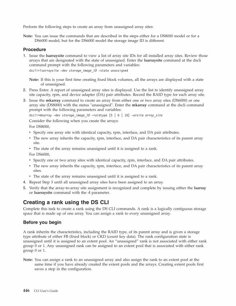
Perform the following steps to create an array from unassigned array sites:
Note: You can issue the commands that are described in the steps either for a DS8000 model or for aDS6000 model, but for the DS6000 model the storage image ID is different.
Procedure1. Issue the lsarraysite command to view a list of array site IDs for all installed array sites. Review those
arrays that are designated with the state of unassigned. Enter the lsarraysite command at the dsclicommand prompt with the following parameters and variables:dscli>lsarraysite -dev storage_image_ID -state unassigned
Note: If this is your first time creating fixed block volumes, all the arrays are displayed with a stateof unassigned.
2. Press Enter. A report of unassigned array sites is displayed. Use the list to identify unassigned arraysite capacity, rpm, and device adapter (DA) pair attributes. Record the RAID type for each array site.
3. Issue the mkarray command to create an array from either one or two array sites (DS6000) or onearray site (DS8000) with the status "unassigned". Enter the mkarray command at the dscli commandprompt with the following parameters and variables:dscli>mkarray -dev storage_image_ID -raidtype [5 | 6 | 10] -arsite array_site
Consider the following when you create the arrays:For DS8000,v Specify one array site with identical capacity, rpm, interface, and DA pair attributes.v The new array inherits the capacity, rpm, interface, and DA pair characteristics of its parent array
site.v The state of the array remains unassigned until it is assigned to a rank.For DS6000,v Specify one or two array sites with identical capacity, rpm, interface, and DA pair attributes.v The new array inherits the capacity, rpm, interface, and DA pair characteristics of its parent array
sites.v The state of the array remains unassigned until it is assigned to a rank.
4. Repeat Step 3 until all unassigned array sites have been assigned to an array.5. Verify that the array-to-array site assignment is recognized and complete by issuing either the lsarray
or lsarraysite command with the -l parameter.
Creating a rank using the DS CLIComplete this task to create a rank using the DS CLI commands. A rank is a logically contiguous storagespace that is made up of one array. You can assign a rank to every unassigned array.
Before you begin
A rank inherits the characteristics, including the RAID type, of its parent array and is given a storagetype attribute of either FB (fixed block) or CKD (count key data). The rank configuration state isunassigned until it is assigned to an extent pool. An “unassigned” rank is not associated with either rankgroup 0 or 1. Any unassigned rank can be assigned to an extent pool that is associated with either rankgroup 0 or 1.
Note: You can assign a rank to an unassigned array and also assign the rank to an extent pool at thesame time if you have already created the extent pools and the arrays. Creating extent pools firstsaves a step in the configuration.
446 CLI User's Guide

About this task
Use the lsarray, mkrank, and lsrank commands to assign a rank to each unassigned array. You must belogged into the DS CLI and connected to the storage unit that will be used for open systems host systemstorage.
Note: You can issue the commands that are described in the steps either for a DS8000 model or for aDS6000 model, but for the DS6000 model the storage image ID is different.
To create ranks, perform the following steps:
Procedure1. Ensure you have a list of the unassigned arrays for which ranks must be assigned. Issue the lsarray
command to obtain this list if you do not already have it. Enter the lsarray command at the dsclicommand prompt with the following parameters and variables:dscli>lsarray -dev IBM.2107-75FA120 -state unassigned
2. Issue the mkrank command to assign a rank to rank group 0 or 1 according to the rank group numberof the assigned extent pool ID. Enter the mkrank command at the dscli command prompt with thefollowing parameters and variables:mkrank -dev IBM.2107-75FA120 -array A44 -stgtype fb-extpool P1
Notes:
a. You can specify either the -wait or the -extpool parameter when you use the mkrankcommand. Either of these parameters allows you to be notified if the rank configurationhas failed for any reason.
b. If you use the -wait parameter, you cannot issue other commands until the entiretransaction has processed.
3. Press Enter to display a report of rank assignments for your entire storage unit.Because the process of creating the rank involves formatting drives, it could take some time before theprocess finishes. If you want to check on the process, you can issue the lsrank command from adifferent DS CLI session. A successful process displays the following type of message:Sun Aug 11 02:23:49 PST 2004 IBM DS CLI Device: IBM.2107-75FA120
Rank IBM.2107-75FA120/R44 successfully created.
4. Repeat Step 2 until all unassigned arrays are assigned a rank and an extent pool.5. Issue the lsrank command to verify that ranks and extent pools have been assigned. Enter the lsrank
command at the dscli command prompt with the following parameters and variables:dscli>lsrank -dev IBM.2107-75FA120 -l
6. Press Enter to display a report of the rank assignments for your entire storage unit.
Creating fixed block volumes using the DS CLIComplete this task to create fixed block volumes.
Before you begin
You must have completed the following tasks before you can create your fixed block volumes:v Created your extent pools.v Created your arrays.v Created and assigned your ranks.
Chapter 5. Configuring and managing logical storage 447

About this task
Perform the following steps to create fixed block volumes:
Procedure1. View your list of fixed block extent pool IDs and determine which extent pool IDs that you want to
use as the source for the fixed block logical volumes. You obtained this list when you first createdyour extent pools. If this list is not available, issue the lsextpool command to obtain the list of extentpool IDs. Enter the lsextpool command at the dscli command prompt with the following parametersand variables:dscli> lsextpool -dev IBM.2107-13AAD7A -stgtype fb -l
Extent pool attributes determine the size and quantity of volumes that can be created. The extent poolID (even/odd) indicates the storage server (0|1), which dictates that the LSS ID component of thevolume ID must be an even or an odd number.
2. Issue the lsaddressgrp command to find unassigned and available address groups. Enter thelsaddressgrp command at the dscli command prompt with the following parameters and variables:dscli> lsaddressgrp -dev IBM.2107-75FA120 -l
An address group refers to a group of LSSs. Up to 16 LSSs can be grouped into one address group.All LSSs in an address group must be of the same format (CKD or fixed block).
Note: If you are creating fixed block volumes for the first time, all the address groups are displayedwith a state of "unassigned".
3. Analyze the address group list to determine which LSSs can be used to make fixed block volumes.Consider the following conditions when doing your analysis:v If the address group list is empty, then all address groups are available to be defined (0 - 3).v If an undefined address group is used to create new fixed block volumes, select the lowest
numbered address group.v If you are adding new fixed block volumes to an existing fixed block address group, use the lslss
command to identify LSSs that are already defined in the target address group.4. Issue the mkfbvol command to create fixed block volumes for the specified LSS. Enter the mkfbvol
command at the dscli command prompt with the following parameters and variables:dscli> mkfbvol -dev IBM.2107-75FA120 -extpool P1-name finance#d -cap 8.6 0100-010F
Consider the following conditions regarding the command example in this step:v All volumes can have the same type and capacity attributes.v The -extpool parameter identifies a fixed block extent pool containing available data extents.v The -name parameter allows you to assign an easy-to-use label or nickname to the volume. The
volume name parameter can include a wildcard (#d or #h) that inserts a decimal or hexadecimalvolume ID value into the volume name.
Note: The decimal designation does not apply to the volume ID number or the number of volumesthat were created by the command. It only applies to the unique name that you haveassigned. Also, when you process this command, the volume name that you have assigneddoes not appear in the confirmation message. To view the volume name that you haveassigned, issue the lsfbvol or showfbvol command.
v The -cap (capacity) parameter is 8.6 GiB. The default is in gibibytes (GiB) where 1 GiB = 1 073 741824 (2^30 bytes)
v The example provides a range of numbers (0100 - 010F) for the number of volumes to be created.Because volumes are created using the hexadecimal numbering system, the range in the examplecreates 16 volumes. The actual number of volumes that can be created is 255 per LSS based on thefollowing criteria:
448 CLI User's Guide
||

– The volume ID is a 32 bit number that can be represented as four hexadecimal digits in the formof XYZZ where:
XY (for a DS8000 model)Specifies the logical subsystem number, 00 - FE.
XY (for a DS6000 model)Specifies the logical subsystem number, 00 - 1E.
ZZ (for DS6000 and DS8000 models)Specifies the volume number, 00 - FF.
X (for DS6000 and DS8000 models)Specifies the address group, 0 - 1.
– For DS8000, you can define up to 255 LSSs in a storage unit. LSSs are either CKD or fixed block.Even numbered LSSs have an association with storage unit server 0. Odd numbered LSSs havean association with storage unit server 1.
– DS6000 has a 16 384 volume address space that is partitioned into 64 logical subsystem (LSS)units, where each LSS contains 256 logical volume numbers. The 64 LSS units are assigned toone of 4 address groups, where each address group contains 16 LSSs, or 4096 volume addresses.All of the LSSs in one address group must be of the same type (CKD or fixed block).
5. Repeat step 4 for all of the required logical volumes for each LSS.6. Issue the lsfbvol command to display a report you can use to confirm the status of your fixed block
volumes. Enter the lsfbvol command at the dscli command prompt with the following parametersand variables:dscli> lsfbvol -dev IBM.2107-75FA120 -l -volgrp V2,V20
Note: The report can display that there was a configuration error that is associated with one or moreof your mkfbvol transactions.
Creating LUN volumes for System i modelsComplete this task to create fixed block LUN volumes for System i models.
Before you begin
You must have completed the following tasks before you can create your fixed block LUN volumes:v Created your extent poolsv Created your arraysv Created and assigned your ranks
About this task
When you begin your initial configuration, the LSSs and address groups do not exist. The LSSs arecreated when the first volume of the LSSs is defined during the processing of the mkfbvol command;likewise, the address group gets defined when the first LSS is defined.
When you create volumes, you must designate the logical subsystem (LSS) that a particular volumebelongs to. After you assign a volume ID, use the first two digits to designate the LSS. For example, ifyou specify a volume ID of 1900, the volume then belongs to LSS 19.
Consider the following specifications before you create your fixed block LUN volumes:v Volumes that belong to an even numbered rank group (cluster) must be in an even numbered LSS;
volumes that belong to an odd numbered rank group (cluster) must be in an odd numbered LSS. Thecluster that a volume belongs to is determined by specifying the extent pool that the volume isassigned to.
Chapter 5. Configuring and managing logical storage 449

v LSS numbers FF (DS8000) and 1F (DS6000) is reserved for internal use and must not be used as avolume ID.
v You must define each volume as protected or unprotected. This action is simply a notification to i5/OS;it does not mean that the volume is protected or unprotected. In reality, all LUNs are protected, eitherby RAID 5, RAID 6 or RAID 10. Defining a volume as unprotected means that it is available for i5/OSto mirror that volume to another internal or external volume of equal capacity. Unless you intend touse i5/OS (host based) mirroring, define your logical volumes as protected.Under some circumstances, you might want to mirror the i5/OS internal Load Source Unit (LSU) to aLUN in the DS6000 or the DS8000. In this case, define only one LUN volume as unprotected;otherwise, i5/OS attempts to mirror all unprotected volumes.
v In general, it is best to use one LSS for volumes from one rank.
Perform the following steps to create fixed block LUN volumes:
Procedure1. View your list of fixed block extent pool IDs and determine which extent pool IDs that you want to
use as the source for the fixed block logical volumes. You obtained this list when you first createdyour extent pools. If this list is not available, issue the lsextpool command to obtain the list of extentpool IDs. Enter the lsextpool command at the dscli command prompt with the following parametersand variables:dscli>lsextpool -dev IBM.2107-75FA120 -stgtype fb -l
Extent pool attributes determine the size and quantity of volumes that can be created. The extent poolID (even | odd) indicates the storage server (0 | 1), which dictates that the LSS ID component of thevolume ID must be an even or an odd number.
2. Issue the mkfbvol command to create fixed block LUN volumes for the specified LSS. Enter themkfbvol command at the dscli command prompt with the following parameters and variables:dscli>mkfbvol -dev IBM.2107-75FA120 -extpool p0-os400 A05 -name i5_unprot_#h 1001-1002
Consider the following conditions regarding the command example in this step:v The -extpool parameter identifies a fixed block extent pool containing available data extents.v The -os400 parameter allows you to designate the size and protection of a LUN volume by
specifying the volume model. The example shows LUN volumes of protected model type A05 witha size of 35.1 decimal gigabytes (GB).
v The -name parameter allows you to assign an easy-to-use label or nickname to the volume. Thevolume name parameter can include a wildcard (#d or #h) that inserts a decimal or hexadecimalvolume ID value into the volume name.
Note: The hexadecimal designation does not apply to the volume ID number or the number ofvolumes that were created by the command. It only applies to the unique name that youhave assigned. Also, when you process this command, the volume name that you haveassigned does not appear in the confirmation message. To view the volume name that youhave assigned, issue the lsfbvol or showfbvol command.
v The example provides a range of numbers (0101 - 0102) for the number of volumes to be created.The actual number of volumes that can be created is 255 per LSS based on the following criteria:– The volume ID is a 32 bit number that can be represented as four hexadecimal digits in the form
of XYZZ where:
XY (for a DS8000 model)Specifies the logical subsystem number, 00 - FE.
XY (for a DS6000 model)Specifies the logical subsystem number, 00 - 1E.
450 CLI User's Guide
|

ZZ (for DS6000 and DS8000 models)Specifies the volume number, 00 - FF.
X (for DS6000 and DS8000 models)Specifies the address group, 0 - 1.
– You can define up to 255 (for DS8000) or 31 (for DS6000) LSSs in a storage unit. Even numberedLSSs have an association with storage unit server 0. Odd numbered LSSs have an associationwith storage unit server 1. LSS numbers FF (DS8000) and 1F (DS6000) is reserved.
3. Repeat step 2 for all of the required logical volumes for each LSS.4. Issue the lsfbvol command to display a report you can use to confirm the status of your LUN
volumes. Enter the lsfbvol command at the dscli command prompt with the following parametersand variables:dscli>lsfbvol -dev IBM.2107-75FA120 -l
Correcting a fixed block configuration errorComplete this task to correct a fixed block volume configuration error.
About this task
There might be occasions when you are using the mkfbvol command to create fixed block volumes, butthe transaction fails. You might not be aware of the failure until you run the lsfbvol or the showfbvolcommand to check the status of the volumes that you have created.
The lsfbvol or the showfbvol commands display reports that includes a configstate category. Theconfiguration state category reports on the current state of the rank. One of the configuration state codesis configuration error.
A status of configuration error specifies that the configuration process did not complete successfully. Thisstate reflects an internal error condition and is not an indication that there was a user input error.
You might want to gather additional information about what caused the error, which can help youdetermine how to correct it. To correct this error state, you must delete the designated volumeconfiguration and submit a new transaction request.
Perform the following steps to obtain additional information about the configuration error and to correctthis error condition.
Procedure1. Add the -v (verbose) command parameters to your mkfbvol command, and reissue the command for
the transactions that show the configuration error designation.
Note: You can also turn on the verbose mode in your profile file, and reissue the command.If you designate the verbose mode, the display of extra output includes the error code that isgenerated when the create rank transaction fails.
2. Issue the rmfbvol command to delete the designated volume configurations if you do not want toobtain additional information about what caused the configuration error.
Note: In the majority of instances, this is the only method for correcting a configuration error.
Creating fixed block volume groups using the DS CLIComplete this task to create fixed block volume groups.
Chapter 5. Configuring and managing logical storage 451

About this task
A volume group identifies the set of fixed block logical volumes that are accessible by one or more SCSIhost system ports. SCSI host system access is constrained to the identified access mode. Only those SCSIhost ports that are registered to a volume group ID are allowed to access the set of logical volumes that iscontained by the volume group.
Logical volumes can be assigned to a volume group when the volume group is created, or the logicalvolumes can be added (or removed) at a later time. The volume group type determines the maximumnumber of volumes that can be assigned to a volume group, either a maximum of 256 volumes or amaximum of 64 000 volumes. The volume group type must be selected according to the addressingcapability of the SCSI host system that will use the volume group.
Perform the following steps to create and view fixed block volume groups:
Procedure1. Issue the mkvolgrp command to create a fixed block volume group. Enter the mkvolgrp command at
the dscli command prompt with the following parameters and variables:
Note: Repeat this step for each volume group that you want to create.dscli> mkvolgrp -dev IBM.2107-75FA120 -hosttype pSeries-volume 0001-0010,0120 my_nickname
Notes:
a. You can use the -hosttype parameter with the mkvolgrp command. This parameter is aneasier way of specifying the type of volume group. If you do not use the -hosttypeparameter, it is assumed that the volume group type is scsimask.
b. You cannot use the -type parameter and the -hosttype parameter together.c. If your volume group is not scsimask type and you do not want to use the -hosttype
parameter, use the -type parameter. scsimask as the default value of the -type parameter;you can also specify scsimap256 or os400mask as your volume group type. Because you needto know the criteria that is associated with these volume group types, see the mkvolgrpcommand for more information.
d. Volume IDs must meet the following criteria:v ID ranges must be separated by a comma (displayed as 0001-0010,0120 in the example).v For scsimap256, the array or ranges cannot exceed 256 volume ID entries. Otherwise, up
to 64 384 entries are allowed.v Use the -type 0s400mask parameter if the volume group is limited to fixed block volume
OS400-protected or OS400-unprotected types. Otherwise, the volume group is limited tothe fixed block volume type DS8000 or DS6000 machine type.
v The volume group name (my_nickname in the example command) must be unique withinthe scope of the specified storage image.
2. Issue the lsvolgrp command to create a list of assigned volume group IDs. Enter the lsvolgrpcommand at the dscli command prompt with the following parameters and variables:dscli> lsvolgrp -dev IBM.2107-75FA120 -l
Notes:
a. The lsvolgrp command with the -l parameter displays a report with the following 3values:v Name (the unique name that you assigned to the volume group)v Volume group IDv Type (the configured volume group type)
452 CLI User's Guide

b. You can narrow the scope of the report by requesting a specific type of volume. See thelsvolgrp command for information about the -type parameter.
Creating a volume group for System i modelsComplete this task to create volume groups for System i models so that volumes can be assigned to the i5Fibre Channel adapters.
About this task
Use the mkvolgrp command to create a volume group that contains the volumes to be assigned to an i5Fibre Channel adapter. The following considerations determine how you will create your volume groups:v If you are using a multipath connection, a volume group is assigned to two or more i5 Fibre Channel
adapters. Each Fibre Channel adapter provides one path to volumes in the volume group.v If you are using an external load source, you create a volume group that contains one volume. After a
partition is initially loaded from the external load source, you can add more volumes to this volumegroup so that the i5/OS recognizes them and can use them.
When you create a volume group for i5/OS, you should specify the -hosttype iSeries parameter as partof the mkvolgrp command. The -hosttype iSeries parameter saves some processing time because thisparameter automatically supplies information that would have to be specified separately. For example,the i5/OS uses a logical blocksize of 520, and volumes that are created for i5/OS use a blocksize of 520bytes. By specifying the -hosttype iSeries parameter, you also denote that the logical size of the blocks inthe volumes is 520 bytes.
Perform the following steps to create and view volume groups for System i models:
Note: You can issue the commands that are described in the steps either for a DS8000 model or for aDS6000 model, but for the DS6000 model the storage image ID is different.
Procedure1. Issue the mkvolgrp command to create a volume group. Enter the mkvolgrp command at the dscli
command prompt with the following parameters and variables:
Note: Repeat this step for each volume group that you want to create.The following two examples provide the commands that you can use to create volume groupsdepending on whether you use the external load source. The first example creates a volume groupthat contains one unprotected volume if you do use an external load source. (If you are using anexternal load source, you can initially only have one volume in the volume group.) The secondexample creates a volume group that contains all volumes if you do not use an external load source.Example 1 (using an external load source)dscli>mkvolgrp -dev IBM.2107-13ABVDA -hosttype iSeries -volume 1000 blue
CMUC00030I mkvolgrp: Volume group V14 successfully created.
Example 2 (not using an external load source)dscli>mkvolgrp -dev IBM.2107-13ABVDA -hosttype iSeries -volume 1000-1002 blue
CMUC00030I mkvolgrp: Volume group V14 successfully created.
Notes:
a. The confirmation message for the end process shows that the created volume group isautomatically assigned an ID that is different from the name of the volume group that youspecify in the command. You will see the name that you assigned associated with the
Chapter 5. Configuring and managing logical storage 453

volume group when you use the lsvolgrp and showvolgrp commands. However, if youwant to work specifically with the volume group, you must reference the volume groupID.
b. This volume group is also referred to as SCSI520-MASK. When an error message isdisplayed for the OS400 MASK, SCSI520-MASK is referenced instead.
c. If you do not use an external load source, it is a good practice to create a volume groupthat contains all the volumes that will be assigned to the i5 Fibre Channel adapter.
d. Some System i models only support 32 device addresses per volume group.2. Issue the lsvolgrp command to create a list of assigned volume group IDs. Enter the lsvolgrp
command at the dscli command prompt with the following parameters and variables:dscli>lsvolgrp -dev IBM.2107-13ABVDA -l
Notes:
a. The lsvolgrp command with the -l parameter displays a report with the following threevalues:v Name (the unique name that you assigned to the volume group)v Volume group ID (the identification number of the volume group)v Type (the configured volume group type)
b. You can narrow the scope of the report by requesting a specific type of volume. See thelsvolgrp command for information about the -type parameter.
3. Verify your host type information by issuing the lshosttype command using the following commandformat at the dscli command prompt:dscli>lshosttype -type os400mask
This command displays a report like the following example:
Name Profile AddrDiscovery LBS
iSeries IBM iSeries - os400 reportlun 520
Note: You can obtain the same results if you use the -type os400all parameter.
Configuring Fibre Channel I/O ports using the DS CLIComplete this task to configure Fibre Channel I/O ports using the DS command-line interface.
Before you begin
Before you begin, you must have the command-line interface prompt, and you must be connected to astorage image that is to be used for open systems host system storage.
In this process, you must designate the topology for the I/O port. The following three topology settingsare available:
fibre channel arbitrated loop (coded as fc-al in the setioport command)Enables the SCSI ULP with a FC-AL topology. The FC-AL topology does not support PPRC path I/Ooperations.
SCSI-FCP (coded as scsi-fcp in the setioport command)Enables the SCSI ULP with a point-to-point or switched fabric topology. PPRC path I/O operationsare enabled for this setting.
Note: Designate this topology for System i models using i5/OS level V5R3M5 and above.
454 CLI User's Guide

ficon (coded as ficon in the setioport command)Enables the FICON ULP with a point-to-point or switched fabric topology. PPRC path I/O operationsare not supported for FICON ULP.
About this task
The storage image supports the Fibre Channel host adapter (HA) card type. For DS8000 machine types,HA cards are installed in I/O enclosures, each containing up to four HA cards. For DS6000 machinetypes, one or two HA cards are installed in each of the two CEC assemblies. Use the lsioport andsetioport commands to configure Fibre Channel I/O ports.
Each Fibre Channel HA card contains four I/O ports. The storage image microcode automatically createsone I/O port to represent each HA card I/O port. The default Fibre Channel I/O port settings enableSCSI-FCP “identified” access to fixed block volumes. You might have to modify the I/O port settings toenable SCSI FC-AL access to fixed block volumes.
To configure the Fibre Channel ports, perform the following steps:
Procedure1. View a list of Fibre Channel port IDs by typing the following command format at the dscli command
prompt:dscli> lsioport -dev IBM.2107–75FA120 -l -type fc
A detailed report is displayed that lists the Fibre Channel I/O ports.2. Analyze the report and determine which I/O port IDs that you want to access the fixed block
volumes.Configure a minimum of four I/O ports for SCSI host I/O operations. Select ports with physicallocations on different host bus adapter (HA) cards. If possible, locate the HA cards in different I/Oenclosures.
3. Set the I/O ports that you have identified to enable the FC-AL (Fibre Channel arbitrated loop),SCSI-FCP, or FICON topology. The following example shows how to enable the FC-AL topology bytyping the following command format at the dscli command prompt:
Note: I/O ports are automatically set to the offline state and returned to the online state afterconfiguration changes are applied.
dscli> setioport -dev IBM.2107–75FA120 -topology fc-al0012 0013 0112 0113
4. Press Enter. A successful process returns a confirmation message indicating that the port IDs havebeen successfully configured.
Creating SCSI host port connections using DS CLIComplete this task to create SCSI host port connections using the DS command-line interface.
Before you begin
Before you begin, you must have the command-line interface prompt, and you must be connected to astorage image that can be used for open systems host system storage.
About this task
The DS8000 and DS6000 machine types support the “identified” access mode for SCSI host attachments,which requires that all SCSI host ports be identified to a DS8000 storage image or DS6000 storage unitrespectively. One SCSI host port connection must be created for each SCSI host port that accesses DS8000storage image and DS6000 storage unit fixed block volumes. Use the lshosttype, mkhostconnect, andlshostconnect commands to create the SCSI host port connections.
Chapter 5. Configuring and managing logical storage 455

A SCSI host port contains attributes that identify the following information:v SCSI host system typev Port profilev Port WWPNv Volume group ID that the port accessesv An array of storage unit or storage image I/O port IDs that the host port logs into for volume accessv An attribute to indicate that all I/O ports can be used for volume accessv Host port descriptionv Port nickname
There are two ways that you can approach this task:v Use the -hosttype parameter with the mkhostconnect command. Using the -hosttype parameter is the
best solution for most users.v Use the mkhostconnect command with the -lbs, -addrdiscovery, and -profile parameters.
Notes:
1. Specifying the -hosttype parameter automatically sets the -lbs, -addrdiscovery, and -profilevalues.
2. If you do not use the -hosttype parameter, you must issue the lsportprof command to ensurethat you obtain the correct values to use with the -lbs, -addrdiscovery, and -profileparameters.
3. You cannot use the -hosttype parameter with these other parameters.
The following task is described from the assumption that you have used the -hosttype parameter.
To configure the SCSI host ports, perform the following steps:
Procedure1. Obtain your host type information by issuing the lshosttype command. Enter the lshosttype
command at the dscli command prompt with the following parameters and variables:dscli>lshosttype –l -type volumeGroup_type
This command displays a report like the following example:
Name Profile AddrDiscovery LBS Description
pSeries® IBM pSeries - AIX reportlun 512 IBM pSeries,RS/6000® andRS/6000 SP Servers(AIX)
zLinux IBM zSeries® - zLinux lunpolling 512 IBM zSeries Servers(Linux)
iSeries (ifos400all wasspecified)
IBM iSeries - os400 reportlun 520 IBM iSeriesServers(System i)
Note: Volume group type is one of the following designations (use a separate command for eachchoice):v ficonallv scsiallv scsimaskv scsimap256
456 CLI User's Guide
v os400allv os400mask
The same results are displayed when you specify os400all or os400mask or when you specifyscsiall and scsimask or scsimap256.
2. Create SCSI host ports by issuing the mkhostconnect command. Enter the mkhostconnect command atthe dscli command prompt with the following parameters and variables:dscli>mkhostconnect -dev storage_image_ID -wwpn wwpn-hosttype host_type -volgrp volume_group_ID -ioport port_ID
host_name
Notes:
a. The -wwpn parameter specifies the 16-character worldwide name that is assigned to the hostsystem Fibre Channel adapter port. This WWPN value is validated each time that the hostsystem port logs into an I/O port.
b. The -hosttype parameter specifies Fibre Channel communications layer characteristics thatmight be unique according to the host system manufacturer, operating system, or versionof the system. Typical specifications are iSeries, pSeries, an so on.
c. The -volgrp parameter specifies the volume group ID that this host port can access. Hostport objects might be created prior to creating volume groups, in which case you must usethe chhostconnect command to add volume group ID assignments at a later time.
d. The -ioport all specifies SCSI host port (WWPN) access into all IO ports that areconfigured for the FC-AL or SCSI-FCP topology.
e. host_name specifies the SCSI host system nickname that you have assigned.3. Repeat Step 2 for each SCSI host system port that will access LUN volumes.4. Verify that all SCSI host ports have been configured and that they are recognized by the storage unit
according to your specifications by issuing the lshostconnect command with the -l parameter.
Configuring new count key data storage using DS CLIThis section describes how to configure new count key data (CKD) storage within your storage image fora System z host system.
Before you begin, you must be logged into the DS CLI in interactive command mode. You must also beconnected to a storage unit that is used for System z models host storage.
Configuring CKD storage involves two basic processes: the creation of the CKD storage configuration andthe configuration of the storage unit I/O ports for System z host system attachment. These two basicprocesses can be performed in the reverse order, but it is better to create storage configurations first.Creating the storage configuration first creates the media to back up configuration data that is not relatedspecifically to the storage configuration.
Configuring new CKD storage involves the following processes:v Creating CKD extent poolsv Creating arraysv Creating and associating ranks with extent poolsv Creating logical control unitsv Creating CKD volumesv Creating CKD volume groups (system generated).
The internal microcode automatically creates the CKD FICON/ESCON All volume group ID (V10) forDS8000, and it creates the CKD FICON All volume group ID (V10) for DS6000, and automaticallyassigns all CKD base and alias volumes to this volume group. This volume group ID (V10) is
Chapter 5. Configuring and managing logical storage 457

automatically assigned to storage unit I/O ESCON ports, and to I/O Fibre Channel ports (for DS8000),and to I/O Fibre Channel ports (for DS6000) that are configured for FICON I/O operations. ForDS8000, the ESCON I/O ports are constrained to access Address Group 0 volume IDs (0000-0FFF).
v Configuring Fibre Channel I/O ports
Creating count key data extent pools using the DS CLIYou can use DS CLI commands to create extent pools for CKD volumes. This step is the first inconfiguring new count key data storage.
Before you begin
You must be logged in to the DS CLI and connected to the storage unit that is to be used for your Systemz host system to complete this task.
You can create the extent pools before the arrays and ranks to save a processing step. When you createnew ranks, you can assign them to existing extent pools. Otherwise, you must modify each rank object tocomplete the extent pool ID assignment after the extent pools have been defined.
About this task
Each extent pool is defined with the rank group of 0 or 1 and a storage type of ckd. You must define atleast one extent pool for each rank group and storage type combination. This requirement means that youmust make a minimum of two extent pools for a storage unit that contains CKD storage: one CKD extentpool per rank group.
Extent pools that are defined for rank group 0 or 1 are assigned an even- or odd-numbered extent poolID, respectively. Even-numbered extent pools are managed by storage server ID 0. Odd-numbered extentpools are managed by storage server ID 1. Each rank group is assigned to one extent pool; therefore,storage server workload is affected by the rank assignments to even- and odd-numbered extent pool IDs.To keep the storage server workloads balanced, evenly distribute rank and extent pool allocations.
Notes:
1. You can create more than the minimum number of extent pools. For example, you can defineunique extent pools for each RAID type (5, 6 or 10) that is configured in a storage image. Or,you can define and name extent pools according to the host system attachments that accessthe volumes that are created from extent pool extents.
2. You can have the same number of extent pools and ranks.
Perform the following step to create the extent pools:
Procedure1. Issue the lsextpool command to display a list of the existing CKD extent pools. The following is an
example of the command that you can type in the dscli command prompt:lsextpool -dev IBM.2107-75FA120 -stgtype ckd
where IBM.2107-75FA120 is the name of the storage image ID.2. Analyze the extent pool listing for the following information:
v Does the minimum set of extent pools exist? There must be one extent pool for rank group 0 andone extent pool for rank group 1.
Note: If extent pools are being created for the first time, the minimum number of extent pools doesnot exist.
v Does each extent pool have a rank group that is assigned to it and are they balanced?
458 CLI User's Guide

Note: If extent pools are being created for the first time, there are no rank assignments.v Are additional extent pools required?
3. Issue the mkextpool command to create the extent pools. The following are examples of thecommands that you can type in the dscli command prompt:
Remember: You must create a minimum of two extent pools. There must be one extent pool for rankgroup 0 and one extent pool for rank group 1.
mkextpool -dev IBM.2107-75FA120 –rankgrp 0 -stgtype ckdextent_pool_namemkextpool -dev IBM.2107-75FA120 –rankgrp 1 -stgtype ckdextent_pool_name
where extent_pool_name is the name that you want to assign to the extent pool. This parameter is arequired. The name cannot be longer than 16 characters.Create additional extent pools for each of the following conditions:v Each RAID type (5, 6 or 10)v Each disk drive module (DDM) sizev Each CKD volume type (3380, 3390)v Each logical control unit (LCU) address group
4. Press Enter.
Note: The unique name that you assigned to the extent pool does not display in the process message.However, when you issue the lsextpool command, the extent pool name is displayed.
The following is an example of the message that is displayed for a successful process:Extent pool P1 successfully created.
5. Repeat step 2 on page 458 for each extent pool that you want to create.
Remember: To keep the storage server workloads balanced, evenly distribute rank and extent poolallocations.
6. After you have created the extent pools, issue the lsextpool command to verify the extent poolassignments. Use the -l parameter to display a full report for the extent pools that are assigned to thestorage unit. The following is an example of the command that you can type in the dscli commandprompt:lsextpool –dev IBM.2107-75FA120 -l
7. Optionally, print the list of extent pools so that you can refer to this list when you create CKDvolumes.
Creating arrays for CKD volumes using the DS CLIComplete this task to create arrays for CKD volumes using the DS CLI commands.
Before you begin
The DS8000 machine type storage image storage devices (DDMs) are packaged into storage enclosurepairs. The DS8000 machine type contains at least one storage enclosure pair, with a minimum of 16DDMs. All DDMs that are installed in a storage enclosure pair have identical capacity, rpm (revolutionsper minute), and interface characteristics.
The DS6000 machine type must contain at least one storage enclosure, with a minimum of four DDMs.
The DDMs of a storage enclosure are partitioned into array sites. A DS8000 machine type array siteconsists of eight DDMs, four from each storage enclosure of a storage enclosure pair, two-or-four (eightDDM) array sites per storage enclosure pair. A DS6000 machine type array site consists of four DDMs inone storage enclosure of a storage enclosure pair, with two to eight (four DDM) array sites per storage
Chapter 5. Configuring and managing logical storage 459

enclosure pair. All array sites of a storage enclosure pair have identical capacity, rpm, and interfacecharacteristics, and an interface to a common DA pair.
About this task
The creation of arrays is based on the array sites that are associated with the storage unit. You must makean array from 1 or 2 array sites. An array inherits the characteristics of its parent array sites, and is givena RAID type attribute (5, 6, or 10). A DS8000 machine type array object of RAID type 5, 6, or 10 is madefrom one (8 DDMs) array site. A DS6000 machine type array object of RAID type 5 or 10 is made fromone or two (4 DDMs) array sites.
Note: The array status is “unassigned” until the array is assigned to a rank.
Use the lsarraysite and mkarray commands to create the arrays. You must be logged into the DS CLIand connected to the storage unit that will be used for open systems host system storage.
Perform the following steps to create arrays for a CKD volume configuration:
Procedure1. Issue the lsarraysite command to find the unassigned array sites. Enter the lsarraysite command
at the dscli command prompt with the following parameters and variables:dscli> lsarraysite -dev storage_image_ID -state unassigned
Note: If this is your first time creating volumes, you will see all the arrays with a state of"unassigned".
2. Press Enter. A report of unassigned array sites is displayed. Use the list to identify unassigned arraysite capacity, rpm, and device adapter (DA) pair attributes. Record the RAID type for each array site.
3. Issue the mkarray command to create an array from each site with the status "unassigned". Enter themkarray command at the dscli command prompt with the following parameters and variables:dscli> mkarray -dev storage_image_ID -raidtype [5 | 6 | 10] -arsite array_site
Repeat this command until all unassigned array sites have been assigned to an array.
Notes:
a. You can specify one or two array sites for DS6000. If there are two array sites, both sitesmust be associated with a common DA pair ID. Two array sites must be separated bycommas with no blank space in between. Example: S10,S11.
b. The new array site inherits the capacity, rpm, interface, and DA pair characteristics of itsparent array site or sites depending on the machine type. The state of the array is“unassigned” until it is assigned to a rank.
Creating a rank for CKD volumes using the DS CLIComplete this task to create a rank for a CKD volume. A rank is a logically contiguous storage space thatis made up of one or more arrays. You want to assign a rank to every unassigned array.
Before you begin
A rank inherits the characteristics, including RAID type, of its parent array and is given a storage typeattribute FB (fixed block) or CKD (count key data). The rank configuration state is unassigned until it isassigned to an extent pool. An unassigned rank is not associated with either rank group 0 or 1. Anyunassigned rank can be assigned to an extent pool that is associated with either rank group 0 or 1.
Note: You can assign a rank to an unassigned array and also assign the rank to an extent pool at thesame time if you have already created the extent pools and the arrays. Creating extent pools firstsaves a step in the configuration.
460 CLI User's Guide

About this task
Use the lsarray, mkrank, and lsrank commands to assign a rank to each unassigned array. You must belogged into the DS CLI and be connected to the storage unit that will be used for open systems hostsystem storage.
To make ranks, perform the following steps:
Procedure1. Issue the lsarray command to ensure you have a list of the unassigned arrays for which ranks must
be assigned. Enter the lsarray command at the dscli command prompt with the following parametersand variables:dscli> lsarray -dev IBM.2107-75FA120 -state unassigned
2. Issue the mkrank command to assign a rank to rank group 0 or 1 according to the rank group numberof the assigned extent pool ID. Enter the mkrank command at the dscli command prompt with thefollowing parameters and variables:dscli> mkrank -dev IBM.2107-75FA120 -array A44-stgtype ckd -extpool P1
Notes:
a. You can specify either the -wait or the -extpool parameter when you use the mkrankcommand. Either of these parameters allows you to be notified if the rank configurationhas failed for any reason.
b. When you use the -wait parameter, you cannot issue any other commands until the entiretransaction has processed.
3. Press Enter to create the ranks.The process of making the rank involves formatting drives. It can take a little time before the processfinishes. To check on the process, issue the lsrank command from a different DS CLI session. Asuccessful process generates the following type of message:Rank IBM.2107-75FA120/R44 successfully created.
4. Repeat Step 2 and step 3 until all unassigned arrays are assigned a rank and an extent pool.5. Issue the lsrank command to verify that ranks and extent pools have been assigned. Enter the lsrank
command at the dscli command prompt with the following parameters and variables:dscli> lsrank -dev IBM.2107-75FA120 -l
6. Press Enter. A report of the rank assignments for your entire storage unit is displayed.
Creating logical control units for CKD volumes using DS CLIThe logical control unit (LCU) is the S/390® and System z host equivalent of the logical subsystem (LSS)for open systems hosts. The LCU must be defined (created) before CKD logical volumes can be created.
About this task
The DS8000 has a 64 KB 256 volume address space that is partitioned into 255 logical subsystem (LSS)units, where each LSS contains 256 logical volume numbers. The 255 LSS units are assigned to one of 16address groups, where each address group contains 16 LSSs, or 4 KB volume addresses.
The DS6000 has a 16 384 volume address space that is partitioned into 64 logical subsystem (LSS) units,where each LSS contains 256 logical volume numbers. The 64 LSS units are assigned to one of 4 addressgroups, where each address group contains 16 LSSs, or 4096 volume addresses. All of the LSSs in oneaddress group must be of the same type (CKD or fixed block).
Typically, LCUs are created in groups of 16, beginning at LSS address X'x0'.
Chapter 5. Configuring and managing logical storage 461

Use the lsaddressgrp, mklcu, and lslcu commands to create the LCU type logical subsystems. You mustbe logged into the DS CLI and connected to the storage unit that will be used for open systems hostsystem storage.
To create LCUs, perform the following steps:
Procedure1. Find unassigned and available address groups by issuing the lsaddressgrp command. To use the
lsaddressgrp command, type the following at the dscli command prompt:dscli> lsaddressgrp -dev IBM.2107-75FA120
This command displays a report on the status of the address groups within your storage unit.2. Analyze the report to identify all of the address groups that are available to be defined. Use the
following criteria:v If the list is empty, all of the address groups are available to be defined.v A defined address group with the storage type fb (fixed block) is not available to be defined.v A defined address group with the storage type ckd and with fewer than 16 LSSs is available for
LCU definition.v If you are using an undefined address group to make new LCUs, select the lowest numbered
address group that is not defined.v If you are defining a new LCU in an existing CKD address group, use the lslcu command to
identify LCUs that are already defined in the target address group.3. Make the LCU logical subsystem objects by issuing the mklcu command. Type the command using the
following format at the dscli command prompt:dscli> mklcu –dev IBM.2107-75FA120 -qty 16 -id 00 -ss 0010 -lcutype 3390-3
In this example, the values specify the following information:
qtySpecifies the number of LCU IDs to be created.
id Specifies the LCU ID to be created, or the first LCU ID in a sequence of LCU IDs to be created.
ss Specifies the subsystem ID that you have assigned. If multiple LCU IDs are being created, thenthe SSID value increments for each additional LCU ID that is created.
If 16 LCUs are created, starting with SSID 0x10, then the SSID values are 0x0010 – 0x001F.
lcutypeSpecifies the type of LCU to be created. You can specify the following types:v 3390-3v 3990-tpv 3990-6v bs2000
4. Press Enter. A successful process displays a confirmation message listing each LCU ID number thathas been successfully created.
5. Verify that the LCUs are recognized in the storage unit by issuing the lslcu command at the dsclicommand prompt as follows:dscli> lslcu -dev IBM.2107-75FA120 -l
Using the -l parameter displays a more detailed report for each LCU that is associated with yourstorage unit.
Creating count key data volumes using the DS CLIComplete this task to create count key data (CKD) volumes.
462 CLI User's Guide

About this task
A logical volume consists of one or more data extents that are allocated from a single extent pool. Thevolume data type is inherited from the extent pool extent storage type (fixed block or CKD) characteristic.When a CKD volume is created, volume attributes are further defined by a base or alias volume type,3390 or 3380 volume cylinder type, and volume capacity in cylinders. These volume attributescharacterize the volume to the host system that will eventually access the volume. Each volume isassigned a volume ID, which is the volume address within the 64 KB address space. Host access to avolume is enabled when the volume ID is assigned to a volume group; however, CKD volumes areautomatically assigned to the volume group CKD FICON/ESCON All (ID V10).
Perform the following steps to create your CKD volumes:
Procedure1. View your list of CKD extent pool IDs and determine which extent pool IDs that you want to use as
the source for the CKD volumes to be created. You obtained this list when you first created yourextent pools. If this list is not available, you can issue the lsextpool command to obtain the list ofextent pool IDs.Extent pool attributes determine the size and quantity of volumes that can be created. The extent poolID (even/odd) indicates the storage server (0|1), which dictates that the logical control unit (LCU) IDcomponent of the volume ID must be an even or an odd number.
2. Issue the mkckdvol command to make 128 base volumes for each LCU. Enter the mkckdvol commandat the dscli command prompt with the following parameters and variables:dscli> mkckdvol –dev IBM.2107-75FA120 -extpool p1 –cap 3339–name finance#d 0000-007F
The following considerations affect the command example in this step:v The -extpool parameter identifies a CKD extent pool that contains available data extents.v The -cap parameter specifies the quantity of CKD cylinders that are allocated to this volume.v The -name parameter allows you to assign an easy-to-use label or nickname to the volume. The
volume name parameter can include a wildcard (#d or #h) that inserts a decimal or hexadecimalvolume ID value into the volume name.
Note: The decimal designation does not apply to the volume ID number or the number of volumesthat were created by the command. It only applies to the unique name that you haveassigned to the volume. When you process the mkckdvol command, the volume name thatyou have assigned does not appear in the confirmation message. To view the volume namethat you have assigned, issue the lsckdvol or showckdvol command.
v Volume ID 0000 - 007F specifies 128 volumes, starting at CKD address group (0), LCU ID (00), andvolume number (00). You must specify volume IDs that have not been previously defined as CKDor fixed block volumes.
3. Press Enter to create the volumes. A confirmation message is displayed that lists the successfulcreation of each volume.
4. Repeat Steps 2 and 3 until all required logical volumes for all LCUs have been created.5. Issue the mkaliasvol command to make 128 alias volumes for each LCU. Enter the mkaliasvol
command at the dscli command prompt with the following parameters and variables:dscli> mkaliasvol –dev IBM.2107-75FA120 –base 0000-004F-order decrement -qty 2 00FF
Consider the following conditions with regard to the command example in this step:v The -base 0000 - 004F parameter specifies that alias volumes are assigned to existing base volume
IDs 0000 - 004F. Base and alias volumes must be associated with a common LCU ID.v The -order parameter specifies the order in which alias volume IDs are assigned.v The -qty parameter specifies the number of alias volumes that are assigned to each base volume.
Chapter 5. Configuring and managing logical storage 463

v The volume ID (00FF) parameter specifies that the alias volumes are assigned, starting at a CKDaddress group (0), LCU ID (00) and volume number (FF). You are responsible for specifying thevolume ID values that have not been previously defined as CKD or fixed block volume types.As a result, alias volumes 00FF and 00FE are created for base volume 0000, 00FD and 00FC for0001, and so on.
6. Repeat Step 5 until you have defined all required logical volumes for all the LCUs.7. Press Enter to create the alias volumes. A confirmation message is displayed that lists the successful
creation of each volume.8. Issue the lsckdvol command to display a report that you can use to confirm the status of your CKD
volumes. Enter the lsckdvol command at the dscli command prompt with the following parametersand variables:dscli> lsckdvol -dev IBM.2107-1300861 -l 1410
Note: It is possible that the report will display that there was a configuration error that is associatedwith one or more of your mkckdvol transactions. In the majority of instances, the only way tocorrect this error is to issue the rmckdvol command.
Correcting a CKD volume configuration errorComplete this task to correct a count key data (CKD) volume configuration error.
About this task
There might be occasions when you are using the mkckdvol command to create CKD volumes, but thetransaction fails. You might not be aware of the failure until you run the lsckdvol or the showckdvolcommand to check the status of the volumes that you have created.
The lsckdvol or the showckdvol commands display reports that includes a configstate category. Theconfiguration state category reports on the current state of the rank. One of the configuration state codesis configuration error.
A status of configuration error specifies that the configuration process did not complete successfully. Thisstate reflects an internal error condition and is not an indication that there was a user input error.
You might want to gather additional information about what caused the error, which can help youdetermine how to correct it. To correct this error state, you must delete the designated volumeconfiguration and submit a new transaction request.
Perform the following steps to obtain additional information about the configuration error and to correctthis error condition.
Procedure1. Add the -v (verbose) command parameter to your mkckdvol command and reissue the mkckdvol
command for the transactions that show there is a configuration error.
Note: You can also turn on the verbose mode in your profile file and reissue the command.If you designate the verbose mode, the display of extra output includes the error code that isgenerated when the create CKD volume transaction fails.
2. Issue the rmckdvol command to delete the designated volume configurations if you do not want toobtain additional information about what caused the configuration error.
Note: In the majority of instances, this is the only method for correcting a configuration error.
464 CLI User's Guide

Configuring Fibre Channel I/O ports using the DS CLIComplete this task to configure Fibre Channel I/O ports using the DS command-line interface.
Before you begin
Before you begin, you must have the command-line interface prompt, and you must be connected to astorage image that is to be used for open systems host system storage.
In this process, you must designate the topology for the I/O port. The following three topology settingsare available:
fibre channel arbitrated loop (coded as fc-al in the setioport command)Enables the SCSI ULP with a FC-AL topology. The FC-AL topology does not support PPRC path I/Ooperations.
SCSI-FCP (coded as scsi-fcp in the setioport command)Enables the SCSI ULP with a point-to-point or switched fabric topology. PPRC path I/O operationsare enabled for this setting.
Note: Designate this topology for System i models using i5/OS level V5R3M5 and above.
ficon (coded as ficon in the setioport command)Enables the FICON ULP with a point-to-point or switched fabric topology. PPRC path I/O operationsare not supported for FICON ULP.
About this task
The storage image supports the Fibre Channel host adapter (HA) card type. For DS8000 machine types,HA cards are installed in I/O enclosures, each containing up to four HA cards. For DS6000 machinetypes, one or two HA cards are installed in each of the two CEC assemblies. Use the lsioport andsetioport commands to configure Fibre Channel I/O ports.
Each Fibre Channel HA card contains four I/O ports. The storage image microcode automatically createsone I/O port to represent each HA card I/O port. The default Fibre Channel I/O port settings enableSCSI-FCP “identified” access to fixed block volumes. You might have to modify the I/O port settings toenable SCSI FC-AL access to fixed block volumes.
To configure the Fibre Channel ports, perform the following steps:
Procedure1. View a list of Fibre Channel port IDs by typing the following command format at the dscli command
prompt:dscli> lsioport -dev IBM.2107–75FA120 -l -type fc
A detailed report is displayed that lists the Fibre Channel I/O ports.2. Analyze the report and determine which I/O port IDs that you want to access the fixed block
volumes.Configure a minimum of four I/O ports for SCSI host I/O operations. Select ports with physicallocations on different host bus adapter (HA) cards. If possible, locate the HA cards in different I/Oenclosures.
3. Set the I/O ports that you have identified to enable the FC-AL (Fibre Channel arbitrated loop),SCSI-FCP, or FICON topology. The following example shows how to enable the FC-AL topology bytyping the following command format at the dscli command prompt:
Note: I/O ports are automatically set to the offline state and returned to the online state afterconfiguration changes are applied.
Chapter 5. Configuring and managing logical storage 465

dscli> setioport -dev IBM.2107–75FA120 -topology fc-al0012 0013 0112 0113
4. Press Enter. A successful process returns a confirmation message indicating that the port IDs havebeen successfully configured.
Managing your logical storage configurationThe topics in this section provide task information that are related to working with configuration filesafter the initial creation of the configuration. This information is for working with the commandsassociated with the DS CLI.
Using DS CLI commands on i5/OSComplete this task to use DS CLI commands from the “green screen” interface on i5/OS.
Before you begin
Before you can use the DS CLI on i5/OS, ensure that the following conditions have been met:v You have installed the DS CLI code on i5/OS.
The DS CLI is installed on the i5/OS integrated file system (IFS) in the following two places:– IFS directory IBM/DSCLI, which contains the profiles, executable files, and readme files.– The library QDSCLI, which contains executable code.
v You have added library QDSCLI to the i5/OS library list by performing the following process:1. Enter WRKSYSVAL QUSRLIBL at the i5/OS command line.2. Press Enter and select option number 2.3. Add the QDSCLI library into the lib list.
v You have completed the initial configuration from the server from which you did your installation. Forexample, you have activated your licenses, created your arrays, ranks, extent pools, host attachments,and logical volumes on the DS8000 or DS6000.
v You have configured the DS CLI profile as appropriate. To edit the profile file, perform the followingsteps:1. Enter EDTF '/ibm/dscli/profile/dscli.profile' at the i5/OS command line.2. Update the following two lines when the profile file displays:
– HMC IP address field and remove the comment from this command line– Dev ID field and remove the comment from this command line
v You have performed an IPL to System i5®.
Note: Ownership and security on the QDSCLI library should be modified after installation to meet yoursecurity requirements.
About this task
Assuming that you have met the previous conditions, perform the following steps using DS CLI oni5/OS to process storage configuration and Copy Services functions on the DS8000 or DS6000:
466 CLI User's Guide

Procedure1. From the i5/OS main menu, enter DSCLI at the prompt to start DS CLI on i5/OS and press Enter.
MAIN OS/400 Main Menu System: IBMSYSTEMSelect one of the following:1. User tasks2. Office tasks3. General system tasks4. Files, libraries, and folders5. Programming6. Communications7. Define or change the system8. Problem handling9. Display a menu10. Information Assistant options11. iSeries Access tasks90. Sign offSelection or command===> dscliF3=Exit F4=Prompt F9=Retrieve F12=Cancel F13=Information AssistantF23=Set initial menu
2. The DSCLI displays the following screen where you can specify a DS CLI script for DS CLIcommands and a DS CLI profile. In this example, a default profile is specified. The profile is notconfigured so the value of *DEFAULT is used. If you are not using a script, specify *None and pressEnter.After you press Enter, more fields appear in the screen as shown in step 3.
Run DSCLI Functions (DSCLI)
Type choices, press Enter.
Script: *NONE or name . . . . . *NONE___
Profile . . . . . . . . . . . . *DEFAULT
F3=Exit F4=Prompt F5=Refresh F12=Cancel F13=How to use this displayF24=More keys
3. Specify the values, as appropriate and press Enter.
Run DSCLI Functions (DSCLI)
Type choices, press Enter.
Script: *NONE or name . . . . . > *NONE
Profile . . . . . . . . . . . . *DEFAULT
HMC1 . . . . . . . . . . . . . . *PROFILEHMC2 . . . . . . . . . . . . . . *PROFILEUser . . . . . . . . . . . . . . adminPassword . . . . . . . . . . . .Install Path . . . . . . . . . . ’/ibm/dscli’DSCLI CMD . . . . . . . . . . . *int
BottomF3=Exit F4=Prompt F5=Refresh F12=Cancel F13=How to use this displayF24=More keys
Consider the following fields and values:v If you are using a DS CLI script for DS CLI commands, enter the name in the Script field.
Otherwise, specify *None.v If you use default profile, leave the value *DEFAULT in the field Profile. If you use another file as a
profile, specify the name and path of this file in the field Profile.
Chapter 5. Configuring and managing logical storage 467

v Enter the hardware management console (also known as the management console) user in the Userfield. Typically, it is Admin.
v Enter the password of the user (typically the administrator's password).v Enter *INT (for interactive session) in the DSCLI CMD field.The screen shown in step 4 displays.
4. Specify the DS CLI commands to invoke storage configuration or Copy Services functions.
dscli>===>F3=Exit F6=Print F9=Retrieve F12=Exit F13=Clear F17=Top F18=BottomF21=CL command entry
Modifying an extent poolComplete this task to modify the properties of an extent pool using the DS CLI.
About this task
Use the chextpool command to modify the properties of an extent pool. You can modify the followingextent pool properties:v name of the extent poolv extent limit on or off indicatorv extent limit percentagev extent threshold percentage
Perform the following steps to modify the extent pool properties.
Procedure1. Issue the lsextpool command to generate a report that identifies the status of your extent pools by
storage type (fixed block or count key data). Enter the lsextpool command at the dscli commandprompt with the following parameters and variables:dscli> lsextpool -dev storage_image_ID -l -stgtype (fb | ckd)
Note: The -stgtype parameter must be designated as either fb (fixed block) or ckd (count key data).The storage type allows you to limit the list of extent pools for issues such as which ones torename or to change the limit or threshold percentages.
2. Issue the chextpool command to change the name that is assigned to the extent pool or to change thepercentages that are allocated for extent and threshold limits. Enter the chextpool command at thedscli command prompt with the following parameters and variables:dscli> chextpool -dev storage_image_ID -name new_extent_pool_name-extentlimit [on | off] -limit extent_limit_percentage-threshold extent_threshold_percentage -extentpool_ID
Notes:
a. The new extent pool name can include up to sixteen characters.b. The -extentpool_ID parameter is required but does not need to be specified as a separate
entry. You can add it to the storage_image_ID parameter. For example: IBM.2107-75FA120/P21, with P21 being the extent pool ID. Extent pool IDs are specified as 4-digit values withno leading zeros, and they are preceded by the letter P.
c. The unique name that you assigned to the extent pool does not display in the outputmessage of the chextpool command. However, when you issue the lsextpool command,the extent pool name is displayed.
3. Issue the lsextpool command to verify that your changes have been processed.
468 CLI User's Guide

Viewing extent pool statusComplete this task to display a list of extent pools in a storage unit and status information on each extentpool in the list.
About this task
Issue the lsextpool command if you want to view the unique names that you have assigned to yourextent pools or if you want to view general status information about the extent pools in your storageunit. If you want to view the details or properties that are associated with your extent pools or if youwant to view the performance metrics, issue the showextpool command.
Perform the following step to display a list of extent pools and their status in a storage unit.
Procedure
Issue the lsextpool command to display the extent pool list and status information. Enter the lsextpoolcommand at the dscli command line prompt with the following parameters and variables:dscli> lsextpool -dev storage_image_ID -l
Notes:
1. Use the -l parameter if you want to see the list and status for all the extent pools (fixed blockand CKD) in your storage unit. A full report is displayed.
2. Use the -s parameter if you want to see only a list of the extent pools in your storage unit. Noadditional information is provided.
Viewing extent pool properties and performance metricsComplete this task to display the detailed properties for the list of extent pools in a storage unit and toview the performance metrics status information on each extent pool in the list.
Before you begin
You must know and use an extent pool ID that resides in your storage unit. You can obtain these IDs byissuing the lsextpool command.
About this task
Issue the showextpool command when you want to view the details of the properties that are associatedwith an extent pool or when you want to view the performance metrics for an extent pool in yourstorage unit.
Perform the following steps to display the detailed properties of an extent pool or to display theperformance metrics of an extent pool.
Procedure1. (For detailed properties information) Issue the showextpool command. Enter the showextpool
command at the dscli command-line prompt with the following parameters and variables:dscli> showextpool -dev storage_image_ID extentpool_ID
2. (For performance metrics information) Issue the showextpool command. Enter the showextpool at thedscli command-line prompt with the following parameters and variables:dscli> showextpool -dev storage_image_ID -metrics extentpool_ID
Notes:
Chapter 5. Configuring and managing logical storage 469

a. All performance metrics are an accumulation since the most recent counter wrap orcounter reset.
b. The extent pool performance counters are reset on the following occurrences:v When the storage unit is turned on.v When a server has failed, and the failover and failback sequence is performed.
Deleting extent pools from a storage configurationComplete this task to remove one or more extent pools from a storage configuration.
Before you begin
When you are using the DS CLI to delete extent pools as part of a storage configuration deletion, thefollowing sequential deletions must have already occurred:v The volumes associated with the extent pool must be removed.v (CKD volume configuration only) The logical control units (LCUs) that are associated with the extent
pool must be removed.v The ranks that are assigned to the extent pool must be unassigned or removed.v The arrays that are assigned to the extent pool must be removed.
About this task
To delete an extent pool or a number of extent pools, you must first generate a list of extent pool IDs bystorage type (fixed block or CKD) by issuing the lsextpool command. After you determine which extentpools can be deleted, you can issue the rmextpool command that designates the extent pools that youwant to delete.
Perform the following steps to delete one or more extent pools from a fixed block volume configuration.
Procedure1. Issue the lsextpool command to display a list of extent pools. Ensure that you designate the storage
type within your command parameters. Enter the lsextpool command at the dscli command promptwith the following parameters and variables:dscli> lsextpool -dev storage_image_ID -l -stgtype [fb | ckd]
2. Analyze the list and determine which extent pools can be deleted.3. Issue the rmextpool command to delete the designated extent pools. Enter the rmextpool command at
the dscli command prompt with the following parameters and variables:dscli> rmextpool -dev storage_image_ID extentpool_ID
Note: If you are deleting several extent pools, you can add the -quiet parameter to your command.This parameter turns off the confirmation message that is generated for each deletiontransaction.
4. Issue the lsextpool command after the deletion processing has completed to verify that the extentpools have been deleted.
Viewing the array disk drive module statusComplete this task to view the status of an array disk drive module (DDM) using DS CLI commands.
470 CLI User's Guide

About this task
The DS8000 machine type storage image DDMs are packaged into storage enclosure pairs. The DS8000machine type contains at least one storage enclosure pair, with a minimum of 16 DDMs. All DDMs thatare installed in a storage enclosure pair have identical capacity, rpm (revolutions per minute), andinterface characteristics.
The DS6000 machine type contains at least one storage enclosure, with a minimum of four DDMs.
The DDMs of a storage enclosure are partitioned into array sites. A DS8000 machine type array siteconsists of eight DDMs, four from each storage enclosure of a storage enclosure pair, two-or-four (eightDDM) array sites per storage enclosure pair. A DS6000 machine type array site consists of four DDMs inone storage enclosure of a storage enclosure pair, with two-to-eight (four DDM) array sites per storageenclosure pair. All array sites of a storage enclosure pair have identical capacity, rpm, and interfacecharacteristics, and an interface to a common DA pair.
The DDMs of a storage enclosure are partitioned into array sites. The creation of arrays is based on thearray sites that are associated with the storage unit. Before and after creating an array, you might want tocheck on the status of the DDMs.
Perform the following steps to view the DDM status:
Procedure1. Issue the lsddm command to obtain a list and status of the DDMs currently associated with the
storage unit. Enter the lsddm command at the dscli command prompt with the following parametersand variables:dscli> lsddm -l storage_image_ID
2. Issue the showarraysite command after you have created an array using the DDMs. Enter theshowarraysite command at the dscli command prompt with the following parameters and variables:dscli> showarraysite storage_image_ID -fullid site_ID
Notes:
a. The storage image ID is optional. You do not have to specify it but, if you choose not touse it, you must provide a fully qualified site_ID which includes the manufacture, modeltype, and serial number information.
b. The site-ID parameter is a four-digit number preceded by the letter "S" with no leadingzeros.
c. The showarraysite command provides the following DDM information that is associatedwith the DDM after the array has been created:v DDM serial numberv Spares - Identifies, if any, the number of spare DDMs that are allocated from the array
site.v Data DDM - Specifies the number of data DDMs. This value is based on the number of
DDMs minus the number of spares.
Viewing array statusComplete this task to view the status of all arrays that are associated with a storage unit using DS CLIcommands.
Before you begin
The steps in this task presume that you have already created your arrays from the array sites.
Chapter 5. Configuring and managing logical storage 471

About this task
The creation of arrays is based on the array sites that are associated with the storage unit. After you havecreated your arrays, there might be times when you want to view the status of the array sites and theassociated arrays.
Perform the following steps to view the status of all the array sites and arrays that are associated withthe storage unit.
Procedure1. Issue the lsarraysite command to generate a list of all the array sites and their status. Enter the
lsarraysite command at the dscli command prompt with the following parameters and variables:dscli> lsarraysite -dev storage_image_ID -l
The state column of the report might be of interest as it specifies the following state of the array siteand conditions that require attention:For DS8000:v Assigned — The array is assigned to a rank.v Unassigned — The array is not assigned to a rank and all of the storage devices that are indicated
by the disk serial numbers are in the Normal state.v Unavailable — The array is not assigned to a rank and one or more of the disk drive modules are
not in the Normal state.For DS6000:v Assigned — The array site has been defined as an array.v Unassigned — The array site is available to be defined as an array.v Unavailable — Specifies that the designated array site is unassigned and at least one disk is not in
the normal state. Also, the array site is not in the initializing state.v Initializing — Specifies that the array site is unassigned and all disks are either in the normal or
initializing state. Also, at least one disk is in the initializing state.2. Issue the lsarray command to generate a list of all the arrays and their status. Enter the lsarray
command at the dscli command prompt with the following parameters and variables:dscli> lsarray -dev storage_image_ID -l
Note: You might want to analyze the state and data column information for the arrays. Some of thereported conditions require further action. See the lsarray command for additionalinformation.
Viewing properties for one arrayComplete this task to view the detailed properties of one array and the array site that is associated with astorage unit using DS CLI commands.
Before you begin
The steps in this task presume that you have created your arrays.
About this task
The creation of arrays is based on the array sites that are associated with the storage unit. After you havecreated your arrays, there might be times when you want to view the status of an array site and theassociated array.
472 CLI User's Guide

Note: For your DS6000 machine type, you might have created your array from one or two array sites. Anarray inherits the characteristics of its parent array sites and is given a RAID type attribute (5 or10).
Perform the following steps to view the status of the array site or sites and the array that is associatedwith the storage unit.
Procedure1. Issue the showarraysite command to generate a report that displays the array site or sites and their
status. Enter the showarraysite command at the dscli command prompt with the followingparameters and variables:dscli> showarraysite -dev storage_image_ID site_ID
Notes:
a. The site ID is a four-digit number that is preceded by the letter S with no leading zeros.b. The site ID does not specify a physical location. It is, however, an identifier for the array
site ID.c. If you have created the array, the array site state shows a value of assigned.
2. Issue the showarray command to generate the properties report for the specified array. Enter theshowarray command at the dscli command prompt with the following parameters and variables:dscli> showarray -dev storage_image_ID array_ID
Removing arrays from a storage configuration or a rank assignmentComplete this task to remove an array or a range of arrays from a storage configuration using the DSCLI.
Before you begin
When the array or arrays are deleted as part of deleting a storage configuration and you are using DSCLI to delete the configuration, the following sequential deletions must have already occurred:v Host access to the volumes of the configuration must have been removed. (Does not apply to a CKD
configuration.)v The associated volume groups must have been removed. (Does not apply to a CKD configuration.)v The fixed block or CKD volumes that are part of the configuration must have been removed.v The LCUs (if you are removing a CKD configuration) must have been removed.v The ranks must have been removed.
About this task
There might be times when you want to remove arrays from a storage configuration or from a rankassignment. You can avoid errors when you use the DS CLI by ensuring that the arrays are ready forremoval. The arrays must have a status of "unassigned" before they can be removed or be reassigned toanother rank.
When you remove a rank using the DS CLI, there is an extended period of processing because the arrayis unassigned from the rank and the drives are formatted. During this processing, the array is still shownwith a status of assigned, even though you have received a confirmation message that the rank has beenremoved. The status for the array does not change to "unassigned" until after the array has beenformatted.
Perform the following steps to remove arrays from a storage configuration or a rank:
Chapter 5. Configuring and managing logical storage 473

Procedure1. Issue the lsarray command to obtain a list of array IDs to be removed. Enter the lsarray command
at the dscli command prompt with the following parameters and variables:dscli> lsarray -dev storage_image_ID -state unassigned
Notes:
a. You might have to issue the lsarray command several times before you observe that thearrays are in a state that allows them to be removed or reassigned.
b. Specify the -stateunassigned parameter to narrow your list to just the array IDs that arenot assigned to a rank ID.
c. If you issue the lsarray command without using the -stateunassigned parameter, youmight see a list of arrays that have a state of unavailable. This is a good indication that theranks have not been removed and that the arrays are still formatting. You must wait untilthe ranks have been removed and the arrays have been formatted before you can proceed.
d. Proceed to the next step (remove arrays) only after all the arrays that you want to removeor reassign are displayed with a state of unassigned.
2. Issue the rmarray command to delete the unassigned arrays so that the array sites can be redefined asnew arrays. Enter the rmarray command at the dscli command prompt with the following parametersand variables:dscli> rmarray -dev storage_image_ID array_ID
Notes:
a. You can remove one or many arrays as long as you designate the range of arrays using ahyphen and separate each range of arrays or a single array with a space before the nextarray designation. For example, A44-A48 A51 designates a range of arrays and a singlearray.
b. If you are removing several arrays, you might want to designate the -quiet parameter inyour command. This parameter turns off the deletion confirmation message that isgenerated after each array is deleted.
Adding a rank to an extent poolComplete this task to add an unassigned rank to an extent pool using the DS CLI.
Before you begin
To add a rank to an extent pool, the rank must have a data state designation of normal and aconfiguration state designation of unassigned.
About this task
A rank is a logically contiguous storage space made up of one or more arrays. An unassigned rank is notassociated with either rank group 0 or 1. Any unassigned rank can be assigned to an extent pool that isassociated with either rank group 0 or 1. Over time, you might remove a rank from an array and extentpool without deleting the rank. When a rank is removed and not deleted, it retains its storage typedesignation of fixed block or CKD. This designation cannot be changed.
Perform the following steps to add a rank to an extent pool:
Procedure1. Issue the lsrank command to generate a report that lists the status of the ranks that are associated
with the storage unit. Enter the lsrank command at the dscli command prompt with the followingparameters and variables:dscli> lsrank -dev storage_unit_ID -l -state unassigned
474 CLI User's Guide

Notes:
a. The report that is generated by this example provides a list of all unassigned ranks;however, the storage type is mixed between fixed block and CKD.
b. You can narrow your report information to a specific storage type by adding the -stgtype[fb | ckd] parameter to your command.
2. Issue the chrank command to add (reassign) a rank or ranks to an extent pool. Enter the chrankcommand at the dscli command prompt with the following parameters and variables:dscli> chrank -dev storage_image_ID -extpool extentpool_ID rank_ID
Notes:
a. The rank ID is a four-digit number with the prefix R and with no leading zeros. You canspecify a range of rank IDs by using a hyphen between the beginning and ending valuesof the range. For example: R102-R105
b. You can specify multiple rank IDs or rank ID ranges, but you must leave a space betweeneach designation. For example: R102 R105 R107-R109
Modifying a rankComplete this task to modify a rank using the DS CLI.
About this task
You can perform the following modifications to a rank using the DS CLI commands:v Designate that the rank be given a reserved status.v Release a rank from a reserved status.v Designate that the rank be removed (but not deleted) from its current extent pool and array assignment
and be designated as unassigned.v Designate that the rank be assigned to an extent pool.
Perform the following steps to modify a rank using DS CLI commands:
Procedure1. Issue the lsrank command to generate a report that lists the status of the ranks that are associated
with the storage unit. Enter the lsrank command at the dscli command prompt with the followingparameters and variables:dscli> lsrank -dev storage_unit_ID -l
Notes:
a. The report that is generated by this example provides a list of all ranks; however, thestorage type is mixed between fixed block and CKD.
b. You can narrow your report information to a specific storage type by adding the -stgtype[fb | ckd] parameter to your command.
2. Use the report to determine the rank or ranks you want to modify. The report contains details aboutthe ranks that you must use to issue the chrank command for modifications.
3. Issue the chrank command to implement one of the following types of modifications:a. To designate a rank as reserved, enter the chrank command at the dscli command prompt with the
following parameters and variables:dscli> chrank -dev storage_image_ID -reserve rank_ID
Changing the rank configuration state to "reserved" designates that the extents that are associatedwith the rank are not eligible for allocation to a logical volume. However, the existing allocationsremain in effect until the configuration state is changed to normal (the characteristics that the rankinherited from its parent array when it was originally assigned remain intact).
Chapter 5. Configuring and managing logical storage 475

Notes:
1) You can specify a range of rank IDs or multiple rank IDs as long as you match thecommand usage criteria.
2) You cannot change the configuration state of a reserved rank to "unassigned" withoutfirst releasing it.
b. To release a rank from its reserved configuration state, enter the chrank command at the dsclicommand prompt with the following parameters and variables:dscli> chrank -dev storage_image_ID -release rank_ID
When a rank is released from the configuration state of "reserved", it is designated with aconfiguration state of "normal".
c. To remove a rank from its current extent pool and array assignment but not delete it, enter thechrank command at the dscli command prompt with the following parameters and variables:dscli> chrank -dev storage_image_ID -unassign rank_ID
Notes:
1) A rank must have a configuration state of normal before it can be changed to aconfiguration state of unassigned.
2) A rank that is unassigned can be assigned to an array and extent pool of anotherstorage configuration as long as the storage type is compatible: all fixed block or allCKD.
Viewing rank statusComplete this task to view the status of all the ranks that are associated with a storage unit using DS CLIcommands.
About this task
After you have created your ranks, there might be times when you want to view the status of all theranks that are associated with your storage unit. Using the parameters that are associated with the lsrankcommand, you can refine your search to specific rank criteria such as:v Storage type (fixed block or CKD)v Data statev Configuration statev RAID type
Perform the following step to view the status of all the ranks that are associated with the storage unit.
Procedure
Issue the lsrank command to generate a list of all the ranks and their status. Enter the lsrank commandat the dscli command prompt with the following parameters and variables:dscli> lsrank -dev storage_image_ID -l
The state and datastate column information for the ranks contains reported conditions that can requirefurther action. See the lsrank command for an explanation of the action designations.
Viewing properties for one rankComplete this task to view the detailed properties of one rank that is associated with a storage unit usingDS CLI commands.
476 CLI User's Guide

About this task
A rank is a logically contiguous storage space that is made up of one array. After you have created yourranks, there might be times when you want to view the status of an individual rank.
Perform the following steps to view the status of a rank that is associated with the storage unit.
Procedure
Issue the showrank command to generate the properties report for the specified rank. Enter the showrankcommand at the dscli command prompt with the following parameters and variables:dscli> showrank -dev storage_image_ID rank_ID
Notes:
1. Because the showrank command requires the use of a specific rank ID, you can issue thelsrank command first to obtain the specific rank IDs.
2. The state and datastate column information for the ranks contains reported conditions that canrequire further action. See the showrank command for an explanation of the actiondesignations.
Correcting a rank-related configuration errorComplete this task to correct a rank-related configuration error.
About this task
There might be occasions when you are using the mkrank command to create ranks, but the transactionfails. You might not be aware of the failure until you run the lsrank or showrank command to check thestatus of the ranks that you have created.
The lsrank or the showrank commands display reports that includes a state category. The state categoryreports on the current state of the rank. One of the state codes is configuration error.
A state of configuration error specifies that a rank configuration process has not completed successfully.This state reflects an internal error condition and is not an indication that there was a user input error.
You might want to gather additional information about what caused the error, which can help youdetermine how to correct it. To correct this error state, you must delete the designated rank configurationand submit a new transaction request.
Perform the following steps to obtain additional information about the configuration error and to correctthis error condition.
Procedure1. Obtain additional information about the transaction by implementing one of the following methods:
v Add the -v (verbose) command parameter to your mkrank command and reissue the command forthe transactions that show the configuration error designation.
Note: You can also turn on the verbose mode in your profile file and reissue the command.Designating the verbose mode allows the display of extra output that includes the error code that isgenerated when the create rank transaction fails.
v Add the -extpool parameter to your mkrank command and reissue the command for thetransactions that show the configuration error.You might consider using this parameter if you have not yet assigned your ranks to the extentpools. If the transaction fails, a message states the reason for a failure.
Chapter 5. Configuring and managing logical storage 477

2. Issue the rmrank command to delete the designated rank configurations if you do not want to obtainadditional information about what caused the configuration error.
Note: In the majority of instances, this is the only method for correcting a configuration error.
Removing ranks from a storage configurationComplete this task to remove ranks from a storage configuration using the DS CLI.
Before you begin
When you are using the DS CLI to delete ranks as part of a storage configuration deletion, the followingsequential deletions must have already occurred:v Host access to the volumes of the configuration must have been removed. (Does not apply to a CKD
configuration.)v The associated volume groups must have been removed. (Does not apply to a CKD configuration.)v The fixed block or CKD volumes that are part of the configuration must have been removed.v The LCUs (if you are removing a CKD configuration) must have been removed.
About this task
When you remove ranks using the DS CLI, there is an extended period of processing because the arraysand extent pools are unassigned from the ranks and the drives are formatted. During this processing, thearrays and extent pools are still shown with a status of assigned, even though you receive a confirmationmessage each time a rank has been deleted. The status for the arrays and extent pools do not change to"unassigned" until after the drives have been formatted.
Perform the following steps to remove ranks from a storage configuration:
Procedure1. Issue the lsrank command to obtain a list of the ranks that are associated with the storage
configuration that is being deleted. Enter the lsrank command at the dscli command prompt with thefollowing parameters and variables:dscli> lsrank -dev storage_image_ID -l -stgtype [fb | ckd]
2. Look at the list and ensure that the ranks are in a state that allows them to be deleted. All the ranksneed to have a data and configuration state of normal.
3. Issue the rmrank command to delete the ranks from the storage configuration. Enter the rmrankcommand at the dscli command prompt with the following parameters and variables:dscli> rmrank -dev storage_image_ID rank_ID
Notes:
a. If you have multiple ranks that are being deleted, you might want to include the -quietparameter in your command. This parameter suppresses the confirmation message that isissued for each rank that is deleted.
b. Deleting a rank or many ranks is a lengthy process because the array and extent poolassignments are unassigned and the disk drives are formatted.When a rank is unassigned from the array and extent pool, a confirmation messages isissued that indicates that the rank has been deleted. However, because of the formatting,the process is not complete. You cannot initiate any action on the arrays or extent poolsuntil the formatting is completed.
Modifying a logical control unitComplete this task to modify a logical control unit (LCU) using the DS CLI.
478 CLI User's Guide

About this task
You can perform the following modifications to an LCU using the DS CLI commands:v Change the subsystem ID to ensure it retains its unique identityv Change the system behavior so that it emulates an LCU type that allows your system to process DS
CLI transactionsv Change the behavior of consistency group creationv Change the system behavior for processing concurrent copy transactionsv Change the system behavior for processing extended remote copy transactions (for DS8000)
Perform the following steps to modify an LCU using DS CLI commands:
Procedure1. Issue the lslcu command to generate a report that lists the status of the LCUs that are associated with
the storage unit. Enter the lslcu command at the dscli command prompt with the followingparameters and variables:dscli> lslcu -dev storage_unit_ID -l
2. Use the report to determine the LCU or LCUs that you want to modify. The report contains detailsabout the LCUs that you must use to issue the chlcu command for modifications.
3. Issue the chlcu command to implement one of the following types of modifications:a. To maintain the unique identity that is associated with your logical subsystem within your Copy
Services domain, you can change your subsystem ID (SSID). Enter the chlcu command at the dsclicommand prompt with the following parameters and variables:dscli> chlcu -dev storage_image_ID -ss new_ss_ID lcu_ID
Note: The new SSID that you specify replaces the existing SSID value in the initial target LCU ID.b. To provide your system a format that allows you to process DS CLI transactions. Enter the chlcu
command at the dscli command prompt with the following parameters and variables:dscli> chlcu -dev storage_image_ID -lcutype [3990-3 | 3990-tpf |3990-6 | bs2000] lcu_ID
Notes:
1) The target LCUs are changed to the LCU type that you designate2) When you designate multiple LCUs, separate multiple IDs and multiple ID ranges with
a space. Separate your LCU range with a dash (-) between the first and last number ofthe range.
c. To modify the concurrent copy timeout value using the chlcu command, see “Modifying theConcurrent Copy timeout value” on page 504.
d. To modify the consistency group timeout value, see “Modifying the consistency group timeoutvalue” on page 505.
e. To modify the critical mode (administrator authority only), see “Modifying the critical modesetting” on page 506.
f. To modify the z/OS Global Mirror timeout value for DS8000, see “Modifying the z/OS GlobalMirror timeout value” on page 505.
Viewing logical control unit statusComplete this task to view the status of all the logical control units (LCUs) that are associated with astorage unit using DS CLI commands.
Chapter 5. Configuring and managing logical storage 479

About this task
After you have created your LCUs, there might be times when you want to view the status of all theLCUs that are associated with your storage unit. Using the parameters that are associated with the lslcucommand, you can refine your search to the following specific LCU criteria:v Address groupv Specific LCUs or multiple LCUs
Perform the following step to view the status of all the LCUs that are associated with the storage unit.
Procedure
Issue the lslcu command to generate a list of all the LCUs and their status. Enter the lslcu command atthe dscli command prompt with the following parameters and variables:dscli> lslcu -dev storage_image_ID -l
Notes:
1. Issue the lsaddressgrp command first if you decide to refine your search to include just theLCUs that are associated with a specific address group. The lsaddressgrp command providesa list of address groups that you can then use with the -addrgrp parameter of the lslcucommand.
2. To specify a range of LCU IDs, separate the LCU IDs with a dash (-). You must separatemultiple LCU IDs or ranges of LCU IDs with a blank space between each ID or range of IDs.
Viewing properties for one logical control unitComplete this task to view the detailed properties of one logical control unit (LCU) that is associatedwith a storage unit using DS CLI commands.
About this task
An LCU represents a logical subsystem for System z hosts.
The DS8000 has a 64 KB 256 volume address space that is partitioned into 255 logical subsystem (LSS)units, where each LSS contains 256 logical volume numbers. The 255 LSS units are assigned to one of 16address groups, where each address group contains 16 LSSs, or 4 KB volume addresses.
The DS6000 has a 16 384 volume address space that is partitioned into 64 logical subsystem (LSS) units,where each LSS contains 256 logical volume numbers. The 64 LSS units are assigned to one of 4 addressgroups, where each address group contains 16 LSSs, or 4096 volume addresses. All of the LSSs in oneaddress group must be of the same type (CKD or fixed block).
Because you can modify some of the properties of an LCU, there might be times when you want toexamine the associated properties. The showlcu command allows you to view the properties of a singleLCU.
Perform the following step to view the properties of a single LCU:
Procedure
Issue the showlcu command to view a report that displays the properties of a single LCU. Enter theshowlcu command at the dscli command prompt with the following parameters and variables:dscli> showlcu -dev storage_image_ID LCU_ID
480 CLI User's Guide

Note: The LCU ID is a two-digit hexadecimal number in the range of 00 - FE for DS8000 or 00 - 1F forDS6000.
Removing logical control units from a CKD storage configurationComplete this task to remove all logical control units (LCUs) from a CKD storage configuration using theDS CLI.
Before you begin
When you are using the DS CLI to delete LCUs as part of a storage configuration deletion, the followingsequential deletions must have occurred:v The alias CKD volumes that are part of the configuration must have been removedv The CKD volumes that are part of the configuration must have been removed
About this task
Perform the following steps to remove LCUs from a CKD storage configuration:
Procedure1. Issue the lslcu command to obtain a list of the LCUs that are associated with the storage
configuration that is being deleted. Enter the lslcu command at the dscli command prompt with thefollowing parameters and variables:dscli> lslcu -dev storage_image_ID -l
2. Look at the list to ensure that the LCUs are in a state to be removed. They are ready if there are novolumes that are assigned to the LCU (zeros are displayed for each LCU in the Confgvols column ofthe list).
3. Issue the rmlcu command to delete the LCUs from the storage configuration. Enter the rmlcucommand at the dscli command prompt with the following parameters and variables:dscli> rmlcu -dev storage_image_ID lcu_ID
Notes:
a. If you have multiple LCUs that are being deleted, you can include the -quiet parameter inyour command. This parameter suppresses the confirmation message that is issued foreach LCU that is deleted.
b. You must separate multiple LCU IDs or ranges of LCU IDs with a blank space betweeneach ID or range of IDs. Each range of LCU IDs must be separated by a dash (-) betweenthe first ID and the last ID of the range.
Chapter 5. Configuring and managing logical storage 481

482 CLI User's Guide

Chapter 6. Copy Services functions
This topic provides information about how to use DS CLI commands to perform the Copy Services tasksassociated with FlashCopy, Metro Mirror, Path establishment, and Global Mirror transactions.
FlashCopy functionsThis topic provides a list of tasks that help you create, monitor, and manage your FlashCopy operationsusing DS CLI commands.
Creating a FlashCopy relationshipComplete this task to create a FlashCopy relationship between a source and target volume that enables apoint-in-time copy of a source volume onto a target volume.
About this task
You can create a FlashCopy relationship between a source and a target volume that enables apoint-in-time copy of a source volume onto a target volume. FlashCopy functions run on a DS8000 modelor DS6000 model and are supported on many operating systems. For example, if you set up andconfigure your machine to use i5/OS, you can create copies of System i disk pools within a singlemachine using FlashCopy. After the FlashCopy function completes, you can immediately access the targetpoint-in-time copies by associating another System i or logical partition.
When you issue a FlashCopy command with the background copy option, the FlashCopy relationship isestablished but it is put in a queue for background copying. The time difference between the submissionand actual start time of the task depends on the number of FlashCopy relationships that are currentlycopying in the background or waiting in the queue. When the copy processing starts, the status displaysas "background copy running" for that FlashCopy volume pair.
How long the actual physical copy processing takes can depend on the amount of data being copied andother activities that are occurring on the storage unit.
Note: The maximum number of FlashCopy relationships allowed on a volume is 65534. If that number isexceeded, the FlashCopy operation fails.
You can complete this task using either the DS CLI or the DS Storage Manager.
Perform the following steps to create FlashCopy relationships using the DS CLI commands. The examplecommands in this task are shown in two formats. The first format shows the type of information thecommand requires. The second format is an example command with declared values for the variables.
Procedure1. Issue the mkflash command to create FlashCopy relationships. Enter the mkflash command at the
dscli command prompt with the following parameters and variables:dscli> mkflash -dev storage_image_ID sourcevolumeID:targetvolumeID
Exampledscli> mkflash -dev IBM.2107-75FA150 0001:0004
Notes:
a. Specify the storage unit for the -dev storage_image_ID parameter. This parameter isrequired if you do not specify a fully qualified ID for the source and target volumes and
© Copyright IBM Corp. 2006, 2012 483

you do not specify a value for the devid variable in your profile file. If the managementconsole has an IP connection to the specified storage unit, the command works. If the IPconnection is not established, you can use the mkremoteflash command if there is a PPRCPath established between the storage unit from which you issue the command and the(remote) storage unit where the FlashCopy volumes are located.
b. For further information, including optional parameters, see the mkflash and mkremoteflashcommands.
A confirmation message is issued for each successful FlashCopy pair that is created.2. Issue the lsflash command to check the status information for each FlashCopy relationship. A
detailed report (when you use the -l parameter) is displayed for each FlashCopy relationship. Enterthe lsflash command at the dscli command prompt with the following parameters and variables:dscli> lsflash -dev storage_image_ID -l SourceVolumeID:TargetVolumeID.dscli> lsflash -dev IBM.2107-75FA150 -l 0100:0100
Use the-l parameter to provide a more detailed report about the FlashCopy relationships.
Note: If you used the mkremoteflash command, you must enter the lsremoteflash command toperform a status check.
Creating a persistent FlashCopy relationshipComplete this task to create a persistent FlashCopy relationship that remains even after the FlashCopyoperation completes.
About this task
Creating a persistent FlashCopy relationship prevents another FlashCopy task from writing to your targetvolume before you have deleted the FlashCopy relationship.
You can perform this task using either the DS CLI or the DS Storage Manager.
Perform the following step to create a persistent FlashCopy relationship. The example commands in thistask are shown in two formats. The first format shows the type of information the command requires.The second format is an example command with declared values for the variables.
Issue the mkflash command with the -persist parameter to create a persistent FlashCopy relationship.Enter the mkflash command at the dscli command prompt with the following parameters and variables:
dscli> mkflash -dev storage_image_ID -persist sourcevolumeID:targetvolumeID
Exampledscli> mkflash -dev IBM.2107-75FA120 -persist 0100:0200
The resulting outputFlashCopy pair 0100:0200 successfully created.
Viewing information about FlashCopy relationshipsComplete this task to view status information about each existing FlashCopy relationship.
About this task
You can perform this task using either the DS CLI or the DS Storage Manager.
484 CLI User's Guide

Perform the following step to view status information about existing FlashCopy relationships using DSCLI commands. The example commands in this task are shown in two formats. The first format showsthe type of information that the command requires. The second format is an example command withdeclared values for the variables.
Issue the lsflash command to provide a report that lists the FlashCopy relationships and statusinformation for each FlashCopy relationship in the list. Enter the lsflash command at the dscli commandprompt with the following parameters and variables:
dscli> lsflash -dev storage_image_ID -l source_volume_ID:target_volume_ID
Exampledscli> lsflash -dev IBM.2107-75FA150 -l 0100:02000101:0201 0102:0202 0103:0203
The resulting output
Note: The following tables display the output that is associated with the lsflash command using the -lparameter.
ID SrcLSS
Seq-uenceNum
Time-out(secs)
ActiveCopy
Recording
Persistent
Revertible
0100:0200 01 10 120 Disabled Disabled Disabled Disabled
0101:0201 01 10 120 Disabled Disabled Disabled Disabled
0102:0202 01 11 120 Disabled Disabled Disabled Disabled
0103:0203 01 11 120 Disabled Disabled Disabled Disabled
Source-Write-Enabled
Target-Write-Enabled
Back-ground-Copy
Copy-Indic-ator
OutOf-Sync-Tracks
Date-Created
Date-Synced
Enabled Disabled Disabled Yes 0 12/01/200302:20:00
12/01/200302:23:47
Enabled Disabled Disabled Yes 0 12/01/200302:20:00
12/01/200302:23:47
Enabled Disabled Disabled Yes 0 12/01/200302:20:00
12/01/200302:23:47
Enabled Disabled Disabled Yes 0 12/01/200302:20:00
12/01/200302:23:47
Deleting FlashCopy relationshipsComplete this task to delete FlashCopy relationships.
Chapter 6. Copy Services functions 485

About this task
Deleting FlashCopy relationships between volume pairs ends a FlashCopy operation. You can delete aFlashCopy relationship at any time. If you delete a FlashCopy relationship with the background copyoption and the background copy operation is still in progress, the target volume is not a completepoint-in-time copy of the source volume.
You can perform this task using either the DS CLI or the DS Storage Manager.
Perform the following steps to remove FlashCopy relationships using DS CLI commands. The examplecommands in this task are shown in two formats. The first format shows the type of information thecommand requires. The second format is an example command with values declared for the variables.
Procedure1. Issue the lsflash command to check the status information for each FlashCopy relationship. A
detailed report (when you use the -l parameter) is displayed for each FlashCopy relationship. Enterthe lsflash command at the dscli command prompt with the following parameters and variables:dscli> lsflash -dev storage_image_ID -l SourceVolumeID:TargetVolumeID.dscli> lsflash -dev IBM.2107-75FA150 -l 0100:0100
Use the -l parameter to provide a more detailed report about the FlashCopy relationships.
Note: If you have originally used the mkremoteflash command to create your FlashCopyrelationships, you must enter the lsremoteflash command to perform a status check.
2. Analyze the list of volumes and ensure that these are the volumes from which the FlashCopyrelationship must be removed.
3. Issue the rmflash command to remove the FlashCopy volume relationships. Enter the rmflashcommand at the dscli command prompt with the following parameters and variables:dscli> rmflash -dev storage_image_ID SourceVolumeID:TargetVolumeID
Exampledscli> rmflash -dev IBM.2107-75FA120 0001:0004 0003:00FF 0008:000C
Notes:
a. The example shows the use of multiple FlashCopy pair IDs. Ensure that you separatemultiple FlashCopy pair IDs with spaces.
b. If you used the mkremoteflash command to create your FlashCopy relationships, you mustenter the rmremoteflash command to remove the FlashCopy relationships.
4. A confirmation message is displayed for each FlashCopy relationship that you want to remove. EnterY in response to each message that requests that you confirm that you want to remove the specifiedFlashCopy pair. A message like the following appears for each FlashCopy pair being removed whenyou process the rmflash command.Are you sure you want to remove the FlashCopy pair 0001:0004? [y/n]: Y
FlashCopy pair 0001:0004 successfully removed.
Creating remote FlashCopy transactionsComplete this task to create a remote FlashCopy (inband FlashCopy on the ESS 2105) at a target (remote)site using remote FlashCopy commands.
About this task
Remote FlashCopy operations can only be processed using the DS CLI and not the DS Storage Manager.(Part of the Remote FlashCopy operation requires that you create paths and volume pairs first. You canissue those requests using either the DS Storage Manager or the DS CLI.)
486 CLI User's Guide

To establish a FlashCopy relationship at the target site, remote FlashCopy commands are issued to asource volume of a remote mirror and copy volume pair on a source (local) storage unit and sent acrosspaths (acting as a conduit) to a target storage unit. This eliminates the need for a network connection tothe target site solely for the management of FlashCopy relationships.
Limitation: Remote FlashCopy commands establish a FlashCopy relationship at the target (remote) sitewhen a network connection to the target site is lost. The Remote FlashCopy operation is not supportedthrough the DS Storage Manager, because network connections to both the source and target sites arerequired. If the network connection to the target site is lost, the DS Storage Manager cannot connect tothe target site. Whether you use the DS Storage Manager or DS CLI for Steps 1 and 2, you must performStep 3 from the DS CLI.
Note: You can perform all steps from the DS CLI. The details are described in "Processing RemoteFlashCopy (inband) transactions."
The following example illustrates the required steps for creating a remote FlashCopy operation.
Procedure1. Create paths between the source LSS and the target LSS. For example, IBM.2107-1300861 and
IBM.2107-1300871 You need to know which volumes are available for use before you can issue therequest to establish the path.
2. Create Metro Mirror volume pairs from the source LSS to the target LSS. For example, volume 2200(IBM.2107-1300861/2200) from LSS22 and volume 2A00 (IBM.2107-1300871/2A00) from LSS22.
3. Enable a Remote FlashCopy operation at the target site using volume B as the source volume andvolume C as the target volume. Assume that the target site network connection is lost. You can createthe FlashCopy relationship from volume B to volume C (both volumes at the target site). However,you cannot use the DS Storage Manager for this step because connections to the target site are lost.
Example
Assume that you performed Step 1 and Step 2 from the DS Storage Manager (connections to both storageunits at the source and target sites were available at that time) and the Metro Mirror relationship betweenthe volume pair still exists. To create the Remote FlashCopy operation, you must perform Step 3 from theDS CLI using the following command as an example. (You must be logged into the DS CLI in interactivecommand mode.)
Note: Use LSS 22 on the local site as a conduit LSS for the new remote Flash Copy relationship on theremote storage unit that will use volume 2A00 as the source. The target can be any other volumeon the remote storage unit (in this example 2A01)
dscli> mkremoteflash -dev IBM.2107-1300871 -conduit IBM.2107-1300861/22 2A00:2A01
where:
-dev Specifies the storage image ID, which includes manufacturer, machine type, and serial number.
-conduit LSS_ID(Required) Identifies the source LSS of an existing remote mirror and copy relationship that isused as a conduit for communicating with the target storage image. The source volume IDs thatare specified in source_volume_ID:target_volume_ID must be the target volumes in a remote mirrorand copy relationship in which one of the conduit LSS volumes acts as a source volume. You canspecify a fully qualified LSS ID, which includes the storage image ID.
source_volume_ID:target_volume_ID(Required) Establishes a remote FlashCopy relationship for the source and target volume pairswith the specified IDs. You can specify fully qualified volume IDs, which includes storage image
Chapter 6. Copy Services functions 487

IDs, or a shortened version without storage image IDs if the -dev parameter is specified. Separatethe IDs of the FlashCopy relationships with spaces.
This report is displayed if your command input is correct.
FlashCopy Pair ID 2A00:2A01 successfully initiated. Use the lsremoteflash command to determinecopy completion.
Verify that the transaction has processed successfully by issuing the following command:
dscli> lsremoteflash -dev IBM.2107-1300871 -conduit IBM.2107-1300861/22 2A00:2A01
Resynchronizing FlashCopy relationshipsComplete this task to resynchronize (apply incremental changes on the source volume to) a FlashCopytarget volume. After the initial FlashCopy operation, only data that has changed on the source volumesince the last resynchronization operation was performed is copied to the target volume.
Before you begin
The change recording option and the persistent option must have been enabled on the FlashCopy volumepair. When a pair is established with the -record and -persist parameters, the pair initially synchronizesand then a record of all host write operations to the source is maintained in the source volumes.
About this task
You can resynchronize a FlashCopy target volume to create a point-in-time copy of your data withoutwaiting to copy an entire volume for each point-in-time copy. Instead, only tracks that have changed onthe source volume since the last resynchronization operation was performed are copied to the targetvolume. The specified parameters in this command replace the parameters in the existing relationship. Tokeep the initial -record and -persist parameters, specify the -record and -persist parameters with theresyncflash command.
You can perform this task using either the DS CLI or the DS Storage Manager.
Perform the following step to resynchronize FlashCopy relationships with DS CLI commands. Theexample commands in this task are shown in two formats. The first format shows the type of informationthe command requires. The second format is an example command with declared values for the variables.
Issue the resyncflash command to resynchronize FlashCopy relationships. Enter the resyncflashcommand at the dscli command prompt with the following parameters and variables:
dscli> resyncflash -dev storage_image_ID sourcevolumeID:targetvolumeID
Exampledscli> resyncflash –dev IBM.2107-75FA120 0100:0200
The resulting outputFlashCopy pair 0100:0200 successfully incremented.
Reversing a FlashCopy relationshipComplete this task to reverse the direction of a FlashCopy volume pair.
488 CLI User's Guide

About this task
When the direction of a FlashCopy relationship is reversed, the volume that was previously defined asthe target becomes the source for the volume that was previously defined as the source. The data that haschanged is copied to the volume that was previously defined as the source. For example, suppose youcreate a FlashCopy relationship between source volume A and target volume B. Data loss occurs onsource volume A. To keep applications running, you can reverse the FlashCopy relationship so that dataon volume B is copied to volume A.
The background copy process must complete before you can reverse the direction of the FlashCopyrelationship.
Exception: You cannot reverse the direction of the FlashCopy relationship during recovery from thefailure of FlashCopy consistency group formation in a Global Mirror configuration due to a failure at theGlobal Mirror primary site. In this case, after you ensure the consistency of the FlashCopy consistencygroup target volumes, you can use the fast option of the reverseflash command before the backgroundcopy process completes to reverse the direction of the FlashCopy volume pair.
You can perform this task using either the DS CLI or the DS Storage Manager.
Perform the following step to reverse the direction of FlashCopy relationships with DS CLI commands.The example commands in this task are shown in two formats. The first format shows the type ofinformation the command requires. The second format is an example command with declared values forthe variables.
Issue the reverseflash command to reverse the direction of FlashCopy relationships. Enter thereverseflash command at the dscli command prompt with the following parameters and variables:
dscli> reverseflash -dev storage_image_ID sourcevolumeID:targetvolumeID
Exampledscli> reverseflash -dev IBM.2107-75FA120 0100:0200
The resulting outputFlashCopy pair 0100:0200 successfully reverse restored.
Applying the FlashCopy revertible option to existing FlashCopyrelationshipsComplete this task to prepare for disaster recovery of a FlashCopy consistency group in a Global Mirrorconfiguration. Issue the setflashrevertible command to a FlashCopy relationship with the persistent,change recording, target write inhibit, and no copy options enabled, and the revertible option disabled. Itis not valid to issue the setflashrevertible command to a FlashCopy relationship that is alreadyrevertible.
Before you begin
The setflashrevertible command modifies a FlashCopy volume pair that is part of a Global Mirrorrelationship to revertible. If a failure occurs on the primary site during a Global Mirror create FlashCopyconsistency group process and if that failure results in an inconsistency of the FlashCopy consistencygroup target volumes, you might be able to correct the inconsistency either by discarding changes orcommitting changes to the target volumes. The revertible option allows data to be committed to thetarget to form a new consistency group or to be reverted to the last consistency group. Thesetflashrevertible command must be run before the FlashCopy pair can be committed or reverted. Youmust have previously created a FlashCopy relationship with the persistent, change recording, target writeinhibit, and no copy options enabled. The FlashCopy Revertible option must be disabled prior to
Chapter 6. Copy Services functions 489

performing this task. It is not valid to perform the FlashCopy Revertible task on a FlashCopy relationshipthat is already revertible.
About this task
The FlashCopy Revertible task restarts an existing FlashCopy volume pair with the revertible optionenabled for disaster recovery. The FlashCopy Revertible option remains in effect until the commit changesor discard changes task is performed. Both the commit changes and discard changes tasks disable theFlashCopy revertible option.
You can perform the FlashCopy Revertible task using either the DS CLI or the DS Storage Manager.
Perform the following steps to apply the revertible option to existing FlashCopy relationships with DSCLI commands. The example commands in this task are shown in two formats. The first format showsthe type of information that the command requires. The second format is an example command withdeclared values for the variables.
Note:
1. The -nocp, -record, -persist, and -tgtinhibit (target inhibit) parameters are includedautomatically when this command processes.
Procedure
Issue the setflashrevertible command to apply the revertible option to existing FlashCopyrelationships. Enter the setflashrevertible command at the dscli command prompt with the followingparameters and variables:dscli> setflashrevertible -dev storage_image_ID sourcevolumeID:targetvolumeID
Note: Specify the storage unit for the -dev storage_image_ID parameter. This parameter is required if youdo not specify a fully qualified ID for the source and target volumes and you do not specify avalue for the devid variable in your profile file.
Exampledscli> setflashrevertible -dev IBM.2107-75FA120 0100:0200
The resulting output
FlashCopy volume pair 0100:0200 successfullymade revertible.
Starting a background copy of a FlashCopy relationshipComplete this task to create a FlashCopy volume pair that allows data to be copied from the sourcevolume to the target volume.
About this task
When you issue a FlashCopy command without using the -nocp parameter, the FlashCopy relationship isestablished but it is put in a queue for background copying. The exact time that the background copyingstarts for the specific relationship depends on the number of FlashCopy relationships that have alreadybegun, or are waiting to begin, background copying. When the background copy starts, the state of thatFlashCopy volume pair is displayed as "background copy running".
A background copy causes all data on the source volume to be physically copied to the target volume.After a FlashCopy pair is established, an automatic withdrawal of the FlashCopy relationship occurswhen all source tracks have been physically copied to the target volume (unless the FlashCopyrelationship was designated as persistent by using the -persist parameter when it was established).
490 CLI User's Guide

Note: The amount of time that the actual physical copy can take depends on the amount of data that iscopied and other activities that are occurring on the storage unit. You can monitor when the copycompletes by issuing the lsflash command to check the status information for each FlashCopyrelationship.
Perform the following steps to create FlashCopy relationships with DS CLI commands. The examplecommands in this task are shown in two formats. The first format shows the type of information that thecommand requires. The second format is an example command with declared values for the variables.
Procedure1. Issue the mkflash command without the -nocp parameter to create FlashCopy relationships that allow
data to be copied from the source volume to the target volume. Enter the mkflash command at thedscli command prompt with the following parameters and variables:dscli> mkflash -dev storage_image_ID sourcevolumeID:targetvolumeID
Exampledscli> mkflash -dev IBM.2107-75FA150 0001:0004
Note: Specify the storage unit for the -dev storage_image_ID parameter. This parameter is required ifyou do not specify a fully qualified ID for the source and target volumes and you do notspecify a value for the devid variable in your profile file.
A confirmation message is issued for each successful FlashCopy pair that is created.2. Issue the lsflash command to check the status information for each FlashCopy relationship. A
detailed report (when you use the -l parameter) is displayed for each FlashCopy relationship. Enterthe lsflash command at the dscli command prompt with the following parameters and variables:dscli> lsflash -dev storage_image_ID -l SourceVolumeID:TargetVolumeID.Exampledscli> lsflash -dev IBM.2107-75FA150 -l 0100:0100
Use the -l parameter to provide a more detailed report about the FlashCopy relationships.
Preventing write operations on FlashCopy target volumesComplete this task to prevent (inhibit) host write operations on FlashCopy target volumes. By inhibitingwrites on the target volume, you ensure that the target is an uncorrupted incremental backup.
About this task
Use the mkflash command with the -tgtinhibit parameter to prevent host write operations on the targetvolume. When you use the -tgtinhibit parameter, the change recording feature is not active on thetarget volume. Write operations are not allowed on the target volume; therefore, the change recordingbitmap for the target volume is not modified.
Note: By default, when you issue a mkflash command with the -record and -persist parameters, theFlashCopy relationship is established to act as an incremental FlashCopy. In addition, by default,when you issue the setflashrevertible command to a FlashCopy volume pair, the source volumeof the volume pair is write inhibited. This allows the FlashCopy relationship to revert (changeback) to a previous consistent state, if needed.
You can perform this task using either the DS CLI or the DS Storage Manager.
Perform the following steps to prevent (inhibit) host write operations on FlashCopy target volumes withDS CLI commands. The example commands in this task are shown in two formats. The first formatshows the type of information the command requires. The second format is an example command withdeclared values for the variables.
Chapter 6. Copy Services functions 491

Procedure
Issue the mkflash command with the -tgtinhibit parameter to prevent host write operations on thetarget volume of the FlashCopy relationships that you create. Enter the mkflash command at the dsclicommand prompt with the following parameters and variables:dscli> mkflash -dev storage_image_ID -tgtinhibit sourcevolumeID:targetvolumeIDExampledscli> mkflash -dev IBM.2107-75FA150 -tgtinhibit 0001:0004
A confirmation message is issued for each successful FlashCopy pair that is created.
Creating a FlashCopy target volume on an existing Metro Mirrorsource volumeComplete this task to create a FlashCopy target volume on an existing Metro Mirror source volume.
About this task
Use the mkflash command with the tgtpprc parameter to create a FlashCopy target volume on an existingMetro Mirror source volume. The FlashCopy takes a point-in-time copy of a source volume, and thenMetro Mirror makes a copy of the FlashCopy target volume at a remote site.
You can perform this task using either the DS CLI or the DS Storage Manager.
Perform the following steps to create a FlashCopy target volume on an existing Metro Mirror sourcevolume with DS CLI commands. The example commands in this task are shown in two formats. The firstformat shows the type of information that the command requires. The second format is an examplecommand with declared values for the variables.
Procedurev Issue the mkflash command with the -tgtpprc parameter to create a FlashCopy target volume on an
existing Metro Mirror source volume. Enter the mkflash command at the dscli command prompt withthe following parameters and variables:dscli> mkflash -dev storage_image_ID -tgtpprc sourcevolumeID:targetvolumeID
Exampledscli> mkflash -dev IBM.2107-75FA150 -tgtpprc 0001:0004
A confirmation message is issued for each successful FlashCopy pair that is created.
Note: The -tgtpprc parameter can also be used with the resyncflash command. When you issue aresyncflash command to a FlashCopy relationship, only the new write operations to the sourcesince the last resynchronization are copied to the target. This minimizes the data that is copiedto the remote site when you also use the -tgtpprc parameter. The specified parameters in theresyncflash command replace the parameters in the existing relationship. To keep the initial-record, -persist, and -tgtpprc parameters, the -record, -persist, and -tgtpprc parametersmust be specified in the resyncflash command.
v Issue the resyncflash command with the -tgtpprc parameter to resynchronize FlashCopy relationshipsand create a FlashCopy target volume on an existing Metro Mirror source volume. Enter theresyncflash command at the dscli command prompt with the following parameters and variables:dscli> resyncflash -dev storage_image_ID -record -persist -tgtpprc sourcevolumeID:targetvolumeID
Exampledscli> resyncflash –dev IBM.2107-75FA120-record -persist -tgtpprc 0100:0200
The resulting outputFlashCopy pair 0100:0200 successfully incremented.
492 CLI User's Guide

Discarding changes to FlashCopy target volumesComplete this task to discard changes to FlashCopy target volumes to form a consistency group on thetarget volumes as part of a disaster recovery process.
Before you begin
You cannot discard changes to FlashCopy target volumes unless you have modified the FlashCopyrelationship using the setflashrevertible command, which changes the Revertible value to Enabled. Youcan use the revertflash command only when your analysis of the FlashCopy relationships reveals one ofthe following conditions:v The FlashCopy relationships are revertible and all the sequence numbers are equal.v There is a group of FlashCopy pairs that are all revertible and another group of FlashCopy pairs that
are all nonrevertible. In addition, all the FlashCopy sequence numbers are not equal. However, thefollowing conditions exist:– The FlashCopy sequence number for all revertible pairs is equal.– The FlashCopy sequence number for all nonrevertible pairs is equal.
About this task
If a FlashCopy consistency group formation operation does not complete, you must determine whether todiscard changes (revert to a previous consistent state) or commit the operation to the current state. Aspart of a disaster recovery process, determine the state of the consistency groups in the affected sessions.The Discard Changes task specifies that the previous consistency group that was created by the GlobalMirror session becomes the current state, and the Commit Changes task is no longer possible.
The Discard Changes task removes the FlashCopy relationship changes and resets them to the lastconsistency group state. The revertible state is set to No.
You can perform this task using either the DS CLI or the DS Storage Manager.
Perform the following step to correct the applicable FlashCopy relationships with DS CLI commands. Theexample command in this task is shown in two formats. The first format shows the type of informationthat the command requires. The second format is an example command with declared values for thevariables.
Procedure
Issue the revertflash command to correct the FlashCopy relationships and reset them to the lastconsistency group state. Enter the revertflash command at the dscli command prompt with thefollowing parameters and variables:dscli> revertflash -dev storage_image_ID SourceVolumeIDExampledscli> revertflash -dev IBM.2107-75FA150 0100
Notes:
1. Remember that storage_image_ID is the value for the remote server that has been designatedthe primary server until the original primary server is again available for use.
2. Global Mirror operations have performed the establish FlashCopy revertible processing butmight have failed to form a consistency group before the disaster occurred. If your analysis,through use of the lsflash command, has determined that a revertflash command is needed,there is no need to issue a new mkflash command.
A confirmation message like the following one is generated for each FlashCopy relationship that has beensuccessfully reset.
Chapter 6. Copy Services functions 493

FlashCopy pair 0100:0200 successfully reverted to the previous consistency.
Committing data to FlashCopy target volumesComplete this task to commit data to FlashCopy target volumes to form a consistency group on the targetvolumes as part of a disaster recovery process.
Before you begin
You can commit changes to FlashCopy target volumes only if you have modified the FlashCopyrelationship using the setflashrevertible command, which changes the Revertible value to Enabled. Youcan use the commitflash command to commit data only when your analysis of the FlashCopyrelationships reveals one of the following conditions:v All the FlashCopy sequence numbers are equal and at least one of the FlashCopy relationships is
nonrevertible.v The FlashCopy relationships appear as follows:
– Some of the FlashCopy relationships completed processing so that a consistent group was created.These FlashCopy relationships are no longer revertible.
– Some of the FlashCopy relationships have not completed creating a consistency group. TheseFlashCopy relationships are still in a revertible state.
– All the FlashCopy relationships have the same FlashCopy sequence number. This indicates that allthe FlashCopy relationships are involved in the same consistency group.
About this task
If a FlashCopy consistency group formation operation does not complete, you must verify the consistencygroup at the remote site and determine whether the changes need to be “rolled forward” (committed) or“rolled backward” (discarded). The commit task specifies that the last consistency group that has beencreated by the Global Mirror session is committed to the current state, and reverting to the previousconsistency group state is no longer possible.
You can perform this task using either the DS CLI or the DS Storage Manager.
Perform the following step to correct the applicable FlashCopy relationships with DS CLI commands. Theexample command in this task is shown in two formats. The first format shows the type of informationthat the command requires. The second format is an example command with declared values for thevariables.
Procedure
Issue the commitflash command to correct the FlashCopy relationships and commit them to theconsistency group that was being formed before the disaster occurred. Enter the commitflash command atthe dscli command prompt with the following parameters and variables:dscli> commitflash -dev storage_image_ID SourceVolumeIDExampledscli> commitflash -dev IBM.2107-75FA150 0100
Note:
v Remember that storage_image_ID is the value for the remote server that has been designated theprimary server until the original primary server is again available for use.
v Global Mirror operations have performed the establish FlashCopy revertible processing andmight have failed to form a consistency group before the disaster occurred. If your analysis,through use of the lsflash command, has determined that a commitflash command is needed,there is no need to issue a new mkflash command.
494 CLI User's Guide

A confirmation message like the following one is generated for each FlashCopy relationship that has beensuccessfully reset.FlashCopy pair 0100:0200 successfully committed.
Metro Mirror functionsThis topic provides information to help you use Metro Mirror functions using the DS CLI commands.Metro Mirror is a function for application data recovery, but also for failover to remote sites for disasterrecovery, remote migration of data, and off-site backups.
Note: If you are using the Cisco MDS 9216 Multilayer Fabric Switch, you must not enable its writeacceleration feature. The Remote Mirror and Copy commands might fail if the write accelerationfeature is enabled.
Displaying the status of established pathsComplete this task to display a list of established remote mirror and copy paths that are establishedbetween LSSs.
Before you begin
Before you begin with this task, ensure that the following guidelines are met:v Fibre Channel I/O ports are configured.v Fibre Channel paths have been established between source and target LSSs.
About this task
Use this task after you have issued the mkpprcpath command to determine the status of the paths thathave been established between the specified source and target LSSs.
Perform the following step to display the status of established remote mirror and copy paths with DS CLIcommands:
Procedure
Issue the lspprcpath command to display the list of established paths. Enter the lspprcpath command atthe dscli command prompt with the following parameters and variables:dscli> lspprcpath -dev storage_image_ID Source_LSS_ID.Exampledscli> lspprcpath -dev IBM.2107-75FA120 10
Note: You can specify multiple LSS IDs, but they must be separated with spaces.
Displaying the WWNN of a storage unitComplete this task to display a list of worldwide node names (WWNNs) of the storage unit in a storagecomplex.
Before you begin
Before you begin, ensure that you have met the following conditions:v The remote mirror and copy license key is installed and enabled to allow operations to be performed.v The Fibre Channel I/O ports are configured.
Chapter 6. Copy Services functions 495

About this task
To participate in a Fibre Channel environment, each storage unit is assigned a unique 16-hexadecimal IDcalled a WWNN that identifies the storage unit. You must use the WWNN of the storage unit as part ofthe lsavailpprcport and mkpprcpath commands.
Perform the following steps to display the WWNN of the storage unit in a storage complex. The examplecommands in this task are shown in two formats. The first format shows the type of information that thecommand requires. The second format provides the command with declared values for the variables.
Procedure1. Issue the lssi command to display the list of WWNNs. Enter the lssi command at the dscli
command prompt as follows:dscli >lssi -l
2. Review the output that displays the WWNN of the storage unit. This information is required whenyou establish a path.
Creating remote mirror and copy pathsComplete this task when you create paths because they are required when creating source and targetremote mirror and copy volume pair relationships.
Before you begin
Before you begin, ensure that you have met the following conditions:v The remote mirror and copy license key is installed and enabled to allow operations to be performed.
If you are using a Model 2105 ESS as part of the configuration, ensure that you have the PPRC Version2 license enabled.
v The I/O ports are configured for paths between source and target LSSs.v The I/O ports to be used for paths are available and identified.v The worldwide node name (WWNN) of the storage image is identified because it is a required
parameter for this task.
About this task
Create paths so that the logical subsystems (LSSs) are associated with each other. Data is to be transferredthrough these paths so sufficient bandwidth for these operations is essential. In addition, you want toensure that the ports used for remote mirror and copy operations are not the same ones to be used forhost I/O activity.
Perform the following steps to create remote mirror and copy paths. The example commands in this taskare shown in two formats. The first format shows the type of information that the command requires.The second format provides the command with declared values for the variables.
Procedure1. Issue the mkpprcpath command to create the Fibre Channel paths for the remote mirror and copy
source and target volume pairs. Enter the mkpprcpath command at the dscli command prompt withthe following parameters and variables:
dscli> mkpprcpath -dev storage_image_ID -remotedev storage_image_ID-remotewwnn wwnn -srclss source_LSS_ID -tgtlss target_LSS_IDsource_port_ID:target_port_ID
Notes:
496 CLI User's Guide
a. The -remotedev parameter specifies the ID of the secondary storage unit.b. The -remotewwnn parameter must specify the WWNN of the secondary storage unit. If you
specify the WWNN of the primary storage unit, the command fails.c. You can specify the -dev and -remotedev parameters or specify fully qualified srclss and
-tgtlss parameters, but not both.d. The shortened version of the -srclss and -tgtlss parameters are shown (value = 00) because
the example uses the fully qualified -dev storage_image_ID parameter. If the fully qualified-dev parameter was not used, you must specify the fully qualified -srclss source_LSS_IDand the -tgtlss target_LSS_ID values. For example: -srclss IBM.2107-75FA120/00 (forDS8000), -srclss IBM.1750-75FA120/00 (for DS6000), -tgtlss IBM.2107-75FA120/01 (forDS8000), and -tgtlss IBM.1750-75FA120/01 (for DS6000).
e. The shortened version of the source_port_ID:target_port_ID parameter is shown (value =I1A10:I2A20), because the example uses the fully qualified -dev storage_image_ID and-remotedev storage_image_ID parameters. If the fully qualified -dev and -remotedevparameters are not used, you must use the fully qualified source_port_ID:target_port_IDvalue. For example: IBM.2107-75FA120/I1A10:IBM.2107-75FA150/I2A20.The fully qualified source_port_ID:target_port_ID parameter is positional on yourcommand line. It must be placed after the -tgtlss parameter. For example:dscli> mkpprcpath -srclss 00 -tgtlss 00IBM.2107-75FA120/I1A10:IBM.2107-75FA150/I2A20
Exampledscli> mkpprcpath -dev IBM.2107-75FA120 -remotedev IBM.2107-75FA150-srclss 01 -tgtlss 00–remotewwnn 12341234000A000F I1A10:I2A20
2. Issue the lspprcpath command to review the list of established remote mirror and copy paths.
Correcting a path-related configuration errorComplete this task to correct a path-related configuration error with DS CLI commands.
About this task
There might be occasions when you are using the mkpprcpath command to establish a path between thespecified source and target LSSs and the transaction fails. You might not be aware of the failure until yourun the lspprcpath command to check the status of the paths that have been established between thespecified source and target LSSs.
The lspprcpath command displays a report that includes a state category. The state category reports onthe current remote mirror and copy path state. One of the state codes is configuration error. A state codeof configuration error is an indication that you have specified an incorrect value for the remote WWNNor the target lss ID.
Perform the following steps to correct the configuration error with DS CLI commands.
Procedure1. Check the original input values you provided for the -remotewwnn and -tgtlss parameters.
The following criteria applies to these parameters:
-remotewwnnYou must use the worldwide node name that is associated with the secondary storage unit. Ifyou use the WWNN (worldwide node name) that is associated with the primary storage unit,the mkpprcpath command fails. Issue the lssi or showsi command to obtain the remoteWWNN number of the secondary storage unit.
Chapter 6. Copy Services functions 497

tgtlss You must use the logical subsystem ID that is associated with the secondary storage unit asthe target. You can verify that you have used the correct value by looking at the report that isgenerated by the lspprcpath command.
2. Obtain the correct values for the remote WWNN or target LSS ID and reissue the mkpprcpathcommand followed by issuing the lspprcpath command to verify that your transaction has processedcorrectly.
Removing pathsComplete this task to remove paths between the LSSs on the source storage unit and the target LSSs onthe target storage units.
Before you begin
Before you delete paths, review the paths that are currently established.
About this task
If you delete all paths, you lose the communication between your remote mirror and copy volume pairs.All paths between the source LSS and target LSS are removed.
Perform the following steps to remove the paths between the source and target LSSs with DS CLIcommands. The example commands in this task are shown in two formats. The first format shows thetype of information that the command requires. The second format provides the command with declaredvalues for the variables.
Procedure1. Issue the lspprcpath command to display a list of existing remote mirror and copy path definitions.
Enter the lspprcpath command at the dscli command prompt with the following parameters andvariables:dscli> lspprcpath -dev storage_image_ID source_LSS_ID
Exampledscli> lspprcpath –dev IBM.2107-75FA120 01
The report that displays from this command provides the worldwide node name (WWNN) that isused with the rmpprcpath command.
2. Issue the rmpprcpath command to remove the paths between all source and target pairs. Enter thermpprcpath command at the dscli command prompt with the following parameters and variables:
dscli> rmpprcpath -dev storage_image_ID -remotedev storage_image_ID-remotewwnn wwnn source_LSS_ID:target_LSS_ID
Exampledscli> rmpprcpath -dev IBM.2107-75FA120 -remotedev IBM.2107-75FA150-remotewwnn 12341234000A000F 01:01
Note:
v The -remotedev parameter specifies the ID of the secondary storage unit.v The -remotewwnn parameter must specify the WWNN of the secondary storage unit. If you
specify the WWNN of the primary storage unit, the command fails.v If you do not specify the fully qualified -dev and -remotedev parameters, you must use the
fully qualified source_LSS_ID:target_LSS_ID value. For example: IBM.2107-75FA120/01:IBM.2107-75FA150/01.The fully qualified source_LSS_ID:target_LSS_ID value must be the last parameter in yourcommand.
498 CLI User's Guide

A confirmation message is displayed for each path that is being removed.3. Enter Y to confirm that you want to remove the specified remote mirror and copy path. A message
like the following appears for each remote mirror and copy path that is being removed when youprocess the rmpprcpath command.Are you sure you want to delete PPRC path (whatever was designated)?[y/n]: YPPRC path (designated in the command) successfully deleted.
4. Repeat Step 2 for all the remote mirror and copy paths that you want removed from the same sourceLSS to a different target LSS.
Creating a Metro Mirror relationshipComplete this task to create a Metro Mirror relationship between a source volume and target volume.
Before you begin
Before you begin, ensure that you have met the following conditions:v The remote mirror and copy license key is installed and enabled to allow operations to be performed.
If you are using a Model 2105 ESS as part of the configuration, ensure that you have enabled PPRCVersion 2 license.
v The I/O ports are configured for paths between source and target LSSs.v The Fibre Channel paths are created between all Metro Mirror source and target LSSs. The paths are
required for communication between the volume pairs and to copy data from the source volumes tothe target volumes. Otherwise, this task fails.
About this task
Metro Mirror is a function of a storage server that constantly updates a target copy of a volume to matchchanges made to a source volume. The source and target volumes can be on the same storage unit or onseparate storage units. Metro Mirror creates the remote mirror and copy relationship in a synchronousmanner.
Metro Mirror functions run on the DS8000 model or DS6000 model and are supported on many operatingsystems. For example, if you set up and configure your machine to use i5/OS, you can use Metro Mirrorto create a copy of a System i disk pool on a separate machine, typically in a remote location.
Perform the following steps to create Metro Mirror relationships between the source volumes and targetvolumes.
Procedure1. Issue the lsfbvol command (for fixed blocked (FB) volumes) or the lsckdvol command (for count key
data (CKD) volumes) to display which volumes are available for Metro Mirror relationships on thesource and target LSSs. A report is displayed that shows the availability of the volumes.
2. Issue the mkpprc command to create a Metro Mirror relationship between a source volume and atarget volume.The mkpprc command must contain the following parameters and variables: dscli> mkpprc -devstorage_image_ID -remotedev storage_image_ID -type mmir SourceVolumeID:TargetVolumeID.
Note:
v The -remotedev parameter specifies the ID of the secondary storage unit.v The -type mmir parameter specifies that you want to establish one or more Metro Mirror
volume relationships. Metro Mirror creates the remote mirror and copy relationship in asynchronous manner.
Chapter 6. Copy Services functions 499

v The shortened version of the SourceVolumeID:TargetVolumeID parameter is shown (value =0100:0100) because the example uses the fully qualified -dev storage_image_ID and -remotedevstorage_image_ID parameters. If the fully qualified -dev and -remotedev parameters were notused, you must use the fully qualified SourceVolumeID:TargetVolumeID value. For exampleIBM.2107-75FA120/0100:IBM.2107-75FA150/0100.
Exampledscli> mkpprc -dev IBM.2107-75FA120 -remotedev IBM.2107-75FA150 -type mmir0100:0100
A confirmation message is issued for each successful Metro Mirror volume association that is created.3. Issue the lspprc command to view the status information of each Metro Mirror relationship in the list.
Enter the lspprc command at the dscli command prompt with parameters and variables as follows:dscli> lspprc -dev storage_image_ID -remotedev storage_image_ID -s SourceVolumeID:TargetVolumeID.dscli> lspprc -dev IBM.2107-75FA120 -remotedev IBM.2107-75FA150 -s 0100:01000101:0101
Creating a Metro Mirror consistency groupComplete this task to create a Metro Mirror consistency group.
Before you begin
Ensure that the Remote Mirror and Copy license key is installed and enabled to allow the operations tobe performed.
About this task
To restart applications at a remote site successfully, data at the remote site must be consistent. The MetroMirror consistency group function keeps data consistency at the remote site using consistency groups. Aconsistency group is a group of volumes that provides the ability to temporarily queue (at the host level)subsequent write operations to all consistency group volumes on a single LSS pairing when an erroroccurs to one of the volumes in the group (source or target), or when a total link failure is detectedbetween the source and target LSS volume pair.
The consistency group function of Metro Mirror consists of two parts. One is the consistency groupoption and the other is the freeze and unfreeze operation. The freeze operation causes the storage unit tosuspend I/O activity through the freezepprc command. The unfreeze operation allows I/O activities toresume when you issue the unfreezepprc command.
You can specify the consistency group option when you are defining Metro Mirror paths between pairs ofLSSs or when you change the default consistency group setting on each LSS (the consistency groupoption is disabled by default) with the chlss command.
A group of volumes in a consistency group can consist of a combination of count-key-data volumes andfixed block volumes. In addition, the group of volumes in a consistency group can also consist of sourcevolumes that are associated with a DS6000 model or a DS8000 model and target volumes that areassociated with an ESS 2105 Model 800 or 750.
Perform the following step to define a path that has enabled the consistency group option for the volumepairs that are associated with the LSS volume pair. The example commands in this task are shown in twoformats. The first format shows the type of information that the command requires. The second formatprovides the command with values declared for the variables.
500 CLI User's Guide

Procedure1. Issue the mkpprcpath command to create a consistency group for the remote mirror and copy volume
pairs. Enter the mkpprcpath command with the -consistgrp parameter at the dscli command promptwith the following parameters and variables:dscli> mkpprcpath -dev storage_image_ID -remotedev storage_image_ID -srclss source_LSS_ID -tgtlsstarget_LSS_ID –remotewwnn wwnn -consistgrp source_port_ID:target_port_ID
Exampledscli> mkpprcpath -dev IBM.2107-75FA120 -remotedev IBM.2107-75FA150-srclss 01 -tgtlss 01 –remotewwnn 12341234000A000F -consistgrp I0100:I0100
2. View the current consistency group state setting status of the consistency group by issuing theshowlss command. You can also use the chlss command to change the default consistency grouptimeout value.dscli> showlss -dev storage_image_ID LSS_ID
Exampledscli> showlss IBM.2107-75FA120/10
Resuming a Metro Mirror relationshipComplete this task to resume a Metro Mirror volume pair that has been suspended (paused).
Before you begin
Before you begin, ensure that you have met the following conditions:v The remote mirror and copy license key is installed and enabled to allow operations to be performed.
If you are using a Model 2105 ESS as part of the configuration, ensure that you have enabled the PPRCVersion 2 license.
v The Fibre Channel paths are created between all Metro Mirror source and target LSSs.
About this task
When you suspend (pause) volume pairs, Metro Mirror processing stops transferring data to the targetvolumes. Any I/O operations to the source volume are tracked during this time.
Use this task to resume a suspended (paused) Metro Mirror volume on the specified LSSs. When I/O isresumed, data is sent across to the target volumes.
Perform the following steps to resume Metro Mirror processing with DS CLI commands. The examplecommands in this task are shown in two formats. The first format shows the type of information that thecommand requires. The second format provides the command with declared values for the variables.
Procedure
Issue the resumepprc command to continue Metro Mirror processing after it has been suspended(paused). Enter the resumepprc command at the dscli command prompt with the following parametersand variables:
dscli> resumepprc -dev storage_image_ID-remotedev storage_image_ID -type [mmir, gcp] SourceVolumeID:TargetVolumeID
Notes:
1. The -remotedev parameter specifies the ID of the secondary storage unit.2. Specify the -type parameter when you use the resumepprc command. Otherwise, the
command fails.
Chapter 6. Copy Services functions 501

3. If you do not specify the fully qualified -dev and -remotedev parameters, you must use thefully qualified SourceVolumeID:TargetVolumeID value. For example: IBM.2107-75FA120/01:IBM.2107-75FA150/01 (DS8000) or IBM.1750-68FA120/01:IBM.1750-68FA150/01 (DS6000)
Exampledscli> resumepprc -dev IBM.2107-75FA120-remotedev IBM.2107-75FA150 -type mmir 0100:0100
Pausing a Metro Mirror relationshipComplete this task to pause (suspend) a Metro Mirror relationship.
About this task
If you need to access target volumes or perform maintenance on a remote storage unit, you can pause (orsuspend) Metro Mirror volume pairs. This task pauses a Metro Mirror volume pair that you specify, anddata is not copied to the target volume. The source storage unit keeps track of all changed data on thesource volume, and after you resume the connection, only changes to the source volume are copied to thetarget volume.
Perform the following steps to pause Metro Mirror processing with DS CLI commands. The examplecommands in this task are shown in two formats. The first format shows the type of information that thecommand requires. The second format provides the command with declared values for the variables.
Procedure
Issue the pausepprc command to pause Metro Mirror processing. Enter the pausepprc command at thedscli command prompt using the following parameters and variables:
dscli> pausepprc -dev storage_image_ID_-remotedev storage_image_IDSourceVolumeID:TargetVolumeID
Note:
v The -remotedev parameter specifies the ID of the secondary storage unit.v If you do not specify the fully qualified -dev and -remotedev parameters, you must use the fully
qualified SourceVolumeID:TargetVolumeID value. For example: IBM.2107-75FA120/01:IBM.2107-75FA150/01.
Example:dscli> pausepprc -dev IBM.2107-75FA120-remotedev IBM.2107-75FA150 0100:0100
A confirmation message is displayed that indicates that processing for the specified volume pair has beenpaused.
What to do next
After making your changes, you can resume processing by issuing the resumepprc command.
Creating a Global Copy relationshipComplete this task to create a Global Copy relationship between a source volume and target volume.
Before you begin
Before you begin, ensure that you have met the following conditions:
502 CLI User's Guide

v The remote mirror and copy license key is installed and enabled to allow operations to be performed.If you are using a Model 2105 ESS as part of the configuration, ensure that you have PPRC Version 2license enabled.
v The I/O ports are configured for paths between source and target LSSs.v The Fibre Channel paths are created between all Metro Mirror source and target LSSs. The paths are
needed for communication between the volume pairs and to copy data from the source volumes to thetarget volumes. Otherwise, this task fails.
About this task
You can create a Global Copy relationship between a source and target volume. Global Copy functionsrun on the DS8000 or DS6000 model and are supported on many operating systems. For example, if youset up and configure your machine to use i5/OS, you can use Global Copy to create a copy of a System idisk pool on a separate machine, typically in a remote location.
Perform the following steps to create Global Copy relationships between the source volumes and targetvolumes.
Procedure1. Issue the lsfbvol command (for fixed blocked (FB) volumes) or the lsckdvol command (for count key
data (CKD) volumes) to display which volumes are available for Global Copy relationships on thesource and target LSSs. A report is displayed that shows the availability of the volumes.
2. Issue the mkpprc command to create a Global Copy relationship between a source volume and a targetvolume. Enter the mkpprc command at the dscli command prompt with the following parameters andvariables:
dscli> mkpprc -dev storage_image_ID -remotedev storage_image_ID-type gcp -mode full SourceVolumeID:TargetVolumeID
Notes:
a. The -remotedev parameter specifies the ID of the secondary storage unit.b. The -type gcp parameter specifies that one or more Metro Mirror volume relationships be
established. Global Copy creates the remote mirror and copy relationship in anasynchronous manner.
c. The shortened version of the SourceVolumeID:TargetVolumeID parameter is shown (value= 0100:0100) because the example uses the fully qualified -dev storage_image_ID and-remotedev storage_image_ID parameters. If the fully qualified -dev and -remotedevparameters were not used, you must use the fully qualifiedSourceVolumeID:TargetVolumeID value. For example: IBM.2107-75FA120/0100:IBM.2107-75FA150/0100. This value must be placed at the end of your command line.
Exampledscli> mkpprc -dev IBM.2107-75FA120 -remotedev IBM.2107-75FA150-type gcp -mode full 0100:0100
A confirmation message is issued for each successful Global Copy volume association that is created.3. Issue the lspprc command to view the status information of each Metro Mirror relationship in the list.
Enter the lspprc command at the dscli command prompt with the following parameters andvariables:dscli> lspprc -dev storage_image_ID -remotedev storage_image_ID -s SourceVolumeID:TargetVolumeID.dscli> lspprc -dev IBM.2107-75FA120 -remotedev IBM.2107-75FA150-s 0100:0100 0101:0101
Deleting a Metro Mirror relationshipComplete this task to delete the Metro Mirror relationship between a source and target volume.
Chapter 6. Copy Services functions 503

About this task
You can use this task to delete the relationship between a Metro Mirror volume pair. The source andtarget volumes are removed from the configuration when this process runs.
The rmpprc command removes a remote mirror and copy (formerly PPRC) volume pair relationship.
Perform the following steps to delete the Metro Mirror relationship with DS CLI commands. The examplecommands in this task are shown in two formats. The first format shows the type of information that thecommand requires. The second format provides the command with declared values for the variables.
Procedure1. Issue the lspprc command to generate a report of Metro Mirror relationships. This can help you
determine which Metro Mirror relationship that you want to delete. Enter the lspprc command at thedscli command prompt with the following parameters and variables:dscli> lspprc -dev storage_image_ID -state -remotedev storage_image_ID SourceVolumeID:TargetVolumeID
Exampledscli> lspprc -dev IBM.2107-75FA120 -l -remotedev IBM.2107-75FA150 0100:01000101:0101
2. Issue the rmpprc command to delete the Metro Mirror relationship between the source and targetvolume. Enter the rmpprc command at the dscli command prompt with the following parameters andvariables:dscli> rmpprc -dev storage_image_ID -remotedev SourceVolumeID:TargetVolumeID
Exampledscli> rmpprc -dev IBM.2107-75FA120 -remotedev IBM.2107-75FA150 0100:0100
Notes:
a. If you delete a Metro Mirror volume pair with the source LSS and the process runssuccessfully, the source and the target volume go into the simplex state.
b. If you delete a Metro Mirror volume pair with the target LSS and the process runssuccessfully, the source volume is in the suspended state, and the target volume is in thesimplex state. This option is useful in a disaster situation when the source (local) site hasfailed.
Modifying logical subsystem timeout valuesThis section describes the list of logical subsystem (LSS) timeout values that you can modify using DSCLI commands.
The following lists contains the LSS timeout values that you can modify using the mkpprcpathcommand:v Concurrent copy timeout (zSeries only)v Consistency group timeoutv Critical mode enable (zSeries only)v z/OS Global Mirror timeout (DS8000 only)
Modifying the Concurrent Copy timeout valueComplete this task to modify a Concurrent Copy timeout value, which determines how long a volume ina Concurrent Copy session stays "long busy" (unavailable) before suspending the session. This topicapplies to System z only.
504 CLI User's Guide

About this task
Use the chlcu command to modify the Concurrent Timeout value of the logical control unit. TheConcurrent timeout value determines how long a logical volume in a Concurrent Copy session in aspecified LSS remains in a long-busy condition before the session is suspended.
Perform the following step to modify a Concurrent Copy timeout value (the DS CLI command refers tothis as -ccsess timeout or Concurrent Copy session timeout). The example commands in this task areshown in two formats. The first format shows the type of information that the command requires. Thesecond format provides the command with declared values for the variables.
Procedure
Issue the chlcu command to modify a Concurrent Copy timeout value. Enter the chlcu command at thedscli command prompt with the following parameters and variables:dscli> chlcu -dev storage_image_ID -ccsess timeout LCU_IDExampledscli> chlcu -dev IBM.2107-75FA120 -ccsess 190 00-0F
A confirmation message is displayed for each LCU that has been modified.
Modifying the consistency group timeout valueComplete this task to modify the consistency group timeout value, which determines the amount of timethat I/O is withheld from updating a source volume of a consistency group after an error occurs.
About this task
The consistency group timeout value (the -extlongbusy timeout parameter) is the time in seconds that avolume in a Metro Mirror consistency group stays unavailable after an error causes the suspension of aconsistency group operation if a consistency group is not received before the timeout value. Theconsistency group timeout value enables automation software to detect that an error has occurred and toissue a command to freeze all other volumes of the consistency group. When an error is detected, along-busy condition occurs.
Perform the following step to modify the consistency group timeout value. The example command in thistask are shown in two formats. The first format shows the type of information that the commandrequires. The second format provides the command with declared values for the variables.
Procedure
Issue the chlcu command to modify the consistency group timeout value. Enter the chlcu command atthe dscli command prompt with the following parameters and variables:dscli> chlcu -dev storage_image_ID -extlongbusy timeout LCU_IDExampledscli> chlcu -dev IBM.2107-75FA120 -extlongbusy 3 00-0F
Modifying the z/OS Global Mirror timeout valueComplete this task to modify the time that a volume in an z/OS Global Mirror session remains in along-busy condition (the volume is not available) before the session is suspended. This task can be donein the DS8000 only.
About this task
You can modify the z/OS Global Mirror timeout value, which determines how long any volume in theselected LSS in a z/OS Global Mirror session remains long busy before the session is suspended. The
Chapter 6. Copy Services functions 505

default value is 300 seconds. (The z/OS Global Mirror timeout value is also known as the ExtendedRemote Copy (XRC) timeout value that is supported on the ESS.)
The long-busy condition occurs because the system data mover cannot copy data when the volume (orz/OS Global Mirror session) is not able to accept additional data. The value of this timeout is associatedwith a z/OS Global Mirror session when the session is created.
Perform the following step to modify the z/OS Global Mirror timeout value. The example command inthis task are shown in two formats. The first format shows the type of information that the commandrequires. The second format provides the command with values declared for the variables.
Procedure
Issue the chlcu command to modify the z/OS Global Mirror timeout value. Enter the chlcu command atthe dscli command prompt with the following parameters and variables:dscli> chlcu -dev storage_image_ID -xrcsess timeout LCU_IDExampledscli> chlcu -dev IBM.2107-75FA120 -xrcsess 175 00-0F
Modifying the critical mode settingComplete this task to enable the critical mode setting to prevent write operations to source volumes ifdata cannot be copied to the target volume of the volume pair because of a permanent error. You musthave administrator authority to perform this task.
About this task
The critical mode setting is used to determine the behavior of remote mirror and copy (PPRC) pairs orconsistency groups after the source and target storage units can no longer communicate or when pathsbetween a volume pair in the specified LSS are lost. This setting is associated with the volume pairs inthe LSSs that you selected. This option is available for z/OS environments only.
When you enable the critical mode setting, the volume pair is suspended and further write operations tothe source volume are not accepted if data cannot be sent to the target volume. The volume pair remainsin a suspended state until you correct the problem and either issue a request to resynchronize the volumepair or delete it.
If you do not enable this setting and an error occurs to the target volume, the remote mirror and copyfeature suspends the copy pair, which allows the subsequent write operations to be copied to the sourcevolume of that volume pair. The storage unit records all tracks that have changed. When the problem isresolved, you can resynchronize the volume pair.
Perform the following step to modify the critical mode setting. The example command in this task areshown in two formats. The first format shows the type of information that the command requires. Thesecond format provides the command with declared values for the variables.
Procedure
Issue the chlcu command to modify the critical mode setting. Enter the chlcu command at the dsclicommand prompt with the following parameters and variables:dscli> chlcu -dev storage_image_ID -critmode enable LCU_IDExampledscli> chlcu -dev IBM.2107-75FA120 -critmode enable 00-0F
Note: Use the -critmode parameter only for log devices, not for devices that the system requires. Inextreme cases, the host system might require you to load the initial program to recover a devicethat is write inhibited. Whenever possible, use the freezepprc command as an alternative to using
506 CLI User's Guide

the -critmode parameter.This parameter cannot be used with Global Copy or remote copy and mirror cascading volumes.This parameter only applies to S/390 or System z volumes.The following table presents an overview of how the critical volume mode works.
Critical Mode LCU, Critical Heavy mkpprc critmode Description
Normal Disabled or Enabled Disabled v Suspends the primaryvolume.
v Allows write operationsto the primary volume.
Critical Volume Disabled Enabled v Suspends primaryvolume when the lastpath to the secondaryvolume has failed.
v Inhibits write operationsto the primary volume.
Critical Heavy Enabled Enabled v Suspends the primaryvolume when thesecondary volume cannotbe updated for anyreason.
v Inhibits write operationsto the primary volume.
Defining a path that has the consistency option enabledComplete this task to define a path that has enabled the consistency group option for the volume pairsthat are associated with the LSS volume pair.
Before you begin
Ensure that the Remote Mirror and Copy license key is installed and enabled to allow the operations tobe performed.
About this task
The mkpprcpath command establishes or replaces a remote mirror and copy (formerly PPRC) pathbetween source and target logical subsystems (LSSs) over a Fibre Channel connection. This is the onlysupported connectivity for machine types 2107 and 1750. Paths can be established between the followingmachine types: 2105:2105, 2107:2107, 2107:1750, 2107:2105, 1750:1750, 1750:2105.
A consistency group is a group of volumes that provides the ability to temporarily queue (at the hostlevel) subsequent write operations to all consistency group volumes on a single LSS pairing when anerror occurs to one of the volumes in the group (source or target), or when a total link failure is detectedbetween the source and target LSS volume pair.
This process describes how to define paths that have enabled the consistency group option. This meansthat when an error occurs on any volume pairs or on the links that are associated with these LSS pairs,an alert is issued and I/O to all duplex remote mirror and copy volumes on LSS pairs will be queuedeither until a consistency group creation operation is run or the consistency group timeout time expires.This allows external automation to use the consistency group created operation to create a dependentwrite consistent set of target volumes over any number of LSS and disk storage units.
Chapter 6. Copy Services functions 507

Perform the following step to define a path that has enabled the consistency group option for the volumepairs that are associated with the LSS volume pair. The example commands in this task are shown in twoformats. The first format shows the type of information that the command requires. The second formatprovides the command with values declared for the variables.
Procedure
Issue the mkpprcpath command to create a consistency group for the remote mirror and copy volumepairs. Enter the mkpprcpath command with the -consistgrp parameter at the dscli command prompt withthe following parameters and variables:dscli> mkpprcpath -dev storage_image_ID -remotedev storage_image_ID -srclss source_LSS_ID -tgtlsstarget_LSS_ID –remotewwnn wwnn -consistgrp source_port_ID:target_port_IDExampledscli> mkpprcpath -dev IBM.2107-75FA120 -remotedev IBM.2107-75FA150-srclss 01 -tgtlss 01 –remotewwnn 12341234000A000F -consistgrp I0100:I0100
Monitoring Remote Mirror and Copy pathsComplete this task to display a list of existing remote mirror and copy path definitions using the DS CLI.
About this task
Perform the following step to display a list of existing remote mirror and copy path definitions. Theexample command in this task are shown in two formats. The first format shows the type of informationthat the command requires. The second format provides the command with declared values for thevariables.
Procedure
Issue the lspprcpath command to generate a report of existing remote mirror and copy path definitions.Enter the lspprcpath command at the dscli command prompt with the following parameters andvariables:dscli> lspprcpath -dev storage_image_ID -fullid Source_LSS_IDExampledscli> lspprcpath -dev IBM.2107-75FA120 -fullid 10
Performing a failback recovery operationComplete this task to perform Global Copy failback processing for the A volumes. This processresynchronizes the volumes at Site A with volumes at Site B and restarts mirroring from site A (local site)to site B (remote site).
Before you begin
You must first create a remote mirror and copy volume pair. Before you run the failback operation, thevolumes must be full duplex.
About this task
The failbackpprc command copies the required data from the source volume to the target volume toresume mirroring. The failover process converted the full-duplex target volumes at site A to suspendedsource volumes. The volumes at site A started the change recording process while in failover mode.
The failback processing that is described in this task can be issued against any remote mirror and copyvolume that is in a primary suspended state. The failback processing copies the required data from thesource volume to the target volume to resume mirroring.
508 CLI User's Guide

Perform the following step to perform a failback recovery operation. The example commands in this taskare shown in two formats. The first format shows the type of information that the command requires.The second format provides the command with declared values for the variables.
Procedure1. Issue the failbackpprc command to perform a failback recovery operation. Enter the failbackpprc
command at the dscli command prompt with the following parameters and variables:dscli> failbackpprc -dev storage_image_ID -remotedev storage_image_ID SourceVolumeID:TargetVolumeID
Exampledscli> failbackpprc -dev IBM.2107-75FA120 -remotedev IBM.2107-75FA1500100-0103:0100-0103
2. Issue the lspprc command to check the status information of each Metro Mirror relationship in thelist. Enter the lspprc command at the dscli command prompt with the following parameters andvariables:
dscli> lspprc -dev storage_image_ID -remotedev storage_image_ID -sSourceVolumeID:TargetVolumeID
Exampledscli> lspprc -dev IBM.2107-75FA120 -remotedev IBM.2107-75FA150-s 0100:0100 0200:0200 0300:0300
Performing a failover recovery operationComplete this task to perform a failover recovery operation using DS CLI Metro Mirror. In a disasterrecovery process, the failover procedure must be followed by a failback procedure after a path from thetarget site to the source site is created.
Before you begin
You must have created a remote mirror and copy volume pair. Volume sizes for operations that usefailover and failback operations must be the same; otherwise, the failback operation fails.
About this task
A failover to the Global Copy secondary volume turns the secondary volumes into primary volumes andsuspends these volumes immediately. When you run a Global Copy failover, the B volumes are theprimary volumes and the A volumes are the secondary volumes. This action just changes the GlobalCopy state of the secondary volumes from Target Copy Pending to Suspended. The failoverpprccommand changes a secondary device into a primary suspended device while leaving the primary devicein its current state. This command succeeds even if the paths are down and the volume at the productionsite is unavailable or nonexistent.
Perform the following step to perform a failover recovery operation. The example commands in this taskare shown in two formats. The first format shows the type of information that the command requires.The second format provides the command with declared values for the variables.
Procedure
Issue the failoverpprc command to perform a failover recovery operation. Enter the failoverpprccommand at the dscli command prompt with the following parameters and variables:dscli> failoverpprc -dev storage_image_ID -remotedev storage_image_ID SourceVolumeID:TargetVolumeIDExampledscli> failoverpprc -dev IBM.2107-75FA150 -remotedev IBM.2107-75FA1200100-0103:0100-0103
Chapter 6. Copy Services functions 509

Viewing information about Metro Mirror relationshipsComplete this task to view information about Metro Mirror relationships using the DS CLI.
About this task
The lspprc command displays a list of remote mirror and copy (formerly PPRC) volume relationships fora storage image (or storage unit for DS6000), and status information for each remote mirror and copyvolume relationship in the list.
Perform the following step to view information about Metro Mirror relationships. The examplecommands in this task are shown in two formats. The first format shows the type of information that thecommand requires. The second format provides the command with declared values for the variables.
Procedure
Issue the lspprc command to generate a report of Metro Mirror relationships. Enter the lspprc commandat the dscli command prompt with the following parameters and variables:dscli> lspprc -dev storage_image_ID -state -remotedev storage_image_ID SourceVolumeID:TargetVolumeIDExampledscli> lspprc -dev IBM.2107-75FA120 -l -remotedev IBM.2107-75FA150 0100:01000101:0101
Converting Global Copy volume pairs to synchronousComplete this task to convert Global Copy volume pairs to synchronous (Metro Mirror volume pairs).
Before you begin
Before you begin, ensure that the license for the remote mirror and copy feature is activated. Paths arerequired between the source and the target LSS storage units for the volume pairs.
About this task
There are two common situations where you would convert a Global Copy volume pair to a MetroMirror volume pair:v You have used the Global Copy function to complete the bulk transfer of data in the creation of many
copy pairs, and you now want to convert some or all of those pairs to Metro Mirror mode.v You have Global Copy pairs for which you want to make FlashCopy backups on the remote site. You
convert the pairs temporarily to synchronous mode to obtain a point-in-time consistent copy.
If you created a Global Copy volume pair where the source volume was associated with a DS8000 or aDS6000 machine type and the target volume was associated with an ESS 2105 Model 800 or 750, you canconvert that volume pair to synchronous.
Perform the following step to convert Global Copy volume pairs to synchronous (Metro Mirror volumepairs). The example commands in this task are shown in two formats. The first format shows the type ofinformation that the command requires. The second format provides the command with declared valuesfor the variables.
Procedure
Issue the mkpprc command to convert Global Copy volume pairs to synchronous (Metro Mirror volumepairs). Enter the mkpprc command with the -type mmir parameter at the dscli command prompt with thefollowing parameters and variables:
510 CLI User's Guide

dscli> mkpprc -dev storage_image_ID -remotedev storage_image_ID -type mmirSourceVolumeID:TargetVolumeIDExampledscli> mkpprc -dev IBM.2107-75FA120 -remotedev IBM.2107-75FA1500100:0100 -type mmir 0101:0101 0102:0102 0103:0103
Determining which I/O ports are available for pathsComplete this task to determine which I/O ports are available for paths between the source and targetLSSs.
Before you begin
Before you begin with this task, ensure that the following guidelines are met:v The remote mirror and copy license key is installed and enabled to allow operations to be performed.v The Fibre Channel I/O ports are configured.v The I/O ports that will be used for paths are available and identified.v The WWNN of the storage unit is identified because it is a required parameter for this task.
About this task
Before you create paths, use this task to determine which ports are available for remote mirror and copy(formerly PPRC) I/O operations. These are the ports through which data will be transferred so it essentialthat bandwidth for these operations be sufficient. In addition, you want to ensure that the ports used forremote mirror and copy operations are not the same ones that will be used for host I/O activity.
You need to determine which source and target I/O ports are available for paths on the local and remotestorage units. The output that is generated from this task displays ESCON (DS8000 only) or FibreChannel protocol (FCP) I/O ports that are available to be used as remote mirror and copy paths. TheEnterprise Storage Server (2105 machine type) supports ESCON ports (DS8000 only).
Note: When you establish FCP paths, the LSSs on the source and target storage units can be connectedeither through a point-to-point connection (no switch) or through a switched fabric. For FibreChannel attachments, you can establish zones to help reduce the possibility of interactions betweensystem adapters in switched configurations. For information, see the Fibre Channel switchespublication that is available for your environment.
Perform the following steps to determine the available I/O ports with DS CLI commands. The examplecommands in this task are shown in two formats. The first format shows the type of information that thecommand requires. The second format provides the command with values declared for the variables.
Procedure1. Issue the lsavailpprcport command to display a list of available I/O ports that are available for
paths. Enter the lsavailpprcport command at the dscli command prompt with the parameters andvariables shown as follows:dscli> lsavailpprcport -dev storage_image_ID -remotedev storage_image_ID -remotewwnn wwnnsource_LSS_ID:target_LSS_ID
Notes:
a. The -remotedev parameter specifies the ID of the secondary storage unit.b. The -remotewwnn parameter must specify the worldwide node name of the secondary
storage unit. If you make a mistake and specify the worldwide node name of the primarystorage unit, the command fails.
Chapter 6. Copy Services functions 511

c. The shortened version of the source_LSS_ID:target_LSS_ID parameter is shown (value =01:01) because the example uses the fully qualified -dev storage_image_ID and -remotedevstorage_image_ID parameters. If the fully qualified -dev and -remotedev parameters werenot used, you must use the fully qualified source_LSS_ID:target_LSS_ID value. ForDS8000, example: IBM.2107-75FA120/01:IBM.2107-75FA150/01The fully qualified source_LSS_ID:target_LSS_ID value must be placed after the-remotewwnn value in your command line. Your command line can look like the followingexample:dscli> lsavailpprcport –l –remotewwnn 12341234000A000FIBM.2107-75FA120/01:IBM.2107-75FA150/01
Exampledscli> lsavailpprcport –l –dev IBM.2107-75FA120-remotedev IBM.2107-75FA150 –remotewwnn 12341234000A000F 01:01
2. Analyze the output that is generated and select from the available I/O ports to create the path. Theinformation that is displayed shows available I/O ports combinations between the source LSSs andthe target LSSs and the output depends on the current selection of adapters.
Deleting a single volume Metro Mirror relationshipComplete this task to delete the single volume Metro Mirror relationship whether it exists on the sourceor the target volume.
About this task
There might be times when a communication problem occurs between your primary server and yoursecondary server or visa versa. If this happens during the processing of a rmpprc command, only part ofthe removal transaction is completed. The removal takes place even though the error message mightindicate that the entire process has failed.
To correct this situation and to remove the other part of the pair relationship, you must reissue thermpprc command for each volume that was not removed using the following parameters:v The -at src parameter, if the pair relationship has not been removed from the source volumes.v The -attgt parameter, if the pair relationship has not been removed from the target volumes.v The -unconditional parameter with the -atsrc or -attgt parameter; otherwise, the transaction fails.
When the transaction completes, the affected volume is returned to a simplex state and becomes availablefor use in another pair relationship.
Perform the following steps to delete the Metro Mirror relationship with DS CLI commands. The examplecommands in this task are shown in two formats. The first format shows the type of information thecommand requires. The second format provides the command with declared values for the variables.
Procedure1. Issue the lspprc command to generate a report about Metro Mirror relationships. This can help you
determine which Metro Mirror relationships must be deleted. Enter the lspprc command at the dsclicommand prompt with the following parameters and variables:dscli> lspprc -dev storage_image_ID -remotedev storage_image_ID -l SourceVolumeID:TargetVolumeID
Exampledscli> lspprc -dev IBM.2107-75FA120-remotedev IBM.2107-75FA150 -l 0100:0100 0101:0101
2. Issue the rmpprc command to delete the pair relationship that the volume still maintains. Enter thermpprc command at the dscli command prompt with the following parameters and variables:
Source volumedscli> rmpprc -dev storage_image_ID -at src -unconditional SourceVolumeID
512 CLI User's Guide

Exampledscli> rmpprc -dev IBM.2107-75FA120 -at src -unconditional 0100
Target volumedscli> rmpprc-dev storage_image_ID -at tgt -unconditional TargetVolumeID
Exampledscli> rmpprc -dev IBM.2107-75FA150 -at tgt -unconditional 0100
Notes:
a. The -dev parameter must contain the value of the secondary server when you areremoving the pair relationship from a target volume.
b. The management console must be able to communicate with the secondary serverfor this command to succeed.
Copy Services functions across a 2105 and DS8000 or DS6000 modelCopy Services functions that are performed using either the DS Storage Manager or DS CLI can interactwith either DS8000 models or the DS6000 model and the IBM System Storage 2105 Enterprise StorageServers (ESS) Models 800 and ESS 750.
Most Copy Services functions that are available on the ESS 2105 are also functional on DS8000 models orthe DS6000 model and in open systems and System z environments.
On the DS8000 models, a storage unit image consists of two logical partitions (LPARs), one LPAR on eachprocessor complex. Each LPAR is allocated resources (processors, memory, I/O adapters and storagedevices). The combination of the two LPARs creates an image of a single DS8000 machine which can beseen by the 2105 machine. You can use the mirroring solutions that are compatible between the 2105 andDS8000 to set up disaster recovery solutions with either machine being the primary (local) site, or thesecondary (remote) site.
Before you begin, consider the following guidelines:v To perform Copy Services functions between machine types that involve a 2105, you must configure a
Copy Services domain on the DS Storage Manager or DS CLI.v To connect to the 2105 Copy Services domain on the ESS, all interfaces that you use require an
authenticated login procedure to access Copy Services functions across the storage complex. Theauthentication is performed by using a user name and password that was created with the ESSSpecialist. Therefore, the existing user name and password that was created with the ESS Specialist forthe 2105 Copy Services domain for which you will be working must match the user name andpassword on the management console that is connected to the DS8000 or DS6000 model. Otherwise,you must add them using either the DS Storage Manager or DS CLI as part of the procedure foradding a 2105 Copy Services domain to the storage complex.
v To manage Copy Services across the 2105 and a DS8000 or DS6000 model, you must install licensedinternal code version 2.4.2 or later on the 2105.
v The 2105 and DS6000 model does not support remote mirror and copy (formerly PPRC) operationswith an ESCON link. If you want to configure a remote mirror and copy relationship between theDS8000 or DS6000 model and a 2105, you must use a FCP link.
Creating a Metro Mirror volume pair between a DS8000 model or aDS6000 model and a 2105Complete this task to create a Metro Mirror volume pair using volumes from a DS8000 or a DS6000model and a 2105.
Chapter 6. Copy Services functions 513

Before you begin
Before you begin, ensure that you meet the following requirements:v The license for the remote mirror and copy feature must be activated.v To create a Metro Mirror volume pair between DS8000 or DS6000 models and a 2105, you must have
added the 2105 Copy Services domain to your storage complex environment.v Ensure that paths are set up between the source and the target LSSs for the Metro Mirror volume pairs.
The paths between the 2105 and the DS8000 or the DS6000 model must be configured using FibreChannel Protocol (FCP) ports.
v The storage type of the source and target volumes on the DS8000 or the DS6000 model and 2105domain must have the same type. That is, if the source volumes are fixed block volumes, the targetvolumes must also be fixed block volumes.
v The size of the volumes in the source LSS must be less than or equal to those of the target LSS.v Gather the following preliminary information:
– Open the ESS Specialist on the ESS 800 to determine the its WWNN. The WWNN is listed in 20point font on the opening page. The format is 5005076300C08641.
– Determine the number of available volumes on the ESS 800 with the ESS 800 GUI.– Document the LSS and volume mappings.– Ensure that the volume sizes are matched and are -type ESS on the DS6000 or the DS8000.
About this task
You can create Metro Mirror relationships using source and target volumes from the following machinetypes:v A DS8000 and a DS8000 modelv A DS6000 and a DS6000 modelv A DS8000 and a DS6000 modelv A 2105 and a DS6000 modelv A 2105 and a DS8000 modelv A 2105 and a 2105
Note: If the source is a Copy Services 2105 domain, the Metro Mirror task is performed on the sourcedomain. However, if you perform a "Suspend at target" action, the suspension occurs at the targetdomain.
Perform the following steps to create a Metro Mirror pair between a DS8000 or a DS6000 model and a2105. For this task, the source domain is a 2105 Model 800 or 750 and the target is a DS8000 or a DS6000model. You can use this task if the target domain is a 2105 Model 800 or 750 and the source is a DS8000or a DS6000 model by switching the device IDs in the volume pairs. The example commands in this taskare shown in two formats. The first format shows the type of information that the command requires.The second format provides the command with declared values for the variables.
Procedure1. Issue the lsavailpprcport command to list all of the available ports to the remote system to create a
connection. Ensure that you use ports that are not mapped to hosts for PPRC for increasedperformance, but sharing host ports with PPRC ports is supported. Specify the remote WWPN anddevice ID for the target cluster. Enter the lsavailpprcport command at the dscli command promptwith the following parameters and variables:
dscli> lsavailpprcport -dev storage_image_ID -remotedev storage_image_ID-remotewwnn wwnn Source_LSS_ID:Target_LSS_ID
514 CLI User's Guide

Exampledscli> lsavailpprcport -dev IBM.2107-13AB7DA -remotedev IBM.2105-18602-remotewwnn 5005076300C08642 10:10
2. Issue the mkpprcpath command to create a path between LSSs on the DS8000 or the DS6000 model tothe ESS 800. You associate an LSS on the DS8000 or the DS6000 model to the ESS 800 and specifyspecific ports. You can list multiple ports. You should create redundant port paths from bothcontrollers of the DS8000 or the DS6000 model to both clusters of the ESS 800. Enter the mkpprcpathcommand at the dscli command prompt with the following parameters and variables:
dscli> mkpprcpath -dev storage_image_ID -remotedev storage_image_ID-srclss source_LSS_ID -tgtlss target_LSS_ID –remotewwnn wwnn-consistgrp source_port_ID:target_port_ID
Exampledscli> mkpprcpath -dev IBM.2107-75FA120-remotedev IBM.2105-18602 -srclss 01 -tgtlss 01–remotewwnn 12341234000A000F -consistgrp I0100:I0100
3. Issue the lspprcpath command to display the created paths and their status. “Success” indicates thatthe path is valid, “failure” indicates that the path did not create correctly, or that the relationship hasbecome separated. Enter the lspprcpath command at the dscli command prompt with the followingparameters and variables:
dscli> lspprcpath -dev storage_image_ID Source_LSS_ID
Exampledscli> lspprcpath -dev IBM.2107-75FA120 10
4. Issue the rmpprcpath command to remove a path. You must specify both the source and target deviceIDs and the source and destination LSS. Enter the rmpprcpath command at the dscli command promptwith the following parameters and variables:
dscli> rmpprcpath -dev storage_image_ID -remotedev storage_image_IDsource_LSS_ID:target_LSS_ID
Exampledscli> rmpprcpath -dev IBM.2107-75FA120 -remotedev IBM.2105-18602 10:10
5. Issue the mkpprc command to create a relationship between a source and target volume. The volumesmust be type ESS and be exactly the same size or the attempt to create the volume pair will fail. Enterthe mkpprc command at the dscli command prompt with the following parameters and variables:
dscli> mkpprc -dev storage_image_ID -remotedev storage_image_ID-type mmir SourceVolumeID:TargetVolumeID
Exampledscli> mkpprc -dev IBM.2107-75FA120 -remotedev IBM.2105-18602-type mmir 1001:1001
6. Issue the lspprc command to list the pairs that are in existence. Upon creation, the volumes will be inthe “copy pending” state. When the initial copy is complete, the volumes will show as “full duplex”on the primary and “target full duplex” on the secondary. If something interrupts the connection, theprimary volumes indicate "suspended", but the target volumes still show "full duplex.” You canspecify a range of volumes to list multiple pairs 1001 - 10ff. Enter the lspprc command at the dsclicommand prompt with the following parameters and variables:dscli> lspprc -dev storage_image_ID SourceVolumeID:TargetVolumeID
Exampledscli> lspprc -dev IBM.2107-75FA120 1001-10ff
Chapter 6. Copy Services functions 515

Global Mirror functionsThis topic provides information to help you use Global Mirror functions using the DS CLI commands.Global Mirror asynchronously copies data from a host to a remote site, and maintains a consistent copyof the data on a storage unit at the remote site.
Note: If you are using the Cisco MDS 9216 Multilayer Fabric Switch, you must not enable its writeacceleration feature. The Global Mirror commands might fail if the write acceleration feature isenabled.
Adding volumes to a session (Global Mirror)Complete this task to add volumes to a Global Mirror session.
About this task
You can add Global Copy primary volumes to a Global Mirror session at any time after the Global Mirrorsession has started without stopping the session. If you attempt to add a Metro Mirror volume orvolumes which, for example, is converted from Global Copy to Metro Mirror, the formation of theconsistency group fails.
Volumes can be added to a Global Mirror session but do not become active in the session until the GlobalCopy pair has completed its first pass and a consistent copy of the data has been formed at the remotesite.
If you have many volumes that you want to add to a Global Mirror session, you might consider addingthem to the session in stages. This lessens the impact on your processing.
Perform the following steps to add volumes to a Global Mirror session. The example commands in thistask are shown in two formats. The first format shows the type of information that the commandrequires. The second format provides the command with declared values for the variables.
Procedure1. Issue the lspprc command to obtain a list of the Global Copy volumes that you can add to the Global
Mirror session. A detailed report is displayed (if you use the -l parameter) that allows you to see theavailable volumes. Enter the lspprc command at the dscli command prompt with the followingparameters and variables:dscli> lspprc -dev storage_image_ID -remotedev storage_image_ID -l SourceVolumeID:TargetVolumeID.Exampledscli> lspprc -dev IBM.2107-75FA120 -remotedev IBM.2107-75FA150 -l 0100:0100
2. Issue the chsession command to add the available volumes to a Global Mirror session. Enter thechsession command at the dscli command prompt with the following parameters and variables:dscli> chsession -dev storage_image_ID -lss LSS_ID -action add -volume volume_ID session_ID
Exampledscli> chsession -dev IBM.2107-75FA120 -lss 10 -action add -volume 0100-010F 01
A confirmation message indicates that the session has been modified successfully.3. Issue the lssession command to query the status of all volumes being processed including the
volumes that you added to the session. Enter the lssession command at the dscli command promptwith the following parameters and variables:dscli> lssession –dev storage_image_ID -l LSS_IDdscli> lssession –dev IBM.2107-75FA120 -l 01
When you use the -l parameter, a detailed report displays a list of Global Mirror sessions for thespecified logical subsystem (LSS) and information about the volumes of each session in the list.
516 CLI User's Guide

Modifying the tuning parameters of a Global Mirror sessionComplete this task to modify the tuning parameters of a Global Mirror session.
About this task
A global mirror session consists of tuning parameters and topology, both of which can be modified.However, they cannot be modified using the same method. The modification of the tuning parametersrequires that you pause the Global Mirror session and change the parameters. Then you can resume thesession with the new tuning parameter values. The modification of the Global Mirror topology requiresthat you stop the Global Mirror session, change the topology, and then restart Global Mirror processing.
A Global Mirror session includes the following tuning parameters:v Consistency group interval timev Maximum coordination interval timev Maximum consistency drain time
There are two specific occasions when you might want to modify the tuning parameters:v After the initial setup of your session and your analysis of Global Mirror processing indicates that
these parameters should be adjusted.v After you have stopped (not just paused) Global Mirror processing. When you restart Global Mirror
processing, the values for the tuning parameters revert to their DS CLI default values.
Perform the following steps to modify the tuning parameters of a Global Mirror session. The examplecommands that are displayed in this task are shown in two formats. The first format shows the type ofinformation that the command requires. The second format provides the command with declared valuesfor the variables.
Procedure1. Issue the pausegmir command to pause Global Mirror processing on the specified logical subsystem
and the specified session within the logical subsystem. Enter the pausegmir command at the dsclicommand prompt using the following parameters and variables:dscli> pausegmir -dev storage_image_ID -lss LSS_ID -session session_IDMaster_Control_Path_LSS_ID:Subordinate_Control_Path_LSS_ID
Exampledscli> pausegmir -dev IBM.2107-75FA120 -lss 10-session 01 IBM.2107-75FA120/00:IBM.2107-75FA150/00
A confirmation message indicates that the session has been paused after all buffered write operationsto the target have been processed.
2. Issue the showgmir command to receive a report that provides the current properties or performancemetrics for a Global mirror logical subsystem ID. Enter the showgmir command at the dscli commandprompt with the following parameters and variables:For a detailed properties report: dscli> showgmir -dev storage_image_ID LSS_ID
For a performance metrics report: dscli> showgmir -dev storage_image_ID -metrics LSS_ID
Example
These commands are entered as follows when you add values:dscli> showgmir -dev IBM.2107-75FA120 10
dscli> showgmir -dev IBM.2107-75FA120 -metrics 10
3. Analyze the report and determine which if any of the Global Mirror tuning parameters must bechanged.
4. Issue the resumegmir command with the values for all three tuning parameters. Enter the resumegmircommand at the dscli command prompt with the following parameters and variables:
Chapter 6. Copy Services functions 517

dscli> resumegmir -dev storage_image_ID -lss ID -cginterval seconds-coordinate milliseconds -drain seconds -session session_IDMaster_Control_Path_LSS_ID:Subordinate_Control_Path_LSS_ID
Example
The example command shows all three tuning parameters with new values. You must specify a valuefor all three tuning parameters even if only one value has changed. The values for the two unchangedtuning parameters would be the DS CLI default values.dscli> resumegmir -dev IBM.2107-75FA120 -lss 10 -cginterval 10-coordinate 60 -drain 35 -session 01IBM.2107-75FA120/00:IBM.2107-75FA150/00
Notes:
a. The -cginterval parameter specifies the consistency group interval time, in seconds. Thevalue specifies how long to wait between the formation of consistency groups. If this valueis set to zero, consistency groups are formed continuously. The DS CLI default value is 0.
b. The -coordinate parameter specifies the maximum coordination interval, in milliseconds.This value indicates the maximum time that Global Mirror processing queuesPrimary/Host/IO to start forming a consistency group. The DS CLI default value is 50milliseconds.
c. The -drain parameter specifies the maximum amount of time that writes (in seconds) areinhibited to the remote site before the current consistency group must stop. The DS CLIdefault value is 30 seconds.
Modifying the topology of a Global Mirror sessionComplete this task to modify the topology of a Global Mirror session that is not part of a script.
About this task
A Global Mirror session consists of tuning parameters and topology, both of which can be modified.However, they cannot be modified using the same method. The modification of the Global Mirrortopology requires that you stop the Global Mirror session, change the topology, and then restart GlobalMirror processing. The modification of the tuning parameters is managed differently.
Topology in this process refers to the list of subordinate storage servers. You establish remote mirror andcopy paths between the master and subordinate LSSs. Just one LSS per subordinate server is sufficient.When you define the remote mirror and copy path, you identify the primary LSS on the master server.The secondary LSS in the remote mirror and copy path establishes command points to a correspondingsubordinate server. These LSSs are part of the topology specification that defines the communicationpaths between the master and subordinate storage servers.
Note: When you restart Global Mirror processing, the tuning parameters revert to their DS CLI defaultvalues.
Perform the following steps to modify the topology of a Global Mirror session. The example commandsin this task are shown in two formats. The first format shows the type of information that the commandrequires. The second format provides the command with declared values for the variables.
Procedure1. Issue the showgmir command to display a detailed properties or performance metrics report for a
Global Mirror logical subsystem ID. Enter the showgmir command at the dscli command prompt withthe following parameters and variables:For a detailed properties report: dscli> showgmir -dev storage_image_ID -fullid LSS_ID
For a performance metrics report: dscli> showgmir -dev storage_image_ID -metrics LSS_ID
518 CLI User's Guide
These commands are entered as follows when you add values:dscli> showgmir -dev IBM.2107-75FA120 -fullid 10
dscli> showgmir -dev IBM.2107-75FA120 -metrics 10
2. Use the report as a guide to see what is currently being processed and to determine what topologyvalues you want to change.
3. Issue the rmgmir command to stop Global Mirror processing. Enter the rmgmir command at the dsclicommand prompt with the following parameters and variables:
dscli> rmgmir -dev storage_image_ID -lss ID -session session_IDMaster_Control_Path_LSS_ID:Subordinate_Control_Path_LSS_ID
Exampledscli> rmgmir -dev IBM.2107-75FA120 -lss 10-session 01 IBM.2107-75FA120/00:IBM.2107-75FA150/00
Notes:
a. This command can interrupt the formation of a consistency group. If this command doesnot complete, an error code is issued. If this occurs, examine the error code and followyour local procedures for problem determination. In most cases, if you correct the error,you can successfully reissue the rmgmir command. If, however, the reissued rmgmircommand fails and Global Mirror processing must be stopped, reissue the rmgmircommand with the -force parameter.
b. You cannot use the rmgmir command to stop a script that involves Global Mirrorprocessing. The only way to stop a script is to press the Ctrl C keys on your keyboard.This action stops the DS CLI session. However, it does not stop the microcode that isprocessing Global Mirror transactions. To stop the microcode processing, you must logback into the DS CLI session and issue the rmgmir command.
4. Enter Y to confirm that you want to stop Global Mirror processing for the specified session.The message is displayed as follows:Are you sure you want to stop Session ID (xx)? [y/n]: YGlobal Mirror for Session ID 01 successfully stopped.
5. Issue the mkgmir command with your updated master and subordinate LSS changes to start GlobalMirror processing. Enter the mkgmir command at the dscli command prompt with the followingparameters and variables:
dscli> mkgmir -dev storage_image_ID -lss ID -session session_ID-cginterval seconds -coordinate milliseconds -drain seconds
Master_Control_Path_LSS_ID:Subordinate_Control_Path_LSS_ID
Exampledscli> mkgmir -dev IBM.2107-75FA120 -lss 10 -session 01 -cginterval 0-coordinate 40 -drain 35 IBM.2107-75FA120/00:IBM.2107-75FA150/00
Notes:
a. You can change your mind and decide not to change any of the topology values. However,you must still issue the mkgmir command to resume Global Mirror processing after youhave stopped the processing. Because the resumegmir command is used only with thepausegmir command, you cannot issue the resumegmir command to restart the processing.
b. When you stopped the Global Mirror session, the values for the tuning parameters becomeinvalid. You must specify values for these parameters (-cginterval, -coordinate, -drain)when you restart your Global Mirror session.
Chapter 6. Copy Services functions 519

Viewing a Global Mirror sessionComplete this task to view the associated properties of the Global Mirror session or information aboutthe volumes in each session.
About this task
Issue the lssession command to display Global Mirror session information regarding the volumes ineach session.
Perform the following step to view the associated properties of the Global Mirror session or informationabout Global Mirror session failures. The example commands in this task are shown in two formats. Thefirst format shows the type of information that the command requires. The second format provides thecommand with values declared for the variables.
Procedure
Issue the lssession command to display Global Mirror session information regarding the volumes ineach session. Enter the lssession command at the dscli command prompt with the following parametersand variables:dscli> lssession –dev storage_image_ID -l LSS_IDExampledscli> lssession –dev IBM.2107-75FA120 -l 01
Note:
v Use the -l parameter if you want to see a detailed report. The report provides the followinginformation:– State of the session status. For example, whether the consistency group of the session is in
progress or the increment process is in progress.– The status of each volume in the session.– Whether the first cycle of the volume in the global mirror relationship has ended. This value
is displayed as true or false.v Use the -s parameter if you only want to see the volumes (with no details) that are associated
with each session within the LSS.
Querying Global Mirror processingComplete this task to display detailed properties and performance metrics for a Global Mirror session.
About this task
Issue the showgmir command to display a detailed report about the current Global Mirror operations andto request that the report include the detailed performance metrics.
Perform the following step to view the detailed properties and performance metrics for a Global Mirrorsession. The example commands in this task are shown in two formats. The first format shows the typeof information that the command requires. The second format provides the command with declaredvalues for the variables.
Procedure
Issue the showgmir command to display a detailed report about the current Global Mirror operations. Or,you can request a report that displays the performance metrics associated with the current Global Mirroroperations. Enter the showgmir command at the dscli command prompt with the following parametersand variables:
520 CLI User's Guide

For transaction details, enter: dscli> showgmir -dev storage_image_ID LSS_IDFor performance metrics, enter: dscli> showgmir storage_image_ID -metrics LSS_IDExamplesdscli> showgmir -dev IBM.2107-75FA120 10
dscli> showgmir -dev IBM.2107-75FA120 -metrics 10
Pausing Global Mirror processingComplete this task to pause Global Mirror processing.
About this task
Use the pausegmir command to pause Global Mirror processing. This pause function allows you totemporarily suspend Global Mirror processing attempts to form consistency groups.
There are 2 primary reasons to pause Global Mirror processing:v You must repair a part of the Global Mirror infrastructure, such as:
– Global Copy volume pairs– FlashCopy pairs– Storage control unit values
v You must make modifications to the Global Mirror tuning parameters
Perform the following steps to pause Global Mirror processing. The example commands in this task areshown in two formats. The first format shows the type of information that the command requires. Thesecond format provides the command with declared values for the variables.
Procedure1. Issue the pausegmir command to pause Global Mirror processing. Enter the pausegmir command at
the dscli command prompt using the following parameters and variables:
dscli> pausegmir -dev storage_image_ID -lss LSS_ID -session session_IDMaster_Control_Path_LSS_ID:Subordinate_Control_Path_LSS_ID
Exampledscli> pausegmir -dev IBM.2107-75FA120 -lss 10-session 01 IBM.2107-75FA120/00:IBM.2107-75FA150/00
2. Use the showgmir command to verify that your changes are correct. When you are ready to resumeGlobal Mirror processing, issue the resumegmir command to continue with the Global Mirrorprocessing. Do not issue the start (mkgmir) command to start Global Mirror processing.
Resuming Global Mirror processingComplete this task to resume Global Mirror processing after you have paused Global Mirror processing.
About this task
Note: If you have issued a pausegmir command to pause Global Mirror processing, issue the resumegmircommand to continue Global Mirror processing.
Use the resumegmir command to change your Global Mirror tuning parameters and continue GlobalMirror processing. When you change the Global Mirror tuning parameters, you must include values forall three parameters (consistency group interval time, coordination interval time, and drain time). Youcannot submit a value for just one parameter, even if the two other parameters do not need to bechanged.
Chapter 6. Copy Services functions 521

Perform the following steps to resume Global Mirror processing. The example commands in this task areshown in two formats. The first format shows the type of information that the command requires. Thesecond format provides the command with declared values for the variables.
Procedure
Issue the resumegmir command to continue Global Mirror processing after you have paused GlobalMirror processing. Enter the resumegmir command at the dscli command prompt using the followingparameters and variables:dscli> resumegmir -dev storage_image_ID -lss LSS_ID -session session_IDMaster_Control_Path_LSS_ID:Subordinate_Control_Path_LSS_IDExampledscli> resumegmir -dev IBM.2107-75FA120 -lss 10-session 01 IBM.2107-75FA120/00:IBM.2107-75FA150/00
Note: If you are making changes to your tuning parameters, your command looks like the followingexample:dscli> resumegmir -dev IBM.2107-75FA120 -lss 10 -cginterval 5-coordinate 50 -drain 30 -session 01IBM.2107-75FA120/00:IBM.2107-75FA150/00
In this example the -cginterval parameter was changed while the -coordinate and -drainparameters maintained their DS CLI default values. However, because the -cginterval parameterwas changed, all the parameters and their corresponding values must be listed in your command.Otherwise, the command fails.
Starting Global Mirror processingComplete this task to start Global Mirror processing.
Before you begin
The volume relationships (paths, pairs, and FlashCopy) plus the creation of a Global Mirror session mustbe complete before Global Mirror processing can start.
About this task
Use the mkgmir command to start Global Mirror processing.
Perform the following step to start Global Mirror processing. The example commands in this task areshown in two formats. The first format shows the type of information that the command requires. Thesecond format provides the command with declared values for the variables.
Procedure
Issue the mkgmir command to start Global Mirror processing. Enter the mkgmir command at the dsclicommand prompt using the following parameters and variables:dscli> mkgmir -dev storage_image_ID -lss LSS_ID -cginterval seconds -coordinate milliseconds -drain seconds-session session_ID Master_Control_Path_LSS_ID:Subordinate_Control_Path_LSS_IDExampledscli> mkgmir -dev IBM.2107-75FA120 -lss 10 -cginterval 0 -coordinate 50-drain 30 -session 01 IBM.2107-75FA120/00:IBM.2107-75FA150/00
Note: Issuing the mkgmir command requires that you specify the tuning parameters. The values for thetuning parameters are not retained when you end Global Mirror processing. So, in the case whereyou must change the Global Mirror topology parameters, resubmit the tuning parameters whenyou restart Global Mirror processing.
522 CLI User's Guide

Ending Global Mirror processing (script mode)Complete this task to end Global Mirror processing that is being controlled through a script. Perform thesteps in this task only if there is no alternative. For example a disaster has occurred and you mustimmediately stop all processing.
About this task
There is no way to pause a script. The only way to stop a script is to press the Ctrl C keys, which stopsyour DS CLI session. It is likely that this action might cause some transactions to remain partlycompleted and others undone.
Pressing Ctrl C does not stop Global Mirror processing which is controlled through the microcode. Tostop the microcode processing of Global Mirror operations, you must log back into a DS CLI session andissue the rmgmir command.
This task does not provide the detailed instructions for recovery. The recovery instructions are describedin the Recovering when a disaster strikes task.
Perform the following step when you want to end Global Mirror processing that is using a script.
Procedure1. Press the Ctrl C keys to immediately end the DS CLI session.2. Log back into a DS CLI session and enter the rmgmir command to stop the microcode processing of
the Global Mirror operations.3. Proceed with the steps that are described in the Recovering when a disaster strikes task.
Ending Global Mirror processing (no script)Complete this task to end Global Mirror processing that is not being controlled through a script.
Before you begin
To use this task your Global Mirror processing cannot be controlled through a script.
About this task
You can use this task when you must end Global Mirror processing to change the topology of a GlobalMirror session or when you have time (because of a rolling disaster) to end processing even though adisaster has occurred. The rmgmir command is used to end Global Mirror processing.
Note: This command might interrupt the formation of a consistency group. If, due to failures, thiscommand cannot complete an error code is issued. If this occurs, examine the error code andfollow your local procedures for problem determination. In most cases, correcting the error andreissuing the rmgmir command is successful. However, if reissuing the rmgmir command fails andGlobal Mirror absolutely must be ended, the rmgmir command can be reissued with the -forceparameter.
Perform the following steps to end Global Mirror processing. The example commands displayed in thistask are shown in two formats. The first format shows the type of information the command requires.The second format provides the command with declared values for the variables.
Procedure1. Issue the rmgmir command to end Global Mirror processing. Enter the rmgmir command at the dscli
command prompt using the following parameters and variables:
Chapter 6. Copy Services functions 523

dscli> rmgmir -dev storage_image_ID -lss LSS_ID -session session_IDMaster_Control_Path_LSS_ID:Subordinate_Control_Path_LSS_ID
Exampledscli> rmgmir -dev IBM.2107-75FA120 -lss 10-session 01 IBM.2107-75FA120/00:IBM.2107-75FA150/00
2. Enter Y in response to each message that requests that you confirm that you want the specifiedsession stopped. A message like the following appears when you process the rmgmir command.Are you sure you want to close Session ID 01? [y/n]: YGlobal Mirror for Session ID 01 closed successfully.
Setting up the Global Mirror EnvironmentThis task lists the high-level steps that you must complete to set up the Global Mirror environment toallow Global Mirror processing.
About this task
Each of these steps must be completed in the order in which they are shown before you can move ontothe next step.
Procedure1. Create Fibre Channel paths between all Global Mirror source and target pairs and between the Master
and subordinate storage units. See “Creating Fibre Channel paths (Global Mirror setup)” foradditional steps.
2. Create Global Copy pairs from the local storage units to the remote storage units. See “CreatingGlobal Copy pairs (Global Mirror setup)” on page 526 for additional information.
3. Create FlashCopy relationships at the remote site between the Global Copy secondary volumes andthe FlashCopy target volumes. See “Creating FlashCopy relationships (Global Mirror setup)” on page527 for additional information.
4. Create the Global Mirror session. See “Creating the Global Mirror session” on page 528 for additionalinformation.
Creating Fibre Channel paths (Global Mirror setup)Complete this task to create Fibre Channel paths between all Global Mirror source and target pairs andbetween the Master and subordinate storage units. This task is the first step in setting up your GlobalMirror environment.
About this task
Create paths so that the logical subsystems (LSSs) are associated with each other. Copy services I/O passthrough these ports. It is preferred that they are not the same ports that are used for host I/O. This setupensures that there is enough capacity for the data transfer.
Perform the following steps to create Fibre Channel paths between all Global Mirror source and targetpairs and between the Master and subordinate storage units. The example commands displayed in thistask are shown in two formats. The first format shows the type of information the command requires.The second format provides the command with declared values for the variables.
Procedure1. Obtain the worldwide node name of the secondary storage unit. This information is needed when you
do the next step. Enter the lssi or showsi at the dscli command prompt as follows:dscli> lssi -l
This input is the entire command. No additional variables are needed.
524 CLI User's Guide

The showsi command does contain a variable and a command parameter: dscli> showsistorage_image_id -fullidExampledscli> showsi -fullid IBM.2107–75FA120
Notes:
a. Use the lssi command if you want to display a list of all the storage image instances for astorage-complex and status information for each storage image in the list.
b. Use the showsi command if you want to display the detailed properties of a specificstorage unit.
c. Use the -fullid parameter with the showsi command to display fully qualified IDs, whichinclude the storage image ID, for every ID that is displayed in the command output.
d. Record the worldwide node name for the secondary (target) storage unit so that it can beused when you issue the mkpprcpath command.
2. Issue the lsavailpprcport command to display a list of Fibre Channel I/O ports that can be definedas remote mirror and copy paths. Enter the lsavailpprcport command at the dscli command promptwith the parameters and variables shown as follows:dscli> lsavailpprcport -dev storage_image_ID -remotedev storage_image_ID -remotewwnn wwnnsource_LSS_ID:target_LSS_ID
Exampledscli> lsavailpprcport –l –dev IBM.2107-75FA120-remotedev IBM.2107-75FA150 –remotewwnn 12341234000A000F 01:01
Notes:
a. The -remotedev parameter specifies the ID of the secondary storage unit.b. The -remotewwnn parameter must specify the worldwide node name of the secondary
storage unit. If you make a mistake and specify the worldwide node name of the primarystorage unit, the command fails.
c. The shortened version of the source_LSS_ID:target_LSS_ID parameter is shown (value =01:01) because the example uses the fully qualified -devstorage_image_ID and-remotedevstorage_image_ID parameters. If the fully qualified -dev and -remotedevparameters are not used, you must use the fully qualified source_LSS_ID:target_LSS_IDvalue. For example: IBM.2107-75FA120/01:IBM.2107-75FA150/01.The fully qualified source_LSS_ID:target_LSS_ID value must be placed after the-remotewwnn value in your command line. Your command line can look like the followingexample:dscli> lsavailpprcport –l –remotewwnn 12341234000A000FIBM.2107-75FA120/01:IBM.2107-75FA150/01
3. Issue the mkpprcpath command to create the Fibre Channel paths between all Global Mirror sourceand target pairs and between the Master and subordinate storage units. Enter the mkpprcpathcommand at the dscli command prompt with the following parameters and variables as follows:dscli> mkpprcpath -dev storage_image_ID -remotedev storage_image_ID -remotewwnn wwnn -srclsssource_LSS_ID -tgtlss target_LSS_ID source_port_ID:target_port_ID
Exampledscli> mkpprcpath -dev IBM.2107-75FA120 -remotedevIBM.2107-75FA150 -remotewwnn 12341234000A000F-srclss IBM.2107-75FA120/00 -tgtlss IBM.2107-75FA150/01 I1A10:I2A20
Notes:
a. The -remotedev parameter specifies the ID of the secondary storage unit.
Chapter 6. Copy Services functions 525
b. The -remotewwnn parameter must specify the worldwide node name of the secondarystorage unit. If you make a mistake and specify the worldwide node name of the primarystorage unit, the command fails.
c. The shortened version of the -srclss parameter is shown (value = 00) because the exampleuses the fully qualified -dev storage_image_ID parameter. If the fully qualified -devparameter was not used, you must use the fully qualified -srclsssource_LSS_ID value. Forexample: -srclss IBM.2107-75FA120/00.
d. The shortened version of the -tgtlss parameter is shown (value = 01) because the exampleuses the fully qualified -dev storage_image_ID parameter. If the fully qualified -devparameter was not used, you must use the fully qualified -tgtlsstarget_LSS_ID value. Forexample: -tgtlss IBM.2107-75FA120/01.
e. The shortened version of the source_port_ID:target_port_ID parameter is shown (value =I1A10:I2A20) because the example uses the fully qualified -devstorage_image_ID and-remotedevstorage_image_ID parameters. If the fully qualified -dev and -remotedevparameters were not used, you must use the fully qualified source_port_ID:target_port_IDvalue. For example: IBM.2107-75FA120/I1A10:IBM.2107-75FA150/I2A20.The fully qualified source_port_ID:target_port_ID parameter is positional on yourcommand line. It must be placed after the -tgtlss parameter and value. For example:dscli> mkpprcpath -srclss 00 -tgtlss 01IBM.2107-75FA120/I1A10:IBM.2107-75FA150/I2A20
Creating Global Copy pairs (Global Mirror setup)Complete this task to create Global Copy pairs from the local storage units to the remote storage units.This is the second step in setting up your Global Mirror environment.
Before you begin
Ensure that you have already created the Fibre Channel paths between all Global Mirror source andtarget pairs and between the master and subordinate storage units.
About this task
The purpose of this step is to create a relationship between a source volume and a target volume.
Perform the following steps to create Global Copy pairs from the local storage units to the remote storageunits. The example commands in this task are shown in two formats. The first format shows the type ofinformation that the command requires. The second format provides the command with declared valuesfor the variables.
Procedure1. Issue the mkpprc command to create a Global Copy pair from the local storage unit to the remote
storage unit and to create a relationship between the associated source volume and target volume.Enter the mkpprc command at the dscli command prompt with the following parameters andvariables:dscli> mkpprc -dev storage_image_ID -remotedev storage_image_ID -type
gcp SourceVolumeID:TargetVolumeID
Exampledscli> mkpprc -dev IBM.2107-75FA120 -remotedev IBM.2107-75FA150 -type gcp0100:0100
Notes:
a. The -remotedev parameter specifies the ID of the secondary storage unit.
526 CLI User's Guide

b. The -type gcp parameter specifies that one or more remote mirror and copy Global Copyvolume relationships be established. Global Copy maintains the remote mirror and copyrelationship in a nonsynchronous manner.
A confirmation message is issued for each successful Global Copy volume association that is created.2. Issue the lspprc command to check the status information for each remote mirror and copy volume
relationship in the list. Enter the lspprc command at the dscli command prompt with the followingparameters and variables:dscli> lspprc -dev storage_image_ID -remotedev storage_image_ID-l SourceVolumeID:TargetVolumeID
Exampledscli> lspprc -dev IBM.2107-75FA120 -remotedev IBM.2107-75FA150 -l 0100:0100
Use the -l parameter to provide a more detailed report about the Global Copy volume relationships.
What to do next
Wait until the Global Copy pair process has completed its first pass before you begin creating theFlashCopy relationships.
Note: Global Copy source volumes are not in the active Global Mirror session until the volumes havebeen added to the session and the session has started.
Creating FlashCopy relationships (Global Mirror setup)Complete this task to create FlashCopy relationships at the remote site between the Global Copysecondary volumes and the FlashCopy target volumes. This is the third step in setting up your GlobalMirror environment.
Before you begin
The following tasks must be completed before you can initiate this step:v Ensure that the Fibre Channel paths between all Global Mirror source and target pairs and between the
master and subordinate storage units have been created.v Ensure that the Global Copy pairs have been created between the local storage units and the remote
storage units.
About this task
The purpose of this task is to create a FlashCopy target for the Global Mirror pairs.
Perform the following steps to create FlashCopy relationships at the remote site between the Global Copysecondary volumes and the FlashCopy target volumes. The example commands in this task are shown intwo formats. The first format shows the type of information that the command requires. The secondformat provides the command with declared values for the variables.
Note: You can issue the commands that are described in the steps either for a DS8000 model or for aDS6000 model, but for the DS6000 model the storage image ID is different.
Procedure1. Issue the mkflash command to create FlashCopy relationships at the remote site between the Global
Copy secondary volumes and the FlashCopy target volumes. Enter the mkflash command at the dsclicommand prompt with the following parameters and variables:dscli>mkflash -dev storage_image_ID -tgtinhibit -persist -record -nocpsourcevolumeID:targetvolumeID
Example
Chapter 6. Copy Services functions 527

dscli>mkflash -dev IBM.2107-75FA150 -tgtinhibit -record-persist -nocp 0001:0004
Notes:
a. Specify the storage image ID of the secondary storage unit for the -dev storage_image_IDparameter. If the management console has an IP connection to the specified remote site, thecommand works. If the IP connection is not established, issue the mkremoteflashcommand with all the same parameters as displayed in the example.
b. Specify the -tgtinhibit parameter to prevent writes to the target volume.c. Specify the -record parameter to activate the change recording function on the volume pair.d. Specify the -persist parameter to retain the FlashCopy relationship after the background
copy completes.e. Specify the -nocp parameter to prevent creating a background copy.
A confirmation message is issued for each successful FlashCopy pair that is created.2. Issue the lsflash command to check the status information for each FlashCopy relationship at the
remote site. Enter the lsflash command at the dscli command prompt with the following parametersand variables:dscli>lsflash -dev storage_image_ID -l SourceVolumeID:TargetVolumeID
Exampledscli>lsflash -dev IBM.2107-75FA150 -l 0100:0100
Use the -l parameter to provide a more detailed report about the FlashCopy relationships.
Note: If you used the mkremoteflash command, you must enter the lsremoteflash command toperform a status check.
Creating the Global Mirror sessionComplete this task to create a Global Mirror session. This is the fourth step in setting up your GlobalMirror environment. After you complete this step you are ready to start Global Mirror processing.
Before you begin
The following tasks must be completed before you can proceed with this step.v Ensure that the Fibre Channel paths between all Global Mirror source and target pairs and between the
master and subordinate storage units have been created.v Ensure that the Global Copy pairs have been created between the local storage units and the remote
storage units.v Ensure that the FlashCopy relationships at the remote site between the Global Copy secondary
volumes and the FlashCopy target volumes have been created.
About this task
The purpose of this step is to create a container that associates volumes with a Global Mirror session.
Perform the following steps to create the Global Mirror session. The example commands in this task areshown in two formats. The first format shows the type of information that the command requires. Thesecond format provides the command with declared values for the variables.
Note: You can issue the commands that are described in the steps either for a DS8000 model or for aDS6000 model, but for the DS6000 model the storage image ID is different.
Procedure1. Issue the mksession command to create the Global Mirror session. Enter the mksession command at
the dscli command prompt using the following parameters and variables:
528 CLI User's Guide

dscli>mksession -dev storage_image_ID -lss LSS_ID -volume volume_ID Session_ID
Exampledscli>mksession -dev IBM.2107-75FA120 -lss 10 -volume 0800-0810 01
2. Repeat Step 1 for each LSS.You must make a session for each LSS. However, you can associate each LSS with the same session.For example: You have LSS 08 and it contains volumes 0800 - 0810. You create a session and assign itto session 08. You also have LSS 09 and it contains volumes 0900 - 0910. You create a session andassign it to session 08. When you start Global Mirror processing, the volumes for LSS 8 and LSS 9 areprocessed in the same session (session 08).
Removing a Global Mirror environmentThis task lists the high-level steps that you must complete to remove the Global Mirror environment fromyour system.
About this task
The removal of a Global Mirror environment is prompted by circumstances like the following cases:v You decide that you want to run with a different configuration.v You were running a test and the volumes you were using you never want to use for an asynchronous
pair again.
Each of the following steps must be completed in sequence before you can proceed to the next step.
Procedure1. Remove all Global Copy primary volumes from the Global Mirror sessions. See “Removing volumes
from a session (Global Mirror)” for additional information.2. End the Global Mirror sessions.
See “Ending a Global Mirror session” on page 530 for additional information.3. Withdraw all FlashCopy relationships between the B and C volumes. See “Removing FlashCopy
relationships” on page 531 for additional information.4. Remove the Global Copy pair relationships. See “Removing the Global Copy pair relationship” on
page 532 for additional information.5. Remove the remote mirror and copy paths between the local site and the remote site. “Removing the
Fibre Channel paths” on page 533 for additional information.
Removing volumes from a session (Global Mirror)Complete this task to remove volumes from a Global Mirror session. This task is also the first step inremoving the Global Mirror environment from your system.
Before you begin
Ensure that you have closed the Global Mirror sessions associated with the Global Mirror environment ifyou are processing this task as part of removing the Global Mirror environment from your system.
About this task
This task covers two circumstancesv removing volumes from a session without removing the session from Global Mirror processingv removing all volumes from each session as part of the steps for removing the Global Mirror
environment from your system.
Chapter 6. Copy Services functions 529

You can remove Global Copy primary volumes from a Global Mirror session at any time after the GlobalMirror session has started without stopping the session.
If you have many volumes that you want to remove from a Global Mirror session, you might considerremoving them from the session in stages. This lessens the impact on your processing. If you intend touse the volumes in a different configuration, you must remove the pair and path associations. Removinga volume from a Global Mirror session does not remove the pair and path associations.
Perform the following steps to remove volumes from a Global Mirror session. The example commands inthis task are shown in two formats. The first format shows the type of information that the commandrequires. The second format provides the command with declared values for the variables.
Note: You can issue the commands that are described in the steps either for a DS8000 model or for aDS6000 model, but for the DS6000 model the storage image ID is different.
Procedure1. Issue the lssession command to query the status of all volumes that are associated with the sessions
of a specified logical subsystem. Enter the lssession command at the dscli command prompt with thefollowing parameters and variables:dscli>lssession –dev storage_image_ID -l LSS_IDdscli>lssession –dev IBM.2107-75FA120 -l 01
When you use the -l parameter, a detailed report displays a list of Global Mirror sessions for thespecified logical subsystem (LSS) and information about the volumes of each session in the list.
2. Analyze the report and determine which volumes that you want to remove.3. Issue the chsession command to remove the specified volumes from the specified Global Mirror
session. Enter the chsession command at the dscli command prompt with the following parametersand variables:dscli>chsession -dev storage_image_ID -lss LSS_ID -action remove -volume volume_ID session_ID
Exampledscli>chsession -dev IBM.2107-75FA120 -lss 10 -action remove-volume 0100-010F,0180-018F,0120 01
A confirmation message indicates that the session has been modified successfully.
Note: A volume ID range is defined by two volume IDs that are separated by a hyphen. Multiplevolume IDs or volume ID ranges must be separated by a comma.
What to do next
After the volumes have been removed from the Global Mirror session, you must end the volumeassociations for the removed volumes (FlashCopy, Global Copy pair, and remote mirror and copy path) ifyou plan to use the volumes in a different configuration.
Ending a Global Mirror sessionComplete this task to end a Global Mirror session. In addition to ending a single session, this task is alsothe second step that you use when you remove the Global Mirror environment from your system.
About this task
Each session that you have created for Global Mirror processing must be ended individually. You cannotdesignate that a range of sessions be ended. Ending a session does not remove the volume or pathassociations. Each of these must be removed in their own way.
530 CLI User's Guide

Perform the following steps to end a Global Mirror session. The example commands in this task areshown in two formats. The first format shows the type of information that the command requires. Thesecond format provides the command with declared values for the variables.
Note: You can issue the commands that are described in the steps either for a DS8000 model or for aDS6000 model, but for the DS6000 model the storage image ID is different.
Procedure1. Issue the lssession command to obtain a list of all sessions that are associated with the specified
logical subsystem. Enter the lssession command at the dscli command prompt with the followingparameters and variables:dscli>lssession -dev storage_image_ID -s LSS_ID
Exampledscli>lssession –dev IBM.2107-75FA120 -s 01
Note: For the circumstance described in this task, it is better to issue the -s parameter. The -sparameter creates a report with the following three items of information:v LSSIDv Session numberv Volume numbers
2. Print the report or record the session numbers that need to be ended.3. Issue the rmsession command to end the specified session. Enter the rmsession command at the dscli
command prompt with the following parameters and variables:dscli>rmsession -dev storage_image_ID -lss ID session_ID
Exampledscli>rmsession -dev IBM.2107-75FA120 -lss 10 01
4. Enter Y to respond to the message that requests that you confirm that you want to end the specifiedsession. A message like the following is displayed when you process the rmsession command.Are you sure you want to close Session ID 01? y/n YGlobal Mirror Session ID 01 closed successfully.
5. Repeat Step 3 for each session that you want to end.
Removing FlashCopy relationshipsComplete this task to remove FlashCopy relationships that exist with the volumes that are part of yourGlobal Mirror environment. In addition, this task is the third step in removing the Global Mirrorenvironment from your system.
Before you begin
Ensure that the following tasks have been completed before this step when you are removing your GlobalMirror environment:v Remove the volumes that are associated with each Global Mirror session you have closed.v End the Global Mirror sessions that are part of your Global Mirror environment.
If you attempt to remove the FlashCopy relationships (as part of removing the Global Mirrorenvironment) before doing the first two tasks, this task fails.
About this task
This task step only applies as part of the removal of your Global Mirror environment.
Chapter 6. Copy Services functions 531

Note: Make certain that you no longer need your consistent set of data before you withdraw yourrelationships. If you still need your consistent data perform a backup data before proceeding withthis task.
Perform the following steps to remove FlashCopy relationships that existed with the volumes that werepart of your Global Mirror environment. The example commands in this task are shown in two formats.The first format shows the type of information the command requires. The second format provides thecommand with declared values for the variables.
Note: You can issue the commands that are described in the steps either for a DS8000 model or for aDS6000 model, but for the DS6000 model the storage image ID is different.
Procedure1. Issue the lsflash command to check the status information for each FlashCopy relationship at the
remote site. A detailed report (when you use the -l parameter) is displayed for each FlashCopyrelationship. Enter the lsflash command at the dscli command prompt with the parameters andvariables shown as follows:dscli>lsflash -dev storage_image_ID -l SourceVolumeID:TargetVolumeID.dscli>lsflash -dev IBM.2107-75FA150 -l 0100:0100
Use the -l parameter to provide a more detailed report about the FlashCopy relationships.
Note: If you originally used the mkremoteflash command to create your FlashCopy relationships,you must enter the lsremoteflash command to perform a status check.
2. Analyze the list of volumes that have been part of your Global Mirror environment and ensure thatthese are the volumes from which the FlashCopy relationship must be removed.
3. Issue the rmflash command to remove the FlashCopy volume relationships. Enter the rmflashcommand at the dscli command prompt with the parameters and variables shown as follows:dscli>rmflash -dev storage_image_ID SourceVolumeID:TargetVolumeID
Exampledscli>rmflash -dev IBM.2107-75FA120 0001:0004 0003:00FF 0008:000C
Note:
v The example shows the use of multiple FlashCopy pair IDs. Ensure that you separatemultiple FlashCopy pair IDs with spaces.
v If you used the mkremoteflash command to create your FlashCopy relationships, you mustenter the rmremoteflash command to remove the FlashCopy relationships.
4. Enter Y in response to each message that requests that you confirm that you want the specifiedFlashCopy pair removed. A message like the following appears for each FlashCopy pair beingremoved when you process the rmflash command.Are you sure you want to remove the FlashCopy pair 0001:0004? [y/n]: Y
FlashCopy pair 0001:0004 successfully removed.
Removing the Global Copy pair relationshipComplete this task to remove Global Copy relationships that existed with the volumes that were part ofyour Global Mirror environment. This task is the fourth step in removing the Global Mirror environmentfrom your system.
Before you begin
Ensure that you have completed the following tasks before you initiate this task; otherwise, this task fails:v Remove the volumes that are associated with each Global Mirror session that you have closed.v End the Global Mirror sessions that are part of your Global Mirror environment.
532 CLI User's Guide
v Remove FlashCopy relationships that exist with the volumes that were part of your Global Mirrorenvironment.
About this task
The purpose of this task is to remove the Global Copy relationships for each pair of source volumes onyour primary site and the target volumes on your secondary site. There might be several LSSs that areinvolved and the Global Copy relationships must be removed within each LSS. This requires that youissue the rmpprc command for each LSS until all relationships are removed.
Perform the following steps to remove Global Copy pair relationships that exist with the volumes thatwere part of your Global Mirror environment. The example commands in this task are shown in twoformats. The first format shows the type of information the command requires. The second formatprovides the command with declared values for the variables.
Note: You can issue the commands that are described in the steps either for a DS8000 model or for aDS6000 model, but for the DS6000 model the storage image ID is different.
Procedure1. Issue the lspprc command to check the status information for each Global Copy volume relationship
in the list. Enter the lspprc command at the dscli command prompt with the parameters and variablesshown as follows:dscli>lspprc -dev storage_image_ID -remotedev storage_image_ID -l SourceVolumeID:TargetVolumeID.Exampledscli>lspprc -dev IBM.2107-75FA120 -remotedev IBM.2107-75FA150 -l 0100:0100
Use the -l parameter to provide a more detailed report about the Global Copy volume relationships.2. Analyze the list of volumes that have been part of your Global Mirror environment, and ensure that
these are the volumes from which the Global Copy relationships must be removed.3. Issue the rmpprc command to remove the Global Copy volume relationships. Enter the rmpprc
command at the dscli command prompt with the following parameters and variables:dscli>rmpprc -dev storage_image_ID -remotedev storage_image_ID SourceVolumeID:TargetVolumeID
Exampledscli>rmpprc -dev IBM.2107-75FA120 -remotedev IBM.2107-75FA150 0100:0100
4. Enter Y in response to each message to confirm that you want to remove the specified Global Copypair. A message like the following is displayed for each Global Copy pair that is being removed whenyou process the rmflash command.Are you sure you want to remove PPRC pair 0100:0100? [y/n]: Y
Remote Mirror and Copy pair IBM.2107-75FA120/0100:0100successfully removed.
5. Repeat Steps 3 and 4 for all the volumes that have Global Copy relationships in the LSSs that werepart of your Global Mirror environment.
Removing the Fibre Channel pathsComplete this task to remove the Fibre Channel paths between all Global Mirror source and target pairsand between the master and subordinate storage units. This is the fifth and final step in removing theGlobal Mirror environment from your system.
Before you begin
Ensure that you have completed the following tasks before you initiate this task; otherwise, this task fails:v Remove the volumes that are associated with each Global Mirror session that you have closed.v Close the Global Mirror sessions that are part of your Global Mirror environment.
Chapter 6. Copy Services functions 533

v Remove FlashCopy relationships that exist with the volumes that were part of your Global Mirrorenvironment.
v Remove the Global Copy relationships that exist with the volumes that were part of your GlobalMirror environment.
About this task
Repeat the process to remove the Fibre Channel paths for each data path and for each control path. Datapaths consists of source LSSs on the storage images at the primary site and target LSSs on the storageimages at the secondary site. Control paths consist of the master storage image LSS and the subordinatestorage image LSSs.
Perform the following steps to remove the Fibre Channel paths between all Global Mirror source andtarget pairs and between the master and subordinate storage units. The example commands in this taskare shown in two formats. The first format shows the type of information that the command requires.The second format provides the command with declared values for the variables.
Note: You can issue the commands that are described in the steps either for a DS8000 model or for aDS6000 model, but for the DS6000 model the storage image ID is different.
Procedure1. Issue the lspprcpath command to display a list of existing remote mirror and copy path definitions.
Enter the lspprcpath command at the dscli command prompt with the following parameters andvariables:dscli>lspprcpath -dev storage_image_ID source_LSS_ID
Exampledscli>lspprcpath –l –dev IBM.2107-75FA120 01
Note: The report that is displayed from this command provides the worldwide node name that isused with the rmpprcpath command.
2. Record the path information to use when you issue the rmpprcpath command.3. Issue the rmpprcpath command to remove the Fibre Channel paths between all Global Mirror source
and target pairs and between the master and subordinate storage units. Do this for each path thatmust be removed. Enter the rmpprcpath command at the dscli command prompt with the followingparameters and variables:dscli>rmpprcpath -dev storage_image_ID -remotedev storage_image_ID -remotewwnn wwnnsource_LSS_ID:target_LSS_ID
Exampledscli>rmpprcpath -dev IBM.2107-75FA120 -remotedev IBM.2107-75FA150-remotewwnn 12341234000A000F 01:01
4. Enter Y in response to each message to confirm that you want to remove the specified remote mirrorand copy path. A message like the following is displayed for each remote mirror and copy path thatis being removed.Are you sure you want to delete the Remote Mirror and Copy path(whatever was designated)? [y/n]: Y
Remote Mirror and Copy path (designated in the command) successfully deleted.
Note: Use of the -quiet parameter with the rmpprcpath command turns off the confirmation questionfor each path that is being removed.
5. Repeat Step 3 for all the remote mirror and copy paths per LSS that were part of your Global Mirrorenvironment.
534 CLI User's Guide

What to do next
After this task is complete, you can create your new Global Mirror environment and configuration.
Chapter 6. Copy Services functions 535

536 CLI User's Guide

Chapter 7. Recovering from a disaster using Global Mirror
This task lists the high-level steps that you must complete to recover from a disaster using Global Mirrorprocessing.
About this task
A failure at the local or primary site stops all I/O to and from the local storage server. The local servercannot communicate with the remote sites. This might impact the formation of consistency groups,because the entire process is managed and controlled by the master storage server, which is the primarystorage server.
Your initial goal is to swap operations between the local and remote sites and then restart theapplications. This requires that you make available a set of consistent volumes at the remote site, beforethe application can restart at the remote site.
When the local site is operational again, you want to return processing to the local site. Before you canreturn processing to the local site, you must apply changes from the remote site to the local site. Thesechanges are the transactions that occurred after you started failover processing to the remote site.
The following considerations can help you determine where transactions are being processed:v The local site contains A volumes (the source volume), which are copied to the recovery site using
Global Copyv The recovery (or remote) site contains B volumes (the target volume and FlashCopy source volume)
and C volumes (the FlashCopy target volume)v A storage unit at the local site is designated as the Global Mirror master and all other local (or
production) storage units are designated as subordinate storage units. The master storage unit sendscommands to its subordinate storage units. These subordinates work together to create a consistencygroup and to communicate the FlashCopy commands to the recovery (or remote) site. All status isrelayed back to the Global Mirror master.
To recover from a disaster, you must perform the following high-level tasks using the Global Mirrorfunction and the DS CLI commands:
Procedure1. End Global Mirror processing when a disaster occurs.
See “Ending Global Mirror processing when a disaster occurs” on page 538 for additional substeps.2. Check the status of the current processing for Global Mirror transactions. See “Checking Global Mirror
transaction status in a disaster situation” on page 539 for additional substeps.3. Initiate the failover process of A volumes to B volumes. See “Initiating failover processing for B volumes
to A volumes” on page 540 for additional substeps.4. Analyze the consistency group status. See “Analyzing and validating the consistency group state” on page
541 for additional substeps.5. Use the revertflash command to correct FlashCopy relationships. See “Using the revertflash command
to correct FlashCopy relationships” on page 542 for additional substeps.6. Use the commitflash command to correct FlashCopy relationships. See “Using the commitflash
command to correct FlashCopy relationships” on page 543for additional substeps.7. Initiate the fast reverse restore process. See “Using fast reverse restore processing to create consistency” on
page 545 for additional substeps.
© Copyright IBM Corp. 2006, 2012 537

8. Wait for the background copy to complete. See “Waiting for the background copy to complete” on page546 for additional substeps.
9. Reestablish the FlashCopy relationships, B volumes to C volumes. See “Reestablishing the FlashCopyrelationships between B volumes and C volumes” on page 547 for additional substeps.
10. Prepare to reinstate production at the local site. See “Preparing to reinstate production at the local site”on page 548 for additional substeps.
11. Resynchronize the volumes. See “Resynchronizing the volumes” on page 549 for additional substeps.12. Query for first pass and drain time out-of-synch zero value and quiesce your system. See “Querying,
quiescing, and re-querying” on page 550 for additional substeps.13. Reestablish the remote mirror and copy paths, A site to B site. See “Reestablishing remote mirror and
copy paths (site A to site B)” on page 551 for additional substeps.14. Perform Global Copy failover processing to the A volumes. See “Performing Global Copy failover
processing to the A volumes” on page 552 for additional substeps.15. Perform Global Copy failback processing for the A volumes. See “Performing Global Copy failback
processing for the A volumes” on page 553 for additional substeps.16. Resume Global Mirror processing at site A. See “Resuming Global Mirror processing at site A” on page
554 for additional substeps.
Ending Global Mirror processing when a disaster occursComplete this task to end Global Mirror processing when a disaster occurs. This is the first step in theGlobal Mirror disaster recovery process.
About this task
Depending on the state of the local Global Mirror storage server, you might have an opportunity to endGlobal Mirror processing before you can initiate the rest of the recovery steps. A disaster can affect yourlocal server and your choices for ending Global Mirror processing in one of the following ways:v Your site experiences a rolling disaster and your Global Mirror processing is not being done through a
DS CLI script. This circumstance allows you time to issue a pause command, followed by a querycommand, and then an end Global Mirror processing command.
Note: If the query displays a status of Fatal or a null (-), you must analyze and correct yourconsistency groups during the recovery process. If the query displays a status of Paused, yourconsistency groups are formed before you end Global Mirror processing.
v Your site experiences a rolling disaster and your Global Mirror processing is being done through a DSCLI script. You can take a chance that you have enough time to allow the script to process to the end.However, it is likely that you must end Global Mirror processing by pressing the CTRL C buttons onyour keyboard because there is no pause feature when running a script.Because this is a rolling disaster, you might have time to log back into your DS CLI session on the localserver and query the status of the Global Mirror processing before it was ended.
v Your sites' local server is affected by the disaster immediately and you have no time to end GlobalMirror processing or issue a status query.
If possible, you want to end Global Mirror processing. Perform the following step to end Global Mirrorprocessing.
Procedure
Issue the rmgmir command to end Global Mirror processing or press the CTRL C buttons when you areusing a DS CLI script and then issue the rmgmir command.
538 CLI User's Guide

What to do next
After Global Mirror processing has been ended, you are ready for the next step in the Global Mirrorfailover recovery process.
Checking Global Mirror transaction status in a disaster situationComplete this task to check the status of your Global Mirror transactions before processing ends as aresult of a disaster. Normally, this is the second step in the Global Mirror failover recovery processbecause in a rolling disaster, your primary server is still operational. This might be the first step if yourprimary server is not operational.
Before you begin
You must end Global Mirror processing before you can initiate this task.
About this task
You must determine the status of the Global Mirror processing before processing ends. Some transactionsmight be half completed while others are not yet started. Querying the status of your transactionsprovides a basis for planning which tasks must be done next. Your situation can be one of the followingconditions:v When Global Mirror processing ends, the formation of a consistency group is in progress and the
FlashCopy state between the B and the C volumes in the remote storage server is not the same for allrelationships.
v Some FlashCopy pairs might have completed the FlashCopy phase of Global Mirror processing toform a new consistency group and might have already committed the changes.
v Some FlashCopy pairs might not have completed and are in the middle of processing to form theirconsistent copy and remain in a revertible state.
v There is no master server that controls and coordinates the processing that might continue for a briefperiod at the remote site.
Complete the following steps to obtain an initial status of your transactions.
Note: You can issue the commands that are described in the steps either for a DS8000 model or for aDS6000 model, but for the DS6000 model the storage image ID is different.
Procedure1. If your primary server is still operational, issue the lssession and lspprc commands to obtain reports
that allow you to determine the status of your Global Mirror transactions. If your primary server isnot available, go to the next step.
2. Gain access to your remote server and navigate to the directory where you installed the DS CLI.3. Log in to a DS CLI session.4. Issue the lspprc command to provide a report that allows you to determine the status of your Global
Mirror transactions.Enter the lspprc command at the dscli command prompt with the following parameters andvariables:
dscli>lspprc -dev storage_image_ID -remotedev storage_image_ID -lSourceVolumeID:TargetVolumeID
Exampledscli>lspprc -dev IBM.2107-75FA120 -remotedev IBM.2107-75FA150 -l0100-0103:0100-0103 0200:0200 0300-0303:0300-0303
Chapter 7. Recovering from a disaster using Global Mirror 539

Note: The report displays your Global Copy pairs with a suspended state.
What to do next
After you obtain your reports, you are ready for the next step in the Global Mirror disaster recoveryprocess, which is to issue the failover command.
Initiating failover processing for B volumes to A volumesComplete this task to perform failover processing for B volumes to A volumes so that the B volumesbecome the primary volumes and A volumes become the secondary volumes. The Global Copy state ofthe B volumes changes from secondary to primary and suspended. This is the next step after you obtaina status of your Global Mirror transactions in the Global Mirror failover recovery process.
Before you begin
Failover processing cannot be performed unless you have completed the following tasks:v Ended Global Mirror processingv Obtained the reports that help you determine the status of your Global Mirror transactions before the
disaster occurred
About this task
Recovery failover processing on the Global Copy volume pair ends the A-to-B volumes extended distancerelationship and instead creates a B-to-A volume Global Copy relationship. Therefore, failover processingto the Global Copy secondary volume turns the secondary volumes into primary volumes andimmediately suspends these volumes. Because the B volumes are the now the primary volumes and theA volumes are now the secondary volumes, the Global Copy state of the secondary volumes has changedfrom Target Copy Pending to Suspended.
To initiate failover processing of the B volumes to the A volumes, perform the following step. Theexample commands in this task are shown in two formats. The first format shows the type of informationthat the command requires. The second format provides the command with declared values for thevariables.
Note: You can issue the commands that are described in the steps either for a DS8000 model or for aDS6000 model, but for the DS6000 model the storage image ID is different.
Procedure
Issue the failoverpprc command to change the Global Copy state on the B volumes from secondary,target pending to primary, suspended. Enter the failoverpprc command at the dscli command promptwith the following parameters and variables:dscli>failoverpprc -dev storage_image_ID -remotedev storage_image_ID SourceVolumeID:TargetVolumeIDExampledscli>failoverpprc -dev IBM.2107-75FA150 -remotedev IBM.2107-75FA1200100:0100 0101:0101 0102:0102 0103:0103
Note: Unlike most other commands, the storage_image_ID and SourceVolumeID:TargetVolumeID valuesare reversed for the failoverpprc command, because the command is issued directly to the remoteserver. You must place the values for the remote server first and the values for the original primaryserver second. This reversal (where the remote server is no longer the primary server) can have thefollowing results:v The source volumes become suspendedv The target volumes become suspended and they are available for mounting
540 CLI User's Guide

An information message like the following one is generated for each Global Copy pair that is changedand moved to a suspended state.Remote Mirror and Copy pair IBM.2107-75FA150/0100:IBM.2107-75FA120/0100successfully suspended.
All B volumes must successfully process the failoverpprc command before you can proceed to the nextstep which involves analyzing the FlashCopy relationships and initiating the appropriate commands.
Analyzing and validating the consistency group stateComplete this task to analyze and validate the consistency group state. This is the fourth step in theGlobal Mirror failover recovery process.
Before you begin
Before you can initiate this task, you must ensure that the following tasks have been completed:v Global Mirror processing has been ended at the primary server site.v The status of Global Mirror transaction processing before the disaster caused the process to end has
been obtained.v Failover processing from B volumes to A volumes has completed with the B volumes state being
changed from a secondary, target pending state to a primary, suspended state.
About this task
The consistency group state must be validated. This means that you must investigate whether allFlashCopy relationships are in a consistent state. Query the FlashCopy relationships that exist between Bvolumes and C volumes to determine the state of the FlashCopy relationship at the time that the primaryserver experienced a failure. Global Mirror might have been in the middle of forming a consistency groupand FlashCopy might not have completed to create a complete set of consistent C volumes.
When you query a FlashCopy pair, there are two key pieces of information, that determine whether the Cvolume set is consistent or needs intervention to correct some states.
Revertible statusThe revertible status is indicated as Enable or Disable and shows whether the FlashCopy isrevertible or nonrevertible. A nonrevertible state means that a FlashCopy process has completedsuccessfully and all changes are committed.
Sequence numberThe sequence number indicates the number of the actual or last FlashCopy process (if theFlashCopy process is finished).
There are some combinations of revertible states and FlashCopy sequence numbers that require differentcorrective actions; this is, what you are looking for when you do your analysis.
Perform the following steps to analyze and validate the consistency group state. The example commanddisplayed in this task are shown in two formats. The first format shows the type of information that thecommand requires. The second format provides the command with declared values for the variables.
Note: You can issue the commands that are described in the steps either for a DS8000 model or for aDS6000 model, but for the DS6000 model the storage image ID is different.
Procedure1. Issue the lsflash command to provide a report that lists the FlashCopy relationships and status
information for each FlashCopy relationship in the list. Enter the lsflash command at the dsclicommand prompt with the following parameters and variables:
Chapter 7. Recovering from a disaster using Global Mirror 541

dscli>lsflash -dev storage_image_ID -l source_volume_ID:target_volume_ID
Exampledscli>lsflash -dev IBM.2107-75FA150 -l 0100:0200 0101:0201 0102:0202 0103:0203
Remember that your remote server has become your primary server.2. Analyze your report to determine the state of the consistency group between the B volume and C
volume. You are looking primarily at the FlashCopy relationships and your analysis determines yournext step in the recovery process.The following provides the types of FlashCopy relationships that might exist and a reference to theaction that must be taken:v The FlashCopy relationships are nonrevertible and all the sequence numbers are equal. Action: No
further action is necessary and the set of C volumes is consistent and a complete copy.v The FlashCopy relationships are revertible and all the sequence numbers are equal. Action: Issue
the revertflash command to revert the FlashCopy pairs to the last consistency group.v All the FlashCopy sequence numbers are equal and at least one of the FlashCopy relationships is
nonrevertible. Action: Issue the commitflash command to commit the data to a target volume toform a consistency group between the source and target.
v The FlashCopy relationships appear as follows:a. Some of the FlashCopy relationships completed processing so that a consistent group was
created. These FlashCopy relationships are no longer revertible.b. Some of the FlashCopy relationships have not completed creating a consistency group
formation. They are still in a revertible state.c. All the FlashCopy relationships have the same FlashCopy sequence number. This indicates that
all the FlashCopy relationships were involved in the same consistency group.
Action: Issue the commitflash command to commit the data of the FlashCopy relationships thathave not completed creating a new consistency group so that a consistency group is formed.
v There is a group of FlashCopy pairs that are all revertible and another group of FlashCopy pairsthat are all nonrevertible. In addition, all the FlashCopy sequence numbers are not equal. However,the following conditions exists:a. The FlashCopy sequence number for all revertible pairs is equal.b. The FlashCopy sequence number for all nonrevertible pairs is equal.
Action: Issue the revertflash command to revert the FlashCopy pairs to the last consistency group.v The FlashCopy sequence numbers are not equal for all FlashCopy relationships in the concerned
consistency group and either a or b in the previous bullet was not true. This indicates that theconsistency group is corrupted. Action: Contact your IBM service representative.
Note: When you know the state of all the FlashCopy relationships, you might want to initiate a tapebackup of the C volume.
What to do next
After determining the state of the FlashCopy relationships, issue the revertflash or commitflashcommands, as appropriate.
Using the revertflash command to correct FlashCopy relationshipsComplete this task to correct the revertible states and FlashCopy sequence numbers that require the useof the DS CLI revertflash command. This is the fifth step in the Global Mirror failover recovery processunless your corrections require the use of the commitflash DS CLI command. In this case, the use of thecommitflash command becomes your fifth step.
542 CLI User's Guide

Before you begin
You can use the revertflash command only when your analysis of the FlashCopy relationships revealsone of the following conditions:v The FlashCopy relationships are revertible and all the sequence numbers are equal.v There is a group of FlashCopy pairs that are all revertible and another group of FlashCopy pairs that
are all nonrevertible. In addition, all the FlashCopy sequence numbers are not equal. However, thefollowing conditions exist:– The FlashCopy sequence number for all revertible pairs is equal.– The FlashCopy sequence number for all nonrevertible pairs is equal.
About this task
The revert action removes the FlashCopy relationship changes and resets them to the last consistencygroup state. The revertible state is set to No.
Perform the following step to correct the applicable FlashCopy relationships. The example command inthis task is shown in two formats. The first format shows the type of information that the commandrequires. The second format provides the command with declared values for the variables.
Note: You can issue the commands that are described in the steps either for a DS8000 model or for aDS6000 model, but for the DS6000 model the storage image ID is different.
Procedure
Issue the revertflash command to correct the FlashCopy relationships and reset them to the lastconsistency group state. Enter the revertflash command at the dscli command prompt with the followingparameters and variables:dscli>revertflash -dev storage_image_ID SourceVolumeIDExampledscli>revertflash -dev IBM.2107-75FA150 0100
Notes:
1. Remember that the storage_image_ID is the value for the remote server that has beendesignated the primary server until the original primary server is available for use.
2. Global Mirror operations have performed the establish FlashCopy revertible processing as itwas trying to form a consistency group before the disaster occurred. If your analysis, throughuse of the lsflash command, has determined that a revertflash command is needed, then thereis no need to issue a new mkflash command.
A confirmation message like the following one is generated for each FlashCopy relationship that has beensuccessfully reset.FlashCopy pair 0100:0200 successfully reverted to the previous consistency.
What to do next
After all the FlashCopy relationships have been corrected, you are ready to use the fast reverse restoreprocess, which is the next step in the Global Mirror disaster recovery process.
Using the commitflash command to correct FlashCopy relationshipsComplete this task to correct the revertible states and FlashCopy sequence numbers that require the useof the DS CLI commitflash command. This is the fifth step in the Global Mirror failover recovery processunless your corrections require the use of the revertflash DS CLI command. In this case, the use of therevertflash command becomes your fifth step.
Chapter 7. Recovering from a disaster using Global Mirror 543

Before you begin
You can use the commitflash command only when your analysis of the FlashCopy relationships revealsone of the following conditions:v All the FlashCopy sequence numbers are equal and at least one of the FlashCopy relationships is
nonrevertible.v The FlashCopy relationships exist as follows:
– Some of the FlashCopy relationships completed processing so that a consistent group has beencreated. These FlashCopy relationships are no longer revertible.
– Some of the FlashCopy relationships have not completed creating a consistency group formation.These FlashCopy relationships are still in a revertible state.
– All the FlashCopy relationships have the same FlashCopy sequence number. This indicates that allthe FlashCopy relationships belong in the same consistency group.
About this task
The commit action keeps a FlashCopy relationship in its current state and resets the revertible state toNo. When the commitflash command is processed, the data in these relationships is committed to theconsistency group to which it would have become a part before the disaster occurred.
Perform the following step to correct the applicable FlashCopy relationships. The example command inthis task is shown in two formats. The first format shows the type of information that the commandrequires. The second format provides the command with declared values for the variables.
Note: You can issue the commands that are described in the steps either for a DS8000 model or for aDS6000 model, but for the DS6000 model the storage image ID is different.
Procedure
Issue the commitflash command to correct the FlashCopy relationships and commit them to theconsistency group that was being formed before the disaster occurred. Enter the commitflash commandat the dscli command prompt with the following parameters and variables:dscli>commitflash -dev storage_image_ID SourceVolumeIDExampledscli>commitflash -dev IBM.2107-75FA150 0100
Notes:
1. Remember that the storage_image_ID is the value for the remote server that has beendesignated the primary server until the original primary server is available for use.
2. Global Mirror operations have performed the establish FlashCopy revertible processing as theGlobal Mirror operations were trying to form a consistency group before the disaster occurred.If your analysis, through use of the lsflash command, has determined that a commitflashcommand is required, then there is no need to issue a new mkflash command.
A confirmation message like the following one is generated for each FlashCopy relationship that has beensuccessfully reset.FlashCopy pair 0100:0200 successfully committed.
What to do next
After all the FlashCopy relationships have been corrected, you are ready to use the fast reverse restoreprocess, which is the next step in the Global Mirror disaster recovery process.
544 CLI User's Guide

Using fast reverse restore processing to create consistencyComplete this task to create the same consistent data on the B volumes that you have on the C volumes.The fast reverse restore option allows you to reverse a FlashCopy relationship without waiting for thebackground copy of a previous FlashCopy operation to finish. This is the sixth step in the Global Mirrordisaster recovery process.
About this task
The fast reverse restore option reverses a FlashCopy target volume and allows consistent data to becopied back to its associated source volume, without having to wait for the background copy from theoriginal source to the original target to complete. You can then vary the volumes online and start yourapplications.
Fast reverse restore processing creates a background copy of all tracks that changed on the B volumesince the last consistency group formation. This results in the B volume becoming the same as the imagethat was present on the C volume. However, this process ends the FlashCopy relationship, so that the Cvolume is no longer usable.
Use the DS CLI reverseflash command with the -fast parameter to accomplish this task. This commandresults the following conditions:v Start background copy from the C volumes to the B volumes.v No change recording.v There must be no I/O allowed to the B or C volumes during the fast reverse restore process.
Perform the following step to create the same consistent data on the B volumes that you have on the Cvolumes. The example command in this task is shown in two formats. The first format shows the type ofinformation that the command requires. The second format provides the command with declared valuesfor the variables.
Note: You can issue the command that is described in the steps below either for a DS8000 model or for aDS6000 model, but for the DS6000 model the storage image ID is different.
Procedure
Issue the reverseflash command to create the same consistency on the B volumes that you have on the Cvolumes. Enter the reverseflash command at the dscli command prompt with the following parametersand variables:dscli>reverseflash -dev storage_image_ID -fast -tgtpprc source_volume_ID:target_volume_IDExampledscli>reverseflash -dev IBM.2107-75FA150 -fast -tgtpprc0200:0100
Notes:
1. The -fast parameter determines that the reverseflash command is processed before thebackground copy completes.
2. When you reverse a FlashCopy relationship, the source and target IDs that you specify for thereverseflash command must be the same as the source and target IDs from the originalFlashCopy relationship (the source and target IDs from the relationship before it is reversed).The target volume ID is the value that is specified for the C volume. The data from thisvolume is copied back to the source volume ID, which is the B volume.
3. The -tgtpprc parameter allows the FlashCopy target volume (B volume) to be a Remote Mirrorand Copy source volume.
Chapter 7. Recovering from a disaster using Global Mirror 545

4. The storage_image_ID parameter is the value that is assigned to the remote storage unit, whichhas become the primary storage unit as a result of the failover action.
5. You must wait for the background copy to complete before you can proceed to the nextprocess.
Waiting for the background copy to completeComplete this task to determine when all fast reverse restore operations are complete and when no moreFlashCopy relationships exist between the B volumes and the C volumes. This is the seventh step in theGlobal Mirror disaster recovery process.
About this task
The fast reverse restore operations complete the data transfer from the C volumes to the B volumes.However, before you can proceed with any additional steps, the back ground copy must complete. Whenthe background copy is completed, FlashCopy relationships no longer exist between the B volumes and Cvolumes. Also, the C volume is no longer usable. Both of these operations must complete before you canmove on in the disaster recovery process.
The best way to determine if these operations are complete is to periodically issue the lsflash commandagainst the B volumes to query the existence of FlashCopy relationships.
Perform the following steps to determine that no FlashCopy relationships exist between the B volumesand the C volumes. The example command in this task is shown in two formats. The first format showsthe type of information that the command requires. The second format provides the command withdeclared values for the variables.
Note: You can issue the commands that are described in the steps either for a DS8000 model or for aDS6000 model, but for the DS6000 model the storage image ID is different.
Procedure1. Issue the lsflash command to check the existence of FlashCopy relationships between the B volume
and the C volume. Enter the lsflash command at the dscli command line prompt with the followingparameters and variables:dscli>lsflash -dev storage_image_ID -s target_volume_ID
Exampledscli>lsflash -dev IBM.2107-75FA150 -s 0200
Notes:
a. The storage_image_ID is the manufacture, storage unit type, and serial number value of theremote storage unit that has become the primary unit because of the disaster.
b. The -s parameter limits the report information that is returned only to the FlashCopy pairrelationships that still exist.
c. By designating only the target volume ID, you are further limiting the report to displayjust the target side of the FlashCopy pair relationship. When the report returns a blankscreen, it indicates that background copy has completed and that no FlashCopyrelationships exist between the B volume and the C volume.
2. Repeat Step one periodically until no FlashCopy relationships exist between the B volume and the Cvolume.
What to do next
After the fast reverse restore and the background copy operations have completed, you can proceed tothe next task which is reestablishing the FlashCopy relationship between the B volume and the C volume.
546 CLI User's Guide

Reestablishing the FlashCopy relationships between B volumes and CvolumesComplete this task to reestablish the FlashCopy relationships between your B volumes and C volumes.This is the eighth step in using the Global Mirror disaster recovery process.
About this task
In this task, you are reestablishing the FlashCopy relationships between the B volumes and C volumesthat were established for Global Mirror operations before the disaster occurred. The task is not muchdifferent than the one that you used to establish FlashCopy relationships during the set up of your GlobalMirror environment.
Perform the following steps to create FlashCopy relationships between the B volumes and the C volumes.The example command in this task are shown in two formats. The first format shows the type ofinformation that the command requires. The second format provides the command with declared valuesfor the variables.
Note: You can issue the commands that are described in the steps either for a DS8000 model or for aDS6000 model, but for the DS6000 model the storage image ID is different.
Procedure1. Issue the mkflash command to create FlashCopy relationships at the remote site between the Global
Copy secondary volumes and the FlashCopy target volumes. Enter the mkflash command at the dsclicommand prompt with the following parameters and variables:
dscli>mkflash -dev storage_image_ID -tgtinhibit -persist -record -nocpsourcevolumeID:targetvolumeID
Exampledscli>mkflash -dev IBM.2107-75FA150 -tgtinhibit -record-persist -nocp 0001:0004
Notes:
a. Specify the secondary storage unit MTS (which has become the primary storage unitbecause of the disaster) for the -dev storage_image_ID parameter.
b. Use the -tgtinhibit parameter to inhibit writes on the target volume.c. Use the -record parameter to activate change recording on the volume pair.d. Use the -persist parameter to retain the FlashCopy relationship after the background copy
completes.e. Use the -nocp parameter to inhibit the background copy.f. The source_volume_ID is the value associated with the B volumes and the target_volume_ID
is the value associated with the C volumes.2. Use the lsflash command to check the status of the FlashCopy relationships after you have processed
the mkflash command.
What to do next
After you have reestablished the FlashCopy relationships, you can start host I/O processing at the remotesite on the B volumes. The production operation on the remote site, in this configuration, remains untilyou are ready to return production to the local site.
Chapter 7. Recovering from a disaster using Global Mirror 547

Preparing to reinstate production at the local siteComplete this task to begin the process of returning production to your local site. Just as there was aseries of steps in the failover recovery process to your remote site, there are a series of steps that youmust take to return production to your local site.
About this task
Returning production to its original implementation is called a failback recovery. After restoringoperations at Site A, you can schedule a failback operation to synchronize data and to enable productionto resume at your original site, Site A.
This task is initiated when your local site has been repaired and is operational. The first step in returningproduction to site A is to create Fibre Channel paths between Site B to Site A and between the specificLSSs.
Perform the following steps to create Fibre Channel paths from Site B to Site A and between the specificLSSs. The example commands in this task are shown in two formats. The first format shows the type ofinformation that the command requires. The second format provides the command with values declaredfor the variables.
Notes:
1. Before you can establish the paths, you must obtain the worldwide node name that isassociated with the remote storage unit. In this task your remote storage unit is your localstorage unit (Site A).
2. You can issue the commands that are described in the steps either for a DS8000 model or for aDS6000 model, but for the DS6000 model the storage image ID is different.
Procedure1. Issue the lssi command against the Site A storage unit to obtain its worldwide node name. A report is
displayed that provides the specific information about the Site A storage unit. Enter the lssi commandat the dscli command prompt with the following parameters and variables:dscli>lssi -l storage_image_ID
Exampledscli>lssi -l IBM.2107-75FA120
Record the worldwide node name because it is used in the next step.2. Issue the mkpprcpath command to create the Fibre Channel paths from Site B to Site A and between
the specific LSSs. Enter the mkpprcpath command at the dscli command prompt with the followingparameters and variables:
dscli>mkpprcpath -dev storage_image_ID -remotedev storage_image_ID-remotewwnn wwnn -srclss source_LSS_ID -tgtlss target_LSS_IDsource_port_ID:target_port_ID
Exampledscli>mkpprcpath -dev IBM.2107-75FA150 -remotedevIBM.2107-75FA120 -remotewwnn 12341234000A000A-srclss IBM.2107-75FA150/00 -tgtlss IBM.2107-75FA120/01I1A20:I2A10
Notes:
a. The -dev parameter specifies the ID of your source storage unit. At this point in time, yoursource is the Site B storage unit.
b. The -remotedev parameter specifies the ID of the secondary storage unit. At this point intime, the remote storage unit is your Site A storage unit.
548 CLI User's Guide

c. The -remotewwnn parameter must specify the worldwide node name of the secondarystorage unit (Site A at this point in time). If you specify the worldwide node name of theprimary storage unit (Site B), the command fails.
d. The -srclss parameter refers to Site B storage unit as the source.e. The -tgtlss parameter specifies the Site A storage unit as the target.f. The source_port_ID:target_port_ID value has the Site B port ID as the source and the Site A
port ID as the target.
What to do next
After you have established the paths, you are ready to move on to the second step on the failbackrecovery process which involves issuing the failbackpprc command from the B volume to the A volume.
Resynchronizing the volumesComplete this task to resynchronize the volumes, B volumes to A volumes. This is the second step in thefailback recovery process that allows production to be returned to your A site.
Before you begin
Before you can do this task, you must ensure that you have created paths from Site B to Site A betweenthe specific LSSs.
About this task
This task requires the use of the failbackpprc command. Processing this command resynchronizes thevolumes in the following manner depending on the volume state:v If a volume at Site A is in simplex state, all of the data for that volume is sent from Site B to Site A.v If a volume at Site A is in full-duplex or suspended state and without changed tracks, only the
modified data on the volume at Site B is sent to the volume at Site A.v If a volume at Site A is in a suspended state but has tracks that have been modified, the volume at Site
B will discover which tracks were modified at any site and send both the tracks that were changed onSite A and the tracks that were marked at Site B from Site A to Site B.
Perform the following step to resynchronize your volumes. The example commands displayed in this taskare shown in two formats. The first format shows the type of information the command requires. Thesecond format provides the command with declared values for the variables.
Notes:
1. This task does not affect normal operations. All your operations remain at the remote site (SiteB). This task is just part of the preparation you need to make to transfer operations back toSite A after it has been repaired.
2. You can issue the command that is described in the steps either for a DS8000 model or for aDS6000 model, but for the DS6000 model the storage image ID is different.
Procedure
Issue the failbackpprc command to resynchronize your volumes. Enter the failbackpprc command at thedscli command prompt with the following parameters and variables:
dscli>failbackpprc -dev storage_image_ID -remotedev storage_image_ID-type gcp source_volume_ID:target_volume_ID
Example
Chapter 7. Recovering from a disaster using Global Mirror 549

dscli>failbackpprc -dev IBM.2107–75FA150 -remotedev IBM.2107–75FA120-type gcp 1000:1000
Notes:
1. The -dev parameter specifies the ID of your source storage unit. At this point in time, yoursource is the Site B storage unit.
2. The -remotedev parameter specifies the ID of the target storage unit. At this point in time, theremote storage unit is your Site A storage unit.
3. The source_volume_ID:target_volume_ID value has the Site B volume ID as the source and theSite A volume ID as the target.
What to do next
After submitting this command for processing, you must track the progress of the transaction until itcompletes its first pass. So, querying for first pass completion is the next step in the failback recoveryprocess.
Querying, quiescing, and re-queryingComplete this task series to query for the first pass of the out-of-sync bitmap completion, to quiesce yoursystem, and to complete the query process to ensure that the out-of-sync tracks equal 0. This series oftasks is the third step in the failback recovery process that allows production to be returned to your Asite.
Before you begin
To perform this series of tasks, you must ensure that you have resynchronized the volumes, B volumes toA volumes.
About this task
This series of tasks requires the use of the lspprc command and that you quiesce your system.
Perform the following steps to complete the third step of the failback recovery process. The examplecommands in this task are shown in two formats. The first format shows the type of information that thecommand requires. The second format provides the command with declared values for the variables.
Note: You can issue the commands that are described in the steps either for a DS8000 model or for aDS6000 model, but for the DS6000 model the storage image ID is different.
Procedure1. Issue the lspprc command periodically to identify when the first pass of the out-of-sync (OOS)
bitmap completes. Depending on the number of transactions that you have, some time elapses. Enterthe lspprc command at the dscli command prompt with the following parameters and variables:dscli>lspprc -dev storage_image_ID -remotedev storage_image_ID -l SourceVolumeID:TargetVolumeID
Exampledscli>lspprc -dev IBM.2107–75FA150 -remotedev IBM.2107–75FA1201000:1000
Notes:
a. The -dev parameter specifies the ID of your source storage unit. Your source is the Site Bstorage unit.
b. The -remotedev parameter specifies the ID of the target storage unit. The remote storageunit is your Site A storage unit.
550 CLI User's Guide

c. The source_volume_ID:target_volume_ID value has the Site B volume ID as the source andthe Site A volume ID as the target.
2. Quiesce your I/O and unmount your file systems at the B site to preserve the integrity of your filesystem.
Note: Unmounting your file systems flushes the host cache and ensures that you actually copy validdata sets.
3. Reissue the “lspprc” on page 392 command periodically to identify when the remaining bitscompletely drain from the B site. This is indicated when the out-of-sync (OOS) tracks equal zero.Depending on the number of transactions that you have, some time elapses. Enter the lspprccommand at the dscli command prompt with the following parameters and variables:dscli>lspprc -dev storage_image_ID -remotedev storage_image_ID -l SourceVolumeID:TargetVolumeID
Exampledscli>lspprc -dev IBM.2107–75FA150 -remotedev IBM.2107–75FA1201000:1000
What to do next
After this task is completed, you are ready to establish the remote mirror and copy paths from Site A toSite B.
Reestablishing remote mirror and copy paths (site A to site B)Complete this task to reestablish the remote mirror and copy paths between site A and site B inpreparation for the transfer of operations from the B site to the A site. This is the fourth step in thefailback disaster recovery process.
Before you begin
Each of the prior tasks must be competed in sequence in order for this task to succeed.
About this task
This task is like your initial creation of remote mirror and copy paths while setting up your GlobalMirror environment, before the disaster occurred.
Create paths so that the logical subsystems (LSSs) are associated with each other. These are the ports thatthe copy services I/O pass through. It is preferred that they are not the same ports that are used for hostI/O. This ensures that there is enough capacity for the data transfer.
Perform the following steps to create remote mirror and copy paths between all Global Mirror source andtarget pairs and between the master and subordinate storage units. The example commands in this taskare shown in two formats. The first format shows the type of information that is required by thecommand. The second format provides the command with declared values for the variables.
Note: You can issue the commands that are described in the steps either for a DS8000 model or for aDS6000 model, but for the DS6000 model the storage image ID is different.
Procedure1. Obtain the worldwide node name of the secondary storage unit. This information is needed when you
do the next step. Enter the lssi or showsi at the dscli command prompt as follows:dscli>lssi -l
This is the entire command. No additional variables are needed.
Chapter 7. Recovering from a disaster using Global Mirror 551

The showsi command does contain a variable and a command: dscli>showsi storage_image_id -fullidExampledscli>showsi -fullid IBM.2107–75FA120
Notes:
a. Use the lssi command if you want to display a list of all the storage image instances for astorage complex and the status information for each storage image in the list.
b. Use the showsi command if you want to display the detailed properties of a specificstorage unit.
c. Use the -fullid DS CLI command with the showsi command to display fully qualified IDs,which include the storage image ID, for every ID that is displayed in the command output.
d. Record the worldwide node name for the secondary (target) site B storage unit so that youcan use it when you issue the mkpprcpath command.
2. Issue the mkpprcpath command to create the remote mirror and copy paths between all GlobalMirror source and target pairs and between the master and subordinate storage units. Enter themkpprcpath command at the dscli command prompt with the following parameters and variables asfollows:dscli>mkpprcpath -dev storage_image_ID -remotedev storage_image_ID -remotewwnn wwnn -srclsssource_LSS_ID -tgtlss target_LSS_ID source_port_ID:target_port_ID
Exampledscli>mkpprcpath -dev IBM.2107-75FA120 -remotedevIBM.2107-75FA150 -remotewwnn 12341234000A000F-srclss 00 -tgtlss 01 I1A10:I2A20
Notes:
a. The -remotedev parameter specifies the ID of the secondary storage unit.b. The -remotewwnn parameter must specify the worldwide node name of the secondary
storage unit. If you make a mistake and specify the worldwide node name of the primarystorage unit, the command fails.
c. The shortened version of the -srclss parameter is shown (value = 00) because the exampleuses the fully qualified -dev storage_image_ID parameter. If the fully qualified -devparameter is not used, you must use the fully qualified -srclss source_LSS_ID value. Forexample: -srclss IBM.2107-75FA120/00.
d. The shortened version of the -tgtlss parameter is shown (value = 01) because the exampleuses the fully qualified -dev storage_image_ID parameter. If the fully qualified -devparameter is not used, you must use the fully qualified -tgtlss target_LSS_ID value. Forexample: -tgtlss IBM.2107-75FA120/01.
e. The shortened version of the source_port_ID:target_port_ID parameter is shown (value =I1A10:I2A20) because the example uses the fully qualified -dev storage_image_ID and-remotedev storage_image_ID parameters. If the fully qualified -dev and -remotedevparameters are not used, you must use the fully qualified source_port_ID:target_port_IDvalue. For example: IBM.2107-75FA120/I1A10:IBM.2107-75FA150/I2A20 .The fully qualified source_port_ID:target_port_ID parameter is positional on yourcommand line. It must be placed after the -tgtlss parameter and value. For example:dscli>mkpprcpath -srclss 00 -tgtlss 01IBM.2107-75FA120/I1A10:IBM.2107-75FA150/I2A20
Performing Global Copy failover processing to the A volumesComplete this task to perform failover processing from A volumes to B volumes so that the A volumesbecome the primary volumes and B volumes become the secondary volumes. This is the fifth step in thefailback recovery process.
552 CLI User's Guide

Before you begin
The resynchronization of the A volumes and B volumes must be completed (no out-of-sync tracks) beforeyou can proceed with this task.
About this task
You must issue this restore failover request on the Global Copy volumes pair to reestablish the extendeddistance relationship and create the A Volume to B Volume Global Copy relationship.
Perform the following step to complete failover processing from the A volumes to the B volumes. Theexample commands in this task are shown in two formats. The first format shows the type of informationthat is required by the command. The second format provides the command with declared values for thevariables.
Note: You can issue the command that is described in the steps either for a DS8000 model or for aDS6000 model, but for the DS6000 model the storage image ID is different.
Procedure
Issue the failoverpprc command to reestablish the extended distance relationship and create the AVolume to B Volume Global Copy relationship. Enter the failoverpprc command at the dscli commandprompt with the following parameters and variables:
dscli>failoverpprc -dev storage_image_ID -remotedev storage_image_ID-type gcp SourceVolumeID:TargetVolumeID
Exampledscli>failoverpprc -dev IBM.2107-75FA120 -remotedev IBM.2107-75FA150-type gcp 0100:0100 0101:0101 0102:0102 0103:0103
Note: The SourceVolume_ID is the A volume and the TargetVolume_ID is the B volume.A confirmation message like the following is generated for each Global Copy pair that has been changedand moved to a state of suspended.PPRC pair IBM.2107-75FA120/0100:IBM.2107-75FA150/0100 successfullysuspended.
Note: All A volumes must successfully process the failoverpprc command before you can proceed to thenext step.
Performing Global Copy failback processing for the A volumesComplete this task to perform Global Copy failback processing for the A volumes. This processresynchronizes the volumes at Site A with volumes at Site B and restarts mirroring from site A (local site)to site B (remote site). This is the sixth step in the failback recovery process.
Before you begin
The failover processing that is described in the fifth step of the failback recovery process must havecompleted. The failover process converted the full-duplex target volumes at site A to suspended sourcevolumes. The volumes at site A started the change recording process while in failover mode.
Chapter 7. Recovering from a disaster using Global Mirror 553

About this task
The failback processing that is described in this task can be issued against any remote mirror and copyvolume that is in a primary suspended state. The failback processing copies the required data from thesource volume to the target volume to resume mirroring.
Perform the following step to complete failback processing for the A volumes. The example commands inthis task are shown in two formats. The first format shows the type of information that is required by thecommand. The second format provides the command with declared values for the variables.
Note: You can issue the command that is described in the steps either for a DS8000 model or for aDS6000 model, but for the DS6000 model the storage image ID is different.
Procedure
Issue the failbackpprc command to resynchronize your volumes. Enter the failbackpprc command at thedscli command prompt with the following parameters and variables:
dscli>failbackpprc -dev storage_image_ID -remotedev storage_image_ID-type gcp SourceVolume_ID:TargetVolume_ID
Exampledscli>failbackpprc -dev IBM.2107–75FA120 -remotedev IBM.2107–75FA150-type gcp 1000:1000
Notes:
1. The -dev parameter specifies the ID of your source storage unit. Your source is the Site Astorage unit.
2. The -remotedev parameter specifies the ID of the target storage unit. The remote storage unitis your Site B storage unit.
3. The SourceVolume_ID:TargetVolume_ID value has the Site A volume ID as the source and theSite B volume ID as the target.
Resuming Global Mirror processing at site AComplete this task to start or resume Global Mirror processing at the A site. This is the final step in thefailback recovery process.
Before you begin
Site A has been repaired and connectivity reestablished with your remote site. You have followed all theprior steps in sequence and are ready to start up I/O processing from your local site.
About this task
Perform the following steps to start or resume Global Mirror processing. The example commands in thistask are shown in two formats. The first format shows the type of information that is required by thecommand. The second format provides the command with declared values for the variables.
Note: You can issue the commands that are described in the steps either for a DS8000 model or for aDS6000 model, but for the DS6000 model the storage image ID is different.
Procedure1. Issue the mkgmir command to start Global Mirror processing. Enter the mkgmir command at the
dscli command prompt using the following parameters and variables:
554 CLI User's Guide
mkgmir -dev storage_image_ID -lss LSS_ID -cginterval seconds-coordinate milliseconds -drain seconds -session session_IDMaster_Control_Path_LSS_ID:Subordinate_Control_Path_LSS_ID
Exampledscli>mkgmir -dev IBM.2107-75FA120 -lss 10 -cginterval 0 -coordinate 50-drain 30 -session 01 IBM.2107-75FA120/00:IBM.2107-75FA150/00
Note: Issuing the mkgmir command requires that you specify the tuning parameters. The values forthe tuning parameters are not retained when you end Global Mirror processing. So, in the casewhere you need to change the Global Mirror topology parameters, you need to resubmit thetuning parameters when you restart Global Mirror processing.
2. Issue the resumegmir command to continue Global Mirror processing after you have paused GlobalMirror processing. Enter the resumegmir command at the dscli command prompt using the followingparameters and variables:dscli>resumegmir -dev storage_image_ID -lss LSS_ID -session session_IDMaster_Control_Path_LSS_ID:Subordinate_Control_Path_LSS_ID
Exampledscli>resumegmir -dev IBM.2107-75FA120 -lss 10-session 01 IBM.2107-75FA120/00:IBM.2107-75FA150/00
Note: You might want to change or maintain the values that you had on your B site for the tuningparameters. You must restate these values before you process the resumegmir command. Youcannot state a value for just one of the tuning parameters. You must restate all of the values(-cginterval, -coordinate, and -drain). The following example shows how to enter theresumegmir command to provide these values:dscli>resumegmir -dev IBM.2107-75FA120 -lss 10 -cginterval 5-coordinate 50 -drain 30 -session 01IBM.2107-75FA120/00:IBM.2107-75FA150/00
Chapter 7. Recovering from a disaster using Global Mirror 555

556 CLI User's Guide

Chapter 8. Recovery scenarios for planned and unplannedoutages using Metro/Global Mirror
This section describes a Metro/Global Mirror environment (DS8000 only) that uses failover and failbackoperations to switch applications to an alternate site during planned outages such as maintenanceupdates or unplanned outages such as disasters:
Note: The steps in these scenarios are examples. Other configurations might be possible but might not besupported by IBM.
v Setting up a Metro/Global Mirror environmentv Failover and restore operations to the intermediate (B) sitev Failover and restore operations to the remote (C) site
Setting up a Metro/Global Mirror environmentUse this process to set up your system environment (DS8000 only) to use Metro/Global Mirror.
Before you begin
The volumes at the local and intermediate sites must be connected to the site from which the commandsare going to be issued. For example, if the intermediate site volumes are connected to an intermediate sitestorage unit only, the Global Mirror setup commands are issued there. If the local site has connectivity tothe intermediate site and local site volumes, then you can issue the commands from the local site.
About this task
Configure the following Metro/Global Mirror environment, which uses three sites (local, intermediate,and remote) and a minimum of four volumes (volume A, volume B, volume C, and volume D) on threestorage units. For ease of description, the Metro/Global Mirror configuration is described in terms of A,B, C, and D volumes. Some environments can contain hundreds or thousands of volumes.
Perform the following steps in sequence. You can perform the commands in any order with the followingtwo exceptions:v You must establish paths before you can establish pairs or start a session.v You must create a session to an LSS before you can add a volumes to the session.
In the event of a disaster, external automated software can detect the loss of the local site. (Automationsoftware is not provided with the storage unit; it must be supplied by the user.) Data consistency on thetarget volumes must be managed using either automation procedures that are able to freeze the activityon the required volumes in the event of an unexpected outage or by remote mirror and copy operationsthat use freeze and run commands.
Perform the following steps to set up your Metro/Global Mirror environment. The command parametersand output are provided as examples.
Procedure1. Ensure that the storage units are configured, assigned, and operating in a normal state.
2. Identify all volumes that will participate in a session. Identify which volumes are to be source andtarget volumes for Metro Mirror, Global Copy, and FlashCopy relationships, and the storage unit thatyou will designate as the master storage unit.
3. At each site, establish Fibre Channel paths.
© Copyright IBM Corp. 2006, 2012 557

a. Determine that there are I/O ports available for paths between the source and the target LSSsusing the lsavailpprcport command. See “Determining which I/O ports are available for paths”on page 511 for more information.
b. Set up paths between local and intermediate sites for the Metro Mirror volume pairs. Enter themkpprcpath command at the dscli command prompt with the following parameters and variables:dscli> mkpprcpath -dev IBM.2107-130165X -remotedev IBM.2107-75ALA2P-remotewwnn 5005076303FFC550 -srclss 61 -tgtlss 63 -consistgrpI0102:I0031 I0002:I0102
The following represents an example of the output:CMUC00149I mkpprcpath: Remote Mirror and Copy path 61:63 successfullyestablished.
Ensure that you create the paths with the PPRC consistency group option (using the -consistgrpparameter) for the A and B volume pairs in Metro Mirror relationships. Specifying the consistencygroup option ensures that volume pairs from the specified LSSs that share the same paths belongto this consistency group. When an error occurs that affects any of these volumes in theconsistency group, the volumes in the consistency group become suspended and enter a long-busystate until a consistency group operation is run. See “Defining a path that has the consistencyoption enabled” on page 507 for more information.
c. Set up paths between the intermediate and remote sites for the Global Copy volume pairs.Enter the mkpprcpath command at the dscli command prompt with the following parameters andvariables:dscli> mkpprcpath -dev IBM.2107-75ALA2P -remotedev IBM.2107-1831760-remotewwnn 5005076303FFC220 -srclss 62 -tgtlss 64 I0033:I0303
The following represents an example of the output:CMUC00149I mkpprcpath: Remote Mirror and Copy path 64:62successfully established.
See “Creating remote mirror and copy paths” on page 496 for more information.d. Use the lspprcpath command to view the newly created paths. See “Displaying the status of
established paths” on page 495 for more information.4. At the intermediate site, create Global Copy volume pairs between the intermediate and remote
sites. Create the pairs from the intermediate storage unit to the remote storage unit using thepreviously established paths. Ensure that you specify the -cascade parameter to allow the sourcevolume in a Global Copy relationship to be eligible to be a target volume for another relationship atthe same time.Enter the mkpprc command at the dscli command prompt with the following parameters andvariables:dscli> mkpprc -dev IBM.2107-75ALA2P -remotedev IBM.2107-1831760-type gcp -mode nocp -cascade 0700-075f:1200-125f
The following represents an example of the output:CMUC00153I mkpprc: Remote Mirror and Copy volume pair relationship0700:1200 successfully created.CMUC00153I mkpprc: Remote Mirror and Copy volume pair relationship0701:1201 successfully created.CMUC00153I mkpprc: Remote Mirror and Copy volume pair relationship0702:1202 successfully created.
See “Creating a Global Copy relationship” on page 502 for more information.5. At the local site:
a. Establish Metro Mirror volume pairs between the local and intermediate sites, with theIncremental Resynchronization option enabled. Create the pairs from the local storage unit to theintermediate storage unit using the previously established paths. Enter the mkpprc command atthe dscli command prompt with the following parameters and variables:
558 CLI User's Guide

dscli> mkpprc -dev IBM.2107-130165X -remotedev IBM.2107-75ALA2P -type mmir-mode full -incrementalresync enable 0700-075f:1200-125f
The following represents an example of the output:CMUC00153I mkpprc: Remote Mirror and Copy volume pair relationship 0700:1200successfully created.CMUC00153I mkpprc: Remote Mirror and Copy volume pair relationship 0701:1201successfully created.CMUC00153I mkpprc: Remote Mirror and Copy volume pair relationship 0702:1202successfully created.
See “Creating a Metro Mirror relationship” on page 499 for more information.6. At the remote site, create FlashCopy relationships. Create the relationships at the remote site
between volume C (the FlashCopy source volume that is also the target volume of the Global Mirrorsession) and volume D (the FlashCopy target volume).
Note: Delay initial FlashCopy operations until the Global Copy pairs have completed their first passof the copying process.
Enter the mkflash command at the dscli command prompt with the following parameters andvariables:dscli> mkflash -dev IBM.2107-75ALAG1 -tgtinhibit -record -persist -nocp1200-125f:1900-195f
The following represents an example of the output:CMUC00137I mkflash: FlashCopy pair 1200:1900 successfully created.CMUC00137I mkflash: FlashCopy pair 1201:1901 successfully created.CMUC00137I mkflash: FlashCopy pair 1202:1902 successfully created.CMUC00137I mkflash: FlashCopy pair 1203:1903 successfully created.
When you create FlashCopy relationships, select the following options:
Enable Change RecordingSelect this option to activate the change recording feature on the volume pair that isparticipating in a FlashCopy relationship.
Note: The Persistent FlashCopy option is automatically selected because it is required withthe Enable Change Recording option.
Inhibit writes to target volumeSelect this option to ensure that updates cannot be made to the target volume. This ensuresdata consistency on the target volume. If you select the Inhibit writes to target option, thechange recording feature is not active on the target volume.
Attention: Do not select the Initiate background copy option. This ensures that data is copied fromthe source volume to the target volume only if a track on the source volume is modified.See “Creating FlashCopy relationships (Global Mirror setup)” on page 527 for more information.
7. At the intermediate site:
a. Define the Global Mirror session. Define the same session on the LSS that contains the masterand on every LSS that contains volumes to be added to the Global Mirror session.Enter the mksession command at the dscli command prompt with the following parameters andvariables:dscli> mksession -lss 07 1
The following represents an example of the output:CMUC00145I mksession: Session 1 opened successfully
See “Creating the Global Mirror session” on page 528 for more information.b. Add volumes to the Global Mirror session. Enter the chsession command at the dscli command
prompt with the following parameters and variables:
Chapter 8. Recovery scenarios using Metro/Global Mirror 559

dscli> chsession -lss 07 -action add -volume 0700-075f 1
The following represents an example of the output:CMUC00147I chsession: Session 1 successfully modified.
See “Adding volumes to a session (Global Mirror)” on page 516 for more information.
Note: If you have many volumes that you want to add to a new or existing Global Mirror session,you might consider adding them to the session in stages. When you add a large number ofvolumes at once to an existing Global Mirror session, the available resources for GlobalCopy processing within the affected ranks might be used by the initial copy pass of the newvolumes. New volumes on the same ranks as existing volumes can use all the processingresources for the initialization of the new volumes.
To avoid too much impact on your processing, you might consider adding new volumes toa Global Mirror session in small numbers per rank and wait until the first pass hascompleted before adding more volumes.
c. Start the Global Mirror session. The master storage unit begins forming consistency groups forthe specified Global Mirror session.Enter the mkgmir command at the dscli command prompt with the following parameters andvariables:dscli> mkgmir -lss 07 -session 1
The following represents an example of the output:CMUC00162I mkgmir: Global Mirror for session 1 successfully started.
See “Starting Global Mirror processing” on page 522 for more information.d. Issue a query to confirm that the session exists. Confirm that the individual LSS sessions are
populated with the appropriate volumes. See “Querying Global Mirror processing” on page 520for more information.Enter the showgmir command at the dscli command prompt with the following parameters andvariables:dscli> showgmir 07
The following represents an example of the output (in table format for clarity):
IDMasterCount
MasterSessionID
CopyState
FatalReason
CGIntervalTime(sec-onds)
Coord.Time(milli-sec-onds)
MaxCGDrainTime(sec-onds)
CurrentTime
IBM.2107-75ALA2P/07
1 0x31 Running Not Fatal 0 50 30 02/19/200610:34:51MST
CGTime
Succes-sful CGPercen-tage
Flash-CopySequ-enceNumber
MasterID
Subor-dinateCount
Master/Subor-dinateAssoc
02/19/200610:34:51MST
50 0x4357D-504
IBM.2107-75ALA2P
0 -
560 CLI User's Guide

Failover and restore operations to the intermediate site during aplanned outageUse this process to perform failover and restore operations (DS8000 only) to the intermediate (B) siteduring an unplanned outage.
About this task
For this scenario, assume that you have to shut down the local site for any reason and move productionfrom the local site to the intermediate site and then return production back to the local site. You can usethe following failover and failback procedures for this scenario. It is assumed that you established GlobalMirror sessions that are creating consistency groups at the local site and sending them to the remote site.
During the outage and until you resume processing at the local site, you perform a failover operation toallow operations to run from your intermediate site, which is protected by a two-site Global Mirrorconfiguration. Global Mirror continues sending updates to the storage unit at the remote site andcontinues to form consistency groups. When production is ready to return to the local site, you perform afailback operation.
Note: When a local site fails, systems must be reset and subsequently restarted using data from the Bvolumes following a failover operation. GDPS HyperSwap can do this transparently (without anysystem outage for systems running at the intermediate site) through the use of a single scriptstatement for planned outages and autonomically for unplanned outages.
Complete these tasks for failover and restore operations at the intermediate site: (The steps in thisscenario are examples.)
Procedure1. At the local site, ensure that data consistency is achieved between the A to B volume pairs. This
process helps coordinate the A volumes and B volumes consistency and allows consistent data to becopied to the remote site. You can use either of the following methods to create data consistency:v Quiesce I/O processing to the A volumes at the local site. Continue to step 2 on page 562.v Freeze write activity to the Metro Mirror primary volumes by performing the following steps:a. Freeze updates to the A volumes in Metro Mirror relationships across the affected LSSs. Enter
the freezepprc command at the dscli command prompt with the following parameters andvariables:dscli> freezepprc -dev IBM.2107-130165X -remotedev IBM.2107-75ALA2P 07-12
The following represents an example of the output:CMUC00161W freezepprc: Remote Mirror and Copy consistency group 07:12successfully created.
This process ensures that the B volumes are consistent at the time of the freeze. (One commandper storage unit or LSS is required.) As a result of the freeze action, the following actions aretaken:v The established paths between the logical subsystem (LSS) pairs are deleted.v The volume pairs that are associated with the source and target LSSs are suspended. During
this time, the storage unit collects data that is sent to the A Metro Mirror volumes.v I/O processing to the Metro Mirror volume pairs is temporarily queued during the time that
updates are frozen.b. If wanted, you can view the state of the pair status at the local site after the freezepprc command
has been processed. Enter the lspprc command at the dscli command prompt with the followingparameters and variables:dscli> lspprc -dev IBM.2107-130165X -remotedev IBM.2107-75ALA2P -fmtdefault 0700-075f
Chapter 8. Recovery scenarios using Metro/Global Mirror 561

The following represents an example of the output:
Notes:
1) The command example uses the command parameter -fmt default. This commandparameter specifies that the output be set to a space-separated plain text table.
2) The following table format is presented for clarity. The actual report is not displayedin this format.
3) The report example represents the information that is reported on when you do notspecify the -l parameter.
See “Viewing information about Metro Mirror relationships” on page 510 for moreinformation.
ID State Reason TypeSource-LSS
Timeout(secs)
CriticalMode
FirstPassStatus
0700:1200 Suspend-ed
Freeze Metro Mirror 07 unknown Disabled Invalid
0701:1201 Suspend-ed
Freeze Metro Mirror 07 unknown Disabled Invalid
0702:1202 Suspend-ed
Freeze Metro Mirror 07 unknown Disabled Invalid
c. Resume operations following a freeze.
Issue the unfreezepprc command to allow I/O processing to resume for the specified volumepairs. Enter the unfreezepprc command at the dscli command prompt with the followingparameters and variables:
Note: This activity is sometimes referred to as a thaw operation.dscli> unfreezepprc -dev IBM.2107-130165X -remotedev IBM.2107-75ALA2P07:12
The following represents an example of the output:CMUC00198I unfreezepprc: Remote Mirror and Copy pair 07:12successfully thawed.
2. Issue a failover command to the B to A volume pairs. This process detects that the B volumes arecascaded volumes at the intermediate site. When the command processes, the B volumes remain asprimaries in a duplex pending state and secondaries to the A volumes. The B volumes remainnonexistent (or unavailable) secondary volumes to the A volumes in a Metro Mirror relationship. (Ina cascaded relationship, the B volumes cannot be primary volumes in a Metro Mirror and GlobalCopy relationship at the same time.) When the direction of the volumes are switched and I/Oprocessing is directed to the new primary B volumes, it is essential that the primary volumes (the Avolumes) be the same size as the secondary volumes (the B volumes).See “Performing a failover recovery operation” on page 509 for more information.Enter the failoverpprc command at the dscli command prompt with the following parameters andvariables:dscli> failoverpprc -dev IBM.2107-75ALA2P -remotedev IBM.2107-130165X-type gcp -cascade 1200-125f:1a00-1a5f
The following represents an example of the output:CMUC00196I failoverpprc: Remote Mirror and Copy pair 1200:1A00successfully reversed.CMUC00196I failoverpprc: Remote Mirror and Copy pair 1201:1A01successfully reversed.
3. Redirect host I/O processing to the B volumes. Changes are recorded on the B volumes until the Avolumes can be resynchronized with the B volumes.
562 CLI User's Guide

4. When the A volumes are ready to return to production, pause the Global Mirror session betweenthe B to C volumes. Direct this command to the same LSS that you used to start the session. Thisstep is needed to later change the direction of the B volumes and restore the A volumes. Enter thepausegmir command at the dscli command prompt with the following parameters and variables:dscli> pausegmir -dev IBM.2107-75ALA2P -quiet -lss 07 -session 1
The following represents an example of the output:CMUC00165I pausegmir: Global Mirror for session 1 successfully paused.
See “Pausing Global Mirror processing” on page 521 for more information.5. Suspend (pause) the B to C volume pairs. Because the site B volumes cannot be source volumes for
Metro Mirror and Global Copy relationships, you must suspend the B to C volumes so that B to Avolumes can be established. This step stops all incoming write I/O operations to the affected B andC volume pairs and helps prepare for a later resynchronization of the A volumes with the currentoperating B volumes.Enter the pausepprc command at the dscli command prompt with the following parameters andvariables:dscli> pausepprc -dev IBM.2107-75ALA2P -remotedev IBM.2107-18317601200-125f:0700-075f
The following represents an example of the output:CMUC00157I pausepprc: Remote Mirror and Copy volume pair 1200:0700relationship successfully paused.CMUC00157I pausepprc: Remote Mirror and Copy volume pair 1201:0701relationship successfully paused.
See “Pausing a Metro Mirror relationship” on page 502 for more information.6. Establish paths between the local site LSS and intermediate site LSS that contain the B to A
Metro Mirror volumes. Enter the mkpprcpath command at the dscli command prompt with thefollowing parameters and variables:dscli> mkpprcpath -dev IBM.2107-130165X -remotedev IBM.2107-75ALA2P-remotewwnn 5005076303FFC550 -srclss 07 -tgtlss 12 -consistgrpI0102:I0031 I0002:I0102
The following represents an example of the output:CMUC00149I mkpprcpath: Remote Mirror and Copy path 07:12successfully established.
See “Creating remote mirror and copy paths” on page 496 for more information.7. Issue a failback command to the B volumes (with A volumes as secondaries). Host I/O processing
continues uninterrupted to the B volumes as the A volumes are made current. This command copiesthe changes back to the A volumes that were made to the B volumes while hosts are running on theB volumes. (In a DS CLI environment, where the local and intermediate sites use differentmanagement consoles, you have to use a different DS CLI session for the management console of theB volumes at the intermediate site.) See “Performing a failback recovery operation” on page 508 formore information.Enter the failbackpprc command at the dscli command prompt with the following parameters andvariables:dscli> failbackpprc -dev IBM.2107-75ALA2P -remotedev IBM.2107-130165X -typegcp 1200-125f:1a00-1a5f
The following represents an example of the output:CMUC00197I failbackpprc: Remote Mirror and Copy pair 1200:1a00successfully failed back.CMUC00197I failbackpprc: Remote Mirror and Copy pair 1201:1a01successfully failed back.
8. Wait for the copy process of the B to A volumes to reach full duplex status (all out-of-sync trackshave completed copying). Host writes are no longer tracked. You can monitor when the number of
Chapter 8. Recovery scenarios using Metro/Global Mirror 563

out-of-sync tracks reaches zero by querying the status of the volumes. See “Viewing informationabout Metro Mirror relationships” on page 510 for more information.Enter the lspprc command at the dscli command prompt with the following parameters andvariables:dscli> lspprc -l 1200-125f:1a00-1a5f
The following represents an example of the output:
ID State Reason Type
OutOfSyncTracks
TgtRead
SrcCascade
1200:1a00 CopyPending
- MetroMirror
46725 Disabled Disabled
1201:1a01 CopyPending
- MetroMirror
46725 Disabled Disabled
TgtCascade
DateSuspended
SourceLSS
Timeout(secs)
CritMode
FirstPassStatus
Incre-mentalResync
TgtWrite
Invalid - 10 Unknown Disabled Invalid Enabled Enabled
Invalid - 10 Unknown Disabled Invalid Enabled Enabled
9. Quiesce host I/O processing to the B volumes.
10. Issue a failover command to the A to B volume pairs. This process ends the B to A volumerelationships and establishes the A to B volume relationships. Enter the failoverpprc command at thedscli command prompt with the following parameters and variables:dscli> failoverpprc -dev IBM.2107-130126X -remotedev IBM.2107-75ALA2P-type mmir 1a00-1a5f:1200-125f
The following represents an example of the output:CMUC00196I failoverpprc: Remote Mirror and Copy pair 1A00:1200successfully reversed.CMUC00196I failoverpprc: Remote Mirror and Copy pair 1A01:1201successfully reversed.
See “Performing a failover recovery operation” on page 509 for more information.11. After the failover operation, you can view the status of the volumes with the lspprc command.
Enter the lspprc command at the dscli command prompt with the following parameters andvariables:dscli> lspprc -dev IBM.2107-130126X -remotedev IBM.2107-75ALA2P -fmt default1a00-1a5f
The following represents an example of the output:
Notes:
a. The command example uses the command parameter -fmt default. This commandparameter specifies that the output be set to a space-separated plain text table.
b. The following table format is presented for clarity. The actual report is not displayed inthis format.
c. The report example represents the information that is reported on when you do notspecify the -l parameter.
564 CLI User's Guide

ID State Reason TypeSource-LSS
Timeout(secs)
CriticalMode
FirstPassStatus
0700:1200 Suspend-ed
Host Source Metro Mirror 1A unknown Disabled Invalid
0701:1201 Suspend-ed
Host Source Metro Mirror 1A unknown Disabled Invalid
0702:1202 Suspend-ed
Host Source Metro Mirror 1A unknown Disabled Invalid
12. Reestablish paths (that were disabled by the freeze operation) between the local site LSS andintermediate site LSS that contain the B to A Metro Mirror volume pairs. Enter the mkpprcpathcommand at the dscli command prompt with the following parameters and variables:dscli> mkpprcpath -dev IBM.2107-130165X -remotedev IBM.2107-75ALA2P-remotewwnn 5005076303FFC550 -srclss 07 -tgtlss 12-consistgrp I0102:I0031 I0002:I0102
The following represents an example of the output:CMUC00149I mkpprcpath: Remote Mirror and Copy path 07:12successfully established.
See “Reestablishing remote mirror and copy paths (site A to site B)” on page 551 for moreinformation.
13. Issue a failback command to the A to B volumes. This failback command completes the restorationof the A to B volume relationships (the B volume becomes the target). The replication of the datastarts immediately when the command is finished. Depending on how many tracks have changedduring the disaster recovery test, resynchronization might take a long time.
Note: At this point, you can resume host I/O processing to the local site if optimizing hostavailability is critical. However, new host I/O that is written to the A volumes at the local siteis not fully protected by Global Mirror processing until the Global Mirror operation is restoredin step 16 on page 566.
Enter the failbackpprc command at the dscli command prompt with the following parameters andvariables:dscli> failbackpprc -dev IBM.2107-130165X -remotedev IBM.2107-75ALA2P -typemmir 1a00-1a5f:1200-125f
The following represents an example of the output:CMUC00197I failbackpprc: Remote Mirror and Copy pair 1A00:1200successfully failed back.CMUC00197I failbackpprc: Remote Mirror and Copy pair 1A01:1201successfully failed back.
14. Reestablish Global Copy relationships between the B to C volumes with the -cascade option.When the failback operation has been done, Global Copy relationships can be re-created.Enter the mkpprc command at the dscli command prompt with the following parameters andvariables:dscli> mkpprc -dev IBM.2107-75ALA2P -remotedev IBM.2107-1831760 -type gcp-mode nocp -cascade 1200-125f:0700-075f
The following represents an example of the output:CMUC00153I mkpprc: Remote Mirror and Copy volume pair relationship 1200:0700successfully created.CMUC00153I mkpprc: Remote Mirror and Copy volume pair relationship 1201:0701successfully created.
15. Wait until the first pass of the Global Copy copying processing of the B to C volume pairs hascompleted. You can monitor this activity by querying the status of the volumes.
Chapter 8. Recovery scenarios using Metro/Global Mirror 565

Enter the lspprc command at the dscli command prompt with the following parameters andvariables:dscli> lspprc -dev IBM.2107-75ALA2P -remotedev IBM.2107-1831760 -l-fmt default 1200-125f:0700-075f
The following represents an example of the output:
ID State Reason Type
OutOfSyncTracks
TgtRead
SrcCascade
0700:1200 CopyPending
- GlobalCopy
0 Disabled Disabled
0701:1201 CopyPending
- GlobalCopy
0 Disabled Disabled
0702:1202 CopyPending
- GlobalCopy
0 Disabled Disabled
TgtCascade
DateSuspended
SourceLSS
Timeout(secs)
CritMode
FirstPassStatus
IncrementalResync
TgtWrite
Invalid - 07 Unknown Disabled True Enabled Enabled
Invalid - 07 Unknown Disabled True Enabled Enabled
Invalid - 07 Unknown Disabled True Enabled Enabled
16. Resume Global Mirror. Now that the original infrastructure has been restored, you can resume theGlobal Mirror session.Enter the resumegmir command at the dscli command prompt with the following parameters andvariables:dscli> resumegmir -dev IBM.2107-75ALA2P -session 1 -lss 07
The following represents an example of the output:CMUC00164I resumegmir: Global Mirror for session 1 successfully resumed.
See “Resuming Global Mirror processing” on page 521 for more information.17. Resume host I/O processing to the A volumes. Direct host I/O processing back to the A volumes in
preparation for resuming host I/O on the A volumes.18. Verify that consistency group are forming successfully.
Enter the showgmir -metrics command at the dscli command prompt with the following parametersand variables:dscli> showgmir -metrics 07
The following represents an example of the output:See “Querying Global Mirror processing” on page 520 for more information.
ID
TotalFailedCGCount
TotalSucces-sful CGCount
Succes-sful CGPercen-tage
FailedCG afterLastSuccess
LastSucces-sful CGFormTime
Coord.Time(milli-seconds)
CGIntervalTime(sec-onds)
IBM.2107-130165X/07
0 55 100 0 02/20/2006
11:38:25MST
50 0
566 CLI User's Guide

MaxCGDrainTime(seconds)
FirstFailureControlUnit
FirstFailureLSS
FirstFailureStatus
FirstFailureReason
FirstFailureMasterState
LastFailureControlUnit
LastFailureLSS
30 - - No Error - - - -
LastFailureStatus
LastFailureReason
LastFailureMasterState
PreviousFailureControlUnit
PreviousFailureLSS
PreviousFailureStatus
PreviousFailureReason
PreviousFailureMasterState
No Error - - - - No Error - -
Failover and restore operations to the intermediate site during anunplanned outageUse this process to perform failover and restore operations (DS8000 only) to the intermediate (B) siteduring an unplanned outage.
About this task
This scenario provides a disaster recovery solution if a failure occurs at your local site. You can run youroperations from your intermediate site, which is protected by a two-site Global Mirror configuration,until your local site has recovered. Global Mirror continues sending updates to the storage unit at theremote site and continues to form consistency groups.
Complete these subtasks for failover and surviving restore operations at the intermediate site: (The stepsin this scenario are examples.)
Procedure1. At the local site, ensure that data consistency is achieved between the A and B volumes. If the
local site was not completely destroyed, it is essential that data from any surviving A and B volumepairs be copied and a consistent copy be achieved at the remote site. You can use freeze andunfreeze commands that are supported using external automation software to create data consistencyto multiple Metro Mirror volume pairs.To freeze write activity to Metro Mirror primary volumes, perform the following steps:a. Freeze updates to the A volumes in Metro Mirror relationships across the affected LSSs. This
ensures that the B volumes are consistent at the time of the freeze process. (One command perLSS is required.) Enter the freezepprc command at the dscli command prompt with the followingparameters and variables:dscli> freezepprc -dev IBM.2107-130165X -remotedev IBM.2107-75ALA2P 07-12
The following represents an example of the output:CMUC00161W freezepprc: Remote Mirror and Copy consistency group 07:12successfully created.
As a result of the freeze action, the following actions processing occurs:v The established paths between the LSS pairs are deleted.v The volume pairs that are associated with the source and target LSSs are suspended. During
this time, the storage unit collects data that is sent to the A volumes in Metro Mirrorrelationships.
v I/O to the Metro Mirror volume pairs is temporarily queued during the time that updates arefrozen.
Chapter 8. Recovery scenarios using Metro/Global Mirror 567

b. Resume operations following a freeze.
Issue the unfreezepprc command to allow I/O activity to resume for the specified volume pairs.Enter the unfreezepprc command at the dscli command prompt with the following parametersand variables:
Note: This activity is sometimes referred to as a thaw operation.dscli> unfreezepprc -dev IBM.2107-130165X -remotedev IBM.2107-75ALA2P
07:12
The following represents an example of the output:CMUC00198I unfreezepprc: Remote Mirror and Copy pair 07:12successfully thawed.
2. Issue a failover command to the B to A volumes. This process detects that the B volumes arecascaded volumes at the intermediate site. Enter the failoverpprc command at the dscli commandprompt with the following parameters and variables:dscli> failoverpprc -dev IBM.2107-75ALA2P -remotedev IBM.2107-130165X -typegcp -cascade 1200-125f:1a00-1a5f
The following represents an example of the output:CMUC00196I failoverpprc: Remote Mirror and Copy pair 1200:1A00successfully reversed.CMUC00196I failoverpprc: Remote Mirror and Copy pair 1201:1A01successfully reversed.CMUC00196I failoverpprc: Remote Mirror and Copy pair 1202:1A02successfully reversed.
See “Performing a failover recovery operation” on page 509 for more information.When the direction of the volumes are switched and I/O processing is directed to the new primary Bvolumes, it is essential that the primary volumes (the A volumes) be the same size as the secondaryvolumes (the B volumes).
3. Redirect host I/O processing to the B volumes. Changes are recorded on the B volumes until the Avolumes can be resynchronized with the B volumes.
4. When the A volumes are ready to return, pause the Global Mirror session between the B to Cvolumes. Direct this command to the same LSS that you used to start the session. This step isneeded to later change the direction of the B volumes and restore the A volumes. Enter thepausegmir command at the dscli command prompt with the following parameters and variables:dscli> pausegmir -dev IBM.2107-75ALA2P -quiet -lss 07 -session 1
The following represents an example of the output:CMUC00165I pausegmir: Global Mirror for session 1 successfully paused.
See “Pausing Global Mirror processing” on page 521 for more information.5. Suspend the B and C volume pairs. Because the site B volumes cannot be source volumes for Metro
Mirror and Global Copy relationships, you must suspend the B volumes to C volumes so that Bvolumes to A volumes can be established.This step stops all incoming write I/Os to the affected B and C volume pairs and helps prepare for alater resynchronization of the A volumes with the current operating B volumes.Enter the pausepprc command at the dscli command prompt with the following parameters andvariables:dscli> pausepprc -dev IBM.2107-75ALA2P -remotedev IBM.2107-18317601200-125f:0700-075f
The following represents an example of the output:CMUC00157I pausepprc: Remote Mirror and Copy volume pair 1200:0700 relationshipsuccessfully paused.CMUC00157I pausepprc: Remote Mirror and Copy volume pair 1201:0701 relationshipsuccessfully paused.
See “Pausing a Metro Mirror relationship” on page 502 for more information.
568 CLI User's Guide

6. Establish paths between the local and intermediate sites that contain the B to A Metro Mirrorvolumes. Enter the mkpprcpath command at the dscli command prompt with the followingparameters and variables:dscli> mkpprcpath -dev IBM.2107-75ALA2P -remotedev IBM.2107-130165X-remotewwnn 5005076303FFC550 -srclss 61 -tgtlss 63 -consistgrpI0102:I0031 I0002:I0102
The following represents an example of the output:CMUC00149I mkpprcpath: Remote Mirror and Copy path 61:63successfully established.
See “Creating remote mirror and copy paths” on page 496 for more information.7. Issue a failback command to the B volumes (with A volumes as secondaries): Host I/O processing
continues uninterrupted to the B volumes as the A volumes are made current. This command copiesthe changes back to the A volumes that were made to the B volumes while hosts are running on theB volumes. (In a DS CLI environment, where the local and intermediate sites use differentmanagement consoles, you have to use a different DS CLI session for the management console of theB volumes at the intermediate site.) Enter the failbackpprc command at the dscli command promptwith the following parameters and variables:dscli> failbackpprc -dev IBM.2107-75ALA2P -remotedev IBM.2107-130165X-type gcp 1200-125f:1a00-1a5f
The following represents an example of the output:CMUC00197I failbackpprc: Remote Mirror and Copy pair 1200:1a00successfully failed back.CMUC00197I failbackpprc: Remote Mirror and Copy pair 1201:1a01successfully failed back.CMUC00197I failbackpprc: Remote Mirror and Copy pair 1202:1a02successfully failed back.
See “Performing a failback recovery operation” on page 508 for more information.8. Wait for the copy process of the B to A volumes to reach full duplex (all out-of-sync tracks have
completed copying). Host writes are no longer tracked. Monitor this activity by issuing queries todetermine when the B to A volumes reach full duplex status (the number of out-of-sync tracksreaches zero). Enter the lspprc command at the dscli command prompt with the followingparameters and variables:dscli> lspprc -dev IBM.2107-75ALA2P -remotedev -remotedev IBM.2107-75ALA2P-l -fmt default 1200-125f:1a00-1a5f
See “Viewing information about Metro Mirror relationships” on page 510 for more information.9. Quiesce host I/O processing to the B volumes.
10. Issue a failover command to the A to B volumes. This process ends the B to A volume relationshipsand establishes the A to B volume relationships. Enter the failoverpprc command at the dsclicommand prompt with the following parameters and variables:dscli> failoverpprc -dev IBM.2107-130126X -remotedev IBM.2107-75ALA2P -typemmir 1a00-1a5f:1200-125f
The following represents an example of the output:CMUC00196I failoverpprc: Remote Mirror and Copy pair 1A00:1200successfully reversed.CMUC00196I failoverpprc: Remote Mirror and Copy pair 1A01:1201successfully reversed.CMUC00196I failoverpprc: Remote Mirror and Copy pair 1A02:1202successfully reversed.
See “Performing a failover recovery operation” on page 509 for more information.11. Reestablish paths (that were disabled by the freeze operation) between the local site LSS and
intermediate site LSS that contain the B to A Metro Mirror volume pairs. Enter the mkpprcpathcommand at the dscli command prompt with the following parameters and variables:
Chapter 8. Recovery scenarios using Metro/Global Mirror 569

dscli> mkpprcpath -dev IBM.2107-130165X -remotedev IBM.2107-75ALA2P-remotewwnn 5005076303FFC550 -srclss 61 -tgtlss 63-consistgrp I0102:I0031 I0002:I0102
The following represents an example of the output:CMUC00149I mkpprcpath: Remote Mirror and Copy path 61:63successfully established.
See “Reestablishing remote mirror and copy paths (site A to site B)” on page 551 for moreinformation.
12. Issue a failback command to the A to B volumes. This failback command completes the restore ofthe A to B volume relationship (the B volume becomes the target). The replication of the data startsimmediately when the command is finished. Depending on how many tracks have changed duringthe disaster recovery test, resynchronization might take a long time.
Note: At this point, you can resume host I/O processing to the local site if optimizing hostavailability is critical. However, new host I/O that is copied to the A volumes at the local siteis not fully protected by Global Mirror processing until the Global Mirror operation is restoredin step 15.
Enter the failbackpprc command at the dscli command prompt with the following parameters andvariables:dscli> failbackpprc -dev IBM.2107-130165X -remotedev IBM.2107-75ALA2P-type mmir 1a00-1a5f:1200-125f
The following represents an example of the output:CMUC00197I failbackpprc: Remote Mirror and Copy pair 1A00:1200successfully failed back.CMUC00197I failbackpprc: Remote Mirror and Copy pair 1A01:1201successfully failed back.CMUC00197I failbackpprc: Remote Mirror and Copy pair 1A02:1202successfully failed back.
See “Performing a failback recovery operation” on page 508 for more information.13. Reestablish Global Copy relationships between the B and C volumes with the Resync and
Cascade options. When the failback operation has been done, Global Copy relationships can bere-created. Enter the mkpprc command at the dscli command prompt with the following parametersand variables:dscli> mkpprc -dev IBM.2107-75ALA2P -remotedev IBM.2107-1831760-type gcp -mode nocp -cascade 1200-125f:0700-075f
The following represents an example of the output:CMUC00153I mkpprc: Remote Mirror and Copy volume pair relationship 1200:0700successfully created.CMUC00153I mkpprc: Remote Mirror and Copy volume pair relationship 1201:0701successfully created.CMUC00153I mkpprc: Remote Mirror and Copy volume pair relationship 1202:0702successfully created.
See “Creating a Global Copy relationship” on page 502 for more information.14. Wait until the first pass of the Global Copy processing of the B and C volumes has completed.
You can monitor this activity by querying the status of the B to C volume pairs in Global Copyrelationships. Enter the lspprc command at the dscli command prompt with the followingparameters and variables:dscli> lspprc -dev IBM.2107-75ALA2P -remotedev IBM.2107-75ALA2P -l-fmt default 1200-125f:0700-075f
15. Resume Global Mirror. Now that the original infrastructure has been restored, you can resume theGlobal Mirror session. Enter the resumegmir command at the dscli command prompt with thefollowing parameters and variables:dscli> resumegmir -dev IBM.2107-75ALA2P -session 1 -lss 07
570 CLI User's Guide

The following represents an example of the output:CMUC00164I resumegmir: Global Mirror for session 1 successfully resumed.
See “Resuming Global Mirror processing” on page 521 for more information.16. Resume host I/O processing to the A volumes. Direct host I/O back to the A volumes in
preparation for resuming host I/O on the A volumes.17. Verify that consistency group are forming successfully. Enter the showgmir -metrics command at
the dscli command prompt with the following parameters and variables:dscli> showgmir -metrics 07
The following represents an example of the output:
ID
TotalFailedCGCount
TotalSucces-sful CGCount
Succes-sful CGPercen-tage
FailedCG afterLastSuccess
LastSucces-sful CGFormTime
Coord.Time(milli-seconds)
CGInterval
Time(sec-onds)
IBM.2107-130165X/07
0 55 100 0 10/20/2005
11:38:25MST
50 0
MaxCGDrainTime(seconds)
FirstFailureControlUnit
FirstFailureLSS
FirstFailureStatus
FirstFailureReason
FirstFailureMasterState
LastFailureControlUnit
LastFailureLSS
30 - - No Error - - - -
LastFailureStatus
LastFailureReason
LastFailureMasterState
PreviousFailureControlUnit
PreviousFailureLSS
PreviousFailureStatus
PreviousFailureReason
PreviousFailureMasterState
No Error - - - - No Error - -
See “Querying Global Mirror processing” on page 520 for more information.
Failover and restore operations at the remote site during a plannedoutageUse this process to perform failover and restore operations (DS8000 only) to your remote (C) site during aplanned outage. Because Global Mirror is not used at the intermediate site, E volumes were not includedin this scenario.
Before you begin
Before you issue a failover operation to the remote site, ensure that data processing has completelystopped between the local and intermediate sites. If you fail to do so, data can be lost if you did not stopI/O to the A volumes at the local site before recovering at the remote site.
About this task
This scenario describes the steps in which a failover operation is done to move production from the localsite to a remote site and then a failback operation is done when processing is ready to return to the local
Chapter 8. Recovery scenarios using Metro/Global Mirror 571

site. Assume that host I/O cannot be sent to the local site (Site A) in a Metro/Global Mirror configurationand it is not possible to run your systems using the B volumes at the intermediate site. You can switchoperations to your remote site (Site C), which allows the processing of data to resume at the remote site.The Global Copy relationships between volumes at the intermediate and remote site are still operational.Global Mirror continues to operate between these two sites.
Note: For planned and unplanned outages at the local site and for certain disaster scenarios, GDPSHyperSwap can reset and restart systems using data from the B volumes following a failoveroperation. GDPS HyperSwap does this transparently (without any system outage for systemsrunning at the intermediate site) through the use of a single script statement.
Complete these steps for failover and restore operations at the remote site: (The steps in this scenario areexamples.)
Procedure1. At the local site, ensure that data consistency is achieved between the A and B volume pairs. This
process will help coordinate the A and B volumes consistency and allow consistent data to be copiedto the C volumes at the remote site. You can use either one of the following methods:v Quiesce host I/O to the A volumes at the local site.v Freeze write activity to the Metro Mirror primary volumes.If you quiesce I/O processing to the A volumes at the local site, continue to step 2 on page 573.If you freeze write activity to the Metro Mirror primary volumes, perform the following steps:a. Freeze updates to the A volumes in Metro Mirror relationships across the affected LSSs. This
process ensures that the B volumes will be consistent at the time of the freeze. (One commandper LSS is required.)freezepprc -dev IBM.2107-130165X -remotedev IBM.2107-75ALA2P 07:12
The following represents an example of the output:CMUC00161W freezepprc: Remote Mirror and Copy consistency group 07:12successfully created.
As a result of the freeze action, the following processing occurs:v I/O processing to the Metro Mirror volume pairs is temporarily queued during the time that
updates are frozen.v The volume pairs that are associated with the source and target LSSs are suspended. During
this time, the storage unit collects data that is sent to the A volumes that are in Metro Mirrorrelationships.
v The established paths between the LSS pairs are disabled.b. If wanted, you can view the state of the pair status at the local site after the freezepprc command
has been processed. Enter the lspprc command at the dscli command prompt with the followingparameters and variables:dscli> lspprc -dev IBM.2107-130165X -remotedev IBM.2107-75ALA2P-fmt default 0700-075f
The following represents an example of the output:
Notes:
1) The command example uses the command parameter -fmt default. This commandparameter specifies that the output be set to a space-separated plain text table.
2) The following table format is presented for clarity. The actual report is not displayedin this format.
3) The report example represents the information that is reported on when you do notspecify the -l parameter.
572 CLI User's Guide

ID State Reason TypeSource-LSS
Timeout(secs)
CriticalMode
FirstPassStatus
0700:1200 Suspend-ed
Freeze Metro Mirror 07 unknown Disabled Invalid
0701:1201 Suspend-ed
Freeze Metro Mirror 07 unknown Disabled Invalid
0702:1202 Suspend-ed
Freeze Metro Mirror 07 unknown Disabled Invalid
c. Resume operations following a freeze.
Issue the unfreezepprc command to allow I/O activity to resume for the specified volume pairs.Enter the unfreezepprc command at the dscli command prompt with the following parametersand variables:
Note: This activity is sometimes referred to as a thaw operation.dscli> unfreezepprc -dev IBM.2107-130165X -remotedev IBM.2107-75ALA2P 07:12
The following represents an example of the output:CMUC00198I unfreezepprc: Remote Mirror and Copy pair 07:12successfully thawed.
2. Verify that the last data from the local site has been included in a Global Mirror consistencygroup. Monitor this activity to determine when at least two consistency groups have formed sinceI/O processing was quiesced or freeze commands were issued to the local site. The "Total SuccessfulCG Count" field from the query output displays this information.At this point, data on the B, C, and D volumes is consistent. Enter the showgmir -metrics commandat the dscli command prompt with the following parameters and variables:dscli> showgmir -metrics 10
The following represents an example of the output:
ID
TotalFailedCGCount
TotalSucces-sful CGCount
Succes-sful CGPercen-tage
FailedCG afterLastSuccess
LastSucces-sful CGFormTime
Coord.Time(milli-seconds)
CGIntervalTime(sec-onds)
IBM.2107-75ALA2P/10
23 139 85 0 02/20/2006
11:33:56MST
50 0
MaxCGDrainTime(seconds)
FirstFailureControlUnit
FirstFailureLSS
FirstFailureStatus
FirstFailureReason
FirstFailureMasterState
LastFailureControlUnit
LastFailureLSS
30 IBM.2107-75ALA2P
0x12 Error SessionorSessionMembers
not inCorrectState
GlobalMirrorRun inProgress
IBM.2107-75ALA2P
NotAvailable
Chapter 8. Recovery scenarios using Metro/Global Mirror 573

LastFailureStatus
LastFailureReason
LastFailureMasterState
PreviousFailureControlUnit
PreviousFailureLSS
PreviousFailureStatus
PreviousFailureReason
PreviousFailureMasterState
Error MaxDrainTimeExceeded
Drain inProgress
IBM.2107-75ALA2P
NotAvailable
Error MaxDrainTimeExceeded
Drain inProgress
3. End the Global Mirror session between the B and C volume pairs.
Enter the rmgmir command at the dscli command prompt with the following parameters andvariables:dscli> rmgmir -quiet -lss 10 -session 31
The following represents an example of the output:CMUC00165I rmgmir: Global Mirror for session 31 successfully stopped.
See “Ending Global Mirror processing (script mode)” on page 523 or “Ending Global Mirrorprocessing (no script)” on page 523 for more information.
4. Verify that the Global Mirror session has ended. Consistency groups will not be forming whenGlobal Mirror processing is stopped.Enter the showgmir command at the dscli command prompt with the following parameters andvariables:dscli> showgmir -metrics 10
The following represents an example of the output:
ID
TotalFailedCGCount
TotalSucces-sful CGCount
Succes-sful CGPercen-tage
FailedCG afterLastSuccess
LastSucces-sful CGFormTime
Coord.Time(milli-seconds)
CGIntervalTime(sec-onds)
IBM.2107-75ALA2P/10
414 148054 99 0 03/20/2006
15:33:56MST
50 0
MaxCGDrainTime(seconds)
FirstFailureControlUnit
FirstFailureLSS
FirstFailureStatus
FirstFailureReason
FirstFailureMasterState
LastFailureControlUnit
LastFailureLSS
30 IBM.2107-75ALA2P
0x12 Error SessionorSessionMembersnot inCorrectState
GlobalMirror
Run inProgress
IBM.2107-75ALA2P
NotAvailable
574 CLI User's Guide
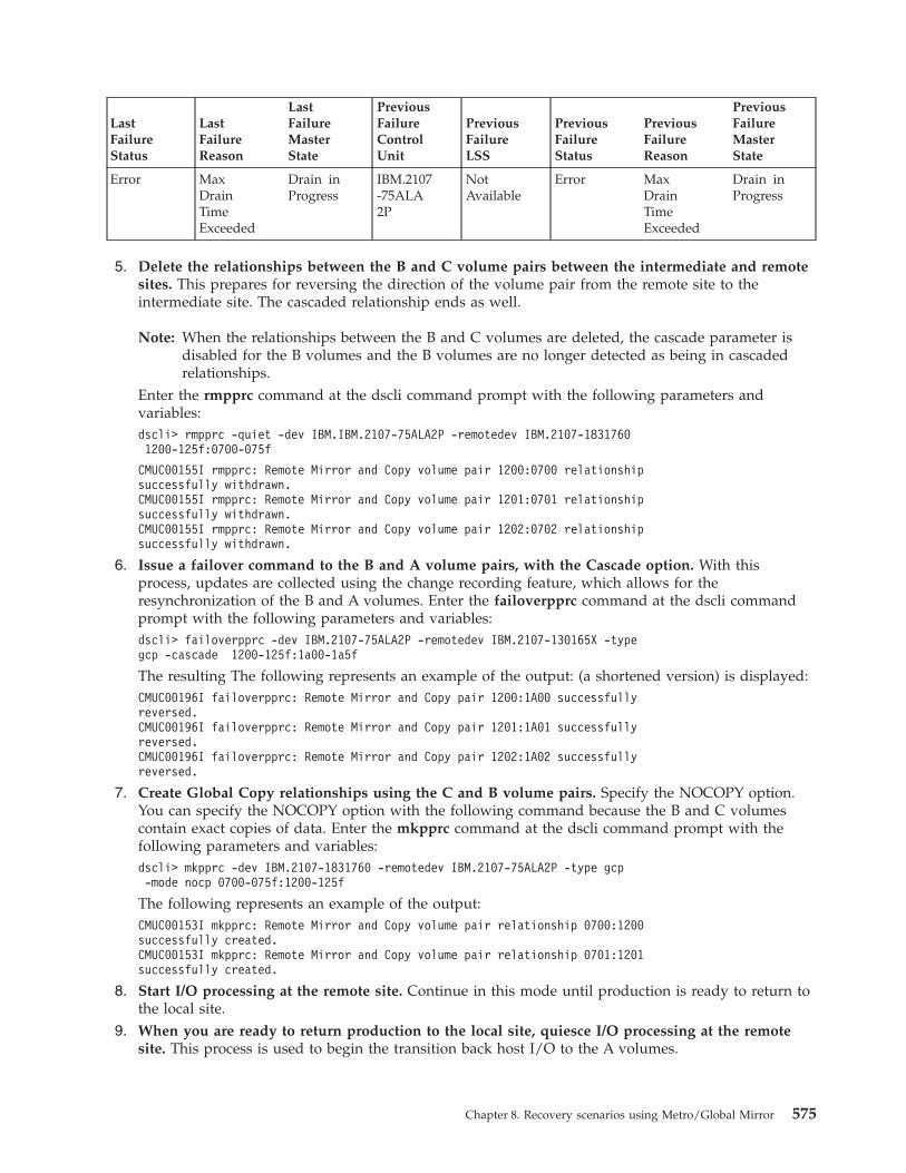
LastFailureStatus
LastFailureReason
LastFailureMasterState
PreviousFailureControlUnit
PreviousFailureLSS
PreviousFailureStatus
PreviousFailureReason
PreviousFailureMasterState
Error MaxDrainTimeExceeded
Drain inProgress
IBM.2107-75ALA2P
NotAvailable
Error MaxDrainTimeExceeded
Drain inProgress
5. Delete the relationships between the B and C volume pairs between the intermediate and remotesites. This prepares for reversing the direction of the volume pair from the remote site to theintermediate site. The cascaded relationship ends as well.
Note: When the relationships between the B and C volumes are deleted, the cascade parameter isdisabled for the B volumes and the B volumes are no longer detected as being in cascadedrelationships.
Enter the rmpprc command at the dscli command prompt with the following parameters andvariables:dscli> rmpprc -quiet -dev IBM.IBM.2107-75ALA2P -remotedev IBM.2107-18317601200-125f:0700-075f
CMUC00155I rmpprc: Remote Mirror and Copy volume pair 1200:0700 relationshipsuccessfully withdrawn.CMUC00155I rmpprc: Remote Mirror and Copy volume pair 1201:0701 relationshipsuccessfully withdrawn.CMUC00155I rmpprc: Remote Mirror and Copy volume pair 1202:0702 relationshipsuccessfully withdrawn.
6. Issue a failover command to the B and A volume pairs, with the Cascade option. With thisprocess, updates are collected using the change recording feature, which allows for theresynchronization of the B and A volumes. Enter the failoverpprc command at the dscli commandprompt with the following parameters and variables:dscli> failoverpprc -dev IBM.2107-75ALA2P -remotedev IBM.2107-130165X -typegcp -cascade 1200-125f:1a00-1a5f
The resulting The following represents an example of the output: (a shortened version) is displayed:CMUC00196I failoverpprc: Remote Mirror and Copy pair 1200:1A00 successfullyreversed.CMUC00196I failoverpprc: Remote Mirror and Copy pair 1201:1A01 successfullyreversed.CMUC00196I failoverpprc: Remote Mirror and Copy pair 1202:1A02 successfullyreversed.
7. Create Global Copy relationships using the C and B volume pairs. Specify the NOCOPY option.You can specify the NOCOPY option with the following command because the B and C volumescontain exact copies of data. Enter the mkpprc command at the dscli command prompt with thefollowing parameters and variables:dscli> mkpprc -dev IBM.2107-1831760 -remotedev IBM.2107-75ALA2P -type gcp-mode nocp 0700-075f:1200-125f
The following represents an example of the output:CMUC00153I mkpprc: Remote Mirror and Copy volume pair relationship 0700:1200successfully created.CMUC00153I mkpprc: Remote Mirror and Copy volume pair relationship 0701:1201successfully created.
8. Start I/O processing at the remote site. Continue in this mode until production is ready to return tothe local site.
9. When you are ready to return production to the local site, quiesce I/O processing at the remotesite. This process is used to begin the transition back host I/O to the A volumes.
Chapter 8. Recovery scenarios using Metro/Global Mirror 575

10. Wait for the number of out-of-sync tracks on the C and B volume to reach zero. You can monitorthis activity by querying the status of the C and B volumes. As soon as the number of out-of-synctracks reaches zero, all data has been copied and the data on the C and B volumes is equal. Allupdates that are needed to resynchronize the A volumes are recorded at the B volumes. Enter thelspprc command at the dscli command prompt with the following parameters and variables:dscli> lspprc -dev IBM.2107-1831760 -remotedev IBM.2107-75ALA2P -l -fmt default0700-075f
The following represents an example of the output:
ID State Reason Type
OutOfSyncTracks
TgtRead
SrcCascade
0700:1200 CopyPending
- GlobalCopy
0 Disabled Disabled
0701:1201 CopyPending
- GlobalCopy
0 Disabled Disabled
0702:1202 CopyPending
- GlobalCopy
0 Disabled Disabled
TgtCascade
DateSuspended
SourceLSS
Timeout(secs)
CritMode
FirstPassStatus
IncrementalResync
TgtWrite
Invalid - 07 Unknown Disabled True Enabled Enabled
Invalid - 07 Unknown Disabled True Enabled Enabled
Invalid - 07 Unknown Disabled True Enabled Enabled
11. Reestablish paths (that were disabled by the freeze operation) between the local site LSS andintermediate site LSS that contain the B to A Metro Mirror volume pairs. Enter the mkpprcpathcommand at the dscli command prompt with the following parameters and variables:dscli> mkpprcpath -dev IBM.2107-130165X -remotedev IBM.2107-75ALA2P-remotewwnn 5005076303FFC550 -srclss 61 -tgtlss 63 -consistgrpI0102:I0031 I0002:I0102
The following represents an example of the output:CMUC00149I mkpprcpath: Remote Mirror and Copy path 61:63successfully established.
See “Creating remote mirror and copy paths” on page 496 for more information.12. Issue a failback command to the B to A volume pairs. This command copies the changes back to
the A volumes that were made to the B volumes while hosts were running on the B volumes. The Avolumes are now synchronized with the B volumes. (In a DS CLI environment, where the local andintermediate sites use different management consoles, you have to use a different DS CLI session forthe management console of the B volumes at the intermediate site.) Enter the failbackpprc commandat the dscli command prompt with the following parameters and variables:dscli> failbackpprc -dev IBM.2107-75ALA2P -remotedev IBM.2107-130165X-type gcp 1200-125f:1a00-1a5f
The following represents an example of the output:CMUC00197I failbackpprc: Remote Mirror and Copy pair 1200:1A00 successfullyfailed back.CMUC00197I failbackpprc: Remote Mirror and Copy pair 1201:1A01 successfullyfailed back.CMUC00197I failbackpprc: Remote Mirror and Copy pair 1202:1A02 successfullyfailed back.
576 CLI User's Guide

See “Performing a failback recovery operation” on page 508 for more information.13. Wait for the copy process of the B and A volume pairs to reach full duplex (all out-of-sync tracks
have completed copying). You can monitor this activity by querying the status of the B and Avolumes. As soon as the number of out-of-sync tracks reaches zero, all data has been copied and thedata on the B and A volumes is equal. At this point, the data on volumes A, B, and C is equal. Enterthe lspprc command at the dscli command prompt with the following parameters and variables:dscli> lspprc -dev IBM.2107-75ALA2P -remotedev IBM.2107-130165X -l -fmt default1200-125f:1a00-1a5f
14. Delete the Global Copy relationships between the C and B volume pairs between theintermediate and remote sites. Deleting the Global Copy relationships between the C to B volumepairs prepares for restoring to the original Global Copy relationships between the B to C volumepairs. Enter the lspprc command at the dscli command prompt with the following parameters andvariables:dscli> rmpprc -quiet -dev IBM.2107-1831760 -remotedev IBM.2107-75ALA2P0700-075f:1200-125f
The following represents an example of the output:CMUC00155I rmpprc: Remote Mirror and Copy volume pair 0700:1200 relationshipsuccessfully withdrawn.CMUC00155I rmpprc: Remote Mirror and Copy volume pair 0701:1201 relationshipsuccessfully withdrawn.CMUC00155I rmpprc: Remote Mirror and Copy volume pair 0702:1202 relationshipsuccessfully withdrawn.
15. Issue a failover command to the A and B volume pairs. This process ends the Metro Mirrorrelationships between the B and A volumes and establishes the Metro Mirror relationships betweenthe A and B volumes. Enter the failoverpprc command at the dscli command prompt with thefollowing parameters and variables:dscli> failoverpprc -dev IBM.2107-130165X -remotedev IBM.IBM.2107-75ALA2P-type mmir 1a00-1a5f:1200-125f
The following represents an example of the output:CMUC00196I failoverpprc: Remote Mirror and Copy pair 1A00:1200successfully reversed.CMUC00196I failoverpprc: Remote Mirror and Copy pair 1A01:1201successfully reversed.CMUC00196I failoverpprc: Remote Mirror and Copy pair 1A02:1202successfully reversed.
16. Reestablish paths (that were disabled by the freeze operation) between the local site LSS and theintermediate site LSS that contain the B to A Metro Mirror volume pairs. Enter the mkpprcpathcommand at the dscli command prompt with the following parameters and variables:dscli> mkpprcpath -dev IBM.2107-130165X -remotedev IBM.2107-75ALA2P-remotewwnn 5005076303FFC550 -srclss 61 -tgtlss 63 -consistgrpI0102:I0031 I0002:I0102
The following represents an example of the output:CMUC00149I mkpprcpath: Remote Mirror and Copy path 61:63successfully established.
See “Creating remote mirror and copy paths” on page 496 for more information.17. Issue a failback command to the A to B volumes. This command copies the changes back to the A
volumes that were made to the B volumes in Metro Mirror relationships while hosts were runningon the B volumes. The A volumes are now synchronized with the B volumes. (In a DS CLIenvironment, where the local and intermediate sites use different management consoles, you have touse a different DS CLI session for the management console of the B volumes at the intermediatesite.) Enter the failbackpprc command at the dscli command prompt with the following parametersand variables:Enter the failbackpprc command at the dscli command prompt with the following parameters andvariables:
Chapter 8. Recovery scenarios using Metro/Global Mirror 577

dscli> failbackpprc -dev IBM.2107-130165X -remotedev IBM.2107-75ALA2P-type mmir 1a00-1a5f:1200-125f
The following represents an example of the output:CMUC00197I failbackpprc: Remote Mirror and Copy pair 1A00:1200successfully failed back.CMUC00197I failbackpprc: Remote Mirror and Copy pair 1A01:1201successfully failed back.CMUC00197I failbackpprc: Remote Mirror and Copy pair 1A02:1202successfully failed back.
See “Performing a failback recovery operation” on page 508 for more information.18. Reestablish the B to C volume pairs in Global Copy relationships. Specify the NOCOPY option
and the Cascade options. Enter the mkpprc command at the dscli command prompt with thefollowing parameters and variables:dscli> mkpprc -dev IBM.2107-75ALA2P -remotedev IBM.2107-1831760 -type gcp-mode nocp -cascade 1200-125f:0700-075f
The following represents an example of the output:CMUC00153I mkpprc: Remote Mirror and Copy volume pair relationship 1200:0700successfully created.CMUC00153I mkpprc: Remote Mirror and Copy volume pair relationship 1201:0701successfully created.CMUC00153I mkpprc: Remote Mirror and Copy volume pair relationship 1202:0702successfully created.
See “Creating a Global Copy relationship” on page 502 for more information.19. Use FlashCopy to create a copy of C source volumes to the D target volumes. Enter the mkflash
command at the dscli command prompt with the following parameters and variables. This creates abackup copy of the consistency group.dscli> mkflash -dev IBM.2107-1831760 -tgtinhibit -record -persist-nocp 1300-125f:1900-195f
The following represents an example of the output:CMUC00137I mkflash: FlashCopy pair 1300:1900 successfully created.CMUC00137I mkflash: FlashCopy pair 1301:1901 successfully created.CMUC00137I mkflash: FlashCopy pair 1302:1902 successfully created.
See “Creating FlashCopy relationships (Global Mirror setup)” on page 527 for more information.20. Resume Global Mirror processing. Enter the resumegmir command at the dscli command prompt
with the following parameters and variables:dscli> resumegmir -dev IBM.2107-75ALA2P -session 31 -lss
The following represents an example of the output:CMUC00164I resumegmir: Global Mirror for session 31 successfully resumed.
See “Resuming Global Mirror processing” on page 521 for more information.21. Resume host I/O processing to the A volumes.
Failover and restore operations at the remote site during an unplannedoutageUse this process to perform failover and restore operations (DS8000 only) at your remote (C) site duringan unplanned outage, using E volumes at the intermediate site.
578 CLI User's Guide

Before you begin
If possible, before you issue a failover operation to the remote site, ensure that data processing hascompletely stopped at the local and intermediate sites. If you fail to do so, data can be lost if you did notquiesce I/O processing to the local site before recovering at the remote site.
About this task
For this scenario, assume that host I/O processing is being sent to the local site in a Metro/Global Mirrorconfiguration. A failure occurs at the local (A) site and it is not possible to run your systems using the Bvolumes at the intermediate site. You can switch operations to your remote (C) site, which allows theprocessing of data to resume at site C. This process is known as a failover recovery. The Global Copyrelationship between volumes at the intermediate and remote site is still operational. Global Mirrorcontinues to operate between these two sites.
Note: The steps to perform a failover operation to the remote site (C) can be done using a single GDPSautomation script running in a GDPS Global Mirror remote controlling system. GDPS provides arecovery check function that determines the state of the volumes before the necessary actions toperform a recovery function are done. This process alerts the user to fix the required problembefore performing the actual recovery, which can reduce the time required to complete it.
Perform the following steps after a failure has been detected at the local site. (The steps in this scenarioare examples.)
Procedure1. If the local site was not completely destroyed, it is essential that data from any surviving A and B
volume pairs be copied and a consistent copy be achieved at the remote site. If possible and you areable to freeze write activity to the Metro Mirror primary volumes, perform the following steps:a. Freeze updates to the A volumes in Metro Mirror relationships across the affected LSSs. This
process ensures that the B volumes are consistent at the time of the freeze. (One command perLSS is required.) Enter the freezepprc command at the dscli command prompt with the followingparameters and variables:dscli> freezepprc -dev IBM.2107-130165X -remotedev IBM.2107-75ALA2P 07:12
The following represents an example of the output:CMUC00161W freezepprc: Remote Mirror and Copy consistency group 07:12successfully created.
As a result of the freeze action, the following processing occurs:v The established paths between the LSS pairs are deleted.v The volume pairs that are associated with the source and target LSSs are suspended. During
this time, the storage unit collects data that is sent to the A volumes that are in Metro Mirrorrelationships.
v I/O processing to the Metro Mirror volume pairs is temporarily queued during the time thatupdates are frozen.
b. Resume operations following a freeze.
Issue the unfreezepprc command to allow I/O activity to resume for the specified volume pairs.Enter the unfreezepprc command at the dscli command prompt with the following parametersand variables:
Note: This activity is sometimes referred to as a thaw operation.dscli> unfreezepprc -dev IBM.2107-130165X -remotedev IBM.2107-75ALA2P07:12
The following represents an example of the output:
Chapter 8. Recovery scenarios using Metro/Global Mirror 579

CMUC00198I unfreezepprc: Remote Mirror and Copy pair 07:12successfully thawed.
2. Verify that the last data from the local site has been included in a Global Mirror consistencygroup. Monitor this activity by querying the B and C volumes to determine when at least twosuccessful consistency groups have formed. The "Total Successful CG Count" field from the queryoutput displays this information.
Note: When you use the showgmir command with the -metrics parameter, you can monitor theprogress of the consistency group formation. When Global Mirror is running, the number ofconsistency groups is steadily growing each time you issue the showgmir command.
Enter the showgmir -metrics command at the dscli command prompt with the following parametersand variables:dscli> showgmir -metrics 10
The following represents an example of the output:
ID
TotalFailedCGCount
TotalSucces-sfulCGCount
Succes-sfulCGPercen-tage
FailedCGafterLastSuc-cess
LastSucces-sfulCGFormTime
Coord.Time(milli-seconds)
CGInter-valTime(sec-onds)
IBM.2107-75ALA2P/10
23 139 85 0 02/20/200611:33:56MST
50 0
MaxCGDrainTime(sec-onds)
FirstFailureControlUnit
FirstFailureLSS
FirstFailureStatus
FirstFailureReason
FirstFailureMasterState
LastFailureControlUnit
LastFailureLSS
30 IBM.2107-75ALA2P
0x12 Error SessionorSessionMembersnot inCorrectState
GlobalMirror
Run inProgress
IBM.2107-75ALA2P
NotAvailable
LastFailureStatus
LastFailureReason
LastFailureMasterState
Prev-iousFailureControlUnit
Prev-iousFailureLSS
Prev-iousFailureStatus
Prev-iousFailureReason
Prev-iousFailureMasterState
Error MaxDrainTimeExceed-ed
DraininProg-ress
IBM.2107-75ALA2P
NotAvail-able
Error MaxDrainTimeExceed-ed
DraininProg-ress
3. Stop the Global Mirror session from which the B and C volume pairs are included. Enter thermgmir command at the dscli command prompt with the following parameters and variables:dscli> rmgmir -quiet -lss 10 -session 31
The following represents an example of the output:
580 CLI User's Guide

CMUC00165I rmgmir: Global Mirror for session 31successfully stopped.
See “Ending Global Mirror processing (script mode)” on page 523 or “Ending Global Mirrorprocessing (no script)” on page 523 for more information.
4. Verify that the Global Mirror session has ended. Consistency groups do not form when GlobalMirror processing is stopped.See “Querying Global Mirror processing” on page 520 for more information.Enter the showgmir command at the dscli command prompt with the following parameters andvariables:dscli> showgmir 10
The following represents an example of the output:
IDMasterCount
MasterSessionID
CopyState
FatalReason
CGInter-val(sec-onds)
Coord.Time(milli-sec-onds)
CGDrainTime(sec-onds)
CurrentTime
IBM.2107-75ALA2P/10
- - - - - - - -
CGTime
Succes-sful CGPercen-tage
Flash-CopySequ-enceNumber
MasterID
Subor-dinateCount
Master/Subordi-nateAssoc.
- - - - - -
5. Delete the Global Copy relationships between the B and C volume pairs at the intermediate andremote sites. When the relationships between the B and C volumes are deleted, the cascadeparameter is disabled for the B volumes and the B volumes are no longer detected as being incascaded relationships. Enter the rmpprc command at the dscli command prompt with the followingparameters and variables:dscli> rmpprc -quiet -dev IBM.2107-75ALA2P -remotedev IBM.2107-18317601200-125f:0700-075f
The following represents an example of the output:CMUC00155I rmpprc: Remote Mirror and Copy volume pair 1200:0700 relationshipsuccessfully withdrawn.CMUC00155I rmpprc: Remote Mirror and Copy volume pair 1201:0701 relationshipsuccessfully withdrawn.CMUC00155I rmpprc: Remote Mirror and Copy volume pair 1202:0702 relationshipsuccessfully withdrawn.
See “Deleting a Metro Mirror relationship” on page 503 for more information.6. Issue a failover command to the B volumes with the Cascade option. With this process, updates
are collected using the change recording feature, which allows the later resynchronization of the B toA volumes. Enter the failoverpprc command at the dscli command prompt with the followingparameters and variables:dscli> failoverpprc -dev IBM.2107-75ALA2P -remotedev IBM.2107-130165X-type gcp -cascade 1200-125f:1a00-1a5f
The following represents an example of the output:
Chapter 8. Recovery scenarios using Metro/Global Mirror 581

CMUC00196I failoverpprc: Remote Mirror and Copy pair 1200:1A00successfully reversed.CMUC00196I failoverpprc: Remote Mirror and Copy pair 1201:1A01successfully reversed.CMUC00196I failoverpprc: Remote Mirror and Copy pair 1202:1A02successfully reversed.
See “Performing a failover recovery operation” on page 509 for more information.7. Create Global Copy relationships using the C and B volume pairs. Specify the NOCOPY option.
Enter the mkpprc command at the dscli command prompt with the following parameters andvariables:
Note: You can specify the NOCOPY option with the following commands because the B and Cvolume pairs contain exact copies of data.
dscli> mkpprc -dev IBM.2107-1831760 -remotedev IBM.2107-75ALA2P -type gcp-mode nocp 0700-075f:1200-125f
The following represents an example of the output:CMUC00153I mkpprc: Remote Mirror and Copy volume pair relationship 0700:1200successfully created.CMUC00153I mkpprc: Remote Mirror and Copy volume pair relationship 0701:1201successfully created.CMUC00153I mkpprc: Remote Mirror and Copy volume pair relationship 0702:1202successfully created.
See “Creating a Global Copy relationship” on page 502 for more information.8. Use FlashCopy to create a copy of B source volumes to E target volumes. Specify the following
options: Persistent and Start Change Recording. This creates a backup copy of the consistency group.Enter the mkflash command at the dscli command prompt with the following parameters andvariables:dscli> mkflash -dev IBM.2107-75ALA2P -tgtinhibit -record -persist -nocp1200-125f:1900-195f
The following represents an example of the output:CMUC00137I mkflash: FlashCopy pair 1200:1900 successfully created.CMUC00137I mkflash: FlashCopy pair 1201:1901 successfully created.CMUC00137I mkflash: FlashCopy pair 1202:1902 successfully created.
See “Creating FlashCopy relationships (Global Mirror setup)” on page 527 for more information.9. Create a Global Mirror session using the C volumes. Enter the mksession command at the dscli
command prompt with the following parameters and variables:dscli> mksession -lss 07 1
The following represents an example of the output:CMUC00145I mksession: Session 1 opened successfully.
See “Creating the Global Mirror session” on page 528 for more information.10. Start the Global Mirror session from which the C, B and E volumes are included. Enter the
mkgmir command at the dscli command prompt with the following parameters and variables:dscli> mkgmir -lss 07 -session 1
The following represents an example of the output:CMUC00162I mkgmir: Global Mirror for session 1 successfully started.
See “Starting Global Mirror processing” on page 522 for more information.11. Verify that the Global Mirror session has started. Enter the showgmir command at the dscli
command prompt with the following parameters and variables:dscli> showgmir 07
The following represents an example of the output:
582 CLI User's Guide

IDMasterCount
MasterSessionID
CopyState
FatalReason
CGInter-val(sec-onds)
Coord.Time(milli-seconds)
CGDrainTime(sec-onds)
CurrentTime
IBM.2107-75ALA2P/07
1 0x01 Running Not Fatal 0 50 30 02/20/200611:37:40
MST
CGTime
Succes-sful CGPercen-tage
Flash-CopySequ-enceNumber
MasterID
Subor-dinateCount
Master/Subordi-nateAssoc.
02/20/200611:37:40
MST
100 0x4357E-3F4
IBM.2107-75ALA2P/07
0 -
12. Allow the I/O to run and monitor the formation of the consistency groups. Enter the showgmircommand at the dscli command prompt with the following parameters and variables:dscli> showgmir 07
The following represents an example of the output:
IDMasterCount
MasterSessionID
CopyState
FatalReason
CGInter-val(sec-onds)
Coord.Time(milli-sec-onds)
CGDrainTime(sec-onds)
CurrentTime
IBM.2107-75ALA2P/07
1 0x01 Running Not Fatal 0 50 30 02/20/200611:37:40
MST
CGTime
Succes-sful CGPercen-tage
Flash-CopySequ-enceNumber
MasterID
Subor-dinateCount
Master/Subordi-nateAssoc.
02/20/200611:37:40
MST
100 0x4357E3-F4
IBM.2107-75ALA2P/07
0 -
13. When the local site is ready to return, issue a failback command to the B and A volumes. Beforethe applications are started at the local site, data at the local site has to be copied from theintermediate site. Issue the failbackpprc command to start copying data from the B volumes at theintermediate site to the A volumes at the local site while hosts are running on the B volumes. Whenall data is copied, the A volumes are synchronized with the B volumes.
Note: In a DS CLI environment, where the local and intermediate sites use different managementconsoles, you have to use a different DS CLI session for the management console of the Bvolumes at the intermediate site.
Chapter 8. Recovery scenarios using Metro/Global Mirror 583

Enter the failbackpprc command at the dscli command prompt with the following parameters andvariables:dscli> failbackpprc -dev IBM.2107-130165X -remotedev IBM.2107-75ALA2P-type gcp -cascade 1200-125f:1a00-1a5f
The following represents an example of the output:CMUC00197I failbackpprc: Remote Mirror and Copy pair 1200:1A00 successfullyfailed back.CMUC00197I failbackpprc: Remote Mirror and Copy pair 1201:1A01 successfullyfailed back.CMUC00197I failbackpprc: Remote Mirror and Copy pair 1202:1A02 successfullyfailed back.
See “Performing a failback recovery operation” on page 508 for more information.14. Wait for the copy operation of the B and A volumes to reach full duplex status (all out-of-sync
tracks have completed copying). You can monitor this activity by querying the status of the B and Avolume pairs. Enter the lspprc command at the dscli command prompt with the followingparameters and variables:dscli> lspprc -dev IBM.2107-75ALA2P -remotedev IBM.2107-130165X -l-fmt default 1200-125f
The following represents an example of the output:
ID State Reason Type
OutOfSyncTracks
TgtRead
SrcCascade
1200:1a00 CopyPending
- GlobalCopy
0 Disabled Enabled
1201:1a01 CopyPending
- GlobalCopy
0 Disabled Enabled
1201:1a02 CopyPending
- GlobalCopy
0 Disabled Enabled
TgtCascade
DateSuspended
SourceLSS
Timeout(secs)
CritMode
FirstPassStatus
IncrementalResync
TgtWrite
Invalid - 12 Unknown Disabled True Enabled Enabled
Invalid - 12 Unknown Disabled True Enabled Enabled
Invalid - 12 Unknown Disabled True Enabled Enabled
15. End I/O processing to the C volumes.. Enter the rmgmir command at the dscli command promptwith the following parameters and variables:dscli> rmgmir -quiet -lss 07 -session 1
The following represents an example of the output:CMUC00165I rmgmir: Global Mirror for session 1 successfully stopped.
See “Ending Global Mirror processing (script mode)” on page 523 or “Ending Global Mirrorprocessing (no script)” on page 523 for more information.
16. Verify that at least two consistency groups have formed. Assuming that the consistency groupsformed successfully, the A, B, C, and E volumes contain consistent data. (Data at the remote site isconsistent to the last successful consistency group formed by the master storage unit.)See “QueryingGlobal Mirror processing” on page 520 for more information.Enter the showgmir -metrics command at the dscli command prompt with the following parametersand variables:
584 CLI User's Guide

dscli> showgmir -metrics 07
The following represents an example of the output:
ID
TotalFailedCGCount
TotalSucces-sful CGCount
Succes-sful CGPercent-age
FailedCG afterLastSuccess
LastSucces-sful CGFormTime
Coord.Time(milli-sec-onds)
CGIntervalTime(sec-onds)
IBM.2107-75ALA2P/10
0 55 100 0 02/20/200611:38:25MST
50 0
MaxCGDrainTime(seconds)
FirstFailureControlUnit
FirstFailureLSS
FirstFailureStatus
FirstFailureReason
FirstFailureMasterState
LastFailureControlUnit
LastFailureLSS
30 - - No Error - - - -
LastFailureStatus
LastFailureReason
LastFailureMasterState
Prev-iousFailureControlUnit
Prev-iousFailureLSS
PreviousFailureStatus
PreviousFailureReason
Prev-iousFailureMasterState
No Error - - - - No Error - -
17. End the Global Mirror session between the C, B, and E volumes. Enter the rmgmir command atthe dscli command prompt with the following parameters and variables:dscli> rmgmir -quiet -lss 07 -session 1
The resulting output is displayed:CMUC00165I rmgmir: Global Mirror for session 1 successfully stopped
See “Ending Global Mirror processing (script mode)” on page 523 or “Ending Global Mirrorprocessing (no script)” on page 523 for more information.
18. Verify that the Global Mirror session that includes the C, B, and E volumes has stopped. Enter theshowgmir command at the dscli command prompt with the following parameters and variables.showgmir 07
The following represents an example of the output:
ID
TotalFailedCGCount
TotalSucces-sful CGCount
Succes-sful CGPercen-tage
FailedCG afterLastSuccess
LastSucces-sful CGFormTime
Coord.Time(milli-sec-onds)
CGIntervalTime(sec-onds)
IBM.2107-75ALA2P/10
23 139 85 0 02/20/200611:33:56MST
50 0
Chapter 8. Recovery scenarios using Metro/Global Mirror 585

MaxCGDrainTime(seconds)
FirstFailureControlUnit
FirstFailureLSS
FirstFailureStatus
FirstFailureReason
FirstFailureMasterState
LastFailureControlUnit
LastFailureLSS
30 IBM.2107-75ALA2P
0x12 Error SessionorSessionMembersnot inCorrectState
GlobalMirror
Run inProgress
IBM.2107-75ALA2P
NotAvailable
LastFailureStatus
LastFailureReason
LastFailureMasterState
PreviousFailureControlUnit
PreviousFailureLSS
PreviousFailureStatus
PreviousFailureReason
PreviousFailureMasterState
Error MaxDrainTimeExceeded
Drain inProgress
IBM.2107-75ALA2P
NotAvailable
Error MaxDrainTimeExceeded
Drain inProgress
See “Querying Global Mirror processing” on page 520 for more information.19. At the remote site, remove the C volumes (or Global Copy secondary volumes) from the Global
Mirror session that includes the C, B, and E volumes. Enter the chsession command at the dsclicommand prompt with the following parameters and variables:dscli> chsession -dev BM.2107-75ALA2P -action remove -volume 1200-125f-lss 07 1
The resulting output is displayed:CMUC00147I chsession: Session 1 successfully modified.
See “Removing volumes from a session (Global Mirror)” on page 529 for more information.20. Delete the Global Copy relationships between the C to B volumes between the intermediate and
remote sites. Deleting the Global Copy relationships between the C to B volume pairs prepares forrestoring to the original Global Copy relationships between the B to C volume pairs. The cascadedrelationship ends, as well.Enter the rmpprc command at the dscli command prompt with the following parameters andvariables:dscli> rmpprc -quiet -dev IBM.2107-1831760 -remotedev IBM.2107-75ALA2P0700-075f:1200-125f
CMUC00155I rmpprc: Remote Mirror and Copy volume pair 0700:1200 relationshipsuccessfully withdrawn.CMUC00155I rmpprc: Remote Mirror and Copy volume pair 0701:1201 relationshipsuccessfully withdrawn.CMUC00155I rmpprc: Remote Mirror and Copy volume pair 0702:1202 relationshipsuccessfully withdrawn.
See “Deleting a Metro Mirror relationship” on page 503 for more information.21. Issue a failover command to the A to B volumes. This process ends the Metro Mirror relationships
between the B and A volumes and establishes the Metro Mirror relationships between the A and Bvolume pairs. Enter the failoverpprc command at the dscli command prompt with the followingparameters and variables:failoverpprc -dev IBM.2107-130165X -remotedev IBM.2107-75ALA2P -type mmir1a00-1a5f:1200-125f
The following represents an example of the output:
586 CLI User's Guide

CMUC00196I failoverpprc: Remote Mirror and Copy pair 1A00:1200 successfullyreversed.CMUC00196I failoverpprc: Remote Mirror and Copy pair 1A01:1201 successfullyreversed.CMUC00196I failoverpprc: Remote Mirror and Copy pair 1A02:1202 successfullyreversed.
22. Reestablish paths that were disabled by the freeze operation between the local site LSS andintermediate site LSS that contain the B to A Metro Mirror volume pairs. Enter the mkpprcpathcommand at the dscli command prompt with the following parameters and variables:dscli> mkpprcpath -dev IBM.2107-75ALA2P -remotedev IBM.2107-130165X-remotewwnn 5005076303FFC550 -srclss 61 -tgtlss 63 -consistgrpI0102:I0031 I0002:I0102
The resulting output is displayed:CMUC00149I mkpprcpath: Remote Mirror and Copy path 61:63successfully established.
See “Reestablishing remote mirror and copy paths (site A to site B)” on page 551 for moreinformation.
23. Issue a failback command to the A and B volumes. This command copies the changes back to theA volumes that were made to the B volumes in Metro Mirror relationships while hosts were runningon the B volumes. The A volumes are now synchronized with the B volumes. (In a DS CLIenvironment, where the local and intermediate sites use different management consoles, you have touse a different DS CLI session for the management console of the B volumes at the intermediatesite.) Enter the failbackpprc command at the dscli command prompt with the following parametersand variables:dscli> failbackpprc -dev IBM.2107-130165X -remotedev IBM.2107-75ALA2P-type mmir 1a00-1a5f:1200-125f
The following represents an example of the output:CMUC00197I failbackpprc: Remote Mirror and Copy pair 1A00:1200 successfullyfailed back.CMUC00197I failbackpprc: Remote Mirror and Copy pair 1A01:1201 successfullyfailed back.CMUC00197I failbackpprc: Remote Mirror and Copy pair 1A02:1202 successfullyfailed back.
24. Establish the B and C volume pairs in Global Copy relationships. Enter the mkpprc command atthe dscli command prompt with the following parameters and variables:dscli> mkpprc -dev IBM.2107-75ALA2P -remotedev IBM.2107-1831760 -type gcp-mode nocp -cascade 1200-125f:0700-075f
The following represents an example of the output:CMUC00153I mkpprc: Remote Mirror and Copy volume pair relationship 1200:0700successfully created.CMUC00153I mkpprc: Remote Mirror and Copy volume pair relationship 1201:0701successfully created.CMUC00153I mkpprc: Remote Mirror and Copy volume pair relationship 1202:0702successfully created
See “Creating a Global Copy relationship” on page 502 for more information.25. Optionally, you can issue a FlashCopy operation to create a backup copy of all the C, B, and E
volumes from which the last consistency group was created. If you need to preserve data from theset of volumes (or consistency group) that was created using the E volumes, allow the backgroundcopy from the FlashCopy process to complete before you continue to the next step, which describesremoving the FlashCopy relationship between the B to E volume pairs.Enter the mkflash command at the dscli command prompt with the following parameters andvariables:dscli> mkflash -dev IBM.2107-75ALA2P -tgtinhibit -record -persist -nocp1200-125f:1900-195f
Chapter 8. Recovery scenarios using Metro/Global Mirror 587

The following represents an example of the output:CMUC00137I mkflash: FlashCopy pair 1200:1900 successfully created.CMUC00137I mkflash: FlashCopy pair 1201:1901 successfully created.
See “Creating FlashCopy relationships (Global Mirror setup)” on page 527 for more information.26. Delete the FlashCopy relationship between the B and E volume pairs to end the relationship at
the intermediate site. Enter the rmflash command at the dscli command prompt with the followingparameters and variables:dscli> rmflash -dev IBM.2107-75ALA2P -quiet 1200-125f:1900-195f
The following represents an example of the output:CMUC00140I rmflash: FlashCopy pair 1200:1900 successfully removed.CMUC00140I rmflash: FlashCopy pair 1201:1901 successfully removed.
See “Removing FlashCopy relationships” on page 531 for more information.27. Resume Global Mirror at the intermediate site. This starts Global Mirror processing for the B, C ,
and D volumes.Enter the resumegmir command at the dscli command prompt with the following parameters andvariables:dscli> resumegmir -dev IBM.2107-75ALA2P -session 10 -lss 31
The resulting output is displayed:CMUC00164I resumegmir: Global Mirror for session 10 successfully resumed.
See “Resuming Global Mirror processing” on page 521 for more information.28. Resume I/O on A volumes.
29. Verify that consistency groups are forming successfully.
Enter the showgmir -metrics command at the dscli command prompt with the following parametersand variables:dscli> showgmir -metrics 10
The following represents an example of the output:
ID
TotalFailedCGCount
TotalSucces-sful CGCount
Succes-sful CGPercen-tage
FailedCG afterLastSuccess
LastSucces-sful CGFormTime
Coord.Time(milli-sec-onds)
CGInter-valTime(sec-onds)
IBM.2107-75ALA2P/10
1 39 97 0 02/20/200611:33:56MST
50 0
MaxCGDrainTime(seconds)
FirstFailureControlUnit
FirstFailureLSS
FirstFailureStatus
FirstFailureReason
FirstFailureMasterState
LastFailureControlUnit
LastFailureLSS
30 IBM.2107-75ALA2P
0x12 Error SessionorSessionMembersnot inCorrectState
GlobalMirror
Run inProgress
IBM.2107-75ALA2P
0x12
588 CLI User's Guide

LastFailureStatus
LastFailureReason
LastFailureMasterState
PreviousFailureControlUnit
PreviousFailureLSS
PreviousFailureStatus
PreviousFailureReason
PreviousFailureMasterState
Error SessionorSessionMembersnot inCorrectState
GlobalMirror
Run inProgress
- - No Error - Drain inProgress
See “Querying Global Mirror processing” on page 520 for more information.
Using forced failover and failback during a planned Metro/GlobalMirror outageUse this process to perform failover operations (DS8000 only) from the local (A) site to the intermediate(B) site during a planned outage.
Before you begin
The following assumptions apply to your 3-site Metro/Global Mirror configuration:v You used incremental resynchronization to establish the relationship between your site A and site B
volumes and between your site A and site C volumes.v You established a Global Mirror session at the local site. This means that Fibre Channel paths were
established between all Global Mirror source and target pairs and between the master and subordinatestorage units.
The command examples use the following site identifiers:v Site A is identified as 2107-130165Xv Site B is identified as 2107-75ALA2Pv Site C is identified as 2107-183176O
About this task
This process uses forced failover and forced failback processing to establish a relationship between the Cand A volumes without verification that this relationship already existed. A -force parameter has beenadded to the failoverpprc and failbackpprc commands to accommodate this processing.
Attention: Use the -force parameter only as directed. This parameter can cause severe damage to yourdata if it is misused. Contact IBM Support before you attempt to use the -force parameter if your outagesituation is outside the boundaries of this example.
Perform the following steps to failover and restore operations to the intermediate (B) site.
Procedure1. At the local site, ensure that data consistency is achieved between the site A and site B volumes.
You can use freeze and unfreeze commands that are supported using external automation softwareto create data consistency to multiple Metro Mirror volume pairs.To freeze write activity to Metro Mirror primary volumes, perform the following steps:
Chapter 8. Recovery scenarios using Metro/Global Mirror 589

a. Freeze updates to the A volumes in Metro Mirror relationships across the affected LSSs. Thisensures that the B volumes will be consistent at the time of the freeze process. (One commandper LSS is required.)Enter the freezepprc command at the dscli command prompt with the following parameters andvariables:dscli> freezepprc -dev IBM.2107-130165X -remotedev IBM.2107-75ALA2P 07-12
The following represents an example of the output:CMUC00161W freezepprc: Remote Mirror and Copy consistency group 07:12successfully created.
As a result of the freeze action, the following processing occurs:v The established Remote Mirror and Copy paths between the LSS pairs are deleted.v The volume pairs that are associated with the source and target LSSs are suspended. During
this time, the storage unit collects data that is sent to the A volumes in Metro Mirrorrelationships.
v I/O to the Metro Mirror volume pairs is temporarily queued.b. Resume operations following a freeze. This operation—also called a thaw operation—allows
I/O processing to resume for the specified volume pairs.Enter the unfreezepprc command at the dscli command prompt with the following parametersand variables:dscli> unfreezepprc -dev IBM.2107-130165X -remotedev IBM.2107-75ALA2P
07:12
The following represents an example of the output:CMUC00198I unfreezepprc: Remote Mirror and Copy pair 07:12successfully thawed.
2. Create a relationship from the C volumes to the A volumes, using the -force and -cascadeparameters. No validation is done at site C to determine that site C is a secondary of site A.
Note: For this step to succeed you must ensure that the Remote Mirror and Copy paths between allGlobal Mirror source and target pairs and between the Master and subordinate storage unitshave been created.
Enter the failoverpprc command at the dscli prompt with the following parameters and variables:dscli>failoverpprc -dev storage_image_ID -remotedev storage_image_ID-type gcp -cascade -force SourceVolumeID:TargetVolumeID
Exampledscli> failoverpprc -dev IBM.2107-183176O -remotedev IBM.2107-130165X -typegcp -cascade -force 1200-125f:1A00-1A5f
The following represents an example of the output:CMUC00196I failoverpprc: Remote Mirror and Copy pair 1200:1A00successfully reversed.CMUC00196I failoverpprc: Remote Mirror and Copy pair 1201:1A01successfully reversed.CMUC00196I failoverpprc: Remote Mirror and Copy pair 1202:1A02successfully reversed.
3. End the Metro Mirror relationship between the A to B volumes at the B volumes intermediatesite.
Enter the rmpprc command at the dscli command prompt with the following parameters andvariables:dscli>rmpprc -dev storage_image_ID -remotedev storage_image_ID-at tgt -unconditional -quiet TargetVolumeID
Exampledscli>rmpprc -dev IBM.2107-75ALA2P -remotedev IBM.2107-130165X-at tgt -unconditional -quiet 1200-125f
590 CLI User's Guide

4. Redirect host I/O processing to the B volumes. Changes are recorded on the B volumes until the Avolumes can be resynchronized with the B volumes. Also, Global Mirror continues to operate fromsite B to site C.
Note: You can run in this configuration until the A site has recovered and you want to restoreoperations there. Begin the next step after the A volumes have been recovered and you're stillin production on the B volumes.
5. Copy changes from site C back to site A, using the -force parameter. Host I/O processingcontinues uninterrupted to the B volumes while the A volumes are made current. (The data is stillflowing from B to C, so any changes made to B are being transferred to C and therefore will getfrom C to A.) This command copies the changes back to the A volumes that were made to the Bvolumes while hosts were running on the A volumes. (In a DS CLI environment, where the local andremote sites are not using the same management console, you have to use the management consoleof the remote site.)Enter the failbackpprc command at the dscli command prompt with the following parameters andvariables:dscli>failbackpprc -dev storage_image_ID -remotedev storage_image_ID-type gcp -force SourceVolumeID:TargetVolumeID
Exampledscli> failbackpprc -dev IBM.2107-183176O -remotedev IBM.2107-130165X-type gcp -force 1200-125f:1A00-1A5f
The following represents an example of the output:CMUC00197I failbackpprc: Remote Mirror and Copy pair 1200:1A00successfully failed back.CMUC00197I failbackpprc: Remote Mirror and Copy pair 1201:1A01successfully failed back.CMUC00197I failbackpprc: Remote Mirror and Copy pair 1202:1A02successfully failed back.
6. Wait for the first pass copy to complete from site C to site A. Issue the lspprc command if youwant to monitor this activity and determine when the first pass status changes to “True.”Enter the lspprc command at the dscli command prompt with the following parameters andvariables:dscli>lspprc -dev storage_image_ID -remotedev storage_image_ID-l SourceVolumeID:TargetVolumeID
Exampledscli>lspprc -dev IBM.2107-183176O -remotedev IBM.2107-75130165X -l1200-125f:1A00-1A5f
The following represents the first two lines of the report generated by the lspprc command:
ID State Reason TypeSource-LSS
Time-out(secs)
CriticalMode
FirstPassStatus
IBM.2107-183176O/2101:IBM.2107-130165X/2101
CopyPend-ing
- GlobalCopy
IBM.2107-130165X/20
300 Disabled True
IBM.2107-183176O/2100:IBM.2107-130165X/2100
CopyPend-ing
- GlobalCopy
IBM.2107-130165X/20
300 Disabled True
Chapter 8. Recovery scenarios using Metro/Global Mirror 591
7. Modify Global Copy relationships between the B and C volume pairs. Specify the NOCOPYoption and initiate incremental resynchronization without initialization.Enter the mkpprc command at the dscli command prompt with the following parameters andvariables:dscli>mkpprc -dev storage_image_ID -remotedev storage_image_ID-type gcp -incrementalresync enablenoinit -mode nocpSourceVolumeID:TargetVolumeID
Exampledscli> mkpprc -dev IBM.2107-75ALA2P -remotedev IBM2107-183176O -type gcp-incrementalresync enablenoinit -mode nocp 1200-125f:1A00-1A5f
The following represents the first two lines of the output:CMUC00153I mkpprc: Remote Mirror and Copy volume pairrelationship 1200:1A00 successfully created.CMUC00153I mkpprc: Remote Mirror and Copy volume pairrelationship 1201:1A01 successfully created.
8. Begin the process to return production to site A. First, the Global Mirror session at site B must bestopped.Enter the rmgmir command at the dscli command prompt with the following parameters andvariables:dscli>rmgmir -dev storage_image_ID -lss LSS_ID -session session_IDMaster_Control_Path_LSS_ID:Subordinate_Control_Path_LSS_ID
Exampledscli> rmgmir -dev IBM.2107-75ALA2P -quiet -lss 07 -session 1
The following represents an example of the output:CMUC00165I rmgmir: Global Mirror for session 1 successfully terminated.
9. Verify that the Global Mirror session has ended.
Enter the showgmir command at the dscli command prompt with the following parameters andvariables:dscli> showgmir -dev storage_image_ID LSS_ID
Exampledscli> showgmir -dev IBM.2107-75ALA2P 10
In the resulting report, the output indicates in the Copy State field whether the session has stopped.10. Suspend the B to C volume pairs. This step stops the transfer of data between the B and C volume
pairs.Enter the pausepprc command at the dscli command prompt with the following parameters andvariables:dscli> pausepprc -dev storage_image_ID_-remotedev storage_image_IDSourceVolumeID:TargetVolumeID
Exampledscli> pausepprc -dev IBM.2107-75ALA2P -remotedev IBM.2107-183176O1200-125f:0700-075f
The following represents an example of the output:CMUC00157I pausepprc: Remote Mirror and Copy volume pair 1200:0700 relationshipsuccessfully paused.CMUC00157I pausepprc: Remote Mirror and Copy volume pair 1201:0701 relationshipsuccessfully paused.
11. Wait until all of the out-of-sync (OOS) tracks have drained from the C and A volume pairs andthe OOS count at C is zero. If you want to monitor this process, issue the lspprc command to querythe status of the C to A volume pairs in Global Copy relationships.Enter the lspprc command at the dscli command prompt with the following parameters andvariables:
592 CLI User's Guide

dscli>lspprc -dev storage_image_ID -remotedev storage_image_ID-l SourceVolumeID:TargetVolumeID
Exampledscli> lspprc -dev IBM.2107-183186O -remotedev IBM.2107-75ALA2P -l1200-125f:0700-075f
12. Suspend the C and A volume pairs.
Enter the pausepprc command at the dscli command prompt with the following parameters andvariables:dscli> pausepprc -dev storage_image_ID_-remotedev storage_image_IDSourceVolumeID:TargetVolumeID
Exampledscli> pausepprc -dev IBM.2107-183176O -remotedev IBM.2107-130165X1200-125f:0700-075f
The following represents an example of the output:CMUC00157I pausepprc: Remote Mirror and Copy volume pair 1200:0700 relationshipsuccessfully paused.CMUC00157I pausepprc: Remote Mirror and Copy volume pair 1201:0701 relationshipsuccessfully paused.
13. End the Global Copy relationship between the B to C volumes at the C remote volume site.
Enter the rmpprc command at the dscli command prompt with the following parameters andvariables:dscli>rmpprc -dev storage_image_ID -remotedev storage_image_ID-at tgt -unconditional -quiet TargetVolumeID
Exampledscli>rmpprc -dev IBM.2107-75ALA2P -remotedev IBM.2107-183176O-at tgt -unconditional -quiet 1A00-1A5f
14. Reverse the direction by making the site A volumes a suspended primary site. Use thefailoverpprc command for A to C with cascading allowed and specifying Global Copy mode.Enter the failoverpprc command at the dscli command prompt with the following parameters andvariables:dscli>failoverpprc -dev storage_image_ID -remotedev storage_image_ID-type gcp -cascade SourceVolumeID:TargetVolumeID
Exampledscli> failoverpprc -dev IBM.2107-130165X -remotedev IBM.2107-183176O-type gcp -cascade 1A00-1A5f:1200-125f
The following represents an example of the output:CMUC00196I failoverpprc: Remote Mirror and Copy pair 1A00:1200successfully reversed.CMUC00196I failoverpprc: Remote Mirror and Copy pair 1A01:1201successfully reversed.
15. Resynchronize the A to C relationships.
Enter the failbackpprc command at the dscli command prompt with the following parameters andvariables:dscli>failbackpprc -dev storage_image_ID -remotedev storage_image_ID-type gcp SourceVolumeID:TargetVolumeID
Exampledscli> failoverpprc -dev IBM.2107-130165X -remotedev IBM.2107-183176O-type gcp -cascade 1A00-1A5f:1200-125f
The following represents an example of the output:CMUC00196I failoverpprc: Remote Mirror and Copy pair 1A00:1200successfully failedback.CMUC00196I failoverpprc: Remote Mirror and Copy pair 1A01:1201successfully failedback.
Chapter 8. Recovery scenarios using Metro/Global Mirror 593

16. Establish Metro Mirror relationships between the A to B volumes using the incrementalresynchronization function and the override option. As a result of this step, the relationshipverification is bypassed and the incremental resynchronization function stops. The system determineswhich data to copy, so a full volume copy is bypassed and only changes are copied from the A to BMetro Mirror volume pairs.Enter the mkpprc command at the dscli command prompt with the following parameters andvariables:dscli>mkpprc -remotedev storage_image_ID -dev storage_image_IDtype mmir -mode nocp -incrementalresync override SourceVolumeID:TargetVolumeID
Exampledscli>mkpprc -remotedev IBM.2107-75ALA2P -dev IBM.2107-130165X -type mmir-mode nocp -incrementalresync override 2100-2107:2100-2107
The following represents an example of the output:CMUC00153I mkpprc: Remote Mirror and Copy volume pair relationship 2100:2100successfully created.CMUC00153I mkpprc: Remote Mirror and Copy volume pair relationship 2101:2101successfully created.
17. Start incremental resynchronization with the initialization option on the B volumes in MetroMirror relationships. Issue the mkpprc command at the intermediate site with the-incrementalresync enable parameter specified.Enter the mkpprc command at the dscli command prompt with the following parameters andvariables:dscli>mkpprc -dev storage_image_ID -remotedev storage_image_ID-type mmir -mode nocp -incrementalresync enable SourceVolumeID:TargetVolumeID
Exampledscli>mkpprc -dev IBM.2107-130165X -remotedev 2107-75ALA2P -type mmir-mode nocp -incrementalresync enable 2100-2107:2100-2107
The following represents an example of the output:CMUC00153I mkpprc: Remote Mirror and Copy volume pair relationship 2100:2100successfully created.CMUC00153I mkpprc: Remote Mirror and Copy volume pair relationship 2101:2101successfully created.
18. Wait for the B to A volume pairs to reach the full duplex state. Issue the lspprc command if youwant to monitor this activity.Enter the lspprc command at the dscli command prompt with the following parameters andvariables:dscli>lspprc -dev storage_image_ID -remotedev storage_image_ID-l SourceVolumeID:TargetVolumeID
Exampledscli>lspprc -dev IBM.2107-75ALA2P -remotedev IBM.2107-130165X -l1200-125f:1A00-1A5f
19. Start the Global Mirror session at the local site.
Enter the mkgmir command at the dscli command prompt with the following parameters andvariables (from the local site):dscli>mkgmir -dev storage_image_ID -lss LSS_ID -session session_ID
Exampledscli>mkgmir -remotedev IBM.2107-75ALA2P -lss 07 -session 31
The following represents an example of the output:CMUC00162I mkgmir: Global Mirror for session 31 successfully started.
When this step is processed, the Metro/Global Mirror operations are running from site B to site A tosite C. You are now ready to transition back to your original configuration, where site A is yourproduction site.
594 CLI User's Guide

20. Quiesce host I/O processing to the B volumes.
21. Suspend the B to A processing.
Enter the pausepprc command at the dscli command prompt with the following parameters andvariables:dscli> pausepprc -dev storage_image_ID_-remotedev storage_image_IDSourceVolumeID:TargetVolumeID
Exampledscli> pausepprc -dev IBM.2107-75ALA2P -remotedev IBM.2107-130165X1200-125f:0700-075f
The following represents an example of the output:CMUC00157I pausepprc: Remote Mirror and Copy volume pair 1200:0700 relationshipsuccessfully paused.CMUC00157I pausepprc: Remote Mirror and Copy volume pair 1201:0701 relationshipsuccessfully paused.
22. Create a relationship from the C volumes to the A volumes using the failoverpprc command withthe -force and -cascade parameters specified.
Enter the failoverpprc command at the dscli prompt with the following parameters and variables:dscli>failoverpprc -dev storage_image_ID -remotedev storage_image_ID-type gcp -cascade -force SourceVolumeID:TargetVolumeID
Exampledscli> failoverpprc -dev IBM.2107-183176O -remotedev IBM.2107-75ALA2P -typegcp -cascade -force 1200-125f:1A00-1A5f
The following represents an example of the output:CMUC00196I failoverpprc: Remote Mirror and Copy pair 1200:1A00successfully reversed.CMUC00196I failoverpprc: Remote Mirror and Copy pair 1201:1A01successfully reversed.CMUC00196I failoverpprc: Remote Mirror and Copy pair 1202:1A02successfully reversed.
23. End the Global Copy relationships between the B and A volume pairs at the local site.
Enter the rmpprc command at the dscli command prompt with the following parameters andvariables:dscli>rmpprc -dev storage_image_ID -remotedev storage_image_ID-at tgt -unconditional -quiet TargetVolumeID
Exampledscli>rmpprc -dev IBM.2107-130165X -remotedev IBM.2107-75ALA2P-at tgt -unconditional -quiet 1A00-1A5f
The following represents an example of the output:CMUC00155I rmpprc: Remote Mirror and Copy volume pair 1200:0700 relationshipsuccessfully withdrawn.CMUC00155I rmpprc: Remote Mirror and Copy volume pair 1201:0701 relationshipsuccessfully withdrawn.
24. Resume host I/O processing to the A volumes.
25. Copy changes from site C back to site A, using the -force parameter.
Enter the failbackpprc command at the dscli command prompt with the following parameters andvariables:dscli>failbackpprc -dev storage_image_ID -remotedev storage_image_ID-type gcp -force SourceVolumeID:TargetVolumeID
Exampledscli> failoverpprc -dev IBM.2107-183176O -remotedev IBM.2107-130165X-type gcp -force 1A00-1A5f:1200-125f
The following represents an example of the output:
Chapter 8. Recovery scenarios using Metro/Global Mirror 595

CMUC00196I failoverpprc: Remote Mirror and Copy pair 1A00:1200successfully failedback.CMUC00196I failoverpprc: Remote Mirror and Copy pair 1A01:1201successfully failedback.
Note: Global Mirror processing continues to operate with site A volumes to site C volumes.26. Wait for the first pass copy to complete from site C to site B. Issue the lspprc command if you
want to monitor this activity and determine when the first pass status changes to “True.”Enter the lspprc command at the dscli command prompt with the following parameters andvariables:dscli>lspprc -dev storage_image_ID -remotedev storage_image_ID-l SourceVolumeID:TargetVolumeID
Exampledscli>lspprc -dev IBM.2107-183176O -remotedev IBM.2107-75ALA2P -l1200-125f:1A00-1A5f
27. Modify Global Copy relationships between the A and C volume pairs. Specify the NOCOPYoption and initiate incremental resynchronization without initialization.Enter the mkpprc command at the dscli command prompt with the following parameters andvariables:dscli>mkpprc -dev storage_image_ID -remotedev storage_image_ID-type gcp -incrementalresync enablenoinit -mode nocpSourceVolumeID:TargetVolumeID
Exampledscli> mkpprc -dev IBM.2107-130165X -remotedev IBM2107-183176O -type gcp-incrementalresync enablenoinit -mode nocp 1200-125f:1A00-1A5f
The following represents the first two lines of the output:CMUC00153I mkpprc: Remote Mirror and Copy volume pairrelationship 1200:1A00 successfully created.CMUC00153I mkpprc: Remote Mirror and Copy volume pairrelationship 1201:1A01 successfully created.
28. Begin the process to include your B site in the 3-site Metro/Global Mirror configuration withproduction on site A. The Global Mirror session between the A, C, and D volumes must be stopped.Enter the rmgmir command at the dscli command prompt with the following parameters andvariables:dscli>rmgmir -dev storage_image_ID -lss LSS_ID -session session_IDMaster_Control_Path_LSS_ID:Subordinate_Control_Path_LSS_ID
Exampledscli> rmgmir -dev IBM.2107-130165X -quiet -lss 07 -session 2
The following represents an example of the output:CMUC00165I pausegmir: Global Mirror for session 2 successfully paused.
29. Suspend the A to C volume pairs.
Enter the pausepprc command at the dscli command prompt with the following parameters andvariables:dscli> pausepprc -dev storage_image_ID_-remotedev storage_image_IDSourceVolumeID:TargetVolumeID
Exampledscli> pausepprc -dev IBM.2107-130165X -remotedev IBM.2107-183176O1200-125f:0700-075f
The following represents an example of the output:CMUC00157I pausepprc: Remote Mirror and Copy volume pair 1200:0700 relationshipsuccessfully paused.CMUC00157I pausepprc: Remote Mirror and Copy volume pair 1201:0701 relationshipsuccessfully paused.
596 CLI User's Guide

30. End the Global Copy relationships between the A to C volumes at the remote site.
Enter the rmpprc command at the dscli command prompt with the following parameters andvariables:dscli>rmpprc -dev storage_image_ID -remotedev storage_image_ID-at tgt -unconditional -quiet TargetVolumeID
Exampledscli>rmpprc -dev IBM.2107-183176O -remotedev IBM.2107-130165X-at tgt -unconditional -quiet 1A00-1A5f
The following represents an example of the output:CMUC00155I rmpprc: Remote Mirror and Copy volume pair 1200:0700 relationshipsuccessfully withdrawn.CMUC00155I rmpprc: Remote Mirror and Copy volume pair 1201:0701 relationshipsuccessfully withdrawn.
31. Wait until all of the out-of-sync (OOS) tracks have drained from the C to B volume pairs and theOOS count is zero. If you want to monitor this process, issue the lspprc command to query thestatus of the C to B volume pairs in Global Copy relationships.Enter the lspprc command at the dscli command prompt with the following parameters andvariables:dscli>lspprc -dev storage_image_ID -remotedev storage_image_ID-l SourceVolumeID:TargetVolumeID
Exampledscli> lspprc -dev IBM.2107-75ALA2P -remotedev IBM.2107-183186O -l1200-125f:0700-075f
32. Suspend the C to B volume pairs.
Enter the pausepprc command at the dscli command prompt with the following parameters andvariables:dscli> pausepprc -dev storage_image_ID_-remotedev storage_image_IDSourceVolumeID:TargetVolumeID
Exampledscli> pausepprc -dev IBM.2107-183176O -remotedev IBM.2107-75ALA2P1200-125f:0700-075f
The following represents an example of the output:CMUC00157I pausepprc: Remote Mirror and Copy volume pair 1200:0700 relationshipsuccessfully paused.CMUC00157I pausepprc: Remote Mirror and Copy volume pair 1201:0701 relationshipsuccessfully paused.
33. Reverse the direction by making the site B volumes a suspended primary site. Use thefailoverpprc command for B to C specifying the Global Copy mode and that cascading is allowed.Enter the failoverpprc command at the dscli command prompt with the following parameters andvariables:dscli>failoverpprc -dev storage_image_ID -remotedev storage_image_ID-type gcp -cascade SourceVolumeID:TargetVolumeID
Exampledscli> failoverpprc -dev IBM.2107-75ALA2P -remotedev IBM.2107-183176O-type gcp -cascade 1A00-1A5f:1200-125f
The following represents an example of the output:CMUC00196I failoverpprc: Remote Mirror and Copy pair 1A00:1200successfully reversed.CMUC00196I failoverpprc: Remote Mirror and Copy pair 1A01:1201successfully reversed.
34. Resynchronize the C to B relationships.
Chapter 8. Recovery scenarios using Metro/Global Mirror 597

Enter the failbackpprc command at the dscli command prompt with the following parameters andvariables:dscli>failbackpprc -remotedev storage_image_ID -dev storage_image_ID-type gcp SourceVolumeID:TargetVolumeID
Exampledscli> failoverpprc -remotedev IBM.2107-183176O -dev IBM.2107-75ALA2P-type gcp -cascade 1A00-1A5f:1200-125f
The following represents an example of the output:CMUC00196I failoverpprc: Remote Mirror and Copy pair 1A00:1200successfully failedback.CMUC00196I failoverpprc: Remote Mirror and Copy pair 1A01:1201successfully failedback.
35. Establish Metro Mirror relationships between the A to B volumes using the incrementalresynchronization function and the override option. As a result of this step, the relationshipverification is bypassed and the incremental resynchronization function stopped. The systemdetermines which data to copy, so a full volume copy is bypassed and only changes are copied fromthe A to B Metro Mirror volume pairs.Enter the mkpprc command at the dscli command prompt with the following parameters andvariables:dscli>mkpprc -dev storage_image_ID -remotedev storage_image_IDtype mmir -mode nocp -incrementalresync override SourceVolumeID:TargetVolumeID
Exampledscli>mkpprc -dev IBM.2107-130165X -remotedev IBM.2107-75ALA2P -type mmir-mode nocp -incrementalresync override 2100-2107:2100-2107
The following represents an example of the output:CMUC00153I mkpprc: Remote Mirror and Copy volume pair relationship 2100:2100successfully created.CMUC00153I mkpprc: Remote Mirror and Copy volume pair relationship 2101:2101successfully created.
36. Start incremental resynchronization with the initialization option on the A volumes in the MetroMirror relationships. Use the mkpprc command at the local site with the -incrementalresync enableparameter specified.Enter the mkpprc command at the dscli command prompt with the following parameters andvariables:dscli>mkpprc -dev storage_image_ID -remotedev storage_image_ID-type mmir -mode nocp -incrementalresync enable SourceVolumeID:TargetVolumeID
Exampledscli>mkpprc -dev IBM.2107-130165X -remotedev IBM.2107-75ALA2P -type mmir-mode nocp -incrementalresync enable 2100-2107:2100-2107
The following represents an example of the output:CMUC00153I mkpprc: Remote Mirror and Copy volume pair relationship 2100:2100successfully created.CMUC00153I mkpprc: Remote Mirror and Copy volume pair relationship 2101:2101successfully created.
37. Wait for A to B to reach the full duplex state and for the first pass of the Global Copy processingof the B and C volumes to complete. You can monitor this activity by entering the lspprc commandto query the status of the B to C volume pairs in Global Copy relationships.Enter the lspprc command at the dscli command prompt with the following parameters andvariables:dscli> lspprc -dev IBM.2107-75ALA2P -remotedev IBM.2107-75ALA2P -l-fmt default 1200-125f:0700-075f
38. Start Global Mirror at the intermediate site. Now that the original infrastructure has been restored,you can resume the Global Mirror session.
598 CLI User's Guide

Enter the mkgmir command at the dscli command prompt with the following parameters andvariables:dscli> mkgmir -dev IBM.2107-75ALA2P -session 1 -lss 07
The following represents an example of the output:CMUC00164I resumegmir: Global Mirror for session 1 successfully resumed.
39. Verify that consistency groups are forming successfully.
Enter the showgmir -metrics command at the dscli command prompt with the following parametersand variables:dscli> showgmir -metrics 07
The following represents an example of the output:
ID
TotalFailedCGCount
TotalSucces-sful CGCount
Succes-sful CGPercen-tage
FailedCG afterLastSuccess
LastSucces-sful CGFormTime
Coord.Time(milli-seconds)
CGIntervalTime(sec-onds)
IBM.2107-130165X/07
0 55 100 0 10/20/2005
11:38:25MST
50 0
MaxCGDrainTime(seconds)
FirstFailureControlUnit
FirstFailureLSS
FirstFailureStatus
FirstFailureReason
FirstFailureMasterState
LastFailureControlUnit
LastFailureLSS
30 - - No Error - - - -
LastFailureStatus
LastFailureReason
LastFailureMasterState
PreviousFailureControlUnit
PreviousFailureLSS
PreviousFailureStatus
PreviousFailureReason
PreviousFailureMasterState
No Error - - - - No Error - -
Using forced failover and failback during an unplanned Metro/GlobalMirror outageUse this process to perform failover operations (DS8000 only) from the local (A) site to the intermediate(B) site during an unplanned outage.
Before you begin
The following assumptions apply to your 3-site Metro/Global Mirror configuration:v You used incremental resynchronization to establish the relationship between your site A and site B
volumes and between your site A and site C volumes.v You established a Global Mirror session at the local site. This means that Fibre Channel paths were
established between all Global Mirror source and target pairs and between the master and subordinatestorage units.
The command examples use the following site identifiers:v Site A is identified as 2107-130165X
Chapter 8. Recovery scenarios using Metro/Global Mirror 599

v Site B is identified as 2107-75ALA2Pv Site C is identified as 2107-183176O
About this task
The process described in this task provides a disaster recovery solution when an unplanned failure occursat your local site and you want to limit the amount of interruption to your local production processing.You can run your operations from your intermediate site, which is protected by a two-site Global Mirrorconfiguration, until your local site recovers. Global Mirror continues sending updates to the storage unitat the remote site and continues to form consistency groups.
This process uses forced failover and forced failback processing to establish a relationship between the Cand A volumes without verification that this relationship already existed. The failoverpprc andfailbackpprc commands with the -force parameter accommodate this processing.
Attention: Use the -force parameter only as directed. This parameter can cause severe damage to yourdata if it is misused. Contact IBM Support before you attempt to use the -force parameter if your outagesituation is outside the boundaries of this example.
Perform the following steps to failover and restore operations to the intermediate (B) site.
Procedure1. At the local site, ensure that data consistency is achieved between the site A and site B volumes.
If the local site was not completely destroyed, it is essential that data from any surviving A and Bvolume pairs be copied and a consistent copy be achieved at the remote site. You can use freeze andunfreeze commands that are supported using external automation software to create data consistencyto multiple Metro Mirror volume pairs.To freeze write activity to Metro Mirror primary volumes, perform the following steps:a. Freeze updates to the A volumes in Metro Mirror relationships across the affected LSSs. This
ensures that the B volumes will be consistent at the time of the freeze process. (One commandper LSS is required.)Enter the freezepprc command at the dscli command prompt with the following parameters andvariables:dscli> freezepprc -dev IBM.2107-130165X -remotedev IBM.2107-75ALA2P 07-12
The following represents an example of the output:CMUC00161W freezepprc: Remote Mirror and Copy consistency group 07:12successfully created.
As a result of the freeze action, the following processing occurs:v The established Remote Mirror and Copy paths between the LSS pairs are deleted.v The volume pairs that are associated with the source and target LSSs are suspended. During
this time, the storage unit collects data that is sent to the A volumes in Metro Mirrorrelationships.
v I/O to the Metro Mirror volume pairs is temporarily queued.b. Resume operations following a freeze. This operation—also called a thaw operation—allows
I/O processing to resume for the specified volume pairs.Enter the unfreezepprc command at the dscli command prompt with the following parametersand variables:dscli> unfreezepprc -dev IBM.2107-130165X -remotedev IBM.2107-75ALA2P
07:12
The following represents an example of the output:CMUC00198I unfreezepprc: Remote Mirror and Copy pair 07:12successfully thawed.
600 CLI User's Guide

2. Create a relationship from the C volumes to the A volumes, using the -force and -cascadeparameters. No validation is done at site C to determine that site C is a secondary of site A.
Note: For this step to succeed you must ensure that the Remote Mirror and Copy paths between allGlobal Mirror source and target pairs and between the Master and subordinate storage unitshave been created.
Enter the failoverpprc command at the dscli prompt with the following parameters and variables:dscli>failoverpprc -dev storage_image_ID -remotedev storage_image_ID-type gcp -cascade -force SourceVolumeID:TargetVolumeID
Exampledscli> failoverpprc -dev IBM.2107-183176O -remotedev IBM.2107-130165X -typegcp -cascade -force 1200-125f:1A00-1A5f
The following represents an example of the output:CMUC00196I failoverpprc: Remote Mirror and Copy pair 1200:1A00successfully reversed.CMUC00196I failoverpprc: Remote Mirror and Copy pair 1201:1A01successfully reversed.CMUC00196I failoverpprc: Remote Mirror and Copy pair 1202:1A02successfully reversed.
3. End the Metro Mirror relationship between the A to B volumes at the B volumes intermediatesite.
Enter the rmpprc command at the dscli command prompt with the following parameters andvariables:dscli>rmpprc -dev storage_image_ID -remotedev storage_image_ID-at tgt -unconditional -quiet TargetVolumeID
Exampledscli>rmpprc -dev IBM.2107-75ALA2P -remotedev IBM.2107-130165X-at tgt -unconditional -quiet 1200-125f
4. Redirect host I/O processing to the B volumes. Changes are recorded on the B volumes until the Avolumes can be resynchronized with the B volumes. Also, Global Mirror continues to operate fromsite B to site C.
Note: You can run in this configuration until the A site has recovered and you want to restoreoperations there. Begin the next step after the A volumes have been recovered and you're stillin production on the B volumes.
5. Copy changes from site C back to site A, using the -force parameter. Host I/O processingcontinues uninterrupted to the B volumes while the A volumes are made current. (The data is stillflowing from B to C, so any changes made to B are being transferred to C and therefore will getfrom C to A.) This command copies the changes back to the A volumes that were made to the Bvolumes while hosts were running on the A volumes. (In a DS CLI environment, where the local andremote sites are not using the same management console, you have to use the management consoleof the remote site.)Enter the failbackpprc command at the dscli command prompt with the following parameters andvariables:dscli>failbackpprc -dev storage_image_ID -remotedev storage_image_ID-type gcp -force SourceVolumeID:TargetVolumeID
Exampledscli> failbackpprc -dev IBM.2107-183176O -remotedev IBM.2107-130165X-type gcp -force 1200-125f:1A00-1A5f
The following represents an example of the output:
Chapter 8. Recovery scenarios using Metro/Global Mirror 601

CMUC00197I failbackpprc: Remote Mirror and Copy pair 1200:1A00successfully failed back.CMUC00197I failbackpprc: Remote Mirror and Copy pair 1201:1A01successfully failed back.CMUC00197I failbackpprc: Remote Mirror and Copy pair 1202:1A02successfully failed back.
6. Wait for the first pass copy to complete from site C to site A. Issue the lspprc command if youwant to monitor this activity and determine when the first pass status changes to “True.”Enter the lspprc command at the dscli command prompt with the following parameters andvariables:dscli>lspprc -dev storage_image_ID -remotedev storage_image_ID-l SourceVolumeID:TargetVolumeID
Exampledscli>lspprc -dev IBM.2107-183176O -remotedev IBM.2107-75130165X -l1200-125f:1A00-1A5f
The following represents the first two lines of the report generated by the lspprc command:
ID State Reason TypeSource-LSS
Time-out(secs)
CriticalMode
FirstPassStatus
IBM.2107-183176O/2101:IBM.2107-130165X/2101
CopyPend-ing
- GlobalCopy
IBM.2107-130165X/20
300 Disabled True
IBM.2107-183176O/2100:IBM.2107-130165X/2100
CopyPend-ing
- GlobalCopy
IBM.2107-130165X/20
300 Disabled True
7. Modify Global Copy relationships between the B and C volume pairs. Specify the NOCOPYoption and initiate incremental resynchronization without initialization.Enter the mkpprc command at the dscli command prompt with the following parameters andvariables:dscli>mkpprc -dev storage_image_ID -remotedev storage_image_ID-type gcp -incrementalresync enablenoinit -mode nocpSourceVolumeID:TargetVolumeID
Exampledscli> mkpprc -dev IBM.2107-75ALA2P -remotedev IBM2107-183176O -type gcp-incrementalresync enablenoinit -mode nocp 1200-125f:1A00-1A5f
The following represents the first two lines of the output:CMUC00153I mkpprc: Remote Mirror and Copy volume pairrelationship 1200:1A00 successfully created.CMUC00153I mkpprc: Remote Mirror and Copy volume pairrelationship 1201:1A01 successfully created.
8. Begin the process to return production to site A. First, the Global Mirror session at site B must bestopped.Enter the rmgmir command at the dscli command prompt with the following parameters andvariables:dscli>rmgmir -dev storage_image_ID -lss LSS_ID -session session_IDMaster_Control_Path_LSS_ID:Subordinate_Control_Path_LSS_ID
Example
602 CLI User's Guide

dscli> rmgmir -dev IBM.2107-75ALA2P -quiet -lss 07 -session 1
The following represents an example of the output:CMUC00165I rmgmir: Global Mirror for session 1 successfully terminated.
9. Verify that the Global Mirror session has ended.
Enter the showgmir command at the dscli command prompt with the following parameters andvariables:dscli> showgmir -dev storage_image_ID LSS_ID
Exampledscli> showgmir -dev IBM.2107-75ALA2P 10
In the resulting report, the output indicates in the Copy State field whether the session has stopped.10. Suspend the B to C volume pairs. This step stops the transfer of data between the B and C volume
pairs.Enter the pausepprc command at the dscli command prompt with the following parameters andvariables:dscli> pausepprc -dev storage_image_ID_-remotedev storage_image_IDSourceVolumeID:TargetVolumeID
Exampledscli> pausepprc -dev IBM.2107-75ALA2P -remotedev IBM.2107-183176O1200-125f:0700-075f
The following represents an example of the output:CMUC00157I pausepprc: Remote Mirror and Copy volume pair 1200:0700 relationshipsuccessfully paused.CMUC00157I pausepprc: Remote Mirror and Copy volume pair 1201:0701 relationshipsuccessfully paused.
11. Wait until all of the out-of-sync (OOS) tracks have drained from the C and A volume pairs andthe OOS count at C is zero. If you want to monitor this process, issue the lspprc command to querythe status of the C to A volume pairs in Global Copy relationships.Enter the lspprc command at the dscli command prompt with the following parameters andvariables:dscli>lspprc -dev storage_image_ID -remotedev storage_image_ID-l SourceVolumeID:TargetVolumeID
Exampledscli> lspprc -dev IBM.2107-183186O -remotedev IBM.2107-75ALA2P -l1200-125f:0700-075f
12. Suspend the C and A volume pairs.
Enter the pausepprc command at the dscli command prompt with the following parameters andvariables:dscli> pausepprc -dev storage_image_ID_-remotedev storage_image_IDSourceVolumeID:TargetVolumeID
Exampledscli> pausepprc -dev IBM.2107-183176O -remotedev IBM.2107-130165X1200-125f:0700-075f
The following represents an example of the output:CMUC00157I pausepprc: Remote Mirror and Copy volume pair 1200:0700 relationshipsuccessfully paused.CMUC00157I pausepprc: Remote Mirror and Copy volume pair 1201:0701 relationshipsuccessfully paused.
13. End the Global Copy relationship between the B to C volumes at the C remote volume site.
Enter the rmpprc command at the dscli command prompt with the following parameters andvariables:dscli>rmpprc -dev storage_image_ID -remotedev storage_image_ID-at tgt -unconditional -quiet TargetVolumeID
Chapter 8. Recovery scenarios using Metro/Global Mirror 603

Exampledscli>rmpprc -dev IBM.2107-75ALA2P -remotedev IBM.2107-183176O-at tgt -unconditional -quiet 1A00-1A5f
14. Reverse the direction by making the site A volumes a suspended primary site. Use thefailoverpprc command for A to C with cascading allowed and specifying Global Copy mode.Enter the failoverpprc command at the dscli command prompt with the following parameters andvariables:dscli>failoverpprc -dev storage_image_ID -remotedev storage_image_ID-type gcp -cascade SourceVolumeID:TargetVolumeID
Exampledscli> failoverpprc -dev IBM.2107-130165X -remotedev IBM.2107-183176O-type gcp -cascade 1A00-1A5f:1200-125f
The following represents an example of the output:CMUC00196I failoverpprc: Remote Mirror and Copy pair 1A00:1200successfully reversed.CMUC00196I failoverpprc: Remote Mirror and Copy pair 1A01:1201successfully reversed.
15. Resynchronize the A to C relationships.
Enter the failbackpprc command at the dscli command prompt with the following parameters andvariables:dscli>failbackpprc -dev storage_image_ID -remotedev storage_image_ID-type gcp SourceVolumeID:TargetVolumeID
Exampledscli> failoverpprc -dev IBM.2107-130165X -remotedev IBM.2107-183176O-type gcp -cascade 1A00-1A5f:1200-125f
The following represents an example of the output:CMUC00196I failoverpprc: Remote Mirror and Copy pair 1A00:1200successfully failedback.CMUC00196I failoverpprc: Remote Mirror and Copy pair 1A01:1201successfully failedback.
16. Establish Metro Mirror relationships between the A to B volumes using the incrementalresynchronization function and the override option. As a result of this step, the relationshipverification is bypassed and the incremental resynchronization function stops. The system determineswhich data to copy, so a full volume copy is bypassed and only changes are copied from the A to BMetro Mirror volume pairs.Enter the mkpprc command at the dscli command prompt with the following parameters andvariables:dscli>mkpprc -remotedev storage_image_ID -dev storage_image_IDtype mmir -mode nocp -incrementalresync override SourceVolumeID:TargetVolumeID
Exampledscli>mkpprc -remotedev IBM.2107-75ALA2P -dev IBM.2107-130165X -type mmir-mode nocp -incrementalresync override 2100-2107:2100-2107
The following represents an example of the output:CMUC00153I mkpprc: Remote Mirror and Copy volume pair relationship 2100:2100successfully created.CMUC00153I mkpprc: Remote Mirror and Copy volume pair relationship 2101:2101successfully created.
17. Start incremental resynchronization with the initialization option on the B volumes in MetroMirror relationships. Issue the mkpprc command at the intermediate site with the-incrementalresync enable parameter specified.Enter the mkpprc command at the dscli command prompt with the following parameters andvariables:
604 CLI User's Guide

dscli>mkpprc -dev storage_image_ID -remotedev storage_image_ID-type mmir -mode nocp -incrementalresync enable SourceVolumeID:TargetVolumeID
Exampledscli>mkpprc -dev IBM.2107-130165X -remotedev 2107-75ALA2P -type mmir-mode nocp -incrementalresync enable 2100-2107:2100-2107
The following represents an example of the output:CMUC00153I mkpprc: Remote Mirror and Copy volume pair relationship 2100:2100successfully created.CMUC00153I mkpprc: Remote Mirror and Copy volume pair relationship 2101:2101successfully created.
18. Wait for the B to A volume pairs to reach the full duplex state. Issue the lspprc command if youwant to monitor this activity.Enter the lspprc command at the dscli command prompt with the following parameters andvariables:dscli>lspprc -dev storage_image_ID -remotedev storage_image_ID-l SourceVolumeID:TargetVolumeID
Exampledscli>lspprc -dev IBM.2107-75ALA2P -remotedev IBM.2107-130165X -l1200-125f:1A00-1A5f
19. Start the Global Mirror session at the local site.
Enter the mkgmir command at the dscli command prompt with the following parameters andvariables (from the local site):dscli>mkgmir -dev storage_image_ID -lss LSS_ID -session session_ID
Exampledscli>mkgmir -remotedev IBM.2107-75ALA2P -lss 07 -session 31
The following represents an example of the output:CMUC00162I mkgmir: Global Mirror for session 31 successfully started.
When this step is processed, the Metro/Global Mirror operations are running from site B to site A tosite C. You are now ready to transition back to your original configuration, where site A is yourproduction site.
20. Quiesce host I/O processing to the B volumes.
21. Suspend the B to A processing.
Enter the pausepprc command at the dscli command prompt with the following parameters andvariables:dscli> pausepprc -dev storage_image_ID_-remotedev storage_image_IDSourceVolumeID:TargetVolumeID
Exampledscli> pausepprc -dev IBM.2107-75ALA2P -remotedev IBM.2107-130165X1200-125f:0700-075f
The following represents an example of the output:CMUC00157I pausepprc: Remote Mirror and Copy volume pair 1200:0700 relationshipsuccessfully paused.CMUC00157I pausepprc: Remote Mirror and Copy volume pair 1201:0701 relationshipsuccessfully paused.
22. Create a relationship from the C volumes to the A volumes using the failoverpprc command withthe -force and -cascade parameters specified.
Enter the failoverpprc command at the dscli prompt with the following parameters and variables:dscli>failoverpprc -dev storage_image_ID -remotedev storage_image_ID-type gcp -cascade -force SourceVolumeID:TargetVolumeID
Exampledscli> failoverpprc -dev IBM.2107-183176O -remotedev IBM.2107-75ALA2P -typegcp -cascade -force 1200-125f:1A00-1A5f
Chapter 8. Recovery scenarios using Metro/Global Mirror 605

The following represents an example of the output:CMUC00196I failoverpprc: Remote Mirror and Copy pair 1200:1A00successfully reversed.CMUC00196I failoverpprc: Remote Mirror and Copy pair 1201:1A01successfully reversed.CMUC00196I failoverpprc: Remote Mirror and Copy pair 1202:1A02successfully reversed.
23. End the Global Copy relationships between the B and A volume pairs at the local site.
Enter the rmpprc command at the dscli command prompt with the following parameters andvariables:dscli>rmpprc -dev storage_image_ID -remotedev storage_image_ID-at tgt -unconditional -quiet TargetVolumeID
Exampledscli>rmpprc -dev IBM.2107-130165X -remotedev IBM.2107-75ALA2P-at tgt -unconditional -quiet 1A00-1A5f
The following represents an example of the output:CMUC00155I rmpprc: Remote Mirror and Copy volume pair 1200:0700 relationshipsuccessfully withdrawn.CMUC00155I rmpprc: Remote Mirror and Copy volume pair 1201:0701 relationshipsuccessfully withdrawn.
24. Resume host I/O processing to the A volumes.
25. Copy changes from site C back to site A, using the -force parameter.
Enter the failbackpprc command at the dscli command prompt with the following parameters andvariables:dscli>failbackpprc -dev storage_image_ID -remotedev storage_image_ID-type gcp -force SourceVolumeID:TargetVolumeID
Exampledscli> failoverpprc -dev IBM.2107-183176O -remotedev IBM.2107-130165X-type gcp -force 1A00-1A5f:1200-125f
The following represents an example of the output:CMUC00196I failoverpprc: Remote Mirror and Copy pair 1A00:1200successfully failedback.CMUC00196I failoverpprc: Remote Mirror and Copy pair 1A01:1201successfully failedback.
Note: Global Mirror processing continues to operate with site A volumes to site C volumes.26. Wait for the first pass copy to complete from site C to site B. Issue the lspprc command if you
want to monitor this activity and determine when the first pass status changes to “True.”Enter the lspprc command at the dscli command prompt with the following parameters andvariables:dscli>lspprc -dev storage_image_ID -remotedev storage_image_ID-l SourceVolumeID:TargetVolumeID
Exampledscli>lspprc -dev IBM.2107-183176O -remotedev IBM.2107-75ALA2P -l1200-125f:1A00-1A5f
27. Modify Global Copy relationships between the A and C volume pairs. Specify the NOCOPYoption and initiate incremental resynchronization without initialization.Enter the mkpprc command at the dscli command prompt with the following parameters andvariables:dscli>mkpprc -dev storage_image_ID -remotedev storage_image_ID-type gcp -incrementalresync enablenoinit -mode nocpSourceVolumeID:TargetVolumeID
Example
606 CLI User's Guide

dscli> mkpprc -dev IBM.2107-130165X -remotedev IBM2107-183176O -type gcp-incrementalresync enablenoinit -mode nocp 1200-125f:1A00-1A5f
The following represents the first two lines of the output:CMUC00153I mkpprc: Remote Mirror and Copy volume pairrelationship 1200:1A00 successfully created.CMUC00153I mkpprc: Remote Mirror and Copy volume pairrelationship 1201:1A01 successfully created.
28. Begin the process to include your B site in the 3-site Metro/Global Mirror configuration withproduction on site A. The Global Mirror session between the A, C, and D volumes must be stopped.Enter the rmgmir command at the dscli command prompt with the following parameters andvariables:dscli>rmgmir -dev storage_image_ID -lss LSS_ID -session session_IDMaster_Control_Path_LSS_ID:Subordinate_Control_Path_LSS_ID
Exampledscli> rmgmir -dev IBM.2107-130165X -quiet -lss 07 -session 2
The following represents an example of the output:CMUC00165I pausegmir: Global Mirror for session 2 successfully paused.
29. Suspend the A to C volume pairs.
Enter the pausepprc command at the dscli command prompt with the following parameters andvariables:dscli> pausepprc -dev storage_image_ID_-remotedev storage_image_IDSourceVolumeID:TargetVolumeID
Exampledscli> pausepprc -dev IBM.2107-130165X -remotedev IBM.2107-183176O1200-125f:0700-075f
The following represents an example of the output:CMUC00157I pausepprc: Remote Mirror and Copy volume pair 1200:0700 relationshipsuccessfully paused.CMUC00157I pausepprc: Remote Mirror and Copy volume pair 1201:0701 relationshipsuccessfully paused.
30. End the Global Copy relationships between the A to C volumes at the remote site.
Enter the rmpprc command at the dscli command prompt with the following parameters andvariables:dscli>rmpprc -dev storage_image_ID -remotedev storage_image_ID-at tgt -unconditional -quiet TargetVolumeID
Exampledscli>rmpprc -dev IBM.2107-183176O -remotedev IBM.2107-130165X-at tgt -unconditional -quiet 1A00-1A5f
The following represents an example of the output:CMUC00155I rmpprc: Remote Mirror and Copy volume pair 1200:0700 relationshipsuccessfully withdrawn.CMUC00155I rmpprc: Remote Mirror and Copy volume pair 1201:0701 relationshipsuccessfully withdrawn.
31. Wait until all of the out-of-sync (OOS) tracks have drained from the C to B volume pairs and theOOS count is zero. If you want to monitor this process, issue the lspprc command to query thestatus of the C to B volume pairs in Global Copy relationships.Enter the lspprc command at the dscli command prompt with the following parameters andvariables:dscli>lspprc -dev storage_image_ID -remotedev storage_image_ID-l SourceVolumeID:TargetVolumeID
Example
Chapter 8. Recovery scenarios using Metro/Global Mirror 607

dscli> lspprc -dev IBM.2107-75ALA2P -remotedev IBM.2107-183186O -l1200-125f:0700-075f
32. Suspend the C to B volume pairs.
Enter the pausepprc command at the dscli command prompt with the following parameters andvariables:dscli> pausepprc -dev storage_image_ID_-remotedev storage_image_IDSourceVolumeID:TargetVolumeID
Exampledscli> pausepprc -dev IBM.2107-183176O -remotedev IBM.2107-75ALA2P1200-125f:0700-075f
The following represents an example of the output:CMUC00157I pausepprc: Remote Mirror and Copy volume pair 1200:0700 relationshipsuccessfully paused.CMUC00157I pausepprc: Remote Mirror and Copy volume pair 1201:0701 relationshipsuccessfully paused.
33. Reverse the direction by making the site B volumes a suspended primary site. Use thefailoverpprc command for B to C specifying the Global Copy mode and that cascading is allowed.Enter the failoverpprc command at the dscli command prompt with the following parameters andvariables:dscli>failoverpprc -dev storage_image_ID -remotedev storage_image_ID-type gcp -cascade SourceVolumeID:TargetVolumeID
Exampledscli> failoverpprc -dev IBM.2107-75ALA2P -remotedev IBM.2107-183176O-type gcp -cascade 1A00-1A5f:1200-125f
The following represents an example of the output:CMUC00196I failoverpprc: Remote Mirror and Copy pair 1A00:1200successfully reversed.CMUC00196I failoverpprc: Remote Mirror and Copy pair 1A01:1201successfully reversed.
34. Resynchronize the C to B relationships.
Enter the failbackpprc command at the dscli command prompt with the following parameters andvariables:dscli>failbackpprc -remotedev storage_image_ID -dev storage_image_ID-type gcp SourceVolumeID:TargetVolumeID
Exampledscli> failoverpprc -remotedev IBM.2107-183176O -dev IBM.2107-75ALA2P-type gcp -cascade 1A00-1A5f:1200-125f
The following represents an example of the output:CMUC00196I failoverpprc: Remote Mirror and Copy pair 1A00:1200successfully failedback.CMUC00196I failoverpprc: Remote Mirror and Copy pair 1A01:1201successfully failedback.
35. Establish Metro Mirror relationships between the A to B volumes using the incrementalresynchronization function and the override option. As a result of this step, the relationshipverification is bypassed and the incremental resynchronization function stopped. The systemdetermines which data to copy, so a full volume copy is bypassed and only changes are copied fromthe A to B Metro Mirror volume pairs.Enter the mkpprc command at the dscli command prompt with the following parameters andvariables:dscli>mkpprc -dev storage_image_ID -remotedev storage_image_IDtype mmir -mode nocp -incrementalresync override SourceVolumeID:TargetVolumeID
Example
608 CLI User's Guide

dscli>mkpprc -dev IBM.2107-130165X -remotedev IBM.2107-75ALA2P -type mmir-mode nocp -incrementalresync override 2100-2107:2100-2107
The following represents an example of the output:CMUC00153I mkpprc: Remote Mirror and Copy volume pair relationship 2100:2100successfully created.CMUC00153I mkpprc: Remote Mirror and Copy volume pair relationship 2101:2101successfully created.
36. Start incremental resynchronization with the initialization option on the A volumes in the MetroMirror relationships. Use the mkpprc command at the local site with the -incrementalresync enableparameter specified.Enter the mkpprc command at the dscli command prompt with the following parameters andvariables:dscli>mkpprc -dev storage_image_ID -remotedev storage_image_ID-type mmir -mode nocp -incrementalresync enable SourceVolumeID:TargetVolumeID
Exampledscli>mkpprc -dev IBM.2107-130165X -remotedev IBM.2107-75ALA2P -type mmir-mode nocp -incrementalresync enable 2100-2107:2100-2107
The following represents an example of the output:CMUC00153I mkpprc: Remote Mirror and Copy volume pair relationship 2100:2100successfully created.CMUC00153I mkpprc: Remote Mirror and Copy volume pair relationship 2101:2101successfully created.
37. Wait for A to B to reach the full duplex state and for the first pass of the Global Copy processingof the B and C volumes to complete. You can monitor this activity by entering the lspprc commandto query the status of the B to C volume pairs in Global Copy relationships.Enter the lspprc command at the dscli command prompt with the following parameters andvariables:dscli> lspprc -dev IBM.2107-75ALA2P -remotedev IBM.2107-75ALA2P -l-fmt default 1200-125f:0700-075f
38. Start Global Mirror at the intermediate site. Now that the original infrastructure has been restored,you can resume the Global Mirror session.Enter the mkgmir command at the dscli command prompt with the following parameters andvariables:dscli> mkgmir -dev IBM.2107-75ALA2P -session 1 -lss 07
The following represents an example of the output:CMUC00164I resumegmir: Global Mirror for session 1 successfully resumed.
39. Verify that consistency groups are forming successfully.
Enter the showgmir -metrics command at the dscli command prompt with the following parametersand variables:dscli> showgmir -metrics 07
The following represents an example of the output:
ID
TotalFailedCGCount
TotalSucces-sful CGCount
Succes-sful CGPercen-tage
FailedCG afterLastSuccess
LastSucces-sful CGFormTime
Coord.Time(milli-seconds)
CGIntervalTime(sec-onds)
IBM.2107-130165X/07
0 55 100 0 10/20/2005
11:38:25MST
50 0
Chapter 8. Recovery scenarios using Metro/Global Mirror 609

MaxCGDrainTime(seconds)
FirstFailureControlUnit
FirstFailureLSS
FirstFailureStatus
FirstFailureReason
FirstFailureMasterState
LastFailureControlUnit
LastFailureLSS
30 - - No Error - - - -
LastFailureStatus
LastFailureReason
LastFailureMasterState
PreviousFailureControlUnit
PreviousFailureLSS
PreviousFailureStatus
PreviousFailureReason
PreviousFailureMasterState
No Error - - - - No Error - -
Discarding changes or committing changes to consistency groupsUse this process to determine whether to discard or commit changes to FlashCopy volumes (DS8000only) that are part of consistency groups.
About this task
When you query the state of the consistency group, the output displays whether the sequence numbersare equal for all FlashCopy relationships that are part of the consistency groups and whether theFlashCopy relationships are revertible.
If the sequence numbers are not equal, which results from something going wrong during a FlashCopyconsistency group formation operation, you must determine the action to take. The action that you takedepends on which phase the consistency group formation was in at the time of the failure. For example,if the failure occurred while FlashCopy commands were processing, intervention is required to providethe consistency. The action depends on the current status of the FlashCopy, where the sequence numbersand the revertible state are important.
The following options are available to help you determine the action to take:
Procedurev Discard changes (revert to a previous consistent state). Assume that the sequence numbers of the
FlashCopy relationships are different and the copy process has not started for all the volumes. In thiscase, the FlashCopy data is inconsistent and cannot be used. You must revert changes, which removesall not-committed data from the FlashCopy target and reverts (or is restored) to the last consistencygroup.
Note: You can discard changes to FlashCopy target volumes only if you have modified the FlashCopyrelationship using the setflashrevertible command, which changes the Revertible value toEnabled.
When you revert a FlashCopy relationship that is in a revertible state, ensure that you specify itsassociated FlashCopy sequence number.
v Commit all FlashCopy relationships in the consistency group to the current level.
Assume that the sequence numbers are all equal and there is a mix of revertible and nonrevertiblevolumes and the copy process to the FlashCopy target volumes has occurred but not completed forsome volumes. In this case, the FlashCopy target volumes are usable and the process has to becommitted manually.This is done by issuing a commit command to all revertible FlashCopy relationships to commit data tothe FlashCopy target volumes and create data consistency between the source and target volumes. The
610 CLI User's Guide

commit process specifies that the last consistency group that has been created by the Global Mirrorsession is committed to the current state, and reverting to the previous consistency group state is nolonger possible.
Note: You can commit changes to FlashCopy target volumes only if you have modified the FlashCopyrelationship using the setflashrevertible command, which changes the Revertible value toEnabled.
Recovery scenario using incremental resynchronization in aMetro/Global Mirror configurationUse this process (DS8000 only) to restart recovery using the incremental resynchronization functionduring an outage at the intermediate site.
About this task
In a Metro/Global Mirror configuration, if you lose access to the storage unit at the intermediate site(either in a planned or unplanned outage), you can restart a two-site Global Mirror environment betweenthe local and remote sites. You can use the incremental resynchronization function to avoid having toperform a full copy of the volumes from the local site to the remote site.
This scenario describes the steps for restarting the recovery environment running Global Mirror from thelocal site to the remote site using the incremental resynchronization function. For best managementpractices, combine the functions of a Metro/Global Mirror environment with automation such asGeographically Dispersed Parallel Sysplex (GDPS) to ensure continuous or near-continuous availabilityduring outages, including disasters.
Notes:
v The following assumptions are made before you initiate the steps in this scenario:– You have established all your Remote Mirror and Copy paths before you establish your pairs
or initiate any of the incremental resynchronization process. If the paths are not establishedfirst, an error condition might result.
– You have established your Metro Mirror volume pairs to use the incrementalresynchronization function on each of the primary volumes when you configured yourMetro/Global Mirror configuration.
– You have specified the -mode full parameter for each of these volume pairs.
Notes:
v The command parameters and options that are used in this scenario are examples.v Some of the query output is presented in table format for clarity. The actual report is not displayed in
this format.v The output for some commands differs depending on the storage unit from which you issue the
command.
Complete these steps for the recovery operation:
Procedure1. Enable the incremental resynchronization option for the A to B Metro Mirror volume pairs. If this
is the first attempt to establish the volume pairs, specify -mode full as shown in the mkpprccommand example. Otherwise, specify -mode nocp.Enter the mkpprc command at the dscli command prompt with the following parameters andvariables:dscli> mkpprc -dev IBM.2107-130165X -remotedev IBM.2107-75ALA2P -type mmir-mode full -incrementalresync enable 2100-2107:2100-2107
Chapter 8. Recovery scenarios using Metro/Global Mirror 611

The following represents an example of the output:CMUC00153I mkpprc: Remote Mirror and Copy volume pair relationship2100:2100 successfully created.CMUC00153I mkpprc: Remote Mirror and Copy volume pair relationship2101:2101 successfully created.
See “Creating a Metro Mirror relationship” on page 499 for more information.2. Pause (suspend) all A to B Metro Mirror volume pairs. Some (but not all) volume pairs might have
been suspended with the outage of the intermediate site.
Note: If the consistency group function is being used, the automation application (such as GPDS)issued the freezepprc command and all devices are suspended.
Enter the pausepprc command at the dscli command prompt with the following parameters andvariables:dscli> pausepprc -dev IBM.2107-130165X -remotedev IBM.2107-75ALA2P-unconditional -at src 2100-2107
The following represents an example of the output:CMUC00157I pausepprc: Remote Mirror and Copy volume pair 2100relationship successfully paused.CMUC00157I pausepprc: Remote Mirror and Copy volume pair 2101relationship successfully paused.
See “Pausing a Metro Mirror relationship” on page 502 for more information.
Notes:
a. With the volume pairs suspended, updates to the A volumes are marked in the changerecording and out-of-synchronization bitmaps on the Metro Mirror A volumes at the localsite.
b. The master storage unit might have been in the process of using FlashCopy to copy theconsistency group to the D volumes when the outage occurred and the consistency groupformation was not able to complete. If so, you must verify the consistency groupformation. See “Querying Global Mirror processing” on page 520 for more information.
3. Issue a failover command to the C to B volumes at the remote site, specifying the -cascade option:With the loss of the B volumes at the intermediate site, the state of the C volumes is changed fromsecondary duplex pending (or suspended) to Suspended Host Source when the command processes.Updates are collected in out-of-sync bitmaps.Enter the failoverpprc command at the dscli command prompt with the following parameters andvariables:dscli> failoverpprc -dev IBM.2107-1831760 -remotedev IBM.2107-75ALA2P-type gcp -cascade 2100-2107:2100-2107
The following represents an example of the output:CMUC00196I failoverpprc: Remote Mirror and Copy pair 2100:2100successfully reversed.CMUC00196I failoverpprc: Remote Mirror and Copy pair 2101:2101successfully reversed.
See “Performing a failover recovery operation” on page 509 for more information.4. After the failover operation, you can view the status of the volumes to determine the state of the
volumes: From the remote site, enter the lspprc command at the dscli command prompt with thefollowing parameters and variables:dscli> lspprc -l 2100-2107
The following represents an example of the output:
612 CLI User's Guide

ID State Reason Type
Out ofSyncTracks
TgtRead
SrcCascade
2100:2100 SuspendedHostSource
- Global Copy 0 Disabled Enabled
2101:2101 SuspendedHostSource
- Global Copy 0 Disabled Enabled
TgtCascade
DateSus-pended
SourceLSS
Time-out(secs)
CritMode
FirstPassStatus
Incre-mentalResync
TgtWrite
Invalid - 21 300 Disabled True Disabled Disabled
Invalid - 21 300 Disabled True Disabled Disabled
5. Attempt to clean up any surviving components of Global Mirror at the intermediate site, ifneeded.
a. End the Global Mirror session at the master storage unit.
Enter the rmgmir command at the dscli command prompt with the following parameters andvariables (from the intermediate site):dscli> rmgmir -dev IBM.2107-75ALA2P -quiet -lss 20 -session 31
The following represents an example of the output:CMUC00165I rmgmir: Global Mirror for session 31 successfullystopped.
b. End the Global Mirror session at the subordinate storage units. Reissue the command if theGlobal Mirror session does not stop because of subordinate storage units still associated to themaster storage unit. See “Ending a Global Mirror session” on page 530 for more information.
6. Verify the Global Mirror consistency group formation: If the intermediate site outage occurred inthe middle of consistency group formation, you must determine whether the FlashCopy operationsmust be committed or reverted.Enter the lsflash command at the dscli command prompt with the following parameters andvariables.dscli> lsflash -l 2100-2107
See “Viewing information about FlashCopy relationships” on page 484 for more information.The following represents an example of the output:
ID SrcLSS
Seq-uenceNum Timeout
ActiveCopy Recording Persistent
2100:2300 21 44357D55 300 Disabled Enabled Enabled
2101:2301 21 44357D55 300 Disabled Enabled Enabled
Revertible
Source-WriteEnabled
Target-WriteEnabled
Back-groundCopy
Out OfSyncTracks
DateCreated
Date-Synced
Disabled Enabled Disabled Disabled 1525879 Fri Mar 2409:45:54MST 2006
Thu Apr06
13:42:58MST 2006
Chapter 8. Recovery scenarios using Metro/Global Mirror 613

Revertible
Source-WriteEnabled
Target-WriteEnabled
Back-groundCopy
Out OfSyncTracks
DateCreated
Date-Synced
Disabled Enabled Disabled Disabled 1525879 Fri Mar 2409:45:54MST 2006
Thu Apr0613:42:58
MST 2006
7. Establish Global Copy relationships using the A and C volume pairs with the IncrementalResynchronization recover option: Enter the mkpprc command at the dscli command prompt withthe following parameters and variables:dscli> mkpprc -dev IBM.2107-130165X -remotedev IBM.2107-1831760 -type gcp-incrementalresync recover 2100-2107:2100-2107
See “Creating a Global Copy relationship” on page 502 for more information.The following represents an example of the output:CMUC00153I mkpprc: Remote Mirror and Copy volume pair relationship2100:2100 successfully created.CMUC00153I mkpprc: Remote Mirror and Copy volume pair relationship2101:2101 successfully created.
Notes:
a. The C volumes were primary suspended volumes that had Global Copy relationshipswith the B volumes, which were in Metro Mirror relationships with the A volumes.
b. The Incremental Resynchronization function that is running on the A volumes is stopped.The tracks of data in the change recording and out-of-synchronization bitmaps aremerged and copied from the A volumes to the C volumes.
8. Wait for the first pass of Global Copy processing to complete between the A to C volumes: Youcan monitor this activity by querying the status of the volumes.From the local site, enter the lspprc command at the dscli command prompt with the followingparameters and variables:dscli> lspprc –dev IBM.2107-130165X –remotedev IBM.2107-18317602101:2101 2100:2101
The following represents an example of the output:
ID State Reason TypeSource-LSS
Time-out(secs)
CriticalMode
FirstPassStatus
IBM.2107-130165X/2101:IBM.2107-1831760/2101
CopyPend-ing
- GlobalCopy
IBM.2107-1831760/20
300 Disabled True
IBM.2107-130165X/2100:IBM.2107-1831760/2100
CopyPend-ing
- GlobalCopy
IBM.2107-1831760/20
300 Disabled True
9. When the first pass of Global Copy processing is completed, start the Global Mirror session onthe A volumes.
614 CLI User's Guide

The master storage unit begins forming consistency groups for the specified Global Mirror session.Global Mirror runs from the local site to the remote site until the intermediate site is ready to resumeoperation.Enter the mkgmir command at the dscli command prompt with the following parameters andvariables (from the local site):mkgmir -dev IBM.2107-130165X -lss 07 -session 31
The following represents an example of the output:CMUC00162I mkgmir: Global Mirror for session 31 successfullystarted.
See “Starting Global Mirror processing” on page 522 for more information. When the intermediatesite has been recovered, the volumes at the intermediate site must be resynchronized with thelocal volumes.
During the outage, data was written to the volumes at the local site. After the intermediate site isrecovered, the volumes at the intermediate site must be resynchronized.The former Metro/Global Mirror configuration must be "cleaned up" to reestablish it back to itsoriginal configuration. A host connection to the storage unit at the intermediate site is required.
10. Perform the following steps in preparation for a failback operation from the remote site to theintermediate site:
a. End the Metro Mirror relationship between the A to B volumes at the intermediate site. Enterthe rmpprc command at the dscli command prompt with the following parameters and variables:dscli> rmpprc -quiet -dev IBM.2107-75ALA2P -remotedev IBM.2107-130165X-unconditional -at tgt 2100-2107
The following represents an example of the output:CMUC00155I rmpprc: Remote Mirror and Copy volume pair :2100 relationshipsuccessfully withdrawn.CMUC00155I rmpprc: Remote Mirror and Copy volume pair :2101 relationshipsuccessfully withdrawn.
See “Deleting a Metro Mirror relationship” on page 503 for more information.b. Pause (suspend) the B to C volume pairs if they are not already suspended. You can query the
status of the volumes for this determination. From the remote site, enter the lspprc command atthe dscli command prompt with the following parameters and variables:dscli> lspprc –dev IBM.2107-130165X –remotedev IBM.2107-18317602101:2101 2100:2101
The following represents an example of the output: See “Pausing a Metro Mirror relationship” onpage 502 for more information.
ID State Reason TypeSource-LSS
Time-out(secs)
CriticalMode
FirstPassStatus
IBM.2107-1831760/2100:IBM.2107-75ALA2P/2100
Suspend-edHostSource
- Global Copy IBM.2107-75ALA2P/21
unknown Disabled True
IBM.2107-1831760
2101:IBM.2107-75ALA2P/2101
CopyPend-ing
- Global Copy IBM.2107-1831760/21
300 Disabled True
Chapter 8. Recovery scenarios using Metro/Global Mirror 615

If necessary, clean up the former Global Mirror configuration at the intermediate site usingthe following two steps:
c. End the Global Mirror session from the master storage unit at the intermediate site.
Note: If the Global Mirror session was successfully stopped at the time of the outage, this stepmight not be necessary and it might generate an error message when the commandprocesses.
Enter the rmgmir command at the dscli command prompt with the following parameters andvariables (from the intermediate site):dscli> rmgmir -dev IBM.2107-1301261 -quiet -lss 20 -session 31
The following represents an example of the output:CMUC00165I rmgmir: Global Mirror for session 31 successfully stopped.
See “Ending Global Mirror processing (script mode)” on page 523 or “Ending Global Mirrorprocessing (no script)” on page 523 for more information.
d. If required, stop the Global Mirror session that is running from any of the subordinates.Enter the rmgmir command at the dscli command prompt with the following parameters andvariables:dscli> rmgmir -quiet -lss 20 -session 31
The following represents an example of the output:CMUC00165I rmgmir: Global Mirror for session 31 successfullystopped.
See “Ending Global Mirror processing (script mode)” on page 523 or “Ending Global Mirrorprocessing (no script)” on page 523 for more information.
11. From the remote site, perform a failback Global Copy operation between the C to B volumes:
When the failbackpprc command processes, data will be copied from the remote site to theintermediate site. Specify the C volumes as the sources and the B volumes as targets with thefailback command.
Note: Ensure the availability of the paths from the remote site to the intermediate site with thelspprcpath command.
Enter the failbackpprc command at the dscli command prompt with the following parameters andvariables:dscli> failbackpprc -dev IBM.2107-1831760 -remotedev IBM.2107-75ALA2P-type gcp -cascade 2100-2107:2100-2107
The following represents an example of the output:CMUC00197I failbackpprc: Remote Mirror and Copy pair 1A00:1200 successfullyfailed back.CMUC00197I failbackpprc: Remote Mirror and Copy pair 1A01:1201 successfullyfailed back.
See “Performing a failback recovery operation” on page 508 for more information.12. Wait for the first pass to complete between the C volumes at the remote site and the B volumes at
the intermediate site: You can monitor this activity by querying the status of the volumes.Enter the lspprc command at the dscli command prompt with the following parameters andvariables: (from the intermediate site)dscli> lspprc -dev IBM.2107-1831760 -remotedev IBM.2107-75ALA2P -l -fullid-fmt default 2100-2107
See “Querying Global Mirror processing” on page 520 for more information.The following represents an example of the output:
616 CLI User's Guide

ID State Reason Type
Out ofSyncTracks
TgtRead
SrcCascade
IBM.2107-1831760/2100:IBM.2107-75ALA2P/2100
CopyPending
- Global Copy 0 Disabled Enabled
IBM.2107-1831760/2101:IBM.2107-75ALA2P/2101
CopyPending
- Global Copy 0 Disabled Enabled
TgtCascade
DateSus-pended
SourceLSS
Time-out(secs)
CritMode
FirstPassStatus
Incre-mentalResync
TgtWrite
Invalid - IBM.2107-1831760/21
Unknown Disabled True Disabled Disabled
Invalid - IBM.2107-1831760/21
Unknown Disabled True Disabled Disabled
13. Start the Incremental Resynchronization function without the initialization option on the Avolumes: This step allows you to "force" a resynchronization later between primary (A) volumes atthe local site and the volumes at the intermediate site to ensure all updates are copied.Enter the mkpprc command at the dscli command prompt with the following parameters andvariables:dscli> mkpprc -dev IBM.2107-130165X -remotedev IBM.2107-75ALA2P -type gcp-incrementalresync enablenoinit -mode nocp 2100-2107:2100-2107
The following represents an example of the output:CMUC00153I mkpprc: Remote Mirror and Copy volume pairrelationship 2100:2100 successfully created.CMUC00153I mkpprc: Remote Mirror and Copy volume pairrelationship 2101:2101 successfully created.
See “Creating a Metro Mirror relationship” on page 499 for more information. You are now ready torestore the original configuration Metro/Global Mirror without interrupting production.
14. Stop the Global Mirror session between the A and C volumes between the local and remote sites.During this transition time, the data on the D volumes in FlashCopy relationships might beconsistent but not current until the transition is complete.Enter the rmgmir command at the dscli command prompt with the following parameters andvariables:dscli> rmgmir -dev IBM.2107-130165X -quiet -lss 21 -session 31
The following represents an example of the output:CMUC00165I rmgmir: Global Mirror for session 31 successfully stopped.
See “Ending Global Mirror processing (script mode)” on page 523 or “Ending Global Mirrorprocessing (no script)” on page 523 for more information.
15. Allow the resynchronization of the C to B volumes to complete by performing the followingsteps:
Chapter 8. Recovery scenarios using Metro/Global Mirror 617

a. Pause (suspend) the A to C volume pairs that were established in Global Copy mode.
Enter the pausepprc command at the dscli command prompt with the following parameters andvariables:dscli> pausepprc -dev IBM.2107-130165X -remotedev IBM.2107-18317602100-2107:2100-2107
The following represents an example of the output:CMUC00157I pausepprc: Remote Mirror and Copy volume pair 2100:2100relationship successfully paused.CMUC00157I pausepprc: Remote Mirror and Copy volume pair 2101:2101relationship successfully paused.
See “Pausing a Metro Mirror relationship” on page 502 for more information.b. Wait for data to be copied from the C volumes at the remote site to the B volumes at the
intermediate site. Enter the lspprc command at the dscli command prompt with the followingparameters and variables:dscli> lspprc -dev IBM.2107-1831760 -remotedev IBM.2107-75ALA2P -l-fmt default 2100-2107
See “Querying Global Mirror processing” on page 520 for more information.The following represents an example of the output:
ID State Reason Type
Out ofSyncTracks
TgtRead
SrcCascade
IBM.2107-1831760/2100:IBM.2107-75ALA2P/2100
CopyPending
- Global Copy 0 Disabled Enabled
IBM.2107-1831760/2101:IBM.2107-75ALA2P/2101
CopyPending
- Global Copy 0 Disabled Enabled
TgtCascade
DateSus-pended
SourceLSS
Time-out(secs)
CritMode
FirstPassStatus
Incre-mentalResync
TgtWrite
Invalid - IBM.2107-1831760/21
Unknown Disabled True Disabled Disabled
Invalid - IBM.2107-1831760/21
Unknown Disabled True Disabled Disabled
c. End the A and C Global Copy relationship at the remote site.
Enter the rmpprc command at the dscli command prompt with the following parameters andvariables:dscli> rmpprc -quiet -dev IBM.2107-1831760 -unconditional -at tgt 2100-2107
The following represents an example of the output:
618 CLI User's Guide

CMUC00155I rmpprc: Remote Mirror and Copy volume pair :2100relationship successfully withdrawn.CMUC00155I rmpprc: Remote Mirror and Copy volume pair :2101relationship successfully withdrawn.
See “Removing the Global Copy pair relationship” on page 532 for more information.
Notes:
1) The value for the -dev parameter must be the remote site server (site C).2) The management console must be able to communicate with the remote server for this
command to process successfully.When the command processes, the C volumes at the remote site are no longer the secondaryvolumes in a Global Copy relationship with the A volumes. This process allows for a laterfailback operation for the B to C volume pairs.The Global Copy relationship between the A to C volumes was stopped at the remote site, whichdid not affect the status of the A volumes at the local site. The updates on the A volumescontinue until the volumes are again fully synchronized.
16. After data on the C volumes has been copied to the B volumes, pause (suspend) the C to Bvolume pairs. This step is required before a failback operation can be issued between the B to Cvolumes, which requires the C volumes to be paused.Enter the pausepprc command at the dscli command prompt with the following parameters andvariables:dscli> pausepprc -dev IBM.2107-1831760 -remotedev IBM.2107-75ALA2P2100-2107:2100-2107
The following represents an example of the output:CMUC00157I pausepprc: Remote Mirror and Copy volume pair 2100:2100relationship successfully paused.CMUC00157I pausepprc: Remote Mirror and Copy volume pair 2101:2101relationship successfully paused.
See “Pausing a Metro Mirror relationship” on page 502 for more information.17. At the intermediate site, issue a failover Global Copy operation to the B to C volumes, with the
-cascade option: The B volumes are primary suspended volumes.Enter the failoverpprc command at the dscli command prompt with the following parameters andvariables:dscli> failoverpprc -dev IBM.2107-75ALA2P -remotedev IBM.2107-1831760 -type gcp-cascade 2100-2107:2100-2107
The following represents an example of the output:CMUC00196I failoverpprc: Remote Mirror and Copy pair 2100:2100successfully reversed.CMUC00196I failoverpprc: Remote Mirror and Copy pair 2101:2101successfully reversed.
See “Performing a failover recovery operation” on page 509 for more information.18. At the intermediate site, perform a failback Global Copy operation for the B to C volumes, with
the -cascade option:
Enter the failbackpprc command at the dscli command prompt with the following parameters andvariables:dscli> failbackpprc -dev IBM.2107-75ALA2P -remotedev IBM.2107-1831760 -type gcp-cascade 2100-2107:2100-2107
The following represents an example of the output:
Chapter 8. Recovery scenarios using Metro/Global Mirror 619

CMUC00197I failbackpprc: Remote Mirror and Copy pair 2100:2100 successfullyfailed back.CMUC00197I failbackpprc: Remote Mirror and Copy pair 2101:2101 successfullyfailed back.
See “Performing a failback recovery operation” on page 508 for more information.19. Establish Metro Mirror relationships between the A to B volumes using the incremental
resynchronization function and the override option. As a result, the relationship verification isbypassed and the incremental resynchronization function stopped. The change recording andout-of-synchronization bitmaps that were monitored and tracked on the primary Metro Mirrorvolumes are merged to determine the data to copy from the A to B Metro Mirror volume pairs. Afull volume copy is bypassed and only changes are copied from the A volumes to the B volumes.Enter the mkpprc command at the dscli command prompt with the following parameters andvariables:dscli> mkpprc -dev IBM.2107-130165X -remotedev IBM.2107-75ALA2P -type mmir-mode nocp -incrementalresync override 2100-2107:2100-2107
The following represents an example of the output:CMUC00153I mkpprc: Remote Mirror and Copy volume pair relationship 2100:2100successfully created.CMUC00153I mkpprc: Remote Mirror and Copy volume pair relationship 2101:2101successfully created.
See “Creating a Metro Mirror relationship” on page 499 for more information.20. At local site, start the incremental resynchronization with the initialization option on the A
volumes in Metro Mirror relationships. The first pass of copying data between the A to B volumesstarts (without a full copy). The B to C volumes data copying can also be in the first pass resultingfrom the failback operation.Enter the mkpprc command at the dscli command prompt with the following parameters andvariables:dscli> mkpprc -dev IBM.2107-130165X -remotedev IBM.2107-1301261 -type mmir-mode nocp -incrementalresync enable 2100-2107:2100-2107
The following represents an example of the output:CMUC00153I mkpprc: Remote Mirror and Copy volume pair relationship 2100:2100successfully created.CMUC00153I mkpprc: Remote Mirror and Copy volume pair relationship 2101:2101successfully created.
See “Creating a Metro Mirror relationship” on page 499 for more information.21. Wait until the first pass of the A to B volume pairs to reach full duplex: You can monitor this
activity by querying the status of the A to B volumes. As soon as the number of out-of-sync tracksreaches zero, all data has been copied and the data on the A to B volumes is equal. Global Mirrorprocessing starts to form consistency groups when the status of the A to B volumes is full duplex.See “Viewing information about Metro Mirror relationships” on page 510 for more information.
22. Start the Global Mirror session at the intermediate site: Enter the mkgmir command at the dsclicommand prompt with the following parameters and variables (from the local site):mkgmir -dev IBM.2107-75ALA2P -lss 07 -session 31
The following represents an example of the output:CMUC00162I mkgmir: Global Mirror for session 31 successfully started.
See “Starting Global Mirror processing” on page 522 for more information.
Results
Your original configuration is restored.
620 CLI User's Guide

Chapter 9. Command-line interface scenarios
These scenarios describe some typical configuration and configuration management tasks. You can usethem as models for writing your own scripts.
The following tasks are illustrated:v Determining the physical configuration characteristics of a storage unit.v Determining the current logical storage and Copy Services configuration settings.v Creating new logical storage and Copy Services configuration settings.v Modifying or deleting logical storage and Copy Services configuration settings.
Modifying fixed block volume groupsThis scenario describes how to modify fixed block storage within a storage image.
Before you begin
To modify fixed block volume groups, you must have the command-line interface prompt, and you mustbe connected to a storage image that will be used for open systems host system storage.
About this task
Adding volumes to a volume group and removing volumes from a volume group are typical storagemanagement tasks. The volumes that are added to a volume group can be “unassigned” to a volumegroup, or they can be volumes that are assigned to a volume group but you want to move them to adifferent volume group. In either case, you are responsible for managing how the volumes are allocatedto volume groups and how the volumes are reserved for future allocation. It is better that you maintain“unassigned” volumes in a volume group that is not accessible by any host system, controlling theaccessibility of volumes that are reserved for future allocation.
You can assign a fixed block volume to multiple volume groups. This might be necessary for some hostsystem applications. However, damage to volume data can occur if a volume is accessed by different hostsystems using different file management systems. To assign a fixed block volume to multiple volumegroups, perform the following steps:
Procedure1. Find the fixed block volumes that are to be assigned to a volume group using the following
command.dscli> lsfbvol -dev ID -datatype 512 | 520p | 520u -extpool ID
The command creates a list of all volumes of the specified volume type within the specified extentpool. It includes only the volumes that are contained by the specified storage image.
2. Retrieve the current volume group volume map using the following command.dscli> showvolgrp -dev ID volume_group_ID
The command creates a list of volumes that are assigned to the target volume group.3. Modify the volume group using the following command.
dscli> chvolgrp -dev ID -action add | remove | replace -volume ID,ID,...,ID volume_group_ID
To add or remove volumes, you can add or remove volume IDs to the list. This command applies theupdated volume ID list.
© Copyright IBM Corp. 2006, 2012 621

Deleting data storage configurationsThis section describes how you can delete or remove fixed block or count key data storage within astorage image by using the command-line interface. This applies to entire configurations and not just theremoval of a volume or volume group.
Before you begin, you must be logged into the DS CLI in interactive command mode. You must also beconnected to a storage image that is used for open systems host system storage.
Deleting data storage configurations involves the following steps:1. Remove host access to the volumes that will be removed.
v For fixed block storage , the SCSI host port IDs must be removed.v For count key data storage, the CKD volumes are automatically removed from the
FICON/ESCON-All volume group ID (10) when the CKD volumes are deleted.2. Remove the volume groups.
v For fixed block storage, if all of the fixed block volumes are being removed, the associated volumegroups must be removed.
v The FICON/ESCON-All volume group is automatically removed when the last CKD volume isremoved.
3. Remove the volumes. This applies to both fixed block and count key data storage.4. Remove the logical control units (CKD only).
Note: Logical subsystems (LSS) are automatically removed when the fixed block volumes areremoved.
5. Remove the ranks.6. Remove the arrays.7. Remove the extent pools.
When all the steps have been completed, the array sites that have been freed are designated asunassigned. They can be redefined to make new fixed block or CKD storage resources.
Deleting a fixed block data storage configurationComplete this task to delete a fixed block data storage configuration.
Before you begin
To delete fixed block data storage, you must have the command-line interface prompt, and you must beconnected to a storage image that contains configured storage.
About this task
Deleting a storage configuration involves several steps that systematically remove host access to the datastorage, and then removes the storage elements (arrays, ranks, extent pools, volumes, and volumegroups) to restore the physical resource to an “equivalent to new” state.
To delete fixed block data storage, perform the following steps:
Note: You can issue the commands that are described in the steps either for a DS8000 model or for aDS6000 model, but for the DS6000 model the storage image ID is different.
622 CLI User's Guide

Procedure1. Remove host access to the volumes that are to be removed. This task requires the issuance of the
lshostconnect command and the rmhostconnect command.a. Issue the lshostconnect command to display a list of SCSI host port IDs that are associated with
the storage to be removed. Enter the lshostconnect command at the dscli command prompt asfollows:dscli>lshostconnect -dev IBM.2107–75FA120 -l -portgrp 1
Notes:
1) The -portgrp port_grp_number parameter is used to only list those port IDs that areassociated with a port group number that you assigned when you originally createdthe host connection.
2) The -l parameter is used to generate the detailed status report for each host connection.b. Issue the rmhostconnect command to delete the SCSI host port IDs that are associated with the
storage volumes to be removed. Enter the rmhostconnect at the dscli command prompt as follows:dscli>rmhostconnect -dev IBM.2107–75FA120 1
Notes:
1) The host_connect_ID parameter (1 in the command example) is required and is aunique identifier (0 - 65 534) within the scope of a storage image.
2) A message is displayed with a request that you confirm the deletion of the hostconnection.
2. Find the volume groups and volume group storage maps by issuing the lsvolgrp and showvolgrpcommands.a. Issue the lsvolgrp command to display a list of defined volume group IDs and their
characteristics. Enter the lsvolgrp command at the dscli command prompt as follows:dscli>lsvolgrp -dev IBM.2107–75FA120 -l
b. Issue the showvolgrp command to display the detailed properties of the volume group that youwant to delete. Enter the showvolgrp command at the dscli command prompt as follows:dscli>showvolgrp -dev IBM.2107–75FA120 -lunmap V1001
Repeat the showvolgrp command for each volume group you want to delete.
Note: The Volume_Group_ID (V1001) parameter is required. The shortened form is allowed whenyou designate the -dev parameter.
c. Copy the list of volumes within the volume group for later use when you analyze which volumesthat you want to remove.
3. Remove the volume groups, as a means to remove volume access by host systems, by issuing thermvolgrp command. Enter the rmvolgrp command at the dscli command prompt as follows:dscli>rmvolgrp -dev IBM.2107–75FA120 V123-V125
Notes:
a. All volume groups that are specified for deletion must belong to the same storage unit.b. The Volume_Group_ID parameter (V123-V125 in the example) is required. If you designate
the -dev parameter, the shortened version of the ID is allowed.c. The example command shows a range of volume group IDs. If you have another volume
group or another volume group range, you must add a blank between the designations(for example, V123-V125 V130-V133 V135).
d. A message is displayed for each deleted volume group ID or range of volume group IDs.The message requests that you confirm the deletion.
Chapter 9. Command-line interface scenarios 623

4. Remove the fixed block volumes by issuing the rmfbvol command. This action enables the removal ofthe associated ranks, arrays, and extent pools. Enter the rmfbvol command at the dscli commandprompt as follows:dscli>rmfbvol -dev IBM.2107-75FA120 0100 0101
Notes:
a. The associated logical subsystem (LSS) is automatically removed when the last volume thatis contained by the LSS is removed.
b. The Volume_ID parameter (represented by 0100 0101 in the example) is required when youissue the rmfbvol command. If you designate the -dev parameter, the shortened version ofthe ID is allowed.
c. A message is displayed for each volume that is deleted. The message requests that youconfirm the deletion.
5. Remove the ranks by issuing the lsrank and rmrank commands.a. Issue the lsrank command to display a list of rank IDs to be removed. Use the command
parameters to develop a selective list of rank IDs. Enter the lsrank command at the dscli promptas follows:dscli>lsrank -dev IBM.2107-75FA120 -l
Note: Rank IDs that indicate extents used = 0 are eligible to be removed. If extents used aregreater than 0 then rank segments are currently assigned to existing volume IDs.
b. Issue the rmrank command to remove the ranks that are assigned to the arrays. Enter the rmrankcommand at the dscli prompt as follows:dscli>rmrank -dev IBM.2107-75FA120 R23
Notes:
1) The rank_ID parameter (R23 in the example) is required. If you designate the -devparameter, the shortened version of the ID is allowed.
2) You must remove the ranks before you can remove the arrays and extent pools.3) The processing time that is associated with the rmrank command can be lengthy and
might inhibit your use of the array on which this command is being processed.4) When the rmrank command is issued, the following processing occurs:
v The rank is unassigned from the array.v The rank is removed. When this process is successful, a message is displayed. This
part of the process does not take long; however, the processing that is associatedwith this command is not complete even though you have received a message thatthe rank was removed.
v The array is formatted. This processing can take some time. During this processing,the array cannot be removed or assigned to another rank. Also, until this process isfully completed, the rank is listed as assigned to the array from which it is has beenremoved.
v You can check the progress of the rmrank command by logging on to anothersession of DS CLI. Issue the lsarray command against the storage image where therank or ranks are being deleted. When you no longer see the rank that is assigned tothe array from which you removed it, the remove rank process is complete.
6. Remove the arrays by issuing the lsarray and rmarray commands.a. Issue the lsarray command to obtain a list of array IDs to be removed. Enter the lsarray command
at the dscli prompt as follows:dscli>lsarray -dev IBM.2107-75FA120 -state unassigned
Notes:
624 CLI User's Guide

1) The -state unassigned parameter allows you to narrow your list to just the array IDsthat are not assigned to a rank ID.
2) If you issue the lsarray command without using the -state parameter, a list of arraysthat have a state of unavailable can appear. This state is a good indication that theranks have not been removed and that the drives are still formatting. You must waituntil the ranks have been removed and the drives have been formatted before you canproceed.
3) Proceed to the next step (remove arrays) only after all the associated arrays aredisplayed with a state of unassigned.
b. Issue the rmarray command to delete the unassigned arrays so that the array sites can beredefined as new arrays. Enter the rmarray command at the dscli command prompt as follows:dscli>rmarray -dev IBM.2107-75FA120 A44-A48 A51
Notes:
1) The example command displays the use of a range of array IDs plus one additionalarray ID.(A44-A48 A51). A range of arrays requires the use of a hyphen and a spacebetween the next array or another range of arrays.
2) A message is displayed for each array being deleted that requests your confirmationbefore processing.
7. Remove the extent pools by issuing the lsextpool and rmextpool commands.a. Issue the lsextpool command to obtain a list of extent pool IDs to be removed. Enter the lsextpool
command at the dscli command prompt as follows:dscli>lsextpool -dev IBM.2107-75FA120 -l -stgtype fb
Note:
v The -stgtype fb parameter allows you to narrow the list so that it displays only thoseextent pools that are assigned for use with fixed block volumes.
v Extent pool IDs that indicate assigned ranks = 0 are eligible to be removed. If theassigned ranks are greater than 0, the extent pool potentially contains assigned storagevolumes. The rank indicator must be 0 before you can remove the extent pool.
b. Issue the rmextpool command to delete extent pool IDs that do not contain assigned rank IDs.Enter the rmextpool command at the dscli command prompt as follows:dscli>rmextpool -dev IBM.2107-75FA120 P21-P25 P30
Notes:
1) All rank assignments must be deleted before the extent pool can be deleted.2) The example command displays the use of a range of extent pool IDs plus one
additional extent pool ID (P21-P25 P30). A range of extent pool IDs requires the use ofa hyphen and a space between the next extent pool ID or next range of extent pool IDs.
Deleting a count key data storage configurationComplete this task to delete a count key data storage (CKD) configuration.
Before you begin
To delete CKD storage, you must have the command-line interface prompt, and you must be connectedto a storage image that contains configured storage.
Chapter 9. Command-line interface scenarios 625

About this task
Deleting a CKD storage configuration starts with the removal of the CKD volumes and proceeds with theremoval of each of the other elements (ranks, arrays, and extent pools) to restore the physical resource toan “equivalent to new” state.
Note: There is no reason to remove the volume groups because the internal code automatically assignsand unassigns CKD volumes to the FICON/ESCON-All volume group ID (10).
To delete CKD storage, perform the following steps:
Note: You can issue the commands that are described in the steps either for a DS8000 model or for aDS6000 model, but for the DS6000 model the storage image ID is different.
Procedure1. Remove the CKD volumes by issuing the lsckdvol and rmckdvol commands.
a. Issue the lsckdvol command to display a list of CKD volume IDs. Analyze the list to determinewhich IDs can be removed. Enter the lsckdvol command at the dscli command prompt as follows:dscli>lsckdvol -dev IBM.2107–75FA120 -lcu 00 -l
Notes:
1) You can narrow the list of volume IDs for the designated storage image by using thesupported parameters of the lsckdvol command.
2) The example displays the use of the -lcu parameter with a value of 00. Logical controlunit (LCU) values are in the range 00 - FE for the DS8000 and in the range 00 - 1E forthe DS6000. You must specify a specific LCU; otherwise, the entire storage unit isqueried, which results in a longer processing time.
b. Issue the rmckdvol command to delete volumes. This action enables the removal of the associatedranks, arrays, and extent pools. Enter the rmckdvol command at the dscli command prompt asfollows:dscli>rmckdvol -dev IBM.2107-75FA120 0100 0101
Note:
v The Volume_ID parameter (represented by the values 0100 0101 in the commandexample) is required when you issue the rmckdvol command.
v A message is displayed for each volume that is being deleted. The message requests thatyou confirm the deletion.
2. Issue the rmlcu command to delete LCUs so that the address groups can be redefined for use withfixed block or CKD volumes. Enter the rmlcu command at the dscli command prompt as follows:dscli>rmlcu -dev IBM.2107-75FA120 00-03 08
Note: The example command displays the use of a range of LCU IDs plus one additional LCU ID(00-03 08). A range of LCU IDs requires the use of a hyphen. If you add an additional LCU IDor a range of LCU IDs, you must allow a space between the next LCU ID or another range ofLCU IDs.
3. Remove the ranks by issuing the lsrank and rmrank commands.a. Issue the lsrank command to display a list of rank IDs to be removed. Use the lsrank command
parameters to develop a selective list of rank IDs. Enter the lsrank command at the dsclicommand prompt as follows:dscli>lsrank -dev IBM.2107-75FA120 -l
626 CLI User's Guide

Note: Rank IDs that indicate extents used = 0 are eligible to be removed. If the displayed valuefor extents used is greater than 0, it indicates that the ranks are currently assigned toexisting volume IDs.
b. Issue the rmrank command to remove the ranks that are assigned to the arrays. Enter the rmrankcommand at the dscli prompt as follows:dscli>rmrank -dev IBM.2107-75FA120 R23
Notes:
1) You must remove the ranks before you can remove the arrays and extent pools.2) The processing time that is associated with the rmrank command can be lengthy and
might inhibit your use of the array on which this command is being processed.3) When the rmrank command is issued, the following processing occurs:
v The rank is unassigned from the array.v The rank is removed. When this is successful, a message is displayed. This part of
the process does not take long; however, the processing that is associated with thiscommand is not complete even though you have received a message that the rankwas removed.
v The array is formatted. This processing can take some time. During this processingthe array cannot be removed or assigned to another rank. Also, until this process isfully completed, the rank is listed as assigned to the array from which it is has beenremoved.
v You can check the progress of the rmrank command by logging onto another sessionof DS CLI. Issue the lsarray command against the storage image where the rank orranks are being deleted. When you no longer see the rank that is assigned to thearray from which you removed it, the remove rank process is complete.
4. Remove the arrays by issuing the lsarray and rmarray commands.a. Issue the lsarray command to obtain a list of array IDs to be removed. Enter the lsarray command
at the dscli prompt as follows:dscli>lsarray -dev IBM.2107-75FA120 -state unassigned
Notes:
1) The -state unassigned parameter allows you to narrow your list to just the array IDsthat are not assigned to a rank ID.
2) If you issue the lsarray command without using the -state parameter, it is possible youwill see a list of arrays that have a state of unavailable. This is a good indication thatthe ranks have not been removed and that the drives are still formatting. You mustwait until the ranks have been removed and the drives have been formatted before youcan proceed.
Proceed to the next step (remove arrays) only after all the associated arrays are displayed with astate of unassigned.
b. Issue the rmarray command to delete the unassigned arrays so that the array sites can beredefined as new arrays. Enter the rmarray command at the dscli command prompt as follows:dscli>rmarray -dev IBM.2107-75FA120 A44-A48 A51
Notes:
1) The example command displays the use of a range of array IDs plus one additionalarray ID (A44-A48 A51). A range of arrays requires the use of a hyphen and a spacebetween the next array or another range of arrays.
2) A message is displayed for each array being deleted that requests your confirmationbefore processing.
5. Remove the extent pools by issuing the lsextpool and rmextpool commands.
Chapter 9. Command-line interface scenarios 627

a. Issue the lsextpool command to obtain a list of extent pool IDs to be removed. Enter the lsextpoolcommand at the dscli command prompt as follows:dscli>lsextpool -dev IBM.2107-75FA120 -stgtype fb -l
Notes:
1) Use the -stgtype fb parameter to narrow the list so that it displays only those extentpools that are assigned for use with fixed block volumes.
2) Extent pool IDs that indicate assigned ranks = 0 are eligible to be removed. If the valuefor assigned ranks is greater than 0, the extent pool potentially contains assignedstorage volumes. The rank indicator must be 0 before you can remove the extent pool.
b. Issue the rmextpool command to delete extent pool IDs that do not contain assigned rank IDs.Enter the rmextpool command at the dscli command prompt as follows:dscli>rmextpool -dev IBM.2107-75FA120 P21-P25 P30
Notes:
1) All rank assignments must be deleted before the extent pool can be deleted.2) The example command displays the use of a range of extent pool IDs plus one
additional extent pool ID (P21-P25 P30). A range of extent pool IDs requires the use ofa hyphen. When you add an additional extent pool ID or another range of extent poolIDs, you must put a space between the current extent pool ID value and the nextextent pool ID value.
Processing remote FlashCopy (inband) transactionsThis scenario describes how to successfully process remote FlashCopy (formerly known as inbandFlashCopy) transactions. These transactions can only be processed using the DS CLI remote FlashCopycommands. These transactions cannot be managed through the GUI.
Before you begin
You must be logged into the DS CLI in interactive command mode.
About this task
Remote FlashCopy commands are issued to a source volume of a remote mirror and copy volume pair ona local storage unit. This enables a FlashCopy pair to be established at the remote site and eliminates theneed for a network connection to the remote site solely for the management of FlashCopy. The followingsteps are based on an example that uses the sites LSS 22 and LSS 2A.
Note: You can issue the commands that are described in the steps either for a DS8000 model or for aDS6000 model, but for the DS6000 model the storage image ID is different.
Procedure1. You must determine which volumes are available for use and then establish a remote mirror and copy
path between LSS 22 and LSS 2A.a. Issue the lsavailpprcport command to obtain a report that lists which volumes are available for
use. Enter the lsavailpprcport command at the dscli command prompt with the followingparameters and variables:dscli> lsavailpprcport -dev IBM.2107-1300861-remotedev IBM.2107-1300871 -remotewwnn 5005076303FFC03D 22:2A
The following report is generated.
628 CLI User's Guide

Local port Attached port Type
I0030 I0031 FCP
I0031 I0030 FCP
I0100 I0101 FCP
I0101 I0100 FCP
b. Issue the mkpprcpath command to establish the remote mirror and copy path between LSS 22 andLSS 2A. Enter the mkpprcpath command at the dscli command prompt with the followingparameters and variables:dscli>mkpprcpath -dev IBM.2107-1300861 -remotedev IBM.2107-1300871-remotewwnn 5005076303FFC03D-srclss 22 -tgtlss 2A I0030:I0031 I0100:I0101
The following confirmation is displayed if your command input is correct.CMUC00149I mkpprcpath: Remote Mirror and Copy path 22:2A successfullyestablished.
2. Issue the mkpprc command to establish a remote mirror and copy pair (2200 to 2A00). Enter themkpprc command at the dscli command prompt with the following parameters and variables:dscli>mkpprc -dev IBM.2107-1300861 -remotedev IBM.2107-1300871-type mmir 2200:2A00
The following confirmation is displayed if your command input is correct.CMUC00153I mkpprc: Remote Mirror and Copy volume pair relationship2200:2A00 successfully created.
3. Issue the mkremoteflash command to use LSS 22 on the local site as a conduit LSS for new remoteFlash Copy relationships on the remote storage unit. These new relationships use volume 2A00 astheir source. The target can be any other volume on the remote storage unit (in this scenario, 2A01).Enter the mkremoteflash command at the dscli command prompt with the following parameters andvariables:dscli>mkremoteflash -dev IBM.2107-1300871 -conduit IBM.2107-1300861/22-record 2A00:2A01
The following confirmation is displayed if your command input is correct.CMUC00173I mkremoteflash: Remote FlashCopy volume pair 2A00:2A01 successfullycreated. Use the lsremoteflash command to determine copy completion.
4. Issue the resyncremoteflash command because the remote FlashCopy relationship (2A00:2A01) wascreated with the -record parameter. Enter the resyncremoteflash command at the dscli commandprompt with the following parameters and variables:dscli>resyncremoteflash -dev IBM.2107-1300871 -conduit IBM.2107-1300861/22-record 2A00:2A01
The following confirmation is displayed if your command input is correct.CMUC00175I resyncremoteflash: Remote FlashCopy volume pair 2A00:2A01successfully resynched. Use the lsremoteflash command to determine copycompletion.
5. Issue the lsremoteflash command to verify that the transaction has processed as you intended. Enterthe lsremoteflash command at the dscli command prompt with the following parameters andvariables:dscli>lsremoteflash -dev IBM.2107-1300871 -conduit IBM.2107-1300861/22 2A00:2A01
The following report is displayed if your command input is correct.
ID SrcLSS Sequence Num ActiveCopy Recording
2A00:2A01 2A 0 Disabled Enabled
Chapter 9. Command-line interface scenarios 629

Persistent RevertibleSourceWriteEnabled
TargetWriteEnabled
BackgroundCopy
Enabled Disabled Disabled Disabled Enabled
Metro Mirror test scenario: failback operation from local to remote siteThis scenario describes the steps required to test the failover and failback procedures in which a failbackis done from the local site to the remote site.
About this task
This test allows you to start a test application on the remote volumes. Then, after the test is complete,resynchronize the remote volumes from the local (production) volumes by copying only changed tracks.
Assume the following for this scenario:v Production is running at Site A (the local site).v You have simulated a disaster by disabling the links between the local and remote storage units.
Complete these steps for the failover and failback test scenario. (The parameters and values included inthis scenario are examples.)
Note: You can issue the commands that are described in the steps either for a DS8000 model or for aDS6000 model, but for the DS6000 model the storage image ID is different.
Procedure1. Freeze updates to the primary (A) volumes in Metro Mirror relationships across the affected LSSs.
This process ensures that the secondary (B) volumes will be consistent at the time of the freeze. (Onecommand per LSS is required.) Enter the freezepprc command at the dscli command prompt with thefollowing parameters and variables:freezepprc -dev IBM.2107-130165X -remotedev IBM.2107-75ALA2P 07:12
The following represents an example of the output:CMUC00161W freezepprc: Remote Mirror and Copy consistency group 07:12successfully created.
As a result of the freeze action, the following processing occurs:v I/O processing to the Metro Mirror volume pairs is temporarily queued during the time that
updates are frozen.v The volume pairs that are associated with the source and target LSSs are suspended. During this
time, updates are collected using the change recording feature on the Site A volumes.v The established paths between the LSS pairs are disabled.
2. Resume operations following a freeze.
Issue the unfreezepprc command to allow I/O activity to resume for the specified volume pairs.Enter the unfreezepprc command at the dscli command prompt with the following parameters andvariables:
Note: This action is sometimes referred to as a thaw operation.dscli> unfreezepprc -dev IBM.2107-130165X -remotedev IBM.2107-75ALA2P 07:12
The following represents an example of the output:CMUC00198I unfreezepprc: Remote Mirror and Copy pair 07:12 successfully thawed.
3. At Site B (remote site), issue a failover command to the B to A volume pairs. Enter the failoverpprccommand at the dscli command prompt with the following parameters and variables:
630 CLI User's Guide

dscli> failoverpprc -dev IBM.2107-75ALA2P -remotedev IBM.2107-130165X -typemmir 1200-125f:1a00-1a5f
The following represents an example of the output:CMUC00196I failoverpprc: Remote Mirror and Copy pair 1200:1A00successfully reversed.CMUC00196I failoverpprc: Remote Mirror and Copy pair 1201:1A01successfully reversed.
When this command processes, the following occurs:v The B volumes become suspended primary volumes. Updates are collected using the change
recording feature on the volumes.v The A volumes are suspended primary volumes.
4. Allow test I/O to start at Site B.
5. When testing is complete, perform the following steps:
a. Quiesce test I/O at Site B (remote site).
b. Enable the remote mirror and copy links between the storage units across the two sites. (Thepaths will not reestablish automatically.)
c. Reestablish paths between the local and remote site LSSs that contain the Metro Mirror volumepairs. Enter the mkpprcpath command at the dscli command prompt with the followingparameters and variables:dscli> mkpprcpath -dev IBM.2107-130165X -remotedev IBM.2107-75ALA2P-remotewwnn 5005076303FFC550 -srclss 07 -tgtlss 12 -consistgrpI0102:I0031 I0002:I0102
The following represents an example of the output:CMUC00149I mkpprcpath: Remote Mirror and Copy path 07:12successfully established.
6. At the local site, issue a failback command to the A to B volume pairs. Enter the failbackpprccommand at the dscli command prompt with the following parameters and variablesdscli> failbackpprc -dev IBM.2107-130165X -remotedev IBM.2107-75ALA2P-type mmir 1a00-1a5f:1200-125f
The following represents an example of the output:CMUC00197I failbackpprc: Remote Mirror and Copy pair 1200:1A00successfully failed back.CMUC00197I failbackpprc: Remote Mirror and Copy pair 1201:1A01successfully failed back.
When this command processes, the following occurs:v Updates that are made to the volumes at Site B are recorded with the change recording feature.
Changed tracks of data are copied from the Site A volumes to Site B volumes.v When the copy process is complete, the Site A volumes will be synchronized with the Site B
volumes.7. Production I/O continues to the A volumes.
Allowed remote mirror and copy volume pair conversionsThis topic describes allowed volume pair conversions using the remote mirror and copy function.
You can convert remote mirror and copy volume pairs between copy modes. For example, you canconvert volume pairs in Global Copy to Metro Mirror mode and vice versa. If you create a Global Copyvolume pair where the source volume was associated with a DS8000 or a DS6000 machine type and thetarget volume was associated with an ESS 2105 Model 800 or 750, you can convert that volume pair toMetro Mirror mode.
Before you establish remote mirror and copy volume pairs, logical paths must be established between thesource and target logical subsystem (LSS). I/O ports must be available and configured before you can
Chapter 9. Command-line interface scenarios 631

establish paths between the source and target LSSs. Each LSS with source volumes requires at least onepath to be established to the LSS that holds the target volumes.
Note: You can issue the commands that are described below either for a DS8000 model or for a DS6000model, but for the DS6000 model the storage image ID is different.
The following mkpprcpath command establishes remote mirror and copy paths:dscli>mkpprcpath -dev storage_image_ID -remotedev storage_image_ID-remotewwnn wwnn -srclss source_LSS_ID -tgtlss target_LSS_IDsource_port_ID:target_port_ID
Exampledscli>mkpprcpath -dev IBM.2107-75FA120 -remotedev IBM.2107-75FA150-srclss 01 -tgtlss 00–remotewwnn 12341234000A000F I1A10:I2A20
Convert Metro Mirror volume pairs to Global Copy mode
You can convert a Metro Mirror volume pair to Global Copy mode. For example, because Global Copycan operate at very long distances, well beyond the 300 km (maximum supported distance for MetroMirror), you might want to convert some Metro Mirror volume pairs, which contain less criticalapplication data, to Global Copy mode.
The following mkpprc command converts Metro Mirror volume pairs Global Copy mode:dscli> mkpprc -dev storage_image_ID -remotedev storage_image_ID-type gcp SourceVolumeID:TargetVolumeID
Exampledscli>mkpprc -dev IBM.2107-75FA120 -remotedev IBM.2107-75FA1500100:0100 -type gcp 0101:0101 0102:0102 0103:0103
Convert Global Copy volume pairs to Metro Mirror mode
There are two common situations when you would convert a Global Copy volume pair to a Metro Mirrormode:v You have used Global Copy to complete the bulk transfer of data in the creation of many copy pairs,
and you now want to convert some or all of those pairs to Metro Mirror mode. This processresynchronizes the volume pairs by copying all changed data from the source volumes to the targetvolumes.
v You have Global Copy pairs for which you want to make FlashCopy backups on the remote site. Youconvert the pairs temporarily to synchronous mode to obtain a point-in-time consistent copy.
The following mkpprc command converts Global Copy volume pairs to Metro Mirror mode:dscli> mkpprc -dev storage_image_ID -remotedev storage_image_ID-type mmir SourceVolumeID:TargetVolumeID
Exampledscli>mkpprc -dev IBM.2107-75FA120 -remotedev IBM.2107-75FA1500100:0100 -type mmir 0101:0101 0102:0102 0103:0103
Resource GroupsRestrictions for using resource groups for Copy Services scope limiting
A resource group is a policy object containing policy attributes that apply to the resources that areassociated with the resource group. The object classes that are associated with a resource group are count
632 CLI User's Guide

key data (CKD) logical volumes, fixed block logical volumes, CKD LCUs and fixed block LSSs. Eachobject in these object classes has a resource group attribute that specifies the single resource group thatthe object is assigned to.
Each resource group has a resource group label (RGL) that provides a unique name for the resourcegroup. Certain policy attributes in the resource group specify a resource scope (RS), and each user sessionhas an assigned user resource scope (URS). A RS or URS is a pattern that can be matched to the RGLs inall of the resource groups. A resource group (RS) can select a set of RGs whose associated resources arewithin the scope of the RS.
The URS allows access only to the resources that the user ID has permission to issue Copy Servicesrequests to. To issue a Copy Services request to establish a volume pairing, an LSS-pairing, orLCU-pairing, the user must be authorized to access the source volume, source LSS, or source LCU,respectively. To issue a Copy Services request that operates on an LSS or LCU or has a session parameter,the user must be authorized to access the LSS or LCU. A URS can be set to either a wild card ( * ), or atext string with no wild card.
When there is a policy attribute that specifies a RS, the RS allows access only to the resources that theresources within this resource group are allowed to relate to according to the specified policy. Theattributes of a policy might involve resources that are on other devices (storage images) when CopyServices relationships are involved with the policy. A RS can be set to either a wild card ( * ), a text stringwith no wild card, or the null string.
A URS or RS set to wild card ( * ) matches any RGL. A URS or RS set to a string value matches an RGLthat has the same string value. A RS set to null does not match any RGL. Additionally, a URS or an RSother than a source resource scope (SRS, which is the scope of a primary/source logical volumes that asecondary/target logical volume may have) that is set to a string value also matches the RGL PUBLIC.
Notes:
1. When resource groups are used to partition the resources of the storage facility betweentenants of a multi-tenancy environment, this usually means that all of the resources assignedto a given tenant are associated with a single resource group that is configured for the tenant'sresources. Such a resource group for tenant Tenant1 might typically have an RGL=Tenant1,CSGRS=Tenant1, PGRS=Tenant1, GMMastersAllowed=Tenant1_Sessions, andGMSessionsAllowed=Tenant1_Sessions where Tenant1_Sessions would specify one or moreGlobal Mirror session numbers that are to be used exclusively by the tenant. When a tenant isenabled to use Copy Services, any LCUs or LSSs associated with the tenant's logical volumesmust also be assigned to the tenant's resource group along with the tenant's logical volumes tohave the policies of the resource group have the desired effect.
2. Resource Group 0 is predefined and cannot be created, deleted, or modified. Resource group 0is the default resource group used when resources are created. The policies in resource group0 are defined to emulate the behavior of a storage subsystem that does not have support forresource groups.
Some restrictions exist when using resource groups and user resource scopes to manage volumes. Onerestriction is accomplished by having the system administrator set the RG label (RGL) of thevolumes/LSSs whose copy services are to be managed, to that of the URS assigned to the users who aremanaging them. The system administrator can still manage these volumes, if needed.
Another restriction involves setting the remaining RG settings, particularly the CS global scope thataffects all copy services functions between volumes associated with the RG. These limitations are activeno matter who sends the command.
There are also existing restrictions for how hosts can access copy services on a unit, including HCDS forCKD hosts. For example, the only RG setting that modifies how CKD hosts can interact with a unit is
Chapter 9. Command-line interface scenarios 633

using copy services pass-through limiting. A CKD volume can be designated as a pass-through volumefor data being moved to a fixed block (FB) volume using copy services.
Notes:
1. Only exclusive multi-managed groups are supported. For example, there are no sub-managedgroups allowed within each managed group.
2. Only copy services is restricted between managed groups. Logical configuration can crossbetween managed group boundaries. For this reason, managed group user IDs should beassigned only copy services or monitor operator authorization. Caution is recommended, sincethe managed group user can still copy a company volume to another company's volume onthe same unit accidentally.
3. The system administrator sets, for a specific managed group, each users URS, the RGL, the CSglobal scope, and the CS pass-through scope to the same value. These actions ensure the RGcompletely protects the volumes being managed. For example, your human resourcesdepartment might need to keep things separate for security or HIPPAA compliancerequirements.
Using Resource GroupsThis scenario describes how you can use Resource Groups to manage volumes on multiple machines.
Situation
You are the network administrator for a company and are in charge of all of its machines. Within yourcompany, there are several subgroups that need their own space on your machines.
Group_1 is running a seating assignment database for World Cup hosting sites. They need a lot of spacefor a short amount of time. They use the DS CLI to manage when the FlashCopy relationships areformed. They request the following hardware:v Machine 1 (located on site)
– Volumes 0000-000f will be used as development volumes on which hosts perform I/O operations.– Volumes 0010-001f will be used for nightly FlashCopys of the development volumes from a DS CLI
running on a host machine that Group_1 controls. Group_1 can control the backup if they choose todo so.
v Machine 2 (located on site)– Volumes 0000-000f are synchronous PPRC (Metro Mirror) targets of Machine 1's volumes of the
same ID.– Volumes 0010-001f are in band FlashCopy target volumes that match the source machine.
Group_2 uses the following machines to store client files for a security firm. Due to security auditrequirements, data must be held in separate cities in the event of a disaster. They use Tivoli StorageProductivity Center for Replication (TPC-R) to manage these relationships. They request the followinghardware:v Machine 1 (located on site)
– Volumes 0200-02ff are all serving a giant database which is backed up to a remote site.v Machine 3 (located 500 miles away)
– Volumes 0000-00ff are Global Mirror targets of the volumes above.
Group_3 needs a large temporary testing environment to convert a bunch of advertising images fromseveral disparate formats to a common one. They do not need Copy Services overhead, as they want tocomplete the task as quickly as possible. They request the following hardware:v Machine 1 (located on site)
634 CLI User's Guide

– Volumes 0300-0301 are two large volumes, one of which holds the unprocessed advertising images,the other of which holds the formatted version of the images.
Group_4 asks you to assist in hosting their customer management databases with data mining usingSystem z. A FlashCopy will be done on the data that is analyzed at that point in time. When the analysisis complete and stored, the FlashCopy will be reestablished and the analysis will be redone. This willoccur over and over again, so the System z will control the FlashCopy with in-band commands. You setup the following volumes to handle this:v Machine 1 (located on site)
– Volumes 0400-040f are the base volumes used for the database.– Volumes 0410-041f are the FlashCopy targets to be used for data mining.
Prerequisites and assumptions
To prepare for these groups, you set up the following cs_operator user account IDs:1. Group_1 will use this ID in their DS CLI scripts to make their FlashCopy relationships.
dscli>mkuser -pw xxxx -group op_copy_services -scope "g1" g1_cs_user
2. Group_2, will use this ID in their TPC-R connection.dscli>mkuser -pw xxxx -group op_copy_services -scope "g2" g2_cs_user
3. No user ID will be created for Group 3 or Group 4 since they are not doing Copy Services thoroughTPC-R, the DS Storage Manager, or the DS CLI.
Configuration details
Next you will create the following resource groups:1. You set the label to g1 to ensure that only users/hosts with scope g1 or "*" can issue Copy Services
commands to these volumes (all Copy Services commands issued to these volumes will fail if theyare not from one of these scopes).
2. You set copyglobalscope to g1 to ensure that the FlashCopy works from/to targets/sources that havea label of g1. If this is not set up, it wouldn't as both source and target FlashCopy volumes wouldnot have a matching copyglobalscope/label pairing.
3. You create RG1 to ensure that the Metro Mirror works between Machine 1 and Machine 2 by settingthe target PPRC volumes to RG1 as well. If this is not setup, the source and target PPRC volumeswould not have a matching copyglobalscope/label pairing.
4. You set the passglobalscope to g1.
Notes:
a. Although it does not affect this particular scenario, it is recommended that you set thepassglobalscope equal to the copyglobalscope in all cases.
b. g1 was used for copyglobalscope and passglobalscope instead of '*'. '*' would haveallowed the relationships to be formed, but it wouldn't have prevented these volumesfrom affecting volumes or being affected by volumes in other resource groups.
5. You issue the following commands:mkresgrp -label "g1" RG1manageresgrp -ctrl copyglobal -action set -scope "g1" RG1manageresgrp -ctrl passglobal -action set -scope "g1" RG1chfbvol -resgrp RG1 0000-000f 0010-001f
6. You issue the following commands on Machine 1 and Machine 3:mkresgrp -label "g2" RG2manageresgrp -ctrl copyglobal -action set -scope "g2" RG2manageresgrp -ctrl passglobal -action set -scope "g2" RG2chckdvol -resgrp RG2 0200-02ff
Chapter 9. Command-line interface scenarios 635

7. To prevent any Copy Services commands from being issued to any volumes that are assigned to thisscope, you issue the following commands on Machine 1:mkresgrp -label "g3" RG3manageresgrp -ctrl copyglobal -action set -scope "" RG3manageresgrp -ctrl passglobal -action set -scope "" RG3chfbvol -resgrp RG3 0300-0301
8. Same as RG1, but needs to be issued on only Machine 1.9. You need to setup HCDS on their System z servers to ensure that only the volumes in RG3 are
visible to that host.mkresgrp -label "g4" RG4manageresgrp -ctrl copyglobal -action set -scope "g4" RG3manageresgrp -ctrl passglobal -action set -scope "g4" RG3chfbvol -resgrp RG3 0300-0301
10. The remaining volumes are not public to these groups, so you set them to RG10 to prevent thegroups from issuing Copy Services commands to them. Specifying these volumes as PUBLIC willprevent any named volume from performing Copy Services operations to them, even byadministrators.
11. You issue the following commands on Machine 1, Machine 2, and Machine 3.mkresgrp -label "not_public" RG10manageresgrp -ctrl copyglobal -action set -scope "not_public" RG10manageresgrp -ctrl passglobal -action set -scope "not_public" RG10chfbvol -resgrp RG4 < all the rest of the volumes on the box >
636 CLI User's Guide

Appendix A. Accessibility
IBM strives to provide products with usable access for everyone, regardless of age or ability.
This product uses standard Windows navigation keys.
For more information, see Accessibility features for IBM System Storage DS8000.
© Copyright IBM Corp. 2006, 2012 637

638 CLI User's Guide

Appendix B. Archived CLI Information
Deprecated CLI information (which includes deprecated commands, parameters, and behavior changes)has been removed from this publication, and can now be found online in the IBM System Storage DS8000Information Center.
Table 7. Deprecated commands table
Deprecated command/parameter Replaced by Explanation
setplex DS6000 only command
showplex DS6000 only command
setdialhome DS6000 only command
setsmtp DS6000 only command
setsnmp DS6000 only command
setsim DS6000 only command
setcontactinfo DS6000 only command
showcontactinfo DS6000 only command
testcallhome DS6000 only command
offloadss DS6000 only command
mkpe DS6000 only command
sendss DS6000 only command
sendpe DS6000 only command
lsss DS6000 only command
lspe DS6000 only command
closeproblem DS6000 only command
lsproblem DS6000 only command
setnetworkport This command is used to configureCEC Network Cards, which are nolonger supported.
lsnetworkport This command is used to configureCEC Network Cards, which are nolonger supported.
shownetworkport This command is used to configureCEC Network Cards, which are nolonger supported.
setoutput setenv, showenv The setoutput command issuperseded by the setenv andshowenv commands.
chsi -etautomode on | off chsi -etautomode all | tiered |none
The on value is replaced by thetiered value, and the off value isreplaced by the none value.
© Copyright IBM Corp. 2006, 2012 639

640 CLI User's Guide

Notices
The information provided by this media supports the products and services described with considerationfor the conditions described herein.
IBM may not offer the products, services, or features discussed in this document in other countries.Consult your local IBM representative for information on the products and services currently available inyour area. Any reference to an IBM product, program, or service is not intended to state or imply thatonly that IBM product, program, or service may be used. Any functionally equivalent product, program,or service that does not infringe any IBM intellectual property right may be used instead. However, it isthe user's responsibility to evaluate and verify the operation of any non-IBM product, program, orservice.
IBM may have patents or pending patent applications covering subject matter described in thisdocument. The furnishing of this document does not give you any license to these patents. You can sendlicense inquiries to:
IBM Director of LicensingIBM CorporationNorth Castle DriveArmonk, NY 10504-1785U.S.A.
The following paragraph does not apply to the United Kingdom or any other country where suchprovisions are inconsistent with local law: INTERNATIONAL BUSINESS MACHINES CORPORATIONPROVIDES THIS PUBLICATION "AS IS" WITHOUT WARRANTY OF ANY KIND, EITHER EXPRESS ORIMPLIED, INCLUDING, BUT NOT LIMITED TO, THE IMPLIED WARRANTIES OFNON-INFRINGEMENT, MERCHANTABILITY OR FITNESS FOR A PARTICULAR PURPOSE. Somestates do not allow disclaimer of express or implied warranties in certain transactions, therefore, thisstatement may not apply to you.
This information could include technical inaccuracies or typographical errors. Changes are periodicallymade to the information herein; these changes will be incorporated in new editions of the publication.IBM may make improvements and/or changes in the product(s) and/or the program(s) described in thispublication at any time without notice.
Any references in this information to non-IBM Web sites are provided for convenience only and do not inany manner serve as an endorsement of those Web sites. The materials at those Web sites are not part ofthe materials for this IBM product and use of those Web sites is at your own risk.
IBM may use or distribute any of the information you supply in any way it believes appropriate withoutincurring any obligation to you.
Any performance data contained herein was determined in a controlled environment. Therefore, theresults obtained in other operating environments may vary significantly. Some measurements may havebeen made on development-level systems and there is no guarantee that these measurements will be thesame on generally available systems. Furthermore, some measurement may have been estimated throughextrapolation. Actual results may vary. Users of this document should verify the applicable data for theirspecific environment.
Information concerning non-IBM products was obtained from the suppliers of those products, theirpublished announcements or other publicly available sources. IBM has not tested those products and
© Copyright IBM Corp. 2006, 2012 641

cannot confirm the accuracy of performance, compatibility or any other claims related to non-IBMproducts. Questions on the capabilities of non-IBM products should be addressed to the suppliers ofthose products.
All statements regarding IBM's future direction or intent are subject to change or withdrawal withoutnotice, and represent goals and objectives only.
This information is for planning purposes only. The information herein is subject to change before theproducts described become available.
This information contains examples of data and reports used in daily business operations. To illustratethem as completely as possible, the examples include the names of individuals, companies, brands, andproducts. All of these names are fictitious and any similarity to the names and addresses used by anactual business enterprise is entirely coincidental.
TrademarksIBM, the IBM logo, and ibm.com® are trademarks or registered trademarks of International BusinessMachines Corp., registered in many jurisdictions worldwide. Other product and service names might betrademarks of IBM or other companies. A current list of IBM trademarks is available on the web atCopyright and trademark information at www.ibm.com/legal/copytrade.shtml.
Adobe, the Adobe logo, PostScript, and the PostScript logo are either registered trademarks or trademarksof Adobe Systems Incorporated in the United States, and/or other countries.
Java and all Java-based trademarks and logos are trademarks or registered trademarks of Oracle and/orits affiliates.
Linux is a trademark of Linus Torvalds in the United States, other countries, or both.
Microsoft, Windows, and Windows NT are trademarks of Microsoft Corporation in the United States,other countries, or both.
Intel, Intel logo, Intel Inside, Intel Inside logo, Intel Centrino, Intel Centrino logo, Celeron, Intel Xeon,Intel SpeedStep, Itanium, and Pentium are trademarks or registered trademarks of Intel Corporation or itssubsidiaries in the United States and other countries.
UNIX is a registered trademark of The Open Group in the United States and other countries.
Other company, product, and service names may be trademarks or service marks of others.
Electronic emission noticesThis section contains the electronic emission notices or statements for the United States and othercountries.
Federal Communications Commission statementThis explains the Federal Communications Commission's (FCC) statement.
This equipment has been tested and found to comply with the limits for a Class A digital device,pursuant to Part 15 of the FCC Rules. These limits are designed to provide reasonable protection againstharmful interference when the equipment is operated in a commercial environment. This equipmentgenerates, uses, and can radiate radio frequency energy and, if not installed and used in accordance withthe instruction manual, might cause harmful interference to radio communications. Operation of this
642 CLI User's Guide

equipment in a residential area is likely to cause harmful interference, in which case the user will berequired to correct the interference at his own expense.
Properly shielded and grounded cables and connectors must be used in order to meet FCC emissionlimits. IBM is not responsible for any radio or television interference caused by using other thanrecommended cables and connectors, or by unauthorized changes or modifications to this equipment.Unauthorized changes or modifications could void the user's authority to operate the equipment.
This device complies with Part 15 of the FCC Rules. Operation is subject to the following two conditions:(1) this device might not cause harmful interference, and (2) this device must accept any interferencereceived, including interference that might cause undesired operation.
Industry Canada compliance statementThis Class A digital apparatus complies with Canadian ICES-003.
Cet appareil numérique de la classe A est conform à la norme NMB-003 du Canada.
European Union Electromagnetic Compatibility DirectiveThis product is in conformity with the protection requirements of European Union (EU) Council Directive2004/108/EC on the approximation of the laws of the Member States relating to electromagneticcompatibility. IBM cannot accept responsibility for any failure to satisfy the protection requirementsresulting from a non-recommended modification of the product, including the fitting of non-IBM optioncards.
Attention: This is an EN 55022 Class A product. In a domestic environment this product might causeradio interference in which case the user might be required to take adequate measures.
Responsible Manufacturer:
International Business Machines Corp.New Orchard RoadArmonk, New York 10504914-499-1900
European community contact:
IBM Deutschland GmbHTechnical Regulations, Department M372IBM-Allee 1, 71139 Ehningen, GermanyTele: +49 7032 15 2941
e-mail: [email protected]
Germany Electromagnetic compatibility directiveDeutschsprachiger EU Hinweis: Hinweis für Geräte der Klasse A EU-Richtlinie zurElektromagnetischen Verträglichkeit
Dieses Produkt entspricht den Schutzanforderungen der EU-Richtlinie 2004/108/EG zur Angleichung derRechtsvorschriften über die elektromagnetische Verträglichkeit in den EU-Mitgliedsstaaten und hält dieGrenzwerte der EN 55022 Klasse A ein.
Um dieses sicherzustellen, sind die Geräte wie in den Handbüchern beschrieben zu installieren und zubetreiben. Des Weiteren dürfen auch nur von der IBM empfohlene Kabel angeschlossen werden. IBMübernimmt keine Verantwortung für die Einhaltung der Schutzanforderungen, wenn das Produkt ohneZustimmung der IBM verändert bzw. wenn Erweiterungskomponenten von Fremdherstellern ohneEmpfehlung der IBM gesteckt/eingebaut werden.
Notices 643

EN 55022 Klasse A Geräte müssen mit folgendem Warnhinweis versehen werden:
"Warnung: Dieses ist eine Einrichtung der Klasse A. Diese Einrichtung kann im WohnbereichFunk-Störungen verursachen; in diesem Fall kann vom Betreiber verlangt werden, angemesseneMabnahmen zu ergreifen und dafür aufzukommen."
Deutschland: Einhaltung des Gesetzes über die elektromagnetische Verträglichkeit von Geräten
Dieses Produkt entspricht dem "Gesetz über die elektromagnetische Verträglichkeit von Geräten (EMVG)."Dies ist die Umsetzung der EU-Richtlinie 2004/108/EG in der Bundesrepublik Deutschland.
Zulassungsbescheinigung laut dem Deutschen Gesetz über die elektromagnetische Verträglichkeit vonGeräten (EMVG) (bzw. der EMC EG Richtlinie 2004/108/EG) für Geräte der Klasse A
Dieses Gerät ist berechtigt, in übereinstimmung mit dem Deutschen EMVG das EG-Konformitätszeichen -CE - zu führen.
Verantwortlich für die Einhaltung der EMV Vorschriften ist der Hersteller:International Business Machines Corp.New Orchard RoadArmonk,New York 10504Tel: 914-499-1900
Der verantwortliche Ansprechpartner des Herstellers in der EU ist:
IBM Deutschland GmbHTechnical Regulations, Abteilung M372IBM-Allee 1, 71139 Ehningen, GermanyTele: +49 7032 15 2941e-mail: [email protected]
Generelle Informationen:
Das Gerät erfüllt die Schutzanforderungen nach EN 55024 und EN 55022 Klasse A.
Japanese Voluntary Control Council for Interference (VCCI) class Astatement
Translation:
This is a Class A product based on the standard of the VCCI Council. If this equipment is used in adomestic environment, radio interference may occur, in which case, the user may be required to takecorrective actions.
Japanese Electronics and Information Technology IndustriesAssociation (JEITA) statement
644 CLI User's Guide

Korea Communications Commission (KCC) ElectromagneticInterference (EMI) Statement
Russia Electromagnetic Interference (EMI) Class A Statement
Taiwan Class A compliance statement
Taiwan contact information
This topic contains the product service contact information for Taiwan.
Japanese Electronics and Information Technology Industries Association (JEITA)Confirmed Harmonics Guideline (products less than or equal to 20 A per phase)
���ガ ���イドライン
Japanese Electronics and Information Technology Industries Association (JEITA)Confirmed Harmonics Guideline with Modifications (products greater than 20 A per phase)
���ガ � �イドライン
f2c01252
rusem
i
Notices 645

IBM Taiwan Product Service Contact Information:IBM Taiwan Corporation3F, No 7, Song Ren Rd., Taipei TaiwanTel: 0800-016-888
f2c0
07
90
646 CLI User's Guide

Index
Numerics2105 to DS8000 DS CLI upgrade 16
Aaccessibility 637account setup 30add volumes to session, CLI 516adding ranks to extent pool, DS CLI 474address group 447AIX
CLI installation considerations 4LIBPATH handling 4
AIX LIBPATH 15alias volumes 239applykey 94arrays status 471arrays, creating (ckd) 459arrays, creating (FB) 445arrays, deleting 473assigning ranks 460audit report, console 438
Bbackground copy 546
Cchaccess 92changing volume states
Metro Mirror (DS CLI) 504, 512chauthpol 61chckdvol 226checking command usage 40chextpool 202chfbvol 259chhostconnect 156chkeymgr 97chlcu 216chlss 254chpass 62chrank 190chresgrp 324chsession 430chsestg 301
space-efficient storage 301chsi 134chsp 123chsu 128chuser 63chvolgrp 289Cisco MDS 9216 Multilayer Fabric
Switch 44, 399, 414ckd
creating LCU 461CKD
deleting configurations 622volume removal 242
CKD configuration error 463CKD configuration error, correcting 464ckd volume
creating arrays 459CKD volume rank 460ckd volumes, creating 463CLI
displayingWWNN 495
pause 502postinstallation 24resuming Metro Mirror
relationship 501CLI commands on a command line 37CLI commands, overview 47CLI default configuration profile file 24CLI help 41CLI history function 40CLI interactive mode 40command line presentation 37commands
applykey 94chaccess 92chauthpol 61chckdvol 226chextpool 202chfbvol 259chhostconnect 156chkeymgr 97chlcu 216chlss 254chpass 62chrank 190chresgrp 324chsession 430chsestg 301chsi 134chsp 123chsu 128chuser 63chvolgrp 289commitflash 333commitremoteflash 355cpauthpol 65diagsi 136dscli 51echo 52failbackpprc 386failoverpprc 389flagless parameters 47freezepprc 404helpmsg 54initckdvol 228initfbvol 262lsaccess 93lsaddressgrp 215lsarray 182lsarraysite 177lsauthpol 66lsavailpprcport 373lsckdvol 229
commands (continued)lsda 110lsddm 118lsextpool 203lsfbvol 263lsflash 337lsframe 112lsgmir 426lshba 117lshostconnect 160lshosttype 175lshostvol 165lsioport 144lskey 95lskeygrp 97lskeymgr 100lslcu 218lslss 255lsperfgrp 318lsperfgrprpt 319lsperfrescrpt 322lsportprof 167lspprc 392lspprcpath 376lsrank 191lsremoteflash 360lsresgrp 324lsserver 136lssession 433lssestg 303lssi 138lsstgencl 114lssu 129lsuser 67lsvolgrp 291lsvolinit 299lsvpn 125manageckdvol 236managefbvol 270managehostconnect 168managekeygrp 101managepwfile 68managereckey 102manageresgrp 326mkaliasvol 237mkarray 185mkauthpol 70mkckdvol 239mkesconpprcpath 380mkextpool 206mkfbvol 272mkflash 342mkgmir 414mkhostconnect 169mkkeygrp 104mkkeymgr 104mklcu 220mkpprc 399mkpprcpath 382mkrank 195mkreckey 105
© Copyright IBM Corp. 2006, 2012 647

commands (continued)mkremoteflash 365mkresgrp 329mksession 432mksestg 309mkuser 70mkvolgrp 293offloadauditlog 438overview structure 47parameters 47pausegmir 416pausepprc 405resumegmir 417resumepprc 407resyncflash 334resyncremoteflash 357reverseflash 345revertflash 348revertremoteflash 367rmarray 186rmauthpol 72rmckdvol 242rmextpool 208rmfbvol 276rmflash 349rmgmir 418rmhostconnect 172rmkeygrp 106rmkeymgr 106rmlcu 222rmpprc 410rmpprcpath 384rmrank 196rmreckey 107rmremoteflash 369rmresgrp 330rmsession 437rmsestg 311rmuser 73rmvolgrp 294setauthpol 73setenv 55setflashrevertible 353setioport 149setremoteflashrevertible 371setrmpw 81setvpn 124showarray 187showarraysite 179showauthpol 82showckdvol 243showenv 57showextpool 209showfbvol 278showgmir 420showgmircg 428showgmiroos 429showhostconnect 173showioport 150showkeygrp 108showlcu 223showlss 257showpass 86showrank 197showresgrp 331showsestg 311showsi 140
commands (continued)showsp 126showsu 131showuser 87showvolgrp 295testauthpol 88unfreezeflash 352unfreezepprc 412variables 47ver 58who 89whoami 91
commitflash 333commitremoteflash 355concurrent copy
modifyingtimeout value (DS CLI) 505
conduit LSS 628configuration error 451configuration profile file 24configuring
Fibre Channel I/O ports 454, 465configuring I/O port, System i 454, 465connection ID, caution 156consistency group 541
inconsistencies 610modifying
timeout value (DS CLI) 505consistency group parameters, CLI 517consistency groups
creating (DS CLI) 507console audit report 438console mode installation, DS CLI 10controlling CLI page help 41conversions
Global Copyto Metro Mirror 631
Metro Mirrorto Global Copy 631
convertingMetro Mirror (DS CLI) 510volume pairs 510
Copy Servicesacross 2105 and DS6000 513across 2105 and DS8000 513
correctingpath-related configuration error 497wrong value for remote WWNN 497wrong value for target LSS ID 497
correcting a CKD configurationerror 464
correcting fixed block configurationerror 451
correcting FlashCopy relationships,commitflash command 544
correcting FlashCopy relationships,revertflash command 543
count key data volumescreating extent pools 458
cpauthpol 65create FlashCopy relations, Global
Mirror 527create Global Copy pairs 526create paths, Global Mirror 524creating
ckd volumes 463consistency group (DS CLI) 500, 507
creating (continued)extent pools, fixed block 443fixed block volume groups 452fixed block volumes 447FlashCopy relationship 483LUN volumes 449Metro Mirror volume pair
using a 2105 (DS CLI) 514persistent FlashCopy 484ranks for CKD volumes 460SCSI host port connections 455volume groups for System i 453
creating a rank, DS CLI 446creating arrays (ckd) 459creating arrays (FB) 445creating extent pools, CKD 458critical heavy mode 399critical mode setting (DS CLI) 506critical volume mode 399
DDDM status 471default CLI settings 24default directories 37delete arrays 473delete extent pools, DS CLI 470delete LCUs 481delete ranks 478deleting
FlashCopy relationships 486paths 498single volume relationship (DS
CLI) 512volume pair (DS CLI) 504
deleting CKD configurations 625deleting fixed block configuration 622determining
available I/O ports 511diagsi 136disableautoresync
failbackpprc 386failoverpprc 389mkpprc 399resumepprc 407
disaster recoverydrain time 550failback
scenario (DS CLI) 508failover (DS CLI) 509failover B volumes to A volumes 540first pass 550OOS 550quiesce your system 550restoring operations (planned) to the
intermediate site 589restoring operations to the
intermediate site 567, 599planned outage 561
restoring operations to the remotesite 571
restoring to the intermediate site 611disaster recovery, Global Mirror
background copy 546begin the failback recovery
process 548checking status 539
648 CLI User's Guide

disaster recovery, Global Mirror(continued)
consistency group analysis 541correcting FlashCopy relationships,
commitflash command 544end Global Mirror processing 538fast reverse restore 545Global Copy failback 553Global Copy failover 553process overview 537reestablish FlashCopy relationships, B
to C 547reestablishing paths 551resume Global Mirror processing 554resume Global Mirror processing at
the A site 554resynchronize B volumes to A
volumes 549revertflash and FlashCopy
relationships 543disk drive module 471displaying
paths 495DS CLI
console mode installation 10create paths 496creating
volume pairs 499, 502default directories 37determining 511ESS machine types 16first time login 37graphical mode installation 7I/O ports 511installation on Linux 10interactive mode 40limitations 44OpenVMS messages 45script mode 39session limitation 44silent mode installation 14silent mode installation, DS CLI 14single-shot mode 38upgrade preparation 16
DS CLI command format 37DS CLI commands
System i 466DS CLI exit codes 42DS CLI installation
AIX considerations 4default directories 4HP Tru64 considerations 4key aspects 4mounting the installation CD 6System i considerations 4
DS CLI TasksGlobal Mirror
add volumes to session 516create FlashCopy
relationships 527create Global Copy pairs 526create session 528end a session 530end processing, no script 523end processing, script mode 523modify tuning parameters 517pausing processing 521
DS CLI Tasks (continued)Global Mirror (continued)
query Global Mirror session 520remove FlashCopy
relationships 531remove Global Copy
relationships 532remove paths 533remove volumes 529resume processing 521setup, creating paths 524start processing 522view session 520
DS CLI Tasksmodify topologyGlobal Mirror 518
DS CLI uninstallLinux systems 17
DS CLI upgrade, 2105 to DS8000 16dscli command 51during an unplanned outage 579
Eeam (extent allocation method)
lsckdvol 229lsfbvol 263mkckdvol 239mkfbvol 272showckdvol 243showfbvol 278
EAV (extended addressing volume)mkckdvol 239
echo command 52end Global Mirror script mode 523ending Global Mirror processing 538exit codes, obtaining 42extent pool modifications, CLI 468extent pool names 443extent pool, adding ranks with DS
CLI 474extent pools, delete with DS CLI 470extent pools, System i 443
Ffailback
disaster recoveryscenario (DS CLI) 508
local to remote 630restoring operations (planned) to the
intermediate site 589restoring operations (unplanned) to
the intermediate site 599using -force 589, 599
failback recovery process 548failbackpprc 386
disableautoresync 386tgtse 386
failoverdisaster recovery (DS CLI) 509during an unplanned outage 579planned outage
restoring operations to theintermediate site 561
restoring operations (planned) to theintermediate site 589
failover (continued)restoring operations (unplanned) to
the intermediate site 599restoring operations to the
intermediate site 567, 611restoring operations to the remote
site 571using -force 589, 599
failoverpprc 389disableautoresync 389tgtse 389
fast reverse restore 545Fibre Channel I/O ports
configuring 454, 465fc-al 454, 465ficon 454, 465scsi-fcp 454, 465
first pass 550first time login 37fixed block
deleting configurations 622fixed block configuration error,
correcting 451fixed block volume
creating arrays 445fixed block volume groups, creating 452fixed block volume groups,
modifying 621fixed block volumes
creating extent pools 443fixed block volumes, creating 447FlashCopy
background copy 490creating a FlashCopy
relationship 483deleting relationships 486inconsistent
data on target volumes 610persistent
creating 484refreshing target volumes 488reversing relationship 489revertible option 489revertible option defined 489setflashrevertible 489target volumes
on Metro Mirror source 492removing write inhibits 491
viewing information about FlashCopyrelationships 484
FlashCopy relationships, create 527force parameter 386, 389freezepprc 404
GGlobal Copy
creatingvolume pairs 502
Global Copy failback 553Global Copy failover 553Global Copy pairs, create 526Global Mirror - CLI
add volumes to session 516create FlashCopy relationships 527create Global Copy pairs 526create session 528
Index 649

Global Mirror - CLI (continued)end processing, no script 523end processing, script mode 523end session 530modify topology 518modify tuning parameters 517pausing processing 521query session 520remove FlashCopy relationships 531remove Global Copy pair 532remove paths 533remove volumes 529resume processing 521setup environment, paths 524start processing 522view session 520
Global Mirror processing, ending 538graphical mode installation, DS CLI 7
Hhelp, CLI 41helpmsg 54HP-UX volume restriction 156
II/O ports
available 511i5/OS
command format 38green screen, DS CLI 466library QDSCLI 466removing DS CLI directly 20silent mode CLI installation 14
i5/OS password file directory 68inband transactions 486, 628incremental FlashCopy
copyingupdated tracks only 488
incremental resynchronizationduring a planned outage
at an intermediate site 611incrementalresync 399initckdvol 228initfbvol 262installing the CLI 24interactive mode
history function 40setoutput command 40
issuingDS CLI commands 466i5/OS 466
JJava Virtual Machine Not Found
Error 15
LLCU creation 461LCU status 480LCU status, one 480LCU, modify with CLI 479
LCUs, deleting 481library QDSCLI 466limitations
remote FlashCopy 486Linux
DS CLI installation, console mode 10lshostvol command
considerations 165Linux password file directory 68Linux, DS CLI upgrade
considerations 16Linux, uninstall DS CLI 17lock account 63logical control unit creation 461logical control unit properties 480lsaccess 93lsaddressgrp 215lsarray 182lsarraysite 177lsauthpol 66lsavailpprcport 373lsckdvol
eam (extent allocation method) 229sam (standard allocation
method) 229lsda 110lsddm 118lsextpool 203lsfbvol 263
eam (extent allocation method) 263tse 263
lsflash 337tgtse, space-efficient volume 337
lsframe 112lsgmir 426lshba 117lshostconnect 160lshosttype 175lshostvol
Linux considerations 165OpenVMS considerations 165
lsioport 144lskey 95lskeygrp 97lskeymgr 100lslcu 218lslss 255lsperfgrp 318lsperfgrprpt 319lsperfrescrpt 322lsportprof 167lspprc 392lspprcpath 376
command 495lsrank 191lsremoteflash 360
tgtse, space-efficient volume 360lsresgrp 324lsserver 136lssession 433lssestg 303
space-efficient storage 303lssi 138
command 495lsstgencl 114lssu 129lsuser 67
lsvolgrp 291lsvolinit 299lsvpn 125LUN sizes 272LUN volumes, creating 449
Mmanageckdvol 236managefbvol 270managehostconnect 168managekeygrp 101managepwfile 68managereckey 102manageresgrp 326message types 45Metro Mirror
consistency groups 500creating
volume pairs 499FlashCopy target on Metro Mirror
source 492scenario 630
Metro/Global Mirrorrestoring operations (planned) to the
intermediate site 589restoring operations (unplanned) to
the intermediate site 599setting up 557
mkaliasvol 237mkarray 185mkauthpol 70mkckdvol 239
eam (extent allocation method) 239EAV (extended addressing
volume) 239tse 239
mkesconpprcpath 380mkextpool 206mkfbvol 272
eam (extent allocation method) 272space-efficient storage 272
mkflash 342tgtse, space-efficient volume 342
mkgmir 414mkhostconnect 169mkkeygrp 104mkkeymgr 104mklcu 220mkpprc 399
disableautoresync 399tgtse 399volume pairs 499, 502
mkpprcpath 382creating paths 496
mkrank 195mkreckey 105mkremoteflash 365
tgtse, space-efficient volume 365mkresgrp 329mksession 432mksestg 309
space-efficient storage 309mkuser 70mkvolgrp 293modify
extent pool, CLI 468
650 CLI User's Guide

modify a rank, CLI 475modify an LCU, CLI 479modify topology, CLI 518modify tuning parameters, CLI 517modifying
concurrent copy timeout value (DSCLI) 505
consistency group timeout (DSCLI) 505
critical mode setting (DS CLI) 506fixed block volume groups 621timeout values (DS CLI) 504z/OS Global Mirror (DS CLI) 505
mounting the DS CLI installation CD 6multiple LCU status 480multiple ranks status 476
Nnonrevertible 543, 544Novell DS CLI graphical installation 7
Ooffloadauditlog 438OpenVMS
DS CLI message considerations 45lshostvol command
considerations 165operational limitations 44OS/400 DS CLI graphical installation 7os400all 453os400mask 453out-of-sync 550overview
accessibility features 637
Ppassword file directories
i5/OS 68LINUX 68UNIX 68Windows 68
pathscreating 496deleting 498displaying 495lspprcpath 508mkpprcpath 496port considerations 496view existing 508
Pathscorrecting configuration error 497
pausegmir 416pausepprc 405
suspending volumes 502persistent FlashCopy
creating 484planned outage
restoring operations to theintermediate site 561
postinstallationCLI 24
postinstallation tasks 24primary volumes 540
processing tips3 site recovery 399cascade 399incrementalresync 399multiple volumes 399volume grouping method 399
Qquery Global Mirror session 520quiesce your system 550
RRAID 6
creating extent pools 458fixed block volumes 443lsarray 182lsrank 191LUN volumes 449showarray 187
rank configuration 446, 460rank group 1 or 1 460rank status, one 477rank, create with DS CLI 446rank, modify with CLI 475ranks status 476ranks, deleting 478reestablishing remote mirror and copy
paths 551relationship
reversing FlashCopy 489release rank, CLI 475remote FlashCopy
limitations 486remote FlashCopy transactions 628Remote Mirror and Copy relationships
viewing (DS CLI) 510remove arrays 473remove LCUs 481remove ranks 478removing
uncorrupted incremental backup 491write inhibits from FlashCopy target
volumes 491removing DS CLI, i5/OS 20report formats
controlling 40reserve rank, CLI 475resource groups
using 634restoring operations (planned) to the
intermediate site 589restoring operations (unplanned) to the
intermediate site 599restoring operations to the intermediate
site 561, 567restoring operations to the remote
site 571, 579resume Global Mirror processing 521resumegmir 417resumepprc 407
disableautoresync 407resuming volumes 501tgtse 407
resynctarget volumes in FlashCopy
relationship 488resyncflash 334
tgtse, space-efficient volume 334resynchronize B volumes to A
volumes 549resyncremoteflash 357
tgtse, space-efficient volume 357reverse a FlashCopy relationship 545reverseflash 345
tgtse, space-efficient volume 345revertflash 348revertremoteflash 367rmarray 186rmauthpol 72rmckdvol 242rmextpool 208rmfbvol 276rmflash 349
tgtse, space-efficient volume 349rmgmir 418rmhostconnect 172rmkeygrp 106rmkeymgr 106rmlcu 222rmpprc 410rmpprcpath 384rmrank 196rmreckey 107rmremoteflash 369
tgtse, space-efficient volume 369rmresgrp 330rmsession 437rmsestg 311
space-efficient storage 311rmuser 73rmvolgrp 294
Sscript mode 39script mode, end processing 523SCSI host port connections
creating 455serial number, obtaining 41service action report, console 438service audit log 438setauthpol 73setenv 55setflashrevertible 353
tgtse, space-efficient volume 353setioport 149setremoteflashrevertible 371
tgtse, space-efficient volume 371setrmpw 81setting up
Metro/Global Mirror 557setup, account 30setvpn 124showarray 187showarraysite 179showauthpol 82showckdvol 243
eam (extent allocation method 243tse 243
showenv 57
Index 651

showextpool 209showfbvol 278
eam (extent allocation method) 278tse 278
showgmir 420showgmircg 428showgmiroos 429showhostconnect 173showioport 150showkeygrp 108showlcu 223showlss 257showpass 86showrank 197showresgrp 331showsestg 311
space-efficient storage 311showsi 140showsp 126showsu 131showuser 87showvolgrp 295single volume relationship
deleting (DS CLI) 512single-shot mode
command format, i5/OS 38command format, Windows 38
space-efficient storagechsestg 301lsfbvol 263lssestg 303mkfbvol 272mksestg 309rmsestg 311showsestg 311
space-efficient volumelsflash 337lsremoteflash 360mkflash 342mkremoteflash 365resyncflash 334resyncremoteflash 357reverseflash 345rmflash 349rmremoteflash 369setflashrevertible 353setremoteflashrevertible 371
startingFlashCopy 490
status information, fixed blockvolume 263
stop the processGlobal Mirror 418
storage image ID, obtaining 41System i
bypassing uninstaller 20CLI installation considerations 4configuring I/O port 454, 465creating
FlashCopy relationships 483Global Copy pairs 502Metro Mirror pairs 499
DS CLI commands 466extent pool considerations 443host connections 455interactive mode 40issuing 466
System i (continued)LUN volumes 449lunmapping 295os400all 453os400mask 453postinstallation tasks 24removing CLI, direct method 20removing CLI, remote method 21script mode 39serial number reporting 140showvolgrp 295single-shot mode 38volume group creation
external load sourceconsideration 453
multipath consideration 453
Ttarget volume
commit changes 494discard changes 493FlashCopy
commit changes 494discard changes 493
testauthpol 88tgtse
failbackpprc 386failoverpprc 389lsflash 337lsremoteflash 360mkflash 342mkpprc 399mkremoteflash 365resumepprc 407resyncflash 334resyncremoteflash 357reverseflash 345rmflash 349rmremoteflash 369setflashrevertible 353setremoteflashrevertible 371
thaw operation 412, 561, 567, 571, 579,589, 599, 630
timeout connection 24timeout values
modifyingconcurrent copy (DS CLI) 504consistency group (DS CLI) 504critical mode enabled (DS
CLI) 504z/OS Global Mirror (DS CLI) 504
topology defined, CLI 518Trademarks 642tse
lsckdvol 229lsfbvol 263mkckdvol 239showckdvol 243showfbvol 278space-efficient storage
lsckdvol 229tse, mksestg
mkfbvol 272tuning parameters, CLI 517
Uunassign rank, CLI 475unattended (silent) mode installation 14unattended (silent) mode installation, DS
CLI 14unfreezeflash 352unfreezepprc 412uninstall.dat 21uninstall.jar 21UNIX DS CLI graphical installation 7UNIX password file directory 68unlock account 63
Vver 58view a specific LCU 480view a specific rank 477view array sites status 471view arrays status 471view LCU status 480view ranks status 476view session, CLI 520viewing
existing paths 508information about FlashCopy
relationships 484Remote Mirror and Copy relationships
(DS CLI) 510volume format processing options 399volume pair
deleting (DS CLI) 504volume removal, CKD 242volumes
FlashCopy target volumescommit changes 494discard changes 493
volumes, alias 239
Wwho 89whoami 91Windows DS CLI graphical
installation 7Windows password file directory 68write acceleration restriction 44, 399, 414write inhibits
mkflash command 491removing from FlashCopy target
volumes 491wwnn
displayingfor paths 495
Zz/OS Global Mirror
modifyingcritical mode setting (DS CLI) 506timeout value (DS CLI) 505
652 CLI User's Guide

Readers' comments — we would like to hear from you
IBM System Storage DSCommand-Line Interface User's Guidefor DS8000 seriesVersion 7 Release 0
Publication No. GC27-4212-00
We appreciate your comments about this publication. Please comment on specific errors or omissions, accuracy,organization, subject matter, or completeness of this book. The comments you send should pertain to only theinformation in this manual or product and the way in which the information is presented.
For technical questions and information about products and prices, please contact your IBM branch office, yourIBM business partner, or your authorized remarketer.
When you send comments to IBM, you grant IBM a nonexclusive right to use or distribute your comments in anyway it believes appropriate without incurring any obligation to you. IBM or any other organizations will only usethe personal information that you supply to contact you about the issues that you state on this form.
Comments:
Thank you for your support.
Send your comments to the address on the reverse side of this form.
If you would like a response from IBM, please fill in the following information:
Name Address
Company or Organization
Phone No. Email address
Readers’ Comments — We'd Like to Hear from YouGC27-4212-00
GC27-4212-00
����Cut or FoldAlong Line
Cut or FoldAlong Line
Fold and Tape Please do not staple Fold and Tape
Fold and Tape Please do not staple Fold and Tape
NO POSTAGENECESSARYIF MAILED IN THEUNITED STATES
BUSINESS REPLY MAILFIRST-CLASS MAIL PERMIT NO. 40 ARMONK, NEW YORK
POSTAGE WILL BE PAID BY ADDRESSEE
International Business Machines CorporationInformation DevelopmentDepartment 61C9032 South Rita RoadTucson, AZ 85775-4401
_ _ _ _ _ _ _ _ _ _ _ _ _ _ _ _ _ _ _ _ _ _ _ _ _ _ _ _ _ _ _ _ _ _ _ _ _ _ _ _ _ _ _ _ _ _ _ _ _ _ _ _ _ _ _ _ _ _ _ _ _ _ _ _ _ _ _ _ _ _ _ _ _ _ _ _ _ _ _ _ _ _ _ _ _ _ _ _ _
_ _ _ _ _ _ _ _ _ _ _ _ _ _ _ _ _ _ _ _ _ _ _ _ _ _ _ _ _ _ _ _ _ _ _ _ _ _ _ _ _ _ _ _ _ _ _ _ _ _ _ _ _ _ _ _ _ _ _ _ _ _ _ _ _ _ _ _ _ _ _ _ _ _ _ _ _ _ _ _ _ _ _ _ _ _ _ _ _
__
__
__
__
__
__
__
__
__
__
__
__
__
__
__
__
__
__
__
__
__
__
__
__
__
__
__
__
__
__
__
__
__
__
__
__
__
__
__
__
__
__
__
__
__
__
__
__
__
_


����
Printed in USA
GC27-4212-00

Spineinformation:
IBM
Syst
emSt
orag
eDS
Vers
ion
7Re
leas
e0
CLIU
ser's
Guid
e��
�