ibc — fire safety
TRANSCRIPT
2021 GROUP A PROPOSED CHANGES TO THE I-CODES
April 11 – May 5, 2021 Virtual Committee Action Hearings
IBC — Fire Safety

First Printing
Publication Date: March 2021
Copyright © 2021By
International Code Council, Inc.
ALL RIGHTS RESERVED. This 2021-2022 Code Development Cycle, Group A (2021 Proposed Changes to the 2021 International Codes is a copyrighted work owned by the International Code Council, Inc. Without advanced written permission from the copyright owner, no part of this book may be reproduced, distributed, or transmitted in any form or by any means, including, without limitations, electronic, optical or mechanical means (by way of example and not limitation, photocopying, or recording by or in an information storage retrieval system). For information on permission to copy material exceeding fair use, please contact: Publications, 4051 West Flossmoor Road, Country Club Hills, IL 60478 (Phone 1-888-422-7233).
Trademarks: “International Code Council,” the “International Code Council” logo are trademarks of the International Code Council, Inc.
PRINTED IN THE U.S.A.

2021 GROUP A – PROPOSED CHANGES TO THE INTERNATIONAL BUILDING CODE – FIRE SAFETY
FIRE SAFETY CODE COMMITTEE
Kenneth E. Bush, Chair Rep: National Association of State Fire Marshals Chief Fire Protection Engineer Maryland State Fire Marshal’s Office Easton, MD Kara Gerczysnki, Vice Chair Rep: Fire Marshal Association of Colorado Division Chief of Administration and Prevention/ Fire Marshal Elizabeth Fire Protection District Elizabeth, CO Shahen Akelyan Assistant Deputy Superintend of Building II, Chief of High-Rise and Seismic Retrofit Programs Department of Building and Safety City of Los Angeles Los Angeles, CA Philip Cameron Plans Examiner Manager Tennessee State Fire Marshal’s Office Nashville, TN Paul D. Coats, PE, CBO Southeast Regional Manager American Wood Council Rock Hill, SC Matthew Dobson, CAE Rep: National Association of Home Builders Vice President Vinyl Siding Institute Burlington, NC Raymond A. Grill, PE, LEED AP Rep: SFPE Principal Ray Grill Consulting, PLLC Clifton, VA Shawn M. Hanson Rep: International Association of Fire Chiefs IAFC Fire & Life Safety Section Assistant Chief/Fire Marshal Greater Naples Fire Rescue District Naples, FL
John Mengedoht, AIA, LEED AP Senior Associate NBBJ Seattle, WA Thomas Meyers, CBO President Building Intuition, LLC Hotchkiss, CO Li Ren, AIA, LEED AP Project Architect Perkins Eastman Architects Washington, DC Jon Roberts, CBO, CFM Senior Regulatory Engineer UL LLC Oklahoma City, OK Richard A. Soltis, Jr. Fire Protection Plan Reviewer/Inspector Ewing Township Ewing, NJ Mark Wassom, PE, CBO, FM Fire Marshal/Asst. Chief of Community Risk Reduction City of Olathe Kansas-Fire Department Olathe, KS Mang sum Mercy Wong, RA Project Executive NYC Department of Design and Construction Long Island City, NY Staff Secretariat Samhar Hoz, LEED Assoc. Technical Staff International Code Council Central Regional Office Country Club Hills, IL Edward L. Wirtschoreck, RA Director–Codes Development International Code Council Central Regional Office Country Club Hills, IL
ICC COMMITTEE ACTION HEARINGS ::: APRIL 2021 FS1

TENTATIVE ORDER OF DISCUSSION 2021 PROPOSED CHANGES TO THE
INTERNATIONAL BUILDING CODE – FIRE SAFETY The following is the tentative order in which the proposed changes to the code will be discussed at the public hearings. Proposed changes which impact the same subject have been grouped to permit consideration in consecutive changes. Proposed change numbers that are indented are those which are being heard out of numerical order. Indentation does not necessarily indicate that one change is related to another. Proposed changes may be grouped for purposes of discussion at the hearing at the discretion of the chair. Note that some FS code change proposals may not be included on this list, as they are being heard by another committee. Number Not Used FS13-21
G4-21 G7-21 G8-21 G9-21 G18-21 G24-21 G27-21
FS1-21 FS2-21 FS3-21 FS4-21 FS5-21 FS6-21 FS7-21 FS8-21 FS9-21 FS10-21 FS11-21
G29-21 FS12-21 FS13-21 FS14-21 FS15-21 FS16-21 FS17-21 FS18-21 FS19-21 FS20-21 FS21-21 FS22-21 FS23-21 FS24-21 FS25-21 FS26-21
FS27-21 FS28-21 FS29-21 FS30-21 FS31-21 FS32-21 FS33-21 FS34-21 FS35-21 FS36-21 FS37-21 FS38-21 FS39-21 FS40-21 FS41-21 FS42-21 FS43-21 FS44-21 FS45-21 FS46-21
G183-21 FS47-21 Part I FS48-21 FS49-21 FS50-21 FS51-21 FS52-21 FS53-21 FS54-21 FS55-21
FS154-21 FS56-21 FS57-21 FS58-21
FS59-21 FS60-21 FS61-21 FS62-21 FS63-21 FS64-21 FS65-21 FS66-21 FS67-21 FS68-21 FS69-21 FS70-21 FS71-21 FS72-21 FS73-21 FS74-21 FS75-21 FS76-21 FS77-21 FS78-21 FS79-21 FS80-21 FS81-21 FS82-21 FS83-21 FS84-21 FS85-21 FS86-21 FS87-21 FS88-21 FS89-21 FS90-21 FS91-21 FS92-21
FS93-21 FS94-21 FS95-21 FS96-21 FS97-21 Part I FS98-21 FS99-21 FS100-21 FS101-21 FS102-21
G17-21 FS103-21 FS104-21 FS105-21 FS106-21 FS107-21 FS108-21
FS155-21 FS109-21 FS110-21 FS111-21 FS112-21 FS113-21 FS114-21 FS115-21 FS116-21 FS117-21 FS118-21 FS119-21 FS120-21 FS121-21 FS122-21 FS123-21 FS124-21
ICC COMMITTEE ACTION HEARINGS ::: APRIL 2021 FS2

FS125-21 FS126-21 FS127-21 FS128-21 FS129-21 FS130-21
FS156-21 FS131-21 FS132-21 FS133-21 FS134-21 FS135-21 FS136-21 FS137-21 FS138-21 FS139-21 FS140-21 FS141-21 FS142-21 FS143-21 FS144-21 FS145-21
FS157-21 FS158-21
FS146-21 FS147-21 FS148-21 FS149-21 Part I FS149-21 Part II FS150-21 FS151-21
S1-21 S2-21 S3-21 S4-21 S5-21 S10-21 F15-21 Part II F16-21 Part II
FS152-21 G 122-21
FS153-21 F60-21 Part II PM21-21
ICC COMMITTEE ACTION HEARINGS ::: APRIL 2021 FS3

FS1-21IBC: 703.2
Proponents: Bill McHugh, The McHugh Company, representing National Fireproofing Contractors Association ([email protected])
2021 International Building CodeRevise as follows:
703.2 Fire resistance. The fire-resistance rating of building elements, components or assemblies shall be determined in accordance with ASTME119 or UL 263. Fire-resistance ratings shall also be determined in accordance Section 703.2.1 or 703.2.2 without the use of automatic sprinklersor any other fire suppression system being incorporated, or in accordance with Section 703.2.3.
Reason Statement: During the 2021 IBC development process, the ASTM E119 and UL 263 standards were omitted from a major floor modificationmade during the hearings. The charging language for this section has had ASTM E119 and UL 263 referenced since the inception of the IBC. Secondly, the definition of fire-resistance rating states, "The period of time a building element, component or assembly maintains the ability to confine a fire, continues to perform astructural function, or both, as determined by tests, or methods based on tests, prescribed in Section 703."
Note that the IBC Ch. 2 definition states, "methods based on tests", which is the basis for determining fire-resistance. The test referred to is ASTME119 or UL 263. This code proposal provides direction to use the 100 years of fire-testing from which to build approvals for fire-resistance,regardless of method.
Cost Impact: The code change proposal will not increase or decrease the cost of constructionThis code proposal references the basis for developing fire-resistance used for over 100 years.
FS1-21
ICC COMMITTEE ACTION HEARINGS ::: APRIL 2021 FS4

FS2-21IBC: 703.2.1
Proponents: Bill McHugh, The McHugh Company, representing National Fireproofing Contractors Association ([email protected])
2021 International Building CodeRevise as follows:
703.2.1 Tested assemblies. A fire-resistance rating of building elements, components or assemblies shall be determined by the test procedures setforth in ASTM E119 or UL 263 using loaded horizontal building elements and assemblies meeting the minimum size requirements in the standard .The fire-resistance rating of penetrations and fire-resistant joint systems shall be determined in accordance with Sections 714 and 715, respectively.
Reason Statement: Fire testing is very technical. The technical details about how fire tests are conducted are part of the standards; ASTME119, Standard Test Methods for Fire Tests of Building Construction and Materials and UL 263 Fire Tests of Building Construction andMaterials. The purpose of this code proposal is to bring clarity to code users about a key point that is in the standards, that is critical to buildingsafety.The key words from the standard in this proposal can help code officials evaluate compliance with the code during plan review and approval.These few words added to the code highlight a very important concept from ASTM E119 and UL 263 - applying a load to the horizontal buildingelements (beams) and also horizontal assemblies (floors or roofs) and also full scale testing rather than small scale testing.
We have heard from the field that products tested in accordance with a "modified" ASTM E119 or UL 263 fire test are being submitted and approvedas code compliant, yet don't comply with the code. The "modification" to the fire-test standards are to remove the load applied and use a smallsample size. This results in passing fire tests at less thickness, causing a safety risk. Removing the weight resistance - a load - during the fire test,and using a smaller sample size are violations of the ASTM E119 and UL 263 fire test standards.
If there is not a load applied and not using full scale testing as required by the ASTM E119 and UL 263 standards, we have no idea how the productswill perform in the field. Adding the words - 'loaded horizontal building elements and assemblies meeting the minimum size requirements specified inthe standards ' - is short, and sets up the questions that the code official can ask to evaluate fire-resistance protection submitted during the approvalprocess. In order to bring consistency to the code requirements, we have added it in each of the new sections added to the '21 code.
Cost Impact: The code change proposal will not increase or decrease the cost of constructionThis proposal will deliver what the code requires to the building owner and manager.
FS2-21
ICC COMMITTEE ACTION HEARINGS ::: APRIL 2021 FS5

ASTM ASTM International100 Barr Harbor Drive, P.O. Box C700
West Conshohocken PA 19428
FS3-21IBC: 703.2.2, ASTM Chapter 35 (New)
Proponents: Marcelo Hirschler, GBH International, representing self ([email protected])
2021 International Building CodeRevise as follows:
703.2.2 Analytical methods. The fire resistance of building elements, components or assemblies established by an analytical method shall be byany of the methods listed in this section, based on the fire exposure and acceptance criteria specified in ASTM E119 or UL 263.
1. Fire-resistance designs documented in approved sources.
2. Prescriptive designs of fire-resistance-rated building elements, components or assemblies as prescribed in Section 721.
3. Calculations in accordance with Section 722.
4. Engineering analysis based on a comparison of building element, component or assemblies designs having fire-resistance ratings asdetermined by the test procedures set forth in ASTM E119 or UL 263.
5. Fire-resistance designs certified by an approved agency.
6. Fire resistance ratings obtained by extension of data from fire resistance tests conducted in accordance with ASTM E119 when using theprinciples contained in ASTM E2032.
Add new text as follows:
E2032: Standard Guide for Extension of Data From Fire Resistance Tests Conducted in Accordance with ASTM E 119 (2009, reapproved2017)
Staff Analysis: A review of the standard proposed for inclusion in the code, ASTM E2032 Standard Guide for Extension of Data From FireResistance Tests Conducted in Accordance with ASTM E 119 (2009, reapproved 2017), with regard to some of the key ICC criteria for referencedstandards (Section 3.6 of CP#28) will be posted on the ICC website on or before March 20, 2021.
Reason Statement: ASTM E2032 provides a mandatory method to calculate a fire resistance rating by extension of the results of fire testsconducted in accordance with ASTM E119. This method has been in use for many years and should also be specifically referenced in the code.1. Note that the methodology in ASTM E2032 is based on having conducted successful tests in accordance with ASTM E119. Furthermore, themethodology in the standard cannot be used for developing fire resistance ratings without having conducted such tests.
2. Note that ASTM E2032 (although labeled a "guide") is written in mandatory language and has been issued by a consensus standards organization(ASTM) and, thus, complies with CP 28.
Cost Impact: The code change proposal will not increase or decrease the cost of constructionThis proposal simply adds another option without deleting an existing option.
FS3-21
ICC COMMITTEE ACTION HEARINGS ::: APRIL 2021 FS6

FS4-21IBC: 703.2.2
Proponents: Bill McHugh, representing National Fireproofing Contractors Association ([email protected])
2021 International Building CodeRevise as follows:
703.2.2 Analytical methods. The fire resistance of building elements, components or assemblies established by an analytical method shall be byany of the methods listed in this section, based on the fire exposure and acceptance criteria with loaded horizontal building elements andassemblies specified in ASTM E119 or UL 263.
1. Fire-resistance designs documented in approved sources.
2. Prescriptive designs of fire-resistance-rated building elements, components or assemblies as prescribed in Section 721.
3. Calculations in accordance with Section 722.
4. Engineering analysis based on a comparison of building element, component or assemblies designs having fire-resistance ratings asdetermined by the test procedures set forth in ASTM E119 or UL 263.
5. Fire-resistance designs certified by an approved agency.
Reason Statement: ASTM E119 and UL 263 are very detailed standards with the purpose of determining fire-resistance-ratings for buildingelements and assemblies. Fire testing conducted in accordance with ASTM E119 and UL 263 is used to prove performance of building elements andassemblies protected with fire-resistive materials. The purpose of this code proposal is to clarify that when developing an analytical method for fire-resistance, ASTM E119 and UL 263 standards - without modifications and with load applied - are to be factored in the analysis. Determining fire-resistance-ratings needs to be performed without modifications to the stated standards to be consistent with 703.2.1, Tested Assemblies. These few words - with load applied to horizontal building elements and assemblies - give the code official the questions to ask when analyticalmethods are submitted for approval for fire-resistance-ratings of horizontal building elements and assemblies.
Cost Impact: The code change proposal will not increase or decrease the cost of constructionIf approved, this code proposal will assure that critical aspects of ASTM E119 and UL 263 are included in the analytical methods.
FS4-21
ICC COMMITTEE ACTION HEARINGS ::: APRIL 2021 FS7

FS5-21IBC: 703.2.3
Proponents: Bill McHugh, The McHugh Company, representing National Fireproofing Contractors Association ([email protected])
2021 International Building CodeRevise as follows:
703.2.3 Approved alternate method. The fire resistance of building elements, components or assemblies not complying with Section 703.2.1 or703.2.2 shall be permitted to be established by an alternative protection method based on a comparison of designs having fire-resistance ratings asdetermined by the test procedures as set forth in ASTM E119 or UL 263 and approved in accordance with Section 104.11.
Reason Statement: When providing an alternate method to determine fire resistance, there needs to be a justification for the claims made in thealternate method. To prove fire resistance of building elements and assemblies, the basis from which to draw conclusions needs to incorporatecomparisons with ASTM E119 and UL 263. There are thousands of fire tests with multiple choices in each design from which to base alternatemethod approval in the UL Product iQ, Intertek and other fire-resistance directories providing ample opportunity to compare for alternate methoddevelopment. The fire testing database has over 100 years of experience from which to draw conclusions.
Cost Impact: The code change proposal will not increase or decrease the cost of constructionThe proposal will not increase cost of construction. Instead, it will assure alternative methods use publicly available information to proveperformance.
FS5-21
ICC COMMITTEE ACTION HEARINGS ::: APRIL 2021 FS8

FS6-21IBC: 703.2.3
Proponents: Bill McHugh, The McHugh Company, representing National Fireproofing Contractors Association ([email protected])
2021 International Building CodeRevise as follows:
703.2.3 Approved alternate method. The fire resistance of building elements, components or assemblies not complying with Section 703.2.1 or703.2.2 shall be permitted to be established by an alternative protection method in accordance with Section 104.11 or ASCE/SEI 7 Appendix E,performance-based structural fire design and comparing information based on testing in accordance with ASTM E119 or UL 263.
Reason Statement: The purpose of this proposal is to provide the AHJ a new additional standard basis from which to approve alternative methodsfor fire-resistance. In addition to section 104.11 of the IBC, the new ASCE/SEI 7 Appendix E, when used in combination with knowledge gained from100 years of fire testing in accordance with ASTM E119 and UL 263, provides the code official a quantitative way - the data fire-resistancedirectories and test reports, to evaluate and approve an alternative method for fire-resistance ratings in buildings. When using a fire-resistance testreport or directory, in addition to the performance based structural fire design analysis, we gain better fire safety in buildings through use of researchand testing knowledge. Plus, this new ASCE/SEI 7 Appendix E provides a standard from which the code official can develop their approval of thealternate method.
Cost Impact: The code change proposal will not increase or decrease the cost of constructionThis proposal provides another option for the code official to use when approving an alternate method in accordance with 104.11.
FS6-21
ICC COMMITTEE ACTION HEARINGS ::: APRIL 2021 FS9

FS7-21IBC: 703.8 (New)
Proponents: Dennis Richardson, representing self ([email protected])
2021 International Building CodeAdd new text as follows:
703.8 Sealing of adjacent fire resistance rated combustible assemblies. In buildings of Types III, IV, and V construction, sealant or adhesiveshall be provided to resist the passage of air in the following locations:
1. At abutting edges and intersections of different combustible assemblies required to be fire-resistance rated.
2. At abutting edges and intersections of combustible assemblies and building elements of other materials where both are required to be fire-resistance rated.
Sealants shall meet the requirements of ASTM C920. Adhesives shall meet the requirements of ASTM D3498.
Exceptions:
1. Sealants or adhesives need not be provided where they are not a required component of a tested fire-resistance-rated assembly.
2. Sealants or adhesives need not be provided between different adjacent light frame assemblies of two hours or less when the finishmaterials are noncombustible and continuous between the two adjacent assemblies on no less than one side.
Reason Statement: Testing of abutting wood elements has shown wood members tightly fitted with a continuous edge across or through theassembly exhibit some air leakage when subjected to fires. Typically the heated volume of air in a compartment fire is more buoyant and at a higherpressure driving air leakage of hot gasses through unsealed cracks where different assemblies abut without continuous finish materials. The ad hoccommittee on tall wood buildings proposed a requirement to seal abutting edges of panels which is now in IBC Section 703.7. As the hot gassesmove through the crack the wood contracts as it chars making the opening more pronounced. Char rates along these interfaces occur at a higherrate.In platform construction multiple joists can be attached together to provide continuity of vertical 2 hour fire barriers or fire walls. A rule of thumb inexistence since the legacy code days was a 2x nominal joist (1.5 inch thickness) joist per hour of fire resistance will be compromised from the fireside so additional joists are provided for bearing in addition to the burned multiple joists. This roughly correlates with the 1.5 inches per hour of charin chapter 20 of the NDS. According to the scoping of the NDS, this 1.5 inches per hour is for structural fire resistance. Temperature rise is not anissue for sufficiently thick wood however ignition of cotton waste can be an issue if continuous edges where wood butts together is not sealed.
As in Section 703.7, if the specific intersection is tested without sealant then the sealant would not be needed.
When the fire resistant finish materials are continuous on one side or the other this continuity accomplishes the same outcome as sealant and islisted as an exception.
Cost Impact: The code change proposal will increase the cost of constructionTypically the sealant is only needed where walls require continuity and do not have continuous finishes so most cases do not require the addition ofsealant in light frame construction covered with gypsum that is taped and sealed on one side or the other.
FS7-21
ICC COMMITTEE ACTION HEARINGS ::: APRIL 2021 FS10

FS8-21IBC: 704.1, 704.1.1 (New)
Proponents: Matthew Hunter, American Wood Council, representing American Wood Council ([email protected])
2021 International Building CodeRevise as follows:
704.1 Requirements. The fire-resistance ratings of structural members and assemblies shall comply with this section and the requirements for thetype of construction as specified in Table 601. The fire-resistance ratings shall be not less than the ratings required for the fire-resistance-ratedassemblies supported by the structural members.
Exception: Fire barriers, fire partitions, smoke barriers and horizontal assemblies as provided in Sections 707.5, 708.4, 709.4 and 711.2,respectively.
Add new text as follows:
704.1.1 Supporting contstruction. The fire-resistance ratings of supporting structural members and assemblies shall be not less than the ratingsrequired for the fire-resistance-rated assemblies supported by the structural members.
Exception: Structural members and assemblies that support Ffire barriers, fire partitions, smoke barriers and horizontal assemblies asprovided in Sections 707.5, 708.4, 709.4 and 711.2, respectively.
Reason Statement: This is an editorial clean-up to better describe the intent of the exception. There is no technical change. The currentexception does not exempt fire barriers, fire partitions, smoke barriers and horizontal assemblies from requirements for type of construction, onlythe provision about supporting construction.
Cost Impact: The code change proposal will not increase or decrease the cost of constructionThe purpose of this code change is editorial in nature and is only proposed to clarify the intent of the Exception.
FS8-21
ICC COMMITTEE ACTION HEARINGS ::: APRIL 2021 FS11

FS9-21IBC: 704.2, 704.3, 704.4, 704.4.1, 704.4.2
Proponents: Shane Nilles, City of Cheney, WA, representing WABO ([email protected]); Micah Chappell, representing WashingtonAssociation of Building Officials ([email protected])
2021 International Building CodeRevise as follows:
704.2 Column protection. Where columns are required to have protection to achieve a fire-resistance rating, the entire column shall be providedindividual encasement protection by protecting it on all sides for the full column height, including connections to other structural members, withmaterials having the required fire-resistance rating. Where the column extends through a ceiling, the encasement protection shall be continuousfrom the top of the foundation or floor/ceiling assembly below through the ceiling space to the top of the column.
Exception: Columns that meet the limitations of Section 704.4.1.
704.2 704.3 Protection of the primary structural frame other than columns. Members of the primary structural frame other than columns thatare required to have protection to achieve a fire-resistance rating and support more than two floors or one floor and roof, or support a load-bearingwallor a nonload-bearing wall more than two stories high, shall be provided individual encasement protection by protecting them on all sides for thefull length, including connections to other structural members, with materials having the required fire-resistance rating.
Exception Exceptions: Individual encasement protection on all sides shall be permitted on all exposed sides provided that the extent ofprotection is in accordance with the required fire-resistance rating, as determined in Section 703.
1. Individual encasement protection is permitted to be interrupted where the primary structural member is in direct contact with anotherstructural member.
2. Primary structural members other than columns that do not support more than two floors or one floor and roof, or a load-bearing wall or anonload-bearing wall more than two stories high, are permitted to be protected by the membrane of a fire-resistance rated wall orhorizontal assembly.
3. Members that are integral elements in walls of light-frame construction, including studs, columns, and boundary elements located entirelybetween the top and bottom plates or tracks, shall be permitted to be protected by the membrane of a fire-resistance rated wallassembly.
704.4 704.3 Protection of secondary structural members. Secondary structural members that are required to have protection to achieve a fire-resistance rating shall be protected by individual encasement protection, by the membrane of a fire-resistance rated wall or horizontal assembly, ora combination of both.
704.4.1 Light-frame construction. Studs, columns and boundary elements that are integral elements in walls of light-frame constructionand arelocated entirely between the top and bottom plates or tracks shall be permitted to have required fire-resistance ratings provided by the membraneprotection provided for the wall.
704.4.2 Horizontal assemblies. Horizontal assemblies are permitted to be protected with a membrane or ceiling where the membrane or ceilingprovides the required fire-resistance rating and is installed in accordance with Section 711.
Reason Statement: The current language is confusing and misleading. It does not follow regular code language structure that provides charginglanguage, and exceptions thereto. It further divides the primary structural elements into two separate sections, columns and those other thancolumns, and it also mixes some secondary member language in with the primary structure section. This proposal restructures and consolidatesinto two sections, primary and secondary members, to have the charging language first and outlines the appropriate exceptions thereto. This willlead to more consistent application and safer buildings without increasing the stringency of the provisions.
Cost Impact: The code change proposal will not increase or decrease the cost of constructionProposal only restructures the code section language to be more understandable.
FS9-21
ICC COMMITTEE ACTION HEARINGS ::: APRIL 2021 FS12

FS10-21IBC: 704.4, 704.4.1
Proponents: John-Jozef Proczka, representing self ([email protected])
2021 International Building CodeRevise as follows:
704.4 Protection of secondary structural members. Secondary structural members that are required to have protection to achieve a fire-resistance rating shall be protected by individual encasement protection or in accordance with Section 704.4.1 and 704.4.2.
704.4.1 Light-frame construction. Studs, columns and boundary elements that are integral assembly elements in walls of light-frame constructionand are located entirely between the top and bottom plates or tracks shall be permitted to have required fire-resistance ratings provided by themembrane protection provided for the wall.
Reason Statement: The wording of Section 704.4 currently does not actually allow any protection measure for secondary structural membersbesides individual encasement protection and causes conflicts between sections, even though the intent is to allow 704.4.1 and 704.4.2 methods toachieve this protection. This proposal would clarify the wording to allow the intended methods.The word integral in the context of light-frame construction is not specific. Is a 6x8 wood column in a 2x6 wood wall integral? Is a structural steelHSS column in a cold-formed steel light-frame construction wall integral? This proposal would clarify that the protection is only afforded to theelements that are in accordance with the fire-resistance rated assembly being utilized for the wall.
Cost Impact: The code change proposal will increase the cost of constructionThis proposal is intending to clarify the code. As the existing wording is not specific enough, the impact on cost will vary in different jurisdictionsbased on how they interpret the provisions. It is possible that this will change interpretations such that more elements will require individualencasement protection.
FS10-21
ICC COMMITTEE ACTION HEARINGS ::: APRIL 2021 FS13

FS11-21IBC: 704.6.1
Proponents: Bill McHugh, representing National Fireproofing Contractors Association ([email protected])
2021 International Building CodeRevise as follows:
704.6.1 Secondary attachments to structural members. Where primary and secondary structural steel members require fire protection,secondary tubular steel attachments to those structural members shall be protected with the same fire-resistive material and thickness as requiredfor the structural member. The protection shall extend away from the structural member a distance of not less than 12 inches (305 mm), or shall beapplied to the entire length where the attachment is less than 12 inches (305 mm) long. Where an attachment is hollow and the ends are open, thefire-resistive material and thickness shall be applied to both exterior and interior of the hollow steel attachment.
Reason Statement: We applaud the proponent that added this new section for fire-resistance-rated protection of secondary steel attachments tostructural steel building elements. While we supported the original proposal that dealt with only tubular steel secondary attachments, we believe theapproved Public Comment far exceeds the 2018/2019 Fire Safety Committee’s Action to protect only tubular - substantial attachments - to thesecondary structural frame. It extends the protection to ANY steel attachments to the primary and secondary structural frame of the building. The new code language means that thin hanger wire that holds up ceiling grid and other items such as ½” or less threaded rod that also holds upitems above ceilings must be protected with fire-resistive materials of thickness equal to or greater than the attachments.
Experts in fire resistance testing from a major testing laboratory and suspended ceiling manufacturer have stated “heat transfer from hanger wiresor small rods have never melted or caused failure of the secondary members to which they are attached. The wires and rods elongate during thefire test, but remain through the end of the fire-tests.” These experts also state that in fire tests of assembles where ceiling panels or gypsumpanels are used, the wires and rods melt when the assembly eventually fails. These attachments are not substantial steel items that make adifference to the building fire safety - but are now are required to have 12" of protection.
To protect wires and rods for 12" means some kind of wire mesh cage must be fabricated around the wire or rod to allow the fireproofing thicknessto build and provide required protection. This new requirement – that does extend to thin 12ga. hanger wire and small threaded rods – addsunjustified cost to the project without proof that it adds to safety.
Finally, there is no tested and listed system design in the UL Product iQ currently that requires 12” protection of threaded rods or ceiling hangerwire. That's why we request reverting back to the original proposal prior to the PCH last cycle, which refers to only tubular attachments that cancause problems on the structure.
Cost Impact: The code change proposal will decrease the cost of constructionThe cost impact will be that the small attachments defined in the proposal will not require protection, reducing costs significantly. The amount ofreduction varies based on the number of small attachments, the presence of a hanging ceiling with metal grid and ceiling tiles, or other buildingservice items such as ducts, cables and pipes, that might hang from a fire-resistance-rated assembly. .
FS11-21
ICC COMMITTEE ACTION HEARINGS ::: APRIL 2021 FS14

FS12-21IBC: 705.2.3.1
Proponents: Stephen DiGiovanni, Clark County, representing Self ([email protected])
2021 International Building CodeRevise as follows:
705.2.3.1 Balconies and similar projections. Balconies and similar projections of combustible construction other than fire-retardant-treated woodshall be fire-resistance rated where required by Table 601 for floor construction or shall be of heavy timber construction in accordance with Section2304.11. The aggregate length of the projections shall not exceed 50 percent of the building’s perimeter on each floor.
Exceptions:
1. On buildings of Types I and II construction, three stories or less above grade plane, fire-retardant-treated wood shall be permitted forbalconies, porches, decks and exterior stairways not used as required exits.
2. Untreated wood and plastic composites that comply with ASTM D7032 and Section 2612 are permitted for pickets, rails and similar guardcomponents that are limited to 42 inches (1067 mm) in height.
3. Balconies and similar projections on buildings of Types III, IV-HT and V construction shall be permitted to be of Type V construction andshall not be required to have a fire-resistance rating where sprinkler protection is extended to these areas.
4. Where sprinkler protection is extended to the balcony areas, the aggregate length of the balcony on each floor shall not be limited.
Reason Statement: The Ad Hoc Committee for Tall Wood Buildings (TWB) was formed by the ICC Board of Directors in 2016 to explore thebuilding science of tall wood buildings with the scope to investigate the feasibility of and take action on developing code changes. A total of 17proposals were presented and approved in the Group A and Group B code cycles leading to the 2021 edition of the I-codes. Having provided thetechnical foundation for deploying tall wood buildings in the various codes, the Ad Hoc Committee for Tall Wood Buildings was sunset in 2020.Upon reflection of the codes, there appears to be at least one item that was not adequately addressed by the TWB. In particular, this proposalseeks to address the allowance of balconies and similar projections on Type IV buildings to be constructed of Type V construction.
A goal of the TWB code changes was to minimize exterior fire spread for Type IV buildings that were proposed for increased heights over what waspreviously permitted for traditional Type IV Heavy Timber construction. The committee took particular care in eliminating combustibles from theexterior walls for Types IV-A, IV-B, and IV-C construction, as evidenced by the language presented for IBC Section 602.4. The only combustiblespermitted are mass timber elements, and a water barrier. Outboard of these materials, the proposals required non-combustible protection with aminimum rating of 40 minutes. The allowances in IBC 705.2.3.1 to allow Type V balconies and projection, exterior of and thus without the benefit ofthe non-combustible protection, are incongruent with the TWB code proposals in terms of the type of construction materials allowed and the lack ofprotection in place. While it can be argued that the specific language in Section 602.4 overrides the general exception in Section 705.2.3.1, still theapparent conflicting provisions would benefit from clarification. For this reason, the proposed fix is being offered. In adding the new constructiontypes, the TWB took care to not affect the existing requirements for traditional Type IV Heavy Timber construction. Where the TWB found codesthat were to be maintained for traditional Type IV construction, but were not applicable to the new Type IV-A, IV-B, and IV-C construction types, thecommittee proposed a change to add the -HT designator, to clarify the particular code requirement applied to Type IV-HT only.
Thus, in order to correct an apparent code conflict, to clarify the intent of the TWB, and to maintain consistency with the traditional Type IV HeavyTimber construction, the proposal simply seeks to add a “-HT” designator to the Type IV construction addressed in Exception 3, thus eliminating theperceived allowance of adding balconies and similar projections of Type V construction for new Types IV-A, IV-B and IV-C construction.
Cost Impact: The code change proposal will not increase or decrease the cost of constructionCost impact is based on interpretation of the code conflict between IBC 602.4 and IBC 705.2.3.1. The author's interpretation is that Type Vbalconies are not currently permitted on Types IV-A, IV-B, and IV-C construction, and that this proposal only seeks to clarify the code's intent, andthus there is no cost impact.
FS12-21
ICC COMMITTEE ACTION HEARINGS ::: APRIL 2021 FS15

FS14-21IBC: 705.3
Proponents: Todd Snider, West Coast Code Consultants, representing Self ([email protected])
2021 International Building CodeRevise as follows:
705.3 Buildings on the same lot. For the purposes of determining the required wall and opening protection, projections and roof-coveringrequirements, buildings on the same lot shall be assumed to have an imaginary line between them. For determining wall protections the imaginaryline shall extend vertically to a point 15 feet above the lower roof of the buildings which it separates. For opening protections the imaginary line shallterminate at the lower roof of the buildings which it separates, openings above the lower roof shall be protected in accordance with Section 706.8.5.
Where a new building is to be erected on the same lot as an existing building, the location of the assumed imaginary line with relation to the existingbuilding shall be such that the exterior wall and opening protection of the existing building meet the criteria as set forth in Sections 705.5 and 705.8.
Exceptions:
1. Two or more buildings on the same lot shall be either regulated as separate buildings or shall be considered as portions of one building ifthe aggregate area of such buildings is within the limits specified in Chapter 5 for a single building. Where the buildings contain differentoccupancy groups or are of different types of construction, the area shall be that allowed for the most restrictive occupancy orconstruction.
2. Where an S-2 parking garage of Construction Type I or IIA is erected on the same lot as a Group R-2 building, and there is no fireseparation distance between these buildings, then the adjoining exterior walls between the buildings are permitted to have occupant useopenings in accordance with Section 706.8. However, opening protectives in such openings shall only be required in the exterior wallofthe S-2 parking garage, not in the exterior wall openings in the R-2 building, and these opening protectives in the exterior wall of the S-2parking garage shall be not less than 1 / -hour fire protection rating.
Reason Statement: As currently written the imaginary line is not limited vertically so it can be assumed to continue indefinitely similar to a propertyline. As such an imaginary line between a 1 story building and an adjacent 10 story building on the same lot would require all stories of the 10 storybuilding to be provided with fire protection from the imaginary line to the one story building. The current code language conflicts with the provisions ofIBC 705.8.6 about opening protections for vertical exposure of building on the same lot. The intent of this change is to correlate these two sectionsto clarify the limit of fire protection and parapets similarly to what is done in 705.8.6 and to clarify that opening protections above the lower roofcomply with 705.8.6.It makes sense to fire rate the exterior wall and protect openings in the exterior wall for all levels of a building based on fire separation distance to aproperty line as there is no control over what can occur on the adjacent property. However, where buildings are on the same lot and have the sameowner, it does not make sense to protect all levels of a taller building to account for future changes to adjoining lower structure. Fire protectionshould only extend as high as necessary for the proposed configuration, if changes are made in the future the new construction would need tocomply at that time.
Cost Impact: The code change proposal will decrease the cost of constructionThis code change should reduce the cost of construction for taller buildings as it eliminates requirements to fire rate the exterior wall and protectopenings that are not really exposed to a fire hazard.
FS14-21
12
ICC COMMITTEE ACTION HEARINGS ::: APRIL 2021 FS16

FS15-21IBC: 705.3.1 (New)
Proponents: Jeffrey S. Grove, P.E. FSFPE, Jensen Hughes, representing Jensen Hughes ([email protected])
2021 International Building CodeAdd new text as follows:
705.3.1 Buildings on adjacent lots. Two or more buildings on adjacent lots shall be permitted to be considered as portions of one building if theaggregate area of such buildings is within the limits specified in Chapter 5 for a single building. Where the buildings contain different occupancygroups or are of different types of construction, the area shall be that allowed for the most restrictive occupancy or construction. For the codeofficial’s review and approval, he or she shall be provided with copies of contractual agreements from the owners of all properties involved that statethat the owners recognize and accept the risks associated with considering all buildings to be portions of a single building.
Reason Statement: The 2018 edition of the IBC added a new exception 2 to section 706.1.1 that stated that party walls are not required on lot linesthat divide a single building for ownership purposes provided that the code official is allowed to review and approve dedicated access easementsand contractual agreements. As noted in the code change proposal (FS27-15, which was submitted by the Fire Code Action Committee), “this proposal is intended to recognizethat it is increasingly common to have property subdivided with a lot line dividing a building for ownership purposes.”
The change to section 706.1.1 in the 2018 edition of the IBC addressed interior separation at property lines; this code change proposal addressesexterior walls at property lines.
For example, consider a building of type IA construction that has a base and two towers above it. If a property line separated the two towers andextended through the base, 706.1.1 would allow omission of a firewall along the property line in the common base, but opening protection may berequired in the two towers above the base where they face the property line.
This proposal builds on the concept in 705.3 (exception) that states that an imaginary line is not required between two or more buildings on the samelot if the aggregate area of such buildings is within the limits in Chapter 5 for a single building.
Cost Impact: The code change proposal will decrease the cost of constructionThis code change proposal would reduce the cost of construction because it would not be necessary to set-back certain building facades from animaginary property line to maximize window area. Thus, land could be used more efficiently.
FS15-21
ICC COMMITTEE ACTION HEARINGS ::: APRIL 2021 FS17

FS16-21IBC: TABLE 705.5
Proponents: Eric Bressman, representing Ankrom Moisan Architects ([email protected])
2021 International Building CodeRevise as follows:
ICC COMMITTEE ACTION HEARINGS ::: APRIL 2021 FS18

TABLE 705.5FIRE-RESISTANCE RATING REQUIREMENTS FOR EXTERIOR WALLS BASED ON FIRE SEPARATION DISTANCE
FIRE SEPARATION DISTANCE= X (feet)
TYPE OFCONSTRUCTION
OCCUPANCYGROUP H
OCCUPANCY GROUP F-1, M, S-1
OCCUPANCY GROUP A, B, E, F-2, I,R , S-2, U
X < 5 All 3 2 1
5 ≤ X < 10IA, IVA 3 2 1
Others 2 1 1
10 ≤ X < 30
IA, IB, IVA, IVB 2 1 1
IIB, VB 1 0 0
Others 1 1 1
X ≥ 30 All 0 0 0
For SI: 1 foot = 304.8 mm.
a. Load-bearing exterior walls shall also comply with the fire-resistance rating requirements of Table 601.
b. See Section 706.1.1 for party walls.
c. Open parking garages complying with Section 406 shall not be required to have a fire-resistance rating.
d. The fire-resistance rating of an exterior wall is determined based upon the fire separation distance of the exterior wall and the story in which thewall is located.
e. For special requirements for Group H occupancies, see Section 415.6.
f. For special requirements for Group S aircraft hangars, see Section 412.3.1.
g. Where Table 705.8 Section 705.8.1 permits nonbearing exterior walls with unlimited area of unprotected openings, the required fire-resistancerating for the exterior walls is 0 hours.
h. For a building containing only a Group U occupancy private garage or carport, the exterior wall shall not be required to have a fire-resistancerating where the fire separation distance is 5 feet (1523 mm) or greater.
i. For a Group R-3 building of Type II-B or Type V-B construction, the exterior wall shall not be required to have a fire-resistance rating where thefire separation distance is 5 feet (1523 mm) or greater.
Reason Statement: The current language in the footnote refers to the table and not the charging language that sends you to the table. Bystructuring the reference in this manner, the two exceptions in the charging language are excluded. These two exceptions allow for 100%unprotected openings. It stands to reason that if the entire wall can be unprotected openings, then any solid portion of the wall should not require afire rating. The footnote should tie to the charging language of the Section and not the table. While the 2 exception is already accounted for in thebody of Table 602 (Types IIB and VB construction), the current language does not capture the first exception for ground floor storefronts with theprescribed fire separation distance or unoccupied space. This results in a situation where a designer can have a wall with 100% unprotectedopenings per this exception, but if any part of the wall is not an opening it is required to be rated per Table 705.5.
Cost Impact: The code change proposal will decrease the cost of constructionThere is potential for a small cost savings for projects not required to rate the ground floor walls due to the added exception.
FS16-21
a, d, g
e f i h
b
c
c
nd
ICC COMMITTEE ACTION HEARINGS ::: APRIL 2021 FS19

FS17-21IBC: 705.5.1 (New)
Proponents: Daniel Nichols, representing Metropolitan Transportation Authority, Construction and Development ([email protected])
2021 International Building CodeAdd new text as follows:
705.5.1 Buildings in the Public Way. Exterior walls on buildings within the public way shall be rated as required for fire separation distance in Table705.5, with the measurement method being modified to measure the distance between the face of the building and:
1. The face of a building on an adjacent lot
2. A property line
3. Another building within the public way
Exception: Group U occupancies
Reason Statement: "Fire Separation Distance" has a defined legacy in the models codes; taking into account distance to a "neighboring lot"(interior lot line), buildings across the street, and a public piece of land called the "public way". The public way has traditionally been consideredpublic land or legal open space- an area where the risk of fire from another building was not considered.However, the challenge of building transportation infrastructure is that construction happens in the public way, negating the safety that was assumedby the codes that were in place when existing buildings were constructed. This assumption, coupled with limited direction on how to handle suchsituations, is the basis for this code change.
The substantiation of the code change is to set the measurement so the fire exposure is the same as to an interior lot line, with no credit given to theexisting building for fire resistance. The measure to a building on an adjacent lot recognizes the challenges of determining actual propertyboundaries on street fronts.
Group U buildings are exempt from these requirements due to their utility nature that are sometimes on place to actually maintain a boundary, like afence or retaining wall.
The language in the code change is to utilize the same methodology as fire separation distance measurement, but not to be called a fire separationdistance since it doesn't meet the definition of such in Chapter 2. the modified reference of Table 705.5 is to maintain uniformity in application.
Cost Impact: The code change proposal will not increase or decrease the cost of constructionThe proposal addresses a topic not currently regulated by the IBC.
FS17-21
ICC COMMITTEE ACTION HEARINGS ::: APRIL 2021 FS20

FS18-21IBC: 705.6 (New), 705.6
Proponents: Eirene Knott, BRR Architecture, representing Metropolitan Kansas City Chapter of the ICC ([email protected])
2021 International Building CodeAdd new text as follows:
705.6 Continuity. The fire-resistance rating of exterior walls shall extend from the top of the foundation or floor/ceiling assembly below to one of thefollowing:
1. The underside of the floor or roof sheathing, deck or slab above.
2. The underside of a one-hour fire-resistance rated floor/ceiling or roof/ceiling assembly.
Parapets shall be provided as required by Section 705.11.
Revise as follows:
705.6 705.7 Structural stability. Exterior walls shall extend to the height required by Section 705.11. Interior structural elements that brace theexterior wall but that are not located within the plane of the exterior wall shall have the minimum fire-resistance rating required in Table 601 for thatstructural element. Structural elements that brace the exterior wall but are located outside of the exterior wall or within the plane of the exterior wallshall have the minimum fire-resistance rating required in Table 601 and Table 705.5 for the exterior wall.
Reason Statement: This is the same proposal that was brought forth last code cycle, FS-19. Steve pointed out a problem with the code in thecontinuity of exterior wall ratings. While his proposal may have been too simplistic, it really does provide the needed clarification on how to addressthe continuity of the required exterior wall rating. This is a huge issue in Type III construction where there is little direction on how the supportingconstruction for the exterior walls are to be rated, especially in the case of a parapet. FS-20 of the same code cycle got into too many specificrequirements but attempted to address the same concern.
Cost Impact: The code change proposal will decrease the cost of constructionI like the Steve Thomas's reason statement from last cycle - this will reduce the cost because confusion will be eliminated and people won't bemaking things up.
In all seriousness, this could reduce the cost of construction as it will clearly define how exterior wall continuity is to be provided.
FS18-21
ICC COMMITTEE ACTION HEARINGS ::: APRIL 2021 FS21

FS19-21IBC: 705.6.1 (New), 705.6.1.1 (New)
Proponents: David Tyree, representing AWC ([email protected]); Paul Coats, representing American Wood Council ([email protected])
2021 International Building CodeAdd new text as follows:
705.6.1 Supporting construction. Construction that supports gravity loads from fire-resistance-rated exterior walls shall have a fire-resistancerating that is equal to or greater than the required fire resistance rating of the supported wall. For achieving the required fire resistance rating forexposure from the interior of the building, ceiling materials shall be permitted to contribute to the required fire-resistance of thesupporting construction.
705.6.1.1 Materials. The material requirements of floor/ceiling assemblies shall be in accordance with requirements for interior building elements forthe Type of Construction, including portions of the floor/ceiling construction that support gravity loads from an exterior wall.
Reason Statement: There is increasing controversy about the requirements for loadbearing exterior walls in Type III construction when floorsintersect the exterior wall in typical “platform” framing. Driving this are overlapping concerns for maintaining the fire resistance of the exterior wall atthe intersection with the floor, as well as material requirements for the floor structure, given that the wall itself is required to be fire-retardant treatedwood if wood framing is used.Platform framing can be accomplished without compromising the fire resistance of the exterior wall. When an unrated or one-hour fire-resistancerated floor intersects and supports the two-hour exterior wall at each floor level, the code requires the construction supporting the wall to have thesame fire-resistance rating as the supported wall. This can be accomplished by several means, such as providing extra rim board members orblocking, and extra protection for the floor elements at the intersection. AWC’s Design for Code Acceptance No. 3 (DCA 3) document has designdetails to maintain the required fire resistance of the wall for fire exposure from the interior of the building, and, when required by IBC Section 705.5,for exposure from the exterior as well. One example of these details (there are four details in DCA 3) is shown below this reason statement.
Maintaining the fire resistance of supporting construction plays a much more important role in the performance of the wall than the use of fire-retardant treated wood in the supporting floor. There is no demonstrated increase in fire-resistance rating for fire-retardant-treated wood whencompared to untreated wood. Fire-retardant treated wood exhibits reduced flame spread, but it does not increase the fire-resistance rating of theassembly. In other words, requiring the end of the floor to be fire-retardant treated does not increase the fire-resistance of the wall. The code doesnot require elements of the floor to be fire-retardant treated even if they serve to support the gravity loads from the wall above. However, it doesrequire those supporting floor elements to provide fire resistance equal to that required for the wall.
The current code language is subject to multiple interpretations, including requiring the floor elements to be fire-retardant-treated or prohibitingplatform details altogether. These interpretations are costly and do not serve to increase safety. Often, they may jeopardize the fire performance ofthe floor for the sake of protecting the wall. The proposed subsections will clarify the issues, encouraging a practical and effective approach withoutcompromising fire resistance or safety.
[Below page 7 from DCA 3 here: Figure 1B example detail and accompanying “methodology” notes]
ICC COMMITTEE ACTION HEARINGS ::: APRIL 2021 FS22

Bibliography: AWC Design for Code Acceptance (DCA) 3 - Fire-Resistance-Rated Wood-Frame Wall and Floor/Ceiling Assemblies can bedownloaded at https://awc.org/codes-standards/publications/dca3
Cost Impact: The code change proposal will not increase or decrease the cost of constructionThis code change only clarifies the intent of this section for more uniform and consistent application. It may decrease costs in some jurisdictionsdepending on interpretation and application of the current code language.
FS19-21
ICC COMMITTEE ACTION HEARINGS ::: APRIL 2021 FS23

FS20-21IBC: 705.7 (New)
Proponents: Jay Hyde, representing Sacramento Valley Association of Building Officials ([email protected])
2021 International Building CodeAdd new text as follows:
705.7 Vertical continuity. Exterior walls shall extend in a continuous vertical plane from the foundation or horizontal building separationconformance with Section 510 to the top of the parapet, underside of roof sheathing, horizontal projection of the roof above or horizontal buildingseparation above.
Exception: At building offsets, exterior walls shall extend from the top or underside of building offsets.
Reason Statement: The definition "[BF] EXTERIOR WALL. A wall, load-bearing or nonfood-bearing, that is used as an enclosing wall for a building,other than a fire wall, and that has a slope of 60 degrees (1.05 rad.) or greater with the horizontal plane." does not indicate if a multi-story buildingelement used to enclose a building is a single exterior wallow a series of single-story exterior walls stacked one-on-top of the other. Recent ICCStaff interpretations appear to indicate that a multi-story enclosing element is a single exterior wall, not a series of walls stacked one on top ofanother. Proposed code change clarifies and codifies the ICC Staff interpretation.Occasionally a local Building Official interprets a wood-framed nonload-bearing exterior wall as a series of one-story walls stacked one-on top ofanother creating load bearing walls. This is an important consideration in Type IIIA buildings where a load bearing wall is required by Table 601 tohave a 2-hour fire-resistance-rating but a nonload-bearing exterior wall is required to have a 1-hour fire-resistance-rating by Table 602.
Cost Impact: The code change proposal will not increase or decrease the cost of constructionThe proposed code change clarifies Staff interpretations and should not increase or decrease the cost of construction. As noted in the reasoningstatement, there may be some savings on individual buildings where Code Officials have inteperted an exterior wall as a series of one-story wallsstacked one on top of another resulting in a non bearing exterior wall being iterperted as a load-bearing exterior wall due to the weight of one wallabove on the walls below.
FS20-21
ICC COMMITTEE ACTION HEARINGS ::: APRIL 2021 FS24

FS21-21IBC: TABLE 705.8
Proponents: David Renn, PE, SE, City and County of Denver, representing Code Change Committee of ICC Colorado Chapter([email protected])
2021 International Building CodeRevise as follows:
ICC COMMITTEE ACTION HEARINGS ::: APRIL 2021 FS25

TABLE 705.8MAXIMUM AREA OF EXTERIOR WALL OPENINGS BASED ON FIRE SEPARATION DISTANCE AND DEGREE OF OPENING PROTECTION
FIRE SEPARATION DISTANCE (feet) DEGREE OF OPENING PROTECTION ALLOWABLE AREA
0 to less than 3
Unprotected, Nonsprinklered (UP, NS) Not Permitted
Unprotected, Sprinklered (UP, S) Not Permitted
Protected (P) Not Permitted
3 to less than 5
Unprotected, Nonsprinklered (UP, NS) Not Permitted
Unprotected, Sprinklered (UP, S) 15%
Protected (P) 15%
5 to less than 10
Unprotected, Nonsprinklered (UP, NS) 10%
Unprotected, Sprinklered (UP, S) 25%
Protected (P) 25%
10 to less than 15
Unprotected, Nonsprinklered (UP, NS) 15%
Unprotected, Sprinklered (UP, S) 45%
Protected (P) 45%
15 to less than 20
Unprotected, Nonsprinklered (UP, NS) 25%
Unprotected, Sprinklered (UP, S) 75%
Protected (P) 75%
20 to less than 25
Unprotected, Nonsprinklered (UP, NS) 45%
Unprotected, Sprinklered (UP, S) No Limit
Protected (P) No Limit
25 to less than 30
Unprotected, Nonsprinklered (UP, NS) 70%
Unprotected, Sprinklered (UP, S) No Limit
Protected (P) No Limit
30 or greater
Unprotected, Nonsprinklered (UP, NS) No Limit
Unprotected, Sprinklered (UP, S) No Limit
Protected (P) No Limit
For SI: 1 foot = 304.8 mm.
UP, NS = Unprotected openings in buildings not equipped throughout with an automatic sprinkler system in accordance with Section 903.3.1.1.
UP, S = Unprotected openings in buildings equipped throughout with an automatic sprinkler system in accordance with Section 903.3.1.1.
P = Openings protected with an opening protective assembly in accordance with Section 705.8.2.
a. Values indicated are the percentage of the area of the exterior wall, per story.
b. For the requirements for fire walls of buildings with differing heights, see Section 706.6.1.
c. For openings in a fire wall for buildings on the same lot, see Section 706.8.
d. The maximum percentage of unprotected and protected openings shall be 25 percent for Group R-3 occupancies.
e. Unprotected openings shall not be permitted for openings with a fire separation distance of less than 15 feet for Group H-2 and H-3 occupancies.
f. The area of unprotected and protected openings shall not be limited for Group R-3 occupancies, with a fire separation distance of 5 feet orgreater.
g. The area of openings in an open parking structure open parking garage that complies with Section 406.5 with a fire separation distance of 10 feetor greater shall not be limited.
h. Includes buildings accessory to Group R-3.
i. Not applicable to Group H-1, H-2 and H-3 occupancies.
j. The area of openings in a building containing only a Group U occupancy private garage or carport with a fire separation distance of 5 feet orgreater shall not be limited.
a
b, c, k
k
i k
k
d, e i
e, f, j
h
i
e, f, g, j
h
i
f, g, j i
f, g, j i
f, g, j i
i
ICC COMMITTEE ACTION HEARINGS ::: APRIL 2021 FS26
k. For openings between S-2 parking garage and Group R-2 building, see Section 705.3, Exception 2.
Reason Statement: Footnote "g" allows an open parking structure to have unlimited openings where the fire separation distance is 10 feet orgreater, but "open parking structure" is not defined and is up for interpretation - this proposal clarifies exactly what requirements must be met toallow unlimited openings. It is believed the intent is that this footnote is for open parking garages that comply with the special requirements in Chapter4 for open parking garages. To clarify intent, this proposal revises "open parking structure" to defined term "open parking garage" and requirescompliance with section 406.5 to use this footnote.
It should be noted that it is necessary to require compliance with 406.5 in addition to using the defined term since the defined term doesn't include allof the requirements in 406.5. For example, 406.5.1 requires Type I, II or V construction, but this isn't mentioned in the definition.
Cost Impact: The code change proposal will not increase or decrease the cost of constructionThis proposal is a clarification that will not change the cost of construction.
FS21-21
ICC COMMITTEE ACTION HEARINGS ::: APRIL 2021 FS27

ASTM ASTM International100 Barr Harbor Drive, P.O. Box C700
West Conshohocken PA 19428
FS22-21IBC: 705.8.5, ASTM Chapter 35 (New)
Proponents: Tony Crimi, representing North American Insulation Manufacturers Association (NAIMA), representing representing North AmericanInsulation Manufacturers Association (NAIMA)
2021 International Building CodeRevise as follows:
705.8.5 Vertical separation of openings. Openings in exterior walls in adjacent stories shall be separated vertically to protect against fire spreadon the exterior of the buildings where the openings are within 5 feet (1524 mm) of each other horizontally and the opening in the lower story is not aprotected opening with a fire protection rating of not less than / hour. Such openings shall be separated vertically not less than 3 feet (914 mm) byspandrel girders, exterior walls or other similar assemblies that have a fire-resistance rating of not less than 1 hour, rated for exposure to fire fromboth sides, or by flame barriers that extend horizontally not less than 30 inches (762 mm) beyond the exterior wall. Flame barriers shall have a fire-resistance rating of not less than 1 hour. The unexposed surface temperature limitations specified in ASTM E119 or UL 263 shall not apply to theflame barriers unless otherwise required by the provisions of this code.
Exceptions:
1. This section shall not apply to buildings that are three stories or less above grade plane.
2. This section shall not apply to buildings equipped throughout with an automatic sprinkler system in accordance with Section 903.3.1.1 or903.3.1.2.
3. Open parking garages.
4. Openings separated by spandrel-panel assemblies complying with ASTM E2874 and installed as tested.
Add new standard(s) as follows:
ASTM E2874-19: Standard Test Method for Determining the Fire-Test Response Characteristics of a Building Spandrel-Panel AssemblyDue to External Spread of Fire
Reason Statement: This proposal provides an additional option for vertical separation of openings based on testing to ASTM E2874-19. This newtest Standard provides a performance based evaluation of that portion of an exterior wall that is installed between vertically adjacent openingsbetween two adjacent stories (i.e. the spandrel-panel assembly). A building spandrel-panel assembly includes the exterior wall spandrel-panelassembly and any glazing. This test method provides a performance based evaluation of the ability of a particular configuration and spandrel-panel assembly to impede thespread of fire to the interior of the room or the story immediately above it via fire spread from the exterior of a building. This test method is simulatesa post flashover compartment fire venting through an opening, onto the exterior surface of a spandrel-panel assembly.
Cost Impact: The code change proposal will not increase or decrease the cost of constructionThis proposal introduces a new option, which can provide greater architectural flexibility in facade design.
FS22-21
34
ICC COMMITTEE ACTION HEARINGS ::: APRIL 2021 FS28

FS23-21IBC: 705.11 (New), 714.4, 714.4.4 (New)
Proponents: Tony Crimi, A.C. Consulting Solutions Inc., representing International Firestop Council
2021 International Building CodeAdd new text as follows:
705.11 Penetrations. Penetrations into or through exterior walls required to have a fire-resistance rating shall comply with Section 714. Penetrations by ducts and air transfer openings shall comply with Section 705.10.
Exception: Penetrations in exterior walls that are permitted to have unprotected openings do not require protection of penetrations.
Revise as follows:
714.4 Fire-resistance-rated walls. Penetrations into or through exterior walls, fire walls, fire barriers, smoke barrier walls and fire partitions shallcomply with Sections 714.4.1 through 714.4.3 4. Penetrations in smoke barrier walls shall also comply with Section 714.5.4.
Add new text as follows:
714.4.4 Penetrations in exterior walls. Walls that are permitted to have unprotected openings in accordance with 705.8 do not require protection ofpenetrations.
Reason Statement: This proposal adds a requirement to protect penetrations where a fire-resistance rated exterior wall is not allowed to have anyother unprotected openings. The language here mirrors the existing requirements to protect joints, openings, and duct and air transfer openings inexterior walls. Although this is for very limited situations, in those cases where it applies, it is critical to also protect penetrations. Currently, the IBCdoes not limit the size, type, or number of unprotected penetrations through exterior walls, even when no other unprotected elements are allowed,including windows, doors, joints and vents. Fires can spread through unprotected penetrations just as easily as through other unprotectedelements. If an exterior wall does not allow unprotected openings, it is because the building is close to a property line. This need for defined limitingdistances is well established in the IBC. By comparison, IBC 705.9 states:
705.9 Joints. Joints made in or between exterior walls required by this section to have a fire-resistance rating shall comply with Section 715.
Exception: Joints in exterior walls that are permitted to have unprotected openings.
Cost Impact: The code change proposal will increase the cost of constructionThis code change proposal will increase the cost of construction, but only for fire resistance rated exterior walls that are not otherwise permitted tohave unprotected openings.
FS23-21
ICC COMMITTEE ACTION HEARINGS ::: APRIL 2021 FS29

FS24-21IBC: 705.12 (New), 714.4
Proponents: John-Jozef Proczka, representing self ([email protected])
2021 International Building CodeAdd new text as follows:
705.12 Penetrations. Penetrations made in exterior walls required by this section to have a fire-resistance rating shall comply with Section 714.
Exception: Penetrations in exterior walls do not need to comply with Section 714 where unprotected openings are allowed in accordance withSection 705.8 and the penetrations contribute their area to the area of unprotected openings.
Revise as follows:
714.4 Fire-resistance-rated walls. Penetrations into or through exterior walls, fire walls, fire barriers, smoke barrier walls and fire partitions shallcomply with Sections 714.4.1 through 714.4.3. Penetrations in smoke barrier walls shall also comply with Section 714.5.4.
Exception: Penetrations into or through exterior walls do not need to comply with this section where unprotected openings are allowed inaccordance with Section 705.8 and the penetrations contribute their area to the area of unprotected openings.
Reason Statement: Openings, Joints, and dusts and air transfer openings are regulated in exterior walls.The inclusion of the protection of penetrations in exterior walls with small fire separation distances will complete the thought process of protectingthese exterior walls that protect from fire spread between buildings.
It is extremely odd that joints currently require protecting, but penetrations do not.
This change will have the beneficial secondary effect of helping the detailing issues that occur regarding type III construction, where only exteriorwalls assemblies are allowed to have fire retardant treated wood. This protection of penetrations provision will open up the detailing possibilities forthis difficult to discern type III with fire retardant treated wood issue.
Cost Impact: The code change proposal will increase the cost of constructionThis provision, although not a change in code intent, would specifically require penetration protection where it was previously not required to beprotected.
FS24-21
ICC COMMITTEE ACTION HEARINGS ::: APRIL 2021 FS30

FS25-21IBC: 706.2, 706.3 (New), 706.5 (New), TABLE 706.5 (New)
Proponents: sarah rice, The Preview Group. Inc., representing The Preview Group ([email protected])
2021 International Building CodeRevise as follows:
706.2 Structural stability. Fire walls shall be designed and constructed to allow collapse of the structure on either side without collapse of the wallunder fire conditions. Fire walls designed and constructed in accordance with NFPA 221 shall be deemed to comply with this section.
Exception: In Seismic Design Categories D through F, where double fire walls are used in accordance with NFPA 221, floor and roof sheathingnot exceeding / inch (19.05 mm) thickness shall be permitted to be continuous through the wall assemblies of light frame construction.
Add new text as follows:
706.3 Double Fire Walls. Back to back walls designed and constructed in accordance with NFPA 221 shall be deemed to be fire walls and shallcomply with this section.
706.5 Double Fire Wall Fire-resistance. Each wall of a double fire wall assembly shall have a minimum fire-resistance rating as specified in Table706.5.
34
ICC COMMITTEE ACTION HEARINGS ::: APRIL 2021 FS31

TABLE 706.5DOUBLE FIRE WALL FIRE-RESISTANCE
Fire resistance of a double fire wall assembly (hours) Minimum fire resistance of each wall in a double fire wall assembly (hours)
4 3
3 2
2 1
Reason Statement: Currently the IBC relies on the reference to NFPA 45 for the constructability details for a double fire wall, including the meansby which a fire-resistance rating is assigned to a double fire wall assembly. While a very old concept, the IBC only recently came to include aspecific acknowledgement and regulations for its use. As often happens with new regulations, we are seeing interesting interpretations , and in thiscase the most common is in regard to the determination the fire ratings needed for each of the walls that make up a double fire wall assembly.This proposal seeks to add a new section and a new table that will add clarity by specifically stating what the minimum fire-resistance rating must befor each of the walls that make up a double fire wall assembly. The values specified in new Table 706.5 are fundamentally based upon Harmathy'sTen Rules of Fire Endurance Ratings (1965) and are consistent with those found in NFPA 45, and which have been documented by actual fire tests.
Harmany's Rule 1 - The “thermal”1 fire endurance of a construction consisting of a number of parallel layers is greater than the sum of the “thermal”fire endurances characteristic of the individual layers when exposed separately to fire. The minimum performance of an untested assembly can beestimated if the fire endurance of the individual components is known. Though the exact rating of the assembly cannot be stated, the endurance ofthe assembly is greater than the sum of the endurance of the components.
Cost Impact: The code change proposal will not increase or decrease the cost of constructionThe code change only adds clarity to the construction of a double fire wall.
FS25-21
ICC COMMITTEE ACTION HEARINGS ::: APRIL 2021 FS32

FS26-21IBC: 706.2
Proponents: Dennis Richardson, representing self ([email protected])
2021 International Building CodeRevise as follows:
706.2 Structural stability. Fire walls shall be designed and constructed to allow collapse of the structure on either side without collapse of the wallunder fire conditions. Fire walls designed and constructed in accordance with NFPA 221 shall be deemed to comply with this section.
Exception Exceptions:
1. In Seismic Design Categories D through F, where double fire walls are used in accordance with NFPA 221, floor and roof sheathing notexceeding 3/4 inch (19.05 mm) thickness shall be permitted to be continuous through the wall assemblies of light frame construction where either of the following conditions are met:1.1. Double fire walls are used in accordance with NFPA 221
1.2. A noncombustible fire wall assembly shall be located directly between two one hour fire resistance rated bearing walls with eachbearing wall rated for fire exposure from the room side and with fire blocking in the concealed wall spaces between the fire wall andstuds on each side accordance with Section 718.2.2.
Reason Statement: In high seismic areas it is absolutely necessary to tie portions of the structure seismically together to prevent pounding ofportions of the building on each side of the fire wall and to provide shear transfer across the fire wall. This is best accomplished by extending thefloor sheathing through the fire wall which has been a practice in high seismic areas for numerous years. Finally a code change was approved in the2018 IBC which acknowledged this practice in buildings with double fire walls.A similar common practice in Type IIIA buildings with three hour noncombustible fire walls is to run the floor sheathing continuous and build a onehour bearing wall on each side to support the one hour structure. Because this type of assembly has a bearing wall on each side of the three hourfire resistance rated non bearing fire wall, the opposite bearing wall away from the fire is protected.
Similar to a double fire wall (covered by the existing exception), the fire wall is protected from collapse by the intact bearing wall on the side awayfrom the fire exposure. The continuous floor or roof sheathing, which is no greater than ¾” nominal, is not felt to be a threat to cause collapse of thefire wall once the fire has burned long enough on one side to breach the first one hour bearing wall. Since ¾” sheathing does not meet therequirements of a 1.5 inch fire block in 718.2.1, additional fire blocking must be provided on each side of the 3 hour noncombustible fire walltermination at the ¾” floor sheathing providing additional resistance to both vertical and lateral burning of the floor sheathing holding the fire wall inplace.
The exception is renumbered to 1 since two other exceptions are also submitted under different code change proposals.
Cost Impact: The code change proposal will not increase or decrease the cost of constructionThis code change makes it clear an existing practice approved by numerous jurisdictions for several years in high seismic areas is recognized.
FS26-21
ICC COMMITTEE ACTION HEARINGS ::: APRIL 2021 FS33

FS27-21IBC: 706.2
Proponents: Dennis Richardson, representing self ([email protected])
2021 International Building CodeRevise as follows:
706.2 Structural stability. Fire walls shall be designed and constructed to allow collapse of the structure on either side without collapse of the wallunder fire conditions. Fire walls designed and constructed in accordance with NFPA 221 shall be deemed to comply with this section.
Exception Exceptions:
1. In Seismic Design Categories D through F, where double fire walls are used in accordance with NFPA 221, floor and roof sheathing notexceeding 3/4 inch (19.05 mm) thickness shall be permitted to be continuous through the wall assemblies of light frame construction.
2. All of structure on both sides of the fire wall shall have a fire resistance rating no less than required for the fire wall.
Reason Statement: Newly incorporated Type IV-A construction has limits on allowable area unlike Type IA unlimited area highrise buildings.Because of equation 5-2 the floor plate of a Type IV-A building gets smaller as the number of stories increases. Because of this it is possible a firewall would be required in an 18 story Type IV-A building with a three hour primary structural frame. If the floor system is directly attached to thecolumns (as in Brock Commons located at University of British Columbia), the two way CLT floor system would also have to be 3 hour fireresistance rated based on the definition of primary structural frame in Section 202. If the entire structure is required to be 3 hour fire resistancerated (the same as the fire wall), then there is no need for the independent collapse language since the building would be fire resistance rated asrequired for the fire wall and the fuel load would be burned out long before collapse becomes an issue.
Cost Impact: The code change proposal will decrease the cost of constructionThe current code requirement for independent collapse of a structure on each side of a fire wall that is rated the same as the building is not feasible.
FS27-21
ICC COMMITTEE ACTION HEARINGS ::: APRIL 2021 FS34

FS28-21IBC: 706.2
Proponents: Dennis Richardson, representing self ([email protected])
2021 International Building CodeRevise as follows:
706.2 Structural stability. Fire walls shall be designed and constructed to allow collapse of the structure on either side without collapse of the wallunder fire conditions. Fire walls designed and constructed in accordance with NFPA 221 shall be deemed to comply with this section.
Exception Exceptions:
1. In Seismic Design Categories D through F, where double fire walls are used in accordance with NFPA 221, floor and roof sheathing notexceeding 3/4 inch (19.05 mm) thickness shall be permitted to be continuous through the wall assemblies of light frame construction.
2. The adjacent structure on both sides providing vertical support of the fire wall shall have a fire resistance rating no less than required forthe fire wall and shall be designed and constructed to allow collapse of lesser fire resistance rated portions of the structure beyond oneither side without collapse of the fire wall under fire conditions.
Reason Statement: With the addition of Type IV-A the primary structural frame is the same three hour fire resistance rating as required for the firewall and the floors are two hours. With Type IV-B and Type IV-C construction a designer could choose to make the primary structural frame havethe same three hour fire resistance rating as required for the fire wall on each side of the wall. Other portions (floor and roof deck) or building baysbeyond could be constructed at a lesser 2 hour fire resistance rating. The intent of the code is for the fire wall supporting structure to be rated asrequired for the fire wall. It is not feasible to have independent collapse on either side when the 3 hour frame is rated the same as the fire wall.Other portions of the building rated less than the three hour fire resistance rating of the fire wall and primary frame on each side of the fire wall canbe detailed and constructed to fail without causing the fire wall and primary frame on either side of the fire wall to fail.
Since the fire wall remains intact, this would meet the intent of the code.
Cost Impact: The code change proposal will decrease the cost of constructionIt is not feasible to require independent collapse of the structure on each side of a fire wall that is rated the same as the fire wall.
FS28-21
ICC COMMITTEE ACTION HEARINGS ::: APRIL 2021 FS35
FS29-21IBC: 706.1.2 (New), 706.2
Proponents: David Collins, representing The American Institute of Architects ([email protected])
2021 International Building CodeAdd new text as follows:
706.1.2 Double fire walls. Double fire walls designed and constructed in accordance with NFPA 221 and its Annex shall be deemed to comply withthis section.
Revise as follows:
706.2 Structural stability. Fire walls shall be designed and constructed to allow collapse of the structure on either side without collapse of the wallunder fire conditions. Fire walls designed and constructed in accordance with NFPA 221 shall be deemed to comply with this section.
Exception: In Seismic Design Categories D through F, where double fire walls are used in accordance with NFPA 221, floor and roof sheathingnot exceeding / inch (19.05 mm) thickness shall be permitted to be continuous through the wall assemblies of light frame construction.
Reason Statement: The use of NFPA 221 for the design and construction of double fire walls is permitted in Section 706.2 regarding structuralstability. Additional details and specific requirements in NFPA 221 go beyond simply structural stability and should be a part of the designatedrequirements for design of fire walls.
Cost Impact: The code change proposal will decrease the cost of constructionThis code change adds clarification how NFPA 221 is used to provide for double fire walls which are signifiantly less expensive to build thanindependent fire walls.
FS29-21
34
ICC COMMITTEE ACTION HEARINGS ::: APRIL 2021 FS36

FS30-21IBC: 706.2
Proponents: Kyle Parag, representing Division of Fire Prevention & Control ([email protected])
2021 International Building CodeRevise as follows:
706.2 Structural stability. Fire walls shall be designed and constructed to allow collapse of the structure on either side without collapse of the wallunder fire conditions. Approved connections of materials that are not building elements to fire walls shall not be construed to reduce the structuralstability of the fire wall. Fire walls designed and constructed in accordance with NFPA 221 shall be deemed to comply with this section.
Exception: In Seismic Design Categories D through F, where double fire walls are used in accordance with NFPA 221, floor and roof sheathingnot exceeding / inch (19.05 mm) thickness shall be permitted to be continuous through the wall assemblies of light frame construction.
Reason Statement: Structural stability is a difficult subject for building inspectors to accurately assess in the field. The current wording of thesection does not provide any method for building officials or inspectors to make judgements of seemingly obvious issues in regards to the subject.Issues in the field with soffits, furring, flashing, grid, cabinets and even lockers continually cause issues to inspectors, as they are unsure if theseitems are allowed to be connected to the structurally independent fire wall and the remaining structure. This change will give the building official acode path to allow these simple item connections without having the project structural engineer re-evaluate the design.
Change is carefully worded to provide latitude to the building official of requiring certain approved methods in unforeseen conditions.
Cost Impact: The code change proposal will not increase or decrease the cost of constructionWording modification to make administration of the code simpler.
FS30-21
34
ICC COMMITTEE ACTION HEARINGS ::: APRIL 2021 FS37

FS31-21IBC: 706.3
Proponents: Dennis Richardson, representing self ([email protected])
2021 International Building CodeRevise as follows:
706.3 Materials. Fire walls shall be of any approved noncombustible materials.
Exception: Buildings of Type III, IV and V construction.
Reason Statement: The requirement for noncombustible fire walls in buildings of type III and IV construction is problematic in tall buildings, controlof shrinkage or differential vertical shrinkage between dissimilar noncombustible fire wall materials and the combustible building bearing wallconstruction may cause damage to the fire wall. In high seismic areas the last thing the structural designer wants to do is put a heavy, earthquakeload attracting concrete or masonry wall in a relatively light wood structure. When CLT was added to the code, a three hour load bearing E-119 test was provided by the American Wood Council to justify the fire resistance ofCLT. It was constructed of 5 ply CLT with one layer of 5/8" type X gypsum each side. In the 2021 code the same three hour bearing wall for TypeIV-A construction would require 2/3 of the fire resistance to come from noncombustible protection on each side so the wall would have 3 layers of5/8" type x gypsum or equivalent on each side and would be expected to last in an E 119 test for over 4 hours. Because the wall is constructed ofsimilar materials as the remainder of the structure, differential shrinkage issues would be minimized. There is no reason why Type IV constructioncan not have combustible fire walls as they would be expected to perform better than noncombustible walls both from a shrinkage compatibilitystandpoint and from a fire performance standpoint.
The core of Type III buildings are the same as Type V construction. Two hour combustible fire walls are allowed in Type V buildings and theallowable area is equal to half of the allowable area of Type III buildings. If double 2 hour wood frame fire walls were allowed in Type III constructionthe area per two hour wall would be exactly the same. Having two-two hour walls at the fire wall location would actually provide better resistance tocollapse in a fire than the current practice of a one hour wood bearing wall on each side of the noncombustible three hour fire wall wall. Differentialsettlement issues would also go away with this option making damage to the noncombustible fire wall due to shrinkage of the wood bearing wallsless of a factor.
Another potential combustible fire wall for Type III would be CLT. The advantage of CLT fire walls in Type III would be the immediate performanceonce installed to minimize the danger of construction fires instead of waiting for the wall to be completed.
Cost Impact: The code change proposal will decrease the cost of constructionFollowing science and allowing options of more materials that perform equal or better to current noncombustible fire walls would result in less cost.
FS31-21
ICC COMMITTEE ACTION HEARINGS ::: APRIL 2021 FS38

FS32-21IBC: 706.3
Proponents: Christopher Athari, Hoover Treated Wood Products, representing Hoover Treated Wood Products ([email protected])
2021 International Building CodeRevise as follows:
706.3 Materials. Fire walls shall be of any approved noncombustible materials.
Exception: Buildings of Type III or Type V construction.
Reason Statement: Fire-retardant-treated wood is currently allowed for use in Type III construction in lieu of noncombustible materials in exterior walls. This codechange eliminates any potential conflict with Section 602.3.
Note that the fire resistances listed in Table 706.4 would remain unchanged.
Cost Impact: The code change proposal will not increase or decrease the cost of constructionEliminates a potential conflict in the code and grants designers more flexibility.
FS32-21
ICC COMMITTEE ACTION HEARINGS ::: APRIL 2021 FS39

FS33-21IBC: 706.3
Proponents: Jeffrey S. Grove, P.E. FSFPE, Jensen Hughes, representing Jensen Hughes ([email protected])
2021 International Building CodeRevise as follows:
706.3 Materials. Fire walls shall be of any approved noncombustible materials.
Exception: Buildings of Type III or V construction.
Reason Statement: The interior walls of buildings of Type III construction and buildings of Type V construction are both permitted to be constructedof any material permitted by the code in accordance with Sections 602.3 and 602.5. Exterior walls of buildings of Type III construction are requiredto be constructed of noncombustible materials with fire retardant treated wood framing and sheathing within the exterior wall assemblies.Fire walls are interior walls, and as such, they should be permitted to be constructed of any materials that is permitted by the code in accordancewith 602.3.
Cost Impact: The code change proposal will decrease the cost of constructionCost of construction can be decreased as any materials permissible by Code can be utilized for these fire walls.
FS33-21
ICC COMMITTEE ACTION HEARINGS ::: APRIL 2021 FS40

FS34-21IBC: 706.3
Proponents: Paul Coats, representing American Wood Council ([email protected])
2021 International Building CodeRevise as follows:
706.3 Materials. Fire walls shall be of any approved noncombustible materials. constructed of any of the following materials:
Exception: Buildings of Type V construction.
1. Fire walls in buildings of Type I, II, IV-A, and IV-B construction shall be of any noncombustible materials permitted by this code.
2. Fire walls in buildings of Type III, IV-C, and IV-HT construction shall be of noncombustible materials, or cross-laminated timber (CLT) andappurtentant heavy timber structural members having noncombustible protection on each side of the fire wall with a minimum assigned timeof 80 minutes for a two-hour fire wall and 120 minutes for a three-hour fire wall and complying with Section 722.7.
3. Fire walls in buildings of Type V construction shall be of any materials permitted by this code.
Reason Statement: This proposal does two things. First, it changes the structure of the section. The new structure will specify the materialsbased on a list that corresponds to the types of construction (i.e., Types I, II, III, IV, and V). Second, this proposal would permit cross-laminatedtimber walls with noncombustible protection as fire walls in Types III, IV-C, and IV-HT construction.The ICC Tall Wood Building Ad Hoc Committee (TWB) reviewed extensive data, including various presentations, at the inception of its work. Upondeliberation of that information, they decided that there seemed to be three levels of construction performance for the new mass timber systems. The TWB Codes Work Group determined that, based on the available data and research, the construction type with mid-level protection, Type IV-Bconstruction, performed equivalently to Type I-B. Since Type I-B is a noncombustible type of construction, it makes sense to include Types IV-Aand IV-B in item 1 which requires noncombustible materials for fire walls. The net effect here is that buildings of those two mass timber types will berequired to use noncombustible materials for fire walls.
Type IV-C and IV-HT are unprotected mass timber types of construction. It makes sense to permit fire walls to be constructed of mass timberelements of the required fire resistance with the additional caveat of having the required noncombustible protection typically required of rated walls inTypes IV-A (and IV-B) construction. In Types IV-A and IV-B construction, the TWB required that where mass timber is required to be rated andprotected, the noncombustible protection must constitute at least two-thirds of the required fire resistance rating of the assembly. For a two-hourfire wall, two-thirds of the rating is 80 minutes (at least two layers of 5/8-inch Type X gypsum wall board), and for a three-hour fire wall, it is 120minutes (at least three layers of 5/8-inch Type X gypsum wall board). In the testing undertaken at the U.S. Bureau of Alcohol, Tobacco, Firearmsand Explosives fire test lab during the TWB deliberations, this amount of protection was shown to be sufficient to protect mass timber and keep itfrom becoming involved in the full burn-out of a high fuel load fire without sprinkler activation or fire department intervention. Therefore mass timberfire walls constructed with the noncombustible protection as required in Type IV-A construction will result in performance more than adequate for thehazards associated with buildings of IV-C and IV-HT construction. Buildings of Type III construction are more limited in area and height than IV-Cconstruction and therefore can be well served by these same rated and protected mass timber fire walls.
Reference to Section 722.7 provides for establishing the contribution of the noncombustible material to the required fire-resistance rating of the firewall and the installation details for gypsum wall board layers as required for walls in the new Type IV-A and IV-B construction types.
Bibliography: For test reports, testing videos, and other supporting documentation related to the new mass timber provisions in the 2021 IBC, seethis web page: https://awc.org/tallmasstimber.
Cost Impact: The code change proposal will not increase or decrease the cost of constructionSince the proposal adds additional options for materials in three construction types, it will not increase the cost of construction. It may decrease thecost of construction when protected cross-laminated timber is used in lieu of noncombustible materials, depending on the variables involved.
FS34-21
ICC COMMITTEE ACTION HEARINGS ::: APRIL 2021 FS41

FS35-21IBC: 706.6
Proponents: Stephen Thomas, Colorado Code Consulting, a Shums Coda Assoc Company, representing Colorado Chapter ICC([email protected]); Timothy Pate, representing Colorado Chapter Code Change Committee ([email protected])
2021 International Building CodeRevise as follows:
706.6 Vertical continuity. Fire walls shall extend from the foundation to a termination point not less than 30 inches (762 mm) above both adjacentroofs.
Exceptions:
1. Stepped buildings in accordance with Section 706.6.1.
2. Two-hour fire-resistance-rated walls shall be permitted to terminate at the underside of the roof sheathing, deck or slab, provided that allof the following requirements are met:
2.1. The lower roof assembly within 4 feet (1220 mm) of the wall has not less than a 1-hour fire-resistance rating and the entire lengthand span of supporting elements for the rated roof assembly has a fire-resistance rating of not less than 1 hour.
2.2. Openings in the roof shall not be located within 4 feet (1220 mm) of the fire wall.
2.3. Each building shall be provided with not less than a Class B roof covering.
3. Walls shall be permitted to terminate at the underside of noncombustible roof sheathing, deck or slabs where both buildings are providedwith not less than a Class B roof covering. Openings in the roof shall not be located within 4 feet (1220 mm) of the fire wall.
4. In buildings of Types III, IV and V construction, walls shall be permitted to terminate at the underside of combustible roof sheathing ordecks, provided that all of the following requirements are met:
4.1. Roof openings are not less than 4 feet (1220 mm) from the fire wall.
4.2. The roof is covered with a minimum Class B roof covering.
4.3. The roof sheathing or deck is constructed of fire-retardant-treated wood for a distance of 4 feet (1220 mm) on both sides of the wallor the roof is protected with / -inch (15.9 mm) Type X gypsum board directly beneath the underside of the roof sheathing or deck,supported by not less than 2-inch (51 mm) nominal ledgers attached to the sides of the roof framing members for a distance of notless than 4 feet (1220 mm) on both sides of the fire wall.
5. In buildings designed in accordance with Section 510.2, fire walls located above the 3-hour horizontal assembly required by Section510.2, Item 1 shall be permitted to extend from the top of this horizontal assembly.
6. Buildings with sloped roofs in accordance with Section 706.6.2.
Reason Statement: Exceptions 2 and 4 are similar in that they require that all of the requirements listed be met. However, the existing language inException 2 does not say this. This proposal is designed to make the two sections consistent and clarify the intent.
Cost Impact: The code change proposal will not increase or decrease the cost of constructionThis language is intended to clarify the requirements and provide consistent language.
FS35-21
58
ICC COMMITTEE ACTION HEARINGS ::: APRIL 2021 FS42

FS36-21IBC: 706.7
Proponents: Dennis Richardson, representing self ([email protected])
2021 International Building CodeRevise as follows:
706.7 Combustible framing in fire walls. Adjacent combustible members entering into a concrete or masonry fire wall from opposite sides shallnot have less than a 4-inch (102 mm) distance between embedded ends. Where combustible members frame into hollow walls or walls of hollowunits, hollow spaces shall be solidly filled for the full thickness of the wall and for a distance not less than 4 inches (102 mm) above, below andbetween the structural members, with noncombustible materials approved for fireblocking.Mass timber members shall be permitted to frame through noncombustible fire walls when designed and constructed to allow collapse of thestructure on either side of the fire wall or when the member and supports are designed and constructed with a fire resistance rating no less than theminimum required for the fire wall without collapse of the fire wall during fire conditions. Hollow spaces shall be solidly filled as required in this Section.
Reason Statement: Section 706.7 has not changed since being placed in the 2000 IBC. The existing language is problematic as most engineeringdesigns require continuity to connect one portion of the building to another. With the advent of mass timber, research shows combustible beams andcolumns can be designed to have a fire resistance rating equal to or greater than the fire resistance rating of fire walls.Wood has substantially higher insulating properties and relatively lower coefficient of thermal expansion when compared to steel and concretemaking it unlikely to transfer heat from one side of the wall to another and unlikely to buckle when constrained by construction and heated in the firecompartment.
In order to be conservative, Type IVA and B construction was limited in area even though they have fire resistance ratings equal to Type IA and Bconstruction in Table 601. Having limits on area cause Type IVA and B building footprints to get smaller and smaller under equation 5-2 divided bythe number of stores as buildings get taller. Taller three hour and two hour Type IVA and B construction may have to incorporate fire walls into theconstruction whereas Type IA and B construction rarely if ever require fire walls.
Framing mass timber continuously through fire walls can be accomplished without causing the fire wall to fail. This is especially true if the masstimber is protected with noncombustible protection and is the same fire resistance rating as the wall. Section 706.7 as currently written could beinterpreted to limit framing mass timber members through a fire wall even though they can be detailed to have equal or greater fire resistance ratingthan required for the fire wall.
Cost Impact: The code change proposal will not increase or decrease the cost of constructionThis code change clarifies old language but does not change the fact wood beams are allowed to be constructed through fire walls.
FS36-21
ICC COMMITTEE ACTION HEARINGS ::: APRIL 2021 FS43

FS37-21IBC: 707.3, 707.3.1, 707.3.2, 707.3.3, 707.3.4, 707.3.5, 707.3.6, 707.3.7, 707.3.8, 707.3.9, 707.3.10, 901.7, TABLE 707.3.10
Proponents: Shane Nilles, City of Cheney, WA, representing Self ([email protected])
2021 International Building CodeRevise as follows:
707.3 Fire-resistance rating. The fire-resistance rating of fire barriers shall comply with the requirements of this codesection.
707.3.1 Shaft enclosures. The fire-resistance rating of the fire barrier separating building areas from a shaft shall comply with Section 713.4.
707.3.2 Interior exit stairway and ramp construction. The fire-resistance rating of the fire barrier separating building areas from an interior exitstairway or ramp shall comply with Section 1023.1.
707.3.3 Enclosures for exit access stairways. The fire-resistance rating of the fire barrier separating building areas from an exit access stairwayor ramp shall comply with Section 713.4.
707.3.4 Exit passageway. The fire-resistance rating of the fire barrier separating building areas from an exit passageway shall comply with Section1024.3.
707.3.5 Horizontal exit. The fire-resistance rating of the separation between building areas connected by a horizontal exit shall comply with Section1026.1.
707.3.6 Atriums. The fire-resistance rating of the fire barrier separating atriums shall comply with Section 404.6.
707.3.7 Incidental uses. The fire barrier separating incidental uses from other spaces in the building shall have a fire-resistance rating of not lessthan that indicated in Table 509.1.
707.3.8 Control areas. Fire barriers separating control areas shall have a fire-resistance rating of not less than that required in Section 414.2.4.
707.3.9 Separated occupancies. Where the provisions of Section 508.4 are applicable, the fire barrier separating mixed occupancies shall have afire-resistance rating of not less than that indicated in Table 508.4 based on the occupancies being separated.
707.3.10 Fire areas. The fire barriers, fire walls, horizontal assemblies or combinations thereof separating a single occupancy into different fireareas shall have a fire-resistance rating of not less than that indicated in Table 707.3.10. The fire barriers, fire walls, horizontal assemblies orcombinations thereof separating fire areas of mixed occupancies shall have a fire-resistance rating of not less than the highest value indicated inTable 707.3.10 for the occupancies under consideration.
901.7 Fire areas. Where buildings, or portions thereof, are divided into fire areas so as not to exceed the limits established for requiring a fireprotection system in accordance with this chapter, such fire areas shall be separated by fire walls constructed in accordance with Section 706, firebarriers constructed in accordance with Section 707, or horizontal assemblies constructed in accordance with Section 711, or a combination therofhaving a fire-resistance rating of not less than that determined in accordance with Table 901.7 Section 707.3.10.
ICC COMMITTEE ACTION HEARINGS ::: APRIL 2021 FS44

TABLE 901.7 707.3.10FIRE-RESISTANCE-RATING REQUIREMENTS FOR FIRE BARRIERS, FIRE WALLS OR HORIZONTAL ASSEMBLIES BETWEEN FIRE
AREAS
OCCUPANCY GROUP FIRE-RESISTANCE RATING (hours)
H-1, H-2 4
F-1, H-3, S-1 3
A, B, E, F-2, H-4, H-5, I, M, R, S-2 2
U 1
Reason Statement: Fire barriers, like fire partitions, are required by several sections of the code for the specific application of the sections. Therequired fire-resistance rating of those fire barriers is also prescribed by those sections. The code user must start at those sections to determinewhat type of rated wall, and what degree of rating is required, and then go to Section 707 to determine other specific requirements for the fire barrierconstruction. It is unnecessary to provide a full list of pointers from Section 707.3 back to the respective sections that told you to go to Section 707in the first place. Such a loop does not exist for fire partitions and has no need for fire barriers. The only exception to the current code structure isfor fire areas, so this proposal corrects the discrepancy as well by providing the fire area rating requirements within the section for fire areas to beconsistent.
Cost Impact: The code change proposal will not increase or decrease the cost of constructionThis proposal contains no technical changes.
FS37-21
ICC COMMITTEE ACTION HEARINGS ::: APRIL 2021 FS45

FS38-21IBC: 707.5
Proponents: David Renn, PE, SE, City and County of Denver, representing Code Change Committee of ICC Colorado Chapter([email protected])
2021 International Building CodeRevise as follows:
707.5 Continuity. Fire barriers shall extend from the top of the foundation or floor/ceiling assembly below to the underside of the floor or roofsheathing, slab or deck above and shall be securely attached thereto. Such fire barriers shall be continuous through concealed space, such as thespace above a suspended ceiling. Joints and voids at intersections shall comply with Sections 707.8 and 707.9
Exceptions:
1. Shaft enclosures shall be permitted to terminate at a top enclosure complying with Section 713.12.
2. Interior exit stairway and ramp enclosures required by Section 1023 and exit access stairway and ramp enclosures required by Section1019 shall be permitted to terminate at a top enclosure complying with Section 713.12.
3. An exit passageway enclosure required by Section 1024.3 that does not extend to the underside of the floor or roof sheathing, slab ordeck above shall be enclosed at the top with construction of the same fire-resistance rating as required for the exit passageway.
Reason Statement: The current wording of Exception 3 is for fire barriers of exit passageways that don't extend to the underside of the roofsheathing, slab or deck above. Exit passageways typically occur on the level of exit discharge and extend to the floor above instead of the roofabove, so the wording in Exception 3 is proposed to be revised to apply to fire barriers that don't extend to the underside of floor or roof sheathing,slab or deck above. This wording is identical to wording in the body of this section.This proposal also corrects a typo by adding a space between "rating" and "as".
Cost Impact: The code change proposal will not increase or decrease the cost of constructionThis proposal is a clarification that will not change the cost of construction.
FS38-21
ICC COMMITTEE ACTION HEARINGS ::: APRIL 2021 FS46

FS39-21IBC: 707.6, 707.7, 707.7.1
Proponents: David Renn, PE, SE, City and County of Denver, representing Code Change Committee of ICC Colorado Chapter([email protected])
2021 International Building CodeRevise as follows:
707.6 Openings. Openings in a fire barrier shall be protected in accordance with Section 716. Openings shall be limited to a maximum aggregatewidth of 25 percent of the length of the wall, and the maximum area of any single opening shall not exceed 156 square feet (15 m ). Openings inenclosures for exit access stairways and ramps, interior exit stairways and ramps and exit passageways shall also comply with Sections 1019,1023.4 and 1024.5, respectively.
Exceptions:
1. Openings shall not be limited to 156 square feet (15 m ) where adjoining floor areas are equipped throughout with an automatic sprinklersystem in accordance with Section 903.3.1.1.
2. Openings shall not be limited to 156 square feet (15 m ) or an aggregate width of 25 percent of the length of the wall where the openingprotective is a fire door serving enclosures forexit access stairways and ramps, andinterior exit stairways and ramps.
3. Openings shall not be limited to 156 square feet (15 m ) or an aggregate width of 25 percent of the length of the wall where the openingprotective has been tested in accordance with ASTM E119 or UL 263 and has a minimum fire-resistance rating not less than the fire-resistance rating of the wall.
4. Fire window assemblies permitted in atrium separation walls shall not be limited to a maximum aggregate width of 25 percent of the lengthof the wall.
5. Openings shall not be limited to 156 square feet (15 m ) or an aggregate width of 25 percent of the length of the wall where the openingprotective is a fire door assembly in a fire barrier separating an enclosure for exit access stairways andramps, and interior exit stairwaysand ramps from an exit passageway in accordance with Section 1023.3.1.
707.7 Penetrations. Penetrations of fire barriers shall comply with Section 714.
Delete without substitution:
707.7.1 Prohibited penetrations. Penetrations into enclosures for exit access stairways and ramps, interior exit stairways and ramps, and exitpassageways shall be allowed only where permitted by Sections 1019, 1023.5 and 1024.6, respectively.
Reason Statement: This proposal is to delete unnecessary references to other sections that are currently incomplete and incorrect. Section 707.6for fire barrier openings is intended to be for opening size and length limitations, but also has a sentence that says openings for stairways, rampsand exit passageways must also comply with 1019, 1023.4 and 1024.5. First, 1019 for exit access stairways and ramps does not have anyopening requirements so this reference shouldn't be made. Second, the list of sections is incomplete since other sections also have additionalopening requirements, such as 713.7.1 that prohibits openings in shafts other than those necessary for the purpose of the shaft. Specific openingrequirements in other sections must be followed whether they are referenced in 707.6 or not, so it is proposed to remove the incorrect andincomplete references to avoid confusion and conflicts in the code. Similarly, Section 707.7.1 for prohibited penetrations in fire barriers references1019, 1023.5 and 1024.6. Again, 1019 has no penetration requirements and the list is incomplete since it doesn't include 713.8.1 for prohibitedpenetrations in shaft enclosures.
Cost Impact: The code change proposal will not increase or decrease the cost of constructionThis proposal is a clarification that will not change the cost of construction.
FS39-21
2
2
2
2
2
ICC COMMITTEE ACTION HEARINGS ::: APRIL 2021 FS47

FS40-21IBC: 707.6, 707.7, 707.7.1
Proponents: Stephen Thomas, representing Colorado Chapter ICC ([email protected])
2021 International Building CodeRevise as follows:
707.6 Openings. Openings in a fire barrier shall be protected in accordance with Section 716. Openings shall be limited to a maximum aggregatewidth of 25 percent of the length of the wall, and the maximum area of any single opening shall not exceed 156 square feet (15 m ). Openings inenclosures for shafts exit access stairways and ramps, interior exit stairways and ramps and exit passageways shall also comply with Sections713.7 1019, 1023.4 and 1024.5, respectively.
Exceptions:
1. Openings shall not be limited to 156 square feet (15 m ) where adjoining floor areas are equipped throughout with an automatic sprinklersystem in accordance with Section 903.3.1.1.
2. Openings shall not be limited to 156 square feet (15 m ) or an aggregate width of 25 percent of the length of the wall where the openingprotective is a fire door serving enclosures for exit access stairways and ramps, and interior exit stairways and ramps.
3. Openings shall not be limited to 156 square feet (15 m ) or an aggregate width of 25 percent of the length of the wall where the openingprotective has been tested in accordance with ASTM E119 or UL 263 and has a minimum fire-resistance rating not less than the fire-resistance rating of the wall.
4. Fire window assemblies permitted in atrium separation walls shall not be limited to a maximum aggregate width of 25 percent of the lengthof the wall.
5. Openings shall not be limited to 156 square feet (15 m ) or an aggregate width of 25 percent of the length of the wall where the openingprotective is a fire door assembly in a fire barrier separating an enclosure for exit access stairways and ramps, and interior exitstairways and ramps from an exit passageway in accordance with Section 1023.3.1.
707.7 Penetrations. Penetrations of fire barriers shall comply with Section 714.
Revise as follows:
707.7.1 Prohibited penetrations. Penetrations into enclosures for shafts exit access stairways and ramps, interior exit stairways and ramps, andexit passageways shall be allowed only where permitted by Sections 713.8.1 1019, 1023.5 and 1024.6, respectively.
Reason Statement: This proposal corrects references to other sections that have additional requirements for fire barrier openings andpenetrations. These sections currently refer to Section 1019 for exit access stairways and ramps, but Section 1019 has no information for openingsand penetrations so these references are deleted. References are added for shaft enclosures that have additional requirements for openings andpenetrations.
Cost Impact: The code change proposal will not increase or decrease the cost of constructionThis proposal corrects references to other sections that serve as pointers. Since compliance with these other sections is required regardless ofpointers to these sections, there is no change to code requiriements and no change in the cost of construction.
FS40-21
2
2
2
2
2
ICC COMMITTEE ACTION HEARINGS ::: APRIL 2021 FS48

FS41-21IBC: 707.6
Proponents: Michael O'Brian, representing FCAC ([email protected])
2021 International Building CodeRevise as follows:
707.6 Openings. Openings in a fire barrier shall be protected in accordance with Section 716. Openings shall be limited to a maximum aggregatewidth of 25 percent of the length of the wall, and the maximum area of any single opening shall not exceed 156 square feet (15 m ). Openings inenclosures for exit access stairways and ramps, interior exit stairways and ramps and exit passageways shall also comply with Sections 1019,1023.4 and 1024.5, respectively.
Exceptions:
1. Openings shall not be limited to 156 square feet (15 m ) where adjoining floor areas are equipped throughout with an automatic sprinklersystem in accordance with Section 903.3.1.1.
2. Openings shall not be limited to 156 square feet (15 m ) or an aggregate width of 25 percent of the length of the wall where the openingprotective is a fire door serving enclosures forexit access stairways and ramps, andinterior exit stairways and ramps.
3. Openings shall not be limited to 156 square feet (15 m ) or an aggregate width of 25 percent of the length of the wall where the openingprotective has been tested in accordance with ASTM E119 or UL 263 and has a minimum fire-resistance rating not less than the fire-resistance rating of the wall.
4. Fire window assemblies permitted in atrium separation walls shall not be limited to a maximum aggregate width of 25 percent of the lengthof the wall.
5. Openings shall not be limited to 156 square feet (15 m ) or an aggregate width of 25 percent of the length of the wall where the openingprotective is a fire door assembly in a fire barrier separating an enclosure for exit access stairways and ramps, and interior exitstairways and ramps from an exit passageway in accordance with Section 1023.3.1.
6. Openings providing entrance to an elevator car shall not be limited to 156 square feet (15 m2) or an aggregate width of 25 percent of thelength of the wall where the opening protective is a fire door assembly in a fire barrier that is an elevator hoistway enclosure.
Reason Statement: The doors to the elevator in an elevator shaft are limited by the size of the associated cab and addressed by the safetystandards in ASME A17.1. The size of the shaft is determined by the car size and the number of cars. While this size and length limitation is a literalrequirement in fire barriers, it is not typically applied to elevator shafts.
This proposal is submitted by the the ICC Fire Code Action Committee (FCAC).ICC Building Code Action Committee (BCAC) worked with the FCAC to develop this proposal.
The FCAC was established by the ICC Board of Directors to pursue opportunities to improve and enhance assigned International Codes with regardto fire and life safety in new and existing buildings and facilities as well as the protection of life and property in wildland urban interface areas. In 2020and 2021 the Fire-CAC held multiple virtual meetings that were open to any interested party. In addition, there were numerous virtual specificworking group meetings that were also open to any interested parties, to develop, discuss and debate the proposed changes. Relateddocumentation and reports are posted on the FCAC website at: FCAC.
Cost Impact: The code change proposal will not increase or decrease the cost of constructionThis is a clarification of existing criteria. This limitation was not typically applied to elevator shafts.
FS41-21
2
2
2
2
2
ICC COMMITTEE ACTION HEARINGS ::: APRIL 2021 FS49

FS42-21IBC: 707.6
Proponents: David Renn, PE, SE, City and County of Denver, representing Code Change Committee of ICC Colorado Chapter([email protected])
2021 International Building CodeRevise as follows:
707.6 Openings. Openings in a fire barrier shall be protected in accordance with Section 716. Openings shall be limited to a maximum aggregatewidth of 25 percent of the length of the wall, and the maximum area of any single opening shall not exceed 156 square feet (15 m ). Openings inenclosures for exit access stairways and ramps, interior exit stairways and ramps and exit passageways shall also comply with Sections 1019,1023.4 and 1024.5, respectively.
Exceptions:
1. Openings shall not be limited to 156 square feet (15 m ) where adjoining floor areas are equipped throughout with an automatic sprinklersystem in accordance with Section 903.3.1.1.
2. Openings shall not be limited to 156 square feet (15 m ) or an aggregate width of 25 percent of the length of the wall where the openingprotective is a fire door serving enclosures for exit access stairways and ramps, and interior exit stairways and ramps.
3. Openings shall not be limited to 156 square feet (15 m ) or an aggregate width of 25 percent of the length of the wall where the openingprotective has been tested in accordance with ASTM E119 or UL 263 and has a minimum fire-resistance rating not less than the fire-resistance rating of the wall.
4. Fire window assemblies permitted in atrium separation walls shall not be limited to a maximum aggregate width of 25 percent of the lengthof the wall.
5. Openings shall not be limited to 156 square feet (15 m ) or an aggregate width of 25 percent of the length of the wall where the openingprotective is a fire door assembly in a fire barrier separating an enclosure for exit access stairways and ramps, and interior exitstairways and ramps from an exit passageway in accordance with Section 1023.3.1.
6. Openings shall not be limited to an aggregate width of 25 percent of the length of the wall where opening serves a shaft enclosure inaccordance with Section 713.
7. Openings shall not be limited to an aggregate width of 25 percent of the length of the wall where opening serves a chute access room inaccordance with Section 713.13.3 or a chute discharge room in accordance with Section 713.13.4.
Reason Statement: This proposal adds two new exceptions to the 25% length limitation for fire barrier openings. This section already includesExceptions 2 and 5 for openings into stair, ramp and exit passageway enclosures where it is not practical to meet this length limitation since the dooropening typically takes up well over 25% of the length of the wall. The two new exceptions are proposed for the same reason - it is simply notpractical to meet this length limitation. Exception 6 is for shaft enclosures where door openings typically exceed 25% of the length of a wall -consider elevator doors or shaft access doors that take up nearly the entire length of the wall. Exception 7 is for chute access rooms and dischargerooms. Chute access rooms are typically very small rooms and it is not practical to meet the 25% limitation for the door into these rooms withoutoversizing the room. Chute discharge rooms often have a large door opening to allow passage of trash or recycling dumpsters and it is notpractical to meet the 25% limitation without oversizing the room.
Cost Impact: The code change proposal will not increase or decrease the cost of constructionDue to impracticality of meeting the the 25% length limitation for shafts, chute access rooms and chute discharge rooms, it is believed that thisrequirement is typically not enforced so this proposal would not change the cost of construction.
FS42-21
2
2
2
2
2
ICC COMMITTEE ACTION HEARINGS ::: APRIL 2021 FS50

FS43-21IBC: 707.8
Proponents: Michael O'Brian, representing FCAC ([email protected])
2021 International Building CodeRevise as follows:
707.8 Joints. Joints made in or between fire barriers, and joints made at the intersection of fire barriers with the underside of a fire-resistance-ratedfloor or roof sheathing, slab or deck above, and the exterior vertical wall intersection with other fire-resistance-rated wall assemblies intersectionshall comply with Section 715.
Reason Statement: This proposal clarifies that the joint requirements apply to the intersection of fire barriers and other fire-resistance-rated wallassemblies (e.g. a smoke barrier wall) and not solely to exterior wall assemblies. As revised this Section addresses just fire-resistance-ratedwalls. Intersections with nonfire-resistance-rated wall assemblies are covered in Section 707.9.This proposal is submitted by the ICC Fire Code Action Committee (FCAC). The FCAC was established by the ICC Board of Directors to pursueopportunities to improve and enhance assigned International Codes with regard to fire and life safety in new and existing buildings and facilities aswell as the protection of life and property in wildland urban interface areas. In 2020 and 2021 the Fire-CAC held multiple virtual meetings that wereopen to any interested party. In addition, there were numerous virtual specific working group meetings that were also open to any interested parties,to develop, discuss and debate the proposed changes. Related documentation and reports are posted on the FCAC websiteat: https://www.iccsafe.org/products-and-services/i-codes/code-development/cs/fire-code-action-committee-fcac/
Cost Impact: The code change proposal will not increase or decrease the cost of constructionThe code change proposal simply clarifies joint protection requirements already stated in Section 715.3.
FS43-21
ICC COMMITTEE ACTION HEARINGS ::: APRIL 2021 FS51

FS44-21IBC: 707.9, 715.6 (New)
Proponents: Richard N Walke, Creative Technology Inc., representing Creative Technology Inc. ([email protected])
2021 International Building CodeRevise as follows:
707.9 Voids at intersections. The voids created at the intersection of a fire barrier and a nonfire-resistance-rated roof assembly or a nonfire-resistance-rated exterior wall assembly shall be filled. An approved material or system shall be used to fill the void, and shall be securely installed inor on the intersection for its entire length so as not to dislodge, loosen or otherwise impair its ability to accommodate expected building movementsand to retard the passage of fire and hot gases. comply with Section 715.
Add new text as follows:
715.6 Fire barrier/nonfire-resistance-rated roof assembly intersections. Voids created at the intersection of a fire barrier and the underside of anonfire-resistance-rated roof sheathing, slab or deck above shall be filled by an approved material or system to retard the passage of fire and hotgases.
Reason Statement: This proposal makes the following editorial changes:1. It moves the details on how to protect the voids created at the intersection of a fire barrier and the underside of a nonfire-resistance-rated roofassembly from Section 707.9 to new Section 715.6 where it more appropriately belongs.
2. It removes redundant language that is already covered in Section 715.2.
This proposal is submitted by the ICC Fire Code Action Committee (FCAC). The FCAC was established by the ICC Board of Directors to pursueopportunities to improve and enhance assigned International Codes with regard to fire and life safety in new and existing buildings and facilities aswell as the protection of life and property in wildland urban interface areas. In 2020 and 2021 the Fire-CAC held multiple virtual meetings that wereopen to any interested party. In addition, there were numerous virtual specific working group meetings that were also open to any interested parties,to develop, discuss and debate the proposed changes. Related documentation and reports are posted on the FCAC websiteat: https://www.iccsafe.org/products-and-services/i-codes/code-development/cs/fire-code-action-committee-fcac/
Cost Impact: The code change proposal will not increase or decrease the cost of constructionThis proposal does not change the cost of construction as the changes are editorial and do not add new construction requirements.
FS44-21
ICC COMMITTEE ACTION HEARINGS ::: APRIL 2021 FS52

ASTM ASTM International100 Barr Harbor Drive, P.O. Box C700
West Conshohocken PA 19428
FS45-21IBC: 202 (New), SECTION 202, 707.9, 715.2, 715.6 (New), ASTM Chapter 35 (New)
Proponents: Michael O'Brian, representing FCAC ([email protected])
2021 International Building CodeAdd new definition as follows:
CONTINUITY HEAD-OF-WALL JOINT SYSTEM. An assemblage of specific materials or products that are designed to resist the passage offire through voids created at the intersection of fire barriers and the underside of nonfire-resistance-rated roof assemblies for a prescribed period oftime.
Revise as follows:
[BF] F RATING. The time period that the through-penetration firestop system, or perimeter fire containment system or continuity head-of-wall jointsystem limits the spread of fire through the penetration or void.
[BF] T RATING. The time period that the penetration firestop system, including the penetrating item, or continuity head-of-wall joint system limitsthe maximum temperature rise to 325°F (163 181°C) above its initial temperature through the penetration or void on the nonfire side when tested inaccordance with ASTM E814 or UL 1479.
707.9 Voids at intersections. The voids created at the intersection of a fire barrier and a nonfire-resistance-rated roof assembly or a nonfire-resistance-rated exterior wall assembly shall be filled. An approved material or system shall be used to fill the void, and shall be securely installed inor on the intersection for its entire length so as not to dislodge, loosen or otherwise impair its ability to accommodate expected building movementsand to retard the passage of fire and hot gases comply with Section 715.
715.2 Installation. Systems or materials protecting joints and voids shall be securely installed in accordance with the manufacturer’s installationinstructions in or on the joint or void for its entire length so as not to dislodge, loosen or otherwise impair its ability to accommodate expected buildingmovements and to resist the passage of fire and hot gases. Fire-resistant joint systems, or systems used to protect voids at exterior curtain wallsand fire-resistance-rated floor intersections , and continuity head-of-wall joint systems shall also be installed in accordance with the listing criteria.
Add new text as follows:
715.6 Fire barriers/nonfire-resistance-rated roof assembly intersections. Voids created at the intersection of a fire barrier and the underside ofa nonfire-resistance-rated roof sheathing, slab or deck above shall be filled by an approved material to retard the passage of fire and hot gases, orshall be protected by an approved continuity head-of-wall joint system tested in accordance with ASTM E2837 to provide an F rating/T rating for atime period not less than the required fire-resistance rating of the fire barrier in which it is installed.
Add new standard(s) as follows:
E2837-2013 (2017): Standard Test Method for Determining the Fire Resistance of Continuity Head-of- Wall Joint Systems InstalledBetween Rated Wall Assemblies and Nonrated Horizontal Assemblies
Staff Analysis: A review of the standard proposed for inclusion in the code, E2837-2013(2017), Standard Test Method for Determining the FireResistance of Continuity Head-of- Wall Joint Systems Installed Between Rated Wall Assemblies and Nonrated Horizontal Assemblies, with regardto some of the key ICC criteria for referenced standards (Section 3.6 of CP#28) will be posted on the ICC website on or before March 20, 2021.
Reason Statement: This proposal revises the requirements for protecting voids at the intersection of a fire barrier and the underside of a nonfire-resistance-rated roof assembly as follows:A. It moves the details on how to protect this void from Section 707.9 to new Section 715.6, leaving Section 707.9 as simply a pointer to Section715.
B. The phrase relating to installation in a manner “so as not to dislodge, loosen or otherwise impair its ability to accommodated expected buildingmovement” is not necessary in new Section 715.6 as it has been incorporated into Section 715.2 of the 2021 IBC.
C. New Section 715.6 includes an OPTION for protecting this void with a tested continuity head-of-wall joint system, without changing the currentprotection option. The use of a continuity head-of-wall joint system provides a simpler method for code compliance and enforcement as the systemdefines the materials necessary and the installation details.
D. A definition of continuity head-of-wall joint system is provided.
ICC COMMITTEE ACTION HEARINGS ::: APRIL 2021 FS53

E. The definition of F rating is being revised to add continuity head-of-wall joint systems.
F. The definition of T rating is being revised to add reference continuity head-of-wall joint systems. In addition, it is being revised to removereference to the two firestop test standards. Because these two firestop test standards were similarly removed from the definition of the F ratingduring the last code cycle, this change provides further consistency.
G. ASTM E2837 is being added as new referenced standard.There are currently over 20 continuity head-of-wall joint system tested and certifiedby UL.This proposal is submitted by the ICC Fire Code Action Committee (FCAC). The FCAC was established by the ICC Board of Directors to pursueopportunities to improve and enhance assigned International Codes with regard to fire and life safety in new and existing buildings and facilities aswell as the protection of life and property in wildland urban interface areas. In 2020 and 2021 the Fire-CAC held multiple virtual meetings that wereopen to any interested party. In addition, there were numerous virtual specific working group meetings that were also open to any interested parties,to develop, discuss and debate the proposed changes. Related documentation and reports are posted on the FCAC websiteat: https://www.iccsafe.org/products-and-services/i-codes/code-development/cs/fire-code-action-committee-fcac/
Cost Impact: The code change proposal will not increase or decrease the cost of constructionThis proposal does not increase construction cost as it simply makes some editorial changes and offers an additional option to install a testedcontinuity head-of-wall joint system.
FS45-21
ICC COMMITTEE ACTION HEARINGS ::: APRIL 2021 FS54

ASTM ASTM International100 Barr Harbor Drive, P.O. Box C700
West Conshohocken PA 19428
FS46-21IBC: 202 (New), SECTION 202, 707.9, 715.2, 715.6 (New), ASTM Chapter 35 (New)
Proponents: Tony Crimi, A.C. Consulting Solutions Inc., representing International Firestop Council
2021 International Building CodeAdd new definition as follows:
CONTINUITY HEAD-OF-WALL JOINT SYSTEM. . An assemblage of specific materials or products that are designed to resist the passage offire through voids created at the intersection of fire barriers and the underside of nonfire-resistance-rated roof or floor assemblies for a prescribedperiod of time.
Revise as follows:
[BF] F RATING. The time period that the through-penetration firestop system, or perimeter fire containment system , or continuity head-of-wall jointsystem limits the spread of fire through the penetration or void.
[BF] T RATING. The time period that the penetration firestop system, including the penetrating item, or the continuity head-of-wall joint systemlimits the maximum temperature rise to 325°F (1 8163°C) above its initial temperature through the penetration on the nonfire side . when tested inaccordance with ASTM E814 or UL 1479.
707.9 Voids at intersections. The voids created at the intersection of a fire barrier and a nonfire-resistance-rated floor, roof assembly or a nonfire-resistance-rated exterior wall assembly shall be filled. An approved material or system shall be used to fill the void, and shall be securely installed inor on the intersection for its entire length so as not to dislodge, loosen or otherwise impair its ability to accommodate expected building movementsand to retard the passage of fire and hot gases comply with Section 715.
715.2 Installation. Systems or materials protecting joints and voids shall be securely installed in accordance with the manufacturer’s installationinstructions in or on the joint or void for its entire length so as not to dislodge, loosen or otherwise impair its ability to accommodate expected buildingmovements and to resist the passage of fire and hot gases. Fire-resistant joint systems or systems used to protect voids at exterior curtain wallsand fire-resistance-rated floor intersections , and continuity head-of-wall joint systems shall also be installed in accordance with the listing criteria.
Add new text as follows:
715.6 Fire barriers/nonfire-resistance-rated floor or roof assembly intersections. Voids created at the intersection of a fire barrier and theunderside of a nonfire-resistance-rated roof sheathing, slab or deck above shall be filled by an approved material to retard the passage of fire andhot gases, or shall be protected by an approved continuity head-of-wall joint system tested in accordance with ASTM E2837 to provide an F rating/Trating for a time period not less than the required fire-resistance rating of the fire barrier in which it is installed.
Add new standard(s) as follows:
ASTM E2837-17: Standard Test Method for Determining the Fire Resistance of Continuity Head-of-Wall Joint Systems Installed BetweenRated Wall Assemblies and Nonrated Horizontal Assemblies
Staff Analysis: A review of the standard proposed for inclusion in the code, ASTM E2837-2013 (2017) Standard Test Method for Determining theFire Resistance of Continuity Head-of- Wall Joint Systems Installed Between Rated Wall Assemblies and Nonrated Horizontal Assemblies, withregard to some of the key ICC criteria for referenced standards (Section 3.6 of CP#28) will be posted on the ICC website on or before March 20,2021.
Reason Statement: This proposal revises the requirements for protecting voids at the intersection of a fire barrier and the underside of a floor slab,nonfire-resistance-rated roof assembly as follows:A. It moves the details on how to protect this void from Section 707.9 to new Section 715.6 , leaving Section 707.9 as simply a pointer to Section715.
B. The phrase relating to installation in a manner “so as not to dislodge, loosen or otherwise impair its ability to accommodated expected buildingmovement” is not necessary in new Section 715.6 as it has been incorporated into Section 715.2 of the 2021 IBC.
C. New Section 715.6 includes an option for protecting this void with a tested continuity head-of-wall joint system, without changing the currentprotection option. The use of a continuity head-of-wall joint system provides a simpler method for code compliance and enforcement as the systemdefines the materials necessary and the installation details.
D. A definition of continuity head-of-wall joint system is provided.
ICC COMMITTEE ACTION HEARINGS ::: APRIL 2021 FS55

E. The definition of F rating is being revised to add continuity head-of-wall joint systems.
F. The definition of T rating is being revised to add reference continuity head-of-wall joint systems. In addition, it is being revised to removereference to the two firestop test standards. Because these two firestop test standards were similarly removed from the definition of the F ratingduring the last code cycle, this change provides further consistency.
G. ASTM E2837 is being added as new referenced standard.
There are currently over 20 continuity head-of-wall joint system tested and certified by UL. This proposals supplements a Proposal submitted byothers by adding floors.
Cost Impact: The code change proposal will not increase or decrease the cost of constructionThe proposal makes some editorial changes and offers an additional option to install a tested continuity head of wall system.
FS46-21
ICC COMMITTEE ACTION HEARINGS ::: APRIL 2021 FS56

FS47-21 Part IIBC: 708.4.2, 713.11, 718.1, 718.3, 718.3.1, 718.4, 718.4.1
Proponents: Andrew Bevis, National Fire Sprinkler Association, representing National Fire Sprinkler Association ([email protected]); Jeffrey Hugo,representing NFSA ([email protected])
THIS IS A 4 PART CODE CHANGE. PART I WILL BE HEARD BY THE FIRE SAFETY CODE COMMITEE. PART II WILL BE HEARD BY THEFIRE CODE COMMITTEE. PART III WILL BE HEARD BY THE MECHANICAL CODE COMMITEE. PART IV WILL BE HEARD BYTHE PLUMBING CODE COMMITTEE. SEE THE TENTATIVE HEARING ORDER FOR THESE COMMITTEES.
2021 International Building CodeRevise as follows:
708.4.2 Fireblocks and draftstops in combustible construction. In combustible construction where fire partitions do not extend to the undersideof the floor or roof sheathing, deck or slab above, the space above and along the line of the fire partition shall be provided with one of the following:
1. Fireblocking up to the underside of the floor or roof sheathing, deck or slab above using materials complying with Section 718.2.1.
2. Draftstopping Draftstops up to the underside of the floor or roof sheathing, deck or slab above using materials complying with Section718.3.1 for floors or Section 718.4.1 for attics.
Exceptions:
1. Buildings equipped with an automatic sprinkler system installed throughout in accordance with Section 903.3.1.1, or in accordance withSection 903.3.1.2 provided that protection is provided in the space between the top of the fire partition and underside of the floor or roofsheathing, deck or slab above as required for systems complying with Section 903.3.1.1.
2. Where corridor walls provide a sleeping unit or dwelling unit separation, draftstopping draftstops shall only be required above one of thecorridor walls.
3. In Group R-2 occupancies with fewer than four dwelling units, fireblocking and draftstopping draftstops shall not be required.
4. In Group R-2 occupancies up to and including four stories in height in buildings not exceeding 60 feet (18 288 mm) in height above gradeplane, the attic space shall be subdivided by draftstops into areas not exceeding 3,000 square feet (279 m ) or above every two dwellingunits, whichever is smaller.
5. In Group R-3 occupancies with fewer than three dwelling units, fireblocking and draftstopping draftstops shall not be required in floorassemblies.
713.11 Enclosure at the bottom. Shafts that do not extend to the bottom of the building or structure shall comply with one of the following:
1. Be enclosed at the lowest level with construction of the same fire-resistance rating as the lowest floor through which the shaft passes, butnot less than the rating required for the shaft enclosure.
2. Terminate in a room having a use related to the purpose of the shaft. The room shall be separated from the remainder of the building by firebarriers constructed in accordance with Section 707 or horizontal assemblies constructed in accordance with Section 711, or both. The fire-resistance rating and opening protectives shall be not less than the protection required for the shaft enclosure.
3. Be protected by approved fire dampers installed in accordance with their listing at the lowest floor level within the shaft enclosure.
Exceptions:
1. The fire-resistance-rated room separation is not required, provided that the only openings in or penetrations of the shaft enclosure to theinterior of the building occur at the bottom. The bottom of the shaft shall be closed off around the penetrating items with materialspermitted by Section 718.3.1 for draftstopping draftstops, or the room shall be provided with an approved automatic sprinkler system.
2. A shaft enclosure containing a waste or linen chute shall not be used for any other purpose and shall discharge in a room protected inaccordance with Section 713.13.4.
3. The fire-resistance-rated room separation and the protection at the bottom of the shaft are not required provided that there are nocombustibles in the shaft and there are no openings or other penetrations through the shaft enclosure to the interior of the building.
718.1 General. Fireblocking and draftstopping draftstops shall be installed in combustible concealed locations in accordance with this section.Fireblocking shall comply with Section 718.2. Draftstopping draftstops in floor/ceiling spaces and attic spaces shall comply with Sections 718.3 and718.4, respectively. The permitted use of combustible materials in concealed spaces of buildings of Type I or II construction shall be limited to theapplications indicated in Section 718.5.
2
ICC COMMITTEE ACTION HEARINGS ::: APRIL 2021 FS57

718.3 Draftstopping Draftstops in floors. Draftstopping draftstops shall be installed to subdivide floor/ceiling assemblies where required bySection 708.4.2. In other than Group R occupancies, draftstopping draftstops shall be installed to subdivide combustible floor/ceiling assemblies sothat horizontal floor areas do not exceed 1,000 square feet (93 m ).
Exception: Buildings equipped throughout with an automatic sprinkler system in accordance with Section 903.3.1.1.
718.3.1 Draftstopping Draftstop materials. Draftstopping Draftstop materials shall be not less than / -inch (12.7 mm)gypsum board, / -inch (9.5mm) wood structural panel, / -inch (9.5 mm) particleboard, 1-inch (25-mm) nominal lumber, cement fiberboard, batts or blankets of mineral wool orglass fiber, or other approved materials adequately supported. The integrity of draftstops shall be maintained.
718.4 Draftstopping Draftstops in attics. Draftstopping Draftstops shall be installed to subdivide attic spaces where required by Section 708.4.2.In other than Group R, draftstopping draftstops shall be installed to subdivide combustible attic spaces and combustible concealed roof spaces suchthat any horizontal area does not exceed 3,000 square feet (279 m ). Ventilation of concealed roof spaces shall be maintained in accordance withSection 1202.2.1.
Exception: Buildings equipped throughout with an automatic sprinkler system in accordance with Section 903.3.1.1.
718.4.1 Draftstopping Draftstop materials. Materials utilized for draftstopping draftstops of attic spaces shall comply with Section 718.3.1.
FS47-21 Part I
2
12
38
38
2
ICC COMMITTEE ACTION HEARINGS ::: APRIL 2021 FS58

FS47-21 Part IIIFC: 707.1
Proponents: Andrew Bevis, National Fire Sprinkler Association, representing National Fire Sprinkler Association ([email protected]);Jeffrey Hugo, representing NFSA ([email protected])
2021 International Fire CodeRevise as follows:
707.1 Fireblocking and draftstopping draftstops. Required fireblocking and draftstopping draftstops in combustible concealed spaces shall bemaintained to provide continuity and integrity of the construction.
FS47-21 Part II
ICC COMMITTEE ACTION HEARINGS ::: APRIL 2021 FS59

FS47-21 Part IIIIMC: 202 (New), 504.2
Proponents: Andrew Bevis, National Fire Sprinkler Association, representing National Fire Sprinkler Association ([email protected]);Jeffrey Hugo, representing NFSA ([email protected])
2021 International Mechanical CodeAdd new definition as follows:
DRAFTSTOP. A material, device or construction installed to restrict the movement of air within open spaces of concealed areas of buildingcomponents such as crawl spaces, floor/ceiling assemblies, roof/ceiling assemblies and attics.
Revise as follows:
504.2 Exhaust penetrations. Where a clothes dryer exhaust duct penetrates a wall or ceiling membrane, the annular space shall be sealed withnoncombustible material, approved fire caulking or a noncombustible dryer exhaust duct wall receptacle. Ducts that exhaust clothes dryers shall notpenetrate or be located within any fireblocking, draftstopping draftstops or any wall, floor/ceiling or other assembly required by the InternationalBuilding Code to be fire-resistance rated, unless such duct is constructed of galvanized steel or aluminum of the thickness specified in Section 603.4and the fire-resistance rating is maintained in accordance with the International Building Code . Fire dampers, combination fire/smoke dampers andany similar devices that will obstruct the exhaust flow shall be prohibited in clothes dryer exhaust ducts.
FS47-21 Part III
ICC COMMITTEE ACTION HEARINGS ::: APRIL 2021 FS60

FS47-21 Part IVIPC: 202 (New)
Proponents: Andrew Bevis, National Fire Sprinkler Association, representing National Fire Sprinkler Association ([email protected]);Jeffrey Hugo, representing NFSA ([email protected])
2021 International Plumbing CodeAdd new definition as follows:
DRAFTSTOP. A material, device or construction installed to restrict the movement of air within open spaces of concealed areas of buildingcomponents such as crawl spaces, floor/ceiling assemblies, roof/ceiling assemblies and attics.
Reason Statement: This is an editorial change. The word draftstopping is used multiple times throughout the IBC, IFC, IMC and IPC. This term isused with no definition. However, the term draftstop is a defined term in the IBC and IFC. These are the same terms. This development replacesall occurrences of draftstopping with the defined term of draftstop. Additionally, this development inserts the definition for draftstop into the IMC andIPC.
Cost Impact: The code change proposal will not increase or decrease the cost of constructionThis is an editorial change.
FS47-21 Part IV
ICC COMMITTEE ACTION HEARINGS ::: APRIL 2021 FS61

FS48-21IBC: 709.5
Proponents: John Woestman, Kellen Company, representing Builders Hardware Manufacturers Assoc. (BHMA)([email protected])
2021 International Building CodeRevise as follows:
709.5 Openings. Openings in a smoke barrier shall be protected in accordance with Section 716.
Exceptions:
1. In Group I-1, Condition 2, Group I-2 and ambulatory care facilities, where a pair of opposite-swinging doors are installed across acorridor in accordance with Section 709.5.1, the doors shall not be required to be protected in accordance with Section 716. The doorsshall be close fitting within operational tolerances, and shall not have a center mullion or undercuts in excess of / inch (19.1 mm),louvers or grilles. The doors shall have head and jamb stops, and astragals or rabbets at meeting edges. Where permitted by the doormanufacturer’s listing, positive-latching devices are not required. Factory-applied or field-applied protective plates are not required to belabeled.
2. In Group I-1, Condition 2, Group I-2 and ambulatory care facilities, special purpose horizontal sliding, accordion or folding doors installedin accordance with Section 1010.3.3 and protected in accordance with Section 716.
Reason Statement: These cross corridor doors do not require a manufacturer's listing, so this sentence is confusing. Thus, the first part of thesentence should be deleted. Also, doors required to comply with Section 716 are required to be positive latching. But, these cross corridors are explicitly not required to complywith Section 716. Thus, the requirement to be positive latching should also be deleted.
Cost Impact: The code change proposal will not increase or decrease the cost of constructionDeleting this sentence cleans up an internal conflict in the code.
FS48-21
34
ICC COMMITTEE ACTION HEARINGS ::: APRIL 2021 FS62

FS49-21IBC: 710.4
Proponents: John Williams, representing Healthcare Committee ([email protected])
2021 International Building CodeRevise as follows:
710.4 Continuity. Smoke partitions shall extend from the top of the foundation or floor below to the underside of the floor or roof sheathing, deck orslab above or to the underside of the ceiling above where the ceiling membrane is constructed to limit the transfer of smoke.
Exception: In Group I-2, a lay-in ceiling system shall be considered capable of limiting the transfer of smoke where the ceiling tiles that weigh aminimum of one pound per square foot and where the HVAC system is fully ducted in accordance with Section 603 of the InternationalMechanical Code.
Reason Statement: Current interpretation of an allowable ceiling system is to be “monolithic.” This type of ceiling is not feasible in a hospital setting,because main utility and ductwork lines run in the corridor to keep them out of patient care areas. This would facilitate the need for many accesspanels which compromise the smoke tight nature of the monolithic ceiling. The construction of the lay-in system would basically mean no openportions or gaps in the ceiling, either as an architectural feature or between items such as louvers. Normal ceiling fixtures such as lights, sprinklerheads, and diffusers and grills (as part of a fully ducted air system) can be considered part of the smoke tight system, as there is no opportunity forsmoke to travel straight through them. A tight fitting lay-in grid is defined as one with no gaps in them, which is easily enforced via visual inspectionand is therefore simply maintained.Group I-2 is being specified, to make clear that this allowance applies to nursing homes (Condition 1) and hospitals (Condition 2), which is consistentwith federal standards.
Lay in ceiling assemblies meeting this requirement would be consistent with listed fire resistance rated floor and roof ceiling assemblies using lay-inceilings as a component of the assembly. Enforcement of this provision including fire code maintenance inspections would be far less challengingthan currently exists for the fire-resistance rated floor- and roof-ceiling assemblies which require a specific manufacture’s product for each of theassemblies that are listed by an approved testing facility. This proposal would allow any manufacturer’s product to be used as long as it met the 1pound per square foot criteria and other code requirements related to combustibility or flame spread. This is also supported by UL’s BXUV GuideInformation - Fire Resistance Ratings - ANSI/UL 263, Section III - FLOOR-CEILINGS AND ROOF-CEILINGS, Paragraph 10 which states “Holddown clips are required for assemblies incorporating ceiling panels weighing less that 1 lb per square foot.”
As noted in past studies, the ceiling tile weight is also consistent with the findings of NBSIR 81-2444 Smoke Movement Through A Suspended CeilingSystem (by John H Klote, 1982, NBS/VA), as noted on page 4 which states “[t]he ceiling tiles weighed 49.6 N/m2 (1.00 lb/ft2). During plan review, acut sheet of the desired ceiling tile (readily available from any manufacturer) can be included in the review package or the one pound per square footcriteria can be listed in the specifications. The NBSIR 81-2444 report also notes in its abstract and conclusions that “smoldering fires of the typeexamined in this test series are not significant problems in hospitals.” This is even more true today because of the expanded use of non combustiblematerials in construction as well as bedding and other typically used items in the hospital.
In terms of enforcement, hospitals have maintenance teams that are tasked with performing preventative maintenance and timely repairs as not tocompromise the environment of care. Also, each hospital has personnel resources that deal specifically with regulatory issues. This regulatorystaff has many regulations that deal with direct patient care, but they also help monitor the environment of care. There is also Infection Preventionprofessionals that Multidisciplinary teams regularly round in the hospital, reviewing delivery of care and the condition of the built environment. Themultidisciplinary rounding team typically consists of representatives from Facilities, Regulatory, Infection Prevention, and leadership from the nursingcare team. The status of a ceiling system is a key element that is observed to maintain its integrity.
A ceiling’s role is a component of the life safety system of the hospital, by way of the relationship to activation of sprinkler heads and control ofsmoke. With the exception of mechanical rooms, all spaces in a patient care area have ceilings as part of the life safety system of the hospital, inparticular the corridor. it is also a key component of the infection prevention elements of the hospital. These are some elements that InfectionPrevention professionals focus on for the integrity of the ceiling:
· Minimize dust and particulates to enter patient care environments, including corridors, patient rooms, procedure rooms, storage rooms ofmedical supply, clean utility rooms, among others.
· Contribute to the air pressure relationships provided for each room. For example, negative pressure patient bed rooms to treat patients withinfectious diseases.
When monitoring the integrity of the ceiling, missing or cracked tiles are a main area of focus, and are easily seen by all staff. The replacement of aceiling tile is a top priority of a hospital maintenance department. This information is also tracked by the agencies that regulate hospitals, includingCenters for Medicare and Medicaid Services (CMS), and deemed authorities including The Joint Commission (TJC). According to TJC, in 2009,citations in the Life Safety portion of surveys that involved ceilings ranked #2 in 2009. In 2019, this citation rank fell to #6. This demonstrates the
ICC COMMITTEE ACTION HEARINGS ::: APRIL 2021 FS63

focus on the issue, even when the criteria for a citation can be the smallest scratch, or stain from a water leak, much less the more obvious missingor tile with a corner out or other damage.
This code change proposal is a key element of compliance with the federal standards that are enforced for I-2 occupancies, and are important to bealigned with those standards.
Also limiting the HVAC system to ducted systems will preclude the possibility of an open plenum return system. Plenum systems are generally notused in hospitals due to the required pressure relationships foe infection prevention considerations and to maintain more accurate control of thetemperature and humidity control.
Corridor walls are built to structure in most cases based on FGI (acoustic requirements), however, having to access the above ceiling space forinspection and maintenance causes issues with infection control, whereas maintaining a suspended acoustic ceiling to limit the transfer of smoke isvisible and easily maintained and as noted above, is being done as part of infection control procedures with the interdisciplinary team.
This proposal is submitted by the ICC Committee on Healthcare (CHC). The CHC was established by the ICC Board to evaluate and assesscontemporary code issues relating to healthcare facilities. This is a joint effort between ICC and the American Society for Healthcare Engineering(ASHE), a subsidiary of the American Hospital Association, to eliminate duplication and conflicts in healthcare regulation. In 2020 the CHC heldseveral virtual meeting, which included members of the committees as well as any interested parties, to discuss and debate the proposed changes.Information on the CHC, including: meeting agendas; minutes; reports; resource documents; presentations; and all other materials developed inconjunction with the CHC effort can be downloaded from the CHC website at CHC.
Cost Impact: The code change proposal will not increase or decrease the cost of constructionThis represents current common practice in Group I-2 facilities.
FS49-21
ICC COMMITTEE ACTION HEARINGS ::: APRIL 2021 FS64

FS50-21IBC: 712.1, 712.1.17 (New)
Proponents: John-Jozef Proczka, representing self ([email protected])
2021 International Building CodeRevise as follows:
712.1 General. Each vertical opening shall comply in accordance with one of the protection methods in Sections 712.1.1 through 712.1.16 712.1.17
Add new text as follows:
712.1.17 Interior exit stairways and ramps. Vertical openings contained entirely within an enclosure complying with Section 1023 shall bepermitted.
Reason Statement: This proposal clarifies that interior exit stairways are permitted to penetrate floors. This proposal is only necessary becauseinterior exit stairways have enclosures required by Section 1023, but they are not shaft enclosures regulated by Section 713.
We should be as unambiguous as possible with code language, so long as the intent is not compromised, and this proposal seeks to do that.
Cost Impact: The code change proposal will not increase or decrease the cost of constructionCode clarification only
FS50-21
ICC COMMITTEE ACTION HEARINGS ::: APRIL 2021 FS65

FS51-21IBC: 712.1.3.2
Proponents: Michael O'Brian, representing FCAC ([email protected])
2021 International Building CodeRevise as follows:
712.1.3.2 Automatic shutters. Protection of the vertical opening by listed or approved shutters at every penetrated floor shall be permitted inaccordance with this section. The shutters shall be installed in accordance with the manufacturer's instructions. The shutters shall be ofnoncombustible construction and have a fire-resistance rating of not less than 1.5 hours. The shutter shall be so constructed as to closeimmediately upon the actuation of a smoke detector installed in accordance with Section 907.3.1 and shall completely shut off the well opening.Escalators shall cease operation when the shutter begins to close. The shutter shall operate at a speed of not more than 30 feet per minute (152.4mm/s) and shall be equipped with a sensitive leading edge to arrest its progress where in contact with any obstacle, and to continue its progress onrelease therefrom.
Reason Statement: This proposal requires the shutters used to protect escalator openings to be listed or approved, rather rather than justapproved. It also requires them to be installed in accordance with the manufacturer's instructions. There is currently a product available which is being marketed to meet this code provision, and is listed in a manner consistent with this proposal.
This proposal is submitted by the ICC Fire Code Action Committee (FCAC). The FCAC was established by the ICC Board of Directors to pursueopportunities to improve and enhance assigned International Codes with regard to fire and life safety in new and existing buildings and facilities aswell as the protection of life and property in wildland urban interface areas. In 2020 and 2021 the Fire-CAC held multiple virtual meetings that wereopen to any interested party. In addition, there were numerous virtual specific working group meetings that were also open to any interested parties,to develop, discuss and debate the proposed changes. Related documentation and reports are posted on the FCAC websiteat: https://www.iccsafe.org/products-and-services/i-codes/code-development/cs/fire-code-action-committee-fcac/
Cost Impact: The code change proposal will not increase or decrease the cost of constructionThis proposal will not increase construction cost but instead will now recognize both listed or approved shutters.
FS51-21
ICC COMMITTEE ACTION HEARINGS ::: APRIL 2021 FS66

FS52-21IBC: 712.1.3.2
Proponents: Richard N Walke, Creative Technology Inc., representing Creative Technology Inc. ([email protected])
2021 International Building CodeRevise as follows:
712.1.3.2 Automatic shutters. Protection of the vertical opening by approved shutters at every penetrated floor shall be permitted in accordancewith this section. The shutters shall be of noncombustible construction and have a fire-resistance rating fire-protection-rating, including fire and hosestream performance, of not less than 1.5 hours. The shutter shall be so constructed as to close immediately upon the actuation of a smoke detectorinstalled in accordance with Section 907.3.1 and shall completely shut off the well opening. Escalators shall cease operation when the shutter beginsto close. The shutter shall operate at a speed of not more than 30 feet per minute (152.4 mm/s) and shall be equipped with a sensitive leading edgeto arrest its progress where in contact with any obstacle, and to continue its progress on release therefrom.
Reason Statement: Section 712.1.3.2 of the 2021 International Building Code (IBC) requires automatic shutters protecting vertical openings forescalators to have a fire-resistance rating. This requirement has been in place since the first edition of the International Building Code (IBC). A fire-resistance rating, as determined by ASTM E119 / UL 263, entitled “Standard for Fire Tests of Building Construction and Materials” would require theshutters to meet a temperature rise requirement of 250°F / 325°F on the unexposed surface during the fire test. Recognizing the products beingused for this application are rolling steel shutters, the laws of physics would prevent them from meeting this temperature rise criteria. Theseproducts are listed based on a fire-protection rating as typically required for opening protectives in Section 716 of the IBC. A fire-protection ratingdoes not require this temperature limitation. As such, it is proposed Section 712.1.3.2 be changed to reference a fire-protection rating. Additionalinformation supporting this change includes the following:1. The 1996 BOCA National Building Code (NBC) and 1994 SBCCI Standard Building Code (SBC) legacy codes contained similar language tothat contained in the IBC. The NBC stated the required rating was a “fire-protection rating”. The SBC states it was a “fire-resistance rating”. Sounfortunately, it seems like the original drafters of the IBC simply used the most restrictive language (fire-resistance) from the legacy codes withoutrecognizing there is no technology which meets this requirement.
2. The requirement for a 1-1/2 hr rating is consistent with the rating periods typically associated with opening protectives, as documented inTable 716.1(2) of the 2021 IBC.
3. The 2003 through 2018 editions of the NFPA 101 Life Safety Code (LSC) states escalator opening shall be “… protected by rolling steelshutters appropriate for the fire resistance rating of the vertical opening …” So the LSC ties the phrase “fire-resistance rating” to the opening in thebarrier, not to the shutter itself. If one assumes the rolling steel shutter is an opening protective, the rating requirement of an opening protective is afire-protection rating, typically somewhat less than the rating of the barrier in which it is installed. So at worst, the LSC is unclear on which rating isrequired.
The one product the proponent is aware of which is being marketed to meet this code provision is listed in a manner consistent with this proposal. So the approval of this proposal creates a clear path to code compliance. The code official reviews the listing online or the label on the productlooking for the phrase fire-protection rating.
During the development of this proposal, the proponent heard the comment this proposal reduces life safety. While true in theory, the reality is theone listed product currently being utilized to comply with this provision is listed with a fire-protection rating. It’s continued use under this proposedupdated language would not change life safety whatsoever. One could even argue this proposal may increase life safety by eliminating the need fordesigners to propose creative solutions to meet the current code language based on the provisions of Section 104.11, Alternate materials, designand methods of construction and equipment.
Cost Impact: The code change proposal will not increase or decrease the cost of constructionIf one was to believe the original intent of the code language was to require a fire-resistance rating, this proposal would decrease the cost ofconstruction as one would not need to use exotic materials to meet the temperature rise criteria of a fire-resistance rating.
FS52-21
ICC COMMITTEE ACTION HEARINGS ::: APRIL 2021 FS67

FS53-21IBC: 712.1.3.2
Proponents: Michael O'Brian, representing FCAC ([email protected])
2021 International Building CodeRevise as follows:
712.1.3.2 Automatic shutters. Protection of the vertical opening by approved shutters at every penetrated floor shall be permitted in accordancewiththis section. all of the following:
1. The shutters shutter shall be of noncombustible construction and have a fire-resistance rating of not less than 1.5 hours.
2. The shutter shall be so constructed as to close immediately upon the actuation of a smoke detector installed in accordance with Section907.3.1 and 907.3.
3. The shutter shall completely shut close off the well vertical opening.
4. Escalators shall cease operation when the shutter begins to close.
5. The shutter shall operate at a speed of not more than 30 feet per minute (152.4 mm/s) and.
6. The shutter shall be equipped with a sensitive sensing leading edge to arrest its progress stop closure where in contact with any obstacle,and to continue its progress on release therefrom to close when the obstacle is cleared.
Reason Statement: The FCAC has several proposals to this section that all work together. However, disapproval of any of the proposals will notjeopardize the remaining proposals. This proposal reformats Section 712.1.3.2 into a “bullet point” format and includes minor technical and editorialchanges.
The reference change from 907.3.1 to 907.3, for smoke activated devices is consistent with similar references in Sections 716.2.6.6 and 717.3.3.2.
The change to sensing leading edge reflects the commonly used industry term. This proposal is submitted by the ICC Fire Code Action Committee (FCAC). The FCAC was established by the ICC Board of Directors to pursueopportunities to improve and enhance assigned International Codes with regard to fire and life safety in new and existing buildings and facilities aswell as the protection of life and property in wildland urban interface areas. In 2020 and 2021 the Fire-CAC held multiple virtual meetings that wereopen to any interested party. In addition, there were numerous virtual specific working group meetings that were also open to any interested parties,to develop, discuss and debate the proposed changes. Related documentation and reports are posted on the FCAC websiteat: https://www.iccsafe.org/products-and-services/i-codes/code-development/cs/fire-code-action-committee-fcac/
Cost Impact: The code change proposal will not increase or decrease the cost of constructionNo change to construction cost as this proposal is primarily an editorial reformatting. The changes do not mandate anything new which increasesthe cost of construction.
FS53-21
ICC COMMITTEE ACTION HEARINGS ::: APRIL 2021 FS68

FS54-21IBC: 712.1.15
Proponents: John-Jozef Proczka, representing self ([email protected])
2021 International Building CodeRevise as follows:
712.1.15 Skylights. Roof openings and penetrations. Skylights Openings and other penetrations through a fire-resistance-rated roof deck orslab are permitted to be unprotected, provided that the structural integrity of the fire-resistance-rated roof assembly is maintained. Unprotectedskylights openings and penetrations shall not be permitted in roof assemblies required to be fire-resistance rated in accordance with Section705.8.6. The supporting construction shall be protected to afford the required fire-resistance rating of the horizontal assembly supported.
Exception: Openings and penetrations through a fire-resistance rated roof deck or slab shall be protected where they occur directly below anoccupiable roof.
Reason Statement: This section applies to all openings and penetrations in a roof, but seems too focused on the specific example of skylights. Theapplicability to skylights would not change, but the code user would have a better understanding of how to use this section if it had a moreappropriate title.Requiring protection of penetrations and openings in the vicinity of occupiable roofs is in recognition that the area may have many combustiblefurnishings while also having large occupant loads. As such, a fire spreading to an occupiable roof from the floor below, although not as bad as a firespreading to another occupiable floor, still presents a safety hazard to the occupants on the roof.
Cost Impact: The code change proposal will increase the cost of constructionAs occupiable roof use continues to expand, the provisions regulating this use need to expand as well, where it is evident that the existing provisionsare not creating safe buildings and structures. This is one such case.
FS54-21
ICC COMMITTEE ACTION HEARINGS ::: APRIL 2021 FS69

FS55-21IBC: 713.4
Proponents: Stephen Thomas, Colorado Code Consulting, a Shums Coda Assoc Company, representing Colorado Chapter ICC([email protected])
2021 International Building CodeRevise as follows:
713.4 Fire-resistance rating. Shaft enclosuresshall have a fire-resistance rating of not less than 2 hours where connecting four stories or more, and not less than 1 hour where connecting lessthan four stories. The number of stories connected by the shaft enclosure shall include any basements but not any mezzanines. Shaft enclosuresshall have a fire-resistance rating not less than the floor assembly penetrated, but need not exceed 2 hours. Shaft enclosures shall meet therequirements of Section 703.2.1.1.
Exception: Shafts permitted to have their fire-resistance rating reduced in high-rise buildings in accordance with Section 403.2.1.2.
Reason Statement: The intent of this proposal is to provide a cross reference back to the high-rise provisions Section 403.2.1.2 permits the ratingof a shaft to be reduced by one-hour. Therefore, there is a conflict between that section and Section 713.4. This improves the language since itclarifies the intent of the provisions and makes the language correct in the application. I also eliminates the conflict between the two sections.
Cost Impact: The code change proposal will not increase or decrease the cost of constructionThe intent of the is proposal is to clarify the language and provide a cross reference.
FS55-21
ICC COMMITTEE ACTION HEARINGS ::: APRIL 2021 FS70

FS56-21IBC: 713.12.1
Proponents: Homer Maiel, PE, CBO, representing ICC Tri-Chapter (Peninsula, East Bay, Monterey Bay) ([email protected])
2021 International Building CodeRevise as follows:
713.12.1 Penthouse mechanical rooms. A fire/smoke damper shall not be required at the penetration of the rooftop structure where shaftenclosures extend up through the roof assembly into a rooftop structure conforming to Section 1511. Ductwork in theshaft shall be connecteddirectly to HVAC equipment.
Reason Statement: The design of the mechanical system that is conveyed by the shaft enclosure may or may not contain actual duct work.However, even if the shaft itself were utilized as the means of conveying the exhaust or supply air and there were no direct connection to the HVACequipment there should not be any created hazard which would require the installation of the fire/smoke damper at the shaft penetration of the roof.
Cost Impact: The code change proposal will not increase or decrease the cost of constructionThis is clarifying where code is silent. It will not affect construction cost.
FS56-21
ICC COMMITTEE ACTION HEARINGS ::: APRIL 2021 FS71

FS57-21IBC: 713.13.4
Proponents: Eric Bressman, representing Ankrom Moisan Architects ([email protected])
2021 International Building CodeRevise as follows:
713.13.4 Chute discharge room. Table 509.1Waste, recycling or linen chutes shall discharge into an enclosed room separated by fire barriers witha fire-resistance rating not less than the required fire rating of the shaft enclosure and constructed in accordance with Section 707 or horizontalassemblies constructed in accordance with Section 711, or both. Openings into the discharge room from the remainder of the building shall beprotected by opening protectives having a fire protection rating equal to based on the protection required for fire rating of the shaft enclosure inaccordance with Tables 716.1(2) and 716.1(3). Doors shall be self- or automatic-closing upon the detection of smoke in accordance with Section716.2.6.6. Waste chutes shall not terminate in an incinerator room. Waste and linen rooms that are not provided with chutes need only comply withTable 509.1.
Reason Statement: The current language is confusing to both designers and building officials. It implies that openings into a termination room haveto carry the same rating as the walls of the shaft, either 60 or 120 minutes. This is not the case, but the use of the words ‘equal to’ implies that it is.There could be no reference at all to the doors, and the requirements would be clearer than they are now since users would refer to Sections 707for the design of the fire barriers and 716 for the associated opening protection requirements. The only places the Code references specific openingrequirements for walls, is when they are not in alignment with Tables 716.1(2) and 716.1(3). An example of this is Section 3007.6.3, doorways intoFire Service Access Elevator lobbies. These lobbies have 1-hour smoke barrier walls around them, but require 45 minute rated doors. This is anexception to the typical 1-hour smoke barrier which would only carry a 20 minute requirement.
Cost Impact: The code change proposal will not increase or decrease the cost of constructionThis proposal only clarifies the existing requirements.
FS57-21
ICC COMMITTEE ACTION HEARINGS ::: APRIL 2021 FS72

ASTM ASTM International100 Barr Harbor Drive, P.O. Box C700
West Conshohocken PA 19428
FS58-21IBC: 201 (New), 714.2, ASTM Chapter 35 (New)
Proponents: Jay McGuire, Fire Stop Technologies, Inc., representing Fire Stop Technologies, Inc. ([email protected])
2021 International Building CodeAdd new definition as follows:
Firestop Identification Device. A label or placard, of any type, that identifies the penetration firestop system.
Revise as follows:
714.2 Installation. A listed penetration firestop system shall be installed in accordance with the manufacturer’s installation instructions and the listingcriteria. Penetration Firestop systems shall also be permanently identified with a device, label or other method in accordance with ASTM WK 70416.
Add new standard(s) as follows:
WK 70416: Standard Specification for On-Site Identification of Penetration Firestops, Fire-Resistive Joints and Perimeter Fire Barriersand Their Systems and Judgments
Staff Analysis: A review of the consensus draft of the standard proposed for inclusion in the code, ASTM WK 70416 Standard Specification for On-Site Identification of Penetration, with regard to some of the key ICC criteria for referenced standards (Section 3.6 of CP#28) will be posted on theICC website on or before March 20, 2021.
Reason Statement: Since the 2012 version of the IBC, Penetration Firestop Systems are inspected in accordance with ASTM E 2174, required by1705.18 Special Inspections. Penetration firestop systems are installed in accordance with the listing criteria and the manufacturers installationinstructions. While the inspector should have the inspection documents at the site, it is still not easy to identify which of the many listings was used atany particular location. The reason for this proposal is to make inspections easier and faster by posting the listing design number and other minimuminformation at the penetration on the jobsite. Using an identification device results in a less costly project in new construction because the inspectordoes not have to search an inspection document or directory with thousands of listings for the particular application being inspected. The buildingowner and manager saves time when they are restoring, replacing damaged penetration firestop systems, speeding the repair process. Thisstandard, under development at ASTM, should be approved soon. A new definition for Firestop identification device has been added as well.
Cost Impact: The code change proposal will increase the cost of constructionThe cost to install a identification device is about $.10 US - ten cents - per penetration. Some or all of the costs are recovered thorough reduced timeneeded for researching and finding listings by inspection and building owner and manager personnel.
FS58-21
ICC COMMITTEE ACTION HEARINGS ::: APRIL 2021 FS73

FS59-21IBC: 714.2.1 (New), 715.2.1 (New)
Proponents: William Koffel, representing Firestop Contractors Association International ([email protected])
2021 International Building CodeAdd new text as follows:
714.2.1 Contractor Qualifications. In high-rise buildings and buildings containing a Group I-2 occupancy, listed penetrations systems shall beinstalled by contractor companies qualified by Underwriters Laboratories (UL), FM Approvals (FM) or an approved agency.
Exceptions:
1. Where the work is of a minor nature as approved by the building official.
2. Work performed in accordance with the International Existing Building Code other than an Addition.
715.2.1 Contractor Qualifications. In high-rise buildings and buildings containing a Group I-2 occupancy, listed fire resistant joint systems shall beinstalled by contractor companies qualified by Underwriters Laboratories (UL), FM Approvals (FM) or an approved agency.
Exceptions:
1. Where the work is of a minor nature as approved by the building official.
2. Work performed in accordance with the International Existing Building Code other than an Addition.
Reason Statement: There currently is a big risk to fire and life safety due to firestop systems and fire resistant joint systems not always installed toin accordance with the listing or manufacturer's installation instructions.Building survey findings have shown penetration and fire-resistive joint system installation deficiencies demonstrating a lack of knowledge regardingpenetration firestop systems by many entities and employees in the construction industry. There is a lack of knowledge and respect for the complexlistings, and disregard for the manufacturer's installation instructions.
The exceptions address concerns identified in previous code change cycles. The code official can determine that the work is of such a nature thatthe contractor qualifications need not apply. The second exception allows building owners to use in-house personnel or other contractors to dowork in an existing building. However, the basic requirement that moving forward the quality of installation of firestop systems and fire resistant jointsystems will improve in high-rise buildings and Group I-2 occupancies where it is essential that compartmentation features perform as anticipated.
By adding a requirement that penetration firestop systems and fire-resistive joint systems be installed by a FM 4991 Approved or UL QualifiedFirestop Contractor means there is a benchmark level of knowledge at the entity providing installations that become systems after installation inaccordance with the listing criteria and the manufacturers installation instructions.
Both programs provide audit proven installation entity management systems resulting in knowledge and processes that results in the likelihood thatlisting criteria and manufacturers installation instructions are followed, providing better fire and life safety to buildings.
The FM 4991, Standard for the Approval of Firestop Contractors and UL Qualified Firestop Contractor Programs are similar to fabricator approvalprocess in 1704.2.5.1 and manufacturers ISO 9000 quality management systems programs, but customized for the construction environment. Theprograms are administered by FM Approvals and UL, both independent of the Firestop Contractors International Association (FCIA) or firestopmanufacturers, and the Contractors being audited.
The programs verify that procedures for worker training, installation, review of installation, documentation or inventory of systems, and more,comply with program requirements and the contractor's quality management system procedures. A designated responsible individual implementsthe program at the firestop contractor company.
The initial cost to become FM 4991 Approved or UL Qualified ranges from $7000 to $12,000. An annual audit is required by the UL and FMprograms which costs about $3,500. The contractor company spreads these costs amongst all their projects, meaning a small cost of doingbusiness. Efficiencies gained from quality processes help offset the costs.
There is a large supply of FM 4991 Approved or UL Qualified Firestop Contractors. The contractors travel regions increasing availability providingcompetitive bidding to building owners and managers regardless of location.
There are enough FM 4991 Approved and UL Qualified Firestop Contractors to provide a competitive environment for the general contractor andbuilding owner and manager, and, should this be mandated, many more will appear. Whereas it will be several years before this requirement wouldbe in effect, there is plenty of time for other firestop installation entities to participate in the FM or UL programs.
ICC COMMITTEE ACTION HEARINGS ::: APRIL 2021 FS74

Cost Impact: The code change proposal will increase the cost of constructionThe firestop installation entity that understands systems selection, analysis, the listing criteria and manufacturers installation instructions installs thepenetration firestop systems and joint systems correctly – which reflects the correct value for the installation. The firestop installation entity thatdoes not know the industry ‘systems’ protocol and installs 'fire caulk' and not systems is not providing the work result demanded by the code andwill be non-compliant. It is recognized that the cost of some projects may increase while the cost of other projects, where it has not been donecorrectly, will decrease.
FS59-21
ICC COMMITTEE ACTION HEARINGS ::: APRIL 2021 FS75

FS60-21IBC: 714.3
Proponents: William Koffel, representing Firestop Contractors Association International ([email protected])
2021 International Building CodeRevise as follows:
714.3 Sleeves. Where sleeves are used, they shall be securely fastened to the assembly penetrated installed in accordance with manufacturer'sinstallation instructions and the listing criteria for the listed system. Where listed systems are not used, sleeves shall be securely fastened to theassembly penetrated. The space between the item contained in the sleeve and the sleeve itself and any space between the sleeve and theassembly penetrated shall be protected in accordance with this section. Insulation and coverings on or in the penetrating item shall not penetrate theassembly unless the specific material used has been tested as part of the assembly in accordance with this section.
Reason Statement: Currently, sleeve installation details are only described generically in this section. The listing needs to be the guiding documentfor sleeve installations with firestop systems. Not all sleeves are required by the listing to be securely fastened to the assembly. In fact, somelistings state fastening is not required. This change allows the instructions shown in the listing to take precedence, where it is part of the listingcriteria. If the system is not a listed system, the sleeves shall be securely attached to the assembly penetrated.
Cost Impact: The code change proposal will not increase or decrease the cost of constructionThe proposed language is consistent with current construction practice.
FS60-21
ICC COMMITTEE ACTION HEARINGS ::: APRIL 2021 FS76

FS61-21IBC: 714.4 (New)
Proponents: William Koffel, representing Firestop Contractors Association International ([email protected])
2021 International Building CodeAdd new text as follows:
714.4 Firestop identification devices. Listed penetration firestop systems shall be permanently identified with a device, label or other method. Thedevice shall be handwritten with permanent ink, or pre-printed, legible tag or label, and of size to accommodate required information. The device shallbe located on both sides of the fire barrier, fire partition, smoke barrier or fire wall and one side of a horizontal assembly. The device shall at aminimum have the following information:
1. Listing system number or engineering judgement number.
2. Date of Installation designated as 00/00/0000, (month/date/year)
3. Installing company name, contact information.
4. Manufacturer company name of the firestop system.
5. "Warning, Penetration Firestop System - Do Not Disturb, Remove or Tamper."
Adhesive or mechanically attached Identification devices shall be located within 6 inches (150 mm), of the penetration firestop system edge, on theassembly, 6 inches (150 mm) below or beside the firestop system. For groupings of penetrations of the same listing number, an identification deviceshall be arranged within 6 inches (150 mm) and located center under the grouping or within 6 inches (150 mm) to either side of the grouping.Hanging tags shall be attached to the penetrating item with permanently, within 6 inches (150 mm) of the assembly.
Reason Statement: Installing penetration firestop systems looks as easy as applying caulk or sealant, or device of some kind in a breach createdin an assembly to accommodate through penetrating items.Firestop systems are not easy to install because they are not just caulk or sealant, or some device, but a complex system comprised of theassembly, the breach, and it’s type and size and the assemblage of materials used to build the penetration firestop assembly.
This proposal adds a requirement to identify the system used to maintain fire-resistance at the assembly in accordance with the simple language inthis proposal. The language is taken from the FCIA Recommended Professional Practice for Firestop Systems, Fire-Resistive Joint, Perimeter FireContainment Identification Systems. Special inspection has been a requirement in the IBC since the 2012 version of the Code. Using theidentification system method in this proposal is a way for special inspection agency inspectors, general contractors, firestop installation contractorsupervisors, code officials during construction, and building owner and manager, during the life of the building, to quickly know the listing number andevaluate the assembly for compliance. The listing criteria has the information needed to evaluate the new installation – and without it, it’s impossibleto evaluate. Even if there was not special inspection required, it speeds evaluation of the assembly for compliance during the building life cycle.
The identification device makes the evaluation and verification process much more efficient and effective, both in new construction and when thebuilding owner and manager has to figure out what’s in the assembly for repairs.
Cost Impact: The code change proposal will increase the cost of constructionThe cost of an identification device will add a very small amount to the cost of construction but will decrease the cost of inspection and maintenance.The reduction in new construction special inspection and the annual visual inspection required of the building owner by the International Fire Code isa result of much less time needed to identify the firestop system. Without the listing number, searching the publicly available directories is a longprocess.
The identification device cost per penetration firestop system is approximately $0.10 US per penetration.
FS61-21
ICC COMMITTEE ACTION HEARINGS ::: APRIL 2021 FS77

FS62-21IBC: 714.4.1.2, 714.5.1.2
Proponents: John-Jozef Proczka, representing self ([email protected])
2021 International Building CodeRevise as follows:
714.4.1.2 Through-penetration firestop system. Through penetrations shall be protected by an approved penetration firestop system installed astested in accordance with ASTM E814 or UL 1479, with a minimum positive pressure differential of 0.01 inch (2.49 Pa) of water and shall have an Frating of not less than the required fire-resistance rating of the wall penetrated.
Exception: Where no tested system exists for a penetration scenario, penetration protection shall be permitted to be established in accordancewith an engineering analysis based on a comparison of tested penetration firestop systems.
714.5.1.2 Through-penetration firestop system. Through penetrations shall be protected by an approved through-penetration firestop systeminstalled and tested in accordance with ASTM E814 or UL 1479, with a minimum positive pressure differential of 0.01 inch of water (2.49 Pa). Thesystem shall have an F rating/T rating of not less than 1 hour but not less than the required rating of the floor penetrated.
Exceptions:
1. Floor penetrations contained and located within the cavity of a wall above the floor or below the floor do not require a T rating.
2. Floor penetrations by floor drains, tub drains or shower drains contained and located within the concealed space of a horizontalassembly do not require a T rating.
3. Floor penetrations of maximum 4-inch (102 mm) nominal diameter metal conduit or tubing penetrating directly into metal-enclosedelectrical power switchgear do not require a T rating.
4. Where no tested system exists for a penetration scenario, penetration protection shall be permitted to be established in accordance withan engineering analysis based on a comparison of tested penetration firestop systems.
Reason Statement: The fire-resistance rating of building elements, components, or assemblies is permitted to be established by engineeringanalysis of similar tested items. This proposal would place penetrations on equal footing with the fire-resistance rating provision.This proposal would allow the longstanding and widely used practice of engineering judgements that are seen in the industry to deal with specificscenarios on individual projects where unique penetration requirements come up during the design or construction phases.
The guidelines and presentation sections of the reference in the bibliography are recommended for evaluation of these engineering judgments.
Bibliography: Recommended IFC Guidelines for Evaluating Firestop System Engineering Judgements, revised 10-2018, International FirestopCouncil (IFC), 15 Main Street Suite 754, Flemington, NJ 088222
Cost Impact: The code change proposal will decrease the cost of constructionCurrently the only method for employing engineering judgments would be through a code modification in accordance with IBC Section 104.10. Thiswould eliminate the requirement to demonstrate the impracticality of the provisions of the code in order to use the method.
FS62-21
ICC COMMITTEE ACTION HEARINGS ::: APRIL 2021 FS78

FS63-21IBC: 714.4.2
Proponents: Eric Bressman, representing Ankrom Moisan Architects ([email protected])
2021 International Building CodeRevise as follows:
714.4.2 Membrane penetrations. Membrane penetrations shall comply with Section 714.4.1. Where walls or partitions are required to have a fire-resistance rating, recessed fixtures shall be installed such that the required fire resistance will not be reduced.
Exceptions:
1. Membrane penetrations of maximum 2-hour fire-resistance-rated walls and partitions by steel electrical boxes that do not exceed 16square inches (0.0 103 m ) in area, provided that the aggregate area of the openings through the membrane does not exceed 100square inches (0.0645 m ) in any 100 square feet (9.29 m ) of wall area. The annular space between the wall membrane and the boxshall not exceed / inch (3.2 mm). Such boxes on opposite sides of the wall or partition shall be separated by one of the following:
1.1. By a horizontal distance of not less than 24 inches (610 mm) on center where the wall or partition is constructed with individualnoncommunicating stud cavities.
1.2. By a horizontal distance of not less than the depth of the wall cavity where the wall cavity is filled with cellulose loose-fill, rockwool orslag mineral wool insulation.
1.3. By solid fireblocking in accordance with Section 718.2.1.
1.4. By protecting both outlet boxes with listed putty pads.
1.5. By other listed materials and methods.
2. Membrane penetrations by listed electrical boxes of any material, provided that such boxes have been tested for use in fire-resistance-rated assemblies and are installed in accordance with the instructions included in the listing. The annular space between the wallmembrane and the box shall not exceed / inch (3.2 mm) unless listed otherwise. Such boxes on opposite sides of the wall or partitionshall be separated by one of the following:
2.1. By the horizontal distance specified in the listing of the electrical boxes.
2.2. By solid fireblocking in accordance with Section 718.2.1.
2.3. By protecting both boxes with listed putty pads.
2.4. By other listed materials and methods.
3. Membrane penetrations by electrical boxes of any size or type, that have been listed as part of a wall opening protective material systemfor use in fire-resistance-rated assemblies and are installed in accordance with the instructions included in the listing.
4. Membrane penetrations by boxes other than electrical boxes, provided that such penetrating items and the annular space between thewall membrane and the box, are protected by an approved membrane penetration firestop system installed as tested in accordance withASTM E814 or UL 1479, with a minimum positive pressure differential of 0.01 inch (2.49 Pa) of water, and shall have an F and T rating ofnot less than the required fire-resistance rating of the wall penetrated and be installed in accordance with their listing.
5. The annular space created by the penetration of an automatic sprinkler, provided that it is covered by a metal escutcheon plate.
6. Membrane penetrations of maximum 2-hour fire-resistance-rated walls and partitions by steel electrical boxes that exceed 16 squareinches (0.0 103 m ) in area, or steel electrical boxes of any size having an aggregate area through the membrane exceeding 100 squareinches (0.0645 m ) in any 100 square feet (9.29 m ) of wall area, provided that such penetrating items are protected by listed putty padsor other listed materials and methods, and installed in accordance with the listing.
Reason Statement: Standard framing of walls using studs is 16 or 24 inches on center. By revising the limitation to ‘on center’ allows boxes to beinstalled at intervals that align with the framing. I have found nothing is the archives to indicate that the 24” spacing is based on specific fire testingwhich would indicate this minor reduction would compromise the integrity of the walls’ fire rating.
Cost Impact: The code change proposal will not increase or decrease the cost of constructionThe minor change in spacing should not change the number of outlets in a building, but makes it simpler for the builder
FS63-21
2
2 2
18
18
2
2 2
ICC COMMITTEE ACTION HEARINGS ::: APRIL 2021 FS79

FS64-21IBC: 714.5, 714.5.1
Proponents: David Renn, PE, SE, City and County of Denver, representing Code Change Committee of ICC Colorado Chapter([email protected])
2021 International Building Code714.5 Horizontal assemblies. Penetrations of a fire-resistance-rated floor, floor/ceiling assembly or the ceiling membrane of a roof/ceiling assemblynot required to be enclosed in a shaft by Section 712.1 shall be protected in accordance with Sections 714.5.1 through 714.5.4.
Revise as follows:
714.5.1 Through penetrations. Through penetrations of horizontal assemblies shall comply with Section 714.5.1.1 or 714.5.1.2.
Exceptions:
1. Penetrations by steel, ferrous or copper conduits, pipes, tubes or vents or concrete or masonry items through a single fire-resistance-rated floor assembly where the annular space is protected with materials that prevent the passage of flame and hot gases sufficient toignite cotton waste when subjected to ASTM E119 or UL 263 time-temperature fire conditions under a minimum positive pressuredifferential of 0.01 inch (2.49 Pa) of water at the location of the penetration for the time period equivalent to the fire-resistance rating of theconstruction penetrated. Penetrating items with a maximum 6-inch (152 mm) nominal diameter shall not be limited to the penetration of asingle fire-resistance-rated floor assembly, provided that the aggregate area of the openings through the assembly does not exceed 144square inches (92 900 mm ) in any 100 square feet (9.3 m ) of floor area.
2. Penetrations in a single concrete floor by steel, ferrous or copper conduits, pipes, tubes or vents with a maximum 6-inch (152 mm)nominal diameter, provided that the concrete, grout or mortar is installed the full thickness of the floor or the thickness required tomaintain the fire-resistance rating. The penetrating items shall not be limited to the penetration of a single concrete floor, provided that thearea of the opening through each floor does not exceed 144 square inches (92 900 mm ).
3. Penetrations by listed electrical boxes of any material, provided that such boxes have been tested for use in fire-resistance-ratedassemblies and installed in accordance with the instructions included in the listing.
4. Penetrations of concrete floors or ramps within parking garages or structures constructed in accordance with Sections 406.5 and 406.6where the areas above and below the penetrations are parking areas.
Reason Statement: Section 712.1.10 currently permits unprotected vertical openings in parking garages for ramps, elevators and duct systemsand Section 715.1 currently permits unprotected joints in floors and ramps within parking garages or structures. Based on these allowances, it goesto reason that penetrations through floors and ramps of parking garages should also be permitted to be unprotected. This proposal allows suchunprotected penetrations but is limited to concrete floors and ramps since these unprotected penetrations do not compromise the fire-resistancerating of the floor, while an unprotected penetration through a floor/ceiling assembly would allow a fire enter the cavity of the assembly andcompromise the fire-resistance rating. These unprotected penetrations are further limited to penetrations with parking above and below thepenetration, which is consistent with 712.1.10 and 715.1 that allow vertical openings and joints "in" or "within" parking garages or structures - thisalso essentially prohibits concealed penetrations which could allow a fire through a penetration to go undetected for some period of time.
Cost Impact: The code change proposal will decrease the cost of constructionThis proposal will allow unprotected penetrations in garages which will reduce the cost of construction due to a reduction in through-penetrationfirestop systems.
FS64-21
2 2
2
ICC COMMITTEE ACTION HEARINGS ::: APRIL 2021 FS80

FS65-21IBC: 714.5.2
Proponents: Eirene Knott, BRR Architecture, representing Metropolitan Kansas City Chapter of the ICC ([email protected])
2021 International Building CodeRevise as follows:
714.5.2 Membrane penetrations. Penetrations of membranes that are part of a horizontal assembly shall comply with Section 714.5.1.1 or714.5.1.2. Where floor/ceiling assemblies are required to have a fire-resistance rating, recessed fixtures shall be installed such that the required fireresistance will not be reduced.
Exceptions:
1. Membrane penetrations by steel, ferrous or copper conduits, pipes, tubes or vents, or concrete or masonry items where the annularspace is protected either in accordance with Section 714.5.1 or to prevent the free passage of flame and the products of combustion.The aggregate area of the openings through the membrane shall not exceed 100 square inches (64 500 mm ) in any 100 square feet(9.3 m ) of ceiling area in assemblies tested without penetrations.
2. Ceiling membrane penetrations of maximum 2-hour horizontal assemblies by steel electrical boxes that do not exceed 16 square inches(10 323 mm ) in area, provided that the aggregate area of such penetrations does not exceed 100 square inches (44 500 mm ) in any100 square feet (9.29 m ) of ceiling area, and the annular space between the ceiling membrane and the box does not exceed / inch (3.2mm).
3. Membrane penetrations by electrical boxes of any size or type, that have been listed as part of an opening protective material system foruse in horizontal assemblies and are installed in accordance with the instructions included in the listing.
4. Membrane penetrations by listed electrical boxes of any material, provided that such boxes have been tested for use in fire-resistance-rated assemblies and are installed in accordance with the instructions included in the listing. The annular space between the ceilingmembrane and the box shall not exceed / inch (3.2 mm) unless listed otherwise.
5. The annular space created by the penetration of a fire sprinkler, provided that it is covered by a metal escutcheon plate.
6. Noncombustible items that are cast into concrete building elements and that do not penetrate both top and bottom surfaces of theelement.
7. The ceiling membrane of a maximum 2-hour fire-resistance-rated horizontal assemblyis permitted to be interrupted with the double woodtop plate of a wall assembly that is sheathed with Type X gypsum wallboard, provided that all penetrating items through the double topplates are protected in accordance with Section 714.5.1.1 or 714.5.1.2 and the ceiling membrane is tight to the top plates.
8. Ceiling membrane penetrations by listed luminaires (light fixtures) or by luminaires protected with listed materials, which have been testedfor use in fire-resistance-rated assemblies and are installed in accordance with the instructions included in the listing.
9. The ceiling membrane of a maximum 2-hour fire-resistance-rated horizontal assembly is permitted to be interrupted with a fire barriercomplying with Section 707.
Reason Statement: The reason for this code change is to provide allowance for a fire barrier to penetrate a horizontal assembly. In the case of afire partition intersecting with a horizontal assembly, exception # 7 would apply. What happens when a fire barrier is provided that is required to becontinuous from the floor below to the underside of the assembly above? How does the fire barrier intersect with the horizontal assembly and stillqualify as a fire barrier? Based on Section 707.5 for continuity, the fire barrier would have to penetrate the horizontal assembly as there is noexception here to allow for the fire barrier to stop at the bottom of the floor/ceiling assembly. This code language would recognize the fire barrier as apermitted membrane penetration based on how it is to be continuous to the underside of the floor sheathing.
Cost Impact: The code change proposal will not increase or decrease the cost of constructionThe impact on the cost may actually decrease as additional firestopping materials may not be required if the intersection of the assemblies ispermitted. Otherwise, no cost should change.
FS65-21
2
2
2 2
2 18
18
ICC COMMITTEE ACTION HEARINGS ::: APRIL 2021 FS81

FS66-21IBC: 714.5.1.2
Proponents: Michael O'Brian, representing FCAC ([email protected])
2021 International Building CodeRevise as follows:
714.5.1.2 Through-penetration firestop system. Through penetrations shall be protected by an approved through-penetration firestop systeminstalled and tested in accordance with ASTM E814 or UL 1479, with a minimum positive pressure differential of 0.01 inch of water (2.49 Pa). Thesystem shall have an F rating/T rating of not less than 1 hour but not less than the required rating of the floor penetrated.
Exceptions:
1. Floor penetrations contained and located within the cavity of a wall above the floor or below the floor do not require a T rating.
2. Floor penetrations by floor drains, tub drains or shower drains contained and located within the concealed space of a horizontalassembly do not require a T rating.
3. Floor penetrations of maximum 4-inch (102 mm) nominal diameter metal conduit or tubing penetrating directly into metal-enclosedelectrical power switchgear do not require a T rating.
4. Penetrations in a single concrete floor by steel, ferrous or copper conduits, pipes, tubes or vents with a maximum 6-inch (152 mm)nominal diameter do not require a T rating. These penetrating items shall not be limited to the penetration of a single concrete floor,provided the area of the opening through each floor does not exceed 144 square inches (92,900 mm ).
Reason Statement: This proposal provides consistency with the temperature rise criteria (T rating) between penetrations protected with tested andlisted systems versus those protected with concrete, grout and mortar. The language in this proposal is identical to the wording used to protectthese same penetrations using concrete, grout and mortar in Section 714.5.1, Exception 2.The code is currently inconsistent in the application of temperature rise criteria for continuous metallic penetrants such as pipes and conduitpenetrating fire separations. Penetrations protected with concrete, grout, or mortar are permitted without a T rating, but the same penetrationsprotected with tested and listed systems would require the T rating. There is no technical justification for such a distinction. If anything, the testedsystems have been specifically evaluated and will reliably achieve the same or higher level of performance.
This proposal is submitted by the ICC Fire Code Action Committee (FCAC). The FCAC was established by the ICC Board of Directors to pursueopportunities to improve and enhance assigned International Codes with regard to fire and life safety in new and existing buildings and facilities aswell as the protection of life and property in wildland urban interface areas. In 2020 and 2021 the Fire-CAC held multiple virtual meetings that wereopen to any interested party. In addition, there were numerous virtual specific working group meetings that were also open to any interested parties,to develop, discuss and debate the proposed changes. Related documentation and reports are posted on the FCAC websiteat: https://www.iccsafe.org/products-and-services/i-codes/code-development/cs/fire-code-action-committee-fcac/
Cost Impact: The code change proposal will decrease the cost of constructionThis proposal will decrease cost by expanding the exception and removing the need to insulate these penetrating items.
FS66-21
2
ICC COMMITTEE ACTION HEARINGS ::: APRIL 2021 FS82

FS67-21IBC: 714.5.2
Proponents: Timothy Pate, Colorado Chapter ICC Code change Committee, representing City and County of Broomfield ([email protected])
2021 International Building CodeRevise as follows:
714.5.2 Membrane penetrations. Penetrations of membranes that are part of a horizontal assembly shall comply with Section 714.5.1.1 or714.5.1.2. Where floor/ceiling assemblies are required to have a fire-resistance rating, recessed fixtures shall be installed such that the required fireresistance will not be reduced.
Exceptions:
1. Membrane penetrations by steel, ferrous or copper conduits, pipes, tubes or vents, or concrete or masonry items where the annularspace is protected either in accordance with Section 714.5.1 or to prevent the free passage of flame and the products of combustion.The aggregate area of the openings through the membrane shall not exceed 100 square inches (64 500 mm ) in any 100 square feet(9.3 m ) of ceiling area in assemblies tested without penetrations.
2. Ceiling membrane penetrations of maximum 2-hour horizontal assemblies by steel electrical boxes that do not exceed 16 square inches(10 323 mm ) in area, provided that the aggregate area of such penetrations does not exceed 100 square inches (44 500 mm ) in any100 square feet (9.29 m ) of ceiling area, and the annular space between the ceiling membrane and the box does not exceed / inch (3.2mm).
3. Membrane penetrations by electrical boxes of any size or type, that have been listed as part of an opening protective material system foruse in horizontal assemblies and are installed in accordance with the instructions included in the listing.
4. Membrane penetrations by listed electrical boxes of any material, provided that such boxes have been tested for use in fire-resistance-rated assemblies and are installed in accordance with the instructions included in the listing. The annular space between the ceilingmembrane and the box shall not exceed / inch (3.2 mm) unless listed otherwise.
5. The annular space created by the penetration of a fire sprinkler, provided that it is covered by a metal escutcheon plate.
6. Noncombustible items that are cast into concrete building elements and that do not penetrate both top and bottom surfaces of theelement.
7. The ceiling membrane of a maximum 1-hour fire-resistance-rated horizontal assembly is permitted to be interrupted with a single 2 inchnominal thickness wood top plate and a maximum 2-hour fire-resistance-rated horizontal assembly is permitted to be interrupted with the a double 2 inch nominal thickness wood top plate of a wall assembly that is sheathed with Type X gypsum wallboard, provided that allpenetrating items through the double top plates are protected in accordance with Section 714.5.1.1 or 714.5.1.2 and the ceilingmembrane is tight to the top plates.
8. Ceiling membrane penetrations by listed luminaires (light fixtures) or by luminaires protected with listed materials, which have been testedfor use in fire-resistance-rated assemblies and are installed in accordance with the instructions included in the listing.
Reason Statement: This code change is proposing to add language to allow a single 2 X wood top plate to be equivalent to one layer of 5/8" typeX drywall for a one hour rated horizontal floor/ceiling or roof/ceiling assembly. It also still allows a double 2 X wood top plate to be equivalent to twolayers of 5/8" type X drywall for a two hour rated horizontal floor/ceiling or roof/ceiling assembly. It adds language to clarify that the top plates need tobe nominal size - that is at least 1 1/2" thick. We have seen some architects and engineers specify a 3/4" thick top plate in order to allow a gapbetween top of wall to the floor or roof trusses in taller wood buildings and this change would clarify the original intent of the code change that I wasable to get approved by the membership. IBC section 722.1 states that the calculated fire resistance of exposed wood members and wood decking shall be permitted in accordance withChapter 16 of ANSI/AWC National Design Specification for Wood Construction (NDS). This chapter gives a nominal char rated of 1.5 inches of woodthickness per hour of fire resistance. Per NDS's calculations a single 2 X wood stud provides an equivalent of 60 minutes of fire protections. PerIBC Table 722.6.2(1), 5/8 inch Type X gypsum wall board provides 40 minutes of fire protection, so the protection by a 2 X wood stud is above andbeyond that provided by one layer of 5/8 inch Type X gypsum. Utilizing the IBC calculated fire resistance method, a single 2 X wood top plateprovides equal or greater fire resistance to one layer of 5/8 inch Type X gypsum and a double 2 X wood top plate provides equal or greater fireresistance to two layers of 5/8 inch Type X gypsum.
Cost Impact: The code change proposal will not increase or decrease the cost of constructionThis code change proposal is to clarify the intent of the original code change that brought this exception into the code.
FS67-21
2
2
2 2
2 18
18
ICC COMMITTEE ACTION HEARINGS ::: APRIL 2021 FS83

FS68-21IBC: 715.2
Proponents: Michael O'Brian, representing FCAC ([email protected])
2021 International Building CodeRevise as follows:
715.2 Installation. Systems or materials protecting joints and voids shall be securely installed in accordance with the manufacturer’s installationinstructions in or on the joint or void for its entire length so as not to dislodge, loosen or otherwise impair its ability to accommodate expected buildingmovements and to resist the passage of fire and hot gases. Fire-resistant joint systems or systems used to protect voids at exterior curtain wallsand fire-resistance-rated floor intersections and perimeter fire containment systems shall also be installed in accordance with the listing criteria.
Reason Statement: This is a clean up arising from changes in the last cycle. Proposal FS52-18 expanded on the installation requirements for jointsand voids contained in Section 715.2, which included the “system used to protect voids at exterior curtain walls and fire-resistance-rated floorintersections.” Proposal FS53-18 introduced a new defined phrase “perimeter fire containment system” to describe the method of protecting thissame void. Since these were two independent proposals, it was not possible to editorially combine the newly defined phrase “perimeter firecontainment system” into the updated Section 715.2, covering Installation. This proposal is intended to do that, thereby simplifying Section 715.2.This proposal is submitted by the ICC Fire Code Action Committee (FCAC). The FCAC was established by the ICC Board of Directors to pursueopportunities to improve and enhance assigned International Codes with regard to fire and life safety in new and existing buildings and facilities aswell as the protection of life and property in wildland urban interface areas. In 2020 and 2021 the Fire-CAC held multiple virtual meetings that wereopen to any interested party. In addition, there were numerous virtual specific working group meetings that were also open to any interested parties,to develop, discuss and debate the proposed changes. Related documentation and reports are posted on the FCAC websiteat: https://www.iccsafe.org/products-and-services/i-codes/code-development/cs/fire-code-action-committee-fcac/
Cost Impact: The code change proposal will not increase or decrease the cost of constructionThe code change proposal will not increase the cost of construction. This change is editorial and does not add new construction requirements
FS68-21
ICC COMMITTEE ACTION HEARINGS ::: APRIL 2021 FS84

ASTM ASTM International100 Barr Harbor Drive, P.O. Box C700
West Conshohocken PA 19428
FS69-21IBC: 201 (New), 715.2, ASTM Chapter 35 (New)
Proponents: Jay McGuire, Fire Stop Technologies, Inc., representing Fire Stop Technologies, Inc. ([email protected])
2021 International Building CodeAdd new definition as follows:
Firestop Identification Device. . A label or placard, of any type, that identifies the fire-resistant joint system.
Revise as follows:
715.2 Installation. Systems or materials protectingjoints and voids shall be securely installed in accordance with the manufacturer’s installationinstructions in or on the joint or void for its entire length so as not to dislodge, loosen or otherwise impair its ability to accommodate expected buildingmovements and to resist the passage of fire and hot gases. Fire-resistant joint systems or systems used to protect voids at exterior curtain wallsand fire-resistance-rated floor intersections shall also be installed in accordance with the listing criteria. Fire-resistant Joint Systems shall bepermanently identified with a device, label or other method in accordance with ASTM WK 70416.
Add new standard(s) as follows:
WK 70416: Standard Specification for On-Site Identification of Penetration Firestops, Fire-Resistive Joints and Perimeter Fire Barriersand Their Systems and Judgments
Staff Analysis: A review of the consensus draft of the standard proposed for inclusion in the code, ASTM WK 70416 Standard Specification for On-Site Identification of Penetration, with regard to some of the key ICC criteria for referenced standards (Section 3.6 of CP#28) will be posted on theICC website on or before March 20, 2021.
Reason Statement: Fire-resistant joint systems, when required, are installed in accordance with the listing criteria and the manufacturersinstallation instructions. Since the 2012 version of the IBC, fire-resistant joint systems are inspected in accordance with ASTM E 2393, requiredby1705.18 Special Inspections. While the inspector should have the inspection documents at the site, it is still not easy to identify which of the manylistings was used at any particular location. The reason for this proposal is to make inspections easier and faster by posting the listing designnumber and other minimum information at the location of the fire-resistive joint system. The marking will be located where convenient, and notinterfering with the aesthetics of the assembly. Using an identification device results in a less costly project in new construction because theinspector does not have to search a directory with thousands of listings for the particular application inspected. The building owner and managersaves time when they are restoring, replacing damaged penetration firestop systems, speeding the repair process. This standard, underdevelopment at ASTM, should be approved soon. A definition for these firestop identification devices is also submitted as part of this proposal.
Cost Impact: The code change proposal will increase the cost of constructionThe cost to install a identification device is about $.10 US - ten cents - per identification device, installed every 30', or .003/lineal foot. Some or all ofthe costs are recovered thorough reduced time needed for researching and finding listings by inspection and building owner andmanager personnel.
FS69-21
ICC COMMITTEE ACTION HEARINGS ::: APRIL 2021 FS85

FS70-21IBC: 715.2, 715.2.1 (New), 715.2.2 (New)
Proponents: William Koffel, representing Firestop Contractors Association International ([email protected])
2021 International Building CodeRevise as follows:
715.2 Installation. Systems or materials protecting joints and voids shall be installed in accordance with 715.2.1 and 715.2.2.Systems or materialsprotecting joints and voids shall be securely installed in accordance with the manufacturer’s installation instructions in or on the joint or void for itsentire length so as not to dislodge, loosen or otherwise impair its ability to accommodate expected building movements and to resist the passage offire and hot gases. Fire-resistant joint systems or systems used to protect voids at exterior curtain walls and fire-resistance-rated floorintersections shall also be installed in accordance with the listing criteria.
Add new text as follows:
715.2.1 List system installation. Listed fire-resistant joint systems and perimeter fire containment systems shall be securely installed inaccordance with the manufacturer’s installation instructions and the listing criteria in or on the joint or void for its entire length so as not to dislodge,loosen or otherwise impair its ability to accommodate expected building movements and to resist the passage of fire and hot gases.
715.2.2 Approved materials installation. Approved materials protecting voids shall be securely installed in accordance with themanufacturer’s installation instructions in or on the void for its entire length so as not to dislodge, loosen or otherwise impair its ability toaccommodate expected building movements and to resist the passage of fire and hot gases.
Reason Statement: The 2018 Edition of the IBC had the language, ‘installed in accordance with the listing criteria and the manufacturers installationinstruction … so as not to dislodge, loosen, or otherwise impair its ability to accommodate expected building movements and to resist the passage offire and hot gasses. The change in the 2021 Edition of the IBC has taken the installation sections out of the material and system requirements andput it in a consolidated installation section. While we agree with moving the language to the installation section, it seems that combining the ‘materials’and ‘systems’ confuses when listings are needed and when manufacturers installation instructions are needed. To be crystal clear, we’ve brokenthe section into two sections:1. Section requiring fire-resistive joint systems and perimeter fire containment systems
2. Section requiring materials and not systems.
Additionally, the listings do not always refer to the manufacturers installation instructions. Therefore, only having the word ‘systems’, does notconnect the manufacturers installation instructions and listing criteria. This clarified section makes it clear what is required in each section of thecode.
Cost Impact: The code change proposal will not increase or decrease the cost of constructionThe proposal is mostly editorial for clarification purposes and is consistent with current practice.
FS70-21
ICC COMMITTEE ACTION HEARINGS ::: APRIL 2021 FS86

FS71-21IBC: 715.3 (New)
Proponents: William Koffel, representing Firestop Contractors Association International ([email protected])
2021 International Building CodeAdd new text as follows:
715.3 Fire-resistant joint system identification devices. Fire-resistant joint systems shall be permanently identified with a device, label or othermethod. The device shall be handwritten with permanent ink, or pre-printed, legible tag or label, and of size to accommodate required information.The device shall at a minimum have the following information:
1. Listing system number or engineering judgement number.
2. Date of Installation designated as 00/00/0000, (month/date/year)
3. Installing company name, contact information.
4. Manufacturer company name of the fire-resistant joint system.
5. "Warning, Fire-Resistant Joint System - Do Not Disturb, Remove or Tamper."
Adhesive or mechanically attached identification devices shall be located within 6 inches (150 mm), of the fire-resistant joint system or the perimetercontainment system edge. Asymmetrical assemblies shall have the identification device applied to the side protected by the joint system.Symmetrical assemblies shall have the identification device applied to both sides of wall. The identification device shall be located at intervals notexceeding 30 ft. Where the fire-resistive joint assembly is located in a horizontal assembly and walking surface, the identification device shall belocated on or under the cover plate, or under the assembly.
Reason Statement: Installing fire-resistant joint systems and perimeter fire containment systems looks as easy as applying caulk or sealant, aspray material, or a metal or rubber material in a breach created in an assembly to accommodate movement or separate assemblies.Fire-resistant joint systems and perimeter fire containment systems are not easy to install because they are not just caulk or sealant, but a systemcomprised of the assembly, the breach, and it’s type and size and the assemblage of materials used to build the assembly.
The proposal adds a requirement to identify the system used to maintain fire-resistance at the assembly in accordance with the simple language inthis proposal. The language is taken from the FCIA Recommended Professional Practice for Firestop and Fire-Resistive Joint, Perimeter FireContainment Identification Systems.
Special inspection has been a requirement in the IBC since the 2012 version of the Code. Using the identification system method in this proposal is away for special inspection agency inspectors, general contractors, firestop installation contractor supervisors, code officials during construction,and building owner and manager, during the life of the building, to quickly know the listing number and evaluate the assembly for compliance. Thelisting criteria has the information needed to evaluate the new installation – and without it, it’s impossible to evaluate. Even if there was not specialinspection required, it speeds evaluation of the assembly for compliance during the building life cycle.
The identification device makes the evaluation and verification process much more efficient and effective, both in new construction and when thebuilding owner has to figure out what’s in the assembly for repairs.
Cost Impact: The code change proposal will not increase or decrease the cost of constructionThe cost of an identification device will add a very small amount to the cost of construction but will decrease the cost ofinspection and maintenance. The reduction in new construction special inspection and the annual visual inspectionrequired of the building owner by the International Fire Code is a result of much less time needed to identify the jointsystem. Without the listing number, searching the publicly available directories is a long process.
The identification device cost per joint system is approximately $0.10 US per device installed.
FS71-21
ICC COMMITTEE ACTION HEARINGS ::: APRIL 2021 FS87

FS72-21IBC: 715.3
Proponents: John-Jozef Proczka, representing self ([email protected])
2021 International Building CodeRevise as follows:
715.3 Fire-resistance-rated assembly intersections. Joints installed in or between fire-resistance-rated walls, floor or floor/ceiling assemblies androofs or roof/ceiling assemblies shall be protected by an approved fire-resistant joint system designed to resist the passage of fire for a time periodnot less than the minimum required fire-resistance rating of the wall, floor or roof in or between which the system is installed.
Exception: Fire-resistant joint systems shall not be required for joints in the following locations:
1. Floors within a single dwelling unit.
2. Floors where the joint is protected by a shaft enclosure in accordance with Section 713.
3. Floors withinatriums where the space adjacent to the atrium is included in the volume of the atrium for smoke control purposes.
4. Floors within malls.
5. Floors and ramps within parking garages or structures constructed in accordance with Sections 406.5 and 406.6.
6. Mezzanine floors.
7. Walls that are permitted to have unprotected openings.
8. Roofs where openings are permitted.
9. Control joints not exceeding a maximum width of 0.625 inch (15.9 mm) and tested in accordance with ASTM E119 or UL 263.
10. The intersection of exterior curtain wall assemblies and the roof slab or roof deck.
Reason Statement: Where joint protection is installed between different assemblies that have different fire-resistance ratings, the required fire-resistance rating of the joint protection itself is unclear. This proposal is intended to clarify that the joint protection only needs to meet the smallestrequired fire-resistance rating of the assemblies it is installed between.
Cost Impact: The code change proposal will not increase or decrease the cost of constructionSimply clarifying wording of the intent that is already present.
FS72-21
ICC COMMITTEE ACTION HEARINGS ::: APRIL 2021 FS88

FS73-21IBC: 715.3
Proponents: Eric Bressman, representing Ankrom Moisan Architects ([email protected])
2021 International Building CodeRevise as follows:
715.3 Fire-resistance-rated assembly intersections. Joints installed in or between fire-resistance-rated walls, floor or floor/ceiling assemblies androofs or roof/ceiling assemblies shall be protected by an approved fire-resistant joint system designed to resist the passage of fire for a time periodnot less than the required fire-resistance rating of the wall, floor or roof in or between which the system is installed.
Exception: Fire-resistant joint systems shall not be required for joints in the following locations:
1. Floors within a single dwelling unit.
2. Floors where the joint is protected by a shaft enclosure in accordance with Section 713.
3. Floors within atriums where the space adjacent to the atrium is included in the volume of the atrium for smoke control purposes.
4. Floors within malls.
5. Floors and ramps within parking garages or structures constructed in accordance with Sections 406.5 and 406.6.
6. Mezzanine floors.
7. Walls that are permitted to have unprotected openings.
8. Roofs where openings are permitted.
9. Control joints not exceeding a maximum width of 0.625 inch (15.9 mm) and tested in accordance with ASTM E119 or UL 263.
10. The intersection of exterior curtain wall assemblies and the roof slab or roof deck.
11. Horizontal assemblies where two-story openings are permitted in accordance with Section 712.1.9
Reason Statement: Where two adjacent stories are allowed to have unprotected vertical openings between them, there is no expectation of fire orsmoke containment between these. Therefore, requiring joint protection in these locations is not warranted and adds unnecessary expense withoutany benefit or protection of the building or the occupants. This would not reduce the required protection of structural elements base on Table 601.
Cost Impact: The code change proposal will decrease the cost of constructionThis change will reduce costs in those buildings with two-story openings only.
FS73-21
ICC COMMITTEE ACTION HEARINGS ::: APRIL 2021 FS89

FS74-21IBC: 715.4, 715.4.1
Proponents: Tony Crimi, representing North American Insulation Manufacturers Association (NAIMA), representing representing North AmericanInsulation Manufacturers Association (NAIMA)
2021 International Building CodeRevise as follows:
715.4 Exterior curtain wall/fire-resistance-rated floor intersections. Voids created at the intersection of exterior curtain wall assemblies and fire-resistance-rated floor or floor/ceiling assemblies shall be protected with an approved perimeter fire containment system to prevent the interiorspread of fire. Such systems shall provide an F rating for a time period not less than the fire-resistance rating of the floor or floor/ceiling assembly.
715.4.1 Fire test criteria. Perimeter fire containment systems shall be tested in accordance with the requirements of ASTM E2307.
Exception: Voids created at the intersection of the exterior curtain wall assemblies and floor assemblies where the vision glass extends to thefinished floor level shall be permitted to be protected with an approved material system to prevent the interior spread of fire. Such material systems shall be securely installed and capable of preventing the passage of flame and hot gases sufficient to ignite cotton waste in thehorizontal orientation where subjected to ASTM E119 time-temperature fire conditions under a minimum positive pressure differential of 0.01 inch(0.254 mm) of water column (2.5 Pa) for the time period not less than the fire-resistance rating of the floor assembly.
Reason Statement: This proposal provides additional clarification to the requirements and exceptions for perimeter fire containment systems(PFC). First, it clarifies that a perimeter fire containment system can be installed in the voids between a floor assembly and any exterior wall or curtain wall. It then clarifies that, for the exception in 715.4, the protection of the void needs to be based on a system that has been test to ASTM E119, but in thehorizontal orientation. This clarifies that it would not be acceptable for any individual material that has been part of an ASTM E119 test to beacceptable if it has not been tested in some configuration that represents an installation that is similar to the intended purpose here. For example, aninsulation material tested to ASTM E119 within the cavity of an interior wall assembly provides no assurance that that material would provide theintended protection for a void installed horizontally between a floor assembly and a curtain wall. Information such as joint width, adhesion tosubstrates, fastening, etc. need to be representative of what is being installed
Cost Impact: The code change proposal will not increase or decrease the cost of constructionThe proposal clarifies the intent of the provision and the exception.
FS74-21
ICC COMMITTEE ACTION HEARINGS ::: APRIL 2021 FS90

FS75-21IBC: 715.4, 715.5
Proponents: David Renn, PE, SE, City and County of Denver, representing Code Change Committee of ICC Colorado Chapter([email protected])
2021 International Building CodeRevise as follows:
715.4 Exterior curtain wall/fire-resistance-rated floor intersections. Voids created at the intersection of exterior curtain wall assemblies and fire-resistance-rated floor or floor/ceiling assemblies shall be protected with anapproved perimeter fire containment system to prevent the interior spreadof fire. Such systems shall provide an F rating for a time period not less than the fire-resistance rating of the floor or floor/ceiling assembly.
Exception: Approved perimeter fire containment system shall not be required for voids in the following locations:
1. Floors within a single dwelling unit.
2. Floors and ramps within parking garages or structures constructed in accordance with Sections 406.5 and 406.6.
3. Mezzanine floors.
715.5 Exterior curtain wall/nonfire-resistance-rated floor assembly intersections. Voids created at the intersection of exterior curtain wallassemblies and nonfire-resistance-rated floor or floor/ceiling assemblies shall be filled with anapproved material or system to retard the interiorspread of fire and hot gases between stories.
Exception: Approved material or system to retard the interior spread of fire and hot gases shall not be required for voids in the followinglocations:
1. Floors within a single dwelling unit.
2. Floors and ramps within parking garages or structures constructed in accordance with Sections 406.5 and 406.6.
3. Mezzanine floors.
Reason Statement: Section 715.1 for fire-resistant joint systems includes exceptions for several types of floors, which essentially allows openjoints between fire-resistant floors or floor/ceiling assemblies. This proposal extends exceptions that are applicable to curtain wall/floor intersectionsto the void at the curtain wall/floor intersection. If an an open joint within these floors is acceptable, it goes to reason that it is also acceptable to havean open void between these floors and exterior curtain wall. The exceptions for this condition include floors within a dwelling unit, floors and ramps inparking garages or structures, and mezzanine floors. An example of the use of these exceptions is a parking garage on the lower floors of a buildingthat have exterior curtain walls to "hide" the garage to match the exterior appearance of the building above the garage levels. Also, in Section 715.5,the words "between stories" is proposed to be deleted to align the wording of this section with that of 715.4 and 715.1.
Cost Impact: The code change proposal will decrease the cost of constructionFor certain conditions, this proposal will remove the requirement for approved systems at voids at curtain wall/floor intersections so the cost ofconstruction will decrease.
FS75-21
ICC COMMITTEE ACTION HEARINGS ::: APRIL 2021 FS91
FS76-21IBC: 715.6
Proponents: Michael O'Brian, representing FCAC ([email protected])
2021 International Building CodeRevise as follows:
715.6 Exterior curtain wall/vertical fire barrier intersections. Voids created at the intersection of nonfire-resistance-rated exterior curtain wallassemblies and vertical fire barriers shall be filled with an approved material or system to retard the interior spread of fire and hot gases.
Reason Statement: This proposal clarifies that this section covers voids created with all non-fire-resistance-rated wall assemblies, not just non-fire-resistance-rated curtain wall assemblies.This proposal is submitted by the ICC Fire Code Action Committee (FCAC). The FCAC was established by the ICC Board of Directors to pursueopportunities to improve and enhance assigned International Codes with regard to fire and life safety in new and existing buildings and facilities aswell as the protection of life and property in wildland urban interface areas. In 2020 and 2021 the Fire-CAC held multiple virtual meetings that wereopen to any interested party. In addition, there were numerous virtual specific working group meetings that were also open to any interested parties,to develop, discuss and debate the proposed changes. Related documentation and reports are posted on the FCAC websiteat: https://www.iccsafe.org/products-and-services/i-codes/code-development/cs/fire-code-action-committee-fcac/
Cost Impact: The code change proposal will not increase or decrease the cost of constructionThe code change proposal will not increase the cost of construction. The proposal simply clarifies the voids are to be protected.
FS76-21
ICC COMMITTEE ACTION HEARINGS ::: APRIL 2021 FS92

FS77-21IBC: 716.1.1
Proponents: Curtis Gonzales, representing Smoke Guard, Inc. ([email protected]); Amanda Hickman, representing SmokeGuard, Inc.([email protected])
2021 International Building CodeRevise as follows:
716.1.1 Alternative methods for determining fire protection ratings. The application of any of the alternative methods specified in this sectionshall be based on the fire exposure and acceptance criteria specified in NFPA 252, NFPA 257, UL 9, UL 10B, or UL 10C or UL 10D. The requiredfire resistance of an opening protective shall be permitted to be established by any of the following methods or procedures:
1. Designs documented in approved sources.
2. Calculations performed in an approved manner.
3. Engineering analysis based on a comparison of opening protective designs having fire protection ratings as determined by the testprocedures set forth in NFPA 252, NFPA 257, UL 9, UL 10B or UL 10C or UL 10D.
4. Alternative protection methods as allowed by Section 104.11.
Reason Statement: In the 2021 code cycle, UL 10D and the definition for Fire-Protective Curtain Assemblies were added. “UL 10D Standard forFire Tests of Fire-Protective Curtain Assemblies”, Edition 2 is an ANSI approved standard used for listing Fire-Protective Curtain Assembly openingprotectives. Alternative methods for determining fire protection ratings should include all reasonable options. This change adds UL 10D, soProfessionals can confidently use it as an alternative method for determining fire protection ratings.
Cost Impact: The code change proposal will not increase or decrease the cost of constructionThis code change proposal will not increase or decrease the cost of construction because it adds another option for code compliance.
FS77-21
ICC COMMITTEE ACTION HEARINGS ::: APRIL 2021 FS93
FS78-21IBC: TABLE 716.1(2)
Proponents: Lawrence Cousin, Huckabee, representing Self ([email protected])
2021 International Building CodeRevise as follows:
ICC COMMITTEE ACTION HEARINGS ::: APRIL 2021 FS94

TABLE 716.1(2)OPENING FIRE PROTECTION ASSEMBLIES, RATINGS AND MARKINGS
TYPE OF ASSEMBLYREQUIRED WALL
ASSEMBLYRATING (hours)
MINIMUMFIRE DOORAND FIRESHUTTER
ASSEMBLYRATING(hours)
DOORVISIONPANELSIZE
FIRE-RATED
GLAZINGMARKING
DOORVISION
PANEL
MINIMUMSIDELIGHT/TRANSOMASSEMBLY RATING
(hours)
FIRE-RATEDGLAZING MARKING
SIDELIGHT/TRANSOMPANEL
Fireprotection
Fireresistance
Fireprotection
Fireresistance
Fire walls and fire barriers havinga required fire-resistance ratinggreater than 1 hour
4 3See Note
aD-H-W-240
NotPermitted
4Not
PermittedW-240
3 3See Note
aD-H-W-180
NotPermitted
3Not
PermittedW-180
2 1 /100 sq.
in.
≤100 sq. in.= D-H-90>100 sq.
in.=D-H-W-90
NotPermitted
2Not
PermittedW-120
1 / 1 /100 sq.
in.
≤100 sq. in.= D-H-90>100 sq.
in.= D-H-W-90
NotPermitted
1 /Not
PermittedW-90
Double fire walls constructed inaccordance with NFPA 221
Single-wall
assemblyrating
(hours)
Each wallof the
double-wall
assembly(hours)
—
4 3 3See Note
aD-H-W-180
NotPermitted
3Not
PermittedW-180
3 2 1 / 100 sq.
in.
≤ 100 sq. in.= D-H-90>100 sq.
in.= D-H-W-90
NotPermitted
2Not
PermittedW-120
2 1 1100 sq.
in.
< 100 sq. in.= D-H-60
> 100 sq. in.= D-H-W-60
NotPermitted
1Not
PermittedW-60
Enclosures for shafts, interiorexit stairways and interior exitramps.
2 1 /100 sq.
in.
≤100 sq. in.= D-H-90> 100 sq.
in.= D-H-T-W-90
NotPermitted
2Not
PermittedW-120
Horizontal exits in fire walls
4 3100 sq.
in.
≤100 sq. in.= D-H-180> 100 sq.
in.=D-H-W-240
NotPermitted
4Not
PermittedW-240
3 3100 sq.
in.
≤100 sq. in.= D-H-180> 100 sq.
in.=D-H-W-180
NotPermitted
3Not
PermittedW-180
Fire barriers having a requiredfire-resistance rating of 1 hour:Enclosures for shafts, exit
100 sq.
≤100 sq. in.= D-H-60
Not Not
a
b,c
d
12
12
12
12
ef
j
12
k
l
12 b
g
d
ICC COMMITTEE ACTION HEARINGS ::: APRIL 2021 FS95

Enclosures for shafts, exitaccess stairways, exit accessramps, interior exit stairways andinterior exit ramps; and exitpassageway walls
1 1100 sq.
in.
= D-H-60>100 sq.
in.=D-H-T-W-60
NotPermitted
1Not
PermittedW-60
Fire protection
Other fire barriers 1 /Maximum
sizetested
D-H / D-H
Fire partitions:Corridor walls
1 /Maximum
sizetested
D-20 / D-H-OH-45
0.5 /Maximum
sizetested
D-20 / D-H-OH-20
Other fire partitions
1 /Maximum
sizetested
D-H-45 / D-H-45
0.5 /Maximum
sizetested
D-H-20 / D-H-20
Exterior walls
3 1 /100 sq.
in.
≤100 sq. in.= D-H-90
> 100 sq. in= D-H-W-90
NotPermitted
3Not
PermittedW-180
2 1 /Maximum
sizetested
D-H 90 orD-H-W-90
1 / 2D-H-OH-
90W-120
Fire protection
1 /Maximum
sizetested
D-H-45 / D-H-45
Smoke barriers
Fire protection
1 /Maximum
sizetested
D-20 / D-H-OH-45
For SI: 1 square inch = 645.2 mm.
a. Fire-resistance-rated glazing tested to ASTM E119 in accordance with Section 716.1.2.3 shall be permitted, in the maximum size tested.
b. Under the column heading “Fire-rated glazing marking door vision panel,” W refers to the fire-resistance rating of the glazing, not the frame.
c. See Section 716.1.2.2.1 and Table 716.1(1) for additional permitted markings.
d. Two doors, each with a fire protection rating of 1 / hours, installed on opposite sides of the same opening in a fire wall, shall be deemedequivalent in fire protection rating to one 3-hour fire door.
e. As required in Section 706.4.
f. As allowed in Section 4.6 of NFPA 221.
g. See Section 716.2.5.1.2.
h. Fire-protection-rated glazing is not permitted for fire barriers required by Section 1207 of the International Fire Code to enclose energy storagesystems. Fire-resistance-rated glazing assemblies tested to ASTM E119 or UL 263, as specified in Section 716.1.2.3, shall be permitted.
i. Two doors, each with a fire rating of 20 minutes, installed on opposite sides of the same opening in a fire partition, shall be deemed equivalent infire protection rating to one 45-minute fire door.
j. One door, with a fire protection rating of 3 hours, installed in a double fire wall, shall be deemed equivalent in fire protection to two 3-hour fire door,if door assembly and framing in the fire wall are independent of fire wall.
34
34h h
13a 3
4a
13a 1
3
34i 3
4
13
13
12 a
12
12h
h
34
34 h
h
13
34
12
ICC COMMITTEE ACTION HEARINGS ::: APRIL 2021 FS96

k. One door, with a fire protection rating of 1 ½ hours, installed in a double fire wall, shall be deemed equivalent in fire protection to two 1 ½ -hour firedoor, if door assembly and framing in the fire wall are independent of fire wall.
l. One door, with a fire protection rating of 1 hour, installed in a double fire wall, shall be deemed equivalent in fire protection to two 1 -hour fire door,if door assembly and framing in the fire wall are independent of fire wall.
Reason Statement: Protecting a double fire wall has been a problem as two fire door assemblies cannot be in each wall simultaneous so avestibule has to be created which the horizontal portion of the vestibule would not be considered a fire wall. These footnotes give another way toprotect openings in fire wall so the horizontal assembly portion of the vestibule is not required. This “portal frame” is on an independent foundationfrom the fire wall and has an e.j. around the “portal frame” so it will be an independent structure in case the wall on either side falls.
Cost Impact: The code change proposal will decrease the cost of constructionThis will decrease the cost of construction because it would required only one door assembly and independent structure in a double fire walls. Thuseliminated the cost of two door assemblies and the cost of the vestibule where the doors are installed.
FS78-21
ICC COMMITTEE ACTION HEARINGS ::: APRIL 2021 FS97

FS79-21IBC: 716.1.1
Proponents: William Koffel, representing Fire Safe North America ([email protected])
2021 International Building CodeRevise as follows:
716.1.1 Alternative methods for determining fire protection ratings. The application of any of the alternative methods specified in this sectionshall be based on the fire exposure and acceptance criteria specified in NFPA 252, NFPA 257, UL 9, UL 10B or UL 10C. The required fireresistancefire protection rating of an opening protective shall be permitted to be established by any of the following methods or procedures:
1. Designs documented in approved sources.
2. Calculations performed in an approved manner.
3. Engineering analysis based on a comparison of opening protective designs having fire protection ratings as determined by the testprocedures set forth in NFPA 252, NFPA 257, UL 9, UL 10B or UL 10C.
4. Alternative protection methods as allowed by Section 104.11.
Reason Statement: The paragraph currently uses the generic, defined term of "fire resistance." However, opening protectives are assigned a "fireprotection rating." The test methods referenced in the paragraph are used to determine a "fire protection rating." The use of "fire resistance"causes confusion and people don't always understand the different performance characteristics associated with assemblies that have a "fireresistance rating" or a "fire protection rating."
Cost Impact: The code change proposal will not increase or decrease the cost of constructionThe proposed change simply clarifies the intent of existing code requirements. If anything, the cost of construction could be decreased byeliminating the confusion associated with the current code text.
FS79-21
ICC COMMITTEE ACTION HEARINGS ::: APRIL 2021 FS98

FS80-21IBC: 716.1.1
Proponents: Michael O'Brian, representing FCAC ([email protected])
2021 International Building CodeRevise as follows:
716.1.1 Alternative methods for determining fire protection ratings. The application of any of the alternative methods specified in this sectionshall be based on the fire exposure and acceptance criteria specified in NFPA 252, NFPA 257, UL 9, UL 10B or UL 10C. The required fireresistance of an opening protective shall be permitted to be established by any of the following methods or procedures:
1. Designs documented in approved sources.
2. Calculations performed in an approved manner.
3 2. Engineering analysis based on a comparison of opening protective designs having fire protection ratings as determined by the testprocedures set forth in NFPA 252, NFPA 257, UL 9, UL 10B or UL 10C.
4 3. Alternative protection methods as allowed by Section 104.11.
Reason Statement: There are no approved calculation methods for open protectives, published by competent sources we are aware of, that wouldyield a reliable determination of fire protection ratings for an open protective. While thermal transfer rates can be calculated in assemblies the resultsdo not yield an equivalent fire protection rating.This proposal is submitted by the ICC Fire Code Action Committee (FCAC). The FCAC was established by the ICC Board of Directors to pursueopportunities to improve and enhance assigned International Codes with regard to fire and life safety in new and existing buildings and facilities aswell as the protection of life and property in wildland urban interface areas. In 2020 and 2021 the Fire-CAC held multiple virtual meetings that wereopen to any interested party. In addition, there were numerous virtual specific working group meetings that were also open to any interested parties,to develop, discuss and debate the proposed changes. Related documentation and reports are posted on the FCAC websiteat: https://www.iccsafe.org/products-and-services/i-codes/code-development/cs/fire-code-action-committee-fcac/
Cost Impact: The code change proposal will not increase or decrease the cost of constructionThere are no known calculation methods that can be used.
FS80-21
ICC COMMITTEE ACTION HEARINGS ::: APRIL 2021 FS99

FS81-21IBC: 716.2.2.1
Proponents: David Dodge, representing McKEON ([email protected])
2021 International Building CodeRevise as follows:
716.2.2.1 Door assemblies in corridors and smoke barriers. Fire door assemblies required to have a minimum fire protection rating of 20 minuteswhere located in corridor walls or smoke barrier walls having a fire-resistance rating in accordance with Table 716.1(2) shall be tested inaccordance with NFPA 252 or UL 10C or UL 10D without the hose stream test.
Exceptions:
1. Viewports that require a hole not larger than 1 inch (25 mm) in diameter through the door, have not less than a 0.25-inch-thick (6.4 mm)glass disc and the holder is of metal that will not melt out where subject to temperatures of 1,700°F (927°C).
2. Corridor door assemblies in occupancies of Group I-2 shall be in accordance with Section 407.3.1.
3. Unprotected openings shall be permitted for corridors in multitheater complexes where each motion picture auditorium has not fewer thanone-half of its required exit or exit access doorways opening directly to the exterior or into an exit passageway.
4. Horizontal sliding doors in smoke barriers that comply with Sections 408.6 and 408.8.4 in occupancies in Group I-3.
Reason Statement: Section 716.2.2.1 allows door assemblies that do not complete a hose stream test to be used in applications where a minimum20-minute opening protective fire rating is required. Since Section 716.4 confirms the fire protective curtain technology is tested without the hosestream, integrity test, in accordance with UL 10D, the maximum fire label that can be placed upon any of its applications is 20 minutes. This minor,somewhat editorial-type code change confirms UL10D is the same criteria as UL10C without the hose stream and specifically assigns fire protectivecurtains their rightful place in the IBC. This clarification confirms the intent of the scope statement in UL 10D as follows:FIRE TESTS OF FIRE-PROTECTIVE CURTAIN ASSEMBLIES - UL 10D
INTRODUCTION
1 Scope
1.1 These requirements cover the evaluation of fire-protective curtain assemblies intended to provide supplemental, passive fire protection as partof an engineered fire protection system. Fire-protective curtain assemblies are horizontally or vertically oriented. Horizontally or vertically orientedfire-protective curtain assemblies provide nonstructural separation only, and are not intended to be substituted for structural hourly rated partitionsor opening protectives that have been tested for fire endurance and hose stream performance.
The current language in Section 716.4, which allows for the use of fire protective curtains, is open to interpretation and potential over-reachingregarding specific applications as opening protectives. This concern was voiced at the final action hearings for the last cycle and it was suggestedthat corrections are definitely needed and could be made in this cycle. This code change addresses those concerns clarifying the intended use ofthe fire protective curtain technology as opening protectives rated not greater than 20 minutes without hose stream in accordance with UL 10D.
Cost Impact: The code change proposal will not increase or decrease the cost of constructionThis code change is a clarification regarding compliance with a test standard.
FS81-21
ICC COMMITTEE ACTION HEARINGS ::: APRIL 2021 FS100

FS82-21IBC: 716.2.2.1
Proponents: Curtis Gonzales, Smoke Guard, Inc., representing Smoke Guard, Inc.; Amanda Hickman, The Hickman Group, representingSmokeGuard, Inc. ([email protected])
2021 International Building CodeRevise as follows:
716.2.2.1 Door Opening protective assemblies in corridors and smoke barriers. Fire door assemblies or fire protective curtainassemblies required to have a minimum fire protection rating of 20 minutes where located in corridor walls or smoke barrier walls having a fire-resistance rating in accordance with Table 716.1(2) shall be tested in accordance with NFPA 252 or UL 10C without the hose stream test ,or UL10D.
Exceptions:
1. Viewports that require a hole not larger than 1 inch (25 mm) in diameter through the door, have not less than a 0.25-inch-thick (6.4 mm)glass disc and the holder is of metal that will not melt out where subject to temperatures of 1,700°F (927°C).
2. Corridor door assemblies in occupancies of Group I-2 shall be in accordance with Section 407.3.1.
3. Unprotected openings shall be permitted for corridors in multitheater complexes where each motion picture auditorium has not fewer thanone-half of its required exit or exit access doorways opening directly to the exterior or into an exit passageway.
4. Horizontal sliding doors in smoke barriers that comply with Sections 408.6 and 408.8.4 in occupancies in Group I-3.
5. Fire protective curtain assemblies shall be permitted for use when listed in accordance with UL 10D. The curtain shall be installed andmaintained in accordance with NFPA 80.
Reason Statement: In the 2021 code cycle, UL 10D and the definition for Fire Protective Curtain Assemblies were added to the code. Thisproposal clarifies the common applications for Fire Protective Curtain Assemblies. “UL 10D Standard for Fire Tests of Fire-Protective CurtainAssemblies”, Edition 2 is an ANSI approved standard for the listing of such Fire-Protective Curtain Assemblies. Fire Protection Curtains can and doserve many 20-minute fire protection applications in corridors and smoke barriers.
Cost Impact: The code change proposal will not increase or decrease the cost of constructionThis code change proposal will not increase or decrease the cost of construction because it adds another option for code compliance.
FS82-21
ICC COMMITTEE ACTION HEARINGS ::: APRIL 2021 FS101

FS83-21IBC: 716.2.2.1, 1020.2.1; (IFC[BE] 1020.2.1)
Proponents: Mike Nugent, Chair, representing ICC Building Code Action Committee ([email protected]); Michael O'Brian, representing FCAC([email protected])
2021 International Building CodeRevise as follows:
716.2.2.1 Door assemblies in corridors and smoke barriers. Fire door assemblies required to have a minimum fire protection rating of 20 minuteswhere located in corridor walls or smoke barrier walls having a fire-resistance rating in accordance with Table 716.1(2) shall be tested inaccordance with NFPA 252 or UL 10C without the hose stream test.
Exceptions:
1. Viewports that require a hole not larger than 1 inch (25 mm) in diameter through the door, have not less than a 0.25-inch-thick (6.4 mm)glass disc and the holder is of metal that will not melt out where subject to temperatures of 1,700°F (927°C).
2. Corridor door assemblies in occupancies of Group I-2 shall be in accordance with Section 407.3.1.
3. Unprotected openings shall be permitted for corridors in multitheater complexes where each motion picture auditorium has not fewer thanone-half of its required exit or exit access doorways opening directly to the exterior or into an exit passageway.
4. Horizontal sliding doors in smoke barriers that comply with Sections 408.6 and 408.8.4 in occupancies in Group I-3.
5. In corridor walls required to have a fire-resistance rating in accordance with Section 1020.2, an elevator hoistway door opening directlyinto the corridor is not required to meet the smoke and draft control door assembly requirements in this section where the elevatorconnect 3 stories or less and the building is equipped throughout with an automatic sprinkler system in accordance with Section903.3.1.1 or 903.3.1.2.
1020.2.1 Hoistway opening protection. Elevator hoistway doors in elevators hoistway enclosures required to be fire resistance rated shall beprotected in accordance with Section 716. Elevator hoistway doors openings shall also be protected in accordance with Section 3006.2.1 3006.2.
Reason Statement: The intent of this proposal is to allow for two and three story Group R and Group I-1 buildings that do not have to have elevatorlobbies to not have smoke and draft control at the doors. Even with sprinklers, these buildings have fire resistance rated corridors. Elevators are within vertical shafts and are sent to fire barrier protection requirements in Section 712.1.1, 713.14 and 3002.1. Section 707.6 in firebarriers references Section 716 for opening protection of all openings, which would include door through the shaft to allows entrance into theelevator car. Elevator car doors often open directly into a rated corridor, so Section 716.2.2.1 is applicable to those elevator doors.
The new exception 5 in Section 716.2.2.1 is to allow for elevators in low rise building to not to have to meet the smoke and draft requirements ofopening protectives in corridors. While many elevator hoistway/vertical shaft doors are tested and labeled for the 1-hour or 1 /2-hour fire resistancerating (see Section 716.2.1), very few, if any of the doors typically sold in the United States will also meet the smoke and draft requirements (seeSection 716.2.2.1.1) that would allow them to open directly into a fire-resistance-rated corridor.
Current text literally results in elevator lobbies or other protection in front of the elevator doors in all rated corridors. There would not be significantstack effect for the movement of smoke with this minimal allowance. The code currently allows other floor vertical openings in Sections 712 and1019.3 for four stories, so how is the elevator shaft more of a hazard? This allowance would make these buildings then require elevatorlobbies/elevator opening protect at the same point, thus coordinating Section 716 and 3006.
The pointer in Section 1020.2.1 is in recognition that elevator entrance doors in rated corridors have to meet both criteria.
Below are what is currently required in even 2 story building with rated corridors.
1
ICC COMMITTEE ACTION HEARINGS ::: APRIL 2021 FS102

ICC COMMITTEE ACTION HEARINGS ::: APRIL 2021 FS103

This proposal is submitted by the ICC Building Code Action Committee (BCAC) and ICC Fire Code Action Committee (BCAC).
BCAC was established by the ICC Board of Directors in July 2011 to pursue opportunities to improve and enhance assigned International Codes orportions thereof. In 2020 the BCAC has held several virtual meetings open to any interested party. In addition, there were numerous virtual WorkingGroup meetings for the current code development cycle, which included members of the committee as well as interested parties. Relateddocuments and reports are posted on the BCAC website at BCAC.
The FCAC was established by the ICC Board of Directors to pursue opportunities to improve and enhance assigned International Codes with regardto fire and life safety in new and existing buildings and facilities as well as the protection of life and property in wildland urban interface areas. In 2020and 2021 the Fire-CAC held multiple virtual meetings that were open to any interested party. In addition, there were numerous virtual specificworking group meetings that were also open to any interested parties, to develop, discuss and debate the proposed changes. Relateddocumentation and reports are posted on the FCAC website at: FCAC.
Cost Impact: The code change proposal will decrease the cost of constructionThis will be a decrease in some 2 and 3 story buildings. The shaft would need a fire resistant elevator entrance door, but would not require a lobbyor other protection options to meet the smoke and draft control.
FS83-21
ICC COMMITTEE ACTION HEARINGS ::: APRIL 2021 FS104

FS84-21IBC: 716.2.2.1.1
Proponents: William Koffel, representing Fire Safe North America ([email protected])
2021 International Building CodeRevise as follows:
716.2.2.1.1 Smoke and draft control. The air leakage rate of the door assembly shall not exceed 3.0 cubic feet per minute per square foot(0.01524 m /s × m ) of door opening at 0.10 inch (24.9 Pa) of water for both the ambient temperature and elevated temperature tests. Louvers shallbe prohibited. Terminated stops shall be prohibited on doors required by Section 405.4.3 to comply with Section 716.2.2.1 and prohibited on doorsrequired by Item 3 of Section 3006.3, or Section 3007.6.3 or 3008.6.3 to comply with this section.
Exception: Elevator hoistway door openings protected in accordance with Section 3006.3.
Reason Statement: It is recognized that elevator doors themselves, at least current elevator door assemblies, are not able to meet the smoke- anddraft-control assembly requirements. However, since its inception the IBC has required that such door openings into a fire resistance rated corridoror a smoke barrier meet smoke- and draft-control assembly requirements. This was clarified when Section 3006.2.1 was added to the 2018 Editionof the IBC, not as a new requirement; but rather as a clarification (G201-15). The Reason Statement for G201-15 read as follows: Reason: During the 2012 cycle the CTC submitted a code change FS88-12 to clarify that it was not the intent to require protection of a hoistwayopening in rated corridors. Instead, the elevator lobby requirements themselves addressed this issue. That proposal was not approved.Based upon that disapproval, it appears that it is within the intent to require protection of elevator hoistway openings based upon the requirement forrated corridor construction. Therefore, this requirement needs to be specifically clarified within Section 3006 to avoid the requirement beingmissed. A new section 3006.2.1 has been written to clarify that intent. Also, to further clarify this intent a Section 1020.1.1 has been provided as apointer to these specific lobby requirements.
BCAC has submitted a proposal to delete Section 3006.2.1 and add the requirement to Section 3006.2. One of the supporting arguments offered bythe proponents is that there is minimal stack effect in low-rise buildings. While there may be some truth to that statement, it fails to address the factthat the intent of the requirements in Chapters 7, 10, and 30 have been to also protected the corridor from a fire originating in the elevator hoistway. While most of the BCAC discussion focused on exit access corridors, it should be noted that this provision also impacts door openings in smokebarriers.
In theory, we support the BCAC proposal related to Section 3006.2.1 but only if the requirement to protect the openings in a corridor or smokebarrier is added to Chapter 7 or Chapter 10. The concerns are different and should be addressed in different sections of the IBC. Chapter 30addresses the vertical migration of smoke in the hoistway. Chapters 7 and 10 address protecting a corridor and smoke barrier that is required tohave a fire resistance rating. For most of the instances in which a fire resistance rated corridor is required, the building is not protected with anautomatic sprinkler system. However, even in a building protected throughout with an automatic sprinkler system, the elevator hoistway is one areain which sprinkler protection is likely to be omitted. Does it make sense to require smoke- and draft-control assemblies on every other corridor dooror smoke barrier door but then omit such a requirement from one of the few spaces that is not likely to be protected with sprinkler protection? If adoor in a corridor or smoke barrier is provided to access a utility shaft, the door is required to meet smoke- and draft-control assemblyrequirements. However, if Section 3006.2.1 is not retained, or similar provisions are added to Chapter 7 as proposed herein, if an elevator is in theshaft the door is not required to meet smoke- and draft-control assembly requirements.
Project FAIL-SAFE, a project of the NASFM Fire Research & Education Foundation, included a phase of computer modeling that looked at theimpact on fire behavior, occupant survivability, and structural resiliency in a Group R-2 occupancy, both with and without sprinkler protection. Oneof the conclusions of the modeling that was done by WPI was that the "single largest impact on occupant egress survivability iscompartmentation of smoke and multiple egress routes."
In summary, the proposal does not change the requirements in the IBC, either the 2021 edition or prior editions. Instead it retains the current coderequirements and clarifies that there are alternative means to ensure that the opening between an elevator hoistway and a fire resistance ratedcorridor or in a smoke barrier is protected in a manner equivalent to that required for all other openings into the corridor or smoke barrier.
Cost Impact: The code change proposal will not increase or decrease the cost of constructionThe proposal clarifies that there are alternative means to comply with current code provisions.
FS84-21
3 2
ICC COMMITTEE ACTION HEARINGS ::: APRIL 2021 FS105

FS85-21IBC: 716.2.6.1
Proponents: Michael O'Brian, representing FCAC ([email protected]); Marc Levitan, representing ICC 500 Storm Shelter Standard Committee([email protected])
2021 International Building CodeRevise as follows:
716.2.6.1 Door closing. Fire doors shall be latching and self- or automatic-closing in accordance with this section.
Exceptions:
1. Fire doors located in common walls separating sleeping units in Group R-1 shall be permitted without automatic- or self-closing devices.
2. The elevator car doors and the associated hoistway enclosure doors at the floor level designated for recall in accordance with Section3003.2 shall be permitted to remain open during Phase I emergency recall operation.
3. Fire doors required solely for compliance with ICC 500 shall not be required to be self-closing or automatic-closing.
Reason Statement: The ICC 500 Standard for the Design and Construction of Storm Shelters allows a room or area within a larger building to bedesigned as a storm shelter, and requires the walls separating the storm shelter from the remaining portions of the host building to be constructedas 2-hour fire barriers, even if the IBC does not require a 2 hour rating.
The 2020 edition of ICC 500 provided an exception to the requirement for door closers in the situation where the fire-resistance rated wall is onlyrequired to separate a storm shelter from a host building. Any doors in the wall would still have to be fire-rated, but they would not have to includeself or automatic closers. In a situation where large numbers of people need to enter the shelter quickly, such as for a tornado warning, exemptingthese doors from closers would allow for a constant flow of occupants seeking shelter without being interrupted by the door closing wheneversomeone releases the door.Once people have entered the shelter, all openings can be secured from the inside by the personnel responsible for operating the shelter, or ifnecessary, by shelter occupants. Once the shelter doors are closed, the openings in the fire-resistance rated walls would be protected. When thestorm is over, no closers would also allow for a smoother flow for egress.
This proposal is submitted by the ICC Fire Code Action Committee (FCAC) and the ICC 500 Development Committee.
The FCAC was established by the ICC Board of Directors to pursue opportunities to improve and enhance assigned International Codes with regardto fire and life safety in new and existing buildings and facilities as well as the protection of life and property in wildland urban interface areas. In 2020and 2021 the Fire-CAC held multiple virtual meetings that were open to any interested party. In addition, there were numerous virtual specificworking group meetings that were also open to any interested parties, to develop, discuss and debate the proposed changes. Relateddocumentation and reports are posted on the FCAC website at: FCAC.
The ICC 500 (Standard for the Design and Construction of Storm Shelters) development committee has held several virtual meetings during the lasttwo years to develop the 202) edition. In addition, there were numerous virtual Working Group meetings. All meetings included members of thecommittee as well as interested parties. Related documents and reports are posted on the ICC 500 website at ICC 500.
Cost Impact: The code change proposal will not increase or decrease the cost of constructionWill not increase the cost of construction if anything it lowers the construction cost as the requirements for door closers are being reduced.
FS85-21
ICC COMMITTEE ACTION HEARINGS ::: APRIL 2021 FS106

ASTM ASTM International100 Barr Harbor Drive, P.O. Box C700
West Conshohocken PA 19428
FS86-21IBC: 717.2.1 (IMC 607.2.1)
Proponents: Tony Crimi, representing International Firestop Council
2021 International Building CodeRevise as follows:
717.2.1 Smoke control system. Where the installation of a fire damper will interfere with the operation of a required smoke control system inaccordance with Section 909, ducts used to supply uncontaminated air shall be protected with a shaft enclosure in accordance with Section 713, ortested in accordance with ASTM E2816, with equal F and T ratings, or shall utilize other approved alternative protection. shall be utilized. Wheremechanical systems including ducts and dampers utilized for normal building ventilation serve as part of the smoke control system, the expectedperformance of these systems in smoke control mode shall be addressed in the rational analysis required by Section 909.4.
Add new standard(s) as follows:
ASTM E2816: Standard Test Methods for Fire Resistive Metallic HVAC Duct Systems
Staff Analysis: A review of the standard proposed for inclusion in the code, ASTM E2816 Standard Test Methods for Fire Resistive Metallic HVACDuct Systems, with regard to some of the key ICC criteria for referenced standards (Section 3.6 of CP#28) will be posted on the ICC website on orbefore March 20, 2021.
Reason Statement: This proposal adds the option to install tested and Listed pressurization ducts that supply uncontaminated air for stairwellpressurization to be enclosed with an ASTM E2816 tested system. The ASTM standard evaluates the fire performance of metallic duct systems based on the same fire exposure, principles and criteria for fire-resistance rating that are defined in ASTM E119. The Standard has the ability to test the fire performance of HVAC ducts for both supply(pressurization) and return air, in the vertical and horizontal orientation, and includes the penetration firestop system installed. The fire performanceof pressurization ducts are evaluated by both Condition A – Horizontal, and Condition B – Vertical,, which are the test configurations appropriatefor pressurization ducts.
The ASTM E2816 standard was developed to establish requirements for fire resistive enclosure systems applied to metallic HVAC ducts in order toprovide a tested alternate to required fire-resistance-rated shafts. When pressurization ducts are used, the protection is installed continuously fromthe air handling equipment to the air inlet and outlet terminals, so the penetration firestop systems installed in these ASTM E2816 protected ducts areincluded as part of the tested Condition A and Condition B systems. There are several systems currently Listed and in use for these applications.
Cost Impact: The code change proposal will not increase or decrease the cost of constructionThe proposal adds an additional option, but does not remove any prior options.
FS86-21
ICC COMMITTEE ACTION HEARINGS ::: APRIL 2021 FS107

FS87-21IBC: 717.2.3 (IMC 607.2.3)
Proponents: Shaun Ray, Metal-Fab, Inc., representing Shaun Ray ([email protected])
2021 International Building CodeRevise as follows:
717.2.3 Static dampers. Fire dampers and ceiling radiation dampers that are listed for use in static systems shall only be installed in heating,ventilation and air-conditioning systems that are automatically shut down in the event of a fire. See Section 717.6.2.1.2 for applicable exceptions.
Reason Statement: Section 717.2.3 of the 2021 IBC refers to ceiling radiation dampers that listed as "static" shall be installed only in HVACsystems that are automatically shut down in the event of fire. Sec. 717.6.2.1.2 of the 2021 IBC provides "Exceptions" where static CRDs can beused in HVAC systems that are not designed or considered for shutdown in the event of fire. Due to the large jump in sections to get to these"Exceptions", added text to Sec. 717.2.3 is justified and therefore submitted for consideration.
Cost Impact: The code change proposal will not increase or decrease the cost of constructionText revision is editorial only.
FS87-21
ICC COMMITTEE ACTION HEARINGS ::: APRIL 2021 FS108
FS88-21IBC: 717.2.4 (New) [IMC 607.2.4 (New)] , 717.2.4.1 (New) [IMC 607.4.1 (New)]
Proponents: William Koffel, representing Air Movement and Control Association ([email protected])
2021 International Building CodeAdd new text as follows:
717.2.4 Mechanical, electrical and plumbing controls. Mechanical, electrical and plumbing controls shall not be installed in air duct systems.
Exception: Controls shall be permitted to be installed in air duct systems only if the wiring is directly associated with the air distribution system.The wiring shall be as short as practicable.
717.2.4.1 Controls not permitted to be installed through dampers. Mechanical, electrical and plumbing controls shall not be installed throughfire dampers, smoke dampers, combination fire/smoke dampers or ceiling radiation dampers unless otherwise permitted by the manufacturer andthe listing.
Reason Statement:There are instances in which wiring and/or cabling is run through fire dampers, smoke dampers, combination fire/smoke dampers, and ceilingradiation dampers, which can cause improper operation of the device during inspection and fire events. Adding the proposed language will preventthis occurrence, thereby increasing occupant safety and lowering building damage during a fire event.
Cost Impact: The code change proposal will not increase or decrease the cost of constructionThis proposal does not increase cost by adding materials or requirements. Alternative solutions would need to be used for instances where wiring isrun through dampers, which might incur labor costs. However, this cost is justified since the full operation of these devices is paramount forincreasing occupant safety and lowering building damage during a fire event.
FS88-21
ICC COMMITTEE ACTION HEARINGS ::: APRIL 2021 FS109

FS89-21IBC: 717.4.1; IMC: [BF] 607.4.1
Proponents: Joseph Sandman, Self, representing Self ([email protected])
International Mechanical Code
2021 International Building CodeRevise as follows:
717.4.1 Access. Fireandsmoke dampers shall be provided with an approved means of access that is large enough to permit inspection and maintenance of the damperand its operating parts. Dampers equipped with fusible links, internal operators, or both shall be provided with an access door that is not less than 12inches (305 mm) square or provided with a removable duct sectio that functions without the use of tools.
2021 International Mechanical CodeRevise as follows:
[BF] 607.4.1 Access. Fire and smoke dampers shall be provided with an approved means of access that is large enough to permit inspection andmaintenance of the damper and its operating parts. Dampers equipped with fusible links, internal operators or both shall be provided with an accessdoor that is not less than 12 inches (305 mm) square or provided with a removable duct section that functions without the use of tools.
Reason Statement: The text “Large enough” was supposed to be removed from this code as part of the code committee recommendation(Thursday October 25 2018) for approval of M72-18 (607.4 Access and identification), William Koffel, representing Air Movement and ControlAssociation submitted a public comment modifying the text of M72-18 and we believe the words “Large enough” was overlooked and not deleted asan error. Attached is the public hearing result showing the code committee request to remove the text “Large enough” from M72-18. The new code 607.4 Access and identification, 607.4.1 Access, that allows for the use of a removable duct section for inspecting the smaller sizefire and smoke damper is a valuable asset to our industry for inspecting and maintaining these smaller dampers. To further assist the fire life safetytechnician with their damper inspections we feel the technician should be able to freely remove and reinstall the removable duct section without theuse of tools, rather than spending valuable time removing and reinstalling fasteners such as bolts, nuts or screws. We also feel the first responders“Fire Fighters” would benefit with a quick released removable duct section in an emergency or for their inspections. Removable ductwork sectionsshould be provided with hand operated latches, clamps or quick release fasteners. Attached are pictures showing one type of rectangularremovable duct section that utilizes draw latches in lieu of mechanical fasteners. This type of removable duct section can be removed andreinstalled without the use of tools very quickly and easily. Also, The State of California mechanical code has the same requirements that I amproposing to access fire and smoke dampers without the use of tools as follows, California mechanical code 605.5 Access and Identification,Access shall not require the use of tools.
Thank you for your time, our sheet metal industry and fire life safety technicians hope that you see the importance and benefits for havingremovable duct sections that can be removed and reinstalled without the use of tools, quickly and easy.
ICC COMMITTEE ACTION HEARINGS ::: APRIL 2021 FS110

Cost Impact: The code change proposal will not increase or decrease the cost of constructionThe code change proposal will not increase or decrease the cost of construction. The proposed change will reduce the time for inspecting andservicing fire dampers by 50%.
FS89-21
ICC COMMITTEE ACTION HEARINGS ::: APRIL 2021 FS111

FS90-21IBC: 717.5.3 (IMC 607.5.5)
Proponents: Raymond Grill, Ray Grill Consulting PLLC, representing Self ([email protected])
2021 International Building CodeRevise as follows:
717.5.3 Shaft enclosures. Shaft enclosures that are permitted to be penetrated by ducts and air transfer openings shall be protected with listed fireand smoke dampers installed in accordance with their listing.
Exceptions:
1. Fire dampers are not required at penetrations of shafts where any of the following criteria are met:1.1. Steel exhaust subducts having a wall thickness of not less than 0.0187 inch (0.4712 mm) are extended not less than 22 inches (559
mm) vertically in exhaust shafts, and an exhaust fan is installed at the upper terminus of the shaft that is powered continuously inaccordance with Section 909.11, so as to maintain a continuous upward airflow to the outdoors.
1.2. Penetrations are tested in accordance with ASTM E119 or UL 263 as part of the fire-resistance-rated assembly.
1.3. Ducts are used as part of an approved smoke control system designed and installed in accordance with Section 909 and where thefire damper will interfere with the operation of the smoke control system.
1.4. The penetrations are in parking garage exhaust or supply shafts that are separated from other building shafts by not less than 2-hour fire-resistance-rated construction.
2. In Group B and R occupancies equipped throughout with an automatic sprinkler system in accordance with Section 903.3.1.1, smokedampers are not required at penetrations of shafts . where all of the following criteria are met:2.1. Kitchen, clothes dryer, bathroom and toilet room exhaust openings are installed with steel exhaust subducts, having a wall
thickness of not less than 0.0187 inch (0.4712 mm).
2.2. The subducts extend not less than 22 inches (559 mm) vertically.
2.3. An exhaust fan is installed at the upper terminus of the shaft that is powered continuously in accordance with the provisions ofSection 909.11, so as to maintain a continuous upward airflow to the outdoors.
3. Smoke dampers are not required at penetration of exhaust or supply shafts in parking garages that are separated from other buildingshafts by not less than 2-hour fire-resistance-rated construction.
4. Smoke dampers are not required at penetrations of shafts where ducts are used as part of an approved mechanical smoke controlsystem designed in accordance with Section 909 and where the smoke damper will interfere with the operation of the smoke controlsystem.
5. Fire dampers and combination fire/smoke dampers are not required in kitchen and clothes dryer exhaust systems where dampers areprohibited by the International Mechanical Code.
Reason Statement: The requirement for smoke dampers at penetrations in shafts was first included in the IBC during the comment phase of thedevelopment of the first edition of the International Building Code. This requirement did not exist in any of the model building codes (BOCA, UBC &SBC). A requirement for smoke dampers at penetrations of shafts has never been incorporated in the NFPA system of codes. The justification for smoke dampers in the original code change is that smoke can travel through a duct to locations in a building that are remote fromthe fire. While this statement is correct, smoke travel through ducted ventilation shafts has not been a contributing factor to fire spread or fire deathsin buildings. Smoke detectors at HVAC equipment have been required to accomplish automatic shut off of HVAC equipment to minimize the potentialof smoke spread through ventilation ducts. For example, the majority of fire deaths in upper stories of the MGM grand fire of 1980 were due tosmoke spread through stair shafts and seismic joints that were not protected. Fan coil units in guestrooms drew air from the corridors which alsocontributed to fatalities. While the HVAC system was cited as a potential source of smoke spread, smoke detectors were not present to provideautomatic shutoff of equipment (NFPA Preliminary Report of the MGM Grand Hotel Fire). The MGM Grand was not sprinkler protected.
There was only one fatality in an upper story of the San Juan DuPont fire in 1986 which was not readily explained. The San Juan Dupont was notsprinkler protected. Smoke travel through ventilation shafts was not a contributing factor in the First Interstate fire in Los Angeles or the Meridian firein Philadelphia. Sprinklers were not active on fire floors in either of those buildings. Even in the World Trade Center bombing of 1993, 6 fatalities wereattributed to the explosion, but there were no fatalities due to the effects of smoke (Isner, Michael S. and Klem, Thomas J., "World Trade CenterExplosion and Fire," National Fire Protection Association). While these fires were thoroughly investigated, and code changes promulgated toaddress fire safety issues, smoke dampers in duct penetrations of shafts were never adopted as changes to any of the model codes as a result ofthese fires.
ICC COMMITTEE ACTION HEARINGS ::: APRIL 2021 FS112

The original code change in the IBC did not present any technical substantiation for the additional requirement for smoke dampers and there hasnever been an instance that I am aware of where the provision of smoke dampers in shafts would have made a difference in the fire performance ofa fully sprinklered building.
This requirement has been massaged based on negotiation with manufactures and building ownership groups over the past code cycles because ithas always been difficult to implement. The requirement for smoke dampers at penetrations of shafts should be removed for fully sprinkleredbuildings.
There have been jurisdictions and federal agencies that have never adopted the smoke damper requirement for sprinklered buildings. There havenot been any incidences reported to show a need for smoke dampers. Agencies include the General Services Administration, Departmentof Veteran Affairs, and Department of Defense. These agencies own and operate buildings that include all of the occupancy types addressed by theIBC. Smoke dampers are not required in shaft penetrations in their buildings.
Performance of Fully Sprinklered Buildings It is important to note that the IBC requires sprinkler protection for most buildings of any significant size or occupant load. Therefore, theperformance of sprinklered buildings isrelevant. There has never been a multiple life loss fire in a fully sprinklered building of any occupancy type where the occupants have not beenintimate with the fire or where an explosive or terrorist event has occurred.
Fire incidents in fully sprinklered buildings have never been identified to demonstrate the need for smoke dampers at shaft penetrations..
Maintaining Operability
Smoke dampers are operated by either a pneumatic actuator or electric motor. Smoke dampers require regular testing and maintenance to keepthem operating. Even the most diligent building owners have a difficult time maintaining operability of smoke dampers.
Sustainability
There is a significant amount of resources that go into the implementation of smoke dampers at shaft penetrations. There has not been ademonstrated value to property protection or life safety in fully sprinklered buildings to justify their need.
Cost Impact: The code change proposal will decrease the cost of constructionThis code change will significantly reduce the cost of construction. A rough installed cost estimate for the smoke dampers and associated requiredequipment can range from $2000-$3000 per damper or even more for large dampers. This does not include the ongoing cost of testing the dampersand detectors that are required to operate the dampers. Regular testing is also required at regular frequencies. Testing costs per damper can varydepending on the number of dampers being tested and the accessibility and complexity of the system.
FS90-21
ICC COMMITTEE ACTION HEARINGS ::: APRIL 2021 FS113

FS91-21IBC: 717.6 (IMC 607.6), 717.6.1 (IMC 607.6.1), 717.6.2 (New) [IMC 607.6.2 (New)]
Proponents: John Williams, Chair, representing Healthcare Committee ([email protected]); James Peterkin, representing TLC EngineeringSolutions ([email protected])
2021 International Building Code717.6 Horizontal assemblies. Penetrations by ducts and air transfer openings of a floor, floor/ceiling assembly or the ceiling membrane of aroof/ceiling assembly shall be protected by a shaft enclosure that complies with Section 713 or shall comply with Sections 717.6.1 through 717.6.3.
717.6.1 Through penetrations. In occupancies other than Groups I-2 and I-3, a duct constructed of approved materials in accordance with theInternational Mechanical Code that penetrates a fire-resistance-rated floor/ceiling assembly that connects not more than two stories is permittedwithout shaft enclosure protection, provided that a listed fire damper is installed at the floor line or the duct is protected in accordance with Section714.5. For air transfer openings, see Section 712.1.9.
Exception: A duct is permitted to penetrate three floors or less without a fire damper at each floor, provided that such duct meets all of thefollowing requirements:
1. The duct shall be contained and located within the cavity of a wall and shall be constructed of steel having a minimum wall thickness of0.0187 inches (0.4712 mm) (No. 26 gage).
2. The duct shall open into only one dwelling unitor sleeping unit and the duct system shall be continuous from the unit to the exterior of thebuilding.
3. The duct shall not exceed 4-inch (102 mm) nominal diameter and the total area of such ducts shall not exceed 100 square inches (0.065m ) in any 100 square feet (9.3 m ) of floor area.
4. The annular space around the duct is protected with materials that prevent the passage of flame and hot gases sufficient to ignite cottonwaste where subjected to ASTM E119 or UL 263 time-temperature conditions under a minimum positive pressure differential of 0.01 inch(2.49 Pa) of water at the location of the penetration for the time period equivalent to the fire-resistance rating of the constructionpenetrated.
5. Grille openings located in a ceiling of a fire-resistance-rated floor/ceiling or roof/ceiling assembly shall be protected with a listed ceilingradiation damper installed in accordance with Section 717.6.2.1.
Add new text as follows:
717.6.2 Through penetration for Group I-2 and I-3. In Group I-2 and I-3 occupancies a duct constructed of approved materials in accordancewith the International Mechanical Code that penetrates a fire-resistance-rated floor of floor/ceiling assembly that connects not more than two storiesis permitted without shaft enclosure protection, provided that a listed fire damper is installed at the floor line.
Reason Statement: It does not make any sense to provide a shaft with a damper into the shaft and a damper out of the shaft when it onlypenetrates one floor. This is consistent with the federal certification requirements for the Centers for Medicaid and Medicare Services (e.g. NFPA101 and NFPA 99).This proposal is submitted by the ICC Committee on Healthcare (CHC) for Group I-2 in cooperation with Jim Peterkin for Group I-3.
The CHC was established by the ICC Board to evaluate and assess contemporary code issues relating to healthcare facilities. This is a joint effortbetween ICC and the American Society for Healthcare Engineering (ASHE), a subsidiary of the American Hospital Association, to eliminateduplication and conflicts in healthcare regulation. In 2020 the CHC held several virtual meeting, which included members of the committees as wellas any interested parties, to discuss and debate the proposed changes. Information on the CHC, including: meeting agendas; minutes; reports;resource documents; presentations; and all other materials developed in conjunction with the CHC effort can be downloaded from the CHC websiteat CHC.
Cost Impact: The code change proposal will decrease the cost of constructionThe code change proposal will slightly decrease the cost of construction, because it eliminates a second damper and minimal shaft construction.
FS91-21
2 2
ICC COMMITTEE ACTION HEARINGS ::: APRIL 2021 FS114

FS92-21IBC: 717.6.2.1.2 (IMC 607.6.2.1.2)
Proponents: Shaun Ray, representing Shaun Ray ([email protected])
2021 International Building CodeRevise as follows:
717.6.2.1.2 Static systems. Static ceiling radiation dampers shall be provided with static floor/ceiling and ceiling/roof designs classified for heat,ventilation and air-conditioning systems that are not designed to operate during a fire.
Exceptions:
1. Where a static ceiling radiation damper is installed at the opening of a duct, a smoke detector shall be installed inside the duct or outsidethe duct with sampling tubes protruding into the duct. The detector or tubes in the duct shall be within 5 feet (1524 mm) of the damper. Airoutlets and inlets shall not be located between the detector or tubes and the damper. The detector shall be listed for the air velocity,temperature and humidity anticipated at the point where it is installed. Other than in mechanical smoke control systems, dampers shall beclosed upon fan shutdown where local smoke detectors require a minimum velocity to operate.
2. Where a static ceiling radiation damper is installed in a ceiling, the ceiling radiation damper shall be permitted to be controlled by a smokedetection system installed in the same room or area as the ceiling radiation damper.
3. A static ceiling radiation damper shall be permitted to be installed in a room where an occupant sensor is provided within the room that willshut down the system.
Reason Statement: The proposed change to Sec. 717.6.2.1.2 is editorial in nature. The intent of the change is to clarify that static ceiling radiationdampers are to be installed in UL classified floor/ceiling and ceiling/roof designs that are tested and classified as "static" (tested only with no airflowthrough ducting for the entire fire exposure test). More recently, UL has tested and classified "dynamic" floor/ceilings and ceiling/roof systems thatcan now be available to the construction market. The word "systems" in this section is possibly too vague. This proposed change is offered to clarify that the horizontal membrane is a "static"design that is intertwined in the HVAC system. The revised wording provides the needed clarity for the subject matter.
Cost Impact: The code change proposal will not increase or decrease the cost of constructionThe proposed change is editorial in nature and intended to clarify the current code intent.
FS92-21
ICC COMMITTEE ACTION HEARINGS ::: APRIL 2021 FS115

FS93-21IBC: 717.6.2.1.2 (IMC 607.6.2.1.2)
Proponents: William Koffel, representing Air Movement and Control Association ([email protected])
2021 International Building CodeRevise as follows:
717.6.2.1.2 Static systems. Static ceiling radiation dampers shall be provided with systems that are not designed to operate during a fire.
Exceptions:
1. Where a static ceiling radiation damper is installed at the opening of a duct, a smoke detector shall be installed inside the duct or outsidethe duct with sampling tubes protruding into the duct. The detector or tubes in the duct shall be within 5 feet (1524 mm) of the damper.Air outlets and inlets shall not be located between the detector or tubes and the damper. The detector shall be listed for the air velocity,temperature and humidity anticipated at the point where it is installed. Other than in mechanical smoke control systems, dampers shallbe closed upon fan shutdown where local smoke detectors require a minimum velocity to operate.
2. Where a static ceiling radiation damper is installed in a ceiling, the ceiling radiation damper shall be permitted to be controlled by asmoke detection system installed in the same room or area as the ceiling radiation damper.
3 2. A static ceiling radiation damper shall be permitted to be installed in a room where an occupant sensor is provided within the room thatwill shut down the system.
Reason Statement: Exception 2 does not make sense because the exception implies that the dampers are motor-driven, which they are not. Staticceiling radiation dampers are not really able to be effectively controlled by the smoke detection system. Static ceiling radiation dampers have noprovision in UL 555C or UL 263 that makes them compatible with any kind of wiring, unless perhaps by a switch (which is impractical). Thus, theexception does not really apply and should be removed for technical accuracy.
Cost Impact: The code change proposal will not increase or decrease the cost of constructionThere is no added cost to this proposal, since it is just clarifying technical capabilities of existing equipment as detailed in this section.
FS93-21
ICC COMMITTEE ACTION HEARINGS ::: APRIL 2021 FS116

FS94-21IBC: 717.6.2.1.2 (IMC 607.6.2.1.2)
Proponents: Eirene Knott, representing Metropolitan Kansas City Chapter of the ICC ([email protected])
2021 International Building CodeRevise as follows:
717.6.2.1.2 Static systems. Static ceiling radiation dampers shall be provided with systems that are not designed to operate during a fire.
Exceptions:
1. Where a static ceiling radiation damper is installed at the opening of a duct, a smoke detector shall be installed inside the duct or outsidethe duct with sampling tubes protruding into the duct. The detector or tubes in the duct shall be within 5 feet (1524 mm) of the damper. Airoutlets and inlets shall not be located between the detector or tubes and the damper. The detector shall be listed for the air velocity,temperature and humidity anticipated at the point where it is installed. Other than in mechanical smoke control systems, dampers shall beclosed upon fan shutdown where local smoke detectors require a minimum velocity to operate.
2. Where a static ceiling radiation damper is installed in a ceiling, the ceiling radiation damper shall be permitted to be controlled by a smokedetection system installed in the same room or area as the ceiling radiation damper.
3. A static ceiling radiation damper shall be permitted to be installed in a room where an occupant sensor is provided within the room that willshut down the system when the room is vacant.
Reason Statement: As the original proponent of the language that was added to the 2021 to allow for the occupant sensor to be used in conjunctionof the damper, my original intention was require the system to shut down by the sensor when the room was vacant. The 2021 language may notclearly indicate that, thus the proposed language. The intention is for the system to shut down by the occupant sensor when the room is vacant.
Cost Impact: The code change proposal will not increase or decrease the cost of constructionThis is for clarification purposes only.
FS94-21
ICC COMMITTEE ACTION HEARINGS ::: APRIL 2021 FS117

FS95-21IBC: 717.6.2.1.2 (IMC 607.6.2.1.2)
Proponents: Shaun Ray, representing Shaun Ray ([email protected])
2021 International Building CodeRevise as follows:
717.6.2.1.2 Static systems. Static ceiling radiation dampers shall be provided with systems that are not designed to operate during a fire.
Exceptions:
1. Where a static ceiling radiation damper is installed at the opening of a duct, a smoke detector shall be installed inside the duct or outsidethe duct with sampling tubes protruding into the duct. The detector or tubes in the duct shall be within 5 feet (1524 mm) of each staticceiling radiation the damper installed in the system. Air outlets and inlets shall not be located between the detector or tubes and thedamper. Each The detector shall be listed for the air velocity, temperature and humidity anticipated at the point where it is installed.Other than in mechanical smoke control systems, dampers shall be closed upon fan shutdown where local smoke detectors require aminimum velocity to operate.
2. Where a static ceiling radiation damper is installed in a ceiling, the ceiling radiation damper shall be permitted to be controlled by asmoke detection system installed in the same room or area as the ceiling radiation damper.
3 2. A static ceiling radiation damper shall be permitted to be installed in a room where an occupant sensor is provided within the room thatwill shut down the system.
3. Static radiation dampers shall be allowed for installation in systems that can possibly continue operation during a fire, provided athermal control switch is used at or within 1 foot (305 mm) of each static ceiling damper. The thermal control switch shall be listed,provide a resettable feature and be accessible for inspection and service. The thermal control switch shall be tested/evaluated for themaximum air velocity and temperature of the system design and shall be independent of the activation of static ceiling dampers during afire. Each thermal control switch is to be connected to activate fan shutdown when elevated temperature is detected at any staticceiling damper location within the system.
4. For control switches and sensing devices noted in these exceptions, information shall be provided at the air handler for heat, ventilationand air-conditioning service and repair technicians stating that shutdown devices are present in the system. Further instructionregarding installation, inspection and repair of such devices shall be provided by the manufacturer.
Reason Statement: It is known that the large majority of floor/ceiling designs used for residential construction are tested under static (no airflow)conditions during fire exposure. Where system design does not take into account the requirement for dynamic ceiling designs (which includedynamic ceiling dampers), or in cases where a dynamic ceiling design does not exist for the application, workaround solutions have been used. Insome jurisdictions, a single thermal sensing switch has been allowed to address the requirement of fan shutdown in the event of a fire. The use of a single thermal switch (typically located near the return or supply duct connected at the furnace or air handler) is not adequateprotection in the event of a fire. In multi-room residential construction, a fire could originate in a room on a separate floor and could be three, four,five or more rooms separated from the room or closet that the furnace fan resides. Static ceiling designs are tested with zero airflow at the start of afire exposure. These ceilings are tested with substantial loading on the floor, which in some instances results in ceiling collapse very soon after therated exposure (such as 1-hour fire rated) has concluded. It has been long understood that UL testing of such floors that have not been evaluatedfor conditions that allow a fan to operate at the beginning of a fire should require some control means to cease fan operation once a fire is detected inthe room that the rated floor/ceiling is exposed. However, code language does not specifically state that thermal or smoke detection at the airhandler alone is adequate (or inadequate) coverage to ensure that static ceiling designs indeed only see a fire exposure without airflow during thestart of a fire.
Furthermore, a static ceiling damper is not tested/evaluated to endure the physical shock that may occur during activation under a dynamiccondition. In other words, a damper might be damaged if it closes while airflow is still present. If this happens, the damaged ceiling damper cannotcontinue to provide its listed performance expectations even if the furnace fan is shut down soon after the static ceiling damper activates (closes). Itis not a stretch to consider that a static ceiling damper located in a room one or more floors or multiple rooms away from the furnace will activateduring a fire in that room prior to a sensor located at the supply duct near the furnace detects a rise in temperature adequate enough to shut downthe fan.
The minor wording change proposed in Exception 1 ensures that the code’s intention is that a protection device (smoke detector) is used for eachstatic ceiling damper installed. Current language could be interpreted as requiring just one smoke detector for one static ceiling damper per systemeven though multiple static ceiling dampers are likely used in the entire system. The added wording is intended to clarify the code’s intent.
Exception 2 specifies use of static ceiling radiation dampers that have a provision to allow a smoke detector to control the damper (interpreted asbeing able to “close” a static ceiling radiation damper). Such ceiling radiation dampers are rare (and likely costly). Due to the rarity of the possible
ICC COMMITTEE ACTION HEARINGS ::: APRIL 2021 FS118

application/solution, the inclusion of this exception probably provides more confusion than resolution.
Exception 3 is also a limited application. Bathrooms that have motion sensing that turns on lights and exhaust fans as a person enters the room,comes to mind. When no one is occupying the room, the exhaust fan shuts down. In such applications, a static ceiling radiation damper could be asuitable solution. However, the wording “when unoccupied” is added to clarify when a fan system would be shut down regardless of a fire or not. This exception could also be applied to ceiling damper/exhaust fan combinations that are currently on the market and have been tested in a staticceiling design for use where the fan is in operation during the start of a fire. Testing such as this establishes precedence that testing/listinglaboratories take into account that a damper could become damaged if closure occurs before a fan can be completely shut down. Devices testedand listed are intended for applications such as used for a bathroom exhaust and are independent of the HVAC system in a building.
New Exception 4 is added to clarify comments made earlier in this justification. Simply providing a heat sensing device at or near the furnace that isintended to shut down the fan during a fire does not adequately address concerns that could arise from such practices. Exception 4 is a means toimprove on what is currently intended in the 2021 IMC.
Since it is possible that nuisance tripping may occur from protective sensing devices installed within the HVAC system, an exception note (New note5) should be included to allow service technicians to be made aware that fan shutdown could be a result of a sensing device that has provided achange in control signal to the furnace/air handler. This label or other means of notification located at the furnace would be provided so that thetechnician is not wasting hours of time trouble shooting a service call related to a furnace that is not operating as expected.
Cost Impact: The code change proposal will not increase or decrease the cost of constructionThe proposed changes and new additions to Sec. 607.6.2.1.2 are intended to clarify the current intent of the code. Inclusion of control switchessuch as a thermostat switch could be less expensive when compared to smoke detection sensing elements and ceiling dampers that allow theability to be closed upon a fan shutdown, which are currently prescribed in this section of the code.
FS95-21
ICC COMMITTEE ACTION HEARINGS ::: APRIL 2021 FS119

FS96-21IBC: 718.2.1
Proponents: Christopher Athari, Hoover Treated Wood Products, representing Hoover Treated Wood Products ([email protected])
2021 International Building CodeRevise as follows:
718.2.1 Fireblocking materials. Fireblocking shall consist of the following materials:
1. Two-inch (51 mm) nominal lumber.
2. Two thicknesses of 1-inch (25 mm) nominal lumber with broken lap joints.
3. One thickness of 0.719-inch (18.3 mm) wood structural panelswith joints backed by 0.719-inch (18.3 mm) wood structural panels.
4. One thickness of 0.75-inch (19.1 mm) particleboardwith joints backed by 0.75-inch (19 mm) particleboard.
5. One-half-inch (12.7 mm)gypsum board.
6. One-fourth-inch (6.4 mm) cement-based millboard.
7. Batts or blankets of mineral wool, mineral fiber or other approved materials installed in such a manner as to be securely retained in place.
8. Cellulose insulation tested in the form and manner intended for use to demonstrate its ability to remain in place and to retard the spread offire and hot gases.
9. Mass timber complying with Section 2304.11.
10. One thickness of 19/32-inch (15.1 mm) fire-retardant-treated wood structural panel complying with IBC Section 2303.2.
Reason Statement: Referencing the data in IBC table 722.6.2(1), one-half-inch gypsum board and 19/32-inch wood structural panel membraneshave the same fire resistance. It is common practice to substitute FRTW structural panels for untreated wood structural panels. One thickness of19/32-inch FRTW structural panel has the same fire resistance as one thickness of 19/32-inch untreated wood structural panel. One-half-inchgypsum board has a flame spread rating of 25 or less, and FRTW complying with IBC Section 2303.2 has a flame spread rating of 25 or less.Therefore, one thickness of 19/32-inch FRTW structural panel demonstrates both the equivalent fire resistance and flame spread properties of one-half-inch gypsum board.
Cost Impact: The code change proposal will not increase or decrease the cost of constructionThe other 9 options remain unchanged and may be chosen as they were. This adds one more option.
FS96-21
ICC COMMITTEE ACTION HEARINGS ::: APRIL 2021 FS120
FS97-21 Part IIBC: TABLE 721.1(2), FIGURE 722.5.1(2)
Proponents: Mike Nugent, Chair, representing ICC Building Code Action Committee ([email protected]); Michael O'Brian, representing FCAC([email protected])
THIS IS A 3 PART CODE CHANGE. PART I WILL BE HEARD BY THE FIRE SAFETY CODE COMMITEE. PART II WILL BE HEARD BY THEFIRE CODE COMMITTEE. PART III WILL BE HEARD BY THE PROPERTY MAINTENANCE/ZONING CODE COMMITTEE. COMMITEE. SEETHE TENTATIVE HEARING ORDER FOR THESE COMMITTEES.
2021 International Building CodeRevise as follows:
ICC COMMITTEE ACTION HEARINGS ::: APRIL 2021 FS121

TABLE 721.1(2)RATED FIRE-RESISTANCE PERIODS FOR VARIOUS WALLS AND PARTITIONS
MATERIAL ITEMNUMBER
CONSTRUCTION
MINIMUM FINISHEDTHICKNESS FACE-TO-
FACE (inches)
4hours
3hours
2hours
1 hour
1. Brick of clayor shale
1-1.1 Solid brick of clay or shale. 6 4.9 3.8 2.7
1-1.2 Hollow brick, not filled. 5.0 4.3 3.4 2.3
1-1.3 Hollow brick unit wall, grout or filled with perlite vermiculite or expanded shale aggregate. 6.6 5.5 4.4 3.0
1-2.1
4" nominal thick units not less than 75 percent solid backed with a hat-shaped metalfurring channel / " thick formed from 0.021" sheet metal attached to the brick wall on24" centers with approved fasteners, and / " Type X gypsum wallboard attached to themetal furring strips with 1"-long Type S screws spaced 8" on center.
— — 5 —
2. Combinationof clay brickand load-bearing hollowclay tile
2-1.1 4" solid brick and 4" tile (not less than 40 percent solid). — 8 — —
2-1.2 4" solid brick and 8" tile (not less than 40 percent solid). 12 — — —
3. Concretemasonry units
3-1.1 Expanded slag or pumice. 4.7 4.0 3.2 2.1
3-1.2 Expanded clay, shale or slate. 5.1 4.4 3.6 2.6
3-1.3 Limestone, cinders or air-cooled slag. 5.9 5.0 4.0 2.7
3-1.4 Calcareous or siliceous gravel. 6.2 5.3 4.2 2.8
4. Solidconcrete
4-1.1
Siliceous aggregate concrete. 7.0 6.2 5.0 3.5
Carbonate aggregate concrete. 6.6 5.7 4.6 3.2
Sand-lightweight concrete. 5.4 4.6 3.8 2.7
Lightweight concrete. 5.1 4.4 3.6 2.5
5. Glazed orunglazed facingtile, nonload-bearing
5-1.1One 2" unit cored 15 percent maximum and one 4" unit cored 25 percent maximum with/ " mortar-filled collar joint. Unit positions reversed in alternate courses.
— 6 / — —
5-1.2One 2" unit cored 15 percent maximum and one 4" unit cored 40 percent maximum with/ " mortar-filled collar joint. Unit positions side with / " gypsum plaster. Two wythes tied
together every fourth course with No. 22 gage corrugated metal ties.— 6 / — —
5-1.3 One unit with three cells in wall thickness, cored 29 percent maximum. — — 6 —
5-1.4One 2" unit cored 22 percent maximum and one 4" unit cored 41 percent maximum with/ " mortar-filled collar joint. Two wythes tied together every third course with 0.030"(No.
22 galvanized sheet steel gage) corrugated metal ties.— — 6 —
5-1.5 One 4" unit cored 25 percent maximum with / " gypsum plaster on one side. — — 4 / —
5-1.6 One 4" unit with two cells in wall thickness, cored 22 percent maximum. — — — 4
5-1.7 One 4" unit cored 30 percent maximum with / " vermiculite gypsum plaster on one side. — — 4 / —
5-1.8 One 4" unit cored 39 percent maximum with / " gypsum plaster on one side. — — — 4 /
6. Solid gypsumplaster
6-1.1
/ " by 0.055" (No. 16 carbon sheet steel gage) vertical cold-rolled channels, 16" oncenter with 2.6-pound flat metal lath applied to one face and tied with 0.049" (No. 18B.W. gage) wire at 6" spacing. Gypsum plaster each side mixed 1:2 by weight, gypsumto sand aggregate.
— — — 2
6-1.2
/ " by 0.05" (No. 16 carbon sheet steel gage) cold-rolled channels 16" on center withmetal lath applied to one face and tied with 0.049" (No. 18 B.W. gage) wire at 6" spacing.Perlite or vermiculite gypsum plaster each side. For three-coat work, the plaster mix forthe second coat shall not exceed 100 pounds of gypsum to 2 / cubic feet of aggregatefor the 1-hour system.
— — 2 / 2
6-1.3/ " by 0.055" (No. 16 carbon sheet steel gage) vertical cold-rolled channels, 16" on
center with / " gypsum lath applied to one face and attached with sheet metal clips.Gypsum plaster each side mixed 1:2 by weight, gypsum to sand aggregate.
— — — 2
Studless with / " full-length plain gypsum lath and gypsum plaster each side. Plaster
a, o, p
b
c
34
12
d
f, g
f, g
f
f, g
h, i
34
38
34
34
34
14
34
34
34
12
34
12
34
d
34
12
12d d
34
38
d
12
d
ICC COMMITTEE ACTION HEARINGS ::: APRIL 2021 FS122
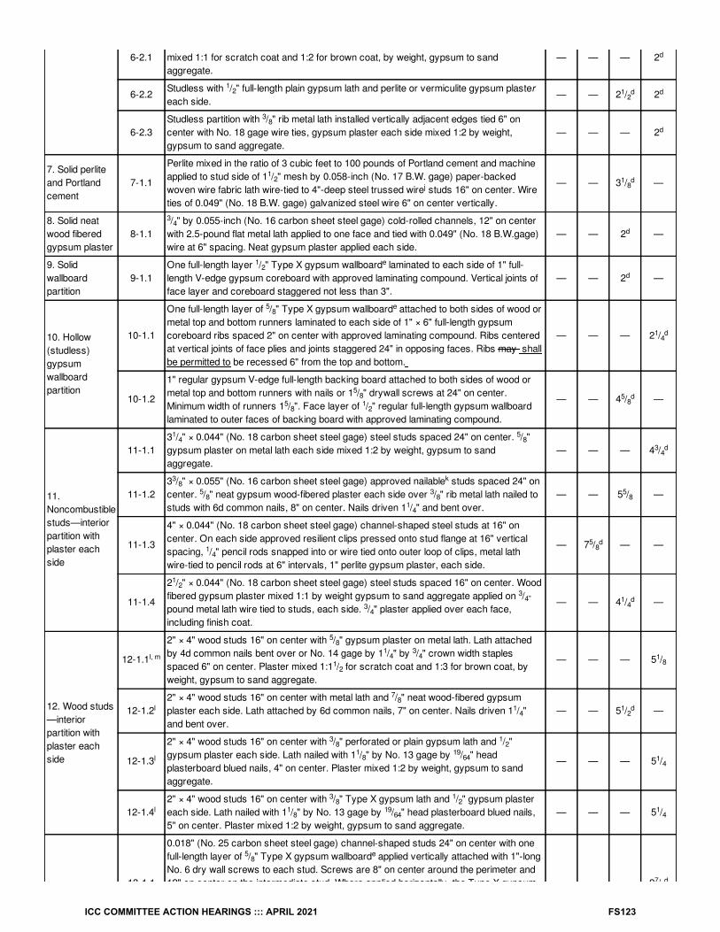
6-2.1Studless with / " full-length plain gypsum lath and gypsum plaster each side. Plastermixed 1:1 for scratch coat and 1:2 for brown coat, by weight, gypsum to sandaggregate.
— — — 2
6-2.2Studless with / " full-length plain gypsum lath and perlite or vermiculite gypsum plastereach side.
— — 2 / 2
6-2.3Studless partition with / " rib metal lath installed vertically adjacent edges tied 6" oncenter with No. 18 gage wire ties, gypsum plaster each side mixed 1:2 by weight,gypsum to sand aggregate.
— — — 2
7. Solid perliteand Portlandcement
7-1.1
Perlite mixed in the ratio of 3 cubic feet to 100 pounds of Portland cement and machineapplied to stud side of 1 / " mesh by 0.058-inch (No. 17 B.W. gage) paper-backedwoven wire fabric lath wire-tied to 4"-deep steel trussed wire studs 16" on center. Wireties of 0.049" (No. 18 B.W. gage) galvanized steel wire 6" on center vertically.
— — 3 / —
8. Solid neatwood fiberedgypsum plaster
8-1.1/ " by 0.055-inch (No. 16 carbon sheet steel gage) cold-rolled channels, 12" on center
with 2.5-pound flat metal lath applied to one face and tied with 0.049" (No. 18 B.W.gage)wire at 6" spacing. Neat gypsum plaster applied each side.
— — 2 —
9. Solidwallboardpartition
9-1.1One full-length layer / " Type X gypsum wallboard laminated to each side of 1" full-length V-edge gypsum coreboard with approved laminating compound. Vertical joints offace layer and coreboard staggered not less than 3".
— — 2 —
10. Hollow(studless)gypsumwallboardpartition
10-1.1
One full-length layer of / " Type X gypsum wallboard attached to both sides of wood ormetal top and bottom runners laminated to each side of 1" × 6" full-length gypsumcoreboard ribs spaced 2" on center with approved laminating compound. Ribs centeredat vertical joints of face plies and joints staggered 24" in opposing faces. Ribs may shallbe permitted to be recessed 6" from the top and bottom.
— — — 2 /
10-1.2
1" regular gypsum V-edge full-length backing board attached to both sides of wood ormetal top and bottom runners with nails or 1 / " drywall screws at 24" on center.Minimum width of runners 1 / ". Face layer of / " regular full-length gypsum wallboardlaminated to outer faces of backing board with approved laminating compound.
— — 4 / —
11.Noncombustiblestuds—interiorpartition withplaster eachside
11-1.13 / " × 0.044" (No. 18 carbon sheet steel gage) steel studs spaced 24" on center. / "gypsum plaster on metal lath each side mixed 1:2 by weight, gypsum to sandaggregate.
— — — 4 /
11-1.23 / " × 0.055" (No. 16 carbon sheet steel gage) approved nailable studs spaced 24" oncenter. / " neat gypsum wood-fibered plaster each side over / " rib metal lath nailed tostuds with 6d common nails, 8" on center. Nails driven 1 / " and bent over.
— — 5 / —
11-1.3
4" × 0.044" (No. 18 carbon sheet steel gage) channel-shaped steel studs at 16" oncenter. On each side approved resilient clips pressed onto stud flange at 16" verticalspacing, / " pencil rods snapped into or wire tied onto outer loop of clips, metal lathwire-tied to pencil rods at 6" intervals, 1" perlite gypsum plaster, each side.
— 7 / — —
11-1.4
2 / " × 0.044" (No. 18 carbon sheet steel gage) steel studs spaced 16" on center. Woodfibered gypsum plaster mixed 1:1 by weight gypsum to sand aggregate applied on / -pound metal lath wire tied to studs, each side. / " plaster applied over each face,including finish coat.
— — 4 / —
12. Wood studs—interiorpartition withplaster eachside
12-1.1
2" × 4" wood studs 16" on center with / " gypsum plaster on metal lath. Lath attachedby 4d common nails bent over or No. 14 gage by 1 / " by / " crown width staplesspaced 6" on center. Plaster mixed 1:1 / for scratch coat and 1:3 for brown coat, byweight, gypsum to sand aggregate.
— — — 5 /
12-1.22" × 4" wood studs 16" on center with metal lath and / " neat wood-fibered gypsumplaster each side. Lath attached by 6d common nails, 7" on center. Nails driven 1 / "and bent over.
— — 5 / —
12-1.3
2" × 4" wood studs 16" on center with / " perforated or plain gypsum lath and / "gypsum plaster each side. Lath nailed with 1 / " by No. 13 gage by / " headplasterboard blued nails, 4" on center. Plaster mixed 1:2 by weight, gypsum to sandaggregate.
— — — 5 /
12-1.42" × 4" wood studs 16" on center with / " Type X gypsum lath and / " gypsum plastereach side. Lath nailed with 1 / " by No. 13 gage by / " head plasterboard blued nails,5" on center. Plaster mixed 1:2 by weight, gypsum to sand aggregate.
— — — 5 /
13-1.1
0.018" (No. 25 carbon sheet steel gage) channel-shaped studs 24" on center with onefull-length layer of / " Type X gypsum wallboard applied vertically attached with 1"-longNo. 6 dry wall screws to each stud. Screws are 8" on center around the perimeter and12" on center on the intermediate stud. Where applied horizontally, the Type X gypsum — — — 2 /
2d
12 1
2d d
38
d
12
j1
8d
34
d
12
e
d
58
e
14d
58
58
12
58d
14
58
34d
38
k
58
38
14
58
14
58d
12
34
34
14d
l, m
58
14
34
12
18
l
78
14
12d
l
38
12
18
1964 1
4
l
38
12
18
1964
14
58
e
78d
ICC COMMITTEE ACTION HEARINGS ::: APRIL 2021 FS123

13.Noncombustiblestuds—interiorpartition withgypsumwallboard eachside
13-1.1 12" on center on the intermediate stud. Where applied horizontally, the Type X gypsumwallboard shall be attached to 3 / " studs and the horizontal joints shall be staggeredwith those on the opposite side. Screws for the horizontal application shall be 8" oncenter at vertical edges and 12" on center at intermediate studs.
— — — 2 /
13-1.2
0.018" (No. 25 carbon sheet steel gage) channel-shaped studs 25" on center with twofull-length layers of / " Type X gypsum wallboard applied vertically each side. Firstlayer attached with 1"-long, No. 6 drywall screws, 8" on center around the perimeter and12" on center on the intermediate stud. Second layer applied with vertical joints offsetone stud space from first layer using 1 / " long, No. 6 drywall screws spaced 9" oncenter along vertical joints, 12" on center at intermediate studs and 24" on center alongtop and bottom runners.
— — 3 / —
13-1.3
0.055" (No. 16 carbon sheet steel gage) approved nailable metal studs 24" on centerwith full-length / " Type X gypsum wallboard applied vertically and nailed 7" on centerwith 6d cement-coated common nails. Approved metal fastener grips used with nails atvertical butt joints along studs.
— — — 4 /
14. Wood studs—interiorpartition withgypsumwallboard eachside
14-1.1
2" × 4" wood studs 16" on center with two layers of / " regular gypsum wallboard eachside, 4d cooler or wallboard nails at 8" on center first layer, 5d cooler or wallboardnails at 8" on center second layer with laminating compound between layers, jointsstaggered. First layer applied full length vertically, second layer applied horizontally orvertically.
— — — 5
14-1.2
2" × 4" wood studs 16" on center with two layers / " regular gypsum wallboard appliedvertically or horizontally each side , joints staggered. Nail base layer with 5d cooler orwallboard nails at 8" on center face layer with 8d cooler or wallboard nails at 8" oncenter.
— — — 5 /
14-1.32" × 4" wood studs 24" on center with / " Type X gypsum wallboard applied verticallyor horizontally nailed with 6d cooler or wallboard nails at 7" on center with end joints onnailing members. Stagger joints each side.
— — — 4 /
14-1.42" × 4" fire-retardant-treated wood studs spaced 24" on center with one layer of / "Type X gypsum wallboard applied with face paper grain (long dimension) parallel tostuds. Wallboard attached with 6d cooler or wallboard nails at 7" on center.
— — — 4 /
14-1.5
2" × 4" wood studs 16" on center with two layers / " Type X gypsum wallboard eachside. Base layers applied vertically and nailed with 6d cooler or wallboard nails at 9" oncenter. Face layer applied vertically or horizontally and nailed with 8d cooler orwallboard nails at 7" on center. For nail-adhesive application, base layers are nailed 6"on center. Face layers applied with coating of approved wallboard adhesive and nailed12" on center.
— — 6 —
14-1.62" × 3" fire-retardant-treated wood studs spaced 24" on center with one layer of / "Type X gypsum wallboard applied with face paper grain (long dimension) at right anglesto studs. Wallboard attached with 6d cement-coated box nails spaced 7" on center.
— — — 3 /
15-1.1
Exterior surface with / " drop siding over / " gypsum sheathing on 2" × 4" wood studsat 16" on center, interior surface treatment as required for 1-hour-rated exterior orinterior 2" × 4" wood stud partitions. Gypsum sheathing nailed with 1 / " by No.11 gageby / " head galvanized nails at 8" on center. Siding nailed with 7d galvanized smoothbox nails.
— — — Varies
15-1.2
2" × 4" wood studs 16" on center with metal lath and / " cement plaster on each side.Lath attached with 6d common nails 7" on center driven to 1" minimum penetration andbent over. Plaster mix 1:4 for scratch coat and 1:5 for brown coat, by volume, cement tosand.
— — — 5 /
15-1.3
2" × 4" wood studs 16" on center with / " cement plaster (measured from the face ofstuds) on the exterior surface with interior surface treatment as required for interiorwood stud partitions in this table. Plaster mix 1:4 for scratch coat and 1:5 for browncoat, by volume, cement to sand.
— — — Varies
15-1.4
3 / " No. 16 gage noncombustible studs 16" on center with / " cement plaster(measured from the face of the studs) on the exterior surface with interior surfacetreatment as required for interior, nonbearing, noncombustible stud partitions in thistable. Plaster mix 1:4 for scratch coat and 1:5 for brown coat, by volume, cement tosand.
— — — Varies
2 / " × 3 / " clay face brick with cored holes over / " gypsum sheathing on exteriorsurface of 2" × 4" wood studs at 16" on center and two layers / " Type X gypsum
58
78d
12
e
58
58d
e
58
e7
8
h, m
38
e
n n n n
l, m
12
e
k n
n n n1
2
l, m
58
e
n n 34
l
58
e
n n
34d
l, m
58
e
n n
n
n
l
58
e 58d
l, m
34
12
34
716
l, m
34
38
l, m
78
58
78
d
14
34
12
58
e
ICC COMMITTEE ACTION HEARINGS ::: APRIL 2021 FS124

15. Exterior orinterior walls
15-1.5
surface of 2" × 4" wood studs at 16" on center and two layers / " Type X gypsumwallboard on interior surface. Sheathing placed horizontally or vertically with verticaljoints over studs nailed 6" on center with 1 / " × No. 11 gage by / " head galvanizednails. Inner layer of wallboard placed horizontally or vertically and nailed 8" on centerwith 6d cooler or wallboard nails. Outer layer of wallboard placed horizontally orvertically and nailed 8" on center with 8d cooler or wallboard nails. Joints staggeredwith vertical joints over studs. Outer layer joints taped and finished with compound. Nailheads covered with joint compound. 0.035 inch (No. 20 galvanized sheet gage)corrugated galvanized steel wall ties / " by 6 / " attached to each stud with two 8dcooler or wallboard nails every sixth course of bricks.
— — 10 —
15-1.6
2" × 6" fire-retardant-treated wood studs 16" on center. Interior face has two layers of/ " Type X gypsum with the base layer placed vertically and attached with 6d box nails
12"on center. The face layer is placed horizontally and attached with 8d box nails 8" oncenter at joints and 12" on center elsewhere. The exterior face has a base layer of / "Type X gypsum sheathing placed vertically with 6d box nails 8" on center at joints and12" on center elsewhere. An approved building paper is next applied, followed by self-furred exterior lath attached with 2 / ", No. 12 gage galvanized roofing nails with a / "diameter head and spaced 6" on center along each stud. Cement plaster consisting of a/ " brown coat is then applied. The scratch coat is mixed in the proportion of 1:3 by
weight, cement to sand with 10 pounds of hydrated lime and 3 pounds of approvedadditives or admixtures per sack of cement. The brown coat is mixed in the proportionof 1:4 by weight, cement to sand with the same amounts of hydrated lime and approvedadditives or admixtures used in the scratch coat.
— — 8 / —
15-1.7
2" × 6" wood studs 16" on center. The exterior face has a layer of / " Type X gypsumsheathing placed vertically with 6d box nails 8" on center at joints and 12" on centerelsewhere. An approved building paper is next applied, followed by 1" by No. 18 gageself-furred exterior lath attached with 8d by 2 / "-long galvanized roofing nails spaced 6"on center along each stud. Cement plaster consisting of a / " scratch coat, a bondingagent and a / " brown coat and a finish coat is then applied. The scratch coat is mixedin the proportion of 1:3 by weight, cement to sand with 10 pounds of hydrated lime and 3pounds of approved additives or admixtures per sack of cement. The brown coat ismixed in the proportion of 1:4 by weight, cement to sand with the same amounts ofhydrated lime and approved additives or admixtures used in the scratch coat. Theinterior is covered with / " gypsum lath with 1" hexagonal mesh of 0.035 inch (No. 20B.W. gage) woven wire lath furred out / " and 1" perlite or vermiculite gypsum plaster.Lath nailed with 1 / " by No. 13 gage by / " head plasterboard glued nails spaced 5"on center. Mesh attached by 1 / " by No. 12 gage by / " head nails with / " furrings,spaced 8" on center. The plaster mix shall not exceed 100 pounds of gypsum to 2 /cubic feet of aggregate.
— — 8 / —
15-1.8
2" × 6" wood studs 16" on center. The exterior face has a layer of / " Type X gypsumsheathing placed vertically with 6d box nails 8" on center at joints and 12" on centerelsewhere. An approved building paper is next applied, followed by 1 / " by No. 17 gageself-furred exterior lath attached with 8d by 2 / "-long galvanized roofing nails spaced 6"on center along each stud. Cement plaster consisting of a / " scratch coat and a / "brown coat is then applied. The plaster may shall be permitted to be placed by machine.The scratch coat is mixed in the proportion of 1:4 by weight, plastic cement to sand. Thebrown coat is mixed in the proportion of 1:5 by weight, plastic cement to sand. Theinterior is covered with / " gypsum lath with 1" hexagonal mesh of No. 20-gage wovenwire lath furred out / " and 1" perlite or vermiculite gypsum plaster. Lath nailed with1 / " by No. 13 gage by / " head plasterboard glued nails spaced 5" on center. Meshattached by 1 / " by No.12 gage by / " head nails with / " furrings, spaced 8" oncenter. The plaster mix shallnot exceed 100 pounds of gypsum to 2 / cubic feet ofaggregate.
— — 8 / —
15-1.9
4" No. 18 gage, nonload-bearing metal studs, 16" on center, with 1" Portland cementlime plaster (measured from the back side of the / -pound expanded metal lath) on theexterior surface. Interior surface to be covered with 1" of gypsum plaster on / -poundexpanded metal lath proportioned by weight—1:2 for scratch coat, 1:3 for brown,gypsum to sand. Lath on one side of the partition fastened to / " diameter pencil rodssupported by No. 20 gage metal clips, located 16" on center vertically, on each stud. 3"thick mineral fiber insulating batts friction fitted between the studs.
— — 6 / —
Steel studs 0.060" thick, 4" deep or 6" at 16" or 24" centers, with / " glass fiber-reinforced concrete (GFRC) on the exterior surface. GFRC is attached with flex
m
8e
34
716
n n
n n
34
58
n n
l, m
58
58
12
38
12
14
l, m
58
12
12
12
38
516
18
1964
34
38
38
12
38
l, m
58
12
12
12
12
38
516
18
1964
34
38
38
12
38
34
34
14
12d
12
1
ICC COMMITTEE ACTION HEARINGS ::: APRIL 2021 FS125

15-1.10
anchors at 24" on center, with 5" leg welded to studs with two / "-long flare-bevel welds,and 4" foot attached to the GFRC skin with / "-thick GFRC bonding pads that extend2 / " beyond the flex anchor foot on both sides. Interior surface to have two layers of / "Type X gypsum wallboard. The first layer of wallboard to be attached with 1"-long TypeS buglehead screws spaced 24" on center and the second layer is attached with 1 / "-long Type S screws spaced at 12" on center. Cavity is to be filled with 5" of 4 pcf(nominal) mineral fiber batts. GFRC has 1 / " returns packed with mineral fiber andcaulked on the exterior.
— — 6 / —
15-1.11
Steel studs 0.060" thick, 4" deep or 6" at 16" or 24" centers, respectively, with / " glassfiber-reinforced concrete (GFRC) on the exterior surface. GFRC is attached with flexanchors at 24" on center, with 5" leg welded to studs with two / "-long flare-bevel welds,and 4" foot attached to the GFRC skin with / "-thick GFRC bonding pads that extend2 / " beyond the flex anchor foot on both sides. Interior surface to have one layerof / "Type X gypsum wallboard , attached with 1 / "-long Type S buglehead screws spaced12" on center. Cavity is to be filled with 5" of 4 pcf (nominal) mineral fiber batts. GFRChas 1 / " returns packed with mineral fiber and caulked on the exterior.
— — — 6 /
15-1.12
2" × 6" wood studs at 16" with double top plates, single bottom plate; interior and exteriorsides covered with / " Type X gypsum wallboard, 4′ wide, applied horizontally orvertically with vertical joints over studs, and fastened with 2 / " Type S drywall screws,spaced 12" on center. Cavity to be filled with 5 / " mineral wool insulation.
— — — 6 /
15-1.13
2" × 6" wood studs at 16" with double top plates, single bottom plate; interior and exteriorsides covered with / " Type X gypsum wallboard, 4′ wide, applied vertically with alljoints over framing or blocking and fastened with 2 / " Type S drywall screws, spaced12" on center. R-19 mineral fiber insulation installed in stud cavity.
— — — 6 /
15-1.14
2" × 6" wood studs at 16" with double top plates, single bottom plate; interior and exteriorsides covered with / " Type X gypsum wallboard, 4′ wide, applied horizontally orvertically with vertical joints over studs, and fastened with 2 / " Type S drywall screws,spaced 7" on center.
— — — 6 /
15-1.15
2" × 4" wood studs at 16" with double top plates, single bottom plate; interior and exteriorsides covered with / " Type X gypsum wallboard and sheathing, respectively, 4′ wide,applied horizontally or vertically with vertical joints over studs, and fastened with 2 / "Type S drywall screws, spaced 12" on center. Cavity to be filled with 3 / " mineral woolinsulation.
— — — 4 /
15-1.16
2" × 6" wood studs at 24" centers with double top plates, single bottom plate; interior andexterior side covered with two layers of / " Type X gypsum wallboard, 4′ wide, appliedhorizontally with vertical joints over studs. Base layer fastened with 2 / " Type S drywallscrews, spaced 24" on center and face layer fastened with Type S drywall screws,spaced 8" on center, wallboard joints covered with paper tape and joint compound,fastener heads covered with joint compound. Cavity to be filled with 5 / " mineral woolinsulation.
— — 8 —
15-2.1
3 / " No. 16 gage steel studs at 24" on center or 2" × 4" wood studs at 24" on center.Metal lath attached to the exterior side of studs with minimum 1" long No. 6 drywallscrews at 6" on center and covered with minimum / " thick Portland cement plaster.Thin veneer brick units of clay or shale complying with C1157/C1157M—2017, GradeTBS or better, installed in running bond in accordance with Section 1404.10. Combinedtotal thickness of the Portland cement plaster, mortar and thin veneer brick units shallbe not less than 1 / ". Interior side covered with one layer of / "-thick Type X gypsumwallboard attached to studs with 1" long No. 6 drywall screws at 12" on center.
— — — 6
15-2.2
3 / " No. 16 gage steel studs at 24" on center or 2" × 4" wood studs at 24" on center.Metal lath attached to the exterior side of studs with minimum 1" long No. 6 drywallscrews at 6" on center and covered with minimum / " thick Portland cement plaster.Thin veneer brick units of clay or shale complying with C1157/C1157M—2017, GradeTBS or better, installed in running bond in accordance with Section 1404.10. Combinedtotal thickness of the Portland cement plaster, mortar and thin veneer brick units shallbe not less than 2". Interior side covered with two layers of / "-thick Type X gypsumwallboard. Bottom layer attached to studs with 1"-long No. 6 drywall screws at 24" oncenter. Top layer attached to studs with 1 / "-long No. 6 drywall screws at 12" oncenter.
— — 6 / —
3 / " No. 16 gage steel studs at 16" on center or 2" × 4" wood studs at 16" on center.Where metal lath is used, attach to the exterior side of studs with minimum 1"-long No. 6
12
58
12
12
e
58
12
12
12
12
58
12
58
e 14
12
18
q5
81
41
2
34
q5
81
4
34
q5
81
4
34
q
58
14
12
34
q
58
14
12
d
58
34
34
58
d
58
34
58
58
78
58
5
ICC COMMITTEE ACTION HEARINGS ::: APRIL 2021 FS126

15-2.3
Where metal lath is used, attach to the exterior side of studs with minimum 1"-long No. 6drywall screws at 6" on center. Brick units of clay or shale not less than 2 / " thickcomplying with C270—14a installed in accordance with Section 1404.6 with a minimum1" airspace. Interior side covered with one layer of / "-thick Type X gypsum wallboardattached to studs with 1"-long No. 6 drywall screws at 12" on center.
— — — 7 /
15-2.4
3 / " No. 16 gage steel studs at 16" on center or 2" × 4" wood studs at 16" on center.Where metal lath is used, attach to the exterior side of studs with minimum 1"-long No. 6drywall screws at 6" on center. Brick units of clay or shale not less than 2 / " thickcomplying with C270—14a installed in accordance with Section 1404.6 with a minimum1" airspace. Interior side covered with two layers of / "-thick Type X gypsum wallboard.Bottom layer attached to studs with 1"-long No. 6 drywall screws at 24" on center. Toplayer attached to studs with 1 / "-long No. 6 drywall screws at 12" on center.
— — 8 / —
16. Exteriorwalls rated forfire resistancefrom the insideonly inaccordancewith Section705.5.
16-1.1
2" × 4" wood studs at 16" centers with double top plates, single bottom plate; interiorside covered with / " Type X gypsum wallboard, 4' wide, applied horizontally unblocked,and fastened with 2 / " Type S drywall screws, spaced 12" on center, wallboard jointscovered with paper tape and joint compound, fastener heads covered with jointcompound. Exterior covered with / " wood structural panels, applied vertically,horizontal joints blocked and fastened with 6d common nails (bright)—12" on center inthe field, and 6" on center panel edges. Cavity to be filled with 3 / " mineral woolinsulation. Rating established for exposure from interior side only.
— — — 4 /
16-1.2
2" × 6" wood studs at 16" centers with double top plates, single bottom plate; interiorside covered with / " Type X gypsum wallboard, 4' wide, applied horizontally orvertically with vertical joints over studs and fastened with 2 / " Type S drywall screws,spaced 12" on center, wallboard joints covered with paper tape and joint compound,fastener heads covered with joint compound, exterior side covered with / " woodstructural panels fastened with 6d common nails (bright) spaced 12" on center in thefield and 6" on center along the panel edges. Cavity to be filled with 5 / " mineral woolinsulation. Rating established from the gypsum-covered side only.
— — — 6 /
16-1.3
2" × 6" wood studs at 16" centers with double top plates, single bottom plates; interiorside covered with / " Type X gypsum wallboard, 4'wide, applied vertically with all jointsover framing or blocking and fastened with 2 / " Type S drywall screws spaced 7" oncenter. Joints to be covered with tape and joint compound. Exterior covered with / "wood structural panels, applied vertically with edges over framing or blocking andfastened with 6d common nails (bright) at 12" on center in the field and 6" on center onpanel edges. R-19 mineral fiber insulation installed in stud cavity. Rating establishedfrom the gypsum-covered side only.
— — — 6 /
For SI: 1 inch = 25.4 mm, 1 square inch = 645.2 mm , 1 cubic foot = 0.0283 m .
a. Staples with equivalent holding power and penetration shall be permitted to be used as alternate fasteners to nails for attachment to woodframing.
b. Thickness shown for brick and clay tile is nominal thicknesses unless plastered, in which case thicknesses are net. Thickness shown forconcrete masonry and clay masonry is equivalent thickness defined in Section 722.3.1 for concrete masonry and Section 722.4.1.1 for claymasonry. Where all cells are solid grouted or filled with silicone-treated perlite loose-fill insulation; vermiculite loose-fill insulation; or expandedclay, shale or slate lightweight aggregate, the equivalent thickness shall be the thickness of the block or brick using specified dimensions asdefined in Chapter 21. Equivalent thickness shall include the thickness of applied plaster and lath or gypsum wallboard, where specified.
c. For units in which the net cross-sectional area of cored brick in any plane parallel to the surface containing the cores is not less than 75 percentof the gross cross-sectional area measured in the same plane.
d. Shall be used for nonbearing purposes only.
e. For all of the construction with gypsum wallboard described in this table, gypsum base for veneer plaster of the same size, thickness and coretype shall be permitted to be substituted for gypsum wallboard, provided that attachment is identical to that specified for the wallboard, and thejoints on the face layer are reinforced and the entire surface is covered with not less than / -inch gypsum veneer plaster.
f. The fire-resistance time period for concrete masonry units meeting the equivalent thicknesses required for a 2-hour fire-resistance rating in Item3, and having a thickness of not less than 7 / inches is 4 hours where cores that are not grouted are filled with silicone-treated perlite loose-fillinsulation; vermiculite loose-fill insulation; or expanded clay, shale or slate lightweight aggregate, sand or slag having a maximum particle size of/ inch.
g. The fire-resistance rating of concrete masonry units composed of a combination of aggregate types or where plaster is applied directly to theconcrete masonry shall be determined in accordance with ACI 216.1/TMS 0216. Lightweight aggregates shall have a maximum combineddensity of 65 pounds per cubic foot.
d5
8
58
78
d
58
58
58
58
12
q
581
4
38
12
12
q
58
14
716
12
916
q
58
14
38 1
2
2 3
116
58
38
ICC COMMITTEE ACTION HEARINGS ::: APRIL 2021 FS127

h. See Note b. The equivalent thickness shall be permitted to include the thickness of cement plaster or 1.5 times the thickness of gypsum plasterapplied in accordance with the requirements of Chapter 25.
i. Concrete walls shall be reinforced with horizontal and vertical temperature reinforcement as required by Chapter 19.
j. Studs are welded truss wire studs with 0.18 inch (No. 7 B.W. gage) flange wire and 0.18 inch (No. 7 B.W. gage) truss wires.
k. Nailable metal studs consist of two channel studs spot welded back to back with a crimped web forming a nailing groove.
l. Wood structural panels shall be permitted to be installed between the fire protection and the wood studs on either the interior or exterior side ofthe wood frame assemblies in this table, provided that the length of the fasteners used to attach the fire protection is increased by an amount notless than the thickness of the wood structural panel.
m. For studs with a slenderness ratio, l /d, greater than 33, the design stress shall be reduced to 78 percent of allowable F′ . For studs with aslenderness ratio, l /d, not exceeding 33, the design stress shall be reduced to 78 percent of the adjusted stress F′ calculated for studs havinga slenderness ratio l /d of 33.
n. For properties of cooler or wallboard nails, see ASTM C514, ASTM C547 or ASTM F1667.
o. Generic fire-resistance ratings (those not designated as PROPRIETARY* in the listing) in the GA 600 shall be accepted as if herein specified.
p. NCMA TEK 5-8A shall be permitted for the design of fire walls.
q. The design stress of studs shall be equal to not more than 100 percent of the allowable F′ calculated in accordance with Section 2306.
e c
e c
e
c
ICC COMMITTEE ACTION HEARINGS ::: APRIL 2021 FS128

For SI: 1 inch = 25.4 mm, 1 foot = 305 mm.1. Structural steel column, either wide flange or tubular shapes.
2. Type X gypsum board or gypsum panel products in accordance with ASTM C1177, C1178, C1278, C1396 or C1658. The total thickness ofgypsum board or gypsum panel products calculated as h in Section 722.5.1.2 shall be applied vertically to an individual column using one of thefollowing methods:
1. As a single layer without horizontal joints.
2. As multiple layers with horizontal joints not permitted in any layer.
3. As multiple layers with horizontal joints staggered not less than 12 inches vertically between layers and not less than 8 feet vertically in anysingle layer. The total required thickness of gypsum board or gypsum panel products shall be determined on the basis of the specified fire-resistance rating and the weight-to-heated-perimeter ratio (W/D) of the column. For fire-resistance ratings of 2 hours or less, one of therequired layers of gypsum board or gypsum panel product may shall be permitted to be applied to the exterior of the sheet steel columncovers with 1-inch long Type S screws spaced 1 inch from the wallboard edge and 8 inches on center. For such installations, 0.0149-inchminimum thickness galvanized steel corner beads with 1 / -inch legs shall be attached to the wallboard with Type S screws spaced 12 incheson center.
3. For fire-resistance ratings of 3 hours or less, the column covers shall be fabricated from 0.0239-inch minimum thickness galvanized or stainlesssteel. For 4-hour fire-resistance ratings, the column covers shall be fabricated from 0.0239-inch minimum thickness stainless steel. The columncovers shall be erected with the Snap Lock or Pittsburgh joint details. For fire-resistance ratings of 2 hours or less, column covers fabricatedfrom 0.0269-inch minimum thickness galvanized or stainless steel shall be permitted to be erected with lap joints. The lap joints shall be permittedto be located anywhere around the perimeter of the column cover. The lap joints shall be secured with / -inch-long No. 8 sheet metal screwsspaced 12 inches on center. The column covers shall be provided with a minimum expansion clearance of / inch per linear foot between theends of the cover and any restraining construction.
FIGURE 722.5.1(2)GYPSUM-PROTECTED STRUCTURAL STEEL COLUMNS WITH SHEET STEEL COLUMN COVERS
FS97-21 Part I
12
12
18
ICC COMMITTEE ACTION HEARINGS ::: APRIL 2021 FS129

FS97-21 Part IIIFC: 5704.2.9.7.5.1, TABLE 6109.12
Proponents: Mike Nugent, Chair, representing ICC Building Code Action Committee ([email protected]); Michael O'Brian, representing FCAC([email protected])
2021 International Fire CodeRevise as follows:
5704.2.9.7.5.1 Information signs. A permanent sign shall be provided at the fill point for the tank, documenting the filling procedure and the tankcalibration chart.
Exception:Where climatic conditions are such that the sign may be has the potential to be obscured by ice or snow, or weathered beyond readability orotherwise impaired, said procedures and chart shall be located in the office window, lock box or other area available to the person filling the tank.
ICC COMMITTEE ACTION HEARINGS ::: APRIL 2021 FS130

TABLE 6109.12SEPARATION FROM EXPOSURES OF LP-GAS CONTAINERS AWAITING USE, RESALE OR EXCHANGE STORED OUTSIDE OF
BUILDINGS
QUANTITYOF LP-
GASSTORED(pounds)
MINIMUM SEPARATION DISTANCE FROM STORED LP-GAS CYLINDERS TO (feet):
Nearest importantbuilding or group ofbuildings or line of
adjoining property thatmay be has the
potential to be built on
Line of adjoining propertyoccupied by schools, places of
religious worship, hospitals,athletic fields or other points of
public gathering; busythoroughfares; or sidewalks
LP-gasdispensing
station
Doorway oropening to a
buildingwith two ormore means
of egress
Doorwayor opening
to abuildingwith onemeans of
egress
Combustiblematerials
Motorvehicle
fueldispenser
720 or less 0 0 5 5 10 10 20
721–2,500 0 10 10 5 10 10 20
2,501–6,000
10 10 10 10 10 10 20
6,001–10,000
20 20 20 20 20 10 20
Over10,000
25 25 25 25 25 10 20
For SI: 1 foot = 304.8 mm, 1 pound = 0.454 kg.
FS97-21 Part II
ICC COMMITTEE ACTION HEARINGS ::: APRIL 2021 FS131

FS97-21 Part IIIIZC: 302.1, 305.1, 1004.4, 1008.1.1, 1008.2.4, 1008.2.6, 1009.2, 1301.1, 1302.2
Proponents: Mike Nugent, Chair, representing ICC Building Code Action Committee ([email protected]); Michael O'Brian, representing FCAC([email protected])
2021 International Zoning CodeRevise as follows:
302.1 Minimum areas. The minimum areas that may constitute a separate or detached part of any of the following zoning districts on the zoningmap or subsequent amendments to said zoning map shall be as shown in Table 302.1. Where a nonresidential district is directly across the streetfrom or abuts the district with the same or less restrictive classification, the area of the land directly across the street or abutting the property may shall be permitted to be included in the calculations in meeting the minimum district size requirements.
305.1 General. The principal objective of this zoning code is to provide for an orderly arrangement of compatible buildings and land uses, and for theproperty location of all types of uses required for the social and economic welfare of the community. To accomplish this objective, each type andkind of use is classified as permitted in one or more of the various use districts established by this code. However, in addition to those usesspecifically classified and permitted in each district, there are certain additional uses that it may be is necessary to allow because of the unusualcharacteristics of the service they provide the public. These conditional uses require particular considerations as to their proper location to adjacent,established or intended uses, or to the planned growth of the community. The conditions controlling the locations and operation of such special usesare established by the applicable sections of this code.
1004.4 Traffic visibility. Signs or sign structures shall not be erected at the intersection of any street in such a manner as to obstruct free andclear vision, nor at any location where by its position, shape or color it may interfere interferes with or obstruct the view of or be confused with anyauthorized traffic sign, signal or device.
1008.1.1 Wall signs. Every single-family residence, multiple-family residential complex, commercial or industrial building, and every separatenonresidential building in a residential zone may shall be permitted to display wall signs per street frontage subject to the limiting standards set forthin Table 1008.1.1(1). For shopping centers, planned industrial parks or other multiple-occupancy nonresidential buildings, the building face or wallshall be calculated separately for each separate occupancy, but in no event will the allowed area for any separate occupancy be less than[JURISDICTION TO INSERT NUMBER] square feet.
1008.2.4 Special event signs in public ways. Signs advertising a special community event shall not be prohibited in or over public rights-of-way,subject to approval by the code official as to the size, location and method of erection. The code official may shall be permitted to not approve anyspecial event signage that would impair the safety and convenience of use of public rights-of-way, or obstruct traffic visibility.
1008.2.6 Political signs. Political signs shall be permitted in all zoning districts, subject to the following limitations:1. Such signs shall not exceed a height of [JURISDICTION TO INSERT NUMBER] feet nor an area of [JURISDICTION TO INSERT NUMBER]
square feet.
2. Such signs for election candidates or ballot propositions shall be displayed only for a period of 60 days preceding the election and shall beremoved within 10 days after the election, provided that signs promoting successful candidates or ballot propositions in a primary electionmay shall be permitted to remain displayed until not more than 10 days after the general election.
3. Such signs shall not be placed in any public right-of-way or obstruct traffic visibility.
1009.2 Development complex sign. In addition to the freestanding business identification signs otherwise allowed by this ordinance, everymultiple-occupancy development complex shall be entitled to one free-standing sign per street front, at the maximum size permitted for businessidentification free-standing signs, to identify the development complex. Business identification shall not be permitted on a development complex sign.Any free-standing sign otherwise permitted under this ordinance may shall identify the name of the development complex.
1301.1 Approval. Planned unit developments (PUDs) shall be allowed by planning commission approval in any zoning district. Such planned unitdevelopment permit shall not be granted unless such development will meet the use limitations of the zoning district in which it is located and meetthe density and other limitations of such districts, except as such requirements may shall be lawfully modified as provided by this code. Compliancewith the regulations of this code in no way excuses the developer from the applicable requirements of a subdivision ordinance, except asmodifications thereof are specifically authorized in the approval of the application for the planned unit development.
1302.2 Uses. Aplanned unit development that will contain uses not permitted in the zoning district in which it is to be located will require a change ofzoning district and shall be accompanied by an application for a zoning amendment, except that any residential use shall be considered to be apermitted use in a planned unit development, which allows residential uses and shall be governed by density, design and other requirements of theplanned unit development permit.
Where a site is situated in more than one use district, the permitted uses applicable to such property in one district may shall be permitted to beextended into the adjacent use district.
ICC COMMITTEE ACTION HEARINGS ::: APRIL 2021 FS132

Reason Statement: The term ‘may’ is subjective. The proposal is to bring the text into enforceable language by using the ICC preferredlanguage.as often as possible. Similar proposals will be submitted for the Group B cycle for IRC, IECC and IEBC. This is a joint proposal submitted by the ICC Building Code Action Committee (BCAC) and the ICC Fire Code Action Committee (FCAC).
BCAC was established by the ICC Board of Directors in July 2011 to pursue opportunities to improve and enhance assigned International Codes orportions thereof. In 2020 the BCAC has held several virtual meetings open to any interested party. In addition, there were numerous virtual WorkingGroup meetings for the current code development cycle, which included members of the committee as well as interested parties. Relateddocuments and reports are posted on the BCAC website at BCAC.
The FCAC was established by the ICC Board of Directors to pursue opportunities to improve and enhance assigned International Codes with regardto fire and life safety in new and existing buildings and facilities as well as the protection of life and property in wildland urban interface areas. In 2020and 2021 the Fire-CAC held multiple virtual meetings that were open to any interested party. In addition, there were numerous virtual specificworking group meetings that were also open to any interested parties, to develop, discuss and debate the proposed changes. Relateddocumentation and reports are posted on the FCAC website at: FCAC.
Cost Impact: The code change proposal will not increase or decrease the cost of constructionThese changes are only changing verbiage.
FS97-21 Part III
ICC COMMITTEE ACTION HEARINGS ::: APRIL 2021 FS133

FS98-21IBC: TABLE 721.1(2)
Proponents: David Tyree, representing AWC ([email protected]); Jason Smart, American Wood Council, representing AWC ([email protected])
2021 International Building CodeRevise as follows:
ICC COMMITTEE ACTION HEARINGS ::: APRIL 2021 FS134

TABLE 721.1(2)RATED FIRE-RESISTANCE PERIODS FOR VARIOUS WALLS AND PARTITIONS
Portions of table not shown remain unchanged.
MATERIAL ITEMNUMBER
CONSTRUCTION
MINIMUM FINISHEDTHICKNESS FACE-TO-
FACE (inches)
4hours
3hours
2hours
1hour
16. Exteriorwalls rated forfire resistancefrom the insideonly inaccordancewith Section705.5.
16-1.4
2" × 6" wood studs at 24" centers with double top plates, single bottom plates; interior sidecovered with / " Type X gypsum wallboard, 4' wide, applied vertically with all joints overframing or blocking and fastened with 2 / " Type S drywall screws spaced 7" on center.Joints covered with tape and joint compound. Exterior covered with / " wood structuralpanels, applied vertically with edges over framing or blocking and fastened with 6dcommon nails (bright) at 12" on center in the field and 6" on center on panel edges. R-19fiberglass insulation installed in stud cavity. Rating established from the gypsum-coveredside only.
— — — 6 /
For SI: 1 inch = 25.4 mm, 1 square inch = 645.2 mm , 1 cubic foot = 0.0283 m .
a. Staples with equivalent holding power and penetration shall be permitted to be used as alternate fasteners to nails for attachment to woodframing.
b. Thickness shown for brick and clay tile is nominal thicknesses unless plastered, in which case thicknesses are net. Thickness shown forconcrete masonry and clay masonry is equivalent thickness defined in Section 722.3.1 for concrete masonry and Section 722.4.1.1 for claymasonry. Where all cells are solid grouted or filled with silicone-treated perlite loose-fill insulation; vermiculite loose-fill insulation; or expandedclay, shale or slate lightweight aggregate, the equivalent thickness shall be the thickness of the block or brick using specified dimensions asdefined in Chapter 21. Equivalent thickness shall include the thickness of applied plaster and lath or gypsum wallboard, where specified.
c. For units in which the net cross-sectional area of cored brick in any plane parallel to the surface containing the cores is not less than 75 percentof the gross cross-sectional area measured in the same plane.
d. Shall be used for nonbearing purposes only.
e. For all of the construction with gypsum wallboard described in this table, gypsum base for veneer plaster of the same size, thickness and coretype shall be permitted to be substituted for gypsum wallboard, provided that attachment is identical to that specified for the wallboard, and thejoints on the face layer are reinforced and the entire surface is covered with not less than / -inch gypsum veneer plaster.
f. The fire-resistance time period for concrete masonry units meeting the equivalent thicknesses required for a 2-hour fire-resistance rating in Item3, and having a thickness of not less than 7 / inches is 4 hours where cores that are not grouted are filled with silicone-treated perlite loose-fillinsulation; vermiculite loose-fill insulation; or expanded clay, shale or slate lightweight aggregate, sand or slag having a maximum particle size of/ inch.
g. The fire-resistance rating of concrete masonry units composed of a combination of aggregate types or where plaster is applied directly to theconcrete masonry shall be determined in accordance with ACI 216.1/TMS 0216. Lightweight aggregates shall have a maximum combineddensity of 65 pounds per cubic foot.
h. See Note b. The equivalent thickness shall be permitted to include the thickness of cement plaster or 1.5 times the thickness of gypsum plasterapplied in accordance with the requirements of Chapter 25.
i. Concrete walls shall be reinforced with horizontal and vertical temperature reinforcement as required by Chapter 19.
j. Studs are welded truss wire studs with 0.18 inch (No. 7 B.W. gage) flange wire and 0.18 inch (No. 7 B.W. gage) truss wires.
k. Nailable metal studs consist of two channel studs spot welded back to back with a crimped web forming a nailing groove.
l. Wood structural panels shall be permitted to be installed between the fire protection and the wood studs on either the interior or exterior side ofthe wood frame assemblies in this table, provided that the length of the fasteners used to attach the fire protection is increased by an amount notless than the thickness of the wood structural panel.
m. For studs with a slenderness ratio, l /d, greater than 33, the design stress shall be reduced to 78 percent of allowable F′ . For studs with aslenderness ratio, l /d, not exceeding 33, the design stress shall be reduced to 78 percent of the adjusted stress F′ calculated for studs havinga slenderness ratio l /d of 33.
n. For properties of cooler or wallboard nails, see ASTM C514, ASTM C547 or ASTM F1667.
o. Generic fire-resistance ratings (those not designated as PROPRIETARY* in the listing) in the GA 600 shall be accepted as if herein specified.
p. NCMA TEK 5-8A shall be permitted for the design of fire walls.
a, o, p
b
q
58
14
1532 19
32
2 3
116
58
38
e c
e c
e
ICC COMMITTEE ACTION HEARINGS ::: APRIL 2021 FS135

q. The design stress of studs shall be equal to not more than 100 percent of the allowable F′ calculated in accordance with Section 2306.
Reason Statement: Fire-resistance-rated wood-frame assemblies can be found in a number of sources including the IBC, UnderwritersLaboratories (UL) Fire Resistance Directory, Intertek Testing Services' Directory of Listed Products, and the Gypsum Association's FireResistance Design Manual. The American Wood Council (AWC) has tested a number of wood-frame fire-resistance-rated assemblies. Thisproposal is adding another tested assembly which is popular among designers and is being provided for the convenience of the building official. It isthe same as Assembly WS6-1.6 in the American Wood Council's publication titled Design for Code Acceptance (DCA) 3 - Fire-Resistance-RatedWood-Frame Wall and Floor/Ceiling Assemblies, which may be downloaded from the AWC website. Similar descriptions of successfully tested woodstud wall assemblies are provided in Table 721.1(2) for one-hour and two-hour fire-resistance-rated wall assemblies.
Bibliography: Design for Code Acceptance (DCA) 3 – Fire-Resistance-Rated Wood-Frame Wall and Floor/Ceiling Assemblies, American WoodCouncil, 2020, https://awc.org/pdf/codes-standards/publications/dca/AWC_DCA3_20200401_AWCWebsite.pdf
Cost Impact: The code change proposal will not increase or decrease the cost of constructionThis proposal simply adds another tested assembly for one-hour wall construction.
FS98-21
c
ICC COMMITTEE ACTION HEARINGS ::: APRIL 2021 FS136

FS99-21IBC: TABLE 721.1(2)
Proponents: John-Jozef Proczka, representing self ([email protected])
2021 International Building CodeRevise as follows:
ICC COMMITTEE ACTION HEARINGS ::: APRIL 2021 FS137

TABLE 721.1(2)RATED FIRE-RESISTANCE PERIODS FOR VARIOUS WALLS AND PARTITIONS
Portions of table not shown remain unchanged.
MATERIAL ITEMNUMBER
CONSTRUCTION
MINIMUM FINISHEDTHICKNESS FACE-TO-
FACE (inches)
4hours
3hours
2hours
1 hour
15-1.1
Exterior surface with / " drop siding over / " gypsum sheathing on 2" × 4" wood studs at16" on center, interior surface treatment as required for 1-hour-rated exterior or interior 2" ×4" wood stud partitions. Gypsum sheathing nailed with 1 / " by No.11 gage by / " headgalvanized nails at 8" on center. Siding nailed with 7d galvanized smooth box nails.
— — — Varies
15-1.22" × 4" wood studs 16" on center with metal lath and / " cement plaster on each side. Lathattached with 6d common nails 7" on center driven to 1" minimum penetration and bent over.Plaster mix 1:4 for scratch coat and 1:5 for brown coat, by volume, cement to sand.
— — — 5 /
15-1.3
2" × 4" wood studs 16" on center with / " cement plaster (measured from the face of studs)on the exterior surface with interior surface treatment as required for interior wood studpartitions in this table. Plaster mix 1:4 for scratch coat and 1:5 for brown coat, by volume,cement to sand.
— — — Varies
15-1.4
3 / " No. 16 gage noncombustible studs 16" on center with / " cement plaster (measuredfrom the face of the studs) on the exterior surface with interior surface treatment as requiredfor interior, nonbearing, noncombustible stud partitions in this table. Plaster mix 1:4 forscratch coat and 1:5 for brown coat, by volume, cement to sand.
— — — Varies
15-1.5
2 / " × 3 / " clay face brick with cored holes over / " gypsum sheathing on exterior surfaceof 2" × 4" wood studs at 16" on center and two layers / " Type X gypsum wallboard oninterior surface. Sheathing placed horizontally or vertically with vertical joints over studsnailed 6" on center with 1 / " × No. 11 gage by / " head galvanized nails. Inner layer ofwallboard placed horizontally or vertically and nailed 8" on center with 6d cooler orwallboard nails. Outer layer of wallboard placed horizontally or vertically and nailed 8" oncenter with 8d cooler or wallboard nails. Joints staggered with vertical joints over studs.Outer layer joints taped and finished with compound. Nail heads covered with jointcompound. 0.035 inch (No. 20 galvanized sheet gage) corrugated galvanized steel wall ties/ " by 6 / " attached to each stud with two 8d cooler or wallboard nails every sixth course
of bricks.
— — 10 —
15-1.6
2" × 6" fire-retardant-treated wood studs 16" on center. Interior face has two layers of / "Type X gypsum with the base layer placed vertically and attached with 6d box nails 12"oncenter. The face layer is placed horizontally and attached with 8d box nails 8" on center atjoints and 12" on center elsewhere. The exterior face has a base layer of / " Type Xgypsum sheathing placed vertically with 6d box nails 8" on center at joints and 12" on centerelsewhere. An approved building paper is next applied, followed by self-furred exterior lathattached with 2 / ", No. 12 gage galvanized roofing nails with a / " diameter head andspaced 6" on center along each stud. Cement plaster consisting of a / " brown coat is thenapplied. The scratch coat is mixed in the proportion of 1:3 by weight, cement to sand with 10pounds of hydrated lime and 3 pounds of approved additives or admixtures per sack ofcement. The brown coat is mixed in the proportion of 1:4 by weight, cement to sand with thesame amounts of hydrated lime and approved additives or admixtures used in the scratchcoat.
— — 8 / —
15-1.7
2" × 6" wood studs 16" on center. The exterior face has a layer of / " Type X gypsumsheathing placed vertically with 6d box nails 8" on center at joints and 12" on centerelsewhere. An approved building paper is next applied, followed by 1" by No. 18 gage self-furred exterior lath attached with 8d by 2 / "-long galvanized roofing nails spaced 6" oncenter along each stud. Cement plaster consisting of a / " scratch coat, a bonding agentand a / " brown coat and a finish coat is then applied. The scratch coat is mixed in theproportion of 1:3 by weight, cement to sand with 10 pounds of hydrated lime and 3 pounds ofapproved additives or admixtures per sack of cement. The brown coat is mixed in theproportion of 1:4 by weight, cement to sand with the same amounts of hydrated lime andapproved additives or admixtures used in the scratch coat. The interior is covered with / "gypsum lath with 1" hexagonal mesh of 0.035 inch (No. 20 B.W. gage) woven wire lath
— — 8 / —
a, o, p
b
l, m
34
12
34
716
l, m
34
38
l, m
78
58
78
d
m
14
34
12
58
e
34
716
n
n
n n
34
58
n n
l, m
58
58
12
38
12
14
l, m
58
12
12
12
38
5 1
38
ICC COMMITTEE ACTION HEARINGS ::: APRIL 2021 FS138

15. Exterioror interiorwalls
gypsum lath with 1" hexagonal mesh of 0.035 inch (No. 20 B.W. gage) woven wire lathfurred out / " and 1" perlite or vermiculite gypsum plaster. Lath nailed with 1 / " by No. 13gage by / " head plasterboard glued nails spaced 5" on center. Mesh attached by 1 / " byNo. 12 gage by / " head nails with / " furrings, spaced 8" on center. The plaster mix shallnot exceed 100 pounds of gypsum to 2 / cubic feet of aggregate.
15-1.8
2" × 6" wood studs 16" on center. The exterior face has a layer of / " Type X gypsumsheathing placed vertically with 6d box nails 8" on center at joints and 12" on centerelsewhere. An approved building paper is next applied, followed by 1 / " by No. 17 gage self-furred exterior lath attached with 8d by 2 / "-long galvanized roofing nails spaced 6" oncenter along each stud. Cement plaster consisting of a / " scratch coat and a / " browncoat is then applied. The plaster may be placed by machine. The scratch coat is mixed inthe proportion of 1:4 by weight, plastic cement to sand. The brown coat is mixed in theproportion of 1:5 by weight, plastic cement to sand. The interior is covered with / " gypsumlath with 1" hexagonal mesh of No. 20-gage woven wire lath furred out / " and 1" perlite orvermiculite gypsum plaster. Lath nailed with 1 / " by No. 13 gage by / " head plasterboardglued nails spaced 5" on center. Mesh attached by 1 / " by No.12 gage by / " head nailswith / " furrings, spaced 8" on center. The plaster mix shallnot exceed 100 pounds ofgypsum to 2 / cubic feet of aggregate.
— — 8 / —
15-1.9
4" No. 18 gage, nonload-bearing metal studs, 16" on center, with 1" Portland cement limeplaster (measured from the back side of the / -pound expanded metal lath) on the exteriorsurface. Interior surface to be covered with 1" of gypsum plaster on / -pound expandedmetal lath proportioned by weight—1:2 for scratch coat, 1:3 for brown, gypsum to sand. Lathon one side of the partition fastened to / " diameter pencil rods supported by No. 20 gagemetal clips, located 16" on center vertically, on each stud. 3" thick mineral fiber insulatingbatts friction fitted between the studs.
— — 6 / —
15-1.10
Steel studs 0.060" thick, 4" deep or 6" at 16" or 24" centers, with / " glass fiber-reinforcedconcrete (GFRC) on the exterior surface. GFRC is attached with flex anchors at 24" oncenter, with 5" leg welded to studs with two / "-long flare-bevel welds, and 4" foot attachedto the GFRC skin with / "-thick GFRC bonding pads that extend 2 / " beyond the flexanchor foot on both sides. Interior surface to have two layers of / " Type X gypsumwallboard. The first layer of wallboard to be attached with 1"-long Type S buglehead screwsspaced 24" on center and the second layer is attached with 1 / "-long Type S screwsspaced at 12" on center. Cavity is to be filled with 5" of 4 pcf (nominal) mineral fiber batts.GFRC has 1 / " returns packed with mineral fiber and caulked on the exterior.
— — 6 / —
15-1.11
Steel studs 0.060" thick, 4" deep or 6" at 16" or 24" centers, respectively, with / " glassfiber-reinforced concrete (GFRC) on the exterior surface. GFRC is attached with flexanchors at 24" on center, with 5" leg welded to studs with two / "-long flare-bevel welds,and 4" foot attached to the GFRC skin with / "-thick GFRC bonding pads that extend 2 / "beyond the flex anchor foot on both sides. Interior surface to have one layerof / " Type Xgypsum wallboard , attached with 1 / "-long Type S buglehead screws spaced 12" oncenter. Cavity is to be filled with 5" of 4 pcf (nominal) mineral fiber batts. GFRC has 1 / "returns packed with mineral fiber and caulked on the exterior.
— — — 6 /
15-1.12
2" × 6" wood studs at 16" with double top plates, single bottom plate; interior and exteriorsides covered with / " Type X gypsum wallboard, 4′ wide, applied horizontally or verticallywith vertical joints over studs, and fastened with 2 / " Type S drywall screws, spaced 12" oncenter. Cavity to be filled with 5 / " mineral wool insulation.
— — — 6 /
15-1.13
2" × 6" wood studs at 16" with double top plates, single bottom plate; interior and exteriorsides covered with / " Type X gypsum wallboard, 4′ wide, applied vertically with all jointsover framing or blocking and fastened with 2 / " Type S drywall screws, spaced 12" oncenter. R-19 mineral fiber insulation installed in stud cavity.
— — — 6 /
15-1.14
2" × 6" wood studs at 16" with double top plates, single bottom plate; interior and exteriorsides covered with / " Type X gypsum wallboard, 4′ wide, applied horizontally or verticallywith vertical joints over studs, and fastened with 2 / " Type S drywall screws, spaced 7" oncenter.
— — — 6 /
15-1.15
2" × 4" wood studs at 16" with double top plates, single bottom plate; interior and exteriorsides covered with / " Type X gypsum wallboard and sheathing, respectively, 4′ wide,applied horizontally or vertically with vertical joints over studs, and fastened with 2 / " TypeS drywall screws, spaced 12" on center. Cavity to be filled with 3 / " mineral wool insulation.
— — — 4 /
15-1.16
2" × 6" wood studs at 24" centers with double top plates, single bottom plate; interior andexterior side covered with two layers of / " Type X gypsum wallboard, 4′ wide, appliedhorizontally with vertical joints over studs. Base layer fastened with 2 / " Type S drywall
— — 8 —
516
18
1964
34
38
38
12
l, m
58
12
12
12
12
38
516
18
1964
34
38
38
12
38
34
34
14
12d
12
12
58
12
12
e
58
12
12
12
12
58
12
58
e 14
12
18
q5
81
41
2
34
q5
81
4
34
q5
81
4
34
q5
81
41
2
34
q
58
14
ICC COMMITTEE ACTION HEARINGS ::: APRIL 2021 FS139

15-1.16horizontally with vertical joints over studs. Base layer fastened with 2 / " Type S drywallscrews, spaced 24" on center and face layer fastened with Type S drywall screws, spaced8" on center, wallboard joints covered with paper tape and joint compound, fastener headscovered with joint compound. Cavity to be filled with 5 / " mineral wool insulation.
— — 8 —
15-2.1
3 / " No. 16 gage steel studs at 24" on center or 2" × 4" wood studs at 24" on center. Metallath attached to the exterior side of studs with minimum 1" long No. 6 drywall screws at 6" oncenter and covered with minimum / " thick Portland cement plaster. Thin veneer brick unitsof clay or shale complying with C1157/C1157M—2017, Grade TBS or better, installed inrunning bond in accordance with Section 1404.10. Combined total thickness of the Portlandcement plaster, mortar and thin veneer brick units shall be not less than 1 / ". Interior sidecovered with one layer of / "-thick Type X gypsum wallboard attached to studs with 1" longNo. 6 drywall screws at 12" on center.
— — — 6
15-2.2
3 / " No. 16 gage steel studs at 24" on center or 2" × 4" wood studs at 24" on center. Metallath attached to the exterior side of studs with minimum 1" long No. 6 drywall screws at 6" oncenter and covered with minimum / " thick Portland cement plaster. Thin veneer brick unitsof clay or shale complying with C1157/C1157M—2017, Grade TBS or better, installed inrunning bond in accordance with Section 1404.10. Combined total thickness of the Portlandcement plaster, mortar and thin veneer brick units shall be not less than 2". Interior sidecovered with two layers of / "-thick Type X gypsum wallboard. Bottom layer attached tostuds with 1"-long No. 6 drywall screws at 24" on center. Top layer attached to studs with1 / "-long No. 6 drywall screws at 12" on center.
— — 6 / —
15-2.3
3 / " No. 16 gage steel studs at 16" on center or 2" × 4" wood studs at 16" on center. Wheremetal lath is used, attach to the exterior side of studs with minimum 1"-long No. 6 drywallscrews at 6" on center. Brick units of clay or shale not less than 2 / " thick complying withC270—14a installed in accordance with Section 1404.6 with a minimum 1" airspace. Interiorside covered with one layer of / "-thick Type X gypsum wallboard attached to studs with 1"-long No. 6 drywall screws at 12" on center.
— — — 7 /
15-2.4
3 / " No. 16 gage steel studs at 16" on center or 2" × 4" wood studs at 16" on center. Wheremetal lath is used, attach to the exterior side of studs with minimum 1"-long No. 6 drywallscrews at 6" on center. Brick units of clay or shale not less than 2 / " thick complying withC270—14a installed in accordance with Section 1404.6 with a minimum 1" airspace. Interiorside covered with two layers of / "-thick Type X gypsum wallboard. Bottom layer attachedto studs with 1"-long No. 6 drywall screws at 24" on center. Top layer attached to studs with1 / "-long No. 6 drywall screws at 12" on center.
— — 8 / —
16. Exteriorwalls ratedfor fireresistancefrom theinside onlyinaccordancewith Section705.5.
16-1.1
2" × 4" wood studs at 16" centers with double top plates, single bottom plate; interior sidecovered with / " Type X gypsum wallboard, 4' wide, applied horizontally unblocked, andfastened with 2 / " Type S drywall screws, spaced 12" on center, wallboard joints coveredwith paper tape and joint compound, fastener heads covered with joint compound. Exteriorcovered with / " wood structural panels, applied vertically, horizontal joints blocked andfastened with 6d common nails (bright)—12" on center in the field, and 6" on center paneledges. Cavity to be filled with 3 / " mineral wool insulation. Rating established for exposurefrom interior side only.
— — — 4 /
16-1.2
2" × 6" wood studs at 16" centers with double top plates, single bottom plate; interior sidecovered with / " Type X gypsum wallboard, 4' wide, applied horizontally or vertically withvertical joints over studs and fastened with 2 / " Type S drywall screws, spaced 12" oncenter, wallboard joints covered with paper tape and joint compound, fastener headscovered with joint compound, exterior side covered with / " wood structural panelsfastened with 6d common nails (bright) spaced 12" on center in the field and 6" on centeralong the panel edges. Cavity to be filled with 5 / " mineral wool insulation. Rating establishedfrom the gypsum-covered side only.
— — — 6 /
16-1.3
2" × 6" wood studs at 16" centers with double top plates, single bottom plates; interior sidecovered with / " Type X gypsum wallboard, 4'wide, applied vertically with all joints overframing or blocking and fastened with 2 / " Type S drywall screws spaced 7" on center.Joints to be covered with tape and joint compound. Exterior covered with / " woodstructural panels, applied vertically with edges over framing or blocking and fastened with 6dcommon nails (bright) at 12" on center in the field and 6" on center on panel edges. R-19mineral fiber insulation installed in stud cavity. Rating established from the gypsum-coveredside only.
— — — 6 /
For SI: 1 inch = 25.4 mm, 1 square inch = 645.2 mm , 1 cubic foot = 0.0283 m .
q 4
12
d
58
34
34
58
d
58
34
58
58
78
d
58
58
58
78
d
58
58
58
58
12
q
581
4
38
12
12
q
58
14
716
12
916
q
58
14
38 1
2
2 3
ICC COMMITTEE ACTION HEARINGS ::: APRIL 2021 FS140

a. Staples with equivalent holding power and penetration shall be permitted to be used as alternate fasteners to nails for attachment to woodframing.
b. Thickness shown for brick and clay tile is nominal thicknesses unless plastered, in which case thicknesses are net. Thickness shown forconcrete masonry and clay masonry is equivalent thickness defined in Section 722.3.1 for concrete masonry and Section 722.4.1.1 for claymasonry. Where all cells are solid grouted or filled with silicone-treated perlite loose-fill insulation; vermiculite loose-fill insulation; or expandedclay, shale or slate lightweight aggregate, the equivalent thickness shall be the thickness of the block or brick using specified dimensions asdefined in Chapter 21. Equivalent thickness shall include the thickness of applied plaster and lath or gypsum wallboard, where specified.
c. For units in which the net cross-sectional area of cored brick in any plane parallel to the surface containing the cores is not less than 75 percentof the gross cross-sectional area measured in the same plane.
d. Shall be used for nonbearing purposes only.
e. For all of the construction with gypsum wallboard described in this table, gypsum base for veneer plaster of the same size, thickness and coretype shall be permitted to be substituted for gypsum wallboard, provided that attachment is identical to that specified for the wallboard, and thejoints on the face layer are reinforced and the entire surface is covered with not less than / -inch gypsum veneer plaster.
f. The fire-resistance time period for concrete masonry units meeting the equivalent thicknesses required for a 2-hour fire-resistance rating in Item3, and having a thickness of not less than 7 / inches is 4 hours where cores that are not grouted are filled with silicone-treated perlite loose-fillinsulation; vermiculite loose-fill insulation; or expanded clay, shale or slate lightweight aggregate, sand or slag having a maximum particle size of/ inch.
g. The fire-resistance rating of concrete masonry units composed of a combination of aggregate types or where plaster is applied directly to theconcrete masonry shall be determined in accordance with ACI 216.1/TMS 0216. Lightweight aggregates shall have a maximum combineddensity of 65 pounds per cubic foot.
h. See Note b. The equivalent thickness shall be permitted to include the thickness of cement plaster or 1.5 times the thickness of gypsum plasterapplied in accordance with the requirements of Chapter 25.
i. Concrete walls shall be reinforced with horizontal and vertical temperature reinforcement as required by Chapter 19.
j. Studs are welded truss wire studs with 0.18 inch (No. 7 B.W. gage) flange wire and 0.18 inch (No. 7 B.W. gage) truss wires.
k. Nailable metal studs consist of two channel studs spot welded back to back with a crimped web forming a nailing groove.
l. Wood structural panels shall be permitted to be installed between the fire protection and the wood studs on either the interior or exterior side ofthe wood frame assemblies in this table, provided that the length of the fasteners used to attach the fire protection is increased by an amount notless than the thickness of the wood structural panel.
m. For studs with a slenderness ratio, l /d, greater than 33, the design stress shall be reduced to 78 percent of allowable F′ . For studs with aslenderness ratio, l /d, not exceeding 33, the design stress shall be reduced to 78 percent of the adjusted stress F′ calculated for studs havinga slenderness ratio l /d of 33.
n. For properties of cooler or wallboard nails, see ASTM C514, ASTM C547 or ASTM F1667.
o. Generic fire-resistance ratings (those not designated as PROPRIETARY* in the listing) in the GA 600 shall be accepted as if herein specified.
p. NCMA TEK 5-8A shall be permitted for the design of fire walls.
q. The design stress of studs shall be equal to not more than that obtained with a load duration factor of 1.0 100 percent of the allowable F′calculated in accordance with Section 2306.
Reason Statement: The change in footnote q is only desired in order to clarify the existing provision. This is the only change presented here.The current wording is intended to not allow a load duration factor associated with shorter term loading being used, based on the type of loadingapplied during testing. The current wording of footnote q does not make it readily apparent that this is the intent, and is not coordinated with theterminology used for structural wood design.
Cost Impact: The code change proposal will not increase or decrease the cost of constructionSimply clarification of what is existing
FS99-21
116
58
38
e c
e c
e
c
ICC COMMITTEE ACTION HEARINGS ::: APRIL 2021 FS141

FS100-21IBC: TABLE 721.1(3)
Proponents: David P. Tyree, American Wood Council, representing AWC ([email protected]); Jason Smart, representing AWC ([email protected])
2021 International Building CodeRevise as follows:
ICC COMMITTEE ACTION HEARINGS ::: APRIL 2021 FS142

TABLE 721.1(3)MINIMUM PROTECTION FOR FLOOR AND ROOF SYSTEMS
Portions of table not shown remain unchanged.
31. Wood I-joist(minimum I-joist depth9 / " with a minimumflange thickness of1 / " and aminimum flange cross-sectional area of2.25 square inches;minimum webthickness of / ") @24" o.c.
31-1.1
Two layers of / " Type C gypsum wallboard applied with the long dimensionperpendicular to the I-joists with end joints staggered. The base layer is fastened with 1"Type S drywall screws spaced 12" o.c. and the face layer is fastened with 1 / " Type Sdrywall screws spaced 12" o.c. in the field and 8" o.c. on the edges. Facelayer edge joints shall not occur on the same I-joist as base layer end joints and edgejoints shall be offset 24" from base layer joints. End joints centered on bottom flange of I-joists and offset a minimum of 48 inches from those of base layer. Face layer to also beattached to base layer with 1 / " Type G drywall screws spaced 8" o.c. with a 4”stagger, placed 6" from face layer end joints. Face layer wallboard joints taped andcovered with joint compound. Screw heads covered with joint compound.
-- -- Varies -- -- -- -- --
For SI: 1 inch = 25.4 mm, 1 foot = 304.8 mm, 1 pound = 0.454 kg, 1 cubic foot = 0.0283 m ,
1 pound per square inch = 6.895 kPa, 1 pound per linear foot = 1.4882 kg/m.
a. Staples with equivalent holding power and penetration shall be permitted to be used as alternate fasteners to nails for attachment to woodframing.
b. Where the slab is in an unrestrained condition, minimum reinforcement cover shall be not less than 1 / inches for 4 hours (siliceous aggregateonly); 1 / inches for 4 and 3 hours; 1 inch for 2 hours (siliceous aggregate only); and / inch for all other restrained and unrestrained conditions.
c. For all of the construction with gypsum wallboard described in this table, gypsum base for veneer plaster of the same size, thickness and coretype shall be permitted to be substituted for gypsum wallboard, provided that attachment is identical to that specified for the wallboard, and thejoints on the face layer are reinfoa.
Staples with equivalent holding power and penetration shall be permitted to be used as alternate fasteners to nails for attachment to woodframing.rced and the entire surface is covered with not less than / -inch gypsum veneer plaster.
d. Slab thickness over steel joists measured at the joists for metal lath form and at the top of the form for steel form units.
e. (a) The maximum allowable stress level for H-Series joists shall not exceed 22,000 psi.
(b) The allowable stress for K-Series joists shall not exceed 26,000 psi, the nominal depth of such joist shall be not less than 10 inches and thenominal joist weight shall be not less than 5 pounds per linear foot.
f. Cement plaster with 15 pounds of hydrated lime and 3 pounds of approved additives or admixtures per bag of cement.
g. Gypsum wallboard ceilings attached to steel framing shall be permitted to be suspended with 1 / -inch cold-formed carrying channels spaced 48inches on center, that are suspended with No. 8 SWG galvanized wire hangers spaced 48 inches on center. Cross-furring channels are tied tothe carrying channels with No. 18 SWG galvanized wire hangers spaced 48 inches on center. Cross-furring channels are tied to the carryingchannels with No. 18 SWG galvanized wire (double strand) and spaced as required for direct attachment to the framing. This alternative isapplicable to those steel framing assemblies recognized under Note q.
h. Six-inch hollow clay tile with 2-inch concrete slab above.
i. Four-inch hollow clay tile with 1 / -inch concrete slab above.
j. Thickness measured to bottom of steel form units.
k. Five-eighths inch of vermiculite gypsum plaster plus / inch of approved vermiculite acoustical plastic.
l. Furring channels spaced 12 inches on center.
m. Double wood floor shall be permitted to be either of the following:
(a) Subfloor of 1-inch nominal boarding, a layer of asbestos paper weighing not less than 14 pounds per 100 square feet and a layer of 1-inchnominal tongue-and-groove finished flooring.
(b) Subfloor of 1-inch nominal tongue-and-groove boarding or / -inch wood structural panels with exterior glue and a layer of 1-inch nominaltongue-and-groove finished flooring or / -inch wood structural panel finish flooring or a layer of Type I Grade M-1 particleboard not lessthan / -inch thick.
n. The ceiling shall be permitted to be omitted over unusable space, and flooring shall be permitted to be omitted where unusable space occursabove.
a, q
14
12
38
12
58
12
3
58
14
34
116
12
12
12
1532
1932
58
ICC COMMITTEE ACTION HEARINGS ::: APRIL 2021 FS143

o. For properties of cooler or wallboard nails, see ASTM C514, ASTM C547 or ASTM F1667.
p. Thickness measured on top of steel deck unit.
q. Generic fire-resistance ratings (those not designated as PROPRIETARY* in the listing) in the GA 600 shall be accepted as if herein specified.
Reason Statement: Fire-resistance-rated wood-frame assemblies can be found in a number of sources including the IBC, UnderwritersLaboratories (UL) Fire Resistance Directory, Intertek Testing Services' Directory of Listed Products, and the Gypsum Association's FireResistance Design Manual. The American Wood Council (AWC) and its members have tested a number of wood-frame fire-resistance-ratedassemblies. This proposal is adding another tested assembly which is popular among designers and is being provided for the convenience of thebuilding official. It is the same as Assembly WIJ-1.5 in the American Wood Council's publication titled DCA3 - Fire-Resistance-Rated Wood-FrameWall and Floor/Ceiling Assemblies, which may be downloaded from the AWC website. Similar descriptions of successfully tested I-joist floorassemblies are provided in Table 721.1(3) for one-hour and two-hour fire-resistance-rated floor/ceiling assemblies. I-joists are required to complywith ASTM D5055, Standard Specification for Establishing and Monitoring Structural Capacities of Prefabricated Wood I-Joists.
Bibliography: DCA3 – Fire-Resistance-Rated Wood-Frame Wall and Floor/Ceiling Assemblies, American Wood Council, 2020, https://awc.org/pdf/codes-standards/publications/dca/AWC_DCA3_20200401_AWCWebsite.pdf
Cost Impact: The code change proposal will not increase or decrease the cost of constructionThe proposal provides the IBC with another tested floor assembly for use by designers and building department personnel.
FS100-21
ICC COMMITTEE ACTION HEARINGS ::: APRIL 2021 FS144

FS101-21IBC: 722.1
Proponents: Jonathan Humble, American Iron and Steel Institute, representing American Iron and Steel Institute ([email protected])
2021 International Building CodeRevise as follows:
722.1 General. The provisions of this section contain procedures by which the fire resistance of specific materials or combinations of materials isestablished by calculations. These procedures apply only to the information contained in this section and shall not be otherwise used. The calculatedfire resistance of specific materials or combinations of materials shall be established by one of the following:
1. Concrete, concrete masonry and clay masonry assemblies shall be permitted in accordance with ACI 216.1/TMS 0216.
2. Precast and precast, prestressed concrete assemblies shall be permitted in accordance with PCI 124.
3. Steel assemblies shall be permitted in accordance with Chapter 5 of ASCE 29 and Appendix 4 of AISC 360.
4. Exposed wood members and wood decking shall be permitted in accordance with Chapter 16 of ANSI/AWC NDS.
Reason Statement: ANSI/AISC 360-16 Specification for Structural Steel Buildings is a consensus developed standard that applies to the design,fabrication, and erection of structural steel systems. Appendix 4 contains provisions for the design and evaluation of structural steel components,systems, and frames under fire conditions, and it includes methods of design to determine fire resistance or fire resistance rated protection (a) byanalysis and (b) by qualification testing. The proposed revision to Section 722.1 will direct users to Appendix 4 for the steel-specific calculationprocedures for fire resistance ratings. We are proposing to use this pointer method as it mirrors the other current pointer methods by the concrete,masonry, and timber provisions that appear in Section 722.1.The upcoming 2022 edition of ANSI/AISC 360 will further consolidate existing steel-related provisions from other standards into one location. This willallow users to refer to one source for all steel-related calculation procedures for structural design and evaluation for design fire scenarios.
Bibliography: There are four attached files to this code change proposal. They are:AISC-360-2022-Appendix-4-Prone-Draft
AISC-360-2022-Change-List-Section-12-Prone-Draft
AISC-360-2022-Summary-of-Revisions
AISC-360-2022-Description-of-Appendix-4
Cost Impact: The code change proposal will not increase or decrease the cost of constructionAny cost associated with this proposal will be borne at the owner’s project requirement and/or design stages of a building project. IncorporatingANSI/AISC 360 Appendix 4 will provide the user with a greater number of options for achieving the required, or program required, minimum for fireresistance. In addition, this reference will allow the user the opportunity to examine and design more effectively through an efficient selection of fireprotection materials versus choosing the conservative approach as shown in the prescriptive provisions of the building code. It will be up to thebuilding owner to choose a method to apply in order to determine if the cost of construction will increase or decrease.
FS101-21
ICC COMMITTEE ACTION HEARINGS ::: APRIL 2021 FS145

FS102-21IBC: TABLE 722.2.1.4(1), TABLE 722.2.1.4(2)
Proponents: Jeffrey S. Grove, P.E. FSFPE, Jensen Hughes, representing Jensen Hughes ([email protected])
2021 International Building CodeRevise as follows:
ICC COMMITTEE ACTION HEARINGS ::: APRIL 2021 FS146

TABLE 722.2.1.4(1)MULTIPLYING FACTOR FOR FINISHES ON NONFIRE-EXPOSED SIDE OF CAST-IN-PLACE OR PRECAST CONCRETE WALL
TYPE OF FINISHAPPLIED TO
CONCRETE ORCONCRETE
MASONRY WALL
TYPE OF AGGREGATE USED IN CONCRETE OR CONCRETE MASONRY
Concrete: siliceous orcarbonate concrete
masonry: siliceous orcarbonate; solid
claybrick
Concrete: sand-lightweightconcrete masonry: clay tile;hollow clay brick; concrete
masonry units of expanded shaleand < 20% sand
Concrete: lightweight concretemasonry: concrete masonry unitsof expanded shale, expanded clay,expanded slag, or pumice < 20%
sand
Concrete masonry:concrete masonryunits of expanded
slag, expanded clay,or pumice
Portland cement-sand plaster
1.00 0.75 0.75 0.50
Gypsum-sandplaster
1.25 1.00 1.00 1.00
Gypsum-vermiculiteor perlite plaster
1.75 1.50 1.25 1.25
Gypsum wallboard 3.00 2.25 2.25 2.25
For SI: 1 inch = 25.4 mm.
a. For Portland cement-sand plaster / inch or less in thickness and applied directly to the concrete or concrete masonry on the nonfire-exposedside of the wall, the multiplying factor shall be 1.00.
a a a
58
ICC COMMITTEE ACTION HEARINGS ::: APRIL 2021 FS147

TABLE 722.2.1.4(2)TIME ASSIGNED TO FINISH MATERIALS ON FIRE-EXPOSED SIDE OF CAST-IN-PLACE OR PRECAST CONCRETE WALL
FINISH DESCRIPTION TIME (minutes)
Gypsum wallboard
/ inch 10
/ inch 15
/ inch 20
2 layers of / inch 25
1 layer of / inch, 1 layer of / inch 35
2 layers of / inch 40
Type X gypsum wallboard
/ inch 25
/ inch 40
Portland cement-sand plaster applied directly to concrete masonry See Note a
Portland cement-sand plaster on metal lath
/ inch 20
/ inch 25
1 inch 30
Gypsum sand plaster on / -inch gypsum lath
/ inch 35
/ inch 40
/ inch 50
Gypsum sand plaster on metal lath
/ inch 50
/ inch 60
1 inch 80
For SI: 1 inch = 25.4 mm.
a. The actual thickness of Portland cement-sand plaster, provided that it is / inch or less in thickness, shall be permitted to be included indetermining the equivalent thickness of the masonry for use in Table 722.3.2.
b. The time assigned is not a finish rating.
Reason Statement: Design professionals may cite Table 722.2.1.4(2) as justification for the added fire-resistance from one layer of 5/8 inch TypeX gypsum wallboard to one side of a wood stud or steel stud wall assembly to increase the overall rating of the assembly by 40 minutes becausethis is the first table that references gypsum wallboard protection. However, the charging language in Section 722.2.1.4 states these time values areonly applicable to cast-in-place or precast concrete walls. Section 722.6 provides more appropriate guidance.The first part of this proposal is to modify the titles of Tables 722.2.1.4 (1) and 722.2.1.4 (2) and add clarifying language that these tables only applyto cast-in-place and precast concrete walls. This clarification in the title ensures that the reader understands that these time values can only beused for concrete type walls.
The second part of this proposal is to add a note to Table 722.2.1.4 (2) stating that the times found in the table are not associated with the finishratings, as defined in the front of the UL Fire Resistance Directory. This note was taken directly from Table 722.6.2 (1). UL Designs have shownthat the finish rating of 5/8 inch Type X gypsum wallboard is closer to 20-24 minutes rather than the 40 minutes assumed by the client. UL DesignU332 states the finish rating of a single layer 5/8 inch Type X gypsum wallboard as 23 minutes.
Cost Impact: The code change proposal will not increase or decrease the cost of constructionThere will be no cost impact associated with this proposal as these changes are clarification in nature.
FS102-21
b
38
12
58
38
38
12
12
12
58
34
78
38
12
58
34
34
78
58
ICC COMMITTEE ACTION HEARINGS ::: APRIL 2021 FS148

FS103-21IBC: FIGURE 722.5.1(2), FIGURE 722.5.1(3), 722.5.1.2.1
Proponents: Tim Earl, representing The Gypsum Association ([email protected])
2021 International Building CodeRevise as follows:
ICC COMMITTEE ACTION HEARINGS ::: APRIL 2021 FS149

For SI: 1 inch = 25.4 mm, 1 foot = 305 mm.1. Structural steel column, either wide flange or tubular shapes.
2. Type X gypsum board or gypsum panel products in accordance with ASTM C1177, C1178, C1278, C1396 or C1658. The total thickness ofgypsum board or gypsum panel products calculated as h in Section 722.5.1.2 shall be applied vertically to an individual column using one of thefollowing methods:
1. As a single layer without horizontal joints.
2. As multiple layers with horizontal joints not permitted in any layer.
3. As multiple layers with horizontal joints staggered not less than 12 inches vertically between layers and not less than 8 feet vertically in anysingle layer. The total required thickness of gypsum board or gypsum panel products shall be determined on the basis of the specified fire-resistance rating and the weight-to-heated-perimeter ratio (W/D) of the column. For fire-resistance ratings of 2 hours or less, one of therequired layers of gypsum board or gypsum panel product may be applied to the exterior of the sheet steel column covers with 1-inch longType S screws spaced 1 inch from the wallboard edge and 8 inches on center. For such installations, 0.0149-inch minimum thicknessgalvanized steel corner beads with 1 / -inch legs shall be attached to the wallboard with Type S screws spaced 12 inches on center.
3. For fire-resistance ratings of 3 hours or less, the column covers shall be fabricated from 0.0239-inch minimum thickness galvanized or stainlesssteel. For 4-hour fire-resistance ratings, the column covers shall be fabricated from 0.0239-inch minimum thickness stainless steel. The columncovers shall be erected with the Snap Lock or Pittsburgh joint details. For fire-resistance ratings of 2 hours or less, column covers fabricatedfrom 0.0269-inch minimum thickness galvanized or stainless steel shall be permitted to be erected with lap joints. The lap joints shall be permittedto be located anywhere around the perimeter of the column cover. The lap joints shall be secured with / -inch-long No. 8 sheet metal screwsspaced 12 inches on center. The column covers shall be provided with a minimum expansion clearance of / inch per linear foot between theends of the cover and any restraining construction.
FIGURE 722.5.1(2)GYPSUM-PROTECTED STRUCTURAL STEEL COLUMNS WITH SHEET STEEL COLUMN COVERS
12
12
18
ICC COMMITTEE ACTION HEARINGS ::: APRIL 2021 FS150

For SI: 1 inch = 25.4 mm, 1 foot = -305 mm.1. Structural steel column, either wide flange or tubular shapes.
2. 1 / -inch deep studs fabricated from 0.0179-inch minimum thickness galvanized steel with 1 / or 1 / -inch legs. The length of the steel studsshall be / inch less than the height of the assembly.
3. Type X gypsum board or gypsum panel products in accordance with ASTM C1177, C1178, C1278, C1396 or C1658. The total thickness ofgypsum board or gypsum panel products calculated as h in Section 722.5.1.2 shall be applied vertically to an individual column using one of thefollowing methods:
1. As a single layer without horizontal joints.
2. As multiple layers with horizontal joints not permitted in any layer.
3. As multiple layers with horizontal joints staggered not less than 12 inches vertically between layers and not less than 8 feet vertically in anysingle layer. The total required thickness of gypsum board or gypsum panel products shall be determined on the basis of the specified fire-resistance rating and the weight-to-heated-perimeter ratio (W/D) of the column.
4. Galvanized 0.0149-inch minimum thickness steel corner beads with 1 / - inch legs attached to the gypsum board or gypsum panel products with1-inch-long Type S screws spaced 12 inches on center.
5. No. 18 SWG steel tie wires spaced 24 inches on center.
6. Sheet metal angles with 2-inch legs fabricated from 0.0221-inch minimum thickness galvanized steel.
7. Type S screws, 1 inch long, shall be used for attaching the first layer of gypsum board or gypsum panel product to the steel studs and the thirdlayer to the sheet metal angles at 24 inches on center. Type S screws 1 / inches long shall be used for attaching the second layer of gypsumboard or gypsum panel product to the steel studs and the fourth layer to the sheet metal angles at 12 inches on center. Type S screws 2 /inches long shall be used for attaching the third layer of gypsum board or gypsum panel product to the steel studs at 12 inches on center.
FIGURE 722.5.1(3)GYPSUM-PROTECTED STRUCTURAL STEEL COLUMNS WITH STEEL STUD/SCREW ATTACHMENT SYSTEM
722.5.1.2.1 Attachment. The gypsum board or gypsum panel products shall be supported as illustrated in either Figure 722.5.1(2) for fire-resistance ratings of 4 hours or less, or Figure 722.5.1(3) for fire-resistance ratings of 3 hours or less.
Reason Statement: The IBC definitions for gypsum products were revised last cycle to match the correct terms used in industry publications. Thedefinition of Gypsum Panel Product makes it clear that Gypsum Board is a subset of Gypsum Panel Product. As such, this is one of severalproposals to remove Gypsum Board throughout the IBC whenever it reads as “Gypsum Board and Gypsum Panel Product” because the first item isa subset of the second item. This proposal covers all instances of the duplication in Chapter 7.
Cost Impact: The code change proposal will not increase or decrease the cost of constructionThis simply removes redundant wording from the code.
FS103-21
58
516
716
12
12
34
14
ICC COMMITTEE ACTION HEARINGS ::: APRIL 2021 FS151

FS104-21IBC: TABLE 722.6.2(1)
Proponents: Tim Earl, representing The Gypsum Association ([email protected])
2021 International Building CodeRevise as follows:
ICC COMMITTEE ACTION HEARINGS ::: APRIL 2021 FS152

TABLE 722.6.2(1)TIME ASSIGNED TO WALLBOARD MEMBRANES ON WOOD FRAME
DESCRIPTION OF FINISH TIME (minutes)
/ -inch wood structural panel bonded with exterior glue 5
1 / -inch wood structural panel bonded with exterior glue 10
1 / -inch wood structural panel bonded with exterior glue 15
/ -inch gypsum wallboard 10
/ -inch gypsum wallboard 15
/ -inch gypsum wallboard 30
/ -inch Type X gypsum wallboard 25
/ -inch Type X gypsum wallboard 40
Double / -inch gypsum wallboard 25
/ -inch + / -inch gypsum wallboard 35
Double / -inch gypsum wallboard 40
For SI: 1 inch = 25.4 mm.
a. These values apply only where membranes are installed on framing members that are spaced 16 inches o.c. or less.
b. Gypsum wallboard installed over framing or furring shall be installed so that all edges are supported, except / -inch Type X gypsum wallboardshall be permitted to be installed horizontally with the horizontal joints staggered 24 inches each side and unsupported but finished.
c. On wood frame floor/ceiling or roof/ceiling assemblies, gypsum board shall be installed with the long dimension perpendicular to framing membersand shall have all joints finished.
d. The membrane on the unexposed side shall not be included in determining the fire resistance of the assembly. Where dissimilar membranes areused on a wall assembly, the calculation shall be made from the least fire-resistant (weaker) side.
e. Fire-resistance ratings calculated for assemblies using this table shall be limited to not more than one hour. The time assigned is not a finishedrating.
f. The time assigned is not a finished rating.
Reason Statement: This proposal inserts language to clarify the use of this table. Although this information is already stated in Section 7.6, it is farremoved from the table itself (by 10 pages in the 2018 edition, for example). If a user simply opens the code book to this table, they may miss thisimportant information.Specifically, this proposal adds the words “on wood frame” to the title, along with a footnote stating the limitations on fire resistance ratings calculatedusing this table.
Again, this is not new information. It is already in Section 7.6, but needs to be restated in the table for greater visibility.
Cost Impact: The code change proposal will not increase or decrease the cost of constructionThis proposal simply adds some clarification to the table with no change in requirements.
FS104-21
a, b, c, d,e
e f
38
532
932
38
12
58
12
58
38
12
38
12
58
ICC COMMITTEE ACTION HEARINGS ::: APRIL 2021 FS153

FS105-21IBC: TABLE 722.6.2(3)
Proponents: Matthew Dobson, representing Vinyl Siding Institute ([email protected])
2021 International Building CodeRevise as follows:
ICC COMMITTEE ACTION HEARINGS ::: APRIL 2021 FS154

TABLE 722.6.2(3)MEMBRANE ON EXTERIOR FACE OF WOOD STUD WALLS
SHEATHING PAPER EXTERIOR FINISH
/ -inch T & G lumber/ -inch exterior glue wood structural panel / -inch gypsum wallboard/ -inch gypsum wallboard/ -inch fiberboard
Sheathing paper
Lumber sidingWood shingles and shakes
/ -inch fiber-cement lap, panel or shingle siding/ -inch wood structural panels-exterior type
/ -inch hardboardInsulated Vinyl Siding
Metal siding
Polypropylene SidingStucco on metal lath
Masonry veneerVinyl siding
None — / -inch exterior-grade wood structural panels
For SI: 1 inch = 25.4 mm.
a. Any combination of sheathing, paper and exterior finish is permitted.
Reason Statement: This change adds two additional products, insulated vinyl siding and polypropylene siding, as options for choice as exteriorfinishes for the fire rating of calculated wood framed wall assemblies. Since the code allows any choice of products as noted in footnote a, it's worthlisting these products to provide specifiers with additional options.This list is for products that are on the outside of the assembly and the fire rating is from the inside in this section. So material choice is notnecessarily relevant.
As further evidence, both products being proposed for addition have shown to be allowed as part of ASTM E119 rated assemblies and although it isnot directly relevant here, it does support that they are safe to use with rated assemblies.
Finally, the acceptance of these code approved products are in line with fire rating performance principals based on Hermathy's Rule that note theaddition of layers of materials will not decrease the the fire rating of assemblies.
Cost Impact: The code change proposal will not increase or decrease the cost of constructionThis change simply provides more material choice options.
FS105-21
a
58
516
12
58
12
141
41
4
38
ICC COMMITTEE ACTION HEARINGS ::: APRIL 2021 FS155

FS106-21IBC: TABLE 722.6.2(5)
Proponents: Tony Crimi, representing North American Insulation Manufacturers Association (NAIMA), representing representing North AmericanInsulation Manufacturers Association (NAIMA)
2021 International Building CodeRevise as follows:
ICC COMMITTEE ACTION HEARINGS ::: APRIL 2021 FS156

TABLE 722.6.2(5)TIME ASSIGNED FOR ADDITIONAL PROTECTION
DESCRIPTION OF ADDITIONAL PROTECTIONFIRE
RESISTANCE(minutes)
Add to the fire-resistance rating of wood stud walls if the spaces between the studs are completely filled with glass fiber or mineralwool batts weighing not less than 2 pounds per cubic foot (0.6 pound per square foot of wall surface) or rockwool or slag materialwool batts weighing not less than 3.3 pounds per cubic foot (1 pound per square foot of wall surface), or cellulose insulation havinga nominal density not less than 2.6 pounds per cubic foot.
15
For SI: 1 pound/cubic foot = 16.0185 kg/m .
Reason Statement: This code change updates the Table to equate the required minimum density for glass fiber and rock and slag wool fiberinsulations. Since both have been included in the design currently, it is not necessary to retain the old minimum density value for rockwool and slagwool batts. Current rock and slag wool insulation products are available at the 2 pcf density.
Cost Impact: The code change proposal will decrease the cost of constructionThe code change will reduce the cost of construction where mineral wool is used.
FS106-21
3
ICC COMMITTEE ACTION HEARINGS ::: APRIL 2021 FS157
FS107-21IBC: SECTION 723 (New), 723.1 (New)
Proponents: Michael O'Brian, Chair, representing FCAC ([email protected])
2021 International Building CodeAdd new text as follows:
SECTION 723 STRUCTURAL FIRE ENGINEERING.
723.1 Performance-based structural fire design. Where the fire protection for the building structural system is designed using a performance-based method, the design shall be in accordance with ASCE/SEI 7 Appendix E
Reason Statement: American Society of Civil Engineers/Structural Engineering Institute (ASCE/SEI) has developed industry consensus onperformance-based structural fire design within the ASCE/SEI 7 standard [1] as demonstrated in their freely-available ASCE/SEI Design Guide(Performance-Based Structural Fire Design: Exemplar Designs of Four Regionally Diverse Buildings using ASCE 7-16, Appendix E) [2]. For the firsttime in U.S. practice, this standard establishes the process that enables designers to upgrade structures (e.g., structural connections) to beintrinsically safer to fire effects (e.g., restrained thermal expansion/contraction and large deflections) in order to better protect building occupantsand firefighters from structural collapse due to uncontrolled fire events. Also, the standard is structured to formally integrate building officials into thedesign process in a similar manner as performance-based structural engineering is conducted for other design hazards (e.g., blast, seismic, andwind). In summary, this code change proposal adds the appropriate reference to the ASCE/SEI 7 standard for performance-based structural firedesign.This proposal is submitted by the ICC Fire Code Action Committee (FCAC). The FCAC was established by the ICC Board of Directors to pursueopportunities to improve and enhance assigned International Codes with regard to fire and life safety in new and existing buildings and facilities aswell as the protection of life and property in wildland urban interface areas. In 2020 and 2021 the Fire-CAC held multiple virtual meetings that wereopen to any interested party. In addition, there were numerous virtual specific working group meetings that were also open to any interested parties,to develop, discuss and debate the proposed changes. Related documentation and reports are posted on the FCAC websiteat: https://www.iccsafe.org/products-and-services/i-codes/code-development/cs/fire-code-action-committee-fcac/
Bibliography: [1] ASCE/SEI 7: Minimum Design Loads and Associated Criteria for Buildings and Other Structures, Appendix E: Performance-Based Design Procedures for Fire Effects on Structures, American Society of Civil Engineers: Structural Engineering Institute, 2016[2] ASCE/SEI Performance-Based Structural Fire Design: Exemplar Designs of Four Regionally Diverse Buildings using ASCE 7-16, Appendix E,American Society of Civil Engineers: Structural Engineering Institute and Charles Pankow Foundation, 2020 <https://ascelibrary.org/doi/book/10.1061/9780784482698 >
Cost Impact: The code change proposal will not increase or decrease the cost of constructionThe proposed code change would have no direct impact on construction costs since alternative methods are already being conducted in practiceand the performance-based structural fire design procedures in ASCE/SEI 7 represent current industry best practices.
FS107-21
ICC COMMITTEE ACTION HEARINGS ::: APRIL 2021 FS158

FS108-21IBC: 803.3
Proponents: Shamim Rashid-Sumar, National Ready Mixed Concrete Association, representing National Ready Mixed Concrete Association([email protected]); Larry Williams, representing Steel Framing Industry Association ([email protected])
2021 International Building CodeRevise as follows:
803.3 Heavy timber exemption. In buildings equipped throughout with an automatic sprinkler system installed in accordance with Section903.3, Eexposed portions of building elements complying with the requirements for buildings of heavy timber construction in Section 602.4 or Section2304.11 shall not be subject to interior finish requirements except in interior exit stairways, interior exit ramps, and exit passageways.
Reason Statement: The intent of this code change is to require exposed portions of building elements in buildings of Type IV construction tocomply with the interior finish requirements of Chapter 8, unless the building is protected by automatic sprinklers. Exposed timber building elementsin interior exit stairways, interior exit ramps, and exit passageways will continue to meet the interior finish requirements of Chapter 8, regardless ofsprinkler protection. Based on revisions in the 2018 edition of the IBC, exposed portions of building elements in Type IV construction in means of egress elements suchas interior exit stairways, interior exit ramps, and exit passageways are required to comply with the interior finish requirements of Chapter 8. Exposed elements of Type IV construction in these means of egress components must meet the minimum interior wall and ceiling finishrequirements of Table 803.13.
With the revisions to Type IV construction in the 2021, glue-laminated or cross-laminated timber may be used to form large portions of entire interiorsurfaces of rooms, corridors, and enclosures that form part of the necessary access to the means of egress. These spaces should also complywith interior finish requirements, particularly in any instances where the timber elements are exposed in buildings that are not protected withautomatic sprinkler protection. The revisions to Type IV construction and allowance for portions of exposed timber in the 2021 revisions of the IBCare based on the provision of automatic sprinklers in the building.
Cost Impact: The code change proposal will increase the cost of constructionThe code change may result in minimal increase in the cost of construction as interior finish with a lower flame spread index required would berequired in buildings not equipped with automatic sprinkler protection. However, when considering overall cost impact, the proposal may decreasecosts or losses over time due to fire incidents.
FS108-21
ICC COMMITTEE ACTION HEARINGS ::: APRIL 2021 FS159

FS109-21IBC: 202 (New), 803.13 (New), 803.13.1 (New)
Proponents: Marcelo Hirschler, representing self ([email protected])
2021 International Building CodeAdd new definition as follows:
COATED WOOD PANEL . A wood panel on which a paint, coating, stain, or other surface treatment, has been applied, at a manufacturing facility,to the exposed surface so as to reduce the propagation of flame over the surface or the smoke developed.
Add new text as follows:
803.13 Coated wood panels. The application of paints, coatings, stains, or other surface treatments to a wood material shall not be an acceptablemethod to achieve the flame spread index or smoke developed index required for interior wall or ceiling finish materials, except as provided in803.13.1.
803.13.1 Requirements. Where used as interior wall or ceiling finish, coated wood panels shall be listed and labeled as complying with one of thefollowing:
1. The panels shall comply with the requirements of Section 803.1.1.1 when tested in accordance with NFPA 286, with the coated surfaceexposed.
2. The panels shall comply with the requirements of a Class A flame spread index and smoke developed index, when tested in accordance withASTM E84 or UL 723, on the coated surface. Test specimen preparation and mounting shall be in accordance with ASTM E2579.
Reason Statement: There is no permission in the IBC to use coated materials as interior finish materials. The IBC allows (in 806.1) the use of fire-retardant coatings, but in existing buildings (only), as follows: “Fire-retardant coatings in existing buildings shall be maintained so as to retain theeffectiveness of the treatment under service conditions encountered in actual use.” This means that coated wood panels (i.e. panels with coatingsthat improve fire performance) are not recognized in the IBC code, other than for use in existing buildings.It is fully appropriate not to allow the application of a paint or coating intended to improve fire performance on-site by someone who is not aregistered or approved applicator, because such an application in a new building would not ensure a consistent application of a safe product.
This proposal would still not allow coatings to be applied on site. The proposal would incorporate into the code, as interior finish, panels that arecoated wood panels that have been produced at a manufacturing facility and that have been listed and labeled as having complied with a Class A(both flame spread index and smoke developed index), based on testing to ASTM E84 or UL 723, or that have complied with the equivalentrequirements of an interior finish tested to NFPA 286 with the acceptance criteria of section 803.1.1.1.
The IBC recognizes fire-retardant treated wood in Chapter 23 and it has a clarifying statement in 2303.2.2 that states: “The use of paints, coating,stains or other surface treatments is not an approved method of protection as required in this section.” That clarification is fully appropriate since acoated wood product is not a product that complies with the requirements of a fire retardant treated wood product, which are clear in section 2303and which require the product to be “impregnated” with chemical. Clearly, coatings do not impregnate the wood. This proposal does not affect that.
This proposal does not introduce any new standards not already in the IBC.
This will require renumbering of sections subsequent to 803.12.
Cost Impact: The code change proposal will increase the cost of constructionThis proposal introduces new requirements for coated wood panels and has the potential to increase the cost of construction.
FS109-21
ICC COMMITTEE ACTION HEARINGS ::: APRIL 2021 FS160
FS110-21IBC: 909.20.1
Proponents: Ali Fattah, City of San Diego Development Services Department, representing City of San Diego Development Services Department([email protected])
2021 International Building CodeRevise as follows:
909.20.1 Access. Access to the stairway or ramp shall be by way of a vestibule or an open exterior balcony. The minimum dimension of thevestibule shall be not less than the required width of the corridor leading to the vestibule but shall not have a clear width of less than 44 inches (1118mm) and shall not have a length of less than 72 inches (1829 mm) in the direction of egress travel into the stairway between the centerline of thedoorways into the vestibule and stairway.
Reason Statement: This proposal resubmits FS-142-15 that was narrowly defeated during the online governmental voting process 94-59 and failedto gain 2/3 of the vote (report of hearings and voting results attached). The Fire Safety committee disapproval was due to poor figures (figuresattached to this proposal were provided for PCH) in the original submittal and due to their belief was that the issue can be resolved with figures in thecommentary. The commentary hints at what the code change proposal is after however ICC repeatedly states that the commentary is not the code.Speakers in opposition raised issues related to ADA and accessibility that were later found to be inaccurate. The assembly in Long Beach approvedthe code change however the OGV process was new at the time and we failed to mobilize the vote. The proposed code change seeks to clarify the dimensional requirements in vestibules used to access stairway doors in smoke proof enclosures.A smoke proof enclosure is an interior exit stairway that is protected with a two-hour fire barrier and includes a vestibule separating the occupiedstory from the stairway. The vestibule seeks to keep smoke from migrating into the stairway portion due to egress by occupants and due to firefighting operations. The dimensional requirements for the vestibule seek to allow sufficient distance between the doorway into the vestibule and intothe stairway such that both doorways are not open at the same time. Additionally, the vestibule provides fire fighters with a safe area to attack a fireon the fire floor without compromising the smoke proof integrity of the stairway.
Both the handbook and the commentary conservatively dimension the 72 inch dimension to be perpendicular to the access doorway into thestairway from the vestibule. If the two doorways are not in line, offset or perpendicular to one another the direction of travel into the vestibule, withinthe vestibule and into the stairway can change and it does not appear reasonable to require 72 inch by 72 inch vestibules if sufficient space isprovided to clear the doorways arcs.
The code change also requires that the 44 inch width be a clear width for consistency with the requirements in Section 1003.3.3 in the event astandpipe is placed within the vestibule or pressurization ductwork is located within the vestibule.
We hope that the Fire Safety can approve this clarifying code change that is reflective of current practice in California.
ICC COMMITTEE ACTION HEARINGS ::: APRIL 2021 FS161
ICC COMMITTEE ACTION HEARINGS ::: APRIL 2021 FS162

Cost Impact: The code change proposal will not increase or decrease the cost of constructionThe proposed code change results in a re-arrangement of doors and does not increase the size of the vestibule, the length of walls or number or fireresistance rating for the doorways. It is not known if it will increase the cost of construction due to building layout issues, this is not determinate.
FS110-21
ICC COMMITTEE ACTION HEARINGS ::: APRIL 2021 FS163

ASTM ASTM International100 Barr Harbor Drive, P.O. Box C700
West Conshohocken PA 19428
FS111-21IBC: 909.20.2, 909.20.2.1, 909.20.2.2 (New), ASTM Chapter 35 (New)
Proponents: Tony Crimi, representing International Firestop Council
2021 International Building Code909.20.2 Construction. The smokeproof enclosure shall be separated from the remainder of the building by not less than 2-hour fire barriersconstructed in accordance with Section 707 or horizontal assemblies constructed in accordance with Section 711, or both. Openings are notpermitted other than the required means of egress doors. The vestibule shall be separated from the stairway or ramp by not less than 2-hour firebarriers constructed in accordance with Section 707 or horizontal assemblies constructed in accordance with Section 711, or both. The openexterior balcony shall be constructed in accordance with the fire-resistance rating requirements for floor assemblies.
909.20.2.1 Door closers. Doors in a smokeproof enclosure shall be self- or automatic closing by actuation of a smoke detector in accordance withSection 716.2.6.6 and shall be installed at the floor-side entrance to the smokeproof enclosure. The actuation of the smoke detector on any doorshall activate the closing devices on all doors in the smokeproof enclosure at all levels. Smoke detectors shall be installed in accordance withSection 907.3.
Add new text as follows:
909.20.2.2 Pressurized stair and vestibule air supply. 909.20.2.2 Pressurized stair and vestibule air supply. Where the installation of a firedamper will interfere with the operation of a required smoke control system in accordance with Section 909, ducts used to supply uncontaminated airto a smokeproof enclosure shall be protected with a shaft enclosure in accordance with Section 713 or a fire resistive metallic duct assembly testedin accordance with ASTM E2816. When installed, the required rating of a duct assembly tested in accordance with ASTM E2816 shall have equal Fand T ratings not less than the assembly penetrated.
Add new standard(s) as follows:
ASTM E2816: Standard Test Methods for Fire Resistive Metallic HVAC Duct Systems
Staff Analysis: A review of the standard proposed for inclusion in the code, ASTM E2816 Standard Test Methods for Fire Resistive Metallic HVACDuct Systems, with regard to some of the key ICC criteria for referenced standards (Section 3.6 of CP#28) will be posted on the ICC website on orbefore March 20, 2021.
Reason Statement: This proposal would add the option to install HVAC ducts installed to supply uncontaminated air for stairwell pressurization tobe protected either with a shaft in accordance with section 713, a tested system in accordance with ASTM E2816 Standard Test Methods for FireResistive Metallic HVAC Duct Systems, or any other approved alternative means. The ASTM E2816 standard evaluates the fire performance of metallic duct systems based on the same fire exposure, principles and criteria for fire-resistance rating that are defined in ASTM E119. The ASTM E2816 standard has the ability to test the fire performance of HVAC ducts for bothsupply (pressurization) and return air, in the vertical and horizontal orientation, and includes the penetration firestop system installed. The fireperformance of pressurization ducts are evaluated by both Condition A – Horizontal, and Condition B – Vertical,, which are the test configurationsappropriate for pressurization ducts. The ASTM E2816 standard was developed to establish requirements for fire resistive enclosure systemsapplied to metallic HVAC ducts in order to provide a tested alternate to required fire-resistance-rated shafts. When pressurization ducts are used,the protection is installed continuously from the air handling equipment to the air inlet and outlet terminals, so the penetration firestop systemsinstalled in these ASTM E2816 protected ducts are included as part of the tested configuration A and configuration B systems. There are severalsystems currently Listed and in use for these applications.
Bibliography: ASTM E2816-20a, Standard Test Methods for Fire Resistive Metallic HVAC Duct Systems
Cost Impact: The code change proposal will not increase or decrease the cost of constructionThe proposal does not mandate any particular system, but provides several options for protection of these pressurization ducts, including currentlyapproved methods.
FS111-21
ICC COMMITTEE ACTION HEARINGS ::: APRIL 2021 FS164

FS112-21IBC: 909.20, 909.20.4, 909.20.4.1, 909.20.4.2, 909.20.4.2.1, 909.20.4.3, 909.20.4.4, 909.20.7
Proponents: Valarie Evans, representing SNICC, SNBO ([email protected])
2021 International Building CodeRevise as follows:
909.20 Smokeproof enclosures. Where required by Section 1023.12, a smokeproof enclosure shall be constructed in accordance with thissection. A smokeproof enclosure shall consist of an interior exit stairway or ramp that is enclosed in accordance with the applicable provisions ofSection 1023 and an open exterior balcony, ventilated vestibule or pressurized stair and pressurized entrance vestibule meeting the requirementsof this section. Where access to the roof is required by the International Fire Code, such access shall be from the smokeproof enclosure where asmokeproof enclosure is required.
Delete without substitution:
909.20.4 Mechanical ventilation alternative. The provisions of Sections 909.20.4.1 through 909.20.4.4 shall apply to ventilation of smokeproofenclosures by mechanical means.
909.20.4.1 Vestibule doors. The door assembly from the building into the vestibule shall be a fire door assembly complying with Section 716.2.2.1.The door assembly from the vestibule to the stairway or ramp shall not have less than a 20-minute fire protection rating and shall meet therequirements for a smoke door assembly in accordance with Section 716.2.2.1. The door shall be installed in accordance with NFPA 105.
909.20.4.2 Vestibule ventilation. The vestibule shall be supplied with not less than one air change per minute and the exhaust shall be not lessthan 150 percent of supply. Supply air shall enter and exhaust air shall discharge from the vestibule through separate, tightly constructed ductsused only for that purpose. Supply air shall enter the vestibule within 6 inches (152 mm) of the floor level. The top of the exhaust register shall belocated at the top of the smoke trap but not more than 6 inches (152 mm) down from the top of the trap, and shall be entirely within the smoke traparea. Doors in the open position shall not obstruct duct openings. Duct openings with controlling dampers are permitted where necessary to meetthe design requirements, but dampers are not otherwise required.
909.20.4.2.1 Engineered ventilation system. Where a specially engineered system is used, the system shall exhaust a quantity of air equal to notless than 90 air changes per hour from any vestibule in emergency operation mode and shall be sized to handle three vestibules simultaneously.Smoke detectors shall be located at the floor-side entrance to each vestibule and shall activate the system for the affected vestibule. Smokedetectors shall be installed in accordance with Section 907.3.
909.20.4.3 Smoke trap. The vestibule ceiling shall be not less than 20 inches (508 mm) higher than the door opening into the vestibule to serve as asmoke and heat trap and to provide an upward-moving air column. The height shall not be decreased unless approved and justified by design andtest.
909.20.4.4 Stairway or ramp shaft air movement system. The stairway or ramp shaft shall be provided with a dampered relief opening andsupplied with sufficient air to maintain a minimum positive pressure of 0.10 inch of water (25 Pa) in the shaft relative to the vestibule with all doorsclosed.
Revise as follows:
909.20.7 Ventilating equipment. The activation of ventilating equipment required by the alternatives in Sections 909.20.4, 909.20.5 and909.20.6 shall be by smoke detectors installed at each floor level at an approved location at the entrance to the smokeproof enclosure. When theclosing device for the stairway and ramp shaft and vestibule doors is activated by smoke detection or power failure, the mechanical equipment shallactivate and operate at the required performance levels. Smoke detectors shall be installed in accordance with Section 907.3.
Reason Statement: This proposal will eliminate the mechanical ventilation alternative. Although the mechanical ventilation alternative has been inthe IBC since inception, it seems unlikely this option is used very often, if at all. This is due to the complexity of the design and the additionalequipment necessary to achieve the specified results. There are two primary approaches to meet the mechanical ventilation option. One approach requires large supply and exhaust fans, as well as theassociated ducts to serve all vestibules simultaneously. A second approach requires not only the supply and exhaust ducts, but also one supplyand one exhaust damper in each vestibule. With this approach, each damper in every vestibule will have to properly configure for the system tofunction, as well as be monitored to confirm status.
Section 909.20.4.2 requires the vestibule exhaust to be at least 150 percent of supply. This means the vestibule is negative relative to the adjacentfloor and smoke can be drawn into the vestibule. As such, this design concept actually contradicts the intent, which is to limit smoke intrusion intothe exit enclosure.
Section 909.20.4.3 requires a minimum ceiling height of 20 inches above the door. With a minimum door opening height of 80 inches as required by
ICC COMMITTEE ACTION HEARINGS ::: APRIL 2021 FS165

Section 1010.1.1, these constraints dictate a minimum of 8 feet 4 inches from the top of one slab to the bottom of the slab above. Adding another 6inches for a reasonable slab thickness gives almost 9 foot slab-to-slab height. Although this may not be a hardship for most multi-story buildings,this will impact some designs.
Cost Impact: The code change proposal will decrease the cost of constructionDue to the complexity of this option, it is more expensive to design, construction, commission, and maintain than other recognized approaches forsmokeproof enclosures.
FS112-21
ICC COMMITTEE ACTION HEARINGS ::: APRIL 2021 FS166

FS113-21IBC: 909.20.5
Proponents: Jeffrey S. Grove, P.E. FSFPE, Jensen Hughes, representing Jensen Hughes ([email protected])
2021 International Building CodeRevise as follows:
909.20.5 Stairway and ramp pressurization alternative. Where the building is equipped throughout with an automatic sprinkler system inaccordance with Section 903.3.1.1, the vestibule is not required, provided that each interior exit stairway or ramp is pressurized to not less than 0.10inch of water (25 Pa) and not more than 0.35 inches of water (87 Pa) in the shaft relative to the building floor of fire origin measured with all interiorexit stairway and ramp doors closed under maximum anticipated conditions of stack effect and wind effect.
Reason Statement: Section 202 of the IBC defines “Building” as: Any structure utilized or intended for supporting or sheltering any occupancy. Using term “building” as a reference point to measure pressure differentials is ambiguous. The proposed change clearly defines the referencepoint. In addition, this change aligns with Section 4.6 NFPA 92 which states as follows:
4.6.1 General. When stairwell pressurization systems are provided, the pressure difference between the smoke zone and the stairwell, with zeroand the design number of doors open, shall be as follows:
(1) Not less than the minimum pressure difference specified in 4.4.2
(2) Not greater than the maximum pressure difference specified in 4.4.2.2
NFPA 92, Section 3.3.25.2 defines Smoke Zone as: The smoke control zone in which the fire is located.
Cost Impact: The code change proposal will not increase or decrease the cost of constructionThis code change is a clarification and does not have a cost impact.
FS113-21
ICC COMMITTEE ACTION HEARINGS ::: APRIL 2021 FS167

FS114-21IBC: 909.20.5.1 (New)
Proponents: Valarie Evans, representing SNICC, SNBO ([email protected])
2021 International Building CodeAdd new text as follows:
909.20.5.1 Stair pressurization relief damper. A controlled relief vent capable of discharging a minimum of 2,500 cfm (1180 L/s) of air at thedesign pressure difference shall be located in the upper portion of the pressurized stair enclosure.
Reason Statement: The requirement for a dampered relief opening capable of discharging at least 2500 cfm (already located in 2021 IBC Section909.20.6.3) allows a safety factor for stair pressurization to compensate for doors opening and closing. The dampered opening relieves excessivepressure when doors are opened and closed and reduces the potential for over pressurization. Further, if smoke does infiltrate the stair, thedampered relief allows smoke to vent to atmosphere. This is an overpressure feature that only opens when the pressure in the stair sufficiently exceeds the required 0.10 inches of water pressure. Thisdesign constraint helps compensate for pressure differences created by stack effect by requiring fans to provide a slightly higher flow and pressurethan needed. Depending on the height of the stair and design of the pressurization system, this option may even allow omission of pressure sensorsand variable speed fans designed to compensate for stack effect conditions that vary through the year.
Cost Impact: The code change proposal will decrease the cost of constructionThis additional requirement is expected to decrease construction cost as described in the preceding justification statement.
FS114-21
ICC COMMITTEE ACTION HEARINGS ::: APRIL 2021 FS168

FS115-21IBC: 909.20.6.4 (New)
Proponents: Jeffrey S. Grove, P.E. FSFPE, Jensen Hughes, representing Jensen Hughes ([email protected])
2021 International Building CodeAdd new text as follows:
909.20.6.4 Smoke Detection. The fan system shall be equipped with a smoke detector that will automatically shut down the fan system whensmoke is detected within the system.
Reason Statement: Section 909.21.4.2 for elevator pressurization systems requires a smoke detector that will automatically shut down the fanswhen smoke is detected within the system. The ICC Commentary to this section states:The airflow must be free of smoke or it will only increase the likelihood of smoke spreading through-out the building. The smoke detector required bythis section should be located on the intake side of the blower fan.
NFPA 92, Sections 6.4.6.2 states:
6.4.6.2.1 A smoke detector shall be provided in the air supply to the pressurized stairwell.
6.4.6.2.2 On detection of smoke in the air supply, the supply fan(s) shall be stopped.
The intent of stair pressurization systems is to maintain a tenable environment within the stair enclosures to exit discharge. A fire on the roof or inthe fan, can result in smoke entering the stair enclosure.
To maintain consistency with NFPA 92, smoke detection should be provided that at the stair pressurization system.
Cost Impact: The code change proposal will increase the cost of constructionThe Cost impact will be nominal per stair pressurization fan, consisting of one duct mounted smoke detector or area detector at the top of theenclosure, and controls.
FS115-21
ICC COMMITTEE ACTION HEARINGS ::: APRIL 2021 FS169

FS116-21IBC: 909.21
Proponents: Jeffrey S. Grove, P.E. FSFPE, Jensen Hughes, representing Jensen Hughes ([email protected])
2021 International Building CodeRevise as follows:
909.21 Elevator hoistway pressurization alternative. Where elevator hoistway pressurization is provided in lieu of required enclosed elevatorlobbies, the pressurization system shall comply with Sections 909.21.1 through 909.21.11. The design shall consider the interaction effects of theoperation of multiple smoke control systems for all design scenarios in accordance with Section 909.4.7. All components/systems associated withthe means of mitigating adverse interaction shall comply with the applicable Sections of 909.
Reason Statement: Multiple published papers identify how elevator hoistway pressurization systems will impact other smoke controls systemsserving high-rise buildings, including stair pressurization. Due to the high leakage factors of both open and closed elevator doors, a large volumeof airflow must be introduced into the elevator hoistway to maintain the prescribed +0.10 inches of water (25 Pa) for elevator pressurization systemson all levels. As documented in the referenced papers, unless, the air introduced into the building by the elevator pressurization is relieved to theexterior, the prescribed pressures cannot be maintained to the pressurized stair enclosures With the low exterior leakage factor of modernbuildings to meet energy code requirements, this issue is further compounded. The means of relieving the air can either mechanical systems or relief dampers at the exterior of the building. The volume of air must be calculatedusing smoke control models such as CONTAM.
While Section 909.4.7 specifically requires the engineer to consider the interaction of multiple systems, the need should be emphasized when thebuilding is the building utilizes elevator pressurization to protect the hoistway. As the components/systems utilized to mitigate the impact are criticalto the functionality of the system, the language simply clarifies the entire system must comply with the provisions of Section 909.
Bibliography: D.C. Bowers, J.R. Ellison, D.E. Beasley and R.S. Miller: Department of Mechanical EngineeringClemson University. The 8thInternational Conference on Performance-Based Codes and FireSafety Design Methods, Society of Fire Protection Engineers, Numerical Study ofElevator and Stairwell Pressurization Systems Using Detailed Building Models: Lund, Sweden; , June 16-18, 2010 Miller, R.S. and Beasley, D.E., Smoke Control by Pressurization in Stairwells and Elevator Shafts, The Singapore Engineer, 6-11, February 2009
Miller, R.S. and Beasley, D.E., On Stairwell and Elevator Shaft Pressurization for Smoke
Cost Impact: The code change proposal will not increase or decrease the cost of constructionThere are number of variables that determine the relief required and the method of providing the relief is dependent upon the architectural features ofthe building. This proposed change is only intended to provide clarification to other provisions of the Code
FS116-21
ICC COMMITTEE ACTION HEARINGS ::: APRIL 2021 FS170

ASTM ASTM International100 Barr Harbor Drive, P.O. Box C700
West Conshohocken PA 19428
FS117-21IBC: 909.21.3, ASTM Chapter 35 (New)
Proponents: Tony Crimi, representing International Firestop Council
2021 International Building CodeRevise as follows:
909.21.3 Ducts for system. Any duct system that is part of the pressurization system shall be protected with the same fire-resistance rating asrequired for the elevator shaft enclosure.
Exception: Ducts tested and listed in accordance with ASTM E2816 having equal F andT ratings not less than the assembly being penetrated.
Add new standard(s) as follows:
ASTM E2816: Standard Test Methods for Fire Resistive Metallic HVAC Duct Systems
Staff Analysis: A review of the standard proposed for inclusion in the code, ASTM E2816 Standard Test Methods for Fire Resistive Metallic HVACDuct Systems, with regard to some of the key ICC criteria for referenced standards (Section 3.6 of CP#28) will be posted on the ICC website on orbefore March 20, 2021.
Reason Statement: This proposal adds the option to install tested and Listed pressurization ducts that supply uncontaminated air for stairwellpressurization to be enclosed with an ASTM E2816 tested system. The ASTM E2816 standard evaluates the fire performance of metallic duct systems based on the same fire exposure, principles and criteria for fire-resistance rating that are defined in ASTM E119. The ASTM E2816 Standard has the ability to test the fire performance of HVAC ducts for bothsupply (pressurization) and return air, in the vertical and horizontal orientation, and includes the penetration firestop system installed. The fireperformance of pressurization ducts are evaluated by both Condition A – Horizontal, and Condition B – Vertical,, which are the test configurationsappropriate for pressurization ducts.
The ASTM E2816 standard was developed to establish requirements for fire resistive enclosure systems applied to metallic HVAC ducts in order toprovide a tested alternate to required fire-resistance-rated shafts. When these pressurization ducts are used, the protection is installed continuouslyfrom the air handling equipment to the air inlet and outlet terminals, so the penetration firestop systems installed in these ASTM E2816 protectedducts are included as part of the tested Condition A and Condition B systems. There are several systems currently Listed and in use for theseapplications.
Cost Impact: The code change proposal will not increase or decrease the cost of constructionThe proposal only adds an additional option to existing requirements.
FS117-21
ICC COMMITTEE ACTION HEARINGS ::: APRIL 2021 FS171

FS118-21IBC: 909.21.6
Proponents: Jeffrey S. Grove, P.E. FSFPE, Jensen Hughes, representing Jensen Hughes ([email protected])
2021 International Building CodeRevise as follows:
909.21.6 Activation of pressurization system. The elevator pressurization system shall be activated upon activation of either the building firealarm system or the elevator lobby smoke detectors. Where both a building fire alarm system and elevator lobby smoke detectors are present, eachshall be independently capable of activating the pressurization system.
Reason Statement: 1. Section 909.21.1 of the IBC requires the elevator hoistways to be pressurized to maintain a minimum positive pressureof 0.10 inch of water (25 Pa) and a maximum positive pressure of 0.25 inch of water (67 Pa) with respect to adjacent occupied space on all floors.This pressure shall be measured at the midpoint of each hoistway door, with all elevator cars at the floor of recall and all hoistway doors on the floorof recall open and all other hoistway doors closed. Section 909.21.1 requires the opening and closing of hoistway doors at each level to bedemonstrated as part of the testing process. Section 3003.2 of the IBC states: Elevators shall be provided with Phase I emergency recall operation and Phase II emergency in-car operation inaccordance with ASME A17.1/CSA B44.
ANSI/ASME A17.1, Section 2.27.3.2.1 (2013 and 2016 Editions) states:
In jurisdictions not enforcing the NBCC, smoke detectors or other automatic fire detectors in environments not suitable for smoke detectors (firealarm initiating devices) used to initiate Phase I Emergency Recall Operation shall be installed in conformance with the requirements of NFPA 72,and shall be located
(a) at each elevator lobby served by the elevator
(b) In the associated elevator machine room, machinery space containing a motor controller or driving machine, control space, or control room
(c) In the elevator hoistway, when sprinklers are located in those hoistways
2. Section 21.3.3 of NFPA 72 (2013 through 2019 Editions) states: Unless otherwise required by the authority having jurisdiction, only theelevator lobby, elevator hoistway, and elevator machine room smoke detectors, or other automatic fire detection as permitted by 21.3.7, andinitiating devices used to initiate shutdown of elevator power in accordance with Section 21.4 shall be used to recall elevators for fire fighters’service.
As 909.21.1 states the pressures are to be measured when the elevators cars are open on the floor of recall, and 909.21.6 requires both lobbysmoke detectors and any building alarm to activate the elevator pressurization, this would suggest that any alarm would be required to recall theelevators. As noted above, ASME A17.1 and NFPA 72 only permits elevator recall upon activation of elevator lobby smoke detector, elevatormachine room smoke detector, or a smoke detector located within the elevator hoistway.
3. Open elevator doors on the floor of recall can discharge approximately 6,000 cfm per door which can equate up to a 24,000-cfm loss for afour-car elevator hoistway. As IBC Section 909.21 requires the pressures to be measured when the elevators are on the floor of recall, this loss ofair must be considered when calculating the fan size to maintain the pressures as prescribed in Section 909.21.
When the elevator pressurization system activates upon receipt of an alarm signal from a fire alarm initiating device that does not activate recalloperations, the pathway to relieve the air is significantly restricted and will result in over-pressurizing the hoistway, thereby exceeding theprescribed pressure differentials. In addition, when an elevator door is opened to load or unload occupants, the open door provides a pathway thatcan cause an opposing force on the elevator door, thereby preventing the door from re-closing. In all cases, the variance between recall and non-recall operation will adversely impact the performance of the elevator pressurization system. The severity of the impact is dependent upon anumber of variables. These include the following:· The size of the pressurization fan.· The height of the hoistway.· The size of thehoistway (number of cars).· The location of the elevator cars at the time of alarm.· The number of elevator cars open and closed. Whenelevators are not in recall operation, they are generally constantly moving throughout the building with doors opening and closing. There is not aneffective or repeatable method of designing the elevator pressurization to consider all of these variables. 4. Depending on the occupancy type,the quantity of manual or automatic fire alarm initiating devices that will recall the elevators can represent a small percentage of the total numberdevices. 5. When hoistway opening protection is provided utilizing an enclosed elevator lobby in accordance with Section 3006.3, the elevatorlobby doors are generally provided with automatic closing devices (magnetic hold-open devices) that release in accordance with Section 907.3.Section 907.3 references NFPA 72 for the requirements to release the doors. NFPA 72 Section 17.7.5.6 (Smoke Detectors for Door ReleaseService) only requires the detector to be within 5 feet of the respective door to release the door. The Code does not require any building alarm to
ICC COMMITTEE ACTION HEARINGS ::: APRIL 2021 FS172

release all of the doors on all floors. The requirement for activating the elevator pressurization should be the same as the other means of providingopening protection for the hoistway. The fundamental intent of elevator hoistway pressurization is to provide an alternate means of opening protection for the elevator shaft enclosure toprevent smoke migration. The smoke detector in the lobby will activate prior to any significant amount of smoke entering into the hoistway. Whenthese detectors initiate an alarm, the elevators will recall, and elevator pressurization system will activate to mitigate smoke migration in thehoistway.
Cost Impact: The code change proposal will decrease the cost of constructionImplementing this code change will reduce cost to design and construct a means of attempting to mitigate the impact of the elevators in recall andnormal operation.
FS118-21
ICC COMMITTEE ACTION HEARINGS ::: APRIL 2021 FS173

FS119-21IBC: 910.2.1
Proponents: Andrew Bevis, National Fire Sprinkler Association, representing National Fire Sprinkler Association ([email protected]); Jeffrey Hugo,representing NFSA ([email protected])
2021 International Building CodeRevise as follows:
910.2.1 Group F-1 or S-1. Smoke and heat vents installed in accordance with Section 910.3 or a mechanical smoke removal system installed inaccordance with Section 910.4 shall be installed in buildings and portions thereof used as a Group F-1 or S-1 occupancy having more than 50,000square feet (4645 m ) of undivided area undivided by draft curtains 4 feet (1.8 m) or greater in depth or walls constructed in accordance withSections 706, 707, 708, 709, or 710. In occupied portions of a building equipped throughout with an automatic sprinkler system in accordance withSection 903.3.1.1 where the upper surface of the story is not a roof assembly, a mechanical smoke removal system in accordance with Section910.4 shall be installed.
Exception: Group S-1 aircraft repair hangars.
Reason Statement: Per the commentary for 910.2.1, "The code is not clear on what is meant by the term “undivided area.” However, the intent isto provide the ability to manage the smoke in large spaces. Draft curtains or potentially any physical separation (regardless of rating) would providesuch division." The commentary goes on to specify what constitutes construction that bounds smoke and the passage of smoke and it states thatdraft curtains are typically 6-feet in depth. NFPA 204, the Standard for Smoke and Heat Venting requires draft curtains to be 20% of the total ceilingheight. For example, a 40 ft. ceiling would have an 8 ft. draft curtain, 30 ft. = 6 ft. draft curtain, 20 ft. = 4 ft. draft curtain. Having constructionrequirements in the commentary is a clear indication that the code text needs some prescriptive requirements. The proposal will provide additionallanguage to section 910.2.1 that clarifies the requirements of what constitutes a divided area by putting requirements on draft curtain depth and theother passive systems found in Chapter 7.
Cost Impact: The code change proposal will increase the cost of constructionThis proposal brings clarification to the issue the commentary raises. It could increase the cost of construction where the current code appliedundivided area lacks a separation. This proposal provides a prescriptive method to divide the area with code recognized boundaries for smoke andheat vent installations.
FS119-21
2
ICC COMMITTEE ACTION HEARINGS ::: APRIL 2021 FS174

FS120-21IBC: [A] 107.2.4, [A] 110.3.9, SECTION 202, SECTION 1401, 1401.1, SECTION 1402, 1402.1, 1402.2, 1402.5, SECTION 1403, 1403.13, TABLE1404.3(3), 1404.4, [BS] 1404.17, 1406.8, 1406.12, 2603.5.5, 3113.3
Proponents: Michael O'Brian, Chair, representing FCAC ([email protected]); Marcelo Hirschler, GBH International, representing self([email protected])
2021 International Building CodeRevise as follows:
[A] 107.2.4 Exterior wall assembly envelope. Construction documents for all buildings shall describe the exterior wall assembly envelope insufficient detail to determine compliance with this code. The construction documents shall provide details of the exterior wall assembly envelope asrequired, including flashing, intersections with dissimilar materials, corners, end details, control joints, intersections at roof, eaves or parapets,means of drainage, water-resistive barrier and details around openings.
The construction documents shall include manufacturer’s installation instructions that provide supporting documentation that the proposedpenetration and opening details described in the construction documents maintain the weather resistance of the exterior wall assembly envelope.The supporting documentation shall fully describe the exterior wall assembly system that was tested, where applicable, as well as the testprocedure used.
[A] 110.3.9 Energy efficiency inspections. Inspections shall be made to determine compliance with Chapter 13 and shall include, but not be limitedto, inspections for: building thermal envelope insulation R- and U-values, fenestration U-value, duct system R-value, and HVAC and water-heatingequipment efficiency.
[BF] CONTINUOUS INSULATION (ci). Insulating material that is continuous across all structural members without thermal bridges other thanfasteners and service openings. It is installed on the interior or exterior, or is integral to any opaque surface of the building thermal envelope.
[BF] EXTERIOR WALL ASSEMBLY ENVELOPE. A system, or assembly of including the exterior wall, exterior wall covering, framing andcomponents, including exterior wall finish materials, such as weather-resistive barriers, air barriers, and insulating materials. This system thatprovides protection of the building structural members, including framing and sheathing materials, and conditioned interior space, from thedetrimental effects of the exterior environment.
SECTION 1401 GENERAL.
Revise as follows:
1401.1 Scope. The provisions of this chapter shall establish the minimum requirements for exterior walls; exterior wall assemblies, exterior wallcoverings; exterior wall openings; exterior windows and doors; and architectural trim.
SECTION 1402 PERFORMANCE REQUIREMENTS.
Revise as follows:
1402.1 General. The provisions of this section shall apply to exterior walls, exterior wall coverings and components thereof.
1402.2 Weather protection. Exterior walls shall provide the building Buildings shall be provided with a weather-resistant exterior wallassembly envelope. The exterior wall assembly envelope shall include flashing, as described in Section 1404.4. The exterior wallassembly envelope shall be designed and constructed in such a manner as to prevent the accumulation of water within the exterior wall assemblyby providing a water-resistive barrier behind the exterior veneer, as described in Section 1403.2, and a means for draining water that enters theassembly to the exterior. Protection against condensation in the exterior wall assembly shall be provided in accordance with Section 1404.3.
Exceptions:
1. A weather-resistant exterior wall assembly envelope shall not be required over concrete or masonry walls designed in accordance withChapters 19 and 21, respectively.
ICC COMMITTEE ACTION HEARINGS ::: APRIL 2021 FS175

2. Compliance with the requirements for a means of drainage, and the requirements of Sections 1403.2 and 1404.4, shall not be required foran exterior wall assembly envelope that has been demonstrated through testing to resist wind-driven rain, including joints, penetrationsand intersections with dissimilar materials, in accordance with ASTM E331 under the following conditions:
The exterior wall envelope design shall be considered to resist wind-driven rain where the results of testing , in accordance with ASTME331, indicate that water did not penetrate control joints in the exterior wall envelope, joints at the perimeter of openings or intersectionsof terminations with dissimilar materials.
2.1. Exterior wall envelope test assemblies shall include not fewer than one opening, one control joint, one wall/eave interface and onewall sill. Tested openings and penetrations shall be representative of the intended end-use configuration.
2.2. Exterior wall envelope test assemblies shall be not less than 4 feet by 8 feet (1219 mm by 2438 mm) in size.
2.3. Exterior wall envelope test assemblies shall be tested at a minimum differential pressure of 6.24 pounds per square foot (0.297kN/m ).
2.4. Exterior wall envelope test assemblies shall be subjected to a minimum test exposure duration of 2 hours.
3. Exterior insulation and finish systems (EIFS) complying with Section 1407.4.1.
1402.5 Water-resistive barriers. Exterior walls on buildings of Type I, II, III or IV construction that are greater than 40 feet (12 192 mm) in heightabove grade plane and contain a combustible water-resistive barrier shall be tested in accordance with and comply with the acceptance criteria ofNFPA 285.Combustibility shall be determined in accordance with Section 703.3. For the purposes of this section, fenestration products, flashing offenestration products and water-resistive-barrier flashing and accessories at other locations, including through wall flashings, shall not beconsidered part of the water-resistive barrier.
Exceptions:
1. Walls Exterior walls in which the water-resistive barrier is the only combustible component and the exterior wall has a an exterior wallcovering of brick, concrete, stone, terra cotta, stucco or steel with minimum thicknesses in accordance with Table 1404.2.
2. Walls Exterior walls in which the water-resistive barrier is the only combustible component and the water-resistive barrier complies withthe following:
2.1 A peak heat release rate of less than 150 kW/m , a total heat release of less than 20 MJ/m and an effective heat of combustion ofless than 18 MJ/kg when tested on specimens at the thickness intended for use, in accordance with ASTM E1354, in the horizontalorientation and at an incident radiant heat flux of 50 kW/m .
2.2 A flame spread index of 25 or less and a smoke-developed index of 450 or less as determined in accordance with ASTM E84 or UL723, with test specimen preparation and mounting in accordance with ASTM E2404.
SECTION 1403 MATERIALS.
Revise as follows:
1403.13 Foam plastic insulation. Foam plastic insulation used in exterior wall covering assemblies shall comply with Chapter 26.
2
2 2
2
ICC COMMITTEE ACTION HEARINGS ::: APRIL 2021 FS176

TABLE 1404.3(3)CLASS III VAPOR RETARDERS
ZONE CLASS III VAPOR RETARDERS PERMITTED FOR:
4
Vented cladding over wood structural panelsVented cladding over fiberboardVented cladding over gypsumContinuous insulation with R-value ≥ R2.5 over 2 × 4 wallContinuous insulation with R-value ≥ R3.75 over 2 × 6 wall
5
Vented cladding over wood structural panelsVented cladding over fiberboardVented cladding over gypsumContinuous insulation with R-value ≥ R5 over 2 × 4 wallContinuous insulation with R-value ≥ R7.5 over 2 × 6 wall
6
Vented cladding over fiberboardVented cladding over gypsumContinuous insulation with R-value ≥ R7.5 over 2 × 4 wallContinuous insulation with R-value ≥ R11.25 over 2 × 6 wall
7 Continuous insulation with R-value ≥ R10 over 2 × 4 wall Continuous insulation with R-value ≥ R15 over 2 × 6 wall
8Continuous insulation with R-value ≥ R12.5 over 2 × 4 wallContinuous insulation with R-value ≥ R20 over 2 × 6 wall
a. Vented cladding shall include vinyl lap siding, polypropylene, or horizontal aluminum siding, brick veneer with airspace as specified in this code,and other approved vented claddings.
b. The requirements in this table apply only to insulation used to control moisture in order to permit the use of Class III vapor retarders. Theinsulation materials used to satisfy this option also contribute to but do not supersede the building thermal envelope requirements of theInternational Energy Conservation Code.
1404.4 Flashing. Flashing shall be installed in such a manner so as to prevent moisture from entering the exterior wall or to redirect that moisture tothe surface of the exterior wall covering finish or to a water-resistive barrier complying with Section 1403.2 and that is part of a means of drainagecomplying with Section 1402.2. Flashing shall be installed at the perimeters of exterior door and window assemblies, penetrations and terminations ofexterior wall assemblies, exterior wall intersections with roofs, chimneys, porches, decks, balconies and similar projections and at built-in guttersand similar locations where moisture could enter the wall. Flashing with projecting flanges shall be installed on both sides and the ends of copings,under sills and continuously above projecting trim. Where self-adhered membranes are used as flashings of fenestration in exterior wall assemblies,those self-adhered flashings shall comply with AAMA 711. Where fluid applied membranes are used as flashing for exterior wall openings, those fluidapplied membrane flashings shall comply with AAMA 714.
[BS] 1404.17 Fastening. Weather boarding and exterior wall coverings shall be securely fastened with aluminum, copper, zinc, zinc-coated orother approved corrosion-resistant fasteners in accordance with the nailing schedule in Table 2304.10.2 or the approved manufacturer’sinstructions. Shingles and other weather coverings shall be attached with appropriate standard-shingle nails to furring strips securely nailed to studs,or with approved mechanically bonding nails, except where sheathing is of wood not less than 1-inch (25 mm) nominal thickness or of woodstructural panels as specified in Table 2308.6.3(3).
1406.8 Fire-resistance rating. Where MCM systems are used on exterior walls required to have a fire-resistance rating in accordance with Section705, evidence shall be submitted to the building official that the required fire-resistance rating is maintained.
Exception: MCM systems that are part of an exterior wall assembly envelope not containing foam plastic insulation and are installed on theouter surface of a fire-resistance-rated exterior wall in a manner such that the attachments do not penetrate through the entire exterior wallassembly, shall not be required to comply with this section.
1406.12 Foam plastic insulation. Where MCM systems are included in an exterior wall assembly envelope containing foam plastic insulation, theexterior wall assembly envelope shall also comply with the requirements of Section 2603.
2603.5.5 Vertical and lateral fire propagation. The exterior wall assembly shall be tested in accordance with and comply with the acceptancecriteria of NFPA 285.
Exceptions:
1. One-story buildings complying with Section 2603.4.1.4.
a, b
ICC COMMITTEE ACTION HEARINGS ::: APRIL 2021 FS177

2. Wall Exterior wall assemblies where the foam plastic insulation is covered on each face by not less than 1-inch (25 mm) thickness ofmasonry or concrete and meeting one of the following:
2.1. There is no airspace between the insulation and the concrete or masonry.
2.2. The insulation has a flame spread index of not more than 25 as determined in accordance with ASTM E84 or UL 723 and themaximum airspace between the insulation and the concrete or masonry is not more than 1 inch (25 mm).
3113.3 Manufacturer’s data plate. Each relocatable module shall have a data plate that is permanently attached on or adjacent to the electricalpanel, and shall include the following information:
1. Occupancy group.
2. Manufacturer’s name and address.
3. Date of manufacture.
4. Serial number of module.
5. Design roof live load, design floor live load, snow load, wind and seismic design.
6. Approved quality assurance agency or approved inspection agency.
7. Codes and standards of construction.
8. Envelope thermal Thermal resistance values of the building thermal envelope.
9. Electrical service size.
10. Fuel-burning equipment and size.
11. Special limitations if any.
Reason Statement: The proposed changes above address every instance in the 2021 IBC where the terms “exterior wall”, “exterior wallassembly”, “exterior wall envelope” and “exterior wall covering” (as well as “thermal envelope” and “building thermal envelope” are used (with someexceptions because the correct term is used and there is no need to look at them in more detail). The proposed changes here are simpleclarification, since there is some confusion as to the meaning of the terms, and the proposal does not intend to make any technical changes.The concept in these proposed changes is that the code should reference the exterior wall unless it refers to a specific issue associated with testingor a similar aspect.
The reference to insulation is intended to encompass any continuous insulation and cavity insulation in walls.
Having discussed this issue with testing labs it has become clear that NFPA 285 fire tests are conducted on the entire wall assembly (includingframing and sheathing), wherefore, it is best to eliminate the term “exterior wall envelope”, since the IBC definition is not consistent with the way theterm is used in the field and there is disagreement over the meaning of the term. Therefore, the proposed changes below eliminate the term “exteriorwall envelope” and replace it by either exterior wall or exterior wall assembly (or even exterior wall covering, if applicable). The exterior wallassembly is pretty much the same as the exterior wall, but, in view of the fact that the “exterior wall” is described in the code based on an exteriorwall not being a fire wall and an exterior wall having a slope of 60 degrees or more, it is best to retain both terms. This proposal eliminates the term“exterior wall envelope” from the IBC, but references still exist in the IRC and IEBC (to be dealt with in Group B, if appropriate).
The exterior wall covering is the outer layer of the exterior wall assembly, which means it is a product, such as an MCM, an EIFS, an HPL or asiding, as shown in the definition.
The term building thermal envelope ( currently described as “thermal envelope” in IBC Table 1404.3(3) or “building envelope” in IBC definitions andIBC Section 110.3.8) should be related only to thermal protection. The term “building thermal envelope” should be used. It is defined in the IECCas: BUILDING THERMAL ENVELOPE. The basement walls, exterior walls, floors, ceilings, roofs and any other building element assemblies thatenclose conditioned space or provide a boundary between conditioned space and exempt or unconditioned space.
This proposal is submitted by the ICC Fire Code Action Committee (FCAC). The FCAC was established by the ICC Board of Directors to pursueopportunities to improve and enhance assigned International Codes with regard to fire and life safety in new and existing buildings and facilities aswell as the protection of life and property in wildland urban interface areas. In 2020 and 2021 the Fire-CAC held multiple virtual meetings that wereopen to any interested party. In addition, there were numerous virtual specific working group meetings that were also open to any interested parties,to develop, discuss and debate the proposed changes. Related documentation and reports are posted on the FCAC websiteat: https://www.iccsafe.org/products-and-services/i-codes/code-development/cs/fire-code-action-committee-fcac/
Cost Impact: The code change proposal will not increase or decrease the cost of constructionNo cost impact because the changes are editorial in nature.
FS120-21
ICC COMMITTEE ACTION HEARINGS ::: APRIL 2021 FS178

FS120-21
ICC COMMITTEE ACTION HEARINGS ::: APRIL 2021 FS179

FS121-21IBC: 1402.5
Proponents: Christopher Athari, Hoover Treated Wood Products, representing Hoover Treated Wood Products ([email protected]); JamesGogolski, representing self ([email protected])
2021 International Building CodeRevise as follows:
1402.5 Water-resistive barriers. Exterior walls on buildings of Type I, II, III or IV construction that are greater than 40 feet (12 192 mm) in heightabove grade plane and contain a combustible water-resistive barrier shall be tested in accordance with and comply with the acceptance criteria ofNFPA 285.Combustibility shall be determined in accordance with Section 703.3. For the purposes of this section, fenestration products, flashing offenestration products and water-resistive-barrier flashing and accessories at other locations, including through wall flashings, shall not beconsidered part of the water-resistive barrier.
Exceptions:
1. Walls in which the water-resistive barrier is the only combustible component and the exterior wall has a wall covering of brick, concrete,stone, terra cotta, stucco or steel with minimum thicknesses in accordance with Table 1404.2.
2. Walls in which the water-resistive barrier is the only combustible component and the water-resistive barrier complies with the following:
2.1 A peak heat release rate of less than 150 kW/m2, a total heat release of less than 20 MJ/m2 and an effective heat of combustion ofless than 18 MJ/kg when tested on specimens at the thickness intended for use, in accordance with ASTM E1354, in the horizontalorientation and at an incident radiant heat flux of 50 kW/m2.
2.2. A flame spread index of 25 or less and a smoke-developed index of 450 or less as determined in accordance with ASTM E84 or UL723, with test specimen preparation and mounting in accordance with ASTM E2404.
3. Walls constructed of fire-retardant-treated wood complying with Section 2303.2 and tested in accordance with and comply with theacceptance criteria of NFPA 285, and the water-resistive barrier shall comply with Exception 1 or Exception 2.
Reason Statement: Building cladding fires, such as the Grenfell Tower fire in London, UK, have prompted review of the application of the NFPA 285test standard to identify potential existing conflicts and areas of needed improvement or clarification. Section 1402.5 appears to create a conflictresulting in significant industry confusion regarding the use of fire-retardant-treated wood (FRTW) in Types I, II, III, & IV construction as allowed bySection 602 and 603. This section suggests that FRTW cannot be used with a NFPA 285-compliant water-resistive barrier beyond 40 feet in height.The code currently allows FRTW used in Type III construction to extend to 85 feet in height. As FRTW does not meet the definition of“noncombustible” per Section 703.5, exceptions 1 and 2 cannot be applied. This change provides for the needed clarification to permit FRTW to beused as permitted in Section 602 and 603 in conjunction with a NFPA 285 compliant water-resistive barrier. One of the arguments from the last code cycle was that the industry wanted this exception because they cannot pass NFPA 285. However, recenttests have resulted in a UL listing for an FRTW lumber and plywood assembly. Demonstrating compliance with NFPA 285 (UL-EWS0045).
Cost Impact: The code change proposal will not increase or decrease the cost of constructionThis code change proposal will not increase or decrease the cost of construction. There is a potential for construction savings where FRTW usewas denied due to existence of a combustible water-resistive barrier.
FS121-21
ICC COMMITTEE ACTION HEARINGS ::: APRIL 2021 FS180

FS122-21IBC: 1402.5 (New), 1402.5.1 (New), 1402.5.2 (New), 1402.5.3 (New), 1402.5.4 (New), 1402.5.5 (New), 1402.5, [BS] 1402.6, [BS] 1402.7
Proponents: Michael O'Brian, representing FCAC ([email protected])
2021 International Building CodeAdd new text as follows:
1402.5 Vertical and lateral flame propagation. . Exterior walls on buildings of Type I, II, III and IV construction that are greater than 40feet (12,192 mm) in height above grade plane and contain a combustible exterior wall covering, combustible insulation, or a combustible water-resistive barrier shall comply with Sections 1402.5.1 through 1402.5.5, as applicable. Where compliance with NFPA 285 and associated acceptancecriteria is required in Sections 1402.5.1 through 1402.5.5, the exterior wall assembly shall be tested in accordance with and comply with theacceptance criteria of NFPA 285.
1402.5.1 Combustible Water resistive barrier. Exterior walls containing a combustible water-resistive barrier shall comply with Section 1402.6.
1402.5.2 Metal Composite Materials (MCM). . Exterior walls containing MCM systems shall comply with Section 1406.
1402.5.3 Exterior insulation and finish system (EIFS). . Exterior walls of any height above grade plane containing EIFS shall comply with Section1407.
1402.5.4 High-pressure decorative exterior-grade compact laminate (HPL) system. . Exterior walls containing an HPL system shall complywith Section 1408.
1402.5.5 Foam Plastic Insulation. Exterior walls of any height above grade plane containing foam plastic insulation shall comply with Section2603.5.
Revise as follows:
1402.5 1402.6 Water-resistive barriers. Exterior walls on buildings of Type I, II, III or IV construction that are greater than 40 feet (12 192 mm) inheight above grade plane and contain a combustible water-resistive barrier shall be tested in accordance with and comply with the acceptancecriteria of NFPA 285.Combustibility shall be determined in accordance with Section 703.3. For the purposes of this section, fenestration products,flashing of fenestration products and water-resistive-barrier flashing and accessories at other locations, including through wall flashings, shall not beconsidered part of the water-resistive barrier.
Exceptions:
1. Walls in which the water-resistive barrier is the only combustible component and the exterior wall has a wall covering of brick, concrete,stone, terra cotta, stucco or steel with minimum thicknesses in accordance with Table 1404.2.
2. Walls in which the water-resistive barrier is the only combustible component and the water-resistive barrier complies with the following:
2.1 A peak heat release rate of less than 150 kW/m , a total heat release of less than 20 MJ/m and an effective heat of combustion ofless than 18 MJ/kg when tested on specimens at the thickness intended for use, in accordance with ASTM E1354, in the horizontalorientation and at an incident radiant heat flux of 50 kW/m .
2.2 A flame spread index of 25 or less and a smoke-developed index of 450 or less as determined in accordance with ASTM E84 or UL723, with test specimen preparation and mounting in accordance with ASTM E2404.
[BS] 1402.6 1402.7 Flood resistance. For buildings in flood hazard areas as established in Section 1612.3, exterior walls extending below theelevation required by Section 1612 shall be constructed with flood-damage-resistant materials.
[BS] 1402.7 1402.8 Flood resistance for coastal high-hazard areas and coastal A zones. For buildings in coastal high-hazard areas andcoastal A zones as established in Section 1612.3, electrical, mechanical and plumbing system components shall not be mounted on or penetratethrough exterior walls that are designed to break away under flood loads.
Reason Statement: This proposal assists users of the Code by providing reference to all the relevant sections of Chapter 14 and Chapter 26containing specific requirements for exterior wall assemblies needing testing to NFPA 285. The existing Section 1402.5 (to become 1402.6)provides requirements for exterior walls with combustible water resistive barriers as the only combustible component but in the absence of a sectionbefore it indicating that exterior wall assemblies containing combustible materials must be tested to NFPA 285 and providing a road map to send thecode user to the appropriate sections, some users may not be clear on the full applicability. In the IBC now:
· Section 1406 provides comprehensive requirements for MCM systems, including use on exterior walls of Types I, II, III and IV construction
· Section 1407 provides comprehensive requirements for EIFS systems that includes compliance with “…other applicable requirements of Chapters7, 14, 16 and 26.,” (Section 1407.1) and compliance with ASTM E2568 (Section 1407.2).
2 2
2
ICC COMMITTEE ACTION HEARINGS ::: APRIL 2021 FS181

· Section 1408 provides comprehensive requirements for HPL systems, including use on exterior walls of Types I, II, III and IV construction
· Section 2603.5 provides comprehensive requirements for foam plastic insulation, including use on exterior walls of Types I, II, III and IVconstruction. In this case, exterior walls of any height must be tested to NFPA 285.
With regard to other sections in Chapters 14 and 26 dealing with materials used in exterior wall assemblies but not with the full assembly, thefollowing applies. :
· Sections 1403 contains specific requirements for some materials used for the construction of exterior walls
· Section 1405.1 contains specific requirements for combustible exterior wall coverings
· Sections 2606 through 2611 contain specific requirements for various types of light transmitting plastics· Other sections in Chapter 26 containspecific requirements for other plastic materials.
This proposal is submitted by the ICC Fire Code Action Committee (FCAC). The FCAC was established by the ICC Board of Directors to pursueopportunities to improve and enhance assigned International Codes with regard to fire and life safety in new and existing buildings and facilities aswell as the protection of life and property in wildland urban interface areas. In 2020 and 2021 the Fire-CAC held multiple virtual meetings that wereopen to any interested party. In addition, there were numerous virtual specific working group meetings that were also open to any interested parties,to develop, discuss and debate the proposed changes. Related documentation and reports are posted on the FCAC websiteat: https://www.iccsafe.org/products-and-services/i-codes/code-development/cs/fire-code-action-committee-fcac/
Cost Impact: The code change proposal will not increase or decrease the cost of constructionThe changes in this proposal are a road map that clarify the intent of the code.
FS122-21
ICC COMMITTEE ACTION HEARINGS ::: APRIL 2021 FS182

FS123-21IBC: 1402.5 (New), 1402.5.1 (New), 1402.5.2 (New), 1402.5.3 (New), 1402.5.4 (New), 1402.5.5 (New)
Proponents: Jeffrey H. Greenwald, North American Modern Building Alliance, representing North American Modern Building Alliance([email protected])
2021 International Building CodeAdd new text as follows:
1402.5 Vertical and lateral flame propagation. Exterior wall assemblies of buildings of Type I, II, III or IV construction that contain a combustibleexterior wall covering, combustible water-resistive barrier, or combustible insulation shall be tested in accordance with and comply with theacceptance criteria of NFPA 285 and shall comply with sections 1402.5.1 though 1402.5.5, as applicable. Combustibility shall be determined inaccordance with Section 703.3. Plastics, other than foam plastic insulation, shall comply with the applicable provisions of Chapter 26.
1402.5.1 Water-resistive barriers. Exterior wall assemblies containing a combustible water-resistive barrier shall comply with Section 1402.6.
1402.5.2 Metal Composite Material (MCM) exterior wall coverings. Exterior wall assemblies greater than 40 feet in height above grade plane withan MCM exterior wall covering shall comply with Section 1406.
1402.5.3 Exterior Insulation and Finish Systems (EIFS) exterior wall coverings. Exterior wall assemblies of any height above grade plane withan EIFS exterior wall covering shall comply with Section 1407.
1402.5.4 High-Pressure Decorative Exterior-Grade Compact Laminate (HPL) exterior wall coverings. Exterior wall assemblies greater than40 feet in height above grade plane with an HPL exterior wall covering shall comply with Section 1408.
1402.5.5 Foam Plastic Insulation. Exterior wall assemblies of any height above grade plane containing foam plastic insulation shall comply withSection 2603.
Reason Statement: This is a clarification of the general requirement for testing of vertical and lateral flame propagation of noncombustible exteriorwall assemblies containing combustible components. Evaluation of vertical and lateral flame propagation in accordance with NFPA 285 is applicableto all combustible exterior wall assemblies where permitted for installation in or on exterior walls of Type I, II, III, IV construction. Current IBC Section1402.5 only describes the case of water-resistive barriers with other combustible wall coverings and components addressed in other sectionsChapter 14 and 26. This proposed code change also provides references to sections containing more specific information and applicablerequirements regarding the application of NFPA 285 testing
The North American Modern Building Alliance (NAMBA) is focused on addressing fire safety through the development and enforcement of buildingcodes. Members of NAMBA are: ACC Center for the Polyurethanes Industry, ACC North American Flame Retardant Alliance, Atlas Roofing Corp.,BASF Corporation, Carlisle Construction Materials, Covestro, DuPont, EIFS Industry Members Association, GAF, Huntsman, Kingspan InsulationLLC, Metal Construction Association, Owens Corning, Polyisocyanurate Insulation Manufacturers Association, Rmax - A Business Unit of the SikaCorporation.
Cost Impact: The code change proposal will not increase or decrease the cost of constructionThe proposal does not change existing performance or construction requirements.
FS123-21
ICC COMMITTEE ACTION HEARINGS ::: APRIL 2021 FS183

FS124-21IBC:202 (New), 1402.7 (New)
Proponents: Jeffrey H. Greenwald, North American Modern Building Alliance, representing North American Modern Building Alliance([email protected])
2021 International Building CodeAdd new definition as follows:
ENGINEERING ANALYSIS. A report from an approved source or an approved agency providing an analysis of alternative building elements,components, assemblies, designs, constructions, or other identified attributes and comparing them to existing data or prescriptive designs forcompliance of the alternative with identified provisions prescribed by the code or other identified standard.
Add new text as follows:
1402.7 Vertical and lateral flame propagation compliance methods. When exterior wall assemblies are required in this Chapter to be tested forvertical and lateral flame propagation in accordance with, and comply with the acceptance criteria of NFPA 285, compliance with the requirementsshall be established by any of the following:
1. An exterior wall assembly tested in accordance with and meeting the acceptance criteria of NFPA 285.
2. An exterior wall assembly design listed by an approved agency for compliance with NFPA 285.
3. An engineering analysis based on NFPA 285 test data as allowed by Section 104.11.
Reason Statement: The new proposal defines engineering analysis, a term that is widely used within the IBC. Terms used in the I-Codes includeengineering evaluation, engineering assessment, engineering calculations, engineering judgement, engineering analysis, and rational analysis with“engineering analysis” used most often in the IBC. Engineering analyses are used to perform critical performance evaluation support the use ofalternate materials and methods as allowed in Section 104.11.The new section on compliance methods assists code enforcement by providing three compliance methods for those exterior wall assemblies thatmust be tested in accordance with NFPA 285. While the Code accepts the concept of approval-by-analysis under Section 104.11 this proposalprovides specific guidance to credible sources of compliance information for required NFPA 285 testing
In the context of exterior wall assemblies of Type I – IV construction, analysis of deviations from an as-tested assembly are an acceptable meansby which to support recognition of a modified assembly. All analysis or extension of results must be substantiated as being based on the fireexposure and acceptance criteria of NFPA 285. Upon submission of such documentation to the building official, the engineering analysis orengineering judgement can be approved as the basis for showing compliance with Section 2603.5.5 of the code.
Each compliance method is addressed below:
1. NFPA 285 test data, from an accredited laboratory, for the exterior wall assembly confirms specific performance of a specific assembly.
2. Designs listed by an accredited and approved agency will be based on successful NFP 285 testing of the exterior wall assembly andaccompanying analysis of data.
3. Analysis of deviations in construction or material(s) from a successful NFPA 285 test using principles of fire science and fire protectionengineering is an appropriate means to support recognition of an assembly where such analysis considers influences that deviation(s) will have onthe performance of the tested assembly and determines the deviations will not significantly alter the full-scale results.
The North American Modern Building Alliance (NAMBA) is focused on addressing fire safety through the development and enforcement of buildingcodes. Members of NAMBA are: ACC Center for the Polyurethanes Industry, ACC North American Flame Retardant Alliance, Atlas Roofing Corp.,BASF Corporation, Carlisle Construction Materials, Covestro, DuPont, EIFS Industry Members Association, GAF, Huntsman, Kingspan InsulationLLC, Metal Construction Association, Owens Corning, Polyisocyanurate Insulation Manufacturers Association, Rmax - A Business Unit of the SikaCorporation.
Cost Impact: The code change proposal will not increase or decrease the cost of constructionThe proposal clarifies methods available to designers, builders, and building officials that are acceptable to support verification and approval exteriorwall assemblies regarding testing and compliance with the acceptance criteria of NFPA 285.
FS124-21
ICC COMMITTEE ACTION HEARINGS ::: APRIL 2021 FS184

ICC COMMITTEE ACTION HEARINGS ::: APRIL 2021 FS185

FS125-21IBC: 1402.8 (New)
Proponents: Jeffrey H. Greenwald, North American Modern Building Alliance, representing North American Modern Building Alliance([email protected]); Bob Zabcik, representing Metal Construction Association (MCA) ([email protected])
2021 International Building CodeAdd new text as follows:
1402.8 Exterior wall veneers manufactured using combustible adhesives. Exterior wall assemblies on buildings of Type I, II, III or IVconstruction that are greater than 40 feet (12,192 mm) in height above grade plane and contain an exterior wall veneer manufactured using acombustible adhesive to laminate a metal core with noncombustible facing materials shall be tested in accordance with, and comply with, theacceptance criteria of NFPA 285, with the adhesive level at the maximum application rate intended for use. Combustibility shall be determined inaccordance with Section 703.3.
Exception:
1. Walls in which the adhesive is the only combustible component and the adhesive complies with the following:1.1. A peak heat release rate of less than 150 kW/m2, a total heat release of less than 20 MJ/m2 and an effective heat of combustion of
less than 18 MJ/kg when tested, in accordance with ASTM E1354, with the adhesive applied to a noncombustible substrate at themaximum application rate intended for use, in the horizontal orientation and at an incident radiant heat flux of 50 kW/m2.
1.2. A flame spread index of 25 or less and a smoke-developed index of 450 or less as determined in accordance with ASTM E84 or UL723.
Reason Statement: This proposed new section is specific to exterior wall veneers composed of a metal core and facings that are bothnoncombustible materials, and the facings are laminated to the core using a combustible laminating adhesive. IBC Section 703.3.1 onnoncombustible materials does not address the condition of combustible adhesives used to adhere a noncombustible surfacing (i.e. facings) to anoncombustible base (i.e. a metal core). The language of Section 703.3.1 has, in practice, been interpreted such that the scope of the exceptionincludes veneer materials / products with a noncombustible core and thin facings (noncombustible or having limited surface burning characteristics),even though a combustible adhesive present.
Interpreting Section 703.3.1 in such manner has resulted in determinations that the veneer materials described above are considerednoncombustible and, therefore, exterior wall coverings using these materials are not required to be tested in accordance with, or comply with theacceptance criteria of, NFPA 285 even though the veneer may contain a combustible material (the adhesive) of unknown and unregulatedflammability. The IBC does not currently contain provisions regulating the flammability of combustible adhesives when used in exterior wallapplications. The proposed change establishes a flame propagation requirement for this type of exterior veneer when used in exterior wall coveringapplications.
The proposal contains an exception to required NFPA 285 testing for the condition where the combustible adhesive is the only combustiblecomponent in the exterior wall assembly and the adhesive complies with specific flammability limitations and surface burning characteristics. Theflammability limitations and surface burning characteristics prescribed in the proposed exception are equivalent to those currently recognized for thecondition where a combustible water resistive barrier is the only combustible component in an exterior wall assembly. The North American Modern Building Alliance (NAMBA) is focused on addressing fire safety through the development and enforcement of buildingcodes. Members of NAMBA are: ACC Center for the Polyurethanes Industry, ACC North American Flame Retardant Alliance, Atlas Roofing Corp.,BASF Corporation, Carlisle Construction Materials, Covestro, DuPont, EIFS Industry Members Association, GAF, Huntsman, Kingspan InsulationLLC, Metal Construction Association, Owens Corning, Polyisocyanurate Insulation Manufacturers Association, Rmax - A Business Unit of the SikaCorporation.
ICC COMMITTEE ACTION HEARINGS ::: APRIL 2021 FS186

Figure 1. Metal honeycomb core (facing removed on lower half) – Combustible adhesives used to attach both top and bottom facings.
Figure 2. Corrugated metal core panel (End View) - Combustible adhesives used to attach both top and bottom facings.
Cost Impact: The code change proposal will increase the cost of constructionBy expanding required compliance with NFPA 285, the proposal will increase testing for a segment of this exterior wall covering putting them ata level that is consistent with other exterior wall coverings specifically identified in the IBC including Metal Composite Materials (MCM), ExteriorInsulation and Finish Systems (EIFS), High-Pressure Laminates (HPL), etc.
FS125-21
ICC COMMITTEE ACTION HEARINGS ::: APRIL 2021 FS187

FS126-21IBC: 1403.2
Proponents: Rob Brooks, Rob Brooks and Associates LLC, representing DuPont Performance Building Solutions ([email protected])
2021 International Building CodeRevise as follows:
1403.2 Water-resistive barrier. Not fewer than one layer of water-resistive barrier material shall be attached to the studs or sheathing, with flashingas described in Section 1404.4, in such a manner as to provide a continuous water-resistive barrier behind the exterior wall veneer. The water-resistive barrier material shall be continuous to the top of walls and terminated at penetrations and building appendages in a manner to meet therequirements of the exterior wall envelope as described in Section 1402.2.
Water-resistive barriers shall comply with one of the following:
1. No. 15 felt complying with ASTM D226, Type 1.
2. ASTM E2556, Type I or II.
3. ASTM E331 in accordance with Section 1402.2.
4. Other approved materials installed in accordance with the manufacturer's installation instructions.
No.15 asphalt felt and water-resistive barriers complying with ASTM E2556 shall be applied horizontally, with the upper layer lapped over the lowerlayer not less than 2 inches (51 mm), and where joints occur, shall be lapped not less than 6 inches (152 mm).
Reason Statement: The purpose of this proposal is to coordinate IBC Section 1403.2 with IRC Section R703.2. Two provisions from the water-resistive barrier Section R703.2 of the IRC are copied. The first provision is located in the charging language of1403.2, which requires that the water-resistive barrier shall be continuous to the top of walls and terminated at penetrations. The second provision islocated after the list of approved materials and requires that No. 15 felt and ASTM E2556 material installation use a horizontal orientationwith specified lap lengths for the horizontal layers and vertical joints.
This proposal strengthens the IBC by ensuring the water-resistive barrier is continuous and will provide a means for draining water that enters theassembly to the exterior.
Cost Impact: The code change proposal will not increase or decrease the cost of constructionThese products are typically installed in accordance with the proposed amendments and will not increase the cost of construction.
FS126-21
ICC COMMITTEE ACTION HEARINGS ::: APRIL 2021 FS188

FS127-21IBC: 1403.2
Proponents: Jay H. Crandell, P.E., ABTG/ARES Consulting, representing Foam Sheathing Committee of the American Chemistry Council([email protected])
2021 International Building CodeRevise as follows:
1403.2 Water-resistive barrier. Not fewer than one layer of water-resistive barrier material shall be attached to the studs or sheathing, with flashingas described in Section 1404.4, in such a manner as to provide a continuous water-resistive barrier behind the exterior wall veneer. The water-resistive barrier material shall be continuous to the top of walls and terminated at penetrations and building appendages in a manner to meet therequirements of the exterior wall envelope as described in Section 1402.2. Water-resistive barriers shall comply with one of the following:
1. No. 15 felt complying with ASTM D226, Type 1.
2. ASTM E2556, Type I or II.
3. ASTM E331 in accordance with Section 1402.2.
4. Other approved materials installed in accordance with the manufacturer's installation instructions.
Reason Statement: The purpose of this proposal is to coordinate IBC language with language in the IRC by adding a sentence that addressesinstallation and continuity of the WRB.
Cost Impact: The code change proposal will not increase or decrease the cost of constructionThe proposal clarifies and does not change requirements for or cost of WRB installation.
FS127-21
ICC COMMITTEE ACTION HEARINGS ::: APRIL 2021 FS189

FS128-21IBC: 1403.2
Proponents: Jay Crandell, P.E., ABTG/ARES Consulting, representing Foam Sheathing Committee of the American Chemistry Council([email protected])
2021 International Building CodeRevise as follows:
1403.2 Water-resistive barrier. Not fewer than one layer of water-resistive barrier material shall be attached to the studs or sheathing, with flashingas described in Section 1404.4, in such a manner as to provide a continuous water-resistive barrier behind the exterior wall veneer. Water-resistivebarriers shall comply with one of the following:
1. No. 15 felt complying with ASTM D226, Type 1.
2. ASTM E2556, Type I or II.
3. Foam plastic insulating sheathing water-resistive barrier systems complying with Section 1402.2 and installed in accordance withmanufacturer's installation instructions.
4.3. ASTM E331 in accordance with Section 1402.2.
5.4. Other approved materials installed in accordance with the manufacturer's installation instructions.
Reason Statement: Foam sheathing has been used successfully for many years as an approved WRB system when qualified for this applicationand installed in accordance with manufacturer installation instructions. It is appropriate to recognize this WRB method in the code because it hasconsistently demonstrated at least equivalent performance of other materials prescriptively recognized in this list (e.g., No.15 felts, Grade D papers,and wraps per ASTM E2556). Section 1402.2 is referenced because those performance criteria have been historically applied as the water-resistance requirements of foam sheathing WRB systems -- tested in an exposed condition on full-scale wall assemblies for qualification purposes.Installation in accordance with manufacturer's instructions also is required because those instructions address the use of qualified components,such as joint treatments (e.g., tapes) and installation procedures consistent with tested performance.
Cost Impact: The code change proposal will not increase or decrease the cost of constructionThe proposal has no cost impact because it simply adds a WRB option to the code. The performance and installation requirements are consistentwith current successful use.
FS128-21
ICC COMMITTEE ACTION HEARINGS ::: APRIL 2021 FS190

FS129-21IBC: 1403.8
Proponents: Jeffrey H. Greenwald, North American Modern Building Alliance, representing North American Modern Building Alliance([email protected])
2021 International Building CodeRevise as follows:
1403.8 Plastics. Plastic panel, apron or spandrel walls as defined in this code shall not be limited in thickness, provided that such plastics and theirassemblies conform to the requirements of Chapter 26 and are constructed of approved weather-resistant materials of adequate strength to resistthe wind loads for cladding specified in Chapter 16. Plastics intended for use in or on exterior walls shall comply with the applicable requirements ofChapter 14 and of Chapter 26.
Reason Statement: This proposal revises the language of 1403.8 in order to maintain confirmation of the general acceptance of plastics used inexterior wall assemblies under Section 1403 Materials, but provide more relevant references.Plastic (and plastic panel), apron (and plastic apron), spandrel (and spandrel wall), and plastic spandrel (and plastic spandrel wall) are not definedterms within Chapter 2 of the IBC, therefore, the “…as defined…” language of Section 1403.8 is incorrect and creates confusion that distracts theUser from the more relevant sections of the IBC. This section has caused confusion because the referenced products and applications (“Plasticpanel, apron or spandrel walls …”) are more specifically addressed under other sections of the Code. Dating to the 2000 Edition of the IBC, thissection has become outdated as more specific provisions have been added to Chapters 14, 16, 17 and 26 over the last 20+ years. The North American Modern Building Alliance (NAMBA) is focused on addressing fire safety through the development and enforcement of buildingcodes. Members of NAMBA are: ACC Center for the Polyurethanes Industry, ACC North American Flame Retardant Alliance, Atlas Roofing Corp.,BASF Corporation, Carlisle Construction Materials, Covestro, DuPont, EIFS Industry Members Association, GAF, Huntsman, Kingspan InsulationLLC, Metal Construction Association, Owens Corning, Polyisocyanurate Insulation Manufacturers Association, Rmax - A Business Unit of the SikaCorporation.
Cost Impact: The code change proposal will not increase or decrease the cost of constructionThe proposal does not change existing performance or construction requirements.
FS129-21
ICC COMMITTEE ACTION HEARINGS ::: APRIL 2021 FS191

FS130-21IBC: 1403.8
Proponents: Marcelo Hirschler, GBH International, representing self ([email protected])
2021 International Building CodeDelete without substitution:
1403.8 Plastics. Plastic panel, apron or spandrel walls as defined in this code shall not be limited in thickness, provided that such plastics and theirassemblies conform to the requirements of Chapter 26 and are constructed of approved weather-resistant materials of adequate strength to resistthe wind loads for cladding specified in Chapter 16.
Reason Statement: 1. This section is misleading because it gives the impression that it handles all of the plastic products used in exterior wallswhen, in reality it deals with a few isolated products with no major applicability and does not deal with the plastic products actually used in exteriorwalls. 2. Moreover, this section is not necessary to tell the user of the code that Chapter 16 deals with structural design and section 1609 deals with windloads (see table of contents). It is also not necessary to point out that chapter 26 deals with plastics (it is already shown in the table of contents) andthat sections 2606 through 2611 deal with various light transmitting plastics issues (also shown in the table of contents). Vague references to otherchapters are not normally contained in the code. For example, there is no reference in Chapter 14 to Chapter 23 for wood products.
3. Finally, the information in this section about terms defined in the code is incorrect. This section states that the terms used in the section are"defined in this code", but that is incorrect, as shown below.
The term spandrel is not defined in the IBC (and neither is the term plastic spandrel wall or spandrel wall). In fact, the term spandrel is used in thefollowing locations, and nowhere does that apply to plastic spandrels or to plastic materials used to the construction of exterior walls.
1. As one of the structural elements for primary structural frames, in the definition of “primary structural frame”.
2. As part of the elements separating openings in 705.8.5 (Vertical separation of openings).
3. In 715.4, Exterior curtain wall/floor intersection, as something requiring fire resistance ratings.
4. In 715.5 Spandrel wall, describing fire resistance requirements.
5. In 2403. 1 Identification of tempered spandrel glass
6. In 2406.3, dealing with tempered spandrel glass
The term plastic panel is also not defined in the IBC, but it clearly is associated with plastic light transmitting panels, which are covered in chapters24 and 26. It is not used in any context other than light transmitting panels. This section does not point to chapter 24 and there is no need to point tochapter 26.The term plastic apron is not used anywhere in the IBC. The term apron is used in item 9 of 603.1.2, referring to windows, and inappendix F on rodentproofing. These sections are not relevant to plastic aprons on exterior walls.
Therefore, the section is unnecessary and misleading.
Cost Impact: The code change proposal will not increase or decrease the cost of constructionThis simply eliminates a section that refers to products that do not exist.
FS130-21
ICC COMMITTEE ACTION HEARINGS ::: APRIL 2021 FS192

FS131-21IBC: 1403.12, 1403.12.1, 1403.12.2
Proponents: Matthew Dobson, VINYL SIDING INSTITUTE, representing Vinyl Siding Institute ([email protected])
2021 International Building CodeRevise as follows:
1403.12 Polypropylene siding. Polypropylene siding shall be certified and labeled as conforming to the requirements of ASTM D7254 and those ofSection 1403.12.1 or 1403.12.2 by an approved quality control agency. Polypropylene siding shall be installed in accordance with the requirementsof Section 1404.18 and in accordance with the manufacturer’s instructions. Polypropylene siding shall be secured to the building so as to provideweather protection for the exterior walls of the building.
Delete without substitution:
1403.12.1 Flame spread index. The certification of the flame spread index shall be accompanied by a test report stating that all portions of the testspecimen ahead of the flame front remained in position during the test in accordance with ASTM E84 or UL 723.
1403.12.2 Fire separation distance. The fire separation distance between a building with polypropylene siding and the adjacent building shall be notless than 10 feet (3048 mm).
Reason Statement: Currently polypropylene siding is the only cladding in both the IBC and IRC that requires a ASTM E84 test respective tospecific Fire Separation Distance areas; 10 feet or closer to another building.Sections proposed for deletion do not provide any additional protection as the code already requires that if the product is used in these settings, it willneed to be a part of an ASTM E119 fire rated assembly, typically a 1-hour rated assembly. In addition, as part of the ASTM product standard,D7254, the product is required to meet an E84 tested fire performance property (max flame spread of 200) that is consistent with other exterior,combustible building materials.
The current code language proposed for deletion is superfluous. The code has adequate provisions for regulating building materials used with FireSeparation Distance areas, for example as specified in Tables 601 and 705.5.
To help the committee understand the fire properties of polypropylene siding better, which has been questioned, VSI conducted a series of tests, atthe Western Fire Center, that provide good fire safe characteristic insights by using ASTM E2707 Standard Test Method for Determining FirePenetration of Exterior Wall Assemblies Using a Direct Flame Impingement Exposure and an exposed wall to this test.
Attached is a VSI Technical Report from these tests to help the committee better understand the fire characteristics of this product category.
The following is an overview of these tests:
-The product was tested in a setting and application that represents tight lot line settings (close Fire Separation Distance) by having a burner walland exposed (receiver wall) facing each other – tests were spaced at 4’ and 6’ with gypsum backing to represent a rated assembly
-The product was also tested at a typical unprotected separation distance 10+’ apart
· -The product was tested with gypsum sheathing as on a protected wall assembly, and as part of an unprotected, combustible material wallassembly.
Based on the results of the test, it is worth noting the following:
· -Polypropylene typically melts, spits, and falls off the wall and, in some cases, will collect and continue to burn on the ground within 18 inches of theburner wall
· -At no point did any portion of the receiver wall with polypropylene siding combust, even at the 4’ wall spacing
-The heat release rate of the polypropylene siding / gypsum sheathing (protected) base wall was about 65% less than the heat release rate of thepolypropylene siding / fully combustible wood wall
-Heat release peaks occurred faster into the tests and at higher magnitudes for the polypropylene siding / wood combustible wall vs. the wall withpolypropylene siding / gypsum assembly-Observation of the reaction of all the wall assemblies to the fire exposures during the tests clearly showand confirm that the respective fire resistive and fire separation distance sections within the building code provide the intended protection of exteriorwalls with polypropylene siding.
ICC COMMITTEE ACTION HEARINGS ::: APRIL 2021 FS193

Cost Impact: The code change proposal will not increase or decrease the cost of constructionThis change is removing requirements and won't necessarily impact cost since the ASTM standard requires this testing as well.
FS131-21
ICC COMMITTEE ACTION HEARINGS ::: APRIL 2021 FS194

ASTM ASTM International100 Barr Harbor Drive, P.O. Box C700
West Conshohocken PA 19428
FS132-21IBC: 1403.15 (New), 1403.15.1 (New), 1403.15.2 (New), 1403.15.3 (New), ASTM Chapter 35 (New)
Proponents: Marcelo Hirschler, representing self ([email protected])
2021 International Building CodeAdd new text as follows:
1403.15 Ignition-resistant building materials. Where ignition-resistant building materials are used in the construction of exterior walls, they shallcomply with Sections 1403.15.1 and 1403.15.2.
1403.15.1 Flame spread. Ignition-resistant building materials shall exhibit a flame spread index of 25 or less when tested on the front and backfaces in accordance with the ASTM E84 or UL 723 test. Additionally, the ASTM E84 or UL 723 test shall be continued for a 20-minute period and theflame front shall not progress more than 10 ½ feet (3200 mm) beyond the centerline of the burners at any time during the test, on either the front orback faces. As an alternative to compliance with the ASTM E84 or UL 723 test, ignition-resistant building materials shall comply with therequirements of ASTM E2768 on both the front and back faces .
1403.15.2 Weathering. Ignition-resistant building materials shall maintain their performance in accordance with Section 1403.15.1 under conditionsof use. Materials shall meet the performance requirements for weathering (including exposure to temperature, moisture and ultraviolet radiation)contained in ASTM D2898, in ASTM D6662, or in ASTM D7032, as applicable.
1403.15.3 Ignition-resistant building materials intended to be used as panel products. Where ignition-resistant building materials are intendedto be used as panel products they shall comply with the requirements of Section 1403.15 when tested with a ripped or cut longitudinal gap of 1/8 inch(3.2 mm).
Add new standard(s) as follows:
ASTM D6662: Standard Specification for Polyolefin-Based Plastic Lumber Decking Boards (2017)
E2768: Standard Test Method for Extended Duration Surface Burning Characteristics of Building Materials (30 min Tunnel Test) (2011 -reapproved 2018)
Staff Analysis: A review of the standard proposed for inclusion in the code, ASTM E2768 Standard Test Method for Extended Duration SurfaceBurning Characteristics of Building Materials (30 min Tunnel Test) (2011 - reapproved 2018) , with regard to some of the key ICC criteria forreferenced standards (Section 3.6 of CP#28) will be posted on the ICC website on or before March 20, 2021.
ASTM D6662: Standard Specification f or Polyolefin-Based Plastic Lumber Decking Boards (2017) is already referenced in the IWUIC. This is simplya new occurrence of the reference in the I-Codes.
Reason Statement: The IWUIC contains requirements for ignition resistant building materials that are consistent with what is being proposed.Section 2303.2 of the code contains the same requirements for fire-retardant treated wood, which is an ignition-resistant building material. However,ignition-resistant building materials are not necessarily made of fire-retardant treated wood (or even of wood) and thus it would be inappropriate tolook for them in chapter 23 and it is more appropriate for them to be in chapter 14 with all other materials potentially used in exterior walls that needto be regulated in terms of flame spread. In order for a material to be an ignition resistant material it needs to have a Class A flame spread index andalso needs to comply with the additional flame front progress requirements, during the extended test. ASTM E2768 (already referenced in theIWUIC) is the equivalent of ASTM E84 (or UL 723) extended for 20 additional minutes, for a total of 30 minutes.The ASTM E2768 test is equivalent to the ASTM E84 or UL 723 test extended to 30 minutes and the requirements included here are the same ascontained in the IWUIC. Similarly, the requirements for panels are as contained in the IBC chapter 23 for FRTW panels.
The weathering requirements are also consistent with those in the IWUIC.
Standards ASTM D6662 and ASTM E2768 were issued by a consensus standards organization (ASTM) and by committees D20 (on plastics, forASTM D6662) and E05 on fire standards (for ASTM E2768). they are both already referenced in ICC codes and they are consistent with CP 28.
Cost Impact: The code change proposal will not increase or decrease the cost of constructionThis proposal simply adds an option for additional types of materials to be use din exterior walls.
FS132-21
ICC COMMITTEE ACTION HEARINGS ::: APRIL 2021 FS195

ICC COMMITTEE ACTION HEARINGS ::: APRIL 2021 FS196

FS133-21IBC: SECTION 1403, 1403.15 (New), SECTION 1404, TABLE 1404.2, 1404.19 (New), 1404.19.1 (New)
Proponents: Michael Gardner, Representing National Gypsum Company, representing National Gypsum Company([email protected])
2021 International Building CodeSECTION 1403 MATERIALS.
Add new text as follows:
1403.15 Fiber-mat reinforced cementitious backer units. Fiber-mat reinforced cementitious backer units used as an exterior substrate for theapplication of exterior finish materials shall comply with ASTM C1325.
SECTION 1404 INSTALLATION OF WALL COVERINGS.
ICC COMMITTEE ACTION HEARINGS ::: APRIL 2021 FS197

TABLE 1404.2MINIMUM THICKNESS OF WEATHER COVERINGS
Portions of table not shown remain unchanged.
COVERING TYPE MINIMUM THICKNESS (inches)
Fiber-mat reinforced cementitious backer units 0.5
Add new text as follows:
1404.19 Fiber-mat reinforced cementitious backer units. Fiber-mat reinforced cementitious backer units shall be permitted on exterior walls.
1404.19.1 Installation. Installation of fiber-mat reinforced cementitious backer units used as an exterior substrate for the application of exteriorfinish materials shall be in accordance with backer unit manufacturer's installation instructions. Panels shall be installed using corrosion-resistantfasteners. Finish materials shall be installed in accordance with approved finish material manufacturer's instructions.
Reason Statement: ASTM C1325 cement boards (technically, fiber-mat reinforced cementitious backer units) were first incorporated into the IBCin 2006 when they were added to Section 2509 as a substrate for interior wall tile in shower and tub areas. In the interim period, cement board hasgained use as an exterior substrate, most often for architectural stone or direct-applied finish system applications. Exterior use of cement board is permitted by the C1325 standard and the two applicable Acceptance Criteria for cement board: AC 376, whichaddresses the cement board itself, and AC 59, which addresses direct-applied finish systems. But because the only IBC reference to the material isthe interior use described in Chapter 25, confusion occurs regarding the ability to use cement board as an exterior substrate. This proposal isintended to clarify that cement board conforming with the ASTM C1325 standard can be used as a substrate in exterior applications by adding theexisting reference contained in Chapter 25 to Chapter 14.
Note that, unlike Chapter 25, this proposal does not use the term “nonasbestos” when making reference to cement board. In 2018, the ASTM C17committee voted to remove the term nonasbestos from the title of the C1325 standard. Removing the term corrected the erroneous perception thatan asbestos-based cement backer unit existed in the marketplace. The first edition of the standard with the term nonasbestos removed from the titlewas issued with a 2018 date. The 2018 edition of the C1325 standard is referenced in Chapter 35.Unfortunately, the listing of the C1325 standard in Chapter 35 is in error because it displays an outdated standard title that contains the term“nonasbestos”. In addition, the related language in Chapter 25 was not updated to coincide with the change to the title of the standard. In submittingthis proposal, it is requested that ICC staff address and correct the noted document title as errata. The proponent intends to submit a proposal toremove the term from Chapter 25 during the B group cycle.To be clear, the scope of the ASTM C1325 standard clearly covers only cement backer units that do not contain asbestos. Materials manufacturedto the C1325 standard do not contain asbestos.
Cost Impact: The code change proposal will not increase or decrease the cost of constructionThe intent of the proposal is to clarify that the material in question can be used in an exterior application.
FS133-21
ICC COMMITTEE ACTION HEARINGS ::: APRIL 2021 FS198

ASTM ASTM International100 Barr Harbor Drive, P.O. Box C700
West Conshohocken PA 19428
FS134-21IBC: 202 (New), 1403.15 (New), ASTM Chapter 35 (New)
Proponents: Matthew Dobson, Vinyl Siding Institute, representing Vinyl Siding Institute ([email protected])
2021 International Building CodeAdd new definition as follows:
INSULATED VINYL SIDING. A continuous insulation cladding product, with manufacturer-installed foam plastic insulating material as an integralpart of the cladding product, having a thermal resistance not less than R-2.
Add new text as follows:
1403.15 Insulated Vinyl Siding. Insulated vinyl siding shall be certified and labeled as conforming to the requirements of ASTM D7793 by anapproved agency.
Add new standard(s) as follows:
ASTM D7793-20: Standard Specification for Insulated Vinyl Siding
Staff Analysis: A review of the standard proposed for inclusion in the code, ASTM D7793-20 Standard Specification for Insulated Vinyl Siding, withregard to some of the key ICC criteria for referenced standards (Section 3.6 of CP#28) will be posted on the ICC website on or before March 20,2021.
Reason Statement: This product category has been in the market place for about 25 years. It was standardized almost 10 years ago. The productcategory has been recognized in both the IRC and IECC since 2015.The IBC Fire Safety Committee and other fire safety experts asked that the product category be tested to the ASTM E84 test as an assembly (bothvinyl and foam together) in order to be recognized in the IBC. That test (max flame-spread 200) has now been added to the standard, ASTM D7793-20.
The proposed definition is slightly different than the definition in the IRC. It is important to clearly identify this cladding as a form of continousinsulation as well, since it is tested for R-value, and must have an R-2 to qualify in the ASTM standard, and is in line with the energy code.
This product category offers both an affordable cladding and form of continuous insulation, adding an excellent sustainable energy efficient option forproduct specifiers.
Cost Impact: The code change proposal will not increase or decrease the cost of constructionThe addition of this standard, simply offers another cladding option which in some cases could help to reduce the cost of construction.
FS134-21
ICC COMMITTEE ACTION HEARINGS ::: APRIL 2021 FS199

FS135-21IBC: 1404.3, 1404.3.3 (New)
Proponents: Theresa Weston, The Holt Weston Consultancy, LLC, representing The Holt Weston Consultancy, LLC ([email protected])
2021 International Building CodeRevise as follows:
1404.3 Vapor retarders. Vapor retarder materials shall be classified in accordance with Table 1404.3(1). A vapor retarder shall be provided on theinterior side of frame walls in accordance with Tables 1404.3(2) and 1404.3(3) , or an approved design using accepted engineering practice forhygrothermal analysis. Vapor retarders shall be installed in accordance with 1404.3.3 The appropriate climate zone shall be selected in accordancewith Chapter 3 of the International Energy Conservation Code.Where a Class II vapor retarder is used in combination with foam plastic insulating sheathing installed as continuous insulation on the exterior side offrame walls, the continuous insulation shall comply with Table 1404.3(4) and the Class II vapor retarder shall have a vapor permeance greater than1 perm when measured by ASTM E96 water method (Procedure B). Use of a Class I interior vapor retarder in frame walls with a Class I vaporretarder on the exterior side shall require an approved design.
Exceptions:
1. Basement walls.
2. Below-grade portion of any wall.
3. Construction where accumulation, condensation or freezing of moisture will not damage the materials.
4. Class I and II vapor retarders with vapor permeance greater than 1 perm when measured by ASTM E96 water method (Procedure B)shall be allowed on the interior side of any frame wall in all climate zones.
Add new text as follows:
1404.3.3 Vapor Retarder Installation. Vapor retarders shall be installed in accordance with the manufacturer’s instructions or an approved design.Where a vapor retarder also functions as an air barrier, the vapor retarder shall be installed as a continuous air barrier in accordance with theInternational Energy Conservation Code.
Reason Statement: In addition to protection from condensation, vapor retarders may be used as part of an air barrier assembly. This proposalseeks to coordinate the installation of vapor retarders between the IBC and IECC in order to streamline the compliance with both codes.Vapor retarders are commonly installed as or in conjunction with an air barrier. Air leakage control is currently dealt with in the I-codes based onenergy efficiency considerations, but it is also critical to protection against moisture condensation.
Cost Impact: The code change proposal will not increase or decrease the cost of constructionThis proposal will neither increase nor decrease the cost of construction, as its intention is to ensure that an existing requirement is installed in aneffective manner that is coordinated with the use of these materials and assemblies in the IECC.
FS135-21
ICC COMMITTEE ACTION HEARINGS ::: APRIL 2021 FS200

FS136-21IBC: 1404.3, TABLE 1404.3(4)
Proponents: Jay Crandell, P.E., ABTG/ARES Consulting, representing Foam Sheathing Committee of the American Chemistry Council([email protected])
2021 International Building CodeRevise as follows:
1404.3 Vapor retarders. Vapor retarder materials shall be classified in accordance with Table 1404.3(1). A vapor retarder shall be provided on theinterior side of frame walls in accordance with Tables 1404.3(2) and 1404.3(3) , or an approved design using accepted engineering practice forhygrothermal analysis. The appropriate climate zone shall be selected in accordance with Chapter 3 of the International Energy Conservation Code.Where a Class I or II vapor retarder is used in combination with foam plastic insulating sheathing installed as continuous insulation on the exteriorside of frame walls, the continuous insulation shall comply with Table 1404.3(4) and the Class I or II vapor retarder shall have a vapor permeancegreater than 1 perm when measured by ASTM E96 water method (Procedure B). Use of a Class I interior vapor retarder in frame walls with a ClassI vapor retarder on the exterior side shall require an approved design.
Exceptions:
1. Basement walls.
2. Below-grade portion of any wall.
3. Construction where accumulation, condensation or freezing of moisture will not damage the materials.
4. Class I and II vapor retarders with vapor permeance greater than 1 perm when measured by ASTM E96 water method (Procedure B)shall be allowed on the interior side of any frame wall in all climate zones.
ICC COMMITTEE ACTION HEARINGS ::: APRIL 2021 FS201

TABLE 1404.3(4)CONTINUOUS INSULATION WITH CLASS I OR II VAPOR RETARDER
Portions of table not shown remain unchanged.
Reason Statement: In the prior code cycle, recognition of Class I and II "responsive" (smart) vapor retarders was added to the code (seeException #4 in Section 1404.3). At that time, it was not possible to coordinate that change with the proposal which added guidance for use of aClass II vapor retarder (which also was required to be responsive, such as a Kraft paper facer on batt insulation) with exterior continuous insulation,particularly foam sheathing. A Class I responsive vapor retarder will provide improved performance over the currently recognized Class IIresponsive vapor retarder and should be permitted as addressed in this coordinating proposal.
Cost Impact: The code change proposal will not increase or decrease the cost of constructionThe proposal does not impact cost because it is adding an option. However, there may be cases where use of this option could reduce cost.
FS136-21
ICC COMMITTEE ACTION HEARINGS ::: APRIL 2021 FS202

FS137-21IBC: 202.2 (New), 1404.3, TABLE 1404.3(4)
Proponents: Jay Crandell, P.E., ABTG/ARES Consulting, representing Foam Sheathing Committee of the American Chemistry Council([email protected])
2021 International Building CodeAdd new definition as follows:
RESPONSIVE VAPOR RETARDER. A vapor retarder material complying with a vapor retarder class of Class I or II, but which also has a vaporpermeance of 1 perm or greater in accordance with ASTM E96, water method (Procedure B).
Revise as follows:
1404.3 Vapor retarders. Vapor retarder materials shall be classified in accordance with Table 1404.3(1). A vapor retarder shall be provided on theinterior side of frame walls in accordance with Tables 1404.3(2) and 1404.3(3) , or an approved design using accepted engineering practice forhygrothermal analysis. The appropriate climate zone shall be selected in accordance with Chapter 3 of the International Energy Conservation Code.Where a Class II vapor retarder is used in combination with foam plastic insulating sheathing installed as continuous insulation on the exterior side offrame walls, the continuous insulation shall comply with Table 1404.3(4) and the Class II vapor retarder shall be a responsive vapor retarder have avapor permeance greater than 1 perm when measured by ASTM E96 water method (Procedure B). Use of a Class I interior vapor retarder , that isnot a responsive vapor retarder, in frame walls with a Class I vapor retarder , that is not a responsive vapor retarder, on the exterior side shallrequire an approved design.
Exceptions:
1. Basement walls.
2. Below-grade portion of any wall.
3. Construction where accumulation, condensation or freezing of moisture will not damage the materials.
4. A responsive vapor retarderClass I and II vapor retarders with vapor permeance greater than 1 perm when measured by ASTM E96water method (Procedure B) shall be allowed on the interior side of any frame wall in all climate zones.
ICC COMMITTEE ACTION HEARINGS ::: APRIL 2021 FS203

TABLE 1404.3(4)CONTINUOUS INSULATION WITH CLASS II RESPONSIVE VAPOR RETARDER
Portions of table not shown remain unchanged.
Reason Statement: This proposal adds a definition for responsive vapor retarders (also known as "smart" vapor retarders). The concept andapplication of responsive vapor retarders was appropriately added in the 2021 IBC last code cycle. However, in each use the properties had to bedescribed because a definition did not exist. This proposal provides a consistent definition and applies it in relevant portions of the code for moreefficient text and clarity.
Cost Impact: The code change proposal will not increase or decrease the cost of constructionThe proposal adds a definition to clarify and make the code text more efficient.
FS137-21
ICC COMMITTEE ACTION HEARINGS ::: APRIL 2021 FS204

FS138-21IBC: 202.2 (New), 1404.3, TABLE 1404.3(1), TABLE 1404.3(2), TABLE 1404.3(3), TABLE 1404.3(4), 1404.3.1, TABLE 1404.3(5) (New),1404.3.2
Proponents: Rob Brooks, Rob Brooks and Associates LLC, representing DuPont Performance Building Solutions ([email protected]); JayCrandell, P.E., ABTG/ARES Consulting, representing Foam Sheathing Committee of the American Chemistry Council ([email protected])
2021 International Building CodeAdd new definition as follows:
RESPONSIVE VAPOR RETARDER. A vapor retarder material complying with a vapor retarder class of Class I or II, but which also has a vaporpermeance of 1 perm or greater in accordance with ASTM E96, water method (Procedure B).
Revise as follows:
1404.3 Vapor retarders. Vapor retarder materials shall be classified in accordance with Table 1404.3(1). A vapor retarder shall be provided on theinterior side of frame walls in accordance with Tables 1404.3(2) and 1404.3(3) , or an approved design using accepted engineering practice forhygrothermal analysis. The appropriate climate zone shall be selected in accordance with Chapter 3 of the International Energy Conservation Code.Where a Class II vapor retarder is used in combination with foam plastic insulating sheathing installed as continuous insulation on the exterior side offrame walls, the continuous insulation shall comply with Table 1404.3(4) and the Class II vapor retarder shall have a vapor permeance greater than1 perm when measured by ASTM E96 water method (Procedure B). Use of a Class I interior vapor retarder in frame walls with a Class I vaporretarder on the exterior side shall require an approved design.
Exceptions:
1. Basement walls.
2. Below-grade portion of any wall.
3. Construction where accumulation, condensation or freezing of moisture will not damage the materials.
4. A vapor retarder shall not be required in Climate Zones 1, 2, and 3. Class I and II vapor retarders with vapor permeance greater than 1perm when measured by ASTM E96 water method (Procedure B) shall be allowed on the interior side of any frame wall in all climatezones.
5. In Climate Zones 4 through 8, a vapor retarder on the interior side of frame walls shall not be required where the assembly complies withTable 1404.3(5)
ICC COMMITTEE ACTION HEARINGS ::: APRIL 2021 FS205

TABLE 1404.3(1)VAPOR RETARDER MATERIALS AND CLASSES
VAPORRETARDER
CLASSACCEPTABLE MATERIALS
I Sheet polyethylene, nonperforated aluminum foil, or other approved materials with a perm rating of less than or equal to 0.1
IIKraft-faced fiberglass batts or vapor retarder paint or other approved materials, applied in accordance with the manufacturer’sinstructions for a perm rating greater than 0.1 and less than or equal to 1.0
IIILatex paint, enamel paint, or other approved materials, applied in accordance with the manufacturer’s instructions for a permrating of greater than 1.0 and less than or equal to 10
Revise as follows:
ICC COMMITTEE ACTION HEARINGS ::: APRIL 2021 FS206

TABLE 1404.3(2)VAPOR RETARDER OPTIONS
CLIMATE ZONEVAPOR RETARDER CLASS
I II III
1, 2 Not permitted Not Permitted Permitted
3 Not permitted Permitted Permitted
4 (except Marine) Not permitted Permitted See Table 1404.3(3)
Marine 4, 5, 6, 7, 8 Permitted Permitted See Table 1404.3(3)
a. See also Section 1404.3.2. A responsive vapor retarder shall be allowed on the interior side of any frame wall in all climate zones.
b. Use of a Class I interior vapor retarder, that is not a responsive vapor retarder, in frame walls with a Class I vapor retarder, that is not aresponsive vapor retarder, on the exterior side shall require an approved design.
c. Where a Class I or II vapor retarder is used in combination with foam plastic insulating sheathing installed as continuous insulation on the exteriorside of frame walls, the continuous insulation shall comply with Table 1404.3(4) and the Class I or II vapor retarder shall be a responsive vaporretarder.
a a a
c
c
b,c c
ICC COMMITTEE ACTION HEARINGS ::: APRIL 2021 FS207

TABLE 1404.3(3)CLASS III VAPOR RETARDERS
ZONE CLASS III VAPOR RETARDERS PERMITTED FOR:
4
Vented cladding over wood structural panelsVented cladding over fiberboardVented cladding over gypsumContinuous insulation with R-value ≥ R2.5 over 2 × 4 wallContinuous insulation with R-value ≥ R3.75 over 2 × 6 wall
5
Vented cladding over wood structural panelsVented cladding over fiberboardVented cladding over gypsumContinuous insulation with R-value ≥ R5 over 2 × 4 wallContinuous insulation with R-value ≥ R7.5 over 2 × 6 wall
6
Vented cladding over fiberboardVented cladding over gypsumContinuous insulation with R-value ≥ R7.5 over 2 × 4 wallContinuous insulation with R-value ≥ R11.25 over 2 × 6 wall
7Continuous insulation with R-value ≥ R10 over 2 × 4 wall
Continuous insulation with R-value ≥ R15 over 2 × 6 wall
8Continuous insulation with R-value ≥ R12.5 over 2 × 4 wallContinuous insulation with R-value ≥ R20 over 2 × 6 wall
a. Vented cladding shall include vinyl lap siding, polypropylene, or horizontal aluminum siding, brick veneer with airspace as specified in this code,and other approved vented claddings.
b. The requirements in this table apply only to insulation used to control moisture in order to permit the use of Class III vapor retarders. Theinsulation materials used to satisfy this option also contribute to but do not supersede the thermal envelope requirements of the InternationalEnergy Conservation Code.
a, b
ICC COMMITTEE ACTION HEARINGS ::: APRIL 2021 FS208

TABLE 1404.3(4)CONTINUOUS INSULATION WITH A CLASS I OR II RESPONSIVE VAPOR RETARDER
CLIMATE ZONE PERMITTED CONDITIONS
3 Continuous insulation with R-value ≥ R2
4, 5, 6Continuous insulation with R-value ≥ R3 over 2 × 4 wallContinuous insulation with R-value ≥ R5 over 2 × 6 wall
7Continuous insulation with R-value ≥ R5 over 2 × 4 wallContinuous insulation with R-value ≥ R7.5 over 2 × 6 wall
8Continuous insulation with R-value ≥ R7.5 over 2 × 4 wallContinuous insulation with R-value ≥ R10 over 2 × 6 wall
a. The requirements in this table apply only to insulation used to control moisture in order to permit the use of Class I or II responsive vaporretarders. The insulation materials used to satisfy this option also contribute to but do not supersede the thermal envelope requirements of theInternational Energy Conservation Code. In addition to the vapor retarder, spray foam with a maximum permeance of 1.5 perms at the installedthickness, applied to the interior cavity side of wood structural panels, fiberboard, insulating sheathing or gypsum is deemed to comply with thecontinuous insulation requirement only for the moisture control purposes of this table where the spray foam R-value plus any continuous insulationR-value provided equals or exceeds the specified continuous insulation R-value.
1404.3.1 Spray foam plastic insulation for moisture control with Class II and III vapor retarders. For purposes of compliance with Table s1404.3(3) and 1404.3(4), spray foam with a maximum permeance of 1.5 perms at the installed thickness applied to the interior cavity side of woodstructural panels, fiberboard, insulating sheathing or gypsum shall be deemed to meet the continuous insulation moisture control requirement inaccordance with one of the following conditions:
1. where the The spray foam R-value meets or exceeds the specified continuous insulation R-value.
2. The combined R-value of the spray foam and continuous insulation is equal to or greater than the specified continuous insulation R-value.
Add new text as follows:
a
ICC COMMITTEE ACTION HEARINGS ::: APRIL 2021 FS209

TABLE 1404.3(5)CONTINUOUS INSULATION ON WALLS WITHOUT A CLASS I, II, or III INTERIOR VAPOR RETARDER
CLIMATE ZONE PERMITTED CONDIITIONS
4 Continuous insulation with R-value >= 4.5
5 Continuous insulation with R-value >= 6.5
6 Continuous insulation with R-value >= 8.5
7 Continuous insulation with R-value >= 11.5
8 Continuous insulation with R-value >= 14
a. The total insulating value of materials to the interior side of the exterior continuous insulation, including any cavity insulation, shall not exceed R-5.Where the R-value of materials to the interior side of the exterior continuous insulation exceeds R-5, an approved design shall be required.
b. A water vapor control material layer having a permeance of not greater than 1 perm in accordance with ASTM E96, Procedure A (dry cup) shallbe placed on the exterior side of the wall and to the interior side of the exterior continuous insulation. The exterior continuous insulation shall bepermitted to serve as the vapor control layer where , at its installed thickness or with a facer on its interior face, the exterior continuous insulationis a Class I or II vapor retarder.
c. The requirements of this table apply only to continuous insulation used to control moisture in order to allow walls without a Class I, II or III interiorvapor retarder. The insulation materials used to satisfy this option also contribute to but do not supersede the thermal envelope requirements ofthe International Energy Conservation Code.
Delete without substitution:
1404.3.2 Hybrid insulation for moisture control with Class III vapor retarders. For the purposes of compliance with Table 1404.3(3), thecombined R-values of spray foam plastic insulation and continuous insulation shall be permitted to be counted toward the continuous R-valuerequirement.
Reason Statement: This proposal is an "omnibus" proposal that incorporates the sum effect of multiple individual proposals separately submittedby the Foam Sheathing Committee of the American Chemistry Council. This omnibus proposal provides a complete view of how all of the individualproposals are integrated (correlated) to avoid any confusion in how the various proposals may relate to the overall vapor retarder provisions. Thus,portions of Section 1404.3 are included even where changes are not made for a complete picture of the final provisions if all the individual proposalsand/or this omnibus proposal is approved.The individual proposals are segregated as follows:
Non-technical revisions to the 2024 IBC that correlate with the 2021 IRC:
a. Proposal 6811 - Relocate text from 1404.3 into Table 1404.3(2) where it is properly assigned to various climate zones.
Technical revisions to the 2024 IBC that correlate with the 2021 IRC:
a. Proposal 6782 - A proposal to not require a vapor retarder in Climate Zones 1, 2 and 3.
b. Proposal 6791 - Combine 1404.3.1 and 1404.3.2 and relocate table footnote to clarify combined use of spray foam and continuous insulation.
c. Proposal 6833 - Revise Table 1404.3(1) footnote to correlate with IRC.
Non-technical revisions that are new to the 2024 IBC that are not contained in the 2021 IRC:
a. Proposal 6789 - Define responsive vapor retarder and insert/replace text where appropriate.
Technical revisions that are new to the 2024 IBC that are not contained in the 2021 IRC:
a. Proposal 6784 - A new table and provisions for walls without a Class I, II or III interior vapor retarder
b. Proposal 6790 - Allow a Class I responsive vapor retarder with foam sheathing
a
b,c
ICC COMMITTEE ACTION HEARINGS ::: APRIL 2021 FS210

This omnibus proposal is needed to better coordinate the 2024 IBC provisions with the 2021 IRC provisions, address unintended correlation issuesthat occurred between various 2021 IBC approved proposals the last code cycle, and to make a few incremental improvements to the 2024 IBCvapor retarder provisions that will also be proposed for the upcoming Group B hearings for the 2024 IRC.
Cost Impact: The code change proposal will decrease the cost of constructionThis overall proposal of multiple separate proposals has the net effect of decreasing cost. For most aspects, this proposal will not increase ordecrease cost because it is simply adding options (as explained in the various individual proposals incorporated into this omnibus proposal). However, in a few cases, such as the addition of the exception to not require a vapor retarder in Climate Zones 1-3 can reduce cost.
FS138-21
ICC COMMITTEE ACTION HEARINGS ::: APRIL 2021 FS211

FS139-21IBC: 1404.3, TABLE 1404.3(2)
Proponents: Jay Crandell, P.E., ABTG/ARES Consulting, representing Foam Sheathing Committee of the American Chemistry Council([email protected])
2021 International Building CodeRevise as follows:
1404.3 Vapor retarders. Vapor retarder materials shall be classified in accordance with Table 1404.3(1). A vapor retarder shall be provided on theinterior side of frame walls in accordance with Tables 1404.3(2) and 1404.3(3) , or an approved design using accepted engineering practice forhygrothermal analysis. The appropriate climate zone shall be selected in accordance with Chapter 3 of the International Energy Conservation Code.Where a Class II vapor retarder is used in combination with foam plastic insulating sheathing installed as continuous insulation on the exterior side offrame walls, the continuous insulation shall comply with Table 1404.3(4) and the Class II vapor retarder shall have a vapor permeance greater than1 perm when measured by ASTM E96 water method (Procedure B). Use of a Class I interior vapor retarder in frame walls with a Class I vaporretarder on the exterior side shall require an approved design.
Exceptions:
1. Basement walls.
2. Below-grade portion of any wall.
3. Construction where accumulation, condensation or freezing of moisture will not damage the materials.
4. Class I and II vapor retarders with vapor permeance greater than 1 perm when measured by ASTM E96 water method (Procedure B)shall be allowed on the interior side of any frame wall in all climate zones.
ICC COMMITTEE ACTION HEARINGS ::: APRIL 2021 FS212

TABLE 1404.3(2)VAPOR RETARDER OPTIONS
CLIMATE ZONEVAPOR RETARDER CLASS
I II III
1, 2 Not permitted Not Permitted Permitted
3 Not permitted Permitted Permitted
4 (except Marine) Not permitted Permitted See Table 1404.3(3)
Marine 4, 5, 6, 7, 8 Permitted Permitted See Table 1404.3(3)
a. See also Section 1404.3.2. Class I and II vapor retarders with vapor permeance greater than 1 perm when measured by ASTM E96 watermethod (Procedure B) shall be allowed on the interior side of any frame wall in all climate zones.
b. Use of a Class I interior vapor retarder in frame walls with a Class I vapor retarder on the exterior side shall require an approved design.
c. Where a Class II vapor retarder is used in combination with foam plastic insulating sheathing installed as continuous insulation on the exteriorside of frame walls, the continuous insulation shall comply with Table 1404.3(4) and the Class II vapor retarder shall have a vapor permeancegreater than 1 perm when measured by ASTM E96 water method (Procedure B).
Reason Statement: This proposal moves text and an exception added last code cycle into footnotes for Table 1404.3(2), also added last codecycle. This makes the IBC formatting consistent with the IRC and is a matter of appropriately correlating individual proposals from the last codedevelopment cycle. It also properly associates the moved provisions with specific application conditions in Table 1404.3(2) as intended. Thisproposal also makes it clearer that the general Exceptions listed in Section 1404.3 do not apply to these specific requirements but to the overallgeneral charging language in the first paragraph of Section 1404.3. This also is consistent with the IRC.
Cost Impact: The code change proposal will not increase or decrease the cost of constructionThis proposal addresses a correlation matter and code formatting clarification without changing technical requirements. Therefore, there is is nocost impact.
FS139-21
a a a
c
c
b c
ICC COMMITTEE ACTION HEARINGS ::: APRIL 2021 FS213

FS140-21IBC: 1404.3
Proponents: Jay Crandell, P.E., ABTG/ARES Consulting, representing Foam Sheathing Committee of the American Chemistry Council([email protected])
2021 International Building CodeRevise as follows:
1404.3 Vapor retarders. Vapor retarder materials shall be classified in accordance with Table 1404.3(1). A vapor retarder shall be provided on theinterior side of frame walls in accordance with Tables 1404.3(2) and 1404.3(3) , or an approved design using accepted engineering practice forhygrothermal analysis. The appropriate climate zone shall be selected in accordance with Chapter 3 of the International Energy Conservation Code.Where a Class II vapor retarder is used in combination with foam plastic insulating sheathing installed as continuous insulation on the exterior side offrame walls, the continuous insulation shall comply with Table 1404.3(4) and the Class II vapor retarder shall have a vapor permeance greater than1 perm when measured by ASTM E96 water method (Procedure B). Use of a Class I interior vapor retarder in frame walls with a Class I vaporretarder on the exterior side shall require an approved design.
Exceptions:
1. Basement walls.
2. Below-grade portion of any wall.
3. Construction where accumulation, condensation or freezing of moisture will not damage the materials.
4. Class I and II vapor retarders with vapor permeance greater than 1 perm when measured by ASTM E96 water method (Procedure B)shall be allowed on the interior side of any frame wall in all climate zones.
5. A vapor retarder shall not be required in Climate Zones 1, 2, and 3.
Reason Statement: This proposal correlates the IBC vapor retarder provisions with current IRC provisions by including an exception added to theIRC in the 2019 Group B hearing cycle. Similar changes to the vapor retarder provisions of the IBC had already been approved in the 2018 Group Ahearing cycle, so it was not possible to correlate proposals on this matter (as intended) at that time. The exception is appropriate for wallsconstructed in accordance with the IRC and IBC.
Cost Impact: The code change proposal will decrease the cost of constructionThe proposal removes the requirement to include an additional material or "control layer" in wall assemblies in Climate Zones 1-3. Thus, where theexception is applicable and used, it can lower the cost of construction.
FS140-21
ICC COMMITTEE ACTION HEARINGS ::: APRIL 2021 FS214

FS141-21IBC: 1404.3, TABLE 1404.3(5) (New)
Proponents: Jay Crandell, P.E., ABTG/ARES Consulting, representing Foam Sheathing Committee of the American Chemistry Council([email protected])
2021 International Building CodeRevise as follows:
1404.3 Vapor retarders. Vapor retarder materials shall be classified in accordance with Table 1404.3(1). A vapor retarder shall be provided on theinterior side of frame walls in accordance with Tables 1404.3(2) and 1404.3(3) , or an approved design using accepted engineering practice forhygrothermal analysis. The appropriate climate zone shall be selected in accordance with Chapter 3 of the International Energy Conservation Code.Where a Class II vapor retarder is used in combination with foam plastic insulating sheathing installed as continuous insulation on the exterior side offrame walls, the continuous insulation shall comply with Table 1404.3(4) and the Class II vapor retarder shall have a vapor permeance greater than1 perm when measured by ASTM E96 water method (Procedure B). Use of a Class I interior vapor retarder in frame walls with a Class I vaporretarder on the exterior side shall require an approved design.
Exceptions:
1. Basement walls.
2. Below-grade portion of any wall.
3. Construction where accumulation, condensation or freezing of moisture will not damage the materials.
4. Class I and II vapor retarders with vapor permeance greater than 1 perm when measured by ASTM E96 water method (Procedure B)shall be allowed on the interior side of any frame wall in all climate zones.
5. In Climate Zones 4 through 8, a vapor retarder on the interior side of frame walls shall not be required where the assembly complies withTable 1404.3(5).
Add new text as follows:
ICC COMMITTEE ACTION HEARINGS ::: APRIL 2021 FS215

TABLE 1404.3(5)CONTINUOUS INSULATION ON WALLS WITHOUT A CLASS I, II, or III INTERIOR VAPOR RETARDER
CLIMATE ZONE PERMITTED CONDITIONS
4 Continuous insulation with R-value >= 4.5
5 Continuous insulation with R-value >= 6.5
6 Continuous insulation with R-value >= 8.5
7 Continuous insulation with R-value >= 11.5
8 Continuous insulation with R-value >= 14
a. The total insulating value of materials to the interior side of the exterior continuous insulation, including any cavity insulation, shall not exceed R-5.Where the R-value of materials to the interior side of the exterior continuous insulation exceeds R-5, an approved design shall be required.
b. A water vapor control material layer having a permeance of not greater than 1 perm in accordance with ASTM E96, Procedure A (dry cup) shallbe placed on the exterior side of the wall and to the interior side of the exterior continuous insulation. The exterior continuous insulation shall bepermitted to serve as the vapor control layer where, at its installed thickness or with a facer on its interior face, the exterior continuous insulationis a Class I or II vapor retarder.
c. The requirements of this table apply only to continuous insulation used to control moisture in order to allow walls without a Class I, II, or III interiorvapor retarder. The insulation materials used to satisfy this option also contribute to but do not supersede the thermal envelope requirements ofthe International Energy Conservation Code.
Reason Statement: This proposal is needed to coordinate with the IECC R-value options for wood-frame and cold-formed steel-frame walls toachieve compliance using exterior continuous insulation only without cavity insulation. This approach is consistent with the long-standing successfuluse of "insulation entirely above the roof deck" for low-slope roof systems (the same principle applies to walls). Consequently, this wall insulationoption needs to be supported with a coordinated approach in the building code's water vapor control provisions to ensure performance at leastequivalent to other wall assembly conditions addressed in Section 1404.3 (e.g., Tables 1404.3(3) and 1404.3(4)). It is well known that placing the majority of insulation continuously on the exterior side of an assembly can provide a high degree of thermal andmoisture control and protection of the structure. It also does not require an interior vapor retarder and, therefore, maximizes inward dryingpotential. For these reasons and others, it is commonly known as the "perfect wall". It is a practice currently and successfully used, yet it needsbuilding code requirements to ensure appropriate use, compliance and enforcement.
As with any practice, there are limitations and requirements to prevent unintended misapplication. These are addressed in footnotes to the table in amanner consistent with other tables in Section 1404.3. The overall requirements of this proposal are based on an extensive review of water vaporcontrol codes, standards, research data, field data, and practices (refer to ABTG, 2015 and ASTM, 2017 in the bibliography). This sameresearch was used to justify major improvements to the vapor retarder provisions for the 2021 editions of the IBC and IRC during the 2018 and 2019code development cycles. However, this "perfect wall" option was not addressed at that time.
Bibliography: ABTG (2015). Assessment of Water Vapor Control Methods for Modern Insulated Light-Frame Wall Assemblies, ABTG ResearchReport No. 1410-03, http://www.appliedbuildingtech.com/rr/1410-03Crandell, J.H., "Assessment of Hygrothermal Performance and Design Guidance for Modern Light-Frame Wall Assemblies," Advances inHygrothermal Performance of Building Envelopes: Materials, Systems and Simulations, ASTM STP1599, P. Mukhopadhyaya and D. Fisler, Eds.,ASTM International, West Conshohocken, PA, 2017, pp. 362-394, http://dx.doi.org/10.1520/STP159920160097
Cost Impact: The code change proposal will not increase or decrease the cost of constructionThe proposal adds an option for vapor control, not a requirement. Thus, it does not impact cost of construction and, in some cases, may provide asolution that is more cost-effective for a particular building wall application.
FS141-21
a
b,c
ICC COMMITTEE ACTION HEARINGS ::: APRIL 2021 FS216

FS142-21IBC: TABLE 1404.3(4), 1404.3.1, 1404.3.2
Proponents: Jay Crandell, P.E., ABTG/ARES Consulting, representing Foam Sheathing Committee of the American Chemistry Council([email protected])
2021 International Building CodeRevise as follows:
ICC COMMITTEE ACTION HEARINGS ::: APRIL 2021 FS217

TABLE 1404.3(4)CONTINUOUS INSULATION WITH CLASS II VAPOR RETARDER
Portions of table not shown remain unchanged.
CLIMATE ZONE PERMITTED CONDITIONS
a. In addition to the vapor retarder, spray foam with a maximum permeance of 1.5 perms at the installed thickness, applied to the interior cavity sideof wood structural panels, fiberboard, insulating sheathing or gypsum is deemed to comply with the continuous insulation requirement only for themoisture control purposes of this table where the spray foam R-value plus any continuous insulation R-value provided equals or exceeds thespecified continuous insulation R-value.
1404.3.1 Spray foam plastic insulation for moiosture control with Class II and III vapor retarders. For purposes of compliance with TableTables 1404.3(3) and 1404.3(4), spray foam with a maximum permeance of 1.5 perms at the installed thickness applied to the interior cavity side ofwood structural panels, fiberboard, insulating sheathing or gypsum shall be deemed to meet the continuous insulation moisture controlrequirement where the in accordance with one of the following conditions:
1. The spray foam R-value meets or exceeds the specified continuous insulation R-value.
2. The combined R-value of the spray foam and continuous insulation is equal to or greater than the specified continuous insulation R-value.
Delete without substitution:
1404.3.2 Hybrid insulation for moisture control with Class III vapor retarders. For the purposes of compliance with Table 1404.3(3), thecombined R-values of spray foam plastic insulation and continuous insulation shall be permitted to be counted toward the continuous R-valuerequirement.
Reason Statement: This proposal aligns provisions for spray foam in the IBC with those in the IRC and, in doing so, applies the maximum 1.5 permlimit to both applications of spray foam (currently it is not consistently applied to Sections 1404.3.1 and 1404.3.2 which was the result of aninadvertent proposal correlation issue from the previous code development cycle). By moving the content of Section 1404.3.2 into Item #2 of1404.3.1 it also simplifies and clarifies the IBC in following the format of the IRC. Also, this proposal ensures that these provision apply to both ClassII and Class III vapor retarder tables which is consistent with the IRC and was intended for the IBC (but also not possible due to inability to correlateseparate proposals last code cycle). Finally, the proposal deletes an "orphaned" footnote in Table 1404.3(4) that was intended to be deleted andreplaced by the code text in Section 1404.3.1 as proposed here. In effect, this is a "clean-up" proposal for changes made in the last code cycle.
Cost Impact: The code change proposal will not increase or decrease the cost of constructionThis proposal does not change the requirements or intent of the code and has no cost impact. However, in making the clarification and coordinationwith the IRC, it does extend the application of these spray foam provisions for use with Class II vapor retarder and continuous insulation which, insome cases, can reduce cost or provide more options for code compliance.
FS142-21
a
ICC COMMITTEE ACTION HEARINGS ::: APRIL 2021 FS218
FS143-21IBC: TABLE 1404.3(4)
Proponents: Jay Crandell, P.E., ABTG/ARES Consulting, representing Foam Sheathing Committee of the American Chemistry Council([email protected])
2021 International Building CodeRevise as follows:
ICC COMMITTEE ACTION HEARINGS ::: APRIL 2021 FS219

TABLE 1404.3(4)CONTINUOUS INSULATION WITH CLASS II VAPOR RETARDER
CLIMATE ZONE PERMITTED CONDITIONS
3 Continuous insulation with R-value ≥ R2
4, 5, 6Continuous insulation with R-value ≥ R3 over 2 × 4 wallContinuous insulation with R-value ≥ R5 over 2 × 6 wall
7Continuous insulation with R-value ≥ R5 over 2 × 4 wallContinuous insulation with R-value ≥ R7.5 over 2 × 6 wall
8Continuous insulation with R-value ≥ R7.5 over 2 × 4 wallContinuous insulation with R-value ≥ R10 over 2 × 6 wall
a. The requirements in this table apply only to insulation used to control moisture in order to permit the use of Class II vapor retarders. Theinsulation materials used to satisfy this option also contribute to but do not supersede the thermal envelope requirements of the InternationalEnergy Conservation Code. In addition to the vapor retarder, spray foam with a maximum permeance of 1.5 perms at the installed thickness,applied to the interior cavity side of wood structural panels, fiberboard, insulating sheathing or gypsum is deemed to comply with the continuousinsulation requirement only for the moisture control purposes of this table where the spray foam R-value plus any continuous insulation R-valueprovided equals or exceeds the specified continuous insulation R-value.
Reason Statement: This proposal addresses a correlation problem between two proposals from the 2018 code development cycle. This table andthe existing footnote was added by proposal FS120-18, but the same footnote in existing Table 1404.3(3) was moved to text in Section 1404.3.1 bya different proposal. This proposal is doing the same thing for Table 1404.3(4) to remove a footnote that is redundant with the text in 1404.3.1. Asanother correlation fix, this proposal is also replacing the deleted footnote with a footnote that was added to Table 1404.3(3) last code cycle andwhich also should apply to Table 1404.3(4). These changes make Table 1404.3(4) consistent with the IRC.
Cost Impact: The code change proposal will not increase or decrease the cost of constructionThe proposal addresses a code correlation issue and does not change requirements. It has no cost impact.
FS143-21
a
ICC COMMITTEE ACTION HEARINGS ::: APRIL 2021 FS220

FS144-21IBC: 202 (New), TABLE 1404.3(3)
Proponents: Theresa Weston, representing The Holt Weston Consultancy, LLC ([email protected])
2021 International Building CodeAdd new definition as follows:
RAINSCREEN. An assembly applied to an exterior wall which consists of, at minimum, an outer layer, an inner layer, and a cavity between themsufficient for the passive removal of liquid water and water vapor.
Revise as follows:
ICC COMMITTEE ACTION HEARINGS ::: APRIL 2021 FS221

TABLE 1404.3(3)CLASS III VAPOR RETARDERS
ZONE CLASS III VAPOR RETARDERS PERMITTED FOR:
4
Vented cladding over wood structural panelsVented cladding over fiberboardVented cladding over gypsumContinuous insulation with R-value ≥ R2.5 over 2 × 4 wallContinuous insulation with R-value ≥ R3.75 over 2 × 6 wall
5
Vented cladding over wood structural panelsVented cladding over fiberboardVented cladding over gypsumContinuous insulation with R-value ≥ R5 over 2 × 4 wallContinuous insulation with R-value ≥ R7.5 over 2 × 6 wall
6
Vented cladding over fiberboardVented cladding over gypsumContinuous insulation with R-value ≥ R7.5 over 2 × 4 wallContinuous insulation with R-value ≥ R11.25 over 2 × 6 wall
7 Continuous insulation with R-value ≥ R10 over 2 × 4 wall Continuous insulation with R-value ≥ R15 over 2 × 6 wall
8Continuous insulation with R-value ≥ R12.5 over 2 × 4 wallContinuous insulation with R-value ≥ R20 over 2 × 6 wall
a. Vented cladding shall include vinyl lap siding, polypropylene, or horizontal aluminum siding, brick veneer with airspace as specified in this code,rainscreens, and other approved vented claddings.
b. The requirements in this table apply only to insulation used to control moisture in order to permit the use of Class III vapor retarders. Theinsulation materials used to satisfy this option also contribute to but do not supersede the thermal envelope requirements of the InternationalEnergy Conservation Code.
Reason Statement: Rainscreens are aa common and growing construction technique that is not material specific. The concept of cladding andsubstrates layers separated by a cavity that allows water to drain and air flow to accelerate drying is the most basic understanding of how arainscreen system works. This proposal seeks to define the term rainscreen and to add to include rainscreens to the list of vented claddings thatwork in a system with Class III Vapor Retarder assemblies.
Cost Impact: The code change proposal will not increase or decrease the cost of constructionThis does not add a new requirement but clarifies existing requirements and already existing option and so will not either increase or decrease thecost of construction.
FS144-21
a, b
ICC COMMITTEE ACTION HEARINGS ::: APRIL 2021 FS222
FS145-21IBC: 1404.4, 1404.4.1 (New)
Proponents: Jay Crandell, P.E., ABTG/ARES Consulting, representing Foam Sheathing Committee of the American Chemistry Council([email protected])
2021 International Building CodeRevise as follows:
1404.4 Flashing. Flashing shall be installed in such a manner so as to prevent moisture from entering the wall or to redirect that moisture tothe surface of the exterior wall finish or to a water-resistive barrier complying with Section 1403.2 and that is part of a means of drainage complyingwith Section 1402.2. Flashing shall be installed at the perimeters of exterior door and window assemblies in accordance with Section 1404.4.1,penetrations and terminations of exterior wall assemblies, exterior wall intersections with roofs, chimneys, porches, decks, balconies and similarprojections and at built-in gutters and similar locations where moisture could enter the wall. Flashing with projecting flanges shall be installed on bothsides and the ends of copings, under sills and continuously above projecting trim. Where self-adhered membranes are used as flashings offenestration in wall assemblies, those self-adhered flashings shall comply with AAMA 711. Where fluid applied membranes are used as flashing forexterior wall openings, those fluid applied membrane flashings shall comply with AAMA 714.
Add new text as follows:
1404.4.1 Fenestration flashing. Flashing of the fenestration to the wall assembly shall comply with the fenestration manufacturer's instructions or,for conditions not addressed by the fenestration manufacturer's instructions, shall comply with one of the following:
1. The water-resistive barrier manufacturer's flashing instructions;
2. The flashing manufacturer's flashing instructions;
3. A flashing design or method of a registered design professional; or,
4. Other approved methods.
Reason Statement: This proposal clarifies the role of fenestration manufacturer instructions in accordance with Section 1404.13.1 with regard toflashing. The proposed new section provides a list of approved sources for flashing instructions where a flashing condition is not addressed in thefenestration manufacturer's flashing instructions. These instructions are separate from the structural installation requirements related to anchorageand support in IBC Section 1709.5, which will be addressed in the 2022 Group B code development cycle under the IBC Structural Committee.Flashing instructions are necessary because the window product standard, NAFS or A440, addresses only water resistance of the fenestration unititself, not the installation and performance of flashing at the fenestration to wall interface. Flashing of window and door penetrations involves multipleproducts including the window or door product, the flashing materials, and WRB materials used on a wall assembly. Each of these productmanufacturers have a vested interest to ensure that their products are properly integrated with other wall components to ensure continuity of waterresistance of the whole wall assembly. Therefore, each of these manufacturer's should be provided with an appropriate role or responsibility forachieving this goal.
More than one source for flashing instruction is often needed. Where fenestration manufacturers include instructions for flashing, they are often andnecessarily limited in scope and unable to address every possible wall assembly condition. Therefore, this proposal is needed to ensure that WRBmanufacturers, flashing manufacturers, designers, and others are provided with a mechanism to communicate their flashing instructions forinterfacing walls with windows and doors.
Cost Impact: The code change proposal will not increase or decrease the cost of constructionThis proposal is a clarification of current accepted practice and is consistent with similar concepts in the IRC.
FS145-21
ICC COMMITTEE ACTION HEARINGS ::: APRIL 2021 FS223

FS146-21IBC: 1407.5 (New)
Proponents: Jeffrey H. Greenwald, North American Modern Building Alliance, representing North American Modern Building Alliance([email protected]); William Egan, representing EIFS Industry Members Association (EIMA) ([email protected])
2021 International Building CodeAdd new text as follows:
1407.5 Exterior walls of buildings of any height. Exterior wall assemblies containing an EIFS exterior wall covering shall be tested inaccordance with, and comply with the acceptance criteria of, NFPA 285 and comply with Section 2603.5.
Reason Statement: This code proposal clarifies the fire testing requirements for EIFS systems and add a reference to Section 2603.5 to ensurethe exterior wall assemblies with EIFS exterior wall coverings will comply with the relevant requirements for fire resistance (E119/UL 263), surfaceburning characteristics (E84/UL 723), vertical and lateral flame propagation (NFPA 285), and ignition resistance (NFPA 268). The current Section1407.1 references, “…in addition to other applicable requirements of […] Chapter 26.,” the new proposed Section 1407.5 provides clear and specificreference to the codified fire testing and fire performance requirements for exterior wall assemblies containing foam plastic insulation and associatedexterior coatings and facings.
The North American Modern Building Alliance (NAMBA) is focused on addressing fire safety through the development and enforcement of buildingcodes. Members of NAMBA are: ACC Center for the Polyurethanes Industry, ACC North American Flame Retardant Alliance, Atlas Roofing Corp.,BASF Corporation, Carlisle Construction Materials, Covestro, DuPont, EIFS Industry Members Association, GAF, Huntsman, Kingspan InsulationLLC, Metal Construction Association, Owens Corning, Polyisocyanurate Insulation Manufacturers Association, Rmax - A Business Unit of the SikaCorporation.
Cost Impact: The code change proposal will not increase or decrease the cost of constructionThe proposal does not change existing performance or construction requirements.
FS146-21
ICC COMMITTEE ACTION HEARINGS ::: APRIL 2021 FS224

FS147-21IBC: 1407.7 (New)
Proponents: Jeffrey H. Greenwald, North American Modern Building Alliance, representing North American Modern Building Alliance([email protected]); William F Egan, Bill Egan Group LLC, representing EIFS Industry Members Association (EIMA)([email protected])
2021 International Building CodeAdd new text as follows:
1407.7 Fire-resistance. Where EIFS are used on exterior walls required to have a fire-resistance rating in accordance with Section 705, evidenceshall be submitted to the building official that the required fire-resistance rating is maintained.
Exception: EIFS which are part of an exterior wall assembly not containing foam plastic insulation and are installed on the outer surface of afire-resistance-rated exterior wall in a manner such that the attachments do not penetrate through the entire exterior wall assembly, shall not berequired to comply with this section.
Reason Statement: The proposal adds a new subsection to Section 1407, EIFS (Exterior Insulation and Finish Systems), consistent with Sections1406 (on MCM systems) and 1408 (on HPL systems), that requires evidence is provided to support that a fire resistance rating, when required bySection 705, is not reduced. The proposal adds this same language to Section 1407 on EIFS.Section 1407.2 requires that “EIFS shall be constructed such that it meets the performance characteristics required in ASTM E2568.” The ASTMspecification contains a requirement equivalent to what is proposed, but adding this proposed language to the IBC makes it easier for the codeofficial to note that the same requirement to verify fire-resistance applies to EIFS as it does to the other assemblies.
The North American Modern Building Alliance (NAMBA) is focused on addressing fire safety through the development and enforcement of buildingcodes. Members of NAMBA are: ACC Center for the Polyurethanes Industry, ACC North American Flame Retardant Alliance, Atlas Roofing Corp.,BASF Corporation, Carlisle Construction Materials, Covestro, DuPont, EIFS Industry Members Association, GAF, Huntsman, Kingspan InsulationLLC, Metal Construction Association, Owens Corning, Polyisocyanurate Insulation Manufacturers Association, Rmax - A Business Unit of the SikaCorporation.
Cost Impact: The code change proposal will not increase or decrease the cost of constructionThe proposal does not change existing performance or construction requirements.
FS147-21
ICC COMMITTEE ACTION HEARINGS ::: APRIL 2021 FS225

FS148-21IBC: SECTION 1409, 1409.1
Proponents: Michael O'Brian, Chair, representing FCAC ([email protected])
2021 International Building CodeDelete without substitution:
SECTION 1409 PLASTIC COMPOSITE DECKING.
Revise as follows:
1409.1 1405.2 Plastic composite decking. Exterior deck boards, stair treads, handrails and guards constructed of plastic composites, includingbut not limited to plastic lumber, shall comply with Section 2612.
Reason Statement: This code proposal simply moves plastic composite decking from its current Section 1409 to a new subsection under Section1405 Combustible Materials on the Exterior Side of Exterior Walls. Plastic composite decking is best placed under Section 1405 because these products (deck boards, stair treads, handrails and guards and plasticlumber) contain plastic composite materials, which are combustible. These products are installed on the exterior side of exterior walls, but are notexterior wall coverings. Furthermore, the current location for plastic composite decking in Section 1409 is easily missed, as it is the last section inChapter 14.
The provisions for plastic composite decking have not been changed and the pointer to Section 2612 for additional requirements remains. A pointerto the requirements contained in chapter 26 (section 2612) is needed because chapter 26 deals primarily with the materials while Chapter 14 dealsmore specifically with the actual products for which the materials are used.
This proposal is submitted by the ICC Fire Code Action Committee (FCAC). The FCAC was established by the ICC Board of Directors to pursueopportunities to improve and enhance assigned International Codes with regard to fire and life safety in new and existing buildings and facilities aswell as the protection of life and property in wildland urban interface areas. In 2020 and 2021 the Fire-CAC held multiple virtual meetings that wereopen to any interested party. In addition, there were numerous virtual specific working group meetings that were also open to any interested parties,to develop, discuss and debate the proposed changes. Related documentation and reports are posted on the FCAC websiteat: https://www.iccsafe.org/products-and-services/i-codes/code-development/cs/fire-code-action-committee-fcac/
Cost Impact: The code change proposal will not increase or decrease the cost of constructionThis is simply the relocation of the provisions to a more appropriate location so the requirements are not overlooked.
FS148-21
ICC COMMITTEE ACTION HEARINGS ::: APRIL 2021 FS226

FS149-21 Part IIBC: (New), SECTION 1409 (New), 1409.1 (New), 1409.2 (New), 1409.2.1. (New), 1409.2.2. (New), 1409.2.3 (New), 1409.3. (New), 1409.4.(New), 1409.5 (New), 1409.5.1. (New), 1409.5.2. (New), 1409.6. (New), 1409.7. (New), 1409.7.1. (New), 1409.7.1.1. (New), 1409.7.2. (New),1409.7.2.1. (New), 1409.7.2.2 (New), 1409.7.3 (New), 1409.7.3.1. (New), 1409.7.3.2. (New), 1409.7.3.3. (New), 1409.7.3.4. (New), 1409.8. (New),1409.9. (New), 1409.9.1. (New)
Proponents: Jeffrey H. Greenwald, North American Modern Building Alliance, representing North American Modern Building Alliance([email protected]); Bob Zabcik, Metal Construction Association (MCA), representing Metal Construction Association (MCA)([email protected])
2021 International Building CodeAdd new definition as follows:
INSULATED METAL PANEL (IMP). A factory manufactured panel consisting of metal facings and an insulation core intended for use as a systemforming an exterior wall, an exterior wall covering, a roof covering, or of a building.
Add new text as follows:
SECTION 1409 INSULTATED METAL PANEL (IMP).
1409.1 General. The provisions of this section shall govern the materials, construction, and quality of insulated metal panels (IMP) for useas exterior walls and exterior wall coverings in addition to other applicable requirements of Chapters 14 and 16.
1409.2 Structural design. Structural design of IMP systems shall be in accordance with this section.
1409.2.1. IMP systems used as exterior walls. IMP systems used as exterior wall shall be designed and constructed to resist design loads inaccordance with applicable provisions of Chapter 16.
1409.2.2. IMP systems used as exterior wall coverings. IMP systems used as exterior wall covering systems shall be designed and constructedto resist wind loads as required by Section 1609.
1409.2.3 Approval. Results of approved tests or engineering analysis shall be submitted to the building official to verify compliance with theapplicable requirements of Chapter 16.
1409.3. Weather resistance. IMP systems shall comply with Section 1402 and shall be designed and constructed to resist wind and rain inaccordance with this section and the manufacturer’s installation instructions.
1409.4. Durability. IMP systems shall be constructed of approved materials that maintain the performance characteristics required in section 1402for the duration of use.
1409.5 Fire-resistance rating. Evidence of the required fire resistance rating of IMPs systems shall be in accordance with this section.
1409.5.1. IMP used as exterior walls. In all types of construction where IMP systems are used as exterior wallsrequired to have a fire resistancerating in accordance with Section 705, evidence shall be submitted to the building official that the wall achieves the required fire-resistance rating.
1409.5.2. IMP used as exterior wall coverings. IMP used as exterior wall coverings. In all types of construction where IMP systems are usedas exterior wall coverings on exterior walls required to have a fire resistance rating in accordance with section 705, evidence shall be submitted tothe building official that the required fire-resistance rating is maintained.
Exception: IMP systems not containing combustible insulation, which are installed on the outer surface of a fire-resistance rated exterior wall ina manner such that the attachments do not penetrate to the entire exterior wall assembly, shall not be required to comply with this section.
1409.6. IMP with noncombustible core insulation. IMP with noncombustible core insulation shall comply with Sections 1409.1 through 1409.5.Combustibility shall be determined in accordance with Section 703.3.
1409.7. IMP Systems with combustible core insulation. IMP systems with combustible core insulation shall comply with Sections 1409.1 through1409.5 and this section. Combustibility shall be determined in accordance with Section 703.3.
1409.7.1. Surface-burning characteristics. Unless otherwise specified in this section, the combustible core shall have a flame spread index of 75or less and a smoke developed index of 450 or less when tested in the maximum thickness intended for use, but not to exceed 4 inches (102 mm),in accordance with ASTM E84 or UL 723. For thickness greater than 4 inches (102 mm) the combustible core shall have a flame spread index of 75or less and a smoke developed index of 450 or less at 4 inches (102 mm) thickness and the IMP approved based on testing in accordance with1409.7.2.2 at the maximum IMP thickness intended for use.
1409.7.1.1. Foam plastic core. For IMP having a core insulation composed of foam plastic, the insulation core shall comply with Section 2603.3.
1409.7.2. Thermal Barrier. Unless otherwise specified in this section, IMP with combustible core shall be separated from the interior of a building byan approved thermal barrier consisting of 1/2 -inch (12.7 mm) gypsum wallboard or a material that is tested in accordance with and meets the
ICC COMMITTEE ACTION HEARINGS ::: APRIL 2021 FS227

acceptance criteria of both the Temperature Transmission Fire Test and the Integrity Fire Test of NFPA 275.
1409.7.2.1. Foam plastic core. For IMP having a foam plastic core, use with the thermal barrier prescribed in Section 1409.7.2 shall be inaccordance with Section 2603.4 unless special approval is obtained on the basis of Section 2603.9.
1409.7.2.2 Special approval. The thermal barrier specified Section 1409.7.2 is not required where IMP is specifically approved based on testsconducted in accordance with, but not limited to, NFPA 286 (with the acceptance criteria of Section 803.1.1.1), FM 4880 or UL 1715. Such testingshall be performed with the IMP in a configuration related to the actual end-use and at the maximum thickness intended for use, and shall includeseams, factory joints and other typical details used sealants intended for use.
1409.7.3 Type I, II, III, and IV construction. Where used as exterior walls or as exterior wall coverings on buildings of Type I, II, III, and IVconstruction, IMP systems shall comply with this section as follows:
1. IMP having a foam plastic core shall comply with Section 2603.5.
2. IMP having combustible core other than foam plastic shall comply with Sections 1409.7.3.1 through 1409.7.3.4.
1409.7.3.1. Surface-burning characteristics. The combustible core shall have a flame spread index of 25 or less and a smoke developed index of450 or less when tested in the maximum thickness intended for use, but not to exceed 4 inches (102 mm), in accordance with ASTM E84 or UL 723.For thickness greater than 4 inches (102 mm) the combustible core shall have a flame spread index of 75 or less and a smoke developed index of450 or less at 4 inches (102 mm) thickness and the IMP approved based on testing in accordance with 1409.7.2.2 at the maximum IMP thicknessintended for use.
1409.7.3.2. Thermal barrier. IMP shall be separated from the interior of a building by an approved thermal barrier in accordance with Section1409.7.2.
1409.7.3.3. Vertical and lateral flame propagation. IMP installations greater than 40 feet (12,192 mm) in height above grade plane shall be testedin accordance with and comply with the acceptance criteria of NFPA 285. Such testing shall be performed on the exterior wall assembly and withthe IMP in the maximum thickness intended for use.
1409.7.3.4. Ignition. IMP installations shall not exhibit sustained flaming where tested in accordance with NFPA 268. Where a material is intended tobe installed in more than one thickness, tests of the minimum and maximum thickness intended for use shall be performed.
Exception: Assemblies protected on the outside with one of the following:
1. A thermal barrier complying with Section 1409.7.2.
2. A minimum 1-inch (25 mm) thickness of concrete or masonry.
3. Glass-fiber-reinforced concrete panels of a minimum thickness of 3/8 inch (9.5 mm).
4. Metal-faced panels having minimum 0.019-inch-thick (0.48 mm) aluminum or 0.016-inch-thick (0.41 mm) corrosion-resistant steel outerfacings.
5. A minimum 7/8-inch (22.2 mm) thickness of stucco complying with Section 2510.
6. A minimum 1/4-inch (6.4 mm) thickness of fiber-cement lap, panel or shingle siding complying with Section 1404.16 and Section1404.16.1 or 1404.16.2.
1409.8. Type V construction. IMP shall be permitted for use in Type V construction.
1409.9. Labeling. Unless otherwise specified, the edge or face of each IMP or package shall bear the label of an approved agency. The label shallcontain the manufacturer’s or distributor’s identification, model number, serial number or definitive information describing the product or materials’performance characteristics and approved agency’s identification.
1409.9.1. Foam plastic core. IMP having a foam plastic core shall be labeled in accordance with Section 2603.2 and 2603.5.6, as applicable.
FS149-21 Part I
ICC COMMITTEE ACTION HEARINGS ::: APRIL 2021 FS228

FS149-21 Part IIIBC: 2603.4.1.4
Proponents: Jeffrey H. Greenwald, North American Modern Building Alliance, representing North American Modern Building Alliance([email protected]); Bob Zabcik, Metal Construction Association (MCA), representing Metal Construction Association (MCA)([email protected])
2021 International Building CodeRevise as follows:
2603.4.1.4 Exterior walls, one-story buildings. For one-story buildings, foam plastic having a flame spread index of 25 or less, and a smoke-developed index of not more than 450, shall be permitted without thermal barriers in or on exterior walls in a thickness not more than 4 inches (102mm) where the foam plastic is covered by a thickness of not less than 0.032-inch-thick (0.81 mm) aluminum or corrosion-resistant steel having abase metal thickness of 0.0160 inch (0.41 mm) and the building is equipped throughout with an automatic sprinkler system in accordance withSection 903.3.1.1. For exterior walls of one-story buildings constructed of insulated metal panels (IMP) with foam plastic insulation cores, the thermal barrier is notrequired when all of the following apply:
1. The foam plastic insulation thickness is not more than 4 inches (102 mm)
2. The foam plastic insulation core has a flame spread index of 25 or less and a smoke developed index of 450 or less.
3. The foam plastic insulation is covered by a thickness of not less than 0.032-inch-thick (0.81 mm) aluminum or corrosion-resistant steelhaving a base metal thickness of 0.0160 inch (0.41 mm).
4. The building is equipped throughout with an automatic sprinkler system in accordance with Section 903.3.1.1.
Reason Statement: The new proposal introduces a new definition of insulated metal panel (IMPs) products specifically designed and used forexterior wall and exterior wall covering applications of the building assembly. Insulated Metal Panel (IMP) systems are construction materials comprised of factory-manufactured panels composed of an insulation core withmetal facers. The insulation core of IMP panels is either combustible (e.g. foam plastic) or noncombustible (e.g. mineral wool) where the metalfacers are most typically, but not limited to, steel. Applications of IMP include exterior walls, exterior wall coverings, roof assemblies, and roofcoverings. The proposed new section focuses on exterior wall and exterior wall covering applications. It is important to note that IMP systems arevery different from metal composite metal (MCM) exterior wall covering systems and have distinctly different performance requirements.
This proposal creates a new and separate section under Chapter 14 to ensure differentiation from MCM systems and to collect the relevantrequirements and appropriate references for applications of IMP related to exterior walls and exterior wall coverings. The establishment of a section within Chapter 14 devoted to IMPs will simplify theidentification and interpretation of code requirements for designers and manufacturers, and to assist building officials with compliance enforcement.The proposed new section does not change any of the current IBC requirements that are typically applied to IMPs. It simply collects them into asingle section.
The North American Modern Building Alliance (NAMBA) is focused on addressing fire safety through the development and enforcement of buildingcodes. Members of NAMBA are: ACC Center for the Polyurethanes Industry, ACC North American Flame Retardant Alliance, Atlas Roofing Corp.,BASF Corporation, Carlisle Construction Materials, Covestro, DuPont, EIFS Industry Members Association, GAF, Huntsman, Kingspan InsulationLLC, Metal Construction Association, Owens Corning, Polyisocyanurate Insulation Manufacturers Association, Rmax - A Business Unit of the SikaCorporation.
Cost Impact: The code change proposal will not increase or decrease the cost of constructionThe proposal does not change existing performance or construction requirements.
FS149-21 Part II
ICC COMMITTEE ACTION HEARINGS ::: APRIL 2021 FS229

FS150-21IBC: SECTION 1410 (New), 1410.1 (New)
Proponents: Michael O'Brian, representing FCAC ([email protected])
2021 International Building CodeAdd new text as follows:
SECTION 1410 BIPV SYSTEMS FOR EXTERIOR WALL COVERINGS AND FENESTRATION.
1410.1 Listing required. In addition to complying with other provisions of this code, BIPV systems used as exterior wall coverings or fenestrationshall be listed and labeled in accordance with UL 1703 or both UL 61730-1 and UL 61730-2.
Reason Statement: Building Integrated Photovoltaic (BIPV) Systems are increasingly becoming popular due to efforts to achieve Net ZeroEnergy. Requirements for BIPV Systems used as roof assemblies and roof coverings are already addressed in Chapter 15. New applications forBIPV systems are systems that are used as either exterior wall coverings or fenestration. The IBC is silent on the requirements for such systems.Chapter 14 contains a variety of requirements for exterior wall coverings and exterior wall assemblies. Clearly, if BIPV systems are included inexterior walls they should comply with all such requirements (including fire tests and weather protection). In addition to those requirements, thisproposal requires that BIPV systems be listed and labeled in accordance with the applicable UL standards. Note these UL standards are alreadyaddressed in the IBC. This proposal is submitted by the ICC Fire Code Action Committee (FCAC). The FCAC was established by the ICC Board of Directors to pursueopportunities to improve and enhance assigned International Codes with regard to fire and life safety in new and existing buildings and facilities aswell as the protection of life and property in wildland urban interface areas. In 2020 and 2021 the Fire-CAC held multiple virtual meetings that wereopen to any interested party. In addition, there were numerous virtual specific working group meetings that were also open to any interested parties,to develop, discuss and debate the proposed changes. Related documentation and reports are posted on the FCAC websiteat: https://www.iccsafe.org/products-and-services/i-codes/code-development/cs/fire-code-action-committee-fcac/
Cost Impact: The code change proposal will not increase or decrease the cost of constructionThis code change proposal will not increase or decrease the cost of construction. This proposal clarifies what requirements apply to BIPV systemsused as an exterior wall covering or fenestration.
FS150-21
ICC COMMITTEE ACTION HEARINGS ::: APRIL 2021 FS230

FS151-21IBC: (New), SECTION 1410 (New), 1410.1 (New), 1410.2 (New), 1410.3 (New), 1410.3.1 (New), 1410.3.1.1 (New), 1410.4 (New)
Proponents: Laverne Dalgleish, representing Rainscreen Association in North America ([email protected])
2021 International Building CodeAdd new definition as follows:
RAINSCREEN. Assembly applied to an exterior wall which consists of, at minimum, an outer layer, an inner layer, and a cavity between themsufficient for the passive removal of liquid water and water vapor.
Add new text as follows:
SECTION 1410 RAINSCREEN.
1410.1 General. The provisions of this section shall govern the materials and construction of rainscreens for use as exterior wall coverings inaddition to other sections of this code.
1410.2 Structural design. The cladding, underlying structural framing and substrate that combine to create a rainscreen shall be designed andconstructed to resist loads as required by Chapter 16.
1410.3 Water resistance. Rainscreens shall comply with Section 1402.
1410.3.1 Rainscreen drainage. The rainscreen drainage cavity shall be designed to drain water from within the drainage cavity to the exterior of thebuilding.
1410.3.1.1 Water-resist ive barrier. Rainscreens shall include a water resistive barrier that complies with Section 1403.2.
1410.4 Installation. Each component of the rainscreen assembly shall be installed in general accordance with the manufacturer's instructions.
Reason Statement: Rainscreen involves a broad spectrum of material components. Identifying each component in a respective material chapter(i.e. concrete, plastic, wood, steel, etc.) would lead to a scattered approach that would make the reader search the code for a complete answer. Creating a single section addressing rainscreen that includes performance requirements is appropriate and allows for the development of additionalperformance testing in the future.The natural location for this Section is Chapter 14 that deals with Exterior Walls.
The proposed section mirrors other wall system sections that are currently included in the IBC (masonry, EIFS, etc.) and provides some minimumrequirements and a format for further criteria as they are developed for the acceptable performance of rainscreens.
For the definition -The use of rainscreen in construction is now common and involves many different types of materials from concrete and brick tometal and plastic, yet the term is not universally defined nor commonly recognized. It does not appear in the current I-Codes. The concept ofcladding and substrate layers separated by a cavity that allows water to drain and air flow to accelerate drying is the most basic understanding ofhow a rainscreen system works. Defining the term rainscreen provides a common understanding of the base system as performance requirementsare developed and placed into the code.
Bibliography: This Section was developed and approved by the Rainscreen Association in North America (RAiNA), an 501c6 industry associationdedicated to serving the rainscreen market in North America.
Cost Impact: The code change proposal will not increase or decrease the cost of constructionBy adding Section 1410, the code can properly address requirements for rainscreens.
FS151-21
ICC COMMITTEE ACTION HEARINGS ::: APRIL 2021 FS231

FS152-21IBC: 2603.1.2 (New), TABLE 2603.1 (New)
Proponents: Jay Crandell, P.E., ABTG/ARES Consulting, representing Foam Sheathing Committee of the American Chemistry Council([email protected])
2021 International Building CodeAdd new text as follows:
2603.1.2 Insulating Sheathing. Foam plastic materials used as insulating sheathing shall comply with the provisions of Section 2603 and thematerial standards in Table 2603.1.
ICC COMMITTEE ACTION HEARINGS ::: APRIL 2021 FS232

TABLE 2603.1MATERIAL STANDARDS FOR FOAM PLASTIC INSULATING SHEATHING
Expanded Polystyrene (EPS) ASTM C578
Extruded Polystyrene (XPS) ASTM C578
Polyisocyanurate ASTM C1289
Reason Statement: In the last code cycle, a material standard for spray-applied foam plastic (ICC-1100) was added in Section 2603.1.1. The foamplastic insulating sheathing industry would like to add their material standards through the addition of Section 2603.1.2 and Table 2603.1. These arethe current product standards referenced in Table 1508.2 for roof applications. But, the applications of these materials extend beyond roofs and,therefore, the material standards should be referenced in Chapter 26. No specific product types (e.g., Type I, Type II, etc.) are specified becauseChapter 26 covers a wide range of product applications including floors, walls, roofs, etc.
Cost Impact: The code change proposal will not increase or decrease the cost of constructionThe proposal recognizes existing material standards applicable to Chapter 26 and, therefore, has no cost impact.
FS152-21
ICC COMMITTEE ACTION HEARINGS ::: APRIL 2021 FS233

FS153-21IBC: 2603.4.1.4. (New)
Proponents: Paul Duffy, representing American Chemistry Council - Spray Foam Coalition ([email protected])
2021 International Building CodeAdd new text as follows:
2603.4.1.4. Separately controlled climate structures. In nonsprinklered buildings, foam plastic having a thickness that does not exceed 4 inches(102 mm) and a maximum flame spread index of 75 is permitted in separately controlled climate structures where the aggregate floor area does notexceed 400 square feet (37 m2) and the foam plastic is covered by a metal facing not less than 0.032-inch-thick (0.81 mm) aluminum or corrosion-resistant steel having a minimum base metal thickness of 0.016 inch (0.41mm). A thickness of up to 10 inches (254 mm) is permitted whereprotected by a thermal barrier.
Reason Statement: Section 2603.4.1.3 describes interior finishes protecting foam plastic in freezers and walk in coolers. This section requiresfoam plastic to be covered by a metal facing not less than 0.032-inch-thick (0.81 mm) aluminum or corrosion-resistant steel having a minimum basemetal thickness of 0.016 inch (0.41mm). A maximum thickness of 4 inches (102 mm) of foam plastic insulation is provided; up to 10 inches (254mm) is permitted where foam is protected by a thermal barrier. The limitation on the size of these structures is 400 square feet and the limitations onfoam plastic are a maximum flame spread index of 75. For reference, the existing section 2603.4.1.3: reads as follows:2603.4.1.3. Walk-in coolers. In nonsprinklered build-ings, foam plastic having a thickness that does not exceed 4 inches (102 mm) and amaximum flame spread index of 75 is permitted in walk-in coolers or freezer units where the aggregate floor area does not exceed 400 square feet(37 m2) and the foam plastic is covered by a metal facing not less than 0.032-inch-thick (0.81 mm) aluminum or corrosion-resistant steel having aminimum base metal thickness of 0.016 inch (0.41mm). A thickness of up to 10 inches (254 mm) is permitted where protected by a thermal barrier.
Currently, there are no specific requirements for foam used in controlled climate buildings that are separate or adjacent to structures. The proposednew section would set similar design requirements (i.e. similar to those in Section 2603.4.1.3) for “separately controlled climate spaces” that are notintended for normal occupancy. Typical uses for these spaces might include equipment rooms that require separate conditioning (usually cooling),rooms for protecting certain foods and liquids from freezing (requiring basic heating to above freezing temperatures), etc. Like Section 2603.4.1.3, asize limitation of 400 square feet for these structures would apply.
Cost Impact: The code change proposal will not increase or decrease the cost of constructionThis proposal seeks to clarify requirements to make design criteria similar to similar types of structures.
FS153-21
ICC COMMITTEE ACTION HEARINGS ::: APRIL 2021 FS234

FS154-21IBC: 713.8
Proponents: Richard Grace, representing Fairfax County, Virginia ([email protected])
2021 International Building CodeRevise as follows:
713.8 Penetrations. Penetrations in a shaft enclosure shall be protected in accordance with Section 714 as required for fire barriers or horizontalassemblies or both. Structural elements, such as beams or joists, where protected in accordance with Section 714 shall be permitted to penetrate ashaft enclosure.
Reason Statement: Section 713.2 states that a shaft shall be constructed as fire barriers or horizontal assemblies or both. In the 2006 code,“horizontal assemblies” was added to Section 713.2, but was not reflected in the penetrations section of 713.8. This change coordinates thepenetration requirements with the current language for shaft construction.
Cost Impact: The code change proposal will not increase or decrease the cost of constructionThis is a clarification change which shouldn't effect the cost of construction.
FS154-21
ICC COMMITTEE ACTION HEARINGS ::: APRIL 2021 FS235

FS155-21IBC: 803.13
Proponents: Matthew Dobson, representing Vinyl Siding Institute ([email protected])
2021 International Building CodeRevise as follows:
803.13 Interior finish requirements based on occupancy. Interior wall and ceiling finish shall have a classification flame spread index not lessgreater than that specified in Table 803.13 for the group and location designated. Interior wall and ceiling finish materials tested in accordance withNFPA 286 and meeting the acceptance criteria of Section 803.1.1.1, shall be permitted to be used where a Class A classification in accordance withASTM E84 or UL 723 is required.
Reason Statement: This is a simple editorial change, as referenced in Table 803.13 are not just about flame spread but are also include the smokedeveloped index, so it should reference the complete classification as defined in Section 803.1.2 (i.e. A, B, C).
Cost Impact: The code change proposal will not increase or decrease the cost of constructionSimply editorial.
FS155-21
ICC COMMITTEE ACTION HEARINGS ::: APRIL 2021 FS236
FS156-21IBC: 1403.9, 1403.12
Proponents: Matthew Dobson, representing Vinyl Siding Institute ([email protected])
2021 International Building CodeRevise as follows:
1403.9 Vinyl siding. Vinyl siding shall be certified and labeled as conforming to the requirements of ASTM D3679 by an approved quality controlagency.
1403.12 Polypropylene siding. Polypropylene siding shall be certified and labeled as conforming to the requirements of D7425/D7425M—13 andthose of Section 1403.12.1 or 1403.12.2 by an approved quality control agency. Polypropylene siding shall be installed in accordance with therequirements of Section 1404.18 and in accordance with the manufacturer’s instructions. Polypropylene siding shall be secured to the building so asto provide weather protection for the exterior walls of the building.
Reason Statement: This change is a simple edit to these sections of the code that make it in line with the defined term "approved agency". Theterm "approved quality control agency" is not defined.
Cost Impact: The code change proposal will not increase or decrease the cost of constructionEditorial.
FS156-21
ICC COMMITTEE ACTION HEARINGS ::: APRIL 2021 FS237

FS157-21IBC: 1405.1.1
Proponents: Jeffrey H. Greenwald, North American Modern Building Alliance, representing North American Modern Building Alliance([email protected])
2021 International Building CodeRevise as follows:
1405.1.1 Types I, II, III and IV construction. On buildings of Types I, II, III and IV construction, exterior wall coverings shall be permitted to beconstructed of combustible materials, complying with the following limitations:
1. Combustible exterior wall coverings shall not exceed 10 percent of an exterior wall surface area where the fire separation distance is 5 feet(1524 mm) or less.
2. Combustible exterior wall coverings shall be limited to 40 feet (12 192 mm) in height above grade plane.
Exceptions:
1. Metal composite material (MCM) systems complying with Section 1406.
2. Exterior insulation and finish systems (EIFS) complying with Section 1407.
3. High-pressure decorative exterior-grade compact laminate (HPL) systems complying with Section 1408.
4. Exterior wall coverings containing foam plastic insulation complying with Section 2603.5.
3. Combustible exterior wall coverings constructed of fire-retardant-treated wood complying with Section 2303.2 for exterior installation shall notbe limited in wall surface area where the fire separation distance is 5 feet (1524 mm) or less and shall be permitted up to 60 feet (18 288 mm)in height above grade plane regardless of the fire separation distance.
4. Wood veneers shall comply with Section 1404.5.
Reason Statement: Section 1405.1.1 permits limited use of combustible exterior wall coverings on Types I – IV construction, however, there is aconflict that requires correction. Limitation #2 (maximum 40-ft in height) conflicts with other sections in Chapters 14 and 26 containing provisions forthese exterior wall assemblies and exterior wall covering installations that are greater than 40-ft. in height. Multiple other sections of Chapter 14 (1406, 1407, and 1408) and Section 2603.5 more specifically address uses of materials in exterior wallassemblies beyond the 40-ft height limitation when successful testing to NFPA 285 is demonstrated. This proposal provides appropriate exceptionsto Limitation 2 and references to those sections of the Code providing the applicable information regarding use on Types I-IV construction greaterthan 40-ft in height.
The North American Modern Building Alliance (NAMBA) is focused on addressing fire safety through the development and enforcement of buildingcodes. Members of NAMBA are: ACC Center for the Polyurethanes Industry, ACC North American Flame Retardant Alliance, Atlas Roofing Corp.,BASF Corporation, Carlisle Construction Materials, Covestro, DuPont, EIFS Industry Members Association, GAF, Huntsman, Kingspan InsulationLLC, Metal Construction Association, Owens Corning, Polyisocyanurate Insulation Manufacturers Association, Rmax - A Business Unit of the SikaCorporation.
Cost Impact: The code change proposal will not increase or decrease the cost of constructionThe proposal does not change existing performance or construction requirements.
FS157-21
ICC COMMITTEE ACTION HEARINGS ::: APRIL 2021 FS238

FS158-21IBC: 1405.1.1
Proponents: James Smith, American Wood Council, representing American Wood Council ([email protected])
2021 International Building CodeRevise as follows:
1405.1.1 Types I, II, III and IV-HT construction. On buildings of Types I, II, III and IV-HT construction, exterior wall coverings shall be permitted tobe constructed of combustible materials, complying with the following limitations:
1. Combustible exterior wall coverings shall not exceed 10 percent of an exterior wall surface area where the fire separation distance is 5 feet(1524 mm) or less.
2. Combustible exterior wall coverings shall be limited to 40 feet (12 192 mm) in height above grade plane.
3. Combustible exterior wall coverings constructed of fire-retardant-treated wood complying with Section 2303.2 for exterior installation shall notbe limited in wall surface area where the fire separation distance is 5 feet (1524 mm) or less and shall be permitted up to 60 feet (18 288 mm)in height above grade plane regardless of the fire separation distance.
4. Wood veneers shall comply with Section 1404.5.
Reason Statement: The provision to allow exterior wall coverings to be of combustible materials is inconsistent with the exterior walls coveringrequirements for Type IV-A, IV-B, and IV-C. Even though this subsection is limited to walls that are no more than 40 ft. in height (limitation 2.) and 60ft. in height (limitation 3.) there is no similar allowance for Type IV-A, IV-B and IV-C. Prior to the 2021 IBC, Type IV (now designated Type IV-HT)exterior walls coverings were regulated by this section and this change maintains that historical allowance without creating a conflict with the exteriorwall protection requirements in subsections 602.4.1.1 (Type IV-A), 602.4.2.1 (Type IV-B) and 602.4.3.1 (Type IV-C). Section 602.4 clearly prohibitsall combustible material of any height on the outside of exterior walls in Types IV-A, IV-B, and IV-C. This proposal eliminates a oversight that createsa conflict in the current code. This does not effect the requirement for noncombustible protection of 40 minutes on the exterior side of exterior wallsin those types of construction.
Cost Impact: The code change proposal will not increase or decrease the cost of constructionWe feel this change is essentially editorial in nature in that it is only clarifying this allowance should only apply to Type IV-HT, rather than includingthe new Types IV-A, IV-B and IV-C.
FS158-21
ICC COMMITTEE ACTION HEARINGS ::: APRIL 2021 FS239

FS159-21IBC: 901.6, 901.6.1, [F] 901.6.2, [F] 901.6.2.1, [F] 901.6.2.2, 901.6.3, 901.6.4
Proponents: Jeffrey Shapiro, representing Self ([email protected])
THIS PROPOSAL WILL BE HEARD BY THE FIRE CODE COMMITTEE. SEE THE TENTATIVE HEARING ORDER FOR THAT COMMITTEE.
2021 International Building Code901.6 Supervisory service. Where required, fire protection systems shall be monitored by an approved supervising station in accordance withNFPA 72.
901.6.1 Automatic sprinkler systems. Automatic sprinkler systems shall be monitored by an approved supervising station.
Exceptions:
1. A supervising station is not required for automatic sprinkler systems protecting one- and two-family dwellings.
2. Limited area systems in accordance with Section 903.3.8.
Delete without substitution:
[F] 901.6.2 Integrated testing. Where two or more fire protection or life safety systems are interconnected, the intended response of subordinatefire protection and life safety systems shall be verified when required testing of the initiating system is conducted. In addition, integrated testing shallbe performed in accordance with Sections 901.6.2.1 and 901.6.2.2.
[F] 901.6.2.1 High-rise buildings. For high-rise buildings, integrated testing shall comply with NFPA 4, with an integrated test performed prior toissuance of the certificate of occupancy and at intervals not exceeding 10 years, unless otherwise specified by an integrated system test planprepared in accordance with NFPA 4. If an equipment failure is detected during integrated testing, a repeat of the integrated test shall not berequired, except as necessary to verify operation of fire protection or life safety functions that are initiated by equipment that was repaired orreplaced.
[F] 901.6.2.2 Smoke control systems. Where a fire alarm system is integrated with a smoke control system as outlined in Section 909, integratedtesting shall comply with NFPA 4, with an integrated test performed prior to issuance of the certificate of occupancy and at intervals not exceeding10 years, unless otherwise specified by an integrated system test plan prepared in accordance with NFPA 4. If an equipment failure is detectedduring integrated testing, a repeat of the integrated test shall not be required, except as necessary to verify operation of fire protection or life safetyfunctions that are initiated by equipment that was repaired or replaced.
Revise as follows:
901.6.2 901.6.3 Fire alarm systems. Fire alarm systems required by the provisions of Section 907.2 of this code and Sections 907.2 and 907.9 ofthe International Fire Code shall be monitored by an approved supervising station in accordance with Section 907.6.6 of this code.
Exceptions:
1. Single- and multiple-station smoke alarms required by Section 907.2.11.
2. Smoke detectors in Group I-3 occupancies.
3. Supervisory service is not required for automatic sprinkler systems in one- and two-family dwellings.
901.6.3 901.6.4 Group H. Supervision and monitoring of emergency alarm, detection and automatic fire-extinguishing systems in Group Hoccupancies shall be in accordance with theInternational Fire Code.
Reason Statement: Editorial. The deleted text is sourced from material added to IFC Section 901.6 in 2021. However, while the IBC and IFC bothinclude sections numbered as 901.6, IBC Section 901.6 is a different topic, and the IFC text for the same section number should not have beenduplicated in the IBC, which is not scoped to include ITM.
Cost Impact: The code change proposal will not increase or decrease the cost of constructionEditorial. No cost impact.
FS159-21
ICC COMMITTEE ACTION HEARINGS ::: APRIL 2021 FS240

FS160-21IBC: 603.1, [F] 806.5, [F]806.6, 806.6.1 (New), [F]806.7, [F]806.8, [F]806.9
Proponents: Marcelo Hirschler, GBH International, representing self ([email protected])
THIS CODE CHANGE WILL BE HEARD BY THE FIRE CODE COMMITTEE. SEE THE TENTATIVE HEARING ORDER FOR THATCOMMITTEE.
2021 International Building CodeDelete without substitution:
[F] 806.5 Foam plastic. Foam plastic used as trim in any occupancy shall comply with Section 2604.2.
Revise as follows:
[F] 806.6 806.5 Pyroxylin plastic. Imitation leather or other material consisting of or coated with a pyroxylin or similarly hazardous base shall notbe used in Group A occupancies.
[F] 806.7 806.6 Interior trim. Material, other than foam plastic used as interior trim, shall have a minimum Class C flame spread and smoke-developed index when tested in accordance with ASTM E84 or UL 723, as described in Section 803.1.2. Combustible trim, excluding handrails andguardrails, shall not exceed 10 percent of the specific wall or ceiling area to which it is attached.
Add new text as follows:
806.6.1 Foam plastic. Foam plastic used as interior trim in any occupancy shall comply with Section 2604.2.
Revise as follows:
[F] 806.8 806.7 Interior floor-wall base. Interior floor-wall base that is 6 inches (152 mm) or less in height shall be tested in accordance withSection 804.2 and shall be not less than Class II. Where a Class I floor finish is required, the floor-wall base shall be Class I.
Exception: Interior trim materials that comply with Section 806.7.
[F] 806.9 806.8 Combustible lockers. Where lockers constructed of combustible materials are used, the lockers shall be considered to be interiorfinish and shall comply with Section 803.
Exception: Lockers constructed entirely of wood and noncombustible materials shall be permitted to be used wherever interior finish materialsare required to meet a Class C classification in accordance with Section 803.1.2.
603.1 Allowable materials. Combustible materials shall be permitted in buildings of Type I or II construction in the following applications and inaccordance with Sections 603.1.1 through 603.1.3:
1. Fire-retardant-treated wood shall be permitted in:
1.1. Nonbearing partitions where the required fire-resistance rating is 2 hours or less except in shaft enclosures within Group I-2 occupancies and ambulatory care facilities.
1.2. Nonbearing exterior walls where fire-resistance-rated construction is not required.
1.3. Roof construction, including girders, trusses, framing and decking.
Exceptions:
1. In buildings of Type IA construction exceeding two stories above grade plane, fire-retardant-treated wood is not permitted inroof construction where the vertical distance from the upper floor to the roof is less than 20 feet (6096 mm).
2. Group I-2, roof construction containing fire-retardant-treated wood shall be covered by not less than a Class Aroofcovering or roof assembly, and the roof assembly shall have a fire-resistance rating where required by the constructiontype.
1.4. Balconies, porches, decks and exterior stairways not used as required exits on buildings three stories or less above grade plane.
ICC COMMITTEE ACTION HEARINGS ::: APRIL 2021 FS241

2. Thermal and acoustical insulation, other than foam plastics, having a flame spread index of not more than 25.
Exceptions:
1. Insulation placed between two layers of noncombustible materials without an intervening airspace shall be allowed to have aflame spread index of not more than 100.
2. Insulation installed between a finished floor and solid decking without intervening airspace shall be allowed to have a flamespread index of not more than 200.
3. Foam plastics in accordance with Chapter 26.
4. Roof coverings that have an A, B or C classification.
5. Interior floor finish and floor covering materials installed in accordance with Section 804.
6. Millwork such as doors, door frames, window sashes and frames.
7. Interior wall and ceiling finishes installed in accordance with Section 803.
8. Trim installed in accordance with Section 806.6 806.
9. Where not installed greater than 15 feet (4572 mm) above grade, show windows, nailing or furring strips and wooden bulkheads belowshow windows, including their frames, aprons and show cases.
10. Finish flooring installed in accordance with Section 805.
11. Partitions dividing portions of stores, offices or similar places occupied by one tenant only and that do not establish a corridor serving anoccupant load of 30 or more shall be permitted to be constructed of fire-retardant-treated wood, 1-hour fire-resistance-rated construction orof wood panels or similar light construction up to 6 feet (1829 mm) in height.
12. Stages and platforms constructed in accordance with Sections 410.2 and 410.3, respectively.
13. Combustible exterior wall coverings, balconies and similar projections and bay or oriel windows in accordance with Chapter 14 and Section705.2.3.1.
14. Blocking such as for handrails, millwork, cabinets and window and door frames.
15. Light-transmitting plastics as permitted by Chapter 26.
16. Mastics and caulking materials applied to provide flexible seals between components of exterior wall construction.
17. Exterior plastic veneer installed in accordance with Section 2605.2.
18. Nailing or furring strips as permitted by Section 803.15.
19. Heavy timber as permitted by Note c to Table 601 and Sections 602.4.4.4 and 705.2.3.1.
20. Aggregates, component materials and admixtures as permitted by Section 703.2.1.2.
21. Sprayed fire-resistant materials and intumescent and mastic fire-resistant coatings, determined on the basis of fire resistance tests inaccordance with Section 703.2 and installed in accordance with Sections 1705.15 and 1705.16, respectively.
22. Materials used to protect penetrations in fire-resistance-rated assemblies in accordance with Section 714.
23. Materials used to protect joints in fire-resistance-rated assemblies in accordance with Section 715.
24. Materials allowed in the concealed spaces of buildings of Types I and II construction in accordance with Section 718.5.
25. Materials exposed within plenums complying with Section 602 of the International Mechanical Code.
26. Wall construction of freezers and coolers of less than 1,000 square feet (92.9 m ), in size, lined on both sides with noncombustiblematerials and the building is protected throughout with an automatic sprinkler system in accordance with Section 903.3.1.1.
27. Wood nailers for parapet flashing and roof cants.
Reason Statement: This is simply an editorial change. Presently Section 603.1 item 8 refers "trim" to section 806 but section 806 contains othermaterials than trim and the definition of trim as "Picture molds, chair rails, baseboards, handrails, door and window frames and similar decorative orprotective materials used in fixed applications." might lead users to think that all of that is covered, including items such as decorative materials. Insection 806, foam plastic trim is covered in 806.5 and interior trim is covered in 806.7). Foam plastic trim should be a subsection of interior trim andsection 603 should refer to the trim section. This proposal just moves sections around without changing the intended meaning.
Cost Impact: The code change proposal will not increase or decrease the cost of constructionThis simply moves sections around to improve the usability.
2
ICC COMMITTEE ACTION HEARINGS ::: APRIL 2021 FS242

FS160-21
ICC COMMITTEE ACTION HEARINGS ::: APRIL 2021 FS243