iacpe training module safety in process design rev2.3
TRANSCRIPT

International Association
Of Certified
Practicing Engineers
Knowledge, Certification, Networking
www.iacpe.com
Page : 1 of 136
Rev: 02
Rev 01- Aug 2014 Rev 02 - Dec 2014
SAFETY IN PROCESS EQUIPMENT DESIGN
INHERENT SAFER DESIGN
Certified Practicing Safety Professional
CPSP Training Module
The International Association of Certified Practicing Engineers is providing the introduction to the Training Module for your review. We believe you should consider joining our Association and becoming a Certified Practicing Safety Professional. This would be a great option for safety improvement, certification and networking. This would help your career by
1. Providing a stands of professional competence in the practicing safety and management field
2. Identify and recognize those individuals who, by studying and passing an examination, meets the standards of the organization
3. Encourage practicing safety management professionals to participate in a continuing program of personal and professional development
www.IACPE.com

International Association
Of Certified
Practicing Engineers
SAFETY IN PROCESS EQUIPMENT DESIGN
INHERENT SAFER DESIGN
Certified Practicing Safety Professional
CPSP Training Module
Page 2 of 136
Rev: 02
December 2014
TABLE OF CONTENT
INTRODUCTION 5
Scope 5
General Design Considerations 6 A. Safety Requirements 11 B. Safety Program 10 C. Engineering Ethics 13 D. Statistics 14 E. Acceptable Risk & Public Perceptions 18 F. Hazard and Operability Analysis (HAZOP) 18 G. Material Hazard 22 H. Fire and Gas Protection 26 I. Inherent Safety 32 DEFINITIONS 35 THEORY 38 Safety Studies 39 The Design Process 41 Site Selection 46 Plant and Unit Layout 49 Storage Tank 63

International Association
Of Certified
Practicing Engineers
SAFETY IN PROCESS EQUIPMENT DESIGN
INHERENT SAFER DESIGN
Certified Practicing Safety Professional
CPSP Training Module
Page 3 of 136
Rev: 02
December 2014
Distillation 67 Reactors 71 Heat Transfer System 74 Piping System 77 Flare 83 Pressure Relief Systems and Specifying Valves to Increase Safety 89 An Electrical Area Classification 93 Inherently Safer Design 94 A. Key Elements 94 B. History 94 C. Basic Concept 97 D. Chemical Process Safety Strategies 98 E. Inherently Safer Design Processes 100 F. ISD in the Process Design Life Cycle 104 G. Transportation 107 H. Human Factors 108 I. Concerns 112 J. ISD Implementation 113 K. The Myths 114 L. Conceptual ISD in Plant 115 Emergency Shut Down (ESD) 119 Hazard Identification Methods Summary 124

International Association
Of Certified
Practicing Engineers
SAFETY IN PROCESS EQUIPMENT DESIGN
INHERENT SAFER DESIGN
Certified Practicing Safety Professional
CPSP Training Module
Page 4 of 136
Rev: 02
December 2014
APPLICATION 126 REFERENCES 134 LIST OF TABLE
Table 2 : Accident Statistics 16
Table 3 : FAR Statistics 17
Table 4 : Guide Words for HAZOPS Studies 19
Table 5 : Typical material characteristic 24
Table 6 : Recommended velocities for commonly service 82
Table 7 : Zone Classification 93
Table 8 : Inherently Safety Techniques 101
Table 9 : The conceptual design phase opportunities 115
Table 10: Efforts aimed at creating less hazardous conditions may be effective. 116
Table 11: look for ays to simplify complex designs during the detailed design phase 117
Table 12: human factors should be re-examined during the procurement / construction
phase 118

International Association
Of Certified
Practicing Engineers
SAFETY IN PROCESS EQUIPMENT DESIGN
INHERENT SAFER DESIGN
Certified Practicing Safety Professional
CPSP Training Module
Page 5 of 136
Rev: 02
December 2014
LIST OF FIGURE
Figure 1 : Causes of losses in the largest hydrocarbon-chemical plant accidents 9
Figure 2 : Hardware associated with largest losses 9
Figure 3 : Ingredients for successful safety prgoram 12
Figure 4 : HAZOP Proceudre Illustration 21
Figure 5 : Failure in Safety Management 32
Figure 6 : Causes of Control System Incidents 43
Figure 7 : Inherent safety review preparation 45
Figure 8 : Inherent safety review 46
Figure 9 : Typical plant Layout 60
Figure 10 : Type of storage tank : (a) Sphere, (b) Cylinder 67
Figure 11 : Layout of Distillation 70
Figure 12 : Simplicity chemical reactor 73
Figure 13 : Heat transfer system in heat exchanger 77
Figure 14 : Layout of piping system 83
Figure 15 : Steam Assisted Elevated Flared System 88
Figure 16 : Pressure Relief Valve 91
Figure 17 : Traditional Risk Management 96
Figure 18 : Chemical Process Safety Strategies 99
Figure 19 : Inherently Safer Design in the Process Design Life Cycle 106
Figure 20 : Illustration of Never Exceed Limits 111
Figure 21 : ISD Implementation 113
Figure 22 : Emergency shut down (ESD) principle hierarchy 123
Figure 23 : Seveso Reactor 105

International Association
Of Certified
Practicing Engineers
SAFETY IN PROCESS EQUIPMENT DESIGN
INHERENT SAFER DESIGN
Certified Practicing Safety Professional
CPSP Training Module
Page 6 of 136
Rev: 02
December 2014
INTRODUCTION Scope This training module covers safety issues in process equipment design including chemical, petrochemical, and hydrocarbon processing facilities. It assists personnel to understand the basic concepts of process safety and increase the knowledge of prevention and reduce the incidents that might happen. The design consideration discussed is methods of safety; 1. Inherently safer design, 2. Hazard and Operability Analysis (HAZOP) 3. Material hazards and 4. Fire protection. Reviewed are plant and unit layout, equipment spacing and some equipment which in which incidents might happen such as storage tank, distillation, reactors, piping system, flare and piping system. It is clear that choices made early in design can reduce the possibility for large releases and may reduce the effects of releases. One should consider the variety of mitigation measures to reduce the severity of the effects of a release,

International Association
Of Certified
Practicing Engineers
SAFETY IN PROCESS EQUIPMENT DESIGN
INHERENT SAFER DESIGN
Certified Practicing Safety Professional
CPSP Training Module
Page 7 of 136
Rev: 02
December 2014
General Design Considerations The comparison of the safety of equipment is not straightforward. It depends on several features of both process and equipment themselves. It can be evaluated from quantitative accident and failure data and from engineering practice and recommendations. Unit operations may include physical operations and further processing or preparation for further reactions or for shipment. These operations include mixing or separating, size reduction or enlargement, and heat transfer. General hazards in physical operations are:
1. Vaporization and diffusion of flammable liquids and gases
2. Spraying or misting of flammable liquids
3. Dispersion of combustible dusts
4. Mixing highly reactive chemicals
5. Increase in the temperature of unstable chemicals
6. Friction or shock of unstable chemicals
7. Pressure increase in vessels
8. Loss of inertants or diluents
Some of the safety elements that can be included on the flow sheets are:
1. Process materials properties
2. Process conditions (pressure, temperature, composition)
3. Inventory
4. Emergency and waste releases
5. Process control philosophy
International Association
Of Certified
Practicing Engineers
SAFETY IN PROCESS EQUIPMENT DESIGN
INHERENT SAFER DESIGN
Certified Practicing Safety Professional
CPSP Training Module
Page 8 of 136
Rev: 02
December 2014
When considering the design aspects of a project, it can be identified three approaches to fault management that are of particular importance:
1. System Architecture The system architecture has an enormous effect on the ability of a system to tolerate faults within it. It can provide some protection against random component failure and some forms of systematic fault. It does not usually tackle the problems associated with specification faults.
2. Reliability Engineering. This is primarily concerned with the susceptibility of a system to random hardware component failures. However, some engineers believe that these techniques may also be applied to some systematic faults.
3. Quality Management Considerations of quality cover all aspects of a system’s life and are therefore of great importance to fault management.
In addition, good plant operating practice would include
1. Written instruction in the use of the hazardous substances and the risks involved.
2. Adequate training of personnel.
3. Provision of protective clothing and equipment.
4. Good housekeeping and personal hygiene.
5. Monitoring of the environment to check exposure levels. Consider the installation of permanent instruments fitted with alarms.
6. Regular medical checkups on employees, to check for the chronic effects of toxic materials.
7. Training of local emergency response personnel.

International Association
Of Certified
Practicing Engineers
SAFETY IN PROCESS EQUIPMENT DESIGN
INHERENT SAFER DESIGN
Certified Practicing Safety Professional
CPSP Training Module
Page 9 of 136
Rev: 02
December 2014
Certain types of processes, process conditions, or fluids handled introduce factors which affect the safety of the plant. These factors must be taken into consideration in the design. They include:
1. High-severity operating conditions, e.g., extremes of temperature or pressure.
2. Batch or cyclic processes or processes undergoing frequent startup and shutdown, where the opportunities for operating error are greater than normal.
3. Processes subject to frequent upsets by integration with other plants or where dangerous conditions may arise from utility failures.
4. Unstable processes, in which decompositions, temperature runaways, or other unstable reactions are possible
5. Fluid solids processes, in which stable and safe operations depend on the effectiveness of fluidization of solids to prevent reverse flow, e.g., catalytic cracking.
6. Fluid properties and characteristics such as flammability, vapor pressure, auto-refrigeration, corrosion, erosion, toxicity, and chemical reactivity, including the variations in these properties which may occur at abnormal operating conditions.
7. Start up or shut down is an infrequent activity. Therefore, startup and emergency/normal shutdown procedures must be as simple and logical as possible. This must be incorporated into design considerations.
8. High noise evolution may pose communications problems and impair operator performance by creating additional stress.
Figure 1 presents the causes of losses for the largest chemical accidents. By far the largest cause of loss in a chemical plant is due to mechanical failure. Failures of this type are usually due to a problem with maintenance. Pumps, valves, and control equipment will fail if not properly maintained. The second largest cause is operator error. For example, valves are not opened or closed in the proper sequence or reactants are not charged to a reactor in the correct order. Process upsets caused by, for example, power or cooling water failures account for 11% of the losses. While figure 1 presents a survey of the type of hardware associated with large accidents.

International Association
Of Certified
Practicing Engineers
SAFETY IN PROCESS EQUIPMENT DESIGN
INHERENT SAFER DESIGN
Certified Practicing Safety Professional
CPSP Training Module
Page 10 of 136
Rev: 02
December 2014
Figure 1: Causes of losses in the largest hydrocarbon-chemical plant accidents (13)
Figure 2 : Hardware associated with largest losses(13)

International Association
Of Certified
Practicing Engineers
SAFETY IN PROCESS EQUIPMENT DESIGN
INHERENT SAFER DESIGN
Certified Practicing Safety Professional
CPSP Training Module
Page 11 of 136
Rev: 02
December 2014
A. Safety Requirements Safety Requirements Specification is a specification that contains all the requirements of the safety instrumented functions that have to be performed by the safety instrumented systems. The safety requirements should have a safe state whereas described as a state of the process when safety is achieved. In some cases, the process may have to go through a number of states before the process enters the final safe state. Actions necessary to keep a safe state in the event of detected fault(s) should be described. The description must address safe state details regarding process actions needed, in example:
• Sequential shutdown.
• Which process valve(s) is needed to perform a specific action during the safe state.
• Fluid flow choices that need to be started or stopped.
• Stop, start or continue operation of rotating elements (motors, pumps etc).
The safety requirements had to have proof-test interval due to the importance of the process application since the proof-test interval affects the design of the application. It is more advisable to perform a proof test when the process (factory) is stopped. Important activities during this time involving :
• Describe the proof test procedures.
• Investigate if additional safety measures (monitoring, redundancy etc) has to be adapted during the proof test interval.
• Investigate if human aspects could also affect the safety during the proof test especially if the consequences could be catastrophic if the proof test goes wrong.
• Specify the required proof tests during the life-cycle.
• The proof test activity must be documented.
The safety requirements had also to have response time. The response time is specifically for the SIS (safety Instrumented system), should also to be stated. Parameters that affect the response time including :
• The process related (such as time and dead time for process response).
• Process control (time delay and sampling time).
Other factors (in addition of mechanical engineering substances like Friction, Inertia, and Wear).

International Association
Of Certified
Practicing Engineers
SAFETY IN PROCESS EQUIPMENT DESIGN
INHERENT SAFER DESIGN
Certified Practicing Safety Professional
CPSP Training Module
Page 12 of 136
Rev: 02
December 2014
B. Safety Program The word ‘safety’ used to mean the older strategy of accident prevention through the use of personal-protection-equipment such as hard hats, safety shoes, and a variety of rules and regulations. The main emphasis was on worker safety. Today, safety has a meaning more as a ‘loss prevention’ which included the action of: (1) Hazard identification, (2) Technical evaluation and (3) The design of new engineering features to prevent loss. Safety, hazard, and risk are frequently-used terms in chemical process safety. Their description are :
• Safety. As mentioned, safety is a loss prevention, the prevention of accidents through the use of appropriate technologies to identify the hazards of a chemical plant and eliminate them before an accident occurs.
• Hazard. A chemical or physical condition that has the potential to cause damage to people, property, or the environment.
• Risk. A risk defined as a measure of human injury, environmental damage, or economic loss in terms of both the incident likelihood and the magnitude of the loss or injury.
Figure 1 shows a successful safety program requires several ingredients involving :
• System. To record what require to be done to have an outstanding safety program and also to record that the needed tasks are done.
• Attitude. The participants should have a positive attitude which will influence the others. This point includes the willingness to do some the thankless work that is required to success.
• Fundamentals. The participants also should understand and use the fundamentals of chemical process safety in the design, construction and operation of their plants.

International Association
Of Certified
Practicing Engineers
SAFETY IN PROCESS EQUIPMENT DESIGN
INHERENT SAFER DESIGN
Certified Practicing Safety Professional
CPSP Training Module
Page 13 of 136
Rev: 02
December 2014
Figure3. Ingredients for successful safety program.
• Experience. Everyone must receive lessons learned from every event and experience of history, this action will prevent a repeat event on the next time after the accident occurred. For the employees, they should read and understand the case histories of past accidents and ask people in their own and other departments for their experience and advice.
• Time. This point should be taken for recognizing the safety. Including time to study, time to do the work properly, time to record the result, time to share the experiences, and also time to train or to be trained.
Safety
Program
System
Attitude
Fundamentals
Experience
Time
Personnel

International Association
Of Certified
Practicing Engineers
SAFETY IN PROCESS EQUIPMENT DESIGN
INHERENT SAFER DESIGN
Certified Practicing Safety Professional
CPSP Training Module
Page 14 of 136
Rev: 02
December 2014
• Personnel. The participants should have a feeling that they are involved with the system. Thus, made them to gain responsibility to contribute to the safety program. The program should have the commitment from all levels within the organization. Nonetheless, concern of safety should be high as or equal as the process production.
C. Engineering Ethics Engineers are responsible for minimizing losses and providing a safe and secure environment for the company and for the employees. This responsibility involving themselves, family, fellow workers, community, and the engineering profession. D. Statistics Accident and Loss which occurred during the running of process plant should be statistically accounted. It is important, since the statistical data will show the measurement of the effectiveness of safety programs either in general or specific topics. These statistics are also valuable for determining whether a process is safe or whether a safety procedure is working effectively. There are tons of statistical methods that available to characterize accident and loss performance. Nonetheless, there is standard method which could generally use for all required aspects. They are only averages and could not reflect the potential for single episodes involving substantial losses. The most used systems are :
• OSHA incident rate.
• Fatal Accident Rate (FAR).
• Fatality rate or deaths per person per year. All of the three methods report the number of accidents and/or fatalities for a fixed number of workers during a specified period.
• OSHA incident rate. OSHA stands for the Occupational Safety and Health Administration of the United States government. The OSHA incidence rate is based on cases per 100 worker years. A worker year is assumed to contain 2000 hours (50 work weeks/year x 40 hours/week). The OSHA incidence rate is therefore based on 200,000 hours of worker exposure to a hazard. The OSHA incidence rate is calculated from the number of

International Association
Of Certified
Practicing Engineers
SAFETY IN PROCESS EQUIPMENT DESIGN
INHERENT SAFER DESIGN
Certified Practicing Safety Professional
CPSP Training Module
Page 15 of 136
Rev: 02
December 2014
occupational injuries and illnesses and the total number of employee hours worked during the applicable period. The calculation for this method as follows :
An incidence rate can also be based on lost workdays instead of injuries and illnesses. The equation for this case following :
The OSHA incidence rate provides information on all types of work-related injuries and illnesses, including fatalities. This provides a better representation of worker accidents than systems based on facilities alone.
• Fatality Accident Rate (FAR). FAR is generally used for the British Chemical Industry. This statistic reports the number of fatalities based on 1000 employees working their entire lifetime. The employees are assumed to work a total of 50 years. Hence, the FAR is based on 108 working hours. The final equation for this method is :

International Association
Of Certified
Practicing Engineers
SAFETY IN PROCESS EQUIPMENT DESIGN
INHERENT SAFER DESIGN
Certified Practicing Safety Professional
CPSP Training Module
Page 16 of 136
Rev: 02
December 2014
• Fatality rate. Fatality rate system is described as an independent of the number of hours actually worked and reports only the number of fatalities expected per person per year. This approach is useful for performing calculations on the general population, where the number of exposed hours is poorly defined. The applicable equation is :
Both of the OSHA and FAR methods are depending on the number of exposed hours. An employee working a ten-hour-shift is at greater total risk than one working an eight-hour shift. A FAR can be converted to fatality rate if the number of exposed hours is known. The OSHA incidence rate cannot be readily converted to a FAR or fatality rate due to the injury and fatality information. Table 2 and 3 show the typical accident statistics for various industries of each kind of method style. Approximately half these deaths are due to ordinary industrial accidents such as being run over, and the falling event, meanwhile the other half is about chemical exposure topic.

International Association
Of Certified
Practicing Engineers
SAFETY IN PROCESS EQUIPMENT DESIGN
INHERENT SAFER DESIGN
Certified Practicing Safety Professional
CPSP Training Module
Page 17 of 136
Rev: 02
December 2014
Table 2. Accident Statistics (for Various Industries)
Industry OSHA incident rate FAR deaths
1985 1998 1986 1990
Chemicals and related products. Motor Vehicle. Steel. Paper. Coal Mining. Food. Construction. Agricultural. Meat products. Trucking. All manufacturing.
0.49 1.08 1.54 2.06 2.22 3.28 3.88 4.53 5.27 7.28
0.35 6.07 1.28 0.81 0.26 1.35 0.6 0.89 0.96 2.10 1.68
4.0 1.3 8.0 40 67 10
1.2 0.6 7.3 5.0 3.7 1.2
The FAR illustrates that if 1000 workers begin employment in the chemical industry, 2 of the workers will die as a result of their employment throughout all of their working lifetime. One of these deaths caused by the direct chemical exposure. On the other hand, 20 of these same 1000 people would die as a result of nonindustrial accidents and 370 die because of the disease. Of those from disease, 40 people will die as a direct result of smoking.

International Association
Of Certified
Practicing Engineers
SAFETY IN PROCESS EQUIPMENT DESIGN
INHERENT SAFER DESIGN
Certified Practicing Safety Professional
CPSP Training Module
Page 18 of 136
Rev: 02
December 2014
Table 3. FAR Statistics
Activity FAR (deaths/108 hours) Fatality rate (deaths per person per
year)
Voluntary activity Staying at home Traveling by Car Bicycle Air Motorcycle Canoeing Rock climbing Smoking (20 cigarettes/day) Involuntary activity Struck by meteorite. Struck by lighting (U.K) Fire (U.K) Run over by vehicle
3
57 96
240 660
1000 4000
17 x 10-5
4 x 10⁻⁵ 500 x 10-5
6 x 10-11 1 x 10⁻⁷
150 x 10-7 600 x 10-7
Table 3 lists the FARs for various common activities. The table is divided into voluntary and involuntary risks. Based on these data, it appears that individuals are willing to take a substantially greater risk if it is voluntary. It is also evident that many common everyday activities are substantially more dangerous than working in chemical plant.

International Association
Of Certified
Practicing Engineers
SAFETY IN PROCESS EQUIPMENT DESIGN
INHERENT SAFER DESIGN
Certified Practicing Safety Professional
CPSP Training Module
Page 19 of 136
Rev: 02
December 2014
E. Acceptable Risk & Public Perceptions Every chemical process has a certain amount of risk associated with it. Engineers should make every effort to minimize risks within the economic constrains of the process. Nonetheless, the engineer should never design a process that they think will result in certain human loss or injury, despite any statistics.
The general public has great difficulty with the concept of acceptable risk. The major objection is because to the involuntary nature of acceptable risk. Chemical plant designers who specify the acceptable risk are assuming that these risks are satisfactory to the civilians living near the plant. F. Hazard and Operability Analysis (HAZOP) A hazard is an inherent physical or chemical characteristic that has the potential for causing harm to people, property, or the environment. In chemical processes, It is the combination of a hazardous material, an operating environment, and certain unplanned events that could result in an accident Hazard and Operability Analysis (HAZOP) is one of the most used safety analysis methods in the process industry. It is one of the simplest approaches to hazard identification. HAZOP involves a vessel to vessel and a pipe to pipe review of a plant. HAZOP is based on guide words such as no, more, less, reverse, other than, which should be asked for every pipe and vessel. HAZOP can be used in different stages of process design but in restricted mode.
A HAZOP is used to question every part of the process to discover what deviations from the intention of the design can occur and what their causes and consequences maybe. This is done systematically by applying suitable guide words. This is a systematic detailed review technique for both batch or continuous plants which can be applied to new or existing processes to identify hazards. A HAZOP study requires considerable knowledge of the process, its instrumentation, and its operation. The HAZOP procedure illustration can be shown in figure 1. A HAZOP study has three steps:
1. Defining the process This step identifies the specific vessels, equipment, and instrumentation to be included in the HAZOP study and the conditions under which they are analysed.

International Association
Of Certified
Practicing Engineers
SAFETY IN PROCESS EQUIPMENT DESIGN
INHERENT SAFER DESIGN
Certified Practicing Safety Professional
CPSP Training Module
Page 20 of 136
Rev: 02
December 2014
2. Performing the study
A HAZOP study focuses on specific points of a process called "study nodes," process sections, or operating steps. Depending on the experience of the study leader, the portion of a process included in a single study node can vary. The HAZOP team examines each study node for potentially hazardous process deviations. Process deviations are determined by combining guide words with the important process parameters. The established set of guide words is shown in Table 4.
3. Documenting the results
The documentation of a HAZOP study is a systematic and consistent tabulation of the effects of process deviations. The study generates narratives about the normal operating conditions and analysis boundary conditions for each equipment item.
The effectiveness of a HAZOP will depend on:
1. The accuracy of information (including process and instrumentation diagrams P&IDs) available to the team information should be complete and up-to-date
2. How well the team is able to use the systematic method as an aid to identifying deviations
3. The maintaining of a sense of proportion in assessing the seriousness of a hazard and the expenditure of resources in reducing its likelihood
4. The competence of the chairperson in ensuring the study team rigorously follows sound procedures.

International Association
Of Certified
Practicing Engineers
SAFETY IN PROCESS EQUIPMENT DESIGN
INHERENT SAFER DESIGN
Certified Practicing Safety Professional
CPSP Training Module
Page 21 of 136
Rev: 02
December 2014
Table 4. Guide Words for HAZOP studies
Guide Word
Meaning Example
None of Negation of Intention No forward flow when there should be.
Sequential process step omitted.
More of Quantitative Increase More of any relevant physical parameter than there should be, such as more flow (rate, quantity), more pressure, higher temperature, or higher viscosity.
Batch step allowed to proceed for too long.
Less of Quantitative Decrease Opposite of "MORE OF"
Part of Qualitative Decrease System composition different from what it should be (in multi-component stream).
As well as Qualitative Increase More things present than should be (extra phases, impurities).
Transfer from more than one source or to more than one destination.
Reverse Logical Opposite Reverse flow.
Sequential process steps performed in reverse order.
Other than Complete Substitution What may happen other than normal continuous operation (start-up, normal shutdown, emergency shutdown, maintenance, testing, sampling).
Transfer from wrong source or to wrong destination.

International Association
Of Certified
Practicing Engineers
SAFETY IN PROCESS EQUIPMENT DESIGN
INHERENT SAFER DESIGN
Certified Practicing Safety Professional
CPSP Training Module
Page 22 of 136
Rev: 02
December 2014
Figure 4. HAZOP Procedure Illustration
Select line
Select deviation e.g. MORE FLOW
Is MORE FLOW possible?
Is it hazardous or does it prevent
efficient operation?
Will the operator know that there is
MORE FLOW?
What change in plant or methods will
prevent the deviation or make it less
likely or protect against the
consequences?
Is the change likely to be cost
effective?
Agree change(s) and who is
responsible for action
Follow up to see action has been
taken
Move on to next
deviation
Consider and
specify mechanisms
for identification of
deviation
Consider other
causes of MORE
FLOW.
Consider other
changes or agree
to accept hazard
Yes
Yes
Yes
No
Yes
No
No
No

International Association
Of Certified
Practicing Engineers
SAFETY IN PROCESS EQUIPMENT DESIGN
INHERENT SAFER DESIGN
Certified Practicing Safety Professional
CPSP Training Module
Page 23 of 136
Rev: 02
December 2014
G. Material Hazard
Information about the chemicals used in a process, as well as chemical intermediates, must be comprehensive enough for an accurate assessment of fire and explosion characteristics, reactivity hazards, safety and health hazards to workers, and corrosion and erosion effects on process equipment and monitoring tools. The information of material can be summarized in a document of Materials Safety Data Sheet (MSDS).
The MSDS contains the information needed to begin analysing materials and process hazards, to understand the hazards to which the workforce is exposed, and to respond to a release of the material or other major incident where emergency response personnel may be exposed to the material.
The process design engineer should always collect the MSDS of every component used in the process, including solvents, acids, bases, adsorbents, etc., at as early a stage in the design as possible. The information in the MSDS can be used to improve the inherent safety of the process, for example, by eliminating incompatible mixtures or substituting less hazardous chemicals as feeds, intermediates, or solvents. The MSDS information can also be used to ensure that the design meets regulatory requirements on vapor recovery and other emissions. The MSDS usually contains the following sections:
1. Chemical product and company information: chemical name and grade; catalogue numbers and synonyms; manufacturer’s contact information, including 24-hour contact numbers.
2. Composition and information of ingredients: chemical names, CAS numbers and concentration of major components of the product.
3. Hazards identification: summary of the major hazards and health effects.
4. First aid measures: procedures for contact with eyes and skin or by ingestion or inhalation.
5. Firefighting measures: information on firefighting, extinguishing media, flammability data, National Fire Protection Association ratings.
6. Accidental release measures: procedures for dealing with leaks or spills.
7. Handling and storage: procedures for transfer, storage, and general use of the material.
8. Exposure controls and personal protection: required engineering controls such as eyewashes, safety showers, ventilation, etc.; OSHA PEL data; required personal protective equipment.

International Association
Of Certified
Practicing Engineers
SAFETY IN PROCESS EQUIPMENT DESIGN
INHERENT SAFER DESIGN
Certified Practicing Safety Professional
CPSP Training Module
Page 24 of 136
Rev: 02
December 2014
9. Physical and chemical properties. Information must include, at a minimum:
a. Toxicity information
b. Permissible exposure limits
c. Physical data such as boiling point, freezing point, liquid/vapor densities, vapor pressure, flash point, autoignition temperature, flammability limits, solubility, appearance, and odor
d. Reactivity data, including potential for ignition or explosion
e. Corrosively data, including effects on metals, building materials, and organic tissues
f. Identified incompatibilities and dangerous contaminants
g. Thermal data (heat of reaction, heat of combustion).
10. Stability and reactivity: conditions that cause instability, known incompatible materials, hazardous decomposition products.
11. Toxicological information: acute effects, LD50 data, chronic effects, carcinogenicity, teratogenicity, mutagenicity.
12. Ecological information: ecotoxicity data for insects and fish, other known environmental impacts.
13. Disposal considerations: requirements for disposal under the Resource Conservation and Recovery Act (RCRA; see Chapter 14).
14. Transport information: shipping information required by the U.S. Department of Transport as well as other international bodies.
15. Regulatory information: U.S. federal and state, European, Canadian, and international regulations listing the material; includes TSCA listing, Clean Air Act, and Clean Water Act limits.
16. Additional information: date of creation and revisions, legal disclaimers.

International Association
Of Certified
Practicing Engineers
SAFETY IN PROCESS EQUIPMENT DESIGN
INHERENT SAFER DESIGN
Certified Practicing Safety Professional
CPSP Training Module
Page 25 of 136
Rev: 02
December 2014
Table 5. Typical material characteristic
Property Characteristics
General Properties Boiling point Vapor pressure Freezing point Molecular weight Critical pressure and temperature Electrical conductivity Fluid density and viscosity Thermal properties enthalpy, specific heat, heat of mixing
Reactivity Reactivity with water or air Potential for sudden violent reaction Sensitivity to mechanical or thermal shock Polymerization Compatibility with materials of construction and other process materials
Flammability Flash point Autoignition temperature Flammability limits Self -heating Minimum ignition energy
Toxicity Threshold limit values Emergency exposure limits Lethal concentration Lethal dose Exposure Effects
Stability Thermal stability Chemical stability Shelf life Products of decomposition

International Association
Of Certified
Practicing Engineers
SAFETY IN PROCESS EQUIPMENT DESIGN
INHERENT SAFER DESIGN
Certified Practicing Safety Professional
CPSP Training Module
Page 26 of 136
Rev: 02
December 2014
The design engineer should consider the preventative aspects of the use of hazardous substances.
1. Substitution: of the processing route with one using less hazardous material or substitution of toxic process materials with nontoxic or less toxic materials. Replacement of volatile organic solvents with aqueous systems or less hazardous organic materials improves safety of many processing operations and final products.
2. Containment: sound design of equipment and piping, to avoid leaks. For example, specifying welded joints in preference to gasketed flanged joints that are liable to leak or suffer materials incompatibility problems.
3. Prevention of releases: by process and equipment design, operating procedures and design of disposal systems.
4. Ventilation: use open structures or provide adequate ventilation systems.
5. Disposal: provision of effective vent stacks to disperse material vented from pressure relief devices or use of vent scrubbers. Collection and treatment of sewer and runoff waters and liquids collected from relief systems.
6. Emergency equipment and procedures: automated shutdown systems, escape routes, rescue equipment, respirators, antidotes (if appropriate), safety showers, eye baths, emergency services.

International Association
Of Certified
Practicing Engineers
SAFETY IN PROCESS EQUIPMENT DESIGN
INHERENT SAFER DESIGN
Certified Practicing Safety Professional
CPSP Training Module
Page 27 of 136
Rev: 02
December 2014
H. Fire and Gas Protection
Fire protection systems are expected to meet a combination of purposes. Designing a fire protection system requires knowing the purposes it must serve. To prevent the fire accidents, the performance equipment design should be planned very well. Basically the system consists of field-mounted detection equipment and manual alarm stations, a system logic unit for processing of incoming signals, alarm and HMI units. The system shall be able to process all input signals in accordance with the applicable Fire Protection Data Sheets or Cause & Effect charts.
The fire and gas detection systems shall automatically start active fire protection systems as appropriate, initiate shutdowns and alarm personnel both audibly and visually throughout platform of a fire (incipient or confirmed) condition or a hydrocarbon gas or a toxic gas release. The Guide presents a process for performance-based design centered around the following major steps:
1. Defining the Project Scope
2. Identifying the Fire Safety Goals
3. Defining Stakeholder and Design Objectives
4. Developing Performance Criteria
5. Developing Design Fire Scenarios
6. Developing Trial Designs
7. Evaluating Trial Designs
8. Selecting the Final Design
When a fire detection system is needed, the following guidelines should be followed to ensure acceptable performance:
1. Review possible fire scenarios: what fuels are involved, where the fire might start, how fast it might spread.
2. Where the rapid spread of the fire is likely, automatic actuation of protective systems should be specified.
3. When a flame detector is used, a dual sensor IR-IR or UV-IR flame detector is preferred to reduce the potential for false alarm and is required when the detector will automatically activate a suppression system.
International Association
Of Certified
Practicing Engineers
SAFETY IN PROCESS EQUIPMENT DESIGN
INHERENT SAFER DESIGN
Certified Practicing Safety Professional
CPSP Training Module
Page 28 of 136
Rev: 02
December 2014
4. IR flame detectors are preferred for hydrocarbons. When the fuel contains little or no carbon, a single UV detector or heat detector is preferred.
5. Flame detectors should be located no greater than 35 ft (10 m) from possible fire sources. Flame detectors should be positioned to see the base of the fire not just the flames above it.
6. Enough flame detectors must be deployed to avoid blind spots and to account for loss in sensitivity away from the detector's central axis.
7. To avoid false alarms from sources outside the risk area, flame detectors should not have a view of the horizon.
Fire detectors shall cover all applicable facilities envisaged in the project. The following types of fire detectors shall be provided.
• Combination Infra-red (IR)/ Ultra Violet (UV) flame detectors
• UV flame detectors
• Heat detectors – rate compensated point source type or linear heat detection type
• Fusible plugs and
• Smoke detectors-ionization type or optical type. The automation fire detection system shall be supports by manual call pints distributed about all the facilities as envisaged in the project to enable personnel to raise an alarm.When a fire detection system is needed, the following guidelines should be followed to ensure acceptable performance
• Review possible fire scenarios: what fuels are involved, where might the fire start, how fast might it spread.
• Where the rapid spread of the fire is likely, automatic actuation of protective systems should be specified.
• When a flame detector is used, a dual sensor IR-IR or UV-IR flame detector, is preferred to reduce the potential for false alarm and is required when the detector will automatically activate a suppression system.
• IR flame detectors are preferred for hydrocarbons. When the fuel contains little or no carbon, a single UV detector or heat detector is preferred. Heat sensing devices are viable alternatives in either case provided the potential flame location is well known and the sensing device can be located nearby.
International Association
Of Certified
Practicing Engineers
SAFETY IN PROCESS EQUIPMENT DESIGN
INHERENT SAFER DESIGN
Certified Practicing Safety Professional
CPSP Training Module
Page 29 of 136
Rev: 02
December 2014
• Flame detectors should be located no greater than 35 ft (10 m) from possible fire sources. At 35 ft (10 m), the detector should respond in ten seconds to a 1 ft2 (0.1 m2) pan fire of the expected material on fire.
• Flame detectors should be positioned to see the base of the fire not just the flames above it.
• Enough flame detectors must be deployed to avoid blind spots and to account for loss in sensitivity away from the detector's central axis.
• To avoid false alarms from sources outside the risk area, flame detectors should not have a view of the horizon.
There are two kinds of fire control; passive and active fire protection system. Passive fire protection shall be applied to critical structures, boundaries, vessel and equipment. While the active fire protection systems shall be to contain/reduce the effects of smoke and radiation and extinguish fires as appropriate. Below are the passive fire protection systems 1. Fire protection of vessels and equipment. Vessels, pipework and supports may fail before
depressurisation, passive fire proofing shall be applied as necessary to vessels, pipework between vessel and shutdown/blowdown valves, and their supports
2. Fire protection of shutdown valves. All shutdown valves shall be designed as fire-safe and shall be of a fail-closed design with spring return actuator. While blowdown valves shall be fire-safe and fail-open type.
3. Fire protection of supports for vessel. Any supporting structure shall be fire proofed.
4. Fire protection of structural steel
5. Fire protection of proofing materials. It shall be either epoxy intumescent, subliming type or fibre containing panels and type approved for duration and ratings identified. The materials shall be suitable for use in an offshore environment, have an operational life of design life of platform, does not degrade by absorbing water.
Below are the active fire protection systems 1. Water deluge systems to cool areas and equipment that may be affected by radiated heat
from a fire and prevent escalation and also to protect personnel from radiation at the bridge crossing.

International Association
Of Certified
Practicing Engineers
SAFETY IN PROCESS EQUIPMENT DESIGN
INHERENT SAFER DESIGN
Certified Practicing Safety Professional
CPSP Training Module
Page 30 of 136
Rev: 02
December 2014
The deluge systems shall be designed to supply at least the following application rates in accordance with API 2030
Items Deluge rate( litres/min per m2 of exposed surface area.)
Air fin coolers 10.2
Compressors, pumps and other hydrocarbon handling equipment.
20.4
Pressure vessel and heat exchangers
10.2
General coverage area 4.1
2. Water monitors to support fixed fire protection systems to cool process areas and
equipment that may be affected by radiated heat from a fire, provide local cooling at jet fire impingement areas on vessels, and prevent escalation. Below are requirements for firewater monitors:
• Portable fire monitors shall be designed for offshore use and shall be secure on plating or grating.
• Each portable monitor shall be capable of flow rate of 900 liters per minute at 7Kg(G)
• be suitable for supply by two hydrants hoses connected to a hydrant
• Portable monitors shall be capable of either supplying firewater alone or firewater/foam mixture utilizing foam concentrate inductors
• Monitor nozzle and other components shall be suitable for use with firewater/ foam mixture.
• Portable monitors shall be compatible with firewater systems on existing system.
3. Foam is used where there is a risk of a pool fire.Manual foam firefighting shall be provided by portable monitors and hydrants/hoses
4. Fire water pumps. The firewater pump shall be capable of supplying the maximum credible demand. Below should be considered for fire water pumps
• The firewater pump shall be located as far as practicable from hazardous inventories of the platform.
• The firewater pump shall be provided with a day tank for its diesel supply. The day tank shall be provided with a fuel- shut-off valve located close to the tank,

International Association
Of Certified
Practicing Engineers
SAFETY IN PROCESS EQUIPMENT DESIGN
INHERENT SAFER DESIGN
Certified Practicing Safety Professional
CPSP Training Module
Page 31 of 136
Rev: 02
December 2014
• The pump shall be contained in an enclosure or dedicated room and shall be provided with its own fire water suppression and automatic detection system.
• A dedicated air receiver shall be provided if compressed air is used as one of the means of starting the diesel
• Provision shall be made for testing of firewater pumps via an overboard discharge.
• It shall be possible to start the firewater pump even if no other systems on the platform are operational.
• The firewater pump shall have two independent starting system.
• The air receiver shall be sized for 180 seconds continuous cranking of the pump without recharging.
5. Fire water distribution ringmain. It shall be located in the optimum location to protect from the effects of hydrocarbon fires and explosions. Below should be considered for ringmain.
• shall be provided with sufficient manual isolation valves.
• shall be designed to accommodate the maximum shut-in head of the pump with no relief valves fitted to protect the pipe work.
• The ringmain shall be constructed from corrosion resistant material
• The ringmain shall be sized so that at least 65% of the design pressure for the largest fire scenario at a flow 50% in excess of the design flow can be supplied with one section of the ringmain isolated.
The plant design must therefore aim to minimize the damage. This is achieved by providing means to stop the release of flammable or hazardous materials as quickly as possible, by enabling the plant to withstand fire exposure without further failure while a fire is being extinguished, and by providing effective firefighting facilities. The essential components of a plant design which are used to minimize the damage resulting from fires and explosions are listed below. 1. Spacing and Layout - A well laid-out plant (including adequate equipment spacing,
adequate drainage, “fire breaks" to establish separation between fire risk areas), limits the geographical extent of a fire and allows effective firefighting access.
2. Fireproofing - Fireproofing of structural steelwork, vessels, and vessel supports provides protection against failure from fire exposure and additional release of fuel. Fireproofing is also employed to ensure the continued functioning of certain emergency systems under fire exposure

International Association
Of Certified
Practicing Engineers
SAFETY IN PROCESS EQUIPMENT DESIGN
INHERENT SAFER DESIGN
Certified Practicing Safety Professional
CPSP Training Module
Page 32 of 136
Rev: 02
December 2014
3. Blast Protection - Central control/computer rooms, main electrical substations, certain instrument houses, and other refinery buildings are designed to withstand a certain size explosion in the plant.
4. Fire Fighting Facilities - Adequate fixed and mobile firefighting facilities must be provided and be capable of meeting extinguishing and equipment cooling requirements for fires in all processing and offsite areas.
5. Emergency Facilities - Emergency facilities are required to reduce the release of flammable material feeding a fire as rapidly as possible. These facilities comprise remote shutdowns for certain items of equipment, emergency isolation and means of de-pressuring and removal of flammable inventory and water flooding capability.
Typical actions from fire gas detection and protection (FDP) systems are:
1. Alert personnel
2. Release firefighting systems
3. Emergency ventilation control
4. Stop flow of minor hydrocarbon sources such as diesel distribution to consumers.
5. Isolate local electrical equipment (may be done by ESD)
6. Initiating ESD and PSD actions
7. Isolate electrical equipment
8. Close watertight doors and fire doors
International Association
Of Certified
Practicing Engineers
SAFETY IN PROCESS EQUIPMENT DESIGN
INHERENT SAFER DESIGN
Certified Practicing Safety Professional
CPSP Training Module
Page 33 of 136
Rev: 02
December 2014
.
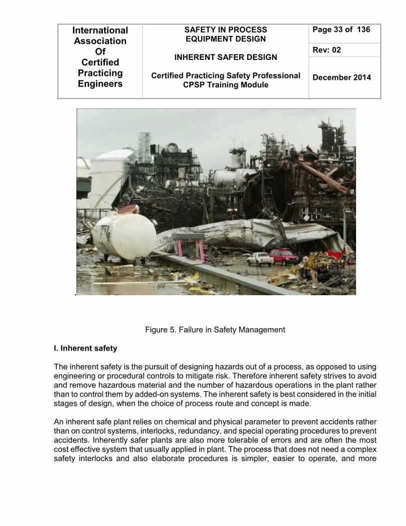
Figure 5. Failure in Safety Management
I. Inherent safety
The inherent safety is the pursuit of designing hazards out of a process, as opposed to using engineering or procedural controls to mitigate risk. Therefore inherent safety strives to avoid and remove hazardous material and the number of hazardous operations in the plant rather than to control them by added-on systems. The inherent safety is best considered in the initial stages of design, when the choice of process route and concept is made. An inherent safe plant relies on chemical and physical parameter to prevent accidents rather than on control systems, interlocks, redundancy, and special operating procedures to prevent accidents. Inherently safer plants are also more tolerable of errors and are often the most cost effective system that usually applied in plant. The process that does not need a complex safety interlocks and also elaborate procedures is simpler, easier to operate, and more

International Association
Of Certified
Practicing Engineers
SAFETY IN PROCESS EQUIPMENT DESIGN
INHERENT SAFER DESIGN
Certified Practicing Safety Professional
CPSP Training Module
Page 34 of 136
Rev: 02
December 2014
reliable. Reducing the dimension or equipment sizing and operating at less severe temperature and pressure condition will lead to decreasing its capital and operating costs. As in general, on the most literature explained that the safety of process is relies on multiple layers of protection. First layer is the process design features, and the next layer contains of many key factors in example : Control systems, interlock, shutdown systems, protective system, alarms, and emergency response plans. Thus, inherent safety is a part of all layers of protection. However, the best approach to prevent accidents is to add process design features to prevent hazardous situations. An inherently safer plant is often more tolerant for human errors and abnormal condition during running the process. The major approach to inherently safer process designs is divided into the following classifications (description included) :
• Intensification. The most effective way of designing inherently safer plants is by intensification. Intensification step could be described as choosing and using smaller amounts of hazardous material. Thus, it will limit the damage in the incidents that occur. Intensification is also the preferred route to inherently safer design, as the reduction in inventory results in a smaller and cheaper plant.
• Substitution. Substitution step generally implied if intensification step is not possible to apply. Substitution means as replacing a hazardous material by a less one. In example using cyclohexane rather than benzene as a solvent. Blended component of mixture will cause a silent potential hazards that mostly people did not realize. Nonetheless, substituting a less substance for mixture component will lead to a safer composition of mixture.
• Attenuation. A third method is called Attenuation. Attenuation means using hazardous materials in the least hazardous form. In example is storing a liquefied toxic or flammable materials at a low operating condition (low temperature and low pressure). The function of this action to decrease the leak rate through a hole and avoid the evaporation process of materials.
• Limitation of effects. Limitation of effects constraint the available energy or the equipment design effect rather than by adding on protective equipment. In example is handling corrosive liquids by plastic container (or plastic-coated) rather than other material construction which heated by an electric immersion heaters. Once the liquid level falls, exposing

International Association
Of Certified
Practicing Engineers
SAFETY IN PROCESS EQUIPMENT DESIGN
INHERENT SAFER DESIGN
Certified Practicing Safety Professional
CPSP Training Module
Page 35 of 136
Rev: 02
December 2014
part of the heater, the container wall could get so hot and lead to a fire. The inherently safer solution is to use a source of heat that less hot to ignite the plastic like low-pressure steam or low-energy electric heaters.
• Simplification / error tolerance. Simplification is to made a system not only modest by its look but also from its function. Put the equipment orderly at the place where it should be is one of the example, such in piperack position and layout. This action will give an advantage such as easier access to people during the process and give benefit from the aesthetic point of view.

International Association
Of Certified
Practicing Engineers
SAFETY IN PROCESS EQUIPMENT DESIGN
INHERENT SAFER DESIGN
Certified Practicing Safety Professional
CPSP Training Module
Page 36 of 136
Rev: 02
December 2014
DEFINITIONS
Accident - An event or sequence of events that results in undesirable consequences
Back Pressure - The pressure on the discharge side of a pressure relief valve. Total back pressure is the sum of superimposed and built-up back pressures.
Bonding – The permanent joining of metallic part to form an electrically conductive path which will assure electrical continuity and the capacity to safely conduct any current likely to be imposed.
Continuous Reactors - Reactors that are characterized by a continuous flow of reactants into and a continuous flow of products from the reaction system. Examples are the Plug Flow Reactor and the Continuous-flow Stirred Tank Reactor
Design Capacity - The capacity used to determine the required area of a relief device based on the limiting contingency.
Design pressure - The pressure in the equipment or piping under consideration at the most severe combination of coincident pressure, temperature, liquid level and vessel pressure drop expected during service, which results in the greatest required component thickness and the highest component rating
Explosion - A release of energy that causes a pressure discontinuity or blast wave.
Failure - An unacceptable difference between expected and observed performance.
Flammability Limits - The range of gas or vapor amounts in air that will burn or explode if a flame or other ignition source is present.
Flash point - The lowest temperature at which a liquid exposed to the air gives off sufficient vapor to form a flammable mixture near the surface of the liquid, or within the test apparatus used, that can be ignited by a suitable flame.
Hazard - An inherent chemical or physical characteristic that has the potential for causing damage to people, property, or the environment. In this document it is typically the combination of a hazardous material, an operating environment, and certain unplanned events that could result in an accident.

International Association
Of Certified
Practicing Engineers
SAFETY IN PROCESS EQUIPMENT DESIGN
INHERENT SAFER DESIGN
Certified Practicing Safety Professional
CPSP Training Module
Page 37 of 136
Rev: 02
December 2014
Hazard Analysis - The identification of undesired events that lead to the materialization of a hazard, the analysis of the mechanisms by which these undesired events could occur and usually the estimation of the consequences.
Hazard and Operability Study (HAZOP) - A systematic qualitative technique to identify process hazards and potential operating problems using a series of guide words to study process deviations.
Hazardous Material - In a broad sense, any substance or mixture of substances having properties capable of producing adverse effects of the health or safety of human beings.
Human Error - Any human action (or lack thereof) that exceeds some limit of acceptability (that is, an out-of-tolerance action) where the limits of human performance are defined by the system.
Inert Gas - A noncombustible, nonreactive gas that renders the combustible material in a system incapable of supporting combustion.
Inherently Safe - A system is inherently safe if it remains in a nonhazardous situation after the occurrence of nonacceptable deviations from normal operating conditions.
Intrinsically Safe - Equipment and wiring which is incapable of releasing sufficient electrical or thermal energy under normal or abnormal conditions to cause ignition of a specific hazardous atmospheric mixture or hazardous layer.
Maximum Allowable Working Pressure (MAWP) - Is the maximum (gauge) pressure permissible at the top of a vessel in its normal operating position at the designated coincident temperature and liquid level specified for that pressure.
Operating pressure - The gauge pressure to which the equipment is normally subjected in service.
Overpressure - Overpressure is the pressure increase over the set pressure of the relieving device during discharge, expressed as a percentage of set pressure. Pressure Relief Device - A device actuated by inlet static pressure and designed to open during an emergency or abnormal condition to prevent the rise of internal fluid pressure in excess of a specified value. The device may also be designed to prevent excessive vacuum.

International Association
Of Certified
Practicing Engineers
SAFETY IN PROCESS EQUIPMENT DESIGN
INHERENT SAFER DESIGN
Certified Practicing Safety Professional
CPSP Training Module
Page 38 of 136
Rev: 02
December 2014
Pressure Relief Valve – This is a generic term applying to relief valves, safety valves or safety relief valves. Is designed to relief the excess pressure and to recluse and prevent the further flow of fluid after normal conditions have been restored.
Process Safety - A discipline that focuses on the prevention of fires, explosions, and accidental chemical releases at chemical process facilities. Excludes classic worker health and safety issues involving working surfaces, ladders, protective equipment, etc.
Process Safety Management - A program or activity that involves the application of management principles and analytical techniques to ensure process safety in chemical facilities. The focus is on preventing major accidents rather than dealing with classic worker health and safety issues.
Risk - The combination of expected likelihood or probability and consequence or severity (effect event) of an accident
Safety - A general term denoting an acceptable level of risk of, relative freedom from and low probability of harm.
Spacing and Layout - A well laid-out plant (including adequate equipment spacing, adequate drainage, “fire breaks" to establish separation between fire risk areas), limits the geographical extent of a fire and allows effective fire fighting access.
Toxic material - One which has the inherent ability to cause adverse biological effects.
Validation -The activity of demonstrating that the safety-instrumented system under consideration, after installation, meets in all respects the safety requirements specification for that safety-instrumented system.
Venting - Emergency flow of vessel contents out the vessel. The pressure is reduced by venting, thus avoiding a failure of the vessel by over pressurization. The emergency flow can be one-phase or multiphase, each of which results in different flow and pressure characteristics

International Association
Of Certified
Practicing Engineers
SAFETY IN PROCESS EQUIPMENT DESIGN
INHERENT SAFER DESIGN
Certified Practicing Safety Professional
CPSP Training Module
Page 39 of 136
Rev: 02
December 2014
THEORY Managing and equipping industrial plant with the right components and sub-systems for optimal operational efficiency and safety is a complex task. Safety Methods employed to protect against or mitigate harm/damage to personnel, plant and the environment, and reduce risk. Safety by definition is the “absence of risk”. There is risk in everything we do, so the safety process model is designed to effectively identify & reduce risk. There is a five-step safety process model.
• Step 1: Identification of risks that are producing accidents and injuries.
• Step 2: Perform accident / incident problem-solving on each identified risk:
1. Process includes: 2. Definition of problem 3. Contributing factors 4. Root Causes
• Step 3: Develop a schedule for implementation of each preventive action Preventive action should all have
1. Responsible party 2. Resources to support actions
Risk Identification
Problem-Solving /
Preventive Actions
Implement Preventive
Actions
Measurement for Result
Employment Performance
Feedback
No Yes

International Association
Of Certified
Practicing Engineers
SAFETY IN PROCESS EQUIPMENT DESIGN
INHERENT SAFER DESIGN
Certified Practicing Safety Professional
CPSP Training Module
Page 40 of 136
Rev: 02
December 2014
3. Timetable for completion
• Step 4: Continuously measure to ensure preventive actions are working as expected.
• Step 5: Employees involved in work environment must be given feedback on a continuous basis.
Safety Studies Safety means a sufficient protection from danger. The safe controls must be designed in a way that any component fault and other imaginable influences do not cause dangerous states in the plant. The safety studies shall be developed during the detailed design phase and continued into the installation and commissioning phases, and shall ensure that risk mitigation is introduced at the earliest possible time. The Safety Studies shall meet all Regulators requirements including methodology, completed Safety Studies and demonstration of “as low as reasonably practicable” (ALARP). As a minimum, the Safety Studies shall address the following:
• The operating conditions, location and environment
• Operations and activities through all phases of work. These shall include, but not limited to: design, fabrication, transportation, installation, commissioning and operation.
• Potential effects during simultaneous operations, if production continues, during certain stages of installation. This shall include considerations of shutdowns, operating procedures (eg. Permit to Work), etc.
• The support services and operations necessary for normal and emergency operations.
• Interaction between the platforms within the process complex (process complex may consist of 2 or 3 platforms which are bridge connected.)
The safety Studies Methodology shall provide a clear and concise statement of the processes to be used. It shall be used an input into the Safety Studies and shall define the deliverables to be generated. It shall address all phases of the Works, including but not limited to
International Association
Of Certified
Practicing Engineers
SAFETY IN PROCESS EQUIPMENT DESIGN
INHERENT SAFER DESIGN
Certified Practicing Safety Professional
CPSP Training Module
Page 41 of 136
Rev: 02
December 2014
transportation, installation, hookup, commissioning, normal operations, and maintenance operations. The Safety Studies Methodology shall include the following:
• Describe the overall process to be used
• Describe the process by which operator/workforce input shall be ensured
• Describe the HAZID and HAZOP process to be employed, resources required and closeout procedure.
• Describe the use of registers in the project such as Assumption Registers, Compliance Registers etc.
• Include Performance Criteria that the Safety Studies shall be using (for example, maximum thermal radiation levels, toxic gas levels, etc)
• Describe the consequence (such as Fire and Explosion Analysis) and other studies (such as Non Process or Emergency Systems Review) to be completed, methodology, software to be used, deliverables, etc.
• Describe a Quantitative Risk Assessment methodology detailing the QRA Rule Set to be used, software to be employed for integration of risk, sources of data, deliverables etc.
• Describe the details of Sensitivity Analysis to be completed as part of the QRA.
• Describe the implementation of Critical Controls
Safety is measured primarily by a parameter called Average Probability of Failure on Demand (PFDavg). Reliability is the ability of a technical device to fulfil its function during its operation time.This is often no longer possible if one component has a failure. So the MTBF (Mean Time Between Failure) is often taken as a measurement of reliability. It can either be calculated statistically via systems in operation or via the failure rates of the components applied. Availability is the probability of a system being a functioning one. It is expressed in per cent and defines the mean operating time between two failures (MTBF) and the mean down time (MDT), according to the following formula

International Association
Of Certified
Practicing Engineers
SAFETY IN PROCESS EQUIPMENT DESIGN
INHERENT SAFER DESIGN
Certified Practicing Safety Professional
CPSP Training Module
Page 42 of 136
Rev: 02
December 2014
The mean down time (MDT) consists of the fault detection time and- in modular systems- the time it takes to replace defective modules. The availability of a system is greatly increased by a short fault detection time. Fast fault detection in modern electronic systems is obtained via automatic test routines and a detailed diagnostic display The Design Process Design plays a part in each phase of the development lifecycle. (9) The design process may be divided into four distinct activities:
1. Abstraction: the operation of generalizing, of identifying the essentials;
2. Decomposition: the process of reducing an object into a number of simpler, smaller parts; analysis of interactions, interfaces and structures; modularization;
3. Elaboration: the operation of detailing, adding features;
4. Decision making: identification and selection of alternative strategies.
Here a few elements of the design process. 1. Top Level or Architectural Design
In safety-related applications, the top-level architectural design is also necessary to allocate the various safety requirements, identified in early phases of the development, to appropriate safety-related systems or subsystems. In general these will include systems based on a number of technologies and may include mechanical, hydraulic or electrical subsystems, as well as both programmable and non-programmable electronic sections. Wherever possible safety features should be implemented using the simplest possible elements.
2. System Partitioning for Safety
The way in which a system is partitioned is fundamental to the provision of safety. One of the important aspects of partitioning is that it aids comprehension of the system. A well partitioned system is much easier to understand.

International Association
Of Certified
Practicing Engineers
SAFETY IN PROCESS EQUIPMENT DESIGN
INHERENT SAFER DESIGN
Certified Practicing Safety Professional
CPSP Training Module
Page 43 of 136
Rev: 02
December 2014
3. Detailed Design
Following the process of decomposition performed in the top-level design phase comes the detailed design of the various functions of each module. The process of decomposition is often iterative, with modules being broken down successively into small sub-modules, each with its own specification. The techniques used in the detailed design phase will be greatly affected by the overall development methods and tools being used.
4. Safety Kernels and Firewalls
In some cases safety can be enhanced by the use of safety kernels or firewalls. A safety kernel consists of a relatively simple arrangement, often a combination of hardware and software. Its small size and lack of complexity enable it to be developed into a trusted subsystem that can be used to ensure the critical safety functions of a system. The success of this arrangement depends on the ability of the designer to protect the kernel from outside influences.
5. Design for Maintainability
Although it may not always be immediately apparent, good maintainability is often a prerequisite of safety. One factor that is often overlooked in the operation of safety-critical systems is the impact of maintenance induced failures. Evidence from a number of sources suggests that there is a significant probability that maintenance operations will not be completed satisfactorily and may lead to new and seemingly unrelated faults.
Figure 6. Causes of Control System Incidents

International Association
Of Certified
Practicing Engineers
SAFETY IN PROCESS EQUIPMENT DESIGN
INHERENT SAFER DESIGN
Certified Practicing Safety Professional
CPSP Training Module
Page 44 of 136
Rev: 02
December 2014
Additional design safety features for design process:
1. Reducing the potential for uncontrolled release of flammable / toxic materials by:
a. Selection of superior quality machinery or materials of construction.
b. Selection of special machinery features such as seal-less pumps, submerged pumps, canned pumps, or oil mist lubrication.
c. Reduce the risk of failure of small piping connections or vulnerable equipment by specifying features such as:
1. Minimizing the number and extent of small piping connections.
2. Increasing mechanical strength by using larger pipe sizes [say 2 in. (50 mm)].
3. Combining multiple connections into a single valve nozzle of larger size at the vessel.
4. Additional gussetting and bracing.
5. Replacing gage glasses with level indicators.
6. Provision of excess flow valves or restriction orifices in small piping such as instrument connections.
2. Provision of additional instrumentation, alarms, and surveillance devices (e.g., closed circuit television, vibration alarms, toxic gas detectors, combustible gas, or fire detectors) to identify potential emergency situations and actuate alarm or corrective devices
3. Designing safety equipment for on-stream maintenance, so that maintenance can be carried out on it while keeping the plant fully protected at all times
4. Provision of fire protection and emergency facilities by increased spacing, additional fireproofing and/or fire fighting facilities, additional facilities for emergency shutdown, isolation, depressuring, or removal of flammable inventory. For some chemical processes storage or handling of highly toxic materials may require features such as secondary enclosures (building a vessel around the equipment) for catching leaks, or facilities for neutralizing blowdown discharges, or others.
Good preparation is very important for an effective inherent safety review. Preparation for the review is summarized in Figure 7.

International Association
Of Certified
Practicing Engineers
SAFETY IN PROCESS EQUIPMENT DESIGN
INHERENT SAFER DESIGN
Certified Practicing Safety Professional
CPSP Training Module
Page 45 of 136
Rev: 02
December 2014
Figure 7: Inherent safety review preparation
DEFINE DESIRED PRODUCT
DEVELOP OPTIONAL ROUTES TO PRODUCT
DEFINE CHEMICAL REACTIONS (DESIRED AND UNDESIRED)
LIST ALL CHEMICALS, CONTAMINANTS, AND MATERIALS OF CONSTRUCTION, ALONG WITH
THEIR PROPERTIES
DEFlNE/ESTIMATE PLANT CAPACITY
PREPARE SIMPLIFIED PROCESS FLOW DIAGRAM
DEFINE SITE AND ENVIRONMENTAL PERMITTING ISSUES
DEVELOP PROCESS CONDITIONS (TEMPERATURE AND PRESSURE)
ESTIMATE QUANTITIES IN EACH MAJOR STREAM AND EQUIPMENT ITEM (INCLUDE RAW MATERIALS
AND WASTE STREAMS)
DEFINE RUNAWAY REACTION AND DECOMPOSITION HAZARDS
DEFINE COMPATIBILITY HAZARDS
DEFINE HEALTH AND ENVIRONMENTAL HAZARDS

International Association
Of Certified
Practicing Engineers
SAFETY IN PROCESS EQUIPMENT DESIGN
INHERENT SAFER DESIGN
Certified Practicing Safety Professional
CPSP Training Module
Page 46 of 136
Rev: 02
December 2014
After the background information is developed, the inherent safety review can be arranged. The review steps are summarized in Figure 8.
Figure 8: Inherent safety review
REVIEW OVERALL PROCESS
• OPTIONS
• PROCESS FLOW SCHEMATIC
• CHEMICAL REACTIONS
• REACTIVE CHEMISTRY INFORMATION
• CHEMICALS EMPLOYED
• HAZARDS ASSOCIATED WITH EACH CHEMICAL
SYSTEMATICALLY REVIEW PROCESS FLOW SCHEMATIC
• CAN SAFER CHEMICALS BE USED?
• CAN QUANTITIES BE REDUCED?
• CAN POTENTIAL RELEASES BE REDUCED VIA
• LOWER TEMPERATURES AND PRESSURES
• CAN WASTE BE REDUCED?
DOCUMENT CONCERNS/QUESTIONS
AND FOLLOW-UP REQUIRED

International Association
Of Certified
Practicing Engineers
SAFETY IN PROCESS EQUIPMENT DESIGN
INHERENT SAFER DESIGN
Certified Practicing Safety Professional
CPSP Training Module
Page 47 of 136
Rev: 02
December 2014
Site Selection
Plant sitting plays an important role in process safety. Safety considerations may take precedence over other factors, possibly causing otherwise attractive sites to be eliminated for process or general safety concerns. Important factors in plant sitting typically include the following items:
1. Population density around the site
2. Occurrence of natural disasters, such as earthquake, flood, hurricane
3. Accessibility to raw materials
4. Accessibility to markets
5. Transportation
6. Availability of land
7. Availability of power and utilities
8. Labor
9. Interface required with other plants
10. Government policies, such as sitting permits and investment incentives
11. Means of effluent disposal
12. maximize safety;
13. prevent spread fire
14. Facilitate easy operation and maintenance
15. Consider future expansion
16. Economize project

International Association
Of Certified
Practicing Engineers
SAFETY IN PROCESS EQUIPMENT DESIGN
INHERENT SAFER DESIGN
Certified Practicing Safety Professional
CPSP Training Module
Page 48 of 136
Rev: 02
December 2014
A process safety management program initiated during the development phases of a new project will identify and explain the nature of hazards associated with the proposed plant. A site can be selected after considering many of the recognized hazards. Some important safety considerations are listed in below.
1. Adequate buffer space between the plant site and vulnerable communities and public facilities
2. Presence of other hazardous installation nearby
3. For highly toxic materials make the material in the plant as a sub process just prior to mixing the material into the main process. Inventory is then made up of less toxic precursor materials.
4. Emergency response support
5. Adequate water supply for fire fighting
6. Stable power supply
7. Weather extremes
8. Presence of strategic installations in nearby area
9. Presence of highways, waterways, airways
10. Pollution and waste disposal
The important factors in sitting central services, such as the boiler house, cooling towers, power station, are listed below:
1. Central services should not be put out of action by fire or explosion or flood.
2. Central services should not constitute a source of ignition.
3. Cooling towers should be located to minimize water drift to avoid corrosion of other units.
4. Flare stacks should be located upwind to minimize the ignition of vapor cloud releases and should be analyzed for intensity of thermal radiation and noise.
The basic requirements to be met in the appropriate diagram when making a piping and equipment layout are:
1. All equipment, ladders, structures, davits, trolley beams, shall be indicated.
2. All instrument shall be located and indicated.

International Association
Of Certified
Practicing Engineers
SAFETY IN PROCESS EQUIPMENT DESIGN
INHERENT SAFER DESIGN
Certified Practicing Safety Professional
CPSP Training Module
Page 49 of 136
Rev: 02
December 2014
3. All valving and hand wheel orientations shall be indicated.
4. Drip funnel locations for underground drains shall be indicated.
5. All electrical switch gear, lighting panels shall be indicated.
6. All sample systems shall be indicated
Plant and Unit Layout The plant layout shall be determined in consideration of classified hazardous areas. Thus, for layout in process units could be considered to follow the several points such as :
• For process fluid run by gravity head. Elevated layouts should be considered. Equipment should be placed at grade as a rule except in cases where gravity flow is specifically required for any reason.
• First direction of the piperack in Unit is highly important due to the overall plot plan (including feed stocks, outgoing products and utility).
• Minimize the piping runs as far as possible. Clear access ways having minimum width of 600 mm.
• Locate large capacity storage tanks that contained flammable and explosive fluids as far as possible.
• Extend the space for future space equipment installation.
• The area of any unit must not exceed 20,000 m2 and the length of each side should not exceed 200 m.
• For a unit that processing flammable fluids, the central control building should be adjacent to a road.
• The drawing shall be prepared in one of the following scales: 1500
1,1200
1 .
• The drawing shall show the following items:
a. Conventional North.
b. Coordinates of battery limits and roads.
c. Symbols for equipment and coordinates of their centerlines.
d. Finished floor elevation.

International Association
Of Certified
Practicing Engineers
SAFETY IN PROCESS EQUIPMENT DESIGN
INHERENT SAFER DESIGN
Certified Practicing Safety Professional
CPSP Training Module
Page 50 of 136
Rev: 02
December 2014
e. Equipment index list.
Process Requirements 1. Equipment shall be laid out along the flows on the process flow diagram. 2. Especially, the fractionators and their reboiler, condensers and overhead receivers shall
be collectively located. 3. Gravity flow lines shall be laid out with consideration given to related elevations, so that
their lengths will become minimum. Especially in the case of lines in which liquids will flow near at their boiling points, related equipment shall be located close to each other so that the lines need not be elevated.
4. Pieces of equipment which are to be connected by large-size piping or alloy piping, shall be located close to each other.
Air coolers shall be laid out so that no heated air may be recirculated Equipment For the following equipment, layout and spacing should be considered to obey any of point such a rule of thumb as follows :
• Reactor. Adequate space should be created for handling and storing catalysts, chemicals, hydrogen, nitrogen, any other reactants, and also mobile equipment like truck and forklift. There is a limitation for maximum space of transportation that handling the chemicals.
• Towers. Location of the tower and its complementary equipment should be arranged adjacent each other and provide a space for assembling and disassembling tower internals such as tray, demister, etc. If there is more than one tower installed, the center-lines should be aligned parallel with the piperack. Support structures are requiring for a self-standing towers exceeding 30 in L/D ratios.
• Fired Equipment. For boilers and furnaces must be located on the windward side of the plant. For common stack employed, suitable barriers or isolating barriers may be provided in individual ducting. Heaters must located near the edge of process area. Tube pulling areas should not encroach on any main roadways. Adequate drainage should be

International Association
Of Certified
Practicing Engineers
SAFETY IN PROCESS EQUIPMENT DESIGN
INHERENT SAFER DESIGN
Certified Practicing Safety Professional
CPSP Training Module
Page 51 of 136
Rev: 02
December 2014
located under and surrounding fired heaters. Burners utilities headers must be arranged with a vertical bundle along furnace walls. Feed control valves should be located at least 15 meters from furnaces.
• Heat Exchangers. Horizontal clearance between shells and any major equipment should be equals or above 1.0 m in any direction. If there is air fins used, air fins should located far from heater. If air cooled heat exchangers are installed beyond the piperacks and structures, additional space should be provided adequately. Thermosyphon reboilers also must be located next to the related vessels. The effect of air cooled exchangers affected the air movement and increasing fire spread probability. Thus, this would be caused of releasing more combustible fluid to the fire. Avoid to locate an air cooler exchangers within 7.5 m horizontally from pumps on the hydrocarbon service, practically it should be at least 20 m horizontally from fired heaters. Tube pulling space in front of exchangers must be approximately 1 ½ times the tube length. When two banks of exchangers face each other, the clear space between channel ends should be 2 times the tube length. Working platforms for the removal of the shell cover, channel or channel cover shall be provided more than 3.70 m above grade or platform. Large diameter stacked exchangers should be limited to 2 shells high. Either for a small or large stacked exchangers must be limited to a maximum elevation of 3.70 above grade.
• Vessels and Drums. Vessels recommended laid out as close as possible to other related equipment. Where horizontal drums are arranged near a pipe way, the horizontal centerline of the drums should be located at right angles to the pipe way.
• Pumps. Pumps must be placed on the feasible space to facilitate its operation and maintenance. Suction lines are the nearest length line if possible. Aisles between rows of pumps should be 3 meters minimum clearance. Recommended space for pump is 0.5 meters to 1.0 meter, wide foundation is 2 meters center to center. Generally, pumps are located in the open area. If it’s at grade level, then adequate ventilated shelter should be provided. Pumps in flammable or toxic duties should not located in pits. For flammable fluid service, the horizontal distance between the related pump and adjacent heat source equals to 650°C or more should be 30 meters for minimal

International Association
Of Certified
Practicing Engineers
SAFETY IN PROCESS EQUIPMENT DESIGN
INHERENT SAFER DESIGN
Certified Practicing Safety Professional
CPSP Training Module
Page 52 of 136
Rev: 02
December 2014
requirements. Suction lines from source above pump should preferably be stepped continuously download toward the pump. Horizontal pumps must be placed below the side portal frames of pipe rack, with the motor side below the pipe rack and the hydraulic section towards the outside.
• Compressors. Several compressors economically located in one area. Area of compressors must available for firefighting access and it contains an associated equipment that do not restrict the access for firefighting. 30 Meters is the minimum spacing between gas compressor and an open flame. If it possible, all operating valves should be accessible from compressor slab, walkaway or grade, and grouped together for maximum ease of operation. Discharge check valves for an air compressor must be installed as near as possible to the compressor with spiral wound gaskets have an internal retaining rings, and used at raised face flanged connections only.
• Storage Vessels (Tanks). Location, layout and spacing of storage vessel/tanks should obey with the latest editions of code standards for the minimum spacing from vessels to its boundaries. Tall slender vessel (L/D > 10) must be located on the minimum height of the top to maintain the aerodynamic oscillations, piping platforms and ladders. For the tanks that designed for 20 kPa or less containing flammable and combustible liquids, tanks should be located in areas remote from process units and must be arranged in rows not more than two deep. If diameter of tanks less than 48 m, individual bounded compounds are not required. On the other hand, for the tank with diameter, a separate bounded compound should be provided. In no case should the number of tanks in any bounded compound exceed 6 nor shall the total capacity exceed 60,000 m3. For non-refrigerated pressure storage vessels designed for 20 kPa or greater which contains flammable liquid or liquefied compressed gases, vessel should be located to permit maximum dissipation of vapors by free circulation of air. Spheroids form vessel must be located in rows not more than two deeps. A pressure storage LP-gas tanks may not be provided with spill dikes and have a 600 mm dividing installation for each vessel. Spacing location and layout of LP-gas storage tanks should be in accordance with the latest code standards.

International Association
Of Certified
Practicing Engineers
SAFETY IN PROCESS EQUIPMENT DESIGN
INHERENT SAFER DESIGN
Certified Practicing Safety Professional
CPSP Training Module
Page 53 of 136
Rev: 02
December 2014
For LPG tanks, site boundary to third party property should have a distance that the radiation at ground level should not exceed 4.7 kW/m2. Horizontal vessels 3.70 m or less from grade to top of vessel will be serviced by portable ladder. While for horizontal vessels over than 3.70 m, the ladder must be permanently installed. When the centerline elevation of either vertical or horizontal vessel is equal to 4.5 m or less from grade, the manholes is not require. Davits or trolley beams should be provided on vessels over 9 m (30 feet) height where the weight of removable internal and/or external equipment, such as relief valves is greater than 90 kg (200 pounds). When lifting cannot be reasonably accomplished by a ½ ton chainblock, a flame proof hoist must be provided for each case.
• Air Intake and Discharges. Air intakes, including intakes to heating and ventilating system, air compressors for process, instrument, plant and breathing air and to gas turbines shall be located as far as is practicable away from areas where air contamination by dust or by flammable or toxic material can occur. They shall not be located in any area classified as zone 0, 1 or 2 (except for gas turbine air intakes which shall be in accordance with manufacturer’s requirement), nor located above or below an area classified as zone 0, or 1. Intakes and discharges shall be separated to prevent cross contamination by recirculation, taking into account natural wind effects. The distance between intakes and discharges shall be not less than 6 m.
Layout of Control Room and Electrical Sub-Station
1. The control room and substation shall be located as close as possible to the plant equipment, maintaining a minimum distance from viewpoint of noise and safety requirements.
2. The control rooms, and substation shall be spaced at least 15 m from the nearest process equipment surface.
3. The control room and substation shall be located with consideration to convenience in daily operation.
4. The control room and substation shall be located from an economic standpoint so as to minimize the length of electrical and instrument cables entering and leaving therefore.

International Association
Of Certified
Practicing Engineers
SAFETY IN PROCESS EQUIPMENT DESIGN
INHERENT SAFER DESIGN
Certified Practicing Safety Professional
CPSP Training Module
Page 54 of 136
Rev: 02
December 2014
5. The control room shall be positioned so that the operator can command a view of the whole system which is under control. Large buildings, or equipment shall not be placed in front of the control room.
Fire Fighting Requirements
1. Each individual process Unit shall be provided with sufficient open spaces there around that, fire trucks can be run and operated thereat. The width of access way there to, shall be 6 meters minimum.
2. Process Units consisting of large hazardous material storage tanks should be located desirably in outer area in the complex site.
3. High-pressure gas lines shall not pass through a process area or run within 30 m of important structures or equipment without shutdown valve to insure that portions of piping within the process area can be isolated from the main gas line and depressurized in the event of an emergency. However, extensive use of shutdown valves may not be needed, since the increased complexity of the system will require a greater degree of preventive maintenance if unwarranted shutdowns are to be avoided. Shutoff valves, sometimes known as "station isolation valves", shall be provided on all gas and product pipelines into and out of the plant.
A bypass line with a normally shut valve may be required between plant inlet and discharge lines. All station isolation valves-and bypass valves, if any should be located at a minimum distance of 75 m but not more than 150 m from any part of the plant operations. Care should be taken in locating these valves so that they will not be exposed to damage by plant equipment or vehicular traffic.
4. At least two remote emergency shutdown stations, located at a minimum distance of 75m apart, shall be provided. Locate actuating points at least 30m from compressor buildings and high pressure gas lines. More than two shutdown stations may be required, depending on the size and complexity of a given plant. One of the actuating stations shall be located in the control room. It shall be distinctively marked and equipped with signs stating the proper method of actuation in the event of an emergency.
5. Wastewater separators handling hydrocarbons should be spaced at least 30 m from process unit equipment handling flammable liquids and 60 m from heaters or other continuous sources of ignition. Preferably, wastewater separators should be located downgrade of process equipment and tanks.
6. Fire training areas are ignition sources when in use. Because of the smoke produced, they can also create a nuisance for the refinery and neighboring facilities. Fire training
International Association
Of Certified
Practicing Engineers
SAFETY IN PROCESS EQUIPMENT DESIGN
INHERENT SAFER DESIGN
Certified Practicing Safety Professional
CPSP Training Module
Page 55 of 136
Rev: 02
December 2014
areas shall be 60 m from process unit battery limits, main control rooms, fired steam generators, fire pumps, cooling towers and all types of storage tanks. They shall also be 75 m from property boundaries, administration, shops, and similar buildings and from the main substation.
Building Requirements 1. Service buildings include offices, control rooms, laboratories, houses, shops,
warehouses, garages, cafeterias and hospitals. 2. These structures and areas require protection of personnel from possible fires and
explosions of major plant equipment and may require additional spacing from high risk facilities.
3. The service buildings shall be located near the entrance of the plant and be readily accessible to a public road or highway.
4. Spacing at refineries, petrochemicals, chemicals, and gas plants for buildings shall be in accordance with standard recommendations.
Access Requirements
Access ways within the plant shall be provided for maintenance, emergency case, and for fire fighting from the road around the plant. Piping system shall be laid in such a way to make possible passage of mobile equipment. Operating passageway between equipment or piping and adjacent equipment generally be 1050 mm minimum except when otherwise shown on drawings. Minimum widths of access way shall be as follows:
1. Vehicular access ways within units: 4.0 m
2. Pedestrian access ways and elevated walkway: 1.2 m
3. Stairways and platforms: 0.8 m
4. Footpaths in tanks areas: 0.6 m
5. Maintenance access around equipment: 1m
6. Fire truck access way: 6m
Minimum headroom clearance for access ways shall be as follows:
1. Over railways or main road: 6.8 m

International Association
Of Certified
Practicing Engineers
SAFETY IN PROCESS EQUIPMENT DESIGN
INHERENT SAFER DESIGN
Certified Practicing Safety Professional
CPSP Training Module
Page 56 of 136
Rev: 02
December 2014
2. Over access roads for heavy trucks: 6 m
3. For passage of truck: 4 m
4. For passage of personnel: 2.1 m
5. Over fork-lift truck access: 2.7 m
During the plant design the safety of process equipment is also recognized by layout. The objectives of layout are to minimize risk to personnel, to minimize escalation (both within the plant and to adjacent plants), and to ensure adequate emergency access. It is also essential to ensure adequate access for maintenance and operations. Plant layout is a crucial factor in the safety of a process plant because of segregation of different risks, containment of accidents and limitation of exposure. Safe plant layout is designed on the basis of design standards and local regulations.
A good layout is one that integrates men, materials, machines and supporting activities and others in a way that the best compromise is obtained. No layout can satisfy each and every principle of a good layout. Some criterion may conflict with some other criterion and as a result no layout can be ideal it has to integrate all factors into the best possible compromise. Some of the safety benefits of a good layout are:
1. Minimal explosion damage, since explosion overpressure falls off rapidly with distance from the center of the explosion.
2. Minimal thermal radiation damage, as the intensity of thermal radiation also falls off with the distance.
3. Less property damage caused by a given incident.
4. Easier access for emergency services such as fire fighting.
5. Easier access to equipment for maintenance and inspection.
6. Efficient and safe construction.
7. Optimum balance among loss control, maintenance, and operation requirements.
Good layout can reduce the effects of some of the controllable factors, such as liquid spills, and uncontrollable factors, such as exposure to natural hazards, site slope, wind direction and force, that contribute to losses.

International Association
Of Certified
Practicing Engineers
SAFETY IN PROCESS EQUIPMENT DESIGN
INHERENT SAFER DESIGN
Certified Practicing Safety Professional
CPSP Training Module
Page 57 of 136
Rev: 02
December 2014
Some important factors in plant layout development are listed below
1. Containment of accidents
2. High hazard operations
3. Segregation of different risks
4. Exposure to possible explosion overpressure
5. Exposure to fire radiation
6. Minimization of vulnerable piping
7. Drainage and grade sloping
8. Prevailing wind direction
9. Future expansions
A preliminary layout is developed without regard for the site. As a general guideline, the layout of the units is based on the flow principle so that the material flow follows the process flow diagram. The goal is to minimize the transfer of materials both for economic and safety reasons, and allow a release to be contained at its source. Plant layout is largely constrained by the need to observe minimum safe separation distances. Facilities that should be separated from each other are:
1. Process units
2. Tank farms
3. Outdoor drum storage yards
4. Loading and unloading stations
5. Heat transfer fluid heaters and other fired equipment
6. Flares
7. Power and boiler houses
8. Electrical and instrument rooms
9. Utilities (e.g., substations, gas metering stations, nitrogen plants, cooling towers)
10. Control rooms
11. Warehouses
12. Fixed fire protection facilities, such as fire pump houses and reservoirs and sprinkler riser buildings

International Association
Of Certified
Practicing Engineers
SAFETY IN PROCESS EQUIPMENT DESIGN
INHERENT SAFER DESIGN
Certified Practicing Safety Professional
CPSP Training Module
Page 58 of 136
Rev: 02
December 2014
13. Other support facilities, such as waste treatment areas, maintenance areas, administrative buildings, and laboratory
Adequate separation is often achieved by dividing up a plant into process blocks of similar hazards (e.g., process units, tank farms, loading/unloading operations, utilities, waste treatment, support areas), and then separating individual operations or hazards within each block. The block approach also serves to reduce the loss potential from catastrophic events, such as unconfined vapor cloud explosions, and to improve accessibility for emergency operations. Here some design for plant layout:
1. The site layout is considering the site constraints include topographical and geological features; weather; people, evacuation routes, activities and buildings in the vicinity; access to utilities; treatment of effluents; and laws and regulations.
2. The site layout should be reviewed carefully for statutory requirements, consequences and mitigation measures, ease of fire fighting and emergency operations.
3. A maximum block size of 300 feet (92 m) by 600 feet (183 m) with adequate spacing between the blocks allows access for fire fighting.
4. Each section of the plant should be accessible from at least two directions with at least two entrances to the plant for emergency vehicles in case one road is blocked during an incident.
5. Adequate overhead and lateral clearance for pipeways, pipe racks and hydrants should be provided to prevent possible damage by large moving vehicles, cranes and trucks.
6. Dead ends should be avoided.
7. Slightly elevated roads may be required in areas subjected to local flooding.Main service utility lines should be designed to run alongside primary or secondary plant roadways in a clear corridor or right-of-way.
In addition to radiant heat exposure, other factors that should be considered in determining separation distances and plant layout include topography, prevailing winds for normal and accidental vapor/gas releases, liquid drainage paths for accidental liquid spills, location of fire protection equipment and accessibility for emergency vehicles. The important factors in sitting central services, such as the boiler house, cooling towers, power station, are listed below:
1. Central services should not be put out of action by fire or explosion or flood.

International Association
Of Certified
Practicing Engineers
SAFETY IN PROCESS EQUIPMENT DESIGN
INHERENT SAFER DESIGN
Certified Practicing Safety Professional
CPSP Training Module
Page 59 of 136
Rev: 02
December 2014
2. Central services should not constitute a source of ignition.
3. Cooling towers should be located to minimize water drift to avoid corrosion of other units.
4. Flare stacks should be located upwind to minimize the ignition of vapor cloud releases and should be analyzed for intensity of thermal radiation and noise.
Unit layout is the arrangement of equipment within a particular block on the site. The processing units are usually grouped because they are generally more hazardous than central services. The unit layout also depends on whether the unit uses single or multi stream operation. Space for future expansion of plant equipment or pipe work, as well as access for installation is another factor to consider. Some further considerations in unit layout are:
1. Location of fired heaters in relation to units that could leak flammable materials.
2. Separation of equipment that is a potential source of explosions, such as chemical reactors, by blast resistant walls, if increased spacing is not practical.
3. Location of pumps and compressors handling flammable material. These items are frequent sources of releases and should not be grouped in one single area. They should not be located under vessels, air-cooled heat exchangers or pipe racks.
4. Large vessels and equipment needing frequent maintenance or cleaning should be located close to unit boundaries for ease of access by cranes.
5. Plant items such as heat exchangers and reactors that need removal of internals should be provided with necessary space and lifting arrangements.
6. Machines should be kept sufficiently apart and with reasonable clearance from the wall so that lubrication, adjustment and replacement of belts, removal of parts at the time of repairs etc can be done conveniently by the maintenance staff.
7. Area in front of electrical panels and fire extinguishers should be kept free from obstructions.

International Association
Of Certified
Practicing Engineers
SAFETY IN PROCESS EQUIPMENT DESIGN
INHERENT SAFER DESIGN
Certified Practicing Safety Professional
CPSP Training Module
Page 60 of 136
Rev: 02
December 2014
Figure 9. Typical plant layout
The overall layout of the process area must be subdivided with accessways for firefighting, turnarounds, fire risk areas, and maintenance in accordance with the following:
1. Access for firefighting is 20 ft (6 m) minimum width accessways are required
2. Turnaround isolation is 50 ft (15 m) separation between groups of equipment which shut down separately and 75 ft (22.5 m) for light ends units.
3. Process area subdivisions for determining fire water rates is 50 ft (15 m) minimum separation as the bases for determination of fire water application rates
4. Access for mobile equipment for on-stream and turnaround maintenance is 20 ft (6 m) minimum accessways are required.
Water
treatment
Metal
separation Ware
house
Emergency
flare Glass
storage
Maintenance
Building Power
transmission Gas & stream
turbine
Administration
building
HCL
Plant
By product &
raw material
storage
Turbine
exhaust
vent
Multi effect
distillation
Distilled
water
storage
Truck
scales
Hazardous
waste
handling
Process
area
Tipping
floor
Raw
material
storage

International Association
Of Certified
Practicing Engineers
SAFETY IN PROCESS EQUIPMENT DESIGN
INHERENT SAFER DESIGN
Certified Practicing Safety Professional
CPSP Training Module
Page 61 of 136
Rev: 02
December 2014
5. Fire risk areas for the sizing of safety valve headers in laying out a unit plot plan is 20 ft (6 m) accessways are provided for maintenance.
Utility For the utility, layout and spacing should be considered to obey any of point such a rule of thumb as follows :
• The utility area should be near the process area to support the process run adequately.
• Standard and Recommendation refer the cooling water should be located to provide the least possible restriction to the free flow of air.
• Cooling tower also must be located to minimize any nuisance, both with in and out side the site, from water blow-out, evaporation, drift and ice formation.
• The circulating fuel oil system that supporting heaters and boilers strongly recommended to be located in one corner of the utility area including tanks and circulating pumps.
• All boilers are grouped together with space provided for at least one future boiler.
• Plant and instrument air compressors including dryers should be located in the utility area.
• The switch gear for the electrical system is placed in an enclosed building and located within the utility area.
• Utility control house shall be provided to house all board mounted instruments used for operation and control of utility equipment.
• Raw water storage and fire pumps shall be located adjacent to either the boilers or the cooling towers whichever provides the more economic arrangement.
• Critical steam and power facilities that feed most of the major process equipment must be protected from possible fire and explosion in equipment handling hydrocarbons.

International Association
Of Certified
Practicing Engineers
SAFETY IN PROCESS EQUIPMENT DESIGN
INHERENT SAFER DESIGN
Certified Practicing Safety Professional
CPSP Training Module
Page 62 of 136
Rev: 02
December 2014
Off Site Facilities A large number of facilities including storage facilities, loading and unloading facilities etc should be involved at the offsite area.
• Tank Farm. The tank farm area should be adjacent to the process and utility area and located on the lee side of and preferably down slope from the remainder of the plant. For horizontal product storage tanks must be located where the longitudinal axes are not in line with buildings and plant equipment. The storage areas should be graded to drain to a safe area. The number of tanks within a dike spacing within the dike and volume of dikes should be in accordance with standards.
• Loading and Unloading Facilities. The loading and unloading racks for tank trucks and rail tank cars should be consolidated at one location as near to the plant site as practical, and close to an access gate. The loading facilities also should be provided with adequate space and roadways for safe truck maneuvering and parking. Truck and rail loading racks for combustible and flammable liquids must be at a distance minimum 30 meters apart from main process Unit.
LP gas truck and rail loading rack should be located at least 75 meters from main process Unit, fire heaters or their continuously exposed sources of ignition. Also, allowing a space for dispersal of vapors and liquid spills to minimize the damage to other equipment. Waste Treatment For the waste treatment facilities, layout and spacing should be considered to obey any of point such a rule of thumb as follows :
• Location of the waste treatment area should be at a refinery/plant low point to insure gravity flow from all unit process areas. The lift stations could also be provided.
• The waste treatment area must be remote from the process and utility area and arranged to permit future expansion of the system.
• The layout of the area must involving vehicle accessibility for maintenance purposes.
International Association
Of Certified
Practicing Engineers
SAFETY IN PROCESS EQUIPMENT DESIGN
INHERENT SAFER DESIGN
Certified Practicing Safety Professional
CPSP Training Module
Page 63 of 136
Rev: 02
December 2014
Storage Tank
Storage areas in the plant usually contain the largest volumes of hazardous materials. Frequently storage areas contain flammable liquids or liquefied gases. The main concern in the design of storage installations for such liquids is to reduce the hazard of fire by reducing the amount of spillage, controlling the spill, and controlling fire.
It cannot be emphasized enough that reducing the quantities of hazardous materials is the single greatest method for reducing the hazards of fire or explosion. Minimizing storage quantities also reduces the potential for large spills and further damage. Pipeline feeds from a reliable source can eliminate the requirement for large storage areas. What type of storage tanks that used is depend on material hazards which kept. The type and material hazard which kept is discussed below.
1. The fixed tank is preferred in applications where it is desirable to collect and treat all emissions from the tank or where an inert gas is used to reduce the possibility of fire, explosion, or chemical reaction. Most organics with a vapor pressure below 1.5 psia can be stored in fixed roof.
2. Floating roof tanks are typically used where the vapor pressure of the stored fluid would be excessive for a cone roof tank or where collection of emissions from the tank is not required but it is still desirable to minimize them. Materials with a vapor pressure between 1.5 and 1.1 psia must be stored in at least a floating roof tank.
3. Domed or cone roof tanks with internal floaters is for environmental emissions controls,
4. Horizontal storage tanks on saddles are used for liquids or gases requiring high pressure.
5. Pressure spheres are used for materials such as butane or ammonia that are normally stored as pressurized liquids.
Safety design considerations for storage tank are:
1. Pressure/vacuum relief valves (including conservation vents for atmospheric tanks) and relief discharge venting.
2. Fire relief and protection, including fire loops and monitors, protective sprays, foam application, and flame arresters
3. Foundations, fabrication techniques and anchorages

International Association
Of Certified
Practicing Engineers
SAFETY IN PROCESS EQUIPMENT DESIGN
INHERENT SAFER DESIGN
Certified Practicing Safety Professional
CPSP Training Module
Page 64 of 136
Rev: 02
December 2014
4. Materials of construction and corrosion
5. Design considerations for related pipework and fittings including stresses due to movement, expansion/contraction, vibration, connections, valves, and layout
6. Selection of ancillary equipment including pumps, compressors, vaporizers, etc.
7. Consideration of the range of operations as well as non-operational periods such as commissioning, decommissioning, unit shutdowns, and tank cleaning.
8. locate producing and consuming plants near to each other so that hazardous intermediates do not have to be stored and transported
9. reduce storage by increasing design flexibility
10. Store in a safer form (less extreme pressure, temperature or in a different chemical form).
Hazards associated with atmospheric tanks (ambient pressure to 15 psig) include overpressure and underpressure, vapor generation, spills, tank rupture, fire and product contamination. In addition, differential settlements, seismic and wind loadings are important concerns. Below is discuss of common causes of spills:
1. Overfilling due to operator error or high level alarm failure (vehicular as well as stationary tanks)
2. Withdrawal of water from the tank bottom without operator attention
3. Mechanical failure of tank support causing collapse of roof
4. Accumulation of a large volume of water, snow or ice on the tank roof causing collapse and subsequent exposure of liquid surface
Strategies to avoid spills and minimize damage to other units are:
1. Instrumentation for tank high level and flow total alarms and shutoffs should be completely separate from the normal level and flow measurement with separate sensors and control units. Inherently safer design
2. Provide safe method of water withdrawal from tanks storing organics and water drainage from the roof the tank.
3. Provide secondary containment around tanks to prevent spills from spreading to other areas. This can take the form of dikes, double walled tanks, or tanks in a concrete vault.

International Association
Of Certified
Practicing Engineers
SAFETY IN PROCESS EQUIPMENT DESIGN
INHERENT SAFER DESIGN
Certified Practicing Safety Professional
CPSP Training Module
Page 65 of 136
Rev: 02
December 2014
4. Overflow lines should be sized to allow full flow in case of a tank overflow. A general rule of thumb for estimating the size of overflow piping is that it should be sized at least one standard pipe size larger than the inlet pipe, but the exact size will be dependent upon the pressure drop in the pipe.
A tank rupture is the sudden loss of tank integrity over a relatively large area of the tank structure, causing a large loss of contents. It can be caused by any of several conditions: overfilling, overpressure due to an internal chemical reaction or material boiling due to a constant exposure to heat, continued impingement of flame over an area of the tank, loss of wall integrity due to corrosion, or loss of wall weld integrity. The chances of tank rupture can be reduced by attention to several design features:
1. The proper use and sizing of overflow piping and pressure relief safety valves and rupture disks.
2. The installation of the appropriate high level alarms and flow shutoffs to prevent overfilling
3. The installation of water sprays to protect exposed tank walls during a fire
4. The diked area should be sloped to a sump within the diked area
5. The proper specification of tank materials and thickness, including corrosion allowances
6. The inspection of tank welding during and after construction and the pressure testing of the tank prior to use.
When flammable materials are being stored, fire is the greatest hazard normally addressed in the design of the storage system. Design items that should be addressed in this area are given below.
1. Protection against electrostatic charges which can cause ignition, including the bonding and grounding of the tank, piping, and other ancillary equipment and the use of bottom or dip-pipe loading to minimize material splashing in the tank.
2. Fire fighting facilities applicable to the type of tank protected. Including fire loops with hydrants and monitors in the storage area, foam systems for the individual tanks, and deluge spray systems to keep the exposed surfaces of tanks cool in case of fire in an adjacent tank.

International Association
Of Certified
Practicing Engineers
SAFETY IN PROCESS EQUIPMENT DESIGN
INHERENT SAFER DESIGN
Certified Practicing Safety Professional
CPSP Training Module
Page 66 of 136
Rev: 02
December 2014
3. Adequate spacing between tanks.
4. Install flame arresters on atmospheric vents to prevent impinging fire on the outside of the tank from reaching the vapor space inside the
5. Do not use air to mix flammable materials.
6. Provide fire resistant insulation for critical vessels, piping, outlet valves on tanks, valve actuators, instruments lines, and key electrical facilities.
7. Provide remote controlled, automatic, and fire-actuated valves to stop loss of tank contents during an emergency; provide fire protection to these valves. Valves should be close-coupled to the tank, and must be resistant to corrosion or other deleterious effects of spilled fluids.
Layout of hazardous materials storage areas requires careful attention. Typically a far larger quantity of material is held in storage than in process. Some of the important aspects of storage layout are:
1. Storage tanks should be arranged in groups so that common dike and firefighting equipment can be used for each group.
2. Tanks should be located downwind of other areas to prevent flammable materials reaching ignition sources, should a leak develop in a tank.
3. It is essential to keep storage tanks away from process areas since a fire or explosion in a process unit may endanger the large inventory of the storage tank.
4. Storage tanks should be diked in accordance with NFPA 30. Piping, valves and flanges should be kept to a minimum when located within dikes. Valves, manifolds, and piping should be installed outside dikes or impounding areas.
5. The effect of intensity of thermal radiation from an adjacent tank on fire should be considered in spacing the tanks. Tolerance of tanks to thermal radiation can be increased by insulating or fireproofing the tank shell, and providing water cooling arrangements.
The provisions for spacing are based on the commodity stored, pressure, temperature, and fire protection measures afforded to each tank. Each parameter adjusts the minimum requirements. For large tanks and those containing crude oil, heated oil, slop oil or

International Association
Of Certified
Practicing Engineers
SAFETY IN PROCESS EQUIPMENT DESIGN
INHERENT SAFER DESIGN
Certified Practicing Safety Professional
CPSP Training Module
Page 67 of 136
Rev: 02
December 2014
emulsion breading materials additional spacing requirements should be considered. These include the following:
1. Where tanks exceed 45.7 meters (150 ft.) in diameter, the spacing between tanks should be a minimum of 1/2 the diameter of the largest tank.
2. Tanks 45.7 meters (150 ft.) or more in diameter containing crude oil should be arranged such that the tanks are a minimum of one diameter apart.
3. Hot oil tanks heated above 65.6 OC (150 OF), excluding flash asphalt, slop oil and emulsion breaking tanks should be spaced apart by the diameter of the largest tank in the group.
(a) (b)
Figure 10. Type of storage tank: (a) Sphere Storage Tank and (b) Cylinder Storage Tank
International Association
Of Certified
Practicing Engineers
SAFETY IN PROCESS EQUIPMENT DESIGN
INHERENT SAFER DESIGN
Certified Practicing Safety Professional
CPSP Training Module
Page 68 of 136
Rev: 02
December 2014
Distillation
Distillation is probably the most widely used separation process in the chemical and allied industries, its applications ranging from the rectification of alcohol, which has been practiced since antiquity, to the fractionation of crude oil. A general procedure for distillation design is as follows
1. Specify the degree of separation required: set product specifications. 2. Select the operating conditions: batch or continuous; operating pressure. 3. Select the type of contacting device: plates or packing. 4. Determine the stage and reflux requirements: the number of equilibrium stages. 5. Size the column: diameter, number of real stages. 6. Design the column internals: plates, distributors, packing supports. 7. Mechanical design: vessel and internal fittings.
Equipment Inspection is very important part of a distillation insure what was intended is what is installed. Items to check include;
1. Levelness 2. Downcomer clearance 3. Weir heights 4. Inlet weir clearance 5. Bolt tightness 6. Feed and reflux piping 7. Fabrication Errors
Equipment inspection in distillation:
1. There’s manways down through each tray for maintenance. These manways have to be closed up.
2. Inspect the particular tray to see all the dirt and debris, paper, tools, flashlight, etc. have been removed from the tray. So the bottom of column, make sure the such things as welding rods, nuts, bolts, pieces of wood, and trash have been removes
3. Make sure that the flange faces thoroughly are cleaned, taken any rust off of the faces of these flanges, installed the gasket and bolted up tight the flanges.
4. Entailing the hydro testing by either a code type test where pressure and temperature factors are calculated or a hydro leak test where the temperature factor is left out. When the hydro test is completed, the water has to be drained out

International Association
Of Certified
Practicing Engineers
SAFETY IN PROCESS EQUIPMENT DESIGN
INHERENT SAFER DESIGN
Certified Practicing Safety Professional
CPSP Training Module
Page 69 of 136
Rev: 02
December 2014
5. In filling the column with water, the column should be vented at the top and all air removed from the column. The column would then fill up completely to the top and overflow and at that point, the top vent valve would be closed and possibly plugged.
6. When draining the column, if the vent valve has been plugged make sure that the plug off and the valve is open. If possible open two or three, so it absolutely certain the column is vented.
7. Never water wash lines into the vessels, because if there is dirt in a line, it could be flushed into a vessel, heat exchanger, heater, etc
8. Make sure that the pump does not overheat.
9. During the water wash, all low point drains and taps of any kind should be opened up to make sure they are not plugged and that the water that is coming out is reasonably clear.
10. During the water washing, pumps are run in. This is the time one should observe the pumps to: check lubrication, see that the pumps are not overheating, and check that the pumps are not cavitating because of plugged suction screens which are installed in the pump.
11. Preparing a vessel for operation is to purge all of the air out of the vessel if oxygen present that could create an explosive atmosphere.
12. If the boilers are ready to run and the steam lines have been blown down and are clear of all debris and dirt and all the traps have been hooked back up to the system, (the traps were taken out because the refiner did not want to blow dirt into the traps during blow down of the steam headers, and condensate system), and are now functioning, then the, system is ready to be steamed.
13. When the column has come to ambient temperature, one can bring the pressure to approximately 0.7 Kg/cm², 10 psig, and block in the fuel gas.
Some suggestions for inventory reduction in conventional distillation systems include:
1. Minimize the size of reflux accumulators and reboilers
2. Use internal reflux condensers and reboilers where practical
3. Use column internals that minimize holdup without sacrificing operation efficiency, including low hold-up in the column base
4. Reduce the amount of material in the base of the column by reducing the diameter of the base
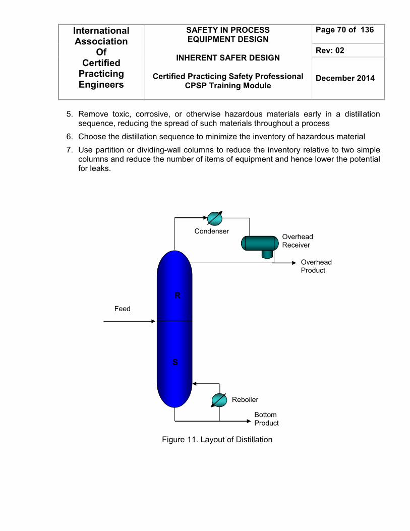
International Association
Of Certified
Practicing Engineers
SAFETY IN PROCESS EQUIPMENT DESIGN
INHERENT SAFER DESIGN
Certified Practicing Safety Professional
CPSP Training Module
Page 70 of 136
Rev: 02
December 2014
5. Remove toxic, corrosive, or otherwise hazardous materials early in a distillation sequence, reducing the spread of such materials throughout a process
6. Choose the distillation sequence to minimize the inventory of hazardous material
7. Use partition or dividing-wall columns to reduce the inventory relative to two simple columns and reduce the number of items of equipment and hence lower the potential for leaks.
Figure 11. Layout of Distillation
R
S
Feed
Reboiler
Overhead Receiver
Condenser
Bottom Product
Overhead Product

International Association
Of Certified
Practicing Engineers
SAFETY IN PROCESS EQUIPMENT DESIGN
INHERENT SAFER DESIGN
Certified Practicing Safety Professional
CPSP Training Module
Page 71 of 136
Rev: 02
December 2014
Reactors Reactors often represent a large portion of the inventory of hazardous material in a chemical process. A reactor maybe large because the chemical reaction is slow. However, in many cases the chemical reaction actually occurs very quickly, but it appears to be slow due to inadequate mixing and contacting of the reactants. With a thorough understanding of the reaction, the designer can identify reactor configurations that maximize yield and minimize size, resulting in a more economical process, reducing generation of by-products and waste, and increasing inherent safety by reducing the reactor size and inventories of all materials. The worst safety problem that can occur with reactors occurs when an exothermic reaction generates heat at a faster rate than the cooling system can remove it. Such runaway reactions are usually caused by coolant failure, perhaps for a temporary period, or reduced cooling capacity due to perhaps a pump failure in the cooling water circuit. The runaway happens because the rate of reaction, and hence the rate of heat generation, increases exponentially with temperature, whereas the rate of cooling increases only linearly with temperature. Once heat generation exceeds available cooling capacity, the rate of temperature rise becomes progressively faster. If the energy release is large enough, liquids will vaporize, and over pressurization of the reactor follows. A general procedure for reactor design is as follows:
1. Collect together all the kinetic and thermodynamic data on the desired reaction and the side reactions. Values will be needed for the rate of reaction over a range of operating conditions: pressure, temperature, flow rate, and catalyst concentration.
2. Collect the physical property data required for the design, either from the literature, by estimation or, if necessary, by laboratory measurements.
3. Identify the predominant rate-controlling mechanism: kinetic, mass, or heat transfer. Choose a suitable reactor type, based on experience with similar reactions, or from the laboratory and pilot plant work.
4. Make an initial selection of the reactor conditions to give the desired conversion and yield.
5. Size the reactor and estimate its performance. Semi-empirical methods based on the analysis of idealized reactors will normally have to be used.

International Association
Of Certified
Practicing Engineers
SAFETY IN PROCESS EQUIPMENT DESIGN
INHERENT SAFER DESIGN
Certified Practicing Safety Professional
CPSP Training Module
Page 72 of 136
Rev: 02
December 2014
6. Select suitable materials of construction. Make a preliminary mechanical design for the reactor: the vessel design, heat transfer surfaces, internals, and general arrangement.
7. When the reactor conditions, particularly the conversion, are chosen and the design optimized, the interaction of the reactor design with the other process operations must not be overlooked
The following changes should be considered to improve safety in reactor:
1. Reducing the inventory of material in the reactor will reduce the potential hazard from runaway.
2. There may be a safety incentive to change from batch to continuous operation. Batch operation requires a larger inventory than the corresponding continuous reactor.
3. The batch operation can be changed to semibatch in which one (or more) of the reactants is added over a period. The advantage of semibatch operation is that the feed can be switched off in the event of a temperature (or pressure) excursion. This minimizes the chemical energy stored up for a subsequent exotherm.
4. For continuous reactors, plug-flow designs require smaller volumes and hence smaller inventories than mixed-flow designs for the same conversion.
5. Reduce the inventory in the reactor by increasing temperature or pressure, by changing catalyst or by better mixing
6. Lower the temperature of a liquid-phase reactor below the normal boiling point, or dilute it with a safe solvent
7. Substitute a hazardous solvent.
8. Externally heated/cooled to internally heated/cooled.

International Association
Of Certified
Practicing Engineers
SAFETY IN PROCESS EQUIPMENT DESIGN
INHERENT SAFER DESIGN
Certified Practicing Safety Professional
CPSP Training Module
Page 73 of 136
Rev: 02
December 2014
Figure 12. Simplicity chemical reactor
O-ring
Reactor vessel
O-ring
Lid
Screen
Gasket
Gasket
Screen
Lid
Fill with media
Insert assembled
reactor with o-ring in
place into reactor base
& rotate to lock pins
inside latches

International Association
Of Certified
Practicing Engineers
SAFETY IN PROCESS EQUIPMENT DESIGN
INHERENT SAFER DESIGN
Certified Practicing Safety Professional
CPSP Training Module
Page 74 of 136
Rev: 02
December 2014
Heat Transfer System Heat transfer systems are normally provided to utilize available process heat, to economize heat for distillation purposes or to preheat fuel supplies before usage. They are generally considered a secondary process support system to the main production process
1. Use water or other nonflammable heat transfer media
2. Use a lower temperature utility or heat transfer medium. The use of an unnecessarily high-temperature hot utility or heating medium should be avoided.
3. Use a liquid heat transfer medium below its atmospheric boiling point if flammable or toxic
4. If refrigeration is required, consider higher pressure if this allows a less hazardous refrigerant to be used
5. Heat transfer equipment should not be installed in closed structures. If installed in closed structures, explosion- (deflagration-) relief panels and ventilation should be considered.
6. Automatic and remotely operated valves and pump shutoffs should be used to prevent the possibility of feeding the fire in case of a tube rupture or break in the distribution piping.
7. Automatic sprinklers should be considered for part of the system, typically for expansion tank, vaporizer, pumps (if with a mechanical seal) and sometimes the heater.
8. For fired heaters:
a. Provide automatic sprinkler protection and supplemental fire hydrants or hose connections.
b. Slope grade so spills or leaks are routed away from equipment.
c. Provide facilities for extinguishing a fire in the fire box (usually steam snuffing or water spray). Include fire detection (high stack temperature).
d. Provide remote operation of valves on key equipment, with manual backup of automated controls
e. Electrical equipment should be designed to prevent ingress of heat transfer fluid mist and vapors.
f. Provide adequate firefighting foam capabilities to handle the largest anticipated heat transfer fluid liquid spill fire.

International Association
Of Certified
Practicing Engineers
SAFETY IN PROCESS EQUIPMENT DESIGN
INHERENT SAFER DESIGN
Certified Practicing Safety Professional
CPSP Training Module
Page 75 of 136
Rev: 02
December 2014
g. Specifically for a vaporizer, the area should be protected by an automatic fire suppression system, such as an automatic deluge sprinkler system.
h. Exposed cable trays, control equipment, pipelines, etc., should be protected by fire-resistant insulation, rated for a minimum of two hours, or automatic water spray.
Leakage of heat transfer fluids from joints and fittings may soak insulation layers and increase the hazards of fire at the temperatures normally encountered in these systems. To ensure leak-free piping and reduce the risk of fire, fabrication, installation and maintenance procedures include:
1. Minimizing the number of flanges and mechanical joints.
2. Using manufacturer's or code recommended piping specifications.
3. Installing valve stems horizontally or in downward position so that leaking fluid will not enter the insulation.
4. Removing the insulation if a leak develops and containing the fluid until the leak is repaired.
5. Using cellular glass or metal-shielded insulation on sections of lines where leaks are more likely to occur (where control valves or instrument fittings are attached).
Heat transfer fluid manufacturers can provide additional guidance on proper safety controls. The following are some of the safety control features that could be incorporated into a heat transfer fluid system design:
1. Expansion tank high-level alarm in case of process leakage into the heat transfer fluid.
2. Expansion tank low-level alarm in case of heat transfer fluid loss.
3. Pressure relief valves on heater outlet, expansion tank, and system users (if appropriate); route effluent for safe disposal.
4. Fail-safe design of control valves and critical instrumentation in case of utilities failure such as loss of power or instrument air.

International Association
Of Certified
Practicing Engineers
SAFETY IN PROCESS EQUIPMENT DESIGN
INHERENT SAFER DESIGN
Certified Practicing Safety Professional
CPSP Training Module
Page 76 of 136
Rev: 02
December 2014
5. Proper electrical classification and minimization of potential ignition sources, recognizing that the heat transfer fluids typically operate above their normal flash points.
6. Fire-safe or automatic fire shut-off valves on connections below liquid level of expansion tank and liquid storage tanks, depending on size.
For vapor-liquid systems, consider:
1. Vent accumulation temperature indicators.
2. Pressure indicator near the vaporizer (to register vacuum as well as positive pressure).
3. High and low pressure alarms in each heating loop.
4. Level indicators in vaporizers, condensate collectors and liquid pre-heaters
5. Low level alarm and low level power cutoff on vaporizer.
Some other features that may need to be considered are:
1. Volatiles in the system. At startup, heat up should be slow to allow for volatiles (water, for example) to be vented.
2. Compatibility-reactivity with process fluids. Welded tube sheets or other special design maybe considered.
3. Tracing with heat-transfer fluid circuits requires unique application techniques. Manufacturer's literature should be consulted.
4. Ethylene (or propylene) glycol-water systems may have further design criteria because of the potential for corrosion of bundles to result in cross-contamination. Freeze protection maybe required.
5. Decomposition products may form deposits on metal heat transfer surfaces, causing localized overheating and failure of the metal.
6. Consideration should be given to conducting special leakage testing in addition to a hydrostatic test. Consult the manufacturer for detailed testing procedures.

International Association
Of Certified
Practicing Engineers
SAFETY IN PROCESS EQUIPMENT DESIGN
INHERENT SAFER DESIGN
Certified Practicing Safety Professional
CPSP Training Module
Page 77 of 136
Rev: 02
December 2014
Figure 13. Heat transfer system in heat exchanger
shell side
shell-side fluid out
baffle tube bundle with U-tubes
shell baffle
shell-side fluid out
tube sheet outlet plenum
out
in
inlet plenum
tube-side fluid

International Association
Of Certified
Practicing Engineers
SAFETY IN PROCESS EQUIPMENT DESIGN
INHERENT SAFER DESIGN
Certified Practicing Safety Professional
CPSP Training Module
Page 78 of 136
Rev: 02
December 2014
Piping System Loss of containment from a pressure system generally occurs not from pressure vessels but from pipework and associated fittings. It is important, therefore, to pay at least as much attention to the pipework as to the vessels. It is critical as a starting point for preparing the project piping specifications. Such information includes:
1. Process fluids/materials (influences materials of construction, gaskets, joint design, sealing materials, etc.)
2. Ranges of temperatures and pressures (influences line flange class, pipe wall thickness, materials of construction, gaskets, sealing material, piping flexibility, etc.)
3. Flow conditions or criteria such as two-phase flow, high pressure drop valves (for noise and vibration considerations), corrosive or erosive fluid properties, or high velocity situations
4. Special valving needs (such as plug or vee-ball, and VOC emission control valves)
Fluid parameters and other parameters which could affect the safety and operation of the piping system include:
1. Flowing medium chemistry, pressure, temperature, velocity, viscosity, density, specific gravity, system contaminants, catalysts, hydrotest water
2. Type of flow, e.g., turbulent, laminar, flashing, cavitating or two-phase
3. Pipe orientation, e.g., horizontal, vertical, or inclined
4. Valve stem, hand wheel, and operator orientation
5. Anticipated localized conditions, such as over pressurization due to inadvertent line isolation and unrelieved thermal expansion

International Association
Of Certified
Practicing Engineers
SAFETY IN PROCESS EQUIPMENT DESIGN
INHERENT SAFER DESIGN
Certified Practicing Safety Professional
CPSP Training Module
Page 79 of 136
Rev: 02
December 2014
Material is important for piping system. Special materials, such as thermoplastics, should be limited in use to situations where temperature and pressure extremes are not encountered.
1. Do not locate in areas of high or low temperature extremes
2. Techniques for applying adhesive and joint makeup are affected by temperature
3. For flammable fluid designs (fiber-reinforced plastic) FRP pipe, but not fittings, may be approved.
4. Prevent pressure surges
5. Provide vacuum and overpressure relief
6. Do not use for above ground compressed air
7. Isolate from vibrating equipment
8. Protect from sunlight (ultraviolet radiation effect)
9. Only a limited number of standards have been developed for design and/or examination
10. Piping constructed of nonmetallic materials may require more support; this requires input to and from other design groups
11. Use of filament-wound reinforced thermosetting resins (i.e., FRP) requires the compatibility of the resin with process chemicals to ensure that neither the resin nor the process chemicals are degraded
12. Installation may also require special preparation and handling to prevent damage
13. Special joints, connectors and adhesives may be required
The following concerns are typically included in design of piping systems.
1. All piping systems handling toxic or lethal materials should be identified (for example, piping handling hydrogen cyanide, nitrogen, etc.).
2. The piping need to be designed to contain a deflagration and a detonation.
3. Special monitoring provisions are provided for overflow lines which have a tendency to plug (for example, lines in caustic service).
4. All equipment and piping shall be indicated or accounted for on the layout. The layout shall be made to scale.

International Association
Of Certified
Practicing Engineers
SAFETY IN PROCESS EQUIPMENT DESIGN
INHERENT SAFER DESIGN
Certified Practicing Safety Professional
CPSP Training Module
Page 80 of 136
Rev: 02
December 2014
5. Piping shall be routed in accordance with the piping and instrumentation diagrams and project specifications.
6. Piping shall be routed to provide convenience, to provide ease of erection and maintenance, and to provide consistency in appearance. These requirements shall be met with consideration given to economy.
7. Piping shall be routed in groups overhead wherever possible. Firewater and sewer systems shall be buried. All piping shall be arranged to avoid or minimize gas and liquid traps except when noted otherwise on the piping and instrumentation diagrams.
8. Piping shall be routed to permit normal bends and offsets to take thermal expansion. Where this is not sufficient, provide expansion loops or other means to accommodate thermal expansion.
9. Do not use trenches unless otherwise is specified.
10. All branch lines off the instrument air, steam and cooling water supply headers are taken off the top of the header.
11. Overhead clearance should be provided above access areas of 2.2 meters minimum.
12. Clear gap between under ground pipes shall be 300 mm minimum. Clearance for above ground is normal-flange to bare pipe (or insulation) plus 25 mm.
13. Operating drains shall be so arranged that the discharge is visible from the drain valve.
14. Uninsulated lines lie directly on the pipe support member. Heat insulated lines set on 100 mm (4 inch) "T" – Bar supports (shoes). Adjust height if insulation is greater than 100 mm thick.
15. The proper metallurgy should be selected for the fluid transported and deleterious materials of construction should be avoided.
16. High temperature shutdowns should be provided for pumps which handle heat sensitive or reactive material.
17. The proper bolt design should be provided for frangible flange systems to accurately control the break point.
18. Special insulation should be used on Therminol or high temperature systems to prevent cracking of high molecular weight organics to a lower flash point material with subsequent auto-ignition.
19. Emergency gas agitation via a dip-pipe should be provided if a hazardous condition exists when mechanical agitation is lost.
20. Dip pipes have weep holes to de-inventory the pipe during a plant shutdown.

International Association
Of Certified
Practicing Engineers
SAFETY IN PROCESS EQUIPMENT DESIGN
INHERENT SAFER DESIGN
Certified Practicing Safety Professional
CPSP Training Module
Page 81 of 136
Rev: 02
December 2014
21. The spring hanger settings for piping used in high temperature or high pressure service should be documented during installation.
22. The proper gasket type and material should be used in hazardous service (for example, lethal systems need spiral wound gaskets).
23. Double-walled piping is used to provide secondary containment for selected hazardous materials. The use of double-walled piping requires consideration of the following issues:
• Electrical grounding or continuity • Support of the internal pipe to prevent sag • Testing of the system • Possible distortion due to differential thermal expansion
24. Pipeline carrying a flammable fluid would be run underground to minimize potential vehicular impact. Fluids for which leakage can represent environmental hazards are often run above ground where leakage can be readily detected.
25. Jacketed or heated piping is used when the process fluid must be heated to prevent solidification and when close temperature control of the process fluid is required.
26. Full jackets are used when maximum heat transfer is desired.
27. Partial jackets should be used when there is the possibility that product contamination or danger of hazardous conditions could occur if the product in the main piping and the heating medium in the jacket were mixed, or where temperature control is not critical and localized hot spots would not be detrimental.
28. A remote "stop" should be provided on a pump which transports flammable material into an operating unit from the outside the battery limits.
29. Liquid velocities are limited to 10 ft/sec in plastic or rubber-lined piping to avoid excessive erosion. In most liquid systems, erosion is not a problem for velocities under 20 ft/sec in metal piping. If a liquid contains small amounts of solids as contaminants (the liquid is not really slurry) which may possibly cause erosion, fairly low velocities are recommended less than 5 ft/sec. Recommended velocities are given below for a number of commonly encountered streams.

International Association
Of Certified
Practicing Engineers
SAFETY IN PROCESS EQUIPMENT DESIGN
INHERENT SAFER DESIGN
Certified Practicing Safety Professional
CPSP Training Module
Page 82 of 136
Rev: 02
December 2014
Table 6. Recommended velocities for commonly service
Service Definition Maximum velocity (ft/sec)
Caustic Solutions involving NaOH, KOH and water mixtures of these and hydrocarbons in which the caustic is more than 5% of
4
Concentrated H2SO4
Water solutions of 80% to 100% concentration by weight and mixtures in which the acid is 5% or more of the mixture by volume
4
Phenolic water Solutions of 1% or more by volume 3
Aqueous amine solutions
MEA, DE A (CO2 rich 10
Wet phenolic water
- 60
Wet vacuum exhaust
- 450
For the piping, layout and spacing should be considered to obey any of point such a rule of thumb as follows :
• Arrangement and spacing referred to the standard and codes
• Should be installed above ground. Cooling water supply and return is an exception for some cases.
• Piperack should not be installed above the equipment that contain hazardous and fire-potential material.
• The layout should minimize piping runs on very high pressure and corrosive/toxic, services such as acidic gases.
• Piping should be grouped at an established elevations in one direction and at other elevations for piping at right angles, to provide for branch line intersections and the crossing of lines. Spacing for pipe supports carrying multiple line should be not exceed than 7600 mm with diameter equals to 8” for single lines and larger, while for multiple lines case the diameter should be less than 8”.

International Association
Of Certified
Practicing Engineers
SAFETY IN PROCESS EQUIPMENT DESIGN
INHERENT SAFER DESIGN
Certified Practicing Safety Professional
CPSP Training Module
Page 83 of 136
Rev: 02
December 2014
Figure 14. Layout of piping system

International Association
Of Certified
Practicing Engineers
SAFETY IN PROCESS EQUIPMENT DESIGN
INHERENT SAFER DESIGN
Certified Practicing Safety Professional
CPSP Training Module
Page 84 of 136
Rev: 02
December 2014
Flare The minimum amount of information required for the permitting process to construct and operate flares includes normal and design maximum flow rates, estimated gas composition and Btu value, normal maximum flare tip velocity, a description of the flame tip monitoring system, and the location and height of the flare. The following common design criteria for flare systems need to be considered by the designer:
1. Regulatory limits on release of toxic, corrosive and flammable substances; noise; smoke (Federal, state, or local venting permits)
2. Location and spacing in relation to process units, storage areas, grade level, and personnel. Criteria are based on radiant heat flux, and ground level concentrations of toxic or corrosive components of the flare gas combustion products.
3. Ability to remove liquids entrained in the flare gas
4. Prevention of oxygen from entering the system, especially via relief devices Maintenance of relief valves should be performed using procedures that prevent air from entering the system
5. Flashback protection to prevent internal explosions in case flammable vapor-air mixtures are generated. Air may be present from backflow through the stack or inlet piping after a release of hot process gas (a hot blow).
6. Provision for pilot ignition systems and their controls to be located safely
7. Provision for purging the flare header with fuel gas or an inert gas
8. A separate flare system for oxygen-containing streams might be preferable to avoid introduction of streams containing air or oxygen into the main flare header. This practice avoids the potential for explosion if flammable concentrations are possible.
9. Exit velocity; excessive exit velocity can cause flame detachment or flameout
10. Materials of construction should be addressed, especially in regard to low temperatures or corrosive or reactive chemicals.

International Association
Of Certified
Practicing Engineers
SAFETY IN PROCESS EQUIPMENT DESIGN
INHERENT SAFER DESIGN
Certified Practicing Safety Professional
CPSP Training Module
Page 85 of 136
Rev: 02
December 2014
Safety concerns in flare design involve the risk of explosion or fire due to improper flare design or operation. Routine scenarios encountered during maintenance and operation should be carefully considered to avoid contamination of relief systems with oxygen or reactive materials that may rapidly polymerize, releasing large amounts of heat or plugging the flare. Some of the concerns listed below
1. The flare must be located to minimize the chance that flammable vapors from a storage tank leak or unit rupture will contact the flare.
2. The possibilities of entrainment and the consequent flashback can be minimized by the use of a seal drum, molecular seal, and sweep gas to prevent air from traveling down the line.
3. In order to prevent the risk of explosion to the flare, protection can be provided by seal drums; header purging; or use of a dry seal such as a molecular seal, especially when the flare gas is lighter than air, for example, hydrogen. Flame arresting devices may be installed in headers of the flare system to prevent propagation of any flashbacks which might occur.
4. Some tanks, wastewater treatment facilities, and other units may continuously vent to the flare without the use of relief valves.
5. A method to monitor the pilot and provide a reliable system to reignite the pilot burners must be provided to ensure that the fuel gas is clean and to verify flow to the pilot.
A. Flare Header
Typical common mode failures such as fire, cooling water failure, and power failure, are generally involved in the simultaneous discharge of several relief devices. Consequently, the controlling loads generated by one of these emergencies must be evaluated for design of the flare headers as well as the equipment items in the system. The flare system includes collection of effluents, phase separation using knockout drums, and combustion in the flare. Some relief systems include solids, and if carryover occurs, burning material can be expelled from the flare or can plug ground flares. If solid carryover is not cleaned from knockout drums and flare headers after a release containing solids, the next release can result in slugs which can damage the flare headers or flare itself. The following are general guidelines for flare header design:
1. Extensive measures should be taken to avoid pockets in the flare header and associated piping.

International Association
Of Certified
Practicing Engineers
SAFETY IN PROCESS EQUIPMENT DESIGN
INHERENT SAFER DESIGN
Certified Practicing Safety Professional
CPSP Training Module
Page 86 of 136
Rev: 02
December 2014
2. Piping (discharge piping, subheaders and headers) should be free draining to the knockout drum.
3. Consider intermediate knockout drums in or near process units if the flare stack is located in a remote area of the plant.
4. Sectionalizing is not a requirement and is avoided in some organizations to avoid maintenance problems with valves and possible mis-operation or malfunction. Line blinds sometimes are used where sectionalizing is required.
5. Flare headers may collapse if a large volume of liquid is inadvertently discharged into the header, exceeding the capacity of the piping supports. To prevent such events, it is advisable to use criteria such as specifying the pipe as half-full of liquid or otherwise ensure that the header can support the weight of the liquid, and absorb the impact of any liquid slugs.
6. Pressure relief headers must not be routed from one operating area through another area where operators frequently perform maintenance.
7. Flares handling combustible vapors from multiple relief valves must not be used for venting air or steam during startup or at any time loss of flame is likely.
8. Avoid freezing or solidification of liquids such as water, high pour point, or high-viscosity oils, polymers or other materials during low ambient temperatures; heat tracing and drains may be required.
For the flare, layout and spacing should be considered to obey any of point such a rule of thumb as follows :
• Keep the radiant flux below allowable limits by maintaining them with a sufficient space.
• Flare stack must be placed remote from offsite and process facilities, preferably downwind from any areas where personnel are required for continuous operation.
• Flare stack must be located minimum at 90 meters from other facilities and have a clear perimeter surrounding them.
The flare knock drum, flare ignition and pumpout pump system should also be located at periphery of the clear area.

International Association
Of Certified
Practicing Engineers
SAFETY IN PROCESS EQUIPMENT DESIGN
INHERENT SAFER DESIGN
Certified Practicing Safety Professional
CPSP Training Module
Page 87 of 136
Rev: 02
December 2014
B. Knockout Drums Knockout drums are used to prevent the hazards associated with flaring gas containing liquid droplets. The flare knockout drum collects relief loads and separates liquid droplets from vapor releases. This liquid may be returned to the process for further recovery or later vaporized and routed to the flare. Considerations in the design of a knockout drum are:
1. A steam coil, jacket, or other means of heating is sometimes provided in the drum to prevent high viscosity liquids from becoming too viscous to drain or be pumped.
2. The drum should be sloped towards the liquid outlet nozzle.
3. For cold climate locations, methods for freeze protection are recommended in the event that the knockout drums capture some water.
4. Consideration should be given to the reactivity of all chemicals which might be encountered, especially when external heating is applied.
C. Seal Drum
The purpose of the seal drum is to prevent air ingress into the flare system thus providing flashback protection. Below is discussed that should be considered to design seal drum.
1. The vapor space should be sized to avoid entraining the seal liquid in the flare gas and to prevent surges of gas flow to the flare.
2. Typically seal drums are designed for at least 50 psig to withstand internal explosion.
3. Seal drum capacity should have sufficient capacity to prevent back flow regardless of the circumstances.
4. Consideration must be given to the proper disposal of the liquid collected in the knockout and seal drums. The liquid may be flammable, or reactive, and may contain toxic compounds. Consideration should be given to liquid seal integrity, including freeze protection.

International Association
Of Certified
Practicing Engineers
SAFETY IN PROCESS EQUIPMENT DESIGN
INHERENT SAFER DESIGN
Certified Practicing Safety Professional
CPSP Training Module
Page 88 of 136
Rev: 02
December 2014
knock-out Drum
Drain
Gas Collection Header and Transfer Line
Water Sear
Purge Gas
Air Line
Gas Line
IgnitionDevice
Steam Line
Pilot Burners Flare Tip
Gas Barrier
Steam Nozzles
Flare Stack
Figure 15. Steam Assisted Elevated Flare System

International Association
Of Certified
Practicing Engineers
SAFETY IN PROCESS EQUIPMENT DESIGN
INHERENT SAFER DESIGN
Certified Practicing Safety Professional
CPSP Training Module
Page 89 of 136
Rev: 02
December 2014
Pressure Relief Systems and Specifying Valves to Increase Safety Relief system is used when inherently safe design simply cannot eliminate every pressure hazards and passive design can be exceedingly expensive and cumbersome. The most common method of overpressure protection is through the use of safety relief valves and /or rupture disks which discharge into either an open system, that is, to the atmosphere, to a containment vessel, or to a disposal system such as a flare or scrubber. Pressure relief system is used to protect piping and equipment against excessive over-pressure and personnel safety. Pressure relief systems are consisted with pressure relief device, flare piping system, flare separation drum and flare system. A pressure relief device is designed to open and relieve excess pressure; it is re-closed after normal conditions have been restored to prevent the further flow of fluid (except rupture disk). The equipment requiring pressure relief protection includes:
1. Pressure vessels
2. Liquid containing parts of a system capable of being isolated
3. Evaporators located within 18 in. (457 mm) upstream or downstream of a heating coil
4. Positive displacement compressors
5. Typically, drums and towers 2 ft (.6 m) and less in diameter, constructed of pipe, pipe fittings or equivalent
6. Fire exposure overpressure protection for filters and heat exchangers
7. Pumps with variable speed drivers
8. Equipment susceptible to thermal expansion.
Relieving pressure shall not exceed maximum allowable working pressure (accumulation) by more than:
1. 3% for fired and unfired steam boilers
2. 10% for vessels equipped with a single pressure relief device
3. 16% for vessels equipped with multiple pressure relief devices

International Association
Of Certified
Practicing Engineers
SAFETY IN PROCESS EQUIPMENT DESIGN
INHERENT SAFER DESIGN
Certified Practicing Safety Professional
CPSP Training Module
Page 90 of 136
Rev: 02
December 2014
4. 21% for fire contingency
Below is discussed that should be considered to design pressure relief.
1. Evaluate the possible causes of overpressure so as to determine the rate of pressure accumulation associated with each and hence estimate the relief load (the flow rate that must be discharged through the relief device)
2. The primary pressure-relief device must have a set pressure not greater than the maximum allowable working pressure of the equipment.
3. The primary relief device must be sized to prevent the pressure from rising 10% or 3 psi (20 kPa), whichever is greater, above the maximum allowable working pressure.
4. If secondary relief devices are used, then their set pressure must be not greater than 5%above the maximum allowable working pressure.
5. Pressure-relief devices must be constructed, located, and installed such that they can be easily inspected and maintained.
6. Pressure-relief devices must be located on or close to the equipment that they are protecting.
Three different types of relief device are commonly used:
1. Conventional relief valve: In a conventional relief valve, the inlet pressure to the valve is directly opposed by a spring. Tension on the spring is set to keep the valve shut at normal operating pressure but allow the valve to open when the pressure reaches relieving conditions. Most conventional safety-relief valves available to the petroleum industry have disks which have a greater area than the nozzle seat area.
2. Balanced relief valves: Balanced relief valveis a spring loaded pressure relief valve that incorporates a bellows or other means for minimizing the effect of back pressure on the performance characteristics opening pressure, closing pressure, lift, and relieving capacity. Balanced pressure relief valve is used when the built-up pressure is too high for conventional pressure relief or when the back pressure varies from time to time.
3. Pilot-operated relief valves: Pilot-operated relief valves are commonly used in clean, low-pressure services and in services where a large relieving area at high set pressures is required. The set pressure of this type of valve can be close to the operating pressure. Pilot operated valves are frequently chosen when operating pressures are within 5 percent of set pressures and a close tolerance valve is required.

International Association
Of Certified
Practicing Engineers
SAFETY IN PROCESS EQUIPMENT DESIGN
INHERENT SAFER DESIGN
Certified Practicing Safety Professional
CPSP Training Module
Page 91 of 136
Rev: 02
December 2014
4. Rupture disk: Rupture disk structure consists of a thin diaphragm held between flanges. It is a device designed to function by the bursting of a pressure-retaining disk. Rupture disks can be used in gas processing plants, upstream of relief valves, to reduce minor leakage and valve deterioration.
Relief valves are normally used to regulate minor excursions of pressure; and bursting discs, as safety devices to relieve major overpressure. Bursting discs are often used in conjunction with relief valves to protect the valve from corrosive process fluid during normal operation.
Figure 12. Pressure relief valve A valve is a device that regulates, directs or controls the flow of a fluid (gases, liquids, fluidized solids, or slurries) by opening, closing, or partially obstructing various passageways.

International Association
Of Certified
Practicing Engineers
SAFETY IN PROCESS EQUIPMENT DESIGN
INHERENT SAFER DESIGN
Certified Practicing Safety Professional
CPSP Training Module
Page 92 of 136
Rev: 02
December 2014
Also to prevent reverse flow, such as flow into a plant from storage vessels, reverses flow through a pump, and reverse flow from a reactor. The following concerns are typically included in design of valves
1. "Air to open" control valves should be selected for those remote valves which want to activate closed during a fire event and plastic air tubing has been provided.
2. The valves must be manually opened or closed during an emergency capable of remote operation.
3. The valves, nipples (open ended) used in pressurized flammable, lethal gas or oxygen service been capped off.
4. The valves in chloride or oxygen service should be degreased before start up and/or after repair
5. Excess check valves should be installed in pressurized hazardous gas systems such as those involving ammonia, chlorine, hydrogen flow.
6. A hole should be drilled in a butterfly valve to prevent overpressure due to thermal expansion or a pressure relief valve has been provided.
7. "Deadman' (spring to close) sampling valves should be installed in high pressure, flammable, or lethal systems to prevent continued flow of material if the operator becomes incapacitated.
8. A manually activated water flush or quench system (if possible) should be provided to stop an uncontrolled reaction or to provide internal fire fighting capability
9. Air-activated valves should be locked out (defused) in the field while maintenance is in progress.
10. A hazard analysis of the process should be conducted to determine the fail safe position of control valves during a specific or total utility outage (electrical power, instrument air, etc.).
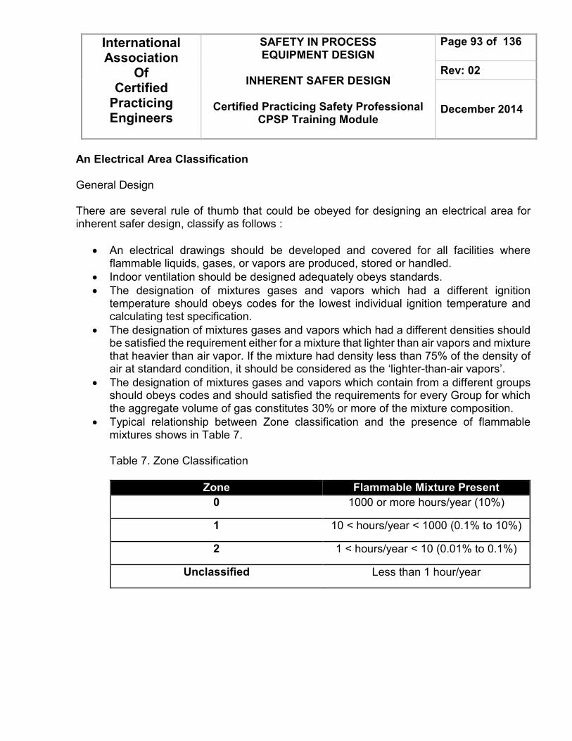
International Association
Of Certified
Practicing Engineers
SAFETY IN PROCESS EQUIPMENT DESIGN
INHERENT SAFER DESIGN
Certified Practicing Safety Professional
CPSP Training Module
Page 93 of 136
Rev: 02
December 2014
An Electrical Area Classification General Design There are several rule of thumb that could be obeyed for designing an electrical area for inherent safer design, classify as follows :
• An electrical drawings should be developed and covered for all facilities where flammable liquids, gases, or vapors are produced, stored or handled.
• Indoor ventilation should be designed adequately obeys standards.
• The designation of mixtures gases and vapors which had a different ignition temperature should obeys codes for the lowest individual ignition temperature and calculating test specification.
• The designation of mixtures gases and vapors which had a different densities should be satisfied the requirement either for a mixture that lighter than air vapors and mixture that heavier than air vapor. If the mixture had density less than 75% of the density of air at standard condition, it should be considered as the ‘lighter-than-air vapors’.
• The designation of mixtures gases and vapors which contain from a different groups should obeys codes and should satisfied the requirements for every Group for which the aggregate volume of gas constitutes 30% or more of the mixture composition.
• Typical relationship between Zone classification and the presence of flammable mixtures shows in Table 7. Table 7. Zone Classification
Zone Flammable Mixture Present
0 1000 or more hours/year (10%)
1 10 < hours/year < 1000 (0.1% to 10%)
2 1 < hours/year < 10 (0.01% to 0.1%)
Unclassified Less than 1 hour/year

International Association
Of Certified
Practicing Engineers
SAFETY IN PROCESS EQUIPMENT DESIGN
INHERENT SAFER DESIGN
Certified Practicing Safety Professional
CPSP Training Module
Page 94 of 136
Rev: 02
December 2014
Inherently Safer Design A. Key Elements What is an Inherently Safer Design? Inherently safer design or ISD is a philosophy to address a safety issues in the design and operation of facility plant that used in process hazardous chemicals. By considering the ISD process engineer usually try to manage process risk by removing or reducing the hazards that caused from its chemical properties. Combination of ISD methods, engineering and administrative control will make a strongly recommendation to manage process risks reliable. ISD focuses on the immediate impacts of single events - chemical accidents - on people, the environment, property and business. Property and business impacts are sometimes referred to as “loss prevention”. In a chemical manufacturing plant, this generally means the immediate impacts of fires, explosions, and the release of toxic materials. Reducing the magnitude or potential likelihood of accidents will also have benefits from the viewpoint of the potential long term impacts. ISD also combined the general factor following the spontaneous event on people, environment (including environment, property, and business). Specifically for chemical processing plant or petrochemicals plant, it will combine the impacts of combustion, explosions, and the release of hazardous materials to environment. Nonetheless, the main concern of ISD is managing and reducing the frequency and potential impact of chemical plant incidents. B. History There’s a long story behind the ISD concept. The technology that is applied now was actually had been recognized many years ago where as to be called ‘the good-design’. In the 1970s, process industries starting to use the term of ‘inherently safety design’, which initiated by Flixborough accident in England and caused by a vapor cloud that lead high explosion event. One traditional risk management approach is to control the hazard by providing layers of protection between it and the people, property, and surrounding environment to be protected. These layers of protection may include operator supervision, control systems, alarms, interlocks, physical protection devices and emergency response systems. Figure 13 shows the layers of protection concept, and includes example of some layers which might be found in a typical chemical processing plant. This approach can be highly effective,

International Association
Of Certified
Practicing Engineers
SAFETY IN PROCESS EQUIPMENT DESIGN
INHERENT SAFER DESIGN
Certified Practicing Safety Professional
CPSP Training Module
Page 95 of 136
Rev: 02
December 2014
and its application has resulted in significant improvement in the safety record of the chemical industry. This approach of imposing barriers between a hazard and potentially impacted several key factors as mentioned before (humans, environments, physical assets such as office and the plant its self) has significant disadvantages :
• The layers of protection should expand a lot investment to build and maintain throughout process life cycle. Factors include initial capital expense, operating costs, safety training cost, maintenance cost, and diversion of scarce and valuable technical resources into maintenance and operation of the layers of protection.
• The hazard is still remains, and some combination of failures of the layers of protection could lead into a bigger opportunities to become an accident event. Since no layer of protection can be perfect, there is always some risk that an incident will occur.
• Because the hazard is still present, there is always a danger that its potential impacts could be realized by some unanticipated route or mechanism. Nature may be more creative in inventing ways by which a hazardous event can occur than experts are in identifying them. Accidents can occur by mechanisms that were unanticipated or poorly understood.
For these reasons, the inherently safer approach should be an essential aspect of any safety program. If the hazards can be eliminated or reduced, the extensive layers or protection to control those hazards will not be needed.

International Association
Of Certified
Practicing Engineers
SAFETY IN PROCESS EQUIPMENT DESIGN
INHERENT SAFER DESIGN
Certified Practicing Safety Professional
CPSP Training Module
Page 96 of 136
Rev: 02
December 2014
Note : SIS : Safety Interlock System. ESD : Emergency Shutdown.
Figure 17. Traditional Risk Management
Community Emergency Response
Plant Emergency Response
Physical Protection
Automatic action, i.e : SIS or ESD.
Basic Controls, Alarms, Operator Supervision

International Association
Of Certified
Practicing Engineers
SAFETY IN PROCESS EQUIPMENT DESIGN
INHERENT SAFER DESIGN
Certified Practicing Safety Professional
CPSP Training Module
Page 97 of 136
Rev: 02
December 2014
Trevor Kletz (1978) strongly suggested that the industries should redirect its risk management efforts towards elimination of hazard where feasible. Despite to devote extensive resources to the safety systems and procedures to manage the resulting risks, the industries is better to take an advantage by identify the existing process and modify them to reduce or (if feasible) eliminate the hazards, such as substituting the hazardous chemical reactant with safer substance without reducing its function on existing reaction. In 1996, Center for Chemical Process Safety (CCPS) published a book called “Inherently Safer Chemical Processes: A Life Cycle Approach.” which related to ISD concept. In 2009, CCPS also published a second edition of the book which upgraded based on more than a decade industrial experiences. C. Basic Concept Based on its terms, ‘Inherent’ could be defined as the essential characteristic that not explicitly occurred (intrinsic). So, something is inherently safer when the safety is built into the process and not by an additional process. Eliminating the risk from hazards on the process design that could not be changed are fundamentally important. Sometimes it will lead to the simpler and efficient plant. On the contrary, it could also need an extensive safety system to control the major hazards along with the complexity of plant. The cost of this case mainly for initial investment for the safety equipment and also for operation and maintenance process. Inherently safer design is a philosophy for addressing safety issues in the design and operation of facilities that use or process hazardous chemicals. The goal is to eliminate or reduce process’ hazards. Hazards described as ‘an inherent physical or chemical characteristic that has the potential for causing harm to people, the environment or property.’ (Guidelines for Hazards Evaluation Procedures, CCPS’s – 2008). Hazards are also an implicit things that could applied on any material or its condition. These hazards cannot be changed unless by changing the material or its condition. The example of hazards such as :
• Chlorine is toxic if inhaled.
• Gasoline is easy to burn.
• High-pressure steam contains a large amount of energy.

International Association
Of Certified
Practicing Engineers
SAFETY IN PROCESS EQUIPMENT DESIGN
INHERENT SAFER DESIGN
Certified Practicing Safety Professional
CPSP Training Module
Page 98 of 136
Rev: 02
December 2014
D. Chemical Process Safety Strategies The strategies of Chemical Process Safety illustrate (Figure 14) on 4 things that should be accomplished and related to each other, there are: Inherent, Passive, Active, and Procedural. The following items of each strategy is to be explained below.
• Inherent. Inherent condition is where the hazards (if feasible) eliminate or greatly reduce by changing the process including the use of materials and its reaction / process conditions. The processes are become safer by applying fundamental changes and integrated system. Substituting water-constituents compound for coating-carrier (previously using oil-based) is one of the example. This application will eliminate the flammable and toxic solvent, which could be categories as an ‘inherent’ characteristic. The hazards are not only eliminate in the manufacturing process but it is also throughout the supply chain of products.
• Passive. In the term of ‘passive’ is describes as a ‘tools’ that could minimized hazards using process which greatly reduce the intensity of an incident without activating any device. For example, the construction of reaction vessel which could be operated above the operating condition that reaction required. The vessel contained the ‘excess-reaction’ that could cause pressure and temperature raised but still available to operate. This containment is robust yet also reliable, but it is less robust than an inherent strategy since there is still a chance lead to the failure process (the reactor damaged, corroded, or become improperly constructed from previous design). Example :
– Containment dike around a hazardous material storage tank

International Association
Of Certified
Practicing Engineers
SAFETY IN PROCESS EQUIPMENT DESIGN
INHERENT SAFER DESIGN
Certified Practicing Safety Professional
CPSP Training Module
Page 99 of 136
Rev: 02
December 2014
Figure 18. Chemical Process Safety strategies.
• Active. Active safety systems include process control systems, safety interlocks, automatic shutdown systems, and automatic incident mitigation systems such as sprinkler systems to extinguish a fire. Active systems are designed to sense a hazardous condition and immediately take an appropriate action to prevent the accident or minimize the consequences. In example, the interlock systems of vessel that will shut off pump feeder and also closes all feed valves to prevent the vessel become overflow. A fire sprinkler system is an example of an active safety system which mitigates the consequences of an incident. Below are multiple active elements.
– Sensor - detect hazardous condition – Logic device - receives a signal from the sensor, determines what must be
done, and sends a signal to some device to implement the required action. – Control element - implements the action in response to the hazardous condition
Example – High level alarm in a tank shuts automatic feed valve – A sprinkler system which extinguishes a fire

International Association
Of Certified
Practicing Engineers
SAFETY IN PROCESS EQUIPMENT DESIGN
INHERENT SAFER DESIGN
Certified Practicing Safety Professional
CPSP Training Module
Page 100 of 136
Rev: 02
December 2014
• Procedural. Standard Operating Procedures (SOP) could be involved as an example of Procedural strategy. The SOP usually filled with safety and procedures, operating training modules, emergency response procedures and also management systems. Generally, procedural risk management systems do not much provide an adequate management for the high-hazard operating system. Hence, procedures; safety systems will always be a part of a comprehensive risk management program. Example:
– Confined space entry procedures
The first three items could be grouped as ‘The engineering controls’, while procedural often dubbed as ‘The administrative control’. Inherent and Passive are the most reliable strategy to apply. Thus, all elements of the strategies is required for a comprehensive process safety management. E. Inherently Safer Design Processes Center for Chemical Process Safety (CCPS) at 2009 also published a strategies for designing inherently safer design processes into four major categorize as follows:
• Substitute. Including use less hazardous materials, chemistry and processes. In example, alternative way to synthesize acrylic acid from propylene oxidation lead to the elimination of carbon monoxide, nickel carbonyl, anhydrous HCl and acetylene usage.
• Minimize. Minimize means only use a small quantities of hazardous materials or it could be also reducing the size of equipment operating if it is under high-risk operation such as High Temperature and High Pressure. Example case is the usage of loop reactors to decreasing probability of incident in polymerization, and chlorination process. The benefits are Reduced consequence of incident (explosion, fire, toxic material release) and improved effectiveness and feasibility of other protective systems.
• Moderate. This term lead to the reducing hazards by applying less hazardous operation such as Refrigeration, Dilution, or any other process alternatives. Substituting anhydrous ammonia with the aqueous form to imply in neutralization process at the off-site plant is one of the example of Moderate strategy.

International Association
Of Certified
Practicing Engineers
SAFETY IN PROCESS EQUIPMENT DESIGN
INHERENT SAFER DESIGN
Certified Practicing Safety Professional
CPSP Training Module
Page 101 of 136
Rev: 02
December 2014
• Simplify. Simplify is to eliminate unnecessary complexity and design user friendly plants, such as removing old piping installation due to the modification process. This action will prevent an accidental transfer material into a reactor through the piping because of operating error or leaking valves.
The terms of inherent safety techniques that are used in the chemical industry shown in Table 8 and also more fully defined in what follows. Table 8. Inherently Safety Techniques
Type Common Techniques
Intensification • Reducing storage inventory of raw materials.
• Exchange from large batch reactor to small continuous reactor.
• Improve control and reducing the inventory of hazardous intermediate chemicals.
• Minimize process hold-up.
Substitution • Use mechanical seals for pump.
• Provide a welded pipe.
• Use less toxic substance for solvent.
• Supply water as a heat medium transfer fluid instead of hot oil.
• Use mechanical gauges vs. mercury
• Use chemicals with higher flash points, boiling points, and other less hazardous properties
Attenuation and Limitation of effects
• Decreasing process pressures and temperatures.
• Prevent the runaway reaction.
• Acoustically insulate noisy lines and equipment.
• Use vacuum to reduce boiling point
• Refrigerate storage vessels
• Dissolve hazardous material in safe solvent
• Operate at conditions where reactor runaway is not possible
• Place control rooms away from operations
• Separate pump rooms from other rooms

International Association
Of Certified
Practicing Engineers
SAFETY IN PROCESS EQUIPMENT DESIGN
INHERENT SAFER DESIGN
Certified Practicing Safety Professional
CPSP Training Module
Page 102 of 136
Rev: 02
December 2014
Type Common Techniques
• Barricade control rooms and tanks
Simplification and error tolerance
• Piperack and pipelines should always neat.
• Choose equipment that requires less maintenance.
• Separating between system and control to make an easier access and understandable.
• Labelling the equipment to encourage people.
• Design control panels that are easy to comprehend
• Pick equipment with low failure rates
• Add fire- and explosion-resistant barricades
• Label pipes for easy “walking the line”
Minimizing entails decreasing the hazards by using smaller quantities of hazardous substances in the reactors, distillation columns, storage vessels, and pipelines. If it is possible, hazardous substances should be treated integrally such as produced and consumed by in situ system. The treatment will affect upon minimizing the storage tank and transportation of hazardous raw materials and intermediates. During the minimization process, substitutions must also be a consideration as an alternative of companion concept. This step could be done by using alternative chemistry that permit the use of less hazardous substances and also decrease the operating condition of process. Moderation is another alternative way to do a substitution step. Moderate is define as using a hazardous material under less hazardous conditions involving :
• Diluting to a lower vapor pressure to reduce the release concentration.
• Refrigerating to lower the vapor pressure.
• Handling larger particle size solids to minimize dust.
• Processing under less operating condition (pressure and temperature). Containment buildings are sometimes used to moderate the impact of a spill of an especially toxic material. When containment is used, special precautions are included to ensure employee protection in example remote controls, continuous monitoring and limiting the access for several areas. Factors Selected to Represent the Inherent Safety in Preliminary Process Design:
1. Heat of Reaction: Reactions in which large quantities of heat or gas are released are potentially hazardous, particularly during fast decomposition or complete oxidations.

International Association
Of Certified
Practicing Engineers
SAFETY IN PROCESS EQUIPMENT DESIGN
INHERENT SAFER DESIGN
Certified Practicing Safety Professional
CPSP Training Module
Page 103 of 136
Rev: 02
December 2014
2. Hazardous Substances: Hazardous substances present in the process are identified on the basis of their flammability, explosiveness and toxicity.
a. Flammability: The flammability of liquids depends on the lower flammability limit of the material and its vapor pressure in prevailing temperature. The liquid which has a flash point below the processing or storage temperature can give rise to a flammable mixture and is generally considered hazardous.
b. Explosiveness: The use of industrial chemicals with less explosive potential makes the process more intrinsically safe. Most dangerous explosions come from large clouds of flammable material which find an ignition source.
c. Toxic Exposure: The toxic hazard is a measure of the likelihood of such damage occurring. It is determined by the frequency and duration of such exposure and the concentration of the chemical in exposure.
3. Corrosiveness: Corrosion reduces the reliability and integrity of plant. It reduces the strength of materials and causes leaks. Corrosion products affect process materials, moving parts, process efficiency and cause fouling. In the design of equipment corrosion is taken into account by the selection of material and corresponding corrosion allowance.
4. Chemical Interaction: Chemical interaction is based on the chemical reactivity of each substance with other substances present in the plant. As a potential process hazard, the chemical reactivity of any substance should be considered in the following contexts:
• Reactivity with elements and compounds with which it is required to react in the process
• Reactivity with atmospheric oxygen
• Reactivity with water
• Reactivity with itself, i.e. its propensity to polymerize, condense, decompose and explode
• Reactivity with other materials, with which it may come in contact unintentionally in process, storage or transport
• Reactivity with materials of construction, i.e. its corrosivity
5. Temperature: The use of high temperatures in combination with high pressures greatly increases the amount of energy stored in the plant. There are severe problems with materials of construction in high temperature plants That can make thermal stresses
International Association
Of Certified
Practicing Engineers
SAFETY IN PROCESS EQUIPMENT DESIGN
INHERENT SAFER DESIGN
Certified Practicing Safety Professional
CPSP Training Module
Page 104 of 136
Rev: 02
December 2014
also in low temperature. These stresses need to be allowed for and, as far as possible, avoided.
6. Pressure: The use of high pressure greatly increases the amount of energy available in the plant. Whereas in an atmospheric plant stored energy is mainly chemical, in a high pressure plant there is in addition the energy of compressed permanent gases and of fluids kept in the liquid state only by the pressure.
7. Equipment safety: Equipment safety tries to measure the possibility that a piece of equipment is unsafe. Equipment safety considers the safety of the equipment as such without interactions through the process with other equipment.
8. Safe Process Structure: The safe process structure means which operations are involved in the process and how they are connected together. It also describes how auxiliary systems such as cooling, heating or relief systems should be configured and connected to the main process. Therefore the safe process structure describes the safety of the process from system engineering point of view.
User-Friendly Design “Simplicity is the ultimate sophistication.” (Steve Jobs). In a modern method, user-friendly design has become an important factor that related to the inherently safer design concepts. Process Design engineer as the one who taking charge to make it happen should try to design that the effects of errors are not serious. There are several ways to accomplish this step including :
• Simplify the design.
• Prevent the knock-on effects.
• Provide a proper assembly.
• Spread a clear information from equipment status.
• Operate the equipment that can tolerate a degree of misuse.
• Apply fixed-pipework, and fixed pipework with expansion loops.
F. ISD in the Process Design Life Cycle As in general, designing the process begin with the selection of product and basic technology to manufacture them. Figure 15 shows the technology progresses through the process development, conceptual plant design, plant construction, start-up, and ongoing operation and future modification. Engineers, Scientists, Researchers, and any other technologists
International Association
Of Certified
Practicing Engineers
SAFETY IN PROCESS EQUIPMENT DESIGN
INHERENT SAFER DESIGN
Certified Practicing Safety Professional
CPSP Training Module
Page 105 of 136
Rev: 02
December 2014
from comprehensive knowledge background usually the ones who decide a change. Nonetheless, the ISD strategy could be applied at all stages (as mentioned). The ISD will give best result and very practicable if the philosophy implied at the early process research and process development program. The benefit of this point is that no commitment has been made to a particular existing design technology, no resources have been expanded that needs to be refinished, give an alternative way to the customer to pick their process that they want to apply, and also no capital has been committed since a plant still not exist yet. As the process goes through the life cycle, it becomes more difficult to change the basic technology. Hence, it is never too late to consider an ISD way, although options for implementation is way more limited when the plant is existed. Take a look of water as a simple example during each stage of Process Design Life Cycle below.
• Selection of Basic Technology. Water could be disinfected by many process such as radiation of ultraviolet light, ozonisation, and chlorination. For each way, there is a different ISD characteristic that could be applied relative to its hazards of concern. Chlorination process will produce a hazardous chlorinated organic materials, while Ozone and Ultraviolet light is much safer since it is not have any hazardous residual. Application of ISD on the Selection of Basic Technology lies on the decision make whom should understand all hazards of concern and the inherent safety characteristics of the available process.
• Implementing the Selected Technology. After deciding basic technology that will applied, there is a window of a very wide option for actual implementation of that technology may be available. In example, the usage of water treatment in chlorination process. The options involving how process engineer choose which path of chlorination that will be implemented. Either by using chlorine gas, sodium hypochloride and also solid chlorinating agents. Each of the option has a specific ISD characteristic to maintain of, relative to its hazards. The reliability, cost economy, feasibility of technology and any other risks should be an important consideration before implementing the Selecting Technology along with the ISD method.
• Plant Design. By this step, process engineer should consider the ISD for a specific plant design. Fabricators might be consists of: (1) Location of the plant due to the surrounding population, (2) Plant Layout, (3) Applied System relative to the plant size. Assuming the system’s designers have decided that disinfection using gaseous chlorines is the optimum approach, then the ISD should be considered: (1) Where the location of the

International Association
Of Certified
Practicing Engineers
SAFETY IN PROCESS EQUIPMENT DESIGN
INHERENT SAFER DESIGN
Certified Practicing Safety Professional
CPSP Training Module
Page 106 of 136
Rev: 02
December 2014
facility, (2) Chlorine storage, and (3) How much the amount and size of water chlorination systems.
Figure 15. Inherently Safer Design in the Process Design Life Cycle
Plant
Modification
Final detailed
design
Engineering
Design
Pilot plant
and scale-up Conceptual
Design Process
Development
Product Satisfaction
Or
Development
Inheren
tl Safety
Analy
sis
Plant
Modification
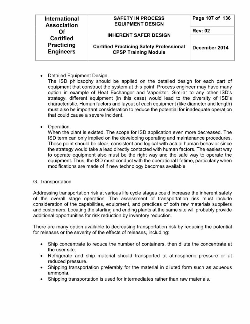
International Association
Of Certified
Practicing Engineers
SAFETY IN PROCESS EQUIPMENT DESIGN
INHERENT SAFER DESIGN
Certified Practicing Safety Professional
CPSP Training Module
Page 107 of 136
Rev: 02
December 2014
• Detailed Equipment Design. The ISD philosophy should be applied on the detailed design for each part of equipment that construct the system at this point. Process engineer may have many option in example of Heat Exchanger and Vaporizer. Similar to any other ISD’s strategy, different equipment (in this case) would lead to the diversity of ISD’s characteristic. Human factors and layout of each equipment (like diameter and length) must also be important consideration to reduce the potential for inadequate operation that could cause a severe incident.
• Operation. When the plant is existed. The scope for ISD application even more decreased. The ISD term can only implied on the developing operating and maintenance procedures. These point should be clear, consistent and logical with actual human behavior since the strategy would take a lead directly contacted with human factors. The easiest way to operate equipment also must be the right way and the safe way to operate the equipment. Thus, the ISD must conduct with the operational lifetime, particularly when modifications are made of if new technology becomes available.
G. Transportation Addressing transportation risk at various life cycle stages could increase the inherent safety of the overall stage operation. The assessment of transportation risk must include consideration of the capabilities, equipment, and practices of both raw materials suppliers and customers. Locating the starting and ending plants at the same site will probably provide additional opportunities for risk reduction by inventory reduction. There are many option available to decreasing transportation risk by reducing the potential for releases or the severity of the effects of releases, including:
• Ship concentrate to reduce the number of containers, then dilute the concentrate at the user site.
• Refrigerate and ship material should transported at atmospheric pressure or at reduced pressure.
• Shipping transportation preferably for the material in diluted form such as aqueous ammonia.
• Shipping transportation is used for intermediates rather than raw materials.

International Association
Of Certified
Practicing Engineers
SAFETY IN PROCESS EQUIPMENT DESIGN
INHERENT SAFER DESIGN
Certified Practicing Safety Professional
CPSP Training Module
Page 108 of 136
Rev: 02
December 2014
Thus, select a transportation mode to minimize risks to the extent practicable. The transportation mode used will also affect the shipper’s options with regard to the selection of the routing of the shipment. The risk of transportation could also be reduced by applying inherently safer design principles to the containers. There are several examples of improvement as follows:
• Thermal insulation could kept low temperature in the containers.
• Tank cars, trailers, and other containers can be specified without bottom outlets or be provided with skid-protection for bottom outlets.
• Suggested to use baffle for large containers application to improve its stability.
• Non-brittle containers can be used to improve resistance to impact or shock damage.
• Remote controlled shutoff valves could reduce the severity of accidents. In order to improving safety during transportation by optimizing the physical conditions, container design, system mode, and also the route., the way of shipment is handled should be examined to see if it possible to improve its safety. Such example a program to train drivers and other handlers in the safe handling of the products, to refresh that training regularly, and to use only certified safe drivers is another way of making transportation inherently safer.
H. Human factors A well-designed human systems could produce inherently safer plant designs and operating procedures. Since the human systems will cover how humans work, and how human error occur. There are also a chance to design a better systems including for: (1) Managing, (2) Supervising, (3) Designing, (4) Training, and (5) Auditing. CCPS at 1994 has been built inherently safer human systems for each stage of chemical processing life cycle involving:
• Appropriate training.
• Reviews and Audits.
• Error correction cycles.

International Association
Of Certified
Practicing Engineers
SAFETY IN PROCESS EQUIPMENT DESIGN
INHERENT SAFER DESIGN
Certified Practicing Safety Professional
CPSP Training Module
Page 109 of 136
Rev: 02
December 2014
The equipment that operates in plant could also be made inherently safer for human factors by applying several points as follows :
• Made them a lot understandable.
• Made the equipment easier to do what is intended.
• Applied limitation of what can be done in order to the desired actions.
Ergonomics is one of important consideration that must be implied in layout equipment, controls, and other factors that operating and maintenance personnel required to access. Eliminating the ‘difficult-design’ such as bending, climbing and stretching will improve the value of human factors. Design and systems should minimize potential harmful exposures in both normal and emergency operations. This action will affects the number of location of normal and emergency drains and vents which lead to the reduced cost. Hence, during the design phase, identify the human interaction with the chemical process and provide means to make that interaction inherently safer. As mentioned before, human factors should be considered in the location of items to be maintained and the required frequency of maintenance :
• Inspection items.
• Calibration items.
• Periodic replacement.
• Repair without shutdown. Equipment that can be reached for inspection, repair, or monitoring from permanent platforms is more likely to be inspected, calibrated, and replaced than equipment that requires climbing with a safety harness or scaffold. It is very recommended to make it easy to do the right thing and hard to do the wrong thing to prevent an errors. The design and layout of process plant also could be clear or could be very anxious of what should be done. Likewise, the design of training also could increase or decrease the potential for an error. Systems in which it is easy to make an error should be avoided. As in general, it is better to avoid bringing several chemicals together in a manifold to decrease the risk of contaminated product and reworked batches. Consistency is also important for inherently safer computer control applications such example upward movement on a control panel always causes the valve to open no matter whether the valve is “air to open” or “air to close”. Thus, control systems should be design with knowledge of the capability of human beings for required tasks. CCPS on 1994 informed that there should be a balance between totally automatic control of the process with operator monitoring versus operating control of key variable. The operators is require to run the

International Association
Of Certified
Practicing Engineers
SAFETY IN PROCESS EQUIPMENT DESIGN
INHERENT SAFER DESIGN
Certified Practicing Safety Professional
CPSP Training Module
Page 110 of 136
Rev: 02
December 2014
process enough to be able to handle it during an emergencies event. A feedback action can decrease error rates from 2/100 (2%) to 2/1000 (0.2%). The only exception is that he should not doing the wrong thing. There are several concern when the chemical engineer consider about the control design, including :
• Prevent a boredom action during in the workplace.
• Display corroborating or verifying information on the DCS should nearly close to the actual plant condition.
• Increase sensitivity of the sensor due to the often setpoint change.
• The operation should operate within the safe and quality operating range.
• Provide a smooth transfer data and setpoint tracking for switching among automatic, manual, and cascade.
• Control design must cover decimal errors by software or procedure.
• Always provide guidance to operators of a specified action to achieve specific goal. An inherently safer operating system should also address how to use personnel effectively in response to a process upset. Without such a system, the most knowledgeable person(s) in the unit frequently rushes to attend to the perceived cause of the emergency. System should be designed with knowledge of the response times for human beings to recognize a problem, diagnose it, and then take the required action. If the required response time is less than human capability, the correct response should be automated. For key operating variables, post, train, and drill, if the process variable approaches the Mandatory Action level, the operator should take the Never Deviate corrective action (Figure 16). Supervision should never criticize taking the Never Deviate action to avoid the Never Exceed limit.

International Association
Of Certified
Practicing Engineers
SAFETY IN PROCESS EQUIPMENT DESIGN
INHERENT SAFER DESIGN
Certified Practicing Safety Professional
CPSP Training Module
Page 111 of 136
Rev: 02
December 2014
Figure 16. Illustration of Never Exceed limits Error recovery by the operators is only one of several layers of protection to prevent undesired consequences. Process and equipment designs that avoid undesired process excursions are inherently safer than designs that require operator intervention. Also, designs that enable the operators to intervene before an upset becomes serious are inherently safer than those that do not. An inherently system should also have inspection and reliability testing of safety critical systems and practices for the human factors concern. Managing the methods to measure the effectiveness of inherently safety efforts and to achieve feedback for personnel to improve their performances. An audit action will give a snapshot in time, but the audit should be done again later to see if the system has changed.

International Association
Of Certified
Practicing Engineers
SAFETY IN PROCESS EQUIPMENT DESIGN
INHERENT SAFER DESIGN
Certified Practicing Safety Professional
CPSP Training Module
Page 112 of 136
Rev: 02
December 2014
The performance of human being was profoundly also influenced by the culture of the organization. The ‘culture’ may be vary due to the value that insisted of each company. This culture will also make an impact at the degree of decision making by an individual operator. I. Concerns The ISD way is not the only key factor that could reduce all potential risks related to any process in general, specifically in chemical. Sometimes the useful characteristic of material or technology is the ones which makes it hazardous. It just like a ‘two-sided-blade’ metaphor. The following point is explained of many cases that involved with this topic.
• Gasoline is easy to burn, but that’s what makes them helpful in order to of human activities. It is stores a large amount of energy in a small mass of material, making them cheaper to distribute.
• In general, Jets could travel for about 600 mph. This very high-velocity is what makes them useful. Nonetheless transporting material at large amount kinetic energy could cause severe damage if it hits something.
• Chlorine is highly toxic and hazardous, but this toxicity could also help killing pathogenic organisms on drinking water. Many drinking water process use chlorination process to wiped out the biological impurities that contained from source-water.
However, as implied in many technologies, there is no inherently safer technology exist, in example the technologies are not economically feasible or occurred an environmental pollution and humans health are important enough that society chooses to use a technology that is less inherently safe. By those cases, engineering controls and administrative control as a part of ISD strategy should be involved to minimize the risk. The process could be called as ‘inherently safer’ usually based only from one or several specific hazards but not all of them are covered since every technology presents multiple hazards potential, such as flammability, toxicity, corrosiveness, reactivity and physical condition that could lead to accidents. Therefore, small changes to existing technology could reduce one or multiple hazards and yet it is affect to another hazards potential, such as increasing the other hazards or gaining a new one. Chlorofluororcarbon (CFC) is one of the substance within this case.

International Association
Of Certified
Practicing Engineers
SAFETY IN PROCESS EQUIPMENT DESIGN
INHERENT SAFER DESIGN
Certified Practicing Safety Professional
CPSP Training Module
Page 113 of 136
Rev: 02
December 2014
J. ISD Implementation Figure 17 represents how ISD philosophy could collaborate with design and operation of chemical processing plants. As mentioned before, the best opportunities for fundamental changes achieved in the early stage of the process life cycle. There are many option to act during this point, such as choose a less hazardous materials, or select the low hazardous chemical synthesis paths. Cooperating ISD strategy into the Process Safety Management (PSM) at all stages (from basic technology selection through detail design and operation) is one of the way to apply the ISD philosophy. Some organizations conduct a separate inherent safety review at relatively early stages of process plant development, while others incorporate ISD considerations into the existing process safety review process.
Figure 17. ISD Implementation
Hazard
Assessment
Methods
Research
Stage
Decommissioning
And
Abandonment
Operation,
Maintenance,
Management of
Change
Process
Design
Process
Development

International Association
Of Certified
Practicing Engineers
SAFETY IN PROCESS EQUIPMENT DESIGN
INHERENT SAFER DESIGN
Certified Practicing Safety Professional
CPSP Training Module
Page 114 of 136
Rev: 02
December 2014
It is clear that the improvement of ISD philosophy will reduce throughout the process life cycle which have more limitation when the plant is to close. In order to this scenario, CCPS has been published a very useful checklist at 2009 to identifying ISD opportunities at various stages in process life cycle. There are several questions that required in order to identify hazards that related to PSM activity, following :
• Can the hazard be eliminated at all cost ?
• If it is not, can the magnitude be noteworthy decrease ?
• Is there any alternative way that could applied ?, what is the effect to the existing hazards potential ?
• What engineering controls and administrative controls are required to manage the hazards that inevitably will remain ?
K. The Myths There are several misunderstanding that generally occur during implementation of ISD topic including :
• The ISD will eliminate all the hazards potential. In fact, there is none of hazards potential could be totally wiped out from the chemical processing plant. Since, hazards is one of the hierarchy that naturally occurred as a substance exist. As in many application implied, the closest action that could be applied is only reduced particular hazards while kept maintaining the other hazard potential not increasing.
• The ISD is often assumed as ‘the best’ approach to manage particular hazard. This is truly false, since technology will always change as the time goes by. So the ISD does. Innovation is actually ‘the best’ to get an approach for every single hazards potential. Society or in specific term as the safety people, will only have choices (option) that could lead into ‘the best decision’ to decreasing the hazards potential.
• The ISD is only reliable on the early stage of process life cycle. ISD could implied at any stage in process life cycle. Nonetheless, it is true that the best opportunities are applying them on the early stage of the life cycle. Since the ISD will face more and more constraint when it goes to the plant existence.

International Association
Of Certified
Practicing Engineers
SAFETY IN PROCESS EQUIPMENT DESIGN
INHERENT SAFER DESIGN
Certified Practicing Safety Professional
CPSP Training Module
Page 115 of 136
Rev: 02
December 2014
• Plant operating personnel contribute little to the ISD. On the contrary, plant operating personnel could be the one who importantly gave many information for plant modification as much as it’s required. Since they cooperate directly with Process Safety management (PSM) activities and also could gave what is the best ISD strategy that should be applied in the existing plant. It concluded that there are two benefit at one chance, whether improving the existence PSM of the company and also cooperate the value of ISD way into the latest condition of chemical processing plant.
L. Conceptual ISD in Plant The conceptual design phase contains the most opportunities for identification and incorporation of inherently safer technologies into the process. Potential process hazards and associated ISD opportunities can be identified through a hazard identified through hazard identification (HAZID) study using the process flow diagrams. Table 9 presents examples of options that may be considered as part of the HAZID study. HAZID may also occur throughout the project prompted by the analyses and reviews undertaken. The key objectives of the HAZID Workshops shall be to
• Identify MAEs (Major Accident Event) capable of posing a serious and immediate risk to health and safety including flammable releases, toxic releases, non-process incidents, etc.
• Identify the hazards that cause, or contribute to causing, those MAEs (eg. Process upset, equipment failure, maintenance).
• Identify existing engineering or operational (eg. Procedural) controls and measures that are included in the design for prevention or mitigation
• Identify those controls that are safety critical to the identified MAE
• Where appropriate identify additional prevention and/or mitigation RRMs for improvement to meet the ALARP concept.

International Association
Of Certified
Practicing Engineers
SAFETY IN PROCESS EQUIPMENT DESIGN
INHERENT SAFER DESIGN
Certified Practicing Safety Professional
CPSP Training Module
Page 116 of 136
Rev: 02
December 2014
Table 9. The conceptual design phase opportunities to minimize excess inventory and eliminate hazardous material.
Strategies Technique
Minimize • Minimize hazardous feedstock, intermediate, and product inventories
• Reduce equipment size
• Reduce piping length
Substitute • Use less hazardous reaction chemistry
• Use lower volatility solvent
• Use less hazardous or non-hazardous heat transfer media
Moderate • Identify an alternative catalyst that operates effectively at a lower temperature or pressure
• Consider alternative chemistries that operate at less severe conditions
Simplify • Eliminate process steps
• Identify a more selective catalyst that avoids the formation of by products and the need for product purification steps
The front-end engineering and design (FEED) phase consists of activities to determine the project’s feasiblity and to develop initial project cost estiates. During this stage, the scope of work and the resposibilities of all involved parties are outlined and agreed upon. Table 10 lists some of the ISD considerations that may be explored during the FEED phase.

International Association
Of Certified
Practicing Engineers
SAFETY IN PROCESS EQUIPMENT DESIGN
INHERENT SAFER DESIGN
Certified Practicing Safety Professional
CPSP Training Module
Page 117 of 136
Rev: 02
December 2014
Table 10: Efforts aimed at creating less hazardous conditions may be effective.
Strategies Technique
Moderate • Reduce pressure
• Reduce temperature
• Refrigerate storage facilities (not with ammonia)
• Unit sources of ignition: identify possible sources and remove them if possible, or keep them separated from flammable materials
Simplify • Eliminate pumps and instead use gravity or pressure/vacuum differentials to transfer hazardous materials
• Eliminate storage of highly hazardous intermediates by using such chemicals as they are produced
Minimize • Reduce equipment sizes
• Substitute
• Use less hazardous chemicals
Although the design is more mature during the detailed design phase, opportunities to incorporate ISD features for high-severity hazards or to correct design flaws do exist. Many of the opportunities at this stage involve simplification. Hazards identified during detailed design are usually mitigated with engineered solutions, such as additional equipment redundancy and safety instrumented systems. However, the addition of equipment introduces new risks into the system. Table 11 show the simplification of ISD strategies.

International Association
Of Certified
Practicing Engineers
SAFETY IN PROCESS EQUIPMENT DESIGN
INHERENT SAFER DESIGN
Certified Practicing Safety Professional
CPSP Training Module
Page 118 of 136
Rev: 02
December 2014
Table 11.: look for ways to simplify complex designs during the detailed design phase
Strategies Technique
Simplify • Use equipment with higher pressure rating
• Use spiral wound and flexible graphite gaskets
• Use pumps with double mechanical scales, diaphragm pumps, educators, seal-less pumps
• Design vessels for full vacuum
• Design equipment containing liquid to withstand the maximum hydrostatic load when full
• Select materials that are impervious to corrosion and resistant to erosion
• Select heat exchanger shells that withstand the maximum expected tubeside or shellside pressure
• Transfer materials by gravity of pressure/vacuum differential
Minimize • Use smaller-diameter piping whee process requirements allow
• Route pipes along the shortest path to minimize length and thus inventory
• Minimize he inventory in specific pieces of equipment
Moderate • Locale equipment to maximize he distance o receptors of concern
Substitute • Use less-concentrated forms of hazardous materials
Human actions are among the most significant contributors to accident. Whenever possible, process should be simplified to minimize the potential for human error.
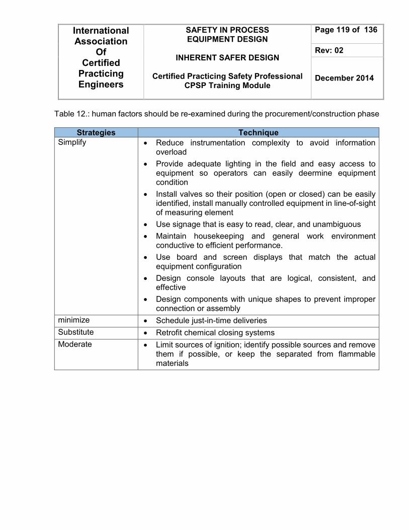
International Association
Of Certified
Practicing Engineers
SAFETY IN PROCESS EQUIPMENT DESIGN
INHERENT SAFER DESIGN
Certified Practicing Safety Professional
CPSP Training Module
Page 119 of 136
Rev: 02
December 2014
Table 12.: human factors should be re-examined during the procurement/construction phase
Strategies Technique
Simplify • Reduce instrumentation complexity to avoid information overload
• Provide adequate lighting in the field and easy access to equipment so operators can easily deermine equipment condition
• Install valves so their position (open or closed) can be easily identified, install manually controlled equipment in line-of-sight of measuring element
• Use signage that is easy to read, clear, and unambiguous
• Maintain housekeeping and general work environment conductive to efficient performance.
• Use board and screen displays that match the actual equipment configuration
• Design console layouts that are logical, consistent, and effective
• Design components with unique shapes to prevent improper connection or assembly
minimize • Schedule just-in-time deliveries
Substitute • Retrofit chemical closing systems
Moderate • Limit sources of ignition; identify possible sources and remove them if possible, or keep the separated from flammable materials

International Association
Of Certified
Practicing Engineers
SAFETY IN PROCESS EQUIPMENT DESIGN
INHERENT SAFER DESIGN
Certified Practicing Safety Professional
CPSP Training Module
Page 120 of 136
Rev: 02
December 2014
Emergency Shut Down (ESD)
ESD system is to prevent escalation of abnormal conditions into a major hazardous event and to limit the extent and duration of any such events that do occur. Emergency shutdown systems enable the operators to perform the quick shutdown of a plant in an emergency situation by remotely carrying out functions such as shutting down major machinery, stopping heat input to fired heater and reboilers, and shutting off air to oxidation processes. They also serve as a means by which machinery may be remotely shutdown in the event of mechanical malfunctions when there is a possibility of catastrophic failure. The Emergency Shutdown System (ESD) shall minimize the consequences of emergency situations, related to typically uncontrolled flooding, escape of hydrocarbons, or outbreak of fire in hydrocarbon carrying areas or areas which may otherwise be hazardous. Traditionally risk analyses have concluded that the ESD system is in need of a high Safety Integrity Level, typically SIL 2 or 3. ESD system are typically composed of sensors, logic solvers and final control elements. The actuated shutdown valve is expected to remain static in one position for a long period of time and reliably operate only when an emergency situation arises, i.e. to spring into safe mode position. Basically the system consists of field-mounted sensors, valves and trip relays, system logic for processing of incoming signals, alarm and HMI units. The system is able to process input signals and activating outputs in accordance with the Cause & Effect charts defined for the installation. ESD system performance is dependent on
• UPS,
• hydraulic power,
• Instrument air. ESD system has interfaces with the following safety systems/functions:
• process safety;
• BD and flare/vent system;
• gas detection;
• fire detection;
• ISC;
• PA, alarm and emergency communication.

International Association
Of Certified
Practicing Engineers
SAFETY IN PROCESS EQUIPMENT DESIGN
INHERENT SAFER DESIGN
Certified Practicing Safety Professional
CPSP Training Module
Page 121 of 136
Rev: 02
December 2014
An emergency shutdown system for a process control system includes an emergency shutdown (ESD) valve and an associated valve actuator. An emergency shutdown (ESD) controller provides output signals to the ESD valve in the event of a failure in the process control system. A solenoid valve responds to the ESD controller to vent the actuator to a fail state
Typical Actions from an Emergency Shutdown System
• Shutdown of part systems and equipment
• Isolate hydrocarbon inventories
• Isolate electrical equipment
• Prevent escalation of events
• Stop hydrocarbon flow
• Depressurize / Blowdown
• Emergency ventilation control
• Close watertight doors and fire doors
Emergency shutdown valves are the final defense against process abnormality. The ESD valve is the Main Process Shut-off valve that controls the process fluid, e.g. steam, gases, liquid, etc. Usually spring loaded – single acting. A shut down valve shall be categorised as an ESD valve if the consequence of valve failure is that a possible fire will exceed the dimensioning fire load for the area in question. In addition the following shut down valves shall be categorised as ESD valves:
• valves located in, or are the nearest shut down valve to, a hydrocarbon riser;
• valves located on the liquid outlet of large liquid vessels, such as separators and coalescers,
• valves located in a utility system where the consequences of valve failure with respect to safety may be significant
• well stream isolation valves (DHSV, master valve, wing valve);

International Association
Of Certified
Practicing Engineers
SAFETY IN PROCESS EQUIPMENT DESIGN
INHERENT SAFER DESIGN
Certified Practicing Safety Professional
CPSP Training Module
Page 122 of 136
Rev: 02
December 2014
Below should be considered when apply ESD valve;
1. ESD valves shall isolate and sectionalise the installations process plant in a fast and reliable manner to reduce the total amount of released hydrocarbons in the event of a leakage.
2. ESD valves shall be equipped with both remote and local position indication
3. ESD valves shall have either spring return or local accumulators to ensure fail-safe function.
4. Spring return type of valves shall be used when required size is available.
5. Local accumulators shall have capacity for at least three operations (close-open-close) and be placed as close as possible to the valve.
6. ESD valves shall have defined criteria for leakage rates based on safety criticality
7. Isolation valves in equalizing lines across ESD valves shall be secured in closed position during normal production
Shutdown controls must be provided with suitable guards to prevent accidental operation. They should be designed for the maximum possible extent of on stream testing without actually shutting down the equipment. Shutdown signal systems to machinery drivers should normally be de-energized while the protected equipment is in operation.
1. Fired heaters, reboilers, and other combustion equipment The ability to close from the control house the main fuel shutdown valves and pilot gas valves to combustion equipment is required. These valves should be tight shutoff, dedicated only to safe shutdown of the equipment 2. Air injection/oxidizer streams to process A shutdown valve actuated from the control house is required for an air injection or oxidizer stream to process where immediate shutoff is a stage in the emergency shutdown procedure, which is essential to making the unit safe. Besides a tight shut off valve, the installation should include a check valve and a vent valve to depressurize the air/oxidizer stream.

International Association
Of Certified
Practicing Engineers
SAFETY IN PROCESS EQUIPMENT DESIGN
INHERENT SAFER DESIGN
Certified Practicing Safety Professional
CPSP Training Module
Page 123 of 136
Rev: 02
December 2014
3. Refrigerated liquid/gas facilities The required Type D EBVs shall be tied into an emergency shutdown system so that refrigerated liquid tanks, pumps, compressors, loading facilities and processing units can be segregated from each other. 4. Emergency shutdown systems for Fluid Catalytic Cracking (FCC)
TRIP INITIATOR AUTOMATED SHUTDOWN SYSTEM ACTIONS
• Low Reactor Temperature
• Low Stripper Level
• Low Overflow Well Level
• High Reactor Temperature
1. Close the Regen Cat slide valve
2. Close the Spent Cat slide valve
3. Close all hydrocarbons to the reactor
4. Divert feed to the fractionator
Low Air Flow to Regenerator 1. Close the Regen Cat slide valve
2. Close the Spent Cat slide valve
3. Close all hydrocarbons to the reactor
4. Divert feed to the fractionator
5. Inject steam in the air lines
• Main air line
• Spent cat riser or control air riser or sparger air line
6. Assist in the closure of check valves in the air lines
7. Shut-off torch oil
8. Shutdown fuel to the auxiliary burner
9. Stop any oxygen injection
• Low Reactor Temperature(1)
• Low Spent Cat Slide Valve P
• Low Regen. Cat Slide Valve P
• High Reactor Temperature
1. Close the Regenerator Cat slide valve
2. Close the Spent Cat slide valve
3. Close all hydrocarbons to the reactor
4. Divert feed to the fractionator
Low Air Flow to Regenerator 1. Close the Regenerator Cat slide valve
2. Close the Spent Cat slide valve
3. Close all hydrocarbons to the reactor
4. Divert feed to the fractionator
5. Inject steam in the main air line

International Association
Of Certified
Practicing Engineers
SAFETY IN PROCESS EQUIPMENT DESIGN
INHERENT SAFER DESIGN
Certified Practicing Safety Professional
CPSP Training Module
Page 124 of 136
Rev: 02
December 2014
6. Assist in the closure of check valve in the air line
7. Shut-off torch oil
8. Shutdown fuel to the auxiliary burner
9. Stop any oxygen injection
Figure 22: Emergency shut down (ESD) principle hierarchy
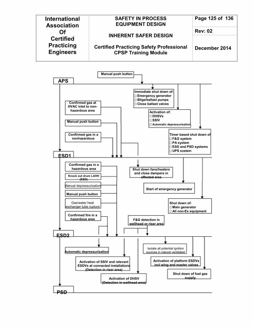
International Association
Of Certified
Practicing Engineers
SAFETY IN PROCESS EQUIPMENT DESIGN
INHERENT SAFER DESIGN
Certified Practicing Safety Professional
CPSP Training Module
Page 125 of 136
Rev: 02
December 2014
Manual push button
APS
Immediate shut down of:
���� Emergency generator
���� Bilge/ballast pumps
���� Close ballast valves
Activation of:
���� DHSVs
���� SSIV
���� Automatic depressurisation
Timer based shut down of
���� F&G system
���� PA system
���� ESD and PSD systems
���� UPS system
Confirmed gas at HVAC inlet to non-
hazardous area
Shut down of:
���� Main generator
���� All non-Ex equipment
Confirmed gas in a nonhazardous
Manual push button
Shut down fans/heaters and close dampers in
affected area
Confirmed gas in a
hazardous area
Knock out drum LAHH
(ESD)
Manual depressurization
Manual push button
Gas/water heat exchanger tube rupture
ESD1
Confirmed fire in a
hazardous area
Start of emergency generator
F&G detection in
wellhead or riser area
ESD2
Isolate all potential ignition
sources in natural ventilated
Activation of platform ESDVs
incl wing and master valves
Shut down of fuel gas
supply
Automatic depressurisation
Activation of SSIV and relevant ESDVs at connected installations
(Detection in riser area)
Activation of DHSV
(Detection in wellhead area)
PSD

International Association
Of Certified
Practicing Engineers
SAFETY IN PROCESS EQUIPMENT DESIGN
INHERENT SAFER DESIGN
Certified Practicing Safety Professional
CPSP Training Module
Page 126 of 136
Rev: 02
December 2014
Hazard Identification Methods Summary Below are the summary of the hazard-identification methods. It is useful to have this list because many companies will have preferences for certain methods or will present situations that require a particular approach. Hazop provides the most comprehensive and auditable method for identification of hazards in process plants but that some types of equipment will be better served by the alternatives listed here. a. Deductive method A good example of a deductive method is Fault tree analysis or FTA. The technique begins with a top event that would normally be a hazardous event. Then all combinations of individual failures or actions that can lead to the event are mapped out in a fault tree. This provides a valuable method of showing all possibilities in one diagram and allows the probabilities of the event to be estimated. Deductive methods are useful for identifying hazards at earlier stages of a design project where major hazards such as fire or explosion can be tested for feasibility at each section of plant. It’s like a cause and effect diagram where you start with the effect and search for causes b. Inductive method So-called ‘what if’ methods are inductive because the questions are formulated and answered to evaluate the effects of component failures or procedural errors on the operability and safety of the plant or a machine.
Method Type When Advantages Disadvantages Hazard study level 1
Inductive, Identifies potential hazard types from list of raw materials and operations
Concept stage before flow sheet
Provide database, assists layout and sitting. Legal obligations identified
Based on minimal info
Hazard study level 2 (PHA/Risk Analysis)
Inductive. Finds potential hazards at each system or unit. Uses guideword tables applied to plant sections to prompt for hazards
Flow sheets and materials known
Used on new facilities or previously untested facilities to get an overall view of where major hazards exist. Early detection offers chance to design out the hazards.
Does not find detailed hazards. Still requires HAZOP later

International Association
Of Certified
Practicing Engineers
SAFETY IN PROCESS EQUIPMENT DESIGN
INHERENT SAFER DESIGN
Certified Practicing Safety Professional
CPSP Training Module
Page 127 of 136
Rev: 02
December 2014
and possible causes and consequences
Allows protection measures to be designed in
HAZOP Deductive and inductive. Structured analysis tool. Takes small sections or nodes of plant and applies all conceivable deviations to design intent. Searched for both cause and consequence
Can be used at any stage where detailed equipment or piping and instruments diagram (P&IDs) are available best used in design at latest stage possible
Very through systematic. Provides high level of confidence in detection of hazards. Improves operability. The most widely used methodology for hazard identification
Very time consuming and costly. If not set up correctly and managed, it can be unreliable. Requires experience leadership.
What-if analysis
Deductive. Similar to HAZOP but uses team of experienced persons to test for hazards by asking relevant ‘what-if’ questions
Any stage of a project for new of existing plants.
Easy to use. Faster than HAZOP, best used with checklists.
Much less systematic than HAZOP. Depends on experience of team and of the process/equipment. Hence requires justifying
Checklist Deductive. Divide plant into nodes as for HAZOP. Apply previously developed or published checklists for known failure and deviations. Record consequences, safeguards and actions
Any stage, provided the checklist has been made available by experienced staff
Useful where only one or two persons are available to study the plant
Requires time to obtain good checklists. Depends on checklists and lacks creative thinking. Hence not through especially for new designs.
MHCA Deductive. Structures a machine into functional parts and operating phases. Reviews each phase for possible malfunctions and deuces hazards.
Safety review of a completed machinery design
Good method for proving the overall safety of a machine or assembly line
Not suitable for process plants.

International Association
Of Certified
Practicing Engineers
SAFETY IN PROCESS EQUIPMENT DESIGN
INHERENT SAFER DESIGN
Certified Practicing Safety Professional
CPSP Training Module
Page 128 of 136
Rev: 02
December 2014
APPLICATION Case Studies Many of the incidents in the world had been caused by the result of leaks of hazardous materials, and the suggestion describe ways of preventing leak by providing better equipment or procedures. The concept of inherent safety as well as its underlying principles has been explained. At this part, there are some of the biggest engineering disasters through the years that give a precious lesson-learned to see how the possibly next big event could have been prevented by applying the concept of inherent safety.
• Bhopal, India. Bhopal could be the worst disaster of the chemical industry since many years and ever now. The event occurred on December, 3rd - 1984. It costly a death of more than 2,000 people and in addition 200,000 people were injured. The immediate cause of the disaster was the contamination of Methyl Isocyanate (MIC) storage tank by several tons of water and chloroform. A runaway reaction was achieved caused the temperature and pressure rise. The next event was the relief valve lifted, and MIC vapor was discharged to atmosphere. On the contrary, the protective equipment was out of order and not fully working, the refrigeration system was shut down, the scrubbing system was also not available, the flare system that should have burned vapor that got past the scrubbing system was also out of use. One of the biggest questions raised against the local company operating the plant was regarding the safety systems in place, in case a disaster such was this was to occur. After investigations it was found and converged to the ‘six’ safety protocols in place were all nonfunctional at the time of the accident following :
• Flare Tower : Disconnected.
• Vent Gas Scrubber : Out of Caustic Soda and Filled with unsafe volume of gas.
• Water Curtain : Not properly function due to the inadequate height.
• Pressure Valve : Found leakage on the equipment.
• Run Off Tank : Already contaminated by MIC.
• Mandatory Refrigeration for MIC Unit : Had been shut down to reduce cost.

International Association
Of Certified
Practicing Engineers
SAFETY IN PROCESS EQUIPMENT DESIGN
INHERENT SAFER DESIGN
Certified Practicing Safety Professional
CPSP Training Module
Page 129 of 136
Rev: 02
December 2014
With the knowledge of inherently safety design methods, it is not difficult to make the process inherently safer and prevent the accident. As explained, inherently safety is an approach to avoid accident by minimizing, substituting, moderating, and also simplifying a hazard. By this case, it begins with by looking for alternative way to the biggest factor of the disaster, which the substances, Methyl-Isocyanate (MIC) is a highly toxic chemical that was an intermediate of Carbanyl. If the substitution principles was applied, the company could have alternative chemicals or an alternative reaction to manufacture Carbanyl. Substitution could also applied involves of knowledge about the exothermic nature reaction between the MIC and water. There were also a problem with the presence of tanks on-site containing large amounts of toxic MIC due to its environmental exposure. The concept that match at this point is minimization, where require a reduction in the amount of unwanted MIC being stored on-site. Only a small amount of MIC allowed to safe and it will reduce either the hazard and the consequences behind them. Moderation concept could also be applied if the plant had been built outside the city. This will leads to minimizing the toxic substance spread and release to the people. Thus, the plant could install dikes or bunds of some form to ensure a toxic gas release didn’t exposed to the surrounding atmosphere. Simplification is where the designed a reactor could sustain at its maximum operating condition (temperature and pressure) during the runaway reaction. The action would strongly eliminate the requirement of multiple safety systems that always need maintenance. Nonetheless, It will to the conclusion that the best way to avoid action that could lead high-impact incident is to make the process and its auxiliaries components inherently safer.
• Flixborough, United Kingdom (UK). The Flixborough accident possibly became the large explosion ever in the United Kingdom history. The accident occurred when the liquid cyclohexane was being oxidized. There were 6 chains reactors (R1 to R6) that converting cyclohexane to the mixture of cyclohexanone and cyclohexanol. Following the investigation, it found that bypass line, which had been installed as the bridge connecting reactor 4 and 6 two months earlier and temporary replaced reactor 5 due to its leakage, ruptured and caused a leakage of 50 tons of cyclohexane in short

International Association
Of Certified
Practicing Engineers
SAFETY IN PROCESS EQUIPMENT DESIGN
INHERENT SAFER DESIGN
Certified Practicing Safety Professional
CPSP Training Module
Page 130 of 136
Rev: 02
December 2014
period of time. The cyclohexane vaporized and lead to vapor cloud form that ignited and caused an severe explosion. The possibly hypothesis of ruptured bypass line including :
• Internal Pressure.
• Bellow leakage at the bypass line.
• Rupture of an 8 inch distillation pipeline that led to aminor explosion which also rupture the bridging assembly then.
Most of the official recommendation would be focused on the operational issues, nonetheless. There were peripheral issues that magnified the extent of explosion, it was found that the large leak was primary caused by the usage of large pipes which were necessary for the 400 ton inventory. From inherently safer perspective, the root cause that magnified the extent of explosion is the presence of large inventory of cyclohexane. Hence, the improvement that could applied is related to reducing the total amount of hazard. The inherently safer approach should combine process engineers and safety specialist at the design stage to produce the required product with less storage. Also, the usage of pure oxygen instead of air increases the yield which leads to reduction of the inventory of cyclohexane. On the other hand, it will caused another problem, which is increasing the possibility of deflagration due to the closed operating system to Limiting Oxygen Concentration. Water, could be the key substance that reduced impact of the incident. Water usage as a solvent in the cyclohexane water mixture would decrease the temperature and increase the vapor pressure compared to the pure cyclohexane. In addition, the usage of oxygen as the oxidizing agent will give twice more product and reduced the inventories. By the leakage event, vapor cloud formation will still occurred but with the less amount of cyclohexane. Thus, water usage will decrease the amount of vapor cyclohexane due to the lower temperature system. In conclusion, it will lead to the reducing the vapor cloud concentration moving the system far from the its flammability limit.

International Association
Of Certified
Practicing Engineers
SAFETY IN PROCESS EQUIPMENT DESIGN
INHERENT SAFER DESIGN
Certified Practicing Safety Professional
CPSP Training Module
Page 131 of 136
Rev: 02
December 2014
• Seveso, Italy. The Seveso disaster caused of the unnecessarily used of a hot heating medium which led to the runaway reaction. The accident taken in 1976 which came from a fallout of dioxin over the surrounding countryside, making it unfit for habitation. Although there was no one had been killed, it cost the environment effect. The story began when a reactor containing an uncompleted batch of 2,4,5-trichlorophenol (TCP) was left for the weekend. The reaction inside reactor was carried out under vacuum, and the reactor was also heated from external source (steam coil supplied from exhaust steam of turbine) as shown in Figure 18. When the turbine was reducing its load, the temperature of steam rose to the 300°C. Meanwhile, the temperature of bulk TCP within the vessel should not above 158°C due to its heat capacity.
Figure 18. Seveso reactor.
When the steam was isolated and the stirrer was switched off next, the heat passed by conduction and radiation from the hot wall above the liquid to the top of the liquid, which became hot enough for a runaway to start. If the steam had been cooler, the runaway reaction could be avoided.
158°C

International Association
Of Certified
Practicing Engineers
SAFETY IN PROCESS EQUIPMENT DESIGN
INHERENT SAFER DESIGN
Certified Practicing Safety Professional
CPSP Training Module
Page 132 of 136
Rev: 02
December 2014
Case design 2 Give the inherently safer design strategy for a batch chemical reactor. The process is a simple exothermic batch reaction in which two or more reactants are added to a reactor, It may generate heat which must be removed to keep the reaction mixture from boiling, or perhaps the reactor contents could decompose at some elevated temperature. Give the inherent, passive, and active aspect. Solution Inherent. Develop a chemistry which is not exothermic, or is only mildly exothermic. The maximum adiabatic reaction temperature is the maximum possible temperature that the reaction mixture could reach assuming 100% reaction of all reactants and no removal of heat. Maximum adiabatic reactor temperature less than boiling point of all ingredients and onset temperature of any decomposition or other reactions, and no gaseous products are generated by the reaction. The reaction is not capable of causing any pressure in the reactor, either from boiling of the reactor contents or from decomposition of any materials. There is no hazard of runaway reaction. If the materials are not toxic or flammable, the reactor might not even have to be a closed vessel. From a safety viewpoint, it would not be necessary to control the rate of reactant addition. The reaction is not capable of generating pressure, so the reaction chemistry will not impact the design of any overpressure protection system such as a relief valve or rupture disk
TI
PI
VENT
REACTANT FEEDS
COOLING

International Association
Of Certified
Practicing Engineers
SAFETY IN PROCESS EQUIPMENT DESIGN
INHERENT SAFER DESIGN
Certified Practicing Safety Professional
CPSP Training Module
Page 133 of 136
Rev: 02
December 2014
Passive Identify a reaction which is exothermic, and which is determined to result in a maximum adiabatic reaction pressure of 150 psig, assuming 100% reaction of all reactants and no removal of heat. Run reaction in a 250 psig design reactor. The 250 psig design reactor contains this pressure because of its design – the thickness of the metal, the strength of the bolts and flanges, the design of the gaskets, and all of the other aspects of pressure vessel design. The reactor provides passive safety with respect to the hazard of a runaway reaction. It is capable of containing the maximum possible pressure from the reaction. Hazard (pressure) still exists, but passively contained by the pressure vessel. This will be more elaborate, requiring construction and operation to meet the relevant pressure vessel codes. A pressure relief valve will be required. The design basis of the relief valve will be based on some other overpressure scenario, perhaps fire exposure, filling the vessel with all of the outlet line valves closed, overheating with steam, for example Active Maximum adiabatic pressure for 100% reaction is 150 psig, reactor design pressure is 50 psig. It now requires a high temperature safety interlock and a high pressure interlock which shut off the reactant feed. Gradually add limiting reactant with temperature control to limit potential energy from reaction. Use high temperature and pressure interlocks to stop feed and apply emergency cooling. this is an active system and requires the proper functioning of
TI
PI
VENT
PRV
REACTANT FEEDS
COOLING

International Association
Of Certified
Practicing Engineers
SAFETY IN PROCESS EQUIPMENT DESIGN
INHERENT SAFER DESIGN
Certified Practicing Safety Professional
CPSP Training Module
Page 134 of 136
Rev: 02
December 2014
a number of components – the temperature (or pressure) sensor; the logic device which receives the temperature (or pressure) signal, compares it to the specified safe value, and sends a signal to take the specified action; and also a field element which takes the specified action – a valve which must close or a pump which must be stopped, for example. Any of these components could fail. As a further active backup, the reactor would be provided with an emergency relief system – a pressure relief valve or rupture disk – to prevent reactor overpressure. The relief valve must sense the pressure and open, or the rupture disk must burst. Also, it is important to confirm that the emergency relief system discharges to a safe place. Procedural Maximum adiabatic pressure for 100% reaction is 150 psig, reactor design pressure is 50 psig. Gradually add limiting reactant with temperature control to limit potential energy from reaction. Train operator to observe temperature, have him manually shut down the reactant feed if it exceeds the specified safe value and apply cooling if temperature exceeds critical operating limit. The reactor looks much the same, except that, instead of an automatic system to stop the reactant feeds, we rely on the operator to observe an unsafe condition and take the required action.
PA
H
VENT
REACTANT FEEDS
COOLING
RUPTURE DISK WITH DISCHARGE
TO SAFE PLACE
TA
H
SAFETY SYSTEM
LOGIC ELEMENT

International Association
Of Certified
Practicing Engineers
SAFETY IN PROCESS EQUIPMENT DESIGN
INHERENT SAFER DESIGN
Certified Practicing Safety Professional
CPSP Training Module
Page 135 of 136
Rev: 02
December 2014
In general, inherent and passive strategies are the most robust and reliable, but elements of all strategies will be required for a comprehensive process safety management program when all hazards of a process and plant are considered.

International Association
Of Certified
Practicing Engineers
SAFETY IN PROCESS EQUIPMENT DESIGN
INHERENT SAFER DESIGN
Certified Practicing Safety Professional
CPSP Training Module
Page 136 of 136
Rev: 02
December 2014
REFERENCES
1. Anna-Mari Heikkilä, Inherent Safety in Process Plant Design an Index-Based Approach. VTT Publications. 1999.
2. Crowl, D A. and Louvar, J F. Chemical Process Safety Fundamentals with Applications. Second edition. Prentice Hall PTR. 2002
3. Guidelines for Engineering Design for Process Safety. American Institute of Chemical Engineers, New York, 1993.
4. Kletz, T. A. 1996. Inherently Safer Design: The Growth of an Idea. Process Safety Progress, Vol. 15, No.1, pp. 5–8
5. Smith, R. Chemical Process Design and Integration. John Wiley & Sons Inc. Chapter 27. 2005.
6. Nolan, D P. Hand of Fire and Explosion Protection Engineering Principles for Oil, Gas, Chemical, and Related Facilities. Noyes Publications. 1996.
7. Sanders R E. Chemical Process Safety 3rd Edition. Elsevier Butterworth–Heinemann. 2005
8. Towler, G. and Sinnot, R. Chemical Engineering Design. Elsevier Inc. Chapter 9 - 12, 2008.
9. Workplace Safety, Volume 4 of the Safety at Work Series. Butterworth-Heinemann. 1999
10. Steven.T et al.2012. Design an Inherently Safer Plant. Risk management, Inc. AICHE
11. Large Property Damage Losses in the Hydrocarbon-Chemical Industries: A Thirty-Year Review(New York: J & H Marsh & McLennan Inc., 1998), p. 2
12. Thirty-Year Review of One Hundred of the Largest Property Damage Losses in the Hydrocarbon-Chemical Industries (New York: Marsh Inc., 1987).