iac-10-d1.1.4 design concepts for a manned ... · unlike the moon and mars nodes, 0.06 gee...
TRANSCRIPT

IAC-10-D1.1.4 Design Concepts for a Manned Artificial Gravity Research Facility 1
IAC-10-D1.1.4
DESIGN CONCEPTS FOR A MANNED ARTIFICIAL GRAVITY RESEARCH FACILITY
Joseph A Carroll
Tether Applications, Inc., USA, [email protected] Abstract
Before mankind attempts long-term manned bases, settlements, or colonies on the moon or Mars, it is prudent to learn whether people exposed to lunar or Martian gravity levels experience continuing physiological deterioration, as they do in micro-gravity. If these problems do occur in partial gravity, then it will also be important to develop and test effective countermeasures, since countermeasures could have drastic effects on manned exploration plans and facility designs. Such tests can be done in low earth orbit, using a long slowly rotating dumbbell that provides Martian gravity at one end, lunar gravity at the other, and lower values in between. To cut Coriolis effects by half, one must cut the rotation rate of an artificial gravity facility by half. This requires a 4X longer facility. The paper argues that ground-based rotating room tests have uncertain relevance, so allowable rotation rates are not yet known. Because of this uncertainty, the paper presents 4 different structural design options that seem suited to rotation rates ranging from 0.25 to 2 rpm. This corresponds to overall facility lengths ranging from 120m to 8km. The paper also discusses early flight experiments that may allow selection of a suitable rotation rate and hence facility length and design. For most design options, “trapeze" tethers can be deployed outward from the Moon and/or Mars nodes. This allows capture of visiting vehicles from low-perigee orbits, and also accurate passive deorbit. Vehicles can also do a traditional rendezvous with a free-fall node at the facility CM. The facility can be co-orbital with ISS, Bigelow, and other manned facilities. This would let their crews re-accommodate to earth gravity in stages (Moon, Mars, earth), rather than all at once. The paper addresses key design trades, layout, assembly, spin-up, expansion, contingencies, transfer between nodes and between facilities, precursors, and operational derivatives for long exploration missions.
1. Introduction: Why Study This?
Most recent interest in artificial gravity has focused on crew health during cruise to and from Mars. Such studies have generally tried to infer the highest spin rate acceptable to the crew from ground-based rotating room test data. Allowable spin rate is critical since it drives required spin radius. That in turn affects facility size, design, weight, cost, operations, and even failure modes.
The focus here is different: it is on a research facility in low earth orbit. The simple stick figure below shows a basic conceptual design of indeterminate length. It also shows a key design detail that may significantly reduce costs: the heavy lunar node can use 3 “cabins” the same size and design as used for the other nodes.
Besides Moon and Mars nodes at opposite ends of the dumbbell, Figure 1 also shows 2 inboard nodes: one at the CM to allow traditional free-fall vehicle approach, and one at 0.06 gee, whose utility is discussed later.
There are several different length regimes for which quite different structural connections seem appropriate between the endmasses. Short dumbbells allow easy “shirtsleeve” transfer between nodes, but much longer ones require pressurized external elevators between the nodes. For safety, such external elevators might be “capsules on clotheslines.”
Unfortunately, if the allowable spin rate is halved, a 4X longer dumbbell is required, so any uncertainties in allowable spin rate imply much larger uncertainties in length and design. This frustrated me until I realized that instead of asking “How short can a facility be?” one can ask “How long a facility may be affordable?”
Rather than just trying to determine suitable gravity levels and spin-rates during cruise to and from Mars, this paper describes a facility focused on the overall effects of long-term hypogravity. This may determine the realism of any visions of eventual Moon and Mars settlements. The facility might address questions like:
1. Can people stay healthy for years—and years later? 2. Can mice and monkeys reproduce normally? 3. Can monkeys raised there adapt to earth gravity? 4. What plants may be useful for food production? 5. Does hypogravity allow advances in basic biology?
Moon CM 0.06g Mars
Figure 1. Basic “spinning dumbbell” geometry
IAC-10-D1.1.4 Design Concepts for a Manned Artificial Gravity Research Facility 2
A facility focused mostly on long-term hypogravity questions can also address nearer-term issues relevant to manned exploration missions to the Moon, Mars, and NEOs, including:
6. How much gravity to use in cruise to/from Mars 7. How much gravity to use on-station near NEOs 8. What spin rates and designs are desired for cruise 9. What countermeasures may still be needed
Many countries not now involved in manned space may have enough interest in some of these questions to participate. A commercial venture may be able to enlist more countries cost-effectively and with fewer problems than government-led programs can, and can more easily accommodate other commercial ventures and tourists as customers. So I assume that a manned artificial gravity facility will be a commercial venture, and that it will be strongly aimed at an international customer base.
Unlike the Moon and Mars nodes, 0.06 gee does not represent a manned exploration destination. But it seems useful for other reasons. First, 0.06 gee is 1/e of lunar gravity. The ratio of Mars to earth gravity is 1/e0.97, and lunar gravity is 1/e0.83 of Mars gravity, similar steps on a log scale. Neal Pellis of NASA JSC has suggested to me that ~1/e steps in gravity level seem very useful for basic gravitational biology research, independent of the fact that the first 2 such steps below Earth also represent Mars and Moon gravity levels. Hence another 1/e step to 0.06 gee may be a good complement to Earth, Mars, Moon, and microgravity studies.
I suspect that 0.06 gee may also be about the lowest gravity level that people can quickly and intuitively adapt to, and do ordinary gravity-dependent things like walk, sit in a chair, handle loose objects and liquids in cups, and roll over in a bed without overshooting and falling onto the floor. I don’t know whether 0.06 gee is enough to prevent the negative effects crews experience in adapting to microgravity, or whether it or other levels may aid or impede that adaptation. It would clearly be useful to learn these things, especially if an artificial-gravity facility may fly in formation with other manned facilities like the ISS.
A 0.06 gee node may also be popular with tourists, if it is the largest change from normal earth gravity that lets one behave intuitively and doesn’t require days of accommodation. Such a node may also be very useful for activities that can use some gravity but don’t need or want much, such as satellite assembly, or plant growth. A final detail is that the orbital maneuvering systems on both shuttle and Soyuz provide ~0.06 gee accelerations. Any useful tests that can be done within a minute or so can hence be tested during shuttle OMS burns on the two remaining shuttle flights, or on Soyuz, perhaps after phasing on the way to the ISS.
While preparing this paper, I realized that the best orbit for such a facility might be co-orbiting with ISS, with coordinated reboost. The arguments for this are also applicable to other manned facilities, so I moved those arguments to an appendix at the end of the paper. The paper and the appendix can be studied separately, but some readers may wish to study the appendix first.
The rest of the paper covers these topics:
2. A key design trade: spinrate vs length 3. Common and unique elements vs length 4. A five-stage development scenario 5. Conclusions and recommendations.
2. A Key Design Trade: Spinrate vs Length Spin rate determines required facility length. This
has large implications on facility design, and on how a facility and its visiting vehicles operate, and whether they can easily visit co-orbital facilities. This section of the paper discusses these implications in some detail.
2.1 Why don’t we know what spin rates are usable?
John Charles of NASA JSC has suggested to me that data from ground-based rotating room tests may not be relevant for estimating maximum allowable spin-rates of orbiting artificial-gravity facilities, since the rotation axis is parallel to gravity, rather than normal to it as in an artificial-gravity facility. This merits discussion.
One issue is that we may not be able to use spin-rates low enough to reduce artificial gravity artifacts below sensible detection, even with 8 km dumbbells spinning at 0.25 rpm. But a more critical issue may be not detection, but thresholds for significant negative effects. There may be even more uncertainty about this. But it may be feasible to reduce this uncertainty using ground-based tests in suitable motion-base simulators.
Two distinct effects need discussion: rotation itself, and Coriolis accelerations. Sensitivity to rotation around a vertical axis is easy to test using rotating rooms. Rates of order 1 rpm are detectable, but most people seem to accommodate to that. Many can adapt to 2-4 rpm, and some to higher rates. They can even adapt (over time) to reversals in rotation direction.
But it is not clear how relevant this is to artificial gravity facilities, because there the sensed rotation in body coordinates is about a different axis, and depends on which way you are facing at the time. Turning around reverses the felt rotation immediately. Turning around even has an azimuth-specific effect: one turn causes a shift in sensed rotation one way, and the next causes an opposite shift in sensed rotation. This is a key difference between ground-based rotating-room tests and orbiting artificial-gravity facilities.

IAC-10-D1.1.4 Design Concepts for a Manned Artificial Gravity Research Facility 3
Now consider Coriolis accelerations. To a person sitting or standing anywhere in a room rotating about a vertical axis, purely vertical motion causes no Coriolis effects. Horizontal motion can cause substantial Coriolis accelerations. In a room rotating clockwise (when you are looking down), the acceleration is to the left of the motion. It is equal to twice the room rotation rate times the horizontal velocity. If one walks at 1 m/s in a room rotating clockwise at 1 rpm (=0.1047 rad/sec), you must lean 1.2o to the right, and 1.2o to the left if you step backward. This effect may be annoying initially, but people can adapt to it. As long as the spin direction and rate remain the same, the acceleration is independent of location and orientation in the room. So every time you walk at a given speed, or reach your arm out at a given speed, you feel the same perturbation, in the same direction in body coordinates. Most people seem to be able to adapt to this fairly well, over time.
Contrast this with an artificial-gravity facility. Both vertical and horizontal motions cause perturbations, and in body coordinates, both vary with azimuth. Vertical (radial) motion causes a horizontal force aligned with the direction of rotation. Most vertical motion is stroke limited (eg., standing up), so the total impulse is limited and may be tolerable. For example, when you stand up, you may raise your CM by ~0.4m. In a facility rotating at 1 rpm, that is like standing up from a wheeled chair moving at 42 mm/sec (1.6”/sec) in a fixed direction, independent of which way the chair is facing. That is probably tolerable, especially since you generally make transient adjustments anyway while standing up.
But now consider horizontal motion with or against the direction of rotation. If you walk only 2.5% as fast as the facility moves at your radius, you get 5% heavier, since weight scales with V2/r. But if you turn around, walking makes you 5% lighter. If you walk at right angles to the rotation, there is no effect. Such changes are relevant because ordinary elevators typically have ~0.05 gee acceleration. People often stumble a bit if they are taking a step when an elevator starts or stops. (A better test than intentionally walking at such times may be to slave the vertical motion of a motion-base simulator to horizontal motions of a single occupant.)
Such tests may show that people can detect weight changes as little as +1-2% when walking. But a key issue here is that the threshold for conscious detection and that for problematic effects may be different—and it is not clear which may be higher. The threshold for negative effects may be well above the threshold for conscious detection. But queasiness and other negative effects could be problems even below the threshold for conscious detection. Because of this uncertainty, one might consider the implications of a threshold for non-trivial negative effects that may range from +1 to +5%
weight change, at a modest walking speed of 1 m/s. This corresponds to facility rotation rates of 0.47 to 2.35 rpm, and overall facility lengths of 88-2200 meters.
A related question is what happens to thresholds in reduced gravity. Coriolis accelerations scale with the rotation rate but are independent of radius, so facility rotation rates of 0.47 to 2.35 rpm will cause weight changes equal to +1 to +5% of earth gravity, whether you are at earth, Mars, lunar, or a lower gravity level. It seems likely that negative-effect thresholds may drop with gravity level, but probably much more slowly than the gravity level itself drops. If thresholds do drop with gravity level, then facility rotation rate limits and hence facility size will be driven more by the lunar node than the Mars node. For example, if thresholds drop with the ¼ to ½ power of gravity level, allowable rotation in lunar gravity may be only 40% to 64% of the 0.47 to 2.35 rpm that may be relevant at earth gravity, and may be as low as 0.19 rpm (requiring a 14 km facility!).
There is one more effect to consider for very long slowly-rotating facilities: periodic gravity variations between the horizontal and vertical, due to gravity-gradient effects and also induced variations in rotation rates. This effect scales linearly with length. Mars/Moon dumbbells near ISS altitude have a total variation of 1% per 6.75 km dumbbell length, with maximum weight at the vertical and minimum at the horizontal. This does not require occupant motion, so people may be more sensitive to it than to comparable variations caused by walking, for the same reason that people are more prone to motion sickness when they are a passenger than when they are driving. On the other hand, this is a smooth and slow sinusoid, with a period of 1 minute for a 2 km dumbbell, and 2 minutes for an 8 km dumbbell.
Based on the above discussion, the major detectable artifact in a slowly-rotating artificial gravity facility, and the best candidate for an upper limit to rotation rates, may be azimuth-dependent weight changes when people walk. But since this occurs only when one walks with or against the direction of rotation, a key feature of the facility design may be long thin aircraft-like cabin layouts, with narrow “aisles” aligned with the spin axis. (Ted Hall recommended this in a 1993 paper.) Then most walking is nearly parallel to the axis of rotation, and weight changes with walking will be low. Steps across the aisle will be at much lower speed because of the limited distance available for starting and stopping.
A supporting design feature might be to cover the floor with a decorative but intuitively clear directional pattern, such as arrows indicating rotation direction, to help people anticipate Coriolis effects. These details could be important, because if a good floor plan and floor covering allow use of 25-50% higher facility spin rates, they could allow 36-56% shorter facility lengths.
IAC-10-D1.1.4 Design Concepts for a Manned Artificial Gravity Research Facility 4
Table 2. Implications of various dumbbell lengths
Radial structure: Modules Inflatable tunnels Tun+cab Cables Rpm, inertial Scaling 2.00 1.50 1.00 0.80 0.55 0.35 0.25 Dumbbell Length L, meters rpm-2 121 216 486 760 1600 4000 8000 VMars (affects Δweight), m/s rpm-1 17.7 23.7 35.5 44.4 64.3 101.7 143.8 ΔEarthWeight, walk 1 m/s rpm +4.3% +3.2% +2.1% +1.7% +1.2% +0.75% +0.53%CyclicΔWeight(Vert-Hor) rpm-2 0.02% 0.03% 0.07% 0.10% 0.24% 0.6% 1.2% MarsNodePerigee, Km345 Δ=rpm-1 284 263 222 191 125 1 -135 Mars NodeOrbitLife, Hrs ~1/ρPer 881 626 285 168 6 <1 <1 MoonNodeOrbitLife, Hrs “ 1464 1291 992 790 467 141 9 PostCutReboostPropIsp=280 rpm-1 0.4% 0.5% 0.8% 1.0% 1.4% 2.2% 3.2% RadialStrucMassFrac15,1%/km rpm-2 ~30% 3.1% 7.1% 11.4% 8.3% 4.0% 8.0% RadialStructDragCdA, m2 Σ(LW) 660 492 1140 1783 1355 860 1720
One can do ground-based studies of human response to motion-caused weight changes, including the effects of different aisle orientations, widths, and coverings, using a large motion-base simulator like the Vertical Motion Simulator at NASA Ames. The VMS allows 18m vertical motion, and 12 and 2m horizontal strokes. The VMS has 4 interchangeable cabs, including one with a 1.8x3.7m floor. This is large enough to get up some speed walking in different directions. What is needed is to outfit this cab with suitable interior layouts, add an occupant motion sensor, write code to move the cab in response to occupant motion, and do all needed safety reviews to make sure that the tests can be done safely. The VMS even allows simulation of Coriolis impulses caused by standing up and sitting down. The VMS can also test responses to gravity-gradient-induced gravity variations for facilities up to 2 km long in open-loop mode (ie, without needing occupant sensors). 2.2 Implications of spin rate on radial structure
What is not obvious from the stick figure on page 1 is that the “stick” itself will be a fairly heavy structure with multiple functions. If it is short enough, it can be a rigid beam, or even pressurized modules joined end to end. This would allow installation of experiments and crew facilities anywhere along the radius. If it is much longer than 100m, such a structure could get too heavy. A narrow pressurized tunnel could be much lighter than modules joined end-to-end, while still allowing easy crew and cargo transfer between nodes. If much longer, even a tunnel gets too heavy, and redundant cabling may be necessary for at least the longest link. Then transfer between those nodes would require some form
of external elevator. Table 1 at the bottom suggests what the maximum lengths might be for these different radial structure options.
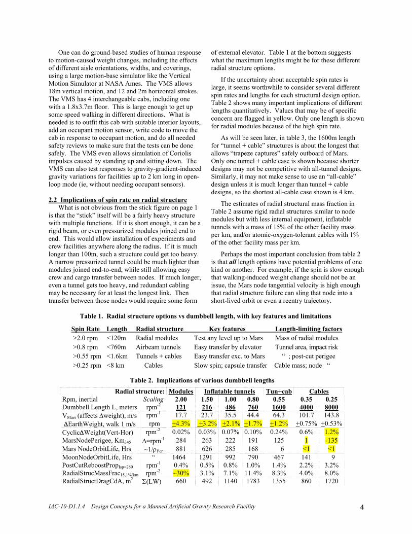
If the uncertainty about acceptable spin rates is large, it seems worthwhile to consider several different spin rates and lengths for each structural design option. Table 2 shows many important implications of different lengths quantitatively. Values that may be of specific concern are flagged in yellow. Only one length is shown for radial modules because of the high spin rate.
As will be seen later, in table 3, the 1600m length for “tunnel + cable” structures is about the longest that allows “trapeze captures” safely outboard of Mars. Only one tunnel + cable case is shown because shorter designs may not be competitive with all-tunnel designs. Similarly, it may not make sense to use an “all-cable” design unless it is much longer than tunnel + cable designs, so the shortest all-cable case shown is 4 km.
The estimates of radial structural mass fraction in Table 2 assume rigid radial structures similar to node modules but with less internal equipment, inflatable tunnels with a mass of 15% of the other facility mass per km, and/or atomic-oxygen-tolerant cables with 1% of the other facility mass per km.
Perhaps the most important conclusion from table 2 is that all length options have potential problems of one kind or another. For example, if the spin is slow enough that walking-induced weight change should not be an issue, the Mars node tangential velocity is high enough that radial structure failure can sling that node into a short-lived orbit or even a reentry trajectory.
Table 1. Radial structure options vs dumbbell length, with key features and limitations
Spin Rate Length Radial structure Key features Length-limiting factors >2.0 rpm <120m Radial modules Test any level up to Mars Mass of radial modules >0.8 rpm <760m Airbeam tunnels Easy transfer by elevator Tunnel area, impact risk >0.55 rpm <1.6km Tunnels + cables Easy transfer exc. to Mars “ ; post-cut perigee >0.25 rpm <8 km Cables Slow spin; capsule transfer Cable mass; node “
IAC-10-D1.1.4 Design Concepts for a Manned Artificial Gravity Research Facility 5
But this may not be an issue. In fact, if the facility flies in formation with other manned facilities, a more critical issue after a badly-timed structural failure may be preventing collision with any co-orbiting facility. Independent of facility length and perceived likelihood of a break, it may be essential to have “smart reboost” capability at each node, to restore that part of the facility to near the pre-break orbit. This is also necessary if one plans to later re-connect the separated pieces.
The propellant needed for the post-cut maneuvers is listed in Table 2 as a percent of total facility mass. The values conservatively assume a 70/30 Moon/Mars mass ratio, no inboard node or radial structure mass, and a reboost Isp=280 sec. The propellant requirements are a modest fraction of facility mass, so the main issue may not be propellant mass so much as ensuring a reliably appropriate and timely response to any failures.
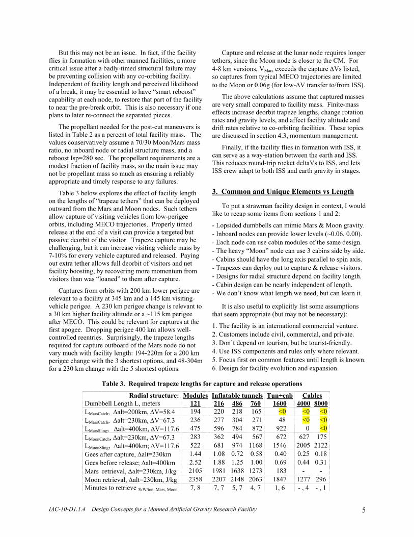
Table 3 below explores the effect of facility length on the lengths of “trapeze tethers” that can be deployed outward from the Mars and Moon nodes. Such tethers allow capture of visiting vehicles from low-perigee orbits, including MECO trajectories. Properly timed release at the end of a visit can provide a targeted but passive deorbit of the visitor. Trapeze capture may be challenging, but it can increase visiting vehicle mass by 7-10% for every vehicle captured and released. Paying out extra tether allows full deorbit of visitors and net facility boosting, by recovering more momentum from visitors than was “loaned” to them after capture.
Captures from orbits with 200 km lower perigee are relevant to a facility at 345 km and a 145 km visiting-vehicle perigee. A 230 km perigee change is relevant to a 30 km higher facility altitude or a ~115 km perigee after MECO. This could be relevant for captures at the first apogee. Dropping perigee 400 km allows well-controlled reentries. Surprisingly, the trapeze lengths required for capture outboard of the Mars node do not vary much with facility length: 194-220m for a 200 km perigee change with the 3 shortest options, and 48-304m for a 230 km change with the 5 shortest options.
Capture and release at the lunar node requires longer tethers, since the Moon node is closer to the CM. For 4-8 km versions, VMars exceeds the capture ΔVs listed, so captures from typical MECO trajectories are limited to the Moon or 0.06g (for low-ΔV transfer to/from ISS).
The above calculations assume that captured masses are very small compared to facility mass. Finite-mass effects increase deorbit trapeze lengths, change rotation rates and gravity levels, and affect facility altitude and drift rates relative to co-orbiting facilities. These topics are discussed in section 4.3, momentum management.
Finally, if the facility flies in formation with ISS, it can serve as a way-station between the earth and ISS. This reduces round-trip rocket deltaVs to ISS, and lets ISS crew adapt to both ISS and earth gravity in stages. 3. Common and Unique Elements vs Length
To put a strawman facility design in context, I would like to recap some items from sections 1 and 2:
- Lopsided dumbbells can mimic Mars & Moon gravity. - Inboard nodes can provide lower levels (~0.06, 0.00). - Each node can use cabin modules of the same design. - The heavy “Moon” node can use 3 cabins side by side. - Cabins should have the long axis parallel to spin axis. - Trapezes can deploy out to capture & release visitors. - Designs for radial structure depend on facility length. - Cabin design can be nearly independent of length. - We don’t know what length we need, but can learn it.
It is also useful to explicitly list some assumptions that seem appropriate (but may not be necessary):
1. The facility is an international commercial venture. 2. Customers include civil, commercial, and private. 3. Don’t depend on tourism, but be tourist-friendly. 4. Use ISS components and rules only where relevant. 5. Focus first on common features until length is known. 6. Design for facility evolution and expansion.
Table 3. Required trapeze lengths for capture and release operations
Radial structure: Modules Inflatable tunnels Tun+cab Cables Dumbbell Length L, meters 121 216 486 760 1600 4000 8000 LMarsCatch, Δalt=200km, ΔV=58.4 194 220 218 165 <0 <0 <0 LMarsCatch, Δalt=230km, ΔV=67.3 236 277 304 271 48 <0 <0 LMarsSling, Δalt=400km, ΔV=117.6 475 596 784 872 922 0 <0 LMoonCatch, Δalt=230km, ΔV=67.3 283 362 494 567 672 627 175 LMoonSling, Δalt=400km; ΔV=117.6 522 681 974 1168 1546 2005 2122 Gees after capture, Δalt=230km 1.44 1.08 0.72 0.58 0.40 0.25 0.18 Gees before release; Δalt=400km 2.52 1.88 1.25 1.00 0.69 0.44 0.31 Mars retrieval, Δalt=230km, J/kg 2105 1981 1638 1273 183 - - Moon retrieval, Δalt=230km, J/kg 2358 2207 2148 2063 1847 1277 296 Minutes to retrieve 5kW/ton; Mars, Moon 7, 8 7, 7 5, 7 4, 7 1, 6 - , 4 - , 1

IAC-10-D1.1.4 Design Concepts for a Manned Artificial Gravity Research Facility 6
Finally, I would like to give definitions to some terms useful in describing the facility design:
- Cabin: a long pressurized cylinder, like a 737 cabin - Cable: a radial tensile structure, for long dumbbells - Capsule: any reentry-capable visiting vehicle (including external elevators and ferries to ISS) - Elevator: inter-node transport (tunnel or clothesline) - Node: one or more joined cabins at one gravity level - Trapeze: tether hanging out to capture/release visitors - Tunnel: pressurized radial structure and passageway.
Figure 2, on the next page, shows 4 different length options from Tables 2 and 3, using 3 different structural design options. Each option uses multiple copies of a small number of different types of elements. Those elements are mostly common across all the designs.
Figure 2 also shows the acceleration vectors seen at 10-second intervals during a round-trip elevator ride between the Mars and 0.06 gee nodes in a 1rpm facility. This assumes 3m/s maximum elevator speed and gentle 0.015 gee accelerations and decelerations. Rides to and from the hub may be more disconcerting despite smaller forces, because elevator accelerations near the CM will cause “up” and “down” to be briefly in the opposite direction, compared to the other end of the ride.
The rest of section 3 discusses in detail 5 key aspects of the design variants shown in Figure 2:
3.1 Overall architecture 3.2 Pressurized cabin design 3.3 Tunnels, cables, elevators, and hallways 3.4 Interfaces to visiting vehicles 3.5 Solar array design, and electric reboost.
The designs in Figure 2 are all to the same scale, except for tunnels, cables, and trapeze tethers shown with truncation symbols. The large number of visiting vehicles indicates potential berthing positions, not how many vehicles might be present at any one time. But as with the ISS, it is prudent to keep enough escape seats for the full crew. It is also prudent to limit the number of people at each node to the number of seats in the capsules berthed there, since some emergencies can disable some of the inter-node transfer capabilities. 3.1 Overall Architecture
Several version-specific design details are worth noting here. The short rigid dumbbell does not have a 0.06 gee node since the radial modules are large enough in diameter to allow crew and other accommodations at any desired radius. On the 0.55 rpm version at the far right, the 0.06 gee node is on the Moon side of the CM, to reduce total tunnel length and weight, while still allowing tunnel access to all nodes other than Mars. This requires additional counterbalance mass at Mars.
It also requires maneuvering far enough out of the spin plane to avoid the Mars-CM cabling, during any low-ΔV trapeze operations between the 0.06 gee node and the ISS or other co-orbiting facilities. (The other trapeze locations do not have this problem.) Other key details shown in Figure 2, including cabin orientation, radial structure options, visiting vehicle interfaces, and solar arrays, are discussed in detail in 3.2-3.5, below. 3.2 Pressurized Cabin Design
Inflatable structures allow large cabin diameters and volumes while fitting into small fairings for launch. But events that depressurize a cabin in artificial gravity would allow structural buckling and consequential damage or uncertainty that may preclude later re-use of the structure and its contents. This is much less of an issue with structures in microgravity. This does not rule out inflatable structures, but indicates a challenge they face. I focus here on rigid cylinders small enough to launch on EELVs, and encourage Bigelow Aerospace and others to investigate inflatable alternatives.
Another issue is whether cylindrical cabins should be horizontal like aircraft cabins, or vertical like a lighthouse, as shown in some artificial-gravity facility concepts and used in Skylab. For cabins on the scale of individual EELV payloads, horizontal layouts may allow better use of cabin volume and crew time. In addition, aligning the cabin axis parallel to the facility spin axis and using a fairly narrow aisle should reduce typical walking-induced weight changes to lower values than may be feasible with vertical orientations.
Once we assume a rigid cylindrical pressure shell that can be launched by EELV-class boosters, the next question is cabin diameter. To increase payload and cut launch cost, we might use a fairing only over the nose during ascent. The cylindrical shell wall can be covered by a micrometeoroid and orbital debris (MMOD) shield that is secured during launch and deployed away from the pressure shell in orbit (as intended on Skylab). Then the cabin ID can be very close to the payload OD during booster ascent. If that is the case, there may be at least 3 candidate cabin diameters:
~ 3.6m: low ascent drag; easy fab (like Falcon 9 tanks) ~ 4.2m: same as shuttle-launched modules on the ISS ~ 5.2m: Falcon 9 and EELV fairing dia; ascent aero ok.
Figure 3, on the page after Figure 2, shows 2 cabin layout concepts for each of these diameters. The same 2.25m (89”) ceiling height is shown for all cases with flat ceilings, except for the bottom center layout, which is used in the US, European, and Japanese labs in the ISS. Its 4 rows of racks are not relevant to an artificial gravity facility, since the floor needs to be “walkable,” and ceilings are not good work surfaces.

IAC-10-D1.1.4 Design Concepts for a Manned Artificial Gravity Research Facility 7
Figure 2. Different facility structure and length options using mostly common elements

IAC-10-D1.1.4 Design Concepts for a Manned Artificial Gravity Research Facility 8
It is not clear whether the facility will even use ISS racks, but it seems useful to be able to handle them or similar items. In partial gravity, wheels and clamps may be better for moving and securing racks weighing up to ~700 kg than the approach used on ISS, which floats and swivels racks into place.
A 3.6m diameter works well with 2 rows of ISS or similar racks. The aisle is wide enough to move racks, but not much wider than that. The spaces underfoot and overhead are not large enough for decent crew sleeping areas as with 4.2 and 5.2m diameters, but those spaces can be used for storage and support equipment. In the top left view, the object to the left of the crewman is overhead equipment swung down for repair, while the narrow panel behind him indicates a floor panel swung up for access to underfloor utility/storage space.
A 5.2m diameter is about the smallest that allows a decent “two-story” layout, as in the bottom right view. But it may not use space as well as the top view, and complicates the interfaces to adjacent cabins needed for a 3-cabin lunar node. Even the top right view may not use space as well as the smaller diameters.
As shown later in Figure 7, different diameter cabins can easily be joined together. If SpaceX has schedule or other problems with early Falcon 9 or Dragon flights, it
may make sense to fly one or more Falcon 9s with whatever useful payload has the lowest replacement cost. This could be a 3.6m diameter cabin built on the Falcon 9 production line. Even with internal outfitting and a berthing interface, a cabin may cost less than the fairing it could replace on some early test flights.
Later, when Dragon is fully operational, a Dragon could berth to a previously-launched cabin and do single-cabin artificial-gravity tests with a spent stage as counterweight. A 3.6m diameter cabin might be much longer than a standard 5.2m fairing, perhaps roughly the same length as the Falcon 9 first-stage LOX tank. Figure 4, at right, shows Falcon 9 boosters with a Dragon, a 5.2m cabin the same size as a standard fairing, and a 3.6 x 17m cabin. This length is shown here and also in Figure 5, because rough
Figure 3. Possible layouts for 3 cabin diameters
Figure 4. Falcon 9 with payloads
ISS rack
3.6m dia. 4.2m dia 5.2m dia
IAC-10-D1.1.4 Design Concepts for a Manned Artificial Gravity Research Facility 9
calculations suggest that it may impose bending loads on the booster during ascent similar to those imposed by the shorter wider standard fairing shown in the middle.
Figure 5, below, shows another perspective on cabin layout: a 3.6x17m cabin is very nearly the same length and diameter as the passenger cabin of a 737-600. A 3.6m cabin is actually a few inches wider than the 737 cabin, and the floor is lower so there is more headroom, but the 737 allows a convenient reference for the usable space inside such a cabin. Boeing Business Jets (based on the 737) also allow examples of cabin layout.
Table 4 gives a rough mass budget for a cabin sized for the Falcon 9. It assumes a Falcon 9 block 2 with 9358 kg payload to a 51.6o, 400 km orbit. The reduced drag of a 3.6m payload, elimination of fairing weight, and flying a lower-MECO ascent trajectory suited to those changes should raise payload to ~10,000 kg.
Table 4. Possible cabin launch mass budget
3800 kg for 6mm aluminum alloy tank and adapter 1000 kg for MMOD shielding at 4kg/m2, plus 10% 2500 kg for interior floors, walls, ducts, etc. 1000 kg for LIDS, tunnel and hall I/F, and scar mass ~100 kg ascent penalty for the nose cap 8400 kg total ~10000 kg expected booster capacity ~1600 kg available for additional items
Cabins plus equipment and supplies (most of which will be delivered later) should constitute most of the facility mass, so this is perhaps the best place to note something I find surprising: “specific vehicle mass” for different vehicles. Below are typical values for several vehicle types, in metric tons (1,000 kg) per person:
<1 Commercial airliners, loaded and fueled 15 Aircraft carriers and typical cruise ships 30 Skylab 40 Mir 60 ISS
Space stations must provide far more life-support than aircraft, but I don’t know why mass/person is 2-4X that of large ships, when the cost of extra mass is so high. Consider the concepts shown in Figure 2. Disregard the short rigid version, and consider the CM node of other versions as utility space. Then those other versions each have 5 habitable cabins: 3 lunar cabins plus 1 each at 0.06 gee and Mars gravity. Each cabin is the same size as a 737-600 cabin. It has ~50 m2 of area at floor level, and more at eye level. Each cabin might have enough room for people and equipment for long-term support of 4 people. Then a facility should support 20. If 6 cabins weigh 60 tons, or ~100 tons with all other equipment and supplies, 100/20 is only 5 tons/person. I have no idea whether ~5 tons/person may actually be feasible.
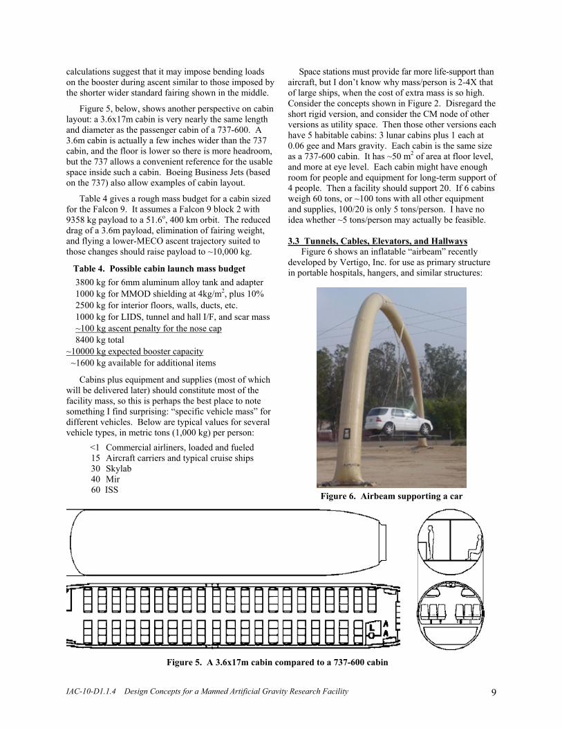
3.3 Tunnels, Cables, Elevators, and Hallways
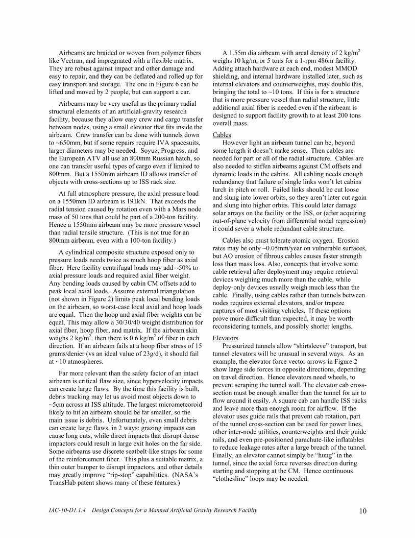
Figure 6 shows an inflatable “airbeam” recently developed by Vertigo, Inc. for use as primary structure in portable hospitals, hangers, and similar structures:
Figure 5. A 3.6x17m cabin compared to a 737-600 cabin
Figure 6. Airbeam supporting a car
IAC-10-D1.1.4 Design Concepts for a Manned Artificial Gravity Research Facility 10
Airbeams are braided or woven from polymer fibers like Vectran, and impregnated with a flexible matrix. They are robust against impact and other damage and easy to repair, and they can be deflated and rolled up for easy transport and storage. The one in Figure 6 can be lifted and moved by 2 people, but can support a car.
Airbeams may be very useful as the primary radial structural elements of an artificial-gravity research facility, because they allow easy crew and cargo transfer between nodes, using a small elevator that fits inside the airbeam. Crew transfer can be done with tunnels down to ~650mm, but if some repairs require IVA spacesuits, larger diameters may be needed. Soyuz, Progress, and the European ATV all use an 800mm Russian hatch, so one can transfer useful types of cargo even if limited to 800mm. But a 1550mm airbeam ID allows transfer of objects with cross-sections up to ISS rack size.
At full atmosphere pressure, the axial pressure load on a 1550mm ID airbeam is 191kN. That exceeds the radial tension caused by rotation even with a Mars node mass of 50 tons that could be part of a 200-ton facility. Hence a 1550mm airbeam may be more pressure vessel than radial tensile structure. (This is not true for an 800mm airbeam, even with a 100-ton facility.)
A cylindrical composite structure exposed only to pressure loads needs twice as much hoop fiber as axial fiber. Here facility centrifugal loads may add ~50% to axial pressure loads and required axial fiber weight. Any bending loads caused by cabin CM offsets add to peak local axial loads. Assume external triangulation (not shown in Figure 2) limits peak local bending loads on the airbeam, so worst-case local axial and hoop loads are equal. Then the hoop and axial fiber weights can be equal. This may allow a 30/30/40 weight distribution for axial fiber, hoop fiber, and matrix. If the airbeam skin weighs 2 kg/m2, then there is 0.6 kg/m2 of fiber in each direction. If an airbeam fails at a hoop fiber stress of 15 grams/denier (vs an ideal value of 23g/d), it should fail at ~10 atmospheres.
Far more relevant than the safety factor of an intact airbeam is critical flaw size, since hypervelocity impacts can create large flaws. By the time this facility is built, debris tracking may let us avoid most objects down to ~5cm across at ISS altitude. The largest micrometeoroid likely to hit an airbeam should be far smaller, so the main issue is debris. Unfortunately, even small debris can create large flaws, in 2 ways: grazing impacts can cause long cuts, while direct impacts that disrupt dense impactors could result in large exit holes on the far side. Some airbeams use discrete seatbelt-like straps for some of the reinforcement fiber. This plus a suitable matrix, a thin outer bumper to disrupt impactors, and other details may greatly improve “rip-stop” capabilities. (NASA’s TransHab patent shows many of these features.)
A 1.55m dia airbeam with areal density of 2 kg/m2 weighs 10 kg/m, or 5 tons for a 1-rpm 486m facility. Adding attach hardware at each end, modest MMOD shielding, and internal hardware installed later, such as internal elevators and counterweights, may double this, bringing the total to ~10 tons. If this is for a structure that is more pressure vessel than radial structure, little additional axial fiber is needed even if the airbeam is designed to support facility growth to at least 200 tons overall mass.
Cables However light an airbeam tunnel can be, beyond
some length it doesn’t make sense. Then cables are needed for part or all of the radial structure. Cables are also needed to stiffen airbeams against CM offsets and dynamic loads in the cabins. All cabling needs enough redundancy that failure of single links won’t let cabins lurch in pitch or roll. Failed links should be cut loose and slung into lower orbits, so they aren’t later cut again and slung into higher orbits. This could later damage solar arrays on the facility or the ISS, or (after acquiring out-of-plane velocity from differential nodal regression) it could sever a whole redundant cable structure.
Cables also must tolerate atomic oxygen. Erosion rates may be only ~0.05mm/year on vulnerable surfaces, but AO erosion of fibrous cables causes faster strength loss than mass loss. Also, concepts that involve some cable retrieval after deployment may require retrieval devices weighing much more than the cable, while deploy-only devices usually weigh much less than the cable. Finally, using cables rather than tunnels between nodes requires external elevators, and/or trapeze captures of most visiting vehicles. If these options prove more difficult than expected, it may be worth reconsidering tunnels, and possibly shorter lengths.
Elevators Pressurized tunnels allow “shirtsleeve” transport, but
tunnel elevators will be unusual in several ways. As an example, the elevator force vector arrows in Figure 2 show large side forces in opposite directions, depending on travel direction. Hence elevators need wheels, to prevent scraping the tunnel wall. The elevator cab cross-section must be enough smaller than the tunnel for air to flow around it easily. A square cab can handle ISS racks and leave more than enough room for airflow. If the elevator uses guide rails that prevent cab rotation, part of the tunnel cross-section can be used for power lines, other inter-node utilities, counterweights and their guide rails, and even pre-positioned parachute-like inflatables to reduce leakage rates after a large breach of the tunnel. Finally, an elevator cannot simply be “hung” in the tunnel, since the axial force reverses direction during starting and stopping at the CM. Hence continuous “clothesline” loops may be needed.

IAC-10-D1.1.4 Design Concepts for a Manned Artificial Gravity Research Facility 11
External elevators seem like a far larger challenge. For failure tolerance, perhaps all external elevator cabs should be fully functional reentry capsules, with enough propellant for safe separation and targeted reentry after an elevator jam, cable break, posigrade release, or other problem. If capsules are lean vehicles, they need an adapter on the elevator for long-term electric power and heat rejection. To align a capsule for berthing at each end of its ride, a double clothesline can hold the capsule adapter. A capsule can capture it using a mechanism other than its hatch, to keep the hatch free for berthing at either end. This may eliminate any need for a node at the CM, since an adapter can move to the CM and damp out transverse oscillations, to allow a traditional free-fall approach. One can also eliminate the 0.06 gee node, have several full-length elevators between Mars and Moon nodes, and use one elevator for low gravity tests, when it is not needed as an elevator.
Hallways or local elevators between adjacent cabins The other critical cabin-to-cabin connection is some
kind of passage between adjacent cabins making up the lunar node. In a 14-cabin growth version of the facility, even the 0.06 gee and Mars nodes each have 3 cabins and hence need such passages. If the facility is short enough for tunnels and hence tunnel interfaces on the cabins, the simplest connection between adjacent cabins is to stack them radially and use a “zero-length tunnel” and “local elevator.” This passage can be offset from the main inter-node tunnel, but can use the same kind of local structural modification of the cabin skin.
With a 1-rpm design 486m long, the Moon node is only 148m from the CM, so a multi-story lunar node has +2.5% weight changes between adjacent floors. This could be more disconcerting than much larger changes between nodes. It may be better to use a “ranch style” one-level layout as on the left side of Figs. 3 and in Fig. 7, below. Figure 7 shows walk-through hallways plus a tunnel and ISS-rack-size elevator. Customized hall interfaces can even join different cabin diameters like the 3.6m and 5.2m diameters shown. Halls can be offset axially from the tunnel, for structural and other reasons.
The “outrigger” cabins in Figure 7 are tilted the right amount for a 1-rpm facility with cabins parallel to the spin axis. The 3.6m cabin on the left could use more internal equipment, to help balance the 5.2m cabin on
the right. The hallways are elliptical, 2.25m high inside but only 1.8m wide. Cabin wall reinforcements around this aperture shape handle pressure loads well. This shape also lets short elliptical hallway structures fit through the hallway aperture. As shown later in Figure 8, rigid hallway structures can be stowed for launch inside a cabin. Later they can be taken out through the hallway aperture, for assembly in orbit. A raised internal floor in the hallway can be flush with the floors on either side, and just wide enough to pass ISS racks. 3.4 Interfaces to Visiting Vehicles
This topic is closely linked to cabin layout and equipment selection, and to tunnel ID if a tunnel is used. If a 1.55m ID tunnel is used, to allow transfer of large payloads, then it makes sense to include a CBM-size interface to transfer rack-sized payloads from visiting vehicles to the facility and back. If a smaller tunnel is used, a CBM-size interface is unnecessary, except to accommodate a specific visiting vehicle.
One key aspect of mating with the CM node is that the CM node will not simply sit still: it is subject to various radial and transverse offsets and oscillations. Fortunately, elevators can be positioned to fine-tune facility CM, and moved to induce Coriolis side-forces that actively damp transverse dynamics. But the hub will still spin with the facility, so some de-spinnable interface like a suitably designed arm is still needed.
It seems worth trying to accommodate existing vehicles from Europe, Japan, Russia, and China, both for robustness against vehicle stand-downs, and also because those countries may participate more if they can send crew or cargo vehicles as well as funding. Their vehicles may be able to approach only the CM node. There are only 2 approach paths there, one at each end of the node. But if a short arm can capture a visiting vehicle and move it to one of several nearby berthing positions, each end of the node might handle up to ~4 vehicles, with interfaces ranging from the 800mm Russian hatch to CBM-size interfaces.
To berth at other nodes after a trapeze capture, a CBM-size interface may be best. This is especially true if the facility is 4-8 km long and hence cannot do trapeze captures outboard of Mars. Then it depends on external elevators to transfer all cargo to and from the Mars node, and a generous port size may be justified.
As discussed in Section 3.3, the cab of an external elevator might be a “lean” capsule like the 12-seat Dragon “bus” shown later, in appendix Figure A1. If so, the capsule adapter on the elevator needs to also provide the long-term power and heat rejection needed by a capsule optimized for brief free flights. This adapter also needs to null out residual dynamics to let a capsule mate with it when it is positioned at the CM.
Figure 7. Lunar node cabins, tunnel, elevator, halls
Elliptical hallway

IAC-10-D1.1.4 Design Concepts for a Manned Artificial Gravity Research Facility 12
It also needs a de-spun interface for initial capsule contact, and the ability to rotate the capsule to keep the crew upright as the elevator traverses from the Moon to the Mars side of the CM. Both elevators and trapezes need to be able to position capsules close enough to a LIDS or other berthing interface to allow engagement. They also need to compliantly support capsule weight during engagement, so the mechanism can retract the capsule into the proper position without having to deal with capsule weight.
The most challenging interface may be for trapeze capture. Sensors and controls seem more critical than capture hardware, which might be as simple as a hook and loop. It is probably a bad idea to prolong trapeze capture windows by reeling or thrusting: one should null errors during minutes of approach, not seconds of panic.
One key to success may be to have enough data from different sensors presented cleanly enough that the crew can see that an approach is at least safe. If there is any question about safety, approach should be aborted. This requires carrying extra propellant, so a capsule can circularize and do free-fall rendezvous 1-2 orbits later. After successful trapeze captures, this propellant can be transferred to the facility for later use there. 3.5 Solar Array Design, Power, and Electric Reboost
Solar array design and tracking pose problems on an artificial-gravity facility. The arrays must track the sun despite rapid facility rotation. They see acceleration loads if mounted away from the spin axis, and even if they mount at the nominal spin axis, CM shifts or cable breaks could cause serious mechanical loads that could deform or break typical large deployable solar arrays.
Rather than designing solar arrays that avoid or just tolerate the artificial gravity, one can design them to use it, by hanging flexible arrays radially outward from each node, and tracking only about the radial axis. (But such 1-axis tracking does require a significantly larger array.) Such an array tends to align itself in the spin plane. If perturbed in yaw, a long flexible array should oscillate solidly through the spin plane, at 1 cycle/spin at low amplitude, and lower frequency at high amplitude. So we may be able to do 1-axis tracking by slightly driving resonant oscillations, with low torques and low array twist even with a very flexible array.
3.5.1 Solar array efficiency and cost The average daytime temperature of high-efficiency
triple-junction solar cells in a 2-axis-tracking solar array in ISS orbit should be ~60C. If rated cell efficiency at 28C is 28%, it should be ~25.6% at 60C. Earth albedo may raise output only ~1% on the average, since albedo radiation is highest near noon, when 2-axis-tracking arrays face away from the earth. If the cell area is 90% of the array area, and the facility is in the sun 0.602 of
the time at 345 km altitude when β=0 (ie, the sun is in the orbit plane), then orbit-average array output should be 190W per m2 of array, neglecting the +3.3% seasonal variations with changes in sun-earth distance.
Compare this with a hanging solar array that tracks the sun only around the “hang axis.” The worst case is with the sun in the spin plane (~4o from the orbit plane, if the facility spins at 1 rpm). Averaging over each half spin of the facility, hanging arrays intercept 2/π as much direct sun as 2-axis arrays that always face the sun. Various other minor differences between hanging and 2-axis-tracking arrays should nearly cancel out. They include higher albedo inputs, ~25C cooler cells, higher reflective losses, and a lower peak-power array voltage. Hence an array that provides 190W/m2 orbit-average power with 2-axis tracking at β=0 should give 120W/m2 if it tracks only about the rotating “hang axis.”
If we size facility solar arrays for 60kW total orbit-average output with β=0, we need 109kW of rated cell capacity with 2-axis tracking, or 173kW with hanging arrays. At $250/watt, cells for a 2-axis array cost $27M, vs $43M for hanging arrays. Challenges posed by 2-axis tracking seem likely to cost far more than $16M extra, so hanging arrays are probably cheaper overall. Solar array drag may be only ~20% of facility drag. Surplus “off-peak” array output should allow high-Isp electric reboost much of each month. If that is done, then cheap low-efficiency thin-film cells may make the most sense.
3.5.2 Median, average, and max solar array power Facilities in ISS-like orbits have the longest eclipse
and lowest orbit-average solar power ~once per month, when nodal regression passes the orbit plane through the sun-earth line so solar beta angle β=0. At other β angles, time in the sun and orbit-average power both increase.
For arrays tracking only about the hang axis, having the sun out of the spin plane also reduces cosine losses that occur around each half-spin, so output increases far more than with 2-axis tracking, which has no cosine losses. With β>72o, there is no eclipse, and average hanging-array cosine loss is <3%. Then hanging array performance can be within 3% of 2-axis performance.
No-eclipse episodes typically occur once near each solstice. Each episode lasts 3-4 days. Table 5 below shows “surplus” power available for various conditions, for hanging and 2-axis arrays sized for 60kW at β=0. In any 51.6o orbit, the median case is with Abs(β)=29o.
Table 5. Orbit-avg surplus power for 60kW @ β=0
Orbit-Avg “Surplus” Power, kW Tracking
60kW arrayarea, m2 β=0 Median Avg No eclipse
Hanging 500 0 14 20 94 2-axis 318 0 2 4 40
IAC-10-D1.1.4 Design Concepts for a Manned Artificial Gravity Research Facility 13
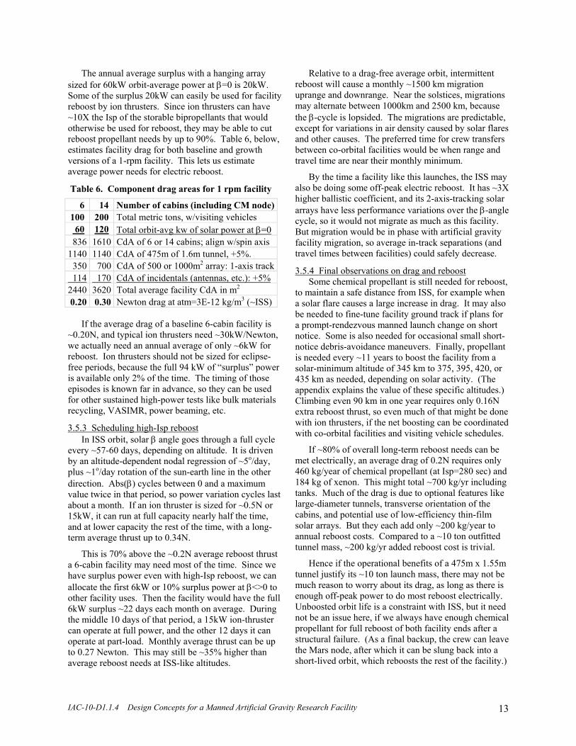
The annual average surplus with a hanging array sized for 60kW orbit-average power at β=0 is 20kW. Some of the surplus 20kW can easily be used for facility reboost by ion thrusters. Since ion thrusters can have ~10X the Isp of the storable bipropellants that would otherwise be used for reboost, they may be able to cut reboost propellant needs by up to 90%. Table 6, below, estimates facility drag for both baseline and growth versions of a 1-rpm facility. This lets us estimate average power needs for electric reboost.
Table 6. Component drag areas for 1 rpm facility
6 14 Number of cabins (including CM node) 100 200 Total metric tons, w/visiting vehicles 60 120 Total orbit-avg kw of solar power at β=0 836 1610 CdA of 6 or 14 cabins; align w/spin axis 1140 1140 CdA of 475m of 1.6m tunnel, +5%. 350 700 CdA of 500 or 1000m2 array: 1-axis track 114 170 CdA of incidentals (antennas, etc.): +5% 2440 3620 Total average facility CdA in m2 0.20 0.30 Newton drag at atm=3E-12 kg/m3 (~ISS)
If the average drag of a baseline 6-cabin facility is ~0.20N, and typical ion thrusters need ~30kW/Newton, we actually need an annual average of only ~6kW for reboost. Ion thrusters should not be sized for eclipse-free periods, because the full 94 kW of “surplus” power is available only 2% of the time. The timing of those episodes is known far in advance, so they can be used for other sustained high-power tests like bulk materials recycling, VASIMR, power beaming, etc.
3.5.3 Scheduling high-Isp reboost In ISS orbit, solar β angle goes through a full cycle
every ~57-60 days, depending on altitude. It is driven by an altitude-dependent nodal regression of ~5o/day, plus ~1o/day rotation of the sun-earth line in the other direction. Abs(β) cycles between 0 and a maximum value twice in that period, so power variation cycles last about a month. If an ion thruster is sized for ~0.5N or 15kW, it can run at full capacity nearly half the time, and at lower capacity the rest of the time, with a long-term average thrust up to 0.34N.
This is 70% above the ~0.2N average reboost thrust a 6-cabin facility may need most of the time. Since we have surplus power even with high-Isp reboost, we can allocate the first 6kW or 10% surplus power at β<>0 to other facility uses. Then the facility would have the full 6kW surplus ~22 days each month on average. During the middle 10 days of that period, a 15kW ion-thruster can operate at full power, and the other 12 days it can operate at part-load. Monthly average thrust can be up to 0.27 Newton. This may still be ~35% higher than average reboost needs at ISS-like altitudes.
Relative to a drag-free average orbit, intermittent reboost will cause a monthly ~1500 km migration uprange and downrange. Near the solstices, migrations may alternate between 1000km and 2500 km, because the β-cycle is lopsided. The migrations are predictable, except for variations in air density caused by solar flares and other causes. The preferred time for crew transfers between co-orbital facilities would be when range and travel time are near their monthly minimum.
By the time a facility like this launches, the ISS may also be doing some off-peak electric reboost. It has ~3X higher ballistic coefficient, and its 2-axis-tracking solar arrays have less performance variations over the β-angle cycle, so it would not migrate as much as this facility. But migration would be in phase with artificial gravity facility migration, so average in-track separations (and travel times between facilities) could safely decrease.
3.5.4 Final observations on drag and reboost Some chemical propellant is still needed for reboost,
to maintain a safe distance from ISS, for example when a solar flare causes a large increase in drag. It may also be needed to fine-tune facility ground track if plans for a prompt-rendezvous manned launch change on short notice. Some is also needed for occasional small short-notice debris-avoidance maneuvers. Finally, propellant is needed every ~11 years to boost the facility from a solar-minimum altitude of 345 km to 375, 395, 420, or 435 km as needed, depending on solar activity. (The appendix explains the value of these specific altitudes.) Climbing even 90 km in one year requires only 0.16N extra reboost thrust, so even much of that might be done with ion thrusters, if the net boosting can be coordinated with co-orbital facilities and visiting vehicle schedules.
If ~80% of overall long-term reboost needs can be met electrically, an average drag of 0.2N requires only 460 kg/year of chemical propellant (at Isp=280 sec) and 184 kg of xenon. This might total ~700 kg/yr including tanks. Much of the drag is due to optional features like large-diameter tunnels, transverse orientation of the cabins, and potential use of low-efficiency thin-film solar arrays. But they each add only ~200 kg/year to annual reboost costs. Compared to a ~10 ton outfitted tunnel mass, ~200 kg/yr added reboost cost is trivial.
Hence if the operational benefits of a 475m x 1.55m tunnel justify its ~10 ton launch mass, there may not be much reason to worry about its drag, as long as there is enough off-peak power to do most reboost electrically. Unboosted orbit life is a constraint with ISS, but it need not be an issue here, if we always have enough chemical propellant for full reboost of both facility ends after a structural failure. (As a final backup, the crew can leave the Mars node, after which it can be slung back into a short-lived orbit, which reboosts the rest of the facility.)

IAC-10-D1.1.4 Design Concepts for a Manned Artificial Gravity Research Facility 14
I assume ion engines rather than electrodynamic reboost because short “tunnel-type” facility designs seem the most attractive right now. (A multi-km ED thruster on a ~1 rpm facility would see high tensile loads and could complicate trapeze operations.) Long ED thrusters would make spin momentum adjustment much easier, and would require less power for the same reboost, but hanging solar arrays can provide enough intermittent surplus power for reboost by ion engines.
An ED thruster seems easy to integrate into a 4-8 km “all-cable” facility design. Independent control of spin and reboost requires electron collectors and emitters at each end. In addition, ED thrust is normal to the earth’s magnetic field, so reboost thrust is roughly due east. Keeping a fixed inclination requires varying reboost thrust with 1-2Cos(2φ), where φ is the orbit phase relative to the ascending node. The 2Cos term more than triples average electron collection plus conduction losses. An alternative is to do mostly ED reboost, mostly far from the orbit nodes, with steered chemical reboost at the nodes. This can maintain orbit inclination without a 2Cos term. I baseline ion reboost since it seems easier to integrate, but ED reboost is also worth serious study. ED thrust may be most useful during early development tests, when the available counterweight mass may be small and the desire for frequent spin changes large.
4. Development Scenario
This facility concept lends itself naturally to 5 stages
of evolution, listed below in Table 7. A key parameter at each stage is the number of cabins launched. Cabins can be re-tasked later, so no cabins need be discarded. Table 7. Five stages with ~ exponential growth
# cabins and key new operations 0 Tether manned capsules to spent boosters for tests 1 Launch 1 cabin, berth capsule, spin up with stage 3 Launch 2 more cabins; join; use any counterweight 6 Launch 3 more cabins + tunnels; join to lunar node 14 Launch 8 more cabins, despin; attach; spin up.
The growth in usable volume is roughly exponential with each stage. Launching 8 more cabins for the last stage is obviously a major cost commitment, but it need only be done if demand justifies it. A large expansion like this is needed, both to keep the facility balanced, and to minimize how often the facility must be despun to connect new cabins. This will disrupt normal gravity-dependent activities and hence should not be done often. Routine equipment and supply delivery allows a gradual continuous expansion of capabilities, within the context of occasional major habitable-volume expansions, in response to demand.
Sections 4.1-4.5 cover the following topics:
4.1 Early tests and precursor missions 4.2 Facility assembly and expansion 4.3 Momentum management: CM, spin, etc. 4.4 Contingency operations 4.5 Operational derivatives of the facility
4.1 Early Tests and Precursor Missions
The most important tests may be the early low-cost tests done on the ground, since they may have the most influence on overall facility design, development plans, and the chances of completion. If tunnel-type designs stay promising after more study, the sweet-spot for most ground tests of weight change and other effects may be roughly 0.5-1.5 rpm. The 1 and 1.5 rpm facilities are nearly identical except for tunnel lengths, and a 1 rpm version may weigh only ~4% more, so it may not even be worth considering spin rates >1 rpm. A final choice on facility length need not even be made until it is time to launch the tunnels, at the start of stage 4. This lets the facility design incorporate whatever was learned from manned hypogravity flight tests during stages 1-3.
Besides the human-response tests recommended in section 2.2.1, early ground tests seem worthwhile on:
- airbeam tunnels (radiation, thermal, impact, repair) - elevator designs (tunnel and possibly external) - cabin layouts (for crew, plant growth, animal care) - 1-gee trapeze capture (a Centennial Challenge?)
Early artificial-gravity tests on Soyuz The first orbital flight test can be manned, and might
be done in <1 year. (A similar test of Gemini XI and its Agena took only a year from conception to flight.) One can even use the same tether and stowage/deployment concept: a flat strap, folded and lightly stitched down.
Soyuz weighs ~3X as much as the booster stage that it leaves at ~200 km. They could stay tethered during phasing on missions to ISS. A 600m tether can put the Soyuz 150m from the CM, the same as the lunar node of a 1-rpm facility. A 0.6 rpm spin provides 0.06 gee to the crew, and 1 rpm gives lunar gravity. A 20 kg tether allows a safety factor >5. Spinning up in several steps allows evaluation of lower gravity levels and spin-rates.
Surprisingly, spin-up can be done nearly for free, even from the heavier (manned) end, by doing pulsed posigrade burns. The key is to later release the booster stage when it is moving backwards. Then the full 62 m/s posigrade ΔV added at the manned end (for lunar gravity with 1 rpm spin and 3:1 mass ratio) can stay there after release. This can displace most propellant needed to climb to ISS after phasing. Doing the burns at southern latitudes and tether release in the north even allows targeted deorbit of the booster into the southeast Pacific, where many disposal reentries are targeted.
IAC-10-D1.1.4 Design Concepts for a Manned Artificial Gravity Research Facility 15
Soyuz is not the only vehicle that can do the above test: Dragon and Shenzhou can also do it. If hypogravity does aid adaptation to microgravity, or if targeted deorbit of spent stages pays for itself, this operation could even become a standard part of all crew missions to ISS.
Tests using 1 to 3 cabins The limited volume and time available for capsule-
based hypogravity tests will limit the scope of testing. But capsule-based tests can refine the objectives and design of larger and longer-duration single-cabin tests. The first such test can tether the cabin to its spent stage. A capsule can berth with the cabin before the dumbbell spins up. Spin-up might be done by the spent stage, or started chemically and finished electrodynamically.
Electrodynamic reboost, using hardware derived from EDDE (the “ElectroDynamic Debris Eliminator”), may be more useful now than later. Early tests may vary the spin rate frequently, stop to attach new capsules and cabins, and reboost to stay away from ISS. And they may need a long tether if the counterweight is light.
This may also be a good time for tests of trapeze operations with manned capsules. The first test might just be deployment and retrieval of a manned capsule on a trapeze tether at the end of a mission (without release), to verify winch and tethered berthing operations.
The same capsule can later be redeployed and then released into lower orbit. (This also helps reboost the dumbbell.) After analysis of the data, the next mission might attempt trapeze capture. An ED thruster can slow the spin down as much as needed to ease early captures. Later flights can try captures with gradually higher spin rates, perhaps on the way to or from ISS. 4.2 Facility Assembly and Expansion
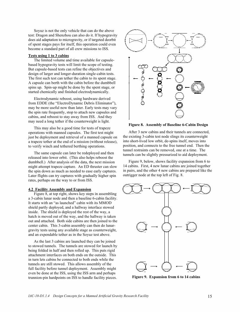
Figure 8, at top right, shows key steps in assembling a 3-cabin lunar node and then a baseline 6-cabin facility. It starts with an “as launched” cabin with its MMOD shield partly deployed, and a hallway interface stowed inside. The shield is deployed the rest of the way, a hatch is moved out of the way, and the hallway is taken out and attached. Both side cabins are then joined to the center cabin. This 3-cabin assembly can then do lunar-gravity tests using any available stage as counterweight, and an expendable tether as in the Soyuz test above.
As the last 3 cabins are launched they can be joined to stowed tunnels. The tunnels are stowed for launch by being folded in half and then rolled up. This puts rigid attachment interfaces on both ends on the outside. This in turn lets cabins be connected to both ends while the tunnels are still stowed. This allows assembly of the full facility before tunnel deployment. Assembly might even be done at the ISS, using the ISS arm and perhaps trunnion-pin hardpoints on ISS to handle facility pieces.
Figure 8. Assembly of Baseline 6-Cabin Design
After 3 new cabins and their tunnels are connected, the existing 3-cabin test node slings its counterweight into short-lived low orbit, de-spins itself, moves into position, and connects to the free tunnel end. Then the tunnel restraints can be removed, one at a time. The tunnels can be slightly pressurized to aid deployment.
Figure 9, below, shows facility expansion from 6 to 14 cabins. First, 4 new lunar cabins are joined together in pairs, and the other 4 new cabins are prepared like the outrigger node at the top left of Fig. 8.
Figure 9. Expansion from 6 to 14 cabins

IAC-10-D1.1.4 Design Concepts for a Manned Artificial Gravity Research Facility 16
Then the facility stops spinning to allow attachment of the new cabins, or just slows down if trapeze capture of cabins is feasible. Stopping requires securing loose items and curtailing many activities, but doing this just once can more than double usable cabin volume. Most of the required spin down and spin up can be provided by capsule thrusters at the maximum length of trapeze capture/release tethers. This can provide a long enough moment arm to cut despin + respin propellant needs to <0.4% of facility mass, with a 486m long 1-rpm facility. 4.3 Momentum Management: CM, Spin, and Orbit
Continuously and simultaneously managing facility CM, spin, dynamics, and orbit involves many challenges and constraints. Consider CM first, since it is simplest. CM shifts are caused by elevator and trapeze operations. What is important is not the individual operations, but all operations that are done at the same time. Lowering a counterweight while raising an elevator can control the CM, as can moving a heavy mass from Mars to 0.06 gee while a trapeze deploys from Mars or is retracted to the Moon.
Visiting vehicle traffic to and from the CM node has no effect on CM, other than through any later payload distribution by elevator. Low-ΔV trapeze operations from the 0.06 gee node (for transport to and from ISS) have little effect on CM, and can be compensated for by moving elevators or counterweights. The main problem is trapeze captures and releases from the ends, because they cause sudden large CM shifts. It may be best to pair these operations when feasible, at least if visiting vehicles are heavy. After a capture, one can deploy and release another capsule.
Retrieval and deployment of separate trapezes from the same node can be done at the same time, because Coriolis effects keep them apart as they pass. If release is done within minutes of capture, the modest transient gravity changes may not affect long-term experiments, especially on the Mars node. The changes will have relatively larger effects on lower-gravity nodes.
Spin control involves keeping the RMS mass radius (or radius of gyration) constant. This involves a simple rule: do no net lifting work, or ensure Σ(WΔr)=0, where W is object weight (not mass), and Δr is radial distance change. As with CM control, the main complications are due to trapeze operations. But here the issue is not capture or release itself, but reeling in or out, since that changes radius of gyration and spinrate. This is another reason for pairing trapeze operations, to limit spin and gravity changes to occasional brief episodes.
A third area of concern is bending of the tunnel or other radial structure. This may have more effect on the inboard nodes than on the Mars and Moon nodes, and may be of most concern during free-fall approaches to
the CM. Tuned motion of elevators, counterweights, and even trapeze winches can reduce undesired motions of the CM node and might also be used to damp all low-frequency modes. The composite tunnel structure itself may help damp most high-frequency modes passively.
For maximum flexibility and accuracy in controlling CM, spin, and bending modes, it seems useful to have separate winches and clothesline loops for the elevators and their counterweights. This increases winch motor torques and currents, but in low gravity, with braking clamps between uses, that may not be a problem. The clothesline loops stay in tension even when loads on the elevator or counterweight reverse in direction. A slack loop can indicate a failure and can trigger emergency braking, just as slack lines do on elevators on earth.
Two other dynamics issues merit discussion. Just as a solar array tries to orient itself in the spin plane, so do long cabins. For any angular momentum, the rotation kinetic energy is lowest when the radius of gyration is largest, ie, when the long dimension is in the spin plane. Long objects like the cabins try to relax into that attitude or oscillate through it. To prevent that, we need reaction wheels with axes parallel to the cabins, spinning in the same direction. They are also needed to react torques caused by reeling of trapeze tethers attached to the ends (rather than the center) of the cabins. The wheels may account for several % of overall facility mass and cost.
The other issue is ensuring that the facility spin plane stays close to the orbit plane as the orbit plane regresses. Rotating the spin plane ~4o out of the orbit plane, away from the equator, induces enough gravity gradient torque to precess a 1-rpm spin along with the orbit, just as the moon’s spin axis slowly wobbles in phase with its orbit, as described by Cassini’s laws.
The above discussion focuses mostly on nulling the undesired effects of short-term configuration changes. We must also deal with long-term trends, including reboost and a gradual increase in facility mass and hence required spin angular momentum. Section 3.5 showed that there is enough off-peak power available for high-Isp electric reboost. Throwing capsules into lower-perigee trajectories than they were captured from also provides reboost. But this will also partly go to compensate for most visiting vehicles leaving some fraction of their mass at the facility.
Unfortunately, releasing a capsule from a trapeze tether that is longer than at capture provides net de-spin. In addition, structural damping acting on small tension changes between the vertical and horizontal causes a very slow spin-down, perhaps up to 1%/month. (The “lost” spin angular momentum goes into the orbit, just as tidal friction on the earth slowly de-spins the earth while boosting the moon into a higher orbit.)

IAC-10-D1.1.4 Design Concepts for a Manned Artificial Gravity Research Facility 17
Surprisingly, it may be easy to increase the facility spin angular momentum despite de-spin mechanisms. Acquiring the full spin angular momentum of a 100 ton 1-rpm facility requires 560 kg of propellant in pulsed posigrade burns at the Mars node, but only 170 kg if used by a capsule at the full sling length of the trapeze. If chemical reboost requires ~460 kg/year, as estimated in section 3.5, we can get all required “spin makeup” by doing part of the reboost at the right time and place. 4.4 Contingency Operations
Below is a list of potentially serious contingencies. I do not include all potential failures and problems, just ones related to this design or affected by it, such as fire and EVA. After the list, I discuss responses to the first 2 problems listed, since they seem the most critical. I encourage readers to e-mail me ideas on other problems and/or solutions, and references to analyses of similar problems and solutions.
Potentially catastrophic events - Severance of tunnel (ie, radial structure failure plus large-area leak and high venting thrust)
- Fire (much more of a problem than in microgravity, where turning fans off can help solve the problem)
- Large breach of tunnel or cabin pressure shell w/o separation (high leakage rate, modest thrust)
- Impact by visiting vehicle: evacuate and seal off the cabin, and send a capsule to get crew in damaged one.
Other serious events - Severance of long cable-type version: use thrusters to restore orbit; de-spin, and reconnect later
- Solar array damage, or tracking failure: cut power use; borrow from other nodes; get new array
- Failure of external elevator cables: capsule separates and then maneuvers to CM node, ISS, or reentry.
Other contingencies - Full loss of reboost (w/loss of reserves on both Mars and Moon nodes): sling Mars back to reboost rest.
- Jam of tunnel-style elevator, or elevator or trapeze cable: TBD (design-specific response needed)
- Small breach of tunnel or cabin, with low but detectable leakage: get there from inside and plug it.
- Severance of single cables: release both segments into low orbit. Use elevator to string new cable.
- EVA: try robotics instead; if really needed, use several restraint lines, plus large parasols for better lighting.
- End of life deorbit: sling modules down in sequence, and use on-board thrusters to deorbit the last one.
Facility designs using wide pressurized “airbeam” tunnels have substantial operational advantages under normal conditions, but they also have unique failure modes. Keeping the tunnel sections sealed off between elevator trips can greatly reduce risks. A hatch that can quickly and automatically roll into position (not slam closed) may be critical. Crude self-deploying seals (perhaps like small heavy-duty parachutes) may also be useful to reduce venting thrust, which reverses the cabin acceleration direction and adds to the crew’s sudden problems. This requires careful study early in facility development, because it is not clear whether one can absolutely preclude tunnel severance.
Fire may be the other really critical issue. In micro-gravity, fires often suffocate themselves if there is no forced convection, so turning fans off is an important first step. That’s not enough here, because there will be enough gravity to keep feeding fresh air to the fuel. Fire safety rules and procedures on submarines may be the closest analogy, so experts in that area could probably be of use here. 4.5 Operational Derivatives
The concepts discussed above may be useful precursors for at least 3 more ambitious derivatives:
- high-ΔV transport slings in LEO, - cruise stages for long exploration missions, and - crew accommodations on the Moon or Mars.
Rotating high-ΔV slings in LEO may make sense once there is enough traffic through LEO to higher orbit and most orbital debris has been removed from LEO. Capture and release should be at 100-130 km altitude, to reduce peak gees during suborbital reentries. As noted in AIAA 95-2895, spin:orbit ratios near 2:1 minimize required facility mass (~30X payload), since the tether stays overhead when the facility is lowest, ~half an orbit after a suborbital capture. This allows a large drop in facility perigee without excess tether drag or heating. Slow spin also eases tether retraction between uses.
Figure 10 below shows payload capture 1.2 km/sec below orbital velocity. The 290 km tether and a “single stage to trapeze” booster trajectory are to scale with the earth, and show the state every 10 seconds from launch to reentry, left to right. Shorter ambitious slings do not work as well, because they cannot capture payloads low enough, while keeping sling CM altitude high enough.
Figure 10. “Single-stage to trapeze” captures

IAC-10-D1.1.4 Design Concepts for a Manned Artificial Gravity Research Facility 18
Existing materials may allow ΔVs up to ~2 km/sec below and above low orbit velocity, for a 4 km/sec total sling ΔV. That is enough to allow GEO boost payloads comparable to existing LEO payloads for each booster. This may radically increase use of GEO. Daily traffic, better tether materials, faster spin, and far higher tether and facility mass allow ΔVs from 3.4 km/sec suborbital to escape. Then “single stage to trapeze” rockets might provide the first ~5 km/sec, and slings can provide the next 6+ km/sec to escape, or well over half the total ΔV from earth to escape. Such slings are feasible even with cable materials far too weak for a space elevator.
Artificial-gravity facilities are relevant to such slings because of trapeze capture, which even involves similar trapeze accelerations (0.3-1 gee). Also, electrodynamic thrust may be the best way to reboost a sling, to make up for net momentum transfer to “up” traffic. So ED reboost of early 1- and 3-cabin phases of an artificial-gravity facility is also a useful precursor for high-ΔV slings. Finally, spinning slings may be manned, and there will be partial gravity everywhere but at the CM. If ED reboost and trapeze capture are mastered, slings may radically enhance throughput to GEO and beyond, without requiring substantial advances in rocketry.
Another “operational derivative” of a LEO artificial-gravity test facility is an artificial-gravity cruise stage for trips to and from Mars, NEOs, or other destinations. It can use its earth-departure stage as counterweight. For Mars gravity, 1 rpm spin, and a spent stage ~15% as massive as the payload, we may need a ~2 km tether ~3% as heavy as the payload. The counterweight and tether can be cut loose before capture into Mars orbit, or retained during the Mars orbit capture burn, as shown in Figure 11:
Figure 11. Cruise maneuver with a counterweight
On the return trip, the same or a later “surplus” mass
can be the counterweight, and gravity can be increased during the trip back. If the counterweight is just a spent stage rather than mission-critical items, tether failure may cause a loss of gravity, but not critical equipment. The relevance of a LEO research facility for such an artificial-gravity cruise stage includes early test of spin-rate and gravity levels, and test and refinement of cruise cabin layout and equipment.
A rotating cruise stage can also serve on-station near a NEO. This lets the crew live in useful gravity levels but explore the NEO in near-microgravity. Early tests on LEO facility precursors can determine whether this causes repeated accommodation problems or is useful.
A final operational derivative of a LEO artificial-gravity test facility is Moon or Mars bases with “ranch-style” layouts similar to the side-by-side arrangement in the LEO facility’s 3-cabin lunar node. Such layouts also ease facility burial, for improved radiation shielding. The payoff here is again cabin-related: extensive early testing of overall cabin layout and critical equipment.
5. Conclusions and Recommendations This paper has presented rationales, constraints, system concepts and designs, and a 5-stage evolutionary scenario for a manned artificial-gravity research facility for low earth orbit. In many ways it is far more ambitious than the International Space Station, especially in crew size, but it may be much cheaper, if done commercially.
It may also be highly synergistic with the ISS and future manned facilities in LEO, since it can reduce the cost of frequent crew traffic to and from all of them, and possibly aid accommodation to and from microgravity.
Finally, it may also aid formulation and execution of plans for manned exploration beyond earth orbit that are far more ambitious but also far more realistic than recent manned exploration plans. It may enable real advances in more extended and more sustainable human activities beyond earth and real progress toward human settlement of the Moon, Mars, and beyond.
Major technical challenges associated with the facility concept include:
- Determining a suitable spin rate and structural design - Developing, testing, and refining the key novelties - Developing hanging solar arrays and resonant tracking - Modifying capsules for max seating & fast rendezvous - Mastering capsule capture by trapeze and rotating hubs - Developing controls for all aspects of the dynamics
Perhaps significantly more critical than the technical challenges are organizational ones, including:
- Will ITAR handicap foreign use of a US facility? - What business venture might want to pursue this? - Will NASA be supportive or antagonistic to this? - Does this justify significant changes in NASA plans?
Recommendations for near-term study include:
- Energia: Gemini-like spinning-tether tests on Soyuz - NASA: motion-base tests; a trapeze capture prize - ISS: repeating ground tracks and co-orbital ops - SpaceX: 12-seat Dragons; cabin layouts for Falcon 9 - Bigelow: inflatable cabins; being co-orbital with ISS - Students: tackle anything (and send me your results!) - Entrepreneurs: please contact me; let’s brainstorm.

IAC-10-D1.1.4 Design Concepts for a Manned Artificial Gravity Research Facility 19
Acknowledgements
I would like to thank my wife and daughters for their patience, and their help with various simple tests that helped clarify my thinking, Lynn Harper for comments that helped lead to this paper, John Charles and Neal Pellis for the discussions mentioned in the paper, Tom Alderete and Kathleen Starmer for data on the Ames Vertical Motion Simulator, Ivan Bekey and NIAC for funding my early work on ambitious sling and capture concepts, Henry Cate for several iterations of feedback on this paper, Laura Woodmansee and Mary Roach for their thought-provoking books on human factors, the Luxor hotel in Las Vegas for ideas stimulated by their “inclinator” elevators, and Roy Haggard of Vertigo, for trusting airbeams enough to hang his car from one.
Bibliography Human factors
F. Guedry, R. Kennedy, C. Harris, and A. Graybiel, “Human Performance During Two Weeks in a Room Rotating at Three RPM,” NASA and US Naval School of Aviation Medicine Joint Report, 1962.
B. Cramer, “Physiological Considerations of Artificial Gravity", Applications of Tethers in Space, vol. 1, p. 3:95-97. NASA CP 2364, 1983.
J. Vernikos, The G-Connection: Harness Gravity and Reverse Aging, iUniverse, 2004.
L. Woodmansee, Sex in Space, Collector's Guide Publishing, Inc., 2006.
M. Roach, Packing for Mars: the Curious Science of Life in the Void, Norton, 2010. Manned artificial gravity facilities
C.D. Pengelley, “Preliminary Survey of Dynamic Sta-bility of a Cable-Connected Spinning Space Station,” Journal of Spacecraft and Rockets 3:10, 1456-1462, 1966.
D.D. Lang and R.K. Nolting, “Operations with Tethered Space Vehicles,” in proceedings of the Gemini summary conference, NASA SP-138, 1967; at http://ntrs.nasa.gov/
T.H. Hall, “The Architecture of Artificial Gravity: Archetypes and Transformations of Terrestrial Design,” in Space Manufacturing 9, Space Studies Institute, 1993; with many other papers at www.artificial-gravity.com/
S.I. Saeed & J.D. Powell, “Use of Passive Damping for a Tethered Artificial Gravity Spacecraft,” AAS 95-356.
K. Sorensen, “A Tether-Based Variable-Gravity Research Facility Concept,” 53rd JANNAF Prop. Meeting, 2005.
B.K. Joosten, “Preliminary Assessment of Artificial Gravity Impacts to Deep-Space Vehicle Design,” JSC-63743, NASA, 2007; available at http://ntrs.nasa.gov/
Rotating slings in orbit
H. Moravec, “A Non-Synchronous Orbital Skyhook,” in Journal of the Astronautical Sciences, Vol. 25, No. 4, pp 307-322, Oct-Dec 1977.
J. Carroll, “Preliminary Design of a 1 Km/Sec Tether Transport Facility,” Final Report on NASA Contract NASW-4461, March 1991.
J. Oldson and J. Carroll, “Potential Launch Cost Savings of a Tether Transport Facility,” AIAA 95-2895; avail-able for download at www.tetherapplications.com.
T. Bogar et al., “Hypersonic Airplane Space Tether Orbital Launch (HASTOL) System: Interim Study Results,” AIAA 99-4802.
R. Hoyt, “Design and Simulation of Tether Facilities for the HASTOL Architecture,” AIAA 00-3615.
K. Sorensen, “Conceptual Design and Analysis of an MXER Tether Boost Station,” AIAA 2001-3915. Electrodynamic tethers
J. McCoy et al., “Plasma Motor-Generator (PMG) Flight Experiment Results,” 4th Int’l Conf. on Tethers in Space, pp. 57-82, Smithsonian, 1995.
J. Pearson, J. Carroll, E. Levin, J. Oldson, and P. Hausgen, “Overview of the ElectroDynamic Delivery Express (EDDE),” AIAA 2003-4790; available at www.star-tech-inc.com/papers/edde/edde_2003.pdf
E. Levin and J. Carroll, “Method and Apparatus for Pro-pulsion and Power Generation Using Spinning Electro-dynamic Tethers,” US patent 6,942,186, Sept. 2005.
S. Coffey, B. Kelm, A. Hoskins, J. Carroll, and E. Levin, “Tethered Electrodynamic Propulsion CubeSat Experi-ment (TEPCE),” Air Force Orbital Resources Iono-sphere Conference, Dayton, January 2010.
J. Pearson, J. Carroll, and E. Levin, “Active Debris Removal: EDDE, the ElectroDynamic Debris Elimin-ator,” IAC2010 paper IAC-10-A6.4.9, Prague, 2010. Space tether overviews
J. Carroll, Guidebook for Analysis of Tether Applica-tions in Space, 1985; at www.tetherapplications.com.
V. Beletsky and E. Levin, Dynamics of Space Tether Systems; originally in Russian; translated into English by E. Levin; published for the AAS by Univelt, 1993.
E. Levin, Dynamic Analysis of Space Tether Missions, Advances in the Astronautical Sciences, Volume 126, Univelt, 2007.
M. Cosmo and E. Lorenzini, editors, Tethers in Space Handbook, 3rd edition. Can be downloaded in 4 parts from links near the bottom of this web-page: www.aoe.vt.edu/~cdhall/courses/aoe4065/NASADesignSPs/

IAC-10-D1.1.4 Design Concepts for a Manned Artificial Gravity Research Facility 20
Appendix: The Benefits of ISS Orbit for Other Manned Facilities
Abstract
This appendix argues that the inclination and the altitude of future manned facilities should be “at least similar” to those of ISS, and that there are mutual benefits for such facilities to all fly in train with ISS. 1. Orbit inclination trades
Selection of manned facility orbit inclination mainly involves a tug-of-war between these two issues:
- Lower inclinations allow higher booster payloads
- Higher inclinations allow views of more of the earth, and use of more launch and recovery sites.
Booster payloads vary with the cosine of the orbit inclination, but the variation is modest for boosters other than the shuttle. For example, the payload penalty for 51.6o vs 28.5o is only 6-7% for the Falcon 9 and most EELV variants. The penalty is ~4X higher for the shuttle despite high engine Isp, because of its high ratio of total to payload mass in orbit. Going to sun-synch orbit causes 4X higher mass penalty even with EELVs, and exposes personnel to higher ionizing radiation doses from solar flares and cosmic rays. So low to medium inclinations seem comparably affordable, but near-polar orbits have substantial drawbacks.
Better views of more of the earth from higher orbit inclinations also have value. If tourists are part of the customer base, it is useful to have an orbit that allows good views of the home countries of most potential tourists. Here again, a medium orbit inclination seems suitable, perhaps 50-60o.
If these factors do not constrain orbit inclination tightly, launch and recovery site options may become the deciding factors. For example, Baikonur is at 45o, but Russia does not now launch to inclinations <51.6o because of the resulting ground track. Soyuz boosters will soon be able to launch from Kourou. But Russia now plans to do all manned launches starting in 2018 from a former ICBM base at Vostochny, near 51.5oN. So Russia clearly still sees a future in ~51.6o orbit. US launch companies may quote somewhat lower prices for commercial launches to 51.6o than to lower inclinations, because of possible Russian bids for the same launch. US providers need not match Russian prices for launch of US payloads, but the prices have to be close enough that ITAR-related costs and problems possible with Russian launches can tip the decision to a US provider.
Another site-specific factor is the shape of the US east coast. Manned launches from Florida that parallel the US east coast allow better abort and first-stage recovery options than launches to lower inclinations.
Easy first-stage recovery and re-use can trump a 6-7% payload difference between 28.5o and 51.6o, and could favor inclinations up to 57o. But first-stage dog-legs of a few degrees have low cost, so any inclination at least moderately above 50o may be attractive for land-based or coastal first-stage recovery. The bottom line is that inclinations of 51.6o to perhaps 55o may be hard to beat. 2. Orbit altitude trades
The key factors in selecting an altitude for a manned facility in low earth orbit seem to be:
- Drag and atomic oxygen erosion scale with air density.
- Radiation and debris risks scale ~inversely w/density.
- Visitor payloads decrease ~linearly with altitude.
At relevant altitudes, which may vary +15% over a typical 11-year solar cycle, air density changes by a factor of 2 every ~30 km. At “too low” an altitude, air drag and AO erosion are the dominant problems, while at “too high” an altitude, radiation dose and impact risk become dominant problems. The net payload delivered by visiting vehicles in excess of facility reboost needs is also a factor. The ISS deals with the same issues, and even with differences in average drag area, visiting vehicle mass, and reboost needs, most manned facilities may end up flying within 30-50 km of ISS altitude. 3. Repeating ground tracks for manned facilities
As with orbit inclination, an apparently minor issue may drive selection of facility altitude. Here that factor is repeating ground tracks. Consider the following operational scenario: launch to the NE from Florida when the destination facility passes overhead, on days when the ground track passes close to the launch site. Then one can rendezvous and berth within a few hours of launch. If on occasion you cannot successfully berth within 7 hours, there is time to abort, deorbit, and reenter near the launch site, during a descending pass that passes near the launch site 8 hours after liftoff.
Limiting missions to 8 hours of free flight reduces crew fatigue. It also reduces the chance of weather problems at the recovery site, but may require night recovery after an abort from orbit. Most people need several days to adapt to microgravity, and adaptation seems easier in cramped quarters. That is a key reason crews tolerate 1-2 days in the “phasing orbits” needed when the facility ground track is not near the launch site. Then launch must occur when the launch site rotates through the facility orbit plane, wherever the facility is then. After launch a capsule must spend time in a lower orbit “chasing” the facility. Spending days in a phasing orbit may have a high cost, since capsules must then resemble motor-homes more than buses. A capsule designed for “prompt rendezvous or abort” needs far less equipment and supplies, and far less room
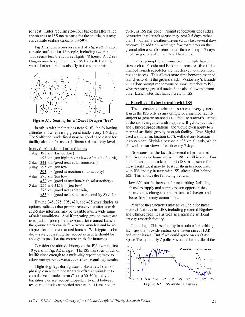
IAC-10-D1.1.4 Design Concepts for a Manned Artificial Gravity Research Facility 21
Figure A2. ISS altitude history
per seat. Rules requiring 24-hour backoffs after failed approaches to ISS make sense for the shuttle, but may cut capsule seating capacity 30-50%.
Fig A1 shows a pressure shell of a SpaceX Dragon capsule outfitted for 12 people, including two 6’6” tall. This seems feasible for free flights <8 hours. A 12-seat Dragon may have no value to ISS by itself, but huge value if other facilities also fly in the same orbit.
In orbits with inclinations near 51.6o, the following altitudes allow repeating ground tracks every 1-5 days. The 5 altitudes underlined may be good candidates for facility altitude for use at different solar activity levels:
Interval Altitude options and issues 1 day 195 km (far too low)
495 km (too high; poor views of much of earth) 2 day 345 km (good near solar minimum) 3 day 295 km (too low)
395 km (good at medium solar activity) 4 day 270 km (too low)
420 km (good at medium-high solar activity) 5 day 255 and 315 km (too low)
375 km (good near solar min) 435 km (good near solar max; used by Skylab)
Having 345, 375, 395, 420, and 435 km altitudes as options indicates that prompt rendezvous after launch at 2-5 day intervals may be feasible over a wide range of solar conditions. And if repeating ground tracks are used just for prompt rendezvous after manned launch, the ground track can drift between launches and be re-aligned for the next manned launch. With typical orbit decay rates, adjusting the reboost schedule should be enough to position the ground track for launches.
Consider the altitude history of the ISS over its first 10 years, in Fig. A2 at right. The ISS has spent much of its life close enough to a multi-day repeating track to allow prompt rendezvous even after several-day scrubs.
Slight dog-legs during ascent plus a few hours of phasing can accommodate track offsets equivalent to cumulative altitude “errors” up to 30-50 km-days. Facilities can use reboost propellant to shift between resonant altitudes as needed over each ~11-year solar
cycle, as ISS has done. Prompt rendezvous does add a constraint that launch scrubs may cost 2-5 days rather than 1, but many weather-driven scrubs last several days anyway. In addition, waiting a few extra days on the ground after a scrub seems better than waiting 1-2 days in phasing orbits after nearly all launches.
Finally, prompt rendezvous from multiple launch sites such as Florida and Baikonur seems feasible if the manned launch schedules are interleaved to allow more regular access. This allows more time between manned launches to shift the ground track. Vostochny’s latitude will allow prompt rendezvous on most launches to ISS; what repeating ground tracks do is also allow this from other launch sites that launch crew to ISS. 4. Benefits of flying in train with ISS
The discussion of orbit trades above is very generic. It uses the ISS only as an example of a manned facility subject to generic manned LEO facility tradeoffs. Most of the above arguments also apply to Bigelow facilities and Chinese space stations, and would even apply to a manned artificial-gravity research facility. Even Skylab used a similar inclination (50o), without any Russian involvement. Skylab also used a 435 km altitude, which allowed repeat views of earth every 5 days.
Now consider the fact that several other manned facilities may be launched while ISS is still in use. If an inclination and altitude similar to ISS make sense for those facilities, it may be best for them to coordinate with ISS and fly in train with ISS, ahead of or behind ISS. This allows the following benefits:
- low-ΔV transfer between the co-orbiting facilities, - shared resupply and sample return opportunities, - shared crew changeout and mutual safe haven, and - better low-latency comm-links.
Most of these benefits may be valuable for most manned facilities in LEO, including potential Bigelow and Chinese facilities as well as a spinning artificial gravity research facility.
Including a Chinese facility in a train of co-orbiting facilities that provide mutual safe haven raises ITAR and other issues. But if we could agree on an Outer Space Treaty and fly Apollo-Soyuz in the middle of the
Figure A1. Seating for a 12-seat Dragon “bus”

IAC-10-D1.1.4 Design Concepts for a Manned Artificial Gravity Research Facility 22
Cold War, we may be able coordinate with China, as we already do commercially, at a ~$300B/year level. But whatever each individual player does, all others should seriously consider flying in train with ISS, or at least with each other. (The ISS does not “own” its orbit: according to the Outer Space Treaty, neither celestial bodies nor space itself can be claimed as territory. Hence ISS and other objects just have equal rights of passage through space.)
The ISS program may have very good reason to co-operate with such a scenario. The main determinant of ISS program success may be two-way traffic frequency for crew and priority cargo (experiment supplies and return samples). Most research is highly iterative. Past opportunities have generally involved iteration periods exceeding a year. This is adequate only for exploratory work by NASA and academic researchers. Applied research of commercial utility may usually require iteration times under a month.
Most experiments do not require two-way transport of supplies and samples for each iteration, but lower transport frequencies drastically drive requirements on supplies, equipment, and crew time and expertise, to do analyses on ISS that nearly always can be done faster, better, and cheaper on the ground. Flying several facilities in train with each other allows supply vehicles that visit any of them to visit all others as needed. This can raise traffic frequencies and research throughput in all of them, making them all far more productive, and better able to attract serious commercial research.
Flying in train to allow low-ΔV transfer between facilities requires matching inclination, ascending node, and altitude history. Matching altitude history is important because altitude differences cause relative in-track drift. Small range variations are ok, but large separations between facilities increase transfer times.
“Lapping” a co-orbiting facility (which involves ~300 km-days of altitude difference) causes differential nodal regression. This adds ~80 m/s cross-plane ΔV per lap. So retaining a low-ΔV transfer capability requires constraining cumulative altitude difference. This in turn requires coordinating reboost plans. Limiting transfer times between facilities to a few hours requires limiting in-track separation to a small fraction of an orbit. That constraint may be entirely acceptable, if quick transfers allow higher vehicle capacity and lower transfer costs, and hence ease access to all co-orbiting facilities.
5. Questions for ISS that may shape manned space
This appendix argues that the inclination and altitude of future manned facilities should be “at least similar” to those of ISS, and that there are mutual benefits for such facilities to all fly in train with ISS. This leads to three questions that seem worthwhile for ISS program management to consider.
The first key question is whether the ISS program should keep ISS near a repeating-ground-track altitude at least when manned launch is scheduled, and relax visiting vehicle rules to allow prompt rendezvous or abort, rather than requiring 24-hour backoff and re-docking. This may significantly raise vehicle crew capacity and/or priority cargo capacity on manned launches, at little or no marginal cost.
The second key question is whether the ISS program is open to coordinating altitudes, reboost schedules, and visiting vehicle interfaces with other facilities, including Bigelow and/or Chinese facilities. A ~12 seat Dragon will cut seat prices to ISS partners only if the extra seats can be sold. If a Dragon can visit not just ISS but also other co-orbital facilities, it should be easy to sell 12 seats all the time, including some to tourists.
The final key question is whether the ISS program is open to other facilities flying with zero separation (ie, attached to ISS), without imposing all ISS rules on them. Some airports have attached hotels or malls that are independently operated. There is an obvious overlap of public safety issues, but even public safety rules may appropriately differ for different operators. Another analog is ISS itself: the “international” and Russian segments have separate but coordinated rules and management. And note that article 5 of the Outer Space Treaty says that:
In carrying on activities in outer space and on celestial bodies, the astronauts of one State Party shall render all possible assistance to the astronauts of other States Parties.
This treaty clause may pre-empt all other rules that
govern ISS use. Hence the real options for ISS may be encouraging vs tolerating attached operation; preventing it may not be feasible. Attached operation has many ramifications, but it may provide high net benefits to all participants, especially early on, when traffic frequency is lowest, and the benefits of mutual safe haven and emergency and routine support are highest.