iaa-aas-dycoss2-14-10-10 cubesat orientation …iaaweb.org/iaa/scientific...
TRANSCRIPT

1
CUBESAT ORIENTATION CONTROL AND MATCHING TO COMMUNICATIONS SYSTEM REQUIREMENTS
Kevin Z. Brown,* Twyman Clements,† Joshua Evans,‡
CubeSat class spacecraft development presents challenges to match communica-tions systems to pointing capabilities. Mission operations, developer capabili-ties, and resource constraints dominate the decision when implementing ADCS and defining the communications link. An in depth look at the development of an S-Band solution for a CubeSat mission will be presented and how the ADCS solution is predicted to affect the operations. This will provide insight into this second generation level CubeSat program which uses a high performance ground station to compensate for limited aperture on the CubeSat platform.
INTRODUCTION
CubeSat communications subsystems traditionally are a monolithic design where one radio and one antenna are used. This single channel approach makes the space vehicle development become very conservative to ensure the data link is achievable at all times. To match this com-mon requirement a study and test cycle is often performed on the antenna system to minimize system risk. How the antenna field and the Attitude Determination and Control System (ADCS) interact becomes an important aspect in mission architecture through this risk.
Satellite development traditionally looks for a multi-channel communications approach to de-crease mission risk.6 One radio system will have a broad link, ‘always on’ capability, while an-other will have a strict usage schedule where a data dump may occur. For CubeSats the reliable link will be of a lower frequency where good efficiencies and broad directionality can be ob-tained. The data dump link will be a higher frequency and with low efficiencies consume much more power along with a more directional antenna. These two links allow for reliable links across a broad range of ADCS categories.
* Assistant Professor, Space Science, Morehead State University, Morehead Kentucky USA. † Aerospace Engineer, Kentucky Space LLC, Lexington Kentucky USA. ‡ Aerospace Engineer, University of Kentucky, Lexington Kentucky USA.
IAA-AAS-DyCoSS2-14-10-10

2
COMMUNICATION SUBSYSTEMS
CubeSat satellite communications systems are generally based on the super heterodyne radio archi-tecture. Radios have been developed which are min-iaturized modules that include the complete system. The radios are easily integrated by direct connection to an antenna network. An antenna system can in-clude a wide variety of source switching, amplifying, or phasing systems. The predominant performance factors for antennas are the directionality and effi-ciency. In aperture deficient applications, like Cu-beSats, the selection of a viable antenna becomes im-portant.
Antennas and Characteristics
Finding an antenna design which fits a mission profile can be a difficult process. There are many sources available to estimate a respective pattern however little information to see how an antenna may perform on a CubeSat body. A lot of information can be garnered from online sources which have com-piled information on antenna performance in the ide-alized form, Figure 1.1 Despite how easy it is to find information, the environment and application will at times neutralize all the expected and perceived bene-fits that were originally selected.
A process for building an antenna design is to first find a family of antennas which work at a mission architecture level. Next, the antenna is modeled to refine element sizes and installation geometry. This is followed by a prototype and tested and compared to the model. The model and prototype are refined and tested once again in an iterative fashion. After the build/test cycle is completed the antenna is installed into the representative spacecraft and tested again in an anechoic chamber. The last iterative loop changes the element sizes once again to minimize any space-craft body effects, Figure 4.
The interaction of the antenna and spacecraft body is usually neglected on CubeSat platforms due to the costs and time associated with testing. At Morehead State University the facilities and process has been refined to make quick turn testing of CubeSat sized spacecraft in single day intervals.
A measure often used to select the direcitonality of an antenna is the half power beam width of the antenna. The HPBW is measured off of the boresight
Figure 1 Wire Antennas
Figure 2 3U CubeSat in Morehead State University Anechoic Chamber

3
of the antenna to the point at which the power density is reduced to half of the normalized.2
Monopoles and Dipoles
Monopole and Dipole antennas have been the most common CubeSat spacecraft antenna since the first launch. The overall omnidirectional nature combined with ease of use have resulted in good performance and robustness. As time continued an even more com-plex form of monopoles have reached orbit known as the quad monopole which has phasing capability. Ap-plying phase to a system provides better interferer rejection capability and performance for off angle contacts, most satellites use Right Hand Circulary Po-larization (RHCP).
Still the majority of CubeSat spacecraft launched to date have used linear monopole or dipole antennas. The test process of a CubeSat spacecraft in an anecho-ic chamber begins with installation onto a non-conductive platform on an azimuth-elevation plat-form, Figure 2. The satellite is then rotated about its test axes to create the polar plots to evaluate the an-tenna design, Figure 3.
-30
-25
-20
-15
-10
-5
00
1530
45
60
75
90
105
120
135
150165
180195
210
225
240
255
270
285
300
315
330345
Figure 3 Radiation Pattern Quad Monopole UHF Antenna on 3U Cu-
beSat
Figure 4 CSSWE CubeSat Pattern Test and Simulated Monopole (http://lasp.colorado.edu/home/csswe/system/subsystems/comm/)

4
Patches
Patch antennas come in a multitude of varities and lend themselves well to CubeSat spacecraft due to their limited volume and minimal installation complexity. A patch antenna has numerous advantages to others in that no deployment needs and minimal internal volume is consumed. The patch antennas used on CubeSats have been quarter wave patches and used for higher, greater than 1.5 GHz, frequency bands. The size and shape of a patch antenna is dominated by the dielectric substrate used in the antenna.
Single layer patch antennas have good hemispherical performance and easily can meet the bandwidth needs of demanding downlinks. Using multiple single layer patch antennas allow for combining of signals from different locations around the spacecraft to achieve complete omni coverage. A typical 2.4 GHz patch for a CubeSat is approximately 40 mm x 40 mm x 5 mm an easily be integrated onto an end 100 mm x 100 mm face, Figure 6. The antenna in this instance has a 45 deg HPBW.
Multi layer patch antennas further expand on single layer designs by providing more directionality using a parasitic element. This allows the beamwidth to be further narrowed by approximately half and a corresponding 3dB increase in gain. Multi-layer patch elements can be used to squeeze as much performance from the on-board system as possible.
Figure 6 Prototype Patch Antenna and Pattern at MSU Anechoic Chamber
30°
60°120°
150°
210°
240° 300°
330°
60 50 40 30 20 10 0 10 20 30 40 50 60
Figure 5 Morehead State University Ane-choic Chamber

5
Figure 8 Simulation of 2.4 GHz Antenna on CubeSat Z-Axis End Face
GROUND STATIONS
The modern ground station will play a vital role in the future of CubeSat missions. To augment the on orbit asset, the ground station aperture needs to be large. One example installation is the 21 meter earth station located in Morehead Kentucky USA, Figure 10. At Morehead State University, the Space Science Center has as one of its primary missions the tracking, communications and control of CubeSat missions.
One of the primary frequency bands in use is the 437 MHz amateur radio allocation. The existing an-tenna systems implemented for this are of the conven-tional long-boom Yagi design, with orthogonally po-larized element sets, quadrature combined to produce
Figure 7 Prototype High Gain Multi Layer Patch Antenna 70 mm x 70 mm and Simulated Pattern
Figure 9: Ground Station Antenna Types

6
circular polarization, Figure 9. These antenna systems are limited in the directivity they can pro-duce.
The Center operates several ground stations, including the low bandwidth VHF/UHF systems and a 21-meter diameter, full motion, parabolic dish antenna system. The 21-m has the capacity to track satellites in low earth orbit (LEO) with extremely low transmission power, as well as sat-ellites at geostationary, lunar, and Earth-Sun Lagrangian orbits. The system currently operates at UHF, L, S, C, X and Ku-bands. The instrument is primarily operated by undergraduate students who work in the associated laboratories to gain hands-on training in RF systems and techniques. Table 1 outlines the basic performance characteristics of the 21-m.
Table 1: 21 Meter Antenna Performance Characteristics
Figure 10: Morehead State Uni-versity 21 Meter Ground Station
A multi band approach will be used in the future for high capability systems. This allows sim-ultaneous channel operations of a CubeSat mission by using distinctive feeds for each and only one tracking station. The main issue with ground station tracking has to do with polarization of the received signal from the satellite due to SV kinematics. CubeSats typically either have no atti-tude determination system (ADAC), or it is very simple. Therefore the physical orientation of the satellite can be random with respect to the orientation of the ground station antenna. This can have a significant impact on the quality of the signal received, as the satellite may go from an op-timal polarization, to an average level, and then swing to maximally suboptimal (no signal, or cross polarization), depending on its relative motion over the period of the track. A robust ap-proach is for circularly polarized (C.P.) antennas to be used for both the satellite and the ground station. There are additional considerations that make it extremely useful that the ground station be able to electrically switch between right and left hand circular polarizations (RHCP & LHCP). Therefore the antenna elements used must be able to provide this capability.
Feature PerformanceAntenna Diameter 21 Meter
Optics Prime Focus
F/D Ratio 0.363
Receive Polarization
RHCP,LHCP,VERT,HORZ
Travel Range AZ +/- 275 degrees from South
EL -1 to 91 degrees POL +/- 90 degrees
Velocity AZ Axis = 3 deg/sec EL Axis = 3 deg/sec
Acceleration AZ = 1. 0 deg/sec/sec min EL = 0.5 deg/sec/sec min
Display Resolution AZ/EL = 0.001 deg
POL = 0.01 deg

7
EXAMPLE CUBESAT MISSIONS: THE KYSAT2 CUBESAT MISSION
The KySat2 mission is a 1U mission with a prime power of 2 Watts. The primary payload is a linx based imaging payload that operates as a stellar gyro system that uses successive exposures to estimate body angular rates. The host system is a 20 MHz Command and Data Handling board, shunt EPS system with deployable panels, and a UHF transceiver. The satellite beacons a ¼ sec-ond long message every 15 seconds at 437.405 MHz. The satellite is stabilized with a passive magnetic system because the payload was to be activated by ground command only, thus the pre-cise timing of the pictures could be selected to occur during anti-nadir times.
Communications
The KySat2 mission used a UHF half duplex communications system and quad monopole antenna in an omni-directional configuration. This architecture matches a low risk profile of typical CubeSat missions. Operating in the 437 MHz band of the amaeature radio spectrum allows for operations to be conducted by amaeature operators across the world. The KySat-2 mission was tracked particularly well from Australia in many communications sessions using a Yagi ground station, Figure 13.3
Figure 11 KySat-2 CubeSat Before Launch
Figure 12 AstroDev Li-1 Radio Module
Figure 13 Yagi Ground Station and Beacon Pass by Packet Received

8
Attitude Control
KySat-2 utilizes an attitude control technique called Passive Magnetic Stabilization. The con-trol system consists of permanent neodymium magnets rigidly attached to the satellite’s chassis along the z-axis of the spacecraft; and hysteresis material, also rigidly attached to the chassis, in the x-y plane. The purpose of this system is to provide predictable attitude stabiliza-tion/orientation by alignment with Earth’s magnetic field.
The permanent magnets are mounted in all four corners of KySat-2’s chassis in such a way that their poles are pointed along the same direction of the z-axis. From a distance, the spacecraft will behave as if it contains a single magnetic dipole located along the z-axis, and passing through the center of the spacecraft’s x-y plane. Due to this orientation of the magnets along the z-axis, in a low Earth orbit, such as that of KySat-2’s, the magnetic dipole attempts to align with Earth’s magnetic field. When this happens, the magnetic dipole provides control torques about the pitch and yaw axes of the spacecraft, however, this type of attitude stabilization does not provide con-trol torques about the roll axis of the spacecraft. Finally, the magnetic dipole is oriented in such a way that KySat-2 points toward Earth when passing over the Northern Hemisphere, and away from Earth when passing over the Southern Hemisphere.
Damping in the system is provided by hysteresis material mounted to the spacecraft’s chassis in the x-y plane. The Smart Nanosatellite Attitude Propagator (SNAP), developed by Samir Rawashdeh at the University of Kentucky, was used to determine the volume of material needed to provide stabilization. Hysteresis material is an alloy that is easily magnetized, and as a result, the material effectively memorizes the current state of the magnetic field passing through it. Be-cause of this characteristic, the hysteresis material provides damping, allowing the spacecraft to resist changes in orientation. This prevents the system from reaching a marginally stable state in which the satellite will oscillate about the pitch and yaw axes due to the torques provided by the magnetic dipole. In addition, the hysteresis material also provides some damping about the roll axis of the spacecraft, reducing a sustained angular rate about that axis, a useful characteristic for the onboard imaging system.
EXAMPLE CUBESAT MISSIONS: THE CXBN CUBESAT MISSION
The Cosmic X-Ray Background Nanosatel-lite (CXBN, Figure 14) is a small satellite mis-sion with the objective to make precise meas-urements of the cosmic/diffuse X-ray back-ground.4 The project is based on a low-cost CubeSat form factor and was accepted by NASA‘s Educational Launch of a Nanosatellite (ELaNa) program for a launch opportunity in 2012. NASA ELaNa is managed by the Launch Services Program to provide secondary payload launch opportunities for science research and technology demonstrations.5
Communications
The CXBN mission used a UHF half duplex communications system with an omni-directional antenna configuration. The mission
Figure 14 CXBN CubeSat

9
required a very low uplink command rate and telemetry at as high as possible rate, the main re-striction being licensable bandwidth. The CXBN communication system consisted of an Astro-Dev Li-1 radio Figure 12, antennas, and an antenna phasing network. Table 2 provides specifica-tions for the on-board radio systems utilized for CXBN.
Table 2 Li-1 Performance Criteria for CXBN-1 Mission
AstroDev Lithium-1 Transceiver UHF: 400 – 450 MHz Half duplex AX.25 packet protocol Operates on 3.3V and 5V Variable transmit power: 250 mW – 4 W 9.6 kbps (base), 115.2 kbps (max) Ping (with or without telemetry) Backdoor reset Provides BSL entry to C&DH
Communications with CXBN were conducted much in the same way as KySat-2. The opera-tions were performed with a Yagi ground station system much like the aforementioned KySat-2 mission.
Attitude Control
At the systems level, mission objectives define the attitude determination and control systems (ADCS). The unique mission of CXBN collected scientific data through a spin-stabilized configuration. Multiple sensors were used on CXBN to produce orientation knowledge. Previous CubeSats have favored magne-tometers, sun sensors, MEMS gyroscopes, and star constellation trackers for scientific attitude knowledge. The added complexity and development can overrun a short program effort. For CXBN, a novel method was sought to reduce system complexi-ty while maintaining reliability and schedule.
The result is a combination of MEMS gyros (Figure 15) and a star sensor (‘pipper’) to generate an absolute position pulse as a star transits the viewing area. After stabilization the combination of these two systems allows one to back out the roll orientation when clocked from a common time reference.
The basic concept is characterized by the spacecraft entering a slow spin that is controlled with 3 magnetic torquers, shown in Figure 16. The sun angle is measured using a dual Sun sensor (DSS), shown in Figure 17, along the -Z spacecraft face. The magnetometers allow the torque coils to be actuated in proper sequence for the
Figure 15 MEMS Gyro on CXBN CDH Board
Figure 16 CXBN Magnetorquer

10
torque to maintain the angular momentum vector in alignment with the sun vector, minimizing the sun an-gle.
The spacecraft also deploys four solar panels with weighted ends at a 90° angle relative to the X-axis providing better body inertial properties. The ADCS system is estimated to provide pointing control to 2˚ and knowledge to 0.1˚
For CXBN, a novel idea was proposed by John Doty to use a very similar concept as a Digital Canopus Tracker used in the 1970s, excluding unnecessary and overcomplicated systems. This idea, coined the Cano-pus Pipper, uses the star Canopus to detect roll posi-tion.
Canopus, or Alpha Carina, is the second brightest star in the sky with an apparent magnitude of -0.72 (11). Canopus is located about 300 light years away at a right angle (RA) of 06h23m57s and a declina-tion (DEC) of -52°41’44”. The brightness and posi-tion in the sky make Canopus an ideal choice for star sensor systems.
Star sensors vary significantly from star trackers. Instead of using imagers, some star sensors operate by using a photo detector to produce pulses when stars transit the detector’s FOV. The concepts were first introduced with dissector tubes in the 1960s to produce a system that could determine when a specific star was reached and then track it with feedback to the ACS.
A difficulty presented when using star sensors is correlating the magnitude of the star with the pulse amplitude during transit. While functional testing in the earth environment can reasonably be performed in very dark geographic locations and good weather conditions, magnitude calibration must be based upon on orbit characterization. The difficulties alleviate many other systems level challenges where power, size, budget, and schedule become dominant. Star pippers provide a much more appealing solution than a star tracker in this application.
The star sensor is mounted in CXBN orthogonal to the spin-axis. By sweeping out the sky as CXBN spins, the Canopus Pipper produces a voltage pulse when star light enters its aperture. Since the Canopus Pipper alone only produces a reference pulse, it needs to be paired with a roll rate to deduce
Figure 17 CXBN Sun Sensor
Figure 18 Canopus Pipper Architec-ture
Figure 19 Pipper Flight Model

11
complete roll knowledge. On CXBN, MEMS gyroscopes are used to measure the roll rate. The end result is not an actively tracking ADCS, but a solution for roll determination that can be implemented with minimal impact on mission schedule.
The DSS on CXBN only provides pitch and yaw knowledge; the Canopus Pipper provides the roll knowledge. Therefore, the major requirement for the Canopus Pipper is to link the science data collected to a position in the sky. To accomplish this, the Pipper is routed through the payload processor where it is sampled and time stamped.
Figure 18 depicts this operational concept of the Canopus Pipper from starlight to data read by a microprocessor and Figure 19 shows the final flight model.
Starlight passes through a lens, to a photodiode. Then the current is converted into a voltage, where it is sampled by analog to digital converters (ADCs). Lastly, the signals from the ADC are sent to a microprocessor for integration into telemetry.
CUBESAT ADCS SYSTEMS
There are two predominant types of ADCS in CubeSats, passive and active stabilization. Ac-tive stabilization systems for CubeSat platforms have been slow to develop due to the complexity and need for on-orbit testing. Larger satellite platforms have completed this development cycle to realize commercial products with a multitude of applications.
Passive Stabilization
A common feature of passive stabilization is that broad antenna patterns are required. This is because a satellite is unable to slew to a ground station contact. Using general systems engineer-ing one can conclude a typical accuracy of an ADCS system.6 Once an ADCS decision is made to support a payload operations criteria, trade can be performed based upon the ground station assets available. Nearly all earth stations are fully articulated for LEO operation, ie high rate azimuth and elevation control. A moderate latitude ground station with a moderate inclination LEO orbit will result in approximately two passes per day from approximately 14 earth orbits. The two passes vary greatly however in contact time and sky path. This means that contacts will occur at nearly all nadir angles to a representative spacecraft. Other more suboptimal passes would require even more off angle communication sessions.
Table 3: Passive Stabilization and Prospective Antenna Pattern6
Type Pointing Accuracy (+/-) Antenna HPBW
Gravity-Gradient Earth local vertical (2 axes) 5 deg > 45 deg
Passive Magnetic Earth North/South (2 axes) 5 deg Omni
Spin Inertially Fixed (2 axes) 0.1 deg to 1 deg Omni
Active Stabilization
Active stabilization presents a much different solution set to the engineering trade. The anten-na patterns may further be refined by using the ADCS bus system to point at a respective ground station. Normal LEO operations allow for this because a single ground station would only need to be slewed to two times per day in nominal conditions.
12
Table 4: Active Stabilization and Prospective Antenna Pattern6
Type Pointing Accuracy (+/-) Antenna HPBW
Magnetic No Constraints 0.1 deg to 5 deg > 10 deg
Momentum
(1 Wheel)
Local Vertical 0.1 deg to 1 deg > 30 deg
Momentum No Constraints 0.001 deg to 1 deg > 1 deg
AN APPLICATION EXAMPLE: CXBN 2
Using most recent high data rate systems allows for more mission capability, flexibility, and efficiency. An example mission for a high rate communications system is the CXBN 2 mission which can use a dual band approach to communicate. The satellite would continue to be driven by the mission requirements, an inertial fixed spin pointing at the sun to satisfy the scientific pay-load.
Robust UHF Communications Channel
As in the first CXBN mission a robust UHF communications channel can be used to recover the satellite from any off nominal condition. This link operates at 50% efficiency during trans-mission at 31.5 dBm, for 3 Watts, and 0.125 Watts for continuous reception. The UHF channel would be used at 10 second intervals to beacon a default health and status packet. The total power consumed would be a continuous average of approximately 0.5 Watts over all orbits.
High Rate Communications Channel
A high rate system would be used at specific times when large chunks of science data could be downloaded. While this has been achieved by other missions it has not been achieved in an effi-cient form. To meet the volume, mass, and power constraints of the CubeSat form factor a com-plete new set of hardware can be installed into the CXBN 2 and matched with a corresponding system on the ground station.
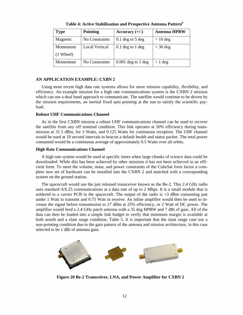
The spacecraft would use the just released transceiver known as the Be-2. This 2.4 GHz radio uses standard AX.25 communications at a data rate of up to 2 Mbps. It is a small module that is soldered to a carrier PCB in the spacecraft. The output of the radio is +3 dBm consuming just under 1 Watt in transmit and 0.75 Watt in receive. An inline amplifier would then be used to in-crease the signal before transmission to 27 dBm at 25% efficiency, or 2 Watt of DC power. The amplifier would feed a 2.4 GHz patch antenna with a 35 deg HPBW and 7 dBi of gain. All of the data can then be loaded into a simple link budget to verify that minimum margin is available at both zenith and a slant range condition, Table 5. It is important that the slant range case use a non-pointing condition due to the gain pattern of the antenna and mission architecture, in this case selected to be 1 dBi of antenna gain.
Figure 20 Be-2 Transceiver, LNA, and Power Amplifier for CXBN 2

13
Table 5 2.4 GHz Downlink from a 700km Orbit
Low Earth Orbit Basic Link Budget Parameter Zenith Value Worse (5 deg El) Unit
Global Link distance 700 2,517 km Frequency 2400. 2400. MHz Free space wavelength 12.50 12.50 cm Transmitter side Transmitter power 27 27 dBm Tx antenna gain 7 1 dBi Tx EIRP 34 28 dBm Channel Free space loss 157 168 dB Atmospheric Loss 1.0 1.0 dB Additional losses (pointing, polarization,cables) 1.0 1.0 dB Ground Station side Rx antenna diameter 21.00 21.00 m Rx antenna efficiency 50. 50. % Rx antenna gain (parabolic reflector) 51 51 dBi Rx antenna 3 dB beamwidth 0.43 0.43 deg. Final Received Signal Received signal power -73 -91 dBm Ground Station Receive sensitivity @ 1% PER @ 256 kbps -90. -90. dBm Margin 16.5 -0.6 dB
Using the high data rate link is a much more restricted case to only downlink times with a large aperture dish. In this link budget the 21 meter installation at MSU was used where 51 dBi of gain is achieved at 2.4 GHz. The high gain allows for negative margins to develop at about 5 de-grees of elevation. When the high rate link is used in downlink the highest efficiency of data transmission is found, however not necessarily the highest value data is available.
CONCLUSION
A multi- channel communications system is the backbone of traditional satellites. CubeSat spacecraft are a continually evolving research area that is making leaps into traditional satellite roles. To match the ever changing missions, case studies and results will be used to advance the communities state of the art. Through proving out this communications links with advanced ground stations the use of CubeSat spacecraft will continue to expand as reliable capability grows.

14
ACKNOWLEDGMENTS
Kentucky Space provides funding for student support allowing undergraduate students to gain invaluable space systems development experience on this and other initiatives. Publication refer-ences are included within the text.
REFERENCES 1“Electronic Warfare And Radar Systems Engineering Handbook”, Naval Air Systems Command, 1999
2Hallas, J.R. ,“Basic Antennas: Understanding Practical Antennas and Design”, American Radio Relay League, Incorporated, 2008. 3Ground Station, Colin Hurst, VK5HI
4Rose, Tyler G., Malphrus, Benjamin K., Brown, Kevin Z., “An Improved Measurement of the Diffuse X-Ray Background: The Cosmic X-Ray Background Nanosat CXBN,” 8th Annual Cu-beSat Developers’ Workshop, CalPoly, San Luis Obispo, CA, USA, April 20-22, 2011, URL: http://www.cubesat.org/images/2011_Spring_Workshop/thur_a9.30_rose_cxbn_cswkshp_sp2011.pdf
5Skrobot, Garret “ELaNa - Educational Launch of Nanosatellite,” 8th Annual CubeSat Develop-ers’ Workshop, CalPoly, San Luis Obispo, CA, USA, April 20-22, 2011, URL: http://mstl.atl.calpoly.edu/~bklofas/Presentations/DevelopersWorkshop2011/21_Skrobot_ELaNa.pdf
6James R. Wertz and Wiley J. Larson, “Space Mission Analysis and Design.” Hawthorne: Micro-cosm Press, 2007.