i2 · i2 radc-tr-90-200 final technical report ... e 12f hiw%2 1sv x~op 0"a. ... nsn...
TRANSCRIPT

I2
RADC-TR-90-200Final Technical ReportSeptember 1990 uric FILE COPY
HOLOGRAPHIC OPTICAL HEAD
Holometrix, Inc.
P. Gregory DeBaryshe, Charles S. th, B. M.eng DTICELECTE
_) SIB D,
I APPROVED FOR PUBLIC RELEASE; DISTRIBUTION UNLIMITED.
This effort was funded totally by the Laboratory Director's funds.
Rome Air Development CenterAir Force Systems Command
Griffiss Air Force Base, NY 13441-5700
90 11 19 266
This report has been reviewed by the RADC Public Affairs Division (PA)and is releasable to the National Technical Information Services (NTIS) AtNTIS it will be releasable to the general public, including foreign nations.
RADC-TR-90-200 has been reviewed and is approved for publication.
APPROVED:7%2.
FRED N. HARITATOSProject Engineer
APPROVED:
WALTER J. SENUSTechnical Director
FOR THE COMMANDER: V~ 4"'' A 4'
IGOR G. PLONISCHDirectorate of Plans & Programs
If your address has changed or if you wish to be removed from the RADCmailing list, or if the addressee is no longer employed by yourorganization, please notify RADC (IRAp ) Griffiss AFB NY 13441-5700.This will assist us in maintaining a current mailing list.
Do not return copies of this report unless contractual obligations ornotices on a specific document require that it be returned.
REPORT DOCUMENTATION PAGE ____________
ft.d Now"i a~ Wi M. ftfa d Wmetu a "WAN a &ap eIt m 9W cemow at h 13M . "am hW ~ OW- EU
mins i ~ NiIsism t.ft WMi.~E Vmm. e 12f hiW%2 1Sv
X~OP 0"a. 074.0W18"Ni i~e i i IMK W • s mOe~br a m' h~aa w
1. REPOA ATE 3. Reoa"rm AND DAS C
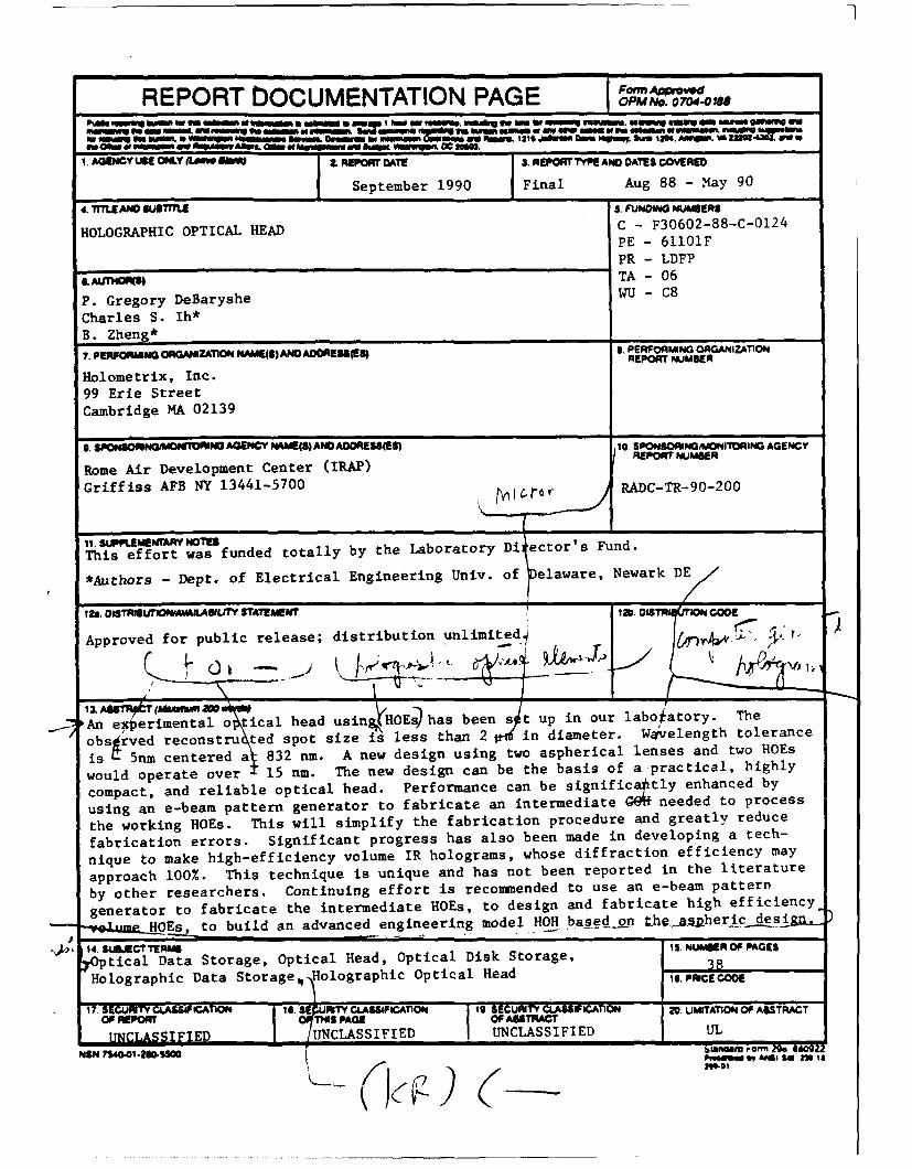
September 1990 Final Aug 88 - May 90
4. TME AND hTME s. FUMO NUMBERS
HOLOGRAPHIC OPTICAL HEAD C - F30602-88-C-01
24
PE - 61101F
PR - LDFP
& K) TA - 06
P. Gregory DeBaryshe WU - C8
Charles S. Ih*B. Zheng*
7. PENFONIANG ORANIZATION t4AMEMS AND ADOOESS(ES) 8. PERFOflIN1G OACANiZAT1ONREPORT NUMMER
Holometrix, Inc.99 Erie StreetCambridge MA 02139
10 SONOANi W1iG GEC
O M N O AGENCY N(3) ANDADRESES) SNG AGNY
Rome Air Development Center (IRAP) REPOR'NUMR
Griffiss AFB NY 13441-5700 RADC-TR-90-200
Ii. SLftEMENTAR, NOTES
This effort was funded totally by the Laboratory Di ector's Fund.
*Authors - Dept. of Electrical Engineering Univ. of elaware, Newark DE
t2& =TMUn0PflOAVAAWL1TV STATEMENT 120. oamiR o cooE
Approved for public release; distribution unlimited4)
SAn experimental o tical head usingHOEs) has been s t up in our laboratory. The
obs rved reconstru ted spot size is less than 2 )in diameter. Wakvelength tolerance
is 1 5nm centered a 832 nm. A new design using two aspherical lenses and two HOEs
would operate over 15 nm. The new design can be the basis of a practical, highly
compact, and reliable optical head. Performance can be significaotly enhanced by
using an e-beam pattern generator to fabricate an intermediate G64f needed to process
the working HOEs. This will simplify the fabrication procedure and greatly reduce
fabrication errors. Significant progress has also been made in developing a tech-
nique to make high-efficiency volume IR holograms, whose diffraction efficiency may
approach 100%. This technique is unique and has not been reported in the literature
by other researchers. Continuing effort is recommended to use an e-beam pattern
generator to fabricate the intermediate HOEs, to design and fabricate high efficiency_
HOEj to build an advanced engineering model HOH based otn theaheric desil
14. W.ECTTERM 1. NUMIeR OF PAGES
tical Data Storage, Optical Head, Optical Disk Storage, 38Holographic Data Storagev Holographic Optical Head Is. VcCOD
17 EUfTYELASSICA1O I e.IFICATION O9 STR049A' 1N 0 WTINO ASPOP cE T~s OF ASSTRA'
UNLSIIED UNCLASSIFIED UNCLASSIFIED UL
NSN r750.O1.20Ss00 POW0 " AN& $ Sol rA
Block 19 (Cont'd)
and to investigate the potential for dramatically improved performanceinherent in the knowledge base developed under this program.

TABLE OF CONTENTS
FIG U R ES .............................................................. iv
G LO SSAR Y ............................................................. v
1.0 INTRODUCTION ..................................................... 1
1.1 Program Goals, Scope, and Achievements .................................... 11.2 Background Information .......................... ................ 2
1.2.1 The Need ............................................... 21.2.2 Technical Background ...................................... 3
1.3 Results and Recommendations ....................................... 3
2.0 TECHNICAL DISCUSSION ............................................. 42.1 Technical Approach .............................................. 4
2.1.1 The Optical Layout and Its Rationale ........................... 42.1.2 Design of the HOE-pair .................................... 62.1.3 Theory ................................................. 7
Introduction ............................................ 7Calculation of CGH Parameters ............................. 8Two-wavelength Operation ................................. 10Dispersion Compensation .................................. 11Correction of Chromatic Aberration .......................... 12
2.1.4 Calculational Results ....................................... 142.1.5 Fabrication of the HOE-pair ................................. 15
2.2 Optical Head Improvement Effort .................................... 222.2.1 Improved Test Equipment ................................... 222.2.2 Investigation of E-Beam HOEs ................................ 222.2.3 Design Improvements ...................................... 232.2.4 Efficiency Improvements .................................... 24
3.0 SUMMARY OF CONCLUSIONS, RESULTS, AND RECOMMENDATIONS ........ 26
4.0 REFERENCES ....................................................... 27
Aooession For
NTIS GRA&IDTIC TAB 0Unannounoed 0Justification
ByyDistribution/
Availability Bodesfll Avail and/or-
Dist Special

FIGURES
Fig. 1 Configuration of the Baseline Optical Head ................................. 5Fig. 2 Use of Intermediate Computer Generated Holograms to Produce a Working HOE ... 9Fig. 3 Compensation Condition for a HOE-pair ................................... 12Fig. 4 Geometry of Chromatic Aberration correction .............................. 13Fig. 5 Configuration of the Advanced Optical Head (Aspherical Optics) ................. 14Fig. 6 Spot Diagram: Baseline Design with 5 Nanometers Wavelength Shift ............. 16Fig. 7 Spot Diagram: Baseline Design with 5 Nanometers Wavelength Shift
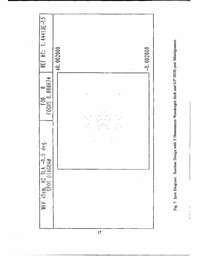
and 0.50 HOE-pair Misalignment ........................... 17Fig. 8 Spot Diagram: Baseline Design with 5 Nanometers Wavelength Shift, 0.50 HOE-
pair Misalignment, and 4 Micron Laser Axial Misalignment ........ 18Fig. 9 Spot Diagram: Aspheric Design with 15 Nanometers Wavelength Shift. .......... 19Fig. 10 Spot Diagram: Apheric Design with 15 Nanometers Wavelength Shift
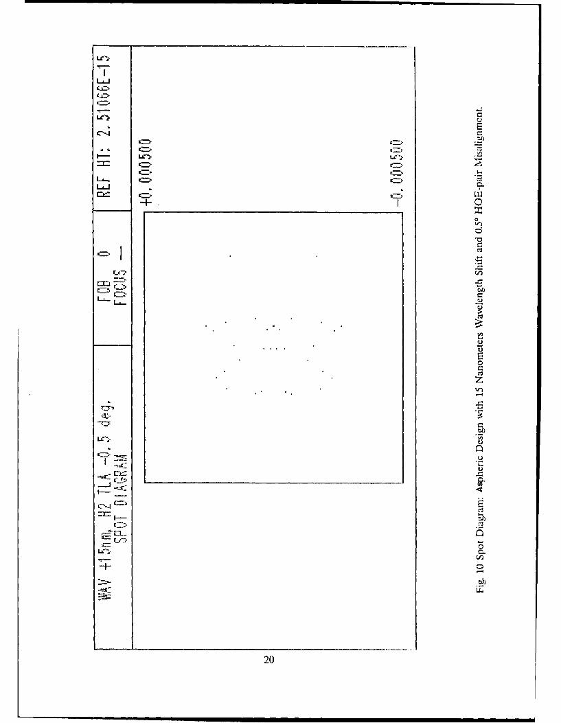
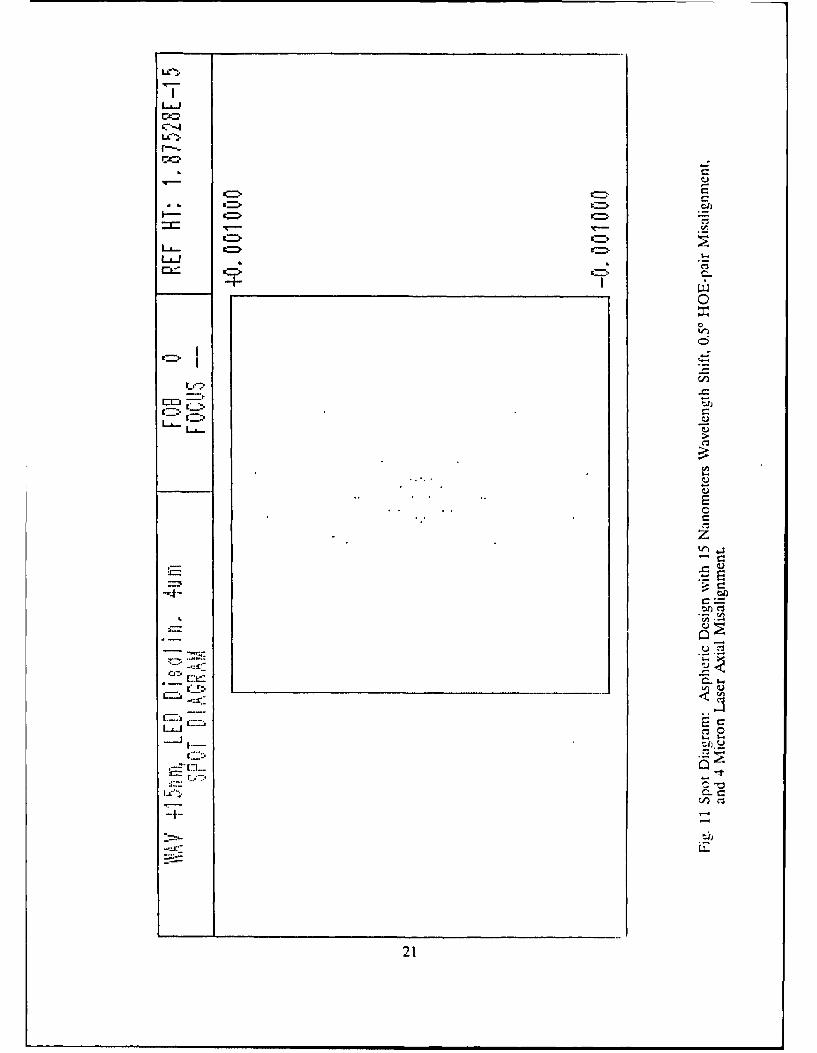
and 0.50 HOE-pair Misalignment ............................ 20Fig. II Spot Diagram: Aspheric Design with 15 Nanometers Wavelength Shift, 0.50 HOE-
pair Misalignment, and 4 Micron Laser Axial Misalignment ........ 21Fig. 12 Making Volume Holograms with Computer Generated Holograms ............... 25
iv

GLOSSARY
Binary hologram: A hologram in which the fringes are of uniform optical density, in transmissionholograms typically high density black lines.
Bragg hologram: A volume hologram formed in thick photopolymer for which the Bragg condi-tion is satisfied.
CGH: Computer Generated Hologram; always computer designed, sometimesfabricated by direct photoreduction of computer output plots, sometimesfabricated by e-beam exposure of photoresist covered glass.
COE: Conventional Optical Element.Color Correction: Balancing of HOE dispersion and COE chromatic aberrations so that the
HOH performance is independent of source wavelength over some range ofwavelengths.
Diffraction efficiency: The ratio of the power in the first order diffracted beam to the power in theincident beam. Typical diffraction efficiencies: binary transmission HOE, lessthan 10%; sinusoidal absorption HOE, less than 6%; phase HOE, 40%; BraggHOE, approaching 100%.
Dispersion (1) A technique which permits the balancing of the wavelength sensitivity ofCompensation: individual HOEs between members of a HOE-pair; (2) combining the
mutual compensation of a HOE-pair with correction for chromaticaberration of COEs present in the HOH. Each HOE corrects for theresidual aberration of its closest neighboring COE.
HOE: Holographic Optical Element.HOE-pair: Holographic optical element consisting of a matched pair of HOES designed
to work in tandem for dispersion compensation and beam shaping.HOH: Holographic Optical Head. An optical head containing HOEs.Hybrid head: HOH containing both HOES and COEs.Intermediate HOE: HOE used to make a working HOE. An intermediate HOE is usually
computer designed.IR hologram: Infrared hologram, used in the infrared. Present technology does not permit
direct exposure of IR holograms at their working wave length because IR-sensitive photoresist is not available.
Sinusoidal hologram: A hologram in which the fringes vary approximately sinusoidally in opticaldensity, typical of a hologram generated directly by interference of two beams.
Spot size: The diameter at which the power density of a focussed beam falls to one-halfits maximum value (FWHM).
Working HOE: Hologram used in an optical head.
v

1.0 INTRODUCTION
1.1 Program Goals, Scope, and Achievements
The objective of this program was to show the feasibility and advantages of holographic optical ele-ments (HOEs) for use in optical disk read/write heads. Specifically, the feasibility of using HOEs inan optical he;d that (1) operates at laser diode wavelengths (780 or 830 nanometers) and (2) canachieve a one-micron diffraction-limited spot was to be demonstrated by design and verifyingmeasurements.
These goals have largely been achieved, despite severe difficulties in the confirmatory measurementprocess. Furthermore, the utility and practicality of this approach has been greatly enhanced by therecent successful introduction of the single element aspheric objective lens in read/write optical headdesign. Aspheric objectives currently are the closest approximation to the ideal read/write lens: theyare rugged, lighter than multi-element objectives and appear capable of smaller spot sizes. However,their performance is limited by chromatic aberrations. Other aberrations are, at least in principal,controllable, but any optical head objective using only single element glass optics, even aspheres, cannot avoid chromatic de gradation. Considering that the spectral bandwidth of diode laser sources isonly a few nanometers', it is a remarkable testimony to the optical quality of these lenses that theyare color limited. It also implies that no conventional lens is likely to afford further major improve-ments in spot size. It is precisely for correction of small residual aberrations, especially wavelengthdependent ones, that holographic optical elements are most suited.
Specific achievements of the program are as follows:
1. Near diffraction-limited performance has been demonstrated: spot size of less than 2 microns fullwidth with clear diffraction rings.
2. Color correction over a range greater than ± 5 nanometers has been demonstrated.
3. Calculational techniques have been significantly improved. Design characteristics can bedetermined and performance predictions can now be accomplished using the standard optical designprogram Super Oslo2 in conjunction with special routines written in FORTRAN.
4. A new optical head has been designed using two aspheric lenses (to date, we have used two piano-convex lenses) which we calculate to produce diffraction-limited spots over a spectral range of +/- 15nanometers. If achieved in practice, this degree of dispersion compensation will permit diffraction-limited operation over a temperature range of +/- 40 'C. Furthermore, this performance is achievedwithout need to refocus the system as laser wavelength changes.
5. The jigs and fixtures needed for fabrication of HOE-pairs have been reworked and improved,making it possible to produce HOE-pairs with better performance than already observed.
6. Extensive tests have been run on a commercial apparatus (the SpotScan3 0390) which, we believeis the optimum instrument available for verifying sub-micron spot sizes in a workable configuration.
' Typical spectral bandwidths of laser diodes used in read/write applications are 3 - 5 nanometers,with temperature drift of approximately - 0.3 nanometers per *C.
2 Super Oslo is a registered trademark of Sinclair Optics, Inc.
3 SpotScan is a registered trademark of Photon, Inc.
7. Intensive efforts to interface our Computer Generated Hologram (CGH) designs to electron-beam(e-beam) machine input requirements have had positive results. Two e-beam facilities have beenidentified which can generate and are willing to attempt e-beam holograms for us. Although detailsstill need to be worked out, it appears that this technology will be available to simplify the fabricationprocedure and reduce fabrication errors.
& Significant progress has also been made in developing a technique to make volume infra-red (IR)holograms, which are known to have diffraction efficiency approaching 100%. This technique isunique and has not been reported in the literature by other researchers.
12 Background Information
1.2.1 The Need
The rapid development of modern micro-computers has created a requirement for low cost mass datastorage, especially in the military environment. Optical disk technology is now maturing and is ideallysuited for this application. A key component of an optical disk system is the optical head. However,optical heads made with conventional optical elements (COEs) severely limit read/write systemperformance because they are complex, relatively heavy and large. They are also a significant costelement. (These conditions do not apply to the commercial audi, compact disk where laser powerfor writing is not an issue and where read errors are usually not observable by the human ear.)Conventional optical elements are used in the optical heads for a group of related optical storagesystems like CD-ROM (Compact Disk-Read Only Memory), WORM (Write-Once-Read-Many)drives, and erasable optical disks.
If we can improve the performance and reliability of the optical head and reduce its size, mass andcost, optical disk systems, particularly the erasable disk system, could become better adapted formilitary computer systems. More particularly, an increase in storage capacity by 100 times is likelyto be possible with smaller spot sizes.
There are many commercial optical heads on the market. However, these optical heads are composedof bulky lenses, prisms, beamsplitters, etc. With conventional elements, it is difficult to reduce the sizeand weight of the optical head. The recent introduction of aspheric lenses has reduced the complexityof one component of the conventional head, but beam shaping prisms (to render the elliptical laserbeam into a circular cross section) are still required.
In the read/write optical head, wavelength compensation becomes a very important becausecompensating for chromatic aberrations requires multi-element lenses to maintain a small focal spot.Uncompensated 3berrations reduce depth of focus because of the resulting large focal spot size.Shallow depth of focus, in turn, increases the demands put on the optical head servos and today limitsperformance for read/write operation (or even for reading high density pre-written data). Faster servosare larger and more massive.
Thus, conventional technology is about at its limit. Smaller spots, which permit greater data densityand higher data rates, now seem to require larger and heavier heads which limit servo response timeand also the number of heads possible per disk. This severely limits access time and has a smallnegative effect on data rate once the data has been accessed.
Also it may be possible to equip an optical disk with several small holographic optical heads whichwould reduce access time in proportion to the number of heads.
High density optical disk are commercially available: small disks up to 300 Megabytes capacity, andlarge disk up to 10 Gigabytes. This capacity is needed for tactical military data storage. Thus,developing optical heads with high response speed becomes urgent.
2

1.2.2 Technical Background
Practical optical disk storage systems all use semiconductor diode laser sources because they are small,rugged, reliable, and energy efficient. Unfortunately their output has several undesirable characteristics:(1) The beam divergence is large and different in the planes parallel and perpendicular to the laserstripe. This leads to elliptical beam cross sections. For consumer products (audio compact disks),the beam is clipped to a circular cross section, which is very wasteful of energy; (2) The relatively lowpower output of a semiconductor diode puts a premium on using all its output for writing data tooptical disks. Writing uses much more energy than reading, and wasting any laser energy reduceswriting speed. Also spot shape is elliptical unless the beam is circularized properly, which clippingdoes not really accomplish. Therefore, prism pairs are universally used to circularize the beam; (3)the output is several nanometers wide and drifts with temperature. Conventional heads rely on theuse of multiple elements to achieve good image quality and spectral tolerance. A single asphericelement can produce an excellent image but can not control chromatic aberrations at the same time.
In principle, holographic elements, used in the pair arrangement developed at the University ofDelaware, can simultaneously correct for the astigmatism of the laser source, for the spectraldispersion of the individual holograms and chromatic aberrations of the focussing elements, replacethe complex beam shaping elements, and also correct for other residual aberrations. If successful,such a hybrid head could be smaller, less massive, less expensive, and more reliable than itsconventional counterpart. Before embarking on an ambitious program to produce a working opticalhead, questions concerning spot size, dispersion compensation, and efficiency all needed to beanswered in a laboratory model small enough to ensure packaging of an advanced model.
It was to address these questions that the present demonstration program was initiated. A pair ofholograms were to be used in conjunction with a pair of simple piano-convex lenses to demonstratenear diffraction-limited operation (one micron goal), small package size, dispersion compensation atleast in the laboratory environment, and scalability to a working optical head. Ancillary questions offabricability were also to be addressed.
13 Results and Recornmcndations
An experimental optical head using HOEs has been set up in our laboratory. The observedreconstructed spot size is less than 2 lim in diameter. Wavelength tolerance is ± 5 nm centered at832 nm. A new design using two aspherical lenses and two HOEs would operate over ± 15 nm. Thenew design can be the basis of a practical, highly compact, and reliable optical head. Performancecan be significantly enhanced by using an e-beam pattern generator to fabricate an intermediate CGHneeded to process the working HOEs. This will simplify the fabrication procedure and greatly reducefabrication errors.
Significant progress has also been made in developing a technique to make high-efficiency volume IRholograms, whose diffraction efficiency may approach 100%. This technique is unique and has notbeen reported in the literature by other researchers.
Continuing effort is recommended to use an e-beam pattern generator to fabricate the intermediateHOES, to design and fabricate high efficiency volume HOEs, to build an advanced engineering modelHOH based on the aspheric design, and to investigate the potential for dramatically improvedpoi-formance inherent in the knowledge base developed under this program.
3

20 TECHNICAL DISCUSSION
2.1 Tednical Approach
2.1.1 The Optical Layout and Its Rationale
The experimental system involves two single-element piano-convex lenses and two holograms. Thisconfiguration can correct the ellipticity of the laser beam and provide diffraction-limited performance.As shown in Fig. 1, the optical configuration consists of a laser diode, S, a collimating lens, Li, acompensation hologram, Hi, a main hologram, H2, and an objective lens, L2. The output of the laseris roughly collimated by the collimating lens. The simple collimating lens is inherently highlyaberrated and is working at a high numerical aperture (approximatelyf 1), so that perfect collimationwould not be possible in any event. Additionally, optimization of system performance over a bandof wavelengths is achieved with a slightly uncollimated wave front impinging on the compensationhologram. The compensation hologram performs two functions: (1) it corrects the incident wave frontfor the aberrations induced by the collimating lens, and (2) it diffracts the incident rays through alarge angle which changes the beam cross section. As will be shown, the wave front emerging fromthe compensation hologram would ideally be perfectly collimated and normal to the hologram plane.
Because the optical axes of the incident and exiting beams are not parallel, these beams havedifferent diameters. Thus, the beam shape factor (ellipticity) is changed by Hi from 2.69 to 1.39. H2reduces the ellipticity factor to unity.
The main hologram, HZ also deliberately aberrates the transiting wave front to pre-compensate theaberrations induced by the objective lens. (The wave front exiting from H2 is designed to be identicalto the wave front which would be propagated by L2 from a point source in the desired focal plane,except that the propagation direction is reversed.) That is, the beam propagated from H2 exactlycompensates for the aberrations of the objective. Thus a diffraction-limited spot can be formed bythe objective, at least at the design wavelength.
The HOE-pair, acting together compensate for the wavelength drift of the laser source and for theinherent wavelength sensitivity (chromatism) of the system components.
Either the angle of incidence on the compensation hologram or the angle between the compensationand main holograms is a free parameter. (Together they must provide beam circularization.) Theycan be chosen to maximize the wavelength range over which the HOE-pair can produce a diffraction-limited spot. Without aberrated lenses, this angle can be specified analytically; in practice, iteratedcalculations are needed to optimize performance.
Holograms are diffraction gratings on which the grating parameters can be locally controlled. Theyare formed by interfering "reference" and "object" beams on a photo-sensitive substrate so that theinterference pattern maxima expose the substrate in the desired grating pattern. Being diffractiongratings, they disperse incident radiation through wide angles, depending on wavelength. By operatinga pair of identical parallel diffraction gratings or HOEs (Sincerbox, in References) in equal butopposite orders (+1 and -1), the net angular dispersion can be made to vanish for an incident beam.In our case, the HOE-pair members can not be identical because it is made inherently asymmetricto correct beam ellipticity. Nonetheless, dispersion can be minimized at a single design wavelength.The design question then becomes trading off dispersion compensation for aberration correction ofthe lenses. That this can be done successfully is demonstrated by the results of this program.
Piano-convex lenses are the simplest possible lens and have very large aberrations. Their choice wasintended to demonstrate the power of our technique. Within our ability to measure the results, thisaspect of the design appears to be successful.
4

lenISj
- "0.. l'(L7 P l
' ... ' " . - C S2
•z .o (| 11
Fig. 1 Configuration of the Baseline Optical Head.
5

However, well corrected single-element aspheres are a better candidate for a future system. Becausethey are single elements, molded aspheres can not compensate for chromatic aberration. Multipleelement systems can, but they suffer from other residual aberrations and fabrication problems. Thecombination of a wavelength compensating dual-HOE and a pair of molded single element aspheresis likely to yield sub-micron spots with wide temperature (read dispersion) compensation.
2.1.2 Design of the HOE-pair
Design of the HOE-pair has been reduced to calculation of the parameters necessary to compensatefor laser wavelength drift and lens aberrations. For reasons to be explicated below, it is necessary tofabricate the HOE-pair through the use of an intermediate hologram.
Note that we determined what the second HOE should do to the wave front incident upon it byspecifying the desired output (a diffraction-limited point in the focal plane). That output from thephysical hologram is called the "reconstructed" beam because it reconstructs the output of the desiredideal optical system. Similarly, the beam which is used to illuminate the physical hologram is calledthe "construction" beam.
As mentioned above, the object and reference beams are used to fabricate the hologram. If spacepermitted and if IR sensitive photoresist were available, the object beam could be generated bypassing laser radiation through the actual optical subsystem whose aberrations we want to coirect.The reference beam is frequently a physical beam identical to the desired construction beam exceptin orientation. (It is the conjugate of the construction beam.) The reference beam is directed at thephotosensitive surface so that the interference pattern resulting from its interaction with the objectbeam would make a hologram that properly redirects the reconstruction beam. Because the wavefront between the holograms is collimated to first order, the reference beam used in making eitherhologram is also nearly collimated, a condition important to making high quality holograms at onewavelength for use at another. Either the reference beam or, more frequently, the object beam canitself be deliberately distorted, for example in our case, to compensate for the fact that the object andconstruction beams must be of different wavelength.
In our case, where it is not feasible to use a real optical system to generate the master reference wavefront, a "synthetic" Computer Generated Hologram (CGH) can be used to generate the workingHOE. [Ih, et al (1986a, 1986b)], [Wyant (1978)]
After computing the design of the optical system and analyzing its performance, fabricating theHOE-pair becomes the key factor in realizing the design.
Because the wavelength of laser diodes are in the near IR region, direct recording of these hologramsis not feasible. First, recording photoresists sensitive to the laser wavelength are not commerciallyavailable. In fact, none of the vendors we have approached will admit t. having such photoresists indevelopment, although there persist unconfirmed reports that at least one manufacturer has developedthe requisite technology. However, even if IR-sensitive photoresist were available, they would not beuseful in fabricating HOEs for a practical optical head: the hybrid head optical layout is too compactto allow introducing a collimated reference beam to interfere with an object beam passed through acollimating lens. Therefore, direct in-place generation of the HOE-pair by interfering beams is outof the question, and the alternative CGH route was taken.
There are two possible approaches to HOE construction without interfering physical beams. Thefirst, discussed above briefly, involves computer generating an intermediate HOE which can then beused to distort the object beam to make the working HOE. The intermediate HOEs can begenerated optically or by using an e-beam pattern generator designed for manufacturing reticles(masks) for semiconductor integrated circuit fabrication. The second approach involves attemptingto use an e-beam apparatus to generate the working HOEs directly. Each approach has its ownpeculiarities which we have not fully resolved.
6

E-beam generation of the final HOEs requires using an e-beam pattern generator at the limits of itscapability. Because these machines are designed to generate reticles for integrated circuit production,they are not ideally suited for generating our final HOEs. Our working HOEs are approximately 3mm in diameter with up to 1,000 steeply curved contour lines per millimeter. Typical reticle patternsare smaller, much less dense and rectilinear. As a result, the data needed to drive a typical e-beamapparatus can overwhelm many of the standard input schemes. Also, most mask makers do not havethe appropriate experience for our needs. The joint problem of input and experience has beenaddressed, and direct generation of masters from which the final HOEs can be contact printedappears worth further pursuit. See Section 2. 2. 2.
Because of the large size of our HOEs, e-beam generation of oversize reticles followed byconventional photo-lithographic reduction is also impractical. Generation of intermediate HOEs bye-beam apparatus does appear to be practical. To date, however, we have employed optical techniquesto fabricate intermediate HOEs.
2.1.3 Theory
Introduction. The concept entailed in the use of an intermediate computer-generated HOE tofabricate a working HOE is simple. For example, the desired output wave front from the firstworking hologram, the compensation hologram, is known. It is simply the perfectly collimated beamfrom an ideal collimating lens with a point source at its focal point. Because the parameters of thereal source and collimating lens are known, it is possible to calculate the actual wave front impingingon the hologram plane, and thus to compute and produce the intermediate HOE.
Because this object-beam-distorting-hologram can be made independently of the working system, thereis great freedom in designing it. In fact, the angle between the reference and object beams can bemade very small, which results in consecutive interference maxima being far apart. This means thatthe distortion hologram may have only a few hundred contours rather than several thousand.
Also, because interference effects scale directly with wavelength, it is possible to design thecompensation hologram to be manufactured using light at one wavelength but used at anotherwavelength. This technique is called two-wavelength operation. In our case, the distortion HOE canbe calculated to expose the plate carrying the photoresist for the working HOE with an argon ion orhe!ium-cadmium laser. The distortion HOE simply compensates for the fact that the working HOEwill operate in the near IR. The specialized computer programs developed to design the workingHOEs and the computer generated precursor distortion HOE have been greatly improved during thecourse of this program.
In practice a distortion CGH is pen-plotted many times oversize and photoreduced to the correct sizeto generate its associated working HOE. As may be expected, this is a difficult and delicate operation,made possible only by the relative coarseness of the distortion HOE. Even so, the process is proneto errors, which provided the motivation for our intensive investigation of using an c-beam apparatusfor generating the intermediate HOE; see Section 2.2.2. For a discussion of theaccuracy requirements for two-wavelength operation, see Wyant (1978).
Here we outline the procedure for making a working HOE using an intermediate CGH; detaileddescriptions are given in Ih, et all (1988 and 1989a).
First, the desired wave fronts of the object and reference beams of the working HOE at its workingwavelength are defined mathematically. We then determine the size, spatial frequency and resolutionof an intermediate CGH which is consistent with the available equipment. The CGH is thencomputer calculated by reconstructing the working hologram at the chosen recording wavelength.Accurate tracing of rays through the system described below enables the computer automatically toinclude aberrations introduced by lenses in the beam paths.
7
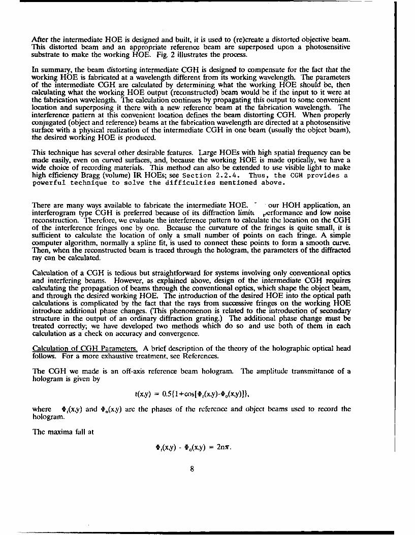
After the intermediate HOE is designed and built, it is used to (re)create a distorted objective beam.This distorted beam and an appropriate reference beam are superposed upon a photosensitivesubstrate to make the working HOE. Fig. 2 illustrates the process.
In summary, the beam distorting intermediate CGH is designed to compensate for the fact that theworking HOE is fabricated at a wavelength different from its working wavelength. The parametersof the intermediate CGH are calculated by determining what the working HOE should be, thencalculating what the working HOE output (reconstructed) beam would be if the input to it were atthe fabrication wavelength. The calculation continues by propagating this output to some convenientlocation and superposing it there with a new reference beam at the fabrication wavelength. Theinterference pattern at this convenient location defines the beam distorting CGH. When properlyconjugated (object and reference) beams at the fabrication wavelength are directed at a photosensitivesurface with a physical realization of the intermediate CGH in one beam (usually the object beam),the desired working HOE is produced.
This technique has several other desirable features. Large HOEs with high spatial frequency can bemade easily, even on curved surfaces, and, because the working HOE is made optically, we have awide choice of recording materials. This method can also be extended to use visible light to makehigh efficiency Bragg (volume) IR HOEs; see Section 2.2.4. Thus, the CGH provides apowerful technique to solve the difficulties mentioned above.
There are many ways available to fabricate the intermediate HOE. - our HOH application, aninterferogram type CGH is preferred because of its diffraction limitt performance and low noisereconstruction. Therefore, we evaluate the interference pattern to calculate the location on the CGHof the interference fringes one by one. Because the curvature of the fringes is quite small, it issufficient to calculate the location of only a small number of points on each fringe. A simplecomputer algorithm, normally a spline fit, is used to connect these points to form a smooth curve.Then, when the reconstructed beam is traced through the hologram, the parameters of the diffractedray can be calculated.
Calculation of a CGH is tedious but straightforward for systems involving only conventional opticsand interfering beams. However, as explained above, design of the intermediate CGH requirescalculating the propagation of beams through the conventional optics, which shape the object beam,and through the desired working HOE. The introduction of the desired HOE into the optical pathcalculations is complicated by the fact that the rays from successive fringes on the working HOEintroduce additional phase changes. (This phenomenon is related to the introduction of secondarystructure in the output of an ordinary diffraction grating.) The additional phase change must betreated correctly; we have developed two methods which do so and use both of them in eachcalculation as a check on accuracy and convergence.
Calculation of CGH Parameters. A brief description of the theory of the holographic optical headfollows. For a more exhaustive treatment, see References.
The CGH we made is an off-axis reference beam hologram. The amplitude transmittance of ahologram is given by
t(x,y) = 0.5 {1 +cos[,'(xy)-4,(xy)J},
where t,(x,y) and $o(x,y) are the phases of the reference and object beams used to record thehologram.
The maxima fall at
t,(x,y) - to(x,y) = 2nr.
8

(a) desiredholog rai
EC=Er
E0 (diffraction -limited)
desired(b) holograin
A2Edc)itrtd
Er2 A2
Fig 2Us o Ineredat CopucrGccracdHoogamstoPrdue aWokig OE
(C9

Analytic conditions on the chief ray can be determined in the absence of aberrations, which providesa crude estimate for starting the calculation. To design the CGH, the computer program performslight ray tracing (because light rays are normals to the wave front) and then finds the phase of thedeformed wave by calculating the optical path length. Unfortunately, the individual hologram gratingconstants are known only on the calculational grid attached to that hologram. Therefore, it is notpossible simply to trace a fan of rays through the system starting either at the laser, or at the focalpoint. To a first approximation, the compensation and main holograms can be calculated indepen-dently, but the piercing points of arbitrary rays traced forward from the calculational grid of thecompensation HOE to the main HOE do not coincide with known points on the calculational gridof the main HOE, and vice versa. Therefore, we solve the ray trace iteratively, first defining theHOEs separately, then tracing rays through them, then interpolating in a coordinate system attachedto each surface, then retracing. This process is repeated until an equitably distributed fan of rays istraced to a converged solution.
Here the vector form of geometric optics is preferred for the ray trace. First, for each ray traced, thecoordinate points are determined on each surface intersected. Then its direction cosine is calculated.
For a refracting surface, the governing equation is Snell's law, given here in vector form.
nf i.x ft = n'fit,,,xxft
where nj and n', are the refractive indices of the media before and after the surface, ti. and t..are unit normals along the incident and refracted rays, and ft is a unit normal to the surface.
If the surface is a hologram, Welford's equation is used instead of Snell's Law.
A X (td - tJ = m (XA) [fr X (t. - tr)
where t, t , and fir are, respectively, the unit vectors for the object beam, the reference beam, andthe normal to the hologram surface in the recording process. Similarly, ti, id, and ftc are the unitvectors of the reconstruction beam, the reconstructed beam, and the normal to the surface of thehologram in the reconstructing process; X and Xc are the wavelengths in the recording andreconstruction process respectively; and m is the diffraction order. In this way we can get theintersection points (x', y', z') and the direction cosine of the refracted ray, (l',m',n'). These datapermit propagation of the ray to the next surface. There a new coordinate system is established, andthe tracing continues as above, using either Snell's or Welford's formulation. Ray tracing is stoppedwhen the ray reaches the image plane.
In order to find the phase of the deformed wave, Ed, we can use the grating equation
d(sine i + sined) = mX (m = 0, + 1, + 2,...)
(and the fact that light rays are normals to the wave front) to determine optical path and, therefore,phase. Alternatively, we can use the cikonal equation to determine optical path.
= grade/I gradG I
As discussed above, we use both techniques and compare them as a check on calculational accuracy.
Two-wavelength Operation. A hologram can easily be exposed at one discrete wavelength and usedat another discrete wavelength, a process usually called two-wavelength operation. It is necessary onlyto ensure that, at all points,
10

[sin {Oi(X)} + sin {Od(I)}]/k I = [sin{Oi(X2)) + sin{Od(X)}],X2.
This condition can be easily satisfied with holograms made with plane waves (simple gratings).. Ingeneral, wave front phase distortions (or compensations) must be introduced into either the object orreference beam, or both, during the recording process. If high resolution and diffraction limitedperformance are not required, approximate methods have been developed to achieve the requiredresults. However, for the HOH application, high resolution and diffraction limited performance arerequired. We have developed a unique method to generate a CGH, outlined above and in detail inIh, et al (1988 and 1989a), which introduces the exact phase compensation into the object beam.
As described above, achieving the two-wavelength condition requires the introduction of a wave frontdistorting CGH into the object beam used to make the working HOE. These distortions guaranteesatisfaction of the two-wavelength condition when the distorted object beam is superposed with anappropriate reference beam to make the final working HOE; see Fig. 2.
Using this method, near diffraction limited performance has been demonstrated; a spot size less than2 Am with clear diffraction rings. (We attribute not achieving the theoretical minimum spot tofabrication errors in making the CGH and misalignment of the fixturing used to generate the workingHOE. See 2.1.5 for details of the fabrication procedure.)
Dispersion Compensation. Individual holograms are diffraction gratings and exquisitely sensitive towavelength changes (highly dispersive); a single hologram can not be made even approximatelydispersion free over a finite range of operating wavelengths. A HOE-pair, is needed.
Also, because the asymmetric HOE-pair members are not simple gratings with the same uniquespatial frequency, dispersion can not be completely compensated. However, dispersion can be madeto vanish at a predetermined nominal operating wavelength, thus permitting satisfactory performanceover a range of wavelengths centered on the perfectly compensated wavelength.
To achieve dispersion compensation between the members of the HOE-pair, it is necessary todetermine conditions on the major free parameters of the optical layout which minimize dispersion.These parameters are the angle of incidence of the chief ray on the compensation HOE and on theangle between HOEs. (These two parameters are not independent; they are constrained by therequirement that the incident elliptical beam be circularized by the HOE-pair.) The range ofdispersion compensation can then be determined numerically by investigating spot diagrams aroundthe fully compensated wavelength. Fortunately, an analytic expression can be derived for an idealunaberrated system in which the beam between the HOEs is strictly parallel. This provides thestarting point for numerical calculations. Fig. 3 shows a convenient set of angular parameters, fromwhich the angle between HOEs can be derived.
From the hologram equation, we have for the compensation and main holograms, HI and HZrespectively,
a(sinOoi - sine,,) = X
and
b(sine. 2 - sinOe) = X
By manipulating the derivatives of these equations we find,
dOoJdX = -dor/dX
From which we get
11

.'.... ....
.... ... .
Fig. 3 Compensation Condition for a HOE-pair.
dEr 2,/d = (sinr 2 - sin 0 o2)/\coSE) 2 - cos9o2(SinE), - sin9oi)/scosEricose 2 = 0,
and if
or, = (r 2 = 0sine01 = tan e0 2,
then
de),/dX = 0
which is the condition for perfect compensation.
Spot diagrams vcrifying system performance over a range of wavelengths about the nominal designwavelength arc shown in Section 2.1.4. Thcse ray traccs automatically include lens aberrations andresidual dispersion of the -OE-p:ir.
Thie critcrion for :cceptabic perlormance is that the spot size must be less than one Am. The nominaldesign with which this program started is wavelength compcnsatcd over +/- 5 nanometers. The newerdesign using moidcd asphlcric elements is compensated over +/- 15 nanometers.
Correction of Chromatic Aberration. InI this subsection, we demonstrate the conditions for makinga HOE correct the chromatic aberration of a lens. To correct the chromatic aberration of a lens usedin an optical head. it is sufficient to hold !he focal length constant over the desired wavelength range,because_- the lenses h:ve m.inimal fiekl. Therefore. we need only to determine the local grating spacingfor a I I)E coupled to a lens which holds the lens focail point constant over a range of a few
12

nanometers. To be concrete, consider the chief ray and any other arbitrary ray incident on tile mainHOE. It is sufficient to show that the optical path from HOE to focal point can be made (ie samefor both rays. We do this for a thin lens; in reality, the condition is obtained by ray tracing.
From Fig. 1, it can be seen that the chief ray can be made to exit normal to the HOE byconstruction. Also, because the wave front between holograms is collimated, to first order all raysstrike the main HOE at the same angle, 3. Sec Fig. 4.
\ ...................
-------------------------...... ...... ...................................
A B
Fig. 4 Geometry of Chromatic Aberration correction.
The lens equation is
1/f(X) = [n(X) - 11 (1/r1 - 1/r2).
The grating equations for the arbitrary and chief rays are, respectively,
sinp - sine = K/a
sinp - sine1 = K/a1.
where a and a, are the fringe spacing on the HOE at C and 0, respcctivelv in Fig. 4, and E is theangie between the diffracted output ray and the normal to the HOE.
By definition. E) = 0. so
sinE = K/a - K/a.
;3
From Fig. 4, we can obtain the relationship between the intercept height of the arbitrary ray, <OC>,and the focal length <OA>. This rclationship can be found either by geometrical construction orby application of the optical invariant [Smith, page 421.
<CA> = <OC>[<OC>[1/r - +rn(X)-i] +
If <OA> is nearlv indc-cndcnt of wavclcngth, the system is chromatically corrected. Setting thederivative of <OA> with respect to wavc!cngth equal to zero, and then making the obvioussubstitutions leads immcdia.tdcv to
d<OA>/dX = 0
when
sin 2 E = I - [<OC>(dn/dX)l/r - 1!r2)1'
This means that the lens can be chromatically corrected to first order by a properly designed HOE.With this as a starting point, a region in the neighborhood of the first order design can be exploredto optimize a real system design.
2.1.4 Calculational Results
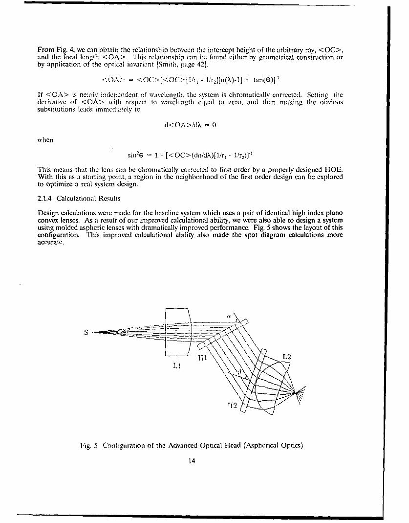
Design calculations were made for the baseline system which uses a pair of identical high index pianoconvex lenses. As a result of our improved calculational ability, we were also able to design a systemusing molded aspheric lenses with dramatically improved performance. Fig. 5 shows the layout of thisconfiguration. This improved calculational ability also made the spot diagram calculations moreaccurate.
S
T12
Fig. 5 Configuration of the Advanced Optical Head (Aspherical Optics)
14

Figs. 6, 7 and 8 are spot diagrams calculated for the baseline system. Fig. 6 was calculated for thenominal design operated at a wavelength of 837.0 nanometers, 5 nanometers more than the designwavelength of 832.0. A large majority of the rays fall well within a one micron spot, with four outliersslightly more than one micron apart. Fig. 7 shows that the design is tolerant of angular misalignmentof the HOE-pair. Tilting the second HOE 0.50 out of alignment does not significantly increase spotsize while operating at 837.0 nm. Fig. 8 shows the effects of incorporating a 4 micron axialdisplacement of the laser with the other misalignments; in this case, aberrations tend to canceisomewhat and the total spot lies within a one micron circle. In all three cases, the Reference Height(radial displacement of the nominal design chief ray) is negligible, less than 2.1 x 10⁻¹⁵ mm. However,these spot diagrams are calculated at best focus; refocussing needed to optimize the focal position(given as FOCUS in the Figures) ranges from 7.9 to almost &7 microns. These tolerances areacceptable for tilt and axial displacement, which would either be build in as fabrication errors or, atworst, change slowly, perhaps with temperature, and would therefore be compensated by the opticalhead servo system. Wavelength change on the order of 5nm may not be so fast that the optical headservo would not follow the induced 8-9 Am focus shift, but this may be problematical in practice.Also, chromatic aberration of the lenses was not considered in these calculations. (Compensation forlens chromatic aberration has been shown to be feasible in Section 2.1.3).
Using our new computational capability, we calculated spot diagrams for a HOH using monolithic(singlet) molded aspherical lenses. Because their spherical aberration is much smaller than that ofthe baseline piano-convex lenses, we were able to design a 2 to 1 reducing system; the focal lengthof the collimating lens is twice that of the objective. Really significant improvement was found. Thisdesign can be recommended for a real system.
Figs. 9, 10, and 11 are spot diagrams for the aspheric design. They are similar to Figs. 5, 6, and 7,except that the operating wavelength has been shifted 15 nm from nominal. For the nominal system,and for the angularly misaligned system, the total spot size is well under 1/2 micron in diameter,
with axial displacement of the laser, the spot is significantly smaller than one Am. Most signiflcantly.there is no need to refocus.
With a +/- 15 nanometer wavelength range, this head would perform satisfactorily over a total rangeof about 80' C.
2.1.5 Fabrication of the HOE-pair
In addition to the iterative calculation which leads to an optimized design, numerous calculations nearthe nominal were made to determine tolerances for assembly, manufacture and for the workingenvironment.
After calculation by the computer program, the CGH is plotted by a large pen plotter (WatanabeMP1000 or Tektronix 4663S). This calculation can now be performed on an AT class PC under DOSas well as on a Unix based VAX system.
The pen plotted CGH is then photoreduced, and the reduced plate mounted on a precisionmicrometer-controlled carrier and introduced into the object beam path. Meticulous adjustment isrequired. Finally, a blue laser beam at 441.6 nm is used to record the working HOE for use at 832.0nm. The several steps required to produce a working HOE are shown in Fig. 2.
The output spot with piano convex lenses was measured in several ways. Although it was impracticalto determine the Strehl ratio, the spot size is clearly less than 2 microns, a close approach to thediffraction limit for this system. The spot size for a diffraction-limited beam is caXFe. For an idealpoint source, a = 2.44 when the spot diameter is measured between the first zeros of the Airy pat-tern. For a TEMoo Gaussian laser source a = 1.57, where the spot is measured to the l/e amplitude
15

Tw
-.4-
-4-
-
1=~
I-
LL... U'. -
Lj~J *
-
-*1-~
-1-
UUE
z
U
UC
I...~J)
0C-,
-C ______________________________________________________
I~? L~r ________________________________________________________________________________________
I-
r~. -.
16
LUL
E=1E
= A p-
LAJ~
7-4-
01
1=17

L.
U-7
w..
LCC
1=18

M=
CmC
cc:,6.
X0
19C
wE
LC)>
==:
LLJ.
0
ci
t)
202
CC:?
LLJ
LCA.
1=w. Cs
IS-
C- C-I-) I~
210

In our case, we appear to have attained ot = 2.4 to a point where the intensity is approximately halfits maximum value.
Nevertheless, this particular optical head is still a experimental model, and much improvement ispossible in the construction of the head, in fabrication techniques, and in measurement of the results.Therefore, work was undertaken to make the optical head more accurate and more practical. This isreported in detail in Section 2.2
22 Optical Head Improvement Effort
For the past year, we have concentrated our efforts on improving performance of the holographicoptical head and in improving our ability to design, predict, and measure that performance.
2.2.1 Improved Test Equipment
In order to determine the spot size more accurately, we developed a highly accurate micropositionerincorporating a piezoelectric drive to improve our knife-edge tester. This has an resolution of 0.1 Amwhich can be observed on an electronic position indicator. In this way a more accurate and reliableresult can be obtained.
Also, a new test instrument, the SpotScan Model 0390 Optical knife-edge profiler, has been purchasedwith other funding. When used with a software package available from the manufacturer, measureddata can be interpreted automatically and spread functions, spot size and the Strehl ratio, etc. deter-mined. This capability is needed to test the extremely well corrected optical head at the sub-micronlevel. However, the mechanical configuration of the present test model optical head is not compatiblewith the detector head of the SpotScan. The very compact head has a small back focal distance (1.3mm), and there is insufficient clearance to mate it to the SpotScan. We have learned that Photon Inc.has introduced a new measuring head which would make the measurement more accessible in tightspaces. In addition, our next optical head will be designed to be more compatible with the SpotScan.
2.2.2 Investigation of E-Beam HOEs.
Using an c-beam machine tu fabricate holograms can avoid very tedious optical alignment work thatrequires very precise optical and mechanical components and that also needs highly skilled personnel.This method can eliminate many potential error sources, because the e-beam mask can be copied ontoa high efficiency substrate. In the long run, making at least the intermediate holograms with ane-beam pattern generator is likely to be both simple and cost effective.
At the present time, however, e-beam generation of high quality holograms is still a subject ofintensive research. The availability and performance of e-beam pattern generators have improvedsignificantly during the past several years. Unfortunately, several hurdles remain to be overcome. Themost immediate one is compatibility with our data format, which is expected to be resolved with twopotential vendors. The others are c-beam resolution and the size of the hologram which can be madeat a supportable cost. We have made important progress in this area which is described below.
We conducted a survey to investigate how many institutions have the capability to, and interest in,making complex holograms using an e-beam. To date, we have identified three companies and auniversity which may be able to satisfy our needs. These are APA Optics Inc., Blaine, Minnesota;Photo Sciences Inc., Irvine, California; Mirage Holography Inc., Dayton, Ohio; and the Universityof California at San Diego. The survey shows that these institutions have experience in makingCGHs at least as difficult as the intermediate HOEs.
The greatest difficulty for e-beam generation of intermediate HOEs lies in translating our output toan acceptable input format for the e-beam pattern generator. UCSD has been very cooperative inthis effort, and we have been able to write a computer program to reformat our output suitably for
22

them. At this time, we can log onto the UCSD computer directly to transfer data and performcalculations. This provides great flexibility and convenience in what will be an iterative process.Unlike some mask houses, there is virtually no wait between sending the data and e-beam generationof the HOE. This will greatly reduce turn around time. This effort is still ongoing as part of aMaster's thesis.
Mirage Holography, Inc. uses AutoCad4 compatible files as the input to their e-beam apparatus,whereas we have been using DesignCAD at the University of Delaware. The output data of ourCGH is normally in DesignCad format. Recently we have discovered that the newer versions ofDesignCad can produce output in AutoCad format. This effort is also continuing as another Masterthesis.
We believe that working with UCSD will provide us with the flexibility and innovative approaches forresearch related activities. We believe that the Mirage holography Inc. would be a more reliablesource and can provide better quality HOE's. We are happy that both have been very cooperativeand believe this strategy will assure us the success of this R/D effort.
In principle, by using wet chemical processing for the electron resist and chromium coated quartzreticles, the minimunm feature size of e-beam reticles can be held to less than 0.1 Am. Thus in thenear future, with further R&D effort, it would be possible to manufacture a HOE directly, bypassingthe intermediate step. Handling of the vast amount of data can be simplified by using special inputand output routines for our CGH program. Routines that transmit data between Super-Oslo and ourCGH software (written in Fortran) are largely completed. The CGH program can be run on a Unixbased VAX computer or a DOS based PC.
If direct e-beam generation of a working HOE is feasible, it will be the most accurate and simplesttechnique to use. However, there still remain fundamental question revolving about the use of binaryholograms as the working HOE. These are based on experience reported over the last few years.Whether this will be a problem, or even if the high contrast will persist through replication of thereticle, can only be determined by experimentation. In any event, using these improved programs, weare in a much better position to produce e-beam fabricated CGHs for HOH applications.
2.2.3 Design Improvements
Improvement in holographic optical head design capabilities is directly related to our calculationalabilities. Accordingly, we have recast our existing design software so that it is fully compatible withSuper Oslo, a high performance general purpose optical evaluation and design program written foruse on AT class personal computers. Super Oslo has been installed on a recently acquired 386 ATgiving a speed increase of 4 to 5 times over its performance in its original installation in a 286 AT.Existing subroutines have been improved to utilize the strengths of Super Oslo in ray tracing andevaluation of conventional optics. With this increased capability we are able to perform moreextensive analysis on HOH designs and can also extend our designs to more complex cases, forexample, the HOH with aspheric lenses.
After extensive analysis of the baseline optical system, we find it can be improved to give widertolerance of wavelength variation and a smaller diffraction-limited spot. 'This improvement usesunequal focal lengths for the collimator and objective lenses; the resulting improvement is notsurprising, but extensive exploration of design alternatives was prohibited by the computer effortformerly required. A new optical system using two aspherical lens and two holograms has beendesigned. This new system has a greater tolerance of wavelength variation. See Section 2.1.4 forexamples of the new analytical capability.
4 AutoCad is a registered trademark of Auto Desk, Inc.
5 DesignCad is a registered trademark of American Small Business Co.
23
2.2.4 Efficiency Improvements
From the inception of this program, it has been known that high efficiency holograms wouldeventually be necessary for a working system. It is also known that both multi-level thin phase andvolume (Bragg) phase holograms can achieve very high diffraction efficiency, with the latterapproaching 100%. Since our final holograms may exceed a spatial frequency of 1,000 lines per mm,a multi-level e-beam hologram will be difficult to made for many years to come. We believe that thedevelopment of IR Bragg hologram using a CGH is essential. Our technique for making thin IRHOEs using a CGH can be readily extended to make a Bragg HOE.
It is now quite clear that the HOH's many advantages cannot be realized unless we can improvethe diffraction efficiency to above 85 %. Since IR volume holograms can not be directly fabricatedby an e-beam, the development of IR volume holograms using a CGH is essential. Once this isachieved, we can then utilize the simplicity, reliability and high performance of HOHs for applicationsin diverse environments. To this end, the basic mathematical analysis has been done and amathematical model has been established. To the best of our knowledge, this new approach isunique; no similar work has been reported in the literature. The basic steps are described briefly belowand illustrated in Fig. 12.
We use the computer to generate two CGH's. The first is used to generate the distorted referencebeam, and second the distorted object beam. For an efficient volume hologram,the Bragg grating condition must be satisfied. For step height Al,
2Asine i = X
% = ed
Like the approach used in calculating CGH parameters in Section 2.1.3, this condition can be usedjointly with the eikonal equation,
= grade/( grade
to calculate the interference fringes on the CGH.
These intermediate CGHs are then produced by an e-beam machine. They are then mounted in anappropriate fixture and illuminated with a laser beam at the visible recording wavelength. The twodiffracted beams from the pair of intermediate CGH's will interfere on the hologram plate to formthe required IR volume hologram.This simple and elegant approach to generating the Bragghologram is a natural outgrowth of our use of a single intermediate CGH to produce working HOEs.In the past, the intermediate CGH has been used to modify object beams only. By modifying boththe object and reference beam at the same time, we can make IR volume HOEs using a visiblewavelength. As mentioned previously, this technique is new and has not been reported by otherresearchers.
24

Eo A2
L1 a). I(ccoidciiig a v(,tiIIic 1(ojn iiA 1,) ComI a:koJE(f if-J;t i;;o : olm
G(;11'2
Ec -
Illl
c k 1( 1( J(' ;b'. 1(1P t l k n , eld c
Fig. 12 Making Volumec Holograms with Computer Gcncratcd Holograms.
25
3.0 SUIMARY OF CONCLUSIONS, RESULTS, AND RECOMMENDATIONS
We have made significant progress and developed many new and innovative techniques for designingand fabricating a HOH. Our sophisticated computer program, which combines powerful commercialsoftware and in-house programs, allows us to design and evaluate complicated optical systemsconsisting of conventional optics and arbitrary HOE's. To our knowledge, no other existing softwarehas this combined capability. Our next goals are to realize this capability in a pracsical HOH and tofurther expand its functionality and performance.
The following approach seems best suited to achieve these goals:
1. Use an e-beam to make intermediate CGHs for the HOH;
2. Build an engineering model of the HOH based on the optimized new design with two asphericallenses and two HOEs;
3. Improve the hardware and software of the SpotScan system and link it a computer and plotter sothat measurements and analyses can be done automatically and more accurately;
4. Design and fabricate a volume IR hologram to increase HOH efficiency:
5. Investigate new potentials of the HOH which may significantly improve performance. Forinstance, we can deliberately offset the hologram angles so that the beam is focused at a slightlydifferent position for different wavelengths. Also we can adjust the chromatic compensation sothat the focal length simultaneously changes with wavelength in a controlled manner (say by 10microns). These unique characteristics may allow us to do simultaneous recording (or reading) ofmultiple tracks on different recording layers. This may also allow us to do tracking or focusingby wavelength tuning instead of by mechanical means, as is now done. These features can becomepractical when wavelength tunable lasers become available. Such lasers are already available as lowpower devices. We believe the same techniques can be applied to high power lasers as well. Thesenew capabilities could become a reality in the near future. We must now explore these newpotentials to realize major improvements in performance later.
It is important to note that we have laid the foundation to design and fabricate a HOH with thepotential to dramatically improve performance. Even more important is that the new understandingof HOE characteristics and novel fabrication techniques could open new applications now consideredimpractical, e.g., compact high-resolution IR holographic imaging systems and imaging Lidar systems.
26

4.0 REFERENCES
S.M. Arnold, Computer-Generated Hologram, MN09-1300, HVN8874461, Scientific Honeyweller(1985).
M. Born and E. Wolf, Principles of Optics 6th (Corrected) Edition, Sections 3.1.2, &6 and 810,Pergamon Press (1986).
C.S. Ih, Design Consideration of 2-D Holographic Sensors, Appl. Opt., 17, 748 (1978).
C.S. Ih, et. al., Compound Holographic Scanners, Proceedings of SPIE, M, 191 (1984).
C.S. Ih, et. al., Wavefront Calculation From a Hologram, JOSA, 4, No. 13, 67 (1987).
C.S. Ih, et. al., Making Infrared Holograms Using a Computer-Generated Hologram, JOSA, 3, No.13, 121 (1986a).
C.S. Ih, et. al., Wavelength Compensation for a Holographic Optical Element, JOSA 3, No. 13, 122(1986a).
C.S. Ih, et. al., Optical Head Using HOE - Technology and Experiments, JOSA, 5, No. 13 (1988b).
C.S. Ih, et. al., Optical Head Design Using HOE's, Proceedings of SPIE, 1052, 177 (1989a).
C.S. Ih, et. al., Progresses Report on Optical Head Design Using HOE, JOSA, 5, No. 13 (1989b).
H. Iwaoka, et. al., Aberration-Free Linear Holographic Scanner and its Application to a Diode-LaserPrinter, Appl. Opt., 25 (1986).
W.H. Lee, Computer-Generated Holograms: Technique and Applications in Progrmss in Otics, E.Wolf, Ed., p. 121 (1978).
J.R. Leger, et. al., Astigmatic Wavelength Correction of a Gain-Guided Laser Diode Array UsingDiffractive Microlenses, Proceedings of SPIE, 88, 82 (1988).
E.N. Leith, et. al., Reconstruction Wavefronts and Communication Theory, JOSA, _., 1123 (1982).
WJ. Smith, Modern Optical Engineering, McGraw-Hill, (1966).
GJ. Swanson, et. al., IR Applications of Diffractive Optical Elements, Proceedings of SPIE, 883, 155(1988).
KS. Urquhart, S.H. Lee, et. al., Computer-Aided Design of Computer-Generated Holograms forElectron Beam Fabrication, Appl. Opt., 28, 3387 (1989).
J.C. Wyant in Optical Shop Testing, D. Malacara, Ed., J. Wiley and Sons, NY (1978)
27

MISSION
ofRome Air Development Center
RADC plans and executes research, development, test andselected acquisition programs in support of Command, Control,
Communications and Intelligence (C3I) activities. Technical andengineering support within areas of competence is provided toESD Program Offices (POs) and other ESD elements toperform effective acquisition of C'I systems. The areas oftechnical competence include communications, command andcontrol, battle management information processing, surveillancesensors, intelligence data collection and handling, solid statesciences, electromagnetics, and propagation, and electronicreliability/maintainability and compatibility.