i on these products. - power distribution- relays · rtmr ordering options ... terminal tools...
TRANSCRIPT

Page: 1Datasheet: 9004
RTMR ORDERING OPTIONS
There are many different ways to order the RTMR block and matching accessories. You can
buy individual parts separately so you can ‘mix & match’ to suit your exact requirements, or
you can buy a Prolec RTMR kit that includes many of the parts you need.
Pre-Wired Terminals & Jumpers (p. )4 Terminals, Cable Seals &Cavity Plugs (p. )& Tools 4
20 Fuse Block
10 Fuse / 5 Relay Block
RTMR kit withpre-assembled cables
RTMR kit with looseterminals & cable seals.
All kits include the RTMRblock, cover & brackets.
Mini Circuit Breakers(Auto, Manual,Modified Reset)
Mini FusesRegular or Indicating
35 PieceFuse AssortmentIncludes 5 pieces ofeach rating;5A, 7.5A, 10A,15A, 20A & 30A.
Resistors orTransorbs
FlasherRelays
ISO 280 Relays (Micro / Mini)Normally Open SPST (4 pin)Change Over SPDT (5 pin)
Butt Connectors
NEW
Refer pages &7 8for more informationon these products.i
Refer page for10more informationon these products.i
Select the RTMR Block
Select the electrical components
Alternatively, select one of our RTMR kits.
Select the mounting & wiring accessories21
3
OR
Email: @info prolecproducts.comprolecproducts.comWeb: www.
Brackets (p. )6Terminal (p.Crimp Tool 5)
Terminal Removal Tool (p. )5

Page: 2Datasheet: 9004
BussmannMINIFUSE & 280 RELAY (RTMR)ISO MODULE - SEALED
The Rear Terminal Mini use and Relay panel ( ) is designed tof RTMR
provide efficient power distribution in a rugged compact form,
suitable for applications in marine, construction, agriculture, heavy
trucking, and specialty vehicle industries.
BLOCK & COVER:
Block Layout20 x Mini fuse( components per side)10 .20 x Mini fuse / circuit breaker( components per side)10 .5 x andMicro relay10 x M circuitini fuse / breaker.3 x relay / andMini micro relay10 x M .ini fuse / breaker3 x 5 x andMini relay or micro relay10 x M .ini fuse / circuit breaker3 x 5 x andMini relay or micro relay10 x M .ini fuse / circuit breaker3 x 5 x andMini relay or micro relay10 x M .ini fuse / circuit breaker
Part Number15303-1-6-3
15303-1-6-4
15303-2-6-4
15303-3-6-4
15303-4-0-4
15303-5-6-4
15303-6-6-4
IncludedCoverShallow
Deep
Deep
Deep
Deep
Deep
Deep
Nbr ofCavities20
20
35
35
50
40
45
Max Nbr of
Terminals20
20
30
30
45
35
40
BussingBussed both sides
Bussed both sides
Bussed both sides
Bussed both sides
No Bussing
Fuse Bussing only
Relay Bussing only*Input stud bussed to
pin 86 on relay.
IP66
Bussing for fuses & relays explained on page 1 .1
Relay wiring diagrams on pages 1 & 1 .2 3
Flasher on page 1 .s explained 4
i
Email: @info prolecproducts.comprolecproducts.comWeb: www.
Components: fuse ini bladedAccepts Mini s, M circuit breakers,ISO 280 Mini & Micro relays and ISO 280 Flashers.All components must have 2.8mm blades on 8.1mm centerline spacing.Mounting: Threaded inserts #10-32 as standard (M5 optional).Block & Cover: Black thermoplastic, improved cover latch design
featuring tether. Silicone seal.Internal Buss: Tin-plated copper (for bussed versions )only .Buss Input Studs: M6 stud (for bussedbright nickel plated brass
versions ).onlyBuss Input Stud Rating: 80A max.Output Terminal Rating: 30A max per terminal.Cover Options: Replacement covers also available.Shallow cover with Gore vent (Mini fuses only) # B151-7168-1- JDeep fuses / # B151-7168-2- Jcover (Mini ISO 280 relays / Mini breakers)Ingress Protection Rating: IP66-IEC 52960 .(Valid when properly installed with cover, cable seals and cavity plugs).Wire Size: # 2 - # 2 AWG mm² mm²2 1 / 0.35 - 3 .Cavity Plugs: Required to fill unused output cavities for ingress
protection.Cable Seals: Please check the overall diameter of your cable before
ordering cable seals.Terminal Tools: Terminal crimping & removal tools .page 5Pack Size: Stocked lines 1pc, indent items 20pcs.Temperature Rating: -40°C to +125°C (PDM only)Ordering: Block is supplied with tethered cover. Bussed versions also
include one nut and one silicone stud cap for each buss input stud.Not Included: erminals, cable seals,Fuses, circuit breakers, relays, t
cavity plugs & brackets are optional extras.
20 x Mini Fuses or20 x Mini Breakers
10 x BMini Fuses or Mini reakersand ISO 280 Micro Relays.5 x
Page: 3Datasheet: 9004
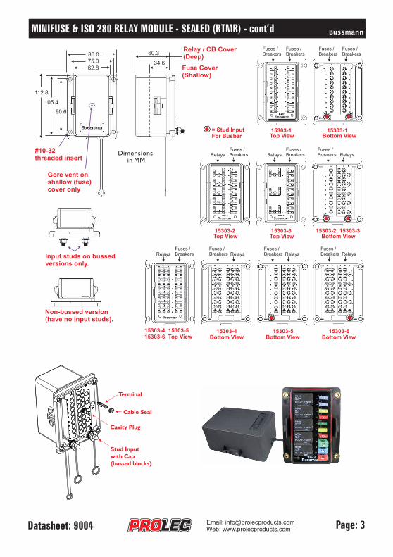
BussmannMINIFUSE & 280 RELAY (RTMR) - cont’dISO MODULE - SEALED
Input studs on bussedversions only.
Non-bussed version(have no input studs).
Relay / CB Cover(Deep)
Fuse Cover(Shallow)
34.6
60.3
62.8
112.8
75.0
105.4
86.0
90.6
#10-32threaded insert
Gore vent onshallow (fuse)cover only
Dimensionsin MM
Top View Bottom View1530 -13 1530 -13
Fuse /sBreakers
Fuse /sBreakers
Fuse /sBreakers
Fuse /sBreakers
= Stud InputFor Busbar
1530 -33 15303-2, 15303-31530 -23
RelaysFuse /sBreakers Relays
Fuse /sBreakers Relays
Fuse /sBreakers
1530 -5315303-4, 15303-515303-6, Top View Bottom View Bottom View Bottom View
1530 -631530 -43
Top View Top View Bottom View
RelaysFuse /sBreakers Relays
Fuse /sBreakers Relays
Fuse /sBreakers Relays
Fuse /sBreakers
Terminal
Cable Seal
Cavity Plug
Stud Input
with Cap
(bussed blocks)
Email: @info prolecproducts.comprolecproducts.comWeb: www.

Page: 4Datasheet: 9004 Email: @info prolecproducts.comprolecproducts.comWeb: www.
ProlecTERMINAL & SEAL KIT
NEWPart NumberTERMKIT001
Description120 piece Metri-Pack Tangless Female Terminal & Seal Kit
Kit Contents:
CAVITY PLUG:Silicone
TERMINALS: TANGLESSFemale SealedTin Brass / Tin plated
Wire (AWG)# #18 - 16# #16 - 14# #14 - 12
Part Number121108471212940912110845
Wire (mm )²0.80 - 1.01.0 - 2.02.0 - 3.0
CABLE SEALS:Silicone
ColourGreenGreyBlue
Cable ia (mm)D .2.03 - 2.852.81 - 3.493.45 - 4.3
Part Number153249821532498015324981
Quantity103010
Quantity103010
Quantity20
Part Number12010300
PACKS OF STERMINALS, CABLE SEALS & CAVITY PLUG
CAVITY PLUG:Silicone
TERMINALS: TANGLESSFemale sealedTin Brass /Tin plated
Wire (AWG)#22 - #20# #18 - 16# #16 - 14# #14 - 12
Part Number12110846121108471212940912110845
Wire (mm )²
0.35 - 0.500.80 - 1.01.0 - 2.02.0 - 3.0
CABLE SEALS:Silicone
ColourDark RedGreenGreyBlue
Cable ia (mm)D .1.70 1.29-2.85 2.03-3.49 2.8- 14.30 3.45-
Part Number15324983153249821532498015324981
Part Number12010300
Delphi Metri-Pack 280 Accessories
PRE-ASSEMBLED CABLES & BUTT SPLICE CONNECTOR
Part NumberCAB2.0X300TS1CAB2.0X300TS2CAB2.0X85TS1J19164-0044
DescriptionOutput CableOutput CableJumper Cable
Butt Connector
PackQty1010110
ColourRedBlueRedBlue
WireSize (mm )
2
1.841.841.841.0 to 2.0
WireLength (mm)30530590N/A
Packard 280 Metri-Pack Female Sealed Tangless Terminal
Red Output Cable
Blue Output Cable
Red Jumper Cable
Search these partnumbers on ourwebsite fordatasheets.
i
Butt Splice Connector

Page: 5Datasheet: 9004 Email: @info prolecproducts.comprolecproducts.comWeb: www.
ProlecTERMINAL TOOLS
Terminal Crimp Tool
Part NumberCRIMPER-03
DescriptionDelphi Metri-Pack 280 &Tyco AMP MCP 2.8 terminals.
Scan this
QR Code
for more
information
QR Code: 8001
Need help using this crimp tool?Scan the QR code to view instructions.
Terminal Removal ToolPart Number12094429
DescriptionExtracts Delphi Metri-Pack
280 terminals & other types.
Search these partnumbers on ourwebsite for datasheets.i

Page: 6Datasheet: 9004
Search these partnumbers on ourwebsite for datasheets.i
Assembled
Example ( )D
Assembled
Example ( )C
MOUNTING BRACKETS & OPTIONAL COVERS
( ) Tall Brackets fitted to a Fuse & Relay RTMRD
56.5
26.0173.0
114.7
69.2
15.5 45
20151.8
104.7
69.2
15.5
20
(C) Medium Bracket fitted to a Fuse & Relay RTMR
31
20151.8
64.543.5
15.5
20
( ) Low Bracket fitted to a Fuse only RTMRA
Email: @info prolecproducts.comprolecproducts.comWeb: www.
(E) Shallow Cover (F) Tall Cover
DescriptionRed S Stud C Protects Input Studs.ilicone ap.Low Profile Bracket, Zinc Anneal Powder Coated (1pc).Medium Profile Bracket, Zinc Anneal Powder Coated (1pc).Tall Profile Brackets, S Natural (2pc ).Stainless teel kitShallow cover (suits fuses only & features a Gore vent).T .all cover (suits fuses, circuit breakers & relays)
Part NumberB066-7008PROBRK002PROBRK001PROBRK008KB151-7168-1- JB151-7168-2- J
(B)(A)
Picture(A)(B)(C)(D)(E)(F)
(D)
NEW
(C)
NEW
Height 31mm Height 45mm Height 56mm

Part NumberMIN002MIN003MIN004MIN005MIN07.5MIN010MIN015MIN020MIN025MIN030
35 Piece fuse kit assortment.
This fuse kit contains;
MIN005 x 5pcsMIN07.5 x 5pcsMIN010 x 5pcsMIN015 x 5pcsMIN020 x 5pcsMIN025 x 5pcsMIN030 x 5pcs
Ampere Rating2A3A4A5A7.5A10A15A20A25A30A
Minifuse 32VDC
AmpereRating3A5A7.5A10A15A20A25A30A
Part NumberMIND003-32VMIND005-32VMIND07.5-32VMIND010-32VMIND015-32VMIND020-32VMIND025-32VMIND030-32V
Minifuse 32VDC (Indicating)
Mini DevicesPart Number22901-1.5
22902-68
ProductTransorb
Resistor
Minifuse 32VDC AssortmentPart NumberMINI-KIT2
14VDCAutomatic TIPart Number21105-0021175-0021110-0021115-0021120-0021125-0021130-00
AmpereRating5A7.5A10A15A20A25A30A
AmpereRating5A7.5A10A15A20A25A30A
14VDCModified TIIPart Number21205-0021275-0021210-0021215-0021220-0021225-0021230-00
AmpereRating5A7.5A10A15A20A25A30A
28VDCManual TIIIPart Number2 305-0032 375-0032 310-0032 315-0032 320-0032 325-0032 330-003
Circuit Breaker (Automatic Reset)
Circuit Breaker (Modified Reset)
Circuit Breaker (Manual Reset)
PLUG-IN COMPONENTS
Page: 7Datasheet: 9004
Search these partnumbers on ourwebsite for datasheets.i
Email: @info prolecproducts.comprolecproducts.comWeb: www.

Page: 8Datasheet: 9004
ISO 280 RELAYS & FLASHERS
Micro Relays (ISO 280)
Mini Relays (ISO 280)
Flasher Units (ISO 280)
Search these partnumbers on ourwebsite for datasheets.i
Email: @info prolecproducts.comprolecproducts.comWeb: www.
Part NumberNO-762-LEDNO.761NO.762
Terminals2.8mm x 42.8mm x 32.8mm x 4
Nbr. Bulbs / Type2 to 6 / LED2 to 4 / Standard3 to 6 / Standard
Please refer to page 14
for more information
on flasher relays.
Please refer to pages 1 & 12 3
for information on using
relays in the RMTR.
Please refer to pages 1 & 12 3
for information on using
relays in the RMTR.
Part Number3011ACR1123011CCR112
3011ACR1243011CCR124
Description12V Normally Open 4 pin (SPST)12V Change Over 5 pin (SPDT)
24V Normally Open 4 pin (SPST)24V Change Over 5 pin (SPDT)
Amp Rating35A (14VDC)NO:35A / NC:20A (14VDC)
15A (28VDC)NO:15A / NC:10A (28VDC)
Contact ratings for resistive load
Protection½ esistoW 680 r rΩ½ esistoW 680 r rΩ
½ esistoW 2700 r rΩ½ esistoW 2700 r rΩ
Part Number898H1AHCR112898H1CHCR112
898H1AHCR124898H1CHCR124
Protection½W 680 r rΩ esisto½W 680 reΩ sistor
½W 2700 reΩ sistor½W 2700 reΩ sistor
Description12V Normally Open 4 pin (SPST)12V Change Over 5 pin (SPDT)
24V Normally Open 4 pin (SPST)24V Change Over 5 pin (SPDT)
Amp Rating50A (14VDC)NO:50A / NC:30A (14VDC)
20A (28VDC)NO:20A / NC:15A (28VDC)
Contact ratings for resistive load
Electrical Rating12.6A at 12.8VDC12.6A at 12VDC12.6A at 12VDC

EXTERNAL FUSE PROTECTION
Page:9Datasheet: 9004
Search these partnumbers on ourwebsite for datasheets.i
Midifuse block, 32V, 125A max.
Bar Rating: 300A max at 58VDC (or less).Note: All kits include S/S nuts & washers, cover. Rating: 58VDC or less.
Note: When selecting a Midifuse, please remember
that each RTMR input stud is rated at 80A max.
Part NumberMIDFBB
Protect your RTMR fuse block by adding a fuse between the battery and the RTMR input stud.
MidifusesMidifuse Fuse BlockPartNumberMID023-32VMID030-32VMID040-32VMID050-32VMID060-32VMID070-32VMID080-32VMID100-32V
AmpereRating23A^30A^40A50A60A70A80A100A
Element Window Side
Fuse is not included.
CFBAR1 (single pole) CFBAR2 (double pole)
Solid Side
Battery FusesBattery Fuse Bars (1 or 2 pole)
Part NumberMRBF030MRBF040MRBF050MRBF060MRBF075MRBF080MRBF090MRBF100
Ampere Rating30A40A50A60A75A80A90A100A
OPTION 1.
OPTION 2.
BATTERY
Ring terminal fusedprotection to RTMR
Part NumberCFBAR1SP-KITCFBAR1SP-KITBCFBAR1M8SPRKCFBAR1M8SPBKCFBAR2M8SPRKCFBAR2M8SPBK
DescriptionSingle pole kitSingle pole kitSingle pole kitSingle pole kitDouble pole kitDouble pole kit
Stud1/4"-201/4"-20M8M8M8M8
CoverRedBlackRedBlackRedBlack
Email: @info prolecproducts.comprolecproducts.comWeb: www.

RTMR PRE-ASSEMBLED KITS
Page: 10Datasheet: 9004
Part NumberPDMKit001
Description
This kit can supply fused power for up to 20 output circuits fed by 2
input power leads connected to the rear studs of the block. Each
input stud supplies power to 10 circuits (1 side). This kit includes the
block & cover, 35 x assorted Minifuses, 20 x pre-terminated cables,
10 x cavity plugs, 20 x butt connectors and 2 x mounting brackets.
20 Minifuse Block Kit (with cables)
Part NumberPDMKit002
Description
This block can be �tted with a combination of up to 10 Minifuses or
mini-bladed breakers and 5 micro relays (SPDT). There are 2 bussed
power studs. One for relays and one for fuses/breakers. This kit
includes the block & cover, 30 x terminals, 30 x cable seals, 10 x
cavity plugs and 2 x mounting brackets.
10 Minifuse/Circuit Breaker & 5 Relay Block Kit (with terminals)
Part NumberPDMKit003
Description
This block can be �tted with a combination of up to 10 Minifuses or
mini-bladed breakers and 5 micro relays (SPDT). There are 2 bussed
power studs. One for relays and one for fuses/breakers. This kit
includes the block & cover, 30 x pre-terminated cables, 30 x butt
connectors, 5 x jumpers, 10 x cavity plugs and 2 x mounting
brackets.
10 Minifuse/Circuit Breaker & 5 Relay Block Kit (with cables)
Search these part numbers on our website for datasheets.i
Part NumberPDMKit004
Description
This kit can supply fused power for up to 20 output circuits fed by 2
input power leads connected to the rear studs of the block. Each
input stud supplies power to 10 circuits (1 side). This kit includes the
block & cover, 35 x assorted Minifuses, 20 x terminals, 20 x cable
seals, 10 x cavity plugs and 2 x mounting brackets.
20 Minifuse Block Kit (with terminals)
Email: @info prolecproducts.comprolecproducts.comWeb: www.

Page: 11Datasheet: 9004
RTMR INTERNALLY BUSSED UNITS EXPLAINED
Fuse Bussed RTMR Units
The following RTMR units feature an internal fuse bus; 15303-1, 15303-2, 15303-3 & 15303-5.The purpose of a fuse bus is to feed power to all 10 fuses from a common input stud on the underside of the block.This reduces the number of terminals, cable seals, cavity plugs and wiring required to assemble the unit. It is also agreat time saver. The only negative of using a common power bus is that you cannot power individual fuses fromalternate power sources eg. 5 fuses powered directly from battery and 5 fuses powered from ignition power.
Relay Bussed RTMR Units
The following RTMR units feature an internal relay bus; 15303-2, 15303-3 & 15303-6.The purpose of this bus is to provide a common power or ground circuit to .relay coil pin 86There is a common misconception that relay pin 30 (common power) is connected to the relay bus.This is NOT the case. The reason why is that power to relay pin 30 should be supplied from a fuse to ensure thatthe accessory is fuse protected. So relay pin 30 should be connected to a fuse on the RTMR using a jumper cable.
To Power
FuseBussStud
Fuse #1
InternalFuseBussBar
Fuse #2
Fuse #3etc.
RTMR with internal Fuse Bus
To Power Fuse #1
Fuse #2
Fuse #3etc.
RTMR without internal Fuse Bus
To Power
To Power
As you can see in these illustrations, the RTMR unit with no internal fusebus requires an input power cable for every fuse, whereas the RTMR unitwith an internal fuse bus only requires 1 power input cable.
30 86
85 87a 87
To Powervia cableor internalfuse bus bar
RelayBussStud
Relay #1
Fuse #1
InternalRelayBussBar
RTMR with internal Relay BusRelay Pin8586308787a
DescriptionRelay coil powerRelay coil powerCommon powerNormally OpenNormally Closed
As you can see in the above illustration, relay coil pin 86 is connected to the internal relay bus bar.Relay common pin 30 is connected to a fuse on the RTMR block using a jumper cable.Depending on how you wish to switch the relays, the relay buss stud can be connected to either positive orground. However, if the relay is diode protected, it can only be used in one wiring configuration. Pleaserefer to pages 1 & 1 which explain these different wiring methods.2 3
85
87a
86
87 30
Relay Circuit Diagram
RelaySwitchCircuit
PowerOutput 2
PowerInput
PowerOutput 1
Email: @info prolecproducts.comprolecproducts.comWeb: www.

Dash MountedLights Switch
Example Overview.In this simple example we are switching lights on/off using a dash mounted light switch. The circuit is fuseprotected (fuse #1) and power to the lights is switched by a normally open relay (relay #1).
How it Works.When we switch the lights ON at the dash, power flows from the RELAY BUSS STUD into relay coil (pin 86)and out relay coil (pin 85) to GROUND via the lights switch on our dash. Powering the relay coil switchespower fed by fuse #1 through a jumper cable to relay pin 30 to flow out relay pin 87 to the lights.
Notes.Fuses and relays can be wired in any circuit configuration you like. The 15303-2 includes one internal buss forfuses and one internal buss for relays. This buss connects one terminal of each component (fuse / circuitbreaker / relay) to the input stud, thereby reducing the amount of wiring that is required for each component.
15303-2 ( )Bottom View
RelaySide
Fuse /CB Side
30 86
85 87a 87
To Power
To Ground
Relay coil ground
Rela
y c
oil p
ow
er
FuseBussStud
To Power
RelayBussStud
Lights fuse
Relay #1
Fuse #1
To Ground
Lights
= Open hole, no connection.
Wiring Example 1.15303-2 (Dual Buss) Fuse/Relay Block with relay coil by Relay Buss Stud.powered
BussmannRTMR WIRING EXAMPLE (RELAY)
Page: 21Datasheet: 9004
No Protection
Resistor Protection Diode ProtectionAnode to pin 85
Suitable Relays for this Circuit:
+ -
+
-
15303-2 Wiring Example(Bottom View).
When energizing the coil of a relay,polarity of the coil does not matterunless the relay is diode protected.
When a relay is diode protected, youmust connect the positive voltage tothe correct terminal of the relay coil asillustrated in the diagram.
InternalFuseBuss
InternalRelayBuss
Email: @info prolecproducts.comprolecproducts.comWeb: www.

BussmannRTMR WIRING EXAMPLE (RELAY)
Page: 31Datasheet: 9004
Dash MountedLights Switch
Example Overview.In this simple example we are switching lights on/off using a dash mounted light switch. The circuit is fuseprotected (fuse #1) and power to the lights is switched by a normally open relay (relay #1).
How it Works.When we switch the lights ON at the dash, power flows from dash mounted lights switch into relay coil (pin85) and back out relay coil (pin 86) to GROUND via RELAY BUSS STUD. Powering the relay coil switchespower fed by fuse #1 through a jumper cable to relay pin 30 to flow out relay pin 87 to the lights.
Notes.Fuses and relays can be wired in any circuit configuration you like. The 15303-2 includes one internal buss forfuses and one internal buss for relays. This buss connects one terminal of each component (fuse / circuitbreaker / relay) to the input stud, thereby reducing the amount of wiring that is required for each component.
15303-2 ( )Bottom View
RelaySide
Fuse /CB Side
30 86
85 87a 87
To Power
To Power
Relay coil power
Rela
y c
oil g
round
FuseBussStud
InternalFuseBuss
To ground
RelayBussStud
InternalRelayBuss
Lights fuse
15303-2 Wiring Example(Bottom View).
Relay #1
Fuse #1
To Ground
Lights
= Open hole, no connection.
Wiring Example 2.15303-2 (Dual Buss) Fuse/Relay Block with relay coil by Relay Buss Stud.grounded
No Protection
Resistor Protection Diode ProtectionAnode to pin 86
Suitable Relays for this Circuit:
++ -
- When energizing the coil of a relay,polarity of the coil does not matterunless the relay is diode protected.
When a relay is diode protected, youmust connect the positive voltage tothe correct terminal of the relay coil asillustrated in the diagram.
Email: @info prolecproducts.comprolecproducts.comWeb: www.
BussmannRTMR (USING A FLASHER RELAY)
Page: 41Datasheet: 9004 Email: @info prolecproducts.comprolecproducts.comWeb: www.
Using Flasher Relays in the RTMR.Flasher relays are typically used to create the on/off flashing effect for turn signals and hazard lights. These relayscan easily be installed in the RTMR. Only one flasher relay is required to create both a turn signal & hazard lightcircuit. There are however, a number of different ways a flasher relay can be wired. Regardless of the method youchoose, it is recommended you do NOT use an RTMR that features internal relay bussing. The flasher relay can beinstalled in 2 different orientations, so please be mindful of this when designing your installation or replacing therelay.
Choosing which RTMR to use for the flasher circuit.It is recommended you use 2 fuses for your flasher circuit. The first fuse is used to protect the turn signal circuit(which powers the turn signal lights on one side of the vehicle). The second fuse is used to protect the hazard lightcircuit (which powers the turn signal lights on both sides of the vehicle simultaneously). In most modern vehicles,the hazard lights will operate even if the ignition is OFF, however the turn signals will only operate when the ignitionis switched ON. To achieve this functionality, we recommend you use the with no internal bussing.15303-4 RTMRHowever if you do not need this exact functionality, then you can also use the 15303-5 RTMR with internal fusebussing.
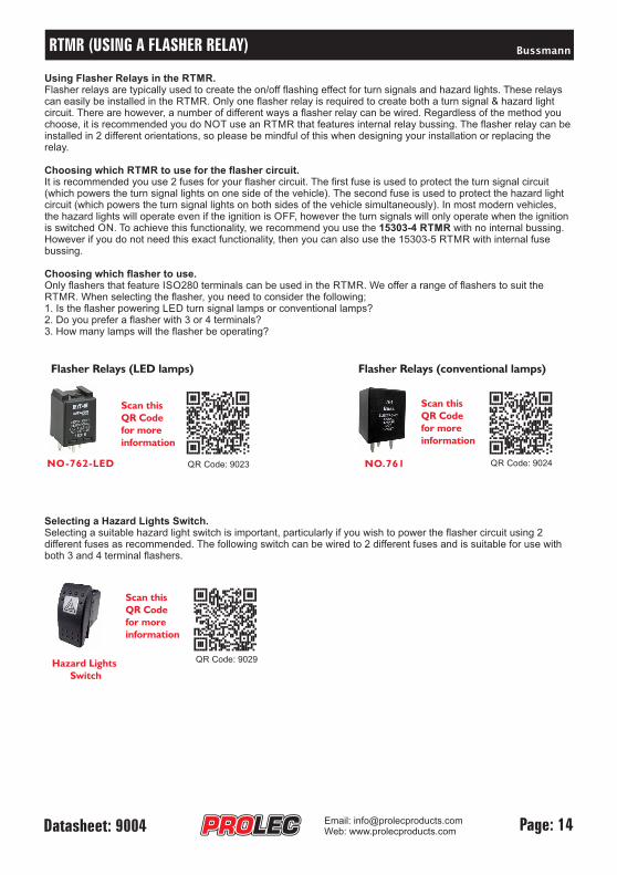
Choosing which flasher to use.Only flashers that feature ISO280 terminals can be used in the RTMR. We offer a range of flashers to suit theRTMR. When selecting the flasher, you need to consider the following;1. Is the flasher powering LED turn signal lamps or conventional lamps?2. Do you prefer a flasher with 3 or 4 terminals?3. How many lamps will the flasher be operating?
Selecting a Hazard Lights Switch.Selecting a suitable hazard light switch is important, particularly if you wish to power the flasher circuit using 2different fuses as recommended. The following switch can be wired to 2 different fuses and is suitable for use withboth 3 and 4 terminal flashers.
NO-762-LED QR Code: 9023
Scan this
QR Code
for more
information
Flasher Relays (LED lamps) Flasher Relays (conventional lamps)
Scan this
QR Code
for more
information
QR Code: 9024NO.761
QR Code: 9029
Scan this
QR Code
for more
information
Hazard Lights
Switch