i ll in oi s
TRANSCRIPT

HI LL IN OI SUNIVERSITY OF ILLINOIS AT URBANA-CHAMPAIGN
PRODUCTION NOTE
University of Illinois atUrbana-Champaign Library
Large-scale Digitization Project, 2007.


Snap-Through and Post-Buckling
Behavior of Cylindrical Shells Under
the Action of External Pressure
by
Henry L. Langhaar
PROFESSOR OF THEORETICAL AND APPLIED MECHANICS
Arthur P. Boresi
ASSISTANT PROFESSOR OF THEORETICAL AND APPLIED MECHANICS
ENGINEERING EXPERIMENT STATION BULLETIN NO. 443

© 1957 BY THE BOARD OF TRUSTEES OF THEUNIVERSITY OF ILLINOIS
2050-4-57-62247UNIVERSITYSF PRENOIS
ýý pR ESS ý:

ABSTRACT
This report treats the buckling and post-buckling behavior of a cylindrical shell that issubjected to uniform external pressure p on itslateral surface, and an axial compressive force F(Fig. A). The force F varies with the pressure pin such a way that F = Xa2p, in which a is themean radius of the shell and A is a dimensionlessconstant. If the shell is immersed in a fluid at con-stant pressure p and if the force F results onlyfrom the pressure p on the ends, A = r.
The ends of the shell are assumed to providesimple support to the cylindrical wall. Accordingly,the radial and circumferential displacement com-ponents of the middle surface of the wall vanishat the ends. If the ends of the shell are free towarp, no other constraint is imposed on the de-formation. If the ends of the shell are rigid, theaxial displacement is constant at either end. Bothof these cases were investigated. For generality,the shell was considered to be reinforced by severalrings or hoops.
Only geometrically perfect shells were studied;that is, initial dents and out-of-roundness were nottaken into account. Only shells with a linear stress-strain relation were considered.
If the axial force F is not too great, the shellassumes a fluted form when it buckles. This formis illustrated by Fig. B, which is a photograph ofsome of Sturmn's test specimens (7 )*. The number of
Fig. B. Front Views of Buckled Cylinders
flutes in the buckled form is influenced strongly bythe ratio L/a, in which L is the length of the shell.Fig. C illustrates several forms of cross sections ofcylindrical shells that have been buckled by ex-ternal pressure.
When the axial force F predominates, thebuckled shell assumes a form in which diamond-shaped facets occur (1. Art. 85). This type ofbuckling was not considered in the present study;the axial force F was assumed to be so small thatthe fluted pattern occurs. The admissible range ofF was not determined, but the fluted pattern usu-ally occurs if A does not exceed 7r.
* Numbers in parentheses, unless otherwise identified, refer to theReferences at the end of this report.
1. -- L 0
Fig. C. End Views of Buckled CylindersFig. A. Forces Acting on Shell

CONTENTS
I. PRELIMINARY CONSIDERATIONS1. Introduction
2. Notations
II. POTENTIAL ENERGY OF A SHELL WITH FLEXIBLE ENDS3. Membrane Strains
4. Fourier Analysis of Displacement Components5. Membrane Energy
6. Potential Energy of External Forces7. Elimination of u0 from the Increment of Total Potential Energy8. Elimination of u, from the Increment of Total Potential Energy9. Elimination of u2 from the Increment of Total Potential Energy
10. Elimination of ua from the Increment of Total Potential Energy11. Further Simplification of AV12. Strain Energy of Bending of an Elastic Cylinder
III. POTENTIAL ENERGY OF A SHELL WITH RIGID ENDS13. Shell with Rigid Ends
IV. PRESSURE-DEFLECTION RELATIONS14. Load-Deflection Curves
15. Tsien Critical Pressure
16. Effect of Assumptions on the Tsien Critical Pressure17. Potential Energy Barriers
18. Numerical Example
V. SUMMARY
VI. REFERENCES
VII. APPENDIX

FIGURES
1. Pressure-Deflection Curve2. Rectangular Coordinates of Shell3. Arc of Buckled Cylindrical Shell4. Increment of Potential Energy versus Deflection Parameter5. Pressure-Deflection Curve for Ideal Shell6. Intersecting Pressure-Deflection Curves7. Pressure-Deflection Curve for Imperfect Shell8. Statistical Distribution Curve for Imperfect Shells9. Determination of Tsien Critical Pressure
10. Graphs of f(p) and <^(p)11. Potential Energy Barrier1 2. Buckling Coefficient K versus Deflection Parameter W,1 3. Buckling Coefficients for Cylindrical Shells Subjected to
Hydrostatic Pressure14. Potential Energy Barriers Separating Buckled and Unbuckled Forms
TABLES
1. Values of K1, K2, . . ., Ks 8 for v 0.302. Values of Coefficients for Computing Buckling
Values of Coefficients for Computing BucklingValues of Coefficients for Computing BucklingValues of Coefficients for Computing BucklingValues of Coefficients for Computing BucklingValues of Coefficients for Computing BucklingValues of Coefficients for Computing BucklingValues of Coefficients for Computing BucklingValues of Coefficients for Computing BucklingValues of Coefficients for Computing BucklingValues of Coefficients for Computing BucklingValues of Coefficients for Computing BucklingValues of Coefficients for Computing BucklingValues of Coefficients for Computing BucklingValues of Coefficients for Computing BucklingValues of Coefficients for Computing BucklingValues of Coefficients for Computing BucklingValues of Coefficients for Computing BucklingValues of Coefficients for Computing BucklingCoefficients K,t, Ki, and K,,»,, (a/h = 1000)Coefficients Kst, Ki, and K,,,, (a/h = 100)
Loads - n =
Loads - n =
Loads - n =
Loads - n =
Loads - n =
Loads - n =
Loads - n =
Loads - n =
Loads - n =
Loads - n =
Loads - n =
Loads - n =
Loads - n =
Loads - n =
Loads - n =
Loads - n =
Loads - n =
Loads - n =
Loads - n =
..... E

I. PRELIMINARY CONSIDERATIONS
1. Introduction
Experimental data on the collapsing pressuresof cylindrical shells have been obtained by Fair-bairn, Carman, Jasper and Sullivan, Saunders andWindenburg, Windenburg and Trilling, Sturm, andnumerous other investigators. (12 ,
,4 5, 6, 7) Theoret-
ical studies of the problem have been performed byBryan, Southwell, Cook, von Mises, Donnell,Sturm, and others. (8' 9, 10, 11, 12, 7) The history ofthese theories (to 1948) is contained in the workof Batdorf. (13'
Von Mises and most of the subsequent investi-gators implicitly based their analyses on the gen-eral principle that a motionless conservativemechanical system becomes unstable when thevalue of its total potential energy ceases to be arelative minimum. The theory of buckling based onthis principle is sometimes called the "infinitesimaltheory" since investigations of relative minimarequire only infinitesimal variations. The bucklingload determined by the infinitesimal theory hasbeen designed by Friedrichs (14) as the "Euler criti-cal load," since Euler employed the infinitesimaltheory in his study of columns. The Euler criticalloads for elastic cylindrical shells that are subjectedto external hydrostatic pressure are in close corre-lation with experimental data, provided that theshells are long in comparison with their diameters.However, the Euler critical loads are much toohigh for short thin shells.
In 1938, von KArmAn and Tsien (15) called at-tention to the fact that an ideal shell can be in astate of weak stability, such that a small blow orother disturbance causes it to snap into a badlydeformed shape. Simple examples of this type ofequilibrium are common. The equilibrium of a cointhat is balanced on its edge is stable, but suchweak stability is usually unsuitable for engineeringdesign. Similarly, if the center of gravity of a ship
is so high that the slightest push will cause theship to capsize, the border line of stability has beenreached. However, this condition has no significancefor the design of hulls. Analogously, the Euler criti-cal load of a shell loses much of its significancewhen snap-through can occur. We merely knowthat the Euler critical load is the upper bound ofthe load that will actually cause failure.
In this investigation,the occurrence of weakstability is manifested bythe conclusion that thepressure required tomaintain a buckled formis frequently much lessthan the Euler criticalpressure. A pressure-deflection curve for anideal elastic cylindricalshell that is loaded byexternal pressure has thegeneral form shown in Fig. 1. Pressure-DeflectionFig. 1. The falling part Curveof the curve (dotted inFig. 1) represents unstable equilibrium configura-tions. Also, the continuation of line OE (dotted)represents unstable unbuckled configurations. Actu-ally, the shell snaps from some configuration A toanother configuration B, as indicated by the dashedline in Fig. 1. Theoretically, point A coincides withthe Euler critical pressure E, but initial imperfec-tions and accidental disturbances prevent the shellfrom reaching this point. To some extent, point Ais indeterminate, but it is presumably higher thanthe minimum point C, unless the shell has excessiveinitial dents or lopsidedness. In this report, ahypothesis of Tsien (19' is used for locating point A.The pressure at point C is the minimum pressureunder which a buckled form can persist. Thus,
ILLINOIS ENGINEERING EXPERIMENT STATION
if the shell is in a buckled state, and if the ex-ternal pressure is gradually relieved, the shell willsnap back to the unbuckled form when the pressureat point C is reached.
An analysis of the post-buckling behavior of astructure determines the buckling load automati-cally. For example, an analysis of the form of abuckled column reveals that there is no real non-zero solution unless the load exceeds a certainvalue, the Euler critical load. Accordingly, in prin-ciple, the nonlinear theory of equilibrium obviatesthe need for a special theory of buckling. However,as a practical expedient, it is usually easier to de-termine the Euler buckling load of a structure bysolving a linear eigenvalue problem than by calcu-lating the bifurcation point of a curve in configura-tion space that represents all equilibrium configura-tions.
Problems of post-buckling behavior of elasticshells may be approached in two different ways.On the one hand, we may seek to solve the equi-librium equations and the compatibility equations,in consistency with given boundary conditions.However, in the large-deformation theory of elas-ticity, the compatibility equations are an extremelycomplicated set of differential equations, representedby the vanishing of a Riemann tensor. (20) As Dr.C. Lanezos once remarked, "We could not hope tosolve the general compatibility equations, but for-tunately we already know their general solution.It is merely an arbitrary displacement vector. Weshould be happy that we know this solution, andwe should make every possible use of it."
When the components of the displacement vec-tor are adopted as the dependent variables in ashell problem, only the equilibrium equations andthe boundary conditions remain to be considered.The equilibrium equations may be derived by bal-ancing forces on a differential element, but, inlarge-deformation theories, the rotations of the ele-ments introduce a complexity into this procedure.Consequently, the equilibrium equations are ob-tained most readily in terms of the initial coordi-nates by applying the Euler equations of thecalculus of variations to the potential energy in-tegral. Unfortunately, in most shell problems, theequilibrium equations are too complicated to besolved rigorously. Instead of tackling the equilib-rium equations directly, we may revert to the po-tential energy integral and apply approximationmethods of the calculus of variations. This pro-cedure was employed in this investigation. The
theory is accordingly founded on the well-knownprinciple that all states of equilibrium - stable andunstable - are determined by the stationary valuesof the potential energy. The stable states corre-spond to relative minima of potential energy.
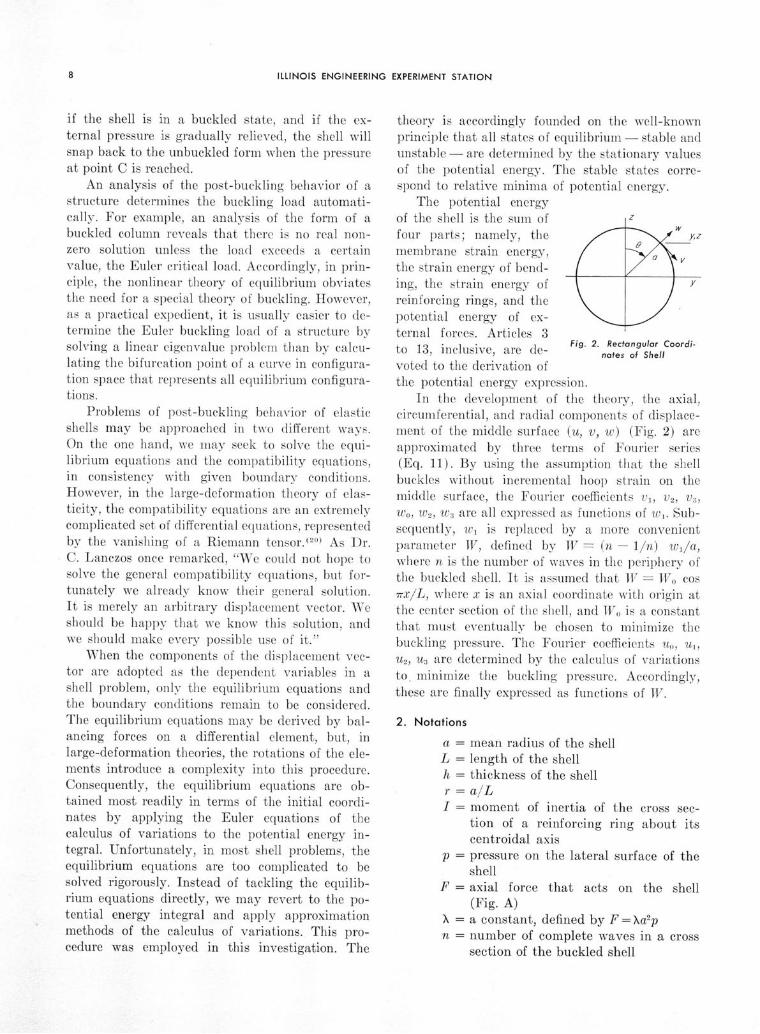
The potential energyof the shell is the sunm of 1Zfour parts; namely, themembrane strain energy,the strain energy of bend-ing, the strain energy ofreinforcing rings, and thepotential energy of ex-4-t 1 f A i lteina oUtrces. Ar c esto 13 inclusive are de- Fig. 2. Rectangular Coordi-
to 13, inclusive, are de- nates of Shellvoted to the derivation ofthe potential energy expression.
In the development of the theory, the axial,circumferential, and radial components of displace-ment of the middle surface (u, v, w) (Fig. 2) areapproximated by three terms of Fourier series(Eq. 11). By using the assumption that the shellbuckles without incremental hoop strain on themiddle surface, the Fourier coefficients vi, v2, vS,wo, w2 , W3 are all expressed as functions of w,. Sub-sequently, w, is replaced by a more convenientparameter W, defined by TV = (n - 1/n) wi/a,where n is the number of waves in the periphery ofthe buckled shell. It is assumed that W = Wo cosrTXiL, where x is an axial coordinate with origin atthe center section of the shell, and Wo is a constantthat must eventually be chosen to minimize thebuckling pressure. The Fourier coefficients Uo, u,,u2, us are determined by the calculus of variationsto. minimize the buckling pressure. Accordingly,these are finally expressed as functions of TV.
2. Notations
a = mean radius of the shellL = length of the shellh = thickness of the shellr = a/LI = moment of inertia of the cross sec-
tion of a reinforcing ring about itscentroidal axis
p = pressure on the lateral surface of theshell
F = axial force that acts on the shell(Fig. A)
X = a constant, defined by F =Xa2p
n = number of complete waves in a crosssection of the buckled shell

Bul. 443. BEHAVIOR OF CYLINDRICAL SHELLS UNDER EXTERNAL PRESSURE
E = Young's modulusv = Poisson's ratio
= n 2r 2 = 0.295804nL/a, ifv =
0.30.x = an axial coordinate with origin at the
center section of the shell0 = an angular coordinate (Fig. 2)
u,v,w = axial, circumferential and radial dis-placement components of the middlesurface due to buckling (Fig. 2)
V = total potential energy of the shell(strain energy plus potential energyof external forces)
AV = increment of potential energy due tobuckling (Eq. 100)
U, = strain energy of a reinforcing ring(Eq. 99)
Ub = part of the strain energy of the shellthat results from bending
K = constant in the buckling formula, per=KEh/a
Ki = value of K determined by the infini-tesimal theory of buckling
Kst = value of K determined by the snap-through theory of buckling (Tsien'stheory)
Ki, K 2 , . . ., K1 = functions of n and v, defined byEqs. (39), (47), (58), and (67), andtabulated in Table 1
a,,a 2,b1 ,b2,b3,c1 ,c2,C3 = functions of n, v, and r, de-fined by Eqs. (72) and (98), and tabu-lated in Tables 2-20
B1, B 2, Ba = constants defined by Eq. (101)Wo = A parameter defined by Eq. (36). Wo
is a measure of the deflection due tobuckling.
7rxW = Wo cos L
LPrimes denote derivatives with respect to
Primes denote derivatives with respect to x.

II. POTENTIAL ENERGY OF A SHELL WITH FLEXIBLE ENDS
3. Membrane Strains
In this article expressions for the membranestrains of the shell in terms of the displacementcomponents of the middle surface of the shell arederived.
The shell is referred to rectangular coordinates(x, y, z), such that the x-axis is the geometricalaxis of the cylinder (Fig. 2). The positive x-axisin Fig. 2 is directed toward the reader. The circlein Fig. 2 represents a cross section of the middlesurface of the unbuckled shell. The origin of x istaken to be the middle section of the shell.
When the shell buckles, the particle that lies atpoint (x, y, z) on the middle surface is displacedto the point (x*, y*, z*). In terms of the axial,circumferential, and radial displacements compo-nents (u, v, w) and the angular coordinate 0 (Fig.2), the coordinates (x*, y*, z*) are given by
* = x + Uy* = a sin 0 + v cos 0 + w sin 0z* = a cos 0 - v sin 0 + w cos 0
The displacement components (u, v, w) are futions of x and 0. In deriving Eq. (1), we have nlected the fact that the deformation befbuckling alters the radius slightly.
If x and 0 take infinitesimal increments dxdO, the coordinates (x*, y*, z*) take increme(dx*, dy*, dz*). These increments are obtaineddifferentiation of Eq. (1); hence
dx* =dy* =
dz* =
(1 + ux) dx + uod6(vx cos 0 + wx sin 6) dx+ (a cos 0 + ve cos 0 - v sin 0+ we sin 0 + w cos 0) dO(-v sin0 + w cos ) dx+ (-asin - vesinO - vcosO+ we cos 6 - w sin 6) do
where subscripts x and 0 denote partial derivates.Consider two differential vectors (dx*, dy*, dz*)
and (Sx*, 8y*, Sz*), the first being the incrementsof (x*, y*, z*) when x alone receives an increment
dx, and the second being the increments of (x*, y*,z*) when 0 alone receives an increment dO. SettingdO - 0 in Eq. (2), we obtain
dx* = (1 + ux) dxdy* = (vx cos 0 + wx sin 0) dxdz* = (-vx sin 0 + w, cos 0) dx
Setting dx = 0 in Eq. (2), we obtain
x* = uodoby* = (a cos 0 + ve cos 0 - v sin 6
+ we sin 0 + w cos 0) dObz* = (-a sin 0 - ve sin 0 - v cos 0
+ we cos 6 - w sin 0) dO
The squares of the magnitudes of the vectors(dx*, dy*, dz*) and (bx*, by*, az*) are
(ds*)2 = (dx*) 2 + (dy*)2 + (dz*) 2
(5s*) 2 = 2 (y*) 2 + (6z*)2
Accordingly, Eqs. (2') and (2") yield
(1) (ds*)2 = [(1 + uX)2 Vx2 + Wx2] (dx) 2
(Bs*) 2 = [uo2 + a2 + e + v 2 + w02 + w 2
+2 ave+ 2aw + 2vew - 2vwe] (dO) 2 (4)
The initial magnitudes of the vectors (dx*, dy*, dz*)and (ax*, by*, bz*) -that is, the magnitudes of theline elements before buckling-are
ds = dx, 6s = adO
Consequently,
(ds*) = 1 + 2ux + u'2 + vx2 + w x2
S= 1 + 2 aV + w
S(e + w 2 + v - we
Since the material will not admit large strains,the ratios ds*/ds and Ss*/bs are approximatelyequal to unity. Therefore, the additive terms in-volving, u, v, w on the right sides of Eqs. (5) and(6) are small compared to unity. Accordingly,ds*/ds and Ss*/ls are closely approximated by
Bul. 443. BEHAVIOR OF CYLINDRICAL SHELLS UNDER EXTERNAL PRESSURE
binomial expansions of the square roots of theright sides of Eqs. (5) and (6) in which only termsto the second degree are retained. Thus, we obtain
ds* 1 1ds = 1 + uý +-2-v' + -wý2
Ss* vo + w 0u- 1 ( v - we 2
as + a + 2a 2 2 \ a /
The shell is already strained before it buckles.When buckling occurs, line elements in the x and 0directions receive incremental strains, Aex and Aoo.According to the customary definition of strain,these increments are
ds* - dsds
Consequently, by Eq. (7),
A, = ux + 1 12 1 2
2
as* - as
A v + w 002 1 (v- wo 2
a 2 2 + aa 2a2 2 a
The shearing strain yxo is defined by yxo = cos 0,where 0 is the angle between the vectors (dx*, dy*,dz*) and (5x*, 5y*, az*). Therefore,
dx*8x* + dy*Sy* + dz*8z*TYo = ds*Ss*
Thus, by Eqs. (2') and (2")
o= d** [(1 + ux) u0 + (vx cos 0 + w, sin 0)
• (a cos 0 + vo cos 0 - v sin 0 + wo sin 0+ w cos 0) + (-v,. sin 0 +w cos 0) (-a sin 0- ve sin 60 - v cos 0 + wo cos 6 - w sin 0)]
Since ds = dx and as = adO, this equation reduces to
1 ds 8so = a ds* as* [(1+u)u + av,
+ v (vo + w) - wx (v - wo)]
Expanding the reciprocals of the right sides ofEq. (7) by the binomial theorem, we obtain, tofirst degree terms,
ds/ds* = 1 - u, s/s* = 1 - vo+a
Only the first degree terms are needed in these ex-pansions, since the first degree terms lead to seconddegree terms in the preceding formula for 7-0.
Eliminating ds/ds* and 5s/ds*, we obtain, tosecond degree terms
Uo " - wo O'xo = a-+ v - w a
e ve + w (9)a a
The axial displacement component u is evi-dently small compared to the radial component w.Consequently, the term u02/2a2 will be discardedfrom Eq. (8). Also, the terms uxv and uo(vo+w)/a 2
will be discarded from Eq. (9), since they aresmall compared to the respective additive termsVx and uo/a. A comparison of the relative magni-tudes of v and w is difficult. It has been foundthat the quadratic terms in v exert a predominanteffect in some problems of buckling of rings. Con-sequently, all the quadratic terms in v and w willbe retained.
Eqs. (8) and (9) merely give the incrementalstrains due to buckling. The strains just beforebuckling are denoted by f,(0) and eo(O). The initialshearing strain is evidently zero. Consequently,when the quadratic terms containing u are neg-lected, the complete formulas for the strain com-ponents are
1 1
E = ,(o) + u + Wa x + w ( w 22 2
o = o0o + ) + W ±w 1 v - W (10)
a 2 a
Us - ( v - We WYx0 - a + - W - a
4. Fourier Analysis of Displacement Components
Equations (10) express the membrane strains interms of the displacement components of the mid-dle surface of the shell. In this article, the displace-ment components (u, v, w) of the middle surface areexpressed in the form of Fourier series in 0. Also,by the assumption that the shell buckles with zeroincremental hoop strain, the coefficients in the se-ries for the v and w displacement components areexpressed in terms of a single parameter wi.
In view of the fluted pattern that a buckledcylindrical shell adopts, the functions u, v, w maybe represented by Fourier series, as follows:
u = U0 + ul cos nO + U2 cos 2nO
+ us cos 3n6 + ...v = v, sin nO + v2 sin 2n6 + va sin 3nO + ... 11)
w = wo + w1 cos nO + w2 cos 2nO+ w3 cos 3n6 + .
Here, n denotes the number of complete wavesin the periphery. The coefficients ui, vi, wi are func-tions of x alone. Only the terms to 3n6 will beretained in Eq. (11).
The membrane strains that accompany buck-ling are small, since large membrane strains cause

ILLINOIS ENGINEERING EXPERIMENT STATION
excessive strain energy. This fact is exemplifiedif we deform a piece of sheet metal in our hands.Although we can bend it easily, we cannot stretchit noticeably. This circumstance implies that themiddle surface of a buckled cylindrical shell re-mains approximately developable, since a widedeparture from a developable form would requirelarge membrane strains. Loosely speaking, the"easiest" way for a shell to buckle is that whichentails the smallest membrane strains. Conse-quently, we introduce the assumption that theincremental hoop strain Aco that accompanies buck-ling is zero. This assumption does not exactly yieldminimum strain energy, since the axial strain exand the shearing strain 7y0 are then too large insome regions-particularly the end regions of theshell. Consequently, the buckling pressure that isobtained with the assumption Ae6=0 is slightlytoo large, both for the infinitesimal theory andthe snap-through theory. The termination of theseries in Eq. (11) after the third terms also raisesthe computed buckling pressures, since this ap-proximation, like the assumption A 0o=0, impliesartificial constraints on the buckling pattern.
Eq. (11) yields
ve + w WoS"- W= -- W + Oai Cos nO • a 2 COs 2nOa a+ as cos 3nO6 (12)
V -- We- = 1 sin nO + 012 sin 2nO + 03 sin 3n0a
whereinvi + wi
avi + inwi
(13)
As was remarked previously, the term uo2 will
be dropped from Eq. (8). Then Eqs. (8), (12), and(13) yield
A = w- -° + ai cos nO + c2 cos 2nO + as cos 3n6a
+ ± (fi sin nO + f• sin 2nO + 03 sin 3n0) 2
With the trigonometric identity,
sin ino sin jn = 2- [cos (i - j) nO - cos (i + j) nO]
we obtain, after regrouping terms,
-O = + (01 + f
2 + + 3)
1+ - (2ai + 0f02 + 203) cos nO
+ 2 - 3 + 13) cos 2nO
+ (2a3 - 1if2) cos 3nO
- (1 ft 2 + 0103) cos 4nO
12 32(33 cos 5nO - 03 2 cos 6nO
1 (14)
Necessary and sufficient conditions for AEo tovanish are that each coefficient in Eq. (14) vanish.Hence,
033 = 0, 2 = 0, a 3 = 0, a, = 0
a2 - 2 = 0,
These conditions yield
Wo + 1 a3 12 = 0
Wlv 1 - , v2 = -2-nw 2,n
Wo =
V3 = 0
(15)(n - l/n) 2 w1
2
W°W2 = 4n-1' w3 = 0
W -2 = n (n - 1/n)2 w,21 n ' - 2a (4n 2 - 1) '
V3 = 0
S= - (n - 1/n)2 ,2 (16)4a
-(n - 1/n) 2 w 2
w2 = -4a(4n 2 - 1) ' w3 0
Eq. (16) expresses the coefficients in the v andw equations (Eq. 11) in terms of wi. Since thecurve of a buckled cross section cannot intersectitself, the admissible values of wi are restricted toa finite range. If wi lies outside of this range, 6ceases to be a regular parameter for the buckledcross section.
Eqs. (10), (11), and (16) yield the followingexpressions for the strains (where primes denotederivatives with respect to x):
ex = ex(0) + u' 0 + u't cos nO + u' 2 cos 2n0
1+ u'3 cos 3n0 + - (v' sin nO
+ v'2 sin 2nO) 2 + (w'o
+ w', cos nO + w' 2 cos 2nO)2
cc = e/»)
79 = -- ul sin nO - -- u2 sin 2nOa a
(17)
Ot =i

Bul.443. BEHAVIOR OF CYLINDRICAL SHELLS UNDER EXTERNAL PRESSURE
3n--- u sin 3n0 + v' sin nOa
+ v'2 sin 2nO - (w'o + w'l cos nO
+ w' 2 cos 2no) ( --- nw-) sin nO
With the trigonometric identities,
cos nO cos 2nO = - (cos nO + cos 3nO)1
sin nO sin 2n0 = I (cos nO - cos 3n0)
sin nO cos 2n0 = (sin 3n0 - sin nO)2
these equations yield
e. = [(o) + u'o + ± v' 2 + '2
+ - w'o2 + 4 w'12 + - w'22
+ U'l + V'lV 2 + W'oW'I
+ • w'w' 2 ] cos no
+ [u'2 - ' 2 4+ 12
+ w'oW' 2] cos 2n0
+ ['3 - V'i'2 + w' 1w' 2 cos 3nO
+ - V4- v' 22 + - w' 22 cos 4nO
7 = - Ul + V' - W'o0 1
+ - w'201i sin nO
+ [ 2n 1 , 1a 2 w'1i13 sin 2nO
1 3nw' 2/31 sin 3n0 - -- us sin 3n0
s2 a
(17)
J
Eqs. (18) are of the form,
Ex = e•x( ) + Co + C, cos nO + C2 cos 2nO
+ Ca cos 3nO + C4 cos 4nO (19)0xo = Si sin nO + 82 sin 2nO + S 3 sin 3nO
where C and S indicate coefficients of cosine andsine terms respectively.
Eqs. (16) and (18) yield
1Co = u'o + (1 + 1/n 2) w' 1
2
(n - 1/n)4 w1 w'12 2+ 4n ' 1
16a 2 2+ (4n2 - 1)2
C, = u' (n - 1/n)2 [2 + 3 ,C1 = 4a 4n 2 -- w- w
C2 = u'2 + (1 - 1I/n 2) w' 12
(n - 1/n)4 w12w' l 2
4a 2 (4n 2 - 1)
C = ui (n - 1/n)2 wiw'i
2
4a (4n 2 - 1)
-= (n - 1/n) 4 W1
2w'
2
16a 2 (4n 2 - 1)
n Wi1S= - -na n
+ (n - /n)2 -4a L 4n 2• 1 wiw'
2n (n - 1/n) (2n 2 + 1) wIw'Ia 2 (4n 2 - 1) a
1 3n (n - 1/n)a w 12w'1a - 3 + ( 1 a2
a 4 (4n' - 1) a
(18)5. Membrane Energy
In Sections 3 and 4, expressions for the mem-brane strains were derived in the form of Fourierseries; and the coefficients of the series for thedisplacement components v and w were expressedin terms of the single parameter wi. We nowproceed to develop an expression for the incrementof membrane energy due to buckling in terms ofthe parameter wi and the coefficients uo, u1, Us, usof the Fourier series for the displacement com-ponent u.
The membrane energy is (16)
U-, Eha f L12 +1- v2 Jo
+ 2veeo + - (1 - v) 7x02 do (21)
in which E is Young's modulus, v is Poisson'sratio, and h is the thickness of the shell. Eqs. (19)and (21) yield
U = Eha L 2 2 (e + C) 2 + CL2 + 2
U 1 - 2 (eI(0) + C)2 2
2 C 3
2
+ C 2 + 2 (fo(o))2 + 4v (eý(0) + Co) oe(O)

ILLINOIS ENGINEERING EXPERIMENT STATION
12+ -I(1 - V) (81' + 82' + 832) dx
in which L is the length of the shell.The membrane energy just before buckling is
U.() = E ha fL 2[ 2 (x (o)) 2 + 2 (e(°)) 2 +4VEx( 0 )<E(0 )] dxI - V2 o
This result is obtained by discarding the C's andS's from the preceding equation.
The increment of membrane energy due tobuckling is AU= -U,,- U ( ) . Consequently, bythe two preceding equations,
A U- 4 (Eo + ve0(o)) Co1 - V 1 Jo
+ 2C 02 + C 1
2 + C 22 + C 32 + C 4
2
1+ 2- (1 - v) (Si2 + S 2
2 + s2)] dx (22)
The initial axial stress is
u(o) E- (eC 0 (o) + v•0()
By statics,
-F0-x(0) = - F
2rah- pa
27rh
where F is the axial compressive force. We setF =Xpa2 where p is the external pressure on thelateral surface. Consequently,
E (f(o) + ,o(o)) X -pa1 - p2
2h -- )
With this relation, the initial strains may be elim-inated from Eq. (22). Then Eqs. (20) and (22)yield
AU r -rEha fL/iA 1 - 2
12u'o02 + k 4u'ow'i 2
- k 5u'o (wi/a)2 w'i 2 + kcw'14
+ k2 (wi/a)41'i
4 + ka (wi/a)2 w'i 4
(+ - (1-V) [k-1 + v hap ],
r Eh
- (1 - Y) [k,
+ - k,-x I (wl/a)2 w'12
r Ehi
+ (1 P- ) k8 (wi/a)4 w', 2
2Xap (1 - ,)2 1 dxirEh u dI'
,(23)
E- (IF + X + T)1->z
where ki, k2, . . . are functions of n only, and T,X, T respectively represent the integrals that con-tain ui, u2, and us. These integrals are
+= 2u 'I - u w'l w'
2- a- a
2 (1 - v) k1]o -- (I -- 1 dx
L12 2X = u'22 + 2 (1 - ) u22
+ kilu'2W12 + kl2U'2 W1 2
W12
U2 W1+ (1 - v) kis 2 W - w'i/ dx
T= u'+2 U32a a JfL~ [ Q/ \
+ k14u'3 s-- w' 2
a
(26)- (1 - v) k 1 2 w',u dxa \ a J
The constants ki are defined by
S=3n4 + 2n 2 + 3
16n4
(n - 1/n)k2 = 25 n ) [2 (32n 4 - 12n 2 + 3)
+ 17 (4n 2 - 1)2]
k= (n [9 6 + 4 4
16n 2 (4n 2 - 1)2 [96n6 44n4
- 17n 2 + 5]
k4 =1+ 1n2
k, = (n - I/n)4 2+ (4 2 1)2
k6 = 1/n 2
S (n- i/n) 2
7k = 4n (n 2 -)2 (60n 6 - 108n 4
+ 45n 2 - 6)
ks = ( 1)2 (3 2 n 4 - 24n 2 + 5)
j (23)

Bul. 443. BEHAVIOR OF CYLINDRICAL SHELLS UNDER EXTERNAL PRESSURE
(n - 1/n)2 (8n12 + 1)2 (4n 2 - 1)
ko n (n - 1/n) (8n2 - 3)2 (4n 2 - 1)
S= 1 (1 - 1/n 2)
k - (n- I/n)4
2 (4n 2 - 1)
km_ (n 2 - 1) (2n 2 + 1)n4n2 -1
k_ - (n - I/n)2
2 (4n 2 - 1)
3n (n - 1/n)3
4 (4n2- 1)
(27)
The notations Ki, K 2, . . . , are reserved for cer-tain combinations of the quantities ki, k2, etc.
6. Potential Energy of External Forces
The potential energy of the external forcesconsists of two parts, the potential energy of theaxial force F and the potential energy of the lateralpressure p. If the ends of the shell are rigid, theFourier coefficients ui, u 2 , us vanish at the ends.Then the increment of potential energy of theaxial force is simply 2Fuo(L/2).
If the ends of the shell are not rigid, the poten-tial energy of the force F depends on the way inwhich the axial load is distributed. We assumethat it is distributed so that the axial stress o-x inthe cylindrical wall is constant at the ends, x=
+L/2. Then the increment of potential energy ofthe force F is
ADQF = -2 fahhx(L/2)u(L/2)dO
Since ax(L/2) is constant, F = -27ahax(L/2). Con-sequently
AQF = F f u(L/2)dO7r Jo
With Eq. (11), this yields AQF=2Fuo(L/2). Thisis the same result that was obtained for a shell
with rigid ends.Since F = Xa2p, the preceding formula yields
ADF = 2Xa 2puo(L/2)
Since, by symmetry, u vanishes at the center sec-
tion, x = 0, this equation may be written in an in-
tegral form, as follows:
L / 2
AUF = 2Xa2p u'odx (28)
To calculate the potential energy of the lateralpressure p, we must determine the area A* of across section of the buckled shell. The intersectionof the plane x = constant with the middle surfaceof the buckled cylindrical wall is represented para-metrically by y* = y*(O), z* = z*(O). These functionsare given explicitly by Eq. (1).
The area enclosed by the curve y*=y*(O),z*=z*(0) is
A* = - y* do0- a8 o (29)
The sign on the right side of this equation is nega-
tive, since the positive sense of 0 runs clockwise.Eq. (29) is a special consequence of Green's the-orem.
By Eq. (1),
y* = a sin 0 + v cos 0 + w sin 0z* = -a sin 0 - v0sin 0 - v cos 0
80
+ we cos 0 - w sin 0
With Eqs. (11) and(15), these equations yield
y* = (a + w0) sin0 - w1 cos 0 sin nOn
+ wi sin 0 cos nO - 4n2 -nwo 1 cos 0 sin 2n0
+ 4n2 - sin 0 cos 2nO
= (a + w0) sin 0 - wo sin 0 cos 2n0
+ (n - 1/n) wi cos 0 sin nO
Consequently, if n>2, Eq. (29) yields
1 2TW3A* = 7r (a + wo) 2 - ir(1 -1/n 2)w 2
- 2(4n 2 -1)
By means of Eq. (16), w0 may be eliminated fromthis equation.
The effect of the deformation before buckling
on the incremental cross-sectional area will be neg-
lected. Then the increment of cross-sectional area
due to buckling is AA =A*-ira2. Consequently,
AA = [ - k6 wi2 + ke
where1
k 1 6 = (n 2 - 1)
k17 = (n - 1/n)4 - 1 1 (31)Although Eq. (30) has bee 2(4n derived - 1
Although Eq. (30) has been derived for n>2, it

ILLINOIS ENGINEERING EXPERIMENT STATION
remains valid for n = 2, as we see by carrying outthe integration specifically for n = 2.
The increment of potential energy of the lateralpressure due to buckling is approximately
A, = fAAdL/2
Ja
Eq. (32) implies the approximation that the axialdisplacement u does not influence the work of thelateral pressure p when the shell buckles.
The total increment of potential energy of theexternal forces due to buckling is A2 = A2F+A±,..
Consequently, Eqs. (28), (30), and (32) yield
,L/2 2 r fLI2
[ W1 2
ASI = 2Xa'pf u'odx + 2 ra'p 2 -k 1 6 --
+ k17 W -)4] dx (33)
7. Elimination of u0o from the Increment of TotalPotential Energy
The increment of total potential energy due tobuckling is AV= AU7+A+A7Ub, in which AUm isthe increment of membrane energy, A2 is the in-cremental potential energy of the external forces,and AUb is the incremental strain energy of bend-ing. The slight axial bending that exists beforebuckling will be neglected. Accordingly, AUb isapproximated by the total strain energy of bend-ing Ub. A detailed analysis of the term Ub is devel-oped in Section 12.
Since the term Ub does not depend on the axialdisplacement u, Eqs. (23) and (33) yield
rEha rL/2 2AV =-- 2 u'o2 + k 4 U'ow 12
+ ksu'o (wi/a)2 w' 12
- E2XaP --I u']o dx
+ 2Xa 2p 0 u'odx
+ terms that do not contain u'o.
By the principle of minimum potential energy,the axial displacement u provides a minimum toAV. Consequently, u'0 minimizes the integrand inthe preceding equation. A necessary condition forthe value of the integrand 0 to be a minimum isao/au'o= 0. Furthermore, this condition is suffi-cient to insure a relative minimum, since
2 _ 4irEhaau'o2 1 - V2
Consequently,
u' - k 4w'1 2 - f k5 (wi/a)2 w'i 2 (34)
Eliminating u'o from AV by means of Eq. (34),we obtain
AV Ub + rEha fL 12 1 41- V2 0 k8
_4 a
1 r, 1± i-, Xap "11+ (1 - V) k 1+V6 k4 X w'l+2(1 - 7r Eh I
-1 (i--)k7T- + k5aP(W21 w/122 1 L7± Eh I (-a )
I (/1 I w 2
-2 (1- k16 a p w 2
+2(1 () -
+ 2 (1 -) k 17 ap wi' dx
+ rEha ( X + T)I -wl V,
It will be assumed that
Wo cos --W _ La n - 1/n
>(35)
7rXLr- w cos LxL
in which Wo is a constant. Observations of buckledcylindrical shells suggest that this is a reasonableassumption. Since this assumption implies an ar-tificial constraint, it possibly raises the computedbuckling pressure, but it cannot lower it. Eq. (36)yields
2L 2( 3 4a 8W o
Sw 14 w'1
4 dx = 256 (n - 1/n)8 L 3
L w1w'4 dx =7ri4a 6
W6 0
32 (n - 1/n)6 L'
fL/2 7r2a2Wo2
w'12dx =
fo 4 (n - 1/n)2 L
foL/2 2= 44 W40
do 16 (n - l/n) 4 L

Bul.443. BEHAVIOR OF CYLINDRICAL SHELLS UNDER EXTERNAL PRESSURE
I L / 2 22 a
6 W
6
wdx 32 (n - 1/n) 6 L
f L / 2 a2L Wo2
wxo 4 (n - 1/n) 2
fL/2 3 a4Wo4 L4do 16 (n - 1/n)4
Consequently, by Eq. (35),
AV = Ub + K 6I LSa4Xp
- K,4L
- Ka2pL] Wo2 + [K 1 Eah
-K7 Eah a4Xp 2]-K L K K--- - KnapL Wo4
I EaCh +K 8 Ealh WL
KEah 8+rEha (q,±X-T)+ 223- w + (+X+T)
in which
- 1 k
K 16 (1 - 2) (n - /n) 4
37r5
256 (1 - ,2) (n 2 1)2
3r• (k 2 - k2)
2 256 (1 - V2) (n - 1/n)8
517~
65536 (1 -2) (4n 2 - 1) 2
7r (ks - - k4k)K6 -- 32(1 - v2) (n - 1/n)6
n 2n - 1)
2 + 4n2 -1 + 2 n 21
256 (1 - V2) (n 2 -)2
K r k 7r2 (n 2 +8 (n - 1/n)2 8 (n 2 - 1)2
32 (n - 1/n)4
r2 [ 4n 2 +1 1
128 (4n2 - 1)2
K 6 = -3k8 (1 + v) (n - 1/n)2
(37)
K 7 =
73
8 (1 + P) (n 2 - 1)2
73k7
32 (1 + v) (n - 1/n)4
73 [-F - n2
32 (1 + v)L (4n 2 - 1) 2
2n 2 - 1 3n 2 - 4+ 2 (n 2 - 1) (4n 2 - 1) 4 (n 2 - 1) 2
K8 -
64 (1 + v) (n - 1/n)6 512 (1 + v)
(4n 2 1)2 4n 2 -
+ 2]
Ž(38)S= rki
16 - 2 (n - 1/n)2
Ku = S3rkn7 8 (n - 1/n) 4
128 2 (4n 2 - 1)
4 rn 2
4 (n2 - )
(39)
These constants have been tabulated (Table 1).
8. Elimination of u, from the Increment of TotalPotential Energy
Since the origin of x is the mid-section of theshell, the displacement component u is an oddfunction of x. Therefore, u\ is an odd function ofx. By the principle of minimum potential energy,this function provides a minimum to V'. When w,is eliminated by means of Eq. (36) the equationfor \IV becomes
L/2 7r2 3
.2 3 Trx
= L i 2 k9 2o u'l cos - sin
-- ( -- e . 7) 7 1 7r.-(1 - v) u sin L- + (1 - v) -- kioul
L L~x 1 L L2 ]
sin - cos -- + (1 ) 2 U dxLC L 2 a 2
where, for brevity, w - 1/nn - 1/n
With the
7rxcos -
L
lrXsin L-
L
(39)
trigonomet]
sin2 -)
cos 2
ric identities,
1 ( •-x= ( COS
4 L1 (. rX
cos 3rxL)
+
this yields
fL/2 7r 2 2a W ( rX
I= [ u'12 -ku' cos4
. 3rx-sin ,
-cos-)

ILLINOIS ENGINEERING EXPERIMENT STATION
+(1-v)-- u sin + (1-v)-) 0 sll
. 1 n 2 ,1|+ sin 37rX kiou + I (1 - v) 2- u1 ]
Since ux(0)=0, integration by parts now yieh= /2u k 2u1
2 + 2A inrx
J0 [ U L L
L/2B . 37rx+ u 1 sin I dx
in which
A = (1 - v) k ~o - 3k 9
2 (1 - v) 7r
a 2
7 n i1-k^n_ -T-
For integrals of this particular type, Euequation of the calculus of variations isnecessary and sufficient for a relative minimuiEuler's equation for I is
, A . rx B . 3wxu " - k u2 = - sin L- + B- sin B --
LThe general odd solution L Li
The general odd solution of Eq. (42) is
ui = CL sinh kx -
K10 =r (1 ) k016 (n - I/n)a
7r (1 - ) n (8n 2 - 3)32 (4n 2 - 1)
KI - (1 - v) rn2 (n2
- 1)
(47)
r = a/L
(40) Then, by Eq. (41),
A = (K1 o - Kor 2) Woa - KnWo
B = (Klo + 3Kor2 ) Wo3
kL = n 1 - V2-kL =1 =r 2 (48)
Accordingly, Eq. (46) yields
1 _ -_ = WO2f•( + [f2) r 2f()] W 04
+ [f4(ý) - r 2f%(ý) + r4f6()] W0 ' (49)
where
ler'sbothm.(17)
(42)
AL . xrx BL . 3rx- sin -sin (43)a L /3 L
in which C is an arbitrary constant of integration,and
a = 2 + k2 L, = 97r 2 + k2 L (44)
Substituting Eq. (43) into Eq. (40), we obtain
1 A 2L B2L (45)- kC 2L' sinh kL -44) 4
If there are no constraints at the ends thataffect the axial displacement u, the constant Cmust be chosen to minimize I. Obviously, thiscondition implies that C = 0. Then,
AA L B2 L4a 4/3
- rKll2 -- Klo2
l (1) -4 V) a 4(1 -p2)
2 rKjoKn K=rKKo2(1-v')a ) 2(1 -V 2)
-- = rKgKn -- rK 9f -2(1- V) fa ( -) 2)
9. Elimination of u2 from the Increment of TotalPotential Energy
Like ul, U2 is an odd function of x. This func-tion must be chosen to minimize X. When wi iseliminated by means of Eq. (36), the equation forX becomes
X = f u' s2 + 2(1 - v) n 2 ( 2
Jo I a
+ T622 4 (1 - 1/n2) (2 1 - cos 2r
S(n - 1/n)4W4 (1- 47rx] U4n 2 - 1 L ]
(1 - v) (n 2 - 1) (2n 2 + 1)22L (4n 2 - 1) WU
M2
sin 2L} dx (51)Evidently, A is negative and it reduces AV. Thiscircumstance might have been anticipated, sincethe introduction of ul effectively gives the shelladditional degrees of freedom.
Let us set
K, = * k r3n (8n' + 1) (47)8 (n - 1/n)3 16 (n - 1) (4n 2 - 1)
Integration by parts yields
L/2 2A . 2xxX = u'2 + 4k2u 2
2 - - u2 sin --[o L L L2B . 47rx 1 r (1L u 2 sin dx + r2 (1
- 1/n 2) W2us (L/2)
I

Bul. 443. BEHAVIOR OF CYLINDRICAL SHELLS UNDER EXTERNAL PRESSURE
where
A [(1 - ') (n2 - 1) (2n' + 1)4 L 4n 2 -
+ r2r2 (1 - 1/n2)] W
(53)B 3r 2 (n - l/n) 4
4
8 4n 2 - 1
Sn 1-vk = , r = a/L
Euler's equation for the integral X is
f A . 27x B . 4rxu 2 - 4ku2 = -L sin L L sin -L-
The general odd solution of this equation is
AL .2 rx BL . 4rx
u2 = CL sinh 2kx + AL sin 2r- +-BL sin 7- (54)4a L 4 7- L
wherea = 7 2 + k2L 2, 7 = 4r 2 + k 2L 2 (55)
Substituting Eq. (54) into Eq. (52), we obtain
X = kL 2 C 2 sinh 2kL - 2L -2L
16a 167
irACL 2rBCL- - sinh kL + sinh kLa2
+ 2L (1 - 1/n 2) c 2C sinh kL (56)
If the ends are not constrained against warping,
C must be chosen to minimize X. Then Eq. (56)
yields
A 2L B 2L 1 ra 2 2 n
S= 16a 167 8k 2L 2
- rA + 2--- tanh kL (57)a 7
Set7r (1 - P) n2 (2n 2 + 1)12 4 (n 2 - 1) (4n 2 - 1)
73 73
K = 3 K18 = 2-K3 4 (n 2 - 1)' 8 (4n - 1)
Then, by Eq. (53),
A = (K 12 + Kiar2) Wo2 B = Ks 8r2W 4
1 n 1 - (59)
2 2r 2
Consequently, to sixth degree terms in Wo,
r X- TL - WO'4 1(i) - Wo0 2 (6 ) (60)1 - v2 L
where
1() = 7r (K12 + Kiar) 2 (61)16 (1 - v2) a
r a tanh 2 7rTr2
+ 16(1 - 2) 2 (n2 - 1)
K12 + K1ar 2 2a I
r a Kisr2 tanh 2 rr 2
4 (1 - v) y L 2 (n2 1)
K 12 + K3r ]a J
(61)
Numerical calculations show that the eighth de-gree terms in Wo are entirely negligible.
10. Elimination of us from the Increment of TotalPotential Energy
The Fourier coefficient u 3 is an odd function
of x that must be chosen to minimize T. When w,
is eliminated by means of Eq. (36), the equation
for T becomes
12( I 9 9 1 ao , .1 rX irxT = u' 2+9k 2 32 + 2 U'3 sin 2 7 cos TL
+ (1- v) k-- s cosr sin dxL 3 L Li
With the trigonometric identities,
* (irx x _X 1/ v•x 3rx\sin 2 cos - = I cos r- cos L/
iX \. irx 1 ( lr 3X )cos 2 sin 1- sin -- + sin-3rx-
iL in 4 +iL L/
this equation yields= L/2 - 2kl4a 2C3 / rX
= L [,' 3 + 9k 2U3 + 4L2 U 3 (cos
3rax\ .rkW3 ( . rx- cos --1 + (1 - V) 4L-- usin L
3rx+ sin 3- )] dx
Integration by parts now yields
T = fL 'a2 + 9k 2u 2 + -- U3 sinJ0 ~ ±~ ± L L
2B . 3rix -- us sinL ] dx (62)
where
A = 3 [r2k14r2 + (1 - P) kis]8 (63)
B = 78 [3r2kl4r2 - (1 - v) k15], r = a/L
Euler's equation for the integral T is
- 9k A .s x B . 3rx" - 9 ku = - sin L L sin L

ILLINOIS ENGINEERING EXPERIMENT STATION
The general odd solution of this equation is
AL . xrxus = CL sinh 3kx - a sin L
+ BL sin 3rx.9a L
where C is a constant of integration, and
a = 72 + k 2L 2, 5 = 7r2 + 9k 2L 2 (
Substituting Eq. (64) into Eq. (62), we obtain
3 A2LT = 2 C2kL 2 sinh 3kL 4- AL
To minimize T, we set C= 0. Then,
A ' L4T-
B 2L36a
B 2L36a
The following notations are introduced:
Krk = k __2
4 -=7n
8 (n - 1/n) 16 (n 2 - 1) (4n 2 -
K5 = ir(1 - v) ki _ 3r(1 - v) nS - 8 (n - 1/n):1 32 (4n 2 - 1)
Then, by Eq. (66),
where
T7 T = - Wg(6)1 - V2 L W
gr [ (K1 4r2 + KI))
2
g 4(1 - v2)
(3Ki 4r2 - Ki5) 2
9a
kL n 1-v2 2r \ 2
11. Further Simplification of AV
In Sections 5 to 10, we have developed ex-pressions for the various components of the in-crement of the total potential energy due to buck-ling. In this article, we proceed to further simplifythe expression for AV (Eq. 38).
Seth 1 1 _
p=KE -, r =a/L, i =-- \a
Then Eqs. (38), (49), (60), and (68) yield
AV UbAhL= - L + (bl - Kai) Wo2
EahL EahL
+ (b2 + Ka 2 ) W04 + b3Wo6
in whicha, = K 4Xr 2 + Kiua 2 = - K5Xr2 + K 17
b = f + Ker2
b, = f 2 - (K, - f ,) r2 + Kir 4 - 0ib3 = f4 + (Ks - f5) r2
+ (K 3 + f) r4 - 2 - JAn eighth degree term in Wo has not been includedin Eq. (71), since numerical calculations showthat it is very small. The constants (ai, a 2) comefrom the potential energy of the external forces,and the constants (bi, b2, bs) come from the mem-brane energy.
The constants Ki, K 2 , . . . have been tabulatedfor v = 0.30. (Table 1). With these data, the con-stants a,, a2, bl, b2, b3 have been tabulated for X = 7r.(Tables 2 to 20). It is to be noted that X affectsonly at and a 2; it does not enter into bi, b2, bN. Inthe construction of the tables, it was convenientto treat ý as an independent variable. The corre-sponding values of L/a have been included in thetables.
12. Strain Energy of Bending of an Elastic Cylinder
In Eq. (71), AV is expressed in terms of thesingle parameter Wo and the strain energy Ub dueto bending. By the theoryof this article, Ub is alsoexpressed in terms of Wo.Also, the strain energy ofreinforcing rings is ex-pressed in terms of Wo.Thus, the increment of the
LoLai potential energy isreduced to a function of Fig. 3 Arc of Buckled
the single parameter Wo.For an elastic cylindrical shell, the strain en-
ergy of bending, per unit area of the middle sur-face is (18)
D [K,2 + K02 + 2VKKo + 2 (1 - v) T2] (73)
where K. is the change of curvature in the lon-gitudinal direction, K0 is the change of curvature inthe circumferential direction, and r is the localtwist. The flexural rigidity D is defined by
EhaD =
12 (1 - v')To express Ko in terms of the displacement
components (v,w) of the middle surface, we refer(71) to Fig. 3. The arc in the figure represents a part
of the cross section of the middle surface of a buck-led cylindrical shell. Since, by assumption, there
(72) is no incremental hoop strain due to buckling,ds* = ds = adO. Also, by Fig. 3, Rdo = ds, where
*
(74)
Bul. 443. BEHAVIOR OF CYLINDRICAL SHELLS UNDER EXTERNAL PRESSURE
R is the radius of curvature of the arc. Further-more, we see by Fig. 3,
sin 0 = - dz*/ds, cos 4 = dy*/ds (75)
Differentiating these equations, we obtain
d4 dez* 4de sin - (76)ds cos 4 - ds2 ' ds d 2 =
By geometry, 1/1 = d4/ds. Consequently,
1 - d2z*/ds 2
R cos 4)_ -d 2y*/ds2
sin 4
Introducing the parameter 0 we obtain by Eq. (77)
1 Zoo* 1 Yoe*a ye* a zo*
Since (yo*) 2 + (zo*) 2 = a2, this equation yields
Ze*yoe* - yo*zoo*
By Eq. (1),
yo* = a cos 0 + vo cos 0 - v sin 0+ We sin 0 + w cos 0
zo* = - a sin 6 - vo sin 0 - v cos 0+ we cos 6 - w sin 0 .(79)
yoo* = - a sin 0 - 2 ve sin 0 + oo cos 6 - v cos 0+ 2 we cos 0 + Wee sin 0 - w sin 0
zoo* = -a cos - 2 ve cos 0 - vooe sin 0+v sin 0- 2we sin 0 + Wee cos 6 - w cos 0
Eqs. (78) and (79) yield
1 1 1R -
3 f[a + (vf + w)] [a + 2 (v + w)
- (woo + w)] - (v - we) [(DVe + we)
- (v - we)]}By Eqs. (12) and (16),
(80)
vo + w = wo - Wo cos 2n0v - we = (n - 1/n) wi sin nO
Wee + w = Wo - (n 2 - 1) w cos nO- Wo cos 2n0
voo + we = 2nwo sin 2nO JSince Ke0= 1 - Eqs. (80) and (81) yield
R aa1 3 1 W2
cos 2n0 + ± n (n - 1/n) WoWi cos 3n62
+ - Wo2 cos 4n}2- 1
With Eq. (16), this yields
1a Ko = nW cos nO + - nW 3 sin2 no cos nO
2
+ 1 W 4 sin 4 nO4
where W = (n - 1/n) wi/a
Eq. (82) yields
Da K2dO = -- E h
n 2W2 -
12 W
4
2 j e 24 (1 - V2) a 4
1 1.5 7+ - n2 W6 + T__ WI
Subsequent calculations show that rarely, if ever,1
does W exceed the value I. Consequently, the
eighth degree term in W is quite negligible, and itwill not be included in the subsequent analysis.
Eq. (36) may be writtenrx(
W = W cos (84)
Eqs. (83) and (84) yield1 D L/2 2
2f d rEn2hL [W22 D L/2d o 48a (1 - v2 ) 0
+ •-W 4 + 256 W 06 (85)
Eq. (85) represents the principal part of thestrain energy of bending. Since the longitudinalcurvature is a minor effect, we shall use the ap-proximation,
(86)K x - XX
Then, by Eq. (11),
Kx = - (W" + wl" cos nO + w 2" cos 2n0) (87)
Consequently,
1 fo2T r-Eh a wI Da f2dO = 24 (1 -iE 2) (2w"o2 + w"& + w" 22)
With Eq. (16), this yields
1 Daf 2Kd 7rEhSa \ W"2
2 7o 24 (1 - v2) (n -/n) 2
+ 2 ++[ 2 (4n2 1)2
[W'14+2WW'2W"+±W2W"2]} (88)
Eqs. (84) and (88) yield
1 DafL/2 dx K2dO = d 7r-Eh3a3 W°2
2 Da -/2 48(1- 2)L 3 (n-l/n) 2
1+ 2+ 8 [2

ILLINOIS ENGINEERING EXPERIMENT STATION
+ (4n - 1)2 W0 (89)
Eqs. (84) and (87) yield
2vKxKodO = - [ w"oW 4 + w" 1 (nW
+I nW" - w"2W4]
With Eq. (16), this yields
2VKxKodO = -2rv' (W' 2 + WW") W 4
+ -1 (nW + nW)
W4 (W2 + WW")+ 16(4n 2 -1) (W' + WW")
Eqs. (84) and (90) yield
1 rL/2 2r 73rvEha n2
-Daj dxo 2vKxKodO-- 24(1_- 2)L 2-2 J-L/2 Jo 24(1-v)L n I'-1
(90)
1By Eq. (16), wo = - 4 aW 2. Consequently,
2a (1 - v) 2 dO = 27r (1 - ) a W' 2
+ 3 ' 2 + - W4W'2)4 32
Hence, by Eq. (84),
L/2 2 r a 2W=2
2a (1 - v) E/dxf T2d0 = r(1 - ) L- W
+± W 04 ± W' 6 (96)
By Eqs. (73), (85), (89), (91), and (96), thetotal strain energy of bending of an elastic cylin-drical shell, excluding the strain energy of rein-forcing rings, is determined by
Ub h 2
EaL = a 2 ( 1 c 2 Wo
2 + c 3 Wo4)
where
(97)
r = a/LS 32Wn2 W 1 [332(n 2 -1) 64 L
2 1 w4n 2-l1 j o (91)
The twist r is defined by T = a4/ax (Fig. 3).Since sin 4 = - az*/as and cos ( = ay*/as, (seeEq. 75),
SCOS 4 = -
T sin 4r = --Hence,
02z* 19 - zxo*,
8xas aa 2y* 1
8xas a e
T cos 2 b = - yo*zo*, 7 sin 2 4 = -a- zo*y~o*
Adding these equations, we get
a2r = zo*yxo* - yo*zxo* (92)Eqs. (1) and (92) yield
a2r = a(v' - wo') + (vo + w) (v' - we')
- (ye' + w') (v - wo) (93)
Consequently, by Eqs. (16) and (82),
aT = aW' - - Ww'o + 3 W'wo sin nO
+ 1- (Ww'o - woW') sin 3n0 (94)
Hence,
2a (1 -) 2(1) = [(aW'
3 3 232 w + )
+ (Ww'1 - woW') 2] (95)
cl- - n + + 2 2 r 1
+ ]S(n - )n 2 -
c -256 (1- 2) 2
3 (4 n
2- 1)
2
c3 = 12288(1 - ) 5 n+2 5
+ -8 1'4n
2 - 1I/
'(98)
The constants cl, c2, c3 have been tabulated (Ta-bles 2 to 20).
The strain energy of a reinforcing ring is
U, = 1 a "EIKo2dO
in which I is the moment of inertia of the crosssection of the ring. Consequently, if I is constantfor a ring, Eq. (83) yields
Ur = El [n 2W 2 + 1 n2W4 + n2W6]2a 14 32
(99)
The eighth degree term in W has been discardedfrom Eq. (83).
Eq. (84) determines the value of W for anyring. The strain energy of all reinforcing rings isrepresented by E Ur, where the sum extends overall rings.

Bul. 443. BEHAVIOR OF CYLINDRICAL SHELLS UNDER EXTERNAL PRESSURE
It is assumed in the derivation of Eq. (99) thatthe centroidal axis of the ring coincides with themiddle surface of the shell. Actually, this conditionrarely occurs in practice. Possibly Eq. (99) can beretained for off-center rings if El is modified totake account of an effective width of shell thatacts with the ring. However, this problem is notexamined in the present investigation.
Eqs. (71) and (97) yield
AVEahl = (B 1 - Kai) W02 + (B 2 + Ka 2) W 04
Ea hL
IUr+ B3Wo
6 + - -EahL
in whichh2 h2
B1 = b1 + cl -- B2 = b2 + c2 -a2
P- 1 h2
3: - 3 3 - t'3
(100)
(101)
The constants a,, a2, bi, b2, b 3, C1, C2, C3 have beentabulated (Tables 2 to 20). The last term in Eq.(100) representing the effect of reinforcing rings,is a sixth degree polynomial in Wo, in which onlyeven powers occur (see Eq. 99).
III. POTENTIAL ENERGY OF A SHELL WITH RIGID ENDS
13. Shell with Rigid Ends
In the preceding analysis, it has been assumedthat the ends of the shell are free to warp out oftheir planes; that is, that the ends of the shell im-pose no restrictions on the axial displacement u.If the ends of the shell are rigid plates, the Four-ier coefficients ul, u2, u3 (See Eq. 11) vanish atthe ends. Accordingly, the functions T', X, and Tmust be modified. Numerical computations showthat the effect of u3 is quite small, and conse-quently the function T will be discarded.
Eqs. (40), (41), (42), (43), (44), and (45) re-main valid. However, the constant C must bechosen so that u, vanishes for x = L/2. Conse-quently,
where
(() = 1K2i(ýl1 - v2
27rK0oK,1 (F 2 - F 1)1 2
2, KK2 r 11 (F, + 3F2)
4(ý) =rK102 (F1 - 2F 2 + F3)
1 - v2
2rK9 Kio (F1 + 2F 2 - 3F3)(-) = -- --- 2
rK 92 (F1 + 6F 2 + 9F,)
1 1 2
A B kLC = - csch -
a 2
Eqs. (45) and (102) yield
LA 2
4a
+ 2 (A - B 2 L coth
in which S is defined by Eq. (48). Consequ
T = A2Fi (F ) - 2ABF 2(ý) + B2F3(2 )Lwhere
where
2 coth - ( 2 + 2)
(72 + 4ý2)2
F,( - 2 coth ý(7r2 + 4ý2) (97r2 + 4(2)
F 2g coth ý - (2 + 9 7rV/4)F3
() (9r + 4ý2)2
Hence,
- L = W1(Q) + [2()
+ 2 34(ý)] WT' + [14(f)
- r2(() + r^46(ý)] W 06
It may be shown that the expression on theright side of Eq. (104) is a negative definite quad-ratic form in A and B. Consequently, I alwaysreduces the membrane energy. For a shell withrigid ends, the functions #ik, . . . e replace thefunctions fi, . . . f6 of Eqs. (50) and (72).
(103) Turning attention to the function X, we ob-serve that Eqs. (54) and (56) remain valid. The
ently, end condition, u2 = 0, obviously requires thatC = 0. Consequently, Eq. (56) yields
(104)
Hence,
A2L
X- 1616a
B 2L167'
(108)
(109)1 - V W
where
S(105) X ) = r (K12 + Ki3r2)2 (110)(105) X() 16 (1 - 2) (•2 + 4ý2)2
Accordingly, the function X, replaces the function1, of Eqs. (60) and (72). The functions 0 2 and g
are discarded from Eq. (72). The second term inEq. (108) has been neglected, since B 3 is of eighthdegree Wo.
With the above modifications, the precedingtheory applies for a shell whose ends are rigid
(106) plates.
(107)
Fi(ý) =

IV. PRESSURE-DEFLECTION RELATIONS
14. Load-Deflection Curves
For a given shell and a given value of the pres-sure p, we may plot a graph of AV/(EahL) versusWTV by means of Eq. (100). The forms of thegraphs, corresponding to several values of p, areillustrated by Fig. 4. The pressures indicated onthe curves are such that pi < p2 <p 3 < P4. Theminima on the curves represent configurations ofstable equilibrium, and the maxima represent con-figurations of unstable equilibrium. If p < P4, theunbuckled state is stable, since the configurationTVWo = 0 then provides a relative minimum to thepotential energy. However, if p ýp4, the unbuckledstate becomes a configuration of maximum poten-tial energy; hence, it is unstable. Accordingly, p4is the Euler critical pressure.
We may pick the maximum and minimumpoints from the curves of Fig. 4, and thus plot pversus Wo. The resulting curve, illustrated by Fig.5, represents all equilibrium configurations. Fig. 5is effectively a load-deflection curve for thebuckled cylinder, since Wo is roughly proportionalto the incremental deflection at the center of alobe due to buckling. The intercept of the curvewith the p-axis is the Euler critical pressure. Thefalling part of the curve (dotted in Fig. 5) rep-resents unstable configurations, since the pointson this part of the curve correspond to maximaon the curves of Fig. 4. The rising part of the
AVEahL
Fig. 4. Increment of Potential Energyversus Deflection Parameter
curve represents stable configurations, as the pointson this part of the curve correspond to minima onthe curves of Fig. 4. The minimum ordinate on thecurve of Fig. 5 is the lowest pressure for which
p
\-s-
Eulercritical pressure
Fig. 5 (above). Pressure-Deflec-tion Curve for Ideal Shell
Fig. 6 (right). IntersectingPressure-Deflection Curves
p
- -SS.
.5- -5'5-
5%-S
the shell will not snap back if it is forced into thebuckled form. It is equal to pi, if the curve corre-sponding to pi in Fig. 4 is considered to have aninflection point with a horizontal tangent.
We may plot Fig. 5 directly by means of Eq.(100). The points on Fig. 5 are solutions of theequation dy/dx= 0, where, for brevity,y = AV/(EahL) and x = TVo2. If there are no re-inforcing rings, this condition yields
B, + 2B2Wo2 + 3B aWo4
K a - 2a2 W 2 , p = KEh/a (111)
In view of Eq. (99), the effect of reinforcing ringsis merely to modify the coefficients bi, b2, b,. Con-sequently, the form of Eq. (111) remains valid fora cylinder that is reinforced by elastic rings. Fig. 5is a graph of Eq. (111). It is irrelevant whetherthe ordinate is p or K.
A curve of the type illustrated in Fig. 5 corre-sponds to each value of the integer n. It is neces-sary to choose n by trial to provide the minimumbuckling pressure. In some cases, the curves corre-sponding to two consecutive values of n intersect,as illustrated by Fig. 6. Then the number of lobesin the final buckled form may possibly be differentfrom the number of lobes in the infinitesimal pat-tern that precipitates buckling. However, since the
ILLINOIS ENGINEERING EXPERIMENT STATION
collapse of an ideal shell is a sudden phenomenonthat carries the shell over the unstable region ontothe rising part of an equilibrium curve (Fig. 6),dynamical processes undoubtedly play an impor-tant part in determining the final pattern.
15. Tsien Critical Pressure
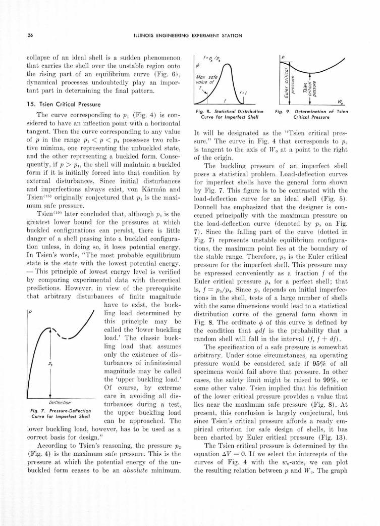
The curve corresponding to pi (Fig. 4) is con-sidered to have an inflection point with a horizontaltangent. Then the curve corresponding to any valueof p in the range pi < p < p4 possesses two rela-tive minima, one representing the unbuckled state,and the other representing a buckled form. Conse-quently, if p > p', the shell will maintain a buckledform if it is initially forced into that condition byexternal disturbances. Since initial disturbancesand imperfections always exist, von KArman andTsien ( 15) originally conjectured that pi is the maxi-mum safe pressure.
Tsien (10) later concluded that, although pi is thegreatest lower bound for the pressures at whichbuckled configurations can persist, there is littledanger of a shell passing into a buckled configura-tion unless, in doing so, it loses potential energy.In Tsien's words, "The most probable equilibriumstate is the state with the lowest potential energy.- This principle of lowest energy level is verifiedby comparing experimental data with theoreticalpredictions. However, in view of the prerequisitethat arbitrary disturbances of finite magnitude
have to exist, the buck-ling load determined bythis principle may becalled the 'lower bucklingload.' The classic buck-ling load that assumesonly the existence of dis-turbances of infinitesimalmagnitude may be calledthe 'upper buckling load.'Of course, by extremecare in avoiding all dis-
Deflection turbances during a test,Fig. 7. Pressure.Defletcion the upper buckling loadCurve for Imperfect Shell
can be approached. Thelower buckling load, however, has to be used as acorrect basis for design."
According to Tsien's reasoning, the pressure P2
(Fig. 4) is the maximum safe pressure. This is thepressure at which the potential energy of the un-buckled form ceases to be an absolute minimum.
Fig. 8. Statistical Distribution Fig. 9. Determination of TsienCurve for Imperfect Shell Critical Pressure
It will be designated as the "Tsien critical pres-sure." The curve in Fig. 4 that corresponds to p2is tangent to the axis of Wo at a point to the rightof the origin.
The buckling pressure of an imperfect shellposes a statistical problem. Load-deflection curvesfor imperfect shells have the general form shownby Fig. 7. This figure is to be contrasted with theload-deflection curve for an ideal shell (Fig. 5).Donnell has emphasized that the designer is con-cerned principally with the maximum pressure onthe load-deflection curve (denoted by p, on Fig.7). Since the falling part of the curve (dotted inFig. 7) represents unstable equilibrium configura-tions, the maximum point lies at the boundary ofthe stable range. Therefore, ps is the Euler criticalpressure for the imperfect shell. This pressure maybe expressed conveniently as a fraction f of theEuler critical pressure p4 for a perfect shell; thatis, f = p5/p 4. Since p5 depends on initial imperfec-tions in the shell, tests of a large number of shellswith the same dimensions would lead to a statisticaldistribution curve of the general form shown inFig. 8. The ordinate 0 of this curve is defined bythe condition that (df is the probability that arandom shell will fall in the interval (f, f + df).
The specification of a safe pressure is somewhatarbitrary. Under some circumstances, an operatingpressure would be considered safe if 95% of allspecimens would fail above that pressure. In othercases, the safety limit might be raised to 99%, orsome other value. Tsien implied that his definitionof the lower critical pressure provides a value thatlies near the maximum safe pressure (Fig. 8). Atpresent, this conclusion is largely conjectural, butsince Tsien's critical pressure affords a ready em-pirical criterion for safe design of shells, it hasbeen charted by Euler critical pressure (Fig. 13).
The Tsien critical pressure is determined by theequation AV = 0. If we select the intercepts of thecurves of Fig. 4 with the wo-axis, we can plotthe resulting relation between p and Wo. The graph

Bul. 443. BEHAVIOR OF CYLINDRICAL SHELLS UNDER EXTERNAL PRESSURE
has the general form shown in Fig. 9. The mini-mum ordinate of the curve is the Tsien critical pres-sure, and the corresponding value of Wo determinesthe deformation of the buckled shell, if the appliedpressure equals the Tsien critical pressure. Theintercept of the curve with the p-axis is the Eulercritical pressure. Although Fig. 9 looks like Fig. 5,the two curves are distinct, since they are derivedby different formulas. Fig. 9 is not a graph ofequilibrium configurations; it merely serves to showhow the Tsien critical pressure may be computed.
If there are no reinforcing rings, and if the shellis elastic, the equation AV = 0 yields
B, + B±2 WO2 + B 3 W04
a, - a2 Wo 2 (112)
The form of Eq. (112) remains valid for a cylinderthat is reinforced by elastic rings, if the coefficientsbi, b2 , b3 are modified suitably (See Eq. 99).
Plotting K versus Wo by means of Eq. (112),we obtain a curve that is essentially equivalent toFig. 9, although the ordinate is K rather than p.The intercept of the curve with the K-axis is de-termined by setting Wo = 0 in Eq. (112). Conse-quently, the value of K corresponding to the Eulercritical pressure is
Ki = Bi/ai (113)
The notation K, denotes the value of K that isobtained by the infinitesimal theory of buckling.
The value of K that corresponds to the Tsiencritical pressure, denoted by K,t (the subscripts"st" denote snap-through) is the minimum valueof the function defined by Eq. (112). To minimizeK, Wo2 must be a root of the equation,
W° = -- [1 + a +2 B - 2aio (114)
Although Eq. (114) may be solved by the quad-ratic formula, it is usually poorly conditioned forthis type of solution, and it is most easily solvedby iteration. The procedure is to obtain an ap-proximation of Wo2 by neglecting the fourth degreeterm on the right side of Eq. (112), and to usethis approximation to refine the first approxima-tion. The process of refinement may be iterated,and it converges quite rapidly. The value of Wo2,
determined by Eq. (114), must be substituted intoEq. (112). Thus, the Tsien critical pressure is de-termined. It is represented by p - KctEh/a, wherethe subscripts "st" denote "snap-through." The
Fig. 10. Graphs of f(p) and 0(p)
buckling coefficient Kst is plotted versus WTV in Fig.13 for values of a/h of 100 and 1000 and X = 7r.
16. Effect of Assumptions on the Tsien CriticalPressure
It is well known that arbitrary assumptionsabout the deformation of a structure cause thecomputed value of the Euler critical load to betoo high. The same conclusion applies for the Tsiencritical pressure. To verify this assertion, we ob-serve that the potential energy V is a functionalof the displacement components (u, v, w) and thepressure p. Let Class I be the set of all continuousdifferentiable functions (u, v, w) that satisfy theforced boundary conditions.
It has been found that there exists a pressurep' for a given shell, such that a buckled configura-tion will persist if p >p'. The buckled configura-tion, being stable, provides a relative minimumto V among functions of Class I. This minimumof V depends only on p; hence, it will be denotedby f(p). (See Fig. 4.)
It has been found that there exists a pressurep" (the Tsien critical pressure), such that f(p) > 0in the range p' < p < p", f(p") = 0, and f(p) < 0in the range p > p".
Let Class II be a given subset of Class I, asdetermined, for example, by assumptions about thenature of the deformation pattern. We have em-ployed two assumptions of this type: (1) the shellbuckles without incremental hoop strain. (2) Thefunction w, is represented by a single term of aFourier series in x (see Eq. 36). When the func-tions (u, v, w) are restricted to Class II, the mini-mum value of V is 0p(p). If our assumptions aregood, 0(p) differs but slightly from f(p).
Since Class II is a subset of Class I, q(p) f(p).Consequently, the graphs of f(p) and 04(p) have

ILLINOIS ENGINEERING EXPERIMENT STATION
the general features shown by Fig. 10. The essen-tial characteristics of these functions are that 0and f are positive for small values of p and nega-tive for large values of p, and that the curve repre-senting 01(p) lies above or in contact with thecurve representing f(p).
The Tsien critical pressure is the intercept ofthe graph of f(p) with the p-axis (Fig. 10). Evi-dently if 0(p) is used as an approximation for f(p),the computed value of the Tsien critical pressure istoo high.
17. Potential Energy Barriers
The maximum on the curve corresponding to p2(Fig. 4) represents a potential energy barrier thatthe shell must cross to arrive at the buckled form,if the pressure is exactly equal to the Tsien criti-cal pressure. Therefore, it serves as a rough indica-tion of the imminence of snap-through. The valueof this maximum may be derived from Eq. (100).For brevity, Eq. (100) is written as follows:
y = ax - bx2 + cx 3
& = EahL' x = Wo (a)
a = B1 - Kai, b = (B 2 + Ka 2), c = B3
The graph of y is as shown in Fig. 11.The maximum value of y is determined by dif-
ferentiation with respect to x. Thus,
a - 2bx + 3cx 2 = 0 (b)
The roots of Eq. (b) are
b [1 < 3acx = 1 - 1 b2
Sc(c)
X2 = I ( 3ac+=3c 1t 1 b2
Fig. 11. Potential EnergyBarrier
The root x1 provides themaximum, and the root x,provides the minimum(Fig. 11). Since the valueof the minimum is zero,
a - bx2 + cx 22 = 0
Eqs. (c) and (d) yield
b = 2 \/ac
Consequently, Eq. (c) yields
(d)
(e)
(f)x2=
Eqs. (a) and (f) yield
4cymax. 27 x X2
In terms of our previous notations, this equationyields,
(AV 4 hL B-Eamax
3 27 a2 B 3W (115)
where 1Wo is the root of Eq. (114) that correspondsto the point of tangency with the x-axis (Fig. 11).Eq. (115) is plotted in Fig. 13 for a/h = 1000,X = and for n= 2 to 20.
1 8. Numerical Example
Consider a shell with the following proportions:a/h = 100, L/a = 0.6010. The value L/a = 0.6010is selected to coincide with a tabulated value. Thiscondition is unimportant. If a selected value ofL/a does not appear in the tables, interpolationmust be used.
(a). Euler Critical Pressure for Shell with Simply-Supported Ends and No Axial End Constraint.
The equilibrium pressure corresponding to anygiven state of deformation is represented in the fol-lowing form: p = KEh/a. The constant K is evi-dently equal to the compression hoop strain thatexists in the unbuckled shell at pressure p. Thevalue of K corresponding to the Euler critical pres-sure is denoted by Ki. By Eq. (113), K1 = B,/a,,where B, = b + ch2 /a 2 . Accordingly, in this ex-ample, B, = bi + 0.0001 c,. The constants al, bi,c, for a shell with simply supported ends have beentabulated (Tables 2 to 20). The number of lobesin the buckled form must be determined by trialto minimize Ki. For very long shells, n = 2. Ingeneral, n increases with decreasing L or h. In thepresent example, L/a is small, but h/a is large.Therefore, a moderate value of n - for example,n = 10 - might be estimated. It is found by severaltrials that the value n = 9 actually provides aminimum to Kj. For n = 9, Table 9 yields (withA = r) a, - 0.9327, bi = 0.0006329, c, = 10.45.Consequently, B, = 0.001678. Accordingly, Eq.(113) yields Kj = 0.001678/0.9327 = 0.001799.
The condition A = 7r indicates that a uniformhydrostatic pressure acts on the ends of the shell.If A = 0, the axial force due to the pressure on theends is removed. Then a1 = 0.7952, as noted at thebottom of Table 9. Since bi and c, are independentof X, B, has the same value as before. Thus, if
1 axx 3 c

Bul. 443. BEHAVIOR OF CYLINDRICAL SHELLS UNDER EXTERNAL PRESSURE
A = 0, then K, = B,/a, = 0.001678/0.7952 =0.002110. Accordingly, in this example, the hydro-static pressure on the ends reduces the Euler criti-cal pressure about 15%.
For the case A = 0, von Mises (1 ' derived a for-mula that may be put in the following form:
Ki = 1 - +
h22S 1)(1 + n2L 12(1 - P) an - 2n 2 -
. n + n L2 (116)1+ n2 L
In the present numerical example, von Mises' for-mula yields K, =0.001900. This result is about 10%lower than that computed by the present theory.There is seemingly a systematic deviation betweenthe present infinitesimal theory and von Mises'theory, for thick shells that are short compared totheir radii. However, in all cases, the Tsien crite-rion yields lower values than the von Mises' theory.
(b) Pressure-Deflection Curves for Elastic Shellwith Simply-Supported Ends and No Axial EndConstraint.
The pressure-deflection curve is essentially agraph of K versus WTV,, where K is defined as above.This curve may be plotted by means of Eq. (111).Setting n = 9, we obtain from Table 9 (with A =X ),
a, = 0.9327, a2 = -1.270,bi = 0.0006329, b2 = -0.02334, bN = 0.3077,c, = 10.45, c2 = 14.89, ca = 0.1124.
The b's and c's are independent of A. The quanti-ties B 1 , B 2, B3 are determined by B, = bi + ch2/a 2 ,B, = b, +c, h'/a2, B3 = b + c+. h2 /a 2 . In the pres-ent example, h2/a 2 = 0.0001. Hence,
B, - 0.001678, B2 = - 0.02185, B3 = 0.3077.
Substituting these values of a, a2, B, B,, B3 intoEq. (111), we obtain an equation whose graph isshown in Fig. 12. Since the curves corresponding ton = 8 and n = 9 intersect each other, the curve forn = 8 is also plotted.
The intercept of the curve for n = 9 with thevertical axis is the Euler critical hoop strain,Ki = 0.001799. The minimum value on the curvefor n = 9 is Kmin = 0.001170. The minimum valueon the curve for n = 8 is Kmin = 0.001080. Thisis the lowest minimum that occurs for any value ofn. Therefore, it determines the lowest pressure atwhich the shell will maintain a buckled form, if itis perfectly elastic.
2400a/h =/00, A7 z-
* denotes rigid ends (Article 13) n=9* denotes Tslen coefficient
2200 _____
1800
oo-\\ \ L/o 0.6010 I
600oo -
1400 - -- -- - - --- f - ---
1200 ._"
/000 - ----
L /a / 5 9 n-8
600 --. _
400-U .05 JoIU .IS
WoFig. 12. Buckling Coefficient K versus
Deflection Parameter Wo
Hence, in this example, the lowest pressure atwhich the elastic shell will maintain a buckledform is 60% of the Euler critical pressure.
The value of K corresponding to the Tsien criti-cal pressure has been denoted by K,t. For this case,Kt = 0.00133. This result may be obtained fromEq. (112). The Tsien critical pressures have beenmarked on the curves of Fig. 15. The Euler criticalpressure for this case (see above) is Ki = 0.001799which is 35% higher than Kt.
(c) Effect of Rigid Ends.
If the ends of the shell are hinged, but the axialdisplacements are constrained by the action ofrigid end plates, the buckling pressure is increasedsignificantly. Eqs. (111) and (113) remain valid,but the coefficients b,, b,, b, are changed. The con-stants a,, a,, c, c2y, C3 are not altered.
The constants b1 , b,, b, have not been tabulatedfor a shell with rigid ends. Consequently, their

ILLINOIS ENGINEERING EXPERIMENT STATION
values must be computed by means of Eqs. (105),(107, (110), and (72).
The constraint imposed by rigid end plates
generally increases the number of lobes in the
buckled form. Trying n - 10, we obtain by Eq.(48), e = 1.778. Hence, by Eq. (105),
Fj(ý) = -0.003675, F 2(Q) = 0.001648,Fa(Q) = -0.002098.
Using the values of the K's from Table 1, we ob-
tain by Eq. (107),
,i = -0.0001565,3a = 0.000382,
P5 = 0.02203,
IP2 = 0.005605,T4 = -0.05900,
IP = -0.006755.
Eq. (110) yields X1 = 0.002364.In Eq. (72), the functions fl, f 2, . . . are to be re-
placed by i,, !2, . . ., respectively. Also, X, replaces
0,. The functions ,2 and g are discarded since they
are negligible.
Hence, bi = 0.0006858, b2 = - 0.01210, b3 =0.2929. Interpolating values from Table 10, weobtain
al = 0.904, a2 = - 1.27, c, = 11.68, c2 = 15.14,c3 = 0.139.
Since B, b, + ch 2/a 2, B 2= b2 + ch 2/a 2, andB, = b + ch2/a 2, B -= 0.00185, B2 = - 0.0106,B3 -= 0.293. Eq. (111) now provides a graph of Kversus Wo (Fig. 12).
It is necessary to repeat the calculations forseveral other values of n. It is found by trial thatthe value n = 11 provides the lowest buckling pres-sure. The curves corresponding to n = 10 andn = 11 are plotted in Fig. 12. It is seen that thesecurves are significantly higher than the curvesobtained for a shell without axial end constraints.Similar calculations have been performed forL/a = 1.159 and the results have been plotted inFig. 12. All the curves for L/a = 1.159 are lowerthan the corresponding curves for L/a = 0.6010.

V. SUMMARY
A theory, based on an energy analysis, has beendeveloped for the snap-through and post-bucklingbehavior of simply-supported ideal shells underthe action of external pressure. The principal re-sults of the theory are given: (a) by Eqs. (71),(72), (97), (100), (101), (111), (112), and (113)for elastic shells whose ends are free to warp outof their planes, and (b) by Eqs. (72), (105), (107),(110), (111), (112), and (113), and the modifica-tions indicated in Article 13 for elastic shells whoseends are rigid plates.
IQ
0ý
The main results of the computations are pre-sented in the form of tables and graphs. Tables1 to 20 list the parameters needed for calculationof the buckling coefficient K given by per = KEh/a.The use of Tables 1 to 20 is illustrated by a nu-merical example (Article 18). Table 21 gives valuesof K, for elastic shells whose ends are free to warpout of their planes, as determined by the infinites-imal theory and the Tsien snap-through theory forvarious values of L/a and A, and for a/h = 1000.For no axial pressure (A = 0), some values of K
Log,0IOL/o
Fig. 13. Buckling Coefficients for Cylindrical Shells Subjected to Hydrostatic Pressure

ILLINOIS ENGINEERING EXPERIMENT STATION
0/h /lO00o , =7-500 -
25C _ - _ _ __ - __
00
-=10 \
Sn=5
50
250 - -
#. - - -- - -- -- -- -- - -
.10 .25 .50 50 /0 25 50 /00
Fig. 14. Potential Energy Barriers Separating Buckledand Unbuckled Forms
as calculated by von Mises' theory are given forcomparison. Table 22 lists similar values of K fora/h = 100.
Discrepancies between von Mises' theory andthe present infinitesimal theory are greatest forshort thick shells. Apparently, the trouble lies inthe assumption that the shell buckles without in-cremental hoop strain. Von Mises did not makethis assumption.
For elastic cylinders whose ends are free towarp out of their planes, the Euler buckling coeffi-cient (Infinitesimal Theory) and the Tsien buck-ling coefficient (Elastic Snap-Through Theory) areplotted versus L/a in Fig. 13 for a/h = 100 anda/h = 1000 with X = r. Some of the data of Fig.13 are reproduced in Tables 21 and 22. For long
slender cylinders (see Tables 21 and 22), the Eulerbuckling coefficient is only slightly higher than theTsien coefficient. However, for relatively smallvalues of L/a (say, L/a = 0.6010), the Euler coeffi-cient may be 30 to 35% higher than the Tsiencoefficient. In the numerical example of Article 18,the Tsien coefficient is approximately 14% higherthan the minimum pressure under which the elasticshell will maintain a buckled form. Prevention ofend warping raises the critical pressure (Fig. 12).
For A = 0 (no end pressure), all the criticalpressures as determined by the different theoriesare raised. The effect of axial compression is great-est for small values of L/a. It becomes insignificantfor very large values of L/a (Tables 21 and 22).
The negative slopes of the load-deflection curves(Fig. 12) denote a condition favorable to snap-through. The potential energy barrier that the shellmust overcome to snap-through is discussed inArticle 17. Fig. 14 is a chart that shows these bar-riers for a/h = 1000 and X = 7. The curve is dis-continuous because of sudden changes in n. Thedashed curves have no significance; they merelyoutline the region in which the discontinuous curvelies. The points of discontinuity correspond to thecusps on curve 4 of Fig. 13. For example, if L/a =0.6 and a/h = 1000, Fig. 14 shows that n = 17and 1012 A V/Ea3 = 11.5. Hence, if a = 20 in. and
E = 30,000,000 psi, AV =- 2.76 in.-lb = 0.23 ft-lb.This result means that only 0.23 ft-lb of work mustbe supplied from the outside to cause snap-through.Accidental disturbances might easily supply thismuch energy. Imperfections are perhaps a morefrequent cause of snap-through than accidental dis-turbances, although submarine hulls may be sub-jected to damaging shocks.

VI. REFERENCES
1. "Theory of Elastic Stability," by S. Timoshenko,McGraw-Hill Book Co., Inc. New York and London,1936.
2. "The Resistance of Tubes to Collapse," by WilliamFairbairn, Philosophical Trans., Vol. 148, pp. 389-413, 1848.
3. "The Collapse of Short Thin Tubes," by A. P. Carman,Bulletin No. 99, Eng. Exp. Sta., Univ. of Ill., 1917.
4. "The Collapsing Strength of Steel Tubes," by T. Mc-Lean Jasper and John W. W. Sullivan, Trans.A.S.M.E., Vol. 53, APM-53-17b, pp. 219-245, Sept.-Dec., 1931.
5. "Strength of Thin Cylindrical Shells Under ExternalPressure," by H. E. Saunders and D. F. Windenburg,Trans. A.S.M.E., Vol. 53, APM-53-17a, pp. 207-218,Sept.-Dec., 1931.
6. "Collapse by Instability of Thin Cylindrical ShellsUnder External Pressure," by D. F. Windenburg andC. Trilling, Trans. A.S.M.E., Vol. 56, APM-56-20,pp. 819-825, Nov., 1934.
7. "A Study of the Collapsing Pressure of Thin-WalledCylinders," by R. G. Sturm, Bulletin No. 329, Eng.Exp. Sta., Univ. of Ill., 1941.
8. "Application of the Energy Test to the Collapse ofLong Thin Pipe Under External Pressure," by G. H.Bryan, Proc. Cambridge Phil. Soc., Vol. VI, pp. 287-292, 1888.
9. "Collapse of Tubes," by R. V. Southwell, Phil. Mag.,pp. 687-698, May, 1913; pp. 503-511, Sept., 1913; pp.67-77, Jan., 1915.
10. "The Collapse of Short Thin Tubes by External Pres-sure," by Gilbert Cook, Phil. Mag., pp. 51-56, July,1914.
11. "Der kritische Aussendruck zylindrischer Rohre," byR. von Mises, Vol. 58, V. D. I. Zeitschr., pp. 750-756, 1914.
12. "A New Theory for the Buckling of Thin CylindersUnder Axial Compression and Bending," by L. H.Donnell, Trans. A.S.M.E., Vol. 56, AER-56-12, pp.795-806, Nov. 1934.
13. "A Simplified Method of Elastic-Stability Analysis forThin Cylindrical Shells." I-Donnell's Equation, byS. B. Batdorf, NACA TN No. 1341, June, 1947.
14. "On the Minimum Buckling Load for Spherical Shells,"by K. 0. Friedrichs, Theodore von Karmtin Anniver-sary Volume, California Institute of Technology,Pasadena, California, pp. 258-272, May 11, 1941.
15. "The Buckling of Spherical Shells by External Pres-sure," by Th. von Karman, and H. Tsien, Jour.Aero. Sci., p. 43, 1939.
16. "Theory of Elasticity," by S. Timoshenko and J. N.Goodier, McGraw-Hill Book Company, Inc., 2ndEd. p. 157, Eq. r. 1951.
17. "Approximation Methods in Higher Analysis" (InRussian), Kantorovich and Krylov, Moscow, 1950,Chapter IV, Article 1.
18. "A Treatise on the Mathematical Theory of Elasticity,"by A. E. H. Love, Dover Publications, New York,4th Edition, p. 503, 1944.
19. "A Theory for the Buckling of Thin Shells," by H. S.Tsien, Jour. Aero. Sci., Vol. 9, No. 10, Aug. 1942.
20. "Finite Deformations of an Elastic Solid," by F. D.Murnaghan, Art. 4, Chap. 2, John Wiley and Sons,New York, 1951.

VII. APPENDIX
Table 1
Values of K's for v = 0.30
Subscripts denote number of zeros preceding first significant figure.n Ki K2 K3 K4 K5 K 6 K7 K, K,2 0.43787 0.0211631 1.44334 0,68539 0.16004 0.33126 0.21035 0.087164 2.84223 0.061575 0.0321363 0.40657 0.19277 0.15654 0.046584 0.084115 0.090544 1 51574 0.017515 0,0465935 0.19723 0.093213 0.15548 0.013250 0.045660 0.091700 1.05825 0.0268417 0.0426701 0.11807 0.055688 0.15501 0.0251760 0.028753 0.092232 0.819696 0.0232170 0.0412798 0.079100 0.037263 0,15476 0.0224338 0.019794 0.092518 0.671397 0.0217104 0.0568822 0.056878 0.026773 0.15461 0.0212940 0.014467 0.092691 0.569568 0.0399290 0.0540245 0.042946 0.020204 0.15452 0.0375116 0.011039 0.092804 0.495069 0.0361575 0.0525084 0.033611 0.015807 0.15445 0.0346584 0.0287018 0.092880 0.43805
10 0.0340208 0.0516438 0.027041 0.012713 0.15441 0.0430419 0.0270368 0.092935 0.3929611 0.0327367 0.0511218 0.022236 0.010452 0.15437 0.0320704 0.0258084 0.092975 0.3563812 0.0a19271 0.0,79152 0.018613 0.0287479 0.15435 0.0314580 0.0248762 0.093006 0.3260913 0.0313963 0.0657437 0.015813 0.0274309 0.15433 0.0a10563 0.0241519 0.093030 0.3005814 0.0310364 0.0642685 0.013603 0.0263916 0,15431 0.0478405 0.0235779 0.093049 0.2787915 0.0478540 0.0632380 0,011827 0.0255568 0.15430 0.0459418 0.0231153 0.093064 0.2599716 0.0460605 0.0625006 0.010379 0.0248760 0.15429 0.0445849 0.0227366 0.093076 0 2435417 0.0447512 0.0619617 0.0,91817 0.0243134 0.15428 0.0435944 0.0224237 0.093087 0.2290818 0.0437773 0.0615605 0.0281810 0.0238432 0.15427 0.0428576 0.0221613 0.093096 0.2162419 0.0430408 0.0612568 0.0273359 0.0,34460 0.15427 0.0423004 0.0219394 0.093103 0.2047720 0.0424754 0.0610235 0.0266155 0.0231075 0.15426 0.0418727 0.0217500 0.093110 0.19446
Table 1 (Concluded)
n Ko K K, K Ku K14 K15 Ku6 K1 7 Kis2 0.26572 0.73304 0.43982 2.5839 0.086128 0.027489 1.04720 0.071177 0.258393 0.40644 0.41234 0.33576 0.09895 0.020763 0.017671 0.88357 0.072579 0.110744 0.54541 0.29322 0.30718 0.51677 0.0282027 0.013090 0 .83776 0.073047 0.0615205 0.68375 0.22907 0.29502 0.32298 0.0240780 0.010412 0.81812 0.073259 0.0391496 0.82178 0.18850 0.28868 0.22147 0.0223231 0.0286504 0.80784 0.073374 0.0271037 0.95964 0.16035 0.28493 0.16149 0.0214493 0.0,74009 0.80176 0.073442 0.0198768 1.09740 0.13963 0.28254 0.12304 0.0,96502 0.0,64680 0.79786 0.073487 0.0151999 1.2351 0.12370 0.28091 0.096894 0.0467496 0.0257446 0.79522 0.073517 0.01199910 1.3727 0.11107 0.27975 0.078299 0.0349059 0.0251671 0.79333 0.073539 0.029713711 1.5103 0.10079 0.27890 0.064596 0.0,36778 0.0246953 0.79194 0.073555 0.028024412 1.6479 0.092271 0.27826 0.054207 0.0328282 0.0243026 0.79089 0,073567 0.026740513 1.7854 0.085085 0.27776 0.046140 0.0,22216 0.0239706 0.79007 0.073576 0.025741914 1.9230 0.078943 0.27736 0.039752 0.0317769 0.0236862 0.78943 0.073584 0.024949915 2.0605 0.073631 0.27704 0.034605 0.0314435 0.0234399 0.78890 0.073590 0.024311216 2.1980 0.068992 0.27678 0.030398 0.0311886 0.0232245 0.78848 0.073595 0.023788617 2.3355 0.064905 0.27656 0.026915 0.0499038 0.0230345 0.78812 0.073599 0,023355618 2.4730 0.061276 0.27638 0.023999 0.0483393 0.0228656 0.78783 0.073603 0.022992919 2.6105 0.058032 0.27623 0.021532 0.0470878 0.0227146 0.78758 0.073606 0.022685920 2.7480 0.055116 0.27610 0.019427 0.0,60749 0.0225787 0.78736 0.073608 0.0224239
Table 2
Values of Coefficients for Computing Buckling Loads-n = 2
n = 2 X r v = 0.30L/a a, az bi b2 b6 ci c2 c3
4 6.7612 1.0943 0.06018 0.039680 0.039558 0.3233 0.05798 0.0256265 8,4516 1.0773 0.06414 0.034165 -0.0a7060 0.0a4230 0.3102 0.05634 0.0256246 10.142 1.0681 0.06629 0.032065 -0.033504 0.0,2144 0.3032 0.05553 0.0256227 11.832 1.0625 0.06759 0.031134 -0.031926 0.031197 0.2990 0.05508 0.0256218 13.522 1.0589 0.06843 0.046720 -0.031146 0.047193 0.2963 0.05480 0.025621
10 16.903 1.0547 0.06942 0.042788 -0.044744 0.0,3041 0.2932 0.05448 0.02562012 20.284 1.0524 0.06996 0.041354 -0.042327 0.041494 0.2915 0.05431 0.02562015 25.355 1.0506 0.07040 0.055574 -0.059597 0.056222 0.2901 0.05417 0.02562020 33.806 1.0491 0.07074 0.041769 -0.0s3054 0.051996 0.2890 0.05407 0.0%561925 42.258 1.0484 0.07090 0.0,7238 -0.061254 0.068235 0.2886 0.05402 0.02561930 50.709 1.0480 0.07098 0.0,3483 -0.066066 0.063989 0.2883 0.05400 0.02561940 67.612 1.0477 0.07107 0.061094 -0.061921 0.0,1270 0.2880 0.05397 0.02561950 84.516 1.0475 0.07111 0.074439 -0.077986 0.075228 0.2879 0.05396 0.0,561960 101.42 1.0474 0.07113 0.072111 -0.073838 0.072535 0.2878 0.05396 0.02561975 126.77 1.0473 0.07115 0.0s8454 -0.071617 0.071046 0.2878 0.05395 0.025619
100 169.03 1.0473 0.07116 0.0s2501 -0.0s5054 0.0s3360 0.2877 0.05395 0.025619125 211.29 1.0472 0.07117 0.0,9686 -0.0s2122 0.0s1408 0.2877 0.05394 0.025619150 253.55 1.0472 0.07117 0.0,4119 -0.0,1011 0.096960 0.2877 0.05394 0.025619200 338.06 1.0472 0.07117 0.0,o9321 -0.0,3034 0.01ol98 0.2877 0.05394 0.025619
If X=0, a = 1.0472 and as= 0.07118. The b's and c's are independent of X.

Bul. 443. BEHAVIOR OF CYLINDRICAL SHELLS UNDER EXTERNAL PRESSURE
Table 3
Values of Coefficients for Computing Buckling Loads - n = 3n = 3 =
L/a a, a2 bi
2.704 0.9664 0.025343 0.0219103.155 0.9444 0.02318 0.0211203.606 0.9301 0.03476 0.0369564.508 0.9134 0.04837 0.0330635.634 0.9026 0.05709 0.0313186.761 0.8968 0,06182 0.0465367.888 0.8933 0.06468 0.0435899.015 0.8910 0.06653 0,042128
11.269 0.8883 0.06871 0.0s883413.523 0.8869 0.06989 0.05429216.904 0.8857 0.07086 0.05176822.538 0.8848 0.07161 0.06562228.172 0.8843 0.07196 0.06230733.81 0,8841 0.07215 0.0N111345.08 0.8839 0,07234 0.07352756.34 0.8838 0.07242 0.07145467.61 0.8837 0.07247 0.0s693884.52 0.8836 0.07251 0.0s2879
112.69 0.8836 0.07254 0.099986If X=0, a1=0.8836 and a2=0.07258. The b's and c's are independent of X.
r ' = 0.30b2 b
-0.0 27619 0.01077-0.024485 0.026490-0.022793 0. 04137-0.021234 0.021911-0.035394 0.038630-0.032639 0. 034443-0.031450 0.032511-0.048596 0.031522-0.043569 0.046506-0.041754 0.043220-0.057145 0.041350-0.052271 0.054352-0.009335 0.0s1799-0.0,4494 0.068725-0. 01421 0.062780-0.07583 0.061145-0.0:279 0.075550-0.07117 0.072294-0.0s34 0.0s729
Table 4
Values of Coefficients for Computing Buckling Loads - n = 4
n = 4L/a al a2 bi
1.690 0.9402 -0.09791 0.0217692.028 0.9089 -0.04568 0.0396562.366 0.8900 -0.01418 0.0356622.704 0.8778 0.026266 0.0335163.381 0.8634 0.03031 0.0315484.226 0.8542 0.04569 0.0466605.071 0.8492 0.05405 0.0433025.916 0.8461 0.05909 0.0418126.761 0.8442 0.06236 0.0410748.452 0.8419 0.06621 0.0.4454
10.14 0.8406 0.06830 0.0,216112.68 0.8396 0.07001 0.0M888116.90 0.8388 0.07134 0.06280921.13 0.8384 0.07195 0.02114525.35 0.8382 0.07229 0.07547833.81 0.8380 0.07262 0.07169842.26 0.8379 0.07277 0.0N6805
If X= 0, ai=0.8378 and a0 =0.07305. The b's and c's are independent of X.
v = 0.30b2 b
-0.01273 0.03261-0.026993 0.01837-0.024116 0.01112-0.022562 0.027116-0.021132 0.023311- 0.04877 0.021507-0.032421 0.037797-0.0A1330 0.034422-0.047886 0.032687-0.043275 0.031152-0.041592 0.045715-0.056562 0.042399-0.052088 0.027749- 0.08585 0.053205-0.024152 0.001555-0.0.1322 0. 06495-0.07545 0.06205
Table 5
Values of Coefficients for Computing Buckling Loads-n 5
=5 X = -L/a a0 as b1
1.082 0.9676 -0.3429 0.0221701.352 0.9138 -0.1931 0.0210801.623 0.8846 -0.1117 0.0358951.893 0.8669 -0.06262 0.0334572.164 0.8555 -0.03077 0.0321472.704 0.8420 0.026678 0.0494543.381 0.8334 0.03065 0,0440684.057 0.8288 0.04367 0.0420174.733 0.8259 0.05151 0.0411085.409 0.8241 0.05661 0.0t65676.761 0.8219 0.06261 0.0M27268.113 0.8208 0.06686 0.051324
10.142 0.8198 0.06852 0.06545613.52 0.8191 0.07060 0.02173416.90 0.8187 0.07155 0.07711520.28 0.8185 0.07208 0.07343227.04 0.8184 0.07259 0.07108633.81 0.8183 0.07283 0.084452
If X=0, ai= 0.8181 and a2= 0.07326. The b's and c's are independent of X.
b2
-0.02441-0.01227-0.026733-0.023963-0.022467-0.021
0 89
-0.034693-0.032329-0.0,l280-0.047586-0.043140-0.041530-0.0s6305-0.0.2005- 0.08229-0.02,4012-0.061257-0.075173
v = 0.30b1
0.097340.049990.028220.017120.010960.0251240.0223380.0212130.0.68900.0341910.0318020.0M89420.0437570.0412150.0050270.0524390.0677830.0N3205
Table 6
Values of Coefficients for Computing Buckling Loads - n = 6
n =6 A = r v =0.30t L/a a a0 b6i
1.2 0.6761 1.0639 -0.9902 0.0233621.6 0.9015 0.9519 -0.5249 0.0214702.0 1.127 0.9000 -0.3095 0.0373122.4 1.352 0.8719 -0,1925 0.0,39912.8 1.578 0.8549 -0.1220 0.0323413.2 1.803 0.8438 -0.07619 0.0314544 2.254 0.8309 -0.02234 0.0464015 2.817 0.8226 0.01111 0.0427546 3.381 0.8181 0.03083 0.0413657 3.944 0.8154 0.04212 0.0574978 4.507 0.8136 0.04944 0.0s4444
10 5.634 0.8115 0.05806 0.05184412 6.761 0.8104 0.06274 0.02895615 8.452 0.8095 0.06657 0.06368720 11.27 0.8088 0.06954 0.06117025 14.08 0.8084 0.07092 0.074790
If = 0, a,= 0.8078 and a2= 0.07337. The b's and c's are independent of X.
b2
-0.05376-0.02393-0.01202-0.026542-0.023888-0.022418-0.021067-0. 04600-0.032282-0.031254-0.047385-0.043087-0.041500-0.026181-0.051966-0.008035
b3
0.30800.13860.071280.040280.024450.015700.0273410.0233560.0217430.0399080. 0360300.0325940.0312880.0454120.0417490.0J7237
Cl C2 C3
6.707 9.160 0.049564.663 3.303 0.050003.844 1.677 0.050213.434 1.083 0.050323.198 0.8222 0.050383.049 0.6925 0.050432.879 0.5798 0.050482.773 0.5302 0.050512.716 0.5106 0.050532.682 0.5014 0.050542.660 0.4963 0.050552.634 0.4914 0.050562.621 0.4892 0.050562.609 0.4877 0.050562.600 0.4866 0.050572.596 0.4862 0.05057
Cl
0.86710.80520.76640.72220.69470.68000.67120.66560.65900.65540.65250.65020.64920.64860.64800.64780.64760.64750.6474
C2
0.17300.15190.14240.13240.12750.12520.12400.12330.12260.12220.12190.12160.12160.12150.12140.12140.12140.12140.1214
C3
0.012620.012620.012630.012630.012640.012640.012640.012640.012640.012640.012640.012640.012640.012640.012640.012640.012640.012640.01264
Cl1.7191.5321.4251.3581.2811.2331.2081.1921.1831.1711.1651.1601.1561.1541.1531.1521.152
C2
0.47790.35220.29590.26710.24100.22890.22370.22110.21960.21800.21720.21670.21630.21610.21600.21590.2158
C3
0.022600.022560.022540.022520.022510.022500.022490.022480.022480.022480.022480.022480.022480.022480.022480.022480.02248
3.2482.6752.3882.2232.1192.0001.9261.8861.8631.8481.8301.8201.8121.8061.8031.8021.8001.799
C2e
1.7310.93470.64090.51110.44590.38830.36230.35180.34660.34380.34090.33960.33860.33790.33760.33750.33730.3372
0c
0.034760.034890.034960.035000.035030.035060.035080.035090.035100.035100.035110.035110.035110.035110.035120.035120.035120.03512

ILLINOIS ENGINEERING EXPERIMENT STATION
Table 7
Values of Coefficients for Computing Buckling Loads - n = 7
n=7 X=( L/a ai a2 bi1.0 0.4829 1.1624 -2.009 0.0,39481.2 0.5795 1.0522 -1.373 0.0224331.6 0.7727 0.9426 -0.7400 0.0210642.0 0.9659 0.8919 -0.4472 0.0352922.4 1.159 0.8644 -0.2881 0ý.028892.8 1.352 0.8478 -0.1922 0.0216943.2 1.545 0.8370 -0.1299 0.0A10524 1.932 0.8243 -0.05671 0.0446345 2.415 0,8162 -0.029858 0.0,19946 2.898 0.8118 0.01559 0.0s98897 3.381 0,8091 0,03094 0.0,54318 3.864 0.8074 0.04090 0.0,3220
10 4.829 0.8054 0.05262 0.051330If X =0, ai=0.8018 and a2=0.07344. The b's and c's are independent of X.
b2
-0.08504-0.05314-0,02364-0,01188-0.026580-0.023838-0.022388-0.021054-0.0A4544-0.032255-0.031239-0.047345-0.043050
=0.30Nb ct c(2
0.6668 12.388 33.430.4162 9.098 16.590.1875 6.335 5.7980.09646 5.227 2.8170.05455 4.670 1.7310.03314 4.350 1.2580.02129 4.148 1.0240.029965 3.918 0.82240.024560 3.774 0.73530.022370 3.696 0.70160.021348 3.650 0.68590.038206 3.621 0.67760.0.3532 3.586 0.6698
Table 8
Values of Coefficients for Computing Buckling Loads - n 8n = 8 X = 6 v = 0.30
t L/a al a2 bi1.0 0.4226 1.153 -2.645 0.0229931.2 0.5071 1.045 -1.814 0.0?18441.6 0.6761 0.9367 -0.9884 0.0,80642.0 0.8452 0.8867 -0,6061 0.0340122.4 1.014 0.8596 -0.3985 0.0a21902.8 1.183 0.8432 -0.2732 0.0,12843.2 1.352 0.8326 -0.1920 0.0479754 1.690 0.8201 -0.09641 0.0435125 2.113 0.8121 -0.03525 0.0,15116 2.535 0.8077 -0.0-2024 0.0374927 2.958 0.8051 0.01801 0.0541138 3.381 0.8034 0,03101 0.0,2438
10 4.226 0.8014 0.04630 0.0,1012If \=0, ai=0.7979 and a= 0.07349. The b's and c's are independent of X.
b2-0.08441-0.05273-0.02346-0.01178-0.026470-0.023808-0.022370-0.021046-0. 0,4509-0.0,2237-0.031213-0.047285-0.043024
Na0. 86670.54110.24380.12550.071030.043160.027740.012990.0259500.0230930.0217600.0210720.034614
Cl
16.1311.868.2646.8226.0975.6805.4175.1164.9284.8284.7684.7294.683
c256.5427.879.5374.4832.6491.8521.4601.1240.98090.92630.90120.88820.8761
Table 9
Values of Coefficients for Computing Buckling Loads - n = 9n = 9 \ = , v = 0.30
L/a a, a2 bi b21.0 0.3756 1.147 -3.366 0.022349 -0.083981.2 0.4507 1.040 -2.315 0.021448 - 0. 052921.6 0.6010 0,9327 -1.270 0.036329 -0.023342.0 0.7512 0.8832 -0.7862 0.033149 -0,011722.4 0.9015 0.8563 -0.5235 0.031719 -0.0264372.8 1.052 0.8401 -0.3651 0.031008 -0.0237883.2 1.202 0.8296 -0.2623 0.046260 -0.0223574 1.502 0.8172 -0.1414 0.042756 -0.0210415 1.878 0.8093 -0.06404 0.041186 -0.0,44846 2.254 0.8050 -0.02201 0.055880 -0.0ý22257 2.629 0.8024 0.0.3333 0.053228 -0.0312228 3.005 0.8007 0.01978 0.0,1914 -0.047247
10 3.756 0.7987 0.03913 0.07941 -0.04300812 4.507 0.7977 0.04964 0.0,3856 -0.04146215 5.634 0.7968 0.05823 0.01587 -0.05602220 7.512 0.7961 0.06492 0 075037 -0.051914
If X=0, ai=0.7952 and a2=0.07352. The b's and c's are independent of X.
b,1.09340.68270. 30770.15850.089700.054530.035050.016420.0%75250.0239130.0222230.0213560.0,58390.0329010.0310680.043941
Cl
20.3814.9910.458.6297.7147.1866.8556.4746.2376.1106.0345.9855.9275.8965.8715.851
C290.0244.1814.896.8283.9082.6442.0241.4951.2711.1861.1481.1291.1111.1031. 0981.095
Table 10
Values of Coefficients for Computing Buckling Loads - n - 10n = 1
0 X =
L/a al a2 bi
0.8 0.2704 1.339 -6.559 0.0233021.0 0.3381 1.143 -4.171 0.0218941.2 0.4057 1.036 -2.874 0.0211671.6 0.5409 0.9298 -1.584 0.0351032.0 0.6761 0.8807 -0.9876 0.0,25392.4 0.8113 0.8540 -0.6634 0.0313862.8 0.9466 0.8379 -0.4677 0.0481273.2 1.082 0.8275 -0.3410 0.0450474 1.352 0.8152 -0.1918 0.0422225 1.690 0.8073 -0.09624 0.0,95636 2.028 0.8030 -0,04437 0.0547427 2.366 0.8005 -0.01309 0.0s26048 2.704 0.7988 0.027217 0.0,1543
10 3.381 0.7968 0.03109 0.0,640712 4.057 0.7958 0.04406 0.0,311215 5.071 0.7949 0.05467 0.06128220 6.761 0.7942 0.06293 0.074074
If X=0, ai=0.7933 and a = 0.07354. The b's and c's are independent of X.
bz
-0.1431-0.08367-0.05227-0.02326-0.01168-0.026412-0.023794-0.022348-0,021037-0.034468-0.0a2217-0.0al218-0.047221-0.043000-0.041454-0.0s6006-0.0A1911
= 0.30b,
2.32171.34670.84100.37920.19530.11060.067240.043230.020260.0292870.0A48310.0227450.0216750.0,72150.0335860.0315080.044882
Cl40.0225.1218.4812.8910.659.5208.8718.4617.9927.6997.5437.4497.3887.3177.2797.2487.223
C2
330.6136.666.8322.2710.025.5933.6792.7421.9451.6101.4841.4281.4001.3731.3631.3561.352
C3
0.066750.067380.068020.068310.068470. 068570.068630.068700.068750.068770.068790.068800.06881
C3
0.087090.087950.088800.089200.089420.089540.089630.089730.089790.089820.089850.089860.08988
C3
0.11010.11120.11240.11290.11310.11330.11340.11360.11360.11370.11370.11370.11370.11370.11370.1137
e3
0.13340.13590.13730.13870.13930.13970.13990.14000.14020.14030.14040.14040.14040.14040.14040.14040.1404
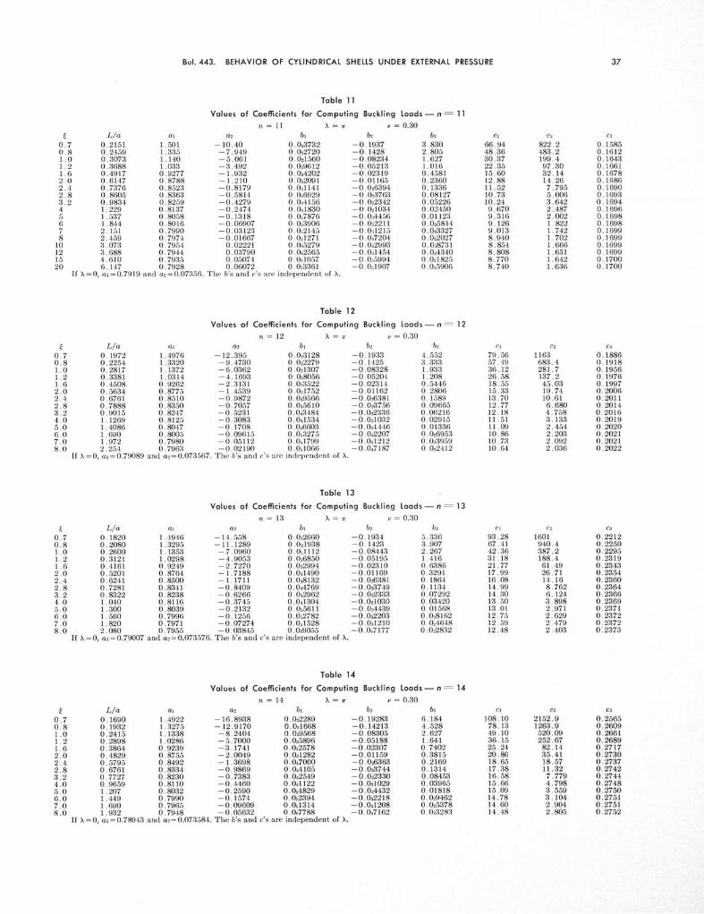
Bul.443. BEHAVIOR OF CYLINDRICAL SHELLS UNDER EXTERNAL PRESSURE
Table 11
Values of Coefficients for Computing Buckling Loads - n = 11n = 11 X = -v = 0.30
t L/a at a2 bi0.7 0.2151 1.501 -10.40 0.0237320.8 0.2459 1.335 -7.949 0,0227201.0 0.3073 1.140 -5.061 0.0215601.2 0,3688 1.033 -3.492 0.0396121.6 0.4917 0.9277 -1.932 0.0342022.0 0.6147 0.8788 -1.210 0.0220912.4 0.7376 0.8523 -0.8179 0.0311412.8 0.8605 0.8363 -0.5814 0.0469293.2 0.9834 0.8259 -0.4279 0.0441564 1.229 0.8137 -0.2474 0.0418305 1.537 0.8058 -0.1318 0.0578766 1,844 0.8016 -0.06907 0.0539067 2.151 0.7990 -0.03123 0.0s21458 2.459 0.7974 -0.01667 0.051271
10 3.073 0.7954 0.02221 0.0N527912 3.688 0.7944 0.03790 0.0«256515 4.610 0.7935 0.05074 0.0W105720 6.147 0.7928 0.06072 0.073361
If X =0, ai=0.7919 and a2=0.07356. The b's and c's are independent of X.
b2
-0.1937-0.1428-0.08234-0.05213-0.02319-0.01165-0.026394-0.023763-0.022342-0. 021034-0.034456-0.032211-0.031215-0.047204-0.042993-0.041454-0.0.5994-0.051907
ba3.8302.8051.6271.0160.45810.23600.13360.081270.052260.024500.011230.0258440.0233270.0220270.0387310.0a43400.0218250.045906
Cl C2 C3
66.94 822.2 0.158548.36 483.2 0.161230.37 199.4 0.164322.35 97.30 0.166115.60 32.14 0.167812.88 14.26 0.168611.52 7.795 0.169010.73 5.006 0.169310.24 3.642 0.16949.670 2.487 0.16969.316 2.002 0.16989.126 1.822 0.16989.013 1.742 0.16998.940 1.702 0.16998.854 1.666 0.16998.808 1.651 0.16998.770 1.642 0.17008.740 1.636 0.1700
Table 12
Values of Coefficients for Computing Buckling Loads-n= 12n = 12 X = xr , = 0.30
L/a at a2 bi0.1972 1.4976 -12.395 0.0231280.2254 1.3320 -9.4730 0.0222790.2817 1.1372 -6.0362 0.0z13070.3381 1.0314 -4.1693 0.0380560.4508 0.9262 -2.3131 0,0335220.5634 0.8775 -1 4539 0.0317520.6761 0.8510 -0.9872 0.0495660.7888 0.8350 -0.7057 0.0456100.9015 0.8247 -0.5231 0.0434841.1269 0.8125 -0.3083 0.0415341.4086 0.8047 -0.1708 0.0566031.690 0.8005 -0,09615 0.0532751.972 0.7980 -0.05112 0.0517992.254 0.7963 -0.02190 0.051066
If X=0, a1=0.79089 and a02=0.073567. The b's and c's are independent of X.
1,2
-0.1933-0.1425-0.08328-0.05204-0.02314-0.01162-0.026381-0,023756-0.022336-0.021032-0.034446-0.022207-0.0A1212-0.047187
b,4.5523.3331.9331.2080.54460.28060.15890.096650.062160.029150.013360.0269530.0239590.022412
Cl c2 C3
79.56 1163 0.188657.49 683.4 0.191836.12 281.7 0.195626.58 137.2 0.197618.55 45.03 0.199715.33 19.74 0.200613.70 10.61 0.201112.77 6.680 0.201412.18 4.758 0.201611.51 3.133 0.201911.09 2.454 0.202010.86 2.203 0.202110.73 2.092 0.202110.64 2.036 0.2022
Table 13
Values of Coefficients for Computing Buckling Loads - n = 13n = 13 N = r v = 0.30
L/a at a2 b, b2
0.7 0.1820 1.4946 -14.558 0.022660 -0.19340.8 0.2080 1.3295 -11.1289 0.021938 -0.14231.0 0.2600 1.1353 -7.0960 0.0,1112 -0.084431.2 0,3121 1.0298 -4.9053 0.036850 -0. 051951 .6 0.4161 0.9249 -2.7270 0.032994 -0.023102.0 0.5201 0.8764 -1.7188 0.031490 -0.011602.4 0.6241 0.8500 -1.1711 0.048132 -0.0263812.8 0.7281 0.8341 -0.8409 0.044769 -0.0237493.2 0.8322 0.8238 -0.6266 0.042962 -0.0223334.0 1.040 0.8116 -0.3745 0.041304 -0.0210305.0 1.300 0.8039 -0.2132 0.055611 -0.0344396.0 1.560 0.7996 -0.1256 0.0,2782 -0.0322037.0 1.820 0.7971 -0.07274 0.051528 -0.0al2108.0 2.080 0.7955 -0.03845 0.069055 -0,047177
If \=0, ai=0.79007 and a2=0.073576. The b's and c's are independent of X.
b8
5.3363.9072.2671.4160.63860.32910.18640.11340.072920.034200.015680.0281620.0A46480.022832
Cl C2 C3
93.28 1601 0.221267.41 940.4 0.225042.36 387.2 0.229531.18 188.4 0.231921.77 61.49 0.234317.99 26.71 0.235416.08 14.16 0.236014.99 8.762 0.236414.30 6.124 0.236613.50 3.898 0.236913.01 2.971 0.237112.75 2.629 0.237212.59 2.479 0.237212.48 2.403 0.2373
L/a a00.1690 1.49220.1932 1.32750.2415 1.13380.2898 1.02860.3864 0.92390.4829 0.87550.5795 0.84920.6761 0.83340.7727 0.82300.9659 0.81101.207 0.80321.449 0.79901.690 0.79651.932 0.7948
If = 0, a- =0.7 8 9 4 3
and a2= 0.073584
Table 14
Values of Coefficients for Computing Buckling Loads - n = 14
n = 14 X = v = 0.30a02 b b2 b3
-16.8938 0.022289 -0.19283 6.184-12.9170 0.021668 -0.14213 4.528
-8.2404 0.039568 -0.08305 2.627-5.7000 0.025896 -0.05188 1.641-3.1741 0.032578 -0.02307 0,7402-2.0049 0.031282 -0.01159 0.3815-1.3698 0.047000 -0.026363 0.2160-0.9869 0.044105 -0.023744 0.1314-0.7383 0.042549 -0.022330 0.08453-0 4460 0.041122 -0.0210
2 9 0.03965
-0.2590 0.054829 -0.034432 0.01818-0 1574 0.052394 -0.032218 0.029462-0.09609 0.0t1314 -0.0l1208 0.025378-0.05632 0.0N7788 -0.047162 0.023283
. The b's and c's are independent of X.
Cl C2 C3
108.10 2152.9 0.256578.13 1263.9 0.260949.10 520.09 0.266136.15 252.67 0.268925.24 82.14 0.271720.86 35.41 0.273018.65 18.57 0.273717.38 11.32 0.274216.58 7.779 0.274415.66 4.798 0.274815.09 3.559 0.275014.78 3.104 0.275114.60 2.904 0.275114.48 2.805 0.2752

ILLINOIS ENGINEERING EXPERIMENT STATION
Table 15
Values of Coefficients for Computing Buckling Loads - n = 15
n = 15 X=r v = 0.30t L/a al a2 bi b2 b3 cl c2 ca
0.7 0.1578 1.49031 -19,4030 0.0219918 -0.1926 7.0940 124.016 2835.839 0.2943800.8 0.1803 1.32592 -14.8381 0.0214514 -0.1420 5.1947 89.6418 1664.536 0.2994631.0 0.2254 1.13259 -9.4699 0.0383243 -0.08296 3.0135 56.3471 684.529 0.3054411.2 0.2704 1.02757 -6.5538 0.0351298 -0.05183 1.8823 41.4908 332.244 0.3086881.6 0.3606 0.92315 -3.6543 0.0322427 -0.02305 0.8492 28.9734 107.647 0.3119162.0 0.4507 0.87482 -2.3123 0.0311157 -0.01158 0.4376 23.9406 46.1196 0.3134112.4 0.5409 0.84857 -1.5833 0.0460908 -0.026356 0.2479 21.4086 23.9515 0.3142232.8 0.6310 0.83274 -1.1437 0.0435719 -0.023740 0.1508 19.9506 14.4137 0.3147123.2 0.7212 0.82246 -0,85839 0.0422182 -0.022328 0.09700 19.0320 9.76469 0.3150304.0 0.9015 0.81038 -0.52288 0.059769 -0.021028 0.04551 17.9794 5.85008 0.3154035.0 1.127 0.80265 -0.30813 0.0t4204 -0.034428 0.02087 17.3216 4.22540 0.3156426.0 1.352 0.79845 -0.19151 0.0 20846 -0.032197 0.01086 16.9695 3.63096 0 3157727.0 1.578 0.79591 -0.12118 0.0511447 -0.031207 0.026185 16.7589 3.37054 0.3158518.0 1,803 0.79427 -0.075527 0.0667869 -0.047156 0.023768 16.6229 3 24099 0.31590110.0 2.254 0.79234 -0.021845 0.0628178 -0.042971 0.0U1624 16.4637 3 12838 0.31596112.0 2.704 0.79129 +0.027316 0.0613692 -0.041443 0.038071 16.3776 3.08521 0.315994
If X=0, a =0.7889 and a2 =0.07359. The b's and c's are independent of X.
Table 16
Values of Coefficients for Computing Buckling Loads - n = 16
n = 16 X = = 0.30L/a al a2 bi b2 b3
0.1479 1.4887 -22.0856 0.021749 -0.1924 8.0670.1690 1.3246 -16.8920 0.021274 -0.1419 5.9070.2113 1.1316 -10.7844 0.037308 -0.08288 3.4270.2535 1.0268 -7.4667 0.0A4503 -0.05178 2.1410.3381 0.9225 -4.1678 0.031969 -0.02303 0.96580.4226 0.8743 -2.6409 0.049794 -0.01156 0.49780.5071 0.8480 -1.8115 0.045346 -0.026349 0.28200.5916 0.8322 -1.3114 0.043135 -0.023754 0.17150.6761 0.8220 -0.9868 0.041947 -0.022340 0.11030.8452 0.8099 -0.6050 0.058574 -0.021035 0.051771.056 0.8022 -0.3607 0.053689 -0.034466 0.023741.268 0.7980 -0.2280 0.0s1829 -0.032194 0.012361.479 0.7955 -0.1480 0.051004 -0.0a1205 0.0270371.690 0.7938 -0.09606 0.065951 -0.047140 0.024288
If X=0, al= 0.7885 and a= 0.07360. The b's and c's are independent of X.
Cl141.0101.964.0947.2032.9627.2424.3622,7021.6520.4619.7119.3119.0718.94
C2 C3
3670 0.33492154 0.3407885.2 0.3475429.3 0.3512138.7 0.354959.12 0.356630.46 0.357518.13 0.358112.12 0,35847.072 0,35894.978 0.35914.213 0.35933.879 0.35943.713 0.3594
Table 17
Values of Coefficients for Computing Buckling Loads - n = 17n = 17 X = . r = 0.30
L/a a01 a2 b0.1392 1.4874 -24.9387 0.0215480.1591 1.3235 -19.0764 0.0211280.1989 1,1308 -12.1824 0.0364680.2386 1.0261 -8.4375 0.0339860.3182 0.9220 -4.7139 0,0317420.3977 0.8738 -2.9904 0.0486690.4773 0.8476 -2.0542 0.0447320.5568 0.8318 -1.4897 0.0427750.6364 0.8216 -1.1233 0.0417230.7954 0.8095 -0.6924 0.0575890.9943 0.8018 -0.4166 0.0532651.193 0.7976 -0.2668 0.0516191.392 0.7951 -0.1765 0.0688901.591 0.7935 -0.1179 0.065269
If X=0, a1=0.7881 and a2=0.07360. The b's and c's are independent of X.
b2
-0.1923-0.1418-0.08283-0.05175-0.02302-0.01156-0.026347-0-023734-0.022324-0.021026-0.034422-0.032194-0.031205-0.017148
bt
9.1006.6643.8672.4161.0900.56180.31820.19360.12450.058430.026800.013950.0279440.0 4840
Cl159.14115.05
72.3453.2737.2130.7527.5025.6224.4423.0922.2521.8021.5221.35
C2 C3
4675.5 0.37792743.6 0.38451127.3 0.3922546.36 0,3964176.11 0.400674.74 0.402538.24 0.403622.55 0.404214.91 0.40468.483 0.40515.824 0.40544.855 0.40564.432 0.40574.223 0.4058
Table 18
Values of Coefficients for Computing Buckling Loads-n = 18
n = 18 X = v = 0.30Cl C2 C3
178.35 5875.0 0.4236128.94 3447.0 0.431081.08 1415.8 0.439759.71 685.86 0.444441.71 220.64 0.449134.47 93.29 0.451330.82 47.45 0.452528.73 27.75 0.453227.40 18.16 0.453625.89 10.10 0.454224.94 6.773 0.454524.44 5.560 0.454724.13 5.033 0.454823.94 4.772 0.4549
L/a a0 a2 bi b2 b30.1315 1.4864 -27.967 0.021379 -0.1922 10.1990.1502 1.3227 -21.395 0.021005 -0.1417 7.4690.1878 1.1301 -13.666 0.035765 -0.08279 4.3340.2254 1.0255 -9.468 0.033552 -0.05171 2.7070.3005 0.9215 -5.294 0.031553 -0.02300 1.2220.3756 0.8734 -3.361 0.047727 -0.01155 0.62960.4507 0.8473 -2.312 0.044218 -0.026342 0.35670.5259 0.8315 -1.679 0.042473 -0.023732 0.21700.6010 0.8212 -1.2682 0.041536 -0.022325 0.13960.7512 0.8092 -0.7851 0.056764 -0,021026 0.065510.9391 0.8015 -0.4760 0.052910 -0.014417 0.030051.127 0.7973 -0.3081 0.0i1443 -0.0s2192 0.015641.315 0.7948 -0.2068 0.067923 -0.0a1204 0.0288911.502 0.7932 -0.1411 0.064089 -0.047137 0.025428
If X = 0, a01 = 0.7878 and a2= 0.07360. The b's and c's are independent of X.
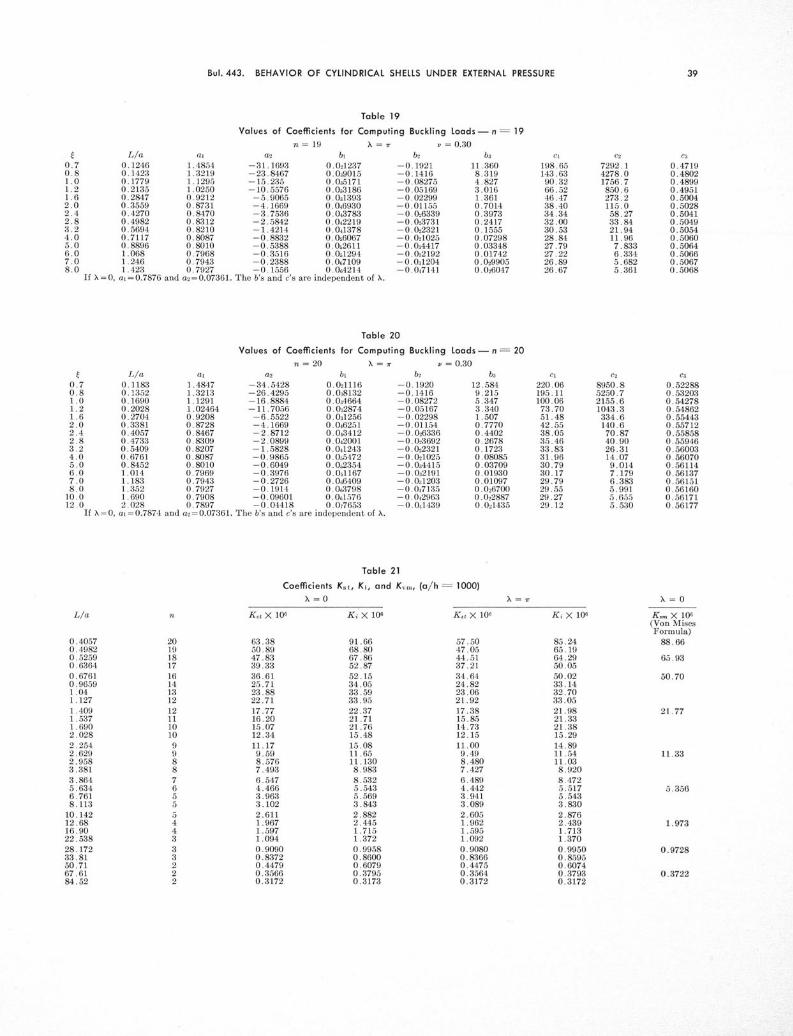
Bul. 443. BEHAVIOR OF CYLINDRICAL SHELLS UNDER EXTERNAL PRESSURE
Table 19
Values of Coefficients for Computing Buckling Loads - n = 19n = 19 X = v = 0.30
L/a ai a2 bi0.1246 1.4854 -31.1693 0.0212370.1423 1.3219 -23.8467 0.0390150.1779 1.1295 -15.235 0.0251710.2135 1.0250 -10.5576 0.0331860.2847 0.9212 -5.9065 0.0313930.3559 0.8731 -4.1669 0.0469300.4270 0.8470 -3.7536 0.0437830.4982 0.8312 -2.5842 0.0422190.5694 0.8210 -1.4214 0.0413780.7117 0.8087 -0.8832 0.0s60670.8896 0.8010 -0.5388 0.0526111.068 0.7968 -0.3516 0.01l
2 9 4
1.246 0.7943 -0.2388 0.0N71091.423 0.7927 -0.1556 0.044214
If X= 0, at1=0.7876 and a2=0.07361. The b's and c's are independent of X.
b2 b3 cl c2 C3-0.1921 11.360 198.65 7292.1 0.4719-0.1416 8.319 143.63 4278.0 0.4802-0.08275 4.827 90.32 1756.7 0.4899-0.05169 3.016 66.52 850.6 0.4951-0.02299 1.361 46.47 273.2 0.5004-0.01155 0.7014 38.40 115.0 0.5028-0.0,6339 0.3973 34.34 58.27 0.5041-0.023731 0.2417 32.00 33.84 0.5049-0.022321 0.1555 30.53 21.94 0.5054-0.021025 0.07298 28.84 11.96 0.5060-0.034417 0.03348 27.79 7.833 0.5064-0.0a2192 0.01742 27.22 6.334 0.5066-0.0Al204 0.029905 26.89 5.682 0.5067-0.047141 0.026047 26.67 5.361 0.5068
Table 20
Values of Coefficients for Computing Buckling Loads -n= 20
n= 20 X = - = 0.30L/a at a2 bi bba c2 ca
0.7 0.1183 1.4847 -34.5428 0.021116
-0.1920 12.584 220.06 8950.8 0.522880.8 0.1352 1.3213 -26,4295 0.038132 -0.1416 9.215 195.11 5250.7 0.532031.0 0.1690 1.1291 -16.8884 0.034664 -0.08272 5.347 100.06 2155.6 0.542781.2 0.2028 1.02464 -11.7056 0.0,2874 -0.05167 3.340 73.70 1043.3 0.548621.6 0.2704 0.9208 -6.5522 0.0s1256 -0.02298 1.507 51.48 334.6 0.554432.0 0.3381 0.8728 -4.1669 0.046251 -0.01154 0.7770 42.55 140.6 0.557122.4 0.4057 0.8467 -2.8712 0.043412 -0.026336 0.4402 38.05 70.87 0.558582.8 0.4733 0.8309 -2.0899 0.042001 -0.023692 0.2678 35.46 40.90 0.559463.2 0.5409 0.8207 -1.5828 0.041243 -0.022321 0,1723 33.83 26.31 0.560034.0 0.6761 0.8087 -0.9865 0.0s5472 -0.021025 0.08085 31.96 14.07 0.560705.0 0.8452 0.8010 -0.6049 0.0s2354 -0.034415 0.03709 30.79 9.014 0.561146.0 1.014 0.7969 -0.3976 0.051167 -0.032191 0.01930 30.17 7.179 0.561377.0 1.183 0.7943 -0.2726 0.0W6409 -0.0,1203 0.01097 29.79 6.383 0.561518.0 1.352 0.7927 -0.1914 0.063798 -0.047135 0.026700 29.55 5.991 0.5616010.0 1.690 0.7908 -0.09601 0.041576 -0.042963 0.022887 29.27 5.655 0.5617112.0 2.028 0.7897 -0.04418 0.077653 -0.041439 0.021435 29.12 5.530 0.56177
If 1= 0, at=0.7874 and a2=0.07361. The b's and c's are independent of 1.
Table 21
Coefficients K4t, Kj, and Kvm, (a/h = 1000)
X= 0 X=r
K.t X 10 Ki X 106 K.t X 106 Ki X 106
63.3850.8947.8339.3336.6125.7123.8822.7117.7716.2015.0712.3411.179.598.5767.493
6.5474.4663.9633.1022.6111.9671.5971.094
0.90900.83720.44790.35660.3172
91.6668.8067.8652.8752.1534.0533.5933.9522.3721.7121.7615.48
15.0811.6511.1308.9838.5325.5435.5693.8432.8822.4451.7151.372
0.99580.86000.60790.37950.3173
57.5047.0544.5137.2134.6424.8223.0621.92
17.3815.8514.7312.1511.009.498.4807.4276.4894.4423.9413.0892.6051.9621.5951.0920.90800.83660.44750.35640.3172
85.2465.1964.2950.0550.0233.1432.7033.0521.9821,3321.3815.29
14.8911.5411.038.9208.4725.5175.5433.8302.8762.4391.7131.3700.99500.85950.60740.37930.3172
-=0
K,. X 106(Von MisesFormula)
88.66
65.93
50.70
21,77
11.33
5.356
1.973
0.9728
0.3722
0.40570.49820.52590.63640.67610.96591.041.1271.4091.5371.6902.0282.2542.6292.9583.3813.8645.6346.7618.113
10.14212.6816.9022.53828.17233.8150.7167.6184.52

ILLINOIS ENGINEERING EXPERIMENT STATION
Table 22
Coefficients Kst, Ki, and Kvm, (a/h = 100)=0 X 10 X 10
K. 1 X 10@ n KiX 106
X =
n K,, X 10«
15 7577.6
14 6707
L/a0.16900.17790.18030.18780.19320.19890.21130.24150.26000.28170.31210.36880.49170.54090.67610.75120.84520.96591.0141.1591.3521.5451.5781.8031.8932.1642.2542.7043.3814.2265.0715.6345.9166.7617.8889.015
11.26911.83213.52216.90320.28425.35533.806
Ki X 10692738454
7684
696963105175
3693
2134193514981334
964.0
712.9621.3
533.6
423.5349.8279.9222.3181.1
162.3148.8115.398.5984.13
54.2340.5632.9129.22
12120
11020
1000090557432
4813
2500226816631481
1039
753.8648.5
557.4
435.6360.0285.2226.7183.6
163.9151.0116.699.4184.57
54.6240.7633.0229.28
14 12000
64845731
3484
19051402
1041882.0
712.0605.5
506.0451.7425.5361.5
297.0230.4186.4167.1140.5
113.498.9391.1383.2871.0856.0842.9637.2232.89
41613651
2473
15441132
904.4765.1
644.1547.2
469.5
394.0340.9
286.1221.6181.9164.4136.8
111.497.6290.23
69.8155.3242.5837.0032.79
K,,, X 106
53444544
3530
2185
1548
634.7
281.1
180.6
97.46
32.59

